AIR CONDITIONING
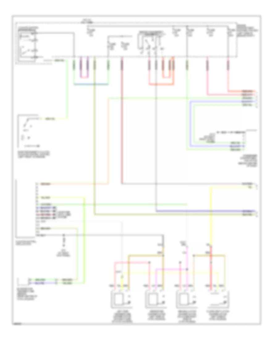
Automatic A/C Wiring Diagram (1 of 2) for Volvo V50 2007

List of elements for Automatic A/C Wiring Diagram (1 of 2) for Volvo V50 2007:
- Air quality sensor (at right side of plenum)
- Climate control module (ccm)
- Climate control system relay
- Computer data lines system
- Defroster damper motor (left side of hvac housing)
- Electromagnetic clutch (climate control system) (left front of engine)
- Engine cpmpartment distribution box (left side of engine compt)
- Engine management main relay
- Evaporator temperature sensor (near center of hvac housing)
- Floor/ventilation damper motor (left side of hvac housing)
- Fuse f10 40a
- Fuse f16 40a
- Fuse f27 10a
- Fuse f3 60a
- Fuse f34 10a
- Fuse f35 15a
- Fuse f9 30a
- G10 (at right kick panel)
- G110 (on right front strut tower)
- Hot at all times
- Interior temerature sensor (center of dash)
- Left side temperature damper motor (on right side of hvac housing)
- Passenger compartment fan motor (behind center of dash)
- Recirculation damper motor (on lower right side of hvac housing)
- Red
- Right side temperature damper motor (on right side of hvac housing)
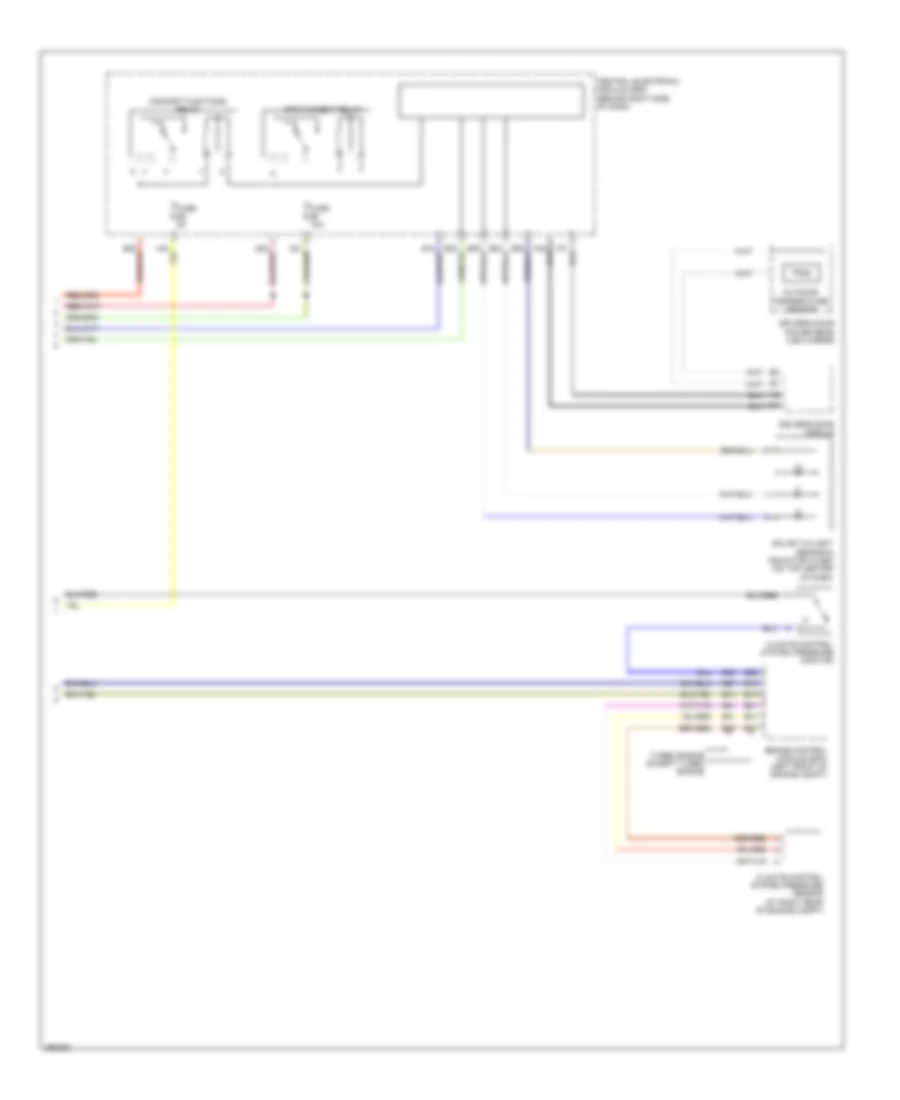
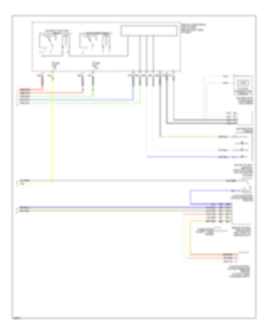
Automatic A/C Wiring Diagram (2 of 2) for Volvo V50 2007
List of elements for Automatic A/C Wiring Diagram (2 of 2) for Volvo V50 2007:
- A17
- B10
- B16
- B25
- B27
- B28
- B31
- B47
- B51
- B53
- Central electronic module (cem) (behind right side of dash)
- Climate control system pressure monitor
- Climate control system pressure sensor (at right rear of engine compt)
- Comfort functions relay
- Driver's door module
- Driver's door power rear view mirror
- Engine control module (ecm) (left front of engine compt)
- Fuse 10a
- Fuse 5a
- Infotainment relay
- Outdoor temperature sensor
- Solar twilight sensor & indicator alarm (on top center of dash)
- Turbo engine except turbo engine
Manual A/C Wiring Diagram (1 of 2) for Volvo V50 2007
List of elements for Manual A/C Wiring Diagram (1 of 2) for Volvo V50 2007:
- Climate control module (ccm)
- Climate control system relay
- Computer data lines system
- Defroster damper motor (left side of hvac housing)
- Electromagnetic clutch (climate control system) (left front of engine)
- Engine cpmpartment distribution box (left side of engine compt)
- Engine management main relay
- Evaporator temperature sensor (near center of hvac housing)
- Floor/ventilation damper motor (left side of hvac housing)
- Fuse f10 40a
- Fuse f16 40a
- Fuse f27 10a
- Fuse f3 60a
- Fuse f34 10a
- Fuse f35 15a
- Fuse f9 30a
- G10 (at right kick panel)
- G110 (on right front strut tower)
- Hot at all times
- Left side temperature damper motor (on right side of hvac housing)
- Passenger compartment fan motor (behind center of dash)
- Recirculation damper motor (on lower right side of hvac housing)
- Red
Manual A/C Wiring Diagram (2 of 2) for Volvo V50 2007
List of elements for Manual A/C Wiring Diagram (2 of 2) for Volvo V50 2007:
- A17
- B10
- B16
- B25
- B27
- B28
- B31
- B47
- B51
- B53
- Central electronic module (cem) (behind right side of dash)
- Climate control system pressure monitor
- Climate control system pressure sensor (at right rear of engine compt)
- Comfort functions relay
- Driver's door module
- Driver's door power rear view mirror
- Engine control module (ecm) (left front of engine compt)
- Fuse 10a
- Fuse 5a
- Infotainment relay
- Outdoor temperature sensor
- Solar twilight sensor & indicator alarm (on top center of dash)
- Turbo engine except turbo engine