AIR CONDITIONING
2.4L
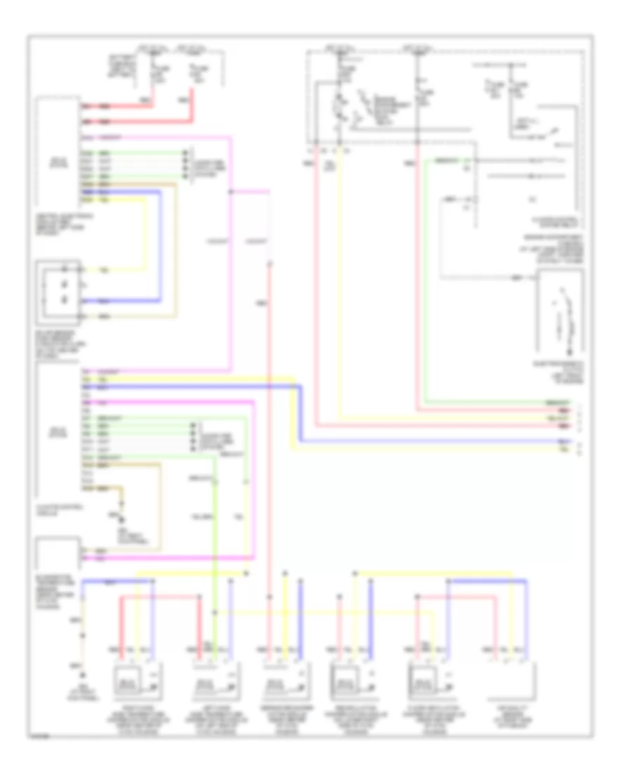
2.4L, Manual A/C Wiring Diagram (1 of 2) for Volvo V70 2005

List of elements for 2.4L, Manual A/C Wiring Diagram (1 of 2) for Volvo V70 2005:
- (not used)
- A10
- A11
- A12
- A13
- A14
- A15
- A16
- Battery fuse box (next to battery)
- C21
- C22
- Central electronic module (cem) (behind left side of dash)
- Climate control module
- Climate control system relay
- Computer data lines system
- D29
- D32
- D42
- D47
- Electromagnetic clutch (left front of engine)
- Engine compartment fuse box (at left side of engine compt, forward of strut tower)
- Engine management system main relay
- Evaporator temperature sensor (near center of hvac housing)
- Fuse a8 60a
- Fuse b11 20a
- Fuse b23 10a
- Fuse b8 10a
- Fuse e4 50a
- Fuse e5 50a
- G84 (at right kick panel)
- Hot at all times
- Left-hand side temperature damper motor module (on left end of hvac housing)
- Recirculation damper motor module (on lower right side of hvac housing)
- Red
- Right-hand side temperature damper motor module (near center of hvac housing)
- Solar sensor, dusk sensor & indicator alarm (on top center of dash)
- Solid state
- Ventilation/floor/defroster damper motor module (near center of hvac housing)
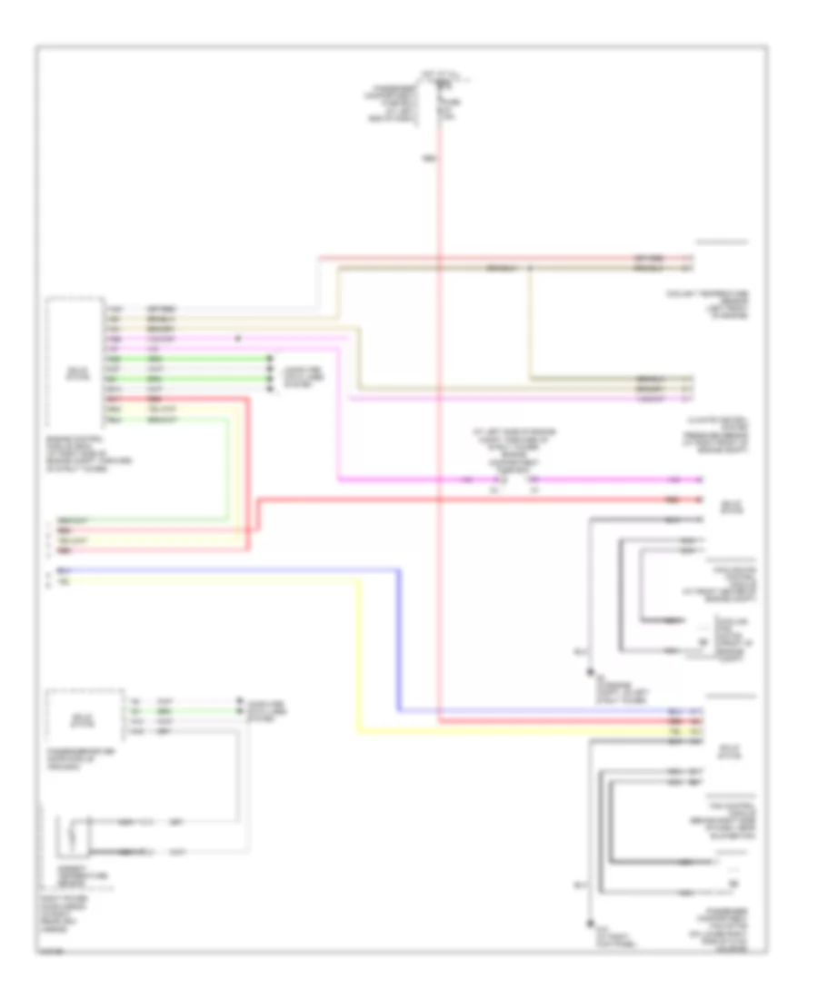
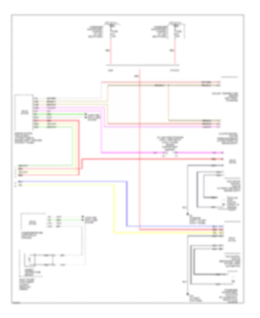
2.4L, Manual A/C Wiring Diagram (2 of 2) for Volvo V70 2005
List of elements for 2.4L, Manual A/C Wiring Diagram (2 of 2) for Volvo V70 2005:
- (at left side of engine compt, forward of strut tower) engine compartment fuse box
- A14
- A18
- A21
- A37
- A40
- A55
- A58
- A61
- Ambient temperature sensor
- B11
- B13
- B38
- B44
- Climate control system pressure sensor (at right front of engine compt)
- Computer data lines system
- Coolant temperature sensor (left front of engine)
- Cooling fan control module (at front center of engine compt)
- Cooling fan motor (front of engine compt)
- Engine control module (ecm) (at right side of engine compt, forward of strut tower)
- Fan control module (behind right side of dash, near blower fan)
- Fuse c3 30a
- G10 (at right kick panel)
- G2 (in engine compt, on left strut tower)
- Hot at all times
- Nca
- Passenger compartment fan motor (on lower right side of hvac housing)
- Passenger compartment fuse box (at left end of dash)
- Passenger/driver door module (pdm/ddm)
- Red
- Right power door mirror (in right rearview mirror)
- Solid state
2.4L TURBO
2.4L Turbo, Automatic A/C Wiring Diagram (1 of 2) for Volvo V70 2005
List of elements for 2.4L Turbo, Automatic A/C Wiring Diagram (1 of 2) for Volvo V70 2005:
- (not used)
- A10
- A11
- A12
- A13
- A14
- A15
- A16
- Air quality sensor (at right side of plenum)
- Battery fuse box (next to battery)
- C21
- C22
- Central electronic module (cem) (behind left side of dash)
- Climate control module
- Climate control system relay
- Computer data lines system
- D29
- D30
- D32
- D42
- D47
- Defroster damper motor module (near center of hvac housing)
- Electromagnetic clutch (left front of engine)
- Engine compartment fuse box (at left side of engine compt, forward of strut tower)
- Engine management system main relay
- Evaporator temperature sensor (near center of hvac housing)
- Floor/ventilation damper motor module (near center of hvac housing)
- Fuse a8 60a
- Fuse b11 20a
- Fuse b23 10a
- Fuse b8 10a
- Fuse e4 50a
- Fuse e5 50a
- G84 (at right kick panel)
- Hot at all times
- Left-hand side temperature damper motor module (on left end of hvac housing)
- Recirculation damper motor module (on lower right side of hvac housing)
- Red
- Right-hand side temperature damper motor module (near center of hvac housing)
- Solar sensor, dusk sensor & indicator alarm (on top center of dash)
- Solid state
2.4L Turbo, Automatic A/C Wiring Diagram (2 of 2) for Volvo V70 2005
List of elements for 2.4L Turbo, Automatic A/C Wiring Diagram (2 of 2) for Volvo V70 2005:
- (at left side of engine compt, forward of strut tower) engine compartment fuse box
- A14
- A18
- A39
- A60
- A68
- Ambient temperature sensor
- B11
- B13
- B38
- B44
- Climate control system pressure sensor (at right front of engine compt)
- Computer data lines system
- Coolant temperature sensor (left front of engine)
- Cooling fan control module (at front center of engine compt)
- Cooling fan motor (front of engine compt)
- Engine control module (ecm) (at right side of engine compt, forward of strut tower)
- Fan control module (behind right side of dash, near blower fan)
- Fuse c1 30a
- Fuse c3 30a
- G10 (at right kick panel)
- G2 (in engine compt, on left strut tower)
- Hot at all times
- Nca
- Passenger compartment fan motor (on lower right side of hvac housing)
- Passenger compartment fuse box (at left end of dash)
- Passenger/driver door module (pdm/ddm)
- Red
- Right power door mirror (in right rearview mirror)
- Solid state
- V70/xc70
- Xc90
2.5L TURBO
2.5L Turbo, Automatic A/C Wiring Diagram (1 of 2) for Volvo V70 2005
List of elements for 2.5L Turbo, Automatic A/C Wiring Diagram (1 of 2) for Volvo V70 2005:
- (not used)
- A10
- A11
- A12
- A13
- A14
- A15
- A16
- Air quality sensor (at right side of plenum)
- Battery fuse box (next to battery)
- C21
- C22
- Central electronic module (cem) (behind left side of dash)
- Climate control module
- Climate control system relay
- Computer data lines system
- D29
- D30
- D32
- D42
- D47
- Defroster damper motor module (near center of hvac housing)
- Electromagnetic clutch (left front of engine)
- Engine compartment fuse box (at left side of engine compt, forward of strut tower)
- Engine management system main relay
- Evaporator temperature sensor (near center of hvac housing)
- Floor/ventilation damper motor module (near center of hvac housing)
- Fuse a8 60a
- Fuse b11 20a
- Fuse b23 10a
- Fuse b8 10a
- Fuse e4 50a
- Fuse e5 50a
- G84 (at right kick panel)
- Hot at all times
- Left-hand side temperature damper motor module (on left end of hvac housing)
- Recirculation damper motor module (on lower right side of hvac housing)
- Red
- Right-hand side temperature damper motor module (near center of hvac housing)
- Solar sensor, dusk sensor & indicator alarm (on top center of dash)
- Solid state
2.5L Turbo, Automatic A/C Wiring Diagram (2 of 2) for Volvo V70 2005
List of elements for 2.5L Turbo, Automatic A/C Wiring Diagram (2 of 2) for Volvo V70 2005:
- (at left side of engine compt, forward of strut tower) engine compartment fuse box
- A14
- A18
- A39
- A60
- A68
- Ambient temperature sensor
- B11
- B13
- B38
- B44
- Climate control system pressure sensor (at right front of engine compt)
- Computer data lines system
- Coolant temperature sensor (left front of engine)
- Cooling fan control module (at front center of engine compt)
- Cooling fan motor (front of engine compt)
- Engine control module (ecm) (at right side of engine compt, forward of strut tower)
- Fan control module (behind right side of dash, near blower fan)
- Fuse c1 30a
- Fuse c3 30a
- G10 (at right kick panel)
- G2 (in engine compt, on left strut tower)
- Hot at all times
- Nca
- Passenger compartment fan motor (on lower right side of hvac housing)
- Passenger compartment fuse box (at left end of dash)
- Passenger/driver door module (pdm/ddm)
- Red
- Right power door mirror (in right rearview mirror)
- Solid state
- V70/xc70
- Xc90