AIR CONDITIONING
Automatic A/C Wiring Diagram (1 of 2) for Volvo XC60 R-Design 2011

List of elements for Automatic A/C Wiring Diagram (1 of 2) for Volvo XC60 R-Design 2011:
- 74/301
- 74/401
- 74/414
- 74/504
- 74/507
- A13
- A68
- A85
- Air quality sensor (aqs) (on hvac assembly)
- B10
- B27
- B31
- B34
- B35
- B41
- B51
- B53
- B54
- Climate control module
- Climate control system
- Climate control system electromagnetic clutch (left front of engine)
- Climate control system pressure sensor (on hvac assembly)
- Climate control system relay
- Comfort functions relay
- Computer data lines system
- Defroster damper motor module (dmm) (on right side of hvac assembly)
- Engine compartment distribution box (left side of engine compt)
- Engine control module (ecm) (left rear of engine compt)
- Engine management system main relay
- Evaporator temperature sensor (on evaporator assembly)
- Floor/ventilation damper motor module (dmm) (on left side of hvac unit)
- Fuse a4 60a
- Fuse a43 80a
- Fuse b11 40a
- Fuse b30 10a
- Fuse b32 15a
- Fuse b33 5a
- Fuse b38 10a
- Fuse c21 5a
- G10 (in left bottom rail)
- G83 (in left bottom rail)
- Hot at all times
- Left power exterior rearview mirror (in driver's door mirror)
- Left temperature damper motor module (dmm) (on left side of hvac assembly)
- Mirrors system
- Outdoor temperature sensor
- Passenger compartment distribution box (right end of dash)
- Pnk
- Recirculation damper motor module (dmm) (on hvac unit)
- Red
- Right temperature damper motor module (dmm) (on right side of hvac assembly)
- Solid state
- T4/409
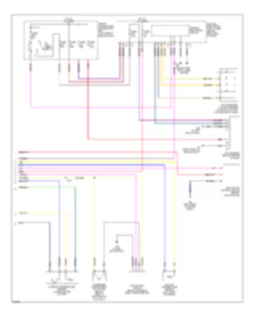
Automatic A/C Wiring Diagram (2 of 2) for Volvo XC60 R-Design 2011
List of elements for Automatic A/C Wiring Diagram (2 of 2) for Volvo XC60 R-Design 2011:
- 15- feed relay
- 74/411
- 74/504
- Central electronic module
- Central electronic module (cem) (behind right end of dash)
- Computer data lines system
- Coolant temperature sensor (left front of engine)
- Cooling fan control module (behind cooling fans)
- Engine compartment distribution box (left side of engine compt)
- Fan control module (behind center of dash, on blower fan)
- Fuse a1 50a
- Fuse a2 50a
- Fuse a7 100a
- Fuse b17 20a
- Fuse b27 5a
- Fuse f14 5a
- Fuse f20 7.5a
- G1 (right front of engine compt)
- G10 (in left bottom rail)
- G2 (left front of engine compt)
- G83 (in left bottom rail)
- Hot at all times
- Interior temperature sensor (lower center of dash)
- Passenger compartment fan motor (behind dash, in right end of hvac unit)
- Ptc element (behind center of dash)
- Red
- Solar sensor, twilight sensor & indicator alarm (top center of dash)