AIR CONDITIONING
Front A/C Wiring Diagram, Auto A/C (1 of 2) for Volvo XC90 2003

List of elements for Front A/C Wiring Diagram, Auto A/C (1 of 2) for Volvo XC90 2003:
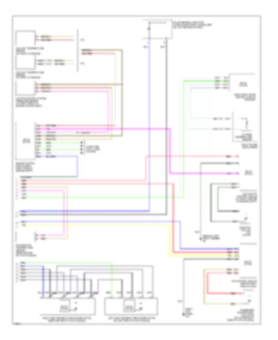
Front A/C Wiring Diagram, Auto A/C (2 of 2) for Volvo XC90 2003
List of elements for Front A/C Wiring Diagram, Auto A/C (2 of 2) for Volvo XC90 2003:
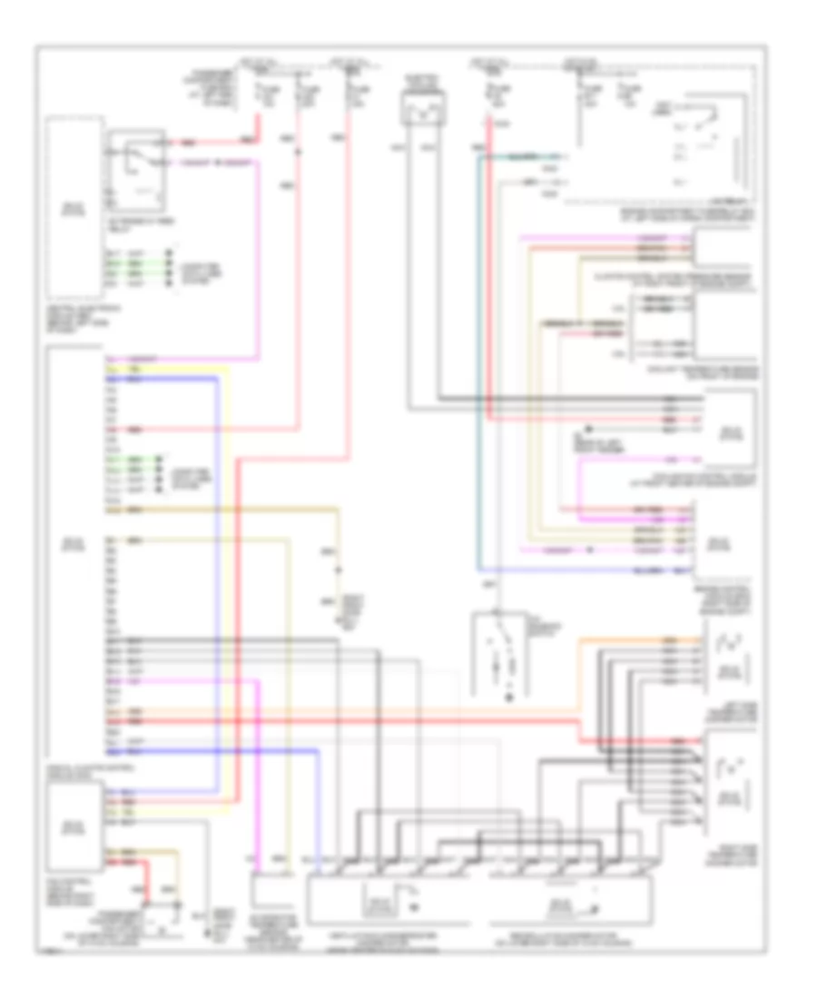
Front A/C Wiring Diagram, Manual A/C for Volvo XC90 2003
List of elements for Front A/C Wiring Diagram, Manual A/C for Volvo XC90 2003:
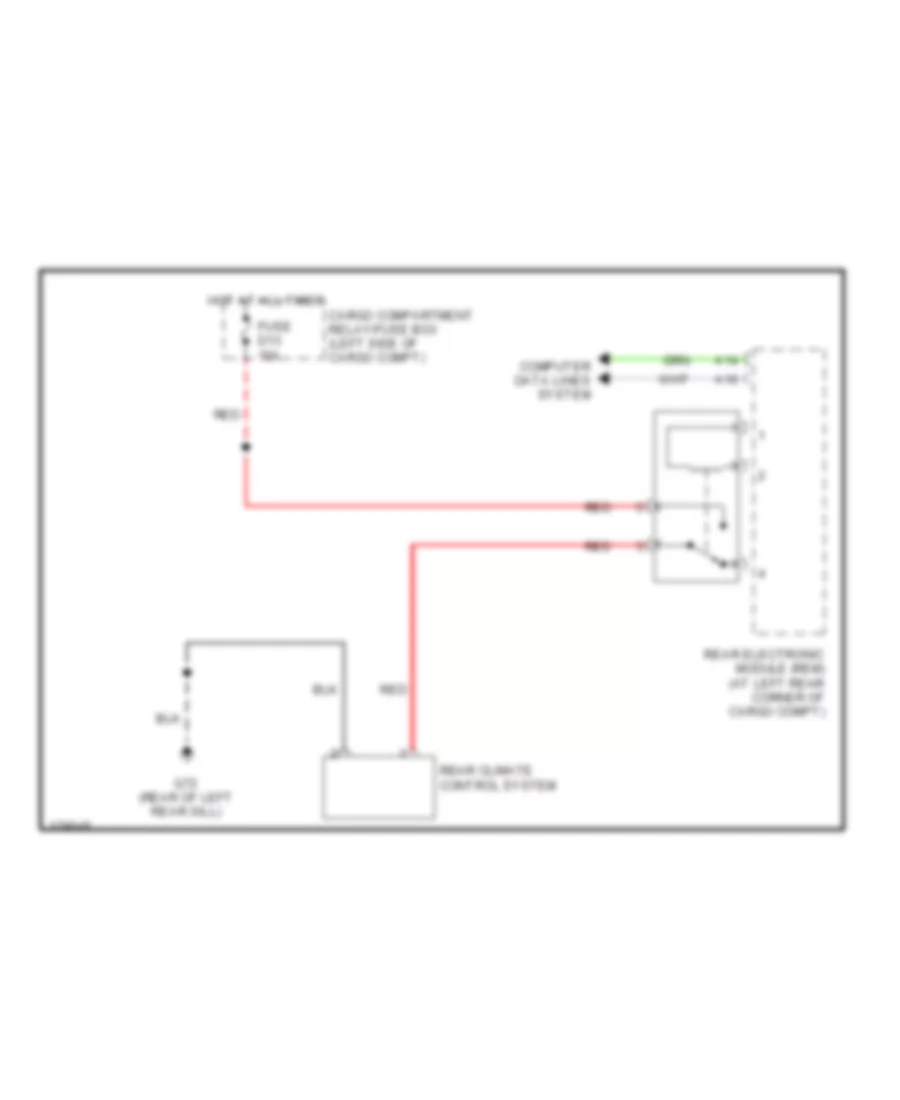
Rear A/C Wiring Diagram for Volvo XC90 2003
List of elements for Rear A/C Wiring Diagram for Volvo XC90 2003: