AIR CONDITIONING
Automatic A/C Wiring Diagram (1 of 2) for Volvo XC90 2004

List of elements for Automatic A/C Wiring Diagram (1 of 2) for Volvo XC90 2004:
- (at
- (not used)
- A10
- A11
- A12
- A13
- A14
- A15
- A16
- Air quality sensor (at right side of plenum)
- B10
- B11
- B12
- B13
- B14
- B15
- B16
- B17
- B18
- B19
- B20
- B21
- B22
- Central electronic module (cem)
- Climate control system relay
- Computer data lines system
- Defroster damper motor (near center of hvac housing)
- Electromagnitic clutch (climate control system) (right front of engine)
- Electronic climate control (ecc) module
- Engine compartment fuse/relay box (at left side of engine compartment, forward of strut tower)
- Extended d1 feed relay (in passenger compartment relay box)
- Fuse a8 80a
- Fuse b11 20a
- Fuse b8 10a
- Fuse c1 30a
- Fuse c21 10a
- Fuse c22 5a
- Hot at all times
- Hot w/ engine management system main relay energized
- Nca
- Passenger compartment fuse box (at left end of dash)
- Recirculation damper motor (on lower right side of hvac housing)
- Red
- Right kick panel) g84
- Solid state
- Ventilation/floor damper motor (near center of hvac housing)
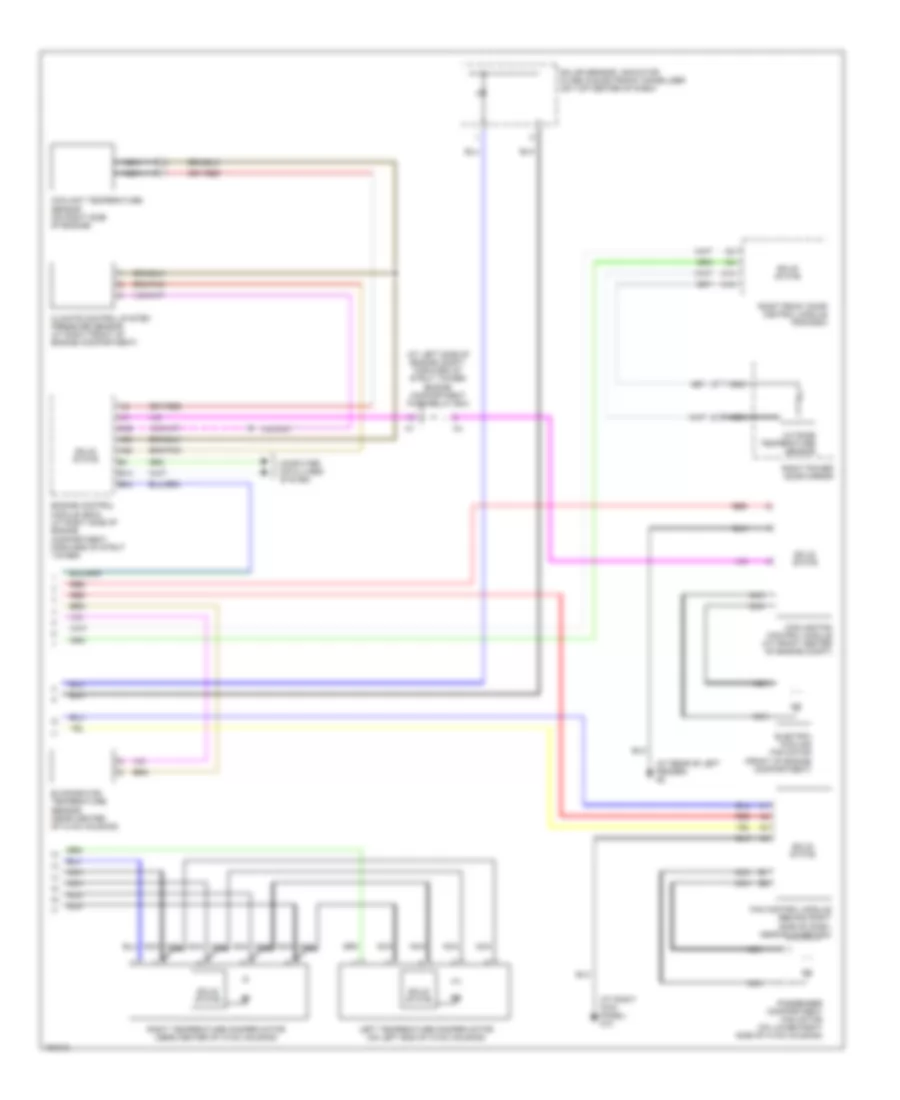
Automatic A/C Wiring Diagram (2 of 2) for Volvo XC90 2004
List of elements for Automatic A/C Wiring Diagram (2 of 2) for Volvo XC90 2004:
- (at left side of engine compt, forward of strut tower) engine compartment fuse/relay box
- (at rear of left fender) g2
- (at right kick panel) g10
- A14
- A18
- A39
- A60
- A68
- B13
- B44
- Climate control system pressure sensor (at right front of engine compartment)
- Computer data lines system
- Coolant temperature sensor (on right side of engine)
- Cooling fan control module (at front center of engine compt)
- Electric cooling fan motor (front of engine compartment)
- Engine control module (ecm) (at right side of engine compartment, forward of strut tower)
- Evaporator temperature sensor (near center of hvac housing)
- Fan control module (behind right side of dash, near blower fan)
- Left temperature damper motor (on left end of hvac housing)
- Nca
- Outside temperature sensor
- Passenger compartment fan motor (on lower right side of hvac housing)
- Red
- Right front door control module (pdm/ddm)
- Right power door mirror
- Right temperature damper motor (near center of hvac housing)
- Solar sensor, indicator alarm & electronic immobilizer (on top center of dash)
- Solid state
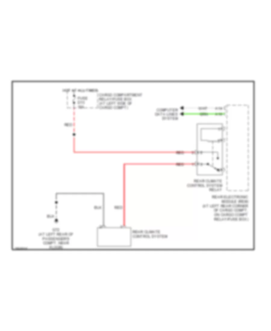
Rear A/C Wiring Diagram for Volvo XC90 2004
List of elements for Rear A/C Wiring Diagram for Volvo XC90 2004:
- A14
- A16
- Cargo compartment relay/fuse box (at left side of cargo compt)
- Computer data lines system
- Fuse d13 15a
- G72 (at left rear of passenger's compt, near floor)
- Hot at all times
- Rear climate control system
- Rear climate control system relay
- Rear electronic module (rem) (at left rear corner of cargo compt, on cargo compt relay/fuse box)
- Red