AIR CONDITIONING
3.2L
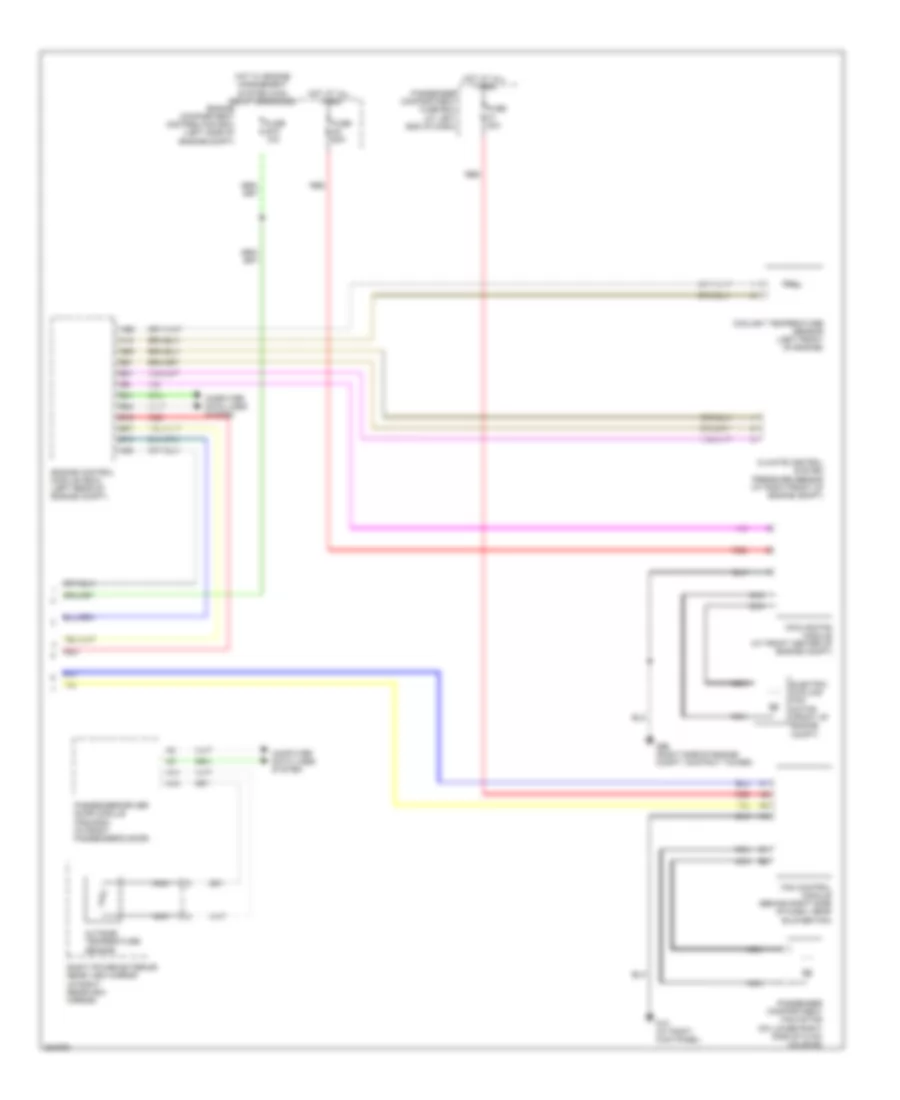
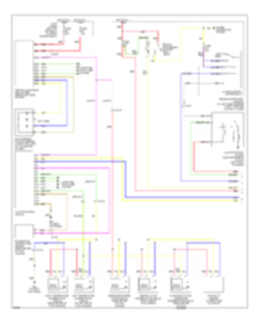
3.2L, Automatic A/C Wiring Diagram (1 of 2) for Volvo XC90 2011

List of elements for 3.2L, Automatic A/C Wiring Diagram (1 of 2) for Volvo XC90 2011:
- (not used)
- 54/132
- 54/1b
- 54/40d
- A10
- A11
- A12
- A13
- A14
- A15
- A16
- Air quality sensor (at right side of plenum)
- C21
- C22
- Central electronic module (cem) (behind left side of dash)
- Climate control module
- Climate control system electromagnetic clutch (left front of engine)
- Climate control system relay
- Computer data lines system
- D29
- D30
- D32
- D42
- D47
- Defroster damper motor module (near center of hvac housing)
- Engine compartment fuse box (at left side of engine compt, forward of strut tower)
- Engine management system main relay
- Evaporator temperature sensor (near center of hvac housing)
- Floor/ventilation damper motor module (near center of hvac housing)
- Fuse b11 10a
- Fuse b19 5a
- Fuse e4 50a
- Fuse e5 50a
- G84 (at right kick panel)
- Hot at all times
- Left temperature damper motor module (on left end of hvac housing)
- Main fuses (next to battery, in cargo compt)
- Power distribution system
- Recirculation damper motor module (right side of hvac plenum)
- Red
- Right temperature damper motor module (near center of hvac housing)
- Solar sensor, twilight sensor & indicator alarm (at top center of dash)
- Solid state
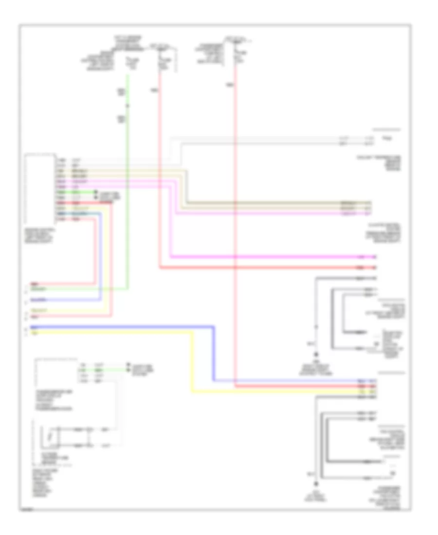
3.2L, Automatic A/C Wiring Diagram (2 of 2) for Volvo XC90 2011
List of elements for 3.2L, Automatic A/C Wiring Diagram (2 of 2) for Volvo XC90 2011:
- A13
- A14
- A18
- A68
- A85
- B10
- B16
- B27
- B31
- B41
- B51
- B53
- B54
- Climate control system pressure sensor (at right front of engine compt)
- Computer data lines system
- Coolant temperature sensor (left front of engine)
- Cooling fan module (at front center of engine compt)
- Electric cooling fan motor (front of engine compt)
- Engine compartment distribution box (left side of engine compt)
- Engine control module (ecm) (left rear of engine compt)
- Fan control module (behind right side of dash, near blower fan)
- Fuse a2 60a
- Fuse b15 10a
- Fuse c1 30a
- G10 (at right kick panel)
- G96 (right side of engine compt, on strut tower)
- Hot at all times
- Hot w/ engine management system main relay energized
- Nca
- Outside temperature sensor
- Passenger compartment fan motor (on lower right side of hvac housing)
- Passenger compartment fuse box (at left end of dash)
- Passenger/driver door module (pdm/ddm) (in front passenger's door)
- Red
- Right power exterior rear view mirror (in right rearview mirror)
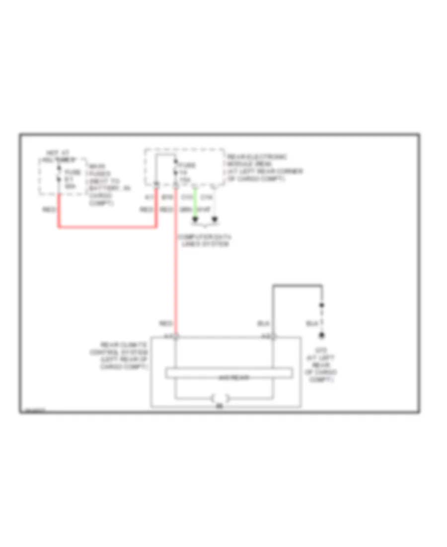
3.2L, Rear A/C Wiring Diagram for Volvo XC90 2011
List of elements for 3.2L, Rear A/C Wiring Diagram for Volvo XC90 2011:
- A/c rear
- B19
- C13
- C14
- Computer data lines system
- Fuse 15a
- Fuse e1 60a
- G72 (at left rear of cargo compt)
- Hot at all times
- Main fuses (next to battery, in cargo compt)
- Rear climate control system (left rear of cargo compt)
- Rear electronic module (rem) (at left rear corner of cargo compt)
- Red
4.4L
4.4L, Automatic A/C Wiring Diagram (1 of 2) for Volvo XC90 2011
List of elements for 4.4L, Automatic A/C Wiring Diagram (1 of 2) for Volvo XC90 2011:
- (not used)
- 54/132
- 54/1b
- 54/40d
- A10
- A11
- A12
- A13
- A14
- A15
- A16
- Air quality sensor (at right side of plenum)
- C21
- C22
- Central electronic module (cem) (behind left side of dash)
- Climate control module
- Climate control system electromagnetic clutch (left front of engine)
- Climate control system relay
- Computer data lines system
- D29
- D30
- D32
- D42
- D47
- Defroster damper motor module (near center of hvac housing)
- Engine compartment fuse box (at left side of engine compt, forward of strut tower)
- Engine management system main relay
- Evaporator temperature sensor (near center of hvac housing)
- Floor/ventilation/ defroster damper motor module (near center of hvac housing)
- Fuse b11 10a
- Fuse b19 5a
- Fuse e4 50a
- Fuse e5 50a
- G84 (at right kick panel)
- Hot at all times
- Left temperature damper motor module (on left end of hvac housing)
- Main fuses (next to battery, in cargo compartment)
- Power distribution system
- Recirculation damper motor module (right side of hvac plenum)
- Red
- Right temperature damper motor module (near center of hvac housing)
- Solar sensor, twilight sensor & indicator alarm (at top center of dash)
- Solid state
4.4L, Automatic A/C Wiring Diagram (2 of 2) for Volvo XC90 2011
List of elements for 4.4L, Automatic A/C Wiring Diagram (2 of 2) for Volvo XC90 2011:
- (in front passenger's door)
- A12
- A14
- A18
- A49
- A68
- B12
- B16
- B19
- B45
- B49
- B53
- B54
- B58
- Climate control system pressure sensor (at right front of engine compt)
- Computer data lines system
- Coolant temperature sensor (rear of engine)
- Cooling fan module (at front center of engine compt)
- Electric cooling fan motor (front of engine compt)
- Engine compartment distribution box (left side of engine compt)
- Engine control module (ecm) (left front of engine compt)
- Fan control module (behind right side of dash, near blower fan)
- Fuse a2 60a
- Fuse b15 10a
- Fuse c1 30a
- G10 (at right kick panel)
- G96 (right side of engine compt, on strut tower)
- Hot at all times
- Hot w/ engine management system main relay energized
- Mirror (in right rearview mirror)
- Nca
- Outside temperature sensor
- Passenger compartment fan motor (on lower right side of hvac housing)
- Passenger compartment fuse box (at left end of dash)
- Passenger/driver door module (pdm/ddm)
- Red
- Right power exterior rear view
4.4L, Rear A/C Wiring Diagram for Volvo XC90 2011
List of elements for 4.4L, Rear A/C Wiring Diagram for Volvo XC90 2011:
- A/c rear
- B19
- C13
- C14
- Computer data lines system
- Fuse 15a
- Fuse e1 60a
- G72 (at left rear of cargo compt)
- Hot at all times
- Main fuses (next to battery, in cargo compt)
- Rear climate control system (left rear of cargo compt)
- Rear electronic module (rem) (at left rear corner of cargo compt)
- Red