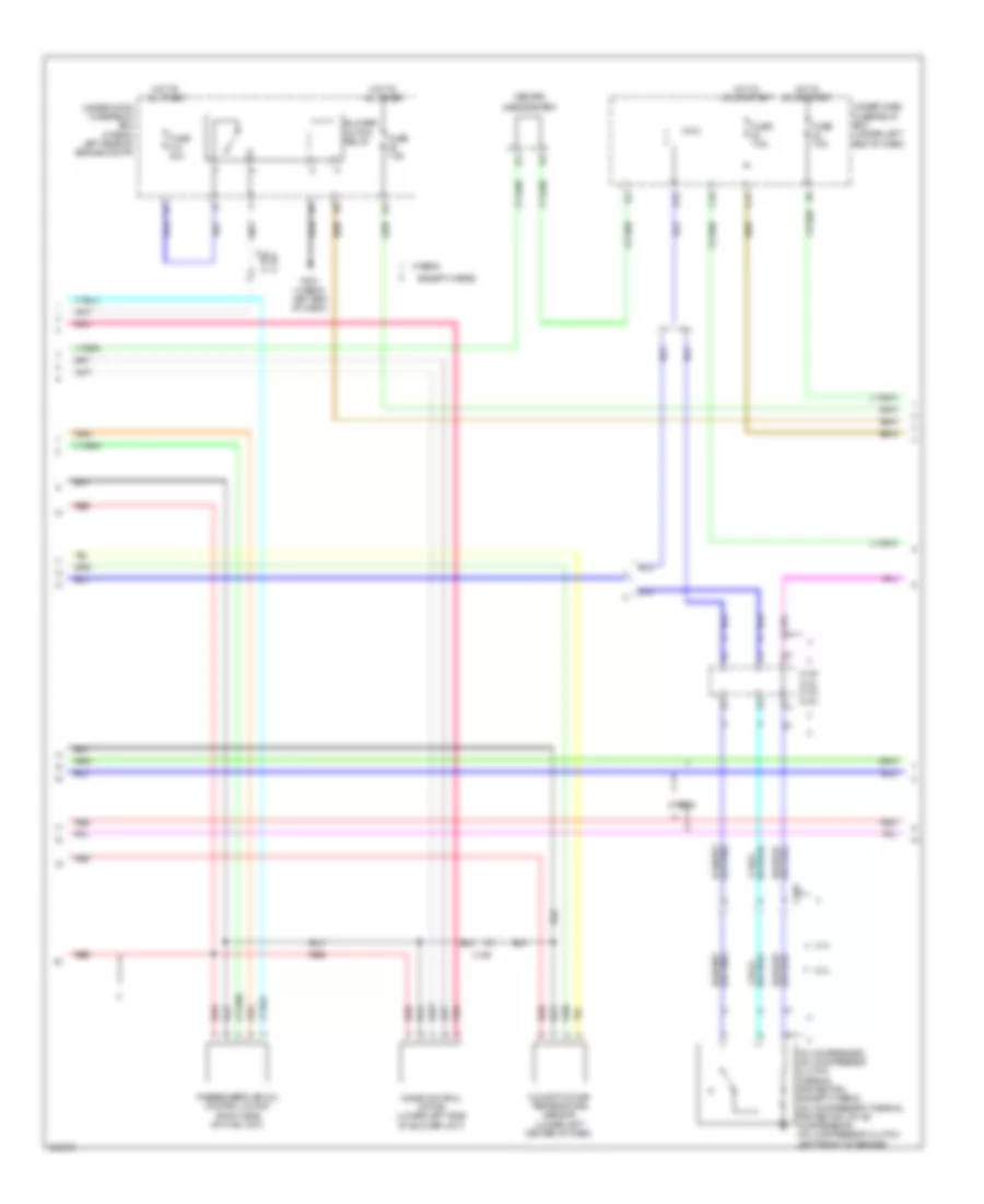
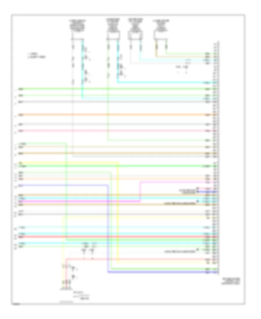
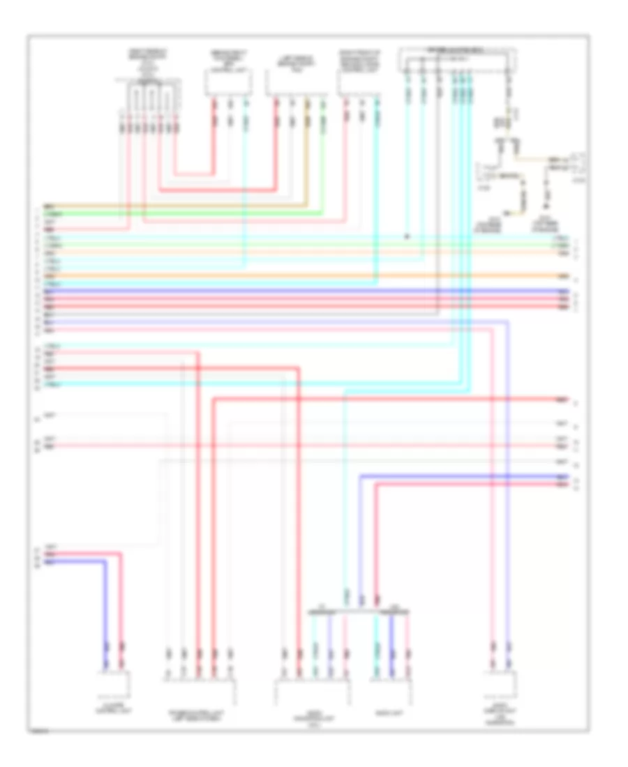
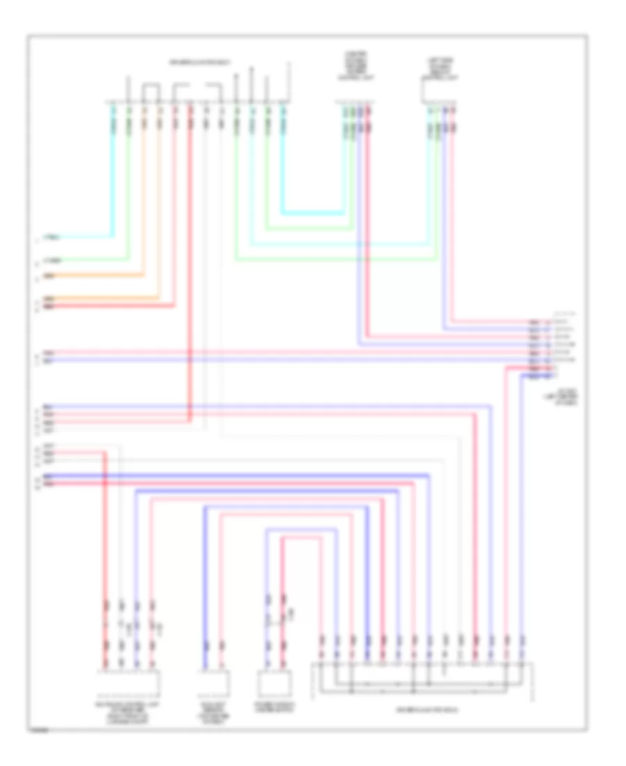
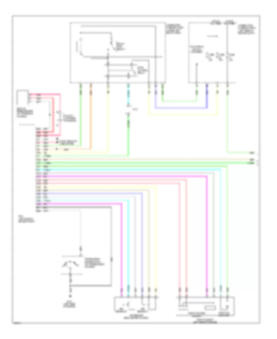
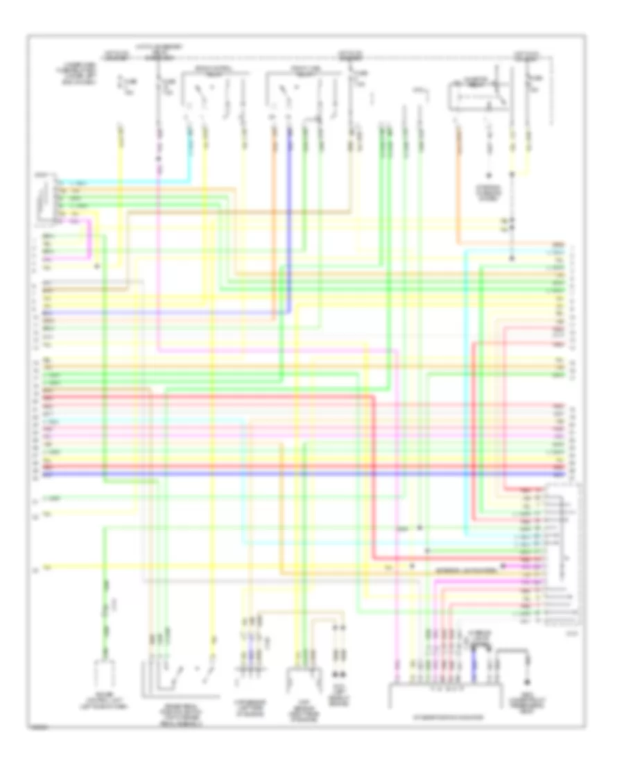
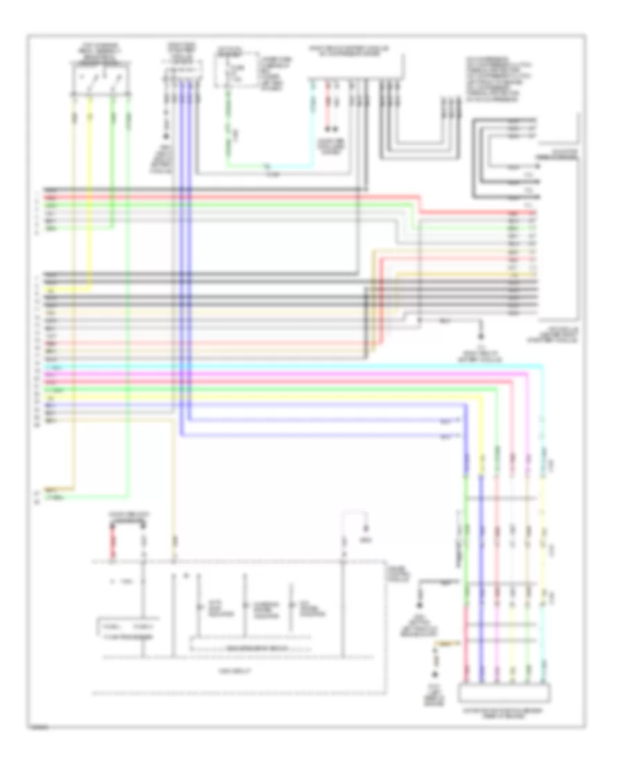
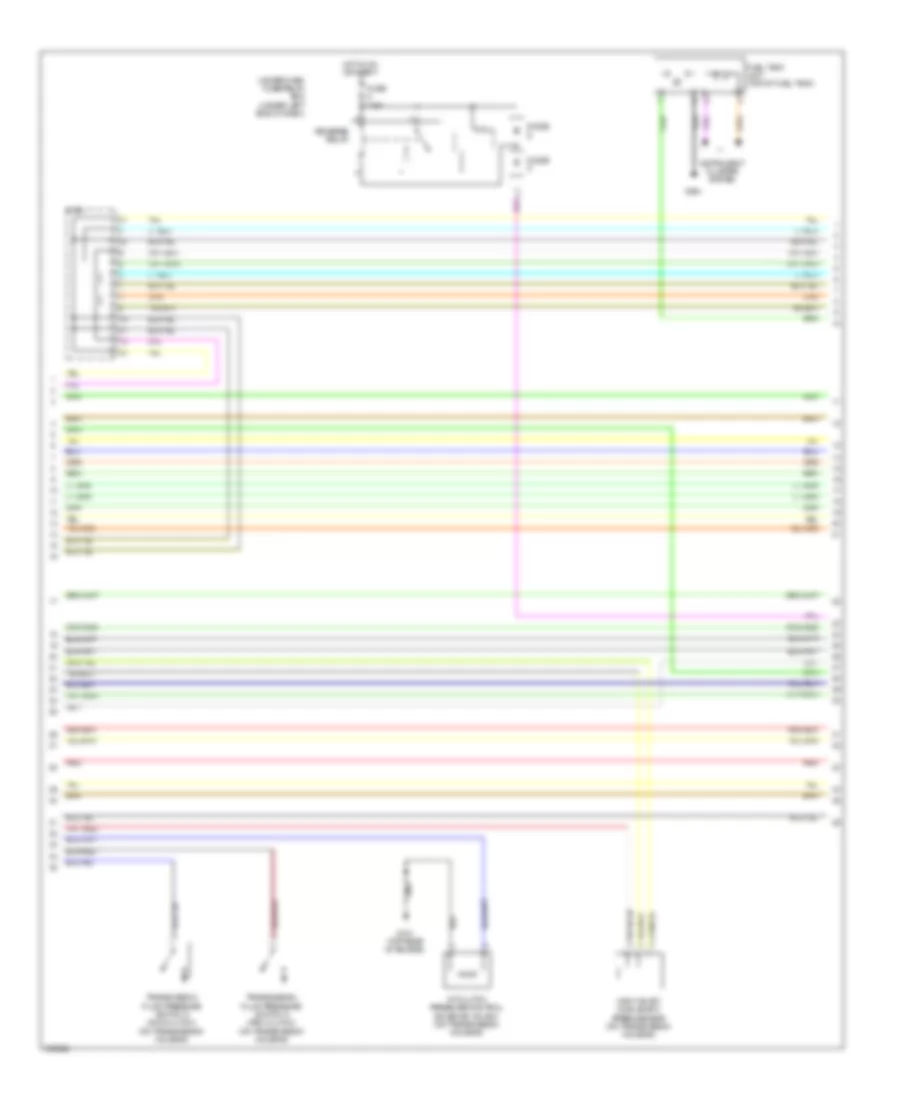
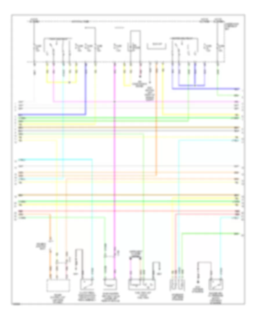
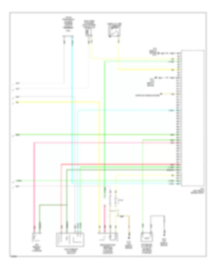
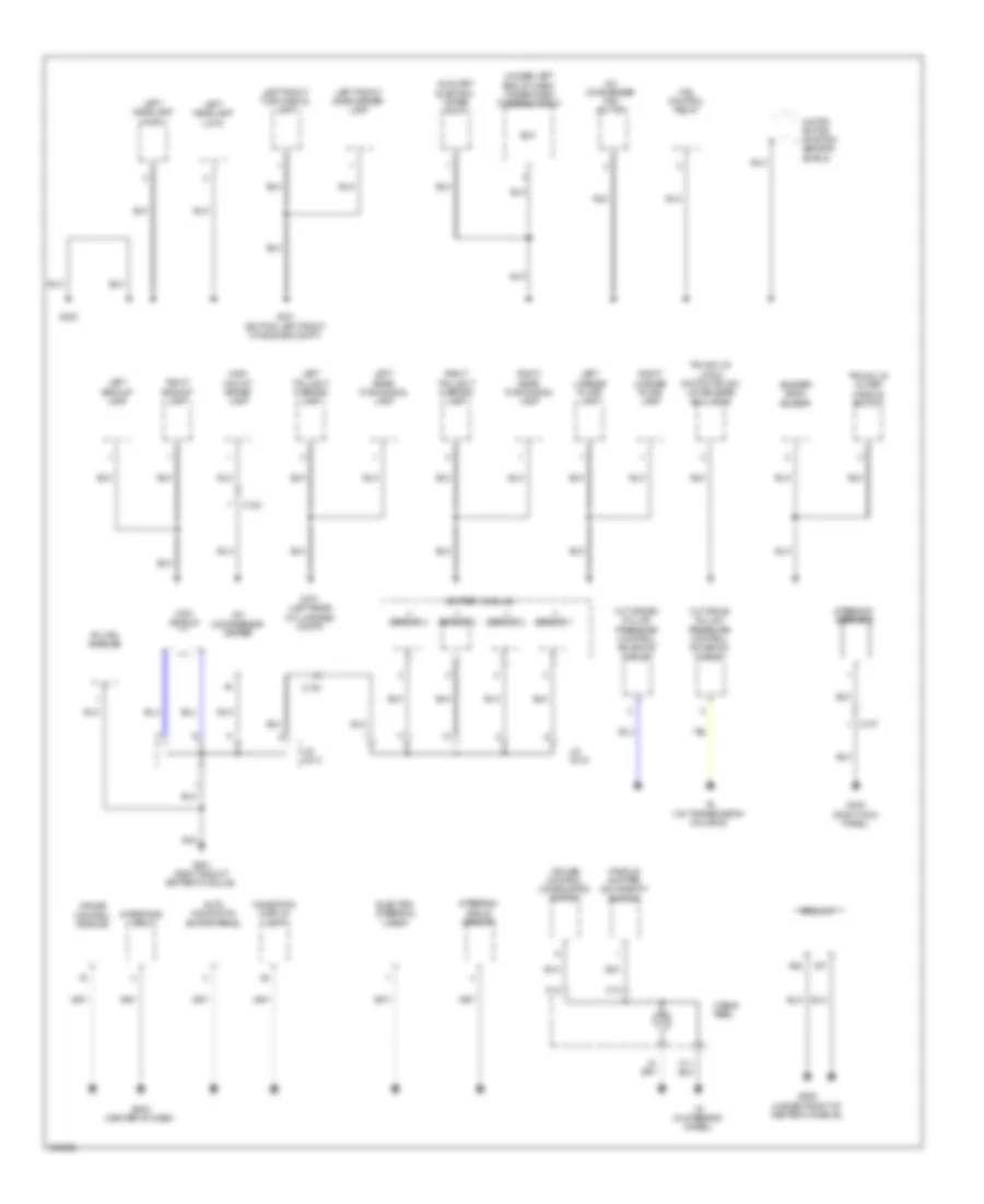
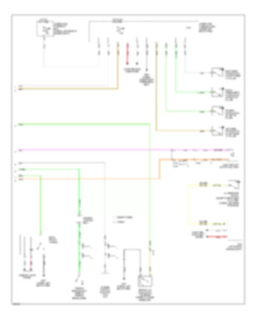
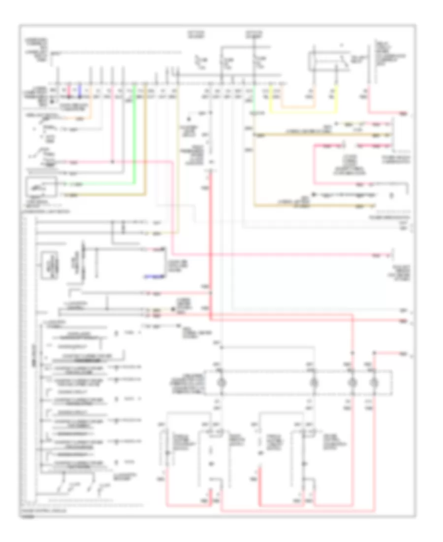
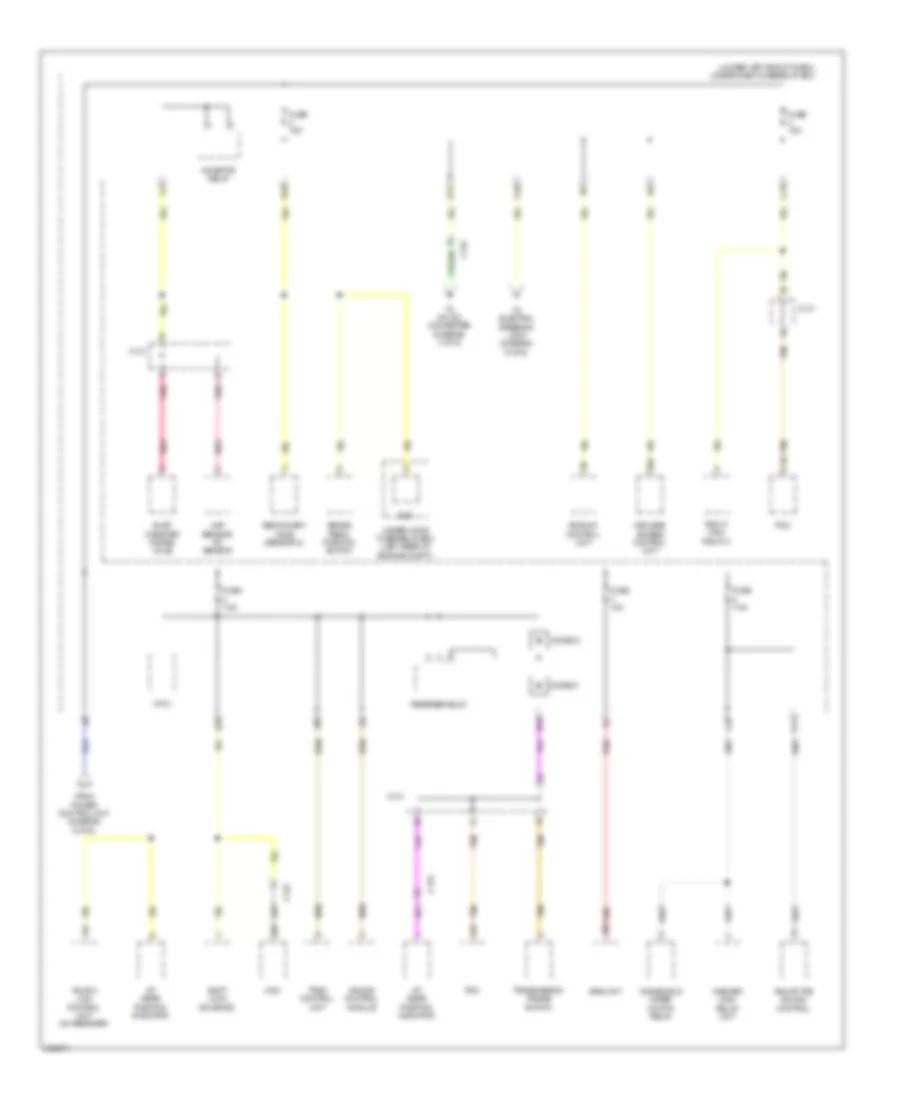
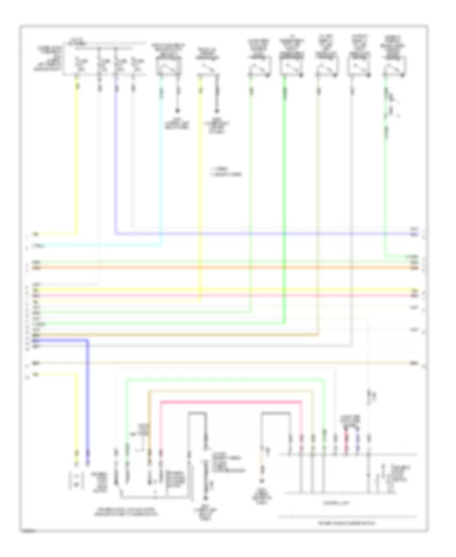
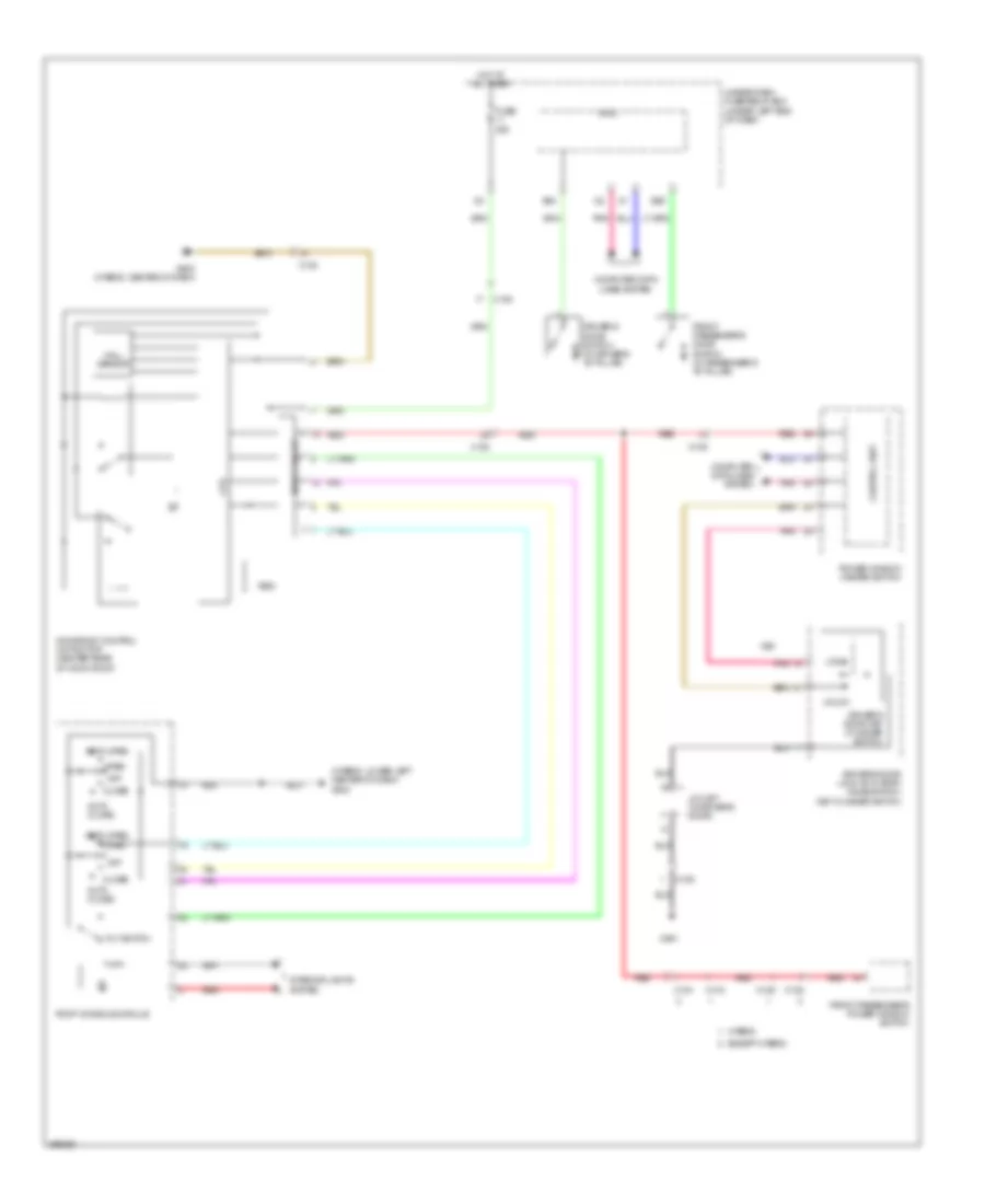
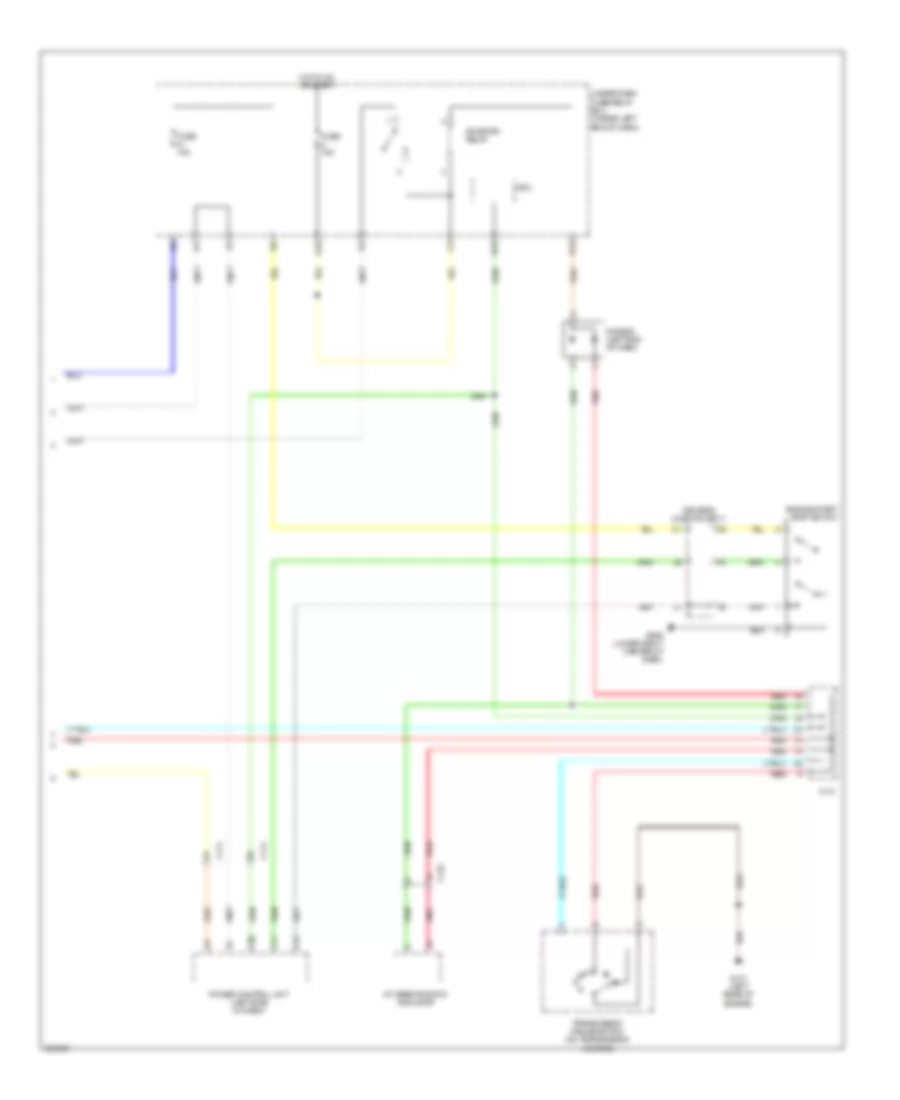
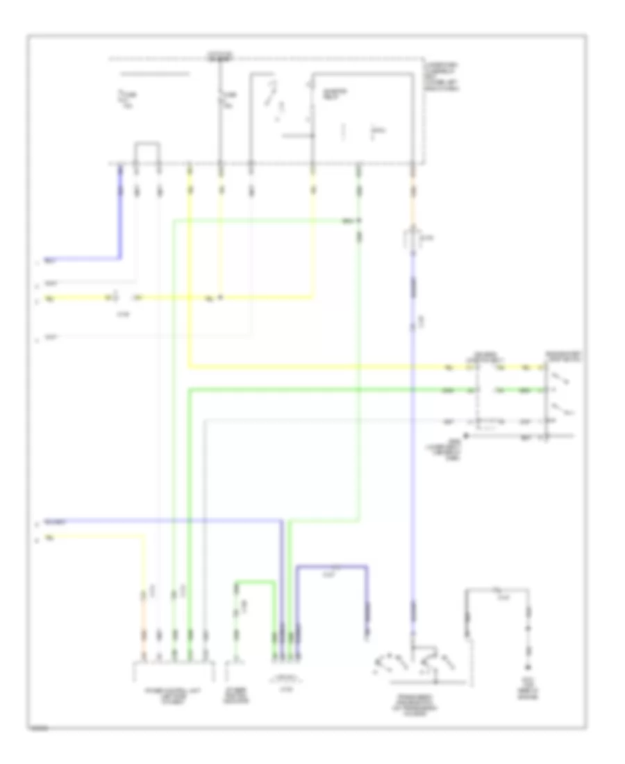
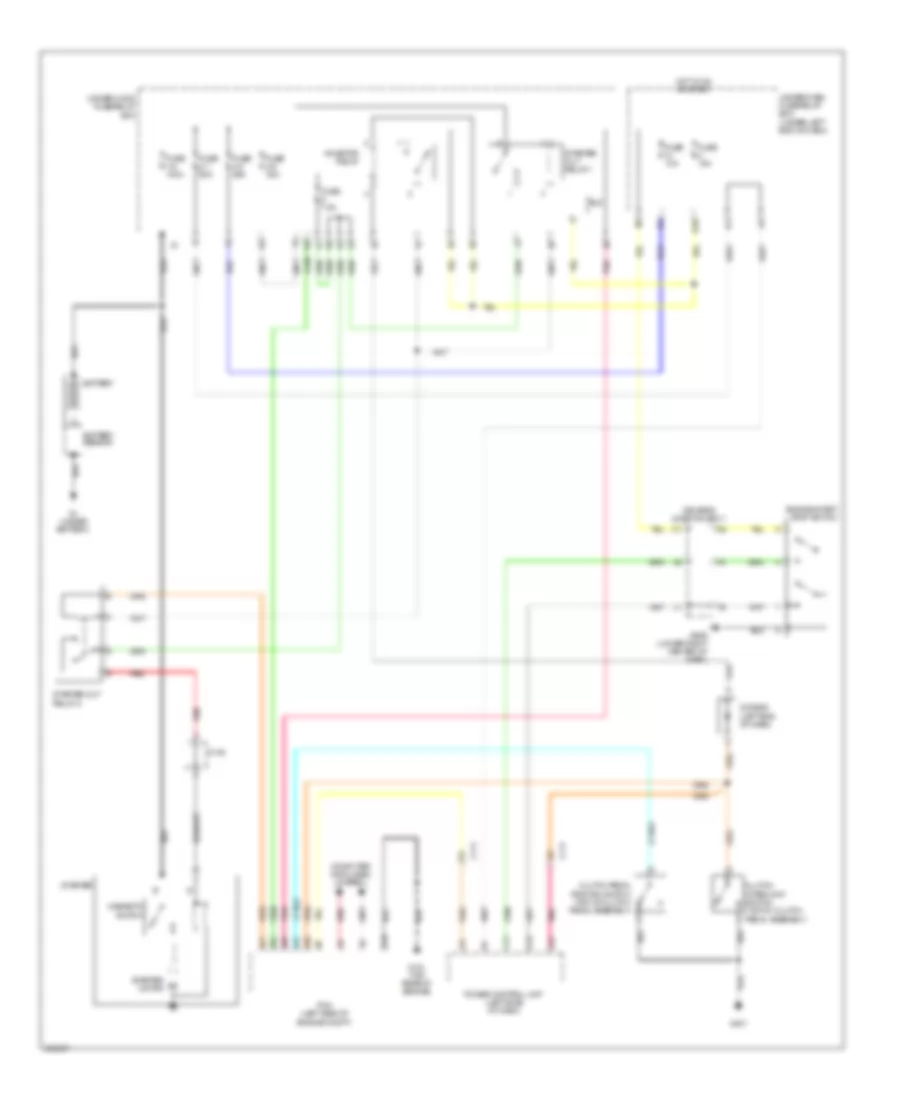
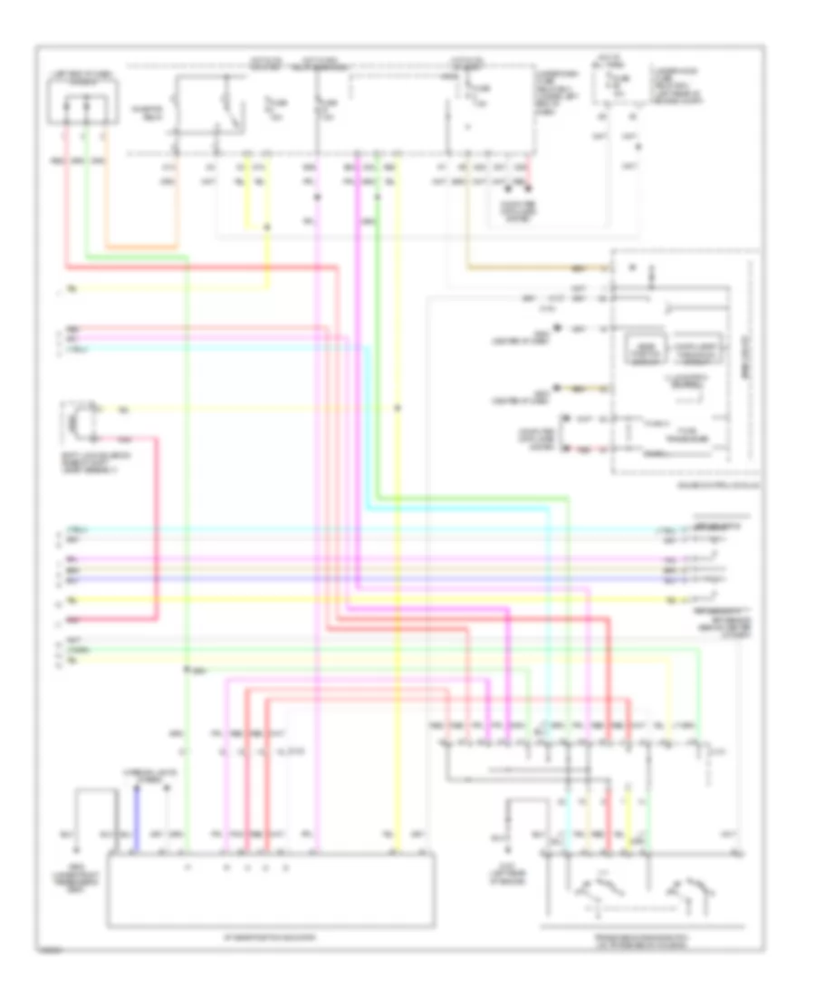
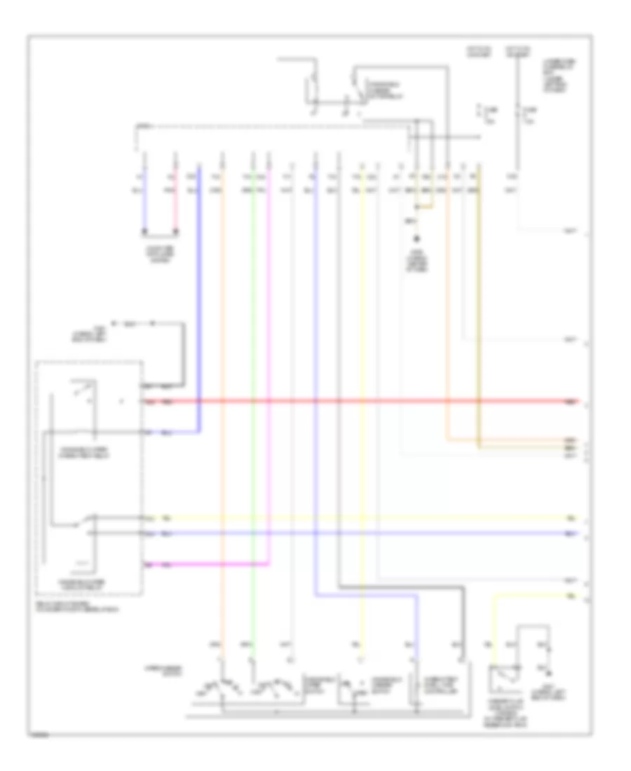
AIR CONDITIONING
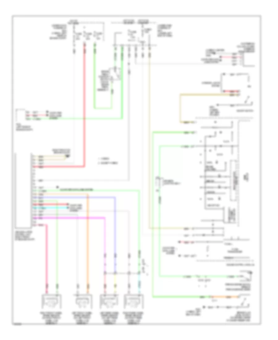
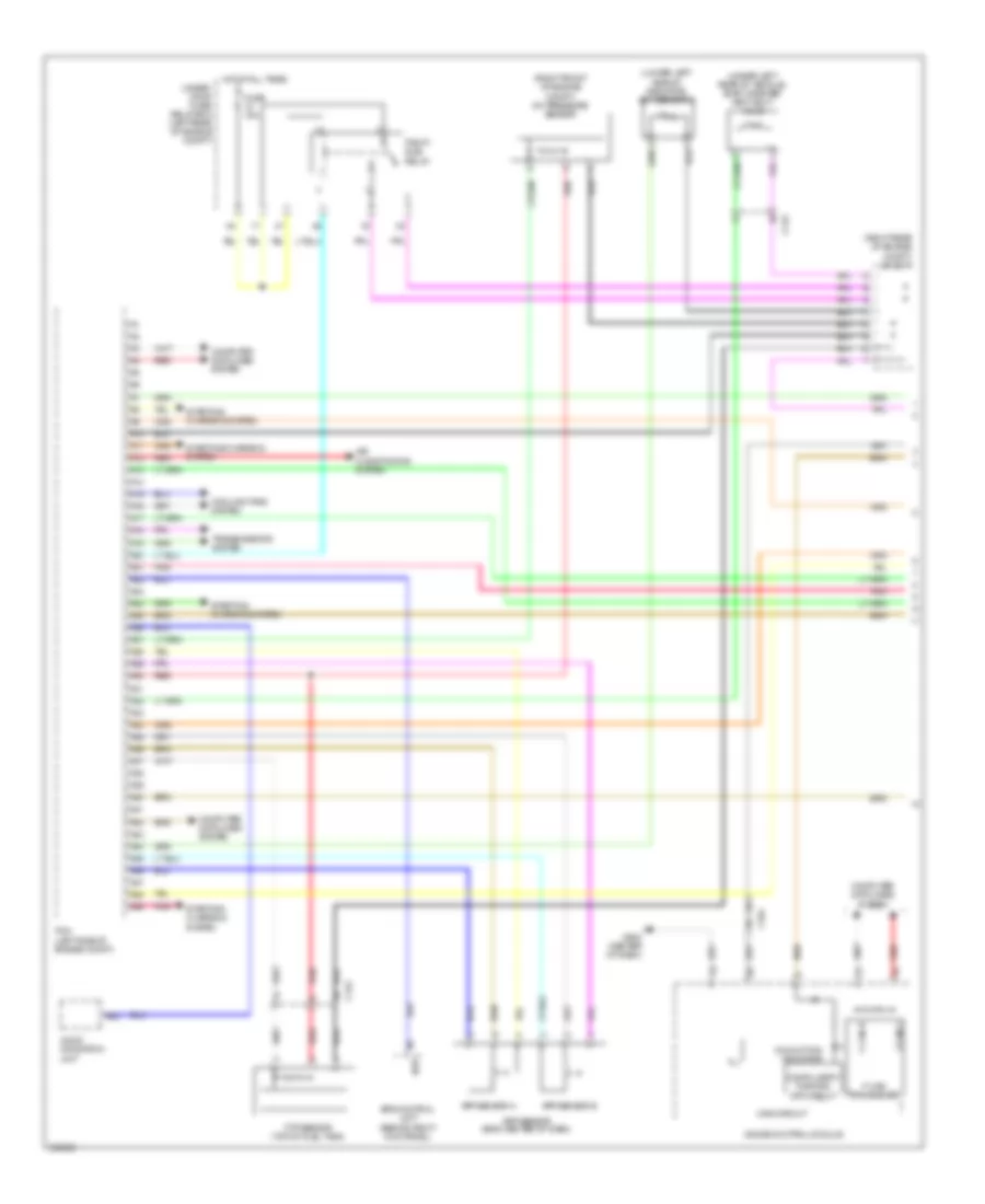
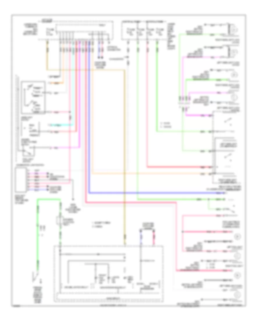
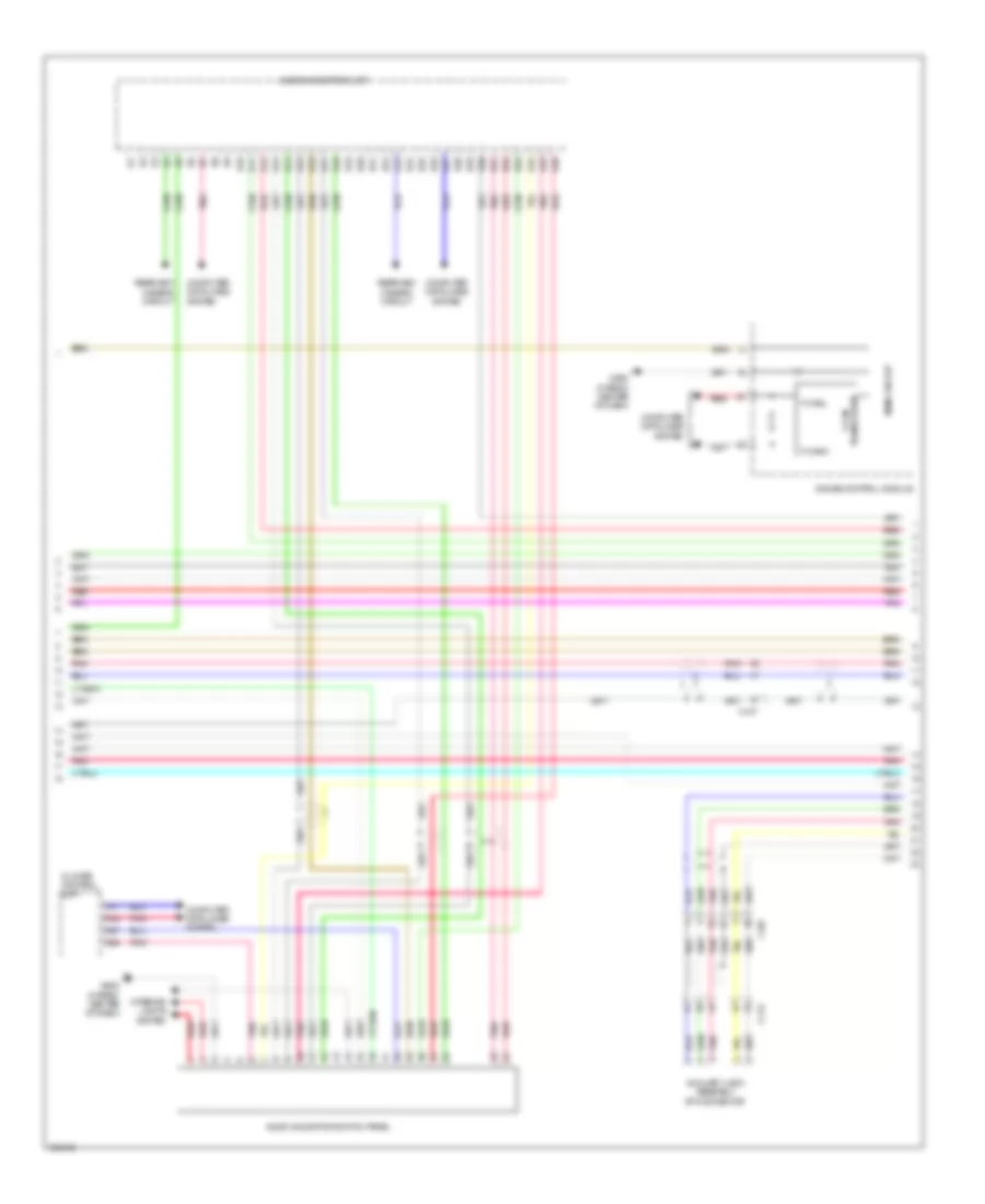
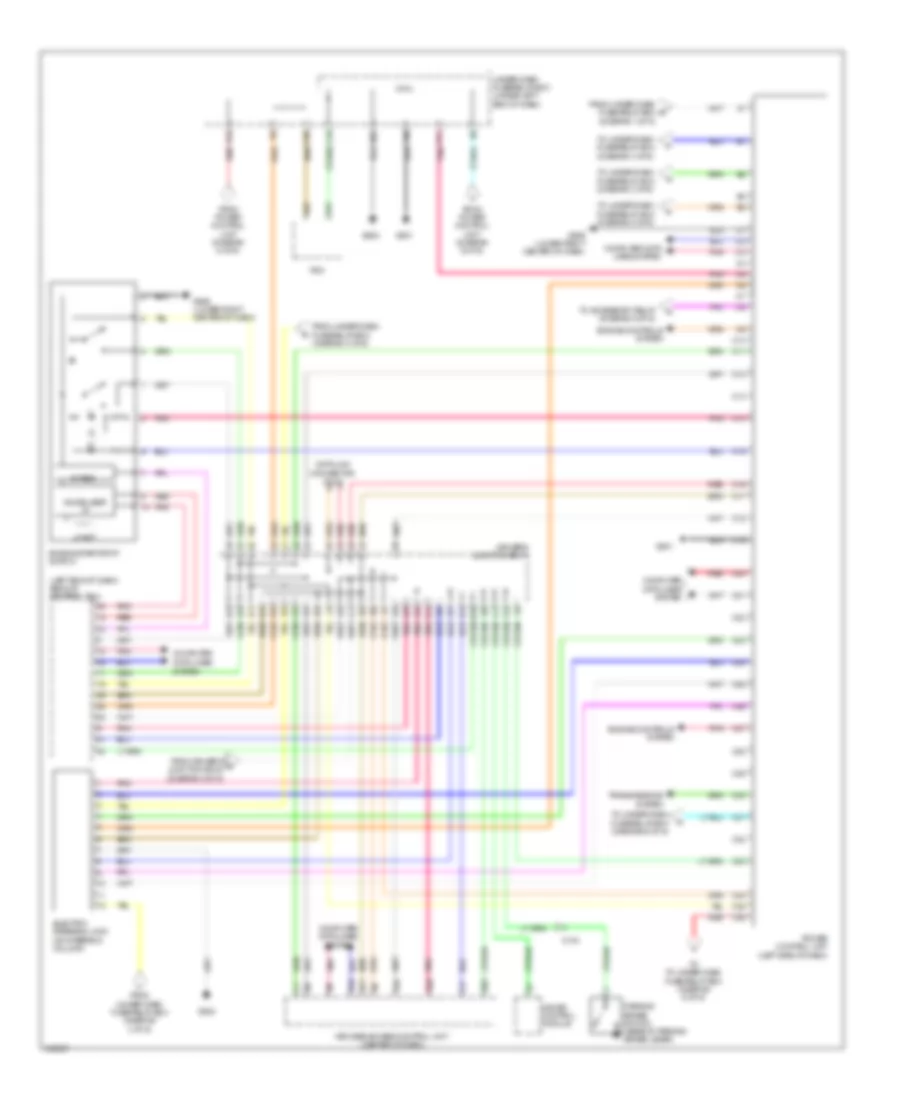
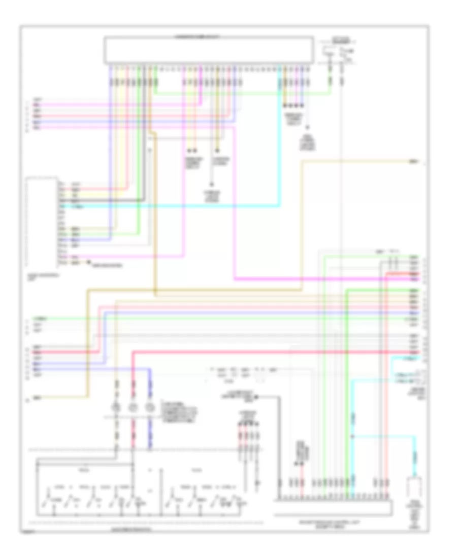
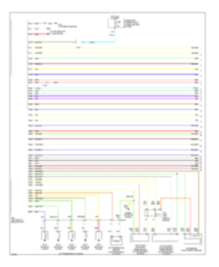
Automatic A/C Wiring Diagram (1 of 4) for Acura ILX 2014

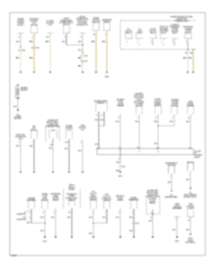
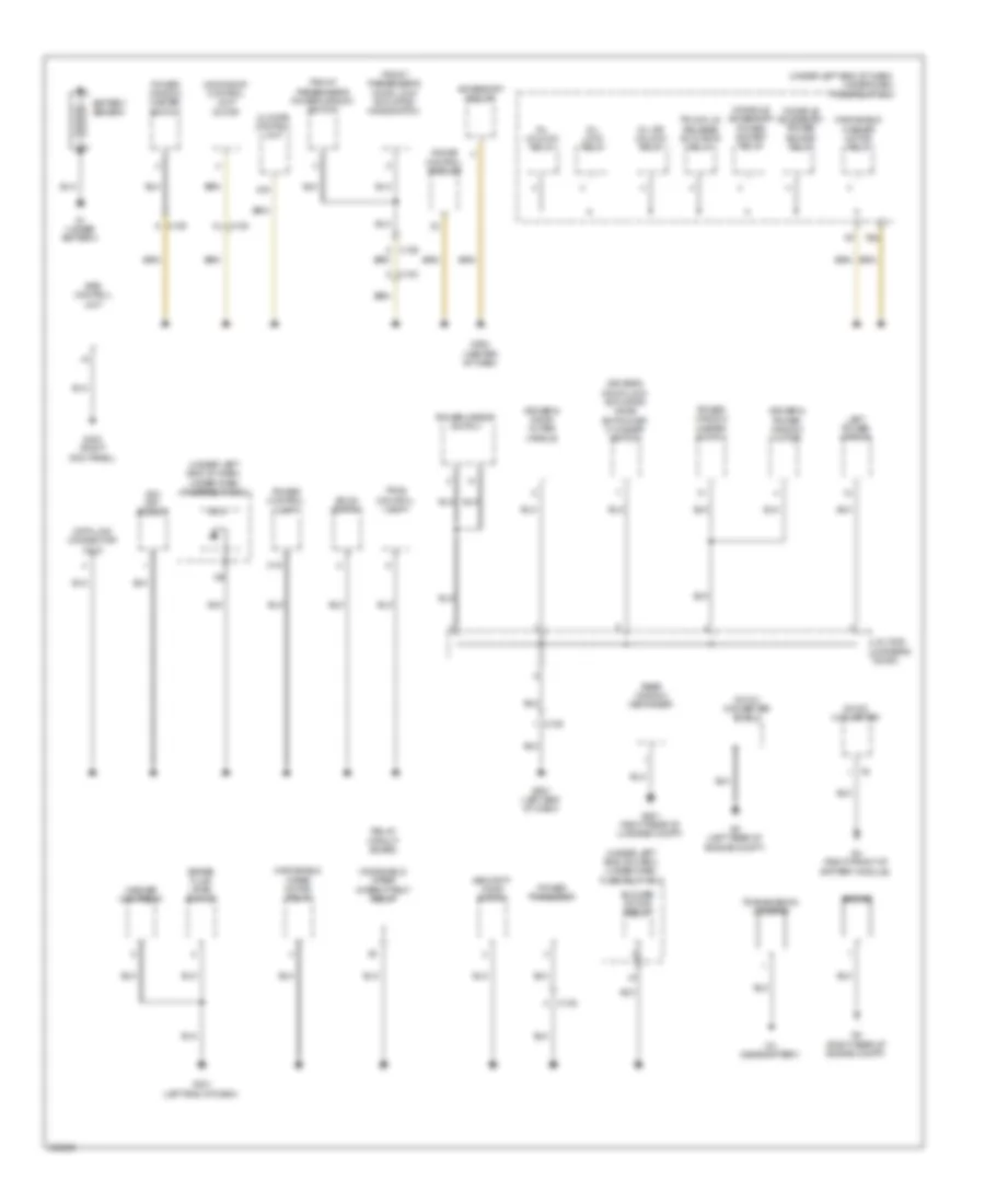
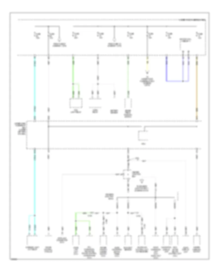
List of elements for Automatic A/C Wiring Diagram (1 of 4) for Acura ILX 2014:
- (bottom center of hvac unit) (hybrid) heater core temperature sensor
- (bottom of blower unit) blower motor
- (left side of blower unit) recirculation control motor
- (left side of hvac assembly) driver's air mix control motor
- A10
- A11
- A12
- A13
- A14
- A15
- A16
- A17
- A18
- A19
- A20
- A21
- A22
- A23
- A24
- A25
- A26
- A27
- A28
- A29
- A30
- A31
- A32
- A33
- A34
- A35
- A36
- A37
- A38
- B10
- B11
- B12
- C106
- C111
- C135
- C136
- C138 c136
- Climate control unit
- Computer data lines system
- Defogger system
- Evaporator temperature sensor (top center of hvac unit)
- Except hybrid
- Exterior lights system
- G401 (hybrid: left end of dash)
- G503 (hybrid: center of dash)
- Hybrid
- Interior lights system
- Navigation system
- Outside air temperature sensor (behind right center of front bumper)
- Pnk
- Power transistor (lower left side of blower unit)
- Rear window defogger switch
- Rear window defogger switch indicator
- Red
- Sunlight sensor (top center of dash)
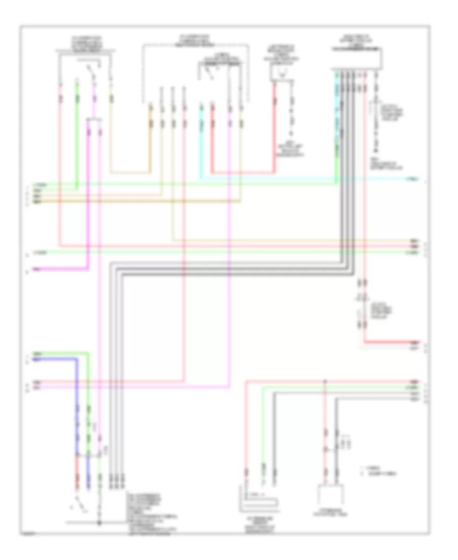
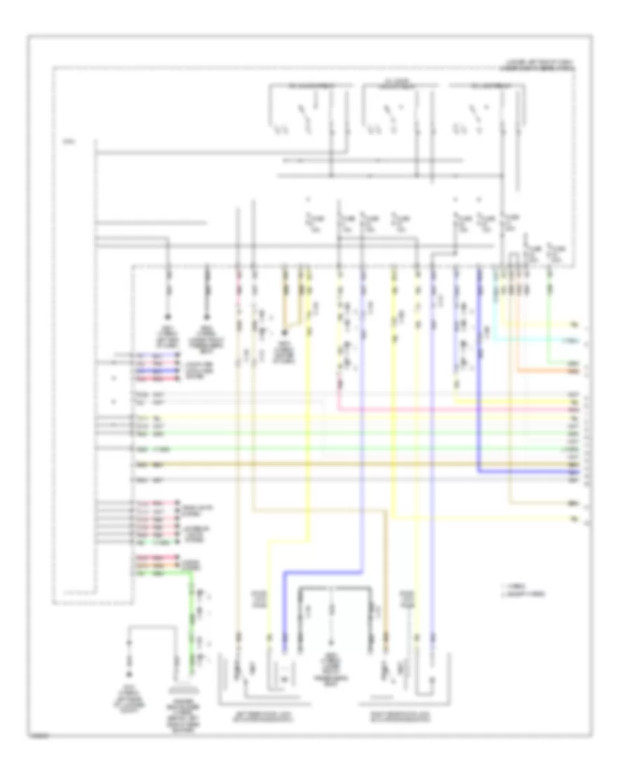
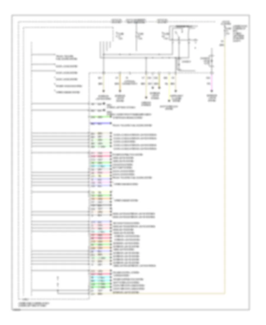
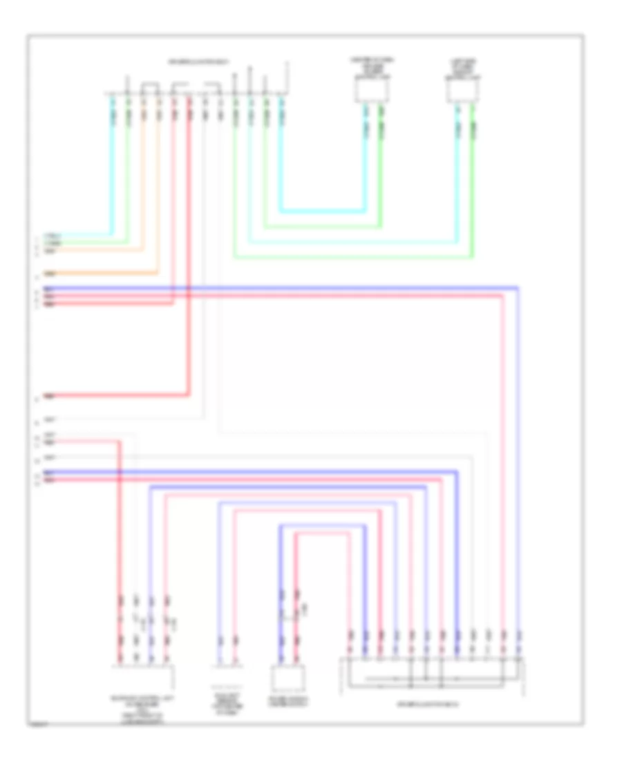
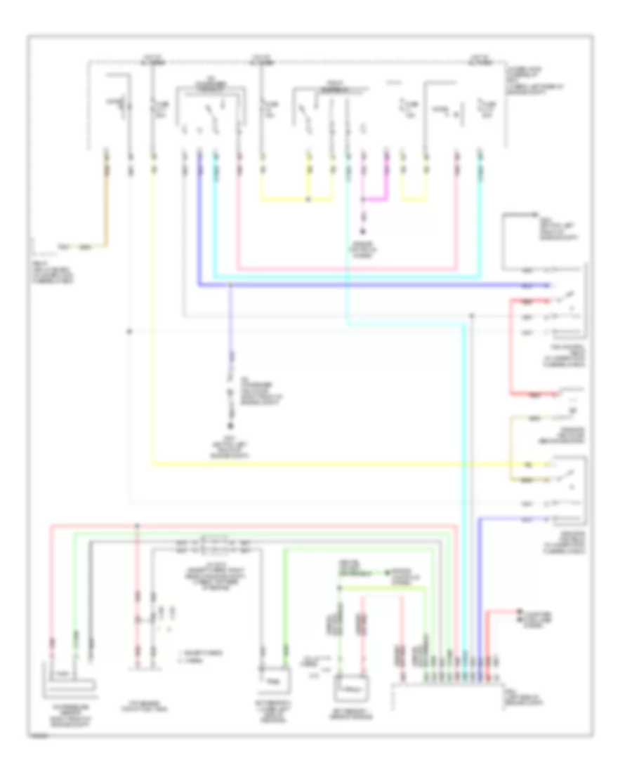
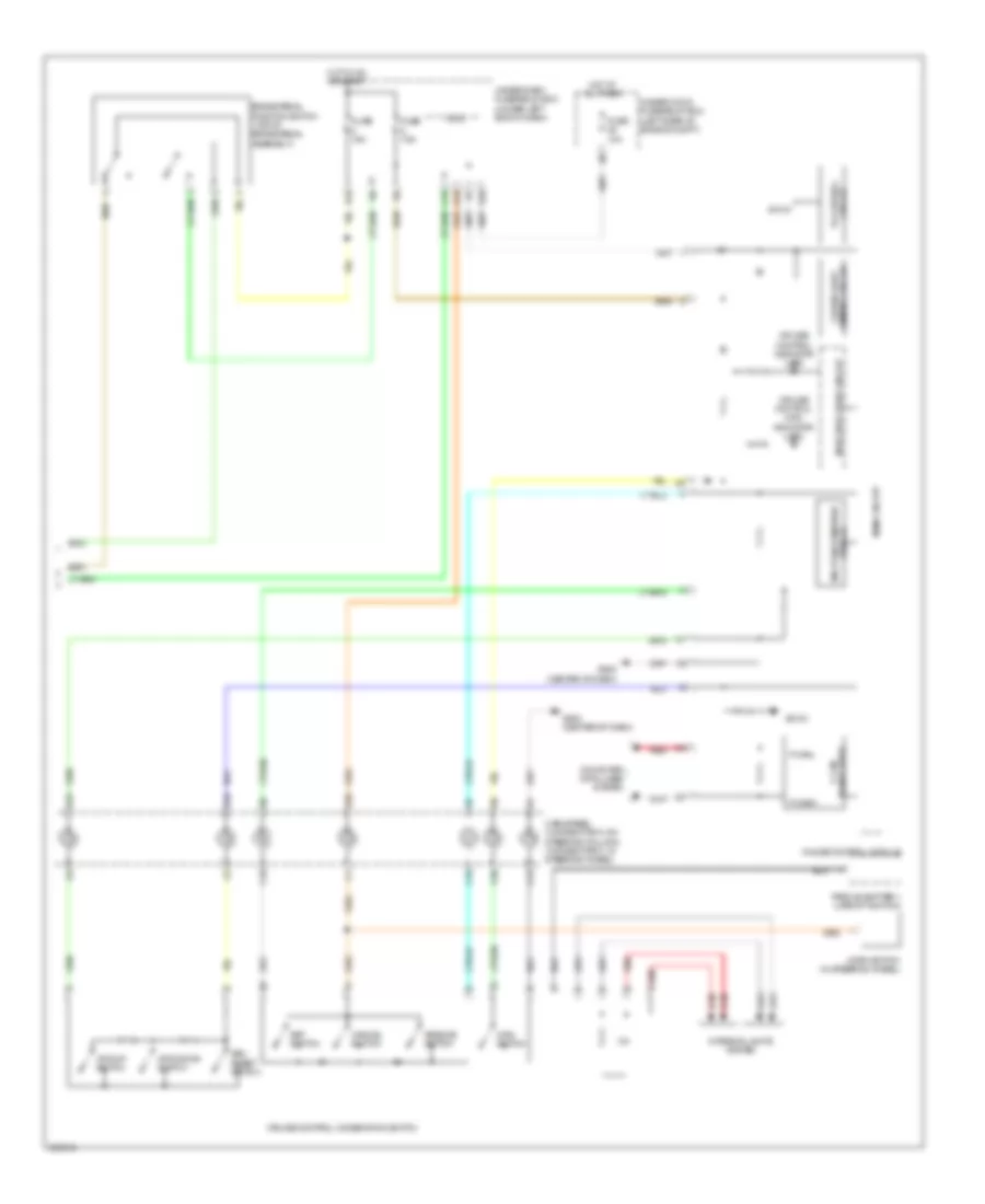
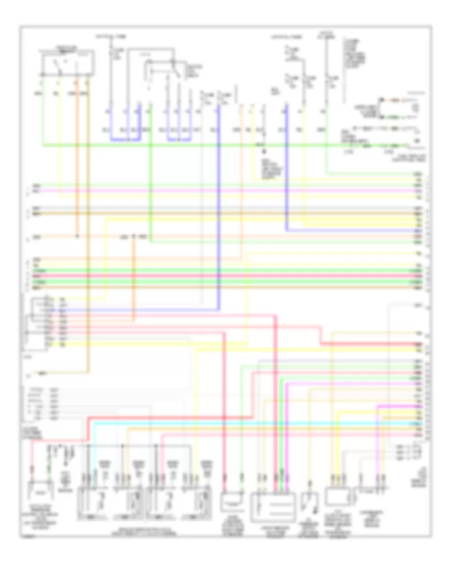
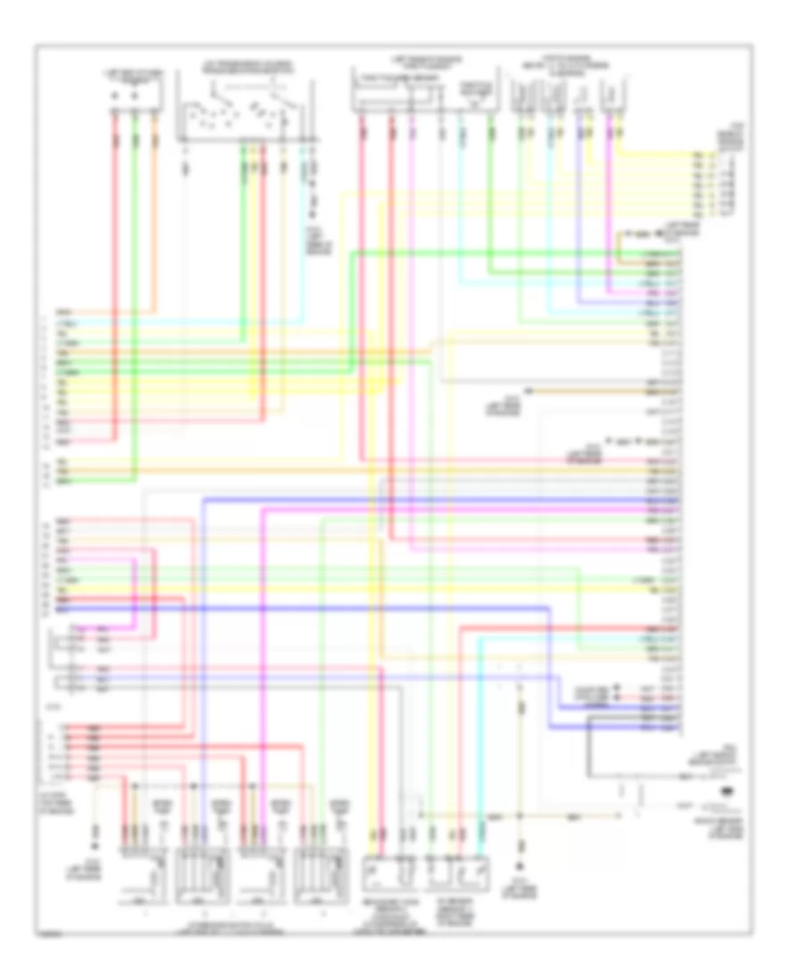
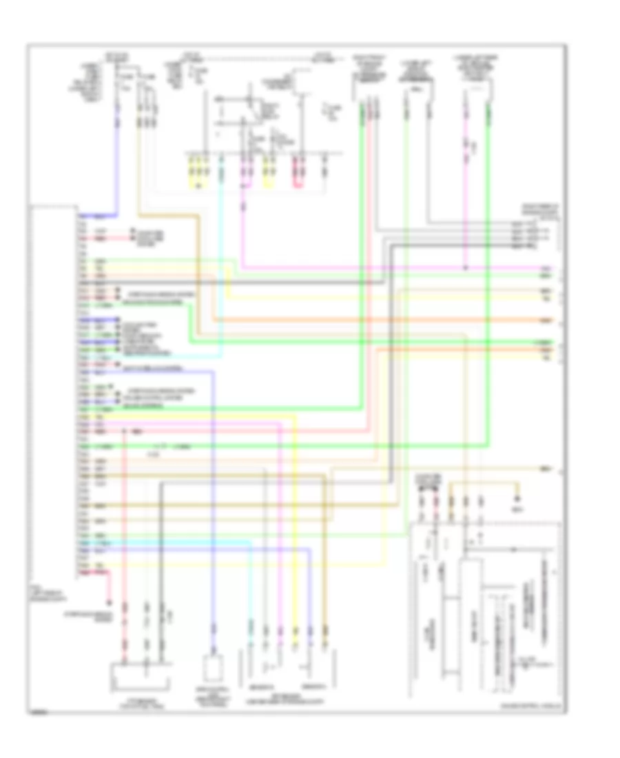
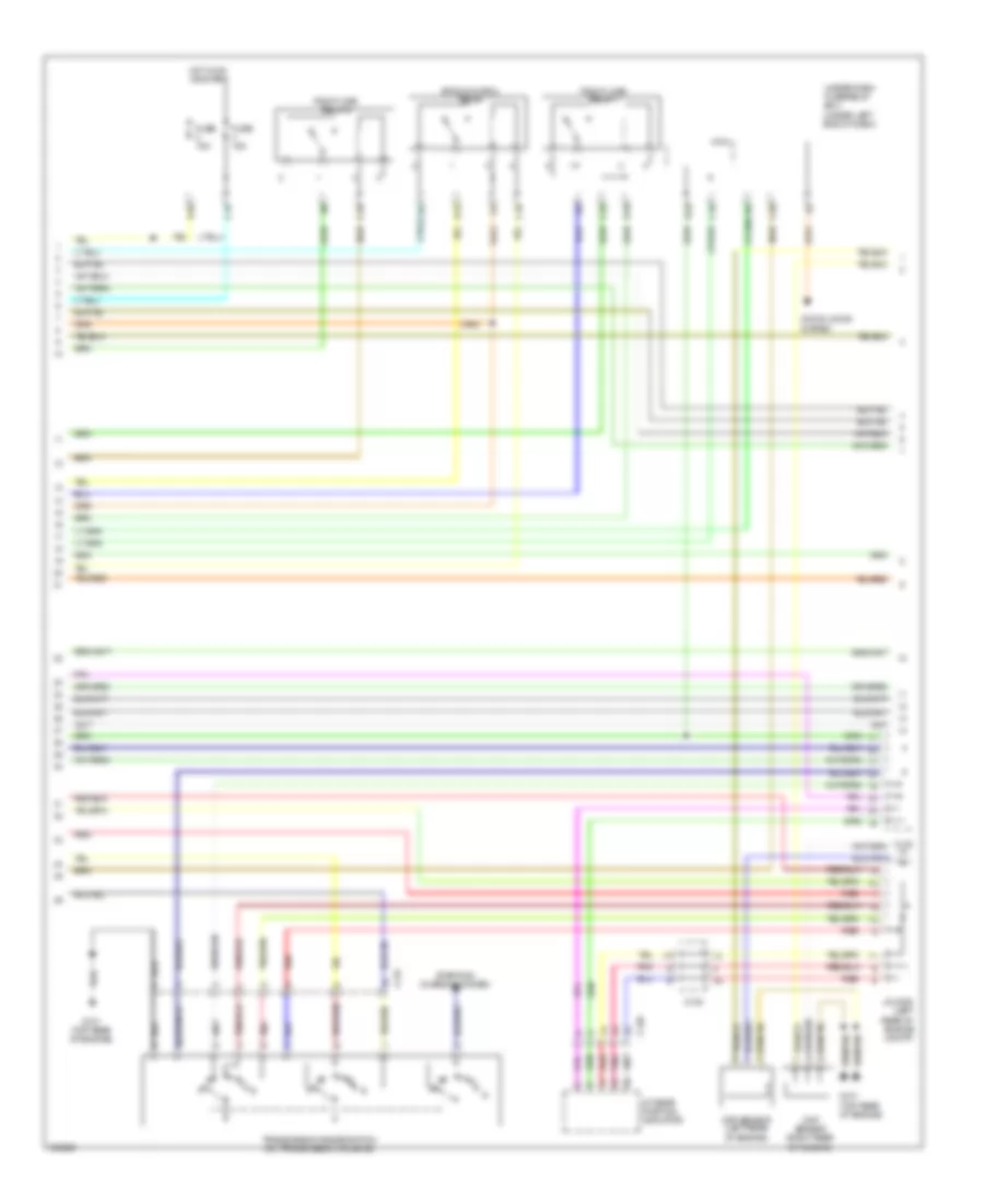
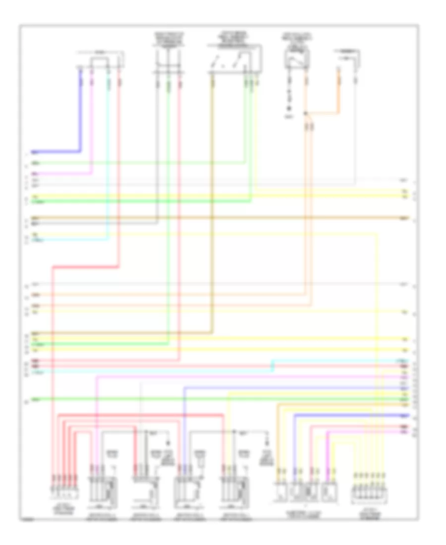
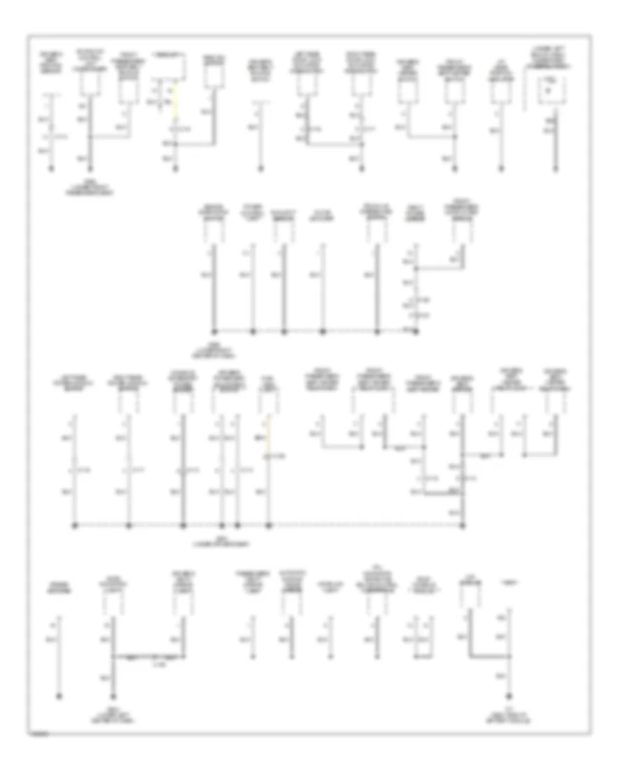
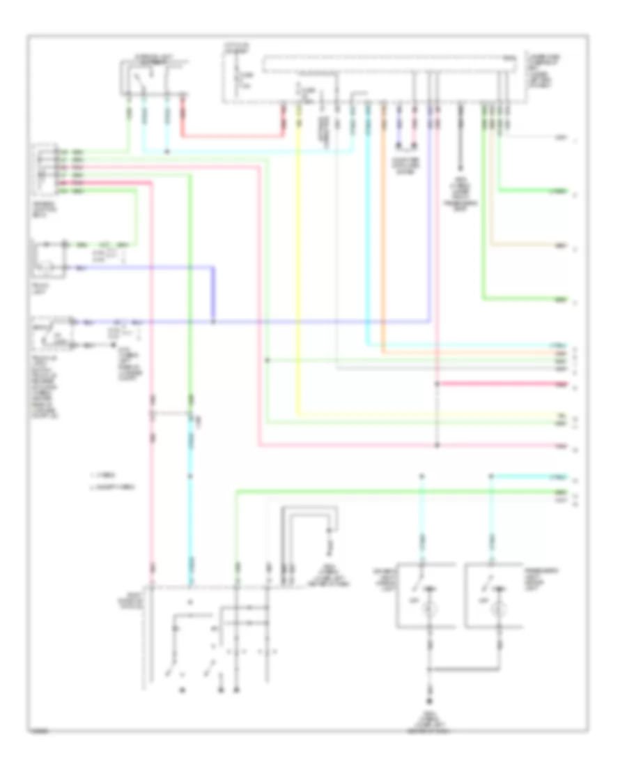
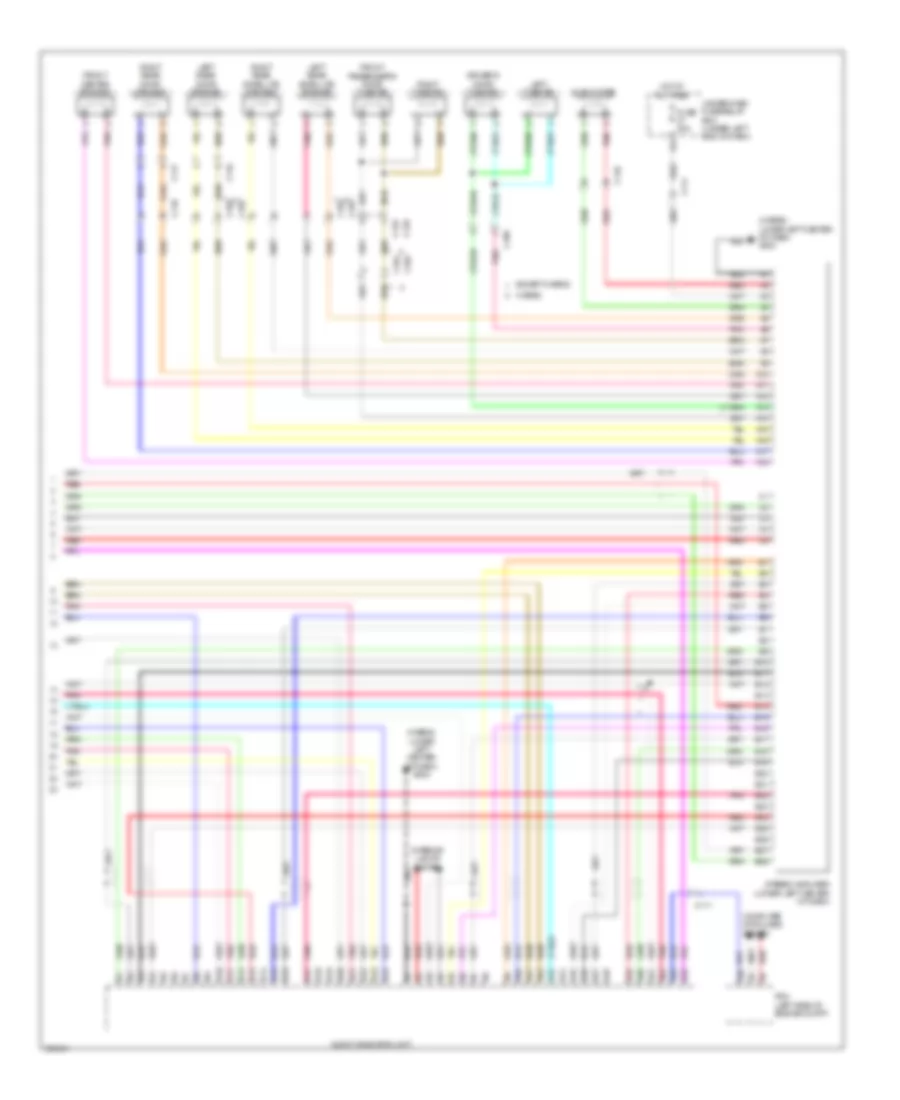
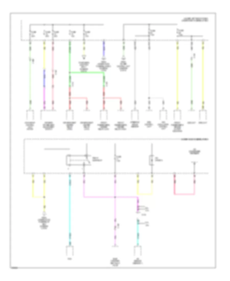
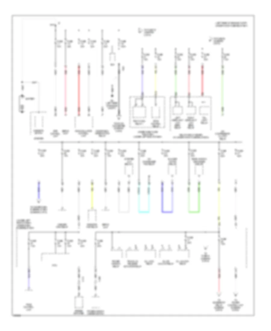
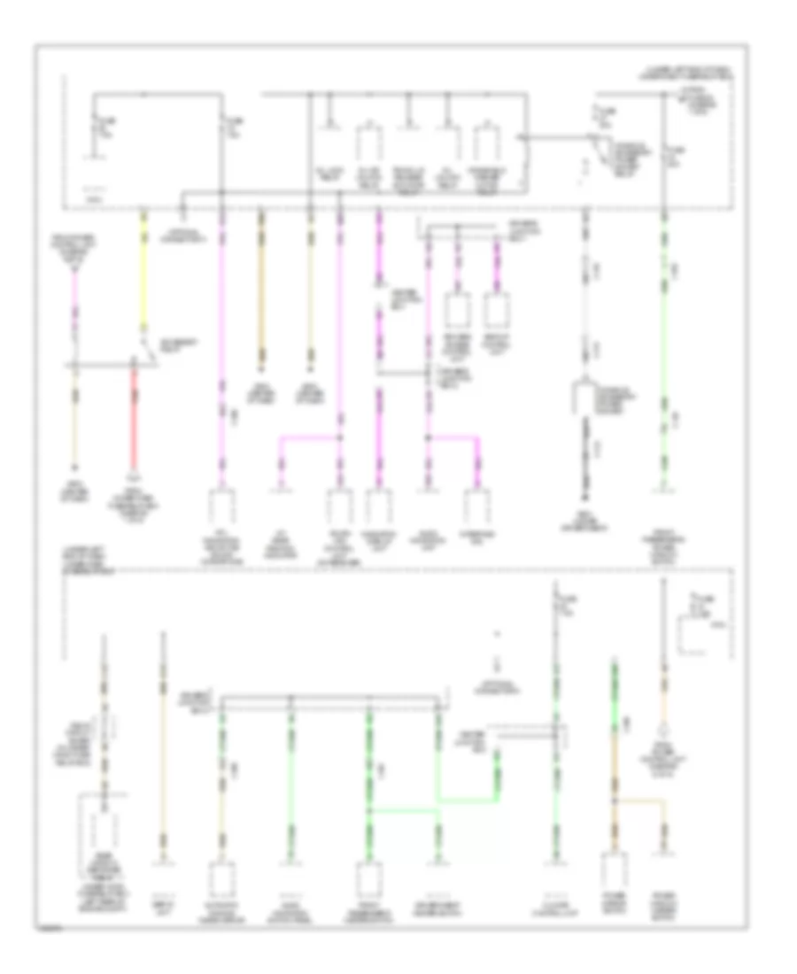
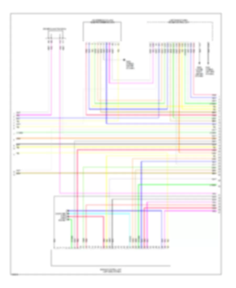
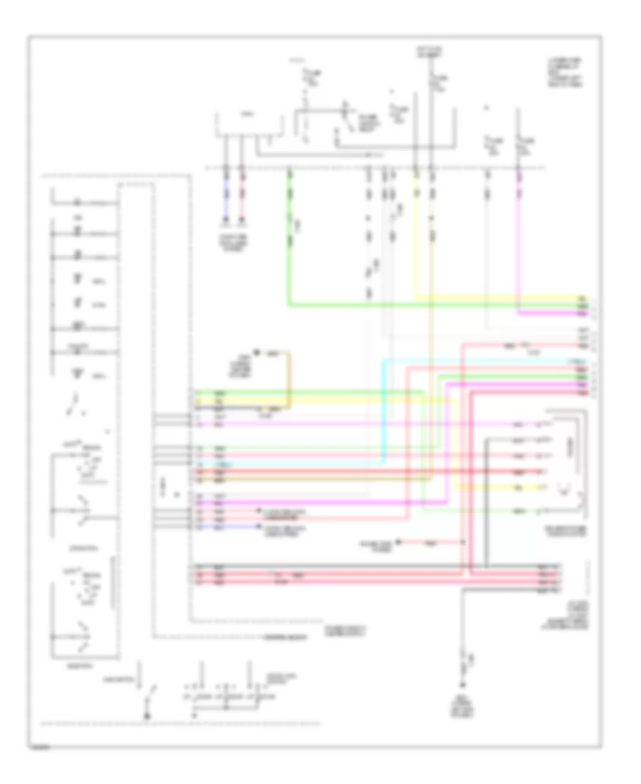
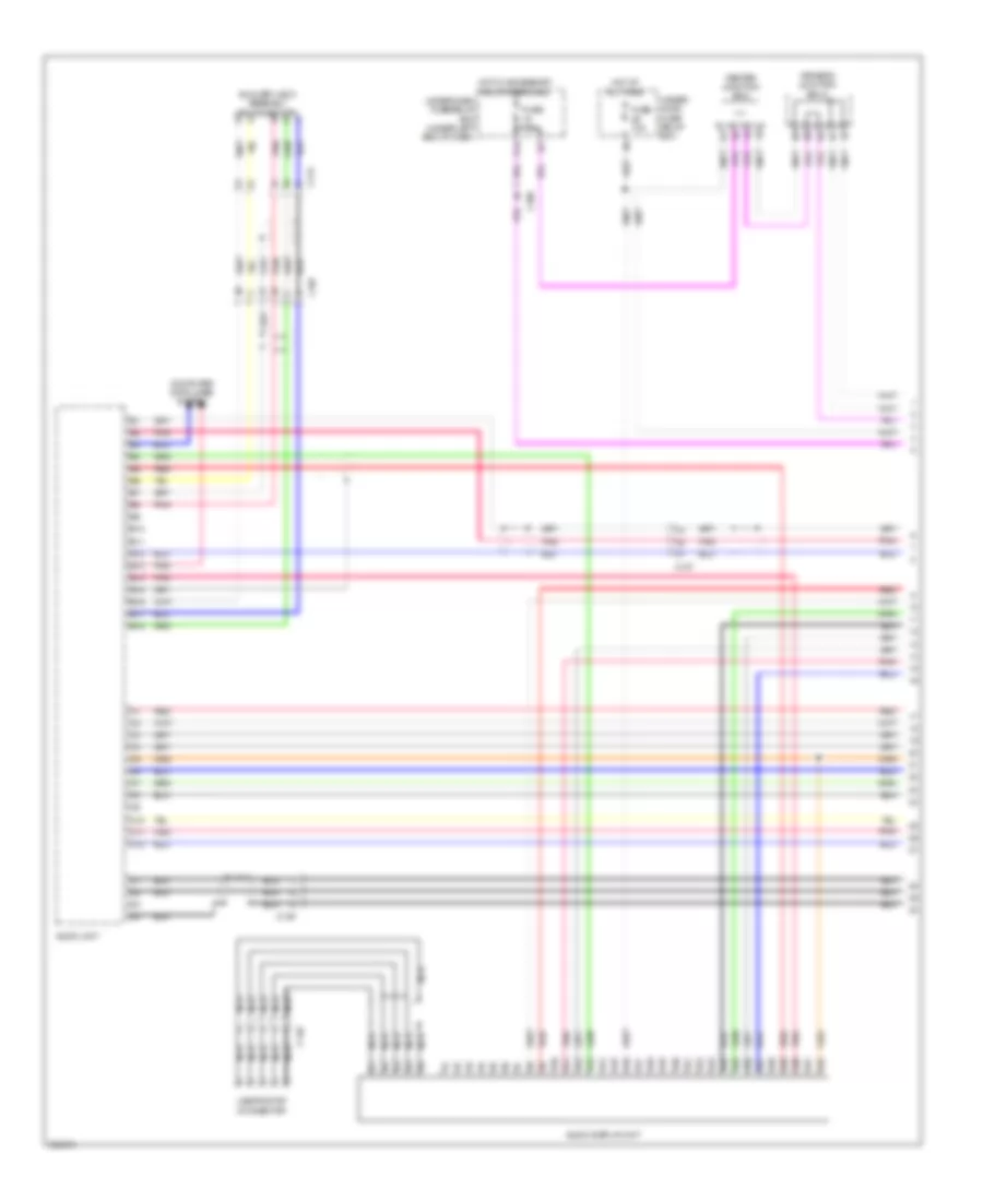
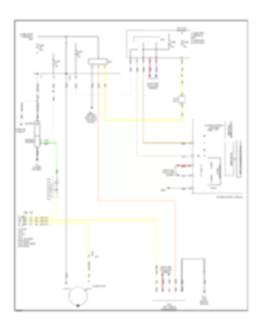
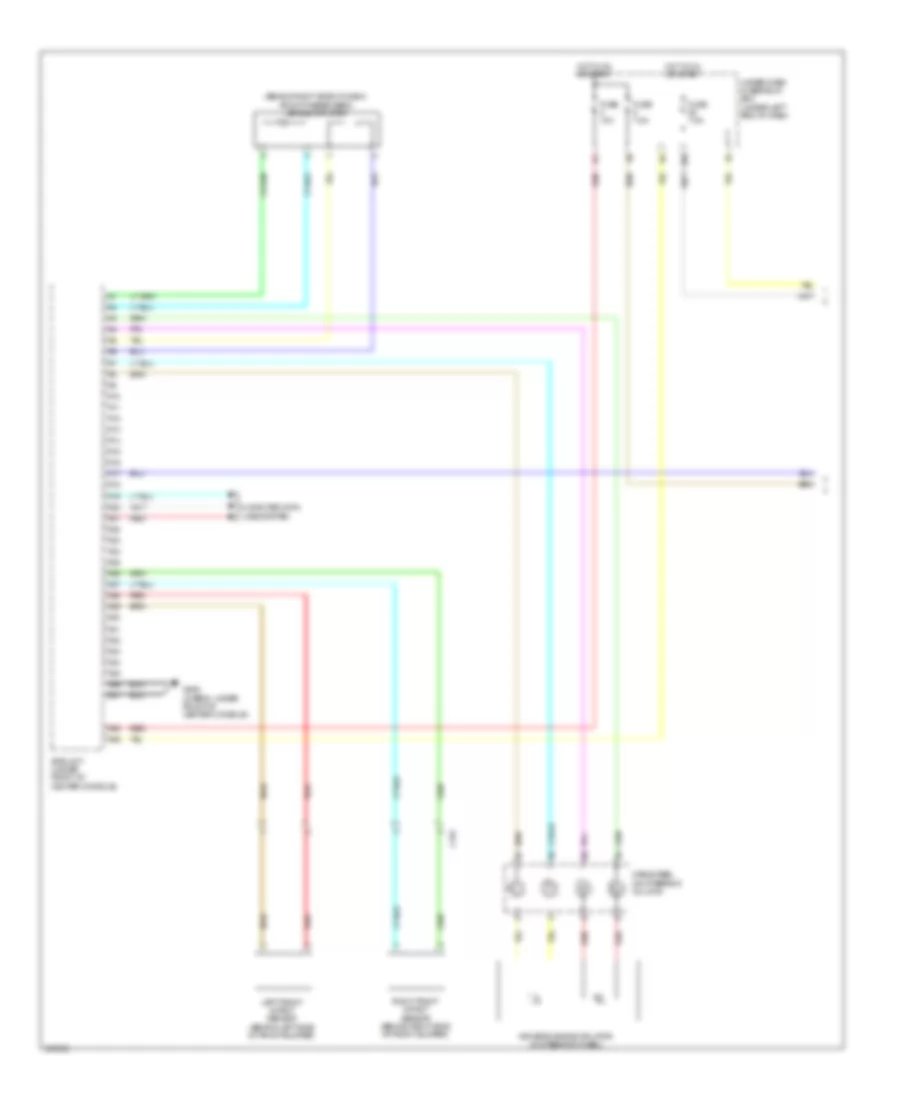
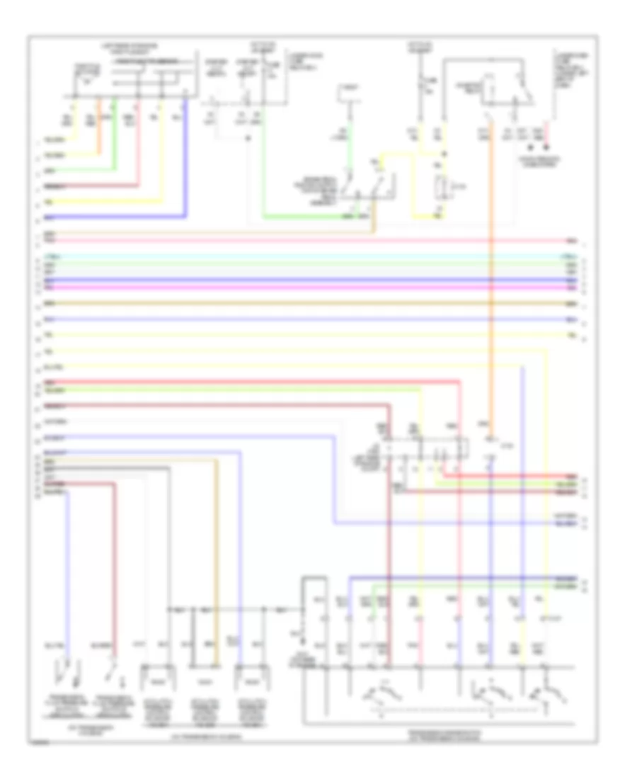
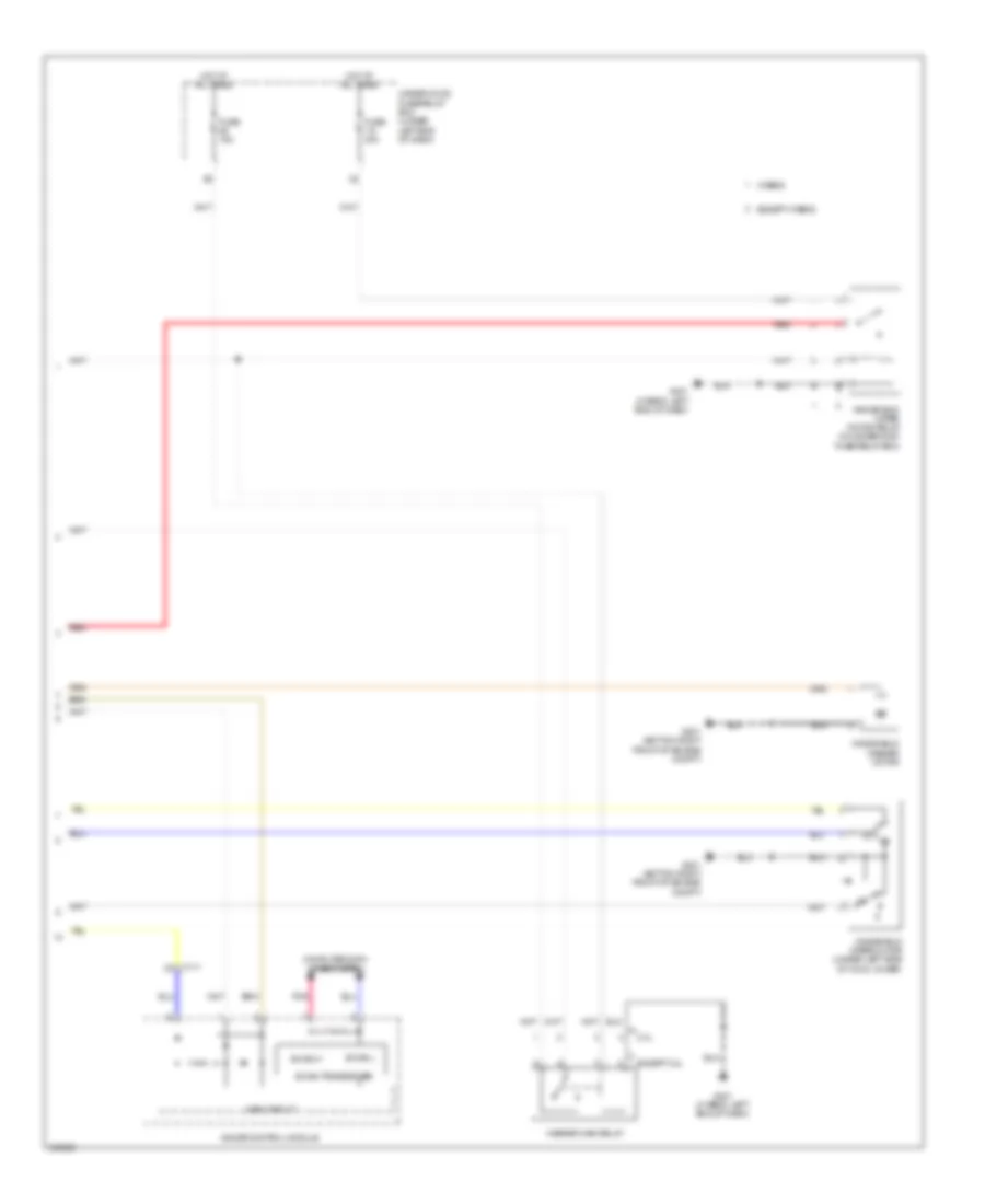
Automatic A/C Wiring Diagram (2 of 4) for Acura ILX 2014
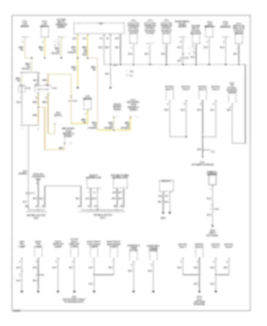
List of elements for Automatic A/C Wiring Diagram (2 of 4) for Acura ILX 2014:
- 2.0l
- 2.4l
- A/c compressor (a/c compressor clutch/ thermal protector) (except hybrid) (a/c compressor thermal protector: on a/c compressor) (a/c compressor clutch: left front of engine)
- Blower motor relay
- C106
- C130 (2.0l) c133 (2.4l)
- C132
- C135
- C136
- C16
- C17
- Center junction box
- D14
- Except hybrid
- Fuse 2-8 40a
- Fuse 7.5a
- G401 (hybrid: left end of dash)
- Hot at all times
- Hot in on or start
- Humidity/in-car temperature sensor (lower left center of dash)
- Hybrid
- Micu
- Mode control motor (lower left side of blower unit)
- Passenger's air mix control motor (right side of hvac unit)
- Pnk
- Red
- Under-dash fuse/relay box (under left end of dash)
- Under-hood fuse/relay box (hybrid: left rear of engine compt)
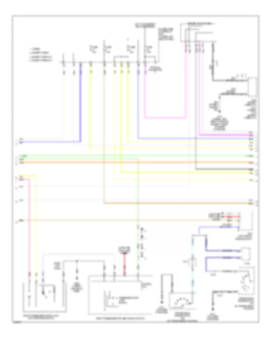
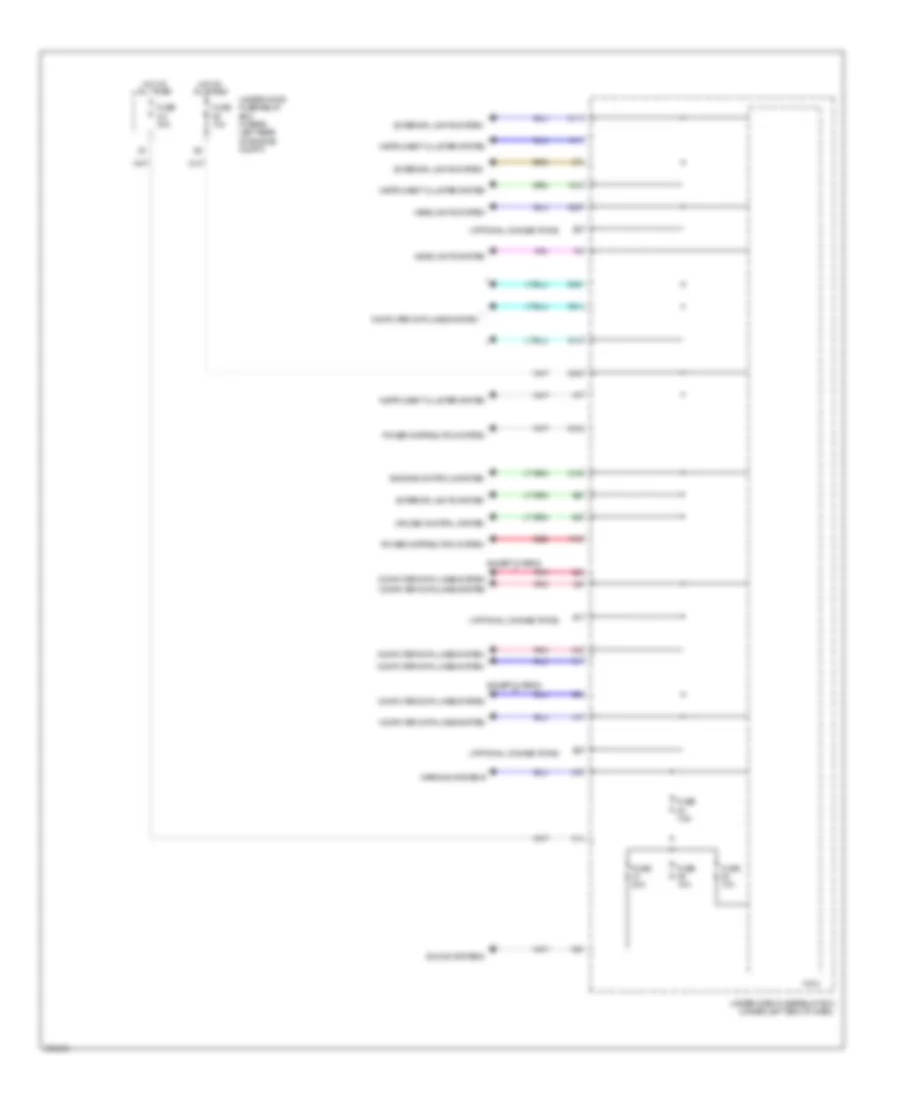
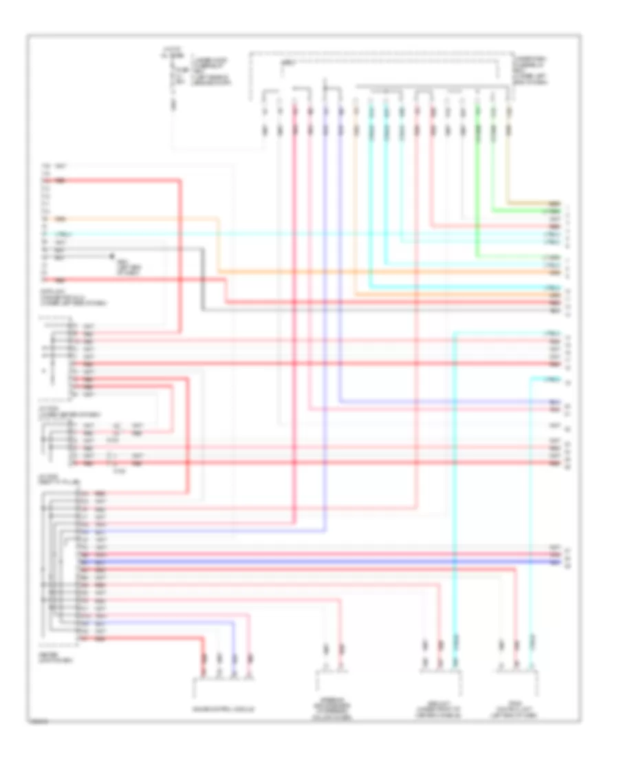
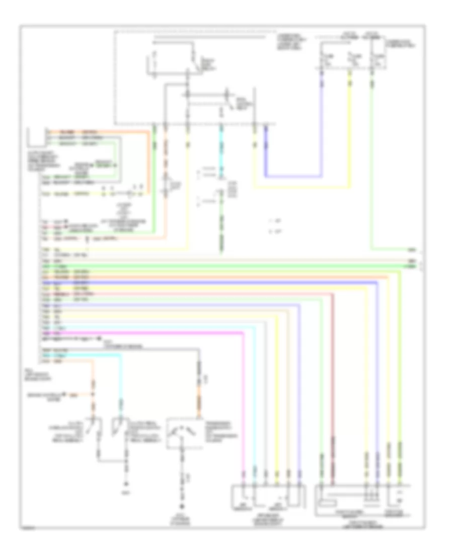
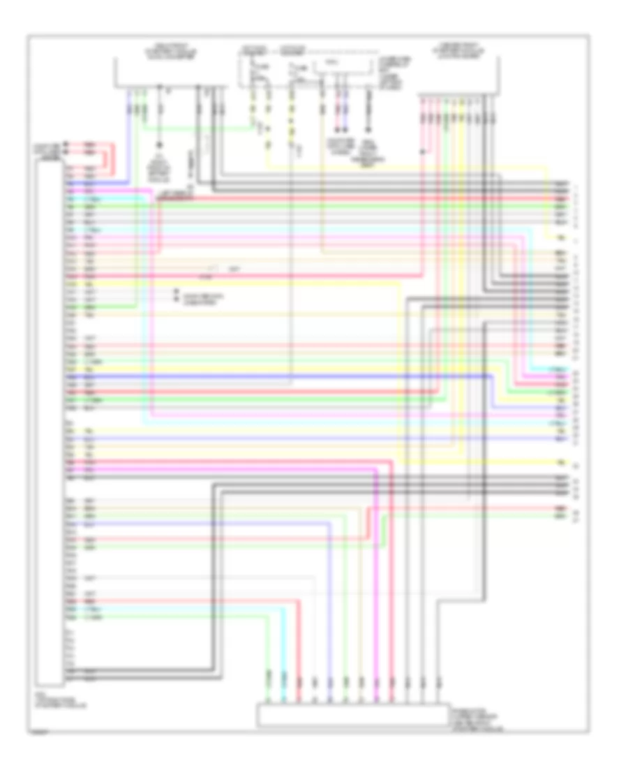
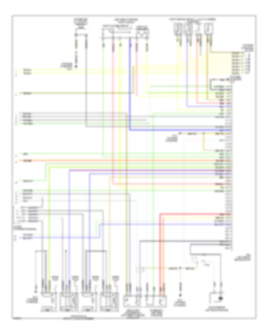
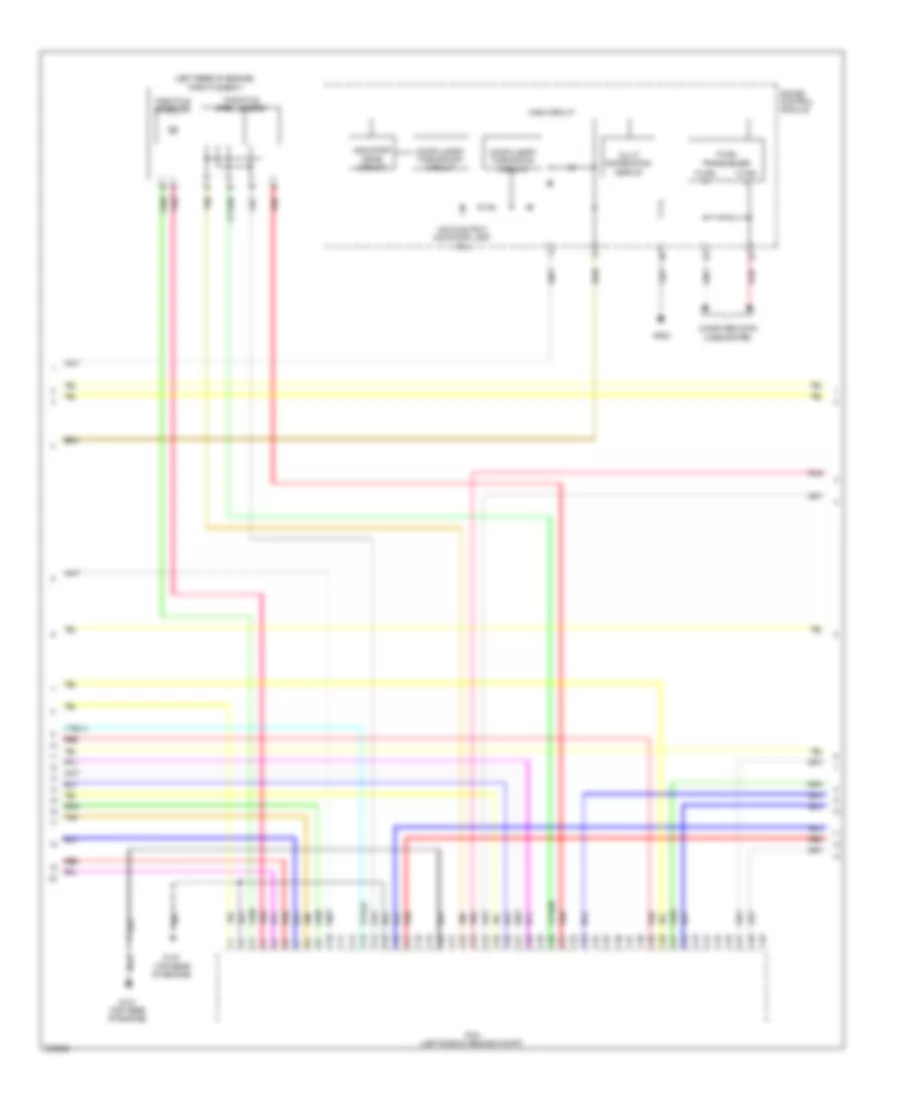
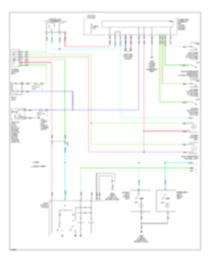
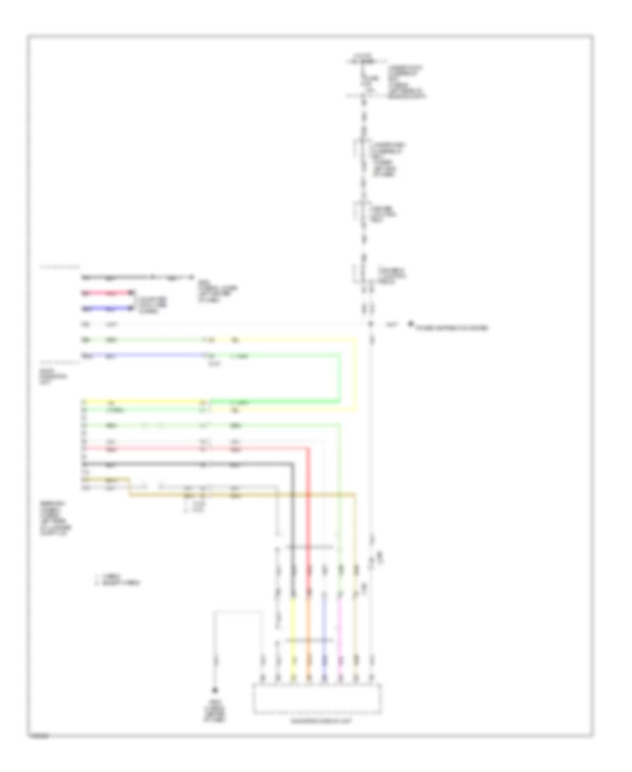
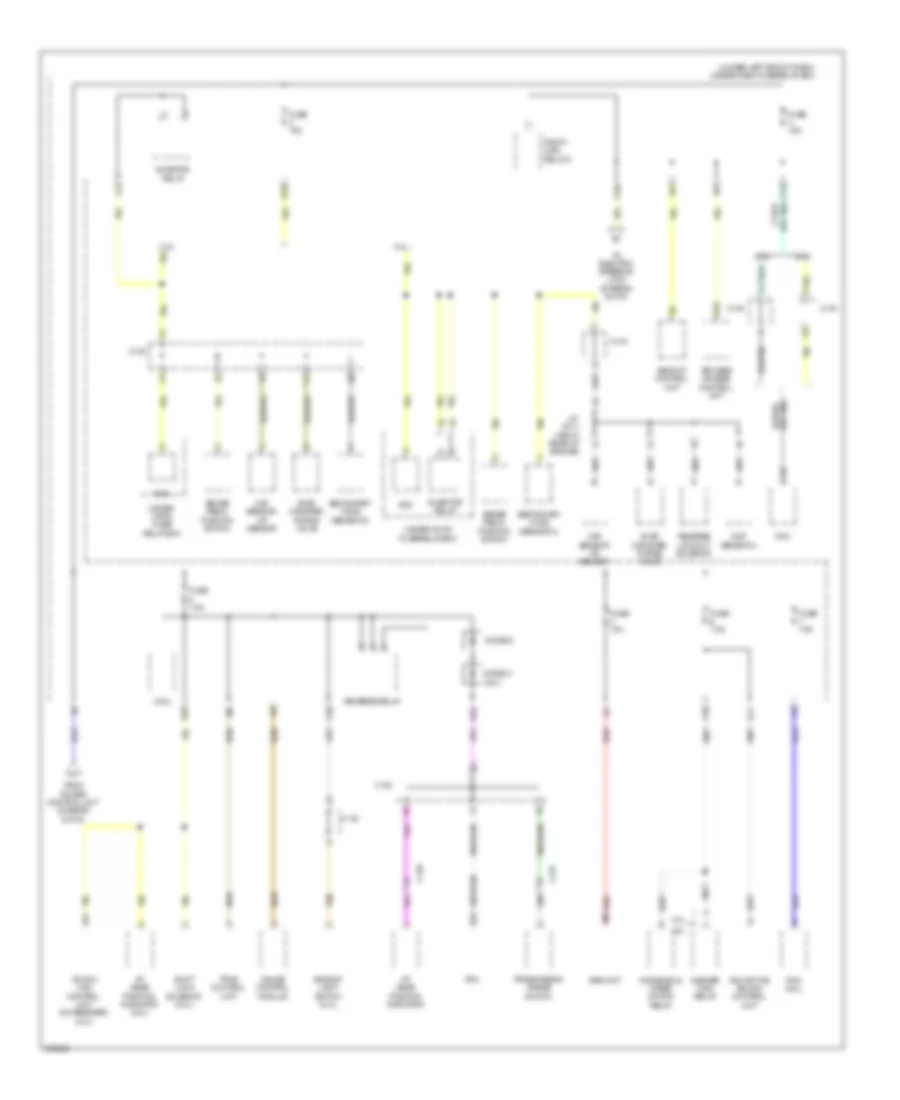
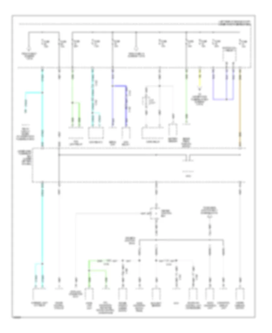
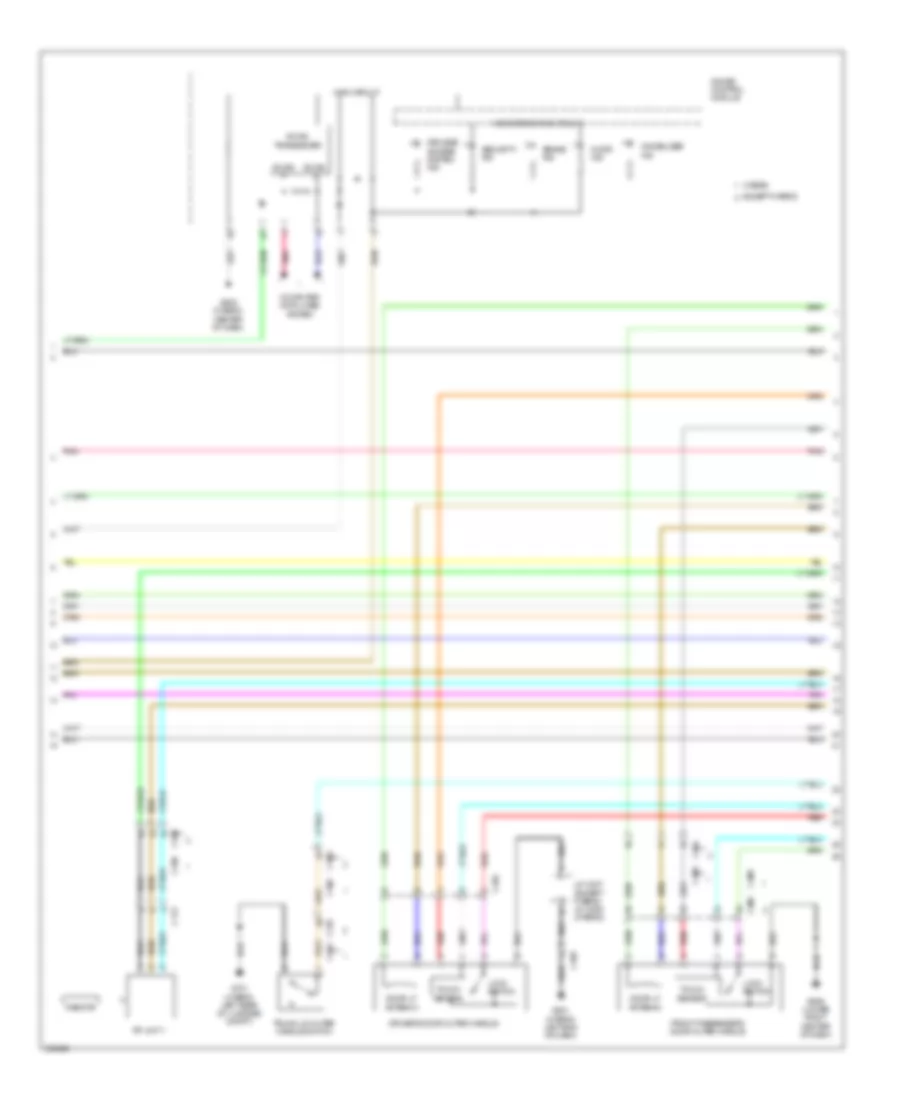
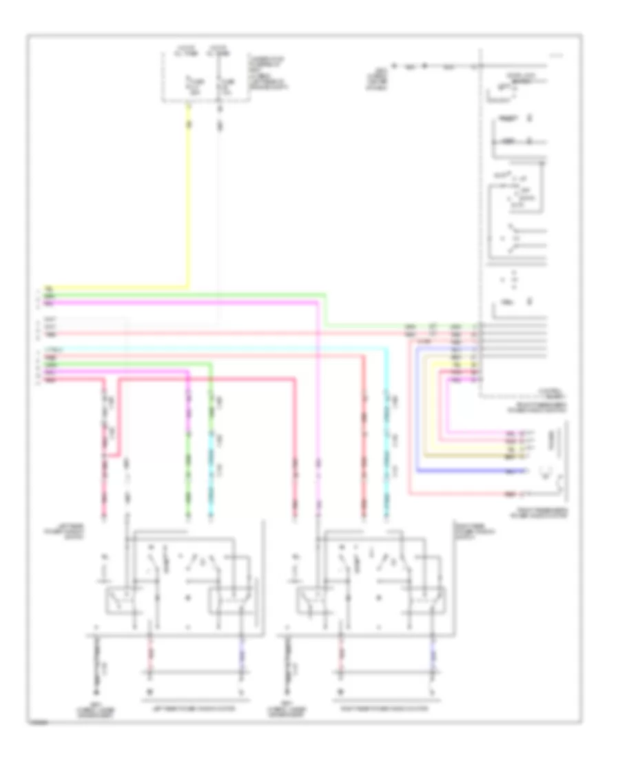
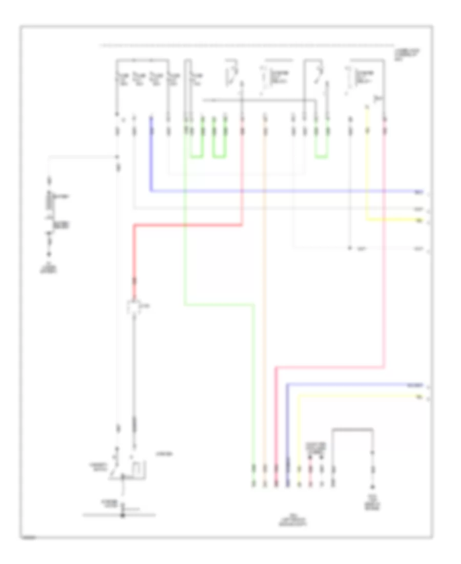
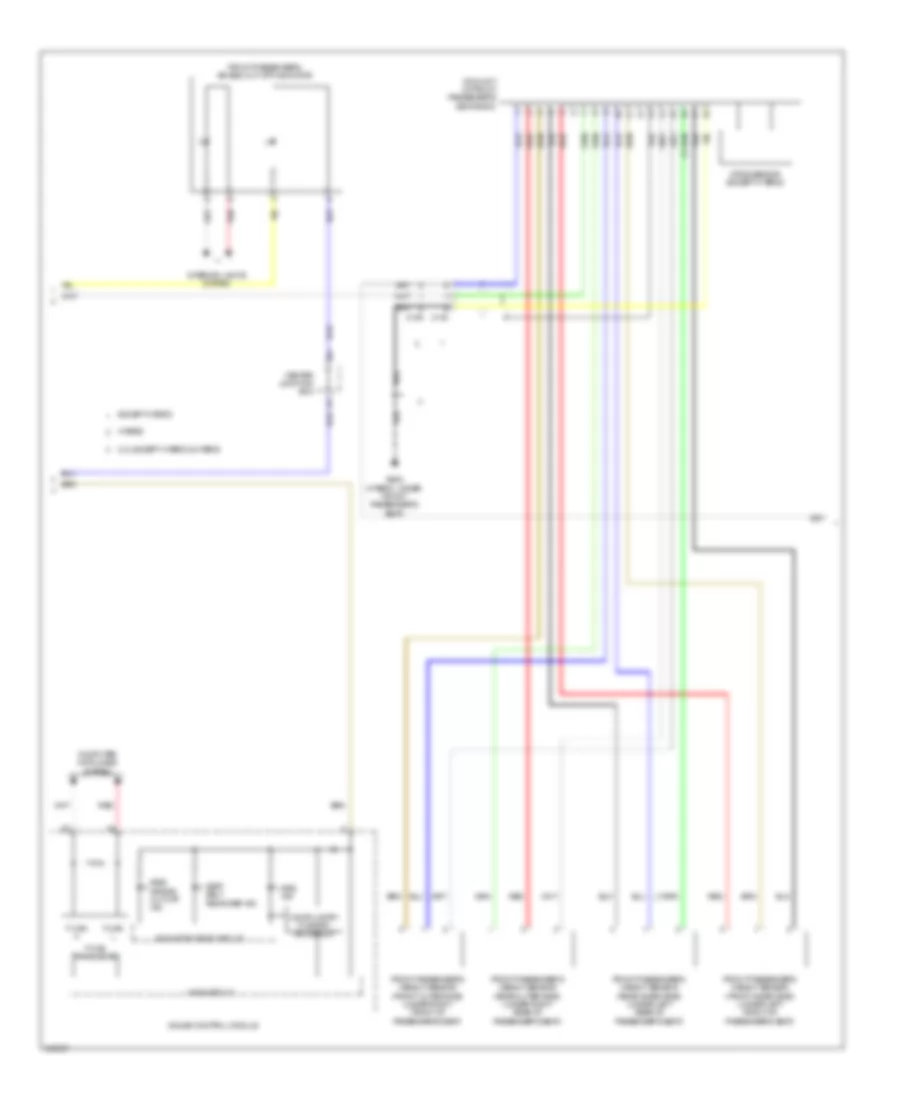
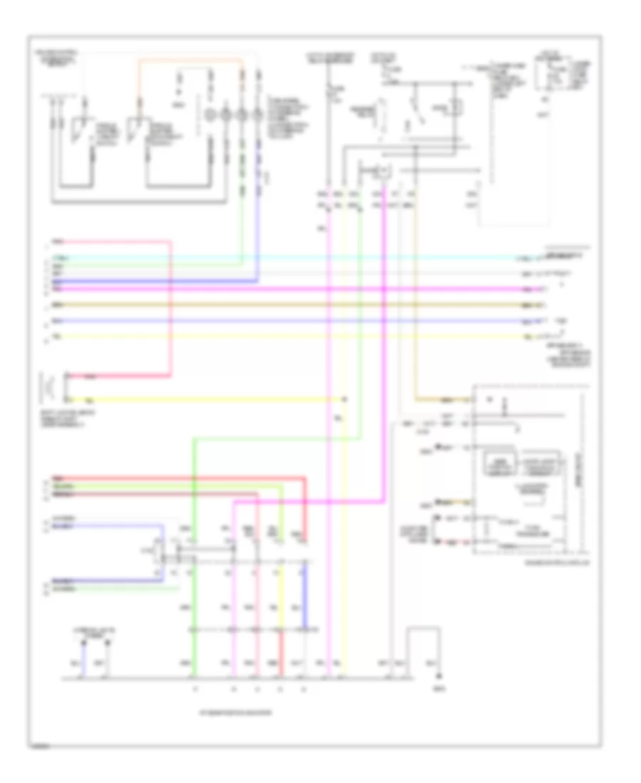
Automatic A/C Wiring Diagram (3 of 4) for Acura ILX 2014
List of elements for Automatic A/C Wiring Diagram (3 of 4) for Acura ILX 2014:
- (hybrid) auxiliary electric water pump relay
- (in under-hood fuse/relay box) a/c compressor clutch relay
- (in under-hood fuse/relay box) relay circuit board
- (left rear of engine compt) (hybrid) auxiliary electric water pump
- (right end of battery module) (hybrid) a/c compressor driver
- A/c compressor (a/c compressor clutch/thermal protector) (hybrid) (a/c compressor thermal protector: on a/c compressor) (a/c compressor clutch: left front of engine)
- A/c pressure sensor (right front of engine compt)
- A10
- A11
- B10
- C102
- C111
- C120
- C122
- C123
- C134
- Except hybrid
- Ftp sensor (top of fuel tank)
- G301 (bottom left front of engine compt)
- G901 (right end of battery module)
- Hybrid
- J/c c012 (right end of battery module)
- J/c c013 (right end of battery module)
- Nca
- Red
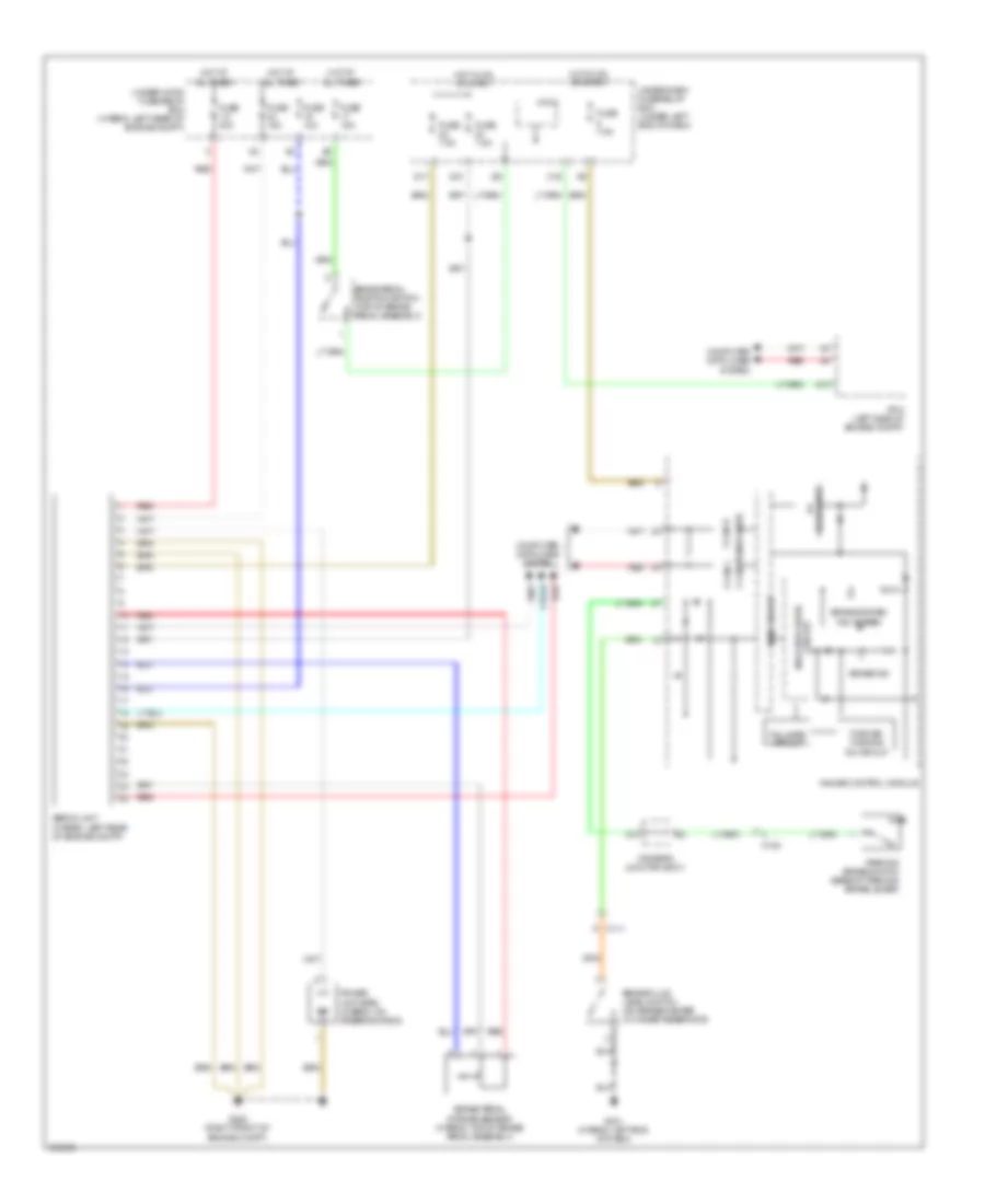
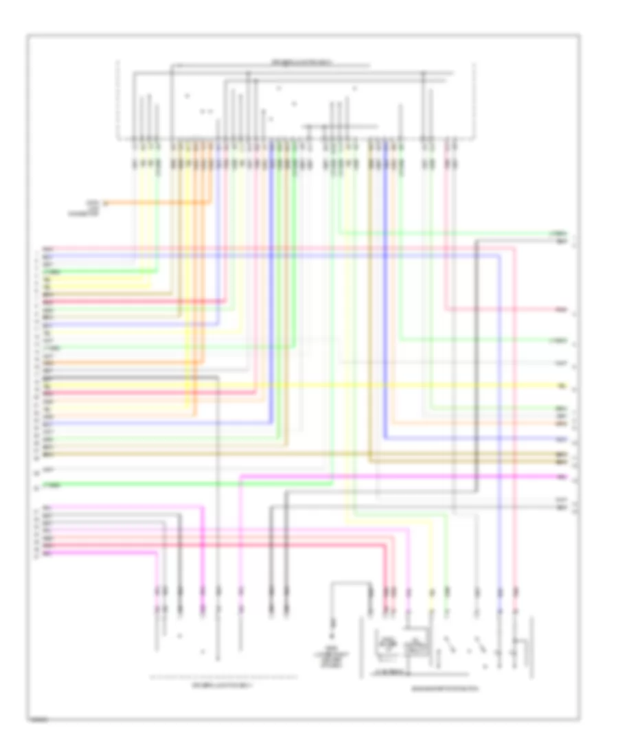
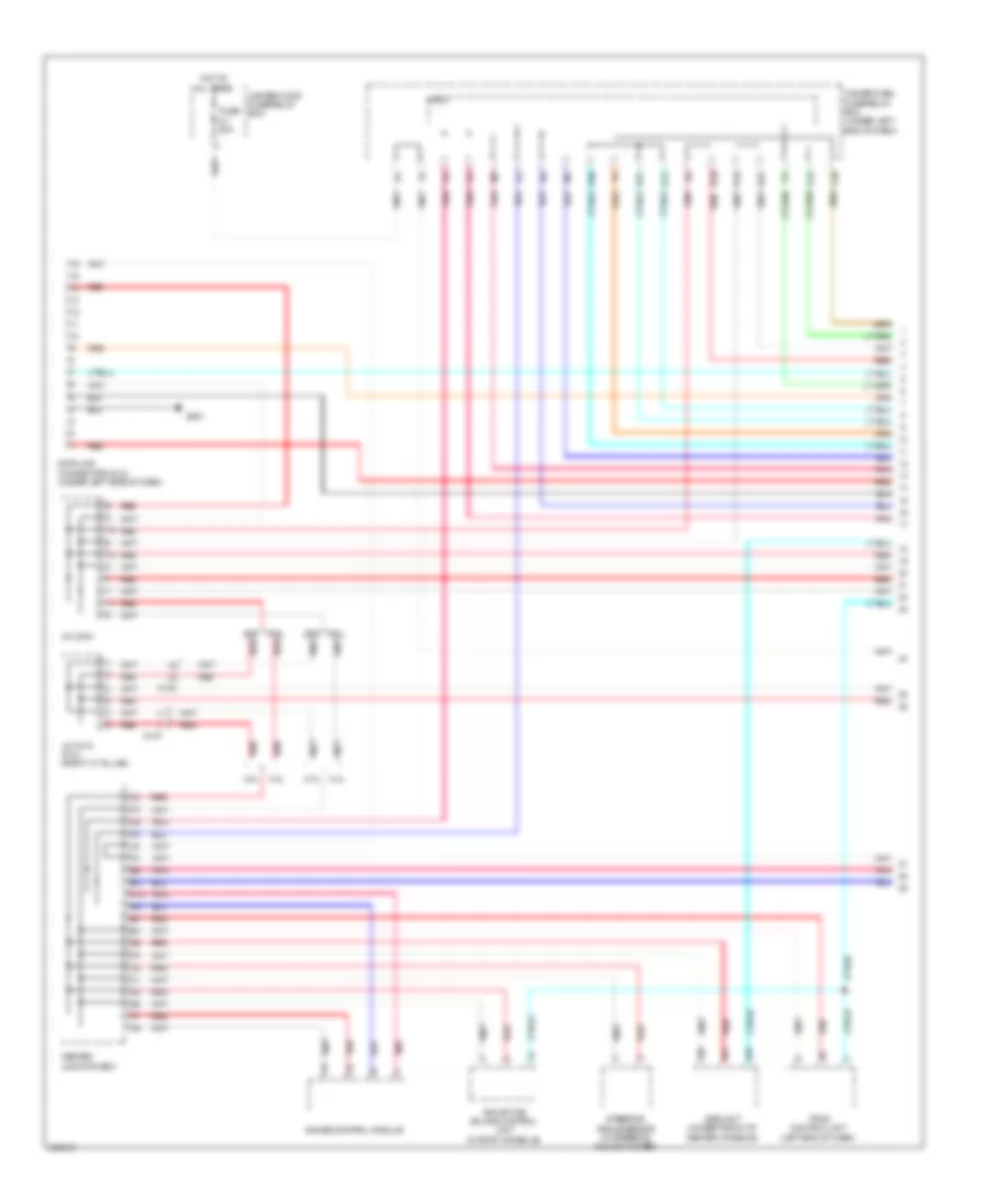
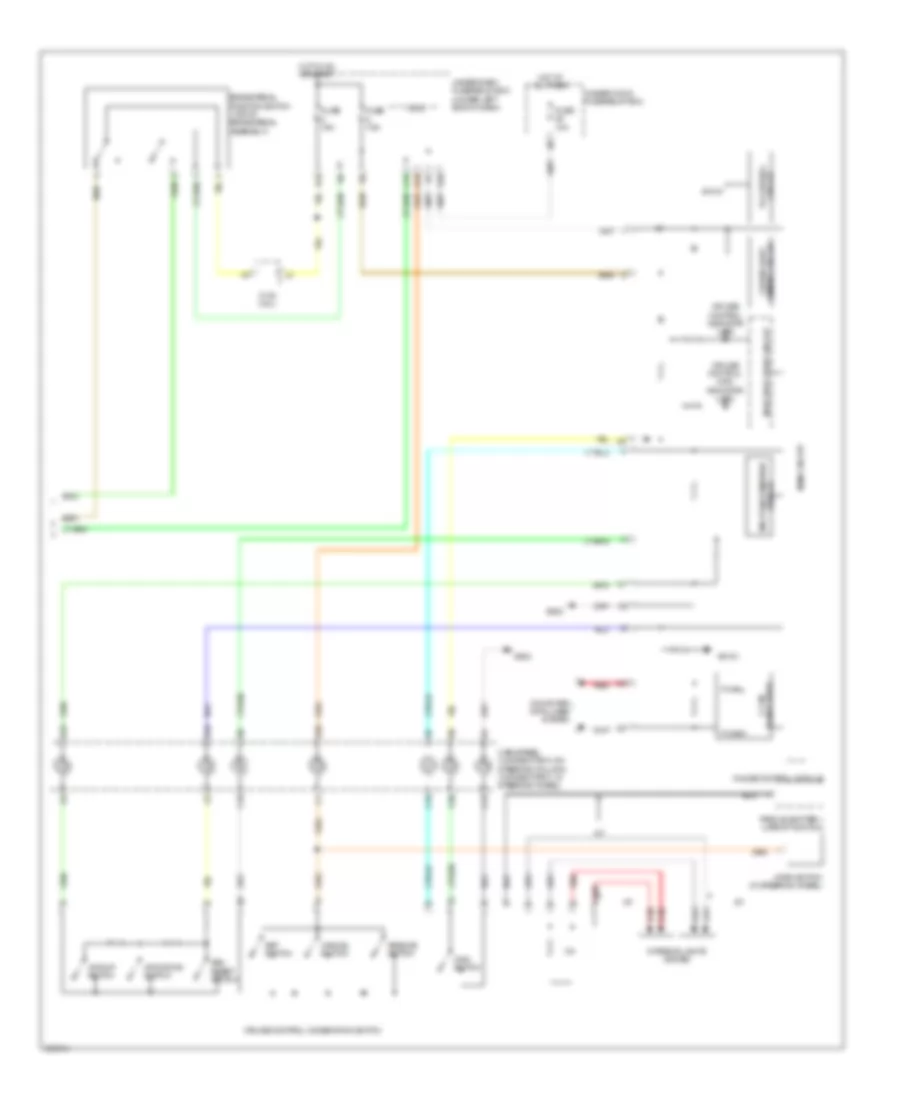
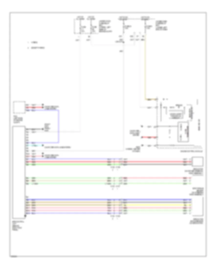
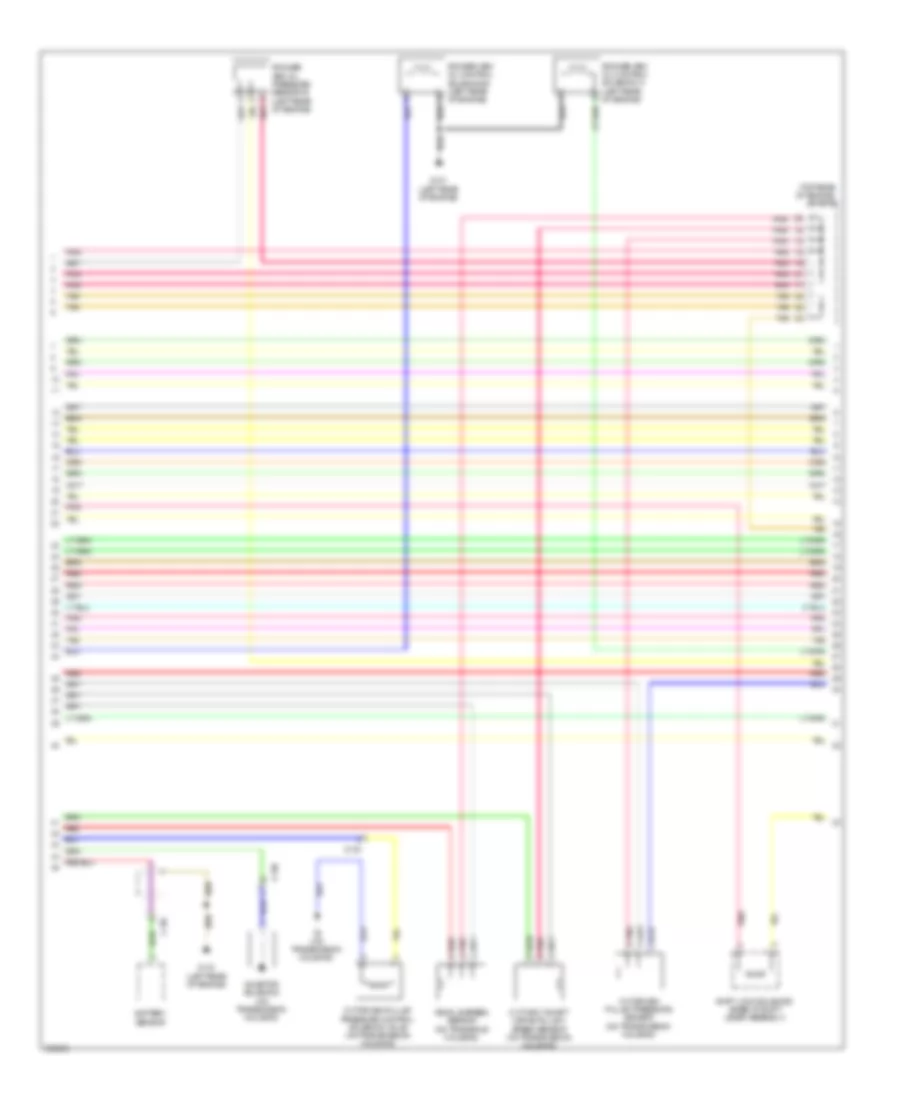
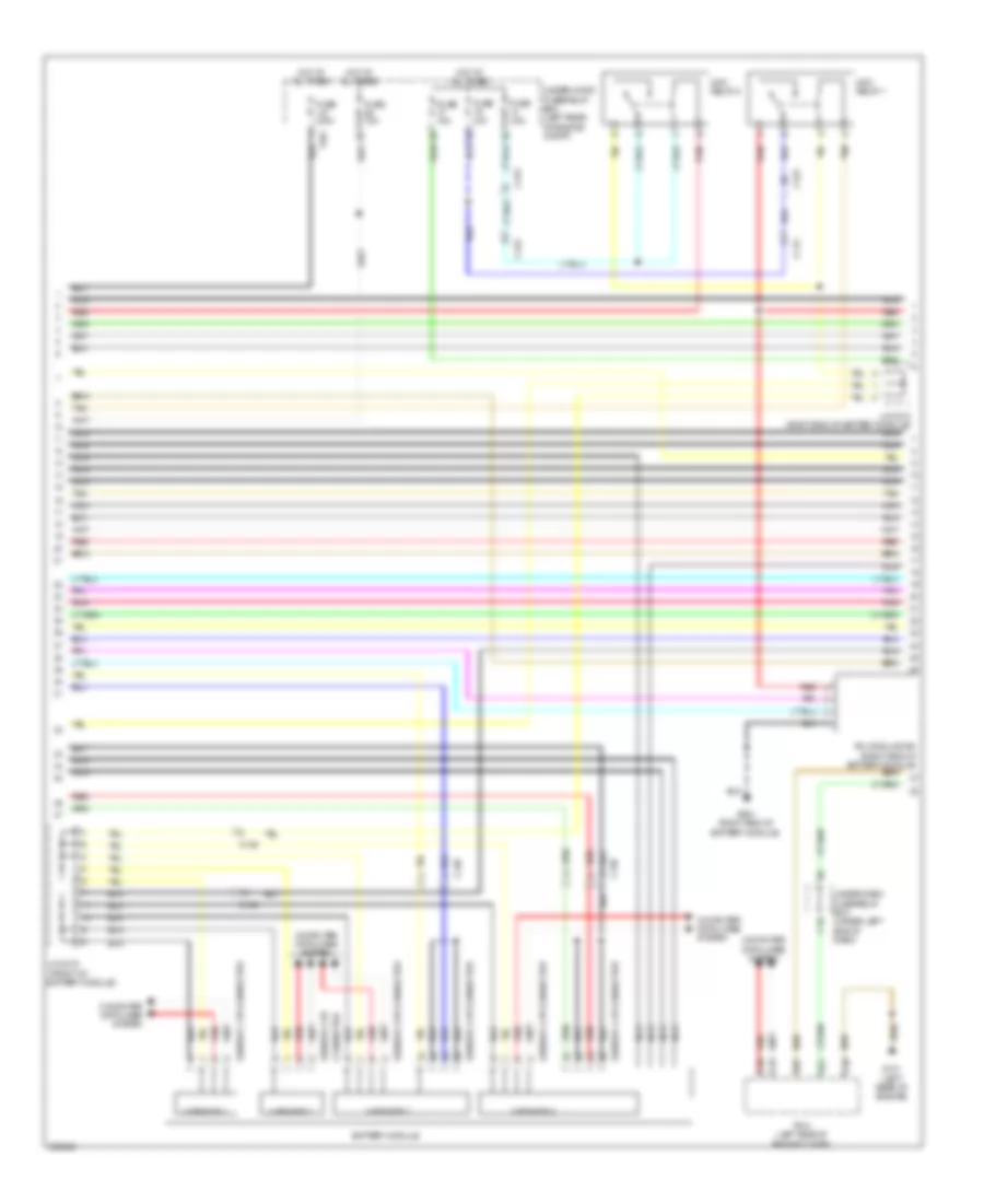
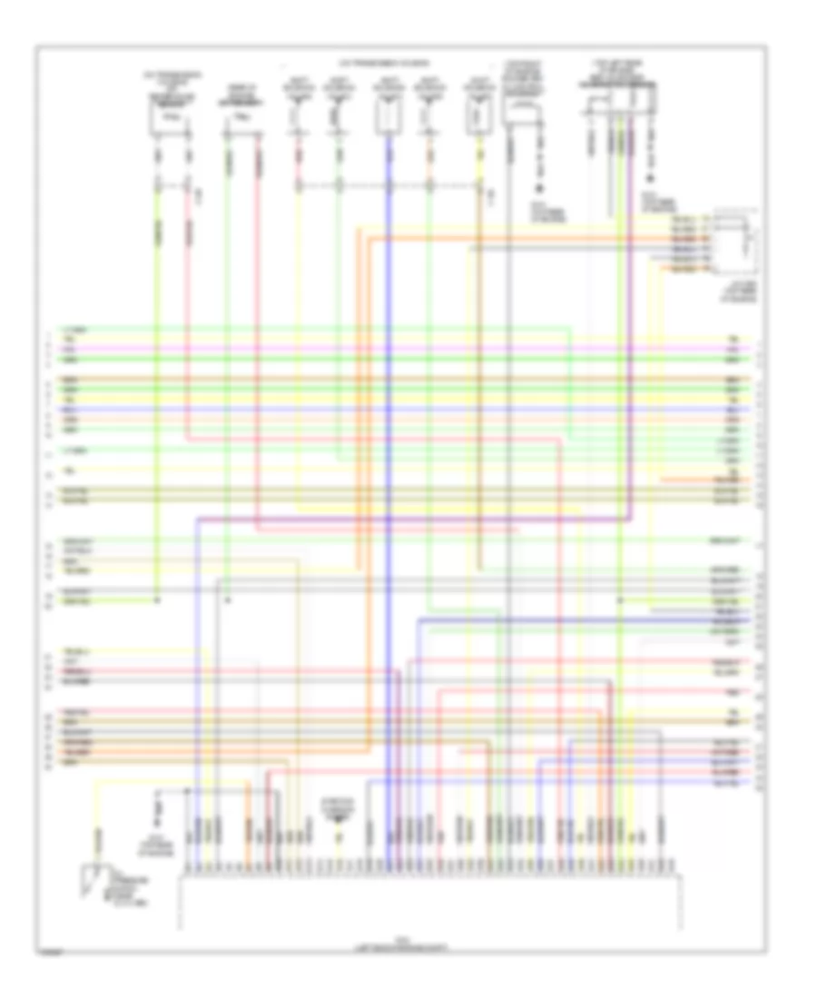
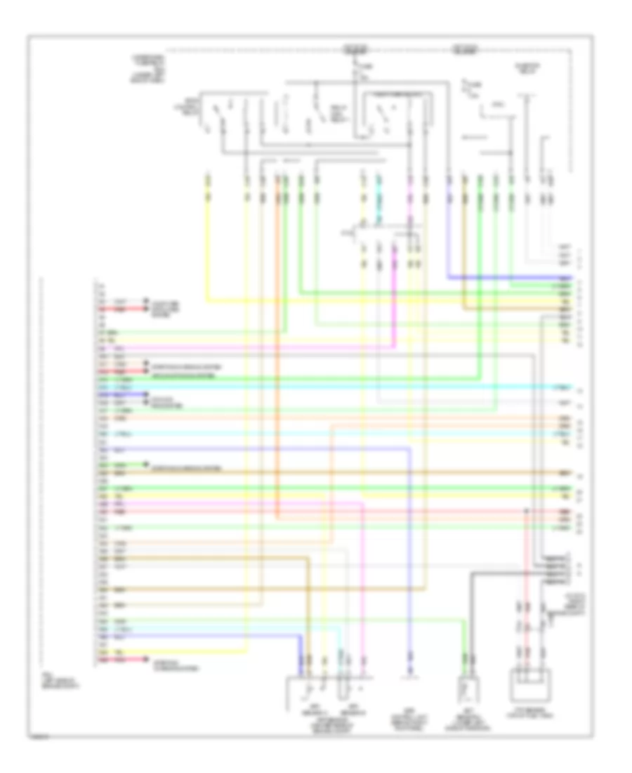
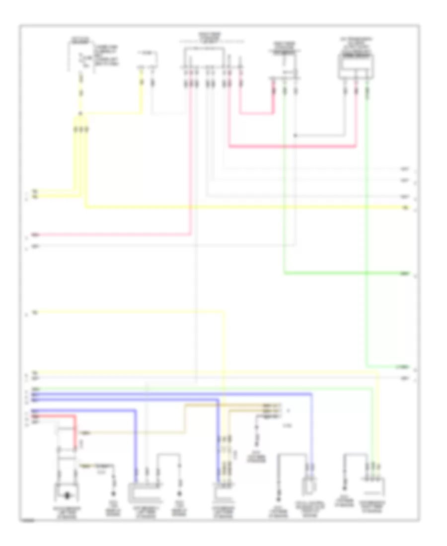
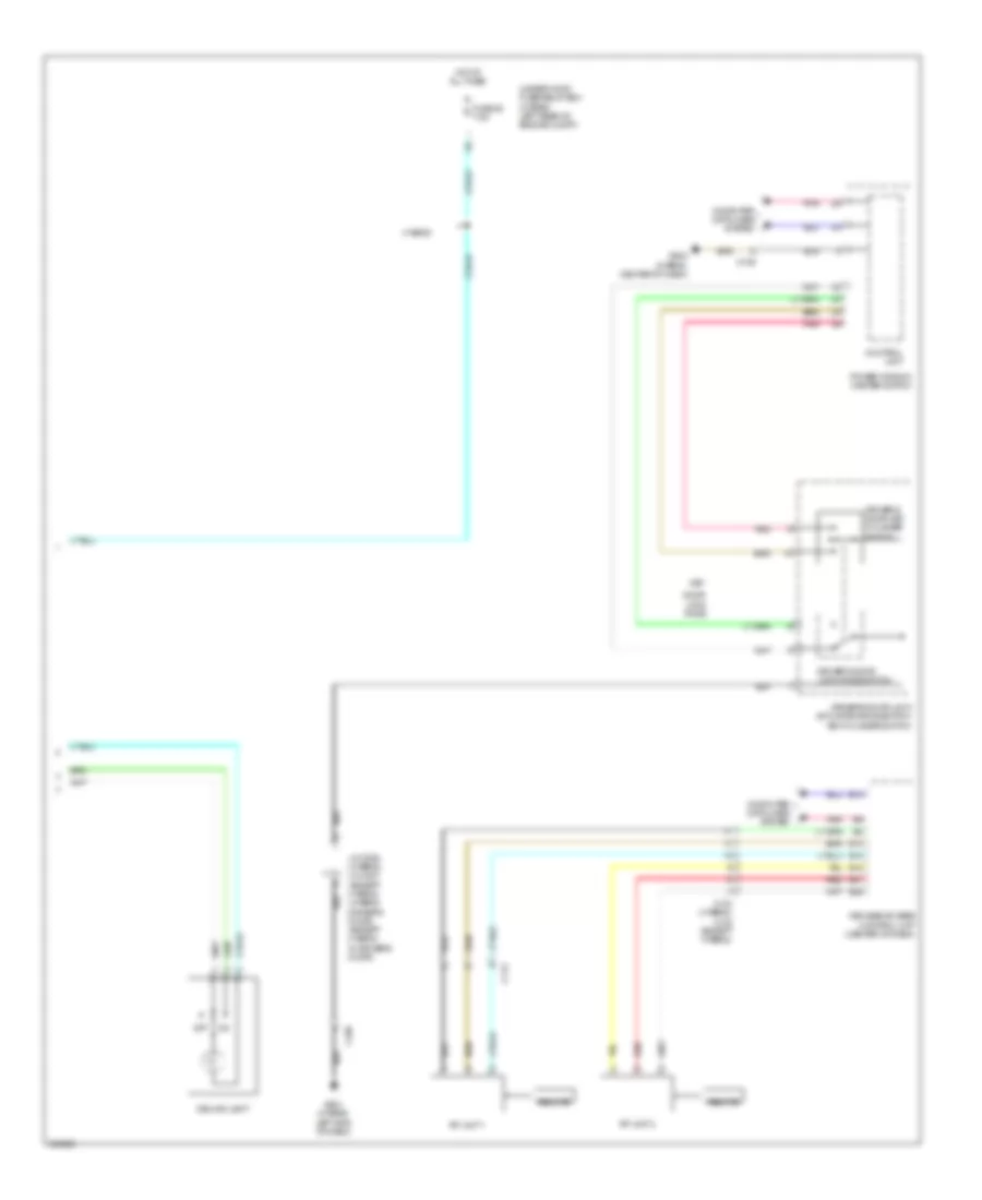
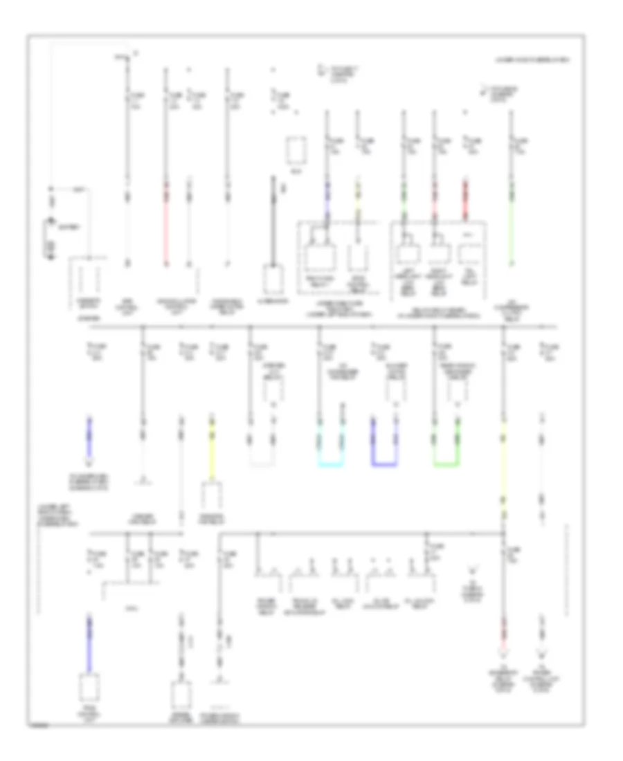
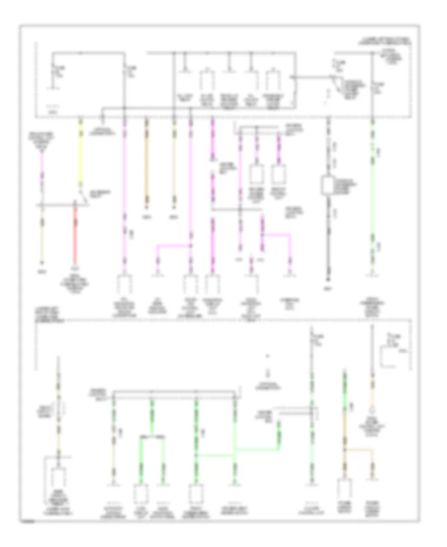
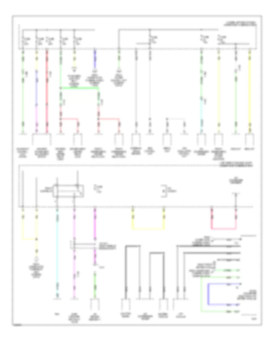
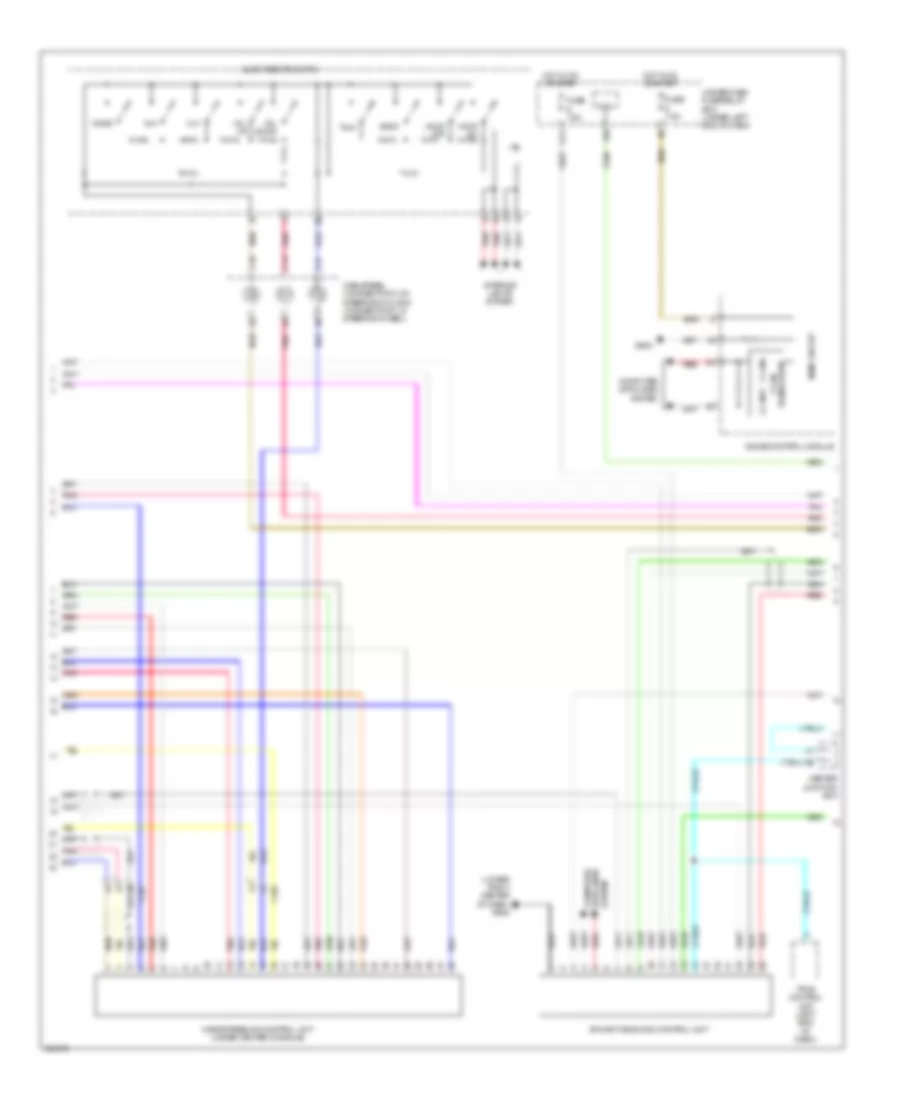
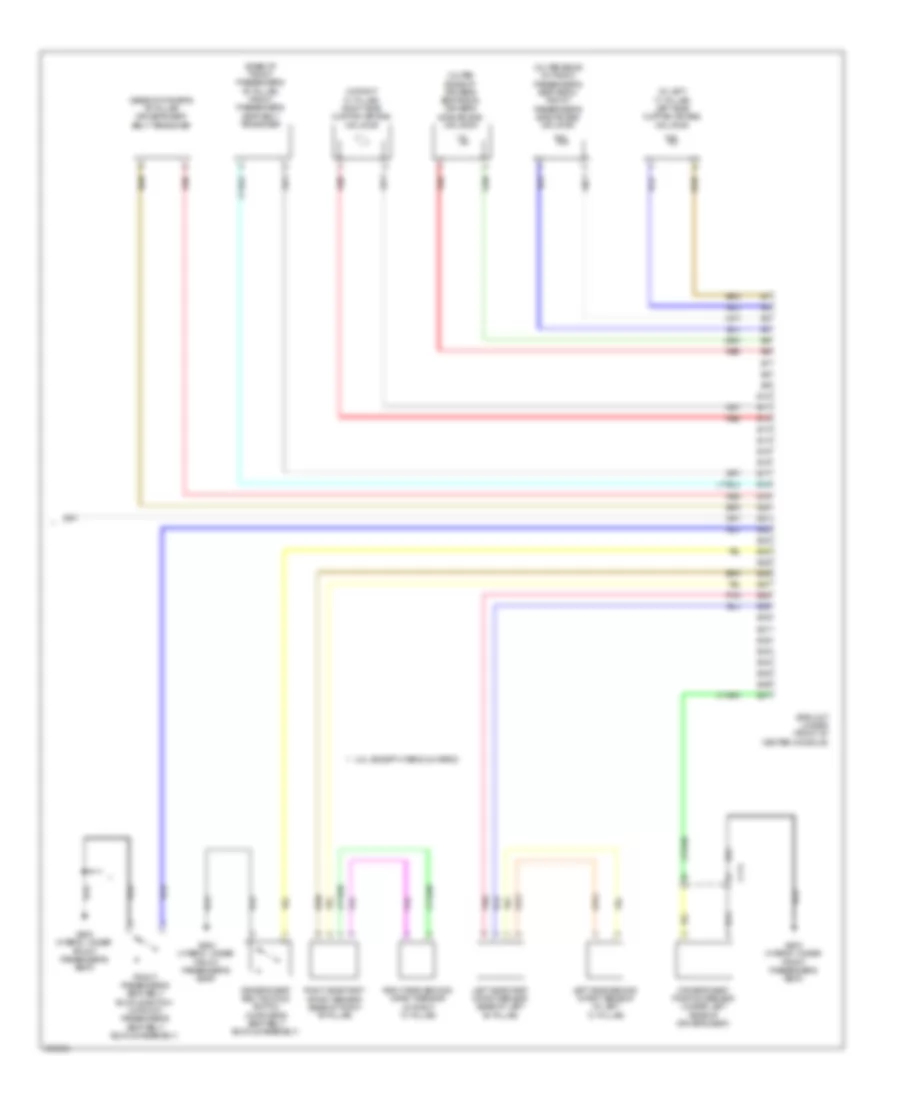
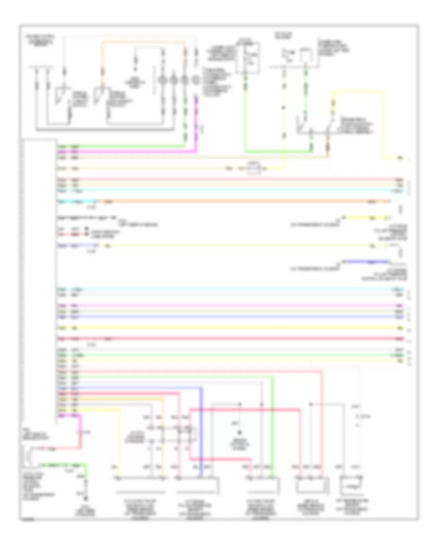
Automatic A/C Wiring Diagram (4 of 4) for Acura ILX 2014
List of elements for Automatic A/C Wiring Diagram (4 of 4) for Acura ILX 2014:
- 2.0l & hybrid
- 2.4l
- A/c condenser fan motor (right front of engine compt)
- A/c condenser fan relay
- A10
- A12
- A13
- A15
- A16
- A20
- A27
- A30
- A44
- B34
- B44
- C121
- C122
- C134
- C45
- C46
- Computer data lines system
- Diode a
- Diode b
- Ect sensor 1 (rear of engine)
- Ect sensor 2 (lower left side of radiator)
- Engine controls system
- Fan control relay (in under-hood fuse/relay box)
- Fuse 15a
- Fuse 2-10 20a
- Fuse 2-11 20a
- Fuse 7.5a
- G301 (bottom left front of engine compt)
- Hot at all times
- J/c c010 (except hybrid: right rear of engine compt) (hybrid: top rear of engine)
- Pcm (left side of engine compt)
- Pgm-fi sub realy
- Pnk
- Radiator fan motor (behind radiator)
- Radiator fan relay (in under-hood fuse/relay box)
- Red
- Under-hood fuse/relay box (hybrid: left rear of engine compt)
ANTI-LOCK BRAKES
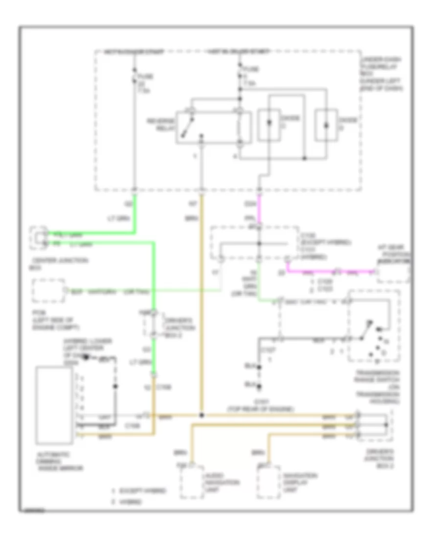
Advanced Hydraulic Booster Wiring Diagram for Acura ILX 2014
List of elements for Advanced Hydraulic Booster Wiring Diagram for Acura ILX 2014:
- 5v regulator
- A13
- Brake fluid level switch (on brake master cylinder reservoir)
- Brake ind
- Brake pedal position switch (top of brake pedal assembly)
- Brake pedal stroke sensor (hybrid: top of brake pedal assembly)
- Brake system ind (amber)
- C102
- C111
- C16
- Circuit
- Computer data lines system
- D17
- D31
- Driver's junction box 1
- F can transceiver
- F-can h
- F-can l
- Fail safe circuit
- Forced turning on circuit
- Fuse 1-2 40a
- Fuse 10a
- Fuse 15a
- Fuse 7.5a
- G202 (right front of engine compt)
- G401 (hybrid: left end of dash)
- Gauge control module
- Hot at all times
- Hot in on or start
- Indicator drive
- Main circuit
- Micu
- Parking brake switch (base of parking brake lever)
- Pcm (left side of engine compt)
- Power unit (eps) (hybrid: on steering rack)
- Red
- Servo unit (hybrid: left rear of engine compt)
- Under-dash fuse/relay box (under left end of dash)
- Under-hood fuse/relay box (hybrid: left rear of engine compt)
Anti-Lock Brakes Wiring Diagram for Acura ILX 2014
List of elements for Anti-Lock Brakes Wiring Diagram for Acura ILX 2014:
- (hybrid: center of dash) g502
- (in steering column cover) steering angle sensor
- (right front of engine compt) g202
- A13
- Abs ind
- Brake fluid level switch (on brake master cylinder reservoir)
- Brake ind (red)
- Brake pedal position switch (top of
- C102
- C103
- C111
- C120
- C123
- C16
- Circuit indicator drive
- Circuit main
- Computer data lines system
- D31
- Driver's junction box 1
- Except hybrid
- F-can h
- F-can l
- F-can transceiver
- Fuse 1-3 30a
- Fuse 1-4 30a
- Fuse 15a
- Fuse 5 7.5a
- Fuse 7.5a
- G401 (hybrid: left end of dash)
- G501 (hybrid: left end of dash)
- Gauge control module
- Hot at all times
- Hot in on or start
- Hybrid
- Interior lights system
- Left front wheel speed sensor (on left front wheel hub assembly)
- Left rear wheel speed sensor (on left rear wheel hub assembly)
- Micu
- On circuit turning compulsory
- P15
- Parking brake switch (base of parking brake lever)
- Pcm (left side of engine compt)
- Pnk
- Red
- Right front wheel speed sensor (on right front wheel hub assembly)
- Right rear wheel speed sensor (on right rear wheel hub assembly)
- Under-dash fuse/relay box (under left end of dash)
- Under-hood fuse/relay box (hybrid: left rear of engine compt)
- Vsa ind
- Vsa modulator control unit (right front of engine compt)
- Vsa off ind
- Vsa off switch
ANTI-THEFT
Anti-theft Wiring Diagram (1 of 7) for Acura ILX 2014
List of elements for Anti-theft Wiring Diagram (1 of 7) for Acura ILX 2014:
- (under left end of dash) under-dash fuse/relay box
- Answer back buzzer (hybrid: behind left side of rear bumper)
- B11
- B15
- B18
- B29
- B32
- B33
- B34
- B35
- B40
- C102
- C103
- C104
- C109
- C116
- C117
- C121
- C124
- C125
- C129
- C14
- C18
- C20
- C27
- C33
- C37
- C38
- Computer data lines system
- D/l door unlock relay
- D/l lock relay
- D/l unlock relay
- D28
- Door lock knob
- Except hybrid
- Exterior lights system
- Fuse 10a
- Fuse 15a
- Fuse 20a
- G501 (hybrid: left end of dash)
- G503 (hybrid: center of dash)
- G602 (hybrid: under front passenger's seat)
- G701 (hybrid: left rear of luggage compt)
- Headlights system
- Horns system
- Hybrid
- Left rear door lock actuator/knob switch
- Lock
- Micu
- N10
- N12
- P20
- Pnk
- Q10
- Q16
- Red
- Right rear door lock actuator/knob switch
- Unlock
- W11
Anti-theft Wiring Diagram (2 of 7) for Acura ILX 2014
List of elements for Anti-theft Wiring Diagram (2 of 7) for Acura ILX 2014:
- (base of parking brake lever) parking brake switch
- (front center of engine compt) security hood switch
- (in driver's "b" pillar) driver's door switch
- (in left rear "c" pillar) left rear door switch
- (in passenger's "b" pillar) front passenger's door switch
- (in right rear "c" pillar) right rear door switch
- C102
- C103
- C109
- Computer data lines system
- Control unit
- Door lock knob
- Driver's door key cylinder switch
- Driver's door lock actuator/ knob switch/key cylinder switch
- Driver's door lock knob switch
- Driver's door lock switch
- Except hybrid
- Fuse 10a
- Fuse 2-1 50a
- Fuse 2-2 60a
- Fuse 2-3 60a
- G401 (hybrid: left end of dash)
- G501 (hybrid:left end of dash)
- G503 (hybrid: center of dash)
- G506 (lower right center of dash)
- Hot at all times
- Hybrid
- J/c c007 (except hybrid) j/c c008 (hybrid) (in driver's door)
- Key
- Lock
- Pnk
- Power window master switch
- Trunk lid opener main switch
- Under-hood fuse/relay box (hybrid: left rear of engine compt)
- Unlock
Anti-theft Wiring Diagram (3 of 7) for Acura ILX 2014
List of elements for Anti-theft Wiring Diagram (3 of 7) for Acura ILX 2014:
- C103
- C104
- C111
- C120
- C125
- C127
- C129
- C130
- C130 (except hybrid a/t) c131 (hybrid) c133 (except hybrid m/t)
- C131
- Center junction box
- Computer data lines system
- Control unit
- Door lock knob
- Except hybrid
- Except hybrid a/t
- Except hybrid m/t
- Front passenger's door lock actuator/knob switch
- Front passenger's power window switch
- Fuse 10a
- Fuse 15a
- Fuse 7.5a
- G101 (hybrid: left rear of engine) (except hybrid: top rear of engine)
- G101 (top rear of engine)
- G503 (hybrid: center of dash)
- Hot w/ accessory relay energized
- Hybrid
- Lock
- Optional connector f
- P18
- Passenger door lock switch
- Pcm (left side of engine compt)
- Pnk
- Red
- S l
- Transmission range switch (a/t) (on transmission housing)
- Under-dash fuse/relay box (under left end of dash)
- Unlock
Anti-theft Wiring Diagram (4 of 7) for Acura ILX 2014
List of elements for Anti-theft Wiring Diagram (4 of 7) for Acura ILX 2014:
- (left side of dash) power control unit
- (on steering column) electric steering lock
- Backup control unit (left side of dash)
- C11
- C12
- C14
- C15
- C17
- C18
- C19
- C23
- C24
- C25
- C26
- C33
- C34
- C35
- Computer data lines system
- Driver's junction box 2
- G501 (hybrid: left end of dash)
- G502 (hybrid: center of dash)
- G506 (lower right center of dash)
- Pnk
- Red
Anti-theft Wiring Diagram (5 of 7) for Acura ILX 2014
List of elements for Anti-theft Wiring Diagram (5 of 7) for Acura ILX 2014:
- 5v control circuit
- Data link connector
- Driver's junction box 1
- Engine start/stop switch
- G506 (lower right center of dash)
- H10
- Immo- bilizer i/f
- Lf antenna
- Pnk
- Red
Anti-theft Wiring Diagram (6 of 7) for Acura ILX 2014
List of elements for Anti-theft Wiring Diagram (6 of 7) for Acura ILX 2014:
- B-can h
- B-can l
- B-can transceiver
- Brake ind
- C102
- C103
- C104
- C105
- C109
- C113
- C121
- C124
- C125
- C129
- Computer data lines system
- Door ind
- Door lf antenna
- Driver's door outer handle
- Except hybrid
- Front passenger's door outer handle
- G501 (hybrid: left end of dash)
- G502 (hybrid: center of dash)
- G506 (lower right center of dash)
- G701 (hybrid: left rear of luggage compt)
- Gauge control module
- Hybrid
- Immobilizer ind
- Indicator drive circuit
- J/c c007 (except hybrid) j/c c008 (hybrid)
- Keyless access system ind
- Lock switch
- Main circuit
- Pnk
- Red
- Remote
- Rf unit 1
- Security ind
- Touch sensor
- Trunk lid outer handle switch
Anti-theft Wiring Diagram (7 of 7) for Acura ILX 2014
List of elements for Anti-theft Wiring Diagram (7 of 7) for Acura ILX 2014:
- (center rear of luggage compt) rear interior lf antenna
- (hybrid: behind center of rear bumper) rear bumper lf antenna
- (lower center of dash) front interior lf antenna
- (under rear of center console) middle interior lf antenna
- A10
- A11
- A12
- A13
- A14
- A15
- A16
- A17
- A18
- A19
- A20
- A21
- A22
- A23
- A24
- A25
- A26
- A27
- A28
- A29
- A30
- A31
- A32
- A33
- A34
- A35
- A36
- B10
- B11
- B12
- B13
- B14
- B15
- B16
- B17
- B18
- B19
- B20
- B21
- B22
- B23
- B24
- B25
- B26
- B27
- B28
- B29
- B30
- B31
- B32
- C102
- C103
- C104
- C113
- C121
- C124
- Computer data lines system
- Except hybrid
- Hybrid
- Keyless access control unit (center of dash)
- Pnk
- Red
- Remote
- Rf unit 2
BODY CONTROL MODULES
Body Control Modules Wiring Diagram (1 of 2) for Acura ILX 2014
List of elements for Body Control Modules Wiring Diagram (1 of 2) for Acura ILX 2014:
- (optional connector f)
- Air conditioning system
- Anti-theft system
- B12
- B21
- B22
- B28
- B29
- B32
- B33
- B34
- B40
- B44
- C14
- C18
- C19
- C22
- C23
- C24
- C26
- C27
- C32
- C36
- C37
- Computer data lines system
- Cruise control system
- D11
- D14
- D23
- D24
- D29
- Diode c (a/t & cvt)
- Diode d
- Door locks & interior lights systems
- Door locks system
- Exterior lights system
- Fuse 10a
- Fuse 7.5a
- G501 (hybrid: left end of dash)
- G602 (hybrid: under front passenger's seat)
- Headlights & exterior lights systems
- Headlights system
- Horns system
- Hot at all times
- Hot in on or start
- Hot w/ accessory relay energized
- Instrument cluster system
- Interior lights system
- Micu
- Navigation system
- P11
- Pnk
- Power distribution system
- Power windows system
- Q10
- Red
- Reverse relay
- Shift interlock system
- Starting/charging system
- T11
- T12
- T13
- T14
- T15
- T16
- T17
- T18
- T19
- Trunk, tailgate, fuel doors system
- Under-dash fuse/relay box (under left end of dash)
- Under-hood fuse/relay box (hybrid: left rear of engine compt)
- W11
- Warning systems
- Wiper/washer system
Body Control Modules Wiring Diagram (2 of 2) for Acura ILX 2014
List of elements for Body Control Modules Wiring Diagram (2 of 2) for Acura ILX 2014:
- (optional connector e)
- C11
- C16
- Computer data lines system
- Cruise control system
- D20
- D21
- D28
- D30
- Engine controls system
- Except hybrid
- Exterior lights system
- Fuse 10a
- Fuse 2-4 30a
- Fuse 20a
- Fuse 7.5a
- Headlights system
- Hot at all times
- Instrument cluster system
- K10
- K11
- Micu
- P19
- Pnk
- Power distribution system
- Q14
- Q16
- Red
- Sound systems
- Under-dash fuse/relay box (under left end of dash)
- Under-hood fuse/relay box (hybrid: left rear of engine compt)
- Warning systems
COMPUTER DATA LINES
Computer Data Lines Wiring Diagram, Except Hybrid (1 of 3) for Acura ILX 2014
List of elements for Computer Data Lines Wiring Diagram, Except Hybrid (1 of 3) for Acura ILX 2014:
- 2.0l
- 2.4l
- A19
- A20
- A21
- Anc/active sound control unit (in roof console)
- C102
- C107
- C20
- C24
- Center junction box
- D21
- D26
- D27
- D30
- Data link connector (dlc) (under left side of dash)
- Fuse 2-1 50a
- G501
- Gauge control module
- H10
- Hot at all times
- J/c c004
- J/c c013 (2.0l) (right "c" pillar)
- Micu
- P16
- Pnk
- Q14
- Red
- Srs unit (under front of center console)
- Steering angle sensor (in steering column cover)
- Tpms control unit (left end of dash)
- Under-dash fuse/relay box (under left end of dash)
- Under-hood fuse/relay box
Computer Data Lines Wiring Diagram, Except Hybrid (2 of 3) for Acura ILX 2014
List of elements for Computer Data Lines Wiring Diagram, Except Hybrid (2 of 3) for Acura ILX 2014:
- (behind right kick panel) eps control unit
- (left side of engine compt) pcm
- (right front of engine compt) vsa modulator control unit
- (right rear of engine compt) (2.4l) j/c c012 (2.0l) j/c c010
- 2.4l
- A10
- A11
- A13
- A15
- A17
- A31
- A42
- Audio display unit (w/o navigation)
- Audio navigation unit (2.0l)
- Audio unit
- B13
- C111
- C130
- C133
- C16
- C18
- C20
- C21
- Center junction box
- Climate control unit
- E27
- G101 (top rear of engine)
- Pnk
- Power control unit (left side of dash)
- Red
- W/ navigation
- W/o navigation
Computer Data Lines Wiring Diagram, Except Hybrid (3 of 3) for Acura ILX 2014
List of elements for Computer Data Lines Wiring Diagram, Except Hybrid (3 of 3) for Acura ILX 2014:
- (center of dash) keyless access control unit
- (left side of dash) backup control unit
- A10
- A11
- Acuralink control unit (xm receiver) (2.0l) (right front of luggage compt)
- B13
- B28
- C109
- C110
- C119
- Driver's junction box 1
- Driver's junction box 2
- Pnk
- Power window master switch
- Red
- Sunlight sensor (top center of dash)
Computer Data Lines Wiring Diagram, Hybrid (1 of 3) for Acura ILX 2014
List of elements for Computer Data Lines Wiring Diagram, Hybrid (1 of 3) for Acura ILX 2014:
- A19
- A20
- A21
- C104
- C122
- C20
- C24
- Center junction box
- D21
- D26
- D27
- D30
- Data link connector (dlc) (under left side of dash)
- Fuse 2-1 50a
- G501 (left end of dash)
- Gauge control module
- H10
- Hot at all times
- J/c c004 (lower center of dash)
- J/c c005 (right "c" pillar)
- Micu
- P16
- Pnk
- Q14
- Red
- Srs unit (under front of center console)
- Steering angle sensor (in steering column cover)
- Tpms control unit (left end of dash)
- Under-dash fuse/relay box (under left end of dash)
- Under-hood fuse/relay box (left rear of engine compt)
Computer Data Lines Wiring Diagram, Hybrid (2 of 3) for Acura ILX 2014
List of elements for Computer Data Lines Wiring Diagram, Hybrid (2 of 3) for Acura ILX 2014:
- (behind right kick panel) eps control unit
- (left rear of engine compt) servo unit
- (left side of engine compt) pcm
- (right front of engine compt) vsa modulator control unit
- (right rear of engine compt) j/c c011
- A10
- A11
- A13
- A15
- A17
- A42
- Audio navigation unit
- C111
- C131
- C16
- C18
- C20
- C21
- Center junction box
- Climate control unit
- E27
- G101 (left rear of engine)
- H18
- Mcm (top right side of battery module)
- Pnk
- Power control unit (left side of dash)
- Red
Computer Data Lines Wiring Diagram, Hybrid (3 of 3) for Acura ILX 2014
List of elements for Computer Data Lines Wiring Diagram, Hybrid (3 of 3) for Acura ILX 2014:
- (center of dash) keyless access control unit
- (left side of dash) backup control unit
- A10
- A11
- Acuralink control unit (xm receiver) (right front of luggage compt)
- B10
- B13
- B28
- C109
- C110
- C120
- Driver's junction box 1
- Driver's junction box 2
- J/c c001 (left center of dash)
- Pnk
- Power window master switch
- Red
- Sunlight sensor (top center of dash)
COOLING FAN
Cooling Fan Wiring Diagram for Acura ILX 2014
List of elements for Cooling Fan Wiring Diagram for Acura ILX 2014:
- 2.0l & hybrid
- 2.4l
- A/c condenser fan motor (right front of engine compt)
- A/c condenser fan relay
- A/c pressure sensor (right front of engine compt)
- A10
- A15
- A16
- A20
- A27
- A30
- A44
- B34
- B44
- C120
- C123
- Computer data lines system
- Diode a
- Diode b
- Ect sensor 1 (rear of engine)
- Ect sensor 2 (lower left side of radiator)
- Engine controls system
- Except hybrid
- Fan control relay (in under-hood fuse/relay box)
- Ftp sensor (top of fuel tank)
- Fuse 15a
- Fuse 2-10 20a
- Fuse 2-11 20a
- Fuse 7.5a
- G301 (bottom left front of engine compt)
- Hot at all times
- Hybrid
- J/c c010 (except hybrid: right rear of engine compt) (hybrid: top rear of engine)
- Pcm (left side of engine compt)
- Pgm-fi sub relay
- Pnk
- Radiator fan motor (behind radiator)
- Radiator fan relay (in under-hood fuse/relay box)
- Red
- Relay circuit board (in under-hood fuse/relay box)
- Under-hood fuse/relay box (hybrid: left rear of engine compt)
CRUISE CONTROL
Cruise Control Wiring Diagram, Except Hybrid (1 of 2) for Acura ILX 2014
List of elements for Cruise Control Wiring Diagram, Except Hybrid (1 of 2) for Acura ILX 2014:
- (or pnk)
- (or red)
- (or tan)
- A/t
- A13
- A14
- A18
- A25
- A28
- A29
- A35
- A36
- A45
- A46
- A48
- App sensor (center rear of engine compt)
- App sensor a
- App sensor b
- B39
- B48
- C127
- C130 (2.0l) c133 (2.4l)
- C133 (m/t)
- C14
- C22
- C23
- C24
- C25
- C30
- C31
- C34
- Clutch interlock switch (m/t) (top of clutch pedal assembly)
- Clutch pedal position switch (m/t) (top of clutch pedal assembly)
- Computer data lines system
- D12
- Engine controls system
- Etcs control relay
- Fuse 15a
- G101 (top rear of engine)
- G401
- Hot at all times
- J/c c009 (a/t) j/c c011 (m/t) (a/t: top rear of engine) (m/t: right rear of engine)
- M/t
- Output shaft (countershaft) speed sensor (on transmission housing)
- Pcm (left side of engine compt)
- Pgm-fi main relay 1
- Red
- Throttle actuator
- Throttle body (left rear of engine)
- Throttle open sensor
- Transmission range switch (a/t) (on transmission housing)
- Under-dash fuse/relay box (under left end of dash)
- Under-hood fuse/relay box
Cruise Control Wiring Diagram, Except Hybrid (2 of 2) for Acura ILX 2014
List of elements for Cruise Control Wiring Diagram, Except Hybrid (2 of 2) for Acura ILX 2014:
- 5v control circuit
- A/t
- A10
- A15
- A16
- Brake pedal position switch (top of brake pedal assembly)
- C12
- C130 (2.0l)
- C16
- C18
- C19
- C20
- Cable reel (connector a: on steering column) (connector c: in steering wheel)
- Cancel switch
- Computer data lines system
- Cruise control combination switch
- Cruise control indicator (led)
- Cruise control main indicator (led)
- Cruise light dimming circuit
- D10
- D28
- Display
- F-canh
- F-canl
- Fuse 10a
- Fuse 15a
- Fuse 7.5a
- G502
- Gauge control module
- Horn switch (in steering wheel)
- Hot at all times
- Hot in on or start
- Indicator drive circuit
- Info/down switch
- Info/up switch
- Interior lights system
- Main circuit
- Main switch
- Micu
- Multi-information
- Paddle shifter + (upshift switch)
- Q10
- Red
- Resume switch
- Sel/ reset switch
- Set switch
- Sw 5v
- Transceiver f-can
- Under-dash fuse/relay box (under left end of dash)
- Under-hood fuse/relay box
Cruise Control Wiring Diagram, Hybrid (1 of 2) for Acura ILX 2014
List of elements for Cruise Control Wiring Diagram, Hybrid (1 of 2) for Acura ILX 2014:
- (california) ignition coil relay
- A13
- A25
- A28
- A29
- A35
- A36
- A45
- A46
- A48
- App sensor (bind center of dash)
- App sensor a
- App sensor b
- B29
- B39
- B44
- B48
- C131
- C14
- C22
- C25
- C30
- C31
- C34
- Computer data lines system
- D12
- D19
- Etcs control relay
- Fuse 15a
- G101 (left rear of engine)
- Hot at all times
- J/c c010 (top rear of engine)
- Pcm (left side of engine compt)
- Pgm-fi main relay 1
- Pnk
- Red
- Throttle actuator
- Throttle body (left rear of engine)
- Throttle open sensor
- Transmission range switch (on transmission housing)
- Under-dash fuse/relay box (under left end of dash)
- Under-hood fuse/relay box (left rear of engine compt)
- Vehicle speed sensor (on transaxle housing)
Cruise Control Wiring Diagram, Hybrid (2 of 2) for Acura ILX 2014
List of elements for Cruise Control Wiring Diagram, Hybrid (2 of 2) for Acura ILX 2014:
- 5v control circuit
- A10
- A15
- A16
- Brake pedal position switch (top of brake pedal assembly)
- C12
- C16
- C18
- C19
- C20
- Cable reel (connector a: on steering column) (connector c: in steering wheel)
- Cancel switch
- Computer data lines system
- Cruise control combination switch
- Cruise control indicator (led)
- Cruise control main indicator (led)
- Cruise light dimming circuit
- D10
- D28
- Display
- F-canh
- F-canl
- Fuse 10a
- Fuse 15a
- Fuse 7.5a
- G502 (center of dash)
- Gauge control module
- Horn switch (in steering wheel)
- Hot at all times
- Hot in on or start
- Indicator drive circuit
- Info/down switch
- Info/up switch
- Interior lights system
- Main circuit
- Main switch
- Micu
- Multi-information
- Paddle shifter + (upshift switch)
- Q10
- Red
- Resume switch
- Sel/ reset switch
- Set switch
- Sw 5v
- Transceiver f-can
- Under-dash fuse/relay box (under left end of dash)
- Under-hood fuse/relay box (left rear of engine compt)
DEFOGGERS
Defoggers Wiring Diagram for Acura ILX 2014
List of elements for Defoggers Wiring Diagram for Acura ILX 2014:
- A15
- A17
- A19
- B-can h
- B-can l
- C103
- C104
- C108
- C109
- C111
- C112
- C125
- C129
- Center junction box
- Climate control unit
- Computer data lines system
- Defogger
- Except hybrid
- Front passenger's power window switch
- Fuse 2-6 30a
- Fuse b22 7.5a
- Fuse b44 20a
- G501 (hybrid: left end of dash)
- G503 (hybrid: center of dash)
- G506 (lower right center of dash)
- G801 (hybrid: right rear of luggage compt)
- Gauge control module
- Hot at all times
- Hot in on or start
- Hybrid
- J/c c008 (hybrid) j/c c007 (except hybrid) (in driver's door)
- Left power mirror
- Moonroof control unit/motor (center rear of moon roof)
- Noise reduction condenser
- Pnk
- Power window master switch
- Rear window defogger
- Rear window defogger ind
- Rear window defogger relay
- Rear window defogger switch
- Red
- Relay circuit board (in under-hood fuse/relay box)
- Right power mirror
- S10
- Under-dash fuse/relay box (under left end of dash)
- Under-hood fuse/relay box (hybrid: left rear of engine compt)
ELECTRONIC POWER STEERING
Electronic Power Steering Wiring Diagram for Acura ILX 2014
List of elements for Electronic Power Steering Wiring Diagram for Acura ILX 2014:
- (right kick panel) g403
- A10
- A11
- A22
- B10
- B11
- B12
- B13
- C122
- C123
- C124
- C126
- C127
- C128
- Compulsory turning-on circuit
- Computer data lines system
- D28
- D31
- Drive circuit indicator
- Eps control unit (behind right kick panel)
- Eps ind
- Eps motor (on power steering rack assembly)
- Eps motor angle sensor (on eps motor)
- Eps torque sensor (on steering rack assembly)
- Except hybrid
- F-can h
- F-can l
- Fuse 1-1 70a
- Fuse 10a
- Fuse 24 7.5a
- Fuse 5 7.5a
- G502 (hybrid: center of dash)
- Gauge control module
- Hot at all times
- Hot in on or start
- Hybrid
- Main circuit
- Pcm (left side of engine compt)
- Pnk
- Red
- Transceiver f-can
- Under-dash fuse/relay box (under left end of dash)
- Under-hood fuse/relay box (hybrid: left rear of engine compt)
ENGINE PERFORMANCE
1.5L HYBRID
1.5L Hybrid, Engine Controls Wiring Diagram (1 of 6) for Acura ILX 2014
List of elements for 1.5L Hybrid, Engine Controls Wiring Diagram (1 of 6) for Acura ILX 2014:
- (lower left side of radiator) ect sensor 2
- (right front of engine compt) a/c pressure sensor
- (right rear of engine compt) j/c c011
- (under left rear of vehicle) evap canister vent shut valve
- A10
- A11
- A12
- A13
- A14
- A15
- A16
- A17
- A18
- A19
- A20
- A21
- A22
- A23
- A24
- A25
- A26
- A27
- A28
- A29
- A30
- A31
- A32
- A33
- A34
- A35
- A36
- A37
- A38
- A39
- A40
- A41
- A42
- A43
- A44
- A45
- A46
- A47
- A48
- A49
- Air conditioning system
- App sensor (bind center of dash)
- App sensor a
- App sensor b
- Audio navigation unit
- C104
- C123
- Compulsory turning- off circuit
- Computer data lines system
- Cooling fans system
- Eps control unit (behind right kick panel)
- F-can h
- F-can l
- F-can transceiver
- Ftp sensor (top of fuel tank)
- Fuse 15a
- G502 (center of dash)
- Gauge control module
- Hot at all times
- Main circuit
- Malfuction indicator
- Nep
- Pcm (left side of engine compt)
- Pgm-fi sub- relay
- Pnk
- Red
- Starting/ charging system
- Starting/charging system
- Transmissions system
- Under- hood fuse/ relay box (left rear of engine compt)
1.5L Hybrid, Engine Controls Wiring Diagram (2 of 6) for Acura ILX 2014
List of elements for 1.5L Hybrid, Engine Controls Wiring Diagram (2 of 6) for Acura ILX 2014:
- (under
- C123
- C125
- C130
- C131
- Cvt clutch pressure control solenoid valve (on transmission housing)
- Cvt output shaft (drive pulley) speed sensor (on transmission housing)
- Driver's seat)
- Eld unit
- Evap canister puge valve (right rear of engine)
- Exhaust side ignition coils (right side of 1, 2, 3 & 4 cylinders)
- Fuel tank unit (top of fuel tank)
- Fuse 1-6 100a
- Fuse 15a
- Fuse 20a
- G101 (left rear of engine)
- G301 (bottom left front of engine compt)
- G601
- Hot at all times
- Icm
- Ignition coil relay
- Instrument cluster system
- J/c c009 (top rear of engine)
- J/c c010 (top rear of engine)
- Maf/iat sensor (on intake air duct)
- Map sensor (left rear of engine)
- Oil pressure switch (left side of engine)
- Pgm-fi main relay 2
- Pnk
- Red
- Spark plug
- Tan
- Under- hood fuse/ relay box (left rear of engine compt)
1.5L Hybrid, Engine Controls Wiring Diagram (3 of 6) for Acura ILX 2014
List of elements for 1.5L Hybrid, Engine Controls Wiring Diagram (3 of 6) for Acura ILX 2014:
- (left front of engine) egr valve & egr valve position sensor
- (left rear of engine) rocker arm oil pressure sensor a
- (lower left front of engine) engine oil temperature sensor
- (on transmission housing) atf temperature sensor
- (rear of engine) ect sensor 1
- B10
- B11
- B12
- B13
- B14
- B15
- B16
- B17
- B18
- B19
- B20
- B21
- B22
- B23
- B24
- B25
- B26
- B27
- B28
- B29
- B30
- B31
- B32
- B33
- B34
- B35
- B36
- B37
- B38
- B39
- B40
- B41
- B42
- B43
- B44
- B45
- B46
- B47
- B48
- B49
- C130
- Cvt drive pulley pressure control solenoid valve
- G101 (left rear of engine)
- Pcm (left side of engine compt)
- Pnk
- Red
- T6 (on transmission housing)
- Tan
1.5L Hybrid, Engine Controls Wiring Diagram (4 of 6) for Acura ILX 2014
List of elements for 1.5L Hybrid, Engine Controls Wiring Diagram (4 of 6) for Acura ILX 2014:
- (top rear of engine) j/c c010
- Battery sensor
- C130
- C135
- Cvt driven pulley pressure control solenoid valve (on transmission housing)
- Cvt driven pulley pressure sensor (on transmission housing)
- Cvt input shaft (drive pulley) speed sensor (on transmission housing)
- G101 (left rear of engine)
- Inhibitor solenoid (on transmission housing)
- Pnk
- Red
- Rocker arm oil control solenoid a (left rear of engine)
- Rocker arm oil control solenoid b (left rear of engine)
- Rocker arm oil pressure sensor b (left rear of engine)
- Shift lock solenoid (base of shift lever assembly)
- T6 (on transmission housing)
- Tan
- Vehicle speed sensor (on transaxle housing)
1.5L Hybrid, Engine Controls Wiring Diagram (5 of 6) for Acura ILX 2014
List of elements for 1.5L Hybrid, Engine Controls Wiring Diagram (5 of 6) for Acura ILX 2014:
- A/t gear position indicator
- B26
- B28
- Brake pedal position switch (top of brake pedal assembly)
- C111
- C123
- C13
- C131
- C132
- C16
- C24
- C25
- C30
- C34
- Ckp sensor (left side of engine)
- Cmp sensor (right rear of engine)
- D10
- D12
- D13
- D19
- D23
- Etcs control relay
- Exterior lights system
- Fuse 15a
- Fuse 7.5a
- G101 (left rear of engine)
- G602 (under front passenger's seat)
- Hot in on or start
- Hot w/ accessary relay energized
- Inhibitor relay
- Interior lights system
- Micu
- Pgm-f1 main relay 1
- Pnk
- Power control unit (left side of dash)
- Red
- Starting/ charging system
- Tan
- Under-dash fuse/relay box (under left end of dash)
1.5L Hybrid, Engine Controls Wiring Diagram (6 of 6) for Acura ILX 2014
List of elements for 1.5L Hybrid, Engine Controls Wiring Diagram (6 of 6) for Acura ILX 2014:
- (left end of dash) diode e
- (left rear of engine) g101
- (left rear of engine) throttle body
- (on transmission housing) transmission range switch
- (top of engine, above 1, 2, 3 & 4 cylinders) injectors
- (top rear of engine) j/c c010
- A/f sensor (sensor 1) (right rear of engine)
- C10
- C11
- C12
- C13
- C131
- C14
- C15
- C16
- C17
- C18
- C19
- C20
- C21
- C22
- C23
- C24
- C25
- C26
- C27
- C28
- C29
- C30
- C31
- C32
- C33
- C34
- C35
- C36
- C37
- C38
- C39
- C40
- C41
- C42
- C43
- C44
- C45
- C46
- C47
- C48
- C49
- Computer data lines system
- G101 (left rear of engine)
- Icm
- Intake side ignition coils (left side of 1, 2, 3 & 4 cylinders)
- J/c c009 (top rear
- Knock sensor (left side of engine)
- Of engine)
- Pcm (left side of engine compt)
- Pnk
- Red
- Secondary ho2s sensor 2 (in exhaust, downstream of catalytic converter)
- Spark plug
- Tan
- Throttle actuator
- Throttle open sensor
1.5L Hybrid, IMA Wiring Diagram (1 of 3) for Acura ILX 2014
List of elements for 1.5L Hybrid, IMA Wiring Diagram (1 of 3) for Acura ILX 2014:
- (center front of battery module) junction board
- (right front of battery module) dc-dc converter
- A10
- A11
- A12
- A13
- A14
- A15
- A16
- A17
- A18
- A19
- A20
- A21
- A22
- A23
- A24
- A25
- A26
- A27
- A28
- A29
- A30
- A31
- A32
- B10
- B11
- B12
- B13
- B14
- B15
- B16
- B17
- B18
- B19
- B20
- B21
- B22
- B23
- B24
- B28
- B32
- C122
- Computer data lines system
- D10
- Fuse 15a
- Fuse 7.5a
- G4 (right front of battery module)
- G5 (left rear of engine compt)
- G602 (under front passenger's seat)
- Hot in on or start
- Mcm (top right side of battery module)
- Micu
- Nca
- Phase motor current sensor (center front of battery module)
- Pnk
- Red
- T10
- Tan
- Under-dash fuse/relay box (under left end of dash)
1.5L Hybrid, IMA Wiring Diagram (2 of 3) for Acura ILX 2014
List of elements for 1.5L Hybrid, IMA Wiring Diagram (2 of 3) for Acura ILX 2014:
- A13
- A25
- Battery module
- C112
- C122
- C123
- C138
- C16
- C20
- C45
- C46
- Computer data lines system
- Connector
- Fuse 1-6 100a
- Fuse 10a
- Fuse 15a
- Fuse 7.5a
- G101 (left rear of engine)
- G901 (right end of battery module)
- Hot at all times
- Ipu module fan (right end of battery module)
- J/c c013 (right end of battery module)
- J/c c015 (front of battery module)
- Mcm relay 1
- Mcm relay 2
- Nca
- Pcm (left side of engine compt)
- Pnk
- Red
- Sensor 1 5p connector
- Sensor 2 5p
- Sensor 3 4p connector
- Sensor 3 5p connector
- Sensor 4 4p connector
- Sensor 4 5p connector
- T101
- Tan
- Under-dash fuse/relay box (under left end of dash)
- Under-hood fuse/relay box (left rear of engine compt)
- V-sensor 1
- V-sensor 2
- V-sensor 3
- V-sensor 4
1.5L Hybrid, IMA Wiring Diagram (3 of 3) for Acura ILX 2014
List of elements for 1.5L Hybrid, IMA Wiring Diagram (3 of 3) for Acura ILX 2014:
- (right end of battery module) a/c compressor driver
- (right end of battery module) j/c c013
- (top of brake pedal assembly) brake pedal position switch
- A/c compressor (a/c compressor clutch/ thermal protector) (a/c compressor clutch: left front of engine) (a/c compressor thermal protector: on a/c compressor)
- Auto stop indicator
- C102
- C121
- C122
- C134
- Charging system indicator
- Computer data lines system
- F-can h
- F-can l
- F-can transceiver
- Fuse 7.5a
- G101 (left rear of engine)
- G301 (bottom left front of engine compt)
- G502
- G901 (right end of battery module)
- Gauge control module
- Hot in on or start
- Ima motor (rear of engine)
- Ima system indicator
- Indicator drive circuit
- Main circuit
- Motor rotor position sensor (rear of engine)
- Mpi module (center front of battery module)
- Nca
- Pnk
- Red
- T11
- T12
- T13
- T17 (right end of battery module)
- Tan
- Under-dash fuse/relay box (under left end of dash)
2.0L
2.0L, Engine Performance Wiring Diagram (1 of 6) for Acura ILX 2014
List of elements for 2.0L, Engine Performance Wiring Diagram (1 of 6) for Acura ILX 2014:
- (lower left side of radiator) ect sensor 2
- (right front of engine compt) a/c pressure sensor
- (right rear of engine compt)
- (under left end of dash)
- (under left rear of vehicle) evap canister vent shut valve
- A/c condenser fan relay
- A/c diode a
- A10
- A11
- A12
- A13
- A14
- A15
- A16
- A17
- A18
- A19
- A20
- A21
- A22
- A23
- A24
- A25
- A26
- A27
- A28
- A29
- A30
- A31
- A32
- A33
- A34
- A35
- A36
- A37
- A38
- A39
- A40
- A41
- A42
- A43
- A44
- A45
- A46
- A47
- A48
- A49
- Air conditioning system
- App sensor (center rear of engine compt)
- C120
- Compulsory turning-off circuit
- Compulsory turning-on circuit
- Computer data lines system
- Cooling fans system computer data lines system
- Cruise control system
- D28
- Display
- Eps control unit (behind right kick panel)
- F-can h
- F-can l
- Ftp sensor (top of fuel tank)
- Fuse 10a
- Fuse 15a
- Fuse 7.5a
- G503
- Gauge control module
- Hot at all times
- Hot in on or start
- Indicator drive circuit
- J/c c010
- Main circuit
- Mil ind
- Multi information
- Pcm (left side of engine compt)
- Pgm-fi sub- relay
- Pnk
- Red
- Sensor a
- Sensor b
- Shift interlock system
- Sound systems
- Starting/charging system
- Transceiver f-can
- Under- dash fuse/ relay box
- Under- hood fuse/ relay box
2.0L, Engine Performance Wiring Diagram (2 of 6) for Acura ILX 2014
List of elements for 2.0L, Engine Performance Wiring Diagram (2 of 6) for Acura ILX 2014:
- (top of brake pedal assembly) brake pedal position switch
- (top rear of engine)
- A/t clutch pressure control solenoid valve a (on transmission housing)
- A/t clutch pressure control solenoid valve b (on transmission housing)
- C111
- C130
- C30
- Eld unit
- Evap canister purge valve (right rear of engine)
- Fuse 15a
- G101
- G101 (top rear of engine)
- G301 (bottom left front of engine compt)
- Hot at all times
- Iat sensor
- Ignition coil relay
- Imt actuator (right front of engine)
- Maf sensor
- Maf/iat sensor (on intake air duct)
- Map sensor (right rear side of engine)
- Output shaft (counter shaft) speed sensor (on transmission housing)
- Power control unit (left side of dash)
- Under- hood fuse/ relay box
2.0L, Engine Performance Wiring Diagram (3 of 6) for Acura ILX 2014
List of elements for 2.0L, Engine Performance Wiring Diagram (3 of 6) for Acura ILX 2014:
- (on transmission housing)
- (on transmission housing) atf temperature sensor
- (rear of engine) ect sensor 1
- (top front of engine) rocker arm oil control solenoid
- (top left rear of engine) egr valve & egr valve position sensor
- B10
- B11
- B12
- B13
- B14
- B15
- B16
- B17
- B18
- B19
- B20
- B21
- B22
- B23
- B24
- B25
- B26
- B27
- B28
- B29
- B30
- B31
- B32
- B33
- B34
- B35
- B36
- B37
- B38
- B39
- B40
- B41
- B42
- B43
- B44
- B45
- B46
- B47
- B48
- B49
- C126
- G101 (top rear of engine)
- J/c c009 (top rear of engine)
- Oil pressure switch (near oil filter)
- Pcm (left side of engine compt)
- Red
- Shift solenoid
- Starting/ charging system
- Valve a
- Valve b
- Valve c
- Valve d
- Valve e
2.0L, Engine Performance Wiring Diagram (4 of 6) for Acura ILX 2014
List of elements for 2.0L, Engine Performance Wiring Diagram (4 of 6) for Acura ILX 2014:
- A/t clutch pressure control solenoid valve c (on transmission housing)
- C130
- D24
- Diode c
- Diode d
- Fuel tank unit (top of fuel tank)
- Fuse 7.5a
- G101 (top rear of engine)
- G601
- Hot in on or start
- Input shaft (main shaft) speed sensor (on transmission housing)
- Instrument cluster system
- Micu
- Red
- Reverse relay
- Transmission fluid pressure switch a (2nd clutch) (on transmission housing)
- Transmission fluid pressure switch a (3rd clutch) (on transmission housing)
- Under-dash fuse/relay box (under left end of dash)
2.0L, Engine Performance Wiring Diagram (5 of 6) for Acura ILX 2014
List of elements for 2.0L, Engine Performance Wiring Diagram (5 of 6) for Acura ILX 2014:
- A/t gear position indicator
- C120
- C127
- C13
- C130
- C16
- C20
- C25
- C34
- C35
- Ckp sensor (left rear of engine)
- Cmp sensor (right rear of engine)
- D10
- D12
- D19
- D23
- Door locks system
- Etcs control relay
- Fuse 15a
- G101 (top rear of engine)
- Hot in on or start
- J/c c008 (left rear of engine compt)
- Micu
- Pgm-f1 main relay 1
- Pgm-fi main relay 2
- Pnk
- Red
- Starting/ charging system
- Transmission range switch (on transmission housing)
- Under-dash fuse/relay box (under left end of dash)
2.0L, Engine Performance Wiring Diagram (6 of 6) for Acura ILX 2014
List of elements for 2.0L, Engine Performance Wiring Diagram (6 of 6) for Acura ILX 2014:
- (left rear of engine) throttle body
- (top of engine, above 1, 2, 3 & 4 cylinders) injectors
- (top rear of engine) g101
- (top rear of engine) j/c c009
- A/f sensor 1 (left rear of engine)
- C10
- C11
- C12
- C128
- C13
- C14
- C15
- C16
- C17
- C18
- C19
- C20
- C21
- C22
- C23
- C24
- C25
- C26
- C27
- C28
- C29
- C30
- C31
- C32
- C33
- C34
- C35
- C36
- C37
- C38
- C39
- C40
- C41
- C42
- C43
- C44
- C45
- C46
- C47
- C48
- C49
- G101 (top rear of engine)
- Icm
- Ignition coils (top of 1, 2, 3 & 4 cylinders)
- J/c c009 (top rear of engine)
- Knock sensor (left side of engine)
- Pcm (left side of engine compt)
- Red
- Rocker arm oil control switch
- Secondary ho2s sensor 2 (left rear of engine, in exhaust)
- Spark plug
- Throttle actuator
- Throttle open sensor
2.4L
2.4L, Engine Performance Wiring Diagram (1 of 6) for Acura ILX 2014
List of elements for 2.4L, Engine Performance Wiring Diagram (1 of 6) for Acura ILX 2014:
- A10
- A11
- A12
- A13
- A14
- A15
- A16
- A17
- A18
- A19
- A20
- A21
- A22
- A23
- A24
- A25
- A26
- A27
- A28
- A29
- A30
- A31
- A32
- A33
- A34
- A35
- A36
- A37
- A38
- A39
- A40
- A41
- A42
- A43
- A44
- A45
- A46
- A47
- A48
- A49
- Air conditioning system
- App sensor (center rear of engine compt)
- App sensor a
- App sensor b
- C120
- C13
- C133
- C16
- C20
- C24
- C25
- C34
- C35
- Computer data lines system
- Cooling fans system
- D12
- D19
- D28
- Ect sensor 2 (lower left side of radiator)
- Eps control unit (behind right kick panel)
- Etcs control relay
- Ftp sensor (top of fuel tank)
- Fuse 15a
- Fuse 7.5a
- Hot in on or start
- Inhibitor relay
- J/c c012 (right rear of engine compt)
- Micu
- Pcm (left side of engine compt)
- Pgm-fi main relay 1
- Pgm-fi main relay 2
- Pnk
- Red
- Starting/ charging system
- Starting/charging system
- Under-dash fuse/relay box (under left end of dash)
2.4L, Engine Performance Wiring Diagram (2 of 6) for Acura ILX 2014
List of elements for 2.4L, Engine Performance Wiring Diagram (2 of 6) for Acura ILX 2014:
- A/c diode a
- A/f sensor (left rear of engine)
- Air conditioning system
- C111
- C120
- C27
- C34
- Clutch pedal position switch (top of clutch pedal assembly)
- Driver's junction box 1
- Eld unit
- Evap canister vent shut valve (under left rear of vehicle)
- Fuel tank unit (top of fuel tank)
- Fuse 10a
- Fuse 15a
- Fuse 7.5a
- G101 (top rear of engine)
- G301 (bottom left front of engine compt)
- G401
- G601
- Hot at all times
- Ignition coil relay
- Instrument cluster system
- Pgm-fi sub relay
- Pnk
- Power control unit (left side of dash)
- Red
- Rocker arm oil pressure switch (top front of engine)
- Under-hood fuse/relay box
2.4L, Engine Performance Wiring Diagram (3 of 6) for Acura ILX 2014
List of elements for 2.4L, Engine Performance Wiring Diagram (3 of 6) for Acura ILX 2014:
- (right front of engine compt) a/c pressure sensor
- (top of brake pedal assembly) brake pedal position switch
- (top of clutch pedal assembly) clutch interlock switch
- C133
- Diode a
- G102 (left side of engine)
- G401
- Icm
- Ignition coil 1 (top of cylinder)
- Ignition coil 2 (top of cylinder)
- Ignition coil 3 (top of cylinder)
- Ignition coil 4 (top of cylinder)
- Injectors 1, 2, 3 & 4 (top of cylinder)
- J/c c011 (right rear of engine)
- Red
- Spark plug
- Tan
2.4L, Engine Performance Wiring Diagram (4 of 6) for Acura ILX 2014
List of elements for 2.4L, Engine Performance Wiring Diagram (4 of 6) for Acura ILX 2014:
- (left rear of engine) throttle body
- C10
- C11
- C12
- C13
- C14
- C15
- C16
- C17
- C18
- C19
- C20
- C21
- C22
- C23
- C24
- C25
- C26
- C27
- C28
- C29
- C30
- C31
- C32
- C33
- C34
- C35
- C36
- C37
- C38
- C39
- C40
- C41
- C42
- C43
- C44
- C45
- C46
- C47
- C48
- C49
- Compulsory turning-off circuit
- Compulsory turning-on circuit
- Computer data lines system
- F-can h
- F-can l
- F-can transceiver
- G101 (top rear of engine)
- G502
- Gauge control module
- Indicator drive circuit
- Main circuit
- Malfunction indicator lamp (mil)
- Multi information display
- Pcm (left side of engine compt)
- Pnk
- Red
- Tan
- Throttle actuator
- Throttle open sensor
2.4L, Engine Performance Wiring Diagram (5 of 6) for Acura ILX 2014
List of elements for 2.4L, Engine Performance Wiring Diagram (5 of 6) for Acura ILX 2014:
- (on transmission housing) output shaft (countershaft) speed sensor
- (right rear of engine) j/c c011
- (right rear of engine) map sensor
- C131
- C133
- C134
- Ckp sensor (left rear of engine)
- Cmp sensor a (left rear of engine)
- Cmp sensor b (right rear of engine)
- D10
- Fuse 15a
- G101 (top rear of engine)
- Hot in on or start
- Knock sensor (left side of engine)
- Pnk
- Red
- Under-dash fuse/relay box (under left end of dash)
- Vtc oil control solenoid valve (front of engine)
2.4L, Engine Performance Wiring Diagram (6 of 6) for Acura ILX 2014
List of elements for 2.4L, Engine Performance Wiring Diagram (6 of 6) for Acura ILX 2014:
- (near oil filter) oil pressure switch
- (right rear of engine) evap canister purge valve
- (top of transmission housing) reverse lockout solenoid
- (top rear of engine) g101
- B10
- B11
- B12
- B13
- B14
- B15
- B16
- B17
- B18
- B19
- B20
- B21
- B22
- B23
- B24
- B25
- B26
- B27
- B28
- B29
- B30
- B31
- B32
- B33
- B34
- B35
- B36
- B37
- B38
- B39
- B40
- B41
- B42
- B43
- B44
- B45
- B46
- B47
- B48
- B49
- C133
- Ect sensor 1 (rear of engine)
- G101 (top rear of engine)
- Maf/iat sensor (on intake air duct)
- Pcm (left side of engine compt)
- Pnk
- Red
- Rocker arm oil control solenoid (top front of engine)
- Secondary ho2s (sensor 2) (left rear of engine, in exhaust)
- Starting/charging system
- Tan
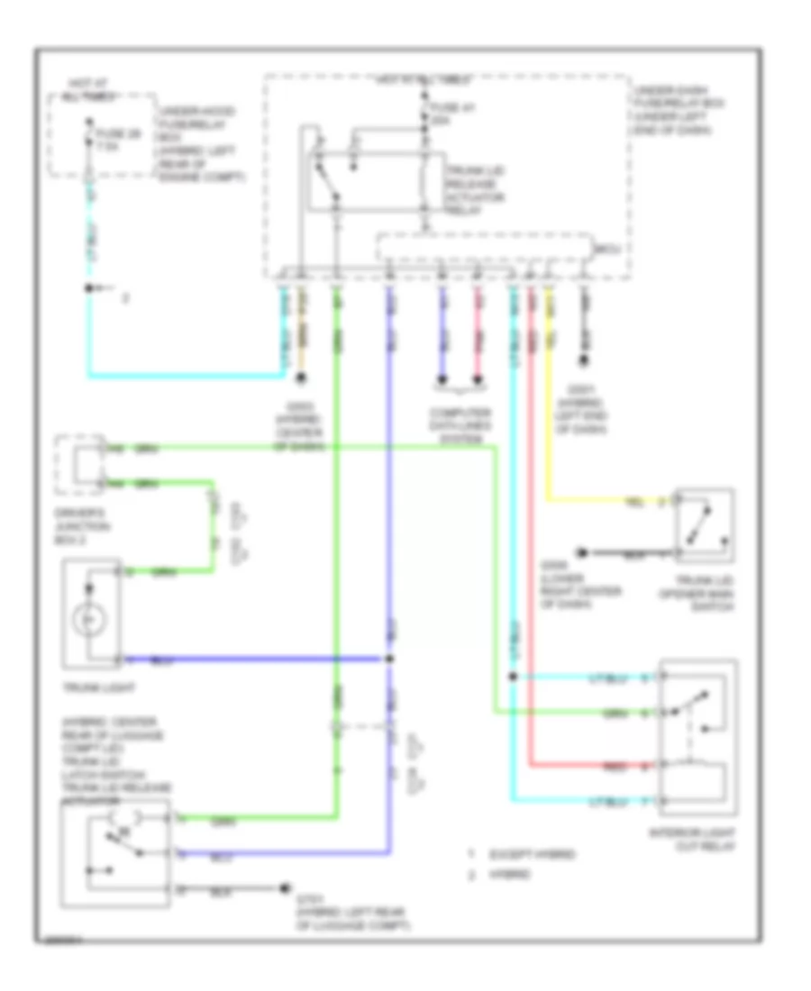
EXTERIOR LIGHTS
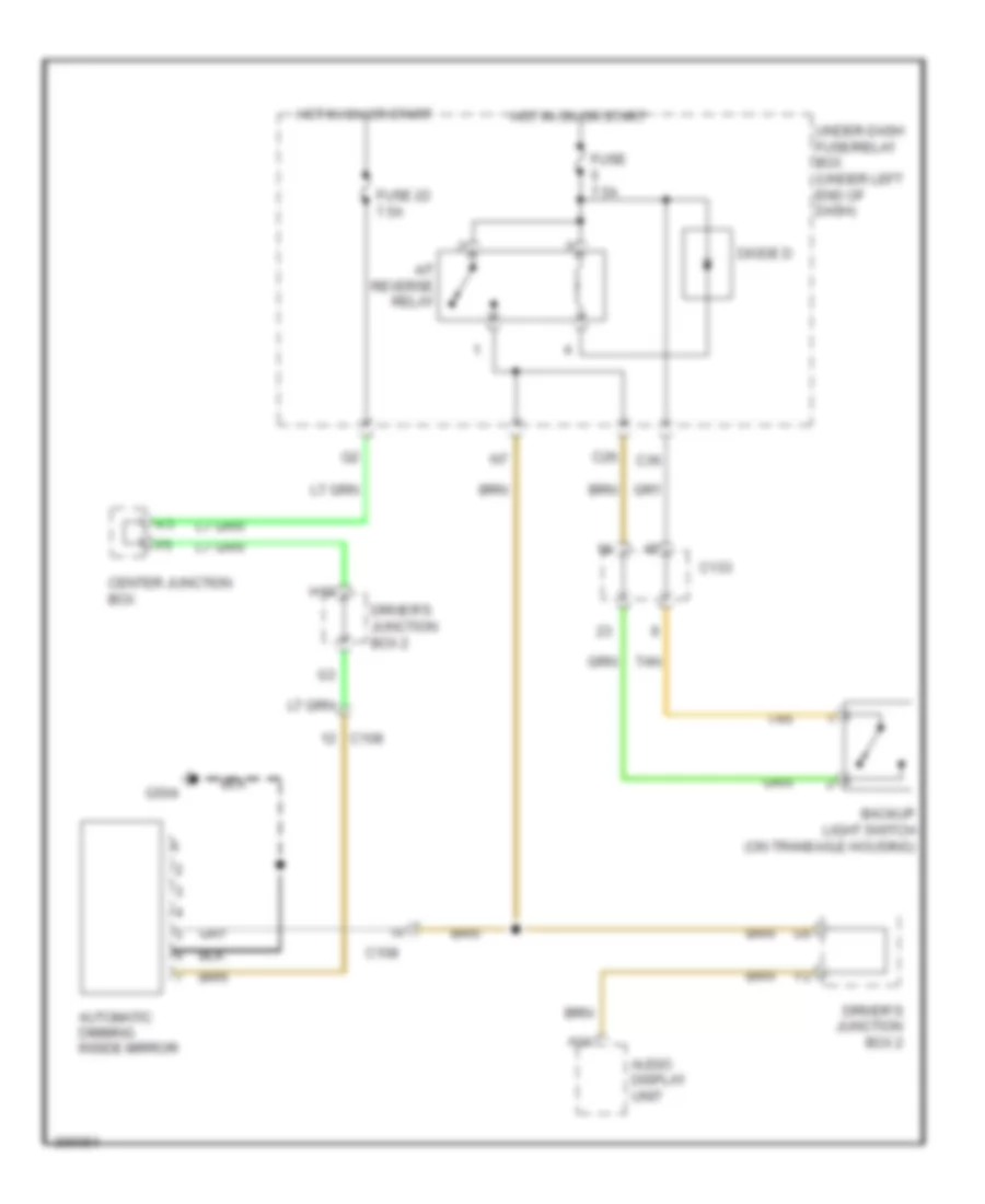
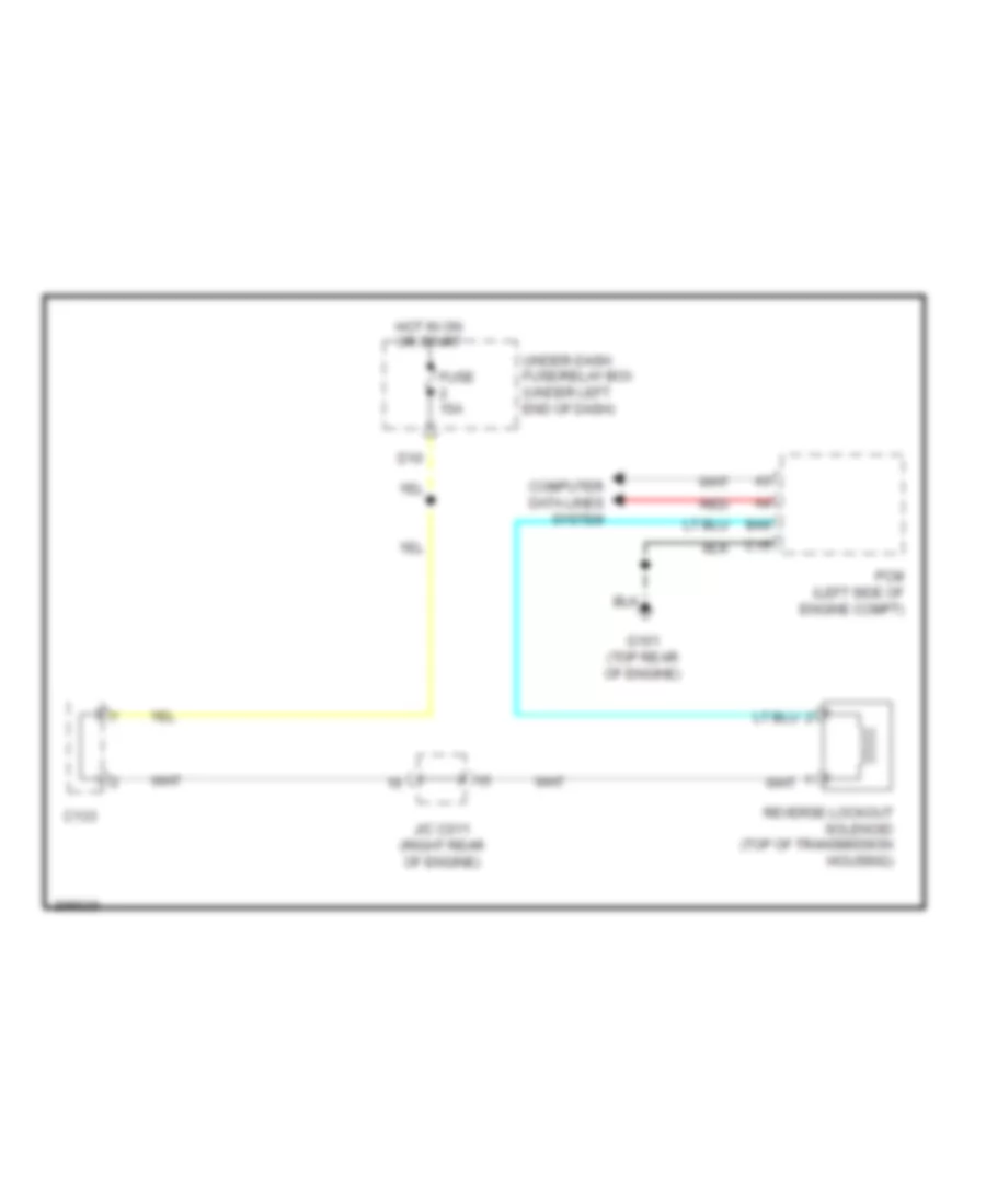
Backup Lamps Wiring Diagram for Acura ILX 2014
List of elements for Backup Lamps Wiring Diagram for Acura ILX 2014:
- (option connector f)
- A/t
- A/t cvt
- A/t gear position indicator
- A14
- Audio navigation unit
- Automatic dimming inside mirror
- B21
- B25
- Backup light switch (m/t) (on transaxle housing)
- C108
- C120 c123
- C121
- C124
- C127
- C131 (cvt) c130 (a/t)
- C133
- C26
- C36
- Cvt
- Cvt & a/t
- D24
- Diode c (a/t & cvt)
- Diode d
- Driver's junction box 2
- Except hybrid
- F15
- Fuse 5 7.5a
- G101 (except hybrid: top rear of engine) (hybrid: left rear of engine)
- G701 (hybrid: left rear of luggage compt)
- Hot in on or start
- Hybrid
- Left backup light
- M/t
- Micu
- Navigation display unit (cvt & a/t) audio display unit (m/t)
- Pcm (left side of engine compt)
- Reverse relay
- Right backup light
- Tan
- Transmission range switch (on transmission housing)
- Under-dash fuse/ relay box (under left end of dash)
Exterior Lamps Wiring Diagram (1 of 2) for Acura ILX 2014
List of elements for Exterior Lamps Wiring Diagram (1 of 2) for Acura ILX 2014:
- B12
- B35
- Brake pedal position switch (top of brake pedal assembly)
- C12
- C121
- C124
- C33
- C38
- Computer data lines system
- D11
- D28
- Except hybrid
- Fuse 10a
- Fuse 15a
- Fuse 20a
- Fuse 34 7.5a
- G701 (hybrid: left rear of luggage compt)
- Hazard warning switch
- High mount brake light
- Hot at all times
- Hybrid
- Interior lights system
- Left license plate light
- Left rear turn signal light
- Left taillight & brake light
- Micu
- Pnk
- Red
- Relay circuit board (in under- hood fuse/ relay box)
- Right license plate light
- Right rear turn signal light
- Right taillight & brake light
- Taillight relay
- Under- hood fuse/ relay box (hybrid: left rear of engine compt)
- Under-dash fuse/relay box (under left end of dash)
Exterior Lamps Wiring Diagram (2 of 2) for Acura ILX 2014
List of elements for Exterior Lamps Wiring Diagram (2 of 2) for Acura ILX 2014:
- Auto
- B-can h
- B-can l
- B-can transceiver
- B32
- C11
- C19
- Combination light switch
- Computer data lines system
- Cruise light dimming circuit
- Fuse 7.5a
- G201 (bottom right front of engine compt)
- G301 (bottom left front of engine compt)
- G502 (hybrid: center of dash)
- G602 (hybrid: under front passenger's seat)
- Gauge control module
- Head
- Headlight switch
- Hot in on or start
- Indicator drive circuit
- K10
- K11
- Left
- Left front side marker light
- Left front turn signal light
- Left turn signal ind
- Lights on ind
- Main circuit
- Micu
- Off
- Off park
- Park
- Pnk
- Red
- Right
- Right front side marker light
- Right front turn signal light
- Right turn signal ind
- Sunlight sensor (top center of dash)
- T13
- T14
- Turn signal switch
- Under-dash fuse/relay box (under left end of dash)
GROUND DISTRIBUTION
Ground Distribution Wiring Diagram, Except Hybrid (1 of 4) for Acura ILX 2014
List of elements for Ground Distribution Wiring Diagram, Except Hybrid (1 of 4) for Acura ILX 2014:
- (m/t) clutch interlock switch
- (m/t) clutch pedal position switch
- (under left end of dash) under-dash fuse/relay box
- A19
- Accessory relay
- Battery sensor
- Blower motor relay
- Brake fluid level switch
- C104
- C108
- C109
- C125
- C136
- C19
- Climate control unit
- Console accessory power socket relay
- D/l dr unlock relay
- D/l lock relay
- D/l unlock relay
- Data link connector (dlc)
- Driver's door lock actuator/ knob switch/key cylinder switch
- Driver's door outer handle
- Driver's power window motor
- Engine
- Eps control unit
- Front passenger's door lock actuator/ knob switch
- Front passenger's power window switch
- G1 (under battery)
- G2 (right rear of engine compt)
- G3 (near battery)
- G401
- G403 (right kick panel)
- G501
- G503
- G801
- Gauge control module
- J/c c007 (in driver's door)
- Left power mirror
- Micu
- Moonroof control unit/ motor
- P20
- Power control unit
- Power mirror switch
- Power transistor
- Power window master switch
- Rear window defogger
- Relay circuit board
- Security hood switch
- Tpms control unit
- Transmission housing
- Trunk lid release actuator relay
- Vsa off switch
- W/ navigation
- W/o navigation
- Washer main relay
- Windshield washer motor relay
- Windshield wiper intermittent relay
- Windshield wiper motor relay
Ground Distribution Wiring Diagram, Except Hybrid (2 of 4) for Acura ILX 2014
List of elements for Ground Distribution Wiring Diagram, Except Hybrid (2 of 4) for Acura ILX 2014:
- (2.0l)
- (2.0l) ckp sensor
- (2.0l) cmp sensor
- (2.0l) egr valve/ egr valve position sensor
- (2.0l) secondary ho2s (sensor 2) shield
- (2.4l) cmp sensor a
- (2.4l) cmp sensor b
- (2.4l) vtc control solenoid valve
- (w/ hid) right headlamp (low)
- 2.0l
- 2.4l
- A/t clutch pressure control solenoid valve a
- A/t clutch pressure control solenoid valve b
- A/t clutch pressure control solenoid valve c
- A19
- A36
- A37
- B10
- B17
- Backup control unit
- C111
- C123
- C127
- C130
- C133
- C134
- C138
- C15
- C20
- Center junction box
- Ckp sensor
- Data link connector (dlc)
- Driver junction box 1
- G101 (top rear of engine)
- G102 (2.4l) (left side of engine)
- G201 (bottom right front of engine compt)
- G402 (right kick panel)
- G505
- Ignition coil 1
- Ignition coil 2
- Ignition coil 3
- Ignition coil 4
- Keyless access control unit
- Knock sensor shield
- Left fog lamp
- Pcm
- Pcm shield
- Right fog lamp
- Right front side marker light
- Right front turn signal light
- Right headlamp (high)
- Rocker arm oil control solenoid
- Rocker arm oil pressure switch
- Secondary ho2s (sensor 2) shield
- Srs unit
- Steering gear box
- Transmission range switch
- Windshield washer motor
- Windshield wiper motor
Ground Distribution Wiring Diagram, Except Hybrid (3 of 4) for Acura ILX 2014
List of elements for Ground Distribution Wiring Diagram, Except Hybrid (3 of 4) for Acura ILX 2014:
- (under left end of dash) under-dash fuse/relay box
- (w/ hid) left headlamp (low)
- (w/ navigation) navigation display unit
- (w/ navigation) paddle shifter (downshift switch)
- (w/o navigation) auto display unit
- (w/o navigation) hvac display unit
- A/c condenser fan motor
- A10
- Answer back buzzer
- Auto navigation switch panel
- C12
- C121
- C13
- Cable reel
- Cruise control combination switch
- Eld
- Electric steering lock
- Fan control relay
- G202 (right front of engine compt)
- G301 (bottom left front of engine compt)
- G302
- G502
- G701
- Gauge control module
- High mount brake lamp
- Interface dial
- Left backup lamp
- Left front side marker lamp
- Left front turn signal lamp
- Left headlamp (high)
- Left license plate lamp
- Left rear turn signal lamp
- Left taillight & brake lamp
- Right backup lamp
- Right license plate lamp
- Right rear turn signal lamp
- Right taillight & brake lamp
- Steering angle sensor
- T8 (in steering wheel)
- Trunk lid latch switch/trunk lid release actuator
- Trunk lid outer handle switch
- Vsa modulator control unit
Ground Distribution Wiring Diagram, Except Hybrid (4 of 4) for Acura ILX 2014
List of elements for Ground Distribution Wiring Diagram, Except Hybrid (4 of 4) for Acura ILX 2014:
- (under left end of dash) under-dash fuse/relay box
- (w/ navigation) audio navigation unit
- (w/ navigation) front passenger's seat belt buckle switch
- (w/ navigation) hfl- navigation anc/active sound control microphone
- (w/ navigation) park pin switch
- (w/o navigation) audio unit
- (w/o navigation) hfl- anc/active sound control microphone
- A/t gear position indicator
- A21
- Acuralink control unit (xm receiver)
- Anc/active sound control unit
- Automatic dimming inside mirror
- B32
- C104
- C108
- C113
- C114
- C116
- C117
- C118
- C125
- Console accessory power socket
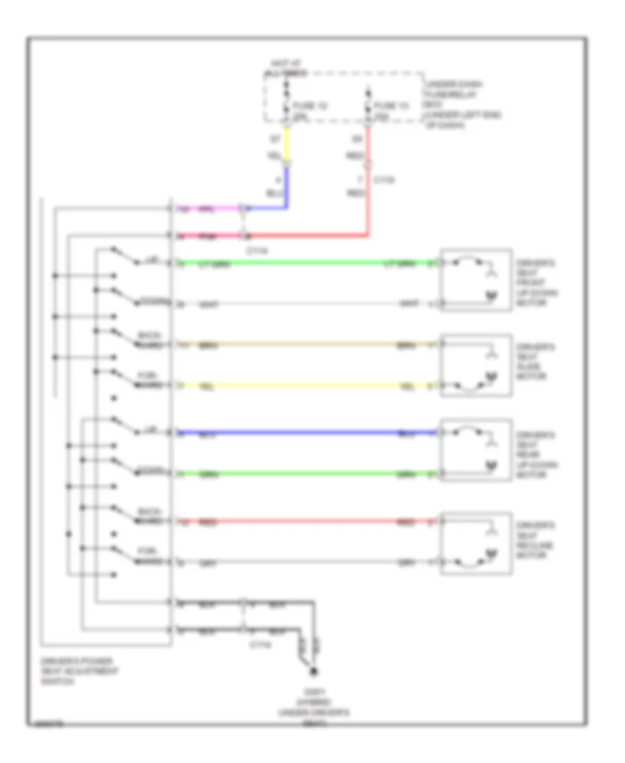
- Driver's power seat adjustment switch
- Driver's seat belt buckle switch
- Driver's seat heater
- Driver's seat heater relay (high)
- Driver's seat heater relay (low)
- Driver's seat heater switch
- Driver's seat position sensor
- Driver's vanity mirror lamp
- Engine start/stop switch
- Front passenger's door outer handle
- Front passenger's seat heater
- Front passenger's seat heater relay (high)
- Front passenger's seat heater relay (low)
- Front passenger's seat heater switch
- Fuel tank unit
- G504
- G506 (lower right center of dash)
- G601
- G602
- Glove box lamp
- Homelink unit
- Left rear door lock actuator/ knob switch
- Left rear power window switch
- Micu
- Ods unit
- Passenger's vanity mirror lamp
- Power control unit
- Right power mirror
- Right rear door lock actuator/ knob switch
- Right rear power window switch
- Roof console module
- Stereo amplifier
- Sunlight sensor
- Trunk lid opener main switch
- W/ navigation
Ground Distribution Wiring Diagram, Hybrid (1 of 4) for Acura ILX 2014
List of elements for Ground Distribution Wiring Diagram, Hybrid (1 of 4) for Acura ILX 2014:
- (under left end of dash) under-dash fuse/relay box
- A19
- Accessory relay
- Battery sensor
- Blower motor relay
- Brake fluid level switch
- C103
- C108
- C109
- C129
- C135
- C19
- Climate control unit
- Console accessory power socket relay
- D/l dr unlock relay
- D/l lock relay
- D/l unlock relay
- Data link connector (dlc)
- Dc-dc converter
- Dc-dc converter shield
- Driver's door lock actuator/ knob switch/key cylinder switch
- Driver's door outer handle
- Driver's power window motor
- Econ switch
- Engine
- Eps control unit
- Front passenger's door lock actuator/ knob switch
- Front passenger's power window switch
- G1 (under battery)
- G2 (right rear of engine compt)
- G3 (near battery)
- G4 (right front of battery module)
- G401 (left end of dash)
- G403 (right kick panel)
- G5 (left rear of engine compt)
- G501 (left end of dash)
- G503 (center of dash)
- G801 (right rear of luggage compt)
- Gauge control module
- J/c c008 (driver's door)
- Left power mirror
- Micu
- Moonroof control unit/ motor
- P20
- Power control unit
- Power mirror switch
- Power transistor
- Power window master switch
- Rear window defogger
- Relay circuit board
- Security hood switch
- Tpms control unit
- Transmission housing
- Trunk lid release actuator relay
- Vsa off switch
- Washer main relay
- Windshield washer motor relay
- Windshield wiper intermittent relay
- Windshield wiper motor relay
Ground Distribution Wiring Diagram, Hybrid (2 of 4) for Acura ILX 2014
List of elements for Ground Distribution Wiring Diagram, Hybrid (2 of 4) for Acura ILX 2014:
- A19
- B10
- B17
- Backup control unit
- C111
- C130
- C132
- C136
- C15
- C20
- Center junctuin box
- Ckp sensor
- Cmp sensor
- Cvt clutch pressure control solenoid valve
- Data link connector (dlc)
- Driver junctuin box 1
- Egr valve/ egr valve position sensor
- Exhaust side ignition coil 1
- Exhaust side ignition coil 2
- Exhaust side ignition coil 3
- Exhaust side ignition coil 4
- G101 (left rear of engine)
- G201 (bottom right front of engine compt)
- G202 (right front of engine compt)
- Intake side ignition coil 1
- Intake side ignition coil 2
- Intake side ignition coil 3
- Intake side ignition coil 4
- J/c c131 (left rear of engine compt)
- Keyless access control unit
- Left fog lamp
- Pcm
- Pcm shield
- Power unit
- Right fog lamp
- Right front side marker lamp
- Right front turn signal lamp
- Right headlamp (high)
- Right headlamp (low)
- Rocker arm oil control solenoid a
- Rocker arm oil control solenoid b
- Secondary ho2s (sensor 2)
- Servo unit
- Transmission range switch
- Vsa modulator control unit
- Windshield washer motor
- Windshield wiper motor
Ground Distribution Wiring Diagram, Hybrid (3 of 4) for Acura ILX 2014
List of elements for Ground Distribution Wiring Diagram, Hybrid (3 of 4) for Acura ILX 2014:
- (under left end of dash) under-dash fuse/relay box
- A/c compressor driver
- A/c condenser fan motor
- A36
- A37
- Answer back buzzer
- Auto navigation switch panel
- Auxiliary electric water pump
- Battery module
- C12
- C124
- C127
- C13
- C138
- Cable reel
- Cruise control combination switch
- Cvt drive pulley pressure control solenoid valve
- Cvt driven pulley pressure control solenoid valve
- Eld
- Electric steering lock
- Fan control relay
- G301 (bottom left front of engine compt)
- G302
- G402 (right kick panel)
- G502 (center of dash)
- G505 (under front of center console)
- G701 (left rear of luggage compt)
- G901 (right end of battery module)
- Gauge control module
- High mount brake lamp
- Interface dial
- Ipu fan module
- J/c c013
- J/c c015
- Left backup lamp
- Left front side marker lamp
- Left front turn signal lamp
- Left headlamp (high)
- Left headlamp (low)
- Left license plate lamp
- Left rear turn signal lamp
- Left taillight & brake lamp
- Mcm shield
- Motor rotor position sensor shield
- Navigation display unit
- Paddle shifter (downshift switch)
- Right backup lamp
- Right license plate lamp
- Right rear turn signal lamp
- Right taillight & brake lamp
- Srs unit
- Steering angle sensor
- Steering gear box
- T6 (on transmission housing)
- T8 (in steering wheel)
- Trunk lid latch switch/trunk lid release actuator
- Trunk lid outer handle switch
- V sensor 1
- V sensor 2
- V sensor 3
- V sensor 4
Ground Distribution Wiring Diagram, Hybrid (4 of 4) for Acura ILX 2014
List of elements for Ground Distribution Wiring Diagram, Hybrid (4 of 4) for Acura ILX 2014:
- (under left end of dash) under-dash fuse/relay box
- A/t gear position indicator
- A21
- A32
- Acuralink control unit (xm receiver)
- Audio navigation unit
- Automatic dimming inside mirror
- B32
- C103
- C108
- C113
- C114
- C116
- C117
- C119
- C125
- C129
- Console accessory power socket
- Driver's power seat adjustment switch
- Driver's seat belt buckle switch
- Driver's seat heater
- Driver's seat heater relay (high)
- Driver's seat heater relay (low)
- Driver's seat heater switch
- Driver's seat position sensor
- Driver's vanity mirror lamp
- Engine start/stop switch
- Front passenger's door outer handle
- Front passenger's seat belt buckle switch
- Front passenger's seat heater
- Front passenger's seat heater relay (high)
- Front passenger's seat heater relay (low)
- Front passenger's seat heater switch
- Fuel tank unit
- G504 (lower left center of dash)
- G506 (lower right center of dash)
- G601 (under driver's seat)
- G602 (under front passenger's seat)
- Glove box lamp
- Hfl- navigation anc/active sound control microphone
- Homelink unit
- Left rear door lock actuator/ knob switch
- Left rear power window switch
- Mcm
- Micu
- Mpi module
- Ods unit
- Park pin switch
- Passenger's vanity mirror lamp
- Power control unit
- Right power mirror
- Right rear door lock actuator/ knob switch
- Right rear power window switch
- Roof console module
- Stereo amplifier
- Sunlight sensor
- T17 (right end of battery module)
- Trunk lid opener main switch
HEADLIGHTS
Headlights Wiring Diagram for Acura ILX 2014
List of elements for Headlights Wiring Diagram for Acura ILX 2014:
- (bottom left front of engine compt) g301
- (optional connector)
- Air conditioning system
- Auto
- B-can h
- B-can l
- B-can transceiver
- C102
- C103
- C136
- C138
- C14
- C18
- Combination light switch
- Computer data lines system
- Cruise lights circuit
- D20
- D29
- Dimmer/ flash-to-pass switch
- Driver's junction box 1
- Except hybrid
- Fog light ind
- Fog light relay (in under-hood fuse/relay box)
- Fog light switch
- Front
- Fuse 10a
- Fuse 15a
- Fuse 20a
- Fuse 7.5a
- G201 (bottom right front of engine compt)
- G301 (bottom left front of engine compt)
- G506 (lower right center of dash)
- Gauge control module
- Head
- Headlight switch
- Hid unit
- High
- High beam ind
- Hot at all times
- Hot in or on start
- Hybrid
- Indicator drive circuit
- Left fog light
- Left headlight (high)
- Left headlight (low) (w/ hid)
- Left headlight (low) (w/o hid)
- Left headlight low beam relay
- Lights on ind
- Low
- Main circuit
- Micu
- Off
- Park
- Parking brake switch (base of parking brake lever)
- Passing
- Pnk
- Red
- Relay circuit board (in under-hood fuse/relay box)
- Right fog light
- Right headlight (high)
- Right headlight (low) (w/ hid)
- Right headlight (low) (w/o hid)
- Right headlight low beam relay
- Sunlight sensor (top center of dash)
- T11
- T12
- Under- hood fuse/ relay box (hybrid: left rear of engine compt)
- Under-dash fuse/relay box (under left end of dash)
- W/ hid
- W/ navigation
- W/o hid
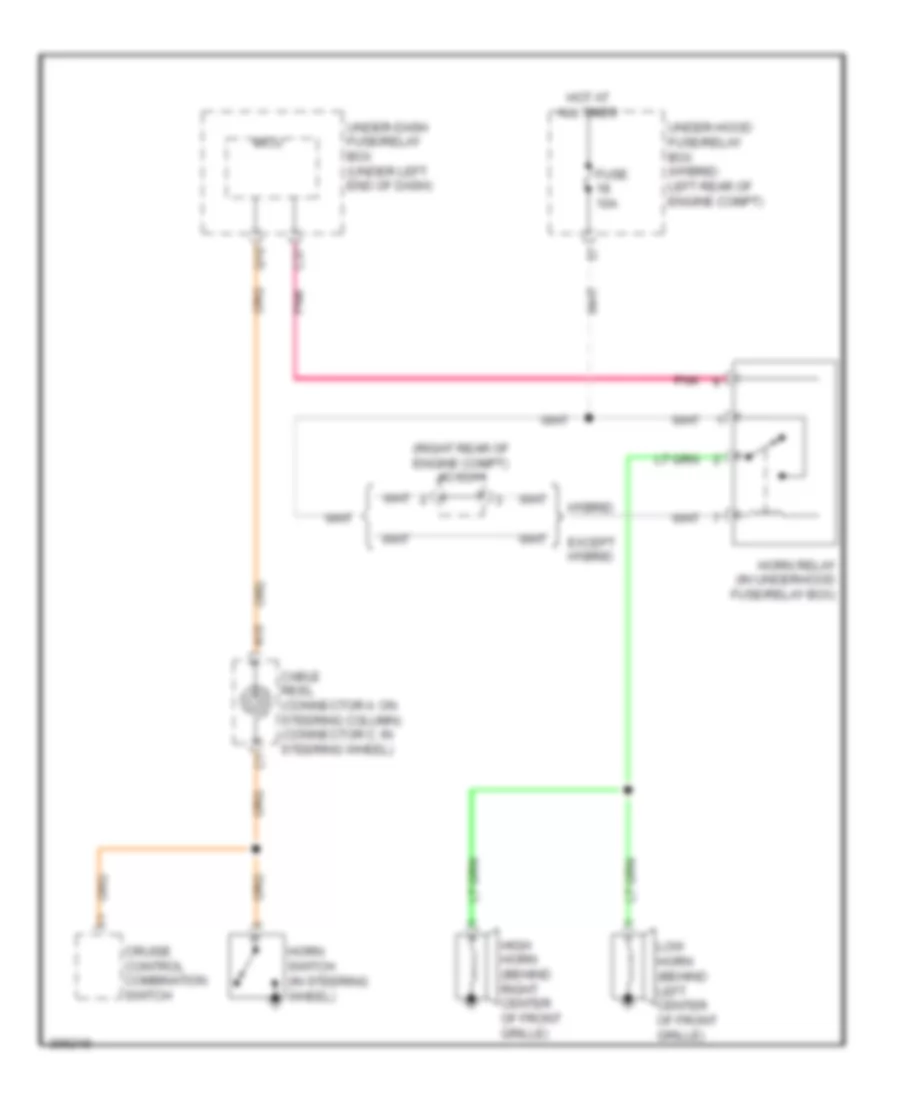
HORN
Horn Wiring Diagram for Acura ILX 2014
List of elements for Horn Wiring Diagram for Acura ILX 2014:
- (right rear of engine compt) j/c c011
- A10
- C37
- Cable reel (connector a: on steering column) (connector c: in steering wheel)
- Cruise control combination switch
- Except hybrid
- Fuse 10a
- High horn (behind right center of front grille)
- Horn relay (in underhood fuse/relay box)
- Horn switch (in steering wheel)
- Hot at all times
- Hybrid
- Low horn (behind left center of front grille)
- Micu
- Pnk
- Q10
- Under-dash fuse/relay box (under left end of dash)
- Under-hood fuse/relay box (hybrid: left rear of engine compt)
INSTRUMENT CLUSTER
Instrument Cluster Wiring Diagram (1 of 2) for Acura ILX 2014
List of elements for Instrument Cluster Wiring Diagram (1 of 2) for Acura ILX 2014:
- (amber)
- (canada)
- (hybrid: center of dash) g502
- Abs ind
- Amp
- Anti-lock brakes system
- Auto stop ind
- B-can h
- B-can l
- B-can transceiver
- Brake ind (red)
- Brake system ind
- Charging system ind
- Circuit control 5v
- Compulsory turning- off circuit
- Compulsory turning- on circuit
- Compulsory turning-off circuit
- Computer data lines system
- Constant current driver for ambient
- Constant current driver for dial/scale
- Constant current driver for gear disp
- Constant current driver for mid lower
- Constant current driver for mid upper
- Constant current driver for mid upper (white)
- Constant current driver for pointer
- Coolant temperature gauge
- Coolant temperature ind
- Cruise control ind
- Cruise control main switch ind
- Cruise control system
- Cruise light dimming circuit
- Dimming circuit
- Door ind
- Eco ind
- Eps ind
- Except hybrid
- Exterior lights system
- F-can h
- F-can l
- F-can transceiver
- Front fog light ind
- Fuel empty ind
- Fuel gauge
- G503 (hybrid: center of dash)
- Gauge control module
- Gear position display
- High beam ind
- Hybrid
- Illumi (+)
- Illumi (-)
- Illumination control
- Illumination encoder
- Ima system ind
- Ima/assist charge
- Immobilizer ind
- Indicator drive circuit
- Interior lights system
- Keyless access system ind
- Left turn signal ind
- Lights-on ind
- Low oil pressure ind
- Low tire pressure ind
- Main circuit
- Malfunction ind lamp (mil)
- Multi-information display
- Multi-information ind
- Pnk
- Pressure ind
- Red
- Right turn signal ind
- Seat belt reminder ind
- Security ind
- Side air bag cut-off ind
- Speaker
- Speedometer
- Srs ind
- Tachometer
- Trip reset
- Vsa ind
- Vsa off ind
- Wiper/washer system
Instrument Cluster Wiring Diagram (2 of 2) for Acura ILX 2014
List of elements for Instrument Cluster Wiring Diagram (2 of 2) for Acura ILX 2014:
- (or tan)
- A/t gear position indicator (a/t & cvt)
- B29
- B32
- B33
- B34
- B40
- Brake fluid level switch (on brake master cylinder reservoir)
- C102
- C103
- C104
- C111
- C125
- Computer data lines system
- D26
- D27
- D28
- Driver's door switch (in left "b" pillar)
- Driver's junction box 1
- Econ switch (hybrid)
- Except hybrid
- Front passenger's door switch (in right "b" pillar)
- Fuel tank unit (top of fuel tank)
- Fuse 10a
- Fuse 7.5a
- G401 (hybrid: left end of dash)
- G501 (hybrid: left end of dash)
- G602 (hybrid: under front passenger's seat)
- Hot at all times
- Hot in on or start
- Hybrid
- Interior lights system
- Left rear door switch (in left rear "c" pillar)
- Micu
- Oil pressure switch (except hybrid: near oil filter) (hybrid: left rear of engine)
- Parking brake switch (base of parking brake lever)
- Pcm (left side of engine compt)
- Red
- Right rear door switch (in right rear "c" pillar)
- Under-dash fuse/relay box (under left end of dash)
- Under-hood fuse/relay box (hybrid: left rear of engine compt)
INTERIOR LIGHTS
Courtesy Lamps Wiring Diagram (1 of 2) for Acura ILX 2014
List of elements for Courtesy Lamps Wiring Diagram (1 of 2) for Acura ILX 2014:
- B22
- B29
- B32
- B33
- B34
- B40
- C102
- C103
- C108
- C12
- C121
- C124
- C19
- Computer data lines system
- Connector) (optional
- D18
- Driver's junction box 2
- Driver's vanity mirror light
- Except hybrid
- Fuse 7.5a
- G504 (hybrid: lower left center of dash)
- G602 (hybrid: under front passenger's seat)
- G701 (hybrid: left rear of luggage compt)
- Hot in on or start
- Hybrid
- Interior light cut relay
- Lock
- Micu
- N13
- Off
- Open
- Passenger's vanity mirror light
- Pnk
- Red
- Roof console module
- Trunk lid latch switch/ trunk lid release actuator (hybrid: center rear of luggage compt lid)
- Trunk light
- Un lock
- Under-dash fuse/relay box (under left end of dash)
Courtesy Lamps Wiring Diagram (2 of 2) for Acura ILX 2014
List of elements for Courtesy Lamps Wiring Diagram (2 of 2) for Acura ILX 2014:
- Ceiling light
- Driver's door switch (in driver's "b" pillar)
- Driver's footwell light
- Front passenger's air bag cutoff indicator
- Front passenger's door switch (in front passenger's "b" pillar)
- Front passenger's footwell light
- Fuse 20a
- Fuse 7.5a
- G506 (lower right center of dash)
- Glove box light
- Hot at all times
- Hybrid
- Left rear door switch (in left rear "c" pillar)
- Off
- Pnk
- Red
- Relay circuit board (in under-hood fuse/relay box)
- Right rear door switch (in right rear "c" pillar)
- Taillight relay
- Under-hood fuse/relay box (hybrid: left rear of engine compt)
Entry Light Timer Wiring Diagram (1 of 2) for Acura ILX 2014
List of elements for Entry Light Timer Wiring Diagram (1 of 2) for Acura ILX 2014:
- B22
- B29
- B32
- B33
- B34
- B40
- C102
- C103
- C108
- C121
- C124
- Computer data lines system
- D18
- Driver's door switch (in driver's "b" pillar)
- Driver's footwell light
- Driver's junction box 2
- Driver's vanity mirror light
- Except hybrid
- Front passenger's door switch (in front passenger's "b" pillar)
- Front passenger's footwell light
- Fuse 5 7.5a
- G504 (hybrid: lower left center of dash)
- G602 (hybrid: under front passenger's seat)
- G701 (hybrid: left rear of luggage compt)
- Hot in on or start
- Hybrid
- Interior light cut relay
- Left rear door switch (in left rear "c" pillar)
- Lock
- Micu
- N13
- Off
- Open
- Passenger's vanity mirror light
- Pnk
- Red
- Right rear door switch (in right rear "c" pillar)
- Roof console module
- Trunk lid latch switch/ trunk lid release actuator (hybrid: center rear of luggage compt lid)
- Trunk light
- Un lock
- Under-dash fuse/relay box (under left end of dash)
Entry Light Timer Wiring Diagram (2 of 2) for Acura ILX 2014
List of elements for Entry Light Timer Wiring Diagram (2 of 2) for Acura ILX 2014:
- B10
- B12
- B14
- B18
- B29
- B31
- C104 (hybrid) c102 (except hybrid)
- C109
- C113
- Ceiling light
- Computer data lines system
- Control unit
- Door lock knob
- Driver's door key cylinder switch
- Driver's door lock actuator/knob switch/ key cylinder switch
- Driver's door lock knob switch
- Fuse 28 7.5a
- G501 (hybrid: left end of dash)
- G503 (hybrid: center of dash)
- Hot at all times
- Hybrid
- J/c c008 (hybrid) j/c c007 (except hybrid) (hybrid: driver's door) (except hybrid: in driver's door)
- Key
- Keyless access control unit (center of dash)
- Off
- Pnk
- Power window master switch
- Red
- Remote
- Rf unit 1
- Rf unit 2
- Under-hood fuse/relay box (hybrid: left rear of engine compt)
Instrument Illumination Wiring Diagram (1 of 2) for Acura ILX 2014
List of elements for Instrument Illumination Wiring Diagram (1 of 2) for Acura ILX 2014:
- (hybrid: center of dash) g503
- (hybrid: under front passenger's seat) g602
- A13
- A14
- Audio remote switch
- Auto
- B-can h
- B-can l
- B27
- B32
- C109
- C12
- C14
- C19
- Cable reel (connector a: on steering column) (connector c: in steering wheel)
- Combination light switch
- Compulsory turning-off circuit
- Computer data lines system
- Constant current driver for ambient
- Constant current driver for dial/scale
- Constant current driver for gear disp
- Constant current driver for mid lower
- Constant current driver for mid upper
- Constant current driver for midd upper (white)
- Constant current driver for pointer
- Courtesy lamps circuit
- Cruise control combination switch
- D28
- Dimming circuit
- Display information multi-
- Front passenger's air bag cutoff indicator
- Fuse 7.5a
- G501 (hybrid: left end of dash)
- G502 (hybrid: center of dash)
- G503 (hybrid: center of dash)
- Gauge control module
- Head
- Headlight switch
- Hot in on or start
- Illumi (+)
- Illumi (-)
- Illumination control
- Illumination encoder
- J/c c008 (hybrid) j/c c007 (except hybrid) (in driver's door)
- Left
- Main circuit
- Micu
- Off
- Paddle shifter + (upshift switch)
- Paddle shifter - (downshift switch)
- Park
- Pnk
- Power mirror switch
- Power window master switch
- Red
- Relay circuit board (in under-hood fuse/relay box)
- Right
- S10
- Sunlight sensor (top center of dash)
- T13
- T14
- Taillight relay
- Transceiver b-can
- Turn signal switch
- Under-dash fuse/relay box (under left end of dash)
Instrument Illumination Wiring Diagram (2 of 2) for Acura ILX 2014
List of elements for Instrument Illumination Wiring Diagram (2 of 2) for Acura ILX 2014:
- A/t gear position indicator
- Audio navigation switch panel (w/ navigation)
- Audio navigation unit (w/ navigation)
- B12
- C107
- C108
- Center junction box
- Climate control unit
- Driver's junction box 2
- Driver's seat heater switch
- Econ switch (hybrid)
- Front passenger's seat heater switch
- Fuse 10a
- Fuse 20a
- G502 (hybrid: center of dash)
- Hazard warning switch
- Hot at all times
- Navigation display unit
- Red
- Roof console module
- Under-hood fuse/relay box (hybrid: left rear of engine compt)
- Vsa off switch
NAVIGATION
Home Link Remote Control Wiring Diagram for Acura ILX 2014
List of elements for Home Link Remote Control Wiring Diagram for Acura ILX 2014:
- Cpu
- Fuse 29 10a
- G504 (hybrid: lower center of dash)
- Homelink unit (in roof console)
- Hot at all times
- Ind
- Pnk
- Red
- Roof console module
- Sw 1
- Sw 2
- Sw 3
- Under-hood fuse/relay box (hybrid: left rear of engine compt)
Navigation Wiring Diagram (1 of 5) for Acura ILX 2014
List of elements for Navigation Wiring Diagram (1 of 5) for Acura ILX 2014:
- (except hybrid) usb port 5p connector
- (hybrid) usb port 5p connector
- (hybrid: under front passenger's seat) g602
- A10
- A11
- A12
- A13
- A14
- A15
- A16
- A17
- A18
- A19
- A20
- A21
- A22
- A23
- A24
- A25
- A26
- A27
- A28
- A29
- A30
- A31
- A32
- Acuralink control unit (xm receiver) (right front of luggage compt)
- Am/fm/xm antenna
- Amplifier amp
- Audio navigation unit
- B26
- B28
- C002
- C003
- C10
- C107
- C108
- C11
- C110
- C12
- C137
- C139
- C140
- Computer data lines system
- Except hybrid
- Fuse 10a
- Fuse 7.5a
- Gps antenna
- H10
- H11
- H12
- H13
- H14
- H15
- H16
- H17
- H18
- H19
- H20
- H21
- H22
- H23
- H24
- H25
- Hot at all times
- Hot in or on start
- Hot w/ accessory relay energized
- Hybrid
- J/c c002 & j/c c003 (right center of dash)
- Lna
- Navigation service check 2p connector (under front of center console)
- Nca
- P14
- Pnk
- Red
- Under-dash fuse/relay box (under left end of dash)
- Under-hood fuse/relay box (hybrid: left rear of engine compt)
Navigation Wiring Diagram (2 of 5) for Acura ILX 2014
List of elements for Navigation Wiring Diagram (2 of 5) for Acura ILX 2014:
- C107
- C108
- Center junction box
- Driver's junction box 2
- Fuse 7.5a
- G502 (hybrid: center of dash)
- G504 (hybrid: lower left center of dash)
- H10
- Handsfreelink control unit (under center console)
- Hfl-navigation-anc/active sound control microphone (in roof console)
- Hot at all times
- Interface dial
- J/c c005 (except hybrid) j/c c006 (hybrid) (under center console)
- J/c c006 (except hybrid) j/c c007 (hybrid) (c007: under center console)
- Navigation system
- Pnk
- Red
- Under-dash fuse/relay box (under left end of dash)
Navigation Wiring Diagram (3 of 5) for Acura ILX 2014
List of elements for Navigation Wiring Diagram (3 of 5) for Acura ILX 2014:
- (except hybrid)
- (lower right center of dash) g506
- Anc/active sound control unit
- Audio navigation unit
- Audio remote switch
- Back
- C108
- C15
- C16
- C17
- Cable reel (connector a: on steering column) (connector c: in steering wheel)
- Center junction box
- Ch+
- Ch-
- F10
- F11
- F12
- F13
- F14
- F15
- Fuse 7.5a
- G502 (hybrid: center of dash)
- Hot in on or start
- Interior lights system
- Micu
- Mirrors system
- Mode
- Navigation display unit
- Off hook
- On hook
- Pnk
- Q11
- Rearview camera circuit
- Red
- System data lines computer
- Talk
- Tpms control unit (left end of dash)
- Vol down
- Vol up
Navigation Wiring Diagram (4 of 5) for Acura ILX 2014
List of elements for Navigation Wiring Diagram (4 of 5) for Acura ILX 2014:
- A15
- A17
- A27
- A28
- Audio navigation switch panel
- Audio navigation unit
- Auxiliary jack assembly 5p connector
- C107
- C113
- Climate control unit
- Computer data lines system
- E10
- E11
- E12
- E13
- E14
- E15
- E16
- E17
- E18
- E19
- E20
- E21
- E22
- E23
- E24
- E25
- E26
- E27
- E28
- E29
- E30
- E31
- E32
- E33
- E34
- E35
- E36
- F-canh
- F-canl
- G502 (hybrid: center of dash)
- Gauge control module
- Interior lights system
- Main circuit
- Pnk
- Rearview camera circuit
- Red
- Transceiver f-can
Navigation Wiring Diagram (5 of 5) for Acura ILX 2014
List of elements for Navigation Wiring Diagram (5 of 5) for Acura ILX 2014:
- (hybrid: lower left center of dash) g504
- A10
- A11
- A12
- A13
- A14
- A15
- A16
- A17
- A18
- A19
- A20
- A21
- A22
- A23
- A24
- A26
- Audio navigation unit
- B10
- B11
- B12
- B13
- B14
- B15
- B16
- B17
- B18
- B19
- B20
- B21
- B22
- B23
- B24
- B25
- B26
- B27
- B28
- C102
- C103
- C104
- C109
- C110
- C111
- C116
- C117
- C125
- C129
- Computer data lines system
- Driver's door tweeter
- Except hybrid
- Front center speaker
- Front passenger's door tweeter
- Fuse 20a
- Hot at all times
- Hybrid
- Interior lights system
- Left rear door speaker
- Left rear satellite speaker
- Left tweeter
- Pcm (left side of engine compt)
- Pnk
- Red
- Right rear door speaker
- Right rear satellite speaker
- Right tweeter
- Stereo amplifier (lower left center of dash)
- Subwoofer
- Under-dash fuse/relay box (under left end of dash)
Rear Camera Wiring Diagram for Acura ILX 2014
List of elements for Rear Camera Wiring Diagram for Acura ILX 2014:
- Audio navigation unit
- C107
- C109
- C121
- C124
- Center junction box
- Computer data lines system
- D28
- Driver's junction box 2
- E23
- E27
- Except hybrid
- Fuse 10a
- G502 (hybrid: center of dash)
- G504 (hybrid: lower left center of dash)
- Hot at all times
- Hybrid
- Navigation display unit
- Pnk
- Power distribution system
- Q16
- Rearview camera (hybrid: left rear of luggage compt lid)
- Red
- Under-dash fuse/relay box (under left end of dash)
- Under-hood fuse/relay box (hybrid: left rear of engine compt)
POWER DISTRIBUTION
Power Distribution Wiring Diagram, Except Hybrid (1 of 6) for Acura ILX 2014
List of elements for Power Distribution Wiring Diagram, Except Hybrid (1 of 6) for Acura ILX 2014:
- (under left end of dash) under-dash fuse/relay box
- A/c compressor clutch relay
- A/c condenser fan relay
- Alternator
- Battery
- Blower motor relay
- C109
- C111
- D/l dr unlock relay
- D/l lock relay
- D/l unlock relay
- D12
- Eld
- Eps control unit
- Etcs control relay
- Fuse 1-1 70a
- Fuse 1-3 30a
- Fuse 1-4 30a
- Fuse 1-5 30a
- Fuse 1-6 100a
- Fuse 10a
- Fuse 15a
- Fuse 2-1 50a
- Fuse 2-10 20a
- Fuse 2-11 20a
- Fuse 2-2 60a
- Fuse 2-3 60a
- Fuse 2-4 30a
- Fuse 2-5 30a
- Fuse 2-6 30a
- Fuse 2-8 40a
- Fuse 20a
- Fuse 7.5a
- Left headlight low beam relay
- Magnetic switch
- Micu
- Pgm-fi main relay 1
- Power window master switch
- Power window relay
- Radiator fan relay
- Rear window defogger relay
- Red
- Relay circuit board (in under-hood fuse/relay box)
- Right headlight low beam relay
- Starter
- Starter cut relay 1
- Stereo amplifier
- T101
- Tail light relay
- To accessory relay (diagram 5 of 6)
- To fuse 17 (diagram 2 of 6)
- To fuse 29 (diagram 2 of 6)
- To fuse 44 (diagram 5 of 6)
- To power control unit (diagram 6 of 6)
- To under-dash fuse/relay box (diagram 3 of 6)
- Tpms control unit
- Trunk lid release actuator relay
- Under-dash fuse/ relay box (under left end of dash)
- Under-hood fuse/relay box
- Vsa modulator control unit
- Washer main relay
- Windshield wiper motor relay
Power Distribution Wiring Diagram, Except Hybrid (2 of 6) for Acura ILX 2014
List of elements for Power Distribution Wiring Diagram, Except Hybrid (2 of 6) for Acura ILX 2014:
- 2.4l
- A16
- Acuralink control unit (xm receiver)
- Anc/ active sound control unit (2.4l)
- Audio display unit
- Audio navigation switch panel (2.0l)
- Audio navigation unit (2.0l) audio unit (2.4l)
- Battery sensor
- Brake pedal position switch
- C102
- C108
- C109
- C119
- Center junction box
- D11
- D18
- D28
- Data link connector (dlc)
- Driver's junction box 2
- Fog light relay
- From fuse 1-6 (diagram 1 of 6)
- From fuse 27 (diagram 1 of 6)
- Fuse 10a
- Fuse 15a
- Fuse 20a
- Fuse 7.5a
- Gauge control module
- Hazard warning switch
- Hfl- navigation- anc/active sound control microphone (2.0l)
- Home link unit (2.0l)
- Horn relay
- Ignition coil relay
- Interior light cut relay
- Micu
- N13
- Navigation display unit
- Power window master switch (2.0l)
- Q16
- Sunlight sensor
- To driver's junction box 1 (diagram 6 of 6)
- To under-hood fuse/relay box (diagram 3 of 6)
- Under-dash fuse/relay box (under left end of dash)
- Under-hood fuse/relay box
Power Distribution Wiring Diagram, Except Hybrid (3 of 6) for Acura ILX 2014
List of elements for Power Distribution Wiring Diagram, Except Hybrid (3 of 6) for Acura ILX 2014:
- (under left end of dash) under-dash fuse/relay box
- 2.0l
- 2.4l
- A/c condenser fan relay
- A/c diode a
- A/f sensor (sensor 1)
- A20
- A39
- B13
- B30
- C108
- C110
- C114
- C118
- C120
- C133
- D31
- Driver's power seat adjustment switch
- Driver's seat heater relay (high)
- Driver's seat heater relay (low)
- Eps control unit
- Evap canister vent shut valve
- From power control unit (diagram 6 of 6)
- From under-hood fuse/relay box (diagram 1 of 6)
- From under-hood fuse/relay box (diagram 2 of 6)
- Front passenger's air bag cutoff indicator
- Front passenger's heater relay (high)
- Front passenger's heater relay (low)
- Fuse 10a
- Fuse 15a
- Fuse 20a
- Fuse 7.5a
- Moonroof control unit/ motor
- Ods unit
- P15
- Pcm
- Pgm-fi sub relay
- Pnk
- Red
- Srs unit
- Steering angle sensor
- To driver's junction box 1 (diagram 6 of 6)
- Under-hood fuse/relay box
- Vsa modulator control unit
Power Distribution Wiring Diagram, Except Hybrid (4 of 6) for Acura ILX 2014
List of elements for Power Distribution Wiring Diagram, Except Hybrid (4 of 6) for Acura ILX 2014:
- (under left end of dash) under-dash fuse/relay box
- 2.0l
- 2.4l
- A/t gear position indicator
- A/t gear position indicator (2.0l)
- A15
- A38
- Acura link control unit (xm receiver) (2.0l)
- Anc/active sound control unit
- B25
- B28
- B32
- Backup control unit
- Backup light switch (2.4l)
- Brake pedal position switch
- C10
- C120
- C127
- C13
- C130
- C133
- C28
- C36
- Cmp sensor a
- D10
- D24
- Diode c (2.0l)
- Diode d
- Eld
- Evap canister purge valve
- From power control unit (diagram 6 of 6)
- Fuse 10a
- Fuse 15a
- Fuse 7.5a
- Gauge control module
- Inhibitor relay
- J/c c011 (right rear of engine)
- Keyless access control unit
- Maf sensor/ iat sensor
- Micu
- P18
- Pcm
- Pcm (2.0l)
- Pgm-fi main relay 2
- Q11
- Red
- Reverse lockout solenoid
- Reverse relay
- Secondary ho2s (sensor 2)
- Shift lock solenoid (2.0l)
- Srs unit
- Tan
- To electric steering lock (diagram 6 of 6)
- Tpms control unit
- Transmission range switch
- Under- hood fuse/ relay box
- Under-hood fuse/relay box
- Washer main relay
- Windshield wiper motor relay
Power Distribution Wiring Diagram, Except Hybrid (5 of 6) for Acura ILX 2014
List of elements for Power Distribution Wiring Diagram, Except Hybrid (5 of 6) for Acura ILX 2014:
- (optional connector f)
- (under left end of dash) under-dash fuse/relay box
- 2.0l
- 2.4l
- A/t gear position indicator
- A14
- A24
- Accessory relay
- Acura link control unit (xm receiver)
- Audio navigation switch panel
- Audio navigation unit (2.0l) audio unit (2.4l)
- Automatic dimming inside mirror
- B26
- Backup control unit
- C104
- C107
- C108
- C109
- C110
- C113
- C125
- C17
- Center junction box
- Climate control unit
- Console accessory power socket
- Console accessory power socket relay
- D/l dr unlock relay
- D/l lock relay
- D/l unlock relay
- Driver's junction box 1
- Driver's junction box 2
- Driver's seat heater switch
- From fuse 25 (diagram 1 of 6)
- From power control unit (diagram 6 of 6)
- From under-dash fuse/relay box (diagram 1 of 6)
- Front passenger's heater switch
- Front passenger's power window switch
- Fuse 20a
- Fuse 7.5a
- G503
- G601
- H10
- Hfl- navigation- anc/active sound microphone
- Hvac display unit
- Interface dial (2.0l)
- Keyless access control unit
- Micu
- Navigation display unit (2.0l)
- P14
- P20
- Power mirror switch
- Power window master switch
- Rear window defogger relay
- Red
- Relay circuit board
- S10
- Trunk lid release actuator relay
- Under-hood fuse/relay box
- Windshield washer motor relay
Power Distribution Wiring Diagram, Except Hybrid (6 of 6) for Acura ILX 2014
List of elements for Power Distribution Wiring Diagram, Except Hybrid (6 of 6) for Acura ILX 2014:
- (diagram 1 of 6)
- (left end of dash) backup control unit
- 5v reg
- A13
- A28
- A42
- B10
- B11
- B16
- B25
- B32
- C10
- C103
- C11
- C12
- C13
- C14
- C15
- C16
- C17
- C18
- C19
- C20
- C21
- C22
- C23
- C24
- C25
- C26
- C27
- C28
- C29
- C30
- C31
- C32
- C33
- C34
- C35
- C36
- Computer data lines system
- Data link connector (dlc)
- Driver's junction box 1
- Electric steering lock (on steering column)
- Engine controls system
- Engine start/stop switch
- From driver's o junction box 2 (diagram 2 of 6)
- From power control unit (diagram 6 of 6)
- From under-dash fuse/relay box (diagram 3 of 6)
- From under-dash fuse/relay box (diagram 4 of 6)
- From under-dash fuse/relay box e
- G501
- G502
- G506 (lower right center of dash)
- G602
- Gauge control module
- H10
- Immobilizer i/f
- Keyless access control unit (center of dash)
- Lf ant
- Micu
- P11
- P19
- Parking brake switch (base of parking brake lever)
- Pcm
- Pnk
- Power control unit (left side of dash)
- Red
- To accessory relay (diagram 5 of 6)
- To to under-dash fuse/relay box (diagram 6 of 6)
- To under-dash fuse/relay box (diagram 3 of 6)
- To under-dash fuse/relay box (diagram 4 of 6)
- To under-dash fuse/relay box (diagram 5 of 6)
- To under-dash fuse/relay box (diagram 6 of 6)
- Transmissions system
- Under-dash fuse/relay box (under left end of dash)
Power Distribution Wiring Diagram, Hybrid (1 of 6) for Acura ILX 2014
List of elements for Power Distribution Wiring Diagram, Hybrid (1 of 6) for Acura ILX 2014:
- (left rear of engine compt) under-hood fuse/relay box
- (under left end of dash) under-dash fuse/relay box
- A/c compressor clutch relay
- A/c condenser fan relay
- Battery
- Blower motor relay
- C109
- C111
- D/l dr unlock relay
- D/l lock relay
- D/l unlock relay
- D12
- Eld
- Eps control unit
- Etcs control relay
- Fuse 1-1 70a
- Fuse 1-2 40a
- Fuse 1-3 30a
- Fuse 1-4 30a
- Fuse 1-5 30a
- Fuse 1-6 100a
- Fuse 10a
- Fuse 15a
- Fuse 2-1 50a
- Fuse 2-10 20a
- Fuse 2-11 20a
- Fuse 2-2 60a
- Fuse 2-3 60a
- Fuse 2-4 30a
- Fuse 2-5 30a
- Fuse 2-6 30a
- Fuse 2-8 40a
- Fuse 20a
- Fuse 7.5a
- G5 (left rear of engine compt)
- Left headlight low beam relay
- Magnetic switch
- Micu
- Pgm-fi main relay 1
- Power window master switch
- Power window relay
- Radiator fan relay
- Rear window defogger relay
- Red
- Relay circuit board (in under-hood fuse/relay box)
- Right headlight low beam relay
- Servo unit
- Starter
- Starter cut relay 1
- Stereo amplifier
- T101
- Tail light relay
- To accessory relay (diagram 5 of 6)
- To dc-dc converter (diagram 3 of 6)
- To fuse 19 (diagram 2 of 6)
- To fuse 28 (diagram 2 of 6)
- To fuse 44 (diagram 5 of 6)
- To power control unit (diagram 6 of 6)
- To under-dash fuse/relay box (diagram 3 of 6)
- Tpms control unit
- Trunk lid release actuator relay
- Under-dash fuse/ relay box (under left end of dash)
- Vsa modulator control unit
- Washer main relay
- Windshield wiper motor relay
Power Distribution Wiring Diagram, Hybrid (2 of 6) for Acura ILX 2014
List of elements for Power Distribution Wiring Diagram, Hybrid (2 of 6) for Acura ILX 2014:
- (left rear of engine compt) under-hood fuse/relay box
- A14
- A16
- Acuralink control unit (xm receiver)
- Audio navigation switch panel
- Audio navigation unit
- Battery sensor
- Brake pedal position switch
- C104
- C108
- C109
- C112
- C120
- C122
- C123
- Center junction box
- D11
- D18
- D28
- Data link connector (dlc)
- Driver's junction box 2
- Fog light relay
- From fuse 1-6 (diagram 1 of 6)
- From fuse 27 (diagram 1 of 6)
- Fuse 10a
- Fuse 15a
- Fuse 20a
- Fuse 7.5a
- Gauge control module
- Hazard warning switch
- Hfl- navigation- anc/active sound control microphone
- Home- link unit
- Horn relay
- Ignition coil relay
- Interior light cut relay
- J/c c011
- Mcm
- Mcm relay 1
- Mcm relay 2
- Micu
- N13
- Navigation display unit
- Power window master switch
- Q16
- Relay circuit board (in under-hood fuse/relay box)
- Servo unit
- Sunlight sensor
- To driver's junction box 1 (diagram 6 of 6)
- To under-hood fuse/relay box (diagram 3 of 6)
- Under-dash fuse/relay box (under left end of dash)
Power Distribution Wiring Diagram, Hybrid (3 of 6) for Acura ILX 2014
List of elements for Power Distribution Wiring Diagram, Hybrid (3 of 6) for Acura ILX 2014:
- (left rear of engine compt) under-hood fuse/relay box
- (under left end of dash) under-dash fuse/relay box
- A/c compressor driver
- A/c condenser fan relay
- A/c diode a
- A/f sensor (sensor 1)
- A19
- A20
- A39
- B13
- B30
- Battery module
- C102
- C108
- C110
- C114
- C119
- C122
- C123
- C131
- D31
- Dc-dc converter (right front of battery module)
- Driver's power seat adjustment switch
- Driver's seat heater relay (high)
- Driver's seat heater relay (low)
- Eps control unit
- Evap canister vent shut valve
- From power control unit (diagram 6 of 6)
- From under-dash s fuse/relay box (diagram 4 of 6)
- From under-hood fuse/relay box (diagram 1 of 6)
- From under-hood fuse/relay box (diagram 2 of 6)
- From under-hood r fuse/relay box (diagram 1 of 6)
- Front passenger's air bag cutoff indicator
- Front passenger's heater relay (high)
- Front passenger's heater relay (low)
- Fuse 10a
- Fuse 15a
- Fuse 20a
- Fuse 7.5a
- G4 (right front of battery module)
- J/c c011 (right rear of engine compt)
- Junction board
- Mcm
- Moonroof control unit/ motor
- Mpi module
- Nca
- Ods unit
- P15
- Pcm
- Pgm-fi sub relay
- Pnk
- Red
- Servo unit
- Srs unit
- Steering angle sensor
- T10
- To driver's junction box 1 (diagram 6 of 6)
- Vsa modulator control unit
Power Distribution Wiring Diagram, Hybrid (4 of 6) for Acura ILX 2014
List of elements for Power Distribution Wiring Diagram, Hybrid (4 of 6) for Acura ILX 2014:
- (under left end of dash) under-dash fuse/relay box
- A/t gear position indicator
- A15
- A29
- A38
- Acura link control unit (xm receiver)
- Anc/active sound control
- B17
- B25
- B28
- B32
- Backup control unit
- Brake pedal position switch
- C10
- C122
- C123
- C13
- C131
- C28
- D10
- D24
- Diode c
- Diode d
- Eld
- Evap canister purge valve
- From power control unit (diagram 6 of 6)
- Fuse 10a
- Fuse 15a
- Fuse 7.5a
- Gauge control module
- Inhibitor relay
- Keyless access control unit
- Maf sensor/ iat sensor
- Mcm
- Micu
- P18
- Pcm
- Pgm-fi main relay 2
- Pnk
- Q11
- Red
- Reverse relay
- Secondary ho2s (sensor 2)
- Shift lock solenoid
- Srs unit
- Tan
- To dc-dc converter (diagram 3 of 6)
- To electric steering lock (diagram 6 of 6)
- Tpms control unit
- Transmission range switch
- Under-hood fuse/relay box (left rear of engine compt)
- Washer main relay unit
- Windshield wiper motor relay
Power Distribution Wiring Diagram, Hybrid (5 of 6) for Acura ILX 2014
List of elements for Power Distribution Wiring Diagram, Hybrid (5 of 6) for Acura ILX 2014:
- (optional connector f)
- (under left end of dash) under-dash fuse/relay box
- A/t gear position indicator
- A14
- A24
- Accessory relay
- Acura link control unit (xm receiver)
- Audio navigation switch panel
- Audio navigation unit
- Automatic dimming inside mirror
- B26
- Backup control unit
- C103
- C107
- C108
- C109
- C110
- C113
- C129
- C17
- Center junction box
- Climate control unit
- Console accessory power socket
- Console accessory power socket relay
- D/l dr unlock relay
- D/l lock relay
- D/l unlock relay
- D17
- Driver's junction box 1
- Driver's junction box 2
- Driver's seat heater switch
- From fuse 25 (diagram 1 of 6)
- From power control unit (diagram 6 of 6)
- From under-dash fuse/relay box (diagram 1 of 6)
- Front passenger's heater switch
- Front passenger's power window switch
- Fuse 20a
- Fuse 7.5a
- G503 (center of dash)
- G601 (under driver's seat)
- H10
- Hfl- navigation- anc/active sound microphone
- Interface dial
- Keyless access control unit
- Micu
- Navigation display unit
- P14
- P20
- Power mirror switch
- Power window master switch
- Rear window defogger relay
- Red
- Relay circuit board (in under- hood fuse/ relay box)
- S10
- Servo unit
- Trunk lid release actuator relay
- Under-hood fuse/relay box (left rear of engine compt)
- Windshield washer motor relay
Power Distribution Wiring Diagram, Hybrid (6 of 6) for Acura ILX 2014
List of elements for Power Distribution Wiring Diagram, Hybrid (6 of 6) for Acura ILX 2014:
- (diagram 1 of 6)
- (left end of dash) backup control unit
- 5v reg
- A13
- A28
- A42
- B10
- B11
- B16
- B25
- B32
- C10
- C102
- C11
- C12
- C13
- C14
- C15
- C16
- C17
- C18
- C19
- C20
- C21
- C22
- C23
- C24
- C25
- C26
- C27
- C28
- C29
- C30
- C31
- C32
- C33
- C34
- C35
- C36
- Computer data lines system
- Data link connector (dlc)
- Driver's junction box 1
- Electric steering lock (on steering column)
- Engine controls system
- Engine start/stop switch
- From driver's o junction box 2 (diagram 2 of 6)
- From power control unit (diagram 6 of 6)
- From under-dash fuse/relay box (diagram 3 of 6)
- From under-dash fuse/relay box (diagram 4 of 6)
- From under-dash fuse/relay box e
- G501 (left end of dash)
- G502 (center of dash)
- G506 (lower right center of dash)
- G602 (under passenger's seat)
- Gauge control module
- H10
- Immobilizer i/f
- Keyless access control unit (center of dash)
- Lf ant
- Micu
- P11
- P19
- Parking brake switch (base of parking brake lever)
- Pcm
- Pnk
- Power control unit (left side of dash)
- Red
- To accessory relay (diagram 5 of 6)
- To to under-dash fuse/relay box (diagram 6 of 6)
- To under-dash fuse/relay box (diagram 3 of 6)
- To under-dash fuse/relay box (diagram 4 of 6)
- To under-dash fuse/relay box (diagram 5 of 6)
- To under-dash fuse/relay box (diagram 6 of 6)
- Transmissions system
- Under-dash fuse/relay box (under left end of dash)
POWER DOOR LOCKS
Power Door Locks Wiring Diagram (1 of 7) for Acura ILX 2014
List of elements for Power Door Locks Wiring Diagram (1 of 7) for Acura ILX 2014:
- (under left end of dash) under-dash fuse/relay box
- Answer back buzzer (hybrid: behind left side of rear bumper)
- B11
- B15
- B18
- B29
- B32
- B33
- B34
- B35
- B40
- C102
- C103
- C104
- C109
- C116
- C117
- C121
- C124
- C125
- C129
- C14
- C18
- C20
- C27
- C33
- C37
- C38
- Computer data lines system
- D/l door unlock relay
- D/l lock relay
- D/l unlock relay
- D28
- Door lock knob
- Except hybrid
- Exterior lights system
- Fuse 10a
- Fuse 15a
- Fuse 20a
- G501 (hybrid: left end of dash)
- G503 (hybrid: center of dash)
- G602 (hybrid: under front passenger's seat)
- G701 (hybrid: left rear of luggage compt)
- Headlights system
- Horns system
- Hybrid
- Left rear door lock actuator/knob switch
- Lock
- Micu
- N10
- N12
- P20
- Pnk
- Q10
- Q16
- Red
- Right rear door lock actuator/knob switch
- Unlock
- W11
Power Door Locks Wiring Diagram (2 of 7) for Acura ILX 2014
List of elements for Power Door Locks Wiring Diagram (2 of 7) for Acura ILX 2014:
- (base of parking brake lever) parking brake switch
- (front center of engine compt) security hood switch
- (in driver's "b" pillar) driver's door switch
- (in left rear "c" pillar) left rear door switch
- (in passenger's "b" pillar) front passenger's door switch
- (in right rear "c" pillar) right rear door switch
- C102
- C103
- C109
- Computer data lines system
- Control unit
- Door lock knob
- Driver's door key cylinder switch
- Driver's door lock actuator/ knob switch/key cylinder switch
- Driver's door lock knob switch
- Driver's door lock switch
- Except hybrid
- Fuse 10a
- Fuse 2-1 50a
- Fuse 2-2 60a
- Fuse 2-3 60a
- G401 (hybrid: left end of dash)
- G501 (hybrid:left end of dash)
- G503 (hybrid: center of dash)
- G506 (lower right center of dash)
- Hot at all times
- Hybrid
- J/c c007 (except hybrid) j/c c008 (hybrid) (in driver's door)
- Key
- Lock
- Pnk
- Power window master switch
- Trunk lid opener main switch
- Under-hood fuse/relay box (hybrid: left rear of engine compt)
- Unlock
Power Door Locks Wiring Diagram (3 of 7) for Acura ILX 2014
List of elements for Power Door Locks Wiring Diagram (3 of 7) for Acura ILX 2014:
- C103
- C104
- C111
- C120
- C125
- C127
- C129
- C130
- C130 (except hybrid a/t) c131 (hybrid) c133 (except hybrid m/t)
- C131
- Center junction box
- Computer data lines system
- Control unit
- Door lock knob
- Except hybrid
- Except hybrid a/t
- Except hybrid m/t
- Front passenger's door lock actuator/knob switch
- Front passenger's power window switch
- Fuse 10a
- Fuse 15a
- Fuse 7.5a
- G101 (hybrid: left rear of engine) (except hybrid: top rear of engine)
- G101 (top rear of engine)
- G503 (hybrid: center of dash)
- Hot w/ accessory relay energized
- Hybrid
- Lock
- Optional connector f
- P18
- Passenger door lock switch
- Pcm (left side of engine compt)
- Pnk
- Red
- S l
- Transmission range switch (a/t) (on transmission housing)
- Under-dash fuse/relay box (under left end of dash)
- Unlock
Power Door Locks Wiring Diagram (4 of 7) for Acura ILX 2014
List of elements for Power Door Locks Wiring Diagram (4 of 7) for Acura ILX 2014:
- (left side of dash) power control unit
- (on steering column) electric steering lock
- Backup control unit (left side of dash)
- C11
- C12
- C14
- C15
- C17
- C18
- C19
- C23
- C24
- C25
- C26
- C33
- C34
- C35
- Computer data lines system
- Driver's junction box 2
- G501 (hybrid: left end of dash)
- G502 (hybrid: center of dash)
- G506 (lower right center of dash)
- Pnk
- Red
Power Door Locks Wiring Diagram (5 of 7) for Acura ILX 2014
List of elements for Power Door Locks Wiring Diagram (5 of 7) for Acura ILX 2014:
- 5v control circuit
- Data link connector
- Driver's junction box 1
- Engine start/stop switch
- G506 (lower right center of dash)
- H10
- Immo- bilizer i/f
- Lf antenna
- Pnk
- Red
Power Door Locks Wiring Diagram (6 of 7) for Acura ILX 2014
List of elements for Power Door Locks Wiring Diagram (6 of 7) for Acura ILX 2014:
- B-can h
- B-can l
- B-can transceiver
- Brake ind
- C102
- C103
- C104
- C105
- C109
- C113
- C121
- C124
- C125
- C129
- Computer data lines system
- Door ind
- Door lf antenna
- Driver's door outer handle
- Except hybrid
- Front passenger's door outer handle
- G501 (hybrid: left end of dash)
- G502 (hybrid: center of dash)
- G506 (lower right center of dash)
- G701 (hybrid: left rear of luggage compt)
- Gauge control module
- Hybrid
- Immobilizer ind
- Indicator drive circuit
- J/c c007 (except hybrid) j/c c008 (hybrid)
- Keyless access system ind
- Lock switch
- Main circuit
- Pnk
- Red
- Remote
- Rf unit 1
- Security ind
- Touch sensor
- Trunk lid outer handle switch
Power Door Locks Wiring Diagram (7 of 7) for Acura ILX 2014
List of elements for Power Door Locks Wiring Diagram (7 of 7) for Acura ILX 2014:
- (center rear of luggage compt) rear interior lf antenna
- (hybrid: behind center of rear bumper) rear bumper lf antenna
- (lower center of dash) front interior lf antenna
- (under rear of center console) middle interior lf antenna
- A10
- A11
- A12
- A13
- A14
- A15
- A16
- A17
- A18
- A19
- A20
- A21
- A22
- A23
- A24
- A25
- A26
- A27
- A28
- A29
- A30
- A31
- A32
- A33
- A34
- A35
- A36
- B10
- B11
- B12
- B13
- B14
- B15
- B16
- B17
- B18
- B19
- B20
- B21
- B22
- B23
- B24
- B25
- B26
- B27
- B28
- B29
- B30
- B31
- B32
- C102
- C103
- C104
- C113
- C121
- C124
- Computer data lines system
- Except hybrid
- Hybrid
- Keyless access control unit (center of dash)
- Pnk
- Red
- Remote
- Rf unit 2
POWER MIRRORS
Automatic Day/Night Mirror Wiring Diagram, A/T for Acura ILX 2014
List of elements for Automatic Day/Night Mirror Wiring Diagram, A/T for Acura ILX 2014:
- (hybrid: lower left center of dash) g504
- (or tan)
- A/t gear
- Audio navigation unit
- Automatic
- B25
- Box
- C108
- C120
- C123
- C127
- C130 (except hybrid) c131 (hybrid)
- Center junction
- D24
- Dimming
- Diode
- Diode d
- Driver's junction box 2
- Except hybrid
- F15
- Fuse 7.5a
- G101 (top rear of engine)
- H10
- Hot in on or start
- Hybrid
- Indicator
- Inside mirror
- Navigation display unit
- Pcm (left side of engine compt)
- Position
- Reverse relay
- Transmission range switch (on transmission housing)
- Under-dash fuse/relay box (under left end of dash)
Automatic Day/Night Mirror Wiring Diagram, M/T for Acura ILX 2014
List of elements for Automatic Day/Night Mirror Wiring Diagram, M/T for Acura ILX 2014:
- A/t reverse relay
- A14
- Audio display unit
- Automatic dimming inside mirror
- Backup light switch (on transaxle housing)
- C108
- C133
- C26
- C36
- Center junction box
- Diode d
- Driver's junction box 2
- Fuse 22 7.5a
- Fuse 7.5a
- G504
- H10
- Hot in on or start
- Tan
- Under-dash fuse/relay box (under left end of dash)
Power Mirrors Wiring Diagram for Acura ILX 2014
List of elements for Power Mirrors Wiring Diagram for Acura ILX 2014:
- C103
- C104
- C108
- C109
- C125
- C129
- Computer data lines system
- Defogger system
- Down/ left
- Down/ right
- Except hybrid
- Front passenger's power window switch
- Fuse 22 7.5a
- Fuse 44 20a
- G501 (hybrid: left end of dash)
- Hot at all times
- Hot in on or start
- Hybrid
- Interior lights system
- J/c c007 (except hybrid) j/c c008 (hybrid) (driver's door)
- Left
- Left power mirror
- Left/right motor
- Moonroof control unit/ motor (center rear of moon roof)
- Pnk
- Power mirror defogger
- Power mirror switch
- Power window master switch
- Red
- Right
- Right power mirror
- S10
- Under-dash fuse/relay box (under left end of dash)
- Up/ left
- Up/down motor
POWER SEATS
Driver Power Seat Wiring Diagram for Acura ILX 2014
List of elements for Driver Power Seat Wiring Diagram for Acura ILX 2014:
- Back- ward
- C110
- C114
- Down
- Driver's power seat adjustment switch
- Driver's seat front up-down motor
- Driver's seat rear up-down motor
- Driver's seat recline motor
- Driver's seat slide motor
- For- ward
- Fuse 12 20a
- Fuse 13 20a
- G601 (hybrid: under driver's seat)
- Hot at all times
- Pnk
- Red
- Under-dash fuse/relay box (under left end of dash)
Heated Seats Wiring Diagram for Acura ILX 2014
List of elements for Heated Seats Wiring Diagram for Acura ILX 2014:
- B13
- C107
- C114
- C118
- C119
- Center junction box
- Driver's junction box 2
- Driver's seat heater
- Driver's seat heater relay (high)
- Driver's seat heater relay (low)
- Driver's seat heater switch
- Except hybrid
- Front passenger's seat heater
- Front passenger's seat heater relay (high)
- Front passenger's seat heater relay (low)
- Front passenger's seat heater switch
- Fuse 14 15a
- Fuse 22 7.5a
- G601 (hybrid: under driver's seat)
- G602 (hybrid: under front passenger's seat)
- H10
- High
- High indi- cator
- High indicator
- Hot at all times
- Hot in on or start
- Hybrid
- Indicator
- Low
- Low indicator
- Red
- Under-dash fuse/relay box (under left end of dash)
POWER TOP/SUNROOF
Power Top/Sunroof Wiring Diagram for Acura ILX 2014
List of elements for Power Top/Sunroof Wiring Diagram for Acura ILX 2014:
- (hybrid: lower left center of dash) g504
- Auto close
- Auto open
- B29
- B40
- C103
- C104
- C108
- C109
- C125
- C129
- Close
- Computer data lines system
- Control unit
- Cpu
- Driver's door key cylinder switch
- Driver's door lock actuator/ knob switch/ key cylinder switch
- Driver's door switch (in driver's "b" pillar)
- Except hybrid
- Front passenger's door switch (in passenger's "b" pillar)
- Front passenger's power window switch
- Fuse 20a
- G501
- G503 (hybrid: center of dash)
- Hall sensor
- Hot at all times
- Hybrid
- Input circuit
- Interior lights system
- J/c c007 (in driver's door)
- Key
- Lock
- Micu
- Moonroof control unit/motor (center rear of moon roof)
- Off
- Open
- Pnk
- Power window master switch
- Red
- Reg
- Roof console module
- Tilt switch
- Under-dash fuse/relay box (under left end of dash)
- Unlck
POWER WINDOWS
Power Windows Wiring Diagram (1 of 2) for Acura ILX 2014
List of elements for Power Windows Wiring Diagram (1 of 2) for Acura ILX 2014:
- As switch
- Auto
- B19
- C103
- C109
- Computer data lines system
- Control block
- D28
- Door lock switch
- Down
- Dr switch
- Driver's power window motor
- Fuse 20a
- Fuse 7.5a
- G501 (hybrid: left end of dash)
- G503 (hybrid: center of dash)
- Hot in on or start
- Ind
- J/c c008 (hybrid) j/c c007 (except hybrid) (in driver's door)
- Lock
- Main
- Main switch
- Micu
- Off
- Pnk
- Power tops system
- Power window master switch
- Power window relay
- Pulser
- Q16
- Red
- S10
- Under-dash fuse/relay box (under left end of dash)
- Unlock
Power Windows Wiring Diagram (2 of 2) for Acura ILX 2014
List of elements for Power Windows Wiring Diagram (2 of 2) for Acura ILX 2014:
- Auto
- C102
- C109
- C110
- C116
- C117
- C129
- Control block
- Door lock switch
- Down
- Front passenger's power window motor
- Front passenger's power window switch
- Fuse 10a
- Fuse 2-2 60a
- G503 (hybrid: center of dash)
- G601 (hybrid: under driver's seat)
- Hot at all times
- Ill
- Left rear power window motor
- Left rear power window switch
- Lock
- Off
- Pnk
- Pulser
- Red
- Right rear power window motor
- Right rear power window switch
- Under-hood fuse/relay box (hybrid: left rear of engine compt)
- Unlock
RADIO
Radio Wiring Diagram, with Navigation (1 of 5) for Acura ILX 2014
List of elements for Radio Wiring Diagram, with Navigation (1 of 5) for Acura ILX 2014:
- (except hybrid) usb port 5p connector
- (hybrid) usb port 5p connector
- (hybrid: under front passenger's seat) g602
- A10
- A11
- A12
- A13
- A14
- A15
- A16
- A17
- A18
- A19
- A20
- A21
- A22
- A23
- A24
- A25
- A26
- A27
- A28
- A29
- A30
- A31
- A32
- Acuralink control unit (xm receiver) (right front of luggage compt)
- Am/fm/xm antenna
- Amplifier amp
- Audio navigation unit
- B26
- B28
- C002
- C003
- C10
- C107
- C108
- C11
- C110
- C12
- C137
- C139
- C140
- Computer data lines system
- Except hybrid
- Fuse 10a
- Fuse 7.5a
- Gps antenna
- H10
- H11
- H12
- H13
- H14
- H15
- H16
- H17
- H18
- H19
- H20
- H21
- H22
- H23
- H24
- H25
- Hot at all times
- Hot in or on start
- Hot w/ accessory relay energized
- Hybrid
- J/c c002 & j/c c003 (right center of dash)
- Lna
- Navigation service check 2p connector (under front of center console)
- Nca
- P14
- Pnk
- Red
- Under-dash fuse/relay box (under left end of dash)
- Under-hood fuse/relay box (hybrid: left rear of engine compt)
Radio Wiring Diagram, with Navigation (2 of 5) for Acura ILX 2014
List of elements for Radio Wiring Diagram, with Navigation (2 of 5) for Acura ILX 2014:
- C107
- C108
- Center junction box
- Driver's junction box 2
- Fuse 7.5a
- G502 (hybrid: center of dash)
- G504 (hybrid: lower left center of dash)
- H10
- Handsfreelink control unit (under center console)
- Hfl-navigation-anc/active sound control microphone (in roof console)
- Hot at all times
- Interface dial
- J/c c005 (except hybrid) j/c c006 (hybrid) (under center console)
- J/c c006 (except hybrid) j/c c007 (hybrid) (c007: under center console)
- Navigation system
- Pnk
- Red
- Under-dash fuse/relay box (under left end of dash)
Radio Wiring Diagram, with Navigation (3 of 5) for Acura ILX 2014
List of elements for Radio Wiring Diagram, with Navigation (3 of 5) for Acura ILX 2014:
- (except hybrid)
- (lower right center of dash) g506
- Anc/active sound control unit
- Audio navigation unit
- Audio remote switch
- Back
- C108
- C15
- C16
- C17
- Cable reel (connector a: on steering column) (connector c: in steering wheel)
- Center junction box
- Ch+
- Ch-
- F10
- F11
- F12
- F13
- F14
- F15
- Fuse 7.5a
- G502 (hybrid: center of dash)
- Hot in on or start
- Interior lights system
- Micu
- Mirrors system
- Mode
- Navigation display unit
- Off hook
- On hook
- Pnk
- Q11
- Rearview camera circuit
- Red
- System data lines computer
- Talk
- Tpms control unit (left end of dash)
- Vol down
- Vol up
Radio Wiring Diagram, with Navigation (4 of 5) for Acura ILX 2014
List of elements for Radio Wiring Diagram, with Navigation (4 of 5) for Acura ILX 2014:
- A15
- A17
- A27
- A28
- Audio navigation switch panel
- Audio navigation unit
- Auxiliary jack assembly 5p connector
- C107
- C113
- Climate control unit
- Computer data lines system
- E10
- E11
- E12
- E13
- E14
- E15
- E16
- E17
- E18
- E19
- E20
- E21
- E22
- E23
- E24
- E25
- E26
- E27
- E28
- E29
- E30
- E31
- E32
- E33
- E34
- E35
- E36
- F-canh
- F-canl
- G502 (hybrid: center of dash)
- Gauge control module
- Interior lights system
- Main circuit
- Pnk
- Rearview camera circuit
- Red
- Transceiver f-can
Radio Wiring Diagram, with Navigation (5 of 5) for Acura ILX 2014
List of elements for Radio Wiring Diagram, with Navigation (5 of 5) for Acura ILX 2014:
- (hybrid: lower left center of dash) g504
- A10
- A11
- A12
- A13
- A14
- A15
- A16
- A17
- A18
- A19
- A20
- A21
- A22
- A23
- A24
- A26
- Audio navigation unit
- B10
- B11
- B12
- B13
- B14
- B15
- B16
- B17
- B18
- B19
- B20
- B21
- B22
- B23
- B24
- B25
- B26
- B27
- B28
- C102
- C103
- C104
- C109
- C110
- C111
- C116
- C117
- C125
- C129
- Computer data lines system
- Driver's door tweeter
- Except hybrid
- Front center speaker
- Front passenger's door tweeter
- Fuse 20a
- Hot at all times
- Hybrid
- Interior lights system
- Left rear door speaker
- Left rear satellite speaker
- Left tweeter
- Pcm (left side of engine compt)
- Pnk
- Red
- Right rear door speaker
- Right rear satellite speaker
- Right tweeter
- Stereo amplifier (lower left center of dash)
- Subwoofer
- Under-dash fuse/relay box (under left end of dash)
Radio Wiring Diagram, without Navigation (1 of 4) for Acura ILX 2014
List of elements for Radio Wiring Diagram, without Navigation (1 of 4) for Acura ILX 2014:
- A10
- A11
- A12
- A13
- A14
- A15
- A16
- A17
- A18
- A19
- A20
- A21
- A22
- A23
- A24
- A25
- A26
- A27
- A28
- A29
- A30
- A31
- A32
- Audio display unit
- Audio unit
- Auxiliary jack assembly 5p connector
- B10
- B11
- B12
- B13
- B14
- B15
- B16
- B17
- B18
- C10
- C107
- C108
- C11
- C113
- C12
- C139
- C140
- Center junction box
- Computer data lines system
- Driver's junction box 2
- Fuse 10a
- Fuse 7.5a
- Hot at all times
- Hot w/ accessory relay energized
- Nca
- P14
- Pnk
- Red
- Under- hood fuse/ relay box
- Under-dash fuse/relay box (under left end of dash)
- Usb port 5p connector
Radio Wiring Diagram, without Navigation (2 of 4) for Acura ILX 2014
List of elements for Radio Wiring Diagram, without Navigation (2 of 4) for Acura ILX 2014:
- (right center of dash) j/c c002
- (right center of dash) j/c c003
- (under center console) j/c c005
- (under center console) j/c c006
- A10
- A11
- A12
- Am/fm/xm antenna
- Amplifier amp
- C108
- C110
- G504
- Hfl-navigation-anc/active sound control microphone (in roof console)
- Lna
- Nca
- Pnk
- Red
- Xm receiver (right front of luggage compt)
Radio Wiring Diagram, without Navigation (3 of 4) for Acura ILX 2014
List of elements for Radio Wiring Diagram, without Navigation (3 of 4) for Acura ILX 2014:
- (lower right center of dash) g506
- Anc/active sound control unit
- Audio remote switch
- Back
- C107
- C15
- C16
- C17
- Cable reel (connector a: on steering column) (connector c: in steering wheel)
- Center junction box
- Ch+
- Ch-
- Computer data lines system
- F-canh
- F-canl
- Fuse 7.5a
- G502
- Gauge control module
- Hands freelink control unit (under center console)
- Hook off
- Hook on
- Hot in on or start
- Interior lights system
- Main circuit
- Micu
- Mode
- Pnk
- Q11
- Red
- System data lines computer
- Talk
- Tpms control unit (left end of dash)
- Transceiver f-can
- Under-dash fuse/relay box (under left end of dash)
- Vol down
- Vol up
Radio Wiring Diagram, without Navigation (4 of 4) for Acura ILX 2014
List of elements for Radio Wiring Diagram, without Navigation (4 of 4) for Acura ILX 2014:
- A10
- A11
- A12
- A13
- A14
- A15
- A16
- A17
- A18
- A19
- A20
- A21
- A22
- A23
- A24
- Audio unit
- B10
- B11
- B12
- B13
- B14
- B15
- B16
- B17
- B18
- B19
- B20
- B21
- B22
- B23
- B24
- B25
- B26
- B27
- B28
- C103
- C104
- C109
- C110
- C111
- C116
- C117
- C125
- Driver's door speaker
- Front passenger's door speaker
- Fuse 20a
- G504
- Hot at all times
- Left rear door speaker
- Left tweeter
- Pnk
- Red
- Right rear door speaker
- Right tweeter
- Stereo amplifier (lower left center of dash)
- Subwoofer
- Under-dash fuse/relay box (under left end of dash)
SHIFT INTERLOCK
Reverse Lockout Wiring Diagram for Acura ILX 2014
List of elements for Reverse Lockout Wiring Diagram for Acura ILX 2014:
- B49
- C133
- C15
- Computer data lines system
- D10
- Fuse 15a
- G101 (top rear of engine)
- Hot in on or start
- J/c c011 (right rear of engine)
- Pcm (left side of engine compt)
- Red
- Reverse lockout solenoid (top of transmission housing)
- Under-dash fuse/relay box (under left end of dash)
Shift Interlock Wiring Diagram for Acura ILX 2014
List of elements for Shift Interlock Wiring Diagram for Acura ILX 2014:
- (except hybrid: top rear of engine) (hybrid: left rear of engine) g101
- A/t gear position indicator
- A13
- A21
- A28
- A29
- A35
- A36
- A45
- A46
- App sensor (hybrid: bind center of dash) (except hybrid: center rear of engine compt)
- App sensor a
- App sensor b
- B24
- B28
- B44
- Brake pedal position switch (top of brake pedal assembly)
- C111
- C120
- C123
- C127
- C131 (hybrid) c130 (except hybrid)
- C16
- C30
- C31
- D23
- Except hybrid
- Fuse 15a
- Fuse 2-1 50a
- Fuse 7.5a
- G101 (except hybrid: top rear of engine) (hybrid: left rear of engine)
- G602 (hybrid: under front passenger's seat)
- Hot at all times
- Hot in on or start
- Hybrid
- Micu
- Park pin switch (base of shift lever assembly)
- Pcm (left side of engine compt)
- Pnk
- Power control unit (left side of dash)
- Shift lock solenoid (base of shift lever assembly)
- Transmission range switch (on transmission housing)
- Transmissions system
- Under-dash fuse/relay box (under left end of dash)
- Under-hood fuse/relay box (hybrid: left rear of engine compt)
STARTING/CHARGING
1.5L HYBRID
1.5L Hybrid, Starting Wiring Diagram (1 of 2) for Acura ILX 2014
List of elements for 1.5L Hybrid, Starting Wiring Diagram (1 of 2) for Acura ILX 2014:
- A11
- A24
- A49
- B23
- B24
- Battery
- Battery sensor
- C133
- Computer data lines system
- Fuse 1-6 100a
- Fuse 2-1 50a
- Fuse 2-3 60a
- Fuse 2-5 30a
- Fuse 7.5a
- G1 (under battery)
- G101 (left rear of engine)
- Magnetic switch
- Pcm (left side of engine compt)
- Pnk
- Red
- Starter
- Starter cut relay 1
- Starter cut relay 2
- Starter motor
- Under-hood fuse/relay box (left rear of engine compt)
1.5L Hybrid, Starting Wiring Diagram (2 of 2) for Acura ILX 2014
List of elements for 1.5L Hybrid, Starting Wiring Diagram (2 of 2) for Acura ILX 2014:
- A/t gear position indicator
- C11
- C111
- C12
- C123
- C131
- C30
- D10
- D13
- D23
- Diode e (left end of dash)
- Driver's junction box 1
- Engine start/ stop switch
- Fuse 10a
- Fuse 15a
- G101 (left rear of engine)
- G506 (lower right center of dash)
- Hot in on or start
- Inhibitor relay
- Micu
- Pnk
- Power control unit (left side of dash)
- Red
- Transmission range switch (on transmission housing)
- Under-dash fuse/relay box (under left end of dash)
2.0L
2.0L, Charging Wiring Diagram for Acura ILX 2014
List of elements for 2.0L, Charging Wiring Diagram for Acura ILX 2014:
- (or tan)
- 2.0l
- 2.4l
- A34
- Alternator
- B10
- B16
- Battery
- Battery sensor
- C130 (2.0l)
- C130 (2.0l) c133 (2.4l)
- C132
- Charging system indicator
- Computer data lines system
- D10
- D28
- Drive circuit indicator
- Eld
- F-can h
- F-can l
- Fuse 1-6 100a
- Fuse 10a
- Fuse 15a
- Fuse 7.5a
- G1 (under battery)
- G101 (top rear of engine)
- G301 (bottom left front of engine compt)
- G502
- Gauge control module
- Hot in on or start
- J/c c009 (2.0l) j/c c011 (2.4l) (2.0l: top rear of engine) (2.4l: right rear of engine)
- Main circuit
- Micu
- Multi-information display
- Pcm (left side of engine compt)
- Pnk
- Red
- Starting circuit
- T101
- Transceiver f-can
- Under-dash fuse/relay box (under left end of dash)
- Under-hood fuse/relay box
2.0L, Starting Wiring Diagram (1 of 2) for Acura ILX 2014
List of elements for 2.0L, Starting Wiring Diagram (1 of 2) for Acura ILX 2014:
- A11
- A24
- A49
- B10
- B24
- Battery
- Battery sensor
- C129
- Computer data lines system
- Eld
- Fuse 1-6 100a
- Fuse 2-1 50a
- Fuse 2-3 60a
- Fuse 2-5 30a
- Fuse 7.5a
- G1 (under battery)
- G101 (top rear of engine)
- Magnetic switch
- Pcm (left side of engine compt)
- Pnk
- Red
- Starter
- Starter cut relay 1
- Starter cut relay 2
- Starter motor
- Under-hood fuse/relay box
2.0L, Starting Wiring Diagram (2 of 2) for Acura ILX 2014
List of elements for 2.0L, Starting Wiring Diagram (2 of 2) for Acura ILX 2014:
- A/t gear position indicator
- C11
- C111
- C12
- C120
- C127
- C130
- C30
- D10
- D13
- D23
- Driver's junction box 1
- Engine start/ stop switch
- Fuse 10a
- Fuse 15a
- G101 (top rear of engine)
- G506 (lower right center of dash)
- Hot in on or start
- Inhibitor relay
- Micu
- Power control unit (left side of dash)
- Transmission range switch (on transmission housing)
- Under-dash fuse/relay box (under left end of dash)
2.4L
2.4L, Charging Wiring Diagram for Acura ILX 2014
List of elements for 2.4L, Charging Wiring Diagram for Acura ILX 2014:
- (or tan)
- 2.0l
- 2.4l
- A34
- Alternator
- B10
- B16
- Battery
- Battery sensor
- C130 (2.0l)
- C130 (2.0l) c133 (2.4l)
- C132
- Charging system indicator
- Computer data lines system
- D10
- D28
- Drive circuit indicator
- Eld
- F-can h
- F-can l
- Fuse 1-6 100a
- Fuse 10a
- Fuse 15a
- Fuse 7.5a
- G1 (under battery)
- G101 (top rear of engine)
- G301 (bottom left front of engine compt)
- G502
- Gauge control module
- Hot in on or start
- J/c c009 (2.0l) j/c c011 (2.4l) (2.0l: top rear of engine) (2.4l: right rear of engine)
- Main circuit
- Micu
- Multi-information display
- Pcm (left side of engine compt)
- Pnk
- Red
- Starting circuit
- T101
- Transceiver f-can
- Under-dash fuse/relay box (under left end of dash)
- Under-hood fuse/relay box
2.4L, Starting Wiring Diagram for Acura ILX 2014
List of elements for 2.4L, Starting Wiring Diagram for Acura ILX 2014:
- A11
- A14
- A18
- A24
- A49
- B10
- Battery
- Battery sensor
- C11
- C111
- C12
- C135
- C27
- Clutch interlock switch (top of clutch pedal assembly)
- Clutch pedal position switch (top of clutch pedal assembly)
- Computer data lines system
- D10
- Diode e (left end of dash)
- Driver's junction box 1
- Eld
- Engine start/ stop switch
- Fuse 1-6 100a
- Fuse 10a
- Fuse 15a
- Fuse 2-1 50a
- Fuse 2-3 60a
- Fuse 2-5 30a
- Fuse 7.5a
- G1 (under battery)
- G101 (top rear of engine)
- G401
- G506 (lower right center of dash)
- Hot in on or start
- Inhibitor relay
- Magnetic switch
- Pcm (left side of engine compt)
- Pnk
- Power control unit (left side of dash)
- Red
- Starter
- Starter cut relay 1
- Starter cut relay 2
- Starter motor
- Under-dash fuse/relay box (under left end of dash)
- Under-hood fuse/relay box
SUPPLEMENTAL RESTRAINTS
Supplemental Restraints Wiring Diagram (1 of 3) for Acura ILX 2014
List of elements for Supplemental Restraints Wiring Diagram (1 of 3) for Acura ILX 2014:
- (behind right side of dash) front passenger's air bag inflator
- A10
- A11
- A12
- A13
- A14
- A15
- A16
- A17
- A18
- A19
- A20
- A21
- A22
- A23
- A24
- A25
- A26
- A27
- A28
- A29
- A30
- A31
- A32
- A33
- A34
- A35
- A36
- A37
- A38
- A39
- B30
- C101
- Cable reel (on steering column)
- Computer data lines system
- Driver's air bag inflator (in steering wheel)
- Fuse 10a
- Fuse 7.5a
- G505 (hybrid: under front of center console)
- Hot in on or start
- Left front impact sensor (behind left side of front bumper)
- Red
- Right front impact sensor (behind right side of front bumper)
- Srs unit (under front of center console)
- Under-dash fuse/relay box (under left end of dash)
Supplemental Restraints Wiring Diagram (2 of 3) for Acura ILX 2014
List of elements for Supplemental Restraints Wiring Diagram (2 of 3) for Acura ILX 2014:
- 2.0l except hybrid & hybrid
- C118
- C119
- Center junction box
- Compulsory turning- on circuit
- Computer data lines system
- Except hybrid
- F-can h
- F-can l
- F-can transceiver
- Front passenger's air bag cut-off indicator
- Front passenger's weight sensor (front inner side) (under left front of passenger's seat)
- Front passenger's weight sensor (front outer side) (under right front of passenger's seat)
- Front passenger's weight sensor (rear inner side) (under left rear of passenger's seat)
- Front passenger's weight sensor (rear outer side) (under right rear of passenger's seat)
- G602 (hybrid: under front passenger's seat)
- Gauge control module
- Hybrid
- Indicator drive circuit
- Interior lights system
- Main circuit
- Ods unit (in front passenger's seat back)
- Opds sensor (except hybrid)
- Red
- Seat belt reminder ind
- Side air bag cut-off ind
- Srs ind
Supplemental Restraints Wiring Diagram (3 of 3) for Acura ILX 2014
List of elements for Supplemental Restraints Wiring Diagram (3 of 3) for Acura ILX 2014:
- (base of driver's "b" pillar) driver's seat belt tensioner
- (base of front passenger's "b" pillar) front passenger's seat belt tensioner
- (in left "c" pillar) left side curtain air bag inflator
- (in right "c" pillar) right side curtain air bag inflator
- (outer edge of driver's seat back) driver's side air bag inflator
- (outer edge of front passenger's seat back) front passenger's side air bag inflator
- 2.0l except hybrid & hybrid
- B10
- B11
- B12
- B13
- B14
- B15
- B16
- B17
- B18
- B19
- B20
- B21
- B22
- B23
- B24
- B25
- B26
- B27
- B28
- B29
- B30
- B31
- B32
- B33
- B34
- B35
- B36
- B37
- C114
- Driver's seat belt buckle switch (in driver's seat belt buckle assembly)
- Driver's seat position sensor (under left rear of driver's seat)
- Front passenger's seat belt buckle switch (in front passenger's seat belt buckle assembly)
- G602 (hybrid: under front passenger's seat)
- Left side first impact sensor (base of left "b" pillar)
- Left side second impact sensor (in left "c" pillar)
- Pnk
- Red
- Right side first impact sensor (base of right "b" pillar)
- Right side second impact sensor (in right "c" pillar)
- Srs unit (under front of center console)
TRANSMISSION
Transmission Wiring Diagram, Except Hybrid (1 of 3) for Acura ILX 2014
List of elements for Transmission Wiring Diagram, Except Hybrid (1 of 3) for Acura ILX 2014:
- (on transmission housing)
- A18
- A19
- A21
- A25
- A28
- A29
- A35
- A36
- A45
- A46
- Atf temperature sensor (on transmission housing)
- B10
- B11
- B19
- B21
- B23
- B24
- B25
- B26
- B28
- B29
- B31
- B32
- B35
- B36
- B38
- B39
- B40
- B44
- B45
- B48
- C10
- C120
- C126
- C13
- C130
- C14
- C21
- C22
- C23
- C24
- C30
- C31
- C32
- Computer data lines system
- Engine controls system
- Fuse 15a
- G101 (top rear of engine)
- Hot in on or start
- Input shaft (mainshaft) speed sensor (on transmission housing)
- J/c c009 (top rear of engine)
- Map sensor (right rear of engine)
- Output shaft (countershaft) speed sensor (on transmission housing)
- Pcm (left side of engine compt)
- Pnk
- Red
- Shift solenoid valve a
- Shift solenoid valve b
- Shift solenoid valve c
- Shift solenoid valve d
- Shift solenoid valve e
- Under-dash fuse/relay box (under left end of dash)
Transmission Wiring Diagram, Except Hybrid (2 of 3) for Acura ILX 2014
List of elements for Transmission Wiring Diagram, Except Hybrid (2 of 3) for Acura ILX 2014:
- (left rear of engine) throttle body
- (on transmission housing)
- A/t clutch pressure control solenoid valve a
- A/t clutch pressure control solenoid valve b
- A/t clutch pressure control solenoid valve c
- Brake pedal position switch (top of brake pedal assembly)
- C127
- C130
- Computer data lines system
- D10
- D13
- D26
- D27
- Fuse 15a
- G101 (top rear of engine)
- Hot in on or start
- Inhibitor relay
- J/c c008 (left rear of engine compt)
- Micu
- Pnk
- Red
- Starter cut relay 1
- Starter cut relay 2
- Throttle actuator
- Throttle open sensor
- Transmission fluid pressure switch a (2nd clutch)
- Transmission fluid pressure switch b (3rd clutch)
- Transmission range switch (on transmission housing)
- Under-dash fuse/ relay box (under left end of dash)
- Under-hood fuse/ relay box
Transmission Wiring Diagram, Except Hybrid (3 of 3) for Acura ILX 2014
List of elements for Transmission Wiring Diagram, Except Hybrid (3 of 3) for Acura ILX 2014:
- A/t gear position indicator
- A17
- A18
- App sensor (center rear of engine compt)
- App sensor a
- App sensor b
- B26
- B28
- C102
- C111
- C12
- C120
- C13
- C130
- Cable reel (connector c: in steering wheel) (connector a: on steering column)
- Compulsory turning-on circuit
- Computer data lines system
- Cruise control combination switch
- D23
- D24
- D28
- Diode c
- Diode d
- F-can h
- F-can l
- F-can transceiver
- Fuse 10a
- Fuse 7.5a
- G502
- G503
- G602
- Gauge control module
- Gear position display
- Hot at all times
- Hot in on or start
- Hot w/ accessory relay energized
- Illumination control
- Interior lights system
- Main circuit
- Paddle shifter + (upshift switch)
- Paddle shifter - (downshift switch)
- Pnk
- Red
- Reverse relay
- Shift lock solenoid (base of shift lever assembly)
- Under- hood fuse/ relay box
- Under-dash micu fuse/ relay box (under left end of dash)
Transmission Wiring Diagram, Hybrid (1 of 2) for Acura ILX 2014
List of elements for Transmission Wiring Diagram, Hybrid (1 of 2) for Acura ILX 2014:
- A17
- A18
- A19
- A21
- A25
- A28
- A29
- A35
- A36
- A45
- A46
- Atf temperature sensor (on transmission housing)
- B11
- B15
- B23
- B24
- B25
- B26
- B28
- B29
- B35
- B36
- B38
- B39
- B44
- B48
- Brake pedal position switch (top of brake pedal assembly)
- C10
- C111
- C12
- C123
- C13
- C130
- C131
- C23
- C24
- C49
- Cable reel (connector c: in steering wheel) (connector a: on steering column)
- Computer data lines system
- Cruise control combination switch
- Cvt clutch pressure control solenoid valve (on transmission housing)
- Cvt drive pulley pressure control solenoid valve
- Cvt driven pulley pressure control solenoid valve
- Cvt driven pulley pressure sensor (on transmission housing)
- Cvt input shaft (drive pulley) speed sensor (on transmission housing)
- Cvt output shaft (driven pulley) speed sensor (on transmission housing)
- Engine controls system
- Fuse 15a
- G101 (left rear of engine)
- G502 (center of dash)
- Hot at all times
- Hot in on or start
- J/c c010 (top rear of engine)
- Micu
- Paddle shifter + (upshift switch)
- Paddle shifter - (downshift switch)
- Pcm (left side of engine compt)
- Pnk
- Red
- T6 (on transmission housing)
- Tan
- Under-dash fuse/relay box (under left end of dash)
- Under-hood fuse/relay box (left rear of engine compt)
- Vehicle speed sensor (on transaxle housing)
Transmission Wiring Diagram, Hybrid (2 of 2) for Acura ILX 2014
List of elements for Transmission Wiring Diagram, Hybrid (2 of 2) for Acura ILX 2014:
- (left end of dash) diode e
- A/t gear position indicator
- App sensor (behind center of dash)
- App sensor a
- App sensor b
- B24
- B26
- B28
- C104
- C123
- C131
- Compulsory turning-on circuit
- Computer data lines system
- D10
- D13
- D23
- D26
- D27
- D28
- F-can h
- F-can l
- F-can transceiver
- Fuse 10a
- Fuse 15a
- Fuse 7.5a
- G101 (left rear of engine)
- G502 (center of dash)
- G503 (center of dash)
- G602 (under front passenger's seat)
- Gauge control module
- Gear position display
- Hot at all times
- Hot in on or start
- Hot w/ acc relay energized
- Illumination control
- Inhibitor relay
- Interior lights system
- Main circuit
- Micu
- Pnk
- Red
- Shift lock solenoid (base of shift lever assembly)
- Tan
- Transmission range switch (on transmission housing)
- Under-dash fuse/ relay box (under left end of dash)
- Under-hood fuse/ relay box (left rear of engine compt)
TRUNK, TAILGATE, FUEL DOOR
Trunk Release Wiring Diagram for Acura ILX 2014
List of elements for Trunk Release Wiring Diagram for Acura ILX 2014:
- (hybrid: center rear of luggage compt lid) trunk lid latch switch/ trunk lid release actuator
- B22
- C102
- C103
- C121
- C124
- Computer data lines system
- D18
- Driver's junction box 2
- Except hybrid
- Fuse 28 7.5a
- Fuse 41 20a
- G501 (hybrid: left end of dash)
- G503 (hybrid: center of dash)
- G506 (lower right center of dash)
- G701 (hybrid: left rear of luggage compt)
- Hot at all times
- Hybrid
- Interior light cut relay
- Micu
- N13
- P20
- Pnk
- Red
- Trunk lid opener main switch
- Trunk lid release actuator relay
- Trunk light
- Under-dash fuse/relay box (under left end of dash)
- Under-hood fuse/relay box (hybird: left rear of engine compt)
- W11
WARNING SYSTEMS
Chime Wiring Diagram for Acura ILX 2014
List of elements for Chime Wiring Diagram for Acura ILX 2014:
- (or tan)
- 0=off 1=park 2=auto 3=head
- 5v control circuit
- A20
- A21
- Amp
- B22
- B24
- B29
- B32
- B33
- B34
- B40
- Brake ind (red)
- C102
- C103
- Combination light switch
- Computer data
- Computer data lines system
- Cruise light dimming circuit
- D18
- Door ind
- Driver's door switch (in driver's "b" pillar)
- Driver's junction box 1
- Driver's micu
- Driver's seat belt buckle switch (in driver's seat belt buckle assembly)
- Except hybrid
- Front passenger's door switch (in front passenger's "b" pillar)
- Front passenger's seat belt buckle switch (in passenger's seat belt buckle assembly)
- Fuse 10a
- Fuse 7.5a
- G503 (hybrid: center of dash)
- G602 (hybrid: under front passenger's seat)
- Gauge control module
- H b-can
- Head light switch
- Hot at all times
- Hot in on or start
- Hybrid
- Indicator drive circuit
- L b-can
- Left rear door switch (in left rear "c" pillar)
- Lights on ind
- Lines system
- Low oil pressure ind
- Main circuit
- Oil pressure switch (except hybrid: near oil filter) (hybrid: left side of engine)
- Parking brake switch (base of parking brake lever)
- Pcm (left side of engine compt)
- Pnk
- Red
- Right rear door switch (in right rear "c" pillar)
- Seat belt reminder ind
- Speaker
- Srs unit (under front of center console)
- Transceiver b-can
- Under- hood fuse/ relay box (hybrid: left rear of engine compt)
- Under-dash fuse/relay box (under left end of dash)
- W/ navigation
Tire Pressure Monitoring Wiring Diagram for Acura ILX 2014
List of elements for Tire Pressure Monitoring Wiring Diagram for Acura ILX 2014:
- (hybrid: left end of dash) g501
- +b tpms
- Computer data lines system
- D28
- Drive circuit indicator
- F can-h
- F can-l
- F-can transceiver
- Fuse 10a
- Fuse 7.5a
- Gauge control module
- Gnd
- Hot at all times
- Hot in on or start
- Ig1 meter
- K-line
- Low tire pressure indicator
- Main circuit
- Multi information display
- Red
- Tpms control unit (left end of dash)
- Under-dash fuse/relay box (under left end of dash)
- Under-hood fuse/relay box (hybrid: left rear of engine compt)
WIPER/WASHER
Wiper/Washer Wiring Diagram (1 of 2) for Acura ILX 2014
List of elements for Wiper/Washer Wiring Diagram (1 of 2) for Acura ILX 2014:
- A13
- A14
- A16
- C15
- C22
- C23
- C28
- C32
- Computer data lines system
- Fuse 7.5a
- G401 (hybrid: left end of dash)
- G503 (hybrid: center of dash)
- Hot in on or start
- Int lo
- Intermittent dwell time controller
- Micu
- Mist
- Off
- P20
- Pnk
- Red
- Relay circuit board (in under-hood fuse/relay box)
- T15
- T16
- T17
- T18
- T19
- Under-dash fuse/relay box (under left end of dash)
- Wash
- Washer fluid level switch (canada) (in washer fluid reservoir tank)
- Windshield washer motor relay
- Windshield washer switch
- Windshield wiper high/low relay
- Windshield wiper intermittent relay
- Windshield wiper switch
- Wiper/washer switch
Wiper/Washer Wiring Diagram (2 of 2) for Acura ILX 2014
List of elements for Wiper/Washer Wiring Diagram (2 of 2) for Acura ILX 2014:
- 2.4l
- B-can h
- B-can l
- B-can transceiver
- C111
- Computer data lines system
- Except 2.4l
- Except hybrid
- Fuse 1-5 30a
- Fuse 15a
- G201 (bottom right front of engine compt)
- G401 (hybrid: left end of dash)
- Gauge control module
- Hot at all times
- Hybrid
- Main circuit
- Pnk
- Red
- Under-hood fuse/relay box (under left end of dash)
- Washer main relay
- Windshield washer motor
- Windshield wiper motor (under left side of cowl cover)
- Windshield wiper motor relay (in underhood fuse/relay box)