AIR CONDITIONING
Manual A/C Wiring Diagram for Audi 80 1991

List of elements for Manual A/C Wiring Diagram for Audi 80 1991:
- (in fuse/ relay panel)
- (in instrument panel wiring harness)
- (not
- A/c compressor clutch
- A/c control unit
- A/c flap
- A/c refrig-
- A/c refrigerant
- A/c refrigerant high pressure switch
- Battery (30)
- Blower motor
- Blower resistors
- Blower switch
- Cluster
- Coolant fan
- Coolant fan after run
- Coolant fan after run control unit
- Coolant fan low speed relay
- Coolant fan resistor
- Coolant fan thermo switch
- Ctrl relay
- Diode
- Electronic thermo switch
- Erant low
- Fuel injection control unit
- Fuse 15a
- Fuse 20a
- Fuse 30a
- Fuse/ relay panel
- G206
- G206 (in instrument panel wiring harness)
- Heater fan relay
- High speed coolant fan
- Hot with load reduction relay energized (x)
- Ignition (15)
- Illumi- nation
- Instru-
- Low coolant switch
- Ment
- Nca
- Off
- Outside temp switch
- Pressure
- Pressure safety switch
- Solenoid
- Switch
- Tcm
- Thermo switch
- Used)
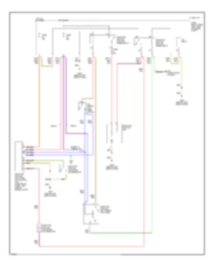
COOLING FAN
Cooling Fan Wiring Diagram for Audi 80 1991
List of elements for Cooling Fan Wiring Diagram for Audi 80 1991:
- 1990 80
- 30as
- A/c refrig high pres switch
- A/c relay
- A30k
- A30m
- A85m
- A86m
- A87m
- Air conditoning system
- C 1995 vftc
- D75a
- D85l
- E87la
- Except 1990 80
- Fuse 25a
- Fuse 30a
- Fuse/ relay panel (left side of engine compt)
- G202 (behind left side of dash)
- G31
- Hot at all times
- Hot in run
- Radiator cooling fan
- Radiator cooling fan after run control unit (fuse/ relay panel, left side of engine compt)
- Radiator cooling fan after run resistor
- Radiator cooling fan high speed relay
- Radiator cooling fan low speed relay
- Radiator cooling fan thermo switches
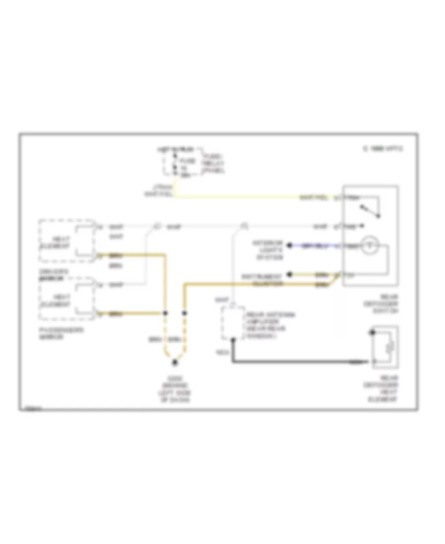
DEFOGGERS
Defoggers Wiring Diagram for Audi 80 1991
List of elements for Defoggers Wiring Diagram for Audi 80 1991:
- 1995 vftc c 1995 vftc c
- 58d
- 75h
- Driver's mirror
- Fuse 30a
- Fuse/ relay panel
- G202 (behind left side of dash)
- Heat element
- Hot in run
- Instrument cluster
- Interior lights system
- Nca
- Passenger's mirror
- Rear antenna amplifier (near rear window)
- Rear defogger heat element
- Rear defogger switch
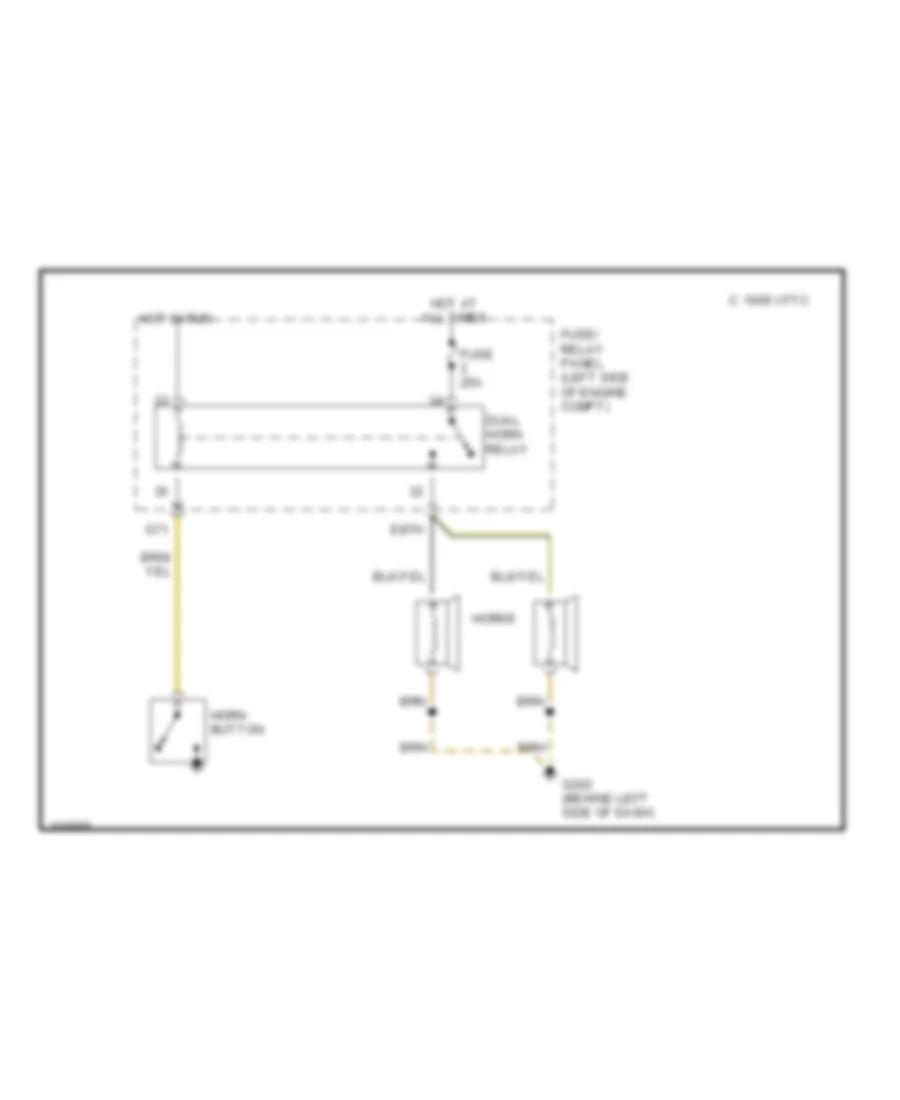
HORN
Horn Wiring Diagram for Audi 80 1991
List of elements for Horn Wiring Diagram for Audi 80 1991:
- 1995 vftc c
- Dual horn relay
- E87h
- Fuse 25a
- Fuse/ relay panel (left side of engine compt)
- G202 (behind left side of dash)
- G71
- Horn button
- Horns
- Hot at all times
- Hot in run
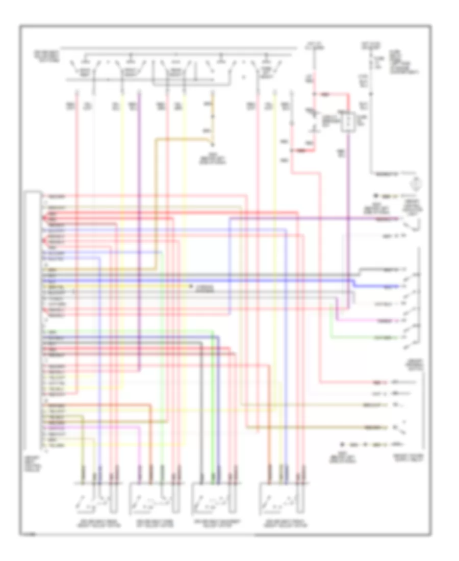
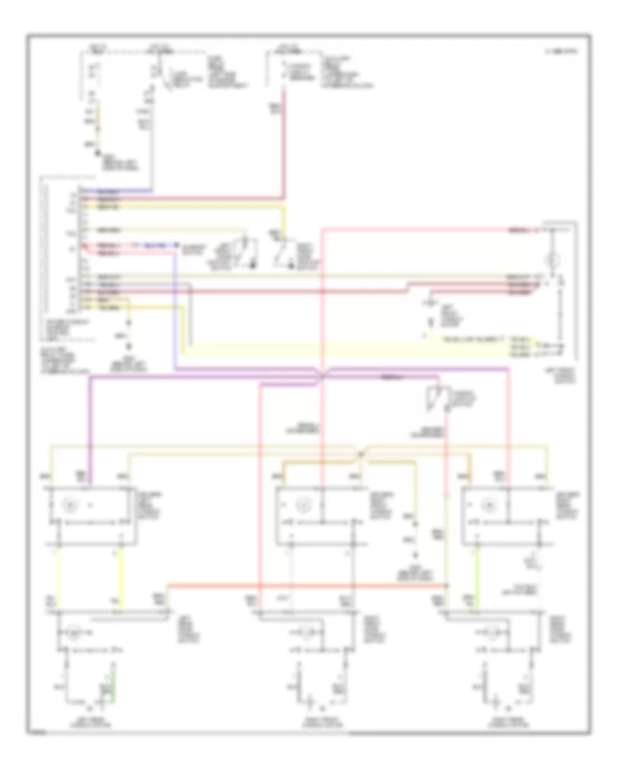
MEMORY SYSTEMS
Memory Systems Wiring Diagram for Audi 80 1991
List of elements for Memory Systems Wiring Diagram for Audi 80 1991:
- 87a
- Back rest
- C15a
- Circuit breaker 20a
- Driver seat adjustment switches
- Driver seat backrest adjust motor
- Driver seat fore/ aft adjust motor
- Driver seat front height adjust motor
- Driver seat rear height adjust motor
- Fore/ aft height
- Front height
- Fuse 15a
- Fuse 30a
- Fuse/ relay panel (left side of engine compartment)
- G202 (behind left side of dash)
- Hot at all times
- Hot in on or start
- L30 red
- Memory control indicator light
- Memory program switch
- Memory seat control module
- R r
- Rear height
- Red
- Warning systems
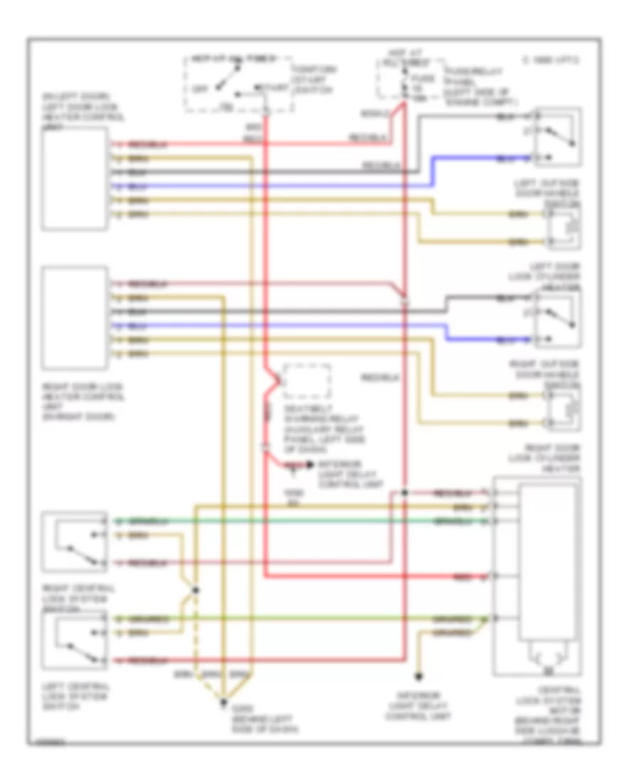
POWER DOOR LOCKS
Power Door Locks Wiring Diagram for Audi 80 1991
List of elements for Power Door Locks Wiring Diagram for Audi 80 1991:
- (in left door) left door lock heater control unit
- 1995 vftc c
- 86s
- Central lock system motor (behind right side luggage compt trim)
- Fuse 10a
- Fuse/relay panel (left side of engine compt)
- G202 (behind left side of dash)
- Hot at all times
- Ignition/ start switch
- Interior light delay control unit
- Left central lock system switch
- Left door lock cylinder heater
- Left outside door handle switch
- M30az
- Off
- Red
- Right central lock system switch
- Right door lock cylinder heater
- Right door lock heater control unit (in right door)
- Right outside door handle switch
- Seatbelt warning relay (auxilary relay panel, left side of dash)
- Start
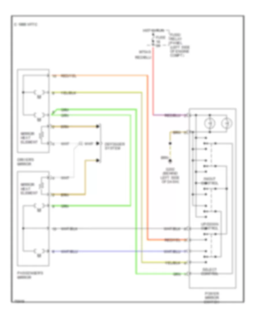
POWER MIRRORS
Power Mirrors Wiring Diagram for Audi 80 1991
List of elements for Power Mirrors Wiring Diagram for Audi 80 1991:
- 1995 vftc c 1995 vftc c
- Defogger system
- Driver's mirror
- Fuse 5a
- Fuse/ relay panel (left side of engine compt)
- G202 (behind left side of dash)
- Hot in run
- In/out control
- M75as
- Mirror heat element
- Passenger's mirror
- Power mirror switch
- Select control
- Up/down control
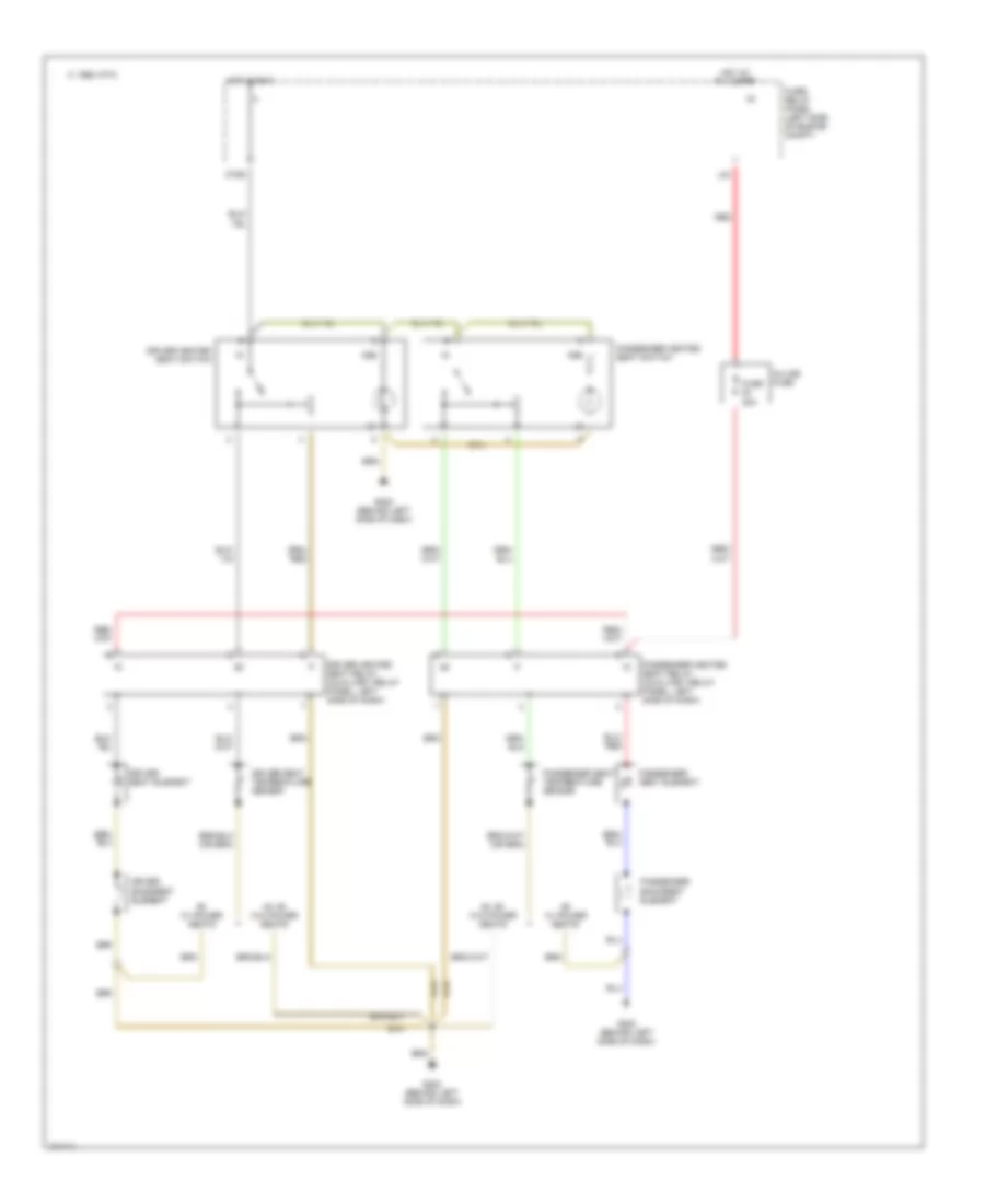
POWER SEATS
Heated Seats Wiring Diagram for Audi 80 1991
List of elements for Heated Seats Wiring Diagram for Audi 80 1991:
- 1995 vftc c
- 58b
- 80, 90 w/o power seats
- Driver backrest element
- Driver heated seat relay (auxiliary relay panel, left side of dash)
- Driver heated seat switch
- Driver seat element
- Driver seat temperature sensor
- Fuse 30a
- Fuse/ relay panel (left side of engine compt)
- G202 (behind left side of dash)
- Hot at all times
- Hot in run
- In-line fuse
- L30
- M75s
- Passenger backrest element
- Passenger heated seat relay (auxiliary relay panel, left side of dash)
- Passenger heated seat switch
- Passenger seat element
- Passenger seat temperature sensor
- Red
- W/ power seats
Passenger Power Seat Wiring Diagram for Audi 80 1991
List of elements for Passenger Power Seat Wiring Diagram for Audi 80 1991:
- Back rest
- Fore/ aft
- Front height
- Fuse 30a
- Fuse/ relay panel (left side of engine compartment)
- G202 (behind left side of dash)
- Hot at all times
- L30 red
- Passenger fore/aft adjust switch
- Passenger seat backrest adjust motor
- Passenger seat backrest adjustment
- Passenger seat fore/aft adjust motor
- Passenger seat front height adjust motor
- Passenger seat rear height adjust motor
- Rear height
- Red
- Switch
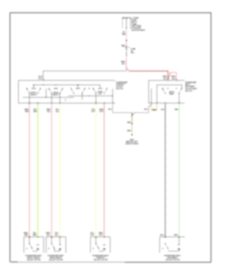
POWER WINDOWS
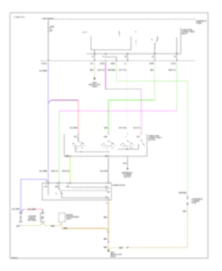
Power Windows Wiring Diagram for Audi 80 1991
List of elements for Power Windows Wiring Diagram for Audi 80 1991:
- 87a
- 87b
- Auxiliary relay panel (under dash, to left of steering column)
- C 1995 vftc c 1995 vftc
- Driver's left rear window switch
- Driver's right front window switch
- Driver's right rear window switch
- Fuse/ relay panel (left side of engine compartment)
- G202 (behind left side of dash)
- G31
- Hot at all times
- Hot in run
- Left front door contact switch
- Left front window motor
- Left front window switch
- Left rear door window switch
- Left rear window motor
- Load reduction relay
- M75s
- Power window/ sunroof control unit
- Right front door contact switch
- Right front door window switch
- Right front window motor
- Right rear door window switch
- Right rear window motor
- Sunroof switch
- Tk2
- Tk3
- Window circuit breaker
- Window lock out switch
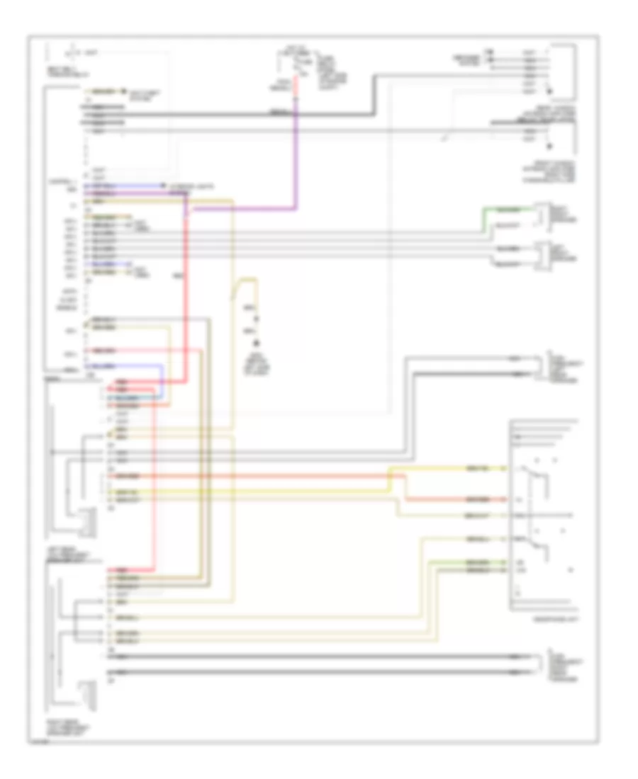
RADIO
Radio Wiring Diagram for Audi 80 1991
List of elements for Radio Wiring Diagram for Audi 80 1991:
- (not used)
- 10e
- 31l
- 31r
- 58d
- Anti-theft system
- Clock
- Control +
- Data
- Defogger system
- Enable
- Front window antenna amplifier (right side windshield pillar)
- Fuse 15a
- Fuse/ relay panel (left side of engine compt)
- G202 (behind left side of dash)
- Headphone unit
- High frequency left rear speaker
- High frequency right rear speaker
- Hot at all times
- Interior lights system
- Left front speaker
- Left rear low frequency speaker unit
- Nca
- Nf(+)
- Nf(-)
- Radio
- Rear window antenna amplifier (below trunk latch)
- Red
- Right front speaker
- Right rear low frequency speaker unit
- Seat belt warning relay
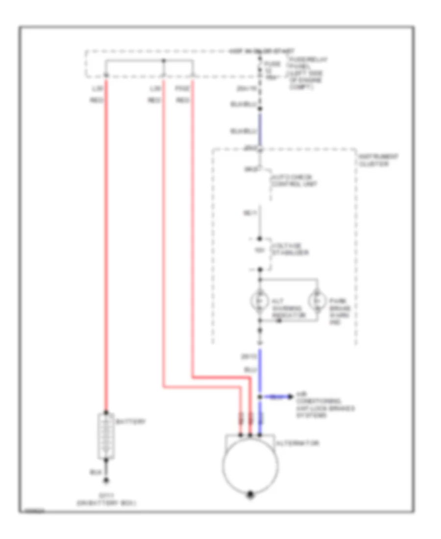
STARTING/CHARGING
Charging Wiring Diagram for Audi 80 1991
List of elements for Charging Wiring Diagram for Audi 80 1991:
- 10v
- 26/13
- 26/3
- 26a/16
- 6e/1
- 6f/2
- Air conditioning, ant-lock brakes systems
- Alt warning indicator
- Alternator
- Auto check control unit
- Battery
- F50z
- Fuse 15a
- Fuse/relay panel (left side of engine compt)
- G111 (on battery box)
- Hot in on or start
- Instrument cluster
- L30
- Park brake warn ind
- Red
- Voltage stabilizer
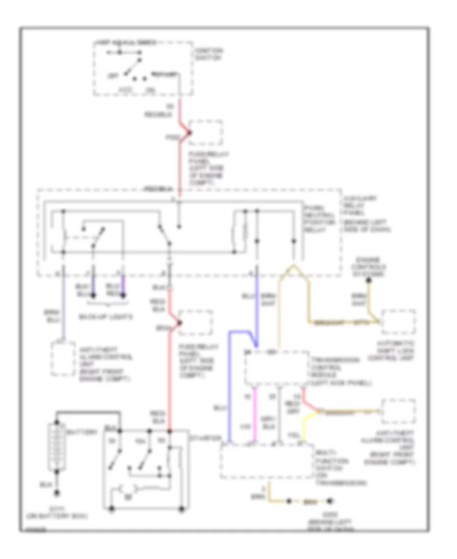
Starting Wiring Diagram, A/T for Audi 80 1991
List of elements for Starting Wiring Diagram, A/T for Audi 80 1991:
- (behind left side of dash)
- (left kick panel)
- 15a
- 2/pn
- Acc
- Anti-theft alarm control unit (right front engine compt)
- Automatic shift lock control unit
- Auxiliary relay panel
- B50a
- Back-up lights
- Battery
- Engine controls systems
- F50z
- Function switch (on transmission)
- Fuse/relay panel (left side of engine compt)
- G111 (on battery box)
- G202 (behind left side of dash)
- Hot at all times
- Ignition switch
- Multi-
- Off
- Park/ neutral position relay
- Start
- Starter
- Transmission control module
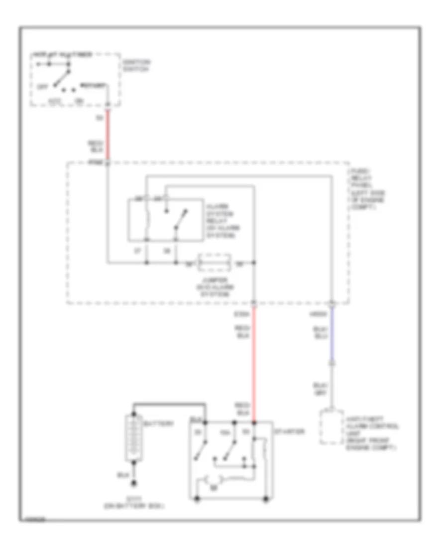
Starting Wiring Diagram, M/T for Audi 80 1991
List of elements for Starting Wiring Diagram, M/T for Audi 80 1991:
- 15a
- Acc
- Alarm system relay (w/ alarm system)
- Anti-theft alarm control unit (right front engine compt)
- Battery
- E50a
- F50z
- Fuse/ relay panel (left side of engine compt)
- G111 (on battery box)
- H50w
- Hot at all times
- Ignition switch
- Jumper (w/o alarm system)
- Off
- Start
- Starter
WIPER/WASHER
Front Wiper/Washer Wiring Diagram for Audi 80 1991
List of elements for Front Wiper/Washer Wiring Diagram for Audi 80 1991:
- 175aw
- 1995 vftc c
- 53a
- 53b
- 53c
- 53e
- B53c
- C31b
- C53c
- C53e
- Emergency flasher switch
- Engine compartment light
- Fuse 25a
- Fuse/relay panel
- G202 (behind left dash)
- G31
- Hot in run
- Nca
- Wash/wipe intermittent relay
- Wash/wipe intermittent switch
- Washer nozzle heaters
- Windshield washer pump
- Wiper motor
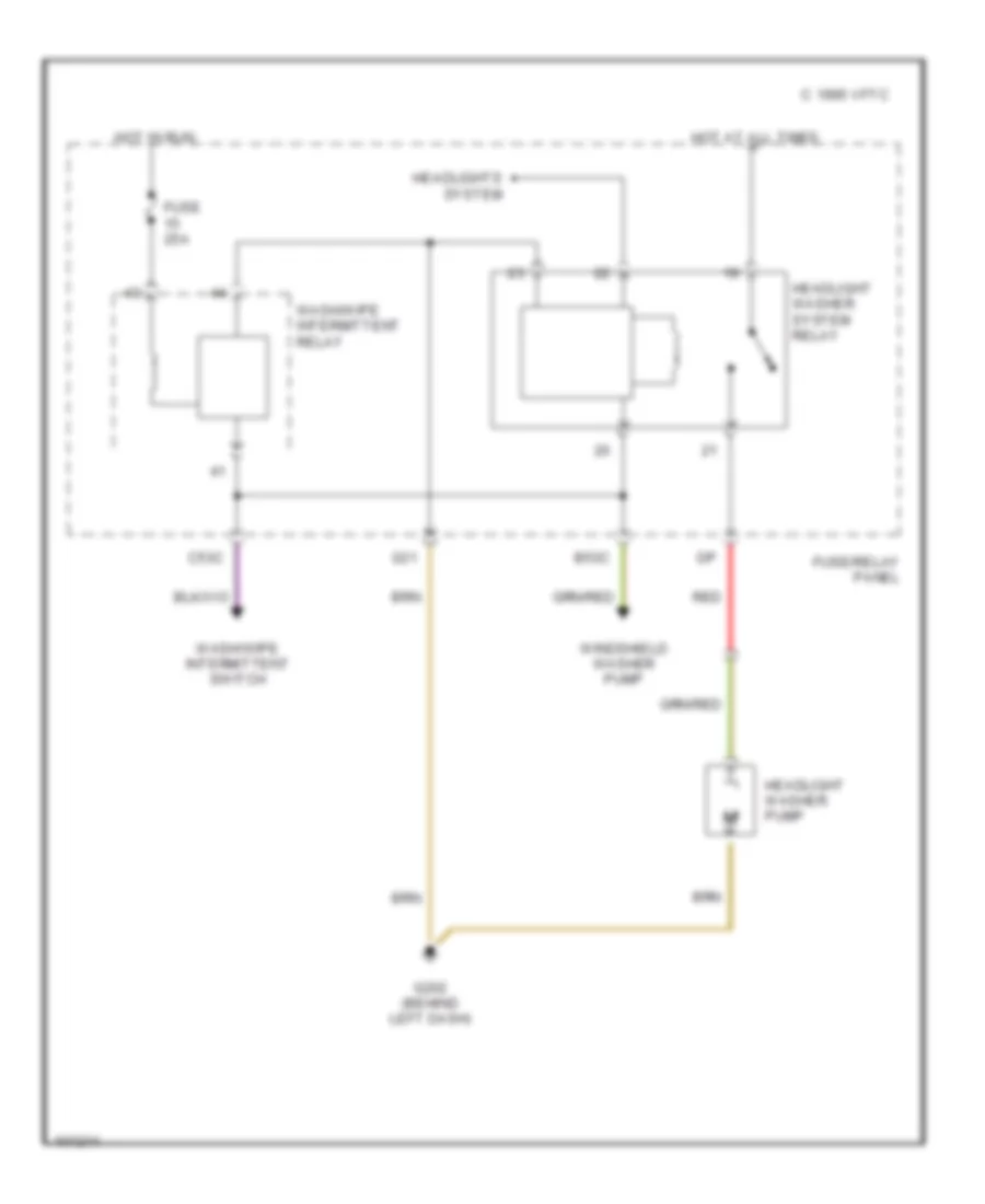
Headlamp Washer Wiring Diagram for Audi 80 1991
List of elements for Headlamp Washer Wiring Diagram for Audi 80 1991:
- 1995 vftc c
- B53c
- C53c
- Fuse 25a
- Fuse/relay panel
- G202 (behind left dash)
- G31
- Headlight washer pump
- Headlight washer system relay
- Headlights system
- Hot at all times
- Hot in run
- Red
- Wash/wipe intermittent relay
- Wash/wipe intermittent switch
- Windshield washer pump