AIR CONDITIONING
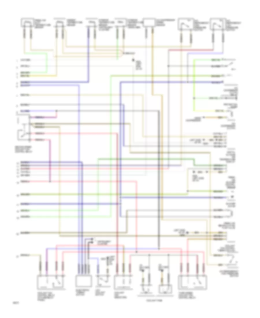
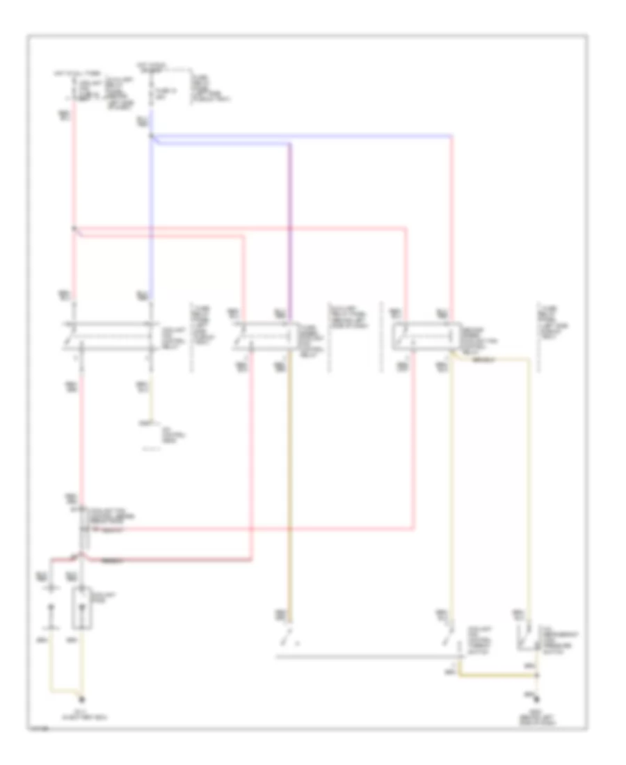
Auto. A/C-Heater System Wiring Diagram (With A/T Wiring Diagram 1 Of 2) for Audi 90 CS Quattro 1993

List of elements for Auto. A/C-Heater System Wiring Diagram (With A/T Wiring Diagram 1 Of 2) for Audi 90 CS Quattro 1993:
- (left side of i/p)
- A/c control head
- Air flow flap motor
- Auxiliary relay panel 2
- B10
- Battery (30)
- C10
- C11
- Central flap motor potentiometer
- Data link connector
- Engine control module
- Footwell/defrost flap motor potentiometer
- Fuse 15a
- Fuse 25a
- Fuse 30a
- Fuse 5a
- Fuse 60a
- Fuse/ relay panel
- G202
- G202 (left side of i/p)
- Hot at all times
- Hot w/ lights on
- Hot w/ load reduction relay energized (x)
- Ignition (15)
- Interior temperature sensor fan
- Temp regulator flap motor potentiometer
- Transmission control module
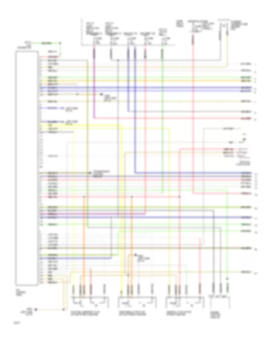
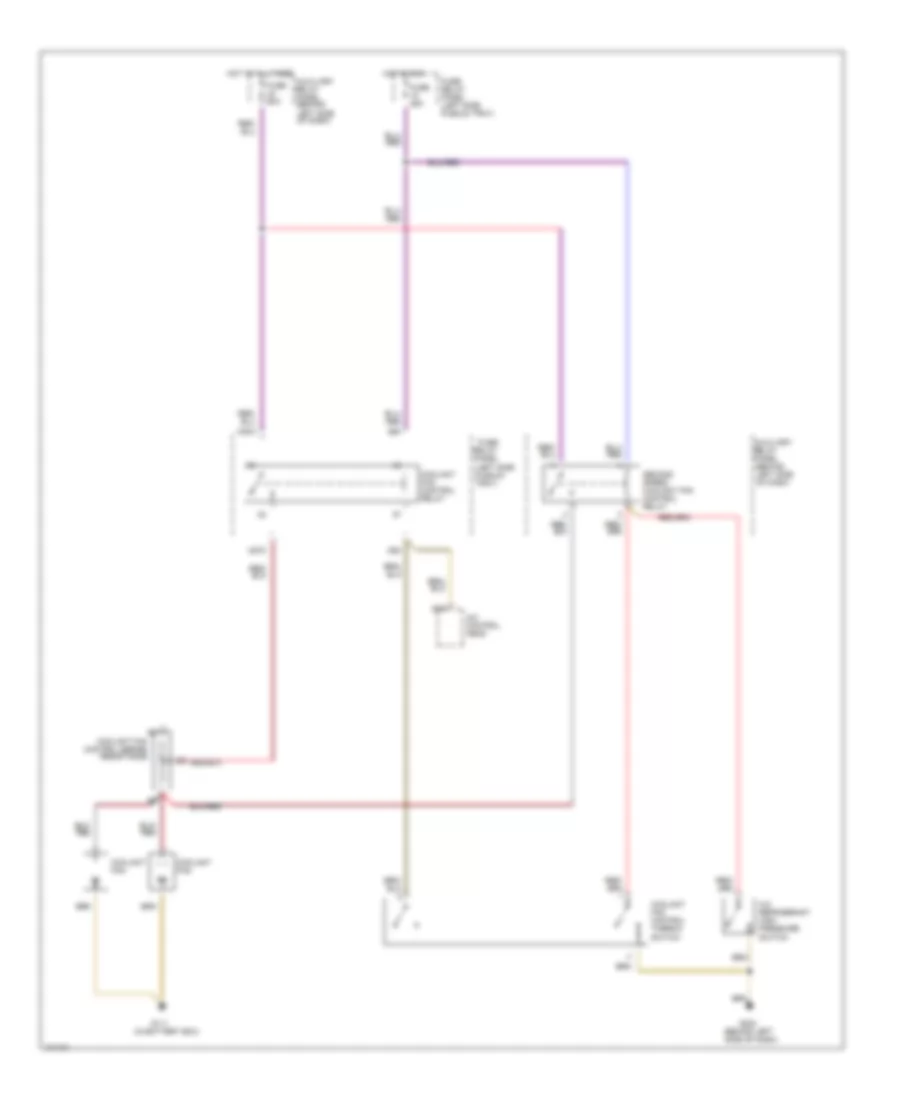
Auto. A/C-Heater System Wiring Diagram (With A/T Wiring Diagram 2 Of 2) for Audi 90 CS Quattro 1993
List of elements for Auto. A/C-Heater System Wiring Diagram (With A/T Wiring Diagram 2 Of 2) for Audi 90 CS Quattro 1993:
- (in battery box)
- (left side of i/p)
- (left side of i/p) g202
- (near compressor)
- A/c compressor clutch
- A/c compressor clutch relay
- A/c compressor speed sensor
- A/c refrigerant high pressure switch
- A/c refrigerant low pressure switch
- Ambient temperature sensor
- Blower motor
- Coolant fan control relay (in fuse/relay panel)
- Coolant fan control thermo switch
- Coolant fan resistors
- Coolant fans
- Digital outside air temperature display
- Electronic thermo switch
- Fresh air blower control module
- Fresh air duct temperature sensor
- Fresh air recirculating flap valve
- G202
- G202 (left side of i/p)
- Instrument cluster
- Interior temperature sensor (headliner)
- Interior temperature sensor (instrument cluster)
- Low coolant switch
- Protection diode
- Second speed coolant fan control relay
- Third speed coolant fan control relay
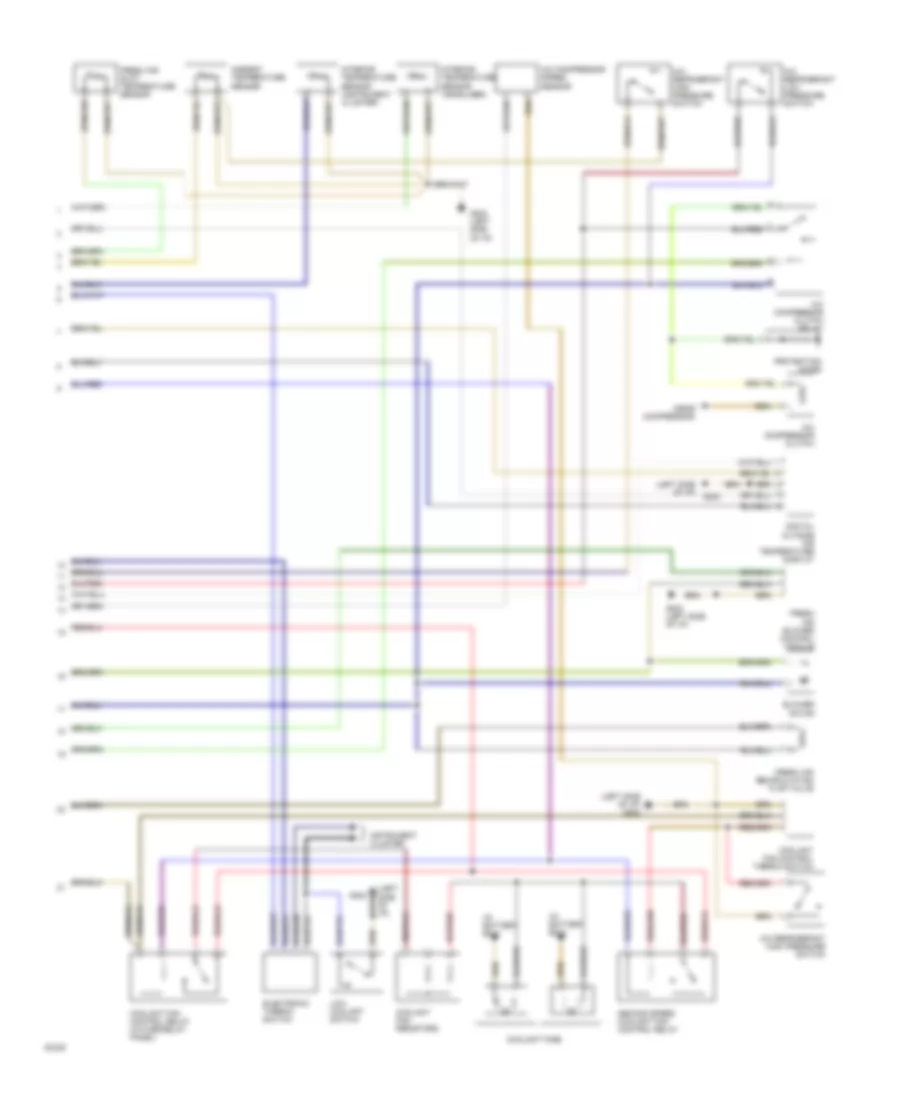
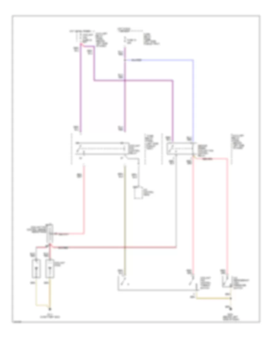
Auto. A/C-Heater System Wiring Diagram (With M/T Wiring Diagram 1 Of 2) for Audi 90 CS Quattro 1993
List of elements for Auto. A/C-Heater System Wiring Diagram (With M/T Wiring Diagram 1 Of 2) for Audi 90 CS Quattro 1993:
- (left side of i/p)
- A/c control head
- Air flow flap motor
- Auxiliary relay panel 2
- B10
- Battery (30)
- C10
- C11
- Central flap motor potentiometer
- Data link connector
- Engine control module
- Footwell/defrost flap motor potentiometer
- Fuse 15a
- Fuse 25a
- Fuse 30a
- Fuse 5a
- Fuse 60a
- Fuse/ relay panel
- G202
- G202 (left side of i/p)
- Hot at all times
- Hot w/ lights on
- Hot w/ load reduction relay energized (x)
- Ignition (15)
- Interior temperature sensor fan
- Temp regulator flap motor potentiometer
- Transmission control module
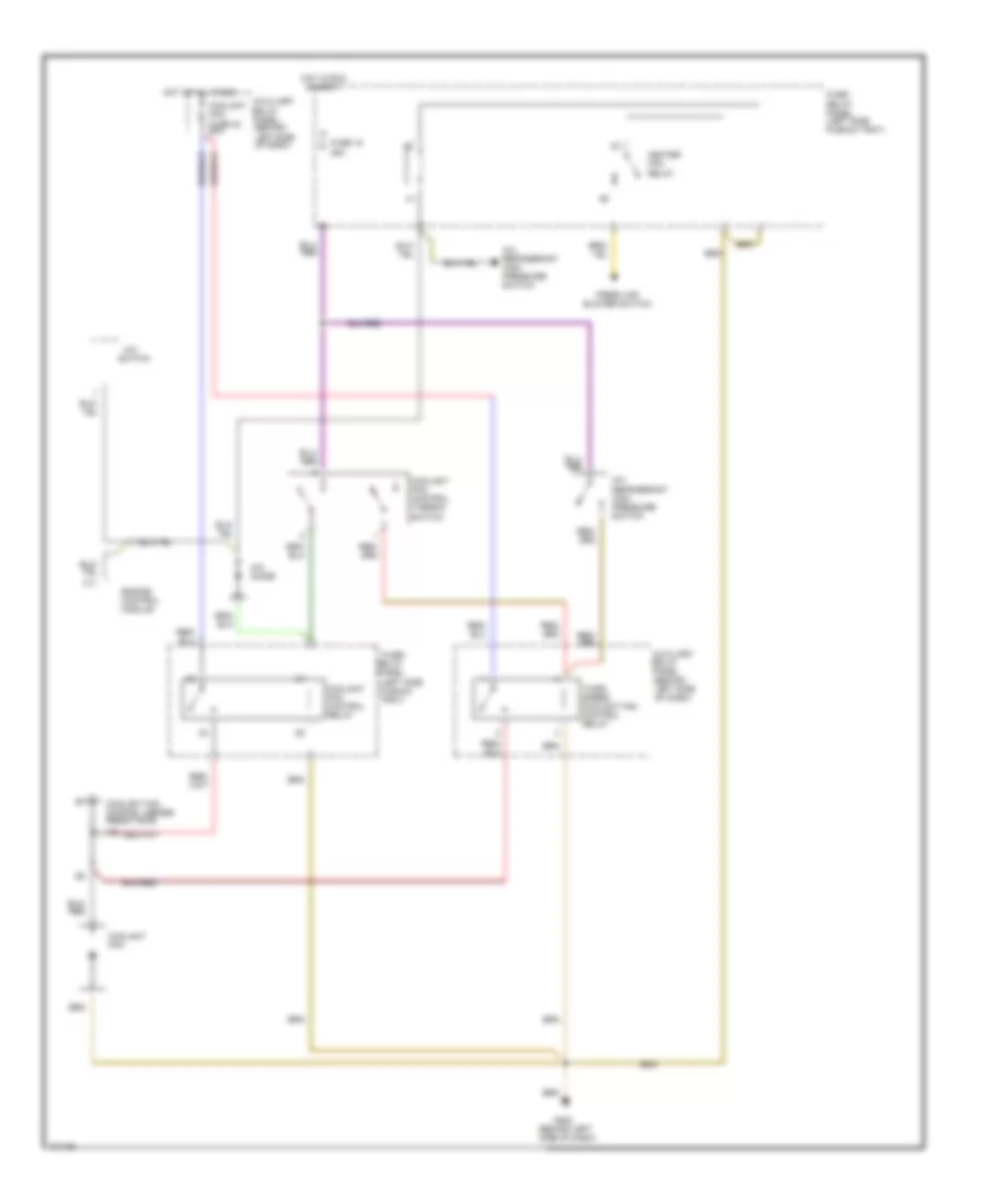
Auto. A/C-Heater System Wiring Diagram (With M/T Wiring Diagram 2 Of 2) for Audi 90 CS Quattro 1993
List of elements for Auto. A/C-Heater System Wiring Diagram (With M/T Wiring Diagram 2 Of 2) for Audi 90 CS Quattro 1993:
- (in battery box)
- (left side of i/p)
- (left side of i/p) g202
- (near compressor)
- A/c compressor clutch
- A/c compressor clutch relay
- A/c compressor speed sensor
- A/c refrigerant high pressure switch
- A/c refrigerant low pressure switch
- Ambient temperature sensor
- Blower motor
- Coolant fan control relay (in fuse/relay panel)
- Coolant fan control thermo switch
- Coolant fan resistors
- Coolant fans
- Digital outside air temperature display
- Electronic thermo switch
- Fresh air blower control module
- Fresh air duct temperature sensor
- Fresh air recirculating flap valve
- G202
- G202 (left side of i/p)
- Instrument cluster
- Interior temperature sensor (headliner)
- Interior temperature sensor (instrument cluster)
- Low coolant switch
- Protection diode
- Second speed coolant fan control relay
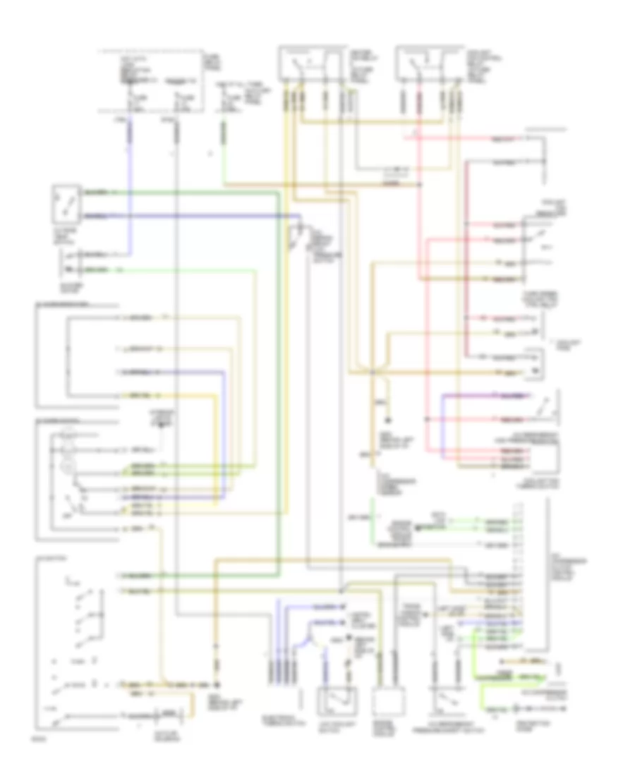
Manual A/C Wiring Diagram for Audi 90 CS Quattro 1993
List of elements for Manual A/C Wiring Diagram for Audi 90 CS Quattro 1993:
- (behind left side of i/p)
- (left side i/p)
- (left side of i/p)
- (near compressor)
- A/c compressor clutch
- A/c compressor clutch control module
- A/c compressor speed sensor
- A/c flap solenoid
- A/c refrig- erant low pressure switch
- A/c refrigerant
- A/c refrigerant high pressure switch'
- A/c switch
- Auxiliary relay panel
- Blower motor
- Blower resistors
- Blower switch
- C10
- C11
- Coolant fan control relay (in fuse/ relay panel)
- Coolant fan resistors
- Coolant fan thermo switch
- Coolant fans
- Data link connector
- Diode
- Electronic thermo switch
- Engine control module
- Engine control module pin b10 (engine rpm)
- Fuse 15a
- Fuse 30a
- Fuse 60a
- Fuse/ relay panel
- G202
- G202 (behind left side of i/p)
- Heater fan relay (in fuse/ relay panel)
- Hot at all times
- Hot with load reduction relay energized (x)
- Ignition (15)
- Instru- ment cluster
- Interior lights system
- Low coolant switch
- Off
- Outside temp switch
- Pressure safety switch
- Protection diode
- Third speed coolant fan ctrl relay
- Trans- mission control module
COOLING FAN
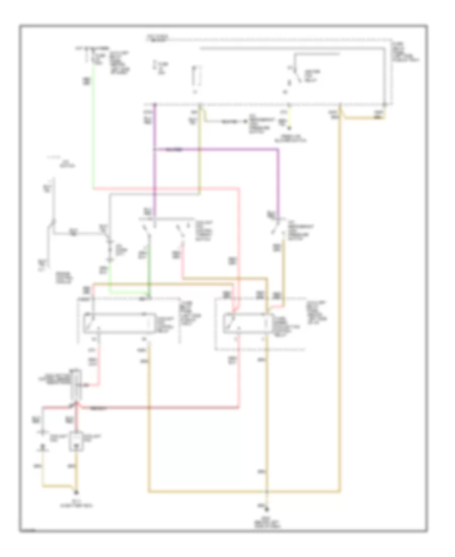
Cooling Fan Wiring Diagram, A/T with Automatic A/C Late Production for Audi 90 CS Quattro 1993
List of elements for Cooling Fan Wiring Diagram, A/T with Automatic A/C Late Production for Audi 90 CS Quattro 1993:
- (behind left side of dash)
- (in battery box)
- (left side plenum tray)
- A/c control head
- A/c refrigerant high pressure switch
- Auxiliary
- Coolant fan fuse 42 60a
- Coolant fan control relay
- Coolant fan control series resistance
- Coolant fan control thermo- switch
- Coolant fans
- D16
- Fuse 15 25a
- Fuse/ relay panel
- Fuse/ relay panel (left side plenum tray)
- G111
- G202
- Hot at all times
- Hot in run or accy
- Relay panel
- Second speed coolant fan control relay
- Third speed coolant fan control relay
Cooling Fan Wiring Diagram, Auto A/C Early Production for Audi 90 CS Quattro 1993
List of elements for Cooling Fan Wiring Diagram, Auto A/C Early Production for Audi 90 CS Quattro 1993:
- (behind left side of dash)
- (in battery box)
- (left side plenum tray)
- 85m
- 86m
- A/c control head
- A/c refrigerant high pressure switch
- A30m
- A87m
- Auxiliary
- Coolant fan
- Coolant fan control relay
- Coolant fan control series resistance
- Coolant fan control thermo- switch
- D16
- Fuse 25a
- Fuse 60a
- Fuse/ relay panel
- Fuse/ relay panel (left side plenum tray)
- G111
- G202
- Hot at all times
- Hot in run
- Relay panel
- Second speed coolant fan control relay
Cooling Fan Wiring Diagram, M/T with Auto A/C Late Production for Audi 90 CS Quattro 1993
List of elements for Cooling Fan Wiring Diagram, M/T with Auto A/C Late Production for Audi 90 CS Quattro 1993:
- (behind left side of dash)
- (left side plenum tray)
- A/c control head
- A/c refrigerant high pressure switch
- Auxiliary
- Coolant fan fuse 42 60a
- Coolant fan control relay
- Coolant fan control thermo- switch
- Coolant fans
- D16
- E1 coolant fan control series resistance
- Fuse 15 25a
- Fuse/ relay panel
- Fuse/ relay panel (left side plenum tray)
- G111 (in battery box)
- G202
- Hot at all times
- Hot in run
- Or accy
- Relay panel
- Second speed coolant fan control relay
Cooling Fan Wiring Diagram, M/T with Manual A/C Late Production for Audi 90 CS Quattro 1993
List of elements for Cooling Fan Wiring Diagram, M/T with Manual A/C Late Production for Audi 90 CS Quattro 1993:
- (behind left side of dash)
- (left side plenum tray)
- A/c
- A/c diode
- A/c refrigerant high pressure switch
- Auxiliary
- C11
- Coolant fan
- Coolant fan fuse 42 60a
- Coolant fan control relay
- Coolant fan control series resistance
- Coolant fan control thermo- switch
- Engine control module
- Fresh air blower switch
- Fuse 15 25a
- Fuse/ relay panel
- Fuse/ relay panel (left side plenum tray)
- G202
- Heater fan relay
- Hot at all times
- Hot in run or accy
- Relay panel
- Switch
- Third speed coolant fan control relay
Cooling Fan Wiring Diagram, Manual A/C Early Production for Audi 90 CS Quattro 1993
List of elements for Cooling Fan Wiring Diagram, Manual A/C Early Production for Audi 90 CS Quattro 1993:
- (behind left side of dash)
- (behind left side of i/p)
- (left side plenum tray)
- 85k
- 85m
- 87k
- 87m
- A/c
- A/c diode (m/t)
- A/c refrigerant high pressure switch
- A30k
- A30m
- A86k
- A86m
- Auxiliary
- C11
- Coolant fan
- Coolant fan control relay
- Coolant fan control series resistance
- Coolant fan control thermo- switch
- D75a
- Engine control module
- Fresh air blower switch
- Fuse 25a
- Fuse 60a
- Fuse/ relay panel
- Fuse/ relay panel (left side plenum tray)
- G111 (in battery box)
- G202
- Heater fan relay
- Hot at all times
- Hot in run
- Or accy
- Relay panel
- Switch
- Third speed coolant fan control relay
DEFOGGERS
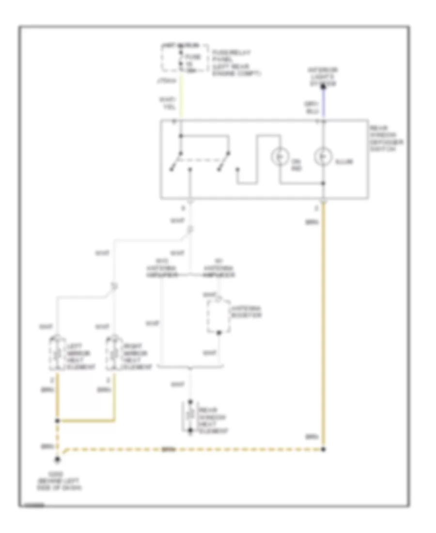
Defoggers Wiring Diagram, Early Production for Audi 90 CS Quattro 1993
List of elements for Defoggers Wiring Diagram, Early Production for Audi 90 CS Quattro 1993:
- Antenna booster
- Fuse 30a
- Fuse/relay panel (left rear engine compt)
- G202 (behind left side of dash)
- Hot in run
- Illum
- Interior lights system
- J75ah
- Left mirror heat element
- On ind
- Rear window defogger switch
- Rear window heat element
- Right mirror heat element
- W/ antenna amplifier
- W/o antenna amplifier
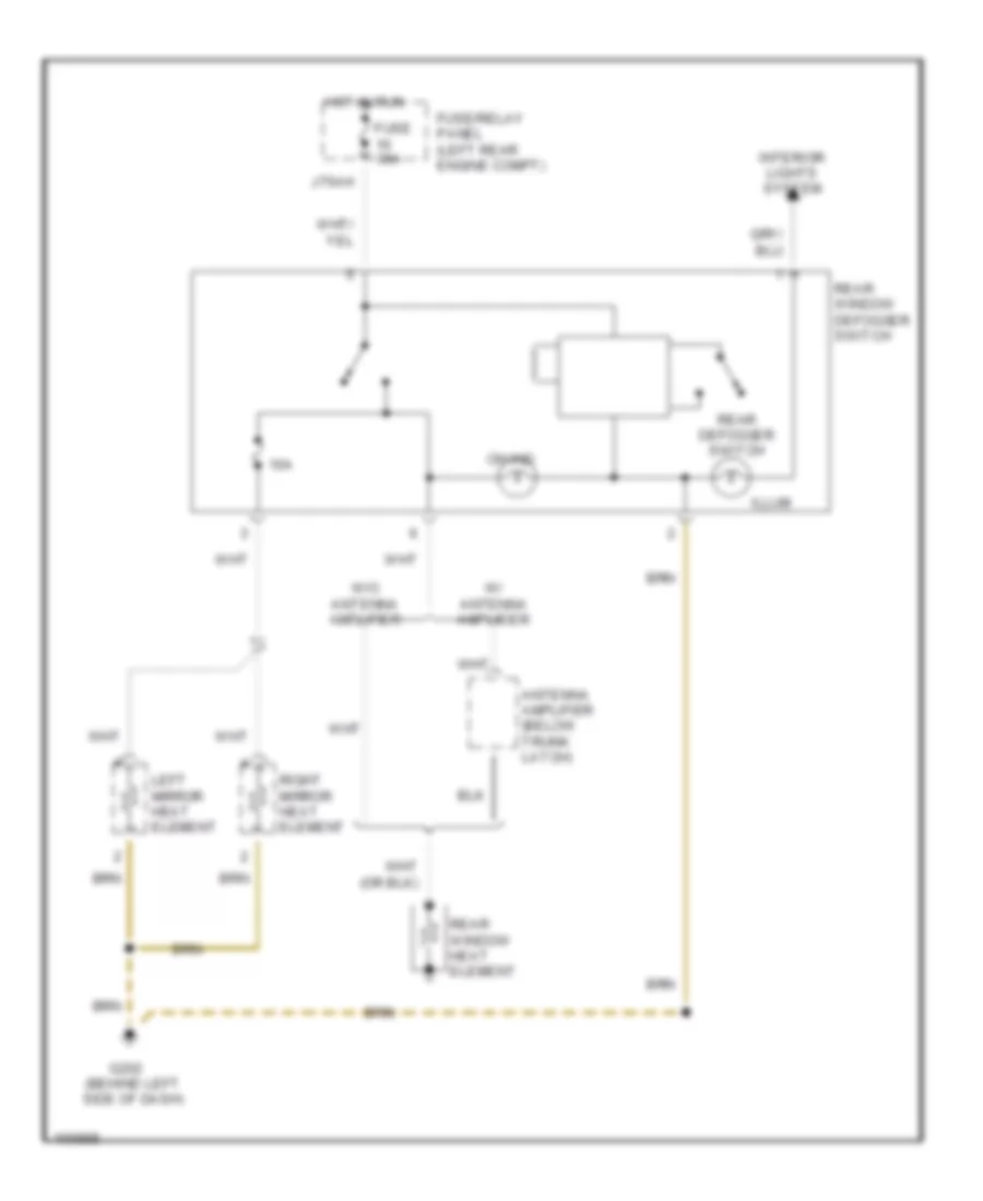
Defoggers Wiring Diagram, Late Production for Audi 90 CS Quattro 1993
List of elements for Defoggers Wiring Diagram, Late Production for Audi 90 CS Quattro 1993:
- 10a
- Antenna amplifier (below trunk latch)
- Fuse 30a
- Fuse/relay panel (left rear engine compt)
- G202 (behind left side of dash)
- Hot in run
- Illum
- Interior lights system
- J75ah
- Left mirror heat element
- On ind
- Rear defogger switch
- Rear window defogger switch
- Rear window heat element
- Right mirror heat element
- W/ antenna amplifier
- W/o antenna amplifier
HORN
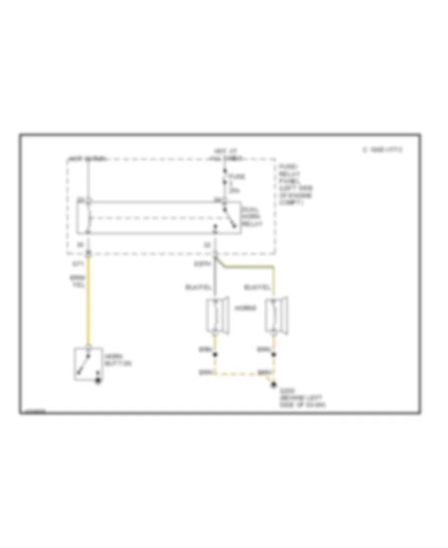
Horn Wiring Diagram for Audi 90 CS Quattro 1993
List of elements for Horn Wiring Diagram for Audi 90 CS Quattro 1993:
- 1995 vftc c
- Dual horn relay
- E87h
- Fuse 25a
- Fuse/ relay panel (left side of engine compt)
- G202 (behind left side of dash)
- G71
- Horn button
- Horns
- Hot at all times
- Hot in run
POWER DOOR LOCKS
Power Door Locks Wiring Diagram for Audi 90 CS Quattro 1993
List of elements for Power Door Locks Wiring Diagram for Audi 90 CS Quattro 1993:
- (early production)
- (early) (late)
- (late 1993)
- (late production)
- 12b a
- 6ae b
- All times
- C15a
- Central locking/ alarm system/ interior light delay control module
- Door handle alarm switches
- Door lock
- Driver's door central locking system switch
- Early
- F30al
- Fuse 10a
- Fuse 15a
- Fuse/relay panel (left side of engine compt on plenum tray)
- G202 (behind left
- G202 (behind left side of dash)
- G404 (near left)
- Heated
- Heater
- Hot at
- Hot at all times
- Hot in on or start
- Interior lights system
- Left door lock heater
- Left front door contact switch
- Left heated door lock control module
- Left heated door lock switch
- Left infrared central locking system sensor
- Left rear door contact switch
- M30az
- Nca
- Passenger's door central locking system switch (late 1993 production)
- Red
- Right
- Right door lock
- Right front door contact switch
- Right heated door lock control module
- Right infrared central locking system sensor
- Right rear door contact switch
- Side of dash)
- Switch
- Taillight)
- Trunk lock alarm/ central locking switch
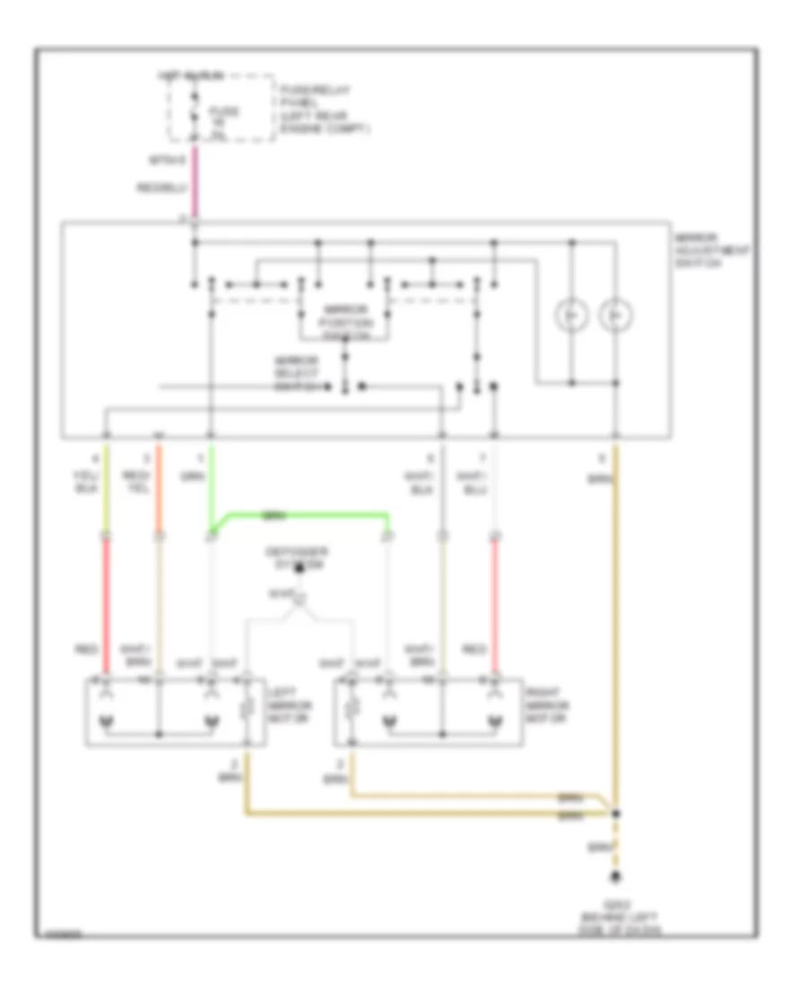
POWER MIRRORS
Power Mirrors Wiring Diagram for Audi 90 CS Quattro 1993
List of elements for Power Mirrors Wiring Diagram for Audi 90 CS Quattro 1993:
- Defogger
- Fuse 5a
- Fuse/relay panel (left rear engine compt)
- G202 (behind left side of dash)
- Hot in run
- Left mirror motor
- M75as
- Mirror adjustment switch
- Mirror position switch
- Mirror select switch
- Red
- Right mirror motor
- System
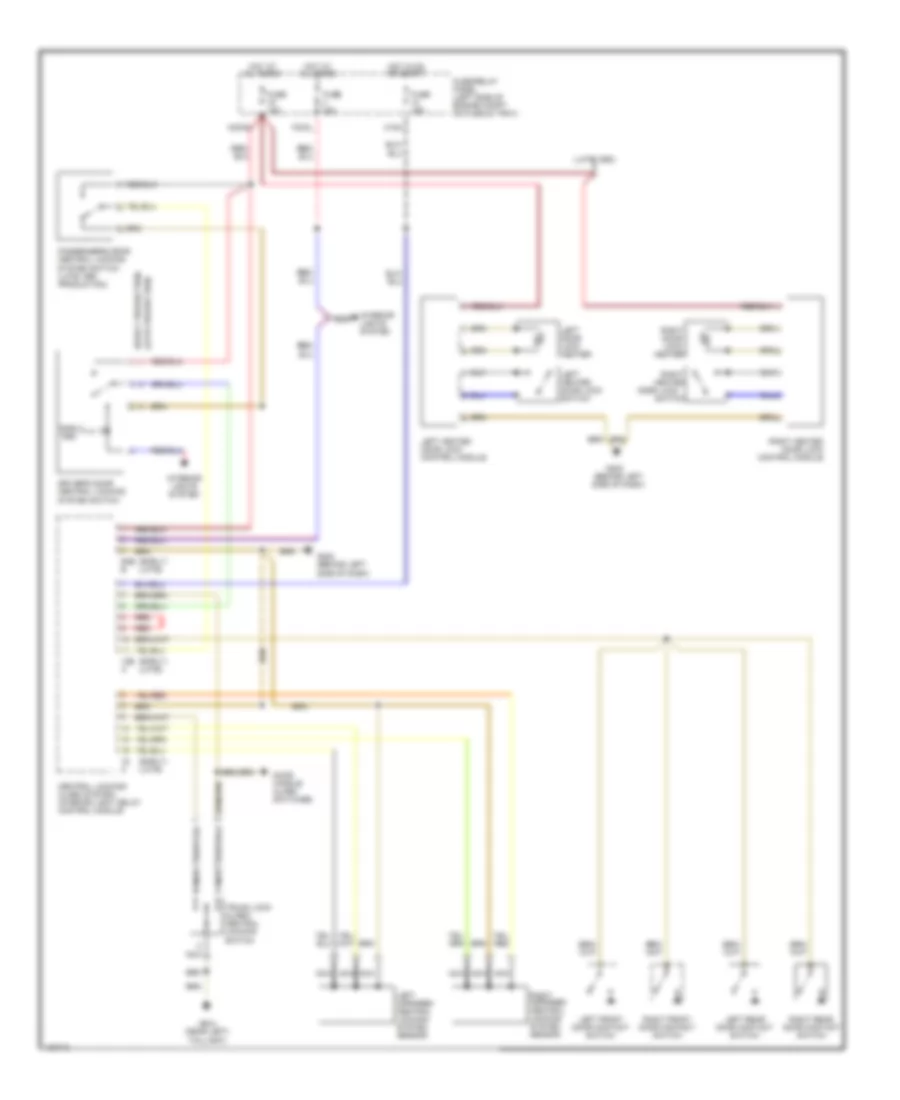
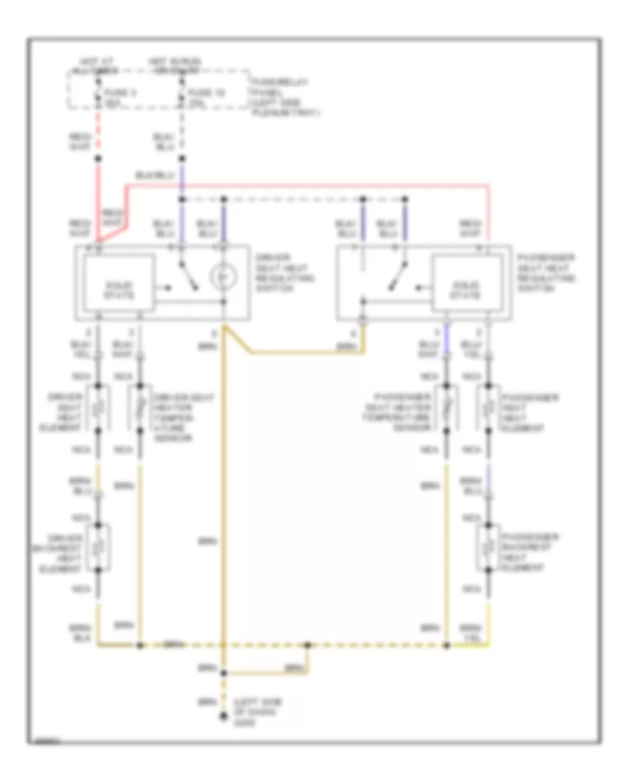
POWER SEATS
Heated Seats Wiring Diagram for Audi 90 CS Quattro 1993
List of elements for Heated Seats Wiring Diagram for Audi 90 CS Quattro 1993:
- (left side of dash) g202
- All times
- Driver backrest heat element
- Driver seat heat element
- Driver seat heat regulating switch
- Driver seat heater temper- ature sensor
- Fuse 12 15a
- Fuse 3 30a
- Fuse/relay panel (left side plenum tray)
- Hot at
- Hot in run or start
- Nca
- Passenger backrest heat element
- Passenger seat heat element
- Passenger seat heat regulating switch
- Passenger seat heater temperature sensor
- Solid state
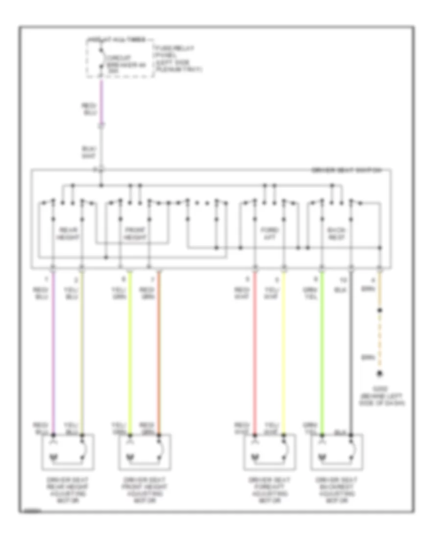
Left Power Seat Wiring Diagram for Audi 90 CS Quattro 1993
List of elements for Left Power Seat Wiring Diagram for Audi 90 CS Quattro 1993:
- Back- rest
- Circuit breaker 44 30a
- Driver seat backrest adjusting motor
- Driver seat fore/aft adjusting motor
- Driver seat front height adjusting motor
- Driver seat rear height adjusting motor
- Driver seat switch
- Fore/ aft
- Front height
- Fuse/relay panel (left side plenum tray)
- G202 (behind left side of dash)
- Hot at all times
- Rear height
POWER WINDOWS
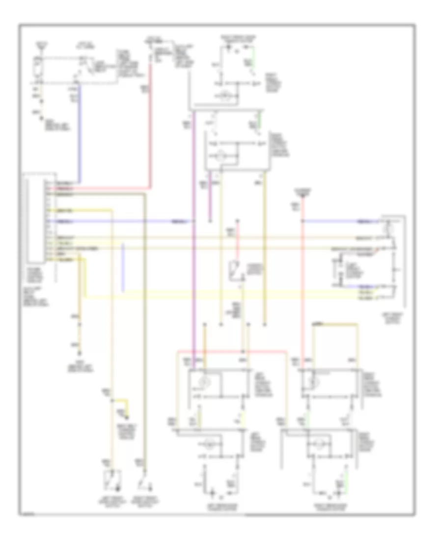
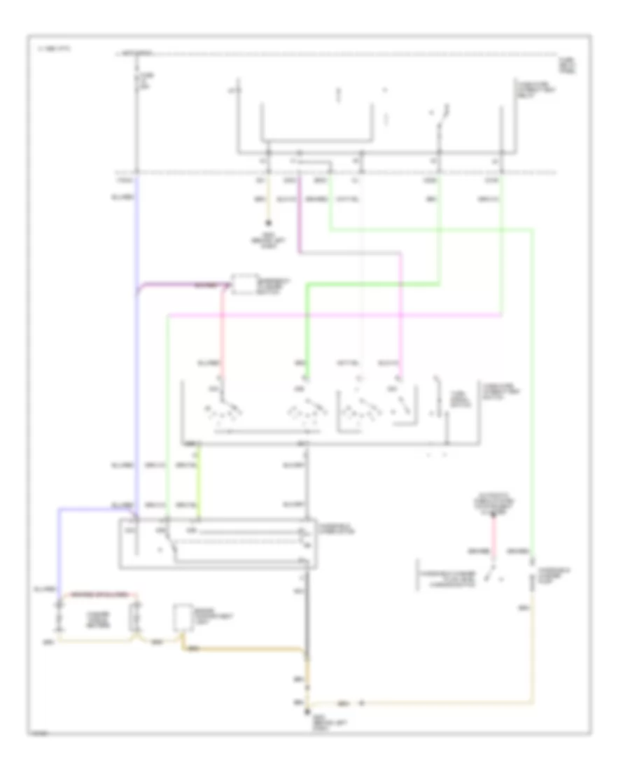
Power Windows Wiring Diagram for Audi 90 CS Quattro 1993
List of elements for Power Windows Wiring Diagram for Audi 90 CS Quattro 1993:
- All times
- Auxiliary relay panel (behind left side of dash)
- Circuit breaker 20a
- Fuse/ relay panel (left side of engine compt on plenum tray)
- G202 (behind left side of dash)
- G31
- Hot at
- Hot at all times
- Hot in run
- Left front door contact switch
- Left front window motor
- Left front window switch
- Left rear
- Left rear door window motor
- Left rear window switch (door)
- Load reduction relay
- M75s
- Nca
- Power window control module
- Right front door contact switch
- Right front door window motor
- Right front window switch (center console)
- Right front window switch (door)
- Right rear
- Right rear door window motor
- Right rear window switch (door)
- Seat belt warning control module
- Sunroof motor
- Window lockout switch
- Window switch (center console)
RADIO
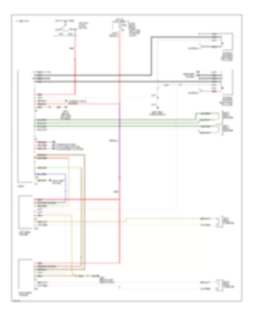
Radio Wiring Diagram for Audi 90 CS Quattro 1993
List of elements for Radio Wiring Diagram for Audi 90 CS Quattro 1993:
- 10e
- 1995 vftc c
- 2af
- 2ag
- Acc
- Antenna
- Antenna booster (left rear "d" pillar)
- Antenna booster (right rear "d" pillar)
- Anti-theft system
- Defogger system
- Fuse 15a
- Fuse/ relay panel (left side of engine compt)
- G202 (behind left side of dash)
- Hot at all times
- Ignition/ start switch
- Interior lights system
- Left front speaker
- Left rear tweeter
- Left rear woofer
- Lock
- Nca
- Radio
- Red
- Right front speaker
- Right rear tweeter
- Right rear woofer
- Run
- Seat belt warning relay
- Start
- Warning system (auto check system, in instrument cluster)
STARTING/CHARGING
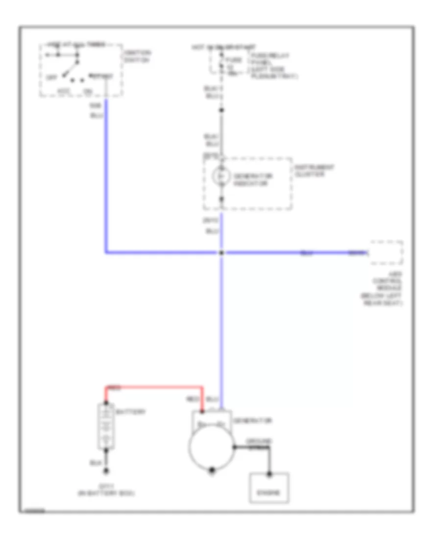
Charging Wiring Diagram for Audi 90 CS Quattro 1993
List of elements for Charging Wiring Diagram for Audi 90 CS Quattro 1993:
- (below left rear seat)
- 26/13
- 26/16
- 35/15
- 50b
- Abs control module
- Acc
- Battery
- Engine
- Fuse 15a
- Fuse/relay panel (left side plenum tray)
- G111 (in battery box)
- Generator
- Generator indicator
- Ground strap
- Hot at all times
- Hot in on or start
- Ignition switch
- Instrument cluster
- Off
- Red
- Start
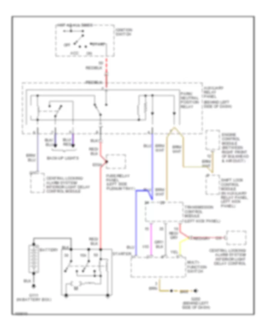
Starting Wiring Diagram, A/T for Audi 90 CS Quattro 1993
List of elements for Starting Wiring Diagram, A/T for Audi 90 CS Quattro 1993:
- (behind left side of dash)
- (left kick panel)
- 15a
- Acc
- Auxiliary relay panel
- Back-up lights
- Battery
- C/1
- C/9
- Central locking/ alarm system/ interior light delay control
- Central locking/ alarm system/ interior light delay control module
- E50a
- Engine control module (between right front of bulkhead & air duct)
- Function switch
- Fuse/relay panel (left side plenum tray)
- G111 (in battery box)
- G202 (behind left side of dash)
- Hot at all times
- Ignition switch
- Multi-
- Off
- Park/ neutral position relay
- Shift lock control module (in auxiliary relay panel, left kick panel)
- Start
- Starter
- Transmission control module
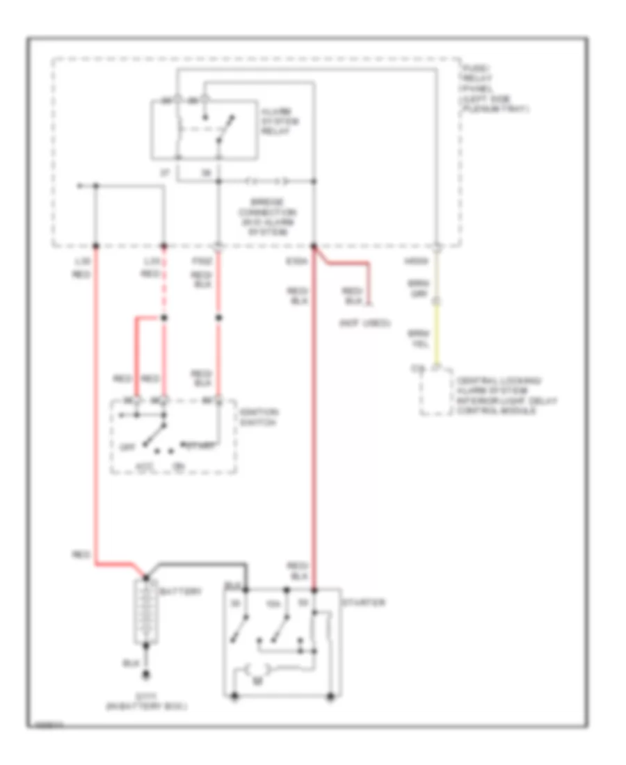
Starting Wiring Diagram, M/T for Audi 90 CS Quattro 1993
List of elements for Starting Wiring Diagram, M/T for Audi 90 CS Quattro 1993:
- (not used)
- 15a
- Acc
- Alarm system relay
- Battery
- Bridge connection (w/o alarm system)
- C/1
- Central locking/ alarm system/ interior light delay control module
- E50a
- F50z
- Fuse/ relay panel (left side plenum tray)
- G111 (in battery box)
- H50w
- Ignition switch
- L30
- Off
- Red
- Start
- Starter
TRANSMISSION
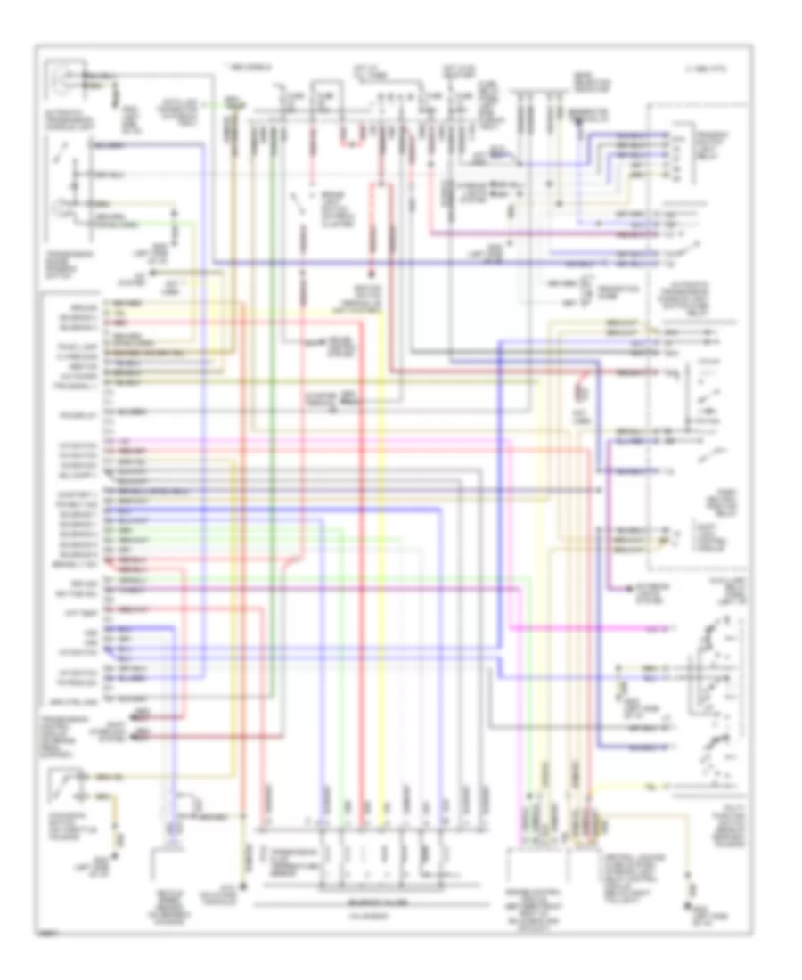
A/T Wiring Diagram for Audi 90 CS Quattro 1993
List of elements for A/T Wiring Diagram for Audi 90 CS Quattro 1993:
- (left side of i/p)
- * 1993 models
- 1995 vftc c
- 2p n
- 50a
- 50z
- 87a
- A/c kickdn
- A/c system
- Abs/tcs
- Atf temp
- Automatic transmission console light
- Automatic transmission console light switch-over relay
- Auxilliary relay panel (left i/p)
- Brake light switch (on pedal cluster)
- Brake lt sw
- C15a
- Central locking/ alarm system/ interior light delay control module (below right taillight)
- Cruise control system
- Data link connector (in plenum tray)
- E50a
- Engine control module (between front right of bulkhead and air duct)
- Exterior lights system
- F30al
- F50z
- Fuse 10a
- Fuse 15a
- Fuse 5a
- Fuse/ relay panel (left side plenum tray)
- G131 (on intake manifold)
- G202 (left side of i/p)
- Gear selection indicator
- Generator terminal d+
- Ground
- H50w
- Hot at all times
- Hot in on or start
- Ign time adj
- Ignition switch terminal 50 (hot in start)
- Interior lights system
- K wire diag
- Kick-down switch (on throttle housing)
- Kickdn sw
- L30
- M-f switch
- Multi- function switch (rear of gear box housing)
- Not
- On/start v
- P/n
- Park/ neutral position relay
- Pk/neut sig
- Program switch light relay
- Protection diode
- R n
- Red
- Red/ starter terminal
- Rpm sig
- Shift interlock system
- Shift lock control module
- Sol supp v
- Solenoid 1
- Solenoid 2
- Solenoid 3
- Solenoid 4
- Solenoid 5
- Solenoid 6
- Solenoid 7
- Solenoid valves
- Spd ctrl mod
- T20
- Tps signal v
- Tr display
- Tr prog sw
- Tr sw lamp
- Transmission control module (on brake pedal support)
- Transmission fluid temperature sensor
- Transmission range program switch
- Used
- Valve body
- Vehicle speed sensor (on gearbox housing)
- Vss
WIPER/WASHER
Front Wiper/Washer Wiring Diagram for Audi 90 CS Quattro 1993
List of elements for Front Wiper/Washer Wiring Diagram for Audi 90 CS Quattro 1993:
- 175aw
- 1995 vftc c
- 53a
- 53b
- 53c
- 53e
- Automatic check system (intstrument cluster)
- B53c
- C31b
- C53c
- C53e
- Emergency flasher switch
- Engine compartment light
- Fuse 25a
- Fuse/ relay panel
- G202 (behind left dash)
- G31
- Hot in run
- Nca
- Pump
- Turn signal switch
- Wash/wipe intermittent relay
- Wash/wipe intermittent switch
- Washer nozzle heaters
- Windshield washer fluid level warning switch
- Windshield washer m
- Windshield wiper motor
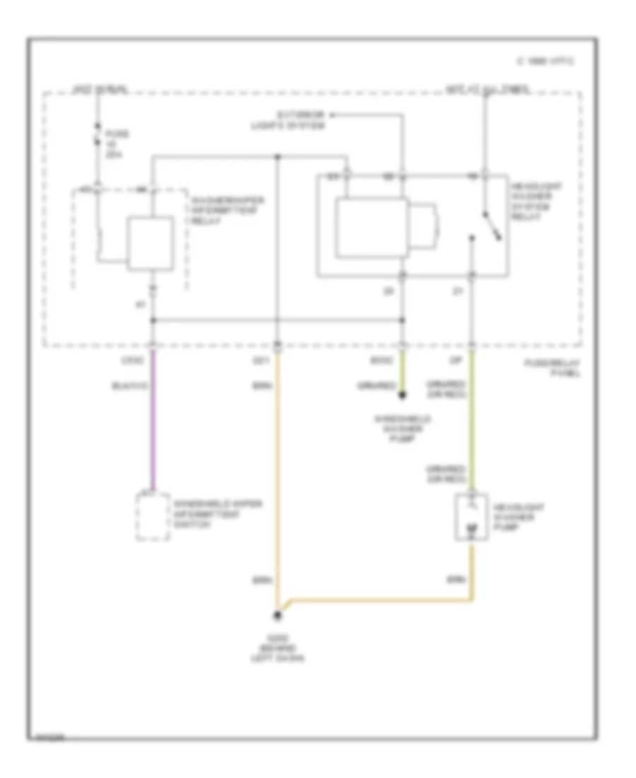
Headlamp Washer Wiring Diagram for Audi 90 CS Quattro 1993
List of elements for Headlamp Washer Wiring Diagram for Audi 90 CS Quattro 1993:
- 1995 vftc c
- B53c
- C53c
- Exterior lights system
- Fuse 25a
- Fuse/relay panel
- G202 (behind left dash)
- G31
- Headlight washer pump
- Headlight washer system relay
- Hot at all times
- Hot in run
- Washer/wiper intermittent relay
- Windshield washer pump
- Windshield wiper intermittent switch