AIR CONDITIONING
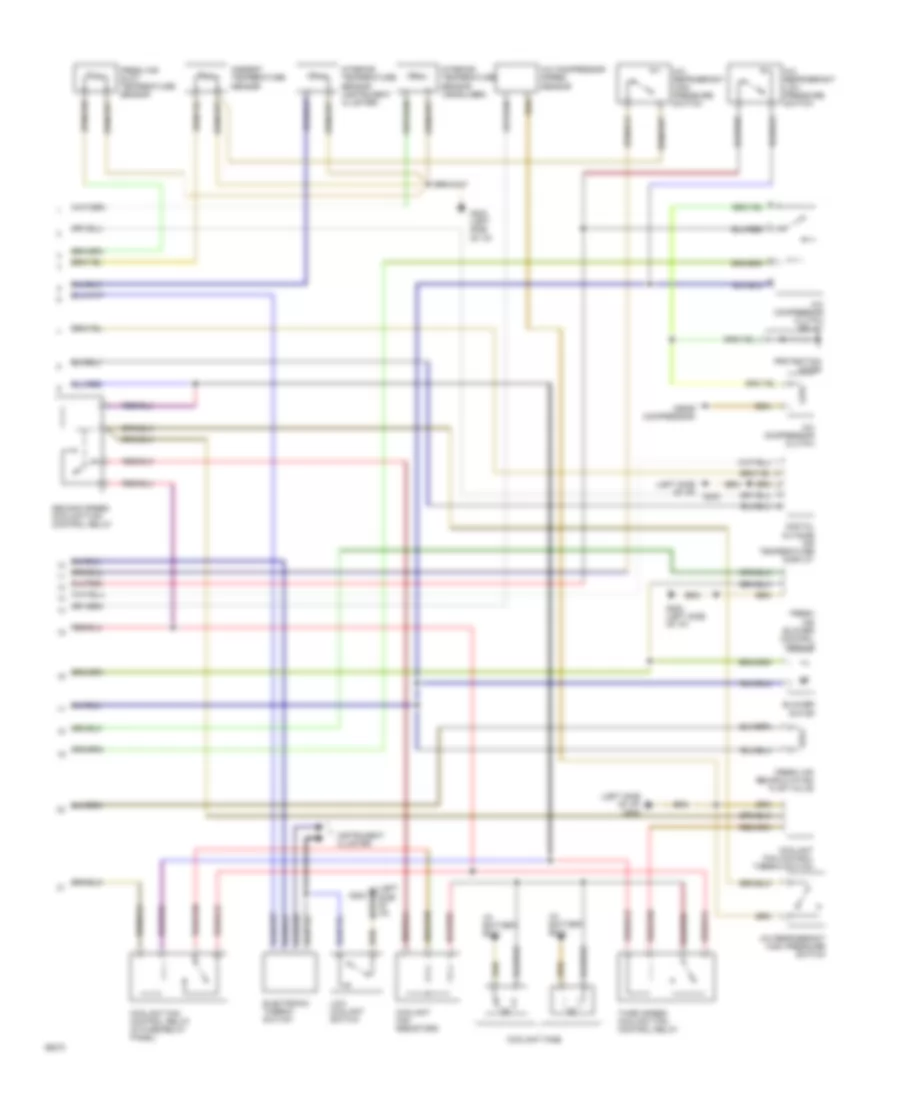
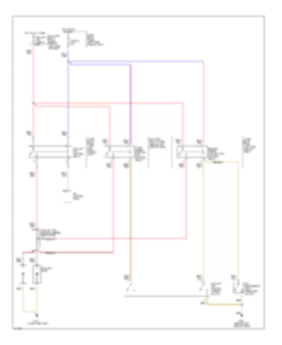
Auto. A/C-Heater System Wiring Diagram (With A/T Wiring Diagram 1 Of 2) for Audi 90 S 1993

List of elements for Auto. A/C-Heater System Wiring Diagram (With A/T Wiring Diagram 1 Of 2) for Audi 90 S 1993:
- (left side of i/p)
- A/c control head
- Air flow flap motor
- Auxiliary relay panel 2
- B10
- Battery (30)
- C10
- C11
- Central flap motor potentiometer
- Data link connector
- Engine control module
- Footwell/defrost flap motor potentiometer
- Fuse 15a
- Fuse 25a
- Fuse 30a
- Fuse 5a
- Fuse 60a
- Fuse/ relay panel
- G202
- G202 (left side of i/p)
- Hot at all times
- Hot w/ lights on
- Hot w/ load reduction relay energized (x)
- Ignition (15)
- Interior temperature sensor fan
- Temp regulator flap motor potentiometer
- Transmission control module
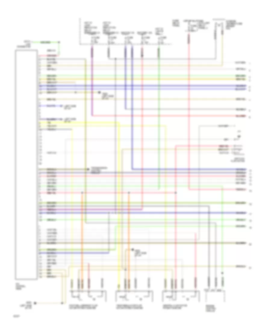
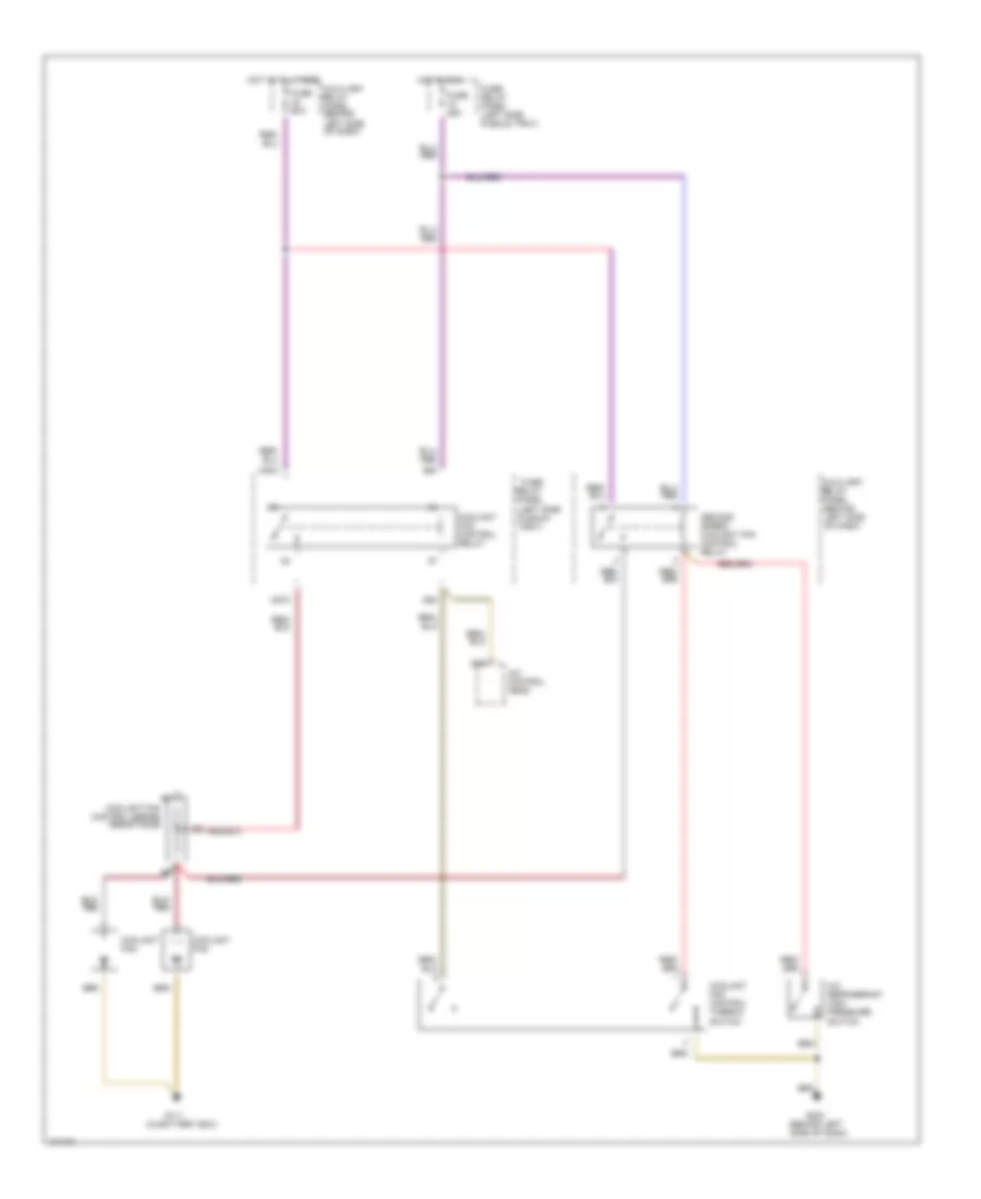
Auto. A/C-Heater System Wiring Diagram (With A/T Wiring Diagram 2 Of 2) for Audi 90 S 1993
List of elements for Auto. A/C-Heater System Wiring Diagram (With A/T Wiring Diagram 2 Of 2) for Audi 90 S 1993:
- (in battery box)
- (left side of i/p)
- (left side of i/p) g202
- (near compressor)
- A/c compressor clutch
- A/c compressor clutch relay
- A/c compressor speed sensor
- A/c refrigerant high pressure switch
- A/c refrigerant low pressure switch
- Ambient temperature sensor
- Blower motor
- Coolant fan control relay (in fuse/relay panel)
- Coolant fan control thermo switch
- Coolant fan resistors
- Coolant fans
- Digital outside air temperature display
- Electronic thermo switch
- Fresh air blower control module
- Fresh air duct temperature sensor
- Fresh air recirculating flap valve
- G202
- G202 (left side of i/p)
- Instrument cluster
- Interior temperature sensor (headliner)
- Interior temperature sensor (instrument cluster)
- Low coolant switch
- Protection diode
- Second speed coolant fan control relay
- Third speed coolant fan control relay
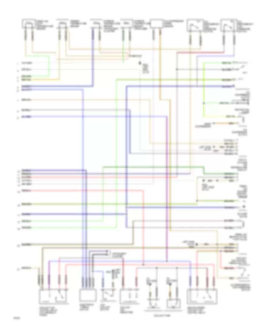
Auto. A/C-Heater System Wiring Diagram (With M/T Wiring Diagram 1 Of 2) for Audi 90 S 1993
List of elements for Auto. A/C-Heater System Wiring Diagram (With M/T Wiring Diagram 1 Of 2) for Audi 90 S 1993:
- (left side of i/p)
- A/c control head
- Air flow flap motor
- Auxiliary relay panel 2
- B10
- Battery (30)
- C10
- C11
- Central flap motor potentiometer
- Data link connector
- Engine control module
- Footwell/defrost flap motor potentiometer
- Fuse 15a
- Fuse 25a
- Fuse 30a
- Fuse 5a
- Fuse 60a
- Fuse/ relay panel
- G202
- G202 (left side of i/p)
- Hot at all times
- Hot w/ lights on
- Hot w/ load reduction relay energized (x)
- Ignition (15)
- Interior temperature sensor fan
- Temp regulator flap motor potentiometer
- Transmission control module
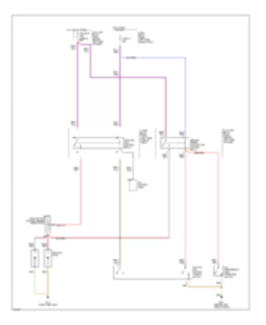
Auto. A/C-Heater System Wiring Diagram (With M/T Wiring Diagram 2 Of 2) for Audi 90 S 1993
List of elements for Auto. A/C-Heater System Wiring Diagram (With M/T Wiring Diagram 2 Of 2) for Audi 90 S 1993:
- (in battery box)
- (left side of i/p)
- (left side of i/p) g202
- (near compressor)
- A/c compressor clutch
- A/c compressor clutch relay
- A/c compressor speed sensor
- A/c refrigerant high pressure switch
- A/c refrigerant low pressure switch
- Ambient temperature sensor
- Blower motor
- Coolant fan control relay (in fuse/relay panel)
- Coolant fan control thermo switch
- Coolant fan resistors
- Coolant fans
- Digital outside air temperature display
- Electronic thermo switch
- Fresh air blower control module
- Fresh air duct temperature sensor
- Fresh air recirculating flap valve
- G202
- G202 (left side of i/p)
- Instrument cluster
- Interior temperature sensor (headliner)
- Interior temperature sensor (instrument cluster)
- Low coolant switch
- Protection diode
- Second speed coolant fan control relay
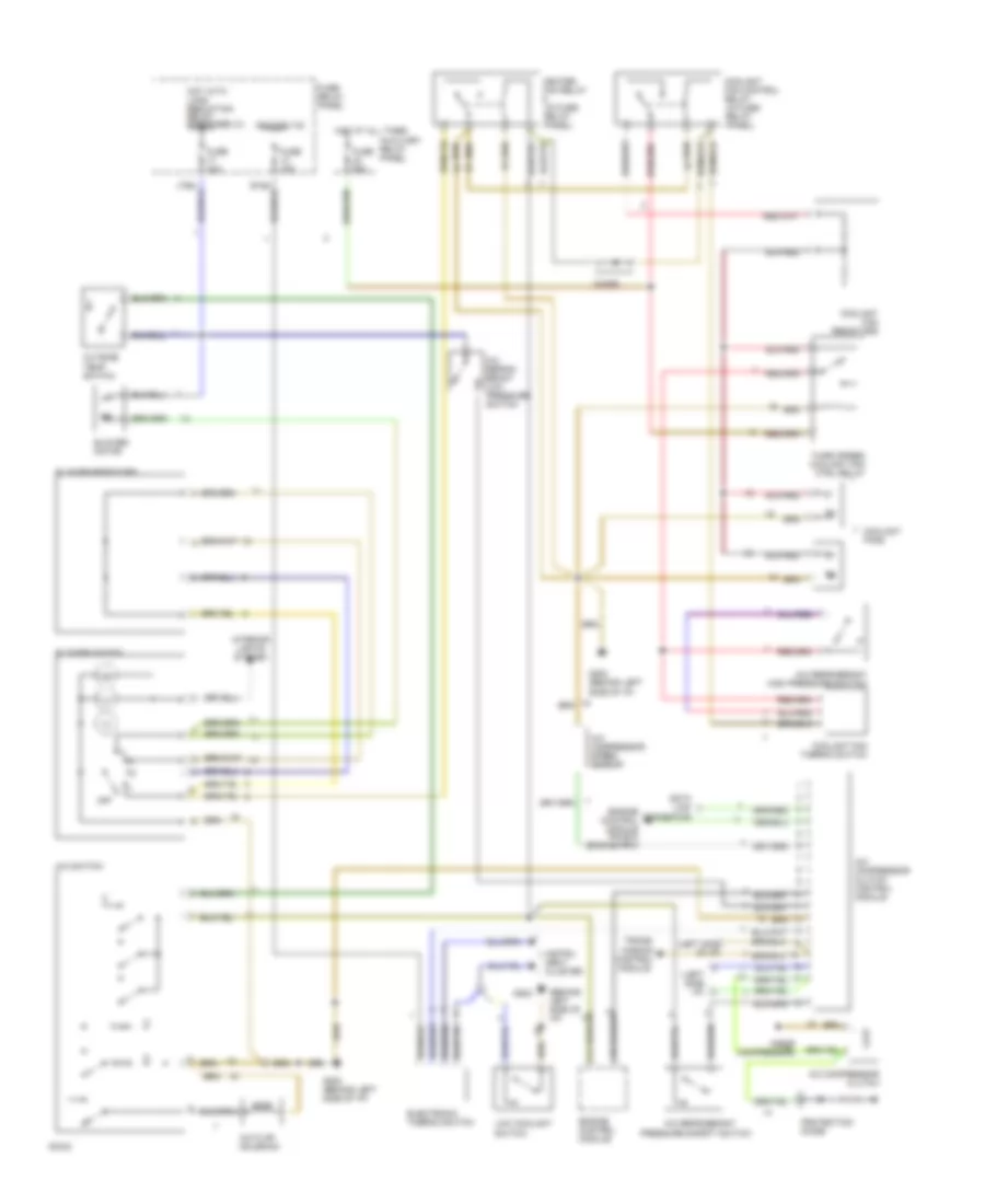
Manual A/C Wiring Diagram for Audi 90 S 1993
List of elements for Manual A/C Wiring Diagram for Audi 90 S 1993:
- (behind left side of i/p)
- (left side i/p)
- (left side of i/p)
- (near compressor)
- A/c compressor clutch
- A/c compressor clutch control module
- A/c compressor speed sensor
- A/c flap solenoid
- A/c refrig- erant low pressure switch
- A/c refrigerant
- A/c refrigerant high pressure switch'
- A/c switch
- Auxiliary relay panel
- Blower motor
- Blower resistors
- Blower switch
- C10
- C11
- Coolant fan control relay (in fuse/ relay panel)
- Coolant fan resistors
- Coolant fan thermo switch
- Coolant fans
- Data link connector
- Diode
- Electronic thermo switch
- Engine control module
- Engine control module pin b10 (engine rpm)
- Fuse 15a
- Fuse 30a
- Fuse 60a
- Fuse/ relay panel
- G202
- G202 (behind left side of i/p)
- Heater fan relay (in fuse/ relay panel)
- Hot at all times
- Hot with load reduction relay energized (x)
- Ignition (15)
- Instru- ment cluster
- Interior lights system
- Low coolant switch
- Off
- Outside temp switch
- Pressure safety switch
- Protection diode
- Third speed coolant fan ctrl relay
- Trans- mission control module
COOLING FAN
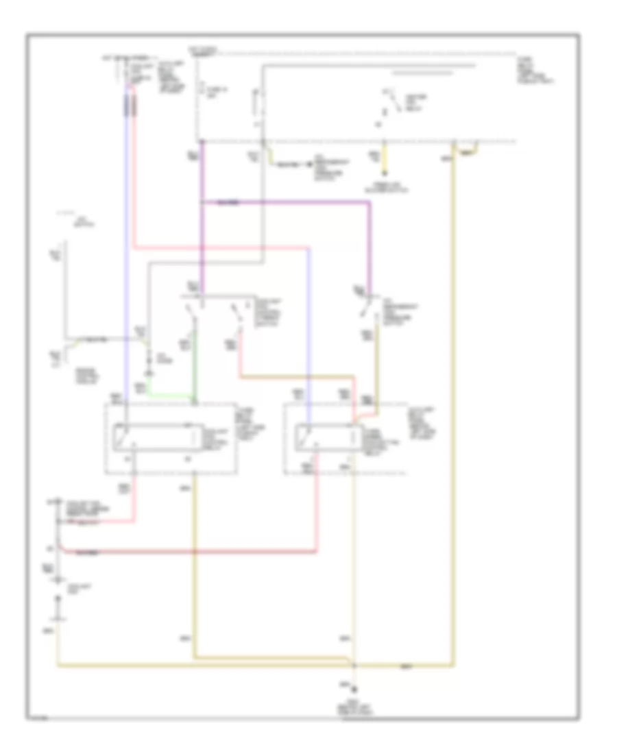
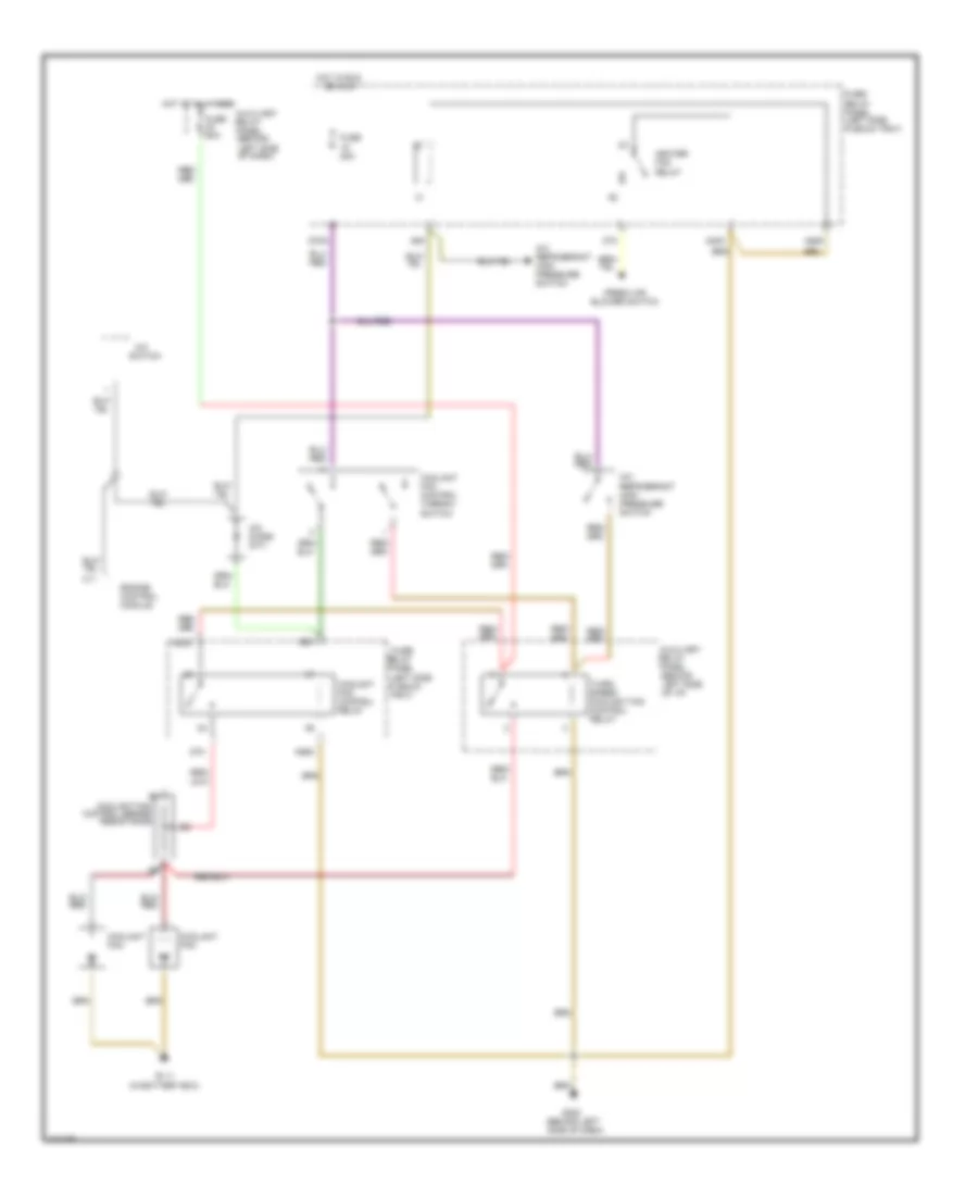
Cooling Fan Wiring Diagram, A/T with Automatic A/C Late Production for Audi 90 S 1993
List of elements for Cooling Fan Wiring Diagram, A/T with Automatic A/C Late Production for Audi 90 S 1993:
- (behind left side of dash)
- (in battery box)
- (left side plenum tray)
- A/c control head
- A/c refrigerant high pressure switch
- Auxiliary
- Coolant fan fuse 42 60a
- Coolant fan control relay
- Coolant fan control series resistance
- Coolant fan control thermo- switch
- Coolant fans
- D16
- Fuse 15 25a
- Fuse/ relay panel
- Fuse/ relay panel (left side plenum tray)
- G111
- G202
- Hot at all times
- Hot in run or accy
- Relay panel
- Second speed coolant fan control relay
- Third speed coolant fan control relay
Cooling Fan Wiring Diagram, Auto A/C Early Production for Audi 90 S 1993
List of elements for Cooling Fan Wiring Diagram, Auto A/C Early Production for Audi 90 S 1993:
- (behind left side of dash)
- (in battery box)
- (left side plenum tray)
- 85m
- 86m
- A/c control head
- A/c refrigerant high pressure switch
- A30m
- A87m
- Auxiliary
- Coolant fan
- Coolant fan control relay
- Coolant fan control series resistance
- Coolant fan control thermo- switch
- D16
- Fuse 25a
- Fuse 60a
- Fuse/ relay panel
- Fuse/ relay panel (left side plenum tray)
- G111
- G202
- Hot at all times
- Hot in run
- Relay panel
- Second speed coolant fan control relay
Cooling Fan Wiring Diagram, M/T with Auto A/C Late Production for Audi 90 S 1993
List of elements for Cooling Fan Wiring Diagram, M/T with Auto A/C Late Production for Audi 90 S 1993:
- (behind left side of dash)
- (left side plenum tray)
- A/c control head
- A/c refrigerant high pressure switch
- Auxiliary
- Coolant fan fuse 42 60a
- Coolant fan control relay
- Coolant fan control thermo- switch
- Coolant fans
- D16
- E1 coolant fan control series resistance
- Fuse 15 25a
- Fuse/ relay panel
- Fuse/ relay panel (left side plenum tray)
- G111 (in battery box)
- G202
- Hot at all times
- Hot in run
- Or accy
- Relay panel
- Second speed coolant fan control relay
Cooling Fan Wiring Diagram, M/T with Manual A/C Late Production for Audi 90 S 1993
List of elements for Cooling Fan Wiring Diagram, M/T with Manual A/C Late Production for Audi 90 S 1993:
- (behind left side of dash)
- (left side plenum tray)
- A/c
- A/c diode
- A/c refrigerant high pressure switch
- Auxiliary
- C11
- Coolant fan
- Coolant fan fuse 42 60a
- Coolant fan control relay
- Coolant fan control series resistance
- Coolant fan control thermo- switch
- Engine control module
- Fresh air blower switch
- Fuse 15 25a
- Fuse/ relay panel
- Fuse/ relay panel (left side plenum tray)
- G202
- Heater fan relay
- Hot at all times
- Hot in run or accy
- Relay panel
- Switch
- Third speed coolant fan control relay
Cooling Fan Wiring Diagram, Manual A/C Early Production for Audi 90 S 1993
List of elements for Cooling Fan Wiring Diagram, Manual A/C Early Production for Audi 90 S 1993:
- (behind left side of dash)
- (behind left side of i/p)
- (left side plenum tray)
- 85k
- 85m
- 87k
- 87m
- A/c
- A/c diode (m/t)
- A/c refrigerant high pressure switch
- A30k
- A30m
- A86k
- A86m
- Auxiliary
- C11
- Coolant fan
- Coolant fan control relay
- Coolant fan control series resistance
- Coolant fan control thermo- switch
- D75a
- Engine control module
- Fresh air blower switch
- Fuse 25a
- Fuse 60a
- Fuse/ relay panel
- Fuse/ relay panel (left side plenum tray)
- G111 (in battery box)
- G202
- Heater fan relay
- Hot at all times
- Hot in run
- Or accy
- Relay panel
- Switch
- Third speed coolant fan control relay
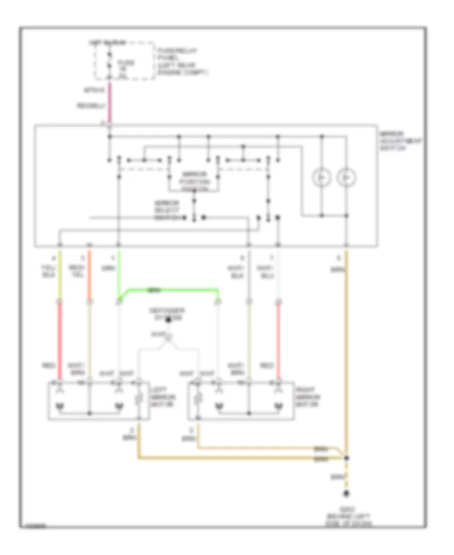
DEFOGGERS
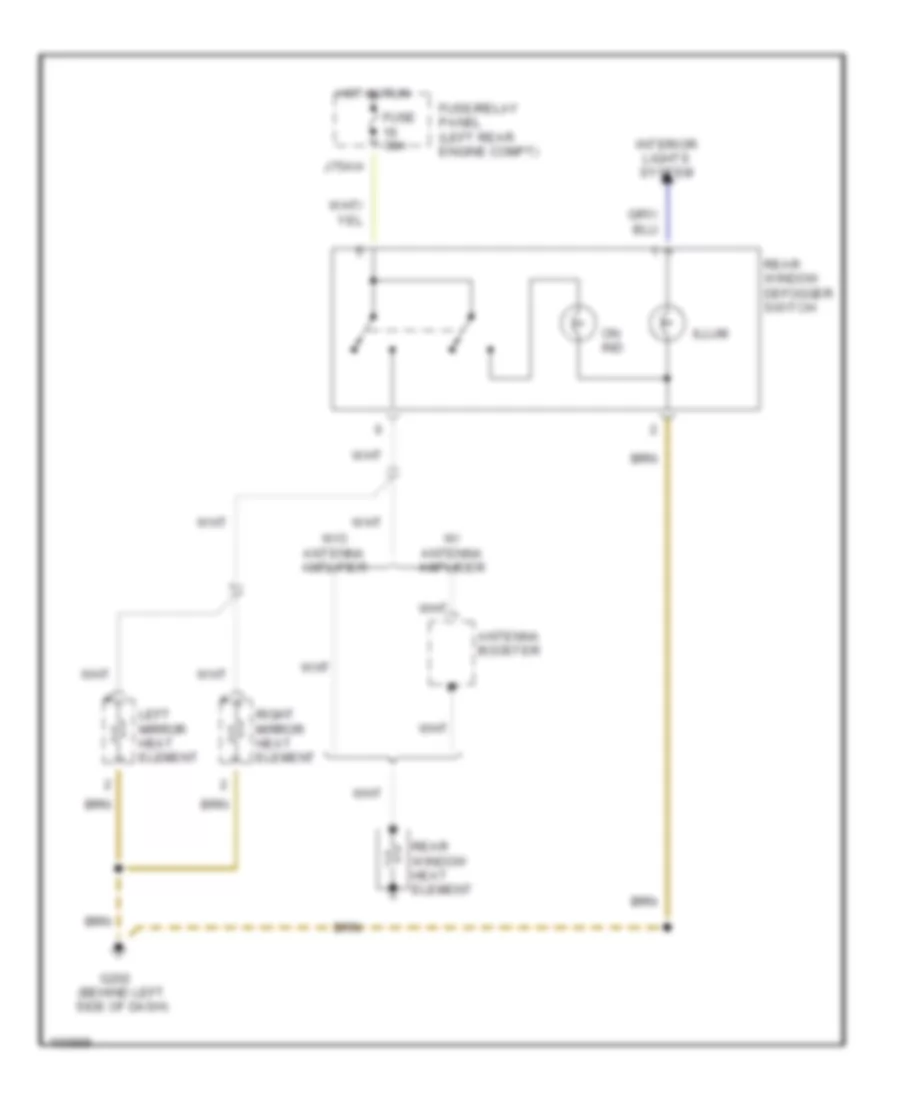
Defoggers Wiring Diagram, Early Production for Audi 90 S 1993
List of elements for Defoggers Wiring Diagram, Early Production for Audi 90 S 1993:
- Antenna booster
- Fuse 30a
- Fuse/relay panel (left rear engine compt)
- G202 (behind left side of dash)
- Hot in run
- Illum
- Interior lights system
- J75ah
- Left mirror heat element
- On ind
- Rear window defogger switch
- Rear window heat element
- Right mirror heat element
- W/ antenna amplifier
- W/o antenna amplifier
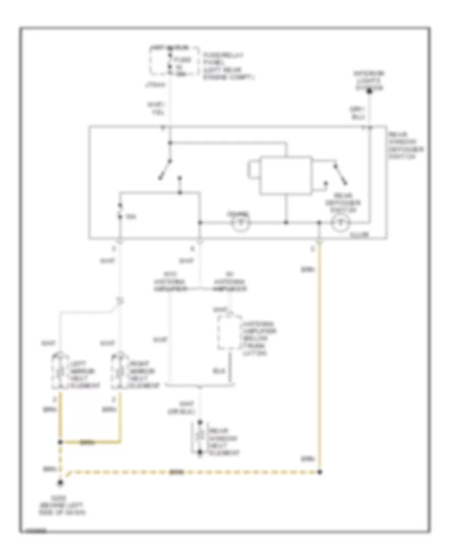
Defoggers Wiring Diagram, Late Production for Audi 90 S 1993
List of elements for Defoggers Wiring Diagram, Late Production for Audi 90 S 1993:
- 10a
- Antenna amplifier (below trunk latch)
- Fuse 30a
- Fuse/relay panel (left rear engine compt)
- G202 (behind left side of dash)
- Hot in run
- Illum
- Interior lights system
- J75ah
- Left mirror heat element
- On ind
- Rear defogger switch
- Rear window defogger switch
- Rear window heat element
- Right mirror heat element
- W/ antenna amplifier
- W/o antenna amplifier
HORN
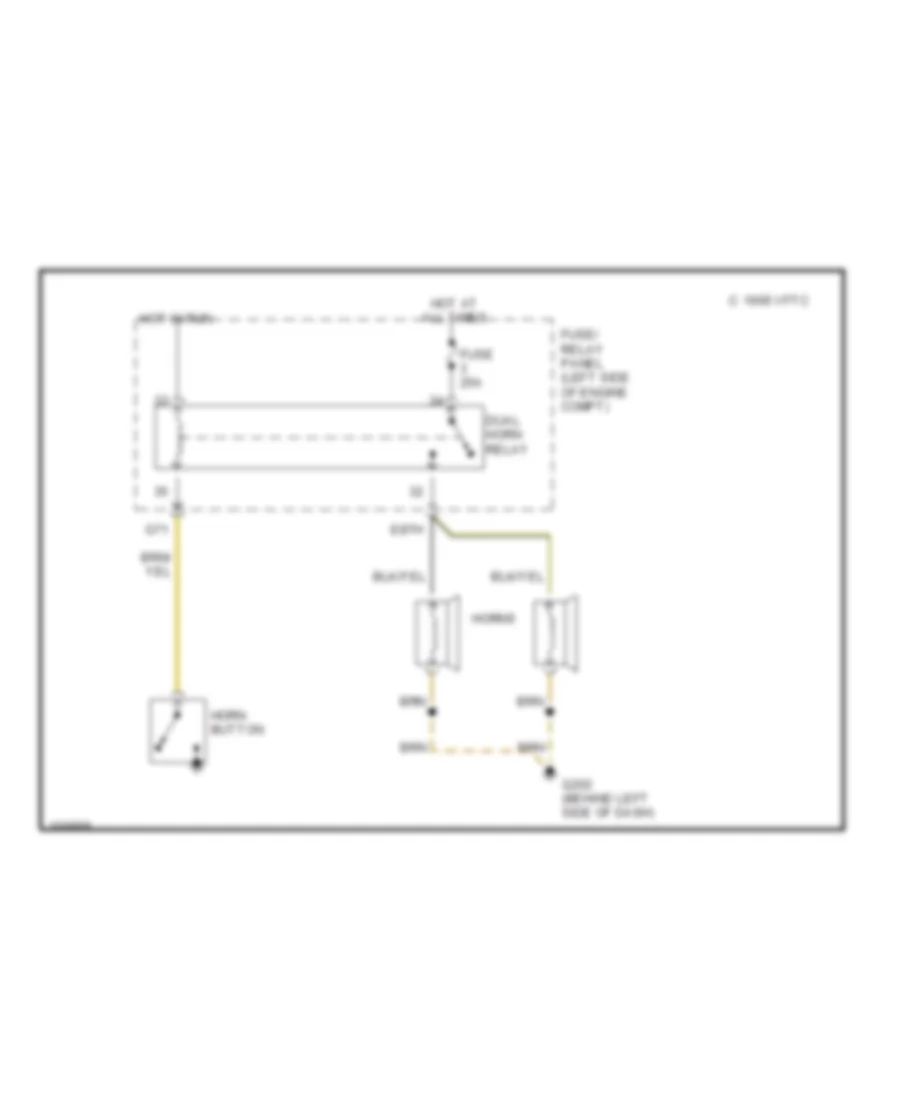
Horn Wiring Diagram for Audi 90 S 1993
List of elements for Horn Wiring Diagram for Audi 90 S 1993:
- 1995 vftc c
- Dual horn relay
- E87h
- Fuse 25a
- Fuse/ relay panel (left side of engine compt)
- G202 (behind left side of dash)
- G71
- Horn button
- Horns
- Hot at all times
- Hot in run
POWER DOOR LOCKS
Power Door Locks Wiring Diagram for Audi 90 S 1993
List of elements for Power Door Locks Wiring Diagram for Audi 90 S 1993:
- (early production)
- (early) (late)
- (late 1993)
- (late production)
- 12b a
- 6ae b
- All times
- C15a
- Central locking/ alarm system/ interior light delay control module
- Door handle alarm switches
- Door lock
- Driver's door central locking system switch
- Early
- F30al
- Fuse 10a
- Fuse 15a
- Fuse/relay panel (left side of engine compt on plenum tray)
- G202 (behind left
- G202 (behind left side of dash)
- G404 (near left)
- Heated
- Heater
- Hot at
- Hot at all times
- Hot in on or start
- Interior lights system
- Left door lock heater
- Left front door contact switch
- Left heated door lock control module
- Left heated door lock switch
- Left infrared central locking system sensor
- Left rear door contact switch
- M30az
- Nca
- Passenger's door central locking system switch (late 1993 production)
- Red
- Right
- Right door lock
- Right front door contact switch
- Right heated door lock control module
- Right infrared central locking system sensor
- Right rear door contact switch
- Side of dash)
- Switch
- Taillight)
- Trunk lock alarm/ central locking switch
POWER MIRRORS
Power Mirrors Wiring Diagram for Audi 90 S 1993
List of elements for Power Mirrors Wiring Diagram for Audi 90 S 1993:
- Defogger
- Fuse 5a
- Fuse/relay panel (left rear engine compt)
- G202 (behind left side of dash)
- Hot in run
- Left mirror motor
- M75as
- Mirror adjustment switch
- Mirror position switch
- Mirror select switch
- Red
- Right mirror motor
- System
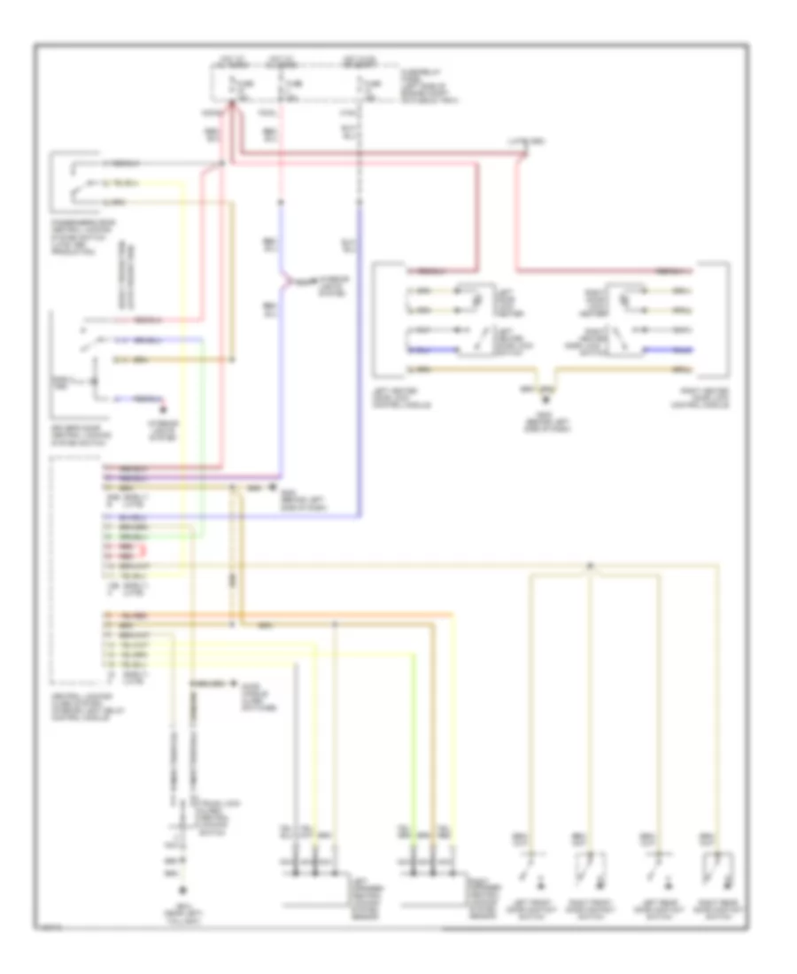
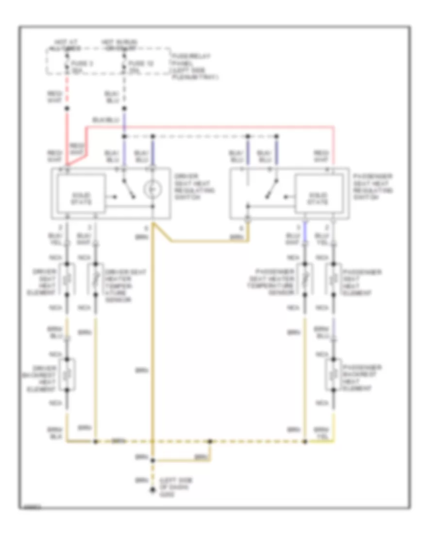
POWER SEATS
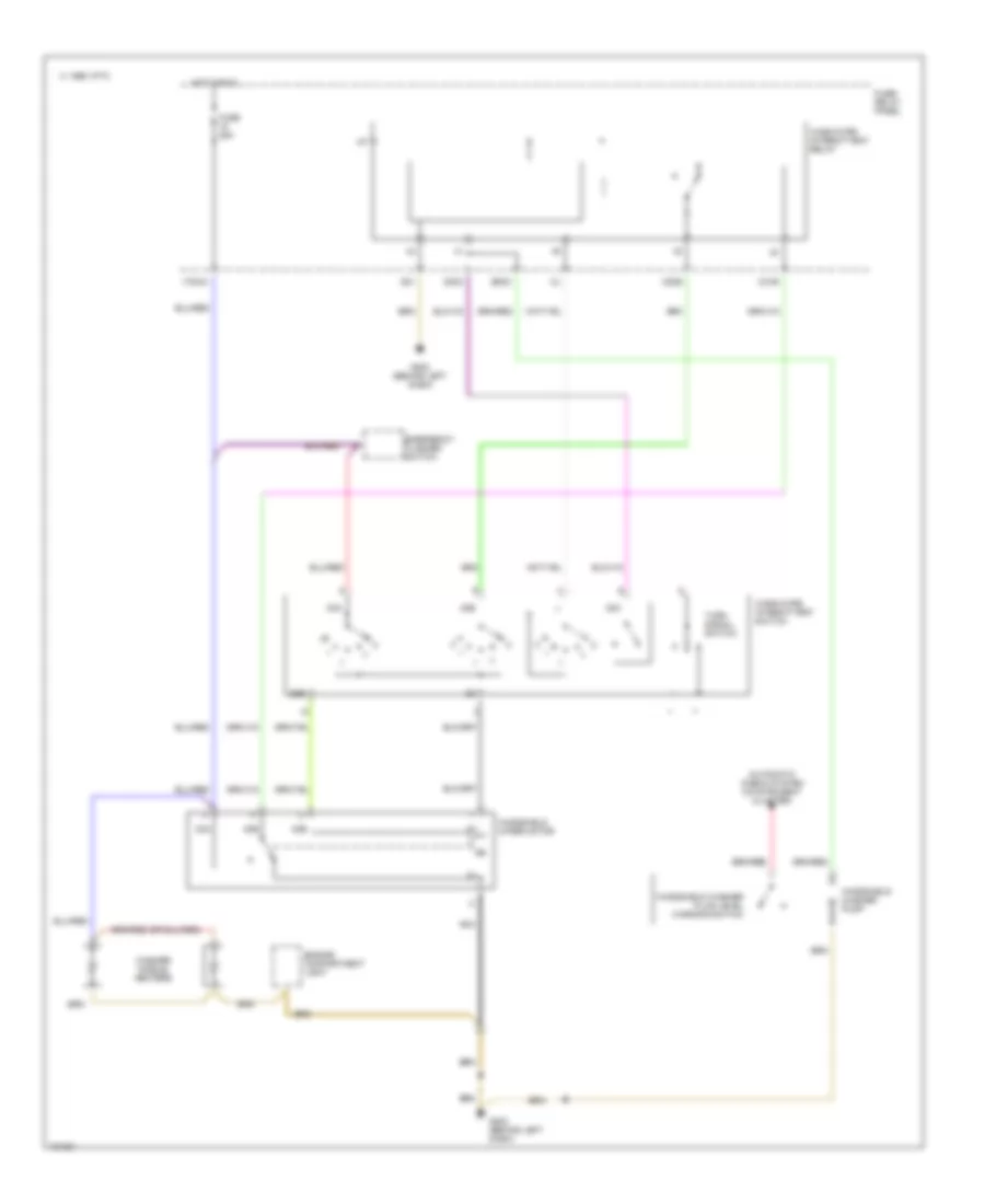
Heated Seats Wiring Diagram for Audi 90 S 1993
List of elements for Heated Seats Wiring Diagram for Audi 90 S 1993:
- (left side of dash) g202
- All times
- Driver backrest heat element
- Driver seat heat element
- Driver seat heat regulating switch
- Driver seat heater temper- ature sensor
- Fuse 12 15a
- Fuse 3 30a
- Fuse/relay panel (left side plenum tray)
- Hot at
- Hot in run or start
- Nca
- Passenger backrest heat element
- Passenger seat heat element
- Passenger seat heat regulating switch
- Passenger seat heater temperature sensor
- Solid state
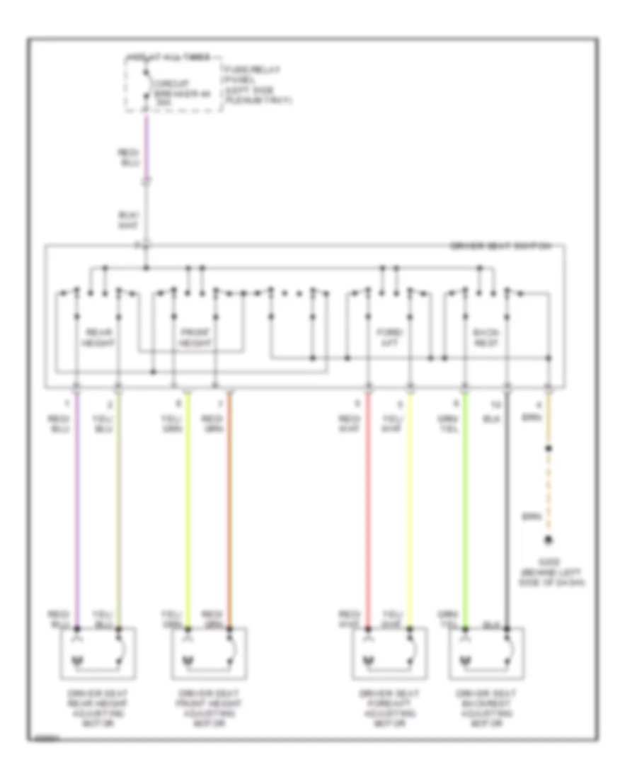
Left Power Seat Wiring Diagram for Audi 90 S 1993
List of elements for Left Power Seat Wiring Diagram for Audi 90 S 1993:
- Back- rest
- Circuit breaker 44 30a
- Driver seat backrest adjusting motor
- Driver seat fore/aft adjusting motor
- Driver seat front height adjusting motor
- Driver seat rear height adjusting motor
- Driver seat switch
- Fore/ aft
- Front height
- Fuse/relay panel (left side plenum tray)
- G202 (behind left side of dash)
- Hot at all times
- Rear height
POWER WINDOWS
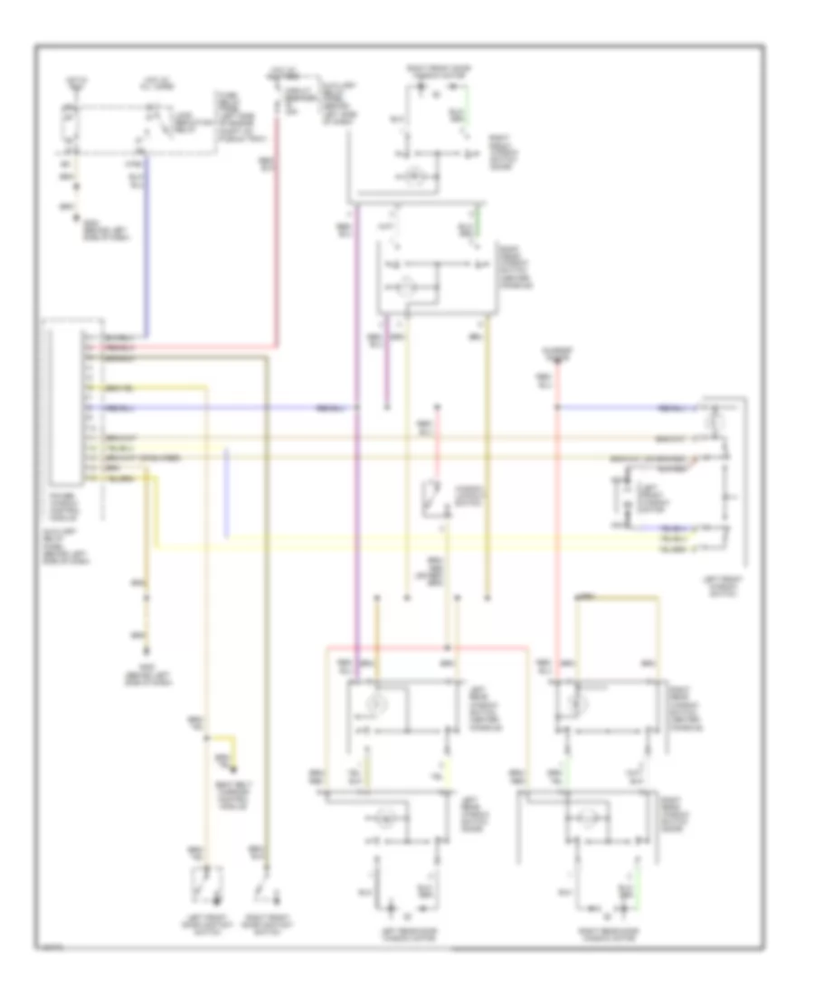
Power Windows Wiring Diagram for Audi 90 S 1993
List of elements for Power Windows Wiring Diagram for Audi 90 S 1993:
- All times
- Auxiliary relay panel (behind left side of dash)
- Circuit breaker 20a
- Fuse/ relay panel (left side of engine compt on plenum tray)
- G202 (behind left side of dash)
- G31
- Hot at
- Hot at all times
- Hot in run
- Left front door contact switch
- Left front window motor
- Left front window switch
- Left rear
- Left rear door window motor
- Left rear window switch (door)
- Load reduction relay
- M75s
- Nca
- Power window control module
- Right front door contact switch
- Right front door window motor
- Right front window switch (center console)
- Right front window switch (door)
- Right rear
- Right rear door window motor
- Right rear window switch (door)
- Seat belt warning control module
- Sunroof motor
- Window lockout switch
- Window switch (center console)
RADIO
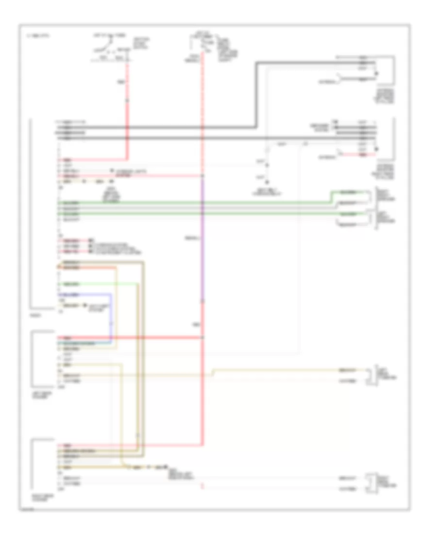
Radio Wiring Diagram for Audi 90 S 1993
List of elements for Radio Wiring Diagram for Audi 90 S 1993:
- 10e
- 1995 vftc c
- 2af
- 2ag
- Acc
- Antenna
- Antenna booster (left rear "d" pillar)
- Antenna booster (right rear "d" pillar)
- Anti-theft system
- Defogger system
- Fuse 15a
- Fuse/ relay panel (left side of engine compt)
- G202 (behind left side of dash)
- Hot at all times
- Ignition/ start switch
- Interior lights system
- Left front speaker
- Left rear tweeter
- Left rear woofer
- Lock
- Nca
- Radio
- Red
- Right front speaker
- Right rear tweeter
- Right rear woofer
- Run
- Seat belt warning relay
- Start
- Warning system (auto check system, in instrument cluster)
STARTING/CHARGING
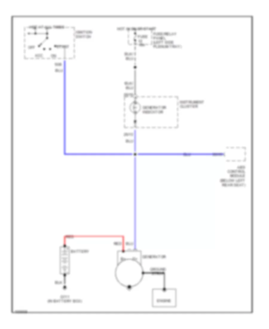
Charging Wiring Diagram for Audi 90 S 1993
List of elements for Charging Wiring Diagram for Audi 90 S 1993:
- (below left rear seat)
- 26/13
- 26/16
- 35/15
- 50b
- Abs control module
- Acc
- Battery
- Engine
- Fuse 15a
- Fuse/relay panel (left side plenum tray)
- G111 (in battery box)
- Generator
- Generator indicator
- Ground strap
- Hot at all times
- Hot in on or start
- Ignition switch
- Instrument cluster
- Off
- Red
- Start
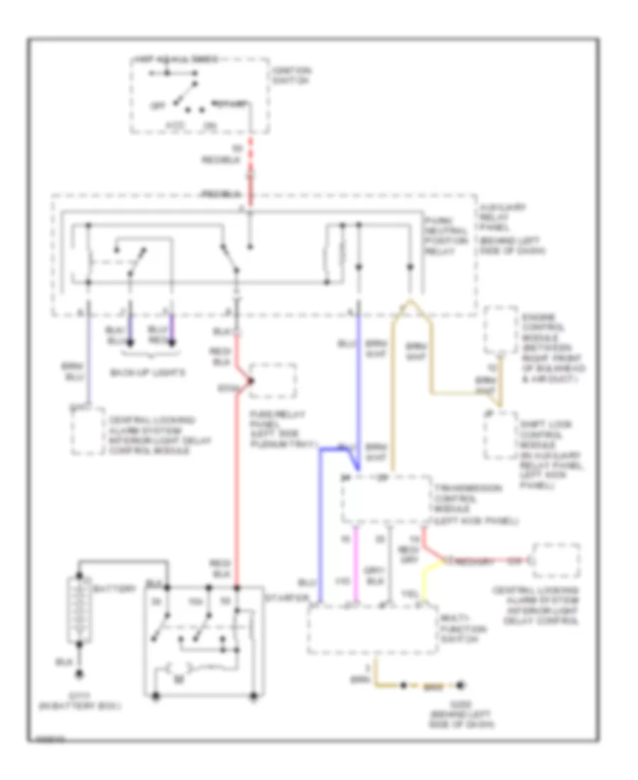
Starting Wiring Diagram, A/T for Audi 90 S 1993
List of elements for Starting Wiring Diagram, A/T for Audi 90 S 1993:
- (behind left side of dash)
- (left kick panel)
- 15a
- Acc
- Auxiliary relay panel
- Back-up lights
- Battery
- C/1
- C/9
- Central locking/ alarm system/ interior light delay control
- Central locking/ alarm system/ interior light delay control module
- E50a
- Engine control module (between right front of bulkhead & air duct)
- Function switch
- Fuse/relay panel (left side plenum tray)
- G111 (in battery box)
- G202 (behind left side of dash)
- Hot at all times
- Ignition switch
- Multi-
- Off
- Park/ neutral position relay
- Shift lock control module (in auxiliary relay panel, left kick panel)
- Start
- Starter
- Transmission control module
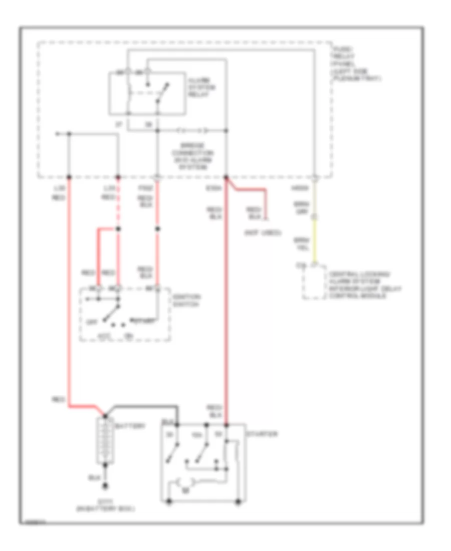
Starting Wiring Diagram, M/T for Audi 90 S 1993
List of elements for Starting Wiring Diagram, M/T for Audi 90 S 1993:
- (not used)
- 15a
- Acc
- Alarm system relay
- Battery
- Bridge connection (w/o alarm system)
- C/1
- Central locking/ alarm system/ interior light delay control module
- E50a
- F50z
- Fuse/ relay panel (left side plenum tray)
- G111 (in battery box)
- H50w
- Ignition switch
- L30
- Off
- Red
- Start
- Starter
TRANSMISSION
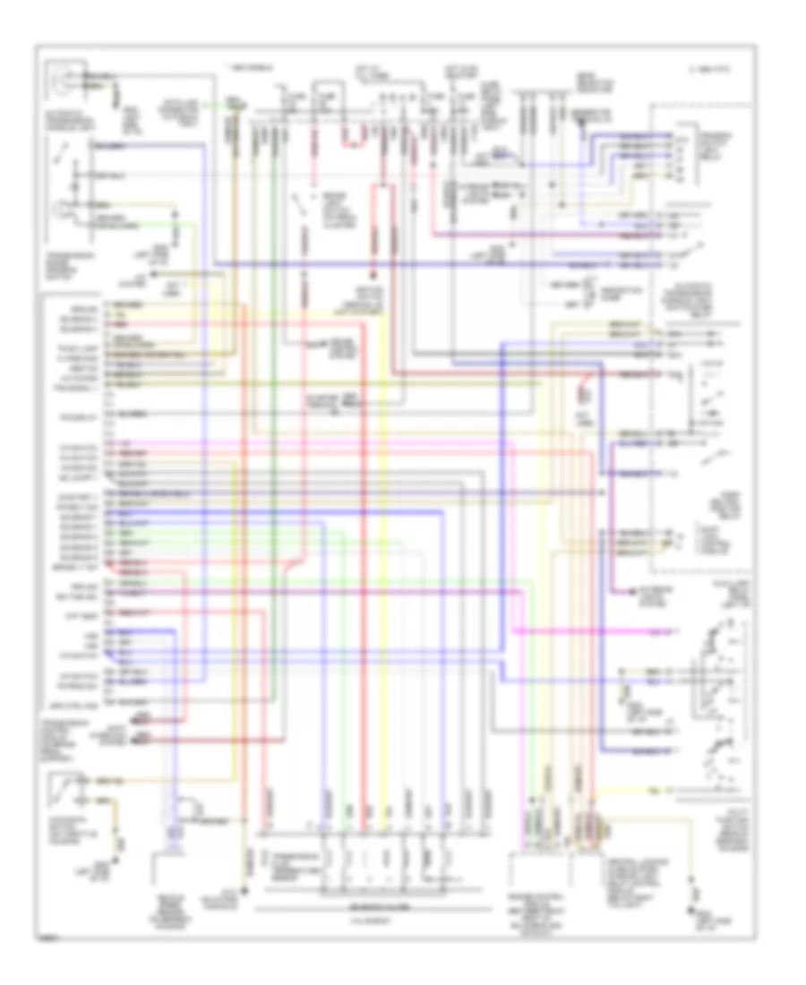
A/T Wiring Diagram for Audi 90 S 1993
List of elements for A/T Wiring Diagram for Audi 90 S 1993:
- (left side of i/p)
- * 1993 models
- 1995 vftc c
- 2p n
- 50a
- 50z
- 87a
- A/c kickdn
- A/c system
- Abs/tcs
- Atf temp
- Automatic transmission console light
- Automatic transmission console light switch-over relay
- Auxilliary relay panel (left i/p)
- Brake light switch (on pedal cluster)
- Brake lt sw
- C15a
- Central locking/ alarm system/ interior light delay control module (below right taillight)
- Cruise control system
- Data link connector (in plenum tray)
- E50a
- Engine control module (between front right of bulkhead and air duct)
- Exterior lights system
- F30al
- F50z
- Fuse 10a
- Fuse 15a
- Fuse 5a
- Fuse/ relay panel (left side plenum tray)
- G131 (on intake manifold)
- G202 (left side of i/p)
- Gear selection indicator
- Generator terminal d+
- Ground
- H50w
- Hot at all times
- Hot in on or start
- Ign time adj
- Ignition switch terminal 50 (hot in start)
- Interior lights system
- K wire diag
- Kick-down switch (on throttle housing)
- Kickdn sw
- L30
- M-f switch
- Multi- function switch (rear of gear box housing)
- Not
- On/start v
- P/n
- Park/ neutral position relay
- Pk/neut sig
- Program switch light relay
- Protection diode
- R n
- Red
- Red/ starter terminal
- Rpm sig
- Shift interlock system
- Shift lock control module
- Sol supp v
- Solenoid 1
- Solenoid 2
- Solenoid 3
- Solenoid 4
- Solenoid 5
- Solenoid 6
- Solenoid 7
- Solenoid valves
- Spd ctrl mod
- T20
- Tps signal v
- Tr display
- Tr prog sw
- Tr sw lamp
- Transmission control module (on brake pedal support)
- Transmission fluid temperature sensor
- Transmission range program switch
- Used
- Valve body
- Vehicle speed sensor (on gearbox housing)
- Vss
WIPER/WASHER
Front Wiper/Washer Wiring Diagram for Audi 90 S 1993
List of elements for Front Wiper/Washer Wiring Diagram for Audi 90 S 1993:
- 175aw
- 1995 vftc c
- 53a
- 53b
- 53c
- 53e
- Automatic check system (intstrument cluster)
- B53c
- C31b
- C53c
- C53e
- Emergency flasher switch
- Engine compartment light
- Fuse 25a
- Fuse/ relay panel
- G202 (behind left dash)
- G31
- Hot in run
- Nca
- Pump
- Turn signal switch
- Wash/wipe intermittent relay
- Wash/wipe intermittent switch
- Washer nozzle heaters
- Windshield washer fluid level warning switch
- Windshield washer m
- Windshield wiper motor
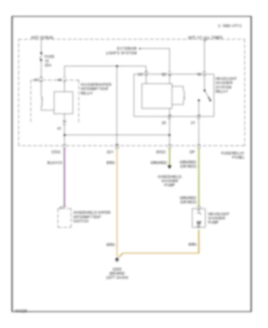
Headlamp Washer Wiring Diagram for Audi 90 S 1993
List of elements for Headlamp Washer Wiring Diagram for Audi 90 S 1993:
- 1995 vftc c
- B53c
- C53c
- Exterior lights system
- Fuse 25a
- Fuse/relay panel
- G202 (behind left dash)
- G31
- Headlight washer pump
- Headlight washer system relay
- Hot at all times
- Hot in run
- Washer/wiper intermittent relay
- Windshield washer pump
- Windshield wiper intermittent switch