AIR CONDITIONING
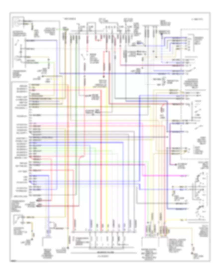
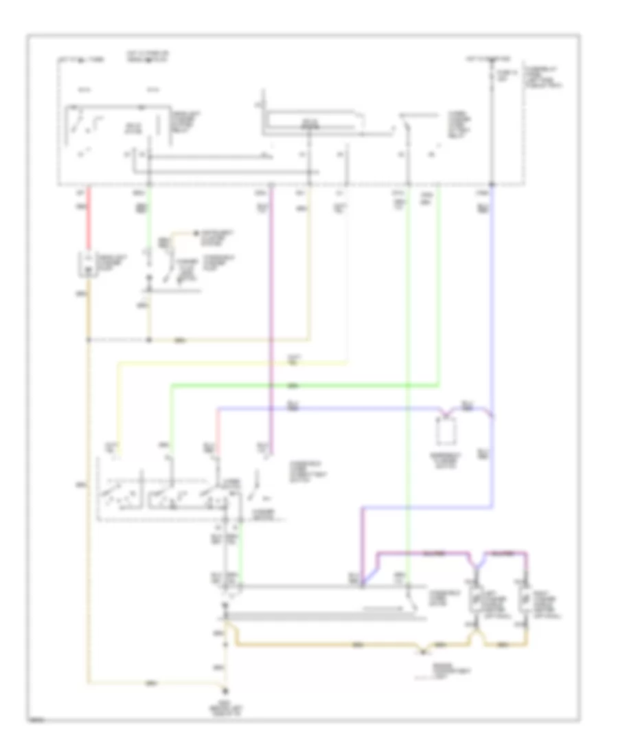
Auto. A/C-Heater System Wiring Diagram (With A/T Wiring Diagram 1 Of 2) for Audi 90 S 1994

List of elements for Auto. A/C-Heater System Wiring Diagram (With A/T Wiring Diagram 1 Of 2) for Audi 90 S 1994:
- (left side of i/p)
- A/c control head
- Air flow flap motor
- Auxiliary relay panel 2
- B10
- Battery (30)
- C10
- C11
- Central flap motor potentiometer
- Data link connector
- Engine control module
- Footwell/defrost flap motor potentiometer
- Fuse 15a
- Fuse 25a
- Fuse 30a
- Fuse 5a
- Fuse 60a
- Fuse/ relay panel
- G202
- G202 (left side of i/p)
- Hot at all times
- Hot w/ lights on
- Hot w/ load reduction relay energized (x)
- Ignition (15)
- Interior temperature sensor fan
- Temp regulator flap motor potentiometer
- Transmission control module
Auto. A/C-Heater System Wiring Diagram (With A/T Wiring Diagram 2 Of 2) for Audi 90 S 1994
List of elements for Auto. A/C-Heater System Wiring Diagram (With A/T Wiring Diagram 2 Of 2) for Audi 90 S 1994:
- (in battery box)
- (left side of i/p)
- (left side of i/p) g202
- (near compressor)
- A/c compressor clutch
- A/c compressor clutch relay
- A/c compressor speed sensor
- A/c refrigerant high pressure switch
- A/c refrigerant low pressure switch
- Ambient temperature sensor
- Blower motor
- Coolant fan control relay (in fuse/relay panel)
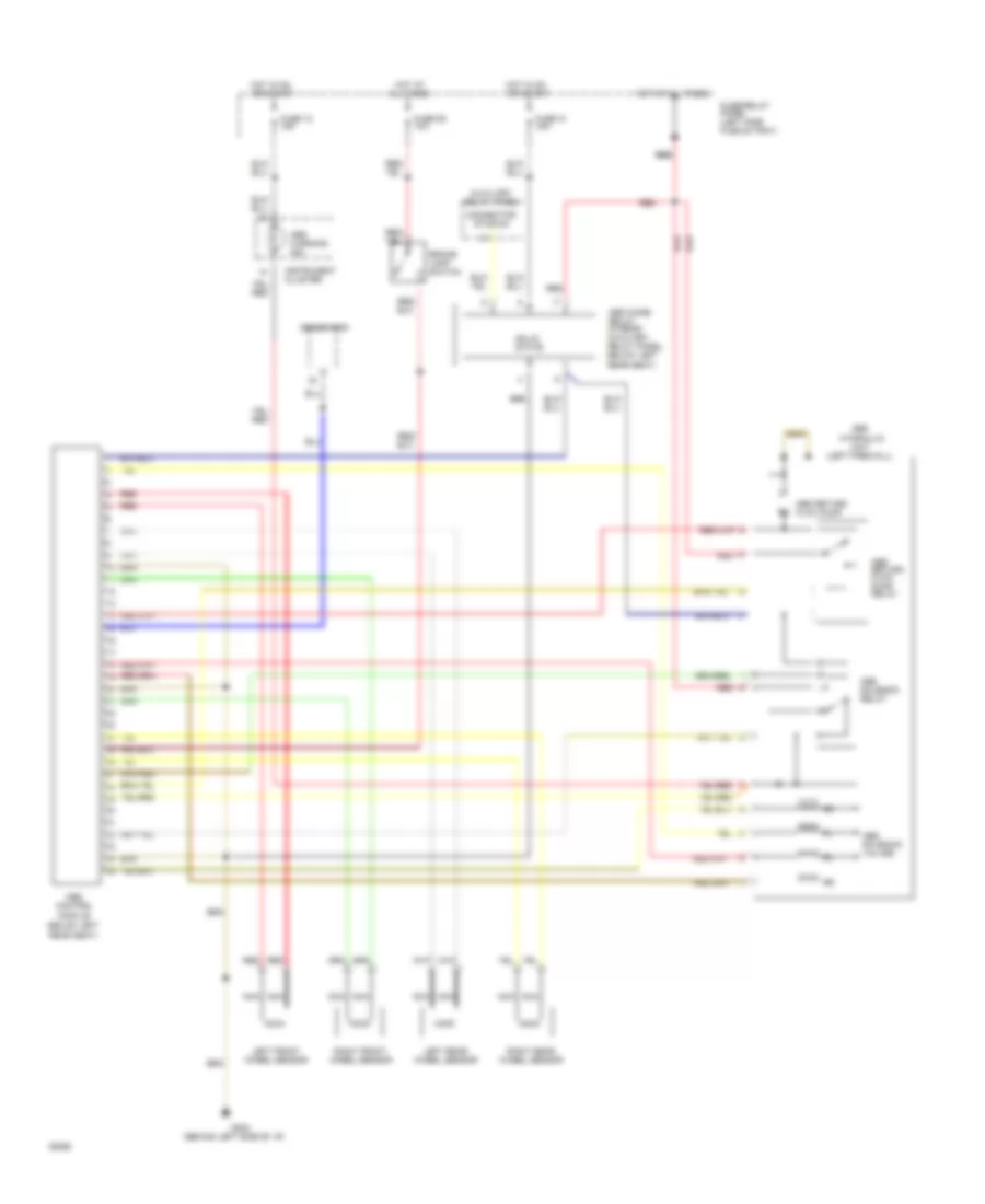
- Coolant fan control thermo switch
- Coolant fan resistors
- Coolant fans
- Digital outside air temperature display
- Electronic thermo switch
- Fresh air blower control module
- Fresh air duct temperature sensor
- Fresh air recirculating flap valve
- G202
- G202 (left side of i/p)
- Instrument cluster
- Interior temperature sensor (headliner)
- Interior temperature sensor (instrument cluster)
- Low coolant switch
- Protection diode
- Second speed coolant fan control relay
- Third speed coolant fan control relay
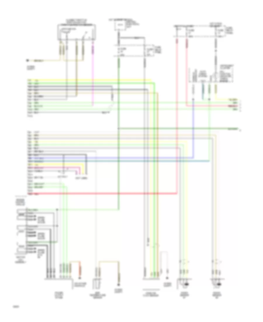
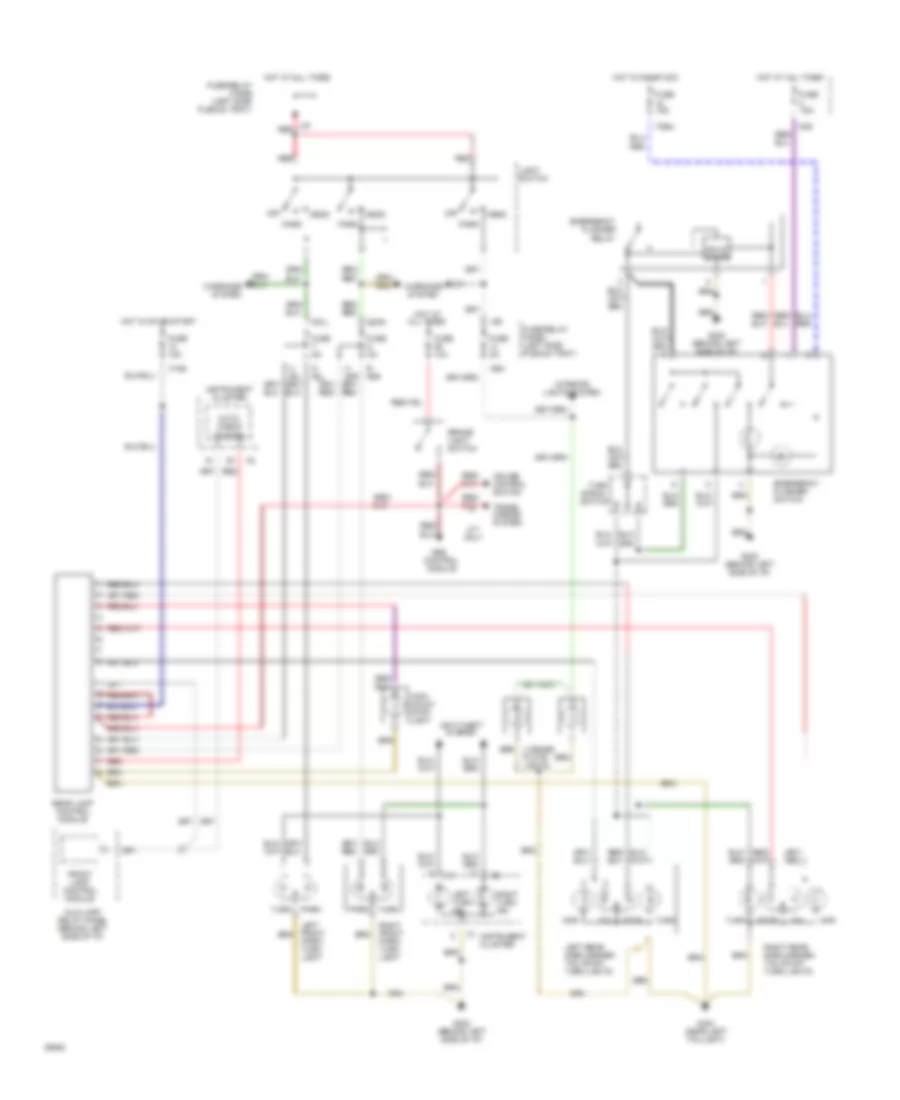
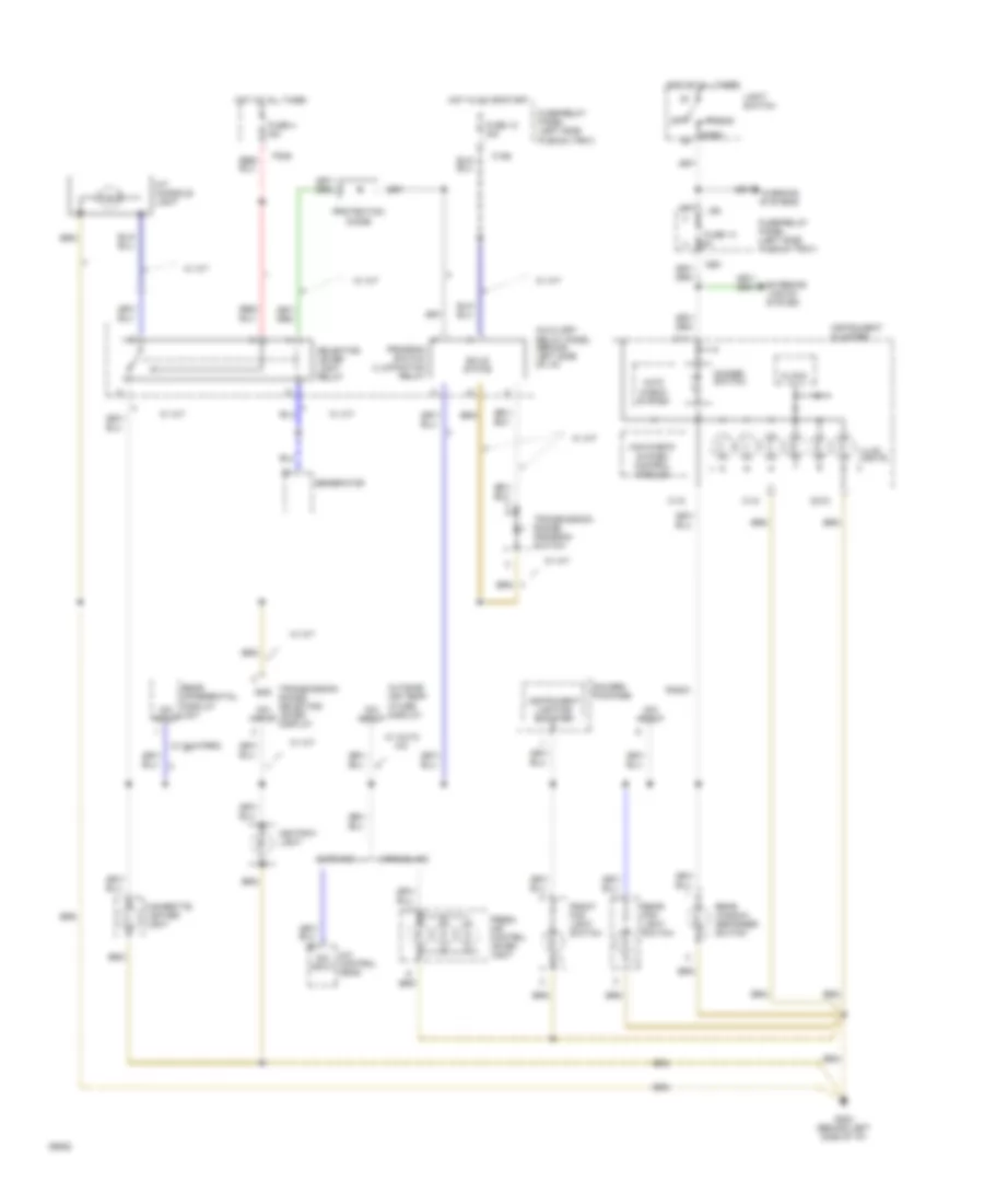
Auto. A/C-Heater System Wiring Diagram (With M/T Wiring Diagram 1 Of 2) for Audi 90 S 1994
List of elements for Auto. A/C-Heater System Wiring Diagram (With M/T Wiring Diagram 1 Of 2) for Audi 90 S 1994:
- (left side of i/p)
- A/c control head
- Air flow flap motor
- Auxiliary relay panel 2
- B10
- Battery (30)
- C10
- C11
- Central flap motor potentiometer
- Data link connector
- Engine control module
- Footwell/defrost flap motor potentiometer
- Fuse 15a
- Fuse 25a
- Fuse 30a
- Fuse 5a
- Fuse 60a
- Fuse/ relay panel
- G202
- G202 (left side of i/p)
- Hot at all times
- Hot w/ lights on
- Hot w/ load reduction relay energized (x)
- Ignition (15)
- Interior temperature sensor fan
- Temp regulator flap motor potentiometer
- Transmission control module
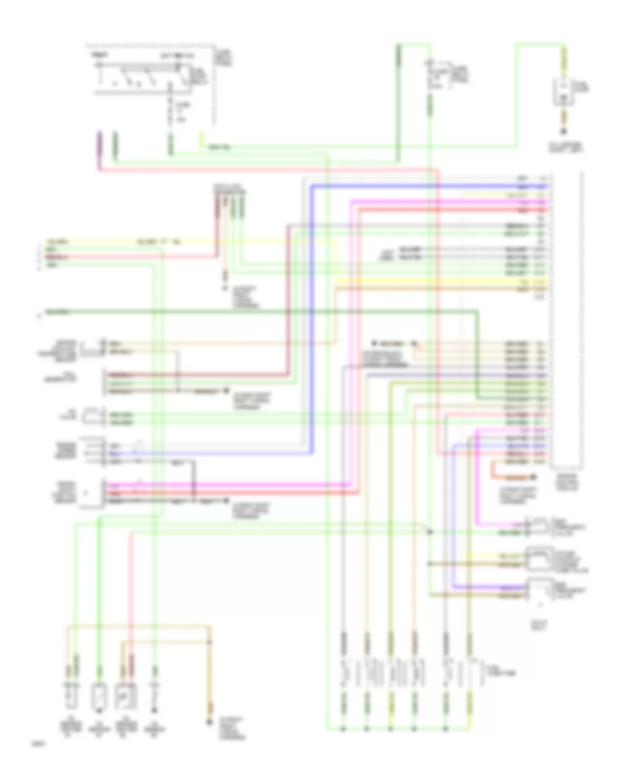
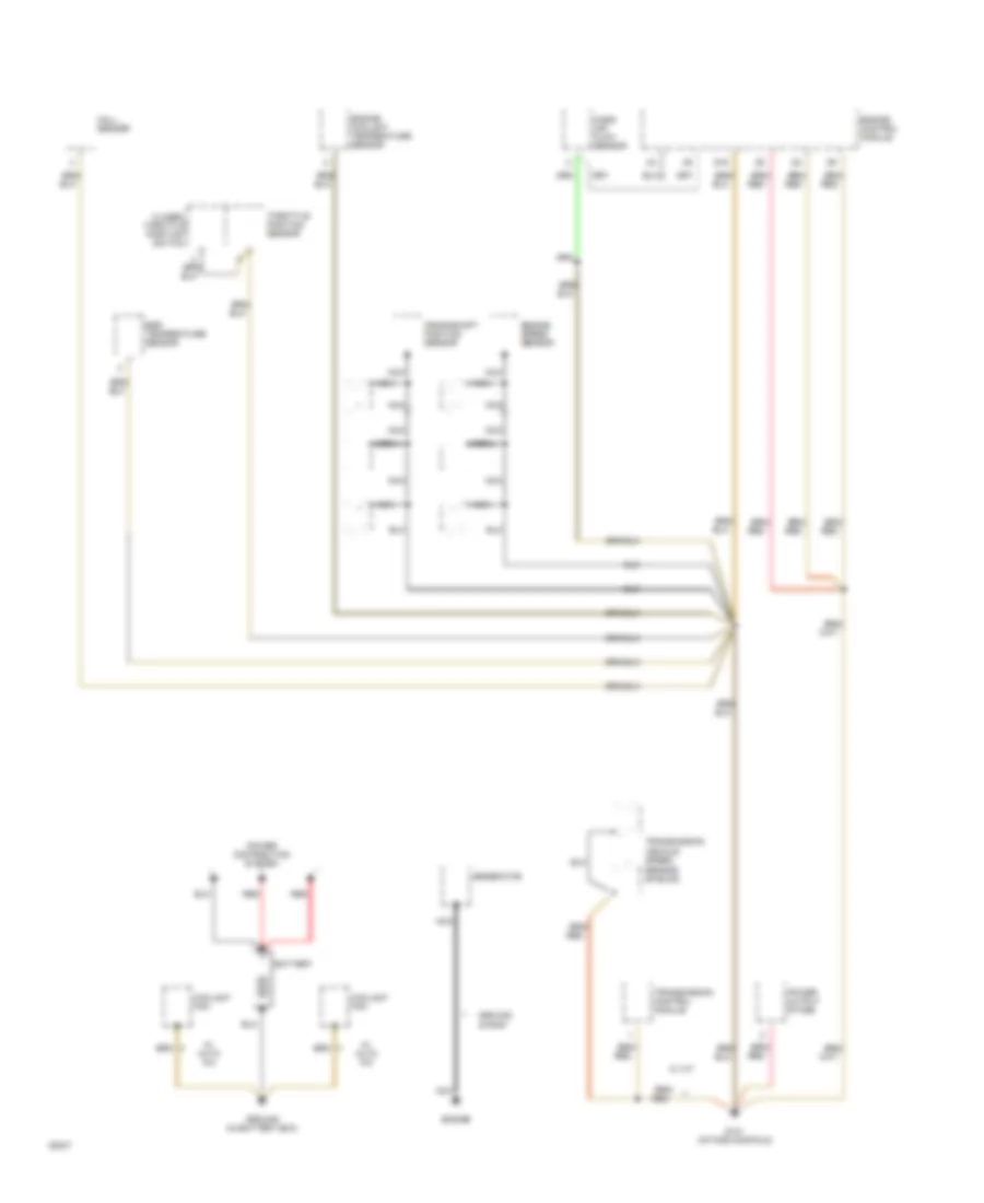
Auto. A/C-Heater System Wiring Diagram (With M/T Wiring Diagram 2 Of 2) for Audi 90 S 1994
List of elements for Auto. A/C-Heater System Wiring Diagram (With M/T Wiring Diagram 2 Of 2) for Audi 90 S 1994:
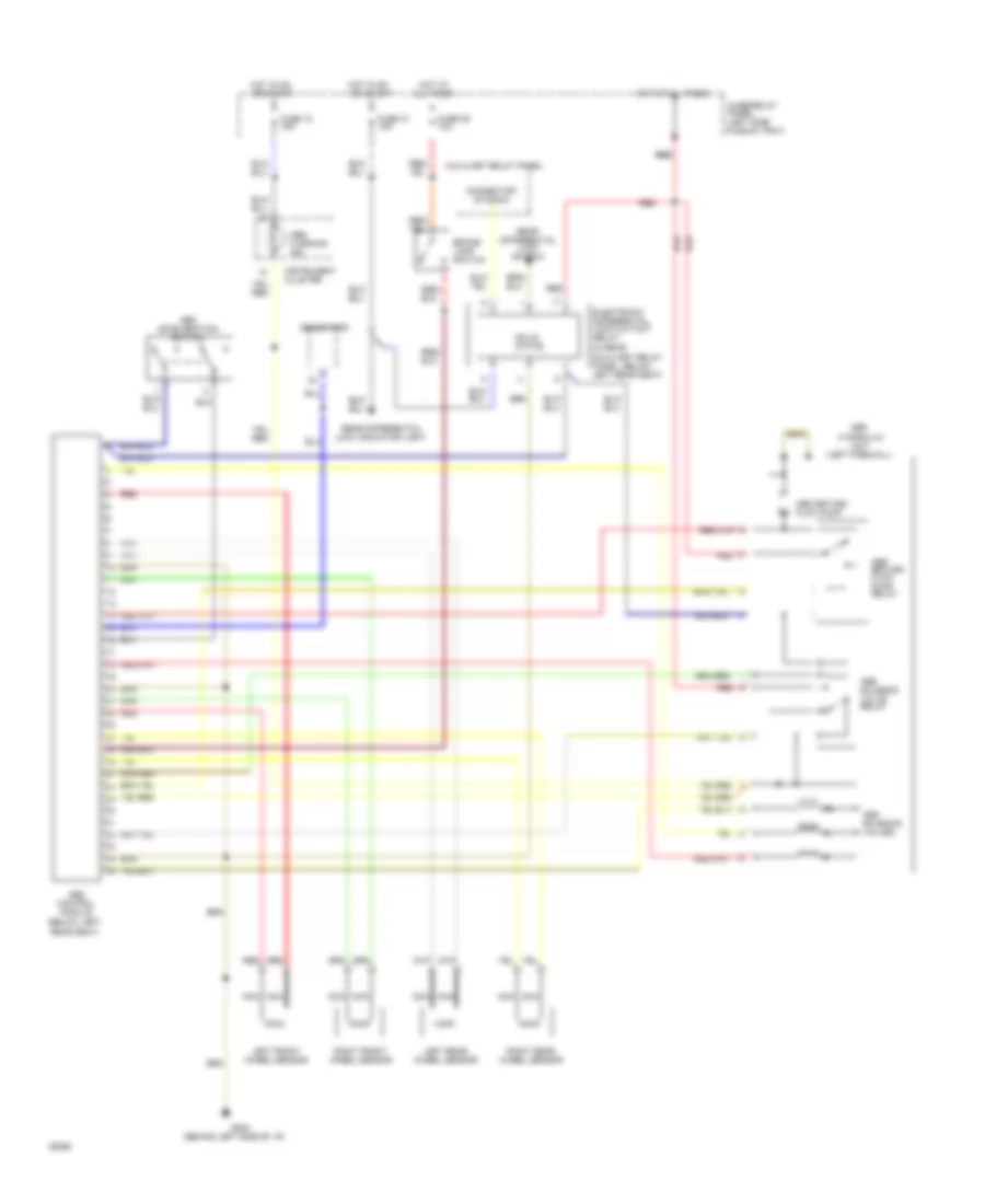
- (in battery box)
- (left side of i/p)
- (left side of i/p) g202
- (near compressor)
- A/c compressor clutch
- A/c compressor clutch relay
- A/c compressor speed sensor
- A/c refrigerant high pressure switch
- A/c refrigerant low pressure switch
- Ambient temperature sensor
- Blower motor
- Coolant fan control relay (in fuse/relay panel)
- Coolant fan control thermo switch
- Coolant fan resistors
- Coolant fans
- Digital outside air temperature display
- Electronic thermo switch
- Fresh air blower control module
- Fresh air duct temperature sensor
- Fresh air recirculating flap valve
- G202
- G202 (left side of i/p)
- Instrument cluster
- Interior temperature sensor (headliner)
- Interior temperature sensor (instrument cluster)
- Low coolant switch
- Protection diode
- Second speed coolant fan control relay
Manual A/C Wiring Diagram for Audi 90 S 1994
List of elements for Manual A/C Wiring Diagram for Audi 90 S 1994:
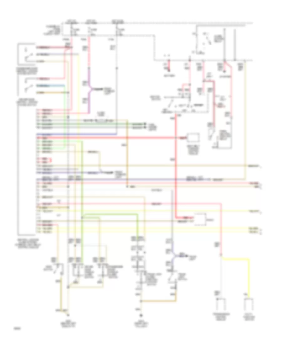
- (behind left side of i/p)
- (left side i/p)
- (left side of i/p)
- (near compressor)
- A/c compressor clutch
- A/c compressor clutch control module
- A/c compressor speed sensor
- A/c flap solenoid
- A/c refrig- erant low pressure switch
- A/c refrigerant
- A/c refrigerant high pressure switch'
- A/c switch
- Auxiliary relay panel
- Blower motor
- Blower resistors
- Blower switch
- C10
- C11
- Coolant fan control relay (in fuse/ relay panel)
- Coolant fan resistors
- Coolant fan thermo switch
- Coolant fans
- Data link connector
- Diode
- Electronic thermo switch
- Engine control module
- Engine control module pin b10 (engine rpm)
- Fuse 15a
- Fuse 30a
- Fuse 60a
- Fuse/ relay panel
- G202
- G202 (behind left side of i/p)
- Heater fan relay (in fuse/ relay panel)
- Hot at all times
- Hot with load reduction relay energized (x)
- Ignition (15)
- Instru- ment cluster
- Interior lights system
- Low coolant switch
- Off
- Outside temp switch
- Pressure safety switch
- Protection diode
- Third speed coolant fan ctrl relay
- Trans- mission control module
ANTI-LOCK BRAKES
Anti-Lock Brakes Wiring Diagram, FWD for Audi 90 S 1994
List of elements for Anti-Lock Brakes Wiring Diagram, FWD for Audi 90 S 1994:
- (behind left side of i/p)
- (below left
- (left firewall)
- Abs
- Abs combi relay (in rear auxiliary relay panel, below left rear seat)
- Abs return flow pump
- Abs return flow pump relay
- Abs solenoid relay
- Abs solenoid valves
- Abs warning ind.
- All times
- Auxiliary relay panel
- Brake lamp switch
- Connector station
- Control
- Fuse 12 15a
- Fuse 29 10a
- Fuse 31 15a
- Fuse/relay panel (left side plenum tray)
- G202
- Generator
- Hot at
- Hot at all times
- Hot in on or start
- Hydraulic
- Instrument cluster
- Left front wheel sensor
- Left rear wheel sensor
- Module
- Nca
- Rear seat)
- Red
- Red red
- Right front wheel sensor
- Right rear wheel sensor
- Solid state
- Unit
Anti-Lock Brakes Wiring Diagram, Quattro for Audi 90 S 1994
List of elements for Anti-Lock Brakes Wiring Diagram, Quattro for Audi 90 S 1994:
- (behind left side of i/p)
- (below left
- (left firewall)
- Abs
- Abs acceleration switch
- Abs control module
- Abs return flow pump
- Abs return flow pump relay
- Abs solenoid valve relay
- Abs solenoid valves
- Abs warning ind.
- All times
- Auxiliary relay panel
- Auxiliary relay panel, below left rear seat)
- Brake lamp switch
- Connector station
- Electronic differential lock cut-out relay (in rear
- Fuse 12 15a
- Fuse 29 10a
- Fuse 31 15a
- Fuse/relay panel (left side plenum tray)
- G202
- Generator
- Hot at
- Hot at all times
- Hot in on or start
- Hydraulic
- Instrument cluster
- Left front wheel sensor
- Left rear wheel sensor
- Lock indicator light
- Nca
- Rear differential
- Rear differential lock switch
- Rear seat)
- Red
- Red red
- Right front wheel sensor
- Right rear wheel sensor
- Solid state
- Unit
ANTI-THEFT
Anti-theft & Central Locking Wiring Diagram (1 of 2) for Audi 90 S 1994
List of elements for Anti-theft & Central Locking Wiring Diagram (1 of 2) for Audi 90 S 1994:
-
-
-
-
- (a/t) (m/t)
- (left side
- 86s
- A/t
- A/t only
- Acc
- Alarm horn
- Alarm system relay
- All times
- Battery
- C15a
- Central locking/ alarm system/ interior light delay control module
- Control module
- Driver door central locking system switch
- Driver door handle alarm switch
- E50a
- F30al
- F50z
- Front interior light
- Function
- Fuse 10a
- Fuse 15a
- Fuse/relay
- G202 (behind left
- G404 (near left)
- H50w
- Hood
- Hot at
- Hot in on or start
- Ignition
- Key switch
- L30
- M/t
- M30az
- Multi-
- Nca
- Off
- Panel
- Park/ neutral position relay
- Passenger door central locking system switch
- Passenger door handle alarm switch
- Plenum tray)
- Radio
- Red
- Seat belt
- Side of i/p)
- Start
- Starter
- Switch
- Taillight)
- Transmission
- Trunk light
- Trunk light switch
- Trunk lock alarm/ central locking switch
- Turn/ hazard lights
- Warning control module
Anti-theft & Central Locking Wiring Diagram (2 of 2) for Audi 90 S 1994
List of elements for Anti-theft & Central Locking Wiring Diagram (2 of 2) for Audi 90 S 1994:
-
-
-
-
- Left front door contact switch
- Left infrared central locking system sensor
- Left rear door contact switch
- Nca
- Right front door contact switch
- Right infrared central locking system sensor
- Right rear door contact switch
COMPUTER DATA LINES
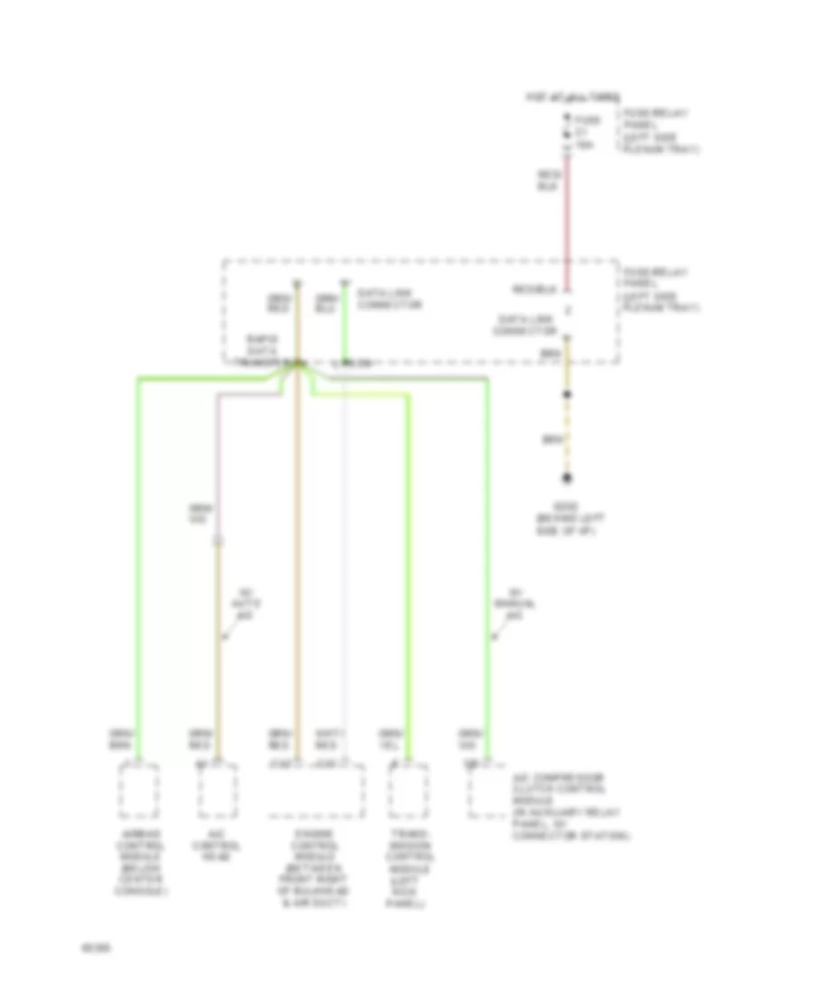
Data Link Connector Wiring Diagram for Audi 90 S 1994
List of elements for Data Link Connector Wiring Diagram for Audi 90 S 1994:
- (behind left side of i/p)
- (left kick panel)
- (left side plenum tray)
- 3/d
- A/c compressor clutch control module (in auxiliary relay panel, w/ connector station)
- A/c control head
- Airbag control module (below center console)
- C12
- C13
- Connector
- Data link
- Data link connector
- Ecm
- Engine control module (between front right of bulkhead & air duct)
- Fuse 10a
- Fuse/relay panel
- G202
- Hot at all times
- Rapid data transfer
- Trans- mission control module
- W/ auto a/c
- W/ manual a/c
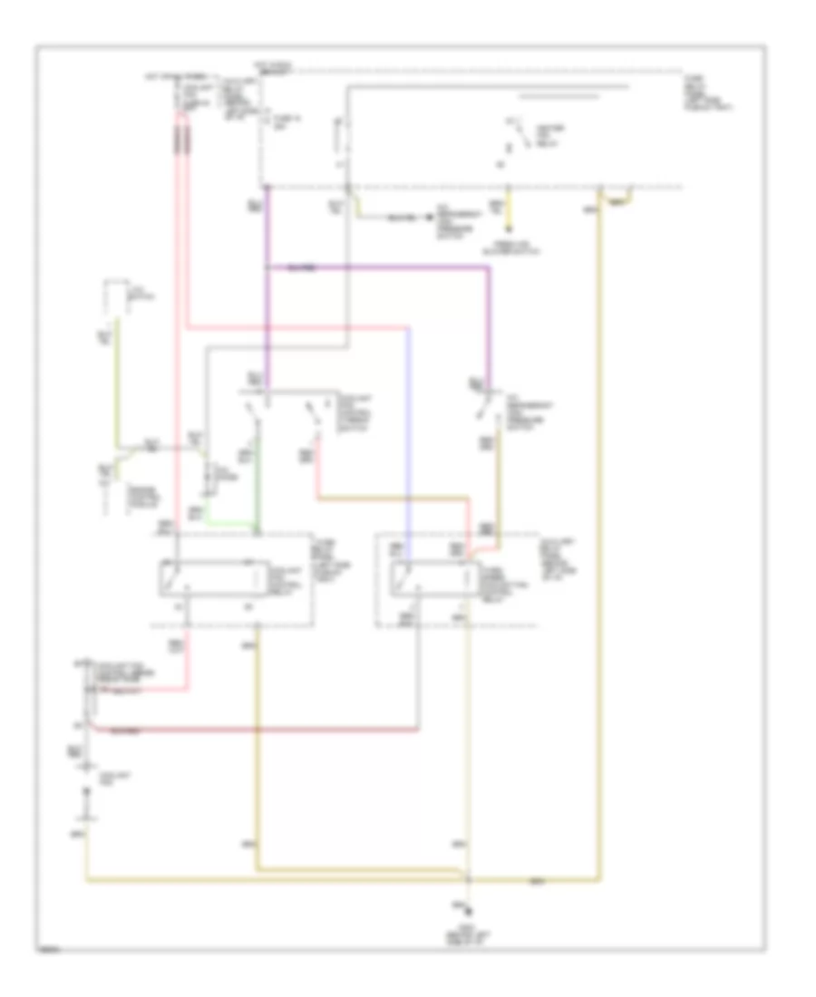
COOLING FAN
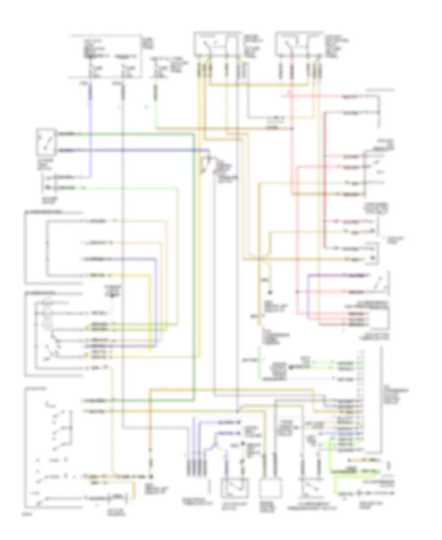
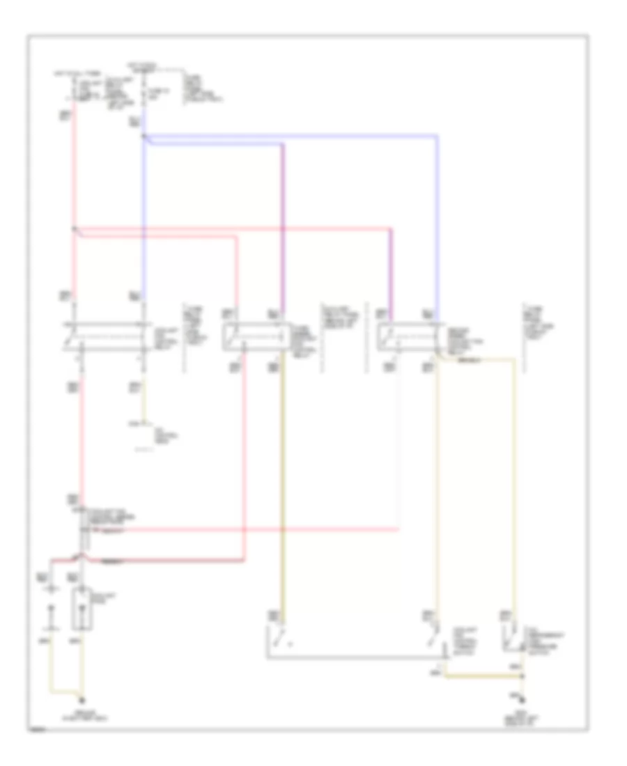
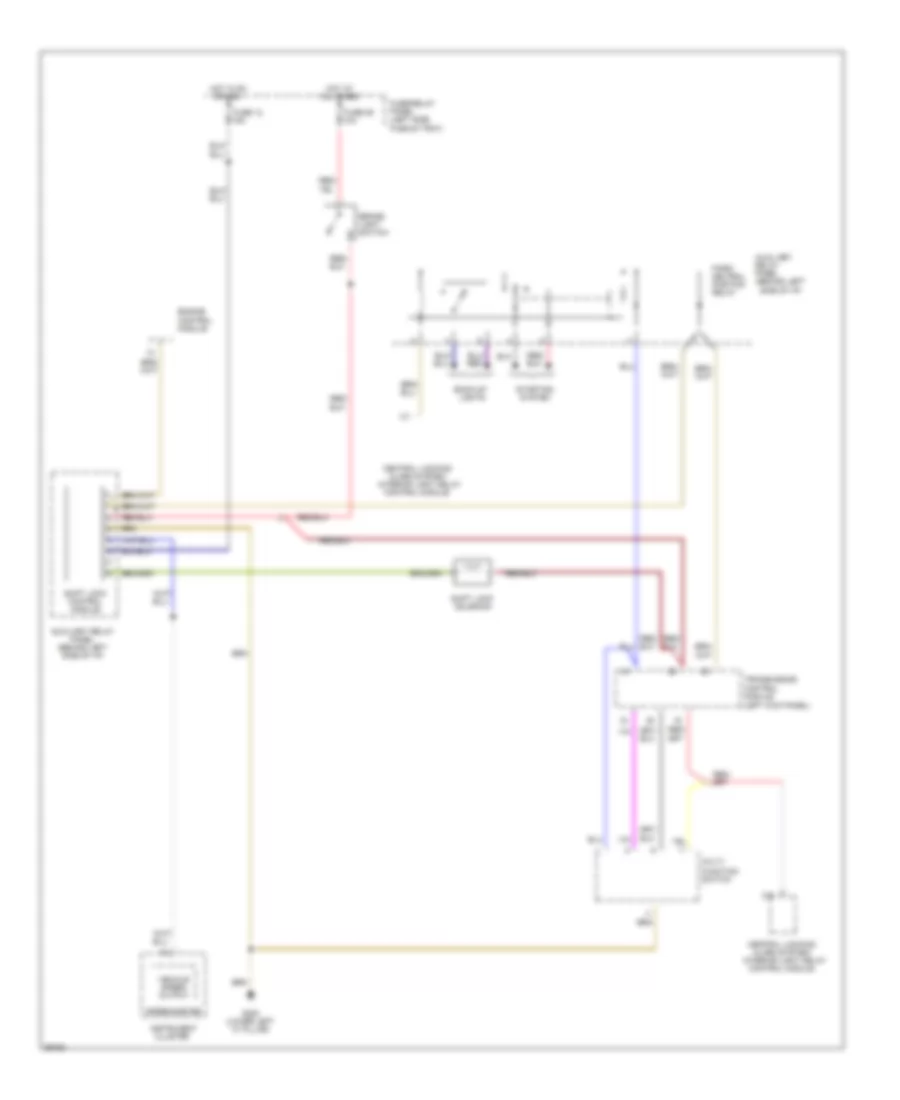
Cooling Fan Wiring Diagram, A/T with Auto A/C for Audi 90 S 1994
List of elements for Cooling Fan Wiring Diagram, A/T with Auto A/C for Audi 90 S 1994:
- (behind left side of i/p)
- (in battery box)
- (left side plenum tray)
- A/c control head
- A/c refrigerant high pressure switch
- Auxiliary
- Coolant fan fuse 42 60a
- Coolant fan control relay
- Coolant fan control series resistance
- Coolant fan control thermo- switch
- Coolant fans
- D16
- Fuse 15 25a
- Fuse/ relay panel
- Fuse/ relay panel (left side plenum tray)
- G202
- Ground
- Hot at all times
- Hot in run
- Or accy
- Relay panel
- Second speed coolant fan control relay
- Third speed coolant fan control relay
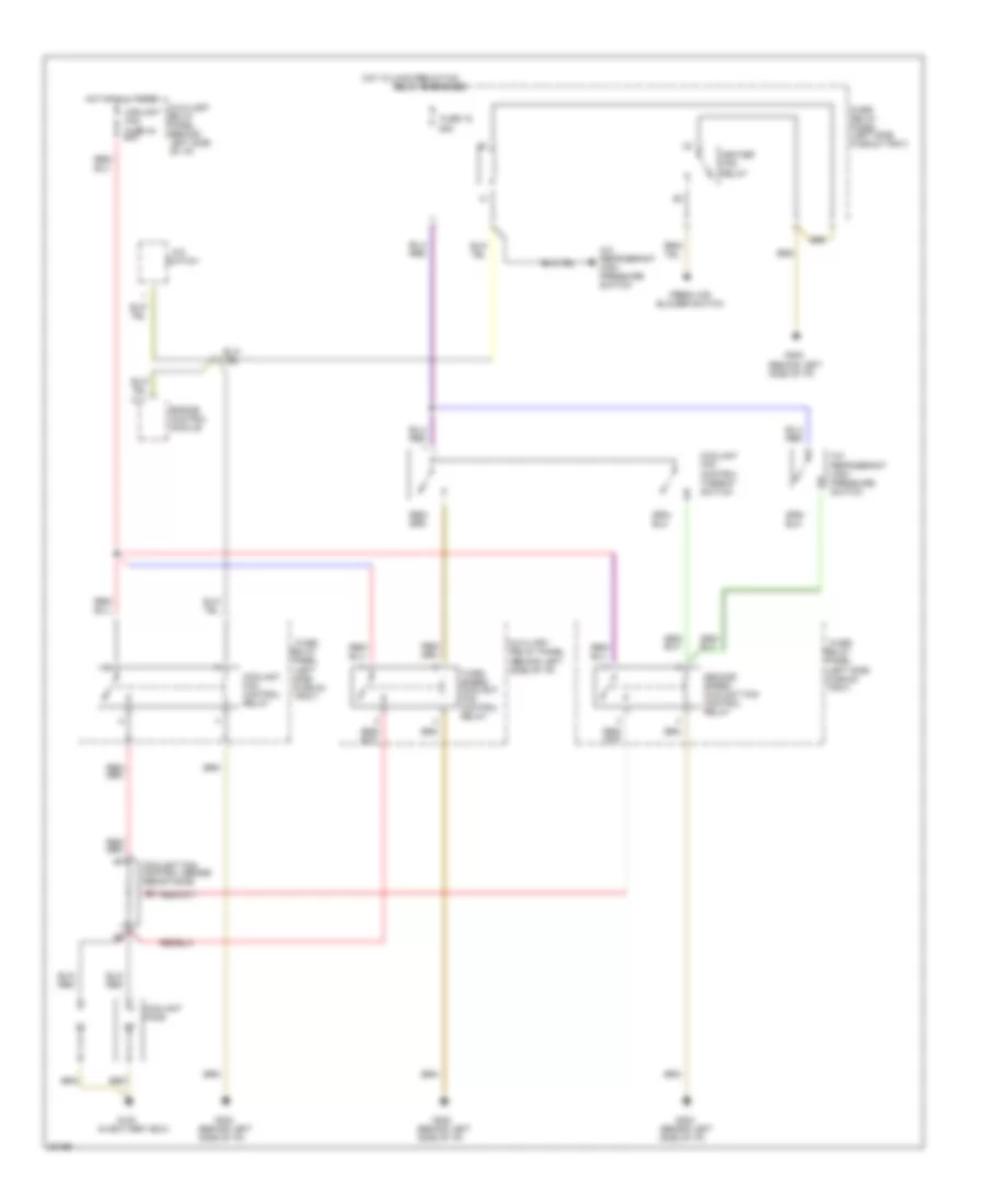
Cooling Fan Wiring Diagram, A/T with Manual A/C for Audi 90 S 1994
List of elements for Cooling Fan Wiring Diagram, A/T with Manual A/C for Audi 90 S 1994:
- (behind left side of i/p)
- (in battery box)
- (left side plenum tray)
- A/c
- A/c refrigerant high pressure switch
- Auxiliary
- C11
- Coolant fan fuse 42 60a
- Coolant fan control relay
- Coolant fan control series resistance
- Coolant fan control thermo- switch
- Coolant fans
- Engine control module
- Fresh air blower switch
- Fuse 15 25a
- Fuse/ relay panel
- Fuse/ relay panel (left side plenum tray)
- G100
- G202
- Heater fan relay
- Hot at all times
- Hot w/load reduction
- Relay energized
- Relay panel
- Second speed coolant fan control relay
- Switch
- Third speed coolant fan control relay
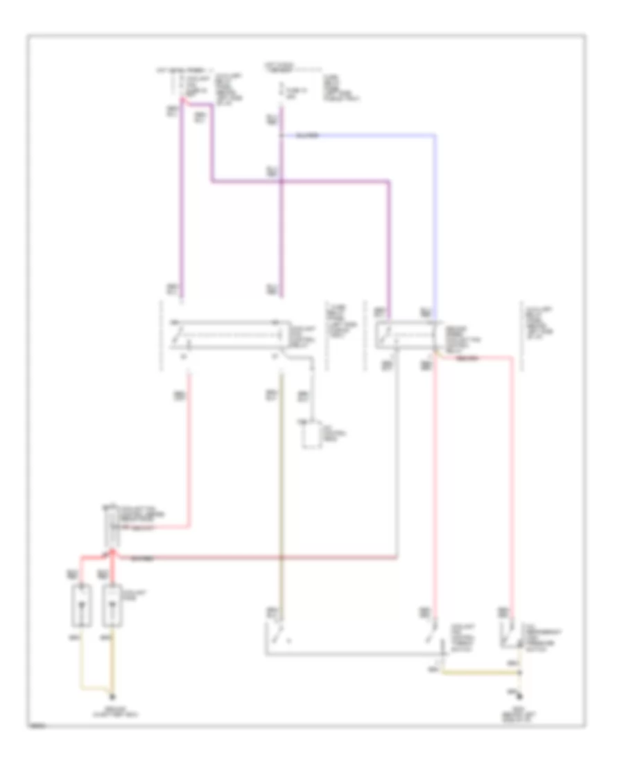
Cooling Fan Wiring Diagram, M/T with Auto A/C for Audi 90 S 1994
List of elements for Cooling Fan Wiring Diagram, M/T with Auto A/C for Audi 90 S 1994:
- (behind left side of i/p)
- (in battery box)
- (left side plenum tray)
- A/c control head
- A/c refrigerant high pressure switch
- Auxiliary
- Coolant fan fuse 42 60a
- Coolant fan control relay
- Coolant fan control series resistance
- Coolant fan control thermo- switch
- Coolant fans
- D16
- Fuse 15 25a
- Fuse/ relay panel
- Fuse/ relay panel (left side plenum tray)
- G202
- Ground
- Hot at all times
- Hot in run
- Or accy
- Relay panel
- Second speed coolant fan control relay
Cooling Fan Wiring Diagram, M/T with Manual A/C for Audi 90 S 1994
List of elements for Cooling Fan Wiring Diagram, M/T with Manual A/C for Audi 90 S 1994:
- (behind left side of i/p)
- (left side plenum tray)
- A/c
- A/c diode
- A/c refrigerant high pressure switch
- Auxiliary
- C11
- Coolant fan
- Coolant fan fuse 42 60a
- Coolant fan control relay
- Coolant fan control series resistance
- Coolant fan control thermo- switch
- Engine control module
- Fresh air blower switch
- Fuse 15 25a
- Fuse/ relay panel
- Fuse/ relay panel (left side plenum tray)
- G202
- Heater fan relay
- Hot at all times
- Hot in run
- Or accy
- Relay panel
- Switch
- Third speed coolant fan control relay
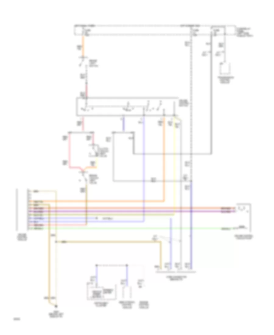
CRUISE CONTROL
Cruise Control Wiring Diagram for Audi 90 S 1994
List of elements for Cruise Control Wiring Diagram for Audi 90 S 1994:
- A/t
- A/t only
- Brake light switch
- Brake vacuum vent valve
- C1-18
- Cluster
- Clutch vacuum vent valve
- Control module
- Cruise control module
- Cruise control switch
- Cruise control vacuum pump
- Engine control module
- Fuse 10a
- Fuse 15a
- Fuse 5a
- Fuse/relay panel (left side plenum tray)
- G200 (behind left side of i/p)
- Hot at all times
- Hot in on or acc
- Instrument
- M/t
- M/t only
- Servotronic control module
- Speedo- meter
- Transmission
- Vehicle speed output
- Wire connector (behind i/p)
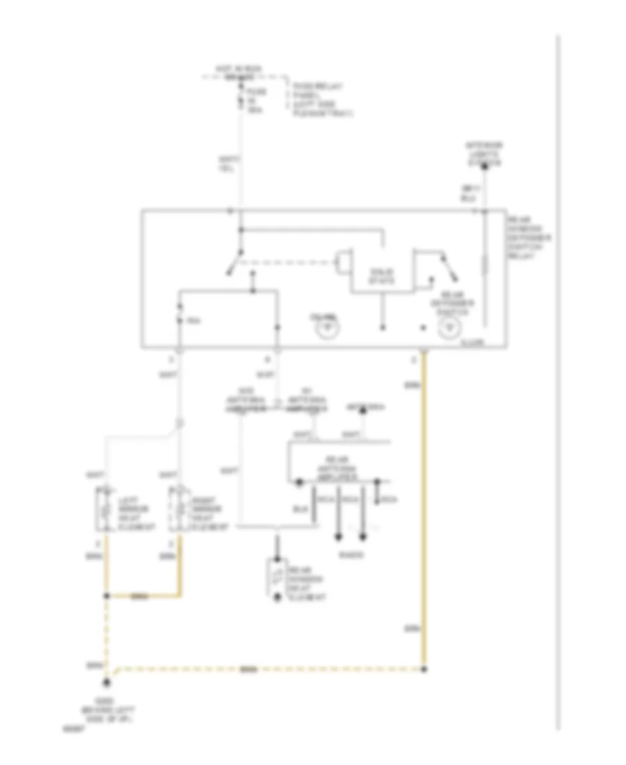
DEFOGGERS
Defoggers Wiring Diagram for Audi 90 S 1994
List of elements for Defoggers Wiring Diagram for Audi 90 S 1994:
- 10a
- Antenna
- Fuse 30a
- Fuse/relay panel (left side plenum tray)
- G202 (behind left side of i/p)
- Hot in run
- Illum.
- Interior lights system
- Left mirror heat element
- Nca
- On ind.
- Or acc
- Radio
- Rear antenna amplifier
- Rear defogger switch
- Rear window defogger switch/ relay
- Rear window heat element
- Right mirror heat element
- Solid state
- W/ antenna amplifier
- W/o antenna amplifier
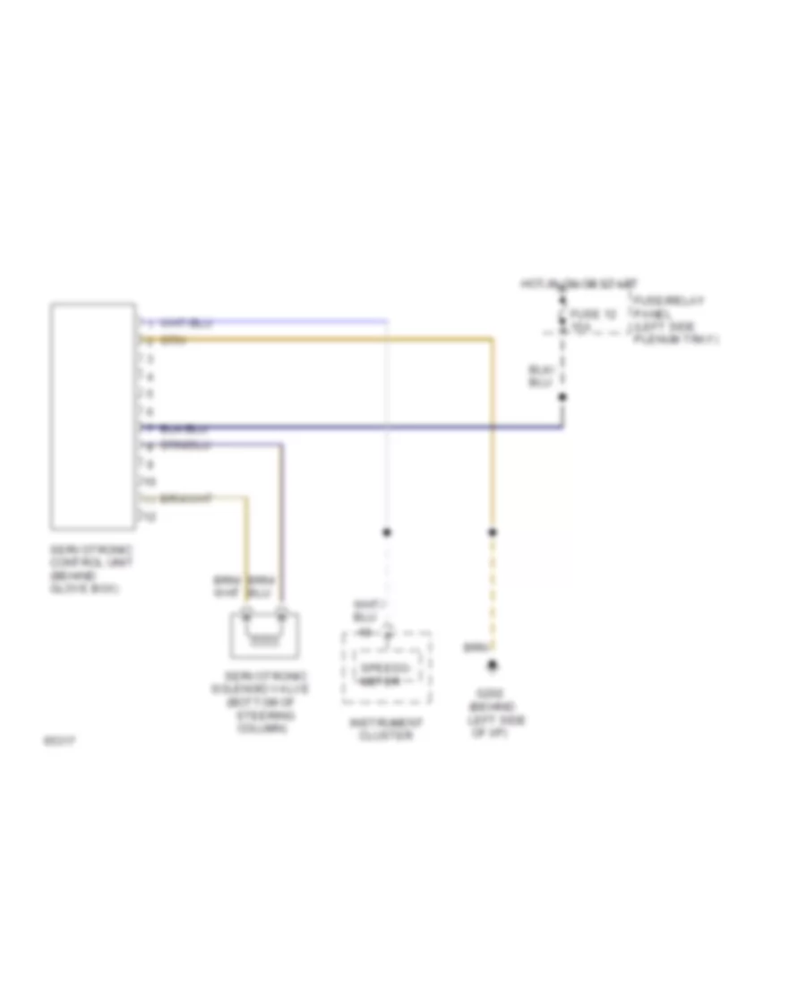
ELECTRONIC POWER STEERING
Electronic Power Steering Wiring Diagram for Audi 90 S 1994
List of elements for Electronic Power Steering Wiring Diagram for Audi 90 S 1994:
-
- (behind left side of i/p)
- (bottom of
- Cluster
- Fuse 12 15a
- Fuse/relay panel (left side plenum tray)
- G202
- Hot in on or start
- Instrument
- Servotronic
- Servotronic control unit (behind glove box)
- Solenoid valve
- Speedo- meter
- Steering column)
ENGINE PERFORMANCE
2.8L
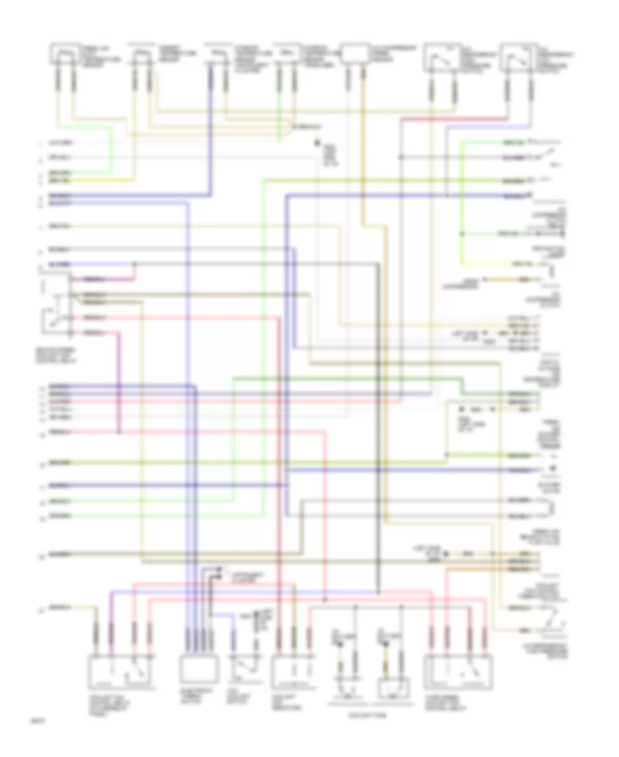
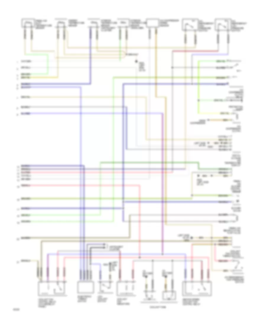
2.8L, Wiring Diagram (Cabriolet & 90 Wiring Diagram 2.8L 1 Of 2) for Audi 90 S 1994
List of elements for 2.8L, Wiring Diagram (Cabriolet & 90 Wiring Diagram 2.8L 1 Of 2) for Audi 90 S 1994:
- (in eng compt)
- (not used)
- (on intake manifold)
- 10a
- 15a
- 20a
- A/t only
- A10
- A11
- A12
- Auto check system
- B10
- B11
- B12
- B13
- B14
- B15
- B16
- B17
- B18
- B19
- B20
- Central electrical unit
- Closed throttle position switch/ throttle position sensor
- Egr temperature sensor
- Engine control module
- Fuse
- Fuse/ relay panel
- Hot at all times
- Hot in run or start
- Hot in start or run
- Ignition coil assembly
- Instrument cluster
- Knock sensor #1
- Knock sensor #2
- Mal- function indicator "check engine"
- Mass air flow sensor
- Nca
- Power output stage
- Red
- Spark plugs #1 & #6
- Spark plugs #2 & #4
- Spark plugs #3 & #5
- Tach
- Vehicle speed out
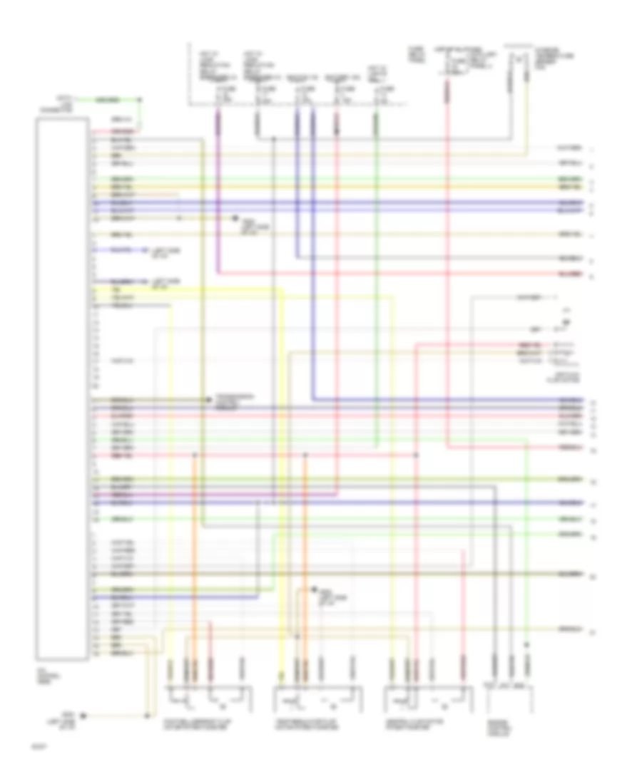
2.8L, Wiring Diagram (Cabriolet & 90 Wiring Diagram 2.8L 2 Of 2) for Audi 90 S 1994
List of elements for 2.8L, Wiring Diagram (Cabriolet & 90 Wiring Diagram 2.8L 2 Of 2) for Audi 90 S 1994:
- (calif only)
- (in eng compt right wiring harness)
- (in luggage compt, left)
- (in right front wiring harness)
- (not used)
- (on eng block, in right front wiring harness)
- 15a
- Battery(30)
- C1
- C10
- C11
- C12
- C13
- C14
- C15
- C16
- Crank- shaft position sensor
- D10
- D11
- D12
- D13
- D14
- D15
- D16
- Data link connector
- Eap frequency valve
- Egr frequency valve
- Engine control module
- Engine coolant temperature sensor
- Engine speed sensor
- Fuel injectors
- Fuel pump
- Fuel pump relay
- Fuse
- Fuse/ relay panel
- Hall generator
- Iac valve
- Ign(15)
- Intake manifold change- over valve
- Nca
- O2 sensor #1
- O2 sensor #2
- O2 sensor heater
- Red
EXTERIOR LIGHTS
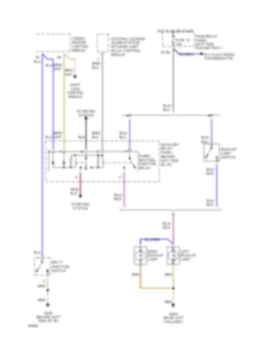
Back-up Lamps Wiring Diagram for Audi 90 S 1994
List of elements for Back-up Lamps Wiring Diagram for Audi 90 S 1994:
- A/t
- Auxiliary relay panel (behind left side of i/p)
- B15a
- Back-up light switch
- Central locking/ alarm system/ interior light delay control module
- Ect electronic thermoswitch
- Function switch
- Fuse 12 15a
- Fuse/relay panel (left side plenum tray)
- G202 (behind left side of i/p)
- G404 (near left taillight)
- Hot in on or start
- Left back-up light
- M/t
- Multi-
- Park/ neutral position relay
- Right back-up light
- Shift lock control module
- Starting system
- Trans- mission control module
Park, Marker, Stop, Tail & Turn Lamps Wiring Diagram, Canada for Audi 90 S 1994
List of elements for Park, Marker, Stop, Tail & Turn Lamps Wiring Diagram, Canada for Audi 90 S 1994:
-
- fuse 5a
- hot in on or start
- (left side
- A/t only
- Abs control module
- Anti-theft system
- Auto- check system
- Auxiliary relay panel (behind left side of i/p)
- Brake light switch
- C15a
- Cluster
- Cruise control switch
- D 58l
- Daytime running lights relay
- E 58r
- Emergency flasher relay
- Emergency flasher switch
- F57l
- Front lamp control module
- Fuse 10a
- Fuse 15a
- Fuse 5a
- Fuse/relay
- G202 (behind left side of i/p)
- G404 (near left taillight)
- G49
- G57r
- H 58l
- H 58r
- Head
- Headlights
- High- mount stop light
- Hot at all times
- Hot in on or acc
- I58d
- I75aw
- Instrument
- Instrument cluster
- Instrument cluster system (dimmer switch)
- J30
- J58
- L30
- Left front park/ turn light
- Left rear side marker/ tail/stop/ turn lights
- Left turn ind.
- License plate lights
- Light switch
- Mkr
- Off
- Panel
- Park
- Plenum tray)
- Rear lamp control module
- Red
- Right front park/ turn light
- Right rear side marker/ tail/stop/ turn lights
- Right turn ind.
- Signal switch
- Solid state
- Stop
- System
- Tail
- Trans- mission system
- Turn
- Warnings
Park, Marker, Stop, Tail & Turn Lamps Wiring Diagram, USA for Audi 90 S 1994
List of elements for Park, Marker, Stop, Tail & Turn Lamps Wiring Diagram, USA for Audi 90 S 1994:
-
- hot in on or start
- (left side
- A/t only
- Abs control module
- Anti-theft system
- Auto- check system
- Auxiliary relay panel (behind left side of i/p)
- Brake light switch
- C15a
- Cluster
- Cruise control switch
- D 58l
- E 58r
- Emergency flasher relay
- Emergency flasher switch
- F57l
- Front lamp control module
- Fuse 10a
- Fuse 15a
- Fuse 5a
- Fuse/relay
- Fuse/relay panel (left side plenum tray)
- G202 (behind left side of i/p)
- G404 (near left taillight)
- G49
- G57r
- H 58l
- H 58r
- Head
- High- mount stop light
- Hot at all times
- Hot in on or acc
- I58d
- I75aw
- Instrument
- Instrument cluster
- Interior
- J58
- L30
- Left front park/ turn light
- Left rear side marker/ tail/stop/ turn lights
- Left turn ind.
- License plate lights
- Light switch
- Lights system
- Mkr
- Off
- Panel
- Park
- Plenum tray)
- Rear lamp control module
- Red
- Right front park/ turn light
- Right rear side marker/ tail/stop/ turn lights
- Right turn ind.
- Signal switch
- Solid state
- Stop
- System
- Tail
- Trans- mission system
- Turn
- Warnings
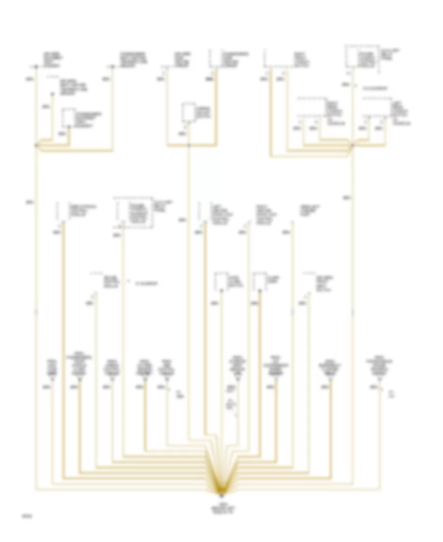
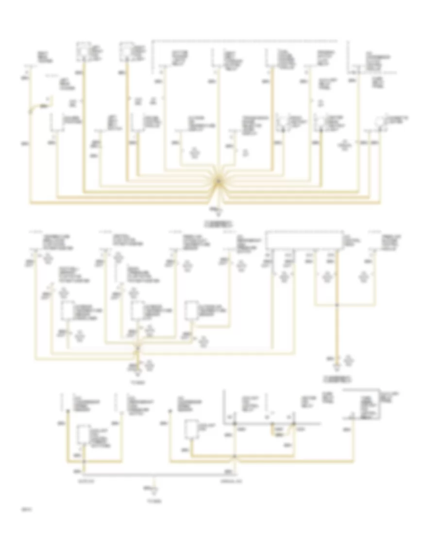
GROUND DISTRIBUTION
Ground Distribution Wiring Diagram (1 of 6) for Audi 90 S 1994
List of elements for Ground Distribution Wiring Diagram (1 of 6) for Audi 90 S 1994:
- Battery
- Closed
- Coolant fan
- Crankshaft position sensor
- D1 d1
- D16
- Egr temperature sensor
- Engine
- Engine control module
- Engine coolant temperature sensor
- Engine speed sensor
- G131 (intake manifold)
- Generator
- Ground (in battery box)
- Ground strap
- Hall sensor
- Mass air flow sensor
- Nca
- Power distribution system
- Power output stage
- Red
- Sensor shields
- Switch
- Throttle position
- Throttle position sensor
- Transmission control module
- Transmission vehicle speed
- W/ a/t
- W/ auto a/c
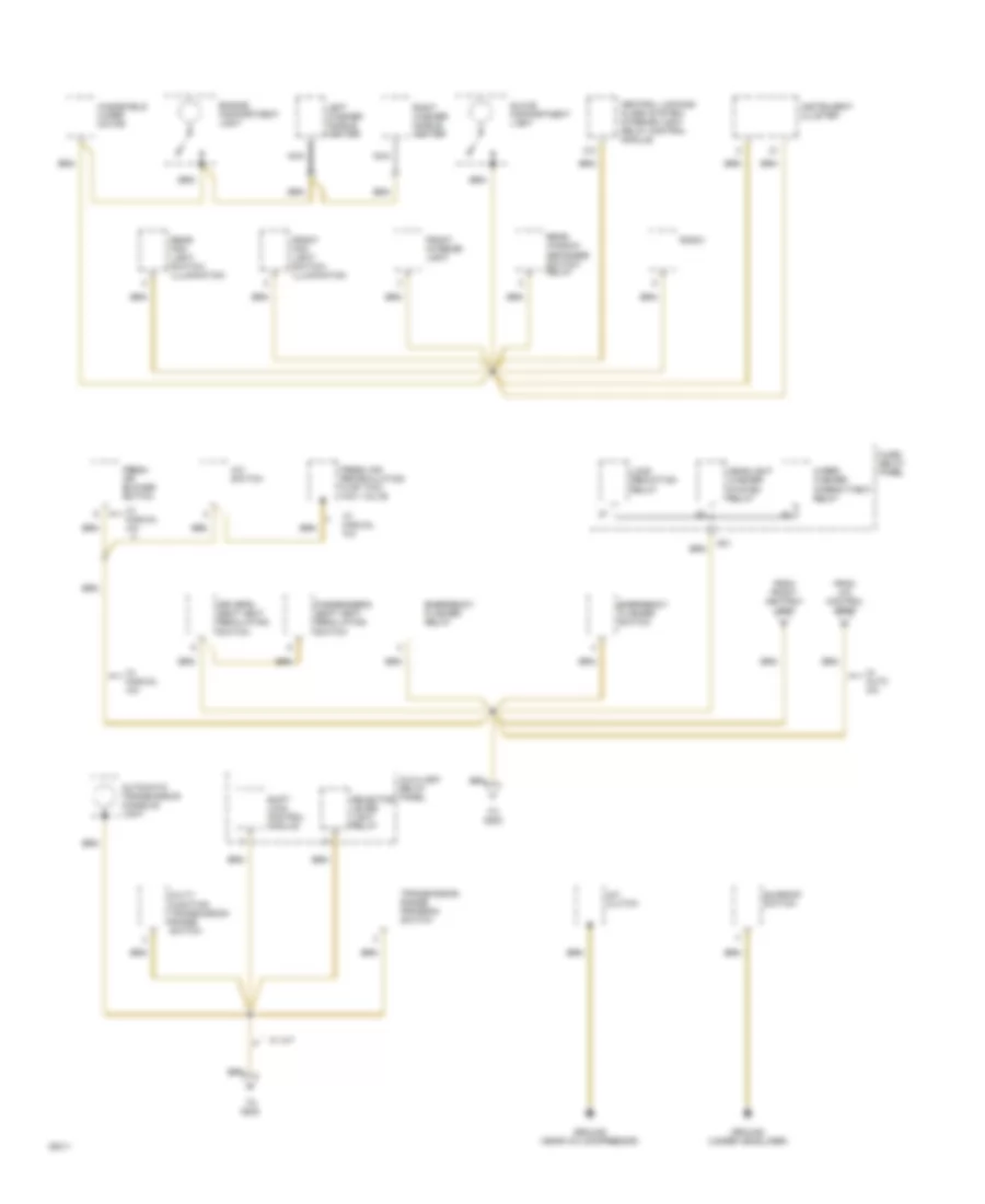
Ground Distribution Wiring Diagram (2 of 6) for Audi 90 S 1994
List of elements for Ground Distribution Wiring Diagram (2 of 6) for Audi 90 S 1994:
- (in console)
- Alarm horn
- Auxiliary relay panel
- Cruise control module
- Driver's backrest heat element
- Driver's front seat switch
- Driver's seat heater temperature sensor
- Driver's side heated mirror
- From a/c compressor speed sensor
- From abs control module
- From airbag control module
- From emergency flasher relay
- From high tone horn
- From interior temp. sensor (i/p)
- From oxygen sensor heater 1
- From passenger's door handle alarm switch
- From transmission range program switch
- G202 (behind left side of i/p)
- Headlight washer pump
- Hood alarm switch
- Left heated door lock control module
- Left rear window switch
- Mirror adjust switch
- Passenger's backrest heat element
- Passenger's seat heater temperature sensor
- Passenger's side heated mirror
- Power window control module
- Power window/ sunroof control module
- Right front window switch
- Right heated door lock control module
- Right rear window switch
- Servotronic control module
- W/ a/t
- W/ abs
- W/ auto a/c
- W/ sunroof
- W/o sunroof
Ground Distribution Wiring Diagram (3 of 6) for Audi 90 S 1994
List of elements for Ground Distribution Wiring Diagram (3 of 6) for Audi 90 S 1994:
- Abs combi relay
- Abs control module
- Airbag control lamp relay
- Airbag control module
- Auxiliary relay panel
- B/3
- Beam
- Brake fluid level warning switch
- C/9
- Central locking/ alarm system/ interior light delay control module
- Data link connector
- Differential lock control module
- Differential lock switch illumination
- Driver's door central locking system switch
- Driver's door handle alarm switch
- Elc warning switch
- Front lamp control module
- Fuse/ relay panel
- High tone horn
- Hydraulic fluid low level sensor
- Kick- down switch
- Left front fog light
- Left front park light
- Left front turn signal light
- Left headlights
- Left infrared central locking system sensor
- Low tone horn
- Only
- Oxygen sensor heater 1
- Oxygen sensor heater 2
- Passenger's door central locking system switch
- Passenger's door handle alarm switch
- Quattro
- Quattro only
- Rear auxiliary relay panel
- Rear differential lock switch
- Rear differential lock switch illumination
- Right front fog light
- Right front park light
- Right front turn signal light
- Right headlights
- Right infrared central locking system sensor
- To g202
- Trunk lock alarm/ central locking switch
- Vehicle speed sensor
- W/ a/t
- W/ abs
- W/ auto check system
- W/ drl
- Windshield washer pump & fluid level warning switch
Ground Distribution Wiring Diagram (4 of 6) for Audi 90 S 1994
List of elements for Ground Distribution Wiring Diagram (4 of 6) for Audi 90 S 1994:
- A/c compressor clutch control module
- A/c compressor speed sensor
- A/c control head
- A/c refrigerant high pressure switch
- A12
- A30k
- A86k
- A86m
- Auto a/c
- Auxiliary relay panel
- Back pressure flap motor potentiometer
- Center
- Central flap motor potentiometer
- Cigarette lighter
- Coolant fan
- Coolant fan control relay
- Coolant fan control thermo- switches
- Cruise control module
- D14
- D15
- Daytime running lights relay
- Footwell/ defrost flap motor potentiometer
- Fresh air blower control
- Fresh air intake duct temperature sensor
- Front ashtray light
- Fuel gauge damper control module
- Fuse/ relay panel
- Gauges package
- Heater fan relay
- Interior temperature sensor (headliner)
- Interior temperature sensor (i/p)
- Left front fog light
- Left rear woofer
- Left seat belt switch
- Manual a/c
- Module
- Outside air temperature display
- Outside air temperature sensor
- Program switch illum. relay
- Rear ashtray light
- Right front fog light
- Right rear woofer
- Seat belt warning system relay
- Temperature regulator flap motor potentiometer
- Third speed coolant fan control relay
- To emergency flasher relay
- To g202
- Transmission range selector lever display
- W/ a/t
- W/ auto a/c
- W/ drl
- W/ manual a/c
- W/o drl
Ground Distribution Wiring Diagram (5 of 6) for Audi 90 S 1994
List of elements for Ground Distribution Wiring Diagram (5 of 6) for Audi 90 S 1994:
- A/c clutch
- A/c switch
- Automatic transmission console light
- Auxiliary relay panel
- C/3
- Central locking/ alarm system/ interior light delay control module
- Driver's seat heat regulating switch
- Emergency flasher relay
- Emergency flasher switch
- Engine compartment light
- Fresh air blower switch
- Fresh air recirculating flap two- way valve
- From a/c control head
- From front ashtray light
- Front fog light switch/ illumination
- Front interior light
- Fuse/ relay panel
- G31
- Glove compartment light
- Ground (near a/c compressor)
- Ground (under headliner)
- Headlight washer system relay
- Instrument cluster
- Left washer nozzle heater
- Load reduction relay
- Multi- function transmission range switch
- Nca
- Passenger's seat heat regulating switch
- Radio
- Rear fog light switch/ illumination
- Rear window defogger switch/ relay
- Right washer nozzle heater
- Selector lever light relay
- Shift lock control module
- Sunroof switch
- To g202
- Transmission range program switch
- W/ a/t
- W/ auto a/c
- W/ manual a/c
- Windshield wiper motor
- Wiper/ washer intermittent relay
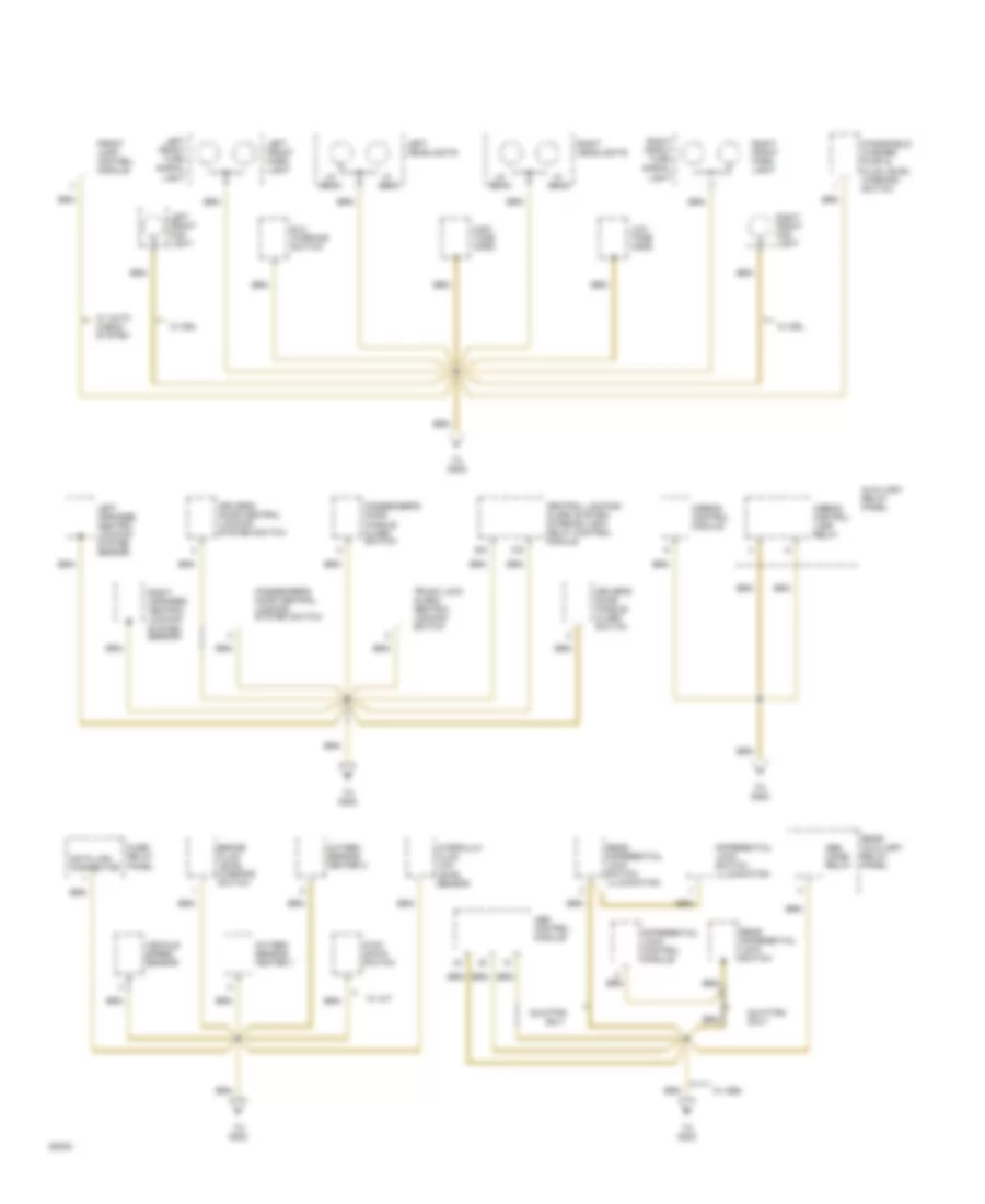
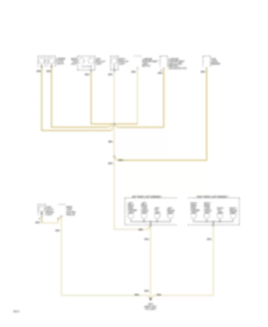
Ground Distribution Wiring Diagram (6 of 6) for Audi 90 S 1994
List of elements for Ground Distribution Wiring Diagram (6 of 6) for Audi 90 S 1994:
- Fuel level sensor
- G404 (near left taillight)
- High mount brake light
- Left back-up light
- Left brake light
- Left rear lamp assembly
- Left rear side marker light
- Left rear turn signal light
- Left tail light
- License plate lights
- Luggage compartment light switch
- Luggage compartment lock alarm/ central locking switch
- Rear fog light
- Rear lamp control module
- Right back-up light
- Right brake light
- Right rear lamp assembly
- Right rear side marker light
- Right rear turn signal light
- Right tail light
HEADLIGHTS
Fog Lamps Wiring Diagram, Canada for Audi 90 S 1994
List of elements for Fog Lamps Wiring Diagram, Canada for Audi 90 S 1994:
- (behind left side of i/p)
- (near left taillight)
- 56a
- 75n
- Acc
- All times
- C56ak
- D56ar
- Dimmer switch
- F55
- Fog light relay
- Fog light switch
- Ftp
- Fuse 10a
- Fuse 15a
- Fuse/relay panel (left side plenum tray)
- G202
- G404
- G85n
- G86n
- Head
- Headlight dimmer/ flasher switch
- Hi beam indicator
- Hot at
- Hot in on or acc
- I56a
- Ignition switch
- Interior lights system
- L30
- Left front fog light
- Light switch
- M75s
- Off
- Park
- Rear fog light
- Rear fog light switch
- Red
- Right front fog light
- Right head- light
- Run
- Start
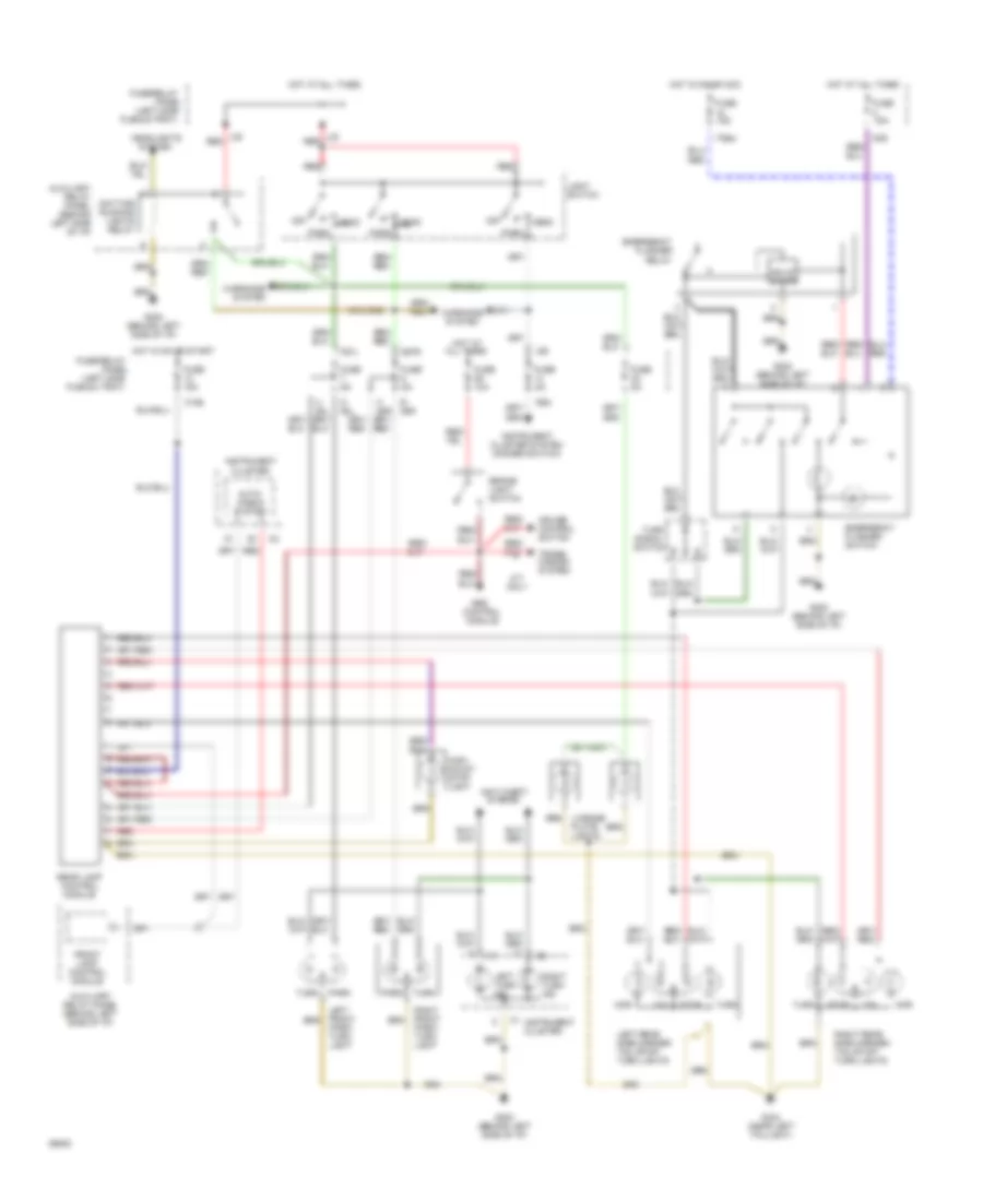
Fog Lamps Wiring Diagram, USA for Audi 90 S 1994
List of elements for Fog Lamps Wiring Diagram, USA for Audi 90 S 1994:
- (behind left side of i/p)
- (near left taillight)
- 56a
- 75n
- Acc
- All times
- C56ak
- D56ar
- Dimmer switch
- F55
- Fog light relay
- Fog light switch
- Ftp
- Fuse 10a
- Fuse 15a
- Fuse/relay panel (left side plenum tray)
- G202
- G404
- G85n
- G86n
- Head
- Headlight dimmer/ flasher switch
- Hi beam indicator
- Hot at
- Hot in on or acc
- I56a
- Ignition switch
- Interior lights system
- L30
- Left front fog light
- Light switch
- M75s
- Off
- Park
- Rear fog light
- Rear fog light switch
- Red
- Right front fog light
- Right head- light
- Run
- Start
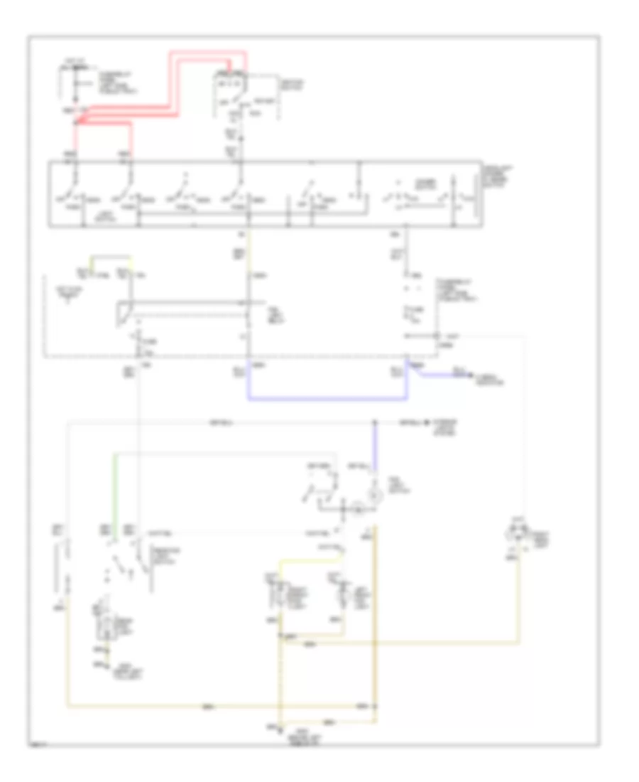
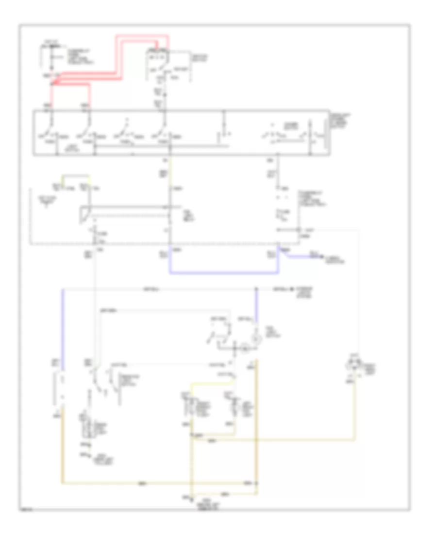
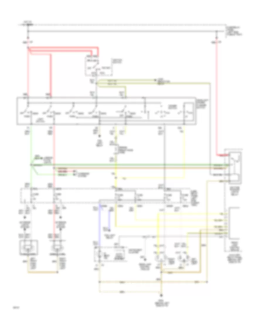
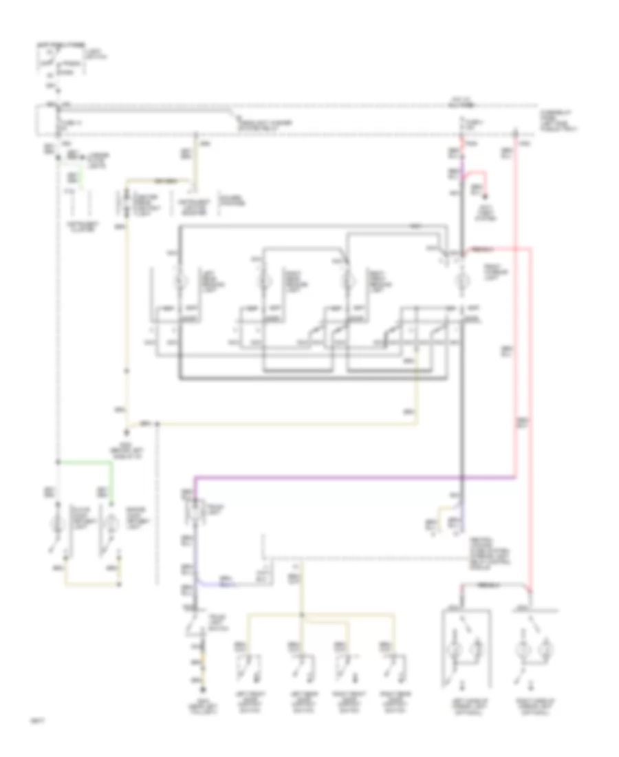
Headlamps Wiring Diagram, Canada for Audi 90 S 1994
List of elements for Headlamps Wiring Diagram, Canada for Audi 90 S 1994:
-
- (behind left side of i/p)
- 56a
- 56b
- Acc
- All times
- Auto- check system
- Auxiliary relay panel (behind left side of i/p)
- C56ak
- D 58l
- D56ar
- D56al
- D56bl
- D56br
- Daytime running lights relay
- Dimmer switch
- E 58r
- Exterior lights system
- F56b
- F57l
- Fog light relay
- Front lamp control module
- Ftp
- Fuse 10a
- Fuse 5a
- Fuse/ relay panel (left side plenum tray)
- Fuse/relay panel (left side plenum tray)
- G202
- G57r
- H 58l
- H 58r
- Head
- Headlight dimmer/ flasher switch
- Hi beam ind.
- Hot at
- I56a
- Ignition switch
- Instrument cluster
- J30
- L30
- Left front park/ turn light
- Left head- light
- Light switch
- Lisence plate lights
- Load reduction relay
- Off
- Park
- Rear lamp control module
- Red
- Right front park/ turn light
- Right head- light
- Run
- Series resistance wire
- Start
- Turn
- Warnings system
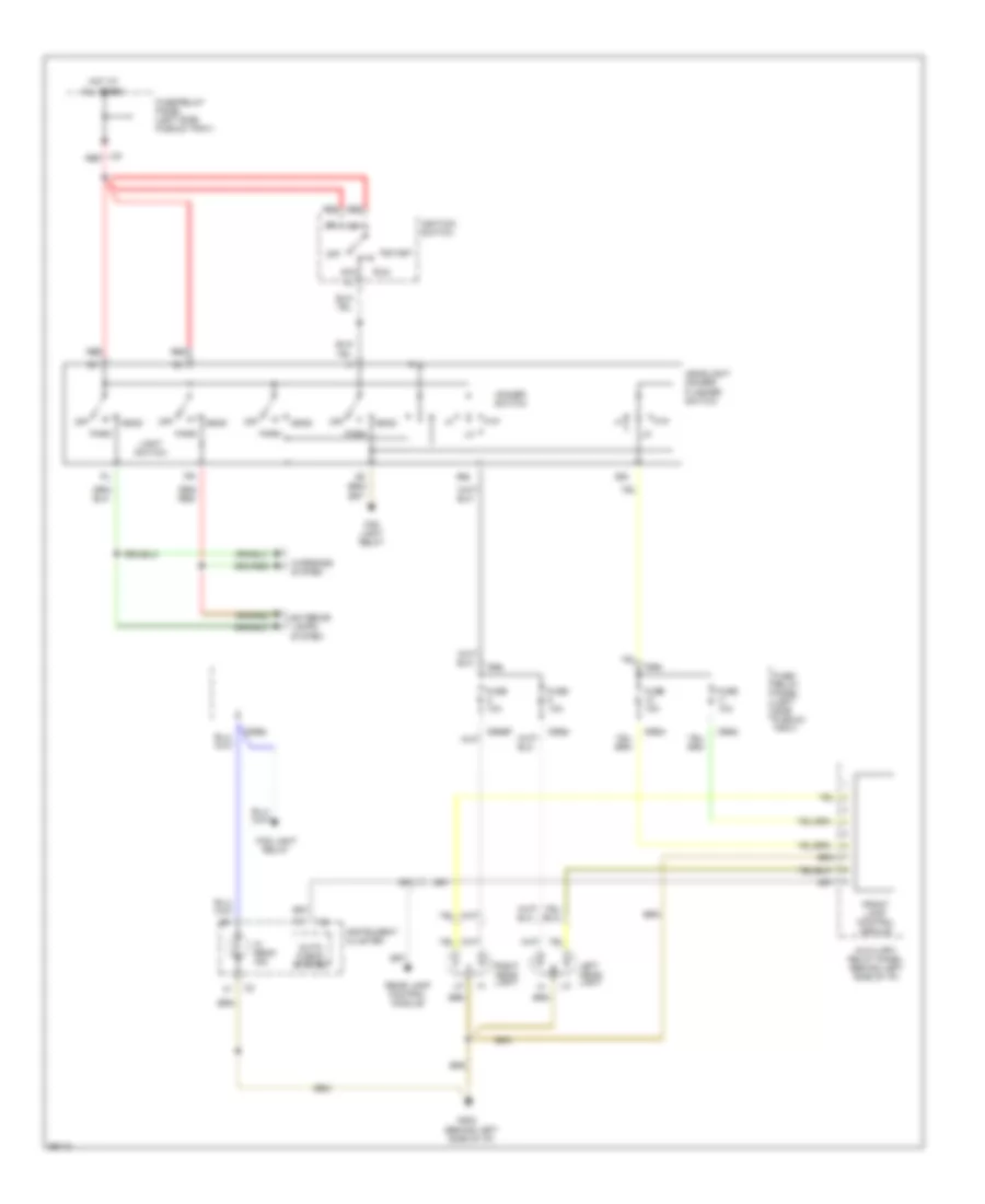
Headlamps Wiring Diagram, USA for Audi 90 S 1994
List of elements for Headlamps Wiring Diagram, USA for Audi 90 S 1994:
- (behind left side of i/p)
- 56a
- 56b
- Acc
- All times
- Auto- check system
- Auxiliary relay panel (behind left side of i/p)
- C56ak
- D56ar
- D56al
- D56bl
- D56br
- Dimmer switch
- Exterior lamps
- F56b
- Fog light relay
- Front lamp control module
- Ftp
- Fuse 10a
- Fuse/ relay panel (left side plenum tray)
- Fuse/relay panel (left side plenum tray)
- G202
- Head
- Headlight dimmer/ flasher switch
- Hi beam ind.
- Hot at
- I56a
- Ignition switch
- Instrument cluster
- L30
- Left head- light
- Light switch
- Off
- Park
- Rear lamp control module
- Red
- Right head- light
- Run
- Start
- System
- Warnings system
HORN
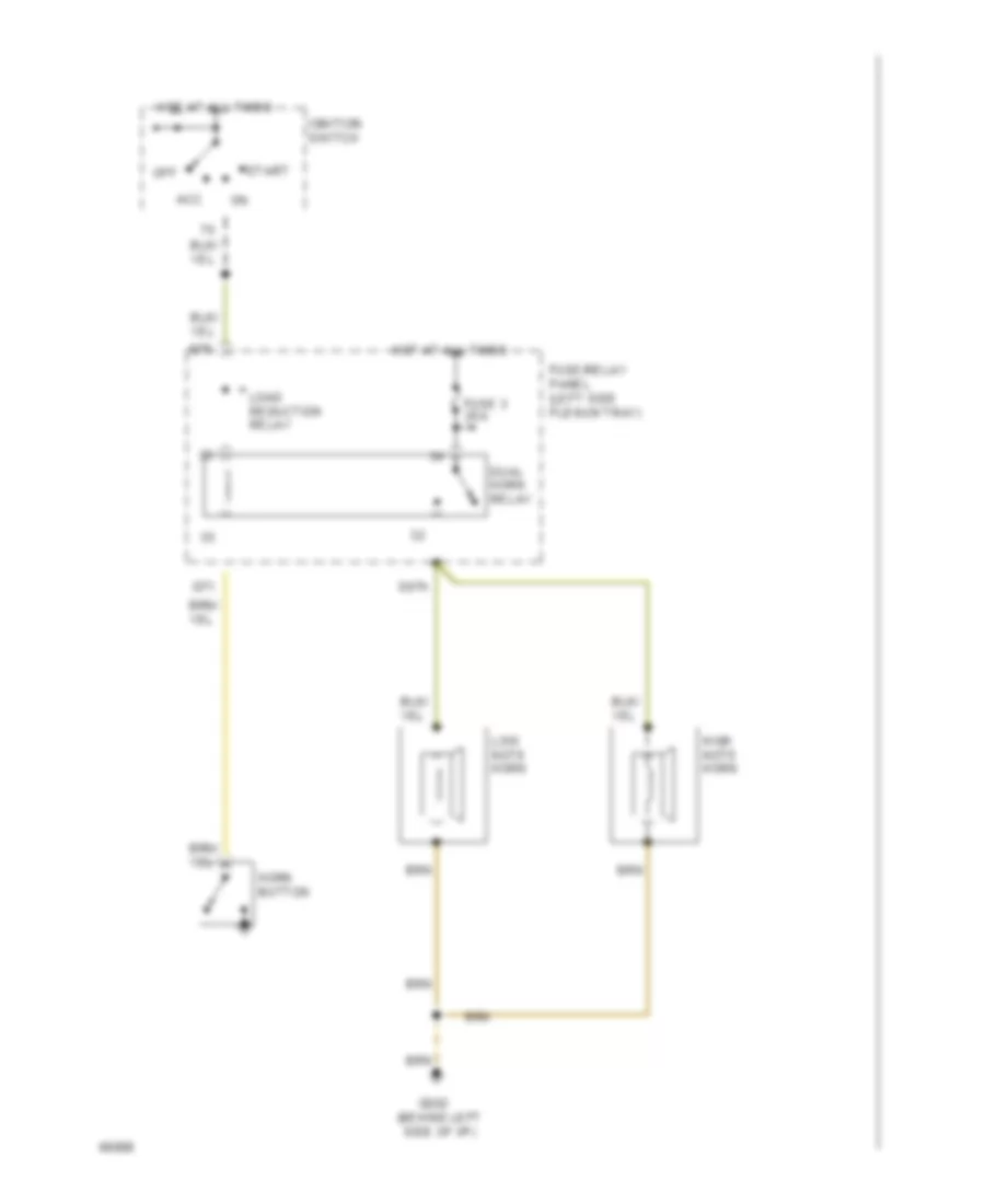
Horn Wiring Diagram for Audi 90 S 1994
List of elements for Horn Wiring Diagram for Audi 90 S 1994:
- Acc
- Dual horn relay
- E87h
- Fuse 3 25a
- Fuse/relay panel (left side plenum tray)
- G202 (behind left side of i/p)
- G71
- G75
- High note horn
- Horn button
- Hot at all times
- Ignition switch
- Load reduction relay
- Low note horn
- Off
- Start
INSTRUMENT CLUSTER
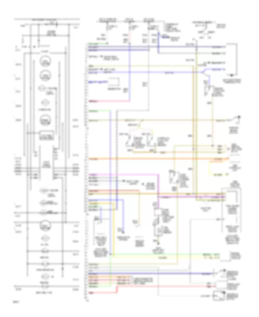
Instrument Panel Wiring Diagram (90 Wiring Diagram 1 Of 2) for Audi 90 S 1994
List of elements for Instrument Panel Wiring Diagram (90 Wiring Diagram 1 Of 2) for Audi 90 S 1994:
- (0.3 bar)
- (3 bulbs)
- (behind left side of i/p)
- 5/1
- 5/2
- 5/3
- 5/5
- 6/1
- 6/2
- 6/3
- 6/4
- 6/5
- 6/6
- A/c system
- Abs control module
- Abs hydraulic unit
- Abs ind.
- Acc
- Auto check system
- Auxiliary relay panel (behind left side of i/p)
- B10
- B15a
- Back-up lights
- Brake fluid level warning switch
- C1-1
- C1-10
- C1-13
- C1-19
- C1-2
- C1-22
- C1-23
- C1-25
- C1-3
- C1-5
- C1-8
- C1-9
- C14
- C15a
- C2-10
- C2-15
- C2-16
- C2-17
- C2-18
- C2-20
- C2-21
- C2-23
- C2-24
- C2-25
- C2-26
- C3-16
- C3-17
- C3-18
- C3-19
- C3-20
- C3-21
- C3-22
- C3-23
- C3-25
- Clock
- Control module
- Cruise control system
- Dimmer switch
- Ect electronic thermoswitch
- Engine
- Engine coolant level switch
- Engine oil pressure
- F30al
- Front lamp control module
- Fuel gauge
- Fuel gauge damper control module
- Fuel level sensor
- Fuse 12 15a
- Fuse 14 5a
- Fuse 4 15a
- Fuse/ relay panel (left side plenum tray)
- Fuse/relay panel (left side plenum tray)
- G202
- G404 (near left taillight)
- Gen ind.
- Generator
- Headlights system
- Hi beam ind.
- Hot at all times
- Hot in on or start
- Hot w/ park or headlights on
- Hydraulic fluid low level sensor
- I58d
- Ignition switch
- Illum. lights
- Instrument cluster
- Instrument panel lights
- Left turn ind.
- Left turn lights
- Lights
- Mil ind.
- Off
- Park brake ind.
- Parking brake switch
- Quattro only
- Rear lamp control module
- Red
- Right turn
- Right turn ind.
- Seat belt ind.
- Seat belt warning system relay
- Speed- ometer
- Start
- Switch
- Tach- ometer
- Temp gauge
- Vehicle speed sensor
- Voltage stabilizer
- Wind- shield washer fluid level switch
- Wire connector (behind console) (not used)
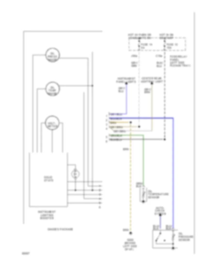
Instrument Panel Wiring Diagram (90 Wiring Diagram 2 Of 2) for Audi 90 S 1994
List of elements for Instrument Panel Wiring Diagram (90 Wiring Diagram 2 Of 2) for Audi 90 S 1994:
- (behind left side
- Auto- check system
- C15a
- Center rear ashtray light
- Fuse 12 15a
- Fuse 14 5a
- Fuse/relay panel (left side plenum tray)
- G202
- Gauges package
- Hot in on or start
- Hot w/ park or headlights on
- Instrument lighting booster
- Instrument panel lights
- J58a
- Of i/p)
- Oil press gauge
- Oil pressure sensor
- Oil temp gauge
- Oil temperature sensor
- Solid state
- Volt- meter
INTERIOR LIGHTS
Courtesy Lamps Wiring Diagram (1 of 2) for Audi 90 S 1994
List of elements for Courtesy Lamps Wiring Diagram (1 of 2) for Audi 90 S 1994:
-
- (optional)
- Anti- theft system
- C1/1
- Center rear ashtray light
- Central locking/ alarm system/ interior light delay control module
- Cluster
- Door
- Engine comp- artment light
- F30al
- Front interior light
- Fuse 14 5a
- Fuse 4 15a
- Fuse/relay panel (left side plenum tray)
- G202 (behind left side of i/p)
- G404 (near left taillight)
- Gauges package
- Glove comp- artment light
- H30b
- Head
- Headlight washer system relay
- Hot at all times
- I58d
- Instrument
- Instrument lighting booster
- J58
- J58a
- Left front door contact switch
- Left make-up mirror light
- Left rear door contact switch
- Left rear reading light
- License plate lights
- Light switch
- Nca
- Off
- Park
- Right front door contact switch
- Right front reading light
- Right make-up mirror light
- Right rear door contact switch
- Right rear reading light
- Trunk light
- Trunk light switch
Courtesy Lamps Wiring Diagram (2 of 2) for Audi 90 S 1994
List of elements for Courtesy Lamps Wiring Diagram (2 of 2) for Audi 90 S 1994:
- C15a
- Driver seat heat regulating switch
- Emergency flasher switch
- Fuse 12 15a
- Fuse 15 25a
- Fuse 18 5a
- Fuse/relay panel (left side plenum tray)
- G202 (behind left side of i/p)
- Hot in on or acc
- Hot in on or start
- I75aw
- M75as
- Mirror adjustment switch
- Passenger seat heat regulating switch
- Wiper/ washer system
Instrument Illumination Wiring Diagram for Audi 90 S 1994
List of elements for Instrument Illumination Wiring Diagram for Audi 90 S 1994:
- A/c control head
- A/t console light
- Ashtray light
- Auto a/c
- Auto check system
- Auxiliary relay panel (behind left side of i/p)
- C1-1
- C1-5
- C1-8
- C15a
- C2-21
- Cigarette lighter light
- Clock
- Dim input
- Dimmer switch
- Exterior
- F30al
- Fresh air control lever light
- Front fog light switch
- Fuse 12 15a
- Fuse 14 5a
- Fuse 4 15a
- Fuse/relay panel (left side plenum tray)
- G202 (behind left side of i/p)
- Gauges package
- Generator
- Gnd
- Head
- Hot at all times
- Hot in on or start
- I58d
- Illum. lights
- Instrument cluster
- Instrument lighting booster
- J58
- Light switch
- Lights system
- Manual a/c
- Mini-check system control module
- Off
- Outside air temp- ature display
- Park
- Program switch illumination relay
- Protection diode
- Radio
- Rear differential display unit
- Rear fog light switch
- Rear window defogger switch
- Selector lever light relay
- Solid state
- Transmission range program switch
- Transmission range selector lever display
- W/ a/t
- W/ auto a/c
- W/ quatrro
- Warning systems
POWER DISTRIBUTION
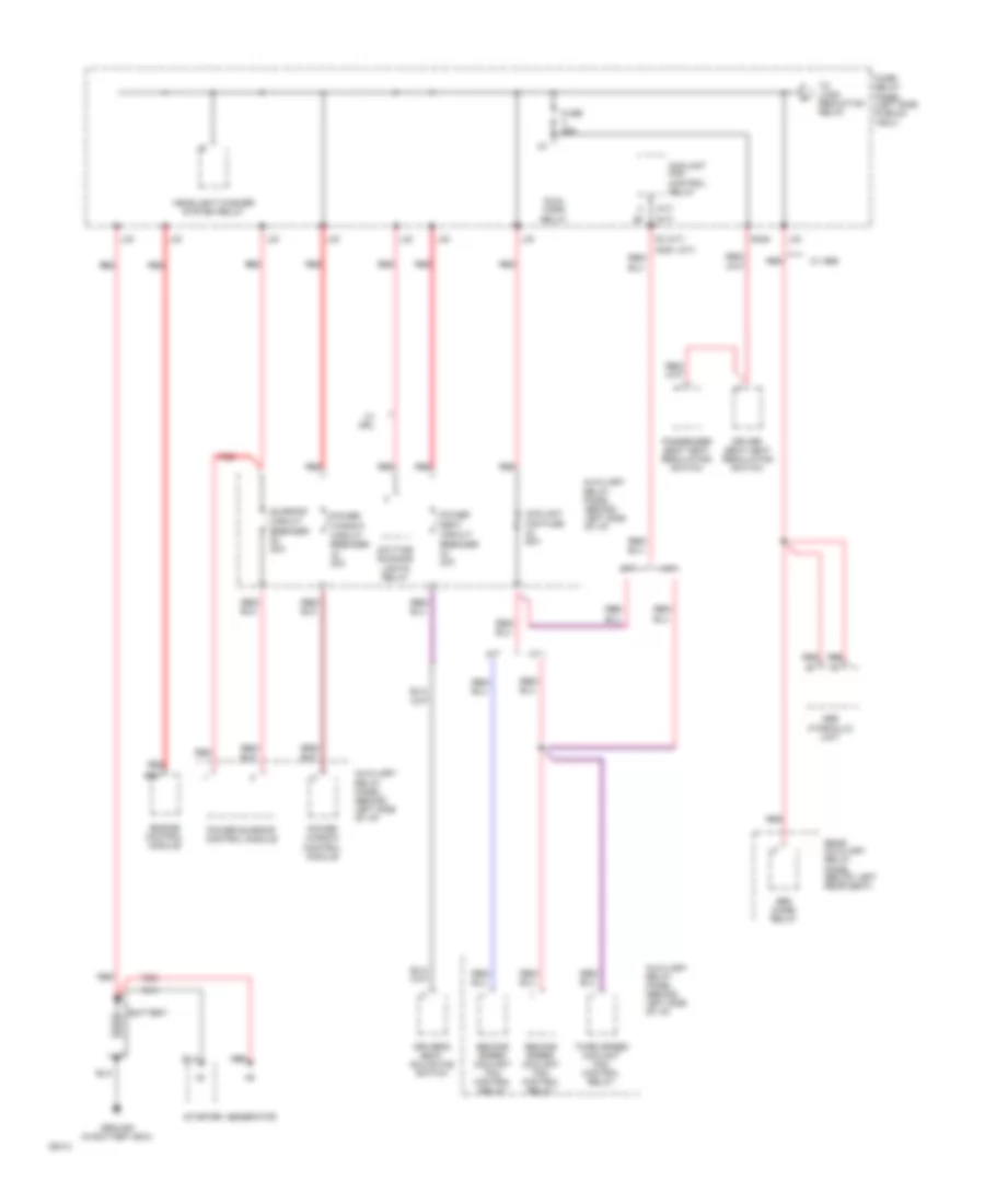
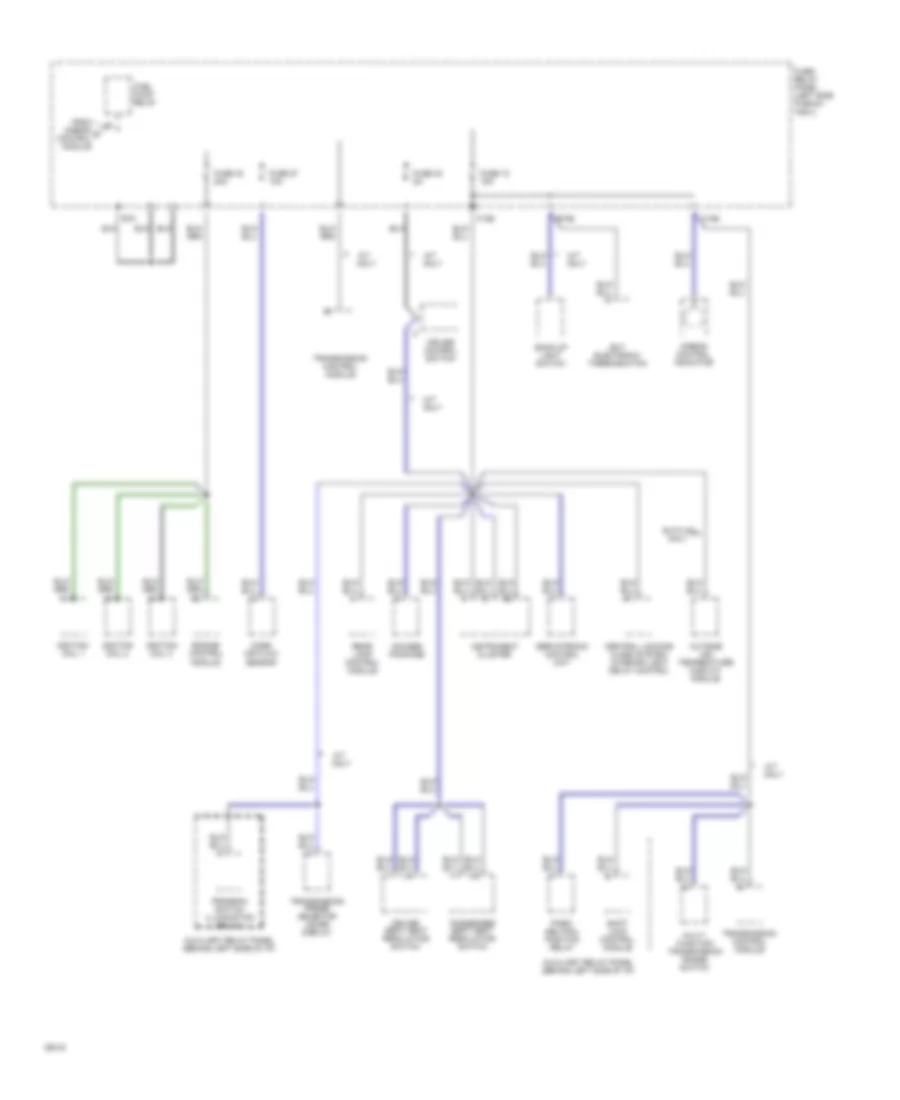
Power Distribution Wiring Diagram (1 of 4) for Audi 90 S 1994
List of elements for Power Distribution Wiring Diagram (1 of 4) for Audi 90 S 1994:
- (a/t)
- (m/t)
- A/t
- A30m
- Abs combi relay
- Abs hydraulic unit
- Auxiliary relay panel (behind left side of i/p)
- B20
- Battery
- Control module
- Coolant fan control relay
- Coolant fan fuse 60a
- Daytime running
- Driver seat heat regulating switch
- Driver's seat adjusting switch
- Dual horn relay
- Engine control module
- Fuse 25a
- Fuse/ relay panel (left side plenum tray)
- G30a
- Generator
- Ground (in battery box)
- Headlight washer system relay
- L30
- Lights relay
- M/t
- Passenger seat heat regulating switch
- Power
- Power sunroof control module
- Power window
- Power window circuit breaker 20a
- Rear auxiliary relay panel (below left rear seat)
- Red
- Seat circuit breaker 30a
- Second speed coolant fan control relay
- Starter
- Sunroof circuit breaker 20a
- Third speed coolant fan control relay
- To load reduction relay
- W/ abs
- W/ drl
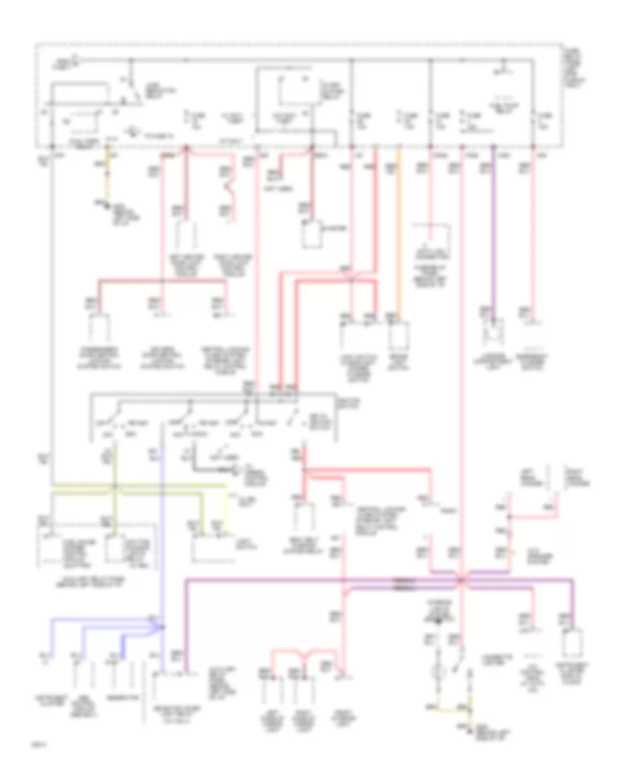
Power Distribution Wiring Diagram (2 of 4) for Audi 90 S 1994
List of elements for Power Distribution Wiring Diagram (2 of 4) for Audi 90 S 1994:
- (a/t only)
- (behind left side of i/p)
- (not used)
- (quattro)
- (w/ drl)
- 50z
- 50b
- 86s
- A/2
- A/c control head (w/ auto a/c)
- Abs control module (abs only)
- Acc
- Alarm system relay
- Alarm system/ interior light delay control
- Auxiliary relay panel
- Auxiliary relay panel (behind left side of i/p)
- B/1
- B/2
- Brake light switch
- C13
- Central locking/
- Central locking/ alarm system/ interior light delay control module
- Cigarette lighter
- D+/61
- Data link connector
- Daytime running lights relay
- Driver's door central locking system switch
- Dual horn relay
- E50a
- Emergency flasher switch
- F30al
- From a fuse 3
- Front interior light
- Fuel gauge damper control module
- Fuel pump relay
- Fuse 10a
- Fuse 15a
- Fuse/ relay panel (left side plenum tray)
- Fuse/relay panel (behind left side of i/p)
- G202 (behind left side of i/p)
- G31
- G49
- G75
- Generator
- H30b
- Ignition switch
- Instrument cluster
- Instrument cluster (digital clock)
- Interior lights system (rheostat)
- Key-in ignition switch
- L30
- Left heated door lock control module
- Left make-up mirror light
- Left rear woofer
- Light switch
- Light switch & headlight dimmer/ flasher switch
- Load reduction relay
- Luggage compartment light
- M/t only
- M30ac
- M30az
- Module
- Off
- Passenger's door central locking system switch
- Radio
- Red
- Right heated door lock control module
- Right make-up mirror light
- Right rear woofer
- Run
- Seat belt warning system relay
- Selector lever light relay
- Start
- Starter
- To airbag control module
- To fuse 15
- W/ 6 speaker system
- W/ anti- theft
- W/ drl only
- W/o anti- theft
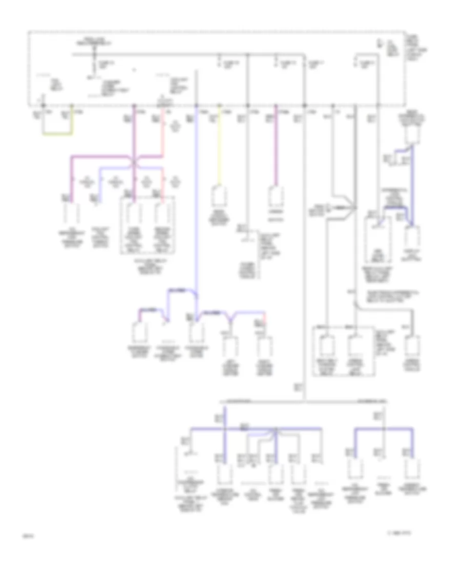
Power Distribution Wiring Diagram (3 of 4) for Audi 90 S 1994
List of elements for Power Distribution Wiring Diagram (3 of 4) for Audi 90 S 1994:
- (a/t)
- (behind
- (left side
- (m/t)
- (quattro)
- *electronic differential lock control cut-off relay w/ quattro
- 15a
- 25a
- 30a
- 75n
- A/c compressor clutch
- A/c control head
- A/c refrigerant high
- A/c refrigerant low pressure switch
- Abs combi relay
- Airbag control lamp relay
- Airbag control module
- Ambient temperature switch
- Auxiliary relay panel
- Auxiliary relay panel (behind left side of i/p)
- Auxiliary relay panel 1 (behind left side of i/p)
- C 1995 vftc
- C14
- Control
- Coolant
- Coolant fan control
- D75a
- Differential lock control module
- Display unit
- Emergency flasher switch
- Fan
- Flap two-way valve
- Fog light relay
- Fresh air blower
- Fresh air/ recirc.
- From ignition switch
- From load reduction relay
- Fuse 15
- Fuse 16
- Fuse 17
- Fuse 18
- Fuse 31
- Fuse/ relay panel
- I15
- I75aw
- Interior temperature sensor
- Intermittent
- J75ah
- J75al
- Left side
- Left washer nozzle heater
- M75as
- M75s
- Mirror
- Nca
- Of i/p)
- Plenum
- Power window control module
- Pressure switch
- Rear auxiliary relay panel (below left rear seat)
- Rear differential lock switch
- Rear window defogger switch
- Relay
- Right washer nozzle heater
- Seat belt warning system relay
- Second speed coolant fan control
- Switch
- Thermo- switch
- Third speed coolant fan control
- To fuel pump relay
- Tray)
- W/ auto a/c
- W/ manual a/c
- Washer/
- Windshield wiper intermittent switch
- Windshield wiper motor
- Wiper
Power Distribution Wiring Diagram (4 of 4) for Audi 90 S 1994
List of elements for Power Distribution Wiring Diagram (4 of 4) for Audi 90 S 1994:
- A/1
- A/t only
- Airbag control indicator
- Auto a/c only
- Auxiliary relay panel (behind left side of i/p)
- B15
- B15a
- Back-up light switch
- C15a
- Central locking/ alarm system/ interior light delay control
- Cruise control switch
- Driver seat heat regulating switch
- Ect electronic thermoswitch
- Engine control module
- From airbag d control module
- Fuel pump relay
- Fuse 12 15a
- Fuse 27 10a
- Fuse 30 5a
- Fuse 32 20a
- Fuse/ relay panel (left side plenum
- Gauges package
- Ignition coil 1
- Ignition coil 2
- Ignition coil 3
- Instrument cluster
- M/t only
- Mass air flow sensor
- Multi- function transmission range switch
- Outside air temperature display module
- Park/ neutral position relay
- Passenger seat heat regulating switch
- Program switch illumination relay
- Rear lamp control module
- Servotronic control unit
- Shift lock control module
- Transmission control module
- Transmission range selector lever display
- Tray)
POWER DOOR LOCKS
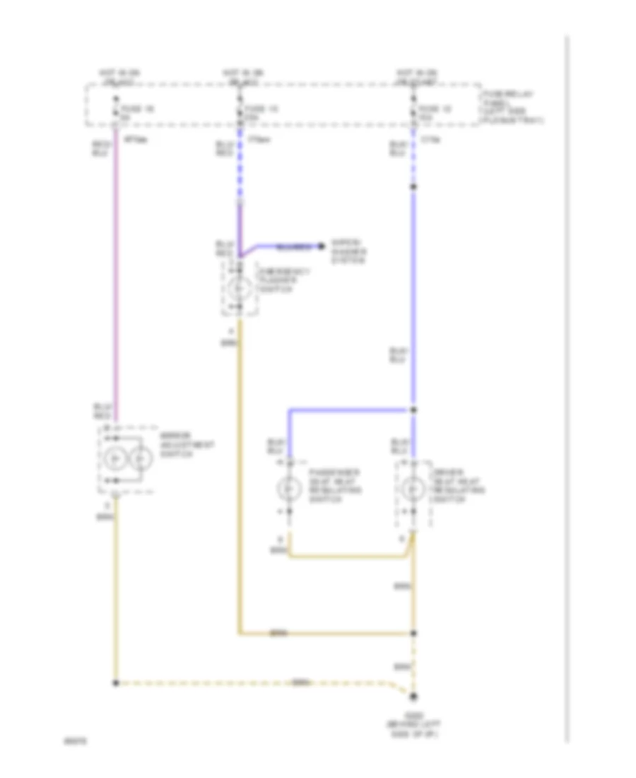
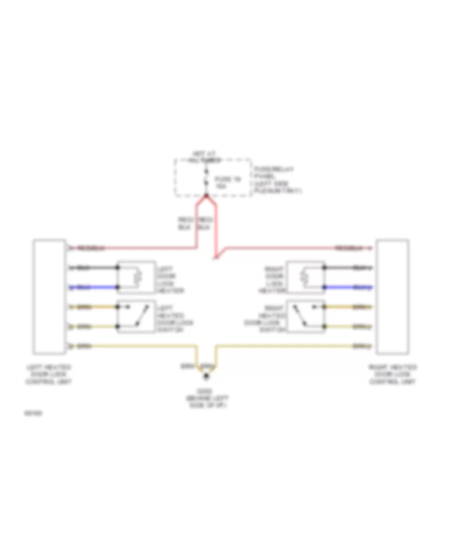
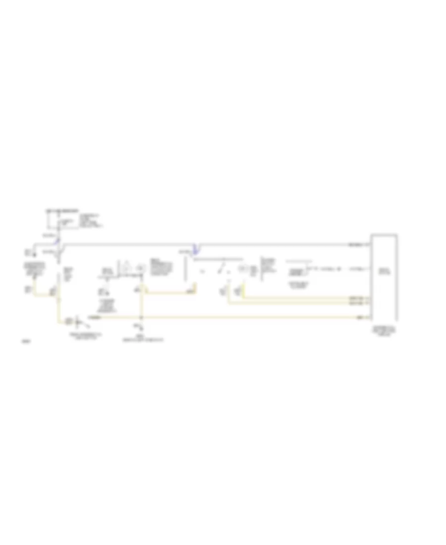
Heated Door Locks Wiring Diagram for Audi 90 S 1994
List of elements for Heated Door Locks Wiring Diagram for Audi 90 S 1994:
- All times
- Door lock
- Fuse 19 10a
- Fuse/relay panel (left side plenum tray)
- G202 (behind left side of i/p)
- Heated
- Heater
- Hot at
- Left door lock heater
- Left heated door lock control unit
- Left heated door lock switch
- Right
- Right door lock
- Right heated door lock control unit
- Switch
POWER MIRRORS
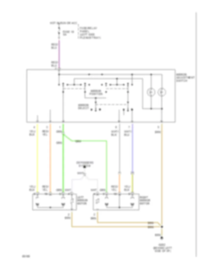
Power Mirrors Wiring Diagram for Audi 90 S 1994
List of elements for Power Mirrors Wiring Diagram for Audi 90 S 1994:
- Defoggers
- Fuse 18 5a
- Fuse/relay panel (left side plenum tray)
- G202 (behind left side of i/p)
- Hot in run or acc
- Left mirror motor
- Mirror adjustment switch
- Mirror position
- Mirror select
- Right mirror motor
- System
POWER SEATS
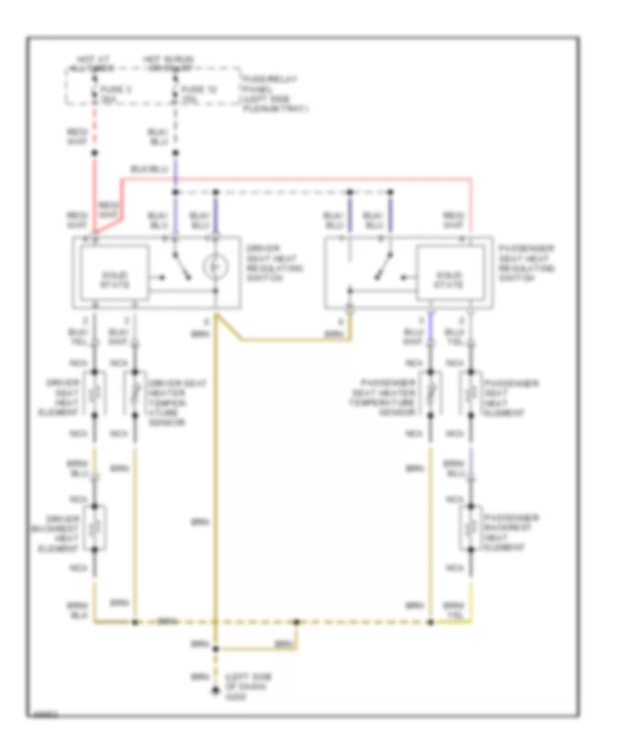
Heated Seats Wiring Diagram for Audi 90 S 1994
List of elements for Heated Seats Wiring Diagram for Audi 90 S 1994:
- (left side of dash) g202
- All times
- Driver backrest heat element
- Driver seat heat element
- Driver seat heat regulating switch
- Driver seat heater temper- ature sensor
- Fuse 12 15a
- Fuse 3 30a
- Fuse/relay panel (left side plenum tray)
- Hot at
- Hot in run or start
- Nca
- Passenger backrest heat element
- Passenger seat heat element
- Passenger seat heat regulating switch
- Passenger seat heater temperature sensor
- Solid state
Left Power Seat Wiring Diagram for Audi 90 S 1994
List of elements for Left Power Seat Wiring Diagram for Audi 90 S 1994:
- Back- rest
- Circuit breaker 44 30a
- Driver seat backrest adjusting motor
- Driver seat fore/aft adjusting motor
- Driver seat front height adjusting motor
- Driver seat rear height adjusting motor
- Driver seat switch
- Fore/ aft
- Front height
- Fuse/relay panel (left side plenum tray)
- G202 (behind left side of dash)
- Hot at all times
- Rear height
POWER TOP/SUNROOF
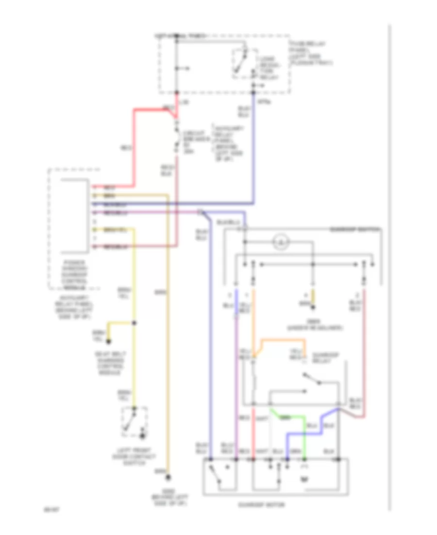
Sunroof Wiring Diagram for Audi 90 S 1994
List of elements for Sunroof Wiring Diagram for Audi 90 S 1994:
- Auxiliary relay panel (behind left side of i/p)
- Circuit breaker 20a
- Fuse/relay panel (left side plenum tray)
- G202 (behind left side of i/p)
- G908 (under headliner)
- Hot at all times
- Iii
- L30
- Left front door contact switch
- Load reduc- tion relay
- M75s
- Power window/ sunroof control module
- Red
- Seat belt warning control module
- Sunroof motor
- Sunroof relay
- Sunroof switch
POWER WINDOWS
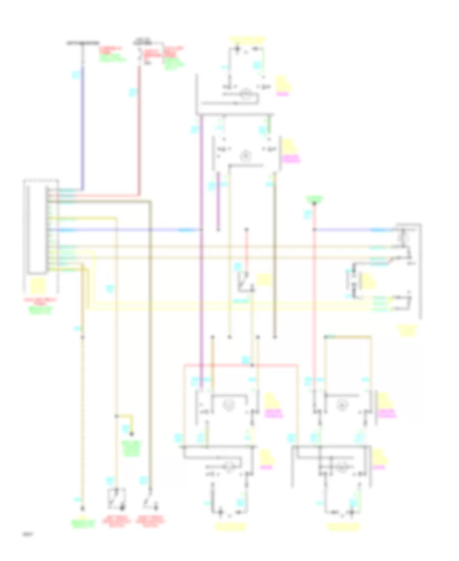
Power Windows Wiring Diagram for Audi 90 S 1994
List of elements for Power Windows Wiring Diagram for Audi 90 S 1994:
-
-
- All times
- Auxiliary relay panel (behind left side of i/p)
- Circuit breaker 20a
- Fuse/relay panel (left side plenum tray)
- G202 (behind left side of i/p)
- Hot at
- Hot in on or acc
- Left front door contact switch
- Left front window motor
- Left front window switch
- Left rear
- Left rear door window motor
- Left rear window switch (door)
- Nca
- Power window control module
- Right front door contact switch
- Right front door window motor
- Right front window switch (center console)
- Right front window switch (door)
- Right rear
- Right rear door window motor
- Right rear window switch (door)
- Seat belt warning control module
- Sunroof motor
- Window lockout switch
- Window switch (center console)
RADIO
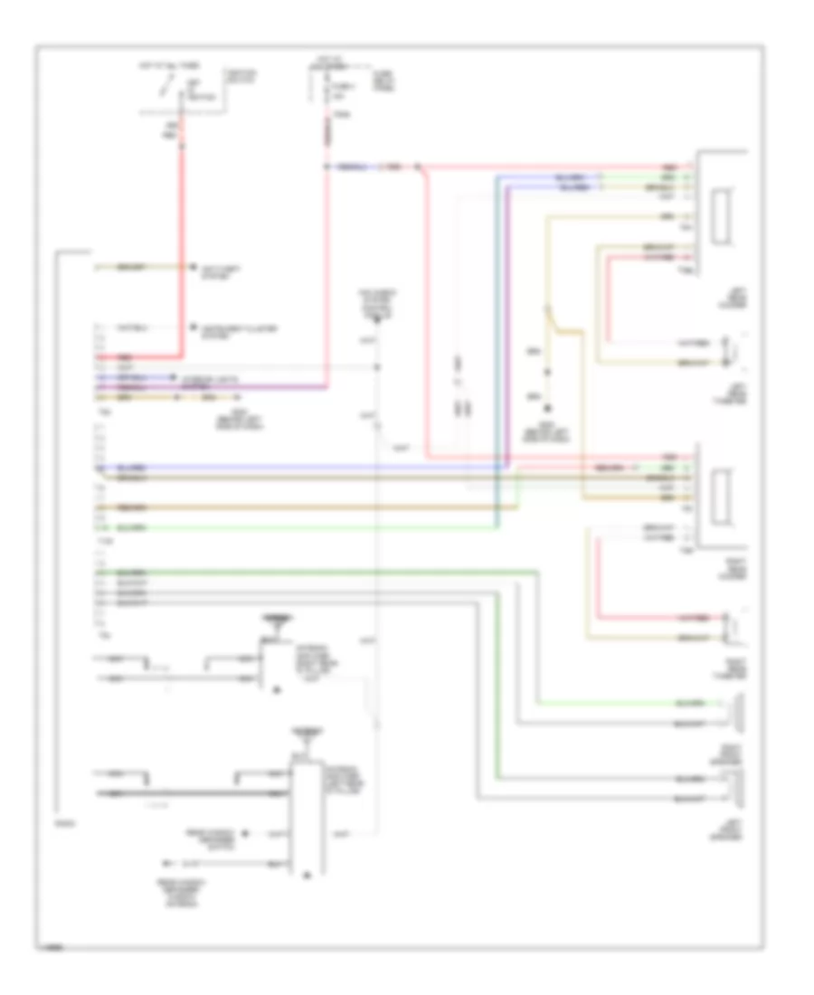
Radio Wiring Diagram for Audi 90 S 1994
List of elements for Radio Wiring Diagram for Audi 90 S 1994:
- 15a
- 86s
- Antenna
- Antenna amplifier (left rear "d" pillar)
- Antenna amplifier (right rear "d" pillar)
- Anti-theft system
- F30al
- Fuse 4
- Fuse/ relay panel
- G202 (behind left side of dash)
- Hot at all times
- Ignition switch
- Instrument cluster system
- Interior lights system
- Key in ignition
- Left front speaker
- Left rear tweeter
- Left rear woofer
- Mini check system control module
- Nca
- Radio
- Rear window defogger switch
- Rear window defogger/ window antenna
- Red
- Right front speaker
- Right rear tweeter
- Right rear woofer
- T10h
- T2af
- T2ag
- T5m
- T5n
- T8b
- T8c
SHIFT INTERLOCK
Shift Interlock Wiring Diagram for Audi 90 S 1994
List of elements for Shift Interlock Wiring Diagram for Audi 90 S 1994:
- (behind left side of i/p)
- (left kick panel)
- Alarm system/
- Auxiliary relay panel
- Auxiliary relay panel (behind left side of i/p)
- Back-up
- Brake light switch
- C/1
- C/9
- Central locking/
- Cluster
- Control module
- Engine control module
- Function switch
- Fuse 12 15a
- Fuse 29 10a
- Fuse/relay panel (left side plenum tray)
- G200 (lower left "a" pillar)
- Hot at all times
- Hot in on or acc
- Instrument
- Interior light delay
- Lights
- Multi-
- Park/ neutral position relay
- Shift lock
- Shift lock control module
- Solenoid
- Speedometer
- Starting
- System
- Transmission control module
- Vehicle speed output
STARTING/CHARGING
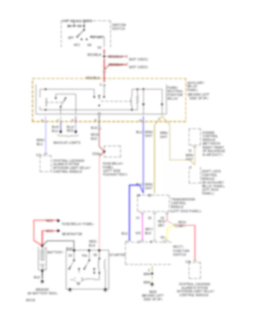
Starter System Wiring Diagram (Cabriolet Wiring Diagram A/T) for Audi 90 S 1994
List of elements for Starter System Wiring Diagram (Cabriolet Wiring Diagram A/T) for Audi 90 S 1994:
- (behind left side of i/p)
- (left kick panel)
- (not used)
- 15a
- Acc
- Alarm system/
- Auxiliary relay panel
- Back-up lights
- Battery
- C/1
- C/9
- Central locking/
- Central locking/ alarm system/ interior light delay control module
- Control module
- E50a
- Engine control module (between right front of bulkhead & air duct)
- Function switch
- Fuse/relay panel
- Fuse/relay panel (left side plenum tray)
- G202 (behind left side of i/p)
- Generator
- Ground (in battery box)
- Hot at all times
- Ignition switch
- Interior light delay
- Multi-
- Off
- Park/ neutral position relay
- Red
- Shift lock control module (in auxiliary relay panel, left kick panel)
- Start
- Starter
- Transmission control module
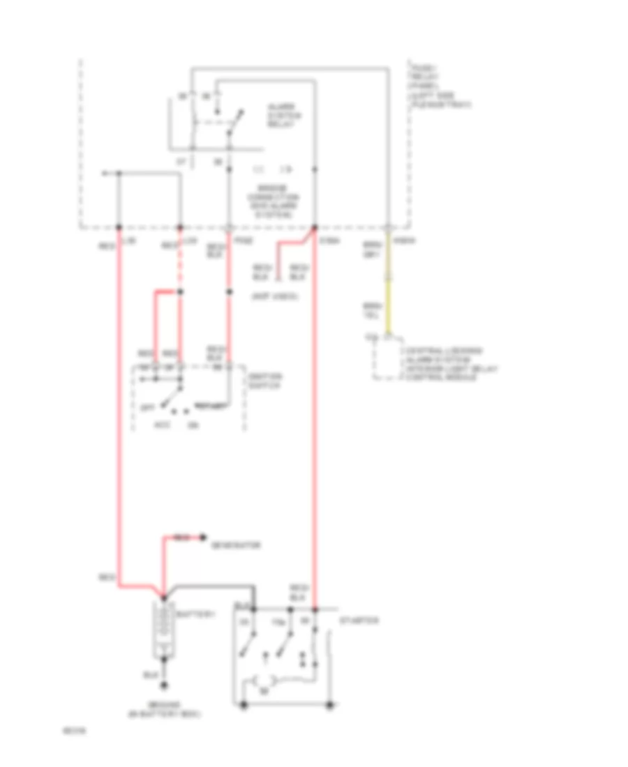
Starter System Wiring Diagram (Cabriolet Wiring Diagram M/T) for Audi 90 S 1994
List of elements for Starter System Wiring Diagram (Cabriolet Wiring Diagram M/T) for Audi 90 S 1994:
- (not used)
- 15a
- Acc
- Alarm system relay
- Battery
- Bridge connection (w/o alarm system)
- C/1
- Central locking/ alarm system/ interior light delay control module
- E50a
- F50z
- Fuse/ relay panel (left side plenum tray)
- Generator
- Ground (in battery box)
- H50w
- Ignition switch
- L30
- L30 red
- Off
- Red
- Start
- Starter
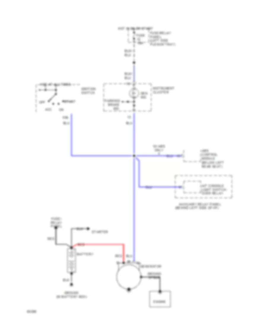
Charging Wiring Diagram for Audi 90 S 1994
List of elements for Charging Wiring Diagram for Audi 90 S 1994:
- (behind left side of i/p)
- (below left rear seat)
- 50b
- A/t console light switch- over relay
- Abs control module
- Acc
- Auxiliary relay panel
- Battery
- Engine
- Fuse 15a
- Fuse/ relay panel
- Fuse/relay panel (left side plenum tray)
- Gen ind.
- Generator
- Ground (in battery box)
- Ground strap
- Hot at all times
- Hot in on or start
- Ignition switch
- Instrument cluster
- Off
- Parking brake ind.
- Red
- Start
- Starter
- W/ abs only
SUPPLEMENTAL RESTRAINTS
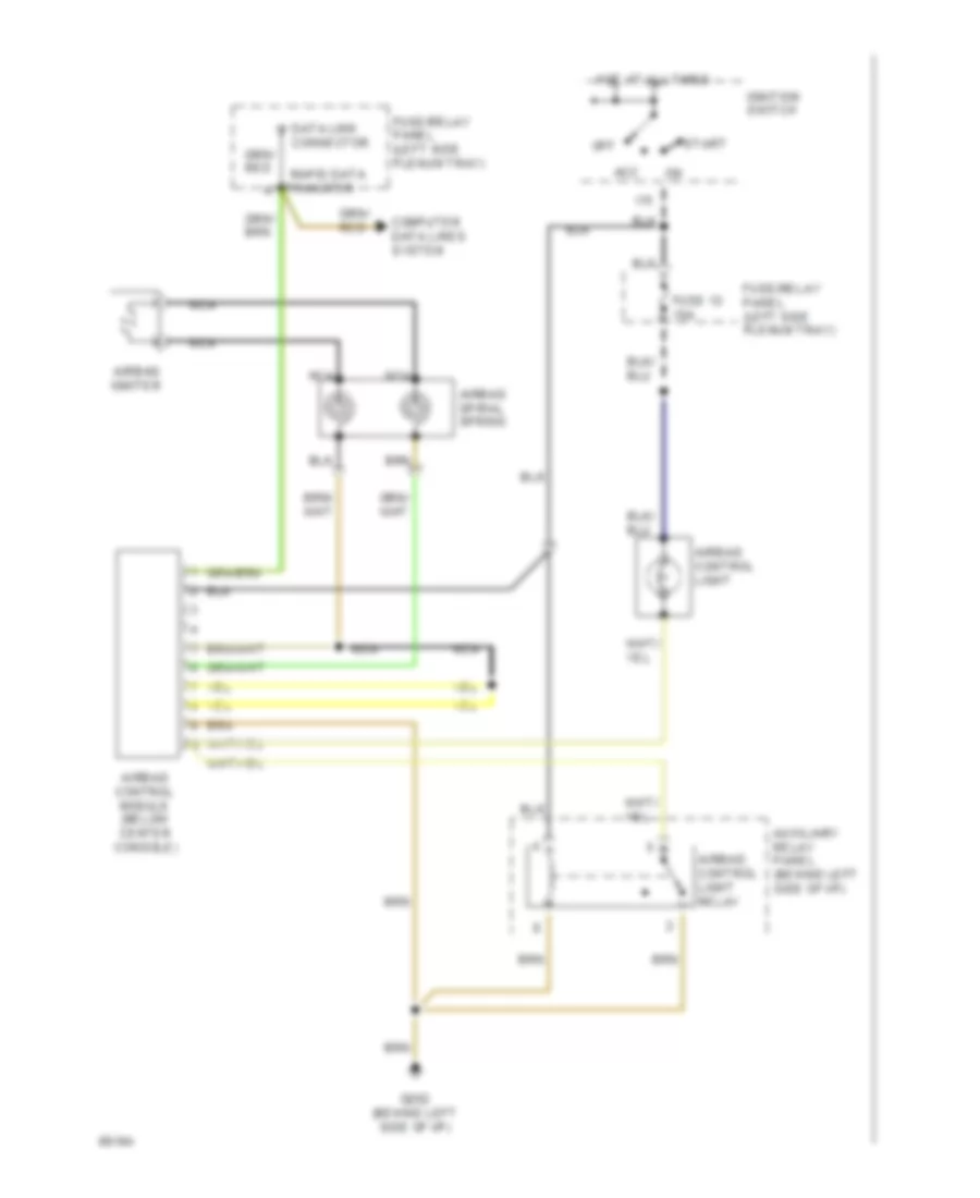
Supplemental Restraints Wiring Diagram for Audi 90 S 1994
List of elements for Supplemental Restraints Wiring Diagram for Audi 90 S 1994:
-
-
- Acc
- Airbag control light
- Airbag control light relay
- Airbag control module (below center console)
- Airbag igniter
- Airbag spiral spring
- Auxiliary relay panel (behind left side of i/p)
- Computer data lines system
- Connector
- Data link
- Fuse 12 15a
- Fuse/relay panel (left side plenum tray)
- G202 (behind left side of i/p)
- Hot at all times
- I15
- Ignition switch
- Nca
- Off
- Rapid data
- Start
- Transfer
TRANSMISSION
A/T Wiring Diagram for Audi 90 S 1994
List of elements for A/T Wiring Diagram for Audi 90 S 1994:
- (left side of i/p)
- * 1993 models
- 1995 vftc c
- 2p n
- 50a
- 50z
- 87a
- A/c kickdn
- A/c system
- Abs/tcs
- Atf temp
- Automatic transmission console light
- Automatic transmission console light switch-over relay
- Auxilliary relay panel (left i/p)
- Brake light switch (on pedal cluster)
- Brake lt sw
- C15a
- Central locking/ alarm system/ interior light delay control module (below right taillight)
- Cruise control system
- Data link connector (in plenum tray)
- E50a
- Engine control module (between front right of bulkhead and air duct)
- Exterior lights system
- F30al
- F50z
- Fuse 10a
- Fuse 15a
- Fuse 5a
- Fuse/ relay panel (left side plenum tray)
- G131 (on intake manifold)
- G202 (left side of i/p)
- Gear selection indicator
- Generator terminal d+
- Ground
- H50w
- Hot at all times
- Hot in on or start
- Ign time adj
- Ignition switch terminal 50 (hot in start)
- Interior lights system
- K wire diag
- Kick-down switch (on throttle housing)
- Kickdn sw
- L30
- M-f switch
- Multi- function switch (rear of gear box housing)
- Not
- On/start v
- P/n
- Park/ neutral position relay
- Pk/neut sig
- Program switch light relay
- Protection diode
- R n
- Red
- Red/ starter terminal
- Rpm sig
- Shift interlock system
- Shift lock control module
- Sol supp v
- Solenoid 1
- Solenoid 2
- Solenoid 3
- Solenoid 4
- Solenoid 5
- Solenoid 6
- Solenoid 7
- Solenoid valves
- Spd ctrl mod
- T20
- Tps signal v
- Tr display
- Tr prog sw
- Tr sw lamp
- Transmission control module (on brake pedal support)
- Transmission fluid temperature sensor
- Transmission range program switch
- Used
- Valve body
- Vehicle speed sensor (on gearbox housing)
- Vss
Differential Lock Wiring Diagram, Quattro for Audi 90 S 1994
List of elements for Differential Lock Wiring Diagram, Quattro for Audi 90 S 1994:
- (behind left side of i/p)
- Cluster
- Diff. lock ind.
- Differ- ential lock switch
- Differential lock control
- Electronic differential lock cut- off relay
- Fuse 31 15a
- Fuse/relay panel (left side plenum tray)
- G202
- Hot in on or start
- Ill.
- Instrument
- Interior lights system (rheostat)
- Module
- Rear diff. lock ind.
- Rear differential lock switch
- Rear differential lock switch illumination/ indicator
- Solid state
- Speedo- meter
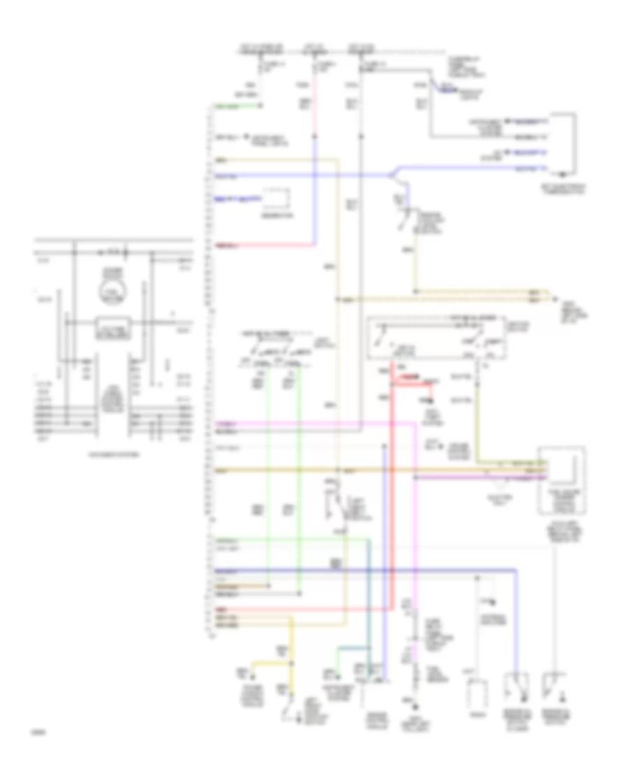
WARNING SYSTEMS
Warning Systems Wiring Diagram, with Mini-Check System for Audi 90 S 1994
List of elements for Warning Systems Wiring Diagram, with Mini-Check System for Audi 90 S 1994:
- (0.3 bar)
- (behind left side of i/p)
- 5/1
- 5/2
- 5/3
- 5/4
- 5/5
- 6/1
- 6/2
- 6/3
- 6/4
- 6/5
- 6/6
- 86s
- A/c system
- Acc
- Antenna amplifier
- Anti- theft system
- Auxiliary relay panel (behind left side of i/p)
- B10
- B15a
- Back-up lights
- C1-1
- C1-10
- C1-11
- C1-13
- C1-19
- C1-4
- C1-5
- C1-8
- C15a
- C2-15
- C2-16
- C2-18
- C2-21
- C3-10
- C3-12
- C3-13
- C3-14
- C3-3
- C3-4
- C3-7
- C3-8
- C3-9
- Cruise control system
- Dimmer switch
- Ect electronic thermoswitch
- Engine control module
- Engine coolant level switch
- Engine oil pressure switch
- F30al
- Fuel gauge
- Fuel gauge damper control module
- Fuel level sensor
- Fuse 12 15a
- Fuse 14 5a
- Fuse 4 15a
- Fuse/ relay panel (left side plenum tray)
- Fuse/relay panel (left side plenum tray)
- G202
- G404 (near left taillight)
- Generator
- Head
- Hot at all times
- Hot in on or start
- Hot w/ park or headlights on
- I58d
- Ignition switch
- Instrument cluster system
- Instrument panel lights
- Key-in ignition
- Left front door contact switch
- Left seat belt switch
- Light switch
- Mini- check system control module
- Mini-check system
- Nca
- Off
- Park
- Power window control module
- Quattro only
- Radio
- Red
- Start
- Voltage stabilizer
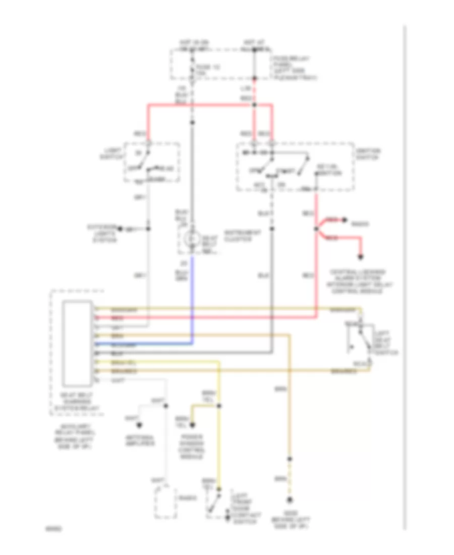
Warning Systems Wiring Diagram, without Mini-Check System for Audi 90 S 1994
List of elements for Warning Systems Wiring Diagram, without Mini-Check System for Audi 90 S 1994:
-
-
- (behind left side of i/p)
- 86a
- Acc
- Alarm system/
- Antenna amplifier
- Auxiliary relay panel
- Central locking/
- Control module
- Exterior
- Fuse 12 15a
- Fuse/relay panel (left side plenum tray)
- G202 (behind left side of i/p)
- Head
- Hot at all times
- Hot in on or start
- Ignition switch
- Instrument cluster
- Interior light delay
- Key-in- ignition
- L30
- Left front door contact switch
- Left seat belt switch
- Light
- Lights system
- Nca
- Off
- Park
- Power window control module
- Radio
- Red
- Seat belt ind.
- Seat belt warning system relay
- Start
- Switch
WIPER/WASHER
Wiper/Washer Wiring Diagram for Audi 90 S 1994
List of elements for Wiper/Washer Wiring Diagram for Audi 90 S 1994:
- B53c
- C31b
- C53c
- C53e
- Emergency
- Engine compartment light
- Flasher switch
- Fuse 15 25a
- Fuse/relay panel (left side plenum tray)
- G202 (behind left side of i/p)
- G31
- Headlight washer pump
- Headlight washer system relay
- Hot at all times
- Hot in on or acc
- Hot w/ park or headlights on
- Instrument cluster system
- J75ah
- Left washer nozzle heater (optional)
- Nca
- Red
- Right washer nozzle heater (optional)
- Solid state
- Washer fluid level switch
- Washer switch
- Windshield washer pump
- Windshield wiper intermittent switch
- Windshield wiper motor
- Wiper switch
- Wiper/ washer inter- mittent relay