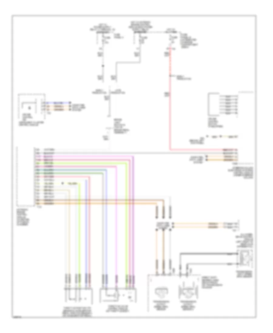
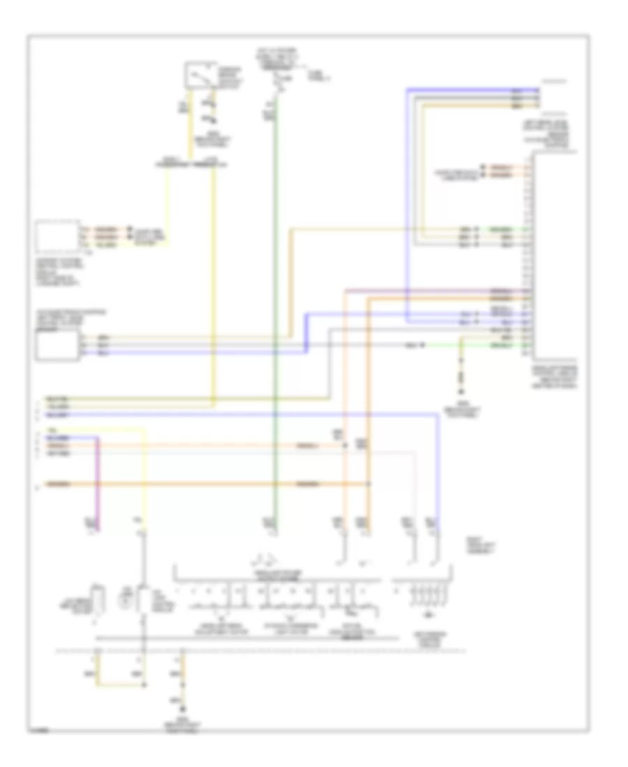
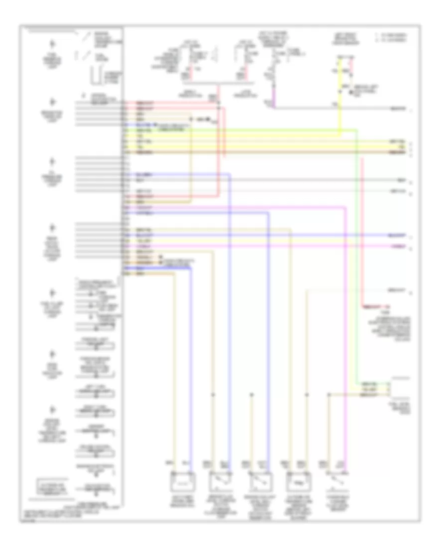
AIR CONDITIONING
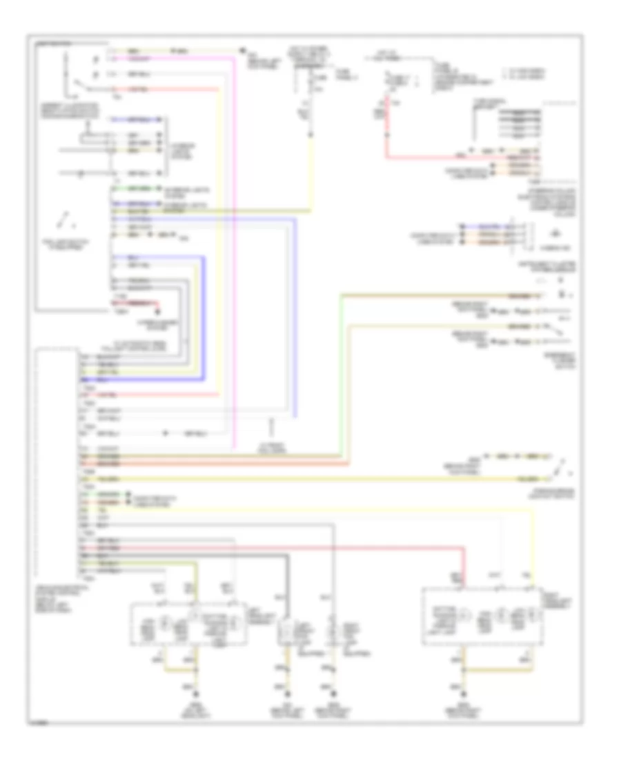
Automatic A/C Wiring Diagram (1 of 3) for Audi A3 2009

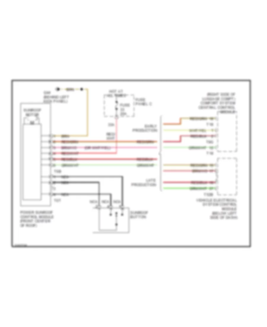
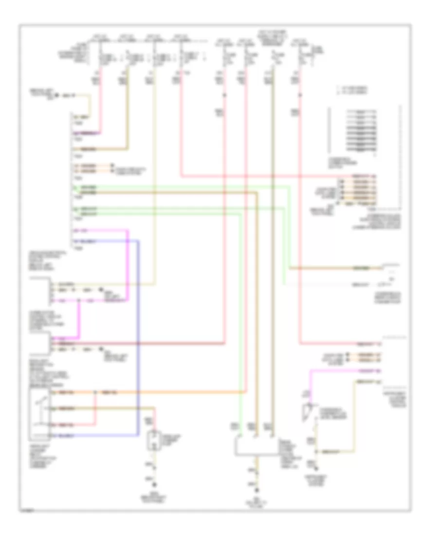
List of elements for Automatic A/C Wiring Diagram (1 of 3) for Audi A3 2009:
- (behind left kick panel) g44
- (behind right kick panel) g638
- (in engine compartment, on a/c high pressure line) high pressure sensor
- (in right plenum chamber) air quality sensor
- 16a
- 22a
- 37a
- A/c compressor regulator valve (rear of a/c compressor)
- Climatronic control module (w/ a/c control head)
- Evaporator vent temperature sensor (right front of center console)
- Fresh air blower (under right side of dash)
- Fresh air blower control module (below right side of dash)
- Fuse 10a
- Fuse 20a
- Fuse 40a
- Fuse 5a
- Fuse panel c
- G638 (behind right kick panel)
- Hot at all times
- Left footwell vent temperature sensor (left side of hvac unit)
- Left temperature flap motor & potentiometer/ actuator (left side of hvac unit)
- Nca
- Red
- Right footwell vent temperature sensor (top right side of hvac unit)
- Seats system
- T16d
- T20j
- W/ heated seats
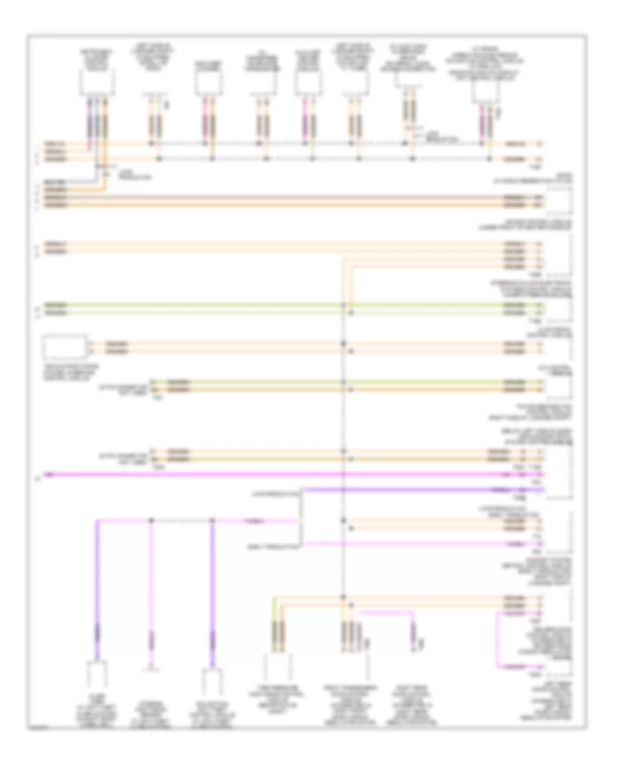
Automatic A/C Wiring Diagram (2 of 3) for Audi A3 2009
List of elements for Automatic A/C Wiring Diagram (2 of 3) for Audi A3 2009:
- (in left dash air vent) left vent temperature sensor
- (in right dash air vent) right vent temperature sensor
- (top left center of dash) sunlight photo sensor
- Central flap motor position sensor (on central flap actuator motor)
- Climatronic control module (w/ a/c control head)
- Computer data lines system
- Defroster flap motor position sensor (on defroster flap motor)
- Fuse 50a
- Fuse panel b (integrated in engine compt e-box)
- Hot at all times
- Recirculation flap motor, air flow flap motor & back pressure flap motor position sensor (recirculation flap motor: behind glove box) (air flow flap motor: left side of fresh air blower unit)
- Red
- Right temperature flap motor & potentiometer/actuator (lower right side of hvac unit)
- Seats system
- T12f
- T16e
- T40
- W/ high e-box
- W/ low e-box
Automatic A/C Wiring Diagram (3 of 3) for Audi A3 2009
List of elements for Automatic A/C Wiring Diagram (3 of 3) for Audi A3 2009:
- (left side of engine, below oil filter) after-run coolant pump
- 2.0l (bpy)
- 2.0l (cbfa)
- 2.0l (ccta & cbfa)
- 2.0l (ccta)
- 2.0l bpy 3.2l
- 3.2l
- After-run coolant pump (left side of engine, below oil filter)
- Coolant circulation pump relay
- Coolant circulation pump relay (2.0l (cbfa)) (on fuse panel "b")
- Coolant circulation pump relay (2.0l (ccta)) (on fuse panel "b")
- Coolant fan 2
- Coolant fan control (fc) control module (front of engine compartment)
- Engine control module (except 3.2l & 2.0l (bpy)) motronic engine control module (3.2l & 2.0l (bpy)) (motronic engine control module: in center of plenum chamber)
- Engine controls system
- Engine coolant temperature sensor (2.0l: right rear of engine) (3.2l: left side of cylinder head)
- Engine coolant temperature sensor (on radiator)
- Except 2.0l (cbfa)
- Fuse 10a
- Fuse 50a
- Fuse 5a
- Fuse panel a
- Fuse panel b (integrated in engine compt e-box)
- G607 (2.0l bpy) (in left plenum chamber)
- G607 (in left plenum chamber)
- G655 (3.2l) (on left headlight)
- G655 (on left headlight)
- Hot at all times
- Nca
- T121
- T26
- T2e
- T40
- T4d
- T60
- T94
- W/ high e-box
- W/ low e-box
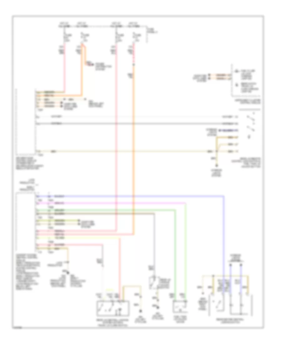
ANTI-LOCK BRAKES
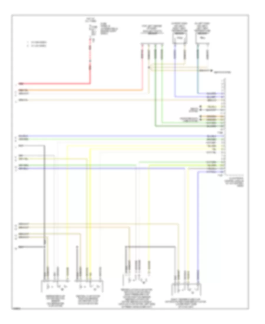
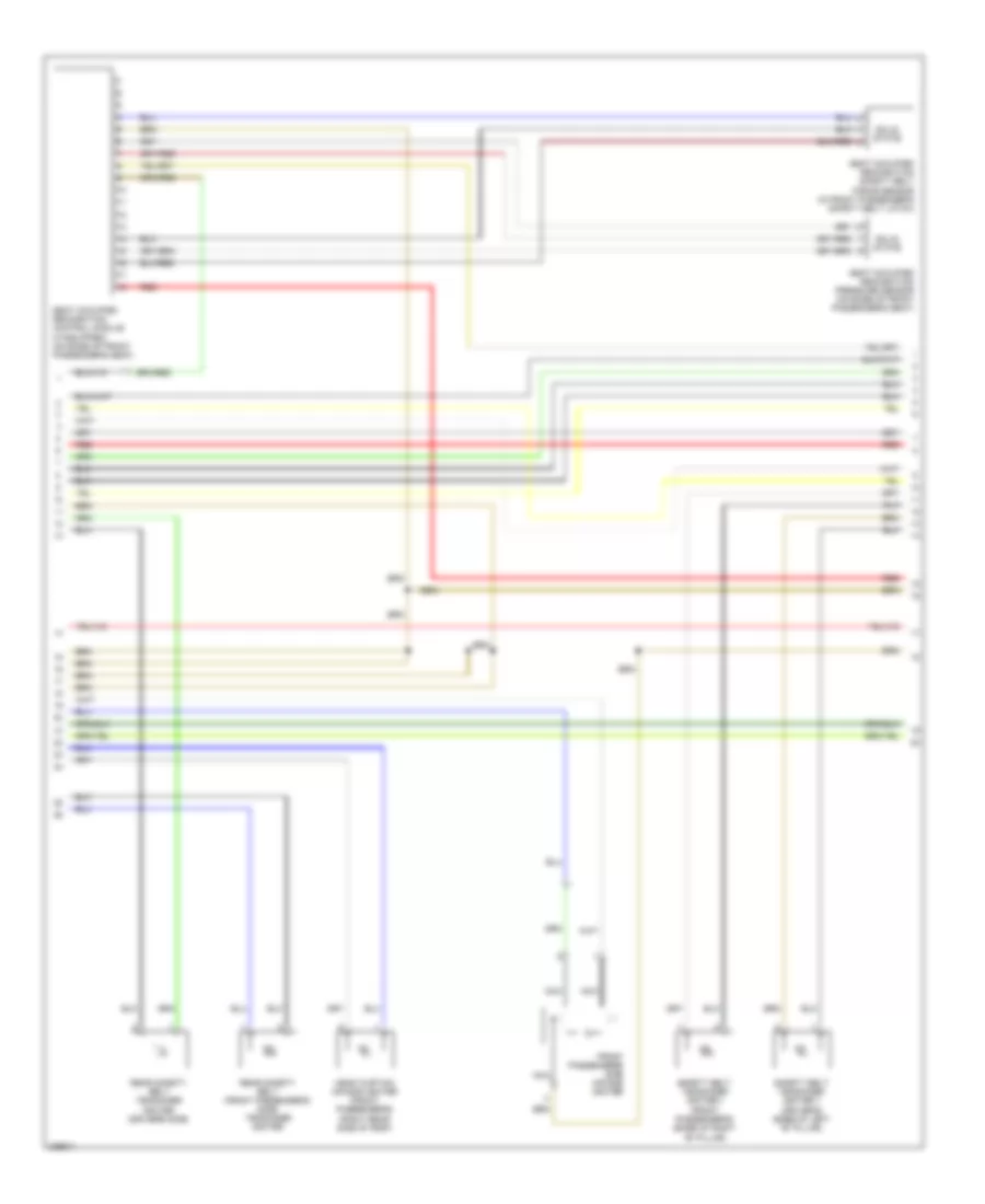
Anti-lock Brakes Wiring Diagram, Early Production with Hill-Hold Assist for Audi A3 2009
List of elements for Anti-lock Brakes Wiring Diagram, Early Production with Hill-Hold Assist for Audi A3 2009:
- (if equipped)
- (under steering column)
- Abs control module (at right rear of engine compt)
- Abs hydraulic pump
- Abs hydraulic unit
- Abs warning ind
- Asr/esp button
- Asr/esp control lamp
- Brake light switch (top of brake pedal assembly)
- Brake pad wear ind
- Brake pressure sensor 1
- Computer data lines system
- Driving dynamic regulation switch valve 1
- Driving dynamics regulation high pressure switch valve 1
- Driving dynamics regulation high pressure switch valve 2
- Driving dynamics regulation switch valve 2
- Fuse 10a
- Fuse 25 fuse 48 40a
- Fuse 4 fuse 2 20a
- Fuse 5a
- Fuse 6 fuse 17 5a
- Fuse panel b (integrated in engine compt e-box)
- Fuse panel c
- G43 (behind right kick panel)
- G44 (behind left kick panel)
- Headlight range control module (behind right center of dash)
- Hot at all times
- Instrument cluster control module
- Interior lights system
- Left front abs inlet valve
- Left front abs outlet valve
- Left front abs wheel speed sensor
- Left front brake pad wear sensor
- Left front level control system sensor (w/o electronic damping)
- Left rear abs inlet valve
- Left rear abs outlet valve
- Left rear abs wheel speed sensor
- Nca
- Red
- Right front abs inlet valve
- Right front abs outlet valve
- Right front abs wheel speed sensor
- Right rear abs inlet valve
- Right rear abs outlet valve
- Right rear abs wheel speed sensor
- Steering angle sensor (behind steering wheel)
- Steering column electronic systems control module
- T16a
- T26a
- T26a w/o cornering lights
- T26b w/ cornering lights
- T32
- Vacuum sensor
- Vehicle electrical system control module (below left side of dash)
- W/ high e-box
- W/ low e-box
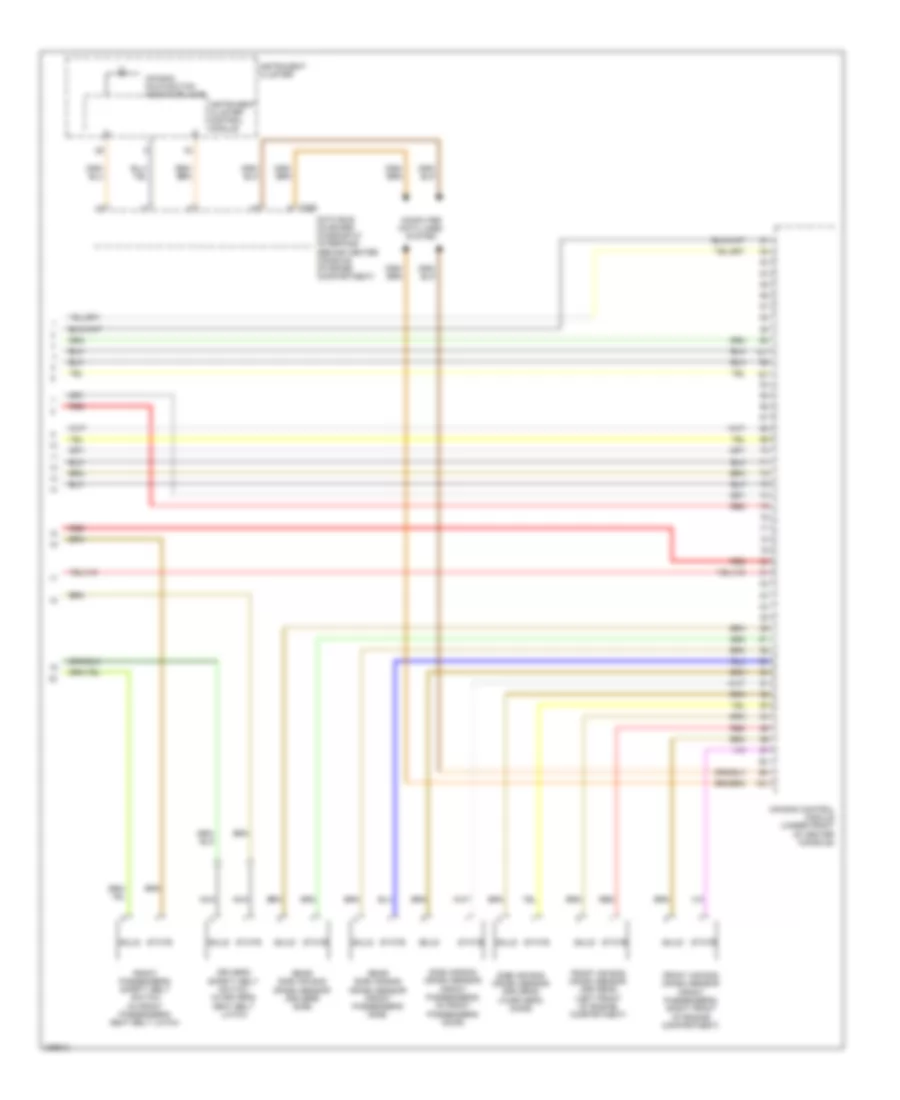
Anti-lock Brakes Wiring Diagram, Late Production with Hill-Hold Assist for Audi A3 2009
List of elements for Anti-lock Brakes Wiring Diagram, Late Production with Hill-Hold Assist for Audi A3 2009:
- (under steering column)
- Abs control module (at right rear of engine compt)
- Abs hydraulic pump
- Abs hydraulic unit
- Abs warning ind
- Asr/esp button
- Asr/esp control lamp
- Brake light switch (top of brake pedal assembly)
- Brake pad wear ind lamp
- Brake pressure sensor 1
- Computer data lines system
- Driving dynamics regulation high pressure switch valve 1
- Driving dynamics regulation high pressure switch valve 2
- Driving dynamics regulation switch valve 1
- Driving dynamics regulation switch valve 2
- Fuse 22 fuse 39 5a
- Fuse 25 fuse 48 40a
- Fuse 4 fuse 2 20a
- Fuse 5a
- Fuse 6 fuse 17 5a
- Fuse panel b (integrated in engine compt e-box)
- Fuse panel c
- G43 (behind right kick panel)
- G44 (behind left kick panel)
- Headlight range control module (behind right center of dash)
- Hot at all times
- Instrument cluster control module
- Interior lights system
- Left front abs inlet valve
- Left front abs outlet valve
- Left front abs wheel speed sensor
- Left front brake pad wear sensor
- Left front level control system sensor (w/o electronic damping)
- Left rear abs inlet valve
- Left rear abs outlet valve
- Left rear abs wheel speed sensor
- M/t
- Nca
- Red
- Right front abs inlet valve
- Right front abs outlet valve
- Right front abs wheel speed sensor
- Right rear abs inlet valve
- Right rear abs outlet valve
- Right rear abs wheel speed sensor
- Steering angle sensor (behind steering wheel)
- Steering column electronic systems control module
- T26a
- T26b
- T32
- T40
- T52c
- Vacuum sensor (if equipped)
- Vehicle electrical system control module (below left side of dash)
- W/ cornering light
- W/ high e-box
- W/ low e-box
- W/o cornering light
Anti-lock Brakes Wiring Diagram, without Hill-Hold Assist for Audi A3 2009
List of elements for Anti-lock Brakes Wiring Diagram, without Hill-Hold Assist for Audi A3 2009:
- (under steering column)
- 3.2l
- Abs control module (at right rear of engine compt)
- Abs hydraulic pump
- Abs warning ind
- Asr/esp button
- Asr/esp control lamp
- Brake pad wear ind
- Brake pressure sensor 1
- Computer data lines system
- Driving dynamic regulation high pressure switch valve 1
- Driving dynamic regulation high pressure switch valve 2
- Driving dynamic regulation switch valve 1
- Driving dynamic regulation switch valve 2
- Esp sensor unit
- Fuse 10a
- Fuse 16 fuse 1 30a
- Fuse 2 fuse 16 5a
- Fuse 4 fuse 2 30a
- Fuse 5a
- Fuse panel b (integrated in engine compt e-box)
- Fuse panel c
- G43 (behind right kick panel)
- G44 (behind left kick panel)
- G638 (behind right kick panel)
- Headlight range control module (behind right center of dash)
- Hot at all times
- Instrument cluster control module
- Interior lights system
- Left front abs inlet valve
- Left front abs outlet valve
- Left front abs wheel speed sensor
- Left front brake pad wear sensor
- Left front level control system sensor (w/o electronic damping)
- Left rear abs inlet valve
- Left rear abs outlet valve
- Left rear abs wheel speed sensor
- Nca
- Red
- Right front abs inlet valve
- Right front abs outlet valve
- Right front abs wheel speed sensor
- Right rear abs inlet valve
- Right rear abs outlet valve
- Right rear abs wheel speed sensor
- Steering angle sensor (behind steering wheel)
- Steering column electronic systems control module
- T16a
- T26a
- T26a w/o cornering lights
- T26b w/ cornering lights
- Vehicle electrical system control module (below left side of dash)
- W/ high e-box
- W/ low e-box
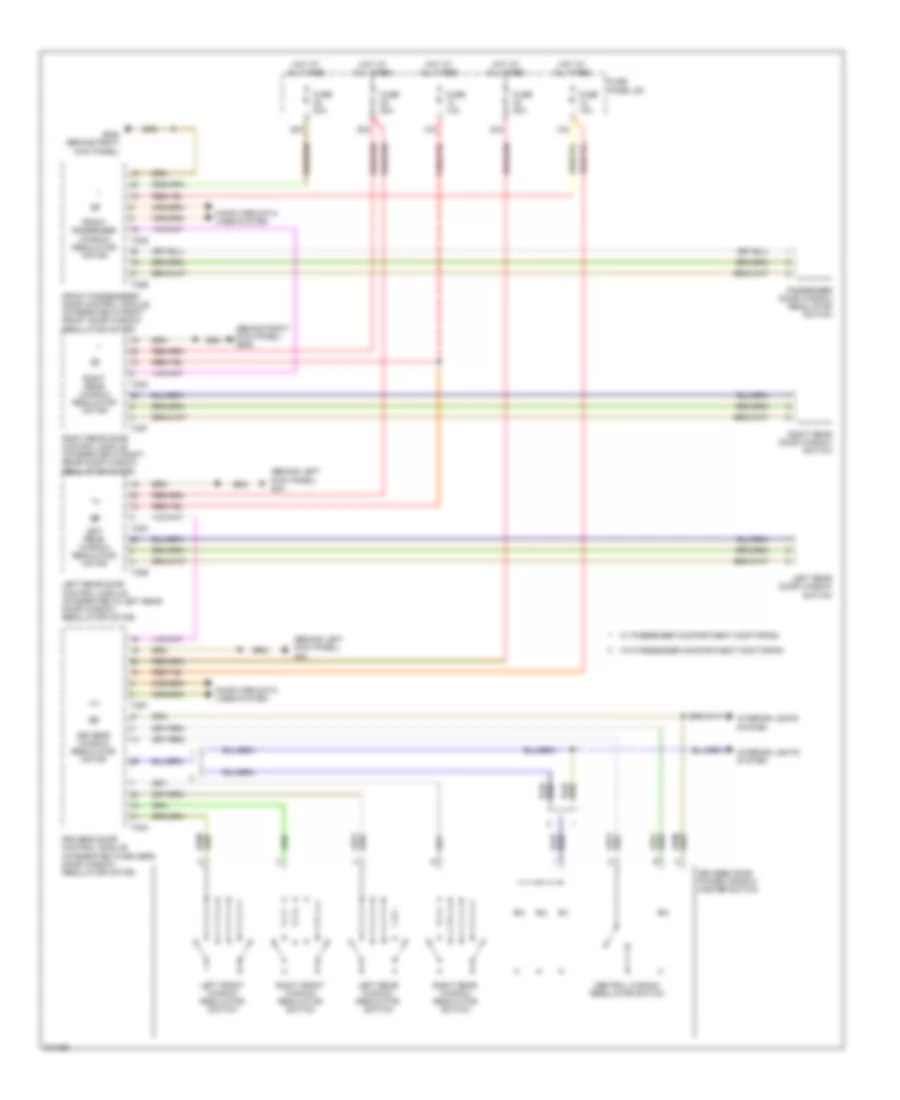
ANTI-THEFT
Anti-theft Wiring Diagram (1 of 2) for Audi A3 2009
List of elements for Anti-theft Wiring Diagram (1 of 2) for Audi A3 2009:
- 12a
- 13a
- 23a
- 28a
- 38a
- Central locking safe indicator lamp
- Computer data lines system
- Door control module (driver's) (integrated in driver's door window regulator motor)
- Door control module (front passenger's) (integrated in right front door window regulator motor)
- Door control module (right rear) (integrated in right rear door window regulator motor)
- Driver interior locking button
- Driver's door central locking lock unit
- Front passenger door central locking lock unit
- Front passenger interior locking button
- Fuse 10a
- Fuse 30a
- Fuse panel c
- G44 (behind left kick panel)
- G638 (behind right kick panel)
- Hot at all times
- Interior lights system
- Mirrors & power windows systems
- Right rear central locking lock unit
- T20f
- T20g
- T20o
- T32a
- T32b
- W/ front passenger's door opener illumination
Anti-theft Wiring Diagram (2 of 2) for Audi A3 2009
List of elements for Anti-theft Wiring Diagram (2 of 2) for Audi A3 2009:
- (behind right kick panel) g638
- (in right front wheelwell) (w/ anti-theft alarm) alarm horn
- (integrated in
- (late production) trunk lid alarm switch
- (left side of luggage compt lid) left antenna module
- (w/ anti-theft alarm) rear window glass breakage sensor
- 17a
- 3 door
- 5 door
- Antenna amplifier 2
- Central locking & anti-theft alarm system antenna
- Comfort system central control module (right side of luggage compt)
- Computer data lines system
- Door control
- Early production
- Early production nca
- Front hood switch (base of engine compt hood latch)
- Fuse 5a
- Fuse panel c
- G44 (behind left kick panel)
- G61 (on left "c" pillar)
- G638 (behind right kick panel)
- G655 (on left headlight)
- Hot at all times
- Interior lights system
- Late production
- Left rear central locking lock unit
- Left rear door
- Module (left rear)
- Motor)
- Nca
- Parking brake contact switch
- Passenger compartment monitoring & alarm system off switches
- Production
- Rear lid central locking system motor (late production)
- Rear window defogger w/ window antenna
- T12e
- T18
- T20n
- T52a
- T52b
- T52c
- T6g
- T8h
- Trunk lid alarm switch & rear lid central locking system motor
- Vehicle electrical system control module (below left side of dash)
- W/ anti-theft alarm
- W/ navigation
- W/o navigation
- Window regulator
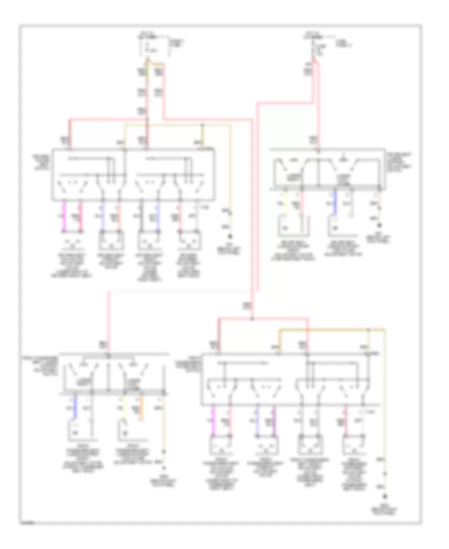
BODY CONTROL MODULES
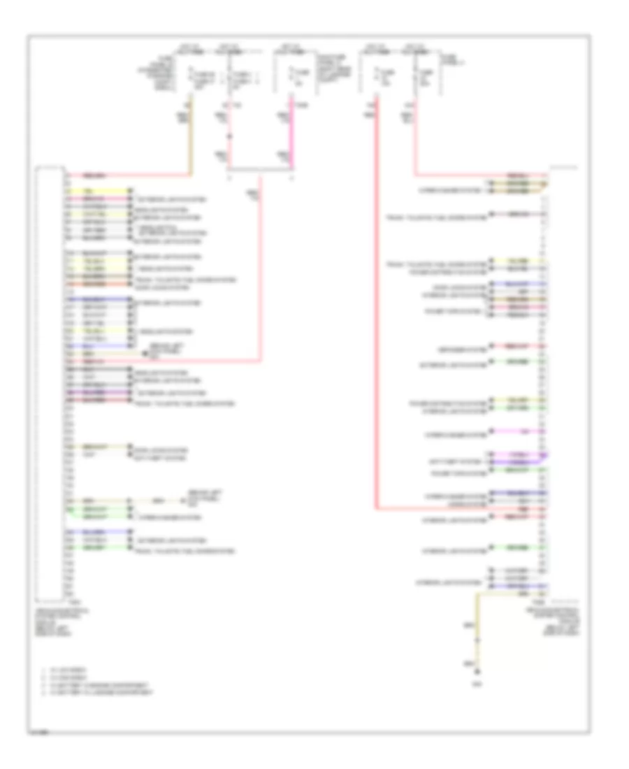
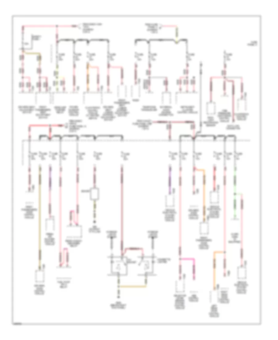
Body Computer Module Wiring Diagram, Early Production (1 of 2) for Audi A3 2009
List of elements for Body Computer Module Wiring Diagram, Early Production (1 of 2) for Audi A3 2009:
- (on right "c" pillar)
- 13a
- 43a
- Anti-theft system
- Comfort system central control module (right side of luggage compt)
- Computer data lines system
- Dual washer pump relay 2 (on relay carrier)
- Exterior lights system
- Fuse 10a
- Fuse 20a
- Fuse panel c
- G62
- Headlights system
- Horn relay (on relay carrier)
- Hot at all times
- Instrument cluster system
- Interior lights system
- Nca
- Power tops system
- Sound & navigation systems
- Steering column electronic systems control module circuit
- T12c
- T12d
- T12e
- T18
- T6g
- T8g
- Trunk, tailgate, fuel doors system
- Vehicle electrical system control module (below left side of dash)
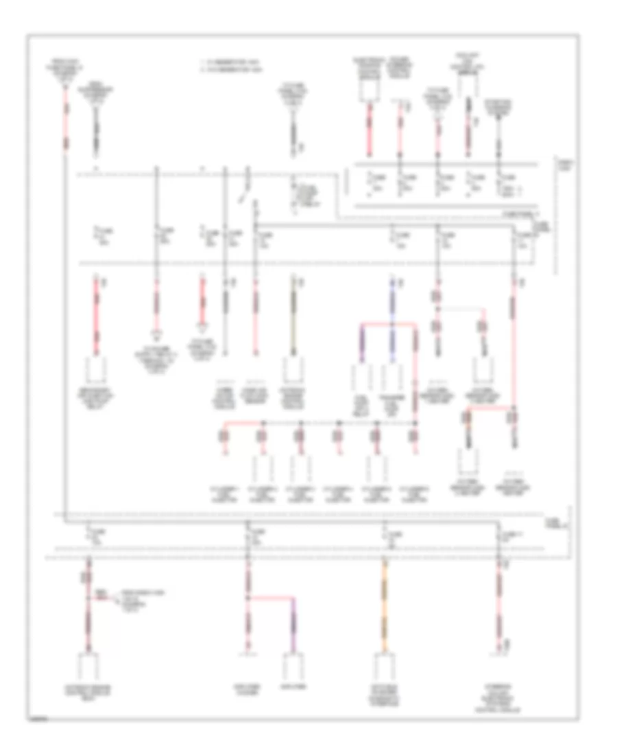
Body Computer Module Wiring Diagram, Early Production (2 of 2) for Audi A3 2009
List of elements for Body Computer Module Wiring Diagram, Early Production (2 of 2) for Audi A3 2009:
- 15a
- 25a
- 42a
- Anti-theft system
- Defogger system
- Dual washer pump relay 1 (on relay carrier)
- Engine controls system
- Exterior lights & headlights systems
- Exterior lights system
- Fuse 10a
- Fuse 15a
- Fuse 30a
- Fuse 5a
- Fuse fuse 15a
- Fuse fuse 30a
- Fuse fuse 50a
- Fuse fuse 5a
- Fuse panel b (integrated in engine compt e-box)
- Fuse panel c
- G44 (behind left kick panel)
- Garage door opener control module (under front bumper)
- Headlights system
- Horns system
- Hot at all times
- Interior lights system
- Main fuse panel d (right rear of luggage compt)
- Nca
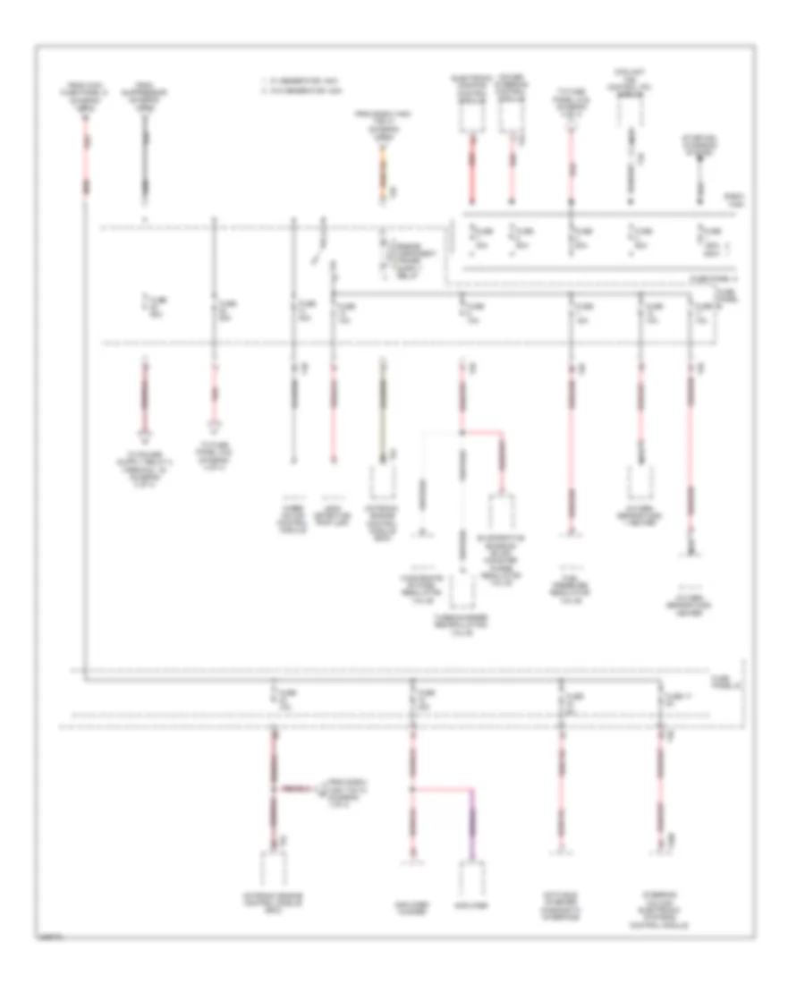
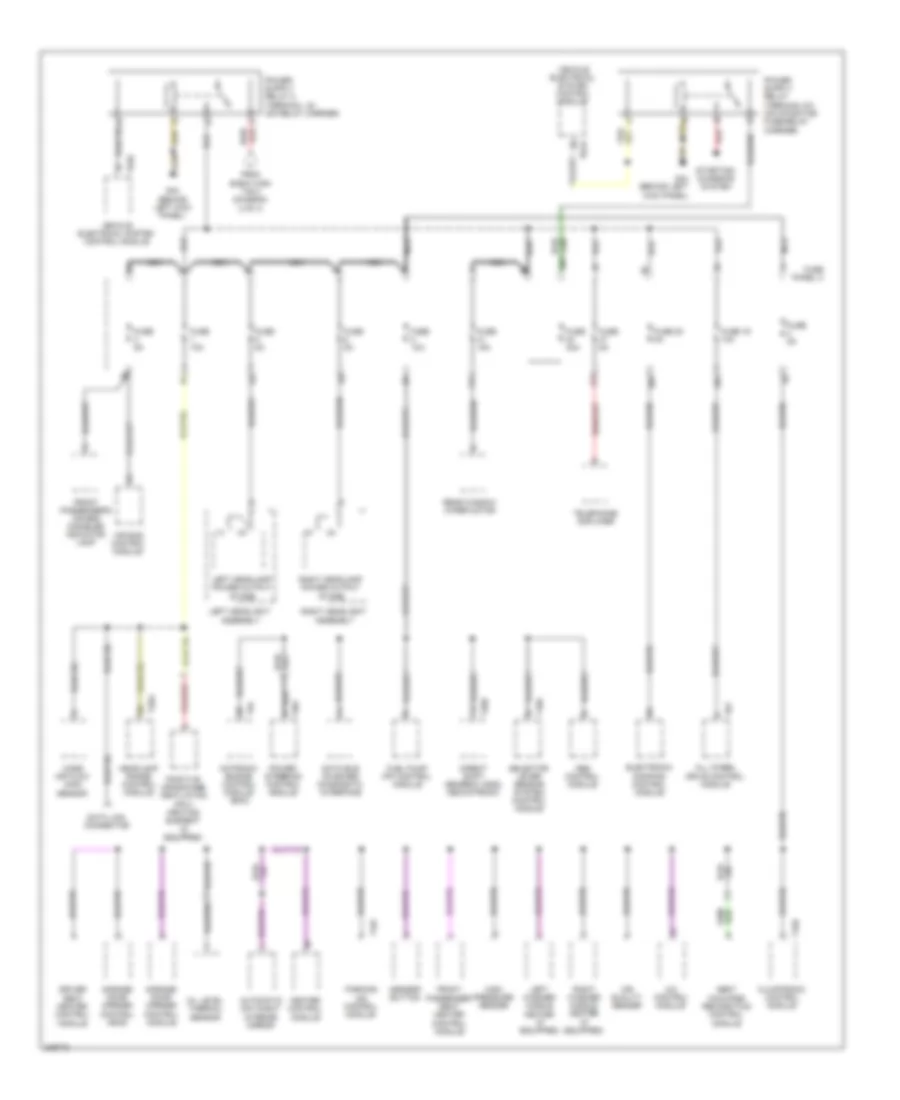
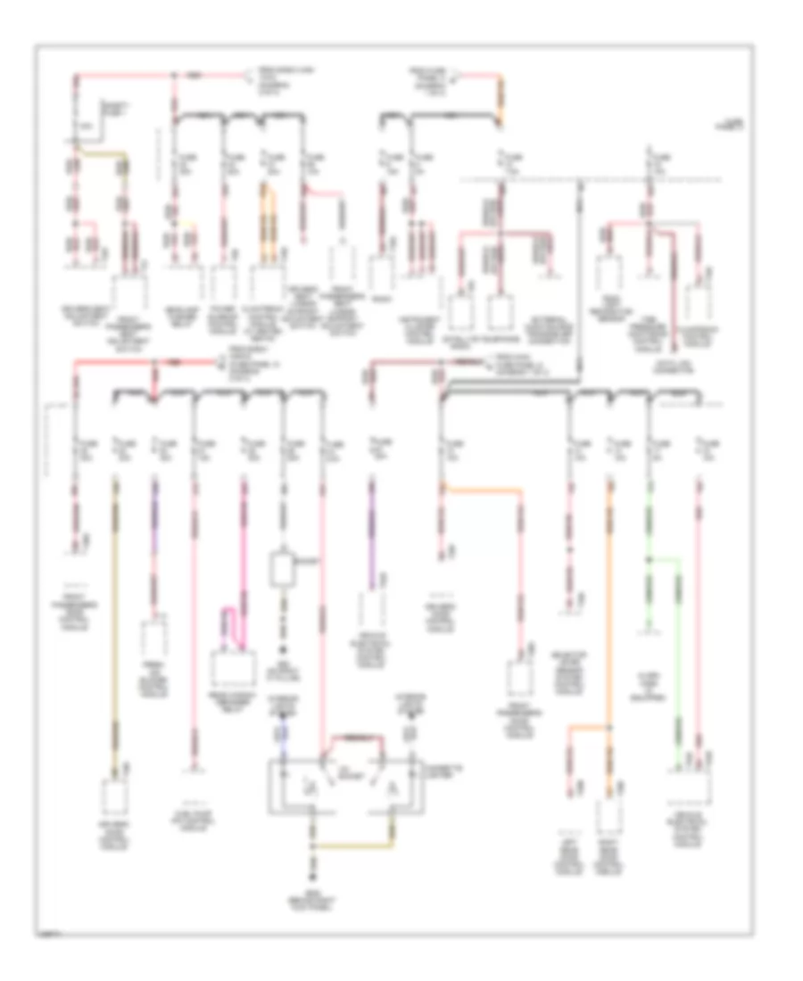
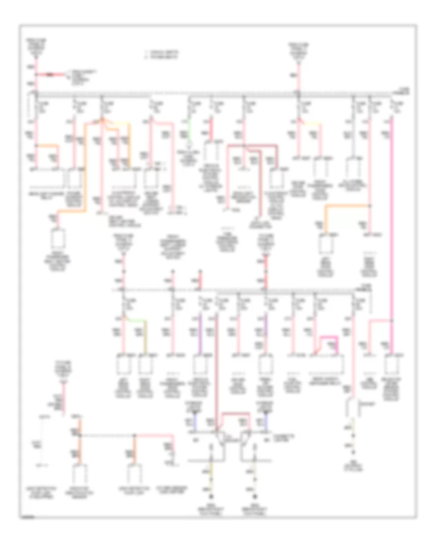
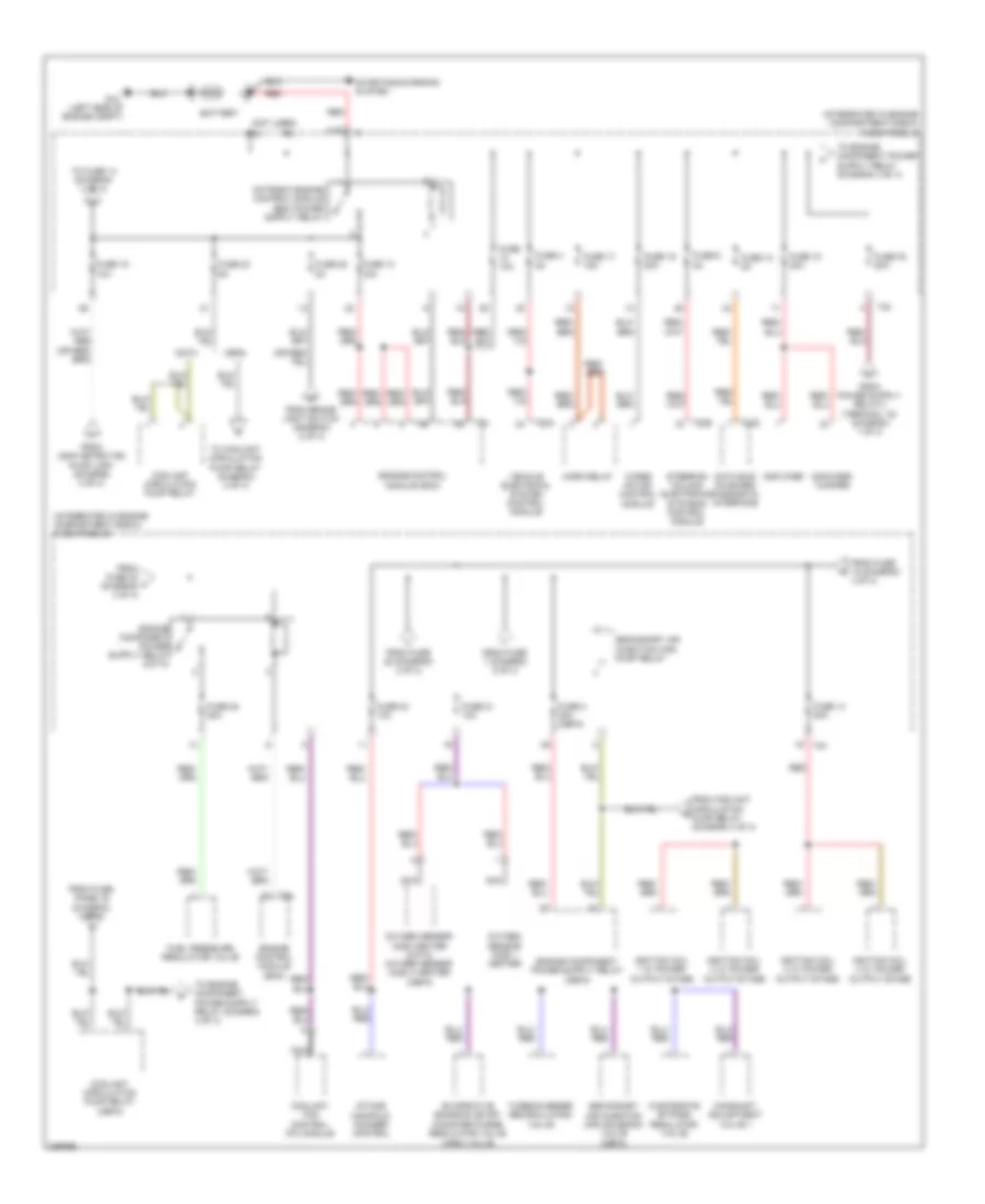
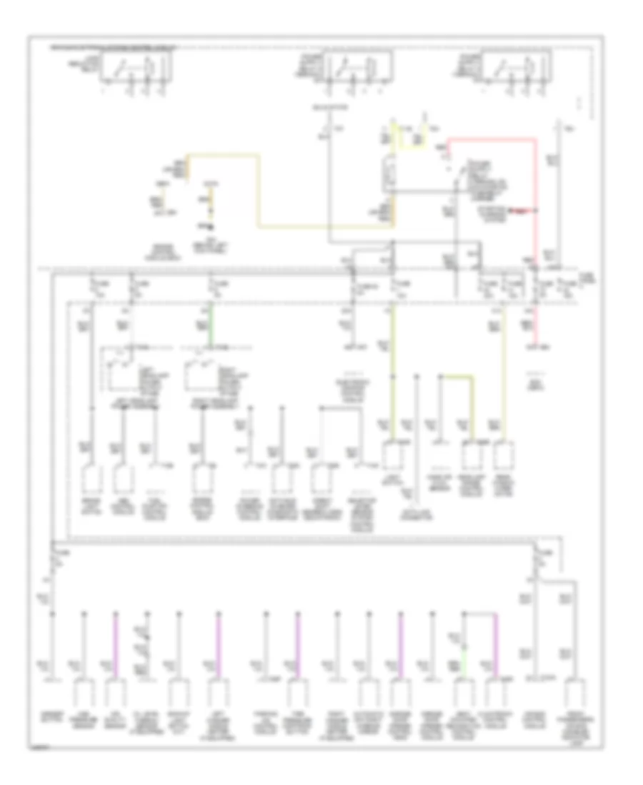
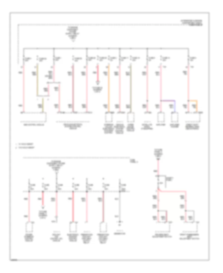
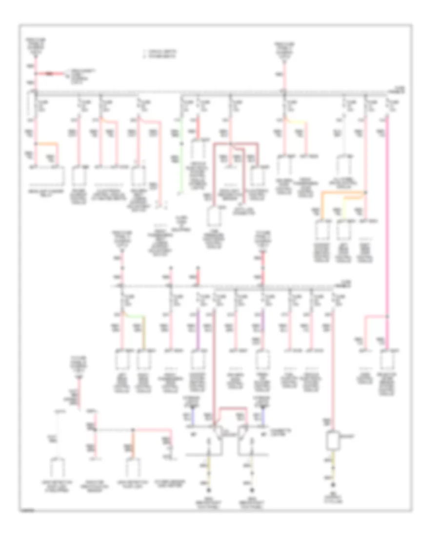
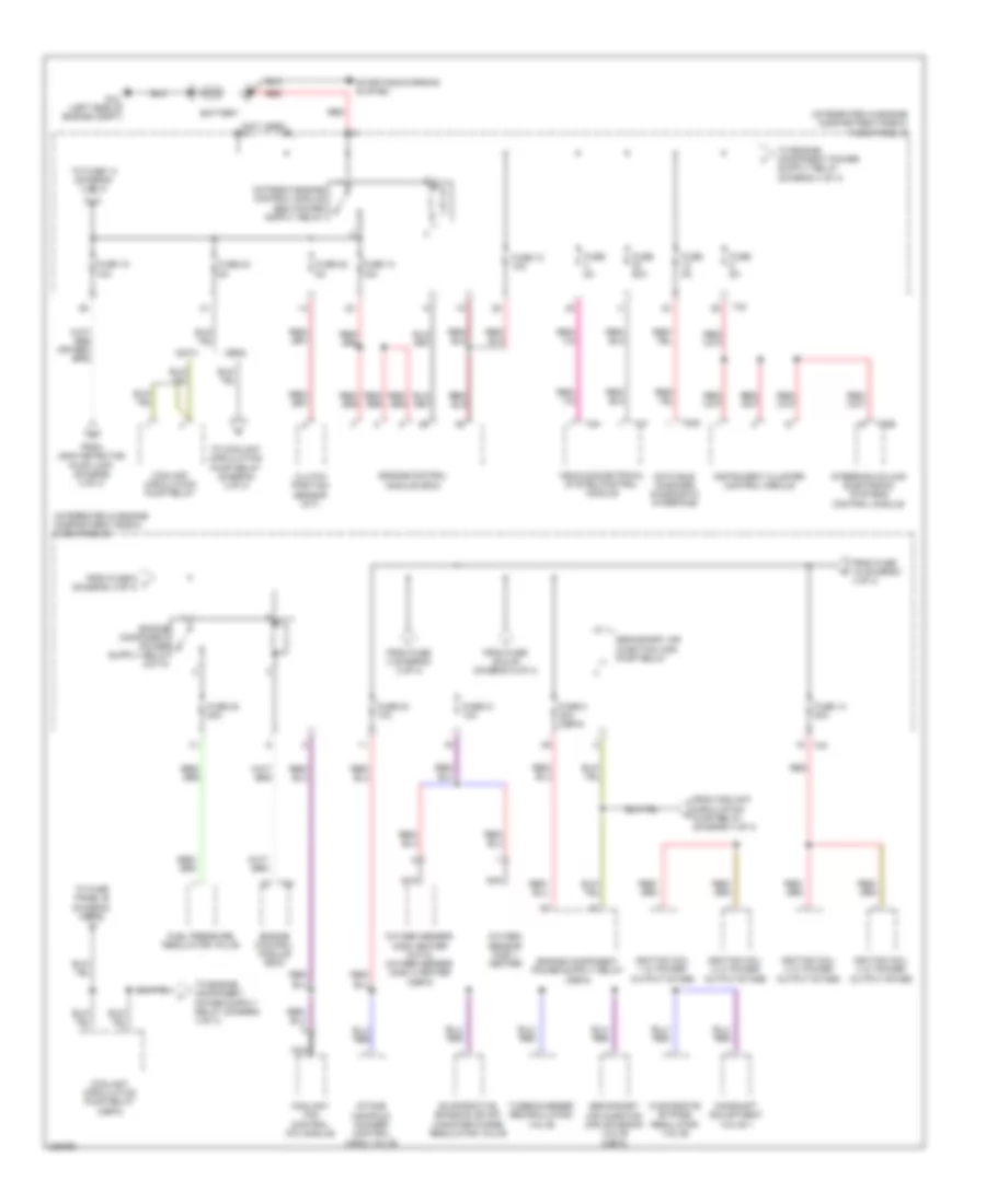
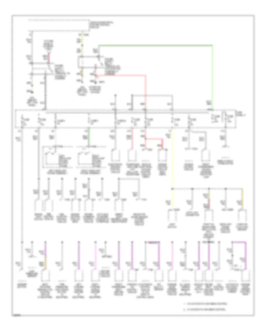
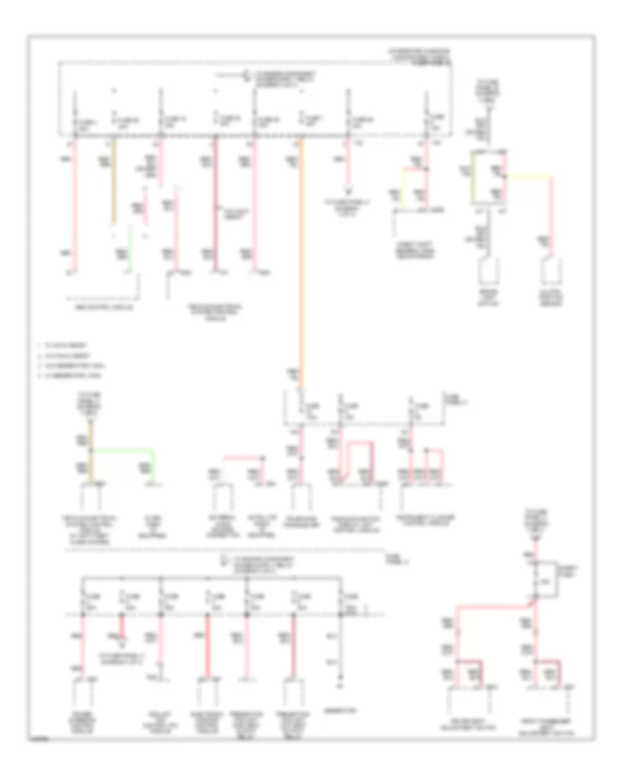
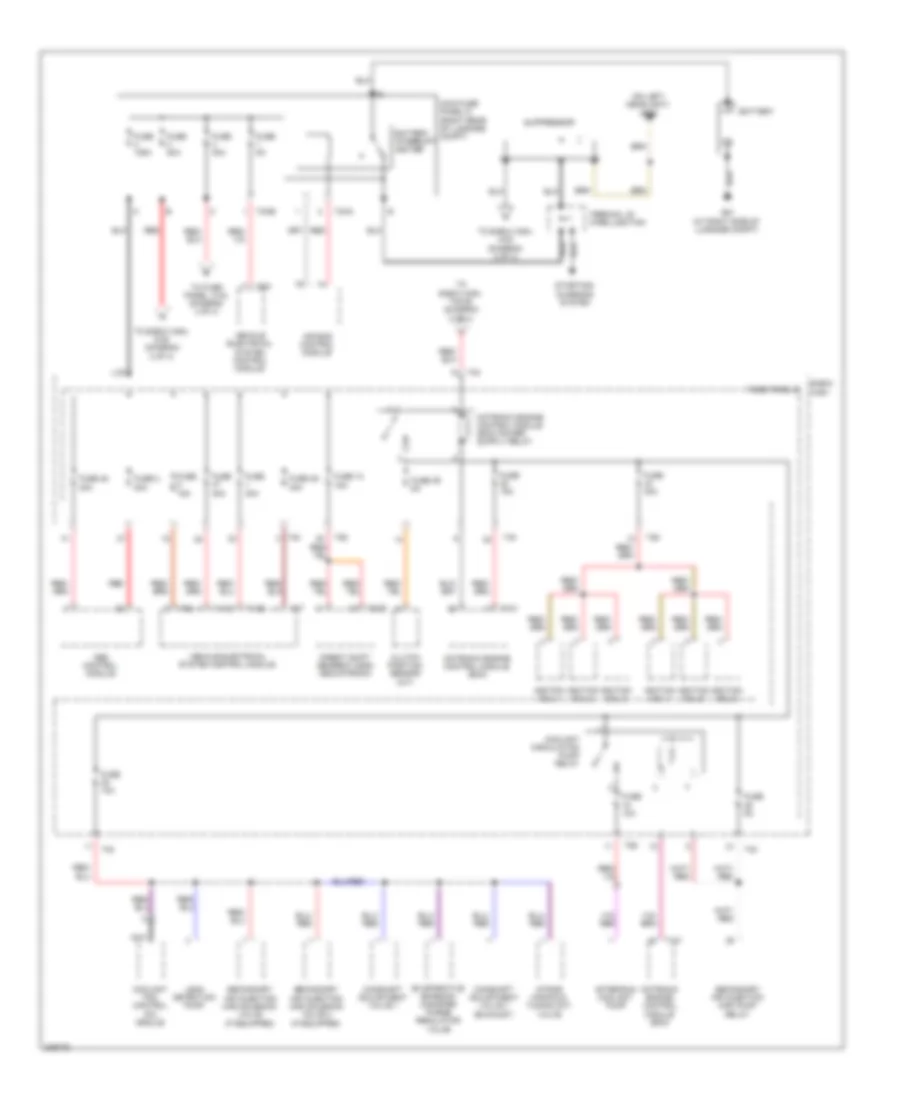
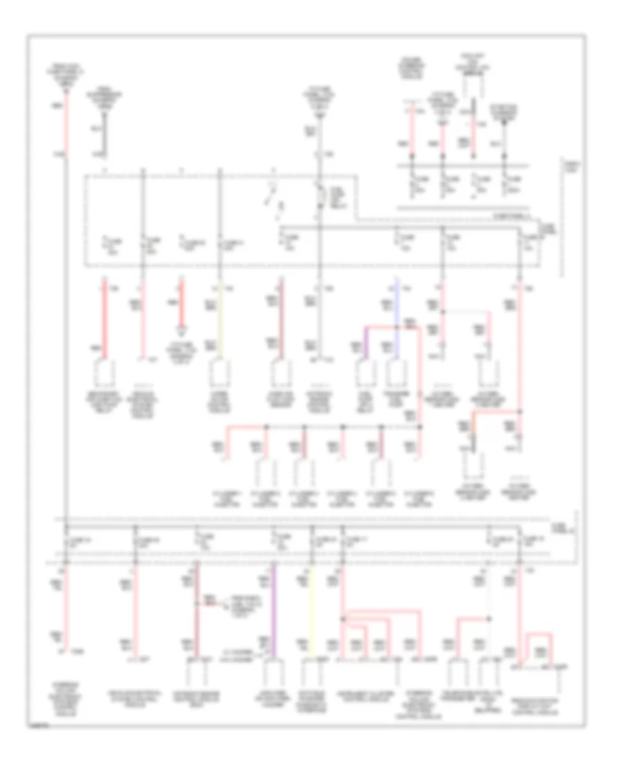
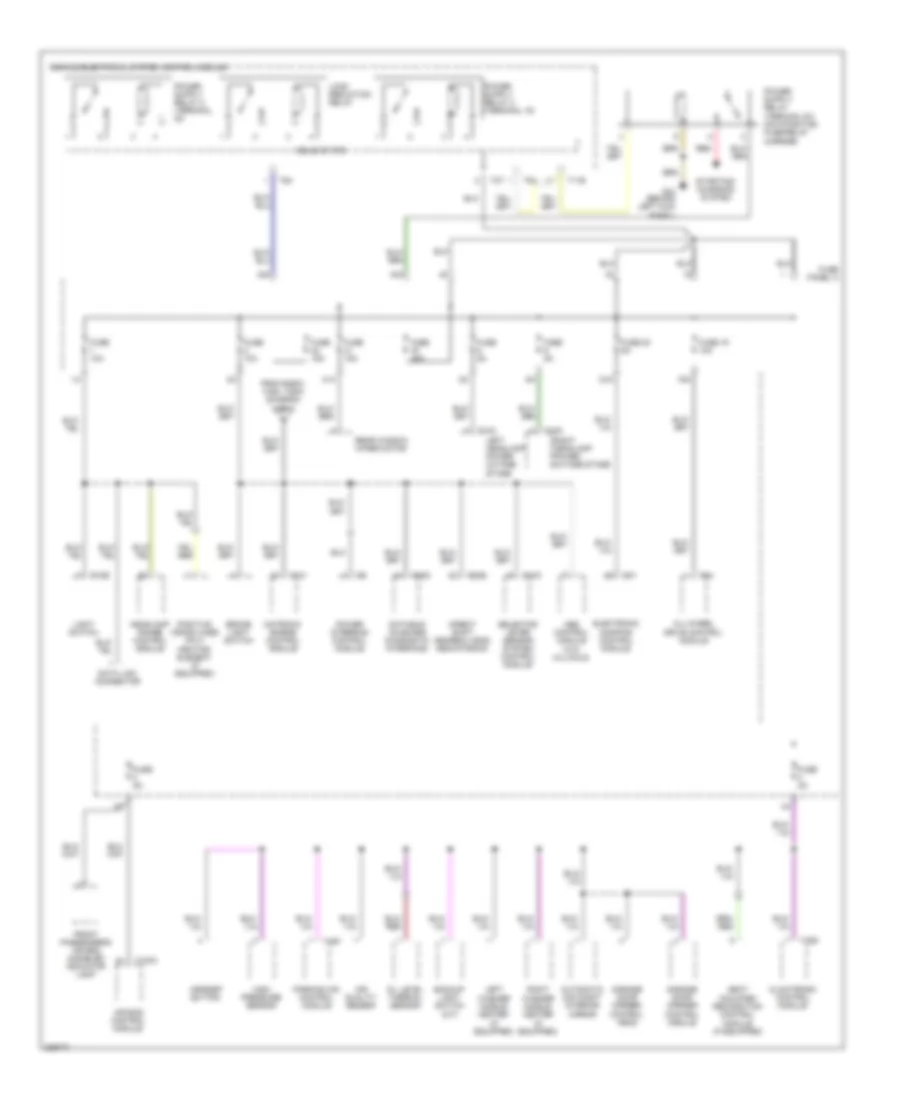
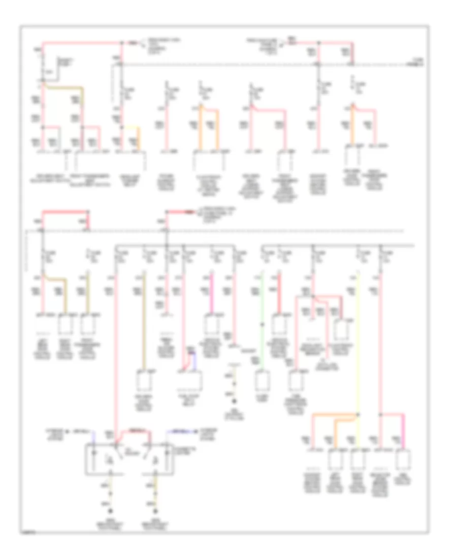
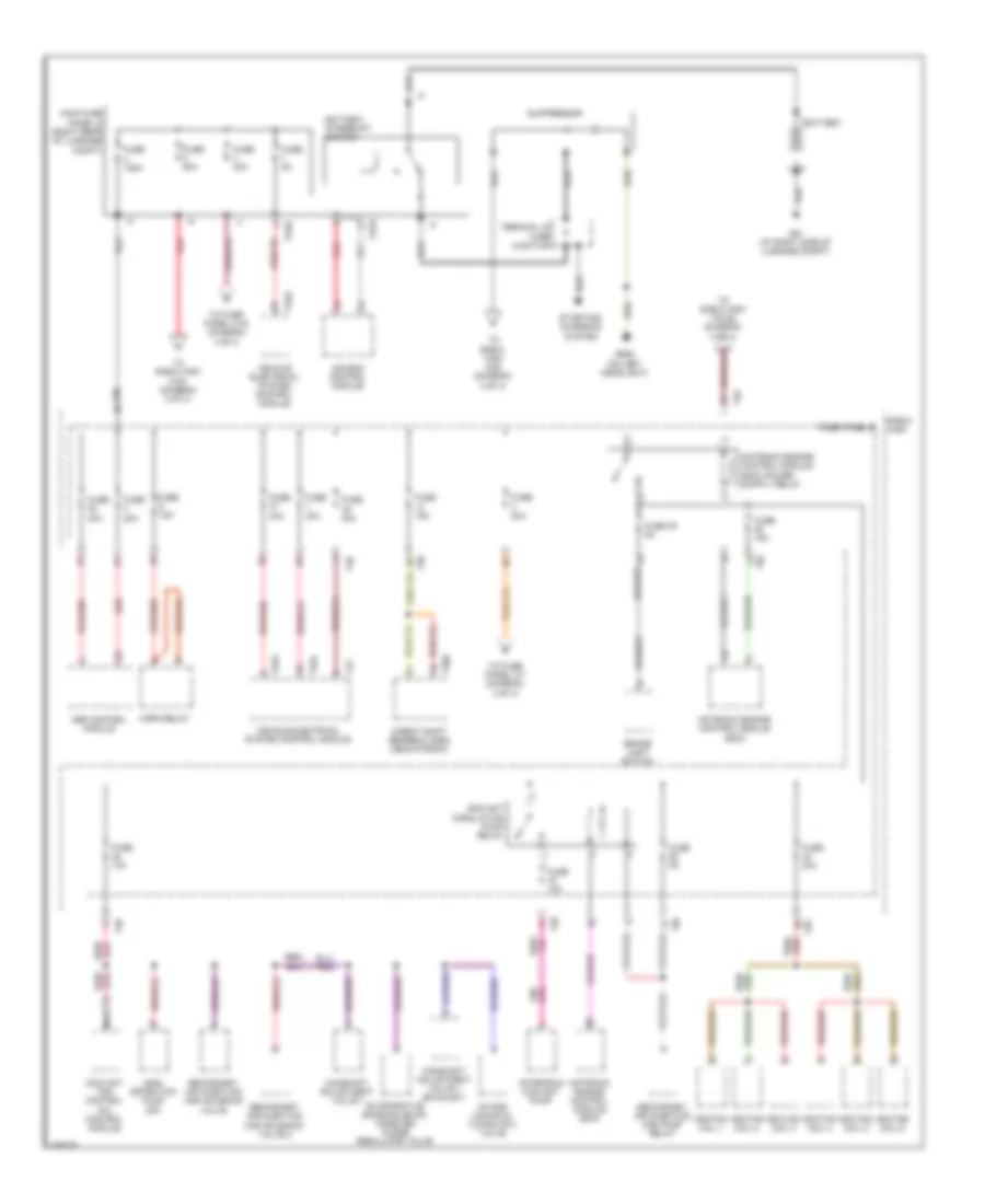
- Power distribution system
- Rear window defogger relay (on relay carrier)
- Red
- Starting/charging system
- T10d
- T11b
- T11c
- T16a
- T2ab
- T2t
- T40
- T6h
- T8h
- Transmissions system
- Vehicle electrical system control module (below left side of dash)
- W/ high e-box
- W/ low e-box
- Wiper/washer system
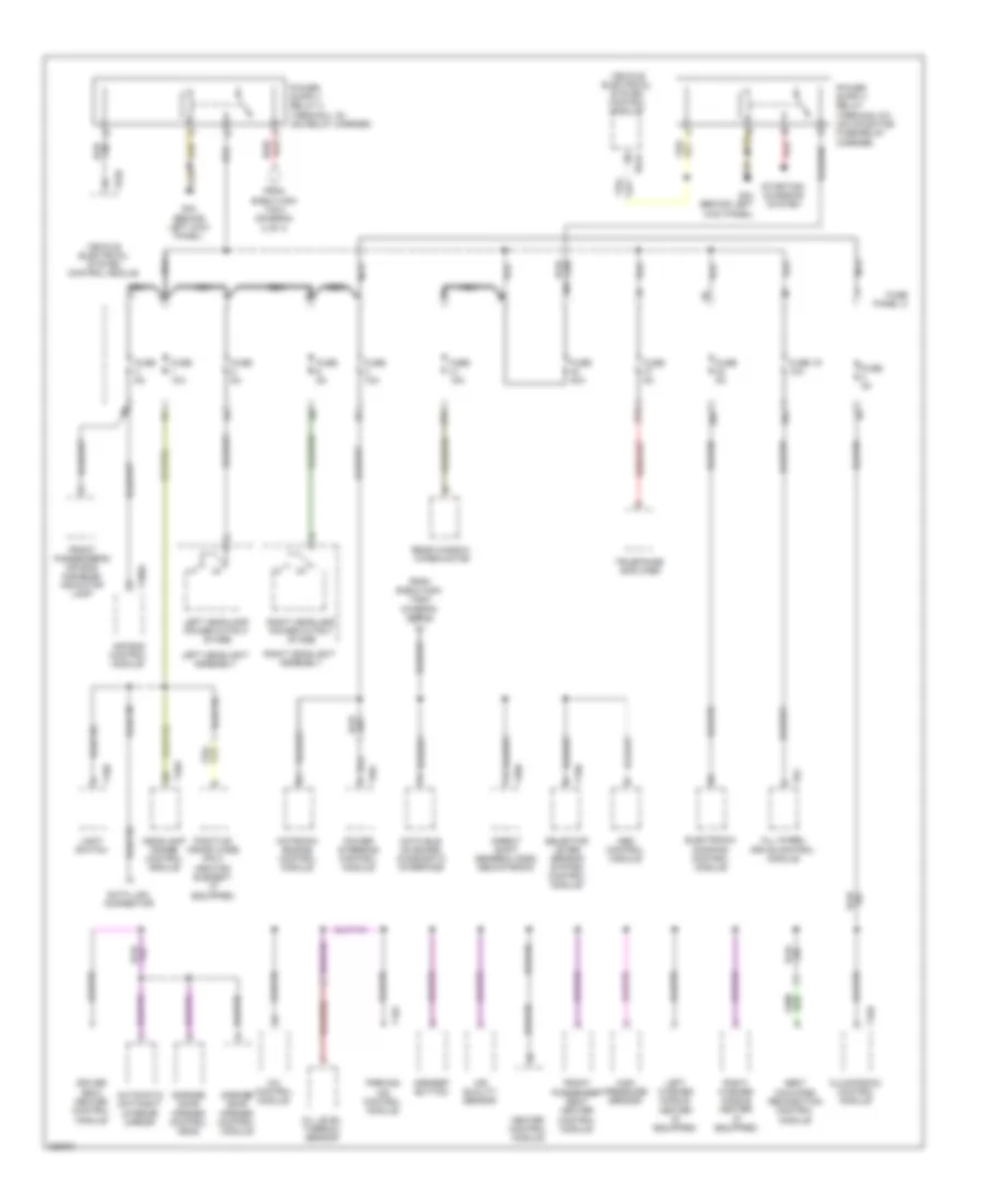
Body Computer Module Wiring Diagram, Late Production (1 of 2) for Audi A3 2009
List of elements for Body Computer Module Wiring Diagram, Late Production (1 of 2) for Audi A3 2009:
- (behind left kick panel) g44
- 15a
- 43a
- Anti-theft system
- Defogger system
- Door locks system
- Exterior lights system
- Fuse 10a
- Fuse 20a
- Fuse 26
- Fuse 3
- Fuse 4 5a
- Fuse 47 30a
- Fuse 5a
- Fuse panel b (integrated in engine compt e-box)
- Fuse panel c
- G42
- Headlights & exterior lights system
- Headlights system
- Horns system
- Hot at all times
- Interior lights system
- Main fuse panel d (right rear of luggage compt)
- Power distribution system
- Power tops system
- Red
- T2ab
- T40
- T52a
- T52b
- Trunk, tailgate, fuel doors system
- Vehicle electrical system control module (below left side of dash)
- W/ battery in engine compartment
- W/ battery in luggage compartment
- W/ high e-box
- W/ low e-box
- Wiper/washer system
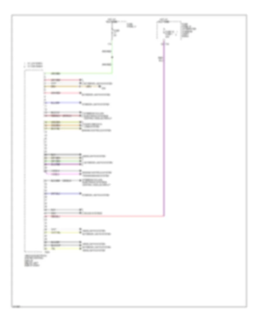
Body Computer Module Wiring Diagram, Late Production (2 of 2) for Audi A3 2009
List of elements for Body Computer Module Wiring Diagram, Late Production (2 of 2) for Audi A3 2009:
- 17a
- Computer data lines system
- Engine controls system
- Exterior lights system
- Fuse 16 fuse 1 30a
- Fuse 5a
- Fuse panel b (integrated in engine compt e-box)
- Fuse panel c
- G42
- Headlights system
- Hot at all times
- Interior lights system
- Nca
- Sound systems
- Steering column electronic systems control module circuit
- T40
- T52c
- Transmissions system
- Vehicle electrical system control module (below left side of dash)
- W/ high e-box
- W/ low e-box
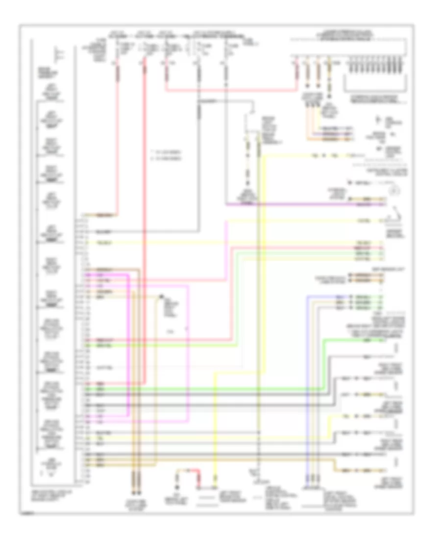
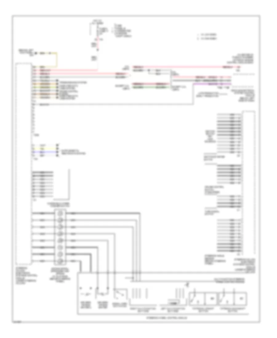
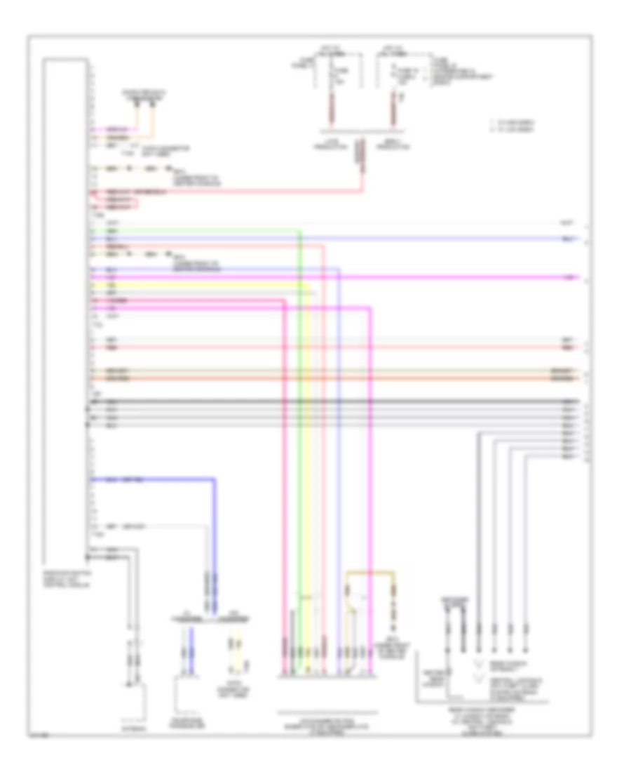
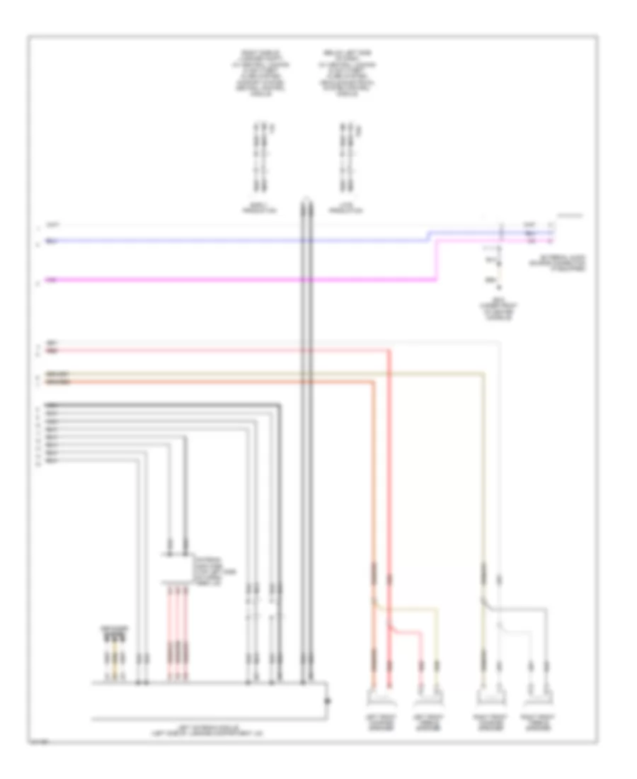
Steering Column Electronic Systems Control Module Wiring Diagram for Audi A3 2009
List of elements for Steering Column Electronic Systems Control Module Wiring Diagram for Audi A3 2009:
- (behind left kick panel) g44
- (in center of plenum chamber) motronic engine control module (ecm)
- 2.0l (cbfa)
- Air bag spiral spring/return spring (w/ slip ring) (behind steering wheel)
- Computer data lines system
- Cruise control switch (if equipped)
- Cruise control system computer data lines system
- Driver's air bag igniter
- Driver's air bag igniter 2
- Early production
- Except 2.0l (cbfa)
- Fuse 6 fuse 17 5a
- Fuse panel b (integrated in engine compt e-box)
- Hot at all times
- Ignition switch key lock solenoid
- Ignition/starter switch
- Late production
- Left multi-function buttons
- Mode
- Multi-function steering wheel control module
- Nca
- Right multi-function buttons
- Signal horn activation
- Steering angle sensor (behind steering wheel)
- Steering column electronic systems control module (under steering column)
- Steering wheel control module
- T12e
- T20b
- T40
- T4n
- T52c
- T94
- Tiptronic downshift button
- Tiptronic upshift button
- Transmissions system
- Turn signal switch
- Vehicle electrical system control module (below left side of dash)
- W/ high e-box
- W/ low e-box
- Windshield wiper/ washer switch
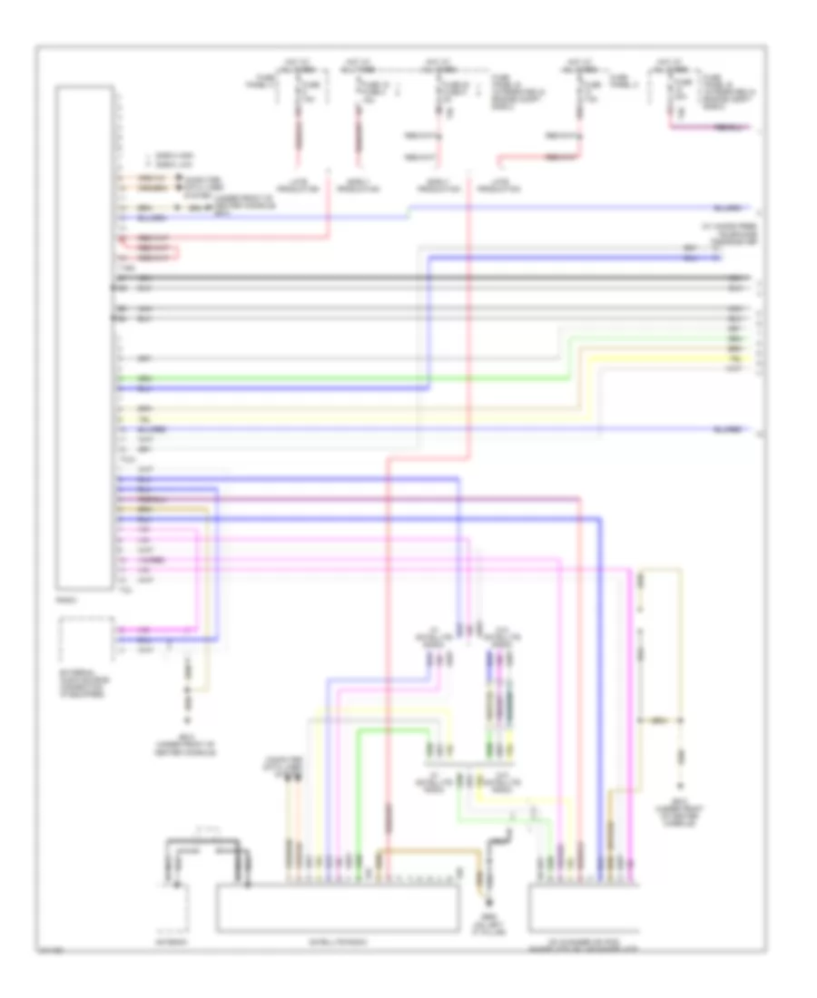
COMPUTER DATA LINES
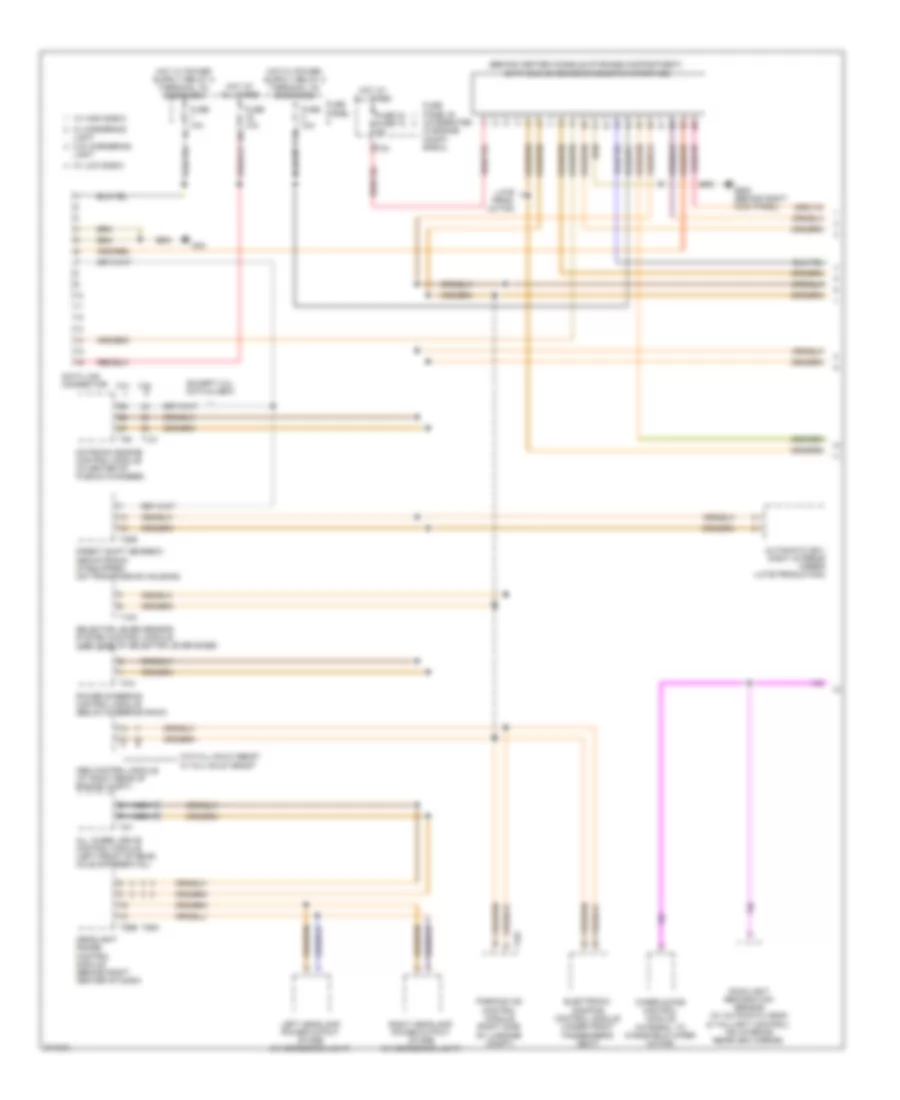
Computer Data Lines Wiring Diagram (1 of 2) for Audi A3 2009
List of elements for Computer Data Lines Wiring Diagram (1 of 2) for Audi A3 2009:
- (behind center console storage compartment)
- 16a
- 2.0l
- 3.2l
- Abs control module (at right rear of engine compt)
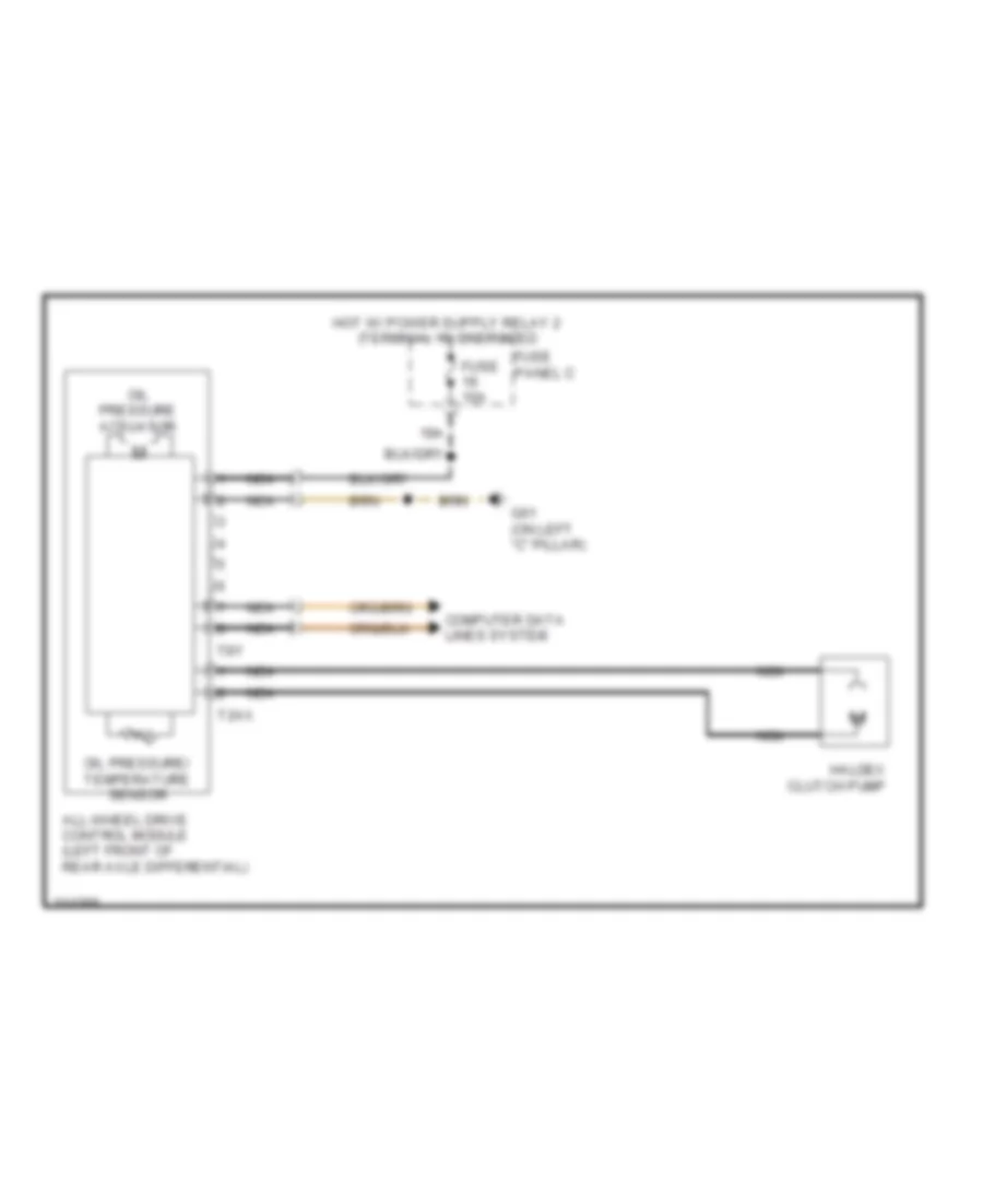
- All wheel drive control module (left front of rear axle differential)
- Automatic day/ night interior mirror (late production)
- Data bus on board diagnostic interface
- Data link connector
- Direct shift gearbox mechatronic (if equipped) (on transmission housing)
- Electronic damping control module (under front passenger's seat)
- Except 2.0l ccta & cbfa
- Fuse 10a
- Fuse 24 fuse 12 5a
- Fuse panel b (integrated in engine compt e-box)
- Fuse panel c
- G42
- G638 (behind right kick panel)
- Headlight range control module (behind right center of dash)
- Hot at all times
- Late prod- uction
- Left headlamp power output stage (w/ cornering light)
- Light
- Motronic engine control module (in center of plenum chamber)
- Nca
- Parking aid control module (right side of luggage compt)
- Power steering control module (below steering rack)
- Rain/light recognition sensor (w/ automatic head & taillight control) (on interior rearview mirror)
- Right headlamp power output stage (w/ cornering light)
- Selector lever sensor system control module (left side of selector lever base)
- T10k
- T121
- T16f
- T20e
- T26a
- T26b
- T3w
- T40
- T8y
- T94
- W/ cornering
- W/ high e-box
- W/ low e-box
- W/o cornering light
- W/o hill-hold assist w/ hill-hold assist
- Wiper motor control module (integral to windshield wiper motor)
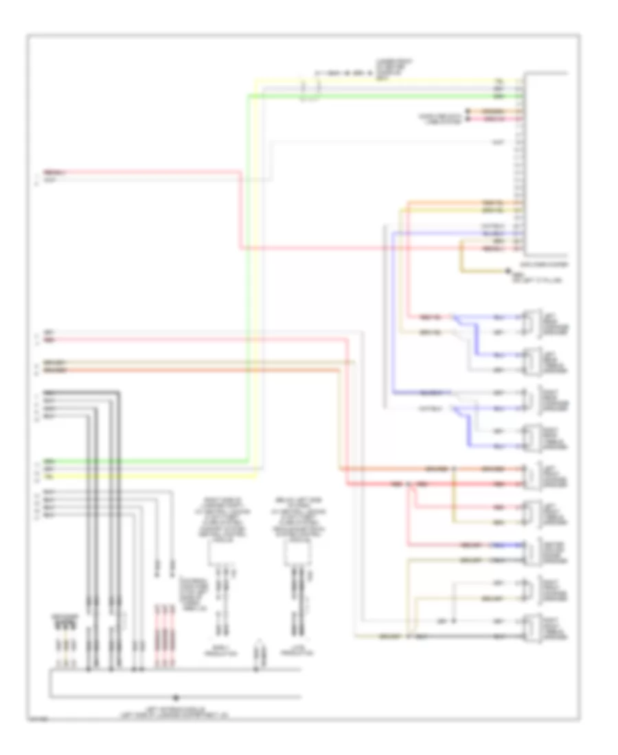
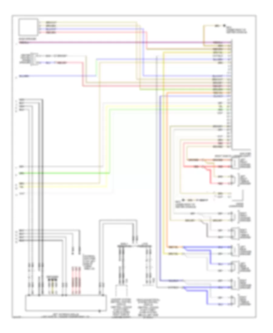
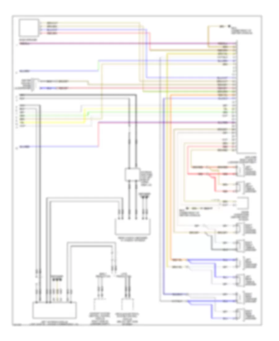
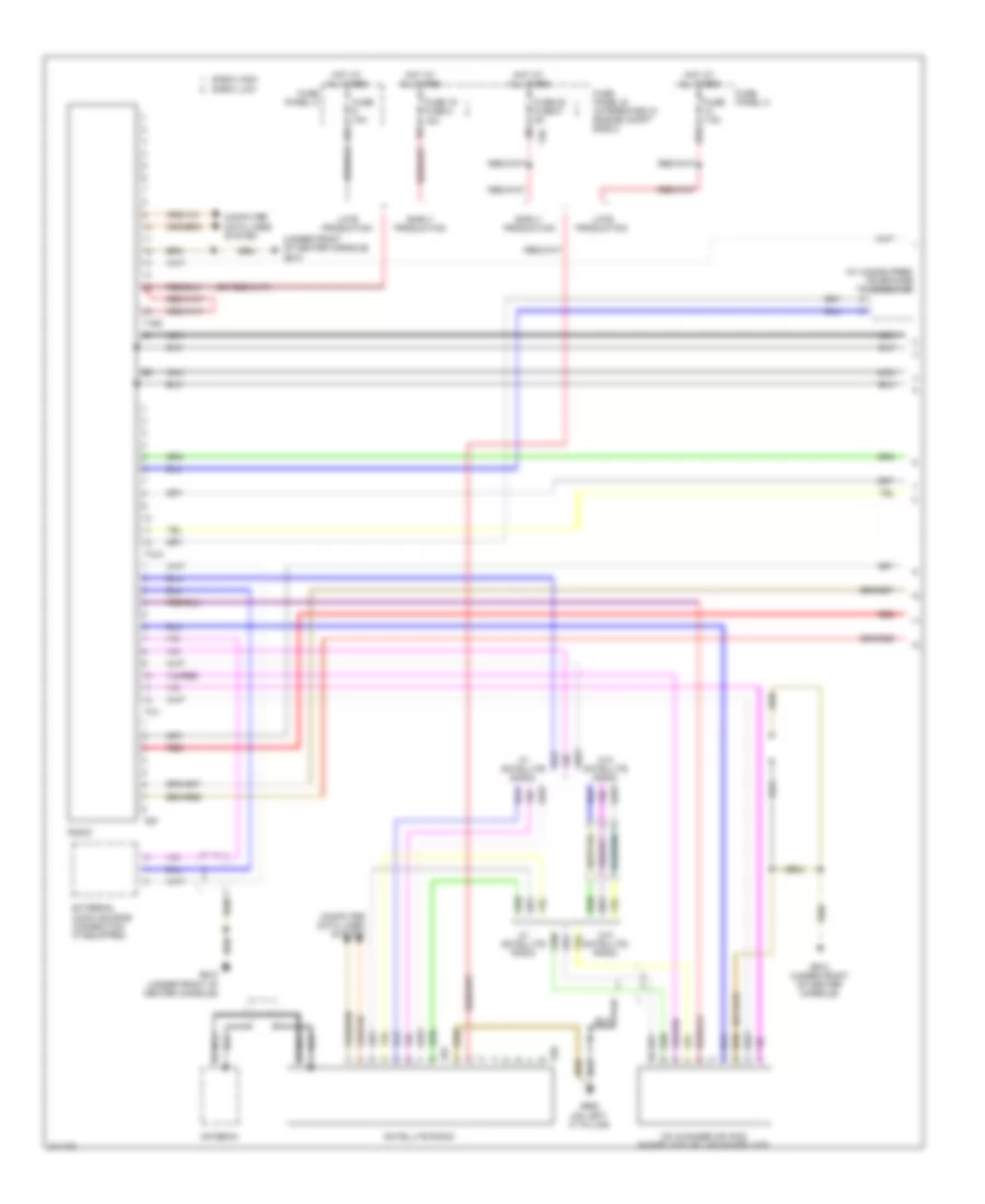
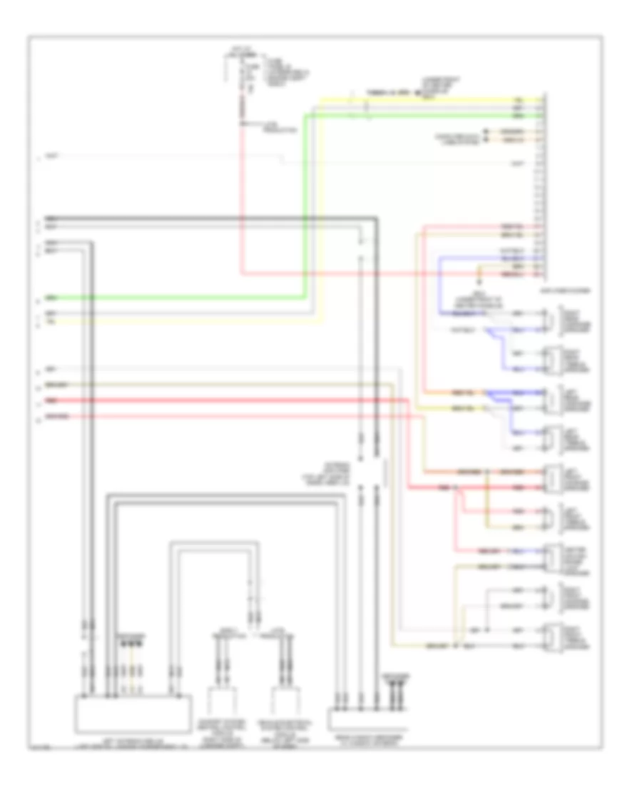
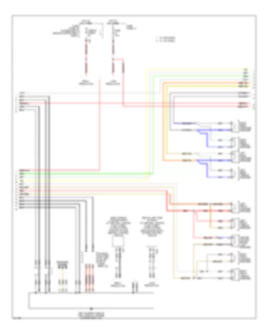
Computer Data Lines Wiring Diagram (2 of 2) for Audi A3 2009
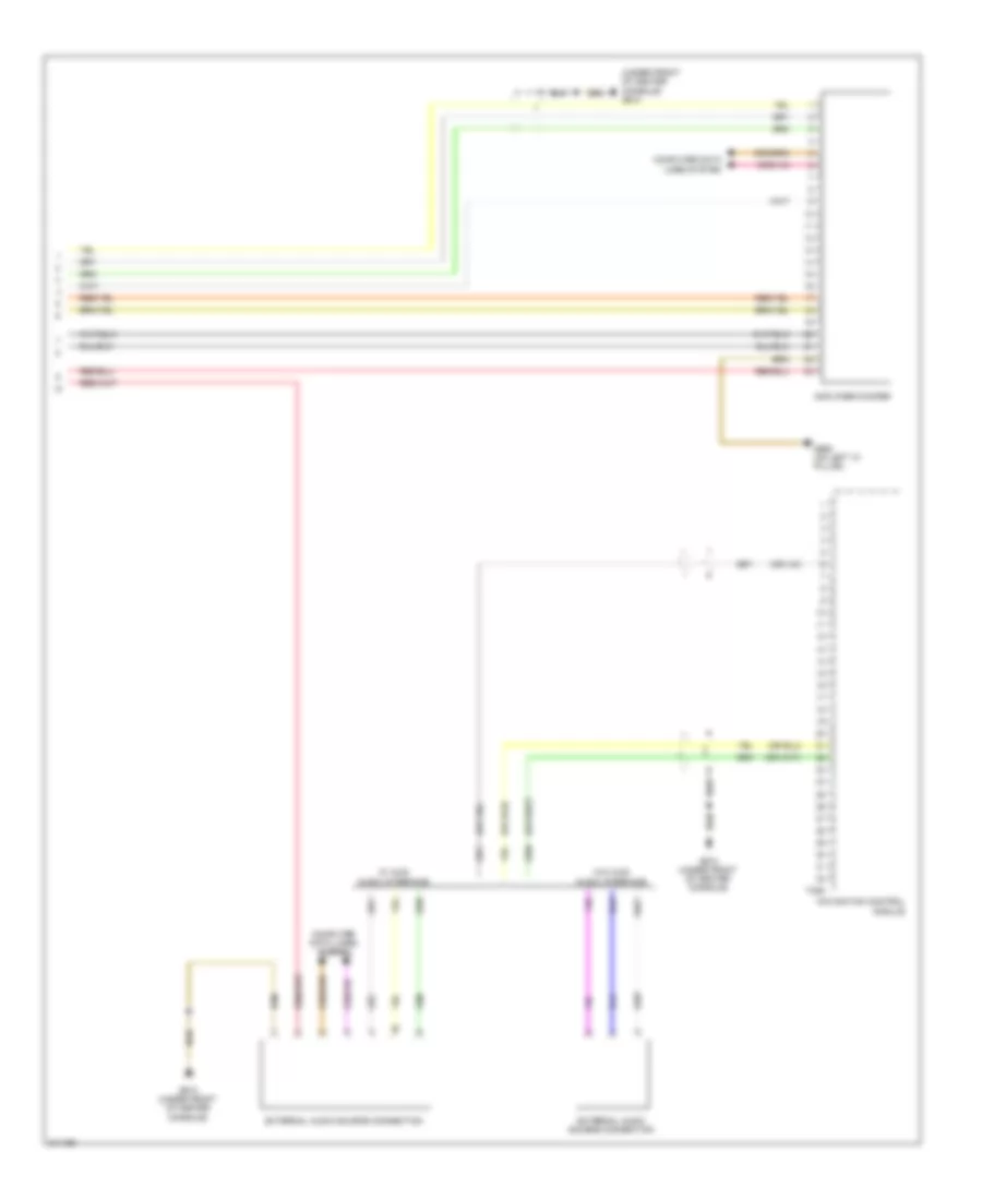
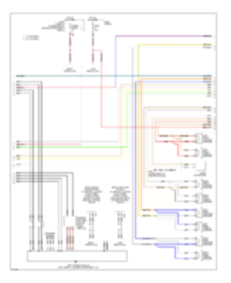
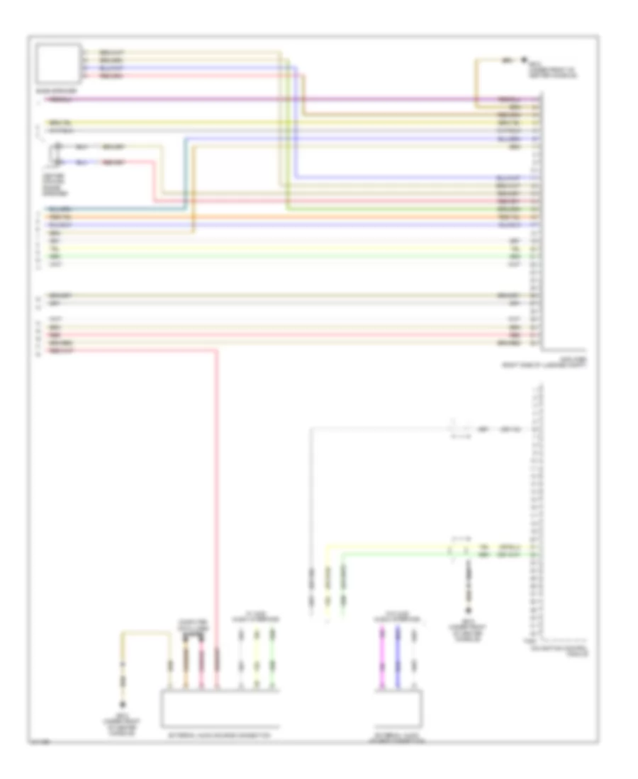
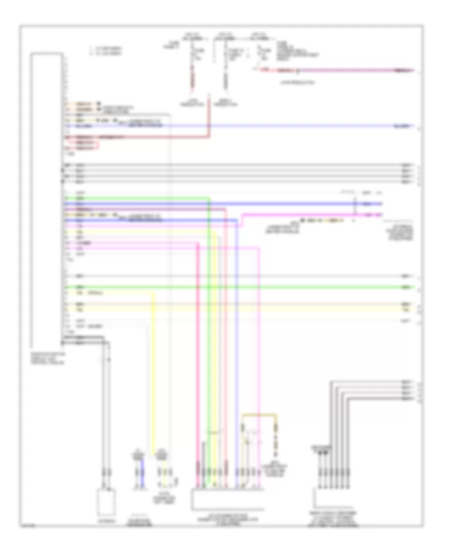
List of elements for Computer Data Lines Wiring Diagram (2 of 2) for Audi A3 2009:
- (below left side of dash) vehicle electrical system control module
- (left side of luggage compt) (if equipped) navigation/ tv tuner
- (left side of luggage compt) (if equipped) satellite radio
- (w/ audi music interface & rsn-e) external audio source connection
- (w/ handsfree) telephone transceiver
- (w/ rns-e) operating electronics navigation control module (w/ rns-low) radio/navigation display unit control module
- 20 pin connector (not used)
- A/c control module
- Air bag control module (under front of center console)
- Alarm horn (w/ anti-theft alarm system) (in right front wheelwell)
- Amplifier/ woofer
- Auxiliary heater control module
- Climatronic control module
- Comfort system central control module (early production) (right side of luggage compt)
- Driver's door control module (integrated in driver's door window regulator motor)
- Early production
- Front passenger's door control module (integrated in right front door window regulator motor)
- Inclination/ anti-theft control module (w/ anti-theft alarm system)
- Instrument cluster control module
- Interior monitoring sensor (w/ anti-theft alarm system)
- Late production
- Left rear door control module (integrated in left rear door window regulator motor)
- Radio (w/ radio generation 2 plus)
- Right rear door control module (integrated in right rear door window regulator motor)
- Steering column electronic systems control module (under steering column)
- T12e
- T16e
- T16g
- T18
- T20b
- T20f
- T20g
- T20i
- T20m
- T20n
- T20o
- T52b
- T52c
- T6g
- T8h
- T8t
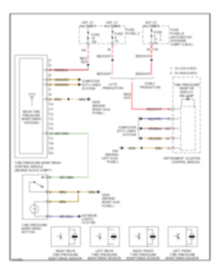
- Tire pressure monitoring control module (behind glove compt)
- Towing recognition control module (right side of luggage compt)
- Vehicle positioning system interface control module
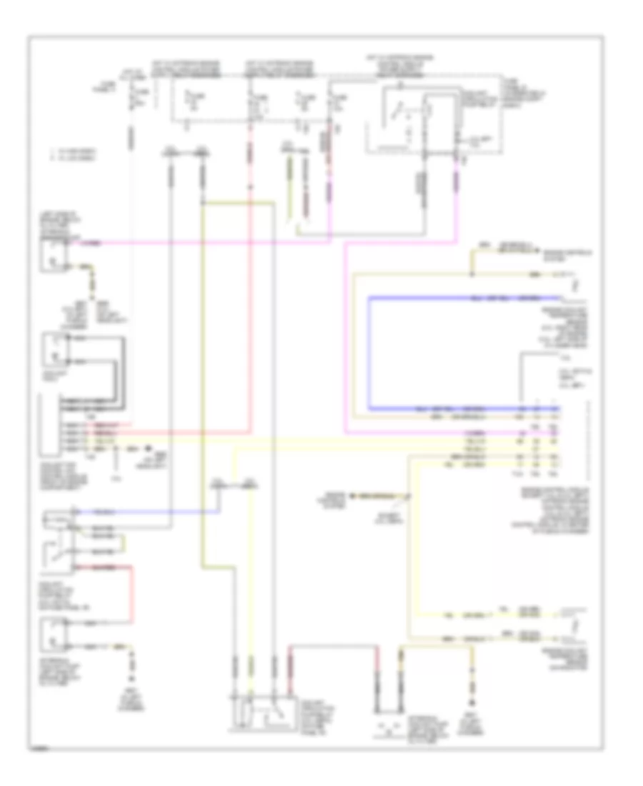
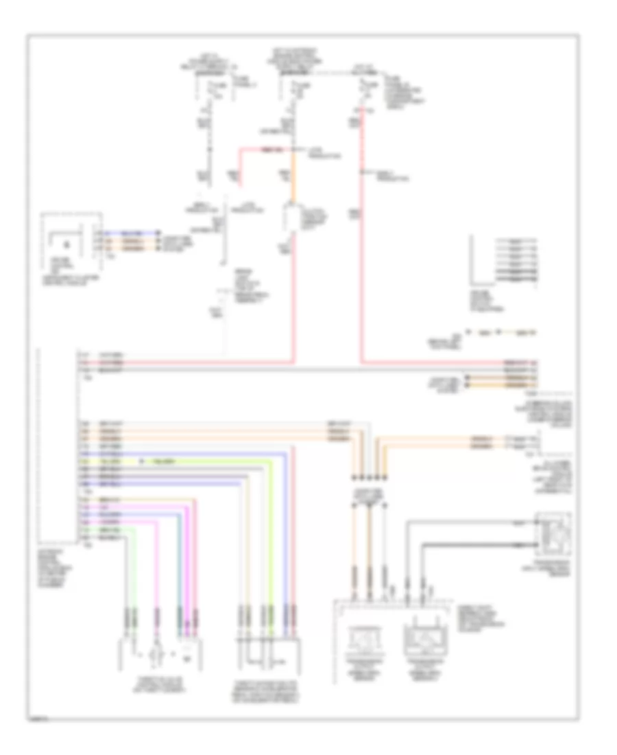
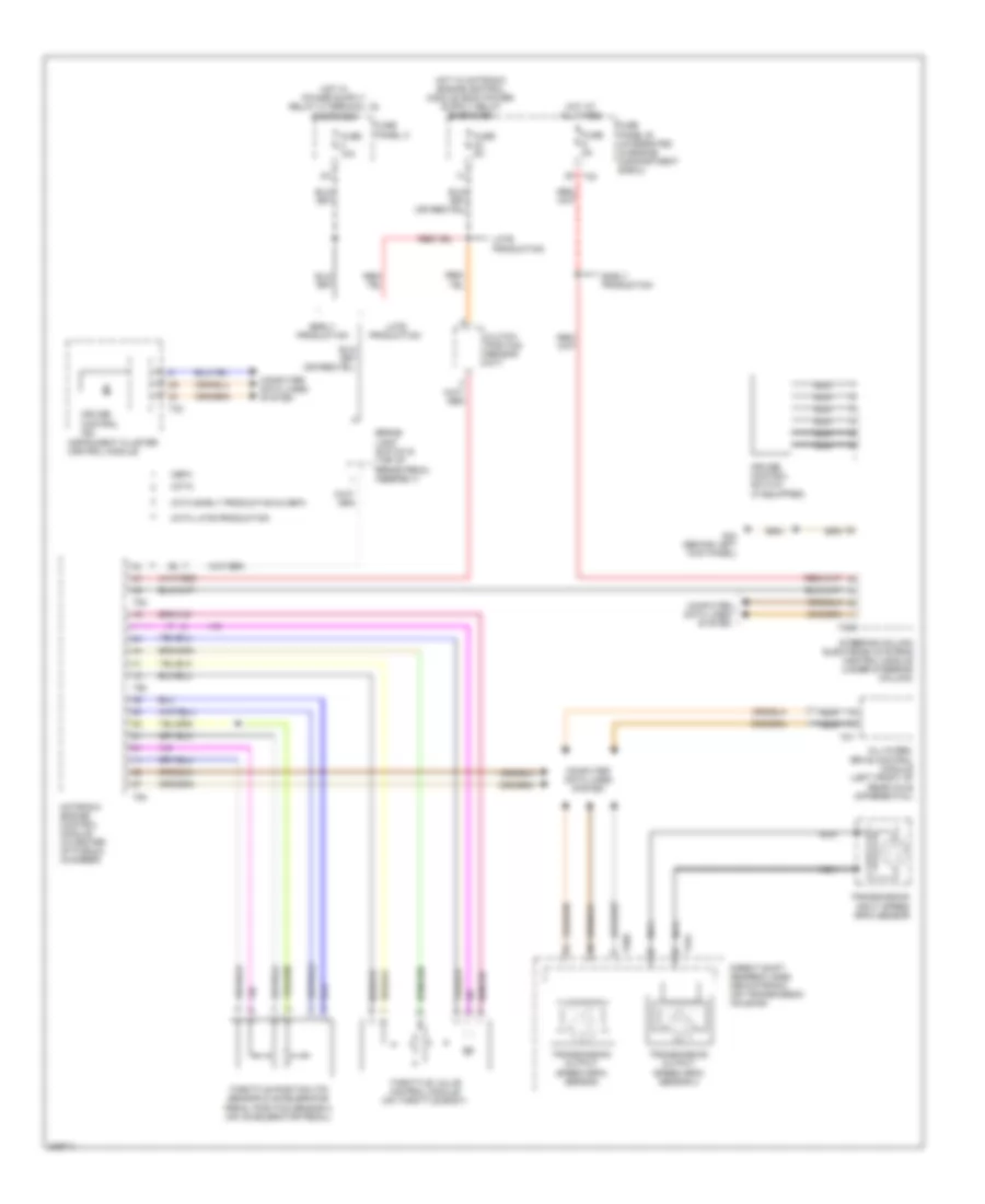
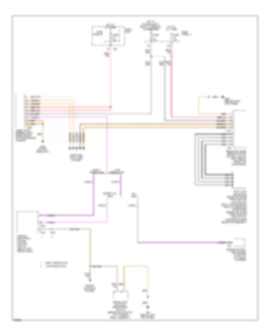
COOLING FAN
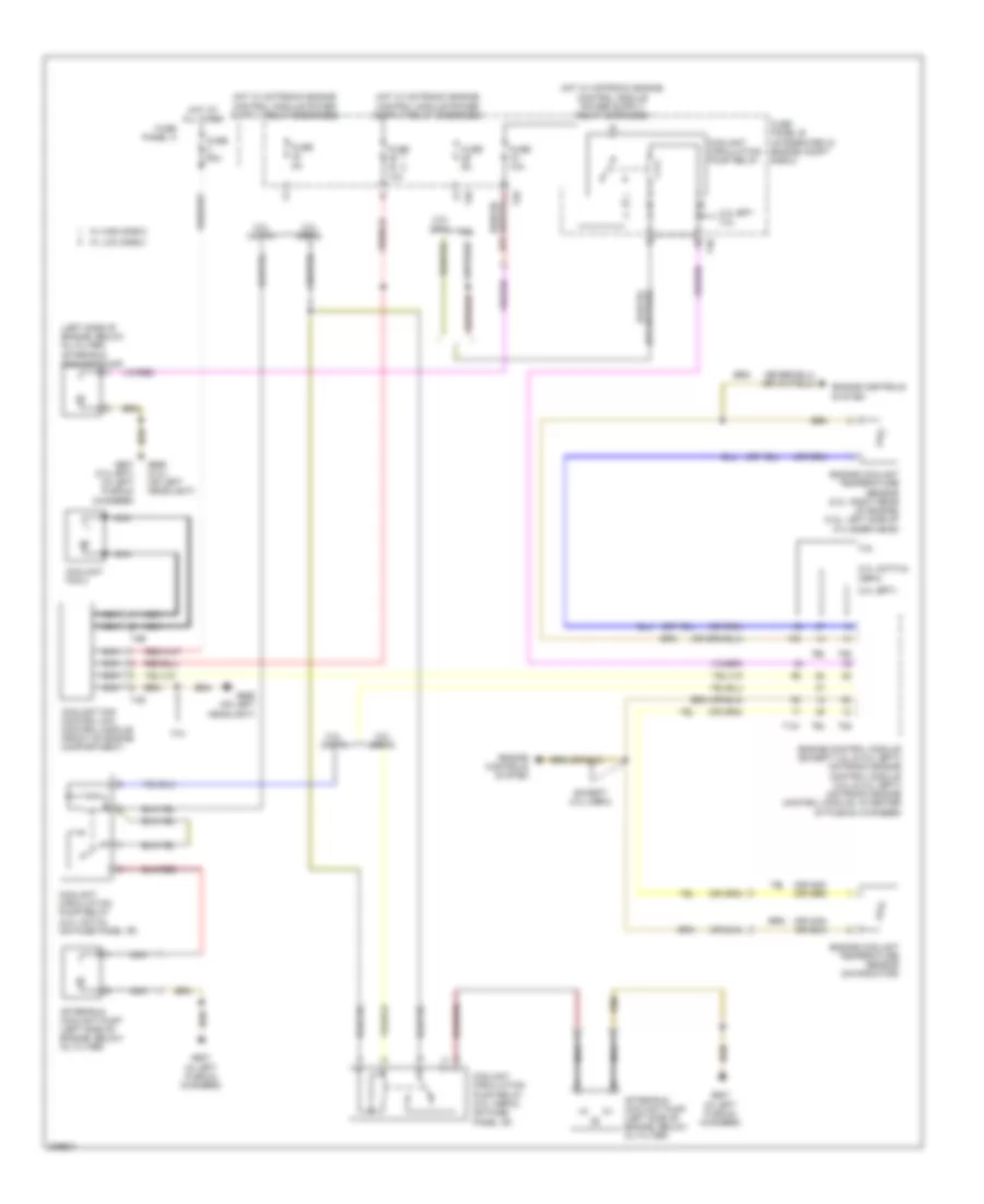
Cooling Fan Wiring Diagram for Audi A3 2009
List of elements for Cooling Fan Wiring Diagram for Audi A3 2009:
- (left side of engine, below oil filter) after-run coolant pump
- 10a
- 2.0l (bpy)
- 2.0l (cbfa)
- 2.0l (ccta & cbfa)
- 2.0l (ccta)
- 2.0l bpy 3.2l
- 3.2l
- After-run coolant pump (left side of engine, below oil filter)
- Coolant circulation pump relay
- Coolant circulation pump relay (2.0l (cbfa)) (on fuse panel "b")
- Coolant circulation pump relay (2.0l (ccta)) (on fuse panel "b")
- Coolant fan 2
- Coolant fan control (fc) control module (front of engine compartment)
- Engine control module (except 3.2l & 2.0l (bpy)) motronic engine control module (3.2l & 2.0l (bpy)) (motronic engine control module: in center of plenum chamber)
- Engine controls system
- Engine coolant temperature sensor (2.0l: right rear of engine) (3.2l: left side of cylinder head)
- Engine coolant temperature sensor (on radiator)
- Except 2.0l (cbfa)
- Fuse
- Fuse 10a
- Fuse 50a
- Fuse 5a
- Fuse panel a
- Fuse panel b (integrated in engine compt e-box)
- G607 (2.0l bpy) (in left plenum chamber)
- G607 (in left plenum chamber)
- G655 (3.2l) (on left headlight)
- G655 (on left headlight)
- Hot at all times
- Nca
- T121
- T26
- T2e
- T40
- T4d
- T60
- T94
- W/ high e-box
- W/ low e-box
CRUISE CONTROL
2.0L TURBO
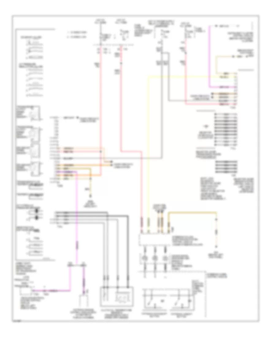
2.0L Turbo, Cruise Control Wiring Diagram, BPY for Audi A3 2009
List of elements for 2.0L Turbo, Cruise Control Wiring Diagram, BPY for Audi A3 2009:
- All-wheel drive control module (left front of rear axle differential)
- Brake light switch & (top of brake pedal assembly)
- Clutch position sensor (m/t)
- Computer data lines system
- Cruise control ind
- Cruise control switch (if equipped)
- Direct shift gearbox (dsg) mechatronic (on transmission housing)
- Early production
- Fuse 10a
- Fuse 5a
- Fuse panel b (integrated in engine compartment e-box)
- Fuse panel c
- G44 (behind left kick panel)
- Hot at all times
- Instrument cluster control module
- Late production
- Motronic engine control module (ecm) (in center of plenum chamber)
- Nca
- Steering column electronic systems control module (under steering column)
- T20b
- T20e
- T32
- T40
- T4al
- T60
- T8y
- T94
- Throttle position (tp) sensor & accelerator pedal position sensor 2 (on accelerator pedal)
- Throttle valve control module (on throttle body)
- Transmission input speed (rpm) sensor
- Transmission output speed (rpm) sensor
- Transmission output speed (rpm) sensor 2
2.0L Turbo, Cruise Control Wiring Diagram, CBFA for Audi A3 2009
List of elements for 2.0L Turbo, Cruise Control Wiring Diagram, CBFA for Audi A3 2009:
- All-wheel drive control module (left front of rear axle differential)
- Brake light switch & (top of brake pedal assembly)
- Cbfa
- Ccta
- Ccta early production & cbfa
- Ccta late production
- Clutch position sensor (m/t)
- Computer data lines system
- Cruise control ind
- Cruise control switch (if equipped)
- Direct shift gearbox (dsg) mechatronic (on transmission housing)
- Early production
- Fuse 10a
- Fuse 5a
- Fuse panel b (integrated in engine compartment e-box)
- Fuse panel c
- G44 (behind left kick panel)
- Hot at all times
- Instrument cluster control module
- Late production
- Motronic engine control module (in center of plenum chamber)
- Nca
- Steering column electronic systems control module (under steering column)
- T20b
- T20e
- T32
- T40
- T4al
- T60
- T8y
- T94
- Throttle position (tp) sensor & accelerator pedal position sensor 2 (on accelerator pedal)
- Throttle valve control module (on throttle body)
- Transmission input speed (rpm) sensor
- Transmission output speed (rpm) sensor
- Transmission output speed (rpm) sensor 2
2.0L Turbo, Cruise Control Wiring Diagram, CCTA for Audi A3 2009
List of elements for 2.0L Turbo, Cruise Control Wiring Diagram, CCTA for Audi A3 2009:
- All-wheel drive control module (left front of rear axle differential)
- Brake light switch & (top of brake pedal assembly)
- Cbfa
- Ccta
- Ccta early production & cbfa
- Ccta late production
- Clutch position sensor (m/t)
- Computer data lines system
- Cruise control ind
- Cruise control switch (if equipped)
- Direct shift gearbox (dsg) mechatronic (on transmission housing)
- Early production
- Fuse 10a
- Fuse 5a
- Fuse panel b (integrated in engine compartment e-box)
- Fuse panel c
- G44 (behind left kick panel)
- Hot at all times
- Instrument cluster control module
- Late production
- Motronic engine control module (in center of plenum chamber)
- Nca
- Steering column electronic systems control module (under steering column)
- T20b
- T20e
- T32
- T40
- T4al
- T60
- T8y
- T94
- Throttle position (tp) sensor & accelerator pedal position sensor 2 (on accelerator pedal)
- Throttle valve control module (on throttle body)
- Transmission input speed (rpm) sensor
- Transmission output speed (rpm) sensor
- Transmission output speed (rpm) sensor 2
3.2L
3.2L, Cruise Control Wiring Diagram for Audi A3 2009
List of elements for 3.2L, Cruise Control Wiring Diagram for Audi A3 2009:
- All-wheel drive control module (left front of rear axle differential)
- Brake light switch & (top of brake pedal assembly)
- Computer data lines system
- Cruise control ind
- Cruise control switch (if equipped)
- Direct shift gearbox (dsg) mechatronic (on transmission housing)
- Early production
- Fuse 10a
- Fuse 5a
- Fuse panel b (integrated in engine compartment e-box)
- Fuse panel c
- G44 (behind left kick panel)
- Hot at all times
- Instrument cluster control module
- Late production
- Motronic engine control module (in center of plenum chamber)
- Nca
- Steering column electronic systems control module (under steering column)
- T121
- T20b
- T20e
- T32
- T40
- T4al
- T8y
- Throttle position (tp) sensor & accelerator pedal position sensor 2 (on accelerator pedal)
- Throttle valve control module (on throttle body)
- Transmission input speed (rpm) sensor
- Transmission output speed (rpm) sensor
- Transmission output speed (rpm) sensor 2
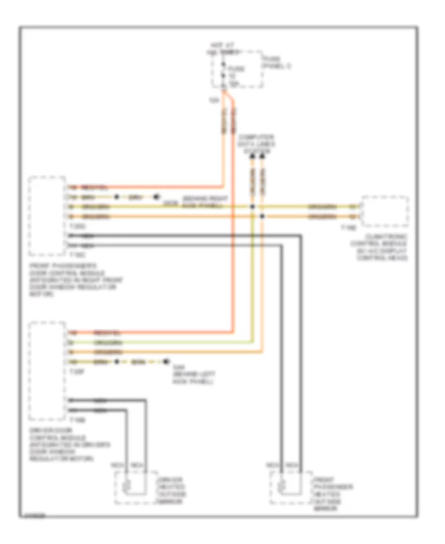
DEFOGGERS
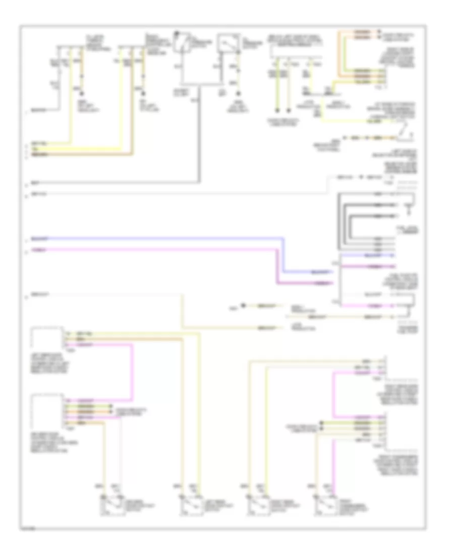
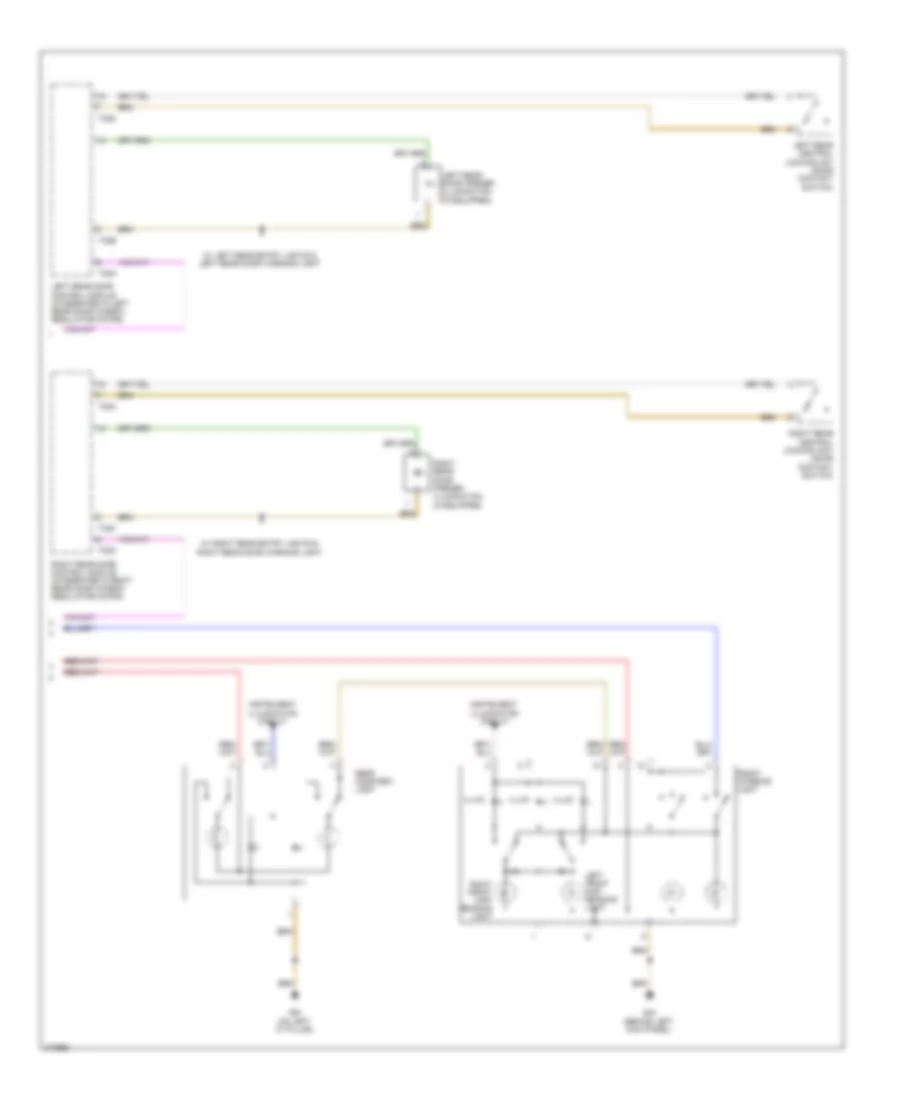
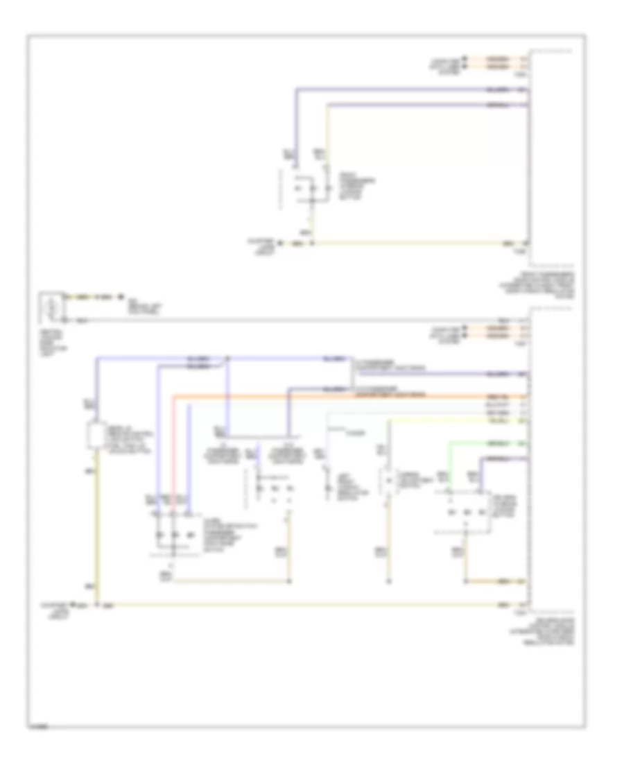
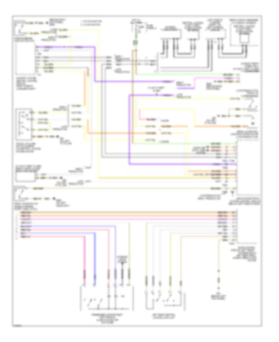
Heated Mirrors Wiring Diagram for Audi A3 2009
List of elements for Heated Mirrors Wiring Diagram for Audi A3 2009:
- (behind right kick panel)
- 12a
- Climatronic control module (w/ a/c display control head)
- Computer data lines system
- Driver door control module (integrated in driver's door window regulator motor)
- Driver heated outside mirror
- Front passenger heated outside mirror
- Front passenger's door control module (integrated in right front door window regulator motor)
- Fuse 10a
- Fuse panel c
- G44 (behind left kick panel)
- G638
- Hot at all times
- Nca
- T16b
- T16c
- T16e
- T20f
- T20g
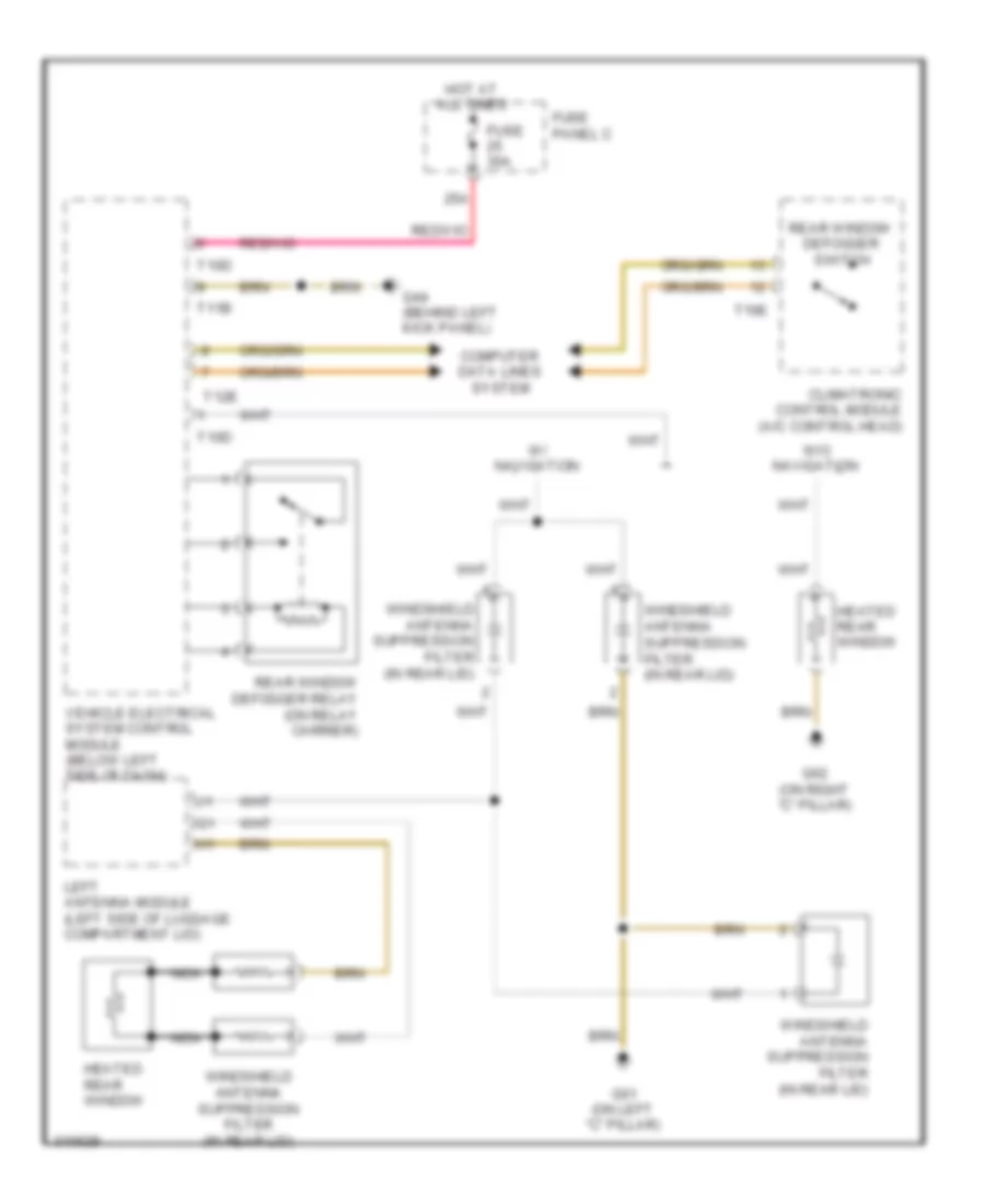
Rear Defogger Wiring Diagram, Early Production for Audi A3 2009
List of elements for Rear Defogger Wiring Diagram, Early Production for Audi A3 2009:
- 25a
- Climatronic control module (a/c control head)
- Computer data lines system
- Fuse 30a
- Fuse panel c
- G44 (behind left kick panel)
- G61 (on left "c" pillar)
- G62 (on right "c" pillar)
- Heated rear window
- Hot at all times
- Left antenna module (left side of luggage compartment lid)
- Nca
- Rear window defogger relay (on relay carrier)
- Rear window defogger switch
- T10d
- T11b
- T12e
- T16e
- Vehicle electrical system control module (below left side of dash)
- W/ navigation
- W/o navigation
- Windshield antenna suppression filter (in rear lid)
Rear Defogger Wiring Diagram, Late Production for Audi A3 2009
List of elements for Rear Defogger Wiring Diagram, Late Production for Audi A3 2009:
- 25a
- Climatronic control module (a/c control head)
- Computer data lines system
- Fuse 30a
- Fuse 5a
- Fuse panel b (integrated in engine compartment e-box)
- Fuse panel c
- G42
- G61 (on left "c" pillar)
- G62 (on right "c" pillar)
- G638 (behind right kick panel)
- Heated rear window
- Heater control module (if equipped)
- Hot at all times
- Left antenna module (left side of luggage compt lid)
- Nca
- Rear window defogger ind lamp
- Rear window defogger relay (on relay carrier)
- Rear window defogger switch
- T16e
- T40
- T52a
- T52b
- T52c
- T54a
- Vehicle electrical system control module (below left side of dash)
- W/ navigation
- W/o navigation
- Windshield antenna suppression filter (in rear lid)
ELECTRONIC POWER STEERING
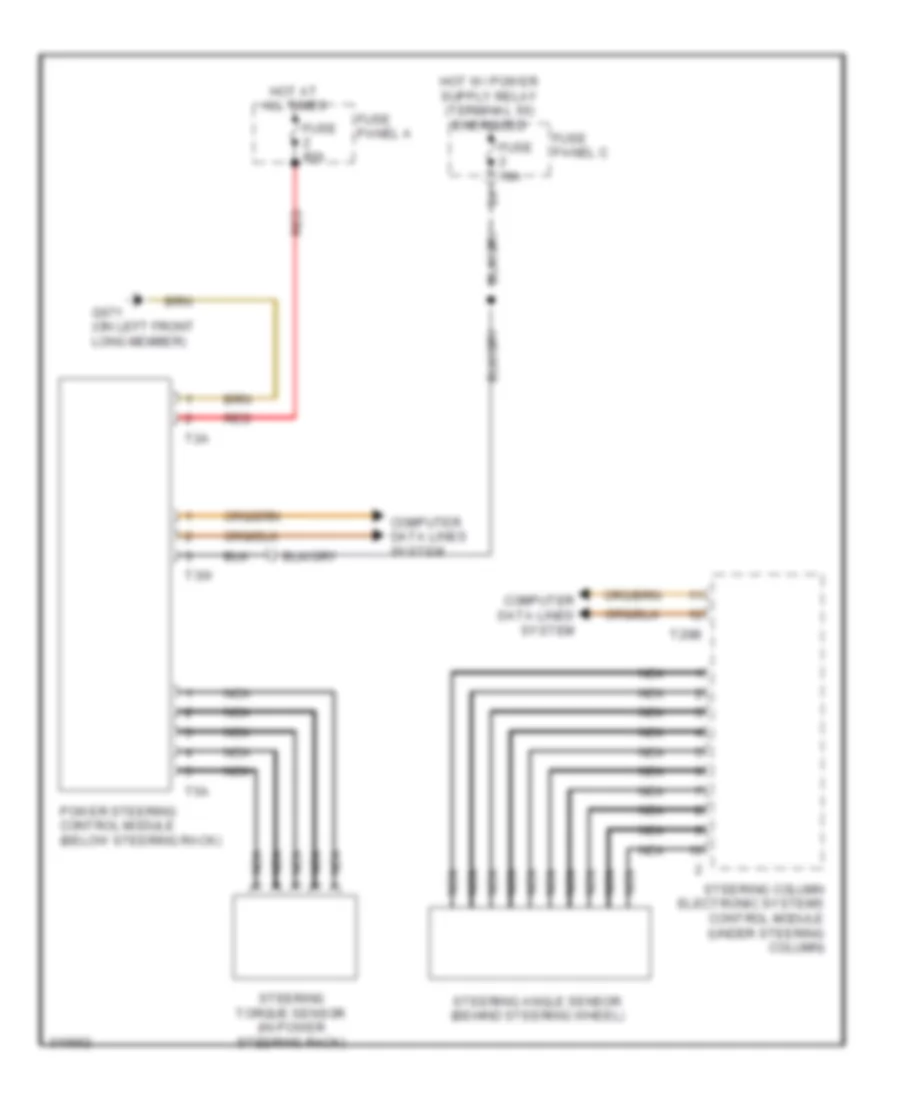
Electronic Power Steering Wiring Diagram for Audi A3 2009
List of elements for Electronic Power Steering Wiring Diagram for Audi A3 2009:
- Computer data lines system
- Fuse 10a
- Fuse 80a
- Fuse panel a
- Fuse panel c
- G671 (on left front long member)
- Hot at all times
- Nca
- Power steering control module (below steering rack)
- Red
- Steering angle sensor (behind steering wheel)
- Steering column electronic systems control module (under steering column)
- Steering torque sensor (in power steering rack)
- T20b
- T2a
- T3w
- T5a
ELECTRONIC SUSPENSION
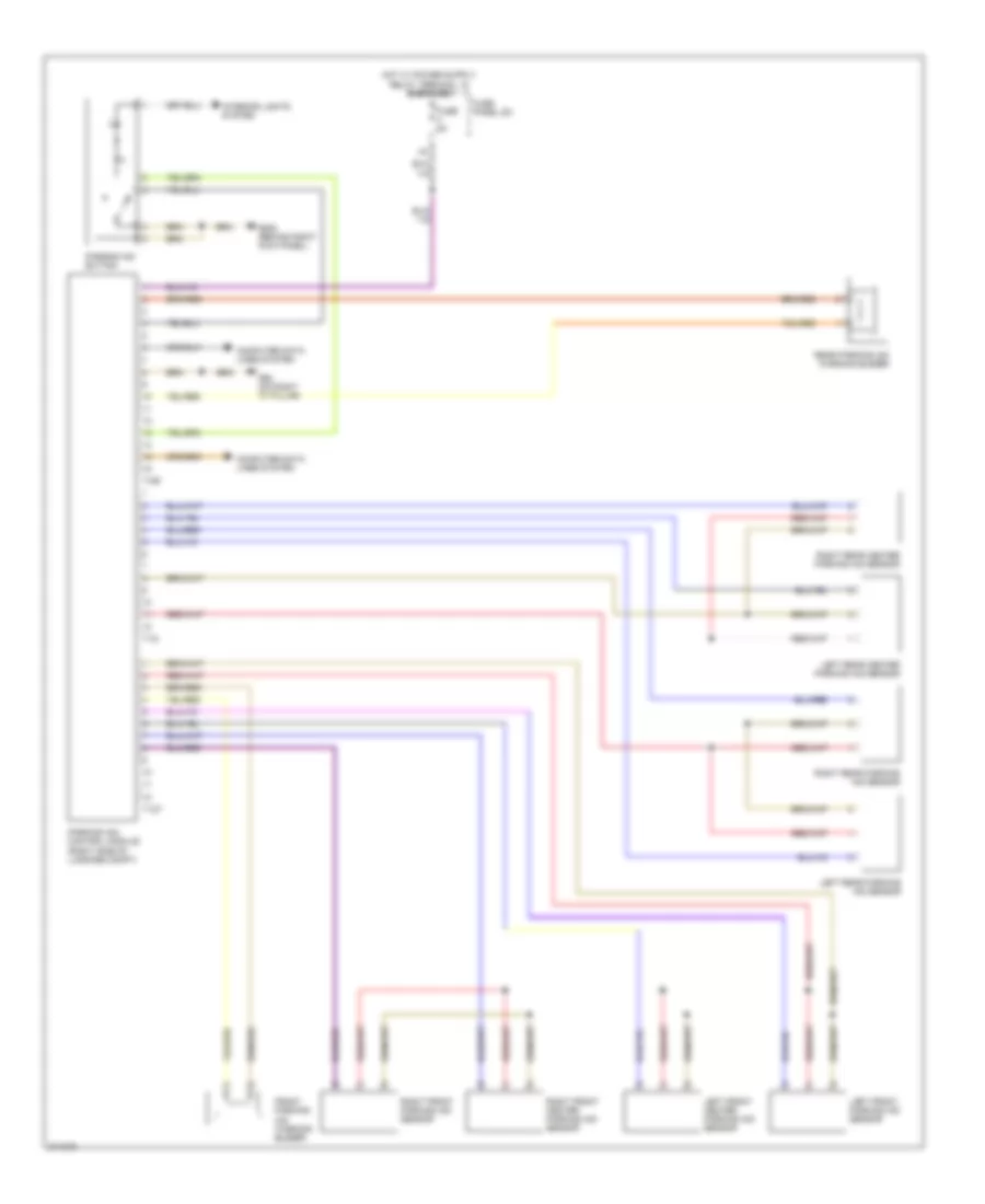
Electronic Suspension Wiring Diagram for Audi A3 2009
List of elements for Electronic Suspension Wiring Diagram for Audi A3 2009:
- 20a
- Computer data lines system
- Dampening adjustment button
- Electronic damping control module (under front passenger's seat)
- Fuse 30a
- Fuse 5a
- Fuse panel a
- Fuse panel c
- G638 (behind right kick panel)
- Hot at all times
- Left front dampening adjustment valve
- Left front level control system sensor
- Left rear dampening adjustment valve
- Left rear level control system sensor
- Pnk
- Red
- Right front dampening adjustment valve
- Right front level control sensor
- Right rear dampening adjustment valve
- Right rear level control system sensor
- T12c
- Vehicle electrical system control module (below left side of dash)
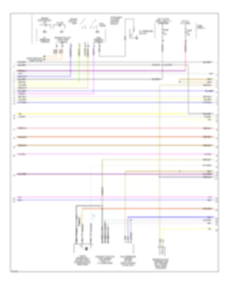
ENGINE PERFORMANCE
2.0L TURBO
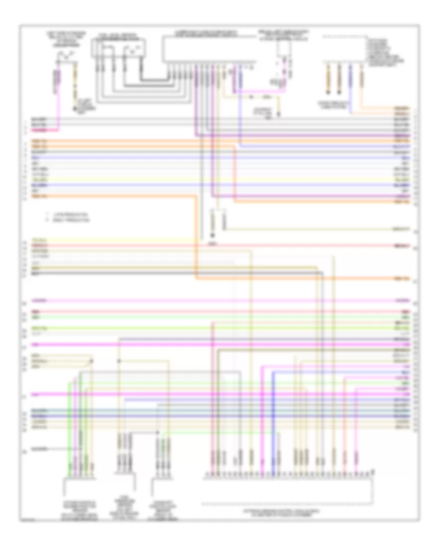
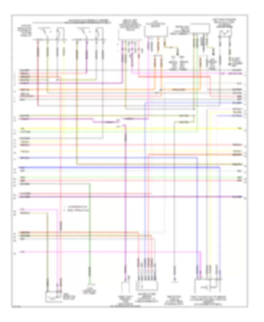
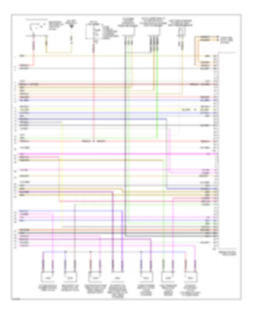
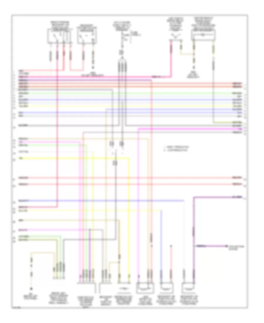
2.0L Turbo, Engine Performance Wiring Diagram, BPY (1 of 5) for Audi A3 2009
List of elements for 2.0L Turbo, Engine Performance Wiring Diagram, BPY (1 of 5) for Audi A3 2009:
- (in center of plenum chamber)
- (in left plenum chamber) g607
- (on engine air intake duct) mass air flow (maf) sensor
- Accelerator pedal position sensor 2 & throttle position (tp) sensor (at accelerator pedal)
- Charge air pressure sensor (if equipped) (in charge air pipe)
- Cooling fans system
- Cruise control system
- Engine coolant temperature (ect) sensor (radiator)
- Fuse 10a
- Fuse 25a
- Fuse panel b (integrated in engine compt e-box)
- Heated oxygen (ho2s) sensor (in exhaust, at turbocharger exit)
- Hot w/ motronic engine control module (ecm) power relay energized
- Motronic engine control module (ecm)
- Nca
- Oxygen sensor (o2s) heater 1 behind three way catalytic converter (twc)
- T26
- T40
- T94
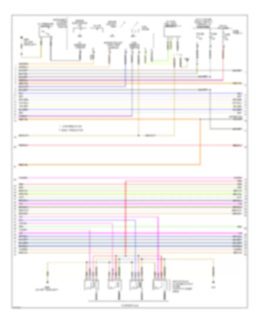
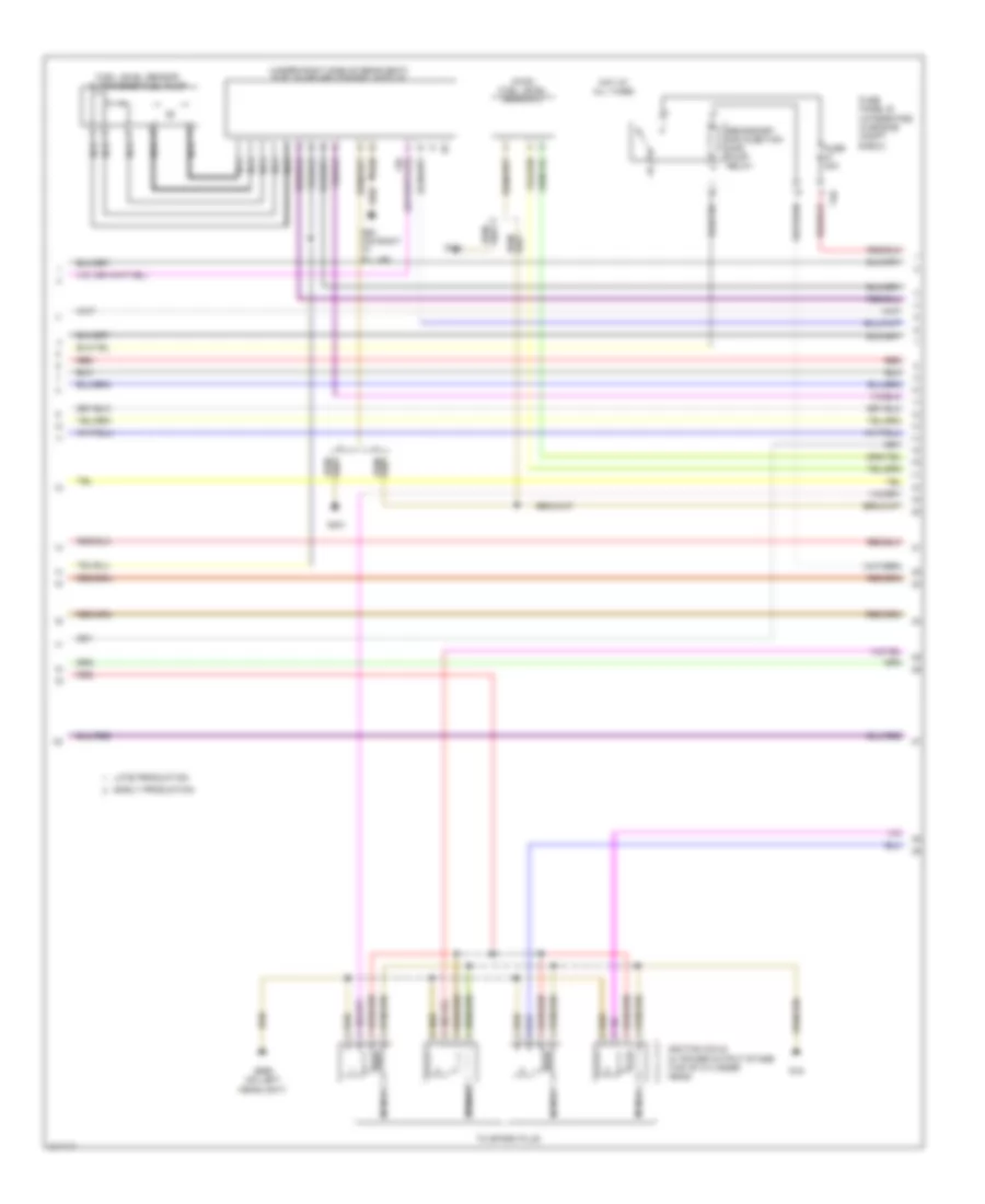
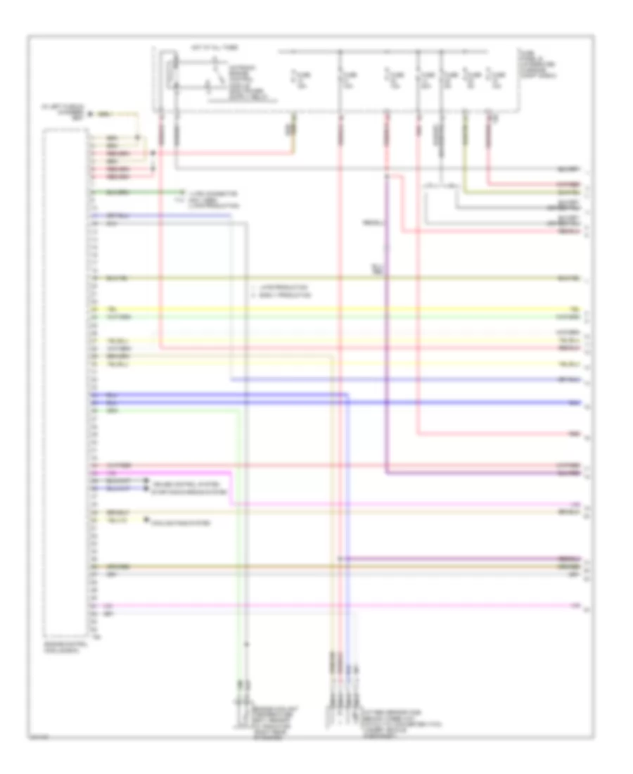
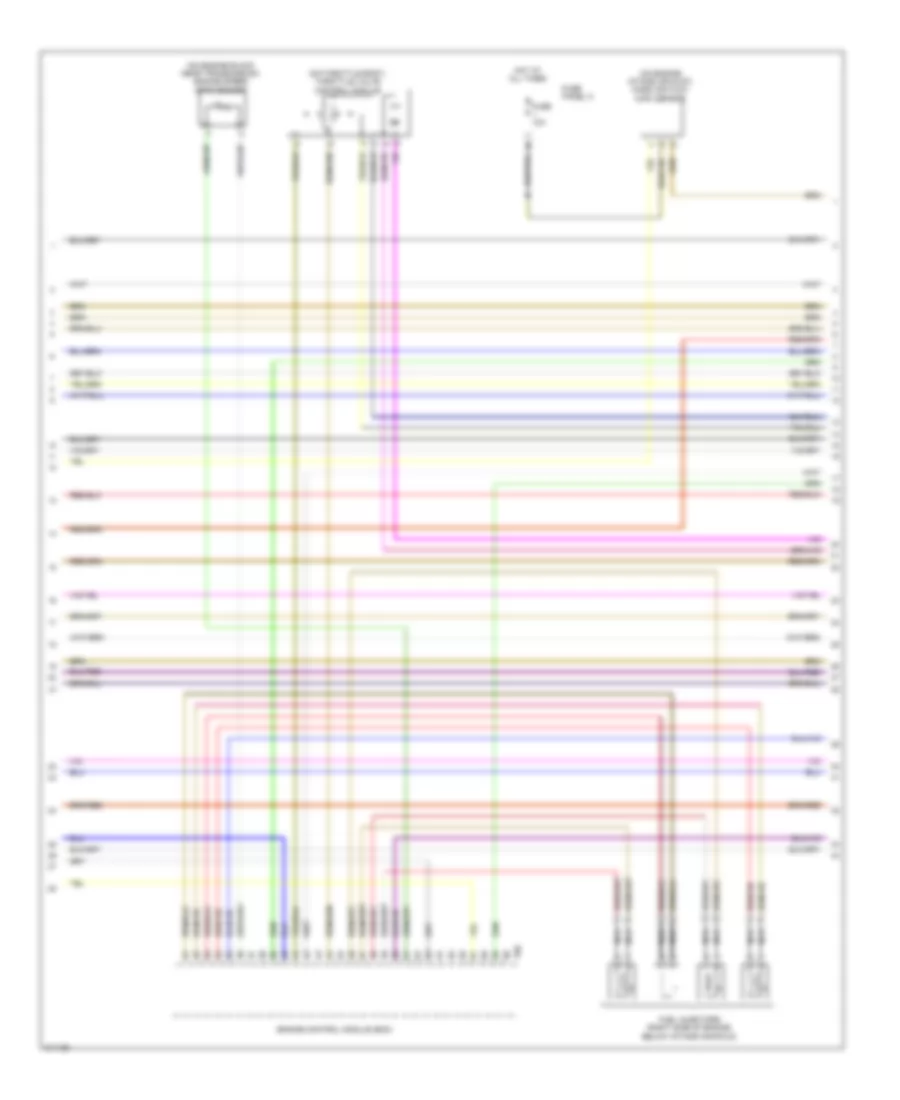
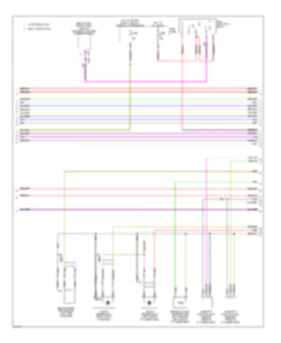
2.0L Turbo, Engine Performance Wiring Diagram, BPY (2 of 5) for Audi A3 2009
List of elements for 2.0L Turbo, Engine Performance Wiring Diagram, BPY (2 of 5) for Audi A3 2009:
- (behind left kick panel)
- (behind left kick panel) g44
- (below left side of dash) vehicle electrical system control module
- (in left plenum chamber)
- (m/t) clutch position sensor
- (top of brake pedal assembly) brake light switch & brake pedal switch
- Abs control module (at right rear of engine compt)
- Coolant circulation pump relay
- Early production
- Engine coolant temperature (ect) sensor (right rear of engine)
- Engine speed sensor (on engine block near transmission)
- Fuse
- Fuse 10a
- Fuse 5a
- Fuse panel b (integrated in engine compt e-box)
- G44
- G607
- Intake air temperature sensor (left side of of engine)
- Knock sensor (ks) 1 (on left front of engine block, near head)
- Knock sensor (ks) 2 (on left rear of engine block, near head)
- Late production
- Leak detection pump (ldp) (if equipped)
- Low fuel pressure sensor (left rear of engine)
- Nca
- Red
- T16a
- T26
- T40
- T52c
- Throttle valve control module (on throttle body)
- Transmissions system
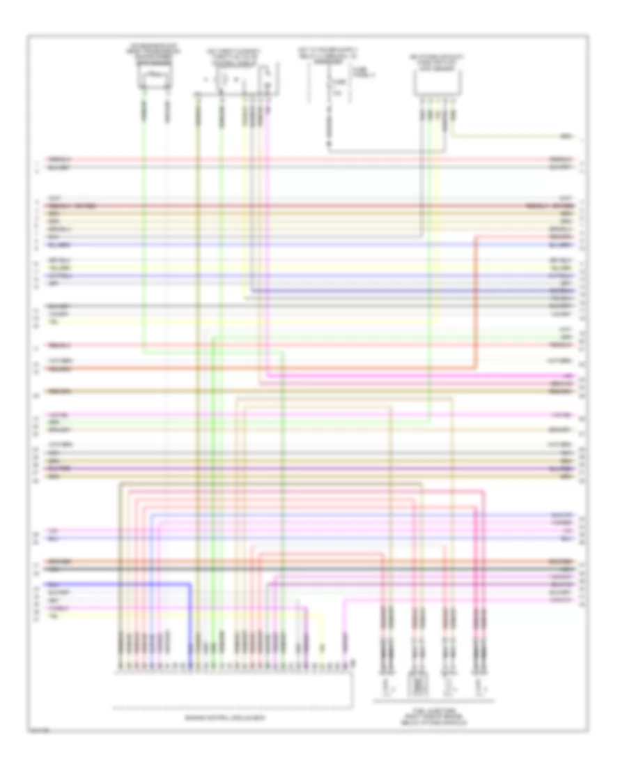
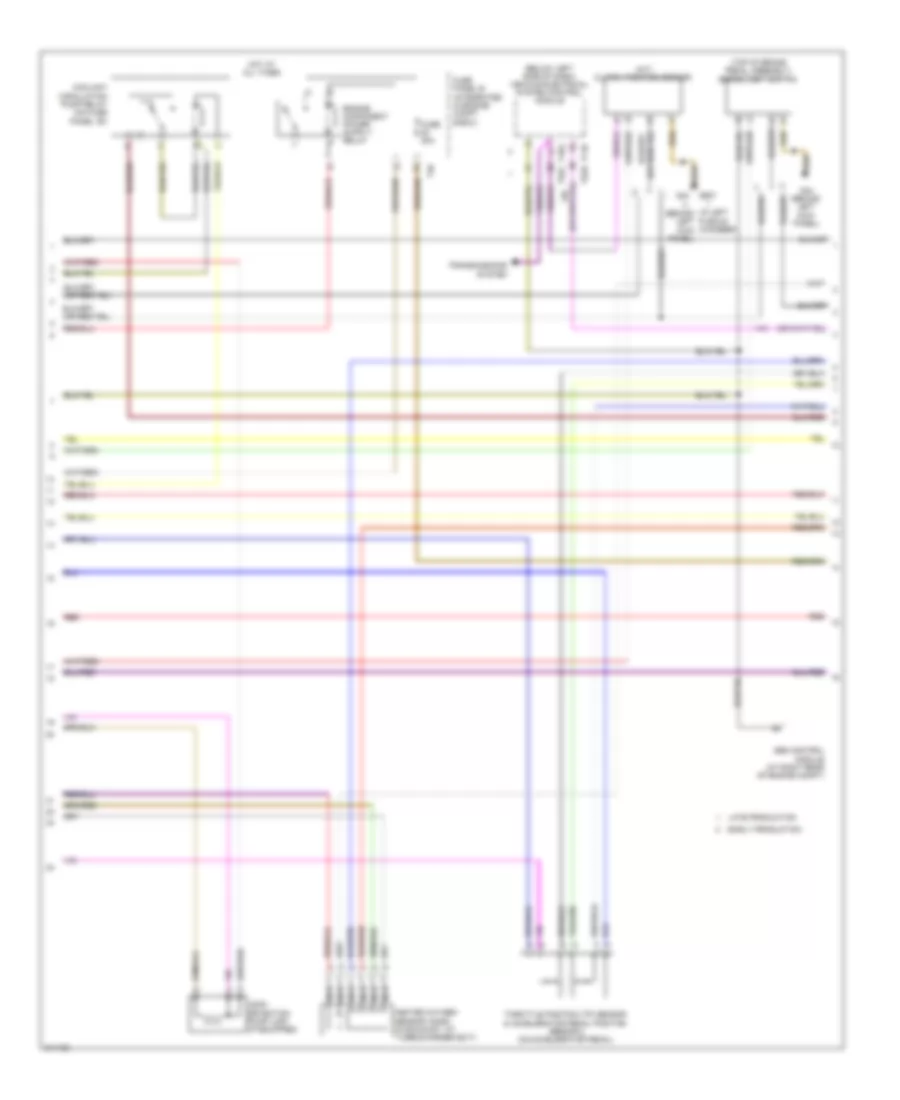
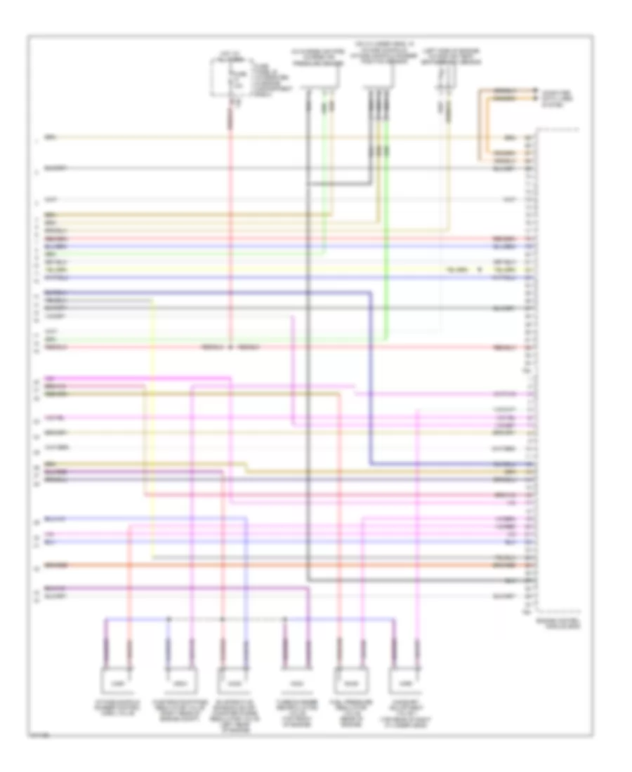
2.0L Turbo, Engine Performance Wiring Diagram, BPY (3 of 5) for Audi A3 2009
List of elements for 2.0L Turbo, Engine Performance Wiring Diagram, BPY (3 of 5) for Audi A3 2009:
- (below left side of dash) vehicle electrical system control module
- (in left plenum chamber) g607
- (left side of engine, below oil filter) after-run coolant pump
- (on right "c" pillar) g62
- (under right side of rear seat) fuel pump (fp) control module
- Camshaft position (cmp) sensor (front of cylinder head)
- Computer data lines system
- Data bus on-board diagnostic interface (behind center console storage compartment)
- Early production
- Fuel level sensor & transfer fuel pump
- Fuel pressure sensor (on left side of engine, in fuel rail)
- G401
- Intake manifold runner position sensor (on cylinder head, in intake manifold)
- Late production
- Motronic engine control module (ecm) (in center of plenum chamber)
- Nca
- Red
- T11b
- T52b
- T60
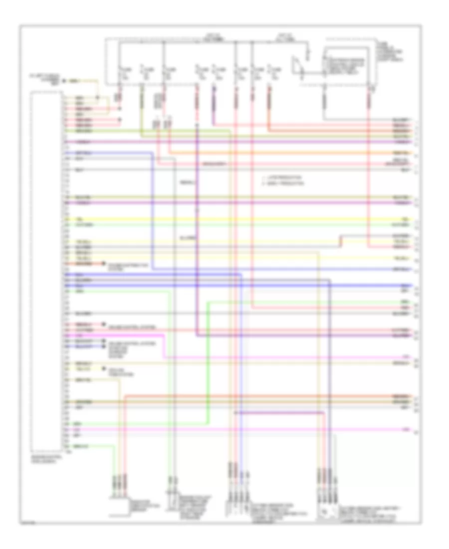
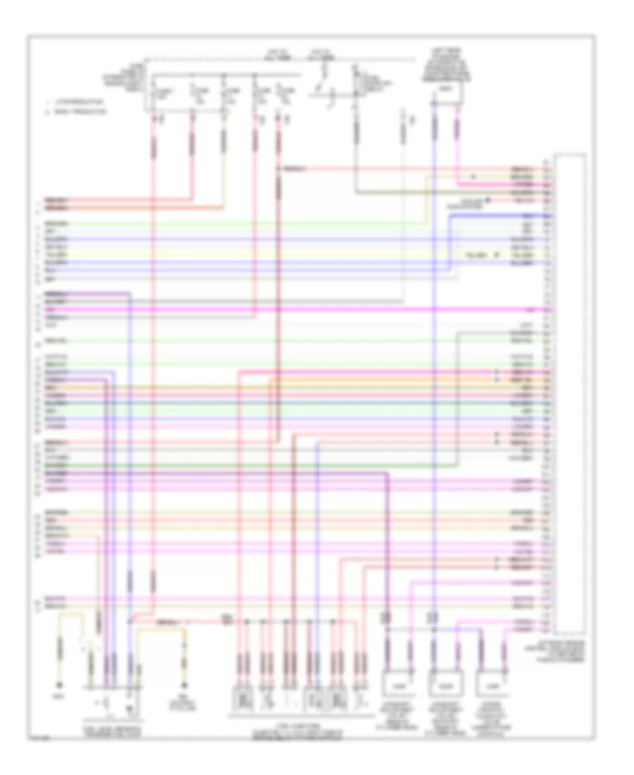
2.0L Turbo, Engine Performance Wiring Diagram, BPY (4 of 5) for Audi A3 2009
List of elements for 2.0L Turbo, Engine Performance Wiring Diagram, BPY (4 of 5) for Audi A3 2009:
- (on left headlight)
- (w/ awd) fuel level sensor 2
- 27a
- Early production
- Engine coolant level/temp warning
- Engine coolant temp
- Engine electronics ind
- Fuel gauge
- Fuel reserve warning
- Fuse 10a
- Fuse 15a
- Fuse panel c
- G15
- G401
- G655
- G655 (on left headlight)
- Hot at all times
- Ignition coils w/ power output stage (top of cylinder head)
- Instrument cluster control module
- Late production
- Mil ind
- Nca
- Oil pressure switch
- Oil pressure warning
- Red
- To spark plug
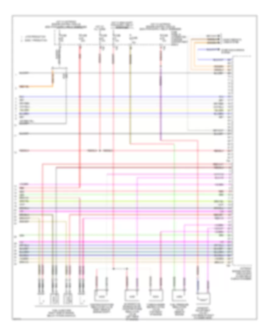
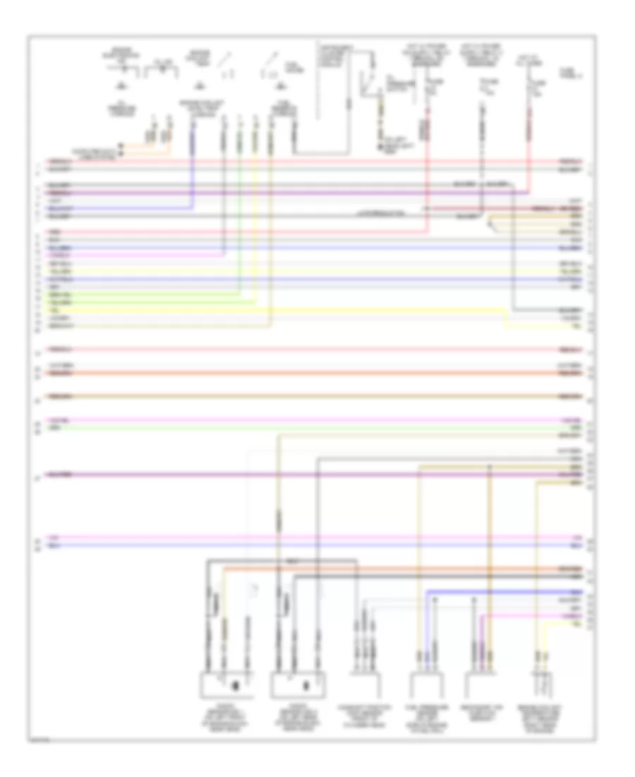
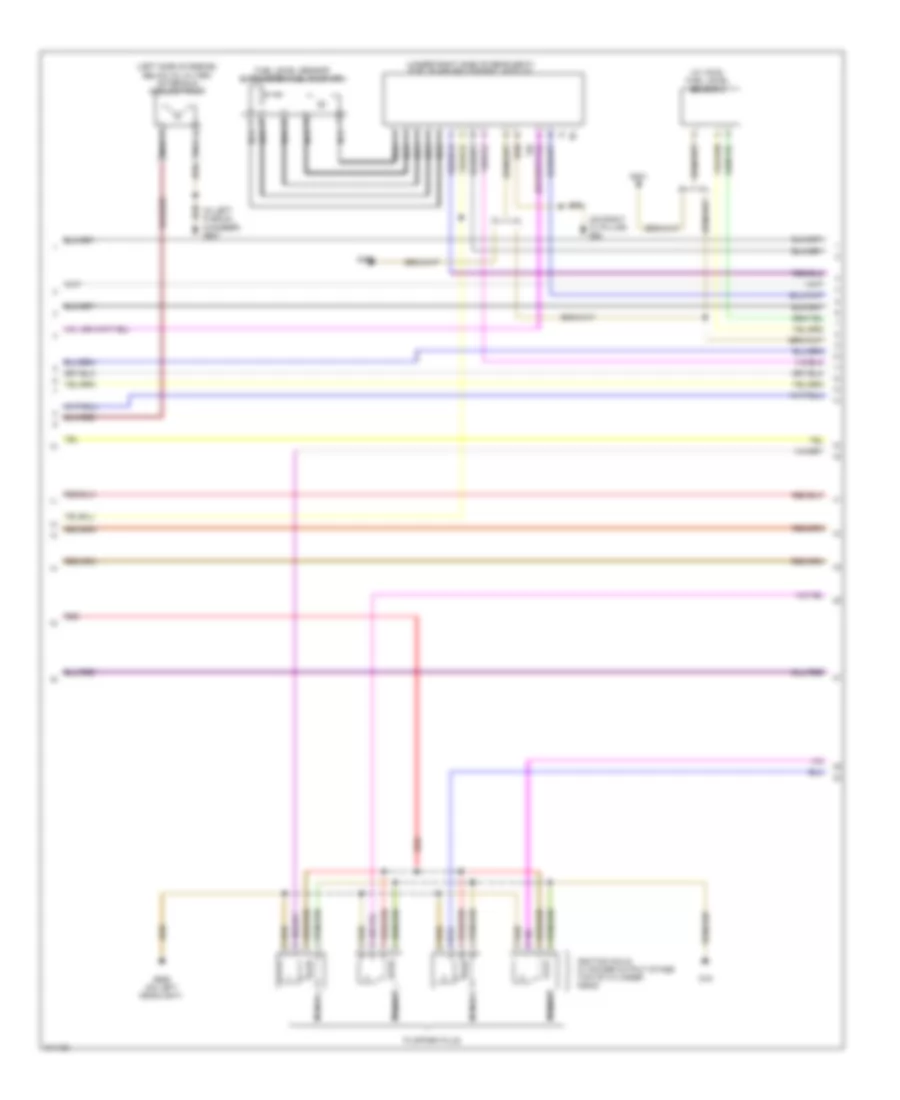
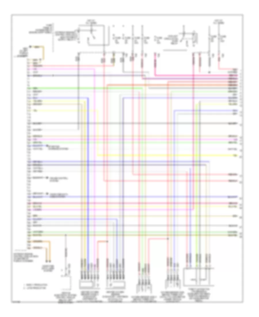
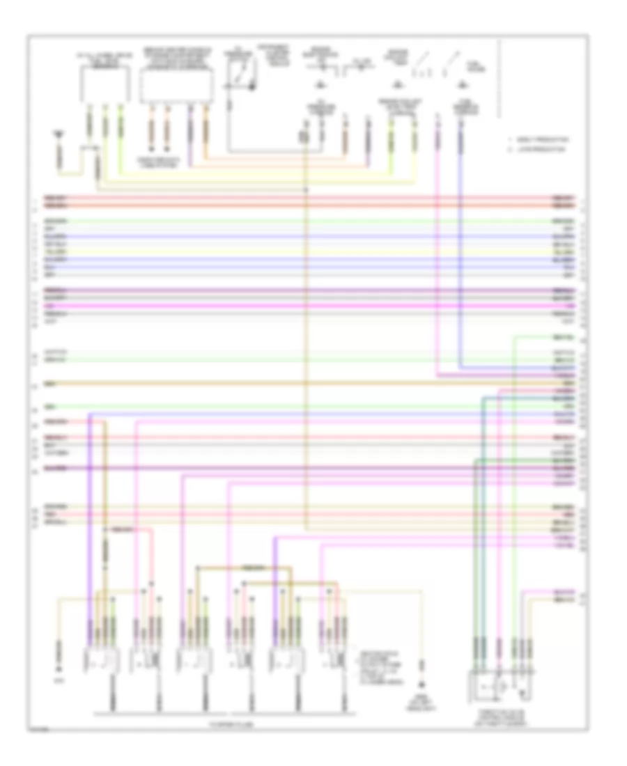
2.0L Turbo, Engine Performance Wiring Diagram, BPY (5 of 5) for Audi A3 2009
List of elements for 2.0L Turbo, Engine Performance Wiring Diagram, BPY (5 of 5) for Audi A3 2009:
- (in center of plenum chamber)
- Camshaft adjustment valve 1 (top rear of right cylinder head)
- Computer data lines system
- Early production
- Evaporative emission (evap) canister purge regulator valve (left rear of engine)
- Fuel injectors (right side of engine, below intake manifold)
- Fuel pressure regulator valve (rear of engine)
- Fuse 10a
- Fuse 15a
- Fuse 20a
- Fuse 5a
- Fuse panel b (integrated in engine compartment e-box)
- Hot at all times
- Late production
- Motronic engine control module (ecm)
- Nca
- Red
- Starting/charging system
- T26
- T40
- T60
- T94
- Turbocharger recirculating valve (top front of engine)
- Wastegate bypass regulator valve (right rear of engine compt)
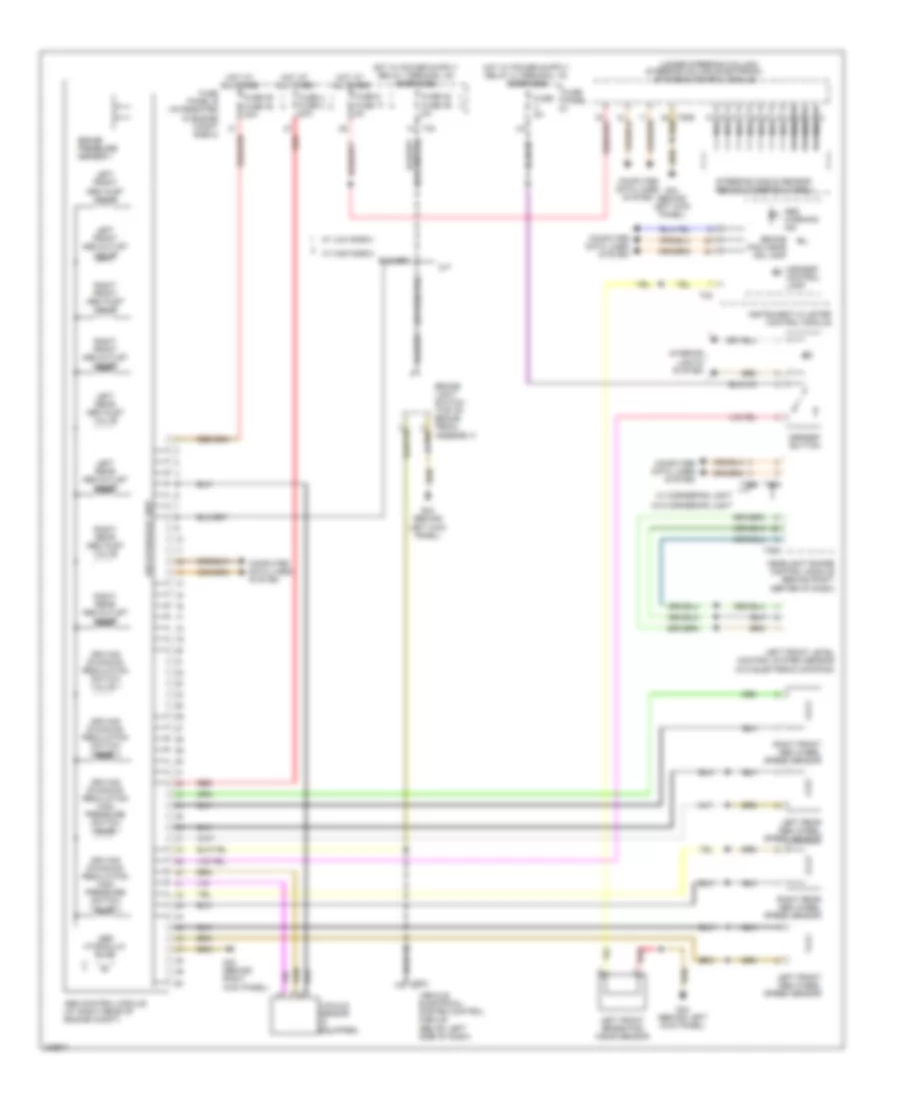
2.0L Turbo, Engine Performance Wiring Diagram, CBFA (1 of 6) for Audi A3 2009
List of elements for 2.0L Turbo, Engine Performance Wiring Diagram, CBFA (1 of 6) for Audi A3 2009:
- (in left plenum chamber) g607
- Cooling fans system
- Cruise control system
- Cruise control system starting/ charging system
- Early production
- Engine control module (ecm)
- Engine coolant temperature (ect) sensor (w/ radiator) (right rear of engine)
- Fuse 10a
- Fuse 15a
- Fuse 20a
- Fuse 5a
- Fuse panel b (integrated in engine compt e-box)
- Hot at all times
- Late production
- Nca
- Oxygen sensor (o2s) behind three way catalytic converter (twc) (under vehicle, in exhaust)
- Oxygen sensor (o2s) heater 1 behind three way catalytic converter (twc) (under vehicle, in exhaust)
- Power distribution system
- Radiator identification sensor
- Red
- T40
- T94
2.0L Turbo, Engine Performance Wiring Diagram, CBFA (2 of 6) for Audi A3 2009
List of elements for 2.0L Turbo, Engine Performance Wiring Diagram, CBFA (2 of 6) for Audi A3 2009:
- (behind (behind left kick panel)
- (below left side of dash) vehicle electrical system control module
- (in left plenum chamber) g607
- (left side of engine, below oil filter) after-run coolant pump
- (m/t) clutch position sensor
- 14-pin connector (not used)
- A/t
- Abs control module (at right rear of engine compt)
- Brake light switch (top of brake pedal assembly)
- Coolant circulation pump relay (on fuse panel "b")
- Direct shift gear box (dsg) mechatronic (on transmission housing)
- Early production
- G44
- G44 (behind left kick panel)
- G607
- Heated oxygen sensor (in exhaust, at turbocharger exit)
- Late production
- Leak detection pump (ldp)
- Left kick panel)
- M/t
- Nca
- Red
- T11b
- T14
- T16a
- T20e
- T52b
- T52c
- Throttle position (tp) sensor & accelerator pedal position sensor 2 (on accelerator pedal)
2.0L Turbo, Engine Performance Wiring Diagram, CBFA (3 of 6) for Audi A3 2009
List of elements for 2.0L Turbo, Engine Performance Wiring Diagram, CBFA (3 of 6) for Audi A3 2009:
- (awd) fuel level sensor 2
- (under right side of rear seat) fuel pump (fp) control module
- Early production
- Fuel level sensor & transfer fuel pump
- Fuse 40a
- Fuse panel b (integrated in engine compt e-box)
- G15
- G401
- G62 (on right "c" pillar)
- G655 (on left headlight)
- Hot at all times
- Ignition coils w/ power output stage (top of cylinder head)
- Late production
- Nca
- Red
- Secondary air injection (air) pump relay
- T40
- To spark plug
2.0L Turbo, Engine Performance Wiring Diagram, CBFA (4 of 6) for Audi A3 2009
List of elements for 2.0L Turbo, Engine Performance Wiring Diagram, CBFA (4 of 6) for Audi A3 2009:
- (on left headlight) g655
- (or red)
- 27a
- Camshaft position (cmp) sensor (front of cylinder head)
- Computer data lines system
- Engine coolant level/temp warning
- Engine coolant temp
- Engine coolant temperature (ect) sensor (right rear of engine)
- Engine electronics ind
- Fuel gauge
- Fuel pressure sensor (on left side of engine, in fuel rail)
- Fuel reserve warning
- Fuse 10a
- Fuse 15a
- Fuse 5a
- Fuse panel c
- Hot at all times
- Instrument cluster control module
- Knock sensor (ks) 1 (on left front of engine block, near head)
- Knock sensor (ks) 2 (on left rear of engine block, near head)
- Late production
- Mil ind
- Nca
- Oil pressure
- Oil pressure warning
- Red
- Secondary air injection sensor 1
- Switch
2.0L Turbo, Engine Performance Wiring Diagram, CBFA (5 of 6) for Audi A3 2009
List of elements for 2.0L Turbo, Engine Performance Wiring Diagram, CBFA (5 of 6) for Audi A3 2009:
- (on engine block near transmission) engine speed (rpm) sensor
- (on intake air duct) mass air flow (maf) sensor
- (on throttle body) throttle valve control module
- (or red)
- Engine control module (ecm)
- Fuel injectors (right side of engine, below intake manifold)
- Fuse 10a
- Fuse panel c
- Nca
- T60
2.0L Turbo, Engine Performance Wiring Diagram, CBFA (6 of 6) for Audi A3 2009
List of elements for 2.0L Turbo, Engine Performance Wiring Diagram, CBFA (6 of 6) for Audi A3 2009:
- (in charge air pipe) charge air pressure sensor
- (left side of engine) intake air temp- erature (iat) sensor
- (on cylinder head, in intake manifold) intake manifold runner position sensor
- (on left headlight) g655
- (or red)
- Camshaft adjustment valve 1 (top rear of right cylinder head)
- Computer data lines system
- Engine control module (ecm)
- Evaporative emission (evap) canister purge regulator valve (left rear of engine)
- Fuel pressure regulator valve (rear of engine)
- Fuse 10a
- Fuse panel b (integrated in engine compartment e-box)
- Hot at all times
- Intake manifold runner control (imrc) valve
- Nca
- Secondary air injection (air) pump motor
- Secondary air injection (air) solenoid valve
- T40
- T60
- T94
- Turbocharger recalculating valve (top front of engine)
- Wastegate bypass regulator valve (right rear of engine compt)
2.0L Turbo, Engine Performance Wiring Diagram, CCTA (1 of 6) for Audi A3 2009
List of elements for 2.0L Turbo, Engine Performance Wiring Diagram, CCTA (1 of 6) for Audi A3 2009:
- (in left plenum chamber) g607
- (late production)
- 14 pin connector (not used) t14
- Cooling fans system
- Cruise control system
- Early production
- Engine control module (ecm)
- Engine coolant temperature (ect) sensor (w/ radiator) (right rear of engine)
- Fuse 10a
- Fuse 15a
- Fuse 20a
- Fuse 5a
- Fuse panel b (integrated in engine compt e-box)
- Hot at all times
- Late production
- Nca
- Oxygen sensor (o2s) behind three way catalytic converter (twc) (under vehicle, in exhaust)
- Red
- Starting/charging system
- T40
- T94
2.0L Turbo, Engine Performance Wiring Diagram, CCTA (2 of 6) for Audi A3 2009
List of elements for 2.0L Turbo, Engine Performance Wiring Diagram, CCTA (2 of 6) for Audi A3 2009:
- (below left side of dash) vehicle electrical system control module
- (in left (behind left kick panel)
- (m/t) clutch position sensor
- (top of brake pedal assembly) brake light switch
- Abs control module (at right rear of engine compt)
- Coolant circulation pump relay (on fuse panel "b")
- Early production
- Fuse 20a
- Fuse panel b (integrated in engine compt e-box)
- G44
- G44 (behind left kick panel)
- G607
- Heated oxygen sensor (ho2s) (in exhaust, at turbocharger exit)
- Hot at all times
- Late production
- Leak detection pump (ldp) (if equipped)
- Nca
- Plenum chamber)
- Red
- T11b
- T16a
- T40
- T52b
- T52c
- Throttle position (tp) sensor & accelerator pedal position sensor 2 (on accelerator pedal)
- Transmissions system
2.0L Turbo, Engine Performance Wiring Diagram, CCTA (3 of 6) for Audi A3 2009
List of elements for 2.0L Turbo, Engine Performance Wiring Diagram, CCTA (3 of 6) for Audi A3 2009:
- (in left plenum chamber) g607
- (left side of engine, below oil filter) after-run coolant pump
- (on right "c" pillar) g62
- (under right side of rear seat) fuel pump (fp) control module
- (w/ awd) fuel level sensor 2
- Fuel level sensor & transfer fuel pump (fp)
- G15
- G401
- G655 (on left headlight)
- Ignition coils w/ power output stage (top of cylinder head)
- Nca
- Red
- To spark plug
2.0L Turbo, Engine Performance Wiring Diagram, CCTA (4 of 6) for Audi A3 2009
List of elements for 2.0L Turbo, Engine Performance Wiring Diagram, CCTA (4 of 6) for Audi A3 2009:
- 27a
- Camshaft position (cmp) sensor (front of cylinder head)
- Computer data lines system
- Engine coolant level/temp warning
- Engine coolant temp
- Engine coolant temperature (ect) sensor (right rear of engine)
- Engine electronics ind
- Fuel gauge
- Fuel pressure sensor (on left side of engine, in fuel rail)
- Fuel reserve warning
- Fuse 10a
- Fuse 15a
- Fuse panel c
- Hot at all times
- Instrument cluster control module
- Knock sensor (ks) 1 (on left front of engine block, near head)
- Mil ind
- Nca
- Oil pressure switch
- Oil pressure warning
2.0L Turbo, Engine Performance Wiring Diagram, CCTA (5 of 6) for Audi A3 2009
List of elements for 2.0L Turbo, Engine Performance Wiring Diagram, CCTA (5 of 6) for Audi A3 2009:
- (on engine block near transmission) engine speed (rpm) sensor
- (on engine intake air duct) mass air flow (maf) sensor
- (on throttle body) throttle valve control module
- Engine control module (ecm)
- Fuel injectors (right side of engine, below intake manifold)
- Fuse 10a
- Fuse panel c
- Hot at all times
- Nca
- T60
2.0L Turbo, Engine Performance Wiring Diagram, CCTA (6 of 6) for Audi A3 2009
List of elements for 2.0L Turbo, Engine Performance Wiring Diagram, CCTA (6 of 6) for Audi A3 2009:
- (in charge air pipe) charge air pressure sensor
- (left side of engine) intake air temp- erature (iat) sensor
- (on cylinder head, in intake manifold) intake manifold runner position sensor
- Camshaft adjustment valve 1 (top rear of right cylinder head)
- Computer data lines system
- Engine control module (ecm)
- Evaporative emission (evap) canister purge regulator valve (left rear of engine)
- Fuel pressure regulator valve (rear of engine)
- Fuse 10a
- Fuse panel b (integrated in engine compartment e-box)
- Hot at all times
- Intake manifold runner control (imrc) valve
- Nca
- T40
- T60
- T94
- Turbocharger recirculating valve (top front of engine)
- Wastegate bypass regulator valve (right rear of engine compt)
3.2L
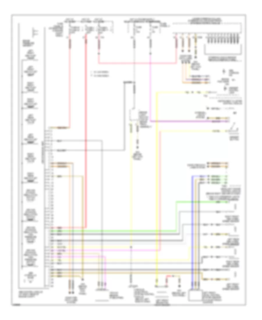
3.2L, Engine Performance Wiring Diagram (1 of 5) for Audi A3 2009
List of elements for 3.2L, Engine Performance Wiring Diagram (1 of 5) for Audi A3 2009:
- Computer data lines system
- Coolant circulation pump relay
- Cruise control system
- Early production
- Fuse 10a
- Fuse 15a
- Fuse 30a
- Fuse 40a
- Fuse 5a
- Fuse panel b (integrated in engine compt e-box)
- G607 (in left plenum chamber)
- Heated oxygen sensor (ho2s) 2 (in exhaust, upstream of catalytic converter)
- Heated oxygen sensor (in exhaust, upstream of catalytic converter)
- Hot at all times
- Late production
- Motronic engine control module (ecm) (in center of plenum chamber)
- Nca
- Oxygen sensor (o2s) 2 behind three way catalytic convertor
- Oxygen sensor (o2s) behind three way catalytic convertor (under vehicle, in exhaust)
- Red
- Starting/ charging system
- T16a
- T26
- T40
- T52c
- Throttle position (tp) sensor & accelerator pedal position sensor 2 (on accelerator pedal)
- Vehicle electrical system control module (below left side of dash)
3.2L, Engine Performance Wiring Diagram (2 of 5) for Audi A3 2009
List of elements for 3.2L, Engine Performance Wiring Diagram (2 of 5) for Audi A3 2009:
- (center rear of engine compt) (if equipped) positive crankcase ventilation (pcv) heating element
- (left side of engine, below oil filter) after-run coolant pump
- (rear of engine)
- Brake light switch & brake pedal switch (top of brake pedal assembly)
- Cooling fans system
- Early production
- Engine coolant temperature (ect) sensor (radiator)
- Fuse 10a
- Fuse panel c
- G44 (behind left kick panel)
- G655 (on left headlight)
- Late production
- Leak detection pump (ldp) (if equipped)
- Mass air flow (maf) sensor (on engine air intake duct)
- Red
- Secondary air injection (air) pump motor
- Secondary air injection (air) pump relay
- Secondary air injection (air) solenoid valve (if equipped)
- Secondary air injection (air) solenoid valve 2 (if equipped)
- Secondary air injection sensor 1
3.2L, Engine Performance Wiring Diagram (3 of 5) for Audi A3 2009
List of elements for 3.2L, Engine Performance Wiring Diagram (3 of 5) for Audi A3 2009:
- (below left side of dash) vehicle electrical system control module
- 27a
- Camshaft position (cmp) sensor (rear of cylinder head)
- Camshaft position (cmp) sensor 2 (rear of cylinder head)
- Early production
- Engine coolant temperature (ect) sensor (left side of cylinder head)
- Engine speed (rpm) sensor (left side of engine)
- Fuel pump (fp) 2 relay
- Fuse 10a
- Fuse 15a
- Fuse panel c
- Hot at all times
- Knock sensor (ks) 1 (right front of engine)
- Knock sensor (ks) 2 (left side of cylinder head)
- Late production
- Nca
- Red
- T11b
- T52b
3.2L, Engine Performance Wiring Diagram (4 of 5) for Audi A3 2009
List of elements for 3.2L, Engine Performance Wiring Diagram (4 of 5) for Audi A3 2009:
- (behind center console storage compartment) data bus on board diagnostic interface
- (w/ all wheel drive) fuel level sensor 2
- Computer data lines system
- Early production
- Engine coolant level/temp warning
- Engine coolant temp
- Engine electronics ind
- Fuel gauge
- Fuel reserve warning
- G15
- G401
- G655 (on left headlight)
- Ignition coils (w/ power output stage) (coils 1, 2, 3 & 4: top of cylinder head))
- Instrument cluster control module
- Late production
- Mil ind
- Nca
- Oil pressure switch
- Oil pressure warning
- Red
- Throttle valve control module (on throttle body)
- To spark plugs
3.2L, Engine Performance Wiring Diagram (5 of 5) for Audi A3 2009
List of elements for 3.2L, Engine Performance Wiring Diagram (5 of 5) for Audi A3 2009:
- (left rear of engine) evaporative emission (evap) canister purge regulator valve
- Camshaft adjustment valve 1 (exhaust) (rear of cylinder head)
- Camshaft adjustment valve 1 (rear of cylinder head)
- Cooling fans system
- Early production
- Fuel injectors (injector 1, 2, 3 & 4: right side of engine, below intake manifold)
- Fuel level sensor & transfer fuel pump
- Fuel pump (fp) relay
- Fuse 10a
- Fuse 7 15a
- Fuse panel b (integrated in engine compt e-box)
- G401
- G62 (on right "c" pillar)
- Hot at all times
- Intake manifold tuning (imt) valve (under intake manifold)
- Late production
- Motronic engine control module (ecm) (in center of plenum chamber)
- Red
- T26
- T40
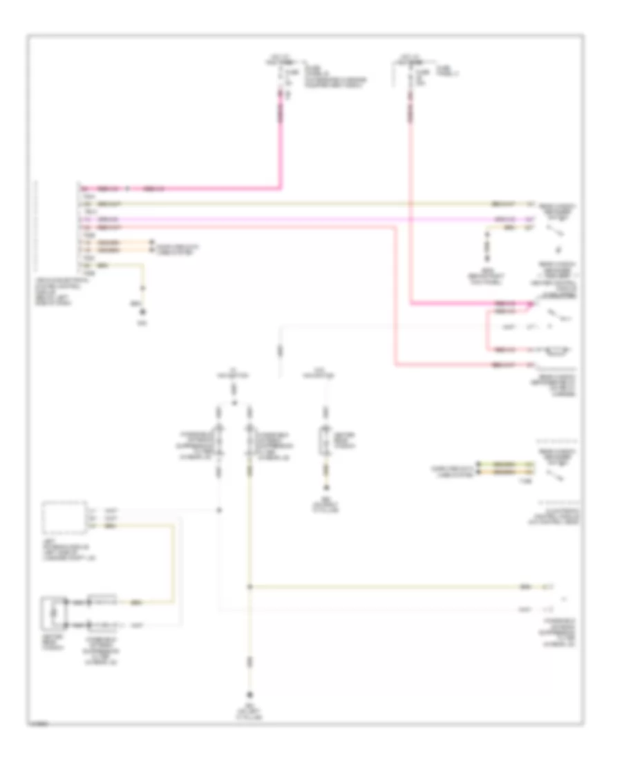
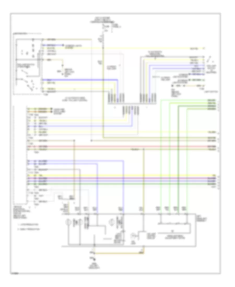
EXTERIOR LIGHTS
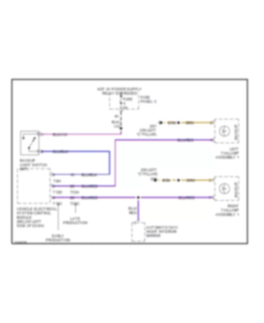
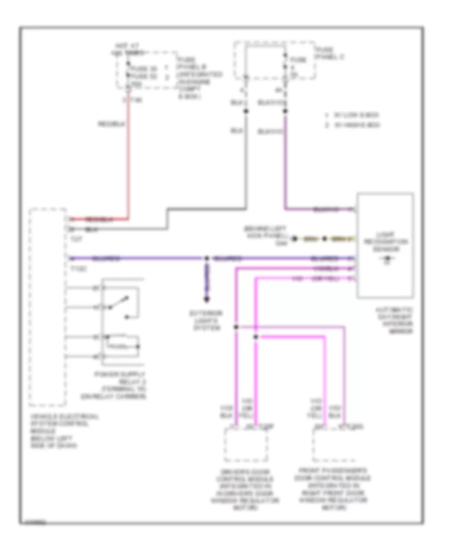
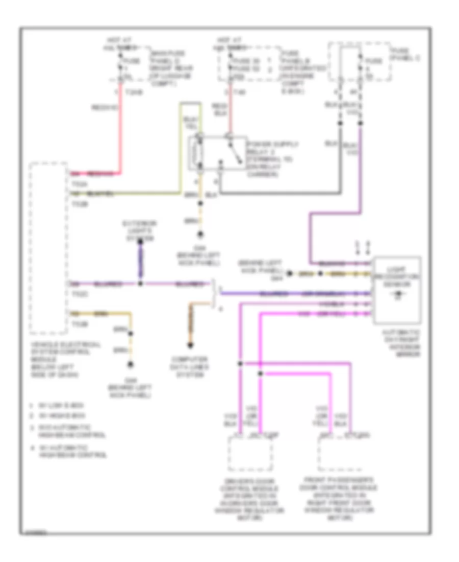
Backup Lamps Wiring Diagram for Audi A3 2009
List of elements for Backup Lamps Wiring Diagram for Audi A3 2009:
- (on left "c" pillar)
- Automatic day/ night interior mirror
- Backup
- Backup light switch (m/t)
- Early production
- Fuse 5a
- Fuse panel c
- G61
- G61 (on left "c" pillar)
- Late production
- Left taillamp assembly 1
- Right taillamp assembly 1
- T12c
- T12d
- T52a
- T52c
- T8h
- Vehicle electrical system control module (below left side of dash)
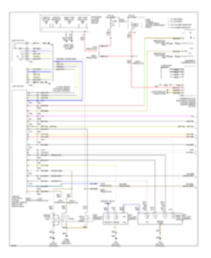
Exterior Lamps Wiring Diagram (1 of 2) for Audi A3 2009
List of elements for Exterior Lamps Wiring Diagram (1 of 2) for Audi A3 2009:
- (behind right kick panel) g638
- Backup
- Backup lights circuit
- Brake
- Brake/ turn
- Computer data lines system
- Early production
- Emergency flasher switch
- Front turn signal
- Fuse 17 fuse 6 5a
- Fuse 5a
- Fuse panel b (integrated in engine compartment e-box)
- Fuse panel c
- G42
- G61 (on left "c" pillar)
- G655 (on left headlight)
- Hot at all times
- Instrument cluster control module
- Late production
- Left headlight assembly
- Left taillamp assembly
- Left turn signal ind lamp
- License plate light
- Light switch
- Nca
- Park
- Parking brake ind lamp
- Parking light ind lamp
- Rear turn signal
- Right turn signal ind lamp
- Steering column electronic systems control module (under steering column)
- T10e
- T11b
- T11c
- T12c
- T12d
- T12e
- T16a
- T20b
- T40
- T52a
- T52b
- T52c
- T8h
- Tail
- Turn signal switch
- Vehicle electrical system control module (below left side of dash)
- W/ fog lamps & automatic head & taillight control
- W/ halogen headlamp
- W/ high e-box
- W/ low e-box
- W/o halogen headlamp
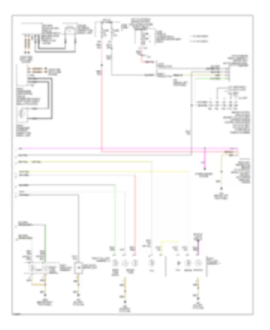
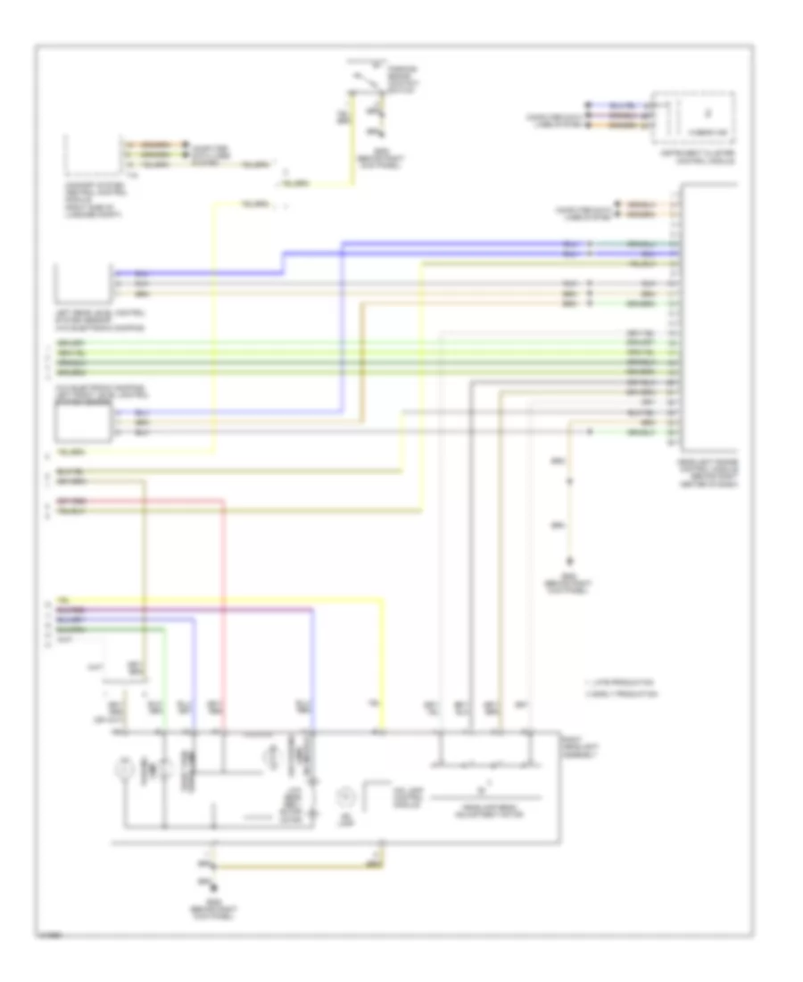
Exterior Lamps Wiring Diagram (2 of 2) for Audi A3 2009
List of elements for Exterior Lamps Wiring Diagram (2 of 2) for Audi A3 2009:
- (top of brake pedal assembly) brake light switch/brake padel switch
- 16a
- 2.0l bpy
- 2.0l cbfa
- 2.0l cbfa early
- 2.0l ccta late
- 3.2l
- Backup
- Backup lights circuit
- Brake
- Brake/ turn
- Computer data lines system
- Driver exterior mirror turn signal lamp
- Driver's door control module (integrated in driver's door t16b window regulator motor)
- Early production
- Engine control module (ecm) (except 3.2l & 2.0l bpy) motronic engine control module (ecm) (3.2l & 2.0l bpy) (3.2l & 2.0l bpy: in center of plenum chamber)
- Front passenger exterior mirror turn signal lamp
- Front passenger's door control module (integrated in right front door window regulator motor)
- Front turn signal
- Fuse 10a
- Fuse fuse 5a
- Fuse panel b (integrated in engine compartment e-box)
- Fuse panel c
- G44 (behind left kick panel)
- G61 (on left "c" pillar)
- G62 (on right "c" pillar)
- G638 (behind right kick panel)
- High mount brake light
- Hot at all times
- Late production
- M/t
- Nca
- Park
- Rain/light recognition sensor (w/ automatic head & taillight control) (on interior rearview mirror)
- Rear turn signal
- Right headlight assembly
- Right taillamp assembly 1
- Right taillamp assembly 2
- T121
- T16c
- T20f
- T20g
- T40
- T94
- Tail
- W/ high e-box
- W/ low e-box
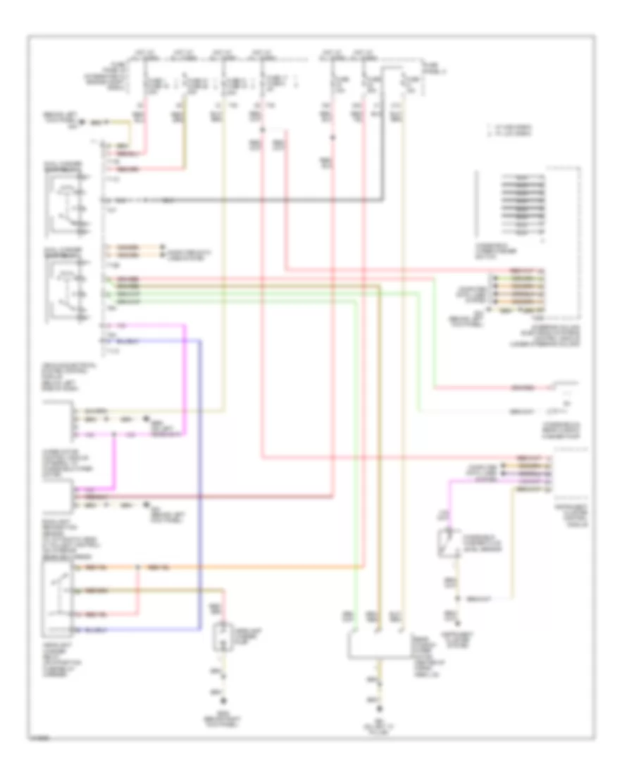
- Wiper/washer system
GROUND DISTRIBUTION
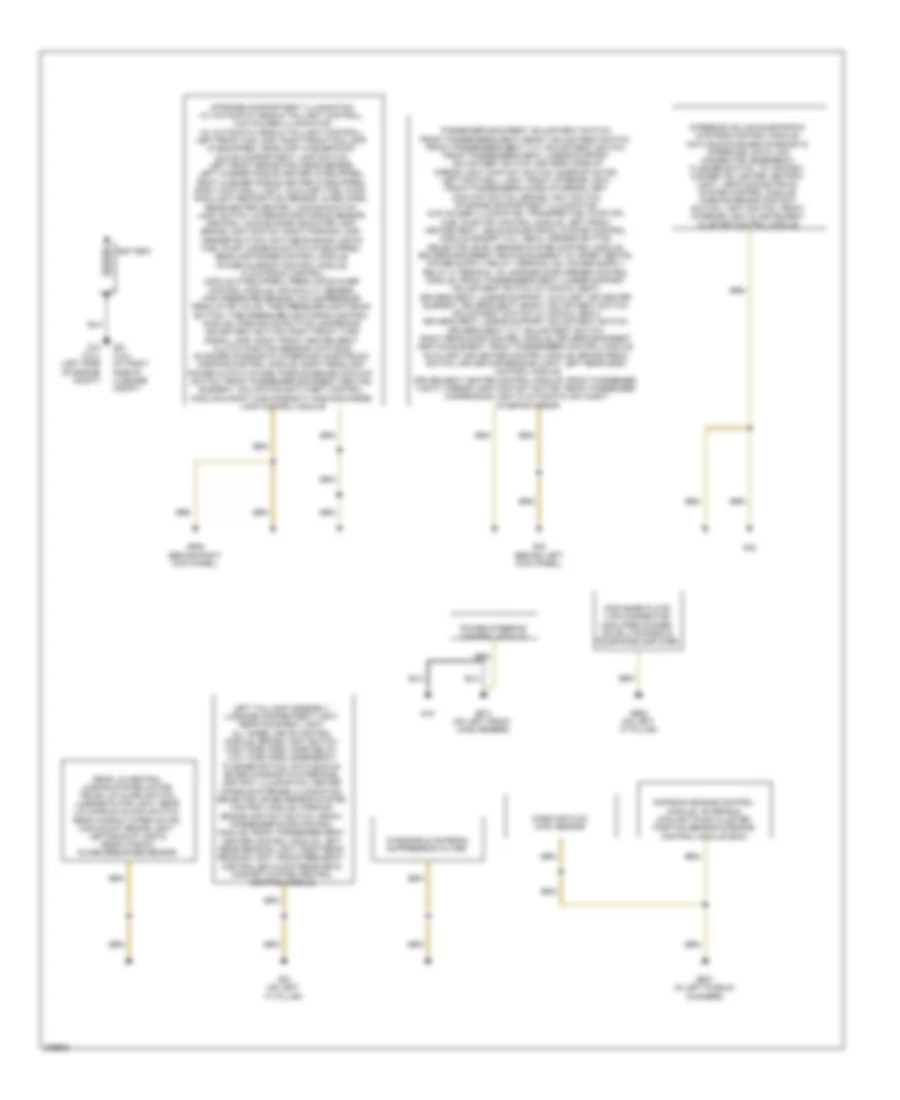
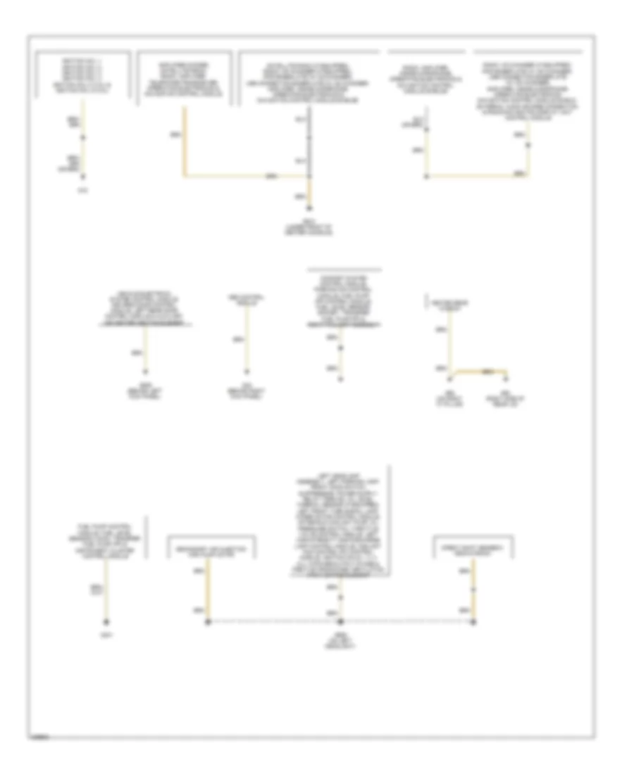
Ground Distribution Wiring Diagram, Early Production (1 of 2) for Audi A3 2009
List of elements for Ground Distribution Wiring Diagram, Early Production (1 of 2) for Audi A3 2009:
- Battery
- G12 (2.0l) (left side of engine compt)
- G18
- G42
- G44 (behind left kick panel)
- G51 (3.2l) (at right side of luggage compt)
- G607 (in left plenum chamber)
- G61 (on left "c" pillar)
- G638 (behind right kick panel)
- G662 (on left "c" pillar)
- G671 (on left front long member)
- Ipod base plate, 3 pin connector, amplifier/woofer, satellite radio & telephone amplifier
- Left taillamp assembly, luggage compartment light, rear courtesy light, all-wheel drive control module, brake light switch, high tone horn, horn relay, low tone horn, emergency flasher switch, data bus on board diagnostic interface, ashtray illumination, center console storage illumination, selector lever sensor system control module, parking brake contact switch, front passenger door control module, front passenger seat heater control module, left rear reading light, right rear reading light, radio frequency controlled clock receiver & comfort system central control module
- Mass air flow (maf) sensor
- Motronic engine control module, after-run coolant pump, cluster position sensor & engine control module (ecm)
- Power steering control module
- Rear lid central locking system motor, trunk lid alarm switch, license plate light, rear lid handle unlock switch, rear window wiper motor, high-mount brake light, left backup lamp & rear window glass breakage sensor
- Steering column electronic systems control module, data bus on board diagnostic interface, data link connector, emergency flasher switch, 12v socket, cigarette lighter, ashtray light, vehicle electrical system control module, parking brake contact switch, light switch, front interior light & instrument cluster control module
- Storage compartment illumination (w/ automatic head & taillight control), cup holder illumination (w/ automatic head & taillight control), left front fog lamp, right front fog lamp (if equipped), headlamp washer pump, glove compartment lamp switch, left front brake pad wear sensor, left washer nozzle heater (if equipped), right washer nozzle heater (if equipped), right footwell light, auxiliary fuel pump, rain/light recognition sensor, alarm horn, rear/center central locking switch, light switch, interior monitoring sensor, central locking safe indicator lamp, brake light switch, right parking lamp, asr/esp button, daytime running lights fuel pump, disable switch (if equipped), headlamp range control module, power sunroof control module, climatronic control module (if equipped), fresh air blower control module, air quality sensor, high pressure sensor, a/c compressor regulator valve, tire pressure monitoring button, tire pressure monitoring control module, parking aid button, dampening adjustment button, right front turn signal lamp, right front heated seat, clutch position sensor, data bus on board diagnostic interface, electronic damping control module, right headlamp power output stage, parking brake contact switch, front passenger backrest heating element, inclination-anti-theft control module & right high-intensity gas discharge lamp control module
- Windshield antenna suppression filter
Ground Distribution Wiring Diagram, Early Production (2 of 2) for Audi A3 2009
List of elements for Ground Distribution Wiring Diagram, Early Production (2 of 2) for Audi A3 2009:
- Abs control module
- Amplifier/woofer, satellite radio, radio, amplifier, telephone transceiver, operating electronics & navigation control module
- Comfort system control module, parking aid control module, fuel pump (fp) control module, fuel level sensor, socket, transfer fuel pump (fp) & right taillamp assembly
- Direct shift gearbox mechatronic
- Fuel pump control module, fuel level sensor 2 (awd), transfer fuel pump (fp) & instrument cluster control module
- G15
- G401
- G43 (behind right kick panel)
- G53 (right side of rear lid)
- G610 (under front of center console)
- G62 (on right "c" pillar)
- G639 (behind left kick panel)
- G655 (on left headlight)
- Heated rear window
- Ignition coil 1, ignition coil 2, ignition coil 3, ignition coil 4, ignition coil 5 (3.2l) & ignition coil 6 (3.2l)
- Radio, amplifier, inside microphone, operating electronics & navigation control module shields
- Radio, cd changer (if equipped), ipod baseplate (w/ cd changer), usb connection baseplate (w/ cd changer), amplifier, inside microphone, operating electronics, navigation control module shield, external audio source connection & radio/navigation display unit control module
- Satellite radio (if equipped), radio, cd changer (if equipped), ipod baseolate (w/ cd changer), usb connection baseplate (w/ cd changer) amplifier, inside microphone, operating electronics & navigation control module shields
- Secondary air injection (air) pump motor
- Vehicle electrical system control module, driver's door control module, left rear door control module & auxiliary air heater heating element
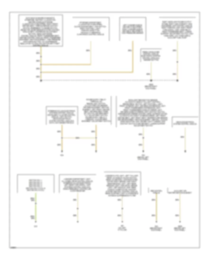
Ground Distribution Wiring Diagram, Late Production (1 of 2) for Audi A3 2009
List of elements for Ground Distribution Wiring Diagram, Late Production (1 of 2) for Audi A3 2009:
- Abs control module
- Auxiliary air heater heating element
- Data bus on board diagnostic interface, ashtray illumination, center console storage illumination (if equipped), right front heated seat, parking brake contact switch, emergency flasher switch, selector lever sensor system control module (bpy), dampening adjustment button, headlamp range control module, front passenger seat heater control module, front passenger backrest heating element, tire pressure monitoring button, a/c compressor regulator valve & inclination-anti-theft control module
- Fresh air blower control module, electronic damping control module & asr/esp button
- G15
- G42
- G43 (behind right kick panel)
- G44 (behind left kick panel)
- G61 (on left "c" pillar)
- G638 (behind right kick panel)
- G639 (behind left kick panel)
- Ignition coil 1, ignition coil 2, ignition coil 3, ignition coil 4, ignition coil 5 (3.2l) & ignition coil 6 (3.2l)
- Left washer nozzle heater (if equipped), right washer nozzle heater (if equipped) & high pressure sensor
- License plate light, left taillamp, rear lid handle unlock switch, rear lid central locking system motor, right brake lamp, right rear reading light, left rear reading light, high mount brake light, left backup lamp, rear window wiper motor, comfort system central control module, rear courtesy/light & windshield antenna suppression filter
- Luggage compartment light, all wheel drive control module, steering column electronic, left rear turn signal lamp systems control module & radio frequency controlled clock receiver
- Rain/light recognition sensor (automatic head & taillight control), brake pedal switch, left footwell light, front interior light, driver's map/reading light, front passenger's map/reading light, front passenger's make-up mirror light, driver's make-up mirror light contact switch, garage door opener control head, sunroof motor, automatic day/night interior mirror, left front heated seat, left front seat temperature sensor, driver backrest heating element, central locking safe indicator lamp, driver vanity mirror lamp contact switch & driver seat lumbar support adjustment switch
- Right headlamp power output stage, right high intensity gas discharge lamp control module, right parking lamp, right front turn signal lamp, horn relay, front passenger seat lumbar support adjustment switch, high tone horn, low tone horn & auxiliary fuel pump
- Steering column electronic systems control module, instrument cluster control module, light switch, vehicle electrical system control module & data link connector (dlc)
- Storage compartment illumination (if equipped), glove compartment lamp switch, right footwell light, parking aid button, air quality sensor & climatronic control module
- Vehicle electrical system control module
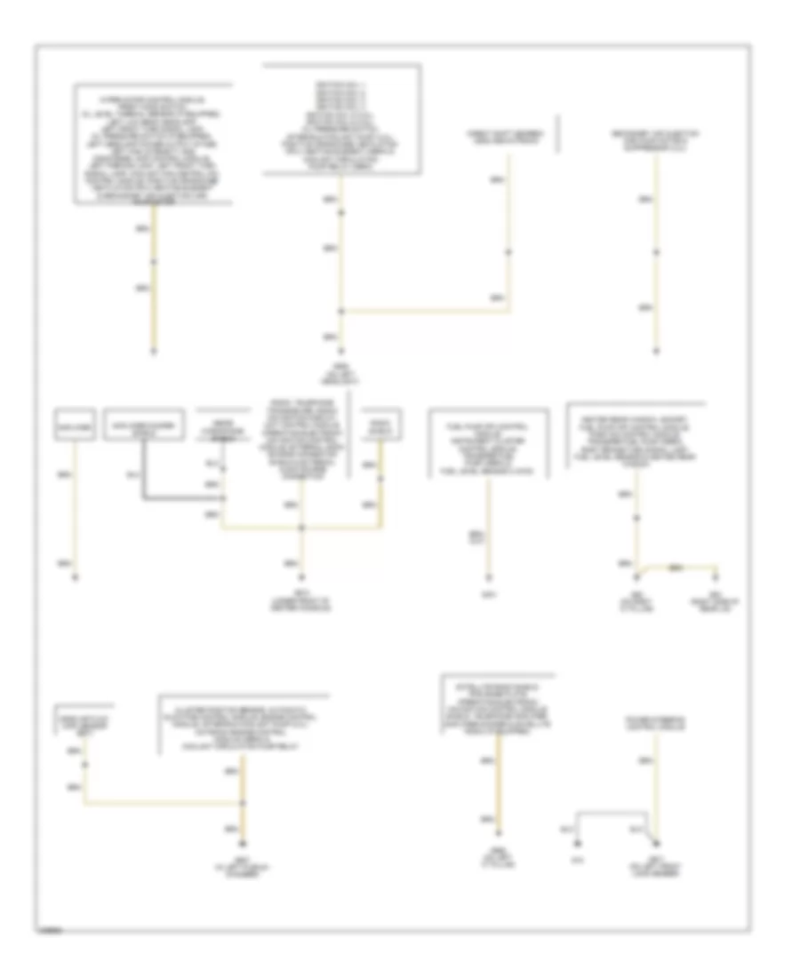
Ground Distribution Wiring Diagram, Late Production (2 of 2) for Audi A3 2009
List of elements for Ground Distribution Wiring Diagram, Late Production (2 of 2) for Audi A3 2009:
- Amplifier
- Amplifier/woofer shield
- Cluster position sensor, automatic glowtime control module, engine control module, after-run coolant pump (2.0l) motronic engine control module (cbra) & coolant circulation pump relay
- Direct shift gearbox (dsg) mechatronic
- Fuel pump (fp) control module, instrument cluster control module, transfer fuel pump (cbra) & fuel level sensor 2 (awd)
- G18
- G401
- G53 (right side of rear lid)
- G607 (in left plenum chamber)
- G610 (under front of center console)
- G62 (on right "c" pillar)
- G655 (on left headlight)
- G662 (on left "c" pillar)
- G671 (on left front long member)
- Heated rear window, socket, fuel pump (fp) control module, park aid control module, transfer fuel pump (cbra), right brake/turn signal lamp, fuel level sensor & heated rear window
- Ignition coil 1, ignition coil 2, ignition coil 3, ignition coil 4, ignition coil 5 (3.2l), ignition coil 6 (3.2l), oil pressure switch, after-run coolant pump (3.2l), positive crankcase ventilation (pcv) heating element (cbra) & coolant circulation pump relay (cbra)
- Inside microphone shield
- Mass air flow (maf) sensor (bpy)
- Power steering control module
- Radio shield
- Radio, telephone transceiver, radio/ navigation display unit control module, operating electronic navigation control module, external audio source connection shield & external audio source connection
- Satellite radio shield, ipod base plate, operating electronic navigation control module shield, telephone amplifier, amplifier/woofer & satellite radio (if equipped)
- Secondary air injection (air) pump motor & suppressor (3.2l)
- Wiper motor control module, front hood switch, oil level thermal sensor (if equipped), left low beam headlamp, left front turn signal lamp, oil pressure switch (if equipped), left headlamp power output stage, left high intensity gas discharge lamp control module, left parking lamp, left front turn signal lamp, coolant fan control (fc) control module, positive crankcase ventilation (pcv) heating element & secondary air injection (air) pump motor
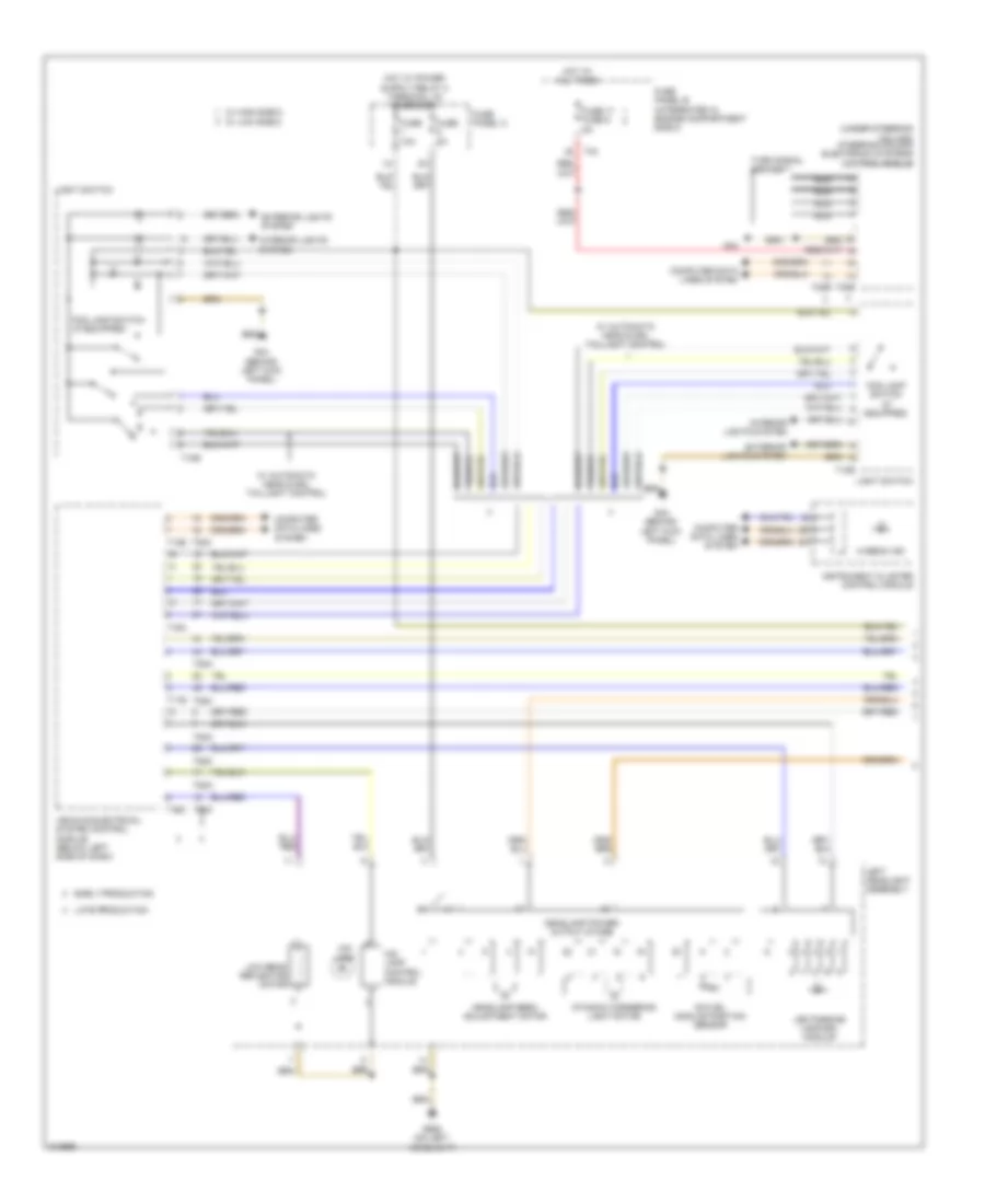
HEADLIGHTS
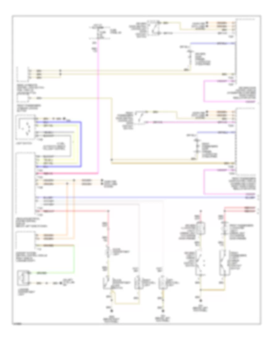
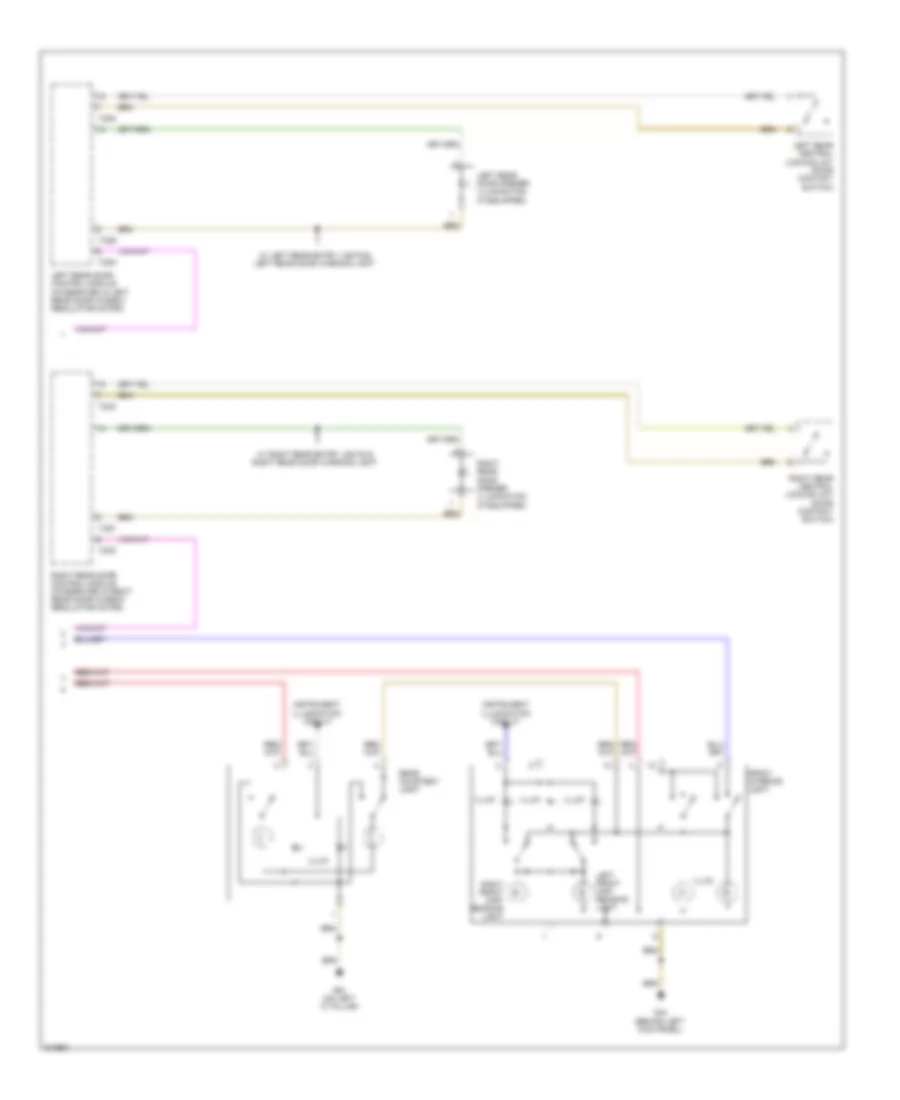
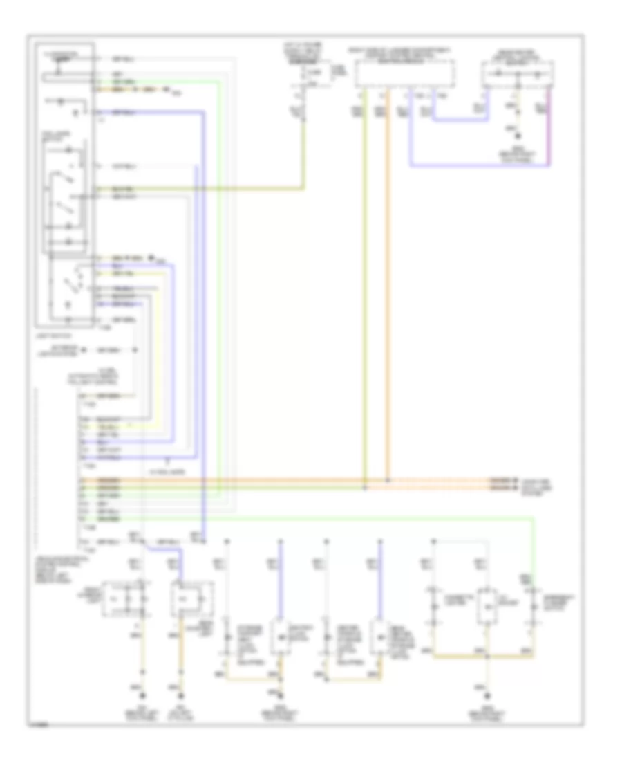
Headlights Wiring Diagram, Early Production with Standard Headlights for Audi A3 2009
List of elements for Headlights Wiring Diagram, Early Production with Standard Headlights for Audi A3 2009:
- (behind left kick panel) g44
- (behind right kick panel) g638
- Ambient illumination deactivation switch (coming-home-switch)
- Comfort system central control module (right side of luggage compt)
- Computer data lines system
- Daytime running light & parking light lamp
- Dimmer switch
- Emergency flasher switch
- Exterior lights system
- Fog lamp switch (if equipped)
- Fuse 10a
- Fuse 17 fuse 6 5a
- Fuse panel b (integrated in engine compartment e-box)
- Fuse panel c
- G42
- G44 (behind left kick panel)
- G638 (behind right
- G638 (behind right kick panel)
- G655 (on left headlight)
- Hi-beam ind
- High beam head lamp
- Hot at all times
- Instrument cluster control module
- Interior lights system
- Kick panel)
- Left front fog lamp (if equipped)
- Left headlight assembly
- Light switch
- Low beam head lamp
- Nca
- Parking brake contact switch
- Right front fog lamp (if equipped)
- Right headlight assembly
- Steering column electronic systems control module (under steering column)
- T10d
- T10e
- T11b
- T11c
- T12d
- T12e
- T16a
- T18
- T20b
- T40
- T6j
- Turn signal switch
- Vehicle electrical system control module (below left side of dash)
- W/ automatic head, taillight control & drl
- W/ front fog lamps
- W/ high e-box
- W/ low e-box
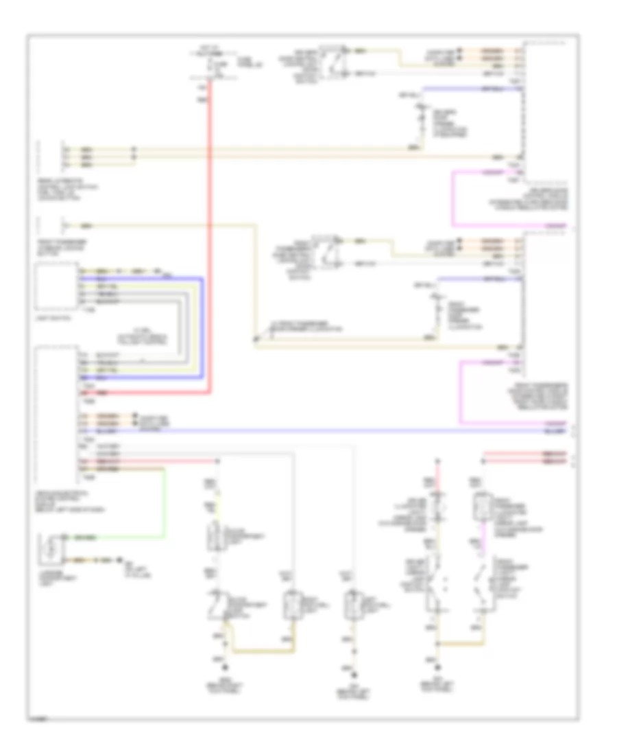
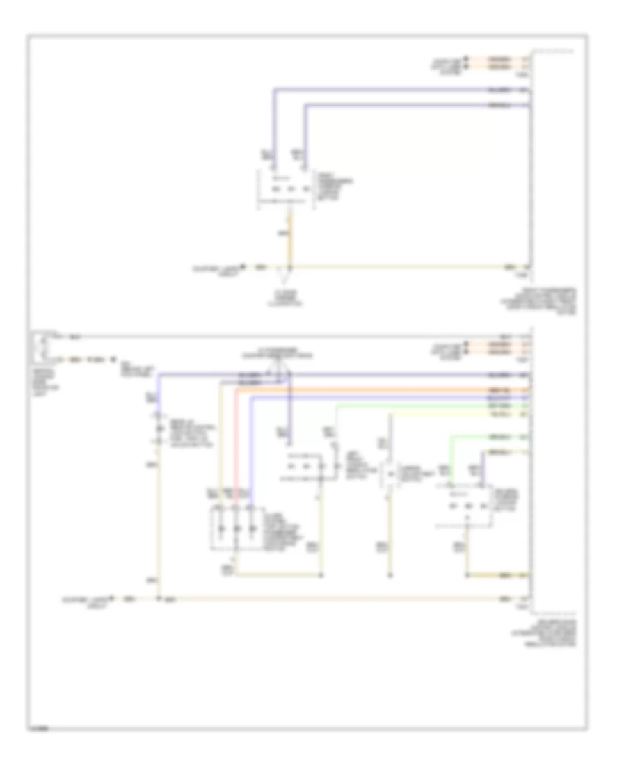
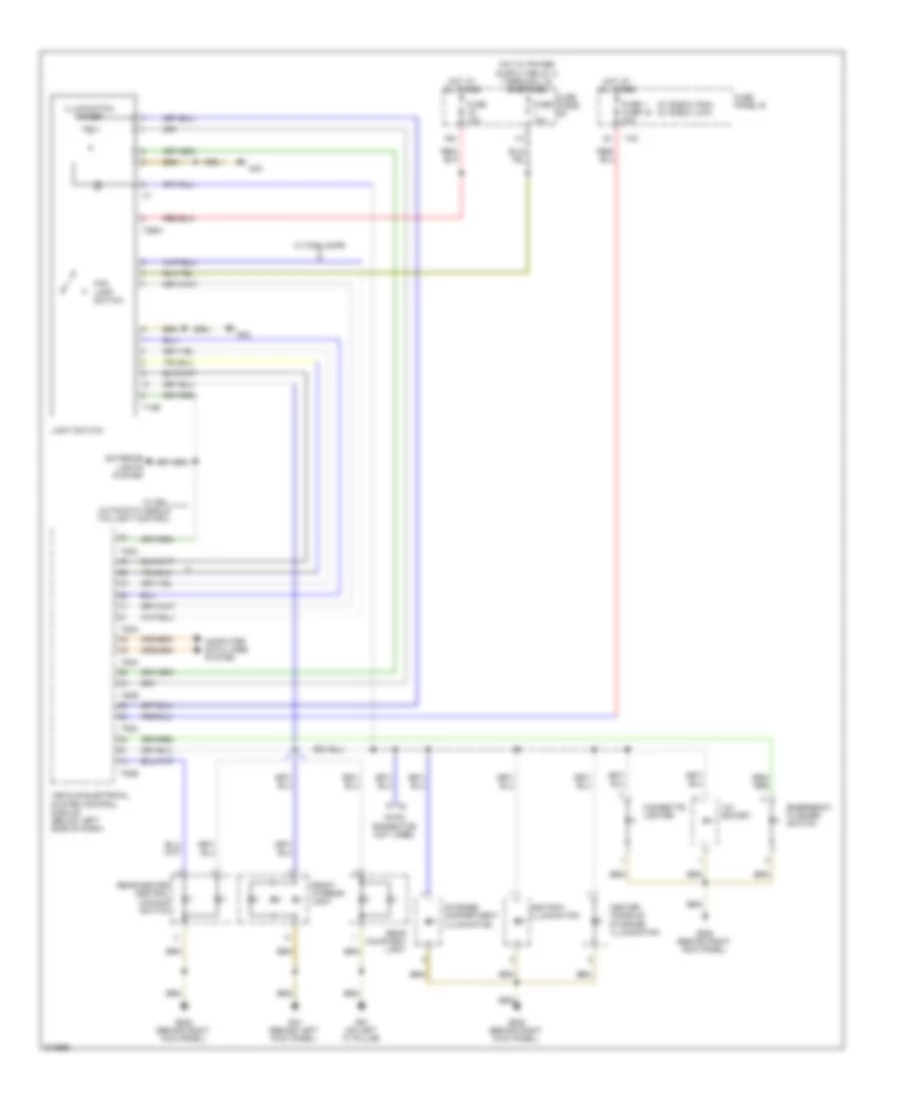
Headlights Wiring Diagram, Late Production with Standard Headlights for Audi A3 2009
List of elements for Headlights Wiring Diagram, Late Production with Standard Headlights for Audi A3 2009:
- (behind right kick panel) g638
- Ambient illumination deactivation switch (coming-home-switch)
- Computer data lines system
- Daytime running light & parking light lamp
- Emergency flasher switch
- Exterior lights system
- Fog lamp switch (if equipped)
- Fuse 10a
- Fuse 17 fuse 6 5a
- Fuse panel b (integrated in engine compartment e-box)
- Fuse panel c
- G42
- G44 (behind left kick panel)
- G638 (behind right
- G638 (behind right kick panel)
- G655 (on left headlight)
- Hi-beam ind
- High beam head lamp
- Hot at all times
- Instrument cluster control module
- Interior lights system
- Kick panel)
- Left front fog lamp (if equipped)
- Left headlight assembly
- Light switch
- Low beam head lamp
- Nca
- Parking brake contact switch
- Right front fog lamp (if equipped)
- Right headlight assembly
- Steering column electronic systems control module (under steering column)
- T10e
- T20b
- T2bw
- T40
- T52a
- T52b
- T52c
- T6j
- Turn signal switch
- Vehicle electrical system control module (below left side of dash)
- W/ automatic head, taillight control & drl
- W/ front fog lamps
- W/ high e-box
- W/ low e-box
- Wiper/washer system
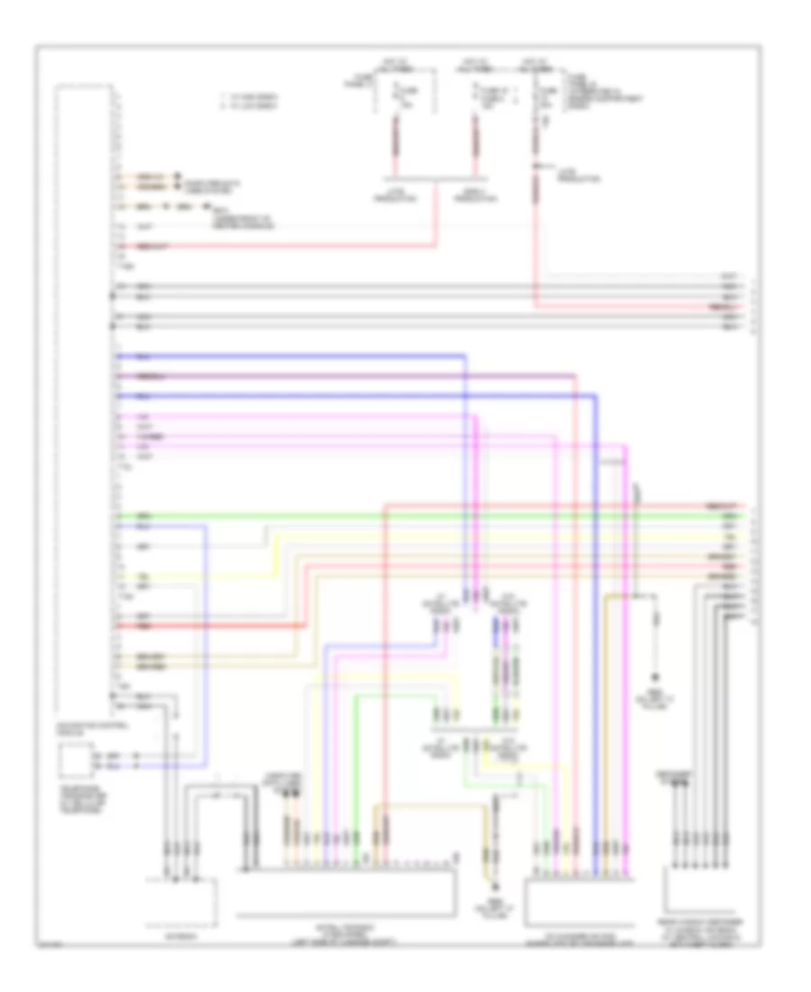
Headlights Wiring Diagram, with Bi-Xenon with Automatic Headlights (1 of 2) for Audi A3 2009
List of elements for Headlights Wiring Diagram, with Bi-Xenon with Automatic Headlights (1 of 2) for Audi A3 2009:
- (behind left kick panel) g44
- Computer data lines system
- Drl module
- Early production
- Exterior lights system
- Fog lamp switch (if equipped)
- Fuse 10a
- Fuse panel c
- G44 (behind left kick panel)
- G655 (on left headlight)
- Headlamp beam adjustment motor
- Hid lamp
- Hid lamp control module
- Interior lights system
- Lamp parking
- Late production
- Led parking lamp/
- Left headlight assembly
- Light switch
- Low beam refl- ector motor
- Signal lamp front turn
- T10e
- T11b
- T11c
- T12d
- T12e
- T16a
- T52a
- T52c
- Vehicle electrical system control module (below left side of dash)
- W/ automatic head & drl taillight control
- W/ front fog lamp
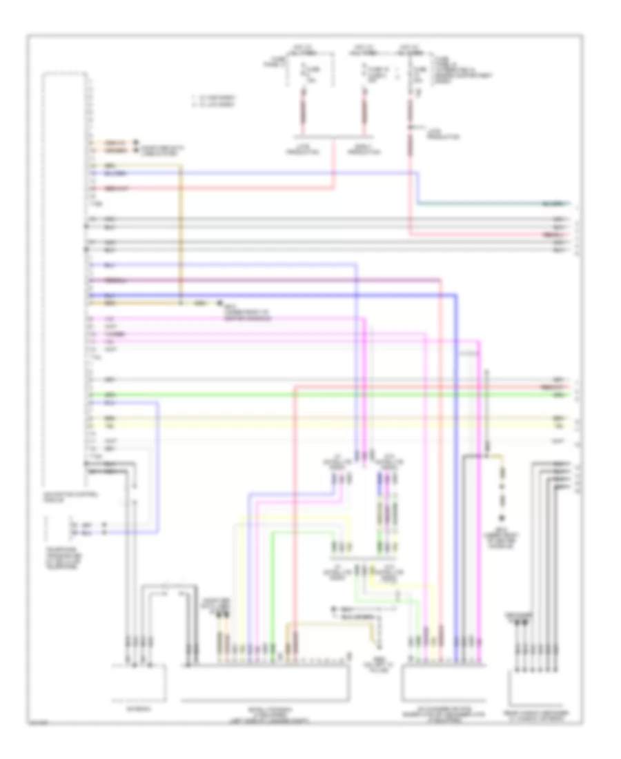
Headlights Wiring Diagram, with Bi-Xenon with Automatic Headlights (2 of 2) for Audi A3 2009
List of elements for Headlights Wiring Diagram, with Bi-Xenon with Automatic Headlights (2 of 2) for Audi A3 2009:
- (w/o electronic damping) left front level control system sensor
- Comfort system central control module (right side of luggage compt)
- Computer data lines system
- Drl module
- Early production
- G638 (behind right kick panel)
- Headlamp beam adjustment motor
- Headlight range control module (behind right center of bash)
- Hi-beam ind
- Hid lamp
- Hid lamp control module
- Instrument cluster control module
- Lamp parking
- Late production
- Led parking lamp/
- Left rear level control system sensor (w/o electronic damping)
- Low beam refl- ector motor
- Parking brake contact switch
- Right headlight assembly
- Signal lamp front turn
- T18
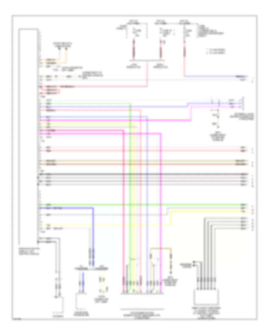
Headlights Wiring Diagram, with Bi-Xenon with Cornering Headlights (1 of 2) for Audi A3 2009
List of elements for Headlights Wiring Diagram, with Bi-Xenon with Cornering Headlights (1 of 2) for Audi A3 2009:
- (under steering column) steering column electronic systems control module
- Computer data lines system
- Dynamic cornering light motor
- Early production
- Exterior lights system
- Fog lamp switch (if equipped)
- Fuse 10a
- Fuse 17 fuse 6 5a
- Fuse 5a
- Fuse panel b (integrated in engine compartment e-box)
- Fuse panel c
- G42
- G44 (behind left kick panel)
- G655 (on left headlight)
- Headlamp beam adjustment motor
- Headlamp power output stage
- Hi-beam ind
- Hid lamp
- Hid lamp control module
- Hot at all times
- Instrument cluster control module
- Interior lights system
- Late production
- Led parking lamp/drl module
- Left headlight assembly
- Light switch
- Low beam reflector motor
- Nca
- Swivel module position sensor
- T10e
- T11b
- T11c
- T12e
- T16a
- T20b
- T40
- T52a
- T52c
- Turn signal switch
- Vehicle electrical system control module (below left side of dash)
- W/ automatic head & drl taillight control
- W/ high e-box
- W/ low e-box
Headlights Wiring Diagram, with Bi-Xenon with Cornering Headlights (2 of 2) for Audi A3 2009
List of elements for Headlights Wiring Diagram, with Bi-Xenon with Cornering Headlights (2 of 2) for Audi A3 2009:
- (behind right center of bash)
- (w/o electronic damping) left front level control system sensor
- Comfort system central control module (right side of luggage compt)
- Computer data lines system
- Dynamic cornering light motor
- Early production
- Fuse 5a
- Fuse panel c
- G638 (behind right
- G638 (behind right kick panel)
- Headlamp beam adjustment motor
- Headlamp power output stage
- Headlamp range control module
- Hid lamp
- Hid lamp control module
- Kick panel)
- Late production
- Led parking lamp/drl module
- Left rear level control system sensor (w/o electronic damping)
- Low beam reflector motor
- Parking brake contact switch
- Right headlight assembly
- Swivel module position sensor
- T18
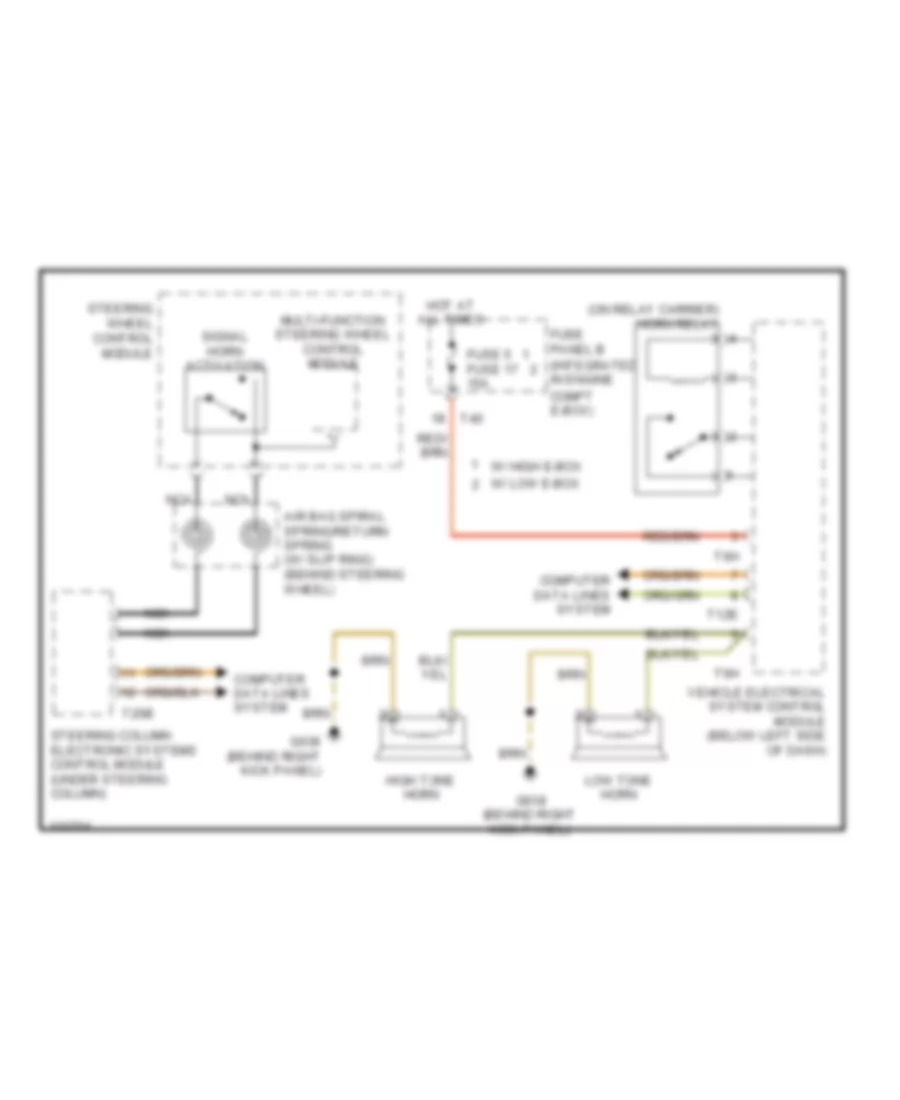
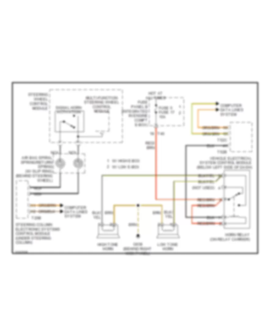
HORN
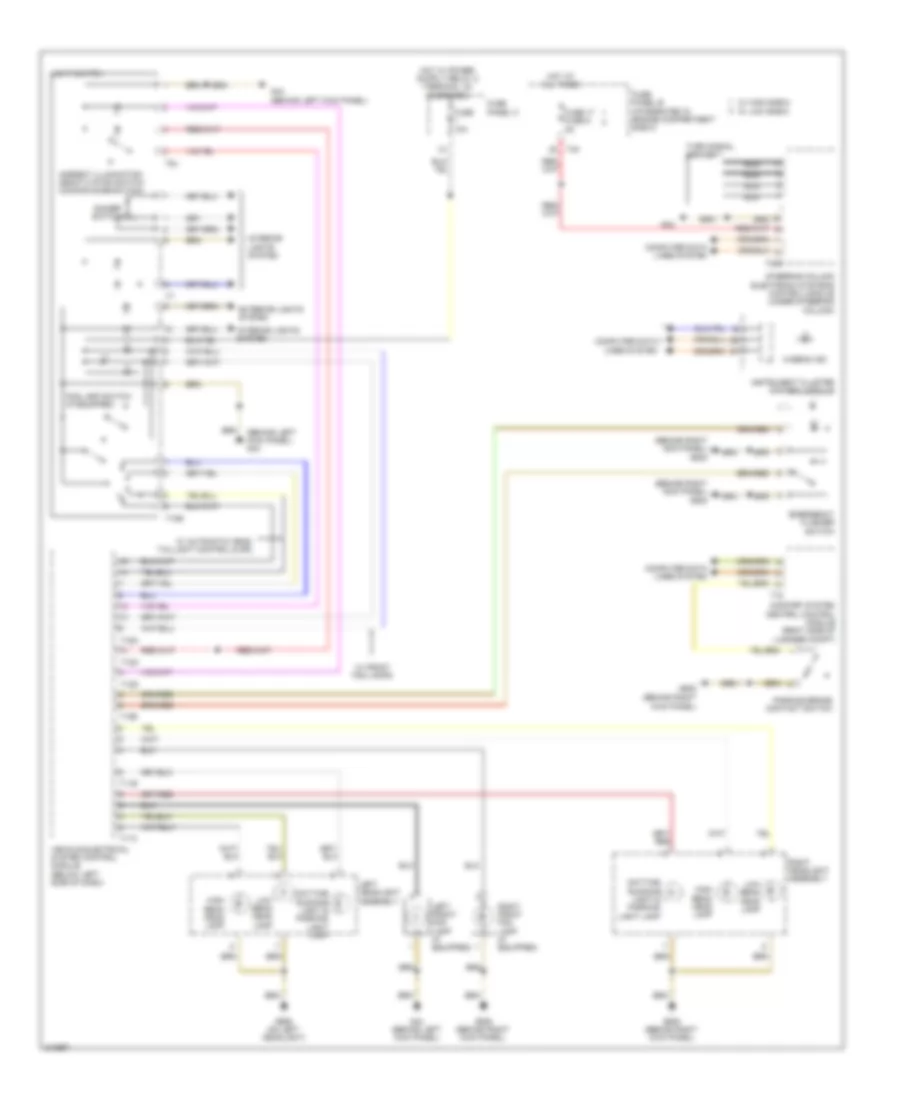
Horn Wiring Diagram, Early Production for Audi A3 2009
List of elements for Horn Wiring Diagram, Early Production for Audi A3 2009:
- (on relay carrier) horn relay
- Air bag spiral spring/return spring (w/ slip ring) (behind steering wheel)
- Compt e-box)
- Computer data lines system
- Fuse 5 fuse 17 15a
- Fuse panel b (integrated in engine
- G638 (behind right kick panel)
- High tone horn
- Hot at all times
- Low tone horn
- Multi-function steering wheel control module
- Nca
- Signal horn activation
- Steering column electronic systems control module (under steering column)
- Steering wheel control module
- T12e
- T20b
- T40
- T6h
- Vehicle electrical system control module (below left side of dash)
- W/ high e-box
- W/ low e-box
Horn Wiring Diagram, Late Production for Audi A3 2009
List of elements for Horn Wiring Diagram, Late Production for Audi A3 2009:
- (not used)
- Air bag spiral spring/return spring (w/ slip ring) (behind steering wheel)
- Computer data lines system
- Fuse 5 fuse 17 15a
- Fuse panel b (integrated in engine compt e-box)
- G638 (behind right kick panel)
- High tone horn
- Horn relay (on relay carrier)
- Hot at all times
- Low tone horn
- Multi-function steering wheel control module
- Nca
- Signal horn activation
- Steering column electronic systems control module (under steering column)
- Steering wheel control module
- T20b
- T40
- T52b
- T52c
- Vehicle electrical system control module (below left side of dash)
- W/ high e-box
- W/ low e-box
INSTRUMENT CLUSTER
Instrument Cluster Wiring Diagram (1 of 2) for Audi A3 2009
List of elements for Instrument Cluster Wiring Diagram (1 of 2) for Audi A3 2009:
- Abs warning lamp
- Air bag malfunction ind lamp
- Anti-theft immobilizer reading coil
- Asr/esp control lamp
- Brake fluid level warning switch (in brake fluid reservoir cap)
- Brake pad wear ind lamp
- Computer data lines system
- Cruise control ind lamp
- Door ajar indicator lamp
- Early production
- Engine coolant level (ecl) warning switch (on coolant reservoir)
- Engine coolant level/ temperature (ecl/ect) warning lamp
- Engine coolant temperature gauge
- Engine electronic ind lamp
- Fuel filler lid lock warning lamp
- Fuel gauge
- Fuel level sensor 2 (awd)
- Fuel reserve warning lamp
- Fuse 17 fuse 6 5a
- Fuse 5a
- Fuse panel b (integrated in engine compartment e-box)
- Fuse panel c
- G42
- Generator warning lamp ind
- High beam ind lamp
- Hot at all times
- Instrument cluster control module (behind instrument cluster)
- Late production
- Left front brake pad wear sensor
- Left turn signal ind lamp
- Malfunction ind lamp (mil)
- Oil pressure warning lamp
- Outside air temperature display
- Outside air temperature sensor (behind left side of front bumper)
- Parking brake ind lamp & brake system warning lamp
- Parking light ind lamp
- Radio frequency controlled clock
- Rear hatch/ trunk lid ajar warning lamp
- Red
- Right turn signal ind lamp
- Steering column electronic systems control module (early production) (under steering column)
- T20b
- T40
- Tire pressure monitoring display ind lamp
- W/ high e-box
- W/ low e-box
- Warning buzzer & tone
- Windshield washer fluid level sensor
Instrument Cluster Wiring Diagram (2 of 2) for Audi A3 2009
List of elements for Instrument Cluster Wiring Diagram (2 of 2) for Audi A3 2009:
- (at base of parking brake lever assembly) parking brake warning light switch
- (below left side of dash) vehicle electrical system control module
- (left side of selector lever base) (a/t) selector lever sensor system control module
- (right side of luggage compt) comfort system central control module
- 2.0l
- 2.0l bpy
- 3.2l
- Computer data lines system
- Driver's door contact switch
- Driver's door control module (integrated in driver's door window regulator motor)
- Early production
- Except 2.0l bpy
- Front passenger's door contact switch
- Front passenger's door control module (integrated in right front door window regulator motor)
- Fuel level sensor
- Fuel pump (fp) control module (under right side of rear seat)
- G401
- G61 (on left "c" pillar)
- G638 (behind right kick panel)
- G655 (on left headlight)
- Late production
- Left rear door contact switch
- Left rear door control module (integrated in left rear door window regulator motor)
- Nca
- Oil level thermal sensor (if equipped)
- Oil pressure switch
- Radio frequency controlled clock receiver
- Right rear door contact switch
- Right rear door control module (integrated in right rear door window regulator motor)
- T10k
- T18
- T20f
- T20g
- T20n
- T20o
- T52a
- T52c
- Transfer fuel pump
INTERIOR LIGHTS
Courtesy Lamps Wiring Diagram, Early Production (1 of 2) for Audi A3 2009
List of elements for Courtesy Lamps Wiring Diagram, Early Production (1 of 2) for Audi A3 2009:
- (on left "c" pillar) g61
- 25a
- Comfort system central control module (right side of luggage compt)
- Computer data lines system
- Driver's door central locking unit (door contact switch)
- Driver's door control module (integrated in driver's door window regulator motor)
- Driver's door opener illumination (if equipped)
- Driver's illuminated vanity mirror light (w/o garage door opener)
- Driver's vanity mirror light contact switch
- Front passenger's door central locking unit (door contact switch)
- Front passenger's door control module (integrated in right front door window regulator motor)
- Front passenger's door opener illumination (if equipped)
- Front passenger's illuminated vanity mirror light (w/o garage door opener)
- Front passenger's interior locking button
- Front passenger's vanity mirror light contact switch
- Fuse 30a
- Fuse panel sc
- G42
- G44 (behind left kick panel)
- G638 (behind right kick panel)
- Glove compartment lamp switch
- Glove compartment light
- Hot at all times
- Left footwell light
- Light switch
- Luggage compartment light
- Rear lid remote control lock switch/ fuel tank lid unlock button
- Right footwell light
- T10d
- T10e
- T12c
- T12e
- T16a
- T18
- T20f
- T20g
- T32a
- T32b
- Vehicle electrical system control module (below left side of dash)
- W/ drl, automatic head & taillight control
Courtesy Lamps Wiring Diagram, Early Production (2 of 2) for Audi A3 2009
List of elements for Courtesy Lamps Wiring Diagram, Early Production (2 of 2) for Audi A3 2009:
- Front interior light
- G44 (behind left kick panel)
- G61 (on left "c" pillar)
- Illum
- Instrument illumination circuit
- Left front map/ reading light
- Left rear central locking unt (door contact switch)
- Left rear door control module (integrated in left rear door window regulator motor)
- Left rear door opener illumination (if equipped)
- Rear courtesy light
- Right front map/ reading light
- Right rear central locking unt (door contact switch)
- Right rear door control module (integrated in right rear door window regulator motor)
- Right rear door opener illumination (if equipped)
- T20n
- T20o
- T32e
- T32f
- W/ left rear entry lights & left rear door warning light
- W/ right rear entry lights & right rear door warning light
Courtesy Lamps Wiring Diagram, Late Production (1 of 2) for Audi A3 2009
List of elements for Courtesy Lamps Wiring Diagram, Late Production (1 of 2) for Audi A3 2009:
- 15a
- Computer data lines system
- Driver illuminated vanity mirror lamp (w/o garage door opener)
- Driver vanity mirror lamp contact switch
- Driver's door central locking unit (door contact switch)
- Driver's door control module (integrated in driver's door window regulator motor)
- Driver's door opener illumination (if equipped)
- Front passenger door opener illumination
- Front passenger illuminated vanity mirror lamp (w/o garage door opener)
- Front passenger interior locking button
- Front passenger vanity mirror lamp contact switch
- Front passenger's door central locking unit (door contact switch)
- Front passenger's door control module (integrated in right front door window regulator motor)
- Fuse 10a
- Fuse panel sc
- G42
- G44 (behind left kick panel)
- G61 (on left "c" pillar)
- G638 (behind right kick panel)
- Glove compartment lamp switch
- Glove compartment light
- Hot at all times
- Left footwell light
- Light switch
- Luggage compartment light
- Rear lid remote control lock switch/ fuel tank lid unlock button
- Red
- Right footwell light
- T10e
- T20f
- T20g
- T32a
- T32b
- T52a
- T52b
- T52c
- Vehicle electrical system control module (below left side of dash)
- W/ drl, automatic head & taillight control
- W/ front passenger door opener illumination
Courtesy Lamps Wiring Diagram, Late Production (2 of 2) for Audi A3 2009
List of elements for Courtesy Lamps Wiring Diagram, Late Production (2 of 2) for Audi A3 2009:
- Front interior light
- G44 (behind left kick panel)
- G61 (on left "c" pillar)
- Illum
- Instrument illumination circuit
- Left front map/ reading light
- Left rear central locking unt (door contact switch)
- Left rear door control module (integrated in left rear door window regulator motor)
- Left rear door opener illumination (if equipped)
- Rear courtesy light
- Right front map/ reading light
- Right rear central locking unit (door contact switch)
- Right rear door control module (integrated in right rear door window regulator motor)
- Right rear door opener illumination (if equipped)
- T20n
- T20o
- T32e
- T32f
- W/ left rear entry lights & left rear door warning light
- W/ right rear entry lights & right rear door warning light
Instrument Illumination Wiring Diagram, Early Production (1 of 2) for Audi A3 2009
List of elements for Instrument Illumination Wiring Diagram, Early Production (1 of 2) for Audi A3 2009:
- (right side of luggage compartment) comfort system central control module
- 12v socket
- Ashtray illumi- nation
- Center console storage illumi- nation (if equipped)
- Cigarette lighter
- Computer data lines system
- Emergency flasher switch
- Exterior lights system
- Fog lamps switch
- Front interior light
- Fuse 10a
- Fuse panel c
- G42
- G44 (behind left kick panel)
- G61 (on left "c" pillar)
- G638 (behind right kick panel)
- Illumination dimmer
- Light switch
- Rear center console storage illumi- nation
- Rear courtesy light
- Rear/center central locking switch
- Storage compart- ment illumi- nation (if equipped)
- T10e
- T12c
- T12d
- T12e
- T16a
- T6g
- T8g
- Vehicle electrical system control module (below left side of dash)
- W/ drl, automatic head & taillight control
- W/ fog lamps
Instrument Illumination Wiring Diagram, Early Production (2 of 2) for Audi A3 2009
List of elements for Instrument Illumination Wiring Diagram, Early Production (2 of 2) for Audi A3 2009:
- Alarm system -off- switch/ passenger compartment monitoring switch
- Central locking- safe- indicator light
- Computer data lines system
- Courtesy lamps circuit
- Driver's door control module (integrated in driver's door window regulator motor)
- Driver's interior locking button
- Front passenger's door control module (integrated in right front door window regulator motor)
- Front passenger's interior locking button
- G44 (behind left kick panel)
- Left front window regulator switch
- Mirror adjustment switch
- Rear lid remote control lock switch/ fuel tank lid unlock button
- T20f
- T20g
- T32a
- T32b
- W/ door opener illumination
- W/ passenger compartment monitoring
Instrument Illumination Wiring Diagram, Late Production (1 of 2) for Audi A3 2009
List of elements for Instrument Illumination Wiring Diagram, Late Production (1 of 2) for Audi A3 2009:
- (w/ e-box high) (w/ e-box low)
- 12v socket
- 16a
- 18-pin connector (not used)
- Ashtray illumination
- Center console storage illumination
- Cigarette lighter
- Computer data lines system
- Emergency flasher switch
- Exterior lights system
- Fog lamp switch
- Front interior light
- Fuse 1 fuse 16 30a
- Fuse 10a
- Fuse panel b
- Fuse panel sc
- G42
- G44 (behind left kick panel)
- G61 (on left "c" pillar)
- G638 (behind right kick panel)
- Hot at all times
- Illumination dimmer
- Light switch
- Rear courtesy light
- Rear/center central locking switch
- Storage compartment illumination
- T10e
- T2bw
- T4o
- T52a
- T52b
- T52c
- Vehicle electrical system control module (below left side of dash)
- W/ drl, automatic head & taillight control
- W/ fog lamps
Instrument Illumination Wiring Diagram, Late Production (2 of 2) for Audi A3 2009
List of elements for Instrument Illumination Wiring Diagram, Late Production (2 of 2) for Audi A3 2009:
- 5 door
- Alarm system-off-switch/ passenger compartment monitoring switch
- Central locking- safe- indicator light
- Computer data lines system
- Courtesy lamps circuit
- Driver's door control module (integrated in driver's door window regulator motor)
- Driver's interior locking button
- Front passenger's door control module (integrated in right front door window regulator motor)
- Front passenger's interior locking button
- G44 (behind left kick panel)
- Left front window regulator switch
- Mirror adjustment switch
- Rear lid remote control lock switch/ fuel tank lid unlock button
- T20f
- T20g
- T32a
- T32b
- W/ passenger compartment monitoring
- W/o passenger compartment monitoring
NAVIGATION
Navigation Wiring Diagram, with RNS-E with Amplifier (1 of 3) for Audi A3 2009
List of elements for Navigation Wiring Diagram, with RNS-E with Amplifier (1 of 3) for Audi A3 2009:
- Antenna
- Cd changer or ipod baseplate or usb baseplate
- Computer data lines system
- Defogger system
- Early production
- Fuse 15a
- Fuse 19 fuse 8 15a
- Fuse 30a
- Fuse panel b (integrated in engine compartment e-box)
- Fuse panel c
- G610 (under front of center console)
- G662 (on left "c" pillar)
- Hot at all times
- Late production
- Navigation control module
- Nca
- Rear window defogger w/ window antenna (w/ central locking & anti-theft alarm)
- Red
- Satellite radio (if equipped) (left side of luggage compt)
- T12l
- T12m
- T16g
- T40
- T8p
- T8t
- T8u
- Telephone transceiver (w/ cellular telephone)
- W/ high e-box
- W/ low e-box
- W/ satellite radio
- W/o satellite radio
Navigation Wiring Diagram, with RNS-E with Amplifier (2 of 3) for Audi A3 2009
List of elements for Navigation Wiring Diagram, with RNS-E with Amplifier (2 of 3) for Audi A3 2009:
- (below left side of dash) (w/ central locking & anti-theft alarm system) vehicle electrical system control module
- (right side of luggage compt) (w/ central locking & anti-theft alarm system) comfort system central control module
- 10a
- Antenna amplifier (top left side of cargo area lid)
- Center mid/high range loud speaker
- Defogger system
- Early production
- Fuse 20 fuse 9 5a
- Fuse 7.5a
- Fuse panel b (integrated in engine compartment e-box)
- Fuse panel c
- Hot at all times
- Late production
- Left antenna module (left side of luggage compartment lid)
- Left front mid-bass speaker
- Left front treble speaker
- Left rear midrange speaker
- Left rear treble speaker
- Nca
- Red
- Right front mid-bass speaker
- Right front treble speaker
- Right rear midrange speaker
- Right rear treble speaker
- T18
- T40
- T52c
- W/ high e-box
- W/ low e-box
Navigation Wiring Diagram, with RNS-E with Amplifier (3 of 3) for Audi A3 2009
List of elements for Navigation Wiring Diagram, with RNS-E with Amplifier (3 of 3) for Audi A3 2009:
- (under front of center console) g610
- Amplifier/woofer
- Computer data lines system
- External audio source connection
- G610 (under front of center console)
- G662 (on left "c" pillar)
- Navigation control module
- T32d
- W/ audi music interface
- W/o audi music interface
Navigation Wiring Diagram, with RNS-E with Bose (1 of 3) for Audi A3 2009
List of elements for Navigation Wiring Diagram, with RNS-E with Bose (1 of 3) for Audi A3 2009:
- Antenna
- Cd changer or ipod baseplate or usb baseplate (if equipped)
- Computer data lines system
- Defogger system
- Early production
- Fuse 15a
- Fuse 19 fuse 8 15a
- Fuse 30a
- Fuse panel b (integrated in engine compartment e-box)
- Fuse panel c
- G610 (under front of center console)
- G662 (on left "c" pillar)
- Hot at all times
- Late production
- Navigation control module
- Nca
- Rear window defogger w/ window antenna
- Satellite radio (if equipped) (left side of luggage compt)
- T12l
- T12m
- T16g
- T40
- T8t
- T8u
- Telephone transceiver (w/ cellular telephone)
- W/ high e-box
- W/ low e-box
- W/ satellite radio
- W/o satellite radio
Navigation Wiring Diagram, with RNS-E with Bose (2 of 3) for Audi A3 2009
List of elements for Navigation Wiring Diagram, with RNS-E with Bose (2 of 3) for Audi A3 2009:
- (below left side of dash) (w/ central locking & anti-theft alarm system) vehicle electrical system control module
- (right side of luggage compt) (w/ central locking & anti-theft alarm system) comfort system central control module
- 10a
- Antenna amplifier (top left side of cargo area lid)
- Defogger system
- Early production
- Fuse 20 fuse 9 5a
- Fuse 7.5a
- Fuse panel b (integrated in engine compartment e-box)
- Fuse panel c
- G610 (under front of center console)
- Hot at all times
- Inside microphone
- Late production
- Left antenna module (left side of luggage compartment lid)
- Left front mid-bass speaker
- Left front treble speaker
- Left rear midrange speaker
- Left rear treble speaker
- Nca
- Red
- Right front mid-bass speaker
- Right front treble speaker
- Right rear midrange speaker
- Right rear treble speaker
- T18
- T40
- T52c
- W/ high e-box
- W/ low e-box
Navigation Wiring Diagram, with RNS-E with Bose (3 of 3) for Audi A3 2009
List of elements for Navigation Wiring Diagram, with RNS-E with Bose (3 of 3) for Audi A3 2009:
- Amplifier (right side of luggage compt)
- Bass speaker
- Center mid/high range speaker
- Computer data lines system
- External audio source connection
- G610 (under front of center console)
- Navigation control module
- Red
- T32d
- W/ audi music interface
- W/o audi music interface
Navigation Wiring Diagram, without RNS-E with Amplifier (1 of 2) for Audi A3 2009
List of elements for Navigation Wiring Diagram, without RNS-E with Amplifier (1 of 2) for Audi A3 2009:
- (under front of center console) g610
- 18-pin connector (not used)
- Antenna
- Cd changer or ipod baseplate or usb baseplate (if equipped)
- Computer data lines system
- Defogger system
- Early production
- External audio source connection (if equipped)
- Fuse 15a
- Fuse 19 fuse 8 15a
- Fuse 30a
- Fuse panel b (integrated in engine compartment e-box)
- Fuse panel c
- G610 (under front of center console)
- Hot at all times
- Late production
- Nca
- Radio/navigation display unit control module
- Rear window defogger w/ window antenna (w/ central locking & anti-theft alarm system)
- Red
- T12l
- T12m
- T16g
- T18a
- T40
- T8p
- Telephone transceiver
- W/ handsfree
- W/ high e-box
- W/ low e-box
- W/o handsfree
Navigation Wiring Diagram, without RNS-E with Amplifier (2 of 2) for Audi A3 2009
List of elements for Navigation Wiring Diagram, without RNS-E with Amplifier (2 of 2) for Audi A3 2009:
- (below left side of dash) (w/ central locking & anti-theft alarm system) vehicle electrical system control module
- (right side of luggage compt) (w/ central locking & anti-theft alarm system) comfort system central control module
- (under front of center console) g610
- Amplifier/woofer
- Antenna amplifier (top left side of cargo area lid)
- Center mid/high range speaker
- Computer data lines system
- Defogger system
- Early production
- G662 (on left "c" pillar)
- Late production
- Left antenna module (left side of luggage compartment lid)
- Left front mid-bass speaker
- Left front treble speaker
- Left rear midrange speaker
- Left rear treble speaker
- Nca
- Red
- Right front mid-bass speaker
- Right front treble speaker
- Right rear midrange speaker
- Right rear treble speaker
- T18
- T52c
Navigation Wiring Diagram, without RNS-E with Bose (1 of 2) for Audi A3 2009
List of elements for Navigation Wiring Diagram, without RNS-E with Bose (1 of 2) for Audi A3 2009:
- (under front of center console)
- 18 pin connector (not used)
- Antenna
- Cd changer or ipod baseplate or usb baseplate (if equipped)
- Computer data lines system
- Defogger system
- Early production
- External audio source connection (if equipped)
- Fuse 15a
- Fuse 19 fuse 8 15a
- Fuse 30a
- Fuse panel b (integrated in engine compartment e-box)
- Fuse panel c
- G610
- G610 (under front of center console)
- Hot at all times
- Late production
- Nca
- Radio/navigation display unit control module
- Rear window defogger w/ window antenna (w/ central locking & anti-theft alarm system)
- T12l
- T12m
- T16g
- T18a
- T40
- Telephone transceiver
- W/ hands free
- W/ high e-box
- W/ low e-box
- W/o hands free
Navigation Wiring Diagram, without RNS-E with Bose (2 of 2) for Audi A3 2009
List of elements for Navigation Wiring Diagram, without RNS-E with Bose (2 of 2) for Audi A3 2009:
- Amplifier (right side of luggage compt)
- Antenna amplifier (top left side of cargo area lid)
- Bass speaker
- Center mid/high range speaker
- Comfort system central control module (central locking & anti-theft alarm system) (right side of luggage compt)
- Defogger system
- Early production
- G610 (under front of center console)
- Inside microphone
- Late production
- Left antenna module (left side of luggage compartment lid)
- Left front mid-bass speaker
- Left front treble speaker
- Left rear midrange speaker
- Left rear treble speaker
- Nca
- Red
- Right front mid-bass speaker
- Right front treble speaker
- Right rear midrange speaker
- Right rear treble speaker
- T18
- T52c
- Vehicle electrical system control module (central locking & anti-theft alarm system) (below left side of dash)
Parking Assistant Wiring Diagram for Audi A3 2009
List of elements for Parking Assistant Wiring Diagram for Audi A3 2009:
- Computer data lines system
- Front parking aid warning buzzer
- Fuse 5a
- Fuse panel sc
- G62 (on right "c" pillar)
- G638 (behind right kick panel)
- Interior lights system
- Left front center parking aid sensor
- Left front parking aid sensor
- Left rear center parking aid sensor
- Left rear parking aid sensor
- Parking aid button
- Parking aid control module (right side of luggage compt)
- Rear parking aid warning buzzer
- Right front center parking aid sensor
- Right front parking aid sensor
- Right rear center parking aid sensor
- Right rear parking aid sensor
- T12i
- T12t
- T16f
POWER DISTRIBUTION
2.0L TURBO
2.0L Turbo, Power Distribution Wiring Diagram, BPY Early Production (1 of 4) for Audi A3 2009
List of elements for 2.0L Turbo, Power Distribution Wiring Diagram, BPY Early Production (1 of 4) for Audi A3 2009:
- 20a
- 40a
- 41a
- 42a
- Air bag control module
- Air quality sensor
- Asr/esp button
- Automatic day/night interior mirror
- Backup light switch (m/t)
- Brake light switch
- Climatronic control module
- Data bus on board diagnostic interface
- Data link connector
- Direct shift gearbox (dsg) mechatronic
- Electronic damping control module
- Front passenger's air bag disabled indicator lamp
- Fuel pump control module
- Fuse 10a
- Fuse 15a
- Fuse 20 5a
- Fuse 40a
- Fuse 5a
- Fuse panel c
- G44 (behind left kick panel)
- Garage door opener control head
- Garage door opener control module
- Headlamp range control module
- High pressure sensor
- Left washer nozzle heater (if equipped)
- Light switch
- Load reduc- ction relay
- Mass air flow sensor
- Motronic engine control module (ecm)
- Oil level thermal sensor (if equipped)
- Parking aid control module
- Power steering control module
- Rear window wiper motor
- Red
- Right washer nozzle heater (if equipped)
- Seat occupied recognition control module
- Selector lever sensor system control module
- Solid state
- Starting/ charging system
- T100a
- T10b
- T10e
- T10k
- T11b
- T16d
- T16f
- T20d
- T20e
- T26b
- T2t
- T3w
- T47
- T6h
- T8h
- T94
- Vehicle electrical system control module
2.0L Turbo, Power Distribution Wiring Diagram, BPY Early Production (2 of 4) for Audi A3 2009
List of elements for 2.0L Turbo, Power Distribution Wiring Diagram, BPY Early Production (2 of 4) for Audi A3 2009:
- (integrated in engine compartment e-box) fuse panel b
- 30a
- Abs control module
- After- run coolant pump
- Coolant fan control (fc) module
- Direct shift gearbox (dsg) mechatronic
- Driver's seat adjustment switch
- Electronic damping control module
- Engine control module (ecm)
- Evaporative emission canister purge regulator valve
- Front passenger's seat adjustment switch
- Fuel pressure regulator valve
- Fuse 10a
- Fuse 150a (or 200a)
- Fuse 15a
- Fuse 2 fuse 4 20a
- Fuse 21 10a
- Fuse 28 15a
- Fuse 30a
- Fuse 40a
- Fuse 48 fuse 25 40a
- Fuse 50a
- Fuse 7 15a
- Fuse 80a
- Fuse panel a
- Generator
- Leak detection pump (ldp) (if equipped)
- Nca
- Oxygen sensor (o2s) heater 1
- Oxygen sensor (o2s) heater 3
- Oxygen sensor heater
- Power steering control module
- Preheating coolant high heat output relay
- Preheating coolant low heat output relay
- Red
- Safety fuse 1
- T20e
- T26
- T2a
- T40
- T47
- T4w
- T4x
- T94
- To coolant circulation pump relay (diagram 4 of 4)
- To fuse 23 (diagram 4 of 4)
- To fuse panel c (diagram 3 of 4)
- Turbocharger recirculating valve
- W/ high e-box
- W/ low e-box
- Wastegate bypass regulator valve
2.0L Turbo, Power Distribution Wiring Diagram, BPY Early Production (3 of 4) for Audi A3 2009
List of elements for 2.0L Turbo, Power Distribution Wiring Diagram, BPY Early Production (3 of 4) for Audi A3 2009:
- 12a
- 12v socket
- 13a
- 14a
- 15a
- 16a
- 17a
- 19a
- 22a
- 23a
- 24a
- 25a
- 26a
- 27a
- 28a
- 32a
- 33a
- 36a
- 37a
- 38a
- 43a
- Alarm horn (if equipped)
- All-wheel drive control module
- Cigarette lighter
- Climatronic control module
- Comfort system central control module
- Data link connector
- Door control module
- Driver's door control module
- Driver's seat lumbar support adjustment switch
- Fresh air blower control module
- From fuse panel a (diagram 2 of 4)
- From fuse panel c (diagram 3 of 4)
- From safety fuse 1 (diagram 2 of 4)
- Front passenger's door control module
- Front passenger's seat lumbar support adjustment switch
- Fuel pump (fp) control module
- Fuse 10a
- Fuse 15a
- Fuse 20a
- Fuse 30a
- Fuse 40a
- Fuse 5a
- Fuse panel c
- G62 (on right "c" pillar)
- G638 (behind right kick panel)
- Headlamp washer relay
- Interior lights system
- Left rear door control module
- Manual seats
- Power seats
- Power sunroof control module
- Rain/light recognition sensor
- Red
- Right rear door control module
- Selector lever sensor system control module
- Socket
- T10b
- T10d
- T10k
- T16d
- T18
- T20f
- T20g
- T20n
- T20o
- T20q
- T6b
- T6m
- T6n
- T84
- Tire pressure monitoring control module
- To fuse panel b (diagram 4 of 4)
- To fuse panel c (diagram 3 of 4)
- Vehicle electrical system control module
2.0L Turbo, Power Distribution Wiring Diagram, BPY Early Production (4 of 4) for Audi A3 2009
List of elements for 2.0L Turbo, Power Distribution Wiring Diagram, BPY Early Production (4 of 4) for Audi A3 2009:
- (integrated in engine compartment e-box) fuse panel b
- A/30
- Amplifier or amplifier/ woofer
- Battery
- Camshaft adjustment valve 1
- Clutch position sensor (m/t)
- Coolant circulation pump relay
- Coolant fan control module
- Data bus on board diagnostic interface
- From fuse 15 b (diagram 2 of 4)
- From fuse 28 (diagram 2 of 4)
- From fuse 3 (diagram 2 of 4)
- From fuse 9 c (diagram 2 of 4)
- From fuse panel c (diagram 3 of 4)
- From secondary air injection pump relay (diagram 4 of 4)
- Fuse 1 fuse 16 30a
- Fuse 1 fuse 3 40a
- Fuse 15a
- Fuse 16 fuse 2 5a
- Fuse 17 fuse 6 5a
- Fuse 19 fuse 8 15a
- Fuse 20 fuse 9 5a
- Fuse 23 10a
- Fuse 24 fuse 12 5a
- Fuse 29 5a
- Fuse 30a
- Fuse 31 fuse 19 30a
- Fuse 38 10a
- Fuse 39 5a
- Fuse 4 fuse 3 5a
- Fuse 40 20a
- Fuse 47 fuse 26 30a
- Fuse 5 fuse 17 15a
- Fuse 52 fuse 30 50a
- Fuse 53 fuse 29 50a
- Fuse 5a
- Fuse 9 15a
- Fuse panel c
- G12 (left side of engine compt)
- Ignition coil 1
- Ignition coil 2
- Ignition coil 3
- Ignition coil 4
- Instrument cluster control module
- L/30
- M/30
- Motronic engine control module
- Motronic engine control module (ecm)
- Nca
- Radio/navigation display unit control module
- Red
- Satellite radio (if equipped)
- Secondary air injection pump relay
- Starting/charging system
- Steering column electronic systems control module
- T11b
- T11c
- T16g
- T20b
- T20d
- T26
- T2t
- T32
- T40
- T6h
- T8h
- T8u
- T94
- Telephone transceiver
- To fuse 28 (diagram 4 of 4)
- Vehicle electrical system control module
- W/ high e-box
- W/ low e-box
- W/ woofer
- W/o woofer
- Wiper motor control module
2.0L Turbo, Power Distribution Wiring Diagram, BPY Late Production (1 of 4) for Audi A3 2009
List of elements for 2.0L Turbo, Power Distribution Wiring Diagram, BPY Late Production (1 of 4) for Audi A3 2009:
- Abs control module
- After-run coolant pump
- Air bag control module
- Battery
- Battery interrupt igniter
- Brake light switch
- Camshaft adjustment valve 1
- Clutch position sensor
- Coolant circulation pump relay
- Coolant fan control (fc) control module
- Direct shift gearbox (dsg) mechatronic
- E-box high
- Evaporative emission (evap) canister purge regulator valve
- Fuse
- Fuse 10a
- Fuse 125a
- Fuse 15a
- Fuse 20a
- Fuse 30a
- Fuse 39 5a
- Fuse 40a
- Fuse 5a
- Fuse 80a
- Fuse panel b
- G51 (at right side of luggage compt)
- G655 (on left headlight)
- Horn relay
- Ignition coil 1 w/ power output stage
- Ignition coil 2 w/ power output stage
- Ignition coil 3 w/ power output stage
- Ignition coil 4 w/ power output stage
- Intake manifold tuning (imt) valve
- L/30
- M/t
- Main fuse panel d (right rear of luggage compt)
- Motronic engine control module (ecm)
- Nca
- Red
- Starting/ charging system
- Suppressor
- T20e
- T26
- T2aa
- T2ab
- T2t
- T40
- T52a
- T52c
- T94
- Terminal 30 wire junction
- To e-box high a/30 (diagram 2 of 4)
- To e-box high m/30 (diagram 2 of 4)
- To e-box high t26-5 (diagram 2 of 4)
- To e-box high t40-28 (diagram 2 of 4)
- To fuse panel c-10 (diagram 4 of 4)
- To fuse panel c-43 (diagram 4 of 4)
- Vehicle electrical system control module
2.0L Turbo, Power Distribution Wiring Diagram, BPY Late Production (2 of 4) for Audi A3 2009
List of elements for 2.0L Turbo, Power Distribution Wiring Diagram, BPY Late Production (2 of 4) for Audi A3 2009:
- 200a
- A/30
- Amplifier
- Amplifier/ woofer
- Coolant fan control (fc) module
- Data bus on board diagnostic interface
- E-box high
- Electronic damping control module
- Evaporative emission (evap) canister purge regulator valve
- From e-box high t26-13 (diagram 1 of 4)
- From e-box high t40-15 (diagram 1 of 4)
- From main fuse panel d (diagram 1 of 4)
- From suppressor (diagram 1 of 4)
- Fuel pressure regulator valve
- Fuse 10a
- Fuse 150a
- Fuse 15a
- Fuse 17 5a
- Fuse 30a
- Fuse 50a
- Fuse 5a
- Fuse 80a
- Fuse panel a
- Fuse panel b
- Leak detection pimp (ldp)
- M/30
- Motronic engine control module (ecm)
- Nca
- Oxygen sensor (o2s) 1 heater
- Oxygen sensor (o2s) heater
- Power steering control module
- Red
- Starting/ charging system
- Steering column electronic systems control module
- T20b
- T26
- T2a
- T40
- T4d
- T94
- To fuse panel c-22 (diagram 4 of 4)
- To fuse panel c-32 (diagram 4 of 4)
- Turbocharger recirculating valve
- W/ generator 140a
- W/o generator 140a
- Wastegate bypass regulator valve
- Wiper motor control module
2.0L Turbo, Power Distribution Wiring Diagram, BPY Late Production (3 of 4) for Audi A3 2009
List of elements for 2.0L Turbo, Power Distribution Wiring Diagram, BPY Late Production (3 of 4) for Audi A3 2009:
- 19a
- 20a
- 40a
- 41a
- 47a
- A/c control module
- Abs control module
- Air bag control module
- Air quality sensor
- All wheel drive control module
- Asr/esp button
- Automatic day/night interior mirror
- Climatronic control module
- Data bus on board diagnostic interface
- Data link connector
- Direct shift gearbox (dsg) mechatronic
- Driver seat heater control module
- Electronic damping control module
- From e-box high t40-3 (diagram 2 of 4)
- Front passenger seat heater control module
- Front passenger's air bag disabled indicator lamp
- Fuel pump (fp) control module
- Fuse 10a
- Fuse 15a
- Fuse 19 10a
- Fuse 20 5a
- Fuse 40a
- Fuse 5a
- Fuse panel c
- G44 (behind left kick panel)
- Garage door opener control head
- Garage door opener control module
- Headlamp range control module
- Heater control module
- High pressure sensor
- Left headlamp power output stage
- Left headlight assembly
- Left washer nozzle heater (if equipped)
- Mass air flow (maf) sensor
- Motronic engine control module (ecm)
- Nca
- Oil level thermal sensor
- Parking aid control module
- Positive crankcase ventilation (pcv) heating element (if equipped)
- Power steering control module
- Rear window wiper motor
- Red
- Red/
- Right headlamp power output stage
- Right headlight assembly
- Right washer nozzle heater (if equipped)
- Seat occupied recognition control module
- Selector lever sensor system control module
- Starting/ charging system
- T10k
- T16d
- T16f
- T20e
- T26a
- T3w
- T52b
- T8y
- T94
- Telephone amplifier
- Vehicle electrical system control module
2.0L Turbo, Power Distribution Wiring Diagram, BPY Late Production (4 of 4) for Audi A3 2009
List of elements for 2.0L Turbo, Power Distribution Wiring Diagram, BPY Late Production (4 of 4) for Audi A3 2009:
- (diagram 1 of 4)
- 10a
- 12a
- 12v socket
- 13a
- 14a
- 15a
- 16a
- 17a
- 22a
- 23a
- 24a
- 25a
- 26a
- 27a
- 30a
- 32a
- 33a
- 36a
- 37a
- 38a
- 43a
- Alarm horn (if equipped)
- Cigarette lighter
- Climatronic control module
- Climatronic control module (w/ heated seats)
- Data link connector
- Driver's door control module
- Driver's seat adjustment switch
- Driver's seat lumbar support adjustment switch
- External audio source transceiver connection
- Fresh air blower control module
- From e-box high t40-2 (diagram 2 of 4)
- From e-box high-d (fuse panel a) (diagram 2 of 4)
- From fuse panel c e
- From main fuse panel d (diagram 1 of 4)
- Front passenger's door control module
- Front passenger's seat adjustment switch
- Front passenger's seat lumbar support adjustment switch
- Fuel pump (fp) control module
- Fuse 10a
- Fuse 15a
- Fuse 20a
- Fuse 30a
- Fuse 40a
- Fuse 5a
- Fuse 7.5a
- Fuse panel c
- G62 (on right "c" pillar)
- G638 (behind right kick panel)
- Headlamp washer relay
- Instrument cluster control module
- Interior lights system
- Left rear door control module
- Nca
- Power sunroof control module
- Radio
- Rain/ light recognition sensor
- Rear window defogger relay
- Red
- Right rear door control module
- Safety fuse 1
- Satellite radio
- Selector lever sensor system control module
- Socket
- T10k
- T16d
- T16g
- T20f
- T20g
- T20n
- T20o
- T4w
- T4x
- T52b
- T52c
- T6b
- T8v
- Telephone
- Tire pressure monitoring control module
- Vehicle electrical system control module
2.0L Turbo, Power Distribution Wiring Diagram, CBFA Early Production (1 of 4) for Audi A3 2009
List of elements for 2.0L Turbo, Power Distribution Wiring Diagram, CBFA Early Production (1 of 4) for Audi A3 2009:
- 18a
- 20a
- 41a
- 42a
- Abs control module
- Air bag control module
- Air quality sensor
- Asr/esp button
- Automatic day/night interior mirror
- Backup light switch (m/t)
- Brake light switch
- Cbfa
- Ccta
- Climatronic control module
- Data bus on board diagnostic interface
- Data link connector
- Direct shift gearbox (dsg) mechatronic
- Ecm (cbfa)
- Electronic damping control module
- Engine control module (ecm)
- Front passenger's air bag disabled indicator lamp
- Fuel pump (fp) control module
- Fuse 10a
- Fuse 15a
- Fuse 20 5a
- Fuse 40a
- Fuse 5a
- Fuse panel c
- G44 (behind left kick panel)
- Garage door opener control head
- Garage door opener control module
- Headlamp range control module
- High pressure sensor
- Left headlamp power assembly
- Left headlamp power output stage
- Left washer nozzle heater (if equipped)
- Light switch
- Load reduction relay
- Mass air flow sensor
- Oil level thermal sensor (if equipped)
- Parking aid control module
- Power steering control module
- Rear window wiper motor
- Red
- Right headlamp power assembly
- Right headlamp power output stage
- Right washer nozzle heater (if equipped)
- Seat occupied recognition control module
- Selector lever sensor system control module
- Solid state
- Starting/ charging system
- T100a
- T10b
- T10e
- T10k
- T11b
- T14c
- T14d
- T16d
- T16f
- T20d
- T20e
- T26b
- T2t
- T3w
- T47
- T6h
- T8h
- T94
- Tire pressure monitring button
- Vehicle electrical system control module
2.0L Turbo, Power Distribution Wiring Diagram, CBFA Early Production (2 of 4) for Audi A3 2009
List of elements for 2.0L Turbo, Power Distribution Wiring Diagram, CBFA Early Production (2 of 4) for Audi A3 2009:
- (integrated in engine compartment e-box) fuse panel b
- 30a
- Abs control module
- Amplifier
- Amplifier/ woofer
- Coolant fan control (fc) module
- Direct shift gearbox (dsg) mechatronic
- Driver's seat adjustment switch
- Electronic damping control module
- Front passenger's seat adjustment switch
- Fuse 1 30a
- Fuse 150a 200a
- Fuse 17 5a
- Fuse 18 30a
- Fuse 19 30a
- Fuse 2 5a
- Fuse 25 40a
- Fuse 26 30a
- Fuse 28 40a
- Fuse 29 40a
- Fuse 30a
- Fuse 4 20a
- Fuse 40a
- Fuse 5 15a
- Fuse 50a
- Fuse 80a
- Fuse 9 5a
- Fuse panel a
- Generator
- Nca
- Power steering control module
- Preheating coolant high heat output relay
- Preheating coolant low heat output relay
- Red
- Safety fuse 1
- Satellite radio (if equipped)
- Steering column electronic systems control
- T11b
- T11c
- T16h
- T20b
- T20e
- T2a
- T2t
- T40
- T47
- T4w
- T4x
- T8u
- To fuse 32 (diagram 3 of 4)
- To fuse panel c (diagram 3 of 4)
- Vehicle electrical system control module
- W/ hold assist
- W/o hold assist
- Wiper motor control module
2.0L Turbo, Power Distribution Wiring Diagram, CBFA Early Production (3 of 4) for Audi A3 2009
List of elements for 2.0L Turbo, Power Distribution Wiring Diagram, CBFA Early Production (3 of 4) for Audi A3 2009:
- 12a
- 12v socket
- 13a
- 14a
- 15a
- 16a
- 17a
- 19a
- 22a
- 23a
- 24a
- 25a
- 26a
- 27a
- 28a
- 32a
- 33a
- 36a
- 37a
- 38a
- 43a
- Alarm horn (if equipped)
- All-wheel drive control module
- Cbfa
- Ccta
- Cigarette lighter
- Climatronic control module
- Climatronic control module (w/ heated seats)
- Comfort system central control module
- Data link connector
- Door control module
- Driver's door control module
- Driver's seat lumbar support adjustment switch
- Fresh air blower control module
- From fuse panel a (diagram 2 of 4)
- From fuse panel b (diagram 2 of 4)
- From fuse panel c (diagram 3 of 4)
- From safety fuse 1 (diagram 2 of 4)
- Front passenger's door control module
- Front passenger's seat lumbar support adjustment switch
- Fuel pump (fp) control module
- Fuse 10a
- Fuse 15a
- Fuse 20a
- Fuse 30a
- Fuse 40a
- Fuse 5a
- Fuse panel c
- G62 (on right "c" pillar)
- G638 (behind right kick panel)
- Headlamp washer relay
- Interior lights system
- Leak detection pump (ldp)
- Leak detection pump (ldp) (if equipped)
- Left rear door control module
- Manual seats
- Nca
- Oxygen sensor (o2s) heater
- Power seats
- Power sunroof control module
- Radiator identification sensor
- Rain/light recognition sensor
- Red
- Right rear door control module
- Selector lever sensor system control module
- Socket
- T10b
- T10d
- T10k
- T16d
- T18
- T20f
- T20g
- T20n
- T20o
- T20q
- T6b
- T84
- Tire pressure monitoring control module
- To fuse panel b (diagram 4 of 4)
- To fuse panel c (diagram 3 of 4)
- Vehicle electrical system control module
- Vehicle electrical system control module (interior lights)
2.0L Turbo, Power Distribution Wiring Diagram, CBFA Early Production (4 of 4) for Audi A3 2009
List of elements for 2.0L Turbo, Power Distribution Wiring Diagram, CBFA Early Production (4 of 4) for Audi A3 2009:
- (integrated in engine compartment e-box) fuse panel b
- (not used)
- Battery
- Camshaft adjustment valve 1
- Cbfa
- Ccta
- Clutch position sensor (m/t)
- Coolant circulation pump relay
- Coolant circulation pump relay (cbfa)
- Coolant fan control (fc) module
- Data bus on board diagnostic interface
- Engine control module (ecm)
- Evaporative emission (evap) canister purge regulator valve
- From coolant circulation pump relay (diagram 4 of 4)
- From fuse 15 (diagram 4 of 4)
- From fuse 3 (diagram 2 of 4)
- From fuse 49 & 28 (diagram 2 of 4)
- From fuse 6 j (diagram 4 of 4)
- From leak detection pump (ldp) (diagram 3 of 4)
- Fuel pressure regulator valve
- Fuse 10 10a
- Fuse 13 15a
- Fuse 14 20a
- Fuse 15 10a
- Fuse 2 20a (cbfa)
- Fuse 20 20a
- Fuse 21 10a
- Fuse 22 5a
- Fuse 23 5a
- Fuse 24 10a
- Fuse 50a
- Fuse 5a
- G12 (left side of engine compt)
- Ignition coil 1 w/ power output stage
- Ignition coil 2 w/ power output stage
- Ignition coil 3 w/ power output stage
- Ignition coil 4 w/ power output stage
- Instrument cluster control module
- Intake manifold runner control (imrc) valve
- Nca
- Oxygen sensor (o2s) 1 heater
- Oxygen sensor (o2s) heater (ccta) oxygen sensor (o2s) 3 heater (cbfa)
- Red
- Secondary air injection (air) pump relay
- Secondary air injection (air) solenoid valve (cbfa)
- Starting/charging system
- Steering column electronic systems control module
- T20b
- T20d
- T2t
- T40
- T8h
- T94
- To coolant circulation pump relay (diagram 4 of 4)
- To fuse 14 (diagram 4 of 4)
- To fuse panel b (diagram 4 of 4)
- Turbocharger recirculating valve
- Vehicle electrical system control module
- Wastegate bypass regulator valve
2.0L Turbo, Power Distribution Wiring Diagram, CBFA Late Production (1 of 4) for Audi A3 2009
List of elements for 2.0L Turbo, Power Distribution Wiring Diagram, CBFA Late Production (1 of 4) for Audi A3 2009:
- 18a
- 20a
- 40a
- 41a
- 47a
- A/c control module
- Abs control module
- Air bag control module
- Air quality sensor
- Asr/esp button
- Automatic day/night interior mirror
- Backup light switch (m/t)
- Brake light switch
- Cbfa
- Climatronic control module (w/ a/c display control head)
- Data bus on board diagnostic interface
- Data link connector
- Direct shift gearbox (dsg) mechatronic
- Driver seat heater control module
- Electronic damping control module
- Engine control module (ecm)
- Engine control module (ecm) (cbfa)
- Front passenger seat heater module
- Front passenger's air bag disabled indicator lamp
- Fuel pump (fp) control module
- Fuse 10a
- Fuse 15a
- Fuse 20 5a
- Fuse 40a
- Fuse 5 5a
- Fuse 5a
- Fuse 6 5a
- Fuse panel c
- G44 (behind left kick panel)
- Garage door opener control head
- Garage door opener control module
- Headlamp range control module
- Heater control module
- High pressure sensor
- Left headlamp power assembly
- Left headlamp power output stage
- Left washer nozzle heater (if equipped)
- Light switch
- Mass air flow (maf) sensor
- Oil level thermal sensor (if equipped)
- Parking aid control module
- Positive crankcase ventilation (pcv) heating element (if equipped)
- Power steering control module
- Rear window wiper motor
- Red
- Right headlamp power assembly
- Right headlamp power output stage
- Right washer nozzle heater (if equipped)
- Seat occupied recognition control module (if equipped)
- Selector lever sensor system control module
- Starting/ charging system
- T100a
- T10b
- T10e
- T10k
- T14c
- T14d
- T16d
- T16f
- T20c
- T20d
- T20e
- T26b
- T3w
- T52b
- T52c
- T6y
- T8ad
- T94
- Telephone amplifier (w/o cellular telephone)
- Tire pressure monitoring button (if equipped)
- To fuse panel b (diagram 4 of 4)
- Vehicle electrical system control module
- Vehicle electrical system control module (cbfa)
- W/ automatic high beam control
- W/o automatic high beam control
2.0L Turbo, Power Distribution Wiring Diagram, CBFA Late Production (2 of 4) for Audi A3 2009
List of elements for 2.0L Turbo, Power Distribution Wiring Diagram, CBFA Late Production (2 of 4) for Audi A3 2009:
- (integrated in engine compartment e-box) fuse panel b
- 10a
- 30a
- A/t
- Abs control module
- Alarm horn (if equipped)
- Brake light switch
- Clutch position sensor
- Coolant fan control (fc) module
- Direct shift gearbox (dsg) mechatronic
- Driver seat adjustment switch
- Electronic damping control module
- External audio source connection
- Front passenger seat adjustment switch
- Fuse 1 40a
- Fuse 150a 200a
- Fuse 15a
- Fuse 16 30a
- Fuse 25 40a
- Fuse 26 30a
- Fuse 28 40a
- Fuse 29 40a
- Fuse 30a
- Fuse 4 20a
- Fuse 40a
- Fuse 50a
- Fuse 5a
- Fuse 7.5a
- Fuse 80a
- Fuse panel a
- Fuse panel c
- Generator
- Instrument cluster control module
- M/t
- Nca
- Power steering control module
- Preheating coolant high heat output relay
- Preheating coolant low heat output relay
- Radio/navigation display unit control module
- Red
- Safety fuse 1
- Satellite radio (if equipped)
- T16g
- T20e
- T2a
- T2t
- T40
- T47
- T4w
- T4x
- T52a
- T52c
- T8u
- Telephone transceiver
- To fuse panel b (diagram 4 of 4)
- To fuse panel c (diagram 3 of 4)
- Vehicle electrical system control module
- Vehicle electrical system control module (w/ anti-theft alarm system)
- W/ generator (140a)
- W/ hold assist
- W/o generator (140a)
- W/o hold assist
2.0L Turbo, Power Distribution Wiring Diagram, CBFA Late Production (3 of 4) for Audi A3 2009
List of elements for 2.0L Turbo, Power Distribution Wiring Diagram, CBFA Late Production (3 of 4) for Audi A3 2009:
- 12a
- 12v socket
- 13a
- 14a
- 15a
- 16a
- 17a
- 19a
- 22a
- 23a
- 24a
- 25a
- 26a
- 27a
- 28a
- 32a
- 33a
- 36a
- 37a
- 38a
- 43a
- Abs control module
- All-wheel drive control module
- Cbfa
- Ccta
- Cigarette lighter
- Climatronic control module (w/ a/c display control head)
- Data link connector
- Driver door control module
- Driver seat heater control module
- Driver seat lumbar support adjustment switch
- Fresh air blower control module
- From alarm horn (diagram 2 of 4)
- From fuse panel a (diagram 2 of 4)
- From fuse panel b (diagram 2 of 4)
- From fuse panel c (diagram 3 of 4)
- From safety fuse 1 (diagram 2 of 4)
- Front passenger seat heater control module
- Front passenger's door control module
- Front passenger's seat lumbar support adjustment switch
- Fuel pump (fp) control module
- Fuse 10a
- Fuse 15a
- Fuse 20a
- Fuse 30a
- Fuse 40a
- Fuse 5a
- Fuse panel c
- G62 (on right "c" pillar)
- G638 (behind right kick panel)
- Headlamp washer relay
- Interior lights system
- Leak detection pump (ldp)
- Leak detection pump (ldp) (if equipped)
- Left rear door control module
- Manual seats
- Nca
- Oxygen sensor (o2s) heater
- Power seats
- Power sunroof control module
- Radiator identification sensor
- Rain/light recognition sensor
- Rear window defogger relay
- Red
- Right rear door control module
- Selector lever sensor system control module
- Socket
- T10b
- T10d
- T10k
- T16d
- T20f
- T20g
- T20n
- T20o
- T20q
- T52b
- T6b
- T6m
- T6n
- T84
- Tire pressure monitoring control module
- To fuse panel b (diagram 4 of 4)
- To fuse panel c (diagram 3 of 4)
- Vehicle electrical system control module
- Vehicle electrical system control module (w/ interior lights)
2.0L Turbo, Power Distribution Wiring Diagram, CBFA Late Production (4 of 4) for Audi A3 2009
List of elements for 2.0L Turbo, Power Distribution Wiring Diagram, CBFA Late Production (4 of 4) for Audi A3 2009:
- (imrc) valve
- (integrated in engine compartment e-box) fuse panel b
- (not used)
- Amplifier
- Amplifier/ woofer
- Battery
- Camshaft adjustment valve 1
- Cbfa
- Ccta
- Coolant circulation pump relay
- Coolant circulation pump relay (cbfa)
- Coolant fan control (fc) module
- Data bus on board diagnostic interface
- Engine control module (ecm)
- Evaprative emission (evap) conister purge regulator valve
- From brake light switch (diagram 2 of 4)
- From coolant circulation pump relay (diagram 4 of 4)
- From fuse 15 (diagram 4 of 4)
- From fuse 28 (diagram 2 of 4)
- From fuse 30 l (diagram 4 of 4)
- From fuse 7 (diagram 2 of 4)
- From fuse panel b (diagram 4 of 4)
- From leak detection pump (ldp) (diagram 3 of 4)
- Fuel pressure regulator valve
- Fuse 10a
- Fuse 12 5a
- Fuse 13 15a
- Fuse 14 20a
- Fuse 15 10a
- Fuse 17 15a
- Fuse 18 30a
- Fuse 19 30a
- Fuse 2 20a (cbfa)
- Fuse 20 20a
- Fuse 21 10a
- Fuse 22 5a
- Fuse 23 5a
- Fuse 24 10a
- Fuse 3 5a
- Fuse 30 50a
- Fuse 6 5a
- G12 (left side of engine compt)
- Horn relay
- Ignition coil 1 w/ power output stage
- Ignition coil 2 w/ power output stage
- Ignition coil 3 w/ power output stage
- Ignition coil 4 w/ power output stage
- Intake manifold runner control
- M/30
- Nca
- Oxygen sensor (o2s) 1 heater
- Oxygen sensor (o2s) heater (ccta) oxygen sensor (o2s) 3 heater (cbfa)
- Red
- Secondary air injection (air) pump relay
- Secondary air injection (air) solenoid valve (cbfa)
- Starting/charging system
- Steering column electronic systems control module
- T20b
- T20d
- T40
- T52a
- T94
- To coolant circulation pump relay (diagram 4 of 4)
- To fuse 14 (diagram 4 of 4)
- Turbocharger recirculating valve
- Vehicle electrical system control module
- Wastegate bypass regulator valve
- Wiper motor control module
2.0L Turbo, Power Distribution Wiring Diagram, CCTA Early Production (1 of 4) for Audi A3 2009
List of elements for 2.0L Turbo, Power Distribution Wiring Diagram, CCTA Early Production (1 of 4) for Audi A3 2009:
- 18a
- 20a
- 41a
- 42a
- Abs control module
- Air bag control module
- Air quality sensor
- Asr/esp button
- Automatic day/night interior mirror
- Backup light switch (m/t)
- Brake light switch
- Cbfa
- Ccta
- Climatronic control module
- Data bus on board diagnostic interface
- Data link connector
- Direct shift gearbox (dsg) mechatronic
- Ecm (cbfa)
- Electronic damping control module
- Engine control module (ecm)
- Front passenger's air bag disabled indicator lamp
- Fuel pump (fp) control module
- Fuse 10a
- Fuse 15a
- Fuse 20 5a
- Fuse 40a
- Fuse 5a
- Fuse panel c
- G44 (behind left kick panel)
- Garage door opener control head
- Garage door opener control module
- Headlamp range control module
- High pressure sensor
- Left headlamp power assembly
- Left headlamp power output stage
- Left washer nozzle heater (if equipped)
- Light switch
- Load reduction relay
- Mass air flow sensor
- Oil level thermal sensor (if equipped)
- Parking aid control module
- Power steering control module
- Rear window wiper motor
- Red
- Right headlamp power assembly
- Right headlamp power output stage
- Right washer nozzle heater (if equipped)
- Seat occupied recognition control module
- Selector lever sensor system control module
- Solid state
- Starting/ charging system
- T100a
- T10b
- T10e
- T10k
- T11b
- T14c
- T14d
- T16d
- T16f
- T20d
- T20e
- T26b
- T2t
- T3w
- T47
- T6h
- T8h
- T94
- Tire pressure monitring button
- Vehicle electrical system control module
2.0L Turbo, Power Distribution Wiring Diagram, CCTA Early Production (2 of 4) for Audi A3 2009
List of elements for 2.0L Turbo, Power Distribution Wiring Diagram, CCTA Early Production (2 of 4) for Audi A3 2009:
- (integrated in engine compartment e-box) fuse panel b
- 30a
- Abs control module
- Amplifier
- Amplifier/ woofer
- Coolant fan control (fc) module
- Direct shift gearbox (dsg) mechatronic
- Driver's seat adjustment switch
- Electronic damping control module
- Front passenger's seat adjustment switch
- Fuse 1 30a
- Fuse 150a 200a
- Fuse 17 5a
- Fuse 18 30a
- Fuse 19 30a
- Fuse 2 5a
- Fuse 25 40a
- Fuse 26 30a
- Fuse 28 40a
- Fuse 29 40a
- Fuse 30a
- Fuse 4 20a
- Fuse 40a
- Fuse 5 15a
- Fuse 50a
- Fuse 80a
- Fuse 9 5a
- Fuse panel a
- Generator
- Nca
- Power steering control module
- Preheating coolant high heat output relay
- Preheating coolant low heat output relay
- Red
- Safety fuse 1
- Satellite radio (if equipped)
- Steering column electronic systems control
- T11b
- T11c
- T16h
- T20b
- T20e
- T2a
- T2t
- T40
- T47
- T4w
- T4x
- T8u
- To fuse 32 (diagram 3 of 4)
- To fuse panel c (diagram 3 of 4)
- Vehicle electrical system control module
- W/ hold assist
- W/o hold assist
- Wiper motor control module
2.0L Turbo, Power Distribution Wiring Diagram, CCTA Early Production (3 of 4) for Audi A3 2009
List of elements for 2.0L Turbo, Power Distribution Wiring Diagram, CCTA Early Production (3 of 4) for Audi A3 2009:
- 12a
- 12v socket
- 13a
- 14a
- 15a
- 16a
- 17a
- 19a
- 22a
- 23a
- 24a
- 25a
- 26a
- 27a
- 28a
- 32a
- 33a
- 36a
- 37a
- 38a
- 43a
- Alarm horn (if equipped)
- All-wheel drive control module
- Cbfa
- Ccta
- Cigarette lighter
- Climatronic control module
- Climatronic control module (w/ heated seats)
- Comfort system central control module
- Data link connector
- Door control module
- Driver's door control module
- Driver's seat lumbar support adjustment switch
- Fresh air blower control module
- From fuse panel a (diagram 2 of 4)
- From fuse panel b (diagram 2 of 4)
- From fuse panel c (diagram 3 of 4)
- From safety fuse 1 (diagram 2 of 4)
- Front passenger's door control module
- Front passenger's seat lumbar support adjustment switch
- Fuel pump (fp) control module
- Fuse 10a
- Fuse 15a
- Fuse 20a
- Fuse 30a
- Fuse 40a
- Fuse 5a
- Fuse panel c
- G62 (on right "c" pillar)
- G638 (behind right kick panel)
- Headlamp washer relay
- Interior lights system
- Leak detection pump (ldp)
- Leak detection pump (ldp) (if equipped)
- Left rear door control module
- Manual seats
- Nca
- Oxygen sensor (o2s) heater
- Power seats
- Power sunroof control module
- Radiator identification sensor
- Rain/light recognition sensor
- Red
- Right rear door control module
- Selector lever sensor system control module
- Socket
- T10b
- T10d
- T10k
- T16d
- T18
- T20f
- T20g
- T20n
- T20o
- T20q
- T6b
- T84
- Tire pressure monitoring control module
- To fuse panel b (diagram 4 of 4)
- To fuse panel c (diagram 3 of 4)
- Vehicle electrical system control module
- Vehicle electrical system control module (interior lights)
2.0L Turbo, Power Distribution Wiring Diagram, CCTA Early Production (4 of 4) for Audi A3 2009
List of elements for 2.0L Turbo, Power Distribution Wiring Diagram, CCTA Early Production (4 of 4) for Audi A3 2009:
- (integrated in engine compartment e-box) fuse panel b
- (not used)
- Battery
- Camshaft adjustment valve 1
- Cbfa
- Ccta
- Clutch position sensor (m/t)
- Coolant circulation pump relay
- Coolant circulation pump relay (cbfa)
- Coolant fan control (fc) module
- Data bus on board diagnostic interface
- Engine control module (ecm)
- Evaporative emission (evap) canister purge regulator valve
- From coolant circulation pump relay (diagram 4 of 4)
- From fuse 15 (diagram 4 of 4)
- From fuse 3 (diagram 2 of 4)
- From fuse 49 & 28 (diagram 2 of 4)
- From fuse 6 j (diagram 4 of 4)
- From leak detection pump (ldp) (diagram 3 of 4)
- Fuel pressure regulator valve
- Fuse 10 10a
- Fuse 13 15a
- Fuse 14 20a
- Fuse 15 10a
- Fuse 2 20a (cbfa)
- Fuse 20 20a
- Fuse 21 10a
- Fuse 22 5a
- Fuse 23 5a
- Fuse 24 10a
- Fuse 50a
- Fuse 5a
- G12 (left side of engine compt)
- Ignition coil 1 w/ power output stage
- Ignition coil 2 w/ power output stage
- Ignition coil 3 w/ power output stage
- Ignition coil 4 w/ power output stage
- Instrument cluster control module
- Intake manifold runner control (imrc) valve
- Nca
- Oxygen sensor (o2s) 1 heater
- Oxygen sensor (o2s) heater (ccta) oxygen sensor (o2s) 3 heater (cbfa)
- Red
- Secondary air injection (air) pump relay
- Secondary air injection (air) solenoid valve (cbfa)
- Starting/charging system
- Steering column electronic systems control module
- T20b
- T20d
- T2t
- T40
- T8h
- T94
- To coolant circulation pump relay (diagram 4 of 4)
- To fuse 14 (diagram 4 of 4)
- To fuse panel b (diagram 4 of 4)
- Turbocharger recirculating valve
- Vehicle electrical system control module
- Wastegate bypass regulator valve
2.0L Turbo, Power Distribution Wiring Diagram, CCTA Late Production (1 of 4) for Audi A3 2009
List of elements for 2.0L Turbo, Power Distribution Wiring Diagram, CCTA Late Production (1 of 4) for Audi A3 2009:
- 18a
- 20a
- 40a
- 41a
- 47a
- A/c control module
- Abs control module
- Air bag control module
- Air quality sensor
- Asr/esp button
- Automatic day/night interior mirror
- Backup light switch (m/t)
- Brake light switch
- Cbfa
- Climatronic control module (w/ a/c display control head)
- Data bus on board diagnostic interface
- Data link connector
- Direct shift gearbox (dsg) mechatronic
- Driver seat heater control module
- Electronic damping control module
- Engine control module (ecm)
- Engine control module (ecm) (cbfa)
- Front passenger seat heater module
- Front passenger's air bag disabled indicator lamp
- Fuel pump (fp) control module
- Fuse 10a
- Fuse 15a
- Fuse 20 5a
- Fuse 40a
- Fuse 5 5a
- Fuse 5a
- Fuse 6 5a
- Fuse panel c
- G44 (behind left kick panel)
- Garage door opener control head
- Garage door opener control module
- Headlamp range control module
- Heater control module
- High pressure sensor
- Left headlamp power assembly
- Left headlamp power output stage
- Left washer nozzle heater (if equipped)
- Light switch
- Mass air flow (maf) sensor
- Oil level thermal sensor (if equipped)
- Parking aid control module
- Positive crankcase ventilation (pcv) heating element (if equipped)
- Power steering control module
- Rear window wiper motor
- Red
- Right headlamp power assembly
- Right headlamp power output stage
- Right washer nozzle heater (if equipped)
- Seat occupied recognition control module (if equipped)
- Selector lever sensor system control module
- Starting/ charging system
- T100a
- T10b
- T10e
- T10k
- T14c
- T14d
- T16d
- T16f
- T20c
- T20d
- T20e
- T26b
- T3w
- T52b
- T52c
- T6y
- T8ad
- T94
- Telephone amplifier (w/o cellular telephone)
- Tire pressure monitoring button (if equipped)
- To fuse panel b (diagram 4 of 4)
- Vehicle electrical system control module
- Vehicle electrical system control module (cbfa)
- W/ automatic high beam control
- W/o automatic high beam control
2.0L Turbo, Power Distribution Wiring Diagram, CCTA Late Production (2 of 4) for Audi A3 2009
List of elements for 2.0L Turbo, Power Distribution Wiring Diagram, CCTA Late Production (2 of 4) for Audi A3 2009:
- (integrated in engine compartment e-box) fuse panel b
- 10a
- 30a
- A/t
- Abs control module
- Alarm horn (if equipped)
- Brake light switch
- Clutch position sensor
- Coolant fan control (fc) module
- Direct shift gearbox (dsg) mechatronic
- Driver seat adjustment switch
- Electronic damping control module
- External audio source connection
- Front passenger seat adjustment switch
- Fuse 1 40a
- Fuse 150a 200a
- Fuse 15a
- Fuse 16 30a
- Fuse 25 40a
- Fuse 26 30a
- Fuse 28 40a
- Fuse 29 40a
- Fuse 30a
- Fuse 4 20a
- Fuse 40a
- Fuse 50a
- Fuse 5a
- Fuse 7.5a
- Fuse 80a
- Fuse panel a
- Fuse panel c
- Generator
- Instrument cluster control module
- M/t
- Nca
- Power steering control module
- Preheating coolant high heat output relay
- Preheating coolant low heat output relay
- Radio/navigation display unit control module
- Red
- Safety fuse 1
- Satellite radio (if equipped)
- T16g
- T20e
- T2a
- T2t
- T40
- T47
- T4w
- T4x
- T52a
- T52c
- T8u
- Telephone transceiver
- To fuse panel b (diagram 4 of 4)
- To fuse panel c (diagram 3 of 4)
- Vehicle electrical system control module
- Vehicle electrical system control module (w/ anti-theft alarm system)
- W/ generator (140a)
- W/ hold assist
- W/o generator (140a)
- W/o hold assist
2.0L Turbo, Power Distribution Wiring Diagram, CCTA Late Production (3 of 4) for Audi A3 2009
List of elements for 2.0L Turbo, Power Distribution Wiring Diagram, CCTA Late Production (3 of 4) for Audi A3 2009:
- 12a
- 12v socket
- 13a
- 14a
- 15a
- 16a
- 17a
- 19a
- 22a
- 23a
- 24a
- 25a
- 26a
- 27a
- 28a
- 32a
- 33a
- 36a
- 37a
- 38a
- 43a
- Abs control module
- All-wheel drive control module
- Cbfa
- Ccta
- Cigarette lighter
- Climatronic control module (w/ a/c display control head)
- Data link connector
- Driver door control module
- Driver seat heater control module
- Driver seat lumbar support adjustment switch
- Fresh air blower control module
- From alarm horn (diagram 2 of 4)
- From fuse panel a (diagram 2 of 4)
- From fuse panel b (diagram 2 of 4)
- From fuse panel c (diagram 3 of 4)
- From safety fuse 1 (diagram 2 of 4)
- Front passenger seat heater control module
- Front passenger's door control module
- Front passenger's seat lumbar support adjustment switch
- Fuel pump (fp) control module
- Fuse 10a
- Fuse 15a
- Fuse 20a
- Fuse 30a
- Fuse 40a
- Fuse 5a
- Fuse panel c
- G62 (on right "c" pillar)
- G638 (behind right kick panel)
- Headlamp washer relay
- Interior lights system
- Leak detection pump (ldp)
- Leak detection pump (ldp) (if equipped)
- Left rear door control module
- Manual seats
- Nca
- Oxygen sensor (o2s) heater
- Power seats
- Power sunroof control module
- Radiator identification sensor
- Rain/light recognition sensor
- Rear window defogger relay
- Red
- Right rear door control module
- Selector lever sensor system control module
- Socket
- T10b
- T10d
- T10k
- T16d
- T20f
- T20g
- T20n
- T20o
- T20q
- T52b
- T6b
- T6m
- T6n
- T84
- Tire pressure monitoring control module
- To fuse panel b (diagram 4 of 4)
- To fuse panel c (diagram 3 of 4)
- Vehicle electrical system control module
- Vehicle electrical system control module (w/ interior lights)
2.0L Turbo, Power Distribution Wiring Diagram, CCTA Late Production (4 of 4) for Audi A3 2009
List of elements for 2.0L Turbo, Power Distribution Wiring Diagram, CCTA Late Production (4 of 4) for Audi A3 2009:
- (imrc) valve
- (integrated in engine compartment e-box) fuse panel b
- (not used)
- Amplifier
- Amplifier/ woofer
- Battery
- Camshaft adjustment valve 1
- Cbfa
- Ccta
- Coolant circulation pump relay
- Coolant circulation pump relay (cbfa)
- Coolant fan control (fc) module
- Data bus on board diagnostic interface
- Engine control module (ecm)
- Evaprative emission (evap) conister purge regulator valve
- From brake light switch (diagram 2 of 4)
- From coolant circulation pump relay (diagram 4 of 4)
- From fuse 15 (diagram 4 of 4)
- From fuse 28 (diagram 2 of 4)
- From fuse 30 l (diagram 4 of 4)
- From fuse 7 (diagram 2 of 4)
- From fuse panel b (diagram 4 of 4)
- From leak detection pump (ldp) (diagram 3 of 4)
- Fuel pressure regulator valve
- Fuse 10a
- Fuse 12 5a
- Fuse 13 15a
- Fuse 14 20a
- Fuse 15 10a
- Fuse 17 15a
- Fuse 18 30a
- Fuse 19 30a
- Fuse 2 20a (cbfa)
- Fuse 20 20a
- Fuse 21 10a
- Fuse 22 5a
- Fuse 23 5a
- Fuse 24 10a
- Fuse 3 5a
- Fuse 30 50a
- Fuse 6 5a
- G12 (left side of engine compt)
- Horn relay
- Ignition coil 1 w/ power output stage
- Ignition coil 2 w/ power output stage
- Ignition coil 3 w/ power output stage
- Ignition coil 4 w/ power output stage
- Intake manifold runner control
- M/30
- Nca
- Oxygen sensor (o2s) 1 heater
- Oxygen sensor (o2s) heater (ccta) oxygen sensor (o2s) 3 heater (cbfa)
- Red
- Secondary air injection (air) pump relay
- Secondary air injection (air) solenoid valve (cbfa)
- Starting/charging system
- Steering column electronic systems control module
- T20b
- T20d
- T40
- T52a
- T94
- To coolant circulation pump relay (diagram 4 of 4)
- To fuse 14 (diagram 4 of 4)
- Turbocharger recirculating valve
- Vehicle electrical system control module
- Wastegate bypass regulator valve
- Wiper motor control module
3.2L
3.2L, Power Distribution Wiring Diagram, Early Production (1 of 4) for Audi A3 2009
List of elements for 3.2L, Power Distribution Wiring Diagram, Early Production (1 of 4) for Audi A3 2009:
- (on left headlight) g655
- Abs control module
- After-run coolant pump
- Air bag control module
- Battery
- Battery interrupt igniter
- Camshaft adjustment valve 1
- Camshaft adjustment valve 1 (exhaust)
- Clutch position sensor (m/t)
- Coolant circulation pump relay
- Coolant fan control (fc) module
- Direct shift gearbox (dsg) mechatronic
- E-box high
- Evaporative emission canister purge regulator valve
- Fuse 10a
- Fuse 125a
- Fuse 13 15a
- Fuse 15a
- Fuse 2 20a
- Fuse 30a
- Fuse 39 5a
- Fuse 48 40a
- Fuse 49 40a
- Fuse 5a
- Fuse 80a
- Fuse panel b
- G51 (at right side of luggage compt)
- Ignition coil 1
- Ignition coil 2
- Ignition coil 3
- Ignition coil 4
- Ignition coil 5
- Ignition coil 6
- Intake manifold tuning (imt) valve
- L/30
- Leak detection pump
- Main fuse panel d (right rear of luggage compt)
- Motronic engine control module (ecm)
- Nca
- Red
- Secondary air injection (air) pump relay
- Secondary air injection (air) solenoid valve (if equipped)
- Secondary air injection (air) solenoid valve 2 (if equipped)
- Starting/ charging system
- Suppressor
- T11b
- T11c
- T121
- T20e
- T26
- T2aa
- T2ab
- T2t
- T40
- T6h
- T8h
- Terminal 30 wire junction
- To e-box high, a/30 (diagram 2 of 4)
- To e-box high, m/30 (diagram 2 of 4)
- To e-box high, t40-28 (diagram 2 of 4)
- To fuse panel, c-43 (diagram 4 of 4)
- Vehicle electrical system control module
3.2L, Power Distribution Wiring Diagram, Early Production (2 of 4) for Audi A3 2009
List of elements for 3.2L, Power Distribution Wiring Diagram, Early Production (2 of 4) for Audi A3 2009:
- A/30
- Amplifier or amplifier/ woofer
- Coolant fan control (fc) module
- Cylinder 1 fuel injector
- Cylinder 2 fuel injector
- Cylinder 3 fuel injector
- Cylinder 4 fuel injector
- Cylinder 5 fuel injector
- Cylinder 6 fuel injector
- Data bus on board diagnostic interface
- E-box high
- From e-box high, t40-15 (diagram 1 of 4)
- From main fuse panel d (diagram 1 of 4)
- From suppressor (diagram 1 of 4)
- Fuel pump (fp) 2 relay
- Fuel pump (fp) relay
- Fuse 10a
- Fuse 15a
- Fuse 16 5a
- Fuse 17 5a
- Fuse 19 15a
- Fuse 20 5a
- Fuse 200a
- Fuse 24 5a
- Fuse 30a
- Fuse 31 30a
- Fuse 40a
- Fuse 49 40a
- Fuse 50a
- Fuse 53 50a
- Fuse 80a
- Fuse panel a
- Fuse panel b
- Instrument cluster control module
- M/30
- Mass air flow (maf) sensor
- Motronic engine control module
- Motronic engine control module (ecm)
- Nca
- Oxygen sensor (o2s) 1 heater
- Oxygen sensor (o2s) 2 heater
- Oxygen sensor (o2s) heater
- Power steering control module
- Radio/navigation display unit control module
- Red
- Satellite radio (if equipped)
- Secondary air injection (air) pump relay
- Starting/ charging system
- Steering column electronic systems control module
- T121
- T16g
- T20b
- T20d
- T26
- T2a
- T2t
- T32
- T40
- T4d
- T8u
- Telephone transceiver
- To fuse panel, c-22 (diagram 4 of 4)
- To fuse panel, c-2a diagram (3 of 4)
- To fuse panel, c-32 (diagram 4 of 4)
- Transfer fuel pump
- Vehicle electrical system control module
- W/ woofer
- W/o woofer
- Wiper motor control module
3.2L, Power Distribution Wiring Diagram, Early Production (3 of 4) for Audi A3 2009
List of elements for 3.2L, Power Distribution Wiring Diagram, Early Production (3 of 4) for Audi A3 2009:
- 19a
- 20a
- 40a
- 41a
- 42a
- Abs control module (w/o hillhold)
- Air bag control module
- Air quality sensor
- All-wheel drive control module
- Asr/esp button
- Automatic day/night interior mirror
- Backup light switch (m/t)
- Brake light switch
- Climatronic control module
- Data bus on board diagnostic interface
- Data link connector
- Direct shift gearbox (dsg) mechatronic
- Electronic damping control module
- From e-box high, t26-5 (diagram 2 of 4)
- Front passenger's air bag disabled indicator lamp
- Fuse 10a
- Fuse 15a
- Fuse 19 10a
- Fuse 20 5a
- Fuse 40a
- Fuse 5a
- Fuse panel c
- G44 (behind left kick panel)
- Garage door opener control head
- Garage door opener control module
- Headlamp range control module
- High pressure sensor
- Left headlamp power outage stage
- Left washer nozzle heater (if equipped)
- Light switch
- Load reduction relay
- Motronic engine control module
- Oil level thermal sensor
- Parking aid control module
- Positive crank case (pcv) heating element (if equipped)
- Power steering control module
- Rear window wiper motor
- Red
- Right headlamp power outage stage
- Right washer nozzle heater (if equipped)
- Seat occupied recognition control module (if equipped)
- Selector lever sensor system control module
- Solid state
- Starting/ charging system
- T100a
- T10e
- T10k
- T11b
- T121
- T14c
- T14d
- T16d
- T16f
- T20d
- T20e
- T2t
- T47
- T64
- T84
- T8h
- Vehicle electrical system control module
3.2L, Power Distribution Wiring Diagram, Early Production (4 of 4) for Audi A3 2009
List of elements for 3.2L, Power Distribution Wiring Diagram, Early Production (4 of 4) for Audi A3 2009:
- (diagram 1 of 4)
- 12a
- 12v socket
- 13a
- 14a
- 15a
- 16a
- 17a
- 22a
- 23a
- 24a
- 25a
- 26a
- 27a
- 28a
- 30a
- 32a
- 33a
- 36a
- 37a
- 38a
- 43a
- Abs control module
- Alarm horn
- Cigarette lighter
- Climatronic control module
- Climatronic control module (w/ heated seats)
- Comfort system central control module
- Data link connector
- Driver's door control module
- Driver's seat adjustment switch
- Driver's seat lumbar support adjustment switch
- Fresh air blower control module
- From e-box high, (fuse panel a) (diagram 2 of 4)
- From e-box high, t40-2 (diagram 2 of 4)
- From main fuse panel d b
- Front passenger's door control module
- Front passenger's seat adjustment switch
- Front passenger's seat lumbar support adjustment switch
- Fuel pump (fp) 2 relay
- Fuse 10a
- Fuse 15a
- Fuse 20a
- Fuse 30a
- Fuse 40a
- Fuse 5a
- Fuse panel c
- G62 (on right "c" pillar)
- G638 (behind right kick panel)
- Headlamp washer relay
- Interior lights system
- Left rear door control module
- Power sunroof control module
- Rain/light recognition sensor
- Red
- Right rear door control module
- Safety fuse 1
- Selector lever sensor system control module
- Socket
- T10d
- T10k
- T16d
- T18
- T20f
- T20g
- T20n
- T20o
- T20q
- T4w
- T4x
- T6b
- T6m
- T6n
- Tire pressure monitoring control module
- Vehicle electrical system control module
3.2L, Power Distribution Wiring Diagram, Late Production (1 of 4) for Audi A3 2009
List of elements for 3.2L, Power Distribution Wiring Diagram, Late Production (1 of 4) for Audi A3 2009:
- Abs control module
- After-run coolant pump
- Air bag control module
- Battery
- Battery interrupt igniter
- Brake light switch
- Camshaft adjustment valve 1
- Camshaft adjustment valve 1 (exhaust)
- Coolant circulation pump relay
- Coolant fan control (fc) control module
- Direct shift gearbox (dsg) mechatronic
- E-box high
- Evaporative emission (evap) canister purge regulator valve
- Fuse 10a
- Fuse 125a
- Fuse 15a
- Fuse 20a
- Fuse 30a
- Fuse 39 5a
- Fuse 40a
- Fuse 5a
- Fuse 80a
- Fuse panel b
- G51 (at right side of luggage compt)
- G655 (on left headlight)
- Horn relay
- Ignition coil 1
- Ignition coil 2
- Ignition coil 3
- Ignition coil 4
- Ignition coil 5
- Ignition coil 6
- Intake manifold tuning (imt) valve
- L/30
- Leak detection pump (dp)
- Main fuse panel d (right rear of luggage compt)
- Motronic engine control module (ecm)
- Nca
- Red
- Secondary air injection (air) pump relay
- Secondary air injection (air) solenoid valve
- Secondary air injection (air) solenoid valve 2
- Starting/ charging system
- Suppressor
- T20e
- T26
- T2aa
- T2ab
- T2t
- T40
- T52a
- T52c
- Terminal 30 wire junction
- To e-box high a/30 (diagram 2 of 4)
- To e-box high m/30 (diagram 2 of 4)
- To e-box high t40-28 (diagram 2 of 4)
- To fuse panel c-43 (diagram 4 of 4)
- To fuse panel c-7 (diagram 4 of 4)
- Vehicle electrical system control module
3.2L, Power Distribution Wiring Diagram, Late Production (2 of 4) for Audi A3 2009
List of elements for 3.2L, Power Distribution Wiring Diagram, Late Production (2 of 4) for Audi A3 2009:
- 200a
- A/30
- Amplifier
- Amplifier/ woofer
- Coolant fan control (fc) module
- Cylinder 1 fuel injector
- Cylinder 2 fuel injector
- Cylinder 3 fuel injector
- Cylinder 4 fuel injector
- Cylinder 5 fuel injector
- Cylinder 6 fuel injector
- Data bus on board diagnostic interface
- E-box high
- Electronic damping control module
- From e-box high t40-15 (diagram 1 of 4)
- From main fuse panel d (diagram 1 of 4)
- From suppressor (diagram 1 of 4)
- Fuel pump (fp) 2 relay
- Fuel pump (fp) relay
- Fuse 10a
- Fuse 150a
- Fuse 15a
- Fuse 17 5a
- Fuse 30a
- Fuse 40a
- Fuse 50a
- Fuse 5a
- Fuse 80a
- Fuse panel a
- Fuse panel b
- M/30
- Mass air flow (maf) sensor
- Motronic engine control module
- Motronic engine control module (ecm)
- Nca
- Oxygen sensor (o2s) 1 heater
- Oxygen sensor (o2s) 2 heater
- Oxygen sensor (o2s) heater
- Power steering control module
- Red
- Secondary air injection (air) pump relay
- Starting/ charging system
- Steering column electronic systems control module
- T20b
- T26
- T2a
- T40
- T4d
- To fuse panel c-22 (diagram 4 of 4)
- To fuse panel c-2a diagram (3 of 4)
- To fuse panel c-32 (diagram 4 of 4)
- Transfer fuel pump (fp)
- W/ generator 140a
- W/o generator 140a
- Wiper motor control module
3.2L, Power Distribution Wiring Diagram, Late Production (3 of 4) for Audi A3 2009
List of elements for 3.2L, Power Distribution Wiring Diagram, Late Production (3 of 4) for Audi A3 2009:
- 19a
- 20a
- 40a
- 41a
- 47a
- A/c control module
- Abs control module
- Air bag control module
- Air quality sensor
- All wheel drive control module
- Asr/esp button
- Automatic day/night interior mirror
- Climatronic control module
- Data bus on board diagnostic interface
- Data link connector
- Direct shift gearbox (dsg) mechatronic
- Driver seat heater control module
- Electronic damping control module
- From e-box high t26-5 diagram (2 of 4)
- From e-box high t40-3 (diagram 2 of 4)
- Front passenger seat heater control module
- Front passenger's air bag disabled indicator lamp
- Fuse 10a
- Fuse 15a
- Fuse 19 10a
- Fuse 40a
- Fuse 5a
- Fuse panel c
- G44 (behind left kick panel)
- Garage door opener control head
- Garage door opener control module
- Headlamp range control module
- Heater control module
- High pressure sensor
- Left headlamp power output stage
- Left headlight assembly
- Left washer nozzle heater (if equipped)
- Light switch
- Motronic engine control module
- Nca
- Nca nca
- Oil level thermal sensor
- Parking aid control module
- Positive crank case (pcv) heating element (if equipped)
- Power steering control module
- Rear window wiper motor
- Red
- Red/
- Right headlamp power output stage
- Right headlight assembly
- Right washer nozzle heater (if equipped)
- Seat occupied recognition control module
- Selector lever sensor system control module
- Starting/ charging system
- T100a
- T10e
- T10k
- T16d
- T16f
- T20e
- T26a
- T3w
- T52b
- T8y
- Telephone amplifier
- Vehicle electrical system control module
3.2L, Power Distribution Wiring Diagram, Late Production (4 of 4) for Audi A3 2009
List of elements for 3.2L, Power Distribution Wiring Diagram, Late Production (4 of 4) for Audi A3 2009:
- (diagram 1 of 4)
- 10a
- 12a
- 12v socket
- 13a
- 14a
- 15a
- 16a
- 17a
- 22a
- 23a
- 24a
- 25a
- 26a
- 27a
- 30a
- 32a
- 33a
- 36a
- 37a
- 38a
- 43a
- Abs control module
- Alarm horn (if equipped)
- Cigarette lighter
- Climatronic control module
- Climatronic control module (w/ heated seats)
- Data link connector
- Driver's door control module
- Driver's seat adjustment switch
- Driver's seat lumbar support adjustment switch
- External audio source connection
- Fresh air blower control module
- From e-box high t40-2 (diagram 2 of 4)
- From e-box high-d (fuse panel a) (diagram 2 of 4)
- From fuse panel c e
- From main fuse panel d b
- Front passenger's door control module
- Front passenger's seat adjustment switch
- Front passenger's seat lumbar support adjustment switch
- Fuel pump (fp) 2 relay
- Fuse 10a
- Fuse 15a
- Fuse 20a
- Fuse 30a
- Fuse 40a
- Fuse 5a
- Fuse 7.5a
- Fuse panel c
- G62 (on right "c" pillar)
- G638 (behind right kick panel)
- Headlamp washer relay
- Instrument cluster control module
- Interior lights system
- Left rear door control module
- Nca
- Power sunroof control module
- Radio
- Rain/ light recognizing sensor
- Rear window defogger relay
- Red
- Right rear door control module
- Safety fuse 1
- Selector lever sensor system control module
- Socket
- T10k
- T16d
- T16g
- T20f
- T20g
- T20n
- T20o
- T4w
- T4x
- T52b
- T52c
- T6b
- Telephone transceiver
- Tire pressure monitoring control module
- Vehicle electrical system control module
POWER DOOR LOCKS
Power Door Locks Wiring Diagram (1 of 2) for Audi A3 2009
List of elements for Power Door Locks Wiring Diagram (1 of 2) for Audi A3 2009:
- 12a
- 13a
- 23a
- 28a
- 38a
- Central locking safe indicator lamp
- Computer data lines system
- Door control module (driver's) (integrated in driver's door window regulator motor)
- Door control module (front passenger's) (integrated in right front door window regulator motor)
- Door control module (right rear) (integrated in right rear door window regulator motor)
- Driver interior locking button
- Driver's door central locking lock unit
- Front passenger door central locking lock unit
- Front passenger interior locking button
- Fuse 10a
- Fuse 30a
- Fuse panel c
- G44 (behind left kick panel)
- G638 (behind right kick panel)
- Hot at all times
- Interior lights system
- Mirrors & power windows systems
- Right rear central locking lock unit
- T20f
- T20g
- T20o
- T32a
- T32b
- W/ front passenger's door opener illumination
Power Door Locks Wiring Diagram (2 of 2) for Audi A3 2009
List of elements for Power Door Locks Wiring Diagram (2 of 2) for Audi A3 2009:
- (behind right kick panel) g638
- (in right front wheelwell) (w/ anti-theft alarm) alarm horn
- (integrated in
- (late production) trunk lid alarm switch
- (left side of luggage compt lid) left antenna module
- (w/ anti-theft alarm) rear window glass breakage sensor
- 17a
- 3 door
- 5 door
- Antenna amplifier 2
- Central locking & anti-theft alarm system antenna
- Comfort system central control module (right side of luggage compt)
- Computer data lines system
- Door control
- Early production
- Early production nca
- Front hood switch (base of engine compt hood latch)
- Fuse 5a
- Fuse panel c
- G44 (behind left kick panel)
- G61 (on left "c" pillar)
- G638 (behind right kick panel)
- G655 (on left headlight)
- Hot at all times
- Interior lights system
- Late production
- Left rear central locking lock unit
- Left rear door
- Module (left rear)
- Motor)
- Nca
- Parking brake contact switch
- Passenger compartment monitoring & alarm system off switches
- Production
- Rear lid central locking system motor (late production)
- Rear window defogger w/ window antenna
- T12e
- T18
- T20n
- T52a
- T52b
- T52c
- T6g
- T8h
- Trunk lid alarm switch & rear lid central locking system motor
- Vehicle electrical system control module (below left side of dash)
- W/ anti-theft alarm
- W/ navigation
- W/o navigation
- Window regulator
POWER MIRRORS
Automatic Day/Night Mirror Wiring Diagram, Early Production for Audi A3 2009
List of elements for Automatic Day/Night Mirror Wiring Diagram, Early Production for Audi A3 2009:
- (behind left kick panel) g44
- Automatic day/night interior mirror
- Driver's door control module (integrated in in driver's door window regulator motor)
- Exterior lights system
- Front passenger's door control module (integrated in right front door window regulator motor)
- Fuse 30 fuse 52 50a
- Fuse 5a
- Fuse panel b (integrated in engine compt e-box)
- Fuse panel c
- Hot at all times
- Light recognition sensor
- T12c
- T20f
- T20g
- T2t
- T40
- Vehicle electrical system control module (below left side of dash)
- W/ high e-box
- W/ low e-box
Automatic Day/Night Mirror Wiring Diagram, Late Production for Audi A3 2009
List of elements for Automatic Day/Night Mirror Wiring Diagram, Late Production for Audi A3 2009:
- (behind left kick panel) g44
- Automatic day/night interior mirror
- Computer data lines system
- Driver's door control module (integrated in in driver's door window regulator motor)
- Exterior lights system
- Front passenger's door control module (integrated in right front door window regulator motor)
- Fuse 30 fuse 52 50a
- Fuse 5a
- Fuse panel b (integrated in engine compt e-box)
- Fuse panel c
- G44 (behind left kick panel)
- High beam control
- Hot at all times
- Light recognition sensor
- Main fuse panel d (right rear of luggage compt)
- T20f
- T20g
- T2ab
- T40
- T52a
- T52b
- T52c
- Vehicle electrical system control module (below left side of dash)
- W/ automatic
- W/ high e-box
- W/ low e-box
- W/o automatic
Power Mirrors Wiring Diagram for Audi A3 2009
List of elements for Power Mirrors Wiring Diagram for Audi A3 2009:
- 12a
- Adjustment motors
- Automatic day/night (if equipped)
- Automatic day/night interior mirror (if equipped)
- Computer data lines system
- Driver's door control module (integrated in driver's door window regulator motor)
- Driver's side outside mirror assembly
- Fold- in
- Front passenger's door control module (integrated in right front door window regulator motor)
- Fuse 10a
- Fuse panel c
- G44 (behind left kick panel)
- G638 (behind right kick panel)
- Heated mirror
- Hot at all times
- Interior lights system
- Light recognition sensor
- Mirror adjustment switch
- Mirror selector switch
- Mirror signal
- Mirror switch
- Nca
- Passenger's side outside mirror assembly
- T16b
- T16c
- T20f
- T20g
- T32a
POWER SEATS
Heated Seats Wiring Diagram, Early Production without Sport Seats for Audi A3 2009
List of elements for Heated Seats Wiring Diagram, Early Production without Sport Seats for Audi A3 2009:
- 37a
- Air conditioning system
- Bolster heater
- Bolster heater 2
- Climatronic control module
- Computer data lines system
- Driver backrest heating element
- Front passenger backrest heating element
- Fuse 20a
- Fuse panel c
- G44 (behind left kick panel)
- G638 (behind right kick panel)
- Heating element
- Hot at all times
- Left front heated seat
- Left front seat temp sensor
- Nca
- Right front heated seat
- Right front seat temp sensor
- T16d
- T16e
Heated Seats Wiring Diagram, Late Production without Sport Seats for Audi A3 2009
List of elements for Heated Seats Wiring Diagram, Late Production without Sport Seats for Audi A3 2009:
- 37a
- Driver backrest heating element
- Driver seat heater control module (under driver front seat)
- Driver seat heating element
- Driver seat side bolster heater
- Driver seat side bolster heater 2
- Front passenger backrest heating element
- Front passenger seat heater control module (under front passenger front seat)
- Front passenger seat heating element
- Front passenger seat side bolster heater 2
- Fuse 20a
- Fuse 5a
- Fuse panel c
- G44 (behind left kick panel)
- G638 (behind right kick panel)
- Heated driver seat adjuster
- Heated front passenger seat adjuster
- Heater control module
- Hot at all times
- Left front heated seat
- Left front seat temp sensor
- Nca
- Right front heated seat
- Right front seat temp sensor
- T52b
- Vehicle electrical system control module (below left side of dash)
Heated Seats Wiring Diagram, with Power Seats for Audi A3 2009
List of elements for Heated Seats Wiring Diagram, with Power Seats for Audi A3 2009:
- 37a
- Air conditioning system
- Bolster heater
- Bolster heater 2
- Climatronic control module
- Computer data lines system
- Driver backrest heating element
- Front passenger backrest heating element
- Fuse 20a
- Fuse panel c
- G44 (behind left kick panel)
- G638 (behind right kick panel)
- Heating element
- Hot at all times
- Left front heated seat
- Left front seat temp sensor
- Nca
- Right front heated seat
- Right front seat temp sensor
- T16d
- T16e
Heated Seats Wiring Diagram, with Sport Seats for Audi A3 2009
List of elements for Heated Seats Wiring Diagram, with Sport Seats for Audi A3 2009:
- 37a
- Air conditioning system
- Bolster heater 2
- Climatronic control module
- Computer data lines system
- Driver backrest heating element
- Front passenger's backrest heating element
- Fuse 20a
- Fuse panel c
- G44 (behind left kick panel)
- G638 (behind right kick panel)
- Heating element
- Hot at all times
- Left front heated seat
- Left front seat temp sensor
- Right front heated seat
- Right front seat temp sensor
- Side bolster heater
- T16d
- T16e
Lumbar Wiring Diagram for Audi A3 2009
List of elements for Lumbar Wiring Diagram for Audi A3 2009:
- 36a
- Driver seat lumbar support curvature adjustment motor
- Driver seat lumbar support height adjustment motor (in driver seat back)
- Driver's seat lumbar support adjustment switch
- Front passenger seat lumbar support adjustment switch
- Front passenger seat lumbar support curvature adjustment motor
- Front passenger seat lumbar support height adjustment motor (in front passenger seat back)
- Fuse 10a
- Fuse panel c
- G44 (behind left kick panel)
- G638 (behind right kick panel)
- Hot at all times
- Lumbar curv- ature
- Lumbar height
Power Seats Wiring Diagram for Audi A3 2009
List of elements for Power Seats Wiring Diagram for Audi A3 2009:
- 30a
- 36a
- Driver seat lumbar support adjustment switch
- Driver seat lumbar support curvature adjustment motor
- Driver seat lumbar support height adjustment motor (in driver's seat back)
- Driver's backrest adjustment motor (in driver's seat back)
- Driver's power seat switch
- Driver's seat fore/aft adjustment motor
- Driver's seat height adjustment motor (under driver's front seat)
- Driver's seat inclination adjustment motor (under front of driver's front seat)
- Front passenger seat lumbar support adjustment switch
- Front passenger seat lumbar support curvature adjustment motor
- Front passenger seat lumbar support height adjustment motor (in front passenger seat back)
- Front passenger's backrest adjustment motor (in front passenger's seat back)
- Front passenger's power seat switch
- Front passenger's seat fore/aft adjustment motor
- Front passenger's seat height adjustment motor (under front passenger's seat)
- Front passenger's seat inclination adjustment motor (under front of passenger's front seat)
- Fuse 10a
- Fuse panel c
- G44 (behind left kick panel)
- G638 (behind right kick panel)
- Hot at all times
- Lumbar curv- ature
- Lumbar height
- Safety fuse 1
- T10r
- T10s
- T4w
- T4x
POWER TOP/SUNROOF
Power Top/Sunroof Wiring Diagram for Audi A3 2009
List of elements for Power Top/Sunroof Wiring Diagram for Audi A3 2009:
- (right side of luggage compt) comfort system central control module
- 33a
- Early production
- Fuse 20a
- Fuse panel c
- G44 (behind left kick panel)
- Hot at all times
- Late production
- Nca
- Power sunroof control module (front center of roof)
- Sunroof button
- Sunroof motor
- T18
- T52b
- T6b
- T6t
- T8g
- Vehicle electrical system control module (below left side of dash)
POWER WINDOWS
Power Windows Wiring Diagram for Audi A3 2009
List of elements for Power Windows Wiring Diagram for Audi A3 2009:
- (behind left kick panel) g44
- (behind right kick panel) g638
- 12a
- 13a
- 23a
- 28a
- 38a
- Central window regulator switch
- Computer data lines system
- Driver's door control module (integrated in driver's door window regulator motor)
- Driver's door power window master switch
- Driver's window regulator motor
- Front passenger window regulator motor
- Front passenger's door control module (integrated in right front door window regulator motor)
- Fuse 10a
- Fuse 30a
- Fuse panel sc
- G638 (behind right kick panel)
- Hot at all times
- Interior lights system
- Left front window regulator switch
- Left rear door control module (integrated in left rear door window regulator motor)
- Left rear door window switch
- Left rear window regulator motor
- Left rear window regulator switch
- Passenger door window regulator switch
- Right front window regulator switch
- Right rear door control module (integrated in right rear door window regulator motor)
- Right rear door window switch
- Right rear window regulator motor
- Right rear window regulator switch
- T20f
- T20g
- T20n
- T20o
- T32a
- T32b
- T32e
- T32f
- W/ passenger compartment monitoring
- W/o passenger compartment monitoring
RADIO
Bose Radio Wiring Diagram (1 of 2) for Audi A3 2009
List of elements for Bose Radio Wiring Diagram (1 of 2) for Audi A3 2009:
- (under front of center console) g610
- (w/ hands free) telephone transceiver
- 10a
- Antenna
- Cd changer or ipod baseplate or usb baseplate
- Computer data lines system
- E-box high
- E-box low
- Early production
- External audio source connection (if equipped)
- Fuse 15a
- Fuse 19 fuse 8 15a
- Fuse 20 fuse 9 5a
- Fuse 30a
- Fuse 7.5a
- Fuse panel b (integrated in engine compt e-box)
- Fuse panel c
- G610 (under front of center console)
- G662 (on left "c" pillar)
- Hot at all times
- Late production
- Nca
- Radio
- Satellite radio
- T12i
- T12m
- T16g
- T40
- T8t
- T8u
- W/ satellite radio
- W/o satellite radio
Bose Radio Wiring Diagram (2 of 2) for Audi A3 2009
List of elements for Bose Radio Wiring Diagram (2 of 2) for Audi A3 2009:
- Amplifier (right side of luggage compartment)
- Antenna amplifier (top left side of cargo area lid)
- Bass speaker
- Center mid/high range loudspeaker
- Comfort system central control module (right side of luggage compt)
- Defogger system
- Early production
- G610 (under front of center console)
- Inside microphone (center front of roof)
- Late production
- Left antenna module (left side of luggage compartment lid)
- Left front mid-bass speaker
- Left front treble speaker
- Left rear midrange speaker
- Left rear treble speaker
- Nca
- Rear window defogger w/ window antenna
- Red
- Right front mid-bass speaker
- Right front treble speaker
- Right rear midrange speaker
- Right rear treble speaker
- Vehicle electrical system control module (below left side of dash)
Radio Wiring Diagram, with Amplifier (1 of 2) for Audi A3 2009
List of elements for Radio Wiring Diagram, with Amplifier (1 of 2) for Audi A3 2009:
- (under front of center console) g610
- (w/ hands free) telephone transceiver
- 10a
- Antenna
- Cd changer or ipod baseplate or usb baseplate
- Computer data lines system
- E-box high
- E-box low
- Early production
- External audio source connection (if equipped)
- Fuse 15a
- Fuse 19 fuse 8 15a
- Fuse 20 fuse 9 5a
- Fuse 7.5a
- Fuse panel b (integrated in engine compt e-box)
- Fuse panel c
- G610 (under front of center console)
- G662 (on left "c" pillar)
- Hot at all times
- Late production
- Nca
- Radio
- Red
- Satellite radio
- T12i
- T12m
- T16g
- T40
- T8p
- T8t
- T8u
- W/ satellite radio
- W/o satellite radio
Radio Wiring Diagram, with Amplifier (2 of 2) for Audi A3 2009
List of elements for Radio Wiring Diagram, with Amplifier (2 of 2) for Audi A3 2009:
- (under front of center console) g610
- Amplifier/woofer
- Antenna amplifier (top left side of cargo area lid)
- Center mid/high range loud speaker
- Comfort system central control module (right side of luggage compt)
- Computer data lines system
- Defogger system
- Early production
- Fuse 30a
- Fuse panel b (integrated in engine compt e-box)
- G610 (under front of center console)
- Hot at all times
- Late production
- Left antenna module (left side of luggage compartment lid)
- Left front mid-bass speaker
- Left front treble speaker
- Left rear midrange speaker
- Left rear treble speaker
- Nca
- Nca a1
- Rear window defogger w/ window antenna
- Red
- Right front mid-bass speaker
- Right front treble speaker
- Right rear midrange speaker
- Right rear treble speaker
- T40
- Vehicle electrical system control module (below left side of dash)
Radio Wiring Diagram, with RNS-E with Amplifier (1 of 3) for Audi A3 2009
List of elements for Radio Wiring Diagram, with RNS-E with Amplifier (1 of 3) for Audi A3 2009:
- Antenna
- Cd changer or ipod baseplate or usb baseplate
- Computer data lines system
- Defogger system
- Early production
- Fuse 15a
- Fuse 19 fuse 8 15a
- Fuse 30a
- Fuse panel b (integrated in engine compartment e-box)
- Fuse panel c
- G610 (under front of center console)
- G662 (on left "c" pillar)
- Hot at all times
- Late production
- Navigation control module
- Nca
- Rear window defogger w/ window antenna (w/ central locking & anti-theft alarm)
- Red
- Satellite radio (if equipped) (left side of luggage compt)
- T12l
- T12m
- T16g
- T40
- T8p
- T8t
- T8u
- Telephone transceiver (w/ cellular telephone)
- W/ high e-box
- W/ low e-box
- W/ satellite radio
- W/o satellite radio
Radio Wiring Diagram, with RNS-E with Amplifier (2 of 3) for Audi A3 2009
List of elements for Radio Wiring Diagram, with RNS-E with Amplifier (2 of 3) for Audi A3 2009:
- (below left side of dash) (w/ central locking & anti-theft alarm system) vehicle electrical system control module
- (right side of luggage compt) (w/ central locking & anti-theft alarm system) comfort system central control module
- 10a
- Antenna amplifier (top left side of cargo area lid)
- Center mid/high range loud speaker
- Defogger system
- Early production
- Fuse 20 fuse 9 5a
- Fuse 7.5a
- Fuse panel b (integrated in engine compartment e-box)
- Fuse panel c
- Hot at all times
- Late production
- Left antenna module (left side of luggage compartment lid)
- Left front mid-bass speaker
- Left front treble speaker
- Left rear midrange speaker
- Left rear treble speaker
- Nca
- Red
- Right front mid-bass speaker
- Right front treble speaker
- Right rear midrange speaker
- Right rear treble speaker
- T18
- T40
- T52c
- W/ high e-box
- W/ low e-box
Radio Wiring Diagram, with RNS-E with Amplifier (3 of 3) for Audi A3 2009
List of elements for Radio Wiring Diagram, with RNS-E with Amplifier (3 of 3) for Audi A3 2009:
- (under front of center console) g610
- Amplifier/woofer
- Computer data lines system
- External audio source connection
- G610 (under front of center console)
- G662 (on left "c" pillar)
- Navigation control module
- T32d
- W/ audi music interface
- W/o audi music interface
Radio Wiring Diagram, with RNS-E with Bose (1 of 3) for Audi A3 2009
List of elements for Radio Wiring Diagram, with RNS-E with Bose (1 of 3) for Audi A3 2009:
- Antenna
- Cd changer or ipod baseplate or usb baseplate (if equipped)
- Computer data lines system
- Defogger system
- Early production
- Fuse 15a
- Fuse 19 fuse 8 15a
- Fuse 30a
- Fuse panel b (integrated in engine compartment e-box)
- Fuse panel c
- G610 (under front of center console)
- G662 (on left "c" pillar)
- Hot at all times
- Late production
- Navigation control module
- Nca
- Rear window defogger w/ window antenna
- Satellite radio (if equipped) (left side of luggage compt)
- T12l
- T12m
- T16g
- T40
- T8t
- T8u
- Telephone transceiver (w/ cellular telephone)
- W/ high e-box
- W/ low e-box
- W/ satellite radio
- W/o satellite radio
Radio Wiring Diagram, with RNS-E with Bose (2 of 3) for Audi A3 2009
List of elements for Radio Wiring Diagram, with RNS-E with Bose (2 of 3) for Audi A3 2009:
- (below left side of dash) (w/ central locking & anti-theft alarm system) vehicle electrical system control module
- (right side of luggage compt) (w/ central locking & anti-theft alarm system) comfort system central control module
- 10a
- Antenna amplifier (top left side of cargo area lid)
- Defogger system
- Early production
- Fuse 20 fuse 9 5a
- Fuse 7.5a
- Fuse panel b (integrated in engine compartment e-box)
- Fuse panel c
- G610 (under front of center console)
- Hot at all times
- Inside microphone
- Late production
- Left antenna module (left side of luggage compartment lid)
- Left front mid-bass speaker
- Left front treble speaker
- Left rear midrange speaker
- Left rear treble speaker
- Nca
- Red
- Right front mid-bass speaker
- Right front treble speaker
- Right rear midrange speaker
- Right rear treble speaker
- T18
- T40
- T52c
- W/ high e-box
- W/ low e-box
Radio Wiring Diagram, with RNS-E with Bose (3 of 3) for Audi A3 2009
List of elements for Radio Wiring Diagram, with RNS-E with Bose (3 of 3) for Audi A3 2009:
- Amplifier (right side of luggage compt)
- Bass speaker
- Center mid/high range speaker
- Computer data lines system
- External audio source connection
- G610 (under front of center console)
- Navigation control module
- Red
- T32d
- W/ audi music interface
- W/o audi music interface
Radio Wiring Diagram, without RNS-E with Amplifier (1 of 2) for Audi A3 2009
List of elements for Radio Wiring Diagram, without RNS-E with Amplifier (1 of 2) for Audi A3 2009:
- (under front of center console) g610
- 18-pin connector (not used)
- Antenna
- Cd changer or ipod baseplate or usb baseplate (if equipped)
- Computer data lines system
- Defogger system
- Early production
- External audio source connection (if equipped)
- Fuse 15a
- Fuse 19 fuse 8 15a
- Fuse 30a
- Fuse panel b (integrated in engine compartment e-box)
- Fuse panel c
- G610 (under front of center console)
- Hot at all times
- Late production
- Nca
- Radio/navigation display unit control module
- Rear window defogger w/ window antenna (w/ central locking & anti-theft alarm system)
- Red
- T12l
- T12m
- T16g
- T18a
- T40
- T8p
- Telephone transceiver
- W/ handsfree
- W/ high e-box
- W/ low e-box
- W/o handsfree
Radio Wiring Diagram, without RNS-E with Amplifier (2 of 2) for Audi A3 2009
List of elements for Radio Wiring Diagram, without RNS-E with Amplifier (2 of 2) for Audi A3 2009:
- (below left side of dash) (w/ central locking & anti-theft alarm system) vehicle electrical system control module
- (right side of luggage compt) (w/ central locking & anti-theft alarm system) comfort system central control module
- (under front of center console) g610
- Amplifier/woofer
- Antenna amplifier (top left side of cargo area lid)
- Center mid/high range speaker
- Computer data lines system
- Defogger system
- Early production
- G662 (on left "c" pillar)
- Late production
- Left antenna module (left side of luggage compartment lid)
- Left front mid-bass speaker
- Left front treble speaker
- Left rear midrange speaker
- Left rear treble speaker
- Nca
- Red
- Right front mid-bass speaker
- Right front treble speaker
- Right rear midrange speaker
- Right rear treble speaker
- T18
- T52c
Radio Wiring Diagram, without RNS-E with Bose (1 of 2) for Audi A3 2009
List of elements for Radio Wiring Diagram, without RNS-E with Bose (1 of 2) for Audi A3 2009:
- (under front of center console)
- 18 pin connector (not used)
- Antenna
- Cd changer or ipod baseplate or usb baseplate (if equipped)
- Computer data lines system
- Defogger system
- Early production
- External audio source connection (if equipped)
- Fuse 15a
- Fuse 19 fuse 8 15a
- Fuse 30a
- Fuse panel b (integrated in engine compartment e-box)
- Fuse panel c
- G610
- G610 (under front of center console)
- Hot at all times
- Late production
- Nca
- Radio/navigation display unit control module
- Rear window defogger w/ window antenna (w/ central locking & anti-theft alarm system)
- T12l
- T12m
- T16g
- T18a
- T40
- Telephone transceiver
- W/ hands free
- W/ high e-box
- W/ low e-box
- W/o hands free
Radio Wiring Diagram, without RNS-E with Bose (2 of 2) for Audi A3 2009
List of elements for Radio Wiring Diagram, without RNS-E with Bose (2 of 2) for Audi A3 2009:
- Amplifier (right side of luggage compt)
- Antenna amplifier (top left side of cargo area lid)
- Bass speaker
- Center mid/high range speaker
- Comfort system central control module (central locking & anti-theft alarm system) (right side of luggage compt)
- Defogger system
- Early production
- G610 (under front of center console)
- Inside microphone
- Late production
- Left antenna module (left side of luggage compartment lid)
- Left front mid-bass speaker
- Left front treble speaker
- Left rear midrange speaker
- Left rear treble speaker
- Nca
- Red
- Right front mid-bass speaker
- Right front treble speaker
- Right rear midrange speaker
- Right rear treble speaker
- T18
- T52c
- Vehicle electrical system control module (central locking & anti-theft alarm system) (below left side of dash)
Radio Wiring Diagram, without RNS-E without Amplifier (1 of 2) for Audi A3 2009
List of elements for Radio Wiring Diagram, without RNS-E without Amplifier (1 of 2) for Audi A3 2009:
- 18-pin connector (not used)
- Antenna
- Cd changer or ipod baseplate or usb baseplate (if equipped)
- Central locking & anti-theft alarm system antenna (if equipped)
- Computer data lines system
- Defogger system
- Early production
- Fuse 15a
- Fuse 19 fuse 8 15a
- Fuse panel b (integrated in engine compartment e-box)
- Fuse panel c
- G610 (under front of center console)
- Heated rear window
- Hot at all times
- Late production
- Nca
- Radio/navigation display unit control module
- Rear window antenna 1
- Rear window defogger w/ window antenna (w/ central locking & anti-theft alarm system)
- Red
- T12l
- T12m
- T16g
- T18a
- T40
- T8p
- Telephone transceiver
- W/ handsfree
- W/ high e-box
- W/ low e-box
- W/o handsfree
Radio Wiring Diagram, without RNS-E without Amplifier (2 of 2) for Audi A3 2009
List of elements for Radio Wiring Diagram, without RNS-E without Amplifier (2 of 2) for Audi A3 2009:
- (below left side of dash) (w/ central locking & anti-theft alarm system) vehicle electrical system control module
- (right side of luggage compt) (w/ central locking & anti-theft alarm system) comfort system central control module
- Antenna amplifier (top left side of cargo area lid)
- Defogger system
- Early production
- External audio source connection (if equipped)
- G610 (under front of center console)
- Late production
- Left antenna module (left side of luggage compartment lid)
- Left front mid-bass speaker
- Left front treble speaker
- Nca
- Red
- Right front mid-bass speaker
- Right front treble speaker
- T18
- T52c
SHIFT INTERLOCK
Shift Interlock Wiring Diagram for Audi A3 2009
List of elements for Shift Interlock Wiring Diagram for Audi A3 2009:
- 14a
- 2.0l cbfa
- Brake light switch & brake pedal switch (brake light switch: top of brake pedal assembly)
- Computer data lines system
- Direct shift gearbox (dsg) mechatronic (on transmission housing)
- E-box high
- Early production
- Engine control module (ecm) (in center of plenum chamber)
- Engine controls system
- Except 2.0l cbfa
- Fuse 10a
- Fuse 15a
- Fuse panel b
- Fuse panel c
- G44 (behind left kick panel)
- G638 (behind right kick panel)
- G655 (on left headlight)
- Hot at all times
- Late production
- Nca
- Selector lever sensor system control module (left side of selector lever base)
- Shift lock solenoid & selector lever park position lock switch (shift lock solenoid: front of selector lever base) (selector lever park position lock switch: forward of gear selector assembly)
- T10k
- T16a
- T20e
- T26
- T4r
- T52c
- T94
- Vehicle electrical system control module (below left side of dash)
STARTING/CHARGING
2.0L TURBO
2.0L Turbo, Charging Wiring Diagram for Audi A3 2009
List of elements for 2.0L Turbo, Charging Wiring Diagram for Audi A3 2009:
- 200a
- Battery
- Computer data lines system
- Early production
- Fuse 150a
- Fuse panel a
- G12 (left side of engine compt)
- Gen warning ind
- Generator
- Instrument cluster module
- Late production
- Motronic engine control module (ecm) (in center of plenum chamber)
- Nca
- Red
- Starting circuit
- T12e
- T52c
- T8h
- T94
- Vehicle electrical system control module (below left side of dash)
- W/ generator 140a
- W/o generator 140a
2.0L Turbo, Starting Wiring Diagram for Audi A3 2009
List of elements for 2.0L Turbo, Starting Wiring Diagram for Audi A3 2009:
- 15a
- 40a
- A/t
- Battery
- Cbfa
- Cbfa early production
- Clutch position sensor
- Direct shift gearbox (dsg) mechatronic (on transmission housing)
- Early production
- Engine control module (ecm) (in center of plenum chamber)
- Except
- Except cbfa
- Fuse 40a
- Fuse panel c
- G12 (left side of engine compt)
- G44 (behind left kick panel)
- G44 (except ccta late production & except cbfa late production) (behind left kick panel)
- G607 (ccta late production & cbfa late production) (in left plenum chamber)
- G655 (on left headlight)
- Ignition/starter switch
- Late production
- M/t
- Nca
- Power distribution system
- Red
- Starter
- Steering column electronic systems control module (under steering column)
- T11b
- T12e
- T16a
- T20b
- T52b
- T52c
- T8h
- T94
- Vehicle electrical system control module (below left side of dash)
3.2L
3.2L, Charging Wiring Diagram for Audi A3 2009
List of elements for 3.2L, Charging Wiring Diagram for Audi A3 2009:
- (on left headlight) g655
- Air bag control module (under front of center console)
- Battery
- Battery interrupt igniter
- Computer data lines system
- E-box high
- Early production
- Fuse 1 150a 200a
- Fuse panel a
- G51 (at right side of luggage compt)
- Gen warning ind
- Generator & voltage regulator
- Instrument cluster module
- Late production
- Main fuse panel d (right rear of luggage compartment)
- Motronic engine control module (ecm) (in center of plenum chamber)
- Nca
- Red
- Starter
- Suppressor
- T121
- T12e
- T2aa
- T52c
- T8h
- Terminal 30 wire junction
- Vehicle electrical system control module (below left side of dash)
- W/ generator 140a
- W/o generator 140a
3.2L, Starting Wiring Diagram for Audi A3 2009
List of elements for 3.2L, Starting Wiring Diagram for Audi A3 2009:
- 15a
- 40a
- Air bag control module (under front of center console)
- Battery
- Battery interrupt igniter
- Computer data lines system
- Early production
- Fuse 40a
- Fuse panel c
- G44 (behind left kick panel)
- G51 (at right side of luggage compt)
- Ignition/starter switch
- Late production
- Main fuse panel d (right rear of luggage compt)
- Nca
- Power distribution system
- Red
- Selector lever sensor system control module (left side of selector lever base)
- Starter
- Steering column electronic systems control module (under steering column)
- T10k
- T11b
- T12e
- T20b
- T2aa
- T52b
- T52c
- T8h
- Terminal 30 wire junction
- Vehicle electrical system control module (below left side of dash)
SUPPLEMENTAL RESTRAINTS
Supplemental Restraints Wiring Diagram (1 of 3) for Audi A3 2009
List of elements for Supplemental Restraints Wiring Diagram (1 of 3) for Audi A3 2009:
- (behind steering wheel)
- (left rear side of roof)
- (right rear of luggage compartment)
- Air bag control module (under front of center console)
- Air bag spiral spring/ return spring (w/ slip ring)
- Battery interrupt igniter
- Computer data lines system
- Driver's air bag igniter
- Driver's side air bag igniter
- Front passenger's air bag disabled indicator lamp
- Front passenger's air bag igniter
- Fuse 5a
- Fuse panel c
- Head curtain air bag igniter (driver's)
- Igniter
- Igniter 2
- Main fuse panel d
- Nca
- Power distribution system
- Rear passenger's side air bag (front passenger's side) igniter
- Rear passenger's side air bag igniter (driver's side)
- Red
- Steering column electronic systems control module (under steering column)
- T20b
- T4n
Supplemental Restraints Wiring Diagram (2 of 3) for Audi A3 2009
List of elements for Supplemental Restraints Wiring Diagram (2 of 3) for Audi A3 2009:
- Front passenger's side air bag igniter
- Head curtain air bag igniter (front passenger's) (right rear side of roof)
- Nca
- Rear safety belt (front passenger's side) tensioner igniter
- Rear safety belt tensioner igniter (driver's side)
- Red
- Safety belt tensioner igniter 1 (driver's) (base of left "b" pillar)
- Safety belt tensioner igniter 1 (front passenger's) (base of right "b" pillar)
- Seat occupied recognition control module (if equipped) (on base of front passenger's seat)
- Seat occupied recognition pressure sensor (on base of front passenger's seat)
- Seat occupied recognition safety belt force sensor (in front passenger's safety belt latch)
- Solid state
Supplemental Restraints Wiring Diagram (3 of 3) for Audi A3 2009
List of elements for Supplemental Restraints Wiring Diagram (3 of 3) for Audi A3 2009:
- Air bag control module (under front of center console)
- Air bag malfunction indicator lamp
- Computer data lines system
- Data bus on board diagnostic interface (behind center console storage compartment)
- Driver's safety belt switch (in driver's seat belt latch)
- Front air bag crash sensor (driver's) (left front of engine compartment)
- Front air bag crash sensor (front passenger's) (right front of engine compartment)
- Front passenger's safety belt switch (in front passenger's seat belt latch)
- Instrument cluster
- Instrument cluster control module
- Nca
- Rear side air bag crash sensor (driver's side)
- Rear side air bag crash sensor (front passenger's side)
- Red
- Side air bag crash sensor (driver's) (in driver's door)
- Side air bag crash sensor (front passenger's) (in front passenger's door)
- Solid
- State
- T20d
TRANSMISSION
A/T Wiring Diagram for Audi A3 2009
List of elements for A/T Wiring Diagram for Audi A3 2009:
- (behind right kick panel) g638
- 14a
- A/t hydraulic pressure sensors
- A/t pressure regulating valves
- Air bag spiral spring/return spring w/ slip ring (behind steering wheel)
- Clutch oil temperature sensor & transmission input speed (rpm) sensor
- Computer data lines system
- Direct shift gearbox (dsg) mechatronic (on transmission housing)
- Driveshaft speed sensor 1
- Driveshaft speed sensor 2
- Early production
- Fuse 10a
- Fuse 13 fuse 5 15a
- Fuse 5a
- Fuse panel b (integrated in engine compt e-box)
- Fuse panel c
- G44 (behind left kick panel)
- G655 (on left headlight)
- Gear position distance sensors
- Hot at all times
- Instrument cluster control module (behind instrument cluster)
- Late production
- Motronic engine control module (ecm) (in center of plenum chamber)
- Multi- function steering wheel control unit
- Nca
- Selector lever scale illumination
- Selector lever sensor system control module (left side of selector lever base)
- Selector lever transmission range position display
- Shift lock solenoid & selector lever park position lock switch (front of selector lever base & forward of gear selector assembly)
- Solenoid valves
- Steering column electronics system control module (under steering column)
- Steering wheel control module
- T10j
- T10k
- T16a
- T20b
- T20e
- T26
- T40
- T4al
- T4r
- T52c
- T94
- Temperature sensor
- Tiptronic downshift button
- Tiptronic upshift button
- Transmission fluid temperature sensor
- Transmission output speed (rpm) sensor 1
- Transmission output speed (rpm) sensor 2
- Vehicle electrical system control module (below left side of dash)
- W/ cbfa
- W/ e-box high
- W/ e-box low
- W/o cbfa
AWD Wiring Diagram for Audi A3 2009
List of elements for AWD Wiring Diagram for Audi A3 2009:
- 19a
- All-wheel drive control module (left front of rear axle differential)
- Computer data lines system
- Fuse 10a
- Fuse panel c
- G61 (on left "c" pillar)
- Haldex clutch pump
- Nca
- Oil pressure actuator
- Oil pressure/ temperature sensor
- T2ax
- T8y
TRUNK, TAILGATE, FUEL DOOR
Trunk & Fuel Door Release Wiring Diagram for Audi A3 2009
List of elements for Trunk & Fuel Door Release Wiring Diagram for Audi A3 2009:
- 12a
- 13a
- 23a
- 43a
- Comfort system central control module (early production) vehicle electrical system control module (late production) (early production: right side of luggage compt) (late production: below left side of dash)
- Computer data lines system
- Driver's door control module (integrated in driver's door window regulator motor)
- Early production
- Fuel filler lid lock warning lamp ind
- Fuel tank lid unlock motor
- Fuse 10a
- Fuse 20a
- Fuse 30a
- Fuse panel c
- G44 (behind left kick panel)
- G44 (late production) (behind left kick panel)
- G61 (on left "c" pillar)
- G62 (early production) (on right "c" pillar)
- G638 (behind right kick panel)
- Hot at all times
- Instrument cluster control module
- Interior lights system
- Late production
- Power distribution system
- Rear hatch/ trunk lid ajar warning lamp ind
- Rear lid central locking system motor & trunk lid alarm switch
- Rear lid handle unlock switch
- Rear lid remote control lock switch & fuel tank lid unlock button
- Rear/center central locking switch
- T18
- T20f
- T32a
- T52a
- T52b
- T52c
- T6g
- T8g
WARNING SYSTEMS
Warning Systems Wiring Diagram for Audi A3 2009
List of elements for Warning Systems Wiring Diagram for Audi A3 2009:
- 16a
- Computer data lines system
- Early production
- Fuse 10a
- Fuse 5a
- Fuse panel b (integrated in engine compt e-box)
- Fuse panel c
- G44 (behind left kick panel)
- G638 (behind right kick panel)
- Hot at all times
- Instrument cluster control module
- Interior lights system
- Late production
- Left front tire pressure monitoring sensor
- Left rear tire pressure monitoring sensor
- Rear tire pressure monitoring antenna
- Right front tire pressure monitoring sensor
- Right rear tire pressure monitoring sensor
- T40
- Tire pressure monitor display ind lamp
- Tire pressure monitoring button
- Tire pressure monitoring control module (behind glove compt)
- W/ high e-box
- W/ low e-box
WIPER/WASHER
Jet Heater Wiring Diagram for Audi A3 2009
List of elements for Jet Heater Wiring Diagram for Audi A3 2009:
- Fuse 5a
- Fuse panel c
- G638 (behind right kick panel)
- Left washer nozzle heater (in left side of plenum chamber)
- Right washer nozzle heater (in right side of plenum chamber)
Wiper/Washer Wiring Diagram, Early Production for Audi A3 2009
List of elements for Wiper/Washer Wiring Diagram, Early Production for Audi A3 2009:
- (behind left kick panel) g44
- 16a
- 32a
- 41a
- Computer data lines system
- Dual washer pump relay 1
- Dual washer pump relay 2
- Fuse 1 fuse 16 30a
- Fuse 10a
- Fuse 15a
- Fuse 17 fuse 6 5a
- Fuse 30a
- Fuse 31 fuse 19 30a
- Fuse 47 fuse 26 30a
- Fuse panel b (integrated in engine compt e-box)
- Fuse panel c
- G44 (behind left kick panel)
- G61 (on left "c" pillar)
- G638 (behind right kick panel)
- G655 (on left headlight)
- Headlamp washer pump
- Headlight washer relay (on 5-position fuse/relay carrier)
- Hot at all times
- Instrument cluster control module
- Instrument cluster system
- Nca
- Rain/light recognition sensor (w/ automatic head & taillight control) (on interior rearview mirror)
- Rear window wiper motor (center of cargo area lid)
- Steering column electronic systems control module (under steering column)
- T11b
- T11c
- T12e
- T20b
- T2t
- T40
- T6h
- T8h
- Vehicle electrical system control module (below left side of dash)
- W/ high e-box
- W/ low e-box
- Windshield & rear window washer pump
- Windshield washer fluid level sensor
- Windshield wiper/washer switch
- Wiper motor control module (integral to windshield wiper motor)
Wiper/Washer Wiring Diagram, Late Production for Audi A3 2009
List of elements for Wiper/Washer Wiring Diagram, Late Production for Audi A3 2009:
- (behind left kick panel) g44
- 16a
- 32a
- 41a
- Computer data lines system
- Fuse 1 fuse 16 30a
- Fuse 10a
- Fuse 15a
- Fuse 17 fuse 6 5a
- Fuse 30a
- Fuse 31 fuse 19 30a
- Fuse 47 fuse 26 30a
- Fuse 5a
- Fuse panel b (integrated in engine compt e-box)
- Fuse panel c
- G44 (behind left kick panel)
- G61 (on left "c" pillar)
- G638 (behind right kick panel)
- G655 (on left headlight)
- Headlamp washer pump
- Headlight washer relay (on 5-position fuse/relay carrier)
- Hot at all times
- Instrument cluster control module
- Instrument cluster system
- Nca
- Rain/light recognition sensor (w/ automatic head & taillight control) (on interior rearview mirror)
- Rear window wiper motor (center of cargo area lid)
- Steering column electronic systems control module (under steering column)
- T20b
- T40
- T52a
- T52b
- T52c
- Vehicle electrical system control module (below left side of dash)
- W/ high e-box
- W/ low e-box
- Windshield & rear window washer pump
- Windshield washer fluid level sensor
- Windshield wiper/washer switch
- Wiper motor control module (integral to windshield wiper motor)