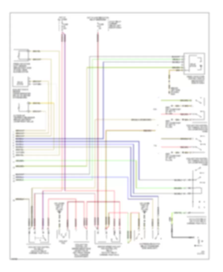
AIR CONDITIONING
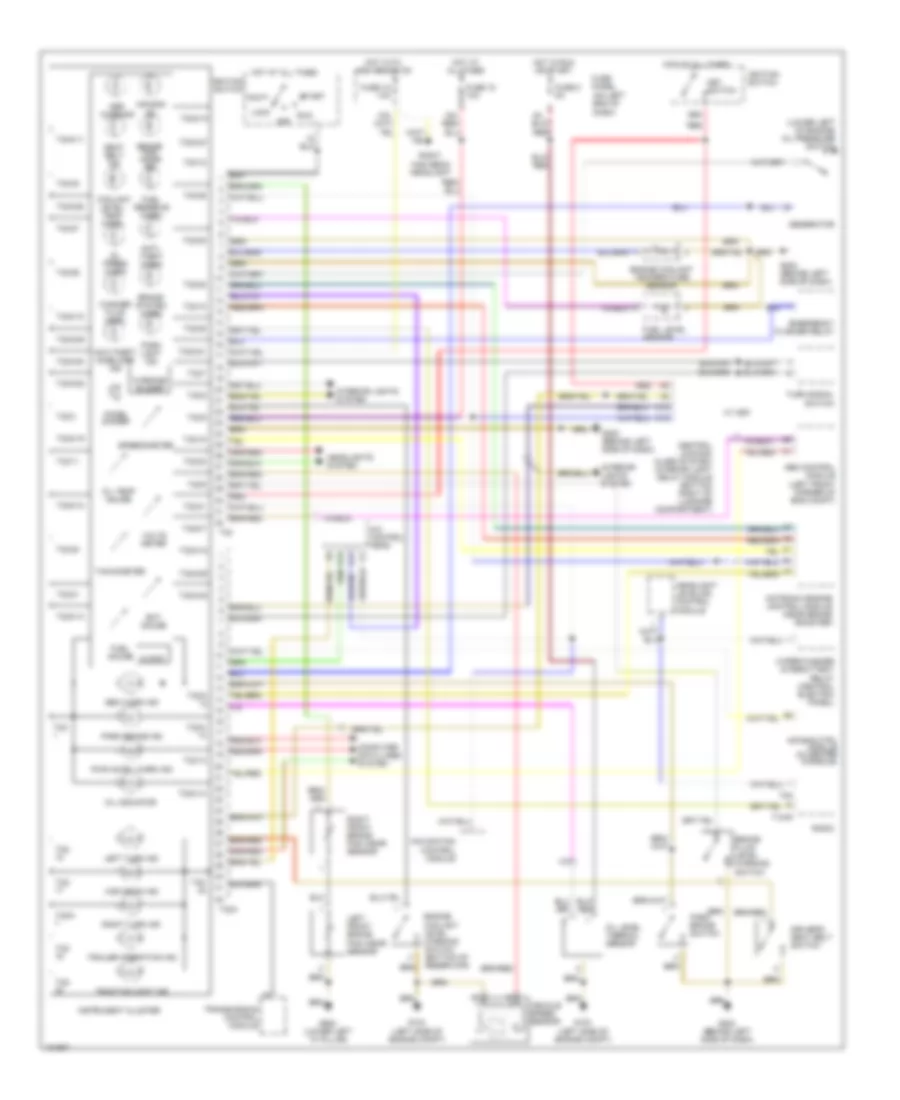
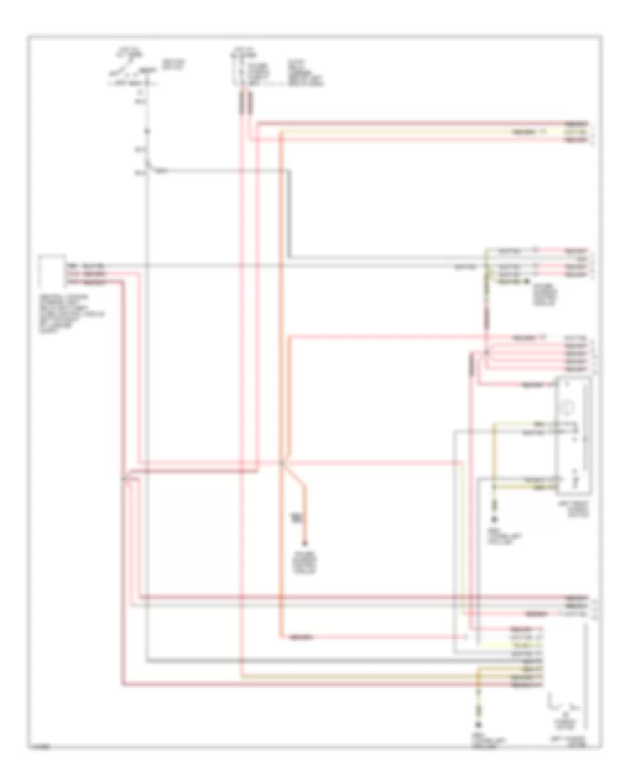
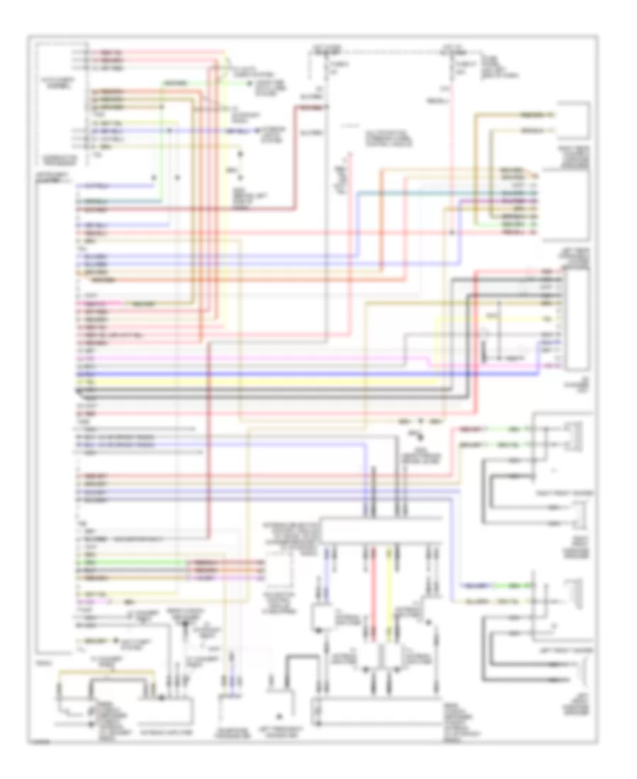
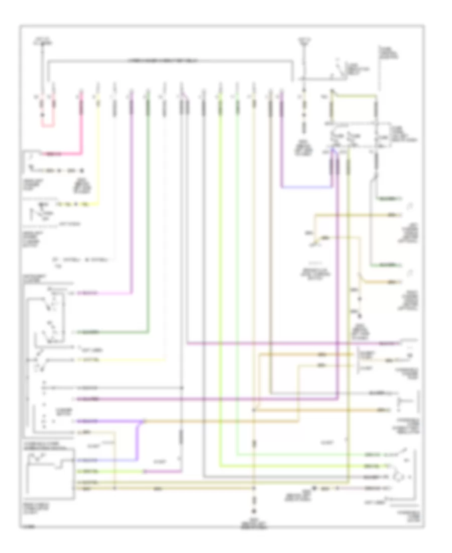
Automatic A/C Wiring Diagram (1 of 2) for Audi A4 Quattro 2001

List of elements for Automatic A/C Wiring Diagram (1 of 2) for Audi A4 Quattro 2001:
- A/c control head
- A10
- A11
- A12
- B10
- B11
- B12
- B13
- B14
- B15
- B16
- B17
- B18
- B19
- B20
- Back pressure flap motor position sensor (behind right side of dash, near base of "a"pillar)
- C10
- C11
- C12
- C13
- C14
- C15
- C16
- Center outlet temperature sender (behind lower center of dash, on hvac unit)
- Central flap motor position sensor (behind lower right center of dash, on hvac unit)
- D10
- D11
- D12
- D13
- D14
- D15
- D16
- Floor outlet temperature sender (behind lower left center of dash, on hvac unit)
- Footwell/defrost flap motor position sensor (behind lower center of dash, above accelerator pedal)
- Fuse 10a
- Fuse 30a
- Fuse 5a
- Fuse panel (on left end of dash)
- G202 (behind left side of dash)
- Hot in run or start
- Hot w/light switch in park or head position
- Hot w/load reduction relay energized
- Instrument cluster
- Motronic engine control module (ecm) (near brake booster, in protective case)
- Solid state
- T32
- T32a
- Temperature flap motor position sensor (behind lower right center of dash, near transmission tunnel)
- Wiper/washer system
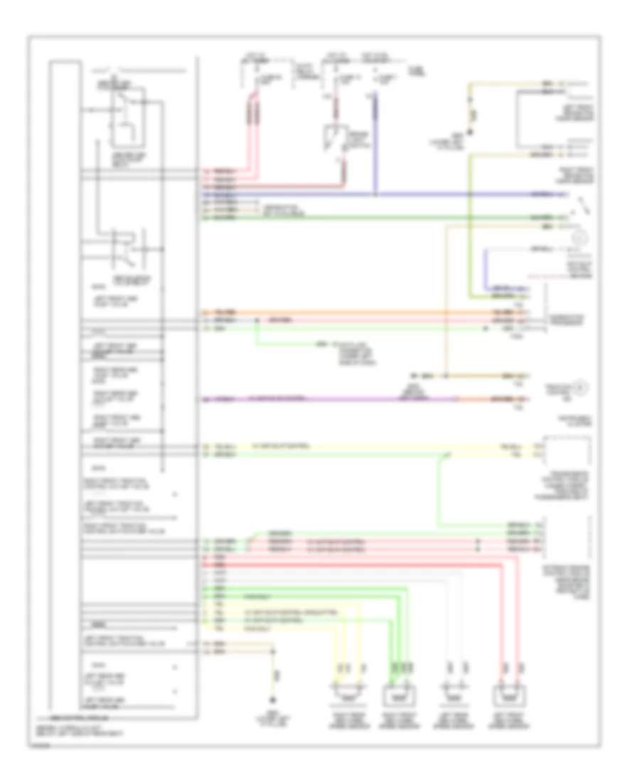
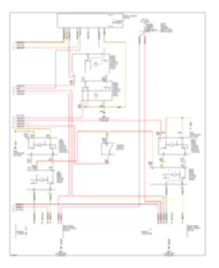
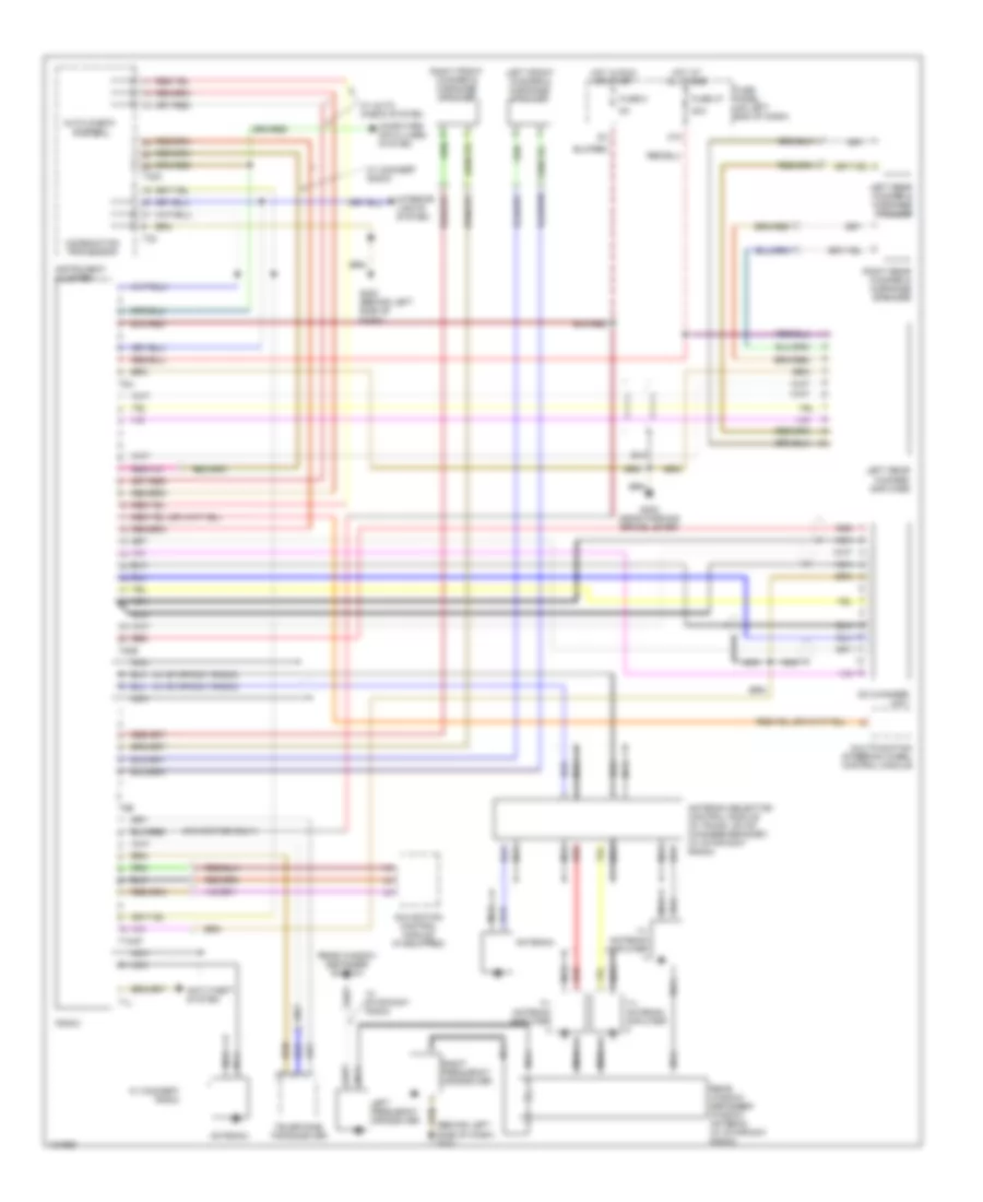
Automatic A/C Wiring Diagram (2 of 2) for Audi A4 Quattro 2001
List of elements for Automatic A/C Wiring Diagram (2 of 2) for Audi A4 Quattro 2001:
- (behind left side of dash) g202
- (on lower part of left "a" pillar) g900
- 1.8l
- 2.8l
- 8-way relay carrier (below left end of dash)
- A/c clutch
- A/c clutch relay (on 13 way relay carrier, position 3)
- A/c pressure switch (below passenger side headlight)
- Coolant fan
- Coolant fan control (fc) relay (on 8-way relay carrier, position 3)
- Coolant fan control (fc) series resistance (on bottom of left front frame rail, in engine compartment)
- Coolant fan control (fc) thermal switch (on lower radiator hose)
- Fresh air blower control module (behind right side of dash)
- Fresh air intake duct sensor (behind right side of dash, near blower motor)
- Fuse 40a
- Fuse 5a
- G900 (on lower part of left "a" pillar)
- Hot at all times
- Hot w/load reduction relay energized
- Nca
- Outside air temperature sensor (behind center of lower front grille)
- Second speed coolant fan control (fc) relay (on 8-way relay carrier, position 2)
- Solid state
- Sunlight photo sensor (inside defroster grille, on center of dashboard)
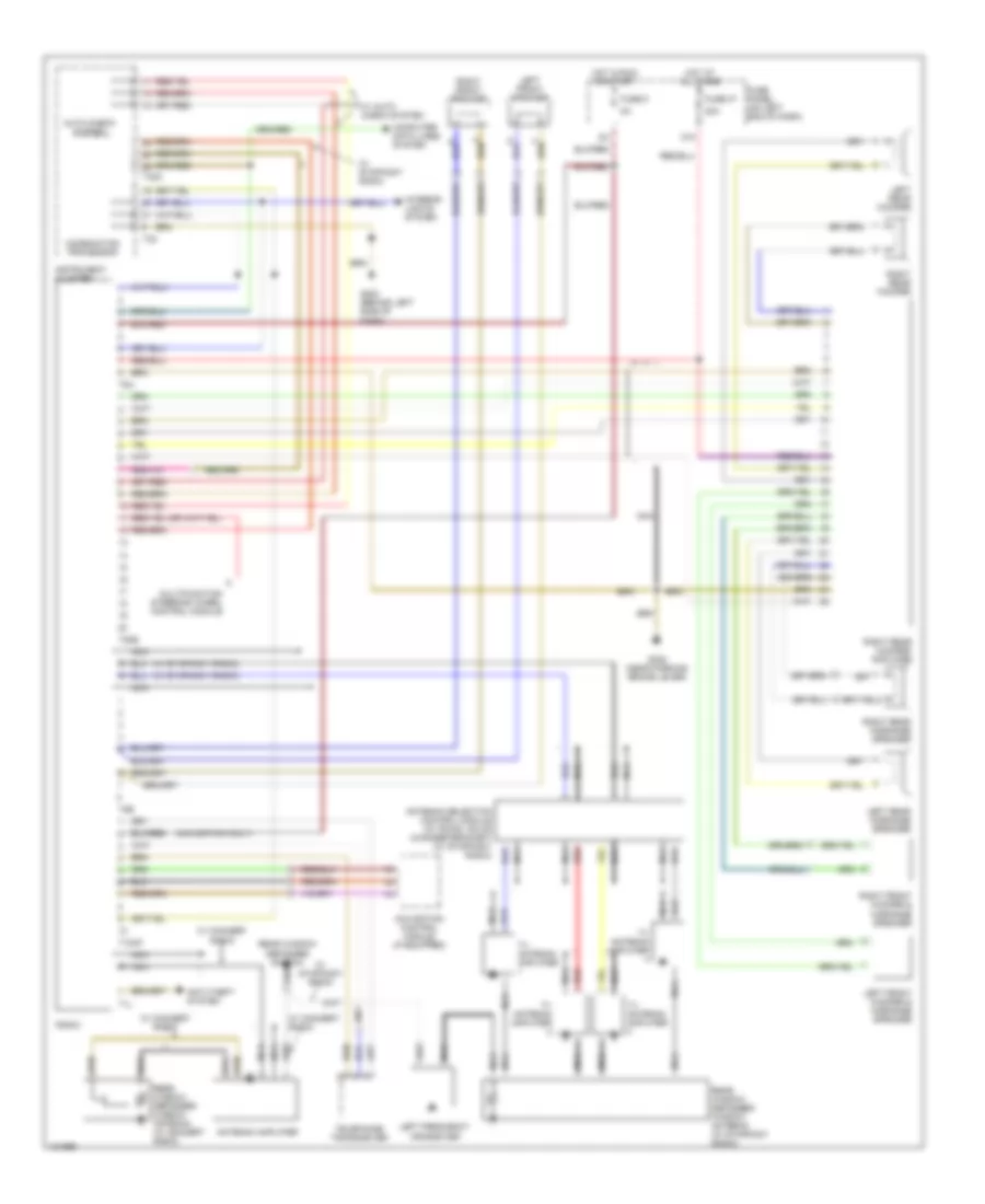
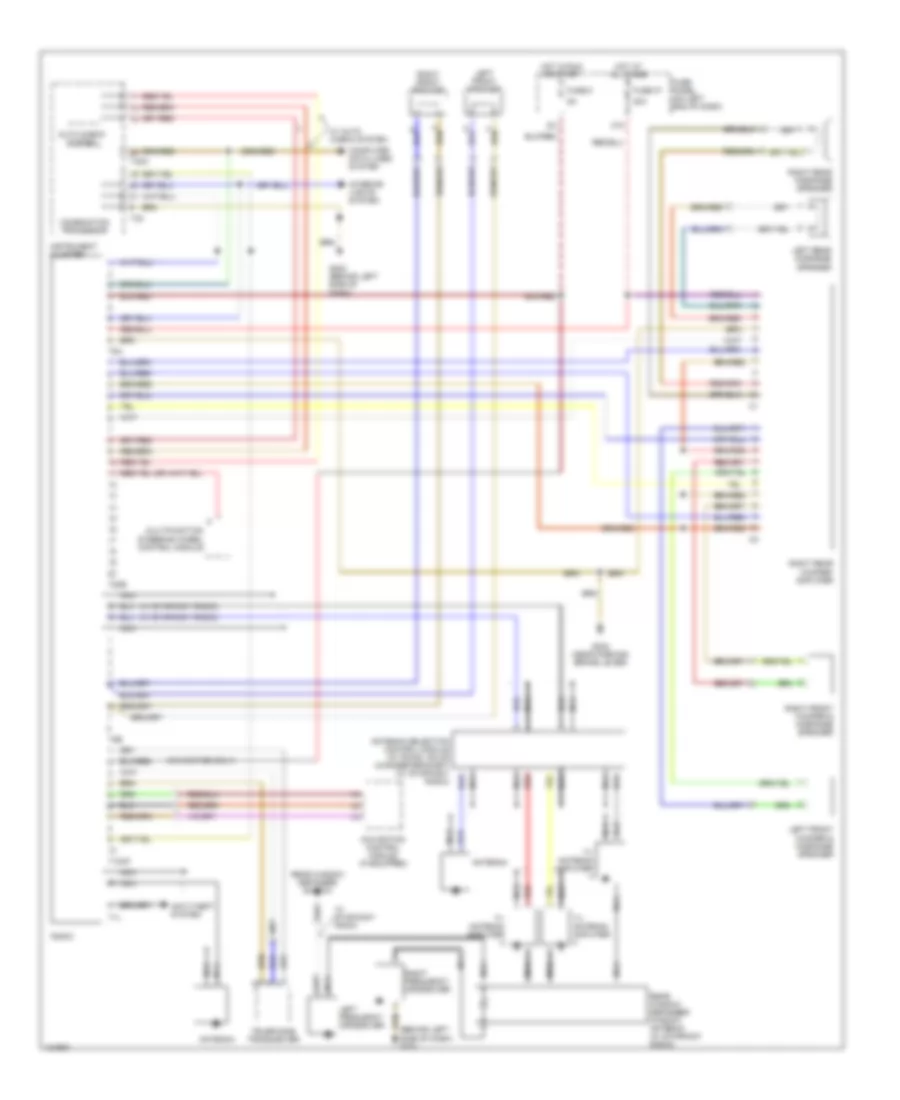
ANTI-LOCK BRAKES
Anti-lock Brakes Wiring Diagram for Audi A4 Quattro 2001
List of elements for Anti-lock Brakes Wiring Diagram for Audi A4 Quattro 2001:
- (information not available)
- 13a
- 8-way relay carrier
- Abs control module
- Abs return flow pump
- Abs return flow pump relay
- Abs solenoid valve relay
- Abs/edl hydraulic unit (below left side of rear seat)
- All times
- Anti-slip control switch
- Brake- light switch
- Combination processor
- Data link connector (under left side of dash)
- Fuse 13 10a
- Fuse 53 60a
- Fuse 7 10a
- Fuse panel
- Fwd only
- G202 (behind left dash)
- G900 (lower left "a" pillar)
- Hot at
- Hot in on or start
- Instrument cluster
- Left front abs inlet valve
- Left front abs outlet valve
- Left front abs wheel speed sensor
- Left front brake pad wear sensor
- Left front traction control outlet valve
- Left front traction control switch-over valve
- Left rear abs inlet valve
- Left rear abs outlet valve
- Left rear abs wheel speed sensor
- Motronic engine control module (near brake booster in protective case)
- Red
- Right front abs inlet valve
- Right front abs outlet valve
- Right front abs wheel speed sensor
- Right front brake pad wear sensor
- Right front traction control outlet valve
- Right front traction control switch-over valve
- Right rear abs inlet valve
- Right rear abs outlet valve
- Right rear abs wheel speed sensor
- T32
- T32a
- Traction control ind
- Transmission control module (under carpet, forward of passenger's seat)
- W/ anti-slip control
- W/ anti-slip control or quattro
ANTI-THEFT
Anti-theft Wiring Diagram (1 of 2) for Audi A4 Quattro 2001
List of elements for Anti-theft Wiring Diagram (1 of 2) for Audi A4 Quattro 2001:
- (avant)
- (central electric position 13)
- (on bottom right of luggage compartment)
- 14a
- 38a
- 86s
- Alarm horn
- Antenna
- Avant
- Central locking/ interior light delay/ anti-theft alarm control module
- Clutch pedal position switch (m/t)
- Door lock switch
- End of dash)
- Exterior lights system
- Fuse 10a
- Fuse 15a
- Fuse 5a
- Fuse panel (on left
- G202 (behind left side of dash)
- G900 (lower left "a" pillar)
- Hot at all times
- Hot in start & run
- Ignition switch
- Instrument cluster
- Interior lights system
- Key switch
- Left door warning light
- Luggage compt light
- Multi- function transmission switch (a/t)
- Nca
- Park/ neutral position relay
- Power windows system
- Radio
- Red
- Right door warning light
- T11
- T32
- T32a
- Tailgate release systems
- Trunk lid alarm switch
- Trunk lid release switch
- Warning light control module
- With remote control
Anti-theft Wiring Diagram (2 of 2) for Audi A4 Quattro 2001
List of elements for Anti-theft Wiring Diagram (2 of 2) for Audi A4 Quattro 2001:
- Auto check system (part of instrument cluster)
- Driver's door contact switch
- Driver's door handle alarm switch
- G202 (behind left side of dash)
- G900 (lower left "a" pillar)
- Hood alarm switch
- Instrument cluster system
- Interior monitor switch
- Left rear broken glass sensor
- Left rear door contact switch
- Left ultra- sound sensor
- Passenger's door contact switch
- Passenger's door handle alarm switch
- Rear window defogger
- Right rear broken glass sensor
- Right rear door contact switch
- Right ultra- sound sensor
- T32a
- T32b
- Trunk lock alarm switch
- Ultra sound sensor control module (below center of rear seat)
- W/ auto check system
- W/o auto check system
COMPUTER DATA LINES
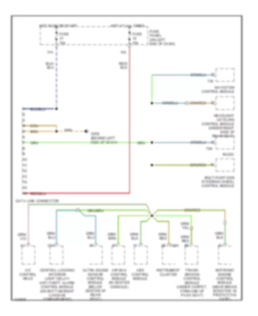
Computer Data Lines Wiring Diagram for Audi A4 Quattro 2001
List of elements for Computer Data Lines Wiring Diagram for Audi A4 Quattro 2001:
- 12a
- 31a
- A/c control head
- Abs control module
- Air bag control module (in center console)
- C14
- Central locking/ interior light delay/ anti-theft alarm control module (on bottom right luggage compartment)
- Data link connector
- Fuse 10a
- Fuse 15a
- Fuse panel (on left end of dash)
- G202 (behind left side of dash)
- Headlight leveling control module (under right side of rear seat)
- Hot at all times
- Hot in on or start
- Instrument cluster
- Motronic engine control module (near brake booster, in protective case)
- Multi-funtcion steering wheel control module
- Navigtion control module
- Radio
- T32a
- T8a
- T8i
- Trans- mission control module (under carpet, forward of pass seat)
- Ultra-sound sensor control module (below center of rear seat)
COOLING FAN
1.8L
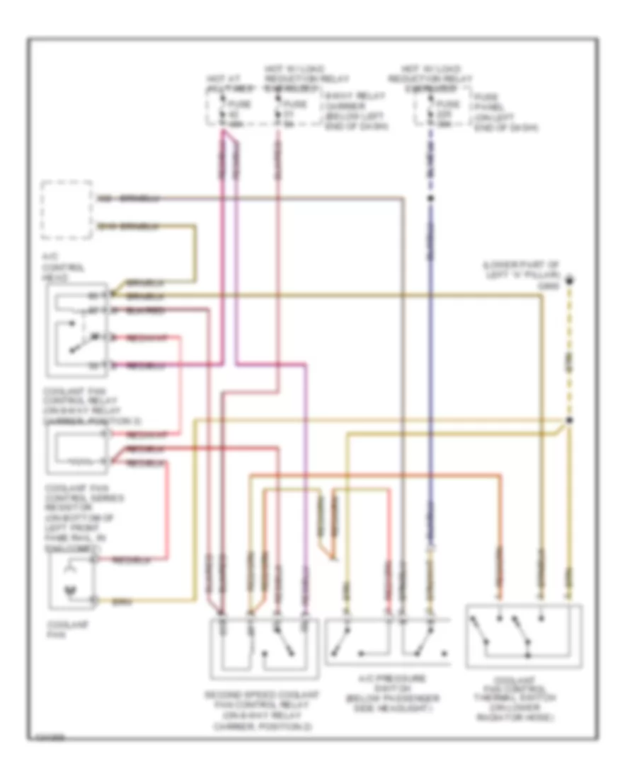
1.8L, Cooling Fan Wiring Diagram for Audi A4 Quattro 2001
List of elements for 1.8L, Cooling Fan Wiring Diagram for Audi A4 Quattro 2001:
- (lower part of left "a" pillar)
- 8-way relay carrier (below left end of dash)
- A/c control head
- A/c pressure switch (below passenger side headlight)
- Carrier, position 2)
- Coolant fan
- Coolant fan control relay (on 8-way relay carrier, position 3)
- Coolant fan control series resistor (on bottom of left front fame rail, in eng compt)
- Coolant fan control thermal switch (on lower radiator hose)
- D16
- Fuse 30a
- Fuse 40a
- Fuse 5a
- Fuse panel (on left end of dash)
- G900
- Hot at all times
- Hot w/ load reduction relay energized
- Second speed coolant fan control relay (on 8-way relay
2.8L
2.8L, Cooling Fan Wiring Diagram for Audi A4 Quattro 2001
List of elements for 2.8L, Cooling Fan Wiring Diagram for Audi A4 Quattro 2001:
- (lower part of left "a" pillar)
- 8-way relay carrier (below left end of dash)
- A/c control head
- A/c pressure switch (below passenger side headlight)
- Carrier, position 2)
- Coolant fan
- Coolant fan control relay (on 8-way relay carrier, position 3)
- Coolant fan control series resistor (on bottom of left front fame rail, in eng compt)
- Coolant fan control thermal switch (on lower radiator hose)
- D16
- Fuse 30a
- Fuse 40a
- Fuse 5a
- Fuse panel (on left end of dash)
- G900
- Hot at all times
- Hot w/ load reduction relay energized
- Second speed coolant fan control relay (on 8-way relay
CRUISE CONTROL
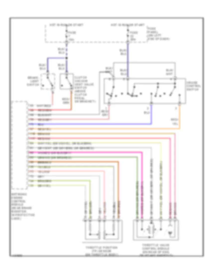
Cruise Control Wiring Diagram for Audi A4 Quattro 2001
List of elements for Cruise Control Wiring Diagram for Audi A4 Quattro 2001:
- Brake- light switch
- Clutch vacuum vent valve switch (above clutch pedal, on bracket)
- Cruise control switch
- Fuse 10a
- Fuse 20a
- Fuse panel (on left end of dash)
- Hot in run or start
- Motronic engine control module (near brake booster, in protective case)
- Red/
- Throttle position (tp) sensor (on throttle body)
- Throttle valve control module (on rear of eng, on intake manifold)
DEFOGGERS
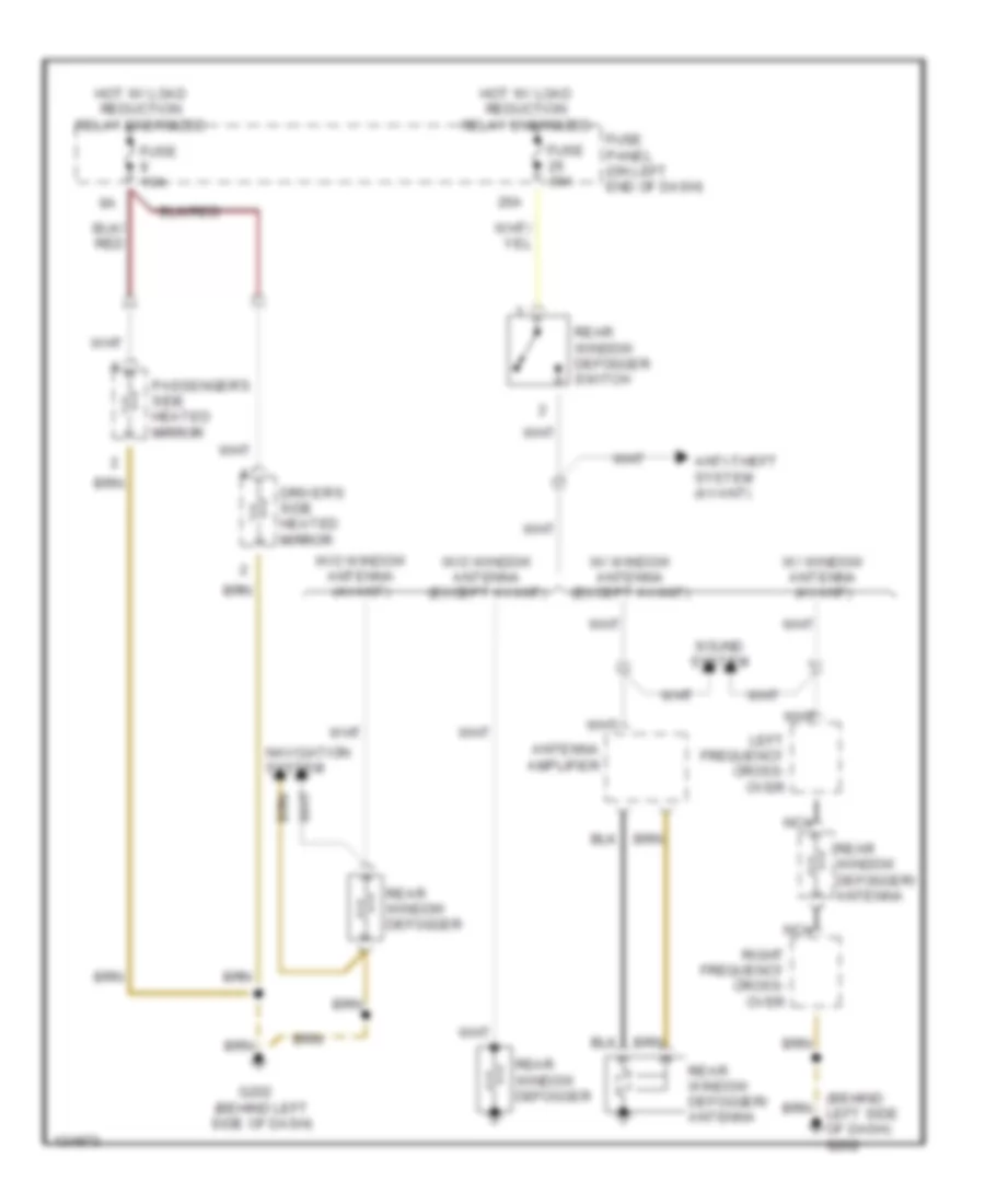
Defoggers Wiring Diagram for Audi A4 Quattro 2001
List of elements for Defoggers Wiring Diagram for Audi A4 Quattro 2001:
- (behind left side of dash) g202
- 26a
- Antenna amplifier
- Anti-theft system (avant)
- Driver's side heated mirror
- Fuse 10a
- Fuse 30a
- Fuse panel (on left end of dash)
- G202 (behind left side of dash)
- Hot w/ load reduction relay energized
- Left frequency cross- over
- Navigation system
- Nca
- Passenger's side heated mirror
- Rear window defogger
- Rear window defogger switch
- Rear window defogger/ antenna
- Right frequency cross- over
- Sound system
- W/ window antenna (avant)
- W/ window antenna (except avant)
- W/o window antenna (avant)
- W/o window antenna (except avant)
ENGINE PERFORMANCE
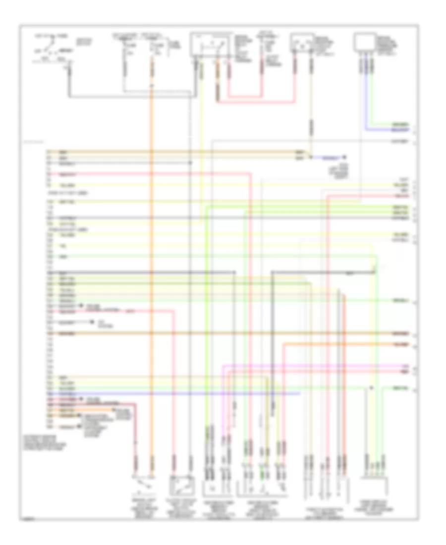
1.8L
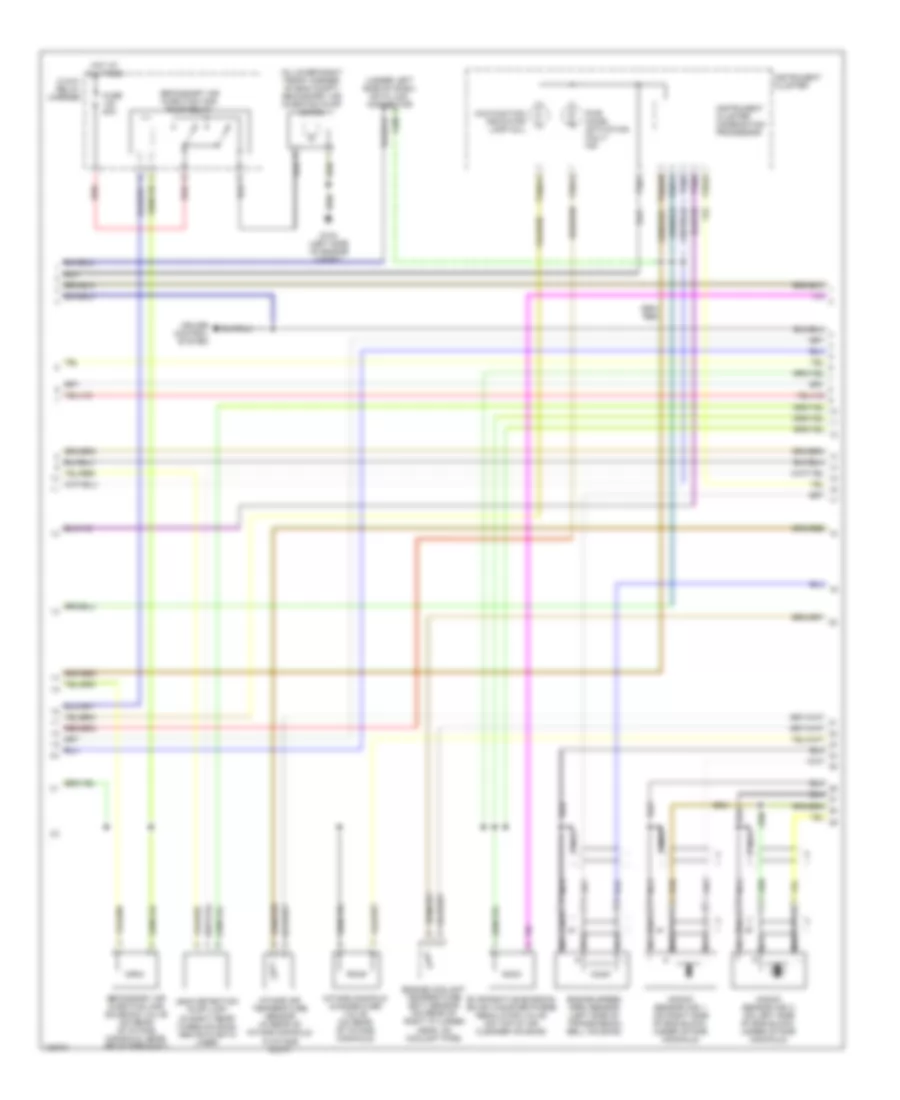
1.8L, Engine Performance Wiring Diagram (1 of 3) for Audi A4 Quattro 2001
List of elements for 1.8L, Engine Performance Wiring Diagram (1 of 3) for Audi A4 Quattro 2001:
- (m/t)
- (pins 10-17 not used)
- (pins 23-24 not used)
- 13-way relay carrier
- A/c system
- Abs system, transmissions system, instrument cluster system
- Acc
- Brake booster pressure sensor (a/t only)
- Brake booster relay (in 13-way relay carrier)
- Brake booster vacuum pump (a/t only)
- Brake light switch (above brake pedal, on bracket)
- Clutch vacuum vent valve switch (above clutch, on bracket)
- Cruise control system
- Fuse 10a
- Fuse 15a
- Fuse panel
- G104 (left side of engine compt)
- Heated oxygen sensor 1 (right side of eng, on exhaust manifold)
- Heated oxygen sensor 2 (behind 3-way catalytic converter)
- Hot at all times
- Hot in start or run
- Ignition switch
- Mass airflow (maf) sensor (inside air cleaner housing)
- Motronic engine control module (near brake booster, in protective case)
- Nca
- Off
- Red
- Run
- Start
- Throttle position (tp) sensor (on throttle body)
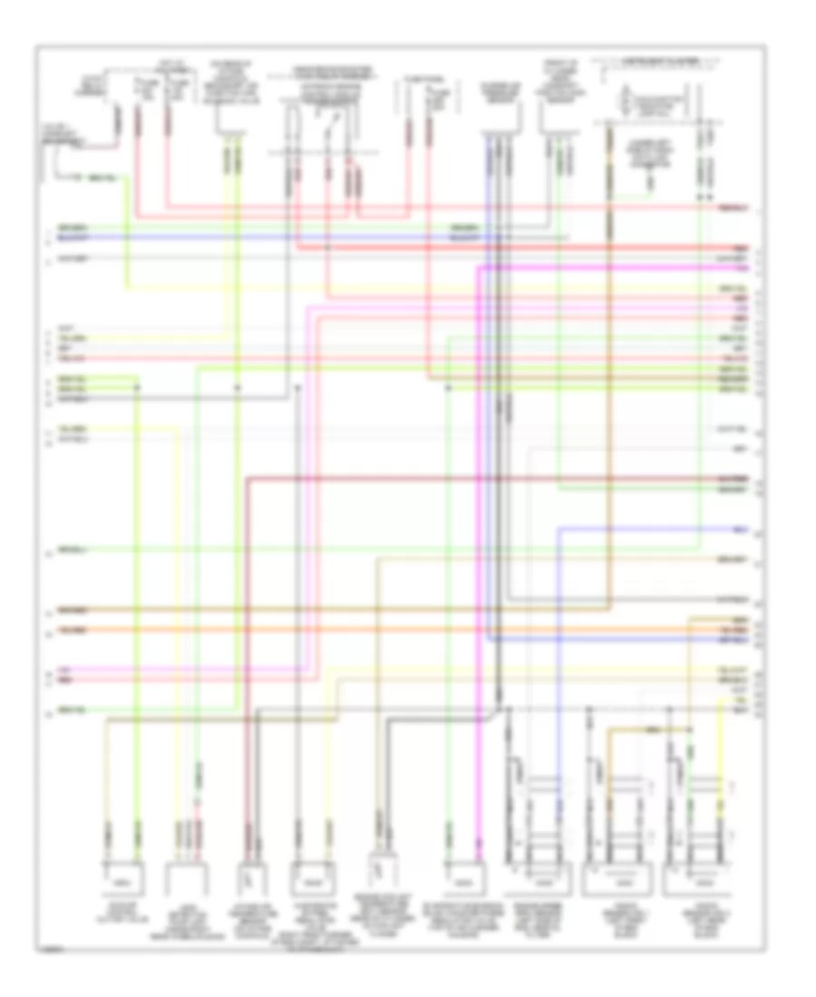
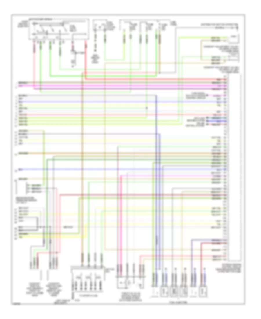
1.8L, Engine Performance Wiring Diagram (2 of 3) for Audi A4 Quattro 2001
List of elements for 1.8L, Engine Performance Wiring Diagram (2 of 3) for Audi A4 Quattro 2001:
- (front of cylinder head) camshaft position (cmp) sensor
- (mil)
- (near brake booster) 3-way relay carrier
- (on rear of intake manifold) secondary air injection (air) solenoid valve
- (under left side of dash) data link connector
- 3-way relay carrier
- Charge air pressure sensor
- Engine coolant temperature (ect) sensor (rear of cylinder, on coolant flange)
- Engine speed (rpm) sensor (left side of eng, near oil filter)
- Evaporative emission (evap) canister purge regulator valve (top of air cleaner housing)
- Fuse 15a
- Fuse 20a
- Fuse 40a
- Fuse panel
- Hot at all times
- Idle air control cut-off valve
- Instrument cluster
- Intake air temperature sensor (on intake manifold)
- Knock sensor (ks) 1 (left front of eng block)
- Knock sensor (ks) 2 (left rear of eng block)
- Leak detection pump (ldp) (inside right rear wheelhousing)
- Malfunction indicator lamp
- Nca
- Red
- T32/11
- T32/3
- T32a/28
- Valve 1 camshaft adjustment
- Wastegate bypass regulator valve (right front corner of eng compt, attached to intake duct)
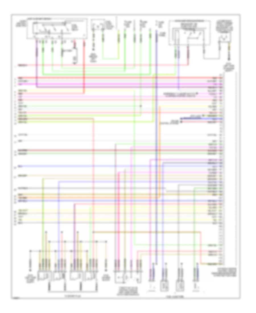
1.8L, Engine Performance Wiring Diagram (3 of 3) for Audi A4 Quattro 2001
List of elements for 1.8L, Engine Performance Wiring Diagram (3 of 3) for Audi A4 Quattro 2001:
- (lower right front corner of eng compt) secondary air injection pump motor
- 87f
- 87a
- Anti-lock brakes system
- Battery
- Cruise control system
- Emergency flasher switch & air bag control module
- Fuel injectors
- Fuel pump (in fuel tank)
- Fuel pump relay
- Fuse 15a
- Fuse 20a
- Fuse panel
- G104 (left side of eng compt)
- G104 (left side of engine compt)
- G132 (on eng block)
- G202 (behind left dash)
- Hot in start or run
- Micro center electronic
- Micro central electric
- Motronic engine control module (near brake booster, in protectice case)
- Nca
- Red
- Secondary air injection (air) pump relay
- Throttle valve control module (left side of eng, on intake manifold)
- To spark plug
2.8L
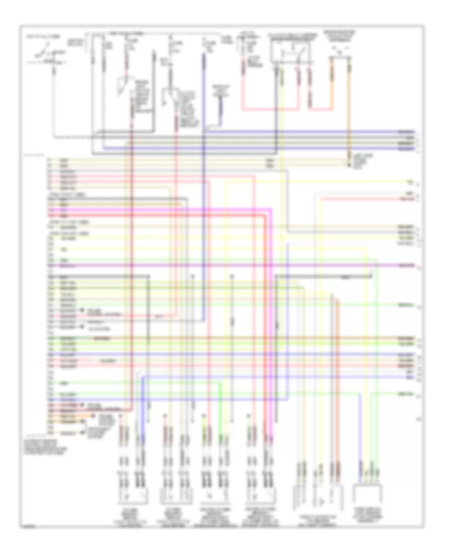
2.8L, Engine Performance Wiring Diagram (1 of 3) for Audi A4 Quattro 2001
List of elements for 2.8L, Engine Performance Wiring Diagram (1 of 3) for Audi A4 Quattro 2001:
- (in 13-way relay carrier) brake booster relay
- (left side of eng compt) g104
- (m/t)
- (pins 14-17 not used)
- (pins 19-24 not used)
- (pins 7-9 not used)
- 13-way relay carrier
- 20a
- A/c system
- Back-up light switch
- Brake booster vacuum pump (a/t only)
- Brake- light switch (above brake pedal, on bracket)
- Clutch vacuum vent valve switch (above clutch pedal, on bracket)
- Cruise control system
- Fuse 10a
- Fuse 15a
- Fuse panel
- Heated oxygen sensor 1 (behind right cylinder head, on exhaust manifold)
- Heated oxygen sensor 2 (behind right cylinder head, on exhaust manifold)
- Hot at all times
- Ignition switch
- Instrument cluster system
- Mass airflow (maf) sensor (in air cleaner assembly)
- Motronic engine control module (near brake booster, in protective case)
- Nca
- Off
- Oxygen sensor 1 (behind 3-way catalytic converter)
- Oxygen sensor 2 (behind 3-way catalytic converter)
- Red
- Run
- Start
- Throttle position (tp) sensor (on throttle body)
2.8L, Engine Performance Wiring Diagram (2 of 3) for Audi A4 Quattro 2001
List of elements for 2.8L, Engine Performance Wiring Diagram (2 of 3) for Audi A4 Quattro 2001:
- (in lower right front corner of eng compt) secondary air injection pump motor
- (under left side of dash) data link connector
- 3-way relay carrier
- Cruise control system
- Engine coolant temperature (ect) sensor (on rear of right cylinder head, on coolant pipe)
- Engine speed (rpm) sensor (left side of transmission bell housing)
- Evaporative emission (evap) canister purge regulator valve (on top of air cleaner housing)
- Fuse 50a
- G104 (left side of engine compt)
- Hot at all times
- Instrument cluster
- Instrument cluster combination processor
- Intake air temperature sensor (in rear of intake manifold, in intake duct)
- Intake manifold change-over valve (on rear of intake manifold)
- Knock sensor (ks) 1 (on right side of eng block, under intake manifold)
- Knock sensor (ks) 2 (on left side of eng block, under intake manifold)
- Leak detection pump (ldp) (in right rear wheelhousing, above plastic liner)
- Malfunction indicator lamp (mil)
- Nca
- Pwr accel activation fault ind
- Red
- Secondary air injection (air) pump relay
- Secondary air injection (air) solenoid valve (on rear of intake manifold, near air intake duct)
- T32/1
- T32/11
- T32/13
- T32/25
- T32/3
- T32/6
- T32a/14
- T32a/28
2.8L, Engine Performance Wiring Diagram (3 of 3) for Audi A4 Quattro 2001
List of elements for 2.8L, Engine Performance Wiring Diagram (3 of 3) for Audi A4 Quattro 2001:
- (left side of
- 87a
- Anti-lock brakes system
- Battery
- Brake booster pressure sensor (a/t only)
- Camshaft adjustment valve 1 (on rear of right cylinder head)
- Camshaft adjustment valve 2 (on front of left cylinder head)
- Camshaft position (cmp) sensor 1 (rear of left cylinder head)
- Camshaft position (cmp) sensor 2 (front of right cylinder head)
- Cruise control system
- Distributor ignition capacitor
- Dti
- Eng compt)
- Fuel injectors
- Fuel pump (in fuel tank)
- Fuel pump relay
- Fuse 15a
- Fuse 20a
- Fuse panel
- G104
- G202 (behind left dash)
- Hot in start or run micro central electric
- Ignition coil
- Motronic engine control module (near brake booster, in protective case)
- Nca
- Red
- Throttle valve control module (on rear of eng, on intake manifold)
- To spark plugs
- Turn signal switch & air bag control module
EXTERIOR LIGHTS
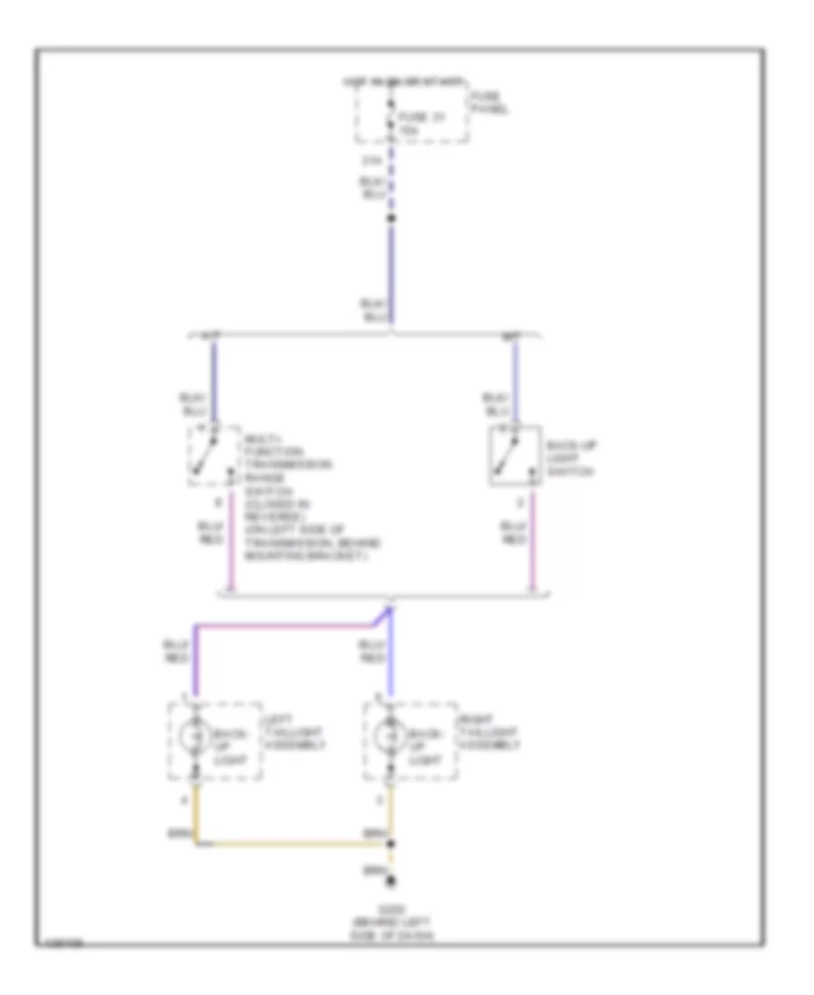
Backup Lamps Wiring Diagram for Audi A4 Quattro 2001
List of elements for Backup Lamps Wiring Diagram for Audi A4 Quattro 2001:
- 31a
- A/t
- Back- up light
- Back-up light switch
- Fuse 31 15a
- Fuse panel
- G202 (behind left side of dash)
- Hot in on or start
- Left taillight assembly
- M/t
- Multi- function transmission range switch (closed in reverse) (on left side of transmission, behind mounting bracket)
- Right taillight assembly
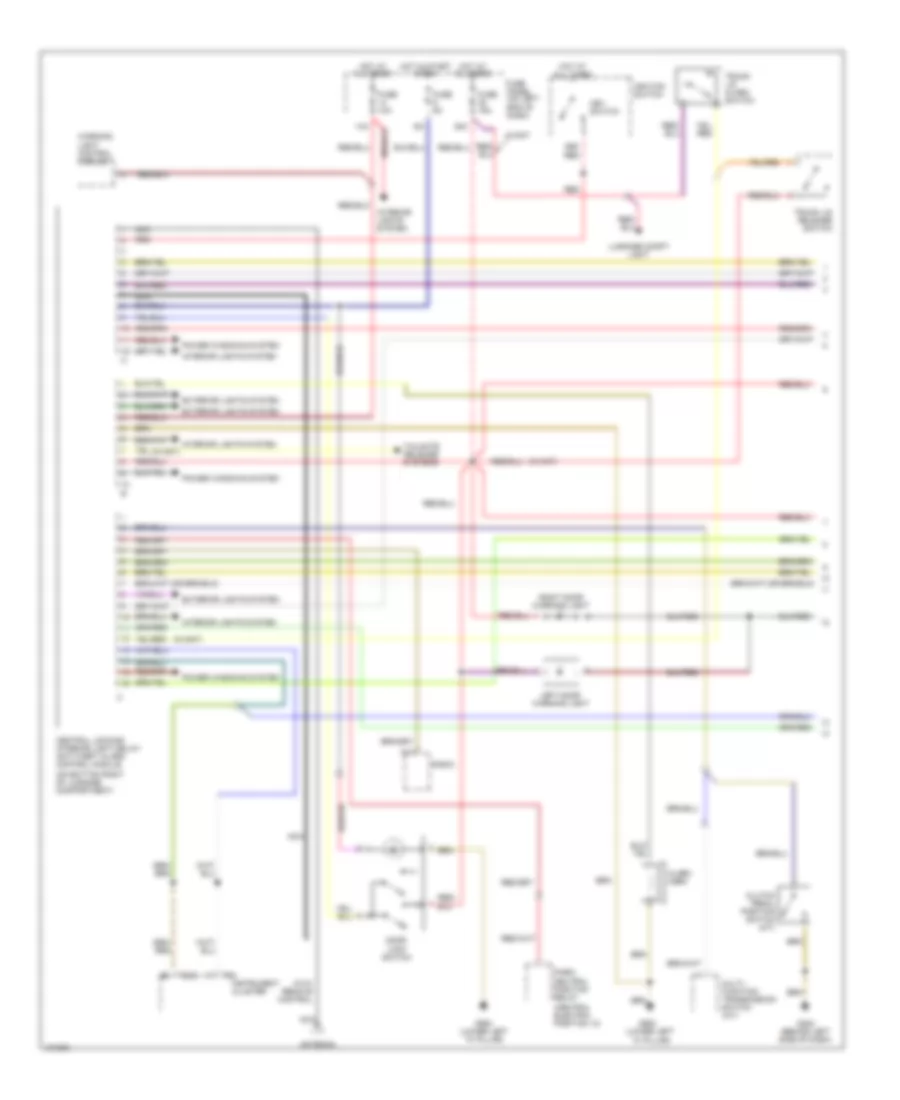
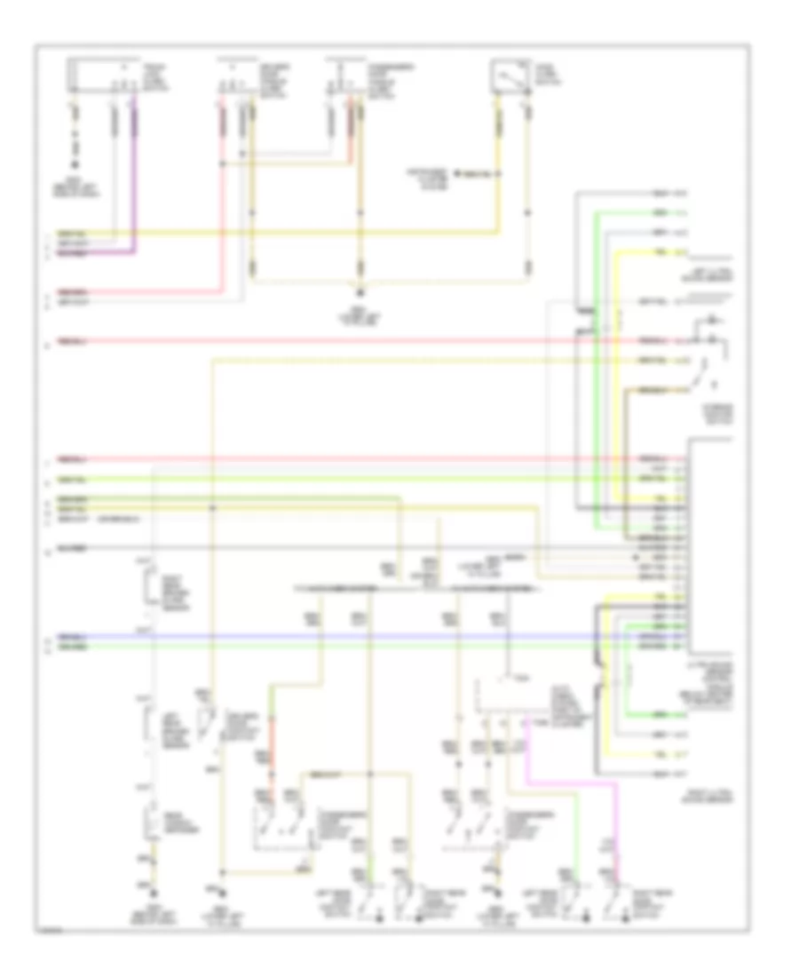
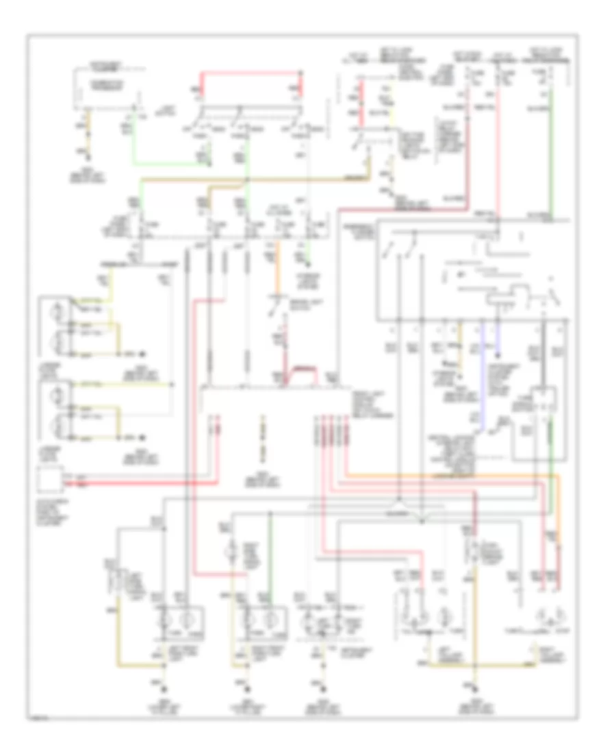
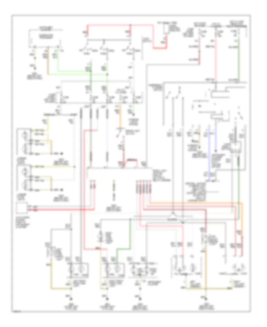
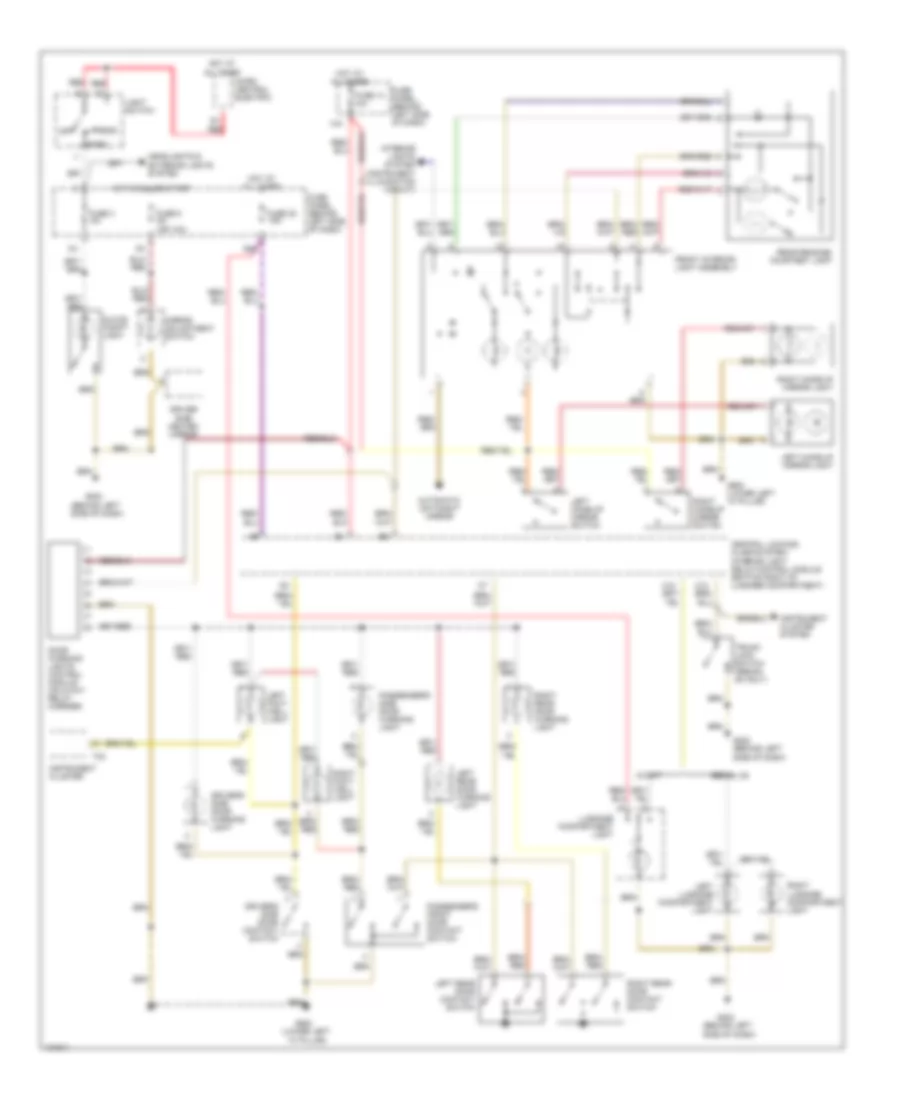
Exterior Lamps Wiring Diagram, with DRL for Audi A4 Quattro 2001
List of elements for Exterior Lamps Wiring Diagram, with DRL for Audi A4 Quattro 2001:
- 13-way relay carrier (behind left side of dash)
- 13a
- 22a
- 23a
- 39a
- 75x
- Auto check system (part of instrument cluster)
- Avant
- Brake light switch
- Central locking/ interior light delay/anti- theft alarm control module (on bottom right of luggage compt)
- Cluster
- Combination processor
- Daytime running lights switch-on relay
- Emergency flasher switch
- Front light control module (on 13-way relay carrier)
- Fuse 10a
- Fuse 15a
- Fuse 5a
- Fuse panel (left end of dash)
- G202 (behind left side of dash)
- G900 (lower left "a" pillar)
- G901 (lower right "a" pillar)
- Head
- High- mount brake light
- Hot at all times
- Hot in run or start
- Hot w/ load reduction relay energized
- Instrument
- Instrument cluster
- Instrument cluster system (with trailer option)
- Interior lights system
- Left front park/turn light
- Left side turn signal light
- Left taillamp assembly
- Left turn ind
- License plate lights
- Light switch
- Micro central electric
- Off
- Park
- Red
- Right front park/turn light
- Right side turn signal light
- Right taillamp assembly
- Right turn ind
- Sedan, s4
- Signal switch
- Stop
- T32
- T32a
- Tail
- Turn
Exterior Lamps Wiring Diagram, without DRL for Audi A4 Quattro 2001
List of elements for Exterior Lamps Wiring Diagram, without DRL for Audi A4 Quattro 2001:
- 13a
- 22a
- 23a
- 39a
- Auto check system (part of instrument cluster)
- Avant
- Brake light switch
- Central locking/ interior light delay/anti- theft alarm control module (on bottom right of luggage compt)
- Combination processor
- Emergency flasher switch
- Front light control module (on 13-way relay carrier)
- Fuse 10a
- Fuse 15a
- Fuse 5a
- Fuse panel (left end of dash)
- G202 (behind left side of dash)
- G900 (lower left "a" pillar)
- G901 (lower right "a" pillar)
- Head
- High- mount brake light
- Hot at all times
- Hot in run or start
- Hot w/ load reduction relay energized
- Instrument cluster
- Instrument cluster system (with trailer option)
- Interior lights system
- Left front park/turn light
- Left side turn signal light
- Left taillamp assembly
- Left turn ind
- License plate lights
- Light switch
- Micro central electric
- Off
- Park
- Red
- Right front park/turn light
- Right side turn signal light
- Right taillamp assembly
- Right turn ind
- Sedan, s4
- Signal switch
- Stop
- T32
- T32a
- Tail
- Turn
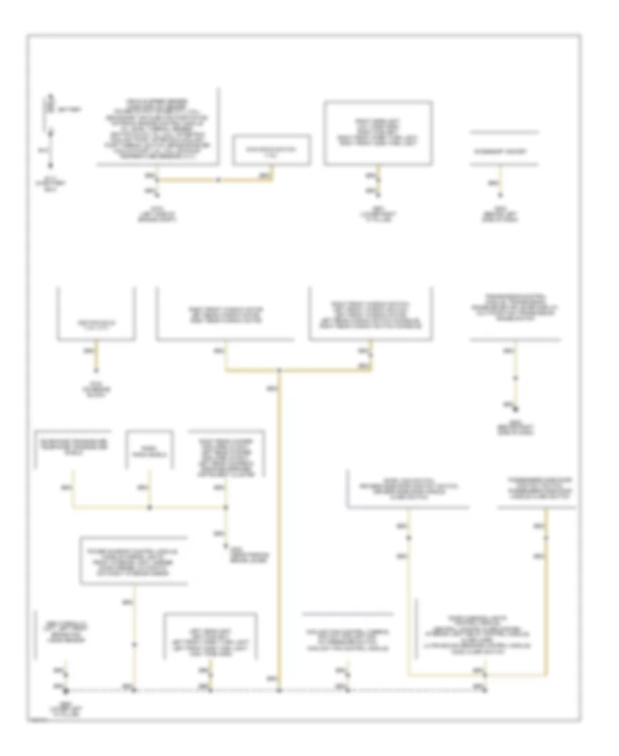
GROUND DISTRIBUTION
Ground Distribution Wiring Diagram (1 of 2) for Audi A4 Quattro 2001
List of elements for Ground Distribution Wiring Diagram (1 of 2) for Audi A4 Quattro 2001:
- Abs hydraulic unit, left front brake pad wear sensor
- Accessory socket
- Battery
- Coolant fan control thermal switch, coolant fan, a/c pressure switch, coolant fan control module
- Door lock switch, driver's side door contact switch, driver's side door handle alarm switch
- Door warning lights control module, central locking/ alarm system/ interior light delay control module, alarm horn, ultra-sound sensors control module,
- G104 (left side of engine compt)
- G111 (in battery box)
- G132 (on engine block)
- G202 (behind left side of dash)
- G203 (behind right side of dash)
- G302 (near parking brake lever)
- G900 (lower left "a" pillar)
- G901 (lower right "a" pillar)
- Hood alarm switch
- Ignition coils (1.8l, 2.7l)
- Kick down switch (1.8l)
- Left headlight, left foglight, left front park/ turn light, left front side turn light, high tone horn
- Passenger's side door contact switch, passenger's side door handle alarm switch
- Power sunroof control module, make-up mirror lights, front interior light, garage door opener, automatic day/night interior mirror
- Radio, radio shield
- Right front window motor left rear window motor, right rear window motor
- Right front window switch, left front window switch, left front window motor, left rear window switch (console), right rear window switch (console)
- Right headlight, low tone horn, right foglight, right front park/ turn light, right front side turn light
- Right rear woofer amplifier (avant), left rear woofer amplifier (avant), left rear woofer & midrange speaker instrument cluster
- Telephone transceiver, telephone transceiver shield
- Transmission control module, transmission range selector lever display, multifunction transmission range switch
- Vehicle speed sensor, mass airflow sensor, power output stage (2.7l, 2.8l), secondary air injection pump motor, motronic engine control module oil level thermal sensor, ignition coils (1.8l, 2.8l), after run coolant pump, after run coolant pump thermal switch, brake booster vacuum pump (1.8l, 2.8l), exhaust temperature sensors (2.7l)
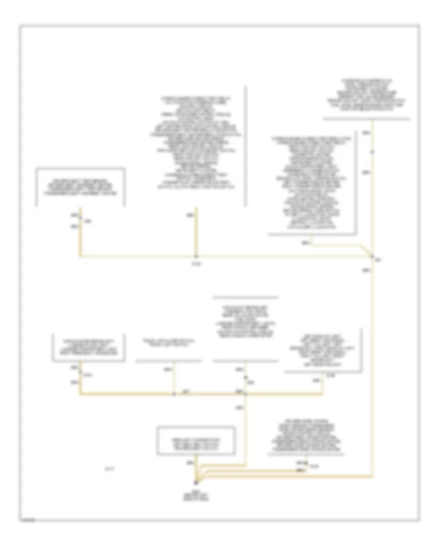
Ground Distribution Wiring Diagram (2 of 2) for Audi A4 Quattro 2001
List of elements for Ground Distribution Wiring Diagram (2 of 2) for Audi A4 Quattro 2001:
- Driver's (side) air bag crash sensor, passenger's (side) air bag crash sensor, air bag control module, driver's (head) air bag igniter, passenger's (head) air bag igniter, driver's (side) air bag igniter, passenger's (side) air bag igniter
- Driver's seat temp sensor, driver's seat headrest heater, passenger's seat temp sensor, passenger's seat headrest heater
- G202 (behind left side of dash)
- Headlight washer pump, left seat belt switch, driver's seat switch
- High mount brakelight, license plate lights, rear lid unlock motor, fuel pump, luggage compartment lights, rear window defogger, navigation control module, rear window wiper motor
- High-mounted brakelight, license plate light, lugagge compartment light right frequency crossover
- Left back-up light, left rear turn signal, left taillight, left brakelight, right back-up light, right rear turn signal, right taillight, right brakelight, left rear foglight
- S109
- S114
- S135
- S196
- S218
- S81
- S86
- S87
- S96
- Trunk lock alarm switch, trunk light switch
- Windshield washer fluid level warning switch, instrument cluster, engine coolant temperature sensor, fuel gauge sender, engine coolant level warning switch, fuel level sensor, board computer function selector switch
- Wiper/washer intermittent regulator, wiper/washer intermittent relay, front foglight switch, rear foglight switch, cigarette lighter, parking brake switch, instrument cluster, glove compartment light, emergency flasher switch, windshield wiper motor, brake fluid level warning switch, left washer nozzle heater, right washer nozzle heater, daytime running lights switch-on relay, micro central electric, foglights control module, air bag spiral spring/ return spring, horn switch, i/p vent illumination lights illumination lights, ashtray illumination, cup holder illumination
- Wiper/washer intermittent relay, multifunction steering wheel control module, driving light relay, fresh air blower control module, a/c control head, anti-slip control switch (w/ asc), left heated door lock control module, driver's seat heater regulator switch, passenger's seat heater regulator switch, driver's side heated mirror, passenger's side heated mirror, rear lamp control module, trip computer function select switch, front foglight switch, rear foglight switch, air bag spiral spring/ return spring, instrument cluster, windshield wiper intermittent switch, windshield washer pump, mirror adjustment switch, clutch pedal position switch
HEADLIGHTS
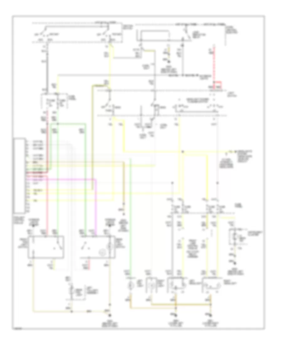
Headlamps Wiring Diagram, Canada with High Intensity Discharge Lamps for Audi A4 Quattro 2001
List of elements for Headlamps Wiring Diagram, Canada with High Intensity Discharge Lamps for Audi A4 Quattro 2001:
- (behind left side of dash)
- (behind left side of dash) g202
- (on 13-way relay carrier)
- 13-way relay carrier
- 18a
- 19a
- 20a
- 21a
- 36a
- 75x
- Acc
- Driving light relay
- Exterior lights
- Foglight control module
- Front lamp control module
- Ftp
- Fuse 10a
- Fuse 15a
- Fuse 5a
- Fuse panel
- G202
- G202 (behind left side of dash)
- G900 (lower left "a" pillar)
- G901 (lower right "a" pillar)
- Head
- Headlight dimmer/ flasher switch
- Headlights system (headlamps leveling circuit)
- Hi beam ind
- Hot at all times
- Ignition switch
- Instrument cluster
- Interior lights system
- Left headlight
- Left taillight assembly
- Light switch
- Load reduction relay
- Micro central electric
- Off
- Park
- Rear fog light
- Rear fog light switch
- Red
- Right headlight
- Run
- S1/75
- Start
- T32
Headlamps Wiring Diagram, Canada without High Intensity Discharge Lamps & All USA for Audi A4 Quattro 2001
List of elements for Headlamps Wiring Diagram, Canada without High Intensity Discharge Lamps & All USA for Audi A4 Quattro 2001:
- (behind left side of dash)
- (on 13-way relay carrier)
- 18a
- 19a
- 20a
- 21a
- 36a
- 75x
- Acc
- Exterior lights
- Foglight control module
- Front fog light switch
- Front lamp control module
- Ftp
- Fuse 10a
- Fuse 15a
- Fuse 5a
- Fuse panel
- G202
- G202 (behind left side of dash)
- G900 (lower left "a" pillar)
- G901 (lower right "a" pillar)
- Head
- Headlight dimmer/ flasher switch
- Headlights system (headlamps leveling circuit)
- Hi beam ind
- Hot at all times
- Ignition switch
- Instrument cluster
- Interior lights system
- Left fog light
- Left headlight
- Left taillight assembly
- Light switch
- Load reduction relay
- Micro central electric
- Off
- Park
- Rear fog light
- Rear fog light switch
- Red
- Right fog light
- Right headlight
- Run
- S1/75
- Start
- T32
- W/ high intensity discharge headlamps
- W/drl only
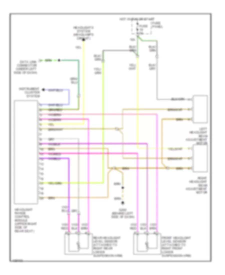
Headlamps Leveling Wiring Diagram for Audi A4 Quattro 2001
List of elements for Headlamps Leveling Wiring Diagram for Audi A4 Quattro 2001:
- 10a
- Data link connector (under left side of dash)
- Front headlight level sensor (attached to right front lower suspension arm)
- Fuse 5a
- Fuse panel
- G202 (behind left side of dash)
- Headlight range control module (upper right side of rear seat)
- Headlights system (headlamps circuit)
- Hot in run or start
- Instrument cluster system
- Left headlight beam adjustment motor
- Rear headlight level sensor (attached to right rear lower suspension arm)
- Right headlight beam adjustment motor
HORN
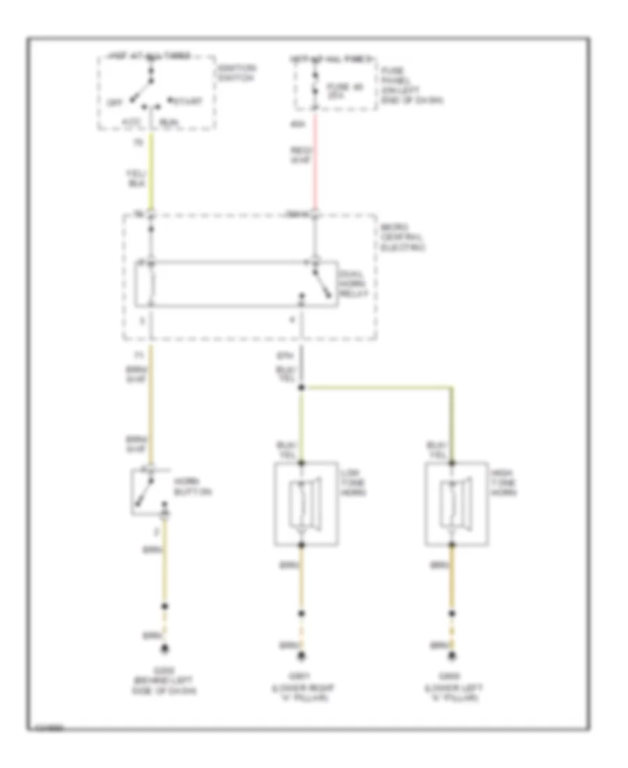
Horn Wiring Diagram for Audi A4 Quattro 2001
List of elements for Horn Wiring Diagram for Audi A4 Quattro 2001:
- (lower left "a" pillar)
- (lower right "a" pillar)
- 30ah
- 40a
- 87h
- Acc
- Dual horn relay
- Fuse 40 25a
- Fuse panel (on left end of dash)
- G202 (behind left side of dash)
- G900
- G901
- High tone horn
- Horn button
- Hot at all times
- Ignition switch
- Low tone horn
- Micro central electric
- Off
- Run
- Start
INSTRUMENT CLUSTER
Auto Check System Wiring Diagram for Audi A4 Quattro 2001
List of elements for Auto Check System Wiring Diagram for Audi A4 Quattro 2001:
- (behind left side of dash)
- 13a
- Auto check system
- Board computer function selector switch
- Brake- light switch (above brake pedal, above bracket)
- Exterior lights system
- Fuse 13 10a
- Fuse 5 15a
- Fuse panel
- G202 (behind left side of dash)
- G900 (lower left "a" pillar)
- Headlights system
- Hot at all times
- Hot in start or run
- Instrument cluster
- Interior lights system
- Left rear door contact switch
- Navigation control module
- Passenger's side door contact switch
- Radio
- Rear light control module (on 13-fold relay carrier, positions 4 & 5)
- Red
- Right rear door contact switch
- Trip computer function select switch
- Trip computer reset button
- Washer fluid level warning switch
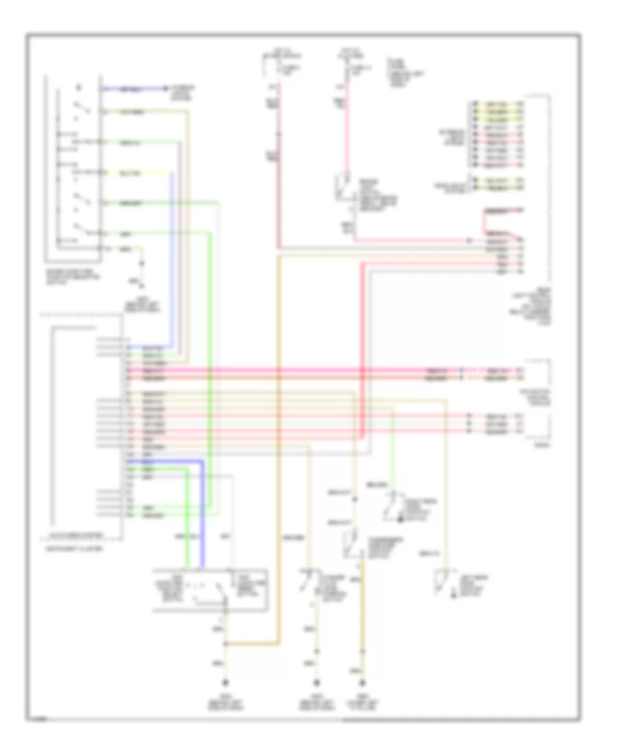
Instrument Cluster Wiring Diagram for Audi A4 Quattro 2001
List of elements for Instrument Cluster Wiring Diagram for Audi A4 Quattro 2001:
- (lower left of engine) oil pressure switch
- (on left end of dash)
- 15a
- 18a
- 86s
- A/c control head
- A11
- Abs control module (left front corner of eng compt)
- Abs warning
- Air bag ctrl module (in center console)
- Air bag mil
- Anti- theft warn
- Anti-theft imobilizer ind
- B13
- Brake fluid level warning switch
- Brake pad wear ind
- Brake system warn
- C10
- C13
- Central locking/ alarm system/ interior light delay module (bottom right of luggage compartment)
- Clock
- Computer data lines system
- Coolant level/ temp warn
- Driver's seat belt switch
- Ect gauge
- Emergency flasher relay
- Engine coolant level warning switch (bottom of reservoir)
- Engine coolant temperature sensor
- Fuel gauge
- Fuel level sensor
- Fuel reserve warn
- Fuse 15 10a
- Fuse 18 10a
- Fuse 5 5a
- Fuse panel
- G104 (left side of engine compt)
- G202 (behind left side of dash)
- G900 (lower left "a" pillar)
- Gen warn ind
- Generator
- Headlight leveling control module
- Headlights system
- High beam ind
- Hot at all times
- Hot in run or start
- Hot with high beams on
- Ignition switch
- Ignition switch acc
- Instrument cluster
- Interior lights system
- Key switch
- Left front brake pad wear sensor
- Left turn ind
- Lock
- Mil indicator
- Motronic engine control module (near brake booster)
- Navigation control module
- Off
- Oil level thermal sensor
- Oil press warn
- Oil temp gauge
- Panel dimmer
- Park brake ind
- Park brake switch
- Park light ind
- Pwr accel warn ind
- Radio
- Red
- Right front brake pad wear sensor
- Right high beam headlight
- Right turn ind
- Run
- Seat belt ind
- Speedometer
- Start
- T10af
- T32
- T32/
- T32/10
- T32/11
- T32/12
- T32/13
- T32/15
- T32/20
- T32/21
- T32/22
- T32/23
- T32/25
- T32/26
- T32/27
- T32/28
- T32/3
- T32/30
- T32/31
- T32/5
- T32/7
- T32/8
- T32/9
- T32a
- T32a/
- T32a/10
- T32a/11
- T32a/12
- T32a/14
- T32a/18
- T32a/19
- T32a/21
- T32a/25
- T32a/27
- T32a/28
- T32a/29
- T32a/30
- T32a/32
- T32a/6
- T32a/7
- T8a
- Tachometer
- Traction cont ind
- Trailer operation ind
- Transmission control module
- Turn signal switch
- Vehicle speed sensor
- Volts meter
- W/ asc
- Warning buzzer
- Washer fluid level
- Wiper/washer intermittent relay (central electric panel)
INTERIOR LIGHTS
Courtesy Lamp Wiring Diagram for Audi A4 Quattro 2001
List of elements for Courtesy Lamp Wiring Diagram for Audi A4 Quattro 2001:
- 14a
- 38a
- A12
- Automatic day/night mirror
- Avant
- C10
- Central locking/ alarm system/ interior light delay control module (bottom right of luggage compartment)
- Door warning lights control module (on 8-way relay carrier)
- Driver side heated mirror
- Driver's side door contact switch
- Driver's side door warning light
- Front interior light assembly
- Fuse 14 10a
- Fuse 3 5a
- Fuse 38 15a
- Fuse 5 5a (or 10a)
- Fuse panel (behind left side of dash)
- G202 (behind left side of dash)
- G900 (lower left "a" pillar)
- Glove compt light
- Head
- Headlights & exterior lights system
- Hot at all times
- Hot in run or start
- Instrument cluster
- Instrument cluster system
- Interior lights system (instrument illumination circuit)
- Left foot- well light
- Left luggage compartment light
- Left make-up mirror light
- Left make-up mirror switch
- Left rear door contact switch
- Left rear door warning light
- Light switch
- Luggage compartment light
- Micro central electric
- Mirror adjustment switch
- Off
- Park
- Passenger's front door contact switch
- Passenger's side door warning light
- Rear reading/ courtesy light
- Red
- Right foot- well light
- Right luggage compartment light
- Right make-up mirror light
- Right make-up mirror switch
- Right rear door contact switch
- Right rear door warning light
- Sedan, s4
- T32
- Trunk lock switch (sedan, s4 only)
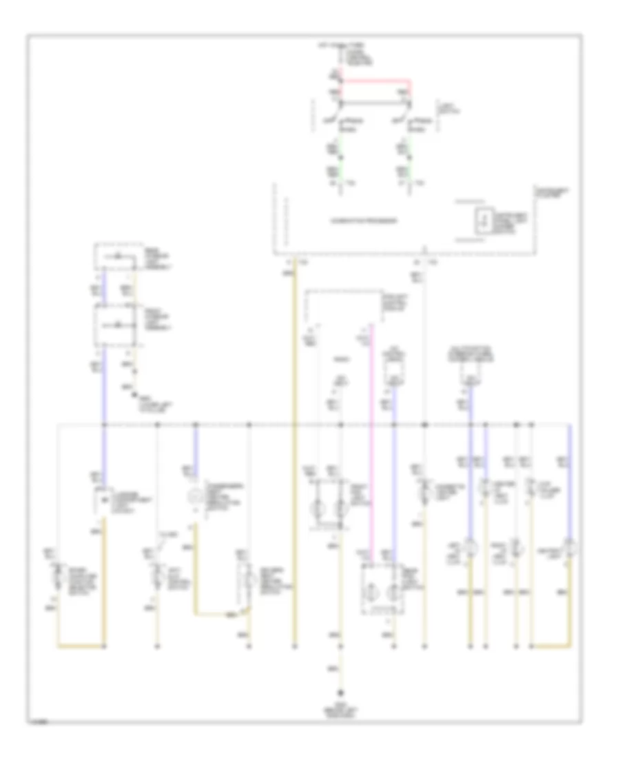
Instrument Illumination Wiring Diagram for Audi A4 Quattro 2001
List of elements for Instrument Illumination Wiring Diagram for Audi A4 Quattro 2001:
- A/c control head
- Anti- slip control switch
- Ashtray light
- Board computer function selector switch
- Center i/p vent illum
- Cigarette lighter light
- Combination processor
- Cup holder illum
- Dim input
- Driver's seat heater regulating switch
- Foglight control module
- Front fog- light switch
- Front interior light assembly
- G202 (behind left side dash)
- G900 (lower left "a" pillar)
- Head
- Hot at all times
- Instrument cluster
- Instrument panel light dimmer switch
- Left i/p vent illum
- Light switch
- Luggage compartment light (avant)
- Micro central electric
- Multifunction steering wheel control module
- Off
- Park
- Passenger's seat heater regulating switch
- Radio
- Rear fog- light switch
- Rear interior light assembly
- Red
- Right i/p vent illum
- T32
- W/ asc
NAVIGATION
Navigation Wiring Diagram for Audi A4 Quattro 2001
List of elements for Navigation Wiring Diagram for Audi A4 Quattro 2001:
- (on left end of dash)
- 15a
- 31a
- A/t
- Auto check system
- Back-up light switch
- Board computer function selector switch
- Combination processor
- Computer data lines system
- Exterior lights system
- Fuse 15 10a
- Fuse 31 15a
- Fuse 5 10a
- Fuse panel
- G202 (behind left side of dash)
- Hot at all times
- Hot in run or start
- Instrument cluster
- Interior lights system
- M/t
- Multi- function transmission range switch (on left side of transmission, behind mounting bracket)
- Navigation control module
- Navigation system antenna
- Nca
- Radio
- T20c
- T32
- T32b
- T8i
- Telephone transceiver
POWER DISTRIBUTION
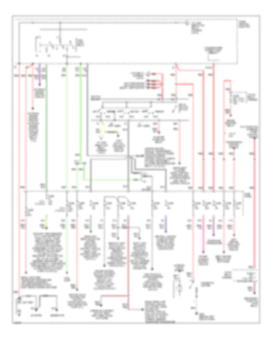
Power Distribution Wiring Diagram (1 of 2) for Audi A4 Quattro 2001
List of elements for Power Distribution Wiring Diagram (1 of 2) for Audi A4 Quattro 2001:
- (1.8l) (2.7l/2.8l)
- (2.7l) (1.8l/2.8l)
- (2.8l) (1.8l)
- (not used)
- 1.8l
- 1.8l & 2.8l
- 10a
- 13-way relay carrier
- 15/30a
- 17a
- 2.7l/ 2.8l
- 28a
- 29a
- 3-way relay carrier
- 30a
- 31a
- 32a
- 33a
- 34a
- 37a
- 44a
- 50b
- 86s
- 87f/ dti
- Acc
- Air bag control module, transmission control module, power window/sunroof control module, window motors, instrument cluster, brake booster relay (1.8l & 2.8l)
- Back-up light switch (m/t), mass airflow sensor, automatic day/night interior mirror, motronic engine control module (2.8l)
- Battery
- Brake booster relay
- Central locking/ alarm system/ interior light delay control module, door lock switch
- Cigarette lighter
- Cruise control switch, motronic engine control module (1.8l), brake light switch, clutch vacuum vent valve switch (m/t)
- Daytime running lights switch-on relay, light switch
- Exhaust temp sensors (2.7l), leak detection pump (1.8l/2.8l), mass airflow sensor, idle air control cutoff valve, evap canister purge regulator valve, camshaft adjustment valves (2.7l/2.8l), secondary air injection sol valve, oxygen sensors, secondary air injection relay, wastegate bypass regulator valve, intake manifold chang over valve (2.8l)
- Fuel pump
- Fuel pump relay
- Fuse 10a
- Fuse 10a 15a
- Fuse 15a
- Fuse 15a 20a
- Fuse 20a
- Fuse 30a
- Fuse 50a 40a
- Fuse 5a
- Fuse panel
- G202 (behind left side of dash)
- Generator
- Headlight beam adjusting motors, headlight adjusting control module, rear lamp control module, headlights (w/o 2.7l)
- Ignition coils, distributor ignition capacitor (2.8l), leak detection pump (2.7l)
- Ignition coils, motronic engine control module (2.8l), fuel injectors, cruise control switch
- Ignition switch
- Instrument cluster, radio, central locking/alarm system/interior light delay control module
- Interior lights system
- Key-in ignition switch
- Left heated door lock control module
- Light switch, foglights control module
- Micro central electric
- Mirror adjustment switch, seat heat regulating switches
- Motronic engine control module
- Multifunction steering wheel control module
- Off
- Power sunroof control module
- Radio, amplifier, telephone transceiver, left rear midrange & woofer speaker (avant), right rear woofer amplifier
- Radio, rear lamp control module, a/c control head, navigation control module, foglights control module, oil level thermal sensor, telephone transceiver
- Red
- Run
- S2/ 87f
- S3/
- S3/ 87a
- S3/ s
- Seat heater regulating switches
- Secondary injection pump relay
- Shift lock solenoid, ecm, multi- function transmission range switch, tiptronic switch, garage door opener, data link connector
- Start
- Starter
- Starter interlock relay
- Telephone transceiver
- To fuse 12 (diagram 2 of 2)
- To load reduction relay (diagram 2 of 2)
- Transmission control module
- Washer/wiper intermittent relay
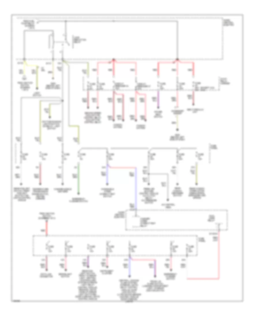
Power Distribution Wiring Diagram (2 of 2) for Audi A4 Quattro 2001
List of elements for Power Distribution Wiring Diagram (2 of 2) for Audi A4 Quattro 2001:
- (except 4x4) (4x4)
- 12a
- 13/15
- 13a
- 14a
- 15a
- 24a
- 25a
- 26a
- 27a
- 36a
- 38a
- 39a
- 40a
- 75x
- 8-way relay carrier
- A/c control head
- Abs hydraulic unit
- Accessory socket
- Brakelight switch
- Central locking/ alarm system/ interior lights delay control module, door lock switch, ultra sound sensor control module door warning lights
- Circuit breaker 37 30a
- Circuit breaker 43 30a
- Data link connector
- Daytime running lights switch- on relay, light switch
- Dual horn relay
- Emergency flasher switch
- Fresh air blower control module, a/c clutch relay, a/c pressure switch
- From fuel pump relay (diagram 1 of 2)
- From ignition switch (diagram 1 of 2)
- Fuse 10a
- Fuse 15a
- Fuse 25a
- Fuse 30a
- Fuse 40a
- Fuse 5a
- Fuse 60a 50a
- Fuse panel
- G202 (behind left side of dash)
- Instrument cluster
- Light switch
- Load reduction relay
- Micro central electric
- Power seat switch
- Rear fog- light switch, front interior light, central locking/alarm system/interior light delay control module, reading lights make-up mirror light switches, door warning lights control module
- Rear foglight switch, front foglight switch, fog- lights control module
- Rear window defogger switch
- Rear window wiper motor, airbag spiral spring/return spring
- Red
- S1/30ah
- S1/31
- S1/75
- Second speed coolant fan control relay, coolant fan control relay
- Temperature/ transmission range switch, heated mirrors
- Trunk lid alarm switch, luggage compartment light, interior monitor switch
- W/ drl
- Washer nozzle heaters
- Washer/ wiper intermittent relay
- Window motors
- Windshield wiper intermittent switch
POWER DOOR LOCKS
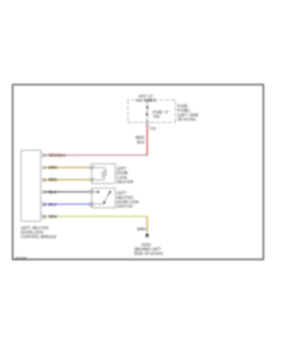
Heated Door Locks Wiring Diagram for Audi A4 Quattro 2001
List of elements for Heated Door Locks Wiring Diagram for Audi A4 Quattro 2001:
- 17a
- All times
- Fuse 17 10a
- Fuse panel (left side of dash)
- G202 (behind left side of dash)
- Hot at
- Left door lock heater
- Left heated door lock control module
- Left heated door lock switch
POWER MIRRORS
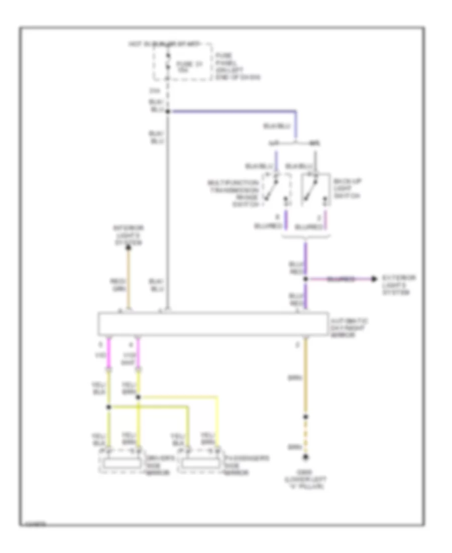
Electrochromic Mirror Wiring Diagram for Audi A4 Quattro 2001
List of elements for Electrochromic Mirror Wiring Diagram for Audi A4 Quattro 2001:
- 31a
- A/t
- Automatic day/night mirror
- Back-up light switch
- Driver's side mirror
- Exterior lights system
- Fuse 31 15a
- Fuse panel (on left end of dash)
- G900 (lower left "a" pillar)
- Hot in run or start
- Interior lights system
- M/t
- Multifunction transmission range switch
- Passenger's side mirror
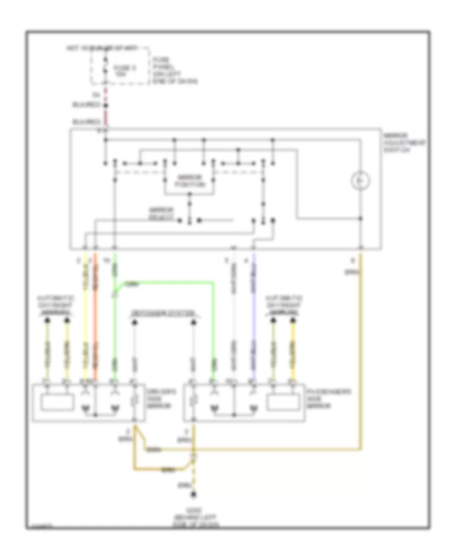
Power Mirror Wiring Diagram for Audi A4 Quattro 2001
List of elements for Power Mirror Wiring Diagram for Audi A4 Quattro 2001:
- Automatic day/night mirrors
- Defogger system
- Driver's side mirror
- Fuse 5 10a
- Fuse panel (on left end of dash)
- G202 (behind left side of dash)
- Hot in run or start
- Mirror adjustment switch
- Mirror position
- Mirror select
- Passenger's side mirror
POWER SEATS
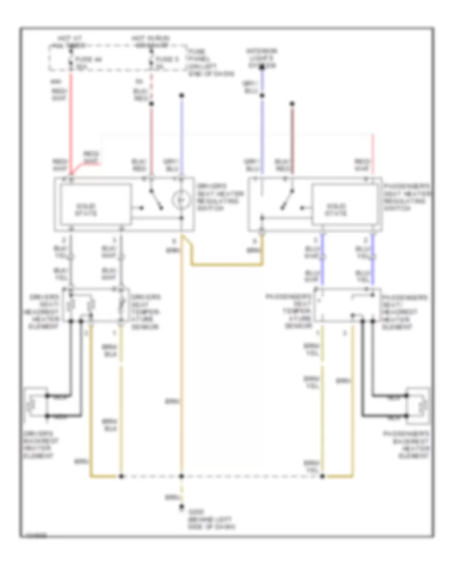
Heated Seats Wiring Diagram for Audi A4 Quattro 2001
List of elements for Heated Seats Wiring Diagram for Audi A4 Quattro 2001:
- 44a
- All times
- Driver's backrest heater element
- Driver's seat heater regulating switch
- Driver's seat temper- ature sensor
- Driver's seat/ headrest heater element
- Fuse 44 30a
- Fuse 5 5a
- Fuse panel (on left end of dash)
- G202 (behind left side of dash)
- Hot at
- Hot in run or start
- Interior lights system
- Nca
- Passenger's backrest heater element
- Passenger's seat heater regulating switch
- Passenger's seat temper- ature sensor
- Passenger's seat/ headrest heater element
- Solid state
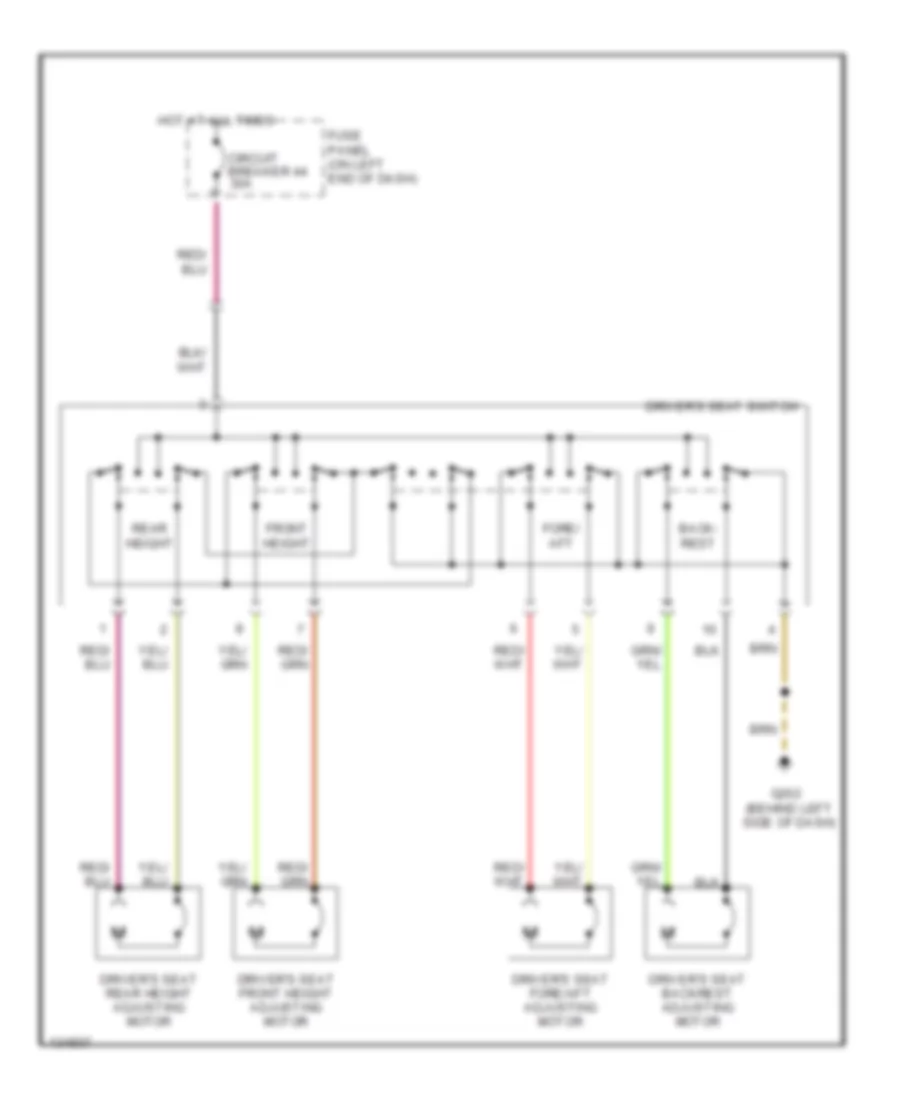
Left Power Seat Wiring Diagram for Audi A4 Quattro 2001
List of elements for Left Power Seat Wiring Diagram for Audi A4 Quattro 2001:
- Back- rest
- Circuit breaker 44 30a
- Driver's seat backrest adjusting motor
- Driver's seat fore/aft adjusting motor
- Driver's seat front height adjusting motor
- Driver's seat rear height adjusting motor
- Driver's seat switch
- Fore/ aft
- Front height
- Fuse panel (on left end of dash)
- G202 (behind left side of dash)
- Hot at all times
- Rear height
POWER TOP/SUNROOF
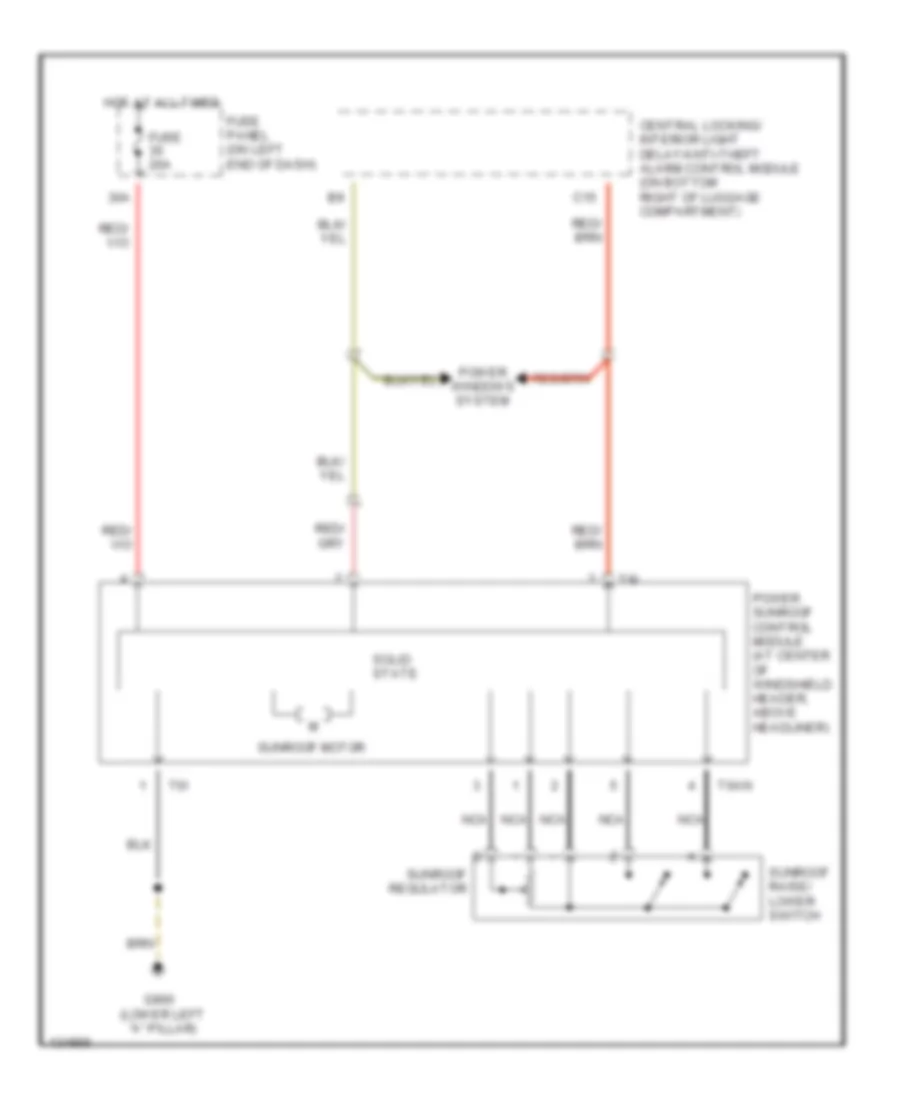
Power Top/Sunroof Wiring Diagram for Audi A4 Quattro 2001
List of elements for Power Top/Sunroof Wiring Diagram for Audi A4 Quattro 2001:
- 30a
- C15
- Central locking/ interior light delay/anti-theft alarm control module (on bottom right of luggage compartment)
- Fuse 20a
- Fuse panel (on left end of dash)
- G900 (lower left "a" pillar)
- Hot at all times
- Nca
- Power sunroof control module (at center of windshield header, above headliner)
- Power windows system
- Solid state
- Sunroof motor
- Sunroof raise/ lower switch
- Sunroof regulator
- T6an
- T6i
POWER WINDOWS
Power Windows Wiring Diagram (1 of 2) for Audi A4 Quattro 2001
List of elements for Power Windows Wiring Diagram (1 of 2) for Audi A4 Quattro 2001:
- 8-way relay carrier (below left end of dash)
- A11
- Acc
- All times
- C15
- Central locking/ interior light delay/anti-theft alarm control module (bottom right of luggage compt)
- G900 (lower left a-pillar)
- Hot at
- Ignition switch start
- Left front window switch
- Left window motor
- Off
- Power sunroof control module
- Power window fuse 37 30a
- Run
- Window motor
Power Windows Wiring Diagram (2 of 2) for Audi A4 Quattro 2001
List of elements for Power Windows Wiring Diagram (2 of 2) for Audi A4 Quattro 2001:
- 8-way relay carrier (below left end of dash)
- All times
- G900 (lower left a-pillar)
- Hot at
- Left rear door window motor
- Left rear door window switch (center console)
- Left rear door window switch (door)
- Power window circuit breaker 43 30a
- Right front door window switch (left door)
- Right front door window switch (right door)
- Right rear door window motor
- Right rear door window switch (center console)
- Right rear door window switch (door)
- Right window motor
- Window lockout switch
- Window m motor
- Window motor
RADIO
AM/FM Stereo Wiring Diagram, Bose Except Avant for Audi A4 Quattro 2001
List of elements for AM/FM Stereo Wiring Diagram, Bose Except Avant for Audi A4 Quattro 2001:
- (navigation only)
- (w/ symphony radio)
- 37a
- Antenna amplifier
- Antenna selection control module (in trunk, on cd changer bracket) (w/ symphony radio)
- Anti-theft system
- Auto check system
- Combination processor
- Computer data lines system
- Fuse panel (on left end of dash)
- G202 (behind left side of dash)
- G302 (near parking brake lever)
- Hot at all times
- Hot in run or start
- Instrument cluster
- Interior lights system
- Left frequency crossover
- Left front speaker
- Left front woofer & midrange speaker
- Left rear midrange speaker
- Left rear woofer
- Multifunction steering wheel control module
- Navigation control module (if equipped)
- Nca
- Radio
- Rear window defogger switch
- Rear window defogger/ window antenna (w/ concert radio)
- Rear window defogger/ window antenna (w/ symphony radio)
- Red
- Right front speaker
- Right front woofer & midrange speaker
- Right rear midrange speaker
- Right rear woofer
- Right rear woofer/ amplifier
- T10af
- T1l
- T20b
- T32
- T32a
- T8a
- T8b
- Telephone transceiver
- Tv antenna amplifier
- W/ auto check system
- W/ concert radio
- W/ symphony radio
AM/FM Stereo Wiring Diagram, Bose with Avant for Audi A4 Quattro 2001
List of elements for AM/FM Stereo Wiring Diagram, Bose with Avant for Audi A4 Quattro 2001:
- (navigation only)
- (w/ symphony radio)
- 37a
- Antenna
- Antenna selection control module (in trunk, on cd changer bracket) (w/ symphony radio)
- Anti-theft system
- Auto check system
- Combination processor
- Computer data lines system
- Fuse panel (on left end of dash)
- G202 (behind left side of dash)
- G302 (near parking brake lever)
- Hot at all times
- Hot in run or start
- Instrument cluster
- Interior lights system
- Left frequency crossover
- Left front speaker
- Left front woofer & midrange speaker
- Left rear midrange speaker
- Multifunction steering wheel control module
- Navigation control module (if equipped)
- Nca
- Radio
- Rear window defogger switch
- Rear window defogger/ window antenna (w/ symphony radio)
- Red
- Right frequency crossover
- Right front speaker
- Right front woofer & midrange speaker
- Right rear midrange speaker
- Right rear woofer/ amplifier
- T10af
- T1l
- T20b
- T32
- T32a
- T8a
- T8b
- Telephone transceiver
- Tv antenna amplifier
- W/ auto check system
- W/ symphony radio
AM/FM Stereo Wiring Diagram, with CD Changer Except Avant for Audi A4 Quattro 2001
List of elements for AM/FM Stereo Wiring Diagram, with CD Changer Except Avant for Audi A4 Quattro 2001:
- (navigation only)
- (w/ symphony radio)
- 37a
- Antenna amplifier
- Antenna selection control module (in trunk, on cd changer bracket) (w/ symphony radio)
- Anti-theft system
- Auto check system
- Cd changer unit
- Combination processor
- Computer data lines system
- Fuse panel (on left end of dash)
- G202 (behind left side of dash)
- G302 (near parking brake lever)
- Hot at all times
- Hot in run or start
- Instrument cluster
- Interior lights system
- Left frequency crossover
- Left front midrange speaker
- Left front woofer
- Left rear midrange & woofer speakers
- Multifunction steering wheel control module
- Navigation control module (if equipped)
- Nca
- Radio
- Rear window defogger switch
- Rear window defogger/ window antenna (w/ concert radio)
- Rear window defogger/ window antenna (w/ symphony radio)
- Red
- Right front midrange speaker
- Right front woofer
- Right rear woofer & midrange speakers
- T10af
- T1l
- T20b
- T32
- T32a
- T8a
- T8b
- Telephone transceiver
- Tv antenna amplifier
- W/ auto check system
- W/ concert radio
- W/ symphony radio
AM/FM Stereo Wiring Diagram, with CD Changer with Avant for Audi A4 Quattro 2001
List of elements for AM/FM Stereo Wiring Diagram, with CD Changer with Avant for Audi A4 Quattro 2001:
- (navigation only)
- (w/ symphony radio)
- 37a
- Antenna
- Antenna selection control module (in trunk, on cd changer bracket) (w/ symphony radio)
- Anti-theft system
- Auto check system
- Cd changer unit
- Combination processor
- Computer data lines system
- Fuse panel (on left end of dash)
- G202 (behind left side of dash)
- G302 (near parking brake lever)
- Hot at all times
- Hot in run or start
- Instrument cluster
- Interior lights system
- Left frequency crossover
- Left front woofer & midrange speaker
- Left rear woofer & midrange speaker
- Left rear woofer/ amplifier
- Multifunction steering wheel control module
- Navigation control module (if equipped)
- Nca
- Radio
- Rear window defogger switch
- Rear window defogger/ window antenna (w/ symphony radio)
- Red
- Right frequency crossover
- Right front woofer & midrange speaker
- Right rear woofer & midrange speaker
- T10af
- T1l
- T20b
- T32
- T32a
- T8a
- T8b
- Telephone transceiver
- Tv antenna amplifier
- W/ auto check system
- W/ concert radio
- W/ symphony radio
SHIFT INTERLOCK
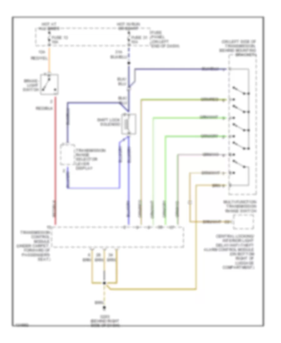
Shift Interlock Wiring Diagram for Audi A4 Quattro 2001
List of elements for Shift Interlock Wiring Diagram for Audi A4 Quattro 2001:
- (on left side of transmission, behind mounting bracket)
- 13a
- 31a
- Brake- light switch
- Central locking/ interior light delay/anti-theft alarm control module (on bottom right of luggage compartment)
- Fuse 13 10a
- Fuse 31 15a
- Fuse panel (on left end of dash)
- G203 (behind right side of dash)
- Hot at all times
- Hot in run or start
- Multi-function transmission range switch
- Shift lock solenoid
- Transmission control module (under carpet, forward of passenger's seat)
- Transmission range selector lever display
STARTING/CHARGING
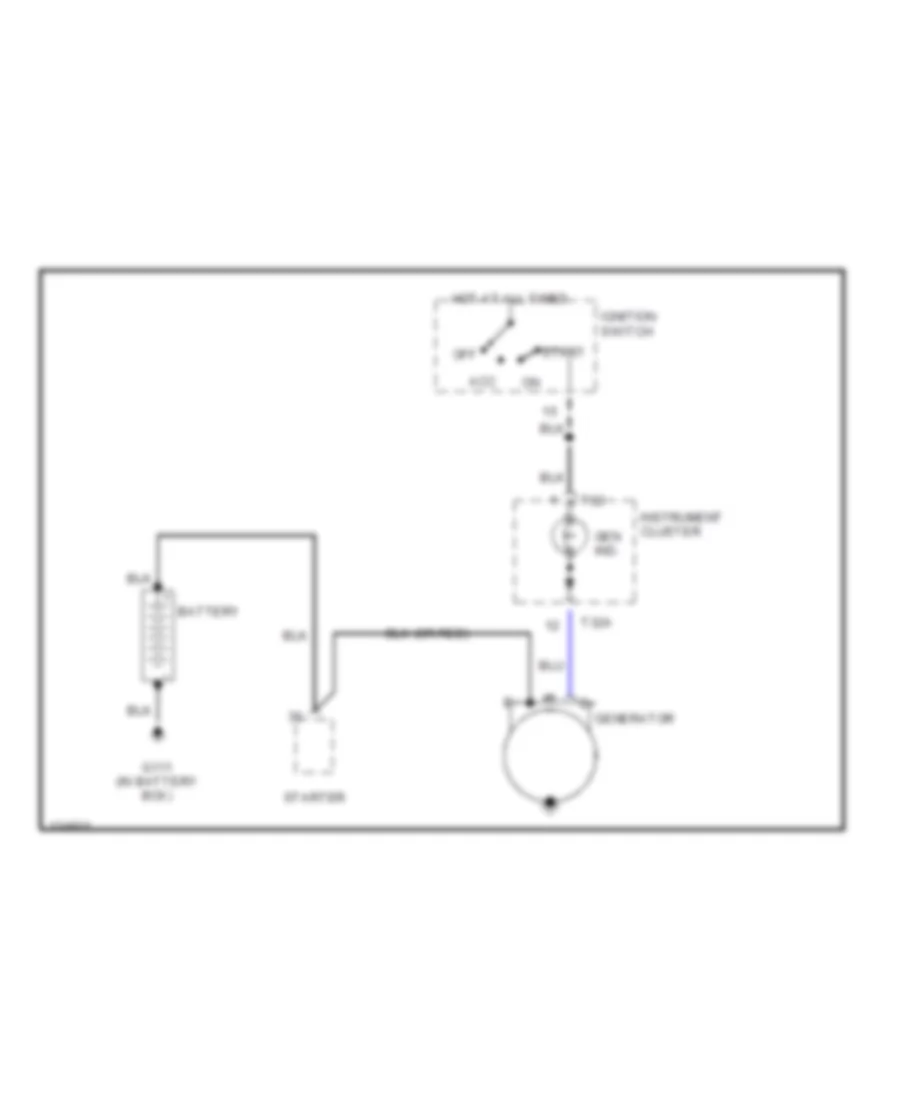
Charging Wiring Diagram for Audi A4 Quattro 2001
List of elements for Charging Wiring Diagram for Audi A4 Quattro 2001:
- Acc
- Battery
- G111 (in battery box)
- Gen ind.
- Generator
- Hot at all times
- Ignition switch
- Instrument cluster
- Off
- Start
- Starter
- T32
- T32a
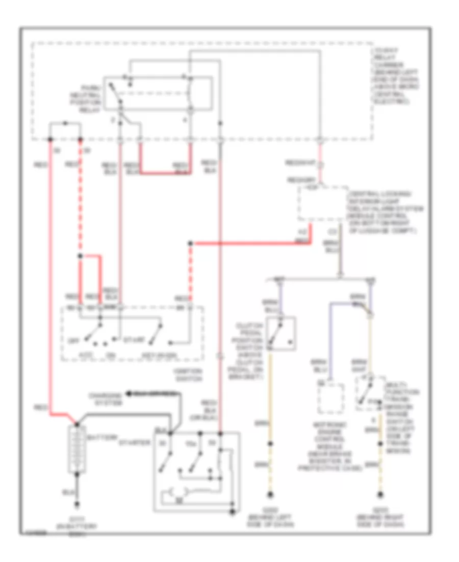
Starting Wiring Diagram for Audi A4 Quattro 2001
List of elements for Starting Wiring Diagram for Audi A4 Quattro 2001:
- 13-way relay carrier (behind left end of dash, above micro central electric)
- 15a
- 50b
- A/t
- Acc
- Battery
- Central locking/ interior light delay/alarm system module control (on bottom right of luggage compt)
- Charging system
- Clutch pedal position switch (above clutch pedal, on bracket)
- G111 (in battery box)
- G202 (behind left side of dash)
- G203 (behind right side of dash)
- Ignition switch
- Key-in ign
- M/t
- Motronic engine control module (near brake booster, in protective case)
- Multi- function trans- mission range switch (on left side of trans- mision)
- Off
- P/n
- Park/ neutral position relay
- Red
- Start
- Starter
SUPPLEMENTAL RESTRAINTS
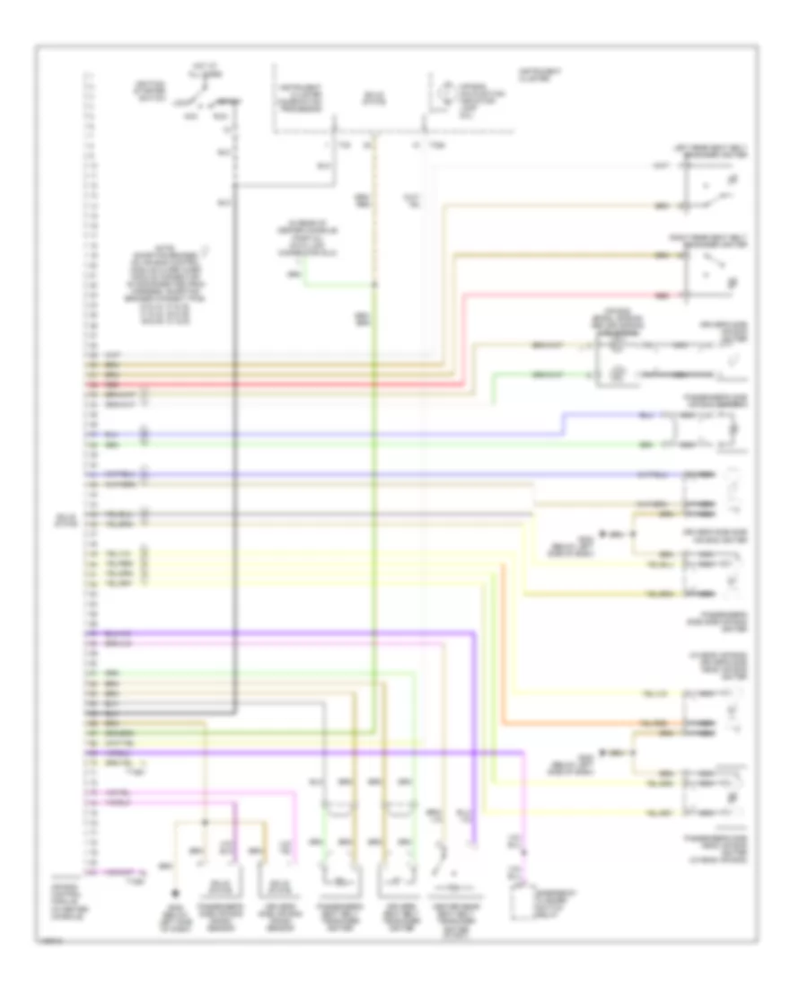
Supplemental Restraints Wiring Diagram for Audi A4 Quattro 2001
List of elements for Supplemental Restraints Wiring Diagram for Audi A4 Quattro 2001:
- (in rear of center console) (partial) data link connector (dlc)
- (w/head air bag) driver's side head air bag igniter
- Acc
- Air bag control module (in center console)
- Air bag malfunction indicator lamp (mil)
- Air bag spiral spring/ return spring w/slip ring
- Center rear seat belt tensioner igniter (avant)
- Driver's seat belt tensioner igniter
- Driver's side air bag crash sensor
- Driver's side air bag igniter
- Driver's side side air bag igniter
- Emergency flasher switch relay
- G202 (below left side of dash)
- Hot at all times
- Ignition/ starter switch
- Instrument cluster
- Instrument cluster combination processor
- Left rear seat belt tensioner igniter
- Lock
- Nca
- Note: shorting bridges on air bag control module close when module connector is disconnected from harness. shorting bridges connect pins: 33 & 34, 37 & 38, 41 & 42, 45 & 46, 49 & 50, 51 & 52
- Passenger's seat belt tensioner igniter
- Passenger's side air bag crash sensor
- Passenger's side air bag igniter 1
- Passenger's side head air bag igniter (w/head air bag)
- Passenger's side side air bag igniter
- Red
- Right rear seat belt tensioner igniter
- Run
- Solid state
- Start
- T10an
- T32
- T32a
TRANSMISSION
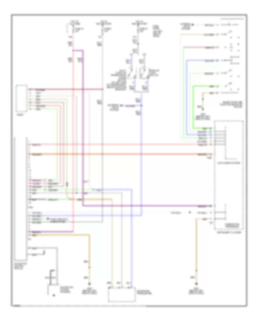
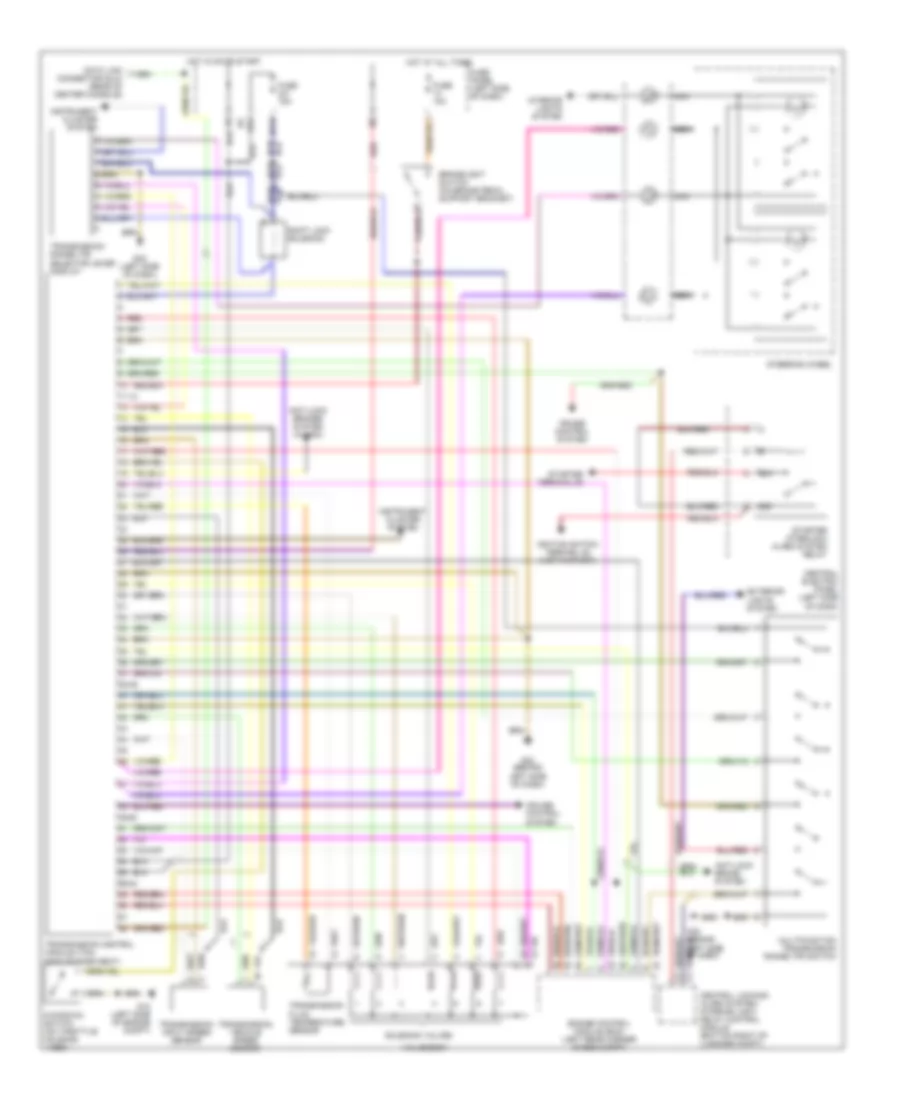
A/T Wiring Diagram for Audi A4 Quattro 2001
List of elements for A/T Wiring Diagram for Audi A4 Quattro 2001:
- 11-12
- 231a
- 38-39
- 49-50
- 50a
- 50z
- 56-84
- Anti-lock brake system
- Anti-lock brakes system (w/ asc)
- Brakelight switch (on brake pedal support bracket)
- Central electric panel (left side of dash)
- Central locking/ alarm system/ interior light delay control module (bottom right of luggage compt)
- Cruise control system
- Data link connector (dlc) (rear of center console)
- Engine control module (ecm) (left rear corner of eng compt)
- Exterior lights system
- Fuse 10a
- Fuse 15a
- Fuse panel (left side of dash)
- G12 (left side of engine compt)
- G32 (behind left side of dash)
- G32 (left side of dash)
- Hot at all times
- Hot in on or start
- Ignition switch terminal 50 (hot in start)
- Instrument cluster system
- Interior lights system
- Kickdown switch (on throttle housing)
- Multifunction transmission range (tr) switch
- Nca
- Red
- Shift lock solenoid
- Solenoid valves
- Starter interlock alarm system relay
- Starter terminal 50
- Steering wheel
- Transmission control module (tcm) (fwd of pass seat)
- Transmission fluid temperature sensor
- Transmission input speed sensor
- Transmission range (tr) selector lever display
- Transmission vehicle speed sensor
- Valve body
TRUNK, TAILGATE, FUEL DOOR
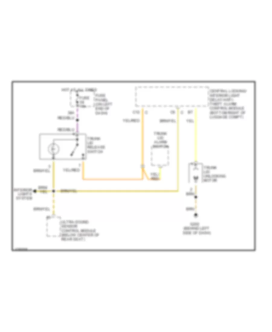
Trunk Release Wiring Diagram for Audi A4 Quattro 2001
List of elements for Trunk Release Wiring Diagram for Audi A4 Quattro 2001:
- 38a
- C12
- Central locking/ interior light delay/anti- theft alarm control module (bottom right of luggage compt)
- Fuse 15a
- Fuse panel (on left end of dash)
- G202 (behind left side of dash)
- Hot at all times
- Interior lights system
- Trunk lid alarm switch
- Trunk lid release switch
- Trunk lid unlocking motor
- Ultra-sound sensor control module (below center of rear seat)
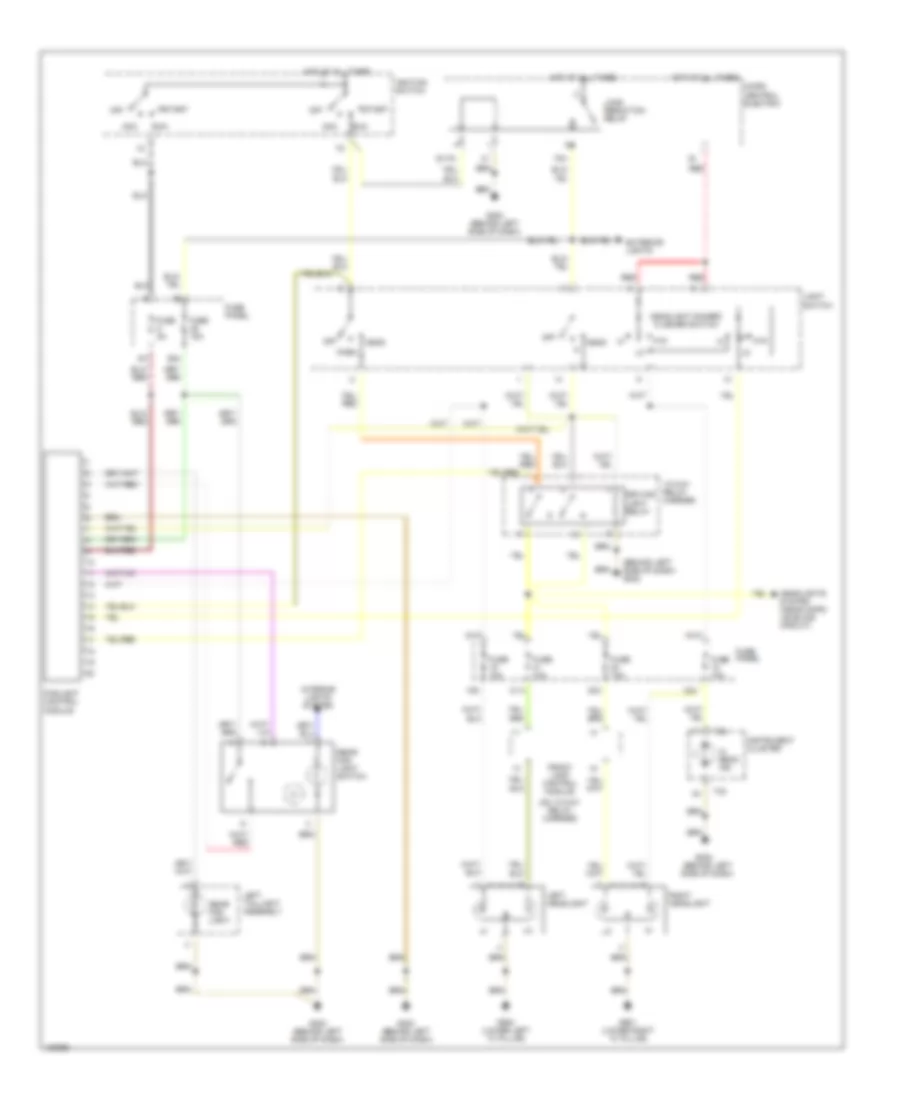
WIPER/WASHER
Wiper/Washer Wiring Diagram for Audi A4 Quattro 2001
List of elements for Wiper/Washer Wiring Diagram for Audi A4 Quattro 2001:
- (not used)
- 24a
- 27a
- 75x
- Avant
- Brake fluid level warning switch
- Except avant
- Fuse 15a
- Fuse 25a
- Fuse 5a
- Fuse panel (on left end of dash)
- G202 (behind left side of dash)
- Head
- Headlight dimmer/ flasher switch
- Headlight washer pump
- Hot at all times
- Hot in run
- Instrument cluster
- Left washer nozzle heater (optional)
- Load reduction relay
- Micro central electric
- Off
- Park
- Rear window wiper motor (avant)
- Red
- Right washer nozzle heater (optional)
- T o
- T32
- Washer switch
- Windshield washer pump
- Windshield wiper intermittent regulator
- Windshield wiper intermittent switch
- Windshield wiper motor
- Wiper/washer intermittent relay