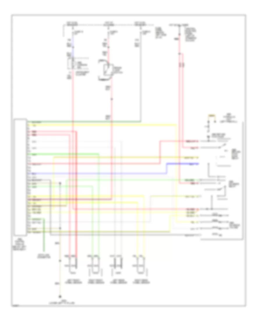
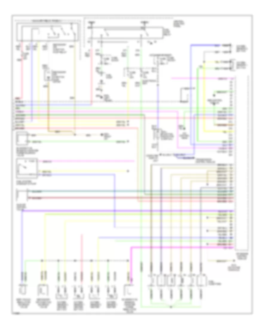
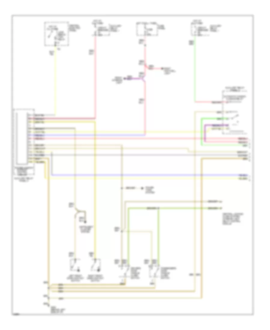
AIR CONDITIONING
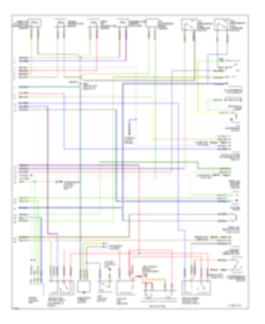
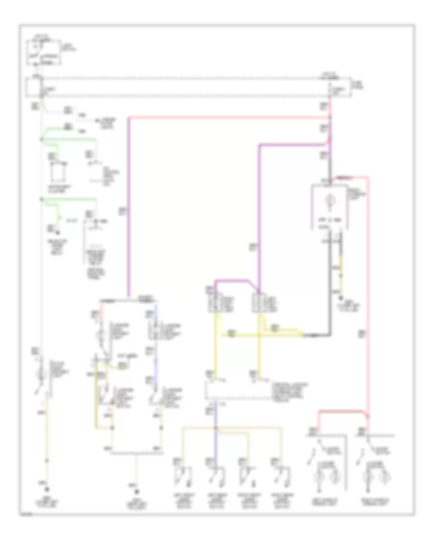
Automatic A/C-Heater System Wiring Diagram (1995 (Early Production) Wiring Diagram 1 Of 2) for Audi A6 1995

List of elements for Automatic A/C-Heater System Wiring Diagram (1995 (Early Production) Wiring Diagram 1 Of 2) for Audi A6 1995:
- A/c control unit
- Air flow flap
- Auxiliary relay panel 2
- Battery(30)
- C 1995 vftc
- Central flap
- Connector
- Coolant 2-way valve
- Data
- Defroster
- Footwell/
- Fuse 15 5a
- Fuse 15a
- Fuse 30a
- Fuse 5a
- Fuse 60a
- Fuse/ relay panel
- G202 (behind left side of i/p)
- G203 (lower right "a" pillar)
- Hot at all times
- Hot w/ lights on
- Hot w/ load reduction relay energized (x)
- Ignition(15)
- Interior temperature fan & sensor
- Link
- Temp regulator flap motor
- Transmission control module (a/t)
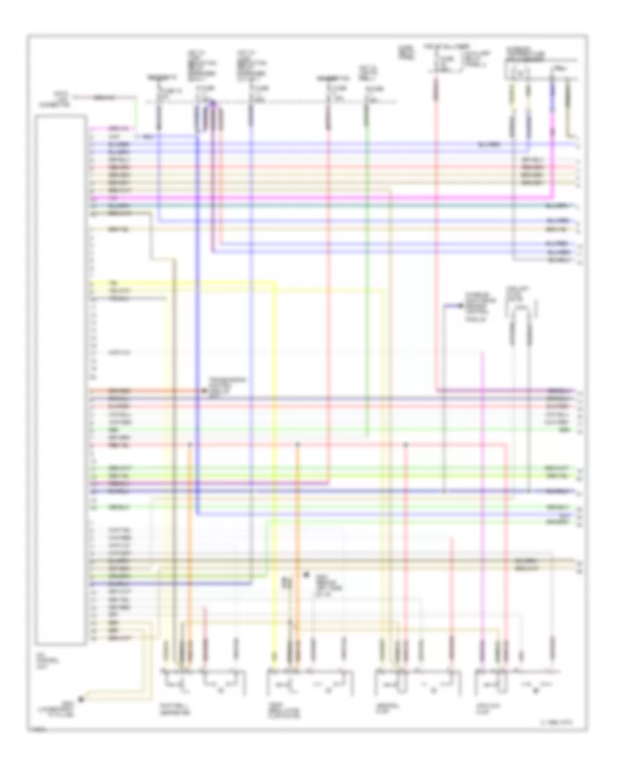
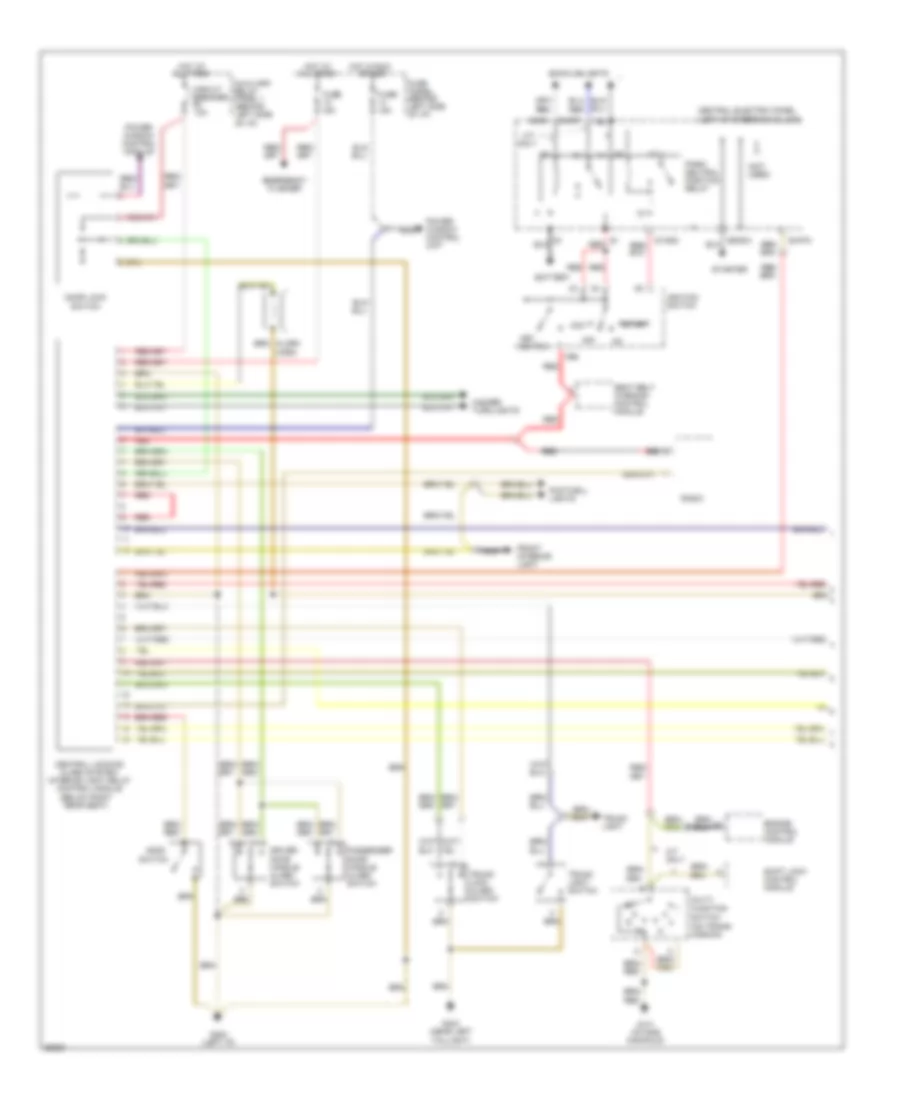
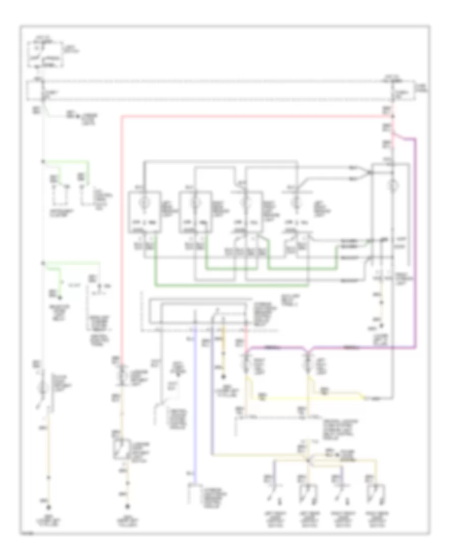
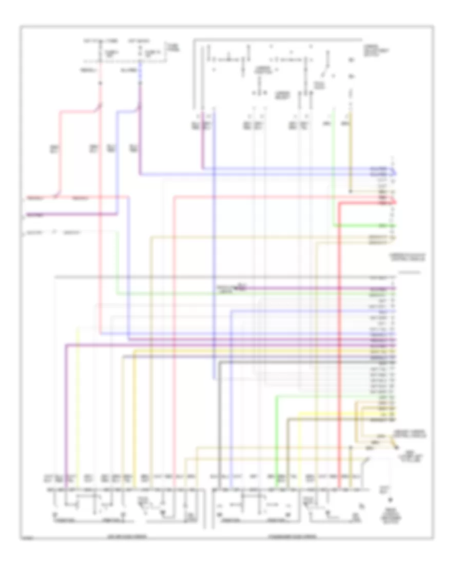
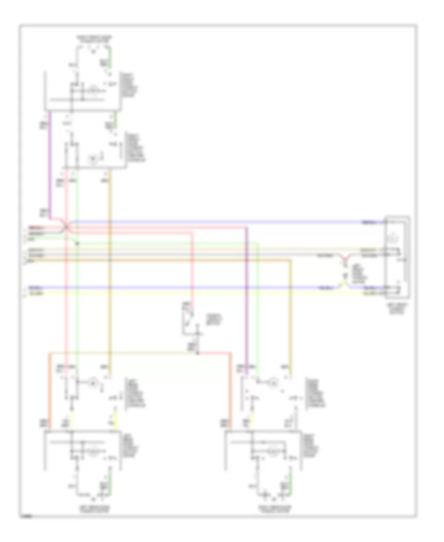
Automatic A/C-Heater System Wiring Diagram (1995 (Early Production) Wiring Diagram 2 Of 2) for Audi A6 1995
List of elements for Automatic A/C-Heater System Wiring Diagram (1995 (Early Production) Wiring Diagram 2 Of 2) for Audi A6 1995:
- (behind left side of i/p)
- (in fuse/relay panel)
- (intake manifold) g131
- (left side of engine compartment)
- (lower left "a" pillar)
- (lower right "a" pillar)
- A/c compressor clutch
- A/c compressor clutch relay
- A/c compressor speed sensor
- A/c refrigerant high pressure switch
- A/c refrigerant low pressure switch
- Ambient temperature sensor
- B10
- Blower motor
- C 1995 vftc
- C10
- C11
- Coolant fan control relay
- Coolant fan control thermo switch
- Coolant fan resistor
- Coolant fans
- Digital outside air temperature display
- Electronic thermo switch
- Engine control unit
- Fresh air blower control module
- Fresh air intake duct temperature sensor
- Fresh air recirculating flap valve
- Fresh air temperature sensor
- G100
- G200
- G202
- G202 (behind left side of i/p)
- G203
- Instrument cluster
- Interior lights system
- Low coolant switch
- Protection diode
- Red
- Second speed coolant fan control relay
- Temperature sensor, headliner
- Transmission control module (a/t)
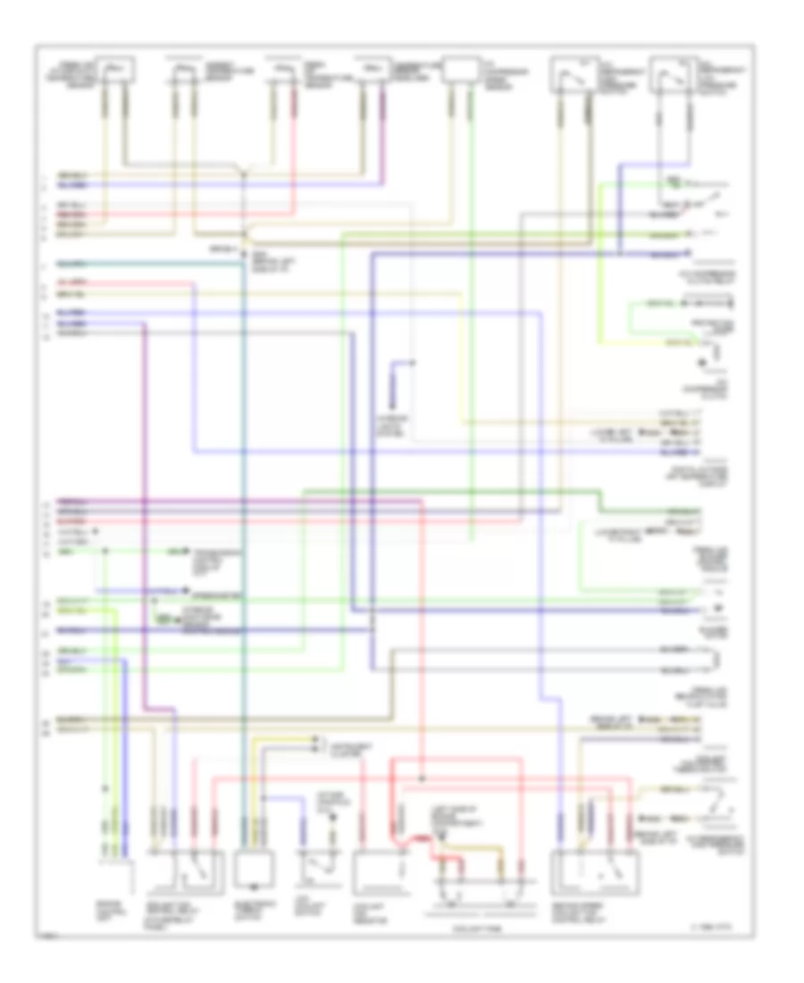
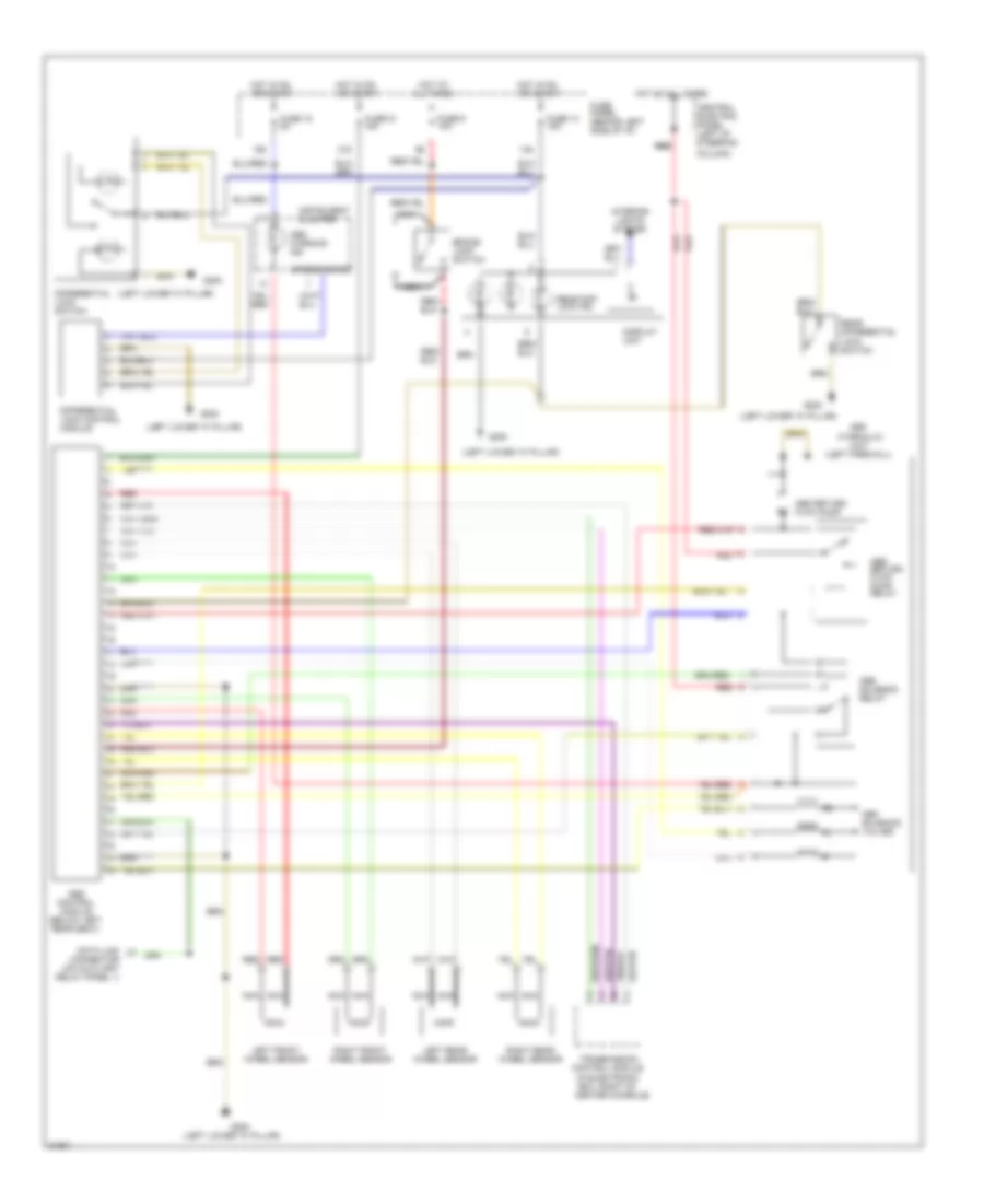
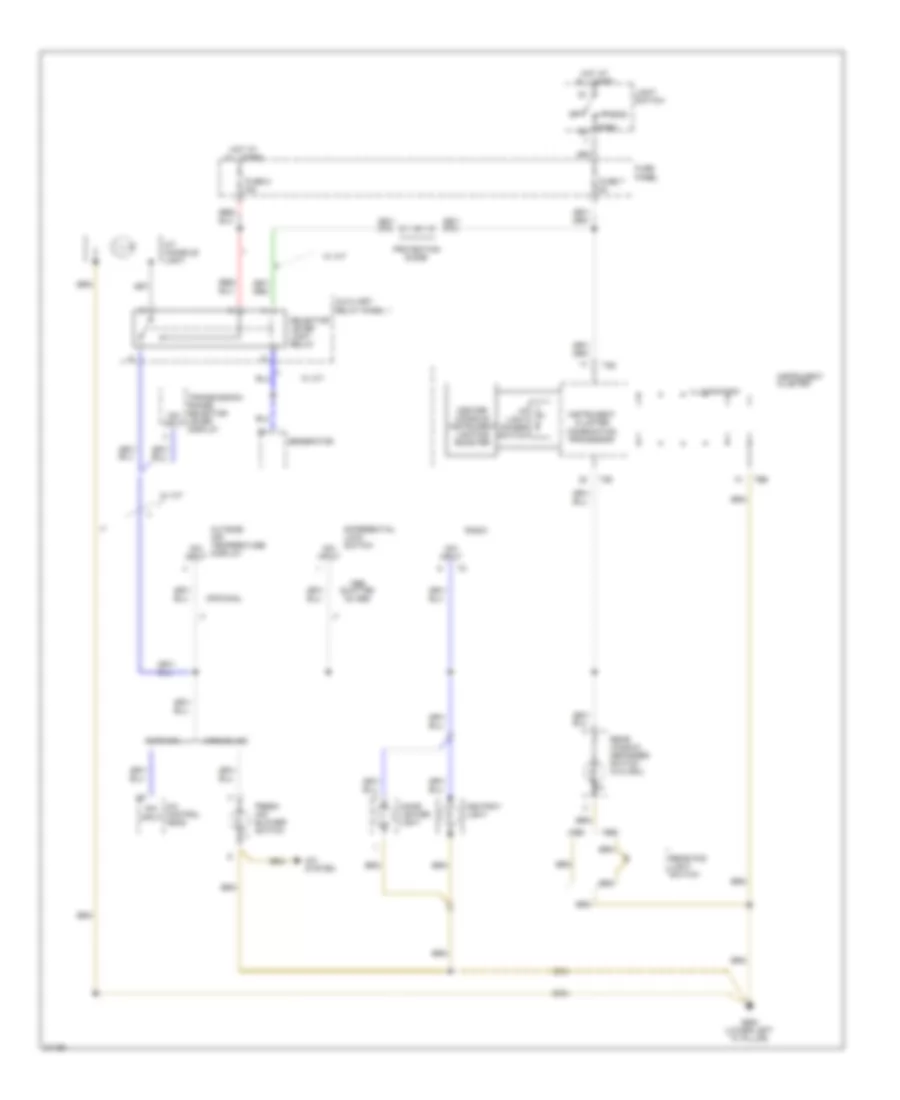
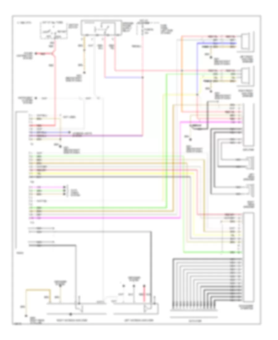
Automatic A/C-Heater System Wiring Diagram (1995 (Late Production) & 1996 Wiring Diagram 1 O for Audi A6 1995
List of elements for Automatic A/C-Heater System Wiring Diagram (1995 (Late Production) & 1996 Wiring Diagram 1 O for Audi A6 1995:
- A/c control unit
- Air flow flap
- Auxiliary relay panel 2
- Battery(30)
- C 1995 vftc
- Central flap
- Connector
- Coolant 2-way valve
- Data
- Defroster
- Footwell/
- Fuse 15 5a
- Fuse 15a
- Fuse 30a
- Fuse 5a
- Fuse 60a
- Fuse/ relay panel
- G202 (behind left side of i/p)
- G203 (lower right "a" pillar)
- Hot at all times
- Hot w/ lights on
- Hot w/ load reduction relay energized (x)
- Ignition(15)
- Interior monitoring sensor control
- Interior temperature fan & sensor
- Link
- Module
- Temp regulator flap motor
- Transmission control module (a/t)
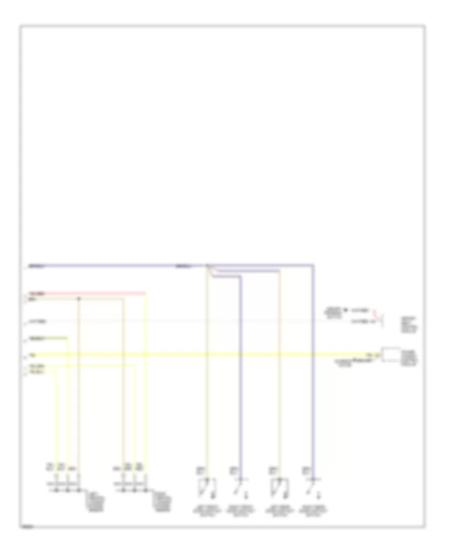
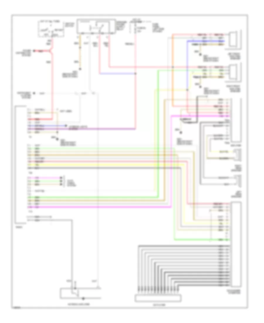
Automatic A/C-Heater System Wiring Diagram (1995 (Late Production) & 1996 Wiring Diagram 2 O for Audi A6 1995
List of elements for Automatic A/C-Heater System Wiring Diagram (1995 (Late Production) & 1996 Wiring Diagram 2 O for Audi A6 1995:
- (behind left side of i/p)
- (in fuse/relay panel)
- (intake manifold) g131
- (left side of engine compartment)
- (lower left "a" pillar)
- (lower right "a" pillar)
- A/c compressor
- A/c compressor clutch
- A/c compressor clutch relay
- A/c refrigerant high pressure switch
- A/c refrigerant low pressure switch
- Ambient temperature sensor
- Blower motor
- C 1995 vftc
- C10
- C11
- Coolant fan control relay
- Coolant fan control thermo switch
- Coolant fan resistor
- Coolant fans
- Digital outside air temperature display
- Electronic thermo switch
- Engine control unit
- Fresh air blower control module
- Fresh air intake duct temperature sensor
- Fresh air recirculating flap valve
- Fresh air temperature sensor
- G100
- G200
- G202
- G202 (behind left side of i/p)
- G203
- Instrument cluster
- Interior lights system
- Interior monitoring sensor control module
- Low coolant switch
- Protection diode
- Red
- Second speed coolant fan control relay
- Speed sensor
- Speedometer
- Temperature sensor, headliner
- Transmission control module (a/t)
ANTI-LOCK BRAKES
ABS Wiring Diagram (1995 A6 Wiring Diagram, FWD with Differential Lock With Differential Locks) for Audi A6 1995
List of elements for ABS Wiring Diagram (1995 A6 Wiring Diagram, FWD with Differential Lock With Differential Locks) for Audi A6 1995:
- (below left
- (left firewall)
- (lower left "a" pillar)
- 15a
- 21a
- Abs
- Abs return flow pump
- Abs return flow pump relay
- Abs solenoid relay
- Abs solenoid valves
- Abs warning ind.
- All times
- Brake lamp switch
- Central electric panel (left of steering column)
- Control
- Data link connector
- Differential lock valves
- Electronic differential lock cut- out relay
- Fuse 15 5a
- Fuse 21 15a
- Fuse 9 10a
- Fuse panel (behind left side of i/p)
- G200
- Hot at
- Hot at all times
- Hot in on or start
- Hydraulic
- Instrument cluster
- Left front wheel sensor
- Left rear wheel sensor
- Module
- Nca
- Rear seat)
- Red
- Red red
- Right front wheel sensor
- Right rear wheel sensor
- Speedometer
- Transmission control module
- Unit
ABS Wiring Diagram (1995 A6 Wiring Diagram, FWD without Differential Lock Without Differential Locks) for Audi A6 1995
List of elements for ABS Wiring Diagram (1995 A6 Wiring Diagram, FWD without Differential Lock Without Differential Locks) for Audi A6 1995:
- (below left
- (left firewall)
- (lower left "a" pillar)
- 15a
- 21a
- Abs
- Abs return flow pump
- Abs return flow pump relay
- Abs solenoid relay
- Abs solenoid valves
- Abs warning ind.
- All times
- Brake lamp switch
- Central electric panel (left of steering column)
- Control
- Data link connector
- Fuse 15 5a
- Fuse 21 15a
- Fuse 9 10a
- Fuse panel (behind left side of i/p)
- G200
- Hot at
- Hot at all times
- Hot in on or start
- Hydraulic
- Instrument cluster
- Left front wheel sensor
- Left rear wheel sensor
- Module
- Nca
- Rear seat)
- Red
- Red red
- Right front wheel sensor
- Right rear wheel sensor
- Unit
Anti-lock Brakes Wiring Diagram, Quattro for Audi A6 1995
List of elements for Anti-lock Brakes Wiring Diagram, Quattro for Audi A6 1995:
- (in electronic box, right of center console)
- (left firewall)
- (left lower "a" pillar)
- 14a
- 15a
- 21a
- Abs
- Abs control module (below left rear seat)
- Abs return flow pump
- Abs return flow pump relay
- Abs solenoid relay
- Abs solenoid valves
- Abs warning ind
- All times
- Brake lamp switch
- Central electric panel (left of steering
- Column)
- Control module
- Data link connector (on auxiliary relay panel 1)
- Differential lock control module
- Differential lock switch
- Display unit
- Fuse 14 15a
- Fuse 15 5a
- Fuse 21 15a
- Fuse 9 10a
- Fuse panel (behind left side of i/p)
- G200
- Hot at
- Hot at all times
- Hot in on or start
- Hydraulic
- Instrument cluster
- Interior lights system
- Left front wheel sensor
- Left rear wheel sensor
- Nca
- Rear diff lock ind
- Rear differential lock switch
- Red
- Red red
- Right front wheel sensor
- Right rear wheel sensor
- Speedometer
- Transmission
- Unit
ANTI-THEFT
Anti-theft & Central Locking Wiring Diagram (1 of 2) for Audi A6 1995
List of elements for Anti-theft & Central Locking Wiring Diagram (1 of 2) for Audi A6 1995:
-
-
- (below right rear seat)
- (not used)
- (on trans- mission)
- 15a
- 86s
- A/t
- A/t only
- Acc
- Alarm
- All times
- Auxiliary relay panel 1 (behind left side of i/p)
- Back-up lights
- Battery
- Central electric panel (left of steering column)
- Central locking/ alarm system/ interior light delay control module
- Circuit breaker 12a
- Door lock switch
- Driver door handle alarm switch
- Emergency flasher
- Engine control module
- Footwell lights
- Front interior light
- Function switch
- Fuse 15a
- Fuse panel (behind left side of i/p)
- G131 (intake manifold)
- G202 (left i/p)
- G404 (near left
- Hazard/ turn lights
- Hood
- Horn
- Hot at
- Hot in run
- Ignition switch
- Key switch
- Multi-
- Nca
- Off
- Only
- Or acc
- Park/ neutral position relay
- Passenger door handle alarm switch
- Power window control module
- Power window control unit
- Radio
- Red
- S1/50z
- S4/b
- S4/p/n
- S4/rf
- S6/50a
- Seat belt warning control module
- Shift lock control module
- Start
- Starter
- Switch
- Taillight)
- Trunk light
- Trunk light switch
- Trunk lock alarm switch
Anti-theft & Central Locking Wiring Diagram (2 of 2) for Audi A6 1995
List of elements for Anti-theft & Central Locking Wiring Diagram (2 of 2) for Audi A6 1995:
-
-
- Left central locking system sensor
- Left front door contact switch
- Left rear door contact switch
- Memory program switch
- Memory seat control module
- Nca
- Power window control module
- Right central locking system sensor
- Right front door contact switch
- Right rear door contact switch
- Sunroof motor
COMPUTER DATA LINES
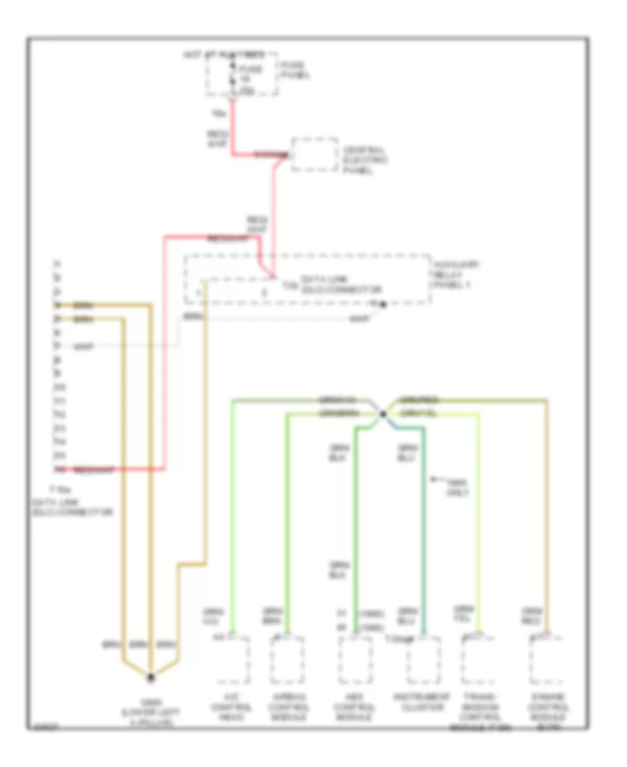
Computer Data Lines Wiring Diagram for Audi A6 1995
List of elements for Computer Data Lines Wiring Diagram for Audi A6 1995:
- (1995)
- (1996)
- 19a
- A/c control head
- Abs control module
- Airbag control module
- Auxiliary relay panel 1
- Central electric panel
- Data link (dlc) connector
- Engine control module (ecm)
- Fuse 25a
- Fuse panel
- G900 (lower left a-pillar)
- Hot at all times
- Instrument cluster
- Only
- S1/30ah
- T16a
- T26a/4
- T2b
- Trans- mission control module (tcm)
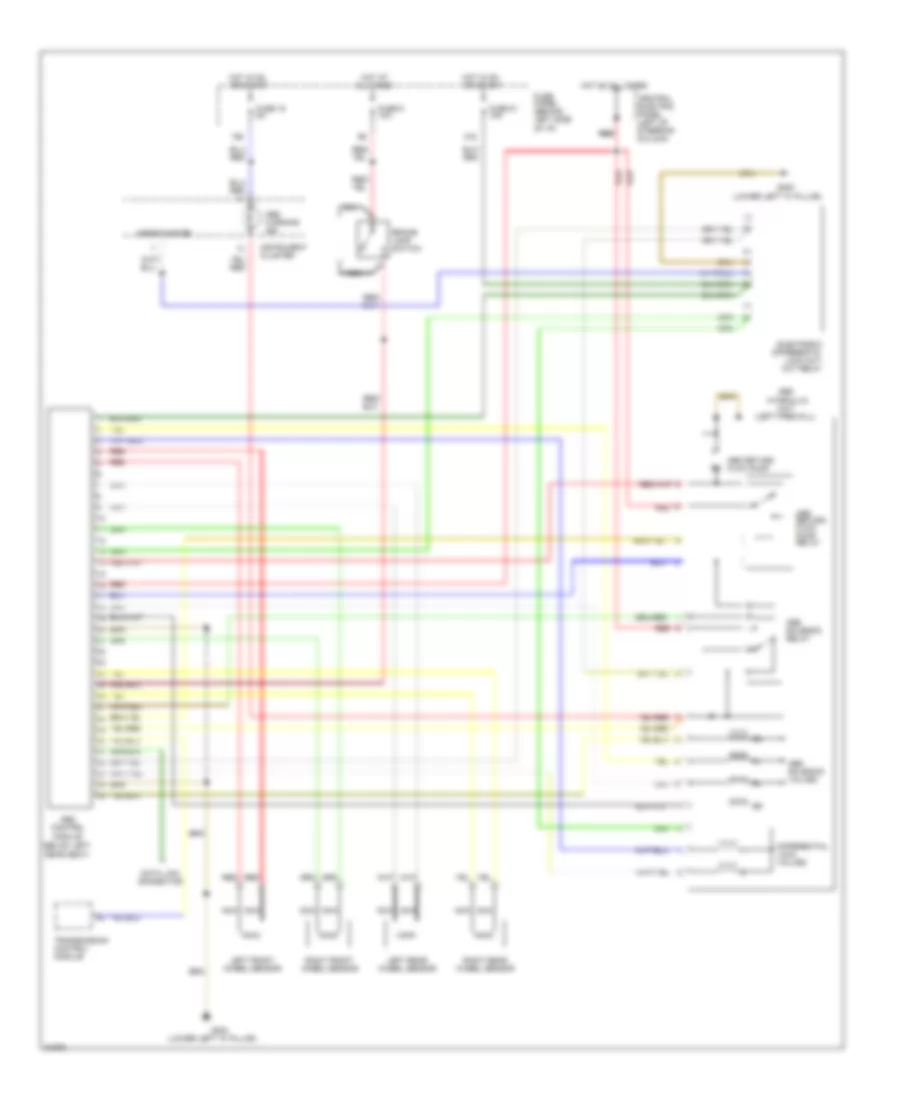
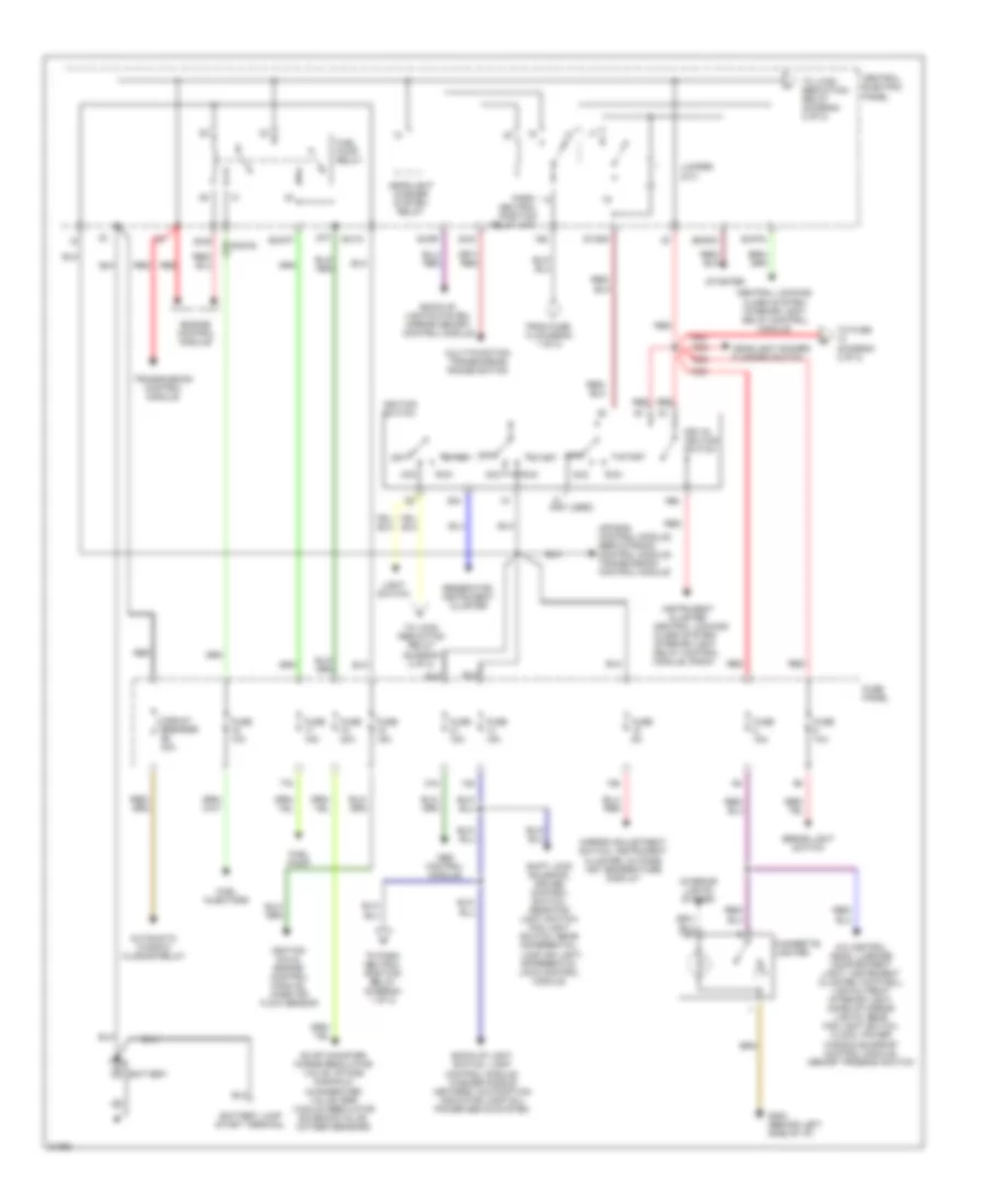
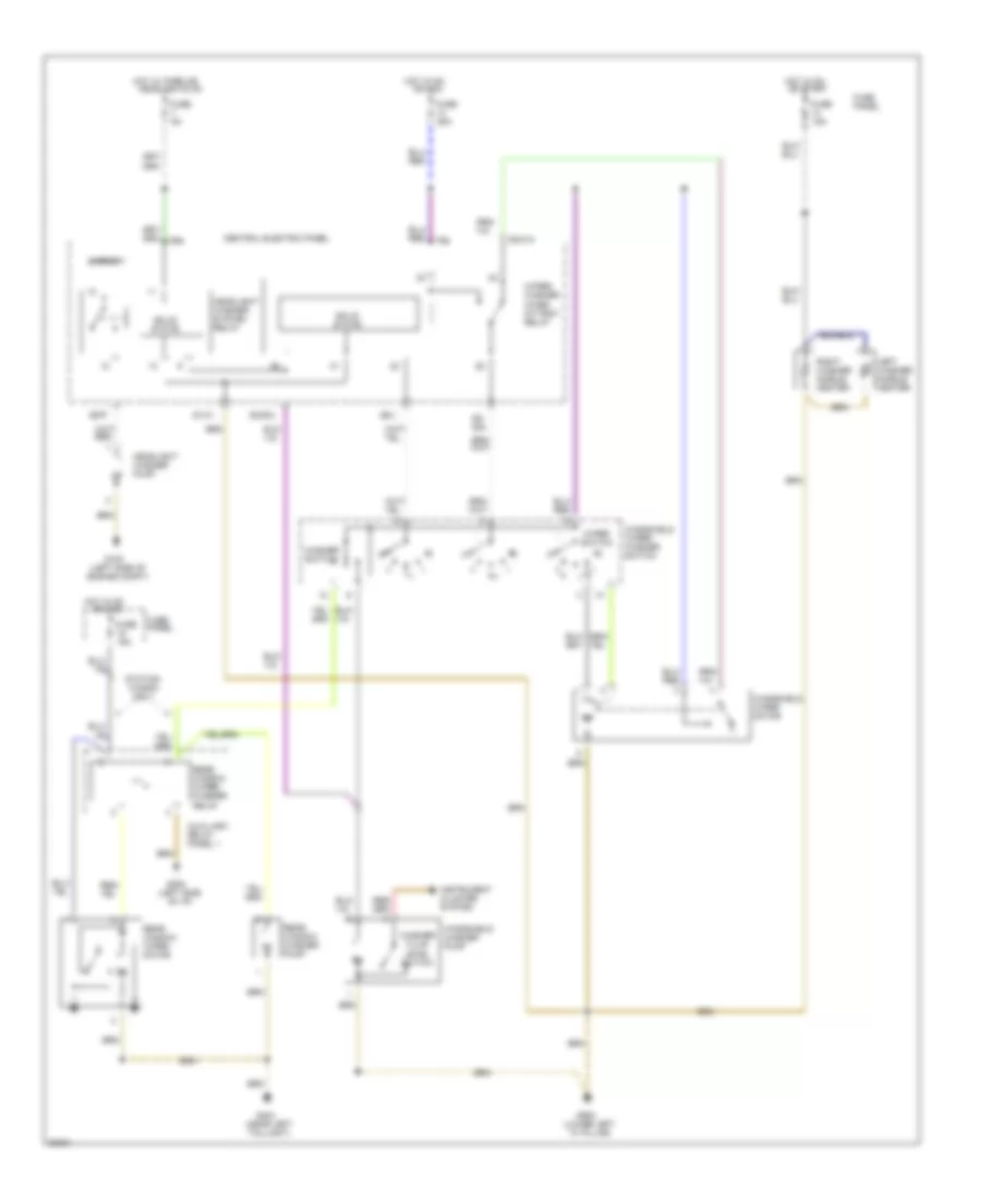
COOLING FAN
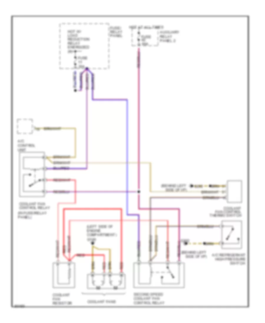
Cooling Fan Wiring Diagram for Audi A6 1995
List of elements for Cooling Fan Wiring Diagram for Audi A6 1995:
- (behind left side of i/p)
- (in fuse/relay panel)
- (left side of engine compartment)
- A/c control unit
- A/c refrigerant high pressure switch
- Auxiliary relay panel 2
- Coolant fan control relay
- Coolant fan control thermo switch
- Coolant fan resistor
- Coolant fans
- Fuse 30a
- Fuse 60a
- Fuse/ relay panel
- G100
- G202
- Hot at all times
- Hot w/ load reduction relay energized (x)
- Red
- Second speed coolant fan control relay
CRUISE CONTROL
Cruise Control Wiring Diagram for Audi A6 1995
List of elements for Cruise Control Wiring Diagram for Audi A6 1995:
- A/c control head
- A/t
- A/t only
- Brake light switch
- Brake vacuum vent valve switch
- Cluster
- Clutch vacuum vent valve switch
- Connector
- Control module
- Cruise control module
- Cruise control switch
- Cruise control vacuum pump
- Fuse 10a
- Fuse 15a
- Fuse 5a
- Fuse panel
- G900 (lower left "a" pillar)
- Hot at all times
- Hot in on or start
- Instrument
- M/t
- M/t only
- Nca
- Outside air temp. display
- Radio
- Servotronic control module
- Speedo- meter
- Station 1
- T26
- T6ab
- T6ac
- Test connector (near cruise control module)
- Transmission
- Vehicle speed output
DEFOGGERS
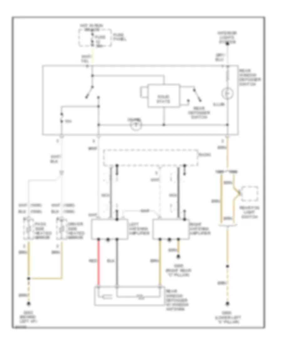
with Antenna Amplifier Wiring Diagram for Audi A6 1995
List of elements for with Antenna Amplifier Wiring Diagram for Audi A6 1995:
- (1995)
- (1996)
- 10a
- Driver side heated mirror
- Fuse 30a
- Fuse panel
- G202 (behind left i/p)
- G900 (lower left "a" pillar)
- G905 (right rear "c" pillar)
- Hot in run
- Illum.
- Interior lights system
- Left antenna amplifier
- Nca
- On ind.
- Or acc
- Pass. side heated mirror
- Radio
- Rear defogger switch
- Rear fog light switch
- Rear window defogger switch
- Rear window defogger w/ window antenna
- Red
- Right antenna amplifier
- Solid state
without Antenna Amplifier Wiring Diagram for Audi A6 1995
List of elements for without Antenna Amplifier Wiring Diagram for Audi A6 1995:
- (1995)
- (1996)
- 10a
- Driver side heated mirror
- Fuse 30a
- Fuse panel
- G202 (behind left i/p)
- G900 (lower left "a" pillar)
- G905 (right rear "c" pillar)
- Hot in run
- Illum.
- Interior lights system
- On ind.
- Or acc
- Pass. side heated mirror
- Rear defogger switch
- Rear fog light switch
- Rear side window glass breakage sensors (anti-theft system)
- Rear window defogger switch
- Rear window defogger/ heat element
- Solid state
- Wagon only
ELECTRONIC POWER STEERING
Electronic Power Steering Wiring Diagram for Audi A6 1995
List of elements for Electronic Power Steering Wiring Diagram for Audi A6 1995:
- (lower left "a" pillar)
- Acc
- Cluster
- G900
- Hot at all times
- Ignition switch
- Instrument
- Lock
- Servotronic
- Servotronic control unit
- Solenoid valve
- Speedo- meter
- Start
- T26/7
ENGINE PERFORMANCE
2.8L
2.8L, Wiring Diagram (A6 2.8L Wiring Diagram Early Production 1 Of 2) for Audi A6 1995
List of elements for 2.8L, Wiring Diagram (A6 2.8L Wiring Diagram Early Production 1 Of 2) for Audi A6 1995:
- (on intake manifold)
- (right i/p)
- (speedometer)
- (tachometer)
- A10
- A11
- A12
- A13
- A14
- A15
- A16
- A17
- A18
- A19
- A20
- A21
- A22
- A23
- A24
- B10
- B11
- B12
- B16
- Bat(30)
- Camshaft position sensor
- Central electric panel
- Closed throttle position switch/ throttle position sensor
- Crankshaft position sensor
- Data link connector (behind console)
- Data link connector (rapid data transfer)
- Egr temperature sensor
- Electronic box
- Engine coolant temperature sensor
- Engine speed sensor
- Fuse 15a
- G131
- G131 (on intake manifold)
- G201
- G900 (left a pillar)
- Ign (15)
- Ignition coil 1
- Ignition coil 2
- Ignition coil 3
- Instrument cluster
- Instrument cluster combination processor
- Intake manifold change- over valve
- Knock sensor #1
- Knock sensor #2
- Mass air flow sensor
- Mfi engine control module
- Nca
- Oxygen sensor
- Power output stage
- Red
- Shield
- Solid state
- Spark plugs 1 & 6
- Spark plugs 2 & 4
- Spark plugs 3 & 5
- Speedo- meter vehicle speed sensor
- T26
- T26a
2.8L, Wiring Diagram (A6 2.8L Wiring Diagram Early Production 2 Of 2) for Audi A6 1995
List of elements for 2.8L, Wiring Diagram (A6 2.8L Wiring Diagram Early Production 2 Of 2) for Audi A6 1995:
- 87f
- 87a
- A/c control head
- Abs control
- Bat(30)
- C1
- C10
- C11
- C12
- C13
- C14
- C15
- C16
- C17
- C18
- C19
- C20
- C21
- C22
- C23
- C24
- Central electric panel
- Computer display
- D10
- D11
- D12
- Dti
- E10
- E11
- E12
- Egr vacuum regulator solenoid valve
- Electronic box
- Evaporative emission canister purge regulator valve
- Evaporative emission sensor
- Fuel injectors
- Fuel pump
- Fuel pump relay
- Fuse 10a
- Fuse 15a
- Fuse 20a
- Fuse block
- G131 (on intake manifold)
- G404 (left trunk)
- Hot in on or start
- Idle air control valve
- Ign(15)
- Mal- function indicator lamp (mil)
- Mfi engine control module
- Module
- Nca
- Oxygen sensor 1 heater
- Oxygen sensor 1 heater, b/h twc
- Oxygen sensor 1, b/h twc
- Oxygen sensor 2 heater
- Oxygen sensor 2 heater, b/h twc
- Oxygen sensor 2, b/h twc
- Shield
- Unit
2.8L, Wiring Diagram (A6 2.8L Wiring Diagram Late Production 1 Of 2) for Audi A6 1995
List of elements for 2.8L, Wiring Diagram (A6 2.8L Wiring Diagram Late Production 1 Of 2) for Audi A6 1995:
- (on intake manifold)
- (right i/p)
- (speedometer)
- (tachometer)
- A10
- A11
- A12
- A13
- A14
- A15
- A16
- A17
- A18
- A19
- A20
- A21
- A22
- A23
- A24
- B10
- B11
- B12
- Bat(30)
- Camshaft position sensor
- Central electric panel
- Central locking/ alarm system/ interior light delay control module, multi-function transmission range switch (w/ a/t)
- Closed throttle position switch (throttle position sensor)
- Crankshaft position sensor
- Data link connector (behind console)
- Data link connector (rapid data transfer)
- Egr temperature sensor
- Electronic box
- Engine coolant temperature sensor
- Engine speed sensor
- Fuse 15a
- G131
- G131 (on intake manifold)
- G201
- G900 (left a pillar)
- Ign (15)
- Ignition coil 1
- Ignition coil 2
- Ignition coil 3
- Instrument cluster
- Instrument cluster combination processor
- Intake change- over valve
- Knock sensor #1
- Knock sensor #2
- Mass air flow sensor
- Mfi engine control module
- Nca
- Oxygen sensor
- Power output stage
- Red
- Shield
- Solid state
- Spark plugs 1 & 6
- Spark plugs 2 & 4
- Spark plugs 3 & 5
- Speedo- meter vehicle speed sensor
- T26
- T26a
- Transmission control module (w/ a/t)
2.8L, Wiring Diagram (A6 2.8L Wiring Diagram Late Production 2 Of 2) for Audi A6 1995
List of elements for 2.8L, Wiring Diagram (A6 2.8L Wiring Diagram Late Production 2 Of 2) for Audi A6 1995:
- 87f
- 87a
- A/c control head
- Abs control
- Auxiliary relay panel 3
- Bat(30)
- C1
- C10
- C11
- C12
- C13
- C14
- C15
- C16
- C17
- C18
- C19
- C20
- C21
- C22
- C23
- C24
- Central electric panel
- Computer display
- D10
- D11
- D12
- Dti
- E10
- E11
- E12
- Egr vacuum regulator solenoid valve
- Electronic box
- Evaporative emission canister purge regulator valve
- Evaporative emission canister purge solenoid valve
- Fuel injectors
- Fuel pump
- Fuel pump relay
- Fuel system diagnostic pump
- Fuse 10a
- Fuse 15a
- Fuse 20a
- Fuse 40a
- Fuse block
- G131 (on intake manifold)
- G201 (right i/p)
- G404 (left trunk)
- Hot in on or start
- Idle air control valve
- Ign(15)
- Mal- function indicator lamp (mil)
- Mfi engine control module
- Module
- Nca
- Oxygen sensor 1 heater
- Oxygen sensor 1 heater, b/h twc
- Oxygen sensor 1, b/h twc
- Oxygen sensor 2 heater
- Oxygen sensor 2 heater, b/h twc
- Oxygen sensor 2, b/h twc
- Red
- Secondary air injection pump motor
- Secondary air injection pump relay
- Secondary air injection solenoid valve
- Shield
- Transmission control module
- Unit
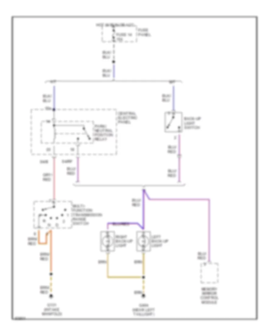
EXTERIOR LIGHTS
Back-up Lamps Wiring Diagram for Audi A6 1995
List of elements for Back-up Lamps Wiring Diagram for Audi A6 1995:
- 15a
- A/t
- Back-up light switch
- Central electric panel
- Fuse 14 15a
- Fuse panel
- G131 (intake manifold)
- G404 (near left taillight)
- Hot in run or acc
- Left back-up light
- M/t
- Memory mirror control module
- Multi- function transmission range switch
- Park/ neutral position relay
- Right back-up light
- S4/b
- S4/rf
Exterior Lamps Wiring Diagram, with DRL for Audi A6 1995
List of elements for Exterior Lamps Wiring Diagram, with DRL for Audi A6 1995:
- A/t only
- Abs control module
- Anti-theft system
- Auto- check system
- Auxiliary relay panel 1
- Brake light switch
- Brake vacuum vent valve
- Central electric panel
- Cluster
- Connector station 2
- Daytime running lights switch- over relay
- Emergency flasher relay
- Emergency flasher switch
- Fuse 10a
- Fuse 15a
- Fuse 25a
- Fuse 5a
- Fuse panel
- G404 (near left taillight)
- G900 (lower left "a" pillar)
- G901 (lower right "a" pillar)
- Head
- Head/ park light switch
- Headlights system
- High- mount brake light
- Hot at all times
- Hot in run or acc
- Instrument
- Instrument cluster
- Interior lights system
- Lamp control module
- Left front park light
- Left front turn light
- Left rear tail/stop/ turn lights
- Left turn ind.
- License plate
- Light switch
- Lights
- Off
- Park
- Red
- Right front park light
- Right front turn light
- Right rear tail/stop/ turn lights
- Right turn ind.
- Shift lock solenoid, shift lock control module
- Signal switch
- Solid state
- Stop
- T14
- T26
- T6b
- Tail
- Turn
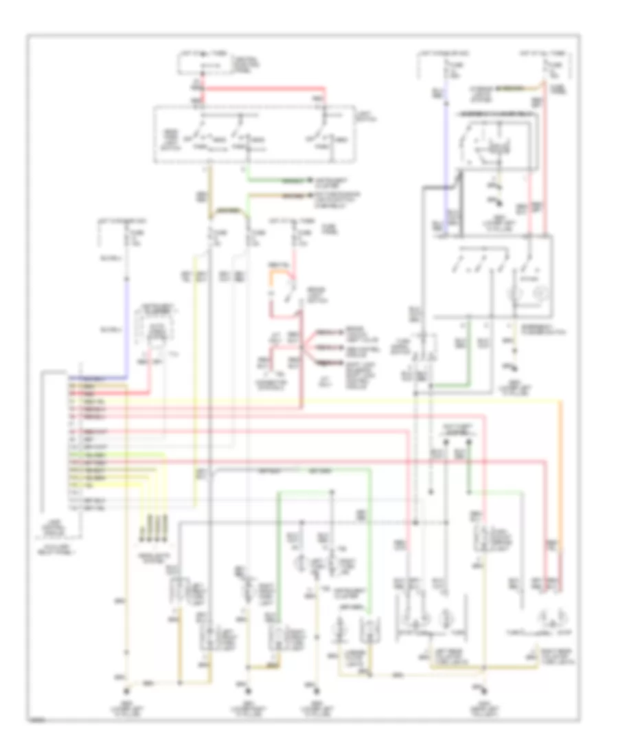
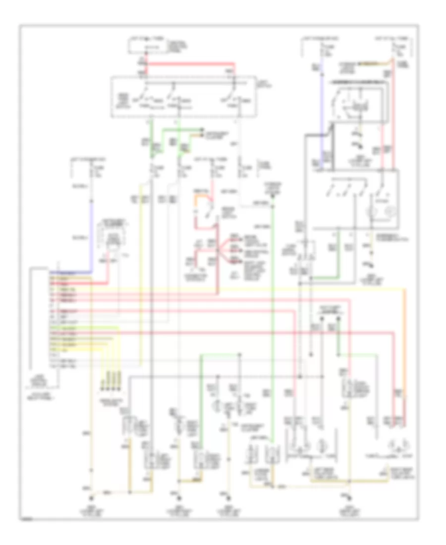
Exterior Lamps Wiring Diagram, without DRL for Audi A6 1995
List of elements for Exterior Lamps Wiring Diagram, without DRL for Audi A6 1995:
- A/t only
- Abs control module
- Anti-theft system
- Auto- check system
- Auxiliary relay panel 1
- Brake light switch
- Brake vacuum vent valve
- Central electric panel
- Cluster
- Connector station 2
- Emergency flasher relay
- Emergency flasher switch
- Fuse 10a
- Fuse 15a
- Fuse 25a
- Fuse 5a
- Fuse panel
- G404 (near left taillight)
- G900 (lower left "a" pillar)
- G901 (lower right "a" pillar)
- Head
- Head/ park light switch
- Headlights system
- High- mount brake light
- Hot at all times
- Hot in run or acc
- Instrument
- Instrument cluster
- Interior lights system
- Lamp control module
- Left front park light
- Left front turn light
- Left rear tail/stop/ turn lights
- Left turn ind.
- License plate
- Light switch
- Lights
- Off
- Park
- Red
- Right front park light
- Right front turn light
- Right rear tail/stop/ turn lights
- Right turn ind.
- Shift lock solenoid, shift lock control module
- Signal switch
- Solid state
- Stop
- T14
- T26
- T6b
- Tail
- Turn
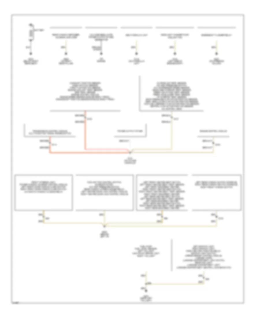
GROUND DISTRIBUTION
Ground Distribution Wiring Diagram (1 of 2) for Audi A6 1995
List of elements for Ground Distribution Wiring Diagram (1 of 2) for Audi A6 1995:
- (on engine)
- Abs hydraulic unit
- Battery
- Camshaft position sensor, mass air flow sensor, throttle position sensor, engine coolant temp. sensor, egr temp. sensor, engine control module, engine speed sensor shields (early prod.), crankshaft position sensor shields (early prod.)
- Coolant fan control switch, sunroof motor, a/c high pressure switch, rear window wiper/washer relay, left heated door lock control module, right heated door lock control module
- Emergency flasher relay
- Engine control module
- Front interior light, power window/ sunroof control module, left front door handle alarm switch, right front door handle alarm switch, automatic window closing relay
- Fuel pump, fuel level sensor, left taillight, high mount brake light, right taillight
- G104 (left side of engine compt)
- G116 (on hydraulic unit)
- G131 (on intake manifold)
- G202 (behind left i/p)
- G207 (on steering column)
- G303 (below right rear seat)
- G404 (near left taillight)
- G905 (on right rear pillar)
- Ground strap
- Headlight washer pump, coolant fan
- Left backup light, right backup light, park/ neutral position relay, backup light switch, mirror memory control module, license lamps, luggage compartment light switch, rear fog light, luggage compartment light, luggage compartment central locking switch
- Left front heated seat switch, left front heated seat temp. sensor, left front backrest heater, right front heated seat switch, right front heated seat temp. sensor, right front backrest heater, left rear heated seat switch, left rear heated seat temp. sensor, left rear backrest heater, right rear heated seat switch, right rear heated seat temp. sensor, right rear backrest heater
- Left rear window switch (console), right rear window switch (console), right front window switch
- Outside air temp. sensor, a/c high pressure switch, a/c compressor speed sensor, headliner interior temp. sensor, fresh air intake temp. sensor, fresh air blower temp. sensor, i/p interior temp. sensor, back pressure flap motor position sensor, temp. regulator flap motor position sensor, footwell/defrost flap motor position sensor, central flap motor position sensor, a/c control head
- Power output stage
- Rear window defogger, antenna amplifier
- S103
- S114
- S127
- S182
- S183
- S86
- S89
- S96
- S98
- Transmission control module, multi-function trans. range switch
- Voltage regulator, power output stage, generator
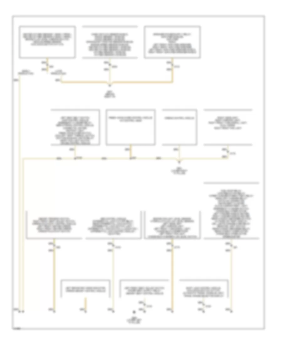
Ground Distribution Wiring Diagram (2 of 2) for Audi A6 1995
List of elements for Ground Distribution Wiring Diagram (2 of 2) for Audi A6 1995:
- (early production)
- (late production)
- Abs control module, differential lock cut-off relay, rear differential lock switch *, differential lock switch light *, differential lock switch illumination *, differential lock control module *, * (quattro)
- Airbag control module
- Engine coolant level sensor, hydraulic fluid low level sensor, left headlight, left parking light, left front turn signal light, windshield washer pump, left front fog light, windshield washer fluid level switch
- Fresh air blower control module, a/c control head
- Fuel pump relay, load reduction relay, wiper/ washer intermittent relay, headlight washer relay, datalink connector, instrument cluster, glove compartment light, emergency flasher switch, windshield wiper motor, left washer nozzle heater, right washer nozzle heater, rear window defogger switch, outside air temp. display, drl lights change-over relay, rear fog light switch, rear window defogger relay, rear window wiper motor, windshield wiper motor, speedometer
- G201 (behind right i/p)
- G900 (lower left "a" pillar)
- G901 (lower right "a" pillar)
- Heated oxygen sensor 1 (early prod.), heated oxygen sensor 2 (early prod.), brake fluid level warning switch, vehicle speed sensor, kick down switch (a/t 01k)
- Left brake pad wear indicator, mirror memory control module
- Left seat belt switch, lamp control module, emergency flasher relay, servotronic control module, cigarette lighter, ashtray light, fresh air blower switch, coolant temp. thermal switch, daytime running lights relay, front fog light switch, cruise control module
- Mass air flow sensor shield, knock sensor 1 shields, knock sensor 2 shields, crankshaft position sensor shields, engine speed sensor shields, heated oxygen sensor 1 shields, heated oxygen sensor 2 shields, oxygen sensor 1 shields, oxygen sensor 2 shields
- Memory program switch, right front seat adjust switch, mirror fold-away control module, left front heated mirror, right front heated mirror, mirror fold-away switch
- Right headlight, right parking light, right front turn signal light, dual horns, right front fog light
- S100
- S133
- S135
- S140
- S150
- S176
- S179
- S200
- S81
- S85
- S95
- S97
- Shift lock control module, kick down switch (a/t 01f), automatic trans. console light, trans. range selector display
HEADLIGHTS
Fog Lamps Wiring Diagram, with DRL for Audi A6 1995
List of elements for Fog Lamps Wiring Diagram, with DRL for Audi A6 1995:
- (lower left "a" pillar)
- (lower right "a" pillar)
- (near left taillight)
- 75x
- Acc
- All times
- Auxiliary relay panel 1
- Central electric panel
- Daytime running lights change- over relay
- Daytime running lights switch- on relay
- Fog light relay (#4)
- Fog light switch
- Ftp
- Fuse 1 10a
- Fuse 15a
- Fuse 2 10a
- Fuse panel
- G404
- G900
- G901
- Head
- Head/park light switch
- Headlight dimmer switch
- Headlight system washer relay
- Hi beam ind
- Hot at
- Hot in acc
- Ignition switch
- Instrument cluster
- Interior lights system
- Left front fog light
- Left head- light
- Light switch
- Load reduction relay
- Off
- Or run
- Park
- Rear fog light
- Rear fog light switch
- Rear window defogger switch (1996 only)
- Red
- Right front fog light
- Right head- light
- Run
- Start
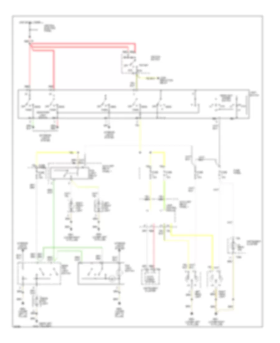
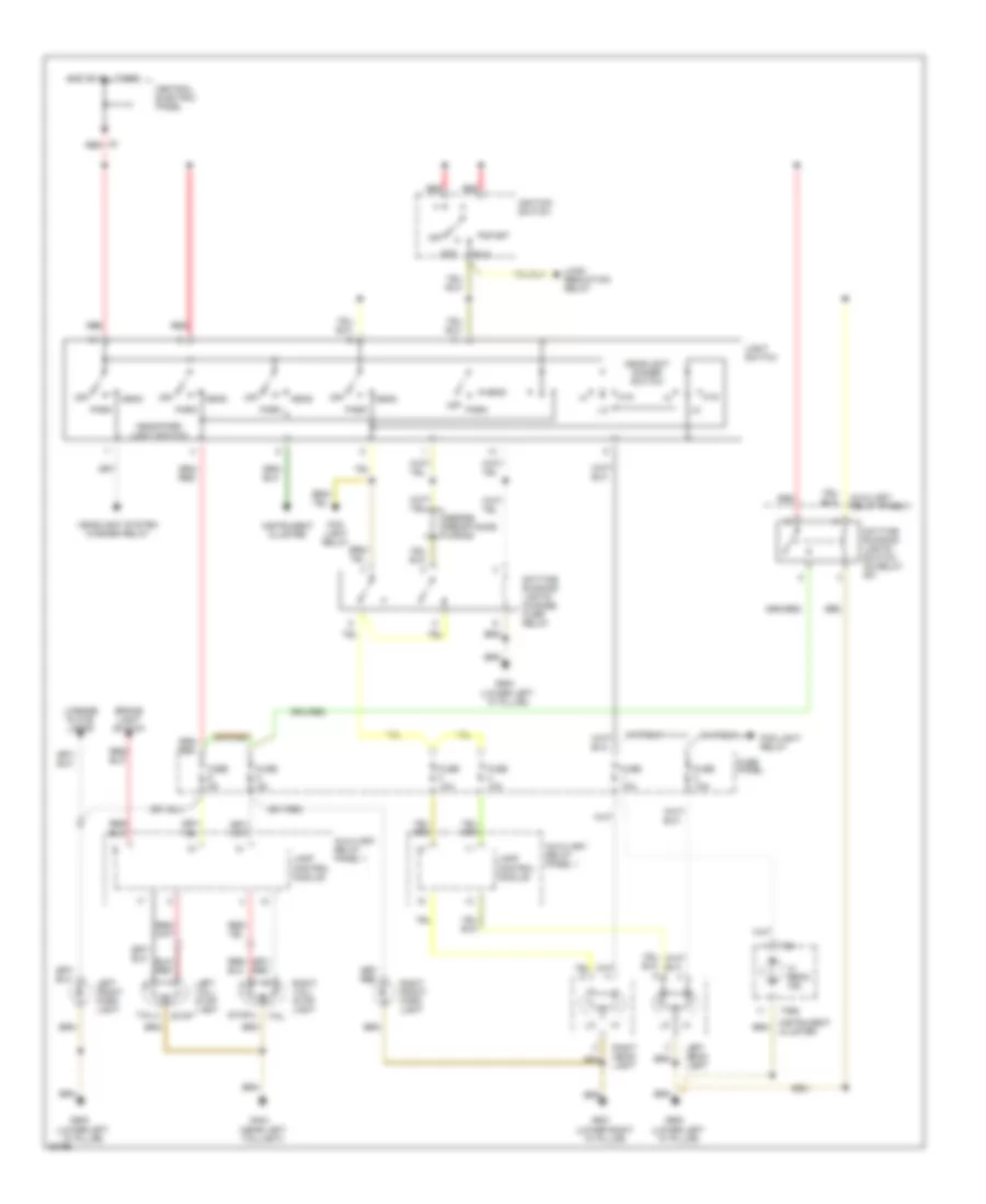
Headlamps & Fog Lamps Wiring Diagram, without DRL for Audi A6 1995
List of elements for Headlamps & Fog Lamps Wiring Diagram, without DRL for Audi A6 1995:
- (lower left "a" pillar)
- (lower right "a" pillar)
- (near left taillight)
- 56a
- 56b
- Acc
- Auto- check system
- Auxiliary relay panel 1
- Central electric panel
- Cluster
- Exterior lights system
- Fog light relay (#4)
- Fog light switch
- Ftp
- Fuse 10a
- Fuse 15a
- Fuse panel
- G404
- G900
- G901
- Head
- Head/park light switch
- Headlight dimmer switch
- Hi beam ind.
- Hot at all times
- Ignition switch
- Instrument
- Instrument cluster
- Interior lights system
- Lamp control module
- Left front fog light
- Left head- light
- Light switch
- Load reduction relay
- Off
- Park
- Rear fog light
- Rear fog light switch
- Red
- Right front fog light
- Right head- light
- Run
- Start
- T14
- T26
- T26a
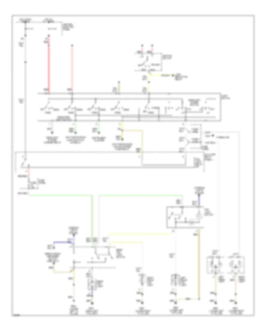
Headlamps Wiring Diagram, with DRL for Audi A6 1995
List of elements for Headlamps Wiring Diagram, with DRL for Audi A6 1995:
- (lower left "a" pillar)
- (lower right "a" pillar)
- (near left taillight)
- Acc
- Auxiliary relay panel 1
- Brake light switch
- Central electric panel
- Daytime running lights change- over relay
- Daytime running lights switch- on relay (#7)
- Fog light relay
- Ftp
- Fuse 10a
- Fuse 5a
- Fuse panel
- G404
- G900
- G901
- Head
- Head/park light switch
- Headlight dimmer switch
- Headlight system washer relay
- Hi beam ind.
- Hot at all times
- Ignition switch
- Instrument cluster
- Lamp control module
- Left front park light
- Left head- light
- Left tail/ stop light
- License plate lamps
- Light switch
- Load reduction relay
- Off
- Park
- Red
- Right front park light
- Right head- light
- Right tail/ stop light
- Run
- Series resistance wiring
- Start
- Stop
- T26
- T26a
- Tail
HORN
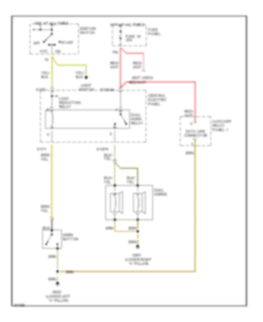
Horn Wiring Diagram for Audi A6 1995
List of elements for Horn Wiring Diagram for Audi A6 1995:
- (not used)
- 19a
- Acc
- Auxiliary relay panel 1
- Central electric panel
- Data link connector
- Dual horn relay
- Dual horns
- Fuse 19 25a
- Fuse panel
- G900 (lower left "a" pillar)
- G901 (lower right "a" pillar)
- Horn button
- Hot at all times
- Ignition switch
- Light switch
- Load reduction relay
- Off
- S1/30ah
- S1/71
- S1/75
- S1/87h
- Start
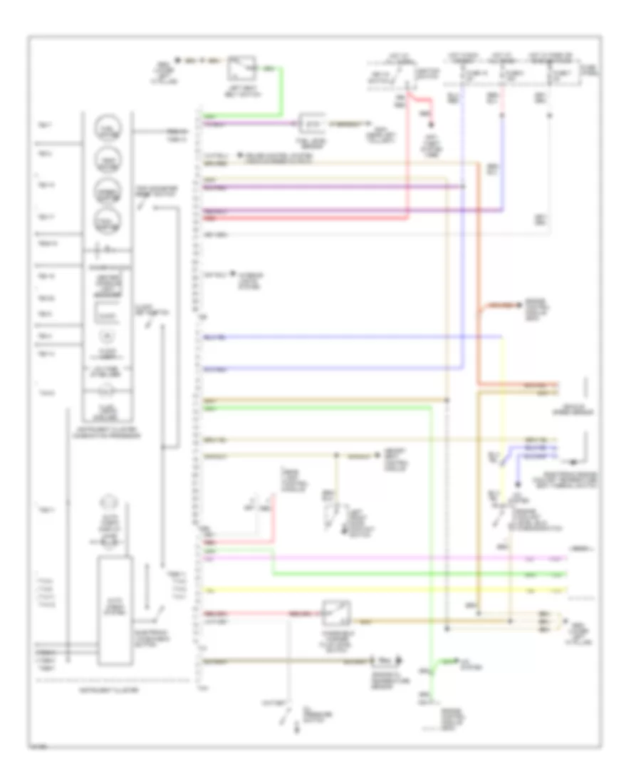
INSTRUMENT CLUSTER
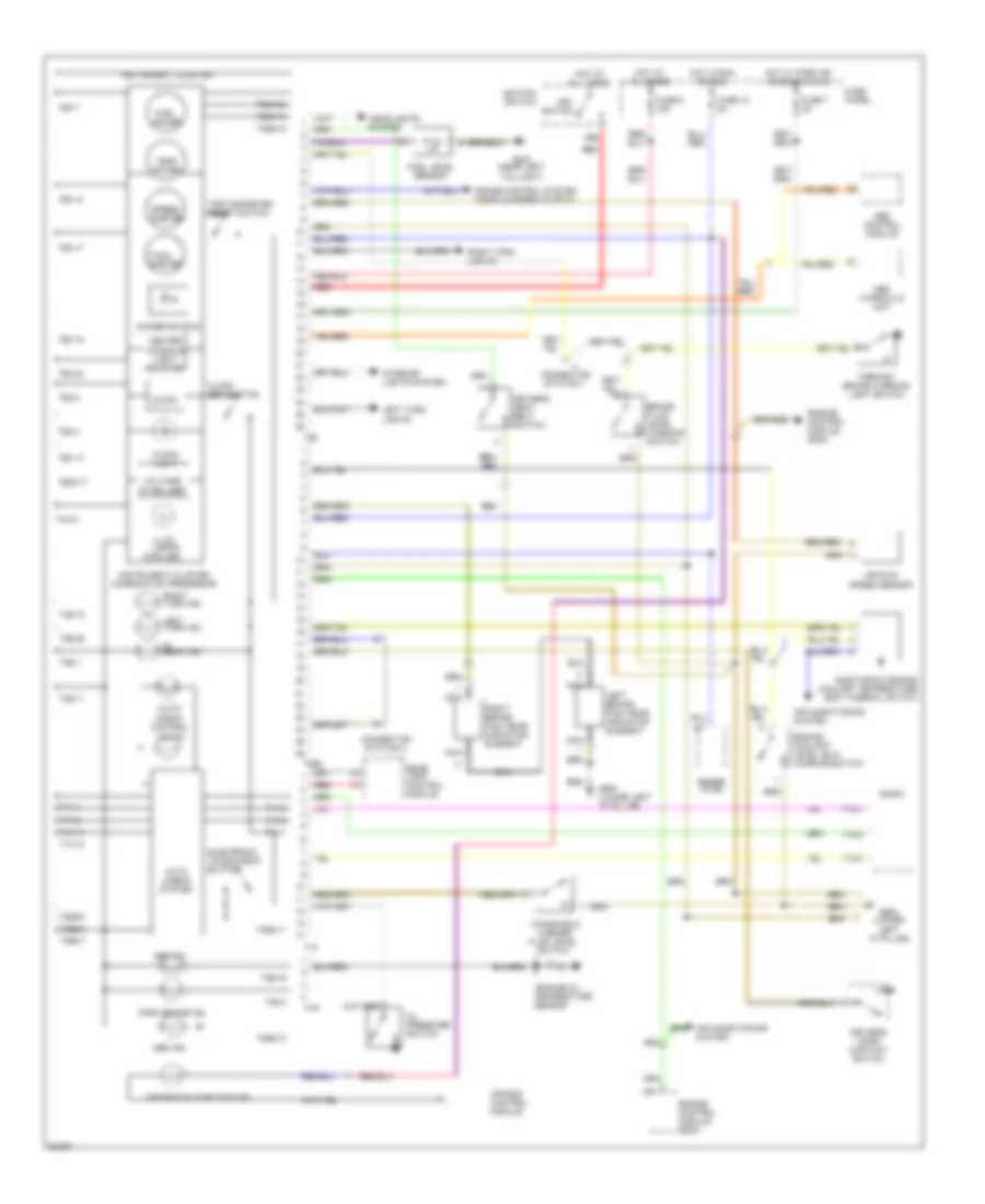
Instrument Cluster Wiring Diagram for Audi A6 1995
List of elements for Instrument Cluster Wiring Diagram for Audi A6 1995:
- (6 bulbs)
- 86s
- Abs control module
- Abs hydraulic unit
- Abs ind.
- Air bag control module
- Air bag malfunction ind.
- Air conditioning system
- Auto check system
- Auto- check control lights
- Brake fluid level warning switch
- C10
- Center console light booster
- Clock
- Clock light
- Clock set button
- Connector station 1
- Connector station 2
- Cruise control system (vehicle speed output)
- Dimmer switch
- Driver's door contact switch
- Driver's seat belt switch
- Electronic engine coolant temperature (ect) thermal switch
- Electronic voice check button
- Engine control module (ecm)
- Engine coolant level (elc) warning switch
- Engine oil
- Fluid level
- Fuel gauge
- Fuel level sensor
- Fuse 15 5a
- Fuse 7 5a
- Fuse 8 15a
- Fuse panel
- G404 (near left taillight)
- G900 (lower left "a" pillar)
- Gen ind.
- Gener- ator
- Headlights system
- Hi beam ind.
- Hot at all times
- Hot in run or acc
- Hot w/ park or headlights on
- Ignition switch
- Illum. lights
- Instrument cluster
- Instrument cluster combination processor
- Interior lights system
- Key switch
- Left brake pad wear indicator element
- Left turn ind.
- Left turn lights
- Nca
- Oil pressure switch
- Park brake ind.
- Parking brake warning light switch
- Radio
- Rear lamp control module
- Red
- Right brake pad wear indicator element
- Right turn ind.
- Right turn lights
- Sensor
- Speed- ometer
- Switch
- T10/1
- T10/2
- T10/3
- T14
- T14-1
- T14-11
- T14-12
- T14-2
- T14-3
- T14-4
- T14-8
- T26
- T26-1
- T26-10
- T26-11
- T26-12
- T26-14
- T26-15
- T26-17
- T26-19
- T26-22
- T26-25
- T26-3
- T26-4
- T26-7
- T26-8
- T26a
- T26a-10
- T26a-11
- T26a-12
- T26a-16
- T26a-17
- T26a-24
- T26a-3
- T26a-6
- T26a-7
- T4m
- T4m-2
- Tach- ometer
- Temp gauge
- Temperature
- Trip odometer reset switch
- Vehicle speed sensor
- Voltage stabilizer
- Washer
- Windshield
INTERIOR LIGHTS
Courtesy Lamps Wiring Diagram for Audi A6 1995
List of elements for Courtesy Lamps Wiring Diagram for Audi A6 1995:
- 15a
- Central electric panel
- Driver seat heat regulating switch
- Emergency flasher switch
- Front
- Front fog light switch
- Fuse 13 25a
- Fuse 14 15a
- Fuse 15 5a
- Fuse panel
- G202 (behind left i/p)
- G900 (lower left "a" pillar)
- Hot in run or acc
- Hot in run or start
- Left rear seat heat regulating switch
- Memory program switch
- Mirror adjustment switch
- Mirror fold-away function control module
- Passenger seat heat regulating switch
- Rear fog light switch
- Rear window defogger switch (w/ drl)
- Right rear seat heat regulating switch
- Seat temperature sensors
Courtesy Lamps Wiring Diagram, Base for Audi A6 1995
List of elements for Courtesy Lamps Wiring Diagram, Base for Audi A6 1995:
- (auto a/c)
- (not used)
- 58a
- A/c control head
- Central electric
- Central locking/ alarm system/ interior light delay control module
- Cover switch
- Door
- Except wagon
- Front interior light
- Fuse 7 5a
- Fuse 8 15a
- Fuse panel
- G404 (near left taillight)
- G900 (lower left "a" pillar)
- Glove comp- artment light
- Head
- Headlight washer system relay
- Hot at all times
- Instrument cluster
- Left foot- well light
- Left front door contact switch
- Left make-up mirror light
- Left rear door contact switch
- License plate lights
- Light switch
- Luggage comp- artment light
- Luggage comp- artment light switch
- Nca
- Off
- On/off switch
- Panel
- Park
- Right foot- well light
- Right front door contact switch
- Right make-up mirror light
- Right rear door contact switch
- Selector lever light relay
- T12
- T26
- W/ a/t
- Wagon
Courtesy Lamps Wiring Diagram, with Radio Control for Audi A6 1995
List of elements for Courtesy Lamps Wiring Diagram, with Radio Control for Audi A6 1995:
- (auto a/c)
- (lower left "a" pillar)
- 58a
- A/c control head
- Anti- theft system
- Auxiliary
- Central electric
- Central locking system control module
- Central locking/ alarm system/ interior light delay control module
- Door
- Front interior light
- Fuse 7 5a
- Fuse 8 15a
- Fuse panel
- G404 (near left taillight)
- G900
- G900 (lower left "a" pillar)
- Glove comp- artment light
- Head
- Headlight washer system relay
- Hot at all times
- Instrument cluster
- Interior monitoring sensors control module
- Interior monitoring sensors control module relay
- Left foot- well light
- Left front door contact switch
- Left front reading light
- Left rear door contact switch
- Left rear reading light
- License plate lights
- Light
- Light switch
- Luggage comp- artment light
- Luggage comp- artment light switch
- Nca
- Off
- Panel
- Panel 2
- Park
- Power locks system
- Relay
- Right foot- well light
- Right front door contact switch
- Right front map/ reading
- Right rear door contact switch
- Right rear reading light
- Selector lever light relay
- T12
- T26
- W/ a/t
Instrument Illumination Wiring Diagram for Audi A6 1995
List of elements for Instrument Illumination Wiring Diagram for Audi A6 1995:
- A/c control head
- A/c system
- A/t console light
- Ashtray light
- Auto a/c
- Auxiliary relay panel 1
- Center console instrument lighting booster
- Cigar lighter light
- Differential lock switch
- Dim input
- Fresh air blower switch
- Fuse 7 5a
- Fuse 8 15a
- Fuse panel
- G900 (lower left "a" pillar)
- Generator
- Head
- Hot at all times
- I/p light dimmer switch
- Illumination
- Instrument cluster
- Instrument cluster combination processor
- Light switch
- Manual a/c
- Off
- Optional
- Outside air temperature display
- Park
- Protection diode
- Quattro w/ abs
- Radio
- Rear fog light switch
- Rear window defogger switch (w/o drl)
- Selector lever light relay
- T26
- T26 t26
- Transmission range selector lever display
- W/ a/t
MEMORY SYSTEMS
Memory Systems Wiring Diagram (1 of 2) for Audi A6 1995
List of elements for Memory Systems Wiring Diagram (1 of 2) for Audi A6 1995:
- Auxiliary relay panel 1
- Back- rest
- Central locking/ alarm system/ interior light delay control module
- Circuit breaker 44 30a
- Driver seat backrest adjusting motor
- Driver seat fore/ aft adjusting motor
- Driver seat front height adjusting motor
- Driver seat rear height adjusting motor
- Driver seat switch
- Fore/ aft
- Front height
- G900 (lower left "a" pillar)
- Hot at all times
- Left front door contact switch
- Memory program switch
- Memory seat control module
- Rear height
- Red
- T16
Memory Systems Wiring Diagram (2 of 2) for Audi A6 1995
List of elements for Memory Systems Wiring Diagram (2 of 2) for Audi A6 1995:
- A10
- B10
- Back-up lights
- De- fog
- Driver side mirror
- Fold- away
- Fuse 15 5a
- Fuse 8 15a
- Fuse panel
- G900 (lower left "a" pillar)
- Hot at all times
- Hot in acc
- Memory mirror control module
- Mirror adjustment switch
- Mirror fold-away control module
- Mirror position
- Mirror select
- Passenger side mirror
- Position
- Rear window defogger switch
- Red
POWER DISTRIBUTION
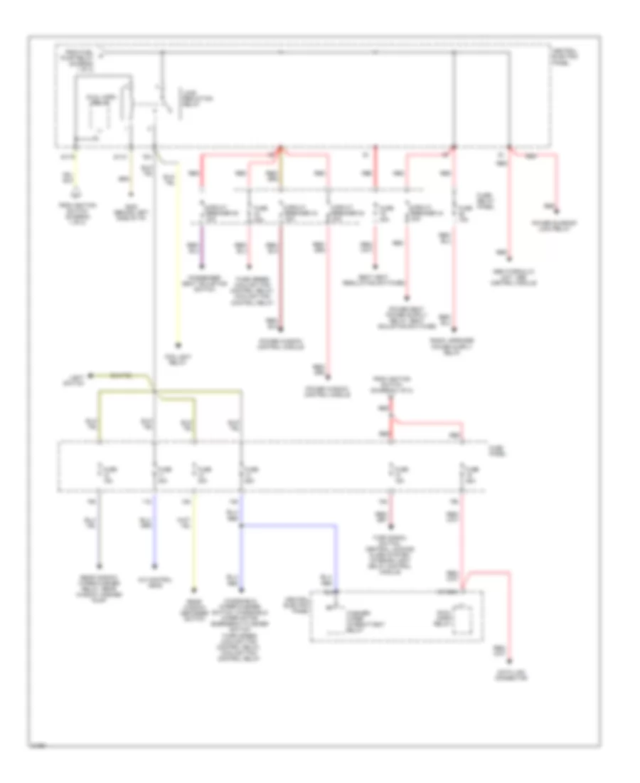
Power Distribution Wiring Diagram (1 of 2) for Audi A6 1995
List of elements for Power Distribution Wiring Diagram (1 of 2) for Audi A6 1995:
- (not used)
- 14a
- 15a
- 17a
- 21a
- 50b
- 86s
- 87f
- A/c control head, luggage compartment light, instrument cluster, footwell lights, front interior light, make-up mirror lights, rear fog light switch, clock, power window/sunroof control module, memory program switch
- Abs control module
- Acc
- Air bag control module, servotronic control module, transmission control module
- Automatic window closing relay
- Back-up light switch, lamp control module, washer nozzle heaters, malfunction indicator lamp (mil) power seats system
- Back-up lights system, mirror memory control module
- Battery
- Battery jump start terminal
- Brake light switch
- Central electric panel
- Central locking/ alarm system/ interior light delay control module
- Central locking/ alarm system/ interior light delay control module, radio
- Cigarette lighter
- Circuit breaker 30a
- Engine control module
- Evap canister purge regulator valve, intake manifold change-over valve, egr vacuum regulator solenoid valve, oxygen sensors
- From fuse 14 (diagram 1 of 2)
- Fuel injectors
- Fuel pump
- Fuel pump relay
- Fuse 10a
- Fuse 15a
- Fuse 20a
- Fuse 5a
- Fuse panel
- G202 (behind left side of i/p)
- Generator, instrument cluster
- Headlight dimmer/ flasher switch
- Headlight washer system relay
- Ignition coils, engine control module, mass air flow sensor
- Ignition switch
- Instrument cluster
- Interior lights system
- Jumper (m/t)
- Key-in ignition switch
- Light switch
- Mirror adjustment switch, instrument cluster, outside air temperature display
- Multi-function transmission range switch
- Off
- Park/ neutral position relay (a/t)
- Red
- Run
- S1/50z
- S2/87f
- S3/15
- S3/s
- S4/5
- S4/p/n
- S4/rf
- S6/50a
- Shift lock solenoid, cruise control switch, rear fog light switch, fog light switch, rear differential lock ind light, differential lock control module
- Start
- Starter
- To fuse (diagram 2 of 2)
- To load reduction relay (diagram 2 of 2)
- To park neutral position relay (diagram 1 of 2)
- Transmission control module
Power Distribution Wiring Diagram (2 of 2) for Audi A6 1995
List of elements for Power Distribution Wiring Diagram (2 of 2) for Audi A6 1995:
- 10a
- 11a
- 12a
- 13a
- 18a
- 19a
- 75a
- 75x
- A/c control head
- Abs hydraulic unit, abs control module
- Central electric panel
- Circuit breaker 43 30a
- Circuit breaker 44 30a
- Circuit breaker 80 30a
- Circuit breaker 83 20a
- Data link connector
- Dual horn relay
- Fog light relay
- From fuel pump relay (diagram 1 of 2)
- From ignition switch (diagram 1 of 2)
- Fuse 15a
- Fuse 25a
- Fuse 30a
- Fuse 40a
- Fuse panel
- Fuse/ relay panel
- G202 (behind left side of i/p)
- Light switch
- Load reduction relay
- Passenger seat adjusting switch
- Power sunroof lock relay
- Power window control module
- Rear window defogger switch
- Rear window wiper/washer relay, rear window washer pump
- Red
- S1/30ah
- S1/31
- S1/75
- Seat heat regulating switches
- Third speed coolant fan control relay, coolant fan control relay
- Turn signal switch, central locking/ alarm system/ interior light delay control module
- Washer/ wiper intermittent relay
- Windshield wiper/washer switch, windshield wiper motor, emergency flasher switch third speed coolant fan control relay, coolant fan control relay
POWER DOOR LOCKS
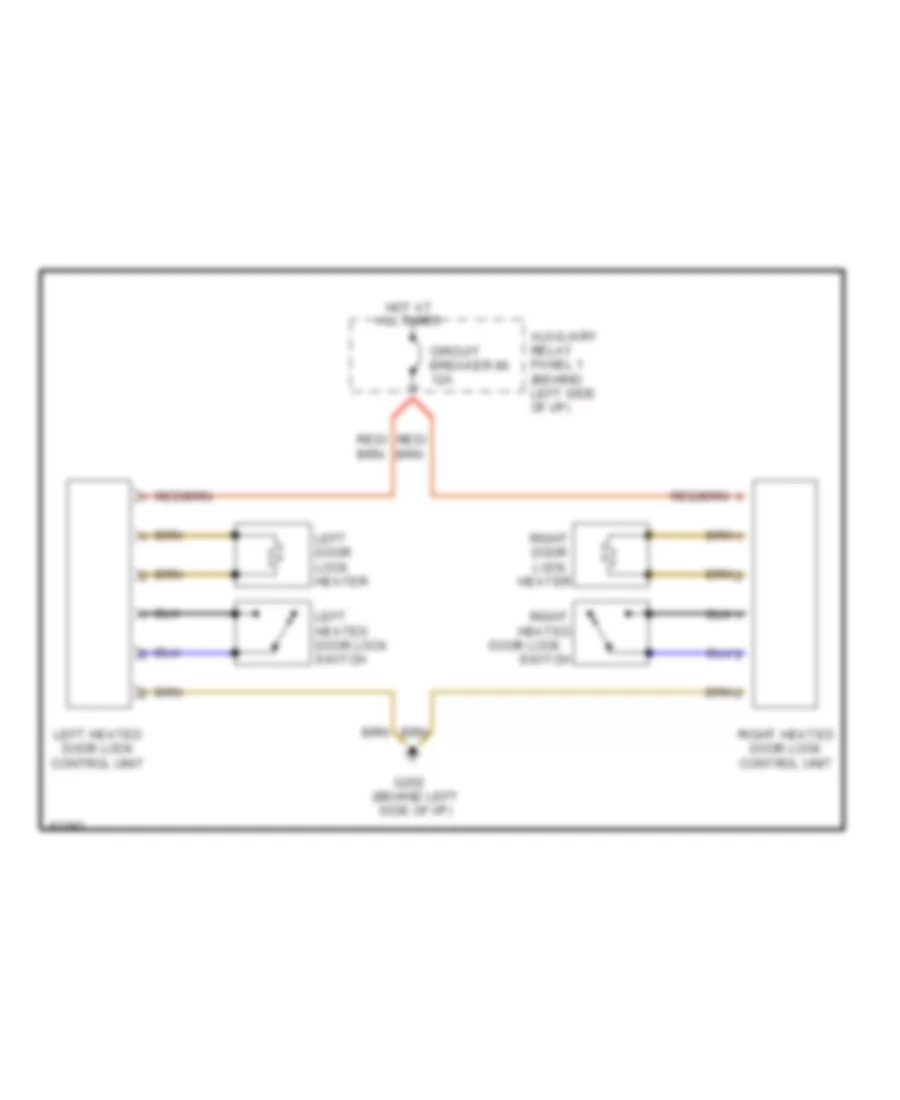
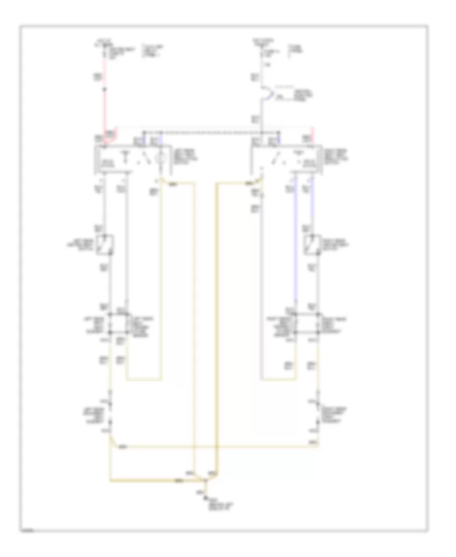
Heated Door Locks Wiring Diagram for Audi A6 1995
List of elements for Heated Door Locks Wiring Diagram for Audi A6 1995:
- All times
- Auxiliary relay panel 1 (behind left side of i/p)
- Circuit breaker 86 12a
- Door lock
- G202 (behind left side of i/p)
- Heated
- Heater
- Hot at
- Left door lock heater
- Left heated door lock control unit
- Left heated door lock switch
- Right
- Right door lock
- Right heated door lock control unit
- Switch
POWER SEATS
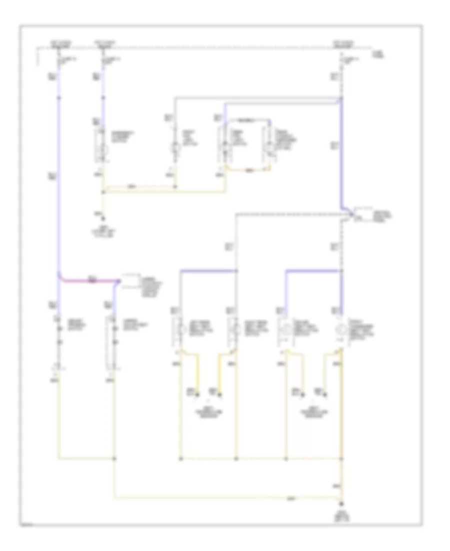
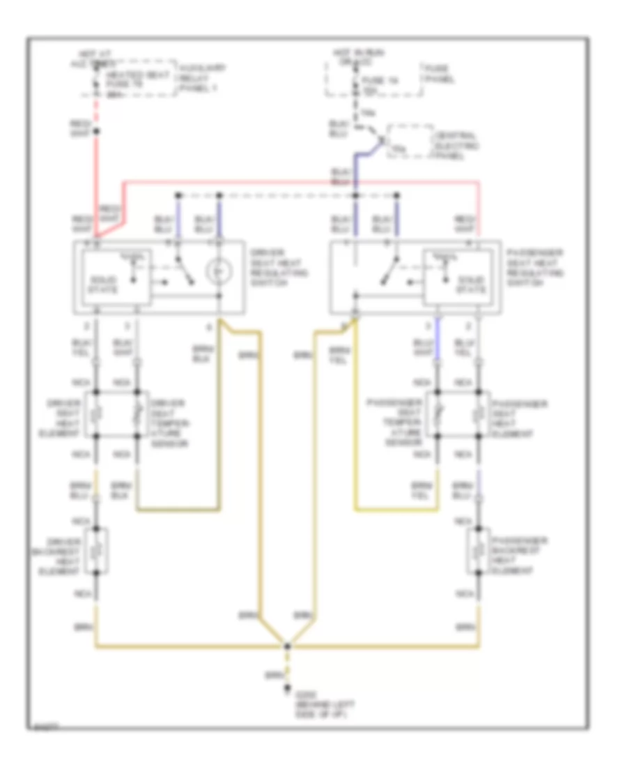
Front Seat Heater Wiring Diagram for Audi A6 1995
List of elements for Front Seat Heater Wiring Diagram for Audi A6 1995:
- 14a
- 15a
- All times
- Auxiliary relay panel 1
- Central electric panel
- Driver backrest heat element
- Driver seat heat element
- Driver seat heat regulating switch
- Driver seat temper- ature sensor
- Fuse 14 15a
- Fuse panel
- G202 (behind left side of i/p)
- Heated seat fuse 79 30a
- Hot at
- Hot in run or acc
- Nca
- Passenger backrest heat element
- Passenger seat heat element
- Passenger seat heat regulating switch
- Passenger seat temper- ature sensor
- Solid state
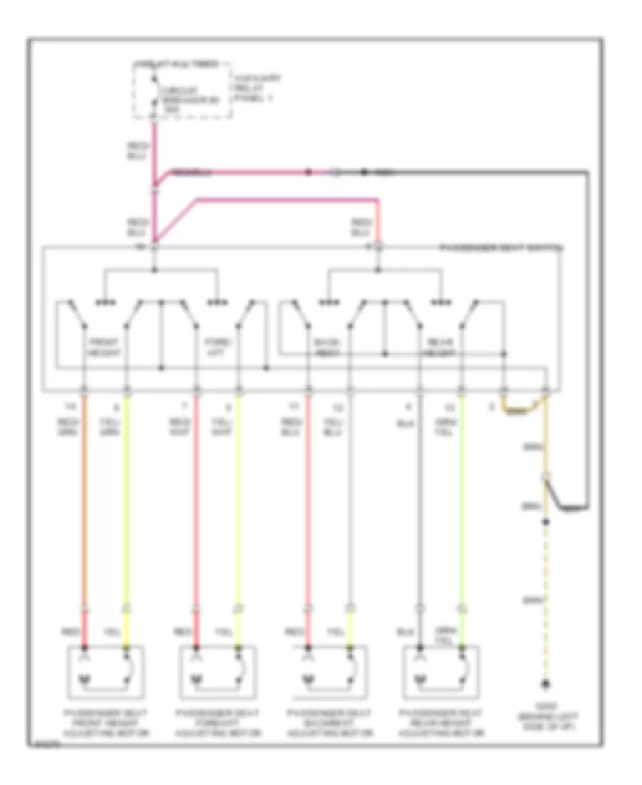
Passenger Seat Wiring Diagram for Audi A6 1995
List of elements for Passenger Seat Wiring Diagram for Audi A6 1995:
- Auxiliary relay panel 1
- Back- rest
- Circuit breaker 80 30a
- Fore/ aft
- Front height
- G202 (behind left side of i/p)
- Hot at all times
- Nca
- Passenger seat backrest adjusting motor
- Passenger seat fore/aft adjusting motor
- Passenger seat front height adjusting motor
- Passenger seat rear height adjusting motor
- Passenger seat switch
- Rear height
- Red
Rear Seat Heater Wiring Diagram for Audi A6 1995
List of elements for Rear Seat Heater Wiring Diagram for Audi A6 1995:
- 14a
- 15a
- All times
- Auxiliary relay panel 1
- Central electric panel
- Fuse 14 15a
- Fuse panel
- G202 (behind left side of i/p)
- Heated seat fuse 79 30a
- Hot at
- Hot in run or acc
- Left rear backrest heat element
- Left rear heated seat switch
- Left rear seat heat element
- Left rear seat heat regulating switch
- Left rear seat temper- ature sensor
- Nca
- Right rear backrest heat element
- Right rear heated seat switch
- Right rear seat heat element
- Right rear seat heat regulating switch
- Right rear seat temper- ature sensor
- Solid state
POWER TOP/SUNROOF
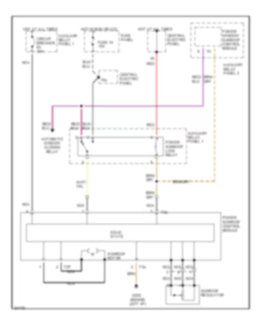
Sunroof Wiring Diagram for Audi A6 1995
List of elements for Sunroof Wiring Diagram for Audi A6 1995:
- 15a
- Automatic window closing relay
- Auxiliary relay panel 1
- Auxiliary relay panel 2
- Central electric panel
- Circuit breaker 20a
- Fuse 14 15a
- Fuse panel
- G202 (behind left i/p)
- Hot at all times
- Hot in run or acc
- Nca
- Power sunroof control module
- Power sunroof lock relay
- Power window/ sunroof control module
- Red
- Solid state
- Sunroof motor
- Sunroof regulator
- T2p
- T5a
POWER WINDOWS
Power Windows Wiring Diagram (1 of 2) for Audi A6 1995
List of elements for Power Windows Wiring Diagram (1 of 2) for Audi A6 1995:
- (behind left side of i/p)
- 75x
- All times
- Automatic window closing relay
- Auxiliary relay panel 1
- Auxiliary relay panel 2
- Central electric panel
- Central locking/ alarm system/ interior light delay control module
- Circuit breaker 30a
- Driver's door handle alarm switch
- Front
- Fuse 15a
- Fuse panel
- G202
- Hot at
- Hot at all times
- Instrument cluster system
- Interior
- Left front door contact switch
- Light
- Load reduc- tion relay
- Passenger's door handle alarm switch
- Power tops system
- Power window/ sunroof control module
- Right footwell light
- Right front door contact switch
Power Windows Wiring Diagram (2 of 2) for Audi A6 1995
List of elements for Power Windows Wiring Diagram (2 of 2) for Audi A6 1995:
- Left front door window motor
- Left front window switch
- Left rear door window motor
- Left rear door window switch (center console)
- Left rear door window switch (door)
- Right front door window motor
- Right front door window switch (center console)
- Right front door window switch (door)
- Right rear door window motor
- Right rear door window switch (center console)
- Right rear door window switch (door)
- Window lockout switch
RADIO
Radio Wiring Diagram, Except Wagon for Audi A6 1995
List of elements for Radio Wiring Diagram, Except Wagon for Audi A6 1995:
- (not used)
- 15a
- 1995 vftc c
- 86s
- Acc
- Amplifier
- Auto check system
- Cd changer interface
- Cd player
- Defogger system
- Fuse 92
- Fuse panel (left side of dash)
- G201 (behind right side of dash)
- G905 (right rear "c" pillar)
- Hot at all times
- Ignition switch
- Instrument cluster system
- Interior lights system
- Left antenna amplifier
- Left front amplified speaker
- Left rear speaker
- Lock
- Nca
- Power distribution system
- Radio
- Red
- Right antenna amplifier
- Right front amplified speaker
- Right rear speaker
- Run
- Start
- T10
- T8b
Radio Wiring Diagram, Wagon for Audi A6 1995
List of elements for Radio Wiring Diagram, Wagon for Audi A6 1995:
- (not used)
- 15a
- 86s
- Acc
- Amplifier
- Antenna amplifier
- Auto check system
- Cd changer interface
- Cd player
- Fuse 92
- Fuse panel (left side of dash)
- G201 (behind right side of dash)
- Hot at all times
- Ignition switch
- Instrument cluster system
- Interior lights system
- Left front amplified speaker
- Left rear speaker
- Lock
- Nca
- Power distribution system
- Radio
- Red
- Right front amplified speaker
- Right rear speaker
- Run
- Start
- T10
- T6ba
- T6bb
- T8b
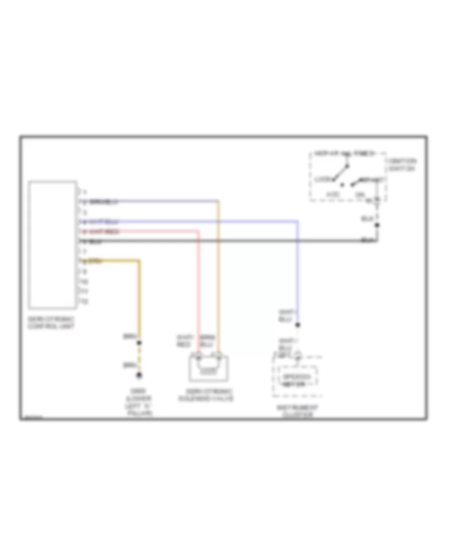
SHIFT INTERLOCK
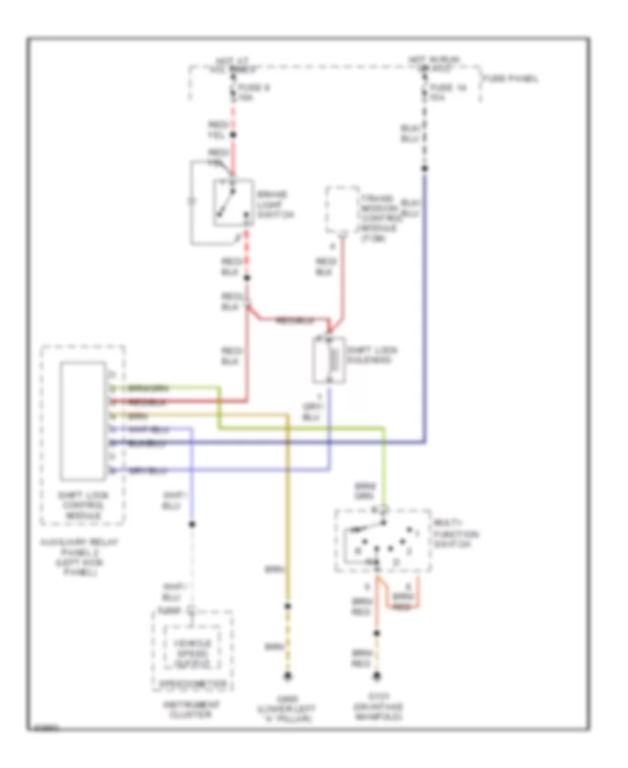
Shift Interlock Wiring Diagram for Audi A6 1995
List of elements for Shift Interlock Wiring Diagram for Audi A6 1995:
- Auxiliary relay panel 2 (left kick panel)
- Brake light switch
- Cluster
- Function switch
- Fuse 14 15a
- Fuse 9 10a
- Fuse panel
- G131 (on intake manifold)
- G900 (lower left "a" pillar)
- Hot at all times
- Hot in run or acc
- Instrument
- Multi-
- Shift lock control module
- Shift lock solenoid
- Speedometer
- T26/7
- Trans- mission control module (tcm)
- Vehicle speed output
STARTING/CHARGING
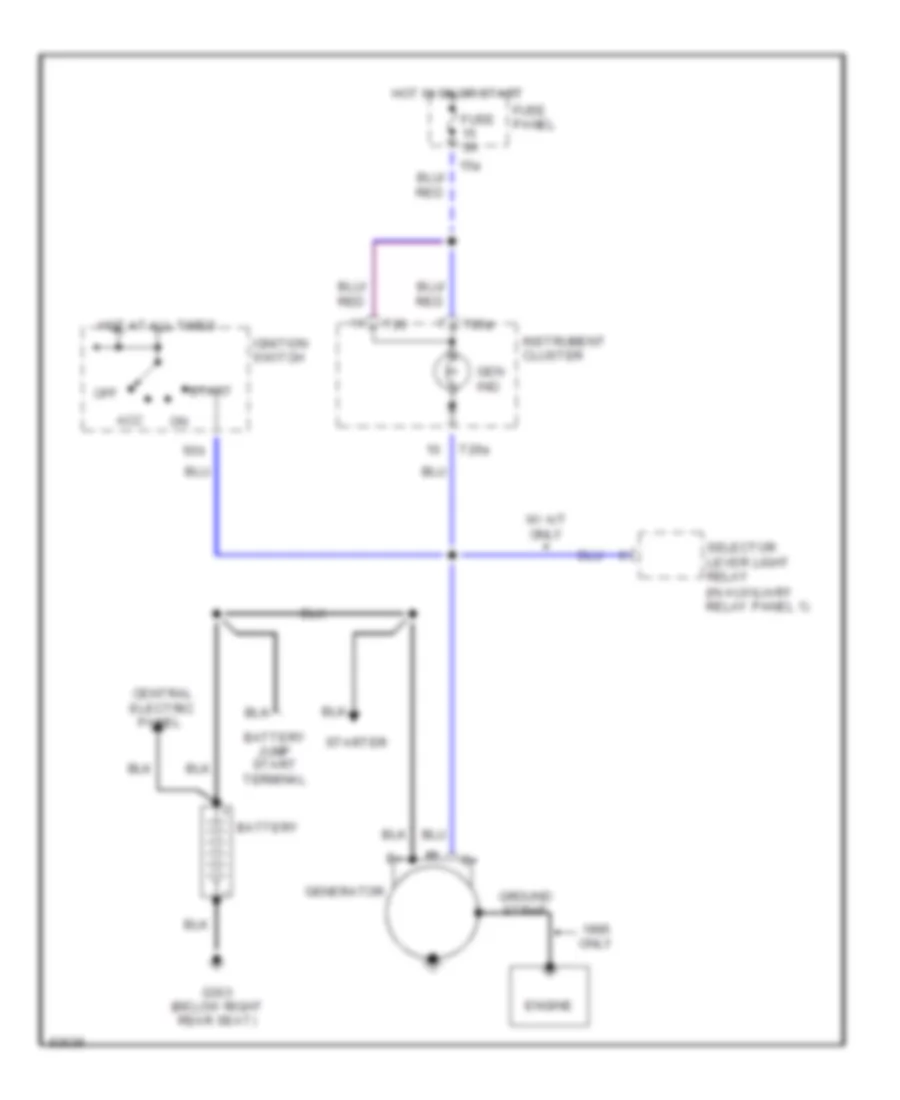
Charging Wiring Diagram for Audi A6 1995
List of elements for Charging Wiring Diagram for Audi A6 1995:
- (in auxiliary relay panel 1)
- 15a
- 50b
- Acc
- Battery
- Battery jump start terminal
- Central electric
- Engine
- Fuse 5a
- Fuse panel
- G303 (below right rear seat)
- Gen ind.
- Generator
- Ground strap
- Hot at all times
- Hot in on or start
- Ignition switch
- Instrument cluster
- Off
- Only
- Panel
- Selector lever light relay
- Start
- Starter
- T26
- T26a
- W/ a/t only
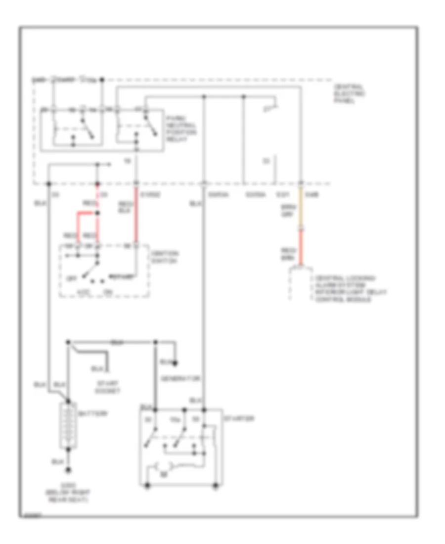
Starting Wiring Diagram, A/T for Audi A6 1995
List of elements for Starting Wiring Diagram, A/T for Audi A6 1995:
- 15a
- Acc
- Battery
- Central electric panel
- Central locking/ alarm system/ interior light delay control module
- G303 (below right rear seat)
- Generator
- Ignition switch
- Off
- Park/ neutral position relay
- Red
- S1/50z
- S3/1
- S3/50a
- S4/b
- S4/rf
- S6/50a
- Start
- Start socket
- Starter
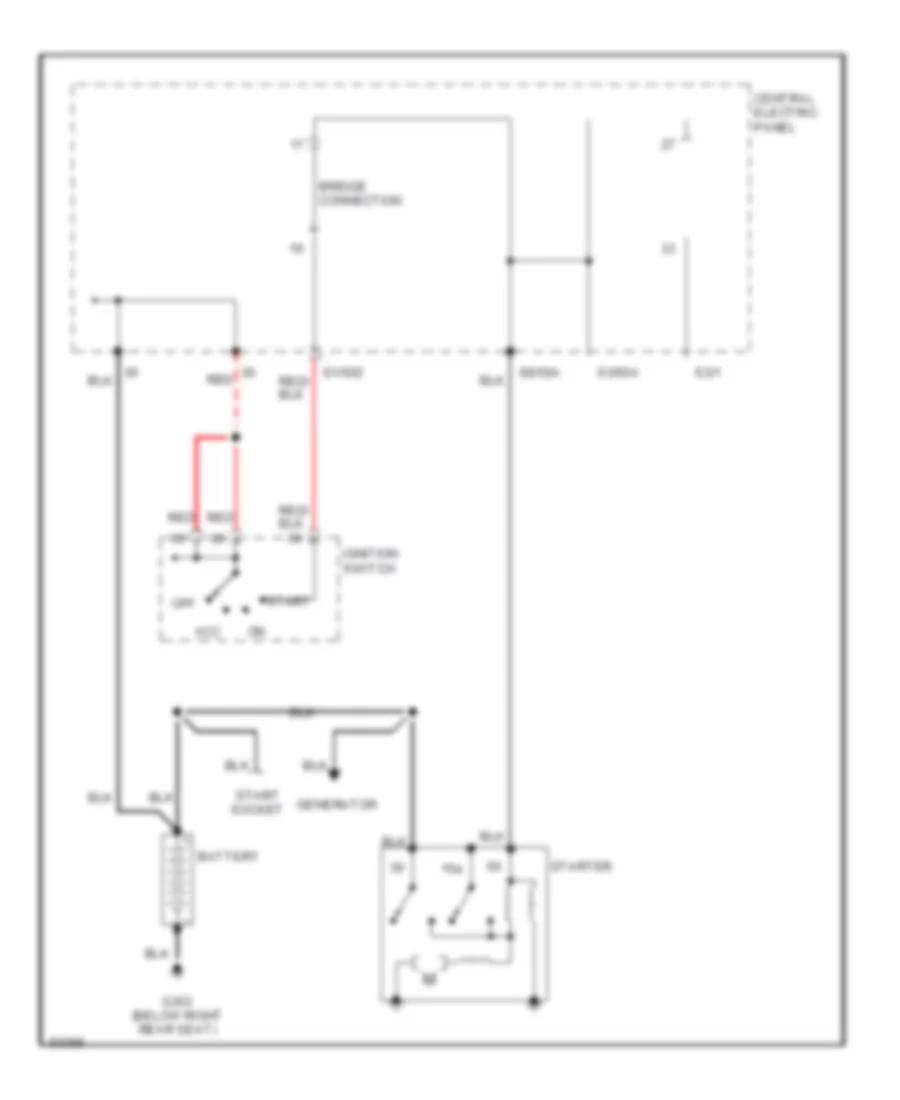
Starting Wiring Diagram, M/T for Audi A6 1995
List of elements for Starting Wiring Diagram, M/T for Audi A6 1995:
- 15a
- Acc
- Battery
- Bridge
- Central electric panel
- Connection
- G303 (below right rear seat)
- Generator
- Ignition switch
- Off
- Red
- S1/50z
- S3/1
- S3/50a
- S6/50a
- Start
- Start socket
- Starter
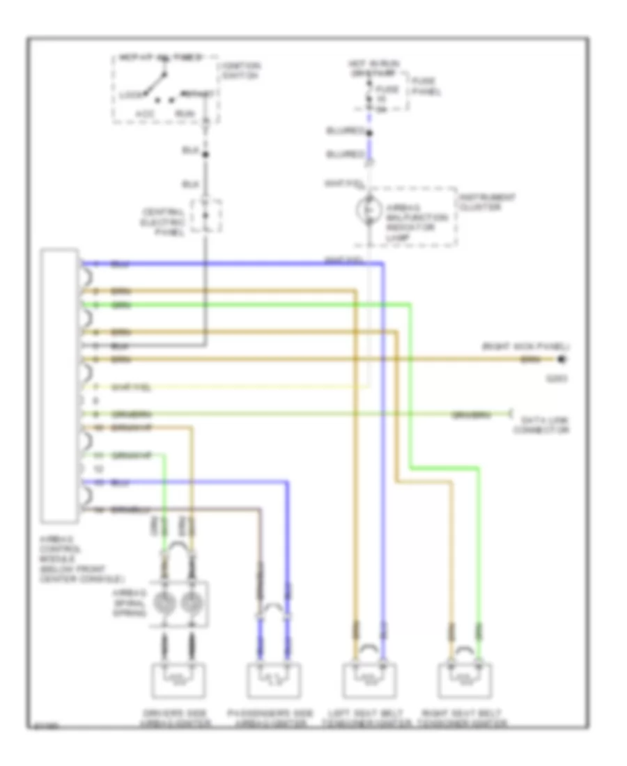
SUPPLEMENTAL RESTRAINTS
Supplemental Restraints Wiring Diagram for Audi A6 1995
List of elements for Supplemental Restraints Wiring Diagram for Audi A6 1995:
- (right kick panel)
- Acc
- Airbag control module (below front center console)
- Airbag malfunction indicator lamp
- Airbag spiral spring
- Central electric panel
- Data link connector
- Driver's side airbag igniter
- Fuse 5a
- Fuse panel
- G203
- Hot at all times
- Hot in run or start
- Ignition switch
- Instrument cluster
- Left seat belt tensioner igniter
- Lock
- Nca
- Passenger's side airbag igniter
- Right seat belt tensioner igniter
- Run
- Start
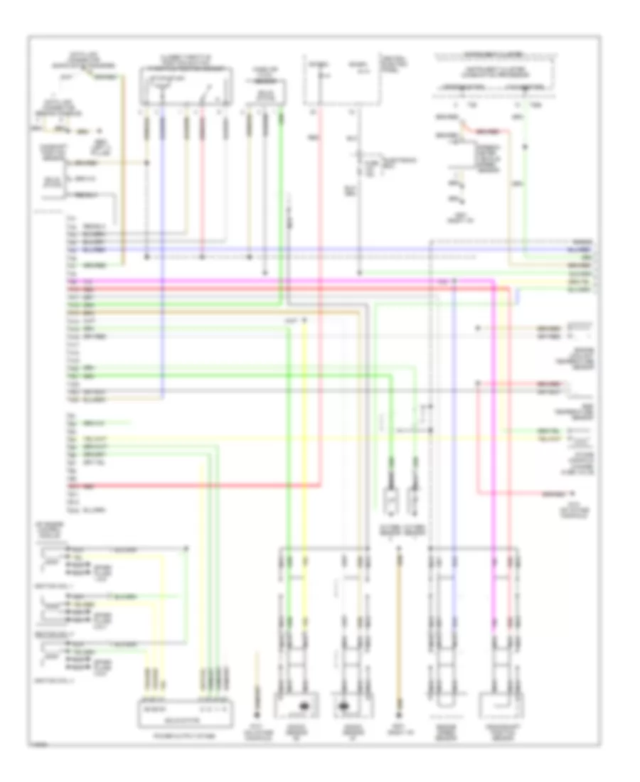
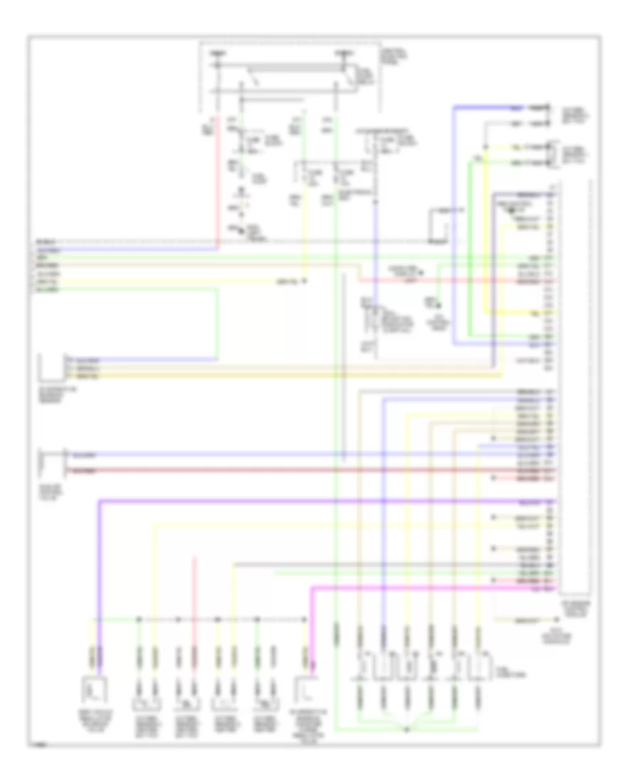
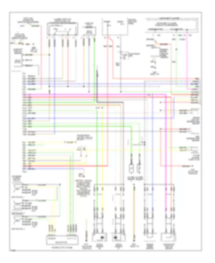
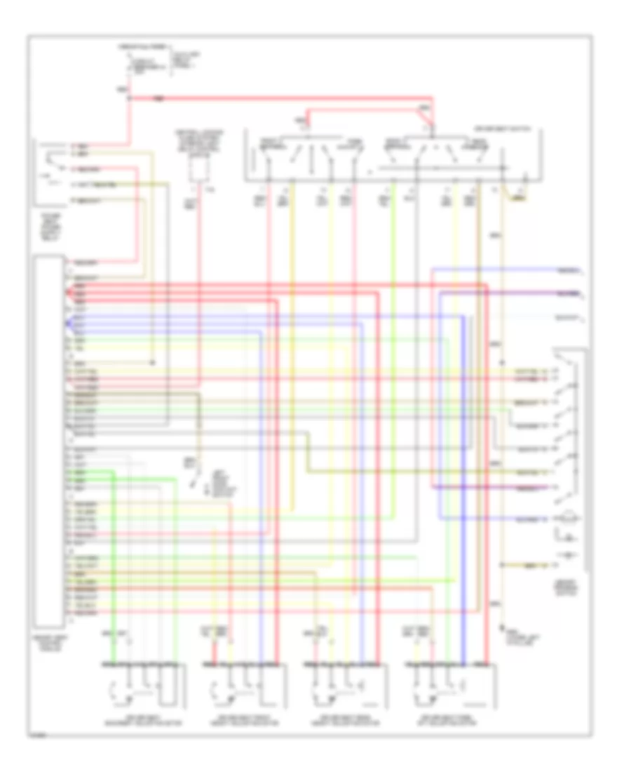
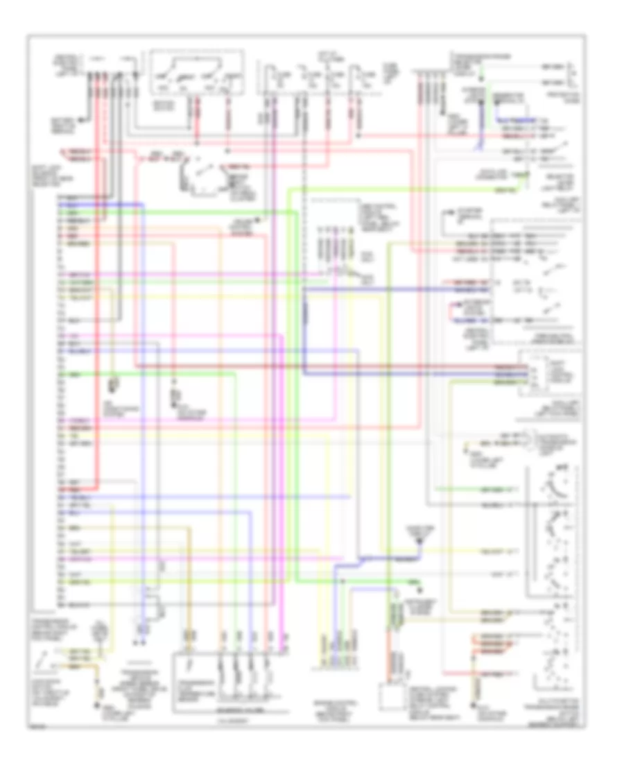
TRANSMISSION
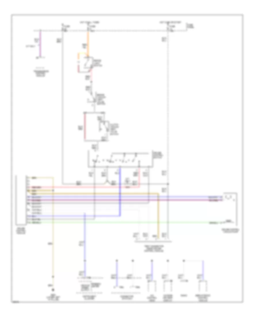
A/T Wiring Diagram for Audi A6 1995
List of elements for A/T Wiring Diagram for Audi A6 1995:
- 14a
- 15a
- 20a
- 50a
- 50z
- 87a
- Abs control module (left heel
- Acc
- Acc on
- Air conditioning system
- All wheel drive only
- Automatic transmission console light
- Auxiliary relay panel 1 (left i/p)
- Auxilliary relay panel 2 (left kick panel)
- Awd only
- B10
- B11
- B12
- B13
- Battery positive terminal
- Brake light switch (on pedal cluster)
- Central electric panel (left i/p)
- Central locking/ alarm system/ interior light delay control module (below rear seat)
- Computer display unit
- Cruise control system
- Data link connector
- Engine control module (behind right kick panel)
- Exterior lights system
- Fuse 10a
- Fuse 15a
- Fuse 5a
- Fuse panel (left i/p)
- Fwd only
- G131 (on intake manifold)
- G200 (lower left "a" pillar)
- G900 (lower left "a" pillar)
- Generator terminal d+
- Hot at all times
- Ignition switch
- Instrument cluster system
- Interior lights system
- Kick down switch (on throttle valve body, or cable)
- Multi-function transmission range
- Mv1
- Mv2
- Mv3
- Nca
- Not used
- Off
- P/n
- Panel, below rear seat)
- Park/neutral position relay
- Protection diode
- Red
- Red/
- Selector lever light relay
- Shift lock control module
- Shift lock solenoid (front of gear selector)
- Solenoid valves
- Start
- Starter terminal
- Switch (below left gearbox support)
- T16
- Transmission control module (behind right kick panel)
- Transmission fluid temperature sensor
- Transmission range selector lever display
- Transmission vehicle speed sensor (front wheel drive) (on right of gearbox housing)
- Valve body
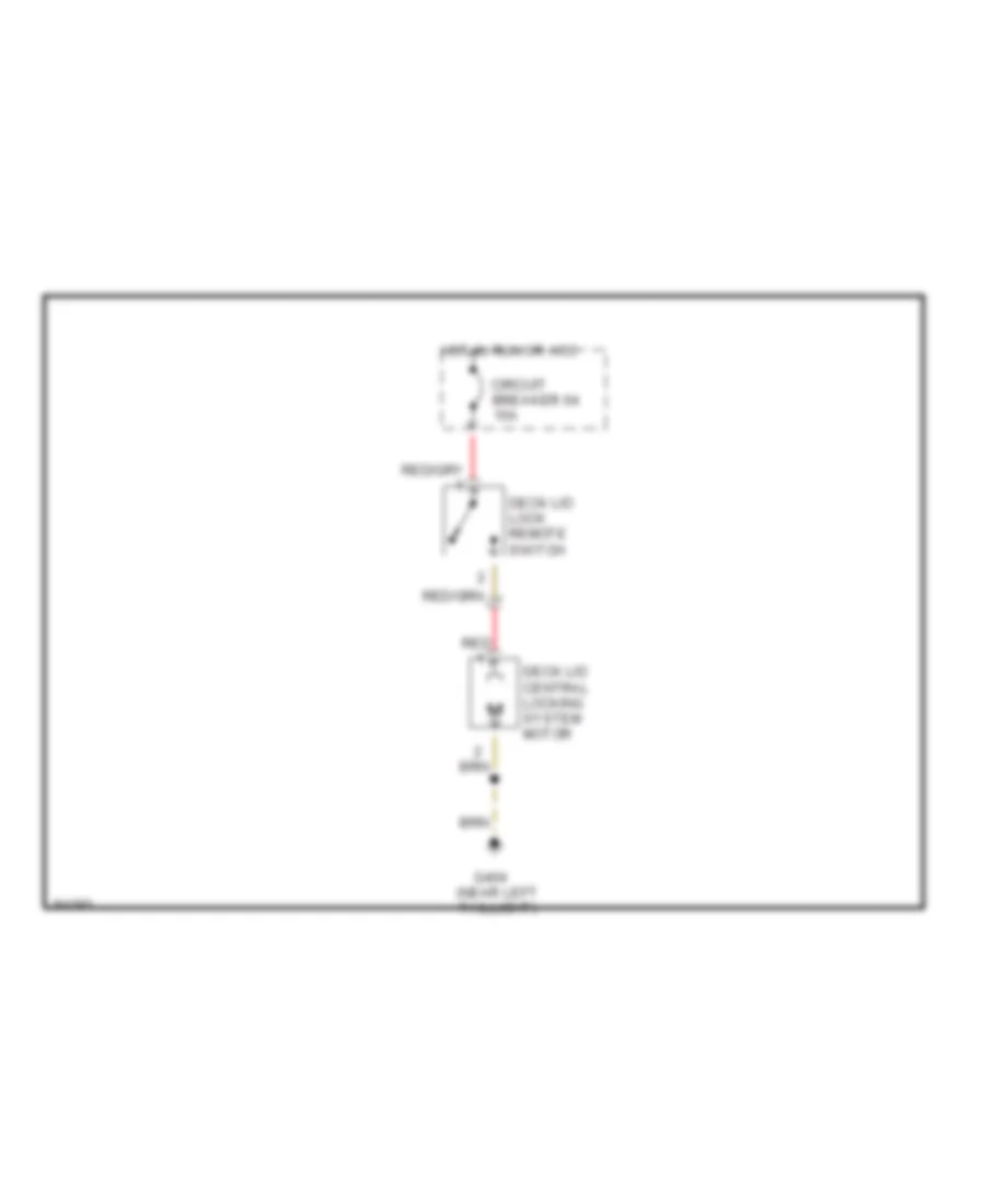
TRUNK, TAILGATE, FUEL DOOR
Deck Lid Release Wiring Diagram for Audi A6 1995
List of elements for Deck Lid Release Wiring Diagram for Audi A6 1995:
- Circuit breaker 64 15a
- Deck lid central locking system motor
- Deck lid lock remote switch
- G404 (near left taillight)
- Hot in run or acc
- Red
WARNING SYSTEMS
Warning Systems Wiring Diagram for Audi A6 1995
List of elements for Warning Systems Wiring Diagram for Audi A6 1995:
- (6 bulbs)
- 86s
- A/c
- A/c system
- Anti- theft system (1996)
- Auto check system
- Auto- check display illum.
- C10
- Center console light booster
- Clock
- Clock light
- Clock set button
- Cruise control system (vehicle speed output)
- Dimmer switch
- Electronic engine coolant temperature (ect) thermal switch
- Electronic voice check button
- Engine control module (ecm)
- Engine coolant level (elc) warning switch
- Engine oil
- Fluid level
- Fuel gauge
- Fuel level sensor
- Fuse 15 5a
- Fuse 7 5a
- Fuse 8 15a
- Fuse panel
- G404 (near left taillight)
- G900 (lower left "a" pillar)
- Hot at all times
- Hot in run or acc
- Hot w/ park or headlights on
- Ignition switch
- Illum. lights
- Instrument cluster
- Instrument cluster combination processor
- Interior lights system
- Key-in switch
- Left front door contact switch
- Left seat belt switch
- Memory seat control module
- Oil pressure switch
- Radio
- Rear lamp control module
- Red
- Sensor
- Speed- ometer
- Switch
- System
- T10/1
- T10/2
- T10/3
- T14
- T14-1
- T14-11
- T14-12
- T14-2
- T14-3
- T14-4
- T14-8
- T26
- T26-10
- T26-11
- T26-14
- T26-15
- T26-17
- T26-2
- T26-22
- T26-3
- T26-7
- T26-8
- T26a
- T26a-11
- T26a-12
- T26a-16
- T26a-18
- T26a-3
- T26a-6
- T26a-7
- T4m
- T4m-2
- Tach- ometer
- Temp gauge
- Temperature
- Trip odometer reset switch
- Vehicle speed sensor
- Voltage stabilizer
- Washer
- Windshield
WIPER/WASHER
Wiper/Washer Wiring Diagram for Audi A6 1995
List of elements for Wiper/Washer Wiring Diagram for Audi A6 1995:
- 58a
- 75a
- Auxiliary relay panel 1
- Battery
- Central electric panel
- Fuse 15a
- Fuse 25a
- Fuse 5a
- Fuse panel
- G100 (left side of engine compt)
- G202 (left side of i/p)
- G404 (near left taillight)
- G900 (lower left "a" pillar)
- Headlight washer pump
- Headlight washer system relay
- Headlights on
- Hot in on
- Hot in on or start
- Hot w/ park or
- Instrument cluster system
- Left washer nozzle heater
- Or acc
- Rear window washer pump
- Rear window wiper motor
- Rear window wiper/ washer relay
- Right washer nozzle heater
- S1/31
- S2/ 53e
- S2/31b
- S2/53c
- S2/j
- S5/p
- Solid state
- Station wagon only
- Washer fluid level switch
- Washer switch
- Windshield washer pump
- Windshield wiper motor
- Windshield wiper/ washer switch
- Wiper switch
- Wiper/ washer inter- mittent relay