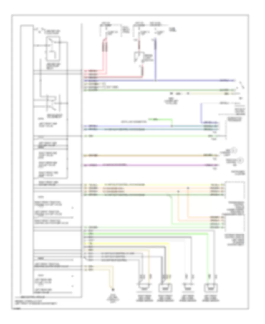
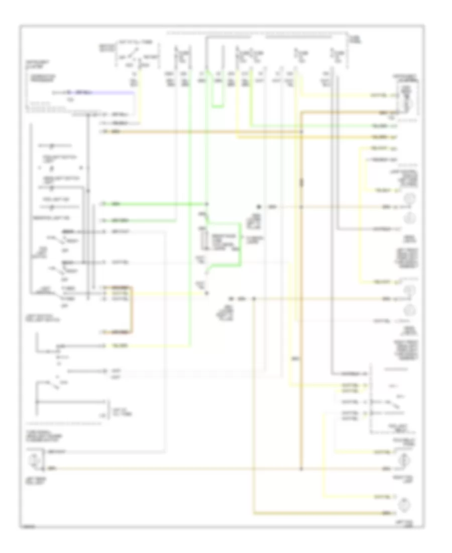
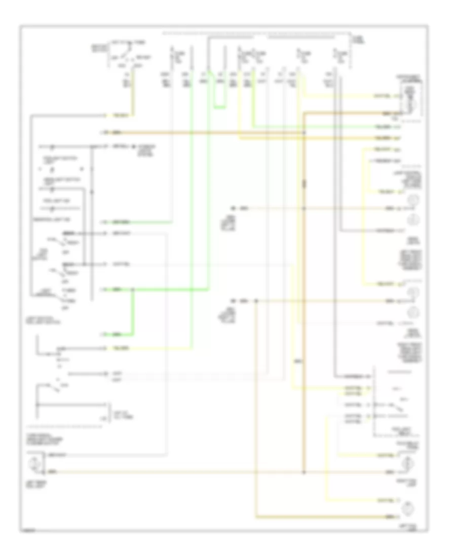
AIR CONDITIONING
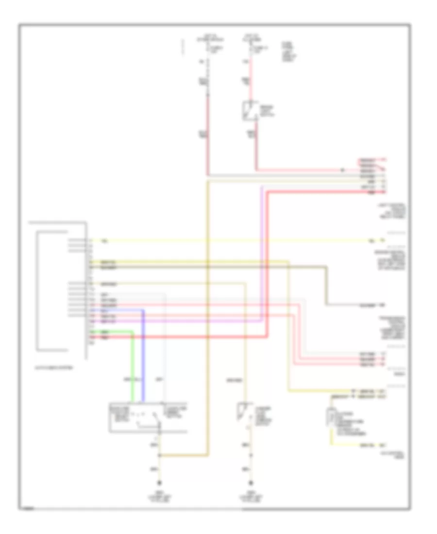
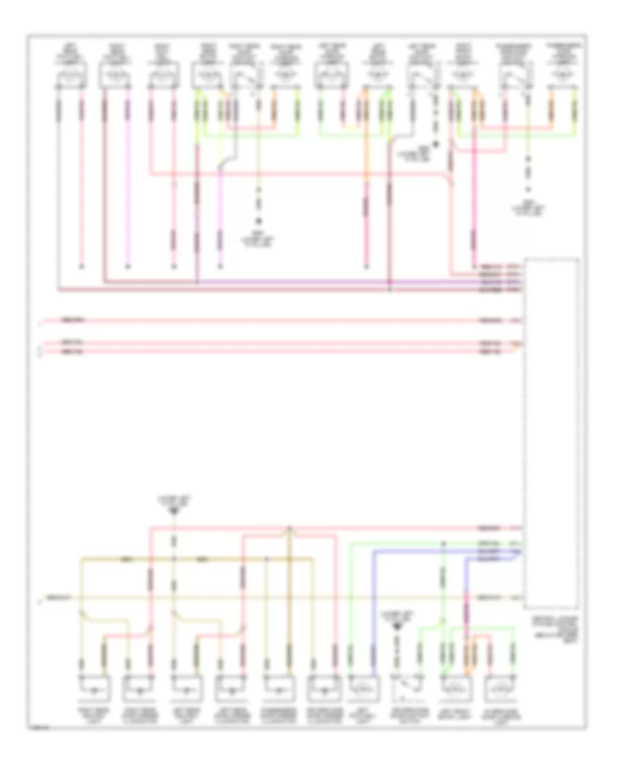
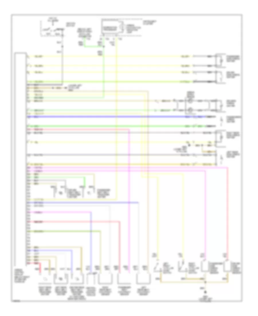
Automatic A/C Wiring Diagram (1 of 2) for Audi A6 1998

List of elements for Automatic A/C Wiring Diagram (1 of 2) for Audi A6 1998:
- 8-fold relay panel
- A/c clutch
- A/c control head
- Air quality sensor
- Anti-lock brakes system
- Coolant fan
- Coolant fan control relay (on 8-fold relay panel)
- Coolant fan control series resistor (behind left side of front bumper, on chassis member)
- Coolant fan control thermal switch (on lower right side of radiator)
- Data link connector (below left side of dash)
- Defogger system
- Fuse 10a
- Fuse 30a
- Fuse 40a
- Fuse 5a
- Fuse panel
- G200 (lower left "a" pillar)
- G200 g200 (lower left (lower left "a" pillar) "a" pillar)
- Hot at all times
- Hot in run
- Hot w/ load reduction relay energized
- Instrument cluster
- Interior lights system
- Motronic engine control module (in elect box, left side of fresh air plenum)
- Second speed coolant fan control relay (on 8-fold relay panel)
- T32
- T32a
- Tachometer
- Wiper/washer system
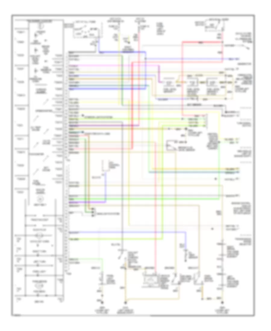
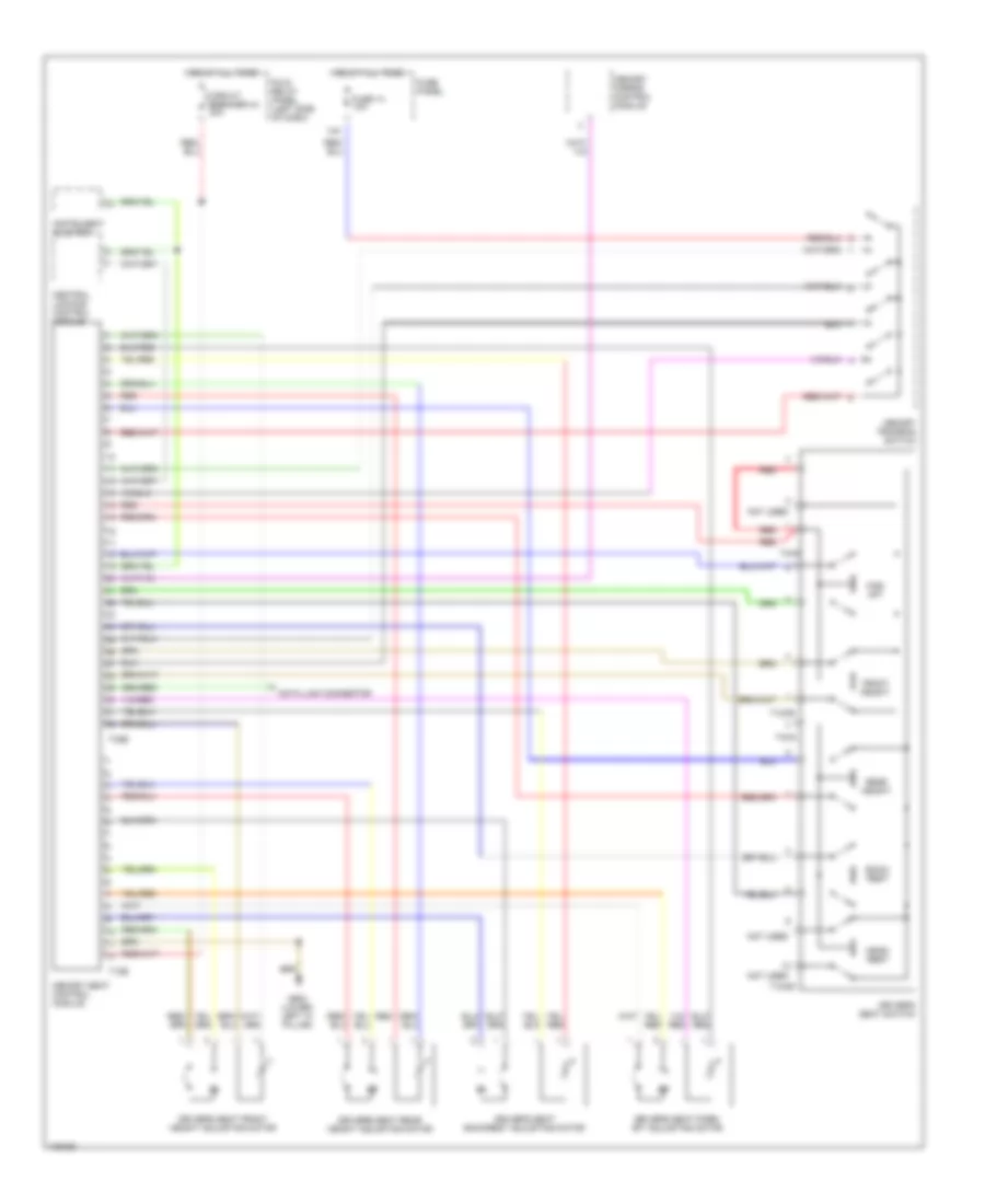
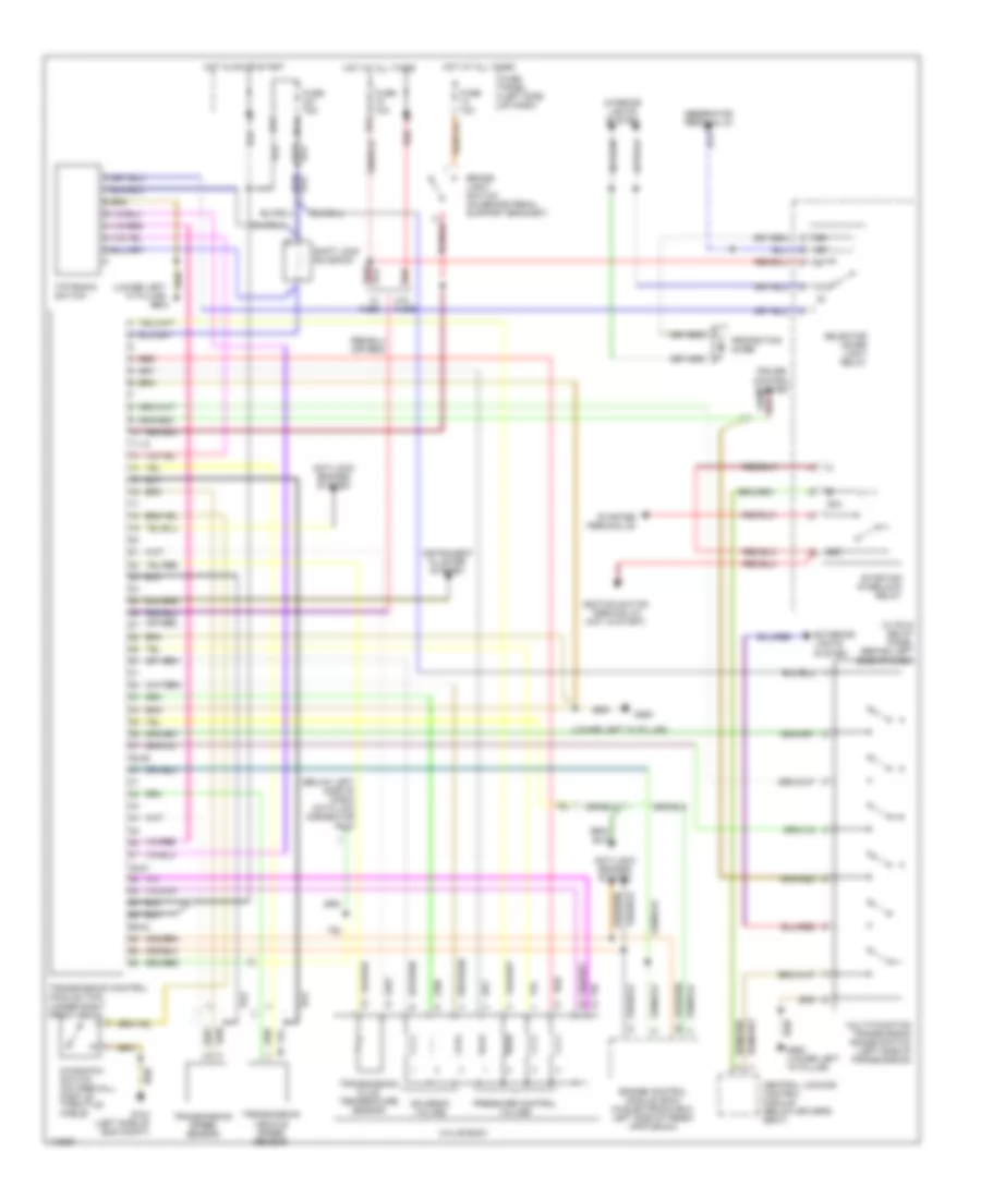
Automatic A/C Wiring Diagram (2 of 2) for Audi A6 1998
List of elements for Automatic A/C Wiring Diagram (2 of 2) for Audi A6 1998:
- (w/ solar cell system)
- (w/o solar cell system)
- A/c pressure switch (on right side of a/c condenser)
- Anti-theft system
- Back pressure flap motor & position sensor
- Central flap motor & position sensor (on right side of evaporator housing)
- Defroster flap motor & position sensor
- Floor outlet temperature sender
- Fresh air blower
- Fresh air blower control module (behind right side of dash)
- Fresh air intake duct temperature sensor (behind right side of dash)
- Fuse 10a
- Fuse panel
- G200 (lower part of left "a" pillar)
- Hot at all times
- Left temperature regulator flap motor & position sensor
- Left vent temperature sensor
- Outside air temperature display
- Outside air temperature sensor (in front of a/c condenser)
- Right temperature regulator flap motor & position sensor
- Right vent temperature sensor
- Sensor
- Solar cell separation relay (w/ solar cell system) (on 13-fold relay panel)
- Solar cells
- Solar operation control module
- Sunlight photo
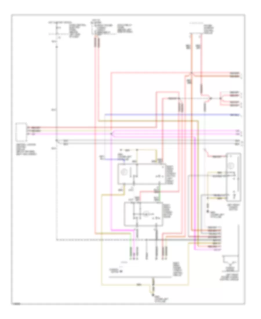
ANTI-LOCK BRAKES
Anti-lock Brakes Wiring Diagram for Audi A6 1998
List of elements for Anti-lock Brakes Wiring Diagram for Audi A6 1998:
- (not used)
- 13a
- Abs control module
- Abs return flow pump
- Abs return flow pump relay
- Abs solenoid valve relay
- Abs warning light
- Abs/edl hydraulic unit (left front of engine compartment)
- All times
- Anti-slip control switch
- Brake light switch
- Combination processor
- Data link connector
- Fold relay panel
- Fuse 123 60a
- Fuse 13 10a
- Fuse 7 10a
- Fuse panel
- G100 (on abs hydraulic unit)
- G900 (lower left "a" pillar)
- Hot at
- Hot in on or start
- Instrument cluster
- Left front abs inlet valve
- Left front abs outlet valve
- Left front abs wheel speed sensor
- Left front traction control outlet valve
- Left front traction control switch-over valve
- Left rear abs inlet valve
- Left rear abs outlet valve
- Left rear abs wheel speed sensor
- Motronic engine control module (left rear of engine compartment)
- Right front abs inlet valve
- Right front abs outlet valve
- Right front abs wheel speed sensor
- Right front traction control outlet valve
- Right front traction control switch-over valve
- Right rear abs inlet valve
- Right rear abs outlet valve
- Right rear abs wheel speed sensor
- T32
- T32a
- Traction control ind
- Transmission control module (under carpet forward of passenger's seat)
- W/ anti-slip control
- W/ anti-slip control w/ awd
- W/ anti-slip control w/o can buss
- W/ can buss can-h
- W/ can buss can-l
- W/o anti-slip control
ANTI-THEFT
Anti-theft Wiring Diagram (1 of 2) for Audi A6 1998
List of elements for Anti-theft Wiring Diagram (1 of 2) for Audi A6 1998:
- 10a
- 14a
- 238a
- 86s
- Alarm horn
- Antenna
- Central locking system control module (below driver's (seat & carpet)
- Driver's door lock assembly
- Driver's side interior lock switch
- Exterior lights system
- Fuel door unlock motor
- Fuse 10a
- Fuse 20a
- Fuse 5a
- Fuse panel
- G901 (lower right "a" pillar)
- Hood alarm switch
- Hot at all times
- Hot in start and run
- Ignition switch
- Instrument cluster system
- Interior lights system
- Key switch
- Level control system control module
- Memory systems
- Multifunction transmission range switch
- Nca
- Power windows system
- Radio
- Red
- Shield
- Starting system
- T1e
- Trunk, tailgates, fuel door system
Anti-theft Wiring Diagram (2 of 2) for Audi A6 1998
List of elements for Anti-theft Wiring Diagram (2 of 2) for Audi A6 1998:
- 226a
- A/c system
- Defogger system
- Fuse 30a
- Fuse panel
- G900 (lower left "a" pillar)
- G901 (lower right "a"pillar)
- Hot in run
- Interior lights system
- Left rear door lock assembly
- Left rear glass sensor
- Left ultra- sound sensor
- Nca
- Passenger's compartment monitoring switch
- Passenger's door lock assembly
- Rear window defogger switch
- Right rear door lock assembly
- Right rear glass sensor
- Right ultra- sound sensor
- Sedan
- T2v
- T2w
- T3o
- Trunk lock assembly
- Trunk, tailgates, fuel doors system
- Ultra sound sensor control module (below left "c" pillar)
- W/ solar cells
- Wagon
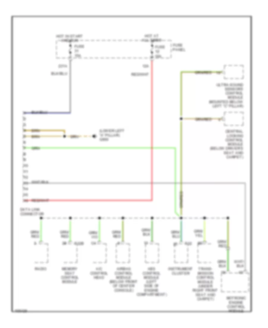
COMPUTER DATA LINES
Computer Data Lines Wiring Diagram for Audi A6 1998
List of elements for Computer Data Lines Wiring Diagram for Audi A6 1998:
- (lower left "a" pillar) g900
- 12a
- 231a
- A/c control head
- Abs control module (left side of engine compartment)
- Airbag control module (below front of center console)
- Central locking control module (below driver's seat and carpet)
- Data link connector
- Fuse 10a
- Fuse 15a
- Fuse panel
- Hot at all times
- Hot in start and run
- Instrument cluster
- Memory seat control module
- Motronic engine control module
- Radio
- T32
- T32b
- Trans- mission control module (under right front seat and carpet)
- Ultra-sound sensors control module (mounted below left "c" pillar)
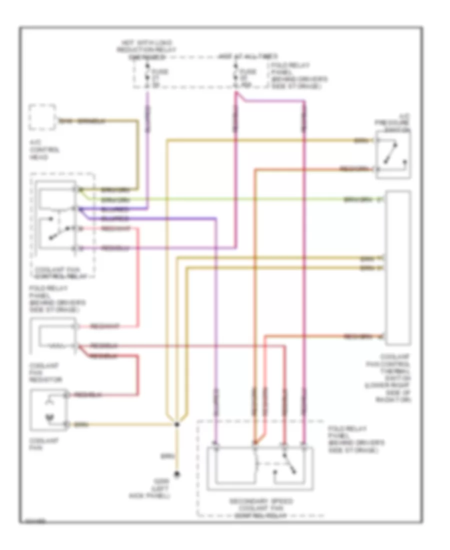
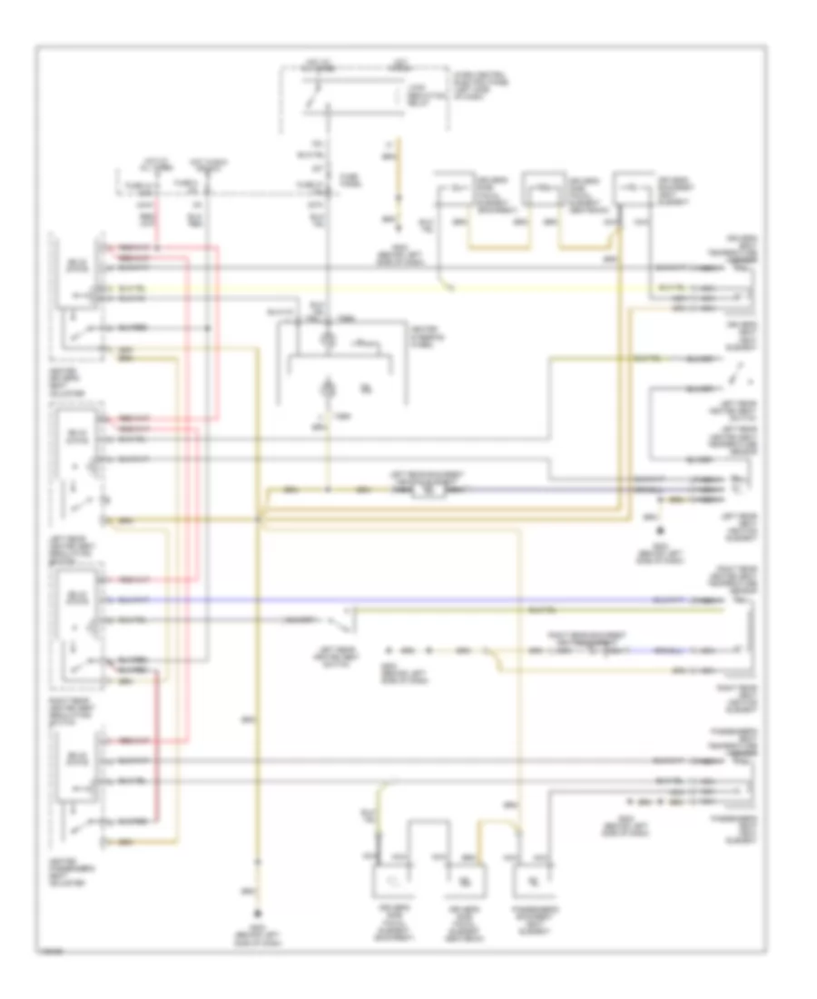
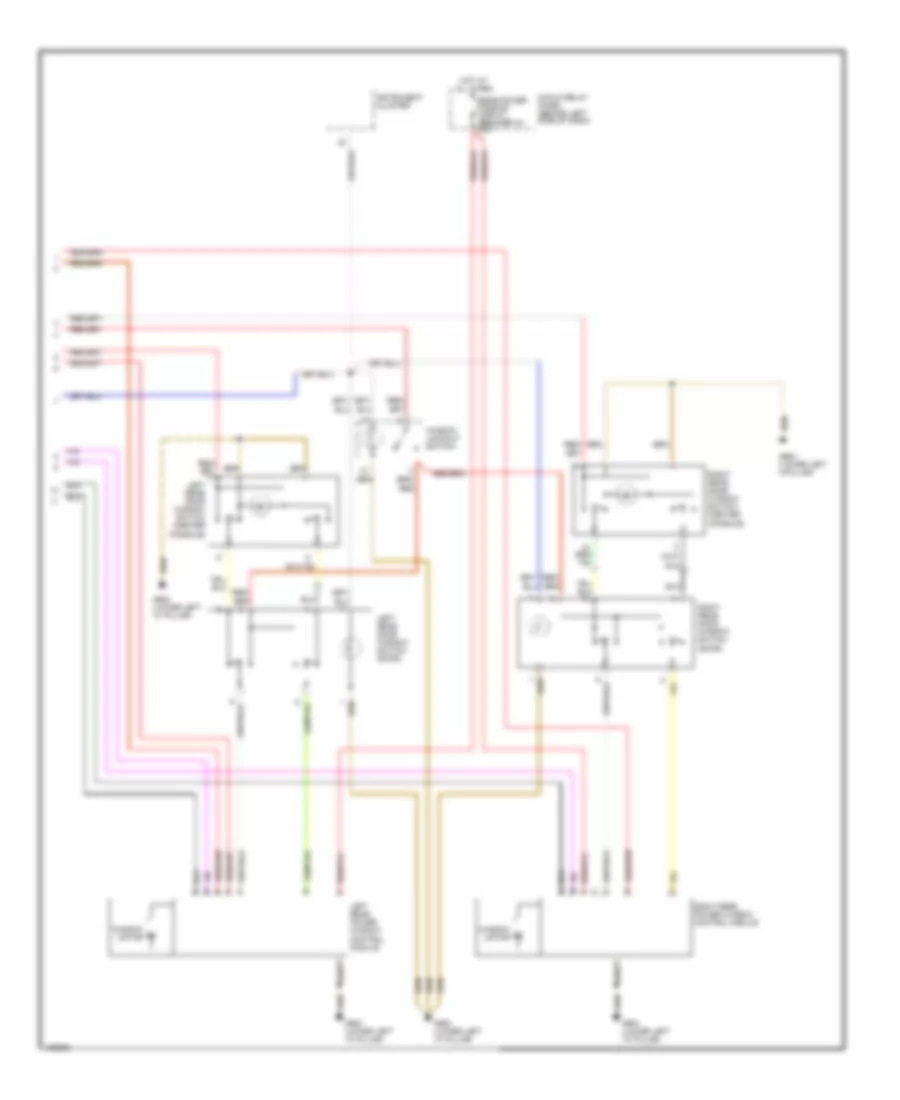
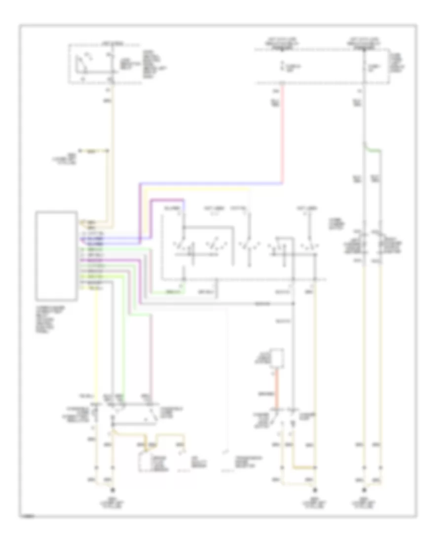
COOLING FAN
Cooling Fan Wiring Diagram for Audi A6 1998
List of elements for Cooling Fan Wiring Diagram for Audi A6 1998:
- A/c control head
- A/c pressure switch
- Coolant fan
- Coolant fan control relay
- Coolant fan control thermal switch (lower right side of radiator)
- Coolant fan resistor
- D16
- Fold relay panel (behind driver's side storage)
- Fuse 40a
- Fuse 5a
- G200 (left kick panel)
- Hot at all times
- Hot with load reduction relay energized
- Secondary speed coolant fan control relay
CRUISE CONTROL
Cruise Control Wiring Diagram for Audi A6 1998
List of elements for Cruise Control Wiring Diagram for Audi A6 1998:
- Brake light switch
- Brake vacuum vent valve
- Cluster
- Combination processor
- Control module
- Cruise control module (behind glovebox)
- Cruise control switch
- Cruise control vacuum pump
- Exterior lights system
- Fuse 10a
- Fuse panel
- G104 (left side of engine compartment)
- G200 (behind left side of dash)
- Hot at all times
- Instrument
- Speedometer vehicle speed sensor
- T32
- Transmission
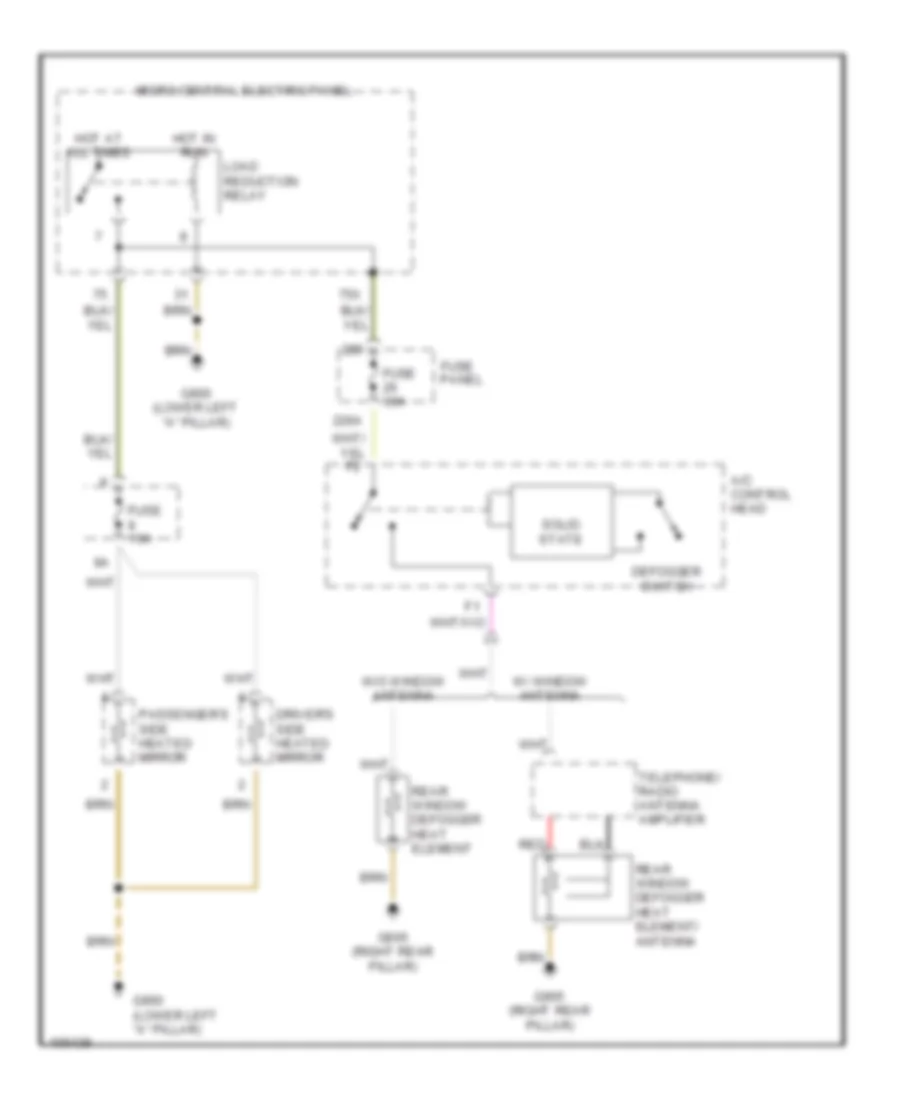
DEFOGGERS
Defoggers Wiring Diagram for Audi A6 1998
List of elements for Defoggers Wiring Diagram for Audi A6 1998:
- 226a
- 75x
- A/c control head
- Defogger switch
- Driver's side heated mirror
- Fuse 10a
- Fuse 30a
- Fuse panel
- G900 (lower left "a" pillar)
- G905 (right rear pillar)
- Hot at all times
- Hot in run
- Load reduction relay
- Micro central electric panel
- Passenger's side heated mirror
- Rear window defogger heat element
- Rear window defogger heat element/ antenna
- Red
- Solid state
- Telephone/ radio antenna amplifier
- W/ window antenna
- W/o window antenna
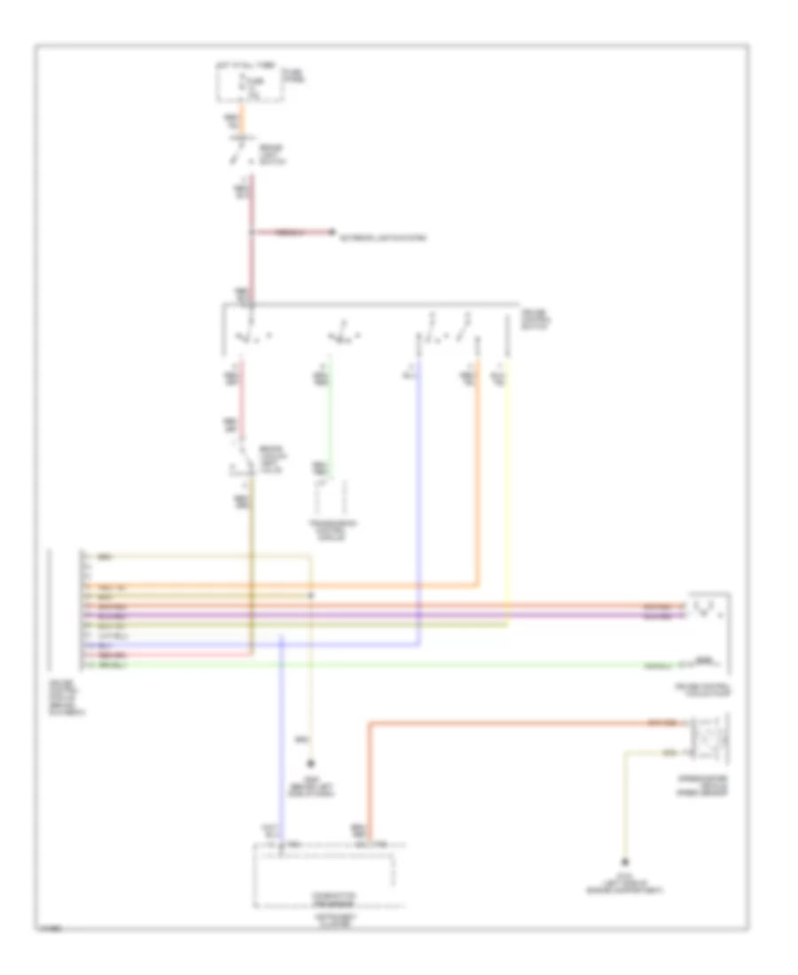
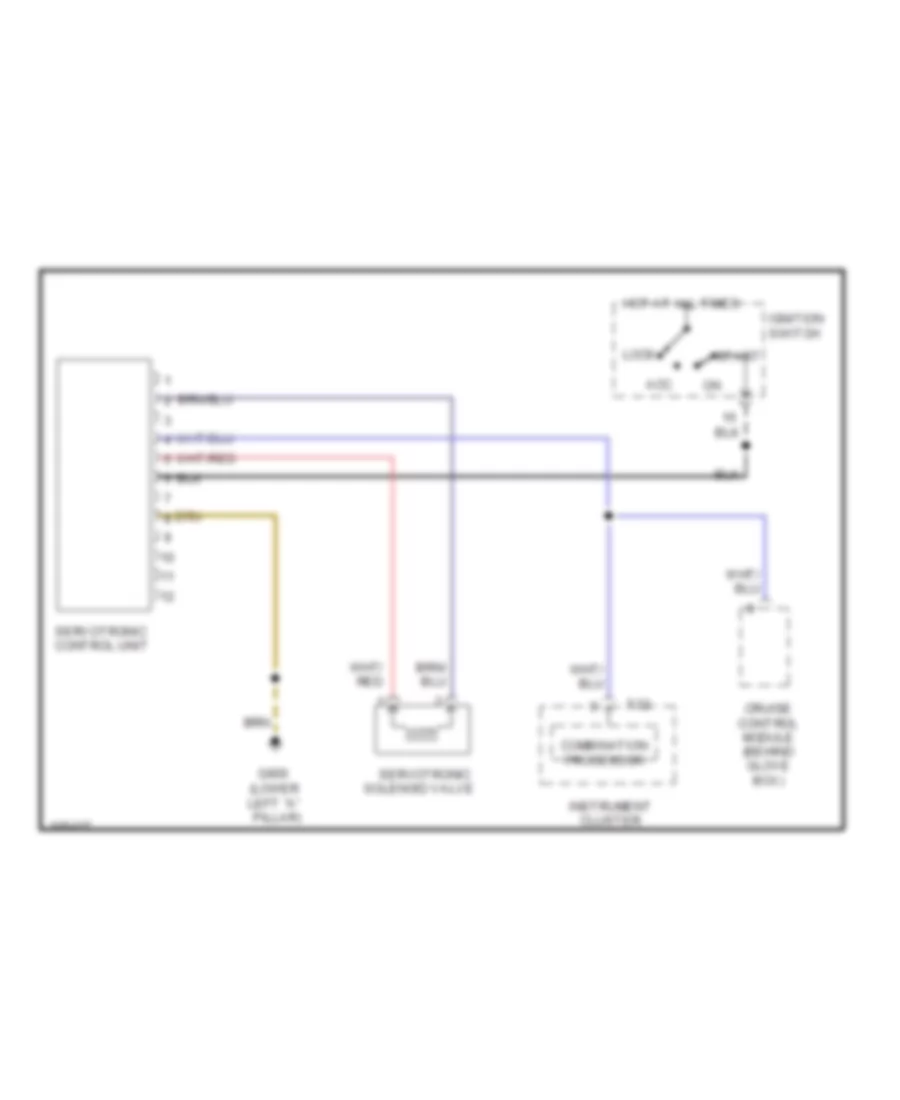
ELECTRONIC POWER STEERING
Electronic Power Steering Wiring Diagram for Audi A6 1998
List of elements for Electronic Power Steering Wiring Diagram for Audi A6 1998:
- (lower left "a" pillar)
- Acc
- Cluster
- Combination processor
- Cruise control module (behind glove box)
- G900
- Hot at all times
- Ignition switch
- Instrument
- Lock
- Servotronic
- Servotronic control unit
- Solenoid valve
- Start
- T32
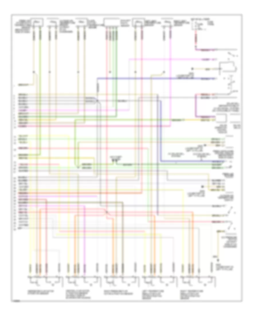
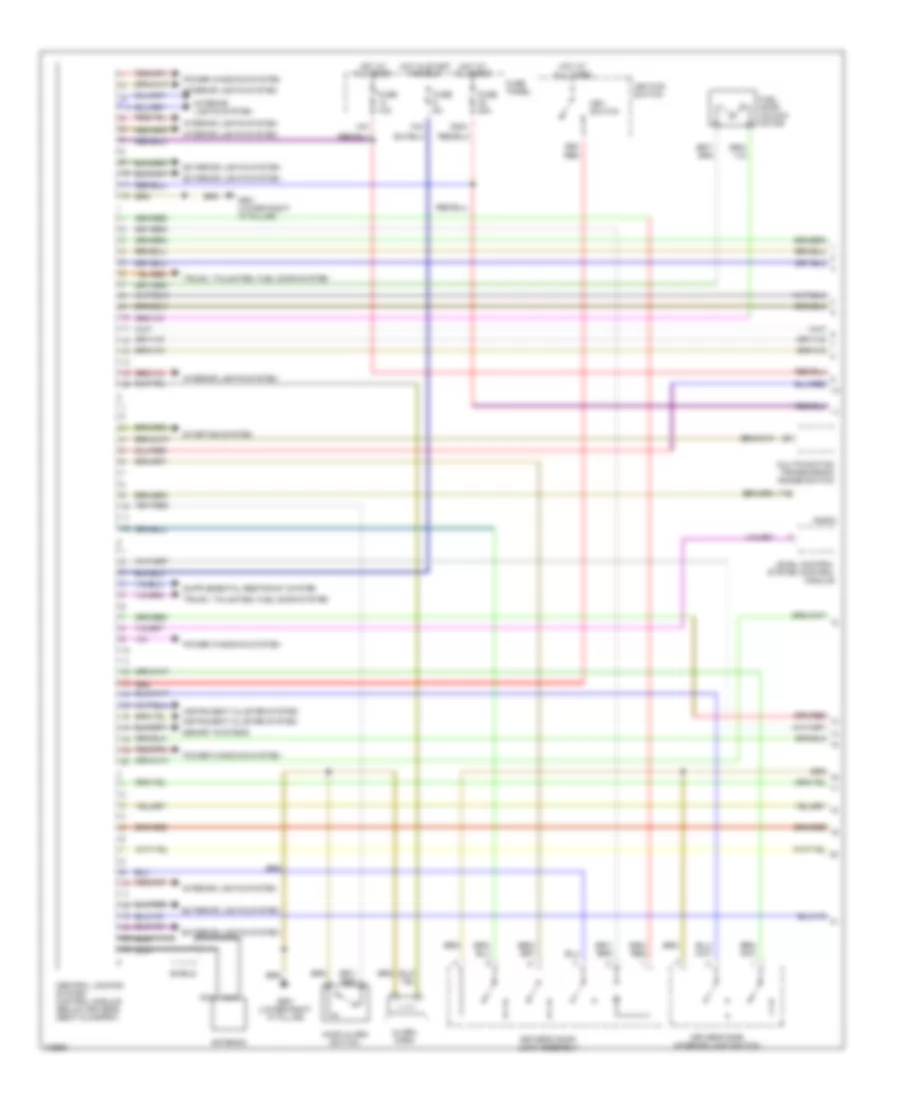
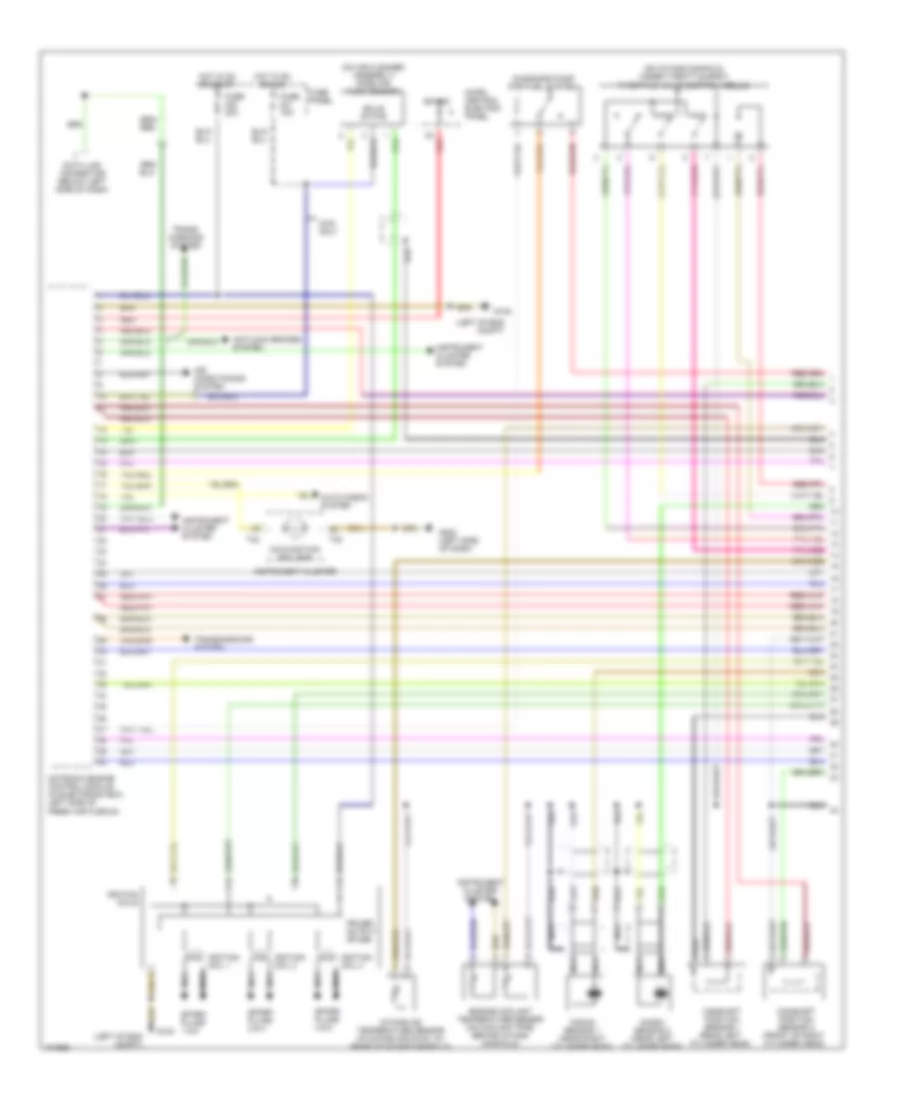
ENGINE PERFORMANCE
2.8L
2.8L, Engine Performance Wiring Diagram (1 of 2) for Audi A6 1998
List of elements for 2.8L, Engine Performance Wiring Diagram (1 of 2) for Audi A6 1998:
- (left of eng compt)
- (on air cleaner assembly) mass air flow sensor
- (on intake manifold, under throttle body) throttle valve control module
- 4wd only
- Air conditioning system
- Antilock brakes system
- Auto check system
- Bat(30)
- Camshaft position sensor 1 (rear left cylinder head)
- Camshaft position sensor 2 (front of right cylinder head)
- Data link connector (below left side of dash)
- Diagnosis pump (for fuel system)
- Engine coolant temperature sensor (on coolant pipe, behind intake manifold)
- Fuse 15a
- Fuse 20a
- Fuse panel
- G100
- G202 (left side of dash)
- Hot in on or acc
- Hot in on or start
- Ignition coil 1
- Ignition coil 2
- Ignition coil 3
- Ignition coils
- Instrument cluster
- Instrument cluster system
- Intake air temperature sensor (in intake air duck, at rear of intake manifold)
- Knock sensor 1 (near right cylinder head)
- Knock sensor 2 (near left cylinder head)
- Malfunction ind lamp
- Micro central electric panel
- Motronic engine control module (in electronic box, left side of fresh air plenum)
- Nca
- Power output stage
- Red
- Solid state
- Spark plugs 1 & 6
- Spark plugs 2 & 4
- Spark plugs 3 & 5
- T32
- Trans- missions system
- Transmissions system
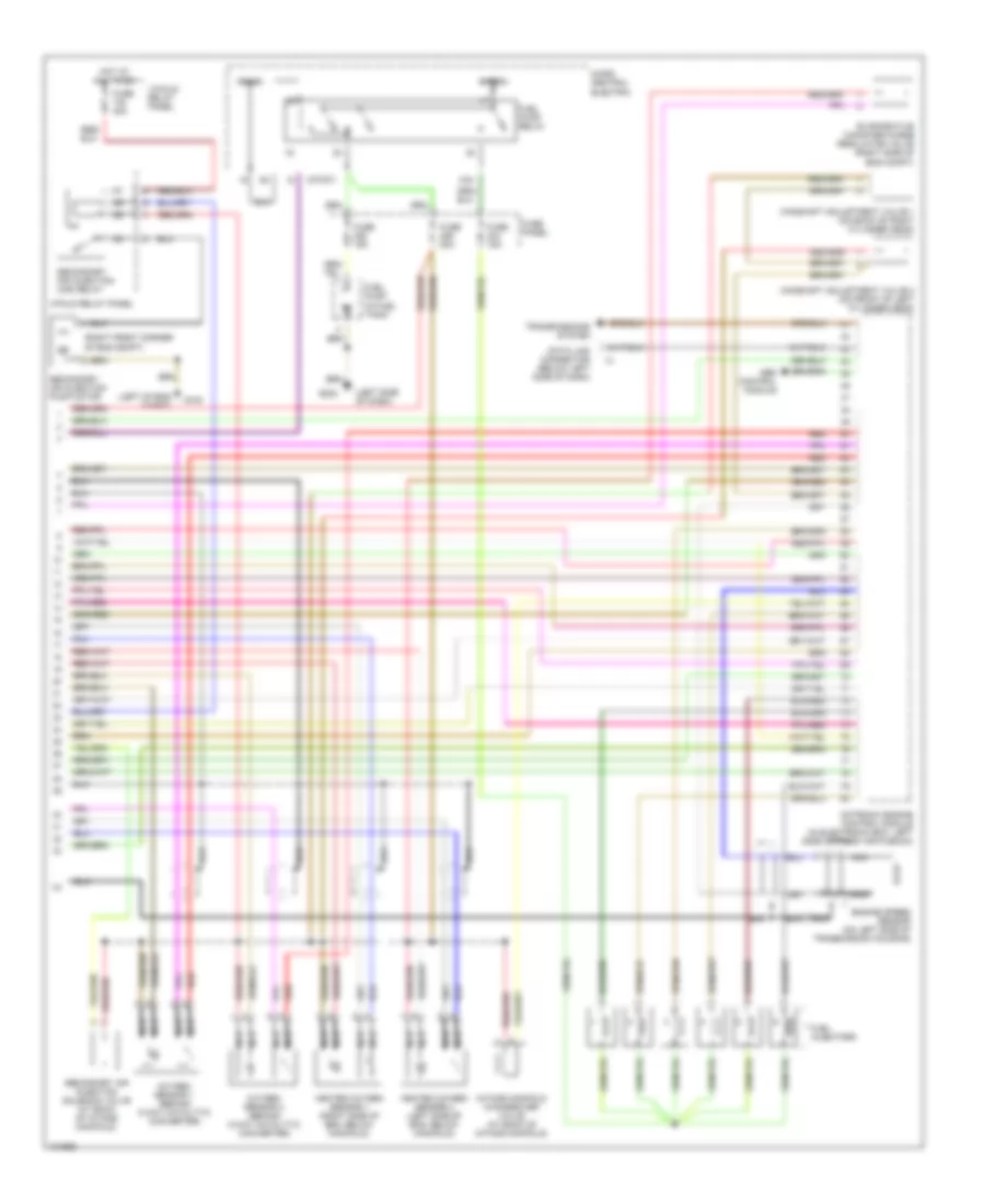
2.8L, Engine Performance Wiring Diagram (2 of 2) for Audi A6 1998
List of elements for 2.8L, Engine Performance Wiring Diagram (2 of 2) for Audi A6 1998:
- (left of eng compt)
- (left side of dash)
- (right front corner of eng compt)
- 13-fold relay panel
- 3-fold relay panel
- 87f/dti
- 87a
- Abs control module
- Bat(30)
- Camshaft adjustment valve 1 (on back of right cylinder head)
- Camshaft adjustment valve 2 (on front of left cylinder head)
- Data link connector (below left side of dash)
- Engine speed sensor (on left side of transmission housing)
- Evaporative canister purge regulator valve (right side of eng compt)
- Fuel injectors
- Fuel pump (in fuel tank)
- Fuel pump relay
- Fuse 15a
- Fuse 20a
- Fuse 40a
- Fuse panel
- G100
- G202
- Heated oxygen sensor 1 (right side of eng, below manifold)
- Heated oxygen sensor 2 (left side of eng, below manifold)
- Hot at all times
- Ign(15)
- Intake manifold changeover valve (at back of intake manifold)
- Micro central electric
- Motronic engine control module (in electronic box, left side of fresh air plenum)
- Nca
- Oxygen sensor 1 (behind 3-way catalytic converter)
- Oxygen sensor 2 (behind 3-way catalytic converter)
- Red
- Secondary air injection (air) relay
- Secondary air injection pump motor
- Secondary air injection solenoid valve (at back of intake manifold)
- Transmissions system
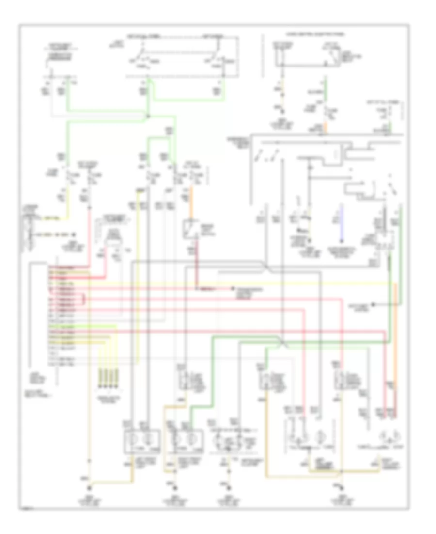
EXTERIOR LIGHTS
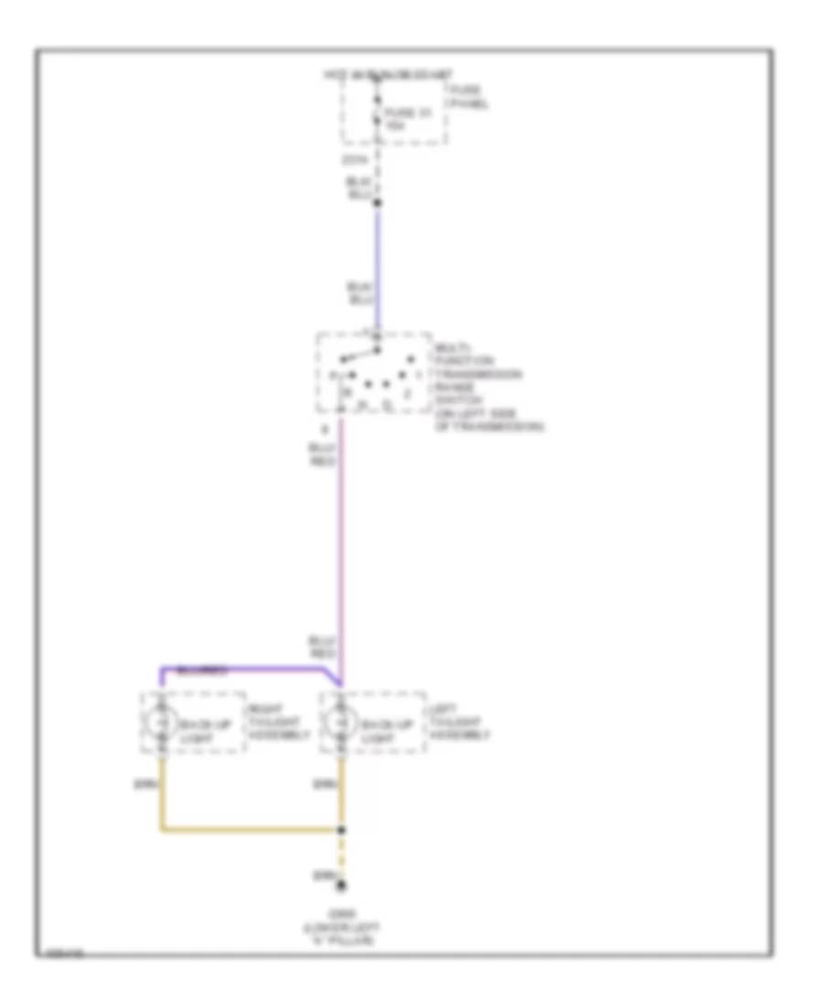
Back-up Lamps Wiring Diagram for Audi A6 1998
List of elements for Back-up Lamps Wiring Diagram for Audi A6 1998:
- 231a
- Back-up light
- Fuse 31 15a
- Fuse panel
- G900 (lower left "a" pillar)
- Hot in run or start
- Left tailight assembly
- Multi- function transmission range switch (on left side of transmission)
- Right tailight assembly
Exterior Lamps Wiring Diagram, with DRL & Chassis Number Up To 5000 for Audi A6 1998
List of elements for Exterior Lamps Wiring Diagram, with DRL & Chassis Number Up To 5000 for Audi A6 1998:
- 13a
- 223a 223a
- 22a
- 5a 5a
- Anti-theft system
- Auto- check system
- Auxiliary relay panel 1
- Brake light switch
- Cluster
- Combination processor
- Emergency flasher relay
- Fuse 10a
- Fuse 15a
- Fuse 5a
- Fuse panel
- G900 (lower left "a" pillar)
- G901 (lower right "a" pillar)
- Head
- Headlights system
- High- mount brake light
- Hot at all times
- Hot in run
- Hot in run or start
- Instrument
- Instrument cluster
- Interior lights system
- Lamp control module
- Left front park/turn light
- Left left taillamp taillamp assembly assembly
- Left side turn signal light
- Left turn ind.
- License plate
- Light switch
- Lights
- Load reduction relay
- Micro central electric panel
- Off
- Park
- Red
- Right front park/turn light
- Right side turn signal light
- Right taillamp assembly
- Right turn ind.
- Signal switch
- Stop
- T20
- T32
- Tail
- Transmission control module
- Turn
Exterior Lamps Wiring Diagram, with DRL & Chassis Number from 5001 for Audi A6 1998
List of elements for Exterior Lamps Wiring Diagram, with DRL & Chassis Number from 5001 for Audi A6 1998:
- 13a
- 223a
- 22a
- Anti-theft system
- Auto- check system
- Auxiliary relay panel 1
- Brake light switch
- Cluster
- Combination processor
- Emergency flasher switch
- Fuse 10a
- Fuse 15a
- Fuse 5a
- Fuse panel
- G900 (lower left "a" pillar)
- G901 (lower right "a" pillar)
- Head
- Headlights system
- High- mount brake light
- Hot at all times
- Hot in run
- Hot in run or start
- Instrument
- Instrument cluster
- Interior lights system
- Lamp control module
- Left front park/turn light
- Left side turn signal light
- Left taillamp assembly
- Left turn ind.
- License plate
- Light switch
- Lights
- Load reduction relay
- Micro central electric panel
- Off
- Park
- Red
- Right front park/turn light
- Right side turn signal light
- Right taillamp assembly
- Right turn ind.
- Signal switch
- Stop
- T20
- T32
- Tail
- Transmission control module
- Turn
Exterior Lamps Wiring Diagram, without DRL & Chassis Number From 5001 for Audi A6 1998
List of elements for Exterior Lamps Wiring Diagram, without DRL & Chassis Number From 5001 for Audi A6 1998:
- 13a
- 223a
- 22a
- Anti-theft system
- Auto- check system
- Auxiliary relay panel 1
- Brake light switch
- Cluster
- Emergency flasher switch
- Fuse 10a
- Fuse 15a
- Fuse 5a
- Fuse panel
- G900 (lower left "a" pillar)
- G901 (lower right "a" pillar)
- Head
- Headlights system
- High- mount brake light
- Hot at all times
- Hot in run or start
- Instrument
- Instrument cluster
- Instrument cluster system
- Interior lights system
- Lamp control module
- Left front park/turn light
- Left side turn signal light
- Left taillamp assembly
- Left turn ind.
- License plate
- Light switch
- Lights
- Load reduction relay
- Micro central electric panel
- Off
- Park
- Park lamp ind
- Red
- Right front park/turn light
- Right side turn signal light
- Right taillamp assembly
- Right turn ind.
- Signal switch
- Stop
- T20
- T32
- T32a
- Tail
- Transmission control module
- Turn
Exterior Lamps Wiring Diagram, without DRL & Chassis Number Up To 5000 for Audi A6 1998
List of elements for Exterior Lamps Wiring Diagram, without DRL & Chassis Number Up To 5000 for Audi A6 1998:
- 13a
- 223a
- 22a
- Anti-theft system
- Auto- check system
- Auxiliary relay panel 1
- Brake light switch
- Cluster
- Emergency flasher relay
- Fuse 10a
- Fuse 15a
- Fuse 5a
- Fuse panel
- G900 (lower left "a" pillar)
- G901 (lower right "a" pillar)
- Head
- Headlights system
- High- mount brake light
- Hot at all times
- Hot in run or start
- Instrument
- Instrument cluster
- Instrument cluster system
- Interior lights system
- Lamp control module
- Left front park/turn light
- Left side turn signal light
- Left taillamp assembly
- Left turn ind.
- License plate
- Light switch
- Lights
- Load reduction relay
- Micro central electric panel
- Off
- Park
- Park lamp ind
- Red
- Right front park/turn light
- Right side turn signal light
- Right taillamp assembly
- Right turn ind.
- Signal switch
- Stop
- T20
- T32
- T32a
- Tail
- Transmission control module
- Turn
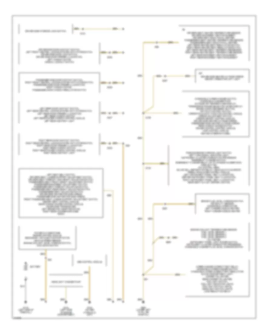
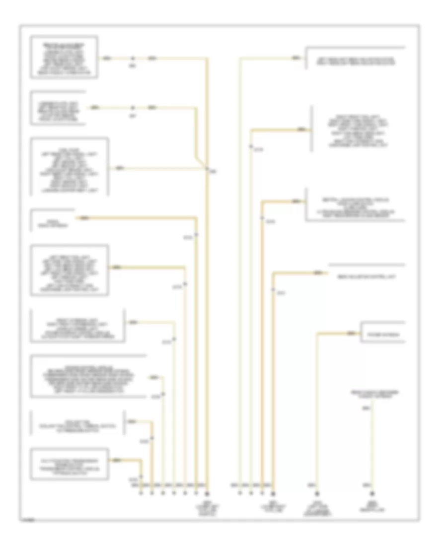
GROUND DISTRIBUTION
Ground Distribution Wiring Diagram (1 of 2) for Audi A6 1998
List of elements for Ground Distribution Wiring Diagram (1 of 2) for Audi A6 1998:
- Abs control module
- Battery
- Brake fluid level warning switch, air quality sensor, windshield wiper motor, left washer nozzle heater, right washer nozzle heater
- Driver side door contact switch, left front central locking system activator/switch, driver side door lock switch, driver side door opener illumination, left window motor, window lockout switch
- Driver side heated outside mirror, memory operating unit light
- Driver side interior lock switch,
- Driver's seat heated temperature sensor, driver's backrest heating element, driver's seat back facial heater, passenger's seat heated temperature sensor, passenger's seat back facial heater, left rear heated seat regulating switch, right rear heated seat regulating switch, left rear heated seat temperature sensor, right rear heated seat temperature sensor, left rear backrest heating element, right rear backrest heating element
- Engine coolant temperature sensor, fuel level sensor 1, fuel level sensor 2, fuel level sensor 3, voltmeter, instrument panel light dimmer switch, instrument cluster combination processor, windshield washer fluid level warning switch
- G100 (on abs hydrualic unit)
- G104 (left side of engine compartment)
- G116 (left side of firewall)
- G900 (lower left "a" pillar) (partial)
- Headlight washer pump
- Left rear door contact switch, left rear central locking system activator/switch, left rear door opener illumination left rear window switch left rear power window control module, left rear ashtray light
- Left seat belt switch, driver's seat lumbar support adjustment switch, driver's seat fore/aft and height adjusting switch, passenger's seat front height adjustment switch, passenger's backrest adjustment switch, passenger seat fore/aft adjusting switch, passenger seat rear height adjusting switch, passenger's seat adjusting switch, driver side igniter for side airbag, passenger side igniter for side airbag, front passenger seat lumbar support adjustment switch, memory seat control module, rear window shade control module, telephone transceiver, left brake pad wear indicator, right rear woofer/amplifier, radio
- Parking brake warning light switch, left turn signal indicator light, instrument cluster combination processor, emergency flasher switch, emergency flasher relay (up to chassis number 5000), horn button, a/c control head, solar cell separation relay (vehicle with sunroof) fresh air blower control module, left instrument panel vent illumination, center instrument panel vent illumination, right instrument panel vent illumination, rear seat outlet center lighting
- Passenger side door contact switch, right front central locking system activator/switch, passenger side door opener illumination, right window motor, passenger door window regulator switch
- Power outage stage, engine control module, secondary air injection pump motor, vehicle speed sensor, engine coolant level warning switch, kick down switch
- Right rear door contact switch, right rear central locking system activator/switch, right rear door opener illumination right rear window switch right rear power window control module, right rear ashtray light
- S103
- S135
- S199
- S205
- S206
- S207
- S208
- S261
- S267
- S269
- S81
- S85
- S89
- S96
- Windshield wiper/washer switch, windshield washer pump, outside air temperature display, transmssion range selector lever display, board computer reset button, anti-slip control switch, mirror fold-away function control module, mirror adjustment switch, mirror memory control module, driver side heated outside mirror, passenger side heated outside mirror, rear window shade switch, cruise control control module, lamp control module, heated steering wheel
- Wiper/washer intermittent relay, windshield wiper/washer switch, windshield wiper intermittent regulator, glove compartment light, cigarette lighter, rear cigarette lighter, fog light switch, fog light indicator lights fog light switch lights, headlight switch lights load reduction relay
Ground Distribution Wiring Diagram (2 of 2) for Audi A6 1998
List of elements for Ground Distribution Wiring Diagram (2 of 2) for Audi A6 1998:
- Air bag control module, driver's side crash sensor (side air bag), passenger's side crash sensor (side air bag), passenger's side igniter (rear side air bag), driver's side igniter (rear side air bag), right front "a" pillar microswitch, left front "a" pillar mircroswitch
- Beam adjusting control unit
- Central locking control module, hood alarm swich, alarm horn, ultra-sound sensors control module, right rear broken glass sensor
- Coolant fan, coolant fan control thermal switch, a/c pressure switch
- Front interior light, right front map/reading light, make-up mirror light, power sunroof control module, automatic day/night interior mirror
- Fuel pump, left rear turn signal light, left tail light, left brake light, left backup light, high mount brake light, right rear turn signal light, right tail light, right brake light, right backup light, luggage compartment light
- G402 (left side of luggage compartment)
- G900 (lower left "a" pillar) (partial)
- G901 (lower right "a" pillar)
- G905 (right rear pillar)
- Left front fog light left side turn signal light left high beam headlight, left low beam headlight, left front turn signal light, left parking light, high tone horn, left high intensity gas discharge lamp control unit
- Left headlight beam adjusting motor, right headlight beam adjusting motor
- License plate light, left rear fog light, remote unlock rear lid motor (sedan) trunk lid switches
- Multi-function transmission range switch, transmission control module, tiptronic switch
- Power antenna
- Radio, radio antenna
- Rear window defogger/ window antenna
- Remote unlock rear lid motor (wagon), license plate light, trunk lid switches, heated rear window left rear fog light, high mount brake light, rear window wiper motor
- Right front fog light, right side turn signal light, right front turn signal light, right parking light, right high beam headlight, low tone horn, right high intensity gas discharge lamp control unit
- S101
- S102
- S105
- S109
- S133
- S176
- S178
- S179
- S193
- S86
- S87
- S98
HEADLIGHTS
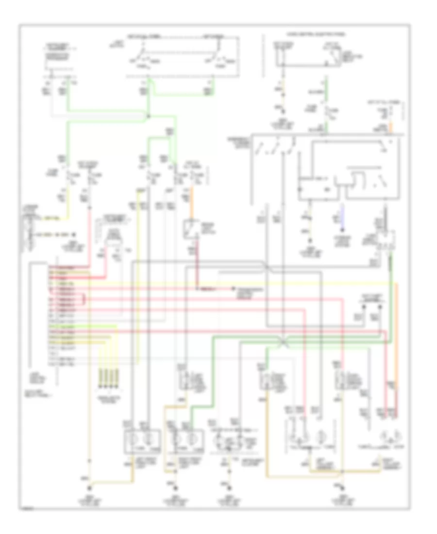
Headlamps & Fog Lamps Wiring Diagram, with DRL for Audi A6 1998
List of elements for Headlamps & Fog Lamps Wiring Diagram, with DRL for Audi A6 1998:
- 18a
- 19a
- 20a
- 21a
- 236a
- Acc
- Combination processor
- Fog light ind
- Fog light relay
- Fog light switch
- Foglight switch light
- Fold relay panel
- Front
- Ftp
- Fuse 10a
- Fuse 15a
- Fuse panel
- G900 (lower left "a" pillar)
- G901 (lower right "a" pillar)
- Head
- Head- lights
- Headlight switch light
- High beam ind
- Hot at all times
- Ignition switch
- Instrument cluster
- Lamp control module (left side of dash)
- Left fog lamp
- Left front headlight/ parklight/ turn signal assembly
- Left rear fog light
- Light switch
- Light switch/ fog light switch
- Off
- Park
- Rear
- Rear fog light ind
- Resistance wire (w/o xenon lamps)
- Right fog lamp
- Right front headlight/ parklight/ turn signal assembly
- Run
- Start
- T32
- Turn signal/ headlight dimmer/ flasher switch
- W/xenon lamps
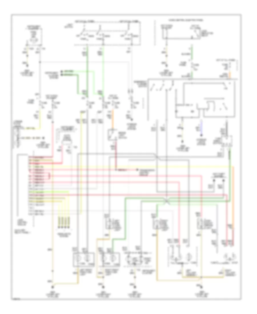
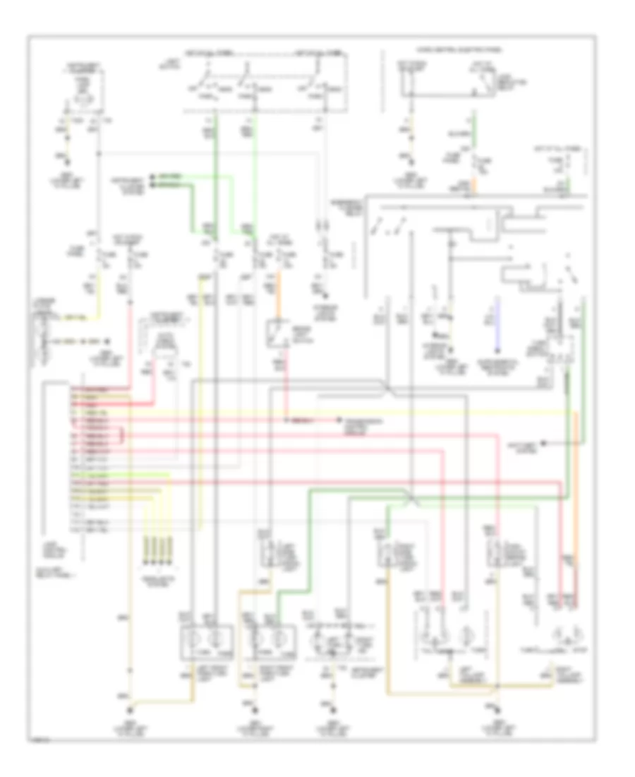
Headlamps & Fog Lamps Wiring Diagram, without DRL for Audi A6 1998
List of elements for Headlamps & Fog Lamps Wiring Diagram, without DRL for Audi A6 1998:
- 18a
- 19a
- 20a
- 21a
- 236a
- Acc
- Fog light ind
- Fog light relay
- Fog light switch
- Foglight switch light
- Fold relay panel
- Front
- Ftp
- Fuse 10a
- Fuse 15a
- Fuse panel
- G900 (lower lrft "a" pillar)
- G901 (lower right "a" pillar)
- Head
- Head- lights
- Headlight switch light
- High beam ind
- Hot at all times
- Ignition switch
- Instrument cluster
- Interior lights system
- Lamp control module (left side of dash)
- Left fog lamp
- Left front headlight/ parklight/ turn signal assembly
- Left rear fog light
- Light switch
- Light switch/ fog light switch
- Off
- Park
- Rear
- Rear fog light ind
- Right fog lamp
- Right front headlight/ parklight/ turn signal assembly
- Run
- Start
- T32
- Turn signal/ headlight dimmer/ flasher switch
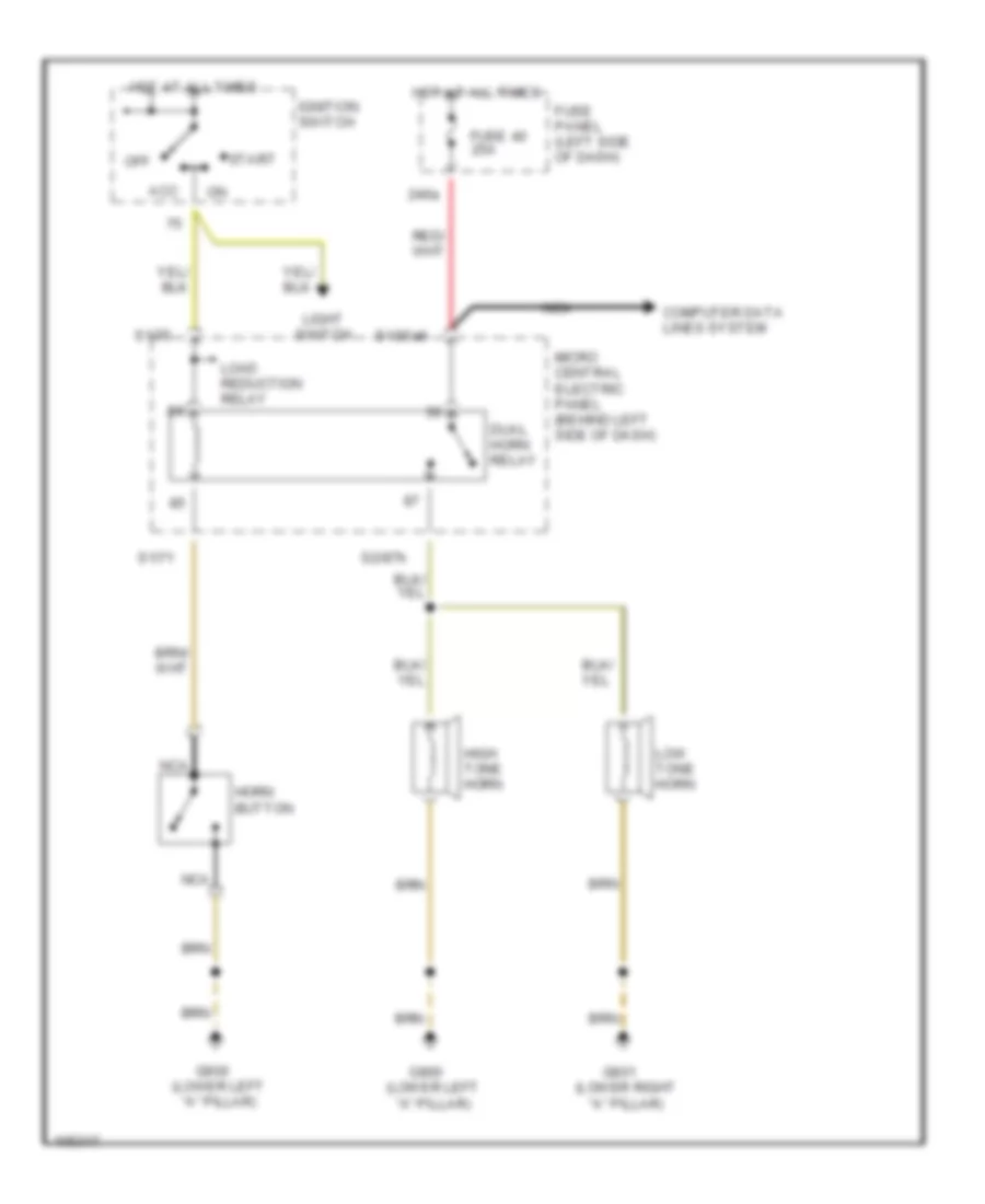
HORN
Horn Wiring Diagram for Audi A6 1998
List of elements for Horn Wiring Diagram for Audi A6 1998:
- 240a
- Acc
- Computer data lines system
- Dual horn relay
- Fuse 40 25a
- Fuse panel (left side of dash)
- G900 (lower left "a" pillar)
- G901 (lower right "a" pillar)
- High tone horn
- Horn button
- Hot at all times
- Ignition switch
- Light switch
- Load reduction relay
- Low tone horn
- Micro central electric panel (behind left side of dash)
- Nca
- Off
- S1/30ah
- S1/71
- S1/75
- S2/87h
- Start
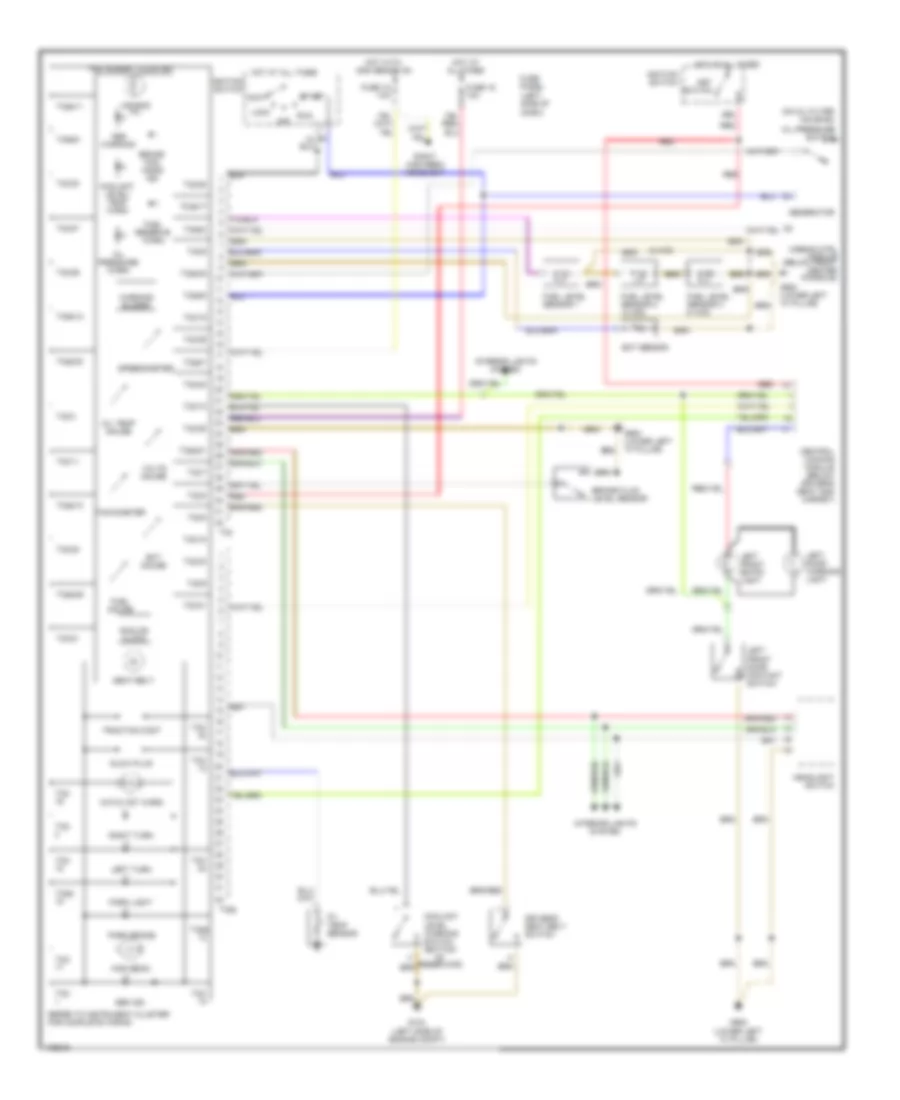
INSTRUMENT CLUSTER
Auto Check System Wiring Diagram for Audi A6 1998
List of elements for Auto Check System Wiring Diagram for Audi A6 1998:
- (left side of dash)
- 13a
- A/c control head
- A12
- Auto check system
- Brake- light switch
- Computer function select switch
- Computer reset button
- Engine control module (in electronic box, left side of air plenum)
- Fuse 13 10a
- Fuse 5 10a
- Fuse panel
- G900 (lower left "a" pillar)
- Hot at all times
- Hot in start or run
- Light control module (on 13-fold relay panel)
- Outside air temperature sensor (in front of a/c condenser)
- Radio
- Red
- Transmission control module (under right front seat and carpet)
- Washer fluid level warning switch
Instrument Cluster Wiring Diagram for Audi A6 1998
List of elements for Instrument Cluster Wiring Diagram for Audi A6 1998:
- (2 w/d)
- (left side of dash)
- (on oil filter housing)
- 15a
- 18a
- 86s
- A/c control head
- Abs module (left of engine compt)
- Abs warning
- Air bag mil
- Airbag ctrl module (below front center console)
- Analog clock
- Brake fluid level sensor
- Brake pad wear ind
- Catalyst warn
- Central locking module (below driver's seat and carpet)
- Computer data lines
- Coolant level warning switch (bottom of reservoir)
- Coolant level/ temp warn
- Driver's seat belt switch
- Ect gauge
- Ect sensor
- Engine control module (in electronic box, left side of air plenum)
- Fuel gauge
- Fuel level sensor 1
- Fuel level sensor 2 (w/ 4wd)
- Fuel level sensor 3 (w/ 4wd)
- Fuel reserve warn
- Fuse 15 10a
- Fuse 18 10a
- Fuse panel
- G104 (left side of engine compt)
- G900 (lower left "a" pillar)
- Gen ind.
- Generator
- Glow plug
- Headlights system
- High beam
- Hot at all times
- Hot with high beams on
- Ignition switch
- Ignition switch acc
- Instrument cluster
- Interior lights system
- Key switch
- Left brake pad wear indicator element
- Left turn
- Lock
- Nca
- Off
- Oil pressure switch
- Oil pressure warn
- Oil temp gauge
- Oil temp sensor
- Panel light dimmer switch
- Park brake
- Park brake switch
- Park light
- Red
- Right brake pad wear indicator element
- Right high beam headlight
- Right turn
- Run
- Seat belt
- Speedometer
- Start
- T32
- T32/
- T32/10
- T32/11
- T32/15
- T32/19
- T32/20
- T32/21
- T32/22
- T32/23
- T32/25
- T32/26
- T32/27
- T32/28
- T32/29
- T32/3
- T32/30
- T32/31
- T32/5
- T32/6
- T32/7
- T32/8
- T32/9
- T32a
- T32a/
- T32a/10
- T32a/11
- T32a/12
- T32a/17
- T32a/2
- T32a/21
- T32a/23
- T32a/29
- T32a/30
- T32a/5
- T32a/6
- T32a/7
- Tachometer
- Traction cont
- Transmission range selector
- Turn signal switch
- Vehicle speed sensor (left side of trans)
- Volts gauge
- Warning buzzer
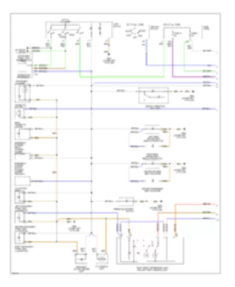
INTERIOR LIGHTS
Interior Lights Wiring Diagram (1 of 3) for Audi A6 1998
List of elements for Interior Lights Wiring Diagram (1 of 3) for Audi A6 1998:
- 15a
- A/c control head
- A/t console light
- Acc
- Center instrument panel vent illumination
- Cigarette lighter
- Combination processor
- Emergency flasher relay (chassis number upto 5000)
- Emergency flasher switch (chassis number from 5001)
- Exterior lights
- Fuse 15 5a
- Fuse 3 5a
- Fuse panel
- G900 (lower left "a" pillar)
- Head
- Heated driver's seat adjuster
- Heated passenger's seat adjuster
- Hot at all times
- Ignition switch
- Instrument cluster
- Instrument panel light dimmer switch
- Left instrument panel vent illumination
- Left rear heated seat regulating switch
- Light switch
- Lock
- Memory operating unit light
- Mirror adjustment switch
- Off
- Park
- Rear cigarette lighter
- Rear seat outlet center light
- Right front map/reading light and left front reading light
- Right instrument panel vent illumination
- Right rear heated seat regulating switch
- Run
- Start
- T32
- T3p
- T4e
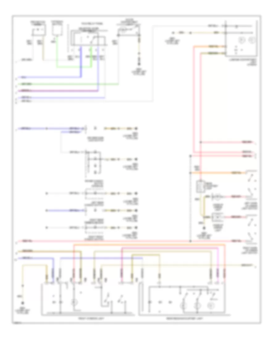
Interior Lights Wiring Diagram (2 of 3) for Audi A6 1998
List of elements for Interior Lights Wiring Diagram (2 of 3) for Audi A6 1998:
- Driver's side lock switch
- Fold relay panel
- Front interior light
- G900 (lower left "a" pillar)
- Glove compartment light
- Left make- up mirror light switch
- Left rear window switch
- Luggage compartment light (wagon)
- Make-up mirror light
- Power window switch (console)
- Protection diode
- Rear courtesy lamp
- Rear reading/courtesy light
- Right front window switch
- Right make- up mirror light switch
- Right rear window switch
- Selector lever light relay
- T6m
- T6n
- Tiptronic switch
Interior Lights Wiring Diagram (3 of 3) for Audi A6 1998
List of elements for Interior Lights Wiring Diagram (3 of 3) for Audi A6 1998:
- (lower left "a" pillar) g900
- 1/1
- 1/2
- 1/4
- 1/5
- 1/6
- 2/15
- 5/1
- 5/10
- 5/12
- 5/14
- Central locking system control module (below driver's seat)
- Diver's side door warning light
- Driver's side door contact switch
- Driver's side door opener illumination
- G900 (lower left "a" pillar)
- Left footwell light
- Left front entry light
- Left rear ashtray light
- Left rear door contact switch
- Left rear door opener illumination
- Left rear door warning light
- Left rear entry light
- Left rear footwell light
- Passenger's door opener illumination
- Passenger's door warning light
- Passenger's side door contact switch
- Right foot- well light
- Right front entry light
- Right rear ashtray light
- Right rear door contact switch
- Right rear door opener illumination
- Right rear door warning light
- Right rear entry light
- Right rear footwell light
MEMORY SYSTEMS
Driver"s Memory Seat Wiring Diagram for Audi A6 1998
List of elements for Driver"s Memory Seat Wiring Diagram for Audi A6 1998:
- 14a
- Back- rest
- Central locking control module
- Circuit breaker 44 30a
- Data link connector
- Driver's seat backrest adjusting motor
- Driver's seat fore/ aft adjusting motor
- Driver's seat front height adjusting motor
- Driver's seat rear height adjusting motor
- Driver's seat switch
- Fold relay panel (left side of dash)
- For/ aft
- Front height
- Fuse 14 10a
- Fuse panel
- G900 (lower left "a" pillar)
- Head- rest
- Hot at all times
- Instrument cluster
- Memory mirror control module
- Memory program switch
- Memory seat control module
- Not used
- Rear height
- Red
- T10ar
- T12e
- T32b
- T4aa
Memory Mirrors Wiring Diagram for Audi A6 1998
List of elements for Memory Mirrors Wiring Diagram for Audi A6 1998:
- B10
- Back-up lights
- De- fog
- Driver side mirror
- Fold- away
- Fuse 15 15a
- Fuse 5
- Fuse 9 10a
- Fuse panel
- G900 (lower left "a" pillar)
- Hot at all times
- Hot in run or start
- Interior lights
- Memory mirror control module
- Memory seat control module
- Mirror adjustment switch
- Mirror fold-away control module
- Passenger side mirror
- Position
- T32b
POWER ANTENNA
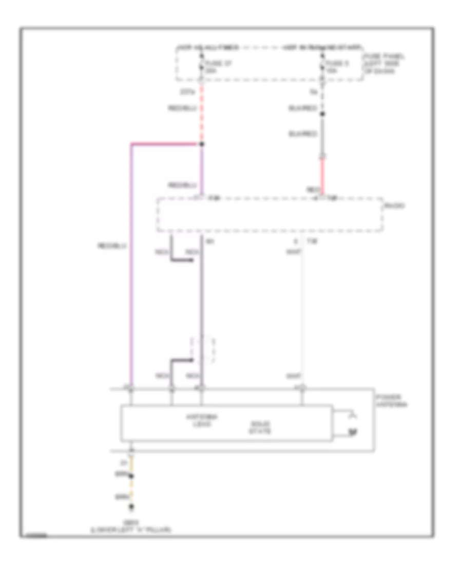
Power Antenna Wiring Diagram for Audi A6 1998
List of elements for Power Antenna Wiring Diagram for Audi A6 1998:
- 237a
- Antenna lead
- Fuse 37 20a
- Fuse 5 10a
- Fuse panel (left side of dash)
- G900 (lower left "a" pillar)
- Hot at all times
- Hot in run and start
- Nca
- Power antenna
- Radio
- Red
- Solid state
- T8f
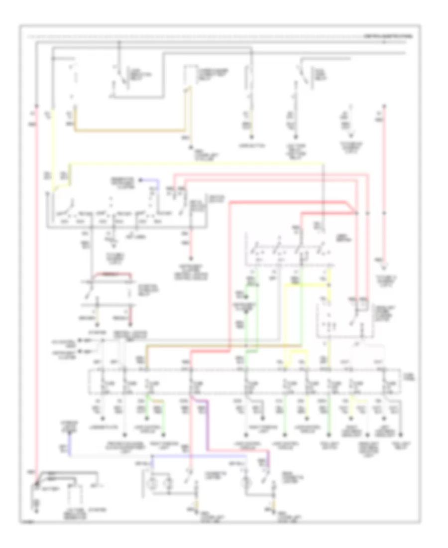
POWER DISTRIBUTION
Power Distribution Wiring Diagram (1 of 3) for Audi A6 1998
List of elements for Power Distribution Wiring Diagram (1 of 3) for Audi A6 1998:
- (not used)
- 18a
- 19a
- 20a
- 21a
- 223a
- 22a
- 233a
- 236a
- 50b
- 86s
- A/c control head
- Acc
- Battery
- Central electric panel
- Central locking control module
- Cigarette lighter
- Dual horn relay
- Fog light relay
- Fog light switch
- Fuse 10a
- Fuse 15a
- Fuse 5a
- Fuse panel
- G900 (lower left "a" pillar)
- Generator, instrument cluster
- Headlight dimmer/ flasher switch
- Headlight high beam indicator light
- Horn button
- Ignition switch
- Instrument cluster
- Instrument cluster, central locking control module
- Interior lights system
- Key-in ignition switch
- Lamp control module
- Left high beam headlight
- License plate
- Light light switch switch
- Load reduction relay
- Low tone relay, high tone relay
- Off
- Protection diode, glove compartment light
- Rear cigarette lighter
- Red
- Right high beam headlight
- Right parking light
- Run
- S1/
- S1/ 30ah
- S2/ 87h
- Start
- Starter
- Starting interlock relay
- To fuse 12 (diagram 2 of 3)
- To fuse 240 (diagram 2 of 3)
- To fuse 5 (diagram 2 of 3)
- Voltage regulator/ generator
- Wiper/washer intermittent relay
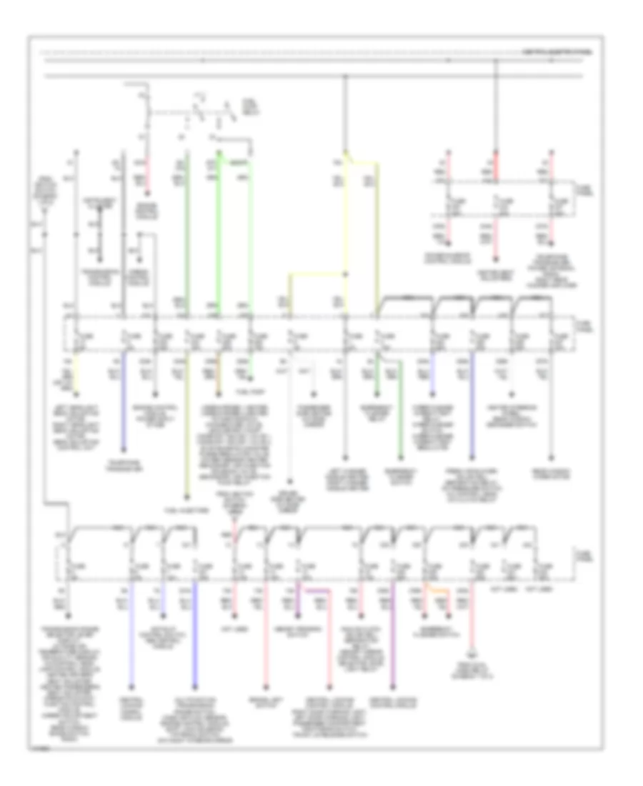
Power Distribution Wiring Diagram (2 of 3) for Audi A6 1998
List of elements for Power Distribution Wiring Diagram (2 of 3) for Audi A6 1998:
- 10a
- 12a
- 13a
- 14a
- 15a
- 224a
- 225a
- 226a
- 227a
- 228a
- 229a
- 230a
- 231a
- 232a
- 234a
- 237a
- 238a
- 239a
- 240a
- 244a
- 75x
- 87f/ dti
- Airbag control module
- Analog clock, solar cell separation relay, memory mirror control module, selector level light relay
- Anti-slip control switch, abs control module
- Brake light switch
- Central electric panel
- Central locking conrol module
- Central locking control module
- Central locking control module, right door warning light, left door warning light, passenger compartment monitoring switch, trunk lid release switch
- Driver side heated outside mirror
- Emergency flasher relay
- Emergency flasher switch
- Engine control module
- Engine control module, power ouput stage
- Fresh air blower, solar cell separation relay, a/c pressure switch, a/c control head, a/c clutch relay
- From dual horn relay (diagram 1 of 2)
- From ignition switch (diagram 1 of 3)
- Fuel injectors
- Fuel pump
- Fuel pump relay
- Fuse 10a
- Fuse 15a
- Fuse 20a
- Fuse 25a
- Fuse 30a
- Fuse 5a
- Fuse 60a
- Fuse panel
- Heated seat adjusters
- Heated steering wheel, rear window defogger switch
- Instrument cluster
- Lambda-probe 1 heater, lambda-probe 2 heater, intake manifold change-over valve, leak detect pump, camshaft adjust valve 1, camshaft adjust valve 2, evap emission canister purge regulator valve, oxygen sensor heater, secondary air injection solenoid valve, secondary air injection pump relay
- Left headlight beam adjusting motor, right headlight beam adjusting motor, beam adjusting control unit
- Left washer nozzle heater, right washer nozzle heater
- Memory program switch
- Multifunction transmissiom range switch, mass air flow sensor, engine control module, shift lock solenoid, tiptronic switch, day/night interior mirror
- Nca
- Not used
- Passenger side heated outside mirror
- Power sunroof control module
- Rear window wiper motor
- Red
- S2/87f
- S3/
- S3/ 87a
- S3/s
- Telephone transceiver
- Telephone transceiver, power antenna, radio, right rear woofer amplifier
- Transmission control module
- Transmission range selector lever display, outside air temperature display, air quality sensor, a/c control head, lamp control module, heated driver's seat adjuster, heated passenger's seat adjuster, mirror fold-away function control module, mirror adjustment switch, rear window shade switch, radio
- Wiper/washer intermittent relay, wiper/washer switch, wiper/washer intermittent regulator
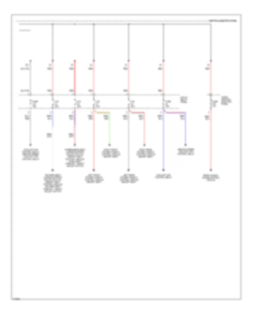
Power Distribution Wiring Diagram (3 of 3) for Audi A6 1998
List of elements for Power Distribution Wiring Diagram (3 of 3) for Audi A6 1998:
- 75x
- 8-fold relay panel
- C.b. 30a
- Central electric panel
- Coolant fan control relay
- Coolant fan control relay, second speed coolant fan control relay
- Driver's seat lumbar support adjust switch, memory seat control module, driver's seat fore/aft height adjust switch
- Fuse 10a
- Fuse 15a
- Left front power window control module memory seat
- Left rear power window control module memory seat
- Micro- central electric panel
- Passenger's seat lumbar support adjust switch, memory seat control module, pass. seat fore/aft height adjust switch
- Rear window shade control module
- Red
- Right front power window control module memory seat
- Right rear power window control module memory seat
- Second speed coolant fan control relay
POWER DOOR LOCKS
Power Door Locks Wiring Diagram (1 of 2) for Audi A6 1998
List of elements for Power Door Locks Wiring Diagram (1 of 2) for Audi A6 1998:
- 10a
- 14a
- 238a
- 86s
- Alarm horn
- Antenna
- Central locking system control module (below driver's (seat & carpet)
- Driver's door lock assembly
- Driver's side interior lock switch
- Exterior lights system
- Fuel door unlock motor
- Fuse 10a
- Fuse 20a
- Fuse 5a
- Fuse panel
- G901 (lower right "a" pillar)
- Hood alarm switch
- Hot at all times
- Hot in start and run
- Ignition switch
- Instrument cluster system
- Interior lights system
- Key switch
- Level control system control module
- Memory systems
- Multifunction transmission range switch
- Nca
- Power windows system
- Radio
- Red
- Shield
- Starting system
- T1e
- Trunk, tailgates, fuel door system
Power Door Locks Wiring Diagram (2 of 2) for Audi A6 1998
List of elements for Power Door Locks Wiring Diagram (2 of 2) for Audi A6 1998:
- 226a
- A/c system
- Defogger system
- Fuse 30a
- Fuse panel
- G900 (lower left "a" pillar)
- G901 (lower right "a"pillar)
- Hot in run
- Interior lights system
- Left rear door lock assembly
- Left rear glass sensor
- Left ultra- sound sensor
- Nca
- Passenger's compartment monitoring switch
- Passenger's door lock assembly
- Rear window defogger switch
- Right rear door lock assembly
- Right rear glass sensor
- Right ultra- sound sensor
- Sedan
- T2v
- T2w
- T3o
- Trunk lock assembly
- Trunk, tailgates, fuel doors system
- Ultra sound sensor control module (below left "c" pillar)
- W/ solar cells
- Wagon
POWER SEATS
Heated Seats Wiring Diagram for Audi A6 1998
List of elements for Heated Seats Wiring Diagram for Audi A6 1998:
- 227a
- 244a
- 75x
- Driver's backrest heat element
- Driver's seat heat element
- Driver's seat temperature sensor
- Driver's side facial element (backrest)
- Driver's side facial element (seatback)
- Fuse 27 15a
- Fuse 44 30a
- Fuse 5 5a
- Fuse panel
- G202 (behind left side of dash)
- Heated driver's seat adjuster
- Heated passenger's seat adjuster
- Heated steering wheel
- Hot at all times
- Hot in run
- Hot in run or acc
- Left rear backrest heating element
- Left rear heated seat regulating switch
- Left rear heated seat switch
- Left rear heated seat temperature sensor
- Left rear seat heating element
- Load reduction relay
- Micro central electric panel (left side of dash)
- Nca
- Passenger's backrest heat element
- Passenger's seat heat element
- Passenger's seat temperature sensor
- Right rear backrest heating element
- Right rear heated seat regulating switch
- Right rear heated seat temperature sensor
- Right rear seat heating element
- Solid state
- T2bg
- T5d
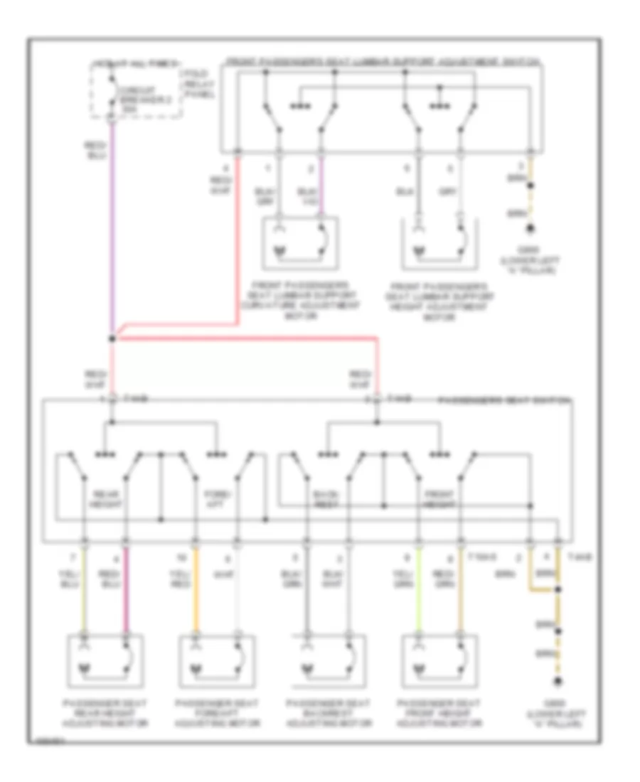
Passenger Power Seat Wiring Diagram for Audi A6 1998
List of elements for Passenger Power Seat Wiring Diagram for Audi A6 1998:
- Back- rest
- Circuit breaker 2 30a
- Fold relay panel
- Fore/ aft
- Front height
- Front passenger's seat lumbar support curvature adjustment motor
- Front passenger's seat lumbar support height adjustment motor
- Front passenger's seat lumbar support adjustment switch
- G900 (lower left "a" pillar)
- Hot at all times
- Passenger seat backrest adjusting motor
- Passenger seat fore/aft adjusting motor
- Passenger seat front height adjusting motor
- Passenger seat rear height adjusting motor
- Passenger's seat switch
- Rear height
- T10as
- T4ab
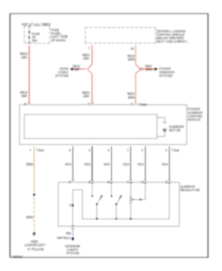
POWER TOP/SUNROOF
Power Top/Sunroof Wiring Diagram for Audi A6 1998
List of elements for Power Top/Sunroof Wiring Diagram for Audi A6 1998:
- "a" pillar)
- 58s
- Central locking control module (below driver's seat and carpet)
- Door locks system
- Fuse 20a
- Fuse panel (left side of dash)
- G900 (lower left
- Hot at all times
- Interior lights system
- Nca
- Power sunroof control module
- Power windows system
- Sunroof motor
- Sunroof regulator
- T6ad
- T6ae
POWER WINDOWS
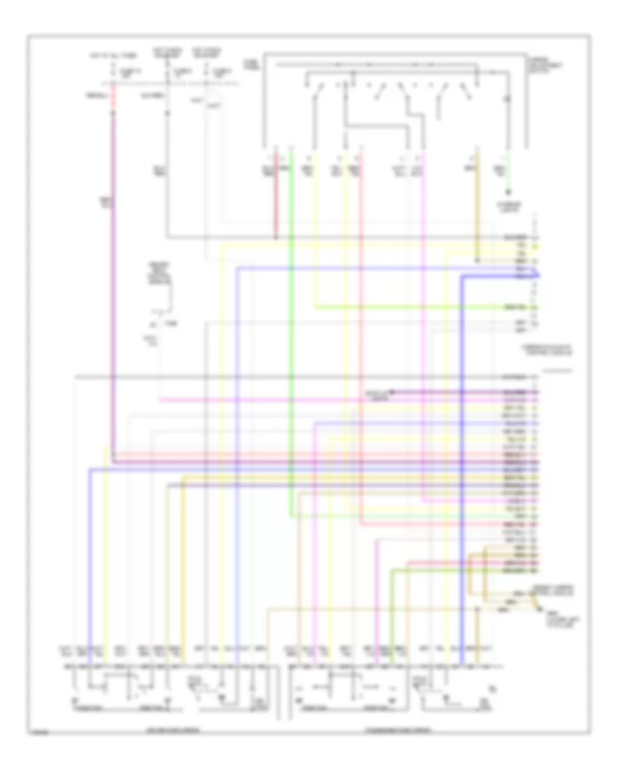
Power Windows Wiring Diagram (1 of 2) for Audi A6 1998
List of elements for Power Windows Wiring Diagram (1 of 2) for Audi A6 1998:
- 8-fold relay panel (behind left side of dash)
- All times
- Central locking control module (below driver's seat and carpet)
- Front power window circuit breaker 37 30a
- G900 (lower left "a" pillar)
- Hot at
- Hot in start or run
- Left front power window control module
- Left front window switch
- Micro central electric panel (behind left side of dash)
- Power sunroof control module
- Right front power window control module
- Right front door window switch (door)
- Right front door window switch (left front door)
- Window motor
Power Windows Wiring Diagram (2 of 2) for Audi A6 1998
List of elements for Power Windows Wiring Diagram (2 of 2) for Audi A6 1998:
- 8-fold relay panel (behind left side of dash)
- All times
- G900 (lower left "a" pillar)
- G900 (lower left a-pillar)
- Hot at
- Instrument cluster
- Left rear door window switch (center console)
- Left rear door window switch (door)
- Left rear power window control module
- Rear power window circuit breaker 43 30a
- Right rear door window switch (center console)
- Right rear door window switch (door)
- Right rear power window control module
- Window lockout switch
- Window motor
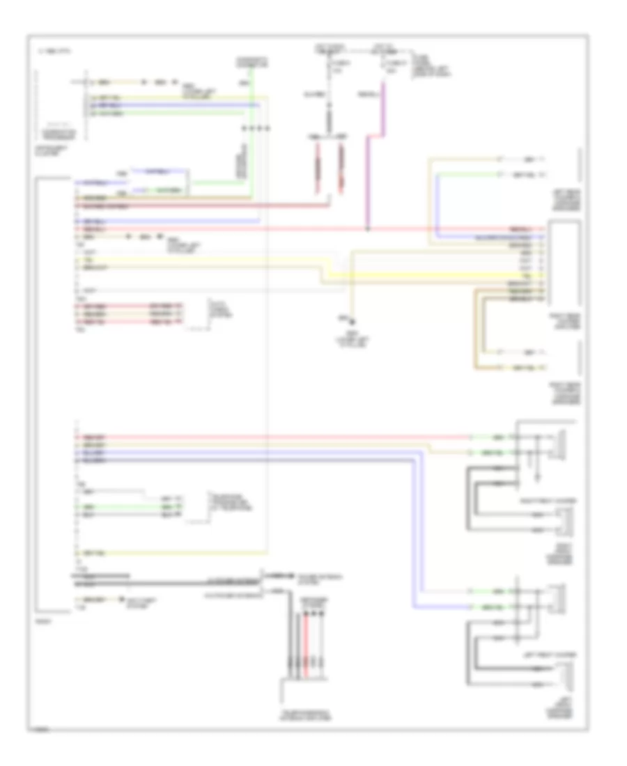
RADIO
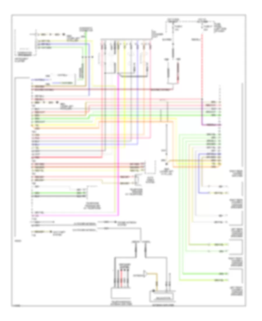
AM/FM Stereo Wiring Diagram, Base Radio without CD Changer for Audi A6 1998
List of elements for AM/FM Stereo Wiring Diagram, Base Radio without CD Changer for Audi A6 1998:
- 10a
- 1995 vftc c
- 20a
- Anti-theft system
- Auto check system
- Combination processor
- Defogger system
- Diagnostic connector
- Fuse 37
- Fuse 5
- Fuse panel (behind left side of dash)
- G900 (lower left "a" pillar")
- G900 (lower left "a" pillar)
- Hot at all times
- Hot in run or accy
- Instrument cluster
- Left front midrange speaker
- Left front woofer
- Left rear woofer & midrange speakers
- Nca
- Power antenna system
- Radio
- Red
- Right front midrange speaker
- Right front woofer
- Right rear woofer & midrange speakers
- Right rear woofer/ amplifier
- T10z
- T1e
- T6w
- T6x
- T8e
- T8f
- Telephone transceiver (w/ telephone)
- Telephone/radio antenna amplifier
- W/ power antenna
- W/o power antenna
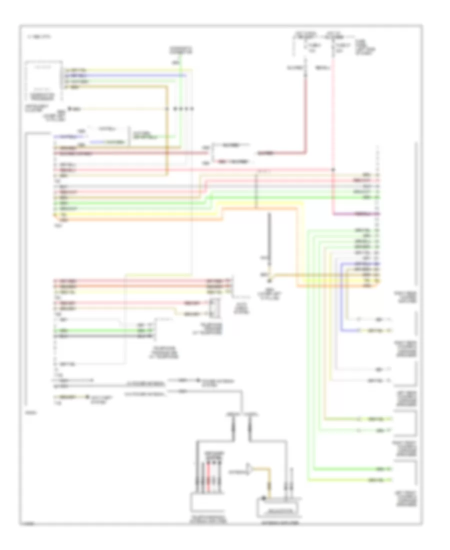
AM/FM Stereo Wiring Diagram, Bose, Bose without CD Changer for Audi A6 1998
List of elements for AM/FM Stereo Wiring Diagram, Bose, Bose without CD Changer for Audi A6 1998:
- 1995 vftc c
- Antenna
- Antenna amplifier
- Anti-theft system
- Auto check system
- Combination processor
- Defogger system
- Diagnostic connector
- Fuse panel (left side of dash)
- G900 (lower left "a" pillar)
- G900 lower left "a" pillar")
- Hot at all times
- Hot in run or accy
- Instrument cluster
- Left front woofer & midrange speakers
- Left rear woofer & midrange speakers
- Nca
- Power antenna system
- Radio
- Red
- Right front woofer & midrange speakers
- Right rear woofer & midrange speakers
- Right rear woofer/ amplifier
- Sedan
- Solid state
- T10z
- T1e
- T6w
- T6x
- T8e
- T8f
- Telephone speaker (w/ telephone)
- Telephone transceiver (w/ telephone)
- Telephone/radio antenna amplifier
- W/ power antenna
- W/o power antenna
- Wagon
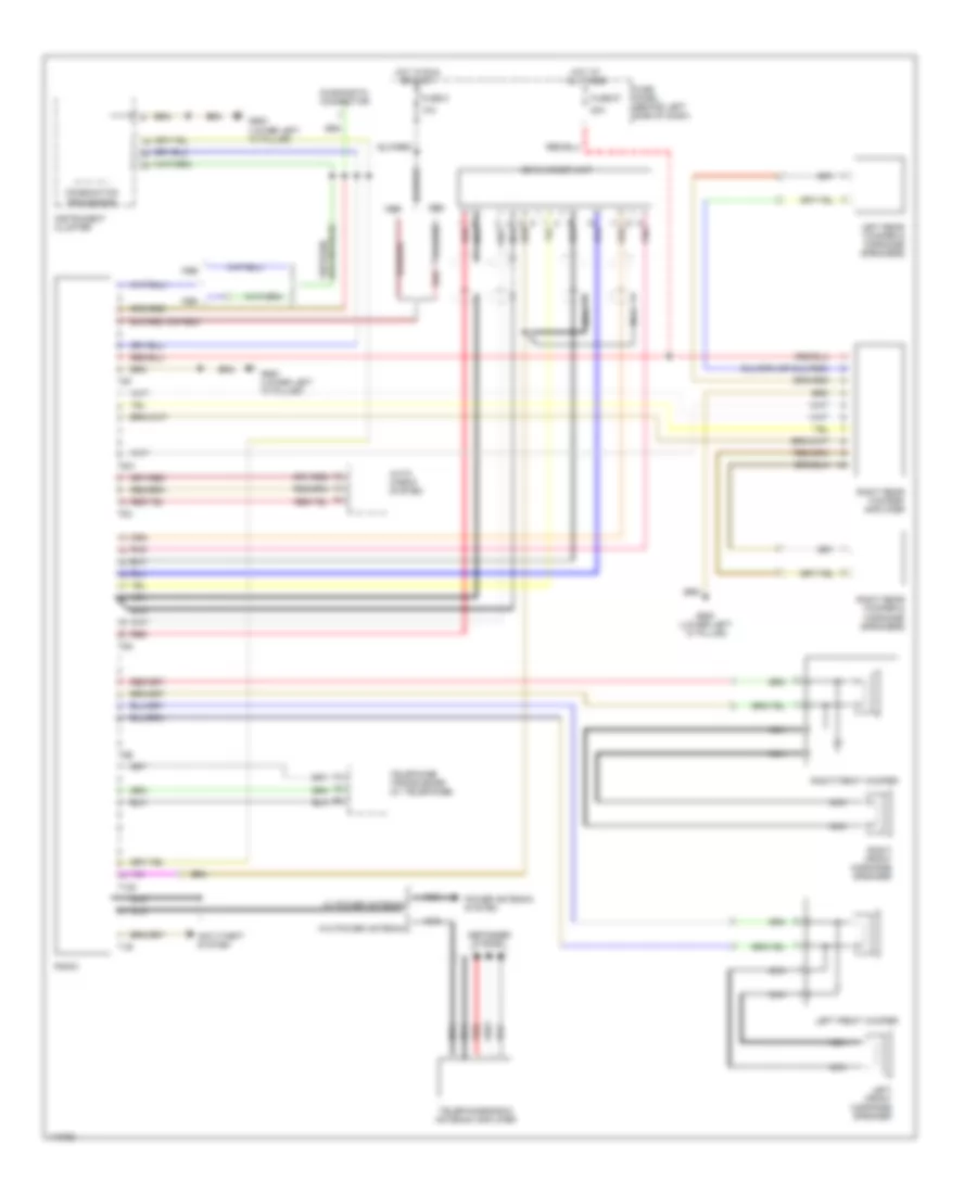
with CD Changer Wiring Diagram, Base Radio with CD Changer for Audi A6 1998
List of elements for with CD Changer Wiring Diagram, Base Radio with CD Changer for Audi A6 1998:
- 10a
- 20a
- Anti-theft system
- Auto check system
- Cd changer unit
- Combination processor
- Defogger system
- Diagnostic connector
- Fuse 37
- Fuse 5
- Fuse panel (behind left side of dash)
- G900 (lower left "a" pillar")
- G900 (lower left "a" pillar)
- Hot at all times
- Hot in run or accy
- Instrument cluster
- Left front midrange speaker
- Left front woofer
- Left rear woofer & midrange speakers
- Nca
- Pnk
- Power antenna system
- Radio
- Red
- Right front midrange speaker
- Right front woofer
- Right rear woofer & midrange speakers
- Right rear woofer/ amplifier
- T10z
- T1e
- T6w
- T6x
- T8e
- T8f
- T8g
- Telephone transciever (w/ telephone)
- Telephone/radio antenna amplifier
- W/ power antenna
- W/o power antenna
with CD Changer Wiring Diagram, Bose, Bose with CD Changer for Audi A6 1998
List of elements for with CD Changer Wiring Diagram, Bose, Bose with CD Changer for Audi A6 1998:
- Antenna
- Antenna amplifier
- Anti-theft system
- Auto check system
- Cd changer unit
- Combination processor
- Defogger system
- Diagnostic connector
- Fuse panel (left side of dash)
- G900 (lower left "a" pillar)
- G900 lower left "a" pillar")
- Hot at all times
- Hot in run or accy
- Instrument cluster
- Left front woofer & midrange speakers
- Left rear woofer & midrange speakers
- Nca
- Pnk
- Power antenna system
- Radio
- Red
- Right front woofer & midrange speakers
- Right rear woofer & midrange speakers
- Right rear woofer/ amplifier
- Sedan
- Solid state
- T10z
- T1e
- T6w
- T6x
- T8e
- T8f
- T8g
- Telephone speaker (w/ telephone)
- Telephone transceiver (w/ telephone)
- Telephone/radio antenna amplifier
- W/ power antenna
- W/o power antenna
- Wagon
SHIFT INTERLOCK
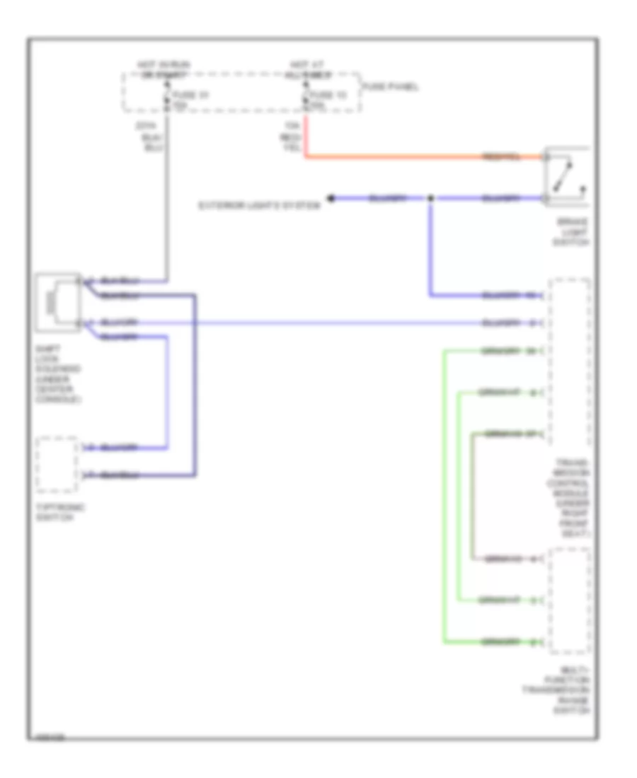
Shift Interlock Wiring Diagram for Audi A6 1998
List of elements for Shift Interlock Wiring Diagram for Audi A6 1998:
- 13a
- 231a
- Brake light switch
- Exterior lights system
- Fuse 13 10a
- Fuse 31 15a
- Fuse panel
- Hot at all times
- Hot in run or start
- Multi- function transmission range switch
- Shift lock solenoid (under center console)
- Tiptronic switch
- Trans- mission control module (under right front seat)
STARTING/CHARGING
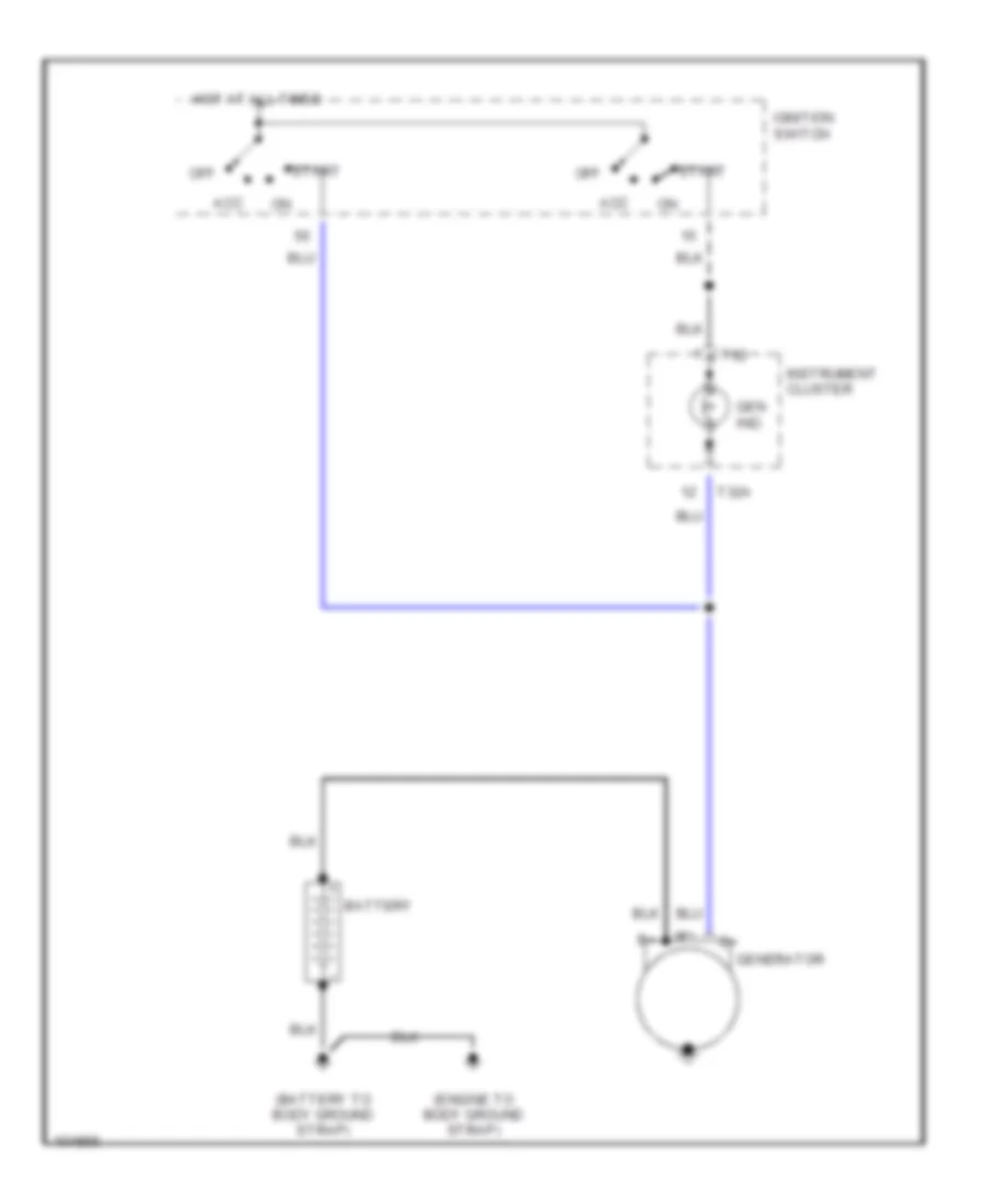
Charging Wiring Diagram for Audi A6 1998
List of elements for Charging Wiring Diagram for Audi A6 1998:
- (battery to body ground strap)
- (engine to body ground strap)
- Acc
- Battery
- Gen ind.
- Generator
- Hot at all times
- Ignition switch
- Instrument cluster
- Off
- Start
- T32
- T32a
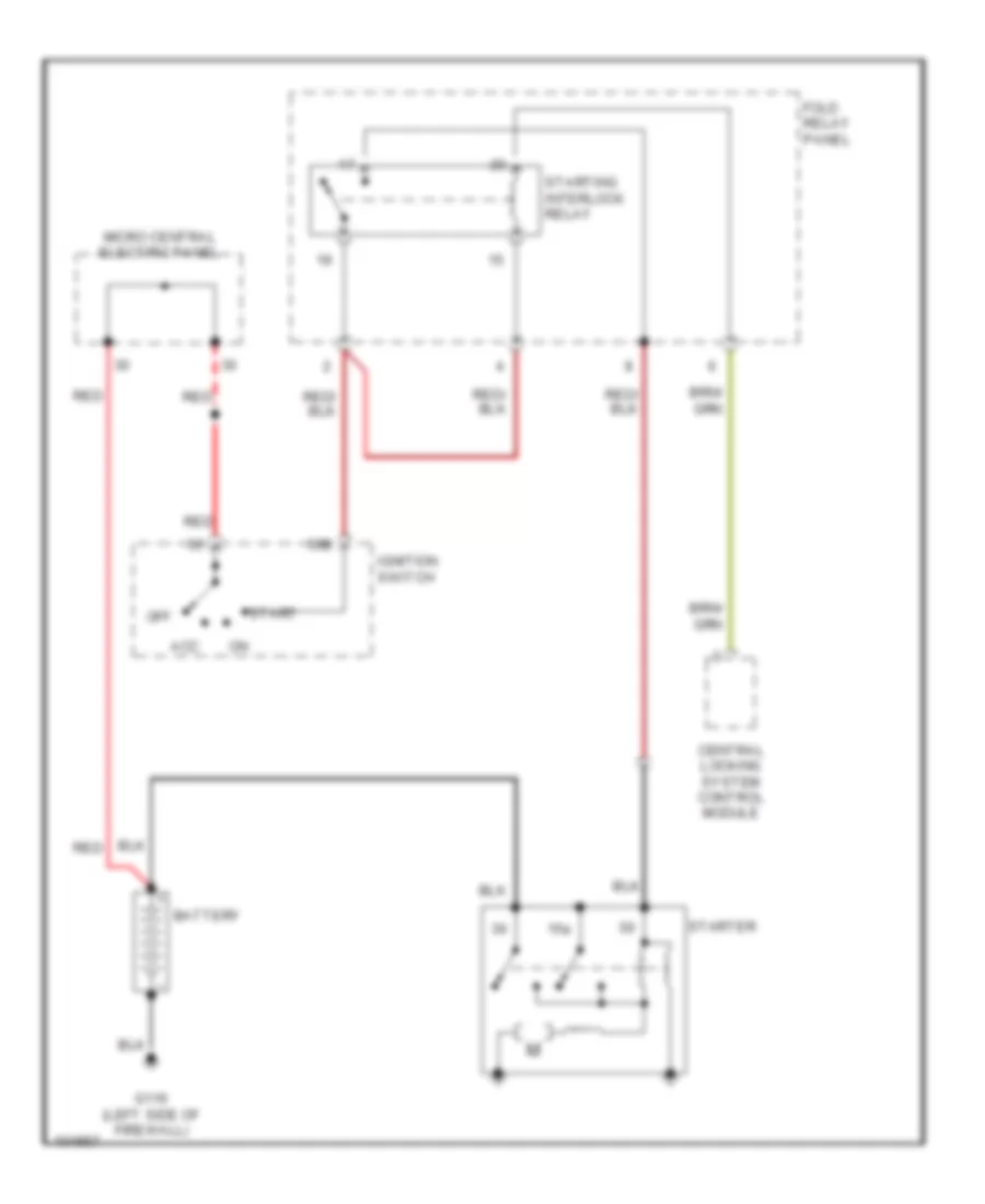
Starting Wiring Diagram for Audi A6 1998
List of elements for Starting Wiring Diagram for Audi A6 1998:
- 15a
- 50b
- Acc
- Battery
- Central locking system control module
- Fold relay panel
- G116 (left side of firewall)
- Ignition switch
- Micro central electric panel
- Off
- Red
- Start
- Starter
- Starting interlock relay
SUPPLEMENTAL RESTRAINTS
Supplemental Restraints Wiring Diagram for Audi A6 1998
List of elements for Supplemental Restraints Wiring Diagram for Audi A6 1998:
- (below left side of dash) data link connector
- (lower left "a" pillar) g900
- Acc
- Airbag control module (below front of center console)
- Airbag malfunction indicator lamp
- Airbag spiral spring
- Center rear seat belt tensioner igniter (w/ undivided rear seatback)
- Central locking control module
- Combination processor
- Driver seat belt tensioner igniter
- Driver side airbag crash sensor
- Driver side airbag igniter
- Driver's airbag igniter
- G900 (lower left "a" pillar)
- Hot at all times
- Ignition switch
- Instrument cluster
- J429
- Left front "a" pillar micro switch
- Left rear seat belt tensioner igniter
- Left rear seat occupancy sensor
- Left rear side airbag igniter
- Lock
- Nca
- Nca nca
- Passenger seat belt tensioner igniter
- Passenger seat occupancy sensor
- Passenger side airbag crash sensor
- Passenger side airbag igniter
- Passenger's airbag igniter
- Red
- Right front "a" pillar micro switch
- Right rear seat belt tensioner igniter
- Right rear seat occupancy sensor
- Right rear side airbag igniter
- Run
- Start
- T16
- T32
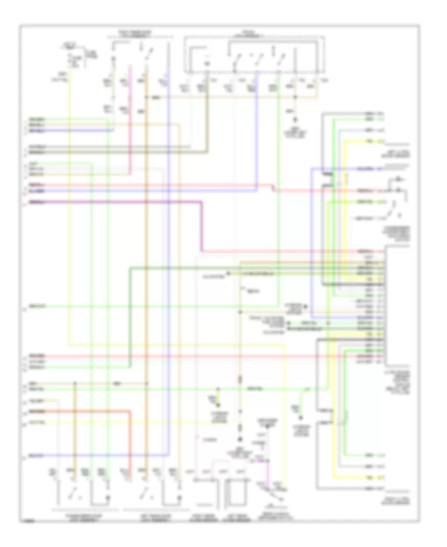
TRANSMISSION
A/T Wiring Diagram for Audi A6 1998
List of elements for A/T Wiring Diagram for Audi A6 1998:
- (below left side of dash) data link connector (dlc)
- (lower left "a" pillar)
- (or red)
- 11-12
- 13- fold relay panel (behind left side of dash)
- 15a
- 231a
- 38-39
- 48-51
- 50a
- 50z
- 56-84
- 87a
- Anti-lock brakes system
- Brake light switch (on brake pedal support bracket)
- Central locking control module (below driver's seat)
- Cruise control system
- Engine control module (ecm) (in electronic box, left side of fresh air plenum)
- Exterior lights system
- Fuse 10a
- Fuse 15a
- Fuse panel (left side of dash)
- G104 (left side of eng compt)
- G900
- G900 (lower left "a" pillar)
- Generator terminal d+
- Hot at all times
- Hot in on or start
- Ignition switch terminal 50 (hot in start)
- Instrument cluster system
- Interior lights system
- Kickdown switch (on firewall, part of throttle cable)
- Multi-function transmission range switch (left side of transmission)
- Pressure control valves
- Protection diode
- Red
- Selector lever light relay
- Shift lock solenoid
- Solenoid valves
- Starter terminal 50
- Starting interlock relay
- Tiptronic switch
- Transmission control module (tcm) (under right front seat)
- Transmission fluid temperature sensor
- Transmission speed sensor
- Transmission vehicle speed sensor
- Valve body
- W/ fuse
- W/0 fuse
TRUNK, TAILGATE, FUEL DOOR
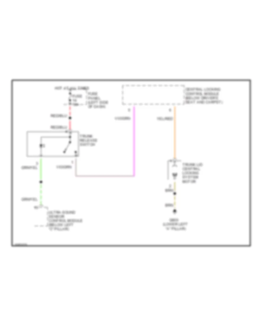
Trunk Release Wiring Diagram for Audi A6 1998
List of elements for Trunk Release Wiring Diagram for Audi A6 1998:
- Central locking control module (below driver's seat and carpet)
- Fuse 10a
- Fuse panel (left side of dash)
- G900 (lower left "a" pillar)
- Hot at all times
- Trunk lid central locking system motor
- Trunk release switch
- Ultra-sound sensor control module (below left "c" pillar)
WARNING SYSTEMS
Warning Systems Wiring Diagram for Audi A6 1998
List of elements for Warning Systems Wiring Diagram for Audi A6 1998:
- (2 w/d)
- (left side of dash)
- (on oil filter housing)
- 15a
- 18a
- 86s
- Abs warning
- Air bag mil
- Airbag ctrl module (below front center console)
- Analog clock
- Brake fluid level sensor
- Brake pad wear ind
- Catalyst warn
- Central locking module (below driver's seat and carpet)
- Coolant level warning switch (bottom
- Coolant level/ temp warn
- Driver's seat belt switch
- Ect gauge
- Ect sensor
- Fuel gauge
- Fuel level sensor 1
- Fuel level sensor 2 (4 w/d)
- Fuel level sensor 3 (4 w/d)
- Fuel reserve warn
- Fuse 15 10a
- Fuse 18 10a
- Fuse panel
- G104 (left side of engine compt)
- G900 (lower left "a" pillar)
- Gen ind.
- Generator
- Glow plug
- Headlight switch
- High beam
- Hot at all times
- Hot with high beams on
- Ignition switch
- Ignition switch acc
- Instrument cluster
- Interior lights system
- Key switch
- Left door warning light
- Left front door contact switch
- Left front entry light
- Left turn
- Lock
- Off
- Oil pressure switch
- Oil pressure warn
- Oil temp gauge
- Oil temp sensor
- Park brake
- Park light
- Red
- Refer to instrument cluster for complete wiring
- Reservoir)
- Right high beam headlight
- Right turn
- Run
- Seat belt
- Speedometer
- Start
- T32
- T32/
- T32/10
- T32/11
- T32/15
- T32/19
- T32/20
- T32/21
- T32/22
- T32/23
- T32/25
- T32/26
- T32/27
- T32/28
- T32/29
- T32/3
- T32/30
- T32/31
- T32/5
- T32/6
- T32/7
- T32/8
- T32/9
- T32a
- T32a/
- T32a/10
- T32a/11
- T32a/12
- T32a/17
- T32a/2
- T32a/21
- T32a/23
- T32a/29
- T32a/30
- T32a/5
- T32a/6
- T32a/7
- Tachometer
- Traction cont
- Volts gauge
- Warning buzzer
WIPER/WASHER
Wiper/Washer Wiring Diagram for Audi A6 1998
List of elements for Wiper/Washer Wiring Diagram for Audi A6 1998:
- (not used)
- 24a
- Air quality sensor
- Auto check system
- Brake fluid level sensor
- Fuse 1 5a
- Fuse 24 25a
- Fuse panel (left side of dash)
- G900 (lower left "a" pillar)
- Hot in run
- Hot with load reduction relay energized
- Left washer nozzle heater
- Load reduction relay
- Micro central electric panel (behind left side of dash)
- Nca
- Right washer nozzle heater
- Transmission range selector
- Washer fluid level switch
- Washer pump
- Windshield wiper intermittent regulator
- Windshield wiper motor
- Wiper/ washer switch
- Wiper/washer intermittent relay (on micro central electric panel)