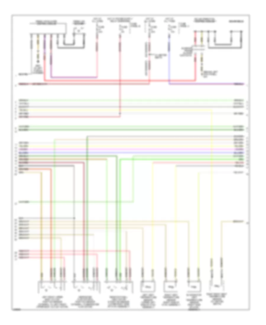
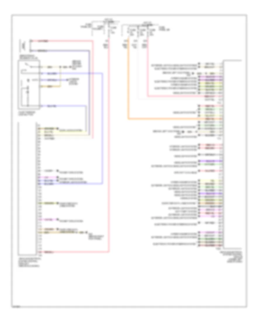
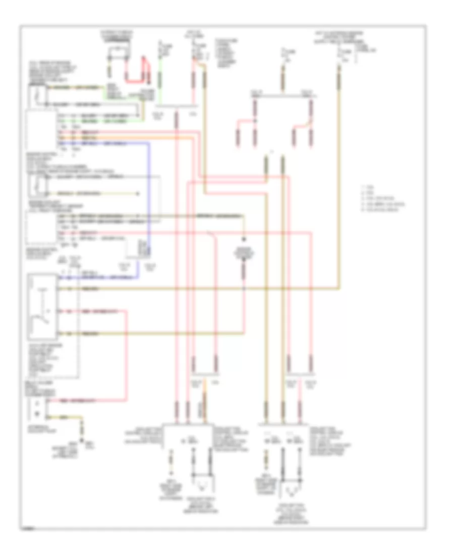
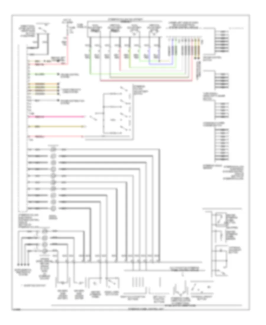
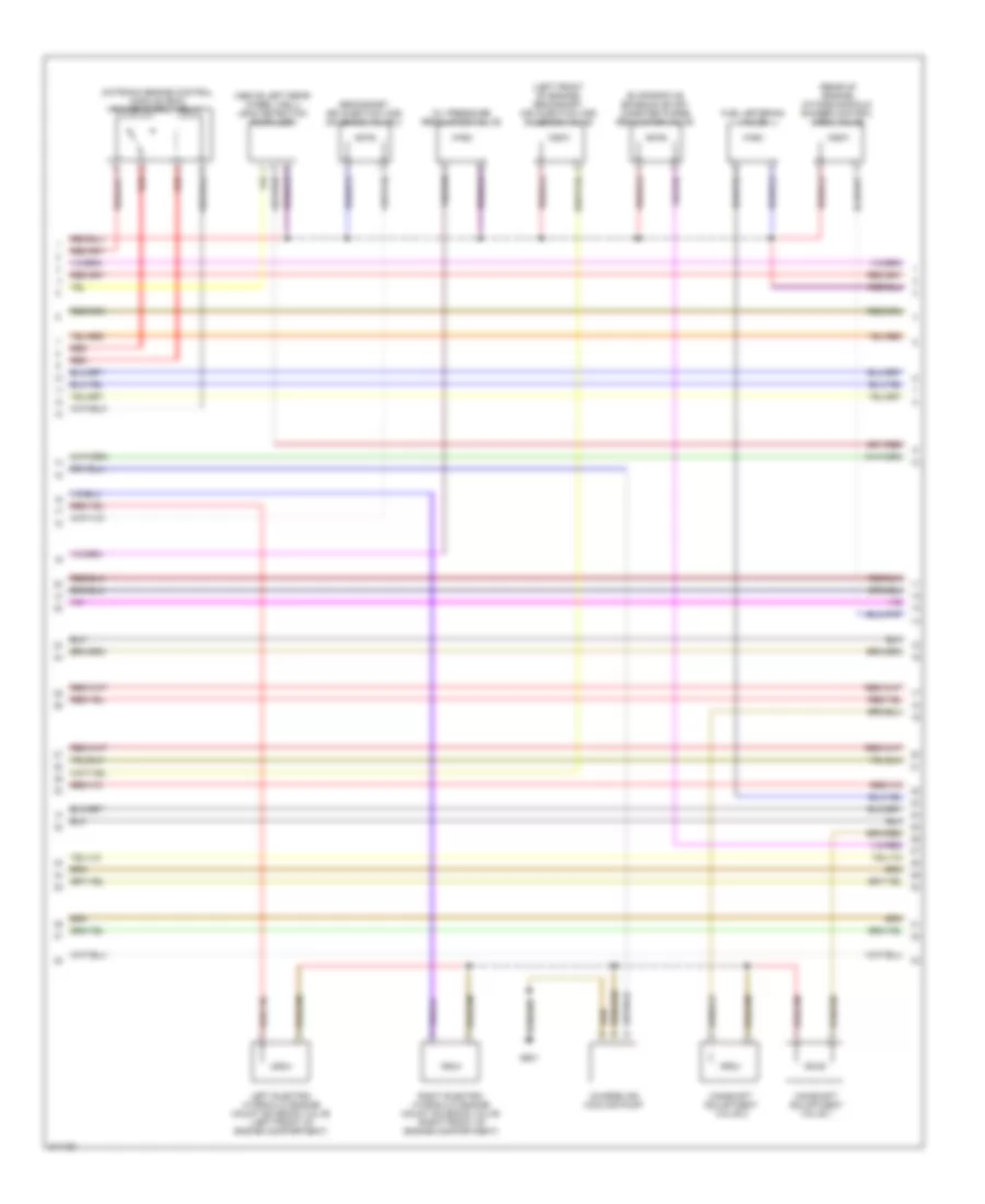
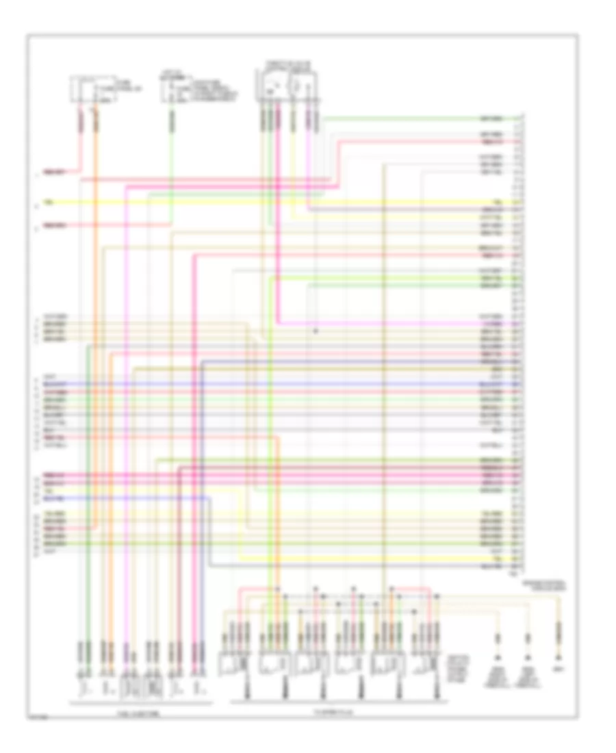
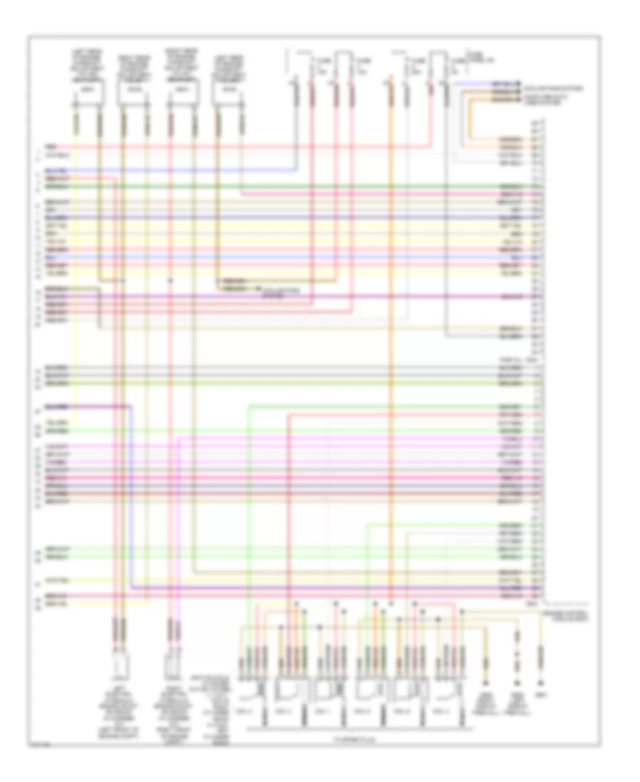
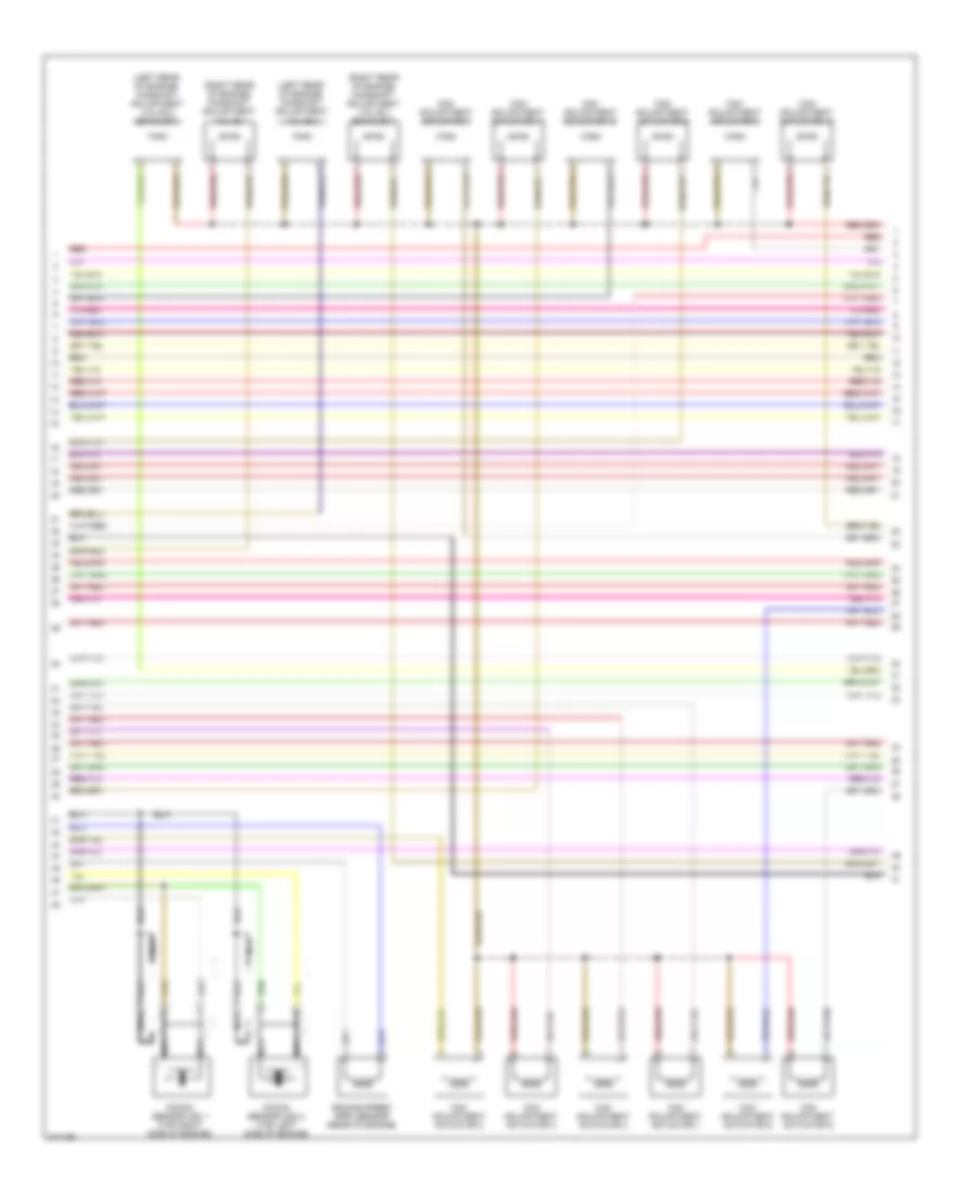
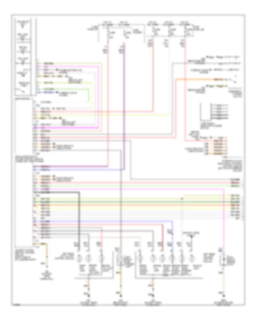
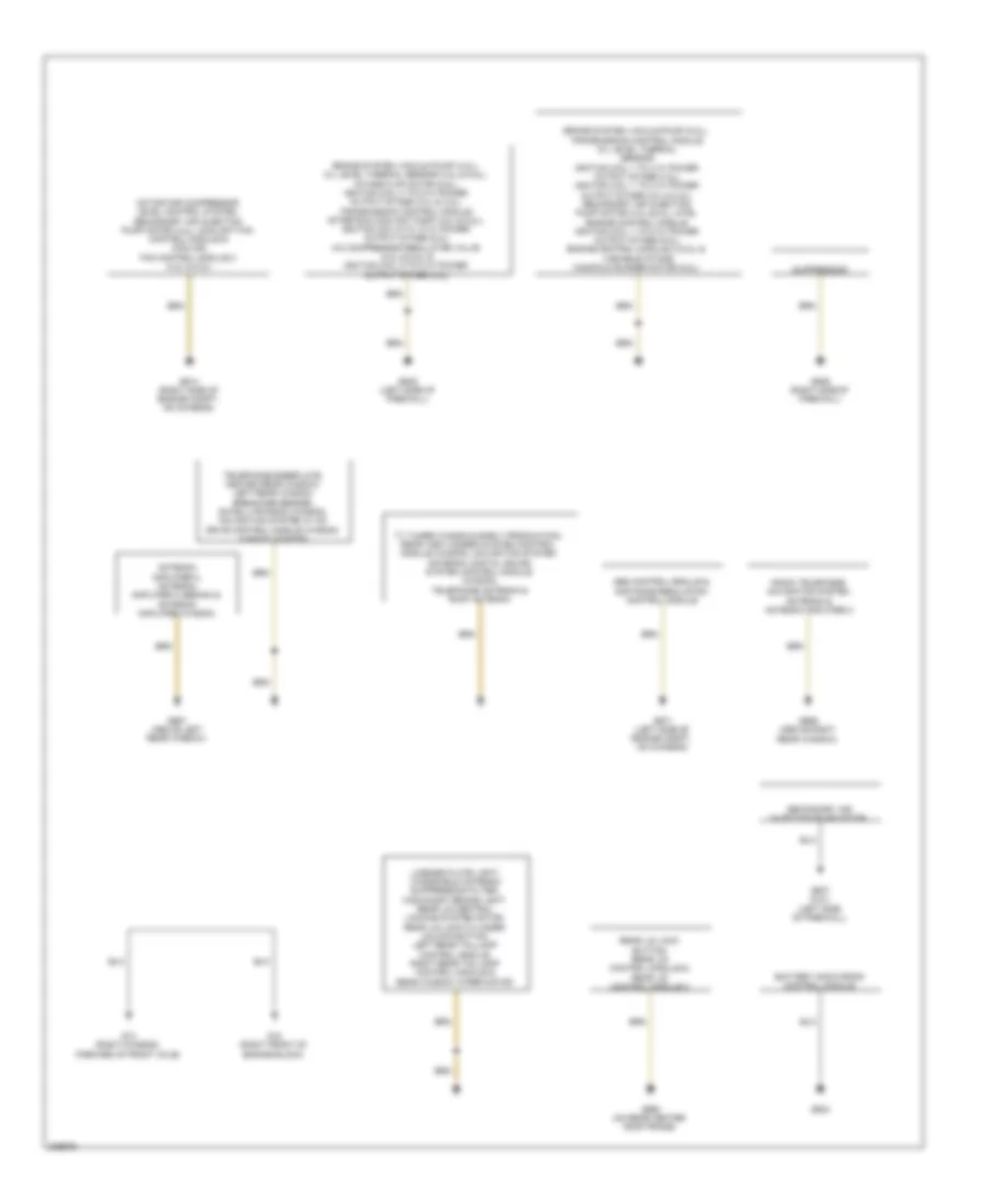
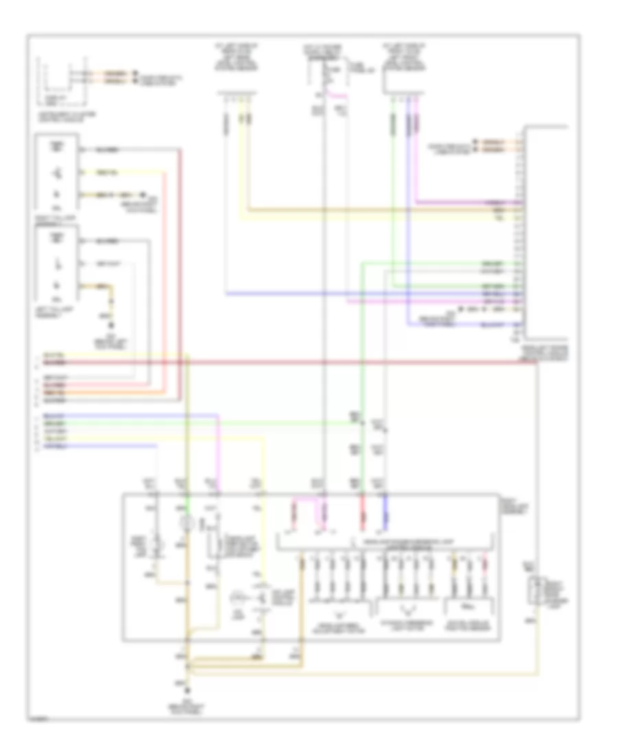
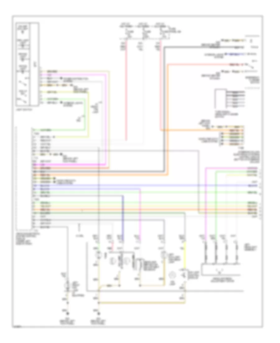
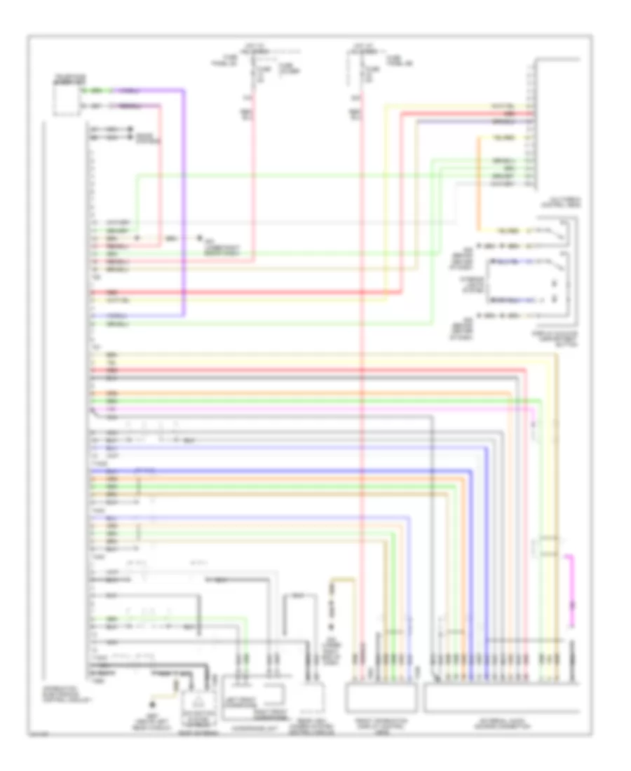
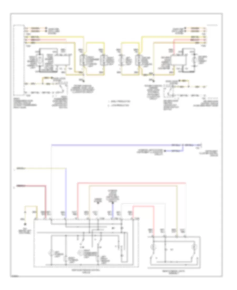
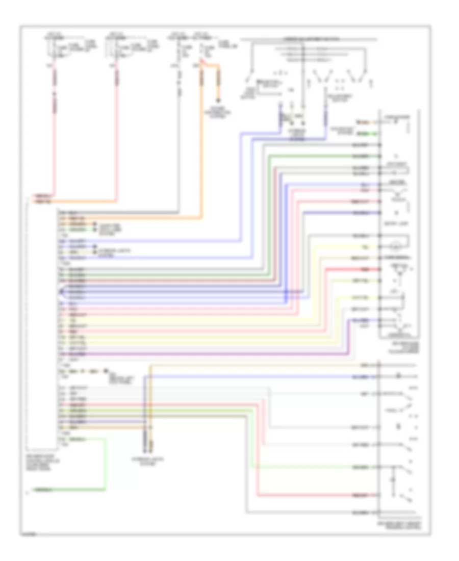
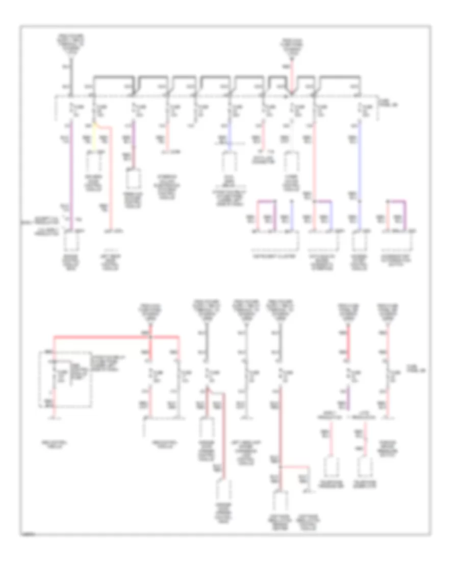
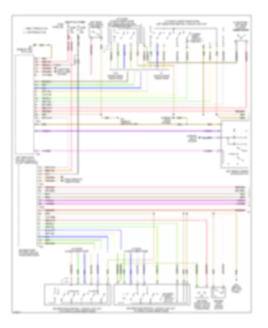
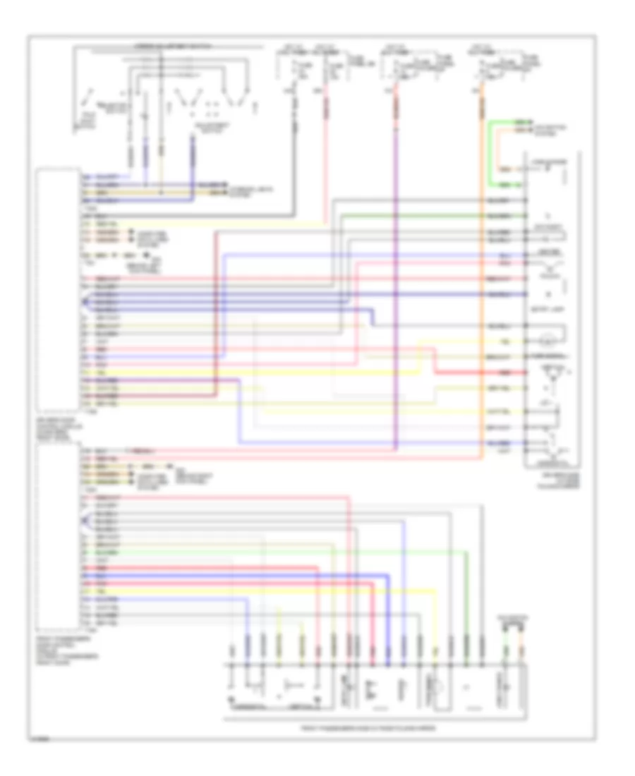
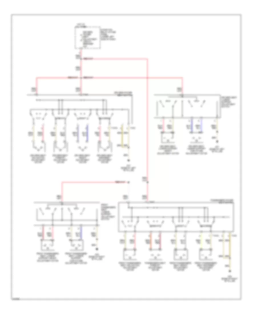
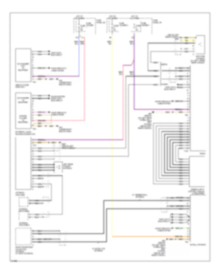
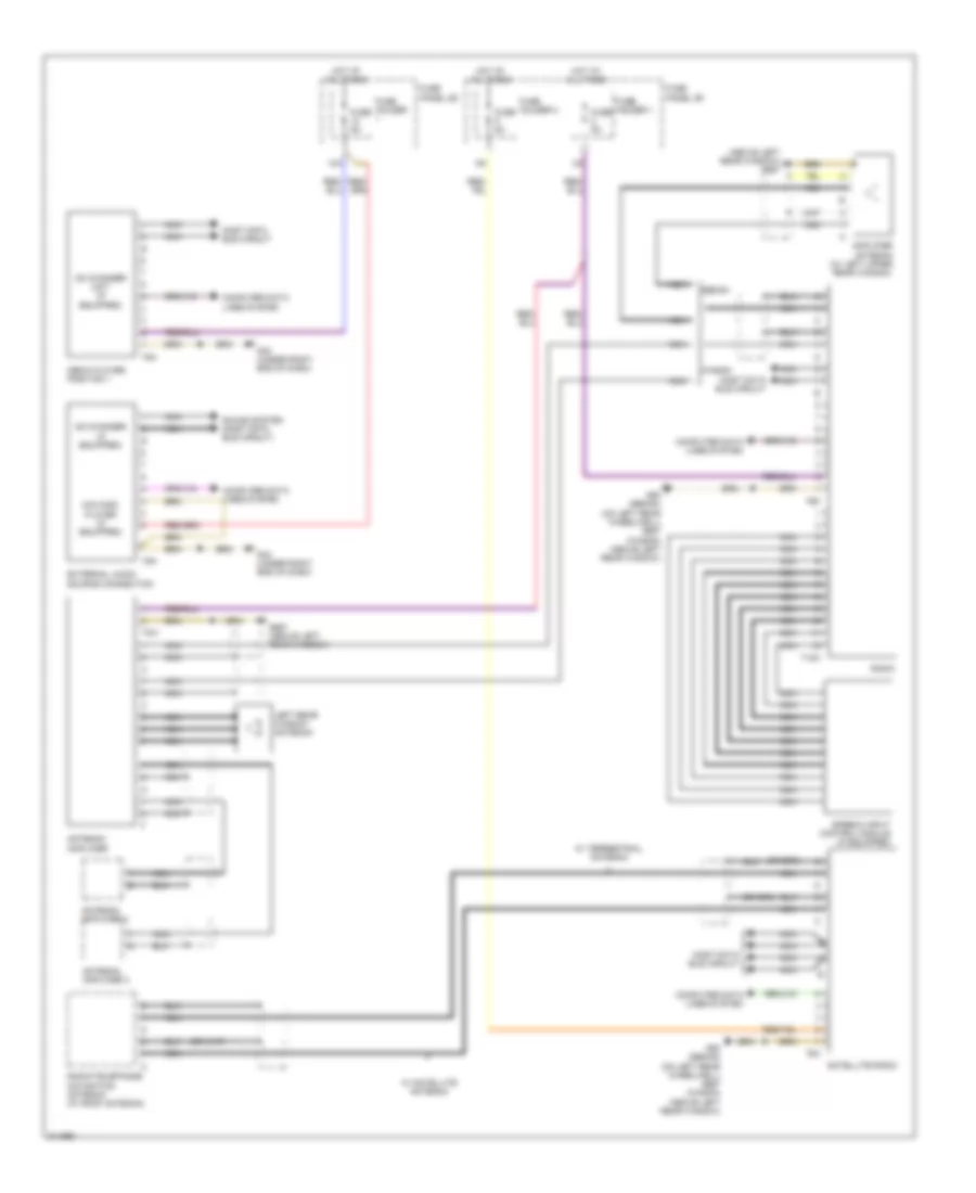
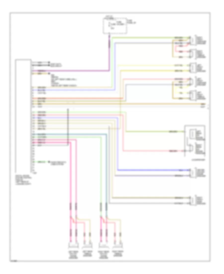
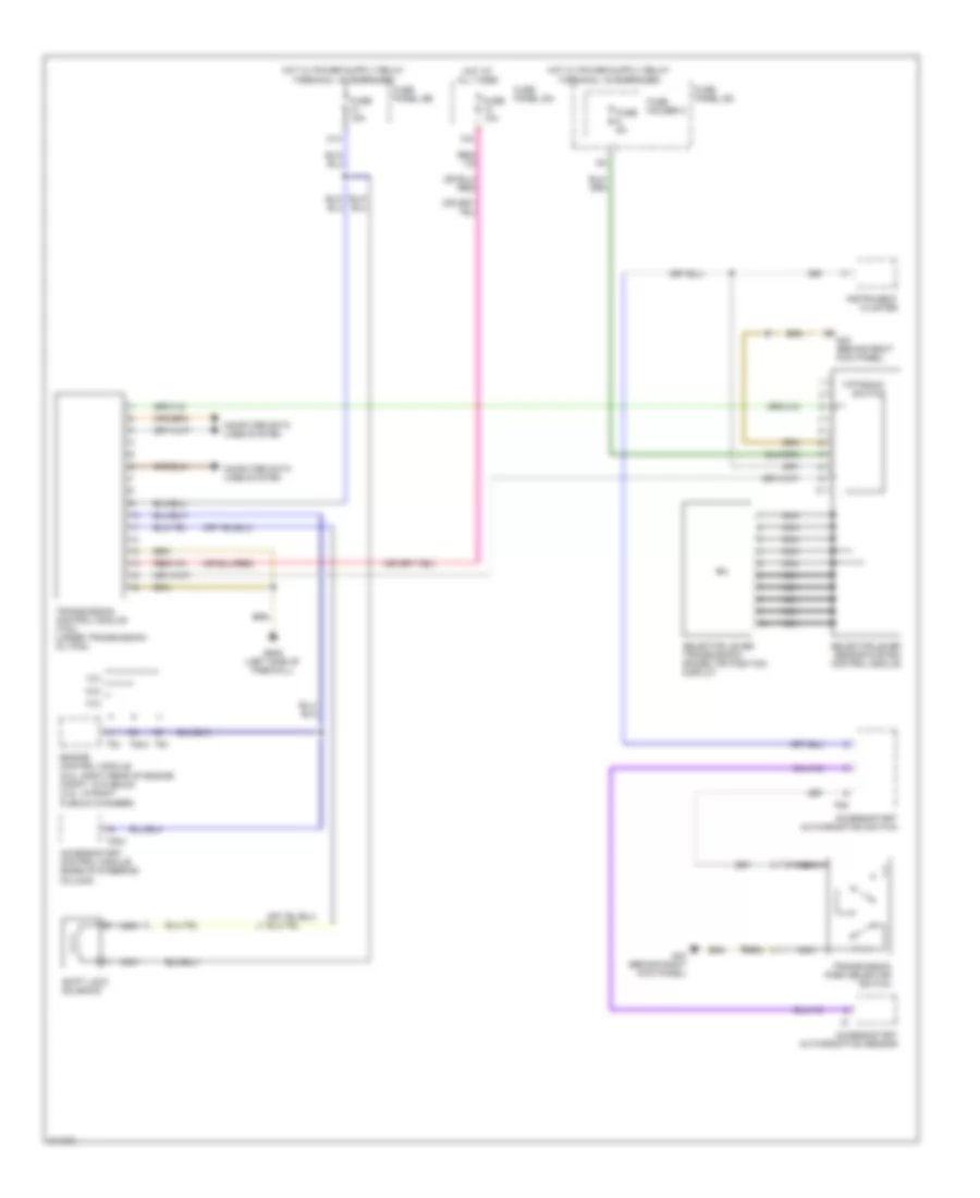
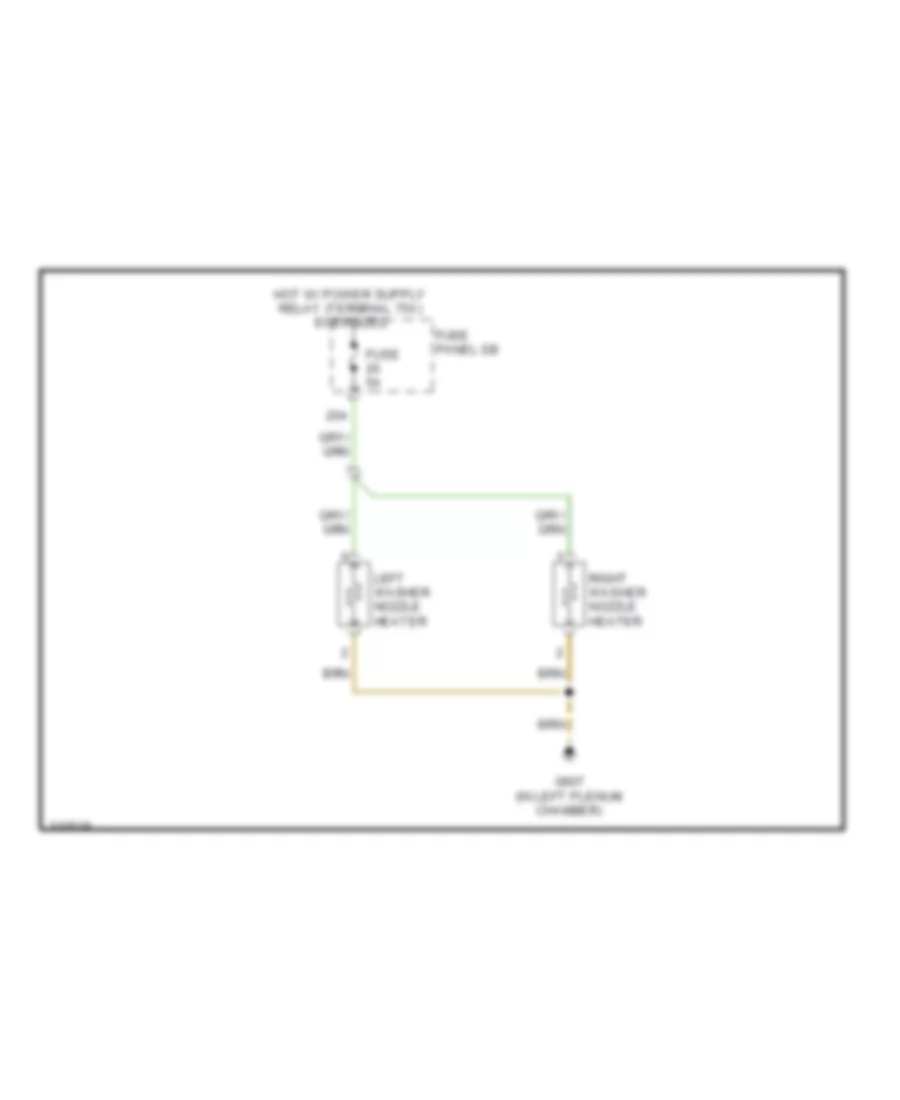
AIR CONDITIONING
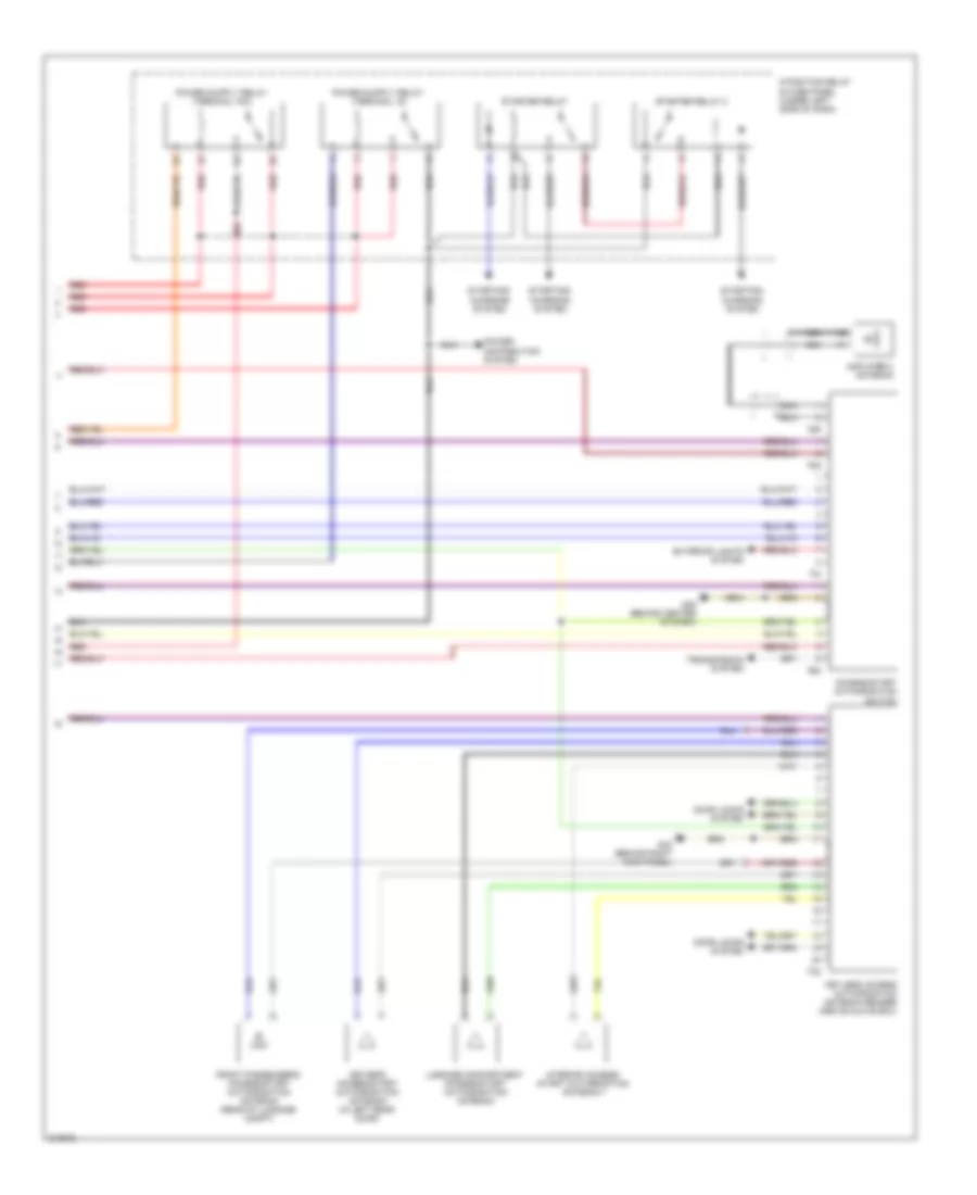
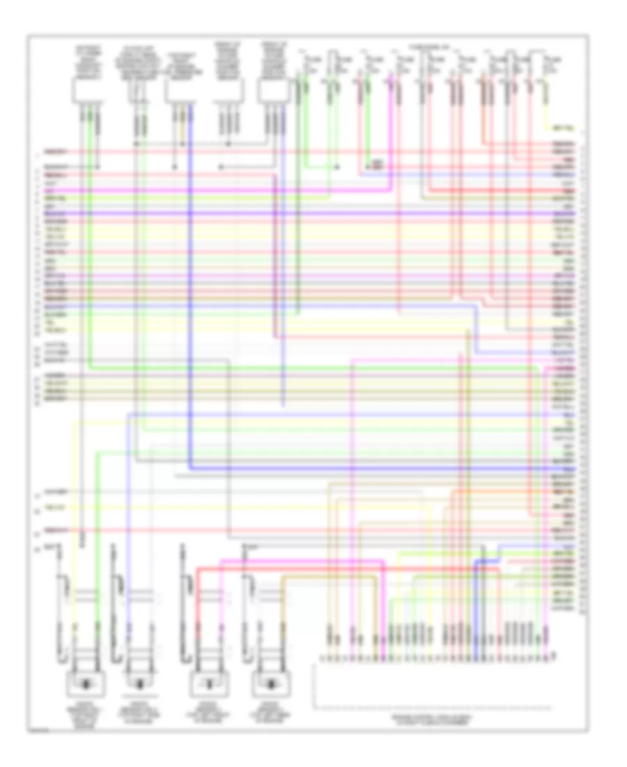
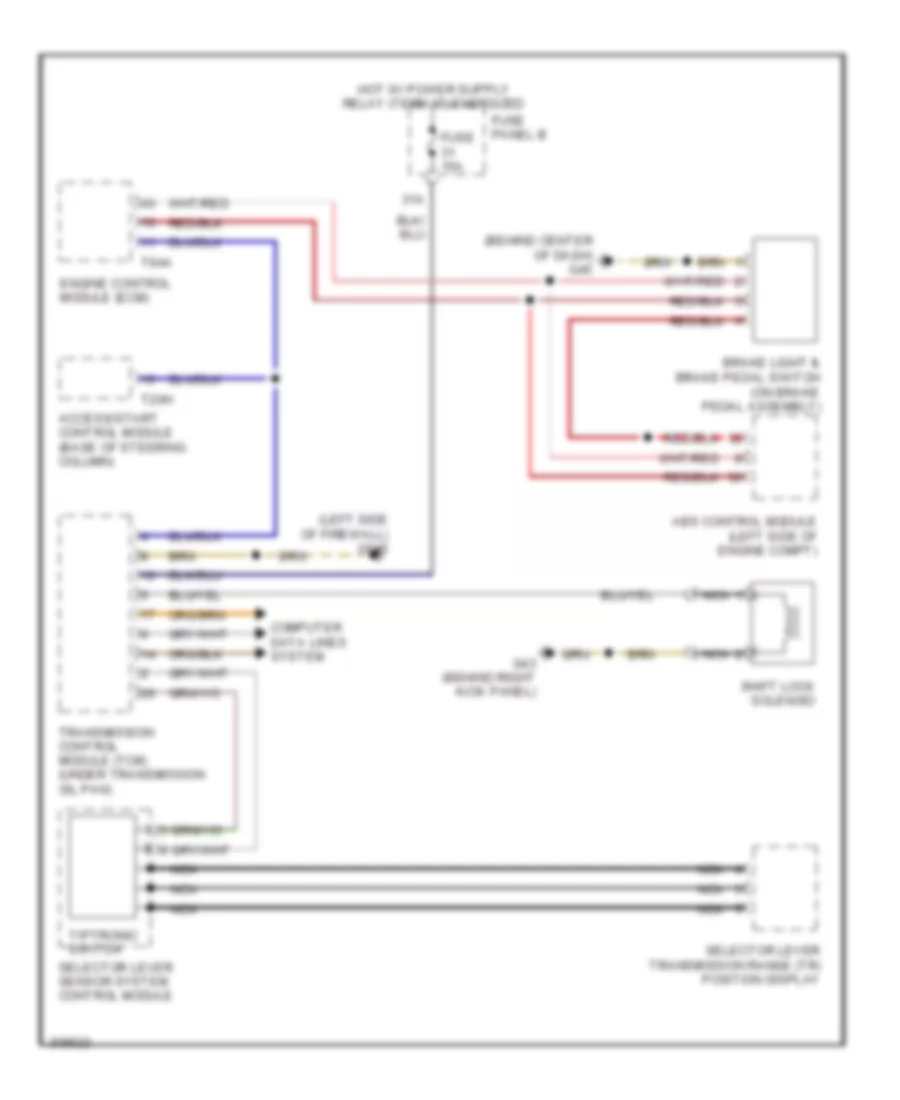
Automatic A/C Wiring Diagram (1 of 4) for Audi A6 Quattro 2009

List of elements for Automatic A/C Wiring Diagram (1 of 4) for Audi A6 Quattro 2009:
- (in center plenum) heat regulating valve & coolant pump
- (right side of hvac assembly) air quality sensor
- A/c compressor regulator valve
- A/c pressure/ temperature sensor
- Center vent motor & position sensor (integral to center vent adjustment motor)
- Climatronic control module
- Computer data lines system
- Front cold air flap motor & position sensor (integral to front cold air flap motor)
- G44 (behind left kick panel)
- G607 (in left plenum chamber)
- G645 (left side of firewall)
- Indirect ventilation flap motor & position sensor (left side of hvac assembly)
- Left footwell flap motor & position sensor (integral to left footwell flap motor)
- Right footwell flap motor & position sensor (integral to right footwell flap motor)
- Right front upper body outlet position sensor (integral to right front upper body outlet motor)
- Seats system (heated seats circuit)
- T16d
- T20f
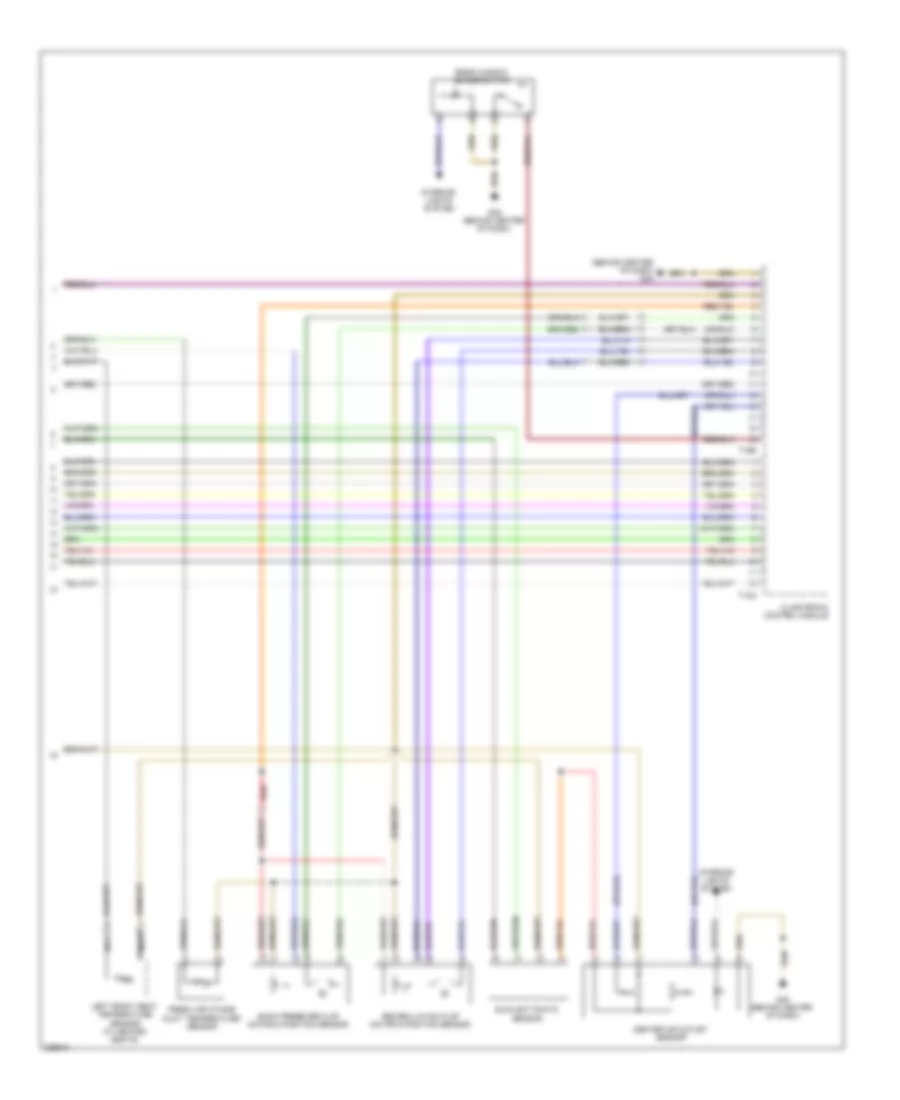
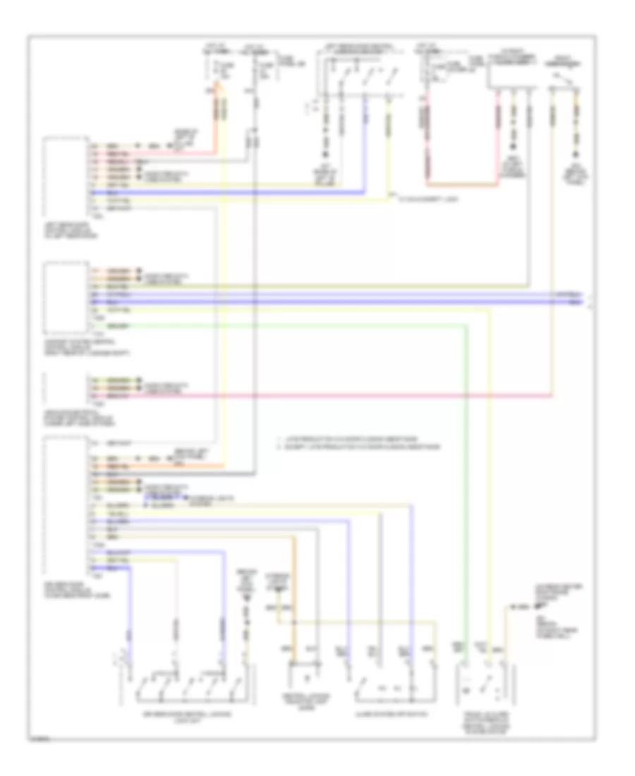
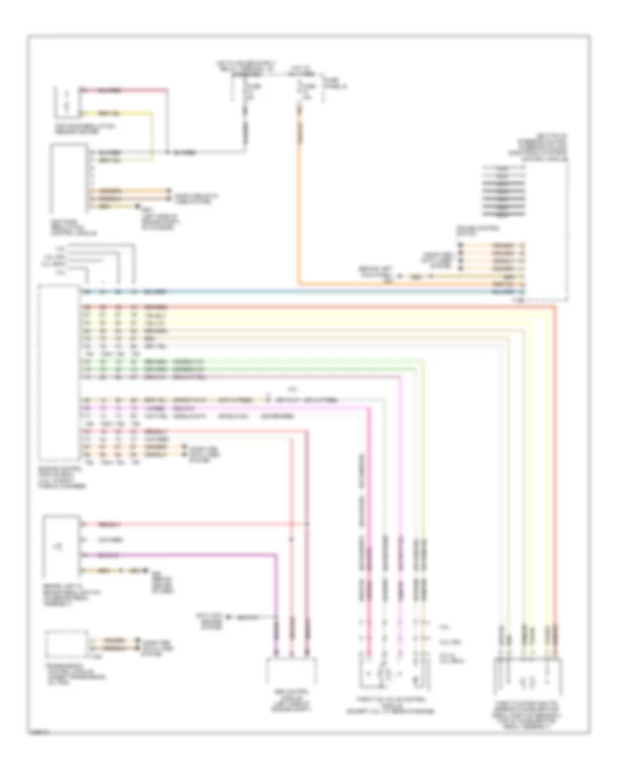
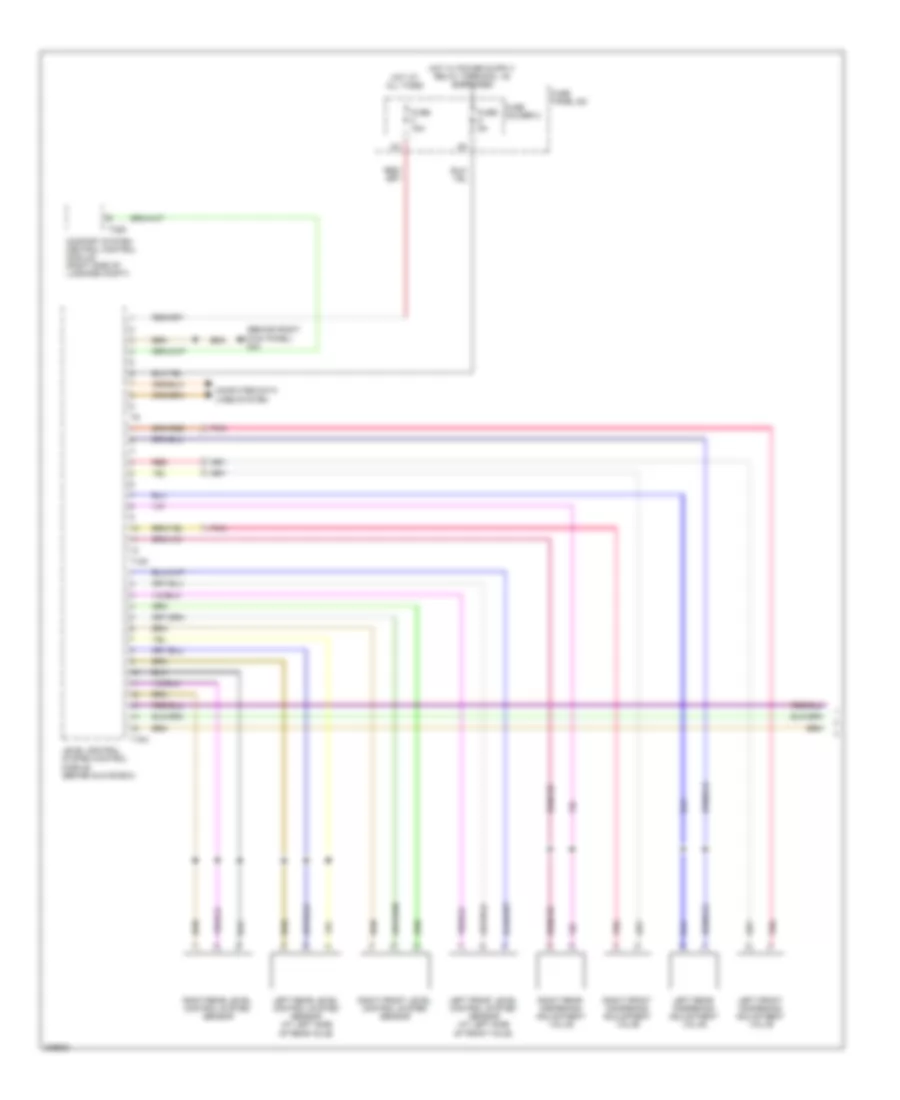
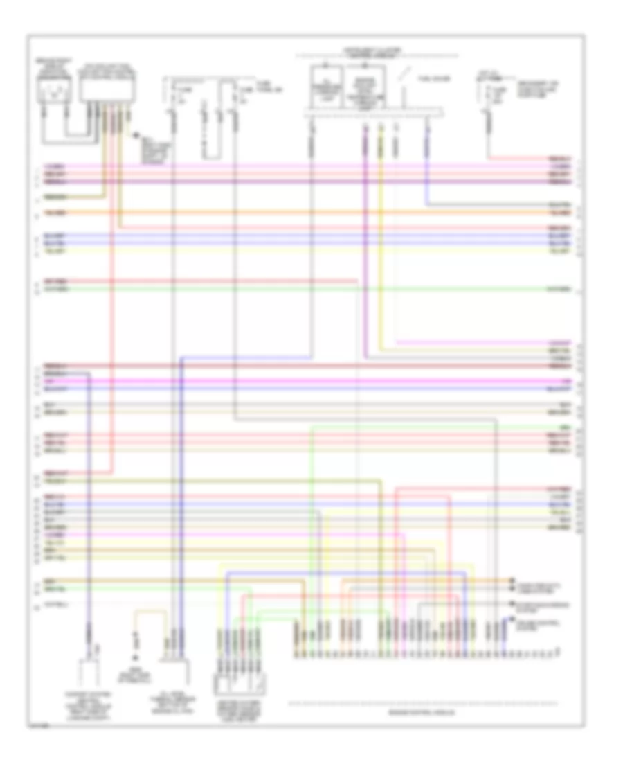
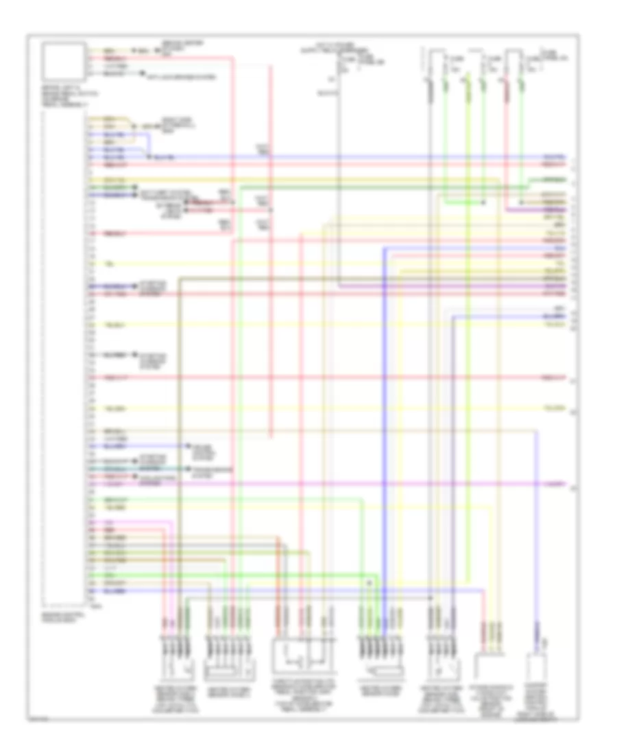
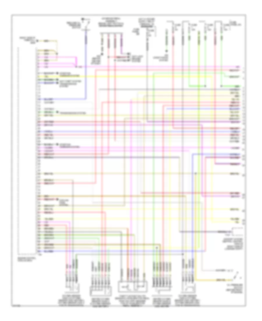
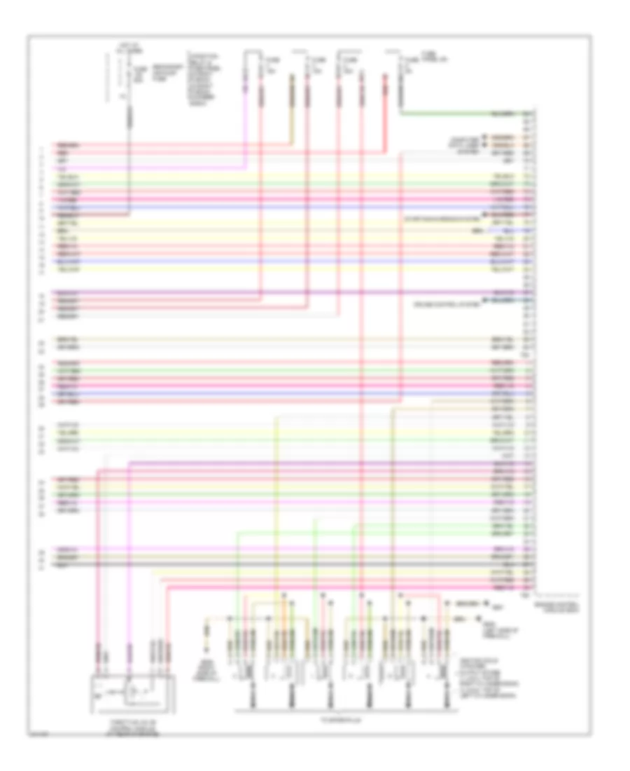
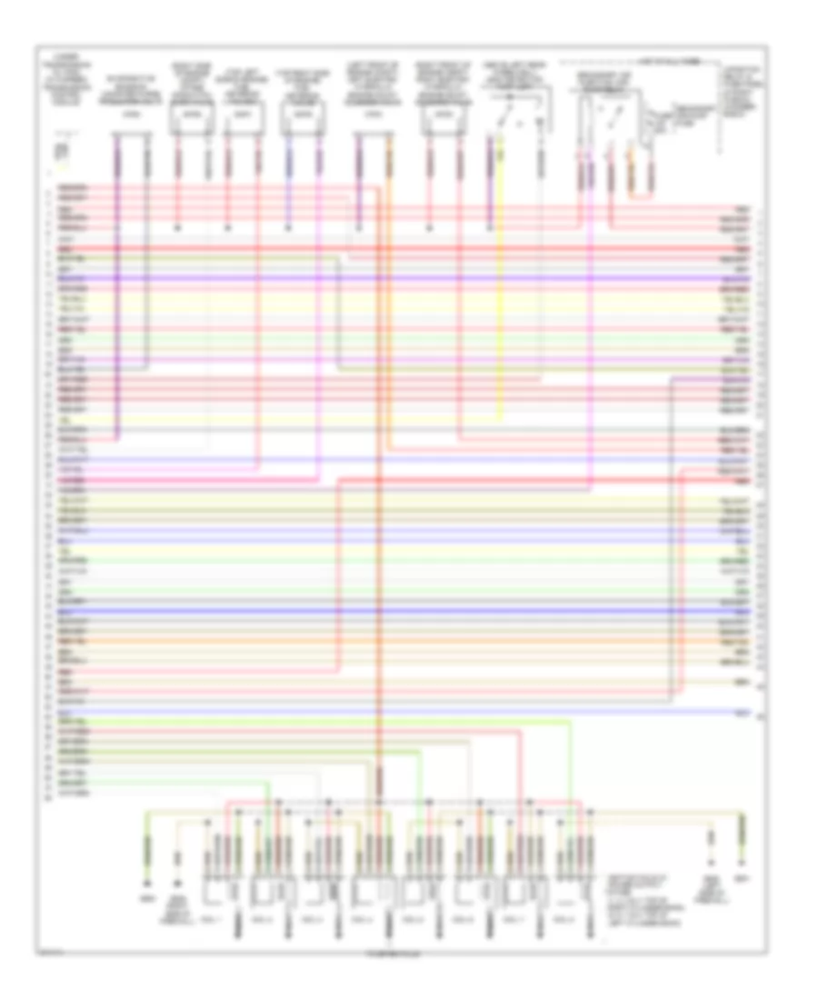
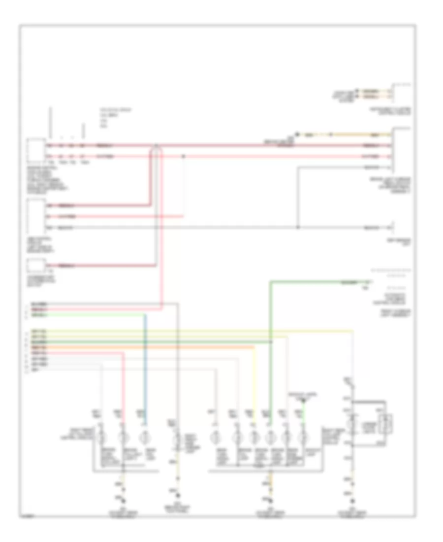
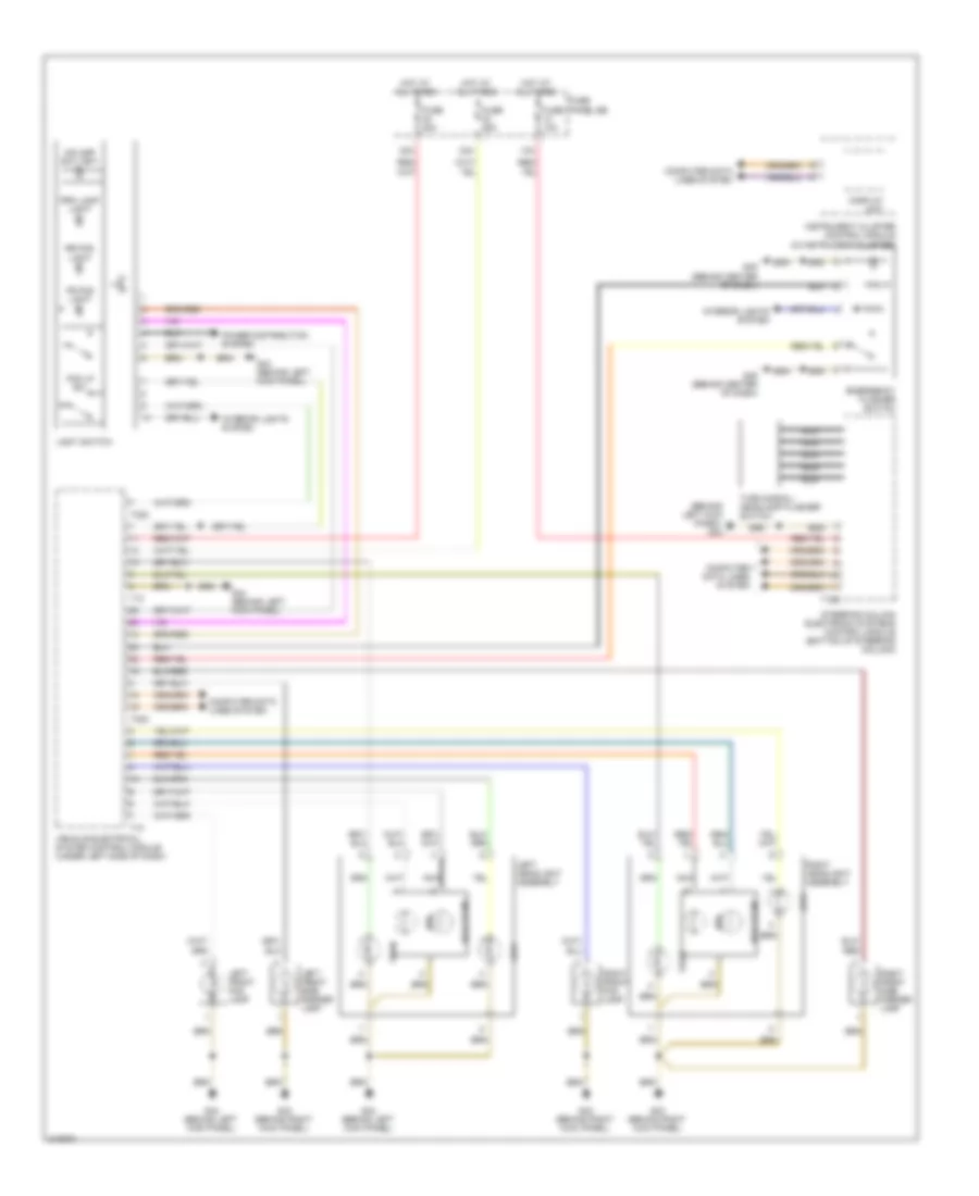
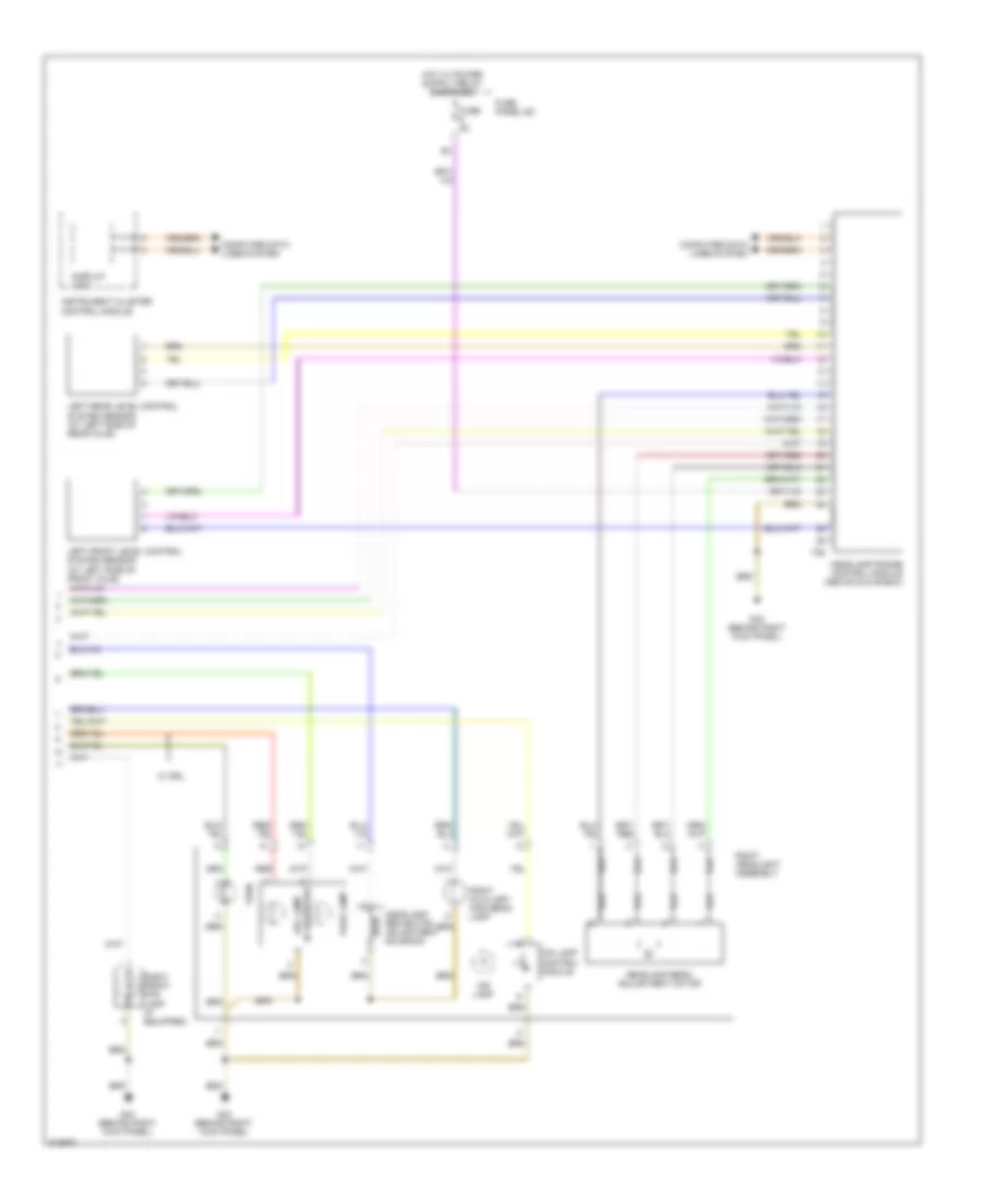
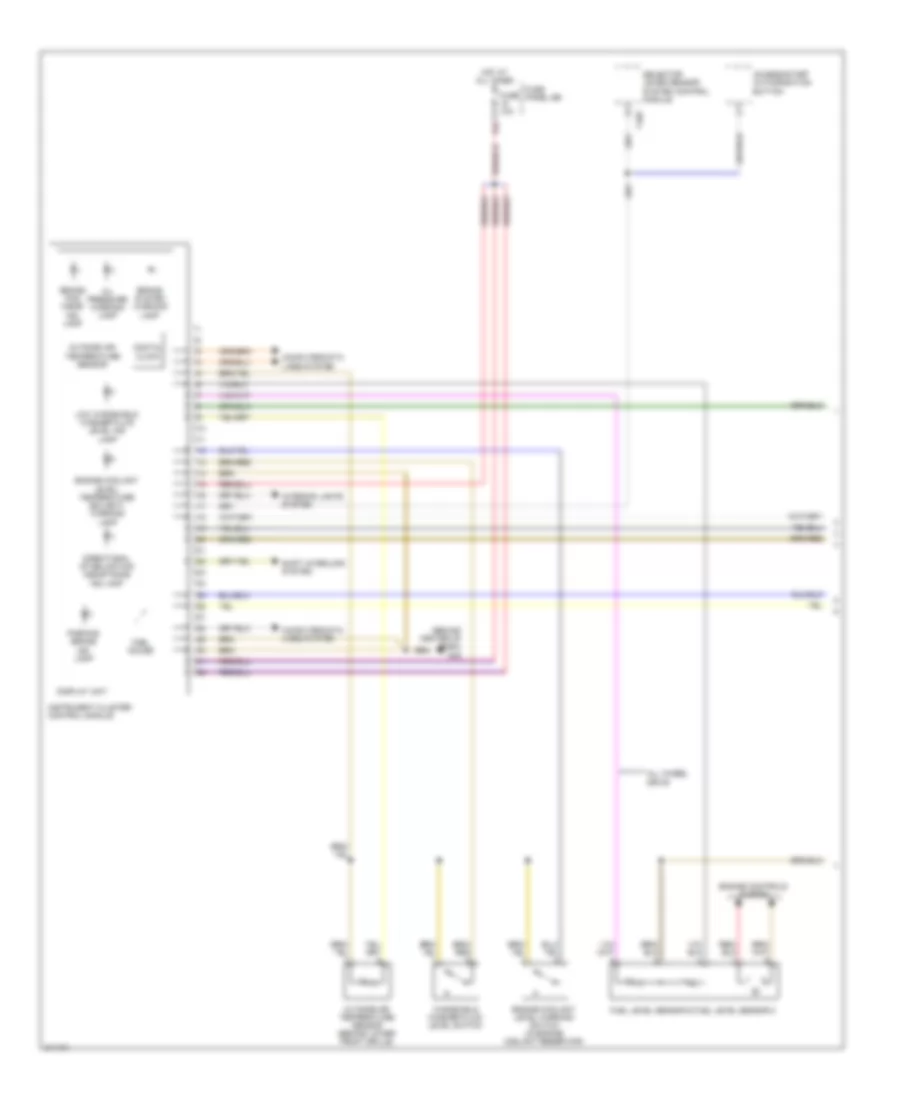
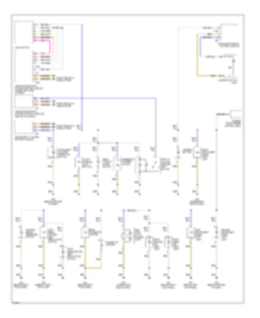
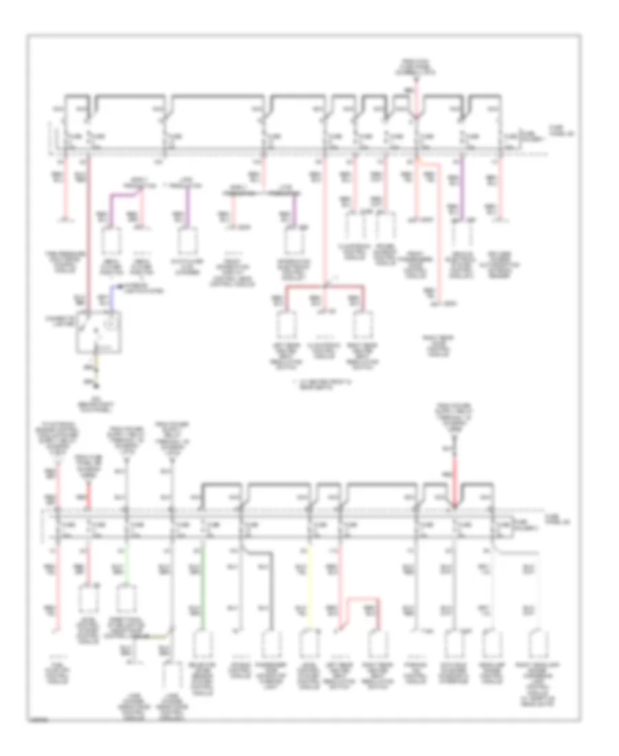
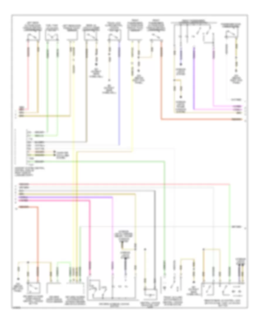
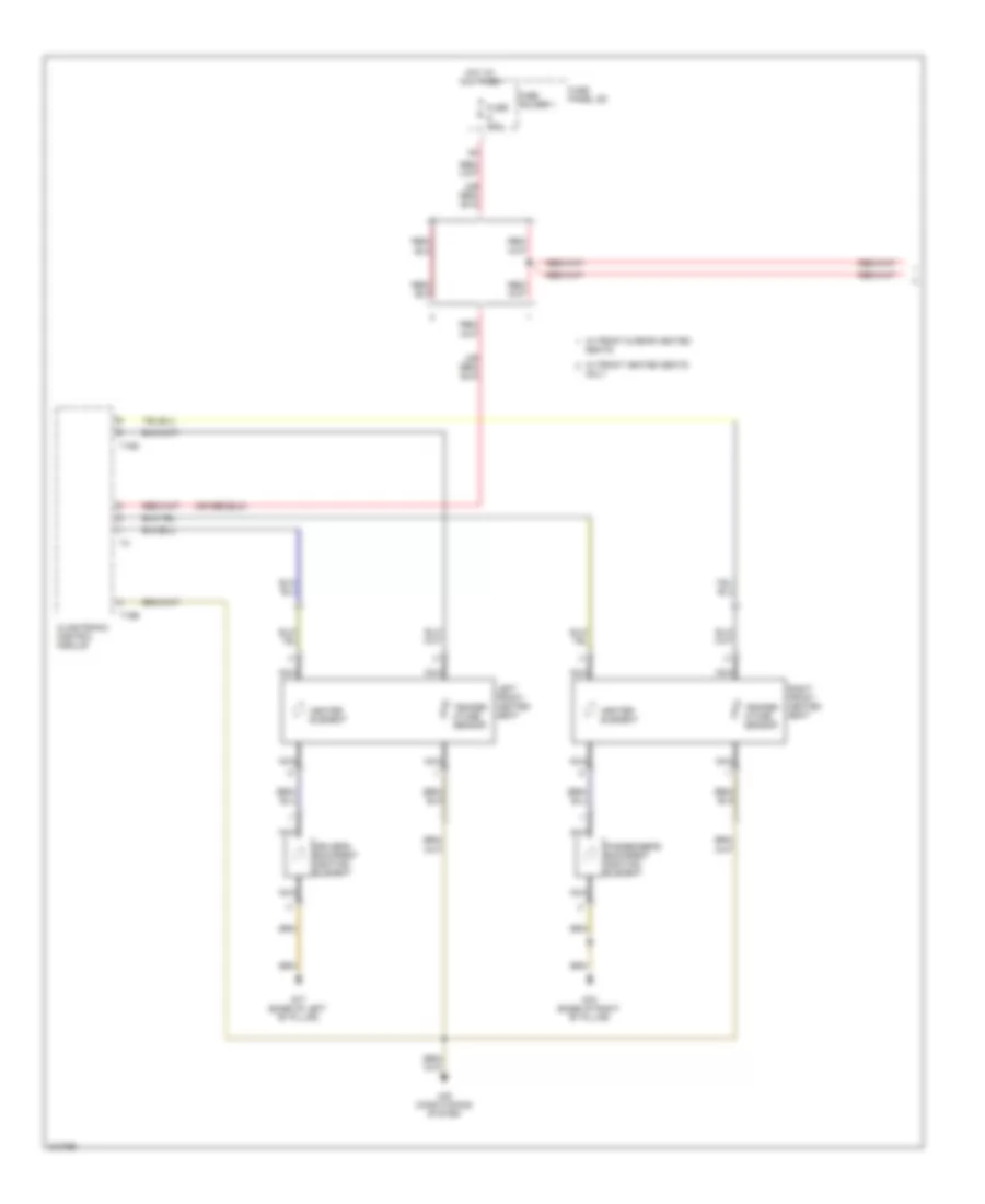
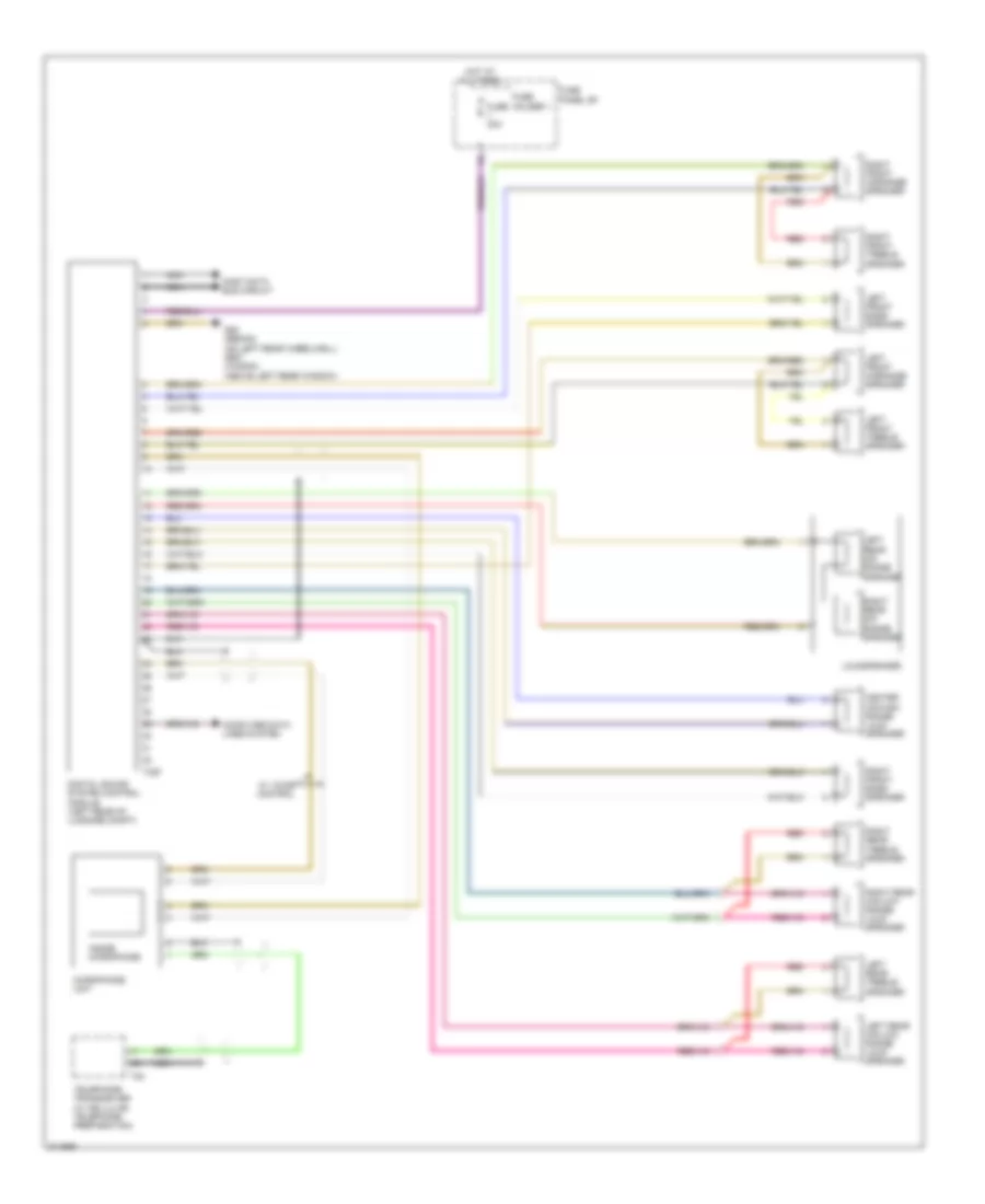
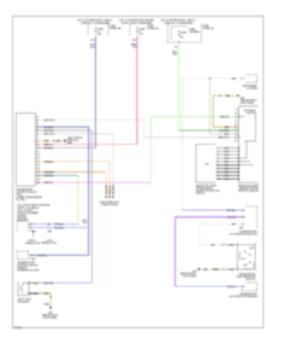
Automatic A/C Wiring Diagram (2 of 4) for Audi A6 Quattro 2009
List of elements for Automatic A/C Wiring Diagram (2 of 4) for Audi A6 Quattro 2009:
- (behind left kick panel) g44
- 41a
- Defroster flap motor & position sensor (integral to defroster flap motor)
- Evaporator vent temperature sensor (right side of hvac assembly)
- Fresh air blower
- Fresh air blower control module
- Fuse 10a
- Fuse 30a
- Fuse 40a
- Fuse 5a
- Fuse panel b
- Fuse panel c
- G607 (in left plenum chamber)
- Hot at all times
- Left front upper body outlet position sensor (integral to left front upper body outlet motor)
- Left vent temperature sensor (upper left side of hvac assembly)
- Nca
- Rear footwell vent motor & position sensor (lower right side of hvac assembly)
- Red
- Right front seat temperature sensor (w/ heated seats)
- Right vent temperature sensor (right side of hvac assembly)
- Solar cells
- Solar operation control module
- Sunroof frame sliding contacts
- W/ heated seats
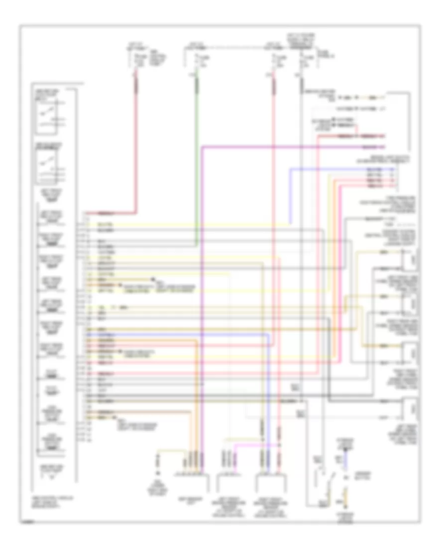
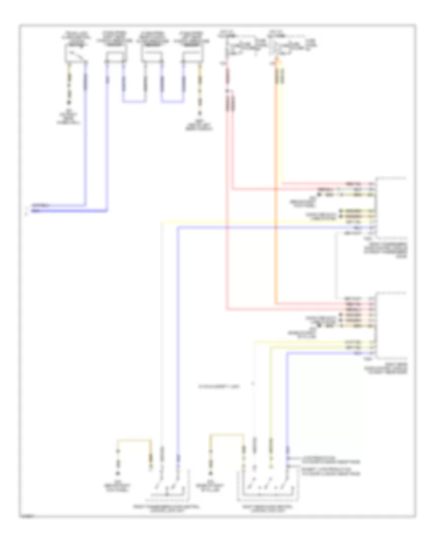
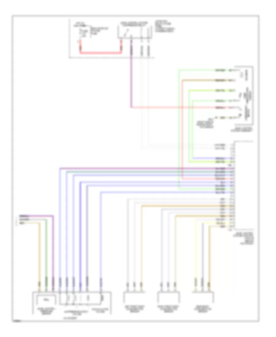
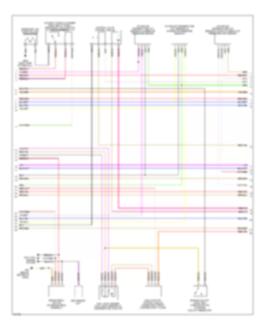
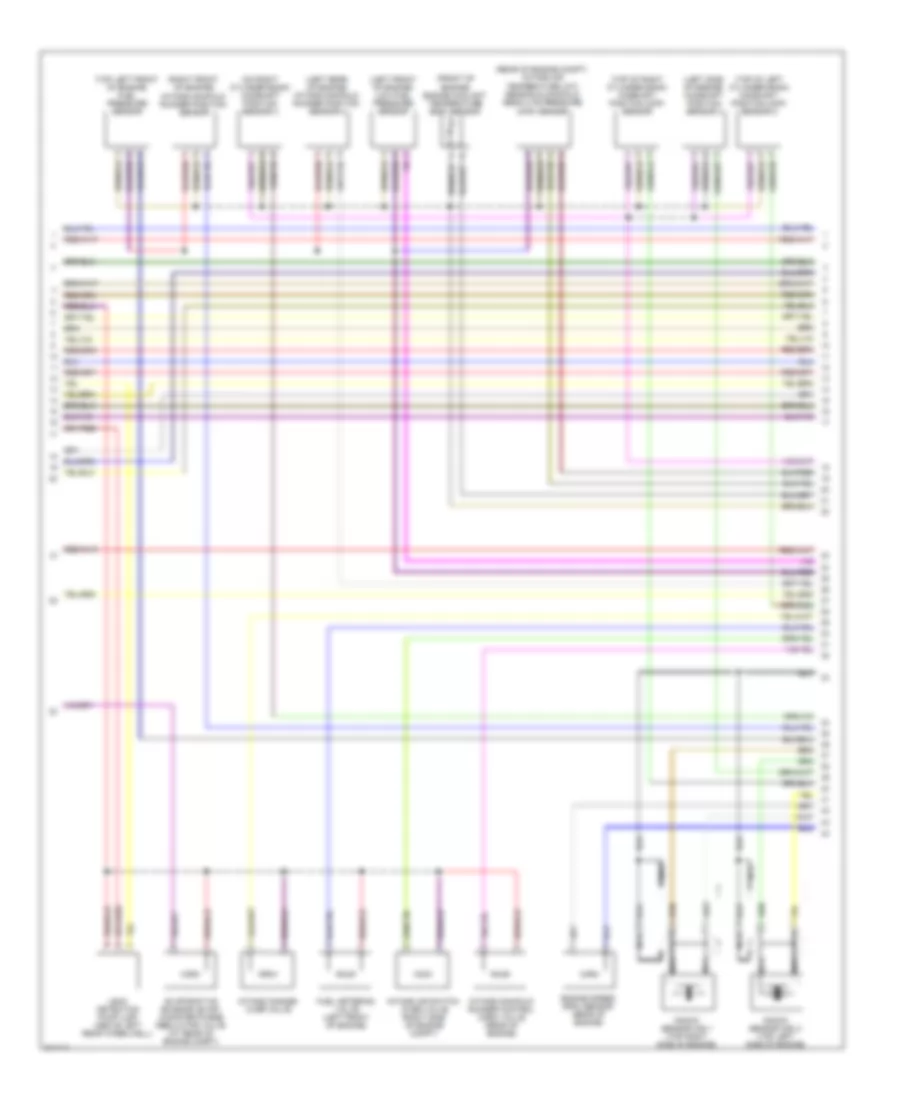
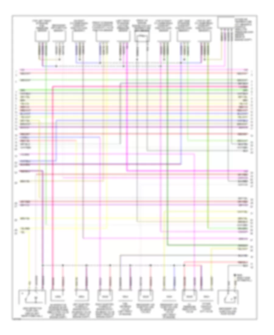
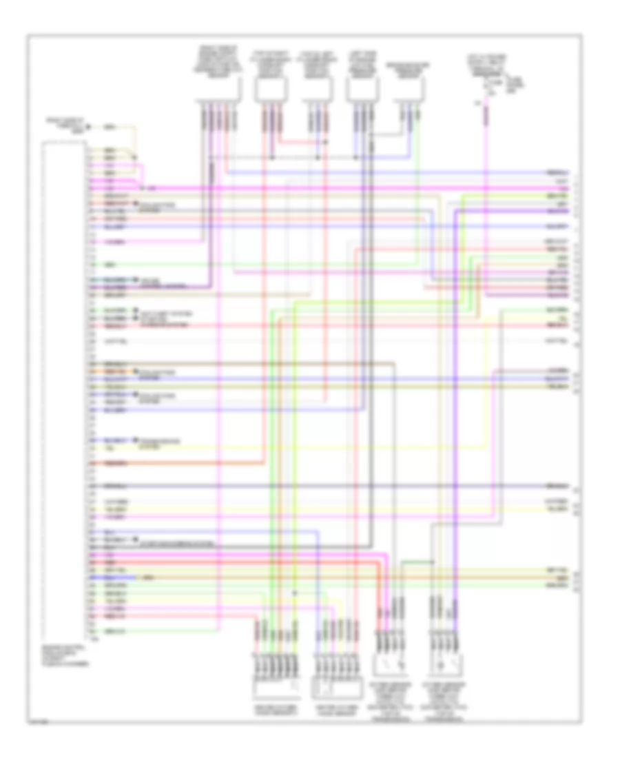
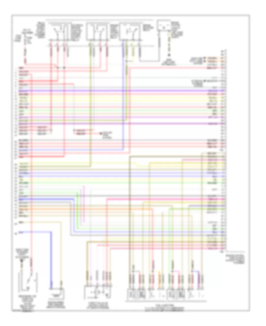
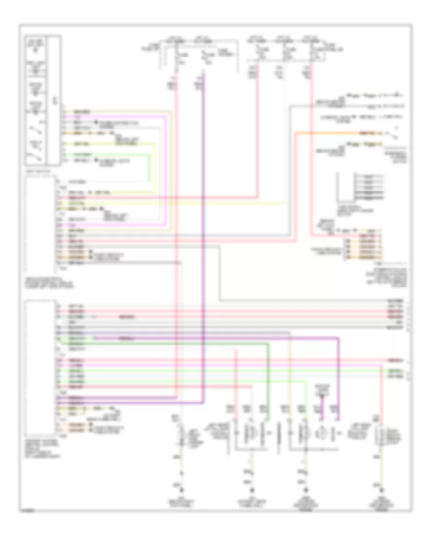
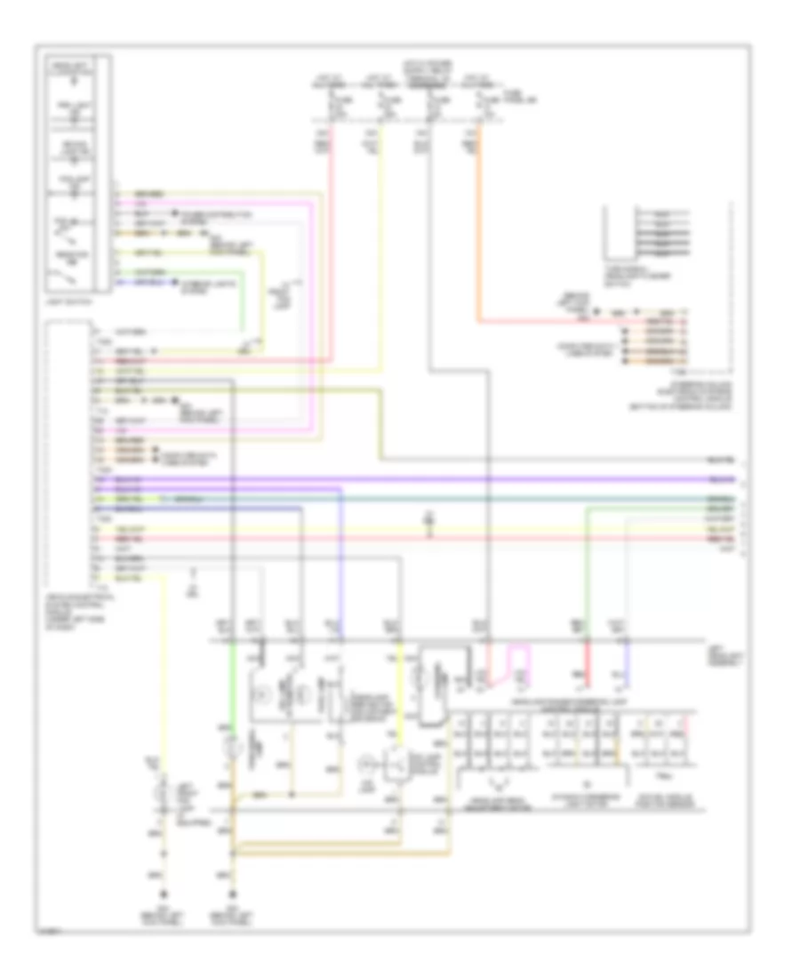
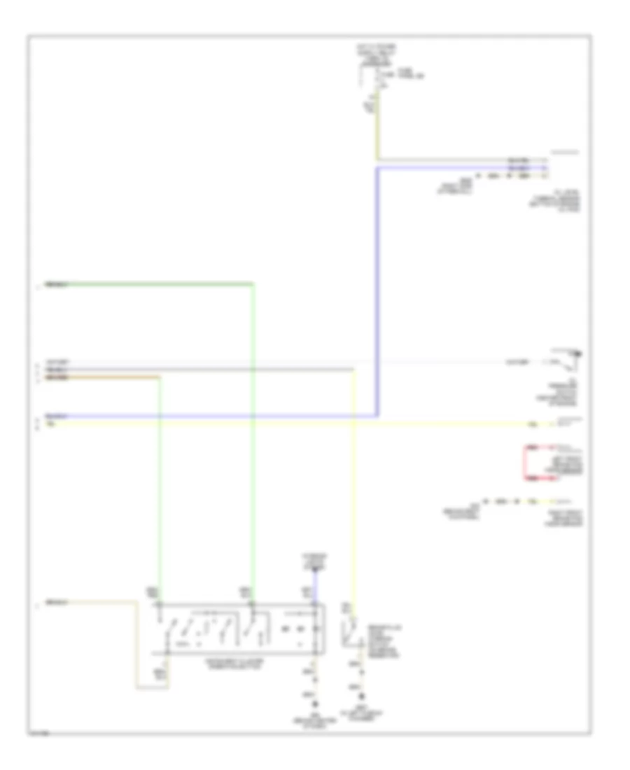
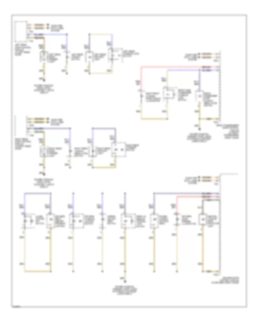
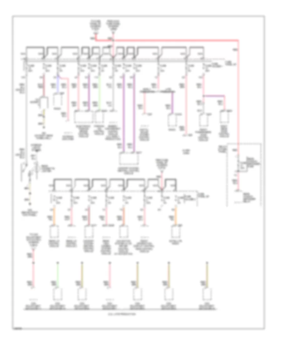
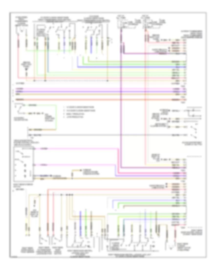
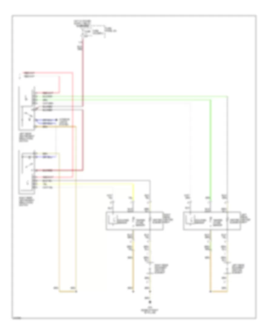
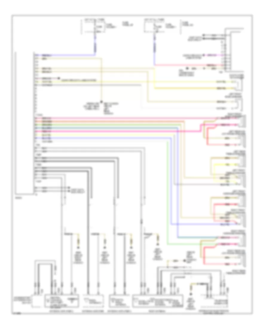
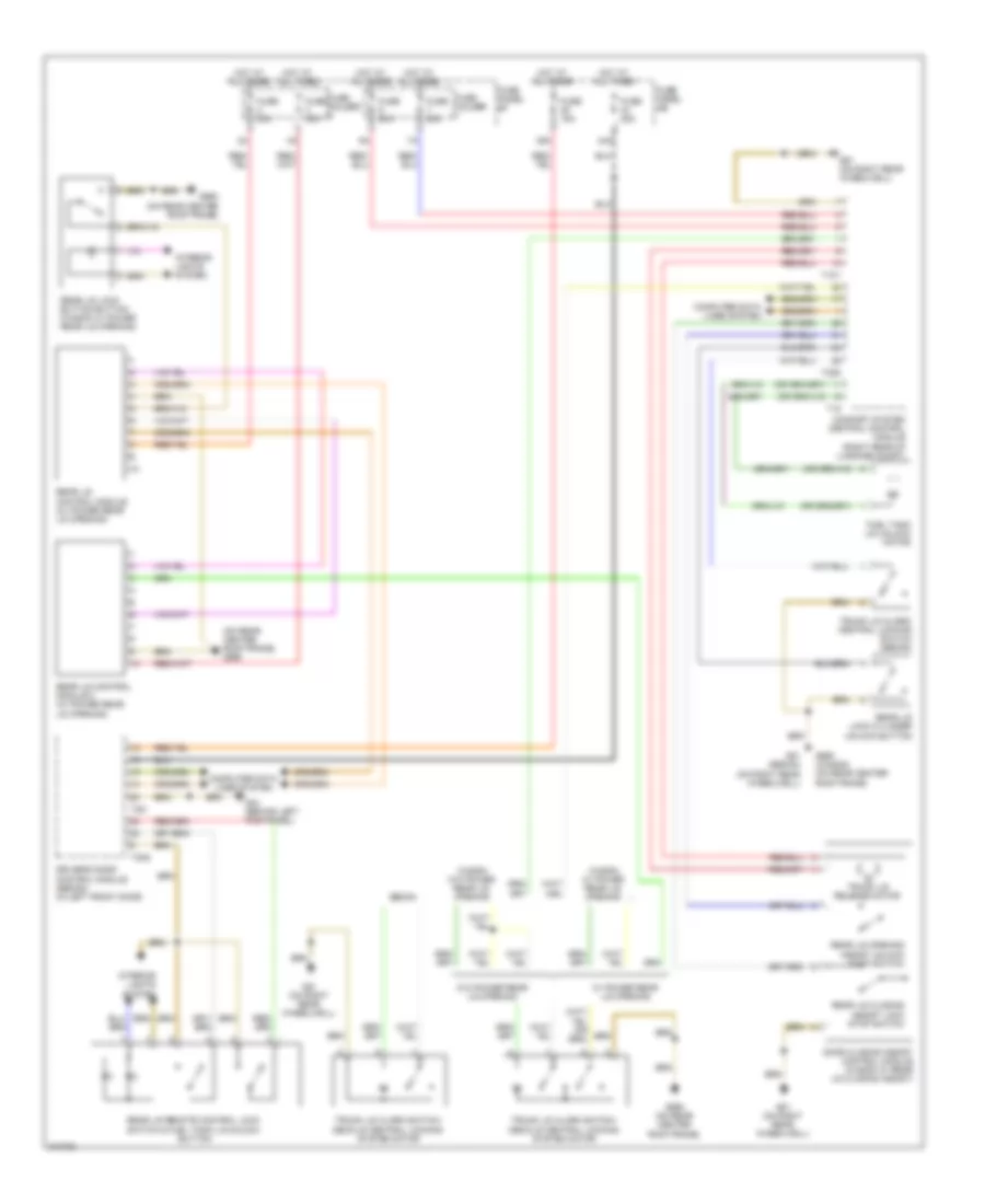
Automatic A/C Wiring Diagram (3 of 4) for Audi A6 Quattro 2009
List of elements for Automatic A/C Wiring Diagram (3 of 4) for Audi A6 Quattro 2009:
- (behind center of dash) g45
- Back pressure flap motor & position sensor
- Center air outlet sensor
- Climatronic control module
- Fresh air intake duct temperature sensor
- G45 (behind center of dash)
- Interior lights system
- Left front seat temperature sensor (w/ heated seats)
- Nca
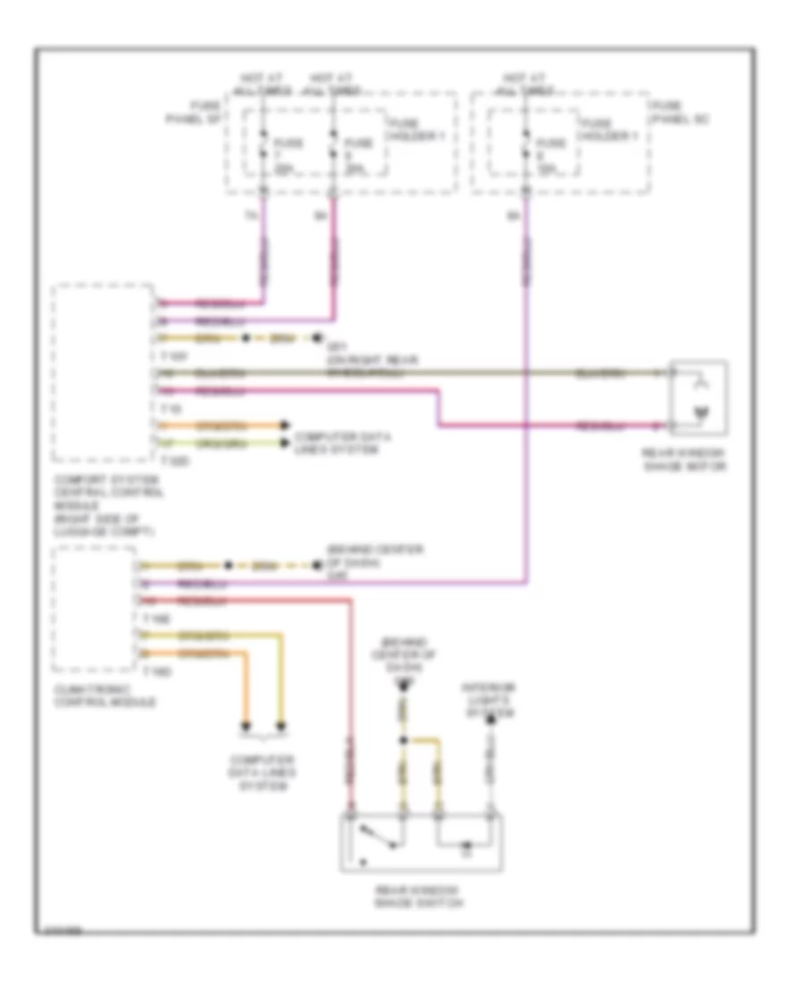
- Rear window shade switch
- Recirculation flap motor & position sensor
- Red
- Sunlight photo sensor
- T12a
- T16e
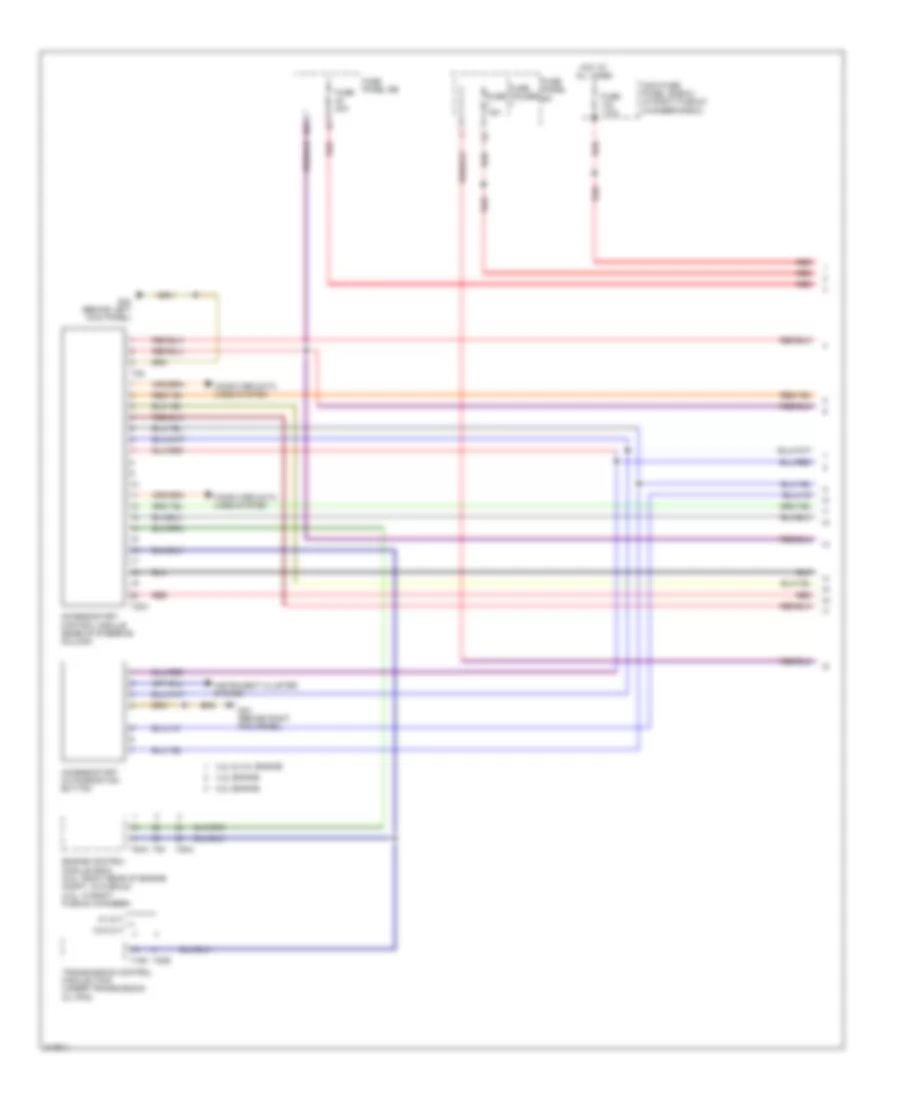
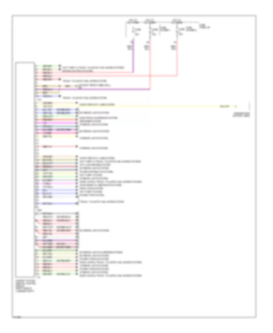
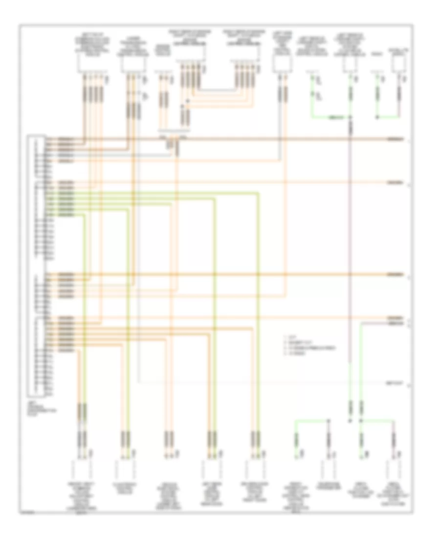
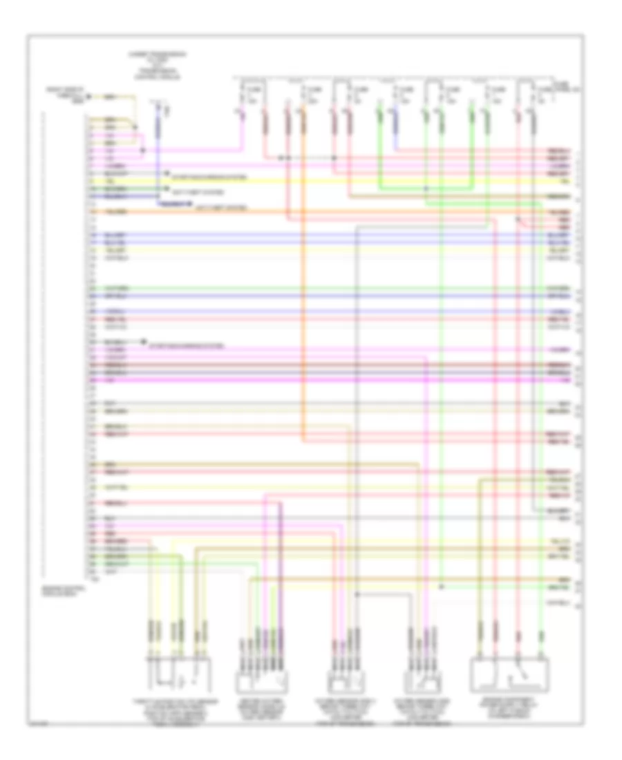
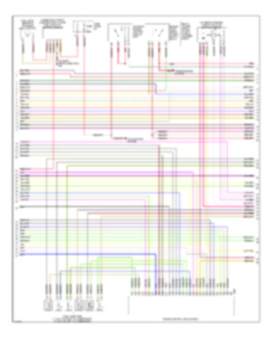
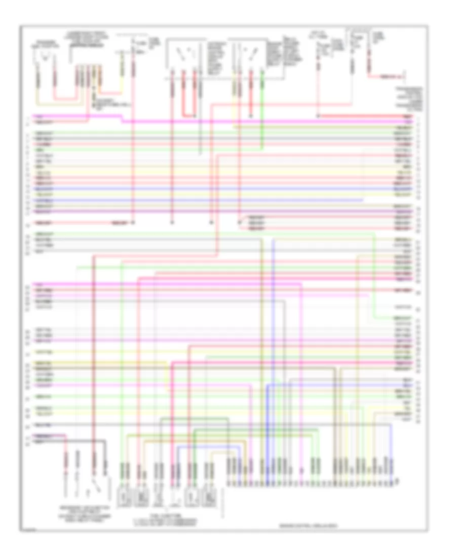
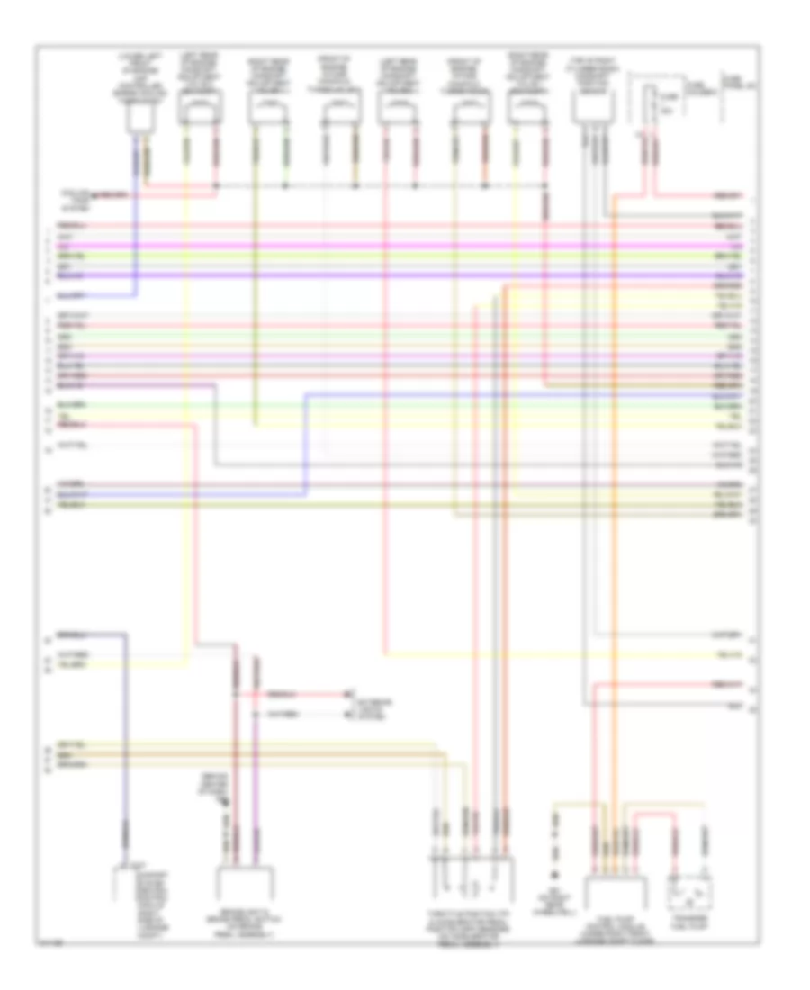
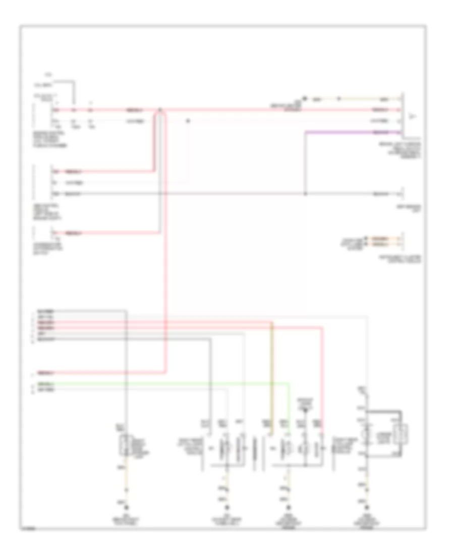
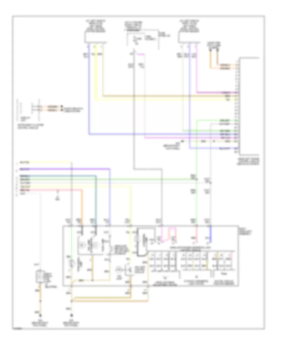
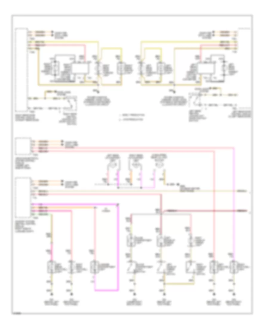
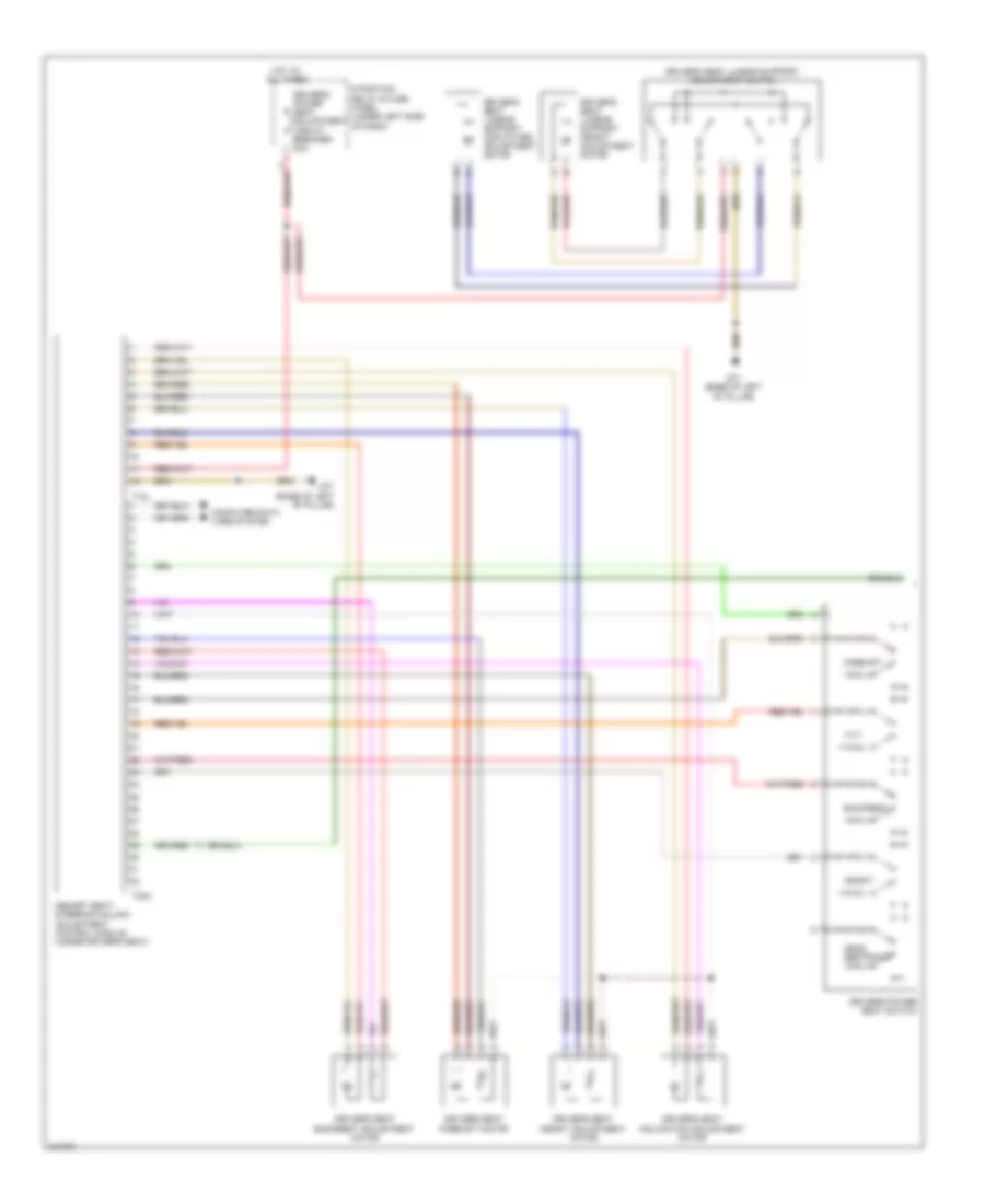
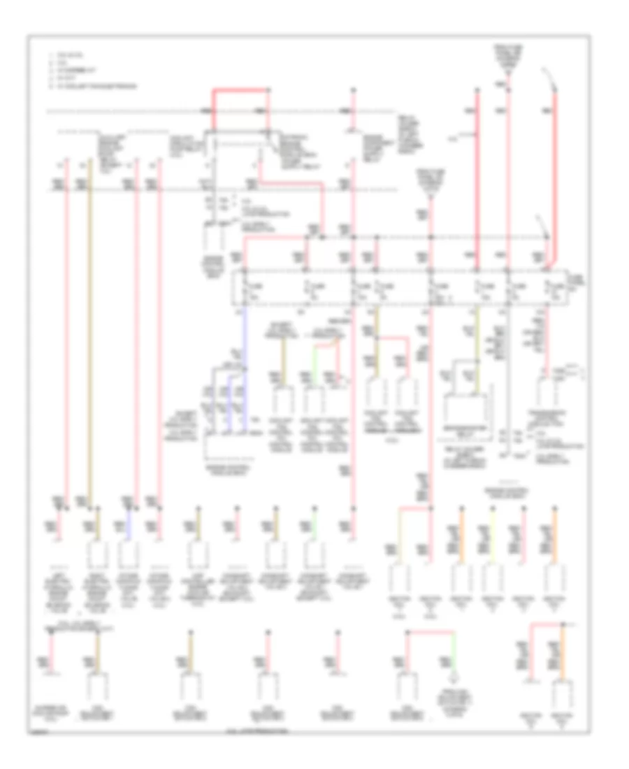
Automatic A/C Wiring Diagram (4 of 4) for Audi A6 Quattro 2009
List of elements for Automatic A/C Wiring Diagram (4 of 4) for Audi A6 Quattro 2009:
- (5.2l: rear of engine) (4.2l: in coolant pipe at rear of engine compt) engine coolant temperature (ect) sensor
- (in right plenum chamber e-box) suppressor
- 3.0l & 3.2l (cala)
- 3.2l
- 3.2l & 3.0l
- 3.2l (bkh)
- 3.2l (bkh), 4.2l & 5.2l
- 3.2l, 3.0l & 4.2l
- 4.2l
- 4.2l & 5.2l
- 5.2l
- After-run coolant pump
- Auxiliary engine coolant (ec) pump relay (3.2l, 5.2l & 3.0l) coolant circulation pump relay (4.2l)
- Coolant fan (3.0l, 3.2l (cala), 4.2l & 5.2l) (behind right side of radiator)
- Coolant fan 2 (4.2l & 5.2l) (behind left side of radiator)
- Coolant fan control module (3.0l, 3.2l (cala), 4.2l, 5.2l & 3.2l (bkh) w/ coolant fan electronics) (on coolant fan)
- Coolant fan control module (3.2l (bkh) w/ coolant fan electronics) (on coolant fan)
- Coolant fan control module 2 (4.2l & 5.2l) (on coolant fan 2)
- Engine control module (ecm) (3.2l & 3.0l)
- Engine control module (ecm) (4.2l & 5.2l) (4.2l: in right plenum chamber) (5.2l: right rear of engine compt, in plenum)
- Engine controls system
- Engine coolant temperature (ect) sensor (3.2l: front of engine)
- Fuse 10a
- Fuse 5a
- Fuse 60a
- Fuse 60a 40a
- Fuse panel sa
- G601 (3.0l)
- G614 (right side of engine compt, on chassis)
- G645 (except 3.0l) (left side of firewall)
- G646 (right side of firewall)
- Hot at all times
- Main fuse panel (e-box) (in right plenum chamber e-box)
- Nca
- Power distribution system
- Red
- Relay holder (e-box) (in left plenum chamber e-box)
- T60
- T60a
- T94
- T94a
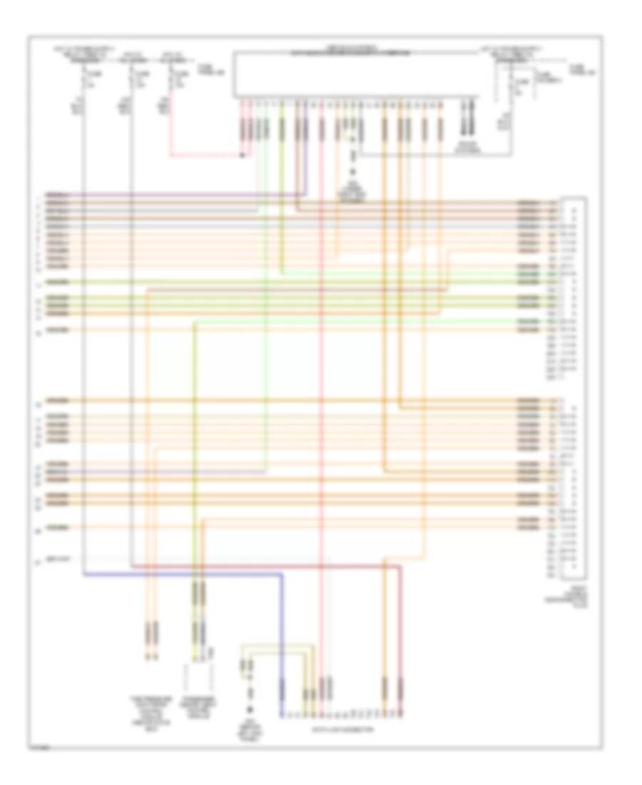
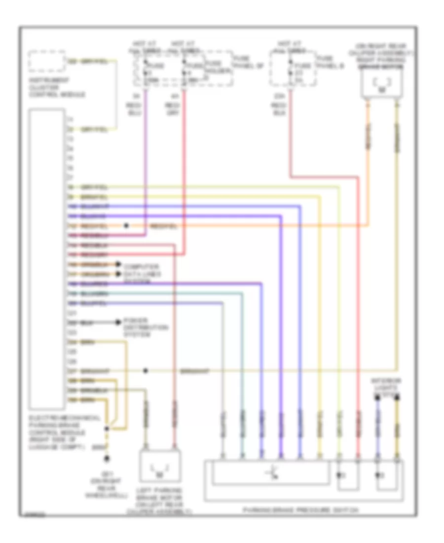
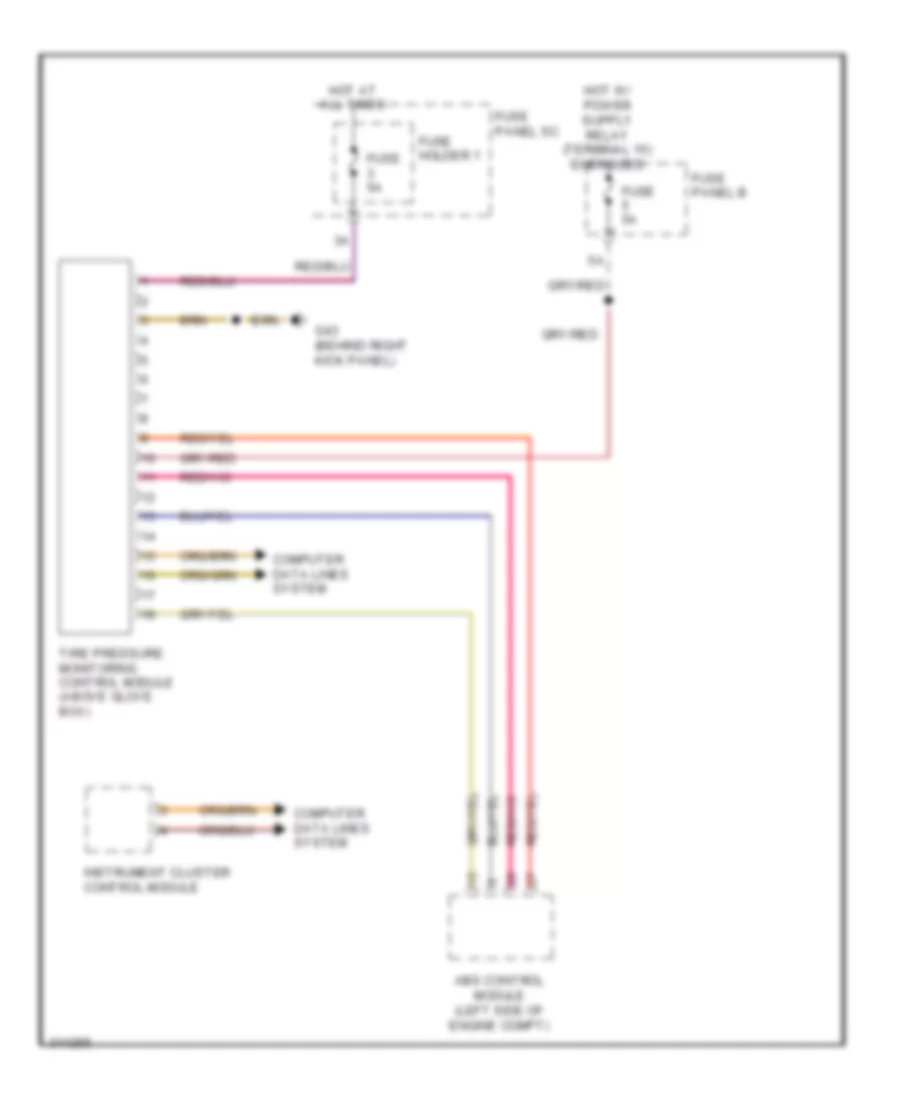
ANTI-LOCK BRAKES
Anti-lock Brakes Wiring Diagram for Audi A6 Quattro 2009
List of elements for Anti-lock Brakes Wiring Diagram for Audi A6 Quattro 2009:
- (behind center of dash) g45
- Abs control module (left side of engine compt)
- Abs control module fuse 1
- Abs return flow pump
- Abs return flow pump relay
- Abs solenoid valve relay
- Asr/esp button
- Brake light switch (on brake pedal assembly)
- Comfort system central control module (right side of luggage compt)
- Computer data lines system
- Esp sensor unit
- Exterior lights system
- Fuse 10a
- Fuse 25a
- Fuse 40a
- Fuse 5a
- Fuse panel b
- G33 (under right end of dash)
- G671 (left side of engine compt, on chassis)
- High pressure switch valve 1
- High pressure switch valve 2
- Hot at all times
- Interior lights system
- Left front abs inlet valve
- Left front abs outlet valve
- Left front abs wheel speed sensor (on left front wheel hub)
- Left front brake pressure sensor (w/ adaptive cruise control)
- Left rear abs inlet valve
- Left rear abs outlet valve
- Left rear abs wheel speed sensor (on left rear wheel hub)
- Pilot valve 1
- Pilot valve 2
- Right front abs inlet valve
- Right front abs outlet valve
- Right front abs wheel speed sensor (on right front wheel hub)
- Right front brake pressure sensor (w/ adaptive cruise control)
- Right rear abs inlet valve
- Right rear abs outlet valve
- Right rear abs wheel speed sensor (on right rear wheel hub)
- T32d
- Tire pressure monitoring control module (if equipped) (above glove box)
ANTI-THEFT
Access/Start Wiring Diagram (1 of 2) for Audi A6 Quattro 2009
List of elements for Access/Start Wiring Diagram (1 of 2) for Audi A6 Quattro 2009:
- 3.2l & 3.0l engine
- 4.2l engine
- 42a
- 5.2l engine
- Access/start authorization button
- Access/start control module (base of steering column)
- Computer data lines system
- Engine control module (ecm) (5.2l: right rear of engine compt, in plenum) (4.2l: in right plenum chamber)
- Fuse 110a
- Fuse 15a
- Fuse 30a
- Fuse holder
- Fuse panel sb
- Fuse panel sc
- G43 (behind right kick panel)
- G44 (behind left kick panel)
- Hot at all times
- Instrument cluster system
- Main fuse panel (e-box) (in right plenum chamber e-box)
- Red
- T16c
- T20e
- T20h
- T3q
- T94
- T94a
- Transmission control module (tcm) (under transmission oil pan)
- W/ cvt
- W/o cvt
Access/Start Wiring Diagram (2 of 2) for Audi A6 Quattro 2009
List of elements for Access/Start Wiring Diagram (2 of 2) for Audi A6 Quattro 2009:
- 9 position relay & fuse panel (under left side of dash)
- Access/start authorization switch
- Amplifier 2 antenna
- Door locks system
- Driver's access/start authorization antenna (in left rear door)
- Exterior lights system
- Front passenger's access/start authorization antenna (rear of luggage compt)
- G43 (behind right kick panel)
- G45 (behind center of dash)
- Interior access/ start authorization antenna 1
- Keyless access authorization antenna reader (above glove box)
- Luggage compartment access/start authorization antenna
- Nca
- Power distribution system
- Red
- Starter relay
- Starter relay 2
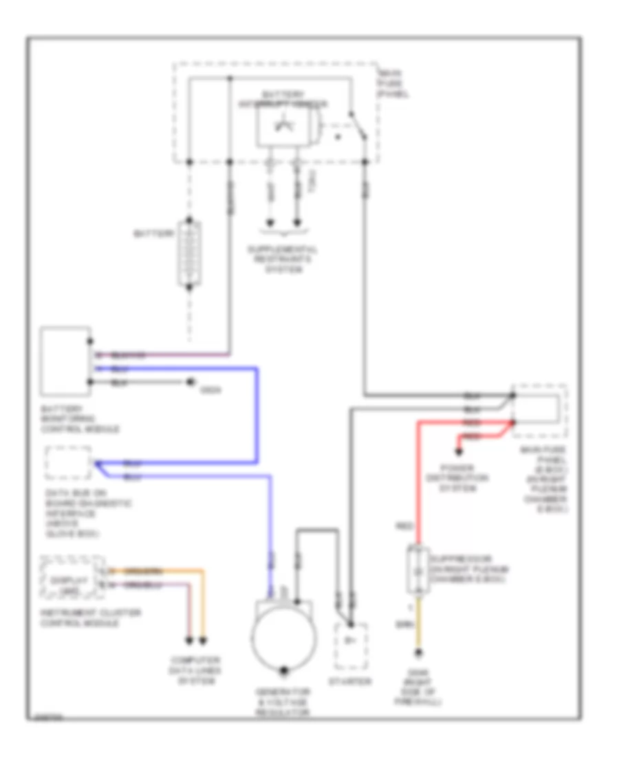
- Starting/ charging system
- T20
- T2q
- T2r
- T6n
- T8i
- Transmission system
Anti-theft Wiring Diagram (1 of 2) for Audi A6 Quattro 2009
List of elements for Anti-theft Wiring Diagram (1 of 2) for Audi A6 Quattro 2009:
- (base of left "b" pillar) g77
- (behind left kick panel) g44
- (in right plenum chamber) alarm horn
- (on rear center roof frame) (wagon) g690
- 39a
- 44a
- Alarm system off switch
- Central locking indicator lamp (safe)
- Comfort system central control module (right rear of luggage compt)
- Computer data lines system
- Driver's door central locking lock unit
- Driver's door control module (in driver's front door)
- Except late production w/o door closing assistance
- Front hood switch
- Fuse 15a
- Fuse 35a
- Fuse 5a
- Fuse holder
- Fuse panel sb
- Fuse panel sf
- G44 (behind left kick panel)
- G51 (sedan) (on right rear wheelwell)
- G607 (in left plenum chamber)
- G77 (base of left "b" pillar)
- Hot at all times
- Interior lights system
- Late production w/o door closing assistance
- Left rear door central locking lock unit
- Left rear door control module (in left rear door)
- T10y
- T20i
- T20l
- T32c
- T32d
- T32g
- Trunk lid alarm switch/decklid central locking system motor
- Vehicle electrical system control module (under left side of dash)
- W/ child safety lock
Anti-theft Wiring Diagram (2 of 2) for Audi A6 Quattro 2009
List of elements for Anti-theft Wiring Diagram (2 of 2) for Audi A6 Quattro 2009:
- (if equipped) left rear window breakage sensor
- (if equipped) rear window glass breakage sensor
- (if equipped) right rear window breakage sensor
- 10a
- Computer data lines system
- Except late production w/o door closing assistance
- Front passenger's door central locking lock unit
- Front passenger's door control module (in front passenger's door)
- Fuse 15a
- Fuse 35a
- Fuse holder
- Fuse panel sc
- Fuse panel sf
- G43 (behind right kick panel)
- G51 (on right rear wheelwell)
- G657 (above left rear window)
- G78 (base of right "b" pillar)
- Hot at all times
- Late production w/o door closing assistance
- Right rear door central locking lock unit
- Right rear door control module (in right rear door)
- T20k
- T20m
- Trunk lock alarm/central locking switch
- W/ child safety lock
BODY CONTROL MODULES
Body Control Modules Wiring Diagram (1 of 2) for Audi A6 Quattro 2009
List of elements for Body Control Modules Wiring Diagram (1 of 2) for Audi A6 Quattro 2009:
- (on right rear wheelwell) g51
- Anti-lock brakes system
- Anti-theft & trunk, tailgate, fuel doors systems
- Anti-theft system
- Comfort system central control module (right side of luggage compt)
- Computer data lines system
- Defogger system
- Door locks & trunk, tailgate, fuel doors systems
- Door locks system
- Electronic suspension system
- Engine controls system
- Exterior lights & mirrors systems
- Exterior lights system
- Fuse 20a
- Fuse 30a
- Fuse holder 1
- Fuse holder 2
- Fuse panel sf
- Garage door control head
- Hot at all times
- Interior lights system
- Power distribution system
- Power tops system
- Power windows system
- T10y
- T15
- T32d
- Trunk, tailgate, fuel doors system
Body Control Modules Wiring Diagram (2 of 2) for Audi A6 Quattro 2009
List of elements for Body Control Modules Wiring Diagram (2 of 2) for Audi A6 Quattro 2009:
- (behind center of dash) g45
- (behind left kick panel) g44
- (info not available)
- 32a
- 33a
- 34a
- Anti-theft system
- Computer data lines system
- Door locks system
- Electronic power steering system
- Exterior lights & headlights systems
- Exterior lights system
- Fuse 15a
- Fuse 25a
- Fuse 30a
- Fuse holder 1
- Fuse panel sb
- Fuse panel sc
- G43 (behind right kick panel)
- Headlights system
- Horns system
- Hot at all times
- Interior lights system
- Power tops system
- Servotronic solenoid valve
- T10
- T12
- T32c
- T40
- Valet parking lock button
- Vehicle electrical system control module (under left side of dash)
- Vehicle electrical system control module 2 (above glove box)
- Wiper/washer system
COMPUTER DATA LINES
Computer Data Lines Wiring Diagram (1 of 3) for Audi A6 Quattro 2009
List of elements for Computer Data Lines Wiring Diagram (1 of 3) for Audi A6 Quattro 2009:
- (bottom of steering column) steering column electronic systems control module
- (left rear of luggage compt) digital sound system control module
- (left rear of luggage compt) navigation system w/ cd drive control module
- (left side of engine compt) abs control module
- (right rear of engine compt, in plenum) engine control module i
- (right rear of engine compt, in plenum) engine control module ii
- (under transmission oil pan) transmission control module
- 10h
- 10l
- 11h
- 11l
- 12h
- 12l
- 13h
- 13l
- 14h
- 14l
- 15h
- 15l
- 16h
- 16l
- 17h
- 17l
- 18h
- 18l
- 19h
- 19l
- 20h
- 20l
- 21h
- 21l
- 22h
- 22l
- 23h
- 23l
- 3.2l
- 5.2l
- Climatronic control module
- Cvt
- Driver's door control module (in left front door)
- Engine control module
- Except cvt
- Front information display control head control module (above glove box)
- Left can-bus disconnection plug
- Left rear door control module (in left rear door)
- Media player position 1/cd changer
- Media player position 2/ cd changer unit & mini disk player
- Memory seat/ steering column adjustment control module (under driver's seat)
- Radio
- Satellite radio
- T16b
- T16c
- T16d
- T20e
- T20g
- T20i
- T20l
- T32a
- T32c
- T32f
- T54
- T8k
- T8m
- T8n
- T8o
- T8p
- T94a
- T94b
- Telephone transceiver
- Vehicle electrical system control module (under left side of dash)
- W/ bose & premium radio
- W/ radio
Computer Data Lines Wiring Diagram (2 of 3) for Audi A6 Quattro 2009
List of elements for Computer Data Lines Wiring Diagram (2 of 3) for Audi A6 Quattro 2009:
- (above glove box) headlamp range control module
- (behind glove box) level control system control module
- (right rear of luggage compt) electronic- mechanical parking brake control module
- (under front of center console) air bag control module
- (w/ adaptive cruise control) distance regulation control module
- Access/ start control module (base of steering column)
- Comfort system central control module (right rear of luggage compt)
- Direction stabilization assistance control module
- Instrument cluster control module
- Parking aid control module (sedan: right side of luggage compt) (avant: right rear floor of luggage compt)
- Passenger door control module (in right front door)
- Rear view camera system control module (if equipped)
- T16a
- T20h
- T20k
- T26
- T30
- T32
- T32d
- T40
- T54b
- Towing recognition control module (right side of luggage compt)
- Vehicle electrical system control module 2 (above glove box)
Computer Data Lines Wiring Diagram (3 of 3) for Audi A6 Quattro 2009
List of elements for Computer Data Lines Wiring Diagram (3 of 3) for Audi A6 Quattro 2009:
- (above glove box) data bus on board diagnostic interface
- 10h
- 10l
- 11h
- 11l
- 12a
- 12h
- 12l
- 13h
- 13l
- 14h
- 14l
- 15a
- 15h
- 15l
- 16h
- 16l
- 17h
- 17l
- 18h
- 18l
- 19h
- 19l
- 20h
- 20l
- 21h
- 21l
- 22h
- 22l
- 23h
- 23l
- Data link connector
- Fuse 10a
- Fuse 5a
- Fuse holder 2
- Fuse panel sb
- Fuse panel sc
- G33 (under right end of dash)
- G44 (behind left kick panel)
- Hot at all times
- Nca
- Passenger memory seat control module
- Right can-bus disconnection plug
- Sound systems
- T32b
- Tire pressure monitoring control module (above glove box)
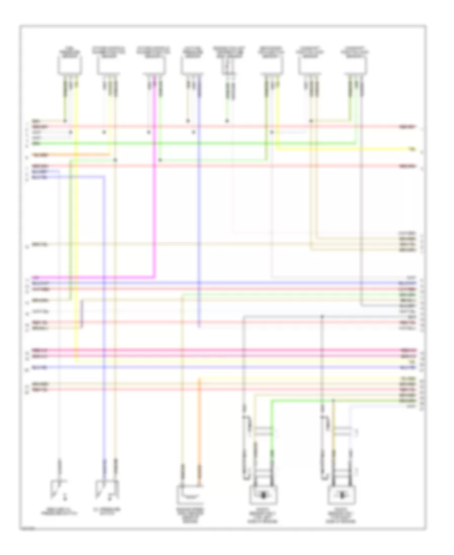
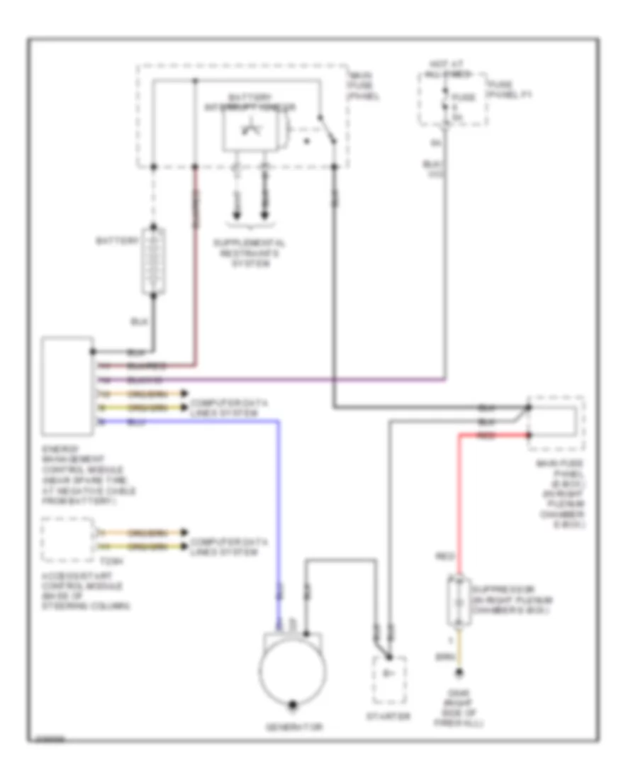
COOLING FAN
Cooling Fan Wiring Diagram for Audi A6 Quattro 2009
List of elements for Cooling Fan Wiring Diagram for Audi A6 Quattro 2009:
- (5.2l: rear of engine) (4.2l: in coolant pipe at rear of engine compt) engine coolant temperature (ect) sensor
- (in right plenum chamber e-box) suppressor
- 3.0l & 3.2l (cala)
- 3.2l
- 3.2l & 3.0l
- 3.2l (bkh)
- 3.2l (bkh), 4.2l & 5.2l
- 3.2l, 3.0l & 4.2l
- 4.2l
- 4.2l & 5.2l
- 5.2l
- After-run coolant pump
- Auxiliary engine coolant (ec) pump relay (3.2l, 5.2l & 3.0l) coolant circulation pump relay (4.2l)
- Coolant fan (3.0l, 3.2l (cala), 4.2l & 5.2l) (behind right side of radiator)
- Coolant fan 2 (4.2l & 5.2l) (behind left side of radiator)
- Coolant fan control module (3.0l, 3.2l (cala), 4.2l, 5.2l & 3.2l (bkh) w/ coolant fan electronics) (on coolant fan)
- Coolant fan control module (3.2l (bkh) w/ coolant fan electronics) (on coolant fan)
- Coolant fan control module 2 (4.2l & 5.2l) (on coolant fan 2)
- Engine control module (ecm) (3.2l & 3.0l)
- Engine control module (ecm) (4.2l & 5.2l) (4.2l: in right plenum chamber) (5.2l: right rear of engine compt, in plenum)
- Engine controls system
- Engine coolant temperature (ect) sensor (3.2l: front of engine)
- Fuse 10a
- Fuse 5a
- Fuse 60a
- Fuse 60a 40a
- Fuse panel sa
- G601 (3.0l)
- G614 (right side of engine compt, on chassis)
- G645 (except 3.0l) (left side of firewall)
- G646 (right side of firewall)
- Hot at all times
- Main fuse panel (e-box) (in right plenum chamber e-box)
- Nca
- Power distribution system
- Red
- Relay holder (e-box) (in left plenum chamber e-box)
- T60
- T60a
- T94
- T94a
CRUISE CONTROL
3.0L
3.0L, Cruise Control Wiring Diagram, CCAA for Audi A6 Quattro 2009
List of elements for 3.0L, Cruise Control Wiring Diagram, CCAA for Audi A6 Quattro 2009:
- (behind left kick panel) g44
- (bottom of steering column) steering column electronic systems control module
- (under transmission
- 10a
- 13a
- 3.0l
- 3.0l & 3.2l (bkh)
- 3.2l (bkh)
- 3.2l (fsi)
- 4.2l
- Abs control module (left side of engine compt)
- Anti-lock brakes system
- Brake light & brake pedal switch (on brake pedal assembly)
- Computer
- Computer data lines system
- Control module
- Cruise control switch
- Data lines
- Distance regulation control module
- Distance regulation sensor heater
- Engine control module (ecm) (4.2l: in right plenum chamber)
- Fuse 10a
- Fuse 5a
- Fuse panel b
- G45 (behind center of dash)
- G671 (left side of engine compt, on chassis)
- Hot at all times
- Nca
- Oil pan)
- System
- T16b
- T16c
- T60
- T60a
- T94
- T94a
- Throttle position (tp) sensor & accelerator pedal position sensor 2 (top of accelerator pedal assembly)
- Throttle valve control module (except 3.0l: at rear of engine)
- Transmission
3.2L
3.2L, Cruise Control Wiring Diagram, BKH for Audi A6 Quattro 2009
List of elements for 3.2L, Cruise Control Wiring Diagram, BKH for Audi A6 Quattro 2009:
- (behind left kick panel) g44
- (bottom of steering column) steering column electronic systems control module
- (under transmission
- 10a
- 13a
- 3.0l
- 3.0l & 3.2l (bkh)
- 3.2l (bkh)
- 3.2l (fsi)
- 4.2l
- Abs control module (left side of engine compt)
- Anti-lock brakes system
- Brake light & brake pedal switch (on brake pedal assembly)
- Computer
- Computer data lines system
- Control module
- Cruise control switch
- Data lines
- Distance regulation control module
- Distance regulation sensor heater
- Engine control module (ecm) (4.2l: in right plenum chamber)
- Fuse 10a
- Fuse 5a
- Fuse panel b
- G45 (behind center of dash)
- G671 (left side of engine compt, on chassis)
- Hot at all times
- Nca
- Oil pan)
- System
- T16b
- T16c
- T60
- T60a
- T94
- T94a
- Throttle position (tp) sensor & accelerator pedal position sensor 2 (top of accelerator pedal assembly)
- Throttle valve control module (except 3.0l: at rear of engine)
- Transmission
3.2L, Cruise Control Wiring Diagram, CALA for Audi A6 Quattro 2009
List of elements for 3.2L, Cruise Control Wiring Diagram, CALA for Audi A6 Quattro 2009:
- (behind left kick panel) g44
- (bottom of steering column) steering column electronic systems control module
- (under transmission
- 10a
- 13a
- 3.0l
- 3.0l & 3.2l (bkh)
- 3.2l (bkh)
- 3.2l (fsi)
- 4.2l
- Abs control module (left side of engine compt)
- Anti-lock brakes system
- Brake light & brake pedal switch (on brake pedal assembly)
- Computer
- Computer data lines system
- Control module
- Cruise control switch
- Data lines
- Distance regulation control module
- Distance regulation sensor heater
- Engine control module (ecm) (4.2l: in right plenum chamber)
- Fuse 10a
- Fuse 5a
- Fuse panel b
- G45 (behind center of dash)
- G671 (left side of engine compt, on chassis)
- Hot at all times
- Nca
- Oil pan)
- System
- T16b
- T16c
- T60
- T60a
- T94
- T94a
- Throttle position (tp) sensor & accelerator pedal position sensor 2 (top of accelerator pedal assembly)
- Throttle valve control module (except 3.0l: at rear of engine)
- Transmission
4.2L
4.2L, Cruise Control Wiring Diagram, BVJ for Audi A6 Quattro 2009
List of elements for 4.2L, Cruise Control Wiring Diagram, BVJ for Audi A6 Quattro 2009:
- (behind left kick panel) g44
- (bottom of steering column) steering column electronic systems control module
- (under transmission
- 10a
- 13a
- 3.0l
- 3.0l & 3.2l (bkh)
- 3.2l (bkh)
- 3.2l (fsi)
- 4.2l
- Abs control module (left side of engine compt)
- Anti-lock brakes system
- Brake light & brake pedal switch (on brake pedal assembly)
- Computer
- Computer data lines system
- Control module
- Cruise control switch
- Data lines
- Distance regulation control module
- Distance regulation sensor heater
- Engine control module (ecm) (4.2l: in right plenum chamber)
- Fuse 10a
- Fuse 5a
- Fuse panel b
- G45 (behind center of dash)
- G671 (left side of engine compt, on chassis)
- Hot at all times
- Nca
- Oil pan)
- System
- T16b
- T16c
- T60
- T60a
- T94
- T94a
- Throttle position (tp) sensor & accelerator pedal position sensor 2 (top of accelerator pedal assembly)
- Throttle valve control module (except 3.0l: at rear of engine)
- Transmission
DEFOGGERS
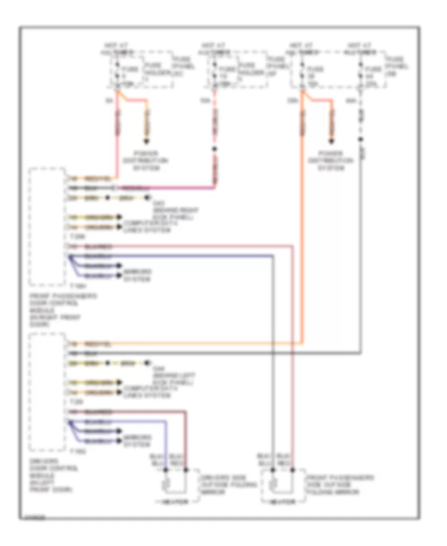
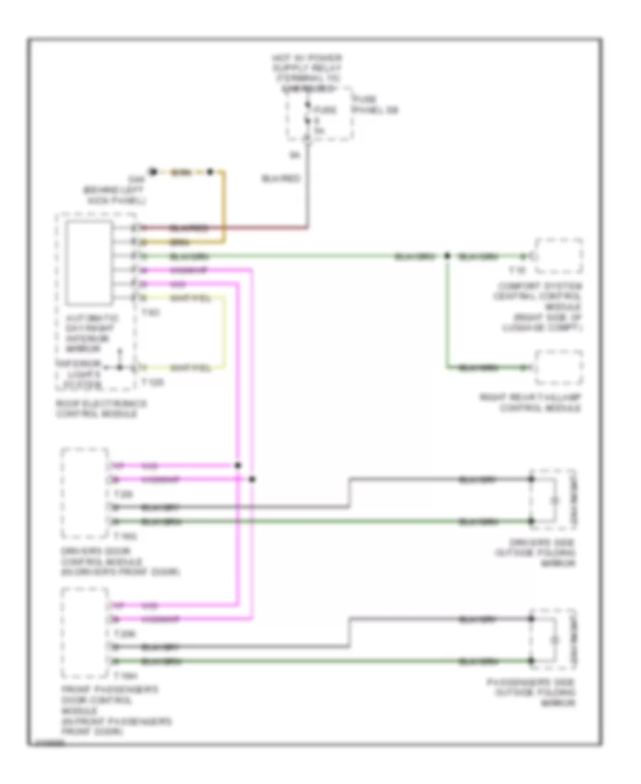
Heated Mirrors Wiring Diagram for Audi A6 Quattro 2009
List of elements for Heated Mirrors Wiring Diagram for Audi A6 Quattro 2009:
- 10a
- 39a
- 44a
- Computer data lines system
- Driver's door control module (in left front door)
- Driver's side outside folding mirror
- Front passenger's door control module (in right front door)
- Front passenger's side outside folding mirror
- Fuse 15a
- Fuse 35a
- Fuse holder
- Fuse panel sb
- Fuse panel sc
- Fuse panel sf
- G43 (behind right kick panel)
- G44 (behind left kick panel)
- Heater
- Hot at all times
- Mirrors system
- Power distribution system
- T16g
- T16h
- T20i
- T20k
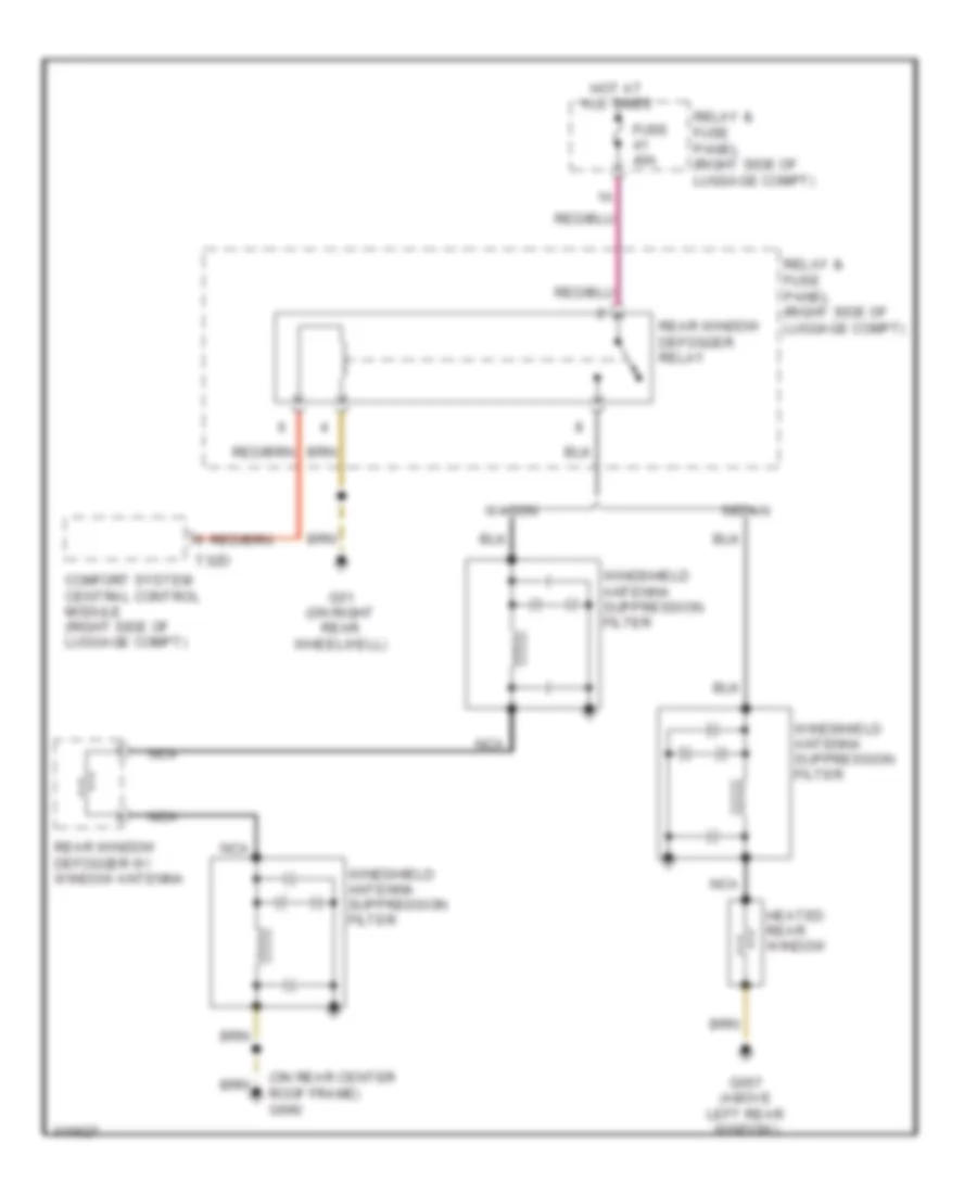
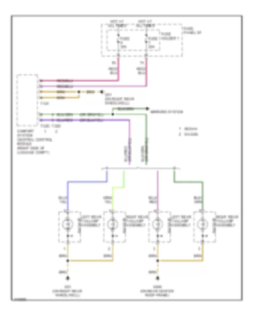
Rear Defogger Wiring Diagram for Audi A6 Quattro 2009
List of elements for Rear Defogger Wiring Diagram for Audi A6 Quattro 2009:
- (on rear center roof frame) g690
- Comfort system central control module (right side of luggage compt)
- Fuse 40a
- G51 (on right rear wheelwell)
- G657 (above left rear window)
- Heated rear window
- Hot at all times
- Nca
- Rear window defogger relay
- Rear window defogger w/ window antenna
- Relay & fuse panel (right side of luggage compt)
- Sedan
- T32d
- Wagon
- Windshield antenna suppression filter
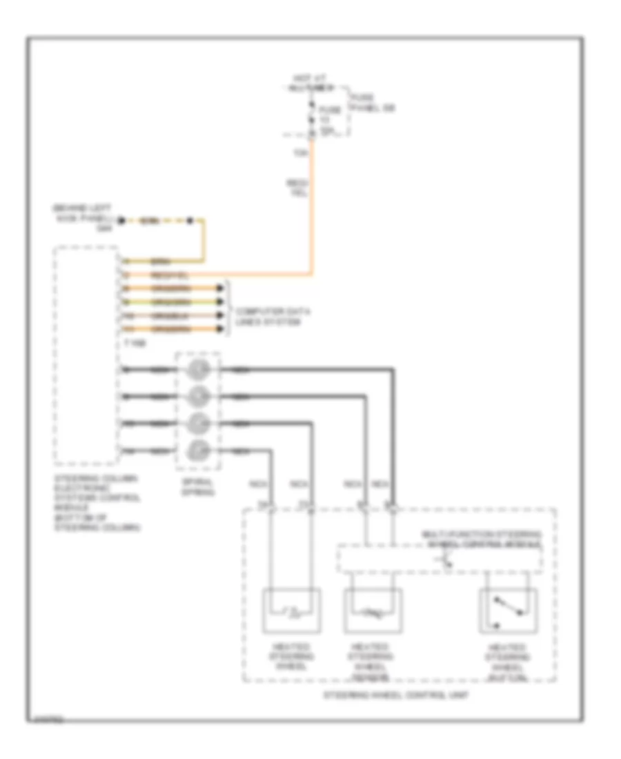
ELECTRONIC POWER STEERING
Electronic Power Steering Wiring Diagram for Audi A6 Quattro 2009
List of elements for Electronic Power Steering Wiring Diagram for Audi A6 Quattro 2009:
- (behind left kick panel)
- (under left side of dash) vehicle electrical system control module
- 13a
- Air bag spiral spring/ return spring (w/ slip ring) (in steering column)
- Axial adjustment motor
- Axial adjustment sensor
- Computer data lines system
- Cruise control switch
- Cruise control system
- Directional stabilization assistance button (if equipped)
- Driver's side air bag igniter
- Driver's side air bag igniter 2
- Fuse 10a
- Fuse panel b
- G44
- Heated steering wheel
- Heated steering wheel button (if equipped)
- Heated steering wheel sensor
- Hot at all times
- Left multi- function buttons
- Multi-function steering wheel control module
- Nca
- Power distribution system
- Right multi-function buttons
- Shorting contact
- Signal horn activation
- Spiral spring
- Steering angle sensor
- Steering column adjustment assembly
- Steering column adjustment switch
- Steering column electronic systems control module (bottom of steering column)
- Steering wheel control unit
- Steering wheel vibration motor (w/ directional stabilization assistance)
- T12
- T16b
- T32c
- T4g
- Tiptronic downshift button
- Tiptronic upshift button
- Turn signal/ headlamp flasher switch
- Vertical adjustment motor
- Vertical adjustment sensor
- Windshield wiper/ washer switch
ELECTRONIC SUSPENSION
Electronic Suspension Wiring Diagram (1 of 2) for Audi A6 Quattro 2009
List of elements for Electronic Suspension Wiring Diagram (1 of 2) for Audi A6 Quattro 2009:
- (behind right kick panel) g43
- Comfort system central control module (right side of luggage compt)
- Computer data lines system
- Fuse 15a
- Fuse 5a
- Fuse holder 2
- Fuse panel sc
- Hot at all times
- Left front dampening adjustment valve
- Left front level control system sensor (at left side of front axle)
- Left rear dampening adjustment valve
- Left rear level control system sensor (at left side of rear axle)
- Level control system control module (behind glove box)
- Pnk
- Red
- Right front dampening adjustment valve
- Right front level control system sensor
- Right rear dampening adjustment valve
- Right rear level control system sensor
- T12k
- T15a
- T32d
Electronic Suspension Wiring Diagram (2 of 2) for Audi A6 Quattro 2009
List of elements for Electronic Suspension Wiring Diagram (2 of 2) for Audi A6 Quattro 2009:
- 4-position relay & fuse panel (in right plenum chamber e-box)
- Accumulator valves
- Compressor motor
- Fuse 40a
- G614 (right side of engine compt, on chassis)
- Hot at all times
- Left front body acceleration sensor
- Level control pressure sensor
- Level control system assembly
- Level control system compressor relay
- Level control system control module (behind glove box)
- Pump temperature sensor
- Rear body acceleration sensor
- Red
- Right front body acceleration sensor
- Self-leveling system fuse
- Solenoid
- Suppression strut valves
- T18
- T6m
- Valve body
ENGINE PERFORMANCE
3.0L
3.0L, Engine Performance Wiring Diagram (1 of 6) for Audi A6 Quattro 2009
List of elements for 3.0L, Engine Performance Wiring Diagram (1 of 6) for Audi A6 Quattro 2009:
- (right side of firewall) g646
- (under transmission oil pan) (a/t) transmission control module
- Anti-theft system
- Engine control module (ecm)
- Fuse 15a
- Fuse 20a
- Fuse 5a
- Fuse panel sa
- Heated oxygen sensor (ho2s) 2 & oxygen sensor (o2s) heater 2
- Nca
- Oxygen sensor (02s) 2 behind three way catalytic (twc) converter (top of transmission)
- Oxygen sensor (o2s) behind three way catalytic (twc) converter (top of transmission)
- Red
- Starting/charging system
- T16c
- T94
- Throttle position (tp) sensor & accelerator pedal position (app) sensor 2 (top of accelerator pedal assembly)
3.0L, Engine Performance Wiring Diagram (2 of 6) for Audi A6 Quattro 2009
List of elements for 3.0L, Engine Performance Wiring Diagram (2 of 6) for Audi A6 Quattro 2009:
- (above left rear wheel well) leak detection pump (ldp)
- (left front of engine) secondary air injection (air) solenoid valve
- (rear of engine) intake manifold runner control (imrc) valve
- Camshaft adjustment valve 1
- Camshaft adjustment valve 2
- Charge air cooling pump
- Evaporative emission (evap) canister purge regulator valve
- Fuel metering valve
- G601
- Left electro- hydraulic engine mount solenoid valve (left front of engine compartment)
- Oil pressure regulation valve
- Red
- Right electro- hydraulic engine mount solenoid valve (right front of engine compartment)
- Secondary air injection (air) solenoid valve 2
3.0L, Engine Performance Wiring Diagram (3 of 6) for Audi A6 Quattro 2009
List of elements for 3.0L, Engine Performance Wiring Diagram (3 of 6) for Audi A6 Quattro 2009:
- (behind right side of radiator) coolant fan
- (on coolant fan) coolant fan control (fc) control module
- Comfort system central control module (right side of luggage compt)
- Computer data lines system
- Cruise control system
- Engine control module
- Engine coolant level/ temperature warning lamp
- Fuel gauge
- Fuse 50a
- Fuse 5a
- Fuse panel sb
- G614 (right side of engine compt, on chassis)
- G646 (right side of firewall)
- Heated oxygen sensor (ho2s) & oxygen sensor (o2s) heater
- Hot at all times
- Instrument cluster control module
- Nca
- Oil level thermal sensor (bottom of engine oil pan)
- Oil pressure warning lamp
- Secondary air injection (air) pump fuse
- Starting/charging system
- T10y
- T94
3.0L, Engine Performance Wiring Diagram (4 of 6) for Audi A6 Quattro 2009
List of elements for 3.0L, Engine Performance Wiring Diagram (4 of 6) for Audi A6 Quattro 2009:
- (on right plenum chamber e-box relay panel) secondary air injection (air) pump relay
- Anti-lock brakes system
- Brake pedal switch (on brake pedal assembly)
- Control valve control module
- Engine coolant level (ecl) warning switch (in engine coolant reservoir)
- Esp sensor unit
- Fuel level sender, fuel level sensor 2 & transfer fuel pump (fp)
- Fuel pump (fp) control module (under right front luggage compt floor)
- G45 (behind center of dash)
- G646 (right side of firewall)
- Intake air temperature (iat) sensor & charge air pressure sensor
- Intake air temperature (iat) sensor & manifold absolute pressure (map) sensor
- Intake air temperature (iat) sensor 2 & charge air pressure sensor 2
- Secondary air injection (air) pump motor
3.0L, Engine Performance Wiring Diagram (5 of 6) for Audi A6 Quattro 2009
List of elements for 3.0L, Engine Performance Wiring Diagram (5 of 6) for Audi A6 Quattro 2009:
- Camshaft position (cmp) sensor
- Camshaft position (cmp) sensor 2
- Engine coolant temperature (ect) sensor
- Engine speed (rpm) sensor (rear of engine)
- Fuel pressure sensor
- Intake manifold runner position sensor
- Intake manifold runner position sensor 2
- Knock sensor (ks) 1 (top right side of engine)
- Knock sensor (ks) 2 (top left side of engine)
- Low fuel pressure sensor
- Nca
- Oil pressure switch
- Reduced oil pressure switch
- Secondary air injection sensor 1
3.0L, Engine Performance Wiring Diagram (6 of 6) for Audi A6 Quattro 2009
List of elements for 3.0L, Engine Performance Wiring Diagram (6 of 6) for Audi A6 Quattro 2009:
- Engine control module (ecm)
- Fuel injectors
- Fuse 20a
- Fuse 40a
- Fuse panel sc
- G601
- G645 (left side of firewall)
- G646 (right side of firewall)
- Hot at all times
- Ignition coils w/ power output stage
- Main fuse panel (e-box) (in right plenum chamber e-box)
- Nca
- T60
- Throttle valve control module
- To spark plug
3.2L
3.2L, Engine Performance Wiring Diagram, Early Production (1 of 4) for Audi A6 Quattro 2009
List of elements for 3.2L, Engine Performance Wiring Diagram, Early Production (1 of 4) for Audi A6 Quattro 2009:
- (behind center of dash) g45
- (right side of firewall) g646
- Anti-lock brakes system
- Anti-theft system transmission system
- Brake light & brake pedal switch (on brake pedal assembly)
- Comfort system central control module (right side of luggage compt)
- Cooling fans system
- Cruise control system
- Engine control module (ecm)
- Exterior lights system
- Fuse 15a
- Fuse 5a
- Fuse panel sa
- Fuse panel sb
- Heated oxygen sensor (ho2s)
- Heated oxygen sensor (ho2s) 2
- Heated oxygen sensor (o2s) 2 behind three way catalytic converter (twc)
- Heated oxygen sensor (o2s) behind three way catalytic converter (twc)
- Intake manifold tuning (imt) valve position sensor (front of engine)
- Nca
- Red
- Starting/ charging system
- T10y
- T94a
- Throttle position (tp) sensor & accelerator pedal position (app) sensor 2 (top of accelerator pedal assembly)
- Transmissions system
3.2L, Engine Performance Wiring Diagram, Early Production (2 of 4) for Audi A6 Quattro 2009
List of elements for 3.2L, Engine Performance Wiring Diagram, Early Production (2 of 4) for Audi A6 Quattro 2009:
- (front of engine) engine coolant temperature (ect) sensor
- (left front of engine) low fuel pressure sensor
- (left rear of engine) intake manifold runner position sensor 2
- (left side of engine) camshaft position sensor 4
- (on right cylinder bank) camshaft position sensor 3
- (rear of engine compt) intake air temperature (iat) sensor & manifold absolute pressure (map) sensor
- (right front of engine) intake manifold runner position sensor
- (top left front of engine) fuel pressure sensor
- (top of left cylinder bank) camshaft position (cmp) sensor 2
- (top of right cylinder bank) camshaft position (cmp) sensor
- Engine speed (rpm) sensor (rear of engine)
- Evaporative emission (evap) canister purge regulator valve (at rear of engine compt)
- Fuel metering valve (left front of engine)
- Intake air switch -over valve (right side of engine compt)
- Intake change- over valve
- Intake manifold runner control (imrc) valve (rear of engine)
- Knock sensor (ks) 1 (top right side of engine)
- Knock sensor (ks) 2 (top left side of engine)
- Leak detection pump (ldp) (above left rear wheelwell)
- Nca
3.2L, Engine Performance Wiring Diagram, Early Production (3 of 4) for Audi A6 Quattro 2009
List of elements for 3.2L, Engine Performance Wiring Diagram, Early Production (3 of 4) for Audi A6 Quattro 2009:
- (at rear of engine) throttle valve control module
- (on right rear wheelwell) g51
- (under right front luggage compt floor) fuel pump (fp) control module
- Cooling fans system
- Engine control module (ecm)
- Fuel injectors (1, 2 & 3: on right cylinder bank) (4, 5 & 6: on left cylinder bank)
- Fuel level sensor & transfer fuel pump (fp)
- Fuse 30a
- Fuse panel sc
- Motronic engine control module (ecm)
- Red
- Relay holder (e-box) (in left plenum chamber e-box)
- T60a
- Transmissions system
3.2L, Engine Performance Wiring Diagram, Early Production (4 of 4) for Audi A6 Quattro 2009
List of elements for 3.2L, Engine Performance Wiring Diagram, Early Production (4 of 4) for Audi A6 Quattro 2009:
- (left rear of engine) camshaft adjustment valve 2
- (left rear of engine) camshaft adjustment valve 2 (exhaust)
- (right rear of engine) camshaft adjustment valve 1
- (right rear of engine) camshaft adjustment valve 1 (exhaust)
- Coil 1
- Coil 2
- Coil 3
- Coil 4
- Coil 5
- Coil 6
- Computer data lines system
- Cooling fans system
- Engine control module (ecm)
- Fuse 10a
- Fuse 15a
- Fuse 20a
- Fuse 5a
- Fuse panel sa
- G601
- G645 (left side of firewall)
- G646 (right side of firewall)
- Ignition coils w/ power outlet stage (1, 2 & 3 : top of right cylinder bank) (4, 5 & 6 : left cylinder bank)
- Left electro- hydraulic engine mount solenoid (w/ 6-speed a/t) (left front of engine compt)
- Nca
- Partial
- Red
- Right electro- hydraulic engine mount solenoid (w/ 6-speed a/t) (right front of engine compt)
- T60a
- T94a
- To spark plug
3.2L, Engine Performance Wiring Diagram, Late Production (1 of 5) for Audi A6 Quattro 2009
List of elements for 3.2L, Engine Performance Wiring Diagram, Late Production (1 of 5) for Audi A6 Quattro 2009:
- (on brake pedal assembly) brake light switch & brake pedal switch
- (right side of firewall) g646
- Air conditioning system
- Anti-lock brakes system
- Anti-theft system
- Comfort system central control module (right side of luggage compt)
- Cooling fans system
- Engine control module (ecm)
- Fuse 15a
- Fuse 5a
- Fuse panel sa
- Fuse panel sb
- G45 (behind center of dash)
- Heated oxygen sensor (h02s) & oxygen sensor (02s) heater
- Heated oxygen sensor (h02s) 2 & oxygen sensor (02s) heater 2
- Nca
- Oil pressure switch (center front of engine)
- Oxygen sensor (o2s) & oxygen sensor (o2s) heater 1 (oxygen sensor (o2s): top of transmission)
- Oxygen sensor (o2s) 2 & oxygen sensor (o2s) heater 2 (oxygen sensor (o2s) 2: top of transmission)
- Red
- Reduced oil pressure switch
- Starting/ charging system
- T10y
- T94
- Throttle position (tp) sensor & accelerator pedal position (app) sensors (top of accelerator pedal assembly)
- Transmissions system
3.2L, Engine Performance Wiring Diagram, Late Production (2 of 5) for Audi A6 Quattro 2009
List of elements for 3.2L, Engine Performance Wiring Diagram, Late Production (2 of 5) for Audi A6 Quattro 2009:
- (front of engine) engine coolant temperature (ect) sensor
- (front of engine) intake manifold tuning (imt) valve position sensor
- (left front of engine) low fuel pressure sensor
- (left side of engine) camshaft position (cmp) sensor 4
- (on right cylinder bank) camshaft position (cmp) sensor 3
- (top left front of engine) fuel pressure sensor
- (top of left cylinder bank) camshaft position (cmp) sensor 2
- (top of right cylinder bank) camshaft position (cmp) sensor
- Evaporative emission (evap) canister purge regulator valve (at rear of engine compt)
- Fuel metering valve (left front of engine)
- G646 (right side of firewall)
- Intake air temperature (iat) sensor & manifold absolute pressure (map) sensor (rear of engine compt)
- Intake manifold tuning (imt) valve
- Leak detection pump (ldp) (above left rear wheelwell)
- Left electro- hydraulic engine mount solenoid valve (left front of engine compt)
- Oil pressure regulation valve
- Right electro- hydraulic engine mount solenoid valve (right front of engine compt)
- Secondary air injection (air) pump motor
- Secondary air injection (air) solenoid valve (left front of engine)
- Secondary air injection (air) solenoid valve 2
- Secondary air injection sensor 1
3.2L, Engine Performance Wiring Diagram, Late Production (3 of 5) for Audi A6 Quattro 2009
List of elements for 3.2L, Engine Performance Wiring Diagram, Late Production (3 of 5) for Audi A6 Quattro 2009:
- (on right rear wheelwell) g51
- (under right front luggage compt floor) fuel pump (fp) control module
- 10a
- Engine control module (ecm)
- Fuel injectors (1, 2 & 3: on right cylinder bank) (4, 5 & 6: on left cylinder bank)
- Fuse 10a
- Fuse 110a
- Fuse 30a
- Fuse panel sa
- Fuse panel sc
- Hot at all times
- Main fuse panel
- Red
- Relay holder (e-box) (in left plenum chamber e-box)
- Secondary air injection (air) pump relay (on right plenum chamber e-box relay panel)
- T60
- Transfer fuel pump (fp)
- Transmission control module (tcm) (under transmission oil pan)
3.2L, Engine Performance Wiring Diagram, Late Production (4 of 5) for Audi A6 Quattro 2009
List of elements for 3.2L, Engine Performance Wiring Diagram, Late Production (4 of 5) for Audi A6 Quattro 2009:
- (left rear of engine) camshaft adjustment valve 2
- (left rear of engine) camshaft adjustment valve 2 (exhaust)
- (right rear of engine) camshaft adjustment valve 1
- (right rear of engine) camshaft adjustment valve 1 (exhaust)
- Cam adjustment actuator 1
- Cam adjustment actuator 10
- Cam adjustment actuator 11
- Cam adjustment actuator 12
- Cam adjustment actuator 2
- Cam adjustment actuator 3
- Cam adjustment actuator 4
- Cam adjustment actuator 5
- Cam adjustment actuator 6
- Cam adjustment actuator 7
- Cam adjustment actuator 8
- Cam adjustment actuator 9
- Engine speed (rpm) sensor (rear of engine)
- Knock sensor (ks) 1 (top right side of engine)
- Knock sensor (ks) 2 (top left side of engine)
- Nca
- Red
3.2L, Engine Performance Wiring Diagram, Late Production (5 of 5) for Audi A6 Quattro 2009
List of elements for 3.2L, Engine Performance Wiring Diagram, Late Production (5 of 5) for Audi A6 Quattro 2009:
- 4-position relay & fuse panel (in right plenum (in right plenum chamber e-box)
- Computer data lines system
- Cruise control system
- Engine control module (ecm)
- Fuse 15a
- Fuse 30a
- Fuse 50a
- Fuse 5a
- Fuse panel sa
- G601
- G645 (left side of firewall)
- G646 (right side of firewall)
- Hot at all times
- Ignition coils w/power output stage (1, 2 & 3: top of right cylinder bank) (4, 5 & 6: top of left cylinder bank)
- Nca
- Red
- Secondary air pump fuse
- Starting/charging system
- T60
- T94
- Throttle valve control module (at rear of engine)
- To spark plug
4.2L
4.2L, Engine Performance Wiring Diagram (1 of 5) for Audi A6 Quattro 2009
List of elements for 4.2L, Engine Performance Wiring Diagram (1 of 5) for Audi A6 Quattro 2009:
- (left side of engine) low fuel pressure sensor
- (right side of engine compt) mass air flow (maf)/intake air temperature (iat) sensor
- (right side of firewall) g646
- (top of left cylinder bank) camshaft position sensor 2
- (top of right cylinder bank) camshaft position sensor 4
- Anti-theft system starting/ charging system
- Brake booster pressure sensor
- Cooling fans system
- Cruise control system
- Engine control module (ecm) (in right plenum chamber)
- Fuse 5a
- Fuse panel sb
- Heated oxygen (ho2s) sensor
- Heated oxygen (ho2s) sensor 2
- Nca
- Oxygen sensor (o2s) behind three way catalytic converter (twc) (top of transmission)
- Red
- Starting/charging system
- T94
- Transmissions system
4.2L, Engine Performance Wiring Diagram (2 of 5) for Audi A6 Quattro 2009
List of elements for 4.2L, Engine Performance Wiring Diagram (2 of 5) for Audi A6 Quattro 2009:
- (behind center of dash) g45
- (front of engine) intake manifold tuning valve
- (front of engine) intake manifold tuning valve 2
- (left rear of engine) camshaft adjustment valve 2
- (left rear of engine) camshaft adjustment valve 2 (exhaust)
- (lower left front of engine) map controlled engine cooling thermostat
- (right rear of engine) camshaft adjustment valve 1
- (right rear of engine) camshaft adjustment valve 1 (exhaust)
- (top of right cylinder bank) camshaft position sensor
- Brakelight & brake pedal switch (on brake pedal assembly)
- Comfort system central control module (right side of luggage compt)
- Cooling fans system
- Exterior lights system
- Fuel pump control module (under right front luggage compt floor)
- Fuse 30a
- Fuse holder 2
- Fuse panel sc
- G51 (on right rear wheelwell)
- T10y
- Throttle position (tp) & accelerator pedal position (app) sensors (on accelerator pedal assembly)
- Transfer fuel pump
4.2L, Engine Performance Wiring Diagram (3 of 5) for Audi A6 Quattro 2009
List of elements for 4.2L, Engine Performance Wiring Diagram (3 of 5) for Audi A6 Quattro 2009:
- (front of engine) intake manifold runner position sensor
- (front of engine) intake manifold runner position sensor 2
- (in coolant pipe at rear of engine compt) engine coolant temperature (ect) sensor
- (on right cylinder bank) camshaft position sensor 3
- (top right front of engine) fuel pressure sensor
- Engine control module (ecm) (in right plenum chamber)
- Fuse 10a
- Fuse 15a
- Fuse 30a
- Fuse 5a
- Fuse panel sa
- Knock sensor (ks) 1 (top right front of engine)
- Knock sensor (ks) 2 (top right side of engine)
- Knock sensor 3 (top left front of engine)
- Knock sensor 4 (top left rear of engine)
- Nca
- Red
- T60
4.2L, Engine Performance Wiring Diagram (4 of 5) for Audi A6 Quattro 2009
List of elements for 4.2L, Engine Performance Wiring Diagram (4 of 5) for Audi A6 Quattro 2009:
- (above left rear wheelwell) leak detection pump (ldp)
- (left front of engine compt) left electro- hydraulic engine mount solenoid valve
- (right front of engine compt) right electro- hydraulic engine mount solenoid valve
- (right side of engine compt) intake air switch- over valve
- (top left side of engine) fuel metering valve 2
- (top right side of engine) fuel metering valve
- (under transmission oil pan) (w/ 6 speed) transmission control module
- 4-position relay & fuse panel (in right plenum chamber e-box)
- Coil 1
- Coil 2
- Coil 3
- Coil 4
- Coil 5
- Coil 6
- Coil 7
- Coil 8
- Evaporative emission canister purge regulator valve
- Fuse 50a
- G600
- G601
- G645 (left side of firewall)
- G646 (right side of firewall)
- Hot at all times
- Ignition coils w/ power output stage (1, 2, 3 & 4: top of right cylinder bank) (5, 6, 7 & 8: top of left cylinder bank)
- Nca
- Red
- Secondary air injection (air) pump relay
- Secondary air pump fuse
- To spark plug
4.2L, Engine Performance Wiring Diagram (5 of 5) for Audi A6 Quattro 2009
List of elements for 4.2L, Engine Performance Wiring Diagram (5 of 5) for Audi A6 Quattro 2009:
- (right side of engine compt, on chassis) g614
- Brake booster relay
- Brake system vacuum pump (left side of engine compt)
- Computer data lines system
- Cooling fans system
- Engine control module (ecm) (in right plenum chamber)
- Engine speed (rpm) sensor (rear of engine)
- Fuel injectors (1, 2, 3 & 4 on right cylinder bank) (5, 6, 7 & 8 on left cylinder bank)
- Fuse 110a
- G645 (left side of firewall)
- Hot at all times
- Main fuse panel
- Red
- Relay holder (e-box) (in left plenum chamber e-box)
- Secondary air injection (air) pump motor (below right headlight assembly)
- Starting/ charging system
- T60
- T94
- Throttle valve control module (at rear of engine)
EXTERIOR LIGHTS
Backup Lamps Wiring Diagram for Audi A6 Quattro 2009
List of elements for Backup Lamps Wiring Diagram for Audi A6 Quattro 2009:
- Backup
- Comfort system central control module (right side of luggage compt)
- Fuse 20a
- Fuse 30a
- Fuse holder 1
- Fuse panel sf
- G51 (on right rear wheelwell)
- G690 (on rear center roof frame)
- Hot at all times
- Left rear taillamp assembly
- Mirrors system
- Right rear taillamp assembly
- Sedan
- T10y
- T32d
- Wagon
Exterior Lamps Wiring Diagram, Sedan (1 of 2) for Audi A6 Quattro 2009
List of elements for Exterior Lamps Wiring Diagram, Sedan (1 of 2) for Audi A6 Quattro 2009:
- (behind left kick panel) g44
- 13a
- 32a
- 33a
- Backup lamp
- Backup lamps circuit
- Brake/ tail lamp
- Brake/ taillight lamp 2
- Brake/ turn signal lamp
- Brake/ turn signal/ tail lamp
- Brake/ turn signal/ taillamp
- Comfort system central control module (right side of of luggage compt)
- Computer data lines system
- Emergency flasher switch
- Fog lamp ind
- Fog lp sw
- Fuse 10a
- Fuse 20a
- Fuse 25a
- Fuse 30a
- Fuse holder 1
- Fuse panel sb
- Fuse panel sf
- G43 (behind right kick panel)
- G44 (behind left kick panel)
- G45 (behind center of dash)
- G51 (on right rear wheelwell)
- G690 (on rear center roof frame)
- Hdlamp sw light
- High- mount brake light
- Hot at all times
- Interior lights system
- Left front side marker lamp
- Left rear lid taillamp control module
- Left rear taillamp control module
- Light switch
- Nca
- Power distribution system
- Prk lamp light
- Rear fog lamp
- Rear fog lp sw
- Rear side marker lamp
- Rear turn signal lamp
- Rr fog light
- Steering column electronic systems control module (bottom of steering column)
- T10y
- T12
- T15
- T16b
- T32c
- T32d
- Turn signal/ headlamp flasher switch
- Vehicle electrical system control module (under left side of dash)
Exterior Lamps Wiring Diagram, Sedan (2 of 2) for Audi A6 Quattro 2009
List of elements for Exterior Lamps Wiring Diagram, Sedan (2 of 2) for Audi A6 Quattro 2009:
- 3.0l & 3.2l (cala)
- 3.2l (bkh)
- 4.2l
- 5.2l
- Abs control module (left side of engine compt)
- Access/start authorization switch
- Automatic high beam control module
- Backup lamp
- Backup lamps circuit
- Brake light & brake pedal switch (on brake pedal assembly)
- Brake/ tail lamp
- Brake/ taillight lamp 2
- Brake/ turn signal lamp
- Brake/ turn signal/ tail lamp
- Brake/ turn signal/ taillamp
- Computer data lines system
- Engine control module (ecm) (4.2l: in right plenum chamber) (5.2l: right rear of engine compartment, in plenum)
- Esp sensor unit
- Front interior light assembly
- G43 (behind right kick panel)
- G45 (behind center of dash)
- G51 (on right rear wheelwell)
- Instrument cluster control module
- License plate lights
- Nca
- Rear fog lamp
- Rear side marker lamp
- Rear turn signal lamp
- Right front side marker lamp
- Right rear lid taillamp control module
- Right rear taillamp control module
- T60
- T8i
- T94
- T94a
Exterior Lamps Wiring Diagram, Wagon (1 of 2) for Audi A6 Quattro 2009
List of elements for Exterior Lamps Wiring Diagram, Wagon (1 of 2) for Audi A6 Quattro 2009:
- (behind left kick panel) g44
- 13a
- 32a
- 33a
- Backup
- Backup lamps circuit
- Brake/tail
- Comfort system central control module (right side of of luggage compt)
- Computer data lines system
- Emergency flasher switch
- Fog
- Fog lp sw
- Fr fog light
- Fuse 10a
- Fuse 20a
- Fuse 25a
- Fuse 30a
- Fuse holder 1
- Fuse panel sb
- Fuse panel sf
- G43 (behind right kick panel)
- G44 (behind left kick panel)
- G45 (behind center of dash)
- G51 (on right rear wheelwell)
- G690 (on rear center roof frame)
- Hdlamp sw light
- High- mount brake light
- Hot at all times
- Interior lights system
- Left front side marker lamp
- Left rear lid taillamp control module
- Left rear taillamp control module
- Light switch
- Nca
- Power distribution system
- Prk lamp light
- Rr fog light
- Side marker
- Steering column electronic systems control module (bottom of steering column)
- T10y
- T12
- T15
- T16b
- T32c
- T32d
- Tail
- Turn signal/ headlamp flasher switch
- Turn/stop
- Vehicle electrical system control module (under left side of dash)
Exterior Lamps Wiring Diagram, Wagon (2 of 2) for Audi A6 Quattro 2009
List of elements for Exterior Lamps Wiring Diagram, Wagon (2 of 2) for Audi A6 Quattro 2009:
- 3.0l & 3.2l (cala)
- 3.2l (bkh)
- 4.2l
- Abs control module (left side of engine compt)
- Access/start authorization switch
- Backup
- Backup lamps circuit
- Brake light & brake pedal switch (on brake pedal assembly)
- Brake/tail
- Computer data lines system
- Engine control module (ecm) (4.2l: in right plenum chamber)
- Esp sensor unit
- Fog
- G43 (behind right kick panel)
- G45 (behind center of dash)
- G51 (on right rear wheelwell)
- G690 (on rear center roof frame)
- Instrument cluster control module
- License plate lights
- Nca
- Right front side marker lamp
- Right rear lid taillamp control module
- Right rear taillamp control module
- Side marker
- T8i
- T94
- T94a
- Tail
- Turn/stop
GROUND DISTRIBUTION
Ground Distribution Wiring Diagram (1 of 3) for Audi A6 Quattro 2009
List of elements for Ground Distribution Wiring Diagram (1 of 3) for Audi A6 Quattro 2009:
- Abs control module & distance regulation control module
- Antenna amplifier 3, antenna amplifier 2 (sedan) & antenna amplifier (wagon)
- Battery monitoring control module
- Brake system vacuum pump (4.2l), oil level thermal sensor (4.2l & 5.2l), intake flap motor (5.2l), ignition coil 4 to 6 w/ power output stage (3.0l & 3.2l), transmission control module after run coolant pump (3.2l & 5.2l), ignition coil 6 to 10 w/ power output stage (5.2l) a/c compressor regulator valve (4.2l & 5.2l) & ignition coil 5 to 8 w/ power output stage (4.2l)
- Brake system vacuum pump (5.2l), transmission control module oil level thermal sensor, ignition coil 1 to 4 w/ power output stage (4.2l), ignition coil 1 to 3 w/ power output stage (3.0l & 3.2l), secondary air injection pump motor (3.0l &3.2l late), engine control module ignition coil 1 to 5 w/ power output stage (5.2l), engine control module 2 (5.2l) & variable intake manifold runner motor (5.2l)
- G13 (right chassis, forward of front axle)
- G18 (right front of engine block)
- G614 (right side of engine compt, on chassis)
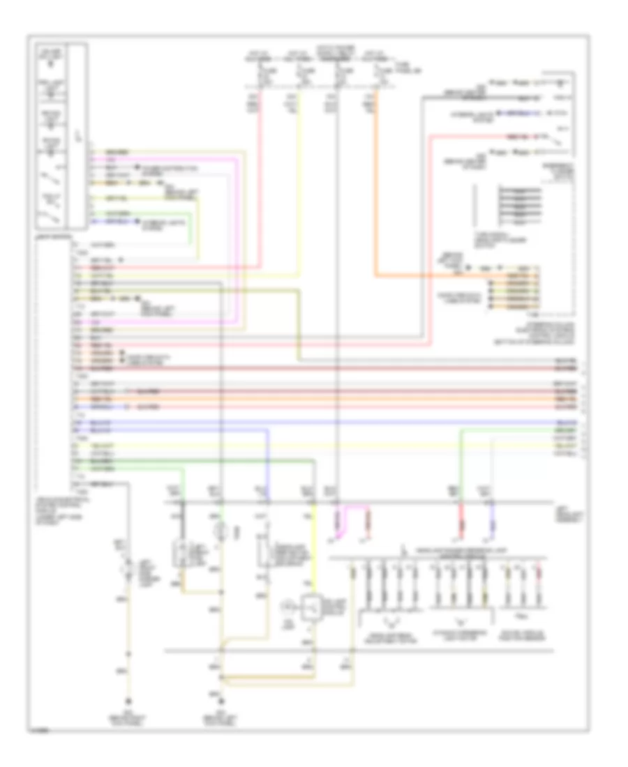
- G624
- G645 (left side of firewall)
- G646 (right side of firewall)
- G647 (5.2l) (left side of firewall)
- G657 (above left rear window)
- G659 (above right rear window)
- G671 (left side of engine compt, on chassis)
- G690 (on rear center roof frame)
- License plate light, windshield antenna suppression filter, high-mount brake light, rear lid central locking system motor, rear lid lock cylinder unlock button, left rear taillamp control module, right rear taillamp control module & rear window wiper motor
- Motor for compressor level control system, secondary air injection pump motor (4.2l), coolant fan control module & cooling fan control module 2 (4.2l & 5.2l)
- Radio telephone navigation system antenna & antenna amplifier 2
- Rear lid lock button, rear lid control module & rear lid control module 2
- Secondary air injection pump motor
- Suppressor
- Telephone baseplate, heated rear window, left rear window breakage sensor, satellite radio (wagon), navigation system w/ cd drive control module (wagon) & radio (wagon)
- Tv tuner (wagon & early production), rear view camera system control module (wagon), navigation system antenna, digital sound system control module (wagon), telephone antenna & roof antenna
Ground Distribution Wiring Diagram (2 of 3) for Audi A6 Quattro 2009
List of elements for Ground Distribution Wiring Diagram (2 of 3) for Audi A6 Quattro 2009:
- Access/start authorization switch, left rear door control module & left rear child saftey lock contact switch
- Driver's seat lumbar support adjustment switch & drivers seat slope adjustment switch
- Fuel pump control module, left rear taillamp control module, right rear taillamp control module, license plate light, comfort system central control module & 12v socket 2
- G51 (on right rear wheelwell)
- G600
- G601
- G607 (in left plenum chamber)
- G77 (base of left "b" pillar)
- G78 (base of right "b" pillar)
- Ignition coil 1 to 4 w/ power output stage (4.2l) & ignition coil 1 to 5 w/ power output stage (5.2l)
- Ignition coil 1 to 6 w/ power output stage (3.2l & 3.0l), charge air cooling pump (3.0l) transmission control module (3.0l) ignition coil 5 to 8 w/ power output stage (4.2l) & ignition coil 6 to 10 w/ power output stage (5.2l)
- Left front heated seat, telephone transceiver, left rear door handle switch, left rear central locking lock unit, left rear door handle touch sensor & left rear outside door handle central locking button
- Left washer nozzle heater, wiper motor control module, right washer nozzle heater, fresh air blower control module, air quality sensor, brake fluid level warning switch & alarm horn
- Right front heated seat, front passenger's seat lumber support adjustment switch & front passenger's seat tilt adjustment button
- Right rear heated seat regulating switch, left rear heated seat regulating switch, right rear child safety lock contact switch, right rear door handle touch sensor right rear outside door handle central locking button, right rear door handle switch, right rear central locking unit & right rear door control module
- Right rear lid taillamp control module, left rear lid taillamp control module, door closing assist control module, rear window defogger relay, rear view camera system control module, decklid central locking system motor, trunk lock alarm/central locking switch & rear lid lock cylinder unlock button
- Transmission control module
Ground Distribution Wiring Diagram (3 of 3) for Audi A6 Quattro 2009
List of elements for Ground Distribution Wiring Diagram (3 of 3) for Audi A6 Quattro 2009:
- A/c pressure/ temperature sensor & front hood switch
- Access/start control module (if equipped), solar operation control module, power sunroof control module, headlamp washer pump, windshield washer pump, rain/light recognition sensor, steering column electronic systems control module, vehicle electrical system control module & driver's door control module
- G33 (under right end of dash)
- G43 (behind right kick panel)
- G44 (behind left kick panel)
- G45 (behind center of dash)
- G50 (on left rear wheelwell)
- Garage door opener control module
- Glove compartment lamp switch, esp sensor unit, ashtray illumination, cup holder illumination & glove box unlock motor
- Instrument cluster operation button, center instrument panel vent illumination, access/start authorization switch, emergency flasher button, instrument cluster control module, glove compartment & display button, emergency flasher switch, brake pedal/light switch & asr/esp button
- Left instrument panel vent illumination, clutch pedal starter interlock switch, dual horn relay, left headlight, light switch, garage door opener control head, left rear footwell light & left footwell light
- Level control system control module, rear cigarette lighter, cigarette lighter, transmission park selector switch, cigarette lighter illumination & vehicle electrical system control module 2
- Low tone horn & high tone horn
- Passenger's door handle switch, front passenger's door central locking lock unit, front passenger's door control module, front passenger's outside door handle central locking button & front passenger's outside door handle touch sensor
- Right & left make-up mirror light switch, left rear air vent illumination, driver's door handle switch, driver's door central locking lock unit, driver's door handle touch sensor, driver's outside door handle central locking button, left front fog lamp, left parking & daytime running light lamp
- Right front brake pad wear sensor, left front side marker lamp, right front side marker lamp, vehicle electrical system control module, right front fog lamp, right headlight right parking & daytime running light lamp
- Right instrument panel vent illumination, dvd player, rear center air vent illumination, external audio source connection, information electronics control module 1, data bus on board diagnostic interface, front information display control head control module & telephone baseplate
- Right rear footwell light, shift lock solenoid, transmission park selector switch, right rear air vent illumination, headlamp range control module, access/start authorization button, keyless access authorization antenna reader, tire pressure monitoring control module, right footwell light, tiptronic switch & comfort system central control module
- Roof electronics control module, front roof module, directional stabilization assistance control module & directional stabilization assistance windshield heater
- Satellite radio (sedan), navigation system w/ cd drive control module (sedan) & radio (sedan)
- Tv tuner (sedan & early production), rear view camera system control module (sedan), navigation system antenna (sedan) & digital sound system control module (sedan)
- Valet parking lock button, rear window shade switch (if equipped), clutch position sensor & climatronic control module
HEADLIGHTS
Headlights Wiring Diagram, with Adaptive Headamps (1 of 2) for Audi A6 Quattro 2009
List of elements for Headlights Wiring Diagram, with Adaptive Headamps (1 of 2) for Audi A6 Quattro 2009:
- (behind left kick panel) g44
- 13a
- 18a
- 32a
- 33a
- Computer data lines system
- Dynamic cornering light motor
- Emergency flasher switch
- Fog lp sw
- Fr fog light
- Fuse 10a
- Fuse 25a
- Fuse 30a
- Fuse 5a
- Fuse panel sb
- G43 (behind right kick panel)
- G44 (behind left kick panel)
- G45 (behind center of dash)
- Hdlamp sw light
- Headlamp beam adjustment motor
- Headlamp range/cornering lamp control module
- Headlamp reflector adjustment solenoid
- Hid lamp
- Hid lamp control module
- Hot at all times
- Interior lights system
- Left front fog lamp
- Left front side marker lamp
- Left headlight assembly
- Light switch
- Nca
- Power distribution system
- Prk lamp light
- Red
- Rr fog light
- Steering column electronic systems control module (bottom of steering column)
- Swivel module position sensor
- T10
- T12
- T16b
- T32c
- Turn
- Turn signal/ headlamp flasher switch
- Vehicle electrical system control module (under left side of dash)
Headlights Wiring Diagram, with Adaptive Headamps (2 of 2) for Audi A6 Quattro 2009
List of elements for Headlights Wiring Diagram, with Adaptive Headamps (2 of 2) for Audi A6 Quattro 2009:
- (at left side of front axle) left front level control system sensor
- (at left side of rear axle) left rear level control system sensor
- Computer data lines system
- Display unit
- Drl
- Dynamic cornering light motor
- Fuse 5a
- Fuse panel sc
- G43 (behind right kick panel)
- G44 (behind left kick panel)
- Headlamp beam adjustment motor
- Headlamp range/cornering lamp control module
- Headlamp reflector adjustment solenoid
- Headlight range control module (above glove box)
- Hid lamp
- Hid lamp control module
- Instrument cluster control module
- Left taillamp assembly
- Nca
- Park
- Red
- Right front fog lamp
- Right front side marker lamp
- Right headlight assembly
- Right taillamp assembly
- Swivel module position sensor
- T26
- Turn
Headlights Wiring Diagram, with Standard Headlights for Audi A6 Quattro 2009
List of elements for Headlights Wiring Diagram, with Standard Headlights for Audi A6 Quattro 2009:
- (behind left kick panel) g44
- 13a
- 32a
- 33a
- Computer data lines system
- Display unit
- Drl
- Emergency flasher switch
- Fog lp sw
- Fr fog light
- Fuse 10a
- Fuse 25a
- Fuse 30a
- Fuse panel sb
- G43 (behind right kick panel)
- G44 (behind left kick panel)
- G45 (behind center of dash)
- Hdlamp sw light
- High beam
- Hot at all times
- Instrument cluster control module (in instrument cluster)
- Interior lights system
- Left front fog lamp
- Left front side marker lamp
- Left headlight assembly
- Light switch
- Low
- Nca
- Power distribution system
- Prk lamp light
- Right front fog lamp
- Right front side marker lamp
- Right headlight assembly
- Rr fog light
- Steering column electronic systems control module (bottom of steering column)
- T10
- T12
- T16b
- T32c
- Turn
- Turn signal/ headlamp flasher switch
- Vehicle electrical system control module (under left side of dash)
Headlights Wiring Diagram, without Adaptive Headlights with Cornering Lamps (1 of 2) for Audi A6 Quattro 2009
List of elements for Headlights Wiring Diagram, without Adaptive Headlights with Cornering Lamps (1 of 2) for Audi A6 Quattro 2009:
- (behind left kick panel) g44
- 13a
- 18a
- 32a
- 33a
- Computer data lines system
- Cornering lamp
- Drl lamp (if equipped)
- Dynamic cornering light motor
- Fog lamp ind
- Fog lp sw
- Fuse 10a
- Fuse 25a
- Fuse 30a
- Fuse 5a
- Fuse panel sb
- G44 (behind left kick panel)
- Headlamp beam adjustment motor
- Headlamp range/cornering lamp control module
- Headlamp reflector adjustment solenoid
- Headlight illumination
- Hid lamp
- Hid lamp control module
- Hot at all times
- Interior lights system
- Left front fog lamp (if equipped)
- Left headlight assembly
- Light switch
- Nca
- Park lamp
- Power distribution system
- Prk light ind
- Rear fog sw
- Red
- Rr fog lamp ind
- Steering column electronic systems control module (bottom of steering column)
- Swivel module position sensor
- T10
- T12
- T16b
- T32c
- Turn signal lamp
- Turn signal/ headlamp flasher switch
- Vehicle electrical system control module (under left side of dash)
- W/ drl
- W/ front fog lamp
Headlights Wiring Diagram, without Adaptive Headlights with Cornering Lamps (2 of 2) for Audi A6 Quattro 2009
List of elements for Headlights Wiring Diagram, without Adaptive Headlights with Cornering Lamps (2 of 2) for Audi A6 Quattro 2009:
- (at left side of front axle) left front level control system sensor
- (at left side of rear axle) left rear level control system sensor
- Computer data lines system
- Cornering lamp
- Display unit
- Drl lamp (if equipped)
- Dynamic cornering light motor
- Fuse 5a
- Fuse holder 2
- Fuse panel sc
- G43 (behind right kick panel)
- Headlamp beam adjustment motor
- Headlamp range/cornering lamp control module
- Headlamp reflector adjustment solenoid
- Headlight range control module (above glove box)
- Hid lamp
- Hid lamp control module
- Instrument cluster control module
- Nca
- Park lamp
- Red
- Right front fog lamp (if equipped)
- Right headlight assembly
- Swivel module position sensor
- Turn signal lamp
- W/ drl
Headlights Wiring Diagram, without Adaptive Headlights without Cornering Lamps (1 of 2) for Audi A6 Quattro 2009
List of elements for Headlights Wiring Diagram, without Adaptive Headlights without Cornering Lamps (1 of 2) for Audi A6 Quattro 2009:
- (behind left kick panel) g44
- (if equipped) drl lamp
- 13a
- 32a
- 33a
- Computer data lines system
- Emergency flasher switch
- Fog lp sw
- Fr fog light
- Fuse 10a
- Fuse 25a
- Fuse 30a
- Fuse panel sb
- G44 (behind left kick panel)
- G45 (behind center of dash)
- Hdlamp sw light
- Headlamp beam adjustment motor
- Headlamp reflector adjustment solenoid
- Hid lamp
- Hid lamp control module
- Hot at all times
- Interior lights system
- Left auxiliary high beam lamp
- Left front fog lamp (if equipped)
- Left headlight assembly
- Light switch
- Nca
- Park lamp
- Power distribution system
- Prk lamp light
- Red
- Rr fog light
- Steering column electronic systems control module (bottom of steering column)
- T10
- T12
- T16b
- T32c
- Turn
- Turn signal/ headlamp flasher switch
- Vehicle electrical system control module (under left side of dash)
- W/ drl
- W/ front fog lamp
Headlights Wiring Diagram, without Adaptive Headlights without Cornering Lamps (2 of 2) for Audi A6 Quattro 2009
List of elements for Headlights Wiring Diagram, without Adaptive Headlights without Cornering Lamps (2 of 2) for Audi A6 Quattro 2009:
- (if equipped) drl lamp
- Computer data lines system
- Display unit
- Fuse 5a
- Fuse panel sc
- G43 (behind right kick panel)
- Headlamp beam adjustment motor
- Headlamp range control module (above glove box)
- Headlamp reflector adjustment solenoid
- Hid lamp
- Hid lamp control module
- Instrument cluster control module
- Left front level control system sensor (at left side of front axle)
- Left rear level control system sensor (at left side of rear axle)
- Park lamp
- Red
- Right auxiliary high beam lamp
- Right front fog lamp (if equipped)
- Right headlight assembly
- T26
- Turn
- W/ drl
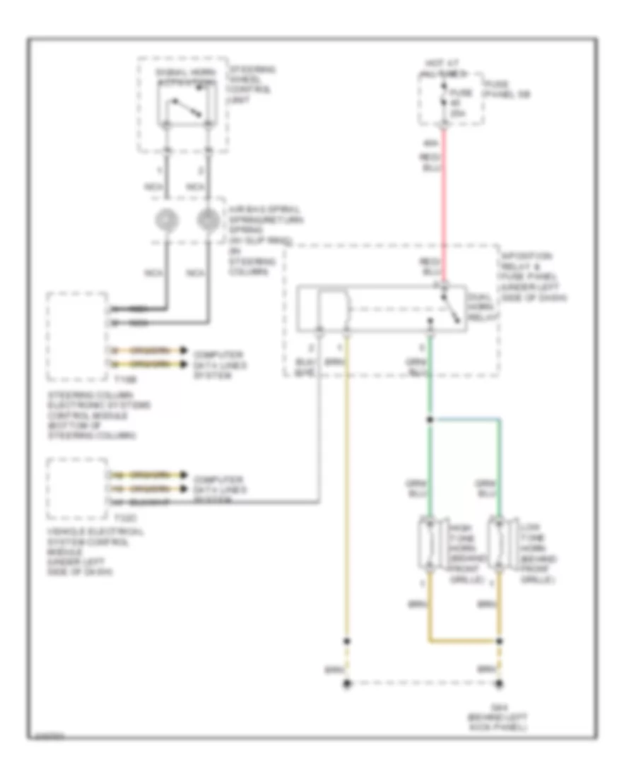
HORN
Horn Wiring Diagram for Audi A6 Quattro 2009
List of elements for Horn Wiring Diagram for Audi A6 Quattro 2009:
- 40a
- 9-position relay & fuse panel (under left side of dash)
- Air bag spiral spring/return spring (w/ slip ring) (in steering column)
- Computer data lines system
- Dual horn relay
- Fuse 25a
- Fuse panel sb
- G44 (behind left kick panel)
- High tone horn (behind front grille)
- Hot at all times
- Low tone horn (behind front grille)
- Nca
- Signal horn activation
- Steering column electronic systems control module (bottom of steering column)
- Steering wheel control unit
- T16b
- T32c
- Vehicle electrical system control module (under left side of dash)
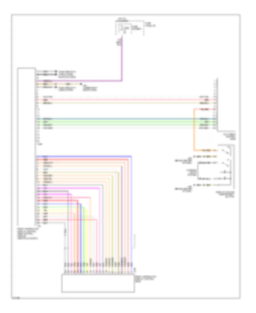
INSTRUMENT CLUSTER
Front Information Display Control Module Wiring Diagram, Early Production for Audi A6 Quattro 2009
List of elements for Front Information Display Control Module Wiring Diagram, Early Production for Audi A6 Quattro 2009:
- 10a
- Computer data lines system
- Display & glove compartment button
- Front information display control head
- Front information display control head control module (above glove box)
- Fuse 5a
- Fuse holder 1
- Fuse panel sc
- G33 (under right end of dash)
- G45 (behind center of dash)
- Hot at all times
- Interior lights system
- Multimedia control head
- Nca
- Red
- Sound systems
- T20g
- T22
- T22e
Front Information Display Control Module Wiring Diagram, Late Production for Audi A6 Quattro 2009
List of elements for Front Information Display Control Module Wiring Diagram, Late Production for Audi A6 Quattro 2009:
- 10a
- 22a
- Display & glove compartment button
- External audio source connection
- Front information display control head
- Fuse 5a
- Fuse holder
- Fuse panel sb
- Fuse panel sc
- G33 (under right end of dash)
- G45 (behind center of dash)
- G657 (above left rear window)
- Hot at all times
- Information electronics control module 1
- Interior lights system
- Left front microphone
- Microphone unit
- Multimedia control head
- Navigation system antenna
- Nca
- Rear view camera system control module
- Red
- Right front microphone
- Roof antenna
- Sound systems
- T12ac
- T12ad
- T2bm
- T2bn
- T4am
- T4an
- T4ao
- T8ac
- T8y
- T8z
- Telephone baseplate
Instrument Cluster Wiring Diagram (1 of 2) for Audi A6 Quattro 2009
List of elements for Instrument Cluster Wiring Diagram (1 of 2) for Audi A6 Quattro 2009:
- (behind center of dash) g45
- 15a
- Access/start authorization button
- All wheel drive
- Brake pad wear ind lamp
- Brake system warning lamp
- Computer data lines system
- Digital clock
- Directional stabilization assistance ind lamp
- Display unit
- Engine controls system
- Engine coolant level warning switch (in engine coolant reservoir)
- Engine coolant level/ temperature (ecl/ect) warning lamp
- Fuel gauge
- Fuel level sensor & fuel level sensor 2
- Fuse 10a
- Fuse panel sb
- Hot at all times
- Instrument cluster control module
- Interior lights system
- Low windshield washer fluid level ind lamp
- Oil pressure warning lamp
- Outside air temperature sensor
- Outside air temperature sensor (behind lower front grille)
- Parking brake ind lamp
- Selector lever sensor system control module
- Shift interlock system
- T10p
- Windshield washer fluid level switch
Instrument Cluster Wiring Diagram (2 of 2) for Audi A6 Quattro 2009
List of elements for Instrument Cluster Wiring Diagram (2 of 2) for Audi A6 Quattro 2009:
- Brake fluid level warning switch (on brake reservoir)
- Fuse 5a
- Fuse panel sb
- G43 (behind right kick panel)
- G45 (behind center of dash)
- G607 (in left plenum chamber)
- G646 (right side of firewall)
- Instrument cluster operation button
- Interior lights system
- Left front brake pad wear sensor
- Oil level thermal sensor (bottom of engine oil pan)
- Oil pressure switch (center front of engine)
- Red
- Right front brake pad wear sensor
INTERIOR LIGHTS
Courtesy Lamps Wiring Diagram (1 of 2) for Audi A6 Quattro 2009
List of elements for Courtesy Lamps Wiring Diagram (1 of 2) for Audi A6 Quattro 2009:
- (if equipped) rear lid lock button
- Comfort system central control module (right side of luggage compt)
- Computer data lines system
- Door locks system
- Early production
- G33 (under right end of dash)
- G43 (behind right kick panel)
- G44 (behind left kick panel)
- G690 (on rear center roof frame)
- Glove compartment light
- Glove compartment light switch
- Late production
- Left footwell light
- Left make-up mirror light
- Left make-up mirror light switch
- Left rear central locking unit (door contact switch)
- Left rear door ambient light
- Left rear door ambient lighting voltage converter
- Left rear door control module (in left rear door)
- Left rear door warning light
- Left rear entry light
- Left rear footwell light
- Left rear lid courtesy light
- Luggage compartment light
- Nca
- Power windows, mirrors, door locks systems & instrument illumination circuit
- Right footwell light
- Right make-up mirror light
- Right make-up mirror light switch
- Right rear central locking unit (door contact switch)
- Right rear door ambient light
- Right rear door ambient lighting voltage converter
- Right rear door control module (in right rear door)
- Right rear door warning light
- Right rear entry light
- Right rear footwell light
- Right rear lid courtesy light
- T15
- T16i
- T16k
- T20l
- T20m
- T2h
- T2i
- T32c
- T32d
- Vehicle electrical system control module (under left side of dash)
- W/ wagon
Courtesy Lamps Wiring Diagram (2 of 2) for Audi A6 Quattro 2009
List of elements for Courtesy Lamps Wiring Diagram (2 of 2) for Audi A6 Quattro 2009:
- Computer data lines system
- Door locks system
- Driver side door warning light
- Driver's door ambient light
- Driver's door ambient lighting voltage converter
- Driver's door central locking unit (door contact switch)
- Driver's door control module (in driver's front door)
- Early production
- Front pass- enger's door ambient light
- Front pass- enger's door ambient lighting voltage converter
- Front passenger door warning light
- Front passenger's door central locking unit (door contact switch)
- Front passenger's door control module (in front passenger's front door)
- Front passenger's map/reading light
- G44 (behind left kick panel)
- Instrument cluster control module
- Interior lights system (instrument illumination circuit)
- Late production
- Left front entry light
- Left front reading light
- Left interior light
- Mirror system
- Nca
- Power windows, mirrors, door locks systems & instrument illumination circuit
- Rear interior lights assembly
- Right front entry light
- Right interior light
- Roof electronics control module
- T12s
- T20i
- T20k
- T2h
- T2i
- T2s
- T32
- T32g
- T32h
Instrument Illumination Wiring Diagram (1 of 2) for Audi A6 Quattro 2009
List of elements for Instrument Illumination Wiring Diagram (1 of 2) for Audi A6 Quattro 2009:
- (3)
- Ash- tray & cup holder light
- Asr/esp button
- Center instrument panel vent light
- Cigarette lighter
- Computer data lines system
- Display & glove compart- ment button
- Emergency flasher switch
- G33 (under right end of dash)
- G43 (behind right kick panel)
- G44 (behind left kick panel)
- G45 (behind center of dash)
- G78 (base of right "b" pillar)
- Garage door opener control head
- Instrument cluster control module
- Instrument cluster operation button
- Left instrument panel vent light
- Left rear heated seat regulating switch
- Light switch
- Parking brake pressure switch
- Rear cigarette lighter
- Rear window shade switch
- Right center air vent light
- Right instrument panel vent light
- Right rear air vent light
- Right rear heated seat regulating switch
- Roof electronics control module
- Sunroof switch light
- T12
- T12s
- T2s
- T32
- T32c
- T40
- Valet parking lock button
- Vehicle electrical system control module (under left side of dash)
- Vehicle electrical system control module 2 (above glove box)
Instrument Illumination Wiring Diagram (2 of 2) for Audi A6 Quattro 2009
List of elements for Instrument Illumination Wiring Diagram (2 of 2) for Audi A6 Quattro 2009:
- Alarm system off switch
- Central locking safe indicator light
- Computer data lines system
- Driver's door control module (in driver's front door)
- Driver's door opener illumination
- Driver's interior locking switch
- Driver's seat memory program control
- Front passenger door window regulator switch
- Front passenger's door control module (in front passenger's front door)
- Front side passenger interior lock switch
- Left rear ashtray light
- Left rear door control module (in left rear door)
- Left rear door opener light
- Left rear interior lock switch
- Left rear window switch
- Mirror adjust- ment switch
- Power window control head
- Power windows, door locks, courtesy lights circuit
- Power windows, mirrors, door locks systems & courtesy lamps circuit
- Rear lid remote control lock switch
- Right front outside door handle illumination
- Right rear ashtray light
- Right rear door control module (in right rear door)
- Right rear door opener light
- Right rear interior switch
- Right rear window regulator switch
- T16i
- T16k
- T20i
- T20k
- T20l
- T20m
- T32g
- T32h
MEMORY SYSTEMS
Memory Systems Wiring Diagram (1 of 3) for Audi A6 Quattro 2009
List of elements for Memory Systems Wiring Diagram (1 of 3) for Audi A6 Quattro 2009:
- 9 position relay & fuse panel (under left side of dash)
- Backrest
- Computer data lines system
- Driver's power seat adjustment circuit breaker 30a
- Driver's power seat switch
- Driver's seat backrest adjustment motor
- Driver's seat fore/aft motor
- Driver's seat height adjustment motor
- Driver's seat inclination adjustment motor
- Driver's seat lumbar support adjustment switch
- Driver's seat lumbar support curvature adjustment motor
- Driver's seat lumbar support height adjustment motor
- Fore/aft
- G77 (base of left "b" pillar)
- Head restraint
- Height
- Hot at all times
- Memory seat/ steering column adjustment control module (under driver's seat)
- T12l
- T32a
- Tilt
Memory Systems Wiring Diagram (2 of 3) for Audi A6 Quattro 2009
List of elements for Memory Systems Wiring Diagram (2 of 3) for Audi A6 Quattro 2009:
- (behind left kick panel)
- (bottom of steering column) steering column electronic systems control module
- (under left side of dash) vehicle electrical system control module
- 13a
- Axial adjustment motor
- Axial adjustment sensor
- Computer data lines system
- Entry lamp
- Fold-in
- Front passenger's door control module (in front passenger's front door)
- Front passenger's side outside folding mirror
- Fuse 10a
- Fuse panel sb
- G43 (behind right kick panel)
- G44
- Heater
- Horizontal
- Hot at all times
- Lane change
- Lines system computer data
- Navigation system
- Nca
- Pnk
- Red
- Steering column adjustment assembly
- Steering column adjustment switch
- T12
- T16b
- T16h
- T20k
- T32c
- T4g
- Turn signal
- Vertical
- Vertical adjustment motor
- Vertical adjustment sensor
Memory Systems Wiring Diagram (3 of 3) for Audi A6 Quattro 2009
List of elements for Memory Systems Wiring Diagram (3 of 3) for Audi A6 Quattro 2009:
- 10a
- 39a
- 44a
- Adjustment switch
- Computer data lines system
- Day/night
- Driver's door control module (in driver's front door)
- Driver's seat memory program control
- Driver's side outside folding mirror
- Entry lamp
- Fold away switch
- Fold-in
- Fuse 15a
- Fuse 35a
- Fuse holder
- Fuse panel sb
- Fuse panel sc
- Fuse panel sf
- G44 (behind left kick panel)
- Heater
- Horizontal
- Hot at all times
- Interior lights system
- Lane change
- Mirror adjustment switch
- Navigation system
- Pnk
- Power distribution system
- Red
- Selector switch
- T16g
- T20i
- T32g
- Turn signal
- Vertical
NAVIGATION
Lane Change Assistance Wiring Diagram for Audi A6 Quattro 2009
List of elements for Lane Change Assistance Wiring Diagram for Audi A6 Quattro 2009:
- Computer data lines system
- Driver's exterior mirror assembly
- Fuse 5a
- Fuse holder 2
- Fuse panel sc
- G45 (behind center of dash)
- G51 (on right rear wheelwell)
- Interior lights system
- Lane change
- Lane change assistance button/ lights
- Lane change assistance control module
- Lane change assistance control module 2
- Passenger's exterior mirror assembly
Lane Departure Warning Wiring Diagram for Audi A6 Quattro 2009
List of elements for Lane Departure Warning Wiring Diagram for Audi A6 Quattro 2009:
- Computer data lines
- Computer data lines system
- Directional stabilization assistance button
- Directional stabilization assistance control module
- Directional stabilization assistance ind
- Directional stabilization assistance windshield heater
- Fuse 10a
- Fuse holder 2
- Fuse panel sc
- G44 (behind left kick panel)
- Instrument cluster control module
- Nca
- Spiral spring
- Steering column electronic systems control module (bottom of steering column)
- Steering wheel control module
- System
Navigation Wiring Diagram for Audi A6 Quattro 2009
List of elements for Navigation Wiring Diagram for Audi A6 Quattro 2009:
- (sedan) (on left rear wheelwell)
- Computer data line system
- Fuse 5a
- Fuse holder 1
- Fuse panel sf
- G50 g657 (wagon) (above left rear window)
- G657 (above left rear window)
- Hot at all times
- Navigation system w/ cd drive control module (left rear of luggage compt)
- Nca
- Radio/ telephone/ navigation system antenna
- Sound systems
- W/ telephone
- W/o telephone
Parking Assistant Wiring Diagram for Audi A6 Quattro 2009
List of elements for Parking Assistant Wiring Diagram for Audi A6 Quattro 2009:
- 11a
- Computer data lines system
- Fuse 5a
- Fuse holder 1
- Fuse holder 2
- Fuse panel sc
- Fuse panel sf
- G51 (on right rear wheelwell)
- Hot at all times
- Left rear center parking aid sensor
- Left rear parking aid sensor
- Parking aid control module (sedan: right side of luggage compt) (avant: right rear floor of luggage compt)
- Rear parking aid warning buzzer
- Red
- Right rear center parking aid sensor
- Right rear parking aid sensor
- T12e
- T16a
Rear Camera Wiring Diagram for Audi A6 Quattro 2009
List of elements for Rear Camera Wiring Diagram for Audi A6 Quattro 2009:
- Computer data lines system
- Early production
- Front information display control head control module
- Fuse 5a
- Fuse holder 2
- Fuse panel sf
- G50 (sedan) (on left rear wheelwell)
- G51 (on right rear wheelwell)
- G657 (wagon) (above left rear window)
- Hot at all times
- Information electronics control module 1
- Late production
- Nca
- Pins: 1-38 (not used)
- Pins: 49-54 (not used)
- Rear view camera
- Rear view camera system control module
- T12ac
- Tv tuner (early production)
POWER DISTRIBUTION
Power Distribution Wiring Diagram (1 of 6) for Audi A6 Quattro 2009
List of elements for Power Distribution Wiring Diagram (1 of 6) for Audi A6 Quattro 2009:
- 3.2l early production
- 4-position relay & fuse panel (except 3.2l early production) (in right plenum chamber e-box)
- 4-position relay & fuse panel (in right plenum chamber e-box)
- 9 position relay & fuse panel (under left side of dash)
- Access/ start control module
- Access/start control module
- Air bag control module
- Auxiliary video/audio connection module
- Battery
- Battery interrupt igniter
- Battery monitoring control module
- Comfort system central control module
- Communication fuse
- Coolant fan control module
- Coolant fan control module (w/ coolant fan electronics) (3.2l early production)
- Coolant fan control module 2 (4.2l)
- Electronic parking brake control module
- Energy management control module
- Except 3.2l early production
- Fuse
- Fuse 110a
- Fuse 40a
- Fuse 50a
- Fuse 5a
- Fuse 60a
- G646 (right side of firewall)
- Leveling control system compressor relay
- Light switch
- Main fuse panel
- Main fuse panel (e-box) (in right plenum chamber e-box)
- Red
- Secondary air injection pump relay
- Secondary air pump fuse
- Self- leveling system fuse
- Starter relay
- Starter relay 2
- Starting/ charging system
- Steering column electronics systems control module
- Suppressor (in right plenum chamber e-box)
- T16b
- T20h
- T32d
- T3o
- To fuse panel sb (diagram 2 of 6)
- To fuse panel sb (diagram 3 of 6)
- To fuse panel sc (diagram 4 of 6)
- To fuse panel sf (diagram 5 of 6)
Power Distribution Wiring Diagram (2 of 6) for Audi A6 Quattro 2009
List of elements for Power Distribution Wiring Diagram (2 of 6) for Audi A6 Quattro 2009:
- 19a
- 20a
- 22a
- 31a
- 32a
- 33a
- 34a
- 36a
- 43a
- 44a
- 9 position relay & fuse panel (under left side of dash)
- A/c pressure/ temperature sensor
- Abs control module
- Air quality sensor
- Asr/esp button
- Automatic day/night interior mirror
- Circuit breaker 30a
- Climatronic control module
- Data link connector
- Driver's door control module
- Driver's power seat
- Driver's seat adjustment switch (w/o memory)
- Driver's seat lumbar support adjustment switch
- From main fuse panel (diagram 1 of 6)
- Front information display control head
- Front passenger's seat adjustment switch
- Front passenger's seat lumbar support adjustment switch
- Fuse 15a
- Fuse 25a
- Fuse 30a
- Fuse 35a
- Fuse 5a
- Fuse panel sb
- Headlamp washer relay
- Left rear door control module
- Left washer nozzle heater
- Memory seat/steering column adjustment control module
- Nca
- Oil level thermal sensor
- Rain/light recognition sensor
- Rear window wiper motor
- Red
- Right washer nozzle heater
- Shift lock solenoid
- T10
- T12
- T12l
- T16c
- T16e
- T20e
- T20i
- T20l
- T4ac
- T6o
- T8ca
- T8x
- Tire pressure monitoring control module
- To fuse panel sa (diagram 6 of 6)
- To fuse panel sb (diagram 3 of 6)
- To fuse panel sc (diagram 4 of 6)
- Transmission control module (tcm)
- Vehicle electrical system control module
- W/ 6-speed a/t
- W/ automatic high beam control
- W/ cvt
- W/o automatic high beam control
Power Distribution Wiring Diagram (3 of 6) for Audi A6 Quattro 2009
List of elements for Power Distribution Wiring Diagram (3 of 6) for Audi A6 Quattro 2009:
- 10a
- 12a
- 13a
- 14a
- 15a
- 16a
- 17a
- 18a
- 23a
- 3.2l early production
- 37a
- 38a
- 39a
- 40a
- 41a
- 42a
- 9 position relay & fuse panel (under left side of dash)
- Abs control module
- Abs control module fuse 1
- Access/ start control module
- Access/start authorization switch
- Data bus on board diagnostic interface
- Data link connector
- Distance regulation control module
- Distance regulation sensor heater
- Driver's door control module
- Dual horn relay
- Early production
- Engine control module (ecm)
- Except 3.2l early production
- Fresh air blower control module
- From fuse panel sb (diagram 2 of 6)
- From main fuse panel (diagram 1 of 6)
- Fuse 10a
- Fuse 15a
- Fuse 25a
- Fuse 30a
- Fuse 40a
- Fuse 5a
- Fuse panel sb
- Garage door opener control head
- Garage door opener control module
- Instrument cluster
- Late production
- Left headlamp range/ cornering lamp control module
- Left rear door control module
- Nca
- Parking brake pressure switch
- Red
- Steering column electronics systems control module
- T16
- T16b
- T20i
- T20l
- T26a
- T2q
- T3q
- T6n
- T94
- T94a
- Telephone baseplate
- Telephone transceiver
- Wiper motor control module
Power Distribution Wiring Diagram (4 of 6) for Audi A6 Quattro 2009
List of elements for Power Distribution Wiring Diagram (4 of 6) for Audi A6 Quattro 2009:
- 10a
- 11a
- 12a
- Air bag control module
- Cigarette lighter
- Climatronic control module
- Data bus on board diagnostic interface
- Directional stabilization assistance control module
- Dvd player & cd changer
- Early production
- From fuse panel sb (diagram 2 of 6)
- From main fuse panel (diagram 1 of 6)
- Front information display control head control module
- Front passenger's door control module
- Fuel pump (fp) control module
- Fuse 10a
- Fuse 15a
- Fuse 20a
- Fuse 30a
- Fuse 5a
- Fuse holder 1
- Fuse holder 2
- Fuse panel sc
- G43 (behind right kick panel)
- Headlamp range control module
- Information electronic control module 1
- Interior lights system
- Keyless access authorization antenna reader
- Lane change assistance control module
- Lane change assistance control module 2
- Late production
- Left rear heated seat regulating switch
- Level control system control module
- Media player position
- Nca
- Parking aid control module
- Passenger side air bag off warning light
- Power sunroof control module
- Rear seats
- Red
- Right headlamp range/ cornering lamp control module (w/ adaptive headlights)
- Right rear door control module
- Right rear heated seat regulating switch
- Selector lever sensor system control module
- T16a
- T16e
- T20g
- T20k
- T20m
- T20p
- T40
- T8z
- Tire pressure monitoring control module
- Vehicle electrical system control module 2
- W/ heated front &
Power Distribution Wiring Diagram (5 of 6) for Audi A6 Quattro 2009
List of elements for Power Distribution Wiring Diagram (5 of 6) for Audi A6 Quattro 2009:
- (3.2l late production)
- 10a
- 11a
- 12a
- 12v socket
- Alarm horn
- Antenna amplifier
- Cam adjustment actuator 10
- Cam adjustment actuator 11
- Cam adjustment actuator 12
- Cam adjustment actuator 6
- Cam adjustment actuator 7
- Cam adjustment actuator 8
- Cam adjustment actuator 9
- Comfort system central control module
- Digital sound system control module
- Early production
- Electronic parking brake control module
- Energy management control module (3.2l early production)
- From fuse panel sf (diagram 5 of 6)
- From main fuse panel (diagram 1 of 6)
- Front information display control head control module
- Front passenger's door control module
- Fuse 20a
- Fuse 30a
- Fuse 35a
- Fuse 40a
- Fuse 5a
- Fuse holder 1
- Fuse holder 2
- Fuse panel sf
- G43 (behind right kick panel)
- G51 (on right rear wheelwell)
- Interior lights system
- Late production
- Navigation system w/ cd driver control module (w/ navigation)
- Nca
- Parking aid control module
- Radio
- Rear cigarette lighter
- Rear lid control module
- Rear lid control module 2
- Rear view camera system control module
- Rear window defogger fuse
- Rear window defogger relay
- Red
- Relay & fuse panel
- Right rear door control module
- Satellite radio
- T10ao
- T10y
- T16a
- T20k
- T20m
- T32f
- T54b
- T80
- T8k
- T8p
- To cam adjustment actuator 5 (diagram 6 of 6)
- To fuse panel sf (diagram 5 of 6)
Power Distribution Wiring Diagram (6 of 6) for Audi A6 Quattro 2009
List of elements for Power Distribution Wiring Diagram (6 of 6) for Audi A6 Quattro 2009:
- (3.0l, 3.2l early production except cvt)
- (3.2l late production)
- (4.2l)
- 10a
- 3.0l & 3.2l
- 3.0l & 3.2l late production
- 3.2l early production
- 4.2l
- Auxiliary engine coolant pump relay (except 4.2l)
- Brake booster relay
- Cam adjustment actuator 1
- Cam adjustment actuator 2
- Cam adjustment actuator 3
- Cam adjustment actuator 4
- Cam adjustment actuator 5
- Camshaft adjustment valve 1
- Camshaft adjustment valve 1 (exhaust) (except 3.0l)
- Camshaft adjustment valve 2
- Camshaft adjustment valve 2 (exhaust) (except 3.0l)
- Charge air cooling pump (3.0l)
- Coolant circulation pump relay (4.2l)
- Coolant fan control (fc) control module
- Coolant fan control module
- Coolant fan control module 2
- Engine control module (ecm)
- Except 3.2l early production
- From cam adjustment actuator 11 (diagram 5 of 6)
- From fuse panel sb (diagram 2 of 6)
- From fuse panel sc (diagram 4 of 6)
- Fuse 10a
- Fuse 15a
- Fuse 30a 20a
- Fuse 5a
- Fuse panel sa
- Ignition coil
- Ignition coil (4.2l)
- Intake manifold tuning (imt) valve (4.2l)
- Intake manifold tuning (imt) valve 2 (4.2l)
- Left electro- hydraulic engine mount solenoid valve
- Map controlled engine cooling thermostat (4.2l)
- Red
- Relay holder (e-box) (in left plenum chamber e-box)
- Right electro- hydraulic engine mount solenoid valve
- T16c
- T20e
- T94
- T94a
- Transmission control module (tcm)
- W/ 6-speed a/t
- W/ coolant fan electronics
- W/ cvt
POWER DOOR LOCKS
Power Door Locks Wiring Diagram (1 of 3) for Audi A6 Quattro 2009
List of elements for Power Door Locks Wiring Diagram (1 of 3) for Audi A6 Quattro 2009:
- (if equipped) left rear closing assist motor
- (w/ door closing assistance) left rear door central locking lock unit
- (w/o door closing assistance) left rear door central locking lock unit
- 39a
- 44a
- Closing assist contact switch
- Computer data lines system
- Driver's door central locking lock unit (w/ door closing assistance)
- Driver's door central locking lock unit (w/o door closing assistance)
- Driver's door closing assist motor (if equipped)
- Driver's door control module (in driver's door)
- Driver's door handle switch
- Early production
- Fuse 15a
- Fuse 35a
- Fuse panel sb
- G44 (behind left kick panel)
- G77 (base of left "b" pillar)
- Hot at all times
- Interior lights system
- Late production
- Left rear door control module (in left rear door)
- Left rear door handle switch
- Left rear interior locking switch
- T16i
- T20i
- T20l
- T32g
- W/ door closing assistance
- W/o door closing assistance
Power Door Locks Wiring Diagram (2 of 3) for Audi A6 Quattro 2009
List of elements for Power Door Locks Wiring Diagram (2 of 3) for Audi A6 Quattro 2009:
- Central locking indicator lamp safe
- Comfort system central control module (right side of luggage compt)
- Computer data lines system
- Driver's door handle touch sensor
- Driver's interior locking switch
- Driver's outside door handle central locking button
- Front passenger's interior locking switch
- Front passenger's outside door handle central locking button
- Front passenger's outside door handle touch sensor
- Fuel tank lid unlock motor
- G43 (behind right kick panel)
- G44 (behind left kick panel)
- G51 (on right rear wheelwell)
- Interior lights system
- Interior lights, mirrors, memory, power windows system
- Interior lights, power windows system
- Keyless access authorization antenna reader (above glove box)
- Left rear door handle touch sensor
- Left rear outside door handle central locking button
- Lock
- Passenger door handle switch
- Rear lid lock cylinder unlock switch
- Remote rear lid control lock switch & fuel tank lid unlock button
- T10y
- T15
- T32d
- Trunk lid alarm switch/decklid central locking system motor
- Trunk lock alarm/central locking switch
- Un lock
Power Door Locks Wiring Diagram (3 of 3) for Audi A6 Quattro 2009
List of elements for Power Door Locks Wiring Diagram (3 of 3) for Audi A6 Quattro 2009:
- (base of right "b" pillar) g78
- (behind center of dash) g45
- (behind right kick panel) g43
- (if equipped) front passenger's closing assist motor
- (in front passenger's front door) front passenger's door control module
- (w/ door closing assistance) front passenger's door central locking lock unit
- (w/o door closing assistance) front passenger's door central locking lock unit
- 10a
- Closing assist contact switch
- Computer data lines system
- Early production
- Fuse 15a
- Fuse 35a
- Fuse holder
- Fuse panel sc
- Fuse panel sf
- G33 (under right end of dash)
- G78 (base of right "b" pillar)
- Glove box unlock motor
- Glove compartment & display button
- Hot at all times
- Instrument cluster system
- Interior lights & power windows system
- Interior lights system
- Late production
- Right rear closing assist motor (if equipped)
- Right rear door central locking lock unit (w/ door closing assistance)
- Right rear door central locking lock unit (w/o door closing assistance)
- Right rear door control module (in right rear door)
- Right rear door handle switch
- Right rear door handle touch sensor
- Right rear interior switch
- Right rear outside door handle central locking button
- T16k
- T20k
- T20m
- T32h
- T40
- Vehicle electrical system control module 2 (above glove box)
- W/ door closing assistance
- W/o door closing assistance
POWER MIRRORS
Automatic Day/Night Mirror Wiring Diagram for Audi A6 Quattro 2009
List of elements for Automatic Day/Night Mirror Wiring Diagram for Audi A6 Quattro 2009:
- Automatic day/night interior mirror
- Comfort system central control module (right side of luggage compt)
- Day/night
- Driver's door control module (in driver's front door)
- Driver's side outside folding mirror
- Front passenger's door control module (in front passenger's front door)
- Fuse 5a
- Fuse panel sb
- G44 (behind left kick panel)
- Interior lights system
- Passenger's side outside folding mirror
- Right rear taillamp control module
- Roof electronics control module
- T12s
- T15
- T16g
- T16h
- T20i
- T20k
- T6o
Power Mirrors Wiring Diagram for Audi A6 Quattro 2009
List of elements for Power Mirrors Wiring Diagram for Audi A6 Quattro 2009:
- 10a
- 39a
- 44a
- Adjustment switch
- Computer data lines system
- Day/night
- Driver's door control module (in driver's front door)
- Driver's side outside folding mirror
- Entry lamp
- Fold away switch
- Fold-in
- Front passenger's door control module (in front passenger's front door)
- Front passenger's side outside folding mirror
- Fuse 15a
- Fuse 35a
- Fuse holder
- Fuse panel sb
- Fuse panel sc
- Fuse panel sf
- G43 (behind right kick panel)
- G44 (behind left kick panel)
- Heater
- Horizontal
- Hot at all times
- Interior lights system
- Lane change
- Mirror adjustment switch
- Navigation system
- Pnk
- Red
- Selector switch
- T16g
- T16h
- T20i
- T20k
- T32g
- Turn signal
- Vertical
POWER SEATS
Heated Seats Wiring Diagram (1 of 2) for Audi A6 Quattro 2009
List of elements for Heated Seats Wiring Diagram (1 of 2) for Audi A6 Quattro 2009:
- Air conditioning system
- Climatronic control module
- Driver's backrest heating element
- Fuse 30a
- Fuse holder 1
- Fuse panel sc
- G77 (base of left "b" pillar)
- G78 (base of right "b" pillar)
- Heater element
- Hot at all times
- Left front heated seat
- Nca
- Only
- Passenger's backrest heating element
- Right front heated seat
- Seats
- T16d
- T16e
- Temper- ature sensor
- W/ front & rear heated
- W/ front heated seats
Heated Seats Wiring Diagram (2 of 2) for Audi A6 Quattro 2009
List of elements for Heated Seats Wiring Diagram (2 of 2) for Audi A6 Quattro 2009:
- 11a
- Fuse 5a
- Fuse holder 2
- Fuse panel sc
- G78 (base of right "b" pillar)
- Heater element
- Interior lights system
- Left rear backrest heating element
- Left rear heated seat
- Left rear heated seat regulating switch
- Occupied sensor
- Right rear backrest heating element
- Right rear heated seat
- Right rear heated seat regulating switch
- Temper- ature sensor
Heated Steering Wheel Wiring Diagram for Audi A6 Quattro 2009
List of elements for Heated Steering Wheel Wiring Diagram for Audi A6 Quattro 2009:
- (behind left kick panel) g44
- 13a
- Computer data lines system
- Fuse 10a
- Fuse panel sb
- Heated steering wheel
- Heated steering wheel button
- Heated steering wheel sensor
- Hot at all times
- Multi-function steering wheel control module
- Nca
- Spiral spring
- Steering column electronic systems control module (bottom of steering column)
- Steering wheel control unit
- T16b
Power Seats Wiring Diagram for Audi A6 Quattro 2009
List of elements for Power Seats Wiring Diagram for Audi A6 Quattro 2009:
- 9 position relay & fuse panel (under left side of dash)
- Backrest
- Driver's power seat adjustment circuit breaker 30a
- Driver's power seat switch
- Driver's seat backrest adjustment motor
- Driver's seat fore/aft adjustment motor
- Driver's seat height adjustment motor
- Driver's seat inclination adjustment motor
- Driver's seat lumbar support adjustment switch
- Driver's seat lumbar support curvature adjustment motor
- Driver's seat lumbar support height adjustment motor
- Fore/aft
- Front passenger's seat backrest adjustment motor
- Front passenger's seat height adjustment motor
- Front passenger's seat inclination adjustment motor
- Front passenger's seat lumbar support adjustment switch
- Front passenger's seat lumbar support curvature adjustment motor
- Front passenger's seat lumbar support height adjustment motor
- G77 (base of left "b" pillar)
- G78 (base of right "b" pillar)
- Height
- Hot at all times
- Passenger's power seat switch
- Passenger's seat fore/aft adjustment motor
- T10aa
- T4ac
- Tilt
POWER TOP/SUNROOF
Power Top/Sunroof Wiring Diagram for Audi A6 Quattro 2009
List of elements for Power Top/Sunroof Wiring Diagram for Audi A6 Quattro 2009:
- Comfort system central control module (right side of luggage compt)
- Fuse 20a
- Fuse holder 1
- Fuse panel sc
- G44 (behind left kick panel)
- Hot at all times
- Interior lights system
- Nca
- Power sunroof control module (center front of roof)
- Sunroof motor
- Sunroof switch
- T32d
- Vehicle electrical system control module 2 (above glove box)
POWER WINDOWS
Power Windows Wiring Diagram (1 of 2) for Audi A6 Quattro 2009
List of elements for Power Windows Wiring Diagram (1 of 2) for Audi A6 Quattro 2009:
- (base of left "b" pillar) g77
- (behind left kick panel) g44
- (in driver's front door) driver's window regulator motor
- 39a
- 44a
- Computer data lines system
- Driver's door control module (in driver's front door)
- Driver's door power window control head
- Driver's window regulator motor (early production) (in driver's front door)
- Early production
- Fuse 15a
- Fuse 35a
- Fuse panel sb
- Hot at all times
- Interior lights systems
- Late production
- Left child safety button
- Left front window regulator switch
- Left rear door control module (in left rear door)
- Left rear window regulator motor
- Left rear window regulator motor (early production)
- Left rear window regulator switch
- Left rear window switch
- Right child safety button
- Right front window regulator switch
- Right rear window regulator switch
- T16i
- T20i
- T20l
- T32g
- T6t
- T6v
- W/ rear ashtray
Power Windows Wiring Diagram (2 of 2) for Audi A6 Quattro 2009
List of elements for Power Windows Wiring Diagram (2 of 2) for Audi A6 Quattro 2009:
- (base of right "b" pillar) g78
- (behind right kick panel) g43
- (early production)
- (early production) (in front passenger's front door)
- (in front passenger's front door) front passenger window regulator motor
- Computer data lines system
- Driver's right rear window regulator switch
- Early production
- Front passenger's door control module (in front passenger's front door)
- Front passenger's window regulator motor
- Fuse 15a
- Fuse 35a
- Fuse holder 1
- Fuse panel sc
- Fuse panel sf
- Hot at all times
- Interior lights systems
- Late production
- Right front window regulator switch
- Right rear door control module (in right rear door)
- Right rear window regulator motor
- T16k
- T20k
- T20m
- T32h
- T6u
- T6w
- W/ rear ashtray
Rear Window Sun Shade Wiring Diagram for Audi A6 Quattro 2009
List of elements for Rear Window Sun Shade Wiring Diagram for Audi A6 Quattro 2009:
- (behind center of dash) g45
- Climatronic control module
- Comfort system central control module (right side of luggage compt)
- Computer data lines system
- Fuse 10a
- Fuse 20a
- Fuse 30a
- Fuse holder 1
- Fuse panel sc
- Fuse panel sf
- G51 (on right rear wheelwell)
- Hot at all times
- Interior lights system
- Rear window shade motor
- Rear window shade switch
- T10y
- T15
- T16d
- T16e
- T32d
RADIO
MOST Data Bus Wiring Diagram, Early Production for Audi A6 Quattro 2009
List of elements for MOST Data Bus Wiring Diagram, Early Production for Audi A6 Quattro 2009:
- Cd changer/ media player position 1 (if equipped)
- Cd changer/ media player position 2/ mini disc player/ video recorder/ dvd player (if equipped)
- Data bus on board diagnostic interface (above glove box)
- Digital sound system control module (left rear of luggage compt)
- Fibre-optic cable bridge is present when component is not installed
- Front information display control head control module (above glove box)
- Lwl in
- Lwl out
- Navigation system w/ cd drive control module (if equipped) (left rear of luggage compt)
- Nca
- Radio
- Satellite radio
- Telephone transceiver (w/ cellular telephone preparation)
- W/ bose
- W/ bose premium
MOST Data Bus Wiring Diagram, Late Production for Audi A6 Quattro 2009
List of elements for MOST Data Bus Wiring Diagram, Late Production for Audi A6 Quattro 2009:
- Data bus on board diagnostic interface (above glove box)
- Digital sound system control module (left rear of luggage compt)
- Dvd player/ cd changer
- Information electronics control module 1
- Lwl in
- Lwl out
- Nca
- Radio
- Tv tuner
Radio Wiring Diagram, Early Production with 6-Channel DSP (1 of 2) for Audi A6 Quattro 2009
List of elements for Radio Wiring Diagram, Early Production with 6-Channel DSP (1 of 2) for Audi A6 Quattro 2009:
- Computer data lines system
- Digital sound system control module (left rear of luggage compt)
- Fuse 30a
- Fuse holder 1
- Fuse panel sf
- G50 (sedan) (on left rear wheelwell) g657 (wagon) (above left rear window)
- Hot at all times
- Left front bass speaker
- Left front midrange speaker
- Left front treble speaker
- Left rear mid/low range loud speaker
- Left rear treble speaker
- Microphone unit
- Most data bus circuit
- Nca
- Red
- Right front bass speaker
- Right front midrange speaker
- Right front treble speaker
- Right rear mid/low range loud speaker
- Right rear treble speaker
- T32f
- T54
- Telephone transceiver
- W/ voice control
Radio Wiring Diagram, Early Production with 6-Channel DSP (2 of 2) for Audi A6 Quattro 2009
List of elements for Radio Wiring Diagram, Early Production with 6-Channel DSP (2 of 2) for Audi A6 Quattro 2009:
- (above left rear window) g657
- 12a
- Amplifier antenna (w/ left upper rear window)
- Antenna amplifier
- Antenna amplifier 2
- Antenna amplifier 3
- Cd changer (if equipped)
- Cd changer unit (if equipped)
- Computer data lines system
- External audio source connection
- Fuse 5a
- Fuse holder
- Fuse holder 1
- Fuse holder 2
- Fuse panel sc
- Fuse panel sf
- G33 (under right end of dash)
- G50 (sedan) (on left rear wheelwell) g657 (wagon) (above left rear window)
- G657 (above left rear window)
- Hot at all times
- Left rear window antenna
- Media player, position 1
- Minidisc player (if equipped)
- Most data bus circuit
- Nca
- Radio
- Radio/telephone/ navigation antenna (w/ roof antenna)
- Satellite radio
- Sedan
- Sound system (most data bus circuit)
- Speech input control module (if equipped)
- T12h
- T3w
- T8k
- T8m
- T8n
- T8p
- W/ satellite antenna
- W/ terrestrial antenna
- Wagon
Radio Wiring Diagram, Early Production with Bose (1 of 2) for Audi A6 Quattro 2009
List of elements for Radio Wiring Diagram, Early Production with Bose (1 of 2) for Audi A6 Quattro 2009:
- Center mid/high range loud speaker
- Computer data lines system
- Digital sound system control module (left rear of luggage compt)
- Fuse 30a
- Fuse holder 1
- Fuse panel sf
- G50 (sedan) (on left rear wheelwell) g657 (wagon) (above left rear window)
- Hot at all times
- Inside microphone
- Left front bass speaker
- Left front midrange speaker
- Left front treble speaker
- Left rear mid range speaker
- Left rear mid/low range loud speaker
- Left rear treble speaker
- Loudspeaker
- Microphone unit
- Most data bus circuit
- Nca
- Red
- Right front bass speaker
- Right front midrange speaker
- Right front treble speaker
- Right rear mid range speaker
- Right rear mid/low range loud speaker
- Right rear treble speaker
- T32f
- T54
- Telephone transceiver (w/ cellular telephone preparation)
- W/ voice control
Radio Wiring Diagram, Early Production with Bose (2 of 2) for Audi A6 Quattro 2009
List of elements for Radio Wiring Diagram, Early Production with Bose (2 of 2) for Audi A6 Quattro 2009:
- (above left rear window) g657
- 12a
- Amplifier antenna (w/ left upper rear window)
- Antenna amplifier
- Antenna amplifier 2
- Antenna amplifier 3
- Cd changer (if equipped)
- Cd changer unit (if equipped)
- Computer data lines system
- External audio source connection
- Fuse 5a
- Fuse holder
- Fuse holder 1
- Fuse holder 2
- Fuse panel sc
- Fuse panel sf
- G33 (under right end of dash)
- G50 (sedan) (on left rear wheelwell) g657 (wagon) (above left rear window)
- G657 (above left rear window)
- Hot at all times
- Left rear window antenna
- Media player, position 1
- Mini disc player (if equipped)
- Most data bus circuit
- Nca
- Radio
- Radio/telephone/ navigation antenna (w/ roof antenna)
- Satellite radio
- Sedan
- Sound system (most data bus circuit)
- Speech input control module (if equipped)
- T12h
- T3w
- T8k
- T8m
- T8n
- T8p
- W/ satellite antenna
- W/ terrestrial antenna
- Wagon
Radio Wiring Diagram, Late Production with 6-Channel DSP for Audi A6 Quattro 2009
List of elements for Radio Wiring Diagram, Late Production with 6-Channel DSP for Audi A6 Quattro 2009:
- (above left rear window) g657
- (sedan) g50 (on left rear wheelwell)
- 12a
- Access/start authorization switch
- Antenna
- Antenna amplifier
- Antenna amplifier 2
- Antenna amplifier 3
- Central locking & anti-theft alarm system antenna
- Computer data lines system
- Digital radio antenna
- Dvd player/ cd changer
- Fuse 30a
- Fuse 5a
- Fuse holder 1
- Fuse panel sc
- Fuse panel sf
- G33 (under right end of dash)
- G657 (above left rear window)
- G657 (wagon) (above left rear window)
- G659 (above right rear window)
- Hot at all times
- Information electronics control module 1
- Left front bass speaker
- Left front midrange speaker
- Left front treble speaker
- Left rear mid/ low range speaker
- Left rear treble speaker
- Most data bus circuit
- Navigation system antenna
- Nca
- Radio
- Radio antenna 2
- Red
- Right front bass speaker
- Right front midrange speaker
- Right front treble speaker
- Right rear mid/ low range speaker
- Right rear treble speaker
- Roof antenna
- Satellite antenna
- T10ao
- T2bm
- T2bn
- T2bo
- T2bp
- T2bq
- T2br
- T2bu
- T2ca
- T2r
- T4ap
- T8f
- T8q
- Tele- phone antenna
- Telephone baseplate
Radio Wiring Diagram, Late Production with Bose (1 of 2) for Audi A6 Quattro 2009
List of elements for Radio Wiring Diagram, Late Production with Bose (1 of 2) for Audi A6 Quattro 2009:
- Center mid/high range speaker
- Computer data lines system
- Digital sound system control module (left rear of luggage compt)
- Fuse 30a
- Fuse holder 1
- Fuse panel sf
- G50 (sedan) (on left rear wheelwell) g657 (wagon) (above left rear window)
- Hot at all times
- Left front bass speaker
- Left front midrange speaker
- Left front treble speaker
- Left rear mid range speaker
- Left rear mid/low range speaker
- Left rear treble speaker
- Loudspeaker
- Most data bus circuit
- Nca
- Red
- Right front bass speaker
- Right front midrange speaker
- Right front treble speaker
- Right rear mid range speaker
- Right rear mid/low range speaker
- Right rear treble speaker
- T32f
Radio Wiring Diagram, Late Production with Bose (2 of 2) for Audi A6 Quattro 2009
List of elements for Radio Wiring Diagram, Late Production with Bose (2 of 2) for Audi A6 Quattro 2009:
- (above left rear window) g657
- 12a
- Access/start authorization switch
- Antenna
- Antenna amplifier
- Antenna amplifier 2
- Antenna amplifier 3
- Central locking anti-theft alaram system antenna
- Computer data lines system
- Digital radio antenna
- Dvd player/ cd charger
- Fuse 5a
- Fuse holder 1
- Fuse panel sc
- Fuse panel sf
- G33 (under right end of dash)
- G50 (sedan) (on left rear wheelwell) g657 (wagon) (above left rear window)
- G657 (above left rear window)
- G659 (above right rear window)
- Hot at all times
- Information electronics control module 1
- Inside micro- phone
- Left front micro- phone
- Microphone unit
- Most data bus circuit
- Navigation system antenna
- Nca
- Nca nca
- Radio
- Radio antenna
- Right front micro- phone
- Roof antenna
- Satellite antenna
- T10ao
- T12ac
- T2bn
- T2bo
- T2bp
- T2bq
- T2br
- T2bs
- T2bt
- T2bu
- T2ca
- T2cb
- T2r
- T4ap
- T8f
- Telaphone antenna
- Telephone base plate
SHIFT INTERLOCK
Electronic Parking Brake Wiring Diagram for Audi A6 Quattro 2009
List of elements for Electronic Parking Brake Wiring Diagram for Audi A6 Quattro 2009:
- (on right rear caliper assembly) right parking brake motor
- 23a
- Computer data lines system
- Electro-mechanical parking brake control module (right side of luggage compt)
- Fuse 30a
- Fuse 5a
- Fuse holder
- Fuse panel b
- Fuse panel sf
- G51 (on right rear wheelwell)
- Hot at all times
- Instrument cluster control module
- Interior lights system
- Left parking brake motor (on left rear caliper assembly)
- Parking brake pressure switch
- Power distribution system
Shift Interlock Wiring Diagram, 6 Speed A/T for Audi A6 Quattro 2009
List of elements for Shift Interlock Wiring Diagram, 6 Speed A/T for Audi A6 Quattro 2009:
- (4.2l: in right plenum chamber) (5.2l: right rear of engine compt, in plenum) engine control module (ecm)
- (behind center of dash) g45
- (left side of firewall) g645
- 3.0l
- 31a
- 4.2l
- 5.2l
- Abs control module (left side of engine compt)
- Access/start control module (base of steering column)
- Brake light & brake pedal switch (on brake pedal assembly)
- Comfort system central control module (right side of luggage compt)
- Computer data lines system
- Fuse 15a
- Fuse panel b
- Nca
- Selector lever sensor system control module
- Selector lever transmission range (tr) position display
- Shift lock solenoid
- T20h
- T94
- T94a
- Tiptronic switch
- Transmission control module (tcm) (under transmission oil pan)
Shift Interlock Wiring Diagram, CVT for Audi A6 Quattro 2009
List of elements for Shift Interlock Wiring Diagram, CVT for Audi A6 Quattro 2009:
- (behind center of dash) g45
- (left side of firewall) g645
- 31a
- Abs control module (left side of engine compt)
- Access/start control module (base of steering column)
- Brake light & brake pedal switch (on brake pedal assembly)
- Computer data lines system
- Engine control module (ecm)
- Fuse 15a
- Fuse panel b
- G43 (behind right kick panel)
- Nca
- Selector lever sensor system control module
- Selector lever transmission range (tr) position display
- Shift lock solenoid
- T20h
- T94a
- Tiptronic switch
- Transmission control module (tcm) (under transmission oil pan)
STARTING/CHARGING
3.0L
3.0L, Charging Wiring Diagram for Audi A6 Quattro 2009
List of elements for 3.0L, Charging Wiring Diagram for Audi A6 Quattro 2009:
- Battery
- Battery interrupt igniter
- Battery monitoring control module
- Computer data lines system
- Data bus on board diagnostic interface (above glove box)
- Display unit
- G624
- G646 (right side of firewall)
- Generator & voltage regulator
- Instrument cluster control module
- Main fuse panel
- Main fuse panel (e-box) (in right plenum chamber e-box)
- Power distribution system
- Red
- Starter
- Suppressor (in right plenum chamber e-box)
- T2au
3.0L, Starting Wiring Diagram for Audi A6 Quattro 2009
List of elements for 3.0L, Starting Wiring Diagram for Audi A6 Quattro 2009:
- 3.0l & 3.2l (cala)
- 4.2l
- 5.2l
- 9-position relay & fuse panel (under left side of dash)
- Access/start control module (base of steering column)
- Battery
- Battery interrupt igniter
- Battery monitoring control module
- Charging circuit
- Computer data lines system
- Engine control module (ecm) (4.2l: in right plenum chamber) (5.2l: right rear of engine compt, in plenum)
- G624
- G646 (right side of firewall)
- Generator & voltage regulator
- Main fuse panel
- Main fuse panel (e-box) (in right plenum chamber e-box)
- Power distribution system
- Red
- Starter
- Starter relay
- Starter relay 2
- Suppressor (in right plenum chamber e-box)
- T20h
- T94
- T94a
3.2L
3.2L, Charging Wiring Diagram, BKH for Audi A6 Quattro 2009
List of elements for 3.2L, Charging Wiring Diagram, BKH for Audi A6 Quattro 2009:
- Access/start control module (base of steering column)
- Battery
- Battery interrupt igniter
- Computer data lines system
- Fuse 5a
- Fuse panel f1
- G646 (right side of firewall)
- Generator
- Hot at all times
- Main fuse panel
- Main fuse panel (e-box) (in right plenum chamber e-box)
- Red
- Starter
- Suppressor (in right plenum chamber e-box)
- T20h
3.2L, Charging Wiring Diagram, CALA for Audi A6 Quattro 2009
List of elements for 3.2L, Charging Wiring Diagram, CALA for Audi A6 Quattro 2009:
- Battery
- Battery interrupt igniter
- Battery monitoring control module
- Computer data lines system
- Data bus on board diagnostic interface (above glove box)
- Display unit
- G624
- G646 (right side of firewall)
- Generator & voltage regulator
- Instrument cluster control module
- Main fuse panel
- Main fuse panel (e-box) (in right plenum chamber e-box)
- Power distribution system
- Red
- Starter
- Suppressor (in right plenum chamber e-box)
- T2au
3.2L, Starting Wiring Diagram, BKH for Audi A6 Quattro 2009
List of elements for 3.2L, Starting Wiring Diagram, BKH for Audi A6 Quattro 2009:
- 9-position relay & fuse panel (under left side of dash)
- Access/start control module (base of steering column)
- Battery
- Battery interrupt igniter
- Charging circuit
- Computer data lines system
- Engine control module (ecm)
- Fuse 5a
- Fuse panel f1
- G646 (right side of firewall)
- Generator & voltage regulator
- Hot at all times
- Main fuse panel
- Main fuse panel (e-box) (in right plenum chamber e-box)
- Power distribution system
- Red
- Starter
- Starter relay
- Starter relay 2
- Suppressor (in right plenum chamber e-box)
- T20h
- T94a
3.2L, Starting Wiring Diagram, CALA for Audi A6 Quattro 2009
List of elements for 3.2L, Starting Wiring Diagram, CALA for Audi A6 Quattro 2009:
- 3.0l & 3.2l (cala)
- 4.2l
- 5.2l
- 9-position relay & fuse panel (under left side of dash)
- Access/start control module (base of steering column)
- Battery
- Battery interrupt igniter
- Battery monitoring control module
- Charging circuit
- Computer data lines system
- Engine control module (ecm) (4.2l: in right plenum chamber) (5.2l: right rear of engine compt, in plenum)
- G624
- G646 (right side of firewall)
- Generator & voltage regulator
- Main fuse panel
- Main fuse panel (e-box) (in right plenum chamber e-box)
- Power distribution system
- Red
- Starter
- Starter relay
- Starter relay 2
- Suppressor (in right plenum chamber e-box)
- T20h
- T94
- T94a
4.2L
4.2L, Charging Wiring Diagram for Audi A6 Quattro 2009
List of elements for 4.2L, Charging Wiring Diagram for Audi A6 Quattro 2009:
- Battery
- Battery interrupt igniter
- Battery monitoring control module
- Computer data lines system
- Data bus on board diagnostic interface (above glove box)
- Display unit
- G624
- G646 (right side of firewall)
- Generator & voltage regulator
- Instrument cluster control module
- Main fuse panel
- Main fuse panel (e-box) (in right plenum chamber e-box)
- Power distribution system
- Red
- Starter
- Suppressor (in right plenum chamber e-box)
- T2au
4.2L, Starting Wiring Diagram for Audi A6 Quattro 2009
List of elements for 4.2L, Starting Wiring Diagram for Audi A6 Quattro 2009:
- 3.0l & 3.2l (cala)
- 4.2l
- 5.2l
- 9-position relay & fuse panel (under left side of dash)
- Access/start control module (base of steering column)
- Battery
- Battery interrupt igniter
- Battery monitoring control module
- Charging circuit
- Computer data lines system
- Engine control module (ecm) (4.2l: in right plenum chamber) (5.2l: right rear of engine compt, in plenum)
- G624
- G646 (right side of firewall)
- Generator & voltage regulator
- Main fuse panel
- Main fuse panel (e-box) (in right plenum chamber e-box)
- Power distribution system
- Red
- Starter
- Starter relay
- Starter relay 2
- Suppressor (in right plenum chamber e-box)
- T20h
- T94
- T94a
5.2L
5.2L, Charging Wiring Diagram for Audi A6 Quattro 2009
List of elements for 5.2L, Charging Wiring Diagram for Audi A6 Quattro 2009:
- Battery
- Battery interrupt igniter
- Battery monitoring control module
- Computer data lines system
- Data bus on board diagnostic interface (above glove box)
- Display unit
- G624
- G646 (right side of firewall)
- Generator & voltage regulator
- Instrument cluster control module
- Main fuse panel
- Main fuse panel (e-box) (in right plenum chamber e-box)
- Power distribution system
- Red
- Starter
- Suppressor (in right plenum chamber e-box)
- T2au
5.2L, Starting Wiring Diagram for Audi A6 Quattro 2009
List of elements for 5.2L, Starting Wiring Diagram for Audi A6 Quattro 2009:
- 3.0l & 3.2l (cala)
- 4.2l
- 5.2l
- 9-position relay & fuse panel (under left side of dash)
- Access/start control module (base of steering column)
- Battery
- Battery interrupt igniter
- Battery monitoring control module
- Charging circuit
- Computer data lines system
- Engine control module (ecm) (4.2l: in right plenum chamber) (5.2l: right rear of engine compt, in plenum)
- G624
- G646 (right side of firewall)
- Generator & voltage regulator
- Main fuse panel
- Main fuse panel (e-box) (in right plenum chamber e-box)
- Power distribution system
- Red
- Starter
- Starter relay
- Starter relay 2
- Suppressor (in right plenum chamber e-box)
- T20h
- T94
- T94a
SUPPLEMENTAL RESTRAINTS
Supplemental Restraints Wiring Diagram (1 of 3) for Audi A6 Quattro 2009
List of elements for Supplemental Restraints Wiring Diagram (1 of 3) for Audi A6 Quattro 2009:
- 10a
- Air bag control module (under front of center console)
- Air bag spiral spring/ return spring (w/ slip ring) (in steering column)
- Battery interrupt igniter
- Comfort system central control module (right side of luggage compt)
- Computer data lines system
- Display unit
- Driver's front air bag crash sensor (near driver's headlight assemblies)
- Driver's side air bag crash sensor (in driver's front door)
- Driver's side air bag igniter
- Front passenger's air bag crash sensor (near front passenger's headlight assemblies)
- Fuse 5a
- Fuse holder
- Fuse panel sc
- Hot at all times
- Igniter
- Igniter 2
- Instrument cluster control module
- Left rear side air bag crash sensor (at bottom of left "c" pillar)
- Main fuse panel
- Nca
- Passenger's side air bag crash sensor (in front passenger's front door)
- Passenger's side air bag off warning light
- Power distribution system
- Red
- Right rear side air bag crash sensor (at bottom of right "c" pillar)
- Solid state
- T12c
- T2au
- T32d
- T4f
Supplemental Restraints Wiring Diagram (2 of 3) for Audi A6 Quattro 2009
List of elements for Supplemental Restraints Wiring Diagram (2 of 3) for Audi A6 Quattro 2009:
- Driver's safety belt tensioner & driver's belt force limiter
- Driver's side air bag igniter
- Early production
- Force limiter
- Front passenger's safety belt tensioner igniter 1
- Front passenger's side air bag igniter
- Igniter
- Late production
- Nca
- Rear passenger's side air bag igniter (driver's side)
- Rear passenger's side air bag igniter (front passenger's side)
- Red
- Right safety belt switch & seat occupied recognition safety belt force sensor
- Seat occupied recognition control module
- Seat occupied recognition pressure sensor
- Solid state
- T2c
- T3z
Supplemental Restraints Wiring Diagram (3 of 3) for Audi A6 Quattro 2009
List of elements for Supplemental Restraints Wiring Diagram (3 of 3) for Audi A6 Quattro 2009:
- Air bag control module (under front of center console)
- Driver's side head air bag igniter
- Driver's side rear belt tensioner igniter
- Front passenger's head air bag igniter
- Front passenger's side air bag igniter
- Igniter
- Left safety belt switch
- Nca
- Rear center igniter belt tensioner
- Rear passenger's side belt tensioner igniter
TRANSMISSION
A/T Wiring Diagram, with 6 Speed A/T for Audi A6 Quattro 2009
List of elements for A/T Wiring Diagram, with 6 Speed A/T for Audi A6 Quattro 2009:
- 10a
- 3.0l
- 31a
- 4.2l
- 5.2l
- Access/start authorization sensor
- Access/start authorization switch
- Access/start control module (base of steering column)
- Computer data lines system
- Engine control module (5.2l: right rear of engine compt, in plenum) (4.2l: in right plenum chamber)
- Fuse 10a
- Fuse 15a
- Fuse 5a
- Fuse holder 2
- Fuse panel sa
- Fuse panel sb
- Fuse panel sc
- G43 (behind right kick panel)
- G645 (left side of firewall)
- Hot at all times
- Instrument cluster
- Nca
- Selector lever sensor system control module
- Selector lever transmission range (tr) position display
- Shift lock solenoid
- T20h
- T6n
- T94
- T94a
- Tiptronic switch
- Transmission control module (tcm) (under transmission oil pan)
- Transmission park selector switch
A/T Wiring Diagram, with CVT for Audi A6 Quattro 2009
List of elements for A/T Wiring Diagram, with CVT for Audi A6 Quattro 2009:
- (5.2l: right rear of engine compt, in plenum) (4.2l: in right plenum chamber) engine control module
- (left side of firewall) g645
- 10a
- 31a
- Access/start authorization sensor
- Access/start authorization switch
- Access/start control module (base of steering column)
- Computer data lines system
- Early production
- Fuse 10a
- Fuse 15a
- Fuse 5a
- Fuse holder 2
- Fuse panel sa
- Fuse panel sb
- Fuse panel sc
- G43 (behind right kick panel)
- Instrument cluster
- Late production
- Nca
- Selector lever sensor system control module
- Selector lever transmission range (tr) position display
- Shift lock solenoid
- T20h
- T6n
- T94
- T94a
- Tiptronic switch
- Transmission control module (tcm) (under transmission oil pan)
- Transmission park selector switch
TRUNK, TAILGATE, FUEL DOOR
Trunk & Fuel Door Release Wiring Diagram for Audi A6 Quattro 2009
List of elements for Trunk & Fuel Door Release Wiring Diagram for Audi A6 Quattro 2009:
- (on rear center roof frame) g690
- 39a
- 44a
- Comfort system central control module (right rear of luggage compt)
- Computer data lines system
- Door closing assist control module (wagon w/ rear lid closing assist)
- Driver's door control module (sedan) (in left front door)
- Fuel tank lid unlock motor
- Fuse 15a
- Fuse 20a
- Fuse 30a
- Fuse 35a
- Fuse holder
- Fuse panel sb
- Fuse panel sf
- G44 (behind left kick panel)
- G51 (on right rear wheelwell)
- G51 (sedan) (on right rear wheelwell)
- G690 (on rear center roof frame)
- G690 (wagon) (on rear center roof frame)
- Hot at all times
- Interior lights system
- Rear lid closing assist lock stop switch
- Rear lid control module (w/ power rear lid opening)
- Rear lid control module 2 (w/ power rear lid opening)
- Rear lid lock button button (wagon w/ power rear lid opening)
- Rear lid lock cylinder unlock button
- Rear lid opening assist unlock stop switch
- Rear lid remote control lock switch & fuel tank lid unlock button
- Sedan
- T10y
- T15
- T20i
- T32d
- T32g
- Trunk lid alarm switch/ decklid central locking system motor
- Trunk lid alarm/ central locking switch (sedan)
- Trunk lid release motor
- W/ power rear lid opening
- W/o power rear lid opening
- Wagon w/ power rear lid opening
- Wagon w/o power rear lid opening
WARNING SYSTEMS
Warning Systems Wiring Diagram for Audi A6 Quattro 2009
List of elements for Warning Systems Wiring Diagram for Audi A6 Quattro 2009:
- Abs control module (left side of engine compt)
- Computer data lines system
- Fuse 5a
- Fuse holder 1
- Fuse panel b
- Fuse panel sc
- G43 (behind right kick panel)
- Hot at all times
- Instrument cluster control module
- Tire pressure monitoring control module (above glove box)
WIPER/WASHER
Jet Heater Wiring Diagram for Audi A6 Quattro 2009
List of elements for Jet Heater Wiring Diagram for Audi A6 Quattro 2009:
- 20a
- Fuse 5a
- Fuse panel sb
- G607 (in left plenum chamber)
- Left washer nozzle heater
- Right washer nozzle heater
Wiper/Washer Wiring Diagram for Audi A6 Quattro 2009
List of elements for Wiper/Washer Wiring Diagram for Audi A6 Quattro 2009:
- 13a
- 15a
- 19a
- 32a
- 33a
- 34a
- 36a
- 38a
- 43a
- 9 position relay & fuse panel (under left side of dash)
- Computer data lines system
- Display unit
- Fuse 10a
- Fuse 15a
- Fuse 25a
- Fuse 30a
- Fuse 5a
- Fuse panel sb
- G44 (behind left kick panel)
- G607 (in left plenum chamber)
- G690 (on rear center roof frame)
- Headlight washer pump (if equipped)
- Headlight washer relay
- Hot at all times
- Instrument cluster control module
- Instrument cluster system
- Low windshield washer fluid level ind lamp
- Nca
- Rain/light recognition sensor (in rearview mirror mount)
- Rear window wiper motor (wagon)
- Red
- Steering column electronic systems control module (bottom of steering column)
- T10
- T12
- T16b
- T32c
- Vehicle electrical system control module (under left side of dash)
- W/ wagon
- W/o wagon
- Windshield & rear window washer pump
- Windshield washer fluid level sensor
- Windshield washer pump
- Windshield wiper/washer switch
- Wiper motor control module (in left plenum chamber)