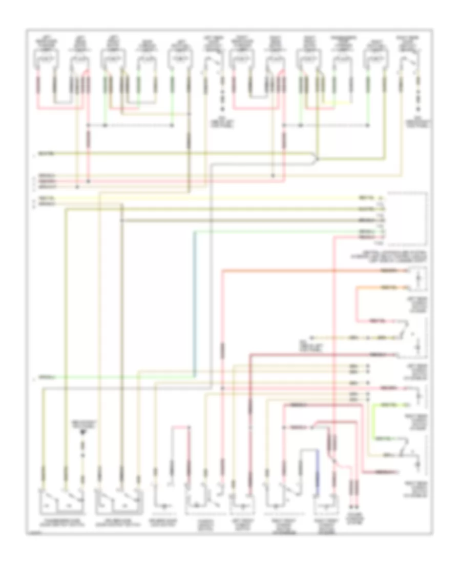
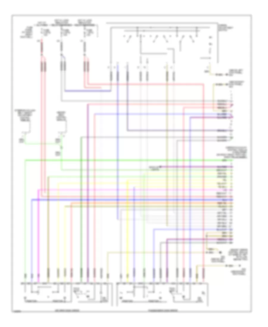
AIR CONDITIONING
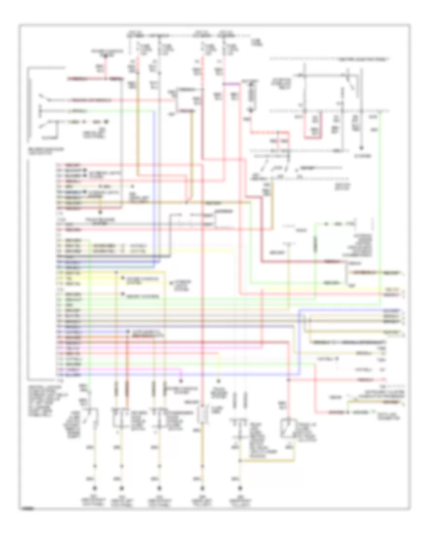
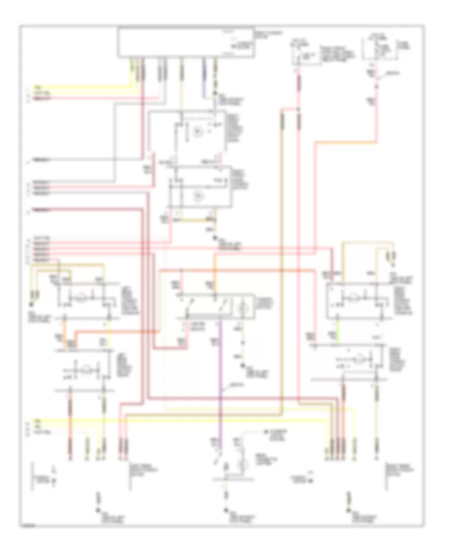
Automatic A/C Wiring Diagram (1 of 3) for Audi A8 1997

List of elements for Automatic A/C Wiring Diagram (1 of 3) for Audi A8 1997:
- (behind lower left center of dash, on hvac assembly)
- (behind lower left center of dash, on hvac assembly) left footwell flap motor/position sensor
- (behind lower right center of dash, on hvac assembly) right footwell flap motor/position sensor
- (behind right center of dash, on hvac assembly) flap motor temperature regulator/position sensor
- (left rear of engine compt)
- (left rear of engine compt) recirculation flap motor/ position sensor
- A/c control head
- A10
- A11
- A12
- A13
- A14
- A15
- A16
- A17
- A18
- A19
- A20
- A21
- A22
- A23
- A24
- Air flow flap motor/ back pressure flap motor position sensor
- B10
- B11
- B12
- B13
- B14
- B15
- B16
- B17
- B18
- B19
- B20
- B21
- B22
- Center vent adjusting motor/position sensor
- Fresh air blower (center rear of engine compt)
- Fresh air blower control module (right rear of engine compt)
- G43 (above right kick panel)
- Interior monitoring sensors control module
- Left center vent motor/position sensor (behind upper left center of dash, on hvac assembly)
- Rear footwell vent motor/position sensor (behind lower left center of dash, on hvac assembly)
- Red
- Right center vent motor/position sensor (behind upper right center of dash, on hvac assembly)
- Solid state
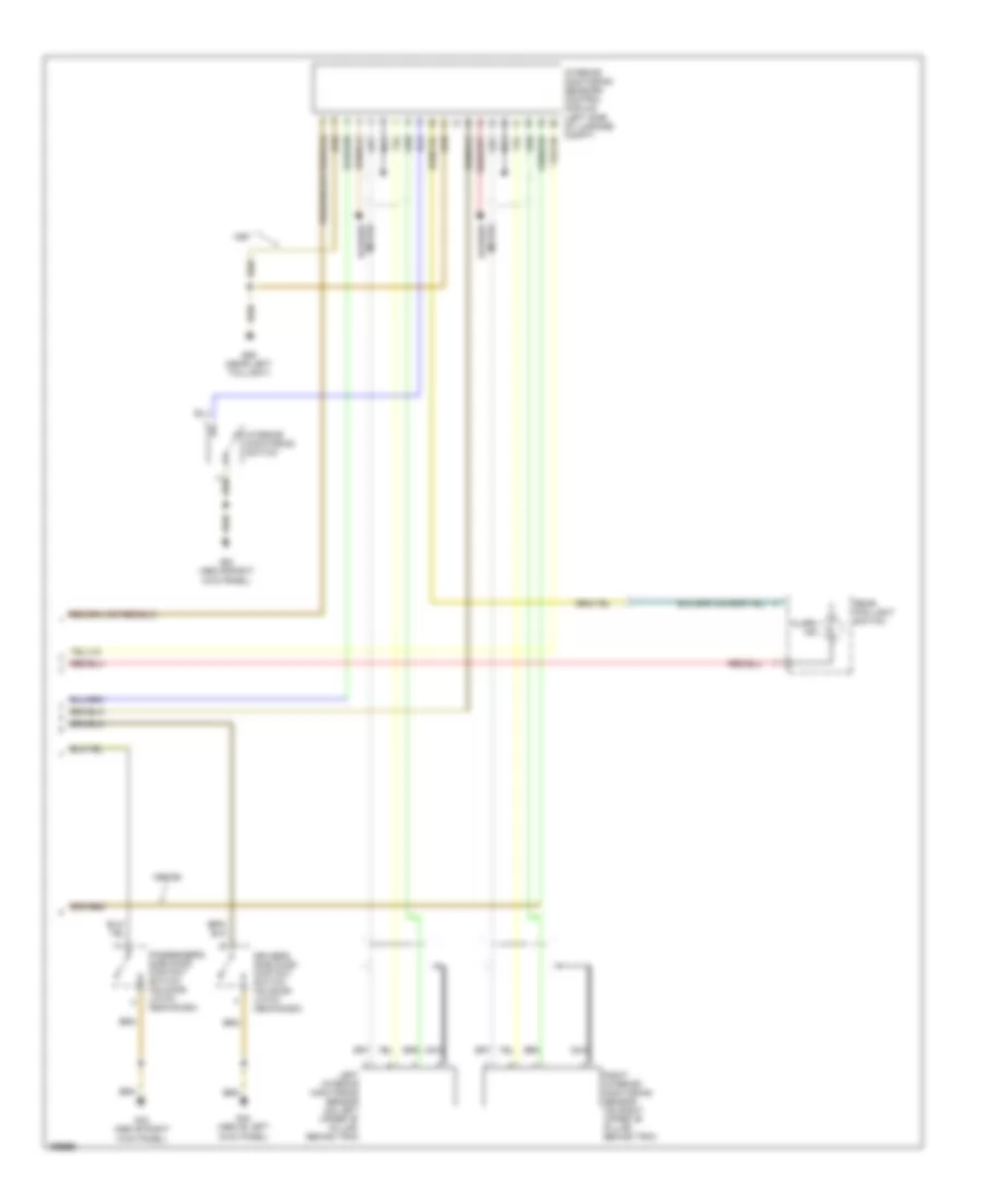
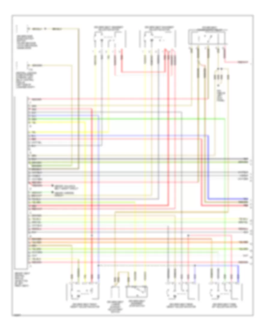
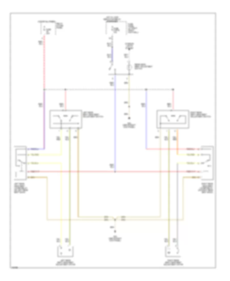
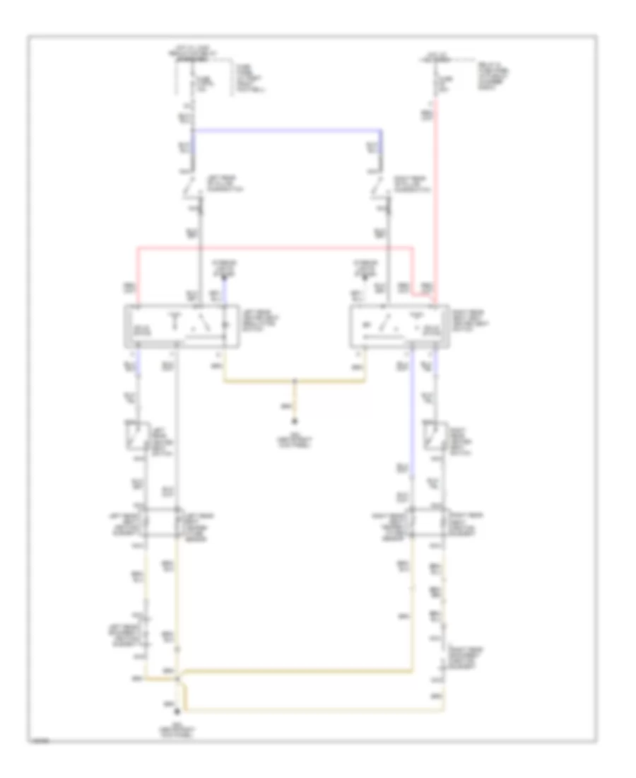
Automatic A/C Wiring Diagram (2 of 3) for Audi A8 1997
List of elements for Automatic A/C Wiring Diagram (2 of 3) for Audi A8 1997:
- (above left kick panel) g44
- (above right kick panel) g43
- (behind left center of dash) left vent temperature sensor
- (behind left center of dash, on hvac assembly) defroster flap motor/ position sensor
- (behind right center of dash)
- (left rear of engine compt) fresh air intake duct temperature sensor
- (on right front footwell e-box relay panel) solar cell separation relay
- 40a
- 60a
- Blower fan fuse
- Central electric panel
- Coolant fan
- Coolant fan control relay (on relay panel)
- Coolant fan control series resistance (lower left front of engine compt)
- Coolant fan control thermal switch (lower right side of radiator)
- Coolant fan fuse
- Fuse 4 (st2) 5a
- Fuse 9 (st1) 5a
- Fuse panel (right front footwell)
- Hot at all times
- Hot w/ load reduction relay energized
- Left center vent switch (behind upper left center of dash, on vent)
- Nca
- Red
- Right vent temperature sensor
- Second speed coolant fan control relay (on relay panel)
- Solar cells
- Solar operation control module
- Third speed coolant fan control relay (below left side of dash)
Automatic A/C Wiring Diagram (3 of 3) for Audi A8 1997
List of elements for Automatic A/C Wiring Diagram (3 of 3) for Audi A8 1997:
- (above a/c controls, in center console) instrument panel interior temperature sensor
- (above a/c controls, in center console) interior temperature sensor fan
- (above left kick panel) g44
- (behind center of lower radiator grill) outside air temperature sensor
- (in plenum chamber e-box) motronic engine control module
- (integral with coolant pump)
- (on top
- 1/+
- 2/-
- A/c clutch
- A/c clutch relay (on right front footwell e-box relay panel)
- A/c control head
- A/c refrigerant high pressure switch (below left headlight)
- A/c refrigerant low pressure switch (left rear of engine compt)
- C10
- C11
- C12
- C13
- C14
- C15
- C16
- C17
- C18
- C19
- C20
- C21
- C22
- C23
- C24
- Center of
- Center vent position sensor (behind upper center of dash, on hvac assembly)
- Computer data lines system
- Coolant pump (left rear of engine compt)
- D10
- D11
- D12
- E10
- E11
- E12
- Fuse 4 (st3) 5a
- Fuse 5 (st3) 15a
- Fuse 7 (st3) 15a
- Fuse panel (right front footwell)
- G43 (above right kick panel)
- Hot at all times
- Hot in run and start
- Instrument cluster combination processor
- Interior lights system
- Left heat regulating valve
- Middle defrost vent) sunlight photo sensor
- Nca
- Protection diode
- Right center vent switch (behind upper right center of dash, on vent)
- Right heat regulating valve
- Solid state
- T16a
- T26
- T26b
ANTI-LOCK BRAKES
Anti-lock Brakes Wiring Diagram, AWD for Audi A8 1997
List of elements for Anti-lock Brakes Wiring Diagram, AWD for Audi A8 1997:
- (above left kick panel)
- 10a
- Abs control module (below left side of dash)
- Abs hydraulic unit (left front of engine compt)
- Abs inlet valves
- Abs outlet valves
- Abs return flow relay & pump
- Abs solenoid valve relay
- Abs warning light
- Brakelight switch (above brake pedal, on bracket)
- C24
- Computer data lines system
- Data link connector
- Exterior lights system
- Fuse 1 (st3) 15a
- Fuse 10 (st4) 10a
- Fuse 25a
- Fuse 4 (st3) 10a
- Fuse 50a
- Fuse 9 (st2) 10a
- Fuse panel (right front footwell)
- G44
- Hot at all times
- Hot in on or start
- Instrument cluster
- Left front
- Left front abs wheel speed sensor
- Left rear
- Left rear abs wheel speed sensor
- Motronic engine control module (in plenum chamber e-box)
- Red
- Relay & fuse panel (right side of luggage compt)
- Right front
- Right front abs wheel speed sensor
- Right rear
- Right rear abs wheel speed sensor
- T26a
- Tf6
- Traction control indicator
- Traction control outlet valves
- Traction control switch-over valves
Anti-lock Brakes Wiring Diagram, FWD for Audi A8 1997
List of elements for Anti-lock Brakes Wiring Diagram, FWD for Audi A8 1997:
- (above left kick panel)
- 10a
- A12
- Abs control module (below left side of dash)
- Abs hydraulic unit (left front of engine compt)
- Abs inlet valves
- Abs outlet valves
- Abs return flow relay & pump
- Abs solenoid valve relay
- Abs warning light
- Anti-slip control switch
- Brakelight switch (above brake pedal, on bracket)
- C24
- Chamber e-box)
- Computer data lines system
- Data link connector
- Exterior lights system
- Fuse 1 (st3) 15a
- Fuse 10 (st4) 10a
- Fuse 25a
- Fuse 4 (st3) 10a
- Fuse 50a
- Fuse 9 (st2) 10a
- Fuse panel (right front footwell)
- G44
- Hot at all times
- Hot in on or start
- Instrument cluster
- Interior lights system
- Left front
- Left front abs wheel speed sensor
- Left rear
- Left rear abs wheel speed sensor
- Motronic engine control module (in plenum
- Red
- Relay & fuse panel (right side of luggage compt)
- Right front
- Right front abs wheel speed sensor
- Right rear
- Right rear abs wheel speed sensor
- T26
- T26a
- Tach
- Tf6
- Traction control indicator
- Traction control outlet valves
- Traction control switch-over valves
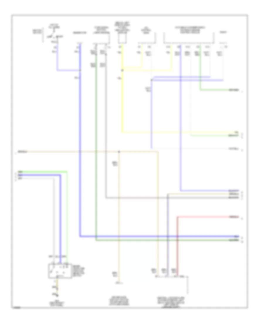
ANTI-THEFT
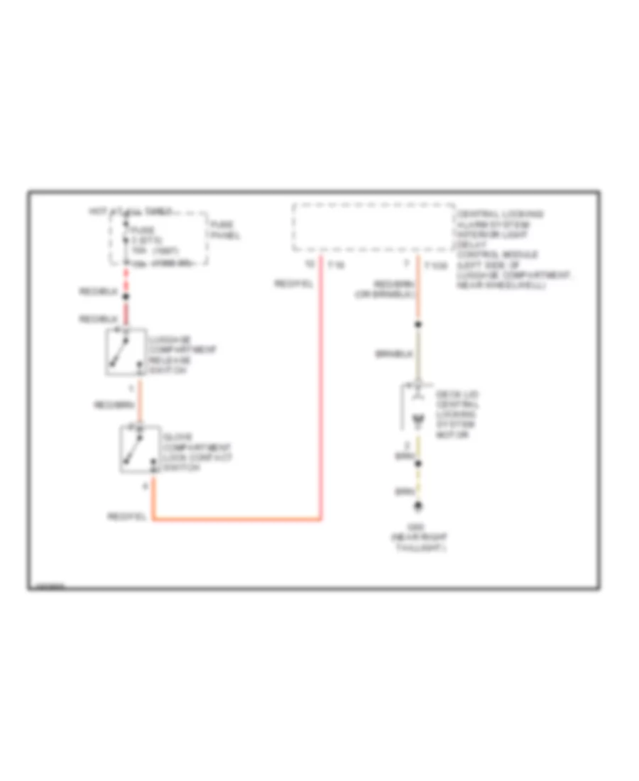
Power Door Locks Wiring Diagram (1 of 2) for Audi A8 1997
List of elements for Power Door Locks Wiring Diagram (1 of 2) for Audi A8 1997:
- 1998-99
- 50b
- 86s
- Acc
- Alarm
- All times
- Antenna
- Battery
- C16
- Central electric panel
- Central locking/ alarm system/ interior light delay control module (at left side of luggage compt, near wheelwell)
- Data link connector
- Driver's door handle alarm switch
- Driver's side door lock switch
- Exterior lights system
- Fuse 1 (st5) 10a
- Fuse 3 (st5) 15a
- Fuse 4 (st5) 10a
- Fuse 5 (st5) 15a
- Fuse panel
- G43 (above right
- G44 (above left
- G44 (above left kick panel)
- G59 (near left taillight)
- G60 (near right
- Hood alarm switch (on right rear of engine compt)
- Horn
- Hot at
- Hot in run
- Ignition switch
- Instrument cluster combination processor
- Interior lights system
- Key switch
- Kick panel)
- Memory systems
- Motronic engine control module (ecm) (in plenum chamber e-box)
- Nca
- Off
- Passenger's door handle alarm switch
- Power windows system
- Radio
- Red
- S1/ 50z
- S4/ 50z
- S4/a
- S4/b
- S6/ 50a
- Start
- Starter
- Starting interlock relay
- T10o
- T12
- T16
- T26
- T26a
- T26b
- Taillight)
- Trunk lid alarm switch (in trunk lid latch)
- Trunk lock alarm/ central locking switch (on trunk lock cylinder housing)
- Trunk release system
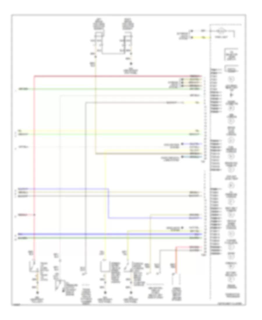
Power Door Locks Wiring Diagram (2 of 2) for Audi A8 1997
List of elements for Power Door Locks Wiring Diagram (2 of 2) for Audi A8 1997:
- 1998-99
- Alarm ind
- Blower motor
- Driver's side door contact switch (on door latch mechanism)
- G43 (above right
- G44 (above left
- G59 (near left taillight)
- Interior monitoring sensors control module (left side of luggage compt)
- Interior monitoring switch
- Kick panel)
- Left interior monitoring sensor (on left upper "b" pillar, behind trim)
- Motor blower
- Nca
- Passenger's side door contact switch (on door latch mechanism)
- Rear fog light switch
- Right interior monitoring sensor (on right upper "b" pillar, behind trim)
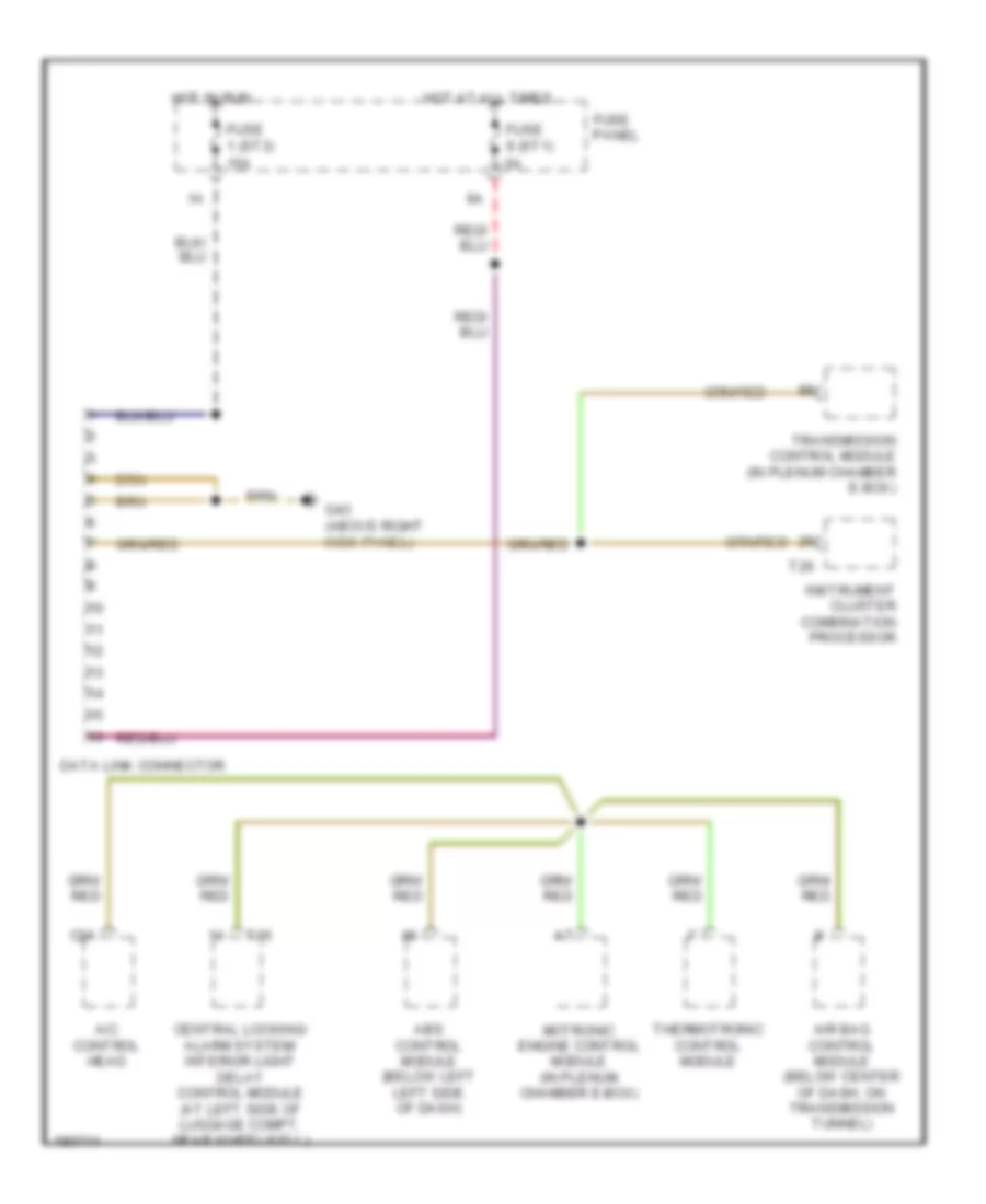
COMPUTER DATA LINES
Computer Data Lines Wiring Diagram for Audi A8 1997
List of elements for Computer Data Lines Wiring Diagram for Audi A8 1997:
- A/c control head
- Abs control module (below left left side of dash)
- Air bag control module (below center of dash, on transmission tunnel)
- C24
- Central locking/ alarm system/ interior light delay control module (at left side of luggage compt, near wheelwell)
- Data link connector
- Fuse 1 (st3) 15a
- Fuse 9 (st1) 5a
- Fuse panel
- G43 (above right kick panel)
- Hot at all times
- Hot in run
- Instrument cluster combination processor
- Motronic engine control module (in plenum chamber e-box)
- T16
- T26
- Thermotronic control module
- Transmission control module (in plenum chamber e-box)
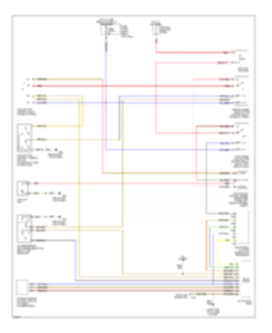
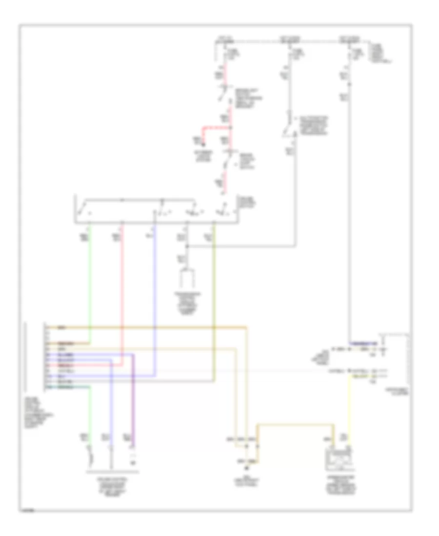
COOLING FAN
Cooling Fan Wiring Diagram for Audi A8 1997
List of elements for Cooling Fan Wiring Diagram for Audi A8 1997:
- 60a
- A/c control head
- A/c refrigerant high pressure switch (below left headlight)
- A/c system
- C11
- C13
- C14
- C24
- Central electric panel
- Computer data lines system
- Coolant fan
- Coolant fan control relay (on relay panel)
- Coolant fan control series resistance (lower left front of engine compt)
- Coolant fan control thermal switch (lower right side of radiator)
- Coolant fan fuse
- D10
- D12
- Data link connector
- E12
- Fuse 4 (st2) 5a
- Fuse panel (right front footwell)
- G43 (above right kick panel)
- G44 (above left kick panel)
- Hot at all times
- Hot w/ load reduction relay energized
- Instrument cluster combination processor
- Motronic engine control module (in plenum chamber e-box)
- Red
- Second speed coolant fan control relay (on relay panel)
- Solid state
- T16a
- T26
- T26b
- Third speed coolant fan control relay (below left side of dash)
CRUISE CONTROL
Cruise Control Wiring Diagram for Audi A8 1997
List of elements for Cruise Control Wiring Diagram for Audi A8 1997:
- Brake vacuum dump switch
- Brakelight switch (above brake pedal, on bracket)
- Cruise control module (in plenum chamber e-box, right rear of engine compt)
- Cruise control switch
- Cruise control vacuum pump (inside front of left front fender)
- Exterior lights system
- Fuse 1 (st3) 15a
- Fuse 6 (st3) 10a
- Fuse 9 (st2) 10a
- Fuse panel (right front footwell)
- G43 (above right kick panel)
- G44 (above left kick panel)
- Hot at all times
- Hot in run or start
- Instrument cluster
- Multifunction transmission range switch (left side of transmission)
- Speedometer vehicle speed sensor (on left side of transmission)
- T26
- T6f
- Transmission control module (in plenum chamber e-box)
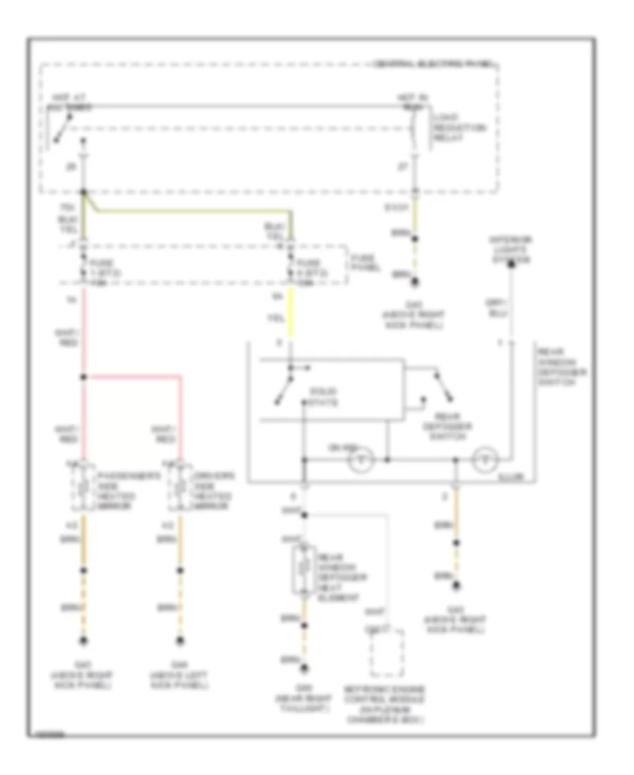
DEFOGGERS
Defoggers Wiring Diagram for Audi A8 1997
List of elements for Defoggers Wiring Diagram for Audi A8 1997:
- 75x
- C22
- Central electric panel
- Driver's side heated mirror
- Fuse 1 (st2) 10a
- Fuse 6 (st2) 30a
- Fuse panel
- G43 (above right kick panel)
- G44 (above left kick panel)
- G60 (near right taillight)
- Hot at all times
- Hot in run
- Illum
- Interior lights system
- Load reduction relay
- Motronic engine control module (in plenum chamber e-box)
- On ind
- Passenger's side heated mirror
- Rear defogger switch
- Rear window defogger heat element
- Rear window defogger switch
- S1/31
- Solid state
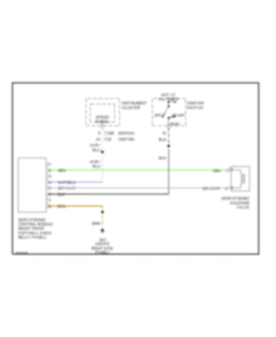
ELECTRONIC POWER STEERING
Electronic Power Steering Wiring Diagram for Audi A8 1997
List of elements for Electronic Power Steering Wiring Diagram for Audi A8 1997:
- (1997-99)
- (2000-03)
- G43 (above right kick panel)
- Hot at all times
- Ignition switch
- Instrument cluster
- Off
- Run
- Servotronic control module (right front footwell e-box relay panel)
- Servotronic solenoid valve
- Speed signal
- Start
- T26
- T32b
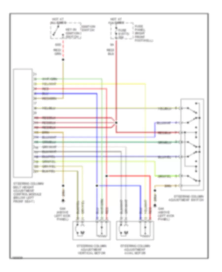
Power Steering Column Wiring Diagram for Audi A8 1997
List of elements for Power Steering Column Wiring Diagram for Audi A8 1997:
- 86s
- Fuse 9 (st5) 20a
- Fuse panel (right front footwell)
- G44 (above left kick panel)
- Hot at all times
- Ignition switch
- Key-in ignition switch
- Red
- Steering column adjustment axial motor
- Steering column adjustment switch
- Steering column adjustment vertical motor
- Steering column/ belt height adjustment control module (below left front seat)
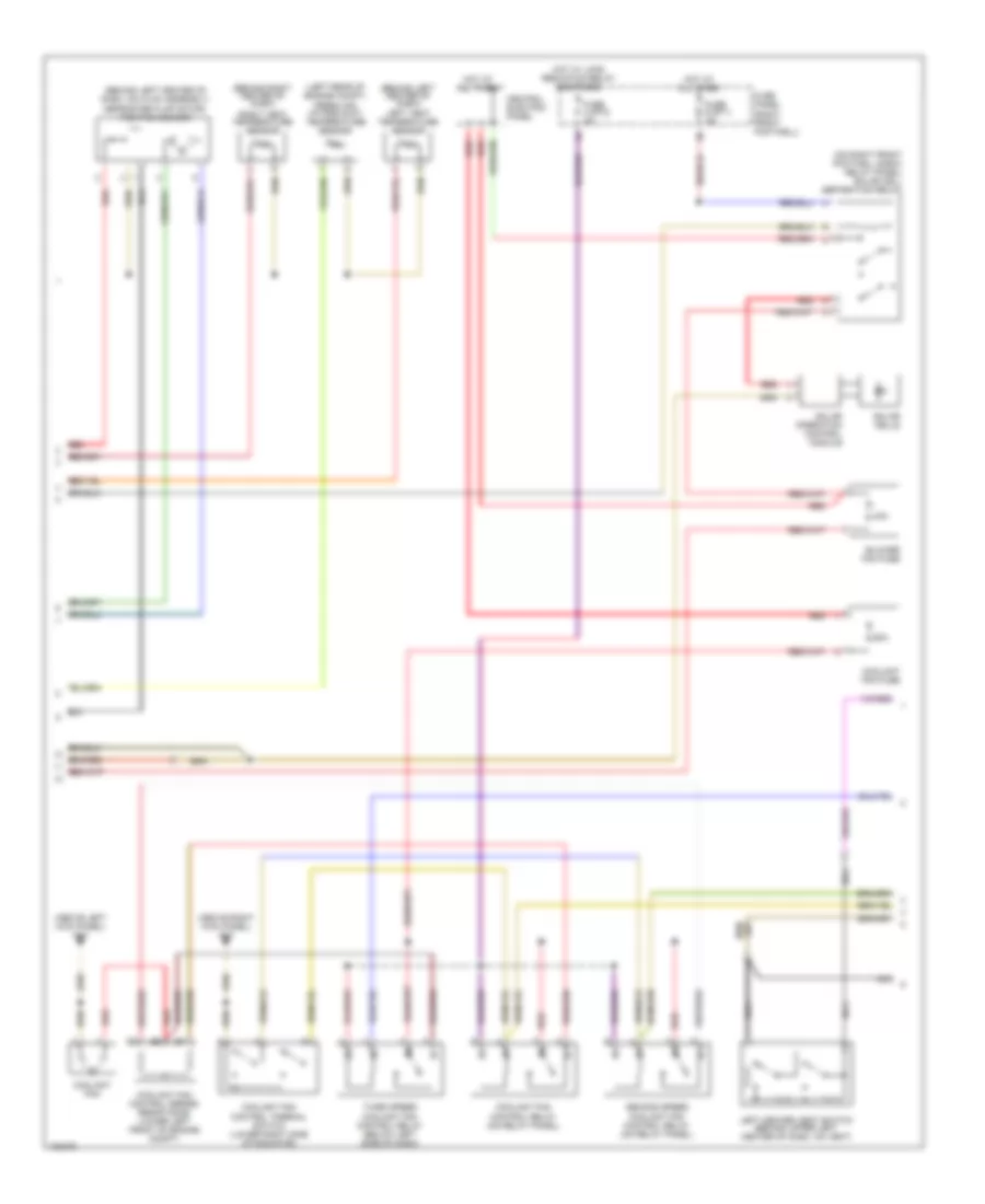
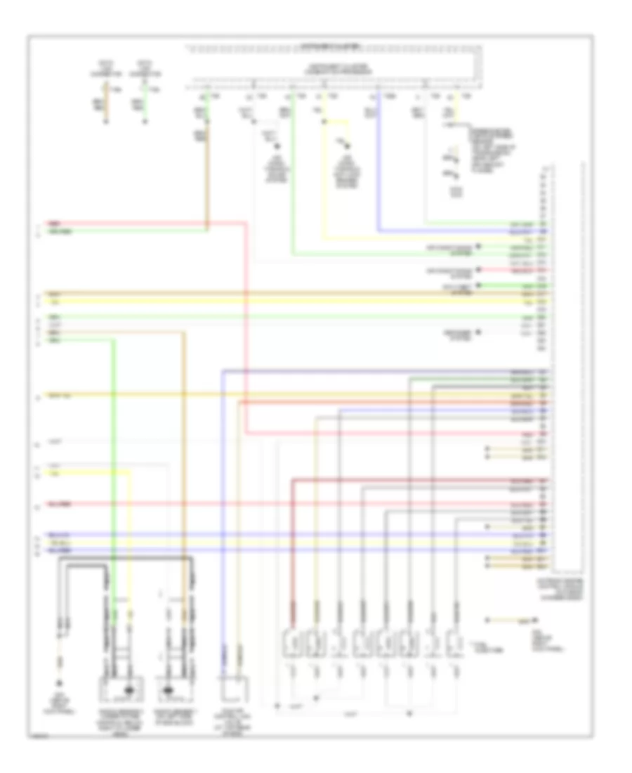
ENGINE PERFORMANCE
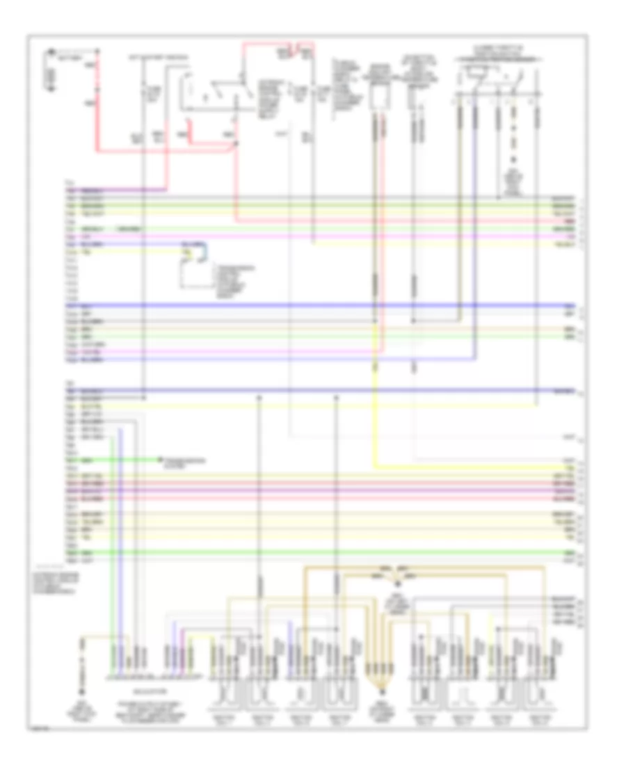
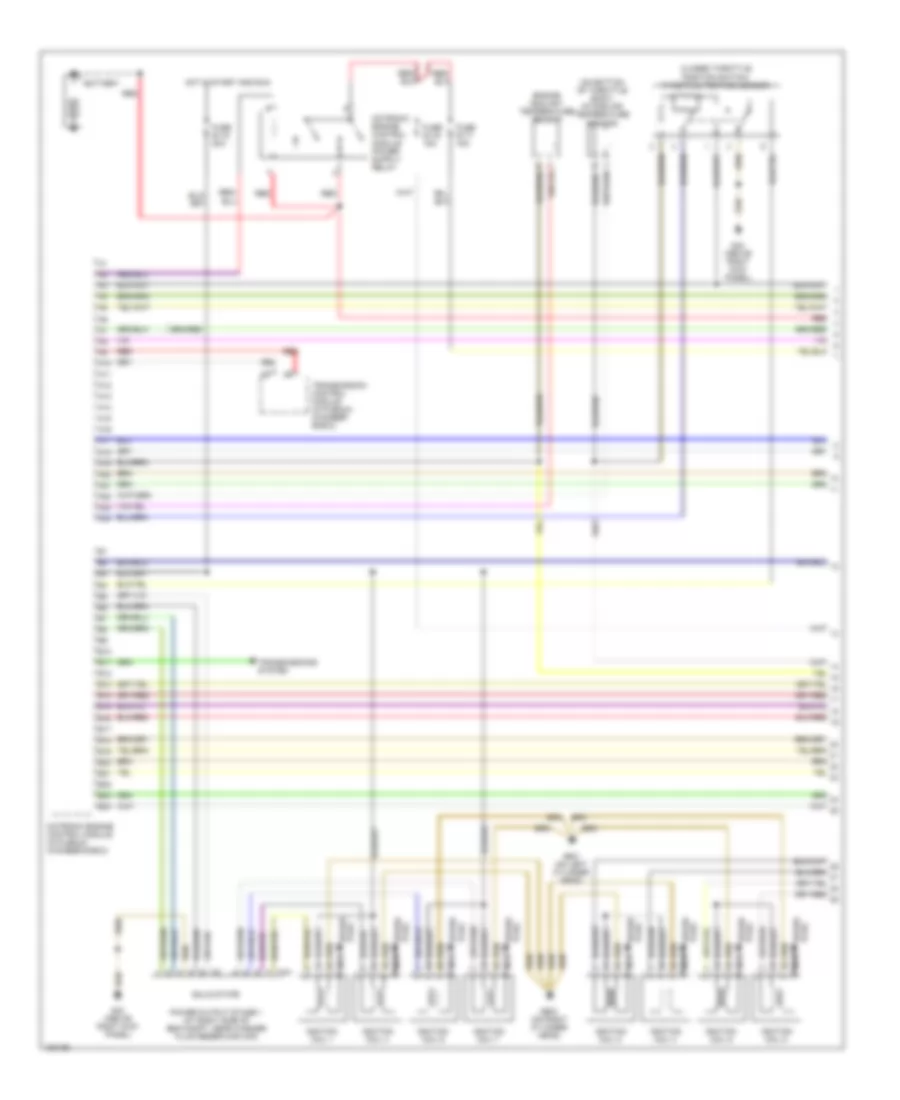
3.7L
3.7L, Engine Performance Wiring Diagram (1 of 3) for Audi A8 1997
List of elements for 3.7L, Engine Performance Wiring Diagram (1 of 3) for Audi A8 1997:
- (on bottom of throttle body) intake air temperature sensor
- A10
- A11
- A12
- A13
- A14
- A15
- A16
- A17
- A18
- A19
- A20
- A21
- A22
- A23
- A24
- B10
- B11
- B12
- B13
- B14
- B15
- B16
- B17
- B18
- B19
- B20
- B21
- B22
- B23
- B24
- Battery
- Closed throttle position switch/ throttle position sensor
- Engine coolant temperature sensor
- Fuse s115 20a
- Fuse s116 15a
- Fuse s117 15a
- G43 (above right kick panel)
- G600 (on right cylinder head)
- G601 (on left cylinder head)
- Hot in start and run
- Ignition coil 1
- Ignition coil 2
- Ignition coil 3
- Ignition coil 4
- Ignition coil 5
- Ignition coil 6
- Ignition coil 7
- Ignition coil 8
- Motronic engine control module (in plenum chamber e-box)
- Nca
- Plenum chamber e-box relay & fuse panel (in plenum chamber e-box)
- Plug spark
- Power output stage 1 (at right side of eng compt, near washer fluid reservoir cap)
- Red
- Solid state
- Spark plug
- T4a
- Transmission control module (in plenum chamber e-box)
- Transmissions system
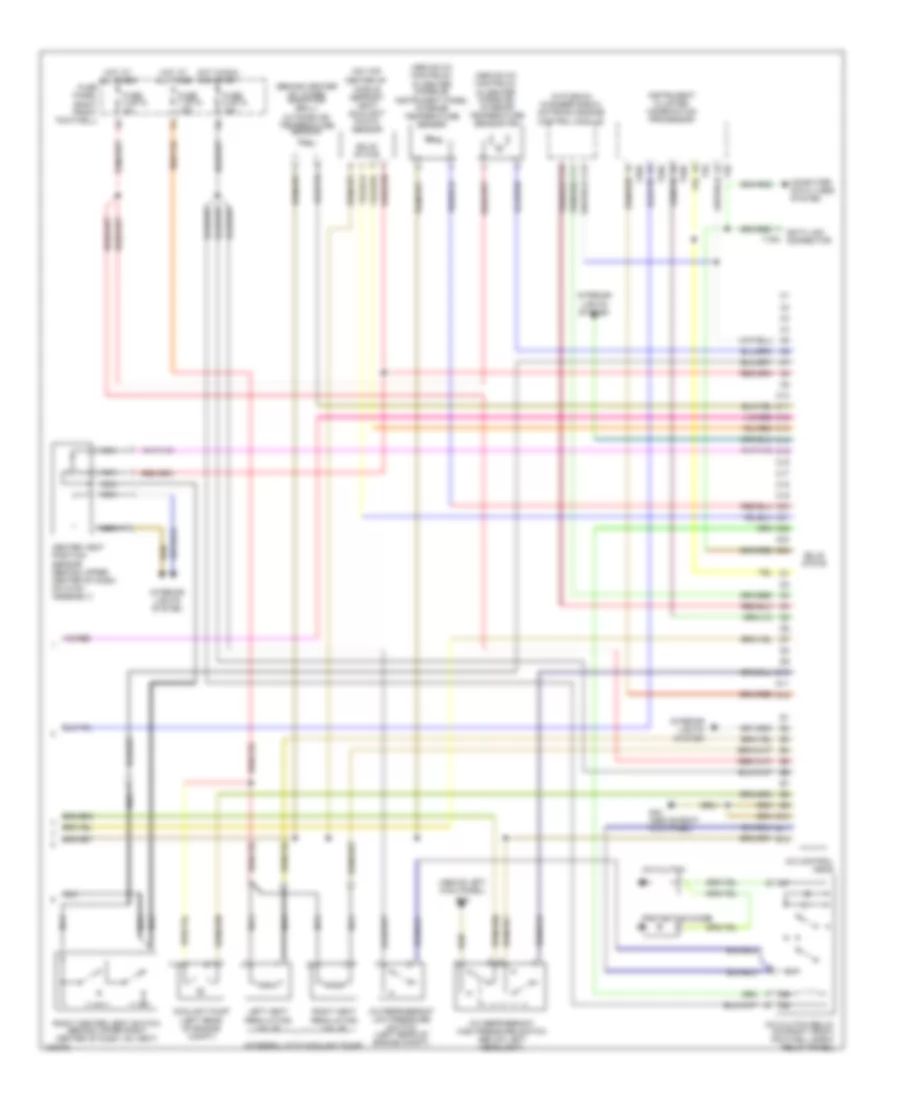
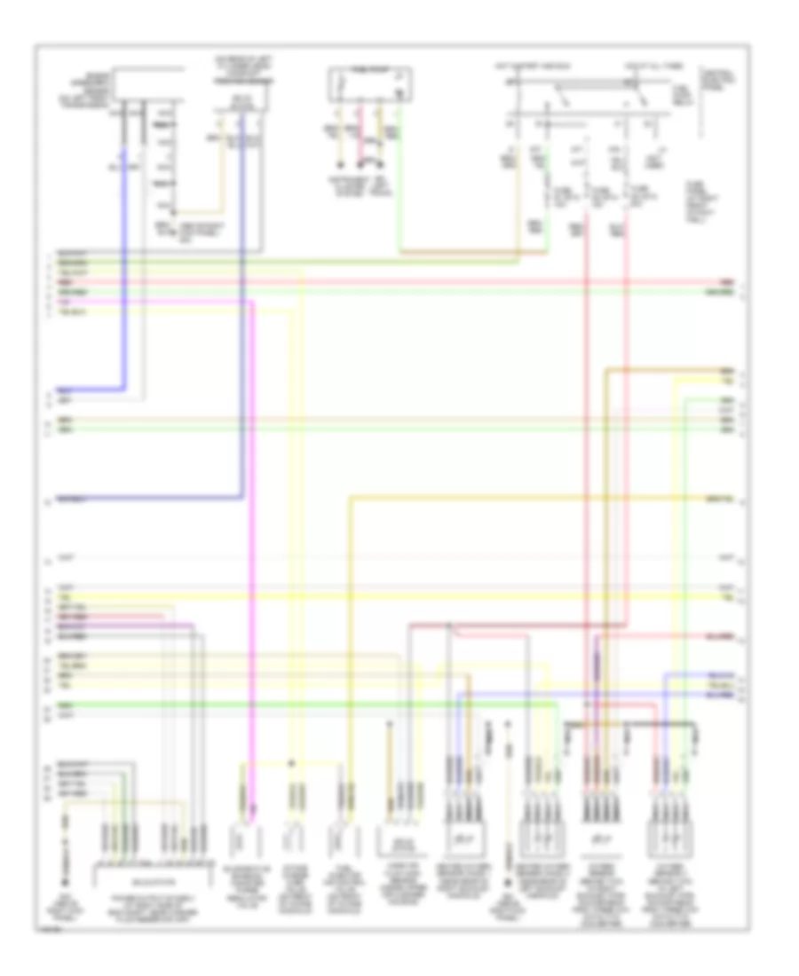
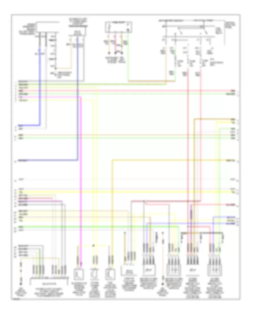
3.7L, Engine Performance Wiring Diagram (2 of 3) for Audi A8 1997
List of elements for 3.7L, Engine Performance Wiring Diagram (2 of 3) for Audi A8 1997:
- (above right kick panel) g43
- (not used)
- (on rear of left cylinder head) camshaft position sensor
- 87f
- 87a
- Central electric panel
- Dti
- Engine speed(rpm) sensor (on left front transmission)
- Evaporative emission canister purge regulator valve
- Fuel injector air control valve (on front of intake manifold)
- Fuel pump
- Fuel pump relay
- Fuse panel (at right front of foot- well)
- Fuse s1 (st4) 15a
- Fuse s3 (st4) 20a
- Fuse s4 (st4) 15a
- G43 (above right kick panel)
- G51 (left trunk)
- Heated oxygen sensor (ho2s) 1 (near rear of right exhaust manifold)
- Heated oxygen sensor (ho2s) 2 (near rear of left exhaust manifold)
- Hot at all times
- Hot in start and run
- Instrument cluster system
- Intake change over valve (on front of intake manifold)
- Mass air flow (maf) sensor (inside upper air cleaner housing)
- Nca
- Oxygen sensor (behind twc) (in right exhaust pipe, downstream from three way catalytic converter)
- Oxygen sensor 2 (behind twc) (in left exhaust pipe, downstream from three way catalytic converter)
- Power output stage 2 (at right side of eng compt, near washer fluid reservoir cap)
- Red
- Solid state
- T4a
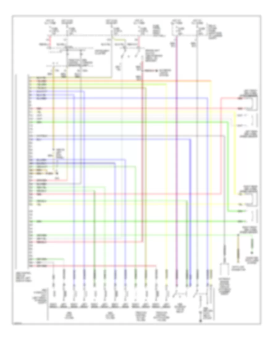
3.7L, Engine Performance Wiring Diagram (3 of 3) for Audi A8 1997
List of elements for 3.7L, Engine Performance Wiring Diagram (3 of 3) for Audi A8 1997:
- Air condi- tioning & anti-lock brakes system
- Air condi- tioning & sound system
- Air conditioning system
- Anti-theft system
- C1
- C10
- C11
- C12
- C13
- C14
- C15
- C16
- C17
- C18
- C19
- C20
- C21
- C22
- C23
- C24
- D10
- D11
- D12
- Data link connector
- Defogger system
- E10
- E11
- E12
- Fuel injectors
- G102 (n/a)
- G43 (above right kick panel)
- Idle air control (iac) valve (at top rear of eng)
- Instrument cluster
- Instrument cluster combination processor
- Knock sensor 1 (on left side of eng block)
- Knock sensor 2 (under intake manifold, below right cylinder head)
- Motronic engine control module (in plenum chamber e-box)
- Nca
- Red
- Speedometer vehicle speed sensor (on left side of transmission, near left driveshaft flange)
- T16a
- T16b
- T26
- T26a
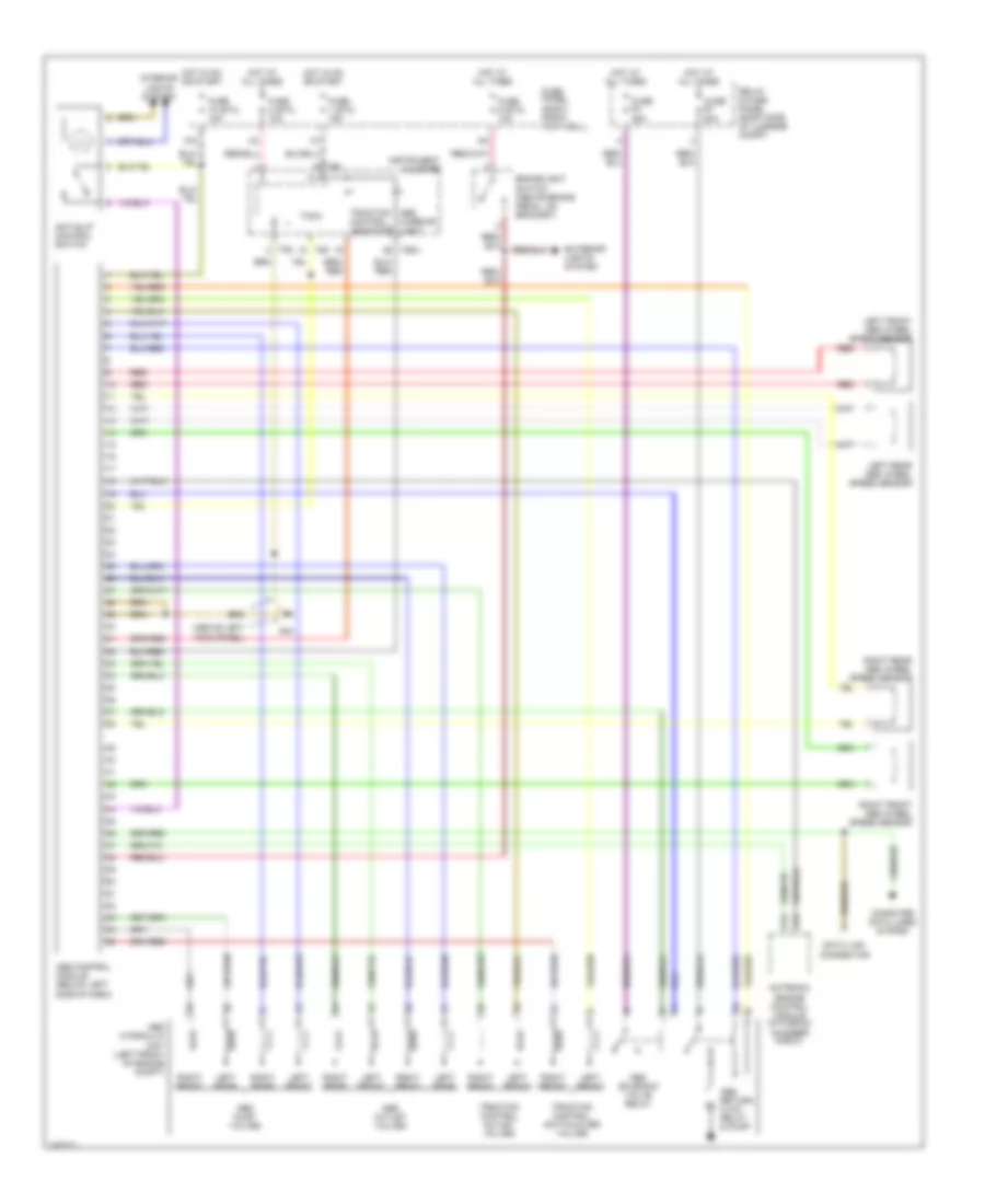
4.2L
4.2L, Engine Performance Wiring Diagram (1 of 3) for Audi A8 1997
List of elements for 4.2L, Engine Performance Wiring Diagram (1 of 3) for Audi A8 1997:
- (on bottom of throttle body) intake air temperature sensor
- A10
- A11
- A12
- A13
- A14
- A15
- A16
- A17
- A18
- A19
- A20
- A21
- A22
- A23
- A24
- B10
- B11
- B12
- B13
- B14
- B15
- B16
- B17
- B18
- B19
- B20
- B21
- B22
- B23
- B24
- Battery
- Closed throttle position switch/ throttle position sensor
- Engine coolant temperature sensor
- Fuse s115 20a
- Fuse s116 15a
- Fuse s117 15a
- G43 (above right kick panel)
- G600 (on right cylinder head)
- G601 (on left cylinder head)
- Hot in start and run
- Ignition coil 1
- Ignition coil 2
- Ignition coil 3
- Ignition coil 4
- Ignition coil 5
- Ignition coil 6
- Ignition coil 7
- Ignition coil 8
- Motronic engine control module (in plenum chamber e-box)
- Nca
- Plug spark
- Power output stage 1 (at right side of eng compt, near washer fluid reservoir cap)
- Red
- Solid state
- Spark plug
- T4a
- Transmission control module (in plenum chamber e-box)
- Transmissions system
4.2L, Engine Performance Wiring Diagram (2 of 3) for Audi A8 1997
List of elements for 4.2L, Engine Performance Wiring Diagram (2 of 3) for Audi A8 1997:
- (above right kick panel) g43
- (not used)
- (on rear of left cylinder head) camshaft position sensor
- 87f
- 87a
- Central electric panel
- Dti
- Electronic box
- Engine speed(rpm) sensor (on left front transmission)
- Evaporative emission canister purge regulator valve
- Fuel injector air control valve (on front of intake manifold)
- Fuel pump
- Fuel pump relay
- Fuse s1 15a
- Fuse s3 20a
- Fuse s4 15a
- G43 (above right kick panel)
- G51 (left trunk)
- Heated oxygen sensor (ho2s) 1 (near rear of right exhaust manifold)
- Heated oxygen sensor (ho2s) 2 (near rear of left exhaust manifold)
- Hot at all times
- Hot in start and run
- Instrument cluster system
- Intake change over valve (on front of intake manifold)
- Mass air flow (maf) sensor (inside upper air cleaner housing)
- Nca
- Oxygen sensor (behind twc) (in right exhaust pipe, downstream from three way catalytic converter)
- Oxygen sensor 2 (behind twc) (in left exhaust pipe, downstream from three way catalytic converter)
- Power output stage 2 (at right side of eng compt, near washer fluid reservoir cap)
- Red
- Solid state
- St4
- T4a
4.2L, Engine Performance Wiring Diagram (3 of 3) for Audi A8 1997
List of elements for 4.2L, Engine Performance Wiring Diagram (3 of 3) for Audi A8 1997:
- Air condi- tioning & anti-lock brakes system
- Air condi- tioning & sound system
- Air conditioning system
- Anti-theft system
- C1
- C10
- C11
- C12
- C13
- C14
- C15
- C16
- C17
- C18
- C19
- C20
- C21
- C22
- C23
- C24
- D10
- D11
- D12
- Data link connector
- Defogger system
- E10
- E11
- E12
- Fuel injectors
- G102 (n/a)
- G43 (above right kick panel)
- Idle air control (iac) valve (at top rear of eng)
- Instrument cluster
- Instrument cluster combination processor
- Knock sensor 1 (on left side of eng block)
- Knock sensor 2 (under intake manifold, below right cylinder head)
- Motronic engine control module (in plenum chamber e-box)
- Nca
- Red
- Speedometer vehicle speed sensor (on left side of transmission, near left driveshaft flange)
- T16a
- T16b
- T26
- T26a
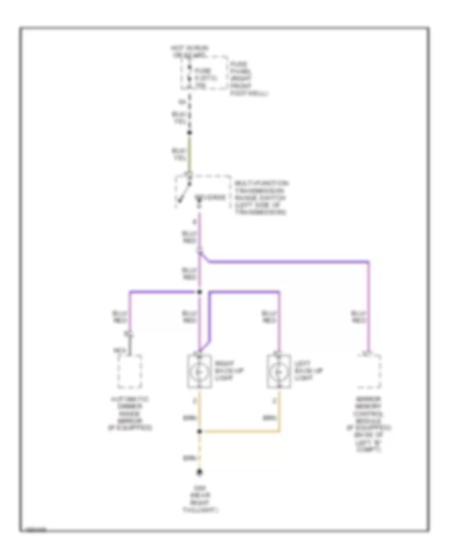
EXTERIOR LIGHTS
Back-up Lamps Wiring Diagram for Audi A8 1997
List of elements for Back-up Lamps Wiring Diagram for Audi A8 1997:
- Automatic dimmer inside mirror (if equipped)
- Fuse 6 (st3) 10a
- Fuse panel (right front footwell)
- G60 (near right taillight)
- Hot in run or start
- Left back-up light
- Mirror memory control module (if equipped) (base of left "b" compt)
- Multi-function transmission range switch (left side of transmission)
- Nca
- Reverse
- Right back-up light
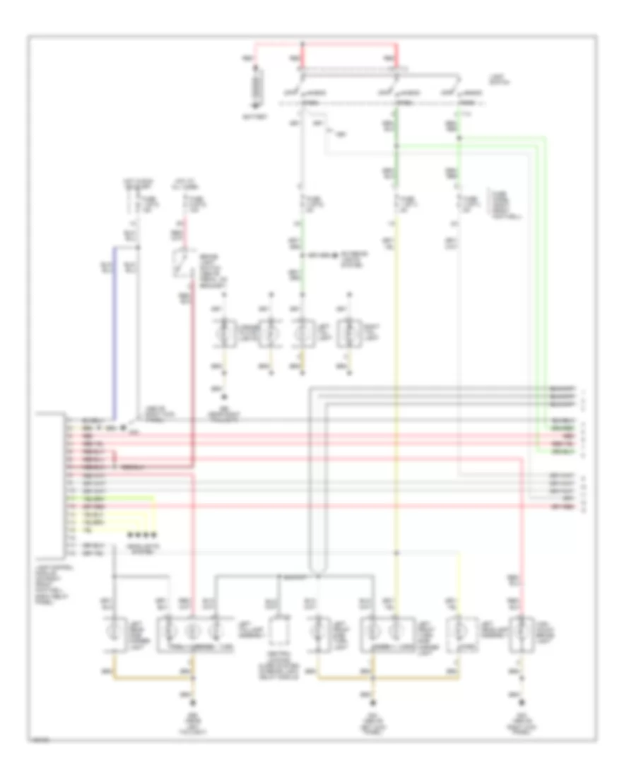
Exterior Lamps Wiring Diagram, with DRL (1 of 2) for Audi A8 1997
List of elements for Exterior Lamps Wiring Diagram, with DRL (1 of 2) for Audi A8 1997:
- (above right kick panel)
- 1998,
- Battery
- Brake
- Brake light switch (above pedal, on bracket)
- Central electric panel
- Central locking/ alarm system/ interior light delay module
- Daytime running lights switch-on relay (on right front footwell e-box relay panel)
- Fuse 1 (st1) 5a
- Fuse 1 (st3) 15a
- Fuse 2 (st1) 5a
- Fuse 9 (st2) 10a
- Fuse panel (right front footwell)
- G43
- G43 (above right kick panel)
- G44 (above left kick panel)
- G59 (near left taillight)
- Head
- Headlights system
- High mount brake light
- Hot at all times
- Hot in run or start
- Ignition switch
- Lamp control module (on right front footwell e-box relay panel)
- Left front side turn light
- Left front turn/ side marker light
- Left headlamp assembly
- Left rear side marker light
- Left taillamp assembly
- Light switch
- Mark
- Off
- Park
- Red
- Run
- S1/75
- Start
- T10
- T14
- Tail
- Turn
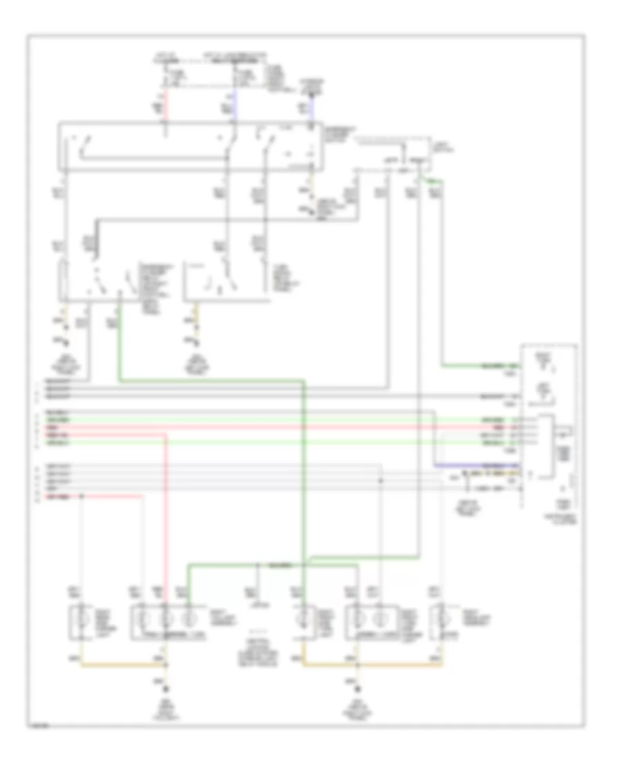
Exterior Lamps Wiring Diagram, with DRL (2 of 2) for Audi A8 1997
List of elements for Exterior Lamps Wiring Diagram, with DRL (2 of 2) for Audi A8 1997:
- (1997)
- (above left kick panel)
- (above right kick panel) g43
- Brake
- Emergency flasher relay (on right front footwell e-box relay panel)
- Emergency flasher switch
- Exterior lights system
- Fuse 7 (st1) 15a
- Fuse 8 (st2) 10a
- Fuse panel (right front footwell)
- G43 (above right kick panel)
- G44
- G44 (above left kick panel)
- G60 (near right taillight)
- Hot at all times
- Hot w/ load reduction relay energized
- Instrument cluster
- Interior lights system
- Left
- Left tail light
- Left turn
- License plate lights
- Light switch
- Mark
- Off
- Park
- Park (1997)
- Park (1998, 1999)
- Red
- Right
- Right front side turn light
- Right front turn/ side marker light
- Right headlamp assembly
- Right rear side marker light
- Right tail light
- Right taillamp assembly
- Right turn
- T26a
- T26b
- T6f
- Tail
- Turn
- Turn signal relay (on relay panel)
Exterior Lamps Wiring Diagram, without DRL (1 of 2) for Audi A8 1997
List of elements for Exterior Lamps Wiring Diagram, without DRL (1 of 2) for Audi A8 1997:
- (above right kick panel)
- Battery
- Brake
- Brake light switch (above pedal, on bracket)
- Central locking/ alarm system/ interior light delay module
- Exterior lights system
- Fuse 1 (st1) 5a
- Fuse 1 (st3) 15a
- Fuse 2 (st1) 5a
- Fuse 3 (st2) 5a
- Fuse 9 (st2) 10a
- Fuse panel (right front footwell)
- G43
- G43 (above right kick panel)
- G44 (above left kick panel)
- G59 (near left taillight)
- G60 (near right taillight)
- Head
- Headlights system
- High mount brake light
- Hot at all times
- Hot in run or start
- Lamp control module (on right front footwell e-box relay panel)
- Left front side turn light
- Left front turn/ side marker light
- Left headlamp assembly
- Left rear side marker light
- Left tail light
- Left taillamp assembly
- License plate lights
- Light switch
- Mark
- Off
- Park
- Red
- Right tail light
- T10
- T14
- Tail
- Turn
Exterior Lamps Wiring Diagram, without DRL (2 of 2) for Audi A8 1997
List of elements for Exterior Lamps Wiring Diagram, without DRL (2 of 2) for Audi A8 1997:
- (1997)
- (above left kick panel)
- (above right kick panel) g43
- Brake
- Central locking/ alarm system/ interior light delay module
- Emergency flasher relay (on right front footwell e-box relay panel)
- Emergency flasher switch
- Fuse 7 (st1) 15a
- Fuse 8 (st2) 10a
- Fuse panel (right front footwell)
- G43 (above right kick panel)
- G44
- G44 (above left kick panel)
- G60 (near right taillight)
- Hot at all times
- Hot w/ load reduction relay energized
- Instrument cluster
- Interior lights system
- Left
- Left turn
- Light switch
- Mark
- Off
- Park
- Park (1997)
- Park (1998, 1999)
- Red
- Right
- Right front side turn light
- Right front turn/ side marker light
- Right headlamp assembly
- Right rear side marker light
- Right taillamp assembly
- Right turn
- T10
- T26a
- T26b
- T6f
- Tail
- Turn
- Turn signal relay (on relay panel)
GROUND DISTRIBUTION
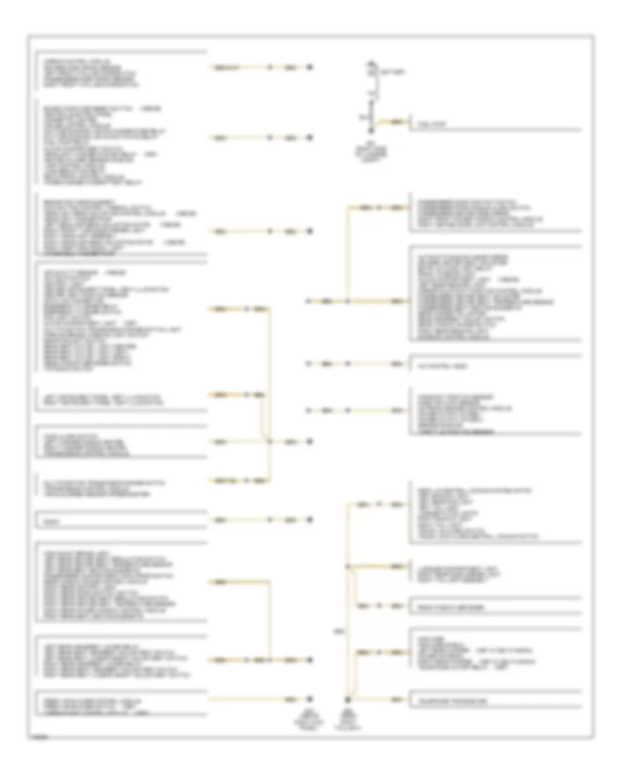
Ground Distribution Wiring Diagram (1 of 2) for Audi A8 1997
List of elements for Ground Distribution Wiring Diagram (1 of 2) for Audi A8 1997:
- (1997 w/ delta radio)
- (1997)
- (1998-99)
- A/c control head
- Air quality sensor anti-slip switch ashtray light center instrument panel vent illumination center vent position sensor data link connector emergency flasher relay emergency flasher switch fog light switch glove compartment light multi-function transmission range switch light parking brake warning light switch rear foglight switch rear seat outlet light (center) rear seat outlet light (left) rear seat outlet light (right) rear window defogger switch tiptronic switch
- Airbag control module drivers side crash sensor left front a pillar microswitch passengers side crash sensor right front a pillar microswitch
- Amplifier amplifier shield left rear woofer power antenna right rear woofer telephone cutoff relay
- Automatic dimming inside mirror drivers heated seat adjuster entry & floor light relay front interior light glove compartment light left rear reading light mirror fold-away function control module passengers heated seat adjuster passengers heated seat temperature sensor passengers seat heating elements rear cigarette lighter rear headrest adjust switch rear window shade switch right rear reading light sunroof control module
- Battery
- Board computer reset button central electric panel cigarette lighter cruise control module daytime running lights change-over relay daytime running lights switch-on relay fuel pump relay glove compartment switch headlight washer system relay heated oxygen sensor shields lamp control module load reduction relay sevotronic control module wiper/washer intermittent relay
- Brake pad wear element coolant fan control thermal switch headlight beam adjusting control module headlight washer pump left headlamp beam adjusting motor right front turn/side marker light right headlamp assembly right headlamp beam adjusting motor right side turn signal light windshield washer pump
- Camshaft position sensor mass air flow sensor motronic engine control module power output stage 1 power output stage 2 sensor shields throttle position sensor
- Deck lid central locking system motor left backup light left rear fog light left tail light license plate lights right backup light right tail light trunk lid alarm switch trunk lock alarm/central locking switch
- Fresh air blower control module fresh air blower switch thermotonic control module
- Fuel pump
- G43 (above right kick panel)
- G51 (right side of luggage compt)
- G60 (near right taillight)
- High mount brake light left rear heated seat regulating switch left rear heated seat temperature sensor left rear seat heating elements passengers compartment monitoring switch rear window shade control module right rear ashtray light right rear door contact switch right rear heated seat regulating switch right rear heated seat temperature sensor right rear power window control module right rear seat heating elements
- Hood alarm switch left washer nozzle heater right washer nozzle heater transmission control module
- Left instrument panel vent illumination right instrument panel vent illumination
- Left rear headrest lower relay left rear seat headrest adjustment switch left rear seat lumbar height adjustment switch right rear headrest lower relay right rear seat headrest adjustment switch right rear seat lumbar height adjustment switch
- Luggage compartment light right rear side marker light right taillamp assembly
- Multi-function transmission range switch transmission control module vehicle speed sensor (speedometer)
- Passengers door contact switch passengers door handle alarm switch passengers heated side mirror right front power window control module right heated door lock control module
- Radio
- Rear window defogger
- Telephone transceiver
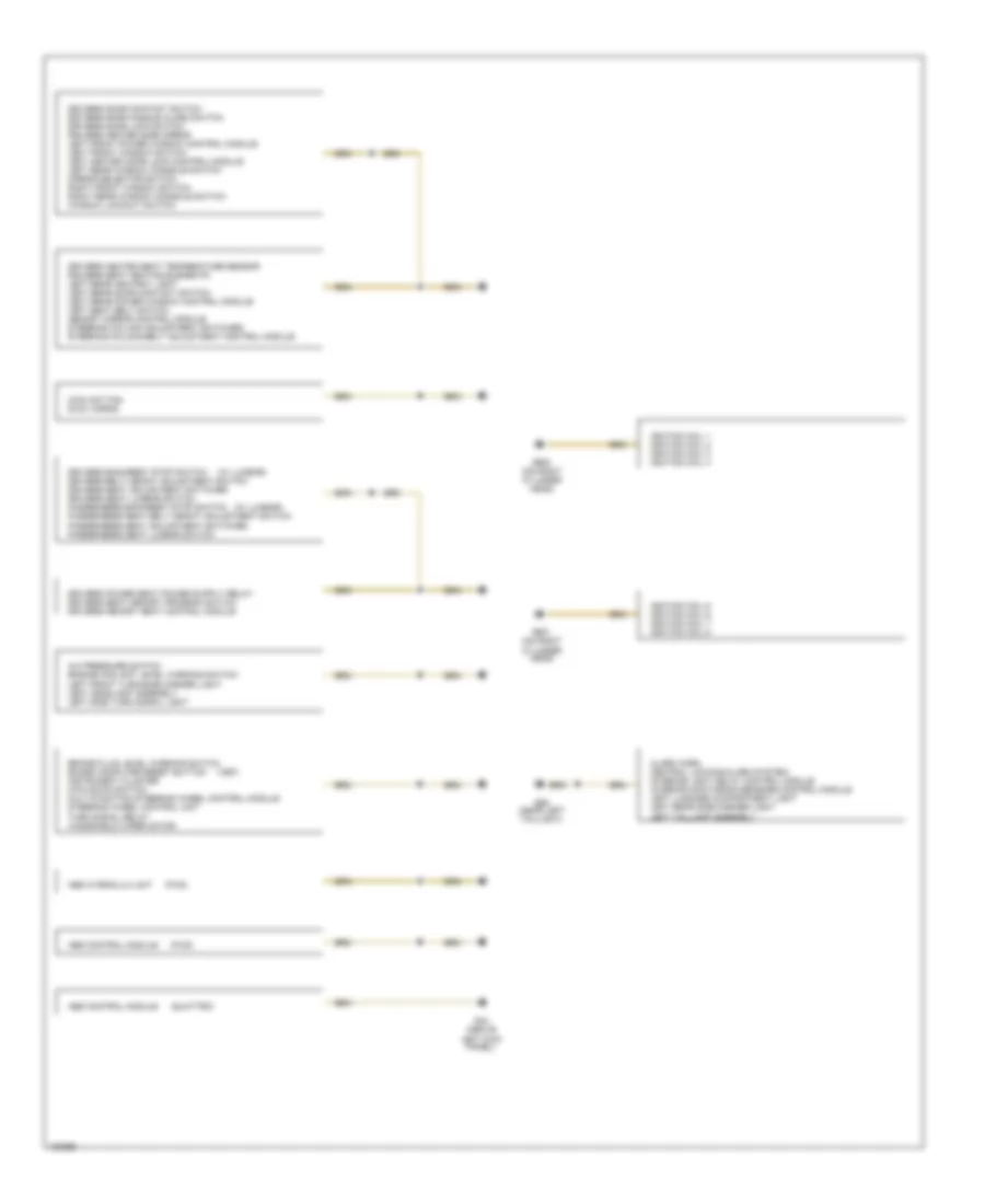
Ground Distribution Wiring Diagram (2 of 2) for Audi A8 1997
List of elements for Ground Distribution Wiring Diagram (2 of 2) for Audi A8 1997:
- (1997)
- (fwd)
- (quattro)
- (w/ lumbar)
- A/c pressure switch engine coolant level warning switch left front turn/side marker light left headlamp assembly left side turn signal light
- Abs control module
- Abs hydraulic unit
- Alarm horn central locking/alarm system/ interior light delay control module interior monitoring sensors control module left luggage compartment light left rear side marker light left taillamp assembly
- Brake fluid level warning switch board computer reset button instrument cluster kick down switch multi-function steering wheel control module steering wheel control unit turn signal relay windshield wiper motor
- Coolant fan dual horns
- Drivers backrest stop switch drivers belt height adjustment switch drivers seat adjustment switches drivers seat lumbar switch passengers backrest stop switch passengers seat belt height adjustment switch passengers seat adjustment switches passengers seat lumbar switch
- Drivers door contact switch drivers door handle alarm switch drivers door lock switch drivers heated side mirror left front power window control module left front window switch left heated door lock control module left rear window console switch mirror selector switch right front window switch right rear window console switch window lockout switch
- Drivers heated seat temperature sensor drivers seat heating elements left rear ashtray light left rear door contact switch left rear power window control module left seat belt switch memory mirror control module steering column adjustment switches steering column/belt adjustment control module
- G44 (above left kick panel)
- G59 (near left taillight)
- G600 (on right cylinder head)
- G601 (on right cylinder head)
- Ignition coil 1 ignition coil 2 ignition coil 3 ignition coil 4
- Ignition coil 5 ignition coil 6 ignition coil 7 ignition coil 8
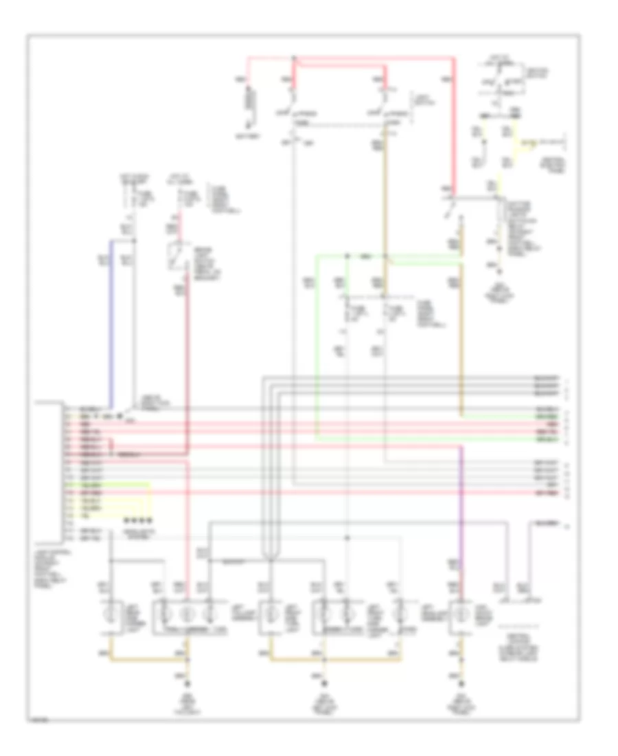
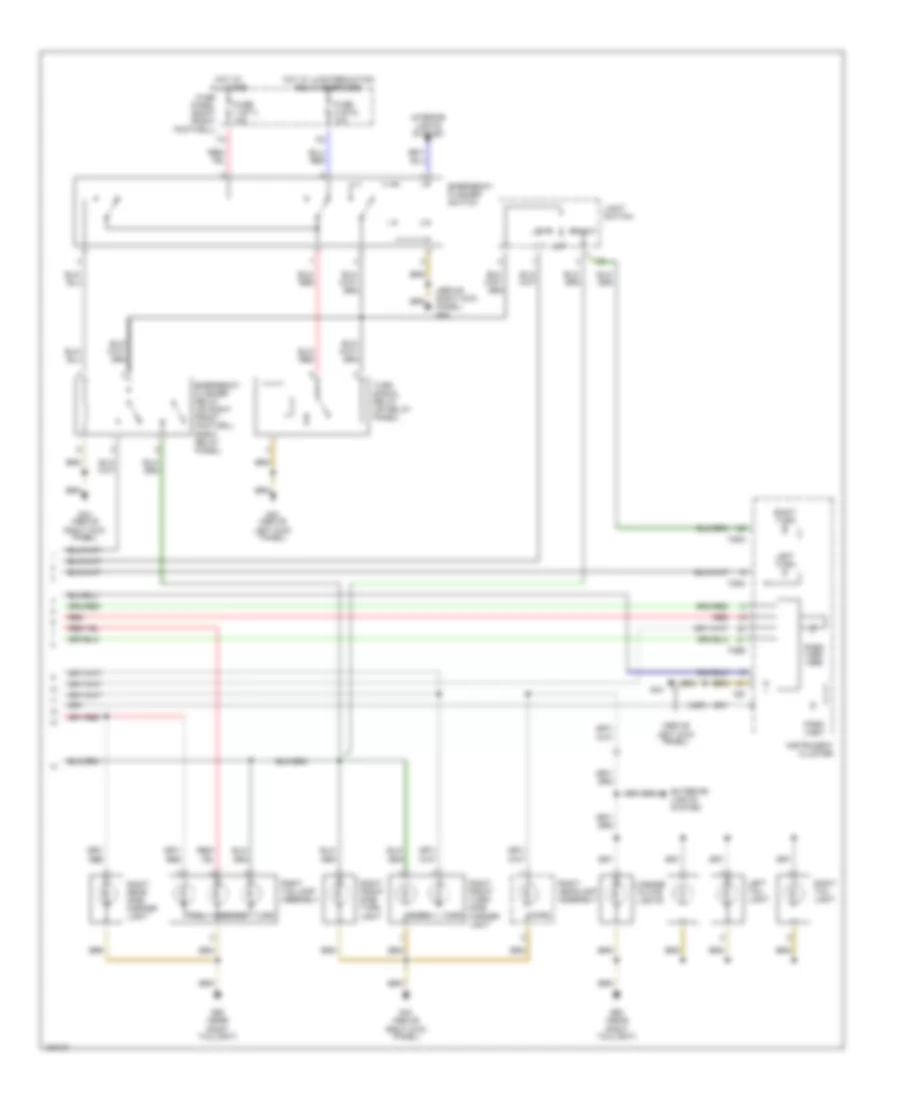
HEADLIGHTS
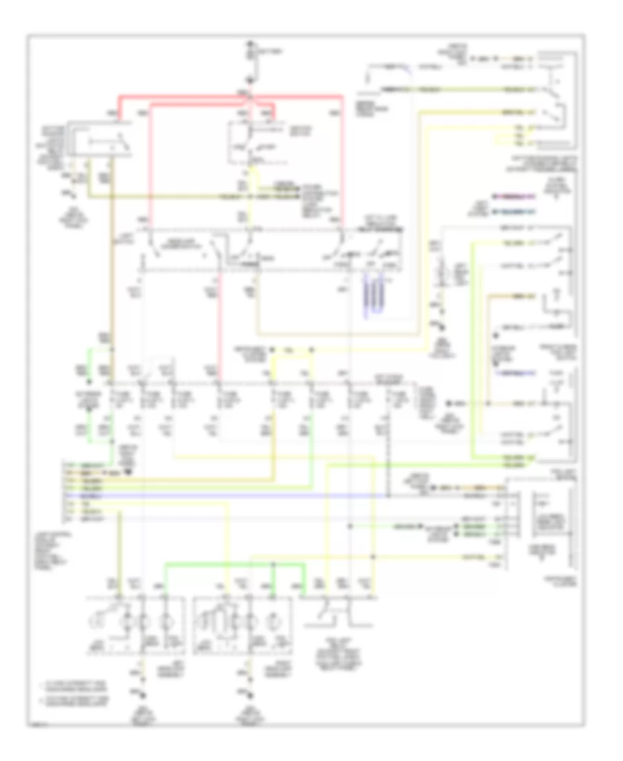
Headlamps & Fog Lamps Wiring Diagram, with DRL for Audi A8 1997
List of elements for Headlamps & Fog Lamps Wiring Diagram, with DRL for Audi A8 1997:
- (1997)
- (above
- (above left kick panel) g44
- (above right kick panel) g43
- Alarm system indicator
- Anti- theft system
- Battery
- Daytime running lights change-over relay (on right footwell e-box)
- Daytime running lights switch-on relay (on right footwell e-box)
- Exterior lights system
- Fog lamp
- Fog light relay (on right front footwell e-box auxiliary fuse & relay panel)
- Fog light switch
- Front & rear fog light switch
- Fuse 1 (st3) 15a
- Fuse 2 (st1) 5a
- Fuse 3 (st1) 15a
- Fuse 3 (st2) 5a
- Fuse 4 (st1) 15a
- Fuse 5 (st1) 10a
- Fuse 5 (st2) 15a
- Fuse 6 (st1) 10a
- Fuse panel (right front foot- well)
- G43 (above
- G43 (above right kick panel)
- G44 (above left kick panel)
- G60 (near right taillight)
- Head
- Headlamp dimmer switch
- High beam
- High beam indicator
- Hot in run or start
- Hot w/ load reduction relay energized
- Ignition switch
- Illum
- Instrument cluster
- Instrument cluster system
- Interior lights system
- Lamp control module (on right front footwell e-box relay panel)
- Left headlamp assembly
- Left rear fog light
- Light switch
- Low beam
- Low beam/ rear light indicator
- Nca
- Off
- Park
- Power distribution system (load reduction relay)
- Red
- Right headlamp assembly
- Right kick panel)
- Right kick panel) g43
- Run
- Series resistance wiring
- Start
- T14
- T26a
- T26b
- T6f
- W/ high intensity gas discharge headlamps
- W/o high intensity gas discharge headlamps
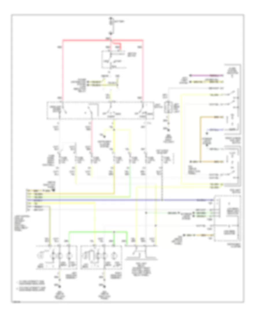
Headlamps & Fog Lamps Wiring Diagram, without DRL for Audi A8 1997
List of elements for Headlamps & Fog Lamps Wiring Diagram, without DRL for Audi A8 1997:
- (above right kick panel) g43
- 1998-99
- Alarm system indicator
- Anti- theft system
- Battery
- Dimmer switch
- Exterior lights system
- Fog lamp
- Fog light relay (on right front footwell e-box auxiliary fuse & relay panel)
- Fog light switch
- Front & rear fog light switch
- Fuse 1 (st3) 15a
- Fuse 3 (st1) 15a
- Fuse 3 (st2) 5a
- Fuse 4 (st1) 15a
- Fuse 5 (st1) 10a
- Fuse 5 (st2) 15a
- Fuse 6 (st1) 10a
- Fuse panel (right front footwell)
- G43 (above right kick panel)
- G44 (above left kick panel)
- G60 (near right taillight)
- Head
- Headlamp
- High beam
- High beam indicator
- Hot in run or start
- Ignition switch
- Illum
- Instrument cluster
- Instrument cluster system
- Interior lights system
- Lamp control module (on right front footwell e-box relay panel)
- Left headlamp assembly
- Left rear fog light
- Light switch
- Low beam
- Low beam/ rear light indicator
- Off
- Park
- Power distribution system (load reduction relay)
- Red
- Right headlamp assembly
- Run
- Start
- T14
- T26a
- T26b
- T6f
- W/ high intensity gas discharge headlamps
- W/o high intensity gas discharge headlamps
HORN
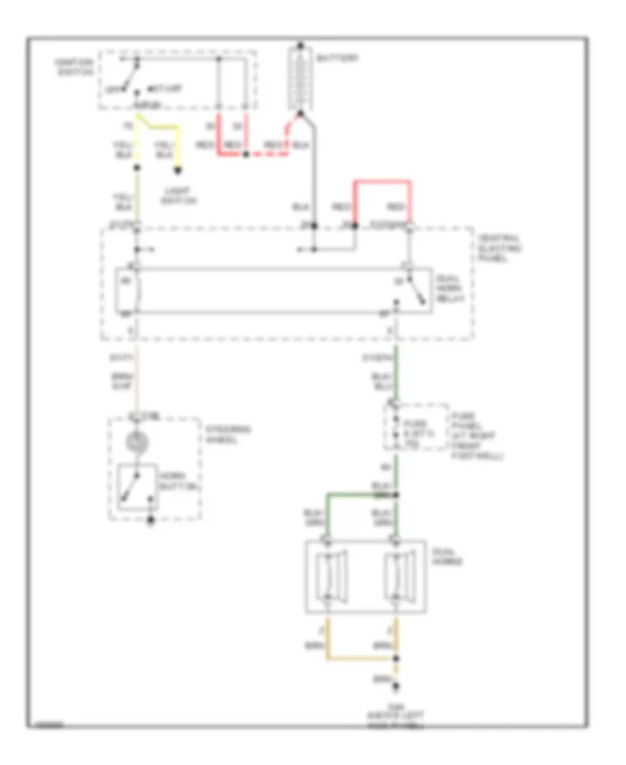
Horn Wiring Diagram, without Steering Wheel Controls for Audi A8 1997
List of elements for Horn Wiring Diagram, without Steering Wheel Controls for Audi A8 1997:
- Battery
- Central electric panel
- Dual horn relay
- Dual horns
- Fuse 8 (st1) 15a
- Fuse panel (at right front footwell)
- G44 (above left kick panel)
- Horn button
- Ignition switch
- Light switch
- Off
- Red
- Run
- S1/30ah
- S1/71
- S1/75
- S1/87h
- Start
- Steering wheel
- T5b
INSTRUMENT CLUSTER
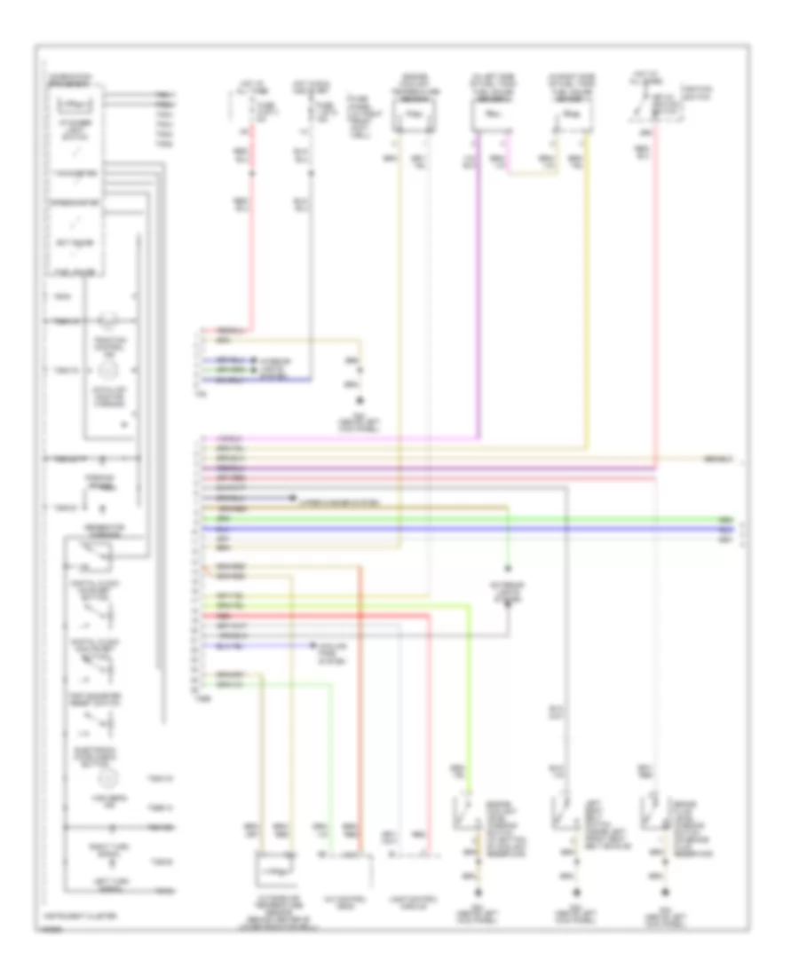
Instrument Cluster Wiring Diagram (1 of 3) for Audi A8 1997
List of elements for Instrument Cluster Wiring Diagram (1 of 3) for Audi A8 1997:
- (in left side of fuel tank) fuel gauge sender 2
- (in right side of fuel tank) fuel gauge sender 1
- 86s
- A/c control head
- Brake fluid level warning switch (on brake fluid reservoir)
- Catalyst monitor warning
- Combination processor
- Cooling fans system
- D12
- Digital clock hour set button
- Digital clock minute set button
- Ect gauge
- Electronic voice check button
- Engine coolant level warning switch (at bottom of coolant reservoir)
- Engine coolant temperature sensor
- Exterior lights system
- Fuel gauge
- Fuse 1 (st3) 15a
- Fuse 9 (st1) 5a
- Fuse panel (at right front foot- well)
- G44 (above left kick panel)
- Generator warning
- High beam ind
- Hot at all times
- Hot in run and start
- I/p dimmer light switch
- Ignition switch
- Instrument cluster
- Interior lights system
- Key-in ignition switch
- Lamp control module
- Left seat belt switch (inside left front seat belt buckle)
- Left turn signal
- Outside air temperature sensor (behind center of lower radiator grill)
- Parking brake
- Red
- Right turn signal
- Speedometer
- T26a/15
- T26a/16
- T26a/19
- T26a/20
- T26a/21
- T26a/22
- T26a/9
- T26b
- T26b/12
- T6f/2
- T6f/6
- Tachometer
- Tf6
- Tf6/1
- Tf6/2
- Tf6/3
- Tf6/4
- Tf6/5
- Tf6/6
- Traction control ind
- Trip odometer reset switch
- Wiper/washer system
Instrument Cluster Wiring Diagram (2 of 3) for Audi A8 1997
List of elements for Instrument Cluster Wiring Diagram (2 of 3) for Audi A8 1997:
- (below left side of dash) (w/ edl) abs control module
- (in plenum chamber e-box) motronic engine control module
- (turn signal switch)
- A/c control head
- Board computer function selector switch
- C10
- C12
- C13
- Central locking/alarm system/interior light delay control module (left side of luggage compt)
- Driver door contact switch (on driver door latch mechanism)
- G43 (above right kick panel)
- Generator
- Hot at all times
- Ignition switch
- Light switch
- Off
- Radio
- Run
- Start
- T16
Instrument Cluster Wiring Diagram (3 of 3) for Audi A8 1997
List of elements for Instrument Cluster Wiring Diagram (3 of 3) for Audi A8 1997:
- Abs control module (w/ edl) (below left side of dash)
- Abs warning
- Airbag control module (below center of dash)
- Airbag mil
- Battery above 2.5v
- Brake fluid level warning
- Brake pad wear ind
- Brake warning
- Combination processor
- Computer data lines system
- Coolant level/temp
- Cooling fans system
- Digital clock
- Doors closed ind
- Exterior lights system
- Fuel reserve warning
- G43 (above right kick panel)
- G60 (near right taillight)
- Headlights system
- Instrument cluster
- Interior lights system
- Left brake pad wear indicator element
- Low beam/ rear light ind
- Nca
- Oil pressure switch (on right side of engine)
- Oil pressure warning
- Ok ind
- Park light
- Parking brake warning light switch (below brake lever, in center console)
- Right brake pad wear indicator element
- Seat belt warning
- Speedo- meter vehicle speed sensor (on left side of trans- mission)
- T26
- T26/1
- T26/18
- T26/19
- T26/2
- T26/22
- T26/23
- T26/24
- T26/25
- T26/26
- T26/3
- T26/4
- T26/5
- T26/7
- T26/9
- T26a
- T26a/15
- T26a/16
- T26a/19
- T26a/20
- T26a/21
- T26a/22
- T26a/25
- T26a/26
- T26a/8
- T26a/9
- T26b/1
- T26b/10
- T26b/11
- T26b/12
- T26b/14
- T26b/17
- T26b/18
- T26b/19
- T26b/2
- T26b/20
- T26b/21
- T26b/22
- T26b/25
- T26b/26
- T26b/3
- T26b/4
- T26b/5
- T26b/6
- T26b/7
- T26b/8
- T26b/9
- Tr selector lever display
- Trans- mission control module (in plenum chamber e-box)
- Trunk lid alarm switch (in trunk lid latch)
- Vehicle speed control warning
- Washer fluid level
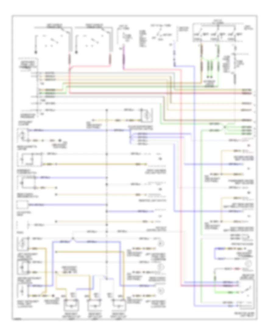
INTERIOR LIGHTS
Interior Lights Wiring Diagram (1 of 3) for Audi A8 1997
List of elements for Interior Lights Wiring Diagram (1 of 3) for Audi A8 1997:
- (above right kick panel) g43
- A/c control head
- Anti-slip control switch
- Center instrument panel vent illumination
- Combination processor
- Driver's heated seat adjuster
- Emergency flasher switch
- Exterior lights system
- Front and rear fog light switch
- Fuse 3 (st2) 5a
- Fuse 9 (st1) 10a
- Fuse panel (at right front foot- well)
- G43 (above right kick panel)
- Glove compartment actuation lighting
- Head
- Head off
- Hot at all times
- Ignition switch
- Instrument cluster
- Instrument panel light dimmer switch
- Left instrument panel vent illumination
- Left make-up mirror light
- Left rear heated seat regulating switch
- Light switch
- Off
- Park
- Passenger's heated seat adjuster
- Protection diode
- Radio
- Rear cigarette lighter
- Rear fog light switch
- Rear seat center outlet light
- Rear seat left outlet light
- Rear seat right outlet light
- Rear window defogger switch
- Rear window shade switch
- Red
- Right instrument panel vent illumination
- Right make-up mirror light
- Right rear heated seat regulating switch
- Run
- Selector lever light
- Selector lever light relay
- Start
- T26
- T26b
- T6f
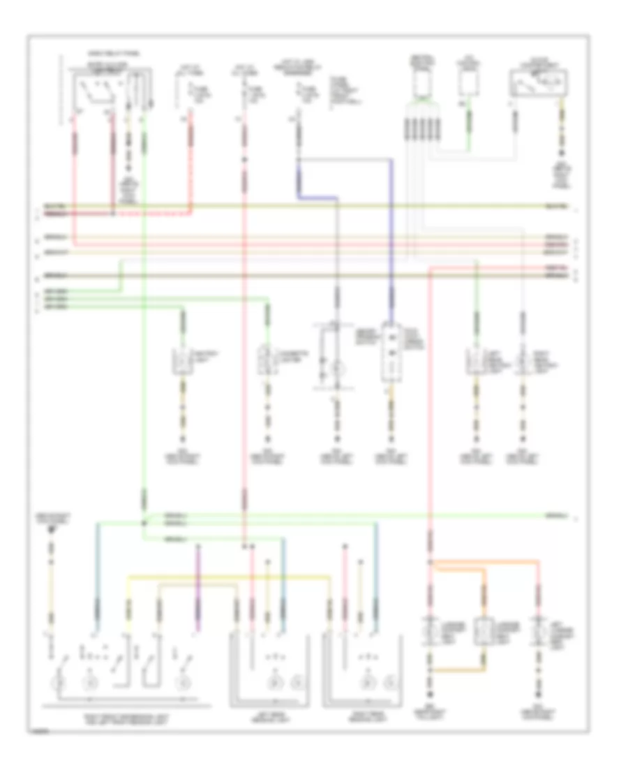
Interior Lights Wiring Diagram (2 of 3) for Audi A8 1997
List of elements for Interior Lights Wiring Diagram (2 of 3) for Audi A8 1997:
- (above right kick panel) g43
- A/c control head
- Ashtray light
- Central electric panel
- Cigarette lighter
- E-box relay panel
- Entry & floor light relay
- Fold- away mirror switch
- Fuse 1 (st5) 10a
- Fuse 2 (st5) 10a
- Fuse 3 (st5) 10a
- Fuse panel (at right front footwell)
- G43 (above right kick panel)
- G44 (above left kick panel)
- G60 (near right taillight)
- Glove compartment light
- Hot at all times
- Hot w/ load reduction relay energized
- Left luggage compart- ment light
- Left rear ashtray light
- Left rear reading light
- Luggage compart- ment light
- Memory program switch
- Right front map/reading light and left front reading light
- Right rear ashtray light
- Right rear reading light
Interior Lights Wiring Diagram (3 of 3) for Audi A8 1997
List of elements for Interior Lights Wiring Diagram (3 of 3) for Audi A8 1997:
- (above right kick panel) g43
- (in console)
- (in door)
- Central locking/alarm system/ interior light delay control module (left side of luggage compt)
- Door warning light
- Driver's door lock switch
- Driver's side door contact switch
- G43 (above right kick panel)
- G44 (above left kick panel)
- Left footwell light
- Left front entry light
- Left front window switch
- Left rear door contact switch
- Left rear door warning light
- Left rear entry light
- Left rear window switch
- Passenger's door warning light
- Passenger's side door contact switch
- Power windows system
- Right footwell light
- Right front entry light
- Right front window switch (in console)
- Right front window switch (in door)
- Right rear door contact switch
- Right rear door warning light
- Right rear entry light
- Right rear window switch
- T10o
- T12
- T16
- Window lockout switch
MEMORY SYSTEMS
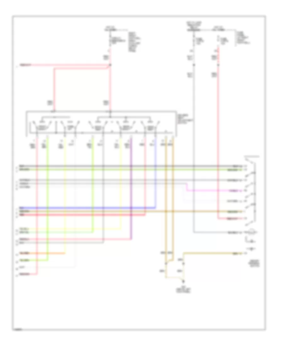
Driver"s Memory Seat Wiring Diagram (1 of 2) for Audi A8 1997
List of elements for Driver"s Memory Seat Wiring Diagram (1 of 2) for Audi A8 1997:
- Central locking/ alarm system/ interior light delay control module (left side of luggage compt)
- Driver's seat backrest adjusting motor
- Driver's seat backrest stop switch
- Driver's seat fore/ aft adjusting motor
- Driver's seat front height adjusting motor
- Driver's seat headrest adjusting motor
- Driver's seat lumbar support adjustment switch
- Driver's seat rear height adjusting motor
- Driver's side door contact switch (on driver door latch mechanism, inside door)
- G44 (above left kick panel)
- Memory column & belt height circuit
- Memory mirrors circuit
- Memory seat control module (on bottom of left front seat)
- Red
- T16
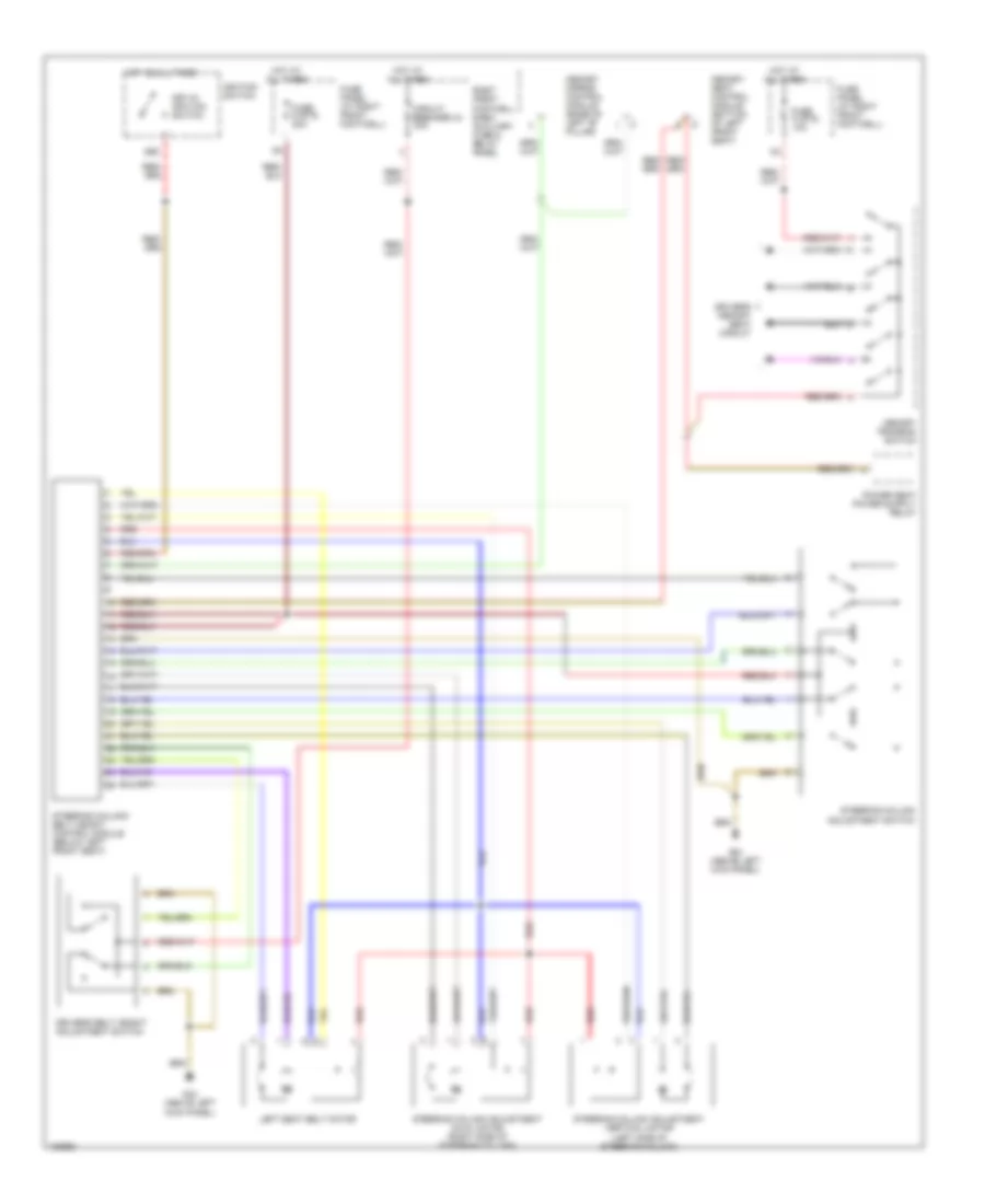
Driver"s Memory Seat Wiring Diagram (2 of 2) for Audi A8 1997
List of elements for Driver"s Memory Seat Wiring Diagram (2 of 2) for Audi A8 1997:
- Back- rest
- Circuit breaker 44 30a
- Driver's seat adjustment switch
- Fore/ aft
- Front height
- Fuse 2 (st5) 10a
- Fuse 8 (st5) 10a
- Fuse panel (at right front footwell)
- G44 (above left kick panel)
- Head- rest
- Hot at all times
- Hot w/ load reduction relay energized
- Memory program switch
- Rear height
- Red
- Right front footwell e-box auxiliary fuse & relay panel
Memory Column & Belt Height Wiring Diagram for Audi A8 1997
List of elements for Memory Column & Belt Height Wiring Diagram for Audi A8 1997:
- 86s
- Circuit breaker 44 30a
- Driver's belt height adjustment switch
- Driver's memory seat circuit
- Fuse 8 (st5) 10a
- Fuse 9 (st5) 20a
- Fuse panel (at right front footwell)
- G44 (above left kick panel)
- Hot at all times
- Ignition switch
- Key-in ignition switch
- Left seat belt motor
- Memory mirror control module (base of left "b" pillar)
- Memory program switch
- Memory seat control module (bottom of left front seat)
- Red
- Right front footwell e-box auxiliary fuse & relay panel
- Steering column adjustment axial motor (right side of steering column)
- Steering column adjustment switch
- Steering column adjustment vertical motor (left side of steering column)
- Steering column/ belt height control module (below left front seat)
Memory Mirrors Wiring Diagram for Audi A8 1997
List of elements for Memory Mirrors Wiring Diagram for Audi A8 1997:
- (above left kick panel) g44
- (above right kick panel) g43
- A10
- B10
- Back-up lights
- De- fog
- Driver's side mirror
- Fold- away
- Fuse 1 (st2) 10a
- Fuse 2 (st5) 10a
- Fuse 8 (st5) 10a
- Fuse panel (at right front footwell)
- G43 (above right kick panel)
- G44 (above left kick panel)
- Hot at all times
- Hot w/ load reduction relay energized
- Memory mirror control module (at base of left "b" pillar, behind trim)
- Memory seat control module
- Mirror adjustment switch
- Mirror fold-away control module (if equipped) (on right front footwell e-box relay panel)
- Passenger's side mirror
- Position
- Steering column/ belt height adjustment control module
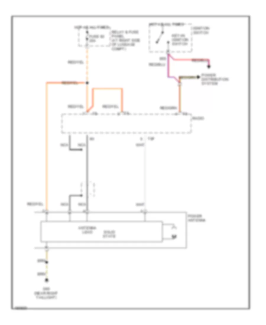
POWER ANTENNA
Power Antenna Wiring Diagram for Audi A8 1997
List of elements for Power Antenna Wiring Diagram for Audi A8 1997:
- 86s
- Antenna lead
- Fuse 92 20a
- G60 (near right taillight)
- Hot at all times
- Ignition switch
- Key-in ignition switch
- Nca
- Power antenna
- Power distribution system
- Radio
- Relay & fuse panel (at right side of luggage compt)
- Solid state
- T8f
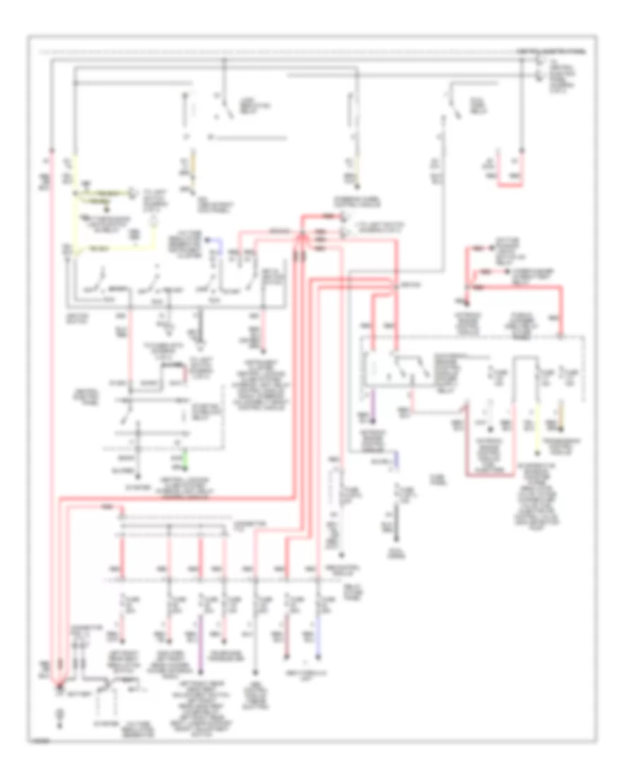
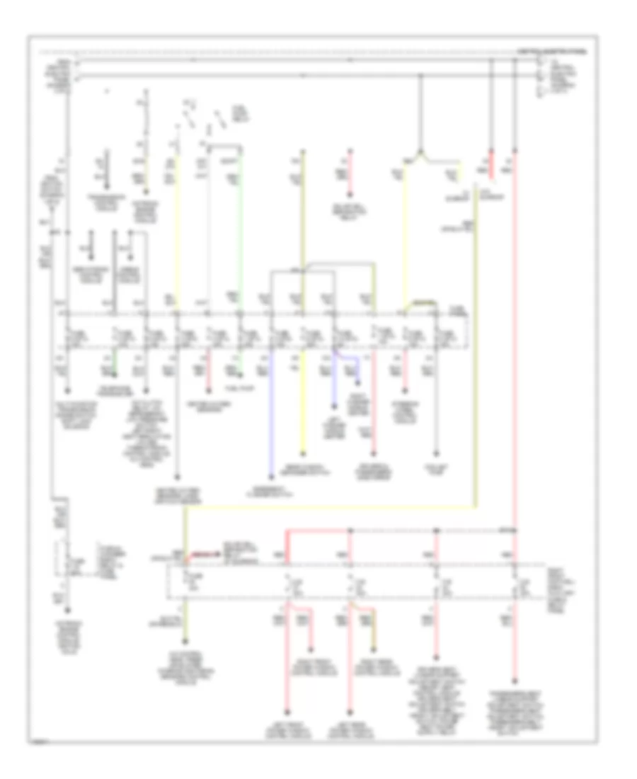
POWER DISTRIBUTION
Power Distribution Wiring Diagram (1 of 4) for Audi A8 1997
List of elements for Power Distribution Wiring Diagram (1 of 4) for Audi A8 1997:
- 1998,
- 50b
- 86s
- A22
- Abs control module
- Abs control module (1998-99 quattro)
- Abs hydraulic unit
- Amplifier, left/right rear woofer, power antenna, radio
- Battery
- Central electric panel
- Central locking/ alarm system/ interior light delay control module
- Connector tv1
- Connector tv2
- D50/a32
- Daytime running lights switch on relay
- Dual horn relay
- Dual horns
- E20/a32
- Evaporative emission canister purge regulator valve, intake change-over valve, fuel injector air control valve, leak detection pump
- Fuse 15a
- Fuse 20a
- Fuse 25a
- Fuse 50a
- Fuse 8 (st1) 15a
- Fuse 9 (st4) 5a
- Fuse panel
- G43 (above right kick panel)
- Ignition switch
- Instrument cluster, central locking/ alarm system/ interior light delay control module, radio, steering column/belt height control module
- Key-in ignition switch
- Left/right rear head rest adjustment switch, left/right rear head rest lower relay, left/right rear seat lumbar support height adjustment switch
- Left/right rear seat regulating switch
- Load reduction relay
- Motronic engine control module
- Motronic engine control module, fuel injectors
- Off
- Plenum chamber e-box relay & fuse panel
- Red
- Relay & fuse panel
- Run
- S1/
- S1/ 30ah
- S1/ 87h
- S1/50z
- S4/50z
- S4/a
- S4/b
- S6/50a
- Start
- Starter
- Starting interlock relay
- Steering wheel control module
- Telephone transceiver
- To central electric panel (diagram 2 of 4)
- To fuse 6 (st3) (diagram 3 of 4)
- To light switch (diagram 2 of 4)
- Transmission control module
- Voltage regulator/ generator
- Voltage regulator/ generator, instrument cluster
- Wiper/washer intermittent relay
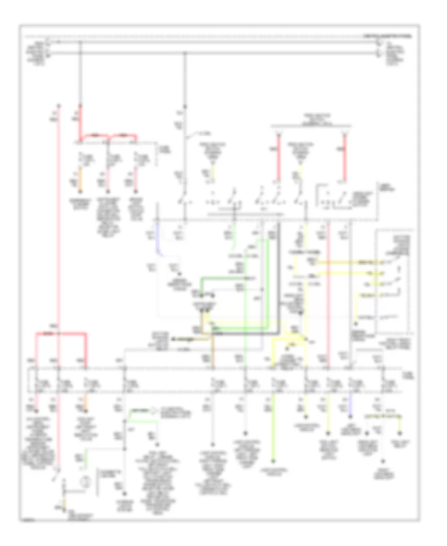
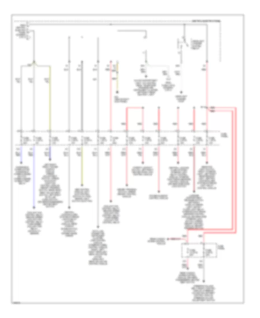
Power Distribution Wiring Diagram (2 of 4) for Audi A8 1997
List of elements for Power Distribution Wiring Diagram (2 of 4) for Audi A8 1997:
- (diagram 1 of 4)
- 75x
- A/c control head, instrument panel interior temperature sensor, instrument cluster, solar cell separation relay, steering wheel control module
- A37
- A51
- Brake light switch, vacuum dump valve
- Central electric panel
- Cigarette lighter
- Coolant pump, left/right heat regulating valve
- Daytime running lights change- over relay
- Daytime running lights switch on relay
- E107
- E108
- E109
- E116
- Emergency flasher switch
- Fog light relay
- Fog light relay, license plate lights (w/o drl), left/right taillights (w/o drl), ashtray light, multi-function transmission range switch, selector lever light relay protection diode, telephone transceiver, a/c control head
- Fog light switch, rear fog light switch
- From a central electric panel b
- From ignition switch (diagram 1 of 4)
- Fuse 1 (st1) 5a
- Fuse 2 (st1) 5a
- Fuse 3 (st1) 15a
- Fuse 3 (st2) 5a
- Fuse 3 (st3) 15a
- Fuse 4 (st1) 15a
- Fuse 4 (st3) 5a
- Fuse 5 (st1) 10a
- Fuse 5 (st2) 15a
- Fuse 6 (st1) 10a
- Fuse 7 (st1) 15a
- Fuse 7 (st3) 15a
- Fuse 9 (st1) 5a
- Fuse 9 (st2) 10a
- Fuse panel
- G43 (above right kick panel)
- Headlight beam adjustment control module
- Headlight dimmer/ flasher switch
- Headlight high beam indicator light
- Instrument cluster
- Instrument cluster, data link connector, solar cell separation relay, selector lever light relay
- Interior lights system
- Lamp control module
- Lamp control module, right parking light, right front side marker light left/right taillights (w/ drl), license plate lights (w/ drl)
- Lamp control module, left parking light, left front side marker light
- Left high beam headlight
- Light light switch switch
- Red
- Right front footwell e-box relay panel
- Right high beam headlight
- Series resistance wiring
- To central electric panel (diagram 3 of 4)
- To central electric panel (diagram 4 of 4)
- W/ drl
- W/o drl
- W/o drl w/ drl
- Wiper/ washer intermittent relay
Power Distribution Wiring Diagram (3 of 4) for Audi A8 1997
List of elements for Power Distribution Wiring Diagram (3 of 4) for Audi A8 1997:
- 10a
- 75x
- 87f/ dti
- A/c clutch relay, a/c refrigerant low pressure switch, left/right heat regulating valves, thermotronic control module, a/c control head
- A/c control head, fresh air blower, interior monitoring sensors control module
- A34
- Airbag control module
- B110
- C.b. 30a
- Central electric panel
- Central electric panel (diagram 2 of 4)
- Coolant pump
- Driver's & passenger's side mirror
- Emergency flasher switch
- From g
- From ignition switch (diagram 1 of 4)
- Fuel pump
- Fuel pump relay
- Fuse 1 (st2) 10a
- Fuse 1 (st4) 15a
- Fuse 10 (st2) 5a
- Fuse 2 (st3) 10a
- Fuse 20a
- Fuse 3 (st4) 20a
- Fuse 4 (st4) 15a
- Fuse 40a
- Fuse 5 (st3) 15a
- Fuse 6 (st2) 30a
- Fuse 6 (st3) 10a
- Fuse 8 (st2) 10a
- Fuse 8 (st3) 15a
- Fuse 9 (st3) 10a
- Fuse panel
- Heated oxygen sensors
- Heated oxygen sensors, mass air flow sensor
- Left front power window control module
- Left rear power window control module
- Left washer nozzle heater
- Motronic engine control module
- Motronic engine control module, ignition coils
- Multi-function transmission range switch, shift lock solenoid
- Passenger's seat lumbar support adjustment switch, passenger's seat adjustment switch, passenger's belt height adjustment
- Plenum chamber e-box relay & fuse panel
- Rear window defogger switch
- Red
- Right front footwell e-box auxiliary fuse & relay panel
- Right front power window control module
- Right rear power window control module
- Right washer nozzle heater
- S2/87f
- S3/
- S3/ 87a
- S3/s
- Servotronic control module
- Solar cell separation relay
- Solar cell separation relay (w/ sunroof)
- Steering wheel control module
- Switch
- Telephone transceiver
- To central electric panel (diagram 4 of 4)
- Transmission control module
- W/ sunroof
- W/o sunroof
Power Distribution Wiring Diagram (4 of 4) for Audi A8 1997
List of elements for Power Distribution Wiring Diagram (4 of 4) for Audi A8 1997:
- (diagram 3 of 4)
- 10a
- 58a
- 75x
- Abs control module, anti- slip control switch (w/ fwd), brake light switch (quattro)
- B115
- Central electric panel
- Central locking/ alarm system/ interior light delay control module, interior monitoring sensors control module, driver's side door lock switch
- Central locking/alarm system/interior lights delay control module, rear window shade switch, automatic dimmer inside mirror
- Coolant fan control relay, second speed coolant fan control relay, third speed coolant fan control relay
- Coolant fan control relay, second speed coolant fan control relay, third speed coolant fan relay, air quality sensor
- D51
- Data link connector, instrument cluster, lamp control module, steering wheel control module, radio, left/ right headlight beam adjusting motor, headlight beam adjusting control module
- From fuse 3 (st2) (diagram 2 of 4)
- From j central electric panel k
- Fuse 1 (st3) 15a
- Fuse 1 (st5) 10a
- Fuse 10 (st1) 25a
- Fuse 10 (st4) 10a
- Fuse 10 (st5) 20a
- Fuse 2 (st5) 10a
- Fuse 3 (st5) 10a
- Fuse 4 (st2) 5a
- Fuse 4 (st5) 10a
- Fuse 5 (st5) 15a
- Fuse 6 (st5) 20a
- Fuse 60a
- Fuse 7 (st5) 15a
- Fuse 8 (st5) 10a
- Fuse 9 (st5) 20a
- Fuse panel
- G43 (above right kick panel)
- Glove compartment light, a/c control head, telephone transceiver, instrument cluster, left/right rear ashtray light
- Headlight washer pump
- Headlight washer system relay
- Left/right front power window module, mirror adjustment switch, mirror fold-away function control module, memory program switch, rear head- rest adjustment switch, left/right "b" pillar micro switch, driver's/passenger's heated seat switch
- Luggage compartment release switch, left/right make up mirror light, entry/ floor light relay, interior monitoring sensors control module, driver's side interior lock switch, mirror memory control module, memory program switch
- Memory program switch, mirror memory control module
- Power sunroof control module
- Rear fog light switch, front interior light, left/right rear reading light, central locking/alarm system/interior light delay control module
- Rear window shade control module
- Rear window shade control module, driver's/ passenger's heated seat switch
- Red
- S1/
- S5a
- Steering column/ belt height control module, steering column adjustment control module, steering column adjustment switch
- Window lockout switch, left/right heated door lock control module
- Windshield wiper motor, windshield wiper/washer switch, wiper/washer intermittent relay
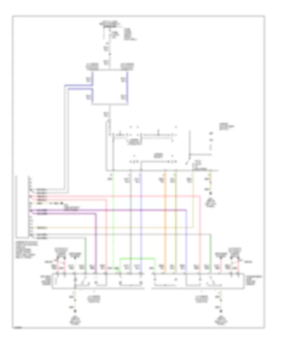
POWER MIRRORS
Power Mirrors Wiring Diagram for Audi A8 1997
List of elements for Power Mirrors Wiring Diagram for Audi A8 1997:
- 1998-99
- Automatic day/night mirror circuit
- Defogger system
- Driver's side heated mirror
- Fold- away (if equipped)
- Fuse 2 (st5) 10a
- Fuse panel (right front footwell)
- G43 (above right kick panel)
- G44 (above left kick panel)
- Hot w/ load reduction relay energized
- Mirror adjustment switch
- Mirror fold-away function control module (if equipped) (right front footwell e-box relay panel)
- Mirror position
- Mirror select
- Passenger's side heated mirror
- Red
- W/ mirror fold-away function
- W/o mirror fold-away function
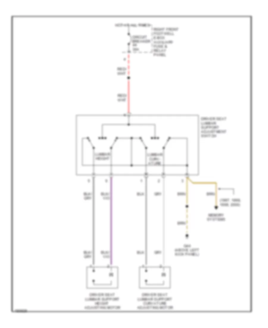
POWER SEATS
Driver"s Lumbar Wiring Diagram for Audi A8 1997
List of elements for Driver"s Lumbar Wiring Diagram for Audi A8 1997:
- (1997, 1998, 1999, 2000)
- Circuit breaker 30a
- Driver seat lumbar support adjustment switch
- Driver seat lumbar support curvature adjusting motor
- Driver seat lumbar support height adjusting motor
- G44 (above left kick panel)
- Hot at all times
- Lumbar curv- ature
- Lumbar height
- Memory systems
- Right front footwell e-box auxiliary fuse & relay panel
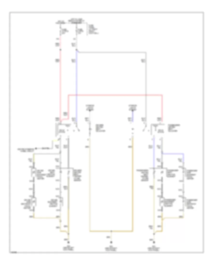
Front Seat Heater Wiring Diagram for Audi A8 1997
List of elements for Front Seat Heater Wiring Diagram for Audi A8 1997:
- 10a
- All times
- Driver backrest heating element
- Driver seat heating element
- Driver side backrest facial heater
- Driver side seatback facial heater
- Drivers heated seat adjuster
- Drivers heated seat temper- ature sensor
- Fuse 10 (st5) 20a
- Fuse 2 (st5) 10a
- Fuse panel (at right front footwell)
- G43 (above right kick panel)
- G44 (above left kick panel)
- Heated steering wheel circuit
- Hot at
- Hot w/ load reduction relay energized
- Interior lights system
- Nca
- Passenger backrest heating element
- Passenger seat heating element
- Passenger side backrest facial heater
- Passenger side seatback facial heater
- Passengers heated seat adjuster
- Passengers heated seat temper- ature sensor
- Solid state
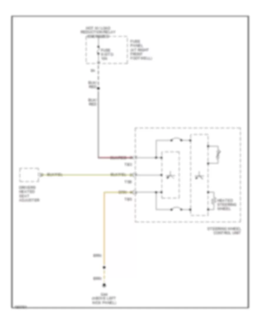
Heated Steering Wheel Wiring Diagram for Audi A8 1997
List of elements for Heated Steering Wheel Wiring Diagram for Audi A8 1997:
- Drivers heated seat adjuster
- Fuse 9 (st3) 10a
- Fuse panel (at right front footwell)
- G44 (above left kick panel)
- Heated steering wheel
- Hot w/ load reduction relay energized
- Steering wheel control unit
- T5b
- Tb3
- Tb5
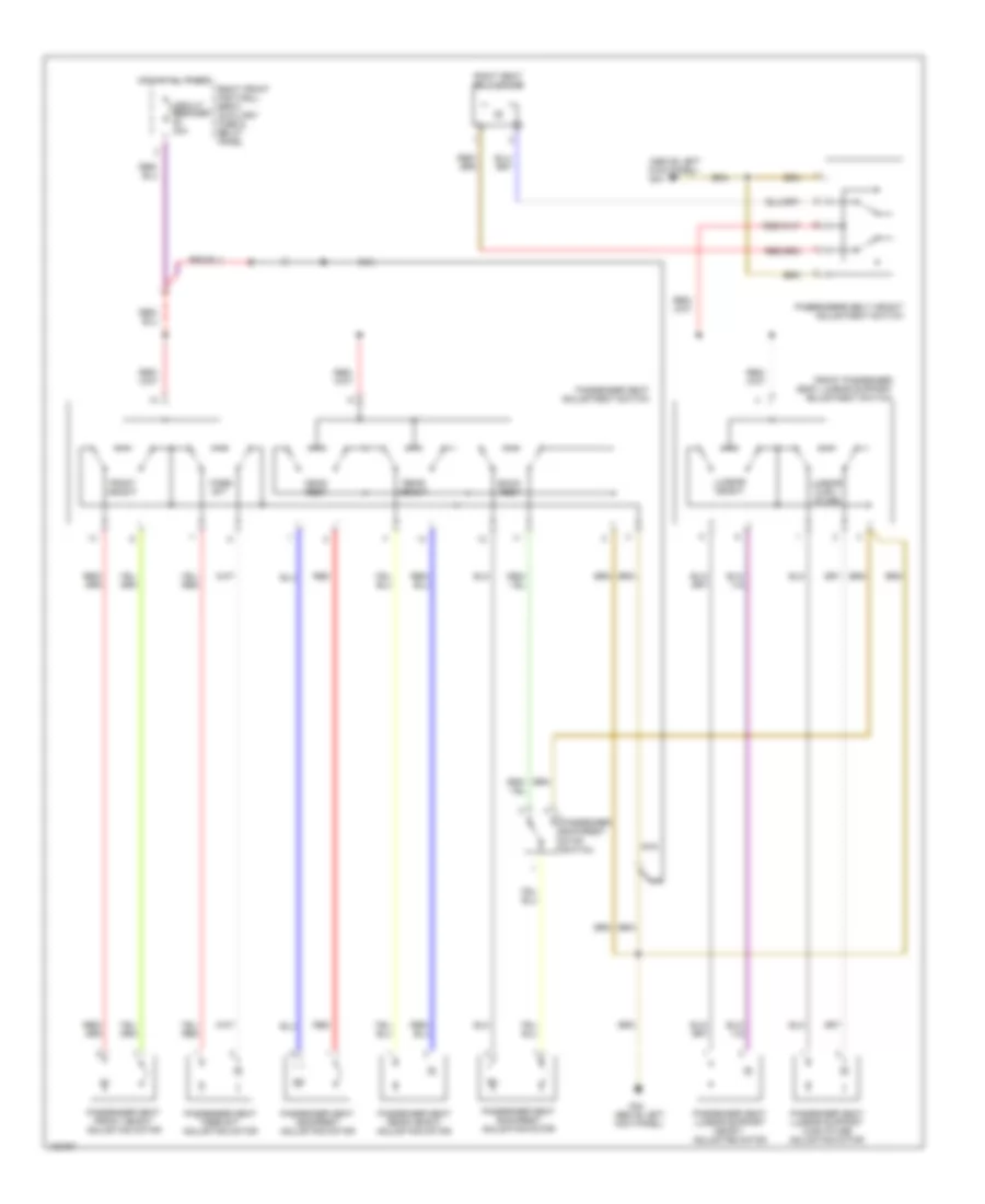
Passenger Seat Wiring Diagram for Audi A8 1997
List of elements for Passenger Seat Wiring Diagram for Audi A8 1997:
- (above left kick panel) g44
- Back- rest
- Circuit breaker 30a
- Fore/ aft
- Front height
- Front passenger seat lumbar support adjustment switch
- G44 (above left kick panel)
- Head- rest
- Hot at all times
- Lumbar curv- ature
- Lumbar height
- Nca
- Passenger backrest stop switch
- Passenger seat adjustment switch
- Passenger seat backrest adjusting motor
- Passenger seat fore/aft adjusting motor
- Passenger seat front height adjusting motor
- Passenger seat headrest adjusting motor
- Passenger seat lumbar support curvature adjusting motor
- Passenger seat lumbar support height adjusting motor
- Passenger seat rear height adjusting motor
- Passengers belt height adjustment switch
- Rear height
- Red
- Right front footwell e-box auxiliary fuse & relay panel
- Right seat belt motor
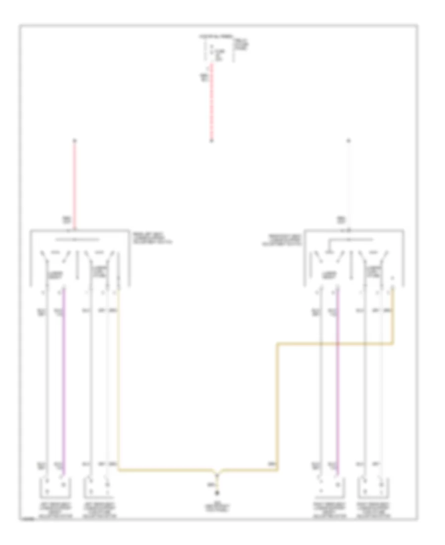
Rear Lumbar Wiring Diagram for Audi A8 1997
List of elements for Rear Lumbar Wiring Diagram for Audi A8 1997:
- Fuse 20a
- G43 (above right kick panel)
- Hot at all times
- Left rear seat lumbar support curvature adjusting motor
- Left rear seat lumbar support height adjusting motor
- Lumbar curv- ature
- Lumbar height
- Rear left seat lumbar support adjustment switch
- Rear right seat lumbar support adjustment switch
- Relay & fuse panel
- Right rear seat lumbar support curvature adjusting motor
- Right rear seat lumbar support height adjusting motor
Rear Power Headrest Wiring Diagram for Audi A8 1997
List of elements for Rear Power Headrest Wiring Diagram for Audi A8 1997:
- Fuse 2 (st5) 10a
- Fuse 20a
- Fuse panel (at right front footwell)
- G43 (above right kick panel)
- Hot at all times
- Hot w/ load reduction relay energized
- Interior lights system
- Left rear head rest lower relay (on left rear seat back)
- Left rear seat head rest adjustment motor
- Left rear seat head rest adjustment switch
- Rear head- rest adjustment switch
- Relay & fuse panel
- Right rear head rest lower relay (on right rear seat back)
- Right rear seat head rest adjustment motor
- Right rear seat head rest adjustment switch
Rear Seat Heater Wiring Diagram for Audi A8 1997
List of elements for Rear Seat Heater Wiring Diagram for Audi A8 1997:
- All times
- Fuse 2 (st5) 10a
- Fuse 20a
- Fuse panel (at right front footwell)
- G43 (above right kick panel)
- Hot at
- Hot w/ load reduction relay energized
- Interior lights system
- Left rear "b" pillar microswitch
- Left rear backrest heating element
- Left rear heated seat regulating switch
- Left rear heated seat switch
- Left rear seat heating element
- Left rear seat temper- ature sensor
- Nca
- Relay & fuse panel (in plenum chamber e-box)
- Right rear
- Right rear "b" pillar microswitch
- Right rear backrest heating element
- Right rear heated seat switch
- Right rear seat heat heated seat switch
- Right rear seat temper- ature sensor
- Seat heating element
- Solid state
POWER TOP/SUNROOF
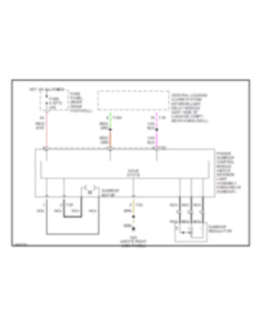
Sunroof Wiring Diagram for Audi A8 1997
List of elements for Sunroof Wiring Diagram for Audi A8 1997:
- Central locking/ alarm system/ interior light delay module (left side of luggage compt, near wheelwell)
- Fuse 6 (st5) 20a
- Fuse panel (right front footwell)
- G43 (above right kick panel)
- Hot at all times
- Nca
- Power sunroof control module (above interior light assembly, forward of sunroof)
- Solid state
- Sunroof motor
- Sunroof regulator
- T10o
- T16
- T2p
- T5c
POWER WINDOWS
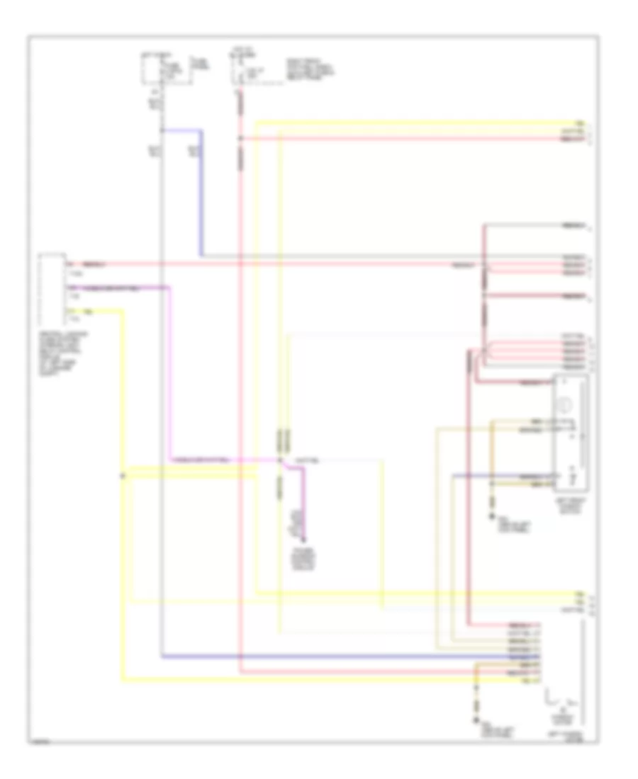
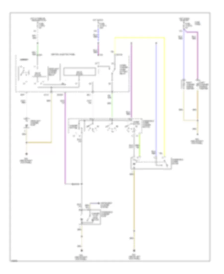
Power Windows Wiring Diagram (1 of 2) for Audi A8 1997
List of elements for Power Windows Wiring Diagram (1 of 2) for Audi A8 1997:
- All times
- C.b. 37 30a
- Central locking/ alarm system/ interior light delay control module (at left side of luggage compt)
- Fuse 2 (st5) 10a
- Fuse panel
- G44 (above left kick panel)
- Hot at
- Hot in run
- Left front window switch
- Left window motor
- Power sunroof control module
- Right front footwell e-box auxiliary fuse & relay panel
- T10o
- T12
- T16
- Window motor
Power Windows Wiring Diagram (2 of 2) for Audi A8 1997
List of elements for Power Windows Wiring Diagram (2 of 2) for Audi A8 1997:
- (1997-99)
- (2000-03)
- 2000-03
- All times
- C.b. 43 30a
- Fuse 7 (st5) 15a
- Fuse panel
- G43 (above right kick panel)
- G44 (above left kick panel)
- Hot at
- Interior lights system
- Left rear door window motor
- Left rear door window switch (center console)
- Left rear door window switch (door)
- Rear cigarette lighter
- Right front door window switch
- Right front door window switch (right door)
- Right front footwell e-box auxiliary fuse & relay panel
- Right rear door window motor
- Right rear door window switch (center console)
- Right rear door window switch (door)
- Right window motor
- Window lockout switch
- Window m motor
- Window motor
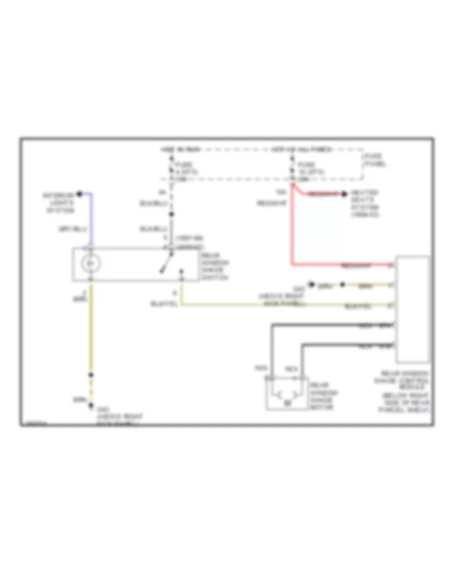
Rear Window Sun Shade Wiring Diagram for Audi A8 1997
List of elements for Rear Window Sun Shade Wiring Diagram for Audi A8 1997:
- (1997-99)
- (2000-03)
- (below right side of rear parcel shelf)
- 10a
- 87a
- 87b
- Fuse 10 (st5) 20a
- Fuse 4 (st5) 10a
- Fuse panel
- G43 (above right kick panel)
- Heated seats system (1998-03)
- Hot at all times
- Hot in run
- Interior lights system
- Nca
- Rear window shade control module
- Rear window shade motor
- Rear window shade switch
RADIO
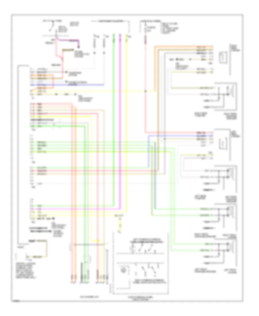
Radio Wiring Diagram, Base for Audi A8 1997
List of elements for Radio Wiring Diagram, Base for Audi A8 1997:
- 20a
- 86s
- Audio steering wheel circuit board
- Cd changer unit
- Central locking/ alarm system/ interior light delay module (at left side of luggage compt, near wheelwell)
- Fuse 92
- G43 (above right kick panel)
- G60 (near right taillight)
- Hot at all times
- Ignition switch
- Instrument cluster
- Key-in ignition switch
- Left front midrange speaker
- Left front woofer
- Left rear midrange speaker
- Left rear tweeter
- Left rear woofer
- Left steering steering wheel radio control switch
- Nca
- Power antenna system
- Power distribution system
- Radio
- Red
- Relay & fuse panel (at right side of luggage compt)
- Right front midrange speaker
- Right front woofer
- Right rear midrange speaker
- Right rear tweeter
- Right rear woofer
- Right steering steering wheel radio control switch
- T16
- T26
- T5d
- T5e
- T6f
- T6g
- T6h
- T8a
- T8b
- Telephone system
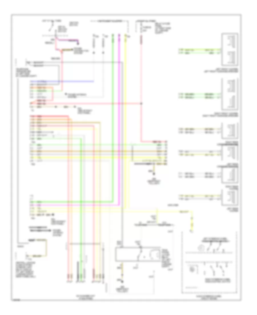
Radio Wiring Diagram, Bose for Audi A8 1997
List of elements for Radio Wiring Diagram, Bose for Audi A8 1997:
- (if equipped)
- 20a
- 86s
- Amplifier
- Audio steering wheel circuit board
- Cd changer unit
- Central locking/ alarm system/ interior light delay module (at left side of luggage compt, near wheelwell)
- Fuse 92
- G43 (above right kick panel)
- G60 (near right taillight)
- Hot at all times
- Ignition switch
- Instrument cluster
- Key-in ignition switch
- Left front woofer/ left front midrange speaker
- Left rear midrange speaker
- Left rear woofer
- Left steering wheel radio control switch
- Nca
- Power antenna system
- Power distribution system
- Radio
- Red
- Relay & fuse panel (at right side of luggage compt)
- Right front woofer/ right front midrange speaker
- Right rear midrange speaker
- Right rear woofer
- Right steering wheel radio control switch
- T16
- T26
- T6f
- T6g
- T6h
- T8a
- Tele- phone cutoff relay (at left side of luggage compt)
- Telephone transceiver (in left side of luggage compt)
- W/ telephone
- W/o telephone
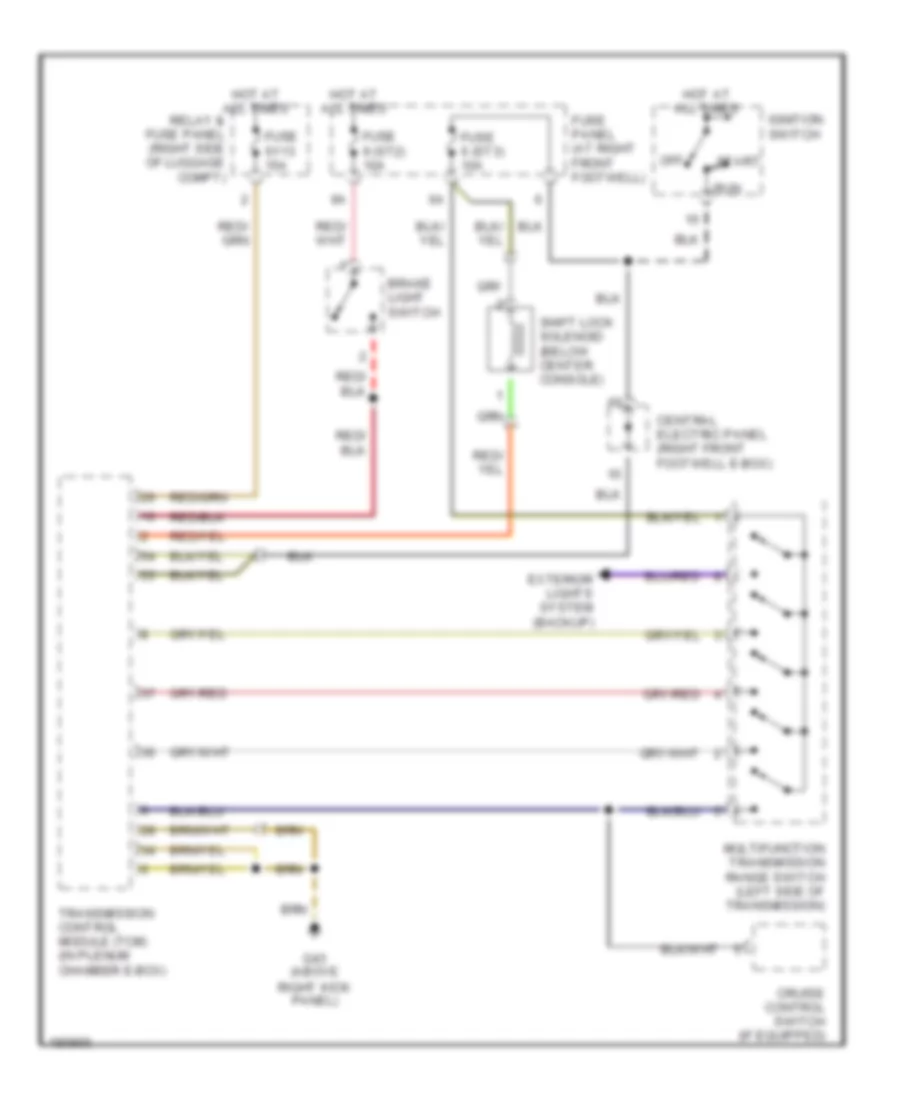
SHIFT INTERLOCK
Shift Interlock Wiring Diagram for Audi A8 1997
List of elements for Shift Interlock Wiring Diagram for Audi A8 1997:
- Brake light switch
- Central electric panel (right front footwell e-box)
- Cruise control switch (if equipped)
- Exterior lights system (backup)
- Fuse 6 (st3) 10a
- Fuse 9 (st2) 10a
- Fuse panel (at right front footwell)
- Fuse s113 15a
- G43 (above right kick panel)
- Hot at all times
- Ignition switch
- Multifunction transmission range switch (left side of transmission)
- Off
- Relay & fuse panel (right side of luggage compt)
- Run
- Shift lock solenoid (below center console)
- Start
- Transmission control module (tcm) (in plenum chamber e-box)
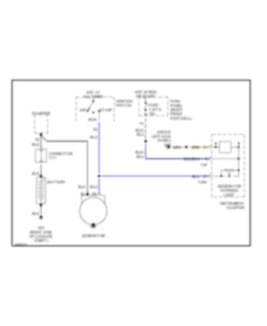
STARTING/CHARGING
Charging Wiring Diagram for Audi A8 1997
List of elements for Charging Wiring Diagram for Audi A8 1997:
- (above left kick panel) g44
- Battery
- Connector tv1
- Fuse 1 (st3) 15a
- Fuse panel (right front footwell)
- G51 (right side of luggage compt)
- Generator
- Generator warning light
- Hot at all times
- Hot in run or start
- Ignition switch
- Instrument cluster
- Off
- Run
- Start
- Starter
- T26a
- T6f
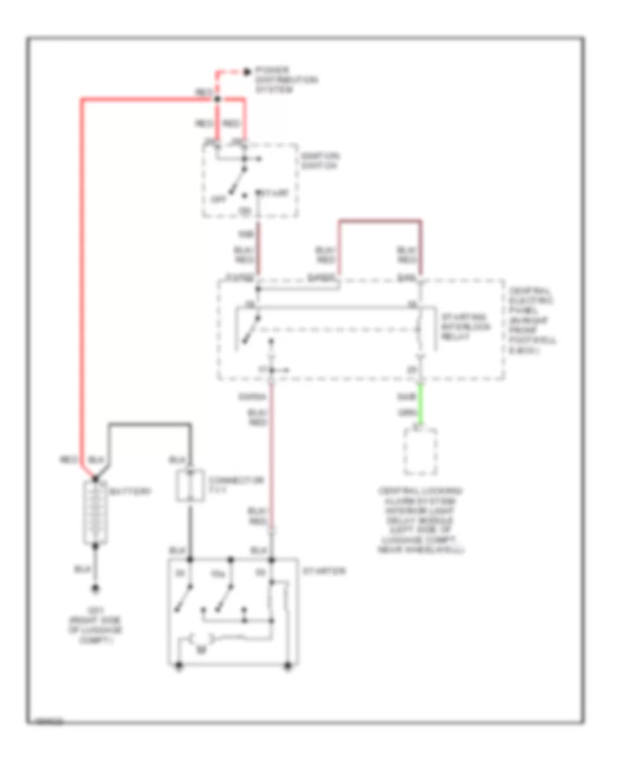
Starting Wiring Diagram for Audi A8 1997
List of elements for Starting Wiring Diagram for Audi A8 1997:
- 15a
- 50b
- Battery
- Central electric panel (in right front footwell e-box)
- Central locking/ alarm system/ interior light delay module (left side of luggage compt, near wheelwell)
- Connector tv1
- G51 (right side of luggage compt)
- Ignition switch
- Off
- Power distribution system
- Red
- S1/50z
- S4/50z
- S4/a
- S4/b
- S6/50a
- Start
- Starter
- Starting interlock relay
SUPPLEMENTAL RESTRAINTS
Supplemental Restraints Wiring Diagram for Audi A8 1997
List of elements for Supplemental Restraints Wiring Diagram for Audi A8 1997:
- Acc
- Air bag control module (below center of dash)
- Air bag malfunction indicator lamp (mil)
- Air bag spiral spring/return spring w/slip ring
- Central locking/ alarm system/ interior light delay control module (left side of luggage compt)
- Computer data lines system
- Data link connector t16a
- Driver's side air bag igniter
- Driver's side rear
- Driver's side rear belt tensioner igniter
- Driver's side side air bag crash sensor
- Fuse 1 (st3) 15a
- Fuse panel (at right front footwell)
- G43 (above right kick panel)
- Hot at all times
- Hot in run and start
- Ignition starter/ switch
- Instrument cluster
- Left front "a" pillar microswitch
- Left seat belt tensioner igniter
- Lock
- Nca
- Note: shorting bridges on air bag control module close when module connector is disconnected from harness. shorting bridges connect pins: 1-2, 3-4, 6-30, 10-11, 13-14, 16-17, 18-19, 22-23, 24-25
- Passenger's side air bag igniter
- Passenger's side airbag igniter 1
- Passenger's side rear
- Passenger's side rear belt tensioner igniter
- Passenger's side seat occupied sensor (in bottom of passenger seat)
- Passenger's side side air bag crash sensor
- Rear driver's side, side airbag igniter
- Rear passenger's side, side airbag igniter
- Red
- Right front "a" pillar microswitch
- Right seat belt tensioner igniter
- Run
- Seat occupied sensor (in bottom of driver's side rear seat)
- Seat occupied sensor (in bottom of passenger's side rear seat)
- Solid state
- Start
- T16
- T26a
- T6f
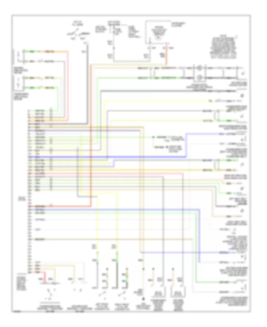
TRANSMISSION
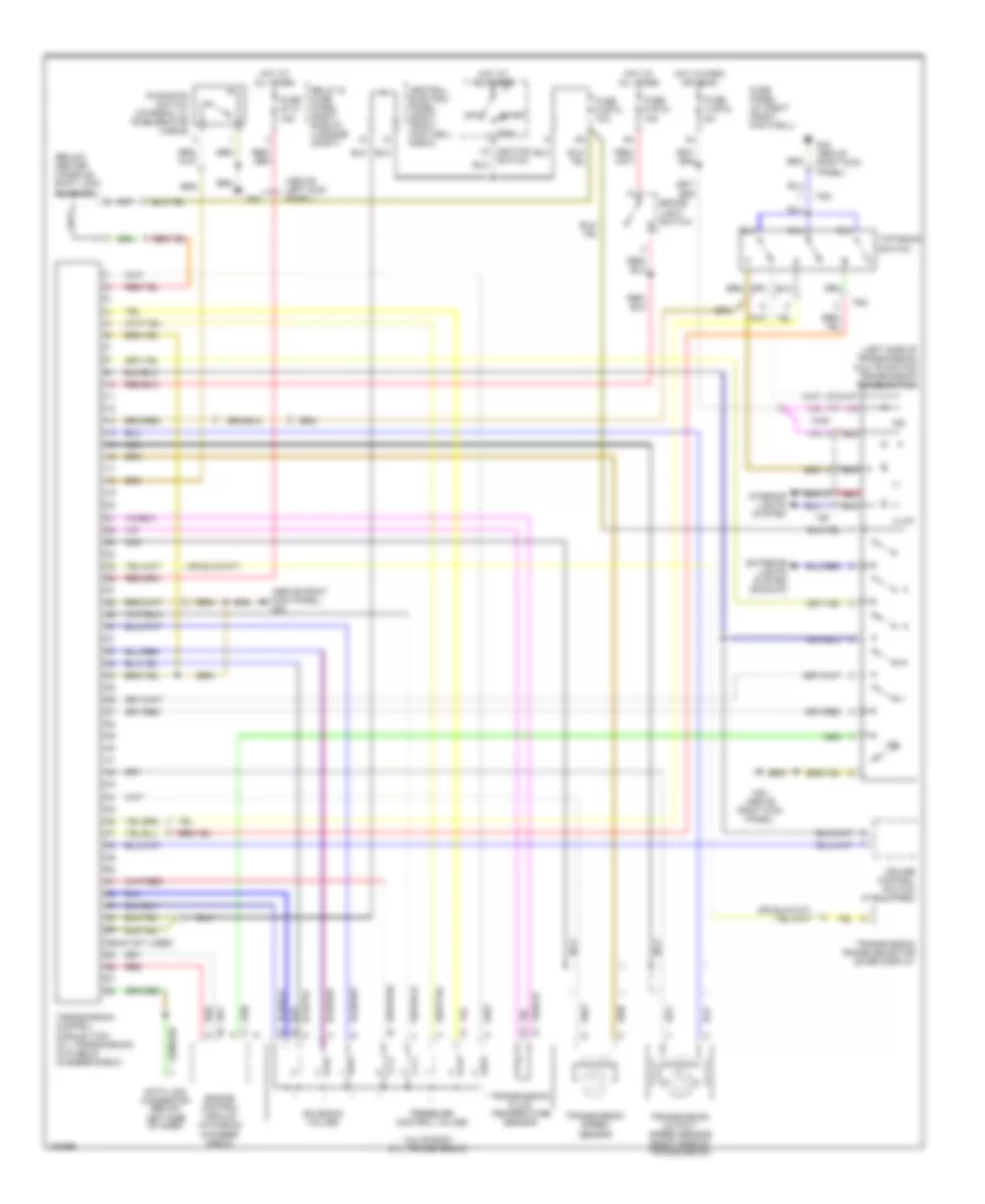
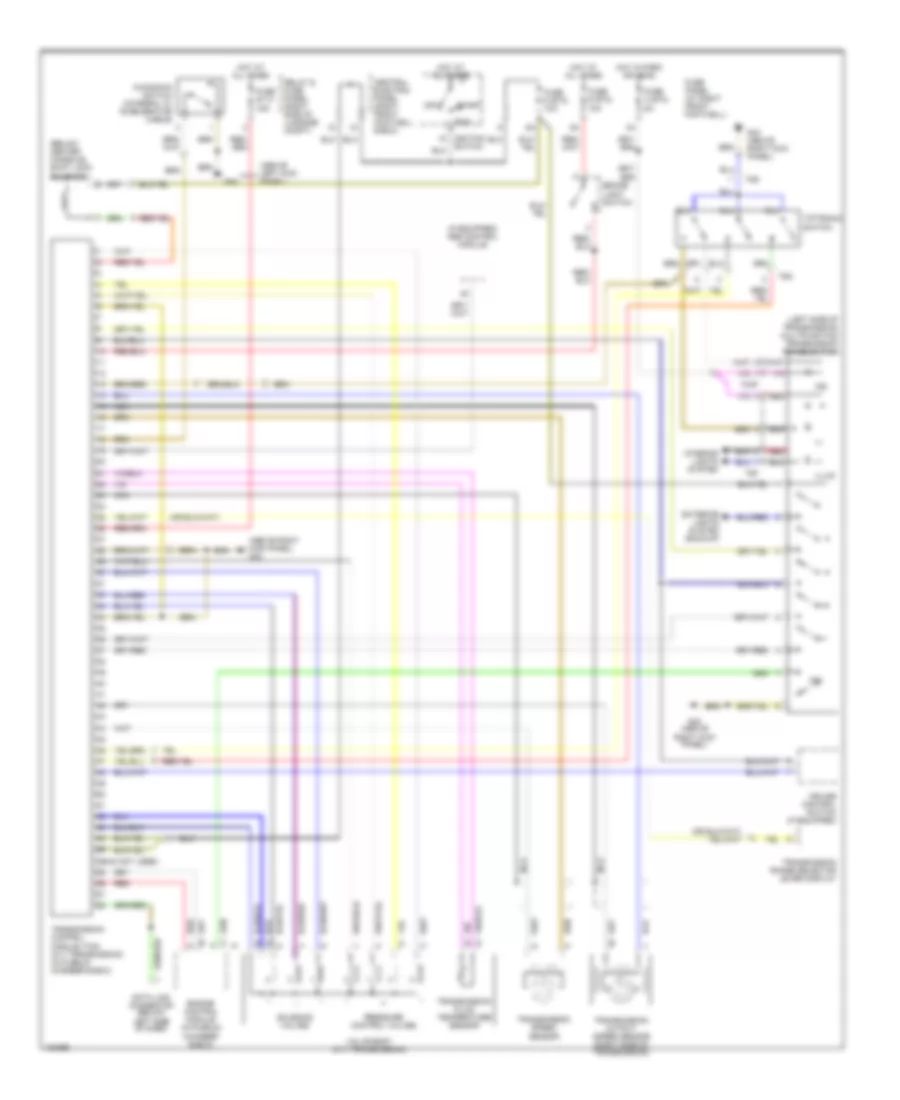
A/T Wiring Diagram, AWD for Audi A8 1997
List of elements for A/T Wiring Diagram, AWD for Audi A8 1997:
- (56-84 not used)
- (above left kick panel)
- (above right kick panel) g43
- (below center console) shift lock solenoid
- (left side of transmission) multifunction transmission range switch
- +/-
- Brake light switch
- Central electric panel (right front footwell e-box)
- Cruise control switch (if equipped)
- Data link connector (below left side of dash)
- Engine control module (in plenum chamber e-box)
- Exterior lights system (backup)
- Fuse 3 (st2) 5a
- Fuse 6 (st3) 10a
- Fuse 9 (st2) 10a
- Fuse panel (at right front footwell)
- Fuse s113 15a
- G43 (above right kick panel)
- G44
- Hot at all times
- Hot in park or head
- Illum
- Ind
- Interior lights system
- Kickdown switch (integral w/ accelerator cable)
- Nca
- Off
- P/n
- Pressure control valves
- Red
- Relay & fuse panel (right side of luggage compt)
- Run
- Solenoid valves
- Start
- T2af
- T5f
- T5g
- Tiptronic switch
- Transmission control module (tcm) (01l transmission) (in plenum chamber e-box)
- Transmission fluid temperature sensor
- Transmission output speed sensor (right side of transmission)
- Transmission range selector lever display
- Transmission speed sensor
- Valve body (01l transmission)
A/T Wiring Diagram, FWD for Audi A8 1997
List of elements for A/T Wiring Diagram, FWD for Audi A8 1997:
- g43 (above right kick panel)
- (56-84 not used)
- (above left kick panel)
- (above right kick panel) g43
- (below center console) shift lock solenoid
- (if equipped) abs control module
- (left side of transmission) multifunction transmission range switch
- +/-
- Brake light switch
- Central electric panel (right front footwell e-box)
- Cruise control switch (if equipped)
- Data link connector (below left side of dash)
- Engine control module (in plenum chamber e-box)
- Exterior lights system (backup)
- Fuse 3 (st2) 5a
- Fuse 6 (st3) 10a
- Fuse 9 (st2) 10a
- Fuse panel (at right front footwell)
- Fuse s113 15a
- G43 (above right kick panel)
- G44
- Hot at all times
- Hot in park or head
- Illum
- Ind
- Interior lights system
- Kickdown switch (integral w/ accelerator cable)
- Nca
- Off
- P/n
- Pressure control valves
- Red
- Relay & fuse panel (right side of luggage compt)
- Run
- Solenoid valves
- Start
- T2af
- T5f
- T5g
- Tiptronic switch
- Transmission control module (tcm) (01v transmission) (in plenum chamber e-box)
- Transmission fluid temperature sensor
- Transmission output speed sensor (right side of transmission)
- Transmission range selector lever display
- Transmission speed sensor
- Valve body (01v transmission)
TRUNK, TAILGATE, FUEL DOOR
Trunk Release Wiring Diagram for Audi A8 1997
List of elements for Trunk Release Wiring Diagram for Audi A8 1997:
- (1997)
- (1998-99)
- 15a
- Central locking/ alarm system/ interior light delay control module (left side of luggage compartment, near wheelwell)
- Deck lid central locking system motor
- Fuse 3 (st5) 10a
- Fuse panel
- G60 (near right taillight)
- Glove compartment lock contact switch
- Hot at all times
- Luggage compartment release switch
- T16
- T1o0
WIPER/WASHER
Wiper/Washer Wiring Diagram for Audi A8 1997
List of elements for Wiper/Washer Wiring Diagram for Audi A8 1997:
- 10a
- 58a
- 75a
- Battery
- Central electric panel
- Fuse 10 (st1) 25a
- Fuse 10 (st2) 5a
- Fuse 3 (st2) 5a
- Fuse panel
- G43 (above right kick panel)
- G44 (above left kick panel)
- Headlight washer pump
- Headlight washer system relay
- Headlights on
- Hot in run
- Hot in run or start
- Hot w/ park or
- Instrument cluster system
- Left washer nozzle heater
- Right washer nozzle heater
- S1/31
- S2/ 53e
- S2/31b
- S2/53c
- S2/j
- S5/p
- Solid state
- Washer fluid level switch
- Washer switch
- Windshield washer pump
- Windshield wiper motor
- Windshield wiper/ washer switch
- Wiper switch
- Wiper/ washer inter- mittent relay