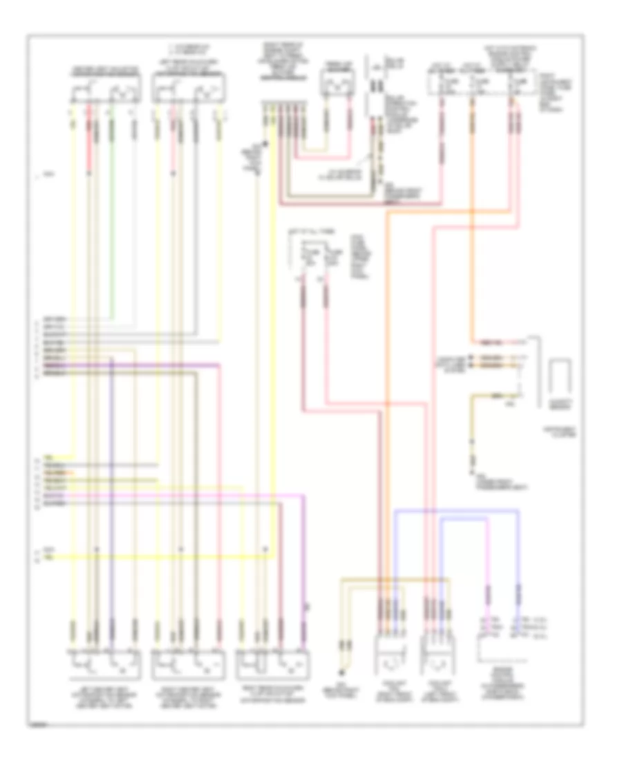
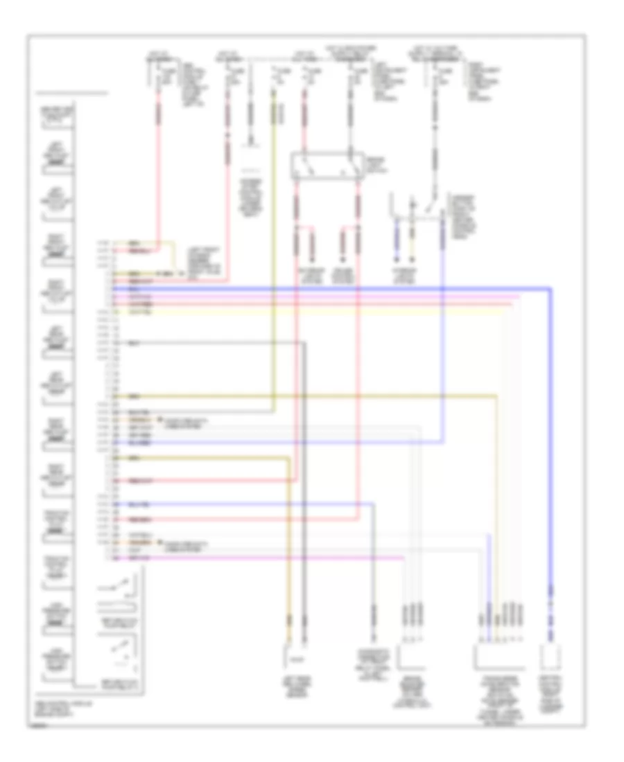
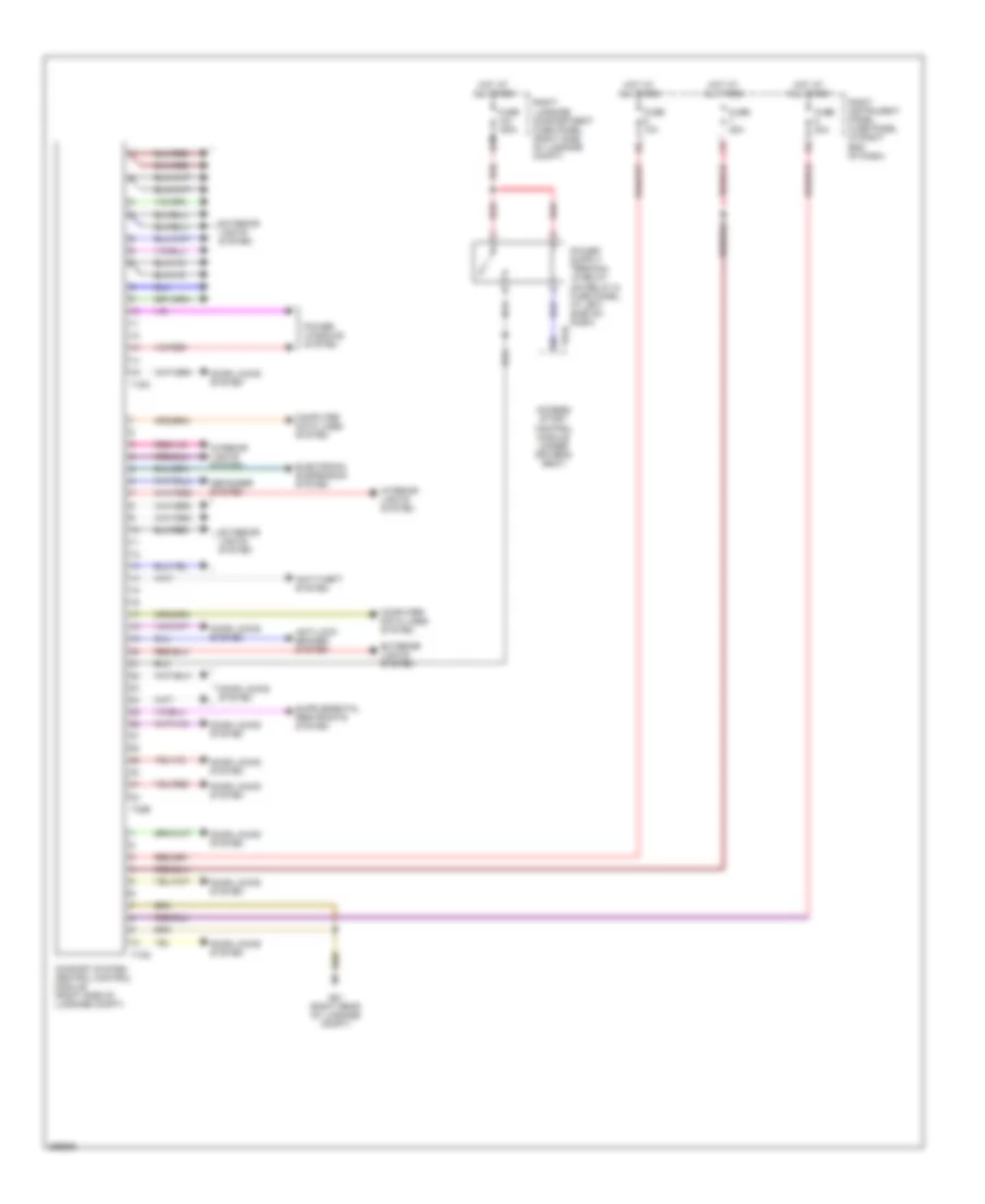
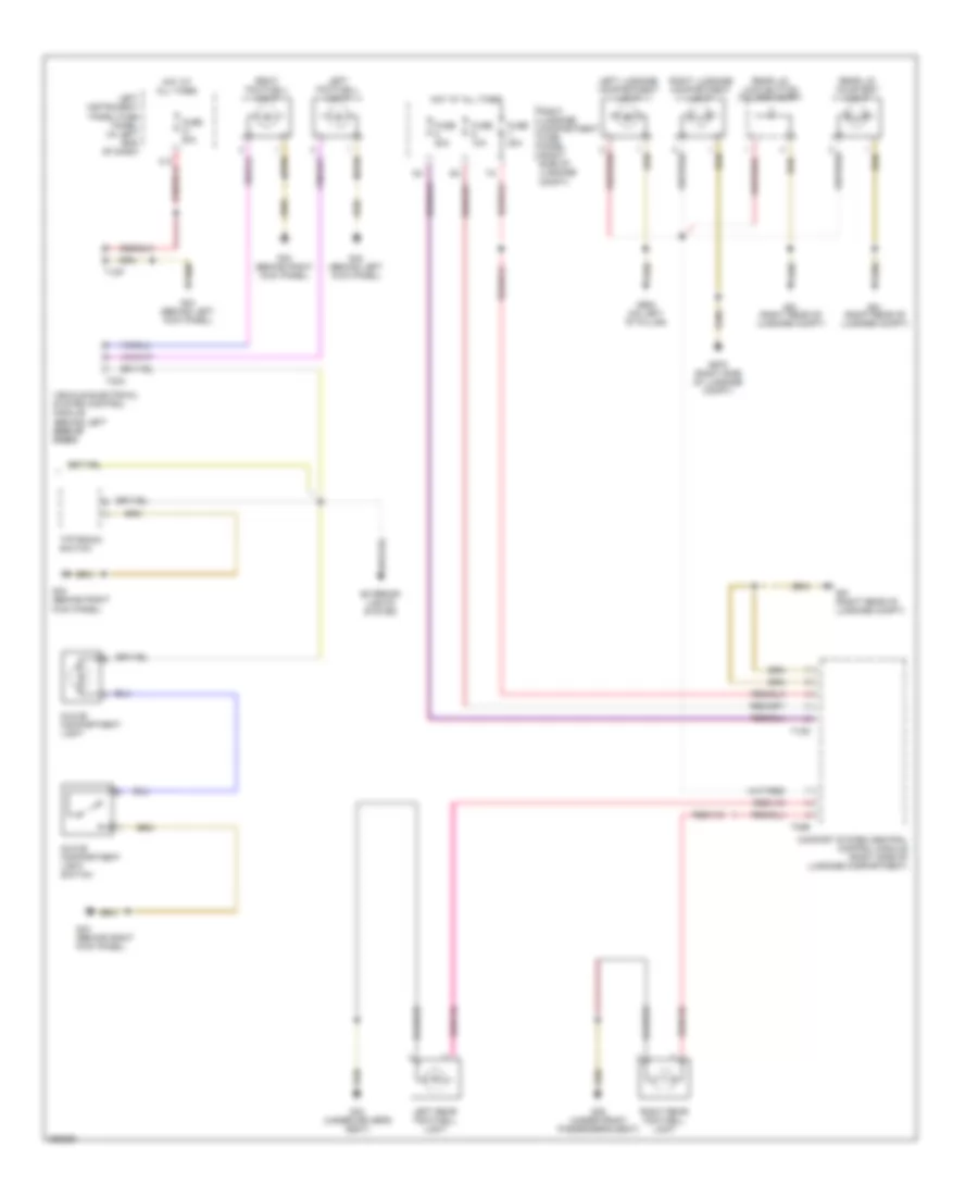
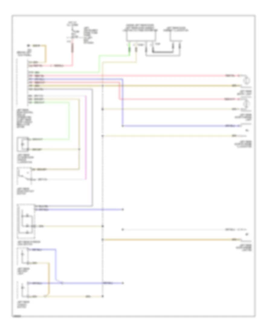
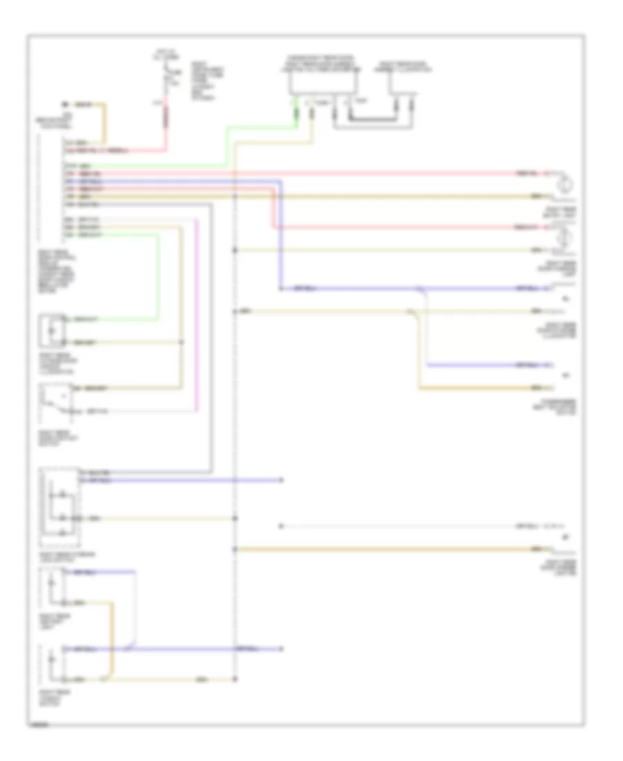
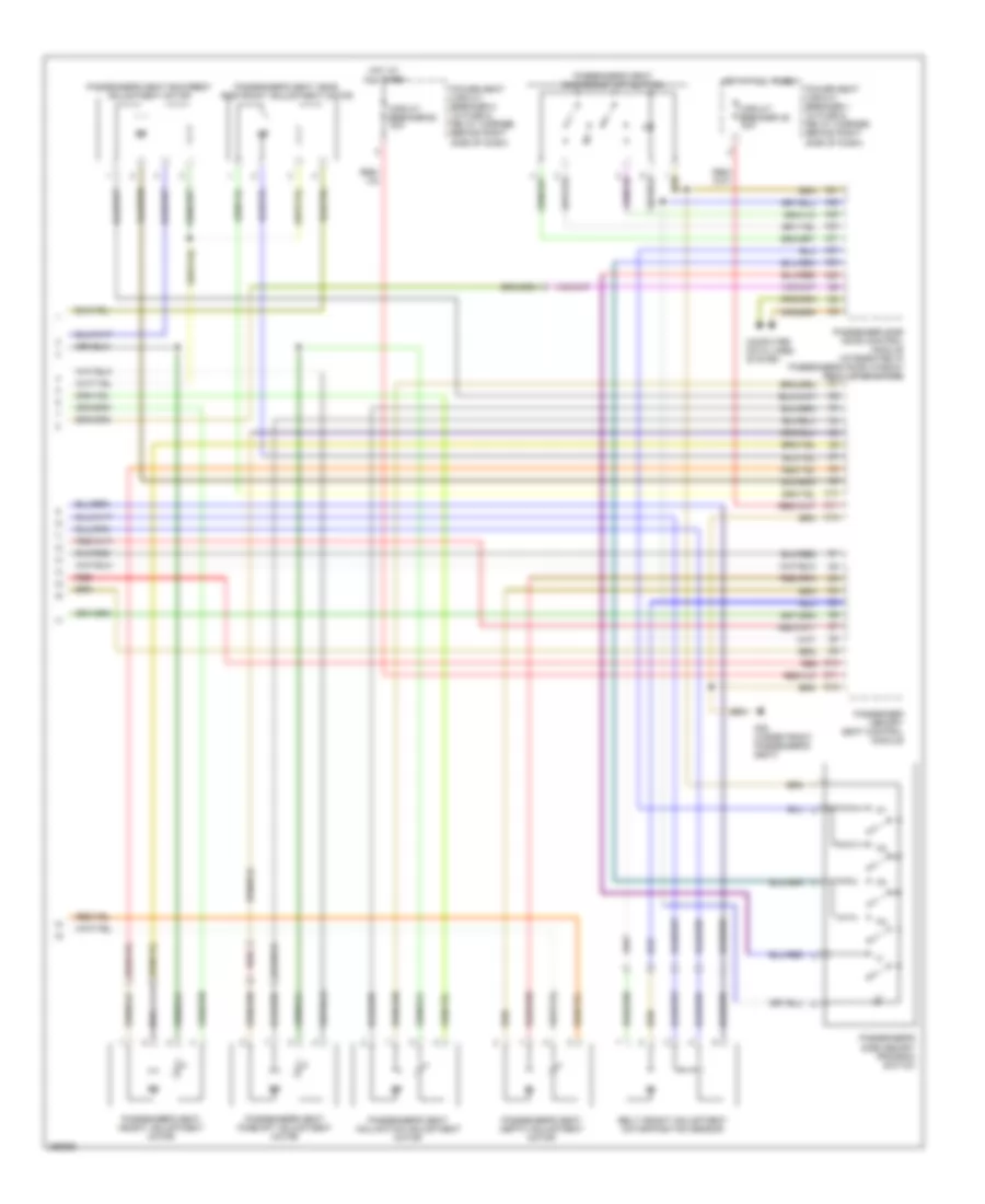
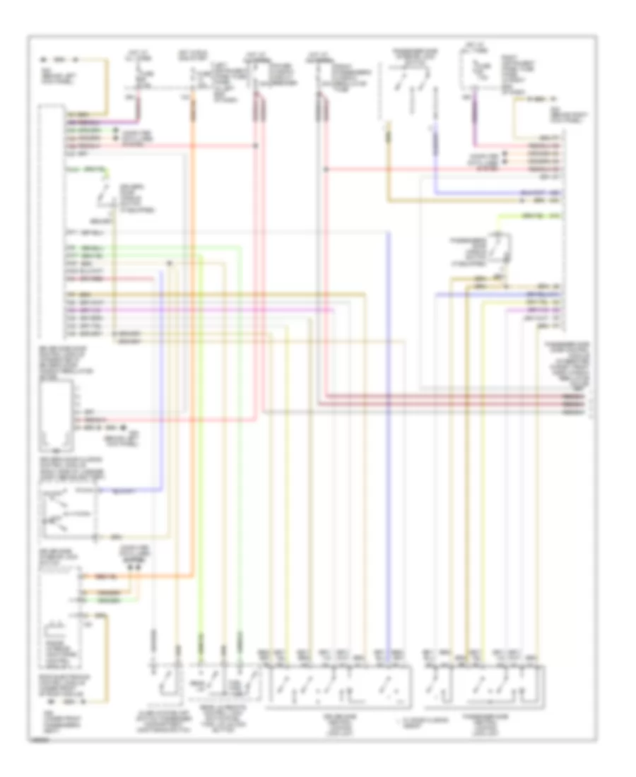
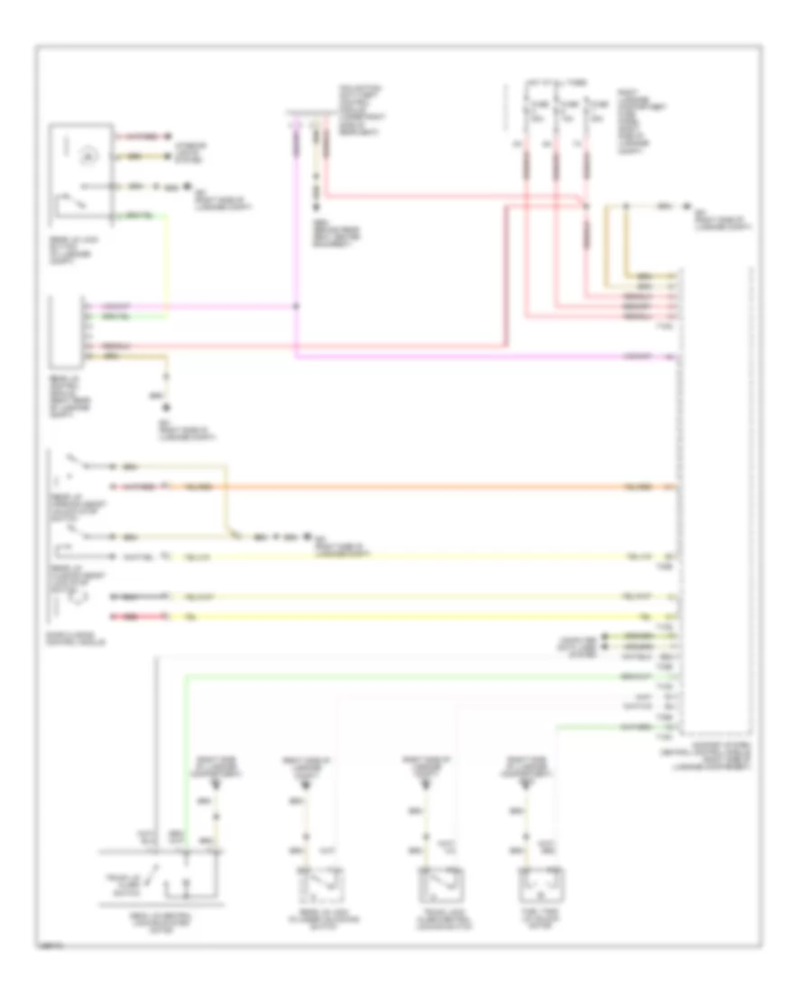
AIR CONDITIONING
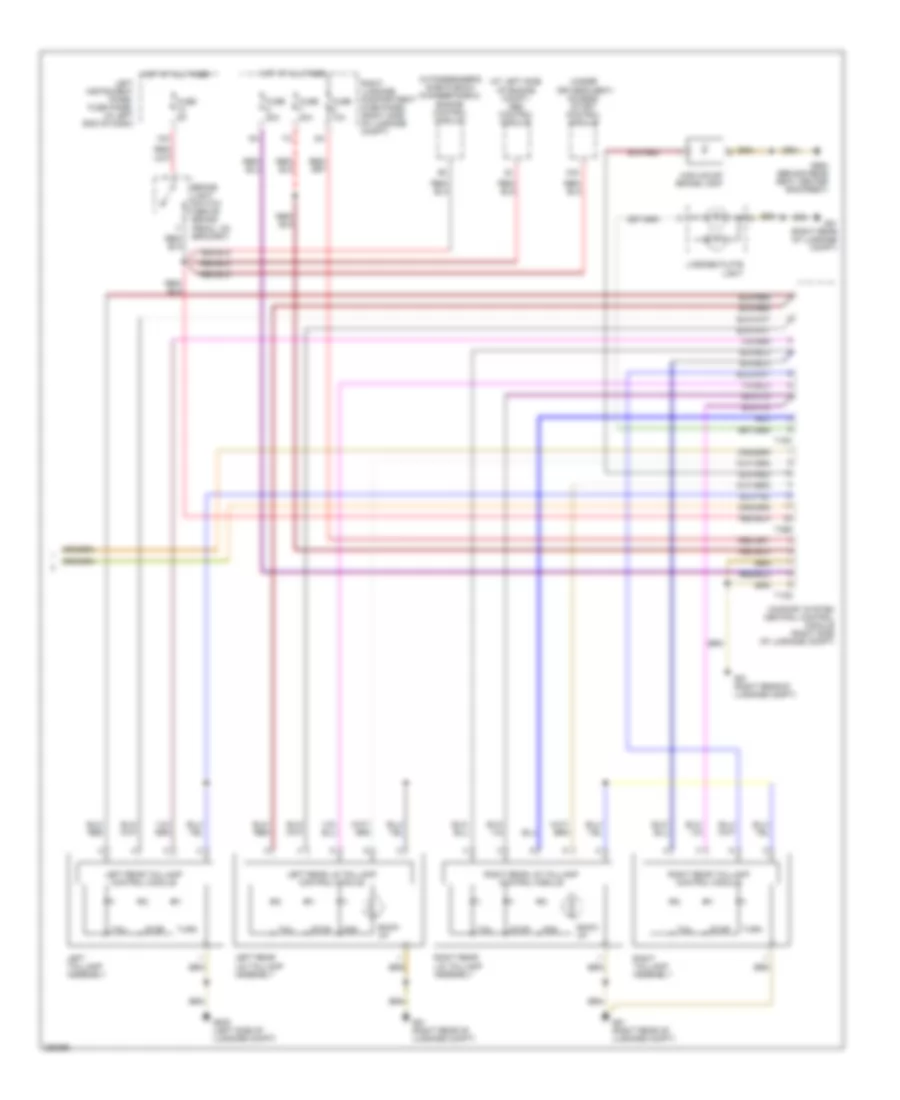
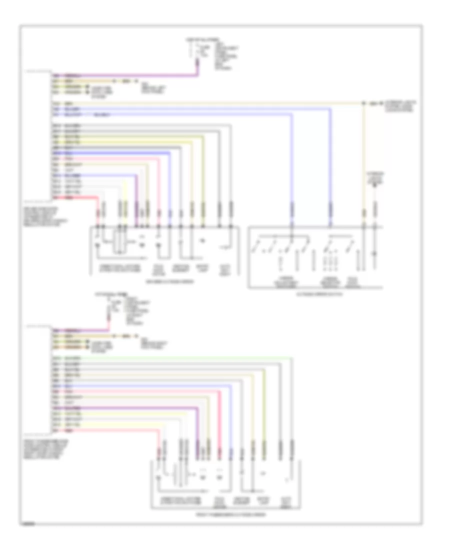
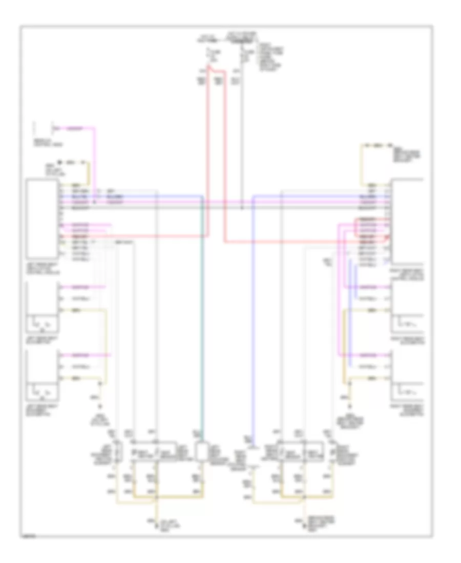
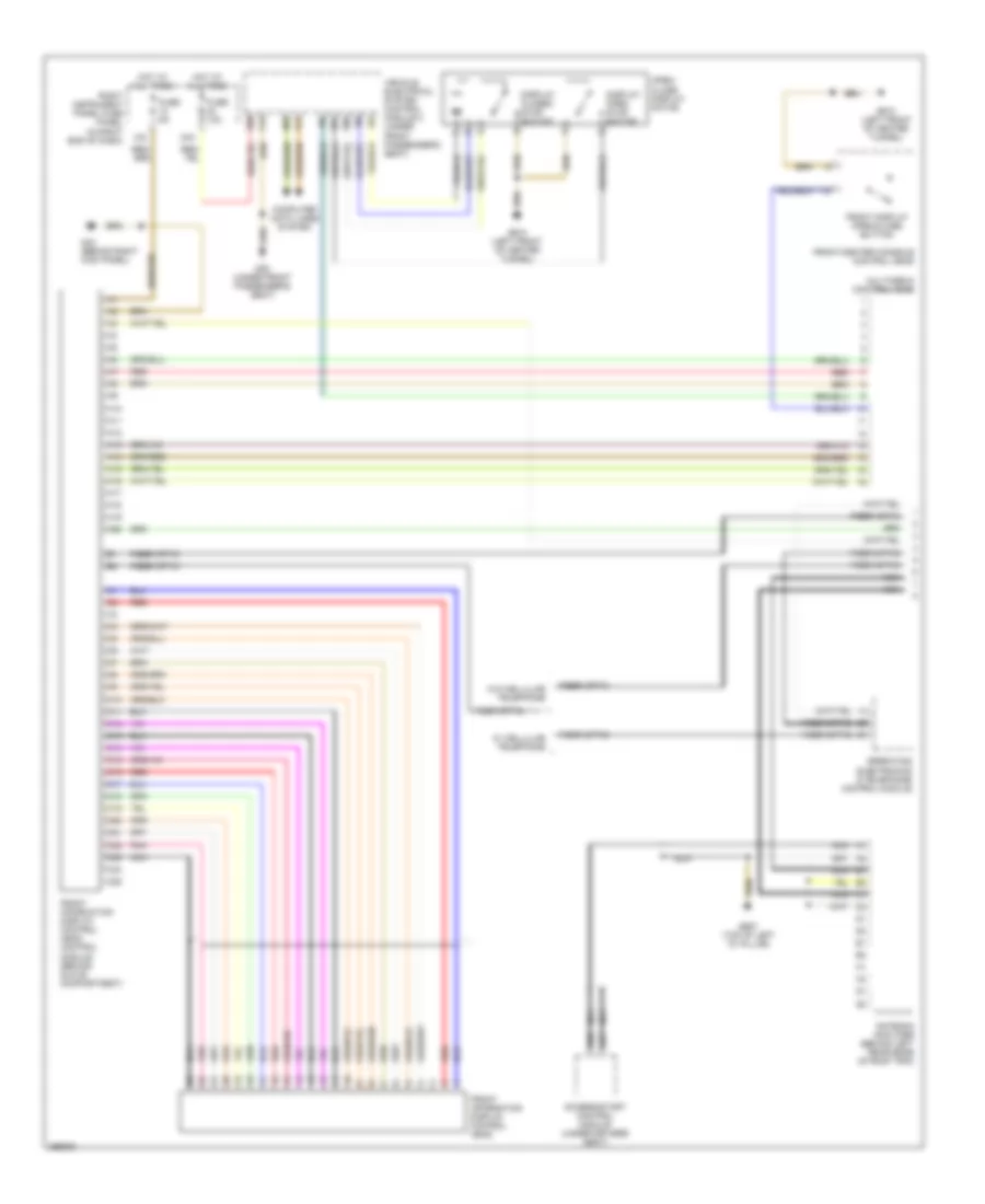
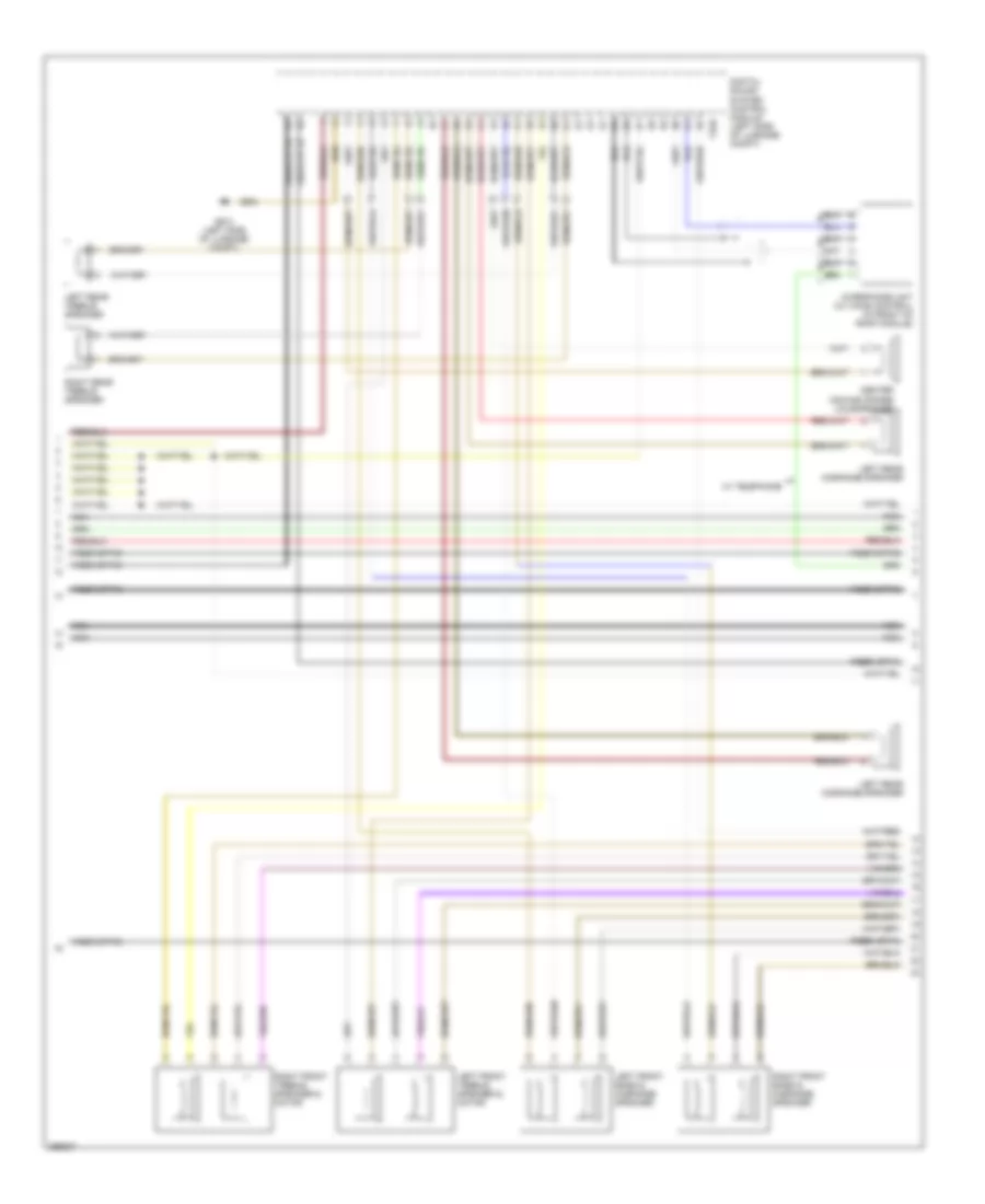
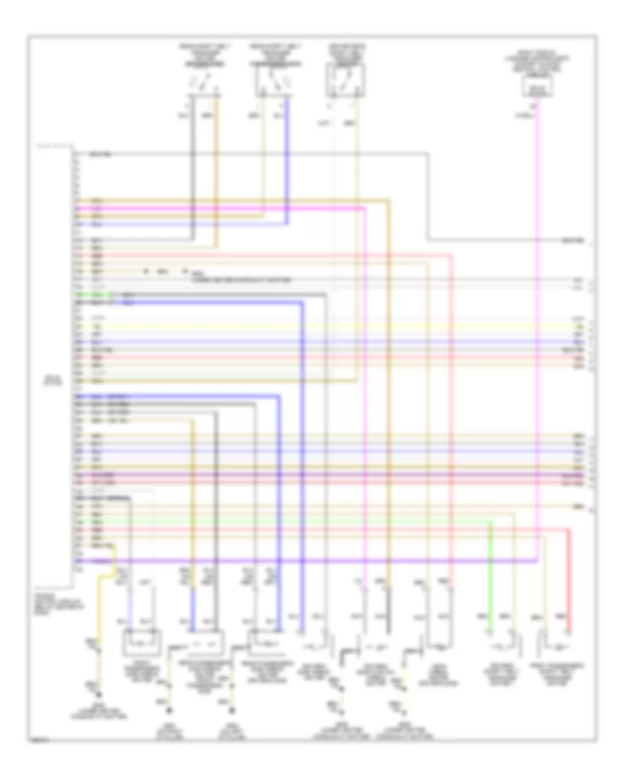
Automatic A/C Wiring Diagram (1 of 3) for Audi A8 Quattro 2007

List of elements for Automatic A/C Wiring Diagram (1 of 3) for Audi A8 Quattro 2007:
- A10
- A11
- A12
- A13
- A14
- A15
- A16
- A17
- A18
- A19
- A20
- A21
- A22
- A23
- A24
- Air flow flap motor/ back pressure flap motor position sensor
- B10
- B11
- B12
- B13
- B14
- B15
- B16
- B17
- B18
- B19
- B20
- B21
- B22
- B23
- B24
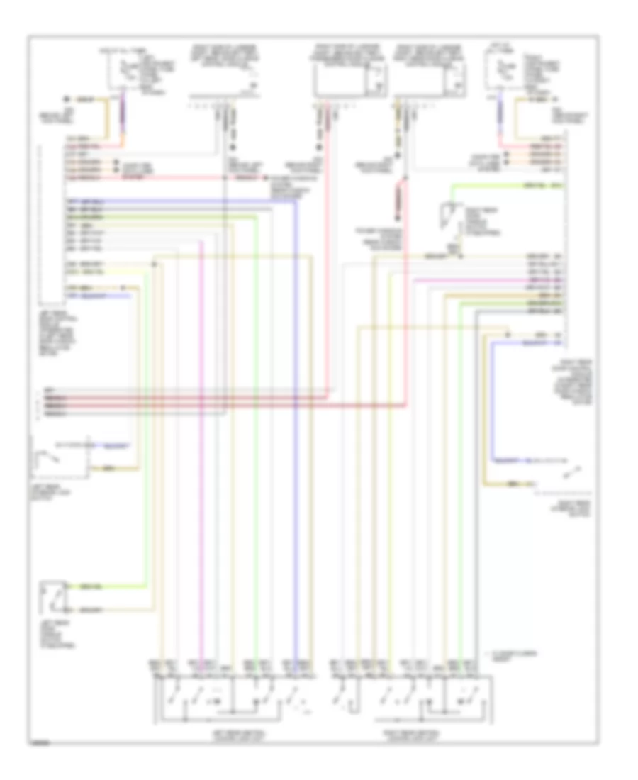
- Climatronic control module (front of center console)
- Defroster flap motor/ position sensor
- Evaporative vent temperature sensor
- Fresh air intake duct temperature sensor
- Left footwell flap motor/position sensor
- Left front defrost/ upper body shut off flap motor/ position sensor
- Left vent temperature sensor
- Nca
- Recirculation flap motor/ position sensor
- Red
- Right footwell flap motor/position sensor
- Right front defrost/ upper body shut off flap motor/ position sensor
- Right vent temperature sensor
- Temperature regulator flap motor/position sensor
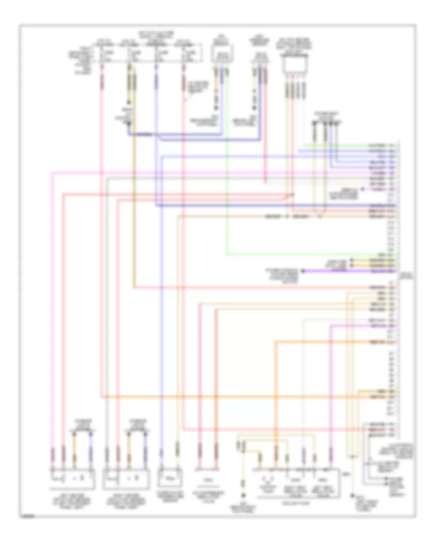
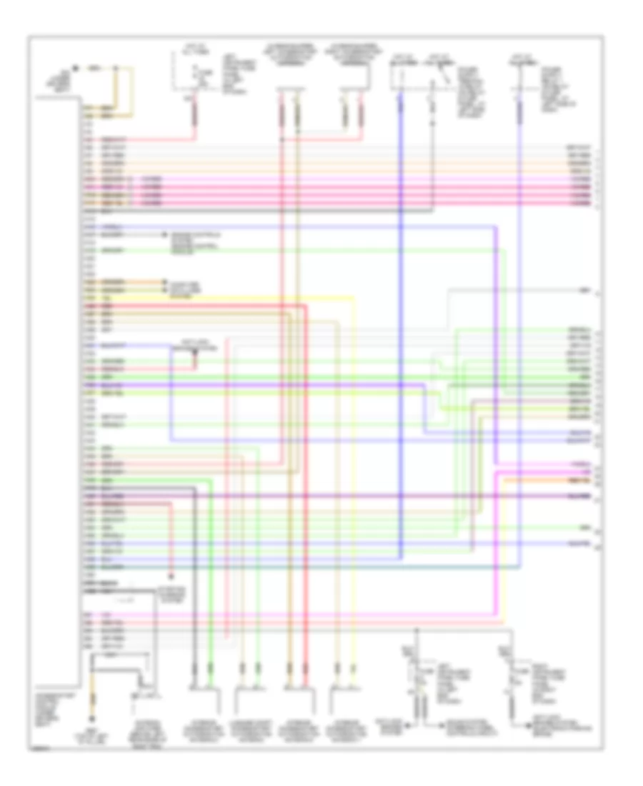
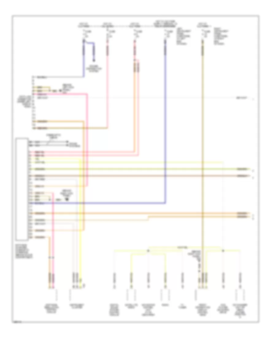
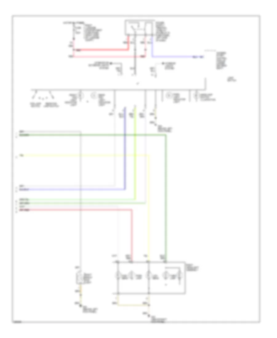
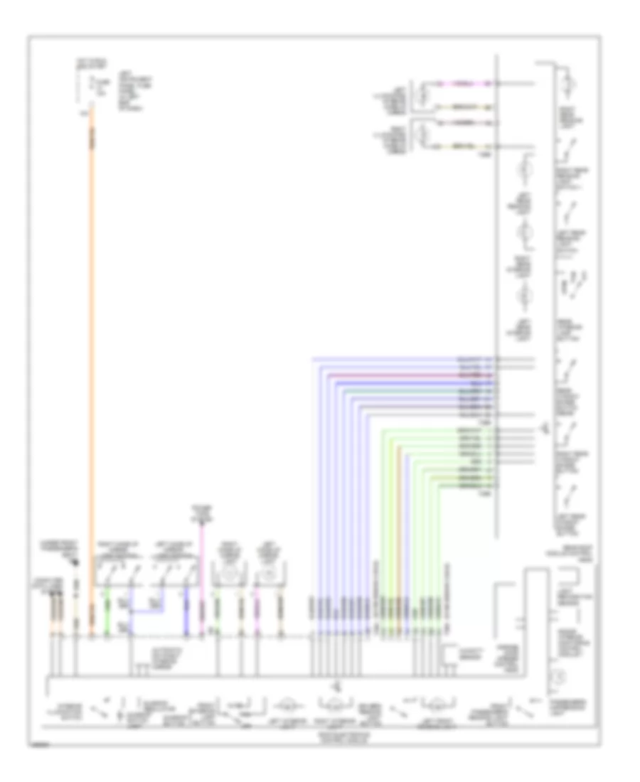
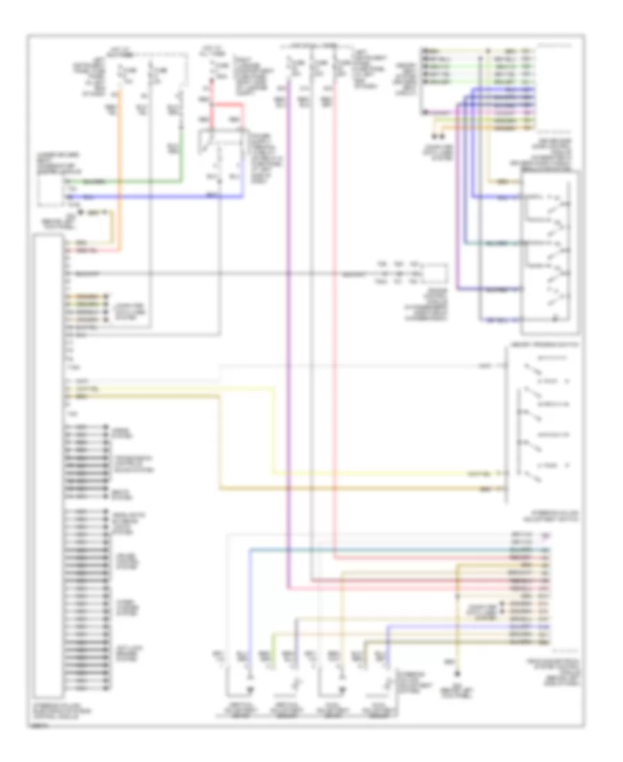
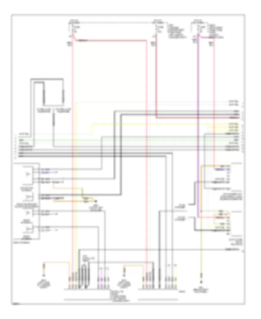
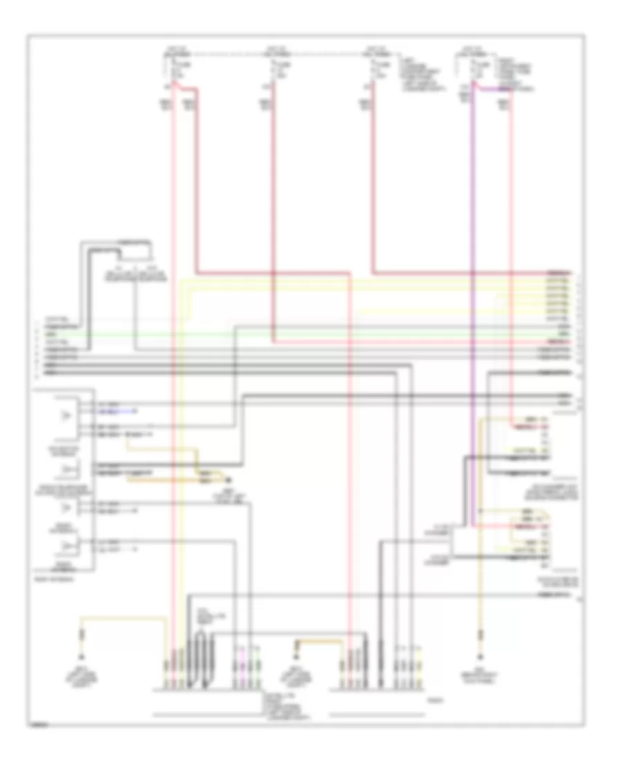
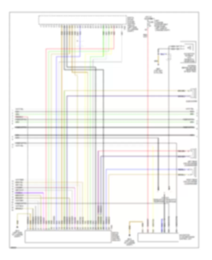
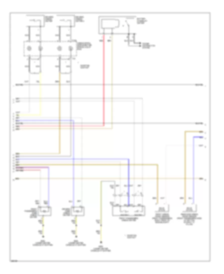
Automatic A/C Wiring Diagram (2 of 3) for Audi A8 Quattro 2007
List of elements for Automatic A/C Wiring Diagram (2 of 3) for Audi A8 Quattro 2007:
- (4.2l)
- (5.2l)
- (6.0l)
- (right rear of engine compt, next to fresh air blower motor) fresh air blower control module
- (w/ sunroof w/ solar cells)
- 13a
- 17a
- 44a
- Center vent adjusting motor/position sensor
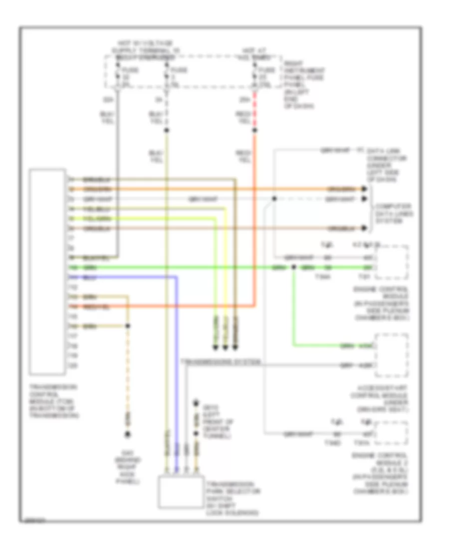
- Computer data lines system
- Coolant fan (right front of eng compt)
- Coolant fan 2 (left front of eng compt)
- Engine control module (in passenger's side plenum chamber e-box)
- Ff8
- Fresh air blower
- Fuse 10a
- Fuse 30a
- Fuse 5a
- Fuse 60a
- G35 (behind front passenger's seat)
- G35 (under front passenger's seat)
- G43 (behind right kick panel)
- Hot at all times
- Humidity sensor
- Instrument cluster
- Left center vent motor/position sensor (integral to left center vent motor)
- Left rear cold/warm flap air outlet motor/position sensor
- Main fuse panel (behind upper right kick panel)
- Motor/position sensor
- Nca
- Red
- Right center vent motor/position sensor (integral to right center vent motor)
- Right instrument panel fuse panel (in right end of dash)
- Right rear cold/warm flap air outlet
- Solar cells
- Solar operation control module (underside of solar roof)
- T40
- T81
- T94
- T94a
- W/o rear a/c w/ rear a/c
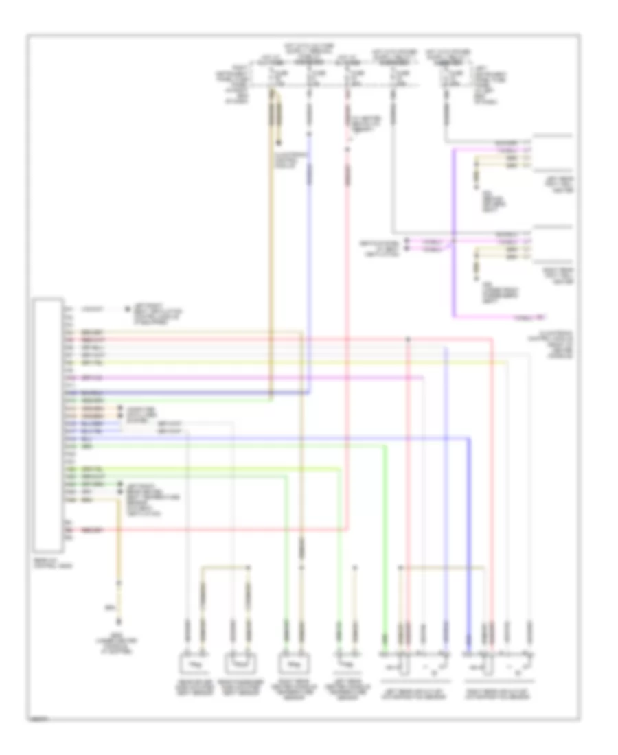
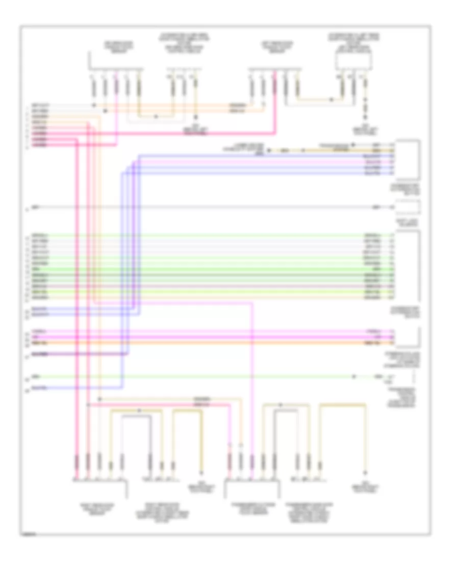
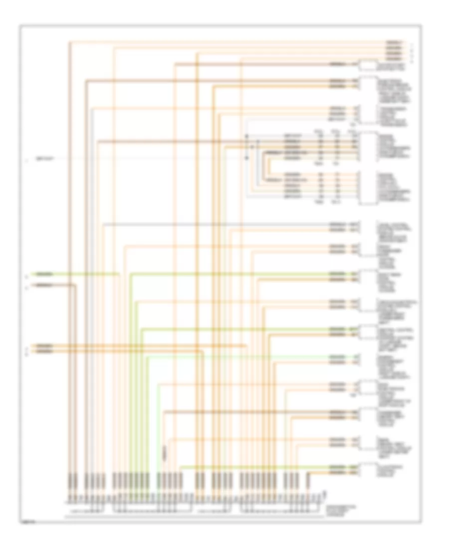
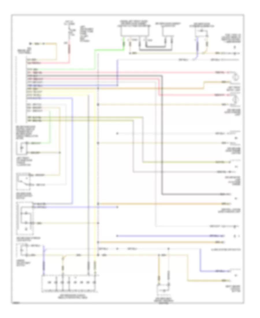
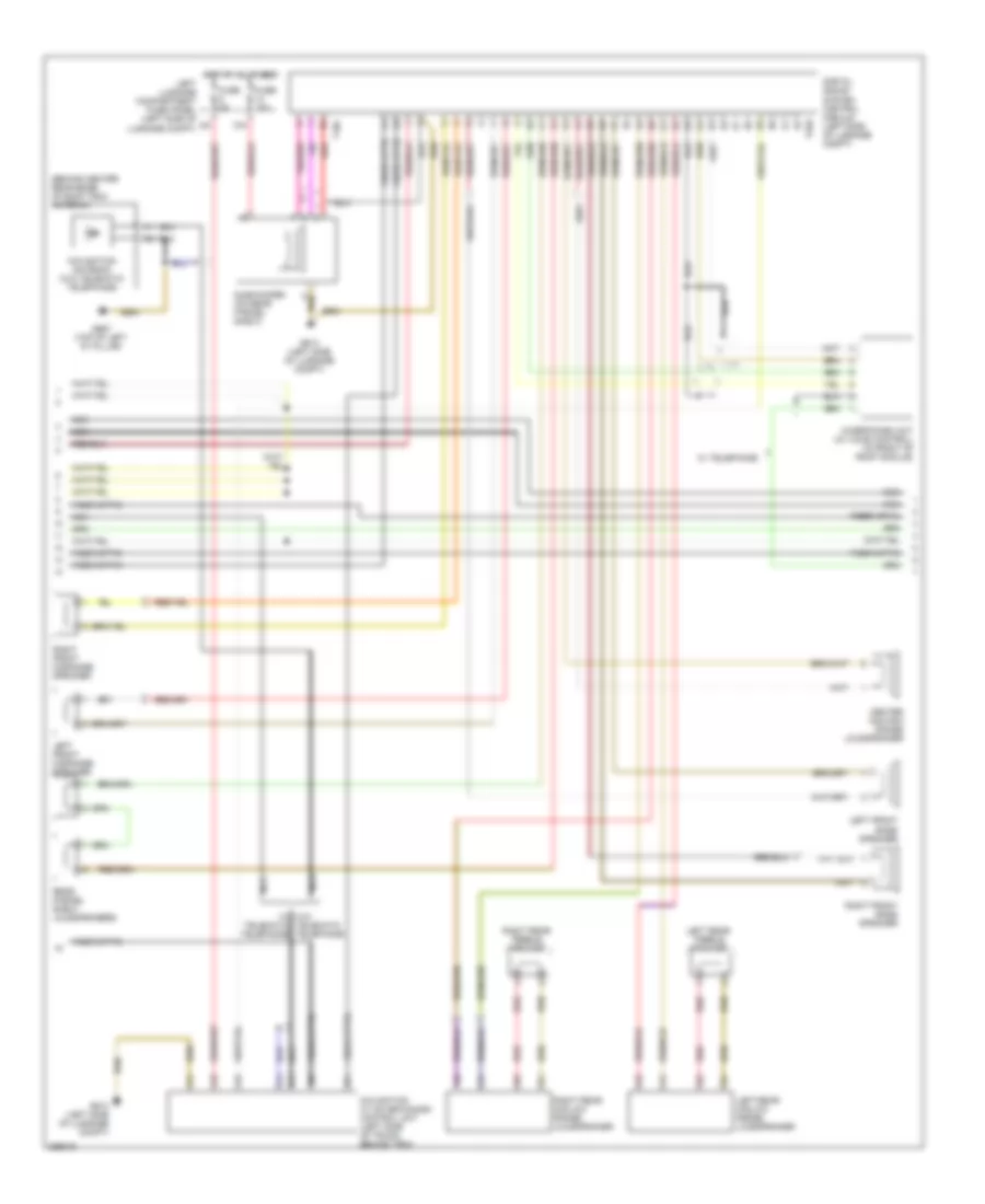
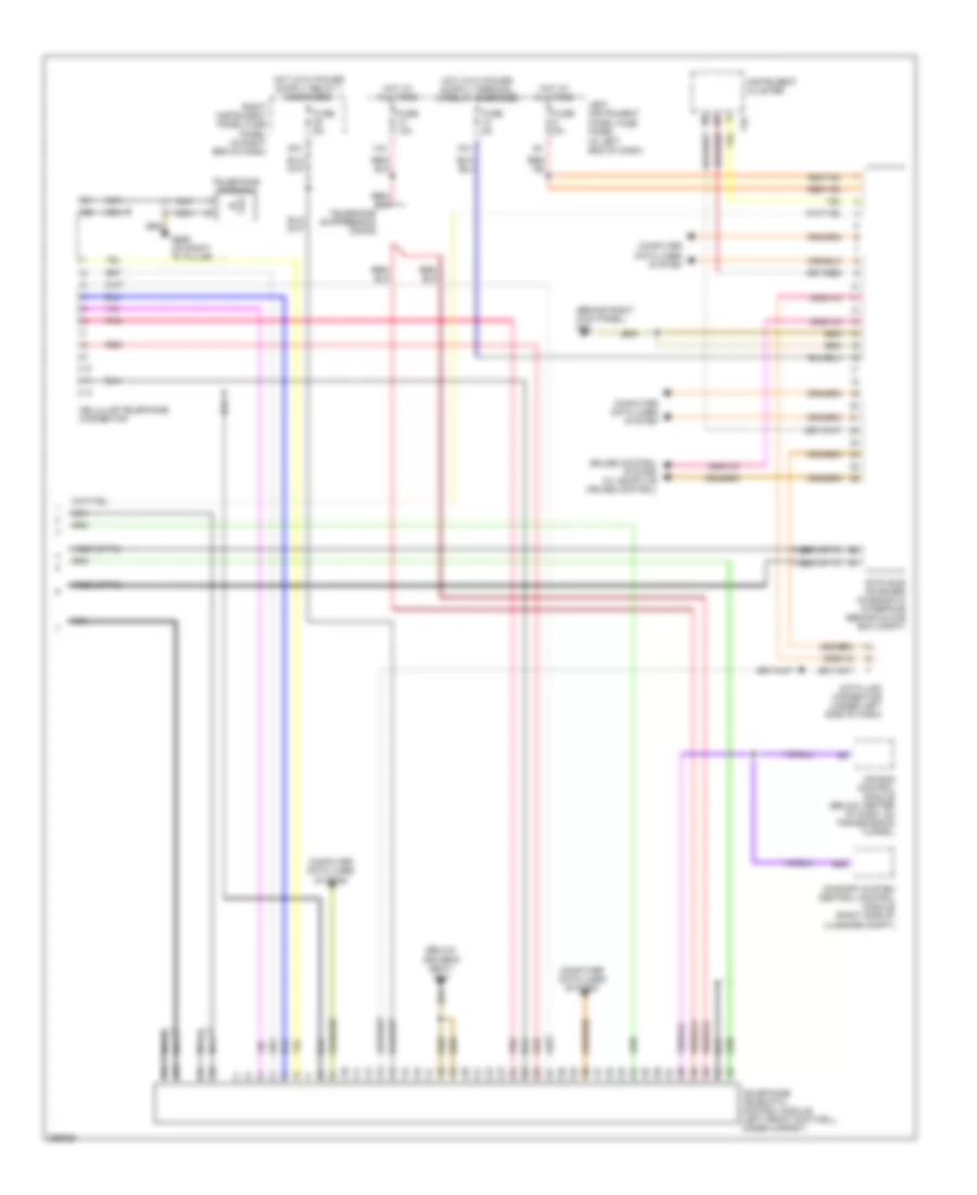
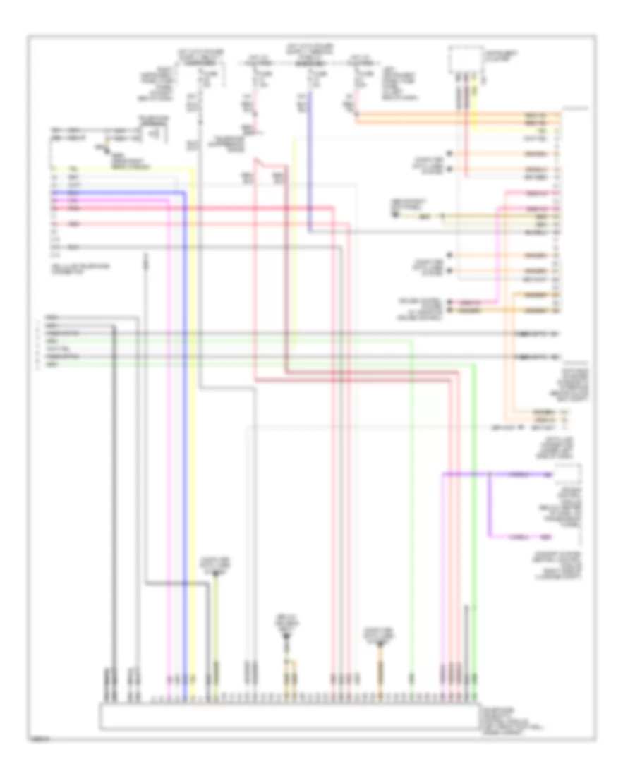
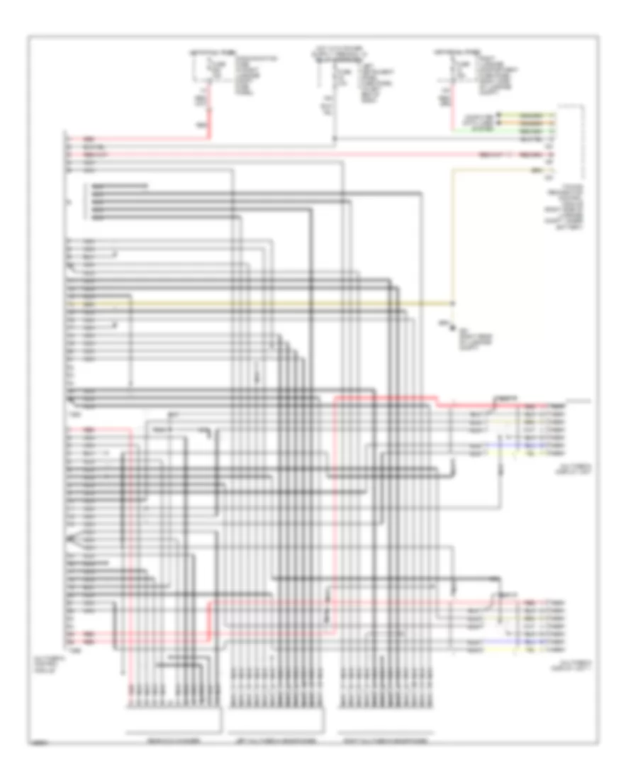
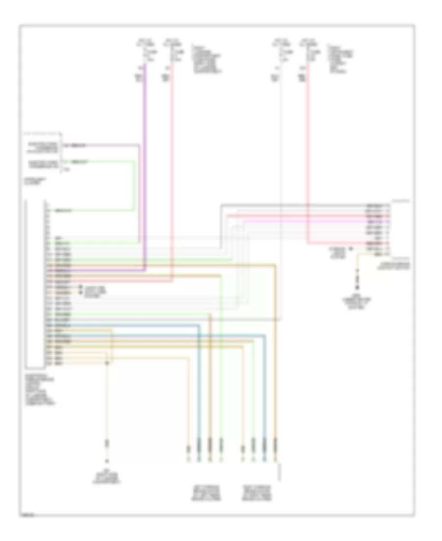
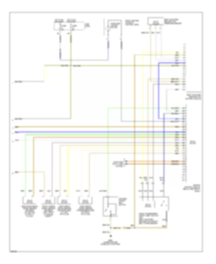
Automatic A/C Wiring Diagram (3 of 3) for Audi A8 Quattro 2007
List of elements for Automatic A/C Wiring Diagram (3 of 3) for Audi A8 Quattro 2007:
- (on top center of middle defrost vent, top of dash) sunlight photo sensor
- (w/ heated seats w/o memory)
- 26a
- 35a
- A/c compressor regulator valve
- Air quality sensor
- C10
- C11
- C12
- C13
- C14
- C15
- C16
- C17
- C18
- C19
- C20
- C21
- C22
- C23
- C24
- Climatronic control module (front of center console)
- Computer data lines system
- Coolant pump
- D10
- D11
- D12
- E10
- E11
- E12
- Floor outlet temperature sensor
- Fuse 10a
- Fuse 20a
- Fuse 5a
- G43 (behind right kick panel)
- G43 (behinde right kick panel)
- G44 (behind left kick panel)
- G610 (left front of center tunnel)
- High pressure sensor
- Hot at all times
- Interior lights system
- Left center air outlet sensor (in left instrument panel vent)
- Left heat regulating valve
- Power seat system (heated seats)
- Power seats system (w/o memory)
- Power windows system (rear window shade switch)
- Rear a/c control head
- Rear a/c system/power seats system
- Right center air outlet sensor (in right instrument panel vent)
- Right heat regulating valve
- Right instrument panel fuse panel (in right end of dash)
- Solid state
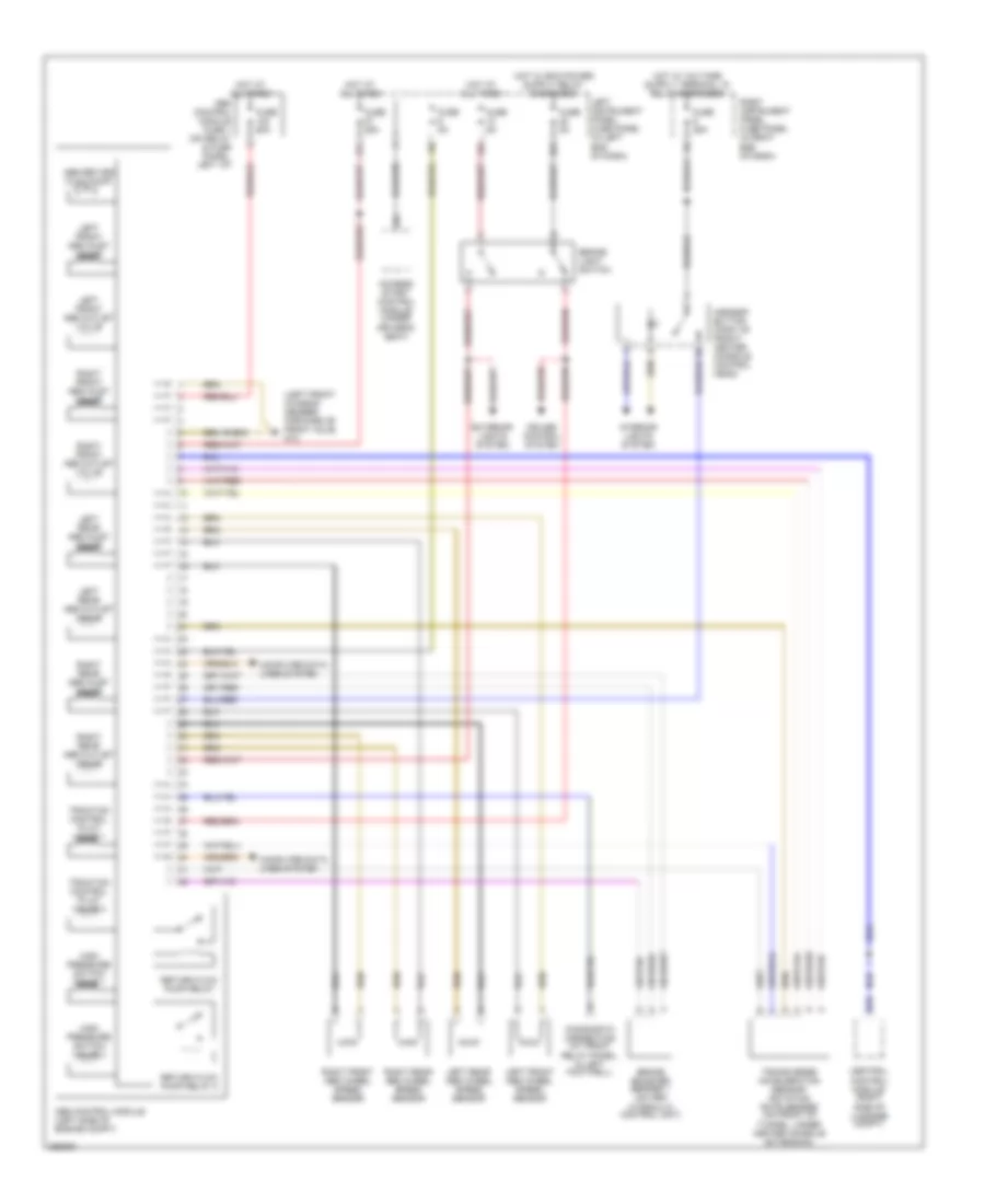
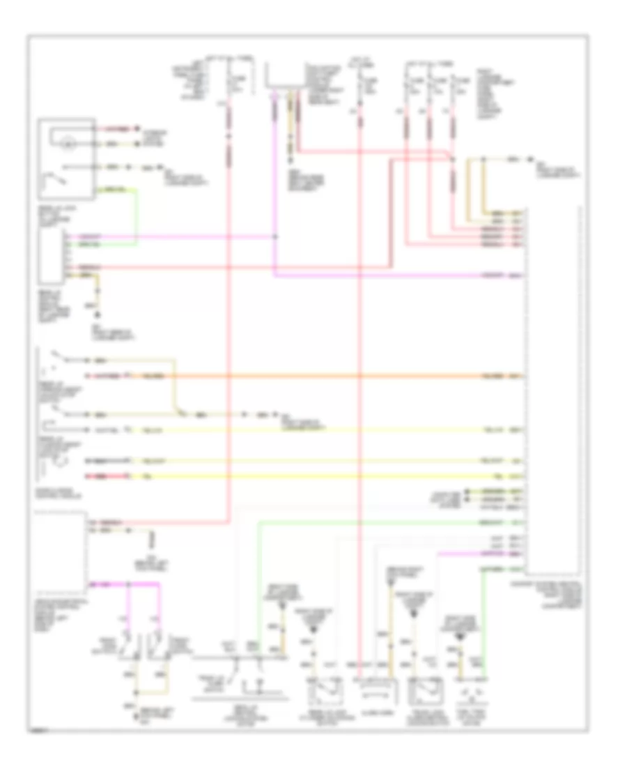
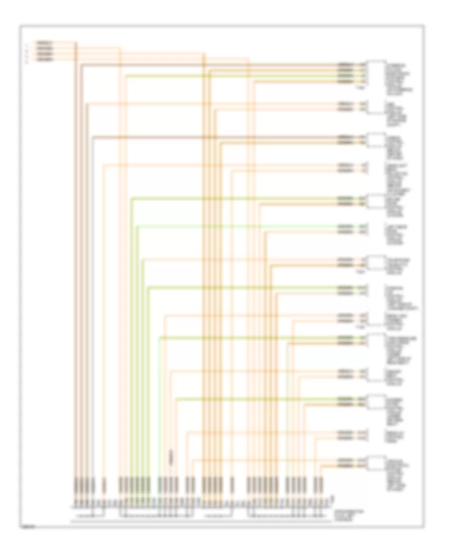
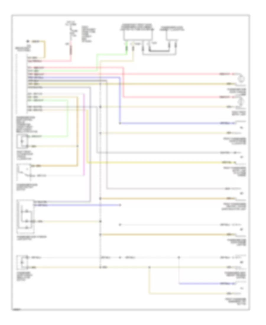
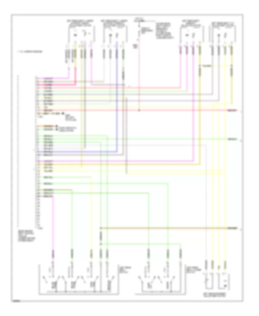
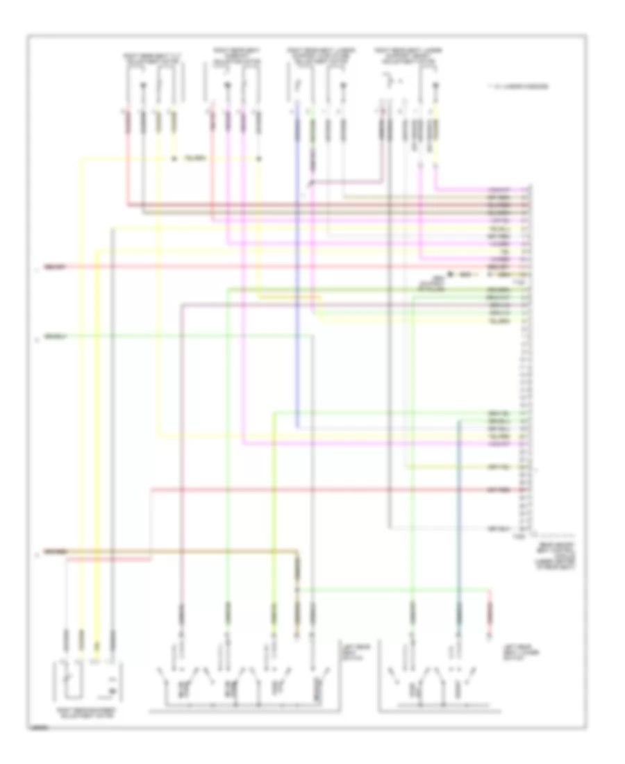
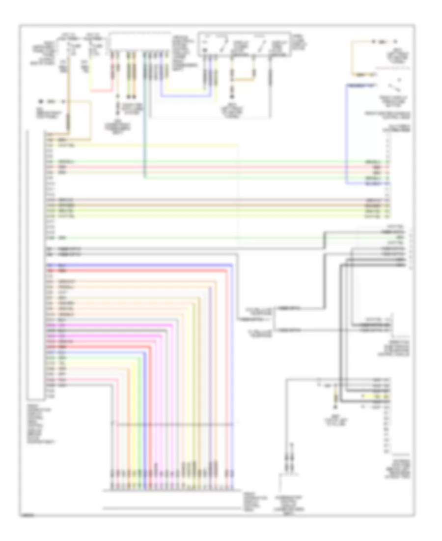
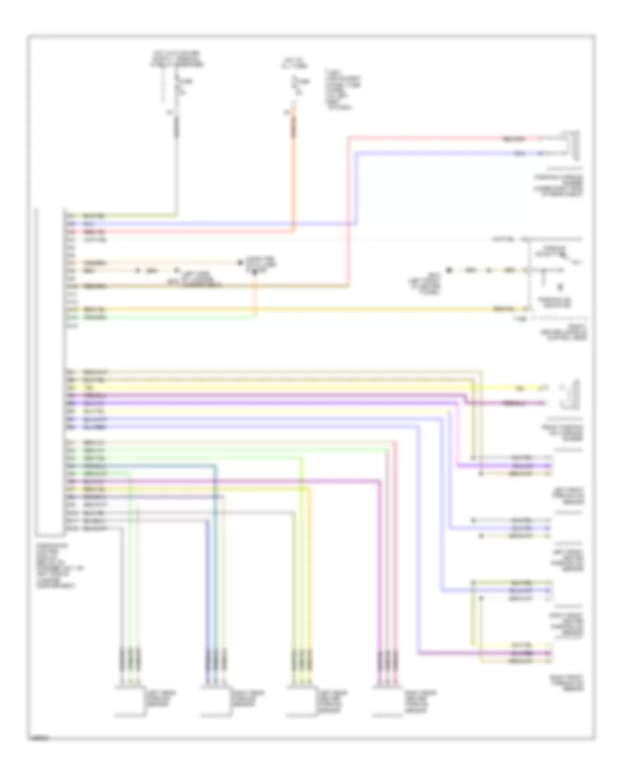
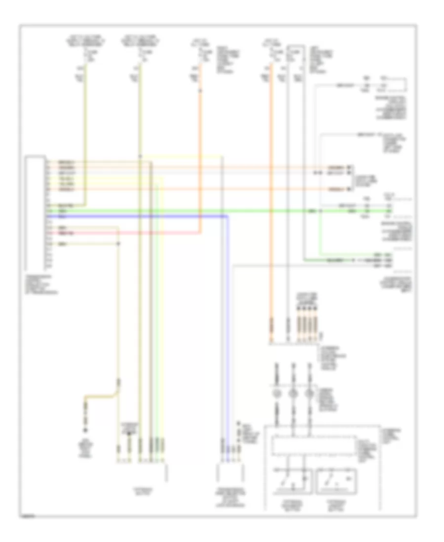
Rear A/C Wiring Diagram for Audi A8 Quattro 2007
List of elements for Rear A/C Wiring Diagram for Audi A8 Quattro 2007:
- (w/ heated seats w/o memory)
- 26a
- 33a
- 34a
- A10
- A11
- A12
- A13
- A14
- A15
- A16
- A17
- A18
- A19
- A20
- A21
- A22
- A23
- A24
- A25
- A26
- Climatronic control module
- Climatronic control module (front of center console)
- Computer data lines system
- Fuse 10a
- Fuse 20a
- Fuse 25a
- Fuse 5a
- G34 (behind driver's seat)
- G35 (under front passenger's seat)
- G606 (under center console, at shifter)
- Hot at all times
- Left instrument panel fuse panel (in left end of dash)
- Left rear air outlet motor/position sensor
- Left rear center console temperature sensor
- Left rear foot well heater
- Left/right rear heated seat temperature sensor (w/o seat ventilation)
- Left/right seat ventilation control module (if equipped)
- Rear a/c control head
- Rear driver side occupied seat sensor
- Rear passenger side occupied seat sensor
- Right instrument panel fuse panel (in right end of dash)
- Right rear air outlet motor/position sensor
- Right rear center console temperature sensor
- Right rear foot well heater
- Seats system (w/ seat ventilation)
ANTI-LOCK BRAKES
4.2L
4.2L, Anti-lock Brakes Wiring Diagram for Audi A8 Quattro 2007
List of elements for 4.2L, Anti-lock Brakes Wiring Diagram for Audi A8 Quattro 2007:
- (left front chassis member, forward of front axle) g12
- 12a
- 22a
- 27a
- Abs control module (left side of engine compt)
- Abs control module fuse 1 (on relay & fuse panel, left i/p)
- Abs return flow pump
- Access/ start control module (under driver's seat)
- Asr/esp button (part of front/ center console control head)
- B19
- Brake booster sender 1 (on abs hydraulic control unit)
- Brake light switch
- Central control module (right side of luggage compt)
- Computer data lines system
- Cruise control system
- Diagnostic connection (at front relay panel, in left footwell)
- Exterior lights system
- Fuse 25a
- Fuse 5a
- Fuse 60a
- High pressure switch valve 1
- High pressure switch valve 2
- Hot at all times
- Interior lights system
- Left front abs inlet valve
- Left front abs outlet valve
- Left front abs wheel speed sensor
- Left instrument panel fuse panel (in left end of dash)
- Left rear abs inlet valve
- Left rear abs outlet valve
- Left rear abs wheel speed sensor
- Return flow pump relay
- Return flow pump relay 2
- Right front abs inlet valve
- Right front abs outlet valve
- Right front abs wheel speed sensor
- Right instrument panel fuse panel (in right end of dash)
- Right rear abs inlet valve
- Right rear abs outlet valve
- Right rear abs wheel speed sensor
- Traction control pilot valve 1
- Traction control pilot valve 2
- Transverse acceleration sensor/ rotation rate sender (on front of tunnel, under center console extension)
6.0L
6.0L, Anti-lock Brakes Wiring Diagram for Audi A8 Quattro 2007
List of elements for 6.0L, Anti-lock Brakes Wiring Diagram for Audi A8 Quattro 2007:
- (left front chassis member, forward of front axle) g12
- 12a
- 22a
- 27a
- Abs control module (left side of engine compt)
- Abs control module fuse 1 (on relay & fuse panel, left i/p)
- Abs return flow pump
- Access/ start control module (under driver's seat)
- Asr/esp button (part of front/ center console control head)
- B19
- Brake booster sender (on abs hydraulic control unit)
- Brake light switch
- Central control module (right side of luggage compt)
- Computer data lines system
- Cruise control system
- Diagnostic connection (at front relay panel, in left footwell)
- Exterior lights system
- Fuse 25a
- Fuse 5a
- Fuse 60a
- High pressure switch valve 1
- High pressure switch valve 2
- Hot at all times
- Interior lights system
- Left front abs inlet valve
- Left front abs outlet valve
- Left instrument panel fuse panel (in left end of dash)
- Left rear abs inlet valve
- Left rear abs outlet valve
- Left rear abs wheel speed sensor
- Return flow pump relay
- Return flow pump relay 2
- Right front abs inlet valve
- Right front abs outlet valve
- Right instrument panel fuse panel (in right end of dash)
- Right rear abs inlet valve
- Right rear abs outlet valve
- Traction control pilot valve 1
- Traction control pilot valve 2
- Transverse acceleration sensor/ rotation rate sender (front of tunnel, under center console extension)
ANTI-THEFT
Access/Start Wiring Diagram (1 of 2) for Audi A8 Quattro 2007
List of elements for Access/Start Wiring Diagram (1 of 2) for Audi A8 Quattro 2007:
- (in rear bumper) left access/start authorization antenna
- (in rear bumper) right access/start authorization antenna
- 42a
- A10 a1
- A11
- A12
- A13
- A14
- A15
- A16
- A17
- A18
- A19
- A20
- A21
- A22
- A23
- A24
- A25
- A26
- A27
- A28
- A29
- A30
- A31
- A32
- A33
- A34
- A35
- A36
- A37
- A38
- A39
- A40
- A41
- A42
- A43
- A44
- A45
- A46
- A47
- A48
- A49
- A50
- A51
- A52
- A53
- A54
- A55
- A56
- A57
- A58
- A59
- A60
- A61
- A62
- Access/start control module (under driver's seat)
- Antenna amplifier (behind left rear edge of roof trim)
- Anti-lock brakes system
- Anti-lock brakes system (electronic parking brake)
- Computer data lines system
- Engine controls system (engine control module)
- Fuse 25a
- Fuse 5a
- G34 (under driver's seat)
- G657 (top of left "d" pillar)
- Hot at all times
- Interior access/start authorization antenna 1
- Interior access/start authorization antenna 2
- Interior access/start authorization antenna 3
- Left instrument panel fuse panel (in left end of dash)
- Luggage compt. access/start authorization antenna
- Nca
- Red
- Right instrument panel fuse panel (in right end of dash)
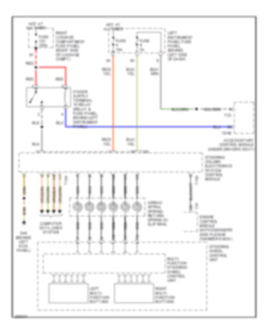
- Sound system (steering wheel controls circuit)
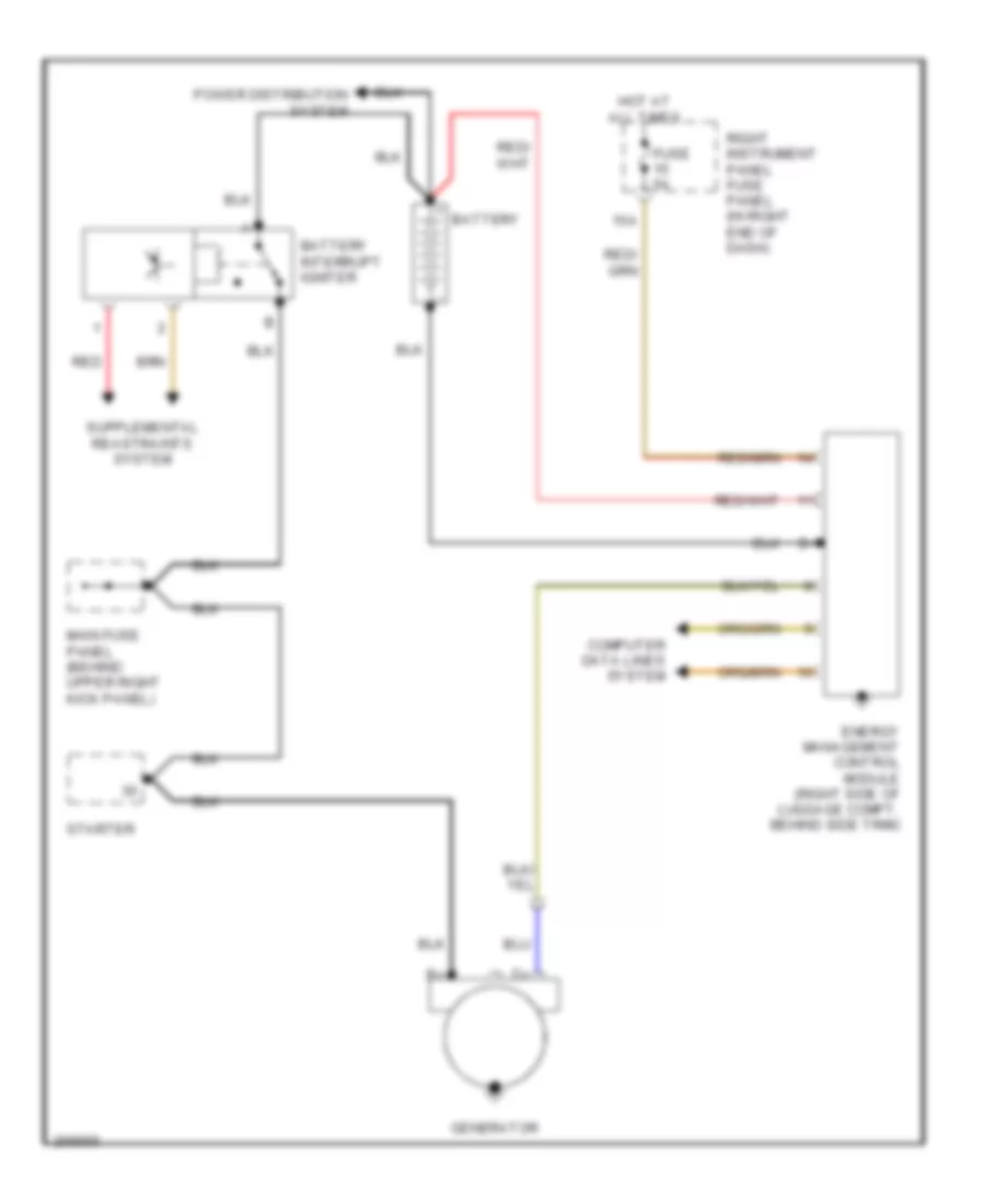
- Starting/ charging system
Access/Start Wiring Diagram (2 of 2) for Audi A8 Quattro 2007
List of elements for Access/Start Wiring Diagram (2 of 2) for Audi A8 Quattro 2007:
- (integrated in driver's door window regulator motor) driver's side door control module
- (integrated in left rear door window regulator motor) left rear door control module
- (under center console at shifter) g606
- Access/start authorization button
- Access/start authorization switch
- C12
- Driver's door handle touch sensor
- G43 (behind right kick panel)
- G44 (behind left kick panel)
- Left rear door handle touch sensor
- Passenger's outside door handle touch sensor
- Passenger's side door control module (integrated in right front door window regulator motor)
- Right rear door control module (integrated in right rear door window regulator motor)
- Right rear door handle touch sensor
- Shift lock solenoid
- Steering column lock actuator (at base of steering column)
- T16c
- Transmission control module (in bottom of transmission)
- Transmissions system
Anti-theft & Central Locking Wiring Diagram (1 of 3) for Audi A8 Quattro 2007
List of elements for Anti-theft & Central Locking Wiring Diagram (1 of 3) for Audi A8 Quattro 2007:
- 30a
- 39a
- A17
- A21
- A23
- Alarm system off switch/ passenger compartment monitoring switch
- Assist
- C10
- C11
- Computer data lines system
- Driver side central locking lock unit
- Driver side door control module (integrated in driver's door window regulator motor)
- Driver side interior lock switch
- Driver's door closing control module (right side of luggage compt behind battery)
- Driver's door handle switch (if equipped)
- Front passenger's window regulator fuse
- Fuel tank lid
- Fuse 10a
- Fuse 7.5a
- G35 (under front passenger's seat)
- G43 (behind right kick panel)
- G44 (behind left kick panel)
- Hot at all times
- Hot in run and start
- Left instrument panel fuse panel (in left end of dash)
- Lock
- Passenger side central locking lock unit
- Passenger side door control module (integrated in right front door window regulator motor)
- Passenger side interior lock switch
- Passenger's door handle switch (if equipped)
- Power window circuit breaker
- Radar interior monitoring control module 1
- Rear lid
- Rear lid remote control lock switch/fuel tank lid unlock button
- Right instrument panel fuse panel (in right end of dash)
- Roof electronics control module (under front of roof module)
- T8f
- Unlock
- W/ door closing
Anti-theft & Central Locking Wiring Diagram (2 of 3) for Audi A8 Quattro 2007
List of elements for Anti-theft & Central Locking Wiring Diagram (2 of 3) for Audi A8 Quattro 2007:
- (right side of luggage compt. behind battery) left rear door closing control module
- (right side of luggage compt. behind battery) passenger's door closing control module
- (right side of luggage compt. behind battery) right rear door closing control module
- 41a
- Assist
- B10
- B11
- B12
- Computer data lines system
- Fuse 7.5a
- G43 (above right kick panel)
- G43 (behind right kick panel)
- G44 (behind left kick panel)
- Hot at all times
- Left instrument panel fuse panel (in left end of dash)
- Left rear central locking lock unit
- Left rear door control module (integrated in left rear door window regulator motor)
- Left rear door handle switch (if equipped)
- Left rear interior lock switch
- Power windows system (rear window sun shade)
- Right instrument panel fuse panel (in right end of dash)
- Right rear central locking lock unit
- Right rear door control module (integrated in right rear door window regulator motor)
- Right rear door handle switch (if equipped)
- Right rear interior lock switch
- W/ door closing
Anti-theft & Central Locking Wiring Diagram (3 of 3) for Audi A8 Quattro 2007
List of elements for Anti-theft & Central Locking Wiring Diagram (3 of 3) for Audi A8 Quattro 2007:
- (behind left kick panel) g44
- (behind right kick panel) g43
- (right side of luggage compartment) g51
- (right side of luggage compartment) g675
- (right side of luggage compt) g51
- 31a
- A15
- Alarm horn
- B14
- B17
- B18
- B24
- B26
- B29
- B31
- Bb22
- C10
- Comfort system central control module (right side of luggage compartment)
- Computer data lines system
- Deck lid central locking system motor
- Door closing control module
- Front hood switch
- Front hood switch 2
- Fuel tank lid unlock motor
- Fuse 10a
- Fuse 150a
- Fuse 20a
- Fuse 30a
- G44 (behind left kick panel)
- G51 (right rear of luggage compt)
- G51 (right side of luggage compt)
- G654 (behind rear seat center backrest)
- Hot at all times
- Inclination/ anti-theft control module (under right side of rear seat)
- Interior lights system
- Left instrument panel fuse panel (in left end of dash)
- Rear lid closing assist lock stop switch
- Rear lid control module (right rear of luggage compt)
- Rear lid lock button (in luggage compt)
- Rear lid lock cylinder unlocking switch
- Rear lid opening assist unlock stop switch
- Red
- Right luggage compartment fuse panel (right side of luggage compt)
- Trunk lid alarm switch
- Trunk lock alarm/central locking switch
- Vehicle electrical system control module (behind left side of dash)
BODY CONTROL MODULES
Body Control Modules Wiring Diagram for Audi A8 Quattro 2007
List of elements for Body Control Modules Wiring Diagram for Audi A8 Quattro 2007:
- Access/ start control module (under driver's seat)
- Anti-lock brakes system
- Anti-theft system
- Comfort system central control module (right side of luggage compt)
- Computer data lines system
- Defogger system
- Door locks system
- Electronic suspension system
- Exterior lights system
- Fuse 10a
- Fuse 150a
- Fuse 20a
- G51 (right rear of luggage compt)
- Hot at all times
- Interior lights system
- Power windows system
- Red
- Right instrument panel fuse panel (in right end of dash)
- Right luggage compartment fuse panel (right side of luggage compt)
- T10q
- T15c
- T32b
- T81b
COMPUTER DATA LINES
Computer Data Lines Wiring Diagram (1 of 3) for Audi A8 Quattro 2007
List of elements for Computer Data Lines Wiring Diagram (1 of 3) for Audi A8 Quattro 2007:
- (behind left kick panel) g44
- (behind right kick panel) g43
- (fibre-optic cable)
- 10a
- 12a
- Cd changer unit or media player (position 2)
- Dash)
- Data bus on board diagnostic interface (behind glove compartment)
- Data link connector (under left side of
- Digital sound system control module
- Distance regulation control module
- Dvd player or cd-rom drive
- Front information display control head
- Fuse 5a
- Hot at all times
- Instrument cluster
- Left instrument panel fuse panel (in left end of dash)
- Navigation control unit w/ cd mechanism
- Nca
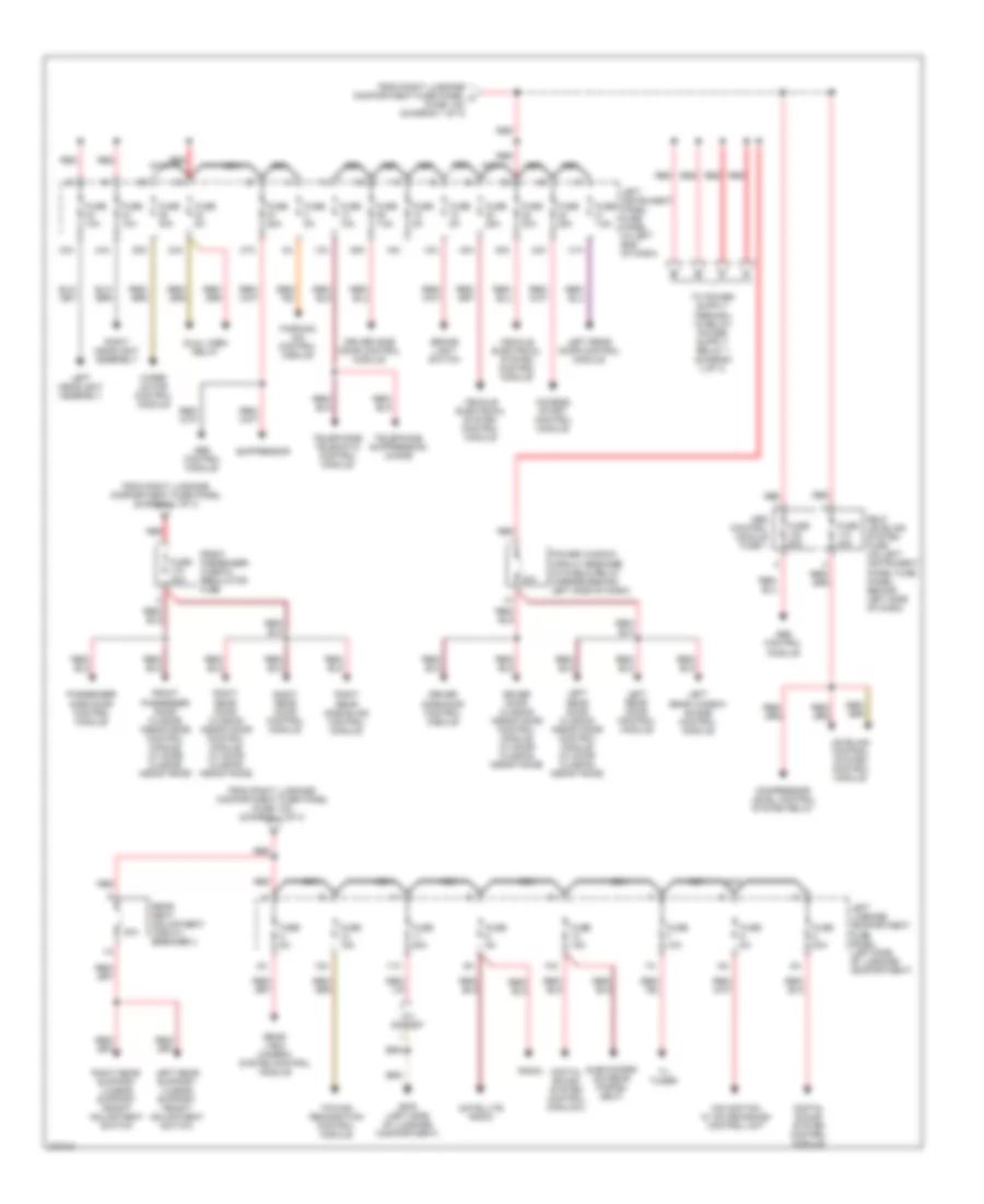
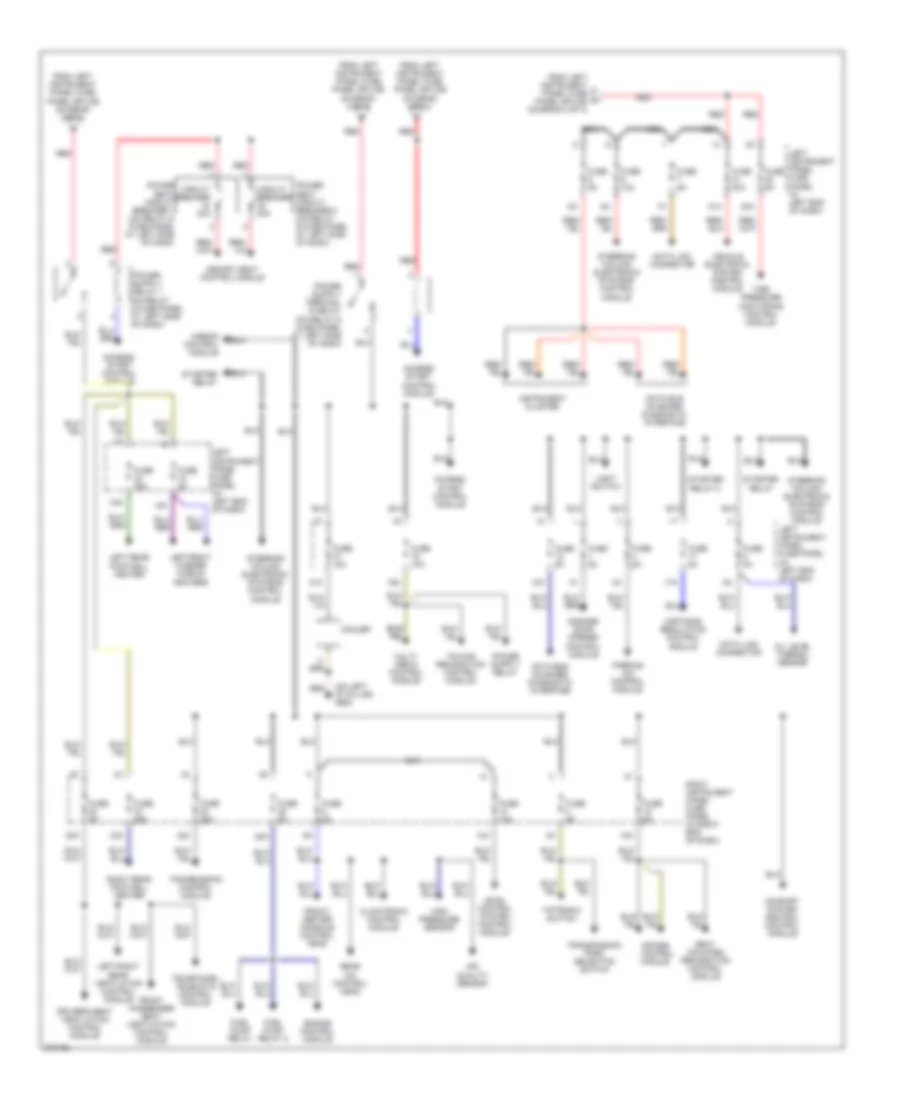
- Power distribution system
- Radio
- Right instrument panel fuse panel (in right end of dash)
- Satellite radio
- Sound systems
- T32
- Tv tuner
Computer Data Lines Wiring Diagram (2 of 3) for Audi A8 Quattro 2007
List of elements for Computer Data Lines Wiring Diagram (2 of 3) for Audi A8 Quattro 2007:
- (4.2l)
- (5.2l)
- 10h
- 10l
- 11h
- 11l
- 12h
- 12l
- 13h
- 13l
- 14h
- 14l
- 15h
- 15l
- 16h
- 16l
- 17h
- 17l
- 18h
- 18l
- 19h
- 19l
- 20h
- 20l
- 21h
- 21l
- 22h
- 22l
- 23h
- 23l
- A61
- A81
- B17
- C22
- C23
- Central control module (comfort system) (in luggage compt, behind battery)
- Climatronic control module
- Disconnection plug, right (can-bus)
- Electronic parking brake control module (right side of luggage compt, under battery)
- Energy management control module (right side of luggage compt)
- Engine control module (in passenger's side plenum chamber e-box)
- Engine control module 2 (5.2l & 6.0l) (in passenger's side plenum chamber e-box)
- Front passenger door control module (in door)
- Level control system control module (behind glove compartment)
- Motor start/ stop button
- Passenger memory seat control module
- Rear memory seat control module (under center
- Right rear door control module (in door)
- Roof electronics control module (under front of roof module)
- Seat)
- T46b
- T81
- T81a
- T8f
- T94a
- T94d
- Transmission control module (in bottom of transmission)
- Vehicle electrical system control module 2 (under front passenger's seat)
Computer Data Lines Wiring Diagram (3 of 3) for Audi A8 Quattro 2007
List of elements for Computer Data Lines Wiring Diagram (3 of 3) for Audi A8 Quattro 2007:
- 10h
- 10l
- 11h
- 11l
- 12h
- 12l
- 13h
- 13l
- 14h
- 14l
- 15h
- 15l
- 16h
- 16l
- 17h
- 17l
- 18h
- 18l
- 19h
- 19l
- 20h
- 20l
- 21h
- 21l
- 22h
- 22l
- 23h
- 23l
- A14
- A15
- A23
- A24
- Abs control module (left side of engine compt)
- Access/ start control module (under drivers seat)
- Airbag control module (below center of dash)
- C14
- C15
- Disconnection plug, left (can-bus)
- Driver door control module (in door)
- Headlight beam adjusting control module (behind instrument cluster)
- Left rear door control module (in door)
- Memory seat control module
- Parking aid control module (left side of luggage compt)
- Rear a/c control head
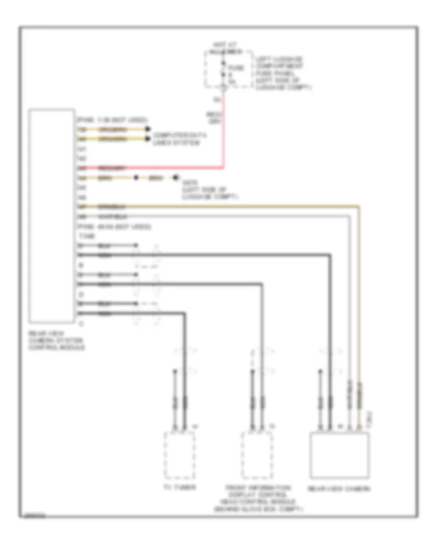
- Rear view camera control module
- Steering column electronic systems control module (on steering column)
- T12m
- T16a
- T42a
- T46a
- Telephone/ telematic control module
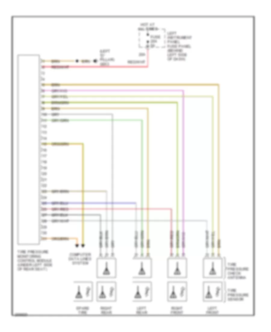
- Tire pressure monitoring control module (under left side of rear seat)
- Vehicle electrical system control module (behind left side of dash)
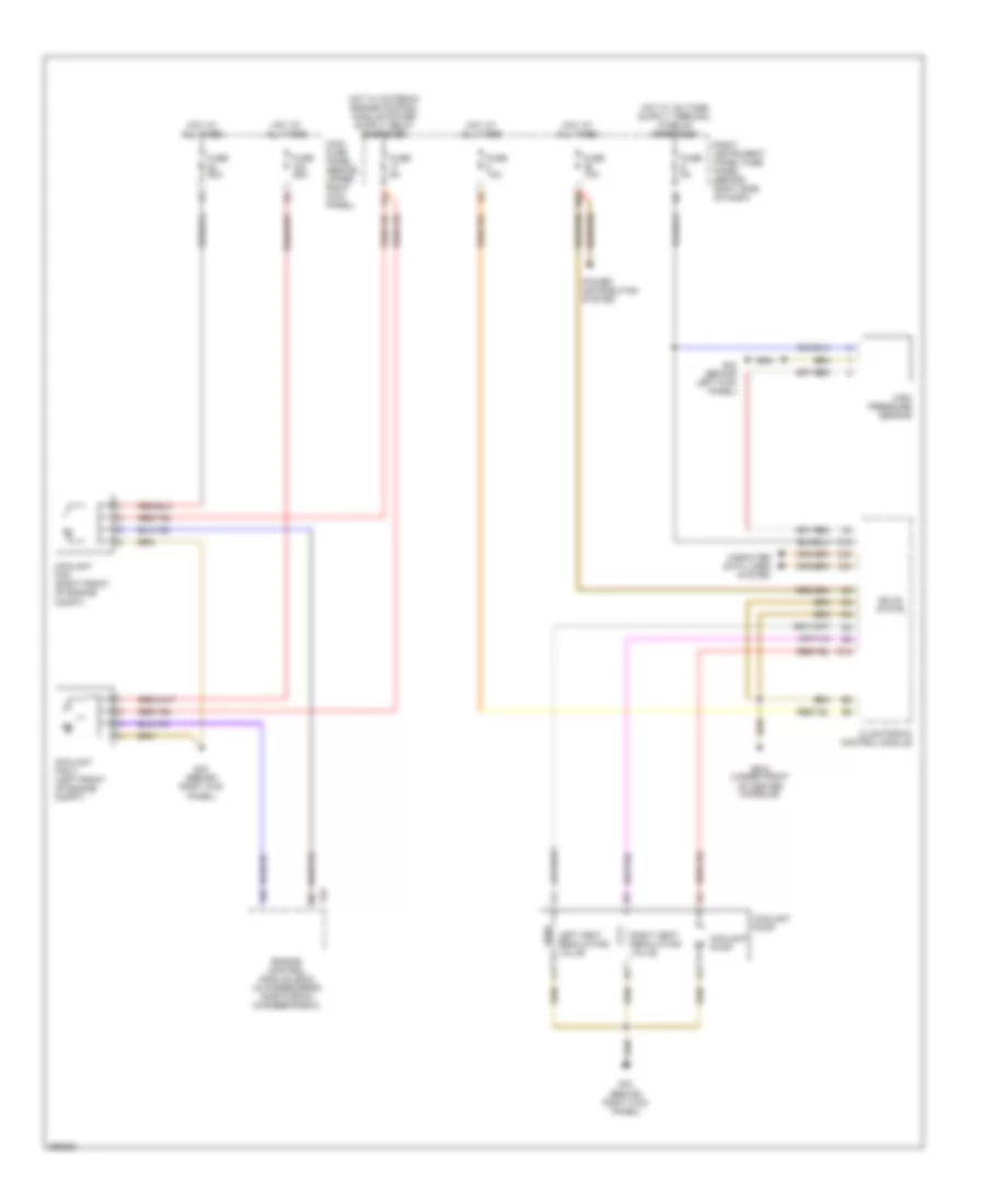
COOLING FAN
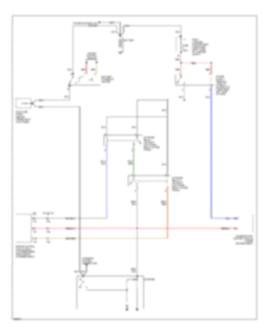
4.2L
4.2L, Cooling Fan Wiring Diagram for Audi A8 Quattro 2007
List of elements for 4.2L, Cooling Fan Wiring Diagram for Audi A8 Quattro 2007:
- 17a
- 26a
- C12
- C22
- C23
- Climatronic control module
- Computer data lines system
- Coolant fan (right front of engine compt)
- Coolant fan 2 (left front of engine compt)
- Coolant pump
- D12
- Engine control module (ecm) (in passenger's side plenum chamber e-box)
- Fuse 10a
- Fuse 5a
- Fuse 60a
- G43 (behind right kick panel)
- G44 (behind left kick panel)
- G610 (under front of center console)
- High pressure sensor
- Hot at all times
- Left heat regulating valve
- Main fuse panel (behind upper right kick panel)
- Power distribution system
- Right heat regulating valve
- Right instrument panel fuse panel (behind right side of dash)
- Solid state
- T94
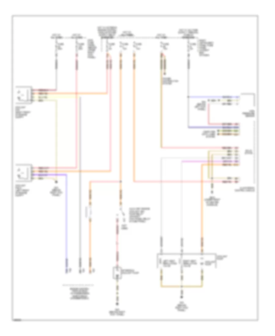
6.0L
6.0L, Cooling Fan Wiring Diagram for Audi A8 Quattro 2007
List of elements for 6.0L, Cooling Fan Wiring Diagram for Audi A8 Quattro 2007:
- (not used)
- 17a
- 26a
- After-run coolant pump
- Auxiliary engine coolant (ec) pump relay (on right kick panel relay & fuse panel)
- C12
- C22
- C23
- Climatronic control module
- Computer data lines system
- Coolant fan (right front of engine compt)
- Coolant fan 2 (left front of engine compt)
- Coolant pump
- D12
- Engine control module (ecm) (in passenger's side plenum chamber e-box)
- Fuse 10a
- Fuse 5a
- Fuse 60a
- G43 (behind right kick panel)
- G43 (behind right kick panel)
- G44 (behind left kick panel)
- G610 (under front of center console)
- High pressure sensor
- Hot at all times
- Left heat regulating valve
- Main fuse panel (behind upper right kick panel)
- Power distribution system
- Right heat regulating valve
- Right instrument panel fuse panel (in right end of dash)
- Solid state
- T40
- T81
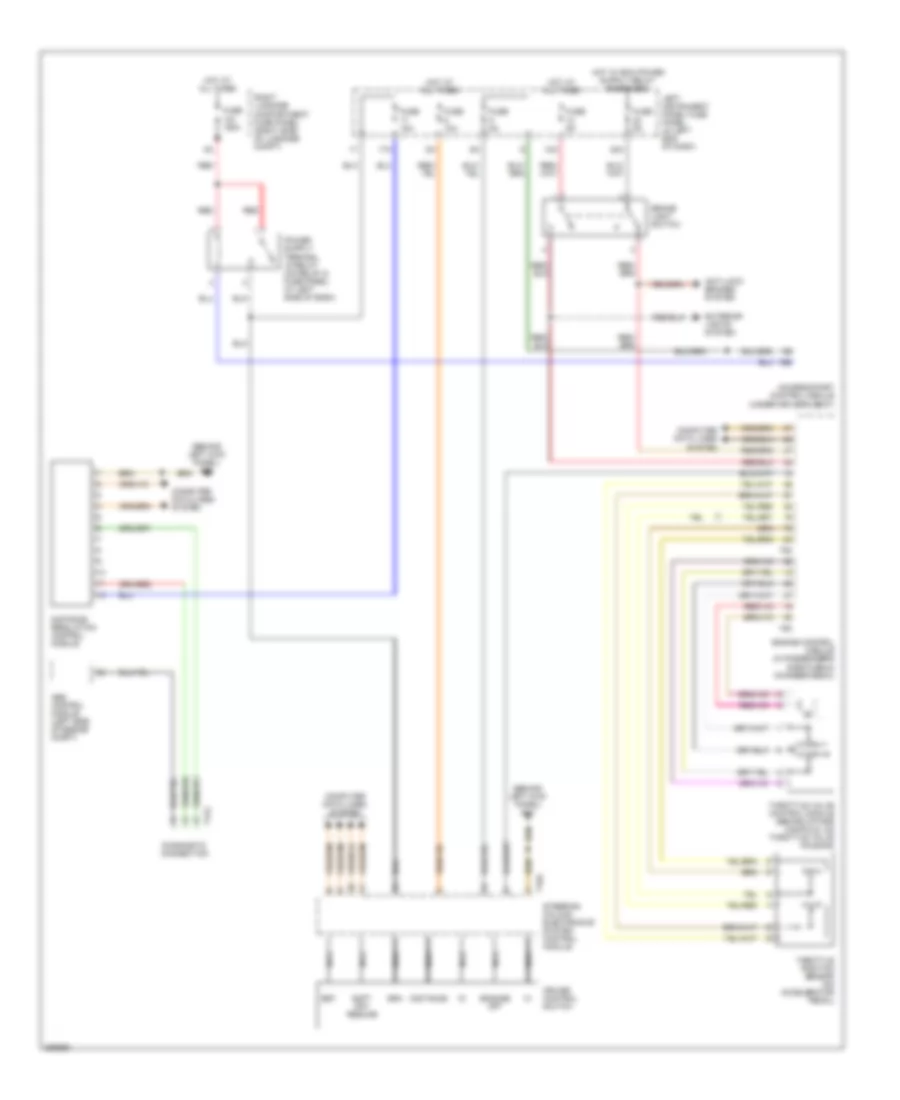
CRUISE CONTROL
4.2L
4.2L, Cruise Control Wiring Diagram for Audi A8 Quattro 2007
List of elements for 4.2L, Cruise Control Wiring Diagram for Audi A8 Quattro 2007:
- (behind left kick panel) g44
- 12a
- 17a
- 22a
- A58
- Abs control module (left side of engine compt)
- Access/start control module (under driver's seat)
- Anti-lock brakes system
- Brake light switch
- Computer data lines system
- Cruise control switch
- Diagnostic connection
- Distance
- Distance regulation control module
- Engage off
- Engine control module (in passenger's side plenum chamber e-box)
- Exterior lights system
- Fuse 10a
- Fuse 150a
- Fuse 15a
- Fuse 5a
- Gra
- Hot at all times
- Left instrument panel fuse panel (in left end of dash)
- Nca
- Red
- Right luggage compartment fuse panel (right side of luggage compt)
- Set
- Soft off/ resume
- Steering column electronics system control module
- T16a
- T17g
- T60
- T94
- Throttle position sensor (on accelerator pedal)
- Throttle valve control module (behind intake manifold, on throttle valve housing)
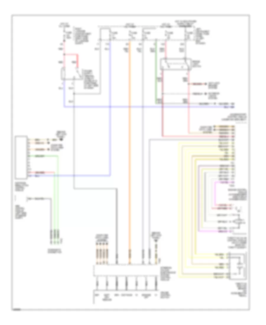
6.0L
6.0L, Cruise Control Wiring Diagram for Audi A8 Quattro 2007
List of elements for 6.0L, Cruise Control Wiring Diagram for Audi A8 Quattro 2007:
- (behind left kick panel) g44
- 12a
- 17a
- 22a
- A58
- Abs control module (left side of engine compt)
- Access/start control module (under driver's seat)
- Anti-lock brakes system
- Brake light switch
- Computer data lines system
- Cruise control switch
- Diagnostic connection
- Distance
- Distance regulation control module
- Engage off
- Engine control module (in passenger's side plenum chamber e-box)
- Exterior lights system
- Fuse 10a
- Fuse 150a
- Fuse 15a
- Fuse 5a
- Gra
- Hot at all times
- Left instrument panel fuse panel (in left end of dash)
- Nca
- Red
- Right luggage compartment fuse panel (right side of luggage compt)
- Set
- Soft off/ resume
- Steering column electronics system control module
- T16a
- T17g
- T40a
- T81
- Throttle position sensor (on accelerator pedal)
- Throttle valve control module (on cylinder bank no 1 throttle body)
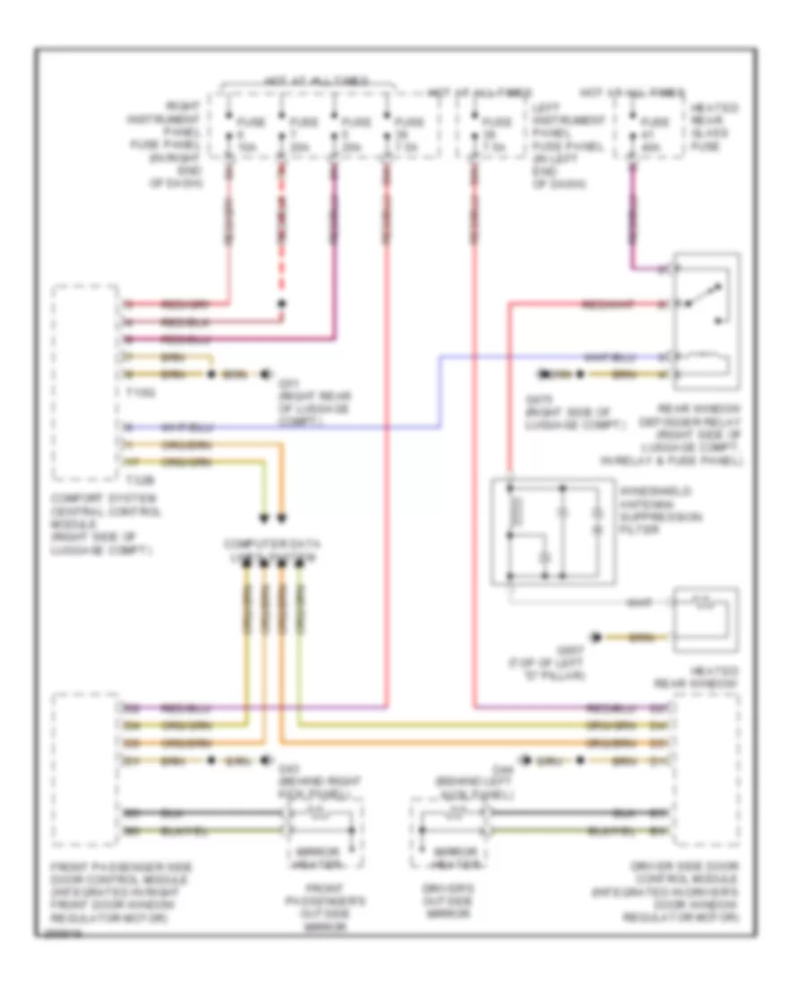
DEFOGGERS
Defoggers Wiring Diagram for Audi A8 Quattro 2007
List of elements for Defoggers Wiring Diagram for Audi A8 Quattro 2007:
- 39a
- Comfort system central control module (right side of luggage compt)
- Computer data lines system
- Driver side door control module (integrated in driver's door window regulator motor)
- Driver's outside mirror
- Front passenger side door control module (integrated in right front door window regulator motor)
- Front passenger's outside mirror
- Fuse 10a
- Fuse 20a
- Fuse 40a
- Fuse 7.5a
- G43 (behind right kick panel)
- G44 (behind left kick panel)
- G51 (right rear of luggage compt)
- G657 (top of left "d" pillar)
- G675 (right side of luggage compt)
- Heated rear glass fuse
- Heated rear window
- Hot at all times
- Left instrument panel fuse panel (in left end of dash)
- Mirror heater
- Rear window defogger relay (right side of luggage compt, in relay & fuse panel)
- Right instrument panel fuse panel (in right end of dash)
- T10q
- T32b
- Windshield antenna suppression filter
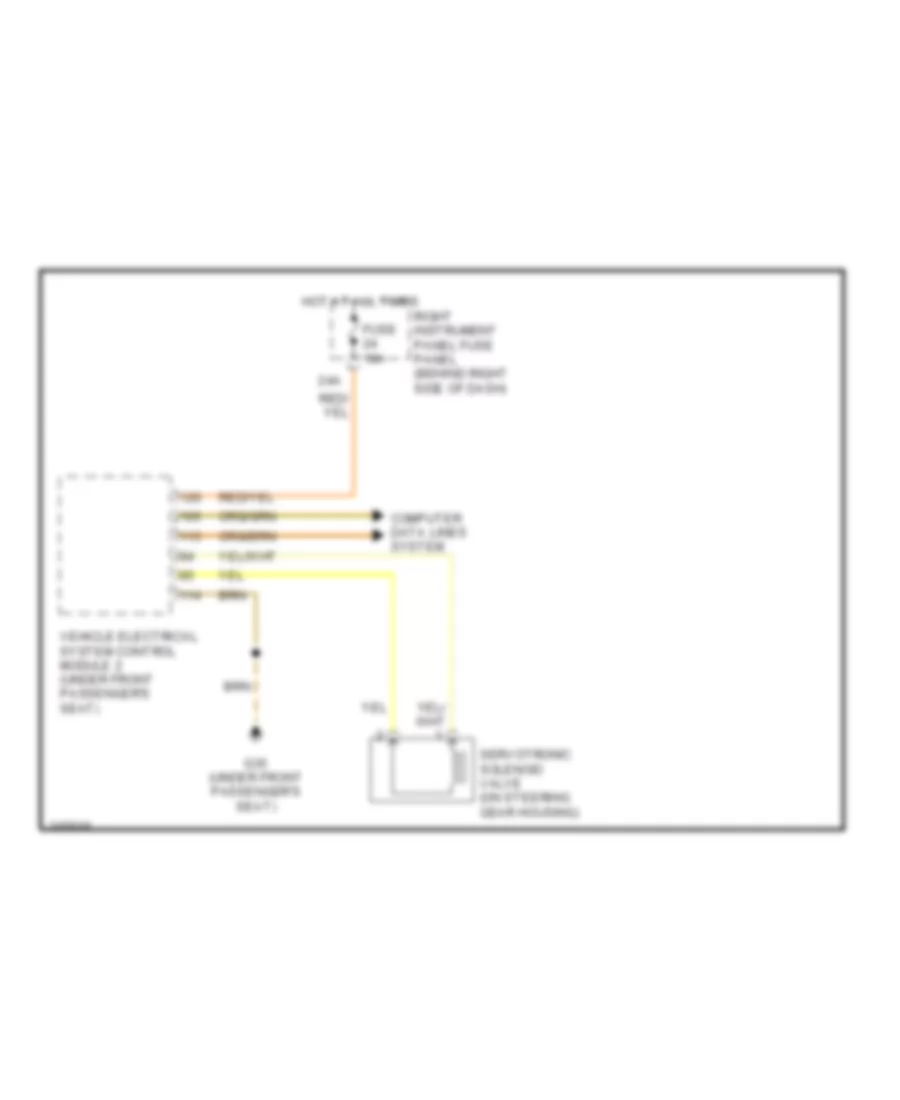
ELECTRONIC POWER STEERING
Electronic Power Steering Wiring Diagram for Audi A8 Quattro 2007
List of elements for Electronic Power Steering Wiring Diagram for Audi A8 Quattro 2007:
- 24a
- Computer data lines system
- Fuse 10a
- G35 (under front passenger's seat)
- Hot at all times
- Right instrument panel fuse panel (behind right side of dash)
- Servotronic solenoid valve (on steering gear housing)
- Vehicle electrical system control module 2 (under front passenger's seat)
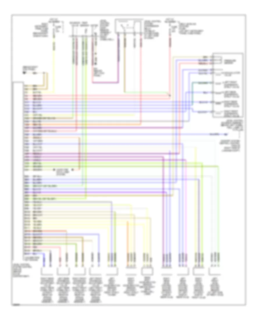
ELECTRONIC SUSPENSION
Electronic Suspension Wiring Diagram for Audi A8 Quattro 2007
List of elements for Electronic Suspension Wiring Diagram for Audi A8 Quattro 2007:
- (behind right kick panel) g43
- (unused pins not shown)
- 10a
- A17
- A18
- A19
- A20
- A31
- A33
- A34
- A36
- A37
- A43
- A53
- A61
- A63
- A64
- A65
- A66
- A67
- A74
- A75
- A76
- A77
- A81
- Accumulator valve
- B102
- B103
- B104
- B106
- B109
- B111
- B114
- B115
- B116
- B117
- B118
- B119
- B120
- B121
- B82
- B83
- B84
- B85
- B90
- B91
- B92
- B93
- B94
- B95
- B96
- Comfort system central control module (right side of luggage compt)
- Computer data lines system
- Fuse 10a
- Fuse 40a
- G44 (behind left kick panel)
- Hot at all times
- Left front body acceleration sensor (on left front strut tower)
- Left front dampening adjustment valve (left front wheelwell) (in right rear air spring damper assembly)
- Left front level control system sensor (at left side of front axle)
- Left front suspension strut valve
- Left rear dampening adjustment valve (left rear wheelwell) (in right rear air spring damper assembly)
- Left rear level control system sensor (at left side of rear axle)
- Left rear suspension strut valve
- Level control solenoid assembly (behind left wheel- well liner, at "a" pillar)
- Level control system comp- ressor assembly (in left front wheelwell)
- Level control system compressor relay (on relay & fuse panel at left side of dash)
- Level control system control module (behind glove compartment)
- Motor
- Pressure sensor
- Rear body acceleration sensor (behind right rear wheelwell liner)
- Red
- Right front body acceleration sensor (on right front strut tower)
- Right front dampening adjustment valve (right front wheelwell) (in right rear air spring damper assembly)
- Right front level control system sensor (at right side of front axle)
- Right front suspension strut valve
- Right instrument panel fuse panel (behind right side of dash)
- Right rear dampening adjustment valve (right rear wheelwell) (in right rear air spring damper assembly)
- Right rear level control system sensor (at right side of rear axle)
- Right rear suspension strut valve
- Self leveling system fuse (on left instrument panel fuse panel)
- Solenoid valve
- Temp sensor
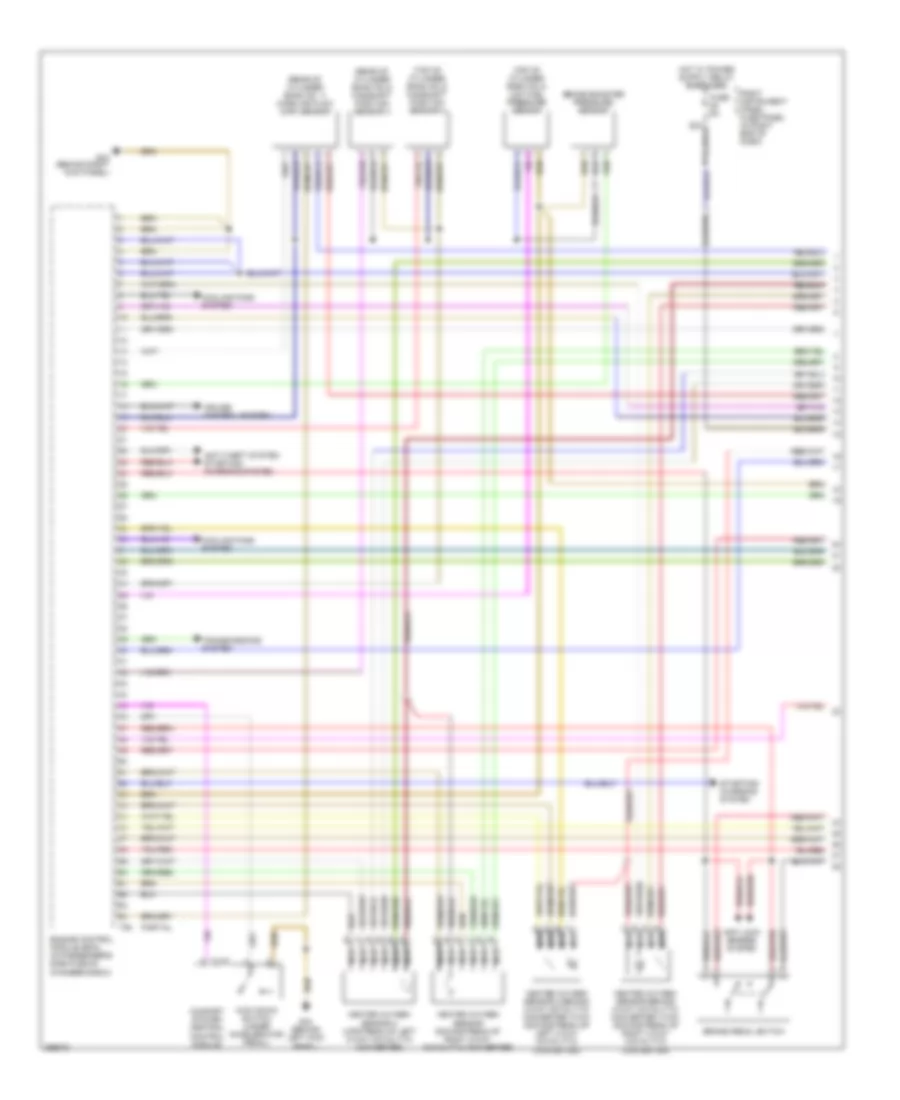
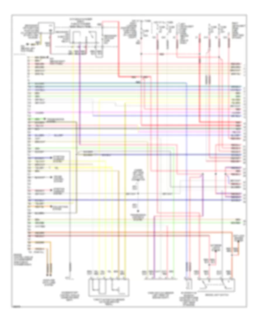
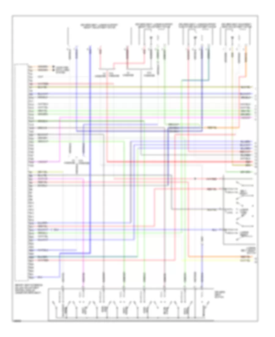
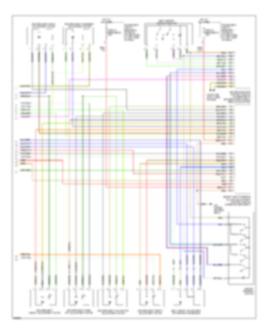
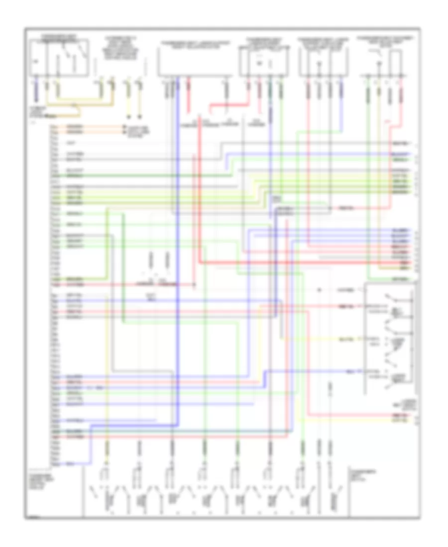
ENGINE PERFORMANCE
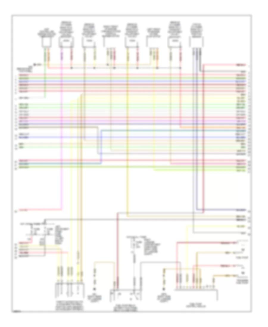
4.2L
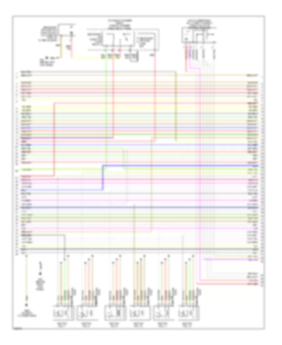
4.2L, Engine Performance Wiring Diagram (1 of 5) for Audi A8 Quattro 2007
List of elements for 4.2L, Engine Performance Wiring Diagram (1 of 5) for Audi A8 Quattro 2007:
- (rear of cylinder bank no 2) camshaft position sensor 4
- (rear of cylinder bank no. 1) mass air flow (maf) sensor
- (top of cylinder bank no 2) camshaft position sensor 2
- (top of cylinder bank no 2) low fuel pressure sensor
- Anti-lock brakes system
- Anti-theft system starting/ charging system
- Brake booster pressure sensor
- Brake pedal switch
- Comfort system central control module
- Cooling fans system
- Cruise control system
- Engine control module (ecm) (in passenger's side plenum chamber e-box)
- Fuse 5a
- G43 (behind right kick panel)
- G44 (behind left kick panel)
- Heated oxygen sensor (downstream of right 3-way catalytic converter)
- Heated oxygen sensor 2 (upstream of left 3-way catalytic converter)
- Heated oxygen sensor 2 behind 3-way catalytic converter (twc) (downstream of left 3-way catalytic converter)
- Heated oxygen sensor behind 3-way catalytic converter (twc) (downstream of right 3-way catalytic converter)
- Kick down switch (under accelerator pedal)
- Nca
- Partial
- Right instrument panel fuse panel (in right end of dash)
- Starting/ charging system
- T10q
- T94
- Transmissions system
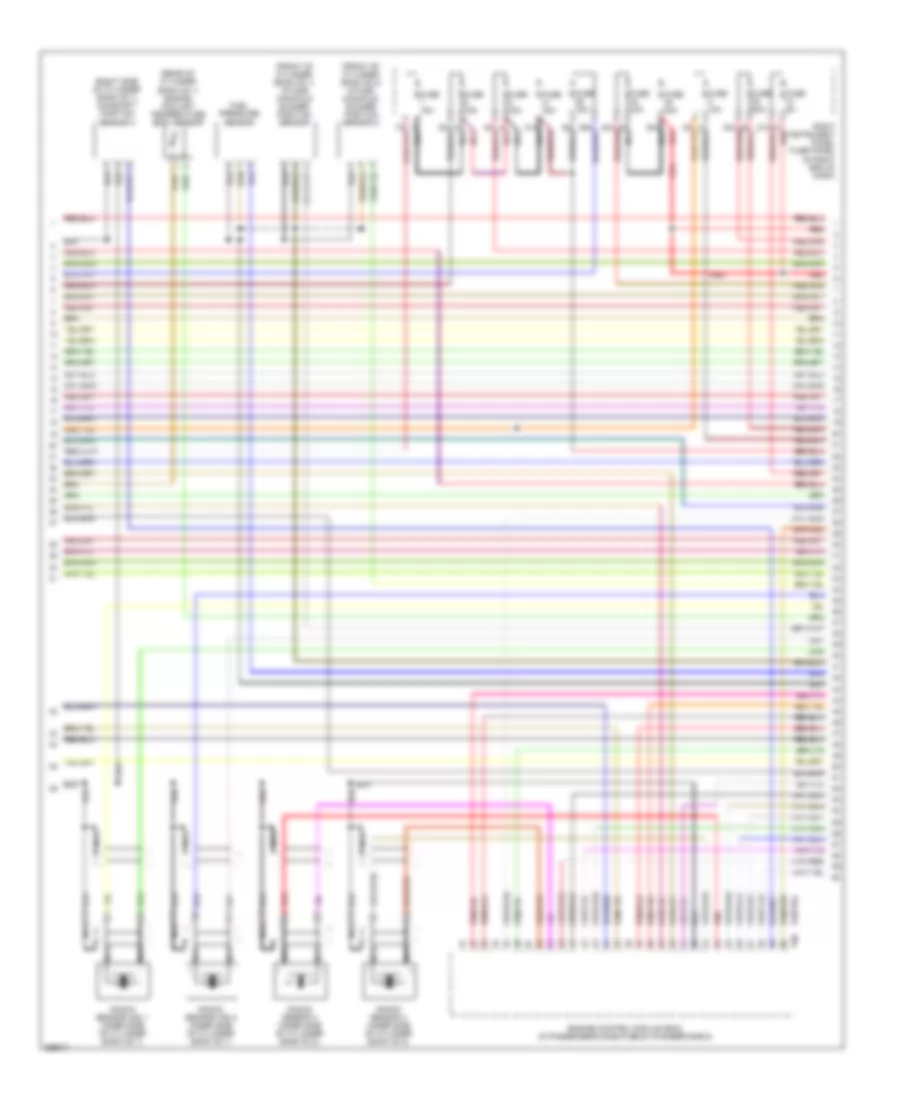
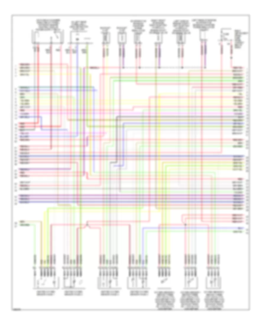
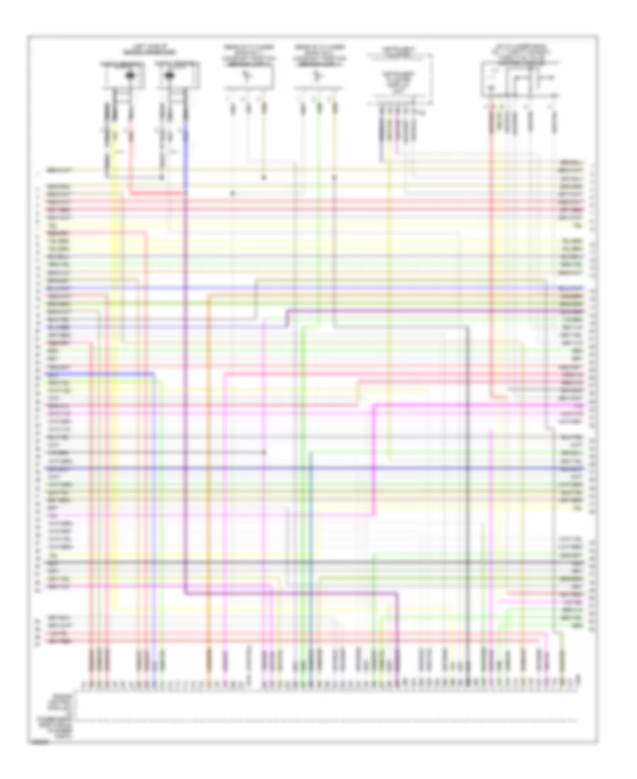
4.2L, Engine Performance Wiring Diagram (2 of 5) for Audi A8 Quattro 2007
List of elements for 4.2L, Engine Performance Wiring Diagram (2 of 5) for Audi A8 Quattro 2007:
- (left front of engine) intake flap motor
- (rear of cylinder bank no 1) camshaft adjustment valve 1
- (rear of cylinder bank no 1) camshaft adjustment valve 1 (exhaust)
- (rear of cylinder bank no 2) camshaft adjustment valve 2
- (rear of cylinder bank no 2) camshaft adjustment valve 2 (exhaust)
- (right front of engine) variable intake manifold runner motor
- (top of cylinder bank no 1) camshaft position sensor
- 12a
- 22a
- Fuel pump
- Fuel pump control module
- Fuel pump relay (on right kick panel relay & fuse panel)
- Fuse 40a
- Fuse 5a
- G43 (behind right kick panel)
- G51 (right rear of luggage compt)
- G675 (right side of luggage compt)
- Hot at all times
- Left instrument panel fuse panel (in left end of dash)
- Map controlled engine cooling thermostat
- Right luggage compartment fuse panel (right side of luggage compt)
- Throttle position (tp) & accelerator pedal position (app) sensor 2 (on accelerator pedal)
- Transfer fuel pump
4.2L, Engine Performance Wiring Diagram (3 of 5) for Audi A8 Quattro 2007
List of elements for 4.2L, Engine Performance Wiring Diagram (3 of 5) for Audi A8 Quattro 2007:
- (front of cylinder bank no 1) intake manifold runner position sensor
- (front of cylinder bank no 2) intake manifold runner position sensor 2
- (rear of cylinder bank no 1) engine coolant temperature (ect) sensor
- (right side of cylinder bank no 1) camshaft position sensor 3
- 31a nca
- 38a nca
- Engine control module (ecm) (in passenger's side plenum chamber e-box)
- Fuel pressure sensor
- Fuse 10a
- Fuse 15a
- Fuse 30a
- Fuse 40a
- Fuse 5a
- Knock sensor (ks) 1 (inner side of cylinder bank no 1)
- Knock sensor (ks) 2 (inner side of cylinder bank no 1)
- Knock sensor 3 (inner side of cylinder bank no 2)
- Knock sensor 4 (inner side of cylinder bank no 2)
- Nca
- Partial
- Red
- Right instrument panel fuse panel (in right end of dash)
- T60
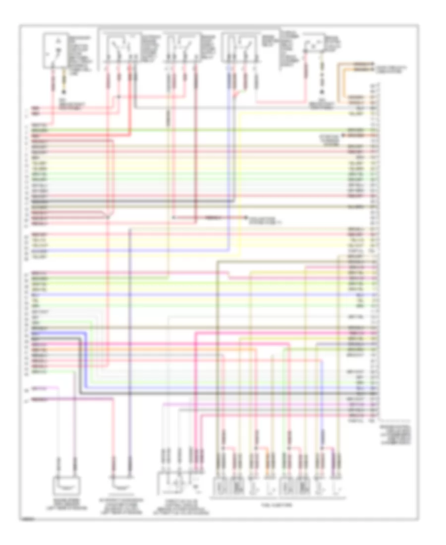
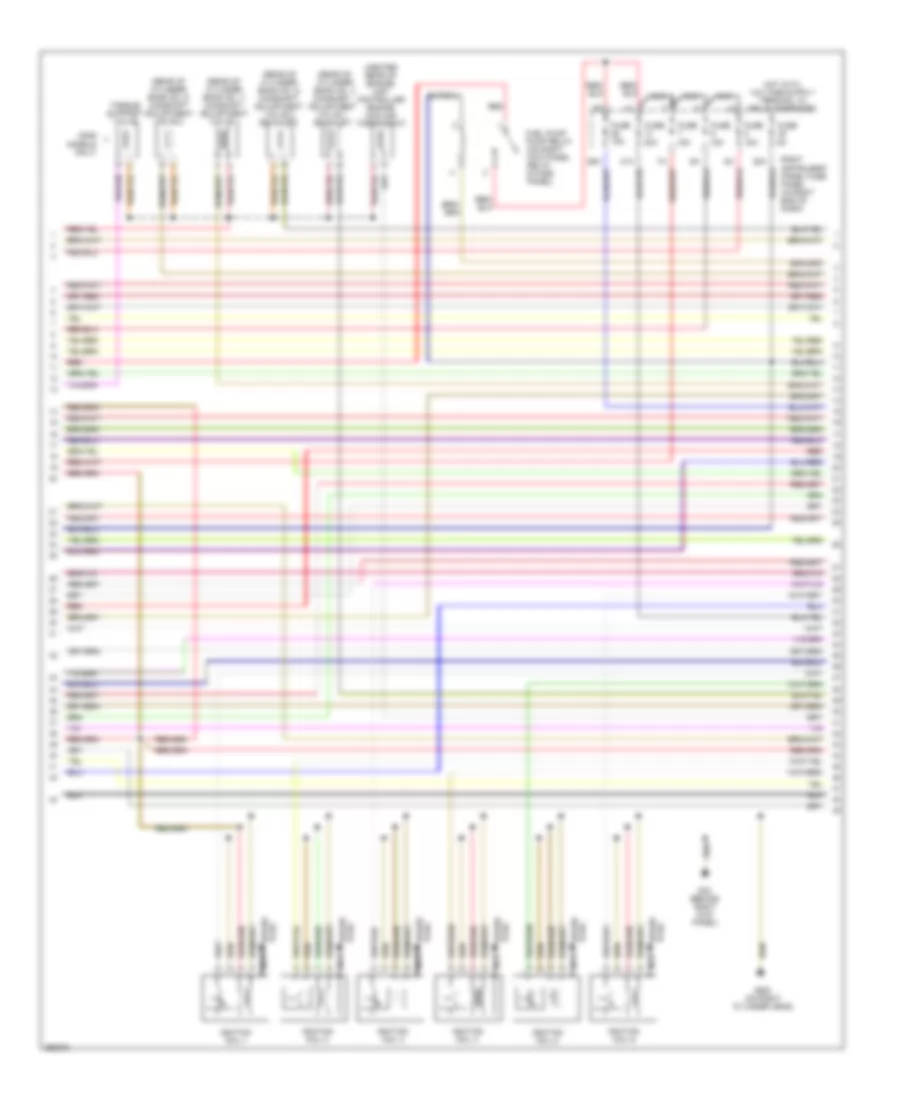
4.2L, Engine Performance Wiring Diagram (4 of 5) for Audi A8 Quattro 2007
List of elements for 4.2L, Engine Performance Wiring Diagram (4 of 5) for Audi A8 Quattro 2007:
- (in left rear wheelwell) leak detection pump (ldp)
- (left rear of engine) evaporative emission canister purge regulator valve
- (left side of engine compt) left electro- hydraulic engine mount solenoid valve
- (right front of engine compt) intake air switch- over valve
- (right front of engine) right electro- hydraulic engine mount solenoid valve
- (top of cylinder bank no 1) fuel metering valve
- (top of cylinder bank no 2) fuel metering valve 2
- 1a red
- 3a red
- Coil 1
- Coil 2
- Coil 3
- Coil 4
- Coil 5
- Coil 6
- Coil 7
- Coil 8
- Fuse 150a
- Fuse 50a
- G15 (on cylinder head)
- G17 (on intake manifold)
- G43 (behind right kick panel)
- Hot at all times
- Nca
- Plenum chamber e-box relay panel (in plenum chamber e-box)
- Red
- Right luggage compart- ment fuse panel (right side of luggage
- Secondary air injection (air) pump relay
- To spark plug
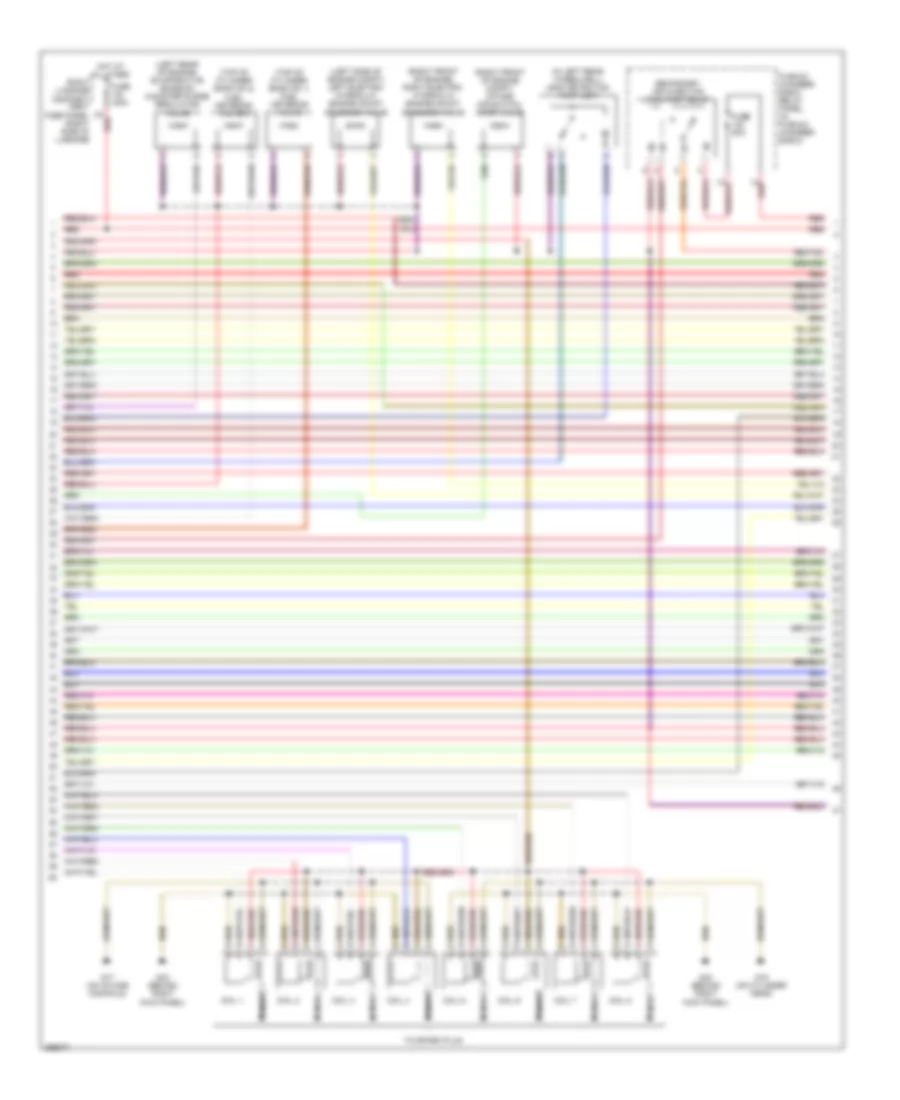
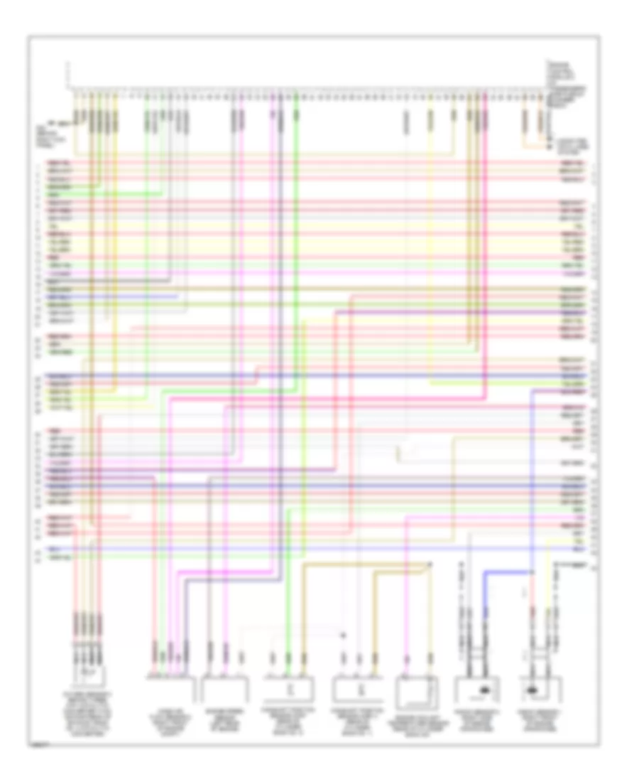
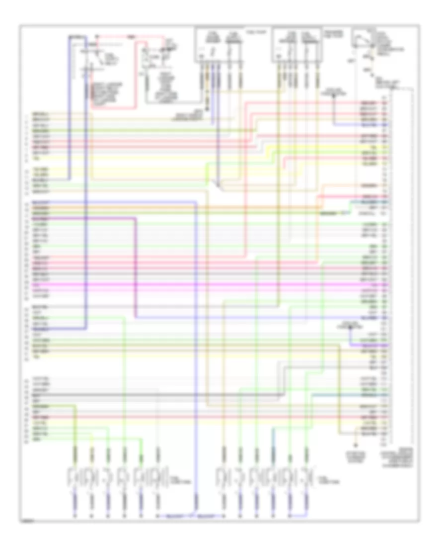
4.2L, Engine Performance Wiring Diagram (5 of 5) for Audi A8 Quattro 2007
List of elements for 4.2L, Engine Performance Wiring Diagram (5 of 5) for Audi A8 Quattro 2007:
- Brake booster relay
- Brake system vacuum pump
- Computer data lines system
- Cooling fans system (fuse 17)
- Engine control module (ecm) (in passenger's side plenum chamber e-box)
- Engine speed (rpm) sensor (left rear of engine)
- Evaporative emission canister purge solenoid valve 2 (left rear of engine)
- Fuel injectors
- G43 (behind right kick panel)
- Partial
- Plenum chamber e-box relay panel (in plenum chamber e-box)
- Red
- Secondary air injection (air) pump motor (between right front bumper & wheelwell line)
- Starting/ charging system
- T60
- T94
- Throttle valve control module (behind intake manifold, on throttle valve housing)
6.0L
6.0L, Engine Performance Wiring Diagram (1 of 7) for Audi A8 Quattro 2007
List of elements for 6.0L, Engine Performance Wiring Diagram (1 of 7) for Audi A8 Quattro 2007:
- (in plenum chamber e-box) plenum chamber e-box relay panel
- (partial)
- (under left side of dash) data link connector
- 12a
- 22a
- 3a red
- A17
- Access/start control module (under driver's seat)
- Anti-lock brakes system
- Brake light switch
- Computer data lines system
- Cooling fans system
- Cruise control system
- Engine control module (in passenger's side plenum chamber e-box)
- Evaporative emission canister purge solenoid valve (left rear of engine)
- Exterior lights system
- Fuse 150a
- Fuse 30a
- Fuse 5a
- G43 (behind right kick panel)
- G44 (behind left kick panel)
- Hot at all times
- Left instrument panel fuse panel (behind left side of dash)
- Mass air flow sensor (left front of engine compt)
- Red
- Right instrument panel fuse panel (right end of dash)
- Right luggage compartment fuse panel (right side of luggage compt)
- Secondary air injection pump motor (in lower part of air filter housing)
- Secondary air injection pump relay
- Secondary air pump fuse 50a
- Starting/ charging system
- T81
- Throttle position sensor (on accelerator pedal)
- Transmission controls system
- Transmissions system
6.0L, Engine Performance Wiring Diagram (2 of 7) for Audi A8 Quattro 2007
List of elements for 6.0L, Engine Performance Wiring Diagram (2 of 7) for Audi A8 Quattro 2007:
- (in left rear wheelwell) leak detection pump (ldp)
- (left rear of engine) evaporative emission canister purge regulator valve 2
- (left side of engine compt) left electro- hydraulic engine mount solenoid valve
- (right front of engine) right electro- hydraulic engine mount solenoid valve
- Behind three way catalytic converter (twc) (downstream of exhaust bank no. 2 catalytic converter)
- Converter)
- Evaporative emission canister purge regulator valve
- Exhaust flap valve 1
- Exhaust flap valve 2
- Fuse 10a
- Heated oxygen sensor (ho2s) 1
- Heated oxygen sensor (ho2s) 2
- Heated oxygen sensor (ho2s) 3
- Heated oxygen sensor (ho2s) 4
- Nca
- Oxygen sensor 1 behind three way catalytic converter (twc) (downstream of exhaust bank no. 1 catalytic
- Oxygen sensor 2
- Oxygen sensor 4 behind three way catalytic converter (twc) (downstream of exhaust bank no. 4 catalytic converter)
- Red
- Right instrument panel fuse panel (in right end of dash)
6.0L, Engine Performance Wiring Diagram (3 of 7) for Audi A8 Quattro 2007
List of elements for 6.0L, Engine Performance Wiring Diagram (3 of 7) for Audi A8 Quattro 2007:
- (partial)
- Camshaft position sensor (cmp) (rear of cylinder bank no. 2)
- Camshaft position sensor (cmp) 3 (rear of cylinder bank no. 1)
- Computer data lines system
- Engine control module 2 (in passenger's side plenum t81a chamber e-box)
- Engine coolant temperature sensor (rear of cylinder bank no)
- Engine speed sensor (left rear of engine)
- G43 (behind right kick panel)
- Knock sensor 1 (right front of engine crankcase)
- Knock sensor 2 (right side of engine crankcase)
- Mass air flow sensor 2 (right front of engine compt)
- Nca
- Oxygen sensor 3 behind three way catalytic converter (twc) (downstream of exhaust bank no. 3 catalytic converter)
- Red
6.0L, Engine Performance Wiring Diagram (4 of 7) for Audi A8 Quattro 2007
List of elements for 6.0L, Engine Performance Wiring Diagram (4 of 7) for Audi A8 Quattro 2007:
- (2006 models only)
- (center rear of engine) map controlled engine cooling thermostat
- (rear of cylinder bank no. 1) camshaft adjustment valve 1
- (rear of cylinder bank no. 1) camshaft adjustment valve 1 (exhaust)
- (rear of cylinder bank no. 2) camshaft adjustment valve 2
- (rear of cylinder bank no. 2) camshaft adjustment valve 2 (exhaust)
- 28a
- 29a
- 31a
- Fuel pump pump relay (on right kick panel relay & fuse panel)
- Fuse 15a
- Fuse 20a
- Fuse 5a
- G43 (behind right kick panel)
- G600 (on right cylinder head)
- Ignition coil 1
- Ignition coil 2
- Ignition coil 3
- Ignition coil 4
- Ignition coil 5
- Ignition coil 6
- Nca
- Plug spark
- Red
- Right instrument panel fuse panel (in right end of dash)
- Spark plug
- Torque support valve
6.0L, Engine Performance Wiring Diagram (5 of 7) for Audi A8 Quattro 2007
List of elements for 6.0L, Engine Performance Wiring Diagram (5 of 7) for Audi A8 Quattro 2007:
- (in plenum chamber e-box) plenum chamber e-box relay panel
- (on cylinder bank no. 2 throttle body) throttle valve control module 2
- G43 (behind right kick panel)
- G44 (behind left kick panel)
- G600 (on right cylinder head)
- Ignition coil 10
- Ignition coil 11
- Ignition coil 12
- Ignition coil 7
- Ignition coil 8
- Ignition coil 9
- Nca
- Plug spark
- Red
- Secondary air injection pump motor 2 (in lower air part of filter housing)
- Secondary air injection pump relay 2
- Secondary air pump fuse 50a
- Spark plug
6.0L, Engine Performance Wiring Diagram (6 of 7) for Audi A8 Quattro 2007
List of elements for 6.0L, Engine Performance Wiring Diagram (6 of 7) for Audi A8 Quattro 2007:
- (left side of engine crankcase)
- (on cylinder bank no. 1 throttle body) throttle valve control module
- (partial)
- (rear of cylinder bank no.1) camshaft position sensor (cmp) 2
- (rear of cylinder bank no.2) camshaft position sensor (cmp) 4
- Engine control module 2 (in passenger's side plenum chamber e-box)
- Instrument cluster
- Instrument cluster display unit
- Knock sensor 3
- Knock sensor 4
- Nca
- Red
- T32
- T40a
- T81a
6.0L, Engine Performance Wiring Diagram (7 of 7) for Audi A8 Quattro 2007
List of elements for 6.0L, Engine Performance Wiring Diagram (7 of 7) for Audi A8 Quattro 2007:
- (partial)
- Compt relay & fuse panel (right side of luggage compt
- Cooling fans system
- Engine control module (in passenger's side plenum chamber e-box)
- Fuel gauge sender
- Fuel injectors
- Fuel level sensor 2
- Fuel pump
- Fuel pump 2 relay
- Fuse 20a
- G44 (behind left kick panel)
- G675 (right side of luggage compt)
- Hot at all times
- Kick down switch (under accelerator pedal)
- Red
- Right luggage compt fuse panel (right side of luggage compt)
- Starting/ charging system
- T40
- T81
- Transfer fuel pump
EXTERIOR LIGHTS
Exterior Lights Wiring Diagram (1 of 2) for Audi A8 Quattro 2007
List of elements for Exterior Lights Wiring Diagram (1 of 2) for Audi A8 Quattro 2007:
- (behind left kick panel) g44
- 10h
- 10l
- 14h
- 14l
- 22h
- 22l
- 31a
- 38a
- 40a
- Abs control module
- Access/ start control module (under driver's seat)
- Access/start control module (under driver's seat)
- B3 ignition output
- Computer data lines system
- Emergency flasher indicator lamp
- Emergency flasher switch
- Front/ center console control head
- Fuse 10a
- Fuse 150a
- Fuse 25a
- Fuse 30a
- Fuse 5a
- G43 (behind right kick panel)
- G44 (behind left kick panel)
- G610 (left front of center tunnel)
- Headlights system
- Horns system
- Hot at all times
- Interior lights system
- Left can bus disconnection plug
- Left front side marker light
- Left headlight assembly
- Left instrument panel fuse panel (in left end of dash)
- Left side turn signal light
- Light switch
- Nca
- Park
- Park light indicator light
- Red
- Right front side marker light
- Right headlight assembly
- Right luggage compartment fuse panel (right side of luggage compt)
- Right side turn signal light
- Steering column electronic systems control module (on steering column, behind steering wheel)
- T10p
- T16a
- T23
- T32a
- T46a
- T46b
- Turn
- Turn signal switch
- Vehicle electrical system control module (behind left side of dash)
- Wiper/ washer system
Exterior Lights Wiring Diagram (2 of 2) for Audi A8 Quattro 2007
List of elements for Exterior Lights Wiring Diagram (2 of 2) for Audi A8 Quattro 2007:
- (at left side of engine compt) abs control module
- (in passenger's side plenum chamber e-box) engine control module
- (under driver's seat) access/ start control module
- 12a
- A34
- Back- up
- Brake light switch (above brake pedal, on bracket)
- Comfort system central control module (right side of luggage compt)
- Fog
- Fuse 10a
- Fuse 20a
- Fuse 5a
- G51 (right rear of luggage compt)
- G654 (behind rear seat center backrest)
- G676 (left side of luggage compt)
- High mount brake light
- Hot at all times
- Left instrument panel fuse panel (in left end of dash)
- Left rear lid taillamp assembly
- Left rear lid taillamp control module
- Left rear taillamp control module
- Left taillamp assembly
- License plate light
- Right luggage compartment fuse panel (right side of luggage compt)
- Right rear lid taillamp assembly
- Right rear lid taillamp control module
- Right rear taillamp control module
- Right taillamp assembly
- Stop
- T10q
- T15c
- T32b
- Tail
- Turn
GROUND DISTRIBUTION
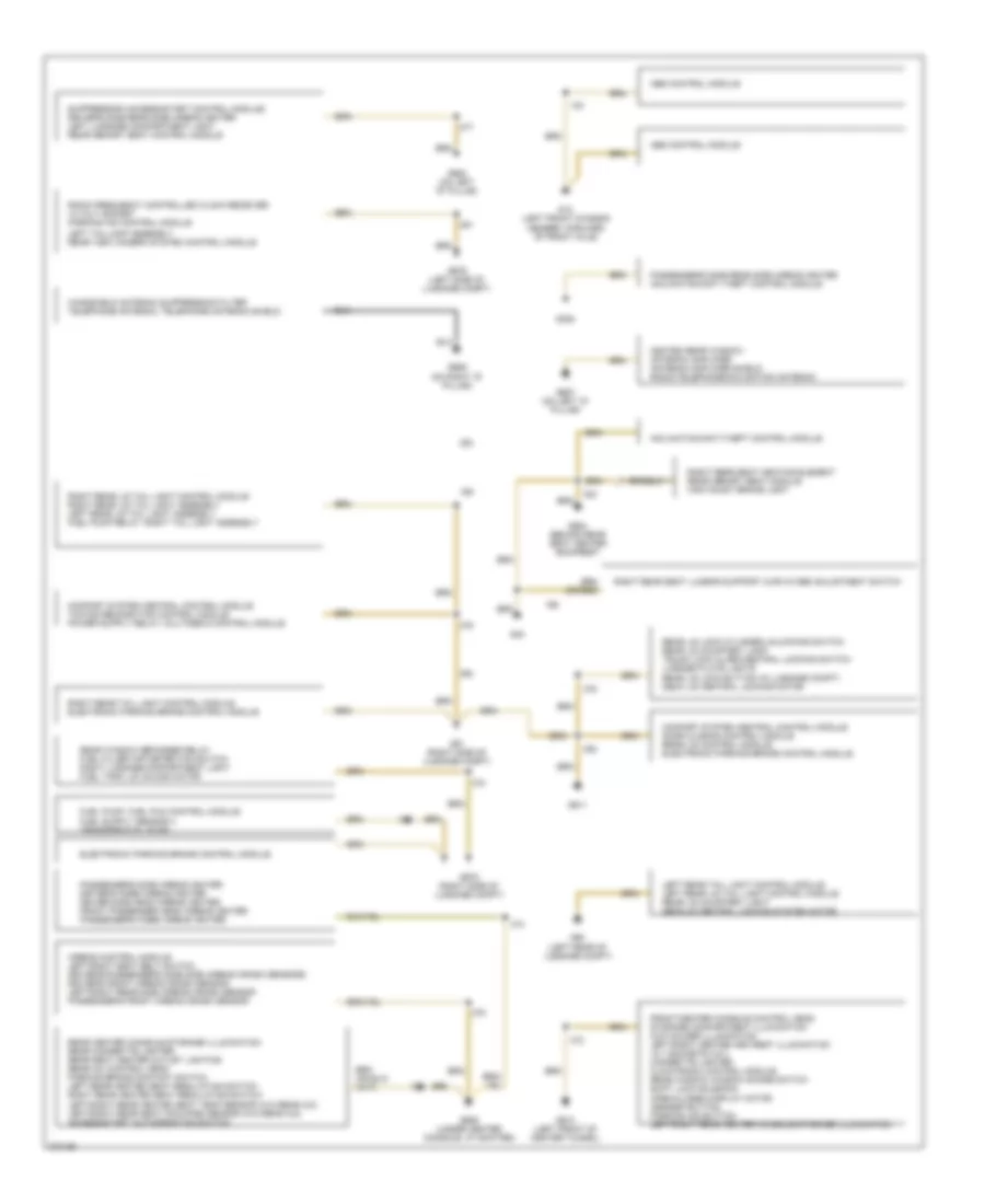
Ground Distribution Wiring Diagram (1 of 2) for Audi A8 Quattro 2007
List of elements for Ground Distribution Wiring Diagram (1 of 2) for Audi A8 Quattro 2007:
- Abs control module
- Airbag control module left/right seat belt switch driver's/passenger's side side airbag crash sensors driver's front airbag crash sensor left/right rear side airbag crash sensor passenger's front airbag crash sensor
- Comfort system central control module door closing control module rear lid control module electronic parking brake control module
- Electronic parking brake control module
- Front/center console control head storage compartment illumination cup holder illumination left/right center arm rest illumination 12 v sockets 2 & 3 cigarette lighter climatronic control module rear window window shade switch shift lock solenoid open/closed display motor asr/esp button parking aid button left/right rear center console storage illumination
- G12 (left front chassis member, forward of front axle)
- G394
- G40
- G50 (left rear of luggage compt)
- G51 (right side of luggage compt)
- G606 (under center console, at shifter)
- G610 (left front of center tunnel)
- G611
- G653 (on left "d" pillar)
- G654 (behind rear seat center backrest
- G657 (on left "d" pillar)
- G659 (on right "d" pillar)
- G675 (right side of luggage compt)
- G676 (left side of luggage compt)
- Heated rear window antenna amplifier antenna amplifier shield radio/telephone/navigation antenna
- Inclination/anti-theft control module
- Left rear tail light control module left rear lid tail light control module rear lid courtesy light decklid central locking system motor
- Left taillamp assembly rear view camera system control module
- Passenger's side airbag igniter driver's knee airbag igniter driver side head airbag igniter front passenger head airbag igniter passenger's knee airbag igniter
- Passenger's side rear side airbag igniter inclination/anti theft control module
- Radio frequency controlled clock receiver 12 volt socket parking aid control module
- Rear center console storage illumination rear cigarette lighter rear seat center outlet lighting rear a/c control head parking brake contact switch left rear heated seat regulating switch right rear heated seat regulating switch left/right rear heated seat temp sensor (w/o rear a/c) left/right rear seat occupied sensor (w/o rear a/c) access/start authorization switch
- Rear lid lock cylinder unlocking switch rear lid courtesy lamp trunk lock alarm/central locking switch license plate lights rear lid lock button (in luggage compt) deck lid central locking motor
- Rear window defogger relay fuel filler cap detection switch right luggage compartment light fuel tank lid unlock motor
- Right rear lid tail light control module right rear lid tail light assembly left rear lid tail light assembly fuel pump relay, right tail light assembly
- Right rear seat heating element rear memory seat module high mount brake light
- Right rear seat lumbar support curvature adjustment switch
- Right rear tail light control module electronic parking brake control module
- Suppressor (access/start control module) driver's side rear side airbag igniter left luggage compartment light rear memory seat control modole
- Windshield antenna suppression filter telephone antenna, telephone antenna shield
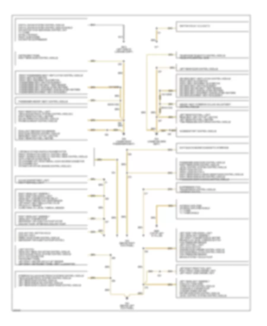
Ground Distribution Wiring Diagram (2 of 2) for Audi A8 Quattro 2007
List of elements for Ground Distribution Wiring Diagram (2 of 2) for Audi A8 Quattro 2007:
- 140/136/96
- 95/m41/m42
- 95/m51/m52
- Access/start control module
- Antenna amplifier antenna amplifier shield tv tuner tv tuner shield
- Coolant fan, ignition coils coolant fan 2 fresh air blower control module secondary air injection pump motor 2
- Data bus on board diagnostic interface
- Digital sound system control module digital sound system control module shield navigation w/cd mechanism control unit tv tuner satellite radio radio, subwoofer navigation suppressor
- Driver's seat ventilation control module front seat blower fan front seat backrest blower fan driver's seat heating element driver's heated seat temp sensor driver's seat side bolster heaters driver's seat backrest side bolster heaters driver's backrest heating element
- Front passenger's seat ventilation control module front seat blower fan front seat backrest blower fan passenger's seat heating element passenger's heated seat temp sensor passenger's seat side bolster heaters passenger's seat backrest side bolster heaters passenger's backrest heating element
- G17
- G34 (under driver's seat)
- G35 (under front passenger's seat)
- G43 (behind right kick panel)
- G44 (behind left kick panel)
- G613 (left side of luggage compt)
- G658 (top of left "d" pillar)
- Glove compartment light right footwell light
- Ignition coils 1,2,3,4,5,6,7,8
- Instrument panel right rear door control module
- Left headlight assembly high/low tone horn wiper motor control module windshield washer pump washer hoses heater driver side door control module level control system control module
- Left rear door control module
- Left rear footwell light rear seat left outlet lighting left rear footwell heater tire pressure monitoring control module
- Left side turn signal light left headlight assembly left/right washer nozzle heater brake fluid level warning switch high pressure sensor left footwell light kick down switch garage door opener control module distance regulation control module high pressure sensor brake system vacuum pump
- Left/right front fog light right front side marker light left front side marker light
- Light switch headlight beam adjusting control module vehicle electrical system control module data link connector instrument panel left/right center air outlet sensor left/right instrument panel vent illumination
- Memory seat steering column adjustment control module
- Passenger memory seat control module
- Passenger side door control module right rear door control module level control system control module front hood switch front hood switch 2 right rear door closing assistance control module right rear side blind control module passenger door closing control module
- Rain/light recognition sensor roof electronics control module rear seat right outlet lighting right rear footwell heater
- Right headlight assembly headlight washer pump secondary air injection pump motor coolant pump, after run coolant pump
- Right headlight assembly right side turn signal light headlight washer system relay right front brake pad wear sensor left/right heat regulating valve air quality sensor alarm horn, oil level thermal sensor
- Right rear footwell light vehicle electrical system control module 2 right rear footwell heater solar operation control module power sunroof control module
- Steering column electronic systems control module vehicle electrical system control module left rear door control module left rear side blind control module left rear door closing assistance control module
- Suppressor (tcm) transmission control module tiptronic switch
- Telephone/telematic control module telematic control head
- Variable intake manifold runner motor front information display control head front information display control head control module cd player or cd rom drive cd changer unit or external audio source connector cd changer unit intake flap motor, engine control module 2
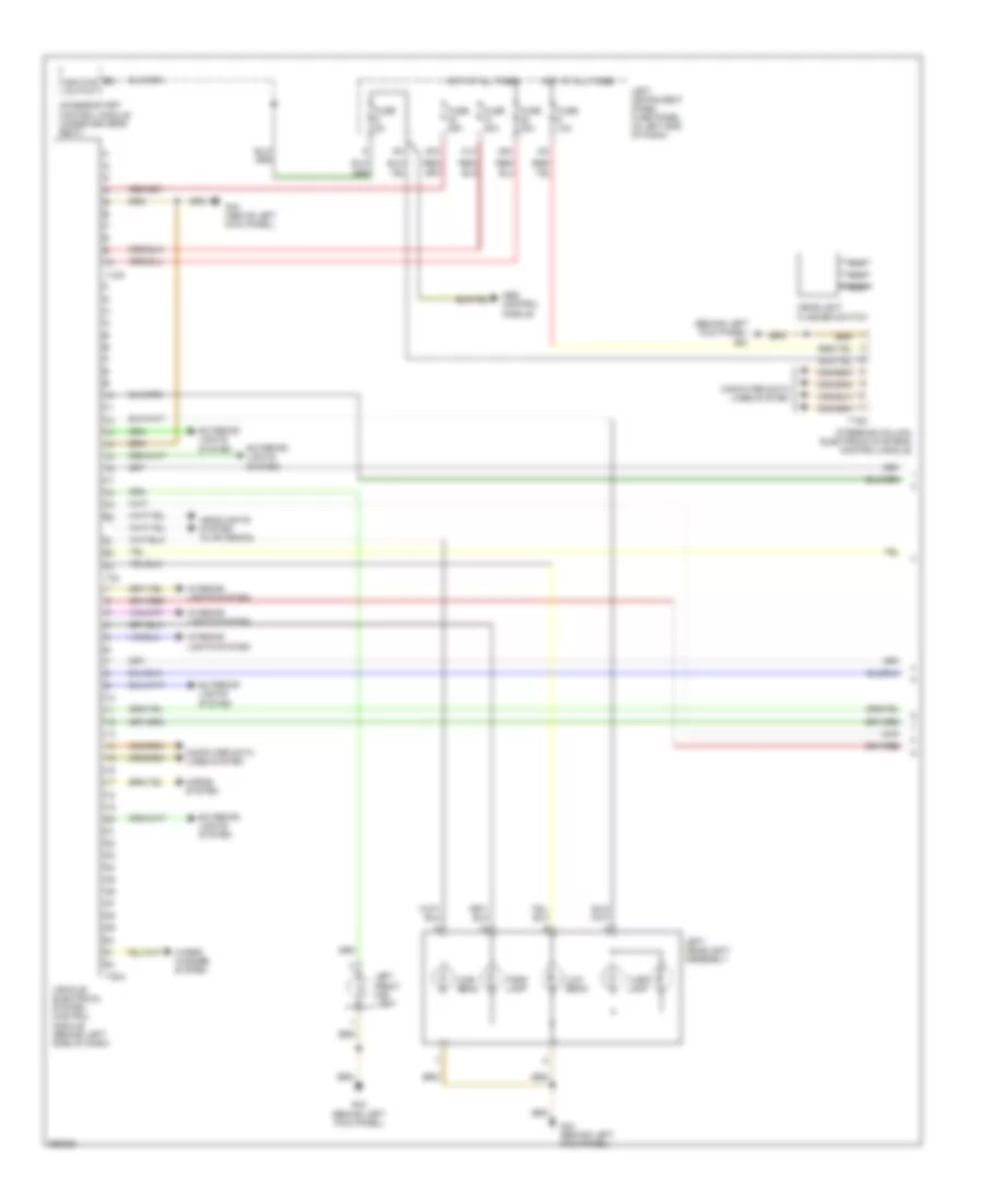
HEADLIGHTS
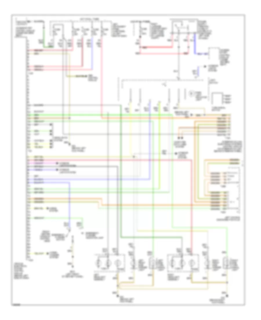
Headlights Wiring Diagram (1 of 2) for Audi A8 Quattro 2007
List of elements for Headlights Wiring Diagram (1 of 2) for Audi A8 Quattro 2007:
- (behind left kick panel) g44
- 31a
- 38a
- 40a
- Abs control module
- Access/start control module (under driver's seat)
- B3 ignition output
- Computer data lines system
- Exterior lights system
- Fuse 10a
- Fuse 25a
- Fuse 30a
- Fuse 5a
- G44 (above left kick panel)
- G44 (behind left kick panel)
- Headlight flasher switch
- Headlights system (w/ bi-xenon)
- High beam
- Horns system
- Hot at all times
- Interior lights system
- Left front fog light
- Left headlight assembly
- Left instrument panel fuse panel (in left end of dash)
- Low beam
- Nca
- Park lamp
- Steering column electronic systems control module
- T10p
- T16a
- T23
- T32a
- Turn lamp
- Vehicle electrical system control module (behind left side of dash)
- Wiper/ washer system
Headlights Wiring Diagram (2 of 2) for Audi A8 Quattro 2007
List of elements for Headlights Wiring Diagram (2 of 2) for Audi A8 Quattro 2007:
- Access/ start control module (under driver's seat)
- Fog lamp switch
- Front fog light indicator light
- Fuse 150a
- G43 (above right kick panel)
- G44 (behind left kick panel)
- G44 behind left kick panel)
- Headlamp switch illumination
- High beam
- Hot at all times
- Interior lights system
- Interior or exterior lights system
- Light switch
- Low beam
- Park lamp
- Park light indicator light
- Rear fog lamp switch
- Rear fog light indicator light
- Red
- Right front fog light
- Right headlight assembly
- Right luggage compartment fuse panel (right side of luggage compt)
- Turn lamp
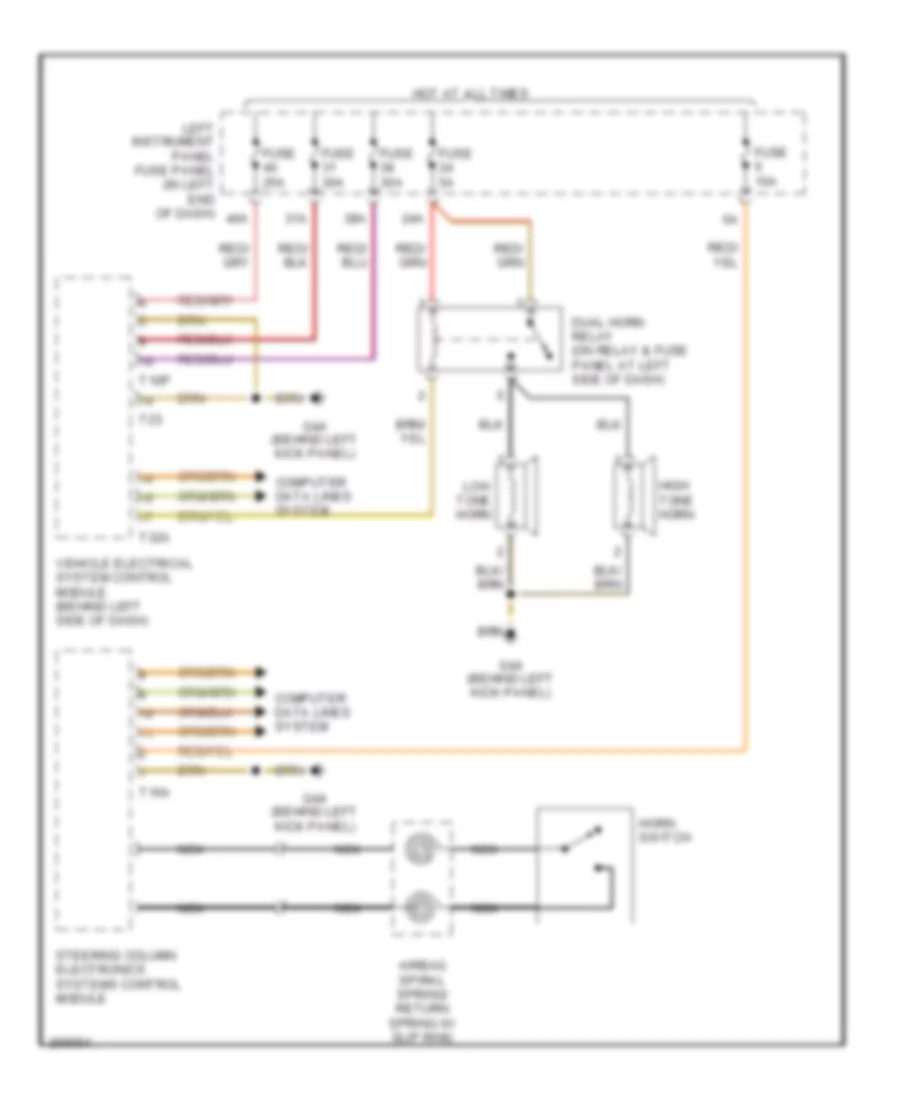
HORN
Horn Wiring Diagram for Audi A8 Quattro 2007
List of elements for Horn Wiring Diagram for Audi A8 Quattro 2007:
- hot at all times
- 24a
- 31a
- 38a
- 40a
- Airbag spiral spring/ return spring w/ slip ring
- Computer data lines system
- Dual horn relay (on relay & fuse panel at left side of dash)
- Fuse 10a
- Fuse 25a
- Fuse 30a
- Fuse 5a
- G44 (behind left kick panel)
- High tone horn
- Horn switch
- Left instrument panel fuse panel (in left end of dash)
- Low tone horn
- Nca
- Steering column electronics systems control module
- T10p
- T16a
- T23
- T32a
- Vehicle electrical system control module (behind left side of dash)
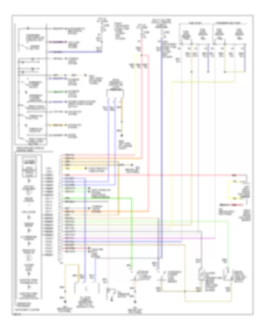
INSTRUMENT CLUSTER
Instrument Cluster Wiring Diagram for Audi A8 Quattro 2007
List of elements for Instrument Cluster Wiring Diagram for Audi A8 Quattro 2007:
- Anti-lock brakes system
- Asr/esp button
- Brake fluid warning switch
- Brake pad wear ind
- Brake warning
- Combination processor
- Computer data lines system
- Coolant level/temp
- Electric park/ handbrake ind
- Electric park/ handbrake malfunction ind
- Emergency flasher indicator
- Emergency flasher switch
- Engine coolant level (ecl) warning switch
- Exterior lights system
- Front display open/close button
- Front/center console control head
- Fuel gauge
- Fuel level sender
- Fuel level sensor
- Fuel pump
- Fuse 5a
- G43 (behind right kick panel)
- G44 (behind left kick panel)
- G610 (left front of center tunnel)
- G676 (left side of luggage compt)
- Hot at all times
- Instrument cluster
- Interior lights system
- Left front brake pad wear sensor
- Left instrument
- Navigation system
- Oil level thermal sensor (sri) (bottom of engine oil pan)
- Oil pressure switch
- Oil pressure warning
- Outside air temp
- Outside air temperature sensor (behind right side of front bumper)
- Panel fuse panel (in right end of dash)
- Parking aid button
- Parking aid indicator
- Parking brake
- Passenger side airbag off warning light
- Power window system (rear window shade switch)
- Radio frequency cntrld clock
- Radio frequency controlled clock receiver
- Rear window shade switch
- Red
- Right front brake pad wear sensor
- Right instrument
- Shift interlock system (electronic parking brake)
- Sound system
- T32
- T32/1
- T32/10
- T32/11
- T32/12
- T32/14
- T32/15
- T32/17
- T32/18
- T32/19
- T32/2
- T32/20
- T32/21
- T32/22
- T32/23
- T32/24
- T32/25
- T32/26
- T32/27
- T32/28
- T32/29
- T32/3
- T32/30
- T32/4
- T32/5
- T32/7
- T32/8
- T32/9
- Transfer fuel pump
- Washer fluid level
- Windshield washer fluid level sensor
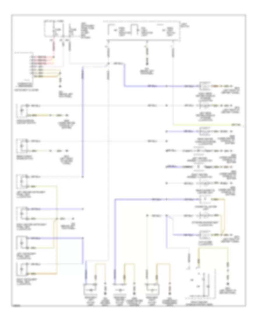
INTERIOR LIGHTS
Interior Lights Wiring Diagram (1 of 7) for Audi A8 Quattro 2007
List of elements for Interior Lights Wiring Diagram (1 of 7) for Audi A8 Quattro 2007:
- 29a
- Cigarette lighter light
- Combination processor
- Cup holder illumination
- Fog light indicator light
- Front/center console control head
- Fuse 1a
- Fuse 5a
- G34 (under driver's seat)
- G35 (under front passenger's seat)
- G44 (behind left kick panel)
- G606 (under center console, at shifter)
- G610 (left front of center panel)
- G610 (left front of center tunnel)
- Head- light switch light
- Hot at all times
- Instrument cluster
- Left center armrest illumination
- Left center instrument panel vent illumination
- Left instrument panel fuse panel (in left end of dash)
- Left instrument panel vent illumination
- Left rear center console storage illumination
- Light switch
- Nca
- Park light indicator light
- Parking brake contact switch
- Rear center console storage illumination
- Rear cigarette lighter light
- Rear seat center outlet light
- Rear seat left outlet light
- Rear seat right outlet light
- Rear window shade switch
- Right center armrest illumination
- Right center instrument panel vent illumination
- Right instrument panel vent illumination
- Right rear center console storage illumination
- Storage compartment illumination
Interior Lights Wiring Diagram (2 of 7) for Audi A8 Quattro 2007
List of elements for Interior Lights Wiring Diagram (2 of 7) for Audi A8 Quattro 2007:
- 31a
- Comfort system central control module (right side of luggage compartment)
- Exterior lights system
- Fuse 10a
- Fuse 20a
- Fuse 30a
- G34 (under driver's seat)
- G35 (under front passenger's seat)
- G43 (behind right kick panel)
- G44 (behind left kick panel)
- G51 (right rear of luggage compt)
- G653 (on left "d" pillar)
- G675 (right side of luggage compt)
- Glove compartment light
- Glove compartment light switch
- Hot at all times
- Left footwell light
- Left instrument panel fuse panel (in left end of dash)
- Left luggage compartment light
- Left rear footwell light
- Rear lid courtesy light
- Rear lid lock button (in lugg compt)
- Right footwell light
- Right luggage compartment fuse panel (right side of luggage compt)
- Right luggage compartment light
- Right rear footwell light
- T10p
- T10q
- T32a
- T32b
- Tiptronic switch
- Vehicle electrical system control module (behind left side of side of dash) dash)
Interior Lights Wiring Diagram (3 of 7) for Audi A8 Quattro 2007
List of elements for Interior Lights Wiring Diagram (3 of 7) for Audi A8 Quattro 2007:
- (10 pin ribbon cable)
- (8 pin ribbon cable)
- (under front passenger's seat) g35
- 13a
- Auto
- Automatic day/night interior mirror
- Computer data lines system
- Driver's reading light button
- Front interior lamp button
- Front passenger's reading light button
- Fuse 10a
- Garage door opener control head
- Hot in run and start
- Humidity sensor
- Interior illumination switch
- Left front reading light
- Left illuminated interior make-up mirror
- Left instrument panel fuse panel (in left end of dash)
- Left interior light
- Left make-up mirror light
- Left make-up mirror light switch
- Left rear interior light
- Left rear reading light
- Left rear reading light switch
- Left rear window shade button
- Light recognition sensor
- Off
- Passenger's map/reading light
- Power tops system
- Radar interior monitoring control module 1
- Rear interior lamp button
- Rear roof module control head
- Rear window shade switch (rear)
- Right illuminated interior make-up mirror
- Right interior light
- Right make-up mirror light
- Right make-up mirror light switch
- Right rear interior light
- Right rear reading light
- Right rear reading light switch 1
- Right rear window shade button
- Roof electronics control module
- Sunroof button
- Sunroof regulator
- Sunroof switch light
- T26a
- T26b
- T8f
Interior Lights Wiring Diagram (4 of 7) for Audi A8 Quattro 2007
List of elements for Interior Lights Wiring Diagram (4 of 7) for Audi A8 Quattro 2007:
- (inside left front door) driver's door ambient lighting voltage converter
- 39a
- A11
- A12
- A15
- A16
- A18
- A19
- A20
- A21
- A22
- Alarm system off switch
- Central locking safe warning light
- Driver entry lamp (in outside mirror)
- Driver side door control module (integrated in driver's door window regulator motor)
- Driver side door opener lighting
- Driver side door warning light
- Driver side interior lock switch
- Driver's door ambient illumination
- Driver's door storage illumination
- Driver's door window regulator control head
- Driver's seat memory program control
- Driver's side door contact switch
- Fuel tank lid unlock/ rear lid remote control lock switch
- Fuse 7.5a
- G44 (behind left kick panel)
- Hot at all times
- Left front entry light
- Left front outside door handle illumination
- Left instrument panel fuse panel (in left end of dash)
- Mirror adjustment switch
- Nca
- Seat memory lock-out button
- T2ae
- T2af
Interior Lights Wiring Diagram (5 of 7) for Audi A8 Quattro 2007
List of elements for Interior Lights Wiring Diagram (5 of 7) for Audi A8 Quattro 2007:
- (inside right front door) passenger's door ambient lighting voltage converter
- 39a
- A12
- A18
- A19
- A20
- A21
- A22
- Front passenger emergency off button
- Front passenger's central locking safe indicator light
- Front passenger's door storage illumination
- Front passenger's entry lamp (in outside mirror)
- Fuse 7.5a
- G43 (behind right kick panel)
- Hot at all times
- Nca
- Passenger door window regulator switch
- Passenger side door control module (integrated in right front door window regulator motor)
- Passenger side door opener lighting
- Passenger side door warning light
- Passenger side interior lock switch
- Passenger's door ambient illumination
- Passenger's seat memory program control
- Passenger's side door contact switch
- Right front entry light
- Right front outside door handle illumination
- Right instrument panel fuse panel (in right end of dash)
- T2ae
- T2af
Interior Lights Wiring Diagram (6 of 7) for Audi A8 Quattro 2007
List of elements for Interior Lights Wiring Diagram (6 of 7) for Audi A8 Quattro 2007:
- (inside left rear door) left rear door ambient lighting voltage converter
- 41a
- A16
- Fuse 7.5a
- G44 (behind left kick panel)
- Hot at all times
- Left instrument panel fuse panel (in left end of dash)
- Left rear ashtray light
- Left rear door ambient illumination
- Left rear door contact switch
- Left rear door control module (integrated in left rear door window regulator motor)
- Left rear door opener lighting
- Left rear door storage illumination
- Left rear door warning light
- Left rear entry light
- Left rear interior lock switch
- Left rear outside door handle illumination
- Left rear window switch
- Nca
- T2ae
- T2af
Interior Lights Wiring Diagram (7 of 7) for Audi A8 Quattro 2007
List of elements for Interior Lights Wiring Diagram (7 of 7) for Audi A8 Quattro 2007:
- (inside right rear door) right rear door ambient lighting voltage converter
- 41a
- A16
- Fuse 7.5a
- G43 (behind right kick panel)
- Hot at all times
- Nca
- Passenger's seat adjusting switch
- Right instrument panel fuse panel (in right end of dash)
- Right rear ashtray light
- Right rear door ambient illumination
- Right rear door contact switch
- Right rear door control module (integrated in right rear door window regulator motor)
- Right rear door opener lighting
- Right rear door storage illumination
- Right rear door warning light
- Right rear entry light
- Right rear interior lock switch
- Right rear outside door handle illumination
- Right rear window switch
- T2ae
- T2af
MEMORY SYSTEMS
Driver"s Memory Seat Wiring Diagram (1 of 2) for Audi A8 Quattro 2007
List of elements for Driver"s Memory Seat Wiring Diagram (1 of 2) for Audi A8 Quattro 2007:
- A10
- A11
- A12
- A13
- A14
- A15
- A16
- A17
- A18
- A19
- A20
- A21
- A22
- A23
- A24
- A25
- A26
- A27
- A28
- A29
- A30
- Aft fore/
- B10
- B11
- B12
- B13
- B14
- B15
- B16
- B17
- B18
- B19
- B20
- B21
- B22
- B23
- B24
- B25
- B26
- B27
- B28
- B29
- B30
- B31
- B32
- Back- rest
- Belt height
- Computer data lines system
- Depth seat
- Driver's seat backrest/ head adjustment motor
- Driver's seat lumbar support curvature adjustment motor
- Driver's seat lumbar support height adjustment motor
- Driver's seat switch
- Head backrest/
- Height seat
- Inclin- ation
- Lumbar fore/ aft
- Lumbar height
- Lumbar/ belt height switch
- Massage
- Memory seat/steering column adjustment control module (under driver's seat)
- Red
- Rest head-
- W/ massage
- W/o massage
Driver"s Memory Seat Wiring Diagram (2 of 2) for Audi A8 Quattro 2007
List of elements for Driver"s Memory Seat Wiring Diagram (2 of 2) for Audi A8 Quattro 2007:
- A21
- A22
- A26
- A27
- A28
- A29
- A30
- A31
- Belt height adjustment motor/position sensor
- C10
- C11
- C12
- Circuit breaker 44 30a
- Circuit breaker 45 30a
- Computer data lines system
- D10
- D11
- D12
- Driver side door control module (integrated in driver's door window regulator motor)
- Driver's seat back adjustment motor
- Driver's seat depth adjustment motor
- Driver's seat fore/ aft adjustment motor
- Driver's seat headrest adjustment motor
- Driver's seat height adjustment motor
- Driver's seat inclination adjustment motor
- G34 (under driver's seat)
- Hot at all times
- Memory program switch
- Memory seat/steering column adjustment control module (under driver's seat)
- Power seat circuit breaker 1 (on relay & fuse panel, at left side of dash)
- Power seat circuit breaker 2 (on relay & fuse panel, at left side of dash)
- Red
- Seat memory lock-out button
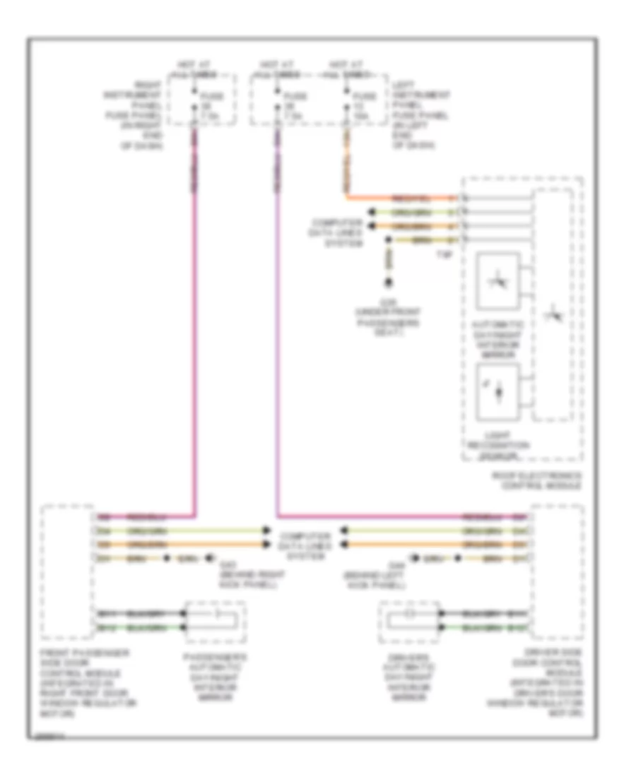
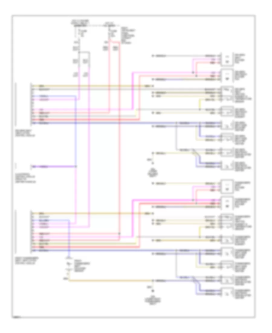
Memory Mirrors Wiring Diagram for Audi A8 Quattro 2007
List of elements for Memory Mirrors Wiring Diagram for Audi A8 Quattro 2007:
- 39a
- A21
- Auto day/ night
- B10
- B11
- B12
- B13
- B14
- B15
- B16
- Computer data lines system
- Directional motors & position switches
- Driver side door control module (integrated in driver's door window regulator motor)
- Driver's outside mirror
- Entry lamp
- Fold away motor
- Fold away switch
- Front passenger side door control module (integrated in right front door window regulator motor)
- Front passenger's outside mirror
- Fuse 7.5a
- G43 (behind right kick panel)
- G44 (behind left kick panel)
- Heating element
- Hot at all times
- Interior lights system
- Interior lights system, door locks system
- Left instrument panel fuse panel (in left end of dash)
- Mirror adjustment switches
- Mirror selector switch
- Outside mirror switch
- Pnk
- Red
- Right instrument panel fuse panel (in right end of dash)
Memory Rear Seat Wiring Diagram (1 of 2) for Audi A8 Quattro 2007
List of elements for Memory Rear Seat Wiring Diagram (1 of 2) for Audi A8 Quattro 2007:
- Aft fore/
- Circuit breaker 2 30a
- Computer data lines system
- Fore/ aft
- G653 (on left "d" pillar)
- Height
- Hot at all times
- Inclin- ation
- Left rear backrest adjustment motor
- Left rear seat fore/aft adjusting motor
- Left rear seat lumabr switch
- Left rear seat lumbar support fore/aft adjustment motor
- Left rear seat lumbar support height adjustment motor
- Left rear seat switch
- Left rear seat tilt adjustment motor
- Massage
- Power rear seat circuit breaker 2 (on relay & fuse panel, right side of luggage compt)
- Rear memory seat control module (under center of rear seat)
- T12n
- T32c
- W/ lumbar massage
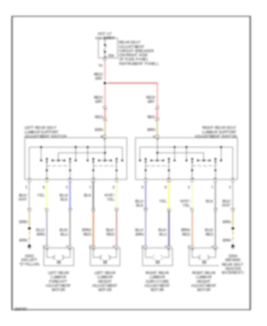
Memory Rear Seat Wiring Diagram (2 of 2) for Audi A8 Quattro 2007
List of elements for Memory Rear Seat Wiring Diagram (2 of 2) for Audi A8 Quattro 2007:
- Aft fore/
- Ation inclin-
- Fore/ aft
- G654 (on right "d" pillar)
- Height
- Inclin- ation
- Left rear seat lumabr switch
- Left rear seat switch
- Massage
- Rear memory seat control module (under center of rear seat)
- Right rear backrest adjustment motor
- Right rear seat fore/aft adjusting motor
- Right rear seat lumbar support curvature adjustment motor
- Right rear seat lumbar support height adjustment motor
- Right rear seat tilt adjustment motor
- T12o
- T32d
- W/ lumbar massage
Passenger"s Memory Seat Wiring Diagram (1 of 2) for Audi A8 Quattro 2007
List of elements for Passenger"s Memory Seat Wiring Diagram (1 of 2) for Audi A8 Quattro 2007:
- (intergrated in right rear door window regulator motor) right rear door control module
- A10
- A11
- A12
- A13
- A14
- A15
- A16
- A17
- A18
- A19
- A20
- A21
- A22
- A23
- A24
- A25
- A26
- A27
- A28
- A29
- A30
- Aft fore/
- B10
- B11
- B12
- B13
- B14
- B15
- B16
- B17
- B18
- B19
- B20
- B21
- B22
- B23
- B24
- B25
- B26
- B27
- B28
- B29
- B30
- B31
- B32
- Back- rest
- Belt height
- Computer data lines system
- Depth seat
- Head backrest/
- Height seat
- Inclin- ation
- Interior lights system
- Lumbar fore/ aft
- Lumbar height
- Lumbar/ belt height switch
- Massage
- Passenger memory seat control module
- Passenger's seat adjusting switch
- Passenger's seat backrest/ head adjustment motor
- Passenger's seat lumbar support curvature adjustment motor
- Passenger's seat lumbar support height adjusting motor
- Passenger's seat lumbar support height adjustment motor
- Passenger's seat switch
- Red
- Rest head-
- W/ massage
- W/o massage
Passenger"s Memory Seat Wiring Diagram (2 of 2) for Audi A8 Quattro 2007
List of elements for Passenger"s Memory Seat Wiring Diagram (2 of 2) for Audi A8 Quattro 2007:
- A21
- A22
- A26
- A27
- A28
- A29
- A30
- A31
- Belt height adjustment motor/position sensor
- C10
- C11
- C12
- Circuit breaker 46 30a
- Circuit breaker 80 30a
- Computer data lines system
- D10
- D11
- D12
- G35 (under front passenger's seat)
- Hot at all times
- Passenger memory seat control module
- Passenger side door control module (integrated in passenger's door window regulator motor)
- Passenger's seat backrest adjustment motor
- Passenger's seat depth adjustment motor
- Passenger's seat emergency off button
- Passenger's seat fore/aft adjustment motor
- Passenger's seat head restraint adjustment motor
- Passenger's seat height adjustment motor
- Passenger's seat inclination adjustment motor
- Passenger's side memory program switch
- Power seat circuit breaker 1 (in fuse & relay carrier, behind right side of dash)
- Power seat circuit breaker 2 (in fuse & relay carrier, behind right side of dash)
- Red
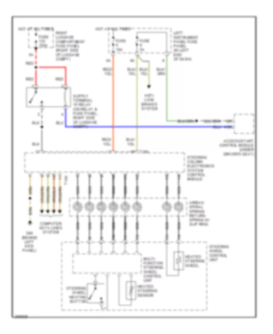
Steering Column Memory Wiring Diagram for Audi A8 Quattro 2007
List of elements for Steering Column Memory Wiring Diagram for Audi A8 Quattro 2007:
- (under driver's seat) access/start control module
- 31a
- 38a
- 4.2l
- 40a
- 5.2l
- 6.0l
- A10
- A21
- A22
- A26
- A27
- A28
- A29
- A30
- A31
- Anti-lock brakes system
- Axial adjustment motor
- Axial adjustment sensor
- B14
- C14
- C15
- C18
- C19
- C21
- C22
- Computer data lines system
- Cruise control system
- Driver side door control module (integrated in driver's door window regulator motor)
- Engine control module (in passenger's side plenum chamber e-box)
- Fuse 10a
- Fuse 150a
- Fuse 25a
- Fuse 30a
- Fuse 5a
- G44 (behind left kick panel)
- Headlights/ exterior lights system
- Horns system
- Hot at all times
- Left instrument panel fuse panel (in left end of dash)
- Memory program switch
- Memory seat system (driver's seat circuit)
- Nca
- Nca nca
- Red
- Right luggage compartment fuse panel (right side of luggage compt)
- Seats system
- Steering column adjustment motors
- Steering column adjustment switch
- Steering column electronic systems control module
- T16a
- T23
- T4d
- T81
- T81b
- T94
- T94a
- Transmission controls/ sound system
- Vehicle electrical system control module (behind left side of dash)
- Vertical adjustment motor
- Vertical adjustment sensor
- Wiper/ washer system
NAVIGATION
Navigation Wiring Diagram, Base Radio (1 of 4) for Audi A8 Quattro 2007
List of elements for Navigation Wiring Diagram, Base Radio (1 of 4) for Audi A8 Quattro 2007:
- 12a
- 24a
- A10
- A11
- A12
- A13
- A14
- A15
- A16
- A17
- A18
- A19
- A20
- A61
- A62
- Access/start control module (under driver's seat)
- Antenna amplifier (behind left rear edge of roof trim)
- C10
- C11
- C12
- C13
- C14
- C15
- C16
- C17
- C18
- C19
- C20
- C21
- C22
- C23
- C24
- C25
- Computer data lines system
- Display closed stop switch
- Display open stop switch
- Fiber optic
- Front display open/close button
- Front information display control head
- Front information display control head control module (behind glove compartment)
- Front/center console control head
- Fuse 10a
- Fuse 5a
- G35 (under front passenger's seat)
- G43 (behind right kick panel)
- G610 (left front of center tunnel)
- G657 (top of left "d" pillar)
- Hot at all times
- Multimedia control head
- Nca
- Open/ close display motor
- Operating electronics & telephone control module
- Pnk
- Red
- Right instrument panel fuse panel (in right end of dash)
- Vehicle electrical system control module 2 (under front passenger's seat)
- W/ cellular telephone
- W/o cellular telephone
Navigation Wiring Diagram, Base Radio (2 of 4) for Audi A8 Quattro 2007
List of elements for Navigation Wiring Diagram, Base Radio (2 of 4) for Audi A8 Quattro 2007:
- 14a
- Cd changer unit or external audio source connector
- Dvd player or cd rom drive
- Fiber optic
- Fuse 30a
- Fuse 5a
- G43 (behind right kick panel)
- G613 (left side of luggage compt)
- G657 (top of left "d" pillar)
- Hot at all times
- Left luggage compartment fuse panel (left side of luggage compt)
- Navigation antenna
- Nca
- Radio
- Radio antenna
- Radio antenna 2
- Radio/telephone/ navigation antenna
- Right instrument panel fuse panel (in right end of dash)
- Roof antenna
- Satellite radio (if equipped) (left side of luggage compt)
- W/ cd changer
- W/ cellular telephone
- W/o cd changer
- W/o cellular telephone
- W/o satellite radio
Navigation Wiring Diagram, Base Radio (3 of 4) for Audi A8 Quattro 2007
List of elements for Navigation Wiring Diagram, Base Radio (3 of 4) for Audi A8 Quattro 2007:
- (behind center rear edge of roof trim) antenna
- 10a
- Center mid/high range loudspeaker
- Digital sound system control module (left side of luggage compt)
- Fiber optic
- Fuse 15a
- Fuse 5a
- G613 (left side of luggage compt)
- G657 (top of left "d" pillar)
- Hot at all times
- Left front bass speaker
- Left front midrange speaker
- Left luggage compartment fuse panel (left side of luggage compt)
- Left rear mid/low range loudspeaker
- Left rear treble speaker
- Microphone unit (w/ voice control) (in front of roof module)
- Navigation antenna (w/o telematic telephone)
- Navigation w/ cd mechanism control unit (left side of trunk, behind trim)
- Nca
- Rear parcel shelf loudspeakers
- Red
- Right front bass speaker
- Right front midrange speaker
- Right rear mid/low range loudspeaker
- Right rear treble speaker
- Subwoofer (on rear parcel shelf)
- T18c
- T32e
- Telephone
- W/ telephone
- W/o w/ telematic telematic telephone
Navigation Wiring Diagram, Base Radio (4 of 4) for Audi A8 Quattro 2007
List of elements for Navigation Wiring Diagram, Base Radio (4 of 4) for Audi A8 Quattro 2007:
- (above right kick panel) g43
- (below driver's seat) g34
- 10a
- 13a
- 20a
- Air bag control module (below center of dash, on transmission tunnel)
- B25
- Cellular telephone connector
- Comfort system central control module (right side of (luggage compt)
- Computer data lines system
- Cruise control system (w/ adaptive cruise control)
- Data bus on board diagnostic interface (behind glove box compt)
- Data link connector (under left side of dash)
- Fiber optic
- Fuse 10a
- Fuse 5a
- G659 (near right rear window)
- Hot at all times
- Instrument cluster
- Left instrument panel fuse panel (in left end of dash)
- Nca
- Pnk
- Red
- Right instrument panel fuse panel (in right end of dash)
- T32
- Telephone antenna
- Telephone suppression choke
- Telephone/ telematic control module (left front footwell, under carpet)
Navigation Wiring Diagram, Premium Radio (1 of 5) for Audi A8 Quattro 2007
List of elements for Navigation Wiring Diagram, Premium Radio (1 of 5) for Audi A8 Quattro 2007:
- 12a
- 24a
- A10
- A11
- A12
- A13
- A14
- A15
- A16
- A17
- A18
- A19
- A20
- A61
- A62
- Access/start control module (under driver's seat)
- Antenna amplifier (behind left rear edge of roof trim)
- C10
- C11
- C12
- C13
- C14
- C15
- C16
- C17
- C18
- C19
- C20
- C21
- C22
- C23
- C24
- C25
- Computer data lines system
- Display closed stop switch
- Display open stop switch
- Fiber optic
- Front display open/close button
- Front information display control head
- Front information display control head control module (behind glove compartment)
- Front/center console control head
- Fuse 10a
- Fuse 5a
- G35 (under front passenger's seat)
- G43 (behind right kick panel)
- G610 (left front of center tunnel)
- G657 (top of left "d" pillar)
- Hot at all times
- Multimedia control head
- Nca
- Open/ close display motor
- Operating electronics & telephone control module
- Pnk
- Red
- Right instrument panel fuse panel (in right end of dash)
- Vehicle electrical system control module 2 (under front passenger's seat)
- W/ cellular telephone
- W/o cellular telephone
Navigation Wiring Diagram, Premium Radio (2 of 5) for Audi A8 Quattro 2007
List of elements for Navigation Wiring Diagram, Premium Radio (2 of 5) for Audi A8 Quattro 2007:
- 10a
- 14a
- Cd changer unit or external audio source connector
- Dvd player or cd rom drive
- Fiber optic
- Fuse 30a
- Fuse 5a
- G43 (behind right kick panel)
- G613 (left side of luggage compt)
- G657 (top of left "d" pillar)
- Hot at all times
- Left luggage compartment fuse panel (left side of luggage compt)
- Navigation antenna
- Nca
- Radio
- Radio antenna
- Radio antenna 2
- Radio/telephone/ navigation antenna
- Right instrument panel fuse panel (in right end of dash)
- Roof antenna
- Satellite radio (if equipped) (left side of luggage compt)
- W/ cd changer
- W/ cellular telephone
- W/o cd changer
- W/o cellular telephone
- W/o satellite radio
Navigation Wiring Diagram, Premium Radio (3 of 5) for Audi A8 Quattro 2007
List of elements for Navigation Wiring Diagram, Premium Radio (3 of 5) for Audi A8 Quattro 2007:
- Center mid/high range loudspeaker
- Digital sound system control module (left side of luggage compt)
- Fiber optic
- G613 (left side of luggage compt)
- Left front bass & midrange speaker
- Left front treble speaker & motor
- Left rear midrange speaker
- Left rear treble speaker
- Microphone unit (w/ voice control) (in front of roof module)
- Nca
- Right front bass & midrange speaker
- Right front treble speaker & motor
- Right rear treble speaker
- T32e
- W/ telephone
Navigation Wiring Diagram, Premium Radio (4 of 5) for Audi A8 Quattro 2007
List of elements for Navigation Wiring Diagram, Premium Radio (4 of 5) for Audi A8 Quattro 2007:
- Antenna (behind center rear edge of roof trim)
- Digital sound system control module (left side of luggage compt)
- Digital sound system control module 2
- Fiber optic
- Fuse 5a
- G613 (left side of luggage compt)
- G657 (top left "d" pillar)
- Hot at all times
- Left luggage compartment fuse panel (left side of luggage compt)
- Left rear mid/low range loudspeaker
- Navigation antenna (w/o telematic telephone)
- Navigation w/ cd mechanism control unit
- Nca
- Red
- Right rear mid/low range loudspeaker
- Subwoofer
- T32f
- T32g
- Telelmatic telephone
- W/ w/o telelmatic telephone
Navigation Wiring Diagram, Premium Radio (5 of 5) for Audi A8 Quattro 2007
List of elements for Navigation Wiring Diagram, Premium Radio (5 of 5) for Audi A8 Quattro 2007:
- (behind right kick panel) g43
- (below driver's seat) g34
- (in left end of dash)
- 10a
- 13a
- 20a
- Air bag control module (below center of dash, on transmission tunnel)
- B25
- Cellular telephone connector
- Comfort system central control module (right side of (luggage compt)
- Computer data lines system
- Cruise control system (w/ adaptive cruise control)
- Data bus on board diagnostic interface (behind glove box compt)
- Data link connector (under left side of dash)
- Fiber optic
- Fuse 10a
- Fuse 5a
- G659 (on right "d" pillar)
- Hot at all times
- Instrument cluster
- Left instrument panel fuse panel
- Nca
- Pnk
- Red
- Right instrument panel fuse panel (in right end of dash)
- T32
- Telephone antenna
- Telephone suppression choke
- Telephone/ telematic control module (left front footwell, under carpet)
Parking Assistant Wiring Diagram for Audi A8 Quattro 2007
List of elements for Parking Assistant Wiring Diagram for Audi A8 Quattro 2007:
- (left side of luggage compartment)
- A10
- A11
- A12
- A13
- A14
- A15
- C10
- C11
- C12
- Computer data lines system
- Front parking aid warning buzzer
- Front/ center console control head
- Fuse 5a
- G610 (left front of center tunnel)
- G676
- Hot at all times
- Left front center parking aid sensor
- Left front parking aid sensor
- Left instrument panel fuse panel (in left end of dash)
- Left rear center parking sensor
- Left rear parking sensor
- Parking aid button
- Parking aid control module (below cd changer unit, on left side of luggage compartment)
- Parking aid indicator
- Parking warning buzzer (under right side of rear shelf)
- Right front center parking aid sensor
- Right front parking aid sensor
- Right rear center parking sensor
- Right rear parking sensor
- T16b
Rear Camera Wiring Diagram for Audi A8 Quattro 2007
List of elements for Rear Camera Wiring Diagram for Audi A8 Quattro 2007:
- Computer data lines system
- Front information display control head control module (behind glove box compt)
- Fuse 5a
- G676 (left side of luggage compt)
- Hot at all times
- Left luggage compartment fuse panel (left side of luggage compt)
- Nca
- Pins: 1-38 (not used)
- Pins: 49-54 (not used)
- Rear view camera
- Rear view camera system control module
- T2au
- T54b
- Tv tuner
POWER DISTRIBUTION
Power Distribution Wiring Diagram (1 of 3) for Audi A8 Quattro 2007
List of elements for Power Distribution Wiring Diagram (1 of 3) for Audi A8 Quattro 2007:
- (right side of luggage compt) right luggage compartment fuse panel
- (right side of luggage compt, behind side trim)
- 11a
- 12a
- 12v socket 2
- 12v socket 3
- 13a
- 14a
- 15a
- 21a
- 23a
- 24a
- 25a
- 26a
- 27a
- 30a
- 34a
- 35a
- 36a
- 37a
- 38a
- 39a
- 40a
- 41a
- 43a
- 44a
- Air bag control module
- Alarm horn
- Battery
- Battery interrupt igniter
- Brake booster relay
- Cd changer unit/ external audio source connection
- Cd rom driver/ dvd player
- Cigarette lighter
- Circuit breaker 30a
- Climatronic control module
- Climatronic control module/ driver's seat ventilation control module/ front passenger's seat ventilation control module
- Comfort system central control module
- Computer data lines system
- Coolant fan
- Coolant fan 2
- Electro- mechanical parking brake control module
- Energy mana- gement control module
- Engine control module
- Fresh air blower control module
- Front information display control head module
- Fuel pump relay
- Fuel pump relay 2
- Fuel pump relay fuse
- Fuse
- Fuse 10a
- Fuse 110a
- Fuse 150a
- Fuse 15a
- Fuse 20a
- Fuse 25a
- Fuse 30a
- Fuse 40a
- Fuse 50a
- Fuse 5a
- Fuse 60a
- Fuse 7.5a
- G606 (under center console, at shifter)
- G610 (left front of center tunnel)
- Generator
- Headlight washer system relay
- Heated front window
- Inclination/ anti-theft control module
- Interior lights system
- Main fuse panel (right "a" pillar)
- Multimedia control module
- Nca
- Parking brake pressure switch
- Passenger memory seat control module
- Passenger side door control module
- Power seat circuit breaker 1 (on relay & fuse panel, at right kick panel)
- Power seat circuit breaker 2 (on relay & fuse panel, at right kick panel)
- Power sunroof control module
- Rain/ light recognition sensor
- Rear a/c control head
- Rear a/c control head/ left/right rear seat ventilation control module
- Rear cigarette lighter
- Rear lid control module
- Rear memory seat control module
- Rear seat adjustment circuit breaker 2
- Rear window defogger fuse (in right luggage compt relay/ fuse panel)
- Rear window defogger relay
- Red
- Right instrument panel fuse panel (behind right side of dash)
- Right instrument panel fuse panel (in right end of dash)
- Right rear door control module
- Right rear seat lumbar support height adjustment switch/rear memory seat control module
- Roof electronics control module
- Secondary air injection pump fuse (plenum chamber e-box relay panel)
- Secondary air injection pump relay
- Starter
- To front passenger door window regulator fuse (diagram 2 0f 3)
- To left instrument panel fuse panel (diagram 2 0f 3)
- To left luggage compt fuse panel (diagram 2 0f 3)
- Towing recognition control module
- Transmission control module
- Vehicle electrical system control module 2
Power Distribution Wiring Diagram (2 of 3) for Audi A8 Quattro 2007
List of elements for Power Distribution Wiring Diagram (2 of 3) for Audi A8 Quattro 2007:
- 10a
- 11a
- 12a
- 12v socket
- 13a
- 15a
- 24a
- 25a
- 27a
- 30a
- 38a
- 39a
- 40a
- 41a
- 42a
- 43a
- 44a
- Abs control module
- Abs control module fuse 1
- Access/ start control module
- Brake light switch
- Compressor level control system relay
- Digital sound system control module
- Digital sound system control module 2
- Driver side door control module
- Drver door closing assistance control module (w/ door closing assistance)
- Dual horn relay
- From right luggage compartment fuse panel (diagram 1 of 3)
- From right luggage compartment fuse panel (fuse 132) (diagram 1 of 3)
- From right luggage compartment fuse panel a (fuse 133) (diagram 1 of 3)
- Front passenger door closing assistance control module (w/ door closing assistance)
- Front passenger window regulator fuse
- Fuse 10a
- Fuse 15a
- Fuse 20a
- Fuse 25a
- Fuse 30a
- Fuse 40a
- Fuse 5a
- Fuse 60a
- Fuse 7.5a
- G676 (left side of luggage compartment)
- Left headlight assembly
- Left instrument panel fuse panel (in left end of dash)
- Left luggage compartment fuse panel (left side of luggage compartment)
- Left rear door closing assistance control module (w/ door closing assistance)
- Left rear door control module
- Left rear support lumbar support height adjustment switch
- Left rear window shade control module
- Leveling control system control module
- Navigation w/ cd mechanism control unit
- Nca
- Parking aid control module
- Passenger side door control module
- Power window circuit breaker (in fuse & relay carrier behind left side of dash)
- Radio
- Rear seat adjustment circuit breaker 2
- Rear view camera system control module
- Red
- Right headlight assembly
- Right rear door closing assistance control module (w/ door closing assistance)
- Right rear door control module
- Right rear side blind control module
- Right rear support lumbar support height adjustment switch
- Satellite radio
- Self leveling system fuse (on left instrument panel fuse panel, behind left side of dash)
- Subwoofer (on rear parcel self)
- Suppressor
- Telephone suppression choke
- Telephone/ telematic control module
- Towing recognition control module
- Tv tuner
- Vehicle electrical system control module
- Wiper motor control module
Power Distribution Wiring Diagram (3 of 3) for Audi A8 Quattro 2007
List of elements for Power Distribution Wiring Diagram (3 of 3) for Audi A8 Quattro 2007:
- (on left "d" pillar) g653
- (on relay & fuse panel at left side of dash)
- 10a
- 16a
- 17a
- 18a
- 20a
- 28a
- 31a
- 32a
- 33a
- 37a
- Access/ start control module
- Air bag control module
- Air quality sensor
- Airbag control module
- Circuit breaker 30a
- Climatronic control module
- Comfort system central control module
- Cooler
- Data bus on board diagnostic interface
- Data link connector
- Distance regulation control module
- Driver's seat ventilation control module
- Engine control module
- From left instrument panel fuse panel splice (diagram 2 of 3)
- Front passenger seat ventilation control module
- Front/ center console control head
- Fuel pump relay
- Fuel pump relay 2
- Fuse 10a
- Fuse 15a
- Fuse 25a
- Fuse 30a
- Fuse 5a
- Garage door opener control module
- High pressure sensor
- Instrument cluster
- Left instrument panel fuse panel (in left end of dash)
- Left rear footwell heater
- Left/right rear ventilation control module
- Left/right washer nozzle heaters
- Level control system control module
- Light switch
- Memory seat control module
- Multi- media control module
- Nca
- Oil level thermal sensor
- Parking aid control module
- Power seat circuit breaker 1 (on relay & fuse panel at left side of dash)
- Power seat circuit breaker 2 (on relay & fuse panel at left side of dash)
- Rear a/c control head
- Red
- Right instrument panel fuse panel (in right end of dash)
- Right rear footwell heater
- Seat occupied recognition control module
- Starter relay
- Starter relay 2
- Steering column electronic systems control module
- Telephone/ telematic control module
- Tiptronic switch
- Tire pressure monitoring control module
- Towing recognition control module
- Transmission control module
- Transmission park selection switch
- Vehicle electrical system control module
POWER DOOR LOCKS
Power Door Locks Wiring Diagram (1 of 3) for Audi A8 Quattro 2007
List of elements for Power Door Locks Wiring Diagram (1 of 3) for Audi A8 Quattro 2007:
- 30a
- 39a
- A17
- A21
- A23
- Alarm system off switch/ passenger compartment monitoring switch
- Assist
- C10
- C11
- Computer data lines system
- Driver side central locking lock unit
- Driver side door control module (integrated in driver's door window regulator motor)
- Driver side interior lock switch
- Driver's door closing control module (right side of luggage compt behind battery)
- Driver's door handle switch (if equipped)
- Front passenger's window regulator fuse
- Fuel tank lid
- Fuse 10a
- Fuse 7.5a
- G35 (under front passenger's seat)
- G43 (behind right kick panel)
- G44 (behind left kick panel)
- Hot at all times
- Hot in run and start
- Left instrument panel fuse panel (in left end of dash)
- Lock
- Passenger side central locking lock unit
- Passenger side door control module (integrated in right front door window regulator motor)
- Passenger side interior lock switch
- Passenger's door handle switch (if equipped)
- Power window circuit breaker
- Radar interior monitoring control module 1
- Rear lid
- Rear lid remote control lock switch/fuel tank lid unlock button
- Right instrument panel fuse panel (in right end of dash)
- Roof electronics control module (under front of roof module)
- T8f
- Unlock
- W/ door closing
Power Door Locks Wiring Diagram (2 of 3) for Audi A8 Quattro 2007
List of elements for Power Door Locks Wiring Diagram (2 of 3) for Audi A8 Quattro 2007:
- (right side of luggage compt. behind battery) left rear door closing control module
- (right side of luggage compt. behind battery) passenger's door closing control module
- (right side of luggage compt. behind battery) right rear door closing control module
- 41a
- Assist
- B10
- B11
- B12
- Computer data lines system
- Fuse 7.5a
- G43 (above right kick panel)
- G43 (behind right kick panel)
- G44 (behind left kick panel)
- Hot at all times
- Left instrument panel fuse panel (in left end of dash)
- Left rear central locking lock unit
- Left rear door control module (integrated in left rear door window regulator motor)
- Left rear door handle switch (if equipped)
- Left rear interior lock switch
- Power windows system (rear window sun shade)
- Right instrument panel fuse panel (in right end of dash)
- Right rear central locking lock unit
- Right rear door control module (integrated in right rear door window regulator motor)
- Right rear door handle switch (if equipped)
- Right rear interior lock switch
- W/ door closing
Power Door Locks Wiring Diagram (3 of 3) for Audi A8 Quattro 2007
List of elements for Power Door Locks Wiring Diagram (3 of 3) for Audi A8 Quattro 2007:
- (behind left kick panel) g44
- (behind right kick panel) g43
- (right side of luggage compartment) g51
- (right side of luggage compartment) g675
- (right side of luggage compt) g51
- 31a
- A15
- Alarm horn
- B14
- B17
- B18
- B24
- B26
- B29
- B31
- Bb22
- C10
- Comfort system central control module (right side of luggage compartment)
- Computer data lines system
- Deck lid central locking system motor
- Door closing control module
- Front hood switch
- Front hood switch 2
- Fuel tank lid unlock motor
- Fuse 10a
- Fuse 150a
- Fuse 20a
- Fuse 30a
- G44 (behind left kick panel)
- G51 (right rear of luggage compt)
- G51 (right side of luggage compt)
- G654 (behind rear seat center backrest)
- Hot at all times
- Inclination/ anti-theft control module (under right side of rear seat)
- Interior lights system
- Left instrument panel fuse panel (in left end of dash)
- Rear lid closing assist lock stop switch
- Rear lid control module (right rear of luggage compt)
- Rear lid lock button (in luggage compt)
- Rear lid lock cylinder unlocking switch
- Rear lid opening assist unlock stop switch
- Red
- Right luggage compartment fuse panel (right side of luggage compt)
- Trunk lid alarm switch
- Trunk lock alarm/central locking switch
- Vehicle electrical system control module (behind left side of dash)
POWER MIRRORS
Automatic Day/Night Mirror Wiring Diagram for Audi A8 Quattro 2007
List of elements for Automatic Day/Night Mirror Wiring Diagram for Audi A8 Quattro 2007:
- 13a
- 39a
- Automatic day/night interior mirror
- B11
- B12
- Computer data lines system
- Driver side door control module (integrated in driver's door window regulator motor)
- Driver's automatic day/night interior mirror
- Front passenger side door control module (integrated in right front door window regulator motor)
- Fuse 10a
- Fuse 7.5a
- G35 (under front passengers seat)
- G43 (behind right kick panel)
- G44 (behind left kick panel)
- Hot at all times
- Left instrument panel fuse panel (in left end of dash)
- Light recognition sensor
- Passenger's automatic day/night interior mirror
- Right instrument panel fuse panel (in right end of dash)
- Roof electronics control module
- T8f
POWER SEATS
Front Seat Heater Wiring Diagram, with Ventilation for Audi A8 Quattro 2007
List of elements for Front Seat Heater Wiring Diagram, with Ventilation for Audi A8 Quattro 2007:
- 20a
- 35a
- Climatronic control module (front of center console)
- Driver's seat blower fan
- Driver's seat heating element & temperature sensor
- Driver's seat side bolster heater
- Driver's seat ventilation control module
- Driver's seatback blower fan
- Driver's seatback heating element
- Driver's seatback side bolster heater
- Front passenger's seat occupied sensor
- Front passenger's seat ventilation control module
- Fuse 20a
- Fuse 5a
- G34 (under driver's seat)
- G35 (under front passenger's seat)
- Hot at all times
- Passenger's seat blower fan
- Passenger's seat heating element & temperature sensor
- Passenger's seat side bolster heater
- Passenger's seatback blower fan
- Passenger's seatback heating element
- Passenger's seatback side bolster heater
- Red
- Right instrument panel fuse panel (in right end of dash)
Heated Steering Wheel Wiring Diagram for Audi A8 Quattro 2007
List of elements for Heated Steering Wheel Wiring Diagram for Audi A8 Quattro 2007:
- A58
- Access/start control module (under driver's seat)
- Airbag spiral spring/ return spring w/ slip ring
- Anti- lock brakes system
- Computer data lines system
- Fuse 10a
- Fuse 150a
- Fuse 5a
- G44 (behind left kick panel)
- Heated steering sensor
- Heated steering wheel
- Hot at all times
- Left instrument panel fuse panel (in left end of dash)
- Multi- function steering wheel control unit
- Nca
- Red
- Right luggage compartment fuse panel (right side of luggage compt)
- Steering column electronics system control module
- Steering wheel control unit
- Steering wheel heating button
- T16a
Rear Lumbar Wiring Diagram for Audi A8 Quattro 2007
List of elements for Rear Lumbar Wiring Diagram for Audi A8 Quattro 2007:
- 30a
- G653 (on left "d" pillar)
- G654 (behind rear seat center backrest)
- Hot at all times
- Left rear lumbar fore/aft adjustment motor
- Left rear lumbar height adjustment motor
- Left rear seat lumbar support adjustment switch
- Rear seat adjustment circuit breaker (on right side of fuse panel instrument panel)
- Red
- Right rear lumbar curvature adjustment motor
- Right rear lumbar height adjustment motor
- Right rear seat lumbar support adjustment switch
Rear Seat Heater Wiring Diagram, with Ventilation for Audi A8 Quattro 2007
List of elements for Rear Seat Heater Wiring Diagram, with Ventilation for Audi A8 Quattro 2007:
- (behind rear seat center bracket) g654
- (on left "d" pillar) g653
- 20a
- 34a
- Fuse 20a
- Fuse 5a
- G653 (on left "d" pillar)
- G654 (behind rear seat center bracket)
- Hot at all times
- Left rear backrest heating element
- Left rear seat backrest blower fan
- Left rear seat blower fan
- Left rear seat heater
- Left rear seat occupied sensor
- Left rear seat ventilation control module
- Rear a/c control head
- Right instrument panel fuse panel (behind right side of dash)
- Right rear backrest heating element
- Right rear seat backrest blower fan
- Right rear seat blower fan
- Right rear seat heater
- Right rear seat occupied sensor
- Right rear seat ventilation control module
- Seat heater
- Temp sensor
POWER TOP/SUNROOF
Power Top/Sunroof Wiring Diagram for Audi A8 Quattro 2007
List of elements for Power Top/Sunroof Wiring Diagram for Audi A8 Quattro 2007:
- 13a
- 27a
- Computer data lines system
- Fuse 10a
- Fuse 20a
- G35 (under front passengers seat)
- Hot at all times
- Left instrument panel fuse panel (in left end of dash)
- Nca
- Power sunroof control module
- Red
- Roof electronics control module
- Sunroof button
- Sunroof regulator
- Sunroof switch light
- T8f
- Wind deflector motor
POWER WINDOWS
Power Windows Wiring Diagram for Audi A8 Quattro 2007
List of elements for Power Windows Wiring Diagram for Audi A8 Quattro 2007:
- 39a
- 41a
- A10
- A13
- A15
- A16
- A21
- A25
- Computer data lines system
- Driver side door control module (integrated in driver's door window regulator motor)
- Driver window switch
- Front passenger side door control module (integrated in right front door window regulator motor)
- Front passenger window switch
- Fuse 7.5a
- G43 (behind right kick panel)
- G44 (behind left kick panel)
- Hot at all times
- Interior lights system
- Interior lights system, door locks system
- Left child safety switch
- Left front window switch
- Left instrument panel fuse panel (in left end of dash)
- Left rear door control module (integrated in left rear door window regulator motor)
- Left rear window switch
- Right child safety switch
- Right front window switch
- Right instrument panel fuse panel (in right end of dash)
- Right rear door control module (integrated in right rear door window regulator motor)
- Right rear window switch
- Window regulator motor
Rear Window Sun Shade Wiring Diagram for Audi A8 Quattro 2007
List of elements for Rear Window Sun Shade Wiring Diagram for Audi A8 Quattro 2007:
- (left front of center tunnel)
- 13a
- 26a
- 30a
- 35a
- 41a
- C22
- C23
- C24
- Climatronic control module (front of center console)
- Comfort system central control module (right side of luggage compt)
- Computer data lines system
- Front passenger window regulator fuse
- Front/center console control head
- Fuse 10a
- Fuse 20a
- Fuse 30a
- Fuse 5a
- Fuse 7.5a
- G35 (under front passenger's seat)
- G43 (behind right kick panel)
- G44 behind left kick panel)
- G51 (right rear of luggage compt)
- G610
- G610 (left front of center tunnel)
- Hot at all times
- Interior lights system
- Left instrument panel fuse panel (in left end of dash)
- Left rear door control module (integrated in left rear door window regulator motor)
- Left rear side blind control module
- Left rear window shade button
- Power distribution system
- Power window circuit breaker
- Rear roof module control head
- Rear window shade motor
- Rear window shade switch (front)
- Rear window shade switch (rear)
- Right instrument panel fuse panel (in right end of dash)
- Right rear door control module (integrated in right rear door window regulator motor)
- Right rear side blind control module
- Right rear window shade button
- Roof electronics control module
- T10q
- T15c
- T16b
- T26a
- T26b
- T32b
- T8f
RADIO
Multimedia Interface Wiring Diagram, Base Radio (1 of 4) for Audi A8 Quattro 2007
List of elements for Multimedia Interface Wiring Diagram, Base Radio (1 of 4) for Audi A8 Quattro 2007:
- 12a
- 24a
- A10
- A11
- A12
- A13
- A14
- A15
- A16
- A17
- A18
- A19
- A20
- A61
- A62
- Access/start control module (under driver's seat)
- Antenna amplifier (behind left rear edge of roof trim)
- C10
- C11
- C12
- C13
- C14
- C15
- C16
- C17
- C18
- C19
- C20
- C21
- C22
- C23
- C24
- C25
- Computer data lines system
- Display closed stop switch
- Display open stop switch
- Fiber optic
- Front display open/close button
- Front information display control head
- Front information display control head control module (behind glove compartment)
- Front/center console control head
- Fuse 10a
- Fuse 5a
- G35 (under front passenger's seat)
- G43 (behind right kick panel)
- G610 (left front of center tunnel)
- G657 (top of left "d" pillar)
- Hot at all times
- Multimedia control head
- Nca
- Open/ close display motor
- Operating electronics & telephone control module
- Pnk
- Red
- Right instrument panel fuse panel (in right end of dash)
- Vehicle electrical system control module 2 (under front passenger's seat)
- W/ cellular telephone
- W/o cellular telephone
Multimedia Interface Wiring Diagram, Base Radio (2 of 4) for Audi A8 Quattro 2007
List of elements for Multimedia Interface Wiring Diagram, Base Radio (2 of 4) for Audi A8 Quattro 2007:
- 14a
- Cd changer unit or external audio source connector
- Dvd player or cd rom drive
- Fiber optic
- Fuse 30a
- Fuse 5a
- G43 (behind right kick panel)
- G613 (left side of luggage compt)
- G657 (top of left "d" pillar)
- Hot at all times
- Left luggage compartment fuse panel (left side of luggage compt)
- Navigation antenna
- Nca
- Radio
- Radio antenna
- Radio antenna 2
- Radio/telephone/ navigation antenna
- Right instrument panel fuse panel (in right end of dash)
- Roof antenna
- Satellite radio (if equipped) (left side of luggage compt)
- W/ cd changer
- W/ cellular telephone
- W/o cd changer
- W/o cellular telephone
- W/o satellite radio
Multimedia Interface Wiring Diagram, Base Radio (3 of 4) for Audi A8 Quattro 2007
List of elements for Multimedia Interface Wiring Diagram, Base Radio (3 of 4) for Audi A8 Quattro 2007:
- (behind center rear edge of roof trim) antenna
- 10a
- Center mid/high range loudspeaker
- Digital sound system control module (left side of luggage compt)
- Fiber optic
- Fuse 15a
- Fuse 5a
- G613 (left side of luggage compt)
- G657 (top of left "d" pillar)
- Hot at all times
- Left front bass speaker
- Left front midrange speaker
- Left luggage compartment fuse panel (left side of luggage compt)
- Left rear mid/low range loudspeaker
- Left rear treble speaker
- Microphone unit (w/ voice control) (in front of roof module)
- Navigation antenna (w/o telematic telephone)
- Navigation w/ cd mechanism control unit (left side of trunk, behind trim)
- Nca
- Rear parcel shelf loudspeakers
- Red
- Right front bass speaker
- Right front midrange speaker
- Right rear mid/low range loudspeaker
- Right rear treble speaker
- Subwoofer (on rear parcel shelf)
- T18c
- T32e
- Telephone
- W/ telephone
- W/o w/ telematic telematic telephone
Multimedia Interface Wiring Diagram, Base Radio (4 of 4) for Audi A8 Quattro 2007
List of elements for Multimedia Interface Wiring Diagram, Base Radio (4 of 4) for Audi A8 Quattro 2007:
- (above right kick panel) g43
- (below driver's seat) g34
- 10a
- 13a
- 20a
- Air bag control module (below center of dash, on transmission tunnel)
- B25
- Cellular telephone connector
- Comfort system central control module (right side of (luggage compt)
- Computer data lines system
- Cruise control system (w/ adaptive cruise control)
- Data bus on board diagnostic interface (behind glove box compt)
- Data link connector (under left side of dash)
- Fiber optic
- Fuse 10a
- Fuse 5a
- G659 (near right rear window)
- Hot at all times
- Instrument cluster
- Left instrument panel fuse panel (in left end of dash)
- Nca
- Pnk
- Red
- Right instrument panel fuse panel (in right end of dash)
- T32
- Telephone antenna
- Telephone suppression choke
- Telephone/ telematic control module (left front footwell, under carpet)
Multimedia Interface Wiring Diagram, Premium Radio (1 of 5) for Audi A8 Quattro 2007
List of elements for Multimedia Interface Wiring Diagram, Premium Radio (1 of 5) for Audi A8 Quattro 2007:
- 12a
- 24a
- A10
- A11
- A12
- A13
- A14
- A15
- A16
- A17
- A18
- A19
- A20
- A61
- A62
- Access/start control module (under driver's seat)
- Antenna amplifier (behind left rear edge of roof trim)
- C10
- C11
- C12
- C13
- C14
- C15
- C16
- C17
- C18
- C19
- C20
- C21
- C22
- C23
- C24
- C25
- Computer data lines system
- Display closed stop switch
- Display open stop switch
- Fiber optic
- Front display open/close button
- Front information display control head
- Front information display control head control module (behind glove compartment)
- Front/center console control head
- Fuse 10a
- Fuse 5a
- G35 (under front passenger's seat)
- G43 (behind right kick panel)
- G610 (left front of center tunnel)
- G657 (top of left "d" pillar)
- Hot at all times
- Multimedia control head
- Nca
- Open/ close display motor
- Operating electronics & telephone control module
- Pnk
- Red
- Right instrument panel fuse panel (in right end of dash)
- Vehicle electrical system control module 2 (under front passenger's seat)
- W/ cellular telephone
- W/o cellular telephone
Multimedia Interface Wiring Diagram, Premium Radio (2 of 5) for Audi A8 Quattro 2007
List of elements for Multimedia Interface Wiring Diagram, Premium Radio (2 of 5) for Audi A8 Quattro 2007:
- 10a
- 14a
- Cd changer unit or external audio source connector
- Dvd player or cd rom drive
- Fiber optic
- Fuse 30a
- Fuse 5a
- G43 (behind right kick panel)
- G613 (left side of luggage compt)
- G657 (top of left "d" pillar)
- Hot at all times
- Left luggage compartment fuse panel (left side of luggage compt)
- Navigation antenna
- Nca
- Radio
- Radio antenna
- Radio antenna 2
- Radio/telephone/ navigation antenna
- Right instrument panel fuse panel (in right end of dash)
- Roof antenna
- Satellite radio (if equipped) (left side of luggage compt)
- W/ cd changer
- W/ cellular telephone
- W/o cd changer
- W/o cellular telephone
- W/o satellite radio
Multimedia Interface Wiring Diagram, Premium Radio (3 of 5) for Audi A8 Quattro 2007
List of elements for Multimedia Interface Wiring Diagram, Premium Radio (3 of 5) for Audi A8 Quattro 2007:
- Center mid/high range loudspeaker
- Digital sound system control module (left side of luggage compt)
- Fiber optic
- G613 (left side of luggage compt)
- Left front bass & midrange speaker
- Left front treble speaker & motor
- Left rear midrange speaker
- Left rear treble speaker
- Microphone unit (w/ voice control) (in front of roof module)
- Nca
- Right front bass & midrange speaker
- Right front treble speaker & motor
- Right rear treble speaker
- T32e
- W/ telephone
Multimedia Interface Wiring Diagram, Premium Radio (4 of 5) for Audi A8 Quattro 2007
List of elements for Multimedia Interface Wiring Diagram, Premium Radio (4 of 5) for Audi A8 Quattro 2007:
- Antenna (behind center rear edge of roof trim)
- Digital sound system control module (left side of luggage compt)
- Digital sound system control module 2
- Fiber optic
- Fuse 5a
- G613 (left side of luggage compt)
- G657 (top left "d" pillar)
- Hot at all times
- Left luggage compartment fuse panel (left side of luggage compt)
- Left rear mid/low range loudspeaker
- Navigation antenna (w/o telematic telephone)
- Navigation w/ cd mechanism control unit
- Nca
- Red
- Right rear mid/low range loudspeaker
- Subwoofer
- T32f
- T32g
- Telelmatic telephone
- W/ w/o telelmatic telephone
Multimedia Interface Wiring Diagram, Premium Radio (5 of 5) for Audi A8 Quattro 2007
List of elements for Multimedia Interface Wiring Diagram, Premium Radio (5 of 5) for Audi A8 Quattro 2007:
- (behind right kick panel) g43
- (below driver's seat) g34
- (in left end of dash)
- 10a
- 13a
- 20a
- Air bag control module (below center of dash, on transmission tunnel)
- B25
- Cellular telephone connector
- Comfort system central control module (right side of (luggage compt)
- Computer data lines system
- Cruise control system (w/ adaptive cruise control)
- Data bus on board diagnostic interface (behind glove box compt)
- Data link connector (under left side of dash)
- Fiber optic
- Fuse 10a
- Fuse 5a
- G659 (on right "d" pillar)
- Hot at all times
- Instrument cluster
- Left instrument panel fuse panel
- Nca
- Pnk
- Red
- Right instrument panel fuse panel (in right end of dash)
- T32
- Telephone antenna
- Telephone suppression choke
- Telephone/ telematic control module (left front footwell, under carpet)
Rear Seat Entertainment Wiring Diagram, Base Radio for Audi A8 Quattro 2007
List of elements for Rear Seat Entertainment Wiring Diagram, Base Radio for Audi A8 Quattro 2007:
- 12a
- 12m
- 16a
- 16f
- Communication fuse (in right luggage compt fuse panel)
- Computer data lines system
- Fuse 10a
- Fuse 15a
- G51 (right rear of luggage compt)
- Hot at all times
- Left instrument panel fuse panel (in left end of dash)
- Left multimedia headphones
- Multimedia control module
- Multimedia display unit
- Multimedia display unit 1
- Nca
- Rear dvd changer
- Red
- Right luggage compartment fuse panel (right side of luggage compt)
- Right multimedia headphones
- T26d
- T26e
- Towing recognition control module (right side of luggage compt, under battery)
Steering Wheel Controls Wiring Diagram for Audi A8 Quattro 2007
List of elements for Steering Wheel Controls Wiring Diagram for Audi A8 Quattro 2007:
- Access/start control module (under driver's seat)
- Airbag spiral spring/ return spring w/ slip ring
- Computer data lines system
- Engine control module (in passenger's side plenum chamber e-box)
- Fuse 10a
- Fuse 150a
- Fuse 5a
- G44 (behind left kick panel)
- Hot at all times
- Left instrument panel fuse panel (behind left side of dash)
- Left multi- function buttons
- Multi- function steering wheel control unit
- Nca
- Red
- Right luggage compartment fuse panel (right side of luggage compt)
- Right multi- function buttons
- Steering column electronics system control module
- Steering wheel control unit
- T16a
- T23
- T81
- T81b
SHIFT INTERLOCK
Park Brake Release Wiring Diagram for Audi A8 Quattro 2007
List of elements for Park Brake Release Wiring Diagram for Audi A8 Quattro 2007:
- 23a
- Computer data lines system
- Electric park/ handbrake ind
- Electric park/ handbrake malfunction ind
- Electronic parking brake control module (right side of luggage compartment, under battery)
- Fuse 30a
- Fuse 5a
- G51 (right side of luggage compartment)
- G606 (under center console, at shifter)
- Hot at all times
- Instrument cluster
- Interior lights system
- Left parking brake motor (at left rear brake caliper)
- Parking brake contact switch
- Right instrument panel fuse panel (in right end of dash)
- Right luggage compartment fuse panel (right side of luggage compartment)
- Right parking brake motor (at right rear brake caliper)
- T32
Shift Interlock Wiring Diagram for Audi A8 Quattro 2007
List of elements for Shift Interlock Wiring Diagram for Audi A8 Quattro 2007:
- 25a
- 32a
- 4.2 & 6.0l
- 5.2l
- 6.0l
- A29
- A54
- Access/start control module (under driver's seat)
- Computer data lines system
- Data link connector (under left side of dash)
- Engine control module (in passenger's side plenum chamber e-box)
- Engine control module 2 (5.2l & 6.0l) (in passenger's side plenum chamber e-box)
- Fuse 15a
- Fuse 5a
- G43 (behind right kick panel)
- G610 (left front of center tunnel)
- Hot at all times
- Right instrument panel fuse panel (in left end of dash)
- T81
- T81a
- T94a
- T94d
- Transmission control module (tcm) (in bottom of transmission)
- Transmission park selector switch (w/ shift lock solenoid)
- Transmissions system
STARTING/CHARGING
Charging Wiring Diagram for Audi A8 Quattro 2007
List of elements for Charging Wiring Diagram for Audi A8 Quattro 2007:
- 15a
- Battery
- Battery interrupt igniter
- Computer data lines system
- Energy management control module (right side of luggage compt, behind side trim)
- Fuse 5a
- Generator
- Hot at all times
- Main fuse panel (behind upper right kick panel)
- Power distribution system
- Red
- Right instrument panel fuse panel (in right end of dash)
- Starter
Starting Wiring Diagram for Audi A8 Quattro 2007
List of elements for Starting Wiring Diagram for Audi A8 Quattro 2007:
- 5.2l & 4.2l
- 6.0l
- A51
- A58
- Access/start control module (under driver's seat)
- Air bag control module
- Battery
- Battery interrupt igniter
- Charging system (generator)
- Engine control module (ecm) (in passenger's side plenum chamber e-box)
- Fuse 150a
- Main fuse panel (behind upper right kick panel)
- Power distribution system
- Red
- Right luggage compartment fuse panel (right side of luggage compt)
- Starter
- Starter relay (on right kick panel relay & fuse panel)
- Starter relay 2 (on right kick panel relay & fuse panel)
- T40
- T81
- T94
SUPPLEMENTAL RESTRAINTS
Supplemental Restraints Wiring Diagram (1 of 3) for Audi A8 Quattro 2007
List of elements for Supplemental Restraints Wiring Diagram (1 of 3) for Audi A8 Quattro 2007:
- head airbag igniter (driver's side)
- (or red)
- (right side of luggage compartment) comfort system central control module
- Air bag control module (below center of dash)
- Center rear safety belt tensioner igniter
- Driver's head curtain airbag igniter
- Driver's safety belt tensioner igniter 1
- Driver's side airbag igniter
- Front passenger's safety belt tensioner igniter
- Front passenger's side airbag igniter
- G606 (under center console at shifter)
- G653 (on left "d" pillar)
- G654 (on right "d" pillar)
- Nca
- Rear passenger's side airbag igniter (driver's side)
- Rear passenger's side airbag igniter (front passenger's side)
- Rear safety belt tensioner igniter (driver's side)
- Rear safety belt tensioner igniter (passenger's side)
- Red
- Solid state
Supplemental Restraints Wiring Diagram (2 of 3) for Audi A8 Quattro 2007
List of elements for Supplemental Restraints Wiring Diagram (2 of 3) for Audi A8 Quattro 2007:
- Airbag spiral spring/return spring w/slip ring
- Battery interrupt igniter
- Driver's airbag igniter
- Driver's airbag igniter 2
- Driver's knee airbag igniter
- Front airbag crash sensor (front passenger's) (right front of engine compt)
- Front passenger's airbag igniter
- Front passenger's knee airbag igniter
- G606 (under center console at shifter)
- Igniter 1
- Igniter 2
- Nca
- Power distribution system
- Rear side airbag crash sensor (front passenger's side) (at bottom of right "c" pillar)
- Red
- Shorting contact
- Solid state
- T12a
- T4c
Supplemental Restraints Wiring Diagram (3 of 3) for Audi A8 Quattro 2007
List of elements for Supplemental Restraints Wiring Diagram (3 of 3) for Audi A8 Quattro 2007:
- front airbag crash sensor (driver's) (left front of engine compt)
- 18a
- Air bag control module (below center of dash)
- Computer data lines system
- Driver's safety belt switch
- Front passenger's safety belt switch and seat occupied recognition safety belt force sensor
- Front/center console control head
- Fuse panel c
- Fuse 5a
- G606 (under center console at shifter)
- Hot in on or start
- Nca
- Pass side air bag off ind
- Rear side airbag crash sensor (driver's) (at bottom of left "c" pillar)
- Seat occupied recognition control module
- Seat occupied recognition pressure sensor
- Side airbag crash sensor (driver's side) (at left "b" pillar)
- Side airbag crash sensor (passenger's side) (at right "b" pillar)
- Solid state
TRANSMISSION
A/T Wiring Diagram for Audi A8 Quattro 2007
List of elements for A/T Wiring Diagram for Audi A8 Quattro 2007:
- 25a
- 32a
- 4.2l & 6.0l
- 5.2l
- 6.0l
- A29
- A54
- Access/start control module (under driver's seat)
- Airbag spiral spring/ return spring w/ slip ring
- Computer data lines system
- Data link connector (under left side of dash)
- Engine control module (in passenger's side plenum chamber e-box)
- Engine control module 2 (5.2l & 6.0l) (in passenger's side plenum chamber e-box)
- Fuse 10a
- Fuse 15a
- Fuse 25a
- Fuse 5a
- G43 (behind right kick panel)
- G610 (left front of center tunnel)
- Hot at all times
- Interior lights system
- Left instrument panel fuse panel (in left end of dash)
- Multi- function steering wheel control unit
- Nca
- Right instrument panel fuse panel (in right end of dash)
- Steering column electronics system control module
- Steering wheel control unit
- T16a
- T81
- T81a
- T94a
- T94d
- Tiptronic downshift button
- Tiptronic switch
- Tiptronic upshift button
- Transmission control module (tcm) (in bottom of transmission)
- Transmission park selector switch (w/ shift lock solenoid)
TRUNK, TAILGATE, FUEL DOOR
Trunk, Tailgate, Fuel Door Wiring Diagram for Audi A8 Quattro 2007
List of elements for Trunk, Tailgate, Fuel Door Wiring Diagram for Audi A8 Quattro 2007:
- (right side of luggage compartment) g51
- (right side of luggage compartment) g675
- (right side of luggage compt) g51
- B22
- Comfort system central control module (right side of luggage comparment)
- Computer data lines system
- Deck lid central locking system motor
- Door closing control module
- Fuel tank lid unlock motor
- Fuse 10a
- Fuse 20a
- G51 (right side of luggage compt)
- G654 (behind rear seat center backrest)
- Hot at all times
- Inclination/ anti-theft control module (under right side of rear seat)
- Interior lights system
- Rear lid closing assist lock stop switch
- Rear lid control module (right rear of luggage compt)
- Rear lid lock button (in luggage compt)
- Rear lid lock cylinder unlocking switch
- Rear lid opening assist unlock stop switch
- Red
- Right luggage compartment fuse panel (right side of luggage compt)
- T10q
- T15c
- T32b
- Trunk lid alarm switch
- Trunk lock alarm/central locking switch
WARNING SYSTEMS
Tire Pressure Monitoring Wiring Diagram for Audi A8 Quattro 2007
List of elements for Tire Pressure Monitoring Wiring Diagram for Audi A8 Quattro 2007:
- (left "d" pillar) g653
- 20a
- Computer data lines system
- Fuse 20a 5a
- Hot at all times
- Left front
- Left instrument panel fuse panel (behind left side of dash)
- Left rear
- Right front
- Right rear
- Spare tire
- Tire pressure check antenna
- Tire pressure monitoring control module (under left side of rear seat)
- Tire pressure sensor
WIPER/WASHER
Wiper/Washer Wiring Diagram for Audi A8 Quattro 2007
List of elements for Wiper/Washer Wiring Diagram for Audi A8 Quattro 2007:
- (behind left kick panel) g44
- 11a
- 18a
- 24a
- 25a
- 31a
- 38a
- 40a
- 43a
- Access/start control module (under driver's seat)
- Board computer
- Computer data lines system
- Fuse 10a
- Fuse 20a
- Fuse 25a
- Fuse 30a
- Fuse 40a
- Fuse 5a
- G35 (under front passengers seat)
- G43 (behind right kick panel)
- G44 (behind left kick panel)
- Headlight washer pump
- Headlight washer system relay (on right kick panel relay & fuse panel)
- Heaters
- Hot at all times
- Left headlight washer jet motor
- Left instrument panel fuse panel (in left end of dash)
- Left washer nozzle heaters
- Nca
- Rain/light recognition sensor
- Right headlight washer jet motor
- Right instrument panel fuse panel (in right end of dash)
- Right washer nozzle r
- Steering column electronics system control module (top of steering column)
- T10p
- T16a
- T23
- T32a
- Vehicle electrical system control module (behind left side of dash)
- Vehicle electrical system control module 2 (under front passengers seat)
- Washer
- Windshield washer pump
- Windshield wiper/ washer switch
- Wiper front
- Wiper interval
- Wiper motor control module