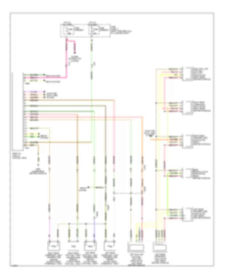
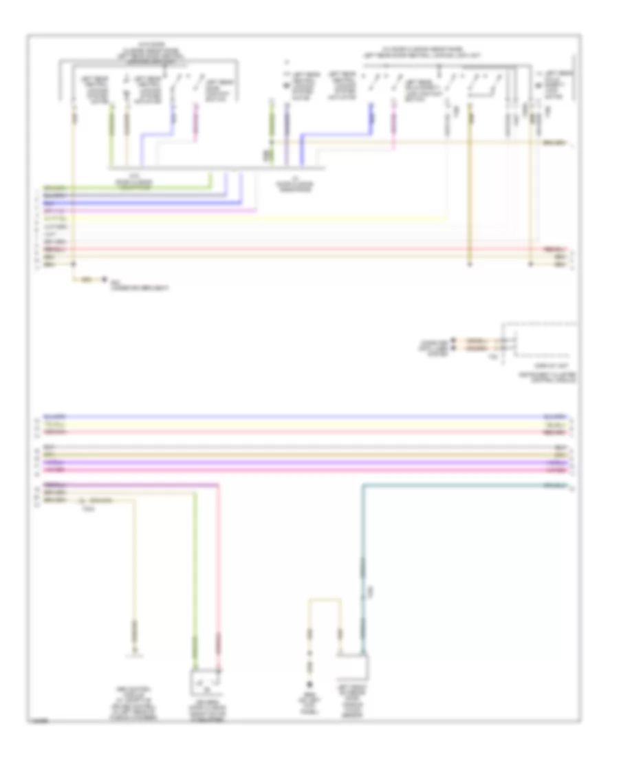
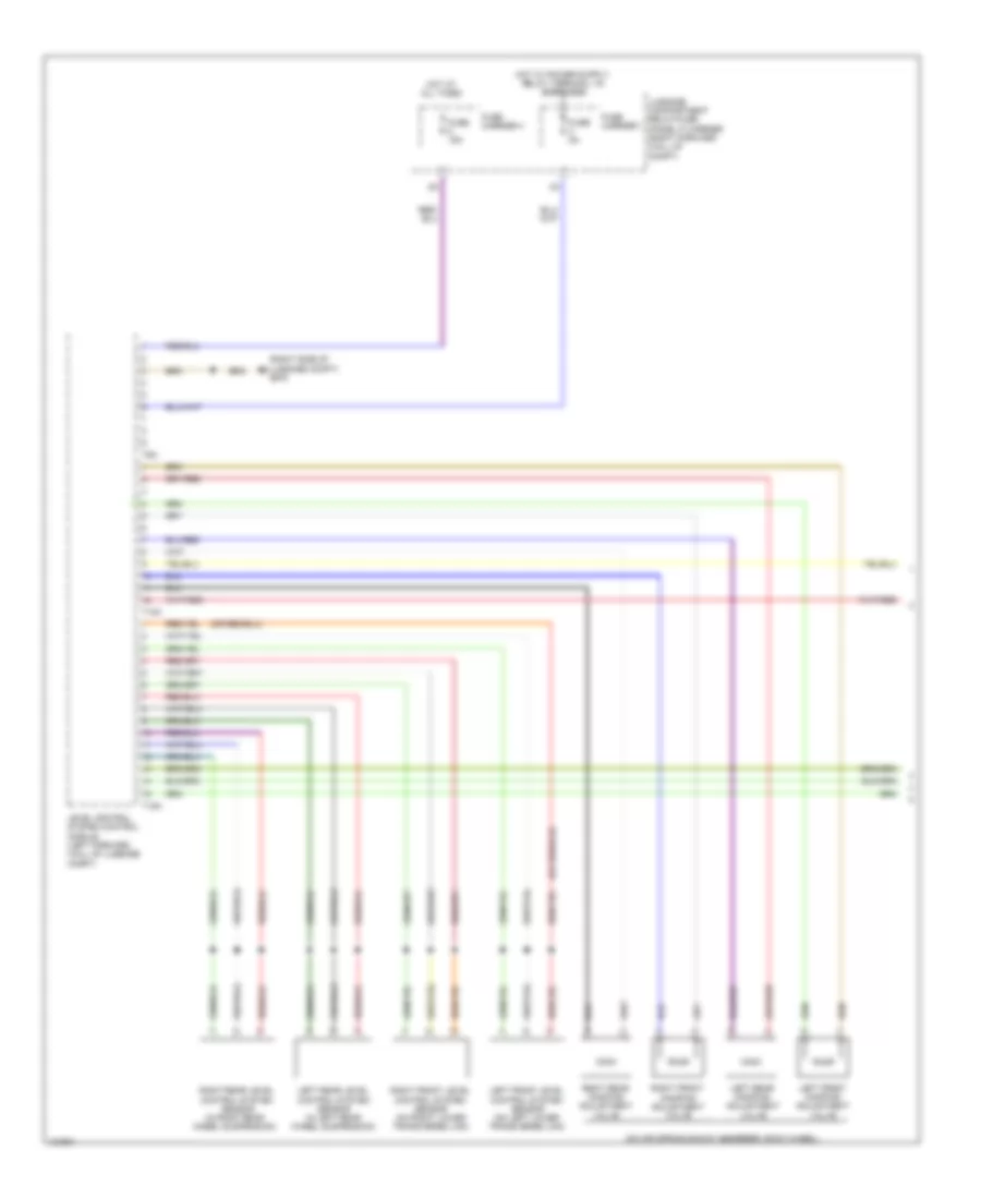
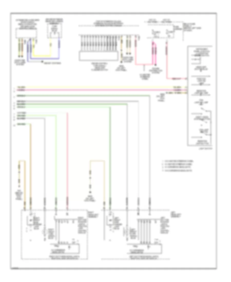
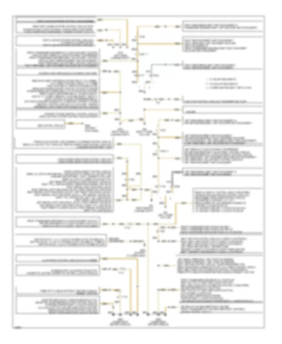
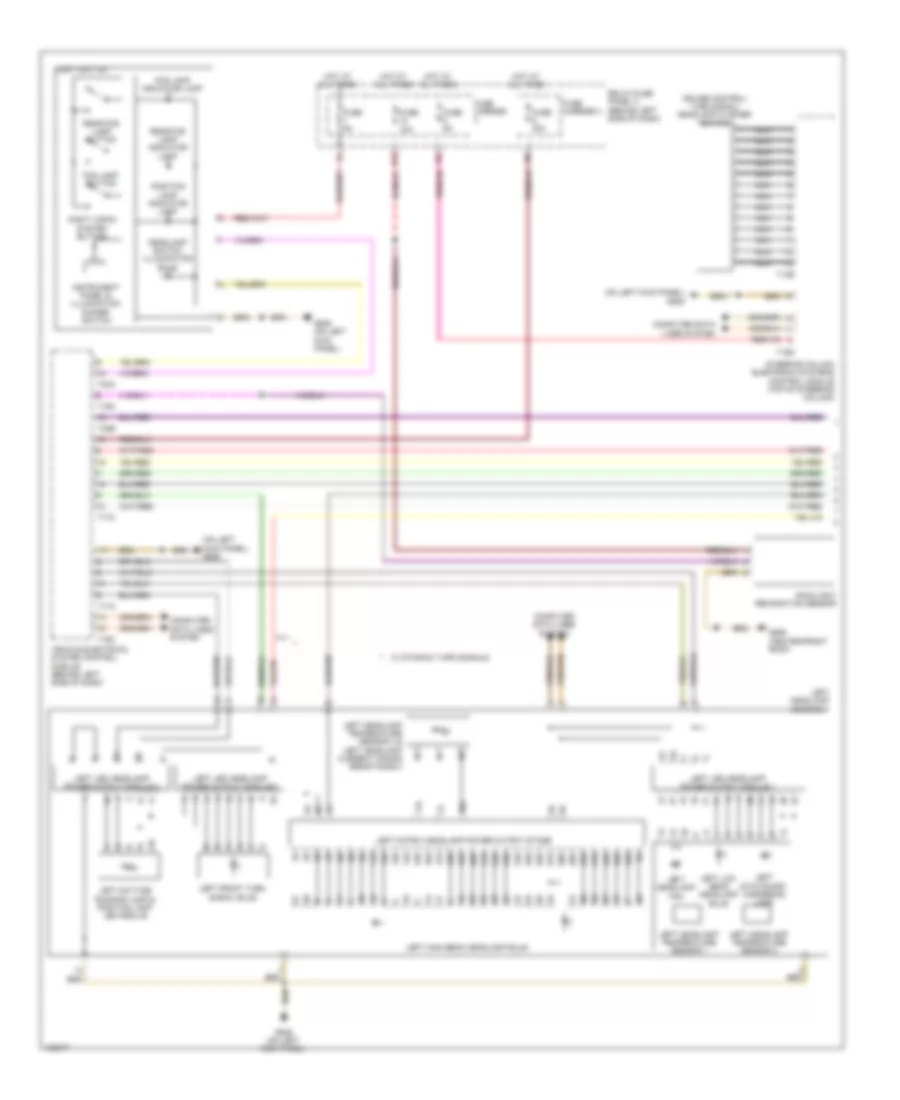
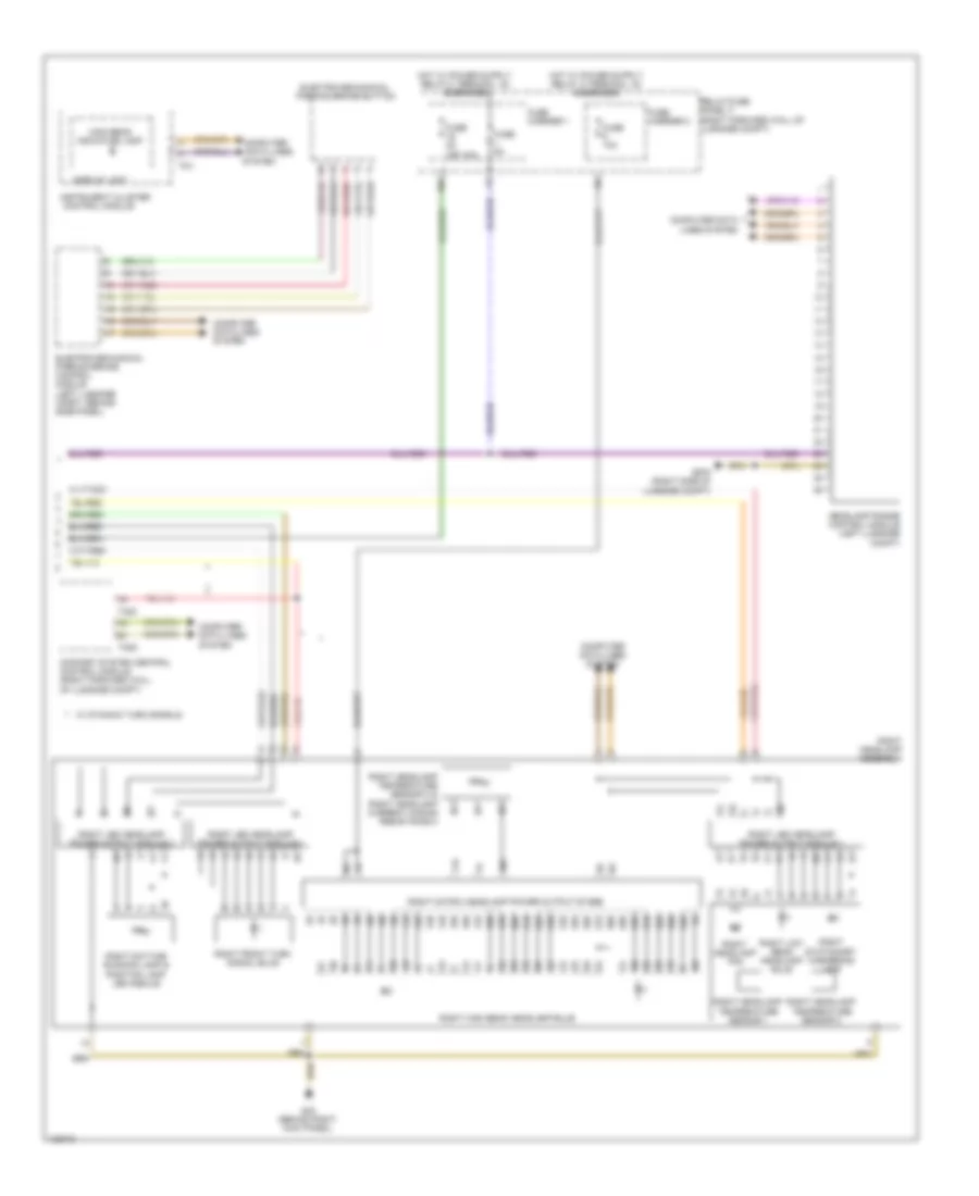
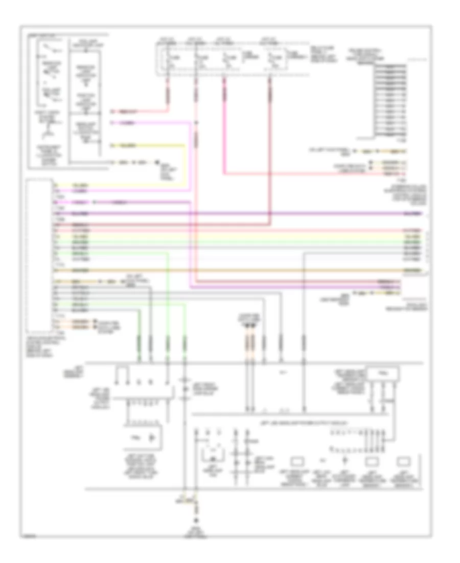
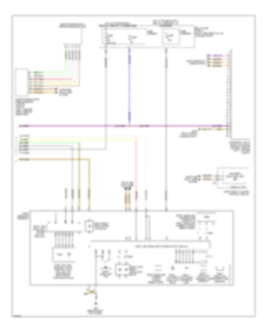
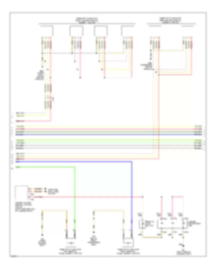
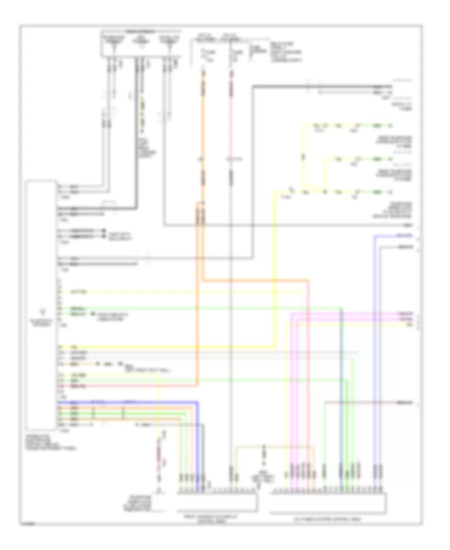
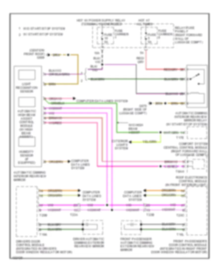
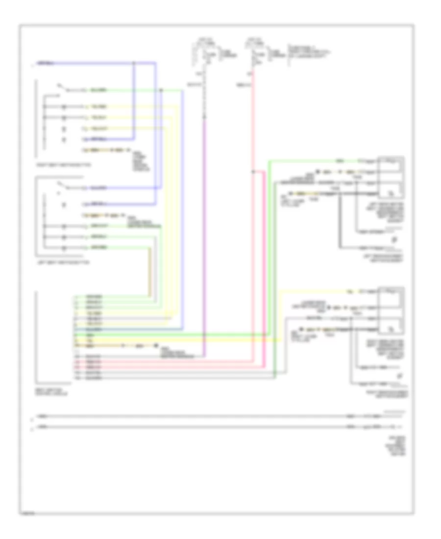
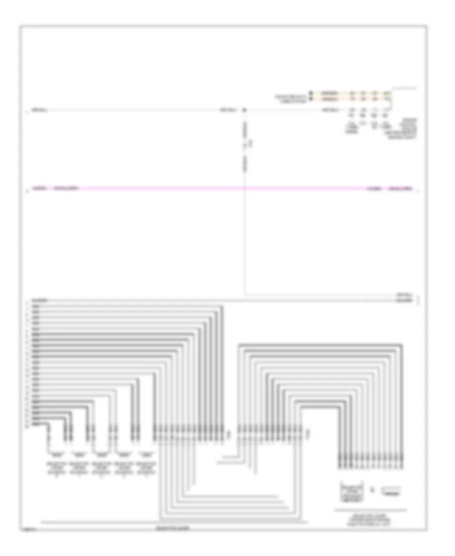
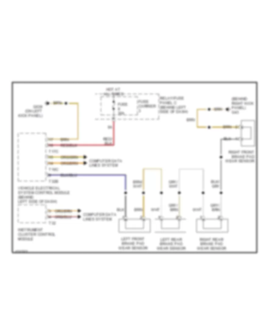
AIR CONDITIONING
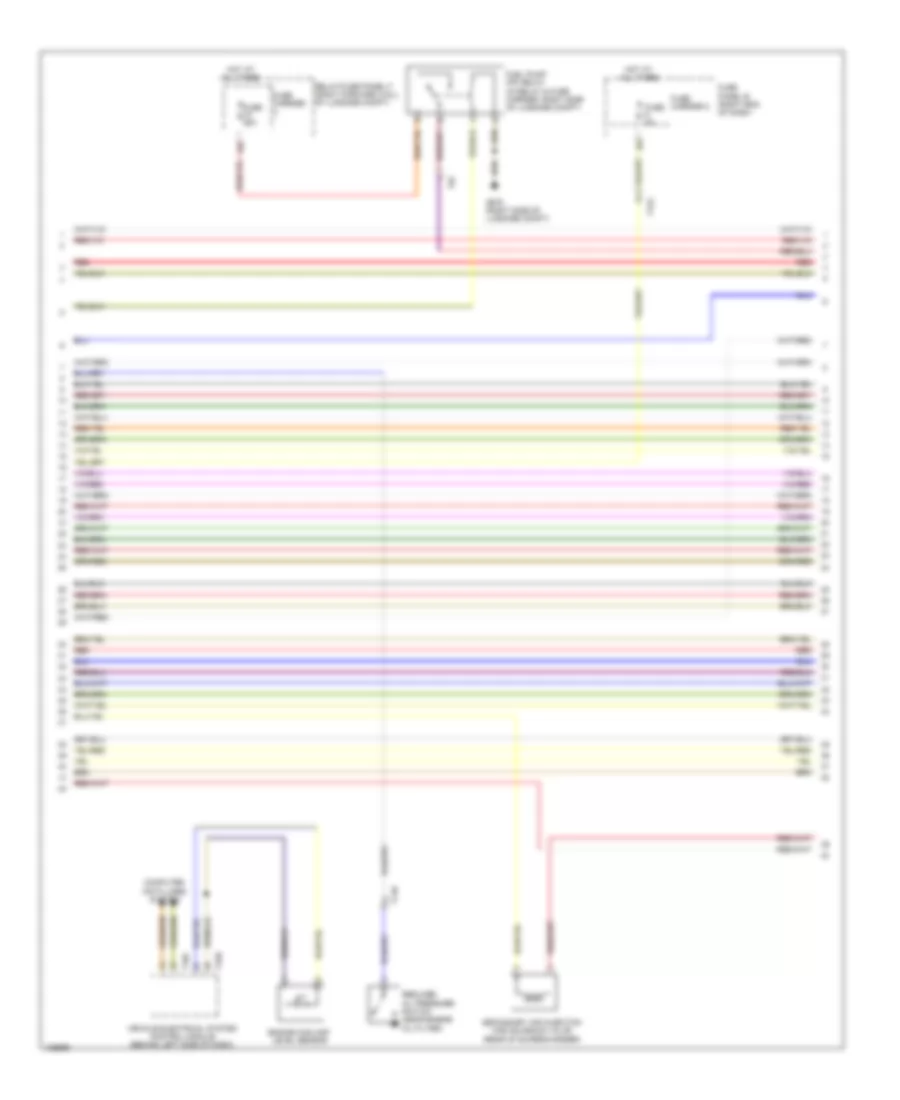
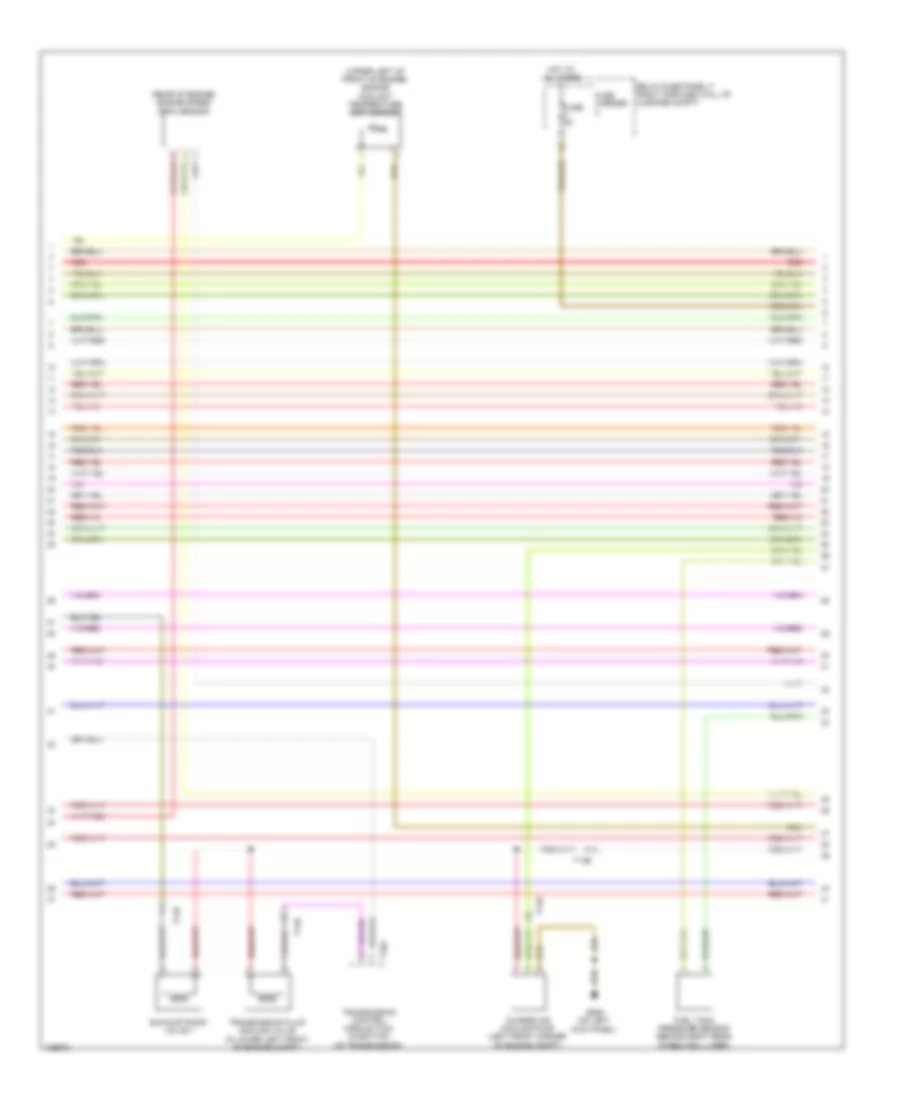
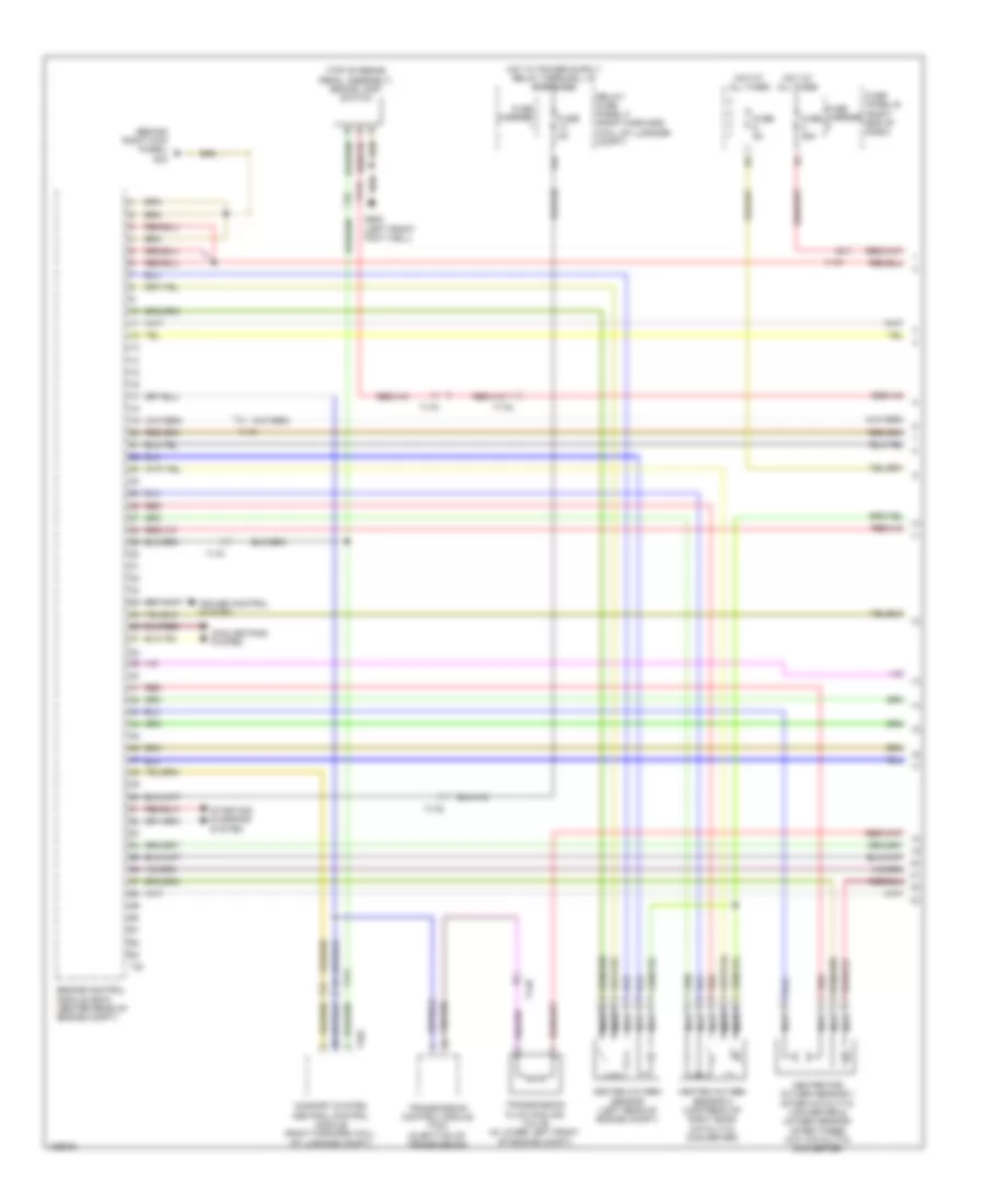
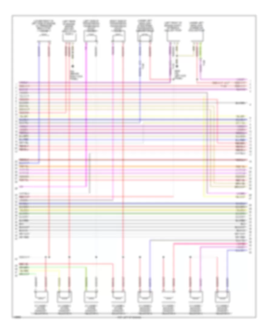
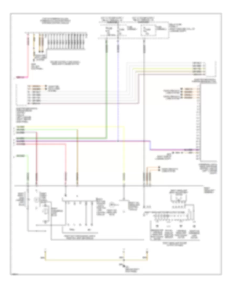
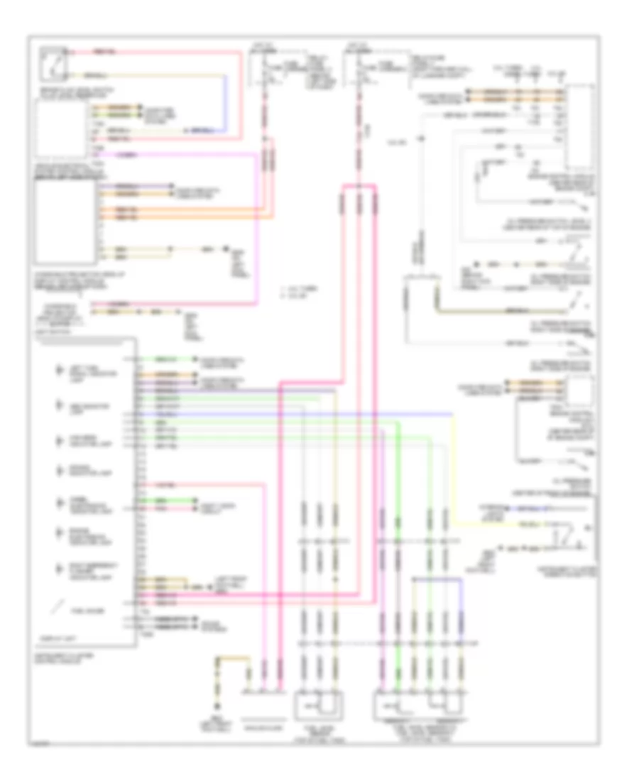
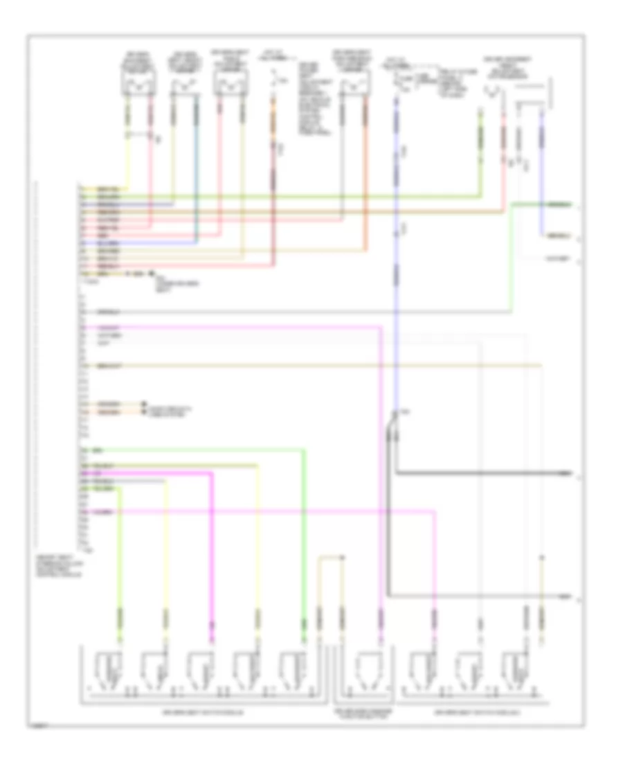
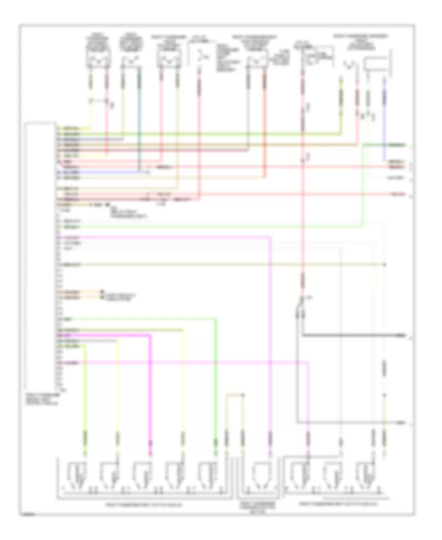
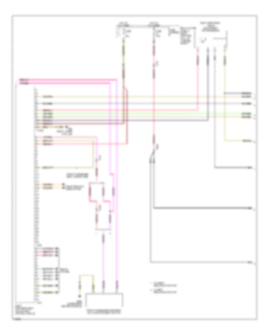
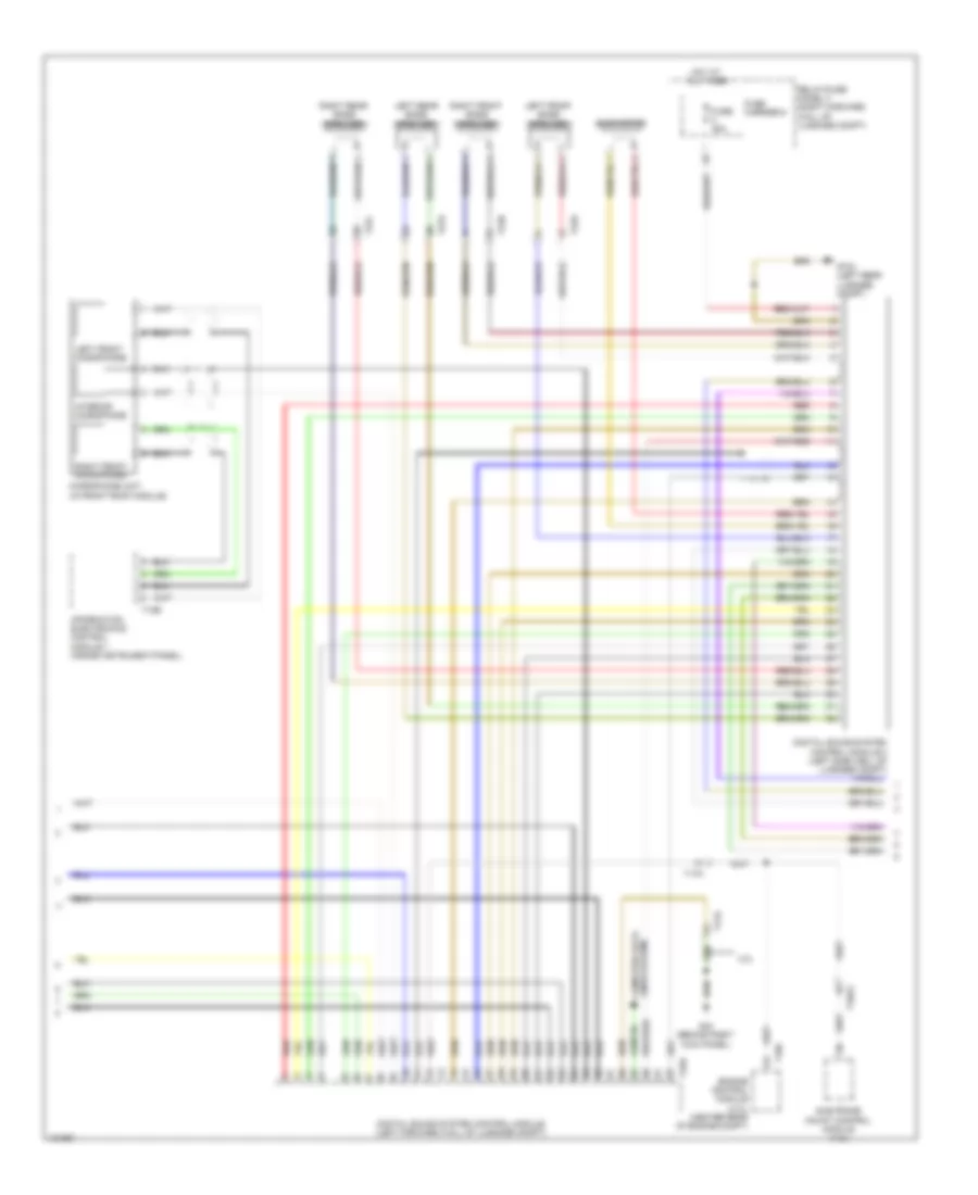
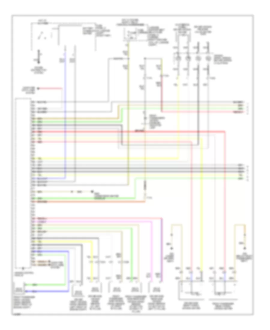
Automatic A/C Wiring Diagram (1 of 4) for Audi A8 Quattro L 2014

List of elements for Automatic A/C Wiring Diagram (1 of 4) for Audi A8 Quattro L 2014:
- (left rear center console) (basic) left b-pillar/ footwell shut-off door motor
- (left rear center console) (basic) left rear upper body vent motor
- (left side dash) left side window defroster door motor
- (right rear center console) (basic) right b-pillar/ footwell shut-off door motor
- (right rear center console) (basic) right rear upper body vent motor
- (right side dash) right side window defroster door motor
- Climatronic control module
- Computer data lines system
- G602 (left front foot well)
- Left center vent position sensor (in left center dash vent)
- Left side vent position sensor (in left side dash vent)
- Red
- Right center vent position sensor (in right center dash vent)
- Right side vent position sensor (in right side dash vent)
- Sunlight photo sensor (under top center of dash)
- T10af
- T16p
- T17i
- T17n
- T20g
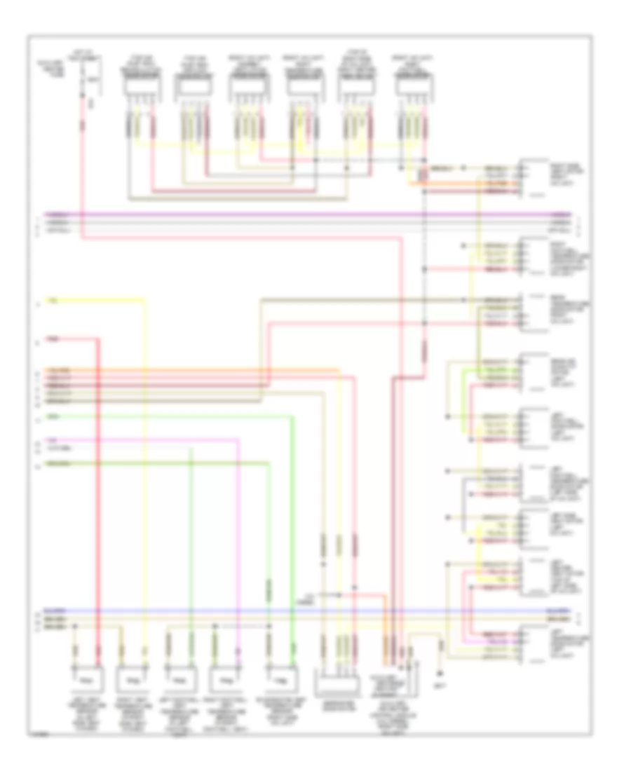
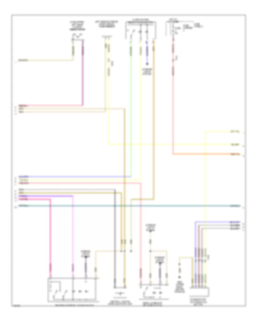
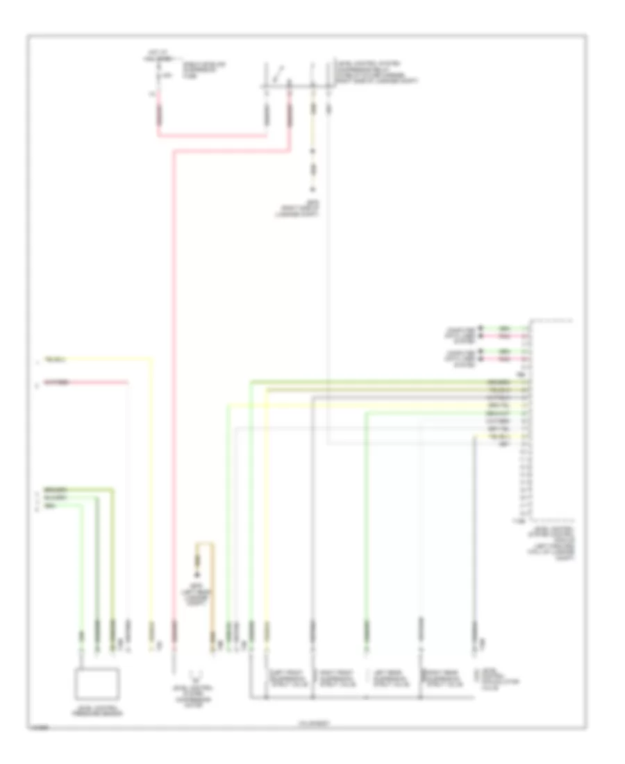
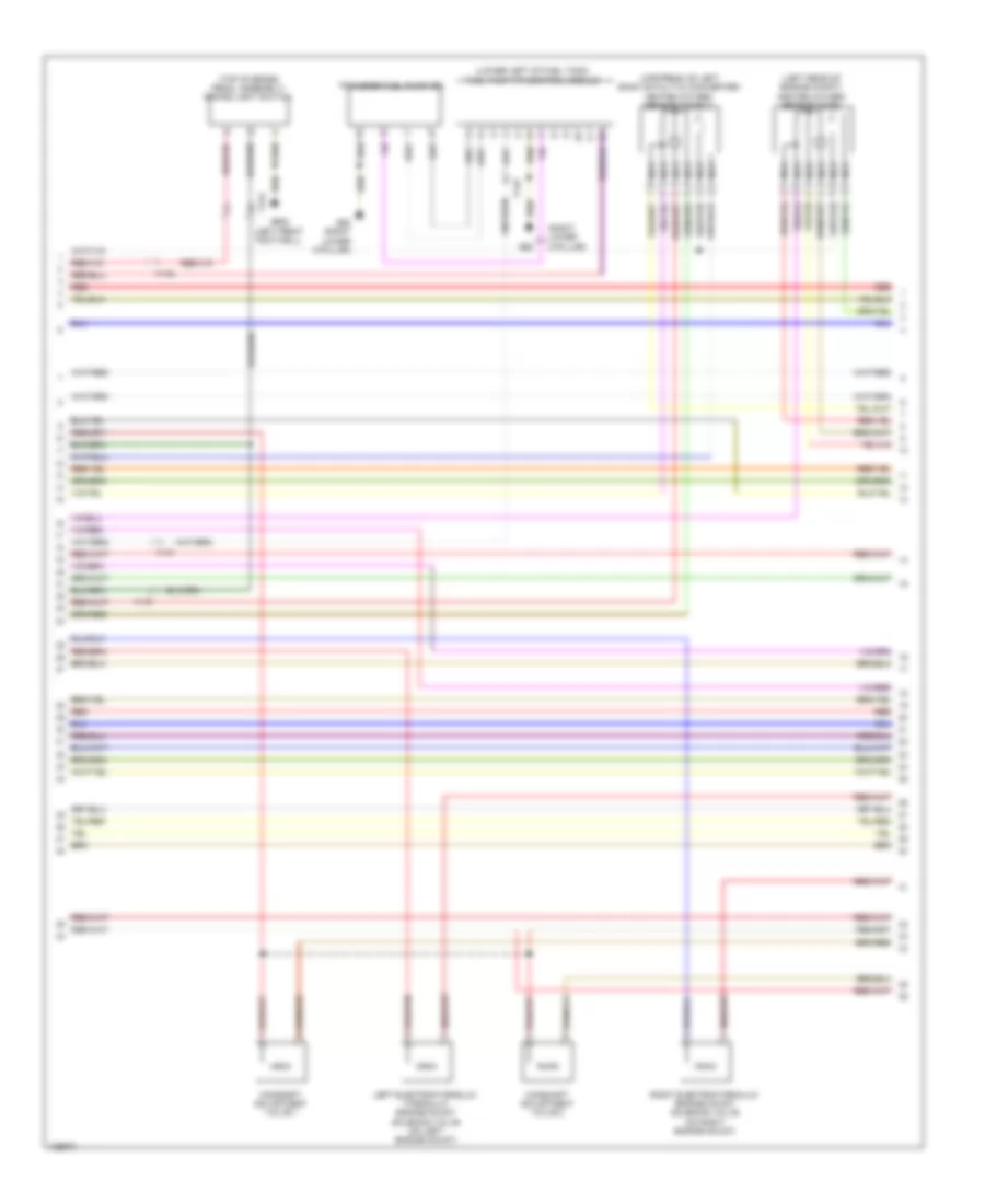
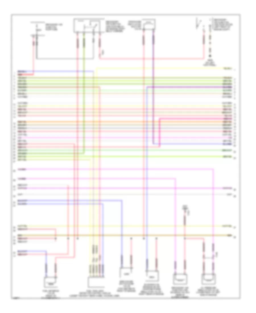
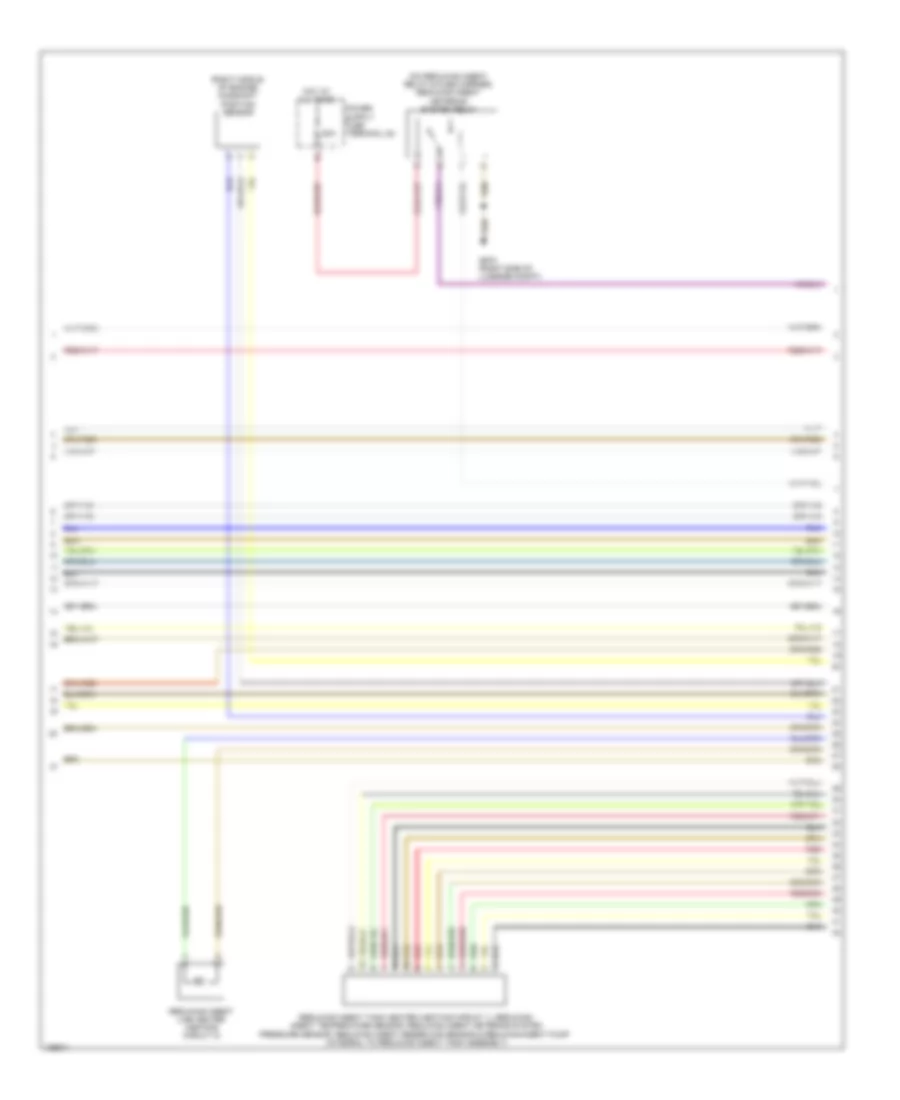
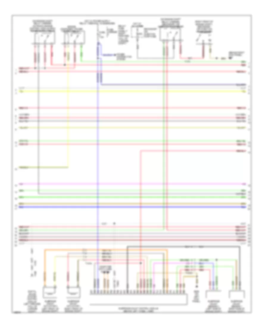
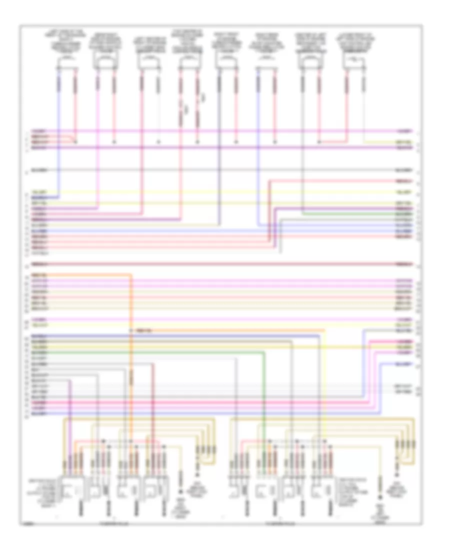
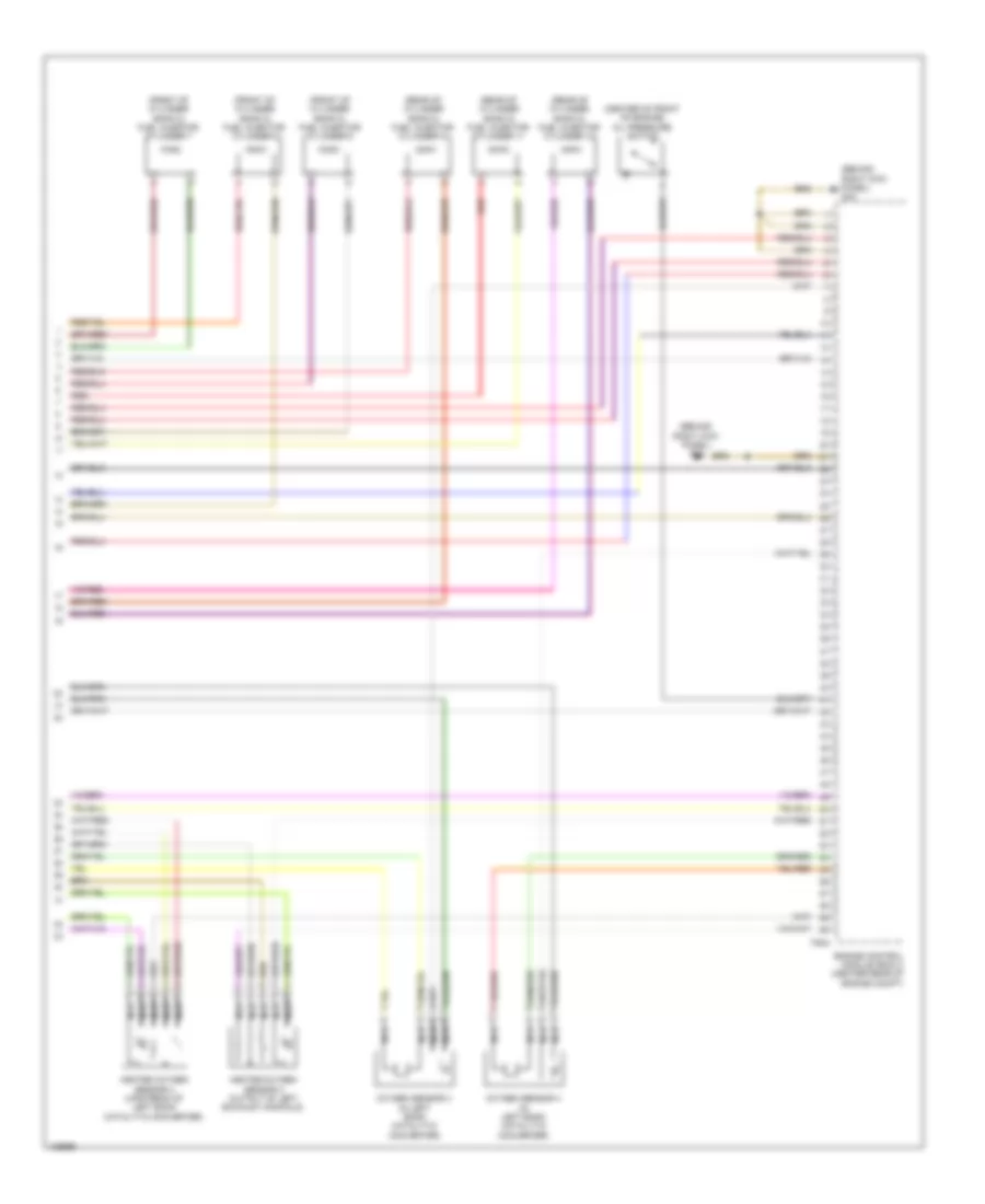
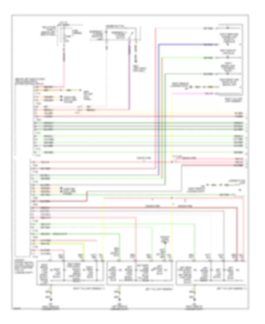
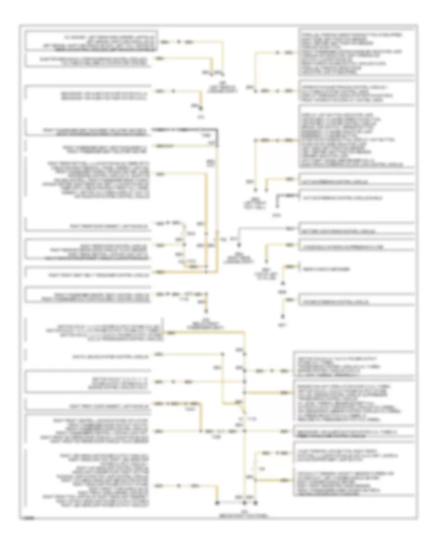
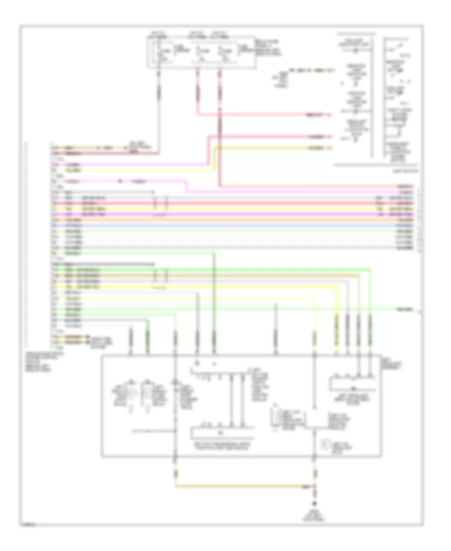
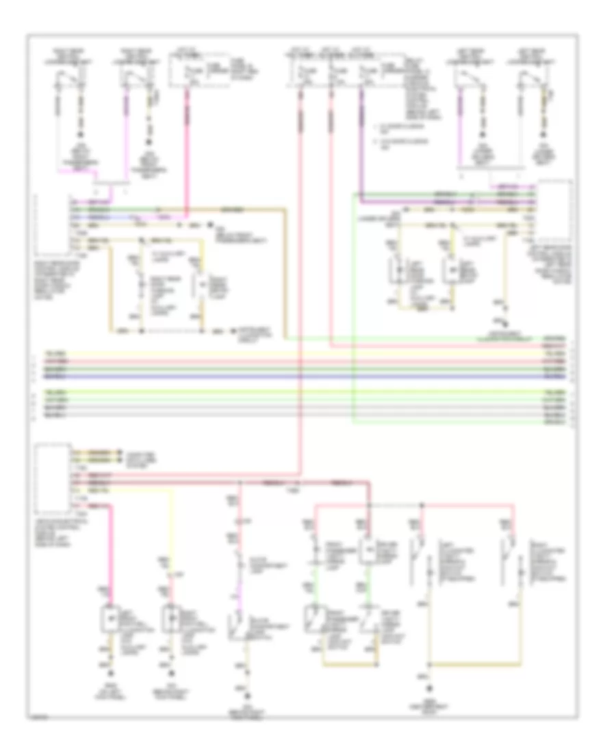
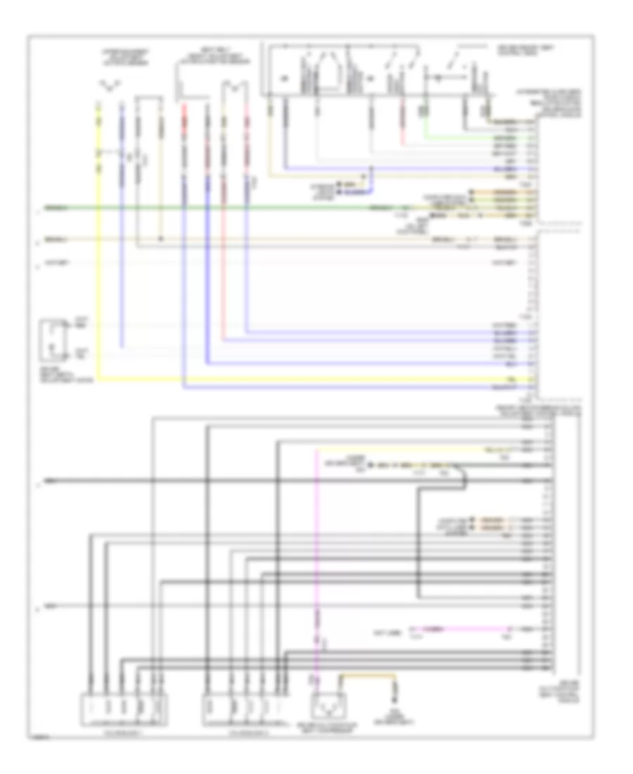
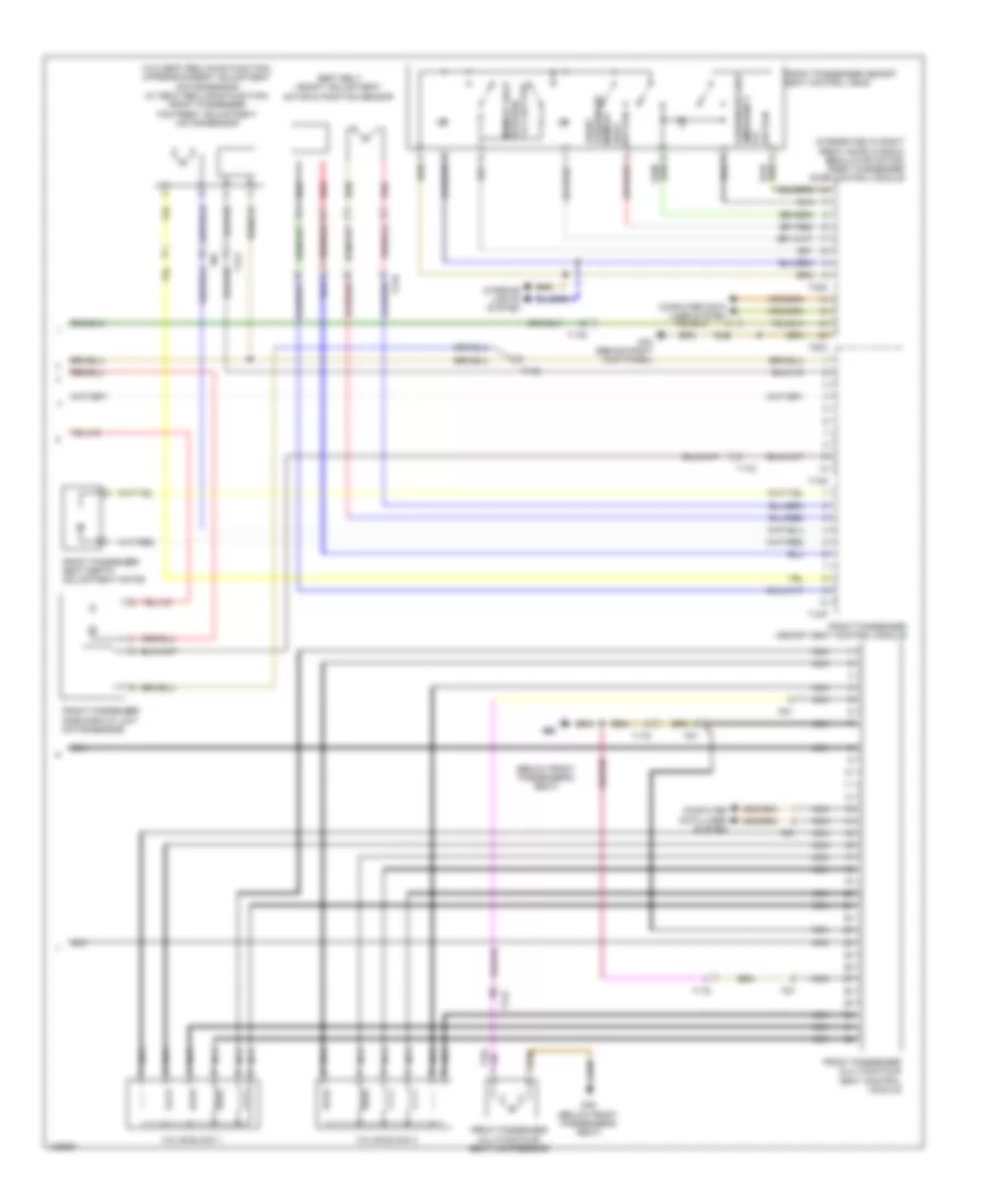
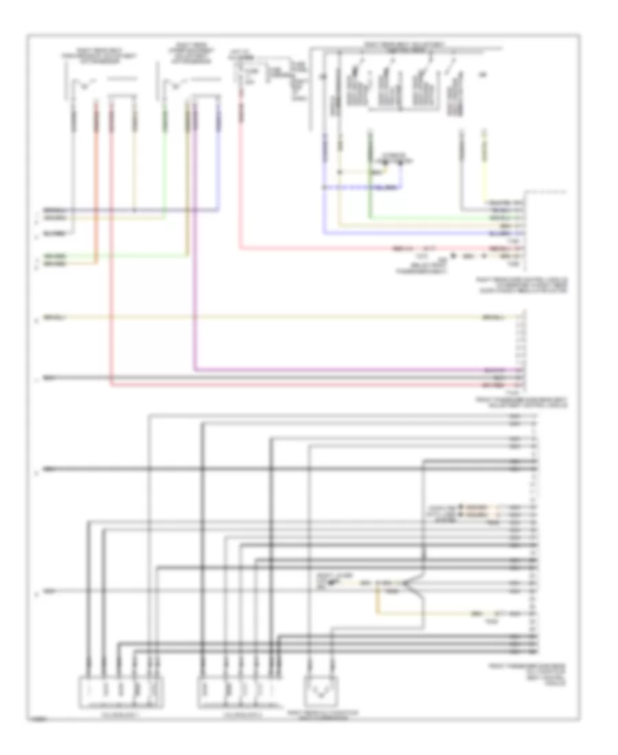
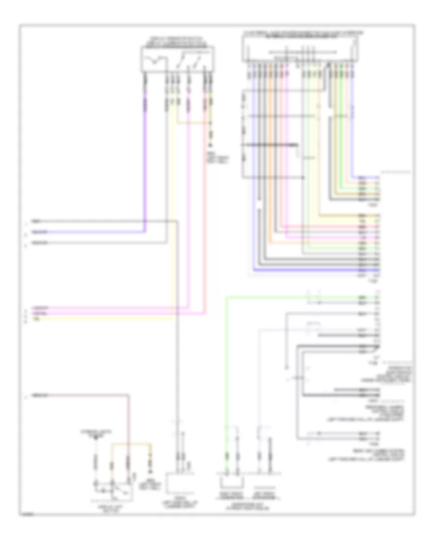
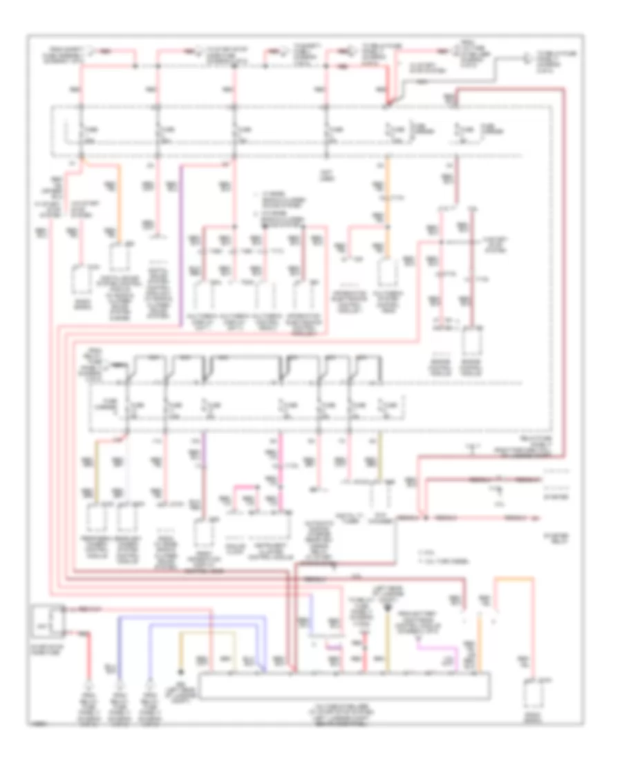
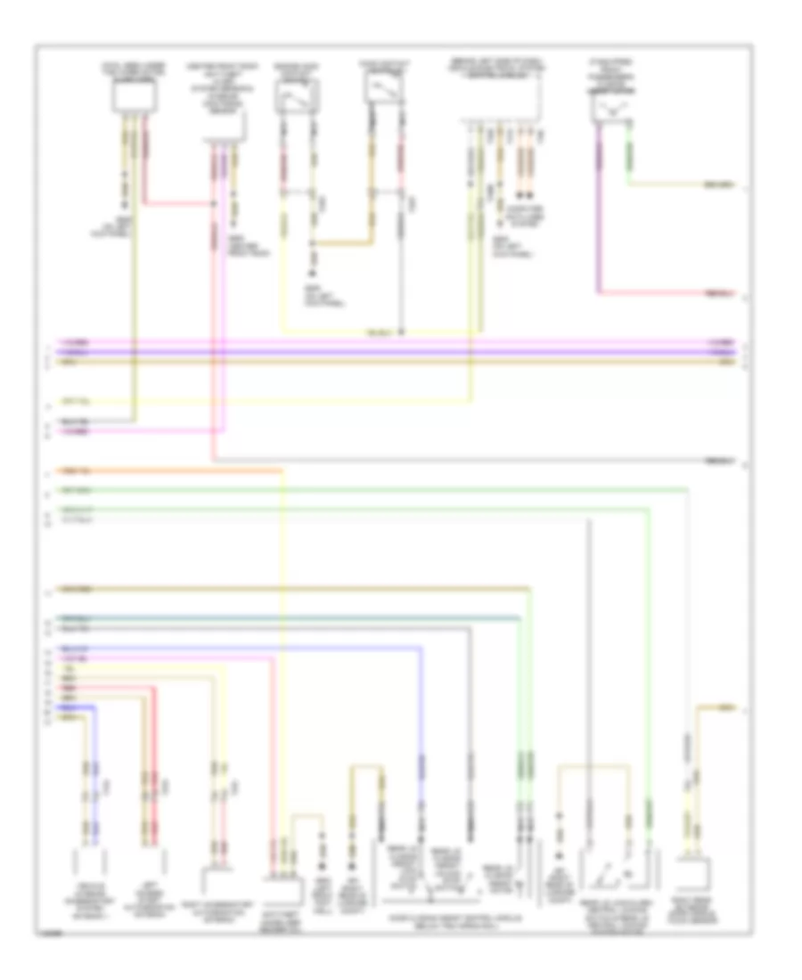
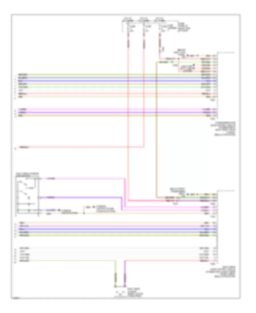
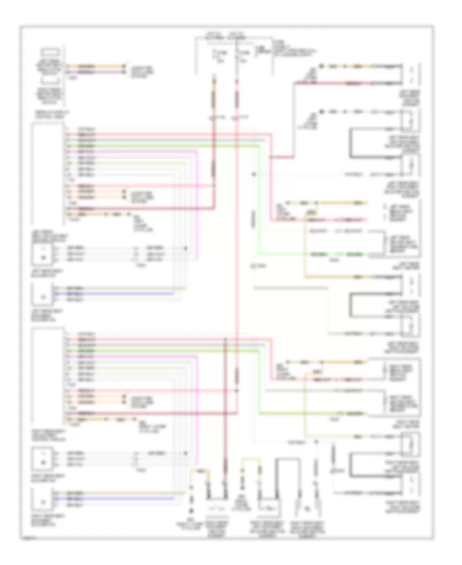
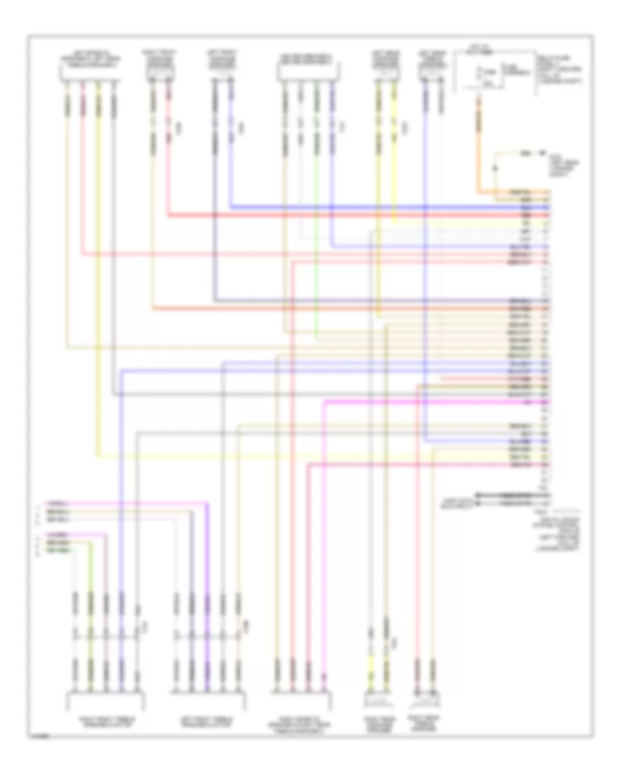
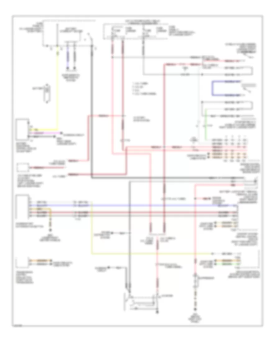
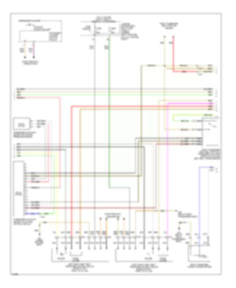
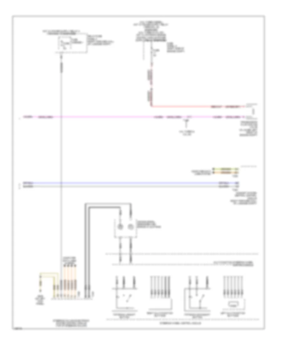
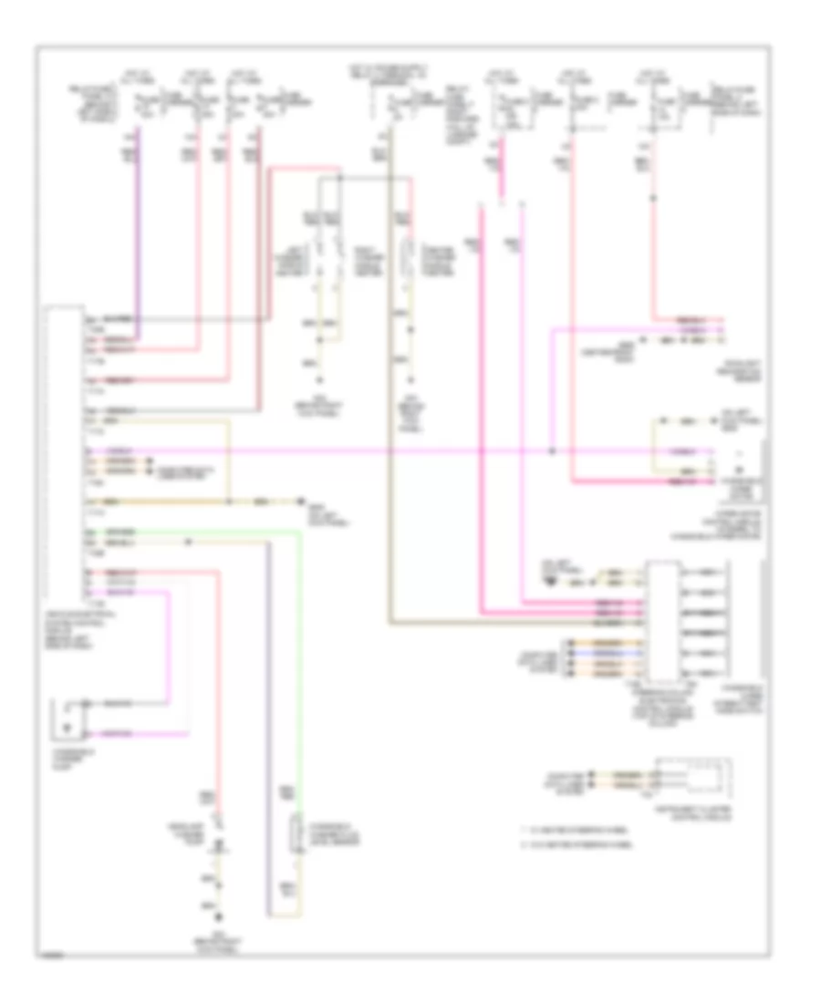
Automatic A/C Wiring Diagram (2 of 4) for Audi A8 Quattro L 2014
List of elements for Automatic A/C Wiring Diagram (2 of 4) for Audi A8 Quattro L 2014:
- (right a/c unit)
- (right a/c unit) indirect ventilation door motor
- (right a/c unit) right footwell door motor
- (top air inlet box) air flow door motor
- (top air inlet box) recirculation door motor
- (top of right side of a/c unit) right center vent motor
- 150a
- 3.0l diesel
- Auxiliary air heater control module (3.0l diesel) (right side a/c unit)
- Auxiliary heater fuse
- Auxiliary heater heating element
- B1a
- Defroster door motor
- Evaporator vent temperature sensor (right side a/c unit)
- G617
- Hot at all times
- Left center vent motor (top of left side of a/c unit)
- Left footwell door motor (left a/c unit)
- Left footwell temperature door motor (left side of a/c unit)
- Left footwell vent temperature sensor (in left footwell vent)
- Left side vent motor (left a/c unit)
- Left temperature door motor (left a/c unit)
- Left vent temperature sensor (in left side vent in dash)
- Rear air quantity motor (left a/c unit)
- Rear temperature door motor (right a/c unit)
- Red
- Right footwell temperature door motor (lower right a/c unit)
- Right footwell vent temperature sensor (in right footwell vent)
- Right side vent motor (right a/c unit)
- Right temperature door motor
- Right vent temperature sensor (in right side vent in dash)
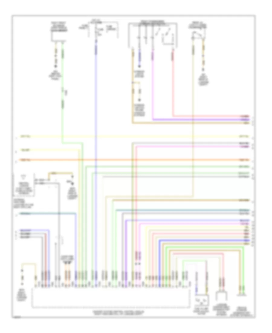
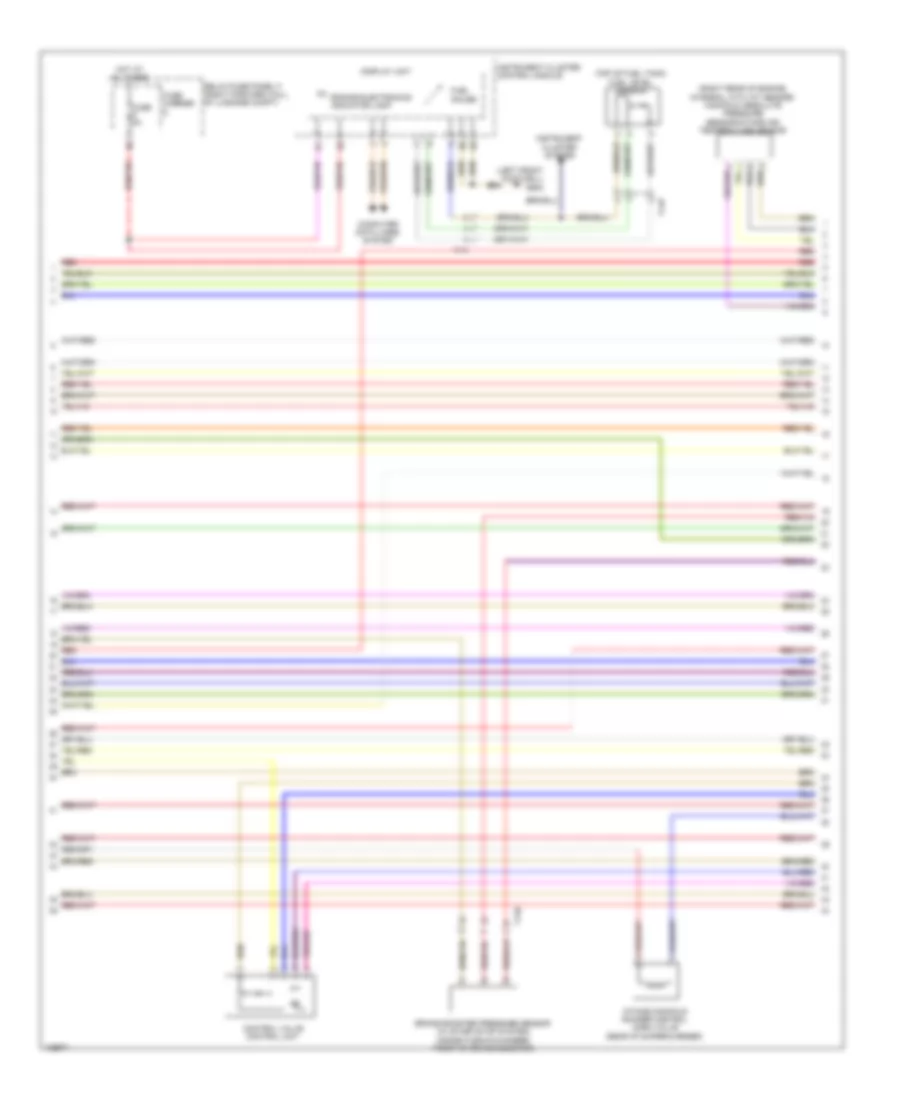
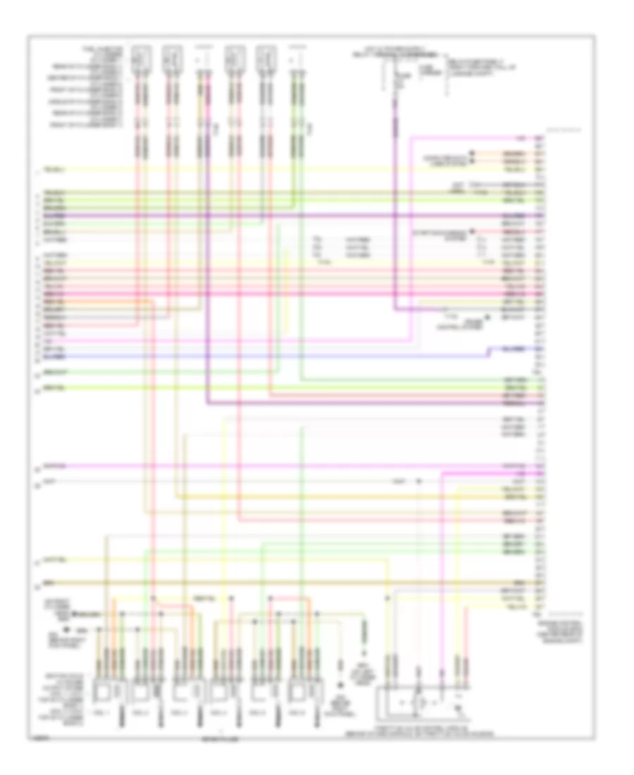
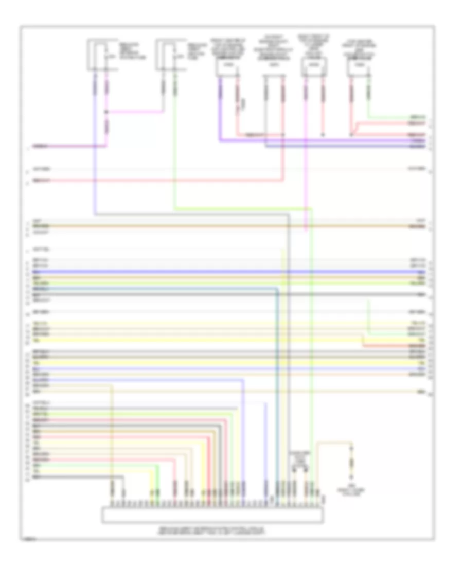
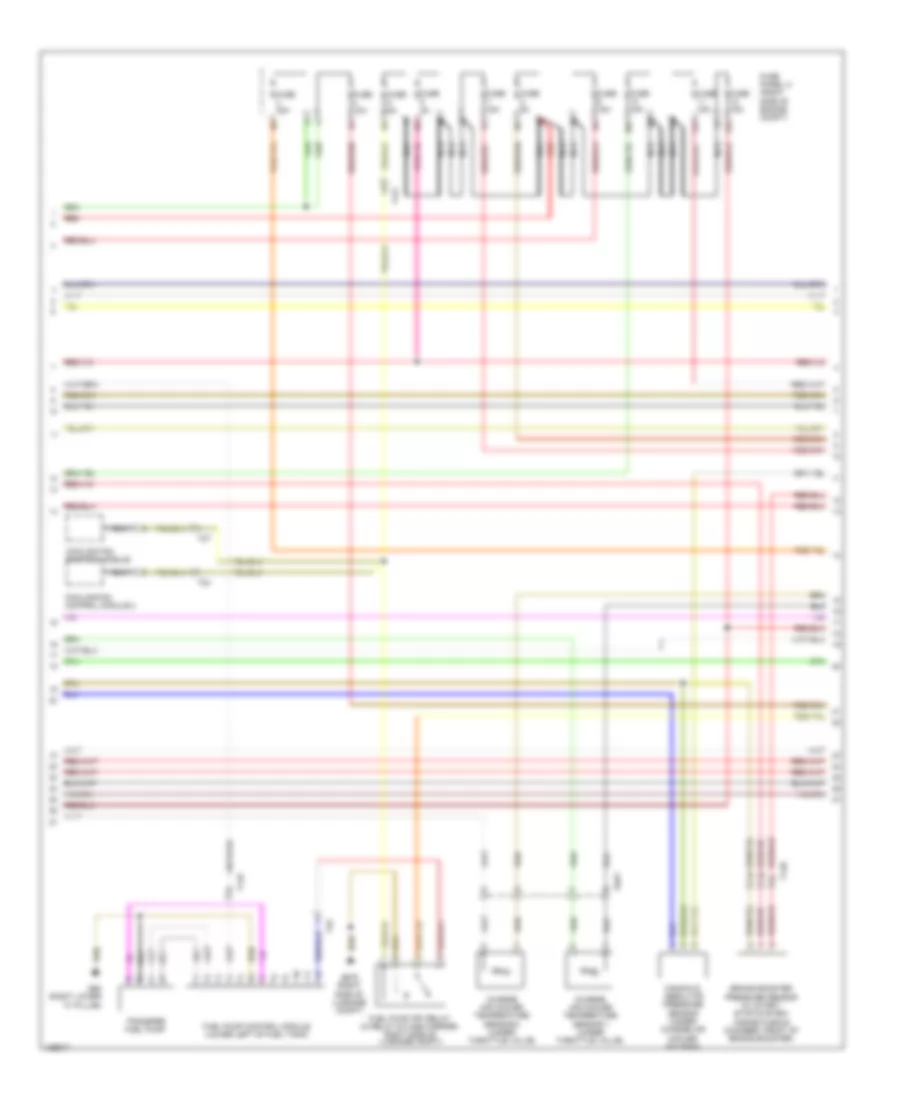
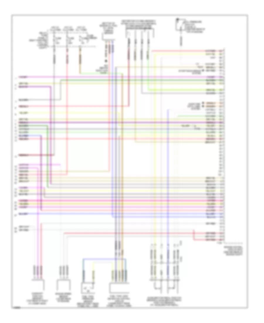
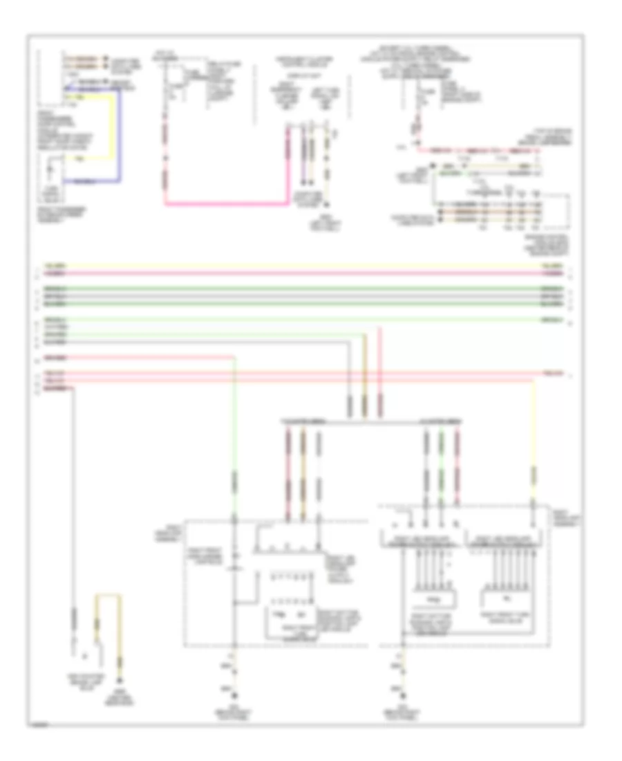
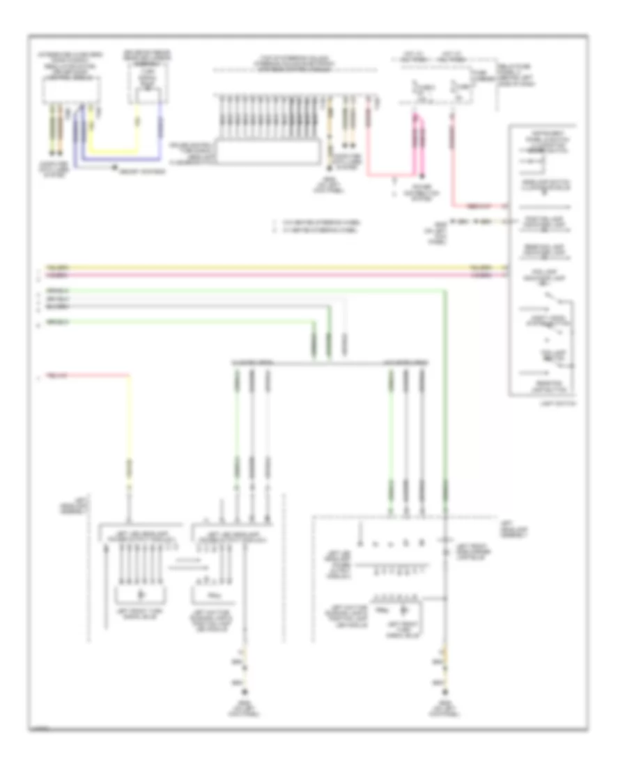
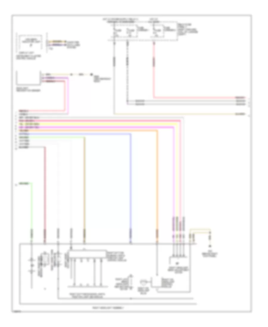
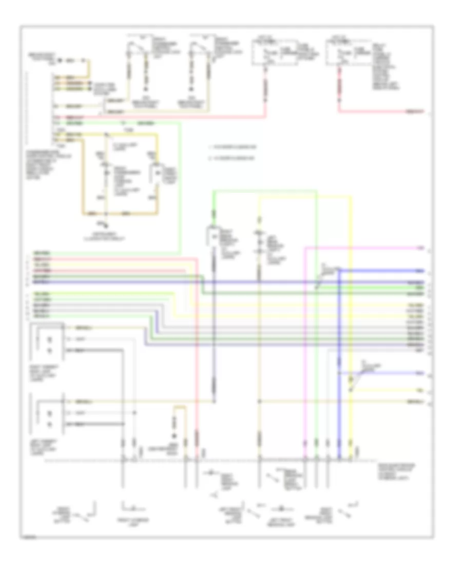
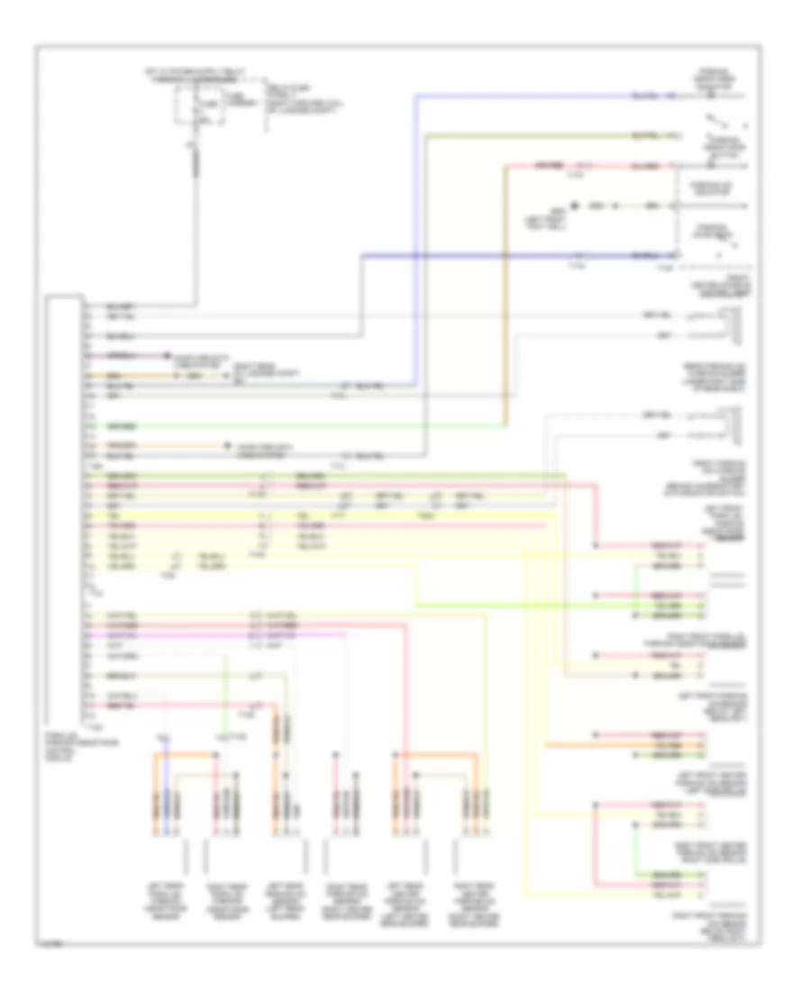
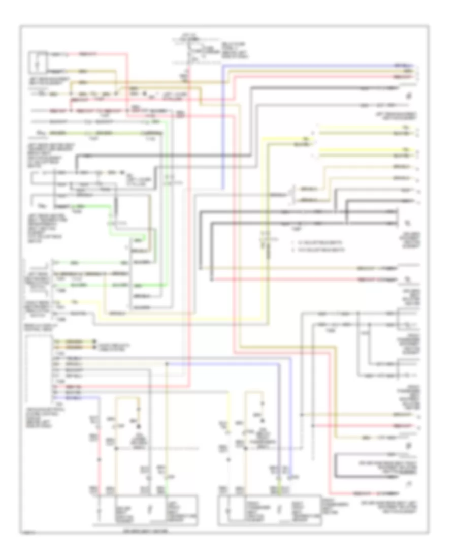
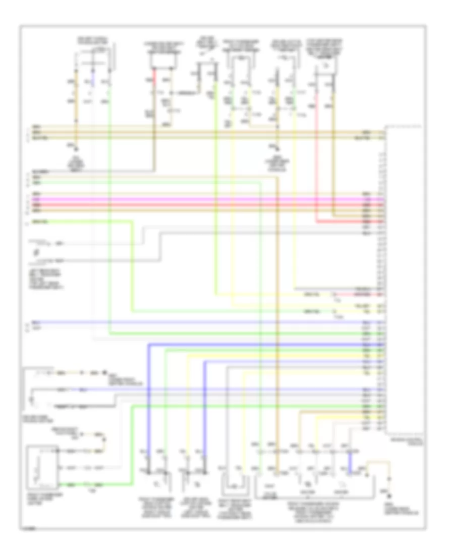
Automatic A/C Wiring Diagram (3 of 4) for Audi A8 Quattro L 2014
List of elements for Automatic A/C Wiring Diagram (3 of 4) for Audi A8 Quattro L 2014:
- (behind radiator) coolant fan
- (behind radiator) coolant fan 2
- (behind right kick panel) g43
- 11a
- 3.0l diesel
- 3.0l sc
- 4.0l turbo
- 6.3l
- After-run coolant pump (4.0l turbo) (left front of engine compt)
- Charge air cooling pump (4.0l turbo & 3.0l sc) (4.0l turbo: under left headlight) (3.0l sc: left front corner of engine compt)
- Computer data lines system
- Coolant fan control module (behind radiator)
- Coolant fan control module 2 (behind radiator)
- Coolant fan fuse 40a 60a
- Coolant fan second speed fuse 40a 60a
- Coolant recirculation pump (6.3l) (installed in plenum chamber)
- Engine control module (ecm) (6.3l: left rear corner of engine compt) (except 6.3l: center rear of engine compt)
- Engine coolant circulation pump 2 (4.0l turbo) (left rear of engine)
- Engine coolant temperature (ect) sensor (3.0l diesel: front left of top of engine) (3.0l sc: upper left of front of engine) (4.0l turbo & 6.3l: right center of front of engine)
- Engine coolant temperature (ect) sensor on radiator outlet (4.0l turbo & 3.0l diesel) (3.0l diesel: right front of engine compt) (4.0l turbo: left front of engine compt)
- Fuse 10a
- Fuse 15a
- Fuse 5a
- Fuse panel a (right side of engine compt)
- G639 (on left kick panel)
- G685 (right front wheelwell)
- Hot at all times
- Interior lights system
- Left & right rear upper body vent position sensor (in left/right rear upper body vent)
- Map controlled engine cooling thermostat (4.0l turbo & 3.0l diesel) (3.0l diesel: front center of top of engine) (4.0l turbo: lower front of left side of engine)
- Nca
- Rear intake air temperature sensor (basic) (bottom center rear a/c unit)
- Red
- T105
- T10af
- T10an
- T14b
- T17g
- T17n
- T2t
- T2u
- T60
- T8ap
- T91
- T94
- Terminal 30 wire junction 2
- W/ trailer socket
- W/o trailer socket
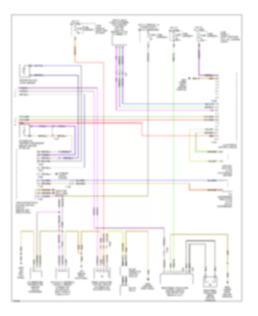
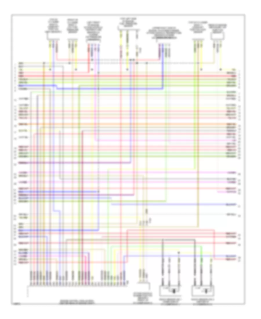
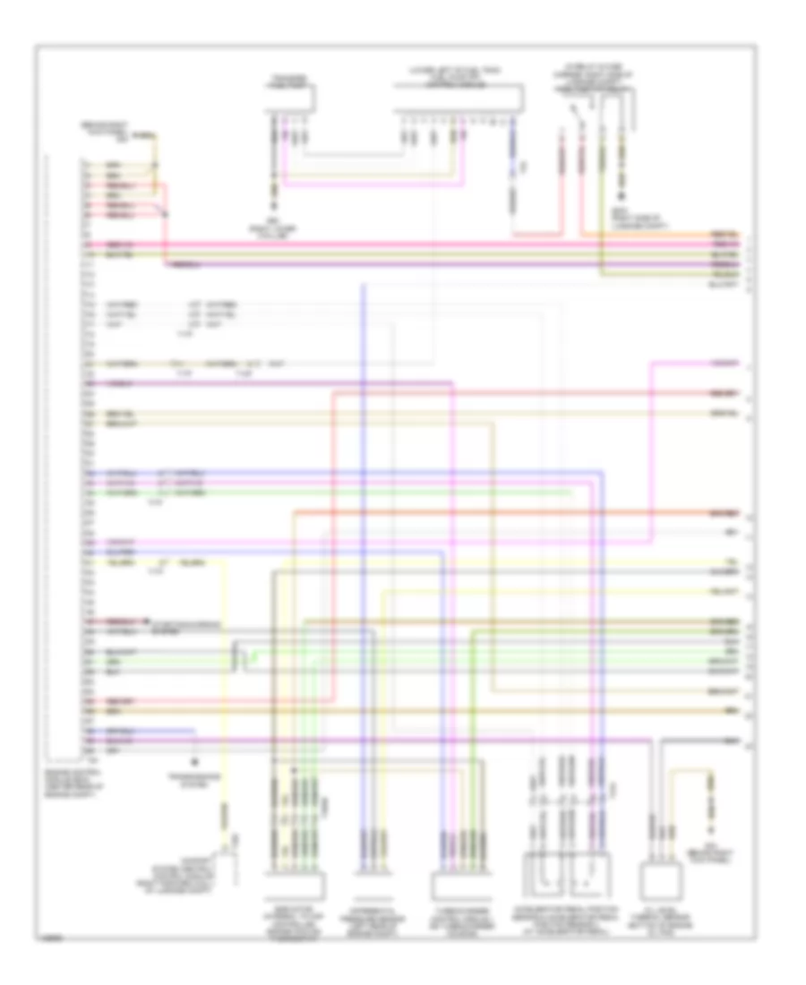
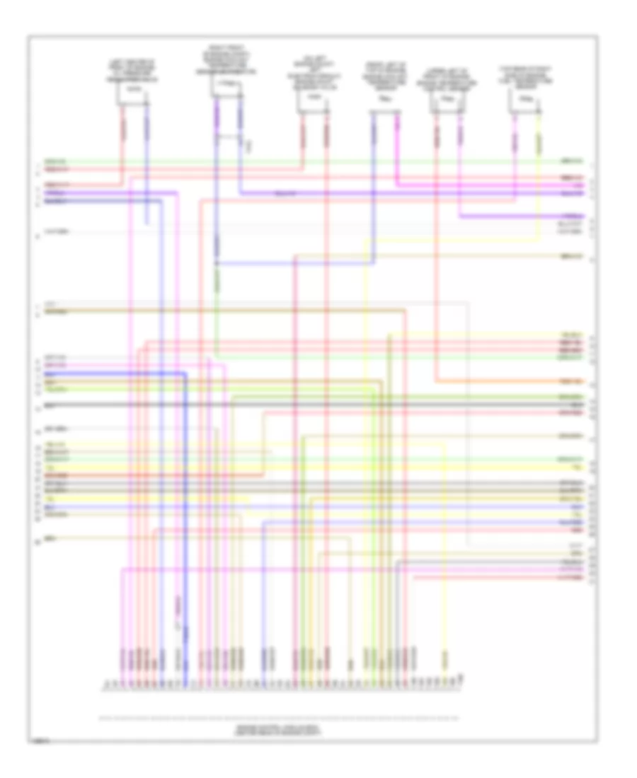
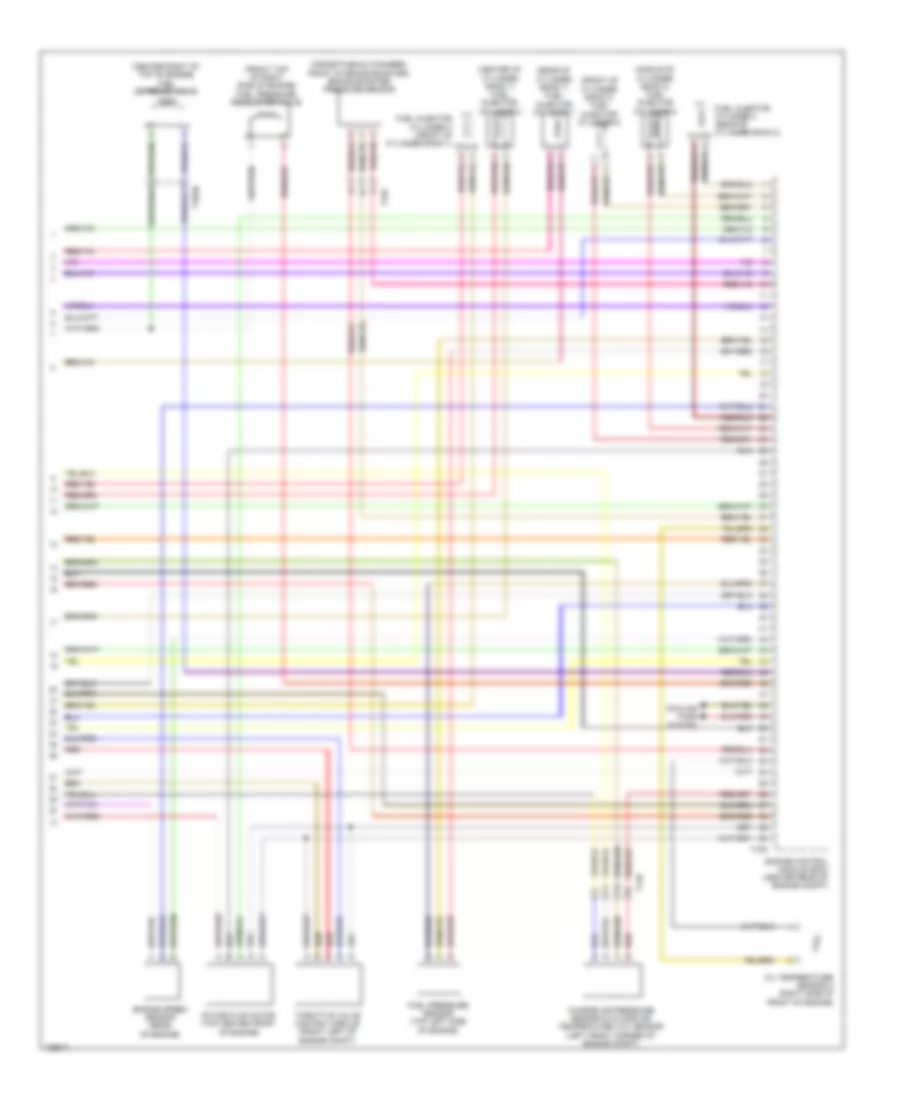
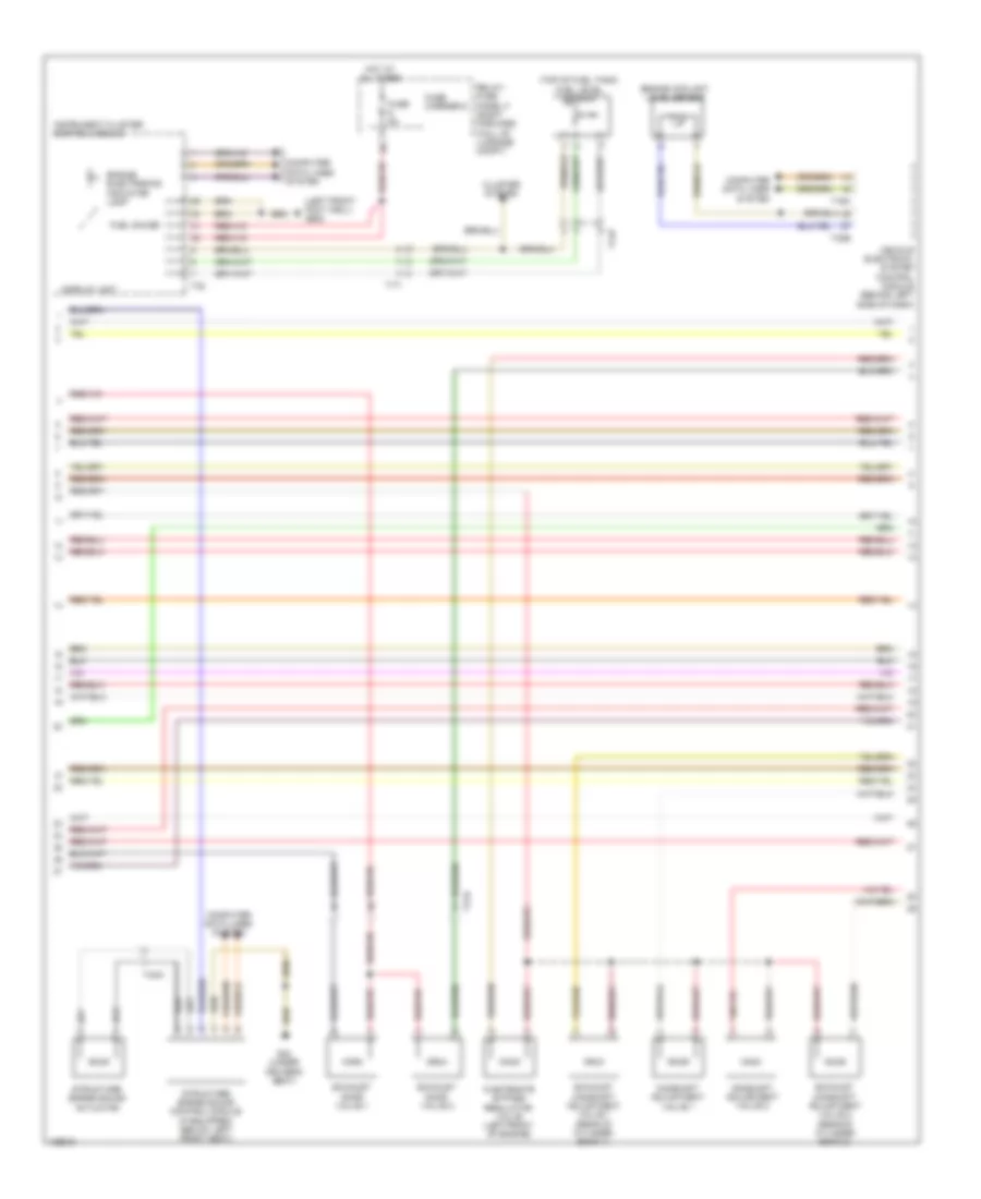
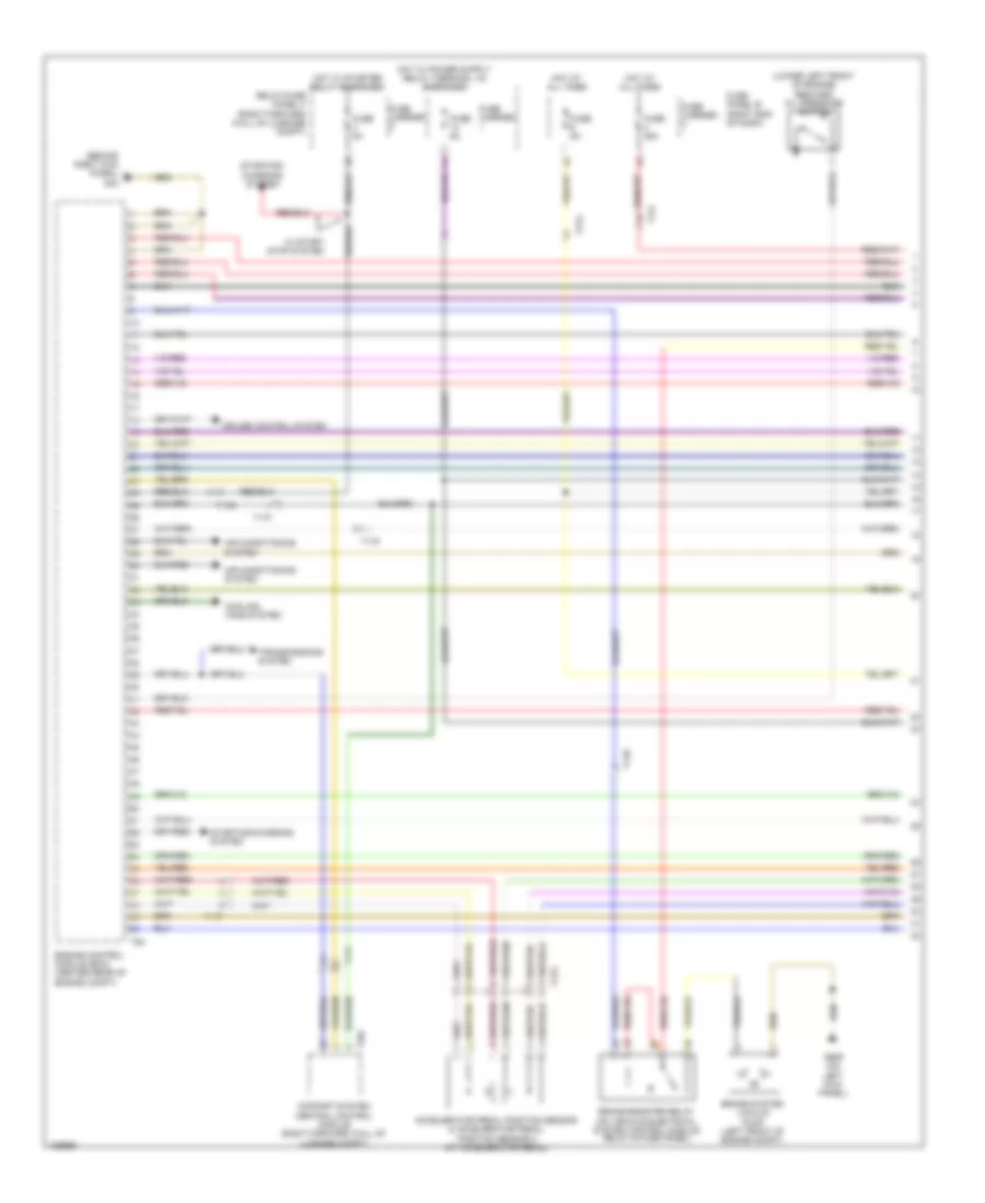
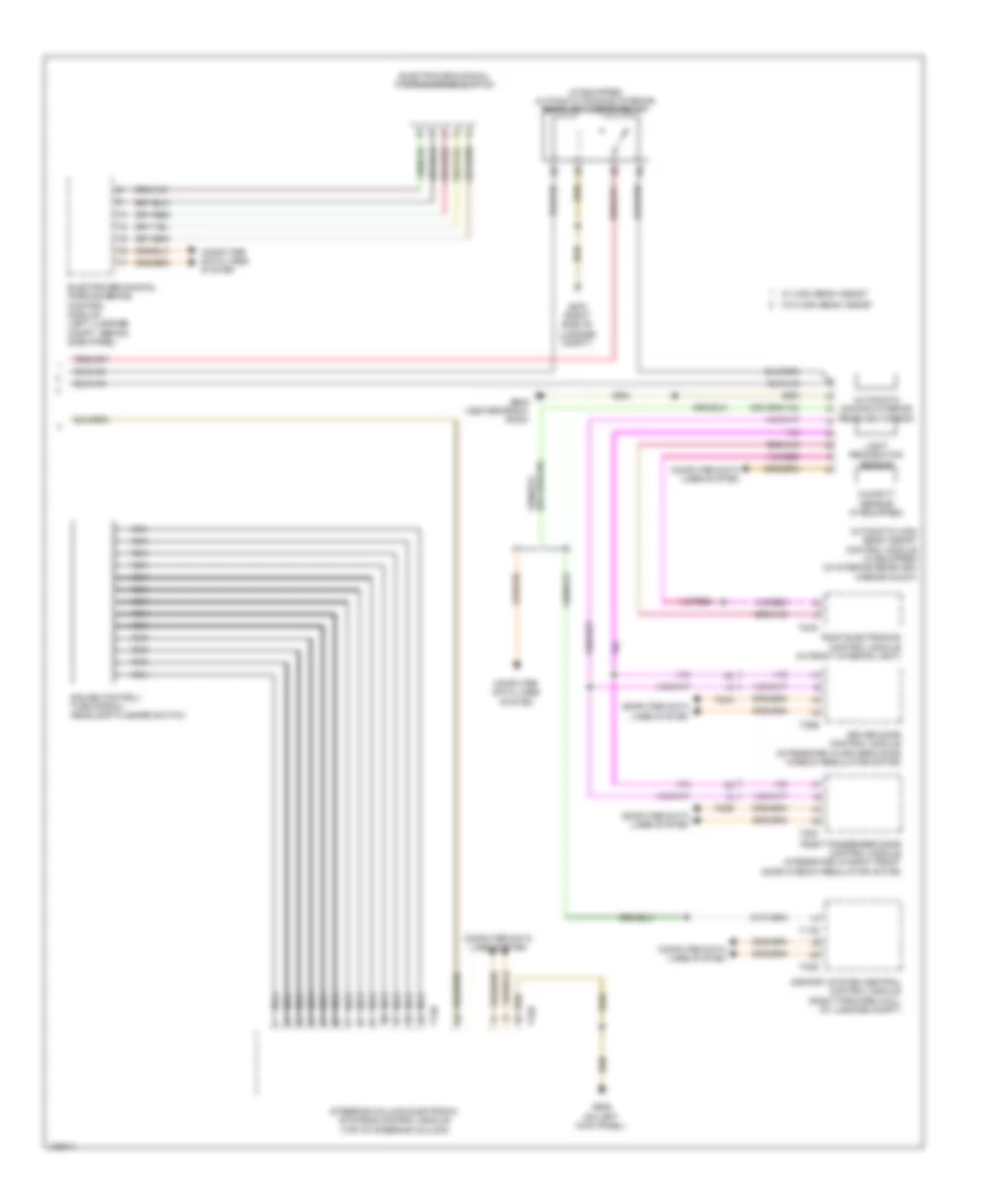
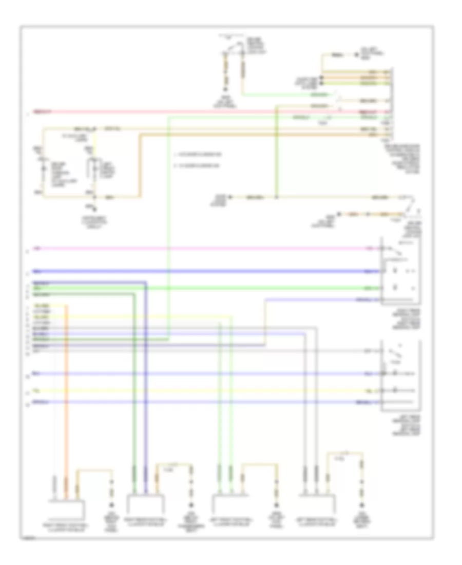
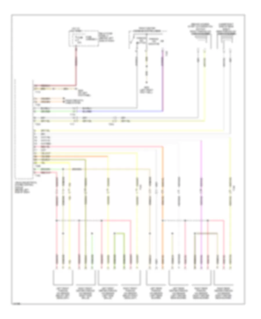
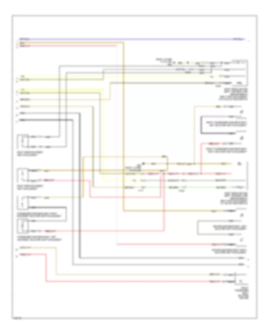
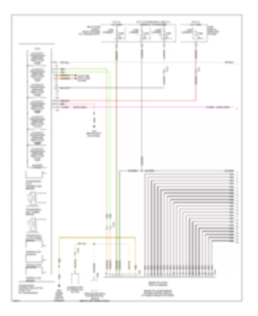
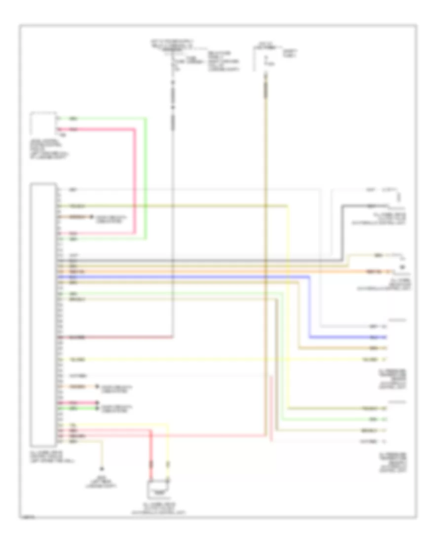
Automatic A/C Wiring Diagram (4 of 4) for Audi A8 Quattro L 2014
List of elements for Automatic A/C Wiring Diagram (4 of 4) for Audi A8 Quattro L 2014:
- (behind left side of dash)
- (installed in plenum chamber) (w/o parking heater) coolant recirculation pump
- 10a
- 11a
- 17h
- A/c compressor regulator valve (on a/c compressor)
- A/c pressure/ temperature sensor (on a/c condenser)
- Air quality sensor & humidity sensor in fresh air intake duct (right side of plenum unit)
- Climatronic control module
- Computer data lines system
- Coolant shut-off valve (w/o parking heater)
- Engine coolant level sensor
- Fresh air blower control module (on fresh air blower motor)
- Fuse 15a
- Fuse 20a
- Fuse 40a
- Fuse 5a
- Fuse carrier 2
- Fuse carrier 3
- Fuse carrier 4
- Fuse panel b (right end of dash)
- Fuse panel f (right forward wall of luggage compt)
- G43 (behind right kick panel)
- G639 (on left kick panel)
- G687 (under front center console)
- G688 (under rear center console)
- G689 (center/ front roof)
- Hot at all times
- Interior lights system
- Nca
- Outside air temperature sensor (behind center of grille)
- Rear fresh air blower (rear center console)
- Rear fresh air blower control module (center bottom rear a/c unit)
- Red
- Solar cells
- Solar operation control module
- T12ai
- T14a
- T14b
- T16c
- T17b
- T17k
- T17m
- T17n
- T2ip
- T32a
- T32b
- T6as
- T6at
- T8ab
- Vehicle electrical system control module
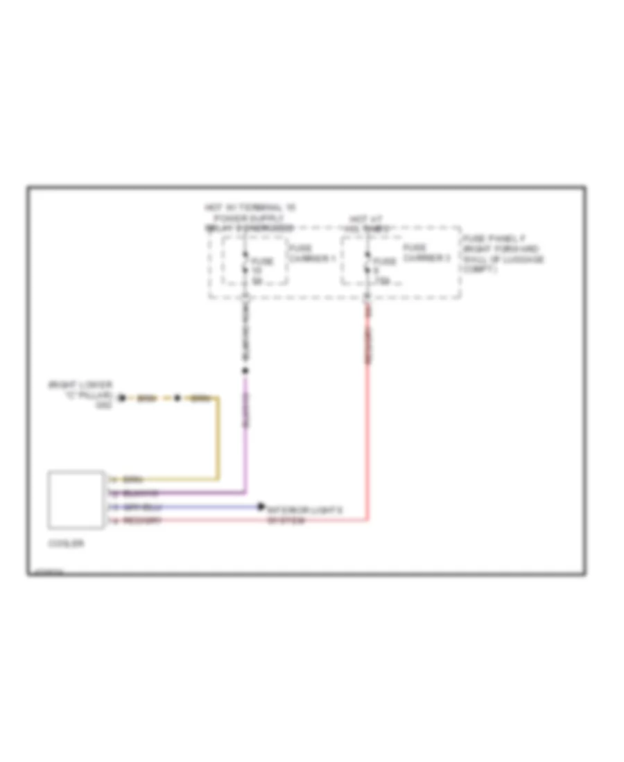
Cool Box Wiring Diagram for Audi A8 Quattro L 2014
List of elements for Cool Box Wiring Diagram for Audi A8 Quattro L 2014:
- (right lower "c" pillar) g62
- 10a
- Cooler
- Fuse 15a
- Fuse 5a
- Fuse carrier 1
- Fuse carrier 3
- Fuse panel f (right forward wall of luggage compt)
- Hot at all times
- Interior lights system
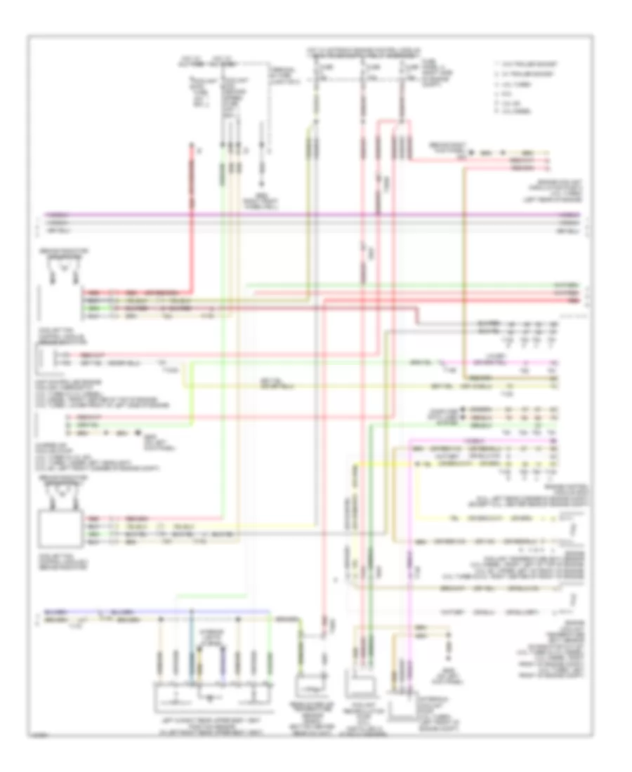
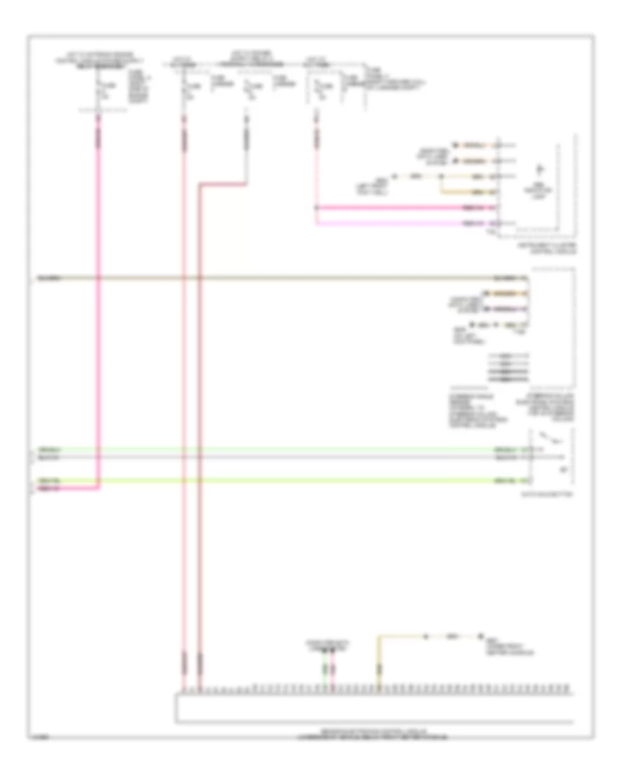
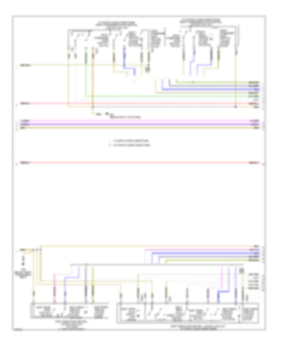
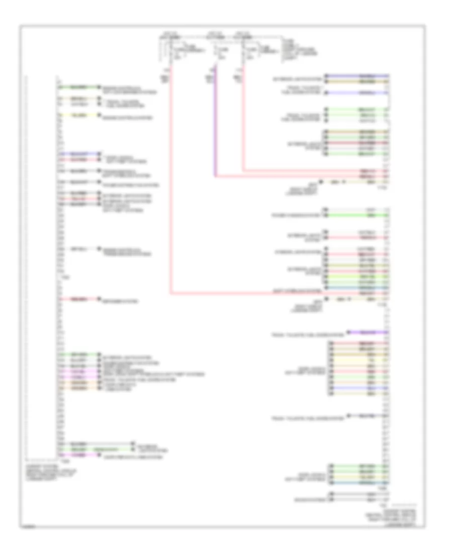
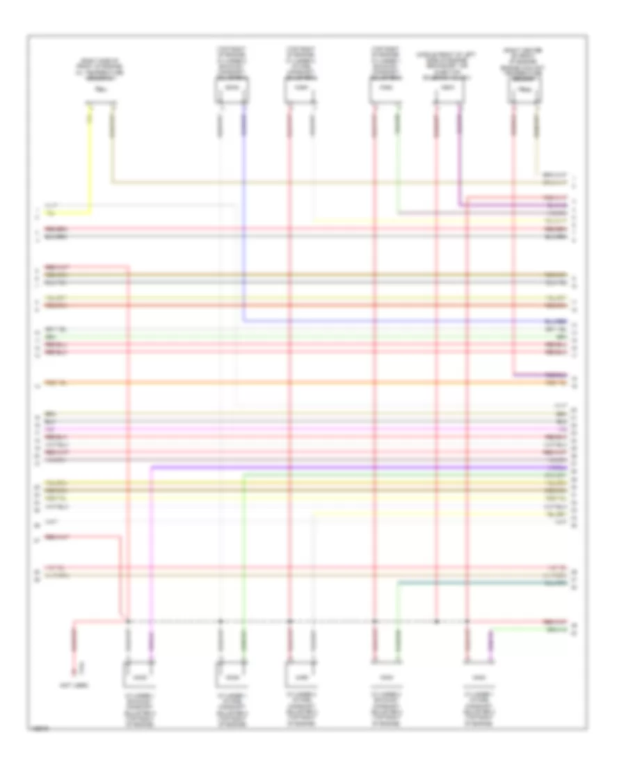
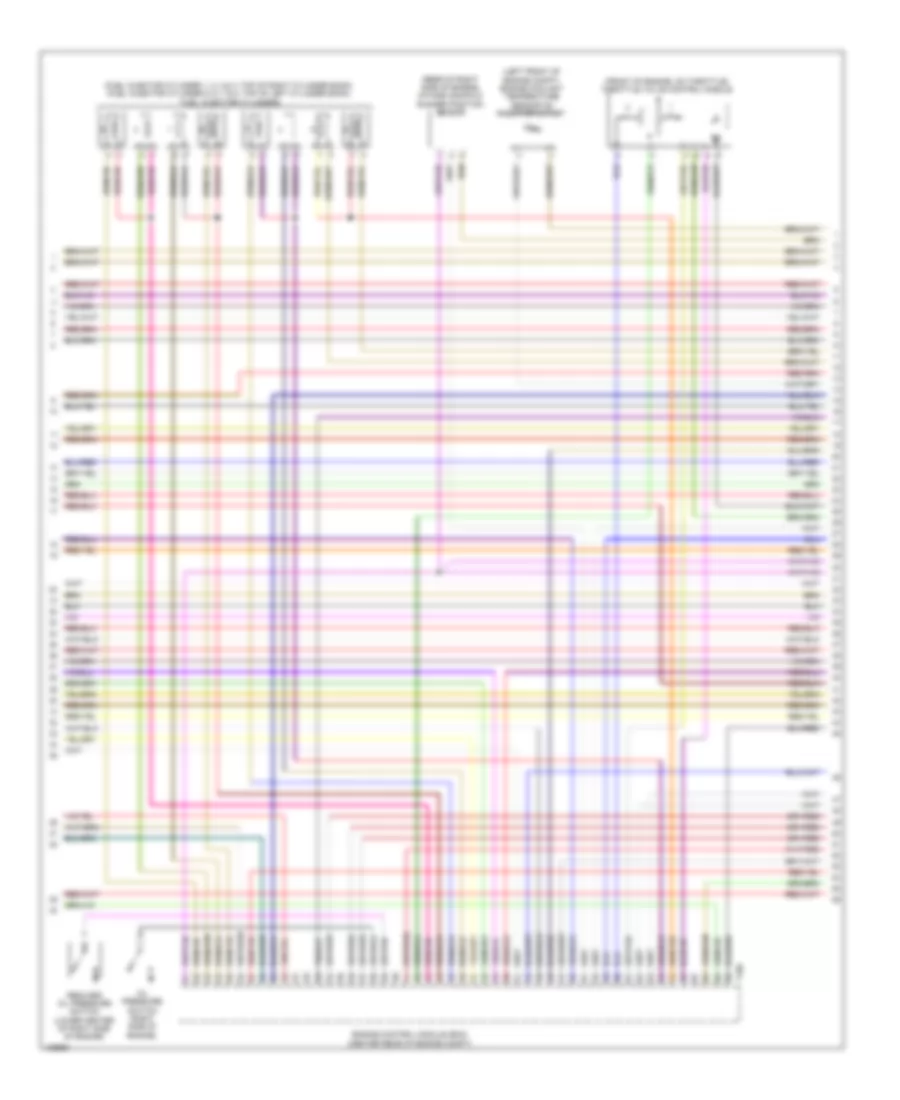
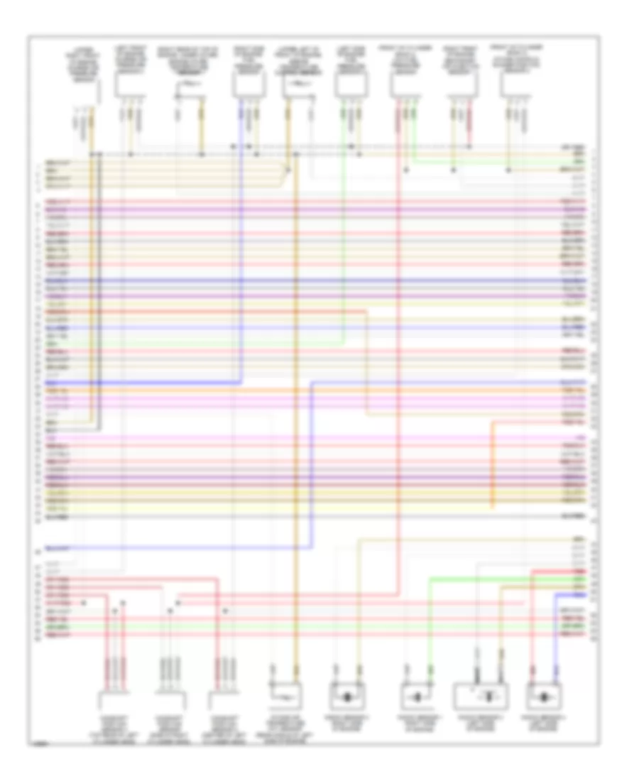
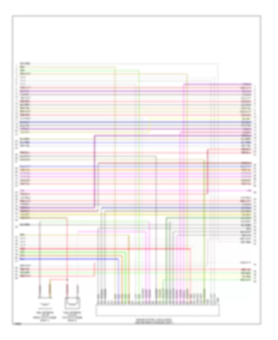
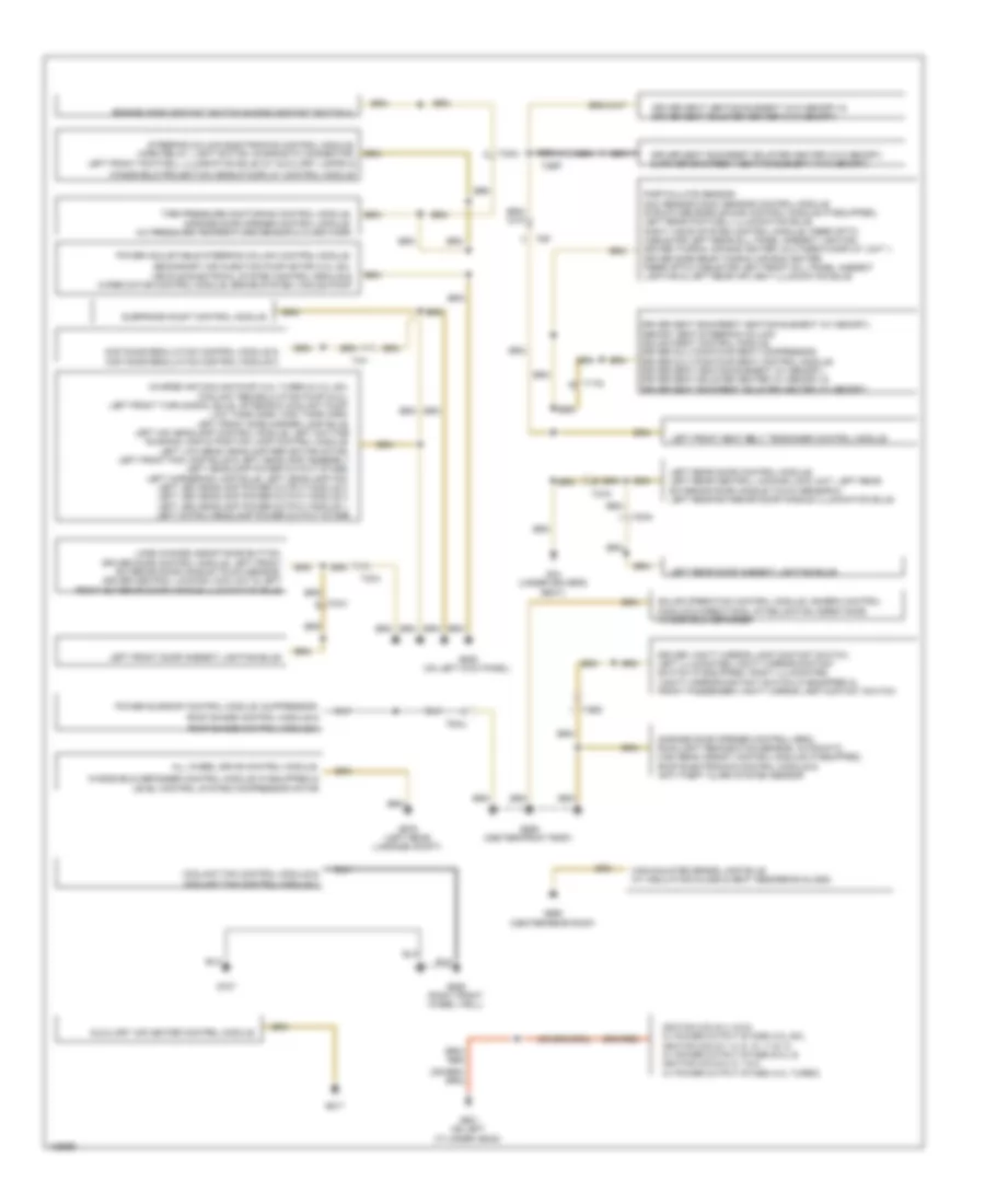
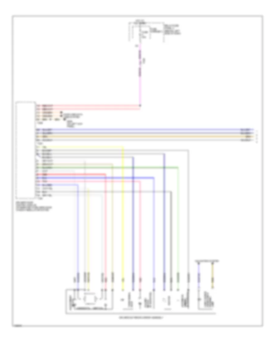
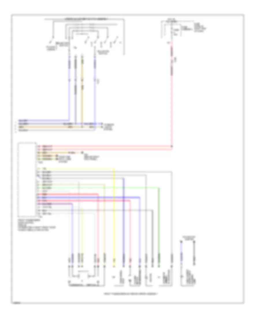
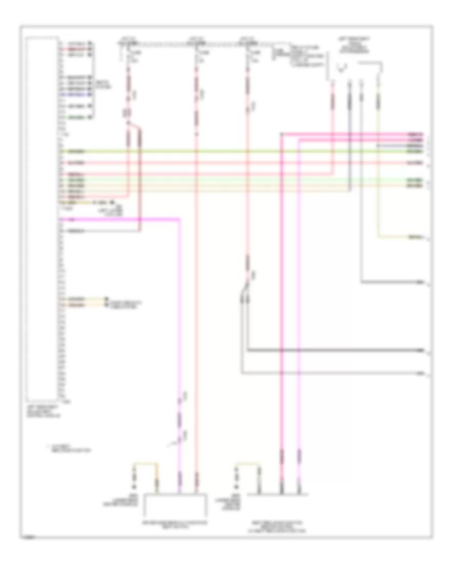
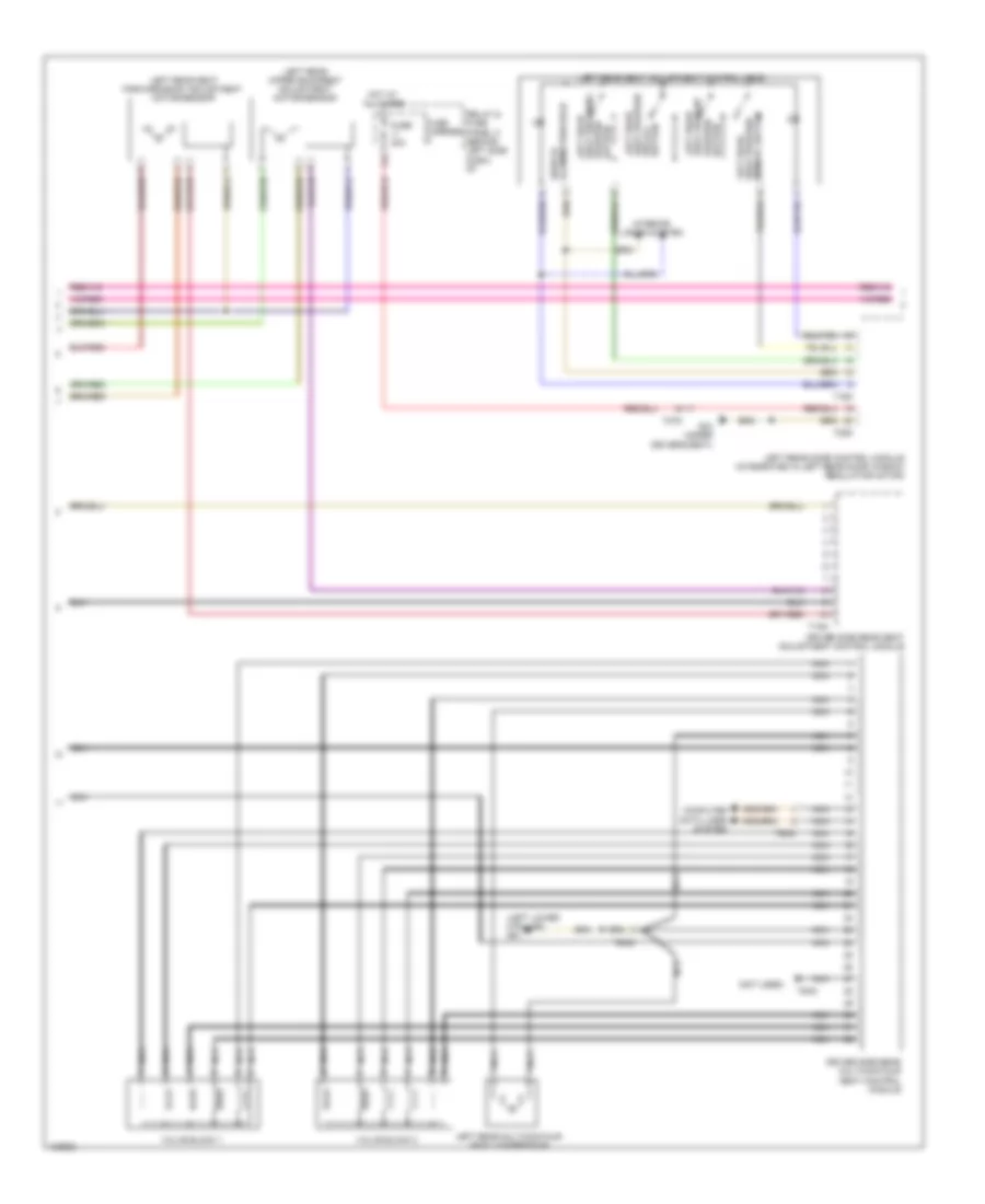
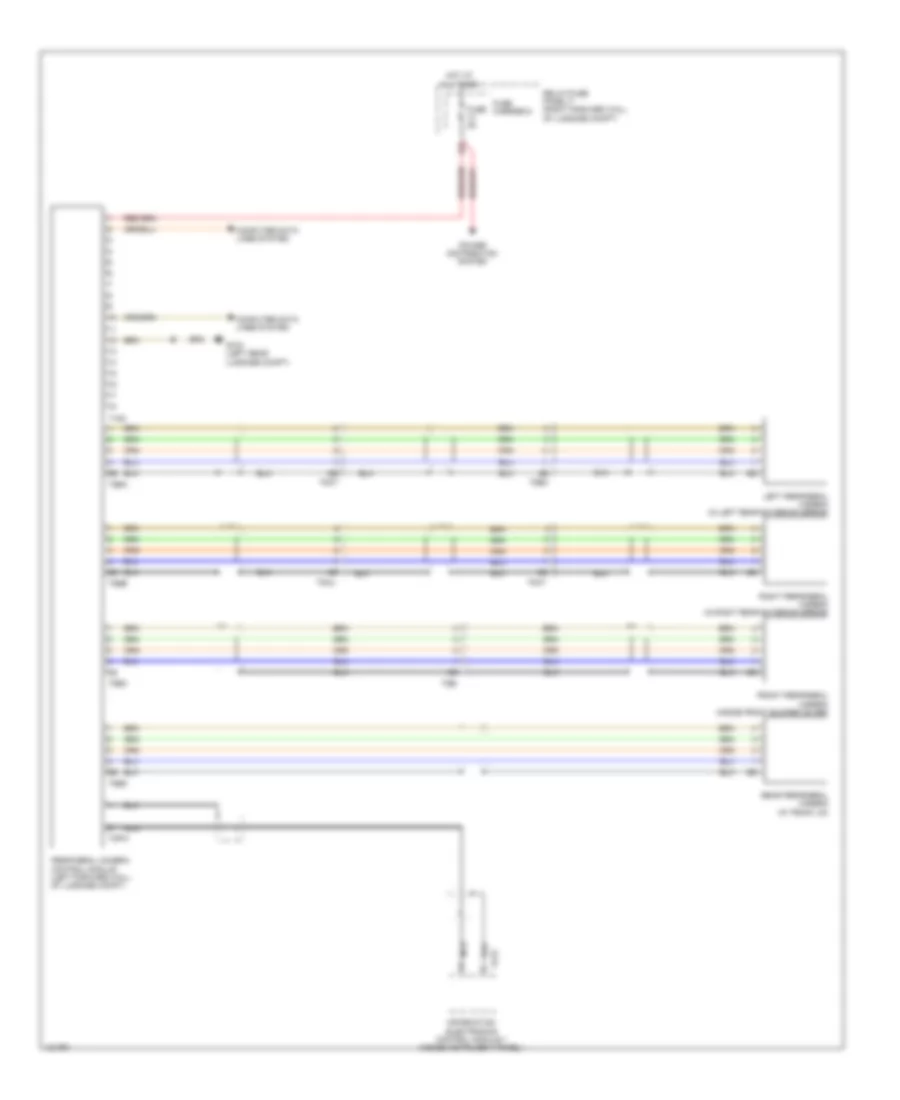
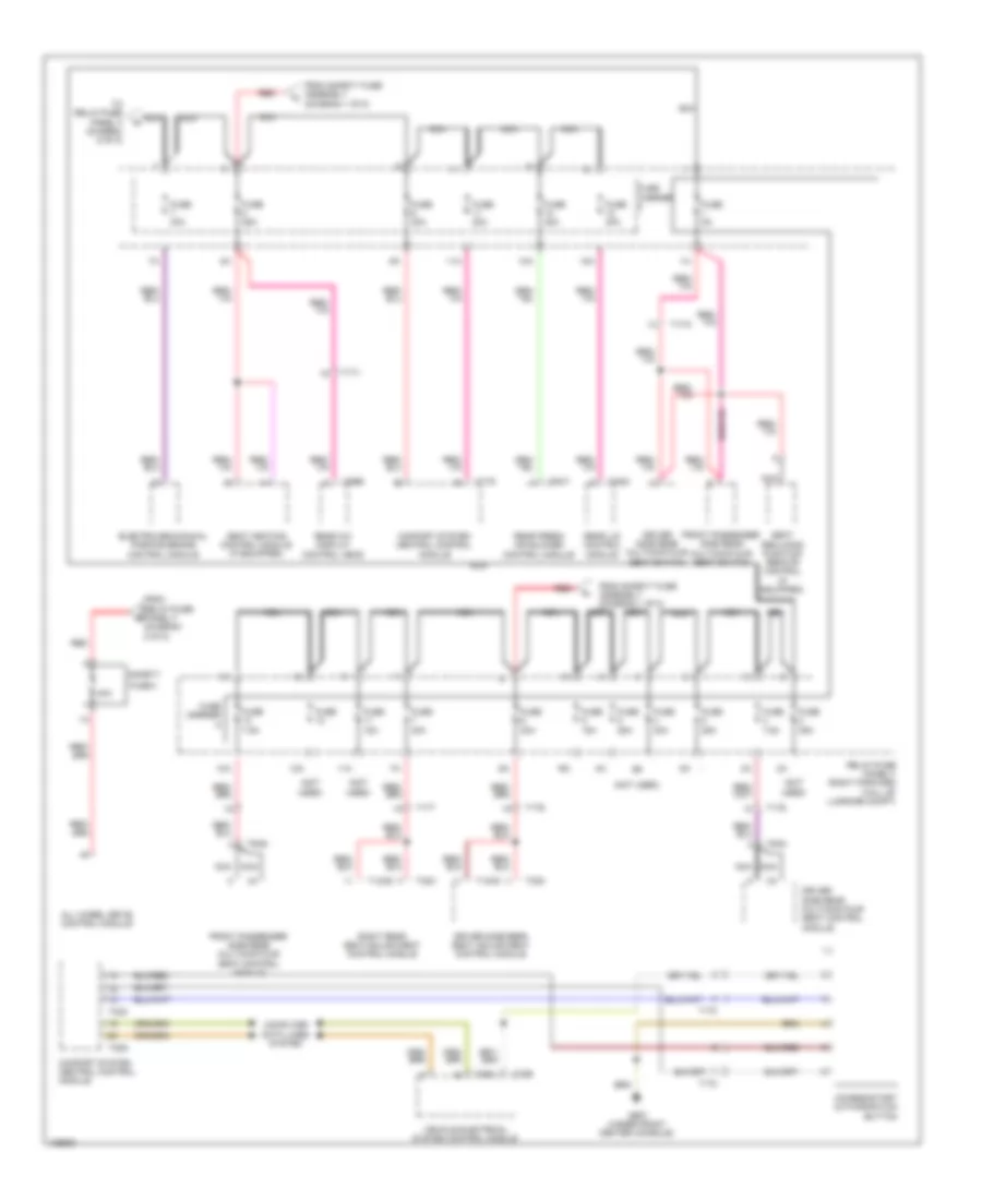
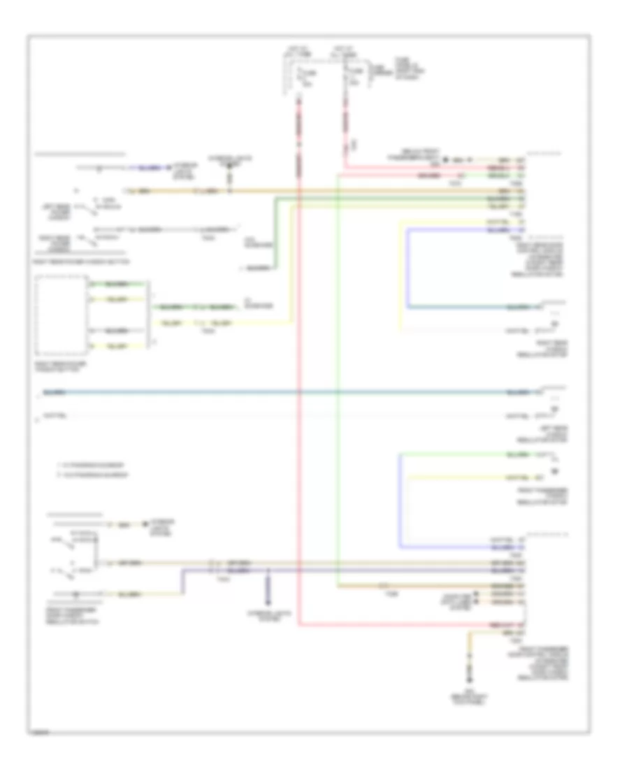
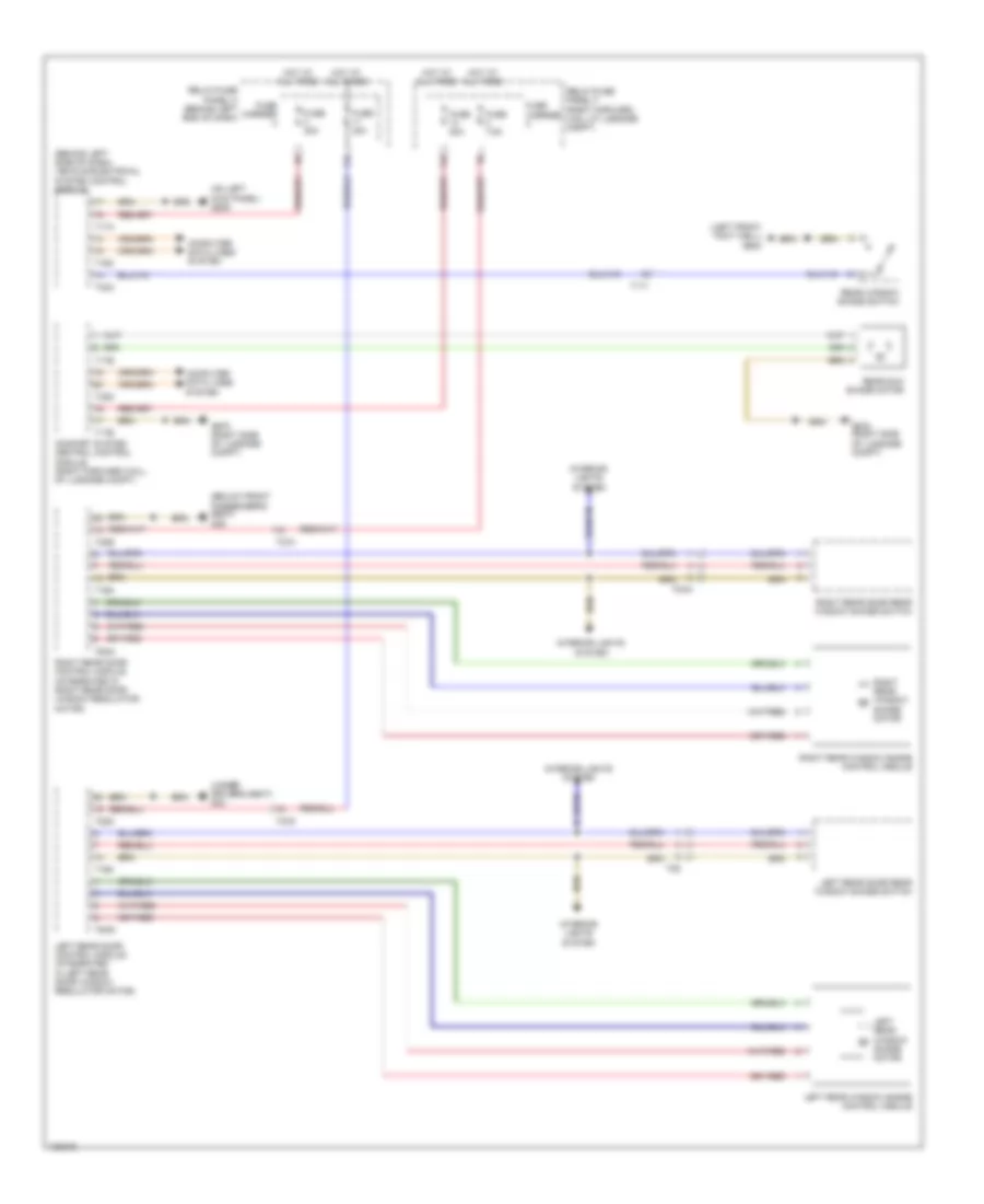
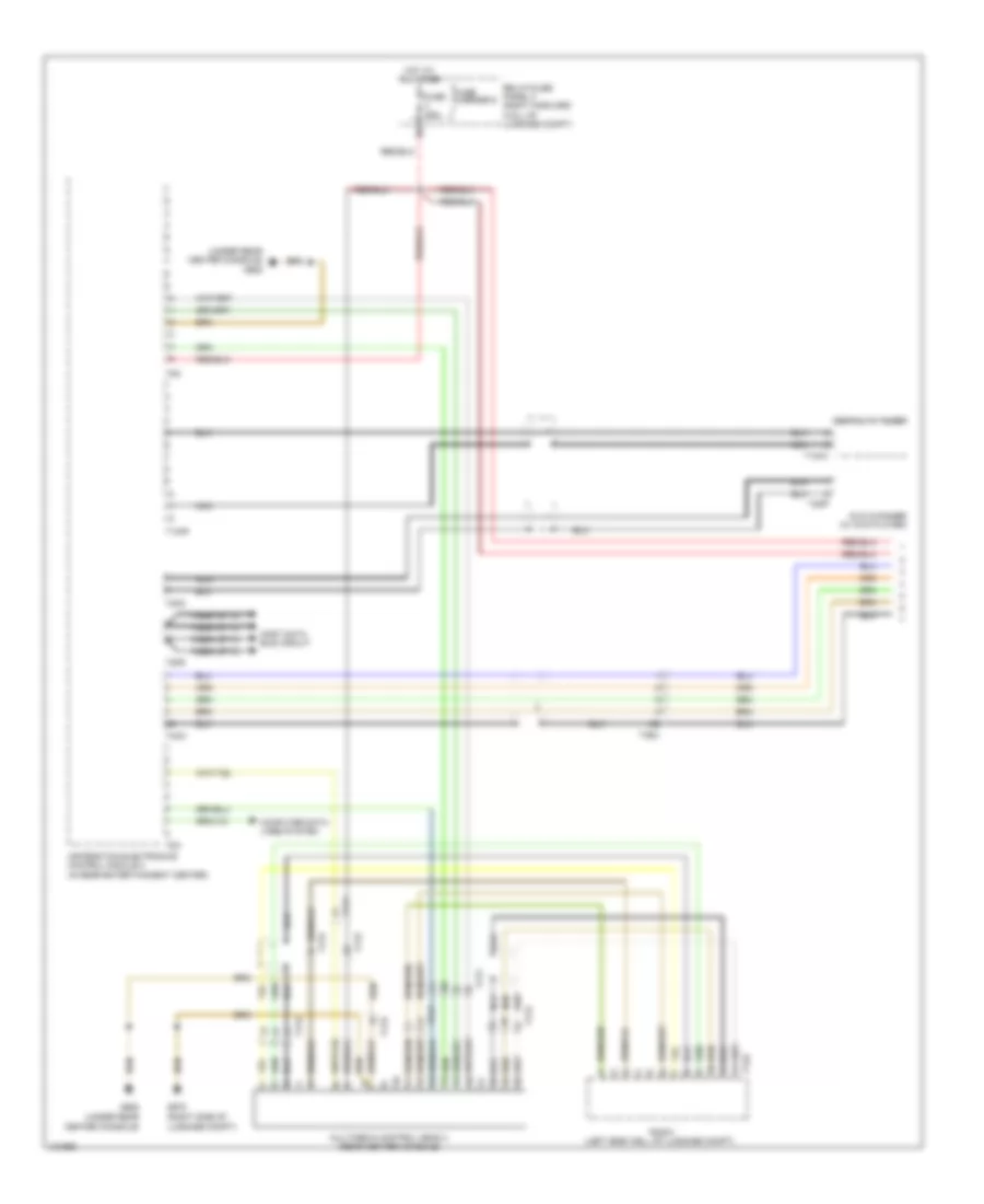
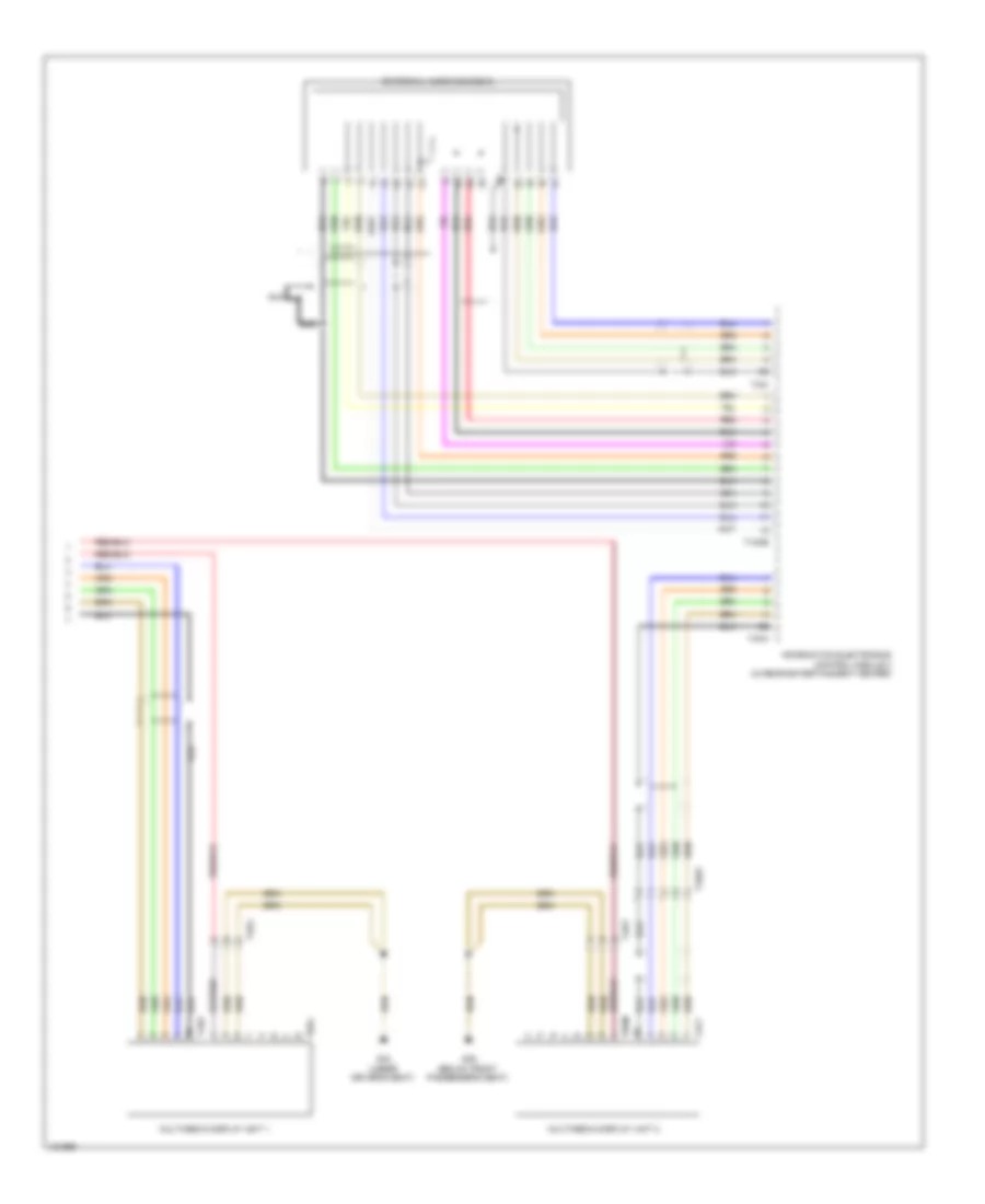
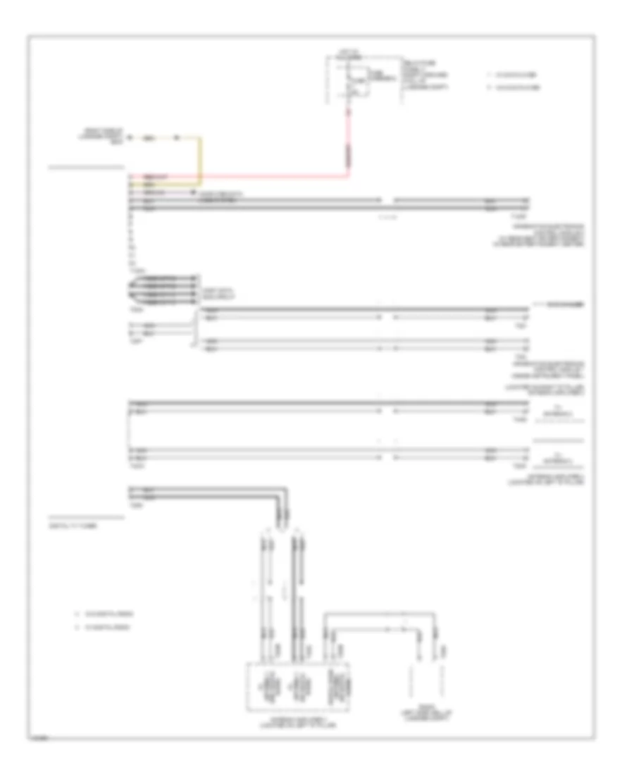
Rear A/C Wiring Diagram for Audi A8 Quattro L 2014
List of elements for Rear A/C Wiring Diagram for Audi A8 Quattro L 2014:
- 17w
- Computer data lines system
- Fuse 10a
- Fuse 25a
- Fuse carrier 3
- Fuse carrier 4
- Fuse panel f (right forward wall of luggage compt)
- G688 (under rear center console)
- Hot at all times
- Left b-pillar/ footwell shut-off door motor (left rear center console)
- Left rear footwell vent temperature sensor (in left rear footwell vent)
- Left rear temperature door motor (left rear center console)
- Left rear upper body vent motor (left rear center console)
- Left rear upper body vent temperature sensor (in left rear upper body vent)
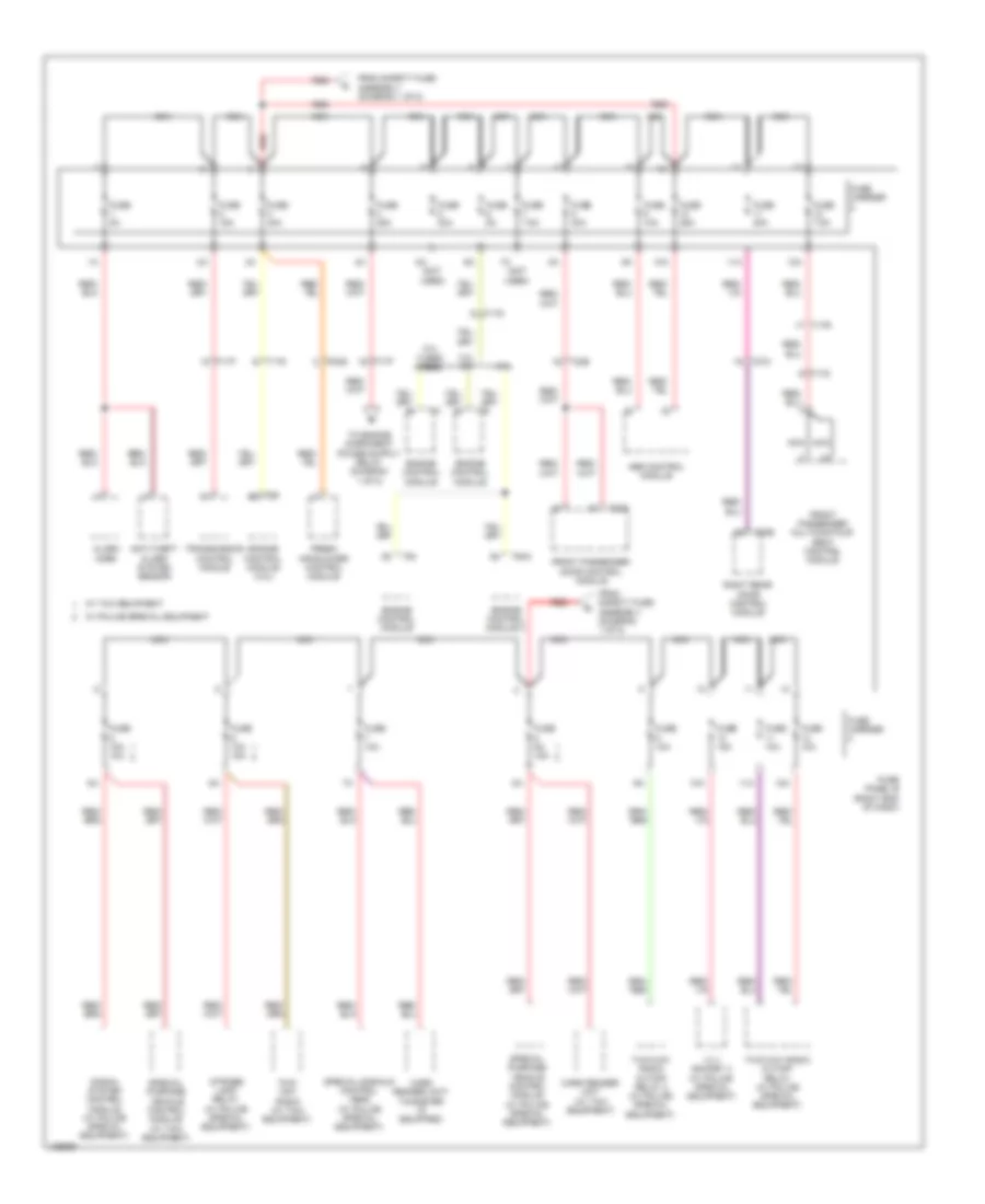
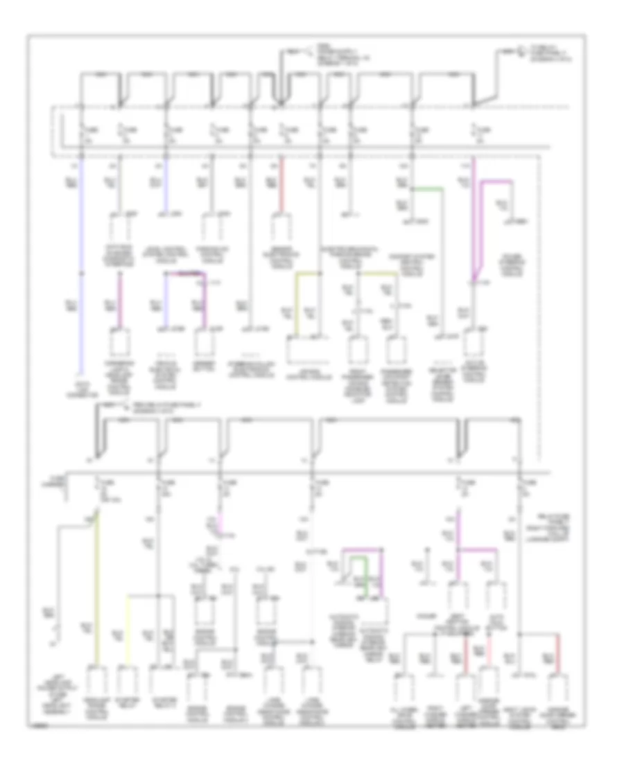
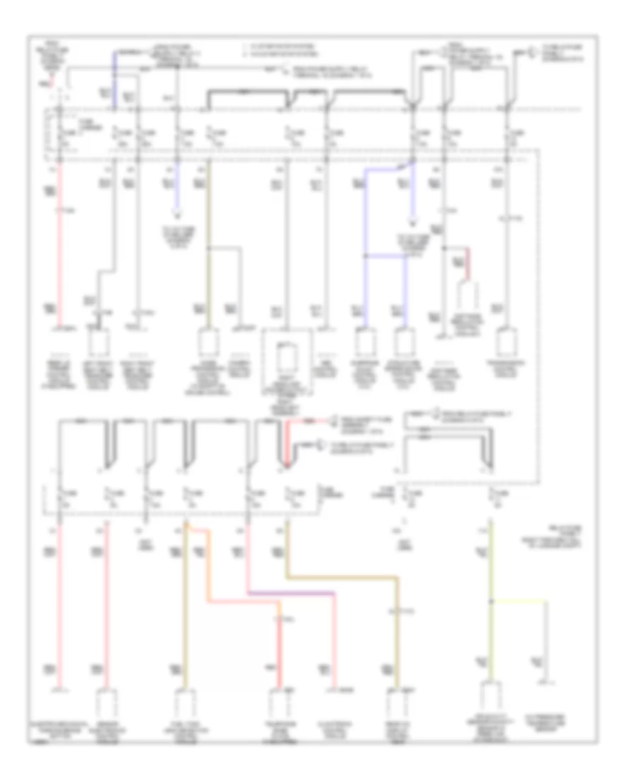
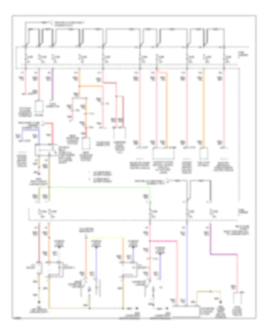
- Power distribution system
- Rear a/c display control head
- Rear recirculation door motor (rear center console)
- Right b-pillar/ footwell shut-off door motor (right rear center console)
- Right rear footwell vent temperature sensor (in right rear footwell vent)
- Right rear temperature door motor (right center console)
- Right rear upper body vent motor (right rear center console)
- Right rear upper body vent temperature sensor (in right rear upper body vent)
- Seats system
- T10ah
- T17v
- T17w
- T20h
- T3bb
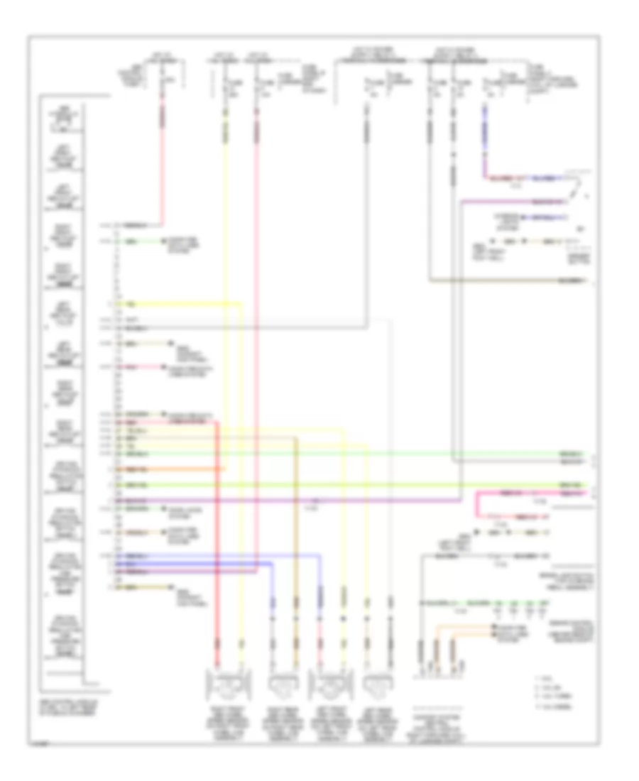
ANTI-LOCK BRAKES
Anti-lock Brakes Wiring Diagram (1 of 2) for Audi A8 Quattro L 2014
List of elements for Anti-lock Brakes Wiring Diagram (1 of 2) for Audi A8 Quattro L 2014:
- 10a
- 3.0l diesel
- 3.0l sc
- 4.0l turbo
- 50a
- 6.3l
- Abs control module (w/ edl: in left rear of plenum chamber)
- Abs control module fuse 1
- Abs hydraulic pump
- Asr/esp button
- Brake lamp switch (top of brake pedal assembly)
- Comfort system central control module (right forward wall of luggage compt)
- Computer data lines system
- Door locks system
- Driving dynamics regulation high pressure switch valve 1
- Driving dynamics regulation high pressure switch valve 2
- Driving dynamics regulation switch valve 1
- Driving dynamics regulation switch valve 2
- Engine control module (center rear of engine compt)
- Fuse 10a
- Fuse 25a
- Fuse 5a
- Fuse carrier
- Fuse panel b (right end of dash)
- Fuse panel f (right forward wall of luggage compt)
- G602 (left front foot well)
- G638 (on right kick panel)
- Hot at all times
- Interior lights system
- Left front abs inlet valve
- Left front abs outlet valve
- Left front abs wheel speed sensor (on left front wheel hub assembly)
- Left rear abs inlet valve
- Left rear abs outlet valve
- Left rear abs wheel speed sensor (on left rear wheel hub assembly)
- Pnk
- Red
- Right front abs inlet valve
- Right front abs outlet valve
- Right front abs wheel speed sensor (on right front wheel hub assembly)
- Right rear abs inlet valve
- Right rear abs outlet valve
- Right rear abs wheel speed sensor (on right rear wheel hub assembly)
- T17f
- T17g
- T17i
- T17k
- T32c
- T32d
- T91
- T94
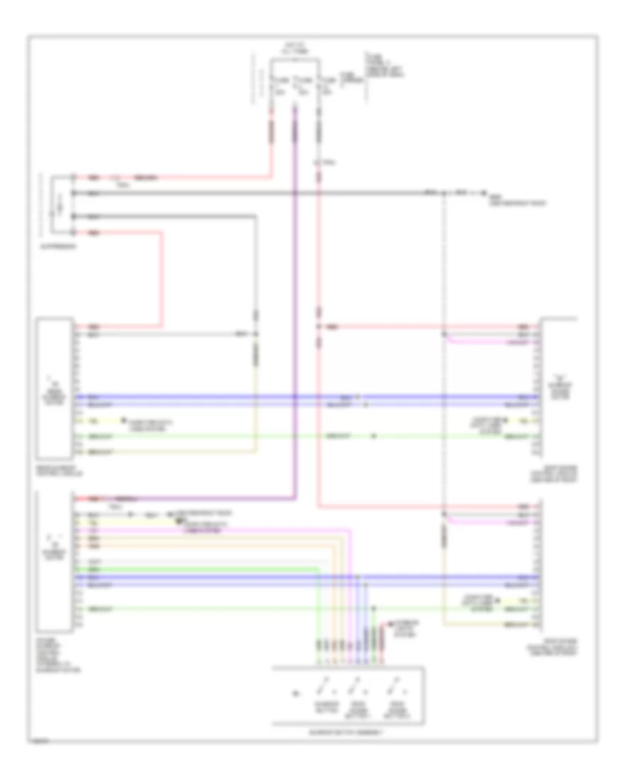
Anti-lock Brakes Wiring Diagram (2 of 2) for Audi A8 Quattro L 2014
List of elements for Anti-lock Brakes Wiring Diagram (2 of 2) for Audi A8 Quattro L 2014:
- Abs indicator lamp
- Auto hold button
- Computer data lines system
- Fuse 5a
- Fuse carrier
- Fuse panel a (right side of engine compt)
- Fuse panel f (right forward wall of luggage compt)
- G602 (left front foot well)
- G639 (on left kick panel)
- G687 (under front center console)
- Hot at all times
- Instrument cluster control module
- Nca
- Pnk
- Sensor electronics control module (underside of vehicle, below front center console)
- Steering angle sensor (integral to steering column electronic systems control module)
- Steering column electronic systems control module (top of steering column)
- T16d
- T32
ANTI-THEFT
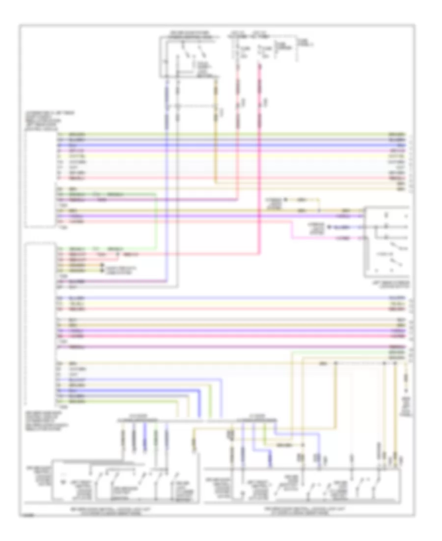
Anti-theft Wiring Diagram (1 of 7) for Audi A8 Quattro L 2014
List of elements for Anti-theft Wiring Diagram (1 of 7) for Audi A8 Quattro L 2014:
- (integrated in left rear door window regulator motor) left rear door control module
- (w/ door closing assistance)
- 11a
- Child safety lock button
- Computer data lines system
- Driver door central locking system motor
- Driver door contact
- Driver door contact switch
- Driver door power window control head
- Driver lock cylinder contact switch
- Driver's door central locking lock unit
- Driver's door central locking lock unit (w/o door closing assistance)
- Driver's side door control module (integrated in driver's door window regulator motor)
- Fuse 30a
- Fuse carrier
- Fuse panel c
- G639 (on left kick panel)
- Hot at all times
- Interior lights system
- Left front central locking system actuator
- Left rear interior locking switch
- Switch
- T10w
- T16m
- T17x
- T20b
- T20d
- T23a
- T27d
- T32k
- T3au
- W/ door closing assistance
- W/o door closing assistance
Anti-theft Wiring Diagram (2 of 7) for Audi A8 Quattro L 2014
List of elements for Anti-theft Wiring Diagram (2 of 7) for Audi A8 Quattro L 2014:
- (w/ door closing assistance) left rear door central locking lock unit
- (w/o door closing assistance) left rear door central locking lock unit
- Abs control module (w/ adaptive cruise control) (in left rear of plenum chamber)
- Computer data lines system
- Display unit
- Driver's door closing assist motor (if equipped)
- G34 (under driver's seat)
- G639 (on left kick panel)
- Instrument cluster control module
- Left front exterior door handle touch sensor
- Left rear central locking system actuator
- Left rear central locking system motor
- Left rear child safety lock contact switch
- Left rear child safety lock motor
- Left rear door contact switch
- T10z
- T23a
- T32
- T3aw
- W/ door closing assistance
- W/o door closing assistance
Anti-theft Wiring Diagram (3 of 7) for Audi A8 Quattro L 2014
List of elements for Anti-theft Wiring Diagram (3 of 7) for Audi A8 Quattro L 2014:
- (if equipped) left rear closing assist motor
- Access/start authorization button
- Alarm system deactivation switch
- Central locking safe indicator lamp
- Driver's interior locking switch
- Fuse 5a
- Fuse carrier
- Fuse panel c
- G687 (under front center console)
- Hot at all times
- Interior lights system
- Left rear exterior door handle touch sensor
- Rear lid remote release button
- T17l
- T17o
- T27d
Anti-theft Wiring Diagram (4 of 7) for Audi A8 Quattro L 2014
List of elements for Anti-theft Wiring Diagram (4 of 7) for Audi A8 Quattro L 2014:
- Antenna amplifier (located on the right d-pillar)
- Central locking & anti-theft alarm system antenna
- Comfort system central control module (right forward wall of luggage compt)
- Computer data lines system
- Front passenger's interior lock switch
- Fuel filler door unlock motor
- Fuse 20a
- Fuse carrier
- Fuse panel f
- G43 (behind right kick panel)
- G51 (right rear of luggage compt)
- G675 (right side of luggage compt)
- Hot at all times
- Interior lights & power windows systems
- Interior lights system
- Luggage compartment access/start system antenna
- Nca
- Rear lid lock cylinder unlock button
- Red
- Right front exterior door handle touch sensor
- T17d
- T17e
- T23b
- T2a
- T32c
- T32d
- T32e
- Vehicle interior access/start system antenna 2
Anti-theft Wiring Diagram (5 of 7) for Audi A8 Quattro L 2014
List of elements for Anti-theft Wiring Diagram (5 of 7) for Audi A8 Quattro L 2014:
- (behind left side of dash) vehicle electrical system control module
- (center front roof) anti-theft alarm system sensor & interior monitoring sensor
- (cowl area under the wiper motor) alarm horn
- (if equipped) front passenger's closing assist motor
- (right rear of luggage compt)
- Anti-theft immobilizer reader coil
- Computer data lines system
- Door closing assist control module (below trim apron rail)
- Engine hood contact switch
- G51
- G51 (right rear of luggage compt)
- G602 (left front foot well)
- G639 (on left kick panel)
- G689 (center/ front roof)
- Hood contact switch 2
- Left access/ start authorization antenna
- Nca
- Rear lid closing assist motor
- Rear lid closing assist/ lock stop switch
- Rear lid closing assist/ unlock stop switch
- Rear lid lock/alarm/ central locking switch & rear lid central locking system motor
- Red
- Right access/start authorization antenna
- Right rear exterior door handle touch sensor
- T16c
- T17a
- T17o
- T27c
- T27d
- T2km
- T2ko
- T2kp
- T32b
- Vehicle interior access/start system antenna 1
Anti-theft Wiring Diagram (6 of 7) for Audi A8 Quattro L 2014
List of elements for Anti-theft Wiring Diagram (6 of 7) for Audi A8 Quattro L 2014:
- (w/ door closing assistance) front passenger's door central locking lock unit
- (w/o door closing assistance) front passenger's door central locking lock unit
- Front passenger door central locking system motor
- Front passenger door contact switch
- G35 (below front passenger's seat)
- G43 (behind right kick panel)
- Right front central locking system actuator
- Right rear central locking system actuator
- Right rear central locking system motor
- Right rear child safety lock contact switch
- Right rear child safety lock motor
- Right rear door central locking lock unit (w/ door closing assistance)
- Right rear door central locking lock unit (w/o door closing assistance)
- Right rear door contact switch
- T10aa
- T3av
- T3ax
- T8x
- W/ door closing assistance
- W/o door closing assistance
Anti-theft Wiring Diagram (7 of 7) for Audi A8 Quattro L 2014
List of elements for Anti-theft Wiring Diagram (7 of 7) for Audi A8 Quattro L 2014:
- (behind right kick panel) g43
- (below front passenger's seat) g35
- 11a
- Computer data lines system
- Fuse 30a
- Fuse 5a
- Fuse carrier
- Fuse panel b (right end of dash)
- Hot at all times
- Interior lights & power windows system
- Interior lights system
- Passenger's side door control module (integrated in right front door window regulator motor)
- Right rear closing assist motor (if equipped)
- Right rear door control module (integrated in right rear door window regulator motor)
- Right rear interior lock switch
- T16n
- T20c
- T20e
- T23b
- T27c
- T32m
BODY CONTROL MODULES
Comfort System Central Control Module Wiring Diagram for Audi A8 Quattro L 2014
List of elements for Comfort System Central Control Module Wiring Diagram for Audi A8 Quattro L 2014:
- 11a
- 14a
- Comfort system central control module (right forward wall of
- Comfort system central control module (right forward wall of luggage compt)
- Computer data lines system
- Defogger system
- Door locks & anti-theft systems
- Engine controls & anti-lock brakes systems
- Engine controls & transmissions systems
- Engine controls system
- Exterior lights system
- Fuse 20a
- Fuse carrier 3
- Fuse carrier 4
- Fuse panel f (right forward wall of luggage compt)
- G675 (right side of luggage compt)
- Hot at all times
- Interior lights system
- Luggage compt)
- Nca
- Power distribution system
- Power distribution system door locks & anti-theft systems door locks, shift interlock & anti-theft systems
- Power windows system
- Red
- Shift interlock system
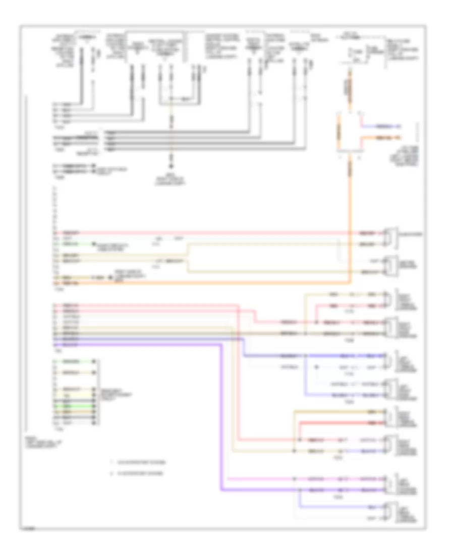
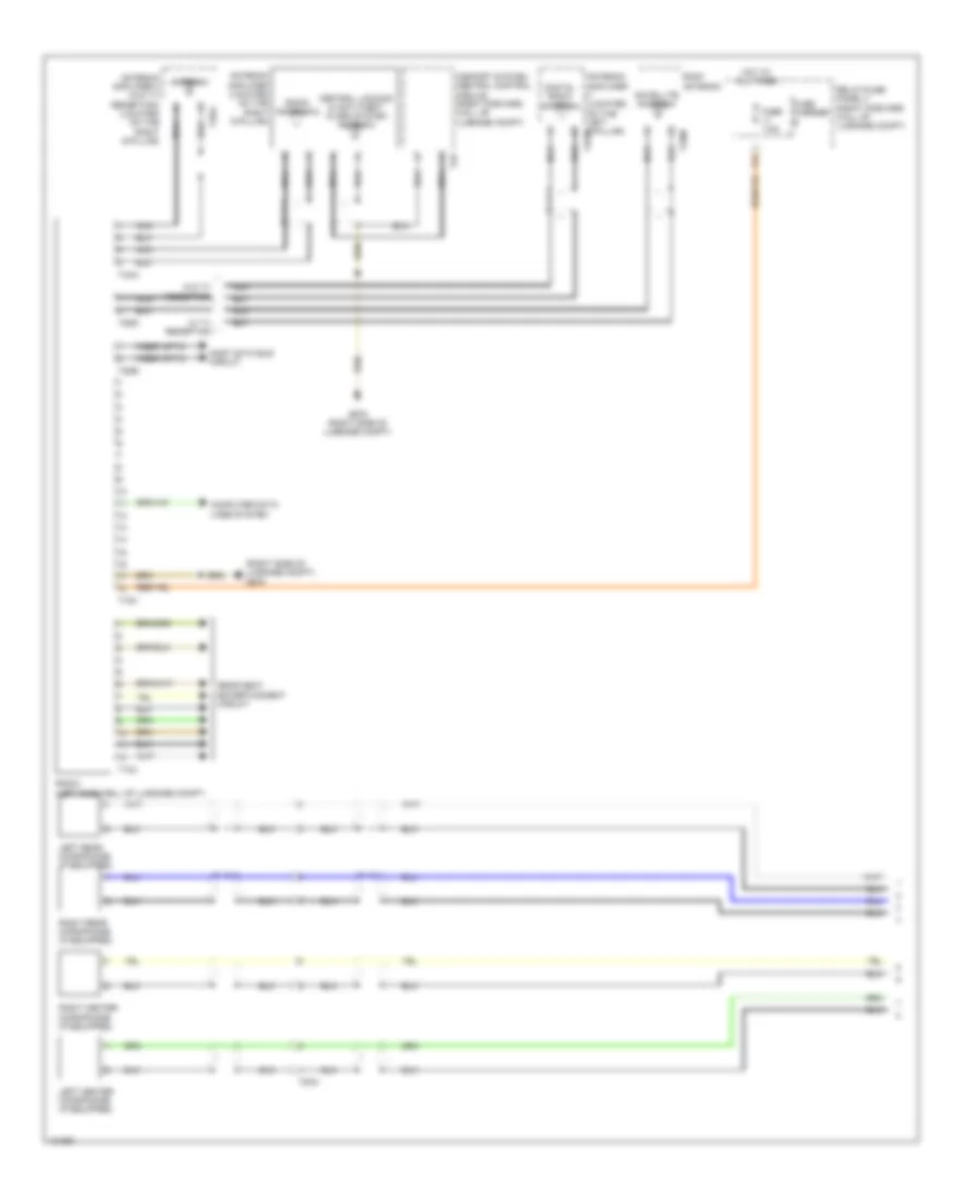
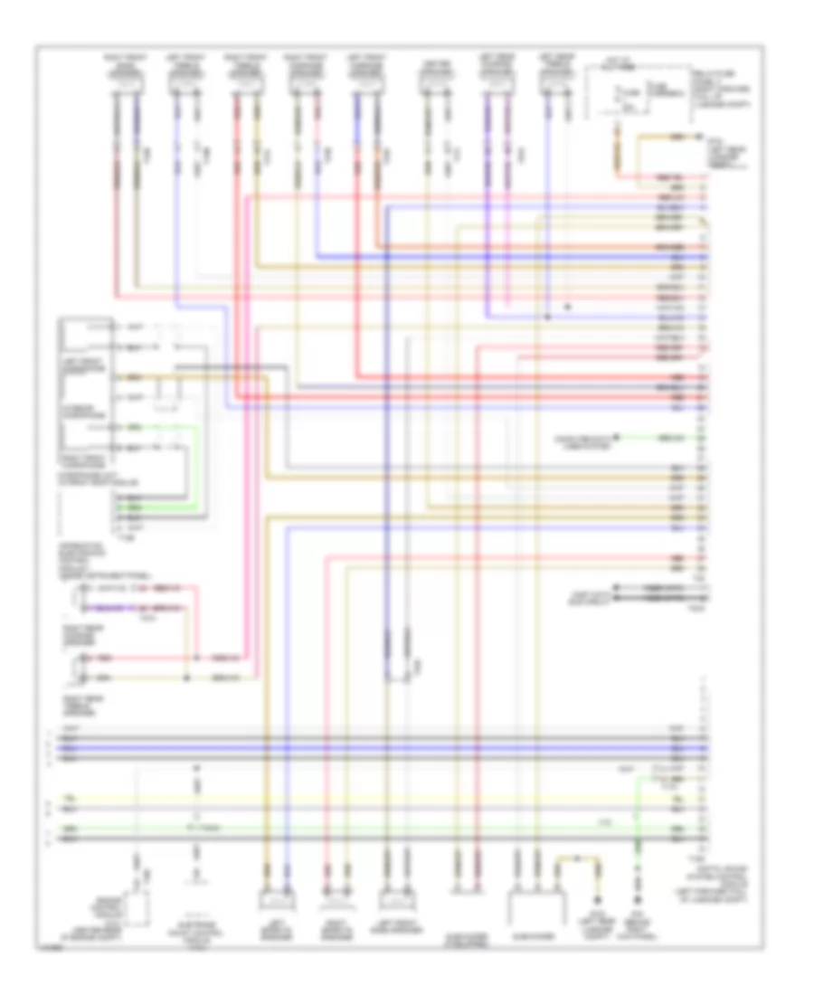
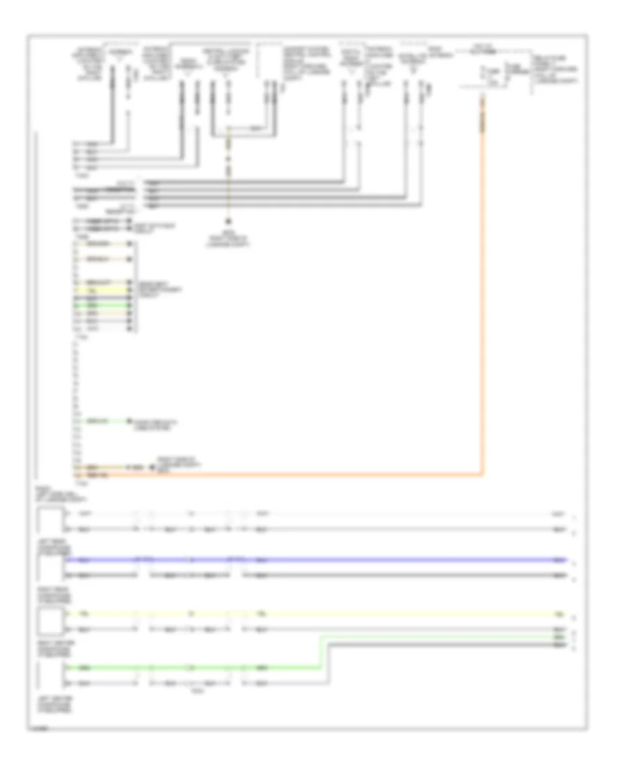
- Sound systems
- T17d
- T17e
- T2a
- T32c
- T32d
- T32e
- Transmissions & shift interlock system
- Trunk, tailgate, fuel doors system
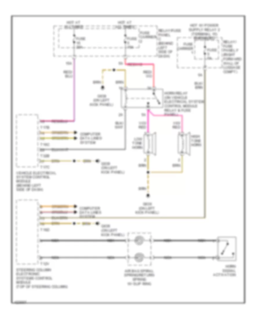
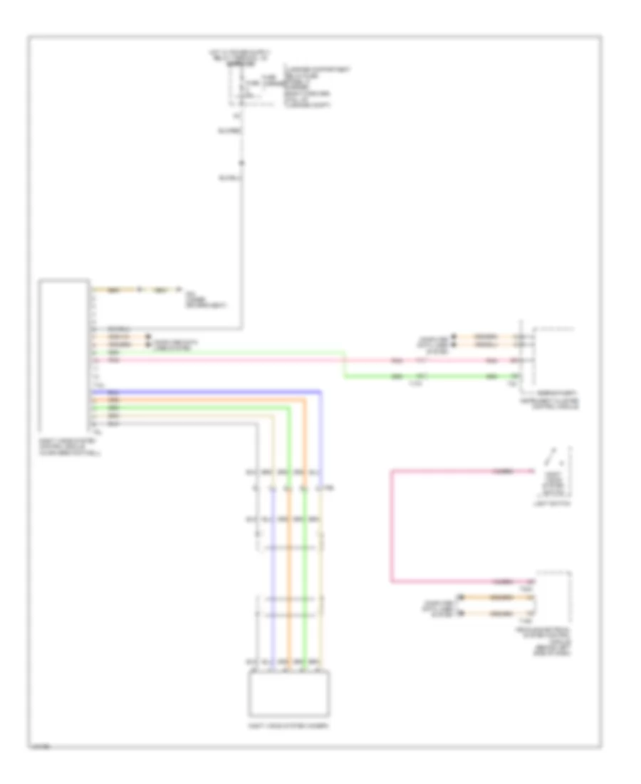
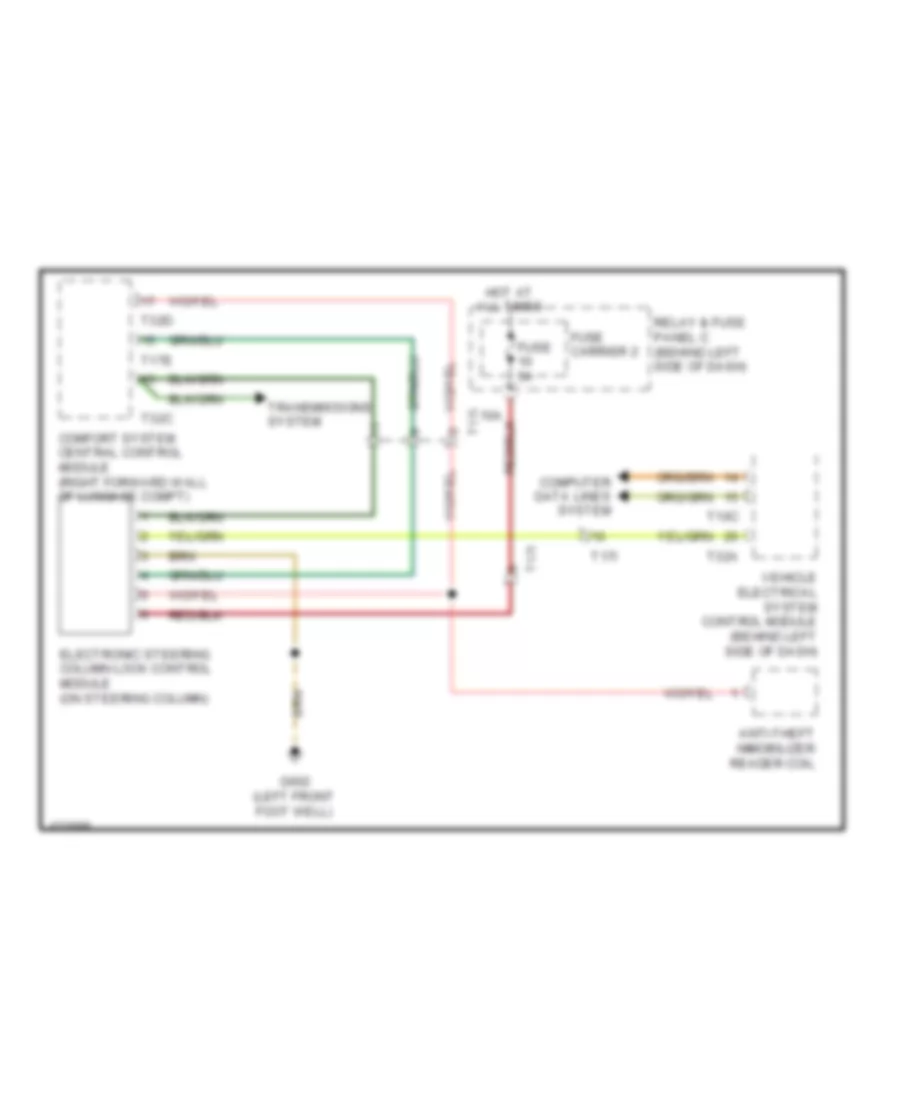
Steering Column Electronic Systems Control Module Wiring Diagram for Audi A8 Quattro L 2014
List of elements for Steering Column Electronic Systems Control Module Wiring Diagram for Audi A8 Quattro L 2014:
- (on left kick panel) g639
- Air bag spiral spring/return spring w/ slip ring
- Computer data lines system
- Cruise control system
- Directional stabilization assistance button (w/ lane assist)
- Driver air bag igniter 2 (in steering wheel)
- Driver's air bag igniter (in steering wheel)
- Fuse 5a
- Fuse 5a (or 10a)
- Fuse carrier
- Fuse panel f (right forward wall of luggage compt)
- Headlamp flasher switch/ cruise control
- Heated steering wheel (if equipped)
- Heated steering wheel sensor
- Horn signal activation
- Hot at all times
- Left multi-function buttons
- Memory systems
- Mode
- Multi-function steering wheel control module
- Nca
- Relay/fuse panel c (behind left side of dash)
- Right multi-function buttons
- Steering angle sensor (integral to steering column electronic systems control module)
- Steering column electronic systems control module (top of steering column)
- Steering wheel vibration motor (w/ lane assist)
- Switch/turn signal switch
- T12v
- T13b
- T16d
- T2dm
- T4ap
- T4aq
- T6m
- Tiptronic downshift button
- Tiptronic upshift button
- W/ heated steering wheel
- Windshield wiper intermittent mode switch
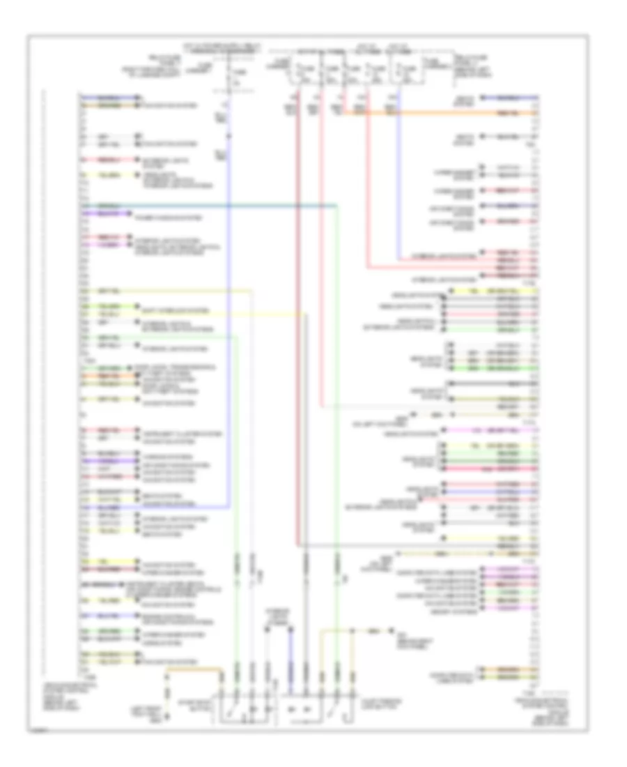
Vehicle Electrical System Control Module Wiring Diagram for Audi A8 Quattro L 2014
List of elements for Vehicle Electrical System Control Module Wiring Diagram for Audi A8 Quattro L 2014:
- (left front foot well) g602
- 10a
- 15a
- Air conditioning system
- Computer data lines system
- Door locks & anti-theft systems
- Door locks, transmissions & anti-theft systems
- Engine controls & air conditioning systems
- Exterior lights system
- Fuse 20a
- Fuse 30a
- Fuse 35a
- Fuse 5a
- Fuse carrier
- Fuse carrier 1
- Fuse carrier 2
- G43 (behind right kick panel)
- G639 (on left kick panel)
- Headlights & exterior lights systems
- Headlights system
- Headlights, exterior lights & interior lights systems
- Horns system
- Hot at all times
- Instrument cluster system
- Instrument cluster, seats, air conditioning, engine controls & wiper/washer systems
- Interior lights & exterior lights systems
- Interior lights system
- Memory systems
- Navigation system
- Pnk
- Power windows system
- Relay/fuse panel c (behind left side of dash)
- Relay/fuse panel f (right forward wall of luggage compt)
- Seats system
- Shift interlock system
- Start/stop button
- T12r
- T16c
- T17a
- T17b
- T17c
- T17m
- T32a
- T32b
- T6a
- T8f
- Valet parking lock button
- Vehicle electrical system control module (behind left side of dash)
- Warning systems
- Wiper/washer system
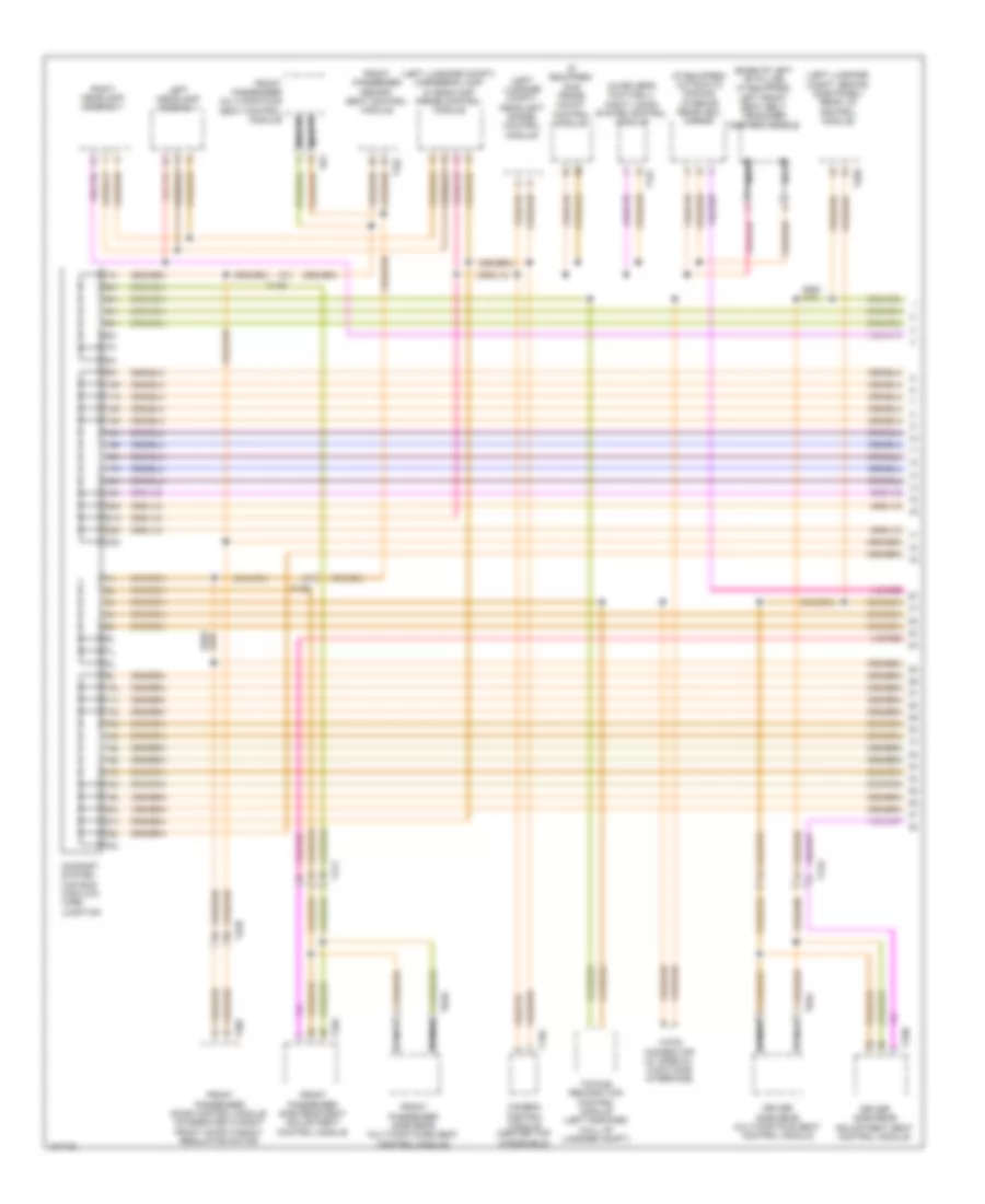
COMPUTER DATA LINES
Computer Data Lines Wiring Diagram (1 of 5) for Audi A8 Quattro L 2014
List of elements for Computer Data Lines Wiring Diagram (1 of 5) for Audi A8 Quattro L 2014:
- (base of left "b" pillar) (if equipped) left front seat belt tensioner control module
- (if equipped) automatic dimming interior rearview mirror
- (if equipped) sub frame mount control module
- (in driver's footwell) night vision system control module
- (left luggage compt) cornering lamp & headlamp range control module
- (left luggage compt) headlight range control module
- (left luggage compt, behind side panel) rear lid control module
- 10h
- 10l
- 11h
- 11l
- 12-pin connector (w/ special functions interface)
- 12h
- 12l
- 13h
- 13l
- 14h
- 14l
- 15h
- 15l
- 16h
- 16l
- 17h
- 17l
- 18h
- 18l
- 19h
- 19l
- 20h
- 20l
- 21h
- 21l
- 22h
- 22l
- 23h
- 23l
- Camera control module (center top windshield)
- Comfort system can bus high/low wire junction
- Driver side rear adjustment seat control module
- Driver side rear multicontour seat control module
- Front passenger door control module (integrated in right front door window regulator motor)
- Front passenger memory seat control module
- Front passenger multicontour seat control module
- Front passenger side rear multicontours seat control module
- Front passenger side rear seat adjustment control module
- Left headlamp assembly
- Nca
- Right headlamp assembly
- T120
- T12l
- T17r
- T17s
- T17t
- T20c
- T23b
- T26b
- T32l
- T32n
- T32o
- T6ac
- T6ad
- T6y
- Towing recognition control module (left forward wall of luggage compt)
Computer Data Lines Wiring Diagram (2 of 5) for Audi A8 Quattro L 2014
List of elements for Computer Data Lines Wiring Diagram (2 of 5) for Audi A8 Quattro L 2014:
- (behind left side of dash) windshield projection headup display control module
- (below rear center console) air bag control module
- (center bottom rear a/c unit) rear fresh air blower control module
- (in driver foot well) (if equipped) active steering control module
- (on fresh air blower motor) fresh air blower control module
- (right center console) right rear temperature door motor
- (right side b-pillar) air ionization system control module
- (right side dash) right side window defroster door motor
- (top of steering column) (if equipped) steering column electronics control module
- Auxiliary heater control module (under right headlight)
- Climatronic control module
- Comfort system central control module 2 (w/ auxiliary lamps) (right forward wall of luggage compt)
- Driver side rear multicontour seat switch
- Instrument cluster control module
- Parking aid control module/ parallel parking assistance control module (if equipped) (right side of luggage compt)
- Peripheral camera control module (left forward wall of luggage compt)
- Rear a/c display control head
- Rear view camera system control module (left forward wall of luggage compt)
- Structure borne sound control module (if equipped) (below left front seat)
- T10ah
- T10i
- T12ag
- T16d
- T16h
- T17k
- T17m
- T17n
- T17p
- T17w
- T18c
- T20g
- T20h
- T20k
- T32
- T6ap
- W/ rear view camera
- W/o rear view camera
- W/o seat reclining function
Computer Data Lines Wiring Diagram (3 of 5) for Audi A8 Quattro L 2014
List of elements for Computer Data Lines Wiring Diagram (3 of 5) for Audi A8 Quattro L 2014:
- (behind left side of dash) vehicle electrical system control module
- (integrated in driver's door window regulator motor) driver's door control module
- (left forward wall of luggage compt) (w/ bang & olufson sound system) digital sound system control module
- (left side well of luggage compt) (w/ bose & audi sound system) radio
- (on steering column) electronic steering column lock control module
- All wheel drive control module (left spare tire well)
- Anti-theft immobilizer reader coil
- Digital sound system control module (w/ bose & sound system) (left forward wall of luggage compt)
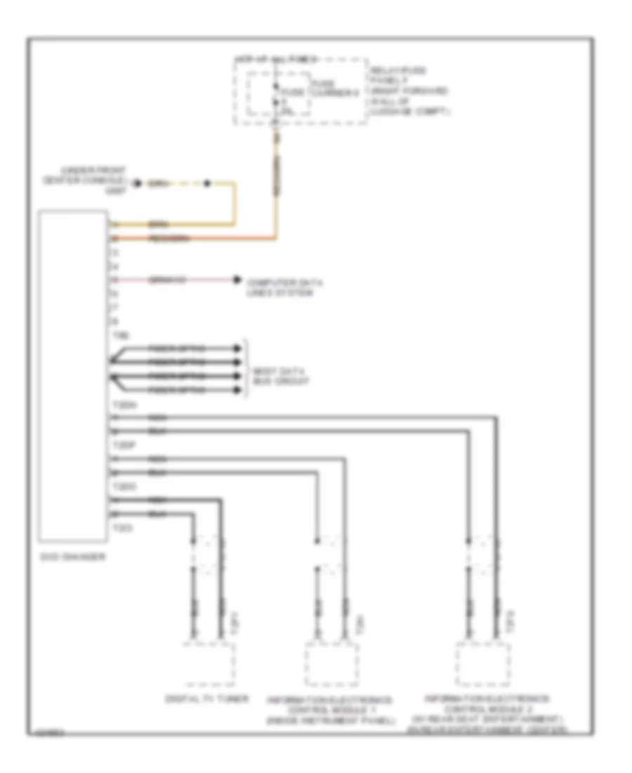
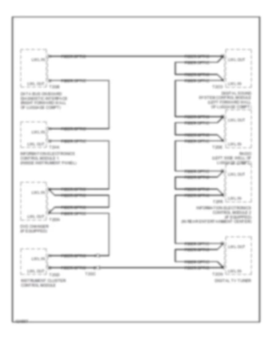
- Digital tv tuner
- Driver multi- contour seat control module
- Dvd changer (w/ dvd player)
- Electro- mechanical parking brake control module (left luggage compartment, behind side panel)
- Information electronics control module 1 (inside instrument panel)
- Information electronics control module 2 (in rear entertainment center)
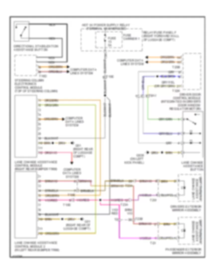
- Lane change assistance control module 1 (right rear bumper trim)
- Lane change assistance control module 2 (in left rear bumper trim)
- Memory seat/ steering column adjustment control module
- Nca
- Right front seat belt tensioner control module (base of right "b" pillar)
- T10e
- T10h
- T12av
- T16c
- T17i
- T17q
- T17y
- T20b
- T23a
- T32h
- T32i
- T38
- T6x
- T8e
- T8o
- T8q
Computer Data Lines Wiring Diagram (4 of 5) for Audi A8 Quattro L 2014
List of elements for Computer Data Lines Wiring Diagram (4 of 5) for Audi A8 Quattro L 2014:
- (below front left headlamp) distance regulation control module 2
- (below front right headlamp) distance regulation control module
- (center rear of engine compt) (6.3l) engine control module 2
- (center rear of engine compt) engine control module
- (in bottom of transmission) transmission control module
- 12a
- 3.0l sc & 6.3l
- 4.0l turbo & 3.0l diesel
- 6.3l
- A/c pressure/ temperature sensor
- Air quality sensor & humidity sensor (air quality sensor: right side of plenum unit) (humidity sensor: in interior rearview mirror mount)
- Anti-theft alarm system sensor (center front roof)
- Comfort system central control module (right forward wall of luggage compt)
- Fuse 10a
- Fuse 5a
- Fuse carrier
- Garage door opener control head
- Garage door opener control module (behind left front bumper)
- Hot at all times
- Pnk
- Power sunroof control module (integral with sunroof motor)
- Rear sunroof control module (integral with rear sunroof motor)
- Relay/fuse panel c (behind left side of dash)
- Relay/fuse panel f (right forward wall of luggage compt)
- Roof electronics control module (in front interior light)
- Roof shade control module 1 (center of roof)
- Roof shade control module 2 (center of roof)
- T17g
- T17k
- T17l
- T17m
- T32d
- T4h
- T6au
- T8ah
- T91
- T94
- T94a
- Windshield defogger control module (if equipped)
Computer Data Lines Wiring Diagram (5 of 5) for Audi A8 Quattro L 2014
List of elements for Computer Data Lines Wiring Diagram (5 of 5) for Audi A8 Quattro L 2014:
- (in front passenger's foot well) image processing control module
- (inside instrument panel) information electronics control module 1
- (right forward wall of luggage compt) data bus on board diagnostic interface
- 3.0l sc & 4.0l turbo
- 6.3l & 3.0l diesel
- Abs control module (in left rear of plenum chamber)
- All wheel drive control module (left spare tire well)
- Battery monitoring control module (on battery)
- Data link connector
- Digital sound system control module (left forward wall of luggage compt)
- Fiber optic
- Front passenger side rear multicontour seat switch
- Fuse 5a
- Fuse carrier
- Fuse carrier 1
- G639 (on left kick panel)
- G675 (right side of luggage compt)
- Generator & voltage regulator
- Hot at all times
- Level control system control module (left forward wall of luggage compt)
- Nca
- Pnk
- Rain/light recognition sensor
- Relay/fuse panel f (right forward wall of luggage compt)
- Seat reclining function remote control (w/ seat reclining function)
- Sound systems
- T17f
- T17w
- T2ak
- T2co
- T2gb
- T2hn
- T32f
- T47
- T6b
- Voltage stabilizer (w/ start/ stop system) (left luggage compt behind side panel)
- W/ adaptive cruise control
- W/ rear final drive-sport differential
- W/ seat reclining function
- W/o adaptive cruise control
- W/o rear final drive-sport differential
- W/o seat reclining function
- Wiper motor control module (integral to windshield wiper motor)
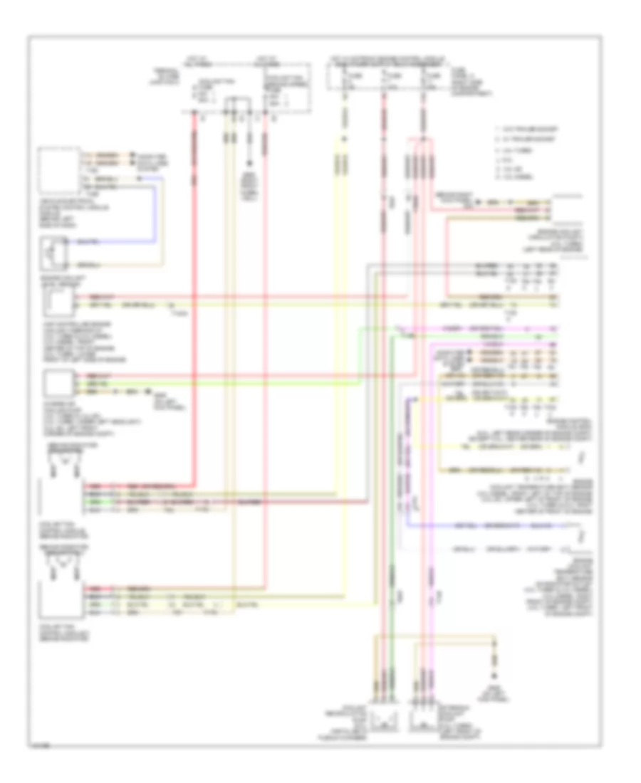
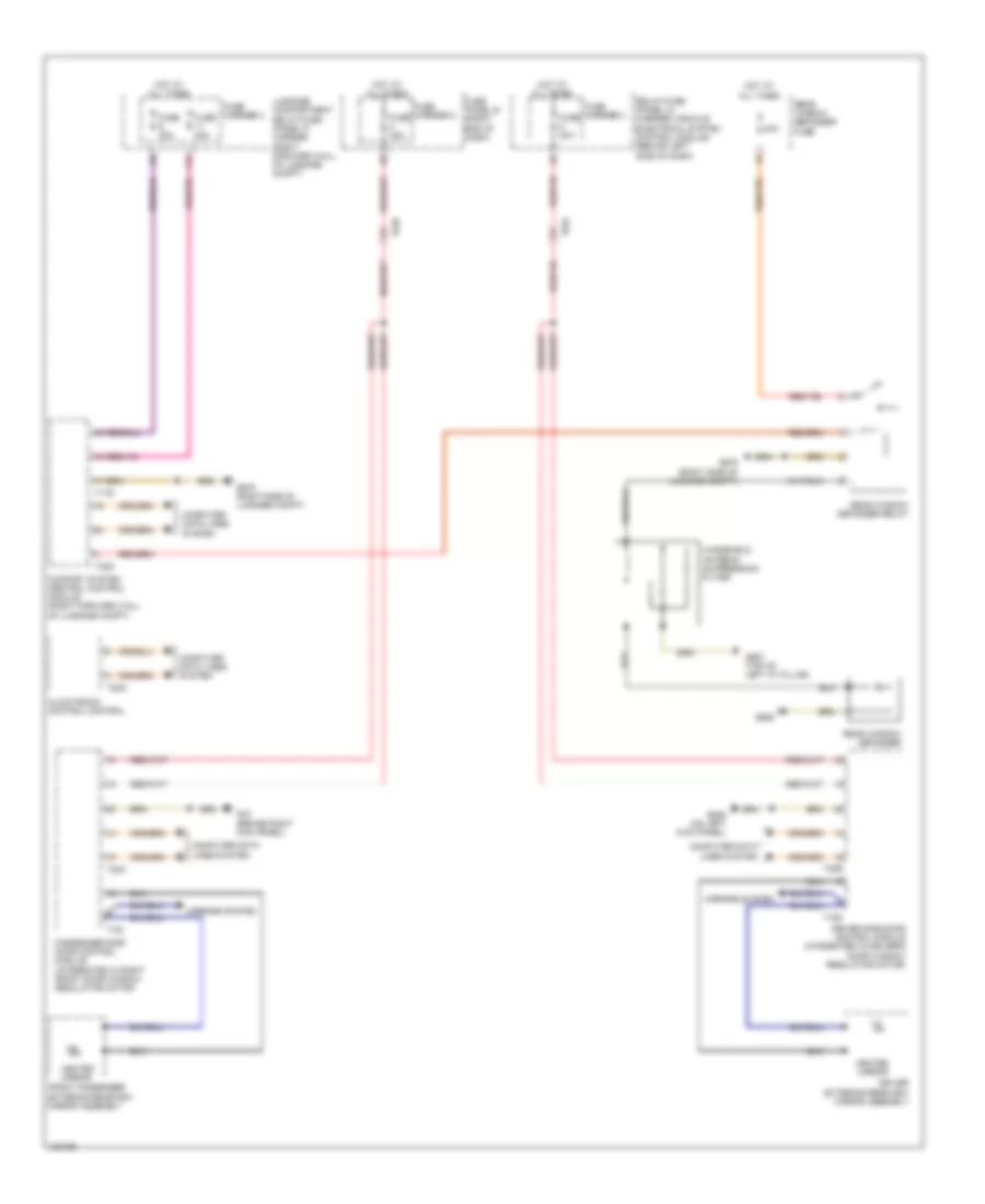
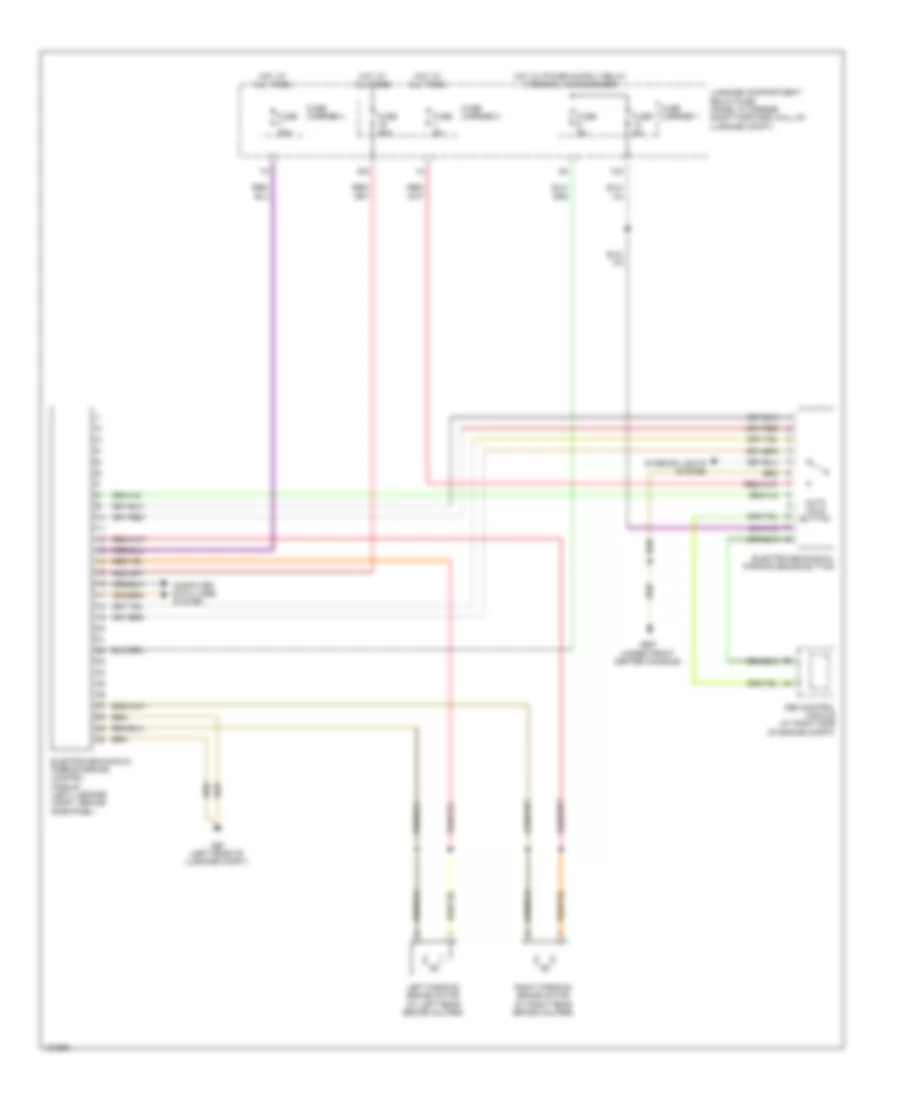
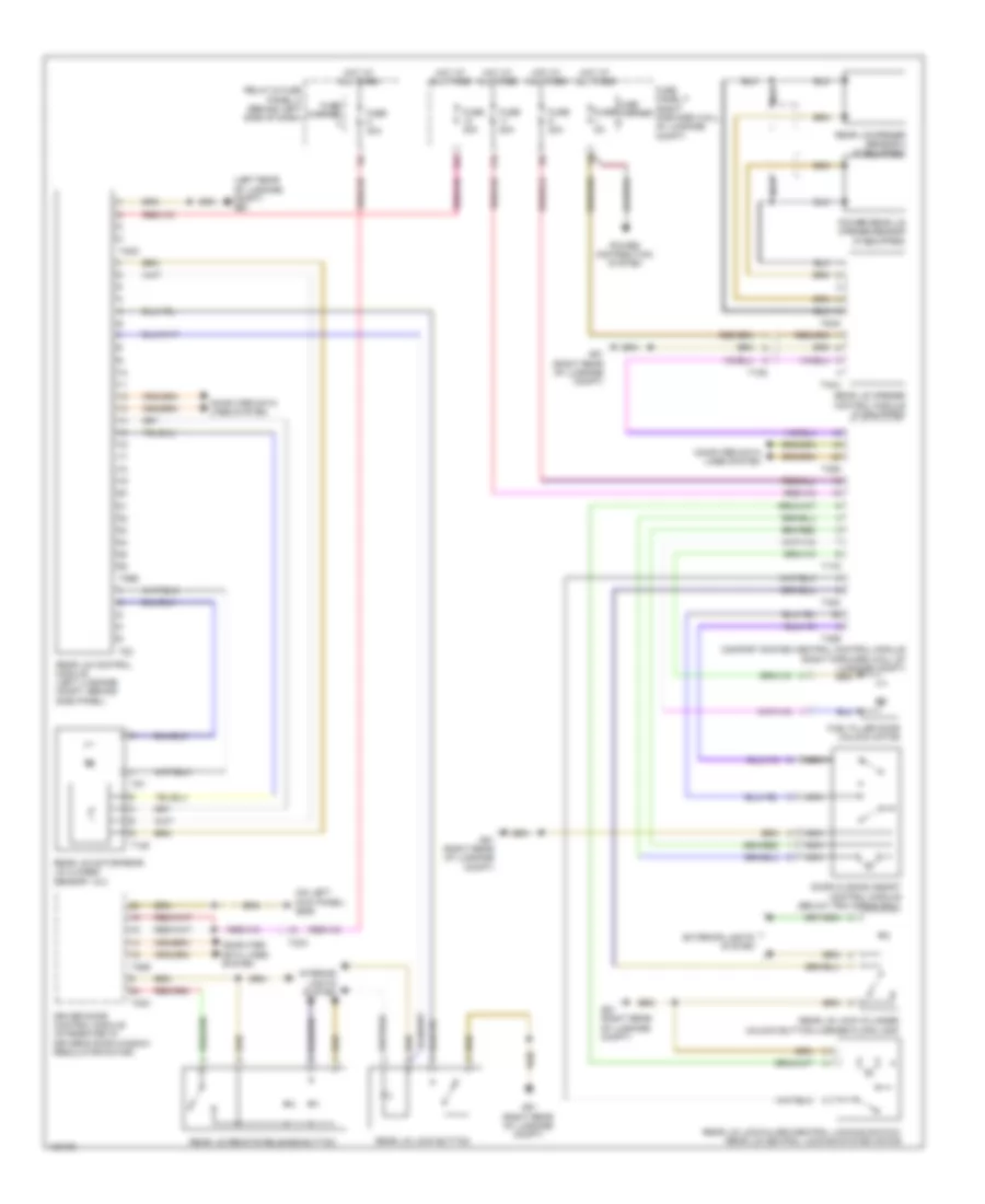
COOLING FAN
Cooling Fan Wiring Diagram for Audi A8 Quattro L 2014
List of elements for Cooling Fan Wiring Diagram for Audi A8 Quattro L 2014:
- (behind radiator) coolant fan
- (behind radiator) coolant fan 2
- (behind right kick panel) g43
- 11a
- 3.0l diesel
- 3.0l sc
- 4.0l turbo
- 40a
- 6.3l
- 60a
- After-run coolant pump (4.0l turbo) (left front of engine compt)
- Charge air cooling pump (4.0l turbo & 3.2l sc) (4.0l turbo: under left headlight) (3.0l sc: left front corner of engine compt)
- Computer data lines system
- Coolant fan control module (behind radiator)
- Coolant fan control module 2 (behind radiator)
- Coolant fan fuse
- Coolant fan second speed fuse
- Coolant recirculation pump (6.3l) (installed in plenum chamber)
- Engine control module (ecm) (6.3l: left rear corner of engine compt) (except 6.3l: center rear of engine compt)
- Engine coolant circulation pump 2 (4.0l turbo) (left rear of engine)
- Engine coolant level sensor
- Engine coolant temperature (ect) sensor (3.0l diesel: front left of top of engine) (3.0l sc: upper left of front of engine) (4.0l turbo & 6.3l: right center of front of engine)
- Engine coolant temperature (ect) sensor on radiator outlet (4.0l turbo & 3.0l diesel) (3.0l diesel: right front of engine compt) (4.0l turbo: left front of engine compt)
- Fuse 10a
- Fuse 15a
- Fuse 5a
- Fuse panel a (right side of engine compartment)
- G639 (on left kick panel)
- G685 (right front wheel well)
- Hot at all times
- Map controlled engine cooling thermostat (4.0l turbo & 3.0l diesel) (3.0l diesel: front center of top of engine) (4.0l turbo: lower front of left side of engine)
- Nca
- Red
- T105
- T10an
- T14b
- T16c
- T17g
- T2t
- T2u
- T32b
- T60
- T8ap
- T91
- T94
- Terminal 30 wire junction 2
- Vehicle electrical system control module module (behind left side of dash)
- W/ trailer socket
- W/o trailer socket
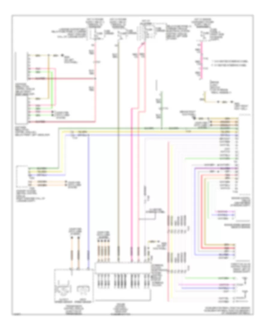
CRUISE CONTROL
3.0L SC
3.0L SC, Cruise Control Wiring Diagram for Audi A8 Quattro L 2014
List of elements for 3.0L SC, Cruise Control Wiring Diagram for Audi A8 Quattro L 2014:
- (left front foot well) g602
- 10a
- 3.0l
- 3.0l sc
- 4.0l turbo
- 6.3l
- Accelerator pedal position sensor/ accelerator pedal position sensor 2 (at accelerator pedal)
- Brake light switch (top of brake pedal assembly)
- Comfort system central control module (right forward wall of luggage compt)
- Computer data lines system
- Cruise control/ turn signal/ headlamp flasher switch
- Distance regulation control module (below front right headlamp)
- Distance regulation control module 2 (below front left headlamp)
- Engine control module (center rear of engine compt)
- Engine control module 2 (6.3l) (left rear corner of engine compt)
- Engine speed sensor (3.0l sc) (rear of engine)
- Engine speed sensor (lower rear of engine)
- Fuse 10a
- Fuse 5a
- Fuse carrier
- Fuse panel a (right side of engine compt)
- G43 (behind right kick panel)
- G639 (on left kick panel)
- Hot at all times
- Input speed sensor
- Luggage compartment relay/fuse (panel f) carrier (right forward wall of luggage compt)
- Nca
- Output speed sensor
- Pnk
- Relay/fuse (panel c) carrier (vehicle electrical system control module) (behind left side of dash)
- Steering column electronics system control module (top of steering column)
- T105
- T13b
- T14b
- T16d
- T17f
- T17g
- T17k
- T32c
- T32d
- T4h
- T60
- T60a
- T91
- T94
- T94a
- Throttle valve control module (3.0l sc: behind intake manifold, on throttle valve housing) (4.0l turbo: front of engine, on throttle) (6.3l: center of right side of engine)
- Throttle valve control module 2 (center of left side of engine)
- Transmission control module (in bottom of transmission)
- W/ heated steering wheel
- W/o heated steering wheel
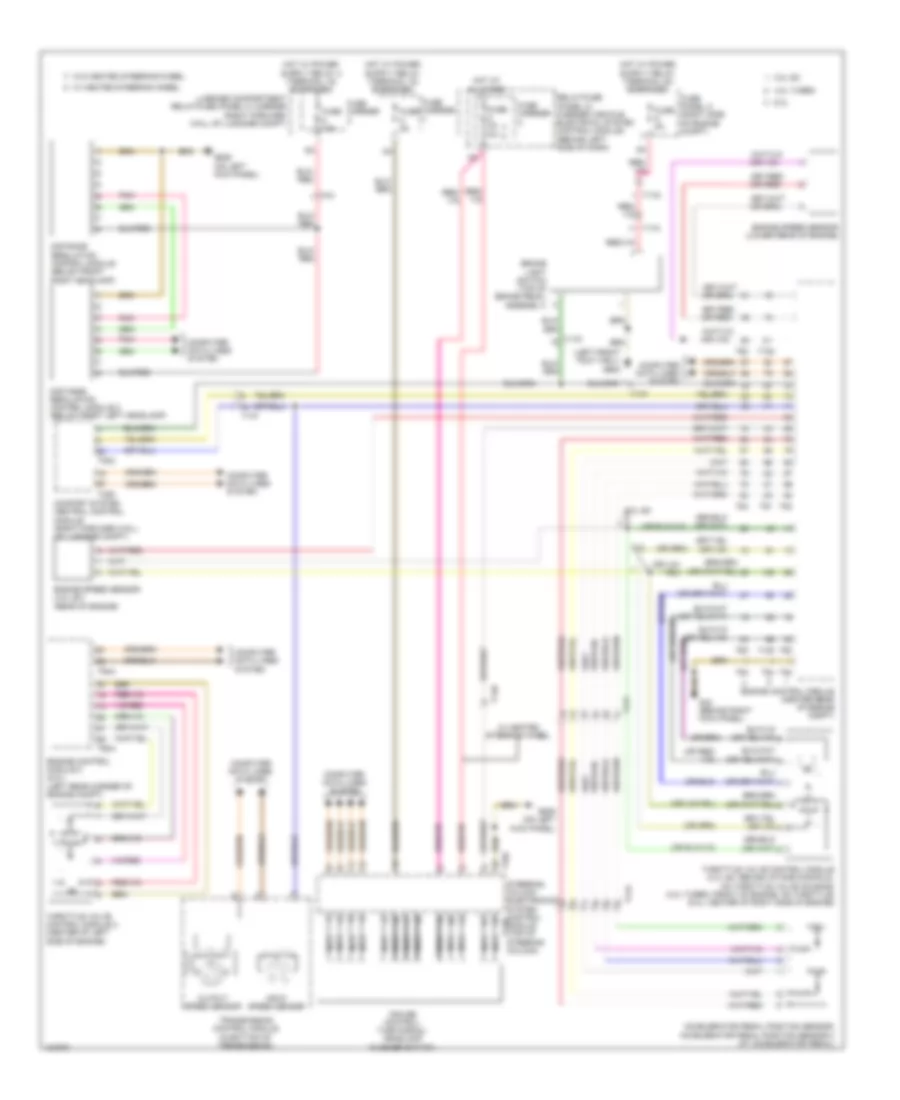
3.0L TURBO DIESEL
3.0L Turbo Diesel, Cruise Control Wiring Diagram for Audi A8 Quattro L 2014
List of elements for 3.0L Turbo Diesel, Cruise Control Wiring Diagram for Audi A8 Quattro L 2014:
- (behind right kick panel) g43
- 10a
- Accelerator pedal position sensor/ accelerator pedal position sensor 2 (at accelerator pedal)
- Brake light switch (top of brake pedal assembly)
- Comfort system central control module (right forward wall of luggage compt)
- Computer data lines system
- Cruise control/ turn signal/ headlamp flasher switch
- Distance regulation control module (below front right headlamp)
- Distance regulation control module 2 (below front left headlamp)
- Engine control module (center rear of engine compt)
- Engine speed sensor (rear of engine)
- Fuse 10a
- Fuse 5a
- Fuse carrier
- Fuse panel a (right side of engine compt)
- G602 (left front foot well)
- G639 (on left kick panel)
- Hot at all times
- Input speed sensor
- Luggage compartment relay/fuse (panel f) carrier (right forward wall of luggage compt)
- Nca
- Output speed sensor
- Pnk
- Red
- Relay/fuse (panel c) carrier (vehicle electrical system control module) (behind left side of dash)
- Steering column electronics system control module (top of steering column)
- T105
- T13b
- T14b
- T16d
- T17f
- T17g
- T17k
- T32c
- T32d
- T4h
- T91
- Throttle valve control module (front left of engine compt)
- Transmission control module (in bottom of transmission)
- W/ heated steering wheel
- W/o heated steering wheel
4.0L TURBO
4.0L Turbo, Cruise Control Wiring Diagram for Audi A8 Quattro L 2014
List of elements for 4.0L Turbo, Cruise Control Wiring Diagram for Audi A8 Quattro L 2014:
- (left front foot well) g602
- 10a
- 3.0l
- 3.0l sc
- 4.0l turbo
- 6.3l
- Accelerator pedal position sensor/ accelerator pedal position sensor 2 (at accelerator pedal)
- Brake light switch (top of brake pedal assembly)
- Comfort system central control module (right forward wall of luggage compt)
- Computer data lines system
- Cruise control/ turn signal/ headlamp flasher switch
- Distance regulation control module (below front right headlamp)
- Distance regulation control module 2 (below front left headlamp)
- Engine control module (center rear of engine compt)
- Engine control module 2 (6.3l) (left rear corner of engine compt)
- Engine speed sensor (3.0l sc) (rear of engine)
- Engine speed sensor (lower rear of engine)
- Fuse 10a
- Fuse 5a
- Fuse carrier
- Fuse panel a (right side of engine compt)
- G43 (behind right kick panel)
- G639 (on left kick panel)
- Hot at all times
- Input speed sensor
- Luggage compartment relay/fuse (panel f) carrier (right forward wall of luggage compt)
- Nca
- Output speed sensor
- Pnk
- Relay/fuse (panel c) carrier (vehicle electrical system control module) (behind left side of dash)
- Steering column electronics system control module (top of steering column)
- T105
- T13b
- T14b
- T16d
- T17f
- T17g
- T17k
- T32c
- T32d
- T4h
- T60
- T60a
- T91
- T94
- T94a
- Throttle valve control module (3.0l sc: behind intake manifold, on throttle valve housing) (4.0l turbo: front of engine, on throttle) (6.3l: center of right side of engine)
- Throttle valve control module 2 (center of left side of engine)
- Transmission control module (in bottom of transmission)
- W/ heated steering wheel
- W/o heated steering wheel
6.3L
6.3L, Cruise Control Wiring Diagram for Audi A8 Quattro L 2014
List of elements for 6.3L, Cruise Control Wiring Diagram for Audi A8 Quattro L 2014:
- (left front foot well) g602
- 10a
- 3.0l
- 3.0l sc
- 4.0l turbo
- 6.3l
- Accelerator pedal position sensor/ accelerator pedal position sensor 2 (at accelerator pedal)
- Brake light switch (top of brake pedal assembly)
- Comfort system central control module (right forward wall of luggage compt)
- Computer data lines system
- Cruise control/ turn signal/ headlamp flasher switch
- Distance regulation control module (below front right headlamp)
- Distance regulation control module 2 (below front left headlamp)
- Engine control module (center rear of engine compt)
- Engine control module 2 (6.3l) (left rear corner of engine compt)
- Engine speed sensor (3.0l sc) (rear of engine)
- Engine speed sensor (lower rear of engine)
- Fuse 10a
- Fuse 5a
- Fuse carrier
- Fuse panel a (right side of engine compt)
- G43 (behind right kick panel)
- G639 (on left kick panel)
- Hot at all times
- Input speed sensor
- Luggage compartment relay/fuse (panel f) carrier (right forward wall of luggage compt)
- Nca
- Output speed sensor
- Pnk
- Relay/fuse (panel c) carrier (vehicle electrical system control module) (behind left side of dash)
- Steering column electronics system control module (top of steering column)
- T105
- T13b
- T14b
- T16d
- T17f
- T17g
- T17k
- T32c
- T32d
- T4h
- T60
- T60a
- T91
- T94
- T94a
- Throttle valve control module (3.0l sc: behind intake manifold, on throttle valve housing) (4.0l turbo: front of engine, on throttle) (6.3l: center of right side of engine)
- Throttle valve control module 2 (center of left side of engine)
- Transmission control module (in bottom of transmission)
- W/ heated steering wheel
- W/o heated steering wheel
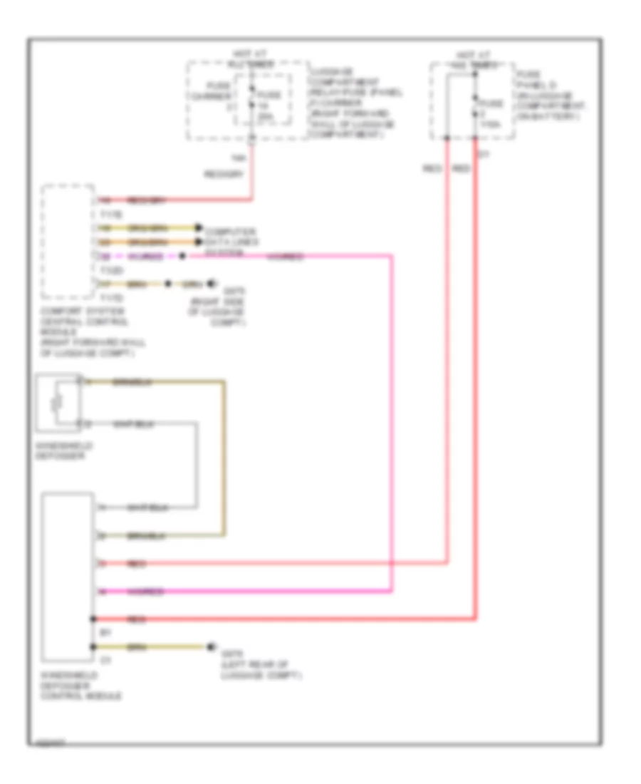
DEFOGGERS
Heated Windshield Wiring Diagram for Audi A8 Quattro L 2014
List of elements for Heated Windshield Wiring Diagram for Audi A8 Quattro L 2014:
- 14a
- Comfort system central control module (right forward wall of luggage compt)
- Computer data lines system
- Fuse 110a
- Fuse 20a
- Fuse carrier
- Fuse panel d (in luggage compartment, on battery)
- G675 (right side of luggage compt)
- G676 (left rear of luggage compt)
- Hot at all times
- Luggage compartment relay/fuse (panel f) carrier (right forward wall of luggage compartment)
- Red
- T17d
- T17e
- T32d
- Windshield defogger
- Windshield defogger control module
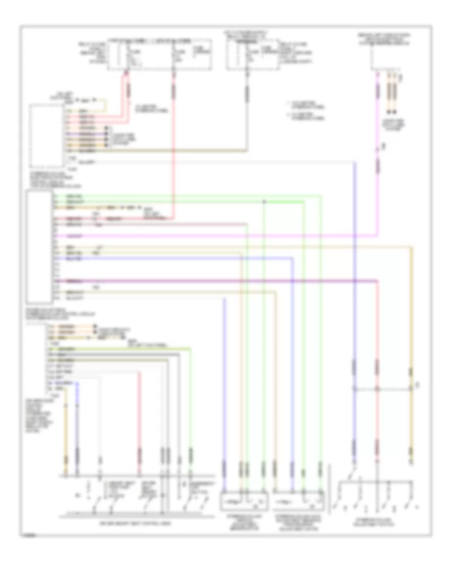
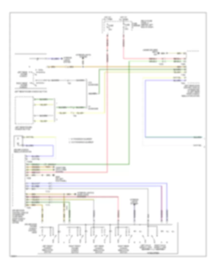
Rear Defogger & Heated Mirrors Wiring Diagram for Audi A8 Quattro L 2014
List of elements for Rear Defogger & Heated Mirrors Wiring Diagram for Audi A8 Quattro L 2014:
- 11a
- 40a
- Climatronic control control
- Comfort system central control module (right forward wall of luggage compt)
- Computer data lines system
- Driver exterior rearview mirror assembly
- Driver side door control module (integrated in driver's door window regulator motor)
- Front passenger exterior rearview mirror assembly
- Fuse 20a
- Fuse 30a
- Fuse carrier 2
- Fuse carrier 3
- Fuse carrier 4
- Fuse panel b (right end of dash)
- G43 (behind right kick panel)
- G639 (on left kick panel)
- G657 (top of left "d" pillar)
- G659
- G675 (right side of luggage compt)
- Heated mirror
- Hot at all times
- Luggage compartment relay/fuse (panel f) carrier (right forward wall of luggage compt)
- Mirrors system
- Passenger side door control module (integrated in right front door window regulator motor)
- Rear window defogger
- Rear window defogger fuse
- Rear window defogger relay
- Relay/fuse (panel c) carrier (vehicle electrical system control module) (behind left side of dash)
- T16k
- T16l
- T17d
- T20b
- T20c
- T20g
- T23a
- T23b
- T32d
- Windshield antenna suppression filter
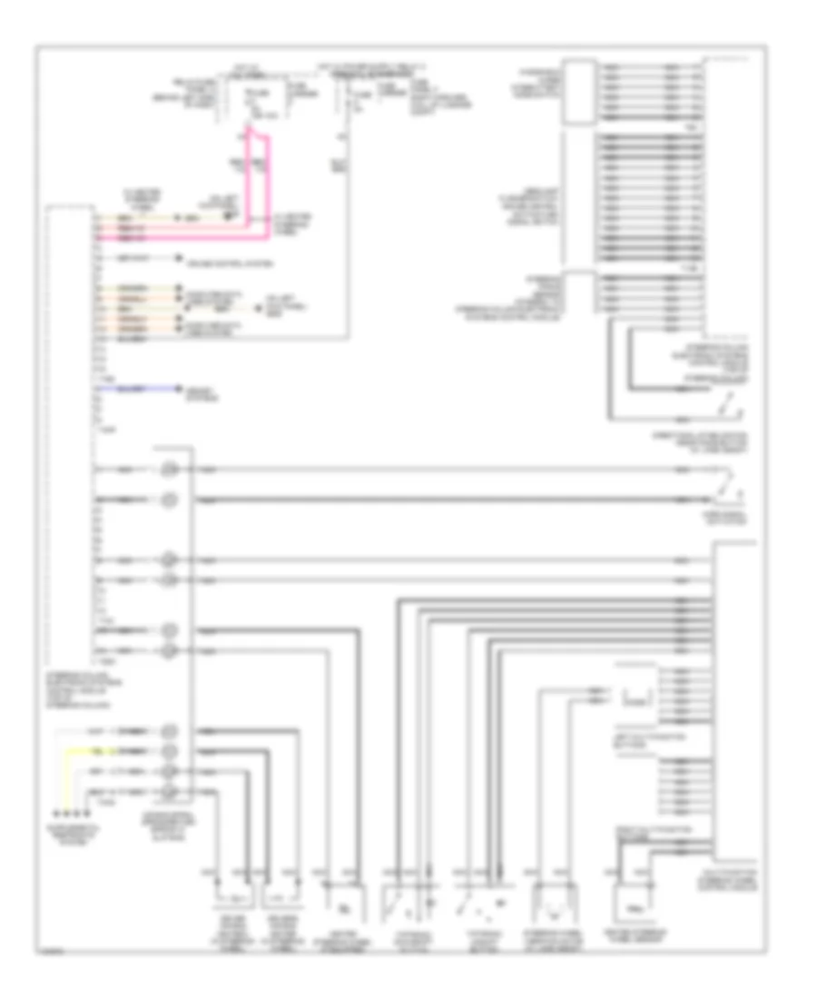
ELECTRONIC POWER STEERING
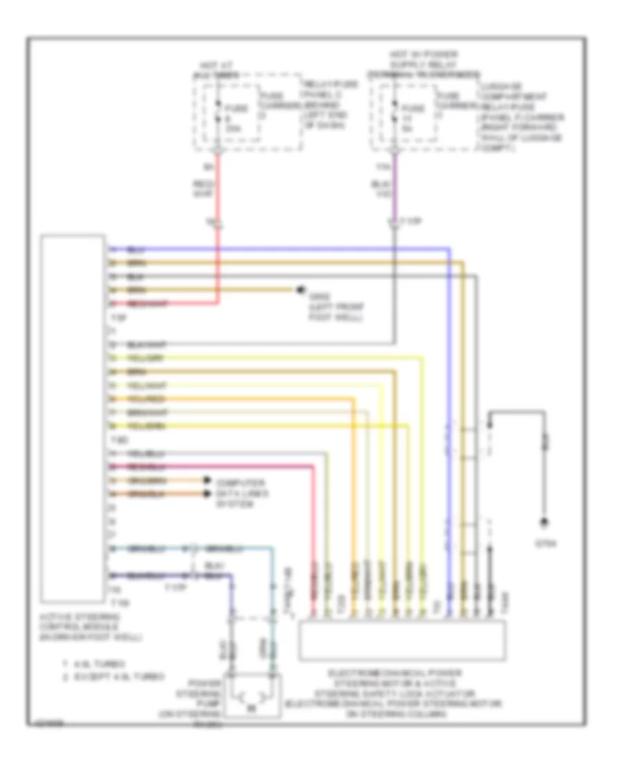
Active Steering Control Module Wiring Diagram for Audi A8 Quattro L 2014
List of elements for Active Steering Control Module Wiring Diagram for Audi A8 Quattro L 2014:
- 11a
- 4.0l turbo
- Active steering control module (in driver foot well)
- Computer data lines system
- Electromechanical power steering motor & active steering safety lock actuator (electromechanical power steering motor: on steering column)
- Except 4.0l turbo
- Fuse 35a
- Fuse 5a
- Fuse carrier
- G602 (left front foot well)
- G704
- Hot at all times
- Luggage compartment relay/fuse (panel f) carrier (right forward wall of luggage compt)
- Power steering pump (on steering rack)
- Relay/fuse panel c (behind left end of dash)
- T10i
- T14b
- T17p
- T2di
- T4ak
- T4an
- T5f
- T6i
- T8d
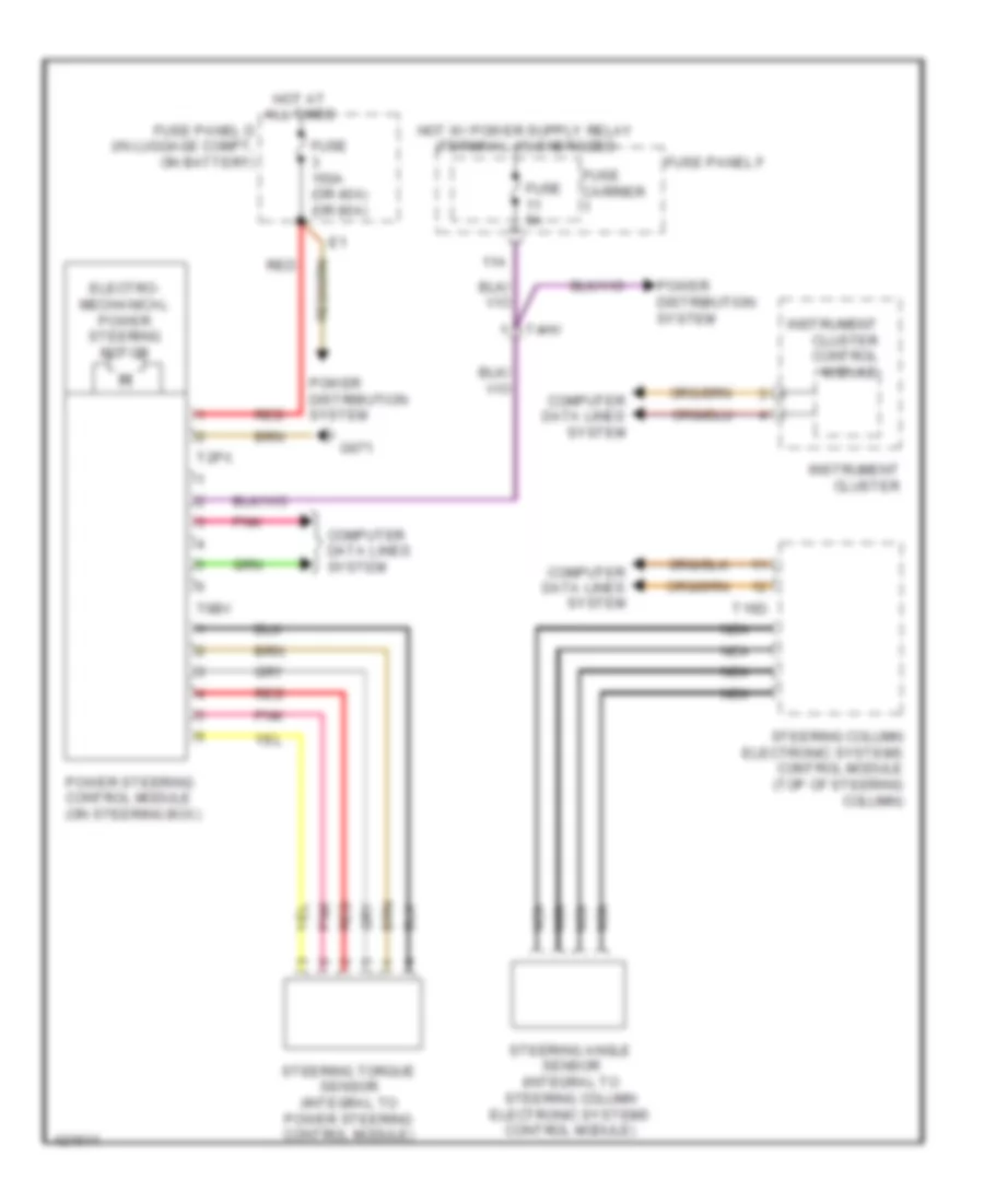
Electromechanical Power Steering Wiring Diagram for Audi A8 Quattro L 2014
List of elements for Electromechanical Power Steering Wiring Diagram for Audi A8 Quattro L 2014:
- 11a
- Computer data lines system
- Electro- mechanical power steering motor
- Fuse 150a (or 40a) (or 80a)
- Fuse 5a
- Fuse carrier
- Fuse panel d (in luggage compt, on battery)
- Fuse panel f
- G671
- Hot at all times
- Instrument cluster
- Instrument cluster control module
- Nca
- Pnk
- Power distribution system
- Power steering control module (on steering box)
- Red
- Steering angle sensor (integral to steering column electronic systems control module)
- Steering column electronic systems control module (top of steering column)
- Steering torque sensor (integral to power steering control module)
- T16d
- T2px
- T4hv
- T6bv
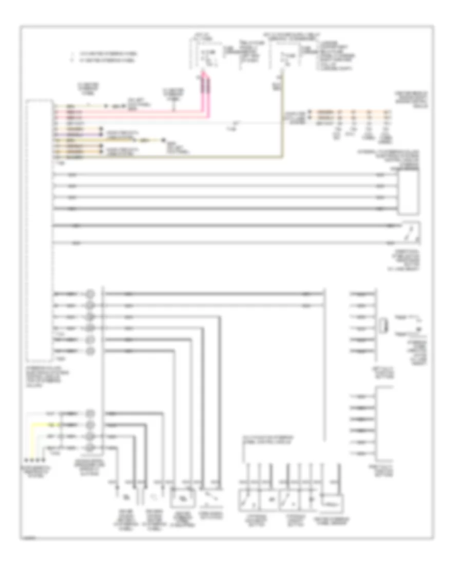
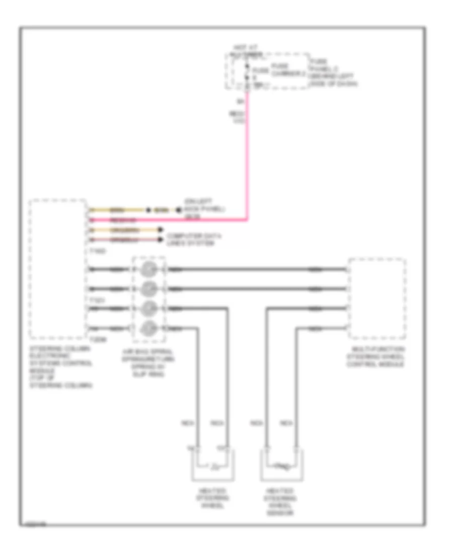
Steering Column Electronic Systems Control Module Wiring Diagram for Audi A8 Quattro L 2014
List of elements for Steering Column Electronic Systems Control Module Wiring Diagram for Audi A8 Quattro L 2014:
- (3.0l sc)
- (3.0l turbo diesel)
- (4.0l turbo)
- (6.3l)
- (center rear of engine compt) engine control module
- (integral to steering column electronic systems control module) steering angle sensor
- (on left kick panel) g639
- Air bag spiral spring/return spring w/ slip ring
- Computer data lines system
- Directional stabilization assistance button (w/ lane assist)
- Driver air bag igniter 2 (in steering wheel)
- Driver's air bag igniter (in steering wheel)
- Fuse 5a
- Fuse 5a 10a
- Fuse carrier
- G639 (on left kick panel)
- Heated steering wheel (if equipped)
- Heated steering wheel sensor
- Horn signal activation
- Hot at all times
- Left multi- function buttons
- Luggage compartment relay/fuse (panel f) carrier (right forward wall of luggage compt)
- Mode
- Multi-function steering wheel control module
- Nca
- Relay/fuse panel c (behind left end of dash)
- Right multi- function buttons
- Steering column electronic systems control module (top of steering column)
- Steering wheel vibration motor (w/ lane assist)
- T12v
- T14b
- T16d
- T2dm
- T4aq
- T91
- T94
- Tiptronic downshift button
- Tiptronic upshift button
- W/ heated steering wheel
- W/o heated steering wheel
ELECTRONIC SUSPENSION
Electronic Suspension Wiring Diagram (1 of 2) for Audi A8 Quattro L 2014
List of elements for Electronic Suspension Wiring Diagram (1 of 2) for Audi A8 Quattro L 2014:
- (on air spring shock absorber, each wheel)
- (right side of luggage compt) g675
- Fuse 15a
- Fuse 5a
- Fuse carrier 1
- Fuse carrier 4
- Hot at all times
- Left front damping adjustment valve
- Left front level control system sensor (on left lower transverse link)
- Left rear damping adjustment valve
- Left rear level control system sensor (in left rear wheel suspension)
- Level control system control module (left forward wall of luggage compt)
- Luggage compartment relay/fuse (panel f) carrier (right forward wall of compt)
- Right front damping adjustment valve
- Right front level control system sensor (on right lower transverse link)
- Right rear damping adjustment valve
- Right rear level control system sensor (in right rear wheel suspension)
- T12a
- T15a
- T9a
Electronic Suspension Wiring Diagram (2 of 2) for Audi A8 Quattro L 2014
List of elements for Electronic Suspension Wiring Diagram (2 of 2) for Audi A8 Quattro L 2014:
- 40a
- Compt)
- Computer data lines system
- G675 (right side of luggage compt)
- G676 (left rear luggage compt)
- Hot at all times
- Left front suspension strut valve
- Left rear suspension strut valve
- Level control accumulator valve
- Level control pressure sensor
- Level control system compressor motor
- Level control system compressor relay (in relay & fuse carrier, right side of luggage compt)
- Level control system control module (left forward wall of luggage
- Pnk
- Right front suspension strut valve
- Right rear suspension strut valve
- Shelf-leveling suspension fuse
- T10b
- T18b
- T2m
- T2n
- T2o
- T6b
- Valve body
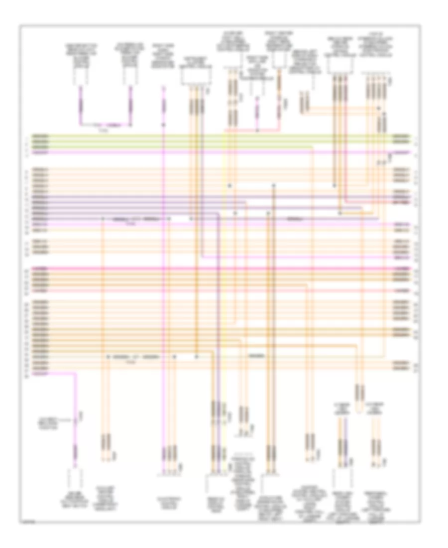
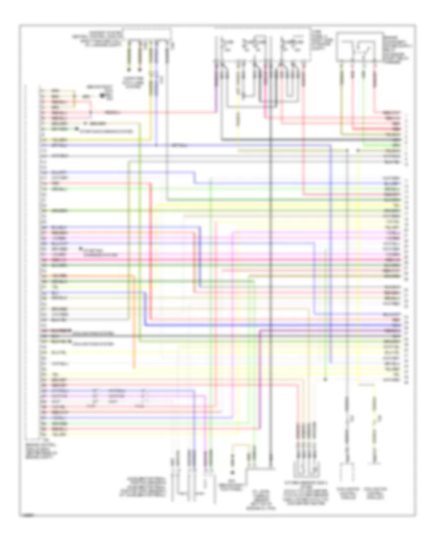
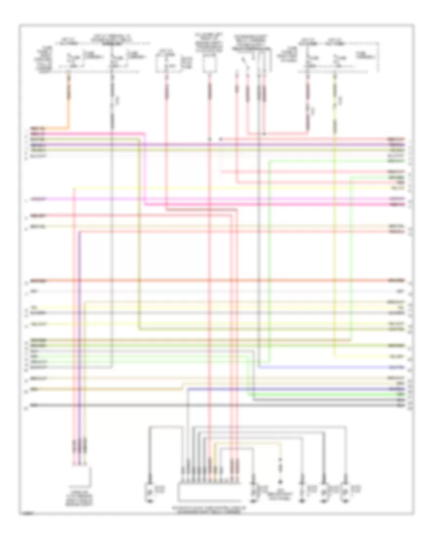
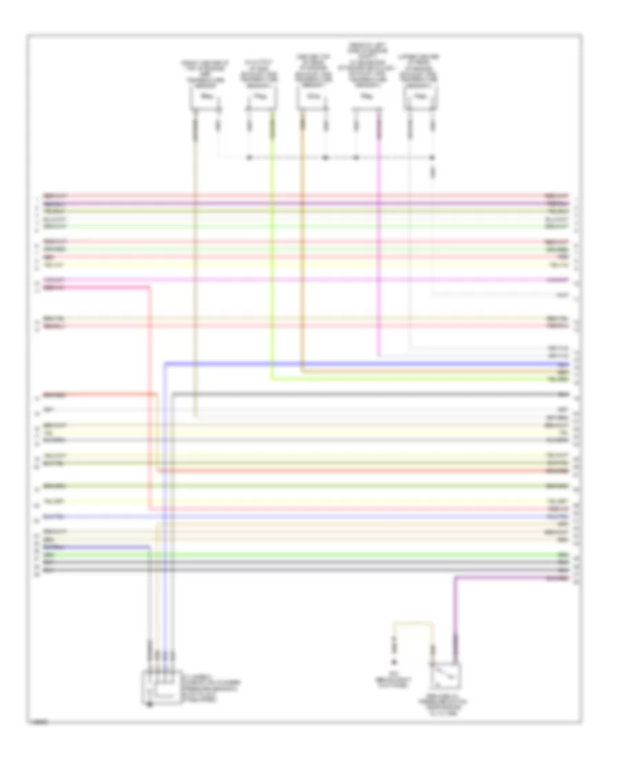
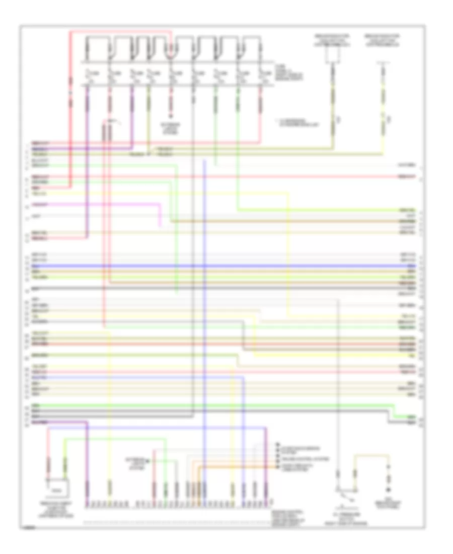
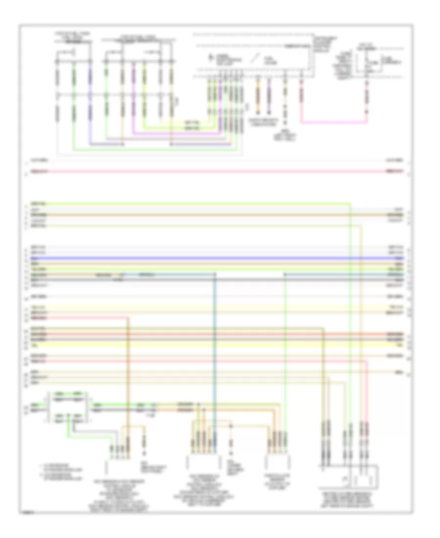
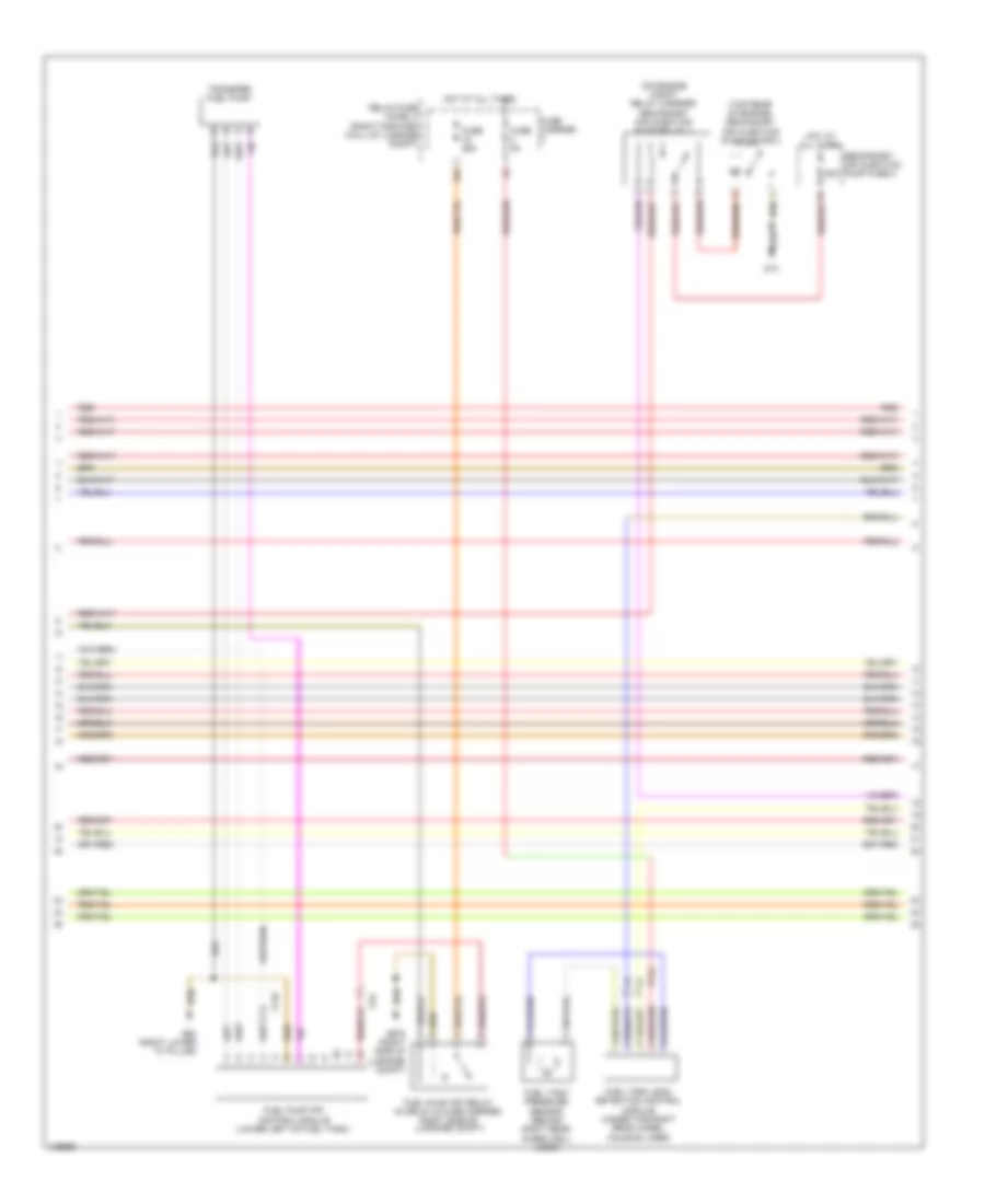
ENGINE PERFORMANCE
3.0L SC
3.0L SC, Engine Performance Wiring Diagram (1 of 9) for Audi A8 Quattro L 2014
List of elements for 3.0L SC, Engine Performance Wiring Diagram (1 of 9) for Audi A8 Quattro L 2014:
- (behind right kick panel) g43
- Accelerator pedal position sensor & accelerator pedal position (app) sensor 2 (at accelerator pedal)
- Comfort system central control module (right forward wall of luggage compt)
- Computer data lines system
- Cooling fan control module
- Cooling fan control module 2
- Cooling fans system
- Engine control module (ecm) (center rear of engine compt)
- Fuse 15a
- Fuse 5a
- Fuse panel a (right side of engine compt)
- G43 (behind right kick panel)
- Nca
- Oil level thermal sensor (bottom of engine oil pan)
- Oxygen sensor (02s) 2 after catalytic converter (twc) & oxygen sensor (o2s) 2 after catalytic converter heater
- Red
- Starting/ charging system
- Starting/charging system
- T17f
- T17k
- T2t
- T2u
- T32c
- T32d
- T94
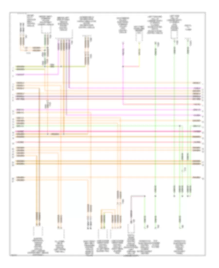
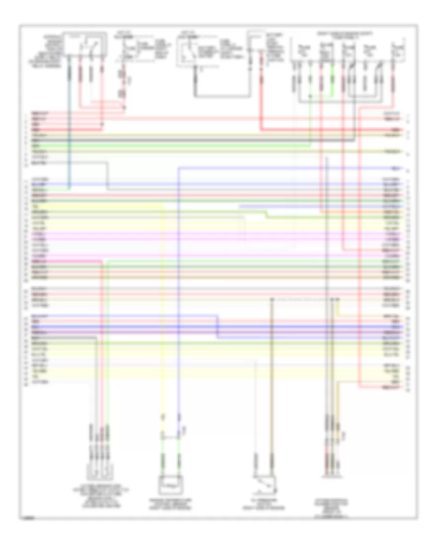
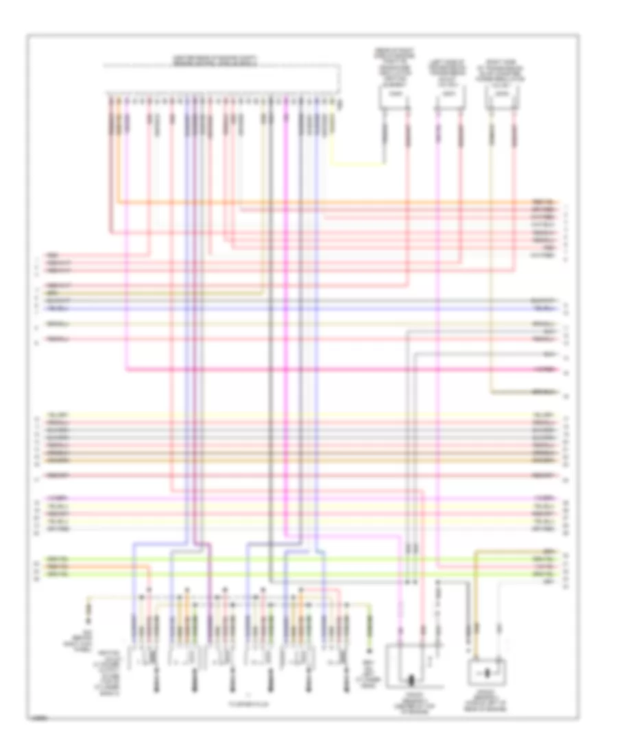
3.0L SC, Engine Performance Wiring Diagram (2 of 9) for Audi A8 Quattro L 2014
List of elements for 3.0L SC, Engine Performance Wiring Diagram (2 of 9) for Audi A8 Quattro L 2014:
- (right side of engine compt) fuse panel a
- 10a
- 11a
- 12a
- Battery interrupt igniter
- Battery jump start terminal (terminal 30 wire
- Engine temperature control sensor (right side of engine)
- Fuse 10a
- Fuse 15a
- Fuse 20a (or 30a)
- Fuse 35a
- Fuse carrier
- Fuse panel b (right end of dash)
- Fuse panel d (in luggage compt, on battery)
- Hot at all times
- Intake manifold runner position sensor (front of cylinder bank 1)
- Junction 2)
- Nca
- Oil pressure switch (right side of engine)
- Oxygen sensor (o2s) after three way catalytic converter & oxygen sensor (o2s) 1 after catalytic converter heater
- Red
- T14k
- T17f
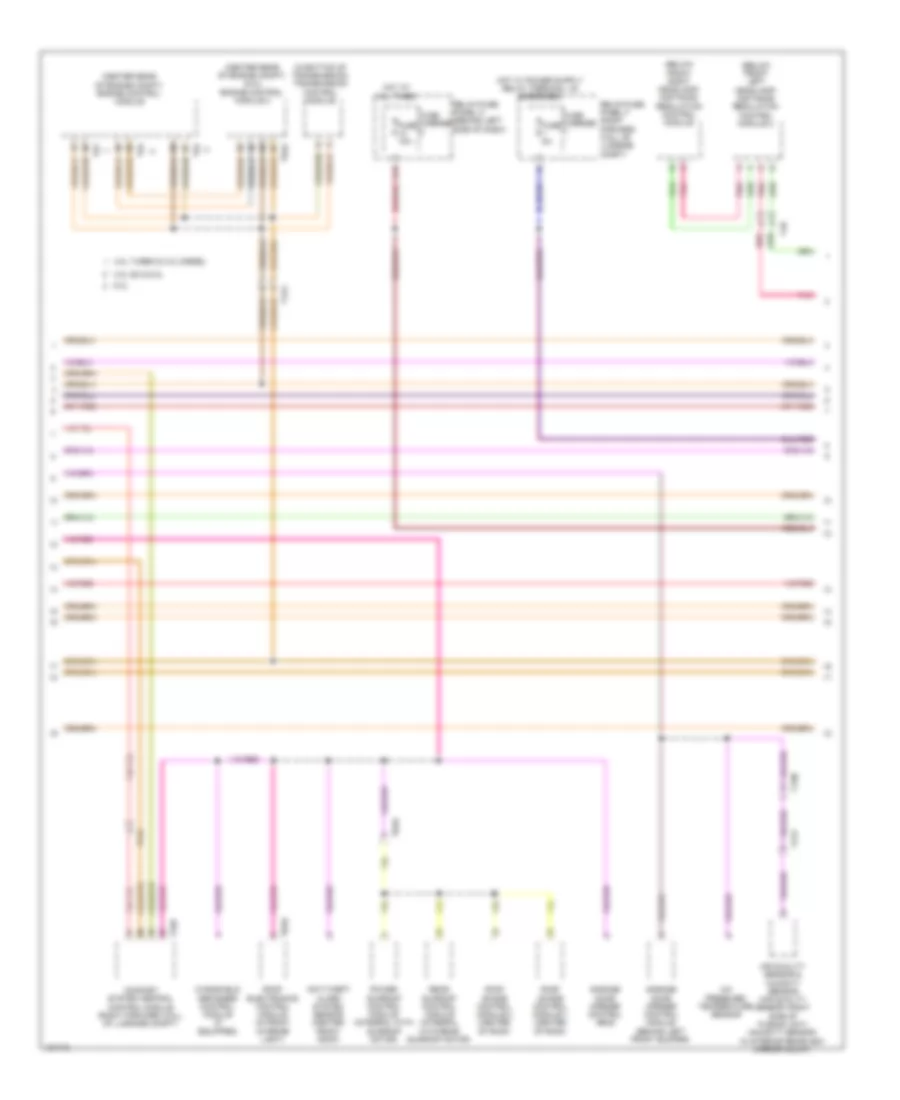
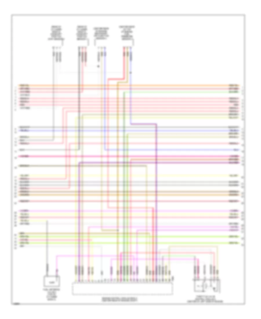
3.0L SC, Engine Performance Wiring Diagram (3 of 9) for Audi A8 Quattro L 2014
List of elements for 3.0L SC, Engine Performance Wiring Diagram (3 of 9) for Audi A8 Quattro L 2014:
- 15a
- Computer data lines system
- Engine coolant level sensor
- Fuel pump (fp) relay (in relay & fuse carrier, right side of luggage compt)
- Fuse 25a
- Fuse 5a
- Fuse carrier
- Fuse carrier 2
- Fuse panel b (right end of dash)
- G675 (right side of luggage compt)
- Hot at all times
- Red
- Reduced oil pressure switch (near engine oil filter)
- Relay/fuse panel f (right forward wall of luggage compt)
- Secondary air injection (air) solenoid valve (rear of supercharger)
- T14d
- T16c
- T17g
- T32b
- T3x
- Vehicle electrical system control module (behind left side of dash)
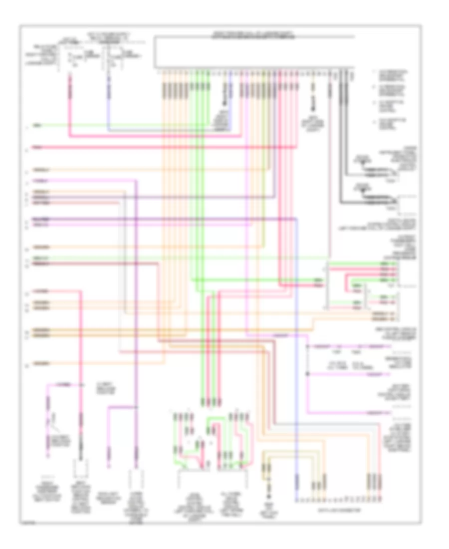
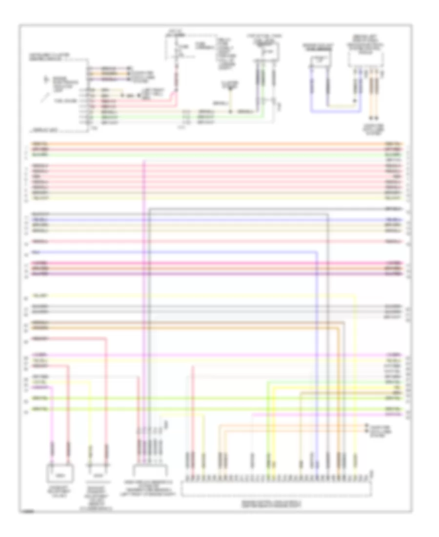
3.0L SC, Engine Performance Wiring Diagram (4 of 9) for Audi A8 Quattro L 2014
List of elements for 3.0L SC, Engine Performance Wiring Diagram (4 of 9) for Audi A8 Quattro L 2014:
- (left rear of engine compt) heated oxygen sensor (h02s)
- (lower left of fuel tank) fuel pump (fp) control module
- (right lower c-pillar)
- (top of brake pedal assembly) brake light switch
- (upstream of left bank catalytic converter)
- Camshaft adjustment valve 1
- Camshaft adjustment valve 2
- G602 (left front footwell)
- G62
- G62 (right lower c-pillar)
- Heated oxygen sensor (ho2s) 2
- Left electrohydraulic hydraulic engine mount solenoid valve (on left engine mount)
- Nca
- Red
- Right electrohydraulic engine mount solenoid valve (on right engine mount)
- T14p
- T17f
- T17g
- T17k
- Transfer fuel pump (fp)
3.0L SC, Engine Performance Wiring Diagram (5 of 9) for Audi A8 Quattro L 2014
List of elements for 3.0L SC, Engine Performance Wiring Diagram (5 of 9) for Audi A8 Quattro L 2014:
- (left front footwell) g602
- (right rear of engine, integral with iat sensor) manifold absolute pressure sensor/intake air temperature sensor
- (top of fuel tank) fuel level sensor
- Brake booster pressure sensor (w/ start/stop system) (inside plenum chamber, front of brake booster)
- Computer data lines system
- Control valve control unit
- Display unit
- Engine electronics indicator lamp
- Fuel gauge
- Fuse 5a
- Fuse carrier
- Hot at all times
- Instrument cluster control module
- Instrument cluster system
- Intake manifold runner control (imrc) valve (rear of supercharger)
- Red
- Relay/fuse panel f (right forward wall of luggage compt)
- T14b
- T14p
- T17i
3.0L SC, Engine Performance Wiring Diagram (6 of 9) for Audi A8 Quattro L 2014
List of elements for 3.0L SC, Engine Performance Wiring Diagram (6 of 9) for Audi A8 Quattro L 2014:
- (front of cylinder bank 1) low fuel pressure sensor
- (left front of engine) intake manifold temperature sensor 2 & charge air pressure sensor 2
- (rear of engine) secondary air injection sensor 1
- (top left side of engine) fuel pressure sensor
- (top of cylinder bank 1) camshaft position (cmp) sensor
- (top of cylinder bank 2) camshaft position (cmp) sensor 2
- (upper right side of engine, on supercharger) intake manifold temperature sensor & charge air pressure sensor
- Engine control module (ecm) (center rear of engine compt)
- Intake manifold runner position sensor 2 (front of cylinder bank 2)
- Knock sensor (ks) 1 (inner side of cylinder bank 1)
- Knock sensor (ks) 2 (center of cylinder bank 2)
- Nca
- Red
- T14d
- T14k
- T60
3.0L SC, Engine Performance Wiring Diagram (7 of 9) for Audi A8 Quattro L 2014
List of elements for 3.0L SC, Engine Performance Wiring Diagram (7 of 9) for Audi A8 Quattro L 2014:
- (rear of engine) engine speed (rpm) sensor
- (upper left of front of engine) engine coolant temperature (ect) sensor
- Charge air cooling pump (left front corner of engine compt)
- Exhaust door valve 1
- Fuel tank pressure sensor (behind right rear wheelwell liner)
- Fuse 5a
- Fuse carrier
- G639 (on left kick panel)
- Hot at all times
- Red
- Relay/fuse panel f (right forward wall of luggage compt)
- T14b
- T16a
- Transmission control module (tcm) (in bottom of transmission)
- Transmission fluid cooling valve (in lower left front of engine compt)
3.0L SC, Engine Performance Wiring Diagram (8 of 9) for Audi A8 Quattro L 2014
List of elements for 3.0L SC, Engine Performance Wiring Diagram (8 of 9) for Audi A8 Quattro L 2014:
- (not used)
- 50a
- Crankcase ventilation shut-off valve
- Egr cooler switch-over valve (top center of front of engine)
- Evaporative emission (evap) canister purge regulator valve 1 (right rear of engine)
- Fuel metering valve (front of cylinder bank 1)
- Fuel tank leak detection control module (under the right rear wheel housing liner)
- G639 (on left kick panel)
- Oil pressure regulation valve (lower front of left side of engine)
- Red
- Secondary air injection (air) pump motor (left front of engine compt)
- Secondary air injection (air) pump relay (on engine compt relay carrier)
- Secondary air injection (air) solenoid valve 2 (rear of supercharger)
- Secondary air injection pump fuse
- T14d
- T17g
- T2cf
3.0L SC, Engine Performance Wiring Diagram (9 of 9) for Audi A8 Quattro L 2014
List of elements for 3.0L SC, Engine Performance Wiring Diagram (9 of 9) for Audi A8 Quattro L 2014:
- (not used)
- (on right cylinder head) g600
- 14a
- Coil 1
- Coil 2
- Coil 3
- Coil 4
- Coil 5
- Coil 6
- Computer data lines system
- Cruise control system
- Engine control module (ecm) (center rear of engine compt)
- Fuel injector cylinders (cylinder 1: rear of cylinder bank 1) (cylinder 2: center of cylinder bank 1 (cylinder 6: front of cylinder bank 2) (cylinder 5: middle of cylinder bank 2) (cylinder 4: rear of cylinder bank 2) (cylinder 3: front of cylinder bank 1)
- Fuse 5a
- Fuse carrier
- G43 (behind right kick panel)
- G601 (on left cylinder head)
- Ignition coils w/ power output stage (coil 1, 2 & 3: top of cylinder bank 1) (coil 4, 5 & 6: top of cylinder bank 2)
- Nca
- Relay/fuse panel f (right forward wall of luggage compt)
- Spark plugs
- Starting/charging system
- T14d
- T14k
- T17f
- T17g
- T17k
- T60
- T94
- Throttle valve control module (behind intake manifold, on throttle valve housing)
3.0L TURBO DIESEL
3.0L Turbo Diesel, Engine Performance Wiring Diagram (1 of 9) for Audi A8 Quattro L 2014
List of elements for 3.0L Turbo Diesel, Engine Performance Wiring Diagram (1 of 9) for Audi A8 Quattro L 2014:
- (behind right kick panel) g43
- (in relay & fuse carrier, right side of luggage compt) fuel pump (fp) relay
- (lower left of fuel tank) fuel pump (fp) control module
- Accelerator pedal position sensor & accelerator pedal position sensor 2 (at accelerator pedal)
- Comfort system central control module (right forward wall of luggage compt)
- Differential pressure sensor (left rear of engine compt)
- Egr motor (integral to map controlled engine cooling thermostat)
- Engine control module (ecm) (center rear of engine compt)
- G43 (behind right kick panel)
- G62 (right lower c-pillar)
- G675 (right side of luggage compt)
- Oil level thermal sensor (bottom of engine oil pan)
- Starting/charging system
- T10an
- T14p
- T17f
- T17k
- T32c
- T3x
- T91
- Transfer fuel pump
- Transmissions system
- Turbocharger control module 1 (on turbocharger housing)
3.0L Turbo Diesel, Engine Performance Wiring Diagram (2 of 9) for Audi A8 Quattro L 2014
List of elements for 3.0L Turbo Diesel, Engine Performance Wiring Diagram (2 of 9) for Audi A8 Quattro L 2014:
- (in lower left front of engine compt) transmission fluid cooling valve
- 14a
- 15a
- 80a
- Automatic glow time control module (on engine compt relay carrier)
- Fuse 25a
- Fuse 35a
- Fuse 5a
- Fuse carrier 1
- Fuse carrier 2
- Fuse carrier 3
- Fuse panel b (right end of dash)
- Fuse panel f (right forward wall of luggage compt)
- G43 (behind right kick panel)
- Glow plug
- Glow plug fuse
- Hot at all times
- Mass air flow sensor (right side of engine compt)
- Red
- T17f
- T17g
3.0L Turbo Diesel, Engine Performance Wiring Diagram (3 of 9) for Audi A8 Quattro L 2014
List of elements for 3.0L Turbo Diesel, Engine Performance Wiring Diagram (3 of 9) for Audi A8 Quattro L 2014:
- (center top of rear of engine) exhaust gas temperature sensor 1
- (front center of top of engine) egr temperature sensor
- (in output of scr) exhaust gas temperature sensor 4
- (rear of left side of engine compt) (w/ emissions standard bin 5/ulev) exhaust gas temperature sensor 2
- (upper center of rear of engine) exhaust gas temperature sensor 3
- Cylinder 2 combustion chamber pressure sensor & glow plug 2 (if equipped)
- G43 (behind right kick panel)
- Red
- Reduced oil pressure switch (near engine oil filter)
3.0L Turbo Diesel, Engine Performance Wiring Diagram (4 of 9) for Audi A8 Quattro L 2014
List of elements for 3.0L Turbo Diesel, Engine Performance Wiring Diagram (4 of 9) for Audi A8 Quattro L 2014:
- (behind radiator) coolant fan control module
- (behind radiator) coolant fan control module 2
- 10a
- 11a
- Computer data lines system
- Cruise control system
- Engine control module (ecm) (center rear of engine compt)
- Exterior lights system
- Fuse 10a
- Fuse 15a
- Fuse 5a
- Fuse panel a (right side of engine compt)
- G43 (behind right kick panel)
- Injector (in exhaust, upstream of scr)
- Nca
- Oil pressure
- Red
- Reducing agent
- Starting/charging system
- Switch (right side of engine)
- T2t
- T2u
- T91
- W/ emissions standard bin5/ulev
3.0L Turbo Diesel, Engine Performance Wiring Diagram (5 of 9) for Audi A8 Quattro L 2014
List of elements for 3.0L Turbo Diesel, Engine Performance Wiring Diagram (5 of 9) for Audi A8 Quattro L 2014:
- (top of fuel tank) fuel level sensor
- (top of fuel tank) fuel level sensor 2 & 3
- Computer data lines system
- Diesel electronics ind lamp
- Display unit
- Fuel gauge
- Fuse 5a
- Fuse carrier 6
- Fuse panel f (right forward wall of luggage compt)
- G34 (under driver's seat)
- G43 (behind right kick panel)
- G602 (left front foot well)
- Heated oxygen sensor & oxygen sensor heater (heated oxygen sensor: left rear of engine compt)
- Hot at all times
- Instrument cluster control module
- Nca
- Nox sensor & nox sensor control module (w/ emissions standard bin5/ulev) (nox sensor 2: in input to scr catalyst) (nox sensor control module 2: right front of engine compt)
- Nox sensor 2 & nox sensor control module 2 (nox sensor 2: downstream of muffler) (nox sensor control module 2: on vehicle underbody, next to muffler)
- Particulate sensor (in output of muffler)
- Standard bin5/ulev
- T14b
- T14p
- T17g
- T17i
- W/ emissions
- W/o emissions standard bin5/ulev
3.0L Turbo Diesel, Engine Performance Wiring Diagram (6 of 9) for Audi A8 Quattro L 2014
List of elements for 3.0L Turbo Diesel, Engine Performance Wiring Diagram (6 of 9) for Audi A8 Quattro L 2014:
- (on reducing agent relay & fuse carrier) reducing agent metering system relay
- (right middle of engine) camshaft position sensor
- 50a
- G675 (right side of luggage compt)
- Hot at all times
- Red
- Reducing agent line heater (heating circuit 2)
- Reducing agent tank heater (heating circuit 1), reducing agent temperature sensor, reducing agent metering system pressure sensor, reducing agent reservoir sensor & reducing agent pump (integral to reducing agent tank assembly)
3.0L Turbo Diesel, Engine Performance Wiring Diagram (7 of 9) for Audi A8 Quattro L 2014
List of elements for 3.0L Turbo Diesel, Engine Performance Wiring Diagram (7 of 9) for Audi A8 Quattro L 2014:
- (front center of top of engine) map controlled engine cooling thermostat
- (on right engine mount) right electrohydraulic engine mount solenoid valve
- (right front of top of engine) cylinder head coolant valve
- (top center front of engine) egr cooler switch over valve
- 30a
- Computer data lines system
- G62 (right lower c-pillar)
- Red
- Reducing agent heating fuse
- Reducing agent metering system control module (above metering agent tank, in left luggage compt)
- Reducing agent metering system fuse
- T10an
- T28a
- T8au
3.0L Turbo Diesel, Engine Performance Wiring Diagram (8 of 9) for Audi A8 Quattro L 2014
List of elements for 3.0L Turbo Diesel, Engine Performance Wiring Diagram (8 of 9) for Audi A8 Quattro L 2014:
- (front left of top of engine) engine coolant temperature sensor
- (left center of front of engine) oil pressure regulation valve
- (on left engine mount) left electrohydraulic engine mount solenoid valve
- (right front of engine compt) engine coolant temperature sensor (on radiator)
- (top rear of right side of engine) fuel temperature sensor
- (upper left of front of engine) engine temperature control sensor
- Engine control module (ecm) (center rear of engine compt)
- Red
- T105
- T10an
- T17g
3.0L Turbo Diesel, Engine Performance Wiring Diagram (9 of 9) for Audi A8 Quattro L 2014
List of elements for 3.0L Turbo Diesel, Engine Performance Wiring Diagram (9 of 9) for Audi A8 Quattro L 2014:
- (center of cylinder bank 1) fuel injector cylinder 2
- (center right of top of engine) fuel metering valve
- (front of cylinder bank 2) fuel injector cylinder 6
- (front top of right side of engine) fuel pressure regulator valve
- (inside plenum chamber, front of brake booster) brake booster pressure sensor
- (middle of cylinder bank 2) fuel injector cylinder 5
- (rear of cylinder bank 1) fuel injector cylinder 1
- Charge air pressure sensor & intake air temperature (iat) sensor (left front corner of engine compt)
- Cooling fans system
- Engine control module (ecm) (center rear of engine compt)
- Engine speed sensor (rear of engine)
- Fuel injector cylinder 3 (front of cylinder bank 1)
- Fuel injector cylinder 4 (rear of cylinder bank 2)
- Fuel pressure sensor (top left side of engine)
- Intake flap motor (top center front of engine)
- Oil temperature sensor 2 (right side of front of engine)
- Red
- T105
- T10an
- T14b
- Throttle valve control module (front left of engine compt)
4.0L TURBO
4.0L Turbo, Engine Performance Wiring Diagram (1 of 11) for Audi A8 Quattro L 2014
List of elements for 4.0L Turbo, Engine Performance Wiring Diagram (1 of 11) for Audi A8 Quattro L 2014:
- (behind right kick panel) g43
- (top of brake pedal assembly) brake lamp switch
- 14a
- Comfort system central control module (right forward wall of luggage compt)
- Cooling fans system
- Cruise control system
- Engine control module (ecm) (center rear of engine compt)
- Fuse 35a
- Fuse 5a
- Fuse carrier
- Fuse panel b (right end of dash)
- G602 (left front foot well)
- Heated oxygen sensor (left rear of engine compt)
- Heated oxygen sensor 2 (upstream of right bank catalytic converter)
- Heater for oxygen sensor 1 after catalytic converter & oxygen sensor after three way catalytic converter
- Hot at all times
- Nca
- Red
- Relay/ fuse panel f (right forward wall of luggage compt)
- Starting/ charging system
- T14b
- T17f
- T17g
- T17k
- T32c
- T91
- Transmission control module (tcm) (in bottom of transmission)
- Transmission fluid cooling valve (in lower left front of engine compt)
4.0L Turbo, Engine Performance Wiring Diagram (2 of 11) for Audi A8 Quattro L 2014
List of elements for 4.0L Turbo, Engine Performance Wiring Diagram (2 of 11) for Audi A8 Quattro L 2014:
- (behind right kick panel) g43
- (on engine compt relay carrier) secondary air injection pump relay
- (right front of engine compt) secondary air injection pump motor
- 50a
- Computer data lines system
- Digital sound system control module (left forward wall of luggage compt)
- Fuse 7.5a
- Fuse carrier
- G639 (on left kick panel)
- Hot at all times
- Power distribution system
- Red
- Relay/ fuse panel f (right forward wall of luggage compt)
- Secondary air injection pump fuse
- Subframe mount actuator 1 (right front of engine compt)
- Subframe mount actuator 2 (left front of engine compt)
- Subframe mount control module (behind left wheel liner)
- Subframe mount sensor 1 (right side of engine compt)
- Subframe mount sensor 2 (left side of engine compt)
- T10ax
- T17h
- T18d
4.0L Turbo, Engine Performance Wiring Diagram (3 of 11) for Audi A8 Quattro L 2014
List of elements for 4.0L Turbo, Engine Performance Wiring Diagram (3 of 11) for Audi A8 Quattro L 2014:
- 10a
- 11a
- 12a
- Brake booster pressure sensor (w/ start/ stop system) (inside plenum chamber, front of brake booster)
- Charge air cooler temperature sensor 1 (under throttle valve)
- Charge air cooler temperature sensor 2 (under throttle valve)
- Cooling fan control module
- Cooling fan control module 2
- Fuel pump (fp) relay (in relay & fuse carrier, right side of luggage compt)
- Fuel pump control module (lower left of fuel tank)
- Fuse 10a
- Fuse 15a
- Fuse 30a
- Fuse 5a
- Fuse panel a (right side of engine compt)
- G62 (right lower "c" pillar)
- G675 (right side of luggage compt)
- Manifold absolute pressure sensor (under charge air cooler housing)
- Nca
- Red
- T14b
- T14p
- T17f
- T2t
- T2u
- T3x
- T8at
- Transfer fuel pump
4.0L Turbo, Engine Performance Wiring Diagram (4 of 11) for Audi A8 Quattro L 2014
List of elements for 4.0L Turbo, Engine Performance Wiring Diagram (4 of 11) for Audi A8 Quattro L 2014:
- (left front foot well) g602
- (top of fuel tank) fuel level sensor
- Camshaft adjustment valve 1
- Camshaft adjustment valve 2
- Cluster system
- Computer data lines system
- Display unit
- Engine coolant level sensor
- Engine electronics indicator lamp
- Exhaust camshaft adjustment valve 1 (rear of cylinder bank 1)
- Exhaust camshaft adjustment valve 2 (rear of cylinder bank 2)
- Exhaust door valve 1
- Exhaust door valve 2
- Fuel gauge
- Fuse 5a
- Fuse carrier 6
- G34 (under driver's seat)
- Hot at all times
- Instrument cluster control module
- Relay/ fuse panel f (right forward wall of luggage compt)
- Structure borne sound actuator
- Structure borne sound control module (if equipped) (below left front seat)
- T14p
- T16c
- T17h
- T17i
- T32
- T32b
- T4hm
- Vehicle electrical system control module (behind left side of dash)
- Wastegate bypass regulator valve (left front of engine)
4.0L Turbo, Engine Performance Wiring Diagram (5 of 11) for Audi A8 Quattro L 2014
List of elements for 4.0L Turbo, Engine Performance Wiring Diagram (5 of 11) for Audi A8 Quattro L 2014:
- (middle front of left side of engine) secondary air injection solenoid valve 2
- (not used)
- (right center of front of engine) engine coolant temperature sensor
- (right side of front of engine) oil temperature sensor 2
- (top right of engine) cylinder 1 exhaust camshaft adjuster 2
- (top right of engine) cylinder 2 exhaust camshaft adjuster 3
- (top right of engine) cylinder 2 intake camshaft adjuster 2
- Cylinder 1 exhaust camshaft adjuster 3 (top right of engine)
- Cylinder 1 intake camshaft adjuster 2 (top right of engine)
- Cylinder 1 intake camshaft adjuster 3 (top right of engine)
- Cylinder 2 exhaust camshaft adjuster 2 (top right of engine)
- Cylinder 2 intake camshaft adjuster 3 (top right of engine)
- T17g
4.0L Turbo, Engine Performance Wiring Diagram (6 of 11) for Audi A8 Quattro L 2014
List of elements for 4.0L Turbo, Engine Performance Wiring Diagram (6 of 11) for Audi A8 Quattro L 2014:
- (front of engine, on throttle) throttle valve control module
- (fuel injector cylinder 1, 2, 3 & 4: top of right cylinder bank) (fuel injector cylinder 5, 6, 7 & 8: top of left cylinder bank) fuel injector cylinders
- (left front of engine compt) engine coolant temperature sensor on radiator outlet
- (rear of right side of engine) intake manifold runner position sensor
- Engine control module (ecm) (center rear of engine compt)
- Oil pressure switch (right side of engine)
- Reduced oil pressure switch (lower center of right side of engine)
- T105
4.0L Turbo, Engine Performance Wiring Diagram (7 of 11) for Audi A8 Quattro L 2014
List of elements for 4.0L Turbo, Engine Performance Wiring Diagram (7 of 11) for Audi A8 Quattro L 2014:
- (front of cylinder bank 2) intake manifold runner position sensor 2
- (front of cylinder bank 2) low fuel pressure sensor
- (left front of engine) charge air pressure sensor 2
- (left side of engine) fuel pressure sensor 2
- (right front of engine) secondary air injection sensor 1
- (right rear of top of engine, under cover) engine cover temperature sensor
- (right side of engine) fuel pressure sensor
- (upper left of front of engine) engine temperature control sensor
- (upper right front of engine) charge air pressure sensor
- Camshaft position sensor (side of right cylinder head)
- Camshaft position sensor 2 (center of left cylinder head)
- Camshaft position sensor 4 (top rear of left cylinder head)
- Intake air temperature (iat) sensor (rear middle of left side of engine)
- Knock sensor 1 (right side of engine)
- Knock sensor 2 (right side of engine)
- Knock sensor 3 (left side of engine)
- Knock sensor 4 (left side of engine)
- Nca
- Red
4.0L Turbo, Engine Performance Wiring Diagram (8 of 11) for Audi A8 Quattro L 2014
List of elements for 4.0L Turbo, Engine Performance Wiring Diagram (8 of 11) for Audi A8 Quattro L 2014:
- Engine control module (ecm) (center rear of engine compt)
- Fuel metering valve (front of cylinder bank 1)
- Fuel metering valve 2 (top of cylinder bank 2)
- Red
- T105
4.0L Turbo, Engine Performance Wiring Diagram (9 of 11) for Audi A8 Quattro L 2014
List of elements for 4.0L Turbo, Engine Performance Wiring Diagram (9 of 11) for Audi A8 Quattro L 2014:
- (left front of engine compt) after-run coolant pump
- (left rear of engine) engine coolant circulation pump 2
- (left side of transmission) transmission mount valve 2
- (lower front of left side of engine) oil pressure regulator valve
- (right side of transmission) transmission mount valve 1
- (top left of engine)
- (under left headlamp) (if equipped) transmission coolant valve
- (under left headlamp) charge air cooling pump
- Cylinder 1 exhaust camshaft adjuster 5
- Cylinder 1 exhaust camshaft adjuster 8
- Cylinder 1 intake camshaft adjuster 5
- Cylinder 1 intake camshaft adjuster 8
- Cylinder 2 exhaust camshaft adjuster 5
- Cylinder 2 exhaust camshaft adjuster 8
- Cylinder 2 intake camshaft adjuster 5
- Cylinder 2 intake camshaft adjuster 8
- G43 (behind right kick panel)
- G639 (on left kick panel)
- T14b
4.0L Turbo, Engine Performance Wiring Diagram (10 of 11) for Audi A8 Quattro L 2014
List of elements for 4.0L Turbo, Engine Performance Wiring Diagram (10 of 11) for Audi A8 Quattro L 2014:
- (center of left side of engine) secondary air injection solenoid valve
- (left center of front of engine) cylinder head coolant valve
- (left side of the front of the engine) bank 2 turbocharger recirculation valve
- (lower front of left side of engine) map controlled engine cooling thermostat
- (rear right side of engine) intake manifold runner control valve
- (right front of engine) turbocharger recirculation valve
- (right rear of engine) evap canister purge regulator valve 1
- (top center of engine on inner v-cover) piston cooling nozzle control valve
- G43 (behind right kick panel)
- G600 (on right cylinder head)
- G601 (on left cylinder head)
- Ignition coils 1, 2, 3 & 4 w/ power output stage (top of cylinder bank 1)
- Ignition coils 5, 6, 7 & 8 w/ power output stage (top of cylinder bank 2)
- Nca
- T8at
- To spark plug
4.0L Turbo, Engine Performance Wiring Diagram (11 of 11) for Audi A8 Quattro L 2014
List of elements for 4.0L Turbo, Engine Performance Wiring Diagram (11 of 11) for Audi A8 Quattro L 2014:
- (bottom of engine oil pan) oil level thermal sensor
- 11a
- 15a
- Accelerator pedal position sensor & accelerator pedal position sensor 2 (at accelerator pedal)
- Camshaft position sensor 3 (top rear of right cylinder head)
- Computer data lines system
- Engine control module (ecm) (center rear of engine compt)
- Engine speed sensor (lower rear of engine)
- Fuel tank leak detection control module (under right rear wheel housing liner)
- Fuel tank pressure sensor (behind right rear wheelwell liner)
- Fuse 15a
- Fuse 25a
- Fuse 5a
- Fuse carrier
- G43 (behind right kick panel)
- Heater for oxygen sensor 2 after catalytic converter & oxygen sensor after catalytic converter
- Hot at all times
- Nca
- Oil pressure switch (level 3) (center rear of top of engine)
- Relay/ fuse panel f (right forward wall of luggage compt)
- Starting/charging system
- T105
- T17f
- T17g
- T17k
- T8at
- T91
6.3L
6.3L, Engine Performance Wiring Diagram (1 of 11) for Audi A8 Quattro L 2014
List of elements for 6.3L, Engine Performance Wiring Diagram (1 of 11) for Audi A8 Quattro L 2014:
- (behind right kick panel) g43
- (lower left front of engine) reduced oil pressure switch
- 14a
- Accelerator pedal position sensor & accelerator pedal position sensor 2 (at accelerator pedal)
- Air conditioning system
- Brake booster relay (on vehicle electrical system control module relay & fuse panel)
- Brake system vacuum pump (left front of engine compt)
- Comfort system central control module (right forward wall of luggage compt)
- Cooling fans system
- Cruise control system
- Engine control module (ecm) (center rear of engine compt)
- Fuse 35a
- Fuse 5a
- Fuse carrier
- Fuse panel b (right end of dash)
- G639 (on left kick panel)
- Hot at all times
- Hot w/ starter relay energized
- Relay/fuse panel f (right forward wall of luggage compt)
- Starting/ charging system
- Starting/charging system
- T14b
- T17f
- T17g
- T17k
- T32c
- T94
- Transmissions system
- W/ start stop system
6.3L, Engine Performance Wiring Diagram (2 of 11) for Audi A8 Quattro L 2014
List of elements for 6.3L, Engine Performance Wiring Diagram (2 of 11) for Audi A8 Quattro L 2014:
- (on engine compt relay carrier) secondary air injection pump relay
- (top rear of engine) secondary air injection pump motor
- 16a
- 50a
- Brake booster vacuum sensor
- Fuse 15a
- Fuse carrier
- Fuse/relay panel c (behind left side of dash)
- G13
- Hot at all times
- Mass air flow sensor & intake air temperature sensor (front right corner of engine compt)
- Nca
- Oxygen sensor (in right bank catalytic converter)
- Oxygen sensor 2 (upstream of right bank catalytic converter)
- Red
- Secondary air injection pump fuse
- T14b
6.3L, Engine Performance Wiring Diagram (3 of 11) for Audi A8 Quattro L 2014
List of elements for 6.3L, Engine Performance Wiring Diagram (3 of 11) for Audi A8 Quattro L 2014:
- (top of brake pedal assembly) brake lamp switch
- 10a
- 11a
- 12a
- Computer data lines system
- Cooling fans system
- Engine control module (ecm) (center rear of engine compt)
- Fuse 10a
- Fuse 15a
- Fuse 30a
- Fuse 5a
- Fuse panel a (right side of engine compt)
- G602 (left front foot well)
- Heated oxygen sensor (left rear of engine compt)
- Heated oxygen sensor 2 (upstream of right bank catalytic converter)
- Nca
- Red
- Starting/ charging system
- T17f
- T17g
- T17k
- T94
6.3L, Engine Performance Wiring Diagram (4 of 11) for Audi A8 Quattro L 2014
List of elements for 6.3L, Engine Performance Wiring Diagram (4 of 11) for Audi A8 Quattro L 2014:
- (bottom of engine oil pan) oil level thermal sensor
- (front of cylinder bank 1) fuel injector cylinder 1
- (front of cylinder bank 1) fuel injector cylinder 2
- (front of cylinder bank 1) fuel injector cylinder 3
- (rear of cylinder bank 1) fuel injector cylinder 4
- (rear of cylinder bank 1) fuel injector cylinder 5
- (rear of cylinder bank 1) fuel injector cylinder 6
- (right center of front of engine) engine coolant temperature sensor
- Camshaft adjustment valve 1 (rear of cylinder bank 1)
- Cooling fans system
- Engine control module (ecm) (center rear of engine compt)
- Exhaust camshaft adjustment valve 1 (rear of cylinder bank 1)
- G43 (behind right kick panel)
- T60
- Throttle valve control module (center of right side of engine)
6.3L, Engine Performance Wiring Diagram (5 of 11) for Audi A8 Quattro L 2014
List of elements for 6.3L, Engine Performance Wiring Diagram (5 of 11) for Audi A8 Quattro L 2014:
- (lower rear of engine) engine speed sensor
- (right side of transmission) transmission mount valve 1
- (w/ start/stop system) oil pressure regulation valve
- Exhaust door valve 1
- Exhaust door valve 2
- Fuel metering valve (rear of cylinder bank 1)
- G43 (behind right kick panel)
- G600 (on right cylinder head)
- Ignition coils w/ power output stage (top of cylinder bank 1)
- Nca
- Red
- T14b
- To spark plug
6.3L, Engine Performance Wiring Diagram (6 of 11) for Audi A8 Quattro L 2014
List of elements for 6.3L, Engine Performance Wiring Diagram (6 of 11) for Audi A8 Quattro L 2014:
- (center rear of engine compt) engine control module (ecm)
- (center rear of top of engine) fuel pressure sensor
- (left top of rear of engine) low fuel pressure sensor
- (rear of cylinder bank 1) camshaft position (cmp) sensor
- (rear of cylinder bank 1) camshaft position sensor 3
- (rear of engine) secondary air injection sensor 1
- Knock sensor 1 (inner side of cylinder bank 1)
- Knock sensor 2 (center of top of engine)
- Nca
- Red
- T60
6.3L, Engine Performance Wiring Diagram (7 of 11) for Audi A8 Quattro L 2014
List of elements for 6.3L, Engine Performance Wiring Diagram (7 of 11) for Audi A8 Quattro L 2014:
- (on engine compt relay carrier) secondary air injection pump relay 2
- (top rear of engine) secondary air injection pump motor 2
- 15a
- 50a
- Fuel pump (fp) control module (lower left of fuel tank)
- Fuel pump (fp) relay (in relay & fuse carrier, right side of luggage compt)
- Fuel tank leak detection control module (under the right rear wheel housing liner)
- Fuel tank pressure sensor (behind right rear wheelwell liner)
- Fuse 25a
- Fuse 5a
- Fuse carrier
- G13
- G62 (right lower "c" pillar)
- G675 (right side of luggage compt)
- Hot at all times
- Red
- Relay/fuse panel f (right forward wall of luggage compt)
- Secondary air injection pump fuse 2
- T14p
- T17g
- T3x
- Transfer fuel pump
6.3L, Engine Performance Wiring Diagram (8 of 11) for Audi A8 Quattro L 2014
List of elements for 6.3L, Engine Performance Wiring Diagram (8 of 11) for Audi A8 Quattro L 2014:
- (center rear of engine compt) engine control module (ecm) 2
- (left side of transmission) transmission mount valve 2
- (rear of right side of engine) positive crankcase ventilation heating element
- (right side of transmission) evap canister purge regulator valve 1
- G43 (behind right kick panel)
- G601 (on left cylinder head)
- Ignition coils w/ power output stage (top of cylinder bank 2)
- Knock sensor 3 (center of top of engine)
- Knock sensor 4 (middle left of rear of engine)
- Nca
- Red
- T60a
- To spark plug
6.3L, Engine Performance Wiring Diagram (9 of 11) for Audi A8 Quattro L 2014
List of elements for 6.3L, Engine Performance Wiring Diagram (9 of 11) for Audi A8 Quattro L 2014:
- (center rear of engine) secondary air injection sensor 2
- (center rear of top of engine) fuel pressure sensor 2
- (rear of cylinder bank 2) camshaft position (cmp) sensor 2
- (rear of cylinder bank 2) camshaft position sensor 4
- Engine control module (ecm) 2 (center rear of engine compt)
- Fuel metering valve 2 (top of cylinder bank 2)
- Red
- T60a
- Throttle valve control module 2 (center of left side of engine)
6.3L, Engine Performance Wiring Diagram (10 of 11) for Audi A8 Quattro L 2014
List of elements for 6.3L, Engine Performance Wiring Diagram (10 of 11) for Audi A8 Quattro L 2014:
- (behind left side of dash) vehicle electrical system control module
- (left front foot well) g602
- (top of fuel tank) fuel level sensor
- Camshaft adjustment valve 2
- Cluster system
- Computer data lines system
- Display unit
- Engine control module (ecm) 2 (center rear of engine compt)
- Engine coolant level sensor
- Engine electronics indicator lamp
- Exhaust camshaft adjustment valve 2 (rear of cylinder bank 2)
- Fuel gauge
- Fuse 5a
- Fuse carrier 6
- Hot at all times
- Instrument cluster control module
- Mass airflow sensor 2 & intake air temperature sensor 2 (left front of engine compt)
- Red
- Relay/ fuse panel f (right forward wall of luggage compt)
- T14p
- T16c
- T17i
- T32
- T32b
- T8ap
- T94a
6.3L, Engine Performance Wiring Diagram (11 of 11) for Audi A8 Quattro L 2014
List of elements for 6.3L, Engine Performance Wiring Diagram (11 of 11) for Audi A8 Quattro L 2014:
- (behind right kick panel) g43
- (center of front of engine) oil pressure switch
- (front of cylinder bank 2) fuel injector cylinder 7
- (front of cylinder bank 2) fuel injector cylinder 8
- (front of cylinder bank 2) fuel injector cylinder 9
- (rear of cylinder bank 2) fuel injector cylinder 10
- (rear of cylinder bank 2) fuel injector cylinder 11
- (rear of cylinder bank 2) fuel injector cylinder 12
- Engine control module (ecm) 2 (center rear of engine compt)
- Heated oxygen sensor 3 (output of left exhaust manifold)
- Heated oxygen sensor 4 (upstream of left bank catalytic converter)
- Nca
- Oxygen sensor 3 (in left bank catalytic converter)
- Oxygen sensor 4 (in left bank catalytic converter)
- Red
- T94a
EXTERIOR LIGHTS
Backup Lamps Wiring Diagram for Audi A8 Quattro L 2014
List of elements for Backup Lamps Wiring Diagram for Audi A8 Quattro L 2014:
- 14a
- Automatic high beam assist control module (in interior rearview mirror mount)
- Backup lamp bulb
- Comfort system central control module (right forward wall of luggage compt)
- Computer data lines system
- Fuse 20a
- Fuse carrier
- G50 (left rear of luggage compt)
- G51 (right rear of luggage compt)
- G675 (right side of luggage compt)
- Hot at all times
- Left taillamp assembly
- Relay/fuse panel f (right forward wall of luggage compt)
- Right taillamp assembly
- T17d
- T17e
- T32d
- Transmission control module (tcm) (in bottom of transmission)
- W/o high beam assist
Exterior Lamps Wiring Diagram, with HID (1 of 3) for Audi A8 Quattro L 2014
List of elements for Exterior Lamps Wiring Diagram, with HID (1 of 3) for Audi A8 Quattro L 2014:
- (behind left side of dash) vehicle electrical system control module
- Asr/esp button
- Backup lamps circuit
- Coding wire
- Comfort system central control module (right forward wall of luggage compt)
- Computer data lines system
- Emergency flasher indicator lamp
- Emergency flasher switch
- Fuse 30a
- Fuse carrier
- G50 (left rear of luggage compt)
- G51 (right rear of luggage compt)
- G602 (left front footwell)
- G639 (on left kick panel)
- G675 (right side of luggage compt)
- Hot at all times
- Left backup lamp bulb
- Left brake lamp/ turn signal bulb 2
- Left rear side marker lamp bulb/ tail lamp bulb
- Left taillamp assembly
- License plate lamp
- Relay/fuse panel c (behind left side of dash)
- Right backup lamp bulb
- Right brake lamp/ turn signal bulb 2
- Right brake lamp/ turn signal bulb 2 brake lamp bulb 2
- Right rear fog lamp bulb
- Right rear side marker lamp bulb/tail lamp bulb
- Right rear signal bulb 2/ right brake lamp/ turn signal bulb 3
- Right rear turn signal bulb/ brake lamp
- Right tail lamp bulb 2
- Right taillamp assembly 2
- T16c
- T17a
- T17c
- T17d
- T17e
- T17l
- T32a
- T32c
- T32d
- T8f
- Turn signal bulb brake lamp
Exterior Lamps Wiring Diagram, with HID (2 of 3) for Audi A8 Quattro L 2014
List of elements for Exterior Lamps Wiring Diagram, with HID (2 of 3) for Audi A8 Quattro L 2014:
- (top of brake pedal assembly) brake lamp switch
- 14a
- 3.0l sc
- 3.0l turbo diesel
- 4.0l
- 4.0l turbo
- 6.3l
- Bulb
- Computer data lines system
- Engine control module (ecm) (center rear of engine compt)
- Front passenger exterior rearview mirror assembly
- Front passenger's door control module (integrated in right front door window regulator motor)
- Fuse 20a
- Fuse 5a
- Fuse carrier
- Fuse panel a (right side of engine compt)
- G43 (behind right kick panel)
- G51 (right rear of luggage compt)
- G602 (left front footwell)
- G690 (center/ rear roof)
- High mounted brake lamp bulb
- Hot at all times
- Illumination switch
- Instrument cluster
- Instrument cluster control module
- Left brake lamp/ turn signal bulb 4
- Left rear fog lamp bulb
- Left rear turn signal bulb 2/left brake lamp/ turn signal bulb 3
- Left tail lamp bulb 2
- Left taillamp assembly 2
- Left turn signal ind lamp
- Memory systems
- Relay/fuse panel f (right front luggage compt)
- Right emergency flasher ind lamp
- T16i
- T17g
- T17k
- T20c
- T91
- T94
- Turn signal bulb
- Valet parking indicator lamp
- Valet parking lock button
Exterior Lamps Wiring Diagram, with HID (3 of 3) for Audi A8 Quattro L 2014
List of elements for Exterior Lamps Wiring Diagram, with HID (3 of 3) for Audi A8 Quattro L 2014:
- (integrated in driver's door window regulator motor) driver's door control module
- (top of steering column) steering column electronic systems control module
- (w/ cornering headlights)
- Computer data lines system
- Cruise control/ turn signal/ headlamp flasher switch
- Driver exterior rearview mirror assembly
- Fog lamp button
- Fog lamp ind lamp
- Fuse 5a
- Fuse 8 5a 10a
- Fuse carrier
- G43 (behind right kick panel)
- G639 (on left kick panel)
- Headlamp switch bulb
- Hot at all times
- Instrument panel & switch illumination dimmer switch
- Left daytime running lamp & position lamp control module
- Left daytime running lamp & position lamp led module
- Left front side marker lamp bulb
- Left front turn signal bulb
- Left headlight assembly
- Light switch
- Memory systems
- Nca
- Night vision system button
- Position lamp ind lamp
- Power distribution system
- Rear fog lamp button
- Rear fog lamp ind lamp
- Relay/fuse panel c (behind left side of dash)
- Right daytime running lamp & position lamp control module
- Right daytime running lamp & position lamp led module
- Right front side marker lamp bulb
- Right front turn signal bulb
- Right headlight assembly
- T13b
- T16d
- T16k
- T20b
- Turn signal bulb
- W/ cornering headlights
- W/ heated steering wheel
- W/o cornering headlights
- W/o heated steering wheel
Exterior Lamps Wiring Diagram, without HID (1 of 3) for Audi A8 Quattro L 2014
List of elements for Exterior Lamps Wiring Diagram, without HID (1 of 3) for Audi A8 Quattro L 2014:
- (behind left side of dash) vehicle electrical system control module
- (right rear of luggage compt) g51
- Asr/esp button
- Backup lamps circuit
- Coding wire
- Comfort system central control module (right forward wall of luggage compt)
- Computer data lines system
- Emergency flasher indicator lamp
- Emergency flasher switch
- Fuse 30a
- Fuse carrier
- G50 (left rear of luggage compt)
- G51 (right rear of luggage compt)
- G602 (left front footwell)
- G639 (on left kick panel)
- Hot at all times
- Left backup lamp bulb
- Left brake lamp/ turn signal bulb
- Left brake lamp/ turn signal bulb 2
- Left brake lamp/ turn signal bulb 4
- Left rear fog lamp bulb
- Left rear side marker lamp bulb/ tail lamp bulb
- Left rear turn signal bulb 2/ left brake lamp/turn signal bulb 3
- Left tail lamp bulb 2
- Left taillamp assembly
- Left taillamp assembly 2
- License plate lamp
- Relay/fuse panel c (behind left side of dash)
- Right backup lamp bulb
- Right brake lamp/ turn signal bulb 2
- Right brake lamp/ turn signal bulb 4/ brake lamp bulb 2
- Right rear fog lamp bulb
- Right rear side marker lamp bulb/tail lamp bulb
- Right rear turn signal bulb 2/ right brake lamp/turn signal bulb 3
- Right rear turn signal bulb/ brake lamp
- Right tail lamp bulb 2
- Right taillamp assembly 2
- Right taillamp lamp assembly
- T16c
- T17a
- T17c
- T17d
- T17e
- T17l
- T32a
- T32c
- T32d
Exterior Lamps Wiring Diagram, without HID (2 of 3) for Audi A8 Quattro L 2014
List of elements for Exterior Lamps Wiring Diagram, without HID (2 of 3) for Audi A8 Quattro L 2014:
- (top of brake pedal assembly) brake lamp switch
- 3.0l sc
- 3.0l turbo diesel
- 4.0l
- 6.3l
- Computer data lines system
- Display unit
- Engine control module (ecm) (center rear of engine compt)
- Front passenger exterior mirror assembly
- Front passenger's door control module (integrated in right front door window regulator motor)
- Fuse 5a
- Fuse carrier
- Fuse panel a (right side of engine compt)
- G43 (behind right kick panel)
- G602 (left front footwell)
- G690 (center/ rear roof)
- High mounted brake lamp bulb
- Hot at all times
- Instrument cluster control module
- Left turn signal ind lamp
- Memory systems
- Relay/fuse panel f (right forward wall of luggage compt)
- Right daytime running lamp & position lamp led module
- Right emergency flasher ind lamp
- Right front side marker lamp bulb
- Right front turn signal bulb
- Right headlamp assembly
- Right led headlamp power output module 2
- Right led headlamp power output module 3
- T16i
- T17g
- T17k
- T20c
- T32
- T91
- T94
- Turn signal bulb
- W/ matrix beam
- W/o matrix beam
Exterior Lamps Wiring Diagram, without HID (3 of 3) for Audi A8 Quattro L 2014
List of elements for Exterior Lamps Wiring Diagram, without HID (3 of 3) for Audi A8 Quattro L 2014:
- (integrated in driver's door window regulator motor) driver door control module
- (top of steering column) steering column electronic systems control module
- Computer data lines system
- Cruise control/ turn signal/ headlamp flasher switch
- Driver exterior rearview mirror assembly
- Fog lamp button
- Fog lamp indicator lamp
- Fuse 5a
- Fuse 8 5a 10a
- Fuse carrier
- G639 (on left kick panel)
- Headlamp switch illumination bulb
- Hot at all times
- Instrument panel & switch illumination dimmer switch
- Left daytime running lamp & position lamp led module
- Left front side marker lamp bulb
- Left front turn signal bulb
- Left headlamp assembly
- Left led headlamp power output module 2
- Left led headlamp power output module 3
- Light switch
- Memory systems
- Nca
- Night vision system button
- Position lamp indicator lamp
- Power distribution system
- Rear fog lamp button
- Rear fog lamp indicator lamp
- Relay/fuse panel c (behind left side of dash)
- T13b
- T16d
- T16k
- T20b
- Turn signal bulb
- W/ heated steering wheel
- W/ matrix beam
- W/o heated steering wheel
- W/o matrix beam
GROUND DISTRIBUTION
Ground Distribution Wiring Diagram (1 of 3) for Audi A8 Quattro L 2014
List of elements for Ground Distribution Wiring Diagram (1 of 3) for Audi A8 Quattro L 2014:
- Abs control module
- Access/start authorization button cigarette lighter, cigarette lighter illumination bulb
- Antenna amplifier shield & antenna amplifier
- Antenna shield, roof antenna, subwoofer (if equipped), 12-pin connector & peripheral camera control module
- Climatronic control module & dvd charger
- Comfort system central control module, level control system control module & radio
- Cooler
- Digital sound system control module & (w/ bang & olufsen sound) digital sound system control module 2
- Digital sound system control module (bose)
- Door closing assist control module, rear lid lock/alarm/central locking switch, rear lid lock button, luggage compartment lamp, license plate lamp, rear lid lock cylinder unlock button, left rear fog lamp bulb, right backup lamp bulb, right tail lamp bulb/right rear side marker lamp bulb, right brake lamp/turn signal bulb, right brake lamp/turn signal bulb 2, right rear fog lamp bulb, right brake lamp/turn signal bulb 3, left rear turn signal bulb 2, right brake lamp/turn signal bulb 4, left brake lamp bulb 2, right tail lamp bulb 2, left tail lamp bulb 2, right rear turn signal bulb, left brake lamp/turn signal bulb 3, right brake lamp bulb, left brake lamp/turn signal bulb 4, right tail lamp bulb, right rear tun signal bulb 2, right brake lamp bulb 2 & right tail lamp bulb 2
- Driver active head restraint igniter, front passenger active head restraint igniter & air bag control module
- Electro-mechanical parking brake button, selector lever sensor system control module, storage compartment illumination bulb, auto hold button, driver knee air bag igniter, sensor electronics control module & front passenger knee air bag igniter
- Fiber optic cable for front center console ambient lighting
- Front passenger side air bag igniter 1, front passenger side air bag igniter 2 & front passenger air bag release valve igniter
- Front passenger side rear multicontour seat control module, right rear multicontour seat compressor, front passenger side rear seat adjustment control module, right rear backrest heating element, right rear seat adjustment control module & right rear seat left backrest bolster heating element
- Front passenger side rear multicontour seat switch (w/ seat reclining function), seat reclining function remote control (if equipped), driver side rear multicontour seat switch (w/ seat reclining function), cup holder illumination bulb, right rear door storage compartment illumination bulb & left rear door storage compartment illumination bulb
- Front passenger side rear multicontour seat switch, driver side rear multicontour seat switch & rear a/c display control head (if equipped)
- Fuel pump control module & transfer fuel pump
- G51 (right rear of luggage compt)
- G600 (on right cylinder head)
- G61 (left lower c-pillar)
- G62 (right lower c-pillar)
- G638 (on right kick panel)
- G675 (right side of luggage compt)
- G687 (under front center console)
- G688 (under rear center console)
- G733 (left rear luggage compt)
- Ignition coils 1, 2, 3, 4, 5 & 6 w/ power output stage (6.3l), ignition coils 1, 2, 3 & 4 w/ power output stage(4.0l turbo) & ignition coils 1, 2 & 3 w/ power output stage (3.0l sc)
- Lane change assistance control module & lane change assistance control module 2
- Left rear backrest heating element, driver side rear seat right backrest bolster heating element, left rear bench seat heating element & left rear seat left bolster heating element
- Left rear bench seat heating element & driver side rear seat left bolster heating element
- Left rear bench seat heating element & left rear backrest heating element
- Left rear multicontour seat compressor, driver side rear seat adjustment control module, driver side rear multicontour seat control module, left rear seat left backrest bolster heating element, left rear seat adjustment control module & left rear backrest heating element
- Left rear upper body vent position sensor, right rear upper body vent position sensor, seat heating control module, telephone baseplate, rear telephone charging station, multimedia control head 2, seat reclining function remote control (if equipped) & fiber optic cable for rear center console ambient lighting
- Nca
- Parking aid control module/rear lid opener control module, rear lid lock button, parallel parking assistance control module & luggage compartment lamp
- Rear a/c display control head (if equipped), information electronics control module 2, rear fresh air blower control module, converter w/ socket 12 v-115 v, rear cigarette lighter/rear cigarette lighter illumination bulb, 12v socket 2/socket illumination bulb & 12v socket 3/socket illumination bulb
- Rear view camera system control module, roof
- Right rear backrest heating element, right rear seat left backrest bolster heating element & front passenger side rear seat right backrest bolster heating element
- Right rear bench seat heating element & passenger side rear seat left bolster heating element
- Right rear bench seat heating element, right rear backrest heating element,
- Seat heating control module (w/ basic climatronic), right seat heating button (w/ basic climatronic), left seat heating button (w/ basic climatronic), left rear heated seat temperature sensor (w/ basic climatronic) & right rear heated seat temperature sensor (w/ basic climatronic)
- T10e
- T17o
- T17s
- T17t
- T17w
- T3x
- T4cf
- T4cg
- T5r
- T6aa
- T6ab
- T8an
- T8ao
- W/ adjustable seats
- W/ rear heated seat ventilation
- W/o adjustable seats
Ground Distribution Wiring Diagram (2 of 3) for Audi A8 Quattro L 2014
List of elements for Ground Distribution Wiring Diagram (2 of 3) for Audi A8 Quattro L 2014:
- 12v socket, left rear side marker lamp bulb, left brake lamp/turn signal bulb, left brake lamp/turn signal/bulb 2, left tail lamp bulb, rear lid control module & left backup lamp bulb
- Active steering control module
- Active steering control module shield
- Air quality sensor, humidity sensor in fresh air intake duct, left washer nozzle heater, right washer nozzle heater, right front brake pad wear sensor, front passenger's knee air bag igniter & center washer nozzle heater
- Battery monitoring control module
- Digital sound system control module
- Display unit button indicator lamp, instrument cluster operation button, instrument cluster control module, brake lamp switch, asr/esp button, emergency flasher indicator lamp, emergency flasher button, start/stop mode button, display unit button, start/stop mode indicator lamp, left side vent position sensor, left center vent position sensor, asr/esp indicator lamp, anti-theft immobilizer reader coil & electronic steering column lock control module
- Electro-mechanical parking brake control module & voltage stabilizer (w/ stop/start system)
- Engine coolant circulation pump 2 (4.0l turbo), ignition coils 4, 5 & 6 w/ power output stage (3.0l sc), engine control module, suppressor, transmission control module, oil level thermal sensor (except 6.3l) automatic glow time control module (3.0l diesel) nox sensor/nox sensor control module (3.0l diesel) oil pressure switch (3.0l diesel) & reduced oil pressure switch (3.0l diesel)
- Front information display control head
- Front passenger memory seat control module, front passenger multicontour seat control module,
- Front passenger seat backrest bolster heater & front passenger backrest heating element
- Front passenger seat heating element & front passenger seat bolster heater
- G13
- G35 (below front passenger's seat)
- G43 (behind right kick panel)
- G50 (left rear of luggage compt)
- G602 (left front foot well)
- G624 (right rear luggage compt)
- G657 (top of left "d" pillar)
- G659
- G671
- G704
- Ignition coils 1, 2, 3 w/ power output stage (3.0l sc), ignition coils 1, 2, 3, 4 w/ power output stage (4.0l turbo), ignition coils 1, 2, 3, 4, 5 & 6 w/ power output stage (6.3l) & transmission control module
- Ignition coils 5, 6, 7 & 8 w/ power output stage (4.0l turbo), transmission control module (4.0l turbo) engine control module 2 (6.3l) & oil level thermal sensor (6.3l)
- Ignition coils 7, 8, 9, 10, 11, 12 power output stage (6.3l) & engine control module 2 (6.3l)
- Information electronics control module 1, multi-media system control head, display opening/closing stop switch/motor &
- Nca
- Parallel parking assistance button (if equipped), right side vent position sensor, right center vent position sensor, parking aid button, front passenger air bag disabled indicator lamp, parking aid indicator lamp, parking aid switch illumination bulb, rear window shade switch, analog clock, parallel parking assistance indicator lamp (if equipped),
- Power steering control module
- Rear window defogger
- Right front central locking system actuator, front passenger door contact switch, front passenger's door control module, front passenger's central locking lock unit, right front exterior door handle illumination bulb & right front exterior door handle touch sensor
- Right front door ambient lighting bulb
- Right front seat belt tensioner control module
- Right led headlamp power output module 2, right headlamp fan, right led headlamp power output module 1, right hid headlamp control module, headlamp washer pump, right daytime running lamp & position lamp control module, right low beam headlamp reflector motor, right headlamp power output stage, right front turn signal bulb, right front side marker lamp bulb, right front fog lamp bulb, right headlamp assembly right matrix headlamp power output stage & right led headlamp power output module 3
- Right rear door ambient lighting bulb
- Right rear door control module, right rear exterior door handle touch sensor, right rear central locking lock unit & right rear exterior door handle illumination bulb
- Right rear footwell illumination bulb, fiber optic cable for right rear sill panel ambient lighting, front passenger thorax air bag igniter, image processing control module (w/ adaptive cruise control), front passenger rear thorax air bag igniter, right rear air vent illumination bulb, fiber optic cable for right front sill panel ambient lighting, multimedia display unit 2 & air ionization system control module
- Secondary air injection pump motor (4.0l turbo) & fresh air blower control module
- Secondary air injection pump motor (6.3l) & secondary air injection pump motor 2 (6.3l)
- T17g
- T17r
- T23b
- T27c
- T2es
- T6ao
- T6q
- T8aw
- T8f
- Valet parking lock button, right front footwell illumination bulb (w/o auxiliary lamps) & glove compartment lamp switch
- Windshield antenna suppression filter
Ground Distribution Wiring Diagram (3 of 3) for Audi A8 Quattro L 2014
List of elements for Ground Distribution Wiring Diagram (3 of 3) for Audi A8 Quattro L 2014:
- All wheel drive control module,
- Auxiliary air heater control module
- Charge air cooling pump (4.0l turbo & 3.0l sc), coolant recirculation pump (6.3l), left front turn signal bulb, after-run coolant pump, low tone horn, high tone horn, left front side marker lamp bulb, left hid headlamp control module, left daytime running lamp & position lamp control module, left low beam headlamp reflector motor, left front fog lamp bulb & left headlamp assembly left headlamp power output stage, left cornering lamp bulb, left headlamp fan, left led headlamp power output module 2, left led headlamp power output module 3, left led headlamp power output module 1, left matrix headlamp power output stage
- Coolant fan control module & coolant fan control module 2
- Distance regulation control module & distance regulation control module 2
- Driver seat backrest bolster heater (w/o memory) & driver backrest heating element (w/o memory)
- Driver seat backrest heating element (w/ memory), memory seat/steering column adjustment control module, driver multicontour seat compressor, driver multicontour seat control module, driver seat heating element (w/ memory), driver seat bolster heater (w/ memory) & driver seat backrest bolster heater (w/ memory)
- Driver seat heating element (w/o memory) & driver seat bolster heater (w/o memory)
- Driver vanity mirror lamp contact switch, left illuminated vanity mirror/contact switch (if equipped), right illuminated vanity mirror/contact switch (if equipped) & front passenger vanity mirror lamp contact switch
- Engine hood contact switch & hood contact switch 2
- G34 (under driver's seat)
- G601 (on left cylinder head)
- G617
- G639 (on left kick panel)
- G676 (left rear luggage compt)
- G685 (right front wheel well)
- G689 (center/front roof)
- G690 (center/rear roof)
- G727
- Garage door opener control head, rain/light recognition sensor, automatic high beam assist control module (if equipped), roof electronics control module & anti-theft alarm system sensor
- High-mounted brake lamp bulb (w/ insulating glass & heat absorbing glass)
- Ignition coils 4, 5 & 6 w/ power output stage (3.0l sc), ignition coils 7, 8, 9, 10, 11 & 12 w/ power output stage (6.3l) & ignition coils 5, 6, 7 & 8 w/ power output stage (4.0l turbo)
- Lane change assistance button, driver door control module, left front exterior door handle touch sensor, driver central locking lock unit & left front exterior door handle illumination bulb
- Left front door ambient lighting bulb
- Left front seat belt tensioner control module
- Left rear door ambient lighting bulb
- Left rear door control module, left rear central locking lock unit, left rear exterior door handle touch sensor & left rear exterior door handle illumination bulb
- Level control system compressor motor
- Nca
- Particulate sensor, nox sensor 2/nox sensor control module, structure born sound control module (if equipped), left rear footwell illumination bulb, night vision system control module, fiber optic cable for left rear sill panel ambient lighting, driver thorax air bag igniter, multimedia display unit 1, driver side rear thorax air bag igniter, fiber optic cable for left front sill panel ambient lighting & left rear air vent illumination bulb
- Power adjustable steering column control module,
- Power sunroof control module, suppressor,
- Roof shade control module &
- Roof shade control module 2
- Secondary air injection pump motor (3.0l sc),
- Solar operation control module, camera control module & directional stabilization assistance windshield defogger
- Steering column electronics control module, horn relay, light switch, diagnostic connector, left front footwell illumination bulb (w/ auxiliary lamps) &
- Subframe mount control module
- T17q
- T23a
- T27d
- T2ep
- T2km
- T4ed
- T4h
- T6an
- T6au
- T6p
- T8av
- Tire pressure monitoring control module, garage door opener control module, a/c pressure/temperature sensor & alarm horn
- Vehicle electrical system control module & wiper motor control module, brake system vacuum pump
- Windshield defogger control module (if equipped) &
- Windshield projection headup display control module
HEADLIGHTS
Headlights Wiring Diagram, with HID with Cornering Headlights (1 of 2) for Audi A8 Quattro L 2014
List of elements for Headlights Wiring Diagram, with HID with Cornering Headlights (1 of 2) for Audi A8 Quattro L 2014:
- (center/front roof) g689
- 12a
- Adaptive cornering lamp motor
- Computer data lines system
- Display unit
- Fog lamp button
- Fog lamp indicator lamp
- Fuse 10a
- Fuse 30a
- Fuse 5a
- Fuse carrier
- Fuse carrier 3
- G639 (on left kick panel)
- Headlamp switch illumination bulb
- High beam indicator lamp
- Hot at all times
- Instrument cluster control module
- Instrument panel & illumination dimmer switch
- Left cornering lamp bulb
- Left daytime running lamp & position lamp control module
- Left daytime running lamp & position lamp led module
- Left front side marker lamp bulb
- Left front turn signal bulb
- Left headlamp beam adjustment motor
- Left headlamp power output stage
- Left headlamp power output stage 2
- Left headlight assembly
- Left hid headlamp bulb
- Left hid headlamp control module
- Light switch
- Night vision system button
- Position lamp indicator lamp
- Rain/light recognition sensor
- Rear fog lamp button
- Rear fog lamp indicator lamp
- Relay/fuse panel c (behind left side of dash)
- Sensor for variable headlamp positioning motor
- Swivel module position sensor
- T16c
- T17a
- T17c
- T32
- T32a
- T32b
- Variable headlamp positioning motor
- Vehicle electrical system control module (behind left side of dash)
Headlights Wiring Diagram, with HID with Cornering Headlights (2 of 2) for Audi A8 Quattro L 2014
List of elements for Headlights Wiring Diagram, with HID with Cornering Headlights (2 of 2) for Audi A8 Quattro L 2014:
- (top of steering column) steering column electronic systems control module
- 16a
- Adaptive cornering lamp motor
- Computer data lines system
- Cornering lamp & headlamp range control module (left luggage compt)
- Cruise control/turn signal/ headlamp flasher switch
- Electro-mechanical parking brake button
- Electro-mechanical parking brake control module (left luggage compt, behind side panel)
- Fuse 10a
- Fuse 5a
- Fuse 5a (or 10a)
- Fuse carrier 1
- Fuse carrier 2
- G43 (behind right kick panel)
- G639 (on left kick panel)
- G675 (right side of luggage compt)
- Nca
- Relay/fuse panel f (right forward wall of luggage compt)
- Right cornering lamp bulb
- Right daytime running lamp & position lamp control module
- Right daytime running lamp & position lamp led module
- Right front side marker lamp bulb
- Right front turn signal bulb
- Right headlamp beam adjustment motor
- Right headlamp power output stage
- Right headlamp power output stage 2
- Right headlight assembly
- Right hid headlamp bulb
- Right hid headlamp control module
- Sensor for variable headlamp positioning motor
- Swivel module position sensor
- T13b
- T16d
- Variable headlamp positioning motor
Headlights Wiring Diagram, with HID without Cornering Headlights (1 of 3) for Audi A8 Quattro L 2014
List of elements for Headlights Wiring Diagram, with HID without Cornering Headlights (1 of 3) for Audi A8 Quattro L 2014:
- (on left kick panel) g639
- 12a
- Computer data lines system
- Fog lamp button
- Fog lamp indicator lamp
- Fuse 10a
- Fuse 30a
- Fuse 5a
- Fuse carrier
- G639 (on left kick panel)
- Headlamp switch illumination bulb
- Hot at all times
- Instrument panel & illumination dimmer switch
- Left daytime running lamp & position lamp control module
- Left daytime running lamp & position lamp led module
- Left front fog lamp bulb
- Left front side marker lamp bulb
- Left front turn signal bulb
- Left headlamp beam adjustment motor
- Left headlight assembly
- Left hid headlamp bulb
- Left hid headlamp control module
- Left low beam headlamp reflector motor
- Light switch
- Night vision system button
- Pnk
- Position lamp indicator lamp
- Rear fog lamp button
- Rear fog lamp indicator lamp
- Relay/fuse panel c (behind left side of dash)
- T16c
- T17a
- T17c
- T32a
- Vehicle electrical system control module (behind left side of dash)
Headlights Wiring Diagram, with HID without Cornering Headlights (2 of 3) for Audi A8 Quattro L 2014
List of elements for Headlights Wiring Diagram, with HID without Cornering Headlights (2 of 3) for Audi A8 Quattro L 2014:
- 10a
- Computer data lines system
- Display unit
- Fuse 5a
- Fuse carrier 1
- Fuse carrier 6
- G43 (behind right kick panel)
- G689 (center/front roof)
- High beam indicator lamp
- Hot at all times
- Instrument cluster control module
- Pnk
- Rain/light recognition sensor
- Relay/fuse panel f (right forward wall of luggage compt)
- Right daytime running lamp & position lamp control module
- Right daytime running lamp & position lamp led module
- Right front fog lamp bulb
- Right front side marker lamp bulb
- Right headlamp beam adjustment motor
- Right headlight assembly
- Right hid headlamp bulb
- Right hid headlamp control module
- Right low beam headlamp reflector motor
- Signal bulb right front turn
- T32
Headlights Wiring Diagram, with HID without Cornering Headlights (3 of 3) for Audi A8 Quattro L 2014
List of elements for Headlights Wiring Diagram, with HID without Cornering Headlights (3 of 3) for Audi A8 Quattro L 2014:
- (if equipped) automatic dimming interior rearview mirror relay
- Automatic dimming interior rearview mirror
- Automatic high beam assist control module (if equipped) (in interior rearview mirror mount)
- Comfort system central control module (right forward wall of luggage compt)
- Computer data lines system
- Cruise control/ turn signal/ headlamp flasher switch
- Driver door control module (integrated in driver's door window regulator motor)
- Electro-mechanical parking brake button
- Electro-mechanical parking brake control module (left luggage compt, behind side panel)
- Front passenger door control module (integrated in right front door window regulator motor)
- G639 (on left kick panel)
- G675 (right side of luggage compt)
- G689 (center/front roof)
- Humidity sensor (if equipped)
- Light recognition sensor
- Nca
- Roof electronics control module (in front interior light)
- Steering column electronic systems control module (top of steering column)
- T13b
- T16d
- T17e
- T20b
- T20c
- T23a
- T23b
- T32d
- T8ah
- W/ high beam assist
- W/o high beam assist
Headlights Wiring Diagram, without HID with Metrix Beam (1 of 2) for Audi A8 Quattro L 2014
List of elements for Headlights Wiring Diagram, without HID with Metrix Beam (1 of 2) for Audi A8 Quattro L 2014:
- (on left kick panel) g639
- 10a
- 11a
- 11b
- 12a
- 12b
- 13b
- 14b
- 15b
- 16b
- 17b
- 18b
- 19b
- 20b
- 21b
- 22b
- 23b
- 24b
- 25b
- 26b
- 27b
- 28b
- 29b
- 30b
- 31b
- 32b
- 33b
- 34b
- Computer data lines system
- Cruise control/ turn signal/ headlamp flasher switch
- Fog lamp button
- Fog lamp indicator lamp
- Fuse 10a
- Fuse 30a
- Fuse 5a
- Fuse carrier
- Fuse carrier 3
- G639 (on left kick panel)
- G689 (center/front roof)
- Headlamp switch illumination bulb
- Hot at all times
- Instrument panel & illumination dimmer switch
- Left daytime running lamp & position lamp led module
- Left front turn signal bulb
- Left headlamp assembly
- Left headlamp fan
- Left headlamp temperature sensor 1
- Left headlamp temperature sensor 2
- Left headlamp temperature sensor 3 & left headlamp current coding resistance 2
- Left high beam headlamp bulb
- Left led headlamp power output module 1
- Left led headlamp power output module 2
- Left led headlamp power output module 3
- Left low beam headlamp bulb
- Left matrix headlamp power output stage
- Left stationary cornering lamp
- Light switch
- Nca
- Night vision system button
- Position lamp indicator lamp
- Rain/light recognition sensor
- Rear fog lamp button
- Rear fog lamp indicator lamp
- Relay/fuse panel c (behind left side of dash)
- Steering column electronic systems control module (top of steering column)
- T13b
- T16c
- T16d
- T17a
- T17c
- T32a
- T32b
- Vehicle electrical system control module (behind left side of dash)
- W/ dynamic turn signals
Headlights Wiring Diagram, without HID with Metrix Beam (2 of 2) for Audi A8 Quattro L 2014
List of elements for Headlights Wiring Diagram, without HID with Metrix Beam (2 of 2) for Audi A8 Quattro L 2014:
- 10a
- 11a
- 11b
- 12b
- 13b
- 14b
- 15b
- 16a
- 16b
- 17b
- 18b
- 19b
- 20b
- 21b
- 22b
- 23b
- 24b
- 25b
- 26b
- 27b
- 28b
- 29b
- 30b
- 31b
- 32b
- 33b
- 34b
- Comfort system central control module (right forward wall of luggage compt)
- Computer
- Computer data lines system
- Control module
- Data lines
- Display unit
- Electro-mechanical parking brake button
- Electro-mechanical parking brake control module (left luggage compt, behind side panel)
- Fuse 10a
- Fuse 5a
- Fuse 5a (or 10a)
- Fuse carrier 1
- Fuse carrier 2
- G43 (behind right kick panel)
- G675 (right side of luggage compt)
- Headlamp range control module (left luggage compt)
- High beam indicator lamp
- Instrument cluster
- Relay/fuse panel f (right forward wall of luggage compt)
- Right daytime running lamp & position lamp led module
- Right front turn signal bulb
- Right headlamp assembly
- Right headlamp fan
- Right headlamp temperature sensor 1
- Right headlamp temperature sensor 2
- Right headlamp temperature sensor 3 & right headlamp current coding resistance 2
- Right high beam headlamp bulb
- Right led headlamp power output module 1
- Right led headlamp power output module 2
- Right led headlamp power output module 3
- Right low beam headlamp bulb
- Right matrix headlamp power output stage
- Right stationary cornering lamp
- System
- T32
- T32c
- T32d
- W/ dynamic turn signals
Headlights Wiring Diagram, without HID without Metrix Beam (1 of 2) for Audi A8 Quattro L 2014
List of elements for Headlights Wiring Diagram, without HID without Metrix Beam (1 of 2) for Audi A8 Quattro L 2014:
- (on left kick panel) g639
- 12a
- Computer data lines system
- Cruise control/ turn signal/ headlamp flasher switch
- Fog lamp button
- Fog lamp indicator lamp
- Fuse 10a
- Fuse 30a
- Fuse 5a
- Fuse carrier
- Fuse carrier 3
- G639 (on left kick panel)
- G689 (center/front roof)
- Headlamp switch illumination bulb
- Hot at all times
- Instrument panel & illumination dimmer switch
- Left daytime running lamp & position lamp led module & left front turn signal bulb
- Left front side marker lamp bulb
- Left headlamp assembly
- Left headlamp current coding resistance 1
- Left headlamp fan
- Left headlamp temperature sensor 1
- Left headlamp temperature sensor 2
- Left headlamp temperature sensor 3 & left headlamp current coding resistance 2
- Left high beam headlamp bulb
- Left led headlamp power output module 1
- Left led headlamp power output module 2
- Left low beam headlamp bulb
- Left stationary cornering lamp
- Light switch
- Nca
- Night vision system button
- Position lamp indicator lamp
- Rain/light recognition sensor
- Rear fog lamp button
- Rear fog lamp indicator lamp
- Relay/fuse panel c (behind left side of dash)
- Steering column electronic systems control module (top of steering column)
- T13b
- T16c
- T16d
- T17a
- T17c
- T32a
- T32b
- T6ar
- Vehicle electrical system control module (behind left side of dash)
Headlights Wiring Diagram, without HID without Metrix Beam (2 of 2) for Audi A8 Quattro L 2014
List of elements for Headlights Wiring Diagram, without HID without Metrix Beam (2 of 2) for Audi A8 Quattro L 2014:
- 16a
- Computer data lines system
- Cornering lamp & headlamp range control module (left luggage compt)
- Display unit
- Electro-mechanical parking brake button
- Electro-mechanical parking brake control module (left luggage compt, behind side panel)
- Fuse 10a
- Fuse 5a
- Fuse 5a (or 10a)
- Fuse carrier 1
- Fuse carrier 2
- G43 (behind right kick panel)
- G675 (right side of luggage compt)
- High beam indicator lamp
- Instrument cluster control module
- Relay/fuse panel f (right forward wall of luggage compt)
- Right daytime running lamp & position lamp led module & right front turn signal bulb
- Right front side marker lamp bulb
- Right headlamp assembly
- Right headlamp current coding resistance 1
- Right headlamp fan
- Right headlamp temperature sensor 1
- Right headlamp temperature sensor 2
- Right headlamp temperature sensor 3 & right headlamp current coding resistance 2
- Right high beam headlamp bulb
- Right led headlamp power output module 1
- Right led headlamp power output module 2
- Right low beam headlamp bulb
- Right stationary cornering lamp
- T32
- T6ar
HORN
Horn Wiring Diagram for Audi A8 Quattro L 2014
List of elements for Horn Wiring Diagram for Audi A8 Quattro L 2014:
- 15a
- Air bag spiral spring/return spring w/ slip ring
- Computer data lines system
- Fuse 15a
- Fuse 20a
- Fuse 5a
- Fuse carrier
- G639 (on left kick panel)
- High tone horn
- Horn relay (on vehicle electrical system control module relay & fuse panel)
- Horn signal activation
- Hot at all times
- Low tone horn
- Nca
- Relay/ fuse panel f (right forward wall of luggage compt)
- Relay/fuse panel c (behind left side of dash)
- Steering column electronic systems control module (top of steering column)
- T12v
- T16c
- T16d
- T17b
- T17c
- T32b
- Vehicle electrical system control module (behind left side of dash)
INSTRUMENT CLUSTER
Instrument Cluster Wiring Diagram for Audi A8 Quattro L 2014
List of elements for Instrument Cluster Wiring Diagram for Audi A8 Quattro L 2014:
- (left front footwell) g602
- 3.0l sc
- 3.0l turbo diesel
- 4.0l turbo
- Abs indicator lamp
- Air bag indicator lamp
- Analog clock
- Brake fluid level switch (fluid level reservoir)
- Computer data lines system
- Diesel electronics indicator lamp
- Display unit
- Engine control module (center rear of engine compt)
- Engine control module 2 (6.3l) (center rear of of engine compt)
- Engine electronics indicator lamp
- Fibre optic
- Fuel gauge
- Fuel level sensor (top of fuel tank)
- Fuel level sensor 2 & fuel level sensor 3 (top of fuel tank)
- Fuse 5a
- Fuse carrier
- Fuse carrier 6
- G43 (behind right kick panel)
- G602 (left front footwell)
- G639 (on left kick panel)
- High beam indicator lamp
- Hot at all times
- Instrument cluster control module
- Instrument cluster operation button
- Interior lights system
- Left turn signal indicator lamp
- Light switch
- Night vision circuit
- Oil pressure switch (center of front of engine)
- Oil pressure switch (right side of engine)
- Oil pressure switch, level 3 (center rear of top of engine)
- Pnk
- Relay/ fuse panel c (behind left side of dash)
- Relay/fuse panel f (right forward wall of luggage compt)
- Right emergency flasher indicator lamp
- Sensor 2
- Sensor 3
- Sound systems
- T105
- T14p
- T16c
- T17i
- T17n
- T2gd
- T32
- T32a
- T32b
- T8at
- T91
- T94
- T94a
- Vehicle electrical system control module (behind left side of dash)
- Windshield projection head up display button
- Windshield projection head up display control module (behind left side of dash)
Night Vision Wiring Diagram for Audi A8 Quattro L 2014
List of elements for Night Vision Wiring Diagram for Audi A8 Quattro L 2014:
- Computer data lines system
- Display unit
- Fuse 5a
- Fuse carrier
- G34 (under driver's seat)
- Instrument cluster control module
- Light switch
- Luggage compartment relay/fuse (panel f) carrier (right forward wall of luggage compt)
- Night vision system camera
- Night vision system control module (in driver's footwell)
- Night vision system switch
- Pnk
- T12l
- T16c
- T17m
- T32
- T32a
- T5e
- T5l
- Vehicle electrical system control module (behind left side of dash)
INTERIOR LIGHTS
Courtesy Lamps Wiring Diagram (1 of 5) for Audi A8 Quattro L 2014
List of elements for Courtesy Lamps Wiring Diagram (1 of 5) for Audi A8 Quattro L 2014:
- (right side of luggage compt) g675
- 13a
- Comfort system central control module 2 (right forward wall of luggage compt)
- Computer data lines system
- Fiber optic cable for left front sill panel ambient lighting
- Fiber optic cable for right front sill panel ambient lighting
- Fuse 10a
- Fuse carrier
- G34 (under driver's seat)
- G35 (below front passenger's seat)
- G43 (behind right kick panel)
- G639 (on left kick panel)
- Hot at all times
- Left front door ambient lighting bulb
- Left rear door ambient lighting bulb
- Luggage compt relay/fuse (panel f) carrier (right forward wall of luggage compt)
- Nca
- Right front door ambient lighting bulb
- Right rear door ambient lighting bulb
- T12ag
- T12ah
- T16o
- T17q
- T17r
- T17x
- T23a
- T23b
- T27c
- T27d
- T4cw
- T4de
- T4dk
- T6an
- T6ao
- T8av
- T8aw
- T8f
Courtesy Lamps Wiring Diagram (2 of 5) for Audi A8 Quattro L 2014
List of elements for Courtesy Lamps Wiring Diagram (2 of 5) for Audi A8 Quattro L 2014:
- Comfort system central control module (right forward wall of luggage compt)
- Computer data lines system
- Fiber optic cable for front center console ambient lighting
- Fiber optic cable for left rear sill panel ambient lighting
- Fiber optic cable for rear center console ambient lighting
- Fiber optic cable for right rear sill panel ambient lighting
- G34 (under driver's seat)
- G35 (below front passenger's seat)
- G51 (right rear of luggage compt)
- G687 (under front center console)
- G688 (under rear center console)
- Luggage compartment lamp
- Nca
- Rear lid lock button
- T17e
- T17o
- T2kg
- T2kh
- T2ki
- T32d
Courtesy Lamps Wiring Diagram (3 of 5) for Audi A8 Quattro L 2014
List of elements for Courtesy Lamps Wiring Diagram (3 of 5) for Audi A8 Quattro L 2014:
- 10a
- 11a
- Aid
- Computer data lines system
- Driver vanity mirror lamp
- Driver vanity mirror lamp contact switch
- Front passenger vanity mirror lamp
- Front passenger vanity mirror lamp contact switch
- Fuse 30a
- Fuse 35a
- Fuse 7.5a
- Fuse carrier
- Fuse panel b (right end of dash)
- G34 (under driver's seat)
- G35 (below front passenger's seat)
- G43 (behind right kick panel)
- G639 (on left kick panel)
- G689 (center/front roof)
- Glove compartment lamp
- Glove compartment lamp switch
- Hot at all times
- Instrument illumination circuit
- Left front footwell illumination lamp (w/o auxiliary lamps)
- Left illuminated vanity mirror & contact switch (if equipped)
- Left rear central locking lock unit
- Left rear door control module (integrated in left rear door window regulator motor)
- Left rear door warning lamp (w/ auxiliary lamps)
- Left rear entry lamp
- Relay/ fuse (panel c) carrier (vehicle electrical system control module) (behind left side of dash)
- Right front footwell illumination lamp (w/o auxiliary lamps)
- Right illuminated vanity mirror & contact switch (if equipped)
- Right rear central locking lock unit
- Right rear door control module (integrated in right rear door window regulator motor)
- Right rear door warning lamp (w/ auxiliary lamps)
- Right rear entry lamp
- T10aa
- T10z
- T16c
- T16m
- T16n
- T17b
- T20d
- T20e
- T27c
- T27d
- T32a
- T4ed
- T8f
- Vehicle electrical system control module (behind left side of dash)
- W/ auxiliary lamps
- W/ door closing
- W/o door closing
Courtesy Lamps Wiring Diagram (4 of 5) for Audi A8 Quattro L 2014
List of elements for Courtesy Lamps Wiring Diagram (4 of 5) for Audi A8 Quattro L 2014:
- (behind right kick panel) g43
- Computer data lines system
- Front interior lamp
- Front interior lamp button
- Front passenger central locking lock unit
- Front passenger central locking lock unit t8x
- Front passenger's door warning lamp (w/ auxiliary lamps)
- Fuse 30a
- Fuse carrier
- Fuse panel b (right end of dash)
- G43 (behind right kick panel)
- G689 (center/front roof)
- Hot at all times
- Instrument illumination circuit
- Left ambient roof lamp (w/ auxiliary lamps)
- Left front reading lamp
- Left front reading lamp button
- Left rear reading lamp 2 (w/ auxiliary lamps)
- Passenger side door control module (integrated in right front door window regulator motor)
- Rear reading lamp front button
- Relay/ fuse (panel c) carrier (vehicle electrical system control module) (behind left side of dash)
- Right ambient roof lamp (w/ auxiliary lamps)
- Right front entry light
- Right front reading lamp
- Right front reading lamp button
- Right rear reading lamp 2 (w/ auxiliary lamps)
- Roof electronics control module (in front interior light)
- T10ag
- T20c
- T23b
- T32m
- T8ah
- W/ auxiliary lamps
- W/ door closing aid
- W/o door closing aid
Courtesy Lamps Wiring Diagram (5 of 5) for Audi A8 Quattro L 2014
List of elements for Courtesy Lamps Wiring Diagram (5 of 5) for Audi A8 Quattro L 2014:
- (on left kick panel) g639
- Computer data lines system
- Door locks system
- Driver central locking lock unit
- Driver door warning lamp (w/ auxiliary lamps)
- Driver side door control module (integrated in driver's door window regulator motor)
- G34 (under driver's seat)
- G35 (below front passenger's seat)
- G43 (behind right kick panel)
- G639 (on left kick panel)
- Instrument illumination circuit
- Left front entry lamp
- Left front footwell illumination bulb
- Left rear footwell illumination bulb
- Left rear reading lamp switch & left rear reading lamp
- Right front footwell illumination bulb
- Right rear footwell illumination bulb
- Right rear reading lamp switch & right rear reading lamp
- T10w
- T17q
- T17r
- T20b
- T23a
- T32k
- W/ auxiliary lamps
- W/ door closing aid
- W/o door closing aid
Instrument Illumination Wiring Diagram (1 of 4) for Audi A8 Quattro L 2014
List of elements for Instrument Illumination Wiring Diagram (1 of 4) for Audi A8 Quattro L 2014:
- (in left center dash vent) left center vent position sensor
- (right lower c-pillar) g62
- (w/ rear seat entertainment) rear telephone charging station
- (w/o rear seat entertainment) rear telephone charging station
- 15a
- Asr/esp display start/stop button
- Cigarette lighter
- Computer data lines system
- Cooler
- Cup holder illumination lamp
- Electromechanical parking brake button
- Fuse 20a
- Fuse 5a
- Fuse carrier
- G34 (under driver's seat)
- G35 (below front passenger's seat)
- G43 (behind right kick panel)
- G602 (left front footwell)
- G687 (under front center console)
- G688 (under rear center console)
- Hot at all times
- Instrument cluster control module
- Instrument cluster operation button
- Left rear & right rear door storage compartment illumination lamp
- Left rear air vent illumination lamp
- Left seat heating button
- Left side vent position sensor (in left side dash vent)
- Relay/fuse (panel c) carrier (vehicle electrical system control module) (behind left end of dash)
- Right & left rear upper body vent position sensor
- Right center vent position sensor (in right center dash vent)
- Right rear air vent illumination lamp
- Right seat heating button
- Right side vent position sensor (in right side dash vent)
- T12k
- T12r
- T16c
- T17b
- T17l
- T17o
- T17u
- T2mg
- T2mm
- T32
- T32a
- T32b
- T5i
- T5k
- T5w
- T8f
- Telephone base plate
- Vallet parking lock button
- Vehicle electrical system control module (behind left side of dash)
Instrument Illumination Wiring Diagram (2 of 4) for Audi A8 Quattro L 2014
List of elements for Instrument Illumination Wiring Diagram (2 of 4) for Audi A8 Quattro L 2014:
- (below front passenger's seat) g35
- (on left kick panel) g639
- (under driver's seat) g34
- (w/ auxiliary lamps) left rear door warning lamp
- (w/ auxiliary lamps) right rear door warning lamp
- Button
- Fog lamp button
- Fog lamp indicator lamp
- G34 (under driver's seat)
- G687 (under front center console)
- Headlamp switch illumination lamp
- Instrument panel & switch illumination dimmer switch
- Left rear ashtray illumination lamp
- Left rear door control module (integrated in left rear door window regulator motor)
- Left rear door opener illumination lamp
- Left rear entry lamp
- Left rear exterior door handle illumination lamp
- Left rear interior locking switch
- Left rear power window button
- Left rear seat adjustment control head
- Light switch
- Night vision system button
- Position lamp indicator lamp
- Rear fog lamp button
- Rear fog lamp indicator lamp
- Right rear ashtray illumination lamp
- Right rear door control module (integrated in right rear door window regulator motor)
- Right rear door opener illumination lamp
- Right rear entry lamp
- Right rear interior locking switch
- Right rear power window
- Right rear seat adjustment control head
- Storage compartment illumination lamp (w/o telephone receiver)
- T16m
- T16n
- T20d
- T20e
- T27c
- T27d
- T2mi
- T2mk
- T8aa
- T8z
Instrument Illumination Wiring Diagram (3 of 4) for Audi A8 Quattro L 2014
List of elements for Instrument Illumination Wiring Diagram (3 of 4) for Audi A8 Quattro L 2014:
- 11a
- 12v socket 2
- 12v socket 3
- Fuse 30a
- Fuse 5a
- Fuse carrier
- Fuse carrier 2
- Fuse panel b (right end of dash)
- G35 (below front passenger's seat)
- G687 (under front center console)
- G688 (under rear center console)
- G689 (center/front roof)
- Hot at all times
- Luggage compt relay/fuse (panel f) carrier (right forward wall luggage compt)
- Power sunroof control module (integral with sunroof motor)
- Rear cigarette lighter
- Relay/fuse (panel c) carrier (vehicle electrical system control module) (behind left of dash)
- Right rear exterior door handle illumination lamp
- Storage compartment illumination lamp (w/ telephone receiver)
- Sunroof switch assembly
- T27c
- T27d
- T6au
Instrument Illumination Wiring Diagram (4 of 4) for Audi A8 Quattro L 2014
List of elements for Instrument Illumination Wiring Diagram (4 of 4) for Audi A8 Quattro L 2014:
- (behind right kick panel) g43
- (on left kick panel) g639
- (w/ auxiliary lamps) driver door warning lamp
- (w/ auxiliary lamps) front passenger door warning lamp
- Alarm system deactivation switch
- Central locking safe indicator lamp
- Computer data lines system
- Driver door opener illumination lamp
- Driver door power window control head
- Driver interior locking switch
- Driver memory seat control head
- Driver side door control module (integrated in driver's door window regulator motor)
- Front passenger door opener illumination lamp
- Front passenger door window regulator switch
- Front passenger interior locking switch
- Front passenger memory seat control head
- G639 (on left kick panel)
- Lane change assistance button
- Left front entry lamp
- Left front exterior door handle illumination lamp
- Mirror adjusting switch
- Passenger side door control module (integrated in right front door window regulator motor)
- Rear lid remote release button
- Right front entry lamp
- Right front exterior door handle illumination lamp
- T17x
- T20b
- T20c
- T23a
- T23b
- T32k
- T32m
- T4cx
- T6ae
- T6af
- T8av
MEMORY SYSTEMS
Driver"s Memory Seat Wiring Diagram (1 of 2) for Audi A8 Quattro L 2014
List of elements for Driver"s Memory Seat Wiring Diagram (1 of 2) for Audi A8 Quattro L 2014:
- 15a
- Angle
- Back forward/
- Backrest
- Computer data lines system
- Driver headrest height adjustment motor/sensor
- Driver power seat adjustment circuit breaker 1 (on vehicle electrical system control module relay & fuse panel)
- Driver side massage function button
- Driver's backrest adjustment motor
- Driver's seat angle adjustment motor
- Driver's seat forward/back adjustment motor
- Driver's seat height adjustment motor
- Driver's seat switch module
- Driver's seat switch module 2
- Forward/ back
- Fuse 7.5a
- Fuse carrier
- G34 (under driver's seat)
- Headrest
- Height
- Hot at all times
- Memory seat/ steering column adjustment control module
- Nca
- Red
- Relay & fuse panel c (behind left side of dash)
- T12aa
- T17q
- T17y
- T32i
- T6x
- T8i
Driver"s Memory Seat Wiring Diagram (2 of 2) for Audi A8 Quattro L 2014
List of elements for Driver"s Memory Seat Wiring Diagram (2 of 2) for Audi A8 Quattro L 2014:
- (integrated in driver's door window regulator motor) driver's door control module
- (not used)
- (under driver's seat) g34
- Button
- Button position 2 memory seat
- Button seat driver
- Computer data lines system
- Driver memory seat control head
- Driver multicontour seat compressor
- Driver multicontour seat control module
- Driver seat depth adjustment motor
- Emergency
- G34 (under driver's seat)
- G639 (on left kick panel)
- Interior lights system
- Memory seat/steering column adjustment control module
- Nca
- Off button
- Position 1 memory seat
- Red
- Seat belt height adjustment motor & position sensor
- T10m
- T10n
- T17q
- T17y
- T20b
- T23a
- T32k
- T6x
- T8i
- Upper backrest adjustment motor & sensor
- Valve block 1
- Valve block 2
Memory Mirrors Wiring Diagram (1 of 2) for Audi A8 Quattro L 2014
List of elements for Memory Mirrors Wiring Diagram (1 of 2) for Audi A8 Quattro L 2014:
- (if equipped) dimming automatic
- Computer data lines system
- Driver's door control module (integrated in driver's door window regulator motor)
- Driver's exterior mirror assembly
- Folding motor (if equipped)
- Fuse 30a
- Fuse carrier 3
- G639 (on left kick panel)
- Heater
- Horizontal
- Hot at all times
- Lamp warning assistance lane change
- Motor adjustment
- Navigation system
- Pnk
- Red
- Relay/fuse panel c (behind left side of dash)
- T16k
- T20b
- T23a
- T32k
- Turn signal bulb
- Vertical
Memory Mirrors Wiring Diagram (2 of 2) for Audi A8 Quattro L 2014
List of elements for Memory Mirrors Wiring Diagram (2 of 2) for Audi A8 Quattro L 2014:
- (if equipped) dimming automatic
- (if equipped) motor folding
- Adjusting switch
- All times
- Bulb turn signal
- Computer data lines system
- Folding mirror
- Front passenger's door control module (integrated in right front door window regulator motor)
- Front passenger's exterior mirror assembly
- Fuse 30a
- Fuse carrier 2
- Fuse panel b (right end of dash)
- G43 (behind right kick panel)
- Heater
- Horizontal
- Hot at
- Interior lights system
- Lamp warning assistance lane change
- Mirror adjustment switch assembly
- Navigation system
- Pnk
- Red
- Selector switch
- T16l
- T17x
- T20c
- T23b
- Vertical
Passenger"s Memory Seat Wiring Diagram (1 of 2) for Audi A8 Quattro L 2014
List of elements for Passenger"s Memory Seat Wiring Diagram (1 of 2) for Audi A8 Quattro L 2014:
- 12a
- 15a
- Angle
- Back forward/
- Backrest
- Computer data lines system
- Forward/ back
- Front passenger angle adjustment motor
- Front passenger backrest adjustment motor
- Front passenger headrest height adjustment motor/sensor
- Front passenger massage function button
- Front passenger memory seat control module
- Front passenger power seat adjustment circuit breaker 1
- Front passenger seat forward/back adjustment motor
- Front passenger seat height adjustment motor
- Front passenger seat switch module
- Front passenger seat switch module 2
- Fuse 7.5a
- Fuse carrier
- Fuse panel b (right end of dash)
- G35 (below front passenger's seat)
- Headrest
- Height
- Hot at all times
- Nca
- Red
- T12ab
- T17r
- T17z
- T32l
- T6y
- T8k
Passenger"s Memory Seat Wiring Diagram (2 of 2) for Audi A8 Quattro L 2014
List of elements for Passenger"s Memory Seat Wiring Diagram (2 of 2) for Audi A8 Quattro L 2014:
- (below front passenger's seat)
- (integrated in right front door window regulator motor) front passenger door control module
- (w/o seat reclining function) upper backrest adjustment motor/sensor (w/ seat reclining function) front passenger footrest adjustment motor/sensor
- Button off
- Button seat memory passenger front
- Computer data lines system
- Emergency passenger side
- Front passenger memory seat control head
- Front passenger memory seat control module
- Front passenger multicontour seat compressor
- Front passenger multicontour seat control module
- Front passenger seat depth adjustment motor
- Front passenger side display unit motor/sensor
- G35
- G35 (below front passenger's seat)
- G43 (behind right kick panel)
- Interior lights system
- Memory seat position 1 & 2 button
- Nca
- Red
- Seat belt height adjustment motor & position sensor
- T10p
- T10q
- T17r
- T17z
- T20c
- T23b
- T32m
- T6y
- T8k
- Valve block 1
- Valve block 2
Rear Seats Wiring Diagram (1 of 4) for Audi A8 Quattro L 2014
List of elements for Rear Seats Wiring Diagram (1 of 4) for Audi A8 Quattro L 2014:
- Computer data lines system
- Driver side rear multicontour seat switch
- Fuse 30a
- Fuse 5a
- Fuse 7.5a
- Fuse carrier
- G61 (left lower c-pillar)
- G688 (under rear center console)
- Hot at all times
- Left rear seat adjustment control module
- Left rear seat angle adjustment motor/sensor
- Nca
- Reclining function
- Relay & fuse panel f (right forward wall of luggage compt)
- Seat reclining function remote control (w/ seat reclining function)
- Seats system
- T12ac
- T16i
- T17s
- T17w
- T32n
- T6ac
- W/o seat
Rear Seats Wiring Diagram (2 of 4) for Audi A8 Quattro L 2014
List of elements for Rear Seats Wiring Diagram (2 of 4) for Audi A8 Quattro L 2014:
- (left lower c-pillar) g61
- (not used)
- 11a
- Button
- Computer data lines system
- Driver side rear multicontour seat control module
- Driver side rear seat adjustment control module
- Fuse 30a
- Fuse carrier
- G34 (under driver's seat)
- Hot at all times
- Interior lights system
- Left rear door control module (integrated in left rear door window regulator motor)
- Left rear multicontour seat compressor
- Left rear seat adjustment control head
- Left rear seat forward/back adjustment motor/sensor
- Left rear seat upright position
- Left rear upper backrest adjustment motor/sensor
- Memory button
- Nca
- Position seat reclining left rear
- Recall button
- Relay & fuse panel c (behind left side dash) of
- Seat position left rear
- Switch illumination bulb
- T10s
- T16m
- T20d
- T27d
- T6ac
- Valve block 1
- Valve block 2
Rear Seats Wiring Diagram (3 of 4) for Audi A8 Quattro L 2014
List of elements for Rear Seats Wiring Diagram (3 of 4) for Audi A8 Quattro L 2014:
- 10a
- Computer data lines system
- Front passenger seat coding wire
- Front passenger side rear multicontour seat switch
- Fuse 30a
- Fuse 7.5a
- Fuse carrier
- G62 (right lower c-pillar)
- G688 (under rear center console)
- Hot at all times
- Nca
- Reclining function
- Relay & fuse panel f (right forward wall of luggage compt)
- Right rear seat angle adjustment motor/sensor
- Right side rear seat adjustment control module
- Seats system
- T12ad
- T16t
- T17t
- T17w
- T32o
- T6ad
- W/ seat
- W/o seat
Rear Seats Wiring Diagram (4 of 4) for Audi A8 Quattro L 2014
List of elements for Rear Seats Wiring Diagram (4 of 4) for Audi A8 Quattro L 2014:
- (right lower c-pillar) g62
- 11a
- Button
- Computer data lines system
- Front passenger side rear multicontour seat control module
- Front passenger side rear seat adjustment control module
- Fuse 30a
- Fuse carrier
- Fuse panel b (right end of dash)
- G35 (below front passenger's seat)
- Hot at all times
- Illumination bulb switch
- Interior lights system
- Memory button seat position right rear
- Nca
- Right rear door control module (integrated in right rear door window regulator motor)
- Right rear multicontour seat compressor
- Right rear seat adjustment control head
- Right rear seat forward/back adjustment motor/sensor
- Right rear seat position recall button
- Right rear seat reclining position
- Right rear seat upright position button
- Right rear upper backrest adjustment motor/sensor
- T10ai
- T16n
- T20e
- T27c
- T6ad
- Valve block 1
- Valve block 2
Steering Column Memory Wiring Diagram for Audi A8 Quattro L 2014
List of elements for Steering Column Memory Wiring Diagram for Audi A8 Quattro L 2014:
- (behind left side of dash) vehicle electrical system control module
- (on left kick panel) g639
- 14a
- Computer data lines system
- Driver memory seat control head
- Driver seat memory button
- Driver's door control module (integrated in driver's door window regulator motor)
- Emergency off button
- Fuse 25a
- Fuse 5a
- Fuse 5a 10a
- Fuse carrier
- G639 (on left kick panel)
- Hot at all times
- Memory seat positions 1 & 2 button
- Of dash)
- Power adjustable steering column control module (on steering column)
- Relay & fuse panel c (behind left side
- Relay & fuse panel f (right forward wall of luggage compt)
- Steering column adjustment switch
- Steering column axial adjustment sensor & forward/back adjustment motor
- Steering column electronic systems control module (top of steering column)
- Steering column vertical adjustment sensor/motor
- Steering wheel
- T16c
- T16d
- T20b
- T32k
- T3i
- T4ap
- T6n
- W/ heated
- W/ heated steering wheel
- W/o heated steering wheel
NAVIGATION
Lane Change Assistance Wiring Diagram for Audi A8 Quattro L 2014
List of elements for Lane Change Assistance Wiring Diagram for Audi A8 Quattro L 2014:
- (right rear of luggage compt)
- 13a
- Computer data lines system
- Directional stabilization assistance button
- Driver door control module (integrated in driver's door window regulator motor)
- Driver's exterior mirror assembly
- Fuse 5a
- Fuse carrier 1
- G51
- G51 (right rear of luggage compt)
- G639 (on left kick panel)
- Lane change assistance button
- Lane change assistance control module (right rear bumper trim)
- Lane change assistance control module 2 (in left rear bumper trim)
- Nca
- Passenger exterior mirror assembly
- Relay/fuse panel f (right forward wall of luggage compt)
- Steering column electronics control module (top of steering column)
- T10e
- T16d
- T20b
- T23a
- T23b
- T2w
- T2x
- T32k
- T8av
- Warning lamp assistance lane change
Navigation Wiring Diagram (1 of 2) for Audi A8 Quattro L 2014
List of elements for Navigation Wiring Diagram (1 of 2) for Audi A8 Quattro L 2014:
- 10a
- Computer data lines system
- Digital tv tuner
- Fiber optic
- Front information display control head
- Fuse 5a
- Fuse 7.5a
- Fuse carrier
- G602 (left front foot well)
- G733 (left rear luggage compt)
- Gps antenna
- Hot at all times
- Information electronics control module 1 (inside instrument panel)
- Most data bus circuit
- Multimedia system control head
- Nca
- Rear telephone charging station (w/ rse)
- Rear telephone charging station (w/o rse)
- Relay/fuse panel f (right forward wall of luggage compt)
- Roof antenna
- Satellite antenna
- T17n
- T17u
- T2ai
- T2ak
- T2al
- T2am
- T2df
- T2fy
- T2hm
- T2py
- T4cl
- T4co
- T4cp
- T5i
- T5k
- T5w
- T8p
- T8q
- T8s
- Telephone antenna
- Telephone base plate (w/ cellphone preparation)
Navigation Wiring Diagram (2 of 2) for Audi A8 Quattro L 2014
List of elements for Navigation Wiring Diagram (2 of 2) for Audi A8 Quattro L 2014:
- (w/ external audio source connection audi music interface)
- Display open-stop switch/ display closed-stop switch & display opening/closing motor
- Display unit button
- External audio source connection
- G602 (left front foot well)
- Information electronics control module 1 (inside instrument panel)
- Interior lights system
- Left front microphone
- Microphone unit (in front roof module)
- Nca
- Peripheral camera control module (if equipped) (left forward wall of luggage compt)
- Radio (left side well of luggage compt)
- Rear view camera system control module (left forward wall of luggage compt)
- Red
- Right front microphone
- T12d
- T12e
- T12r
- T2ae
- T2dd
- T2pw
- T4cn
Parking Assistant Wiring Diagram, with Parallel Parking for Audi A8 Quattro L 2014
List of elements for Parking Assistant Wiring Diagram, with Parallel Parking for Audi A8 Quattro L 2014:
- (right rear of luggage compt) g51
- Computer data lines system
- Front parking aid warning buzzer (behind access/start authorization switch)
- Front/ center console control head
- Fuse 5a
- Fuse carrier 1
- G602 (left front foot well)
- Left front center parking aid sensor (left side grille)
- Left front parallel parking assistance sensor
- Left front parking aid sensor (below left headlight)
- Left rear center parking aid sensor (left center rear bumper)
- Left rear parallel parking assistance sensor
- Left rear parking aid sensor (left rear bumper)
- Parallel parking assistance control module
- Parking aid button
- Parking aid indicator
- Parking assistance button
- Parking assistance indicator
- Rear parking aid warning buzzer (under right side of rear shelf)
- Relay/fuse panel f (right forward wall of luggage compt)
- Right front center parking aid sensor (right side grille)
- Right front parallel parking assistance sensor
- Right front parking aid sensor (below right headlight)
- Right rear center parking aid sensor (right center rear bumper)
- Right rear parallel parking assistance sensor
- Right rear parking aid sensor (right center rear bumper)
- T12h
- T12i
- T12k
- T14a
- T14q
- T16h
- T17i
- T17l
- T17n
- T2nu
- T4iq
Parking Assistant Wiring Diagram, without Parallel Parking for Audi A8 Quattro L 2014
List of elements for Parking Assistant Wiring Diagram, without Parallel Parking for Audi A8 Quattro L 2014:
- (behind access/ start authorization switch) front parking aid warning buzzer
- (under right side of rear shelf) rear parking aid warning buzzer
- Computer data lines system
- Front/center console control head
- Fuse 30a
- Fuse carrier 3
- G602 (left front foot well)
- G639 (on left kick panel)
- Hot at all times
- Left front center parking aid sensor (left side grille)
- Left front parking aid sensor (below left headlight)
- Left rear center parking aid sensor (left center rear bumper)
- Left rear parking aid sensor (left rear bumper)
- Parking aid button
- Parking aid indicator
- Relay/fuse panel c (behind left side of dash)
- Right front center parking aid sensor (right side grille)
- Right front parking aid sensor (below right headlight)
- Right rear center parking aid sensor (right center rear bumper)
- Right rear parking aid sensor (right center rear bumper)
- T12k
- T14a
- T14q
- T16c
- T17c
- T17i
- T17n
- T2nu
- T32a
- T32b
- Vehicle electrical system control module (behind left side of dash)
Peripheral Camera Wiring Diagram for Audi A8 Quattro L 2014
List of elements for Peripheral Camera Wiring Diagram for Audi A8 Quattro L 2014:
- 12a
- Computer data lines system
- Front peripheral camera (inside front bumper cover)
- Fuse 5a
- Fuse carrier 6
- G733 (left rear luggage compt)
- Hot at all times
- Information electronics control module 1 (inside instrument panel)
- Left peripheral camera (in left rear exterior mirror)
- Nca
- Peripheral camera control module (left forward wall of luggage compt)
- Power distribution system
- Rear peripheral camera (in trunk lid)
- Relay/fuse panel f (right forward wall of luggage compt)
- Right peripheral camera (in right rear exterior mirror)
- T12e
- T18c
- T2pw
- T5at
- T5au
- T5ay
- T5ba
- T5bb
- T5bc
- T5bd
- T5bi
Rear Camera Wiring Diagram for Audi A8 Quattro L 2014
List of elements for Rear Camera Wiring Diagram for Audi A8 Quattro L 2014:
- 12a
- Computer data lines system
- Fuse 5a
- Fuse carrier
- G733 (left rear luggage compt)
- Hot at all times
- Information electronics control module 1 (inside instrument panel)
- Nca
- Power distribution system
- Rear view camera
- Rear view camera control module (left forward wall of luggage compt)
- Relay/fuse panel f (right forward wall of luggage compt)
- T12e
- T20k
- T2ae
- T2af
- T2ag
- T2ah
POWER DISTRIBUTION
Power Distribution Wiring Diagram (1 of 8) for Audi A8 Quattro L 2014
List of elements for Power Distribution Wiring Diagram (1 of 8) for Audi A8 Quattro L 2014:
- (4.0l & 3.0l sc)
- (6.3l & 3.0l turbo diesel)
- (behind right kick panel) g43
- (right rear of engine compt) battery jump start terminal
- 15a
- 3.0l turbo diesel
- 40a
- 40a 60a
- 50a
- 80a
- Abs control module
- Abs control module fuse 1
- Air bag control module
- Automatic glow time control module (3.0l diesel)
- B2a
- Battery
- Battery interrupt igniter
- Battery monitoring control module (on battery)
- C3a
- Comfort system central control module
- Coolant fan control module
- Coolant fan control module 2
- Coolant fan fuse
- Coolant fan second speed fuse 40a 60a
- Data bus on board diagnostic interface
- Driver power seat adjustment circuit breaker 1 (on vehicle electrical system control module relay & fuse panel)
- Except 3.0l turbo diesel
- From fuse panel b (diagram 3 of 8)
- Front end fuse panel
- Fuse 110a
- Fuse 150a (or 40a) (or 80a)
- Fuse 175a
- Fuse 80a
- Fuse panel d (in luggage compt, on battery)
- G624 (right rear luggage compt)
- G675 (right side of luggage compt)
- G685 (right front wheel well)
- Generator & voltage regulator
- Glow plug fuse
- Level control system compressor relay
- Memory seat/steering column adjustment control module
- Nca
- Power steering control module
- Rear window defogger fuse
- Rear window defogger relay
- Red
- Safety fuse assembly
- Secondary air injection pump fuse
- Secondary air injection pump fuse 2
- Secondary air injection pump relay
- Secondary air injection pump relay 2 (6.3l)
- Self- leveling suspension fuse
- Starter
- Suppressor
- T17f
- T17q
- T2b
- T2hn
- T32c
- To fuse panel b (diagram 3 of 8)
- To fuse panel c (diagram 2 of 8)
- To relay/ fuse panel f (diagram 7 of 8)
- To relay/ fuse panel f (diagram 8 of 8)
- To relay/fuse panel f (diagram 4 of 8)
- To relay/fuse panel f (diagram 5 of 8)
- To relay/fuse panel f (diagram 7 of 8)
- To sockets relay (diagram 6 of 8)
- To voltage stabilizer (diagram 8 of 8)
- W/ trailer socket
- W/o trailer socket
- Windshield defogger control module
Power Distribution Wiring Diagram (2 of 8) for Audi A8 Quattro L 2014
List of elements for Power Distribution Wiring Diagram (2 of 8) for Audi A8 Quattro L 2014:
- (not used)
- 10a
- 11a
- 12a
- 13a
- 14a
- 15a
- 16a
- Active steering control module
- Anti-theft immobilizer reader coil
- Brake booster relay
- Data link connector
- Driver multicontour seat control module
- Driver's door control module
- Electronic steering column lock control module
- From safety fuse assembly (diagram 1 of 8)
- From safety fuse assembly (diagram 1 of 8) nca
- Fuse
- Fuse 10a
- Fuse 15a
- Fuse 20a
- Fuse 25a
- Fuse 30a
- Fuse 35a
- Fuse 5a
- Fuse 5a 10a
- Fuse 7.5a
- Fuse carrier
- Horn relay
- Left rear door control module
- Light switch
- Nca
- Power adjustable steering column control module
- Power sunroof control module
- Rain/light recognition sensor
- Rear sunroof control module
- Red
- Relay/fuse panel c (behind left side of dash)
- Roof electronics control module
- Roof shade control module
- Roof shade control module 2
- Steering column electronics control module
- Suppressor
- T16d
- T17a
- T17b
- T17c
- T17l
- T17p
- T17q
- T17y
- T20b
- T20d
- T23a
- T27d
- T5f
- T6a
- T6au
- T6n
- T8ah
- Vehicle electrical system control module
- W/ heated steering wheel
- W/o heated steering wheel
- Windshield projection headup display control module
- Wiper motor control module
Power Distribution Wiring Diagram (3 of 8) for Audi A8 Quattro L 2014
List of elements for Power Distribution Wiring Diagram (3 of 8) for Audi A8 Quattro L 2014:
- (not used)
- 10a
- 11a
- 12 v socket 4 (w/ police special equipment)
- 12a
- 3.0l sc
- 3.0l turbo diesel
- 6.3l
- Abs control module
- Alarm horn
- Anti-theft alarm system sensor
- Card reader unit (w/ taxi equipment)
- Card reader unit/ taximeter (if equipped)
- Engine control module
- Engine control module (4.0l)
- Engine control module 2
- Fresh air blower control module
- From safety fuse assembly (diagram 1 of 8)
- Front passenger door control module
- Front passenger multicontour seat control module
- Fuse 10a
- Fuse 10a 15a
- Fuse 15a
- Fuse 15a 10a
- Fuse 25a
- Fuse 30a
- Fuse 35a
- Fuse 40a
- Fuse 5a
- Fuse 5a 15a
- Fuse 7.5a
- Fuse carrier
- Fuse panel b (right end of dash)
- Nca
- Red
- Right rear door control module
- Signal system control module (w/ police special equipment)
- Special purpose vehicle control module (w/ police special equipment)
- Special purpose vehicle control module (w/ taxi equipment)
- Special signals control head (w/ police special equipment)
- Strobe lamp relay (w/ police special equipment)
- T17f
- T17g
- T17r
- T17z
- T20c
- T20e
- T23b
- T27c
- T6as
- T91
- T94
- T94a
- Transmission control module
- Two- way radio (w/ taxi equipment)
- Two-way radio cutoff relay (w/ police special equipment)
- Two-way radio cutoff relay 2 (w/ police special equipment)
- W/ police special equipment
- W/ taxi equipment
Power Distribution Wiring Diagram (4 of 8) for Audi A8 Quattro L 2014
List of elements for Power Distribution Wiring Diagram (4 of 8) for Audi A8 Quattro L 2014:
- 10a
- 11a
- 12a
- 13a
- 14a
- 15a
- 16a
- 3.0l sc
- 4.0l & 3.0l turbo diesel
- 6.3l
- Active steering control module
- Air bag control module
- All wheel drive control module
- Asr/esp button
- Auto hold button
- Automatic dimming interior interior rearview mirror
- Automatic dimming interior rearview mirror relay
- Comfort system central control module
- Cooler
- Cornering lamp & headlamp range control module
- Data bus on board diagnostic interface
- Data link connector
- Electro-mechanical parking brake control module
- Engine control module
- Engine control module 2
- From relay/fuse panel f (diagram 4 of 8)
- Front passenger air bag disabled indicator lamp
- Fuse 40a
- Fuse 5a
- Fuse 5a (or 10a)
- Fuse carrier
- Garage door opener control head
- Garage door opener control module
- Headlamp range control module
- Lane change assistance control module
- Lane change assistance control module 2
- Left headlamp power output stage left headlight assembly
- Left washer nozzle heater
- Level control system control module
- Nca
- Night vision system control module
- Parking aid control module
- Passenger occupant detection system control module
- Power steering control module
- Relay/fuse panel f (right forward wall of luggage compt)
- Right washer nozzle heater
- Seat heating control module (if equipped)
- Selector lever sensor system control module
- Sensor electronics control module
- Starter relay
- Starter relay 2
- Steering column electronics control module
- T10a
- T10e
- T10f
- T12l
- T12r
- T16d
- T16h
- T17g
- T17i
- T17n
- T17p
- T32b
- T32c
- T32f
- T6bv
- T8d
- T91
- T94
- T94a
- T9a
- To relay/ fuse panel f (diagram 4 of 8)
- Vehicle electrical system control module
Power Distribution Wiring Diagram (5 of 8) for Audi A8 Quattro L 2014
List of elements for Power Distribution Wiring Diagram (5 of 8) for Audi A8 Quattro L 2014:
- (not used)
- (terminal 15) (diagram 1 of 8)
- 10a
- 11a
- 12a
- A/c pressure/ temperature sensor
- Abs control module
- Air quality sensor/humidity sensor in fresh air intake duct
- Camera control module
- Climatronic control module
- Distance regulation control module
- Distance regulation control module 2
- Electro-mechanical parking brake button
- From relay/fuse panel f (diagram 5 of 8)
- From relay/fuse panel f (diagram 8 of 8)
- From safety fuse assembly (diagram 1 of 8)
- Fuel tank leak detection control module
- Fuse 10a
- Fuse 15a
- Fuse 25a
- Fuse 5a
- Fuse 7.5a
- Fuse carrier
- Image processing control module (w/adaptive cruise control)
- Left front seat belt tensioner control module
- Nca
- Rear a/c display control head
- Rear lid opener control module (if equipped)
- Red
- Relay/fuse panel f (right forward wall of luggage compt)
- Right front seat belt tensioner control module
- Right headlamp power output stage right headlight assembly
- Sensor electronics control module
- Structure borne sound control module (4.0l)
- Subframe mount control module (4.0l)
- T10d
- T12o
- T17g
- T17w
- T20h
- T4au
- T4b
- T4cl
- T4h
- T4hu
- T5c
- T8ab
- Telephone base plate (if equipped)
- To relay/fuse panel f (diagram 5 of 8)
- To relay/fuse panel f (diagram 6 of 8)
- To voltage stabilizer (diagram 8 of 8)
- Transmission control module
- W/ start/stop system
- W/o start/stop system
Power Distribution Wiring Diagram (6 of 8) for Audi A8 Quattro L 2014
List of elements for Power Distribution Wiring Diagram (6 of 8) for Audi A8 Quattro L 2014:
- (4.0l)
- 10a
- 11a
- 12 v socket
- 12 v socket 2
- 12 v socket 3
- 12-pin connector
- 12a
- 13a
- 14a
- 15a
- 16a
- Cigarette lighter
- Comfort system central control module
- Comfort system central control module 2 (w/ auxiliary lamps)
- Converter w/ socket, 12v-230v
- Cooler
- Data bus on board diagnostic interface
- Electro- mechanical parking brake control module
- From relay/fuse panel f (diagram 5 of 8)
- From relay/fuse panel f o (diagram 7 of 8)
- From safety fuse assembly (diagram 1 of 8)
- Fuel pump (fp) relay
- Fuse 10a
- Fuse 15a
- Fuse 20a
- Fuse 25a
- Fuse 30a
- Fuse 5a
- Fuse carrier
- G50 (left rear of luggage compt)
- G675 (right side of luggage compt)
- G687 (under front center console)
- G688 (under rear center console)
- Interior lights system
- Level system control module
- Nca
- Rear cigarette lighter
- Rear telephone charging station
- Red
- Relay/fuse panel f (right forward wall of luggage compt)
- Selector lever sensor system control module
- Sockets relay (in relay & fuse carrier, right side of luggage compt)
- Subframe mount control module
- T10f
- T12ag
- T17e
- T17o
- T17u
- T32d
- T32f
- T5i
- T5k
- T5w
- T9a
- Telephone baseplate
- W/ rear seat entertainment
- W/o heated rear seats
- W/o rear seat entertainment
Power Distribution Wiring Diagram (7 of 8) for Audi A8 Quattro L 2014
List of elements for Power Distribution Wiring Diagram (7 of 8) for Audi A8 Quattro L 2014:
- (not used)
- 10a
- 11a
- 12a
- 40a
- Access/start authorization button
- All wheel drive control module
- Comfort system central control module
- Computer data lines system
- Driver side rear multicontour seat control module
- Driver side rear multicontour seat switch
- Driver side rear seat adjustment control module
- Electro-mechanical parking brake control module
- From relay/fuse panel f (diagram 8 of 8)
- From safety fuse assembly (diagram 1 of 8)
- From safety fuse assembly (diagram 1 of 8) nca
- Front passenger side rear multicontour seat control module
- Front passenger side rear multicontour seat switch
- Fuse
- Fuse 15a
- Fuse 20a
- Fuse 25a
- Fuse 30a
- Fuse 35a
- Fuse 4
- Fuse 5a
- Fuse 7.5a
- Fuse carrier
- G687 (under front center console)
- Nca
- Rear a/c display control head
- Rear fresh air blower control module
- Rear lid control module
- Red
- Relay/fuse panel f (right forward wall of luggage compt)
- Right rear seat adjustment control module
- Safety
- Seat heating control module (if equipped)
- Seat reclining function remote control (if equipped)
- T12ac
- T12ad
- T16c
- T170
- T17d
- T17s
- T17t
- T17v
- T17w
- T32b
- T32c
- T32d
- T32n
- T32o
- T3bb
- T4do
- T6ac
- T6ad
- T6at
- To relay/fuse panel f (diagram 6 of 8)
- Vehicle electrical system control module
Power Distribution Wiring Diagram (8 of 8) for Audi A8 Quattro L 2014
List of elements for Power Distribution Wiring Diagram (8 of 8) for Audi A8 Quattro L 2014:
- (left rear of luggage compt) g50
- (not used)
- 10a
- 11a
- 12a
- 3.0l turo diesel
- 4.0l
- 40a
- 6.3l
- Analog clock
- Automatic dimming interior rearview mirror relay (w/ start/ stop system)
- Bang & olufsen sound system
- Digital sound system control module (w/ bang & olufsen sound system & bose)
- Digital sound system control module 2 (w/ bang & olufsen sound system)
- Digital tv tuner
- Dvd changer
- Engine control module
- From battery monitoring control module (diagram 1 of 8)
- From relay/ fuse panel f (diagram 5 of 8)
- From relay/ fuse panel f (diagram 8 of 8)
- From relay/ fuse panel f x (diagram 8 of 8)
- From safety fuse assembly (diagram 1 of 8)
- From voltage stabilizer diagram 8 of 8)
- Front information display control head
- Fuse 10a
- Fuse 30a
- Fuse 5a
- Fuse 7.5a
- Fuse carrier
- G50 (left rear of luggage compt)
- Information electronics control module 1
- Information electronics control module 2
- Instrument cluster control module
- Multimedia control head 2
- Multimedia display unit 1
- Multimedia display unit 2
- Multimedia system control head
- Nca
- Peripheral camera control module
- Radio (basic)
- Radio (w/ bose, bang & olufsen sound system)
- Rearview camera system control module
- Red
- Red q
- Red s
- Red u
- Relay/fuse panel f (right forward wall of luggage compt)
- Start/stop mode fuse
- Starter
- Starter relay
- T10h
- T12av
- T17g
- T17n
- T17u
- T18c
- T20k
- T32
- T38
- T4ev
- T4ex
- T8al
- T8am
- T8e
- T8n
- T8p
- T8s
- T91
- T94
- To relay/ fuse panel f (diagram 8 of 8)
- To relay/fuse panel f (diagram 5 of 8)
- To relay/fuse panel f (diagram 8 of 8)
- To safety fuse 4 (diagram 7 of 8)
- To start/stop mode fuse (diagram 8 of 8)
- Voltage stabilizer (w/ start/stop system) (left luggage compt, behind side panel)
- W/ bose, bang & olufsen sound system
- W/ start/ stop system
- W/o bose,
- W/o start stop system
- W/start/ stop system
POWER DOOR LOCKS
Power Door Locks Wiring Diagram (1 of 7) for Audi A8 Quattro L 2014
List of elements for Power Door Locks Wiring Diagram (1 of 7) for Audi A8 Quattro L 2014:
- (integrated in left rear door window regulator motor) left rear door control module
- (w/ door closing assistance)
- 11a
- Child safety lock button
- Computer data lines system
- Driver door central locking system motor
- Driver door contact
- Driver door contact switch
- Driver door power window control head
- Driver lock cylinder contact switch
- Driver's door central locking lock unit
- Driver's door central locking lock unit (w/o door closing assistance)
- Driver's side door control module (integrated in driver's door window regulator motor)
- Fuse 30a
- Fuse carrier
- Fuse panel c
- G639 (on left kick panel)
- Hot at all times
- Interior lights system
- Left front central locking system actuator
- Left rear interior locking switch
- Switch
- T10w
- T16m
- T17x
- T20b
- T20d
- T23a
- T27d
- T32k
- T3au
- W/ door closing assistance
- W/o door closing assistance
Power Door Locks Wiring Diagram (2 of 7) for Audi A8 Quattro L 2014
List of elements for Power Door Locks Wiring Diagram (2 of 7) for Audi A8 Quattro L 2014:
- (w/ door closing assistance) left rear door central locking lock unit
- (w/o door closing assistance) left rear door central locking lock unit
- Abs control module (w/ adaptive cruise control) (in left rear of plenum chamber)
- Computer data lines system
- Display unit
- Driver's door closing assist motor (if equipped)
- G34 (under driver's seat)
- G639 (on left kick panel)
- Instrument cluster control module
- Left front exterior door handle touch sensor
- Left rear central locking system actuator
- Left rear central locking system motor
- Left rear child safety lock contact switch
- Left rear child safety lock motor
- Left rear door contact switch
- T10z
- T23a
- T32
- T3aw
- W/ door closing assistance
- W/o door closing assistance
Power Door Locks Wiring Diagram (3 of 7) for Audi A8 Quattro L 2014
List of elements for Power Door Locks Wiring Diagram (3 of 7) for Audi A8 Quattro L 2014:
- (if equipped) left rear closing assist motor
- Access/start authorization button
- Alarm system deactivation switch
- Central locking safe indicator lamp
- Driver's interior locking switch
- Fuse 5a
- Fuse carrier
- Fuse panel c
- G687 (under front center console)
- Hot at all times
- Interior lights system
- Left rear exterior door handle touch sensor
- Rear lid remote release button
- T17l
- T17o
- T27d
Power Door Locks Wiring Diagram (4 of 7) for Audi A8 Quattro L 2014
List of elements for Power Door Locks Wiring Diagram (4 of 7) for Audi A8 Quattro L 2014:
- Antenna amplifier (located on the right d-pillar)
- Central locking & anti-theft alarm system antenna
- Comfort system central control module (right forward wall of luggage compt)
- Computer data lines system
- Front passenger's interior lock switch
- Fuel filler door unlock motor
- Fuse 20a
- Fuse carrier
- Fuse panel f
- G43 (behind right kick panel)
- G51 (right rear of luggage compt)
- G675 (right side of luggage compt)
- Hot at all times
- Interior lights & power windows systems
- Interior lights system
- Luggage compartment access/start system antenna
- Nca
- Rear lid lock cylinder unlock button
- Red
- Right front exterior door handle touch sensor
- T17d
- T17e
- T23b
- T2a
- T32c
- T32d
- T32e
- Vehicle interior access/start system antenna 2
Power Door Locks Wiring Diagram (5 of 7) for Audi A8 Quattro L 2014
List of elements for Power Door Locks Wiring Diagram (5 of 7) for Audi A8 Quattro L 2014:
- (behind left side of dash) vehicle electrical system control module
- (center front roof) anti-theft alarm system sensor & interior monitoring sensor
- (cowl area under the wiper motor) alarm horn
- (if equipped) front passenger's closing assist motor
- (right rear of luggage compt)
- Anti-theft immobilizer reader coil
- Computer data lines system
- Door closing assist control module (below trim apron rail)
- Engine hood contact switch
- G51
- G51 (right rear of luggage compt)
- G602 (left front foot well)
- G639 (on left kick panel)
- G689 (center/ front roof)
- Hood contact switch 2
- Left access/ start authorization antenna
- Nca
- Rear lid closing assist motor
- Rear lid closing assist/ lock stop switch
- Rear lid closing assist/ unlock stop switch
- Rear lid lock/alarm/ central locking switch & rear lid central locking system motor
- Red
- Right access/start authorization antenna
- Right rear exterior door handle touch sensor
- T16c
- T17a
- T17o
- T27c
- T27d
- T2km
- T2ko
- T2kp
- T32b
- Vehicle interior access/start system antenna 1
Power Door Locks Wiring Diagram (6 of 7) for Audi A8 Quattro L 2014
List of elements for Power Door Locks Wiring Diagram (6 of 7) for Audi A8 Quattro L 2014:
- (w/ door closing assistance) front passenger's door central locking lock unit
- (w/o door closing assistance) front passenger's door central locking lock unit
- Front passenger door central locking system motor
- Front passenger door contact switch
- G35 (below front passenger's seat)
- G43 (behind right kick panel)
- Right front central locking system actuator
- Right rear central locking system actuator
- Right rear central locking system motor
- Right rear child safety lock contact switch
- Right rear child safety lock motor
- Right rear door central locking lock unit (w/ door closing assistance)
- Right rear door central locking lock unit (w/o door closing assistance)
- Right rear door contact switch
- T10aa
- T3av
- T3ax
- T8x
- W/ door closing assistance
- W/o door closing assistance
Power Door Locks Wiring Diagram (7 of 7) for Audi A8 Quattro L 2014
List of elements for Power Door Locks Wiring Diagram (7 of 7) for Audi A8 Quattro L 2014:
- (behind right kick panel) g43
- (below front passenger's seat) g35
- 11a
- Computer data lines system
- Fuse 30a
- Fuse 5a
- Fuse carrier
- Fuse panel b (right end of dash)
- Hot at all times
- Interior lights & power windows system
- Interior lights system
- Passenger's side door control module (integrated in right front door window regulator motor)
- Right rear closing assist motor (if equipped)
- Right rear door control module (integrated in right rear door window regulator motor)
- Right rear interior lock switch
- T16n
- T20c
- T20e
- T23b
- T27c
- T32m
POWER MIRRORS
Power Mirrors Wiring Diagram for Audi A8 Quattro L 2014
List of elements for Power Mirrors Wiring Diagram for Audi A8 Quattro L 2014:
- (center/ front roof) g689
- 10a
- Automatic dimming interior rearview mirror
- Automatic dimming interior rearview mirror relay (w/ start/stop system)
- Automatic high beam assist control module (w/ high beam assist)
- Comfort system central control module (right forward wall of luggage compt)
- Computer data lines system
- Driver automatic dimming exterior rearview mirror
- Driver's door control module (integrated in driver's door window regulator motor)
- Exterior lights system
- Front passenger automatic dimming exterior rearview mirror
- Front passenger's door control module (integrated in right front door window regulator motor)
- Fuse 5a
- Fuse carrier
- G675 (right side of luggage compt)
- Hot at all times
- Humidity sensor (if equipped)
- Light recognition sensor
- Relay/fuse panel f (right forward wall of luggage compt)
- Roof electronics control module (in front interior light)
- T16k
- T16l
- T17e
- T20b
- T20c
- T23a
- T23b
- T8ah
- W/ start/stop system
- W/o high beam assist
- W/o start/stop system
POWER SEATS
Heated Seats Wiring Diagram, with Memory for Audi A8 Quattro L 2014
List of elements for Heated Seats Wiring Diagram, with Memory for Audi A8 Quattro L 2014:
- Computer data lines system
- Fuse 30a
- Fuse carrier
- Fuse panel f (right forward wall of luggage compt)
- G61 (left lower "c" pillar)
- G62 (right lower "c" pillar)
- Heated seat temperature sensor
- Hot at all times
- Left rear
- Left rear backrest heating element
- Left rear bench seat heating element
- Left rear heated seat regulating switch
- Left rear seat adjustment control module
- Left rear seat backrest blower fan
- Left rear seat blower fan
- Left rear seat heater
- Left rear seat left backrest bolster heating element
- Left rear seat left bolster heating element
- Left rear seat right backrest bolster heating element
- Left rear seat right bolster heating element
- Nca
- Rear a/c display control head
- Right rear
- Right rear backrest heating element
- Right rear bench seat heating element
- Right rear heated seat regulating switch
- Right rear seat adjustment control module
- Right rear seat backrest blower fan
- Right rear seat blower fan
- Right rear seat heater
- Right rear seat left backrest bolster heating element
- Right rear seat left bolster heating element
- Right rear seat right backrest bolster heating element
- Right rear seat right bolster heating element
- T12ac
- T12ad
- T16i
- T16t
- T17s
- T17t
- T20h
- T32n
- T32o
- T8an
- T8ao
Heated Seats Wiring Diagram, without Memory (1 of 3) for Audi A8 Quattro L 2014
List of elements for Heated Seats Wiring Diagram, without Memory (1 of 3) for Audi A8 Quattro L 2014:
- (left lower "c" pillar)
- Computer data lines system
- Driver seat heating element
- Driver side rear seat left backrest bolster heating element
- Driver side rear seat right backrest bolster heating element
- Driver's backrest heating element
- Driver's seat bolster heater
- Driver's seat heater
- Front passenger backrest heating element
- Front passenger seat backrest bolster heater
- Front passenger seat heating element
- Front passenger's seat heater
- Fuse 30a
- Fuse carrier
- G34 (under driver's seat)
- G35 (below front passenger's seat)
- G61
- G61 (left lower "c" pillar)
- Hot at all times
- Left front seat temperature sensor
- Left rear backrest heating element
- Left rear heated seat regulating switch
- Left rear heated seat temperature sensor/ bench seat heating element (w/ adjustable seats)
- Left rear heated seat temperature sensor/bench seat heating element (w/o adjustable seats)
- Nca
- Rear a/c display control head
- Relay/fuse panel c (behind left side of dash)
- Right front seat temperature sensor
- Right rear heated seat regulating switch
- T16c
- T17s
- T17v
- T17w
- T20h
- T2ep
- T2es
- T32b
- T3bb
- T4cf
- T6a
- T6ab
- T6p
- T6q
- Vehicle electrical system control module (behind left side of dash)
- W/ adjustable seats
- W/o adjustable seats
Heated Seats Wiring Diagram, without Memory (2 of 3) for Audi A8 Quattro L 2014
List of elements for Heated Seats Wiring Diagram, without Memory (2 of 3) for Audi A8 Quattro L 2014:
- (right lower "c" pillar) g62
- Driver side rear seat left bolster heating element
- Driver side rear seat right bolster heating element
- Front passenger seat bolster heater
- Front passenger side rear seat left bolster heating element
- Front passenger side rear seat right bolster heating element
- G62 (right lower "c" pillar)
- Nca
- Passenger side rear seat left backrest bolster heating element
- Passenger side rear seat right backrest bolster heating element
- Right rear backrest heating element
- Right rear heated seat temperature sensor/bench seat heating element (w/ adjustable seats)
- Right rear heated seat temperature sensor/bench seat heating element (w/o adjustable seats)
- T17t
- T4cg
- T6aa
Heated Seats Wiring Diagram, without Memory (3 of 3) for Audi A8 Quattro L 2014
List of elements for Heated Seats Wiring Diagram, without Memory (3 of 3) for Audi A8 Quattro L 2014:
- (under rear center console) g688
- 10a
- Driver's seat backrest bolster heater
- Fuse 25a
- Fuse 5a
- Fuse carrier
- Fuse panel f (right forward wall of luggage compt)
- G61 (left lower "c" pillar)
- G62 (right lower "c" pillar)
- G688 (under rear center console)
- Hot at all times
- Left rear backrest heating element
- Left rear heated seat temperature sensor/bench seat heating element
- Left seat heating button
- Nca
- Right rear backrest heating element
- Right rear heated seat temperature sensor/bench seat heating element
- Right seat heating button
- Seat heating control module
- T6aa
- T6ab
Heated Steering Wheel Wiring Diagram for Audi A8 Quattro L 2014
List of elements for Heated Steering Wheel Wiring Diagram for Audi A8 Quattro L 2014:
- (on left kick panel) g639
- Air bag spiral spring/return spring w/ slip ring
- Computer data lines system
- Fuse 10a
- Fuse carrier 2
- Fuse panel c (behind left side of dash)
- Heated steering wheel
- Heated steering wheel sensor
- Hot at all times
- Multi-function steering wheel control module
- Nca
- Steering column electronic systems control module (top of steering column)
- T12v
- T16d
- T2dm
POWER TOP/SUNROOF
Power Top/Sunroof Wiring Diagram for Audi A8 Quattro L 2014
List of elements for Power Top/Sunroof Wiring Diagram for Audi A8 Quattro L 2014:
- (center/front roof) g689
- 12a
- Computer data lines system
- Fuse 20a
- Fuse 40a
- Fuse carrier
- Fuse panel c (behind left side of dash)
- G689 (center/front roof)
- Hot at all times
- Interior lights system
- Power sunroof control module (integral w/ sunroof motor)
- Rear sunroof control module
- Rear sunroof motor
- Red
- Roof shade button 1
- Roof shade button 2
- Roof shade control module (center of roof)
- Roof shade control module 2 (center of roof)
- Sunroof button
- Sunroof motor
- Sunroof shade motor
- Sunroof switch assembly
- Suppressor
- T6au
POWER WINDOWS
Power Windows Wiring Diagram (1 of 2) for Audi A8 Quattro L 2014
List of elements for Power Windows Wiring Diagram (1 of 2) for Audi A8 Quattro L 2014:
- (if equipped)
- (under driver's seat)
- 11a
- Computer data lines system
- Driver door control module (integrated in driver's door window regulator motor)
- Driver door power window control head
- Driver window regulator motor
- Fuse 30a
- Fuse carrier
- G34
- G639 (on left kick panel)
- Hot at all times
- Interior lights & door locks systems
- Interior lights system
- Left child safety lock button
- Left front window regulator switch
- Left rear door control module (integrated in left rear door window regulator motor)
- Left rear power window
- Left rear power window button
- Left rear window regulator switch
- Relay/fuse panel c (behind left end of dash)
- Right child safety lock button
- Right front power window switch
- Right rear power window
- Right rear window regulator switch
- T16ae
- T16m
- T17x
- T20b
- T20d
- T23a
- T27d
- T32k
- T6al
- T8z
- W/ panorama sunroof
- W/ sunshade
- W/o panorama sunroof
- W/o sunshade
Power Windows Wiring Diagram (2 of 2) for Audi A8 Quattro L 2014
List of elements for Power Windows Wiring Diagram (2 of 2) for Audi A8 Quattro L 2014:
- (below front passenger's seat)
- 11a
- Computer data lines system
- Front passenger door control module (integrated in right front door window regulator motor)
- Front passenger door window regulator switch
- Front passenger window regulator motor
- Fuse 30a
- Fuse carrier
- Fuse panel b (right end of dash)
- G35
- G43 (behind right kick panel)
- Hot at all times
- Interior lights system
- Left rear power window
- Left rear window regulator motor
- Right rear door control module (integrated in right rear door window regulator motor)
- Right rear power window
- Right rear power window button
- Right rear window regulator motor
- T16n
- T20c
- T20e
- T23b
- T27c
- T32m
- T4cx
- T6af
- T6am
- T8aa
- W/ panorama sunroof
- W/ sunshade
- W/o panorama sunroof
- W/o sunshade
Rear Window Sun Shade Wiring Diagram for Audi A8 Quattro L 2014
List of elements for Rear Window Sun Shade Wiring Diagram for Audi A8 Quattro L 2014:
- (behind left side of dash) vehicle electrical system control module
- (below front passenger's seat) g35
- (left front foot well) g602
- (on left kick panel) g639
- (under driver's seat) g34
- 11a
- 14a
- Comfort system central control module (right forward wall of luggage compt)
- Computer data lines system
- Fuse 20a
- Fuse 30a
- Fuse 7.5a
- Fuse carrier
- G675 (right side of luggage compt)
- Hot at all times
- Interior lights system
- Left rear door control module (integrated in left rear door window regulator motor)
- Left rear door rear window shade switch
- Left rear window shade control module
- Left rear window shade motor
- Rear sun shade motor
- Rear window shade switch
- Relay/fuse panel c (behind left end of dash)
- Relay/fuse panel f (right forward wall 0f luggage compt)
- Right rear door control module (integrated in right rear door window regulator motor)
- Right rear door rear window shade switch
- Right rear window shade control module
- Right rear window shade motor
- T16c
- T16m
- T16n
- T171
- T17a
- T17e
- T20d
- T20e
- T27c
- T27d
- T32a
- T32d
- T6ag
- T6ah
- T8aa
- T8z
RADIO
CD/DVD Changer Wiring Diagram for Audi A8 Quattro L 2014
List of elements for CD/DVD Changer Wiring Diagram for Audi A8 Quattro L 2014:
- (under front center console) g687
- Computer data lines system
- Digital tv tuner
- Dvd changer
- Fiber optic
- Fuse 5a
- Fuse carrier 6
- Hot at all times
- Information electronics control module 1 (inside instrument panel)
- Information electronics control module 2 (w/ rear seat entertainment) (in rear entertainment center)
- Most data bus circuit
- Nca
- Relay/fuse panel f (right forward wall of luggage compt)
- T2ai
- T2ci
- T2dn
- T2do
- T2dp
- T2fq
- T2py
- T8e
MOST Data Bus Wiring Diagram for Audi A8 Quattro L 2014
List of elements for MOST Data Bus Wiring Diagram for Audi A8 Quattro L 2014:
- Data bus on board diagnostic interface (right forward wall of luggage compt)
- Digital sound system control module (left forward wall of luggage compt)
- Digital tv tuner
- Dvd changer (if equipped)
- Fiber optic
- Information electronics control module 1 (inside instrument panel)
- Information electronics control module 2 (if equipped) (in rear entertainment center)
- Instrument cluster control module
- Lwl in
- Lwl out
- Radio (left side well of luggage compt)
- T2ak
- T2cn
- T2co
- T2de
- T2dn
- T2fr
- T2gb
- T2gc
- T2gd
Multimedia Interface Wiring Diagram (1 of 2) for Audi A8 Quattro L 2014
List of elements for Multimedia Interface Wiring Diagram (1 of 2) for Audi A8 Quattro L 2014:
- 10a
- Computer data lines system
- Digital tv tuner
- Fiber optic
- Front information display control head
- Fuse 5a
- Fuse 7.5a
- Fuse carrier
- G602 (left front foot well)
- G733 (left rear luggage compt)
- Gps antenna
- Hot at all times
- Information electronics control module 1 (inside instrument panel)
- Most data bus circuit
- Multimedia system control head
- Nca
- Rear telephone charging station (w/ rse)
- Rear telephone charging station (w/o rse)
- Relay/fuse panel f (right forward wall of luggage compt)
- Roof antenna
- Satellite antenna
- T17n
- T17u
- T2ai
- T2ak
- T2al
- T2am
- T2df
- T2fy
- T2hm
- T2py
- T4cl
- T4co
- T4cp
- T5i
- T5k
- T5w
- T8p
- T8q
- T8s
- Telephone antenna
- Telephone base plate (w/ cellphone preparation)
Multimedia Interface Wiring Diagram (2 of 2) for Audi A8 Quattro L 2014
List of elements for Multimedia Interface Wiring Diagram (2 of 2) for Audi A8 Quattro L 2014:
- (w/ external audio source connection audi music interface)
- Display open-stop switch/ display closed-stop switch & display opening/closing motor
- Display unit button
- External audio source connection
- G602 (left front foot well)
- Information electronics control module 1 (inside instrument panel)
- Interior lights system
- Left front microphone
- Microphone unit (in front roof module)
- Nca
- Peripheral camera control module (if equipped) (left forward wall of luggage compt)
- Radio (left side well of luggage compt)
- Rear view camera system control module (left forward wall of luggage compt)
- Red
- Right front microphone
- T12d
- T12e
- T12r
- T2ae
- T2dd
- T2pw
- T4cn
Radio Wiring Diagram, Basic for Audi A8 Quattro L 2014
List of elements for Radio Wiring Diagram, Basic for Audi A8 Quattro L 2014:
- (right side of luggage compt) g675
- Antenna
- Antenna amplifier (located on the left d-pillar) t2cm
- Antenna amplifier (located on the right d-pillar)
- Antenna amplifier 2 (w/o tv reception) (located on the right d-pillar)
- Center speaker
- Central locking & anti-theft alarm system antenna
- Comfort system central control module (right forward wall of luggage compt)
- Computer data lines system
- Digital radio antenna
- Fiber optic
- Fuse 30a
- Fuse carrier
- G675 (right side of luggage compt)
- Hot at all times
- Left front bass speaker
- Left front treble speaker
- Left rear mid-bass speaker
- Left rear treble speaker
- Most data bus circuit
- Nca
- Radio (left side well of luggage compt)
- Radio antenna 2
- Rear seat entertainment circuit
- Red
- Relay/fuse panel f (right forward wall of luggage compt)
- Right front bass speaker
- Right front treble speaker
- Right rear mid-bass speaker
- Right rear treble speaker
- Roof antenna
- Satellite antenna
- Subwoofer
- T10h
- T12u
- T17i
- T17k
- T17m
- T20g
- T23a
- T23b
- T27c
- T27d
- T2a
- T2dd
- T2de
- T2hm
- T4ah
- T8c
- Voltage stabilizer (left luggage compt, behind side panel)
- W/ stop/start system
- W/ tv reception
- W/o stop/start system
- W/o tv reception
Radio Wiring Diagram, Bose (1 of 2) for Audi A8 Quattro L 2014
List of elements for Radio Wiring Diagram, Bose (1 of 2) for Audi A8 Quattro L 2014:
- (right side of luggage compt) g675
- 11a
- Antenna
- Antenna amplifier (located on the left d-pillar)
- Antenna amplifier (located on the right d-pillar)
- Antenna amplifier 2 (w/o tv reception) (located on the right d-pillar)
- Central locking & anti-theft alarm system antenna
- Comfort system central control module (right forward wall of luggage compt)
- Computer data lines system
- Digital radio antenna
- Fiber optic
- Fuse 7.5a
- Fuse carrier
- G675 (right side of luggage compt)
- Hot at all times
- Left center microphone (if equipped)
- Left rear microphone (if equipped)
- Most data bus circuit
- Nca
- Radio (left side well of luggage compt)
- Radio antenna 2
- Rear seat entertainment circuit
- Relay/fuse panel f (right forward wall of luggage compt)
- Right center microphone (if equipped)
- Right rear microphone (if equipped)
- Roof antenna
- Satellite antenna
- T10h
- T12u
- T2a
- T2cm
- T2dd
- T2de
- T2dg
- T2hm
- T4ah
- T8ax
- W/ tv reception
- W/o tv reception
Radio Wiring Diagram, Bose (2 of 2) for Audi A8 Quattro L 2014
List of elements for Radio Wiring Diagram, Bose (2 of 2) for Audi A8 Quattro L 2014:
- 4.0l
- Center speaker
- Computer data lines system
- Digital sound system control module (left forward wall of luggage compt)
- Engine control module (4.0l) (center rear of engine compt)
- Fiber optic
- Fuse 30a
- Fuse carrier 6
- G43 (behind right kick panel)
- G733 (left rear luggage compt)
- Hot at all times
- Information electronics control module 1 (inside instrument panel)
- Interior microphone
- Left effects speaker
- Left front bass speaker
- Left front microphone
- Left front midrange speaker
- Left front treble speaker
- Left rear mid-bass speaker
- Left rear treble speaker
- Microphone unit (in front roof module)
- Most data bus circuit
- Red
- Relay/fuse panel f (right forward wall of luggage compt)
- Right effects speaker
- Right front bass speaker
- Right front microphone
- Right front midrange speaker
- Right front treble speaker
- Right rear mid-bass speaker
- Right rear treble speaker
- Sub frame mount control module (4.0l)
- Subwoofer
- Subwoofer (if equipped)
- T105
- T10ax
- T12e
- T17h
- T17i
- T17k
- T17m
- T18d
- T23a
- T23b
- T27c
- T27d
- T2co
- T38
Radio Wiring Diagram, with Bang & Olufson Sound (1 of 3) for Audi A8 Quattro L 2014
List of elements for Radio Wiring Diagram, with Bang & Olufson Sound (1 of 3) for Audi A8 Quattro L 2014:
- (right side of luggage compt) g675
- 11a
- Antenna
- Antenna amplifier (located on the left d-pillar) t2cm
- Antenna amplifier (located on the right d-pillar)
- Antenna amplifier 2 (located on the right d-pillar)
- Central locking & anti-theft alarm system antenna
- Comfort system central control module (right forward wall of luggage compt)
- Computer data lines system
- Digital radio antenna
- Fiber optic
- Fuse 7.5a
- Fuse carrier
- G675 (right side of luggage compt)
- Hot at all times
- Left center microphone (if equipped)
- Left rear microphone (if equipped)
- Most data bus circuit
- Nca
- Radio (left side well of luggage compt)
- Radio antenna 2
- Rear seat entertainment circuit
- Relay/fuse panel f (right forward wall of luggage compt)
- Right center microphone (if equipped)
- Right rear microphone (if equipped)
- Roof antenna
- Satellite antenna
- T10h
- T12u
- T2a
- T2dd
- T2de
- T2dg
- T2hm
- T4ah
- T8ax
- W/ tv reception
- W/o tv reception
Radio Wiring Diagram, with Bang & Olufson Sound (2 of 3) for Audi A8 Quattro L 2014
List of elements for Radio Wiring Diagram, with Bang & Olufson Sound (2 of 3) for Audi A8 Quattro L 2014:
- 4.0l
- Digital sound system control module (left forward wall of luggage compt)
- Digital sound system control module 2 (left side well of luggage compt)
- Engine control module (4.0l) (center rear of engine compt)
- Fuse 30a
- Fuse carrier 6
- G43 (behind right kick panel)
- G733 (left rear luggage compt)
- Hot at all times
- Information electronics control module 1 (inside instrument panel)
- Interior microphone
- Left front bass speaker
- Left front microphone
- Left rear bass speaker
- Lines system computer data
- Microphone unit (in front roof module)
- Red
- Relay/fuse panel f (right forward wall of luggage compt)
- Right front bass speaker
- Right front microphone
- Right rear bass speaker
- Sub frame mount control module (4.0l)
- Subwoofer
- T105
- T10ax
- T12e
- T17h
- T23a
- T23b
- T27c
- T27d
- T32h
Radio Wiring Diagram, with Bang & Olufson Sound (3 of 3) for Audi A8 Quattro L 2014
List of elements for Radio Wiring Diagram, with Bang & Olufson Sound (3 of 3) for Audi A8 Quattro L 2014:
- Center speaker & center speaker 2
- Digital sound system control module (left forward wall of luggage compt)
- Fiber optic
- Fuse 30a
- Fuse carrier 6
- G733 (left rear luggage compt)
- Hot at all times
- Left effects speaker & left rear treble speaker 2
- Left front midrange speaker
- Left front treble speaker & motor
- Left rear midrange speaker
- Left rear treble speaker
- Most data bus circuit
- Red
- Relay/fuse panel f (right forward wall of luggage compt)
- Right effects speaker & right rear treble speaker 2
- Right front midrange speaker
- Right front treble speaker & motor
- Right rear midrange speaker
- Right rear treble speaker
- T17i
- T17k
- T17m
- T23a
- T23b
- T27c
- T27d
- T2co
- T38
Rear Seat Entertainment Wiring Diagram (1 of 2) for Audi A8 Quattro L 2014
List of elements for Rear Seat Entertainment Wiring Diagram (1 of 2) for Audi A8 Quattro L 2014:
- (under rear center console) g688
- Center console)
- Computer data lines system
- Digital tv tuner
- Dvd changer (w/ dvd player)
- Fiber optic
- Fuse 10a
- Fuse carrier 6
- G675 (right side of
- G688 (under rear
- Hot at all times
- Information electronics control module 2 (in rear entertainment center)
- Luggage compt)
- Most data bus circuit
- Multimedia control head 2 (rear center console)
- Nca
- Radio (left side well of luggage compt)
- Relay/fuse panel f (right forward wall of luggage compt)
- T12af
- T12av
- T12u
- T17u
- T17v
- T2dp
- T2fq
- T2fr
- T4ck
- T4eu
- T8n
- T8o
Rear Seat Entertainment Wiring Diagram (2 of 2) for Audi A8 Quattro L 2014
List of elements for Rear Seat Entertainment Wiring Diagram (2 of 2) for Audi A8 Quattro L 2014:
- External audio source 2
- G34 (under driver's seat)
- G35 (below front passenger's seat)
- Information electronics control module 2 (in rear entertainment center)
- Multimedia display unit 1
- Multimedia display unit 2
- Nca
- Red
- T12ae
- T4ch
- T4ci
- T4ev
- T4ew
- T4ex
- T4ez
- T4fy
- T8al
- T8am
TV Tuner Wiring Diagram for Audi A8 Quattro L 2014
List of elements for TV Tuner Wiring Diagram for Audi A8 Quattro L 2014:
- (located on right "d" pillar) antenna amplifier 2
- (right side of luggage compt) g675
- Antenna amplifier 3 (located on left "d" pillar)
- Antenna amplifier 4 (located on left "d" pillar)
- Computer data lines system
- Digital tv tuner
- Dvd changer
- Fiber optic
- Fuse 5a
- Fuse carrier 6
- Hot at all times
- Information electronics control module 1 (inside instrument panel)
- Information electronics control module 2 (w/ rear seat entertainment) (in rear entertainment center)
- Most data bus circuit
- Nca
- Radio (left side well of luggage compt)
- Radio) (w/ digital antenna 1 tv
- Radio) (w/ digital antenna digital radio
- Radio) (w/o digital antenna 1 tv
- Relay/fuse panel f (right forward wall of luggage compt)
- T12af
- T12av
- T2ai
- T2ci
- T2ck
- T2cm
- T2cn
- T2dd
- T2py
- T2pz
- T4ae
- T4ag
- T4hw
- Tv antenna 2
- Tv antenna 3
- W/ digital radio
- W/ dvd player
- W/o digital radio
- W/o dvd player
SHIFT INTERLOCK
Park Brake Release Wiring Diagram for Audi A8 Quattro L 2014
List of elements for Park Brake Release Wiring Diagram for Audi A8 Quattro L 2014:
- 10a
- 16a
- Abs control module (at right side of engine compt)
- Auto hold button
- Computer data lines system
- Electro-mechanical parking brake button
- Electro-mechanical parking brake control module (left luggage compt, behind side panel)
- Fuse 30a
- Fuse 5a
- Fuse carrier 1
- Fuse carrier 3
- Fuse carrier 4
- G50 (left rear of luggage compt)
- G687 (under front center console)
- Hot at all times
- Interior lights system
- Left parking brake motor (at left rear brake caliper)
- Luggage compartment relay/fuse (panel f) carrier (right forward wall of luggage compt)
- Right parking brake motor (at right rear brake caliper)
Steering Column Wiring Diagram for Audi A8 Quattro L 2014
List of elements for Steering Column Wiring Diagram for Audi A8 Quattro L 2014:
- Anti-theft immobilizer reader coil
- Comfort system central control module (right forward wall of luggage compt)
- Computer data lines system
- Electronic steering column lock control module (on steering column)
- Fuse 5a
- Fuse carrier 2
- G602 (left front foot well)
- Hot at all times
- Relay & fuse panel c (behind left side of dash)
- T16c
- T17e
- T17i
- T32a
- T32c
- T32d
- Transmissions system
- Vehicle electrical system control module (behind left side of dash)
STARTING/CHARGING
Charging Wiring Diagram for Audi A8 Quattro L 2014
List of elements for Charging Wiring Diagram for Audi A8 Quattro L 2014:
- (4.0l turbo & 3.0l sc) t17f
- (6.3l & 3.0l turbo diesel) t2hn
- Battery
- Battery interrupt igniter
- Battery jump start terminal (terminal 30 wire junction 2) (right rear of engine compt)
- Battery monitoring control module (on battery)
- Computer data lines system
- Data bus on board diagnostic interface (under left side of dash)
- Display unit
- Engine controls system
- Fuse panel d (in luggage compt, on battery)
- G43 (behind right kick panel)
- G624 (right rear luggage compt)
- Generator & voltage regulator
- Instrument cluster
- Instrument cluster control module
- Nca
- Power distribution system
- Red
- Starter
- Suppressor
- Voltage stabilizer (w/ start/stop system) (left luggage compt, behind side panel)
Starting Wiring Diagram for Audi A8 Quattro L 2014
List of elements for Starting Wiring Diagram for Audi A8 Quattro L 2014:
- (4.0l turbo)
- (6.3l & 3.0l turbo diesel)
- (in relay & fuse carrier, right side of luggage compt) starter relay
- 15a
- 3.0l sc
- 3.0l turbo diesel
- 4.0l turbo
- 4.0l turbo & 3.0l sc
- 6.3l
- 6.3l & 3.0l turbo diesel
- Access/start authorization button
- Battery
- Battery interrupt igniter
- Battery jump start terminal (terminal 30 wire junction 2) (right rear of engine compt)
- Battery monitoring control module (on battery)
- Charging circuit
- Comfort system central control module (right forward wall of luggage compt)
- Computer data lines system
- Engine control module (ecm) (center rear of engine compt)
- Engine controls system
- Fuse 40a
- Fuse 5a
- Fuse carrier
- Fuse panel d (in luggage compt, on battery)
- Fuse panel f (right forward wall of luggage compt)
- G43 (behind right kick panel)
- G624 (right rear luggage compt)
- G687 (under front center console)
- Nca
- Power distribution system
- Red
- Starter
- Starter relay 2 (in relay & fuse carrier, right side of luggage compt)
- Suppressor
- T16c
- T17f
- T17g
- T17o
- T2hn
- T32b
- T32c
- T32d
- T91
- T94
- Transmission control module (tcm) (in bottom of transmission)
- Vehicle electrical system control module (behind left side of dash)
- Voltage stabilizer (w/ start/ stop system) (left luggage compt, behind side panel)
- W/ start/ stop system
SUPPLEMENTAL RESTRAINTS
Supplemental Restraints Wiring Diagram (1 of 3) for Audi A8 Quattro L 2014
List of elements for Supplemental Restraints Wiring Diagram (1 of 3) for Audi A8 Quattro L 2014:
- (in steering wheel) driver air bag igniter
- Air bag control module
- Air bag spiral spring/ return spring w/ slip ring
- Battery interrupt igniter
- Computer data lines system
- Driver air bag release valve igniter
- Driver front air bag crash sensor (left front of engine compt)
- Driver side air bag crash sensor (at left "b" pillar)
- Driver side rear side air bag crash sensor (at bottom of left "c" pillar)
- Driver side rear thorax air bag igniter
- Front passenger front air bag crash sensor (right front of engine compt)
- Front passenger rear thorax air bag igniter
- Front passenger side air bag crash sensor (at right "b" pillar)
- Front passenger side rear side air bag crash sensor (at bottom of right "c" pillar)
- Front passenger's air bag disabled indicator lamp
- Fuse 5a
- Fuse carrier
- Fuse panel d (in luggage compt on battery)
- G34 (under driver's seat)
- G35 (below front passenger's seat)
- G688 (under rear center console)
- Hot at all times
- Luggage compartment relay/fuse (panel f) carrier (right forward wall of luggage compt)
- Nca
- Power distribution system
- Red
- Solid state
- T10a
- T17n
- T23a
- T23b
- T4aq
Supplemental Restraints Wiring Diagram (2 of 3) for Audi A8 Quattro L 2014
List of elements for Supplemental Restraints Wiring Diagram (2 of 3) for Audi A8 Quattro L 2014:
- Air bag indicator lamp
- Computer data
- Computer data lines system
- Force limiter
- Front passenger seat belt switch & passenger occupied detection system seat belt force sensor
- Front passenger seat position sensor
- Front passenger thorax air bag igniter
- Fuse 25a
- Fuse carrier
- G34 (under driver's seat)
- G35 (below front passenger's seat)
- Igniter
- Instrument cluster
- Instrument cluster control module
- Left front seat belt tensioner control module (base of left front "b" pillar)
- Lines system
- Luggage compartment relay/fuse (panel f) carrier (right forward wall of luggage compt)
- Nca
- Passenger occupant detection system control module
- Passenger occupant detection system pressure sensor
- Red
- Right front seat belt tensioner control module (base of right front "b" pillar)
- Solid state
- T10a
- T4au
- T4b
- T5g
- T5h
Supplemental Restraints Wiring Diagram (3 of 3) for Audi A8 Quattro L 2014
List of elements for Supplemental Restraints Wiring Diagram (3 of 3) for Audi A8 Quattro L 2014:
- (behind right kick panel) g43
- (top center rear passenger seat) center rear seat belt tensioner igniter
- (under driver seat) driver seat position sensor
- Air bag control module
- Driver active head restraint igniter
- Driver head curtain air bag igniter (left middle side roof trim)
- Driver knee air bag igniter
- Driver seat belt switch
- Driver thorax air bag igniter
- Front passenger active head restraint igniter
- Front passenger air bag release valve igniter & front passenger air bag igniter 1 & 2 (above glove box)
- Front passenger head curtain air bag igniter (right middle side roof trim)
- Front passenger knee air bag igniter
- G34 (under driver's seat)
- G687 (under front center console)
- G688 (under rear center console)
- Igniter
- Left rear seat belt tensioner igniter (top left rear passenger seat)
- Nca
- Red
- Right rear seat belt tensioner igniter (top right rear passenger seat)
- T10
- T10a
- T17q
- T17r
- T17y
- T17z
- T2dq
- T2dr
- T2ed
- T3am
- T3b
- T5r
- Valve igniter
TRANSMISSION
A/T Wiring Diagram (1 of 3) for Audi A8 Quattro L 2014
List of elements for A/T Wiring Diagram (1 of 3) for Audi A8 Quattro L 2014:
- 10a
- 12a
- Access/start authorization button
- Accumulator solenoid
- Automatic transmission pressure regulating valve 1
- Automatic transmission pressure regulating valve 2
- Automatic transmission pressure regulating valve 3
- Automatic transmission pressure regulating valve 4
- Automatic transmission pressure regulating valve 5
- Automatic transmission pressure regulating valve 6
- Automatic transmission pressure regulating valve 7
- Computer data lines system
- Fuse 10a
- Fuse 15a
- Fuse 5a
- Fuse carrier
- Fuse carrier 2
- Fuse carrier 3
- Fuse panel b (right end of dash)
- G43 (behind right kick panel)
- G687 (under front center console)
- Hot at all times
- Nca
- Parking lock sensor
- Parking lock solenoid
- Relay/fuse panel f (right forward of luggage compt)
- Selector lever position sensor
- Selector lever sensor system control module (at base of selector lever)
- Solenoid valve 1
- T10f
- T17f
- T17g
- T17o
- T22a
- T32b
- Transmission control module (tcm) (in bottom of transmission)
- Transmission fluid temperature sensor
- Transmission input speed sensor
- Transmission output speed sensor
- Vehicle electrical system control module (behind left side of dash)
A/T Wiring Diagram (2 of 3) for Audi A8 Quattro L 2014
List of elements for A/T Wiring Diagram (2 of 3) for Audi A8 Quattro L 2014:
- 3.0l sc
- 3.0l turbo diesel
- 4.0l turbo
- 6.3l
- Computer data lines system
- Engine control module (center rear of engine compt)
- Nca
- Prnds
- Selector lever
- Selector lever release button
- Selector lever solenoid
- Selector lever transmission range position display unit
- T12al
- T17f
- T22b
- T91
- T94
A/T Wiring Diagram (3 of 3) for Audi A8 Quattro L 2014
List of elements for A/T Wiring Diagram (3 of 3) for Audi A8 Quattro L 2014:
- 11a
- 3.0l sc
- 4.0l turbo &
- Air bag spiral spring/return spring w/ slip ring
- Comfort system central control module (right forward wall of luggage compt)
- Computer data lines system
- Fuse 5a
- Fuse carrier 1
- Fuse panel a (right side of engine compt)
- G639 (on left kick panel)
- Left multi-function buttons
- Mode
- Multi-function steering wheel control module
- Nca
- Relay/fuse panel f (right forward wall of luggage compt)
- Right multi-function buttons
- Steering column electronic system control module (top of steering column)
- Steering wheel control module
- T12v
- T14b
- T16d
- T32c
- T32d
- Tiptronic downshift button
- Tiptronic upshift button
- Transmission fluid cooling valve (in lower left front of engine compt)
AWD Wiring Diagram for Audi A8 Quattro L 2014
List of elements for AWD Wiring Diagram for Audi A8 Quattro L 2014:
- (in hydraulic control unit)
- 40a
- All wheel drive clutch valve (in hydraulic control unit)
- All wheel drive clutch valve 2
- All wheel drive control module (left spare tire well)
- All wheel drive pump (in hydraulic control unit)
- Computer data lines system
- Fuse 5a
- Fuse carrier 1
- G676 (left rear luggage compt)
- Hot at all times
- Level control system control module (left forward wall of luggage compt)
- Oil pressure/ temperature sensor (in hydraulic control unit)
- Oil pressure/ temperature sensor 2 (in hydraulic control unit)
- Pnk
- Red
- Relay/fuse panel f (right forward wall of luggage compt)
- Safety fuse 4
- T6b
TRUNK, TAILGATE, FUEL DOOR
Trunk & Fuel Door Release Wiring Diagram for Audi A8 Quattro L 2014
List of elements for Trunk & Fuel Door Release Wiring Diagram for Audi A8 Quattro L 2014:
- (left rear of luggage compt) g50
- (on left kick panel) g639
- 11a
- 12a
- Comfort system central control module (right forward wall of luggage compt)
- Computer data lines system
- Door closing assist control module (below trim apron rail)
- Driver door control module (integrated in driver's door window regulator motor)
- Exterior lights system
- Fuel filler door unlock motor
- Fuse 20a
- Fuse 30a
- Fuse 5a
- Fuse carrier
- Fuse panel f (right forward wall of luggage compt)
- G51 (right rear of luggage compt)
- Hot at all times
- Interior lights system
- Nca
- Power distribution system
- Power rear lid opener sensor (if equipped)
- Rear lid control module (left luggage compt, behind side panel)
- Rear lid lock button
- Rear lid lock cylinder unlock button/license plate lamp
- Rear lid lock/alarm/central locking switch/ rear lid central locking system motor
- Rear lid motor/rear lid closed sensor 1 & 2
- Rear lid opener control module (if equipped)
- Rear lid opener sensor 2 (if equipped)
- Rear lid remote release button
- Relay & fuse panel c (behind left side of dash)
- T10d
- T12z
- T17d
- T20b
- T23a
- T26b
- T32c
- T32d
- T32e
- T32k
- T4do
- T4hu
- T5am
- T5x
- T5y
WARNING SYSTEMS
Warning Systems Wiring Diagram for Audi A8 Quattro L 2014
List of elements for Warning Systems Wiring Diagram for Audi A8 Quattro L 2014:
- (behind right kick panel) g43
- Computer data lines system
- Fuse 30a
- Fuse carrier
- G639 (on left kick panel)
- Hot at all times
- Instrument cluster control module
- Left front brake pad wear sensor
- Left rear brake pad wear sensor
- Relay/fuse panel c (behind left side of dash)
- Right front brake pad wear sensor
- Right rear brake pad wear sensor
- T16c
- T17c
- T32
- T32b
- Vehicle electrical system control module (behind left side of dash)
WIPER/WASHER
Wiper/Washer Wiring Diagram for Audi A8 Quattro L 2014
List of elements for Wiper/Washer Wiring Diagram for Audi A8 Quattro L 2014:
- (on left kick panel) g639
- 10a
- 12a
- 15a
- Center washer nozzle heater
- Computer data lines system
- Fuse 10a
- Fuse 2 30a
- Fuse 20a
- Fuse 30a
- Fuse 35a
- Fuse 5a
- Fuse 8 5a (or 10a)
- Fuse carrier
- G43 (behind right kick panel)
- G639 (on left kick panel)
- G689 (center/front roof)
- Headlamp washer pump
- Hot at all times
- Instrument cluster control module
- Left washer nozzle heater
- Nca
- Rain/light recognition sensor
- Relay/ fuse panel f (right forward wall of luggage compt)
- Relay/fuse panel c (behind left side of dash)
- Right washer nozzle heater
- Steering column electronics control module (top of steering column)
- System control module (behind left side of dash)
- T16c
- T16d
- T17a
- T17b
- T17c
- T32
- T32b
- T6m
- Vehicle electrical
- W/ heated steering wheel
- W/o heated steering wheel
- Windshield washer fluid level sensor
- Windshield washer pump
- Windshield wiper intermittent mode switch
- Windshield wiper motor
- Wiper motor control module (integral to windshield wiper motor)