AIR CONDITIONING
2.7L TURBO
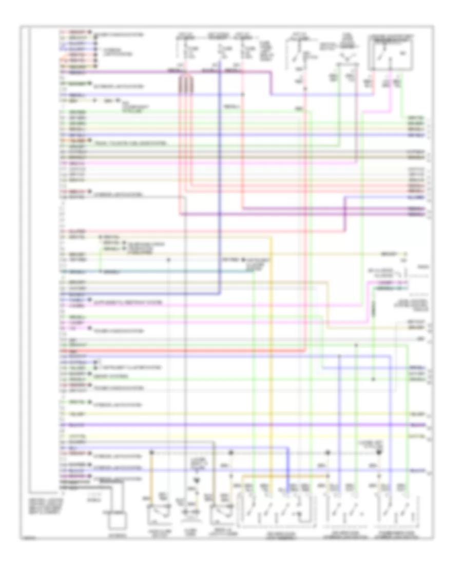
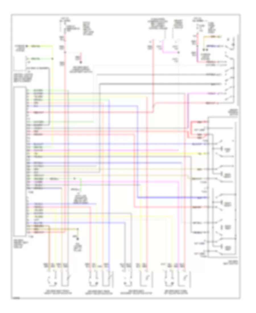
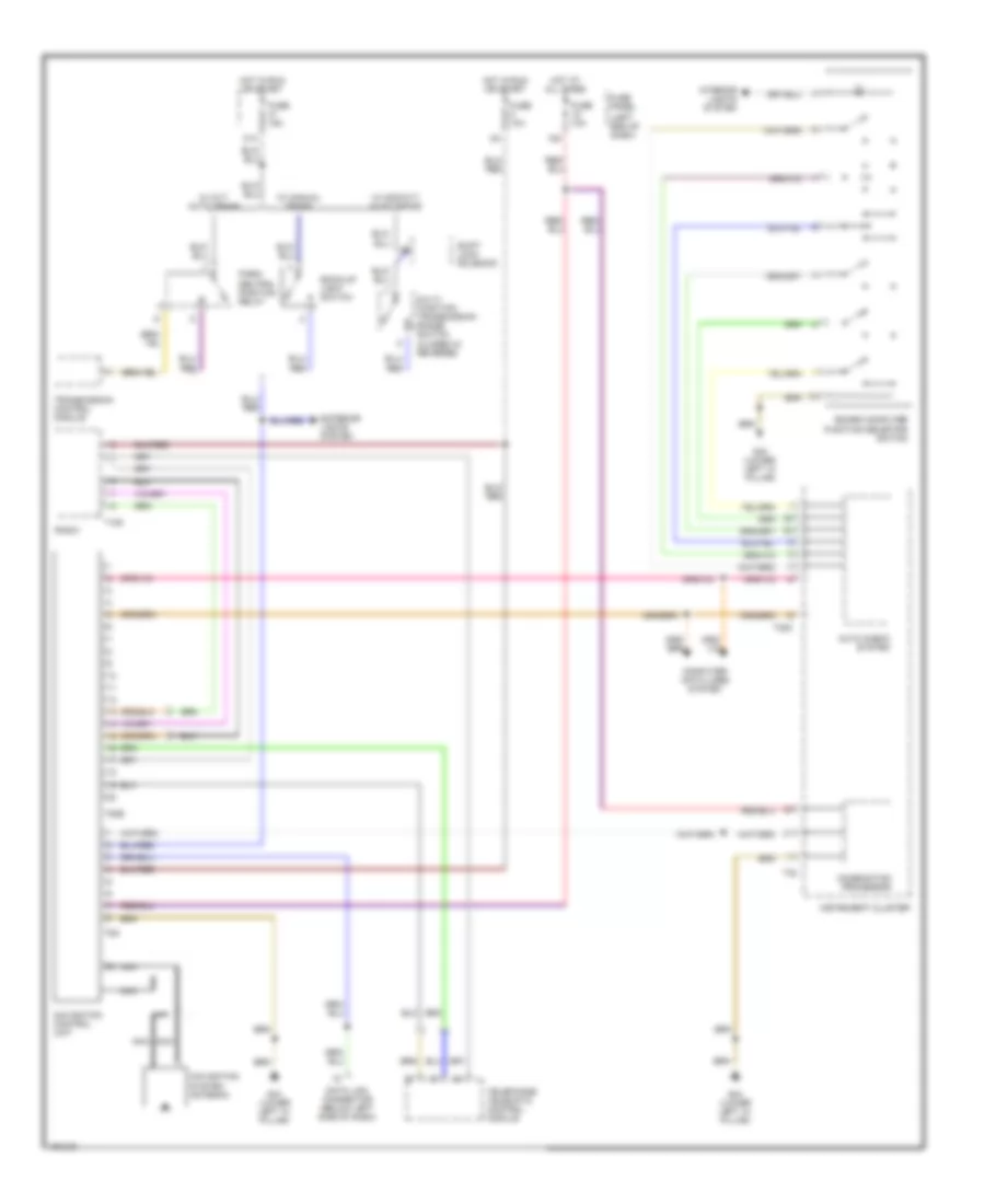
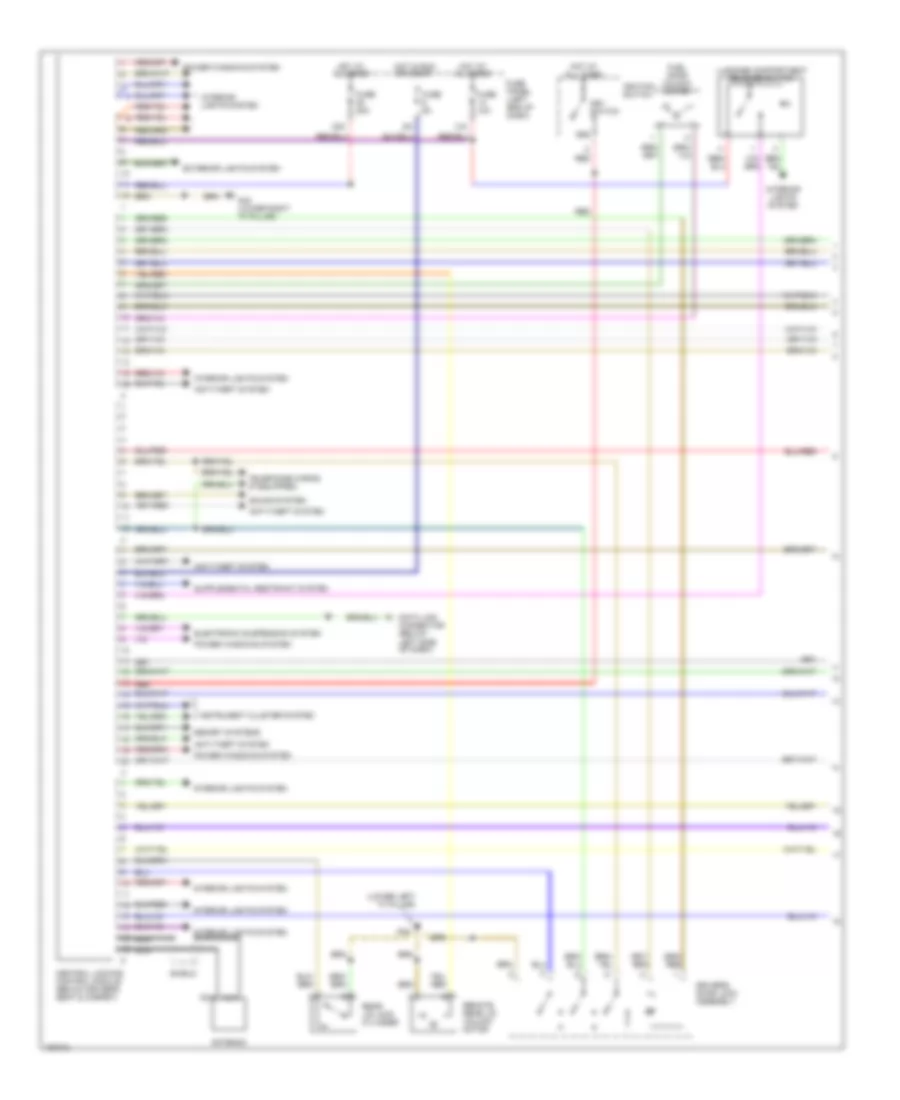
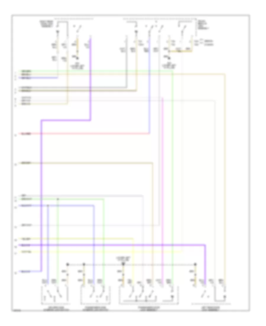
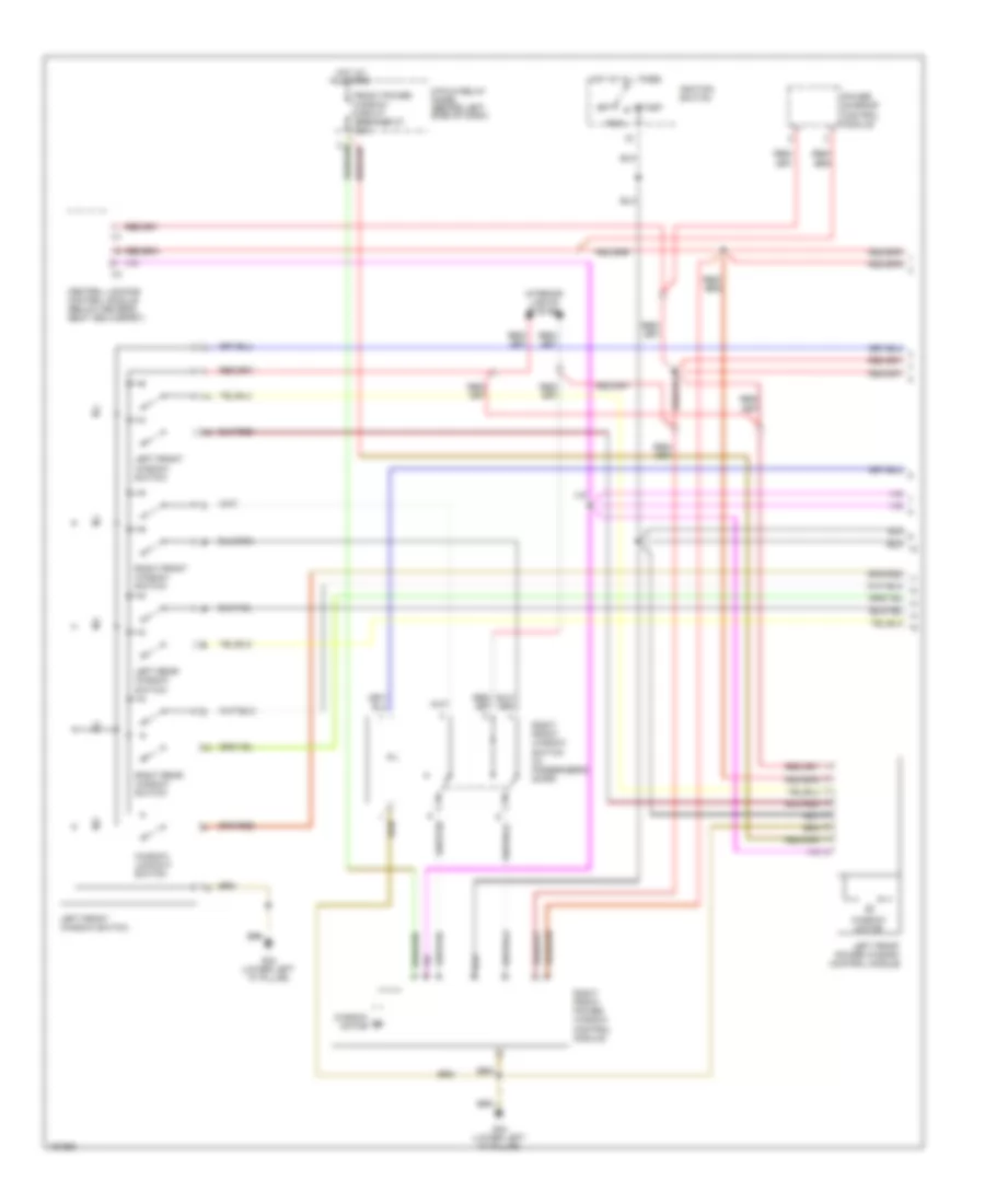
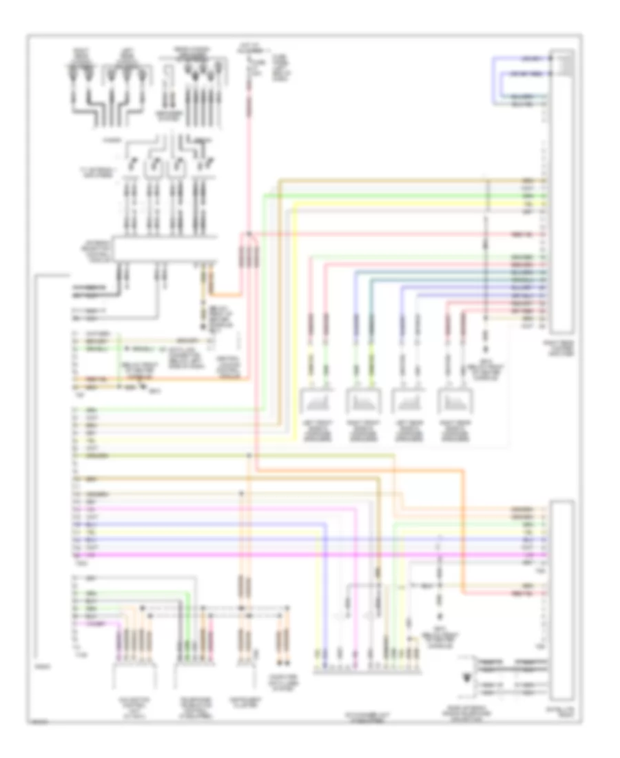
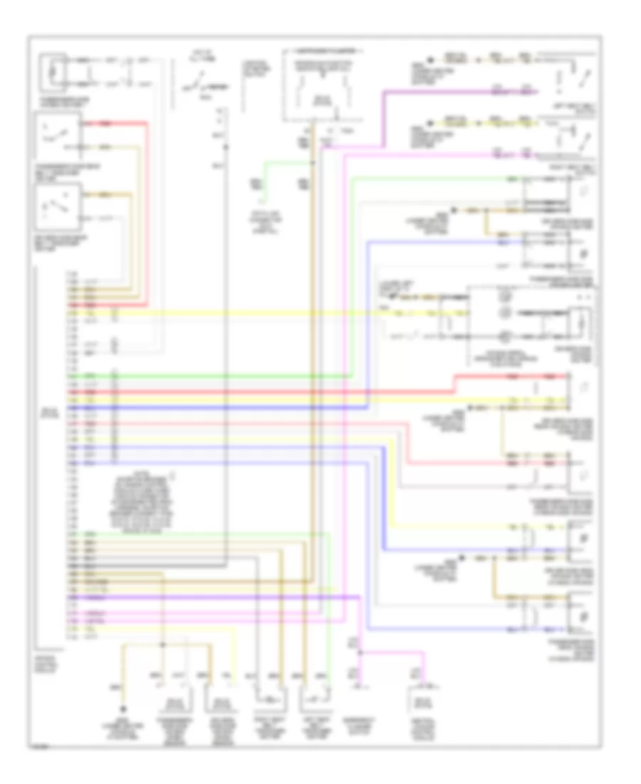
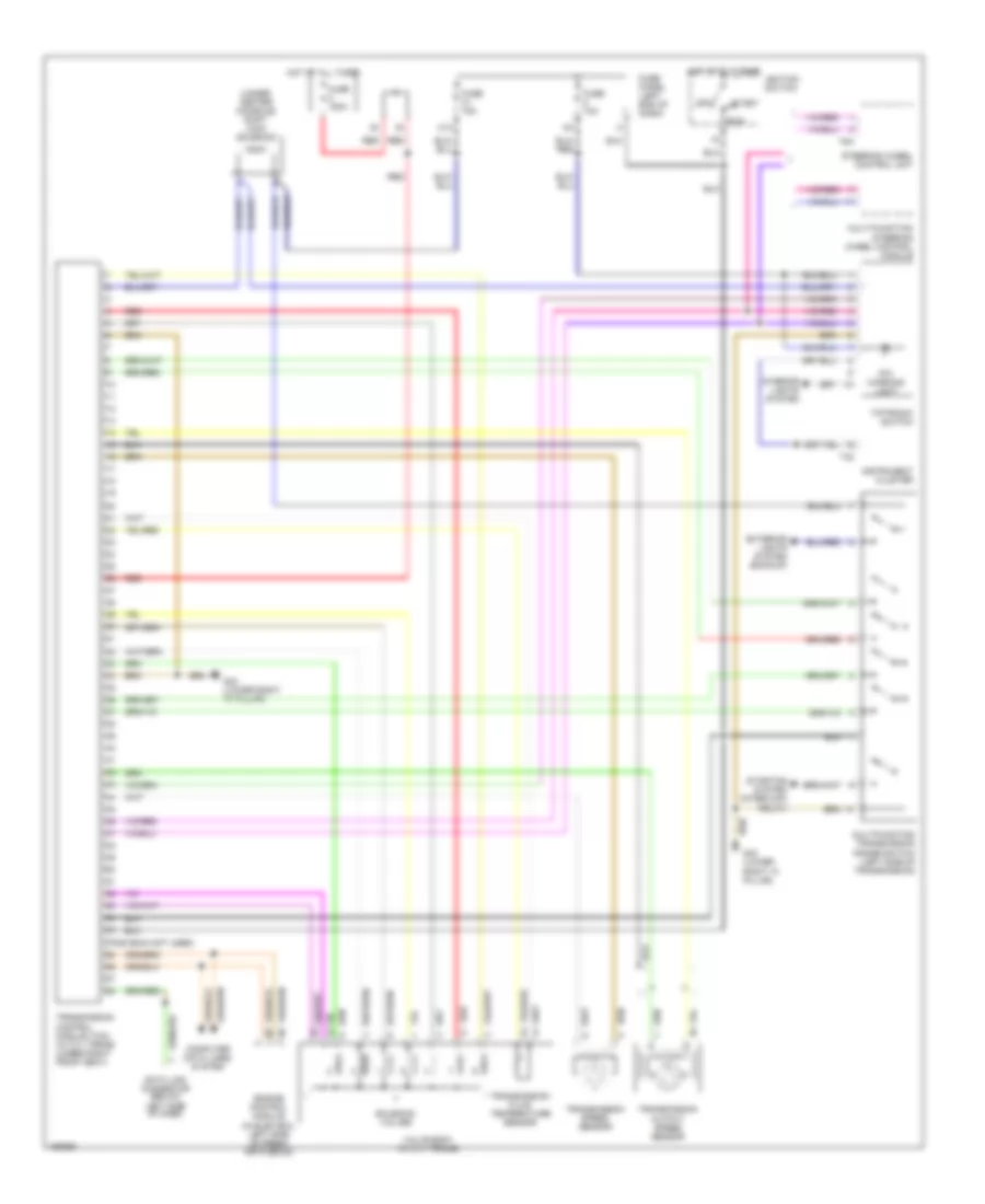
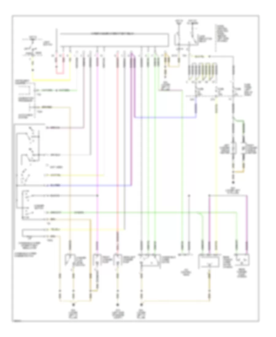
2.7L Turbo, Automatic A/C Wiring Diagram (1 of 2) for Audi allroad Quattro 2005

List of elements for 2.7L Turbo, Automatic A/C Wiring Diagram (1 of 2) for Audi allroad Quattro 2005:
- (w/ solar cell)
- (w/o solar cell)
- 25a
- 26a
- 8-fold relay panel (behind left side of dash)
- A/c clutch
- A/c clutch relay (on 13-fold relay panel)
- A/c control head
- A10
- A11
- A12
- After-run coolant pump (2.7l)
- After-run coolant thermal switch (2.7l)
- Air quality sensor
- B10
- B11
- B12
- B13
- B14
- B15
- B16
- B17
- B18
- B19
- B20
- C10
- C11
- C12
- C13
- C14
- C15
- C16
- Computer data lines system
- Connector
- Coolant control module
- Coolant fan
- Coolant fan 2
- Coolant fan control (fc) thermal switch
- D10
- D11
- D12
- D13
- D14
- D15
- D16
- Data link
- Defogger system
- Fuse 10a
- Fuse 30a
- Fuse 60a
- Fuse panel (left end of dash)
- G12 (left side of engine compt)
- G44 (lower left "a" pillar)
- Hot at all times
- Hot in run or start
- Hot w/ load reduction relay energized
- Ignition switch
- Instrument cluster
- Interior lights system
- Motronic engine control module (ecm)
- Off
- Run
- Solid state
- Start
- T32
- T32a
- Tachometer
- Wiper/washer system
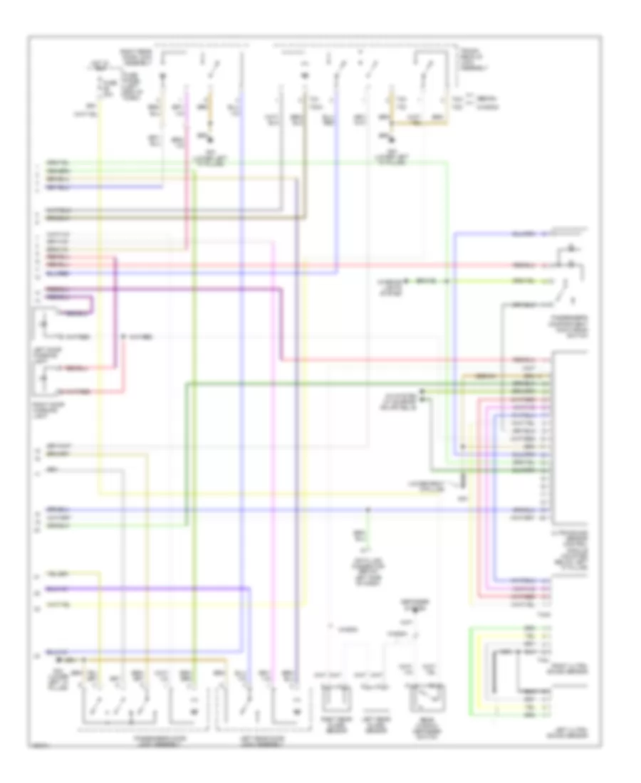
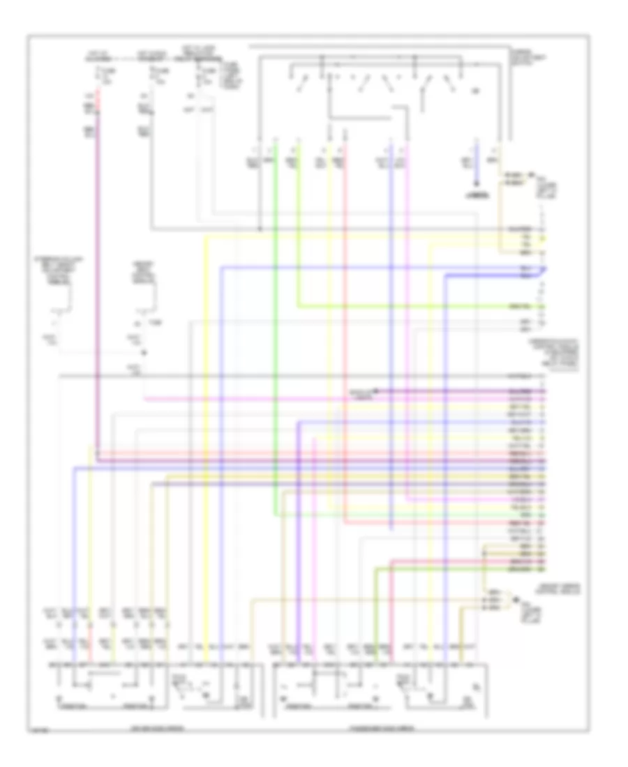
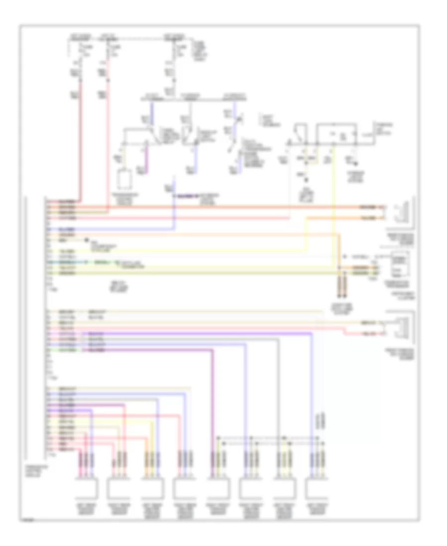
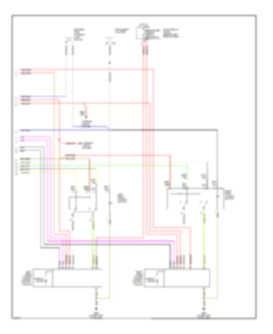
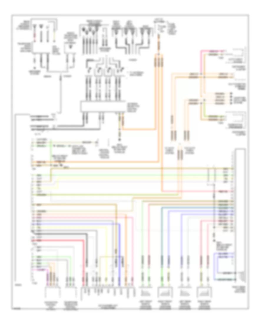
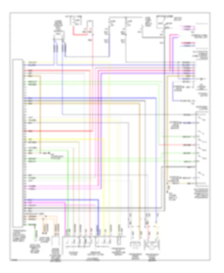
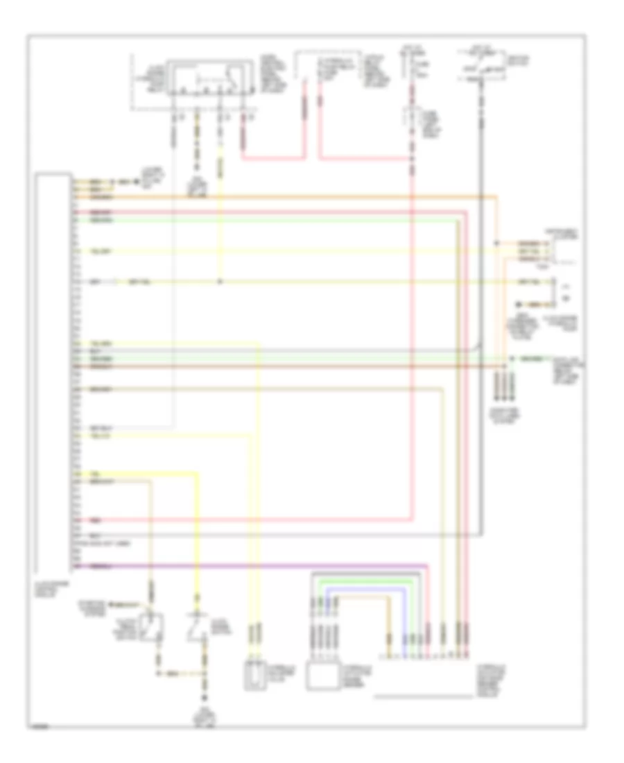
2.7L Turbo, Automatic A/C Wiring Diagram (2 of 2) for Audi allroad Quattro 2005
List of elements for 2.7L Turbo, Automatic A/C Wiring Diagram (2 of 2) for Audi allroad Quattro 2005:
- (w/ solar cell)
- (w/o solar cell)
- 15a
- A/c high pressure sensor
- Anti-theft system
- Back pressure flap motor & position sensor
- Center outlet temperature sender
- Central air flap motor position sensor
- Defroster flap motor/ position sensor
- Fresh air blower
- Fresh air blower control module
- Fresh air intake duct temperature sensor
- Fuse 10a
- Fuse panel (left end of dash)
- G44 (lower left "a" pillar)
- Hot at all times
- Left temperature flap actuator/ potentiometer
- Left vent temperature sensor
- Outside air temperature sensor
- Recirculation flap motor & position sensor
- Right temperature flap actuator/ potentiometer
- Right vent temperature sensor
- Sensor
- Solar cell separation relay (w/ solar cell system) (on 13-fold relay panel)
- Solar cells
- Solar operation control module
- Solid state
- Sunlight photo
4.2L
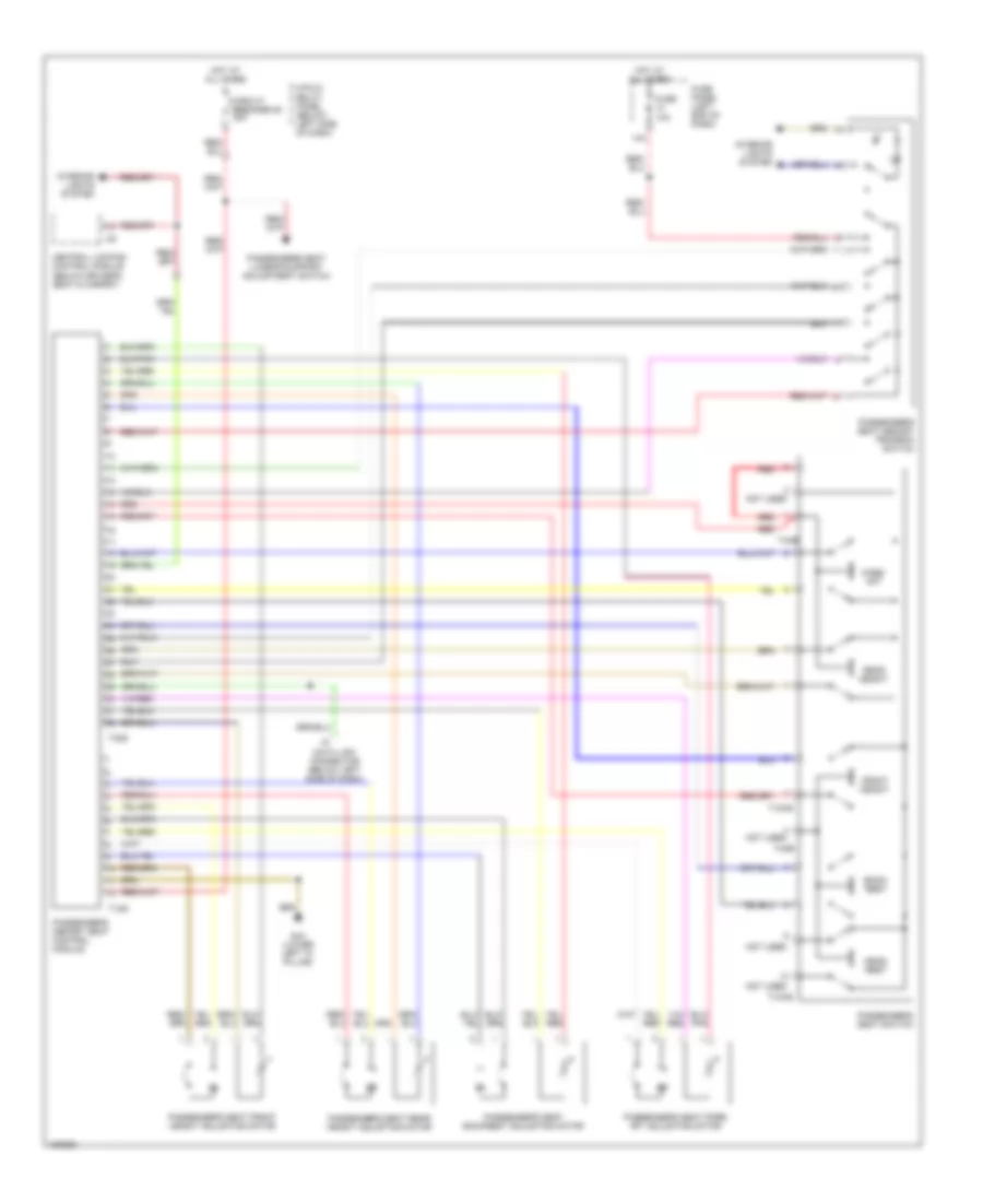
4.2L, Automatic A/C Wiring Diagram (1 of 2) for Audi allroad Quattro 2005
List of elements for 4.2L, Automatic A/C Wiring Diagram (1 of 2) for Audi allroad Quattro 2005:
- (w/ solar cell)
- (w/o solar cell)
- 25a
- 26a
- 8-fold relay panel
- 8-fold relay panel (behind left side of dash)
- A/c clutch
- A/c clutch relay (on 13-fold relay panel)
- A/c compressor regulator valve
- A/c control head
- A10
- A11
- A12
- Air quality sensor
- B10
- B11
- B12
- B13
- B14
- B15
- B16
- B17
- B18
- B19
- B20
- C10
- C11
- C12
- C13
- C14
- C15
- C16
- Computer data lines system
- Connector
- Coolant control module
- Coolant control module 2
- Coolant fan
- Coolant fan 2
- D10
- D11
- D12
- D13
- D14
- D15
- D16
- Data link
- Defogger system
- Fuse 10a
- Fuse 30a
- Fuse 40a
- Fuse 5a
- Fuse 60a
- Fuse panel (left end of dash)
- G44 (lower left "a" pillar)
- Hot at all times
- Hot in run or start
- Hot w/ ecm relay energized
- Hot w/ load reduction relay energized
- Instrument cluster
- Interior lights system
- Motronic engine control module (ecm)
- Oil level thermal sensor
- Solid state
- T32
- T32a
- Tachometer
- Wiper/washer system
4.2L, Automatic A/C Wiring Diagram (2 of 2) for Audi allroad Quattro 2005
List of elements for 4.2L, Automatic A/C Wiring Diagram (2 of 2) for Audi allroad Quattro 2005:
- (w/ solar cell)
- (w/o solar cell)
- 15a
- A/c high pressure sensor
- Anti-theft system
- Back pressure flap motor & position sensor
- Center outlet temperature sender
- Central air flap motor position sensor
- Defroster flap motor/ position sensor
- Fresh air blower
- Fresh air blower control module
- Fresh air intake duct temperature sensor
- Fuse 10a
- Fuse panel (left end of dash)
- G44 (lower left "a" pillar)
- Hot at all times
- Left temperature flap actuator/ potentiometer
- Left vent temperature sensor
- Outside air temperature sensor
- Ricirculation flap motor & position sensor
- Right temperature flap actuator/ potentiometer
- Right vent temperature sensor
- Sensor
- Solar cell separation relay (w/ solar cell system) (on 13-fold relay panel)
- Solar cells
- Solar operation control module
- Solid state
- Sunlight photo
ANTI-LOCK BRAKES
Anti-lock Brakes Wiring Diagram (1 of 2) for Audi allroad Quattro 2005
List of elements for Anti-lock Brakes Wiring Diagram (1 of 2) for Audi allroad Quattro 2005:
- 41a
- 8-fold relay panel (behind left side of dash)
- Abs control module (in passenger footwell, below carpet)
- Abs hydraulic unit (left side of engine compartment)
- Abs inlet left front
- Abs inlet left rear
- Abs outlet left front
- Abs outlet left rear
- Abs outlet right front
- Abs outlet right rear
- Abs return flow pump
- Abs return flow pump relay
- Abs solenoid valve relay
- Fuse 25a
- Fuse 50a
- Fuse panel (left end of dash)
- G100 (on abs hydraulic unit)
- Headlight beam adjusting control module
- Hot at all times
- Left front abs wheel speed sensor (mounted to left front wheel bearing housing)
- Left rear abs wheel speed sensor (mounted to left rear wheel bearing housing)
- Right front
- Right front abs wheel speed sensor (mounted to right front wheel bearing housing)
- Right rear abs inlet valve
- Right rear abs wheel speed sensor (mounted to right rear wheel bearing housing)
- Switch valve 2 high pressure
- Traction control
- Traction control high pressure switch valve 1
- Traction control hydraulic pump
- Traction control pilot valve 1
- Traction control pilot valve 2
- Valve
- Valve abs inlet
Anti-lock Brakes Wiring Diagram (2 of 2) for Audi allroad Quattro 2005
List of elements for Anti-lock Brakes Wiring Diagram (2 of 2) for Audi allroad Quattro 2005:
- Abs control module (in passenger footwell, below carpet)
- Abs warning light
- Asr/esp button
- Brake pressure sensor
- Brake- light switch (on brake pedal support bracket)
- Combination processor
- Computer data lines system
- Data link connector (below left side of dash)
- Engine controls system
- Esp control ind
- Exterior lights system
- Fuse 10a
- Fuse 25a
- Fuse 5a
- Fuse panel (left end of dash)
- G44 (lower left "a" pillar)
- Hot at all times
- Hot in on or start
- Instrument cluster
- Instrument cluster system
- Level control system control head
- Parking brake warning light switch
- Red
- Steering angle sensor
- T32
- T32a
- Transverse acceleration sensor/ yaw sensor
- Vacuum vent valve
ANTI-THEFT
Anti-theft Wiring Diagram (1 of 2) for Audi allroad Quattro 2005
List of elements for Anti-theft Wiring Diagram (1 of 2) for Audi allroad Quattro 2005:
- (allroad)
- (ex allroad)
- (lower left "a" pillar) g44
- (lower right "a" pillar)
- 14a
- 38a
- 86s
- Alarm horn
- Antenna
- Central locking control module (below driver's seat & carpet)
- Driver's door lock assembly
- Driver's side interior lock switch
- Exterior lights system
- Fuel door unlock motor
- Fuse 10a
- Fuse 20a
- Fuse 5a
- Fuse panel (left end of dash)
- G43
- G43 (lower right "a" pillar)
- Hood alarm switch
- Hot at all times
- Hot in run or start
- Ignition switch
- Instrument cluster system
- Interior lights system
- Key switch
- Level control system control module
- Luggage compartment release switch
- Memory systems
- Nca
- Passenger's side interior lock switch
- Power windows system
- Radio
- Rear lid lock cylinder
- Red
- Shield
- T8f
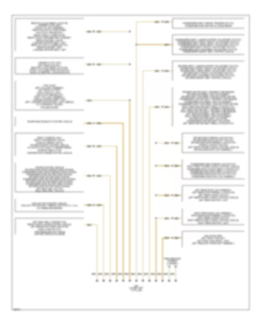
- Telephone wiring (telematics) (if equipped)
- Trunk, tailgate, fuel door system
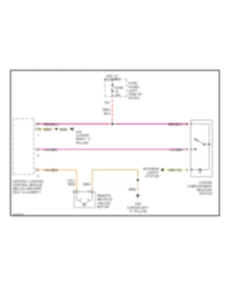
Anti-theft Wiring Diagram (2 of 2) for Audi allroad Quattro 2005
List of elements for Anti-theft Wiring Diagram (2 of 2) for Audi allroad Quattro 2005:
- (lower right "a"pillar)
- (sedan)
- (wagon)
- 26a
- A/c system (w/ sunroof solar cells)
- Data link connector (below left side of dash)
- Defogger system
- Fuse 30a
- Fuse panel (left end of dash)
- G43
- G44 (lower left "a" pillar)
- Hot in run
- Interior lights system
- Left door warning light
- Left rear door lock assembly
- Left rear glass sensor
- Left ultra- sound sensor
- Nca
- Passenger's compartment monitoring switch
- Passenger's door lock assembly
- Rear window defogger switch
- Right door warning light
- Right rear door lock assembly
- Right rear glass sensor
- Right ultra- sound sensor
- T2ch
- T2ci
- T2v
- T2w
- T3o
- Ta4k
- Ta4l
- Trunk/ decklid lock assembly
- Ultra-sound sensor control module (mounted below left "c" pillar)
- Wagon
COMPUTER DATA LINES
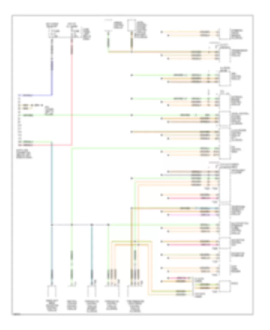
Computer Data Lines Wiring Diagram for Audi allroad Quattro 2005
List of elements for Computer Data Lines Wiring Diagram for Audi allroad Quattro 2005:
- 12a
- 16d
- 2.7l, 4.2l
- 3.0l
- 31a
- 4-low range control module (m/t) (allroad)
- A/c control head
- A6, s6
- Abs control module
- Airbag control module
- Allroad
- B17
- B18
- Central locking control module
- Chip card reader
- Data link connector (below left side of dash)
- Fuse 10a
- Fuse 15a
- Fuse panel (left end of dash)
- G44 (lower left "a" pillar)
- Headlight beam adjusting control module
- Hot at all times
- Hot in run or start
- Instrument cluster
- Level control system control module (allroad)
- Level control system control module (except allroad)
- Motronic engine control module
- Multifunction steering wheel control module
- Navigation control unit
- Navigation interface
- Parking aid control module (allroad)
- Parking aid control module (except allroad)
- Radio
- Steering angle sensor (allroad)
- T12f
- T16c
- T16d
- T20a
- T20b
- T20c
- T32a
- T32c
- T4au
- Telephone/ telematic control module
- Tire pressure monitoring control module (allroad)
- Transmission control module
- W/ auto check
- W/ cvt
- W/o auto check
- W/o cvt
COOLING FAN
2.7L TURBO
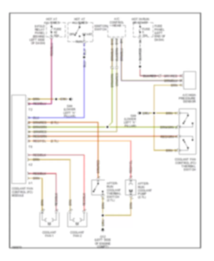
2.7L Turbo, Cooling Fan Wiring Diagram for Audi allroad Quattro 2005
List of elements for 2.7L Turbo, Cooling Fan Wiring Diagram for Audi allroad Quattro 2005:
- (2.7l)
- 8-fold relay panel (behind left side of dash)
- A/c control head
- A/c high pressure sensor
- After- run coolant pump (2.7l)
- After- run coolant thermal switch (2.7l)
- B12
- B13
- Coolant fan 1
- Coolant fan 2
- Coolant fan control (fc) module
- Coolant fan control (fc) thermal switch
- Fuse 10a
- Fuse 60a
- Fuse panel (left end of dash)
- G12 (left side of engine compt)
- G44 (lower left "a" pillar)
- Hot at all times
- Hot in run or start
- Ignition switch
- Off
- Run
- Start
4.2L
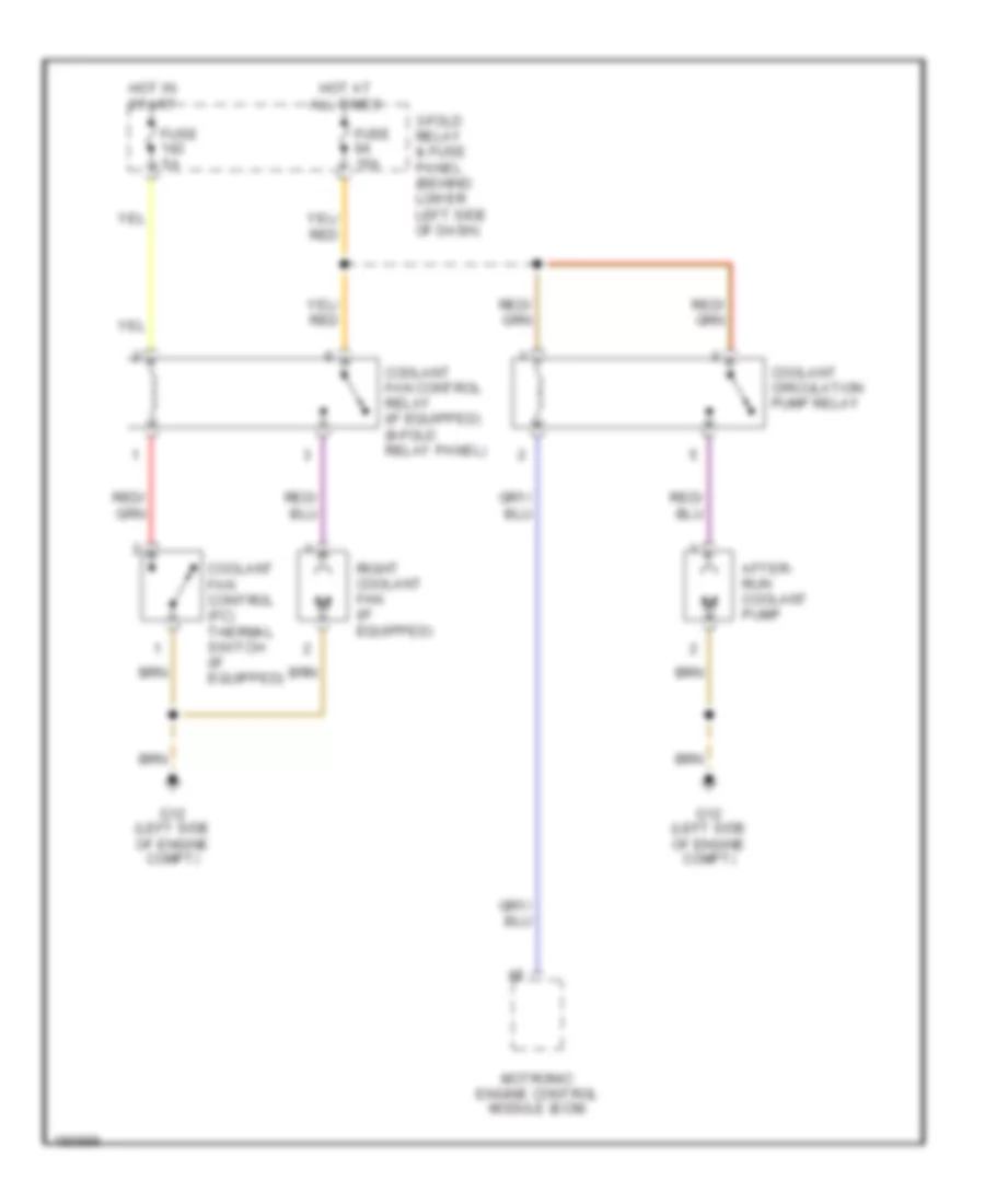
4.2L, After Run Coolant Pump Wiring Diagram for Audi allroad Quattro 2005
List of elements for 4.2L, After Run Coolant Pump Wiring Diagram for Audi allroad Quattro 2005:
- 3-fold relay & fuse panel (behind lower left side of dash)
- After- run coolant pump
- Coolant circulation pump relay
- Coolant fan control (fc) thermal switch (if equipped)
- Coolant fan control relay (if equipped) (8-fold relay panel)
- Fuse 15a
- Fuse 5a
- G12 (left side of engine compt)
- Hot at all times
- Hot in start
- Motronic engine control module (ecm)
- Right coolant fan (if equipped)
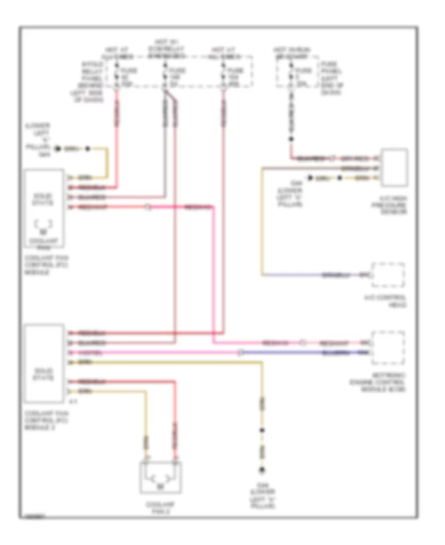
4.2L, Cooling Fan Wiring Diagram for Audi allroad Quattro 2005
List of elements for 4.2L, Cooling Fan Wiring Diagram for Audi allroad Quattro 2005:
- (lower left "a" pillar) g44
- 8-fold relay panel (behind left side of dash)
- A/c control head
- A/c high pressure sensor
- Coolant fan
- Coolant fan 2
- Coolant fan control (fc) module
- Coolant fan control (fc) module 2
- Fuse 10a
- Fuse 40a
- Fuse 5a
- Fuse 60a
- Fuse panel (left end of dash)
- G44 (lower left "a" pillar)
- Hot at all times
- Hot in run or start
- Hot w/ ecm relay energized
- Motronic engine control module (ecm)
- Solid state
CRUISE CONTROL
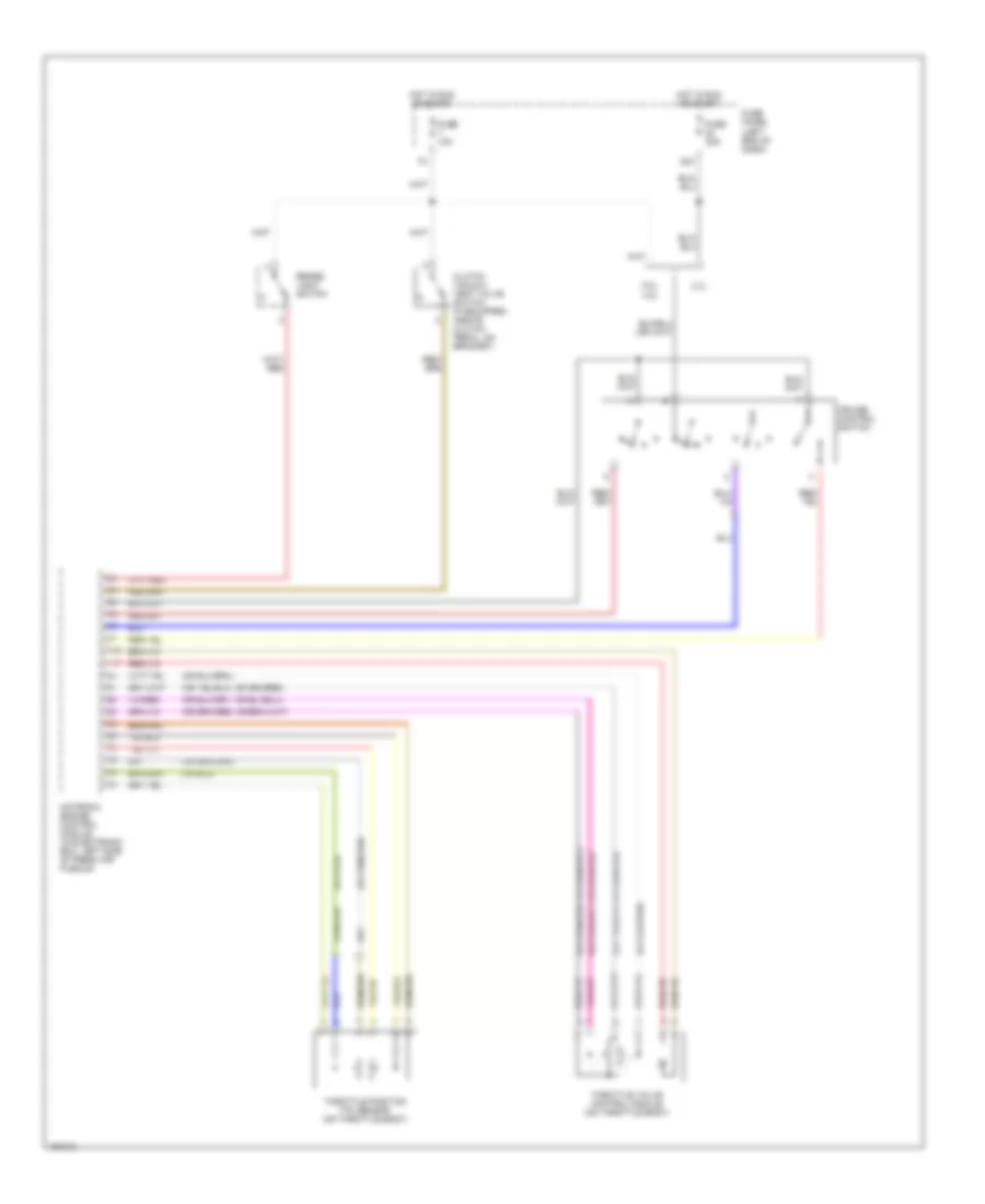
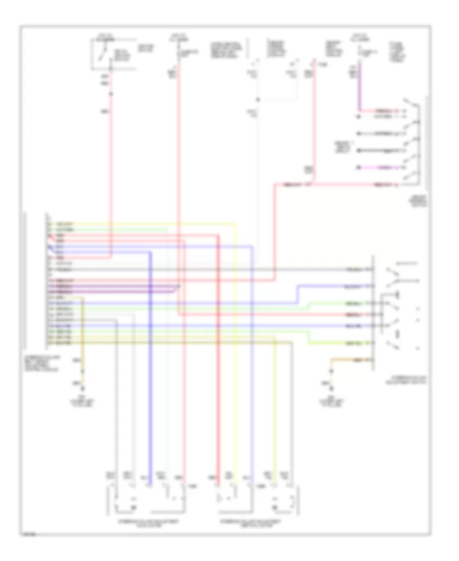
Cruise Control Wiring Diagram for Audi allroad Quattro 2005
List of elements for Cruise Control Wiring Diagram for Audi allroad Quattro 2005:
- 2.7l
- 3.0l, 4.2l
- 32a
- Brake- light switch
- Clutch vacuum vent valve switch (if equipped) (above clutch pedal, on bracket)
- Cruise control switch
- Fuse 10a
- Fuse 20a
- Fuse panel (left end of dash)
- Hot in run or start
- Motronic engine control module (in electronic box, left side of fresh air plenum)
- Throttle position (tp) sensor (on throttle body)
- Throttle valve control module (on throttle body)
DEFOGGERS
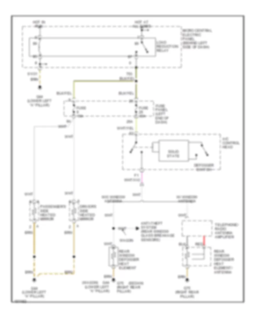
Defoggers Wiring Diagram for Audi allroad Quattro 2005
List of elements for Defoggers Wiring Diagram for Audi allroad Quattro 2005:
- (sedan)
- (wagon)
- 26a
- 75x
- A/c control head
- Anti-theft system (rear window glass breakage sensors)
- Defogger switch
- Driver's side heated mirror
- Fuse 10a
- Fuse 30a
- Fuse panel (left end of dash)
- G44 (lower left "a" pillar)
- G75 (right rear pillar)
- Hot at all times
- Hot in run
- Load reduction relay
- Micro central electric panel (behind left side of dash)
- Passenger's side heated mirror
- Rear window defogger heat element
- Rear window defogger heat element/ antenna
- Red
- S1/31
- Solid state
- Telephone/ radio antenna amplifier
- W/ window antenna
- W/o window antenna
- Wagon
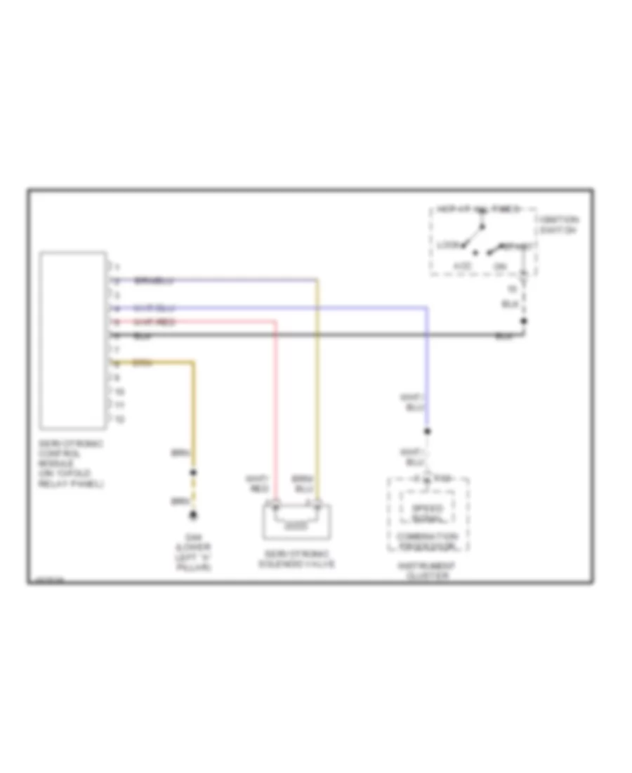
ELECTRONIC POWER STEERING
Electronic Power Steering Wiring Diagram for Audi allroad Quattro 2005
List of elements for Electronic Power Steering Wiring Diagram for Audi allroad Quattro 2005:
- Acc
- Combination processor
- G44 (lower left "a" pillar)
- Hot at all times
- Ignition switch
- Instrument cluster
- Lock
- Servotronic control module (on 13-fold relay panel)
- Servotronic solenoid valve
- Speed signal
- Start
- T32
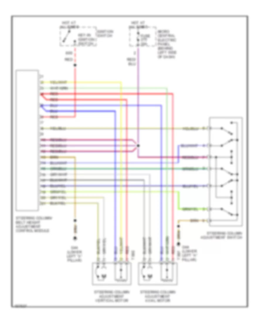
Power Steering Column Wiring Diagram for Audi allroad Quattro 2005
List of elements for Power Steering Column Wiring Diagram for Audi allroad Quattro 2005:
- 86s
- Fuse 20a
- G44 (lower left "a" pillar)
- Hot at all times
- Ignition switch
- Key-in ignition switch
- Micro central electric panel (behind left side of dash)
- Red
- Steering column adjustment axial motor
- Steering column adjustment switch
- Steering column adjustment vertical motor
- Steering column/ belt height adjustment control module
- T3be
- T3bf
ELECTRONIC SUSPENSION
Electronic Suspension Wiring Diagram for Audi allroad Quattro 2005
List of elements for Electronic Suspension Wiring Diagram for Audi allroad Quattro 2005:
- (below right rear seat)
- (lower left "a" pillar)
- 15a
- 17a
- 8-fold relay panel (left side of dash)
- Abs control module (left side
- Accumu- lator
- Asr/esp button
- Central locking control module
- Combination processor
- Computer data lines system
- Data link connector (below
- Fog light shutoff switch
- Fuse 10a
- Fuse 40a
- Fuse panel (left end of dash)
- G40
- G43 (lower right "a" pillar)
- G44
- G44 (lower left "a" pillar)
- Head
- Headlight adjustment system control module (on left side of luggage compt)
- Hot at all times
- Hot in run
- Hot in run or start
- Illum
- Instrument cluster
- Interior lights system
- Left front level control system sensor
- Left headlight beam adjusting motor
- Left rear level control system sensor
- Left side of dash)
- Level 1
- Level 2
- Level control solenoid assembly
- Level control system comp- ressor assembly
- Level control system compressor relay
- Level control system control head
- Level control system control module
- Level control system ind
- Light switch
- Low
- Lower
- Manual
- Motor
- Normal
- Not used
- Of engine compt)
- Off
- Park
- Parking aid control module
- Pressure sensor
- Raise
- Red
- Right front level control system sensor
- Right headlight beam adjusting motor
- Right rear level control system sensor
- Solenoid valve
- Starting/ charging system
- T2co
- T2cp
- T2cq
- T32
- T32a
- Temp sensor
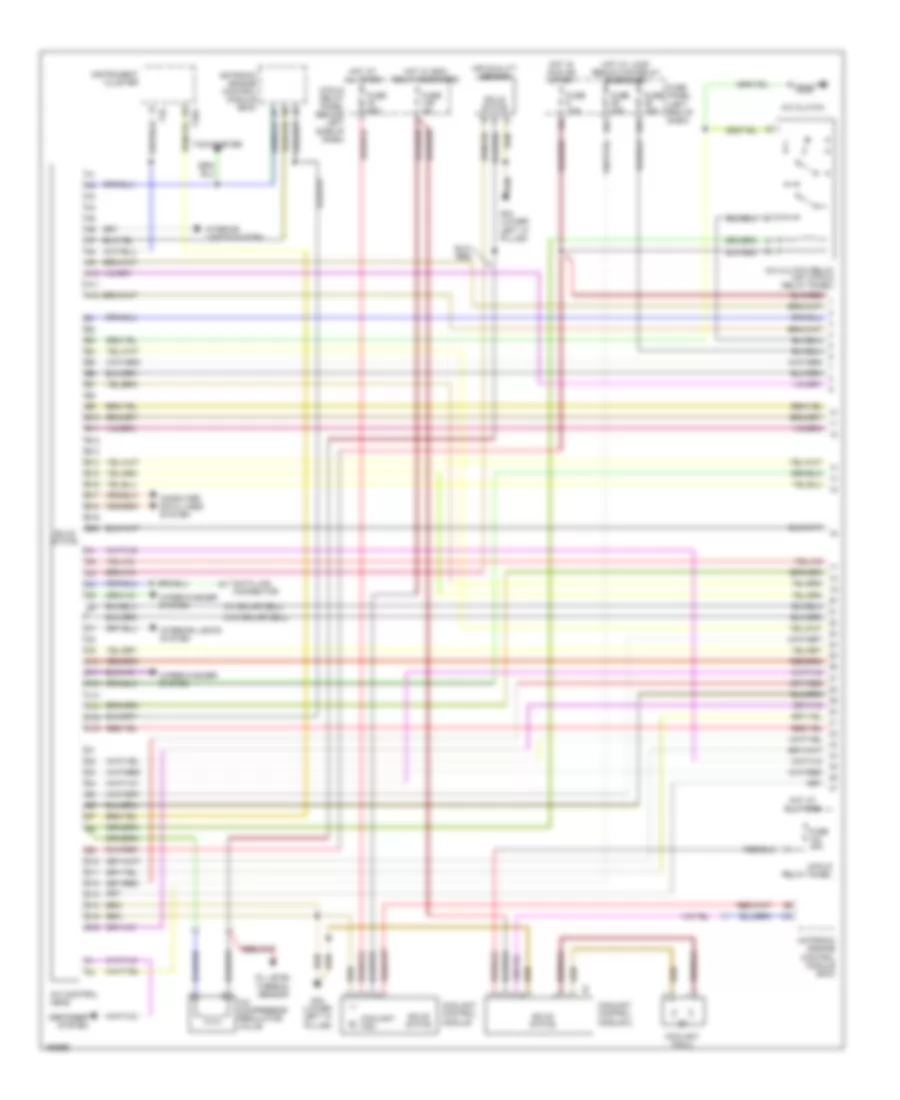
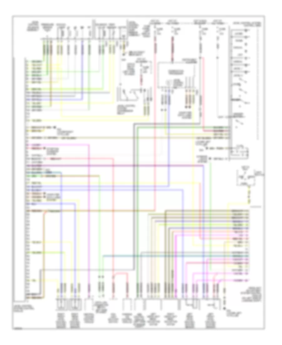
ENGINE PERFORMANCE
2.7L TURBO
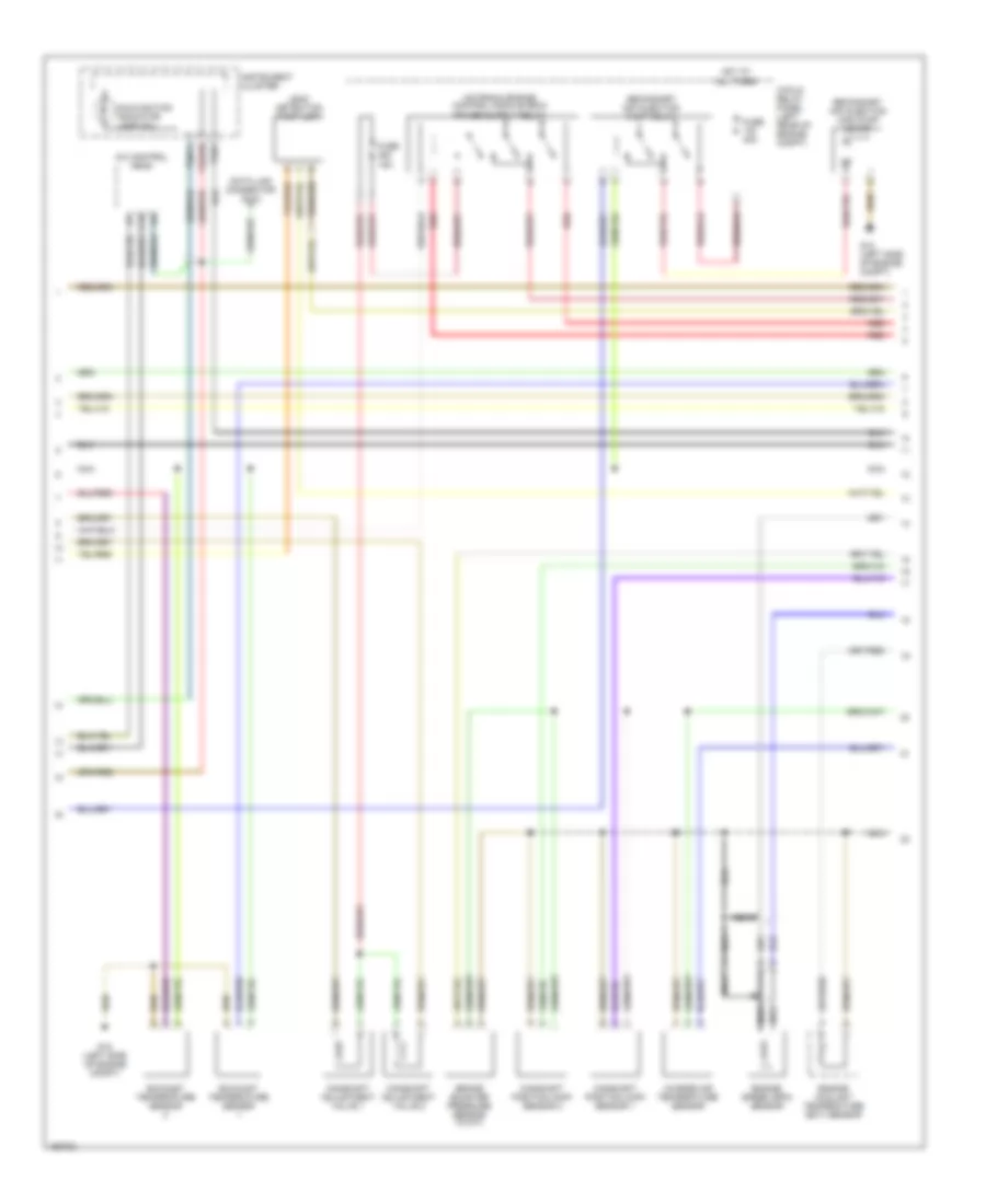
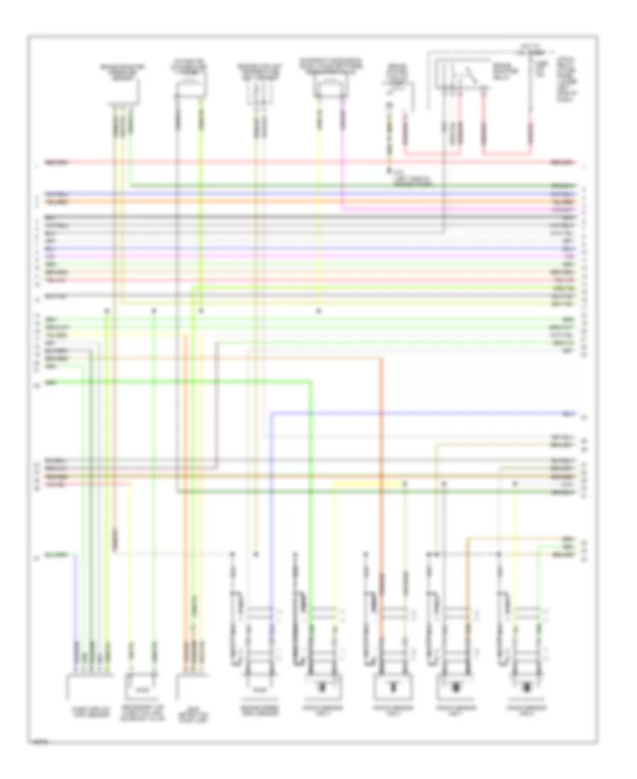
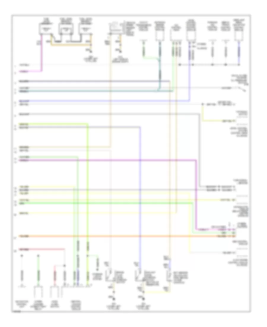
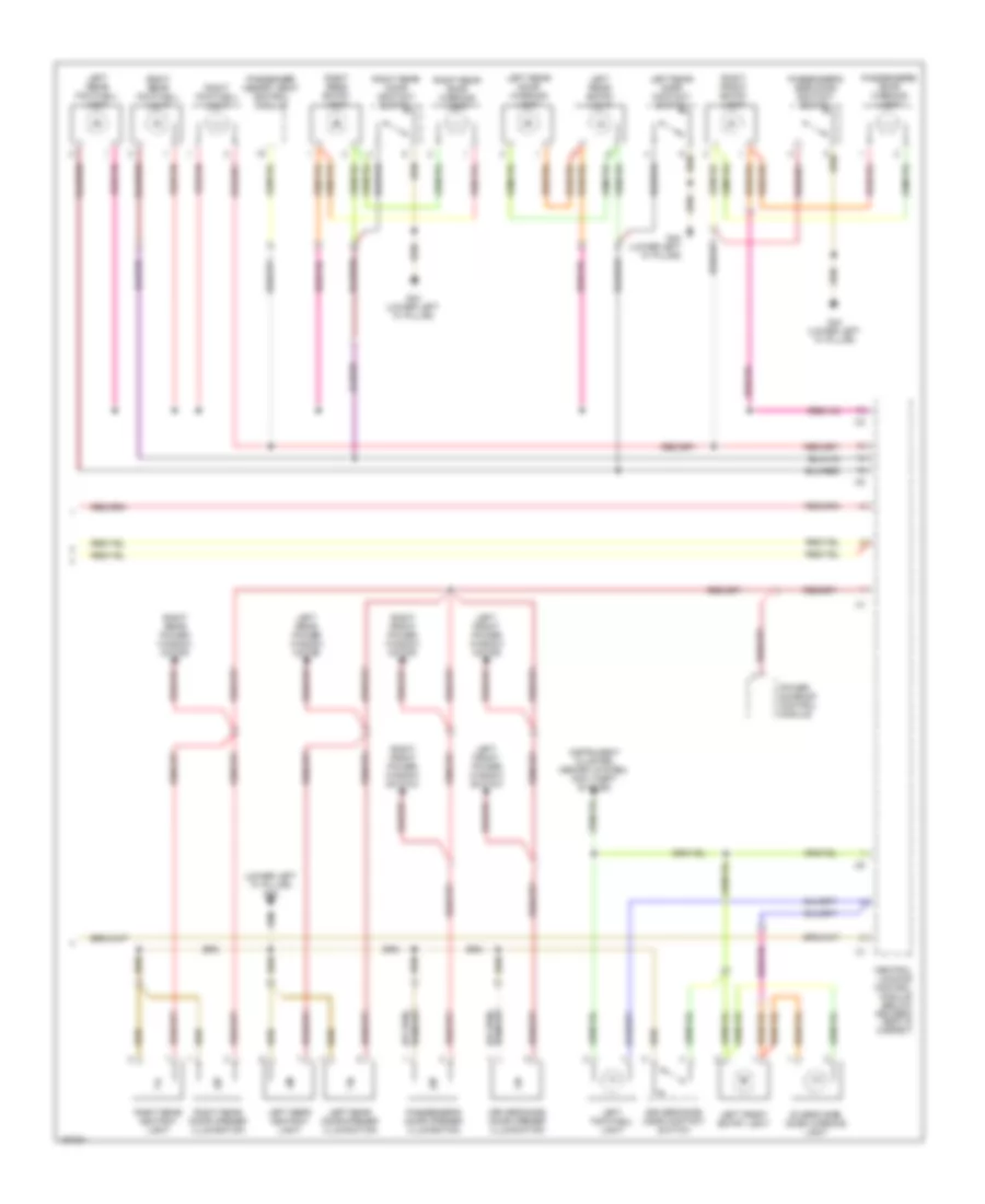
2.7L Turbo, Engine Performance Wiring Diagram (1 of 4) for Audi allroad Quattro 2005
List of elements for 2.7L Turbo, Engine Performance Wiring Diagram (1 of 4) for Audi allroad Quattro 2005:
- (behind twc) heated oxygen sensor (o2s) 2
- 13a
- Brakelight switch/ brake pedal switch
- Clutch vacuum vent valve switch (w/m/t)
- Computer data lines system
- Cruise control system
- Fuse 10a
- Fuse panel (left end of dash)
- G12 (left side of engine compt)
- Heated oxygen sensor (ho2s) 1
- Heated oxygen sensor (ho2s) 2
- Hot at all times
- Idle air control cut-off valve
- Intake air temperature (iat) sensor
- Mass airflow (maf) sensor
- Motronic engine control module (ecm) in electronic box, on leftside of fresh air plenum)
- Nca
- Red
- Secondary air injection (air) solenoid valve
- Throttle position (tp) sensor/ accelerator pedal position sensor
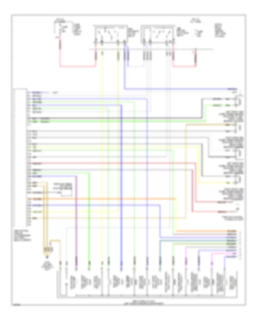
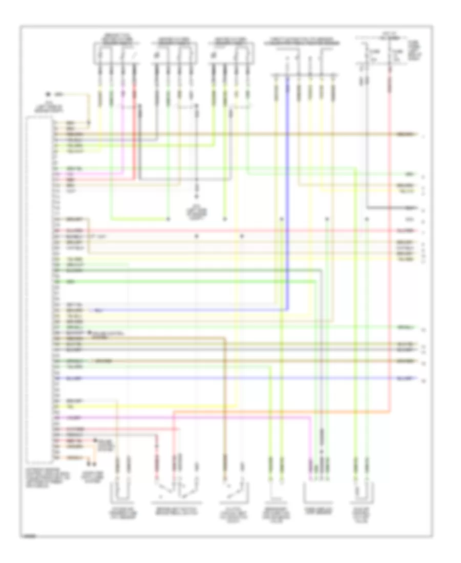
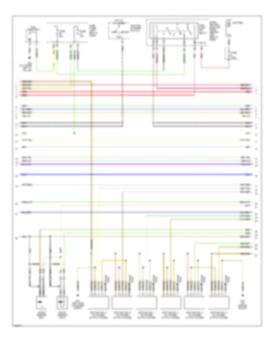
2.7L Turbo, Engine Performance Wiring Diagram (2 of 4) for Audi allroad Quattro 2005
List of elements for 2.7L Turbo, Engine Performance Wiring Diagram (2 of 4) for Audi allroad Quattro 2005:
- 3-fold relay panel (left rear of engine compt)
- A/c control head
- Brake booster pressure sensor (w/a/t)
- C15
- Camshaft adjustment valve 1
- Camshaft adjustment valve 2
- Camshaft position (cmp) sensor 1
- Camshaft position (cmp) sensor 2
- Charge air temperature sensor
- Data link connector (dlc)
- Engine coolant temperature (ect) sensor
- Engine speed (rpm) sensor
- Exhaust temperature sensor
- Fuse 15a
- Fuse 40a
- G12 (left side of engine compt)
- Hot at all times
- Instrument cluster
- Leak detection pump (ldp)
- Malfunction indicator lamp (mil)
- Nca
- Red
- Secondary air injection (air) pump motor
- Secondary air injection pump relay
- T32/1
- T32/11
- T32a/28
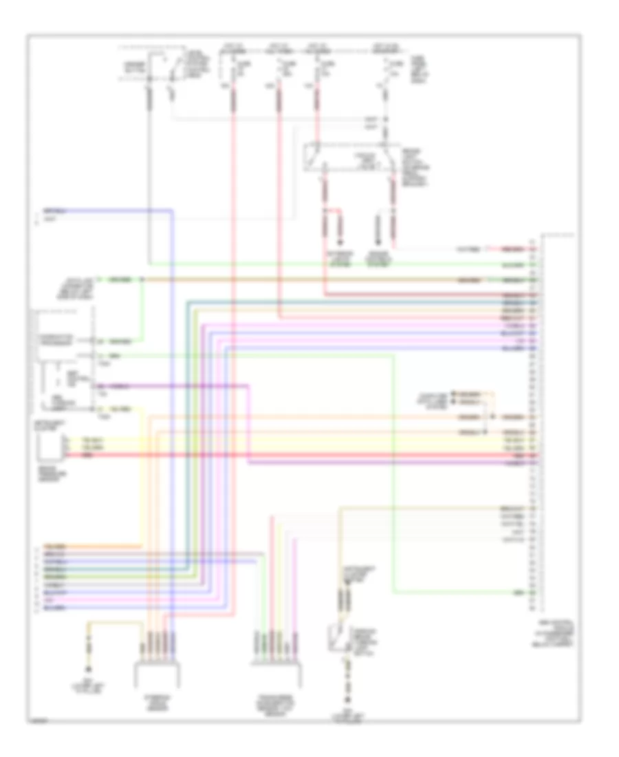
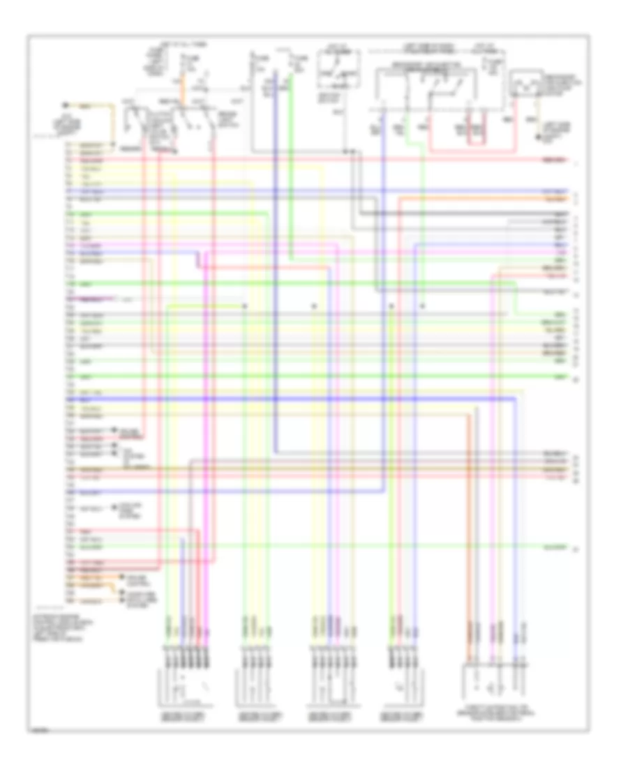
2.7L Turbo, Engine Performance Wiring Diagram (3 of 4) for Audi allroad Quattro 2005
List of elements for 2.7L Turbo, Engine Performance Wiring Diagram (3 of 4) for Audi allroad Quattro 2005:
- 28a
- 34a
- 87a
- 87f
- Battery
- Fuel pump (fp)
- Fuel pump (fp) relay
- Fuse 150a
- Fuse 15a
- Fuse 20a
- Fuse panel (left end of dash)
- G12 (left side of engine compt)
- G18 (on engine block)
- G44 (on lower left "a" pillar)
- Hot at all times
- Ignition coil 1 (w/ power output stage)
- Ignition coil 2 (w/ power output stage)
- Ignition coil 3 (w/ power output stage)
- Ignition coil 4 (w/ power output stage)
- Ignition coil 5 (w/ power output stage)
- Ignition coil 6 (w/ power output stage)
- Ignition/ starter switch
- Knock sensor (ks) 1
- Knock sensor (ks) 2
- Micro central electric panel (behind left side of dash)
- Nca
- Off
- Plug spark
- Red
- Run
- Spark plug
- Start
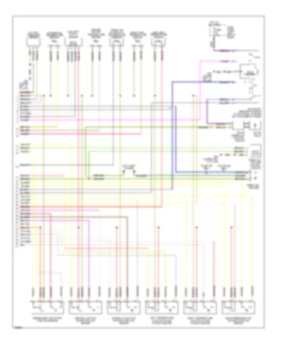
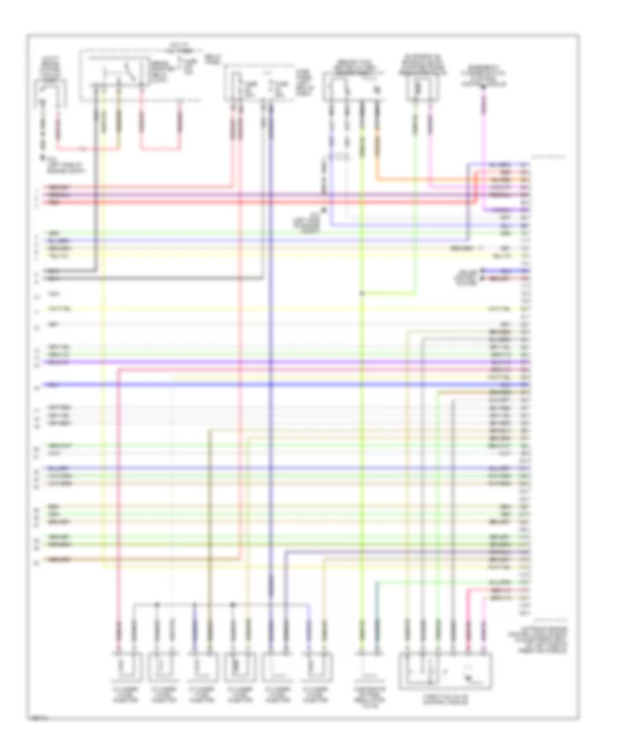
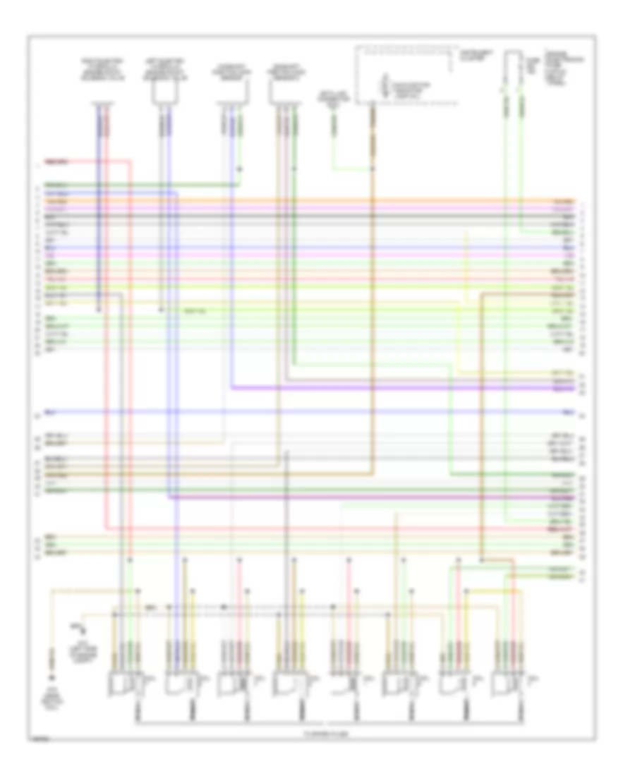
2.7L Turbo, Engine Performance Wiring Diagram (4 of 4) for Audi allroad Quattro 2005
List of elements for 2.7L Turbo, Engine Performance Wiring Diagram (4 of 4) for Audi allroad Quattro 2005:
- (behind twc) heated oxygen sensor (o2s) 1
- (w/a/t) brake system vacuum pump
- 29a
- 32a
- Brake booster relay (w/a/t)
- Cruise control system
- Cylinder 1 fuel injector
- Cylinder 2 fuel injector
- Cylinder 3 fuel injector
- Cylinder 4 fuel injector
- Cylinder 5 fuel injector
- Cylinder 6 fuel injector
- Emergency flasher switch & air bag control module
- Evaporative emission (evap) canister purge regulator valve
- Fuse 15a
- Fuse 20a
- Fuse panel (left end of dash)
- G12 (left side of engine compt)
- Hot at all times
- Motronic engine control module (ecm) (in electronic box, on left side of fresh air plenum)
- Nca
- Red
- Relay panel
- Throttle valve control module
- Wastegate bypass regulator valve
4.2L
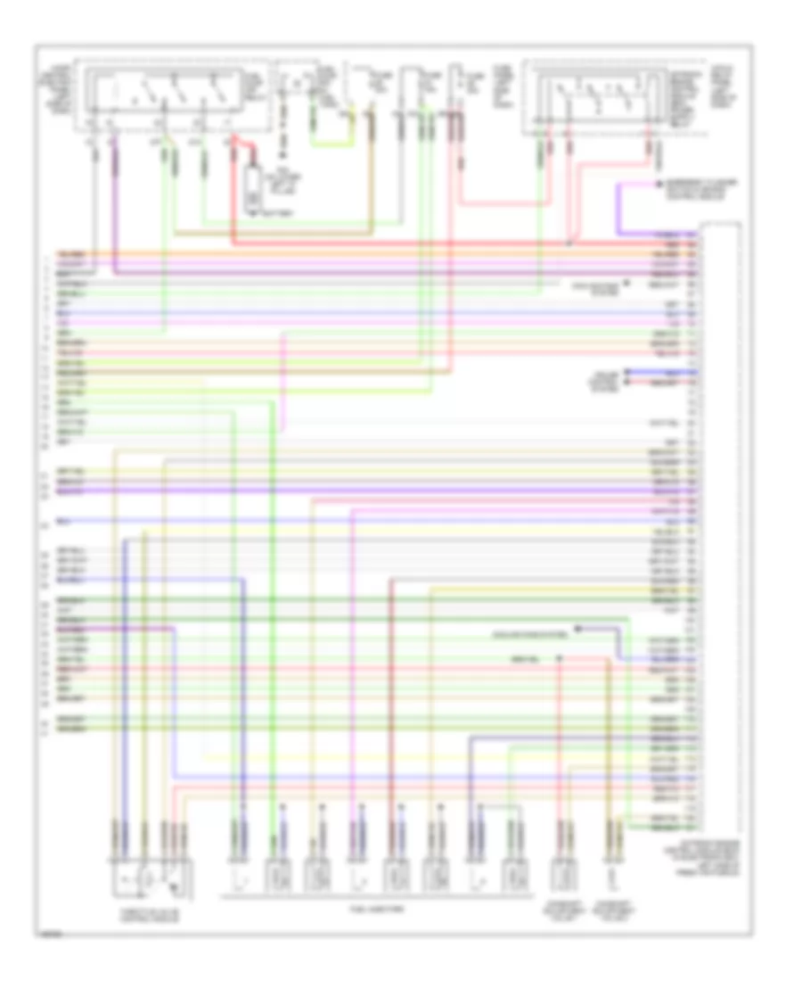
4.2L, Engine Performance Wiring Diagram (1 of 4) for Audi allroad Quattro 2005
List of elements for 4.2L, Engine Performance Wiring Diagram (1 of 4) for Audi allroad Quattro 2005:
- (left side of dash)
- (left side of dash) 3-fold relay panel
- (left side of engine compt) g12
- 13a
- 32a
- A/c system (if equipped)
- Brake- light switch
- Clutch vacuum vent valve switch (m/t)
- Computer data lines system
- Cooling fans system
- Cruise control
- Fuse 10a
- Fuse 20a
- Fuse 40a
- Fuse panel
- G12 (left side of engine compt)
- Heated oxygen sensor (ho2s) 1
- Heated oxygen sensor (ho2s) 2
- Hot at all times
- Ignition switch
- Motronic engine control module (ecm) (in electronic box, left side of fresh air plenum)
- Nca
- Off
- Red
- Run
- Secondary air injection (air) pump motor
- Secondary air injection (air) pump relay
- Start
- Throttle position (tp) sensor/accelerator pedal position sensor 2
4.2L, Engine Performance Wiring Diagram (2 of 4) for Audi allroad Quattro 2005
List of elements for 4.2L, Engine Performance Wiring Diagram (2 of 4) for Audi allroad Quattro 2005:
- 3-fold relay & fuse panel (lower left side of dash)
- Brake booster pressure sensor
- Brake booster relay
- Brake system vacuum pump
- Engine coolant temperature (ect) sensor
- Engine speed (rpm) sensor
- Evaporative emission (evap) canister purge regulator valve
- Fuse 15a
- G12 (left side of engine compt)
- Hot at all times
- Intake air change-over valve
- Knock sensor (ks) 1
- Knock sensor (ks) 2
- Knock sensor (ks) 3
- Knock sensor (ks) 4
- Leak detection pump (ldp)
- Mass airflow (maf) sensor
- Nca
- Secondary air injection (air) solenoid valve
4.2L, Engine Performance Wiring Diagram (3 of 4) for Audi allroad Quattro 2005
List of elements for 4.2L, Engine Performance Wiring Diagram (3 of 4) for Audi allroad Quattro 2005:
- (mil)
- Camshaft position (cmp) sensor
- Camshaft position (cmp) sensor 2
- Coil
- Data link connector (dlc)
- Engine electronics fuse (3-fold relay panel)
- Fuse 15a
- G12 (left side of engine compt)
- G19 (near ignition coil)
- Instrument cluster
- Left electro- hydraulic engine mount solenoid valve
- Malfunction indicator lamp
- Nca
- Right electro- hydraulic engine mount solenoid valve
- T32a/28
- To spark plugs
4.2L, Engine Performance Wiring Diagram (4 of 4) for Audi allroad Quattro 2005
List of elements for 4.2L, Engine Performance Wiring Diagram (4 of 4) for Audi allroad Quattro 2005:
- 3-fold relay panel (left side of dash)
- 87a
- 87f
- Battery
- Camshaft adjustment valve 1
- Camshaft adjustment valve 2
- Cooling fans system
- Cruise control system
- Emergency flasher switch & air bag control module
- Fuel injectors
- Fuel pump (fp) (in fuel tank)
- Fuel pump (fp) relay
- Fuse 15a
- Fuse 20a
- Fuse 30a
- Fuse panel (left side of dash)
- G44 (on lower left "a" pillar)
- Micro central electric panel (left side of dash)
- Motronic engine control module (ecm) (in electronic box, left side of fresh air plenum)
- Red
- Throttle valve control module
EXTERIOR LIGHTS
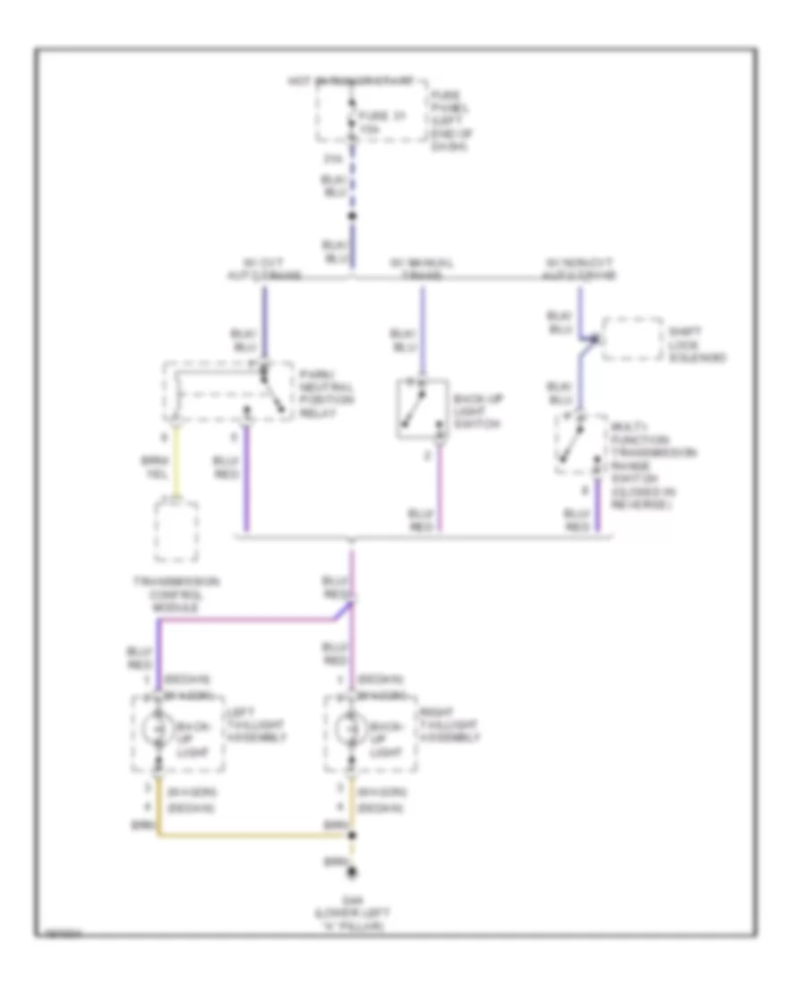
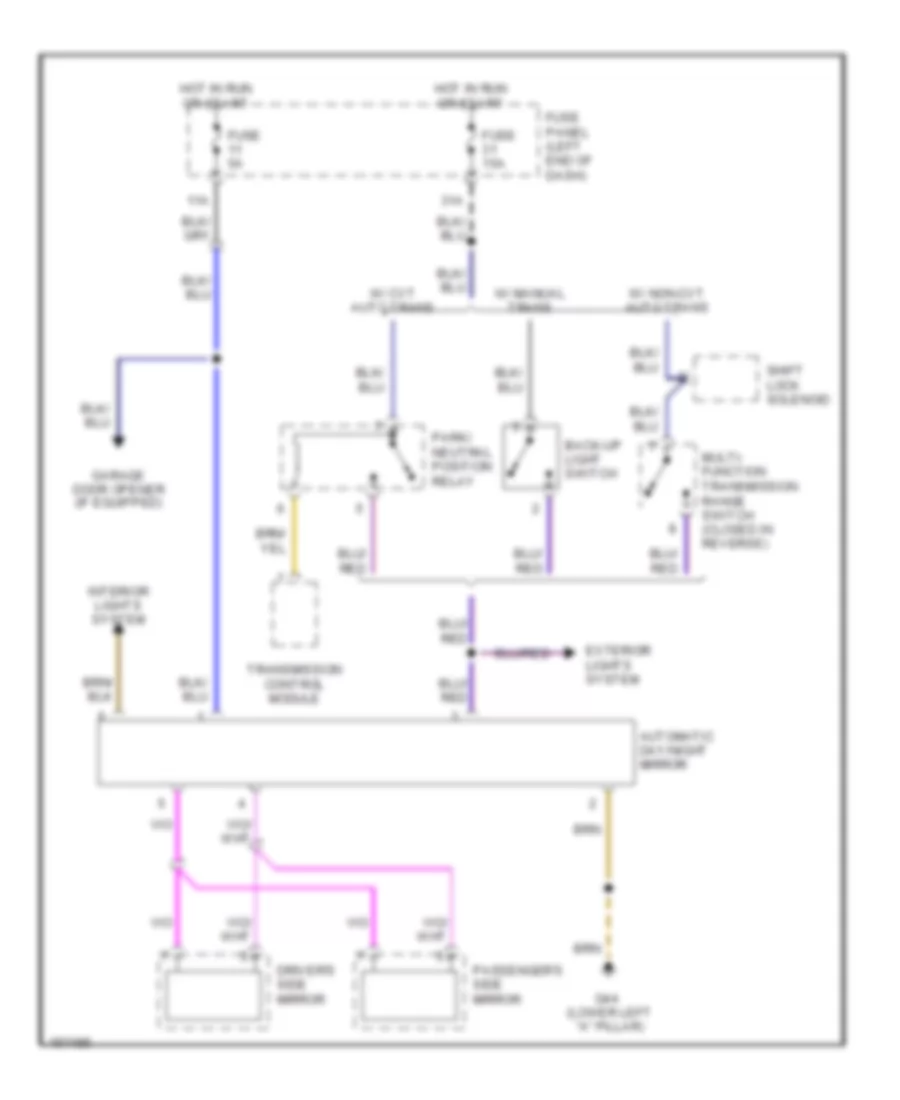
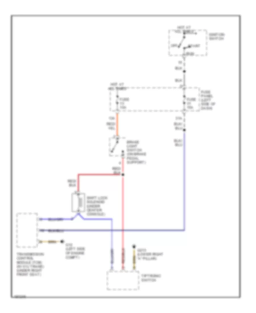
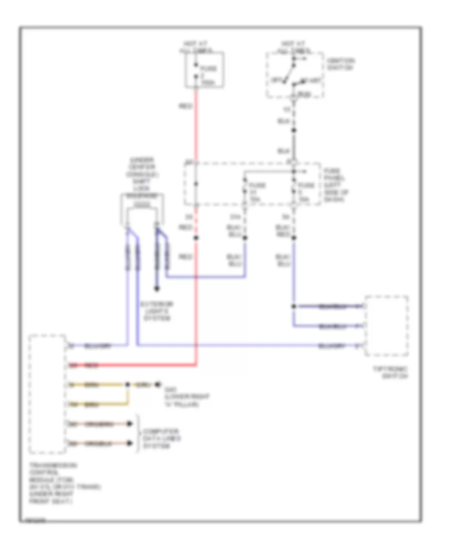
Back-up Lamps Wiring Diagram for Audi allroad Quattro 2005
List of elements for Back-up Lamps Wiring Diagram for Audi allroad Quattro 2005:
- (sedan)
- (wagon)
- 31a
- Back- up light
- Back-up light switch
- Fuse 31 15a
- Fuse panel (left end of dash)
- G44 (lower left "a" pillar)
- Hot in run or start
- Left taillight assembly
- Multi- function transmission range switch (closed in reverse)
- Park/ neutral position relay
- Right taillight assembly
- Shift lock solenoid
- Transmission control module
- W/ cvt auto trans
- W/ manual trans
- W/ non-cvt auto trans
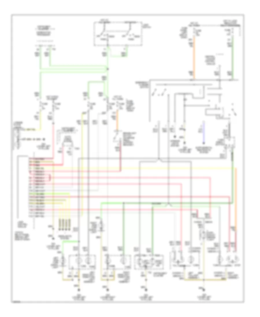
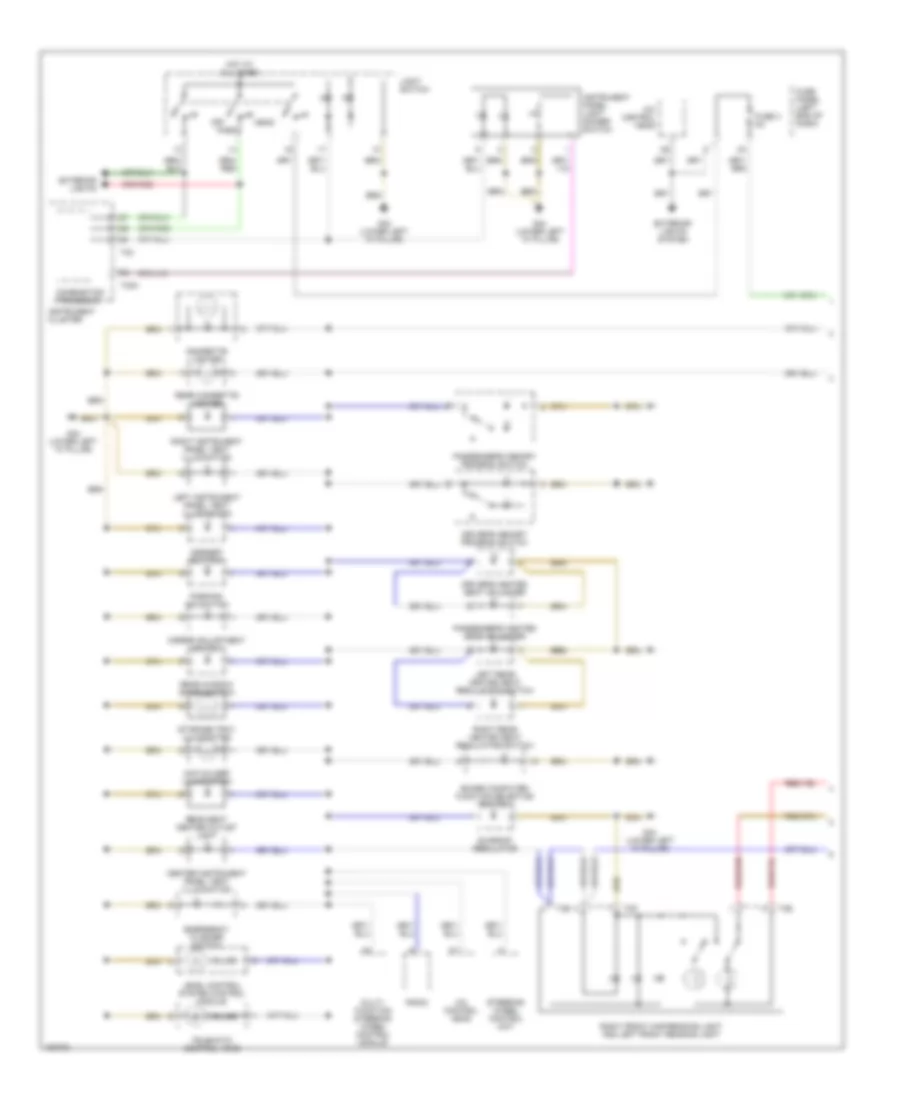
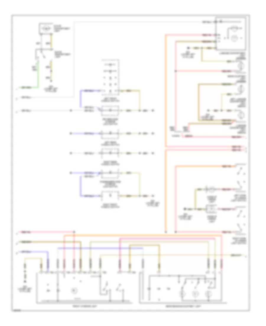
Exterior Lamps Wiring Diagram, with DRL, with Driver Information Center for Audi allroad Quattro 2005
List of elements for Exterior Lamps Wiring Diagram, with DRL, with Driver Information Center for Audi allroad Quattro 2005:
- (sedan)
- (wagon)
- 13-fold relay panel (behind left side of dash)
- 13a
- 22a
- 23a
- 39a
- Auto- check system
- Brakelight switch (on brake pedal support bracket)
- Central locking control module
- Cluster
- Combination processor
- Emergency flasher switch
- Fuse 10a
- Fuse 15a
- Fuse 5a
- Fuse panel (left end of dash)
- G43 (lower right "a" pillar)
- G44 (lower left "a" pillar)
- Head
- Headlights system
- High- mount brake light
- Hot at all times
- Hot in run
- Hot in run or start
- Hot w/ load reduction relay energized
- Instrument
- Instrument cluster
- Interior lights system
- Lamp control module
- Left headlight/ park/turn light assembly
- Left side turn signal light
- Left taillamp assembly
- Left turn ind
- License plate
- Light switch
- Lights
- Off
- Park
- Red
- Right headlight/ park/turn light assembly
- Right side turn signal light
- Right taillamp assembly
- Right turn ind
- Sedan
- Signal switch
- Stop
- T32
- T32a
- T32c
- Tail
- Turn
- Wagon
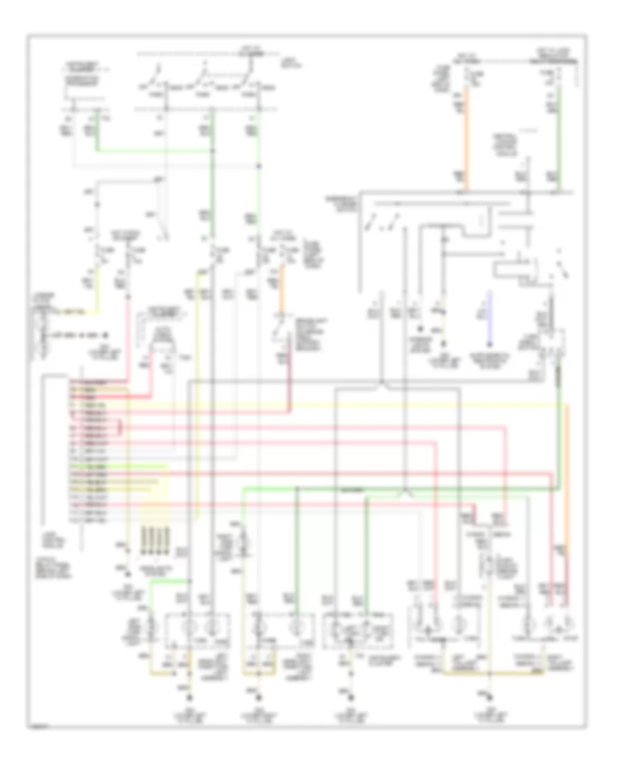
Exterior Lamps Wiring Diagram, without DRL, with Driver Information Center for Audi allroad Quattro 2005
List of elements for Exterior Lamps Wiring Diagram, without DRL, with Driver Information Center for Audi allroad Quattro 2005:
- (sedan)
- (wagon)
- 13-fold relay panel (behind left side of dash)
- 13a
- 22a
- 23a
- 39a
- Auto- check system
- Brakelight switch (on brake pedal support bracket)
- Central locking control module
- Cluster
- Combination processor
- Emergency flasher switch
- Fuse 10a
- Fuse 15a
- Fuse 5a
- Fuse panel (left end of dash)
- G43 (lower right "a" pillar)
- G44 (lower left "a" pillar)
- Head
- Headlights system
- High- mount brake light
- Hot at all times
- Hot in run or start
- Hot w/ load reduction relay energized
- Instrument
- Instrument cluster
- Interior lights system
- Lamp control module
- Left headlight/ park/turn light assembly
- Left side turn signal light
- Left taillamp assembly
- Left turn ind
- License plate
- Light switch
- Lights
- Off
- Park
- Red
- Right headlight/ park/turn light assembly
- Right side turn signal light
- Right taillamp assembly
- Right turn ind
- Sedan
- Signal switch
- Stop
- T32
- T32a
- T32c
- Tail
- Turn
- Wagon
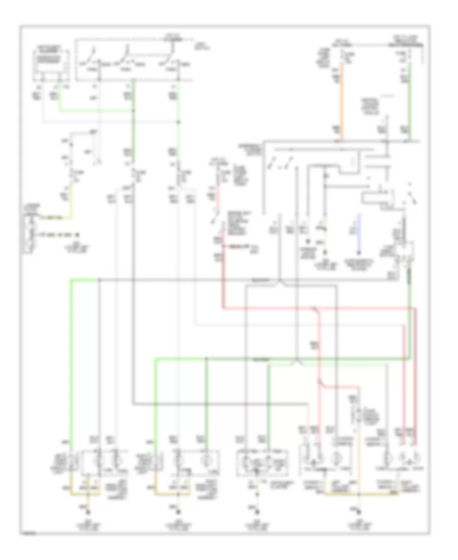
Exterior Lamps Wiring Diagram, without DRL, without Driver Information Center for Audi allroad Quattro 2005
List of elements for Exterior Lamps Wiring Diagram, without DRL, without Driver Information Center for Audi allroad Quattro 2005:
- (sedan)
- (wagon)
- 13a
- 22a
- 23a
- 39a
- Brakelight switch (on brake pedal support bracket)
- Central locking control module
- Cluster
- Combination processor
- Emergency flasher switch
- Fuse 10a
- Fuse 15a
- Fuse 5a
- Fuse panel (left end of dash)
- G43 (lower right "a" pillar)
- G44 (lower left "a" pillar)
- Head
- High- mount brake light
- Hot at all times
- Hot w/ load reduction relay energized
- Instrument
- Instrument cluster
- Interior lights system
- Left headlight/ park/turn light assembly
- Left side turn signal light
- Left taillamp assembly
- Left turn ind
- License plate
- Light switch
- Lights
- Off
- Park
- Right headlight/ park/turn light assembly
- Right side turn signal light
- Right taillamp assembly
- Right turn ind
- Signal switch
- Stop
- T32
- T32a
- Tail
- Tcm, ecm
- Turn
GROUND DISTRIBUTION
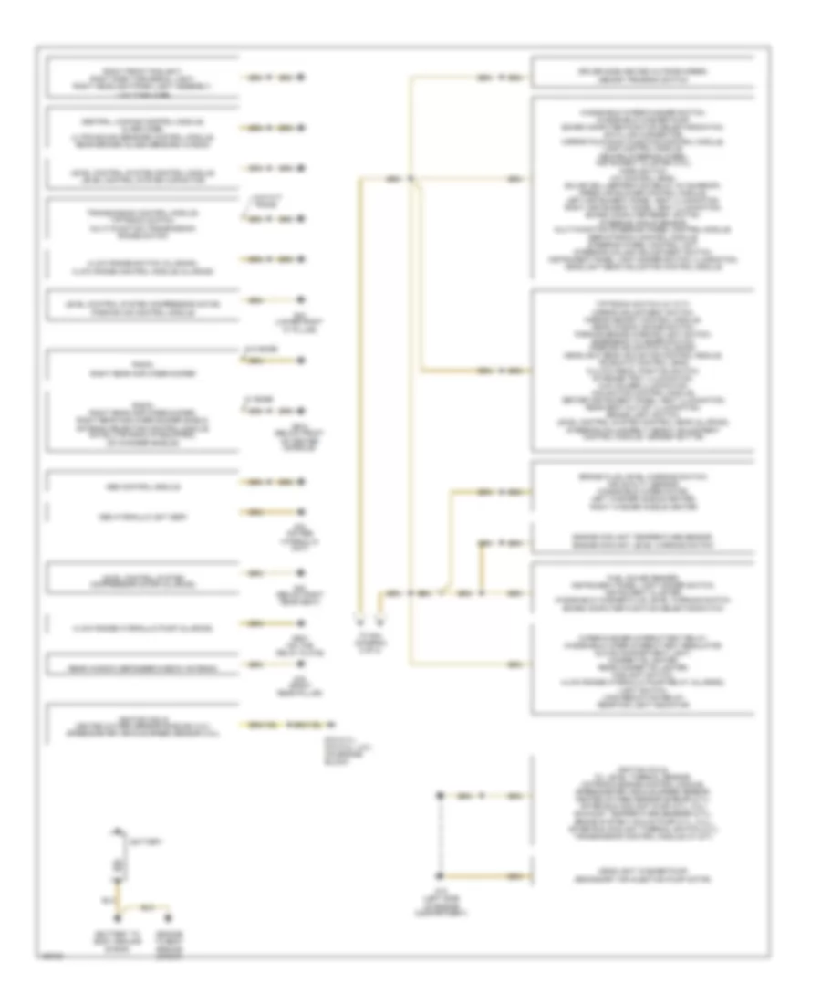
Ground Distribution Wiring Diagram (1 of 2) for Audi allroad Quattro 2005
List of elements for Ground Distribution Wiring Diagram (1 of 2) for Audi allroad Quattro 2005:
- (battery to body ground strap)
- (engine to body ground strap)
- 4-low range hydraulic pump (allroad)
- 4-low range switch (allroad), 4-low range control module (allroad)
- Abs control module
- Abs hydraulic unit (esp)
- Battery
- Board computer function selector switch
- Brake fluid level warning switch, air quality sensor, windshield wiper motor, left washer nozzle heater,
- Central locking control module, alarm horn, ultra-sound sensors control module, rear broken glass sensors (wagon)
- Driver side heated outside mirror,
- Engine coolant level warning switch
- Engine coolant temperature sensor,
- Fuel gauge sender, instrument panel light dimmer switch, instrument cluster, windshield washer fluid level warning switch,
- G12 (left side of engine compartment)
- G18 (2.7l) g19 (3.0l, 4.2l) (on engine block)
- G22 (on abs hydraulic unit)
- G40 (below right rear seat)
- G43 (lower right "a" pillar)
- G503 (on the relay plate)
- G610 (below front
- G75 (right rear pillar)
- Headlight washer pump, secondary air injection pump motor,
- Ignition coils heated oxygen sensor shields (4.2l) speedometer vehicle speed sensor (4.2l)
- Ignition coils, oil level thermal sensor, motronic engine control module, speedometer vehicle speed sensor, heated oxygen sensor shields (2.7l), after run coolant pump (2.7l, 3.0l), exhaust temperature sensors (2.7l), brake system vacuum pump (2.7l, 3.0l), after run coolant thermal switch (2.7l) transmission control module (w/ cvt)
- Level control system compressor motor (allroad)
- Level control system compressor motor,
- Level control system control module, level control system capacitor
- Low tone horn
- Memory program switch
- Multi-function transmission range switch
- Of center console)
- Parking aid control module
- Radio,
- Radio, right rear amplifier/woofer, right rear amplifier/woofer shield, antenna selection control module, satellite radio (if equipped), cd changer shields
- Rear window defogger/window antenna
- Right front foglight, right side turn signal light, right headlight/park light assembly,
- Right rear amplifier/woofer
- Right washer nozzle heater
- Tiptronic switch (w/ cvt), mirror adjustment switch, mirror memory control module, rear window shade switch, parking brake warning light switch, emergency flasher switch, parking aid switch (allroad), headlight beam adjusting control module, telematic control head, clutch pedal position switch, storage tray illumination, cup holder illumination, navigation control module, center instrument panel vent illumination, rear seat outlet illumination, brake light switch, level control system control head (allroad), steering column/belt height adjustment control module, asr/esp button
- To g44 (diagram 2 of 2)
- Transmission control module, tiptronic switch,
- W/ bose
- W/o bose
- W/o cvt trans
- Windshield wiper/washer switch, windshield washer pump, board computer function selector switch, data link connector, mirror fold-away function control module, lamp control module, heated steering wheel, instrument cluster (3.0l), horn switch, a/c control head, solar cell separation relay (w/ sunroof), fresh air blower control module, left instrument panel vent illumination, right instrument panel vent illumination, board computer reset switch, steering angle sensor, multi-function steering wheel control module, servotronic control module, steering wheel control unit, steering column adjustment switch, instrument panel light dimmer switch illumination, headlight beam adjusting control module
- Wiper/washer intermittent relay, windshield wiper intermittent regulator, glove compartment light, cigarette lighter, rear cigarette lighter, foglight switch, 4-low range hydraulic pump relay (allroad), light switch, load reduction relay, rear fog light indicator
Ground Distribution Wiring Diagram (2 of 2) for Audi allroad Quattro 2005
List of elements for Ground Distribution Wiring Diagram (2 of 2) for Audi allroad Quattro 2005:
- Air bag control module, driver's side crash sensor (side air bag), passenger's side crash sensor (side air bag), passenger's side igniter (side air bag), driver's side igniter (side air bag), passenger's side igniter (rear side air bag), driver's side igniter (rear side air bag), passenger's side igniter (head air bag), driver's side igniter (head air bag), left seat belt switch, right seat belt switch
- Coolant fan control module, coolant fan control thermal switch (2.7l, 4.2l), a/c pressure sensor,
- Driver side interior lock switch, driver side door contact switch, driver side door opener illumination, window lockout switch, left front power window control module, driver side door lock assembly,
- Driver's heated seat temperature sensor, driver's backrest heating element, driver's seat backrest side bolster heater, passenger's heated seat temperature sensor, passenger's backrest heating element, passenger's seat backrest side bolster heater,
- Driver's seat lumbar support adjustment switch, driver's seat front height adjustment switch, driver's seat rear height adjustment switch, driver's seat for/aft adjustment switch, driver's seat backrest adjustment switch, driver's memory seat control module,
- From grounds (diagram 1 of 2)
- Front interior light, front map/reading lights, make-up mirror lights, power sunroof control module, automatic day/night interior mirror,
- Fuel pump, left taillight assembly, left back-up light, right back-up light, high mount brakelight, right taillight assembly, luggage compartment light, left luggage compartment light (sedan), 12v accessory socket,
- G44 (lower left "a" pillar)
- High note horn, left front foglight, left side turn signal light, left headlight/parklight assembly,
- Hood alarm switch, tire pressure monitoring control module (allroad)
- Left rear door lock assembly, left rear door opener illumination,
- Left rear window switch left rear power window control module, left rear ashtray light
- Left seat belt microswitch, rear window shade control module, left brake pad wear indicator,
- License plate light, left rear foglight, remote unlock rear lid motor, trunk lid closed position switch, trunk lid central locking switch
- Passenger door window regulator switch, passenger side door open illumination, passenger side door contact switch,
- Passenger side door lock assembly
- Passenger side interior lock switch, right front power window control module,
- Passenger's seat lumbar support adjustment switch, passenger's seat front height adjustment switch, passenger's seat rear height adjustment switch, passenger's seat for/aft adjustment switch, passenger's seat backrest adjustment switch, passenger's memory seat control module,
- Passenger's seat memory program switch, passenger side heated outside mirror
- Remote unlock rear lid motor, license plate light, trunk lid lock assembly, rear foglights (if equipped), high mount brakelight, rear window wiper motor, rear window defoger/heat element, rear courtesy lights, luggage compartment light, rear lid lock cylinder switch, rear courtesy lamp, luggage compartment light
- Right rear door lock assembly, right rear door opener illumination, right rear window switch, right rear power window control module, right rear ashtray light
- Right rear heated seat regulating switch, left rear heated seat temperature sensor, right rear heated seat temperature sensor, left rear backrest heating element, right rear backrest heating element, driver's heated seat adjuster, passenger's heated seat adjuster left rear heated seat regulating switch,
- Sunroof regulator, garage door opener control module
- Telephone/telematic control module
- Trailer socket
HEADLIGHTS
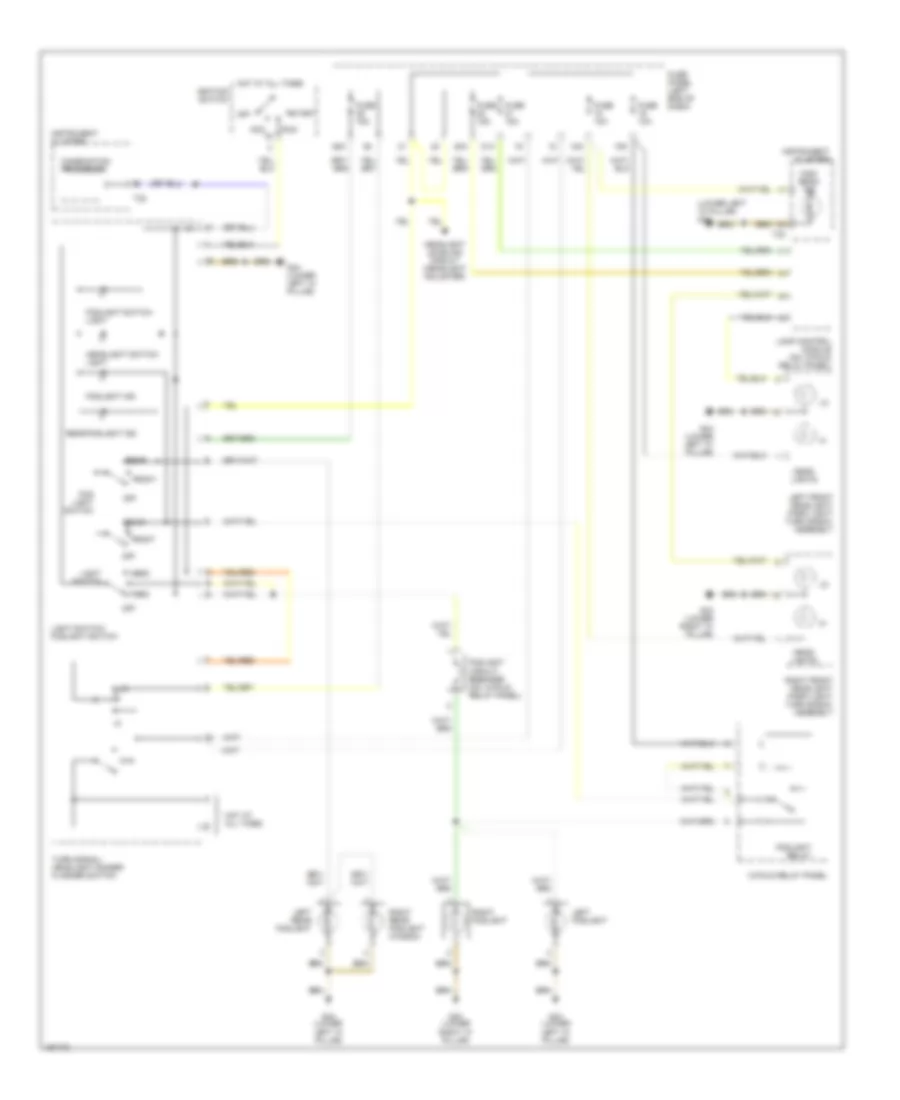
Headlamps & Fog Lamps Wiring Diagram, with DRL, with Driver Information Center for Audi allroad Quattro 2005
List of elements for Headlamps & Fog Lamps Wiring Diagram, with DRL, with Driver Information Center for Audi allroad Quattro 2005:
- (lower left "a" pillar) g44
- 13-fold relay panel
- 18a
- 19a
- 20a
- 21a
- 36a
- Acc
- Combination processor
- Fog light switch
- Foglight circuit breaker (on 13-fold relay panel)
- Foglight ind
- Foglight relay
- Foglight switch light
- Front
- Ftp
- Fuse 10a
- Fuse 15a
- Fuse panel (left end of dash)
- G43 (lower right "a" pillar)
- G44 (lower left "a" pillar)
- Head
- Head- lights
- Headlight leveling circuit (headlight adjuster)
- Headlight switch light
- High beam ind
- Hot at all times
- Ignition switch
- Instrument cluster
- Lamp control module (on 13-fold relay panel)
- Left foglight
- Left front headlight/ park light/ turn signal assembly
- Left rear foglight
- Light switch
- Light switch/ foglight switch
- Off
- Park
- Rear
- Rear foglight ind
- Right foglight
- Right front headlight/ park light/ turn signal assembly
- Right rear foglight (wagon)
- Run
- Start
- T32
- Turn signal/ headlight dimmer/ flasher switch
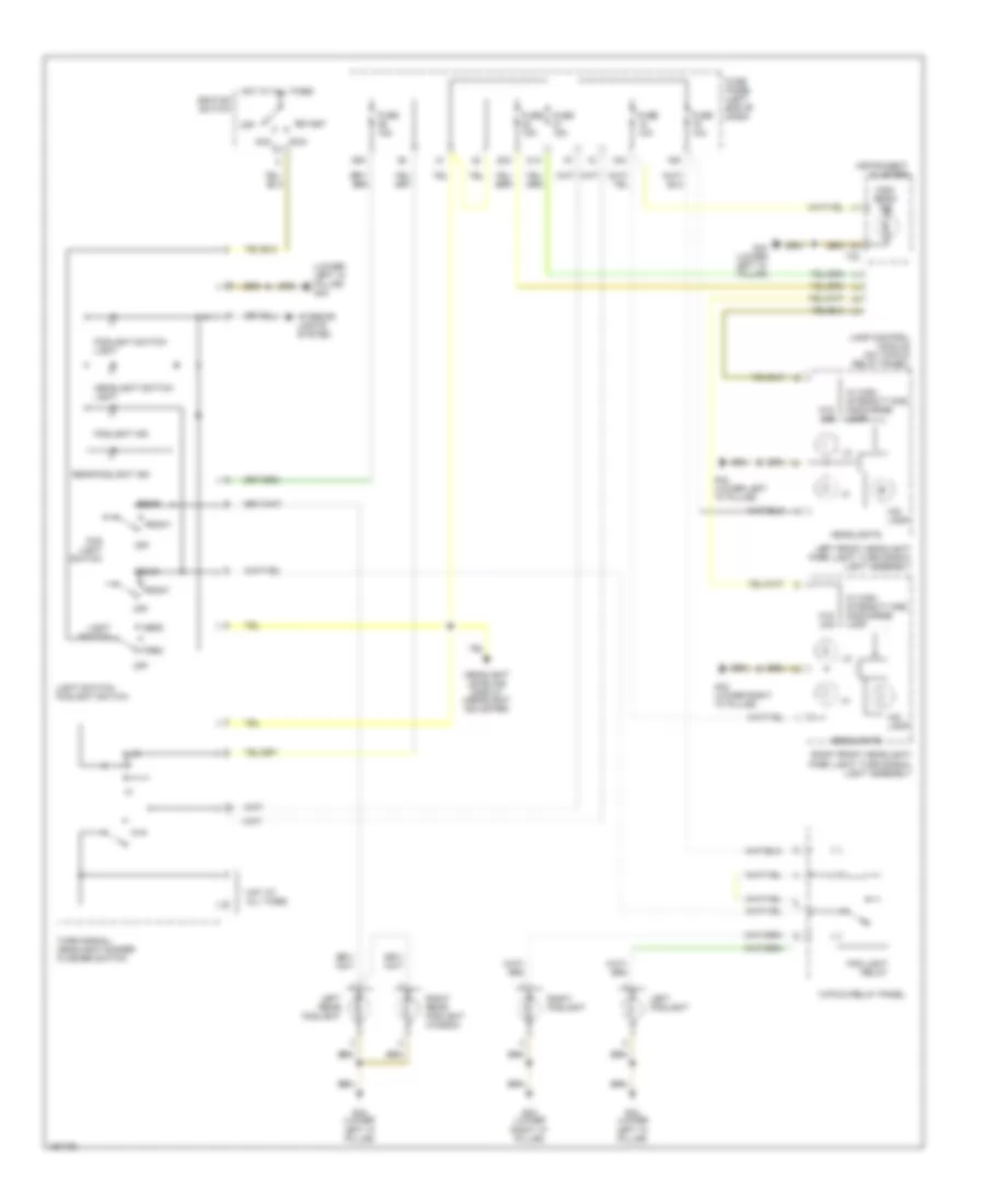
Headlamps & Fog Lamps Wiring Diagram, without DRL, with Driver Information Center for Audi allroad Quattro 2005
List of elements for Headlamps & Fog Lamps Wiring Diagram, without DRL, with Driver Information Center for Audi allroad Quattro 2005:
- (lower left "a" pillar) g44
- 13-fold relay panel
- 18a
- 19a
- 20a
- 21a
- 36a
- Acc
- Fog light relay
- Fog light switch
- Foglight ind
- Foglight switch light
- Front
- Ftp
- Fuse 10a
- Fuse 15a
- Fuse panel (left end of dash)
- G43 (lower right "a" pillar)
- G44 (lower left "a" pillar)
- Head
- Headlight leveling circuit (headlight adjuster)
- Headlight switch light
- Headlights
- Hid lamp
- High beam ind
- Hot at all times
- Ignition switch
- Instrument cluster
- Interior lights system
- Lamp control module (on 13-fold relay panel)
- Left foglight
- Left front headlight/ park light/ turn signal light assembly
- Left rear foglight
- Light switch
- Light switch/ foglight switch
- Off
- Park
- Rear
- Rear foglight ind
- Right foglight
- Right front headlight/ park light/ turn signal light assembly
- Right rear foglight (wagon)
- Run
- Start
- T32
- Turn signal/ headlight dimmer/ flasher switch
- W/ high intensity gas discharge lamp
- W/o hid
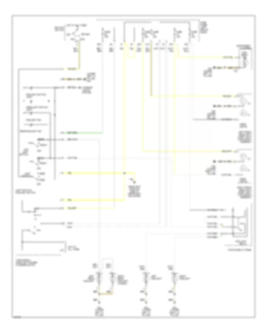
Headlamps & Fog Lamps Wiring Diagram, without DRL, without Driver Information Center for Audi allroad Quattro 2005
List of elements for Headlamps & Fog Lamps Wiring Diagram, without DRL, without Driver Information Center for Audi allroad Quattro 2005:
- (lower left "a" pillar) g44
- 13-fold relay panel
- 18a
- 19a
- 20a
- 21a
- 36a
- Acc
- Fog light relay
- Fog light switch
- Foglight ind
- Foglight switch light
- Front
- Ftp
- Fuse 10a
- Fuse 15a
- Fuse panel (left end of dash)
- G43 (lower right "a" pillar)
- G44 (lower left "a" pillar)
- Head
- Head- lights
- Headlight leveling circuit (headlight adjuster)
- Headlight switch light
- High beam ind
- Hot at all times
- Ignition switch
- Instrument cluster
- Interior lights system
- Left foglight
- Left front headlight/ park light/ turn signal assembly
- Left rear foglight
- Light switch
- Light switch/ foglight switch
- Off
- Park
- Rear
- Rear foglight ind
- Right foglight
- Right front headlight/ park light/ turn signal assembly
- Right rear foglight (wagon)
- Run
- Start
- T32
- Turn signal/ headlight dimmer/ flasher switch
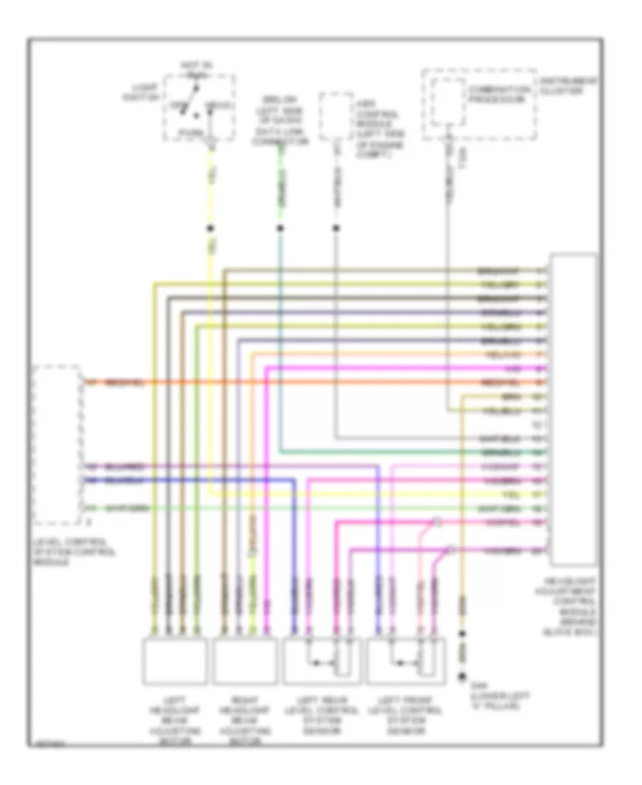
Headlamps Leveling Wiring Diagram for Audi allroad Quattro 2005
List of elements for Headlamps Leveling Wiring Diagram for Audi allroad Quattro 2005:
- (below left side of dash) data link connector
- Abs control module (left side of engine compt)
- Combination processor
- G44 (lower left "a" pillar)
- Head
- Headlight adjustment control module (behind glove box)
- Hot in run
- Instrument cluster
- Left front level control system sensor
- Left headlight beam adjusting motor
- Left rear level control system sensor
- Level control system control module
- Light switch
- Off
- Park
- Right headlight beam adjusting motor
- T32a
HORN
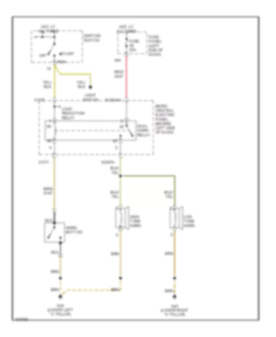
Horn Wiring Diagram for Audi allroad Quattro 2005
List of elements for Horn Wiring Diagram for Audi allroad Quattro 2005:
- 40a
- Dual horn relay
- Fuse 25a
- Fuse panel (left end of dash)
- G43 (lower right "a" pillar)
- G44 (lower left "a" pillar)
- High tone horn
- Horn button
- Hot at all times
- Ignition switch
- Light switch
- Load reduction relay
- Low tone horn
- Micro central electric panel (behind left side of dash)
- Nca
- Off
- Run
- S1/30ah
- S1/71
- S1/75
- S2/87h
- Start
INSTRUMENT CLUSTER
Auto Check System Wiring Diagram for Audi allroad Quattro 2005
List of elements for Auto Check System Wiring Diagram for Audi allroad Quattro 2005:
- (left end of dash)
- 13a
- A/c control head
- A12
- Auto check system
- Board computer function selector switch ii
- Brake- light switch
- Computer data lines system
- Computer function select switch
- Computer function select/ reset switch
- Computer reset button
- Fuse 13 10a
- Fuse 5 10a
- Fuse panel
- G44 (lower left "a" pillar)
- G900 (lower left "a" pillar)
- Hot at all times
- Hot in run or start
- Instrument cluster
- Interior lights system
- Lamp control module (on 13-fold relay panel)
- Navigation control unit
- Outside air temp display
- Outside air temperature sensor (in front of a/c condenser)
- Radio
- Red
- T32a
- T32c
- Washer fluid level warning switch
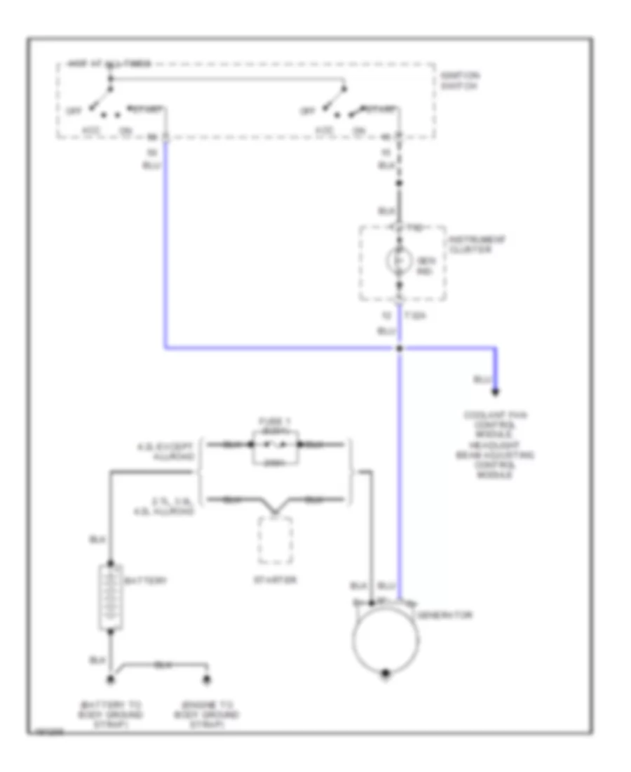
Instrument Cluster Wiring Diagram (1 of 2) for Audi allroad Quattro 2005
List of elements for Instrument Cluster Wiring Diagram (1 of 2) for Audi allroad Quattro 2005:
- (allroad)
- (information not available)
- (left end of dash)
- (lower left "a" pillar)
- (w/ tow package) emergency flasher unit
- 15a
- 18a
- 86s
- Abs warning
- Air bag mil
- Analog clock
- Anti-theft immobilizer
- Anti-theft immobilizer key ring induction coil
- Brake pad wear ind
- Computer data lines system
- Coolant level/temp
- Data link connector (below left side of dash)
- Ect gauge
- Elec power control ind
- Fuel gauge
- Fuel reserve warning
- Fuse 10a
- Fuse panel
- G100 (on abs hydraulic unit)
- G12 (left side of engine compt)
- G44
- G44 (lower left "a" pillar)
- Gen ind
- Generator
- Headlamp beam adjusting control module
- Headlights system
- High beam
- Hot at all times
- Hot in on or start
- Hot with high beams on
- Ignition switch
- Illumination
- Instrument cluster
- Instrument panel light dimmer switch
- Interior lights system
- Key switch
- Left brake pad wear indicator element
- Left front seat belt micro switch
- Left turn
- Level ctrl
- Malfunction indicator
- Nca
- Off
- Oil level thermal sensor
- Oil pressure warning
- Park brake
- Park brake switch
- Parklight
- Red
- Right brake pad wear indicator element
- Right turn
- Run
- Seat belt
- Speedometer
- Start
- T32
- T32/1
- T32/10
- T32/11
- T32/12
- T32/14
- T32/15
- T32/16
- T32/17
- T32/18
- T32/2
- T32/20
- T32/21
- T32/22
- T32/23
- T32/24
- T32/26
- T32/27
- T32/28
- T32/29
- T32/3
- T32/30
- T32/31
- T32/32
- T32/5
- T32/7
- T32/8
- T32/9
- T32a
- T32a/10
- T32a/11
- T32a/12
- T32a/13
- T32a/15
- T32a/17
- T32a/18
- T32a/19
- T32a/2
- T32a/21
- T32a/22
- T32a/23
- T32a/25
- T32a/27
- T32a/28
- T32a/29
- T32a/30
- T32a/32
- T32a/6
- T32a/7
- T32a/8
- Tachometer
- Trailer operation
- Voltmeter
- W/o auto check system
- Warning buzzer
Instrument Cluster Wiring Diagram (2 of 2) for Audi allroad Quattro 2005
List of elements for Instrument Cluster Wiring Diagram (2 of 2) for Audi allroad Quattro 2005:
- (on oil filter housing) oil pressure switch
- (w/cvt)
- 4-low range control module (allroad)
- A/c control head
- Abs control module
- Air bag ctrl module (below front center console)
- Allroad
- Brake fluid level warning switch
- Central locking control module
- Coolant level warning switch (bottom of reservoir)
- Ect sensor (on coolant pipe, behind intake manifold)
- Fuel level sensor 1
- Fuel level sensor 2 (w/ awd)
- Fuel level sensor 3 (w/ awd)
- G12 (left side of engine compt)
- G44 (lower left "a" pillar)
- Headlamp beam adjusting control module
- Hood alarm switch
- Interior lights system
- Level control system control head (allroad)
- Level control system control module
- Motronic engine control module
- Navigation control unit
- Nca
- Others
- Others allroad
- Parking aid control module
- Servo- tronic control module
- Tiptronic switch
- Transmission control module
- Turn signal switch
- Vehicle speed sensor (left side of trans)
- Wiper/ washer intermittent relay
INTERIOR LIGHTS
Interior Lights Wiring Diagram (1 of 3) for Audi allroad Quattro 2005
List of elements for Interior Lights Wiring Diagram (1 of 3) for Audi allroad Quattro 2005:
- 3 bulbs
- A/c control head
- Asr/esp button
- Board computer function selector switch
- Center instrument panel vent illumination
- Cigarette lighter
- Combination processor
- Cup holder illumination
- Driver's heated seat adjuster
- Driver's memory program switch
- Emergency flasher switch
- Exterior lights
- Exterior lights system
- Fuse 3 5a
- Fuse panel (left end of dash)
- G44 (lower left "a" pillar)
- Head
- Hot at all times
- Instrument cluster
- Instrument panel light dimmer switch
- Left instrument panel vent illumination
- Left rear heated seat regulating switch
- Level control system control module
- Light switch
- Mirror adjustment switch
- Multi- function steering wheel control module
- Off
- Park
- Parking aid switch
- Passenger's heated seat adjuster
- Passenger's memory program switch
- Radio
- Rear cigarette lighter
- Rear seat center outlet light
- Rear window shade switch
- Right front map/reading light and left front reading light
- Right instrument panel vent illumination
- Right rear heated seat regulating switch
- Steering wheel control unit
- Storage tray illumination
- Sunroof regulator
- T32
- T32a
- T3p
- T4e
- Telematic control head
Interior Lights Wiring Diagram (2 of 3) for Audi allroad Quattro 2005
List of elements for Interior Lights Wiring Diagram (2 of 3) for Audi allroad Quattro 2005:
- Driver's side interior lock switch
- Front interior light
- G44 (lower left "a" pillar)
- Glove compartment light
- Left front window switch
- Left luggage compartment light (sedan)
- Left make- up mirror light switch
- Left rear window switch
- Luggage compartment light (sedan)
- Luggage compartment light (wagon)
- Make-up mirror light
- Passenger's side interior lock switch
- Rear courtesy light (wagon)
- Rear reading/courtesy light
- Right front window switch
- Right make- up mirror light switch
- Right rear window switch
- Sedan
- T6m
- T6n
- Wagon
Interior Lights Wiring Diagram (3 of 3) for Audi allroad Quattro 2005
List of elements for Interior Lights Wiring Diagram (3 of 3) for Audi allroad Quattro 2005:
- (lower left "a" pillar) g44
- Central locking control module (below driver's seat & carpet)
- Diver's side door warning light
- Driver's side door contact switch
- Driver's side door opener illumination
- G44 (lower left "a" pillar)
- Instrument cluster, memory system, anti-theft system
- Left footwell light
- Left front entry light
- Left front power window motor
- Left front power window switch
- Left rear ashtray light
- Left rear door contact switch
- Left rear door opener illumination
- Left rear door warning light
- Left rear entry light
- Left rear footwell light
- Left rear power window motor
- Passenger memory seat control module
- Passenger's door opener illumination
- Passenger's door warning light
- Passenger's side door contact switch
- Power sunroof control module
- Right footwell light
- Right front entry light
- Right front power window motor
- Right front power window switch
- Right rear ashtray light
- Right rear door contact switch
- Right rear door opener illumination
- Right rear door warning light
- Right rear entry light
- Right rear footwell light
- Right rear power window motor
MEMORY SYSTEMS
Driver"s Memory Seat Wiring Diagram for Audi allroad Quattro 2005
List of elements for Driver"s Memory Seat Wiring Diagram for Audi allroad Quattro 2005:
- (if equipped) steering column/ belt height adjustment control module
- 14a
- 8-fold relay panel (below left side of dash)
- Back- rest
- Central locking control module (below driver's seat & carpet)
- Circuit breaker 80 30a
- Data link connector (below left side of dash)
- Driver's memory seat control module
- Driver's seat backrest adjusting motor
- Driver's seat fore/ aft adjusting motor
- Driver's seat front height adjusting motor
- Driver's seat lumbar support adjustment switch
- Driver's seat rear height adjusting motor
- Driver's seat switch
- Fore/ aft
- Front height
- Fuse 10a
- Fuse panel (left end of dash)
- G44 (lower left "a" pillar)
- Head- rest
- Hot at all times
- Interior lights system
- Memory mirror control module
- Memory program switch
- Not used
- Rear height
- Red
- T10ar
- T12e
- T32b
- T4aa
Memory Mirrors Wiring Diagram for Audi allroad Quattro 2005
List of elements for Memory Mirrors Wiring Diagram for Audi allroad Quattro 2005:
- 14a
- B10
- Back-up lights
- De- fog
- Driver side mirror
- Fold- away
- Fuse 10a
- Fuse panel (left end of dash)
- G44 (lower left "a" pillar)
- Hot at all times
- Hot in run or start
- Hot w/ load reduction relay energized
- Lights interior
- Memory mirror control module
- Memory seat control module
- Mirror adjustment switch
- Mirror fold-away control module (if equipped) (on 13-fold relay panel)
- Passenger side mirror
- Position
- Steering column/ belt height adjustment control module
- T32b
Passenger"s Memory Seat Wiring Diagram for Audi allroad Quattro 2005
List of elements for Passenger"s Memory Seat Wiring Diagram for Audi allroad Quattro 2005:
- 14a
- 8-fold relay panel (below left side of dash)
- Back- rest
- Central locking control module (below driver's seat & carpet)
- Circuit breaker 80 30a
- Data link connector (below left side of dash)
- Fore/ aft
- Front height
- Fuse 10a
- Fuse panel (left end of dash)
- G44 (lower left "a" pillar)
- Head- rest
- Hot at all times
- Interior lights system
- Not used
- Passenger's memory seat control module
- Passenger's seat backrest adjusting motor
- Passenger's seat fore/ aft adjusting motor
- Passenger's seat front height adjusting motor
- Passenger's seat lumbar support adjustment switch
- Passenger's seat memory program switch
- Passenger's seat rear height adjusting motor
- Passenger's seat switch
- Rear height
- Red
- T10as
- T12g
- T32d
- T4ab
Steering Column Memory Wiring Diagram for Audi allroad Quattro 2005
List of elements for Steering Column Memory Wiring Diagram for Audi allroad Quattro 2005:
- 14a
- 86s
- Fuse 14 10a
- Fuse 275 20a
- Fuse panel (left end of dash)
- G44 (lower left "a" pillar)
- Hot at all times
- Ignition switch
- Key-in ignition switch
- Memory mirror control module
- Memory program switch
- Memory seat control module
- Memory seats circuit
- Micro central electric panel (behind left side of dash)
- Red
- Steering column adjustment
- Steering column adjustment axial motor
- Steering column adjustment switch
- Steering column/ belt height adjustment control module
- T32b
- T3be
- T3bf
- Vertical motor
NAVIGATION
Navigation Wiring Diagram for Audi allroad Quattro 2005
List of elements for Navigation Wiring Diagram for Audi allroad Quattro 2005:
- (left end of dash)
- 15a
- 31a
- Auto check system
- Back-up light switch
- Board computer function selector switch
- Combination processor
- Computer data lines system
- Data link connector (below left side of dash)
- Exterior lights system
- Fuse 10a
- Fuse 15a
- Fuse panel
- G44 (lower left "a" pillar)
- Hot at all times
- Hot in run or start
- Instrument cluster
- Interior lights system
- Multi- function transmission range switch (closed in reverse)
- Navigation control unit
- Navigation system antenna
- Nca
- Park/ neutral position relay
- Radio
- Shift lock solenoid
- T10z
- T20b
- T32
- T32c
- T8m
- Telephone/ telematic control module
- Transmission control module
- W/ cvt auto trans
- W/ manual trans
- W/ non-cvt auto trans
Parking Assistant Wiring Diagram for Audi allroad Quattro 2005
List of elements for Parking Assistant Wiring Diagram for Audi allroad Quattro 2005:
- (below left side of dash)
- 17a
- 31a
- Back-up light switch
- Can
- Combination processor
- Computer data lines system
- Data link connector
- Exterior lights system
- Front parking aid warning buzzer
- Fuse 10a
- Fuse 15a
- Fuse panel (left end of dash)
- G43 (lower right "a" pillar)
- G44 (lower left "a" pillar)
- Hot at all times
- Hot in run or start
- Illum
- Instrument cluster
- Interior lights system
- Left front center parking sensor
- Left front parking sensor
- Left rear center parking sensor
- Left rear parking sensor
- Multi- function transmission range switch (closed in reverse)
- On ind
- Park/ neutral position relay
- Parking aid control module
- Parking aid switch
- Rear parking aid warning buzzer
- Red
- Right front center parking sensor
- Right front parking sensor
- Right rear center parking sensor
- Right rear parking sensor
- Shift lock solenoid
- Speed signal
- T12h
- T12i
- T16d
- T32
- T32a
- Transmission control module
- W/ cvt auto trans
- W/ manual trans
- W/ non-cvt auto trans
POWER DISTRIBUTION
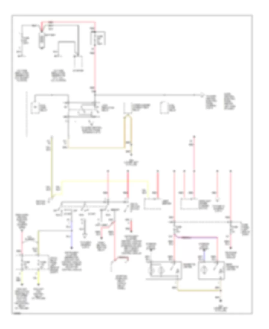
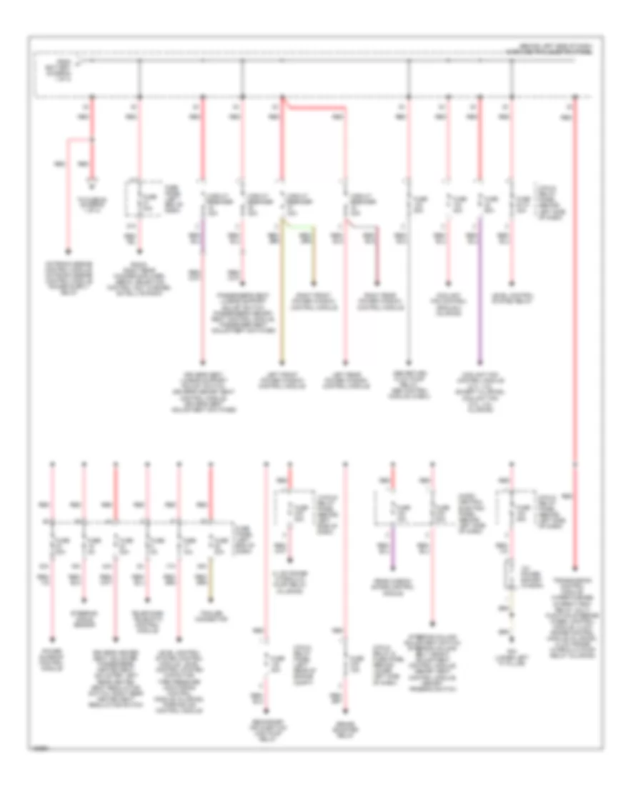
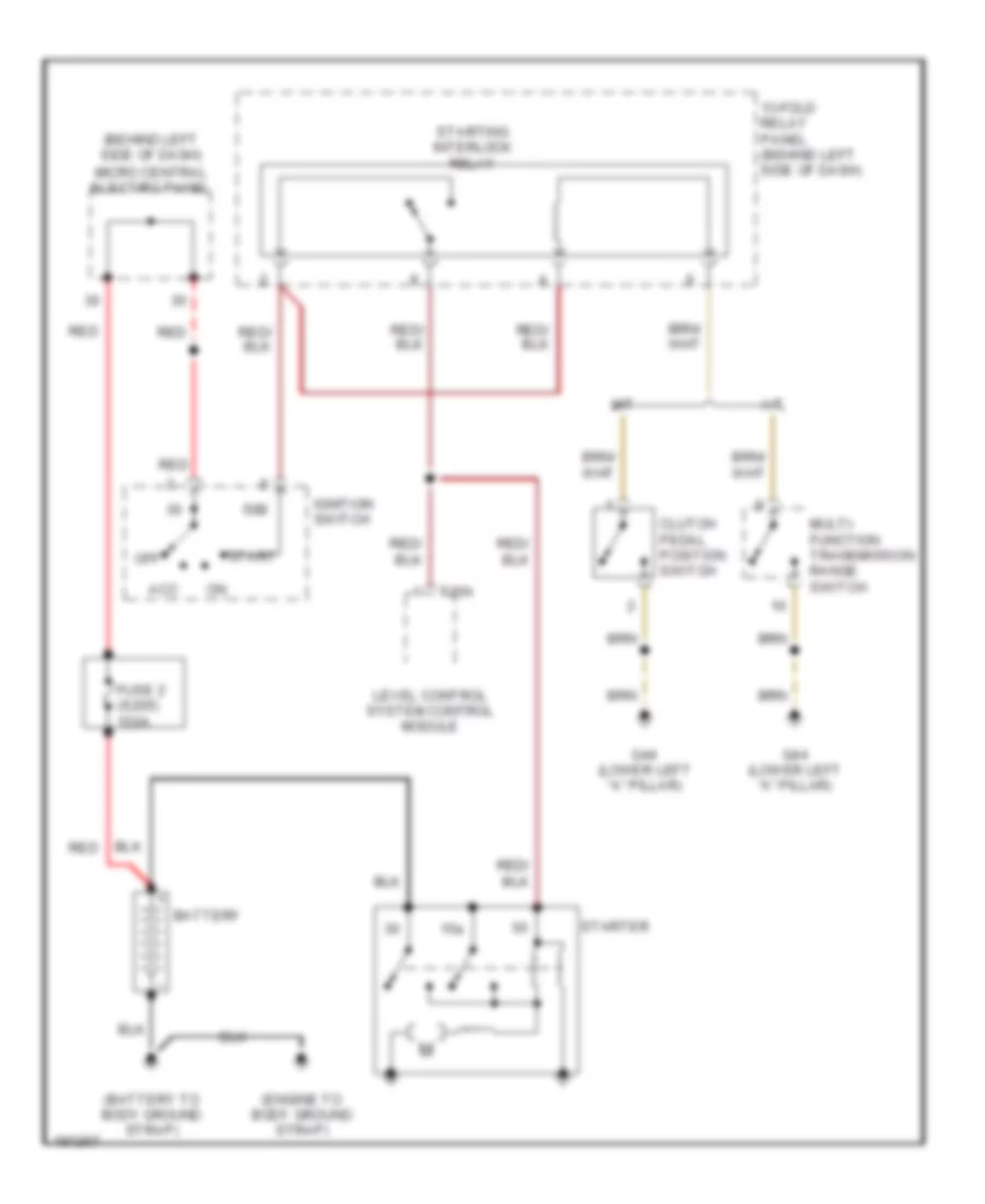
Power Distribution Wiring Diagram (1 of 3) for Audi allroad Quattro 2005
List of elements for Power Distribution Wiring Diagram (1 of 3) for Audi allroad Quattro 2005:
- (not used)
- 3-fold relay panel (left rear of engine compt)
- 33a
- 4.2l allroad
- 50b
- 86s
- Battery
- Cigarette lighter
- Coolant circulation pump relay (w after- run fan), coolant fan control relay (w/ trailer)
- Coolant fan control relay (w/ trailer)
- Dual horn relay
- From micro central electric panel (diagram 3 of 3)
- Fuel pump relay
- Fuse (2) 150a
- Fuse 15a
- Fuse 200a
- Fuse 5a
- Fuse panel (left end of dash)
- G44 (lower left "a" pillar)
- Headlight dimmer/ flasher switch
- Ignition switch
- Instrument cluster, central locking control module, steering column/ belt height adjustment control module
- Instrument cluster, generator, coolant fan control module, headlight beam adjusting control module
- Interior lights system
- Key-in ignition switch
- Light light switch switch
- Load reduction relay
- Micro central electric panel (behind left side of dash)
- Off
- Park/ neutral position relay
- Rear cigarette lighter
- Red
- Run
- S1/
- Start
- Starter
- Starting interlock relay (13-fold relay panel)
- Telphone control module
- To fuse 12 (diagram 2 of 3)
- To fuse 5 (diagram 2 of 3)
- To micro central electric panel (diagram 2 of 3)
- To micro central electric panel (diagram 3 of 3)
- Voltage regulator/ generator (2.7l, 3.0l, 4.2l allroad)
- Voltage regulator/ generator (4.2l except allroad)
- Wiper/washer intermittent relay
Power Distribution Wiring Diagram (2 of 3) for Audi allroad Quattro 2005
List of elements for Power Distribution Wiring Diagram (2 of 3) for Audi allroad Quattro 2005:
- 10a
- 11a
- 12a
- 13a
- 14a
- 15a
- 24a
- 25a
- 26a
- 27a
- 31a
- 32a
- 38a
- 39a
- 40a
- 41a
- 42a
- 75x
- A/c control head, lamp control module, driver's heated seat adjuster, passenger's heated seat adjuster, mirror fold-away function control module, radio, mirror adjustment switch, oil level thermal sensor, lamp control module, parking aid control module, navigation control module, level control system control head, level control system control module, air quality sensor, high pressure sensor, a/c clutch relay, tiptronic switch, parking aid control module, left rear heated seat regulating switch, right rear heated seat regulating switch, motronic engine control module (4.2l), brake light switch (4.2l), a/c compressor regulator valve (allroad), tire pressure monitoring control module (allroad), rear window shade switch
- A/c control head, rear window defogger switch
- Abs control module (w/edl)
- Abs control module, brake light switch, clutch vacuum vent valve switch (m/t), motronic engine control module, level control system control head, level control system control module, asr/esp button, cruise control switch, steering angle sensor
- Abs solenoid valve relay
- Automatic day/night mirror, garage door opener control module
- Brakelight switch
- Central locking control module
- Central locking control module, right door warning light, left door warning light, passenger compartment monitoring switch, trunk lid release switch, driver & passenger seat memory control head
- Central locking control module, ultra-sound sensors control module
- Data link connector
- Driver side heated outside mirror
- Dual horn relay, dual horn relay 2 (w/ phone)
- Emergency flasher switch
- Fresh air blower, a/c control head, solar cell separation relay, a/c clutch relay, ultra-sound sensors control module
- From ignition switch (diagram 1 of 3)
- From load reduction relay (diagram 1 of 3)
- From micro central electric panel (diagram 1 of 3)
- Fuel pump relay
- Fuse 10a
- Fuse 15a
- Fuse 1a
- Fuse 20a
- Fuse 25a
- Fuse 30a
- Fuse 5a
- Fuse panel (left end of dash)
- Headlight beam adjusting control module
- Left front power window control module, right front power window control module, left rear power window control module, right rear power window control module, multi function steering wheel control unit , tire pressure monitoring control module (allroad), 4-low range control module (allroad), steering wheel control unit, servotronic control module, instrument cluster, level control system control module, airbag control module, transmission control module, multi-function transmission range switch, brake booster relay
- Left washer nozzle heater, right washer nozzle heater
- Micro central electric panel (behind left side of dash)
- Motronic engine control module, fuel injectors, cruise control switch
- Multi function steering wheel control unit
- Multi function transmission range switch, shift lock solenoid, back-up light switch, data link connector, emergency flasher switch, park/neutral position switch, park/neutral position relay, transmission control module
- Nca
- Passenger side heated outside mirror
- Rear window wiper motor, heated steering wheel, steering wheel control unit
- Red
- S3/15
- Solar cell separation relay, memory mirror control module, instrument cluster, navigation control module
- Telephone/ telematic control module
- Wiper/washer intermittent relay, wiper/washer switch, windshield wiper intermittent regulator, emergency flasher switch
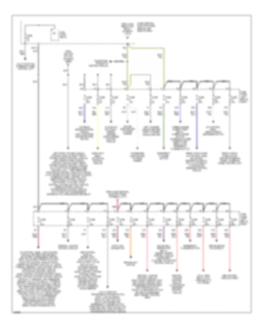
Power Distribution Wiring Diagram (3 of 3) for Audi allroad Quattro 2005
List of elements for Power Distribution Wiring Diagram (3 of 3) for Audi allroad Quattro 2005:
- (behind left side of dash) micro central electric panel
- 12v power socket (wagon)
- 13-fold relay panel (behind left side of dash)
- 16a
- 17a
- 3-fold relay & fuse panel (behind lower left side of dash)
- 3-fold relay panel (left rear of engine compt)
- 30a
- 35a
- 37a
- 4-low range hydraulic pump relay (allroad)
- 44a
- 8-fold relay panel (behind left side of dash)
- Abs return flow pump relay, abs control module (w/edl)
- Brake booster relay
- Circuit breaker 30a
- Coolant fan control module (2.7l, 4.2l except allroad), coolant fan (3.0l, 4.2l allroad)
- Coolant fan control module 2 (allroad)
- Driver's heated seat adjuster, passenger's heated seat adjuster, left rear heated seat regulating switch, right rear heated seat regulating switch
- Driver's seat lumbar support adjust switch, driver's memory seat control module, driver's seat adjustment switches
- From a battery (diagram 1 of 3)
- Fuse 10a
- Fuse 15a
- Fuse 20a
- Fuse 30a
- Fuse 40a
- Fuse 50a
- Fuse 5a
- Fuse 60a
- Fuse panel (left end of dash)
- Fuse s110 40a
- G44 (lower left "a" pillar)
- Left front power window control module
- Left rear power window control module
- Level control system control module, level control system capacitor, tire pressure monitoring control module (allroad), parking aid control module
- Level control system relay
- Micro- central electric panel (behind left side of dash)
- Passenger's seat lumbar support adjust switch, passenger's memory seat control module, passenger seat adjustment switches
- Power sunroof control module
- Radio, right rear woofer/amplifier, aerial selection control unit (w/bose), satellite radio
- Rear window shade control module
- Red
- Right front power window control module
- Right rear power window control module
- Secondary air injection (air) pump relay
- Steering angle sensor
- Steering column adjustment switch, steering column/ belt height adjustment control module, memory seat control module, memory program switch
- Telephone/ telematic control module
- To fuse 94 (diagram 1 of 3)
- Trailer connector
- Transmission control module, wiper/washer intermittent relay, multi function steering wheel control module, 4-low range control module (allroad), 4-low range hydraulic pump relay (allroad)
POWER DOOR LOCKS
Power Door Locks Wiring Diagram (1 of 2) for Audi allroad Quattro 2005
List of elements for Power Door Locks Wiring Diagram (1 of 2) for Audi allroad Quattro 2005:
- (lower left "a" pillar)
- 14a
- 38a
- 86s
- Antenna
- Anti-theft system
- Central locking control module (below driver's seat & carpet)
- Data link connector (below left side of dash)
- Driver's door lock assembly
- Electronic suspension system
- Exterior lights system
- Fuel door unlock motor
- Fuse 10a
- Fuse 20a
- Fuse 5a
- Fuse panel (left end of dash)
- G43 (lower right "a" pillar)
- G44
- Hot at all times
- Hot in run or start
- Ignition switch
- Instrument cluster system
- Interior lights system
- Key switch
- Luggage compartment release switch
- Memory systems
- Nca
- Power windows system
- Rear lid lock cylinder
- Red
- Remote rear lid unlock motor
- Shield
- Sound system
- Telephone wiring (if equipped)
Power Door Locks Wiring Diagram (2 of 2) for Audi allroad Quattro 2005
List of elements for Power Door Locks Wiring Diagram (2 of 2) for Audi allroad Quattro 2005:
- (lower left "a" pillar) g44
- (sedan)
- (wagon)
- Driver's side interior lock switch
- G44 (lower left "a" pillar)
- Left rear door lock assembly
- Passenger's door lock assembly
- Passenger's side interior lock switch
- Right rear door lock assembly
- T2ch
- T2ci
- T2v
- T2w
- T3o
- Trunk/ decklid lock assembly
POWER MIRRORS
Automatic Day/Night Mirror Wiring Diagram for Audi allroad Quattro 2005
List of elements for Automatic Day/Night Mirror Wiring Diagram for Audi allroad Quattro 2005:
- 11a
- 31a
- Automatic day/night mirror
- Back-up light switch
- Driver's side mirror
- Exterior lights system
- Fuse 15a
- Fuse 5a
- Fuse panel (left end of dash)
- G44 (lower left "a" pillar)
- Garage door opener (if equipped)
- Hot in run or start
- Interior lights system
- Multi- function transmission range switch (closed in reverse)
- Park/ neutral position relay
- Passenger's side mirror
- Shift lock solenoid
- Transmission control module
- W/ cvt auto trans
- W/ manual trans
- W/ non-cvt auto trans
POWER SEATS
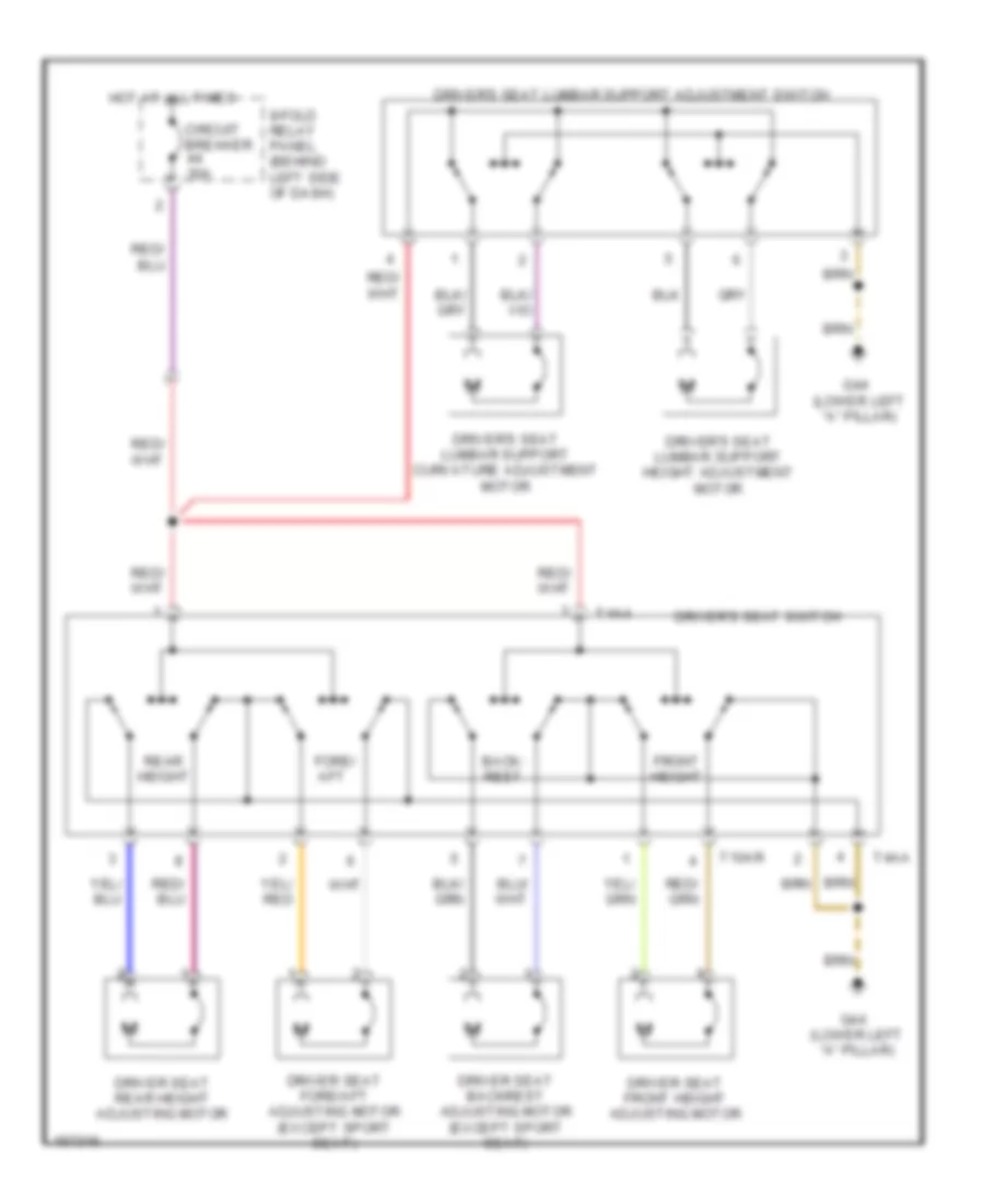
Driver Seat Wiring Diagram for Audi allroad Quattro 2005
List of elements for Driver Seat Wiring Diagram for Audi allroad Quattro 2005:
- 8-fold relay panel (behind left side of dash)
- Back- rest
- Circuit breaker 30a
- Driver seat backrest adjusting motor (except sport seat)
- Driver seat fore/aft adjusting motor (except sport seat)
- Driver seat front height adjusting motor
- Driver seat rear height adjusting motor
- Driver's seat lumbar support adjustment switch
- Driver's seat lumbar support curvature adjustment motor
- Driver's seat lumbar support height adjustment motor
- Driver's seat switch
- Fore/ aft
- Front height
- G44 (lower left "a" pillar)
- Hot at all times
- Rear height
- T10ar
- T4aa
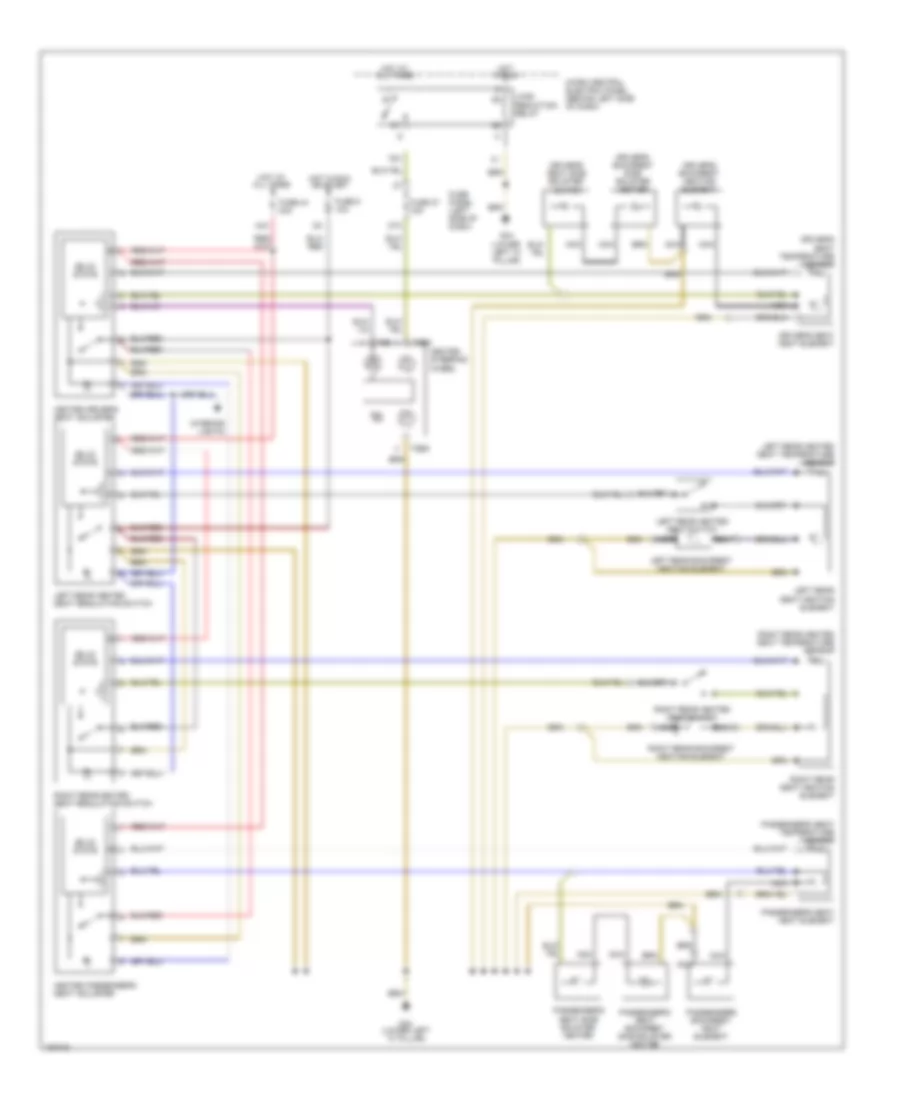
Heated Seats Wiring Diagram for Audi allroad Quattro 2005
List of elements for Heated Seats Wiring Diagram for Audi allroad Quattro 2005:
- 27a
- 44a
- 75x
- Driver's backrest heating element
- Driver's backrest side bolster heater
- Driver's seat heat element
- Driver's seat side bolster heater
- Driver's seat temperature sensor
- Fuse 27 15a
- Fuse 44 30a
- Fuse 5 10a
- Fuse panel (left side of dash)
- G44 (lower left "a" pillar)
- Heated driver's seat adjuster
- Heated passenger's seat adjuster
- Heated steering wheel
- Hot at all times
- Hot in run
- Hot in run or start
- Interior lights
- Left rear backrest heating element
- Left rear heated seat regulating switch
- Left rear heated seat switch
- Left rear heated seat temperature sensor
- Left rear seat heating element
- Load reduction relay
- Micro central electric panel (behind left side of dash)
- Nca
- Passenger's backrest heat element
- Passenger's seat backrest side bolster heater
- Passenger's seat heat element
- Passenger's seat side bolster heater
- Passenger's seat temperature sensor
- Right rear backrest heating element
- Right rear heated seat regulating switch
- Right rear heated seat switch
- Right rear heated seat temperature sensor
- Right rear seat heating element
- Solid state
- T2bg
- T5d
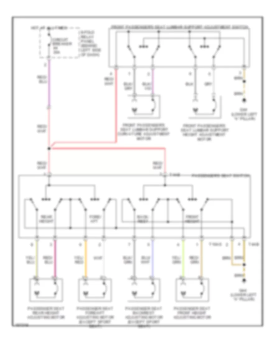
Passenger Seat Wiring Diagram for Audi allroad Quattro 2005
List of elements for Passenger Seat Wiring Diagram for Audi allroad Quattro 2005:
- 8-fold relay panel (behind left side of dash)
- Back- rest
- Circuit breaker 30a
- Fore/ aft
- Front height
- Front passenger's seat lumbar support curvature adjustment motor
- Front passenger's seat lumbar support height adjustment motor
- Front passenger's seat lumbar support adjustment switch
- G44 (lower left "a" pillar)
- Hot at all times
- Passenger seat backrest adjusting motor (except sport seat)
- Passenger seat fore/aft adjusting motor (except sport seat)
- Passenger seat front height adjusting motor
- Passenger seat rear height adjusting motor
- Passenger's seat switch
- Rear height
- T10as
- T4ab
POWER TOP/SUNROOF
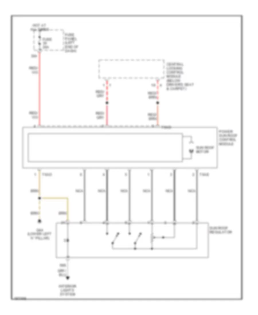
Power Top/Sunroof Wiring Diagram for Audi allroad Quattro 2005
List of elements for Power Top/Sunroof Wiring Diagram for Audi allroad Quattro 2005:
- 30a
- 58s
- Central locking control module (below driver's seat & carpet)
- Fuse 20a
- Fuse panel (left end of dash)
- G44 (lower left "a" pillar)
- Hot at all times
- Interior lights system
- Nca
- Power sun roof control module
- Sun roof motor
- Sun roof regulator
- T6ad
- T6ae
POWER WINDOWS
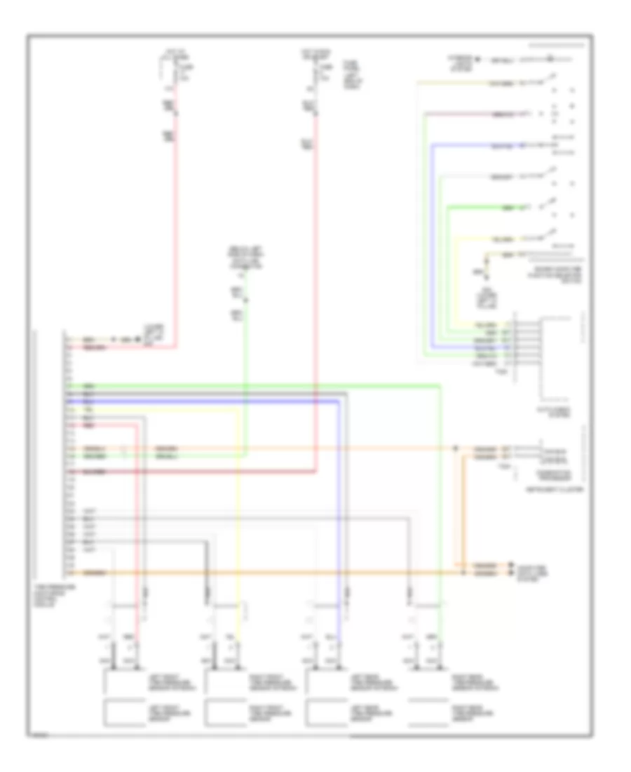
Power Windows Wiring Diagram (1 of 2) for Audi allroad Quattro 2005
List of elements for Power Windows Wiring Diagram (1 of 2) for Audi allroad Quattro 2005:
- 8-fold relay panel (behind left side of dash)
- All times
- Central locking control module (below driver's seat and carpet)
- Front power window circuit breaker 37 30a
- G44 (lower left "a" pillar)
- Hot at
- Hot at all times
- Ignition switch
- Interior lights system
- Left front power window control module
- Left front window switch
- Left rear window switch
- Off
- Power sunroof control module
- Right front power window control module
- Right front window switch
- Right front window switch (in passenger's door)
- Right rear window switch
- Run
- Start
- Window lockout switch
- Window motor
Power Windows Wiring Diagram (2 of 2) for Audi allroad Quattro 2005
List of elements for Power Windows Wiring Diagram (2 of 2) for Audi allroad Quattro 2005:
- 8-fold relay panel (behind left side of dash)
- All times
- Driver's side interior lock switch
- G900 (lower left "a" pillar)
- Hot at
- Instrument cluster
- Interior lights system
- Left rear power window control module
- Left rear window switch
- Rear power window circuit breaker 43 30a
- Right rear power window control module
- Right rear window switch
- T32
- Window motor
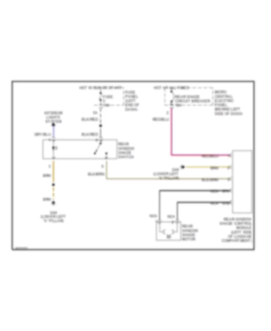
Rear Window Sun Shade Wiring Diagram for Audi allroad Quattro 2005
List of elements for Rear Window Sun Shade Wiring Diagram for Audi allroad Quattro 2005:
- 87a
- 87b
- Fuse 10a
- Fuse panel (left end of dash)
- G44 (lower left "a" pillar)
- Hot at all times
- Hot in run or start
- Interior lights system
- Micro central electric panel (behind left side of dash)
- Nca
- Rear shade circuit breaker 10a
- Rear window shade control module (left side of luggage compartment)
- Rear window shade motor
- Rear window shade switch
RADIO
Radio Wiring Diagram, Base for Audi allroad Quattro 2005
List of elements for Radio Wiring Diagram, Base for Audi allroad Quattro 2005:
- (below front of center console)
- 37a
- Acc
- Auto check system
- Batt
- Cd changer unit (if equipped)
- Central locking control module
- Ch data
- Clock
- Combination processor
- Computer data lines system
- Data link connector (below left side of dash)
- Defogger system
- Fuse 20a
- Fuse panel (left end of dash)
- G610
- G610 (below front of center console)
- G75 (right rear pillar)
- Gnd
- Hot at all times
- Instrument cluster
- Lch
- Left front bass & midrange speakers
- Left rear bass & midrange speakers
- Multi-function steering wheel
- Nca
- Pnk
- R data
- Radio
- Rch
- Rear window defogger w/ antenna
- Red
- Right front bass & midrange speakers
- Right rear bass & midrange speakers
- Right rear woofer/ amplifier
- Roof antenna (radio/ telephone/ navigation)
- S gnd
- Sedan
- T10z
- T20c
- T32a
- T32c
- T8e
- T8f
- Telephone/ radio antenna amplifier
- Telephone/ telematics control (if equipped)
- W/ auto check system
- W/o auto check system
- Wagon
Radio Wiring Diagram, Bose with Satellite for Audi allroad Quattro 2005
List of elements for Radio Wiring Diagram, Bose with Satellite for Audi allroad Quattro 2005:
- (below front of center console)
- (below front of center console) g610
- 37a
- Antenna selection control module
- Cd changer unit (if equipped)
- Central locking control module
- Computer data lines system
- Data link connector (below left side of dash)
- Defogger system
- Fm1
- Fm2
- Fm3
- Fm4
- Fuse 20a
- Fuse panel (left end of dash)
- G610
- G610 (below front of center console)
- Hot at all times
- Instrument cluster
- Left front bass & midrange speakers
- Left rear bass & midrange speakers
- Left rear window antenna fm4
- Navigation control unit (w/ navi)
- Nca
- Radio
- Rear window defogger w/ antenna
- Right front bass & midrange speakers
- Right rear bass & midrange speakers
- Right rear window antenna
- Right rear woofer/ amplifier
- Roof antenna (radio/telephone/ navigation)
- Satellite radio
- Sedan
- T10z
- T20c
- T32c
- T8f
- T8r
- T8s
- Telephone/ telematics control (if equipped)
- Tv antenna amplifiers
- Wagon
Radio Wiring Diagram, Bose without Satellite for Audi allroad Quattro 2005
List of elements for Radio Wiring Diagram, Bose without Satellite for Audi allroad Quattro 2005:
- (below front of center console)
- (radio/ telephone/ navigation) roof antenna
- 37a
- Acc
- Antenna selection control module
- Auto check system
- Batt
- Cd changer unit (if equipped)
- Central locking control module
- Ch data
- Clock
- Combination processor
- Computer data lines system
- Data link connector (below left side of dash)
- Defogger system
- Fm1
- Fm2
- Fm3
- Fm4
- Fuse 20a
- Fuse panel (left end of dash)
- G610
- G610 (below front of center console)
- G75 (right rear pillar)
- Gnd
- Hot at all times
- Instrument cluster
- Lch
- Left front bass & midrange speakers
- Left rear bass & midrange speakers
- Left rear window antenna
- Multi-function steering wheel wheel
- Navigation control unit (w/ navi)
- Nca
- Pnk
- R data
- Radio
- Rch
- Rear window defogger w/ antenna
- Red
- Right front bass & midrange speakers
- Right rear bass & midrange speakers
- Right rear window antenna fm1
- Right rear woofer/ amplifier
- Roof antenna
- S gnd
- Sedan
- T10z
- T20c
- T32a
- T32c
- T8f
- Telephone/ radio antenna amplifier
- Telephone/ telematics control (if equipped)
- Tv antenna amplifiers
- W/ auto check system
- W/ tv
- W/o auto check system
- W/o tv
- Wagon
SHIFT INTERLOCK
Shift Interlock Wiring Diagram, with CVT for Audi allroad Quattro 2005
List of elements for Shift Interlock Wiring Diagram, with CVT for Audi allroad Quattro 2005:
- 13a
- 31a
- Brake light switch (on brake pedal support)
- Fuse 10a
- Fuse 15a
- Fuse panel (left side of dash)
- G12 (left side
- G213 (lower right "a" pillar)
- Hot at all times
- Ignition switch
- Of engine compt)
- Off
- Run
- Shift lock solenoid (under center console)
- Start
- Tiptronic switch
- Transmission control module (tcm) (w/ 01j trans) (under right front seat)
Shift Interlock Wiring Diagram, without CVT for Audi allroad Quattro 2005
List of elements for Shift Interlock Wiring Diagram, without CVT for Audi allroad Quattro 2005:
- "a" pillar)
- (under center console) shift lock solenoid
- 31a
- Computer data lines system
- Exterior lights system
- Fuse 10a
- Fuse 150a
- Fuse 15a
- Fuse panel (left side of dash)
- G43 (lower right
- Hot at all times
- Ignition switch
- Off
- Red
- Run
- Start
- Tiptronic switch
- Transmission control module (tcm) (w/ 01l or 01v trans) (under right front seat)
STARTING/CHARGING
Charging Wiring Diagram for Audi allroad Quattro 2005
List of elements for Charging Wiring Diagram for Audi allroad Quattro 2005:
- (battery to body ground strap)
- (engine to body ground strap)
- 2.7l, 3.0l, 4.2l allroad
- 200a
- 4.2l except allroad
- Acc
- Battery
- Coolant fan control module, headlight beam adjusting control module
- Fuse 1 (s204)
- Gen ind.
- Generator
- Hot at all times
- Ignition switch
- Instrument cluster
- Off
- Start
- Starter
- T32
- T32a
Starting Wiring Diagram for Audi allroad Quattro 2005
List of elements for Starting Wiring Diagram for Audi allroad Quattro 2005:
- (battery to body ground strap)
- (behind left side of dash) micro central electric panel
- (engine to body ground strap)
- 13-fold relay panel (behind left side of dash)
- 15a
- 50b
- A/t
- Acc
- Battery
- Clutch pedal position switch
- Fuse 2 (s205) 150a
- G44 (lower left "a" pillar)
- Ignition switch
- Level control system control module
- M/t
- Multi- function transmission range switch
- Off
- Red
- Start
- Starter
- Starting interlock relay
- T20a
SUPPLEMENTAL RESTRAINTS
Supplemental Restraints Wiring Diagram for Audi allroad Quattro 2005
List of elements for Supplemental Restraints Wiring Diagram for Audi allroad Quattro 2005:
- (+)
- (-)
- (lower left part of "a" pillar)
- Air bag control module
- Air bag malfunction indicator lamp (mil)
- Air bag spiral spring/return spring w/slip ring
- Central locking control module
- Data link connector (dlc) (partial)
- Driver side head air bag igniter (w/head air bag)
- Driver's side air bag igniter
- Driver's side rear belt tensioner igniter
- Driver's side side air bag crash sensor
- Driver's side side air bag igniter
- Driver's side side rear air bag igniter (w/rear side air bag)
- Emergency flasher switch
- G44
- G606 (under center console at shifter)
- Hot at all times
- Ignition starter/ switch
- Instrument cluster
- Left seat belt switch
- Left seat belt tensioner igniter
- Nca
- Note: shorting bridges on air bag control module close when module connector is disconnected from harness. shorting bridges connect pins: 33 & 34, 37 & 38, 41 & 42, 43 & 44, 45 & 46, 47 & 48, 49 & 50, 51 & 52
- Off
- Passenger side head air bag igniter (w/head air bag)
- Passenger's side air bag igniter 1
- Passenger's side rear belt tensioner igniter
- Passenger's side side air bag igniter
- Passenger's side side air bag crash sensor
- Passenger's side side rear air bag igniter (w/rear side air bag)
- Red
- Right seat belt switch
- Right seat belt tensioner igniter
- Run
- Solid state
- Start
- T32a
TRANSMISSION
A/T Wiring Diagram, with O1L for Audi allroad Quattro 2005
List of elements for A/T Wiring Diagram, with O1L for Audi allroad Quattro 2005:
- "a" pillar)
- (pins 56-84 not used)
- (under center console) shift lock solenoid
- 31a
- Computer data lines system
- Data link connector (below left side of dash)
- Engine control module (in elec box, left side of fresh air plenum)
- Exterior lights system (backup)
- Fuse 10a
- Fuse 150a
- Fuse 15a
- Fuse panel (left end of dash)
- G43 (lower
- G43 (lower right
- Hot at all times
- Ignition switch
- Instrument cluster
- Interior lights system
- Multi-function steering wheel control module
- Multifunction transmission range switch (left side of transmission)
- Nca
- Off
- P/n warning light
- Pressure control valves
- Red
- Right "a" pillar)
- Run
- Solenoid valves
- Start
- Starting system (interlock relay)
- Steering wheel control unit
- T32
- T5h
- Tiptronic switch
- Transmission control module (tcm) (w/ 01l trans) (under right front seat)
- Transmission fluid temperature sensor
- Transmission output speed sensor
- Transmission speed sensor
- Valve body (w/ 01l trans)
A/T Wiring Diagram, with O1V for Audi allroad Quattro 2005
List of elements for A/T Wiring Diagram, with O1V for Audi allroad Quattro 2005:
- "a" pillar)
- (pins 56-84 not used)
- (under center console) shift lock solenoid
- 31a
- Computer data lines system
- Data link connector (below left side of dash)
- Engine control module (in elec box, left side of fresh air plenum)
- Exterior lights system (backup)
- Fuse 10a
- Fuse 150a
- Fuse 15a
- Fuse panel (left end of dash)
- G43 (lower
- G43 (lower right
- Hot at all times
- Ignition switch
- Instrument cluster
- Interior lights system
- Multi-function steering wheel control module
- Multifunction transmission range switch (left side of transmission)
- Off
- P/n warning light
- Red
- Right "a" pillar)
- Run
- Solenoid valves
- Start
- Starting system (interlock relay)
- Steering wheel control unit
- T32
- T5h
- Tiptronic switch
- Transmission control module (tcm) (w/ 01v trans) (under right front seat)
- Transmission fluid temperature sensor
- Transmission output speed sensor
- Transmission speed sensor
- Valve body (w/ 01v trans)
M/T Wiring Diagram, with Low Range Control Module for Audi allroad Quattro 2005
List of elements for M/T Wiring Diagram, with Low Range Control Module for Audi allroad Quattro 2005:
- (lower right "a" pillar) g43
- (pins 48-64 not used)
- 13-fold relay panel (behind left side of dash)
- 4-low range control module
- 4-low range hydraulic pump
- 4-low range hydraulic pump relay
- 4-low range switch
- 53c
- 53e
- 75a
- Clutch pedal position switch
- Computer data lines system
- Fuse 150a
- Fuse panel (left end of dash)
- G43 (lower right "a" pillar)
- G44 (lower left "a" pillar)
- G503 (threaded connection on relay plate)
- Hot at all times
- Hydraulic actuator distance sender control module
- Hydraulic actuator range sender
- Hydraulic adjuster valve
- Hydraulic pump relay fuse 30a
- Ignition switch
- Instrument cluster
- Micro central electric panel (behind left side of dash)
- Off
- Red
- Run
- Start
- Starting/ charging system
- T32a
TRUNK, TAILGATE, FUEL DOOR
Trunk Release Wiring Diagram for Audi allroad Quattro 2005
List of elements for Trunk Release Wiring Diagram for Audi allroad Quattro 2005:
- 14a
- Central locking control module (below driver's seat & carpet)
- Fuse 10a
- Fuse panel (left side of dash)
- G43 (lower right "a" pillar)
- G44 (lower left "a" pillar)
- Hot at all times
- Interior lights system
- Lugage compartment release switch
- Remote rear lid unlock motor
WARNING SYSTEMS
Tire Pressure Monitoring Wiring Diagram for Audi allroad Quattro 2005
List of elements for Tire Pressure Monitoring Wiring Diagram for Audi allroad Quattro 2005:
- (below left side of dash) data link connector
- (left end of dash)
- (lower left "a" pillar) g44
- 17a
- Auto check system
- Board computer function selector switch
- Can bus
- Combination processor
- Computer data lines system
- Fuse 10a
- Fuse panel
- G44 (lower left "a" pillar)
- Hot at all times
- Hot in run or start
- Instrument cluster
- Interior lights system
- Left front tire pressure sensor
- Left front tire pressure sensor antenna
- Left rear tire pressure sensor
- Left rear tire pressure sensor antenna
- Nca
- Red
- Right front tire pressure sensor
- Right front tire pressure sensor antenna
- Right rear tire pressure sensor
- Right rear tire pressure sensor antenna
- T32a
- T32c
- Tire pressure monitoring control module
WIPER/WASHER
Wiper/Washer Wiring Diagram for Audi allroad Quattro 2005
List of elements for Wiper/Washer Wiring Diagram for Audi allroad Quattro 2005:
- (not used)
- (wagon)
- 24a
- 27a
- 75x
- A/c control head
- Auto check system
- C11
- Combination processor
- Front washer pump
- Fuse 15a
- Fuse 25a
- Fuse 5a
- Fuse panel (left end of dash)
- G12 (left side of engine compt)
- G44 (lower left "a" pillar)
- Head
- Headlight washer pump
- Hot at all times
- Hot in run
- Instrument cluster
- Left washer nozzle heater
- Light switch
- Load reduction relay
- Micro central electric panel (behind left side of dash)
- Nca
- Off
- Park
- Rear washer pump (wagon)
- Rear window wiper motor (wagon)
- Red
- Right washer nozzle heater
- S1/31
- T32
- T32c
- T6ac
- T8i
- Washer fluid level switch
- Washer switch
- Windshield wiper intermittent regulator
- Windshield wiper motor
- Windshield wiper/ washer switch
- Wiper/washer intermittent relay