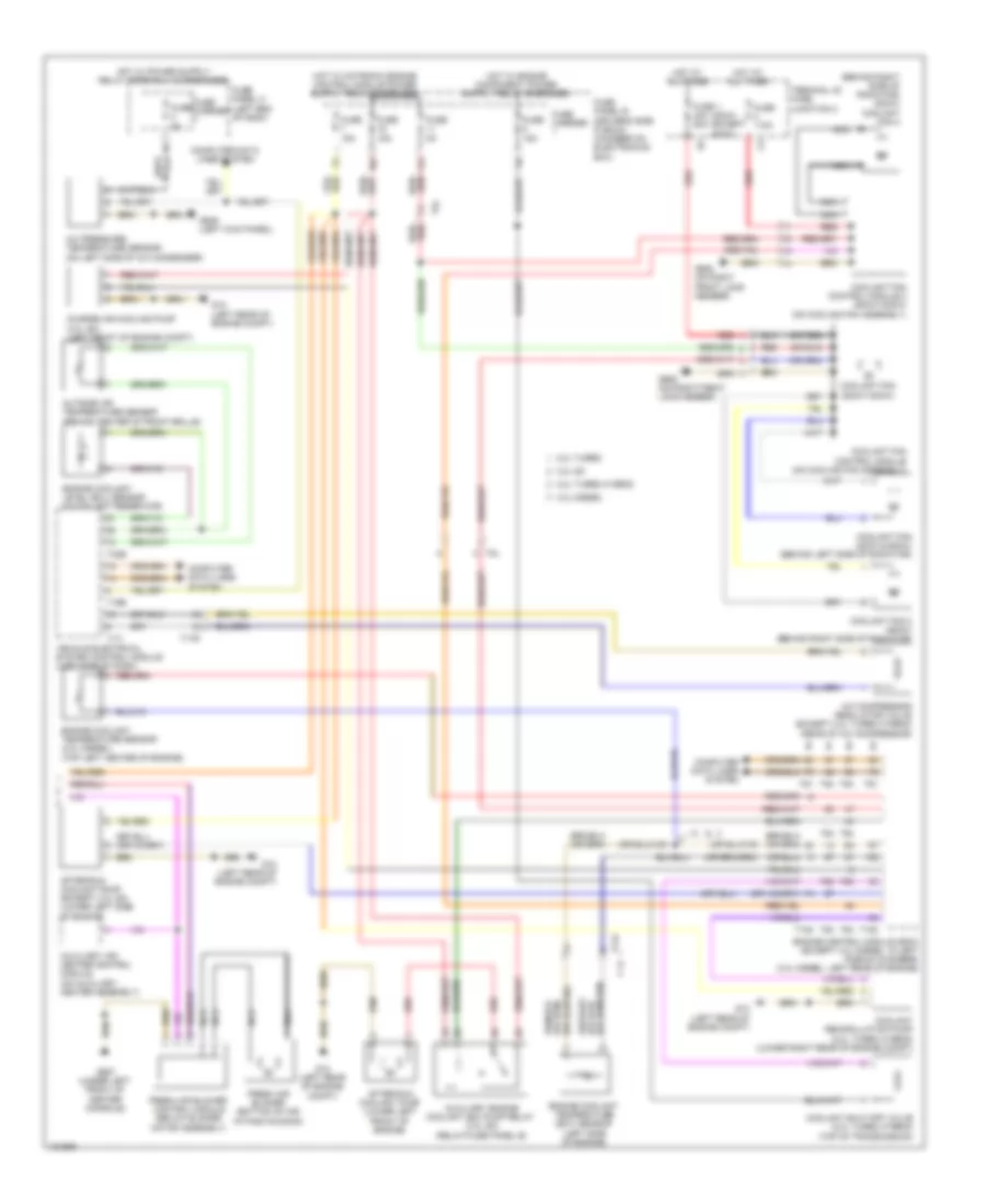
AIR CONDITIONING
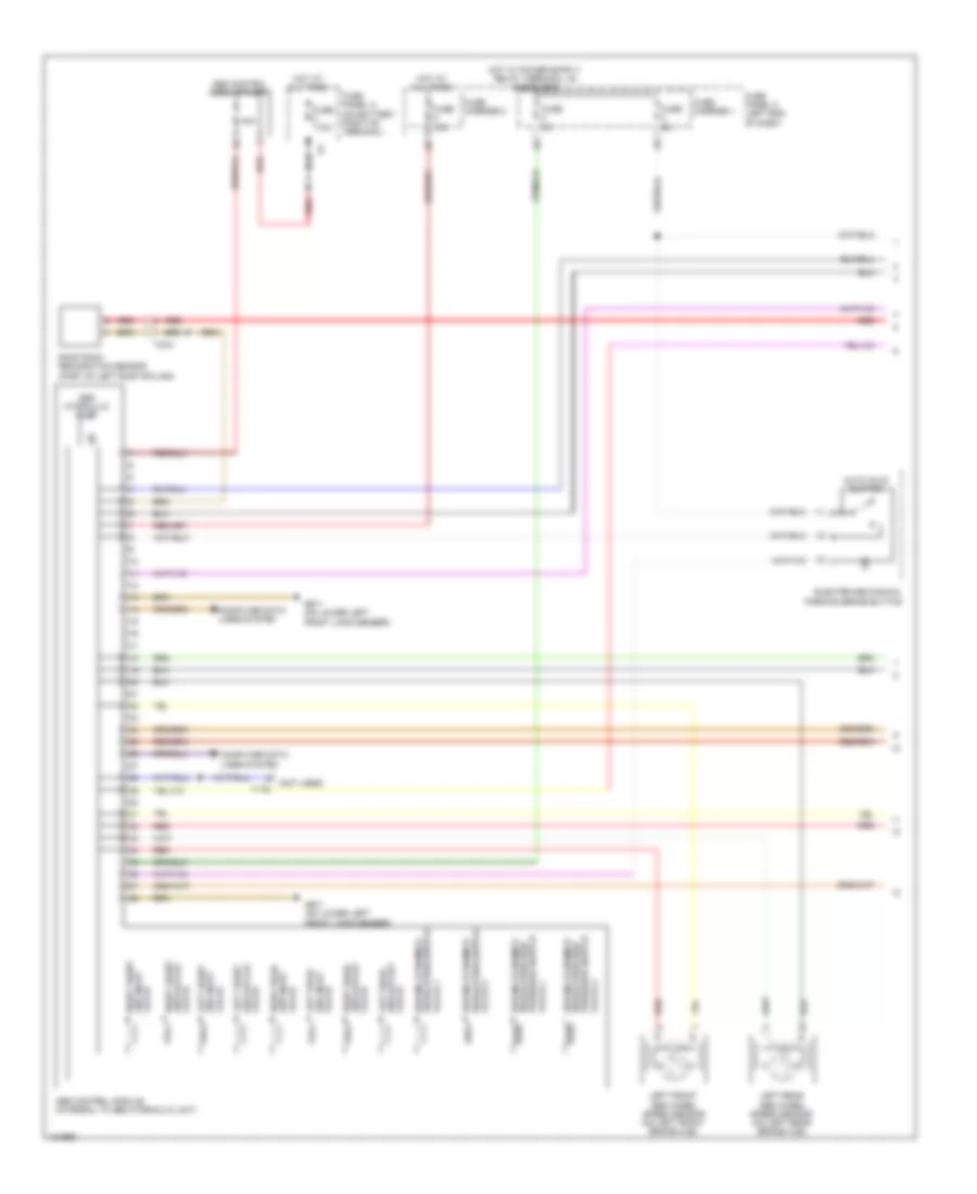
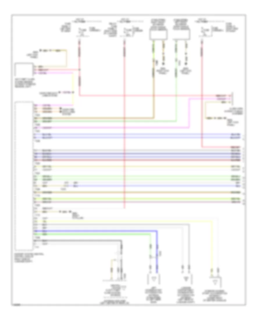
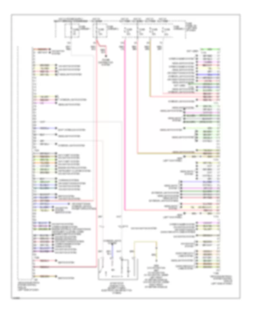
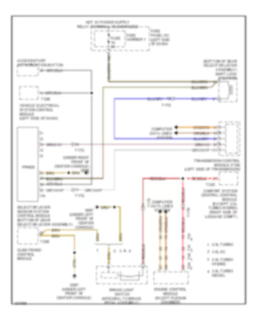
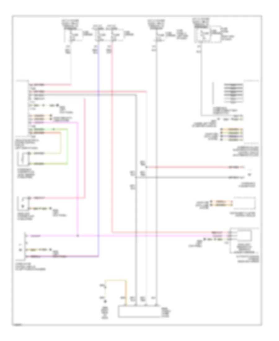
Automatic A/C Wiring Diagram, Basic (1 of 2) for Audi Q5 Prestige 2014

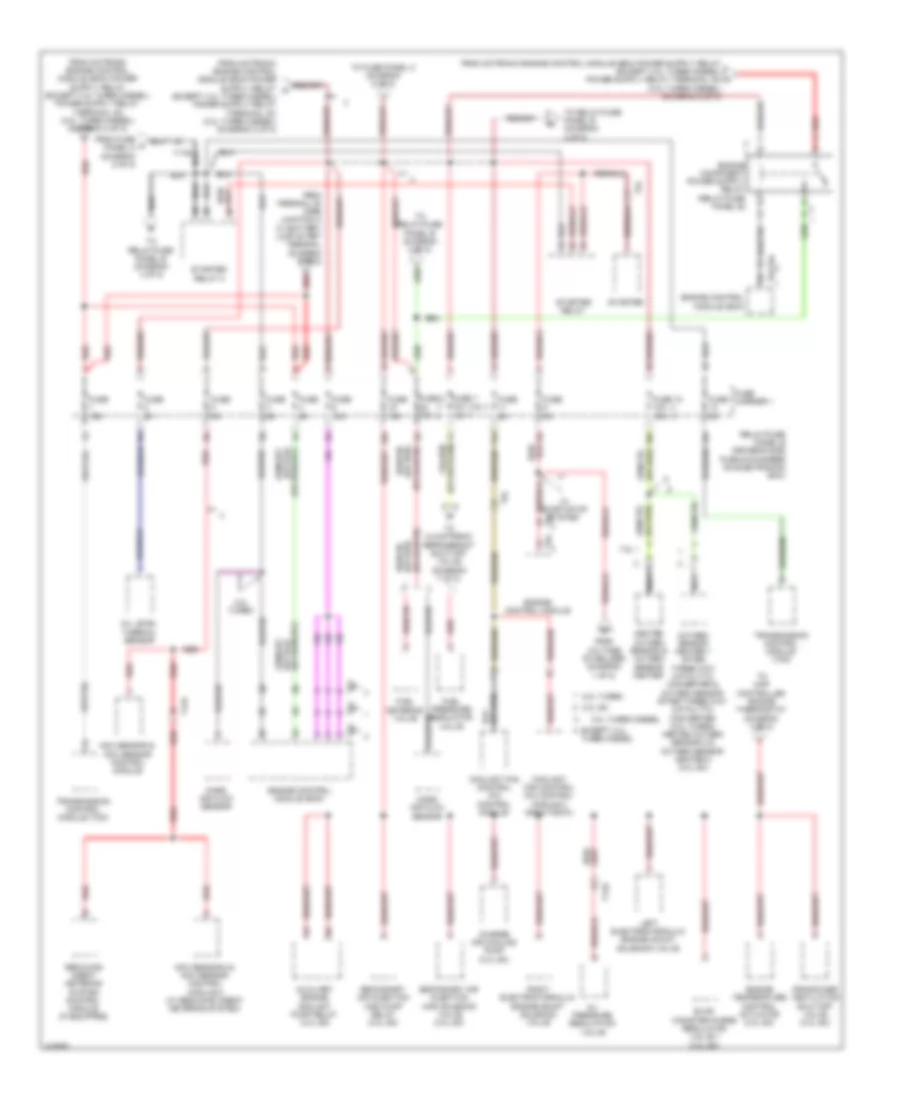
List of elements for Automatic A/C Wiring Diagram, Basic (1 of 2) for Audi Q5 Prestige 2014:
- (left rear of engine compt) g12
- (under left front of center console) g687
- 10a
- 13a
- 17a
- 2.0l turbo
- 2.0l turbo hybrid
- Air flow door motor (left side of air intake housing)
- Center vent adjustment motor (right side of hvac unit)
- Center vent temperature sensor
- Climatronic control module
- Climatronic refrigerant shut-off valve (except 3.0l sc) (rear center of engine compt)
- Compressor magnetic clutch (2.0l turbo)
- Computer data
- Computer data lines system
- Coolant recirculation pump (except 2.0l turbo hybrid) (lower right rear of engine compt)
- Defroster door motor (left side of hvac unit)
- Electric drive power & control electronics (right plenum chamber)
- Electrical a/c compressor
- Electrical a/c compressor control module (on a/c compressor)
- Evaporator vent temperature sensor (right side of evaporator housing)
- Footwell door motor (left side of hvac unit)
- Footwell vent temperature sensor
- Fuse 10a
- Fuse 40a
- Fuse 5a
- Fuse carrier
- Fuse panel b (driver's side plenum chamber on electronics box)
- Fuse panel d (right end of dash)
- G12 (left rear of engine compt)
- Hot at all times
- Lines system
- Low temperature circuit coolant pump (2.0l turbo hybrid)
- Nca
- Recirculation door motor (left side of air intake housing)
- Red
- Sunlight photo sensor (top center of dash)
- T16i
- T17b
- T17e
- T17q
- T20e
- T28jx
- T4jx
- Temperature regulator door motor
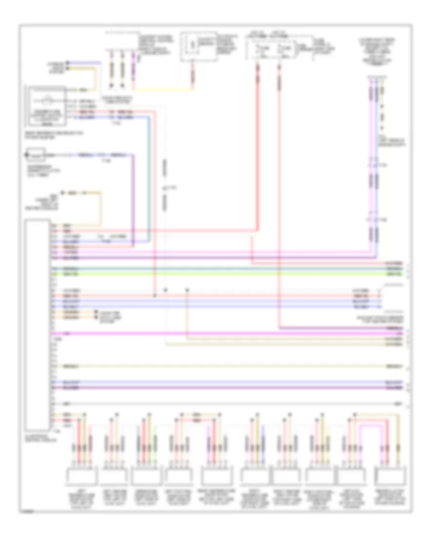
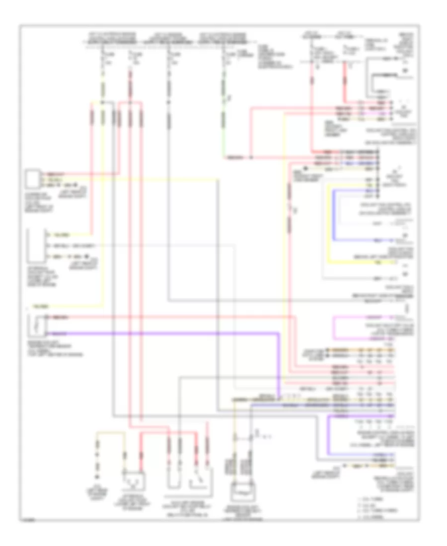
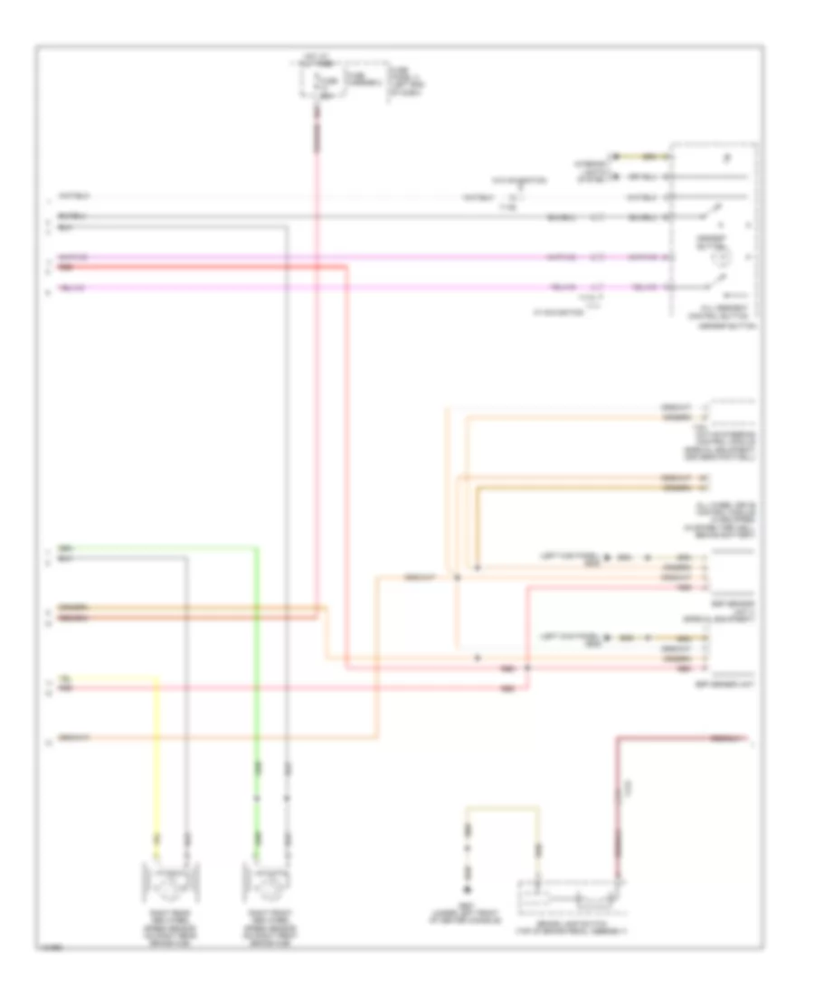
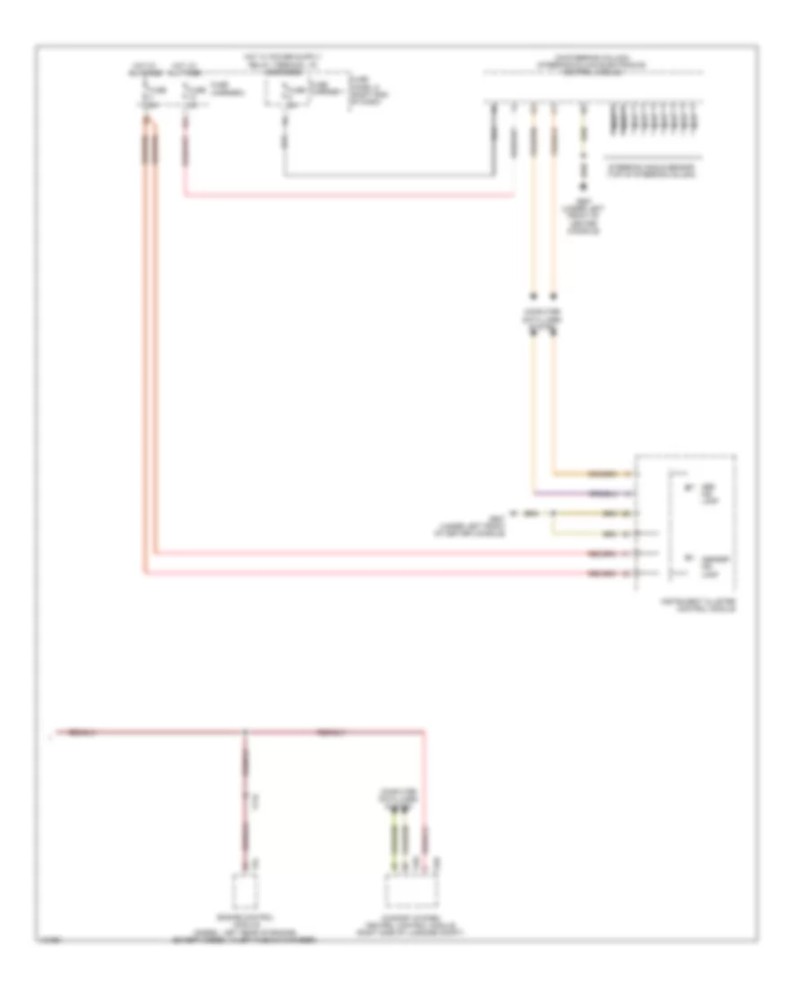
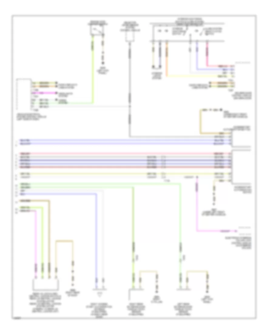
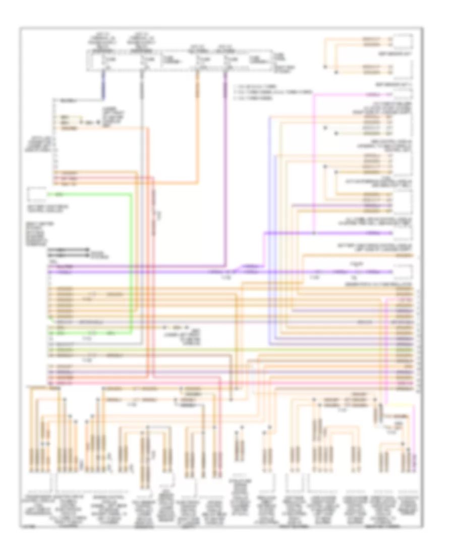
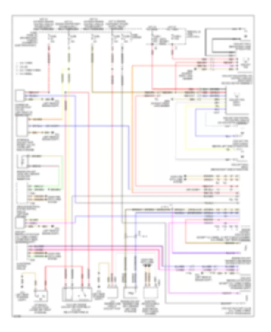
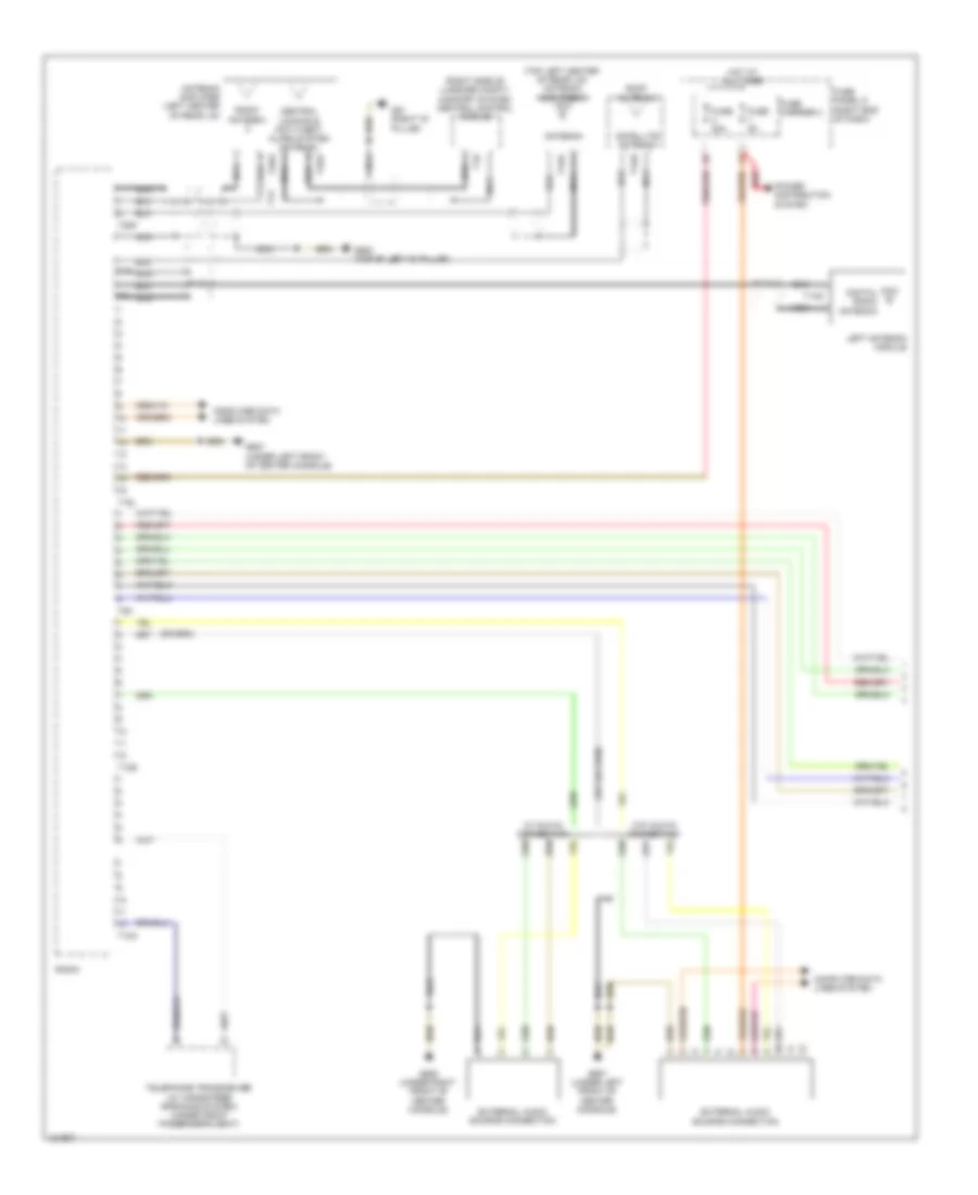
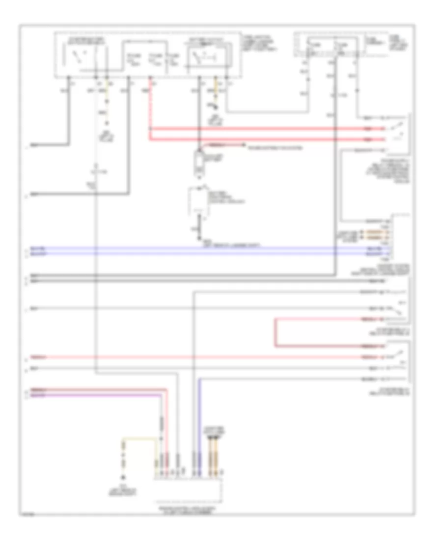
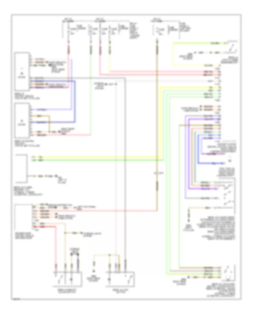
Automatic A/C Wiring Diagram, Basic (2 of 2) for Audi Q5 Prestige 2014
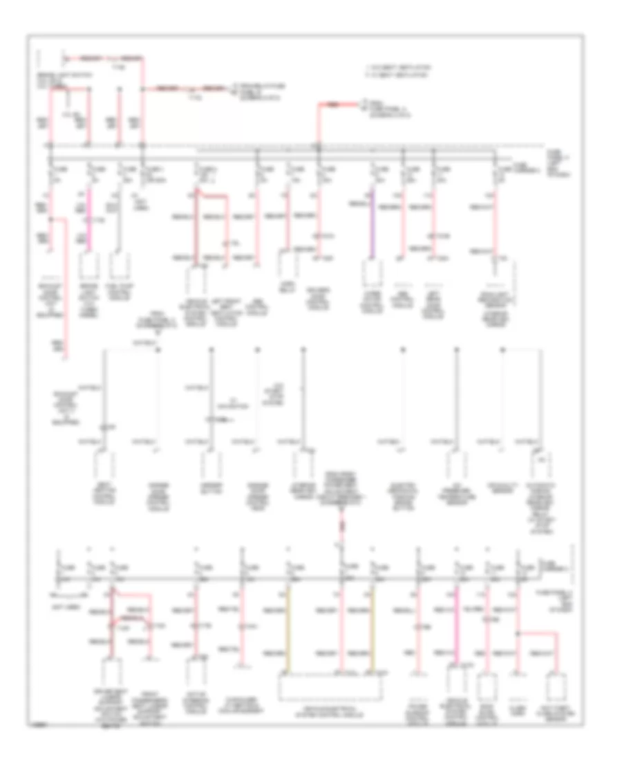
List of elements for Automatic A/C Wiring Diagram, Basic (2 of 2) for Audi Q5 Prestige 2014:
- (400w) (except 400w)
- (behind right side of radiator) (800w) coolant fan 2
- (or red)
- 11a
- 16a
- 2.0l turbo
- 2.0l turbo hybrid
- 3.0l diesel
- 3.0l sc
- A/c compressor regulator valve (except 2.0l turbo hybrid) (rear of a/c compressor)
- A/c pressure/ temperature sensor (on left side of a/c condenser)
- After-run coolant pump (except 3.0l sc) (lower left side of engine)
- After-run coolant pump (lower left front of engine)
- Auxiliary air heater control module (on auxiliary heater assembly)
- Auxiliary engine coolant (ec) pump relay (3.0l sc) (relay/fuse panel b)
- Charge air cooling pump (3.0l sc) (left front of engine compt)
- Computer data lines system
- Coolant fan (400w & 600w) (behind left side of radiator)
- Coolant fan (800w/1000w)
- Coolant fan 2 (600w) (behind right side of radiator)
- Coolant fan control module (on cooling fan assembly)
- Coolant fan control module 2 (800w/1000w) (on cooling fan assembly)
- Coolant recirculation pump (2.0l turbo hybrid) (lower right rear of engine compt)
- Coolant shut-off valve (2.0l turbo hybrid) (top of transmission)
- Engine control module (ecm) (except 3.0l diesel: in left plenum chamber) (3.0l diesel: left rear of engine)
- Engine coolant level (ecl) sensor (in coolant reservoir)
- Engine coolant temperature (ect) sensor (left side of engine)
- Engine coolant temperature sensor (3.0l diesel) (top left center of engine)
- Fresh air blower (bottom of air intake housing)
- Fresh air blower control module (below blower motor assembly)
- Fuse 1 40a 60a
- Fuse 110a
- Fuse 15a
- Fuse 5a
- Fuse carrier
- Fuse panel b (driver's side plenum chamber on electronics box)
- Fuse panel c (left end of dash)
- G12 (left rear of engine compt)
- G639 (left kick panel)
- G685 (on right front long member)
- G687 (under left front of center console)
- Hot at all times
- Nca
- Outside air temperature sensor (behind center of front grille)
- Red
- T105
- T14f
- T16b
- T17i
- T17r
- T32b
- T5l
- T60
- T91
- T94
- Terminal 30 wire junction 2
- Vehicle electrical system control module (left side of dash)
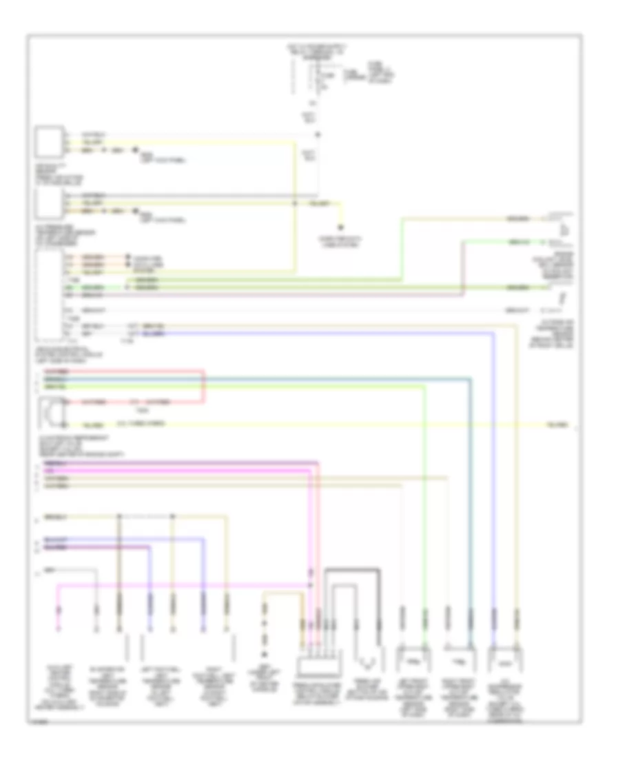
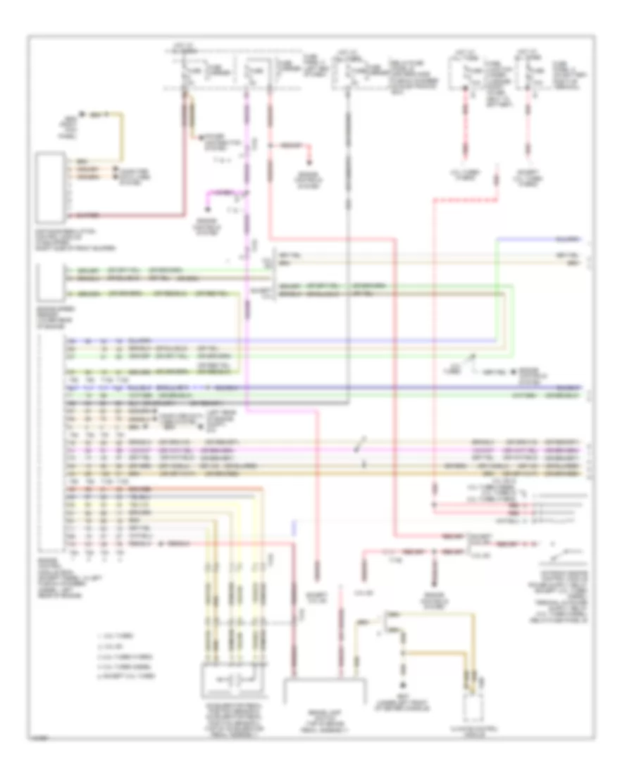
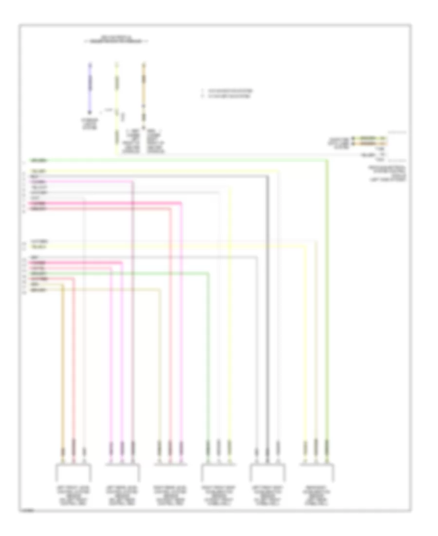
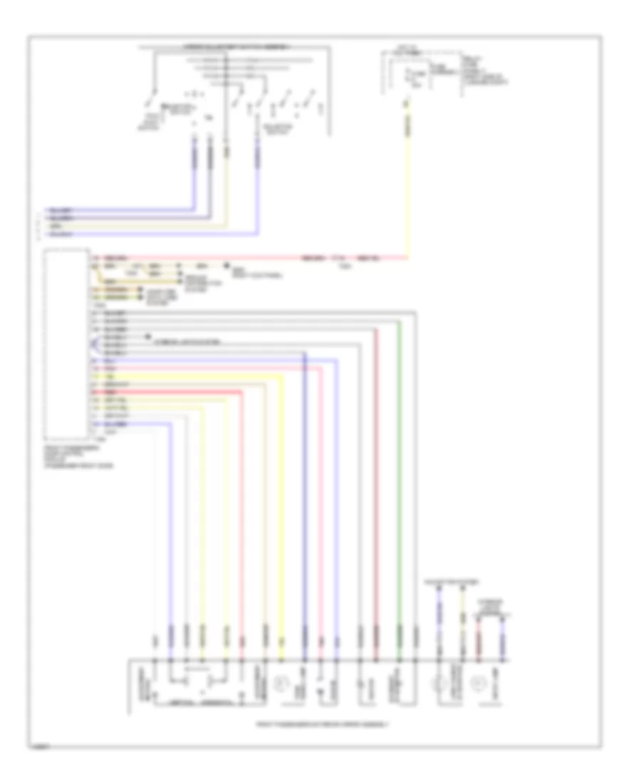
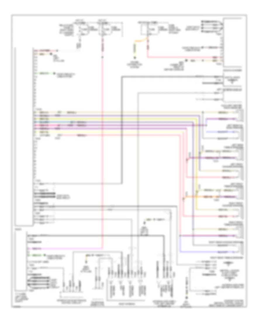
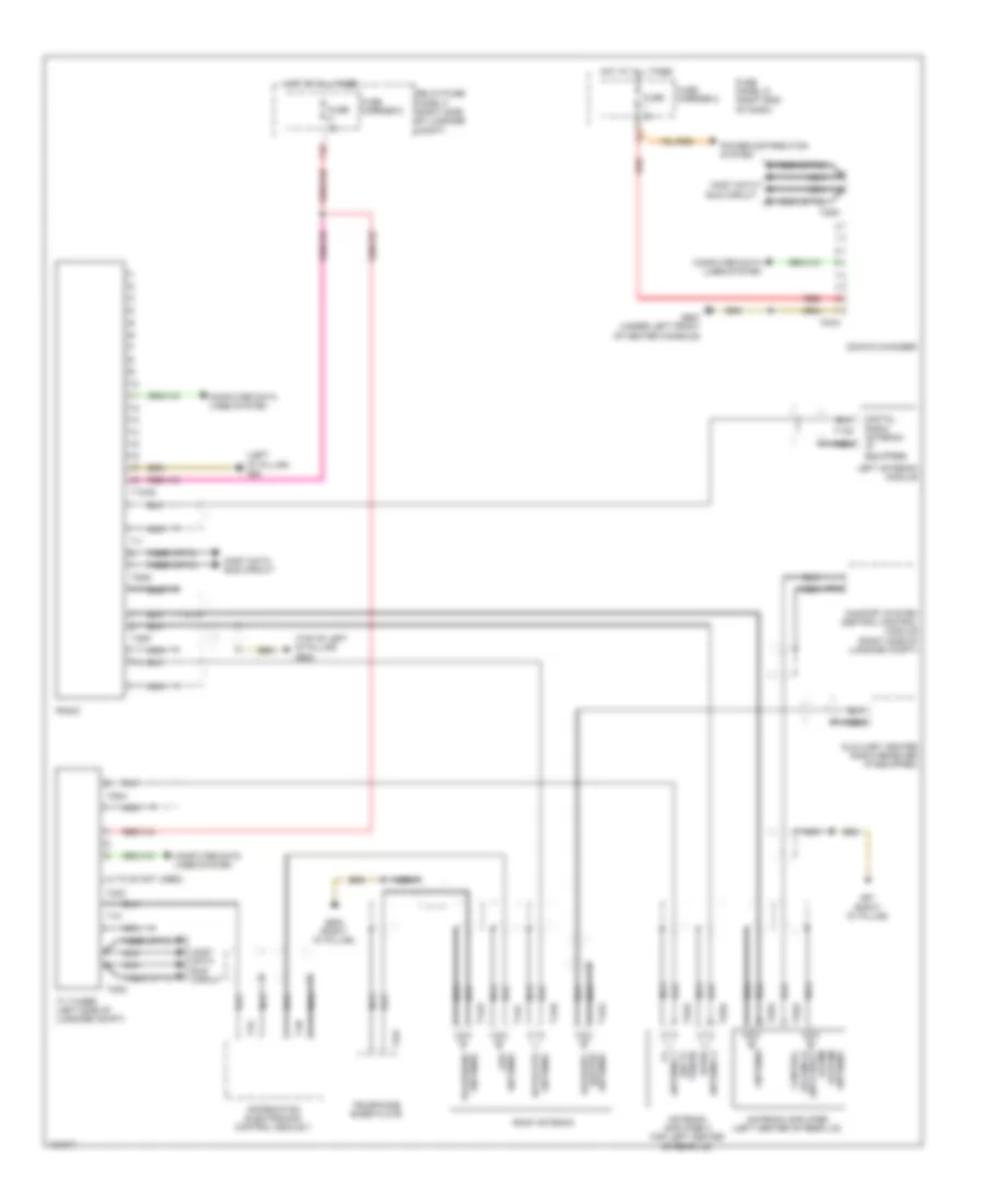
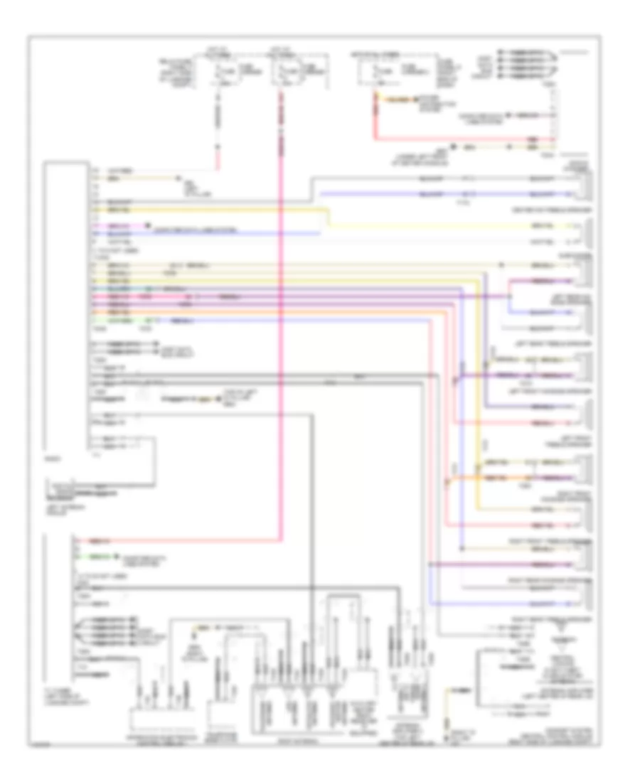
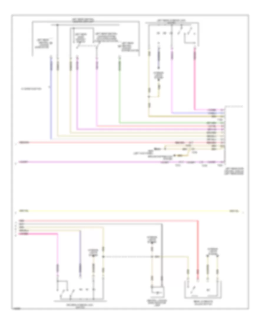
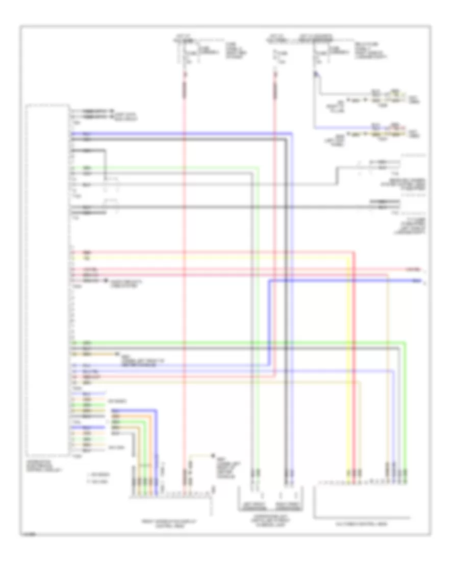
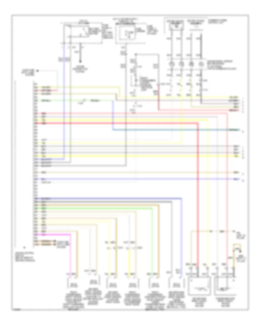
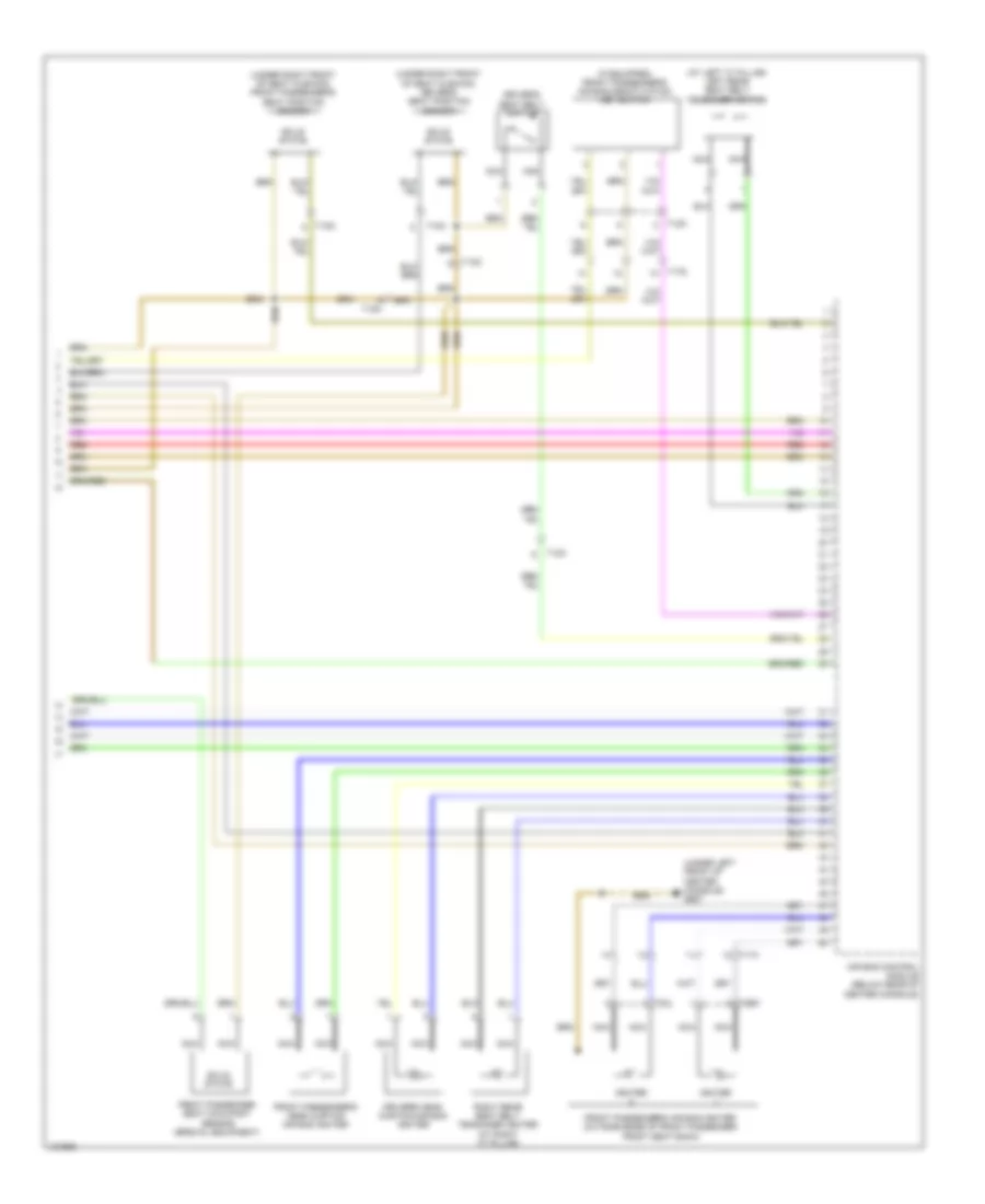
Automatic A/C Wiring Diagram, Comfort (1 of 3) for Audi Q5 Prestige 2014
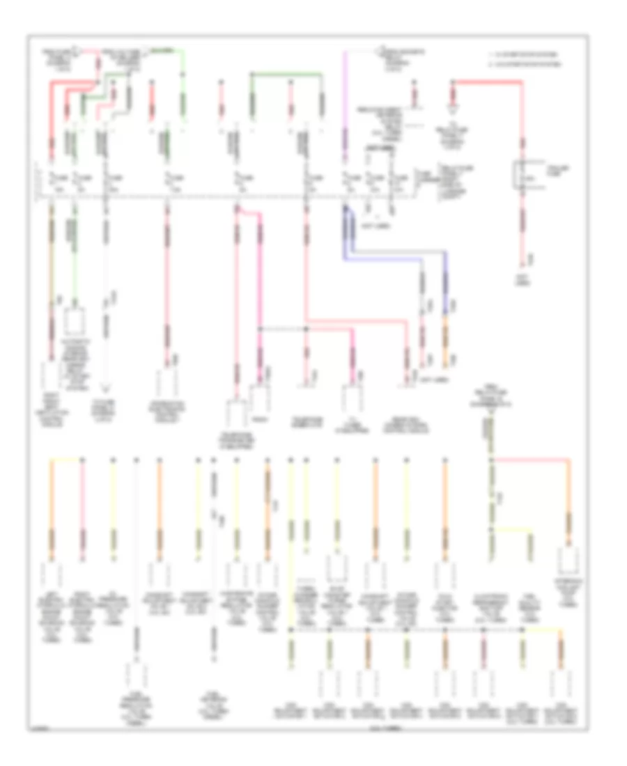
List of elements for Automatic A/C Wiring Diagram, Comfort (1 of 3) for Audi Q5 Prestige 2014:
- (lower right rear of engine compt) (except 2.0l turbo hybrid) coolant recirculation pump
- 10a
- Air flow door motor (left side of air intake housing)
- Automatic dimming interior rearview mirror
- Climatronic control module
- Comfort system central control module (right side of luggage compt) t32c
- Compressor magnetic clutch (2.0l turbo)
- Computer data lines system
- Defroster door motor (left side of hvac unit)
- Fuse 10a
- Fuse 40a
- Fuse carrier
- Fuse panel d (right end of dash)
- G12 (left rear of engine compt)
- G687 (under left front of center console)
- Hot at all times
- Humidity sensor
- Interior lights system
- Left center vent motor (top left of hvac unit)
- Left footwell door motor (left side of hvac unit)
- Left temperature door motor (top left of hvac unit)
- Nca
- Rear temperature door motor (bottom left side of hvac unit)
- Rear temperature selection potentiometer
- Recirculation door motor (left side of air intake housing)
- Red
- Right center vent motor (top right side of hvac unit)
- Right footwell door motor (lower right side of hvac unit)
- Right temperature door motor (top right side of hvac unit)
- Sunlight photo sensor (top center of dash)
- T16i
- T17b
- T17d
- T17q
- T20e
- Temperature control switch illumination bulb
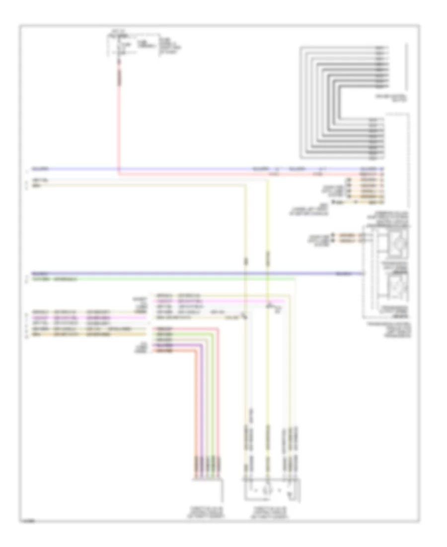
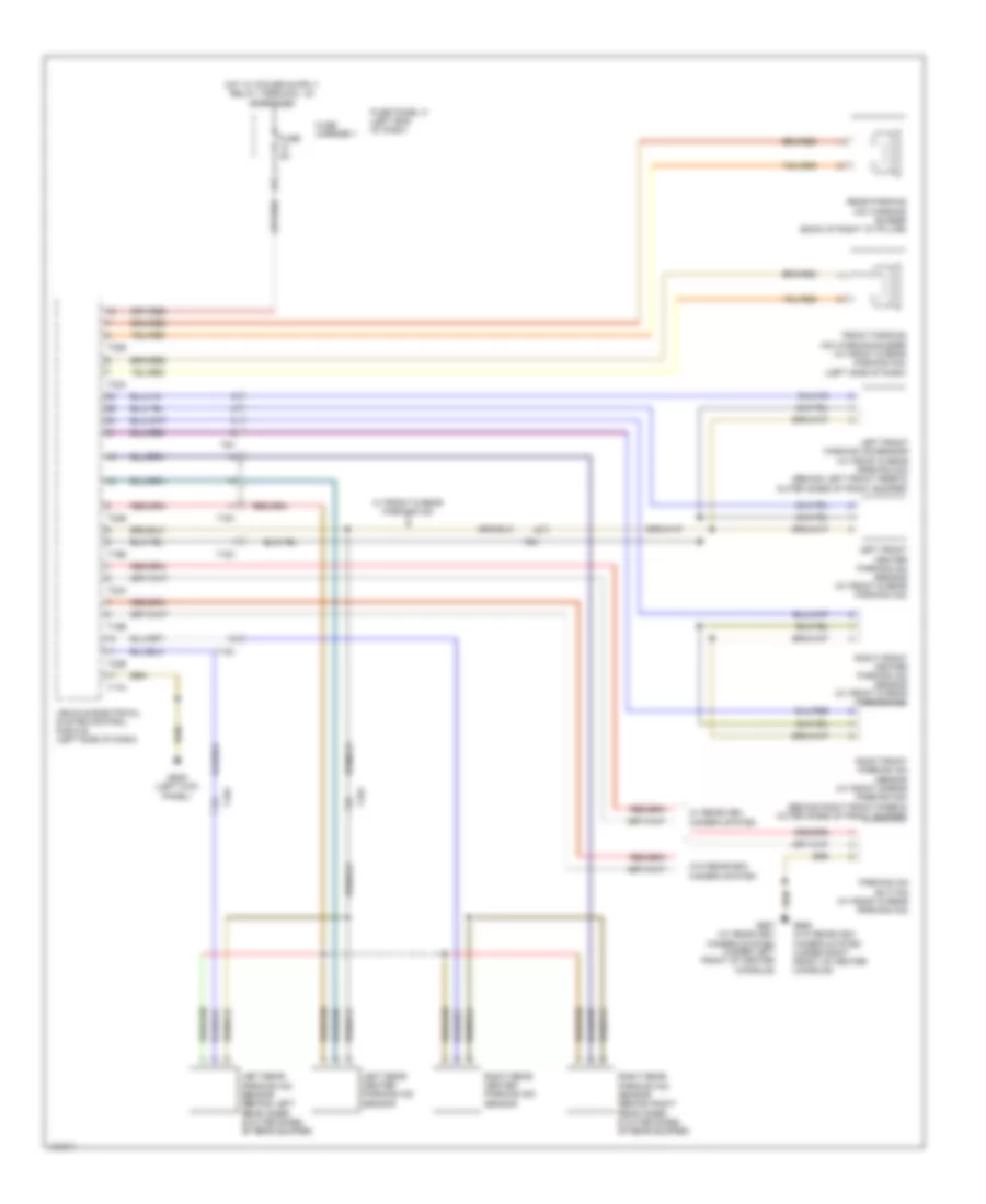
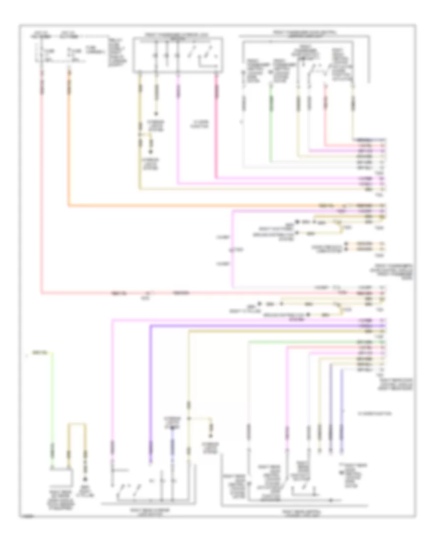
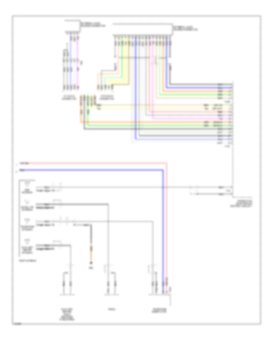
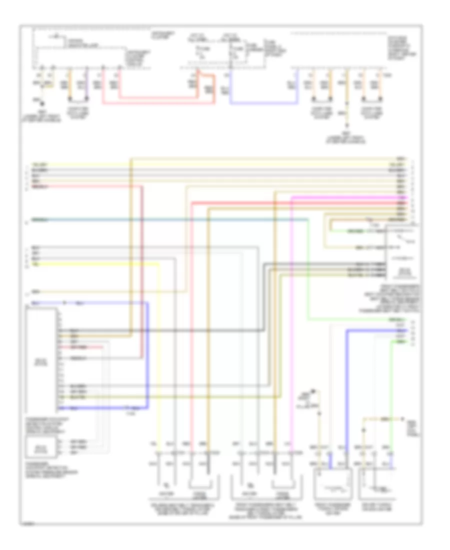
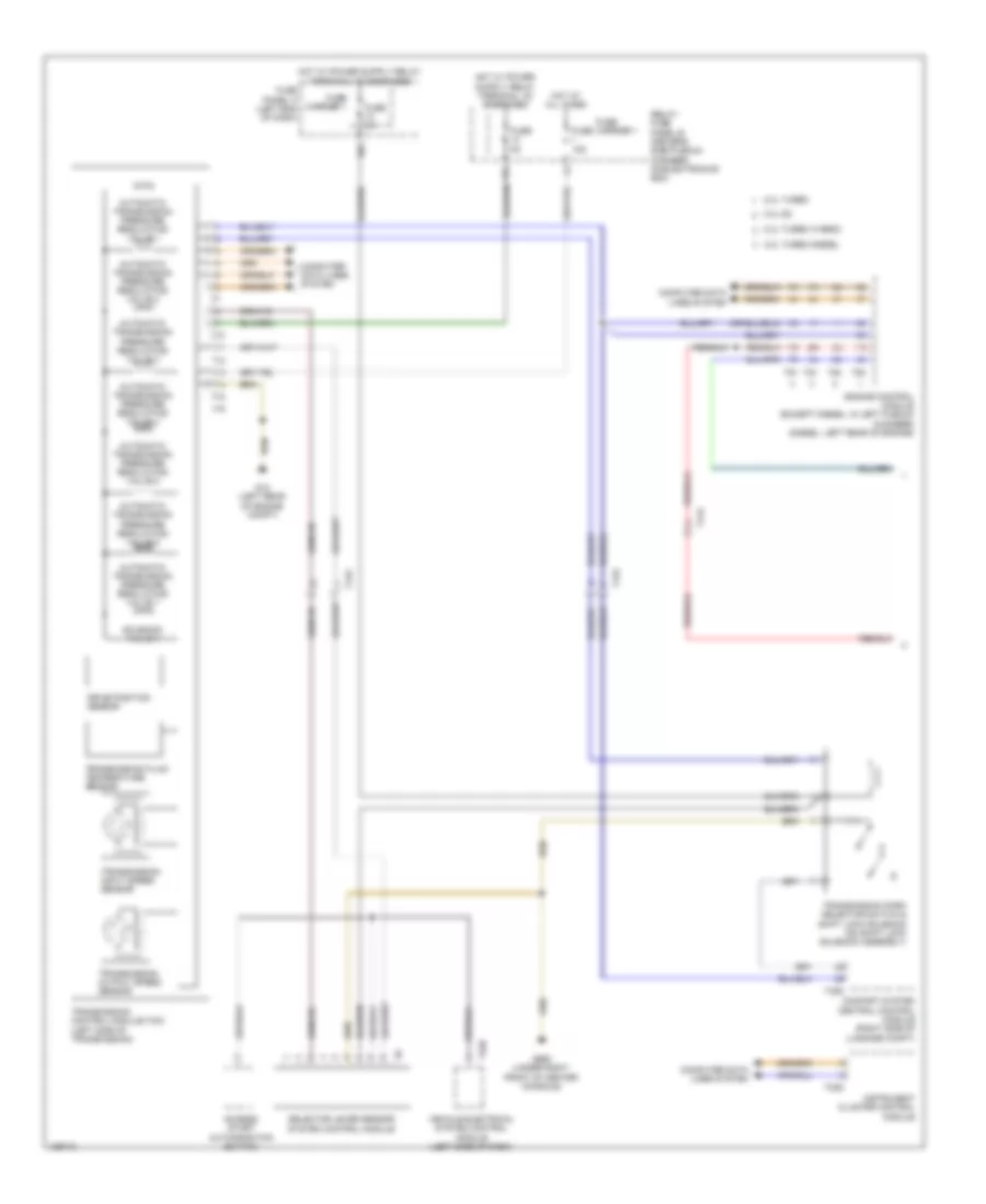
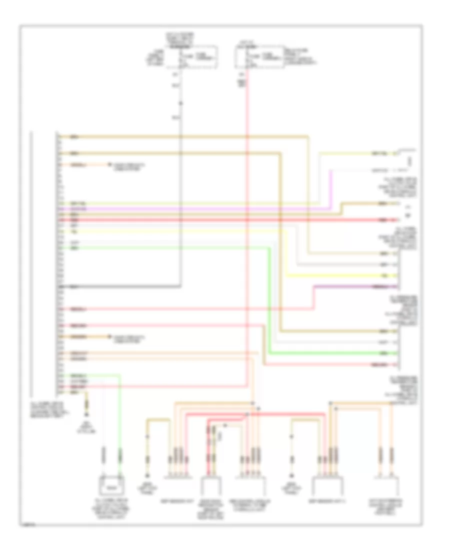
Automatic A/C Wiring Diagram, Comfort (2 of 3) for Audi Q5 Prestige 2014
List of elements for Automatic A/C Wiring Diagram, Comfort (2 of 3) for Audi Q5 Prestige 2014:
- 2.0l turbo hybrid
- A/c compressor regulator valve (except 2.0l turbo hybrid) (rear of a/c compressor)
- A/c pressure/ temperature sensor (on left side of a/c condenser)
- Air quality sensor (fresh air intake w/ intake grille)
- Auxiliary heater control module (2.0l turbo hybrid) (on auxiliary heater assembly)
- Climatronic refrigerant shut-off valve (except 3.0l sc) (rear center of engine compt)
- Computer data lines system
- Engine coolant level (ecl) sensor (in coolant reservoir)
- Evaporator vent temperature sensor (right side of evaporator housing)
- Fresh air blower (bottom of air intake housing)
- Fresh air blower control module (below blower motor assembly)
- Fuse 5a
- Fuse carrier
- Fuse panel c (left end of dash)
- G639 (left kick panel)
- G687 (under left front of center console)
- Left footwell vent temperature sensor (in left footwell vent)
- Left front upper body outlet temperature sensor (left side of dash)
- Nca
- Outside air temperature sensor (behind center of front grille)
- Right footwell vent temperature sensor (in right footwell vent)
- Right front upper body outlet temperature sensor (right side of dash)
- T16b
- T17i
- T17q
- T17r
- T32b
- Vehicle electrical system control module (left side of dash)
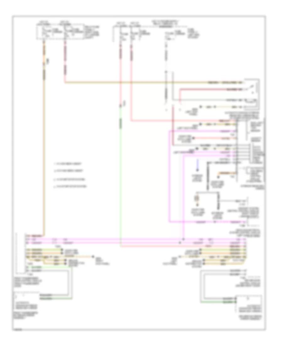
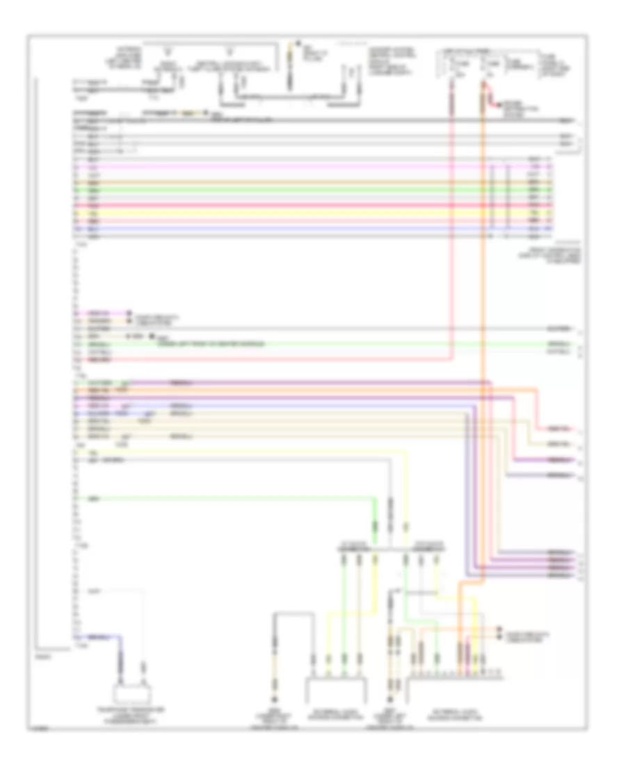
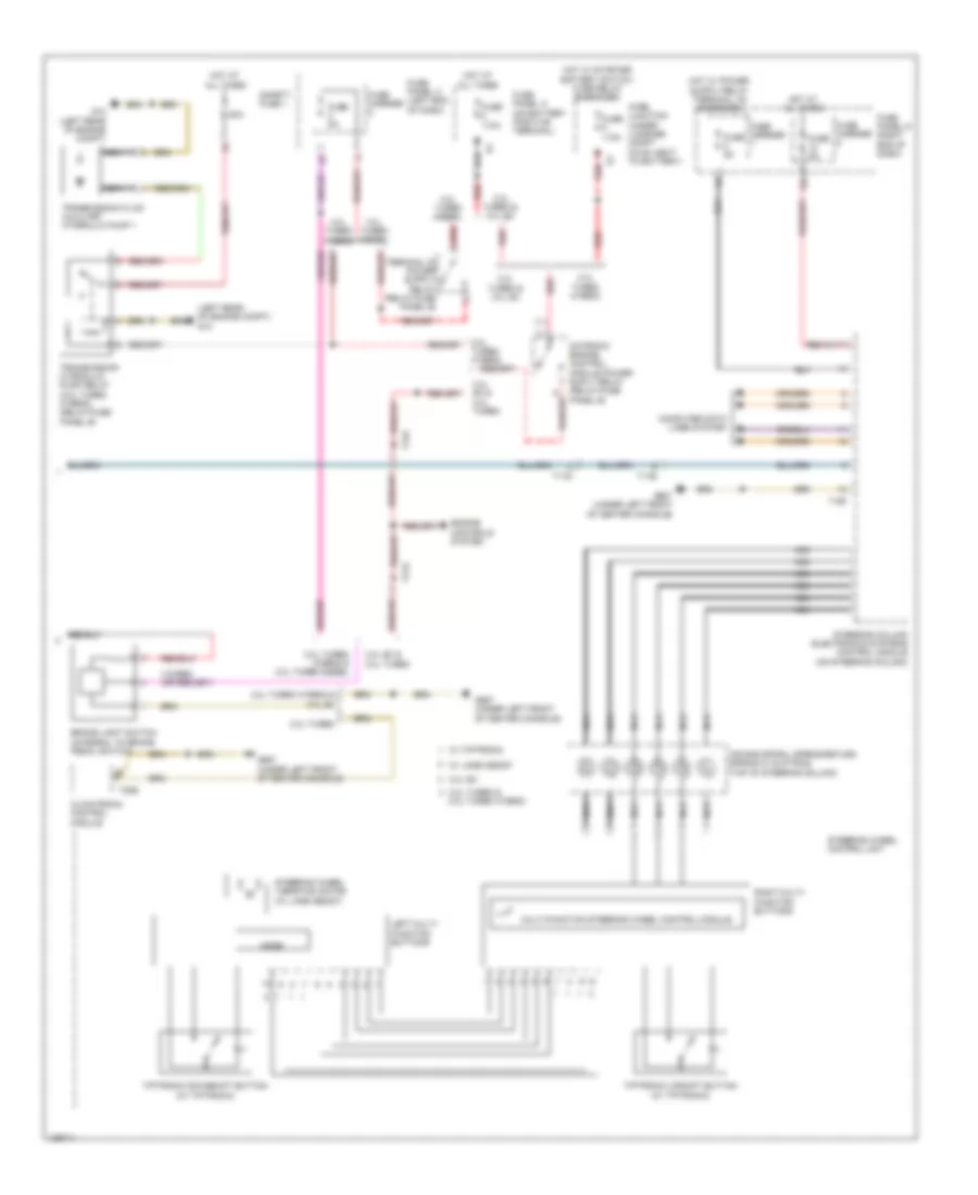
Automatic A/C Wiring Diagram, Comfort (3 of 3) for Audi Q5 Prestige 2014
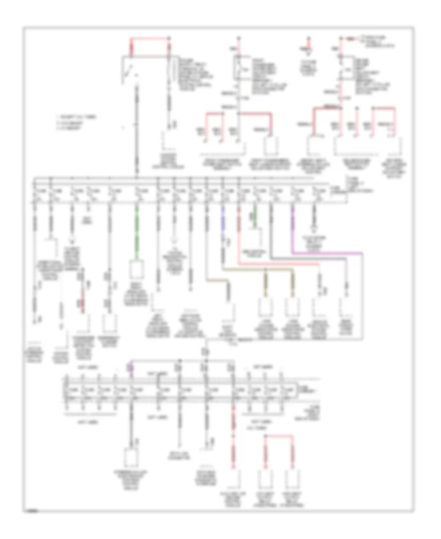
List of elements for Automatic A/C Wiring Diagram, Comfort (3 of 3) for Audi Q5 Prestige 2014:
- (400w) (except 400w)
- (behind right side of radiator) coolant fan 2
- (or red)
- 11a
- 16a
- 2.0l turbo
- 2.0l turbo hybrid
- 3.0l diesel
- 3.0l sc
- After-run coolant pump (except 3.0l sc) (lower left side of engine)
- After-run coolant pump (lower left front of engine)
- Auxiliary engine coolant (ec) pump relay (3.0l sc) (relay/fuse panel b)
- Charge air cooling pump (3.0l sc) (left front of engine compt)
- Computer data lines system
- Coolant fan
- Coolant fan (400w & 600w) (behind left side of radiator)
- Coolant fan (800w/1000w)
- Coolant fan 2 (600w) (behind right side of radiator)
- Coolant fan control (fc) control module (on cooling fan assembly)
- Coolant fan control (fc) control module 2 (800w/1000w) (on cooling fan assembly)
- Coolant recirculation pump (2.0l turbo hybrid) (lower right rear of engine compt)
- Coolant shut-off valve (2.0l turbo hybrid) (top of transmission)
- Engine control module (ecm) (except 3.0l diesel: in left plenum chamber) (3.0l diesel: left rear of engine)
- Engine coolant temperature (ect) sensor (left side of engine)
- Engine coolant temperature sensor (3.0l diesel) (top left center of engine)
- Fuse 1 40a 60a
- Fuse 15a
- Fuse 2 110a
- Fuse 5a
- Fuse carrier
- Fuse panel b (driver's side plenum chamber on electronics box)
- G12 (left rear of engine compt)
- G685 (on right front long member)
- Hot at all times
- Nca
- Red
- T105
- T14f
- T5l
- T60
- T91
- T94
- Terminal 30 wire junction 2
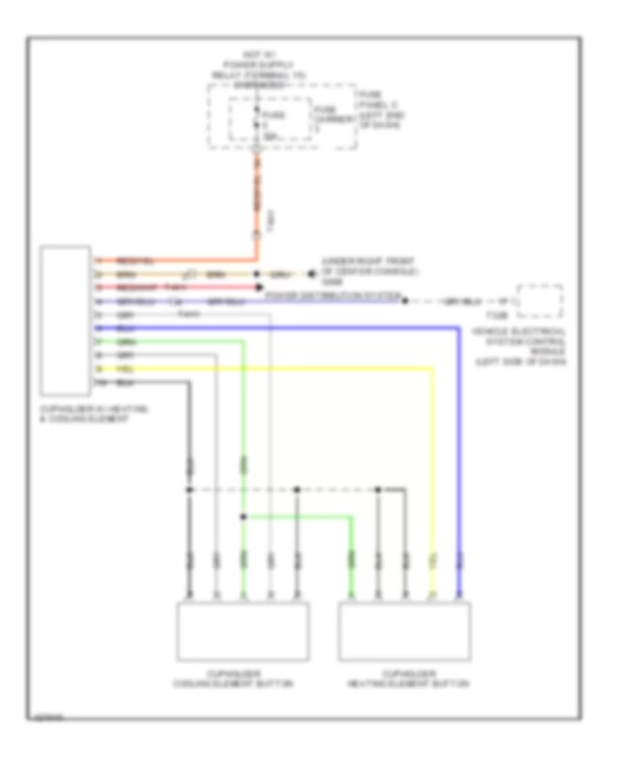
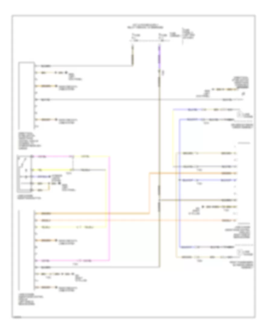
Heated And Cooled Cup Holder Wiring Diagram for Audi Q5 Prestige 2014
List of elements for Heated And Cooled Cup Holder Wiring Diagram for Audi Q5 Prestige 2014:
- (under right front of center console) g688
- Cupholder cooling element button
- Cupholder heating element button
- Cupholder w/ heating & cooling element
- Fuse 10a
- Fuse carrier
- Fuse panel c (left end of dash)
- Power distribution system
- T32b
- T4av
- Vehicle electrical system control module (left side of dash)
ANTI-LOCK BRAKES
Anti-lock Brakes Wiring Diagram (1 of 3) for Audi Q5 Prestige 2014
List of elements for Anti-lock Brakes Wiring Diagram (1 of 3) for Audi Q5 Prestige 2014:
- (not used)
- 40a
- Abs control module (integral to abs hydraulic unit)
- Abs control module fuse 1
- Abs hydraulic pump
- Auto hold button
- Computer data lines system
- Electro-mechanical parking brake button
- Fuse 10a
- Fuse 110a
- Fuse 5a
- Fuse carrier 1
- Fuse carrier 2
- Fuse panel a (on battery positive terminal)
- Fuse panel c (left end of dash)
- G671 (on lower left front long member)
- Hot at all times
- Left front abs wheel speed sensor (on left front brake hub)
- Left rear abs wheel speed sensor (on left rear brake hub)
- Red
- Roof rack recognition sensor (part of left roof railing)
- T17d
- T2ax
- Valve 1 pressure switch regulation high driving dynamics
- Valve 1 regulation switch driving dynamics
- Valve 2 pressure switch regulation high driving dynamics
- Valve 2 regulation switch driving dynamics
- Valve abs inlet left front
- Valve abs inlet left rear
- Valve abs inlet right front
- Valve abs inlet right rear
- Valve abs outlet left front
- Valve abs outlet left rear
- Valve abs outlet right front
- Valve abs outlet right rear
Anti-lock Brakes Wiring Diagram (2 of 3) for Audi Q5 Prestige 2014
List of elements for Anti-lock Brakes Wiring Diagram (2 of 3) for Audi Q5 Prestige 2014:
- (left kick panel) g639
- 10a
- Active steering control module (special equipment) (driver's footwell)
- All wheel drive control module (if equipped) (in spare tire well, behind battery)
- Asr/esp button
- Brake lamp switch (top of brake pedal assembly)
- Esp sensor unit
- Esp sensor unit 2 (special equipment)
- Fuse 25a
- Fuse carrier 2
- Fuse panel c (left end of dash)
- G687 (under left front of center console)
- Hill descent control button
- Hot at all times
- I10h
- Interior lights system
- Red
- Right front abs wheel speed sensor (on right front brake hub)
- Right rear abs wheel speed sensor (on right rear brake hub)
- T17c
- T17e
- W/ navigation
- W/o navigation
Anti-lock Brakes Wiring Diagram (3 of 3) for Audi Q5 Prestige 2014
List of elements for Anti-lock Brakes Wiring Diagram (3 of 3) for Audi Q5 Prestige 2014:
- (on steering column) steering column electronics control module
- Abs ind lamp
- Asr/esp ind lamp
- Comfort system central control module (right side of luggage compt)
- Computer data lines system
- Engine control module (diesel: left rear of engine) (except diesel: in left plenum chamber)
- Fuse 5a
- Fuse carrier 1
- Fuse carrier 2
- Fuse panel d (right end of dash)
- G687 (under left front of center console)
- Hot at all times
- Instrument cluster control module
- Nca
- Steering angle sensor (top of steering column)
- T17r
- T32c
- T32d
- T94
ANTI-THEFT
Anti-theft Wiring Diagram (1 of 2) for Audi Q5 Prestige 2014
List of elements for Anti-theft Wiring Diagram (1 of 2) for Audi Q5 Prestige 2014:
- (if equipped) left front exterior door handle touch sensor
- (if equipped) right front exterior door handle touch sensor
- 11a
- 12a
- Alarm horn (in right plenum chamber)
- Antenna amplifier (left center of rear lid)
- Anti-theft alarm system sensor (in front interior/ reading light)
- Central locking & anti-theft alarm system antenna
- Comfort system central control module (right side of luggage compt)
- Computer data lines system
- Fuse 20a
- Fuse 5a
- Fuse carrier
- Fuse carrier 2
- Fuse carrier 3
- Fuse panel c (left end of dash)
- Fuse panel d (right end of dash)
- G638 (right kick panel)
- G639 (left kick panel)
- G663 (right "c" pillar)
- Hot at all times
- Interior access/ start authorization antenna 1 (under front of center console)
- Left access/start authorization antenna (if equipped) (in left rear door)
- Luggage compartment access/start authorization antenna (left rear of luggage compt)
- Relay/ fuse panel f (right side of luggage compt)
- T17o
- T1h
- T20m
- T27a
- T27b
- T27d
- T2de
- T32c
- T32d
- T32e
Anti-theft Wiring Diagram (2 of 2) for Audi Q5 Prestige 2014
List of elements for Anti-theft Wiring Diagram (2 of 2) for Audi Q5 Prestige 2014:
- Access/start authorization button
- Access/start authorization switch
- Alarm system deactivation switch
- Computer data lines system
- Driver's door control module (driver's door)
- Electronic steering column lock control module (on steering column)
- Engine hood contact switch
- G639 (left kick panel)
- G663 (right "c" pillar)
- G666 (right rear of roof)
- G687 (under left front of center console)
- G688 (under right front of center console)
- Headlights system
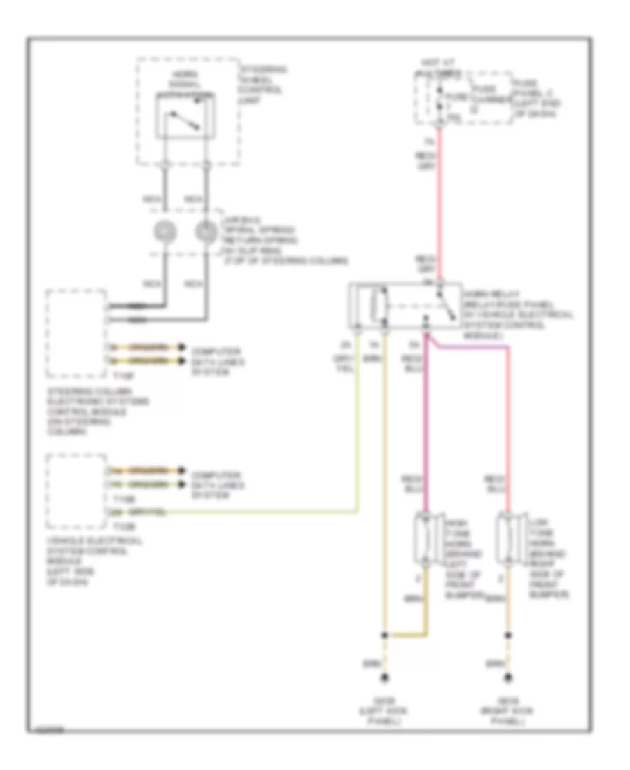
- Horns system
- Interior lights system
- Interior monitoring switch
- Interior monitoring switch & alarm system deactivation switch
- Left rear exterior door handle touch sensor (if equipped)
- Rear lid lock/alarm/ central locking switch & rear lid central locking system motor (rear lid central locking system motor: integral to rear lid central locking unit)
- Right access/ start authorization antenna (if equipped) (in right rear door)
- Right rear exterior door handle touch sensor (if equipped)
- Selector lever sensor system control module
- T16b
- T17g
- T20f
- T27b
- T27d
- T32a
- T32b
- T32j
- Vehicle electrical system control module (left side of dash)
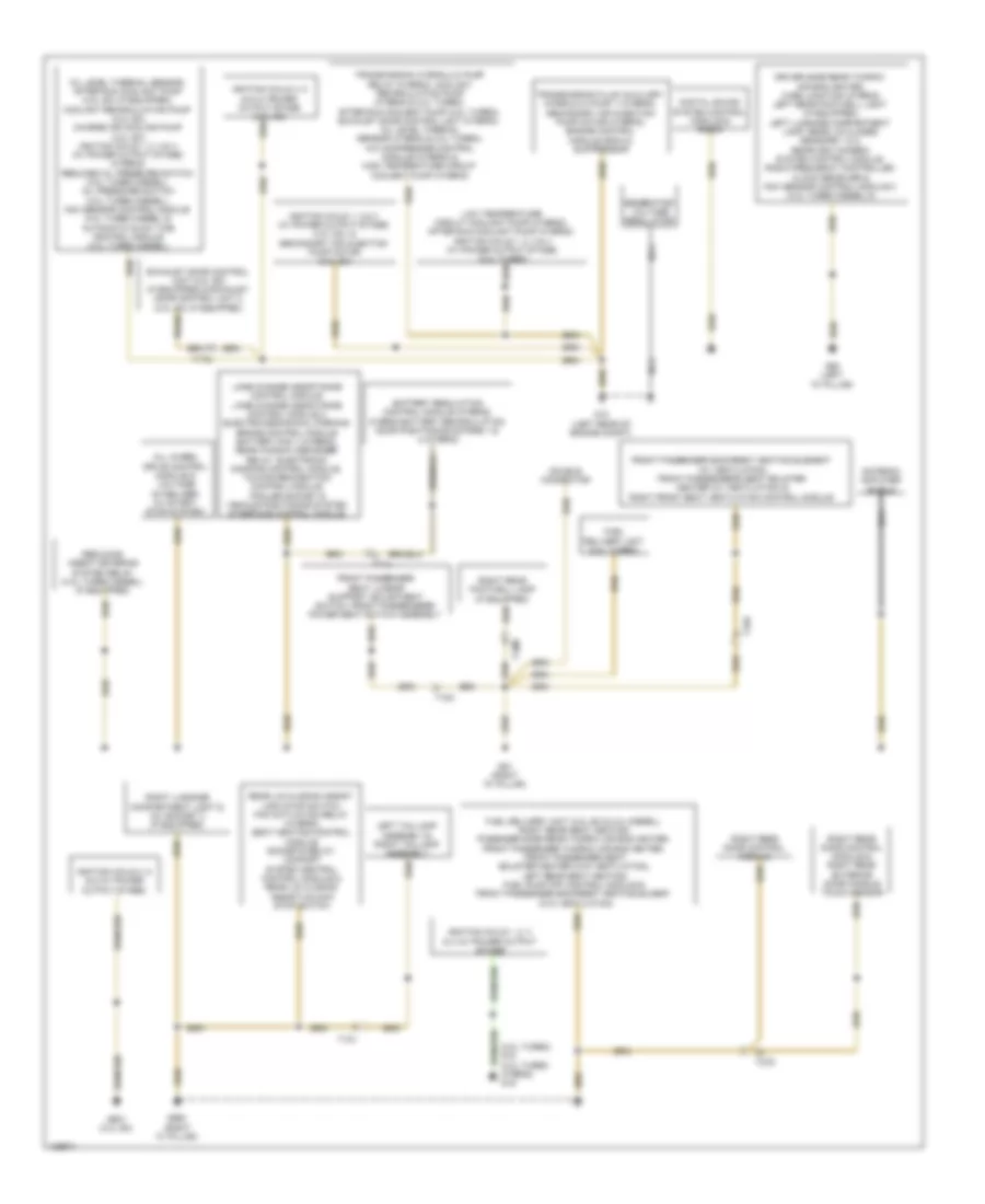
BODY CONTROL MODULES
Comfort System Central Control Module Wiring Diagram for Audi Q5 Prestige 2014
List of elements for Comfort System Central Control Module Wiring Diagram for Audi Q5 Prestige 2014:
- 10a
- 11a
- Anti-theft system
- Comfort system central control module (right side of luggage compt)
- Computer data lines system
- Defogger system
- Door locks system
- Engine controls system
- Exterior lights system
- Fuse 20a
- Fuse 30a
- Fuse carrier 2
- G663 (right "c" pillar)
- G666 (right rear of roof)
- Hot at all times
- Interior lights system
- Power distribution system
- Rear window defogger w/ window antenna
- Relay/fuse panel sf (right side of luggage compt)
- Shift interlock system
- T17o
- T17p
- T1h
- T32c
- T32d
- T32e
- Transmissions system
- Trunk, tailgate, fuel doors system
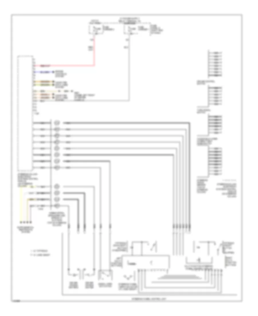
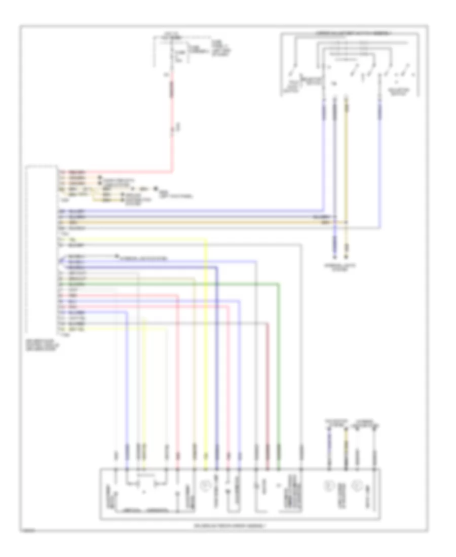
Steering Column Electronic Systems Control Module Wiring Diagram for Audi Q5 Prestige 2014
List of elements for Steering Column Electronic Systems Control Module Wiring Diagram for Audi Q5 Prestige 2014:
- 12a
- Airbag spiral spring/return spring w/ slip ring (top of steering column)
- Computer data lines system
- Cruise control switch
- Driver air bag igniter
- Driver air bag igniter 2
- Engine controls system
- Fuse 5a
- Fuse carrier 1
- Fuse carrier 2
- Fuse panel d (right end of dash)
- G687 (under left front of center console)
- Hot at all times
- Left multi- function buttons
- Mode
- Multi-function steering wheel control module
- Nca
- Right multi- function buttons
- Signal horn activation
- Steering angle sensor (top of steering column)
- Steering column electronic systems control module (on steering column)
- Steering wheel control unit
- Steering wheel vibration motor (w/ lane assist)
- T16f
- T4ac
- Tiptronic down shift button (if equipped)
- Tiptronic upshift button (if equipped)
- Turn signal switch
- W/ lane assist
- W/ tiptronic
- Windshield wiper intermittent mode switch
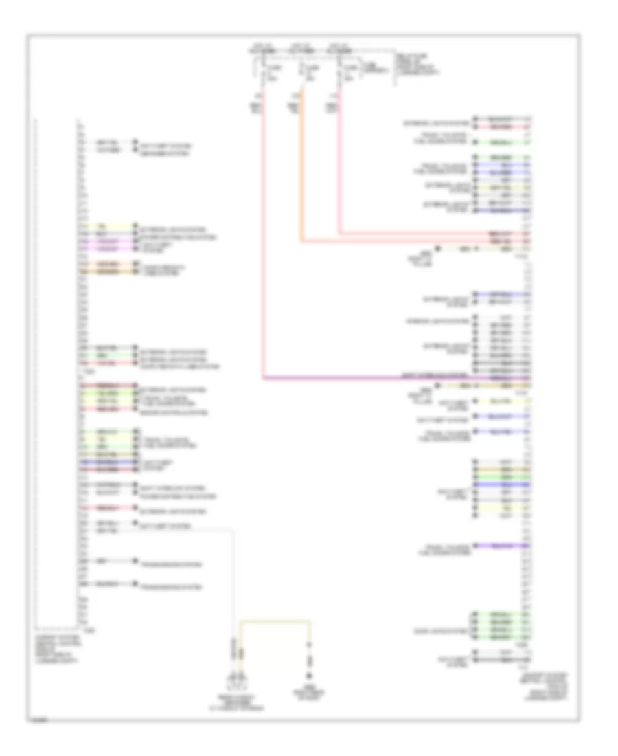
Vehicle Electrical System Control Module Wiring Diagram for Audi Q5 Prestige 2014
List of elements for Vehicle Electrical System Control Module Wiring Diagram for Audi Q5 Prestige 2014:
- (not used)
- 10a
- 12a
- Air conditioning & computer data lines systems
- Air conditioning system
- Air conditioning, interior lights & power tops systems
- Anti-theft system
- Computer data lines system
- Engine controls system
- Exterior lights system
- Fuse 15a
- Fuse 20a
- Fuse 30a
- Fuse 35a
- Fuse 5a
- Fuse carrier 1
- Fuse carrier 2
- Fuse carrier 3
- Fuse panel sc (left end of dash)
- G639 (left kick panel)
- G688 (w/o navigation) g687 (w/ navigation) (w/ navigation: under left front of center console) (w/o navigation: under right front of center console)
- Headlights & exterior lights systems
- Headlights system
- Horns system
- Hot at all times
- Instrument cluster system
- Interior lights system
- Navigation system
- Navigation system engine controls & air conditioning systems wiper/washer system
- Navigation system seats system
- Power distribution system
- Seats system
- Shift interlock system
- Start/stop mode button (except hybrid) electrical driver button (hybrid)
- T16b
- T17c
- T17l
- T17m
- T17n
- T17q
- T17r
- T32a
- T32b
- T6f
- Vehicle electrical system control module (left side of dash)
- W/o navigation system
- Warning systems
- Wiper/washer system
- Wiper/washer system engine controls, air conditioning, instrument cluster, wiper/ washer & seats systems
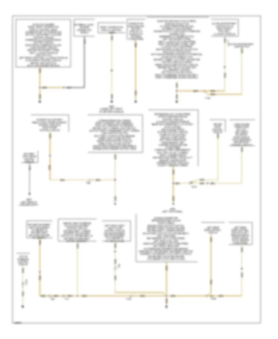
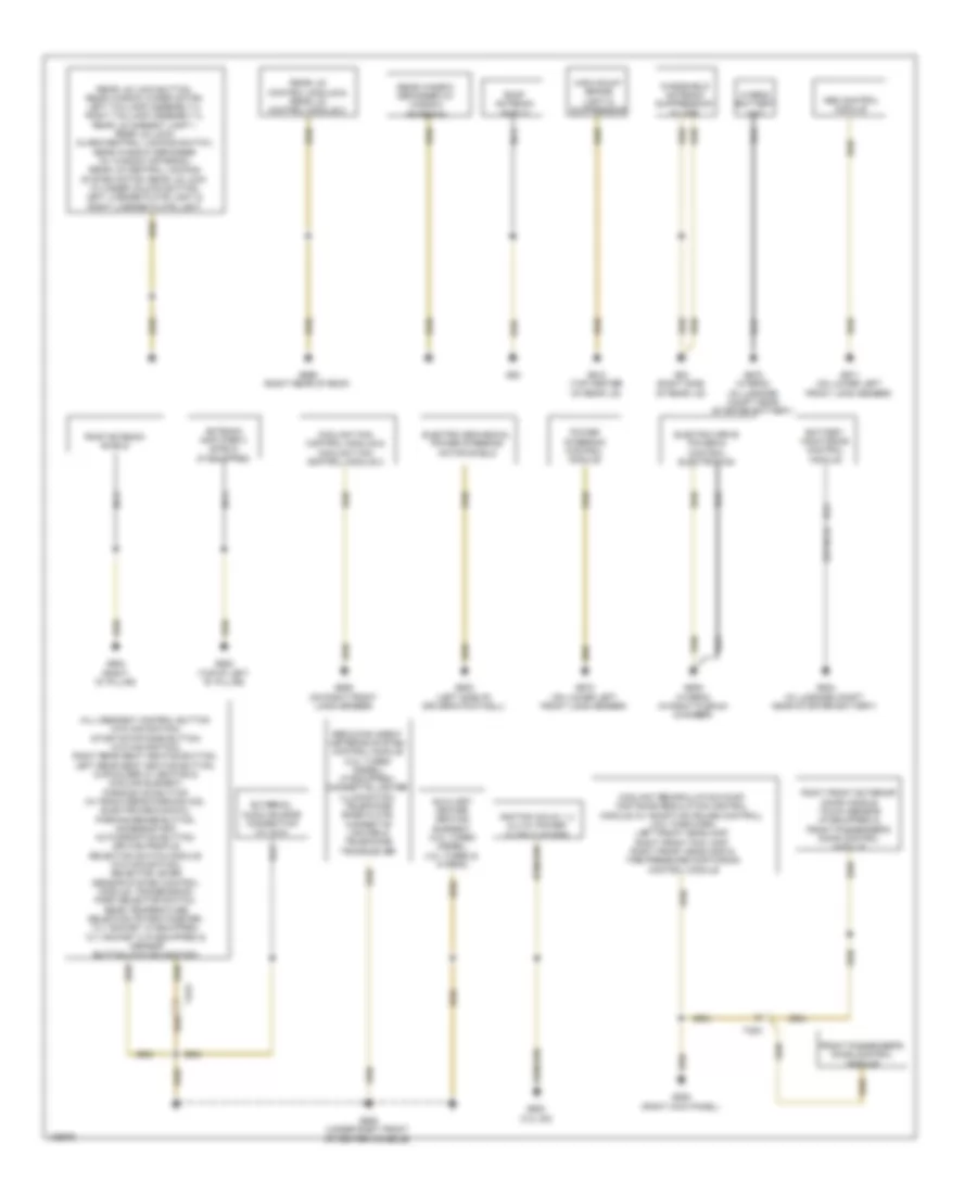
COMPUTER DATA LINES
Computer Data Lines Wiring Diagram (1 of 3) for Audi Q5 Prestige 2014
List of elements for Computer Data Lines Wiring Diagram (1 of 3) for Audi Q5 Prestige 2014:
- (right center of dash) data bus on board diagnostic interface
- (under left front of center console) g687
- 11a
- 3.0l sc
- 3.0l sc & 2.0l turbo
- 3.0l turbo diesel
- 3.0l turbo diesel & 2.0l turbo hybrid
- Abs control module (integral to abs hydraulic control unit)
- Active steering control module (driver's foot well)
- Air bag control module (below rear of center console)
- All wheel drive control module (in spare tire well, behind battery)
- Automatic dimming interior rearview mirror
- Battery monitoring control module (left side of luggage compt)
- Battery monitoring control module 2
- Data link connector (under left side of dash)
- Directional stabilization assistance control module (integral to interior rearview mirror)
- Distance regulation control module (if equipped) (right side of front bumper)
- Electric drive power & control electronics module (2.0l turbo hybrid) (right plenum chamber)
- Electronic damping control module (right side of luggage compt)
- Engine control module (diesel: left rear of engine) (except diesel: in left plenum chamber)
- Esp sensor unit
- Esp sensor unit 2
- Fuse 10a
- Fuse 5a
- Fuse carrier 1
- Fuse carrier 2
- Fuse panel d (right end of dash)
- G687 (under left front of center console)
- Generator & voltage regulator
- Hot at all times
- Lane change assistance control module (if equipped) (left side of rear bumper)
- Lane change assistance control module 2 (right side of rear bumper)
- Nca
- Nox sensor control module (under vehicle, near nox sensor)
- Nox sensor control module 2 (under vehicle, near nox sensor 2)
- Reducing agent metering system control module (if equipped)
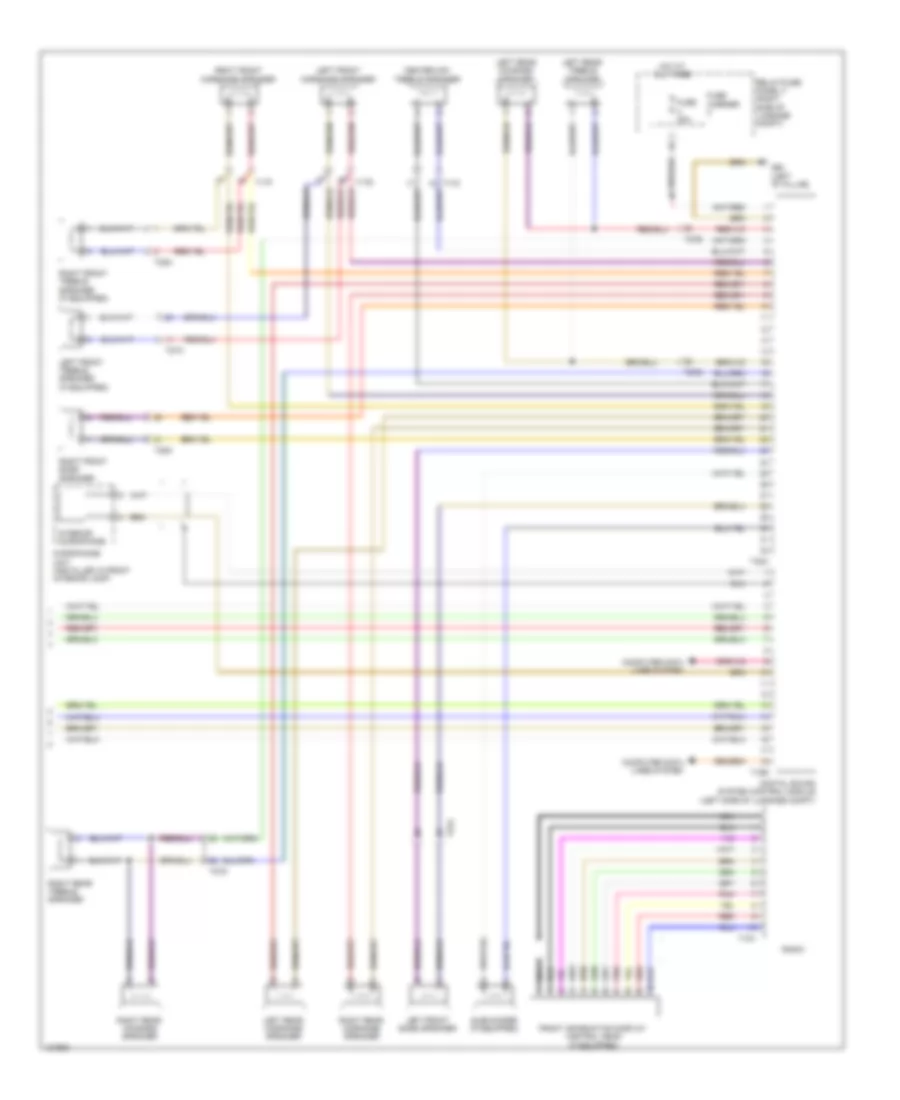
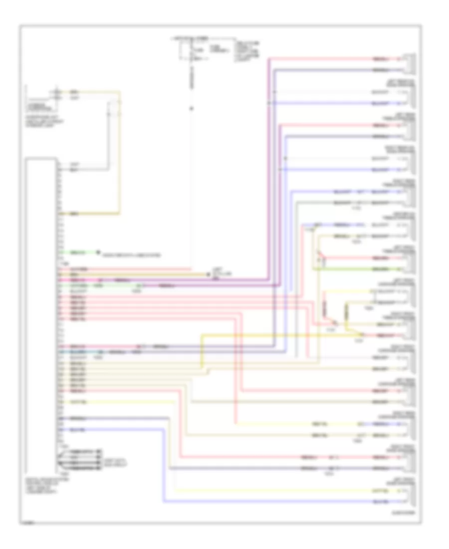
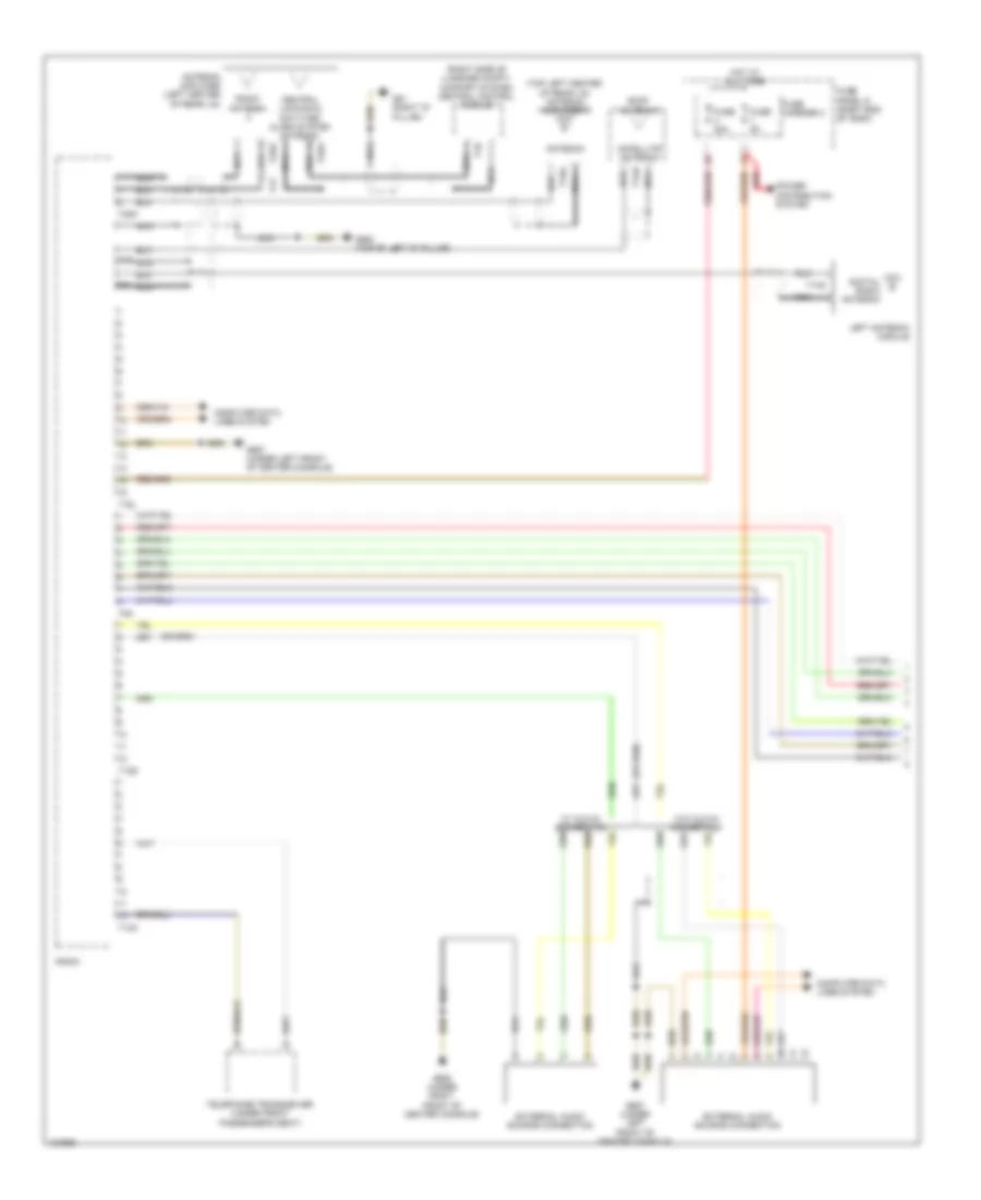
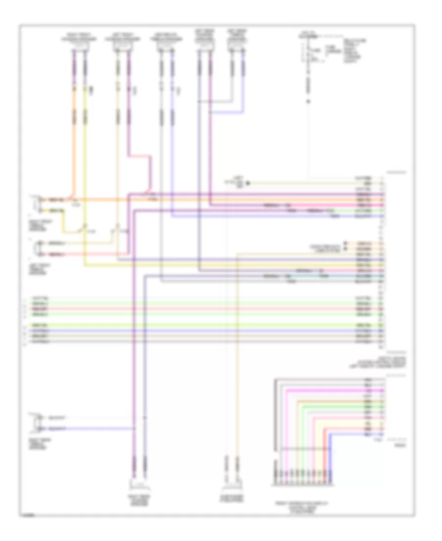
- Sound systems
- Structure borne sound control module (in plenum chamber, center of cowl)
- T10h
- T16v
- T17b
- T17c
- T17e
- T17f
- T17q
- T17r
- T20d
- T28jx
- T2dl
- T5l
- T91
- T94
- Transmission control module (tcm) (left side of transmission)
- Voltage stabilizer (w/ stop/ start system) (right side of luggage compt)
Computer Data Lines Wiring Diagram (2 of 3) for Audi Q5 Prestige 2014
List of elements for Computer Data Lines Wiring Diagram (2 of 3) for Audi Q5 Prestige 2014:
- (center of grille) garage door opener control module
- (fresh air intake with intake grille) (premium) air quality sensor
- (in front interior/ reading light) anti-theft alarm system sensor
- (on left side of a/c condenser) a/c pressure/ temperature sensor
- (under left seat) left front seat ventilation control module
- (under luggage compt cover) (2.0l turbo hybrid) hybrid battery unit
- (under right seat) right front seat ventilation control module
- 10h
- 10l
- 11h
- 11l
- 12h
- 12l
- 13h
- 13l
- 14h
- 14l
- 15h
- 15l
- 16h
- 16l
- 17h
- 17l
- 18h
- 18l
- 19h
- 19l
- 20h
- 20l
- 21h
- 21l
- 22h
- 22l
- 23h
- 23l
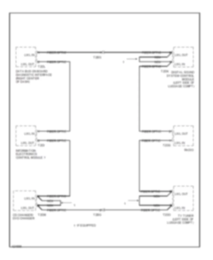
- Cd/dvd changer
- Digital sound system control module (left side of luggage compt)
- Driver's door control module (driver's front door)
- Driver's side can separating plug
- Garage door opener control head
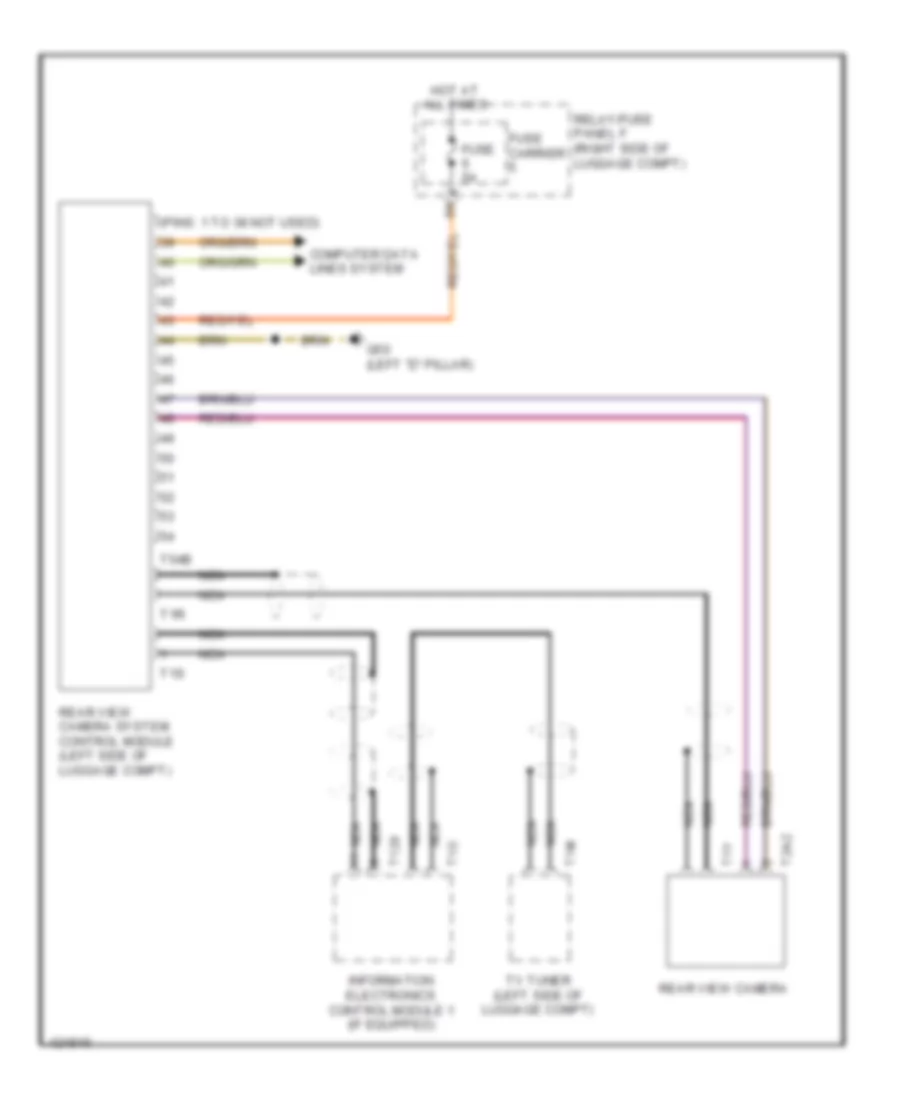
- Information electronics control module 1
- Left headlamp assembly
- Memory seat/ steering column adjustment control module (below driver's seat)
- Power steering control module
- Premium
- Right headlamp assembly
- Standard
- T10p
- T14l
- T16b
- T17b
- T17c
- T17d
- T17e
- T17r
- T17t
- T18b
- T20f
- T27a
- T32g
- T32h
- T6h
- T6k
- T6l
- T8ah
- T8ax
- Telephone transceiver (under front passenger seat)
- Tv tuner (left side of luggage compt)
- Vehicle electrical system control module (left side of dash)
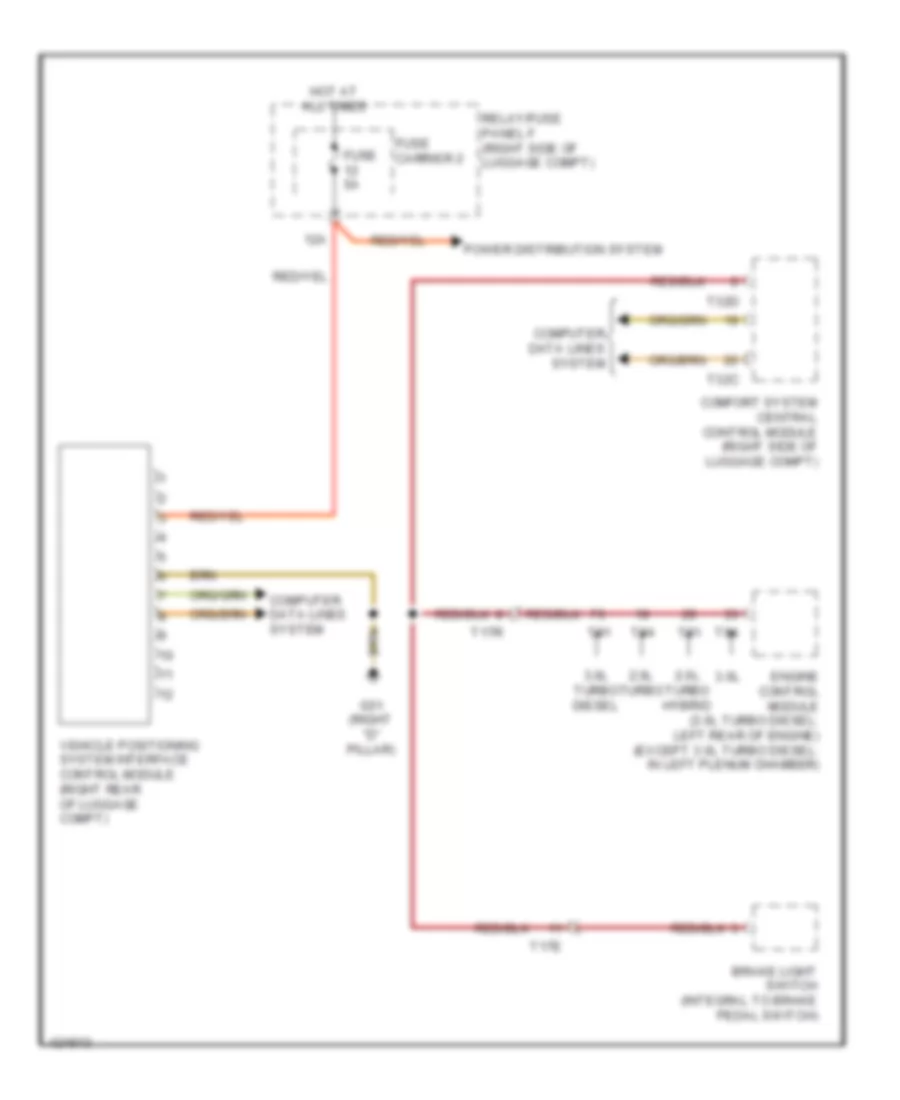
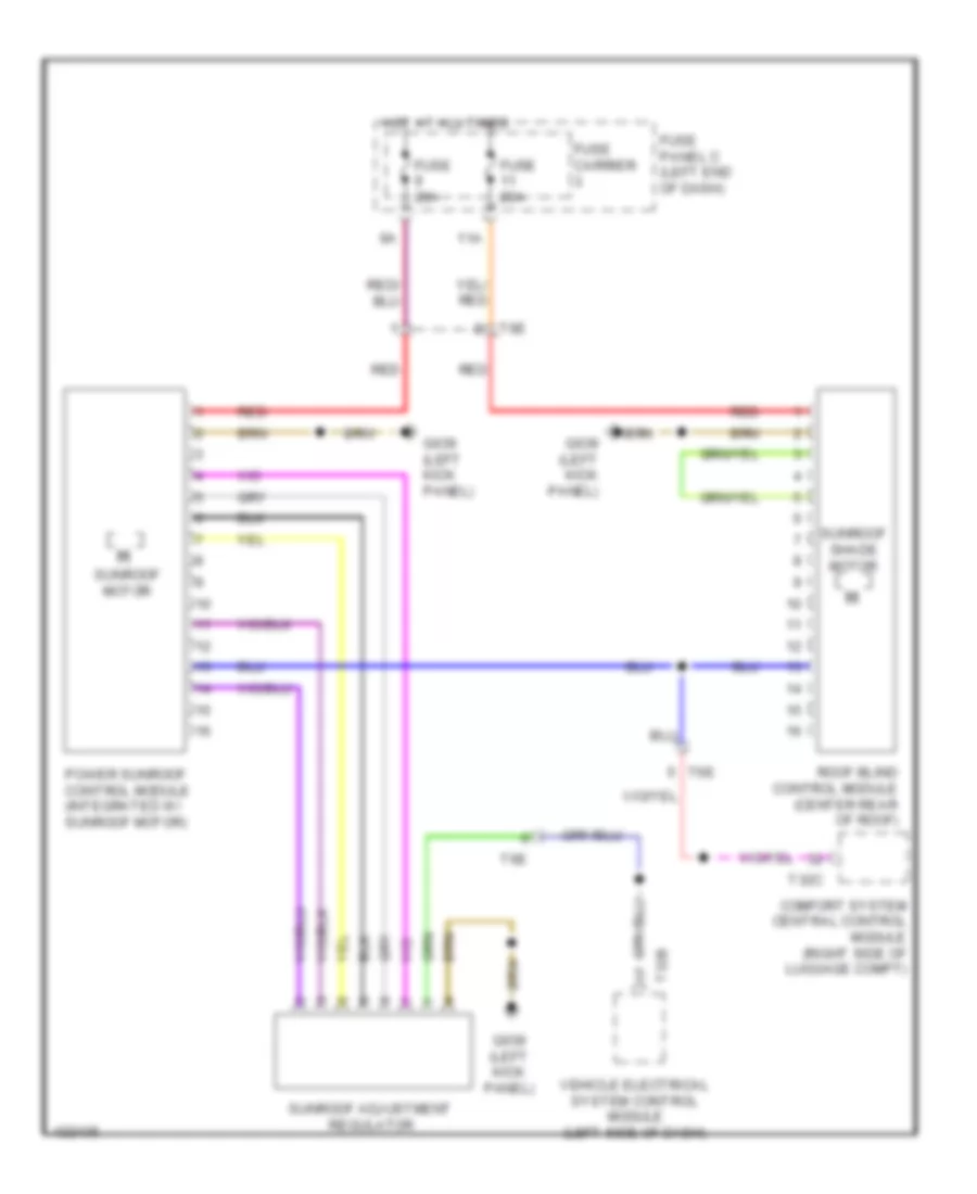
Computer Data Lines Wiring Diagram (3 of 3) for Audi Q5 Prestige 2014
List of elements for Computer Data Lines Wiring Diagram (3 of 3) for Audi Q5 Prestige 2014:
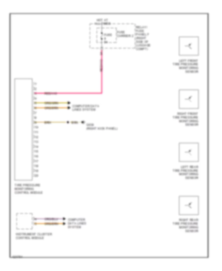
- (if equipped) tire pressure monitoring control module
- (integrated with sunroof motor) power sunroof control module
- (left side of luggage compt) (if equipped) rear view camera system control module
- (on steering column) electronic steering column lock control module
- (right rear of luggage compt) vehicle positioning system interface control module
- (right side of luggage compt) (w/ trailer socket) towing recognition control module
- (right side of luggage compt) comfort system central control module
- (top of left "d" pillar) rear lid control module
- 10h
- 10l
- 11h
- 11l
- 12h
- 12l
- 13h
- 13l
- 14h
- 14l
- 15h
- 15l
- 16h
- 16l
- 17h
- 17l
- 18h
- 18l
- 19h
- 19l
- 20h
- 20l
- 21h
- 21l
- 22h
- 22l
- 23h
- 23l
- Access/start authorization switch
- Auxiliary air heater control module (on auxiliary heater assembly)
- Auxiliary heat control module (on 3-pin relay/ fuse panel)
- Climatronic control module
- Electro mechanical parking brake control module (right side of luggage compt)
- External audio source connection
- Fresh air blower control module (below blower motor assembly)
- Front passenger's door control module (front passenger door)
- Instrument cluster control module
- Passenger's side can separating plug
- Radio
- Roof shade control module
- Steering column electronic system control module (on steering column)
- T0ag
- T16i
- T17f
- T17g
- T20e
- T20g
- T20m
- T32c
- T6e
COOLING FAN
Cooling Fan Wiring Diagram for Audi Q5 Prestige 2014
List of elements for Cooling Fan Wiring Diagram for Audi Q5 Prestige 2014:
- (400w) (except 400w)
- (or red)
- 11a
- 16a
- 17a
- 2.0l turbo
- 2.0l turbo hybrid
- 3.0l diesel
- 3.0l sc
- After-run coolant pump (except 3.0l sc) (lower left side of engine)
- After-run coolant pump (lower left front of engine)
- Auxiliary engine coolant (ec) pump relay (3.0l sc) (relay/fuse panel b)
- Charge air cooling pump (3.0l sc) (left front of engine compt)
- Climatronic control module
- Computer data lines system
- Coolant fan
- Coolant fan (400w & 600w) (behind left side of radiator)
- Coolant fan (800w/ 1000w)
- Coolant fan 2 (600w) (behind right side of radiator)
- Coolant fan 2 (behind right side of radiator)
- Coolant fan control (fc) control module (on cooling fan assembly)
- Coolant fan control (fc) control module 2 (800w/1000w) (on cooling fan assembly)
- Coolant recirculation pump (2.0l turbo hybrid) (lower right rear of engine compt)
- Coolant recirculation pump (except 2.0l turbo hybrid) (lower right rear of engine compt)
- Coolant shut-off valve (2.0l turbo hybrid) (top of transmission)
- Electric drive power & control electronics (right plenum chamber)
- Engine control module (ecm) (except 3.0l diesel: in left plenum chamber) (3.0l diesel: left rear of engine)
- Engine coolant level (ecl) sensor (in coolant reservoir)
- Engine coolant temperature (ect) sensor (left side of engine)
- Engine coolant temperature sensor (on radiator outlet)
- Fuse 1 40a 60a
- Fuse 10a
- Fuse 15a
- Fuse 2 110a
- Fuse 5a
- Fuse carrier
- Fuse panel b (driver's side plenum chamber on electronics box)
- G12 (left rear of engine compt)
- G685 (on right front long member)
- Hot at all times
- Low temperature circuit coolant pump
- Nca
- Red
- T105
- T14f
- T16b
- T17b
- T17q
- T20e
- T28jx
- T32b
- T5l
- T60
- T91
- T94
- Terminal 30 wire junction 2
- Vehicle electrical system control module (left side of dash)
CRUISE CONTROL
Cruise Control Wiring Diagram (1 of 2) for Audi Q5 Prestige 2014
List of elements for Cruise Control Wiring Diagram (1 of 2) for Audi Q5 Prestige 2014:
- (left rear of engine compt) g12
- 2.0l turbo
- 2.0l turbo & 2.0l turbo hybrid
- 2.0l turbo hybrid
- 3.0l sc
- 3.0l sc & 3.0l turbo diesel
- 3.0l turbo diesel
- 3.ol sc
- Accelerator pedal position sensor & accelerator pedal position sensor 2 (top of accelerator pedal assembly)
- Brake lamp switch (top of brake pedal assembly)
- Climate control module
- Computer data lines system
- Distance regulation control module (if equipped) (right side of front bumper)
- Engine control module (ecm) (except diesel: in left plenum chamber) (diesel: left rear of engine)
- Engine controls system
- Engine speed sensor (lower rear of engine)
- Except 2.0l turbo
- Except 2.0l turbo hybrid
- Except 3.0l
- Except 3.ol sc
- Fuse 110a
- Fuse 5a
- Fuse carrier
- Fuse panel a (on battery positive terminal)
- Fuse panel c (left end of dash)
- G638 (right kick panel)
- G687 (under left front of center console)
- Hot at all times
- Power distribution system
- Red
- Relay/fuse panel b (driver's side plenum chamber on electronics box)
- T105
- T17e
- T17r
- T20e
- T60
- T91
- T94
- Wire junction (under luggage compt cover, next to battery)
Cruise Control Wiring Diagram (2 of 2) for Audi Q5 Prestige 2014
List of elements for Cruise Control Wiring Diagram (2 of 2) for Audi Q5 Prestige 2014:
- 12a
- 3.0l sc
- 3.0l turbo diesel
- Computer data lines system
- Cruise control switch
- Except 3.0l turbo diesel
- Fuse 5a
- Fuse carrier 2
- Fuse panel d (right end of dash)
- G687 (under left front of center console)
- Hot at all times
- Nca
- Steering column electronic systems control module (on steering column)
- T17a
- T17b
- Throttle valve control module (on throttle body)
- Transmission control module (tcm) (left side of transmission)
- Transmission input speed sensor
- Transmission output speed sensor
DEFOGGERS
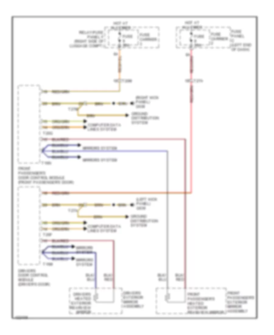
Heated Mirrors Wiring Diagram for Audi Q5 Prestige 2014
List of elements for Heated Mirrors Wiring Diagram for Audi Q5 Prestige 2014:
- (left kick panel) g639
- (right kick panel) g638
- Computer data lines system
- Driver's door control module (driver's door)
- Driver's exterior mirror assembly
- Driver's heated exterior rearview mirror
- Front passenger's door control module (front passenger's door)
- Front passenger's exterior mirror assembly
- Front passenger's heated exterior rearview mirror
- Fuse 30a
- Fuse carrier
- Fuse panel c (left end of dash)
- Ground distribution system
- Hot at all times
- Mirrors system
- Relay/fuse panel f (right side of luggage compt)
- T16m
- T16n
- T20f
- T20g
- T20m
- T27a
- T27m
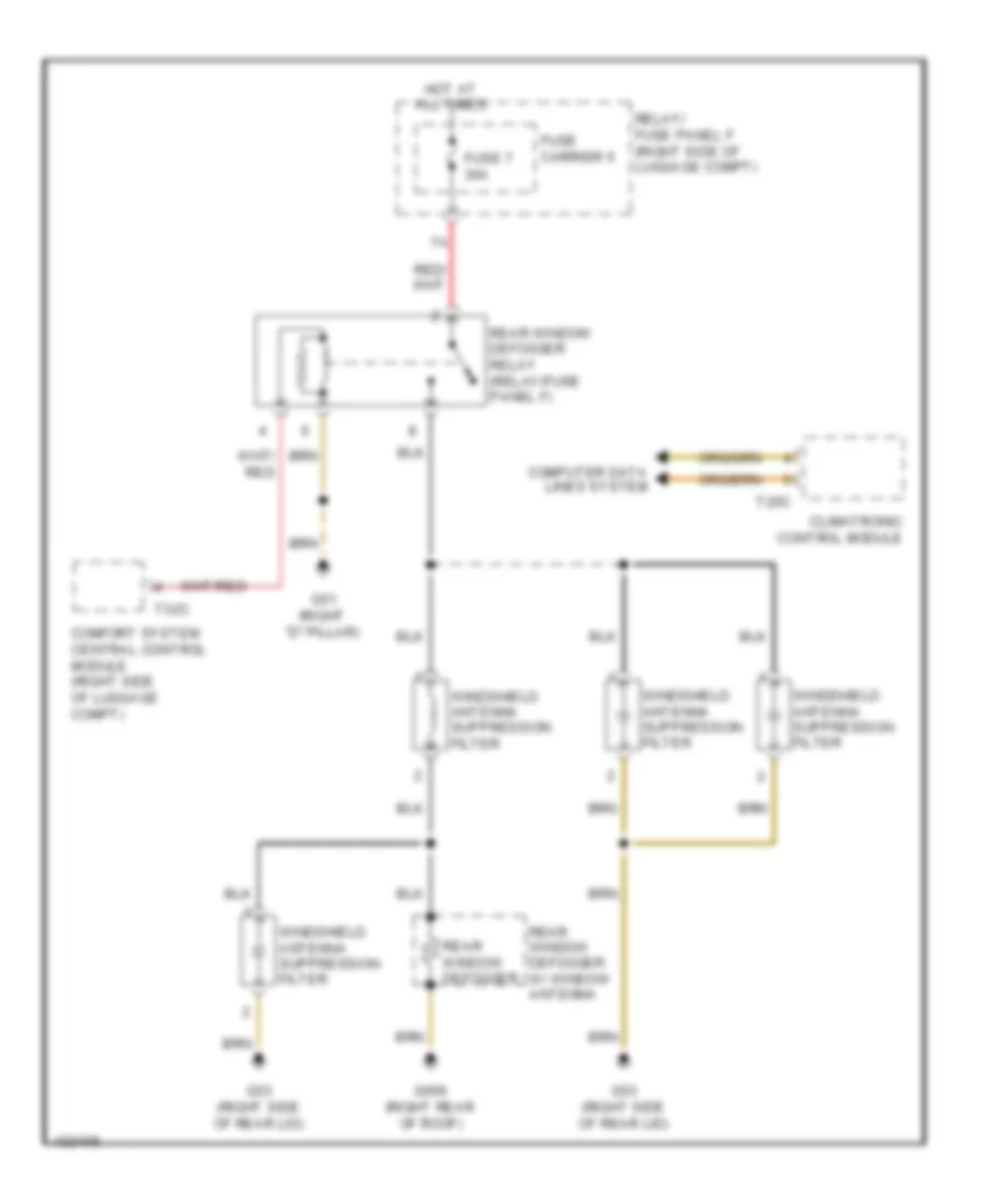
Rear Defogger Wiring Diagram for Audi Q5 Prestige 2014
List of elements for Rear Defogger Wiring Diagram for Audi Q5 Prestige 2014:
- Climatronic control module
- Comfort system central control module (right side of luggage compt)
- Computer data lines system
- Fuse 7 30a
- Fuse carrier 5
- G51 (right "d" pillar)
- G53 (right side of rear lid)
- G666 (right rear of roof)
- Hot at all times
- Rear window defogger
- Rear window defogger relay (relay/fuse panel f)
- Rear window defogger w/ window antenna
- Relay/ fuse panel f (right side of luggage compt)
- T20c
- T32c
- Windshield antenna suppression filter
ELECTRONIC POWER STEERING
Active Steering Control Module Wiring Diagram for Audi Q5 Prestige 2014
List of elements for Active Steering Control Module Wiring Diagram for Audi Q5 Prestige 2014:
- Active steering control module (driver's footwell)
- Anti-lock brakes system
- Computer data lines system
- Electromechanical power steering motor
- Fuse 35a
- Fuse 5a
- Fuse carrier
- Fuse panel c (left end of dash)
- G602 (left side of driver's footwell)
- G639 (left kick panel)
- Hot at all times
- T10h
- T17b
- T17e
- T2bb
- T4r
- T5d
- T6ar
- T8g
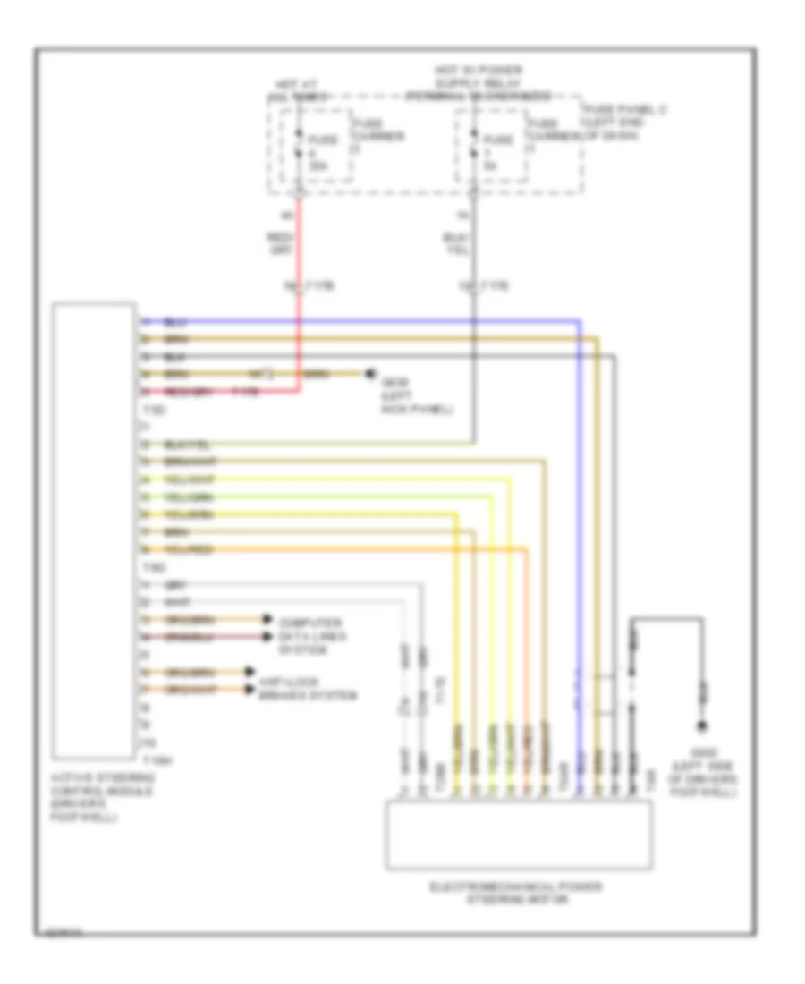
Electromechanical Power Steering Wiring Diagram for Audi Q5 Prestige 2014
List of elements for Electromechanical Power Steering Wiring Diagram for Audi Q5 Prestige 2014:
- 15a
- Computer data lines system
- Fuse 110a
- Fuse 5a
- Fuse carrier 1
- G672 (on lower left front long member)
- Hot at all times
- Instrument cluster control module
- Nca
- Power steering control module
- Relay/fuse panel b (driver's side plenum chamber on electronics box)
- Steering angle sensor (top of steering column)
- Steering column electronic systems control module (on steering column)
- Steering torque sensor
- Steering torque sensor 2
- T16f
- T2n
- T6h
- T6i
- Terminal 30 wire junction 2 w/battery jump start terminal (in center plenum chamber)
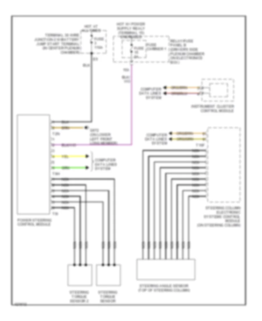
Steering Column Electronic Systems Control Module Wiring Diagram for Audi Q5 Prestige 2014
List of elements for Steering Column Electronic Systems Control Module Wiring Diagram for Audi Q5 Prestige 2014:
- 12a
- Airbag spiral spring/return spring w/ slip ring (top of steering column)
- Computer data lines system
- Cruise control switch
- Driver air bag igniter
- Driver air bag igniter 2
- Engine controls system
- Fuse 5a
- Fuse carrier 1
- Fuse carrier 2
- Fuse panel d (right end of dash)
- G687 (under left front of center console)
- Hot at all times
- Left multi- function buttons
- Mode
- Multi-function steering wheel control module
- Nca
- Right multi- function buttons
- Signal horn activation
- Steering angle sensor (top of steering column)
- Steering column electronic systems control module (on steering column)
- Steering wheel control unit
- Steering wheel vibration motor (w/ lane assist)
- T16f
- T4ac
- Tiptronic down shift button (if equipped)
- Tiptronic upshift button (if equipped)
- Turn signal switch
- W/ lane assist
- W/ tiptronic
- Windshield wiper intermittent mode switch
ELECTRONIC SUSPENSION
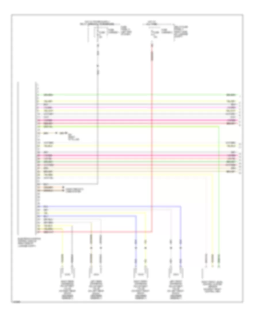
Electronic Suspension Wiring Diagram (1 of 2) for Audi Q5 Prestige 2014
List of elements for Electronic Suspension Wiring Diagram (1 of 2) for Audi Q5 Prestige 2014:
- Computer data lines system
- Electronic damping control module (right side of luggage compt)
- Fuse 15a
- Fuse 5a
- Fuse carrier 1
- Fuse carrier 2
- Fuse panel c (left end of dash)
- G51 (right "d" pillar)
- Hot at all times
- Left front dampening adjustment valve (on left front shock absorber assembly)
- Left rear dampening adjustment valve (on left rear shock absorber assembly)
- Relay/fuse panel f (right side of luggage compt)
- Right front dampening adjustment valve (on right front shock absorber assembly)
- Right front level control system sensor (on right front control arm)
- Right rear dampening adjustment valve (on right rear shock absorber assembly)
Electronic Suspension Wiring Diagram (2 of 2) for Audi Q5 Prestige 2014
List of elements for Electronic Suspension Wiring Diagram (2 of 2) for Audi Q5 Prestige 2014:
- Computer data lines system
- Driving profile selection switch module
- G687 (under left front of center console)
- G688 (under right front of center console)
- Interior lights system
- Left front body acceleration sensor (in left front wheelwell)
- Left front level control system sensor (on left front control arm)
- Left rear level control system sensor (on left rear control arm)
- Rear body acceleration sensor (left rear wheelwell)
- Right front body acceleration sensor (in right front wheelwell)
- Right rear level control system sensor (on right rear control arm)
- T16b
- T17d
- T32a
- Vehicle electrical system control module (left side of dash)
- W/ navigation system
- W/o navigation system
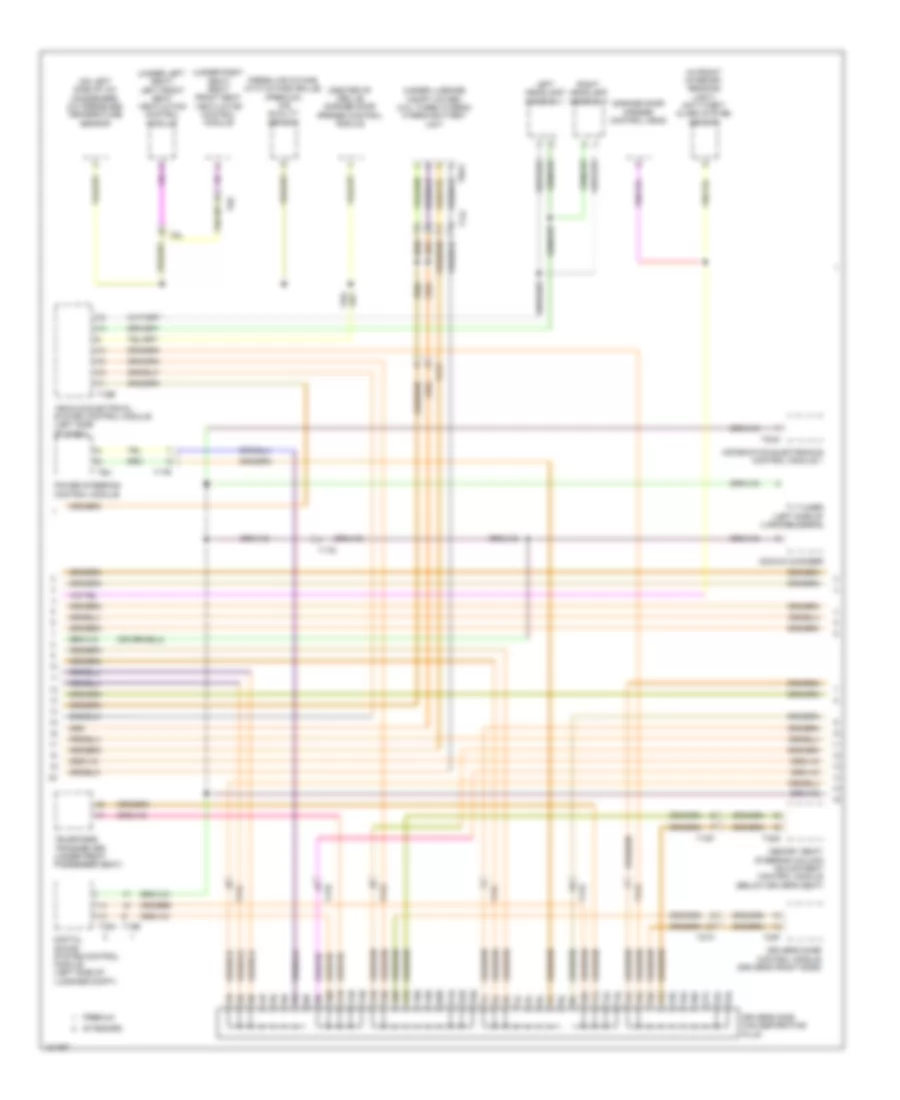
ENGINE PERFORMANCE
2.0L TURBO
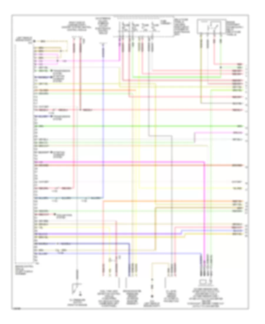
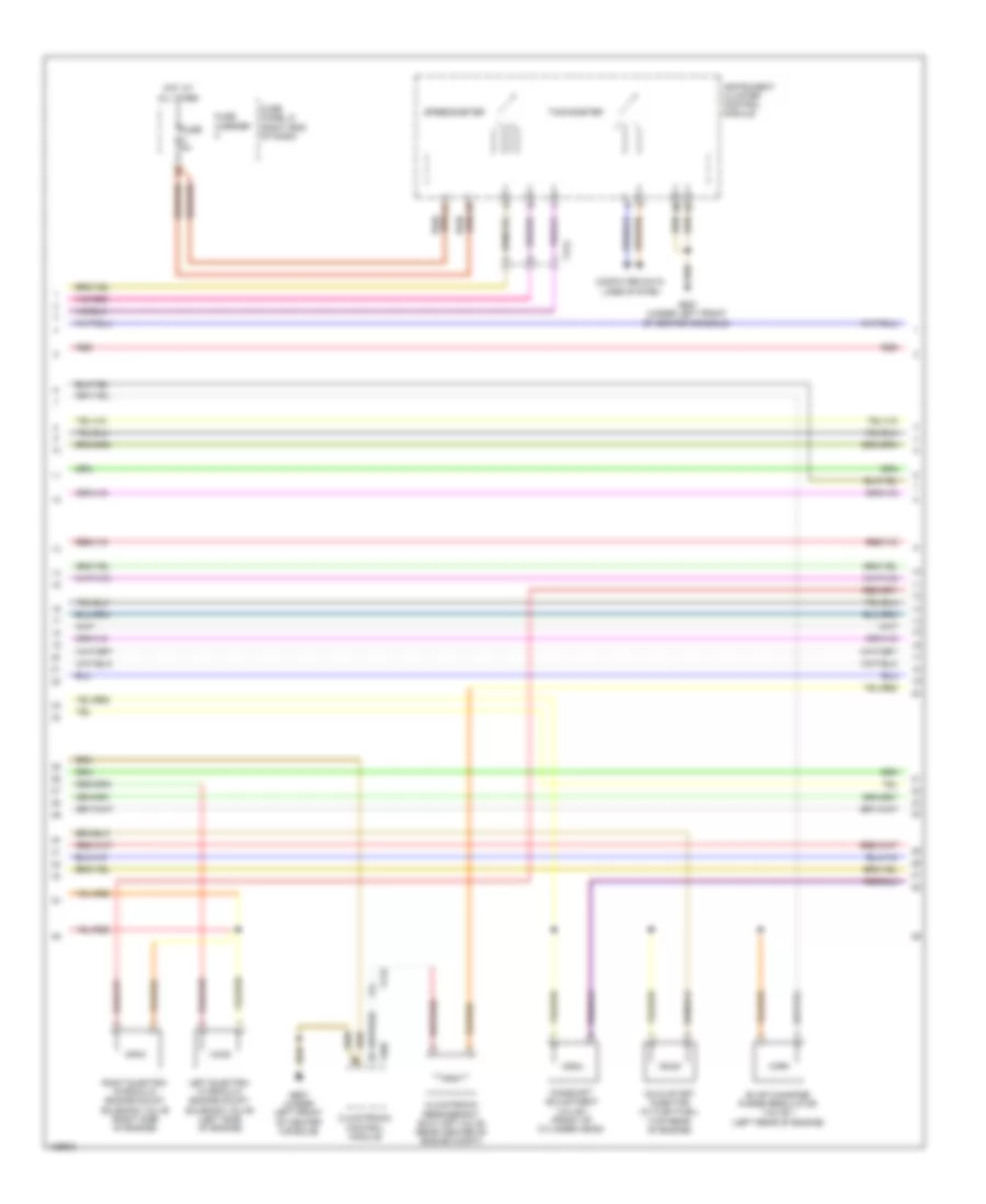
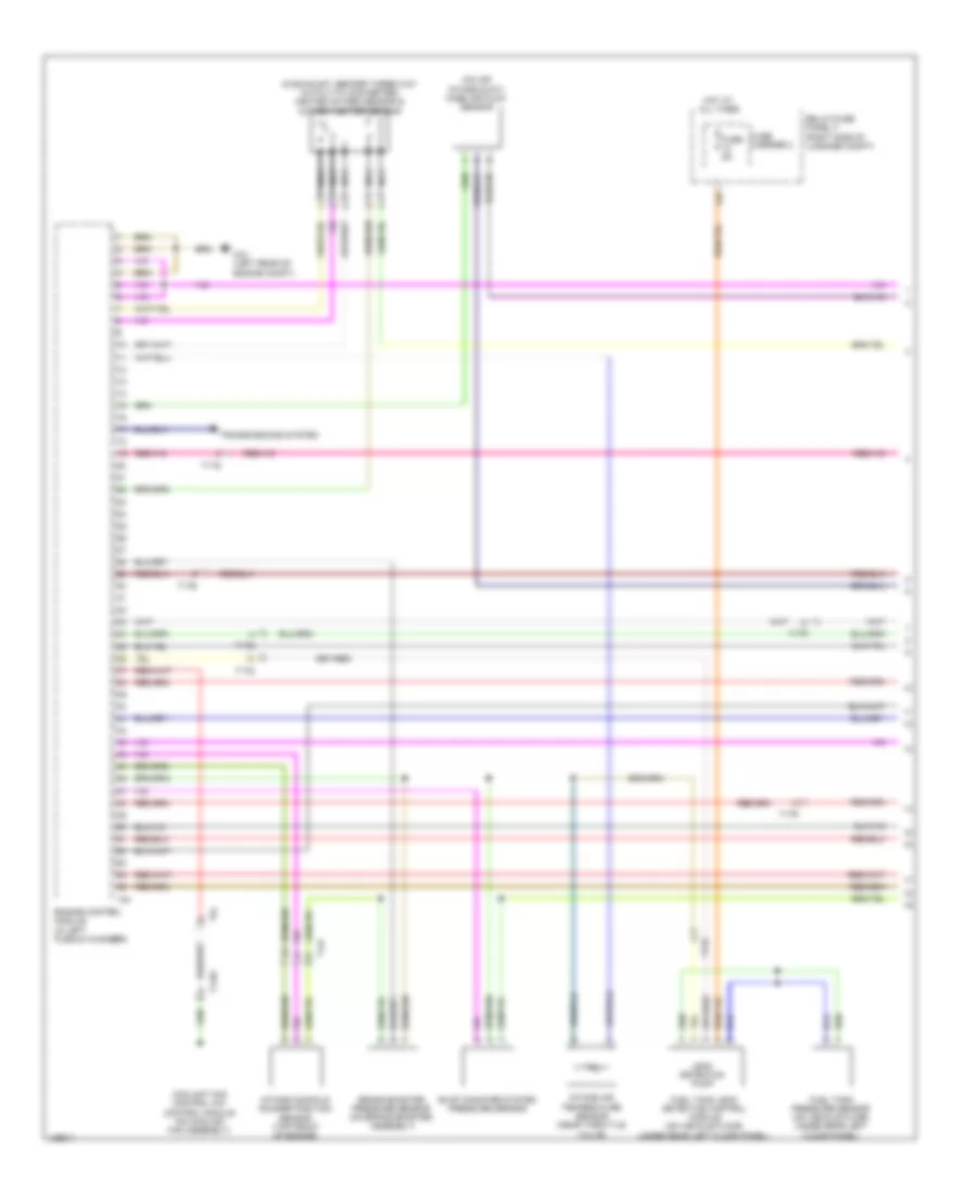
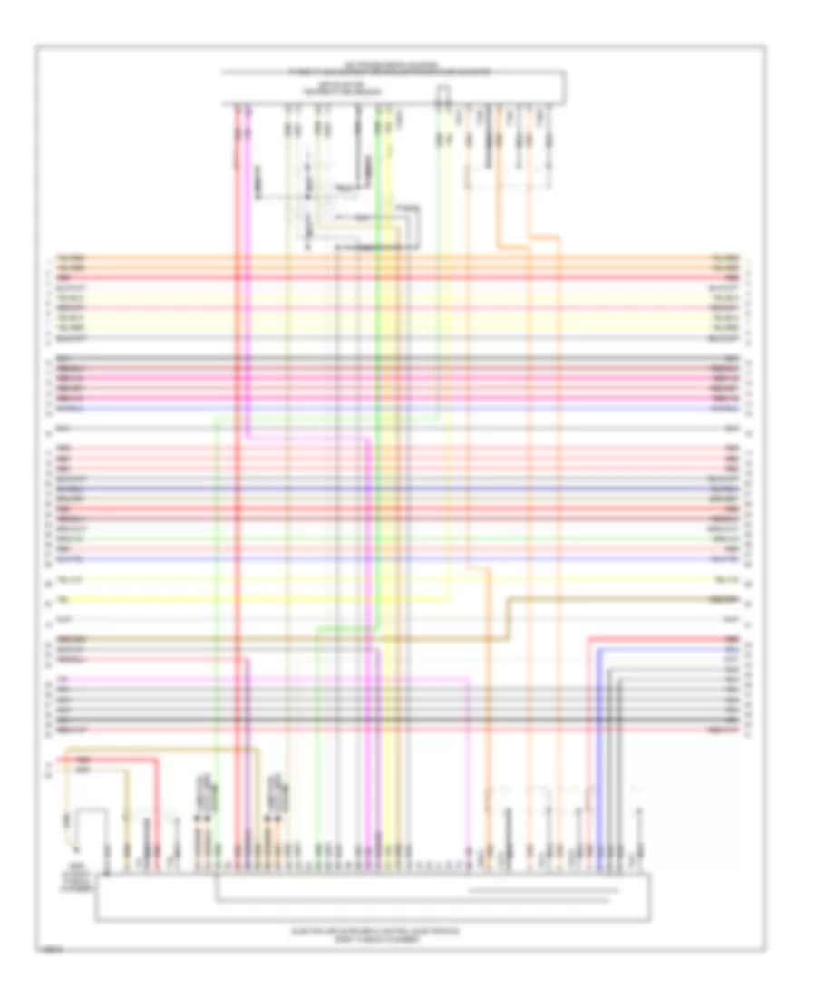
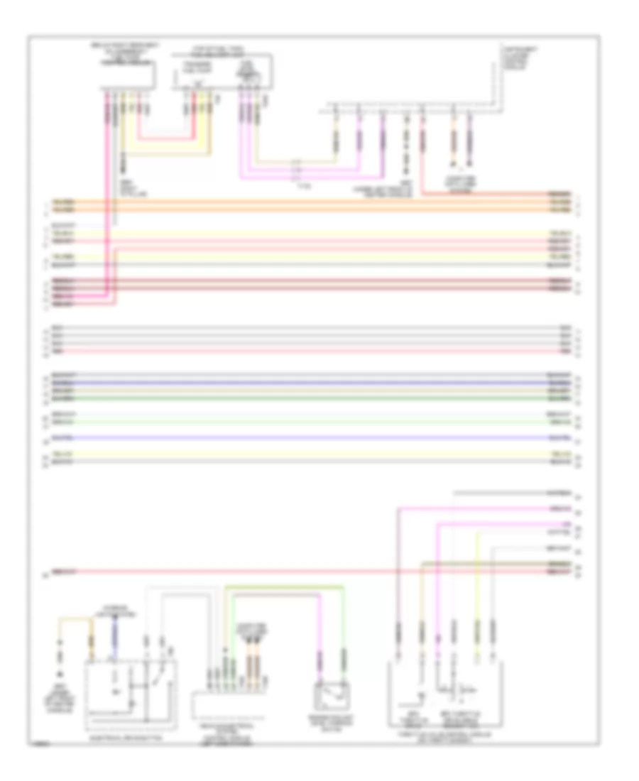
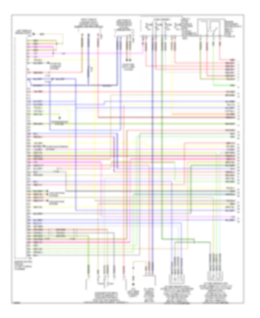
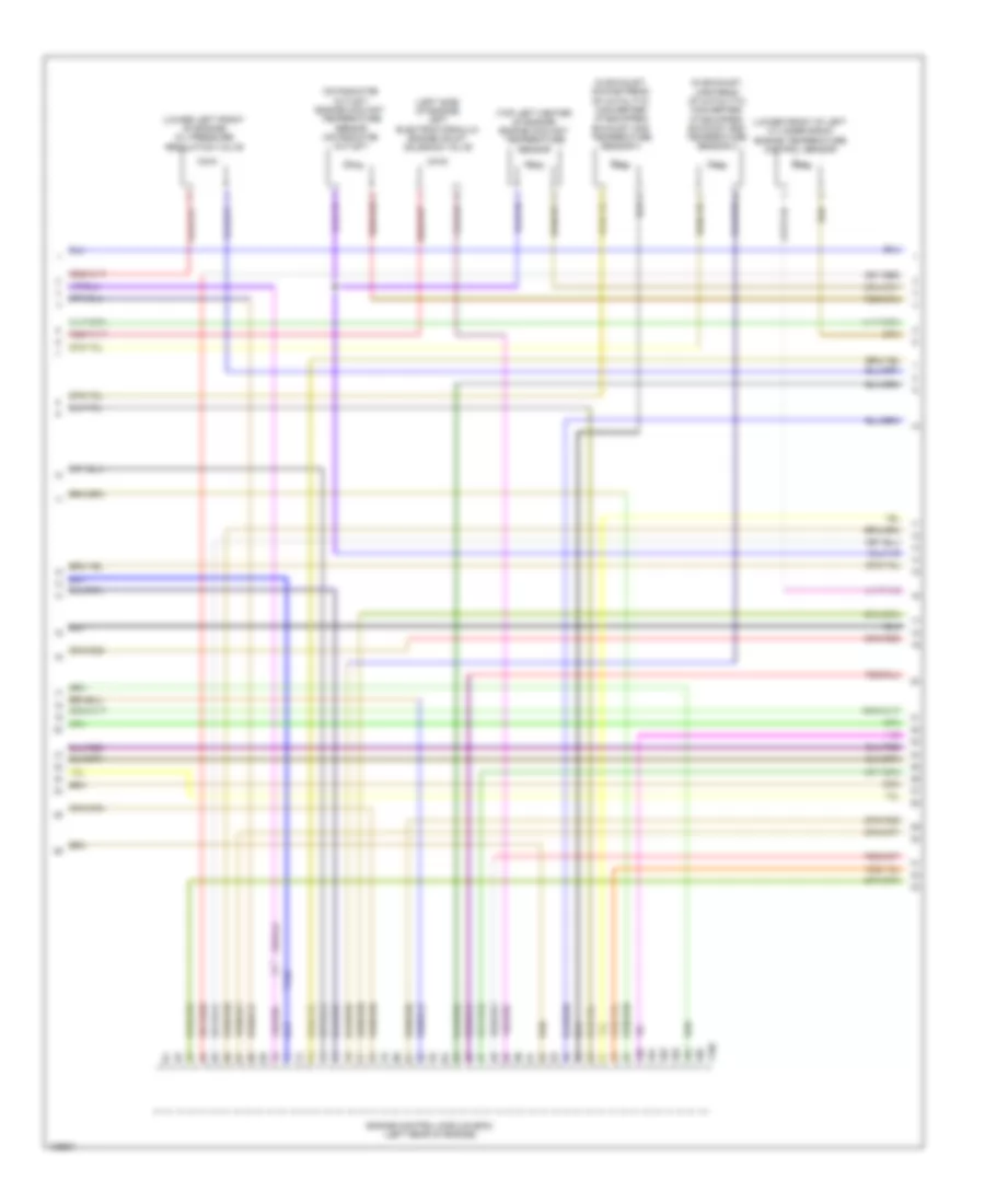
2.0L Turbo, Engine Performance Wiring Diagram (1 of 7) for Audi Q5 Prestige 2014
List of elements for 2.0L Turbo, Engine Performance Wiring Diagram (1 of 7) for Audi Q5 Prestige 2014:
- (left rear of engine compt) g12
- (on steering column) steering column electronics control module
- (right side of luggage compt) comfort system central control module
- 14a
- 17q
- Brake booster pressure sensor (on brake booster assembly)
- Cooling fans system
- Engine control module (in left plenum chamber)
- Fuel tank leak detection control module (if equipped) (on vehicle floor, under rear left floor panel)
- Fuse 15a
- Fuse 20a
- Fuse 5a
- Fuse carrier 1
- G12 (left rear of engine compt)
- Nca
- Oil level thermal sensor (in lower oil pan section)
- Oil pressure switch (front of engine)
- Oxygen sensor (o2s) after 3-way catalytic converter (twc) & oxygen sensor (o2s) 1 after catalytic converter heater (in exhaust, before three way catalytic converter)
- Red
- Relay/fuse panel b (driver's side plenum chamber on electronics box)
- Starting/ charging system
- System
- T17b
- T17q
- T17r
- T32d
- T94
- Transmissions
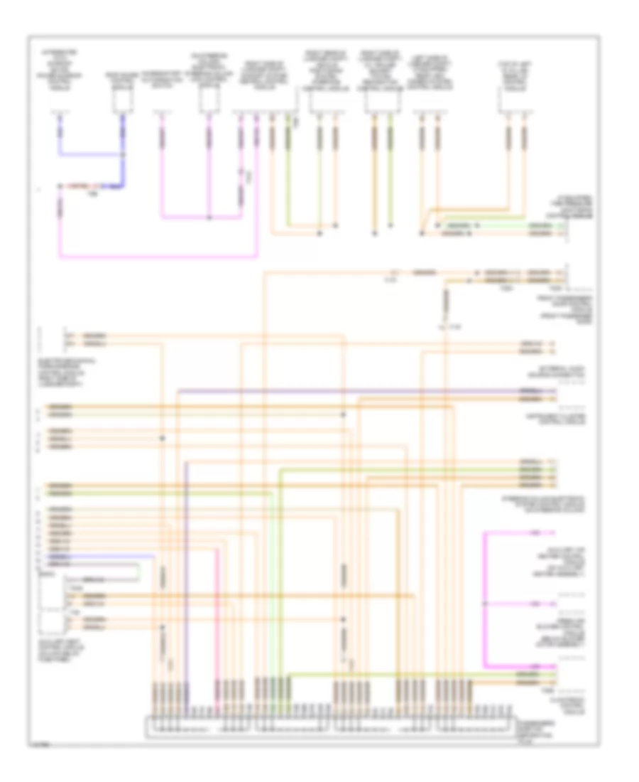
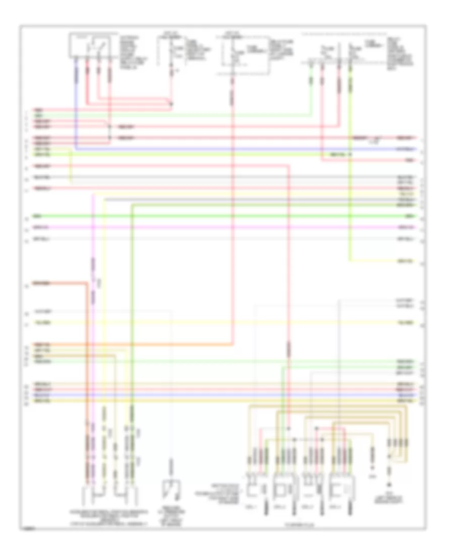
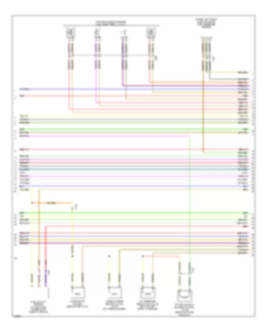
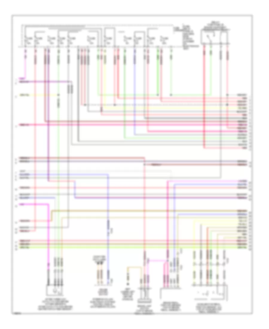
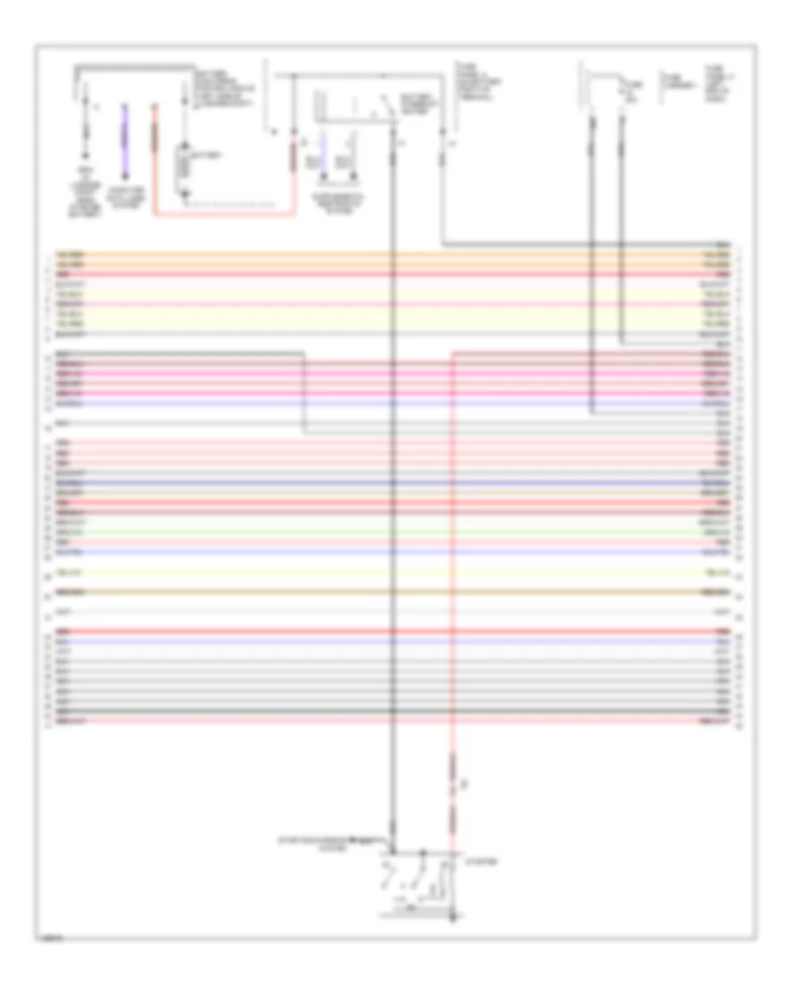
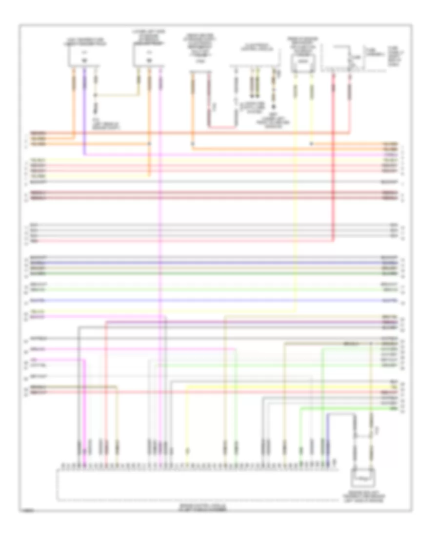
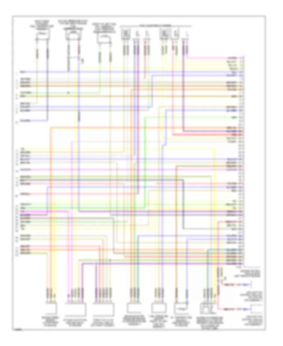
2.0L Turbo, Engine Performance Wiring Diagram (2 of 7) for Audi Q5 Prestige 2014
List of elements for 2.0L Turbo, Engine Performance Wiring Diagram (2 of 7) for Audi Q5 Prestige 2014:
- 10a
- 12a
- Accelerator pedal position sensor & accelerator pedal position sensor 2 (top of accelerator pedal assembly)
- Coil 1
- Coil 2
- Coil 3
- Coil 4
- Fuse 10a
- Fuse 110a
- Fuse 15a
- Fuse 5a
- Fuse carrier 1
- Fuse carrier 2
- Fuse panel a (on battery positive terminal)
- G12 (left rear of engine compt)
- G18
- Hot at all times
- Ignition coils 1, 2, 3 & 4 w/ power output stage (top right side of engine)
- Nca
- Red
- Reduced oil pressure switch (left front of engine)
- Relay/ fuse panel b (driver's side plenum chamber on electronics box)
- Relay/fuse panel f (right side of luggage compt)
- T17e
- T17q
- T17r
- To spark plug
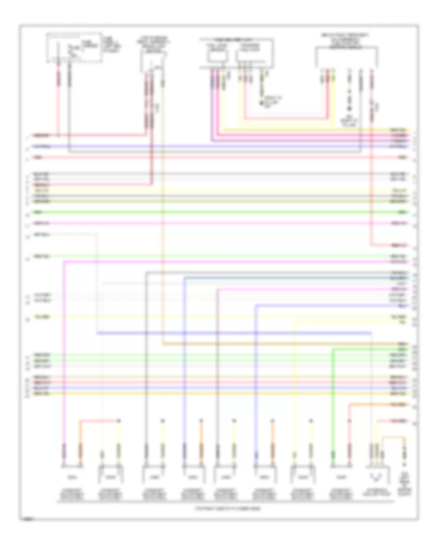
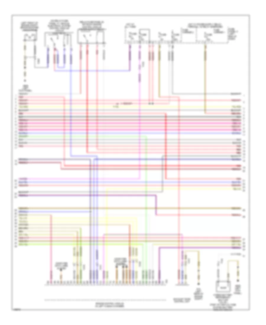
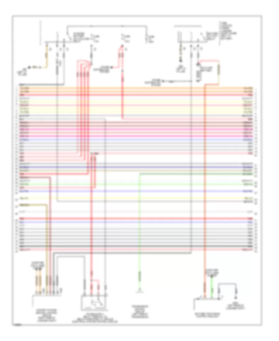
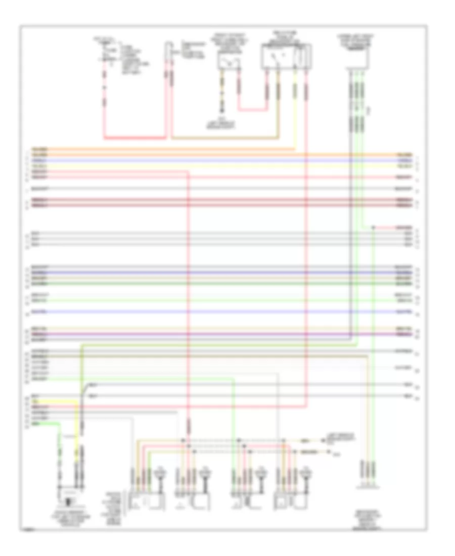
2.0L Turbo, Engine Performance Wiring Diagram (3 of 7) for Audi Q5 Prestige 2014
List of elements for 2.0L Turbo, Engine Performance Wiring Diagram (3 of 7) for Audi Q5 Prestige 2014:
- (below right rear seat, on underbody) fuel pump (fp) control module
- (right "d" pillar) g51
- (top of brake pedal assembly) brake lamp switch
- (top right side of cylinder head)
- After-run coolant pump
- Camshaft adjustment actuator 1
- Camshaft adjustment actuator 2
- Camshaft adjustment actuator 3
- Camshaft adjustment actuator 4
- Camshaft adjustment actuator 5
- Camshaft adjustment actuator 6
- Camshaft adjustment actuator 7
- Camshaft adjustment actuator 8
- Coil
- Fuel delivery unit
- Fuel level sensor
- Fuse 25a
- Fuse carrier
- Fuse panel c (left end of dash)
- G12 (left rear of engine compt)
- G51 (right "d" pillar)
- Red
- T17e
- T17q
- T3ak
- T4q
- Transfer fuel pump
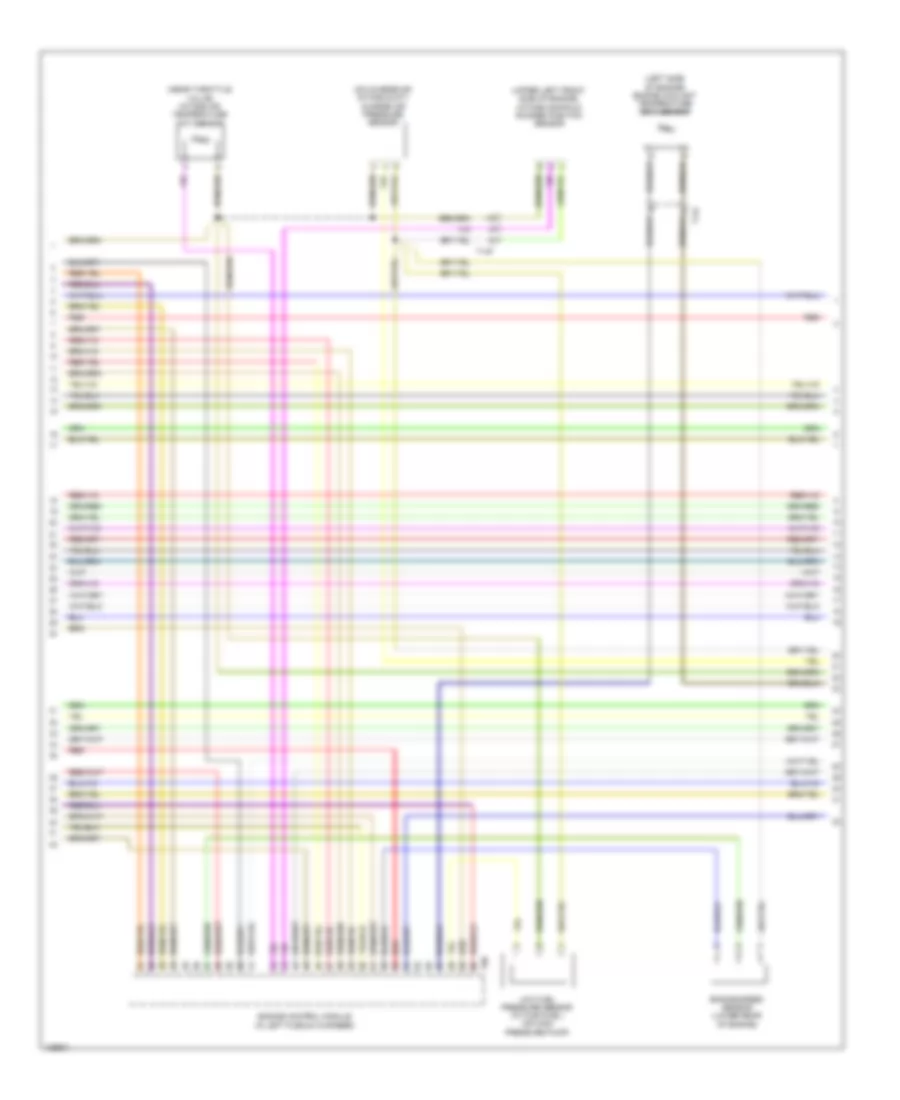
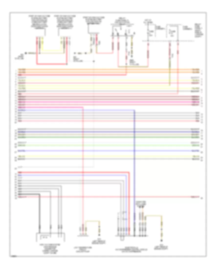
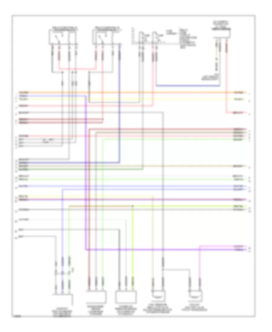
2.0L Turbo, Engine Performance Wiring Diagram (4 of 7) for Audi Q5 Prestige 2014
List of elements for 2.0L Turbo, Engine Performance Wiring Diagram (4 of 7) for Audi Q5 Prestige 2014:
- Camshaft adjustment valve 1 (front of cylinder head)
- Climatronic control module
- Climatronic refrigerant shut-off valve (rear center of engine compt)
- Cold start injector (w/ flex fuel) (top rear of engine)
- Computer data lines system
- Evap canister purge regulator valve 1 (left rear of engine)
- Fuse 5a
- Fuse carrier
- Fuse panel d (right end of dash)
- G687 (under left front of center console)
- Hot at all times
- Instrument cluster control module
- Left electro- hydraulic engine mount solenoid valve (left side of engine)
- Red
- Right electro- hydraulic engine mount solenoid valve (right side of engine)
- Speedometer
- T17b
- T17g
- T20e
- Tachometer
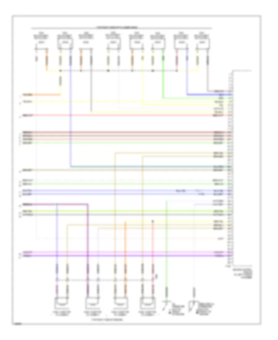
2.0L Turbo, Engine Performance Wiring Diagram (5 of 7) for Audi Q5 Prestige 2014
List of elements for 2.0L Turbo, Engine Performance Wiring Diagram (5 of 7) for Audi Q5 Prestige 2014:
- (top right side of engine) fuel injectors 1, 2, 3 & 4
- (upper left front side of engine) fuel pressure sensor
- Fuel quality sensor (w/ flex fuel) (under right side of vehicle)
- Intake manifold runner control valve (rear of intake manifold)
- Oil pressure regulation valve (bottom left front of engine)
- Red
- T14f
- T17q
- T8w
- Turbocharger recirculation valve (on turbocharger)
- Wastegate bypass regulator valve
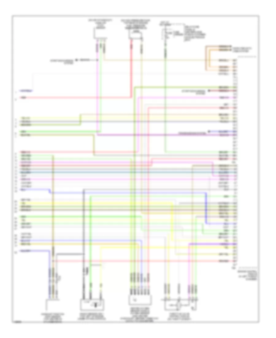
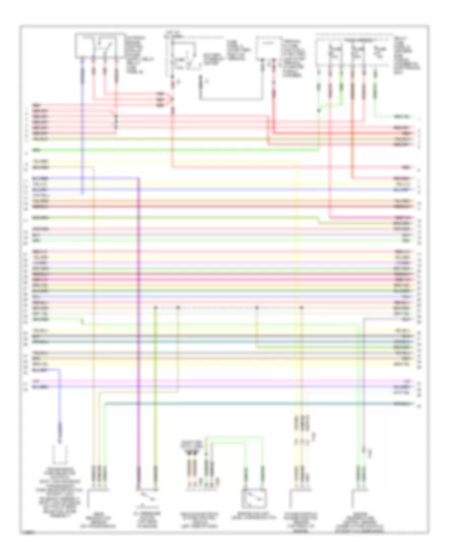
2.0L Turbo, Engine Performance Wiring Diagram (6 of 7) for Audi Q5 Prestige 2014
List of elements for 2.0L Turbo, Engine Performance Wiring Diagram (6 of 7) for Audi Q5 Prestige 2014:
- (left side of engine) engine coolant temperature (ect) sensor
- (near throttle valve) intake air temperature (iat) sensor
- (on charge air intake duct) charge air pressure sensor
- (upper left front side of engine) intake manifold runner position sensor
- Engine control module (in left plenum chamber)
- Engine speed sensor (lower rear of engine)
- Low fuel pressure sensor (w/ flex fuel) (on high pressure pump)
- Red
- T14f
- T60
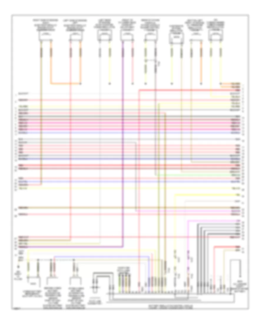
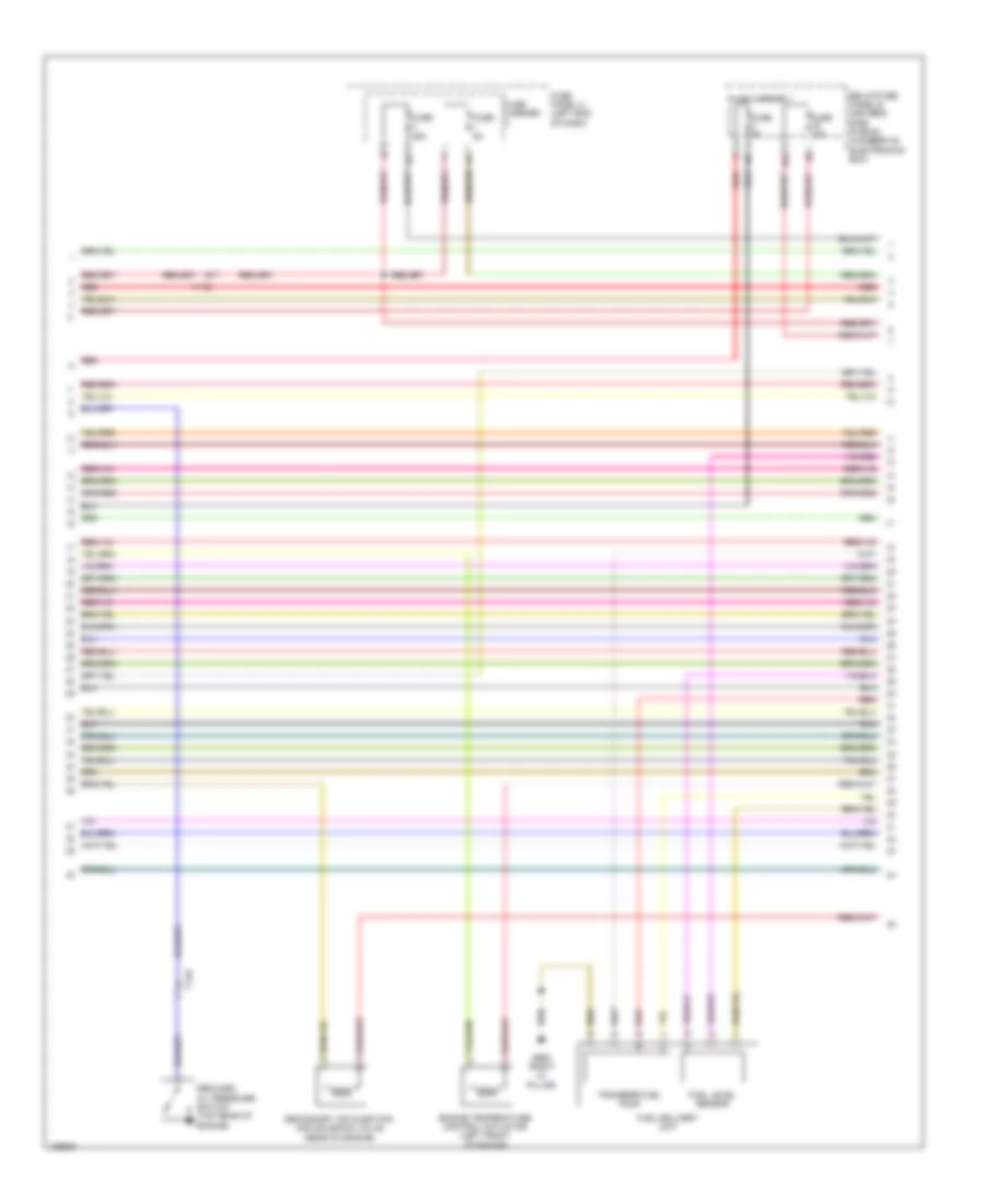
2.0L Turbo, Engine Performance Wiring Diagram (7 of 7) for Audi Q5 Prestige 2014
List of elements for 2.0L Turbo, Engine Performance Wiring Diagram (7 of 7) for Audi Q5 Prestige 2014:
- (on air intake duct) mass air flow sensor
- (on high pressure pump, top rear of engine) fuel pressure regulator valve
- Camshaft position (cmp) sensor (top center of cylinder bank)
- Computer data lines system
- Engine control module (in left plenum chamber)
- Fuse 5a
- Fuse carrier
- Heated oxygen sensor (ho2s) & oxygen sensor (o2s) heater (in exhaust, before three way catalytic converter)
- Hot at all times
- Knock sensor (ks) 1 (top left of engine, under intake manifold)
- Nca
- Red
- Relay/fuse panel b (driver's side plenum chamber on electronics box)
- Starting/charging system
- T14f
- T60
- T94
- Throttle valve control module (on throttle body)
- Transmissions system
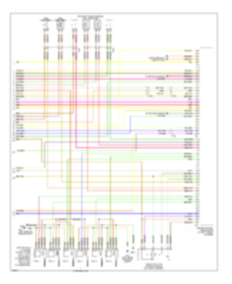
2.0L TURBO HYBRID
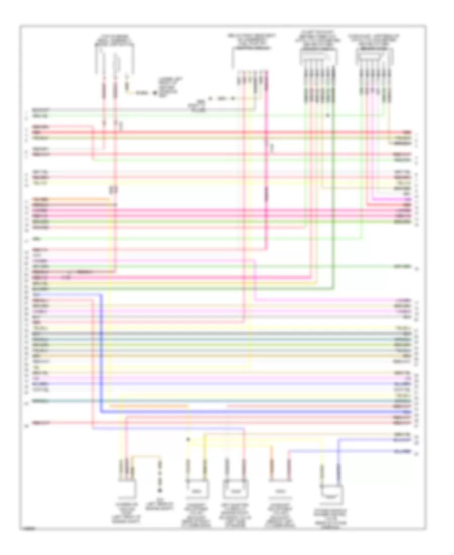
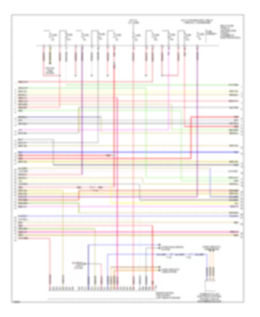
2.0L Turbo Hybrid, Engine Performance Wiring Diagram (1 of 13) for Audi Q5 Prestige 2014
List of elements for 2.0L Turbo Hybrid, Engine Performance Wiring Diagram (1 of 13) for Audi Q5 Prestige 2014:
- (in exhaust, before three way catalytic converter) heated oxygen sensor & oxygen heater sensor
- (on air intake duct) mass air flow sensor
- 12a
- Brake booster pressure sensor (on brake booster assembly)
- Coolant fan control (fc) control module (on cooling fan assembly)
- Engine control module (in left plenum chamber)
- Evap canister system pressure sensor
- Fuel tank leak detection control module (on vehicle floor, under rear left floor panel)
- Fuel tank pressure sensor (on vehicle floor, under rear left floor panel)
- Fuse 5a
- Fuse carrier 2
- G12 (left rear of engine compt)
- Hot at all times
- Intake air temperature sensor (near throttle valve)
- Intake manifold runner position sensor (top front of engine)
- Leak detection pump
- Nca
- Relay/fuse panel f (right side of luggage compt)
- T14bi
- T14f
- T17e
- T17q
- T17r
- T5l
- T91
- Transmissions system
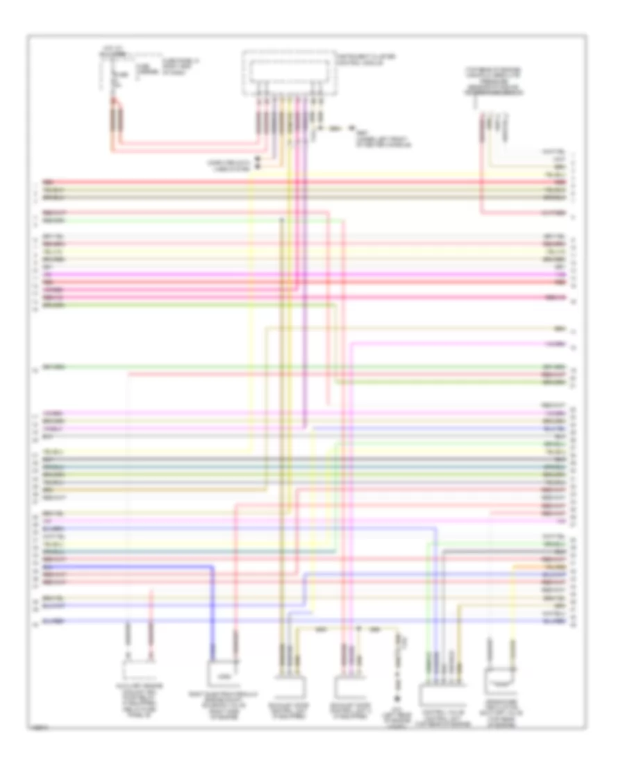
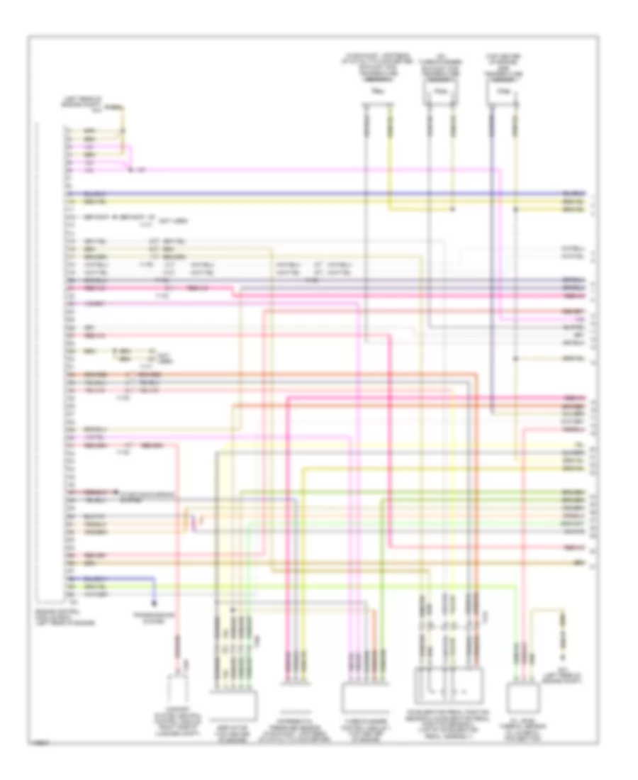
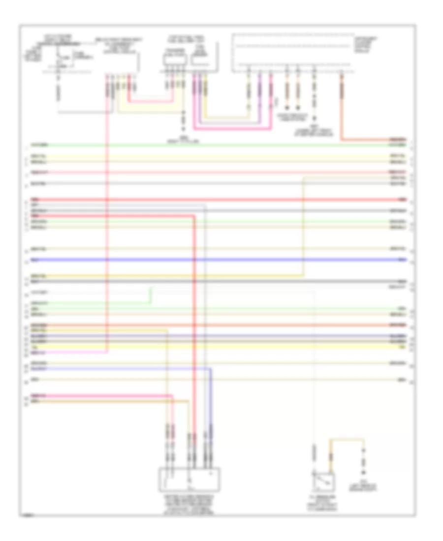
2.0L Turbo Hybrid, Engine Performance Wiring Diagram (2 of 13) for Audi Q5 Prestige 2014
List of elements for 2.0L Turbo Hybrid, Engine Performance Wiring Diagram (2 of 13) for Audi Q5 Prestige 2014:
- 10a
- 13a
- 14a
- 17a
- Accelerator pedal position sensor 1 & 2 (top of accelerator pedal assembly)
- After three way catalytic converter oxygen sensor & after catalytic converter heater for oxygen sensor 1
- Brake lamp switch (top of brake pedal assembly)
- Brake pedal position sensor (top of brake pedal assembly)
- Computer data lines system
- Cruise control switch
- Fuse 10a
- Fuse 15a
- Fuse 20a
- Fuse 5a
- Fuse carrier
- Fuse/ relay panel b (driver's side plenum chamber on electronics box)
- G687 (under left front of center console)
- Nca
- Red
- Steering column electronic systems control module (on steering column)
- T16f
- T17b
- T17c
- T17e
- T17t
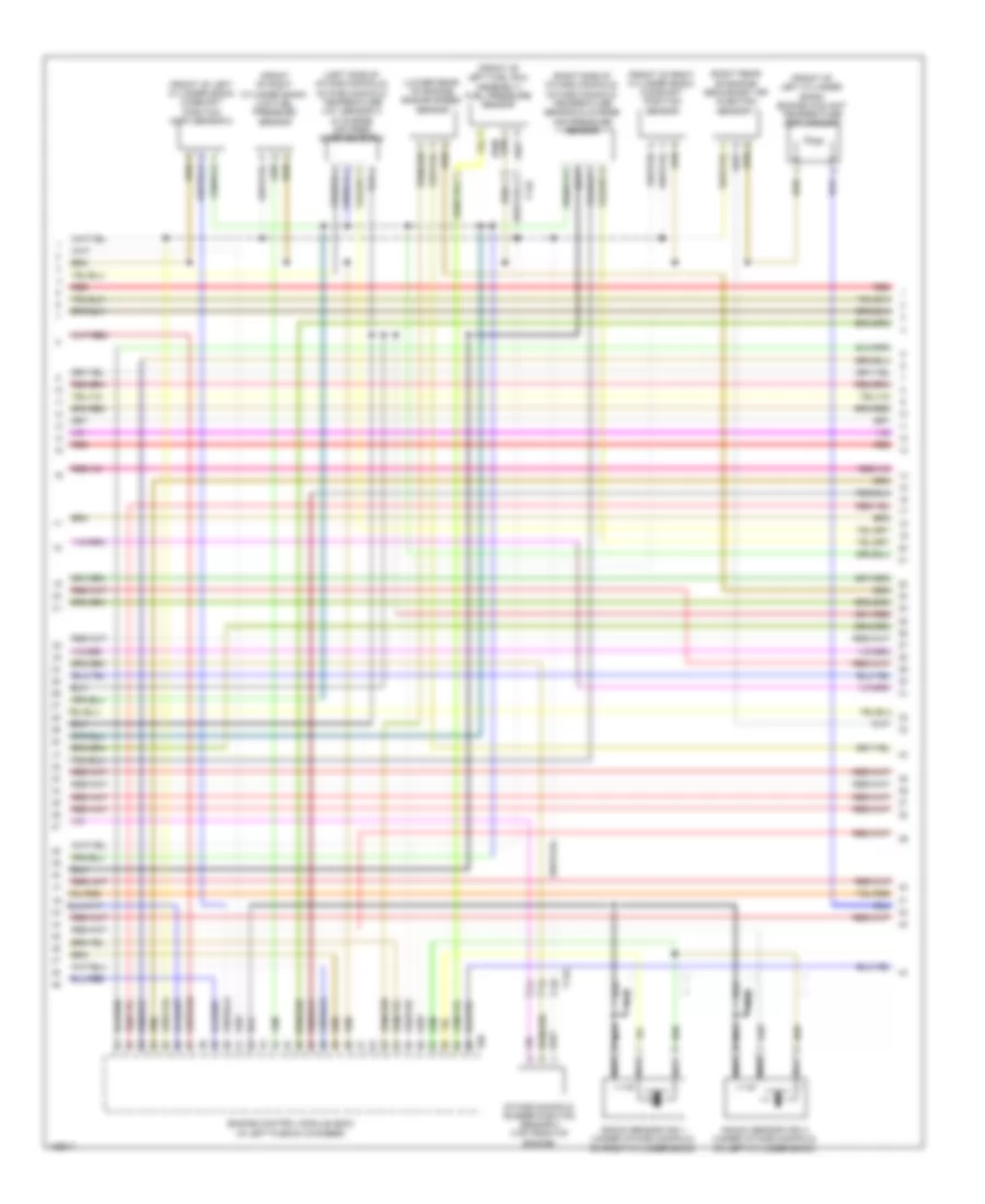
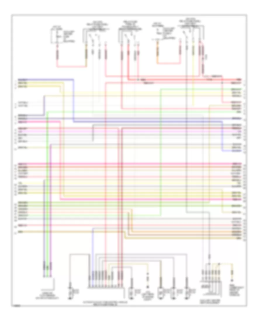
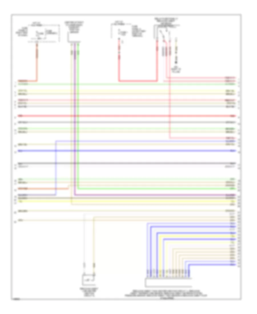
2.0L Turbo Hybrid, Engine Performance Wiring Diagram (3 of 13) for Audi Q5 Prestige 2014
List of elements for 2.0L Turbo Hybrid, Engine Performance Wiring Diagram (3 of 13) for Audi Q5 Prestige 2014:
- (left front of engine compt) brake booster vacuum pump
- (on relay/fuse panel w/ vehicle electrical system control module) vacuum pump relay
- Computer data lines system
- Engine control module (in left plenum chamber)
- Exhaust door control unit
- Fuse 25a
- Fuse 30a
- Fuse 5a
- Fuse carrier 1
- Fuse carrier 2
- Fuse panel c (left end of dash)
- G12 (left rear of engine compt)
- G639 (left kick panel)
- Hot at all times
- Hybrid battery refrigerant shut-off valve 1 (part of high-voltage system battery cooling module)
- Red
- T14l
- T17e
- T17q
- T17r
- T17t
- T2ek
- T91
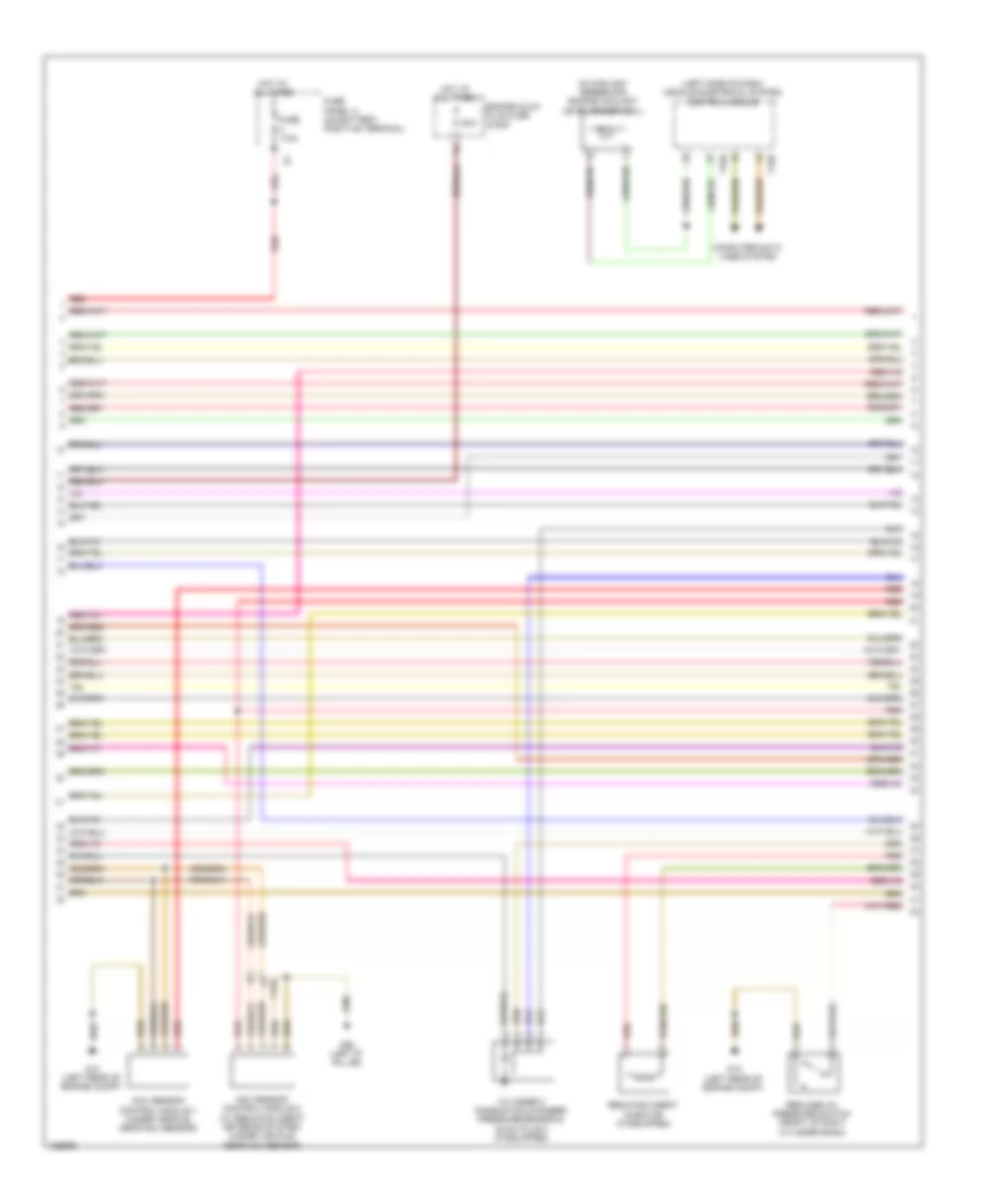
2.0L Turbo Hybrid, Engine Performance Wiring Diagram (4 of 13) for Audi Q5 Prestige 2014
List of elements for 2.0L Turbo Hybrid, Engine Performance Wiring Diagram (4 of 13) for Audi Q5 Prestige 2014:
- (bottom left front of engine) oil pressure regulation valve
- (front of cylinder head) camshaft adjustment valve 1
- (left rear of engine) evap canister purge regulator valve 1
- (left side of engine) left electrohydraulic engine mount solenoid valve
- (on turbocharger) turbocharger recirculation valve
- (rear of intake manifold) intake manifold runner control valve
- (right side of engine) right electrohydraulic engine mount solenoid valve
- After hybrid battery evaporator temperature sensor (part of high- voltage system battery cooling module)
- Battery regulation control module (under luggage compartment cover)
- Before hybrid battery evaporator temperature sensor (part of high- voltage system battery cooling module)
- Computer data lines system
- G51 (right "d" pillar)
- G675 (in luggage compt near starter battery)
- Hybrid battery refrigerant shut-off valve 2
- Nca
- Pilot line connector 1
- Red
- T14ax
- T14f
- T14l
- T17t
- T1b
- T1c
- T8ax
- Wastegate bypass regulator valve
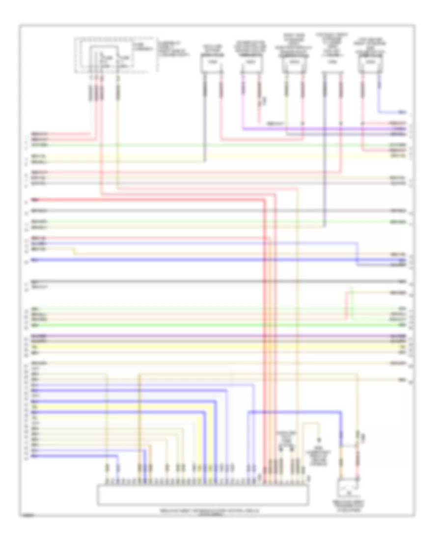
2.0L Turbo Hybrid, Engine Performance Wiring Diagram (5 of 13) for Audi Q5 Prestige 2014
List of elements for 2.0L Turbo Hybrid, Engine Performance Wiring Diagram (5 of 13) for Audi Q5 Prestige 2014:
- (on transmission housing) three-phase current drive/electro-drive drive motor
- Computer data lines system
- Drive motor temperature sensor
- Electric drive power & control electronics (right plenum chamber)
- G609 (in right plenum chamber)
- Nca
- Red
- System data lines computer
- T10vx
- T1bu
- T1bv
- T1bw
- T1cu
- T1cv
- T1cw
- T1e
- T1f
- T28jx
- T2vx
- T4jx
2.0L Turbo Hybrid, Engine Performance Wiring Diagram (6 of 13) for Audi Q5 Prestige 2014
List of elements for 2.0L Turbo Hybrid, Engine Performance Wiring Diagram (6 of 13) for Audi Q5 Prestige 2014:
- 16a
- Battery
- Battery interrupt igniter
- Battery monitoring control module (left side of luggage compt) b
- Computer data lines system
- Fuse 40a
- Fuse carrier 1
- Fuse panel a (on battery positive terminal)
- Fuse panel c (left end of dash)
- G624 (in luggage compt near starter battery)
- Nca
- Red
- Starter
- Starting/charging system
- T5i
2.0L Turbo Hybrid, Engine Performance Wiring Diagram (7 of 13) for Audi Q5 Prestige 2014
List of elements for 2.0L Turbo Hybrid, Engine Performance Wiring Diagram (7 of 13) for Audi Q5 Prestige 2014:
- Auxiliary battery
- Battery cut-out relay
- Battery monitoring control module 2
- Comfort system central control module (right side of luggage compt)
- Computer data lines system
- Fuse 110a
- Fuse 125a
- G50 (left "d" pillar)
- G676 (left rear of luggage compt)
- Nca
- Power distribution system
- Red
- Starter battery switch-over relay
- T17r
- T32c
- T32d
- Transmission control module (left side of transmission)
- Wire junction (under luggage compt cover, next to battery)
2.0L Turbo Hybrid, Engine Performance Wiring Diagram (8 of 13) for Audi Q5 Prestige 2014
List of elements for 2.0L Turbo Hybrid, Engine Performance Wiring Diagram (8 of 13) for Audi Q5 Prestige 2014:
- (part of high-voltage system battery cooling module) battery fan 1
- (part of high-voltage system battery cooling module) hybrid battery recirculation door positioning motor 1
- (part of high-voltage system battery cooling module) hybrid battery recirculation door positioning motor 2
- (relay/ fuse panel f) fan activation relay
- 12a
- Computer data lines system
- Electrical & a/c compressor control module (on a/c compressor)
- Fuse
- Fuse 30a
- Fuse carrier 3
- Fuse carrier 5
- G12 (left rear of engine compt)
- G51 (right "d" pillar)
- G663 (right "c" pillar)
- High voltage system maintenance connector (under luggage compt cover)
- Hot at all times
- Low temperature circuit coolant pump
- N/a
- Nca
- Red
- Relay/ fuse panel f (right side of luggage compt)
- T14l
- T2ei
2.0L Turbo Hybrid, Engine Performance Wiring Diagram (9 of 13) for Audi Q5 Prestige 2014
List of elements for 2.0L Turbo Hybrid, Engine Performance Wiring Diagram (9 of 13) for Audi Q5 Prestige 2014:
- (below right rear seat, on underbody) fuel pump control module
- (top of fuel tank) fuel delivery unit
- Computer data lines system
- Electrical drive button
- Engine coolant level warning switch
- Epc throttle drive
- Epc throttle drive angle sensor 1 & 2
- Fuel level sensor
- G663 (right "d" pillar)
- G687 (under left front of center console)
- Instrument cluster control module
- Interior lights system
- Red
- T16b
- T17g
- T32b
- T3ak
- T4q
- T8s
- Throttle valve control module (on throttle body)
- Transfer fuel pump
- Vehicle electrical system control module (left side of dash)
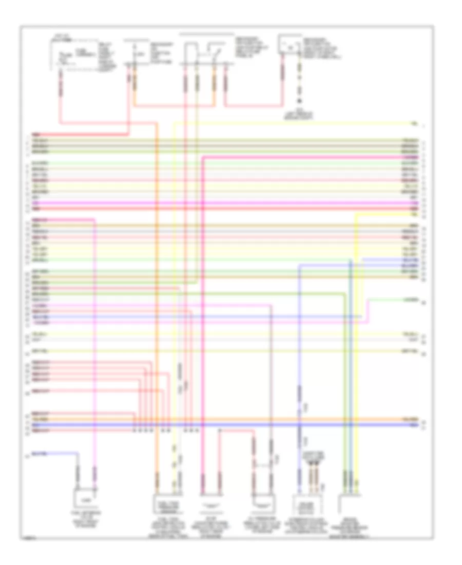
2.0L Turbo Hybrid, Engine Performance Wiring Diagram (10 of 13) for Audi Q5 Prestige 2014
List of elements for 2.0L Turbo Hybrid, Engine Performance Wiring Diagram (10 of 13) for Audi Q5 Prestige 2014:
- (lower left side of engine) after-run coolant pump
- (rear center of engine compt) climatronic refrigerant shut-off valve
- (rear of engine) secondary air injection solenoid valve
- Climatronic control module
- Computer data lines system
- Engine control module (in left plenum chamber)
- Engine coolant temperature sensor (left side of engine)
- Fuse 5a
- Fuse carrier 2
- Fuse panel d (right end of dash)
- G12 (left rear of engine compt)
- G687 (under left front of center console)
- High temperature circuit coolant pump
- Red
- T105
- T14f
- T17b
- T17q
- T20e
2.0L Turbo Hybrid, Engine Performance Wiring Diagram (11 of 13) for Audi Q5 Prestige 2014
List of elements for 2.0L Turbo Hybrid, Engine Performance Wiring Diagram (11 of 13) for Audi Q5 Prestige 2014:
- (front of right front wheelwell) secondary air injection pump motor
- (left rear of engine compt) g12
- (relay/fuse panel b) secondary air injection pump relay
- (upper left front side of engine) fuel pressure sensor
- 50a
- Fuse 200a
- G12 (left rear of engine compt)
- G15
- Hot at all times
- Ignition coils w/ power output stage (top right side of engine)
- Knock sensor 1 (top left of engine under intake manifold)
- Nca
- Red
- Secondary air injection pump fuse
- Secondary air injection sensor 1 (rear of engine compt)
- T14f
- To spark plug
- Wire junction (under luggage compt cover, next to battery)
2.0L Turbo Hybrid, Engine Performance Wiring Diagram (12 of 13) for Audi Q5 Prestige 2014
List of elements for 2.0L Turbo Hybrid, Engine Performance Wiring Diagram (12 of 13) for Audi Q5 Prestige 2014:
- (in lower oil pan section) oil level thermal sensor
- (relay/fuse panel b) starter relay
- (relay/fuse panel b) starter relay 2
- 12a
- Camshaft position sensor (top center of cylinder bank)
- Charge air pressure sensor (on charge air intake duct)
- Coolant shut-off valve (top of transmission)
- Engine speed sensor (lower rear of engine)
- Fuel pressure regulator valve (on high pressure pump, top rear of engine)
- Fuse 5a
- Fuse carrier 1
- G12 (left rear of engine compt)
- Relay/ fuse panel b (driver's side plenum chamber on electronics box)
- T14f
- T17r
2.0L Turbo Hybrid, Engine Performance Wiring Diagram (13 of 13) for Audi Q5 Prestige 2014
List of elements for 2.0L Turbo Hybrid, Engine Performance Wiring Diagram (13 of 13) for Audi Q5 Prestige 2014:
- (top right side of cylinder head)
- (top right side of engine)
- Cam adjustment actuator 1
- Cam adjustment actuator 2
- Cam adjustment actuator 3
- Cam adjustment actuator 4
- Cam adjustment actuator 5
- Cam adjustment actuator 6
- Cam adjustment actuator 7
- Cam adjustment actuator 8
- Engine control module (in left plenum chamber)
- Fuel injector cylinder 1
- Fuel injector cylinder 2
- Fuel injector cylinder 3
- Fuel injector cylinder 4
- Oil pressure switch (front of engine)
- Reduced oil pressure switch (front of engine)
- T105
- T17r
- T8w
3.0L SC
3.0L SC, Engine Performance Wiring Diagram (1 of 8) for Audi Q5 Prestige 2014
List of elements for 3.0L SC, Engine Performance Wiring Diagram (1 of 8) for Audi Q5 Prestige 2014:
- (left rear of engine compt) g12
- (left side of transmission) transmission control module (tcm)
- (right side of luggage compt) comfort system central control module
- 17a
- Accelerator pedal position sensor 1 & accelerator pedal position (app) sensor 2 (top of accelerator pedal assembly)
- Computer data lines system
- Cooling fans system
- Engine control module (in left plenum chamber)
- Fuse 10a
- Fuse 15a
- Fuse 5a
- Fuse carrier 1
- G12 (left rear of engine compt)
- Nca
- Oil level thermal sensor (in lower oil pan section)
- Oxygen sensor (02s) 2 after catalytic converter (twc) & oxygen sensor (o2s) 2 after catalytic converter heater (in left exhaust, behind three way catalytic converter)
- Oxygen sensor (o2s) after three way catalytic converter (twc) & oxygen sensor (o2s) 1 after catalytic converter heater (in right exhaust, behind three way catalytic converter)
- Red
- Relay/ fuse panel b (driver's side plenum chamber on electronics box)
- Starting/ charging system
- Starting/charging system
- T14g
- T16r
- T17e
- T17q
- T17r
- T32d
- T94
- Transmissions system
3.0L SC, Engine Performance Wiring Diagram (2 of 8) for Audi Q5 Prestige 2014
List of elements for 3.0L SC, Engine Performance Wiring Diagram (2 of 8) for Audi Q5 Prestige 2014:
- 10a
- 14a
- Battery interrupt igniter
- Computer data lines system
- Engine coolant level warning switch
- Engine temperature control sensor (under intake manifold, on right cylinder bank)
- Fuse 10a
- Fuse 110a
- Fuse 15a
- Fuse 20a
- Fuse carrier 1
- Fuse panel a (on battery positive terminal)
- Gear recognition sensor (on transmission)
- Hot at all times
- Intake manifold runner position sensor (top front of engine)
- Oil pressure switch (top rear of engine)
- Red
- Relay/ fuse panel b (driver's side plenum chamber on electronics box)
- T14g
- T16b
- T32b
- Terminal 30 wire junction 2 w/ battery jump start terminal (in center plenum chamber)
- Transmission park selector switch & shift lock solenoid (transmission park selector switch: on shift lock solenoid assembly) (shift lock solenoid: bottom of gear selector lever assembly)
- Vehicle electrical system control module (left side of dash)
3.0L SC, Engine Performance Wiring Diagram (3 of 8) for Audi Q5 Prestige 2014
List of elements for 3.0L SC, Engine Performance Wiring Diagram (3 of 8) for Audi Q5 Prestige 2014:
- 16a
- Engine temperature control actuator (left front of engine)
- Fuel delivery unit
- Fuel level sensor
- Fuse 15a
- Fuse 25a
- Fuse 5a
- Fuse carrier
- Fuse carrier 1
- Fuse panel c (left end of dash)
- G663 (right "c" pillar)
- Red
- Reduced oil pressure switch (top rear of engine)
- Relay/fuse panel b (driver's side plenum chamber on electronics box)
- Secondary air injection (air) solenoid valve (rear of engine)
- T14e
- T17q
- Transfer fuel pump
3.0L SC, Engine Performance Wiring Diagram (4 of 8) for Audi Q5 Prestige 2014
List of elements for 3.0L SC, Engine Performance Wiring Diagram (4 of 8) for Audi Q5 Prestige 2014:
- (below right rear seat, on underbody) fuel pump (fp) control module
- (in exhaust, upstream of catalytic converter) heated oxygen sensor (h02s)
- (in left exhaust, before three way catalytic converter) heated oxygen sensor (ho2s) 2
- (top of brake pedal assembly) brake lamp switch
- (under left front of center console) g687
- Camshaft adjustment valve 1 (exhaust) (rear of right cylinder bank)
- Camshaft adjustment valve 2 (exhaust) (rear of left cylinder bank)
- Charge air cooling pump (left front of engine compt)
- G12 (left rear of engine compt)
- G663 (right "c" pillar)
- Intake manifold runner control valve (rear of intake manifold)
- Left electro- hydraulic engine mount solenoid valve (left side of engine)
- Nca
- Red
- T17e
- T17q
- T17r
3.0L SC, Engine Performance Wiring Diagram (5 of 8) for Audi Q5 Prestige 2014
List of elements for 3.0L SC, Engine Performance Wiring Diagram (5 of 8) for Audi Q5 Prestige 2014:
- (top rear of engine) manifold absolute pressure sensor/intake air temperature sensor
- Auxiliary engine coolant (ec) pump relay (if equipped) (relay/fuse panel b)
- Computer data lines system
- Control valve control unit (top rear of engine)
- Crankcase ventilation shut-off valve (top rear of engine)
- Exhaust door control unit (if equipped)
- Exhaust door control unit 2 (if equipped)
- Fuse 5a
- Fuse carrier
- Fuse panel d (right end of dash)
- G12 (left rear of engine compt)
- G687 (under left front of center console)
- Hot at all times
- Instrument cluster control module
- Red
- Right electrohydraulic engine mount solenoid valve (right side of engine)
- T17g
- T17q
3.0L SC, Engine Performance Wiring Diagram (6 of 8) for Audi Q5 Prestige 2014
List of elements for 3.0L SC, Engine Performance Wiring Diagram (6 of 8) for Audi Q5 Prestige 2014:
- (front of left cylinder bank) camshaft position (cmp) sensor 2
- (front of left cylinder bank) engine coolant temperature (ect) sensor
- (front of left fuel rail assembly) fuel pressure sensor
- (front of right cylinder bank) camshaft position sensor
- (front of right cylinder bank) low fuel pressure sensor
- (left side of intake manifold) intake manifold temperature (iat) sensor 2 & charge air pres- sure sensor 2
- (lower rear of engine) engine speed sensor
- (right rear of engine) secondary air injection sensor 1
- (right side of intake manifold) intake manifold temperature sensor & charge air pressure sensor
- Engine control module (ecm) (in left plenum chamber)
- Intake manifold runner position sensor 2 (top front of engine)
- Knock sensor (ks) 1 (under intake manifold, on right cylinder bank)
- Knock sensor (ks) 2 (under intake manifold, on left cylinder bank)
- Nca
- Red
- T14e
- T14g
- T60
3.0L SC, Engine Performance Wiring Diagram (7 of 8) for Audi Q5 Prestige 2014
List of elements for 3.0L SC, Engine Performance Wiring Diagram (7 of 8) for Audi Q5 Prestige 2014:
- 12a
- 50a
- Brake booster pressure sensor (on brake booster assembly)
- Computer data lines system
- Cruise control switch
- Evap canister purge regulator valve 1 (right rear of engine)
- Fuel metering valve (right front of engine)
- Fuel tank leak detection control module (if equipped) (rear of fuel tank)
- Fuel tank pressure sensor
- Fuse 5a
- Fuse carrier 2
- G12 (left rear of engine compt)
- Hot at all times
- Oil pressure regulation valve (lower left side of engine)
- Red
- Relay/ fuse panel f (right side of luggage compt)
- Secondary air injection (air) pump fuse
- Secondary air injection (air) pump motor (front of right front wheelwell)
- Secondary air injection (air) pump relay (relay/fuse panel b)
- Steering column electronic systems control module (on steering column)
- T14e
- T16f
- T17b
- T17q
3.0L SC, Engine Performance Wiring Diagram (8 of 8) for Audi Q5 Prestige 2014
List of elements for 3.0L SC, Engine Performance Wiring Diagram (8 of 8) for Audi Q5 Prestige 2014:
- (top right side of engine) fuel injectors
- Coil 1
- Coil 2
- Coil 3
- Coil 4
- Coil 5
- Coil 6
- Computer data lines system
- Engine control module (ecm) (in left plenum chamber)
- Fuel injectors 5
- Fuel injectors 6
- G12 (left rear of engine compt)
- G600
- G601
- Ignition coils w/ power output stage (coil 1, 2 & 3: top of right cylinder bank) (coil 4, 5 & 6: top of left cylinder bank)
- Nca
- Red
- Starting/charging system
- T14e
- T14g
- T17e
- T17q
- T17r
- T60
- T94
- Throttle valve control module (on throttle body)
- To spark plug
3.0L TURBO DIESEL
3.0L Turbo Diesel, Engine Performance Wiring Diagram (1 of 9) for Audi Q5 Prestige 2014
List of elements for 3.0L Turbo Diesel, Engine Performance Wiring Diagram (1 of 9) for Audi Q5 Prestige 2014:
- (in exhaust, upstream of catalytic converter) exhaust gas temperature sensor 3
- (left rear of engine compt) g12
- (not used)
- (on turbocharger) exhaust gas temperature sensor 1
- (top center of engine) egr temperature sensor
- Accelerator pedal position sensor & accelerator pedal position sensor 2 (top of accelerator pedal assembly)
- Comfort system central control module (right side of luggage compt)
- Differential pressure sensor (in exhaust, upstream of catalytic converter)
- Egr motor (top center of engine)
- Engine control module (ecm) (left rear of engine)
- G12 (left rear of engine compt)
- Oil level thermal sensor (in lower oil pan section)
- Starting/charging system
- T10d
- T17b
- T17e
- T17q
- T17r
- T17t
- T32d
- T91
- Transmissions system
- Turbocharger control module 1 (top center of engine)
3.0L Turbo Diesel, Engine Performance Wiring Diagram (2 of 9) for Audi Q5 Prestige 2014
List of elements for 3.0L Turbo Diesel, Engine Performance Wiring Diagram (2 of 9) for Audi Q5 Prestige 2014:
- (on 3-pin relay/fuse panel) high heat output relay
- (on 3-pin relay/fuse panel) low heat output relay
- 40a
- 60a
- Automatic glow time control module (relay/fuse panel b)
- Auxiliary heater fuse (if equipped)
- Auxiliary heater fuse 2 (if equipped)
- Auxiliary heater heating element
- Compt)
- G12 (left rear of engine
- G688 (under right front of center console)
- Glow plug
- Hot at all times
- Mass air flow sensor (on air intake duct)
- Red
- T17b
- T17q
3.0L Turbo Diesel, Engine Performance Wiring Diagram (3 of 9) for Audi Q5 Prestige 2014
List of elements for 3.0L Turbo Diesel, Engine Performance Wiring Diagram (3 of 9) for Audi Q5 Prestige 2014:
- (in coolant reservoir) engine coolant level sensor (ecl)
- (left side of dash) vehicle electrical system control module
- 80a
- Computer data lines system
- Cylinder 2 combustion chamber pressure sensor & glow plug 2 (if equipped)
- Engine glow plug fuse strip
- Fuse 110a
- Fuse panel a (on battery positive terminal)
- G12 (left rear of engine compt)
- G50 (left "d" pillar)
- Hot at all times
- Injector (if equipped)
- Nox sensor control module 1 (under vehicle, near nox sensor)
- Nox sensor control module 2 (w/ reducing agent metering system) (under vehicle, near nox sensor)
- Red
- Reduced oil pressure switch (front of right cylinder bank)
- Reducing agent
- T16b
- T17q
- T32b
3.0L Turbo Diesel, Engine Performance Wiring Diagram (4 of 9) for Audi Q5 Prestige 2014
List of elements for 3.0L Turbo Diesel, Engine Performance Wiring Diagram (4 of 9) for Audi Q5 Prestige 2014:
- 10a
- 11a
- 16a
- Computer data lines system
- Cooling fans system
- Engine control module (ecm) (left rear of engine)
- Exterior lights system
- Fuse 10a
- Fuse 15a
- Fuse 5a
- Fuse carrier 1
- Hot at all times
- Red
- Relay/fuse panel b (driver's side plenum chamber on electronics box)
- Starting/charging system
- Steering column electronic systems control module (on steering column)
- T17b
- T17q
- T91
3.0L Turbo Diesel, Engine Performance Wiring Diagram (5 of 9) for Audi Q5 Prestige 2014
List of elements for 3.0L Turbo Diesel, Engine Performance Wiring Diagram (5 of 9) for Audi Q5 Prestige 2014:
- (below right rear seat, on underbody) fuel pump control module
- (top of fuel tank) fuel delivery unit
- Computer data lines system
- Fuel level sensor
- Fuse 25a
- Fuse carrier 2
- Fuse panel c (left end of dash)
- G12 (left rear of engine compt)
- G663 (right "c" pillar)
- G687 (under left front of center console)
- Heated oxygen sensor & oxygen sensor heater (heated oxygen sensor: in exhaust, upstream of catalytic converter)
- Instrument cluster control module
- Nca
- Oil pressure switch (front of right cylinder bank)
- Red
- T17g
- Transfer fuel pump
3.0L Turbo Diesel, Engine Performance Wiring Diagram (6 of 9) for Audi Q5 Prestige 2014
List of elements for 3.0L Turbo Diesel, Engine Performance Wiring Diagram (6 of 9) for Audi Q5 Prestige 2014:
- (center of right cylinder bank) camshaft position sensor
- (if equipped)
- (relay/fuse panel f) reducing agent metering system relay
- Fuse 1 110a
- Fuse 5a
- Fuse carrier 2
- Fuse panel a (on battery positive terminal)
- Fuse panel d (right end of dash)
- G51 (right "d" pillar)
- Hot at all times
- Red
- Reducing agent line heater (heating circuit 2)
- Reducing agent tank heater (heating circuit 1), reducing agent temperature sensor, reducing agent metering system pressure sensor, reducing agent tank sensor & reducing agent pump
3.0L Turbo Diesel, Engine Performance Wiring Diagram (7 of 9) for Audi Q5 Prestige 2014
List of elements for 3.0L Turbo Diesel, Engine Performance Wiring Diagram (7 of 9) for Audi Q5 Prestige 2014:
- (on egr motor) map controlled engine cooling thermostat
- (right side of engine) right electrohydraulic engine mount solenoid valve
- (top center front of engine) egr cooler switch over valve
- (top right front of engine) cylinder head coolant valve
- 11a
- 12a
- Air filter bypass door valve
- Computer data lines system
- Fuse 10a
- Fuse 30a
- Fuse carrier 5
- Fuse/relay panel f (right side of luggage compt)
- G688 (under right front of center console)
- Red
- Reducing agent metering system control module (if equipped)
- Reducing agent transfer pump (if equipped)
- T10d
- T28a
- T2rm
- T8d
3.0L Turbo Diesel, Engine Performance Wiring Diagram (8 of 9) for Audi Q5 Prestige 2014
List of elements for 3.0L Turbo Diesel, Engine Performance Wiring Diagram (8 of 9) for Audi Q5 Prestige 2014:
- (in exhaust, downstream of catalytic converter) (if equipped) exhaust gas temperature sensor 4
- (in exhaust, upstream of catalytic converter) (if equipped) exhaust gas temperature sensor 2
- (left side of engine) left electrohydraulic engine mount solenoid valve
- (lower front of left cylinder bank) engine temperature control sensor
- (lower left front of engine) oil pressure regulation valve
- (on radiator outlet) engine coolant temperature sensor (on radiator outlet)
- (top left center of engine) engine coolant temperature sensor
- Engine control module (ecm) (left rear of engine)
- T105
- T10d
3.0L Turbo Diesel, Engine Performance Wiring Diagram (9 of 9) for Audi Q5 Prestige 2014
List of elements for 3.0L Turbo Diesel, Engine Performance Wiring Diagram (9 of 9) for Audi Q5 Prestige 2014:
- (front of left fuel rail assembly) fuel pressure regulator valve
- (on high pressure pump, top center of engine) fuel metering valve
- (right rear of engine) fuel temperature sensor
- Brake booster pressure sensor (on brake booster assembly)
- Charge air pressure sensor & intake air temperature sensor (on charge air intake tube)
- Coolant fan control module (on cooling fan assembly)
- Coolant fan control module 2 (on cooling fan assembly)
- Engine control module (ecm) (left rear of engine)
- Engine speed sensor (lower rear of engine)
- Fuel injector cylinders
- Fuel pressure sensor (front of left fuel rail assembly)
- Intake flap motor (center front of engine)
- Oil temperature sensor 2 (center front of engine)
- Red
- T105
- T10d
- T5l
- Throttle valve control module (on throttle body)
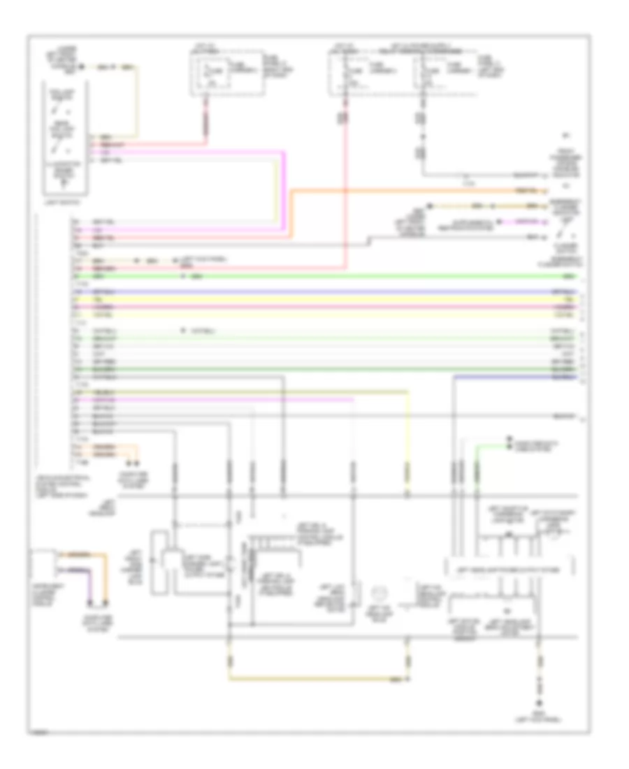
EXTERIOR LIGHTS
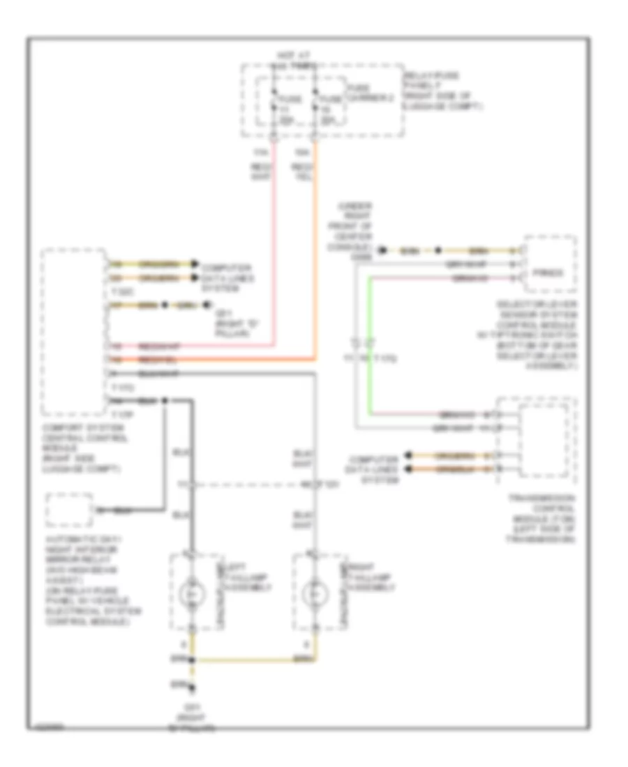
Backup Lamps Wiring Diagram for Audi Q5 Prestige 2014
List of elements for Backup Lamps Wiring Diagram for Audi Q5 Prestige 2014:
- (under right front of center console) g688
- 10a
- 11a
- Automatic day/ night interior mirror relay (w/o high beam assist) (on relay/fuse panel w/ vehicle electrical system control module)
- Backup lamp
- Comfort system central control module (right side luggage compt)
- Computer data lines system
- Fuse 20a
- Fuse 30a
- Fuse carrier 2
- G51 (right "d" pillar)
- Hot at all times
- Left taillamp assembly
- Prnds
- Relay/fuse panel f (right side of luggage compt)
- Right taillamp assembly
- Selector lever sensor system control module w/ tiptronic switch (bottom of gear selector lever assembly)
- T12v
- T17o
- T17p
- T17q
- T32c
- Transmission control module (tcm) (left side of transmission)
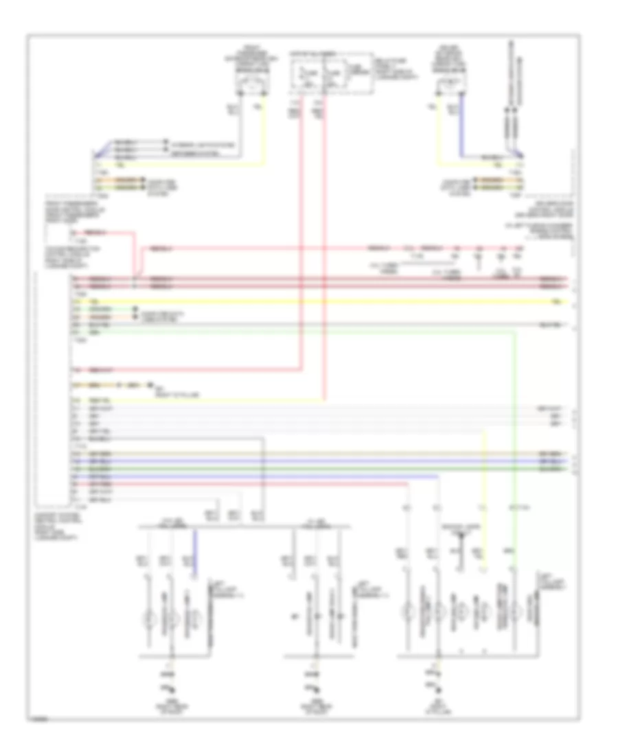
Exterior Lamps Wiring Diagram (1 of 4) for Audi Q5 Prestige 2014
List of elements for Exterior Lamps Wiring Diagram (1 of 4) for Audi Q5 Prestige 2014:
- (in left plenum chamber) engine control module (ecm)
- 10a
- 11a
- 2.0l turbo
- 2.0l turbo hybrid
- 3.0l sc
- 3.0l turbo diesel
- Backup lamp
- Backup lamps circuit
- Brake lamp bulb 2
- Brake/tail lamp
- Brake/tail lamp 2
- Brake/turn signal/
- Comfort system central control module (right side luggage compt)
- Computer data lines system
- Defogger system
- Driver exterior rearview mirror turn signal bulb
- Driver's door control module (driver's front door)
- Front passenger exterior rearview mirror turn signal bulb
- Front passenger's door control module (front passenger's front door)
- Fuse 20a
- Fuse 30a
- Fuse carrier
- G51 (right "d" pillar)
- G666 (right rear of roof)
- Hot at all times
- Interior lights system
- Left taillamp assembly
- Left taillamp assembly 2
- Marker lamp
- Rear fog lamp
- Rear side
- Rear turn signal lamp
- Relay/fuse panel f (right side of luggage compt)
- Signal/tail lamp brake lamp/turn
- T12d
- T12v
- T16m
- T16n
- T17o
- T17p
- T17r
- T20f
- T20g
- T32c
- T32d
- T91
- T94
- Tail lamp 2
- Towing recognition control module (right side of luggage compt)
- W/ led tail lamps
- W/o led tail lamps
Exterior Lamps Wiring Diagram (2 of 4) for Audi Q5 Prestige 2014
List of elements for Exterior Lamps Wiring Diagram (2 of 4) for Audi Q5 Prestige 2014:
- (integral to brake pedal switch) brake light switch
- (top of brake pedal assembly) brake pedal position sensor
- 12a
- 2.0l turbo
- 2.0l turbo hybrid
- 3.0l sc
- 3.0l turbo diesel
- Backup lamp
- Backup lamps circuit
- Brake/tail lamp
- Brake/turn signal/tail lamp 2
- Break lamp
- Climatronic control module
- Computer data lines system
- Except 2.0l turbo
- Fuse 5a
- Fuse carrier
- Fuse panel c (left end of dash)
- Fuse panel d (right end of dash)
- G51 (right "d" pillar)
- G666 (right rear of roof)
- G687 (under left front of center console)
- Hot at all times
- Lamp 2 brake/tail
- Marker lamp rear side
- Nca
- Rear fog lamp
- Right taillamp assembly
- Right taillamp assembly 2
- Signal lamp rear turn
- Signal/tail lamp brake/turn
- Steering column electronic systems control module (on steering column)
- T12v
- T17e
- Turn signal switch
- W/ led tail lamps
- W/o led tail lamps
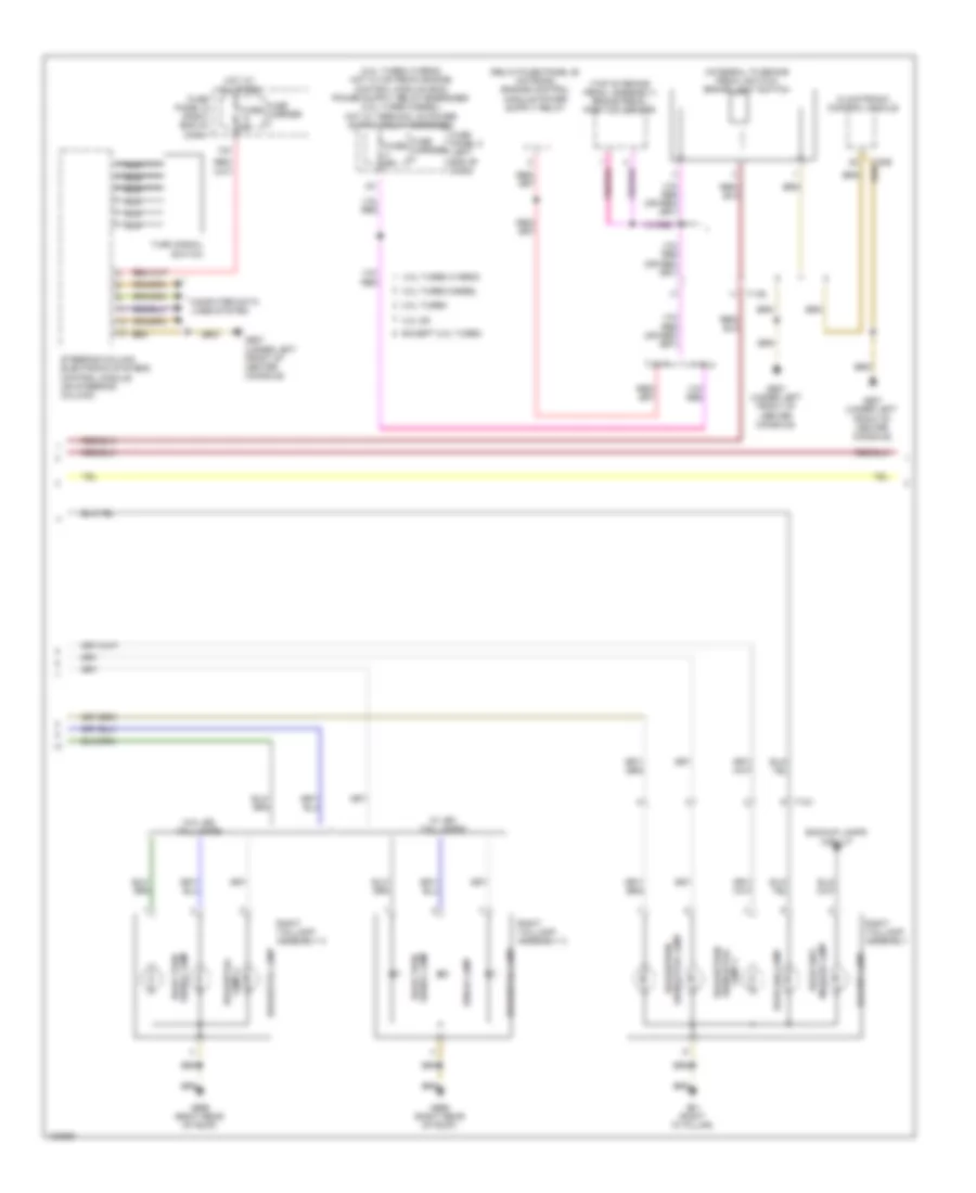
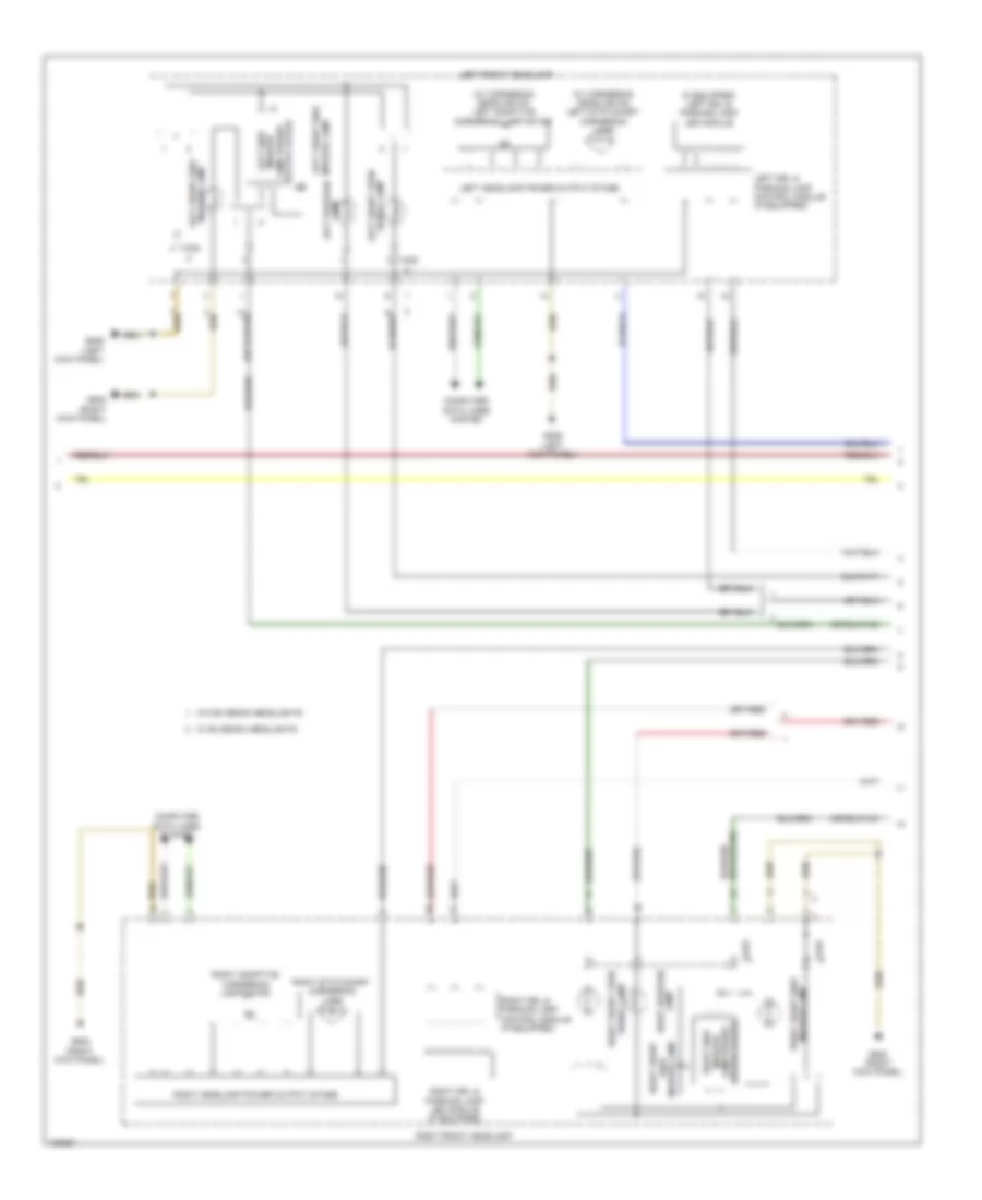
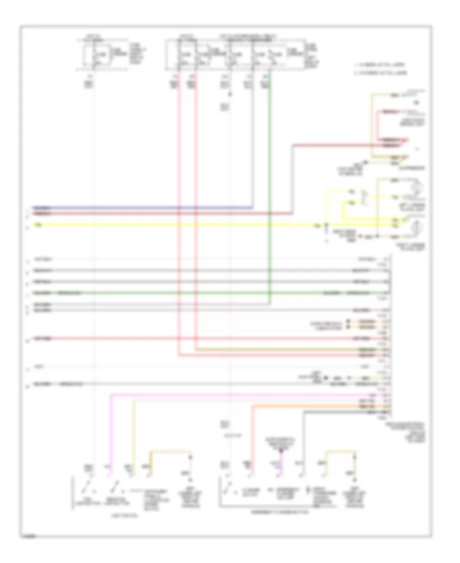
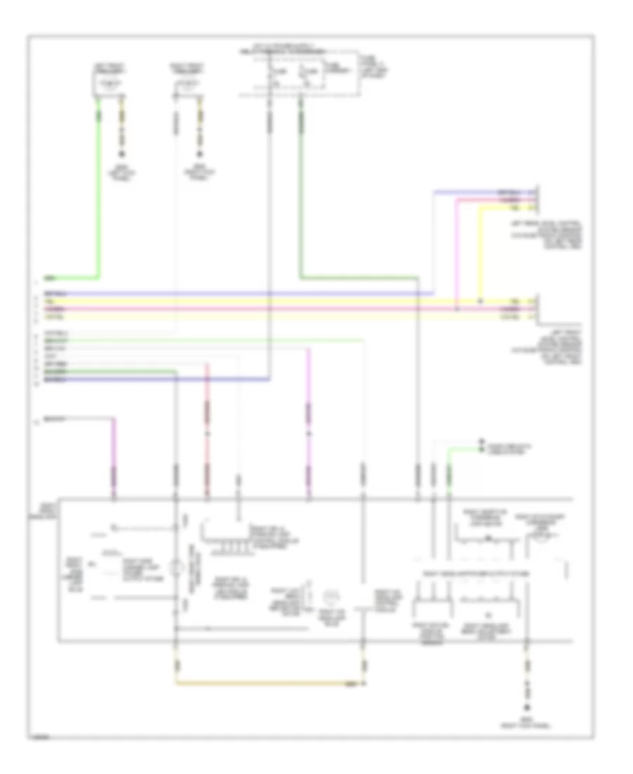
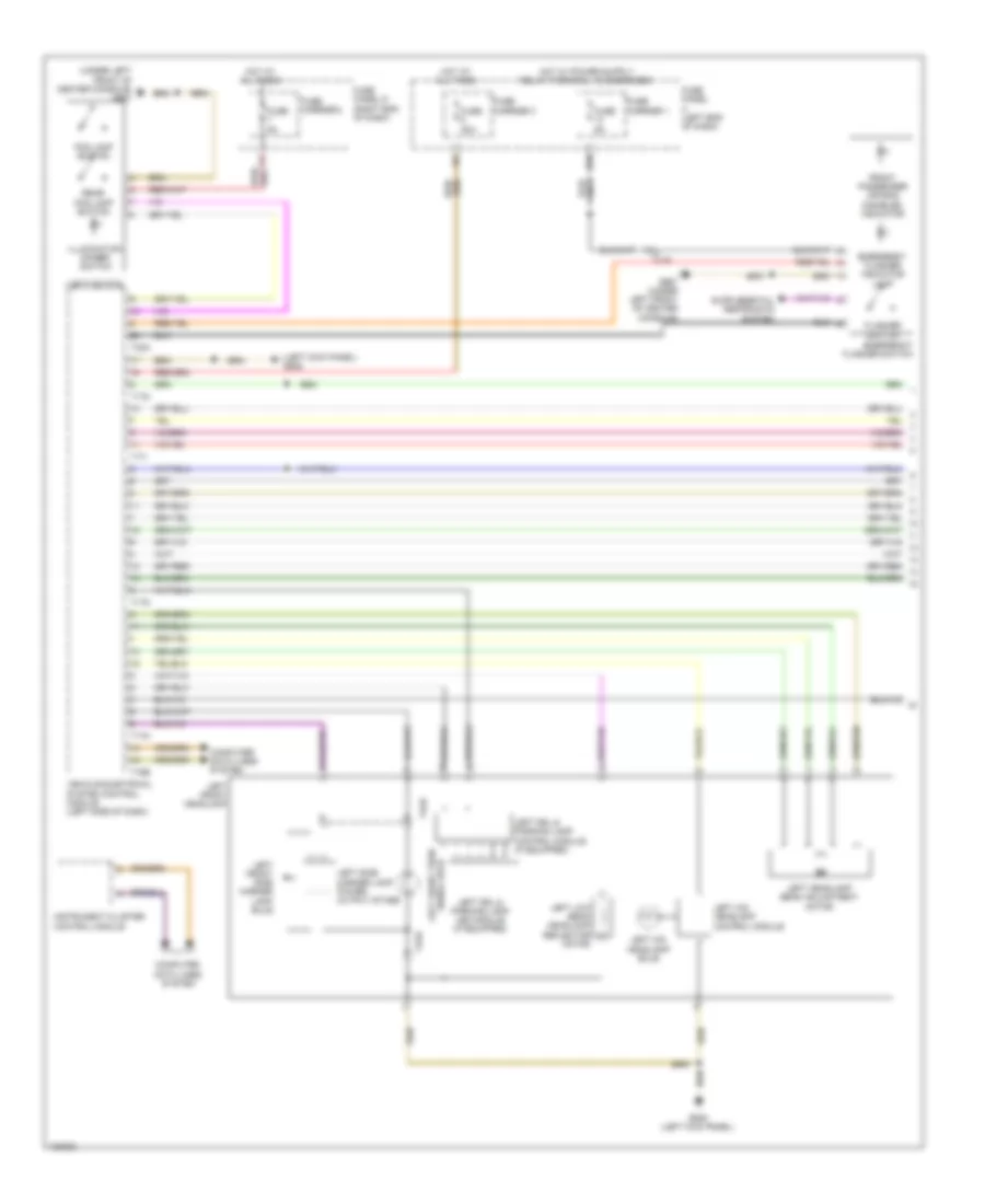
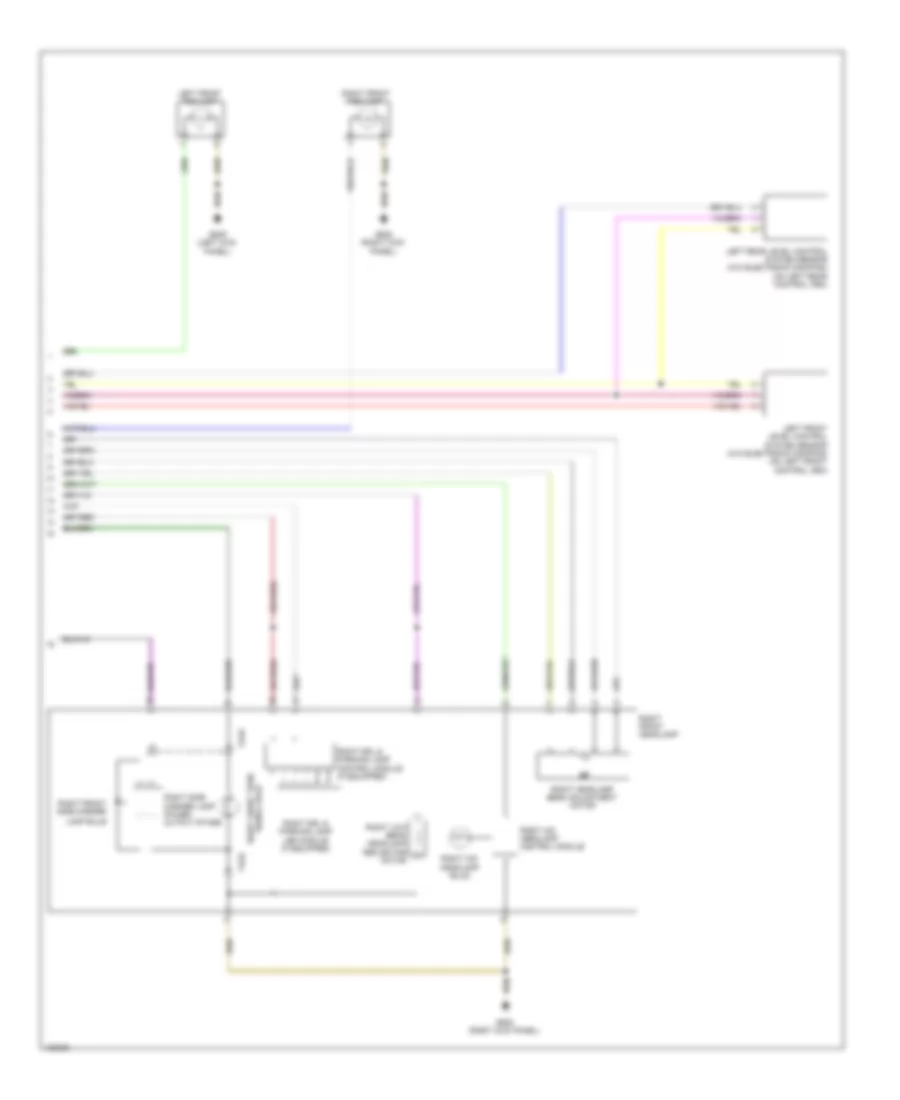
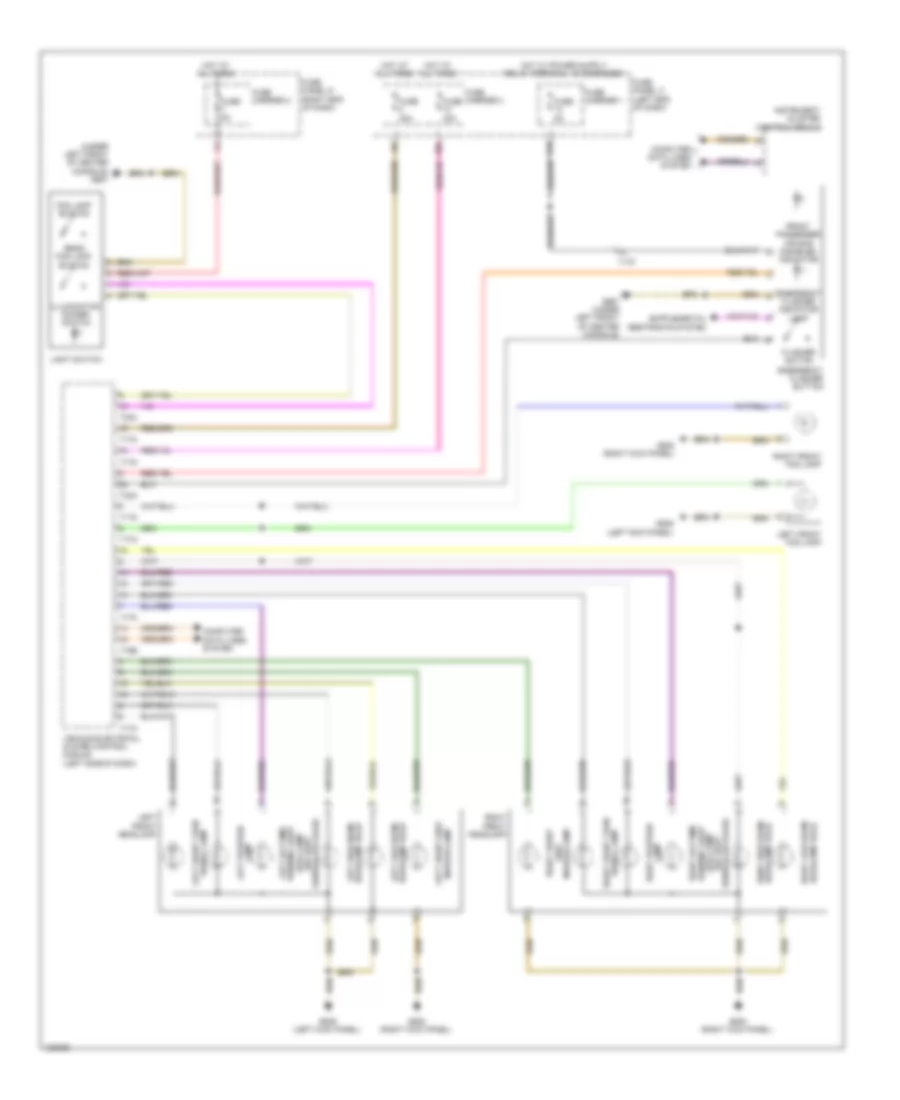
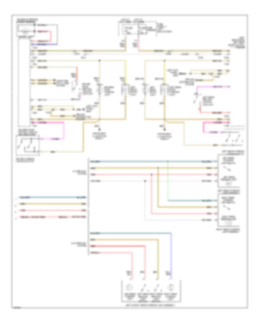
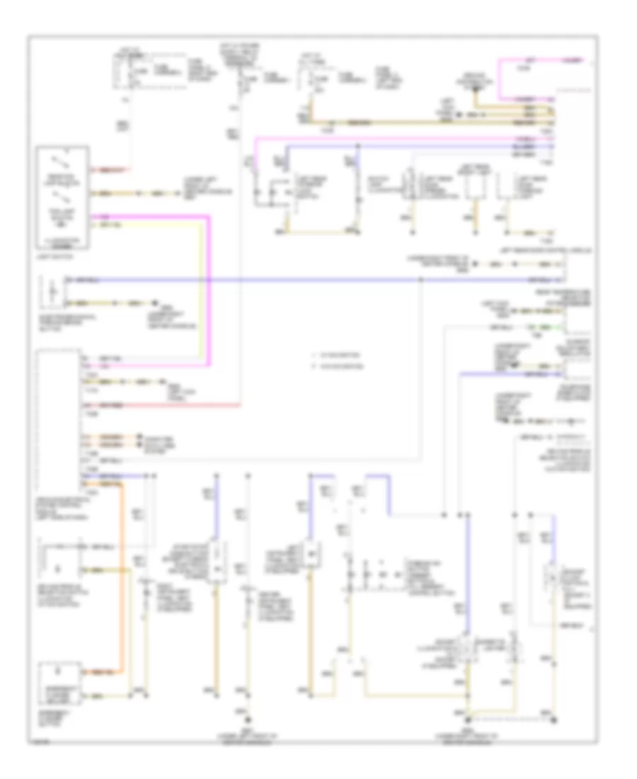
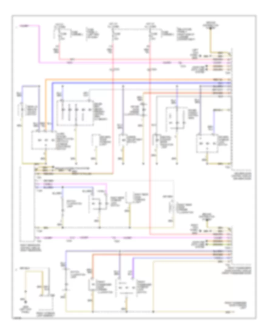
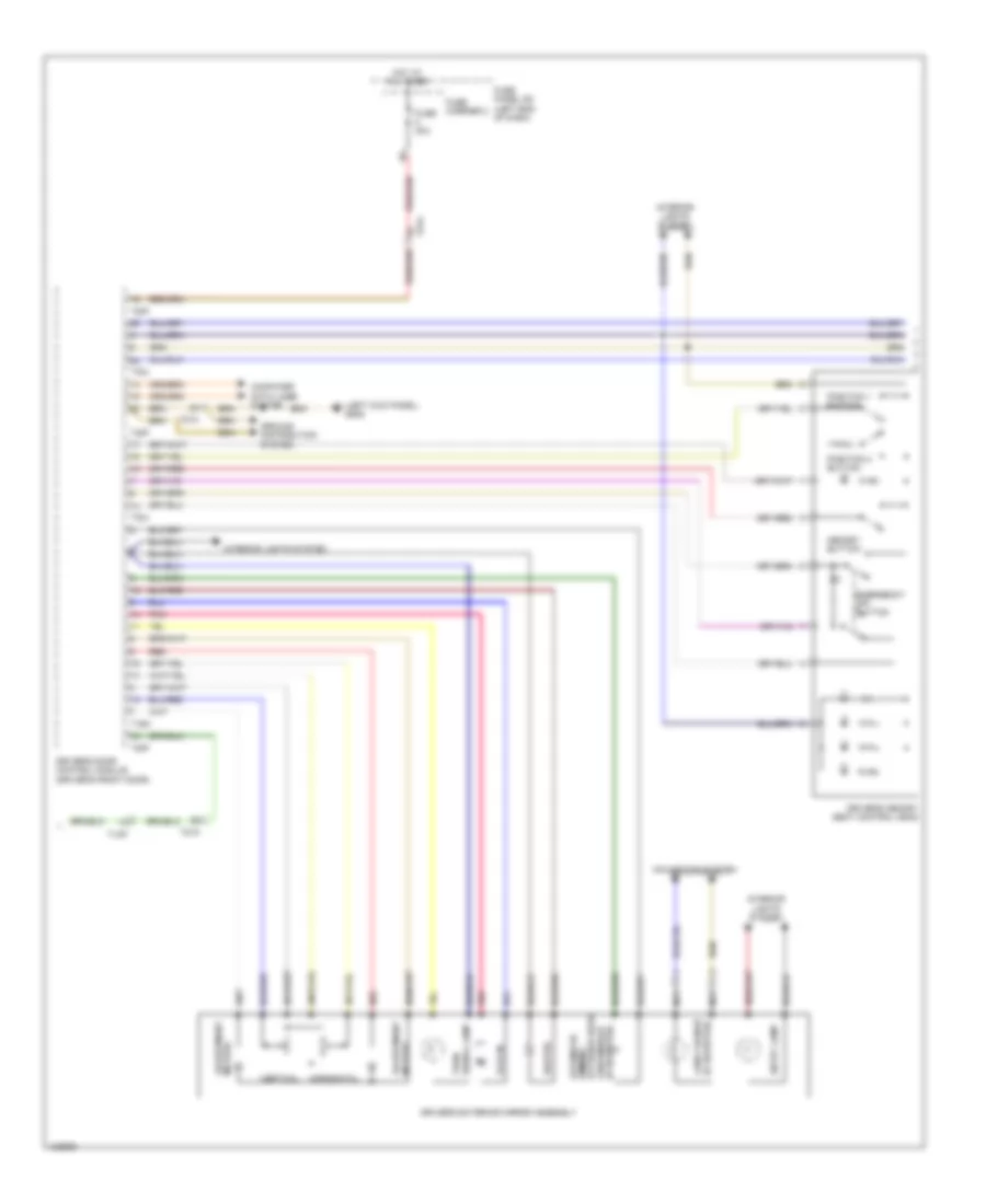
Exterior Lamps Wiring Diagram (3 of 4) for Audi Q5 Prestige 2014
List of elements for Exterior Lamps Wiring Diagram (3 of 4) for Audi Q5 Prestige 2014:
- (if equipped) left drl & parking lamp led module
- (w/ cornering headlights) left adaptive cornering lamp motor
- (w/ cornering headlights) left stationary cornering lamp
- Computer data lines system
- G638 (right kick panel)
- G639 (left kick panel)
- Lamp power output stage
- Lamp right position
- Left drl & parking lamp control module (if equipped)
- Left front headlamp
- Left front side marker lamp
- Left front turn signal lamp
- Left headlamp power output stage
- Left position lamp
- Left side marker
- Marker lamp side
- Output stage lamp power marker right side
- Right adaptive cornering lamp motor
- Right drl & parking lamp control module (if equipped)
- Right drl & parking lamp led module (if equipped)
- Right front
- Right front headlamp
- Right front side marker lamp
- Right headlamp power output stage
- Right stationary cornering lamp
- Signal lamp right front turn
- T4ad
- T4ae
- W/ bi-xenon headlights
- W/o bi-xenon headlights
Exterior Lamps Wiring Diagram (4 of 4) for Audi Q5 Prestige 2014
List of elements for Exterior Lamps Wiring Diagram (4 of 4) for Audi Q5 Prestige 2014:
- (left kick panel) g639
- (right rear of roof) g666
- 13a
- Computer data lines system
- Emergency flasher button
- Emergency flasher ind lamp
- Flasher switch
- Fog lamp button
- Front passenger air bag disabled ind
- Fuse 20a
- Fuse 35a
- Fuse 5a
- Fuse carrier
- Fuse panel c (left end of dash)
- Fuse panel d (right end of dash)
- G612 (top center of rear lid)
- G687 (under left front of center console)
- High mount brake light
- Hot at all times
- Instrument panel & illumination dimmer switch
- Left license plate light
- Light switch
- Rear fog lamp button
- Right license plate light
- Suppressor
- T16b
- T17f
- T17l
- T17m
- T17n
- T32a
- Vehicle electrical system control module (left side of dash)
- W/ rear lid tail lamps
- W/o rear lid tail lamps
Trailer Tow Wiring Diagram for Audi Q5 Prestige 2014
List of elements for Trailer Tow Wiring Diagram for Audi Q5 Prestige 2014:
- (in left plenum chamber) engine control module (ecm)
- (right side of luggage compt) comfort system control module
- 2.0l turbo
- 2.0l turbo hybrid
- 3.0l sc
- 3.0l turbo diesel
- Brake light switch (integral to brake pedal switch)
- Brake pedal position sensor (top of brake pedal assembly)
- Climatronic control module
- Computer data lines system
- Except 2.0l turbo
- Fuse 15a
- Fuse 20a
- Fuse 5a
- Fuse carrier
- Fuse panel c (left end of dash)
- G51 (right "d" pillar)
- G687 (under left front of center console)
- Hot at all times
- Lock bolt contact switch
- Red
- Red)
- Relay/fuse panel f (right side of luggage compt)
- T12d
- T12z
- T16d
- T17e
- T17k
- T17r
- T20e
- T32d
- T91
- T94
- Towing recognition control module (right side of luggage compt)
- Trailer hitch locked & unlocked indicator lamp
- Trailer socket
GROUND DISTRIBUTION
Ground Distribution Wiring Diagram (1 of 3) for Audi Q5 Prestige 2014
List of elements for Ground Distribution Wiring Diagram (1 of 3) for Audi Q5 Prestige 2014:
- (2.0l turbo) g18 (2.0l turbo hybrid) g15
- All wheel drive control module & voltage stabilizer (w/ start/ stop system)
- Antenna amplifier shield
- Battery regulation control module (hybrid), hybrid battery recirculation door positioning motors 1 & 2 (hybrid)
- Digital sound system control module & radio
- Double connector
- Driver side rear thorax air bag igniter, wire junction (hybrid) left rear footwell light (if equipped), left luggage compartment lamp, rear lid closed sensors 1 & 2, rearview camera system control module, radio frequency controlled clock receiver & nox sensor control module 2 (3.0l turbo diesel) &
- Exhaust door control unit (3.0l sc) (if equipped) & exhaust door control unit 2 (3.0l sc) (if equipped)
- Front passenger backrest heating element (w/ ventilation), front passenger's seat bolster heater (w/ ventilation) & right front seat ventilation control module
- Front passenger seat lumbar support adjustment switch, front passenger's power seat switch assembly
- Fuel delivery unit (2.0l turbo)
- Fuel delivery unit (3.0l sc & 3.0l diesel), right rear seat heating, pasenger side rear thorax air bag igniter, front passenger thorax air bag igniter, front passenger seat bolster heater (w/o ventilation), left rear seat heating, fuel pump (fp) control module & front passenger backrest heating elment (w/o ventilation)
- G12 (left rear of engine compt)
- G50 (left "d" pillar)
- G51 (right "d" pillar)
- G601 (3.0l sc)
- G663 (right "c" pillar)
- Generator/ voltage regulator
- Ignition coils 1, 2 & 3 (w/ power output stage) (3.0l sc), & secondary air injection pump motor (3.0l sc)
- Ignition coils 1, 2, 3 & 4 (w/ power output stage)
- Ignition coils 4, 5 & 6 (w/ power output stage)
- Ignition coils 4, 5 & 6 w/ power output stage (3.0l sc)
- Lane change assistance control module, lane change assistance control module 2, electro-mechanical parking brake control module battery fan 1 (hybrid), rear window defogger relay, electronic damping control module, towing recognition control module, trailer socket & vehicle positioning system interface control module
- Left taillamp assembly & right taillamp assembly
- Low temperature circuit coolant pump (hybrid), after run coolant pump (hybrid), ignition coils 1, 2, 3 & 4 (w/ power output stage) (2.0l turbo)
- Nca
- Oil level thermal sensor, after run coolant pump (3.0l sc) (if equipped), coolant recirculation pump (3.0l sc), charge air cooling pump (3.0l sc), ignition coils 1, 2, 3 & 4 (w/ power output stage) (hybrid), reduced oil pressure switch (3.0l turbo diesel), oil pressure switch (3.0l turbo diesel), nox sensor control module (3.0l turbo diesel) & automatic glow time control module (3.0l turbo diesel)
- Rear lid closing assist lock stop switch, fan activation relay (hybrid), seat heating control module, sockets relay, comfort system central control module & rear lid closing assist/unlock stop switch
- Reducing agent metering system relay (3.ol turbo diesel) (if equipped)
- Right luggage compartment light & 12v socket 3 (if equipped)
- Right rear door control module
- Right rear door control module & right rear exterior door handle touch sensor
- Right rear footwell lamp (if equipped)
- T10m
- T12v
- T14l
- T16k
- T17q
- T27d
- Transmission fluid auxiliary hydraulic pump 1 (hybrid), secondary air injection pump motor (hybrid), engine control module (ecm) & suppressor
- Transmission hydraulic pump relay (hybrid), coolant recirculation pump (hybrid & 2.0l turbo), after run coolent pump (2.0l turbo), exhaust door control unit (hybrid), oil level thermal sensor (hybrid & 2.0l turbo), a/c compressor control module (hybrid) & high temperature circuit coolent pump (hybrid)
Ground Distribution Wiring Diagram (2 of 3) for Audi Q5 Prestige 2014
List of elements for Ground Distribution Wiring Diagram (2 of 3) for Audi Q5 Prestige 2014:
- Active steering control module
- Battery monitoring control module
- Double connector, brake booster vacuum pump (hybrid), engine hood contact switch, driver thorax air bag igniter, driver's seat lumbar support adjustment switch (w/o power seat), high tone horn, esp sensor unit 2 (if equipped), left front fog lamp, headlamp washer pump (if equipped), left front headlamp, a/c pressure/temperature sensor, horn relay, driver seat backrest heating element (w/o memory & w/o ventilation) & driver seat bolster heater (w/o memory & w/o ventilation)
- Driver door control module
- Driver's backrest heating element (w/ memory) & driver's seat bolster heater (w/ memory)
- Dvd & cd changer, radio, front information display control head, access/start authorization switch, instrument cluster control module, steering column electronic control module, electronic steering column lock control module, center instrument panel vent illumination bulb, light switch, left front footwell illumination bulb climatronic control module, brake lamp switch & data link connector (dlc)
- Electric drive button (hybrid), parking aid button (w/ front/rear parking aid) external audio source connection (w/ audio music interface connection), emergency flasher switch, left instrument panel, vent illumination (if equipped), right instrument panel vent illumination (if equipped), driving profile selection switch module (w/ navigation), data bus on board diagnostic interface, start/stop mode button (except hybrid), auxiliary air heater control module (hybrid), fresh air blower control module, asr/esp button (w/ navigation), hill descent control button (w/ navigation) & front passenger air bag igniter 1/ front passenger air bag igniter 2
- Esp sensor unit (if equipped), structure born sound control module, automatic dimming interior rearview mirror relay (w/ start/ stop system), vehicle electrical system control module, wiper motor control module, alarm horn, left front brake pad wear sensor, left washer nozzle heater (if equipped), hybrid battery refrigerant shut-off valve 1 (hybrid), right washer nozzle heater (if equipped), air quality sensor, garage door opener control module & humidity sensor (hybrid)
- External audio source connection shield
- Front information display control head
- G639 (left kick panel)
- G676 (left rear of luggage compt)
- G687 (under left front of center console)
- Glove compartment lamp switch
- Glove compartment lamp switch & right front footwell illumination bulb
- Interior rearview mirror, front interior lamp assembly, rain/light recognition sensor, driver vanity mirror lamp contact switch, front passenger vanity mirror lamp contact switch, anti-theft alarm system sensor, directional stabilization assistance control module, directional stabilization assistance windshield defogger & garage door opener control head
- Lane change assistance button, left front exterior door handle touch sensor & driver door control module
- Left front seat ventilation control module, driver backrest heating element (w/o memory & w/ ventilation)
- Left rear door control module
- Left rear door control module & left rear exterior door handle touch sensor (if equipped)
- Memory seat/steering column adjustment control module, driver's seat lumbar support adjustment switch (w/ power seat) & driver's power seat switch assembly
- Nca
- Sunroof adjustment regulator, power sunroof control module & roof shade control module
- T10p
- T12k
- T17e
- T1a
- T27a
- T27b
- T6e
- T6l
- T8z
Ground Distribution Wiring Diagram (3 of 3) for Audi Q5 Prestige 2014
List of elements for Ground Distribution Wiring Diagram (3 of 3) for Audi Q5 Prestige 2014:
- (or nca)
- Abs control module
- Antenna amplifier 3 shield (if equipped)
- Auxiliary heater heating element (3.0l turbo diesel, 2.0l turbo & hybrid)
- Battery monitoring control module
- Coolant fan control module & coolant fan control module 2
- Coolant recirculation pump, distance regulation control module (w/ adaptive cruise control), low tone horn, left front headlamp, right front fog lamp, right front headlamp & tire pressure monitoring control module
- Electric drive power & control electronics
- Electro mechanical power steering motor shield
- External audio source connection (w/ aux)
- Front passenger's door control module
- G53 (right side of rear lid)
- G600 (3.0l sc)
- G602 (left side of driver's footwell)
- G609 (hybrid) (in right plenum chamber)
- G612 (top center of rear lid)
- G62
- G624 (in luggage compt near starter battery)
- G638 (right kick panel)
- G653 (top of left "d" pillar)
- G654 (right "d" pillar)
- G666 (right rear of roof)
- G671 (on lower left front long member)
- G672 (on lower left front long member)
- G675 (hybrid) (in luggage compt near starter battery)
- G685 (on right front long member)
- G688 (under right front of center console)
- High mount brake light & suppressor
- Hill descent control button (w/o navigation), start/stop mode button (w/o navigation), right rear seat heating button, left rear seat heating button, cupholder w/ heating & cooling element, parking aid button (w/ front/rear parking aid), electro-mechanical parking brake button, access/start authorization button, driving profile selection switch module (w/o navigation), selector lever sensor system control module, transmission park selector switch, rear temperature selection potentiometer, 12 v socket (if equipped), 12 v socket 2 (if equipped) & asr/esp button (w/o navigation)
- Hybrid battery unit
- Ignition coils 1, 2 & 3 (w/ power output stage)
- Nca
- Power steering control module
- Rear lid control module & rear lid control module 2
- Rear lid lock button, rear window wiper motor, left taillamp assembly 2, right taillamp assembly 2, rear lid ambient lamp 1, rear lid lock/ alarm/central locking switch, rear window defogger (w/ window antenna), rear lid central locking system motor, rear lid lock cylinder unlock button, left license plate light & right license plate light
- Rear window defogger (w/ window antenna)
- Reducing agent metering system control module (3.0l turbo diesel) (if equipped), cigarette lighter illumination, telephone base plate, cigarette lighter & telephone transceiver
- Right front exterior door handle touch sensor (if equipped) & front passenger's door control module
- Roof antenna shield
- T20m
- T4av
- Windshield antenna suppression filter
HEADLIGHTS
Headlights Wiring Diagram, with Bi-Xenon with Cornering Headlights (1 of 2) for Audi Q5 Prestige 2014
List of elements for Headlights Wiring Diagram, with Bi-Xenon with Cornering Headlights (1 of 2) for Audi Q5 Prestige 2014:
- (left kick panel) g639
- (under left front of center console) g687
- 13a
- Computer data lines system
- Emergency flasher indicator lamp
- Emergency flasher switch
- Flasher switch
- Fog lamp button
- Front passenger air bag disabled indicator
- Fuse 30a
- Fuse 5a
- Fuse carrier 1
- Fuse carrier 2
- Fuse carrier 3
- Fuse panel c (left end of dash)
- Fuse panel d (right end of dash)
- G639 (left kick panel)
- G687 (under left front of center console)
- Hot at all times
- Illumination dimmer switch
- Instrument cluster control module
- Left adaptive cornering lamp motor
- Left drl & parking lamp control module (if equipped)
- Left drl & parking lamp led module (if equipped)
- Left front headlamp
- Left front side marker lamp bulb
- Left headlamp beam adjustment motor
- Left headlamp power output stage
- Left hid headlamp bulb
- Left hid headlamp control module
- Left low beam headlamp reflector motor
- Left side marker lamp power output stage
- Left stationary cornering lamp
- Left swivel module position sensor
- Light switch
- Rear fog lamp button
- Signal bulb left front turn
- T16b
- T17f
- T17i
- T17m
- T17n
- T32a
- T4ad
- Vehicle electrical system control module (left side of dash)
Headlights Wiring Diagram, with Bi-Xenon with Cornering Headlights (2 of 2) for Audi Q5 Prestige 2014
List of elements for Headlights Wiring Diagram, with Bi-Xenon with Cornering Headlights (2 of 2) for Audi Q5 Prestige 2014:
- Computer data lines system
- Fuse 5a
- Fuse carrier 1
- Fuse panel c (left end of dash)
- G638 (right kick panel)
- G639 (left kick panel)
- Left front fog lamp
- Left front level control system sensor (w/o electronic damping) (on left front control arm)
- Left rear level control system sensor (w/o electronic damping) (on left rear control arm)
- Right adaptive cornering lamp motor
- Right drl & parking lamp control module (if equipped)
- Right drl & parking lamp led module (if equipped)
- Right front fog lamp
- Right front headlamp
- Right front side marker lamp bulb
- Right headlamp beam adjustment motor
- Right headlamp power output stage
- Right hid headlamp bulb
- Right hid headlamp control module
- Right low beam headlamp reflector motor
- Right side marker lamp power output stage
- Right stationary cornering lamp
- Right swivel module position sensor
- Signal bulb right front turn
- T4ae
Headlights Wiring Diagram, with Bi-Xenon without Cornering Headlights (1 of 2) for Audi Q5 Prestige 2014
List of elements for Headlights Wiring Diagram, with Bi-Xenon without Cornering Headlights (1 of 2) for Audi Q5 Prestige 2014:
- (left kick panel) g639
- (under left front of center console) g687
- 13a
- Computer data lines system
- Emergency flasher indicator lamp
- Emergency flasher switch
- Flasher switch
- Fog lamp button
- Front passenger air bag disabled indicator
- Fuse 30a
- Fuse 5a
- Fuse carrier 1
- Fuse carrier 2
- Fuse carrier 3
- Fuse panel c (left end of dash)
- Fuse panel d (right end of dash)
- G639 (left kick panel)
- G687 (under left front of center console)
- Hot at all times
- Illumination dimmer switch
- Instrument cluster control module
- Left drl & parking lamp control module (if equipped)
- Left drl & parking lamp led module (if equipped)
- Left front headlamp
- Left front side marker lamp bulb
- Left headlamp beam adjustment motor
- Left hid headlamp bulb
- Left hid headlamp control module
- Left low beam headlamp reflector motor
- Left side marker lamp power output stage
- Light switch
- Rear fog lamp button
- Signal bulb left front turn
- T16b
- T17f
- T17i
- T17m
- T17n
- T32a
- T4ad
- Vehicle electrical system control module (left side of dash)
Headlights Wiring Diagram, with Bi-Xenon without Cornering Headlights (2 of 2) for Audi Q5 Prestige 2014
List of elements for Headlights Wiring Diagram, with Bi-Xenon without Cornering Headlights (2 of 2) for Audi Q5 Prestige 2014:
- G638 (right kick panel)
- G639 (left kick panel)
- Lamp bulb
- Left front fog lamp
- Left front level control system sensor (w/o electronic damping) (on left front control arm)
- Left rear level control system sensor (w/o electronic damping) (on left rear control arm)
- Right drl & parking lamp control module (if equipped)
- Right drl & parking lamp led module (if equipped)
- Right front fog lamp
- Right front headlamp
- Right front side marker
- Right headlamp beam adjustment motor
- Right hid headlamp bulb
- Right hid headlamp control module
- Right low beam headlamp reflector motor
- Right side marker lamp power output stage
- Signal bulb right front turn
- T4ae
Headlights Wiring Diagram, without Bi-Xenon Headlights for Audi Q5 Prestige 2014
List of elements for Headlights Wiring Diagram, without Bi-Xenon Headlights for Audi Q5 Prestige 2014:
- (under left front of center console) g687
- 10a
- 13a
- Computer data lines system
- Emergency flasher button
- Emergency flasher indicator lamp
- Flasher switch
- Fog lamp button
- Front passenger air bag disabled indicator
- Fuse 30a
- Fuse 5a
- Fuse carrier 1
- Fuse carrier 2
- Fuse carrier 3
- Fuse panel c (left end of dash)
- Fuse panel d (right end of dash)
- G638 (right kick panel)
- G639 (left kick panel)
- G687 (under left front of center console)
- Headlamp bulb left high beam
- Headlamp bulb left low beam
- Headlamp bulb right high beam
- Headlamp bulb right low beam
- Hot at all times
- Illumination dimmer switch
- Instrument cluster control module
- Lamp left position
- Lamp right position
- Left front fog lamp
- Left front headlamp
- Light switch
- Marker lamp left front side
- Marker lamp side
- Rear fog lamp button
- Right front
- Right front fog lamp
- Right front headlamp
- Sensor package) (w/ light (drl) lamp running light left daytime
- Sensor package) (w/ light (drl) lamp running light right daytime
- Signal lamp left front turn
- Signal lamp right front turn
- T16b
- T17f
- T17m
- T17n
- T32a
- Vehicle electrical system control module (left side of dash)
HORN
Horn Wiring Diagram for Audi Q5 Prestige 2014
List of elements for Horn Wiring Diagram for Audi Q5 Prestige 2014:
- Activation
- Air bag spiral spring/ return spring w/ slip ring (top of steering column)
- Computer data lines system
- Fuse 15a
- Fuse carrier
- Fuse panel c (left end of dash)
- G638 (right kick panel)
- G639 (left kick panel)
- High tone horn (behind left side of front bumper)
- Horn relay (relay/fuse panel w/ vehicle electrical system control module)
- Horn signal
- Hot at all times
- Low tone horn (behind right side of front bumper)
- Nca
- Steering column electronic systems control module (on steering column)
- Steering wheel control unit
- T16b
- T16f
- T32b
- Vehicle electrical system control module (left side of dash)
INSTRUMENT CLUSTER
Instrument Cluster Wiring Diagram for Audi Q5 Prestige 2014
List of elements for Instrument Cluster Wiring Diagram for Audi Q5 Prestige 2014:
- (under left front of center console) g687
- 2.0l turbo
- 2.0l turbo hybrid
- 3.0l sc
- 3.0l turbo diesel
- Abs indicator lamp
- Air bag indicator lamp
- Asr/ esp indicator lamp
- Brake fluid level warning switch (in master cylinder reservoir)
- Computer data lines system
- Engine control module (3.0l turbo diesel: left rear of engine) (except 3.0l turbo diesel: in left plenum chamber)
- Fuel delivery unit (top of fuel tank)
- Fuel level sensor
- Fuse 5a
- Fuse carrier 2
- Fuse panel d (right end of dash)
- G12 (left rear of engine compt)
- G50 (left "d" pillar)
- Hot at all times
- Instrument cluster control module
- Oil pressure switch (2.0l turbo: front of engine)
- Oil pressure switch (front of right cylinder bank)
- Oil pressure switch (top rear of engine)
- Radio frequency controlled clock receiver
- Speedometer
- T105
- T16b
- T17c
- T17g
- T32b
- T91
- T94
- Tachometer
- Vehicle electrical system control module (left side of dash)
INTERIOR LIGHTS
Courtesy Lamps Wiring Diagram (1 of 3) for Audi Q5 Prestige 2014
List of elements for Courtesy Lamps Wiring Diagram (1 of 3) for Audi Q5 Prestige 2014:
- (right side of luggage compartment) comfort system central control module
- (under right front of center console) (w/o navigation) g688
- 10a
- 12a
- Ambient lamp
- Computer data lines system
- Driver vanity mirror lamp contact switch
- Driving profile selection switch module
- Front passenger's vanity mirror lamp contact switch
- Fuse 30a
- Fuse 5a
- Fuse carrier
- Fuse panel c (left end of dash)
- G50 (left "d" pillar)
- G51 (right "d" pillar)
- G639 (left kick panel)
- G666 (right rear of roof)
- G687 (under left front of center console)
- G687 (w/ navigation) (under left front of center console)
- Glove compartment lamp switch
- Glove compartment light
- Hot at all times
- Instrument illumination circuit
- Left front footwell light
- Left luggage compartment lamp
- Left rear footwell light
- Left vanity mirror lighting
- Rear lid lock button
- Relay/fuse panel f (right side of luggage compt)
- Right front footwell light
- Right luggage compartment lamp
- Right rear footwell light
- Right vanity mirror lighting
- T10m
- T10p
- T12k
- T16b
- T17c
- T17d
- T17l
- T17m
- T17o
- T17p
- T32a
- T32b
- T32c
- Vehicle electrical system control module (left side of dash)
- W/o navigation
Courtesy Lamps Wiring Diagram (2 of 3) for Audi Q5 Prestige 2014
List of elements for Courtesy Lamps Wiring Diagram (2 of 3) for Audi Q5 Prestige 2014:
- (right "c" pillar) g663
- (right kick panel) g638
- (right rear door) right rear door control module
- 11a
- Automatic dimming interior rearview mirror
- Computer data lines system
- Driver reading lamp
- Driver reading light button
- Entry lamp
- Front interior lamp
- Front interior lamp assembly
- Front passenger door central locking lock unit
- Front passenger door warning light
- Front passenger interior locking switch
- Front passenger reading lamp
- Front passenger reading lamp button
- Front passenger's door control module (front passenger door)
- Front passenger's exterior mirror assembly
- Fuse 30a
- Fuse carrier
- Fuse panel f (right side of luggage compt)
- G639 (left kick panel)
- Ground distribution system
- Hot at all times
- Instrument illumination circuit
- Interior lighting switch
- Red
- Right front entry light
- Right rear central locking lock unit
- Right rear door warning light
- Right rear entry light
- Right rear interior locking switch
- T16n
- T16p
- T20g
- T20i
- T20m
- T27d
- T32l
- T4ar
- T8b
Courtesy Lamps Wiring Diagram (3 of 3) for Audi Q5 Prestige 2014
List of elements for Courtesy Lamps Wiring Diagram (3 of 3) for Audi Q5 Prestige 2014:
- (left kick panel) g639
- (left rear door) left rear door control module
- 11a
- Computer data lines system
- Driver door central locking lock unit
- Driver exterior's mirror assembly
- Driver interior locking switch
- Driver's door control module (driver's door)
- Driver's door warning light
- Entry lamp
- Fuse 30a
- Fuse carrier
- Fuse panel c (left end of dash)
- Ground distribution system
- Hot at all times
- Instrument illumination circuit
- Left & right rear interior lamp assembly
- Left front entry light
- Left rear central locking lock unit
- Left rear door warning light
- Left rear entry light
- Left rear interior lamp assembly
- Left rear interior lamp switch
- Left rear interior light
- Left rear interior locking switch
- Left rear reading lamp
- Left rear reading light switch
- Red
- Right rear interior lamp assembly
- Right rear interior lamp switch
- Right rear interior light
- Right rear reading lamp
- Right rear reading light switch
- T16m
- T16o
- T20f
- T20h
- T27a
- T27b
- T32j
- W/ open sky system
- W/o open sky system
Instrument Illumination Wiring Diagram (1 of 2) for Audi Q5 Prestige 2014
List of elements for Instrument Illumination Wiring Diagram (1 of 2) for Audi Q5 Prestige 2014:
- (left kick panel)
- (left kick panel) g639
- (under left front of center console) g687
- (under right front of center console)
- (under right front of center console) g688
- 11a
- 12a
- Button
- Center instrument panel vent illumination (if equipped)
- Cigarette lighter
- Computer data lines system
- Driving profile selection switch illumination (w/ navigation)
- Driving profile selection switch illumination (w/o navigation)
- Electromechanical parking brake
- Emergency flasher button
- Emergency flasher ind lamp
- Fog lamp button
- Fuse 30a
- Fuse 5a
- Fuse carrier 1
- Fuse carrier 2
- Fuse panel c (left end of dash)
- Fuse panel d (right end of dash)
- G639
- G639 (left kick panel)
- G687 (under left front of center console)
- G688
- G688 (under right front of center console)
- Ground distribution system
- Hot at all times
- Illumination dimmer
- Left instrument panel vent illumination (if equipped)
- Left rear door control module
- Left rear door opener illumination
- Left rear door warning light
- Left rear entry light
- Left rear interior lock switch
- Light switch
- Parking aid button, asr/esp button & hill descent control button
- Rear fog lamp button
- Rear temperature selection potentiometer
- Right instrument panel vent illumination (if equipped)
- Socket illumi- nation & 12 v socket 2 (if equipped)
- Socket illumination & 12 v socket (if equipped)
- Start/stop mode button (except hybrid) electrical drive button (hybrid)
- Sunroof adjustment regulator
- Switch lamp illumination
- T16b
- T16o
- T17m
- T20h
- T27b
- T32a
- T32b
- T6e
- Telephone base plate (if equipped)
- Vehicle electrical system control module (left side of dash)
- W/ navigation
- W/o navigation
Instrument Illumination Wiring Diagram (2 of 2) for Audi Q5 Prestige 2014
List of elements for Instrument Illumination Wiring Diagram (2 of 2) for Audi Q5 Prestige 2014:
- (left kick panel)
- (right kick panel)
- 11a
- Alarm system deactivation switch & interior monitoring switch
- Central locking safe- indicator lamp
- Computer data lines system
- Driver door opener illumination
- Driver seat memory program control head (w/ memory)
- Driver's door control module (driver's door)
- Driver's door warning light
- Driver's interior lock switch
- Front interior lamp assembly
- Front passenger door opener illumination
- Front passenger door warning light
- Front passenger interior lock switch
- Front passenger's door control module (front passenger door)
- Fuse 30a
- Fuse carrier 2
- Fuse carrier 3
- Fuse panel c (left end of dash)
- G638
- G639
- G639 (left kick panel)
- G663 (right "c" pillar)
- Ground distribution system
- Hot at all times
- Mirror adjustment switch
- Power window control head
- Rear lid remote unlock switch
- Relay/fuse panel f (right side of luggage compartment)
- Right rear door control module (right rear door)
- Right rear door opener illumination
- Right rear door warning light
- Right rear interior lock switch
- Switch illumination lamp
- T16p
- T20f
- T20g
- T20i
- T20m
- T27a
- T27d
- T32j
- T32l
- T8b
MEMORY SYSTEMS
Memory Systems Wiring Diagram (1 of 3) for Audi Q5 Prestige 2014
List of elements for Memory Systems Wiring Diagram (1 of 3) for Audi Q5 Prestige 2014:
- 15a
- Angle
- Back)
- Backrest
- Computer data lines system
- Driver backrest adjustment motor/sensor (driver's seat
- Driver power seat adjustment circuit breaker 1 (on left "a" pillar 6-pin connector station)
- Driver seat height adjustment motor/sensor (under rear
- Driver seat lumbar support curvature adjustment motor (driver's seat back)
- Driver seat lumbar support height adjustment motor (driver's seat back)
- Driver's seat adjustment control head
- Driver's seat angle/tilt adjustment motor/sensor
- Driver's seat forward/back adjustment motor/sensor (under driver's seat)
- Driver's seat lumbar support adjustment switch
- Forward/back
- G639 (left kick panel)
- Headrest
- Height
- Hot at all times
- Memory seat/ steering column adjustment control module (below driver's seat)
- Of seat)
- Red
- Seats system
- T10q
- T12l
- T16h
- T32g
- T8u
Memory Systems Wiring Diagram (2 of 3) for Audi Q5 Prestige 2014
List of elements for Memory Systems Wiring Diagram (2 of 3) for Audi Q5 Prestige 2014:
- (if equipped) lane change
- (if equipped) view mirror exterior rear dimming automatic
- (left kick panel) g639
- Computer data lines system
- Driver's door control module (driver's front door)
- Driver's exterior mirror assembly
- Driver's memory seat control head
- Emergency off button
- Entry lamp
- Fold-in
- Fuse 30a
- Fuse carrier 2
- Fuse panel sc (left end of dash)
- Ground distribution system
- Heater
- Horizontal
- Hot at all times
- Interior lights system
- Memory button
- Motors adjustment
- Navigation system
- Nca
- Pnk
- Position 1 button
- Position 2 button
- Red
- Signal lamp turn
- T10p
- T16m
- T20f
- T27a
- T32j
- Vertical
Memory Systems Wiring Diagram (3 of 3) for Audi Q5 Prestige 2014
List of elements for Memory Systems Wiring Diagram (3 of 3) for Audi Q5 Prestige 2014:
- (if equipped) day/night
- (if equipped) lane change
- Adjusting switch
- Adjustment
- Computer data lines system
- Entry lamp
- Fold away switch
- Fold-in
- Front passenger's door control module (passenger front door)
- Front passenger's exterior mirror assembly
- Fuse 30a
- Fuse carrier 3
- G638 (right kick panel)
- Ground distribution system
- Heater
- Horizontal
- Hot at all times
- Interior lights system
- Mirror adjustment switch assembly
- Motors
- Motors adjustment
- Navigation system
- Nca
- Pnk
- Red
- Relay/ fuse panel f (right side of luggage compt)
- Selector switch
- Signal lamp turn
- T16n
- T20g
- T20m
- Vertical
NAVIGATION
Lane Departure Warning Wiring Diagram for Audi Q5 Prestige 2014
List of elements for Lane Departure Warning Wiring Diagram for Audi Q5 Prestige 2014:
- 11a
- Computer data lines system
- Directional stabilization assistance control module (integral to interior rearview mirror)
- Directional stabilization assistance windshield defogger
- Driver's exterior mirror assembly
- Front passenger's exterior mirror assembly
- Fuse 10a
- Fuse 5a
- Fuse carrier 1
- Fuse panel c (left end of dash)
- G51 (right "d" pillar)
- G639 (left kick panel)
- Interior lights system
- Lane change
- Lane change assistance button
- Lane change assistance control module (left side of rear bumper)
- Lane change assistance control module 2 (right side of rear bumper)
- Nca
- T16v
- T20m
- T27a
Navigation Wiring Diagram, Basic MMI for Audi Q5 Prestige 2014
List of elements for Navigation Wiring Diagram, Basic MMI for Audi Q5 Prestige 2014:
- (4 to 20 not used)
- Antenna
- Antenna 2 radio
- Antenna amplifier (left center of rear lid)
- Antenna amplifier 3 (top left center of rear lid)
- Antenna gps
- Antenna heater auxiliary
- Antenna satellite
- Antenna telephone
- Auxiliary heater radio receiver
- Cd/dvd changer
- Central locking & anti-theft alarm system antenna
- Comfort system central control module (right side of luggage compt)
- Computer data lines system
- Digital radio antenna
- Fiber optic
- Fuse 30a
- Fuse 5a
- Fuse carrier
- Fuse panel d (right end of dash)
- G50 (left "d" pillar)
- G51 (right "d" pillar)
- G653 (top of left "d" pillar)
- G654 (right "d" pillar)
- G687 (under left front of center console)
- Hot at all times
- Information electronics control module 1
- Left antenna module
- Left front mid-bass speaker
- Left front treble speaker
- Left rear mid- bass speaker
- Left rear treble speaker
- Most data bus circuit
- Nca
- Power distribution system
- Radio
- Red
- Relay/fuse panel f (right side of luggage compt)
- Right front mid-bass speaker
- Right front treble speaker
- Right rear mid-bass speaker
- Right rear treble speaker
- Roof antenna
- T10ag
- T12w
- T17d
- T17f
- T1ac
- T1ae
- T1af
- T1ag
- T1ah
- T1h
- T1i
- T1l
- T1m
- T1n
- T1o
- T1w
- T1x
- T20c
- T20m
- T27a
- T27b
- T27d
- T2dd
- T2de
- T2df
- T2dg
- T2dh
- T2dm
- T2do
- T8aa
- T8ag
- Telephone base plate
- Tuner) (w/ tv antenna 1 tv
- Tv tuner (left side of luggage compt)
Navigation Wiring Diagram, Premium MMI (1 of 2) for Audi Q5 Prestige 2014
List of elements for Navigation Wiring Diagram, Premium MMI (1 of 2) for Audi Q5 Prestige 2014:
- (4 to 20 not used)
- (left "d" pillar) g50
- (top of left "d" pillar) g653
- Antenna
- Antenna 2 radio
- Antenna amplifier (left center of rear lid)
- Antenna amplifier 3 (top left center of rear lid)
- Antenna heater auxiliary
- Antenna satellite
- Antenna system alarm anti-theft locking & central
- Auxiliary heater radio receiver (if equipped)
- Cd/dvd changer
- Comfort system central control module (right side of luggage compt)
- Computer data lines system
- Digital radio antenna (if equipped)
- Fiber optic
- Fuse 5a
- Fuse carrier 2
- Fuse carrier 5
- Fuse panel d (right end of dash)
- G51 (right "d" pillar)
- G654 (right "d" pillar)
- G687 (under left front of center console)
- Gps antenna
- Hot at all times
- Information electronics control module 1
- Left antenna module
- Most data bus circuit
- Nca
- Power distribution system
- Radio
- Red
- Relay/fuse panel f (right side of luggage compt)
- Roof antenna
- T10ag
- T1ac
- T1ae
- T1af
- T1ag
- T1ah
- T1h
- T1i
- T1l
- T1m
- T1n
- T1o
- T1w
- T20c
- T2dd
- T2de
- T2df
- T2dg
- T2dh
- T2dm
- T2do
- T8aa
- Telephone antenna
- Telephone base plate
- Tuner) (w/ tv antenna 1 tv
- Tv tuner (left side of luggage compt)
Navigation Wiring Diagram, Premium MMI (2 of 2) for Audi Q5 Prestige 2014
List of elements for Navigation Wiring Diagram, Premium MMI (2 of 2) for Audi Q5 Prestige 2014:
- (left "d" pillar) g50
- Center mid treble speaker
- Computer data lines system
- Digital sound system control module (left side of luggage compt)
- Fiber optic
- Fuse 30a
- Fuse carrier 3
- Hot at all times
- Interior microphone
- Left front bass speaker
- Left front midrange speaker
- Left front treble speaker
- Left rear mid- bass speaker
- Left rear midrange speaker
- Left rear treble speaker
- Microphone unit (installed in front interior lamp)
- Most data bus circuit
- Nca
- Relay/fuse panel f (right side of luggage compt)
- Right front bass speaker
- Right front midrange speaker
- Right front treble speaker
- Right rear mid- bass speaker
- Right rear midrange speaker
- Right rear treble speaker
- Subwoofer
- T17c
- T17d
- T17f
- T18b
- T20m
- T27a
- T27b
- T27d
- T2dk
- T32h
Navigation Wiring Diagram, Standard MMI for Audi Q5 Prestige 2014
List of elements for Navigation Wiring Diagram, Standard MMI for Audi Q5 Prestige 2014:
- (1 to 8 not used)
- (4 to 20 not used)
- (top of left "d" pillar) g653
- Antenna
- Antenna 2 radio
- Antenna amplifier (left center of rear lid)
- Antenna amplifier 3 (top left center of rear lid)
- Antenna gps
- Antenna heater auxiliary
- Auxiliary heater radio receiver (if equipped)
- Cd/dvd changer
- Center mid-treble speaker
- Central locking & anti-theft alarm system antenna
- Comfort system central control module (right side of luggage compt)
- Computer data lines system
- Digital radio t1ac
- Fiber optic
- Fuse 30a
- Fuse 5a
- Fuse carrier
- Fuse carrier 2
- Fuse panel d (right end of dash)
- G50 (left "d" pillar)
- G654 (right "d" pillar)
- G687 (under left front of center console)
- Hot at all times
- Information electronics control module 1
- Left antenna module
- Left front mid-bass speaker
- Left front treble speaker
- Left rear mid- bass speaker
- Left rear treble speaker
- Most data bus circuit
- Nca
- Power distribution system
- Radio
- Red
- Relay/fuse panel f (right side of luggage compt)
- Right front mid-bass speaker
- Right front treble speaker
- Right rear mid-bass speaker
- Right rear treble speaker
- Roof antenna
- Satellite antenna
- Subwoofer
- T10ag
- T17c
- T17d
- T17f
- T1ae
- T1af
- T1ag
- T1ah
- T1h
- T1i
- T1l
- T1m
- T1n
- T1o
- T1w
- T1x
- T20c
- T20m
- T27a
- T27b
- T27d
- T2dd
- T2de
- T2df
- T2dg
- T2dh
- T2dm
- T2do
- T8aa
- T8ag
- Telephone antenna
- Telephone base plate
- Tuner) (w/ tv antenna 1 tv
- Tv tuner (left side of luggage compt)
Parking Assistant Wiring Diagram for Audi Q5 Prestige 2014
List of elements for Parking Assistant Wiring Diagram for Audi Q5 Prestige 2014:
- 12a
- Camera system
- Front parking aid warning buzzer (w/ front & rear parking aid) (left side of dash)
- Fuse 5a
- Fuse carrier 1
- Fuse panel c (left end of dash)
- G639 (left kick panel)
- G687 (w/ rearview camera system (under left front of center console)
- G688 (w/o rearview camera system (under right front of center console)
- Left front center parking aid sensor (w/ front & rear parking aid)
- Left front parking aid sensor (w/ front & rear parking aid) (behind left front inner & outer sides of front bumper)
- Left rear center parking aid sensor
- Left rear parking aid sensor (behind left rear inner & outer sides of rear bumper)
- Parking aid button (w/ front & rear parking aid)
- Rear parking aid warning buzzer (back of right "d" pillar)
- Right front center parking aid sensor (w/ front & rear parking aid)
- Right front parking aid sensor (w/ front & rear parking aid) (behind right front inner & outer sides of front bumper)
- Right rear center parking aid sensor
- Right rear parking aid sensor (behind right rear inner & outer sides of rear bumper)
- T16b
- T16v
- T17m
- T32a
- T32b
- T6v
- Vehicle electrical system control module (left side of dash)
- W/ front & rear parking aid
- W/ rearview
- W/o rearview
Rear Camera Wiring Diagram for Audi Q5 Prestige 2014
List of elements for Rear Camera Wiring Diagram for Audi Q5 Prestige 2014:
- (pins: 1 to 38 not used)
- Computer data lines system
- Fuse 5a
- Fuse carrier
- G50 (left "d" pillar)
- Hot at all times
- Information electronics control module 1 (if equipped)
- Nca
- Rear view camera
- Rear view camera system control module (left side of luggage compt)
- Relay/fuse panel f (right side of luggage compt)
- T12x
- T1m
- T1o
- T1r
- T1s
- T1y
- T2az
- T54b
- Tv tuner (left side of luggage compt)
Vehicle Positioning Interface Control Module Wiring Diagram for Audi Q5 Prestige 2014
List of elements for Vehicle Positioning Interface Control Module Wiring Diagram for Audi Q5 Prestige 2014:
- 12a
- 2.0l turbo
- 2.0l turbo hybrid
- 3.0l
- 3.0l turbo diesel
- Brake light switch (integral to brake pedal switch)
- Comfort system central control module (right side of luggage compt)
- Computer data lines system
- Engine control module (3.0l turbo diesel: left rear of engine) (except 3.0l turbo diesel: in left plenum chamber)
- Fuse 5a
- Fuse carrier 2
- G51 (right "d" pillar)
- Hot at all times
- Power distribution system
- Relay/fuse panel f (right side of luggage compt)
- T17e
- T17r
- T32c
- T32d
- T91
- T94
- Vehicle positioning system interface control module (right rear of luggage compt)
POWER DISTRIBUTION
Power Distribution Wiring Diagram, Except Hybrid (1 of 8) for Audi Q5 Prestige 2014
List of elements for Power Distribution Wiring Diagram, Except Hybrid (1 of 8) for Audi Q5 Prestige 2014:
- (not used)
- 10a
- 11a
- 12a
- 2.0l turbo
- 3.0l sc & 3.0l turbo diesel
- All wheel drive control module
- Battery
- Battery monitoring control module (left side of luggage compt)
- Data bus on board diagnostic interface
- Digital sound system control module
- Electro- mechanical parking brake control module
- Electronic damping control module
- From battery monitoring control module (diagram 1 of 8)
- From fuse panel c (diagram 8 of 8)
- Front passenger's door control module
- Fuse 10a
- Fuse 110a
- Fuse 15a
- Fuse 20a
- Fuse 25a
- Fuse 30a
- Fuse 3a
- Fuse 40a
- Fuse 5a
- Fuse carrier
- Fuse carrier 1
- Fuse n/a
- Fuse panel a (on battery positive terminal)
- G51 (right "d" pillar)
- G624 (in luggage compartment near starter battery)
- Generator & voltage regulator
- Radio
- Rear lid control module
- Rear window defogger relay
- Red
- Relay/fuse panel f (right side of luggage compt)
- Right rear door control module
- Seat heating control module
- T10ag
- T12d
- T17e
- T17q
- T17r
- T20d
- T20g
- T20i
- T20m
- T27d
- T32h
- T5l
- Telephone baseplate (w/ center armrest)
- To fuse 2 (diagram 2 of 8)
- To relay/ fuse panel b (diagram 5 of 8)
- To relay/ fuse panel f (diagram 7 of 8)
- To sockets relay (diagram 4 of 8)
- To voltage stabilizer (diagram 1 of 8)
- Towing recognition control module
- Voltage stabilizer (w/ stop/ start system) (right side of luggage compt)
- W/ stop/ start system
Power Distribution Wiring Diagram, Except Hybrid (2 of 8) for Audi Q5 Prestige 2014
List of elements for Power Distribution Wiring Diagram, Except Hybrid (2 of 8) for Audi Q5 Prestige 2014:
- (except 400w) (400w)
- (in center plenum chamber) terminal 30 wire junction 2 w/battery jump start terminal
- (not used)
- 10a
- 11a
- 12a
- 2.0l turbo
- 3.0l sc
- 3.0l sc & 3.0l turbo diesel
- 3.0l turbo diesel
- 3.0l turbo diesel 2.0l turbo
- 40a
- 40a b2
- 50a
- 80a
- Abs control module
- Abs control module fuse 1
- Access/start authorization switch
- Air bag control module
- Automatic glow-time control module
- Battery interrupt igniter
- Climatronic control module
- Comfort system central control module
- Coolant fan control (fc) control module
- Coolant fan control (fc) control module 2 (800w/1000w)
- Data bus on board diagnostic interface
- Data link connector
- Dvd & cd changer
- Electronic steering column lock control module
- Engine control module
- Engine glow plug fuse strip
- Except 3.0l turbo diesel
- External audio source connection (if equipped)
- Fresh air blower control module
- From a fuse 1 (diagram 1 of 8)
- From relay/fuse panel f (diagram 7 of 8)
- Front information display control head (if equipped)
- Fuse 10a
- Fuse 110a
- Fuse 3 5a 20a
- Fuse 40a
- Fuse 5a
- Fuse 60a
- Fuse carrier 2
- Fuse panel a (on battery positive terminal)
- Fuse panel d (right end of dash)
- G12 (left rear of engine compt)
- G687 (under left front of center console)
- Generator & voltage regulator
- Instrument cluster
- Instrument cluster control module
- Light switch
- Power steering control module
- Radio
- Red
- Safety fuse 1
- Secondary air injection (air) pump fuse
- Secondary air injection (air) pump relay
- Starter
- Steering column electronic systems control module
- Suppressor
- T16f
- T16l
- T17g
- T20d
- T20e
- T2n
- T32c
- T32d
- T8aa
- T8ai
- T91
- T94
- To auxiliary heater fuse (diagram 3 of 8)
- To driver power seat adjustment circuit breaker 1 (diagram 8 of 8)
- To fuse panel c (diagram 6 of 8)
- To relay/fuse panel b (diagram 5 of 8)
- W/ mmi
- W/ start/ stop system
- W/ start/stop system
- W/o mmi
- W/o start/stop system
Power Distribution Wiring Diagram, Except Hybrid (3 of 8) for Audi Q5 Prestige 2014
List of elements for Power Distribution Wiring Diagram, Except Hybrid (3 of 8) for Audi Q5 Prestige 2014:
- (under left front of center console) (w/ navigation) g687
- 10a
- 11a
- 12a
- 40a
- 60a
- Air filter bypass door valve (3.0l turbo) diesel
- All wheel drive control module
- Automatic glow time control module (3.0l turbo) diesel
- Auxiliary heater fuse (if equipped)
- Auxiliary heater fuse 2 (if equipped)
- Comfort system central control module
- Cylinder head coolant valve (3.0l turbo) diesel
- Egr cooler switch over valve (3.0l turbo) diesel
- Electro- mechanical parking brake button
- Electro- mechanical parking brake control module
- Electronic damping control module
- From engine temperature control actuator (diagram 5 of 8)
- From relay/fuse panel f (diagram 7 of 8)
- From terminal 30 wire junction 2 w/battery jump start terminal (diagram 2 of 8)
- Fuel tank leak detection control module (if equipped)
- Fuse 15a
- Fuse 20a
- Fuse 30a
- Fuse 35a
- Fuse 5a
- Fuse carrier 2
- G688 (w/o navigation) (under right front of center console)
- High heat output relay (3.0l turbo) diesel
- High output relay (3.0l turbo diesel)
- Interior lights system
- Low heat output relay (3.0l turbo) diesel
- Low output relay (3.0l turbo diesel)
- Map controlled engine thermostat (3.0l turbo) diesel
- Rear lid control module 2
- Red
- Relay/fuse panel f (right side of luggage compt)
- Start/stop mode button (if equipped)
- T10d
- T12d
- T17b
- T17c
- T17o
- T17p
- T17q
- T32a
- Tire pressure monitoring control module
- Towing recognition control module
- Vehicle electrical system control module
- Vehicle positioning system interface control module
- W/o navigation
Power Distribution Wiring Diagram, Except Hybrid (4 of 8) for Audi Q5 Prestige 2014
List of elements for Power Distribution Wiring Diagram, Except Hybrid (4 of 8) for Audi Q5 Prestige 2014:
- (not used)
- (right "c" pillar) g663
- 12v socket (if equipped)
- 12v socket 3 (if equipped)
- 13a
- 14a
- 15a
- 17a
- 2.0l turbo
- 3.0l sc
- Cigarette lighter
- Comfort system central control module
- Cup holder w/ heating & cooling element
- From relay/fuse panel b (diagram 5 of 8)
- From relay/fuse w panel f (diagram 1 of 8)
- From starter relay 2 (diagram 5 of 8)
- Fuse 15a
- Fuse 20a
- Fuse 5a
- Fuse carrier 1
- Fuse carrier 4
- Fuse n/a
- G663 (right "c" pillar)
- G688 (under right front of center console)
- Ignition coil 1 w/ power output stage
- Ignition coil 2 w/ power output stage
- Ignition coil 3 w/ power output stage
- Ignition coil 4 w/ power output stage
- Ignition coil 5 w/ power output stage
- Ignition coil 6 w/ power output stage
- Interior lights system
- Nca
- Oxygen sensor 2 after catalytic converter & oxygen sensor heater 2 after catalytic converter
- Oxygen sensor after three way catalytic converter & oxygen sensor heater 1 after catalytic converter
- Power steering control module
- Relay/fuse panel b (driver's side plenum chamber on electronics box)
- Relay/fuse panel f (right side of luggage compt)
- Sockets relay (relay/ fuse panel f)
- T32c
- T4av
- T6h
- To relay/fuse panel f (diagram 7 of 8)
Power Distribution Wiring Diagram, Except Hybrid (5 of 8) for Audi Q5 Prestige 2014
List of elements for Power Distribution Wiring Diagram, Except Hybrid (5 of 8) for Audi Q5 Prestige 2014:
- 10a
- 11a
- 12a
- 16a
- 2.0l turbo
- 3.0l sc
- 3.0l turbo diesel
- Auxiliary engine coolant pump relay (3.0l sc)
- Charge air cooling pump (3.0l sc)
- Coolant fan control (fc) control module
- Coolant fan control (fc) control module 2 (800w/1000w)
- Crankcase ventilation shut-off valve (3.0l sc)
- Engine control module
- Engine control module (ecm)
- Engine temperature control actuator (3.0l sc)
- Evap canister purge regulator valve 1 (3.0l sc)
- Except 3.0l turbo diesel
- From fuse h panel c (diagram 8 of 8)
- From terminal 30 wire junction 2 w/ battery jump start terminal (diagram 2 of 8)
- From voltage stabilizer (diagram 1 of 8)
- Fuel metering valve
- Fuel pressure regulator valve
- Fuse 10 10a 15a
- Fuse 15a
- Fuse 5 5a 10a
- Fuse 5a
- Fuse 7 10a 15a
- Fuse carrier 1
- Heated oxygen sensor & oxygen sensor heater
- Left electrohydraulic engine mount solenoid valve
- Mass air flow sensor
- Nca
- Nox sensor & nox sensor control module
- Nox sensor 2 & nox sensor control module 2 (w/ reducing agent metering system)
- Oil level thermal sensor
- Oil pressure regulation valve
- Oxygen sensor heater 1 after three way catalytic converter & oxygen sensor after three way catalytic converter (2.0l turbo) heated oxygen sensor 2 & oxygen sensor heater 2 (3.0l sc)
- Red
- Reducing agent metering system control module (if equipped)
- Relay/fuse panel b (driver's side plenum chamber on electronics box)
- Right electrohydraulic engine mount solenoid valve
- Secondary air injection (air) pump relay (3.0l sc)
- Secondary air injection (air) solenoid valve (3.0l sc)
- Starter
- Starter relay
- Starter relay 2
- T14e
- T17q
- T17r
- T5l
- T91
- T94
- To climatronic refrigerant shut-off valve (diagram 7 of 8)
- To fuse panel c (diagram 6 of 8)
- To map controlled engine thermostat (diagram 3 of 8)
- To relay/fuse panel b (diagram 4 of 8)
- Transmission control module (tcm)
- W/ start/stop system
Power Distribution Wiring Diagram, Except Hybrid (6 of 8) for Audi Q5 Prestige 2014
List of elements for Power Distribution Wiring Diagram, Except Hybrid (6 of 8) for Audi Q5 Prestige 2014:
- (not used)
- 10a
- 11a
- 12a
- 3.0l sc
- A/c pressure/ temperature sensor
- Abs control module
- Active steering control module
- Air quality sensor
- Alarm horn
- Anti-theft alarm system sensor
- Asr/esp button
- Automatic dimming interior rearview mirror relay (w/ start/ stop system)
- Brake light switch (3.0l sc & 2.0l turbo)
- Brake light switch (3.0l turbo diesel)
- Cupholder w/ heating & cooling element
- Driver seat lumbar support adjustment switch (w/o power seats)
- Driver's door control module
- Electro- mechanical parking brake button
- Exhaust door control unit (if equipped)
- Exhaust door control unit 2 (if equipped)
- From front passenger power seat adjustment circuit breaker 1 (diagram 8 of 8)
- From fuse panel a (diagram 2 of 8)
- From fuse panel c (diagram 8 of 8)
- From relay/fuse panel b (diagram 5 of 8)
- Front passenger's seat lumbar support adjustment switch
- Fuel pump control module
- Fuse 10a
- Fuse 15a
- Fuse 20a
- Fuse 25a
- Fuse 30a
- Fuse 35a
- Fuse 4 5a (or 25a)
- Fuse 5 15a 30a
- Fuse 5a
- Fuse carrier 2
- Fuse carrier 3
- Fuse n/a
- Fuse panel c (left end of dash)
- Garage door opener control head
- Garage door opener control module
- Horn relay
- Interior rearview mirror
- Left front seat ventilation control module
- Left rear door control module
- Power sunroof control module
- Rain/light recognition sensor
- Red
- Roof blind control module
- Seat heating control module
- T10m
- T10p
- T17b
- T17e
- T17l
- T17m
- T17n
- T17q
- T20f
- T20h
- T27a
- T27b
- T3c
- T4av
- T5d
- T6e
- T6f
- T6l
- T8c
- T8f
- Vehicle electrical system control module
- W/ navigation
- W/ seat ventilation
- W/o seat ventilation
- W/o start/ stop system
- Wiper motor control module
Power Distribution Wiring Diagram, Except Hybrid (7 of 8) for Audi Q5 Prestige 2014
List of elements for Power Distribution Wiring Diagram, Except Hybrid (7 of 8) for Audi Q5 Prestige 2014:
- (2.0l turbo)
- (not used)
- 10a
- 30a
- After-run coolant pump (2.0l turbo)
- Automatic dimming interior rearview mirror relay (w/ start/ stop system)
- Cam adjustment actuator 1
- Cam adjustment actuator 2
- Cam adjustment actuator 3
- Cam adjustment actuator 4
- Cam adjustment actuator 5
- Cam adjustment actuator 6
- Cam adjustment actuator 7 (2.0l turbo)
- Cam adjustment actuator 8 (2.0l turbo)
- Camshaft adjustment valve 1 (2.0l turbo)
- Camshaft adjustment valve 1 (3.0l sc)
- Camshaft adjustment valve 2 (3.0l sc)
- Climatronic refrigerant shut-off valve (2.0l turbo)
- Cold start injector (2.0l turbo)
- Evap canister purge regulator valve 1 (2.0l turbo)
- From fuse x panel a (diagram 1 of 8)
- From relay/fuse panel b (diagram 5 of 8)
- From sockets relay (diagram 4 of 8)
- From voltage f stabilizer (diagram 1 of 8)
- Fuel metering valve (3.0l turbo diesel)
- Fuel pressure regulation valve (3.0l turbo diesel)
- Fuel quality sensor (2.0l turbo)
- Fuse 15a
- Fuse 30a
- Fuse 5a
- Fuse 7.5a
- Fuse carrier
- Fuse n/a
- Information electronics control module 1
- Intake manifold runner control valve (2.0l turbo)
- Intake manifold runner control valve (3.0l sc)
- Left electro- hydraulic engine mount solenoid valve (2.0l turbo)
- Oil pressure regulation valve (2.0l turbo)
- Radio
- Rearview camera system control module
- Red
- Reducing agent metering system relay (3.0l turbo diesel)
- Relay/fuse panel f (right side of luggage compt)
- Right electro- hydraulic engine mount solenoid valve (2.0l turbo)
- Right front seat ventilation control module
- T10ag
- T10d
- T14f
- T17q
- T17w
- T20c
- T2da
- T2db
- T2dy
- T2dz
- T4aj
- T4aq
- T54b
- T6k
- T8ao
- Telephone baseplate
- Telephone transceiver (if equipped)
- To fuse panel d (diagram 2 of 8)
- To relay/fuse panel f (diagram 3 of 8)
- Trailer fuse
- Turbo- charger recircu- lation valve (2.0l turbo)
- Tv tuner (if equipped)
- W/ start/stop system
- W/o start/stop system
- Wastegate bypass regulator valve (2.0l turbo)
Power Distribution Wiring Diagram, Except Hybrid (8 of 8) for Audi Q5 Prestige 2014
List of elements for Power Distribution Wiring Diagram, Except Hybrid (8 of 8) for Audi Q5 Prestige 2014:
- (not used)
- 10a
- 11a
- 12a
- 13a
- 14a
- 15a
- 16a
- 2.0l turbo
- Abs control module
- Active steering control module
- Air bag control module
- Auxiliary air heater control module
- Comfort system central control module
- Data bus on board diagnostic interface
- Data link connector
- Directional stabilization assistance control module
- Distance regulation control module (w/ adaptive cruise control)
- Driver power seat adjustment circuit breaker 1 (on left "a" pillar 6-pin connector station)
- Driver power seat switch assembly
- Driver's seat lumbar support adjustment switch
- Emergency flasher switch
- Except 2.0l turbo
- From fuse panel a (diagram 2 of 8)
- Front passenger power seat adjustment circuit breaker 1 (on left "a" pillar 6-pin connector station)
- Front passenger power seat switch assembly
- Front passenger's seat lumbar support adjustment switch
- Fuse 10a
- Fuse 15a
- Fuse 40a
- Fuse 5a
- Fuse carrier
- Fuse carrier 1
- Fuse n/a
- Fuse panel c (left end of dash)
- Fuse panel d (right end of dash)
- High heat output relay (if equipped)
- Lane change assistance control module
- Lane change assistance control module 2
- Left front headlamp (w/ bi-xenon & cornering headlights)
- Low heat output relay (if equipped)
- Memory seat/ steering column adjustment control
- Passenger occupant detection system control module
- Rear window wiper motor
- Red
- Right front headlamp (w/ bi-xenon & cornering headlights)
- Shift lock solenoid
- Steering column electronics systems control module
- T10m
- T10n
- T10p
- T12l
- T16f
- T16v
- T17c
- T17e
- T17f
- T20d
- T32b
- T32d
- T8g
- To fuse panel c (diagram 6 of 8)
- To seat heating control module (diagram 6 of 8)
- To starter relay 2 (diagram 5 of 8)
- To towing recognition control module (diagram 1 of 8)
- Vehicle electrical system control module
- W/ memory
- W/o memory
Power Distribution Wiring Diagram, Hybrid (1 of 7) for Audi Q5 Prestige 2014
List of elements for Power Distribution Wiring Diagram, Hybrid (1 of 7) for Audi Q5 Prestige 2014:
- (not used)
- (on battery positive terminal) fuse panel a
- (under left front of center console) (w/ navigation) g687
- 10a
- 11a
- 12a
- 13a
- 14a
- 15a
- 16a
- Abs control module
- Active steering control module
- Air bag control module
- Auxiliary battery
- Battery
- Battery interrupt igniter
- Battery monitoring control module (left side of luggage compt)
- Battery monitoring control module 2
- Battery regulation control module
- Comfort system central control module
- Data bus on board diagnostic interface
- Directional stabilization assistance control module
- Distance regulation control module (w/ adaptive cruise control)
- Electrical drive button
- Emergency flasher switch
- From fuse panel c (diagram 6 of 7)
- Fuse 10a
- Fuse 15a
- Fuse 40a
- Fuse 5a
- Fuse carrier
- Fuse panel c (left end of dash)
- G624 (in luggage compt near starter battery)
- G676 (left rear of luggage compt)
- G688 (w/o navigation) (under right front of center console)
- Interior lights system
- Lane change assistance control module
- Lane change assistance control module 2
- Left front headlamp (w/ bi-xenon & cornering headlights)
- Nca
- Passenger occupant detection system control module
- Rear window wiper motor
- Red
- Right front headlamp (w/ bi-xenon & cornering headlights)
- Shift lock solenoid
- Starter
- T10n
- T14ax
- T14l
- T16v
- T17c
- T17e
- T17f
- T20d
- T32a
- T32b
- T32d
- T8g
- To asr/ esp button (diagram 5 of 7)
- To electronic damping control module (diagram 3 of 7)
- To fuse panel d (diagram 4 of 7)
- To starter relay 2 (diagram 5 of 7)
- To wire junction (diagram 2 of 7)
- Vehicle electrical system control module
- W/o navigation
Power Distribution Wiring Diagram, Hybrid (2 of 7) for Audi Q5 Prestige 2014
List of elements for Power Distribution Wiring Diagram, Hybrid (2 of 7) for Audi Q5 Prestige 2014:
- (400w)
- (except 400w)
- (in center plenum chamber) terminal 30 wire junction 2 w/battery jump start terminal
- (not used)
- (under luggage compt cove, next to battery) wire junction
- 10a
- 11a
- 12a
- 40a
- 50a
- Abs control module
- Abs control module fuse 1
- Access/start authorization switch
- Battery cut-out relay
- Climatronic control module
- Comfort system central control module
- Coolant fan control (cfc) control module
- Data bus on board diagnostic interface
- Data link connector
- Dvd & cd changer
- Electric drive power & control electronics
- Electronic steering column lock control module
- Engine control module
- External audio source connection (if equipped)
- Fresh air blower control module
- From auxiliary battery (diagram 1 of 7)
- From fuse panel a (diagram 1 of 7)
- From towing recognition control module (diagram 3 of 7)
- Front information display control head (if equipped)
- Fuse 1 60a 40a
- Fuse 10a
- Fuse 110a
- Fuse 125a
- Fuse 2 175a
- Fuse 200a
- Fuse 3 5a 20a
- Fuse 40a
- Fuse 5a
- Fuse carrier 2
- Fuse panel d (right end of dash)
- G12 (left rear of engine compt)
- G50 (left "d" pillar)
- G687 (under left front of center console)
- Instrument cluster
- Instrument cluster control module
- Light switch
- Power steering control module
- Radio
- Red
- Safety fuse 1
- Secondary air injection (air) pump fuse
- Secondary air injection (air) pump relay
- Starter battery switch-over relay
- Steering column electronic systems control module
- Suppressor
- T105
- T16f
- T16l
- T17g
- T17r
- T20d
- T20e
- T2n
- T32c
- T32d
- T8aa
- T8ai
- T91
- To driver power seat adjustment circuit breaker 1 (diagram 6 of 7)
- To fuse panel c (diagram 6 of 7)
- To relay/ fuse panel f (diagram 3 of 7)
- To relay/ fuse panel f (diagram 7 of 7)
- To relay/fuse panel b (diagram 5 of 7)
- Transmission hydraulic pump relay
- W/ basic sound system
- W/o basic sound system
Power Distribution Wiring Diagram, Hybrid (3 of 7) for Audi Q5 Prestige 2014
List of elements for Power Distribution Wiring Diagram, Hybrid (3 of 7) for Audi Q5 Prestige 2014:
- (not used)
- 10a
- 11a
- 12a
- All wheel drive control module
- Comfort system central control module
- Digital sound system control module
- Electro- mechanical parking brake button
- Electro- mechanical parking brake control module
- Electronic damping control module
- Fan activation relay
- From fuse panel c (diagram 1 of 7)
- From relay/fuse panel f (diagram 7 of 7)
- From wire junction (diagram 2 of 7)
- Front passenger's door control module
- Fuel tank leak detection control module
- Fuse 10a
- Fuse 15a
- Fuse 20a
- Fuse 25a
- Fuse 30a
- Fuse 35a
- Fuse 3a
- Fuse 40a
- Fuse 5a
- Fuse carrier
- Fuse carrier 1
- Fuse carrier 2
- Fuse n/a
- Radio (basic mmi & standard mmi)
- Rear lid control module
- Rear lid control module 2
- Red
- Relay/fuse panel f (right side of luggage compt)
- Right rear door control module
- Seat heating control module
- T10ag
- T12d
- T17o
- T17p
- T20g
- T20i
- T20m
- T27d
- T32h
- Telephone baseplate (w/ center armrest)
- Tire pressure monitoring control module
- To sockets relay (diagram 4 of 7)
- To wire junction (diagram 2 of 7)
- Towing recognition control module
- Vehicle positioning system interface control module
Power Distribution Wiring Diagram, Hybrid (4 of 7) for Audi Q5 Prestige 2014
List of elements for Power Distribution Wiring Diagram, Hybrid (4 of 7) for Audi Q5 Prestige 2014:
- (not used)
- (right "c" pillar) g663
- 10a
- 11a
- 12a
- 12v socket (if equipped)
- 12v socket 3 (if equipped)
- 13a
- 14a
- 15a
- 17a
- Cigarette lighter
- Comfort system central control module
- Cup holder w/ heating & cooling element
- Data bus on board diagnostic interface
- Data link connector
- Electrical a/c compressor control module
- From fuse panel c g (diagram 1 of 7)
- From relay/ fuse panel b (diagram 5 of 7)
- From relay/fuse v panel f (diagram 3 of 7)
- From starter relay 2 (diagram 5 of 7)
- Fuse 10a
- Fuse 20a
- Fuse 5a
- Fuse carrier 1
- Fuse carrier 4
- Fuse n/a
- Fuse panel d (right end of dash)
- G663 (right "c" pillar)
- G688 (under right front of center console)
- Ignition coil 1 w/ power output stage
- Ignition coil 2 w/ power output stage
- Ignition coil 3 w/ power output stage
- Ignition coil 4 w/ power output stage
- Interior lights system
- Low temperature circuit coolant pump
- Nca
- Power steering control module
- Relay/fuse panel b (driver's side plenum chamber on electronics box)
- Relay/fuse panel f (right side of luggage compt)
- Sockets relay (relay/ fuse panel f)
- Steering column electronic systems control module
- T16f
- T17c
- T20d
- T32c
- T4av
- T6h
- To relay/fuse panel f (diagram 7 of 7)
Power Distribution Wiring Diagram, Hybrid (5 of 7) for Audi Q5 Prestige 2014
List of elements for Power Distribution Wiring Diagram, Hybrid (5 of 7) for Audi Q5 Prestige 2014:
- (not used)
- 10a
- 11a
- 12a
- 16a
- A/c pressure/ temperature sensor
- Air quality sensor
- Asr/esp button
- Automatic dimming interior rearview mirror (w/ start/ stop system
- Coolant fan control (cfc) control module
- Coolant fan control (cfc) control module 2 (800w/1000w)
- Coolant shut-off valve
- Electric drive power & control electronics
- Electro- mechanical parking brake button
- Engine control module
- From fuse h panel c (diagram 1 of 7)
- From fuse panel c (diagram 1 of 7)
- From motronic engine control module o
- Fuel pressure regulator valve
- Fuse 10a
- Fuse 15a
- Fuse 5a
- Fuse carrier 1
- Garage door opener control head
- Garage door opener control module
- Heated oxygen sensor & oxygen sensor heater
- Heater oxygen sensor after three way catalytic converter & oxygen sensor heater 1 after catalytic converter
- Interior rearview mirror (w/o start/ stop system
- Mass air flow sensor
- Nca
- Oil level thermal sensor
- Red
- Relay/fuse panel b (driver's side plenum chamber on electronics box)
- Seat heating control module
- Starter
- Starter relay
- Starter relay 2
- T17e
- T17r
- T28jx
- T5l
- T8c
- T8f
- T91
- To climatronic refrigerant shut-off valve (diagram 7 of 7)
- To fuse panel c (diagram 6 of 7)
- To relay/fuse panel b (diagram 4 of 7)
- Transmission control module (tcm)
- Transmission hyduraulic pump relay
- W/ navigation
Power Distribution Wiring Diagram, Hybrid (6 of 7) for Audi Q5 Prestige 2014
List of elements for Power Distribution Wiring Diagram, Hybrid (6 of 7) for Audi Q5 Prestige 2014:
- (not used)
- 10a
- 11a
- 12a
- 15a
- Abs control module
- Active steering control module
- Alarm horn
- Anti-theft alarm system sensor
- Brake light switch
- Brake pedal position sensor
- Cup holder w/ heating & cooling element
- Driver power seat adjustment circuit breaker 1 (on left "a" pillar 6-pin connector station)
- Driver power seat switch assembly
- Driver seat lumbar support adjustment switch (w/o power seats)
- Driver's door control module
- Driver's seat lumbar support adjustment switch
- Exhaust door control unit
- From relay/fuse panel b (diagram 5 of 7)
- From wire junction (diagram 2 of 7)
- Front passenger power seat adjustment circuit breaker 1 (on left "a" pillar 6-pin connector station)
- Front passenger power seat switch assembly
- Front passenger's seat lumbar support adjustment switch
- Fuel pump control module
- Fuse 10a
- Fuse 15a
- Fuse 20a
- Fuse 25a
- Fuse 30a
- Fuse 35a
- Fuse 4 5a (or 25a)
- Fuse 5 15a 30a
- Fuse 5a
- Fuse carrier 2
- Fuse carrier 3
- Fuse n/a
- Fuse panel c (left end of dash)
- Horn relay
- Interior rearview mirror
- Left front seat ventilation control module
- Left rear door control module
- Memory seat/ steering column adjustment control module
- Power sunroof control module
- Rain/light recognition sensor
- Red
- Roof blind control module
- T10m
- T10p
- T12l
- T17b
- T17e
- T17l
- T17m
- T17n
- T17q
- T20f
- T20h
- T27a
- T27b
- T3c
- T4av
- T5d
- T6e
- T6f
- T6l
- Vacuum pump relay
- Vehicle electrical system control module
- W/ memory
- W/ seat ventilation
- W/o memory
- W/o seat ventilation
- Wiper motor control module
Power Distribution Wiring Diagram, Hybrid (7 of 7) for Audi Q5 Prestige 2014
List of elements for Power Distribution Wiring Diagram, Hybrid (7 of 7) for Audi Q5 Prestige 2014:
- (not used)
- 10a
- 11a
- 12a
- 30a
- After run coolant pump
- Battery regulation control module
- Cam adjustment actuator 1
- Cam adjustment actuator 2
- Cam adjustment actuator 3
- Cam adjustment actuator 4
- Cam adjustment actuator 5
- Cam adjustment actuator 6
- Cam adjustment actuator 7
- Cam adjustment actuator 8
- Camshaft adjustment valve 1
- Climatronic refrigerant shut-off valve
- Evap canister purge regulator valve 1
- From relay/fuse panel b (diagram 5 of 7)
- From sockets relay (diagram 4 of 7)
- From wire b junction (diagram 2 of 7)
- From wire w junction (diagram 2 of 7)
- Fuse 15a
- Fuse 30a
- Fuse 5a
- Fuse 7.5a
- Fuse carrier
- Fuse n/a
- High temperature circuit coolant pump
- Information electronics control module 1
- Intake manifold runner control valve
- Left electro- hydraulic engine mount solenoid valve
- Oil pressure regulation valve
- Radio (premium mmi)
- Rear window defogger relay
- Rearview camera system control module
- Red
- Relay/fuse panel f (right side of luggage compt)
- Right electro- hydraulic engine mount solenoid valve
- Right front seat ventilation control module
- Secondary air injection pump relay
- Secondary air injection solenoid valve
- T10ag
- T14ax
- T14f
- T14l
- T20c
- T2da
- T2db
- T2dy
- T2dz
- T4aj
- T4aq
- T54b
- T6k
- T8ao
- Telephone baseplate
- Telephone transceiver (if equipped)
- To relay/fuse panel f (diagram 3 of 7)
- Trailer fuse
- Turbo- charger recircu- lation valve
- Tv tuner (if equipped)
- Wastegate bypass regulator valve
POWER DOOR LOCKS
Power Door Locks Wiring Diagram (1 of 3) for Audi Q5 Prestige 2014
List of elements for Power Door Locks Wiring Diagram (1 of 3) for Audi Q5 Prestige 2014:
- (if equipped) left front exterior door handle touch sensor
- (if equipped) left rear exterior door handle touch sensor
- (if equipped) right front exterior door handle touch sensor
- (left kick panel) g639
- 11a
- Antenna amplifier (left center of rear lid)
- Central locking & anti-theft alarm system antenna
- Comfort system central control module (right side of luggage compt)
- Computer data lines system
- Driver door central locking safe motor
- Driver door central locking system motor
- Driver door contact switch
- Driver lock cylinder contact switch
- Driver's door central locking lock unit
- Driver's door control module (driver's door)
- Fuel filler door unlock motor
- Fuse 20a
- Fuse 30a
- Fuse carrier 2
- Fuse panel c (left end of dash)
- G638 (right kick panel)
- G639 (left kick panel)
- G663 (right "c" pillar)
- G666 (right rear of roof)
- Ground distribution system
- Hot at all times
- Left front central locking system actuator & safe function actuator
- Rear lid lock alarm/central locking switch & rear lid central locking system motor (rear lid central locking system motor: integral to rear lid central locking unit)
- Rear lid lock cylinder unlock button
- Red
- Relay/fuse panel f (right side of luggage compt)
- T17o
- T1h
- T20f
- T20m
- T27a
- T27b
- T27d
- T2de
- T32c
- T32d
- T32e
- T32j
- W/ safe function
Power Door Locks Wiring Diagram (2 of 3) for Audi Q5 Prestige 2014
List of elements for Power Door Locks Wiring Diagram (2 of 3) for Audi Q5 Prestige 2014:
- Central locking safe indicator lamp
- Driver's interior lock switch
- G639 (left kick panel)
- Ground distribution system
- Interior lights system
- Left rear central locking lock unit
- Left rear central locking system actuator & safe function actuator
- Left rear central m
- Left rear door contact switch
- Left rear door control module (left rear door)
- Left rear interior lock switch
- Locking safe motor
- Locking system motor
- Rear lid remote unlock switch
- Red
- T16o
- T20h
- T27a
- T27b
- W/ safe function
Power Door Locks Wiring Diagram (3 of 3) for Audi Q5 Prestige 2014
List of elements for Power Door Locks Wiring Diagram (3 of 3) for Audi Q5 Prestige 2014:
- (right "c" pillar)
- 11a
- Computer data lines system
- Front passenger central locking safe motor
- Front passenger central m locking system motor
- Front passenger door central locking lock unit
- Front passenger door contact switch
- Front passenger interior lock switch
- Front passenger's door control module (front passenger door)
- Fuse 30a
- Fuse carrier 3
- G638 (right kick panel)
- G663
- G663 (right "c" pillar)
- Ground distribution system
- Hot at all times
- Interior lights system
- Relay/ fuse panel f (right side of luggage compt)
- Right front central locking actuator & safe function actuator
- Right rear central locking lock unit
- Right rear door central locking system actuator & safe function actuator
- Right rear door central locking system motor
- Right rear door contact switch
- Right rear door control module (right rear door)
- Right rear door m central locking safe motor
- Right rear exterior door handle touch sensor (if equipped)
- Right rear interior lock switch
- T16p
- T20g
- T20i
- T20m
- T27d
- T32l
- W/ safe function
POWER MIRRORS
Automatic Day/Night Mirror Wiring Diagram for Audi Q5 Prestige 2014
List of elements for Automatic Day/Night Mirror Wiring Diagram for Audi Q5 Prestige 2014:
- (if equipped)
- 12a
- Auto- matic dimming interior rear view mirror
- Automatic dimming exterior rearview mirror
- Automatic dimming interior rearview mirror relay (w/ start/stop system)
- Automatic high beam assist control module
- Comfort system central control module (right side of luggage compt)
- Computer data lines system
- Driver door control module (driver front door)
- Driver's exterior mirror assembly
- Exterior lights system
- Front passenger's door control module (front passenger's door)
- Front passenger's exterior mirror assembly
- Fuse 30a
- Fuse 5a
- Fuse carrier
- Fuse panel c (left end of dash)
- G638 (right kick panel)
- G639 (left kick panel)
- Ground distribution system
- Hot at all times
- Humidity sensor
- Interior lights system
- Interior rearview mirror
- Rain light recogni- tion sensor
- Relay/fuse panel f (right side of luggage compt)
- T16b
- T16m
- T16n
- T17p
- T20f
- T20g
- T20m
- T27a
- T3c
- T8c
- Vehicle electrical system control module (left side of dash)
- W/ high beam assist
- W/ start/stop system
- W/o high beam assist
- W/o start/stop system
Power Mirrors Wiring Diagram (1 of 2) for Audi Q5 Prestige 2014
List of elements for Power Mirrors Wiring Diagram (1 of 2) for Audi Q5 Prestige 2014:
- (if equipped) lane change
- (if equipped) rearview mirror dimming exterior automatic
- Adjusting switch
- Driver's door control module (driver's door)
- Driver's exterior mirror assembly
- Entry lamp
- Fold away switch
- Fold-in motor
- Fuse 30a
- Fuse carrier 2
- Fuse panel c (left end of dash)
- G639 (left kick panel)
- Ground distribution system
- Heater
- Horizontal
- Hot at all times
- Interior lights system
- Mirror adjustment switch assembly
- Motor adjustment
- Navigation system
- Nca
- Pnk
- Red
- Selector switch
- T16m
- T20f
- T27a
- T32j
- Turn signal lamp
- Vertical
Power Mirrors Wiring Diagram (2 of 2) for Audi Q5 Prestige 2014
List of elements for Power Mirrors Wiring Diagram (2 of 2) for Audi Q5 Prestige 2014:
- (if equipped) lane change
- (if equipped) rearview mirror dimming exterior automatic
- All times
- Computer data lines system
- Entry lamp
- Fold-in motor
- Front passenger's door control module (front passenger's door)
- Front passenger's exterior mirror assembly
- Fuse 30a
- Fuse carrier 3
- G638 (right kick panel)
- Ground distribution system
- Heater
- Horizontal
- Hot at
- Interior lights system
- Navigation system
- Nca
- Pnk
- Red
- Relay/ fuse panel f (right side of luggage compt)
- T16n
- T20g
- T20m
- Turn signal lamp
- Vertical
POWER SEATS
Driver"s Lumbar Wiring Diagram for Audi Q5 Prestige 2014
List of elements for Driver"s Lumbar Wiring Diagram for Audi Q5 Prestige 2014:
- Driver seat lumbar support adjustment switch
- Driver seat lumbar support curvature adjustment motor (driver's seat back)
- Driver seat lumbar support height adjustment motor (driver's seat back)
- Front passenger's seat lumbar support adjustment switch
- Fuse 10a
- Fuse carrier 3
- Fuse panel c (left end of dash)
- G639 (left kick panel)
- Hot at all times
- T10m
- T10p
- T4u
Front Heated Seats Wiring Diagram, with Memory for Audi Q5 Prestige 2014
List of elements for Front Heated Seats Wiring Diagram, with Memory for Audi Q5 Prestige 2014:
- (left kick panel) g639
- 15a
- Climatronic control module
- Computer data lines system
- Driver power seat adjustment circuit breaker 1 (on left "a" pillar 6-pin connector station)
- Driver's backrest heating element
- Driver's seat backrest blower fan
- Driver's seat backrest blower fan 2
- Driver's seat cushion blower fan
- Driver's seat cushion blower fan 2
- Driver's seat heater (w/ ventilated seats)
- G639 (left kick panel)
- Heated driver's seat adjuster
- Hot at all times
- Left front seat temperature sensor
- Memory seat/ steering column adjustment control module (below driver's seat)
- Red
- Seat bolster heater
- Seat heating element
- T12l
- T16h
- T20e
- T32g
- T8z
Front Heated Seats Wiring Diagram, without Memory & Ventilation for Audi Q5 Prestige 2014
List of elements for Front Heated Seats Wiring Diagram, without Memory & Ventilation for Audi Q5 Prestige 2014:
- Backrest heating element
- Climatronic control module
- Computer data lines system
- Driver's backrest heating element
- Driver's seat heater
- Front passenger's backrest heating element
- Front passenger's seat heater
- Fuse 30a
- Fuse carrier 2
- Fuse panel c (left end of dash)
- G639 (left kick panel)
- G663 (right "c" pillar)
- Heated driver's seat adjuster
- Heated front passenger's seat adjuster
- Heating element
- Hot at all times
- Left front seat temperature sensor
- Power distribution system
- Right front seat temperature sensor
- Seat bolster heater
- Seat heating
- T16b
- T20e
- T32b
- T6f
- Vehicle electrical system control module (left side of dash)
Front Heated Seats Wiring Diagram, without Memory with Ventilation for Audi Q5 Prestige 2014
List of elements for Front Heated Seats Wiring Diagram, without Memory with Ventilation for Audi Q5 Prestige 2014:
- (left kick panel) g639
- (right "d" pillar) g51
- Climatronic control module
- Computer data lines system
- Driver's backrest heating element
- Driver's seat backrest blower fan
- Driver's seat backrest blower fan 2
- Driver's seat cushion blower fan
- Driver's seat cushion blower fan 2
- Driver's seat heater
- Front passenger's backrest heating element
- Front passenger's seat backrest blower fan
- Front passenger's seat backrest blower fan 2
- Front passenger's seat cushion blower fan
- Front passenger's seat cushion blower fan 2
- Front passenger's seat heater
- Fuse 15a
- Fuse 30a
- Fuse carrier 2
- Fuse carrier 5
- Fuse panel c (left end of dash)
- G51 (right "d" pillar)
- G639 (left kick panel)
- Heated driver's seat adjuster
- Heated front passenger's seat adjuster
- Hot at all times
- Left front seat temperature sensor
- Left front seat ventilation control module (under left front seat)
- Power distribution system
- Red
- Relay/ fuse panel f (right side of luggage compt)
- Right front seat temperature sensor
- Right front seat ventilation control module (under right front seat)
- Seat bolster heater
- Seat heating element
- T20e
- T6k
- T6l
- T8y
- T8z
Passenger"s Lumbar Wiring Diagram for Audi Q5 Prestige 2014
List of elements for Passenger"s Lumbar Wiring Diagram for Audi Q5 Prestige 2014:
- Driver's lumbar circuit
- Front passenger seat lumbar support adjustment switch
- Front passenger seat lumbar support curvature adjustment motor (in front passenger's seat back)
- Front passenger seat lumbar support height adjustment motor (front passenger seat back)
- Fuse 10a
- Fuse carrier 3
- Fuse panel c (left end of dash)
- G51 (right "d" pillar)
- Hot at all times
- T10m
- T4v
Power Seats Wiring Diagram for Audi Q5 Prestige 2014
List of elements for Power Seats Wiring Diagram for Audi Q5 Prestige 2014:
- 15a
- Angle
- Backrest
- Driver backrest adjustment motor (driver's seat back)
- Driver power seat adjustment circuit breaker 1 (on left "a" pillar 6-pin connector station)
- Driver seat height adjustment motor (under rear of seat)
- Driver seat lumbar support curvature adjustment motor (driver's seat back)
- Driver seat lumbar support height adjustment motor (driver's seat back)
- Driver's power seat switch assembly
- Driver's seat angle adjustment motor
- Driver's seat forward/back adjustment motor (under driver seat)
- Driver's seat lumbar support adjustment switch
- Fore/ back
- Front passenger backrest adjustment motor (front passenger's seat back)
- Front passenger power seat adjustment circuit breaker 1 (on left "a" pillar 6-pin connector station)
- Front passenger seat height adjustment motor (under rear of seat)
- Front passenger seat lumbar support curvature adjustment motor (in front passenger's seat back)
- Front passenger seat lumbar support height adjustment motor (front passenger seat back)
- Front passenger's power seat switch assembly
- Front passenger's seat angle adjustment motor
- Front passenger's seat forward/back adjustment motor (under front passenger seat)
- Front passenger's seat lumbar support adjustment switch
- G51 (right "d" pillar)
- G639 (left kick panel)
- Height
- Hot at all times
- T10m
- T8u
- T8v
Rear Heated Seats Wiring Diagram for Audi Q5 Prestige 2014
List of elements for Rear Heated Seats Wiring Diagram for Audi Q5 Prestige 2014:
- Bench seat heating element
- Fuse 30a
- Fuse 5a
- Fuse carrier 1
- Fuse carrier 3
- Fuse panel c (of dash left end)
- G663 (right "c" pillar)
- G688 (under right front of center console)
- Hot at all times
- Left rear backrest heating element
- Left rear seat heating
- Left rear seat heating button
- Relay/ fuse panel f (right side of luggage compt)
- Right rear backrest heating element
- Right rear seat heating
- Right rear seat heating button
- Seat heating control module
- T32b
- T8f
- Temperature sensor
- Vehicle electrical system control module (left side of dash)
POWER TOP/SUNROOF
Power Top/Sunroof Wiring Diagram for Audi Q5 Prestige 2014
List of elements for Power Top/Sunroof Wiring Diagram for Audi Q5 Prestige 2014:
- 11a
- Comfort system central control module (right side of luggage compt)
- Fuse 20a
- Fuse carrier
- Fuse panel c (left end of dash)
- G639 (left kick panel)
- Hot at all times
- Power sunroof control module (integrated w/ sunroof motor)
- Red
- Roof blind control module (center rear of roof)
- Sunroof adjustment regulator
- Sunroof motor
- Sunroof shade motor
- T32b
- T32c
- T6e
- Vehicle electrical system control module (left side of dash)
POWER WINDOWS
Power Windows Wiring Diagram (1 of 2) for Audi Q5 Prestige 2014
List of elements for Power Windows Wiring Diagram (1 of 2) for Audi Q5 Prestige 2014:
- (left kick panel) g639
- 11a
- Child safety lock button
- Computer data lines system
- Driver door power window control head
- Driver window regulator motor
- Driver's door control module (driver's door)
- Fuse 15a
- Fuse 30a
- Fuse carrier 2
- Fuse panel c (left end of dash)
- Ground distribution system
- Hot at all times
- Interior lights system
- Left front window regulator switch
- Left rear door control module
- Left rear power window switch
- Left rear window regulator switch
- Right front window regulator switch
- Right rear window regulator switch
- Switch illumination bulb
- T160
- T20f
- T20h
- T27a
- T27b
- T32j
- T6am
- T6au
Power Windows Wiring Diagram (2 of 2) for Audi Q5 Prestige 2014
List of elements for Power Windows Wiring Diagram (2 of 2) for Audi Q5 Prestige 2014:
- (right "c" pillar) g663
- (right kick panel) g638
- 11a
- Computer data lines system
- Front passenger window regulator motor
- Front passenger's door control module (front passenger door)
- Fuse 15a
- Fuse 30a
- Fuse carrier 3
- Ground distribution system
- Hot at all times
- Interior lights system
- Left rear window regulator motor
- Passenger door window regulator switch
- Relay/fuse panel f (right side of luggage compt)
- Right rear door control module (in left rear door)
- Right rear window regulator motor
- Right rear window switch
- T16p
- T20g
- T20i
- T20m
- T27d
- T32l
- T6ao
- T6av
RADIO
MOST Data Bus Wiring Diagram for Audi Q5 Prestige 2014
List of elements for MOST Data Bus Wiring Diagram for Audi Q5 Prestige 2014:
- Cd changer/ dvd changer
- Data bus on board diagnostic interface (right center of dash)
- Digital sound system control module (left side of luggage compt)
- Fiber optic
- If equipped
- Information electronics control module 1
- Lwl in
- Lwl out
- Nca
- Radio
- T2bg
- T2dg
- T2di
- T2dk
- T2dl
- T2dm
- T2do
- Tv tuner (left side of luggage compt)
Multimedia Interface Wiring Diagram (1 of 2) for Audi Q5 Prestige 2014
List of elements for Multimedia Interface Wiring Diagram (1 of 2) for Audi Q5 Prestige 2014:
- (not used)
- Computer data lines system
- Fiber optic
- Front information display control head
- Fuse 5a
- Fuse 7.5a
- Fuse carrier 2
- Fuse carrier 5
- Fuse panel d (right end of dash)
- G51 (right "d" pillar)
- G639 (left kick panel)
- G687 (under left front of center console)
- Hot at all times
- Hot w/ sockets relay energized
- Information electronics control module 1
- Left front microphone
- Microphone unit (installed in front interior lamp)
- Mmi basic
- Mmi high
- Most data bus circuit
- Multimedia control head
- Nca
- Rearview camera system control head (if equipped)
- Red
- Relay/fuse panel f (right side of luggage compt)
- Right front microphone
- T10
- T12x
- T1m
- T1s
- T2da
- T2db
- T2di
- T4al
- T4am
- T4an
- T4ao
- T8ah
- T8ai
- T8ao
- Tv tuner (if equipped) (left side of luggage compt)
Multimedia Interface Wiring Diagram (2 of 2) for Audi Q5 Prestige 2014
List of elements for Multimedia Interface Wiring Diagram (2 of 2) for Audi Q5 Prestige 2014:
- Auxiliary heater antenna
- Auxiliary heater radio reciever (if equipped)
- External audio source connection
- G62
- Gps antenna
- Information electronics control module 1
- Nca
- Radio
- Red
- Roof antenna
- Satellite antenna
- T12y
- T1ae
- T1af
- T1ag
- T1ah
- T1i
- T1n
- T1w
- T4aj
- T4ap
- T5g
- Telephone antenna
- Telephone base plate
- W/ aux-in connection
- W/o aux-in connection
Radio Wiring Diagram, Basic Infotainment (1 of 2) for Audi Q5 Prestige 2014
List of elements for Radio Wiring Diagram, Basic Infotainment (1 of 2) for Audi Q5 Prestige 2014:
- Antenna amplifier (left center of rear lid)
- Central locking & anti- theft alarm system antenna
- Comfort system central control module (right side of luggage compt)
- Computer data lines system
- External audio source connection
- Front information display control head (if equipped)
- Fuse 20a
- Fuse 5a
- Fuse carrier 2
- Fuse panel d (right end of dash)
- G51 (right "d" pillar)
- G653 (top of left "d" pillar)
- G687 (under left front of center console)
- G688 (under right front of center console)
- Hot at all times
- Nca
- Pnk
- Power distribution system
- Radio
- Radio antenna 2
- Red
- T10v
- T12a
- T12s
- T16l
- T1h
- T1i
- T1k
- T1x
- T27b
- T27d
- T2de
- T2df
- T8k
- Telephone transceiver (under front passenger's seat)
- W/ aux-in connection
- W/o aux-in connection
Radio Wiring Diagram, Basic Infotainment (2 of 2) for Audi Q5 Prestige 2014
List of elements for Radio Wiring Diagram, Basic Infotainment (2 of 2) for Audi Q5 Prestige 2014:
- (under left front of center console) g687
- Antenna
- Antenna amplifier 3 (top left center of rear lid)
- Digital radio antenna
- Front information display control head (if equipped)
- Left antenna module
- Left front mid-bass speaker
- Left front treble speaker
- Left rear mid-bass speaker
- Left rear treble speaker
- Nca
- Right front mid-bass speaker
- Right front treble speaker
- Right rear mid-bass speaker
- Right rear treble speaker
- Roof antenna
- Satellite antenna
- T17d
- T17f
- T1ac
- T1ah
- T1ao
- T20m
- T27a
Radio Wiring Diagram, Basic MMI for Audi Q5 Prestige 2014
List of elements for Radio Wiring Diagram, Basic MMI for Audi Q5 Prestige 2014:
- (4 to 20 not used)
- Antenna
- Antenna 2 radio
- Antenna amplifier (left center of rear lid)
- Antenna amplifier 3 (top left center of rear lid)
- Antenna gps
- Antenna heater auxiliary
- Antenna satellite
- Antenna telephone
- Auxiliary heater radio receiver
- Cd/dvd changer
- Central locking & anti-theft alarm system antenna
- Comfort system central control module (right side of luggage compt)
- Computer data lines system
- Digital radio antenna
- Fiber optic
- Fuse 30a
- Fuse 5a
- Fuse carrier
- Fuse panel d (right end of dash)
- G50 (left "d" pillar)
- G51 (right "d" pillar)
- G653 (top of left "d" pillar)
- G654 (right "d" pillar)
- G687 (under left front of center console)
- Hot at all times
- Information electronics control module 1
- Left antenna module
- Left front mid-bass speaker
- Left front treble speaker
- Left rear mid- bass speaker
- Left rear treble speaker
- Most data bus circuit
- Nca
- Power distribution system
- Radio
- Red
- Relay/fuse panel f (right side of luggage compt)
- Right front mid-bass speaker
- Right front treble speaker
- Right rear mid-bass speaker
- Right rear treble speaker
- Roof antenna
- T10ag
- T12w
- T17d
- T17f
- T1ac
- T1ae
- T1af
- T1ag
- T1ah
- T1h
- T1i
- T1l
- T1m
- T1n
- T1o
- T1w
- T1x
- T20c
- T20m
- T27a
- T27b
- T27d
- T2dd
- T2de
- T2df
- T2dg
- T2dh
- T2dm
- T2do
- T8aa
- T8ag
- Telephone base plate
- Tuner) (w/ tv antenna 1 tv
- Tv tuner (left side of luggage compt)
Radio Wiring Diagram, Premium Infotainment (1 of 2) for Audi Q5 Prestige 2014
List of elements for Radio Wiring Diagram, Premium Infotainment (1 of 2) for Audi Q5 Prestige 2014:
- (right side of luggage compt) comfort system central control module
- (top left center of rear lid) antenna amplifier 3
- Antenna
- Antenna amplifier (left center of rear lid)
- Central locking & anti-theft alarm system antenna
- Computer data lines system
- Digital radio antenna
- External audio source connection
- Fuse 20a
- Fuse 5a
- Fuse carrier 2
- Fuse panel d (right end of dash)
- G51 (right "d" pillar)
- G653 (top of left "d" pillar)
- G687 (under left front of center console)
- G688 (under right front of center console)
- Hot at all times
- Left antenna module
- Nca
- Power distribution system
- Radio
- Radio antenna
- Red
- Roof antenna
- Satellite antenna
- T12a
- T12s
- T16l
- T1ac
- T1ah
- T1ao
- T1h
- T1i
- T1k
- T1x
- T2de
- T2df
- T8k
- Telephone transceiver (w/ hands-free speaking system) (under front passenger's seat)
- W/ aux-in connection
- W/o aux-in connection
Radio Wiring Diagram, Premium Infotainment (2 of 2) for Audi Q5 Prestige 2014
List of elements for Radio Wiring Diagram, Premium Infotainment (2 of 2) for Audi Q5 Prestige 2014:
- Center mid- treble speaker
- Computer data lines system
- Digital sound system control module (left side of luggage compt)
- Front information display control head (if equipped)
- Fuse 30a
- Fuse carrier
- G50 (left "d" pillar)
- Hot at all times
- Interior microphone
- Left front bass speaker
- Left front midrange speaker
- Left front treble speaker (if equipped)
- Left rear mid-bass speaker
- Left rear midrange speaker
- Left rear treble speaker
- Microphone unit (installed in front interior lamp)
- Nca
- Pnk
- Radio
- Red
- Relay/fuse panel f (right side of luggage compt)
- Right front bass speaker
- Right front midrange speaker
- Right front treble speaker (if equipped)
- Right rear mid-bass speaker
- Right rear midrange speaker
- Right rear treble speaker
- Subwoofer (if equipped)
- T10v
- T17d
- T17f
- T18b
- T20m
- T27a
- T27b
- T27d
- T32h
Radio Wiring Diagram, Premium MMI (1 of 2) for Audi Q5 Prestige 2014
List of elements for Radio Wiring Diagram, Premium MMI (1 of 2) for Audi Q5 Prestige 2014:
- (4 to 20 not used)
- (left "d" pillar) g50
- (top of left "d" pillar) g653
- Antenna
- Antenna 2 radio
- Antenna amplifier (left center of rear lid)
- Antenna amplifier 3 (top left center of rear lid)
- Antenna heater auxiliary
- Antenna satellite
- Antenna system alarm anti-theft locking & central
- Auxiliary heater radio receiver (if equipped)
- Cd/dvd changer
- Comfort system central control module (right side of luggage compt)
- Computer data lines system
- Digital radio antenna (if equipped)
- Fiber optic
- Fuse 5a
- Fuse carrier 2
- Fuse carrier 5
- Fuse panel d (right end of dash)
- G51 (right "d" pillar)
- G654 (right "d" pillar)
- G687 (under left front of center console)
- Gps antenna
- Hot at all times
- Information electronics control module 1
- Left antenna module
- Most data bus circuit
- Nca
- Power distribution system
- Radio
- Red
- Relay/fuse panel f (right side of luggage compt)
- Roof antenna
- T10ag
- T1ac
- T1ae
- T1af
- T1ag
- T1ah
- T1h
- T1i
- T1l
- T1m
- T1n
- T1o
- T1w
- T20c
- T2dd
- T2de
- T2df
- T2dg
- T2dh
- T2dm
- T2do
- T8aa
- Telephone antenna
- Telephone base plate
- Tuner) (w/ tv antenna 1 tv
- Tv tuner (left side of luggage compt)
Radio Wiring Diagram, Premium MMI (2 of 2) for Audi Q5 Prestige 2014
List of elements for Radio Wiring Diagram, Premium MMI (2 of 2) for Audi Q5 Prestige 2014:
- (left "d" pillar) g50
- Center mid treble speaker
- Computer data lines system
- Digital sound system control module (left side of luggage compt)
- Fiber optic
- Fuse 30a
- Fuse carrier 3
- Hot at all times
- Interior microphone
- Left front bass speaker
- Left front midrange speaker
- Left front treble speaker
- Left rear mid- bass speaker
- Left rear midrange speaker
- Left rear treble speaker
- Microphone unit (installed in front interior lamp)
- Most data bus circuit
- Nca
- Relay/fuse panel f (right side of luggage compt)
- Right front bass speaker
- Right front midrange speaker
- Right front treble speaker
- Right rear mid- bass speaker
- Right rear midrange speaker
- Right rear treble speaker
- Subwoofer
- T17c
- T17d
- T17f
- T18b
- T20m
- T27a
- T27b
- T27d
- T2dk
- T32h
Radio Wiring Diagram, Standard Infotainment (1 of 2) for Audi Q5 Prestige 2014
List of elements for Radio Wiring Diagram, Standard Infotainment (1 of 2) for Audi Q5 Prestige 2014:
- (right side of luggage compt) comfort system central control module
- (top left center of rear lid) antenna amplifier 3
- Antenna
- Antenna amplifier (left center of rear lid)
- Central locking & anti-thef alarm system antenna
- Computer data lines system
- Digital radio antenna
- External audio source connection
- Fuse 20a
- Fuse 5a
- Fuse carrier 2
- Fuse panel d (right end of dash)
- G51 (right "d" pillar)
- G653 (top of left "d" pillar)
- G687 (under left front of center console)
- G688 (under right front of center console)
- Hot at all times
- Left antenna module
- Nca
- Power distribution system
- Radio
- Radio antenna
- Red
- Roof antenna
- Satellite antenna
- T12a
- T12s
- T16l
- T1ac
- T1ah
- T1ao
- T1h
- T1i
- T1k
- T1x
- T2de
- T2df
- T8k
- Telephone transceiver (under front passenger's seat)
- W/o aux-in connection
Radio Wiring Diagram, Standard Infotainment (2 of 2) for Audi Q5 Prestige 2014
List of elements for Radio Wiring Diagram, Standard Infotainment (2 of 2) for Audi Q5 Prestige 2014:
- (left "d" pillar) g50
- Center mid- treble speaker
- Computer data lines system
- Digital sound system control module (left side of luggage compt)
- Front information display control head (if equipped)
- Fuse 30a
- Fuse carrier
- Hot at all times
- Left front mid-bass speaker
- Left front treble speaker
- Left rear mid-bass speaker
- Left rear treble speaker
- Nca
- Pnk
- Radio
- Red
- Relay/fuse panel f (right side of luggage compt)
- Right front mid-bass speaker
- Right front treble speaker
- Right rear mid-bass speaker
- Right rear treble speaker
- Subwoofer (if equipped)
- T10v
- T17c
- T17d
- T17f
- T20m
- T27a
- T27b
- T27d
Radio Wiring Diagram, Standard MMI for Audi Q5 Prestige 2014
List of elements for Radio Wiring Diagram, Standard MMI for Audi Q5 Prestige 2014:
- (1 to 8 not used)
- (4 to 20 not used)
- (top of left "d" pillar) g653
- Antenna
- Antenna 2 radio
- Antenna amplifier (left center of rear lid)
- Antenna amplifier 3 (top left center of rear lid)
- Antenna gps
- Antenna heater auxiliary
- Auxiliary heater radio receiver (if equipped)
- Cd/dvd changer
- Center mid-treble speaker
- Central locking & anti-theft alarm system antenna
- Comfort system central control module (right side of luggage compt)
- Computer data lines system
- Digital radio t1ac
- Fiber optic
- Fuse 30a
- Fuse 5a
- Fuse carrier
- Fuse carrier 2
- Fuse panel d (right end of dash)
- G50 (left "d" pillar)
- G654 (right "d" pillar)
- G687 (under left front of center console)
- Hot at all times
- Information electronics control module 1
- Left antenna module
- Left front mid-bass speaker
- Left front treble speaker
- Left rear mid- bass speaker
- Left rear treble speaker
- Most data bus circuit
- Nca
- Power distribution system
- Radio
- Red
- Relay/fuse panel f (right side of luggage compt)
- Right front mid-bass speaker
- Right front treble speaker
- Right rear mid-bass speaker
- Right rear treble speaker
- Roof antenna
- Satellite antenna
- Subwoofer
- T10ag
- T17c
- T17d
- T17f
- T1ae
- T1af
- T1ag
- T1ah
- T1h
- T1i
- T1l
- T1m
- T1n
- T1o
- T1w
- T1x
- T20c
- T20m
- T27a
- T27b
- T27d
- T2dd
- T2de
- T2df
- T2dg
- T2dh
- T2dm
- T2do
- T8aa
- T8ag
- Telephone antenna
- Telephone base plate
- Tuner) (w/ tv antenna 1 tv
- Tv tuner (left side of luggage compt)
SHIFT INTERLOCK
Park Brake Release Wiring Diagram for Audi Q5 Prestige 2014
List of elements for Park Brake Release Wiring Diagram for Audi Q5 Prestige 2014:
- Abs control module (integral to abs hydraulic unit)
- Auto hold switch
- Computer data lines system
- Electro- mechanical parking brake control module (right side of luggage compt)
- Electro-mechanical parking brake button
- Fuse 30a
- Fuse 5a
- Fuse carrier 1
- Fuse carrier 2
- Fuse carrier 3
- Fuse panel sc (left end of dash)
- G51 (right "d" pillar)
- G688 (under right front of center console)
- Hot at all times
- Hot w/ power suply relay (terminal 15) energized
- Interior lights system
- Left parking brake motor
- Relay/fuse panel f (right side of luggage compt)
- Right parking brake motor
Shift Interlock Wiring Diagram for Audi Q5 Prestige 2014
List of elements for Shift Interlock Wiring Diagram for Audi Q5 Prestige 2014:
- (bottom of gear selector lever assembly) shift lock solenoid
- (under right front of center console) g688
- 10a
- 2.0l turbo
- 2.0l turbo hybrid
- 3.0l sc
- 3.0l turbo
- Access/start authorization button
- Brake light switch (integral to brake pedal assembly)
- Climatronic control module
- Comfort system central control module (except 2.0l turbo hybrid) (right side of luggage compt)
- Computer data lines system
- Diesel
- Engine control module (in left plenum chamber)
- Fuse 5a
- Fuse carrier 1
- Fuse panel sc (left end of dash)
- G687 (under left front of center console)
- Prnds
- Selector lever sensor system control module (bottom of gear selector lever assembly)
- T17e
- T17q
- T17r
- T20e
- T32b
- T32d
- T91
- T94
- Transmission control module (tcm) (left side of transmission)
- Vehicle electrical system control module (left side of dash)
Steering Column Wiring Diagram for Audi Q5 Prestige 2014
List of elements for Steering Column Wiring Diagram for Audi Q5 Prestige 2014:
- Access/start authorization switch
- Comfort system central control module (right side of luggage compt)
- Electronic steering column lock control module (on steering column)
- Fuse 5a
- Fuse carrier 2
- Fuse panel sd (right end of dash)
- G687 (under left front of center console)
- Hot at all times
- T17f
- T17g
- T17p
- T32a
- T32c
- T32d
- Vehicle electrical system control module (left side of dash)
STARTING/CHARGING
2.0L TURBO
2.0L Turbo, Charging Wiring Diagram for Audi Q5 Prestige 2014
List of elements for 2.0L Turbo, Charging Wiring Diagram for Audi Q5 Prestige 2014:
- (left side of luggage compt) battery monitoring control module
- 2.0l turbo
- 3.0l sc & 3.0l turbo diesel
- 3.0l turbo diesel & 3.0l sc
- Battery
- Battery interrupt igniter
- Battery jump start terminal (terminal 30 wire junction 2) (in center plenum chamber)
- Computer data lines system
- Data bus on board diagnostic interface (right center of dash)
- Fuse panel a (on battery positive terminal)
- G624 (in luggage compt near starter battery)
- Generator & voltage regulator
- Instrument cluster control module
- Starter
- T17e
- T17r
- T5l
- Voltage stabilizer (w/ start/stop system) (right side of luggage compt)
2.0L Turbo, Starting Wiring Diagram for Audi Q5 Prestige 2014
List of elements for 2.0L Turbo, Starting Wiring Diagram for Audi Q5 Prestige 2014:
- 2.0l turbo
- 3.0l sc
- 3.0l turbo diesel
- 3.0l turbo diesel & 3.0l sc 2.0l turbo
- Access/start authorization button
- Battery
- Battery interrupt igniter
- Battery jump start terminal (terminal 30 wire junction 2) (in center plenum chamber)
- Battery monitoring control module (left side of luggage compt)
- Charging circuit
- Comfort system central control module (right side of luggage compt)
- Computer data lines system
- Engine control module (ecm) (except diesel: in left plenum chamber) (diesel: left rear of engine)
- Engine controls system
- Fuse 3 5a
- Fuse 9 5a
- Fuse carrier 1
- Fuse panel a (on battery positive terminal)
- G624 (in luggage compt near starter battery)
- G668
- G688 (under right front of center console)
- G887 (w/ navigation) g688 (w/o navigation) (w/o navigation: under right front of center console)
- Ignition/ starter switch
- Navigation
- Nca
- Relay/fuse panel b (driver's side plenum chamber on electronics box)
- Selector lever sensor system control module (bottom of gear selector lever assembly)
- Start/stop mode button
- Starter
- Starter relay (relay/fuse panel b)
- Starter relay 2 (relay/fuse panel b)
- Steering column electronic systems control module (on steering column)
- T16b
- T16f
- T17c
- T17q
- T32a
- T32b
- T32c
- T32e
- T5i
- T91
- T94
- Transmission control module (tcm) (left side of transmission)
- Vehicle electrical system control module (left side of dash)
- Voltage stabilizer (w/ start/stop system) (right side of luggage compt)
- W/ start/stop system
- W/o
- W/o start/stop system
2.0L TURBO HYBRID
2.0L Turbo Hybrid, Charging Wiring Diagram for Audi Q5 Prestige 2014
List of elements for 2.0L Turbo Hybrid, Charging Wiring Diagram for Audi Q5 Prestige 2014:
- (left side of luggage compt) battery monitoring control module
- 2.0l turbo
- 3.0l sc & 3.0l turbo diesel
- 3.0l turbo diesel & 3.0l sc
- Battery
- Battery interrupt igniter
- Battery jump start terminal (terminal 30 wire junction 2) (in center plenum chamber)
- Computer data lines system
- Data bus on board diagnostic interface (right center of dash)
- Fuse panel a (on battery positive terminal)
- G624 (in luggage compt near starter battery)
- Generator & voltage regulator
- Instrument cluster control module
- Starter
- T17e
- T17r
- T5l
- Voltage stabilizer (w/ start/stop system) (right side of luggage compt)
2.0L Turbo Hybrid, Starting Wiring Diagram (1 of 2) for Audi Q5 Prestige 2014
List of elements for 2.0L Turbo Hybrid, Starting Wiring Diagram (1 of 2) for Audi Q5 Prestige 2014:
- (400w)
- (except 400w)
- (in center plenum chamber) terminal 30 wire junction 2 w/ battery jump start terminal
- 15a
- Access/start authorization button
- Battery
- Battery interrupt igniter
- Battery monitoring control module (left side of luggage compt)
- Computer data lines system
- Coolant fan control module (on cooling fan assembly)
- Electrical drive button (if equipped)
- Fuse 1 60a 40a
- Fuse 3 5a
- Fuse 9 5a
- Fuse carrier
- Fuse panel a (on battery positive terminal)
- G12 (left rear of engine compt)
- G624 (in luggage compt near starter battery)
- G687 (under left front of center console)
- G688 (under right front of center console)
- G688 under right front of center console)
- Nca
- Power distribution system
- Red
- Relay/ fuse panel b (driver's side plenum chamber on electronics box)
- Selector lever sensor system control module (bottom of gear selector lever assembly)
- Starter
- Suppressor
- T16b
- T17q
- T32a
- T32b
- T5i
- Transmission control module (tcm) (left side of transmission)
- Vehicle electrical system control module (left side of dash)
2.0L Turbo Hybrid, Starting Wiring Diagram (2 of 2) for Audi Q5 Prestige 2014
List of elements for 2.0L Turbo Hybrid, Starting Wiring Diagram (2 of 2) for Audi Q5 Prestige 2014:
- 16a
- Auxiliary battery
- Battery cut-out relay
- Battery monitoring control module 2
- Comfort system central control module (right side of luggage compt)
- Computer data lines system
- Engine control module (ecm) (in left plenum chamber)
- Fuse 110a
- Fuse 125a
- Fuse 200a
- Fuse 40a
- Fuse 5a
- Fuse carrier 1
- Fuse panel c (left end of dash)
- G12 (left rear of engine compt)
- G50 (left "d" pillar)
- G676 (left rear of luggage compt)
- Nca
- Power distribution system
- Red
- Starter battery switch-over relay
- Starter relay (relay/fuse panel b)
- Starter relay 2 (relay/fuse panel b)
- T105
- T17r
- T32c
- T32d
- T32e
- T91
- Wire junction (under luggage compt cover, next to battery)
3.0L SC
3.0L SC, Charging Wiring Diagram for Audi Q5 Prestige 2014
List of elements for 3.0L SC, Charging Wiring Diagram for Audi Q5 Prestige 2014:
- (left side of luggage compt) battery monitoring control module
- 2.0l turbo
- 3.0l sc & 3.0l turbo diesel
- 3.0l turbo diesel & 3.0l sc
- Battery
- Battery interrupt igniter
- Battery jump start terminal (terminal 30 wire junction 2) (in center plenum chamber)
- Computer data lines system
- Data bus on board diagnostic interface (right center of dash)
- Fuse panel a (on battery positive terminal)
- G624 (in luggage compt near starter battery)
- Generator & voltage regulator
- Instrument cluster control module
- Starter
- T17e
- T17r
- T5l
- Voltage stabilizer (w/ start/stop system) (right side of luggage compt)
3.0L SC, Starting Wiring Diagram for Audi Q5 Prestige 2014
List of elements for 3.0L SC, Starting Wiring Diagram for Audi Q5 Prestige 2014:
- 2.0l turbo
- 3.0l sc
- 3.0l turbo diesel
- 3.0l turbo diesel & 3.0l sc 2.0l turbo
- Access/start authorization button
- Battery
- Battery interrupt igniter
- Battery jump start terminal (terminal 30 wire junction 2) (in center plenum chamber)
- Battery monitoring control module (left side of luggage compt)
- Charging circuit
- Comfort system central control module (right side of luggage compt)
- Computer data lines system
- Engine control module (ecm) (except diesel: in left plenum chamber) (diesel: left rear of engine)
- Engine controls system
- Fuse 3 5a
- Fuse 9 5a
- Fuse carrier 1
- Fuse panel a (on battery positive terminal)
- G624 (in luggage compt near starter battery)
- G668
- G688 (under right front of center console)
- G887 (w/ navigation) g688 (w/o navigation) (w/o navigation: under right front of center console)
- Ignition/ starter switch
- Navigation
- Nca
- Relay/fuse panel b (driver's side plenum chamber on electronics box)
- Selector lever sensor system control module (bottom of gear selector lever assembly)
- Start/stop mode button
- Starter
- Starter relay (relay/fuse panel b)
- Starter relay 2 (relay/fuse panel b)
- Steering column electronic systems control module (on steering column)
- T16b
- T16f
- T17c
- T17q
- T32a
- T32b
- T32c
- T32e
- T5i
- T91
- T94
- Transmission control module (tcm) (left side of transmission)
- Vehicle electrical system control module (left side of dash)
- Voltage stabilizer (w/ start/stop system) (right side of luggage compt)
- W/ start/stop system
- W/o
- W/o start/stop system
3.0L TURBO DIESEL
3.0L Turbo Diesel, Charging Wiring Diagram for Audi Q5 Prestige 2014
List of elements for 3.0L Turbo Diesel, Charging Wiring Diagram for Audi Q5 Prestige 2014:
- (left side of luggage compt) battery monitoring control module
- 2.0l turbo
- 3.0l sc & 3.0l turbo diesel
- 3.0l turbo diesel & 3.0l sc
- Battery
- Battery interrupt igniter
- Battery jump start terminal (terminal 30 wire junction 2) (in center plenum chamber)
- Computer data lines system
- Data bus on board diagnostic interface (right center of dash)
- Fuse panel a (on battery positive terminal)
- G624 (in luggage compt near starter battery)
- Generator & voltage regulator
- Instrument cluster control module
- Starter
- T17e
- T17r
- T5l
- Voltage stabilizer (w/ start/stop system) (right side of luggage compt)
3.0L Turbo Diesel, Starting Wiring Diagram for Audi Q5 Prestige 2014
List of elements for 3.0L Turbo Diesel, Starting Wiring Diagram for Audi Q5 Prestige 2014:
- 2.0l turbo
- 3.0l sc
- 3.0l turbo diesel
- 3.0l turbo diesel & 3.0l sc 2.0l turbo
- Access/start authorization button
- Battery
- Battery interrupt igniter
- Battery jump start terminal (terminal 30 wire junction 2) (in center plenum chamber)
- Battery monitoring control module (left side of luggage compt)
- Charging circuit
- Comfort system central control module (right side of luggage compt)
- Computer data lines system
- Engine control module (ecm) (except diesel: in left plenum chamber) (diesel: left rear of engine)
- Engine controls system
- Fuse 3 5a
- Fuse 9 5a
- Fuse carrier 1
- Fuse panel a (on battery positive terminal)
- G624 (in luggage compt near starter battery)
- G668
- G688 (under right front of center console)
- G887 (w/ navigation) g688 (w/o navigation) (w/o navigation: under right front of center console)
- Ignition/ starter switch
- Navigation
- Nca
- Relay/fuse panel b (driver's side plenum chamber on electronics box)
- Selector lever sensor system control module (bottom of gear selector lever assembly)
- Start/stop mode button
- Starter
- Starter relay (relay/fuse panel b)
- Starter relay 2 (relay/fuse panel b)
- Steering column electronic systems control module (on steering column)
- T16b
- T16f
- T17c
- T17q
- T32a
- T32b
- T32c
- T32e
- T5i
- T91
- T94
- Transmission control module (tcm) (left side of transmission)
- Vehicle electrical system control module (left side of dash)
- Voltage stabilizer (w/ start/stop system) (right side of luggage compt)
- W/ start/stop system
- W/o
- W/o start/stop system
SUPPLEMENTAL RESTRAINTS
Supplemental Restraints Wiring Diagram (1 of 3) for Audi Q5 Prestige 2014
List of elements for Supplemental Restraints Wiring Diagram (1 of 3) for Audi Q5 Prestige 2014:
- 13a
- Air bag control module (below rear of center console)
- Air bag spiral spring/ return spring (w/ slip ring) (top of steering column)
- Battery interrupt igniter
- Computer data lines system
- Driver air bag igniter
- Driver air bag igniter 2
- Driver side rear thorax air bag igniter
- Driver's front air bag crash sensor (mounted to driver headlamp housing bracket)
- Driver's side air bag crash sensor (in driver front door)
- Driver's side rear air bag crash sensor (inside driver rear wheel housing, behind sill trim)
- Front passenger's air bag disabled indicator lamp
- Front passenger's front air bag crash sensor (mounted to front passenger headlamp housing bracket)
- Front passenger's side air bag crash sensor (in passenger front door)
- Front passenger's side rear air bag crash sensor (inside passenger rear wheel housing, behind sill trim)
- Fuse 5a
- Fuse carrier
- Fuse panel a (on battery positive terminal)
- Fuse panel c (left end of dash)
- G50 (left "d" pillar)
- G663 (right "c" pillar)
- Hot at all times
- Nca
- Passenger side rear thorax air bag igniter
- Power distribution system
- Red
- Solid state
- Steering wheel control unit
- T10n
- T17f
- T17x
- T20m
- T27a
- T2y
- T4ac
Supplemental Restraints Wiring Diagram (2 of 3) for Audi Q5 Prestige 2014
List of elements for Supplemental Restraints Wiring Diagram (2 of 3) for Audi Q5 Prestige 2014:
- Air bag indicator lamp
- Computer data lines system
- Data bus on board diagnostic interface (right center of dash)
- Driver thorax air bag igniter
- Driver's seat belt tensioner & driver's belt force limiter (base of driver "b" pillar)
- Force limiter
- Front passenger thorax air bag igniter
- Front passenger's seat belt switch & seat occupied recognition seat belt force sensor (special equipment) (integrated w/ front passenger seat belt switch)
- Front passenger's seat belt tensioner & front passenger's belt force limiter (base of front passenger "b" pillar)
- Fuse 5a
- Fuse carrier
- Fuse panel d (right end of dash)
- G639 (left kick panel)
- G663 (right "c" pillar)
- G687 (under left front of center console)
- Hot at all times
- Igniter
- Instrument cluster
- Instrument cluster control module
- Nca
- Passenger occupant detection system control module (special equipment)
- Passenger occupant detection system pressure sensor (special equipment)
- Red
- Solid state
- T10n
- T20d
- T2ai
- T2ca
- T2cd
- T2ce
Supplemental Restraints Wiring Diagram (3 of 3) for Audi Q5 Prestige 2014
List of elements for Supplemental Restraints Wiring Diagram (3 of 3) for Audi Q5 Prestige 2014:
- (at left "c" pillar) left rear seat belt tensioner igniter
- (if equipped) front passenger's air bag deactivation key switch
- (under left front of center console) g687
- (under right front of seat cushion) driver's seat position sensor
- (under right front of seat cushion) front passenger's seat position sensor
- Air bag control module (below rear of center console)
- Driver's head curtain air bag igniter
- Driver's seat belt switch
- Front passenger seat occupant sensor (special equipment)
- Front passenger's air bag igniter (outside edge of front passenger front seat back)
- Front passenger's head curtain air bag igniter
- Igniter
- Nca
- Red
- Right rear seat belt tensioner igniter (at right "c" pillar)
- Solid state
- T10n
- T10o
- T12k
- T17g
- T17x
- T2bh
- T2cl
TRANSMISSION
A/T Wiring Diagram (1 of 2) for Audi Q5 Prestige 2014
List of elements for A/T Wiring Diagram (1 of 2) for Audi Q5 Prestige 2014:
- 10a
- 12a
- 2.0l turbo
- 2.0l turbo hybrid
- 3.0l sc
- 3.0l turbo diesel
- Access/ start authorization button
- Automatic transmission pressure regulating valve 1
- Automatic transmission pressure regulating valve 2
- Automatic transmission pressure regulating valve 3
- Automatic transmission pressure regulating valve 4
- Automatic transmission pressure regulating valve 5
- Automatic transmission pressure regulating valve 6
- Automatic transmission pressure regulating valve 7
- Comfort system central control module (right side of luggage compt)
- Computer data lines system
- Drive position sensor
- Engine control module (except diesel: in left plenum chamber) (diesel: left rear of engine)
- Fuse 15a
- Fuse 5a
- Fuse carrier 1
- Fuse panel c (left end of dash)
- G12 (left rear of engine compt)
- G688 (under right front of center console)
- Hot at all times
- Instrument cluster control module
- Relay/ fuse panel b (driver's side plenum chamber on electronics box)
- Selector lever sensor system control module
- Solenoid valve 1
- T17e
- T17q
- T32b
- T32d
- T91
- T94
- Transmission control module (tcm) (left side of transmission)
- Transmission fluid temperature sensor
- Transmission input speed sensor
- Transmission output speed sensor
- Transmission park selector switch & shift lock solenoid (on shift lock solenoid assembly)
- Vehicle electrical system control module (left side of dash)
A/T Wiring Diagram (2 of 2) for Audi Q5 Prestige 2014
List of elements for A/T Wiring Diagram (2 of 2) for Audi Q5 Prestige 2014:
- (left rear of engine compt) g12
- 12a
- 2.0l turbo
- 2.0l turbo & 2.0l turbo hybrid
- 2.0l turbo & 3.0l sc
- 2.0l turbo hybrid
- 2.0l turbo hybrid & 3.0l sc
- 2.0l turbo hybrid & 3.0l turbo diesel
- 3.0l sc
- 3.0l sc & 2.0l turbo
- 3.0l turbo diesel
- 50a
- Air bag spiral spring/return spring w/ slip ring (top of steering column)
- Brake light switch (integral to brake pedal switch)
- Climatronic control module
- Computer data lines system
- Engine controls system
- Fuse 110a
- Fuse 5a
- Fuse carrier
- Fuse panel a (on battery positive terminal)
- Fuse panel c (left end of dash)
- Fuse panel d (right end of dash)
- G12 (left rear of engine compt)
- G687 (under left front of center console)
- Hot at all times
- Hot w/ starter battery switch- over relay energized
- Left multi- function buttons
- Mode
- Motronic engine control module power suply relay (relay/fuse panel b)
- Multi-function steering wheel control module
- Nca
- Red
- Right multi- function buttons
- Safety fuse 1
- Steering column electronics systems control module (on steering column)
- Steering wheel control unit
- Steering wheel vibration motor (w/ lane assist)
- T16f
- T17b
- T17e
- T17q
- T20e
- Tiptronic downshift button (w/ tiptronic)
- Tiptronic upshift button (w/ tiptronic)
- Transmission fluid auxiliary hydraulic pump 1
- Transmission hydraulic pump relay (2.0l turbo hybrid) (relay/fuse panel b)
- W/ lane assist
- W/ tiptronic
- Wire junction (under luggage compt cove, next to battery)
AWD Wiring Diagram for Audi Q5 Prestige 2014
List of elements for AWD Wiring Diagram for Audi Q5 Prestige 2014:
- Abs control module (integral to abs hydraulic unit)
- Active steering control module (driver's footwell)
- All wheel drive clutch valve (part of all-wheel drive hydraulic control unit)
- All wheel drive clutch valve 2 (part of all-wheel drive hydraulic control unit)
- All wheel drive control module (in spare tire well, behind battery)
- All wheel drive pump (part of all-wheel drive hydraulic control unit)
- Computer data lines system
- Esp sensor unit
- Esp sensor unit 2
- Fuse 35a
- Fuse 5a
- Fuse carrier 1
- Fuse carrier 2
- Fuse panel c (left end of dash)
- G51 (right "d" pillar)
- G639 (left kick panel)
- Hot at all times
- Oil pressure/ temperature sensor (part of all-wheel drive hydraulic control unit)
- Oil pressure/ temperature sensor 2 (part of all-wheel drive hydraulic control unit)
- Red
- Relay/fuse panel f (right side of luggage compt)
- Roof rack recognition sensor (part of left roof railing)
- T2ax
TRUNK, TAILGATE, FUEL DOOR
Trunk & Fuel Door Release Wiring Diagram for Audi Q5 Prestige 2014
List of elements for Trunk & Fuel Door Release Wiring Diagram for Audi Q5 Prestige 2014:
- (left kick panel) g639
- (right rear of roof) g666
- 10a
- 11a
- Comfort system central control module (right side of luggage compartment)
- Computer data lines system
- Driver's door control module (driver's door)
- Fuel tank lid unlock motor (right side of luggage compt)
- Fuse 20a
- Fuse 30a
- Fuse carrier
- Fuse panel c (left end of dash)
- G50 (left "d" pillar)
- G663 (right "c" pillar)
- G666 (right rear of roof)
- Ground distribution system
- Hot at all times
- Interior lights system
- Motor
- Rear lid closed sensors 1 & 2 (integral to rear lid central locking unit)
- Rear lid closing assist motor/rear lid closing assist unlock stop switch/rear lid closing assist lock stop switch (rear lid closing assist motor: left rear of roof) (rear lid closing assist lock stop switch: integral to rear lid closing assist motor assembly)
- Rear lid control module (top of left "d" pillar)
- Rear lid control module 2 (top of left "d" pillar)
- Rear lid lock button
- Rear lid lock cylinder unlock button
- Rear lid lock/alarm/ central locking switch/ rear lid central locking system motor (integral to rear lid central locking unit)
- Rear lid remote unlock switch
- Red
- Relay/ fuse panel f (right side of luggage compt)
- T17o
- T17p
- T20f
- T27a
- T32c
- T32d
- T32e
- T32j
WARNING SYSTEMS
Brake Wear Sensor Wiring Diagram for Audi Q5 Prestige 2014
List of elements for Brake Wear Sensor Wiring Diagram for Audi Q5 Prestige 2014:
- Computer data lines system
- Fuse 20a
- Fuse carrier
- Fuse panel c (left end of dash)
- G639 (left kick panel)
- Hot at all times
- Instrument cluster control module
- Left front brake pad wear sensor
- T16b
- T17l
- T17m
- T32b
- Vehicle electrical system control module (left side of dash)
Tire Pressure Monitoring Wiring Diagram for Audi Q5 Prestige 2014
List of elements for Tire Pressure Monitoring Wiring Diagram for Audi Q5 Prestige 2014:
- Computer data lines system
- Fuse 5a
- Fuse carrier 2
- G638 (right kick panel)
- Hot at all times
- Instrument cluster control module
- Left front tire pressure monitoring sensor
- Left rear tire pressure monitoring sensor
- Relay/ fuse panel f (right side of luggage compt)
- Right front tire pressure monitoring sensor
- Right rear tire pressure monitoring sensor
- Tire pressure monitoring control module
WIPER/WASHER
Jet Heater Wiring Diagram for Audi Q5 Prestige 2014
List of elements for Jet Heater Wiring Diagram for Audi Q5 Prestige 2014:
- 12a
- Computer data lines system
- Fuse 5a
- Fuse carrier
- Fuse panel c (left end of dash)
- G639 (left kick panel)
- Left washer nozzle heater
- Right washer nozzle heater
- T16b
- T17m
- T17n
- T32b
- Vehicle electrical system control module (left side of dash)
Wiper/Washer Wiring Diagram for Audi Q5 Prestige 2014
List of elements for Wiper/Washer Wiring Diagram for Audi Q5 Prestige 2014:
- 12a
- 14a
- Automatic dimming interior rearview mirror
- Computer data lines system
- Fuse 15a
- Fuse 30a
- Fuse 5a
- Fuse carrier
- Fuse panel c (left end of dash)
- Fuse panel d (right end of dash)
- G639 (left kick panel)
- G666 (right rear of roof)
- G687 (under left front of center console)
- Headlamp washer pump (if equipped)
- Hot at all times
- Instrument cluster control module
- Nca
- Rain/light recognition sensor & humidity sensor
- Rear window wiper motor
- Steering column electronic systems control module (on steering column)
- T16b
- T17l
- T17m
- T32b
- T3c
- Vehicle electrical system control module (left side of dash)
- Windshield washer fluid level sensor (if equipped)
- Windshield washer pump
- Windshield wiper intermittent mode switch
- Wiper motor control module (in left plenum chamber)