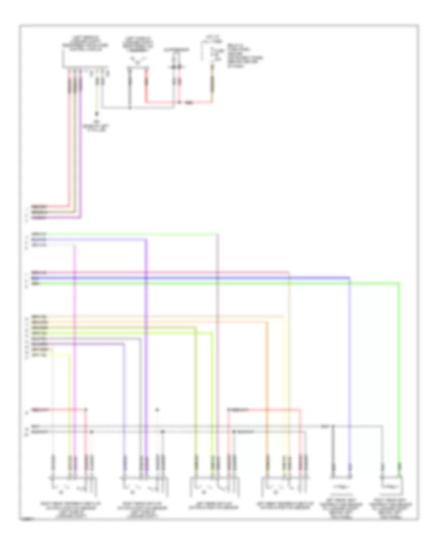
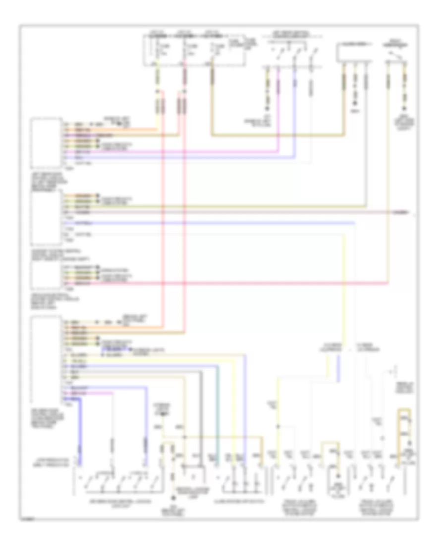
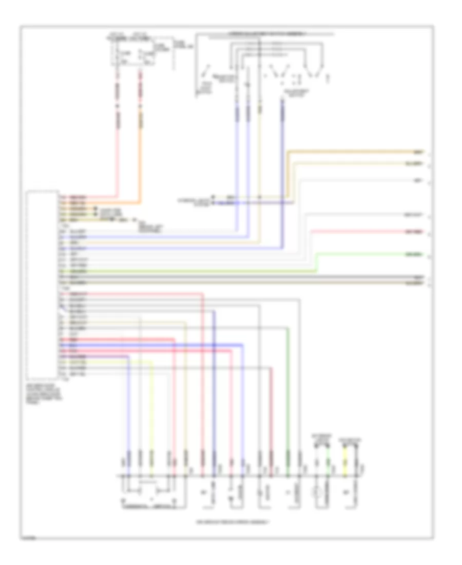
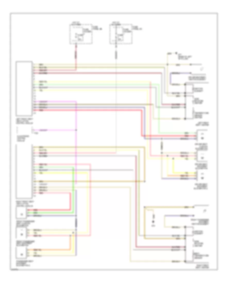
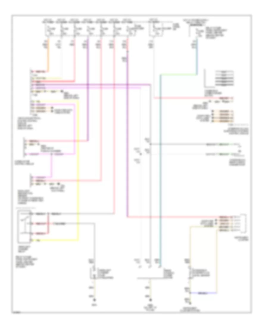
AIR CONDITIONING
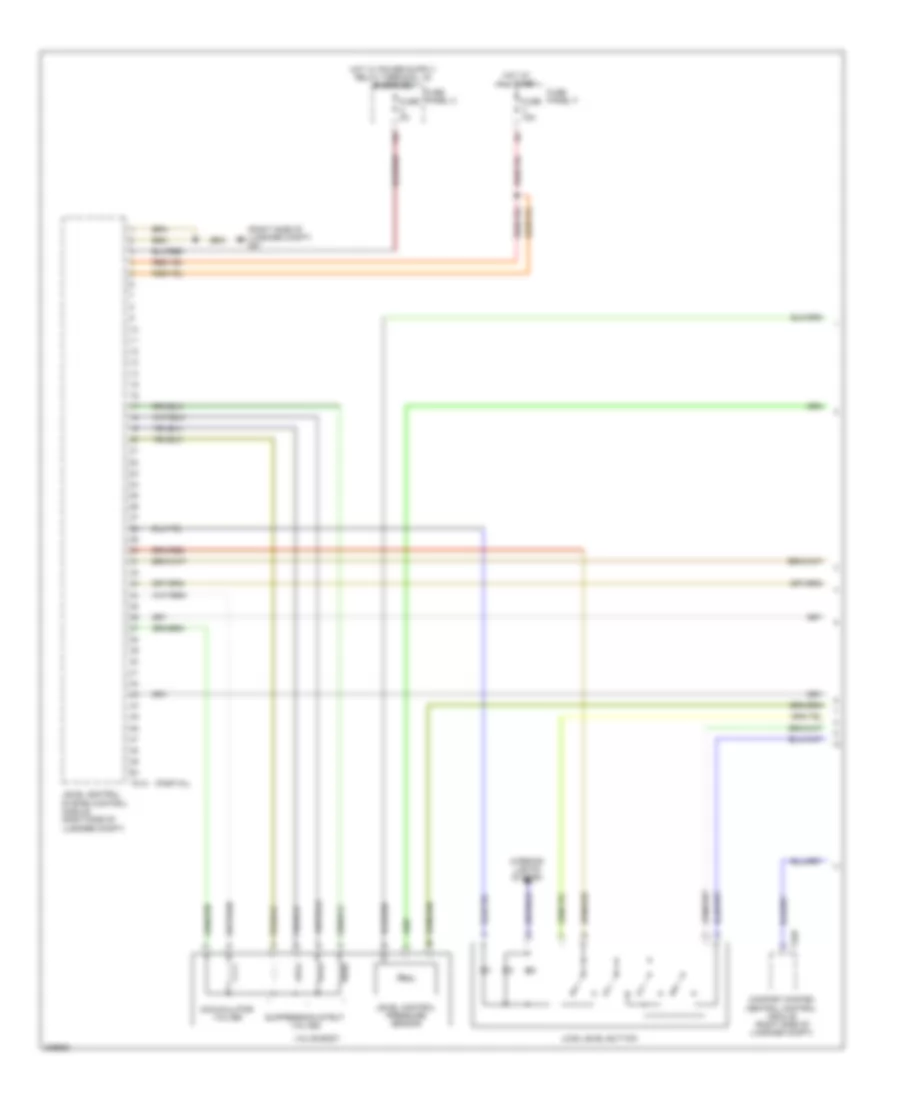
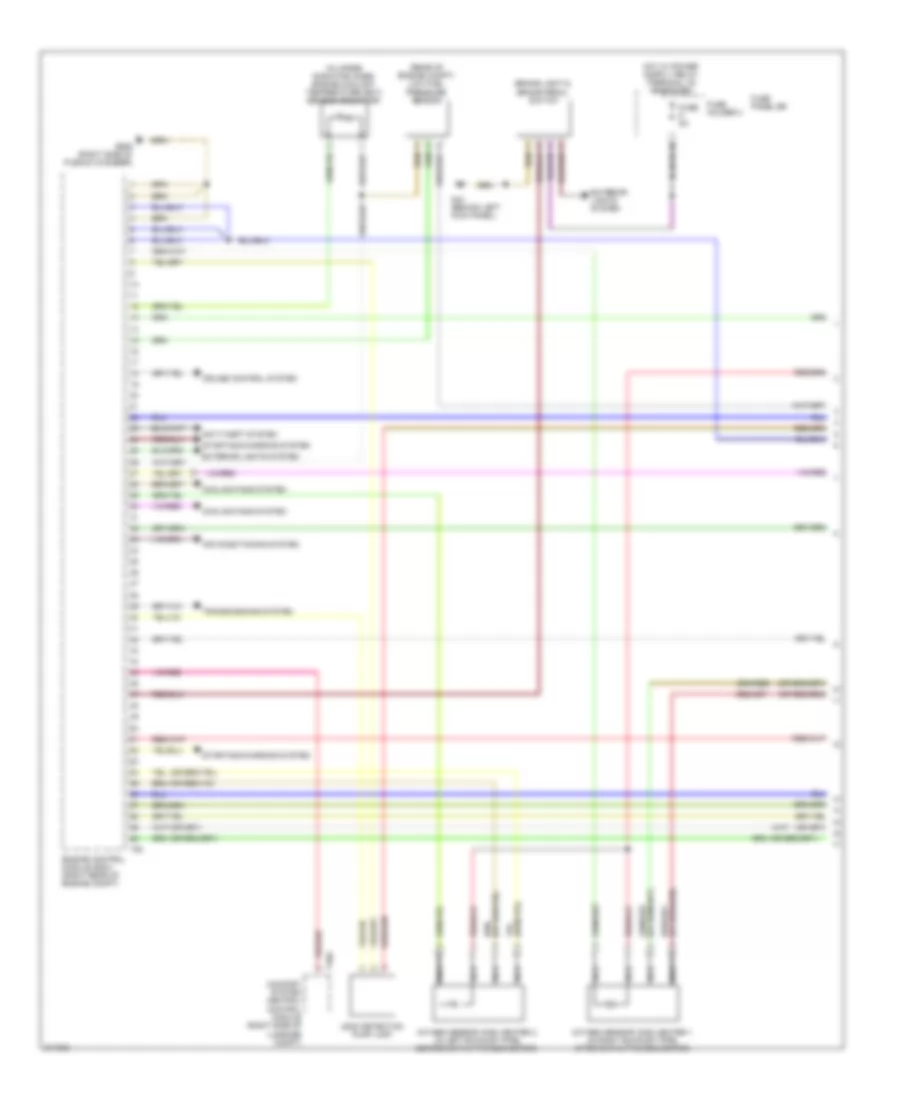
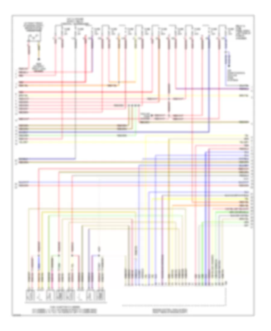
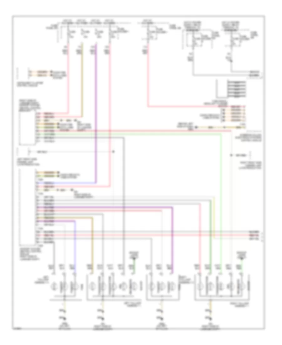
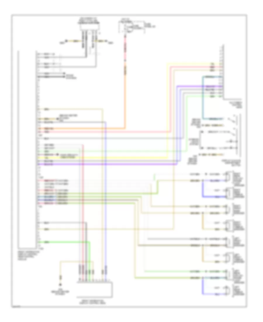
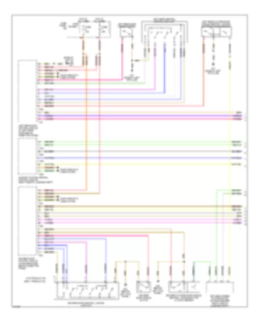
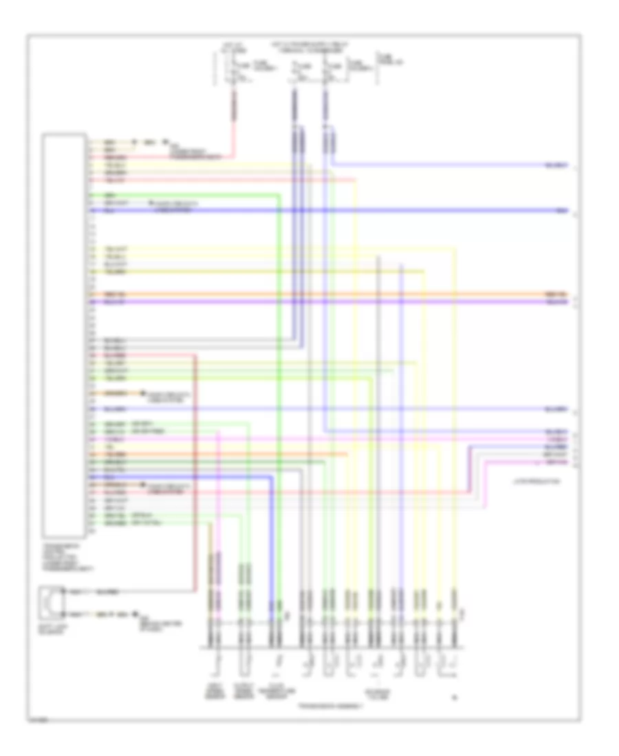
Automatic A/C Wiring Diagram (1 of 4) for Audi Q7 4.2 2009

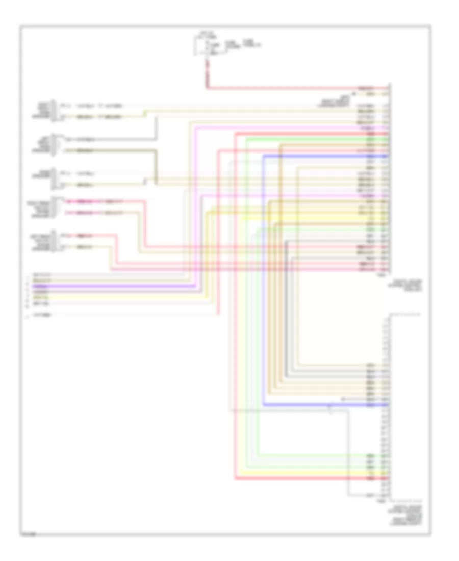
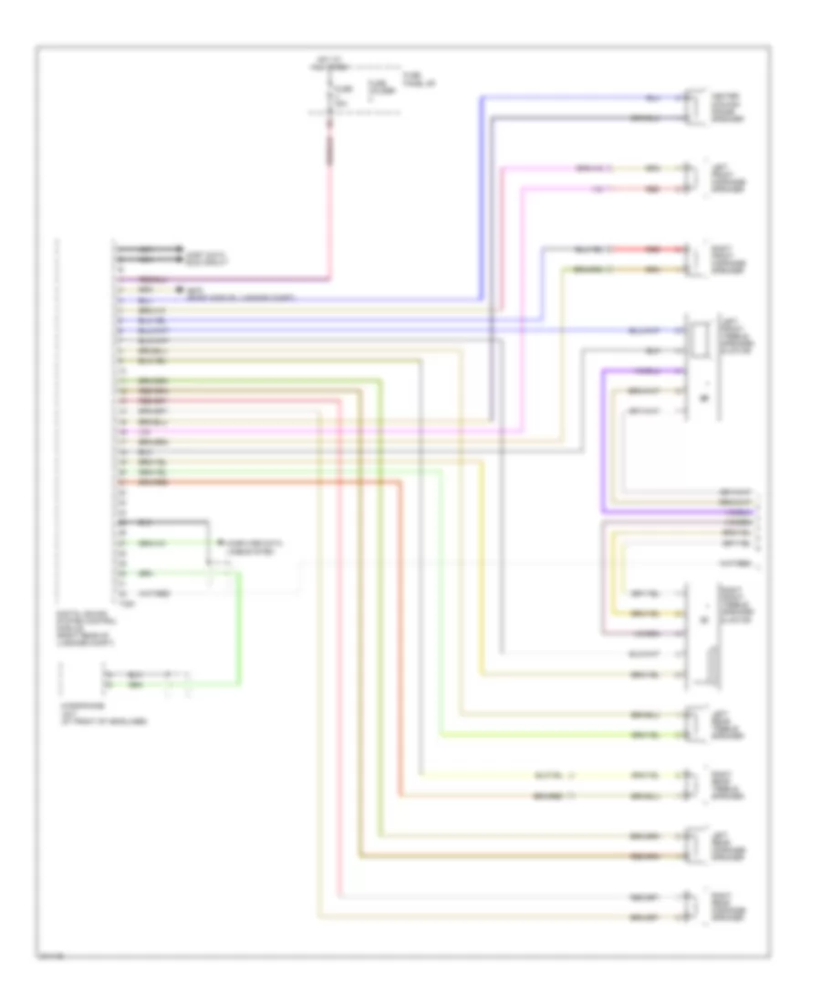
List of elements for Automatic A/C Wiring Diagram (1 of 4) for Audi Q7 4.2 2009:
- A/c compressor regulator valve
- Air quality sensor
- Climatronic control module
- Computer data lines system
- G45 (behind center of dash)
- Left center vent motor & position sensor (in center console, on left side of hvac housing)
- Left footwell flap motor & position sensor (in center console, on left side of hvac housing)
- Left temperature flap motor & potentiometer/ actuator (in center console, on left side of hvac housing)
- Recirculation flap motor & position sensor
- Right footwell flap motor & position sensor
- Seats system
- T16c
- T20i
- T3c
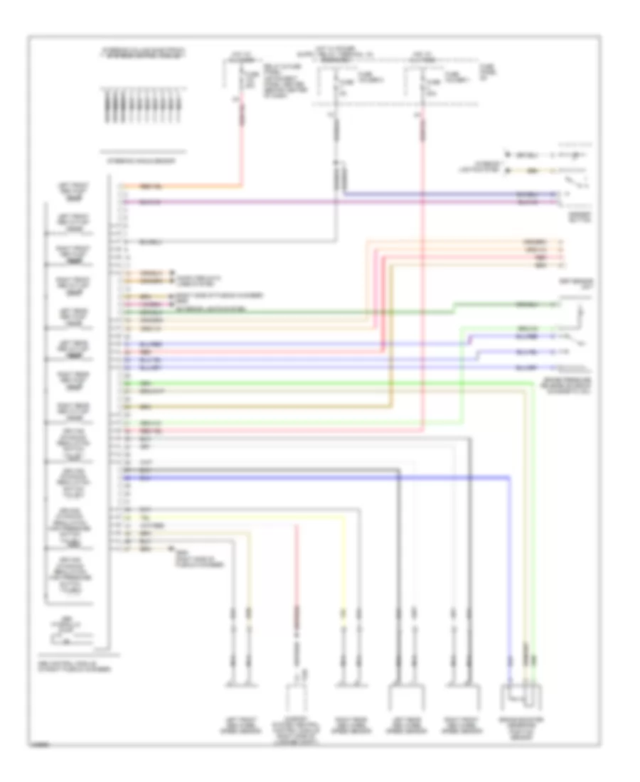
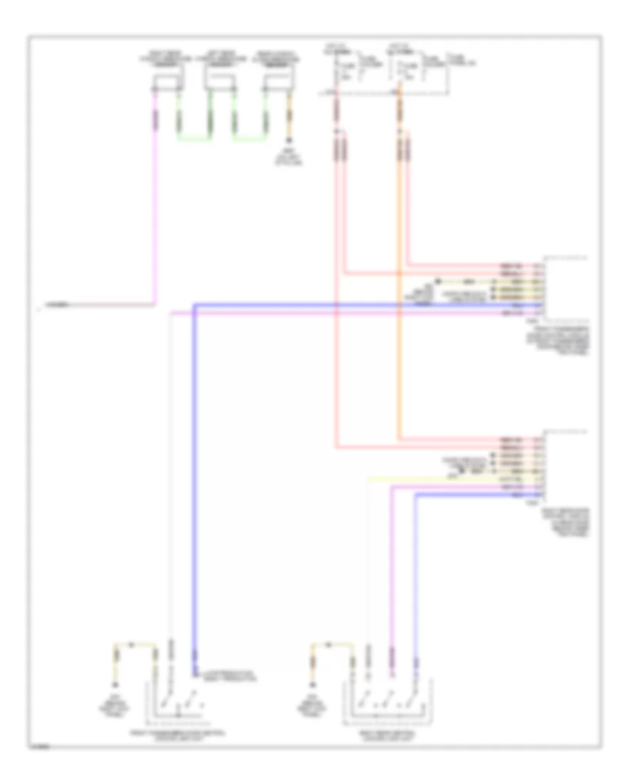
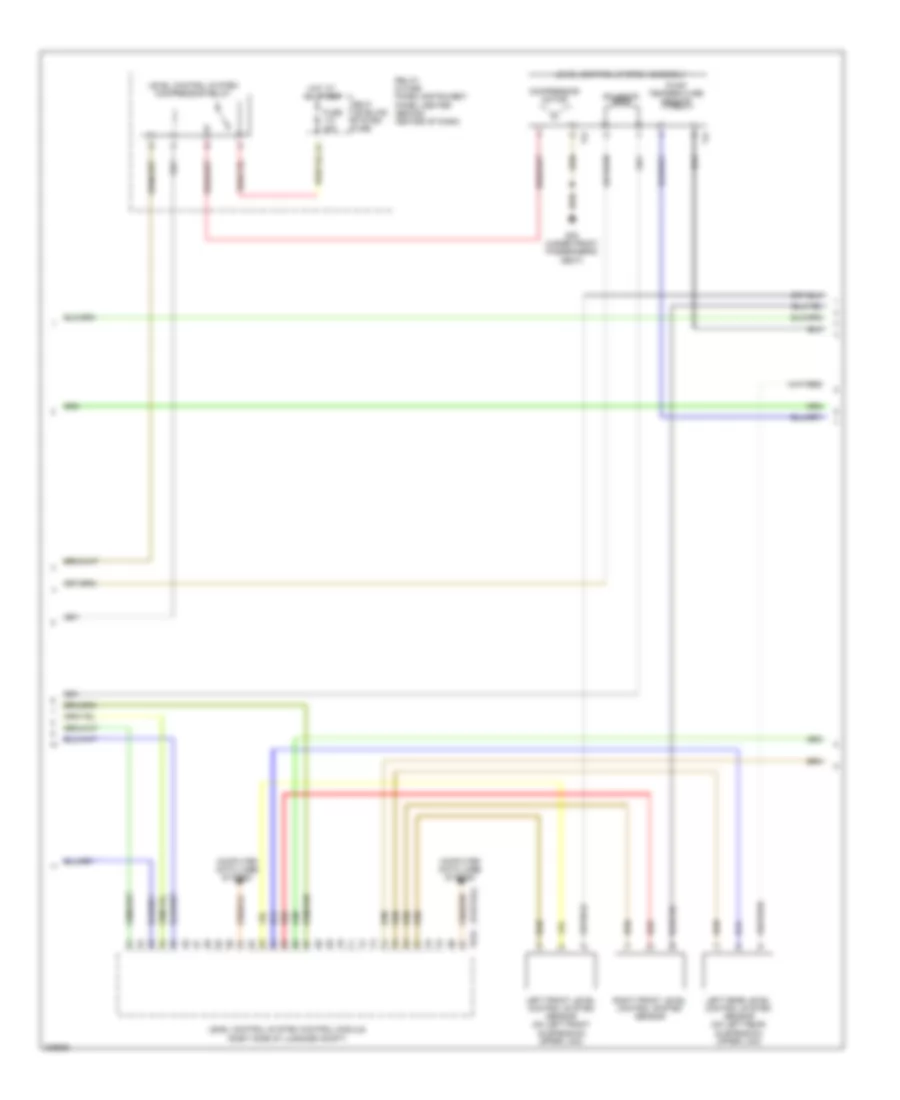
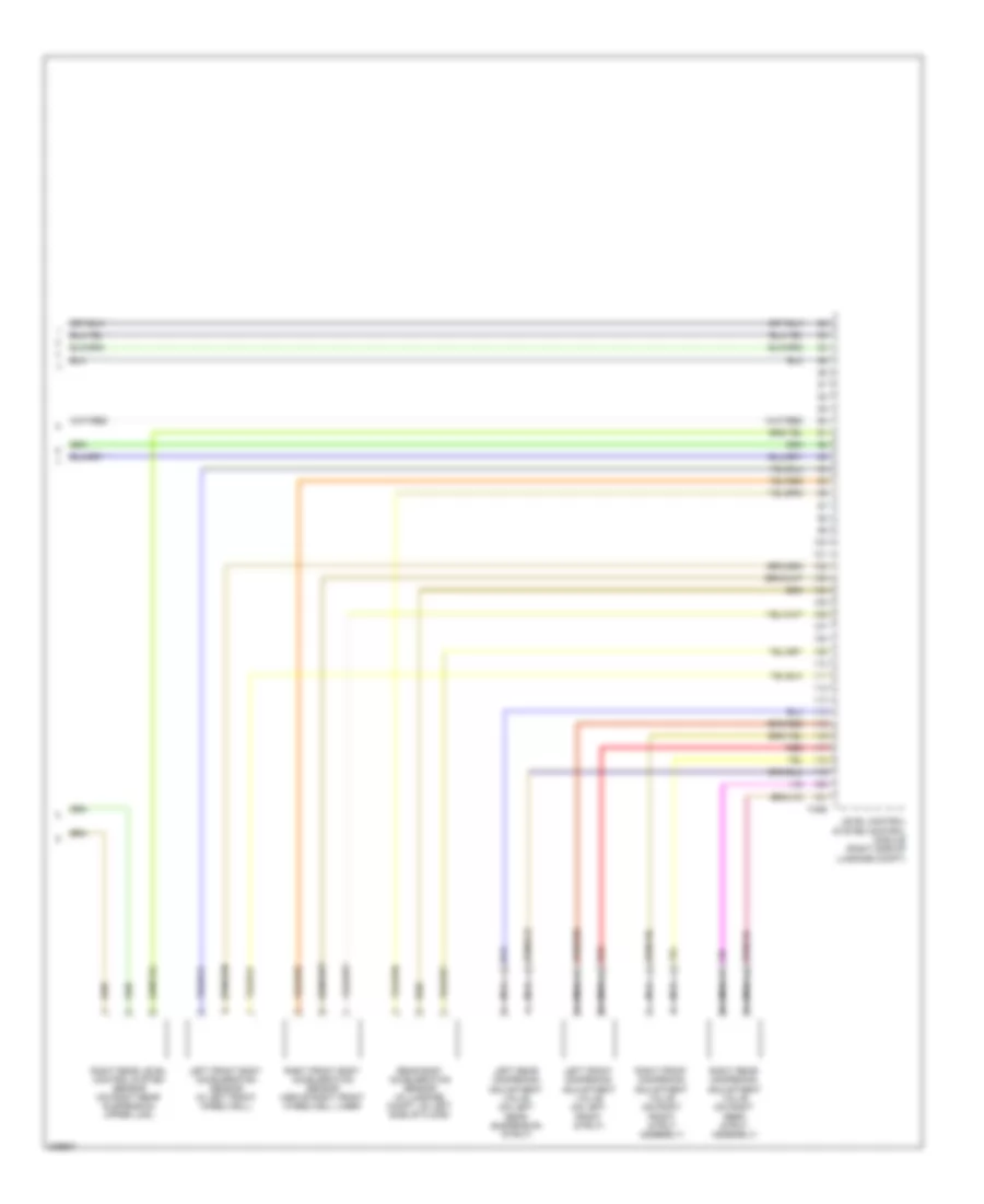
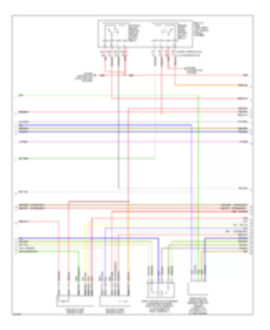
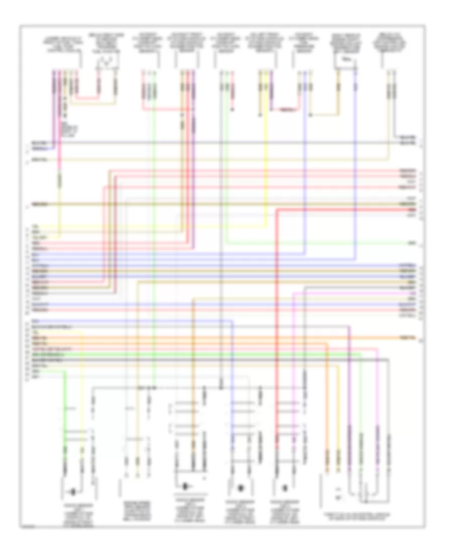
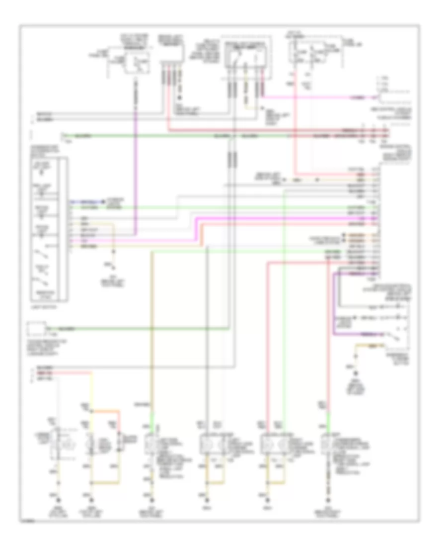
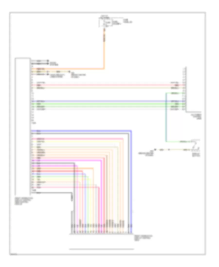
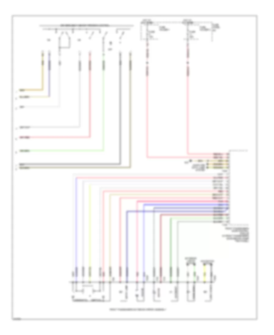
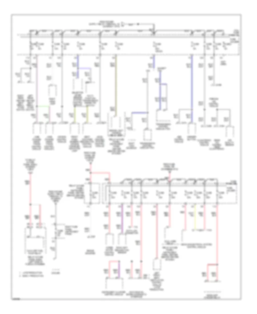
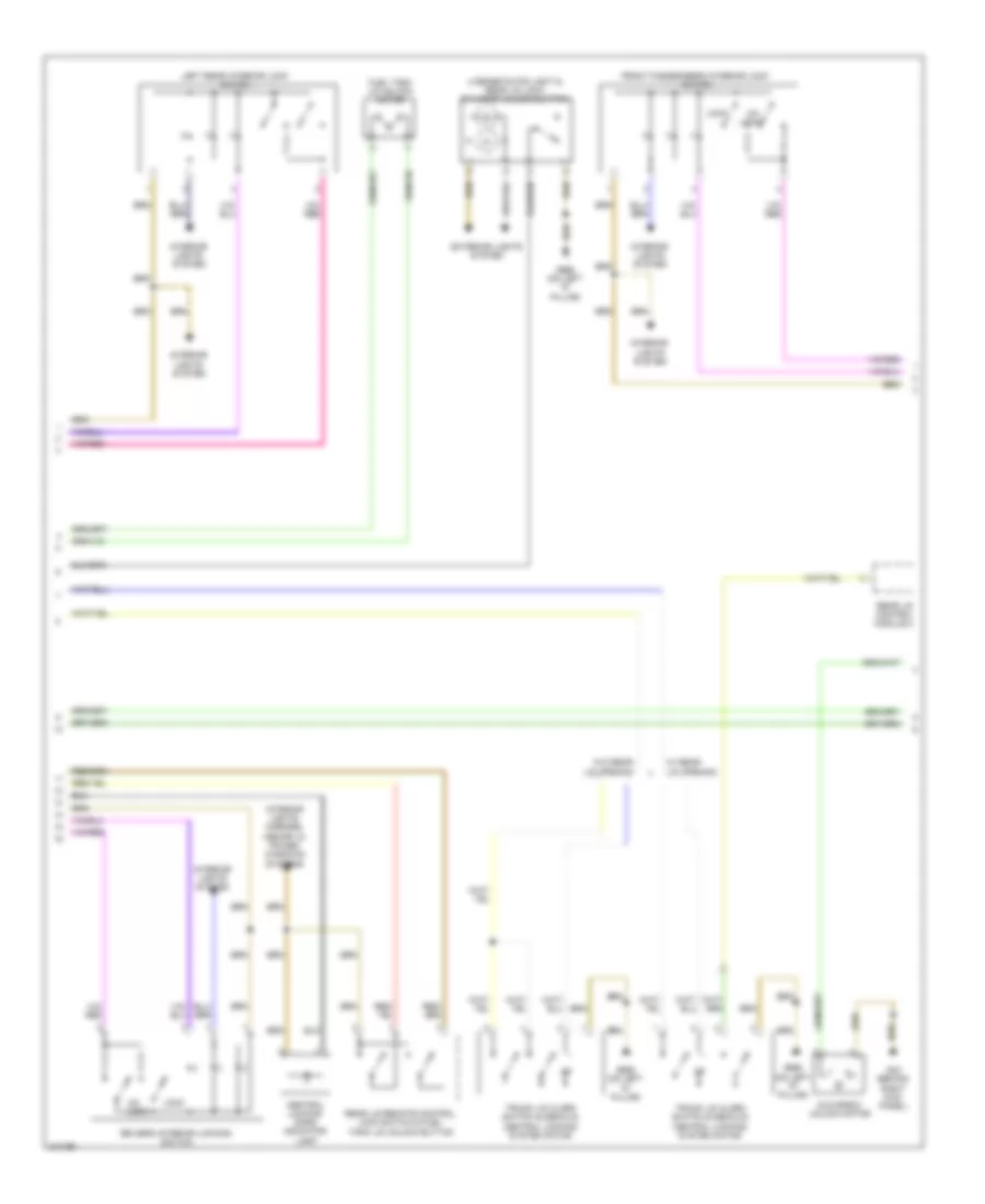
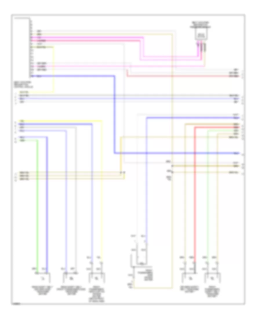
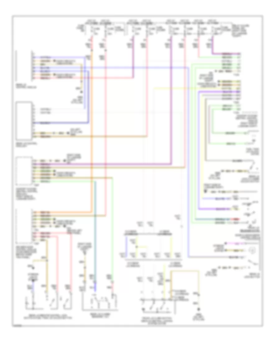
Automatic A/C Wiring Diagram (2 of 4) for Audi Q7 4.2 2009
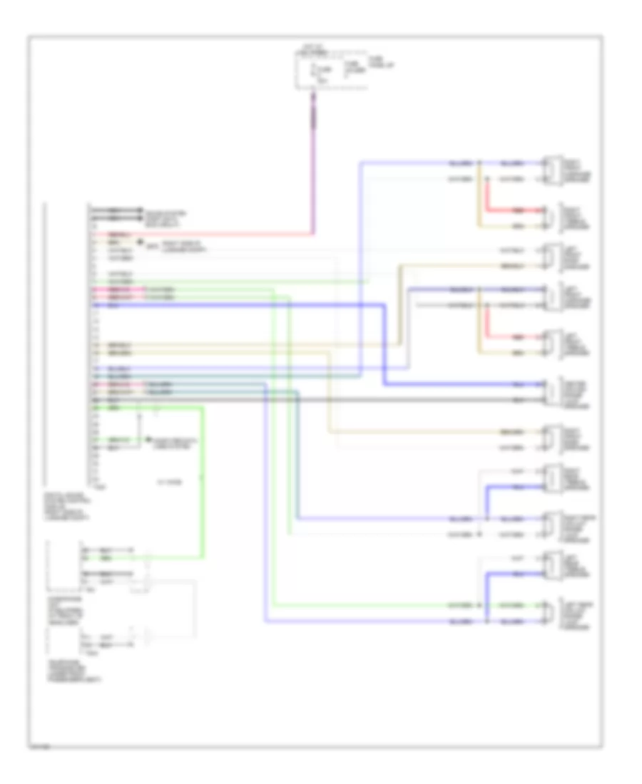
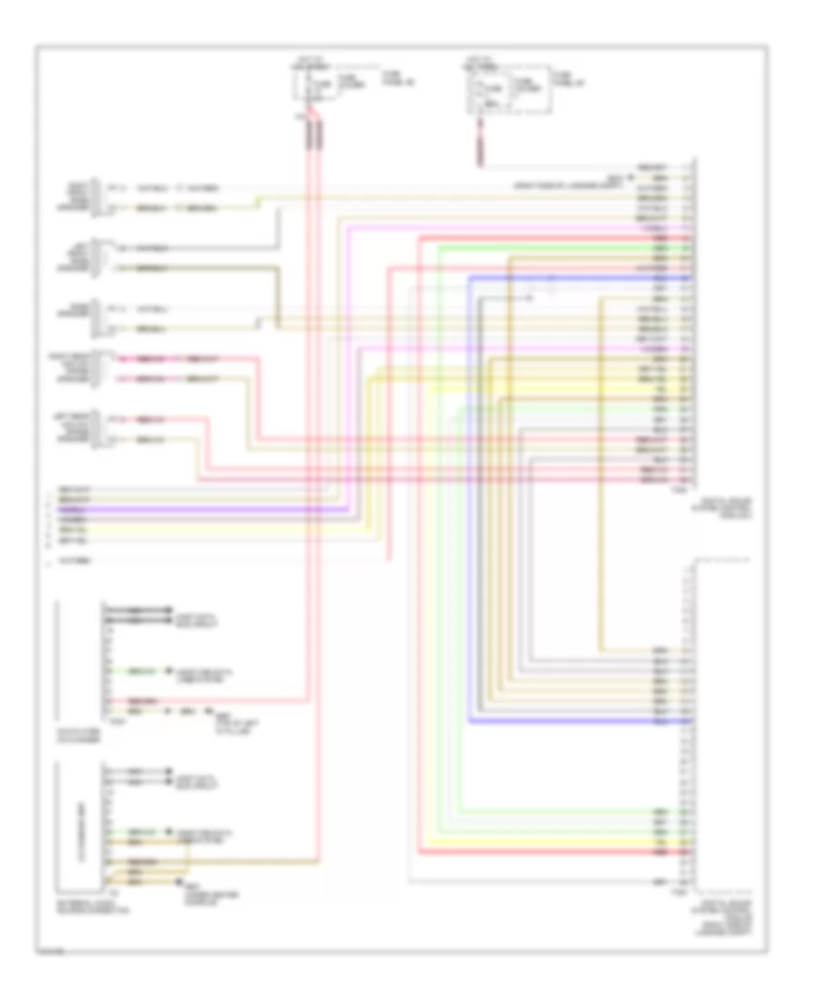
List of elements for Automatic A/C Wiring Diagram (2 of 4) for Audi Q7 4.2 2009:
- (behind glove box, in hvac housing) fresh air blower
- (under passenger side dash panel) fresh air blower control module
- 10a
- 12a
- Cooler
- Cooler fuse
- Defroster flap motor & position sensor (in center console, on left side of hvac housing)
- Fuse 10a
- Fuse 15a
- Fuse 30a
- Fuse 5a
- Fuse holder
- Fuse panel sc
- G43 (behind right kick panel)
- G62 (base of right "c" pillar)
- Hot at all times
- Indirect ventilation flap motor & position sensor
- Left side vent motor & position sensor (in center console, on left side of hvac housing)
- Pnk
- Right center vent motor & position sensor
- Right side vent motor & position sensor
- Right temperature flap motor & potentiometer/ actuator
- T2q
- T6at
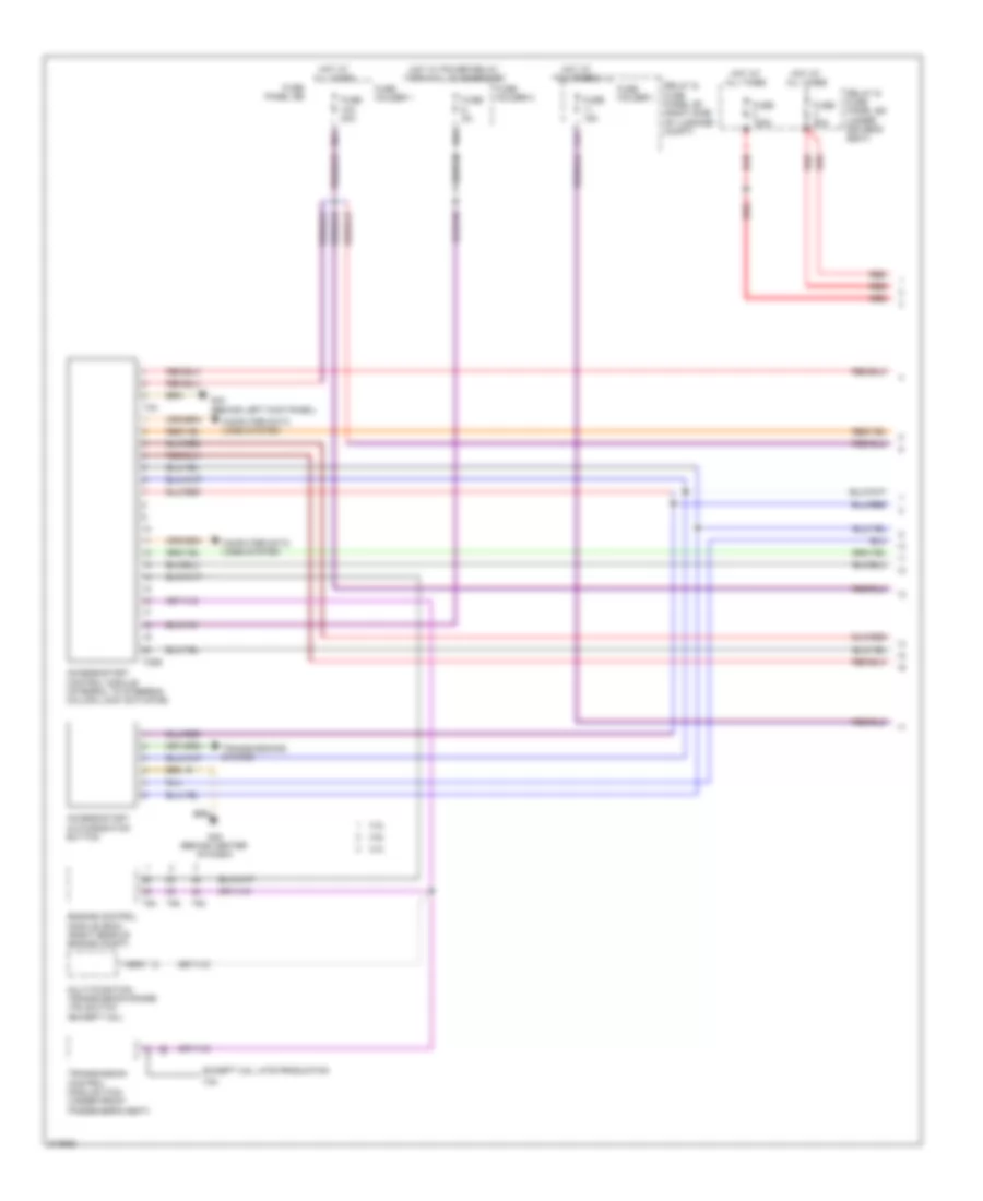
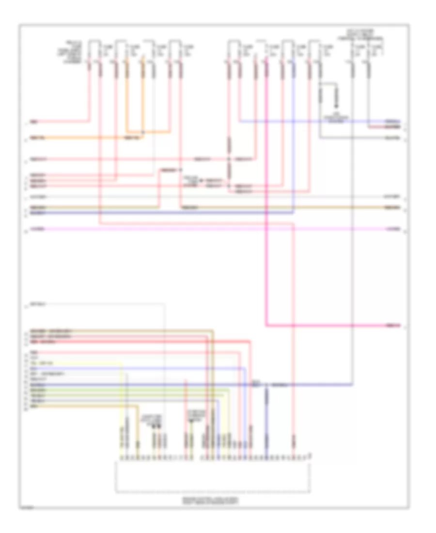
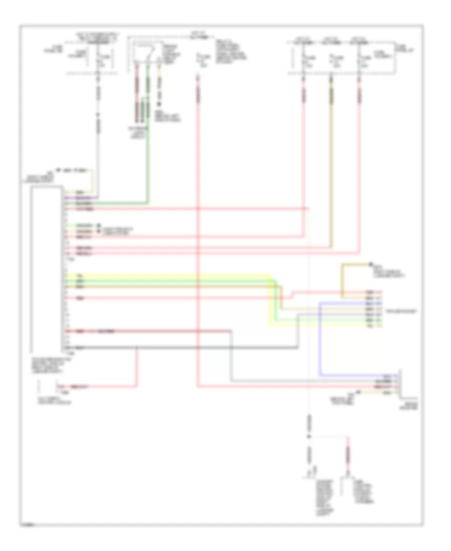
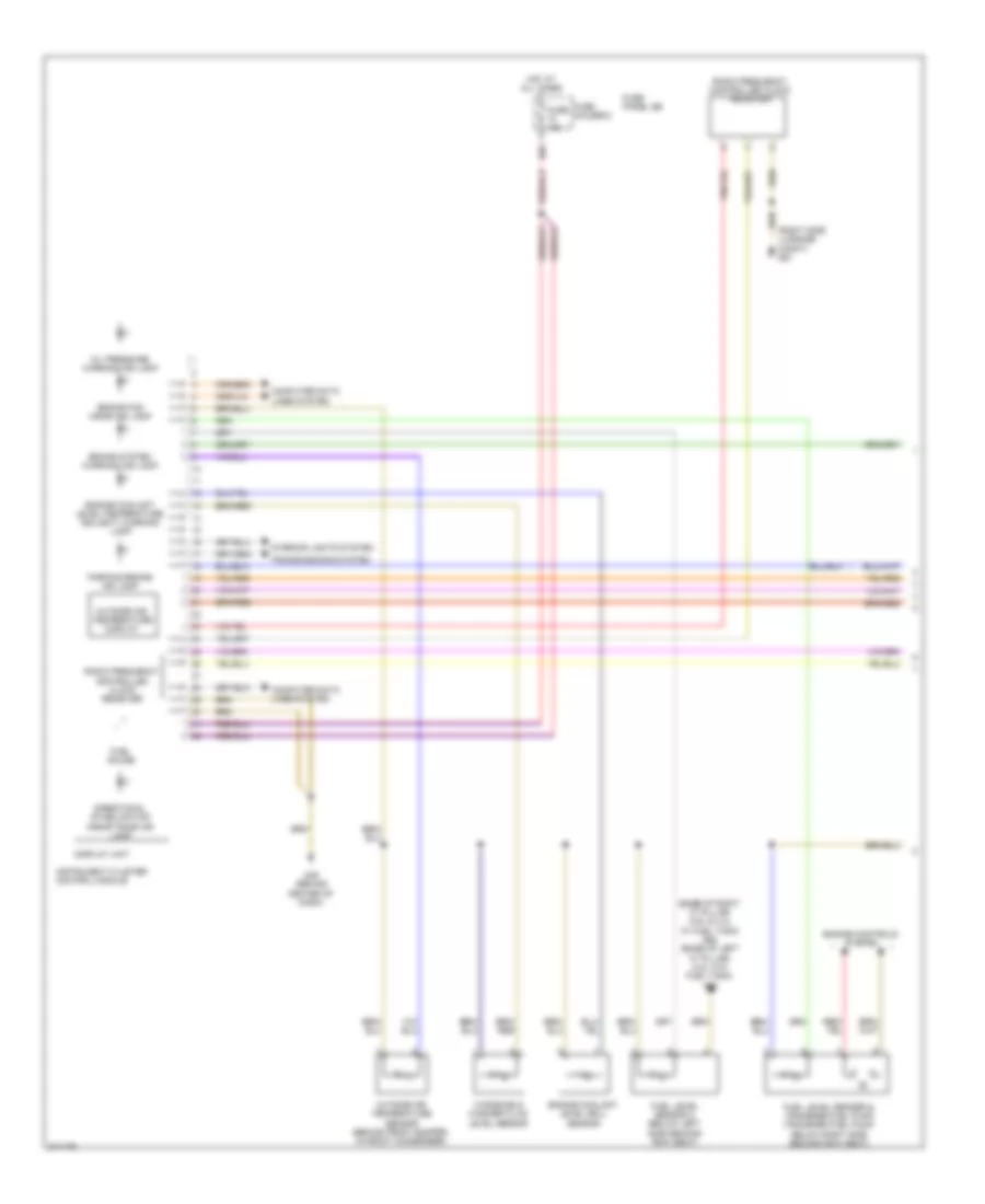
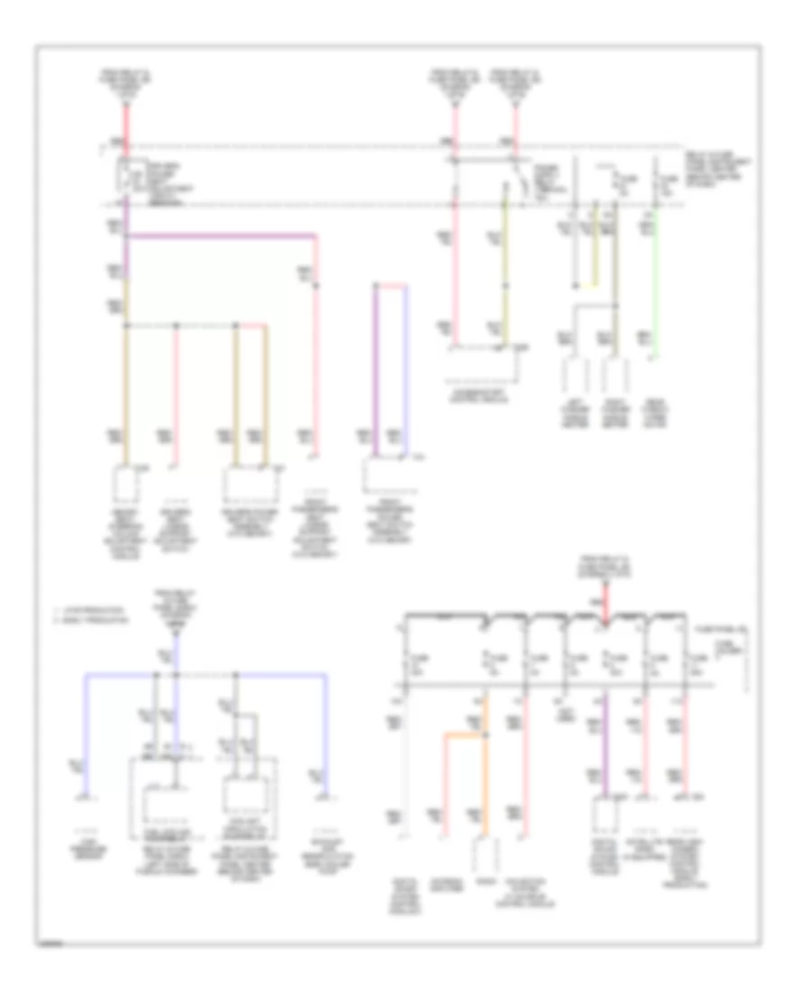
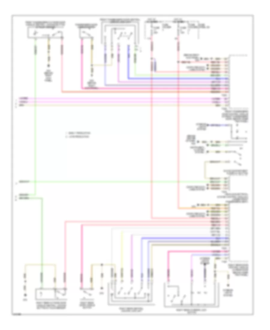
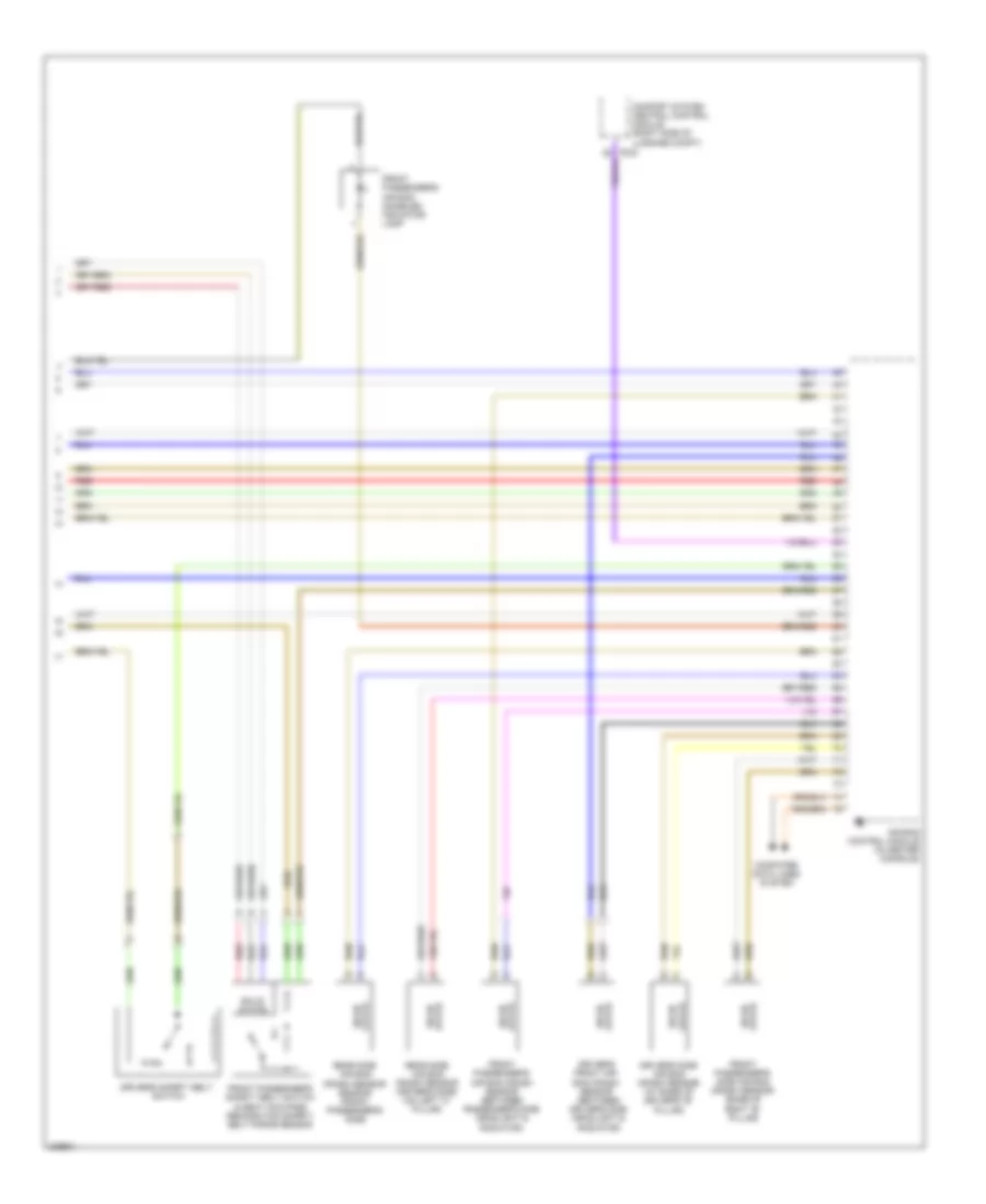
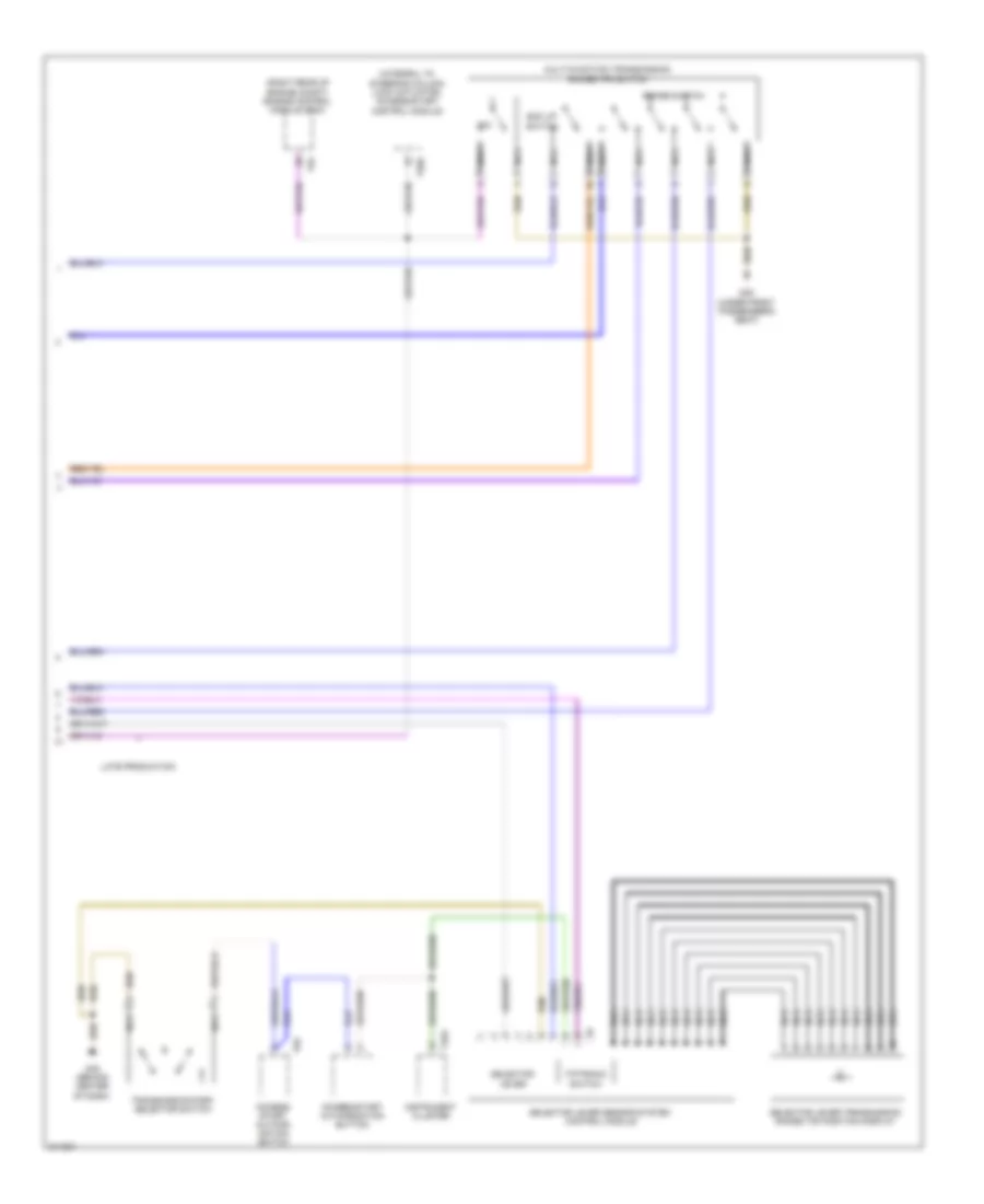
Automatic A/C Wiring Diagram (3 of 4) for Audi Q7 4.2 2009
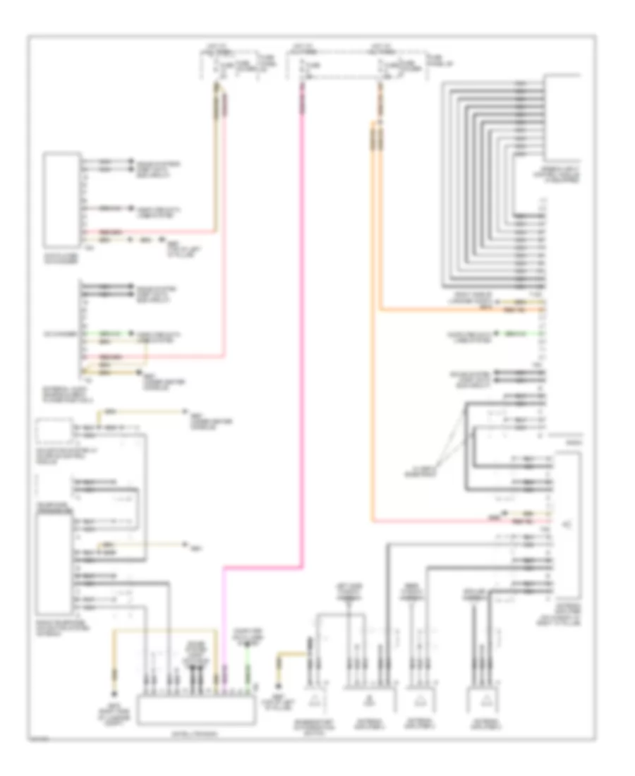
List of elements for Automatic A/C Wiring Diagram (3 of 4) for Audi Q7 4.2 2009:
- (except 3.6l) coolant circulation pump relay
- (in left front wheelwell) coolant pump
- (right side of plenum chamber) (3.6l) g609
- 10a
- 13a
- 3.0l
- 3.6l
- Except 3.0l
- Except 3.6l
- Fuse 10a
- Fuse 13a
- Fuse 40a
- Fuse 5a
- Fuse 60a
- G609 (right side of plenum chamber)
- G640 (except 3.6l) (left side of engine compt)
- High pressure sensor
- Hot at all times
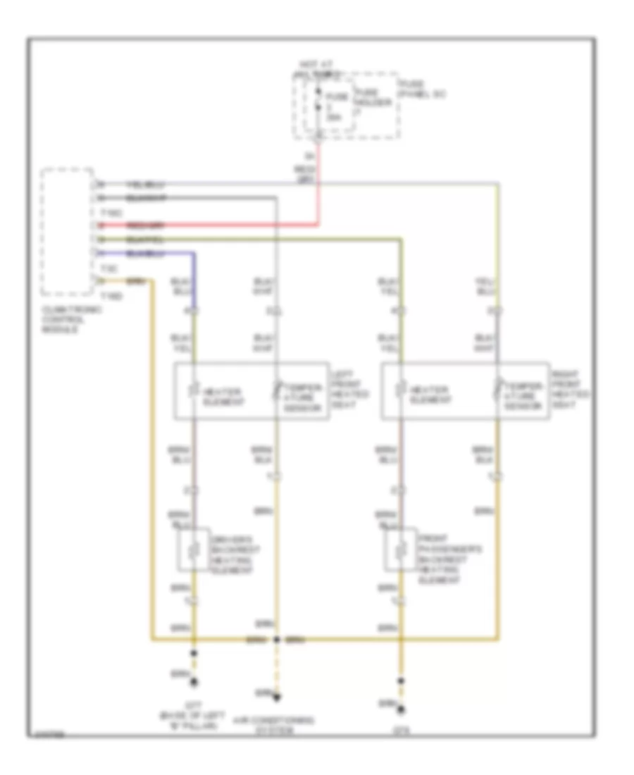
- Left front seat temperature sensor (w/ seat heater)
- Pnk
- Relay & fuse panel e-box (left side of plenum chamber)
- Relay & fuse panel/instrument panel center (behind center of dash)
- Right front seat temperature sensor (w/ seat heater)
- Sunlight photo sensor (top of dash panel, between defroster vents)
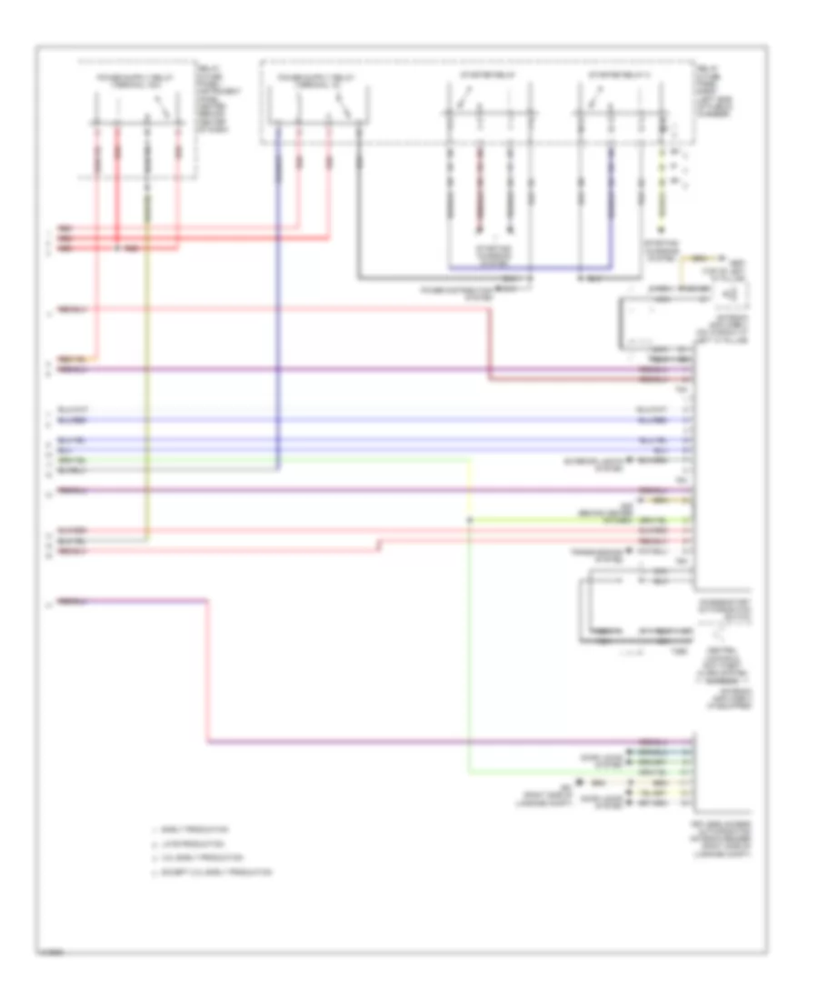
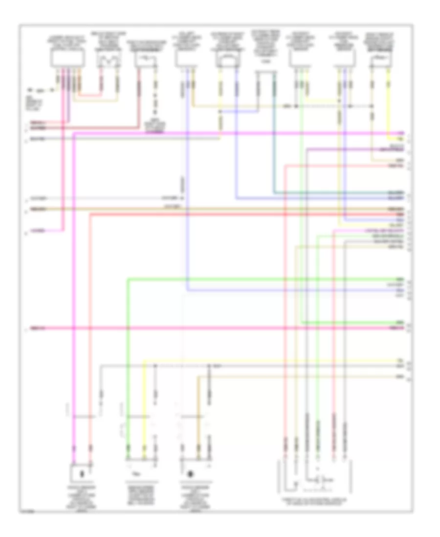
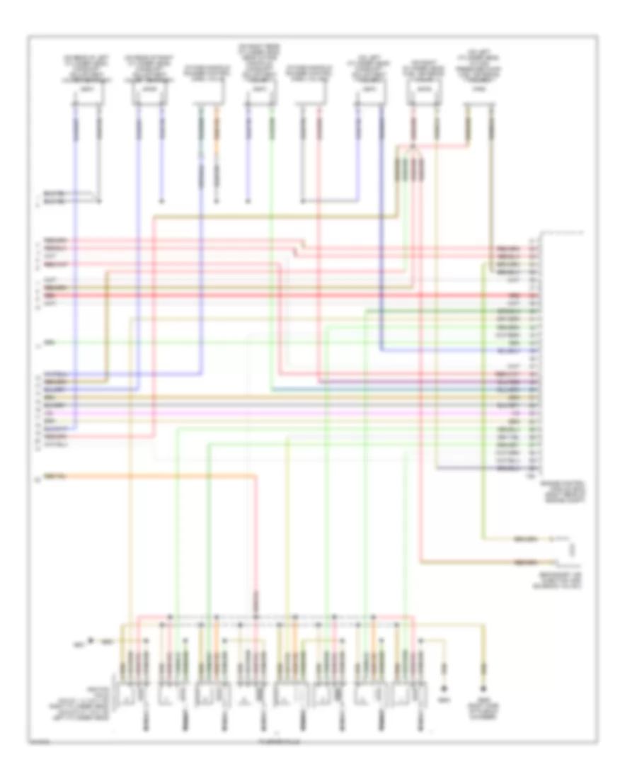
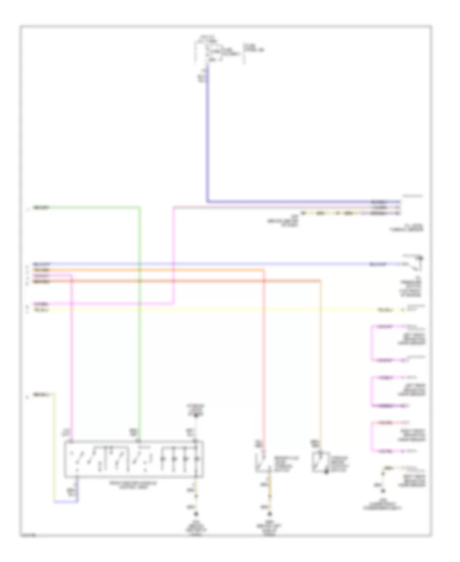
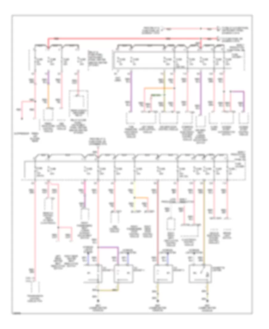
Automatic A/C Wiring Diagram (4 of 4) for Audi Q7 4.2 2009
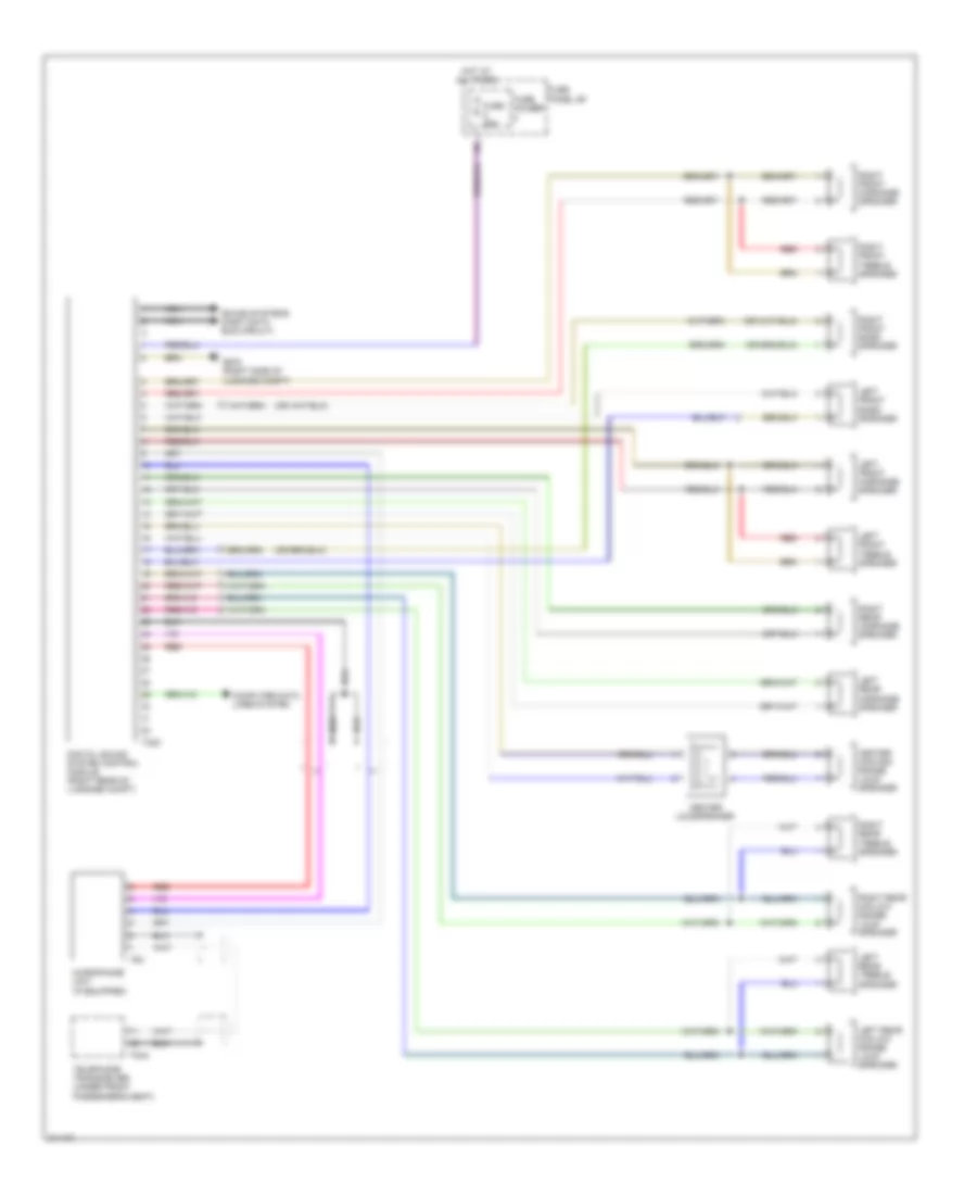
List of elements for Automatic A/C Wiring Diagram (4 of 4) for Audi Q7 4.2 2009:
- (3.0l: right side of radiator) (except 3.0l: in upper radiator hose) engine coolent temperature (ect) sensor (on radiator)
- (3.6l) recirculation pump relay
- (behind center of dash) g45
- (on left front long member) g671
- (right rear of engine compt) engine control module
- 19a
- 19b
- 19c
- 19d
- 19e
- 3.0l
- 3.6l
- 4.2l
- Climatronic control module
- Computer data lines system
- Coolant fan
- Coolant fan 2
- Coolant fan control module
- Coolant fan control module 2
- Engine coolant temperature (ect) sensor (right rear of engine compt)
- Evaporator vent temperature sensor
- Except 3.0l
- Fresh air intake duct temperature sensor (under right side dash panel, in air intake for hvac housing)
- Left footwell vent temperature sensor
- Left front upper body outlet temperature sensor
- Pnk
- Relay & fuse panel e-box (left side of plenum chamber)
- Right footwell vent temperature sensor
- Right front upper body outlet temperature sensor
- T12g
- T16d
- T60
- T94
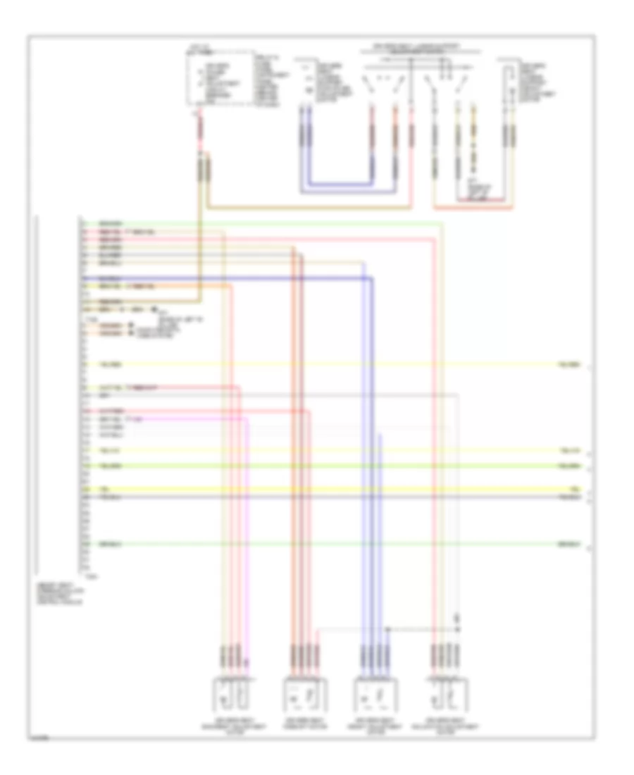
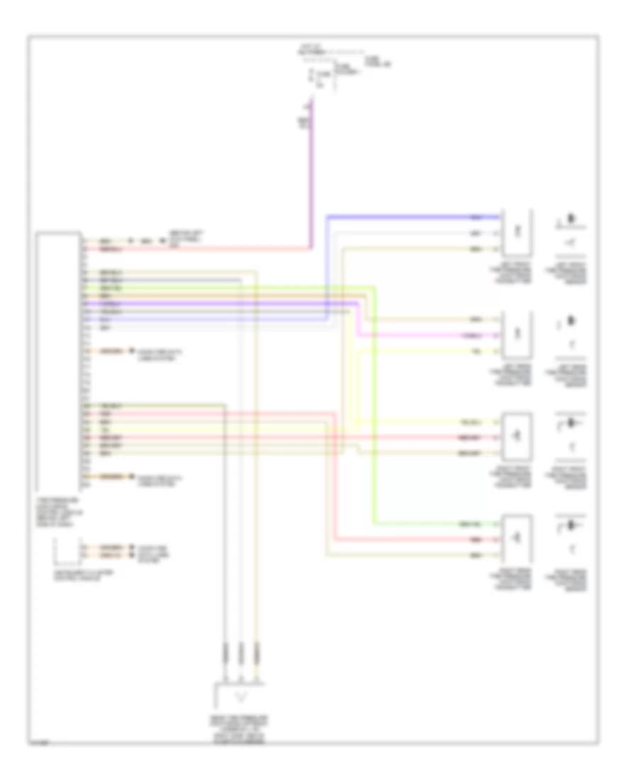
Rear A/C Wiring Diagram (1 of 2) for Audi Q7 4.2 2009
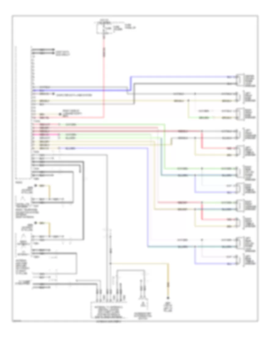
List of elements for Rear A/C Wiring Diagram (1 of 2) for Audi Q7 4.2 2009:
- (under center console) g687
- 12a
- Computer data lines system
- Fuse 10a
- Fuse 20a
- Fuse 5a
- Fuse holder 1
- Fuse holder 2
- Fuse holder 3
- Fuse panel fc
- Hot at all times
- Left "b" pillar/footwell shut-off flap motor & position sensor
- Left rear upper body vent motor & position sensor
- Rear climatronic control module
- Right "b" pillar/footwell shut-off flap motor & position sensor
- Right rear upper body vent motor & position sensor
- Seats system
- T12h
- T16h
- T20h
- T3h
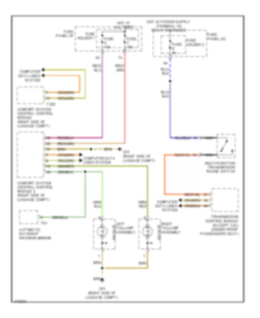
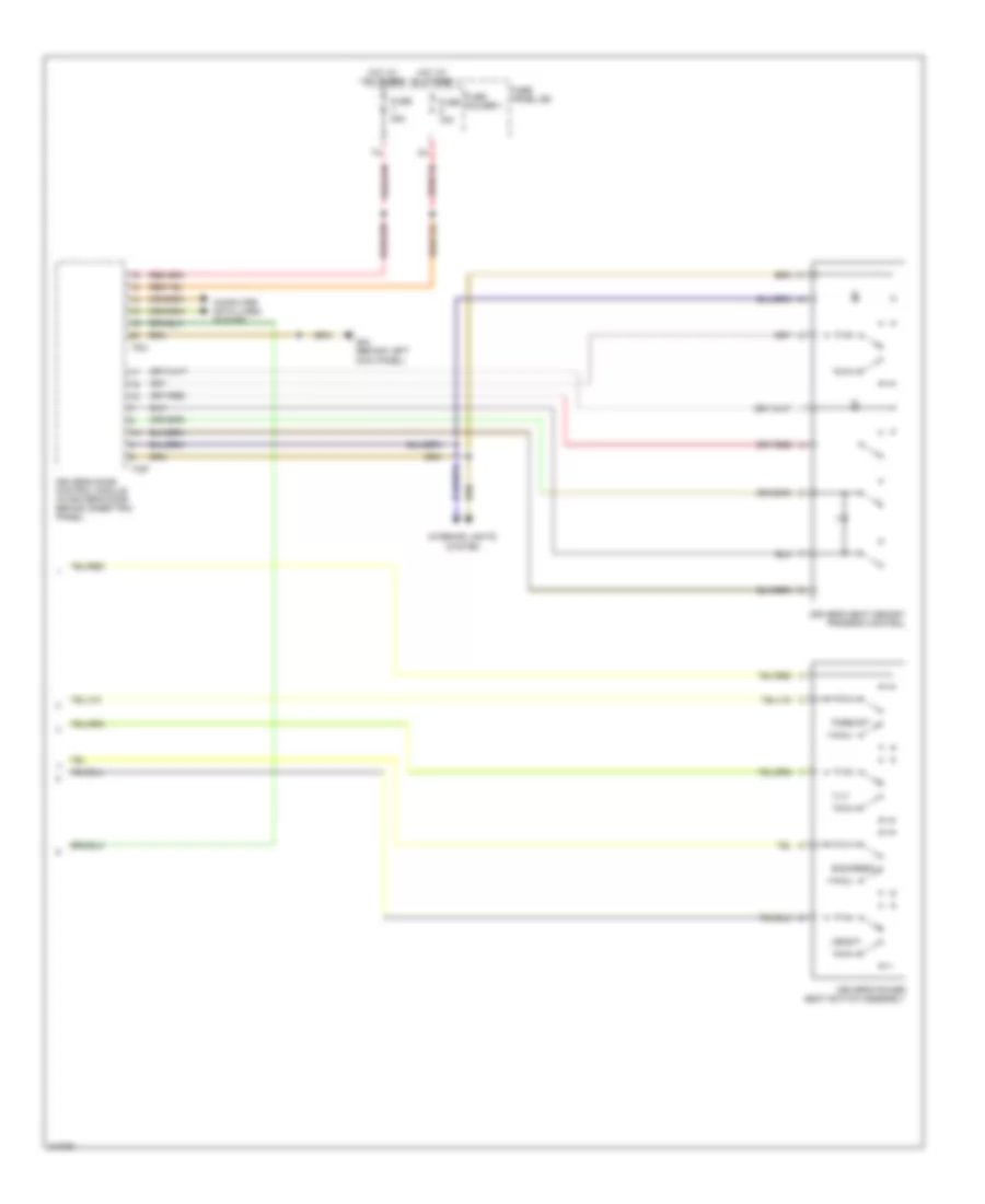
Rear A/C Wiring Diagram (2 of 2) for Audi Q7 4.2 2009
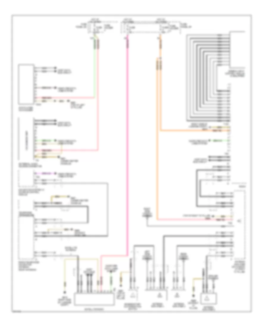
List of elements for Rear A/C Wiring Diagram (2 of 2) for Audi Q7 4.2 2009:
- (left rear of luggage compt) rear fresh air blower control module
- (left side of luggage compt) rear fresh air blower
- Fuse 40a
- G61 (base of left "c" pillar)
- Hot at all times
- Left rear air flap motor & position sensor
- Left rear temperature flap motor & position sensor
- Left rear vent temperature sensor (in luggage compt, behind left trim panel)
- Red
- Relay & fuse panel/ center instrument panel (behind center of dash)
- Right rear air flap motor & position sensor (left side of luggage compt)
- Right rear temperature flap motor & position sensor (left side of luggage compt)
- Right rear vent temperature sensor (in luggage compt, behind left trim panel)
- Suppressor
- T2r
- T4u
ANTI-LOCK BRAKES
Anti-lock Brakes Wiring Diagram for Audi Q7 4.2 2009
List of elements for Anti-lock Brakes Wiring Diagram for Audi Q7 4.2 2009:
- (right side of plenum chamber) g609
- Abs control module (in right plenum chamber)
- Abs hydraulic pump
- Asr/esp button
- Brake booster membrane position sensor
- Brake pressure release solenoid & magnetic coil
- Comfort system central control module (right side of luggage compt)
- Computer data lines system
- Driving dynamics regulation high pressure switch valve 1
- Driving dynamics regulation high pressure switch valve 2
- Driving dynamics regulation switch valve 1
- Driving dynamics regulation switch valve 2
- Esp sensor unit
- Exterior lights system
- Fuse 20a
- Fuse 40a
- Fuse 5a
- Fuse holder 1
- Fuse holder 2
- Fuse panel sc
- G609 (right side of plenum chamber)
- Hot at all times
- Interior lights system
- Left front abs inlet valve
- Left front abs outlet valve
- Left front abs wheel speed sensor
- Left rear abs inlet valve
- Left rear abs outlet valve
- Left rear abs wheel speed sensor
- Nca
- Red
- Relay & fuse panel/ instrument panel center (behind center of dash)
- Right front abs inlet valve
- Right front abs outlet valve
- Right front abs wheel speed sensor
- Right rear abs inlet valve
- Right rear abs outlet valve
- Right rear abs wheel speed sensor
- Steering angle sensor
- Steering column electronic systems control module
- T32d
ANTI-THEFT
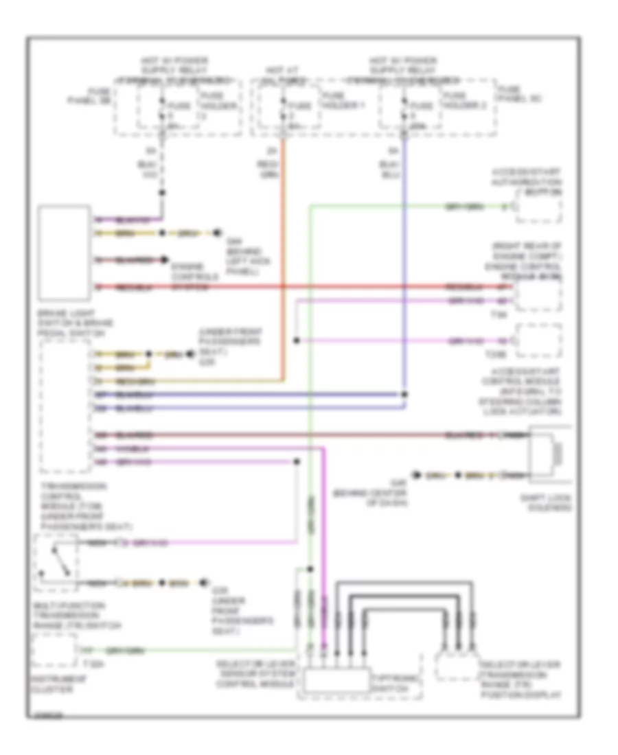
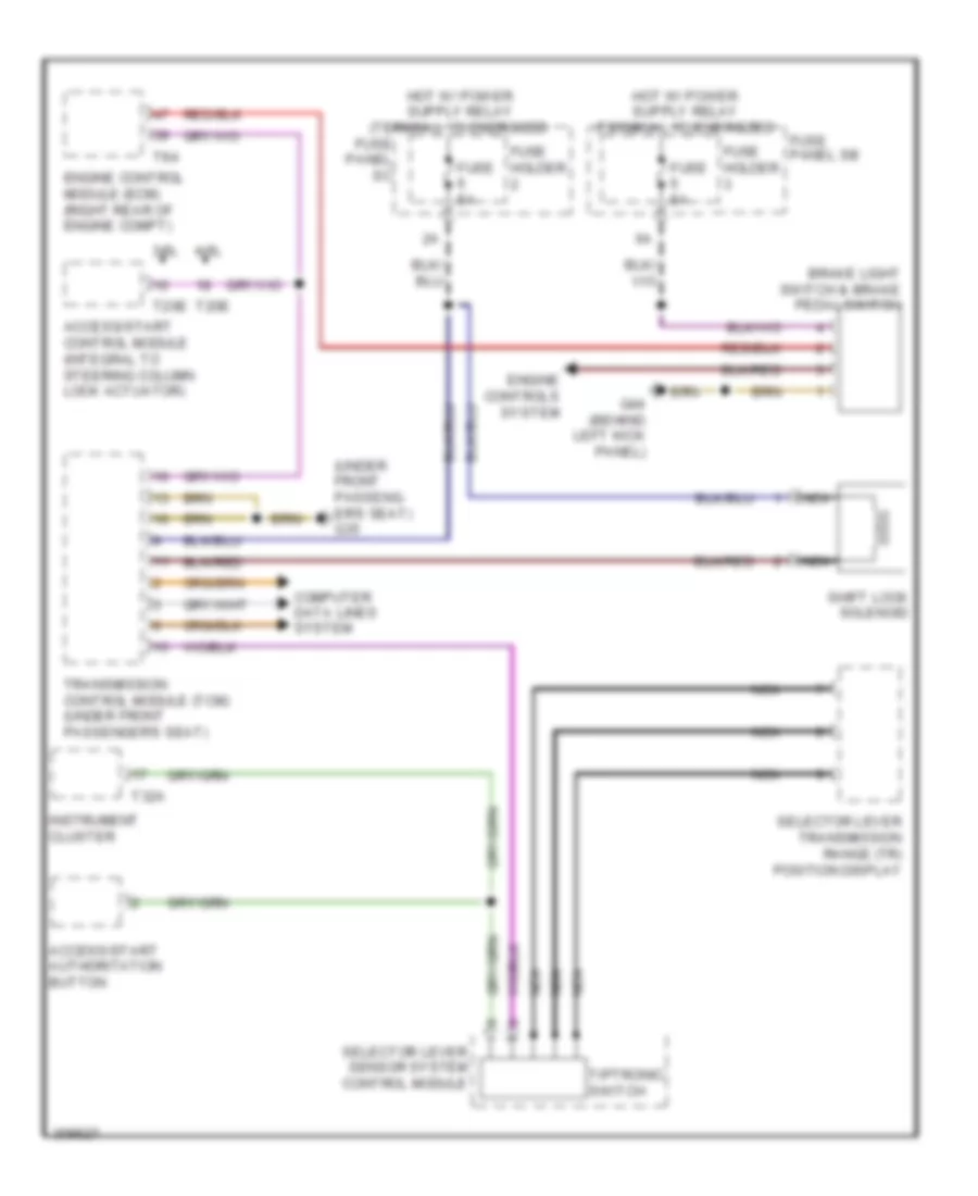
Access/Start Wiring Diagram (1 of 2) for Audi Q7 4.2 2009
List of elements for Access/Start Wiring Diagram (1 of 2) for Audi Q7 4.2 2009:
- 10a
- 11a
- 3.0l
- 3.6l
- 4.2l
- Access/start authorization button
- Access/start control module (integral to steering column lock actuator)
- Computer data lines system
- Engine control module (ecm) (right rear of engine compt)
- Except 3.6l late production
- Fuse 10a 30a
- Fuse 150a
- Fuse 15a
- Fuse 5a
- Fuse 60a
- Fuse holder 1
- Fuse holder 3
- Fuse panel sb
- G44 (behind left kick panel)
- G45 (behind center of dash)
- Hot at all times
- Hot w/ power relay (terminal 15) energized
- Multi-function transmission range (tr) switch (except 3.6l)
- Nca
- Red
- Relay & fuse panel sd (under driver's seat)
- Relay & fuse panel sf (right side of luggage compt)
- T20e
- T3a
- T94
- Transmission control module (tcm) (under front passenger's seat)
- Transmissions system
Access/Start Wiring Diagram (2 of 2) for Audi Q7 4.2 2009
List of elements for Access/Start Wiring Diagram (2 of 2) for Audi Q7 4.2 2009:
- 3.0l early production
- Access/start authorization switch
- Antenna amplifier 3 (if equipped)
- Antenna amplifier 4 (on window at left "c" pillar)
- Central locking & anti-theft alarm system antenna
- Door locks system
- Early production
- Except 3.0l early production
- Exterior lights system
- G45 (behind center of dash)
- G51 (right side of luggage compt)
- G667 (top of left "d" pillar)
- Keyless access authorization antenna reader (right side of luggage compt)
- Late production
- Nca
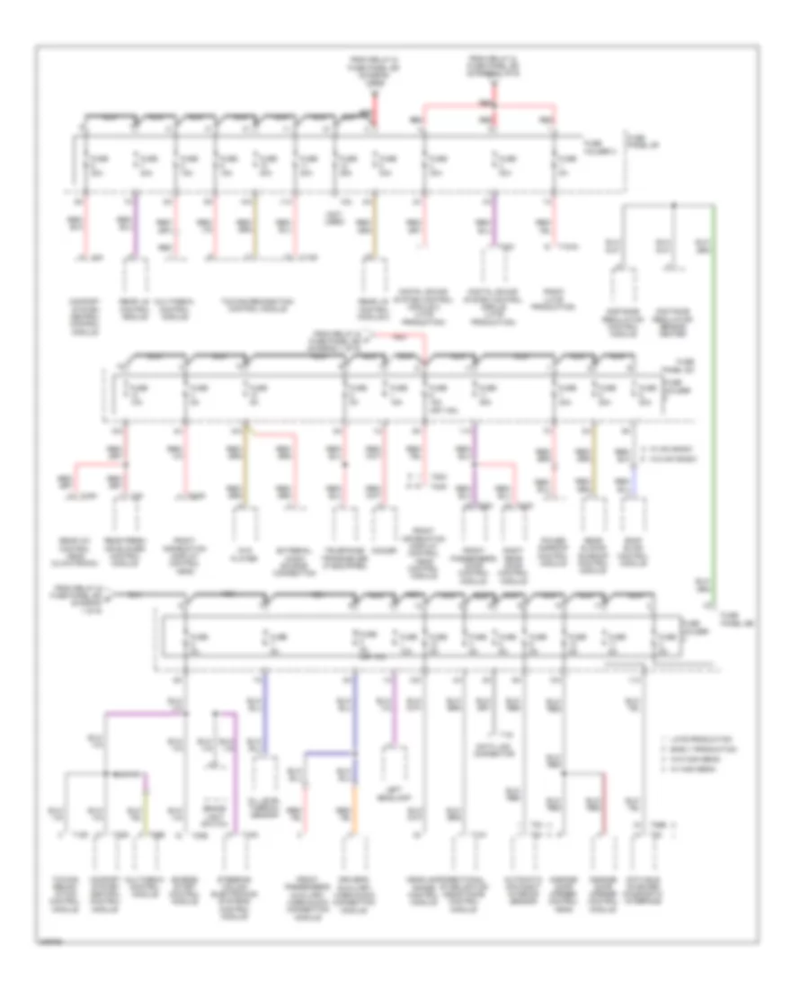
- Power distribution system
- Red
- Relay & fuse panel e-box (left side of plenum chamber)
- Relay & fuse panel/ instrument panel center (behind center of dash)
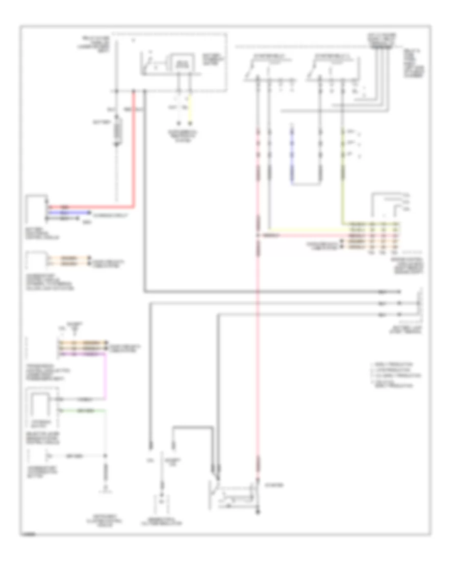
- Starter relay
- Starter relay 2
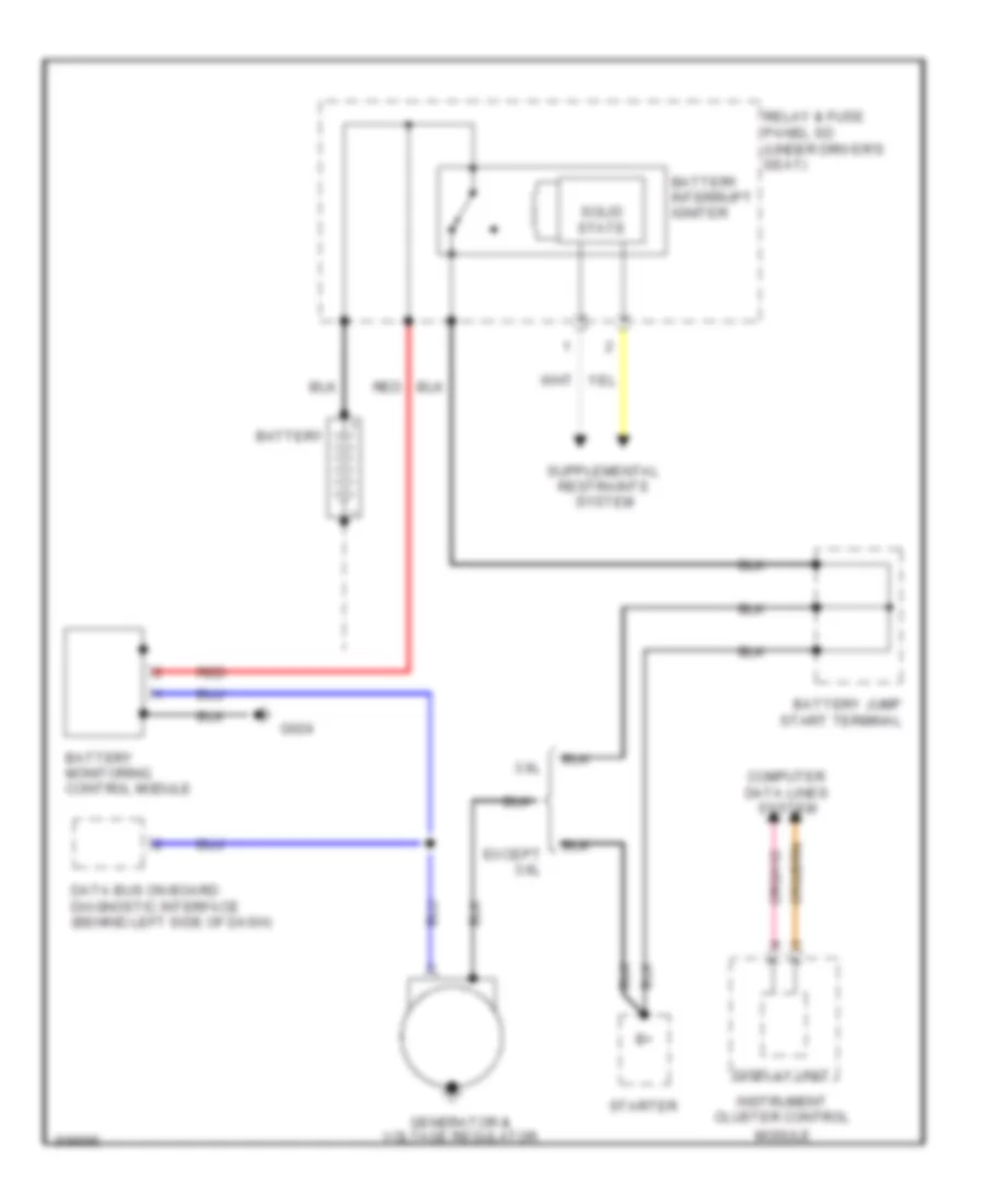
- Starting/ charging system
- T2a
- T2bz
- T6a
- T8a
- Transmissions system
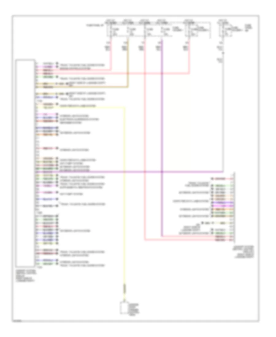
Anti-theft Wiring Diagram (1 of 2) for Audi Q7 4.2 2009
List of elements for Anti-theft Wiring Diagram (1 of 2) for Audi Q7 4.2 2009:
- (base of left "b" pillar) g77
- (behind left kick panel) g44
- 12a
- Alarm horn
- Alarm system off switch
- Central locking- safe-indicator lamp
- Comfort system central control module (right side of luggage compt)
- Computer data lines system
- Driver's door central locking lock unit
- Driver's door control module (in driver's door behind inner trim panel)
- Early production
- Front hood switch
- Fuse 15a
- Fuse 35a
- Fuse 5a
- Fuse holder
- Fuse panel sb
- G44 (behind left kick panel)
- G640 (left side of engine compt)
- G644
- G668 (on left "d" pillar)
- G77 (base of left "b" pillar)
- Horns system
- Hot at all times
- Interior lights system
- Late production
- Left rear central locking lock unit
- Left rear door control module (in left rear door behind inner trim panel)
- Rear lid control module 2
- T10g
- T20l
- T20n
- T32b
- T32d
- T32f
- Trunk lid alarm switch & decklid central locking system motor
- Vehicle electrical system control module (behind left side of dash)
- W/ rear lid opening
- W/o rear lid opening
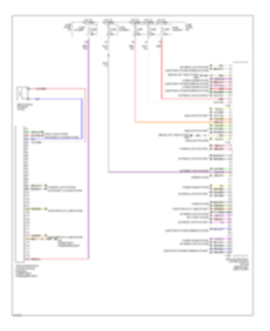
Anti-theft Wiring Diagram (2 of 2) for Audi Q7 4.2 2009
List of elements for Anti-theft Wiring Diagram (2 of 2) for Audi Q7 4.2 2009:
- 11a
- Computer data lines system
- Front passenger's door central locking lock unit
- Front passenger's door control module (in front passenger's door behind inner trim panel)
- Fuse 15a
- Fuse 35a
- Fuse holder
- Fuse panel sc
- G43 (behind right kick panel)
- G657 (on left "d" pillar)
- G78
- Hot at all times
- Late production early production
- Left rear window breakage sensor
- Rear window glass breakage sensor
- Right rear central locking lock unit
- Right rear door control module (in rear door behind inner trim panel)
- Right rear window breakage sensor
- T20m
- T20o
BODY CONTROL MODULES
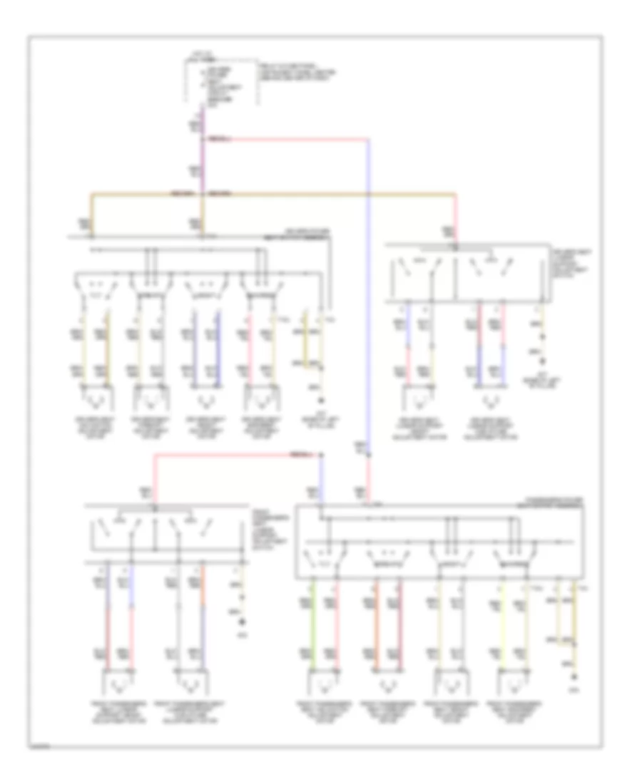
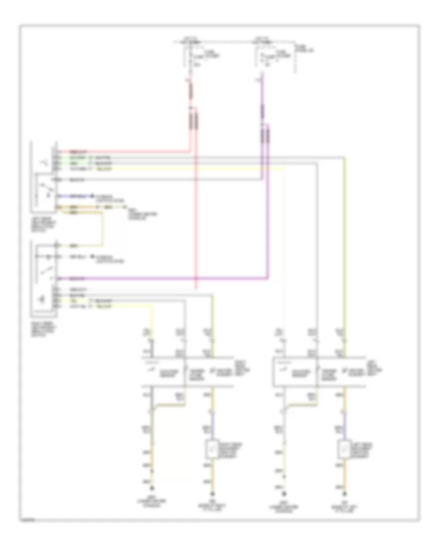
Body Computer Module Wiring Diagram (1 of 2) for Audi Q7 4.2 2009
List of elements for Body Computer Module Wiring Diagram (1 of 2) for Audi Q7 4.2 2009:
- (right side of luggage compt) g51
- 10a
- 12a
- Anti-theft system
- Comfort system central control module (right side of luggage compt)
- Comfort system central control module 2 (right side of luggage compt)
- Computer data lines system
- Defogger system
- Electronic suspension system
- Engine controls system
- Exterior lights system
- Fuse 15a
- Fuse 20a
- Fuse 30a
- Fuse 5a
- Fuse holder 1
- Fuse holder 3
- Fuse panel sb
- Fuse panel sf
- G51 (right side of luggage compt)
- Garage door opener control head
- Hot at all times
- Interior lights system
- T10g
- T15a
- T32d
- Trunk, tailgate, fuel doors system
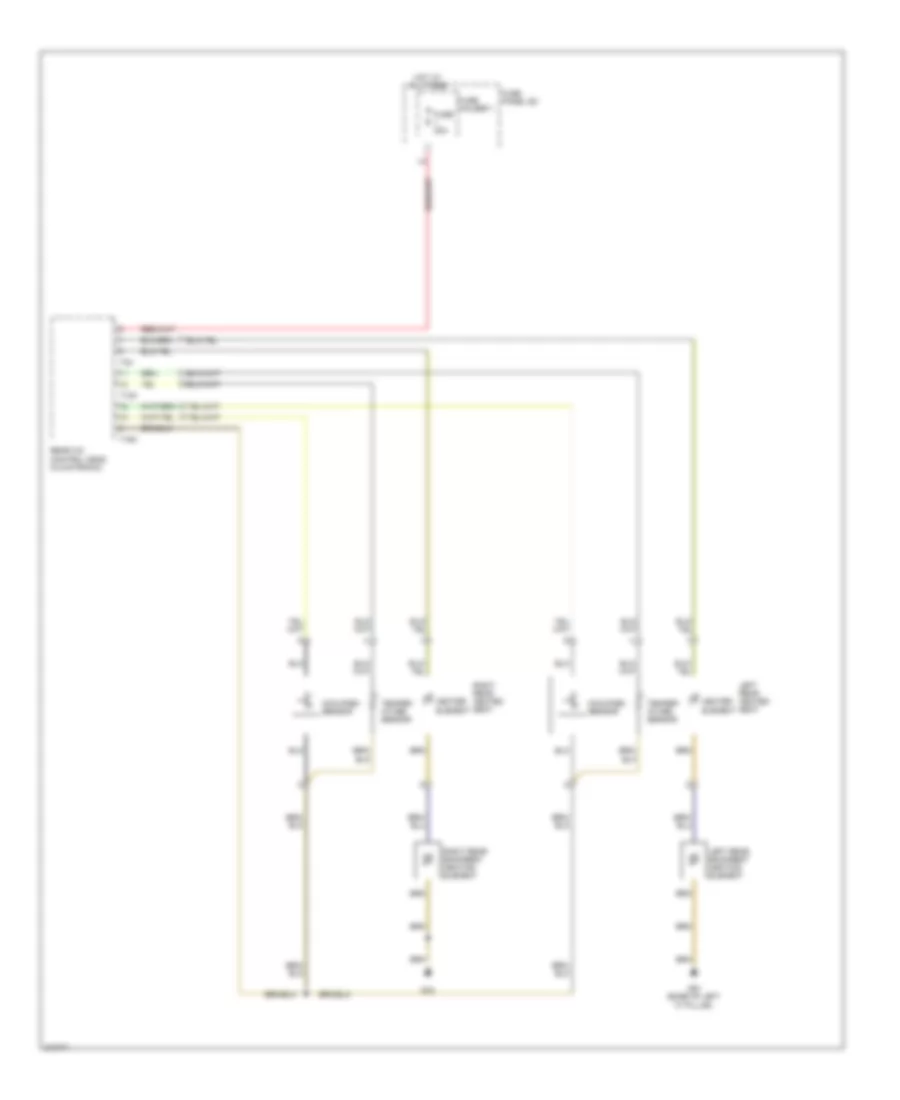
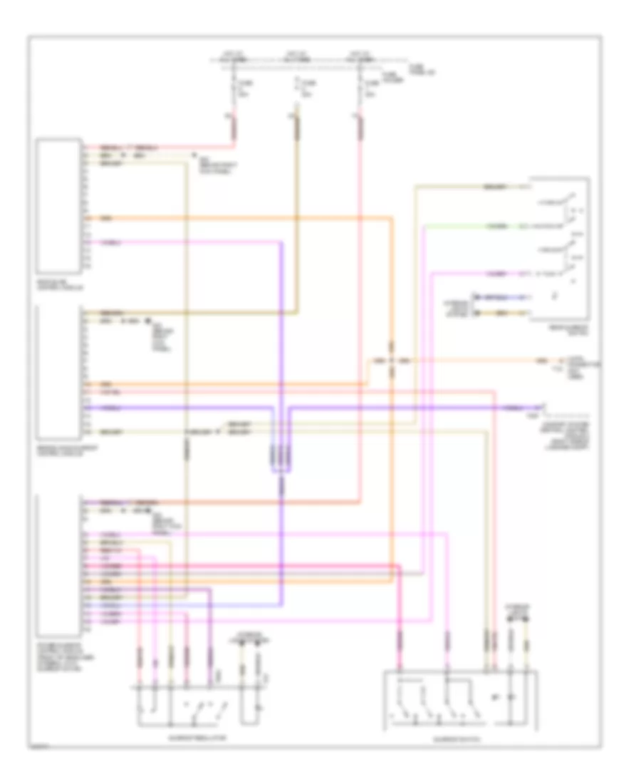
Body Computer Module Wiring Diagram (2 of 2) for Audi Q7 4.2 2009
List of elements for Body Computer Module Wiring Diagram (2 of 2) for Audi Q7 4.2 2009:
- (behind left side of dash) g664
- 12a
- Anti-theft system
- Computer data lines system
- Door locks system
- Electronic power steering system
- Exterior lights system
- Fuse 15a
- Fuse 25a
- Fuse 30a
- Fuse 5a
- Fuse holder 1
- Fuse holder 2
- Fuse holder 3
- Fuse panel sb
- Fuse panel sc
- G35 (under front passenger's seat)
- Headlights system
- Horns system
- Hot at all times
- Instrument cluster system
- Interior lights system
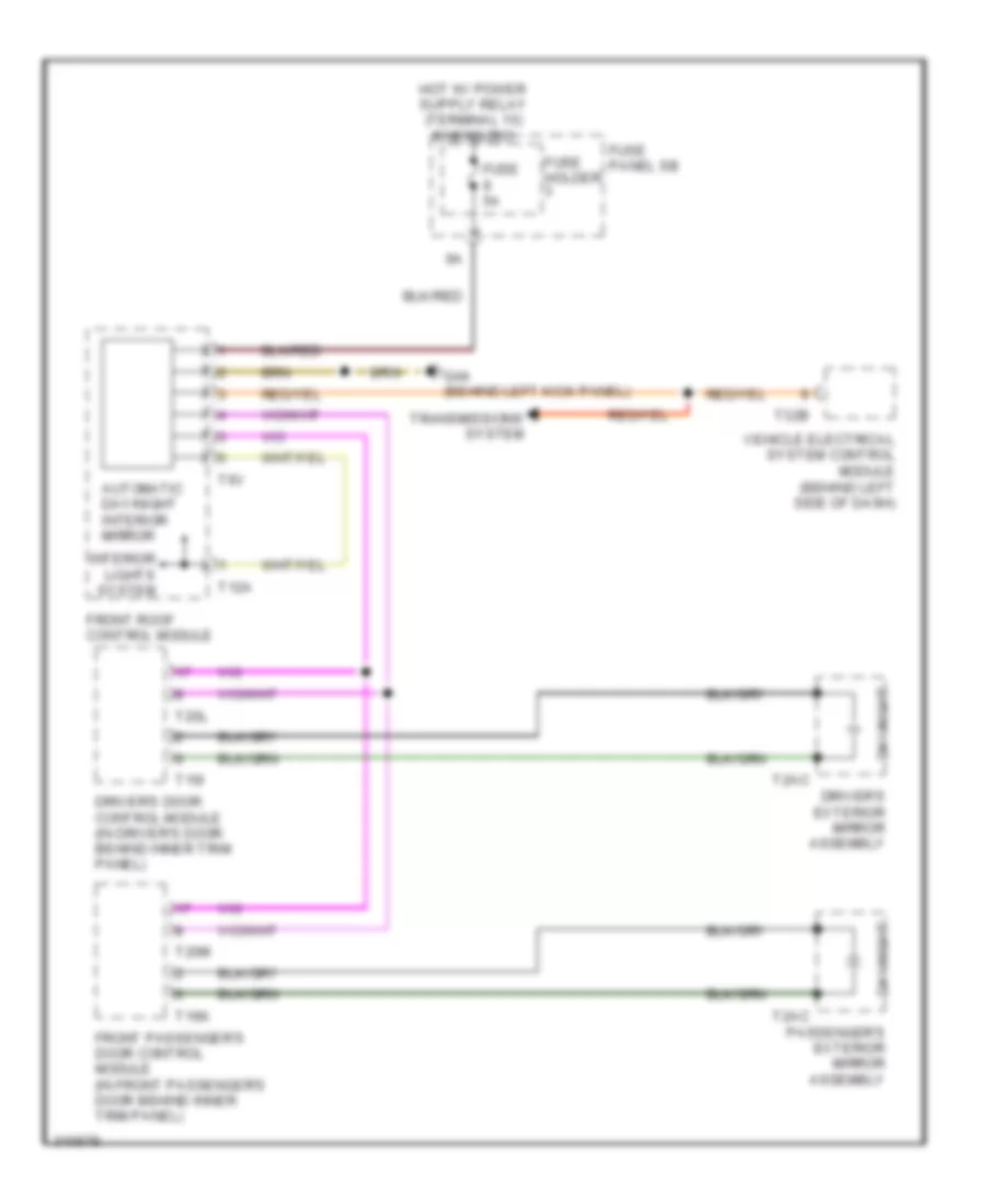
- Mirror system
- Red
- Servotronic solenoid valve
- T10a
- T12b
- T32b
- Vehicle electrical system control module (behind left side of dash)
- Vehicle electrical system control module 2 (under front passenger's seat)
- Wiper/washer system
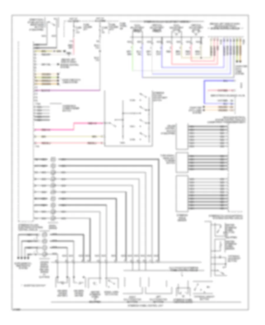
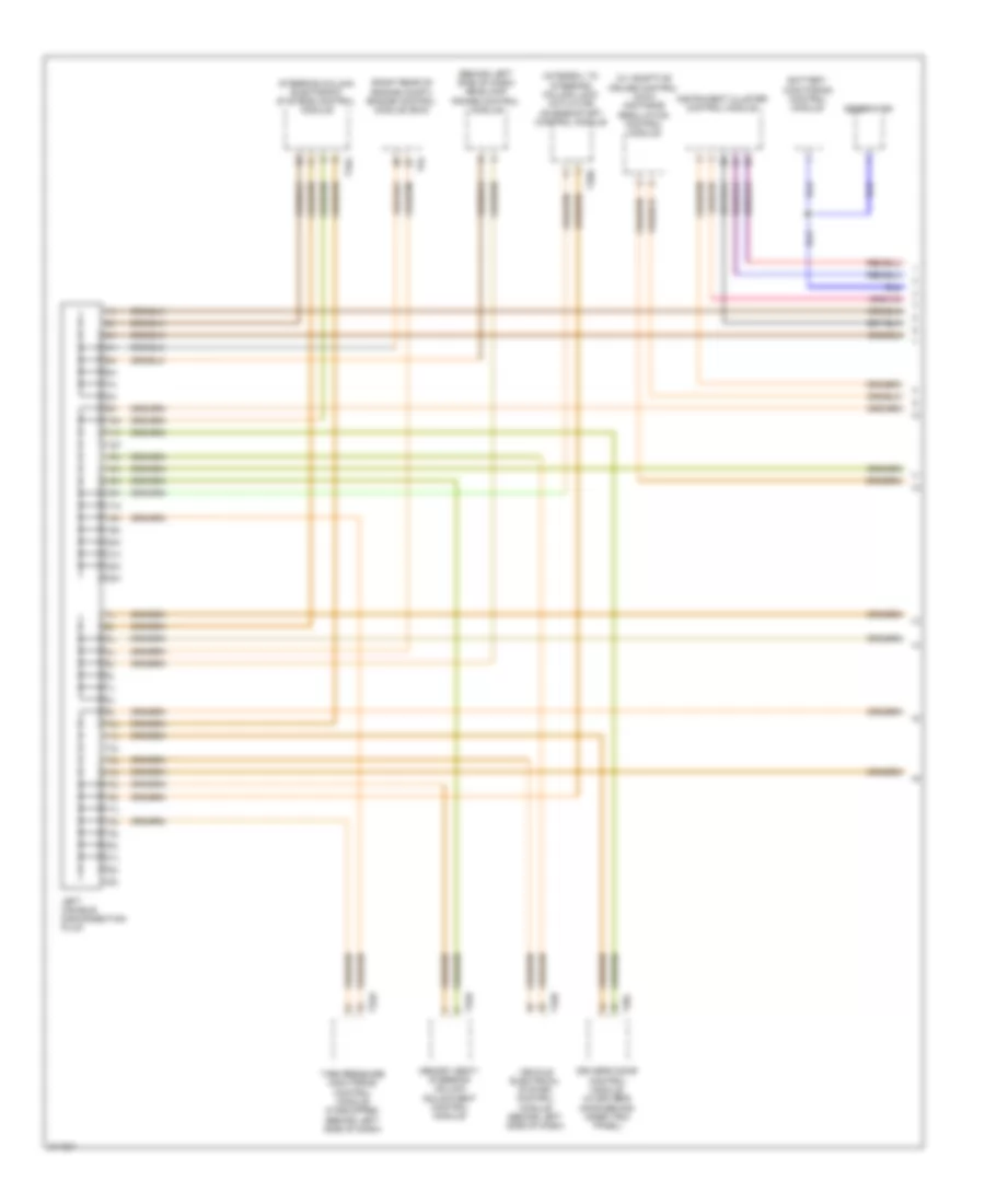
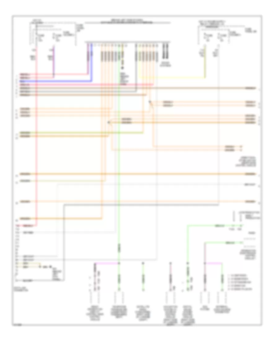
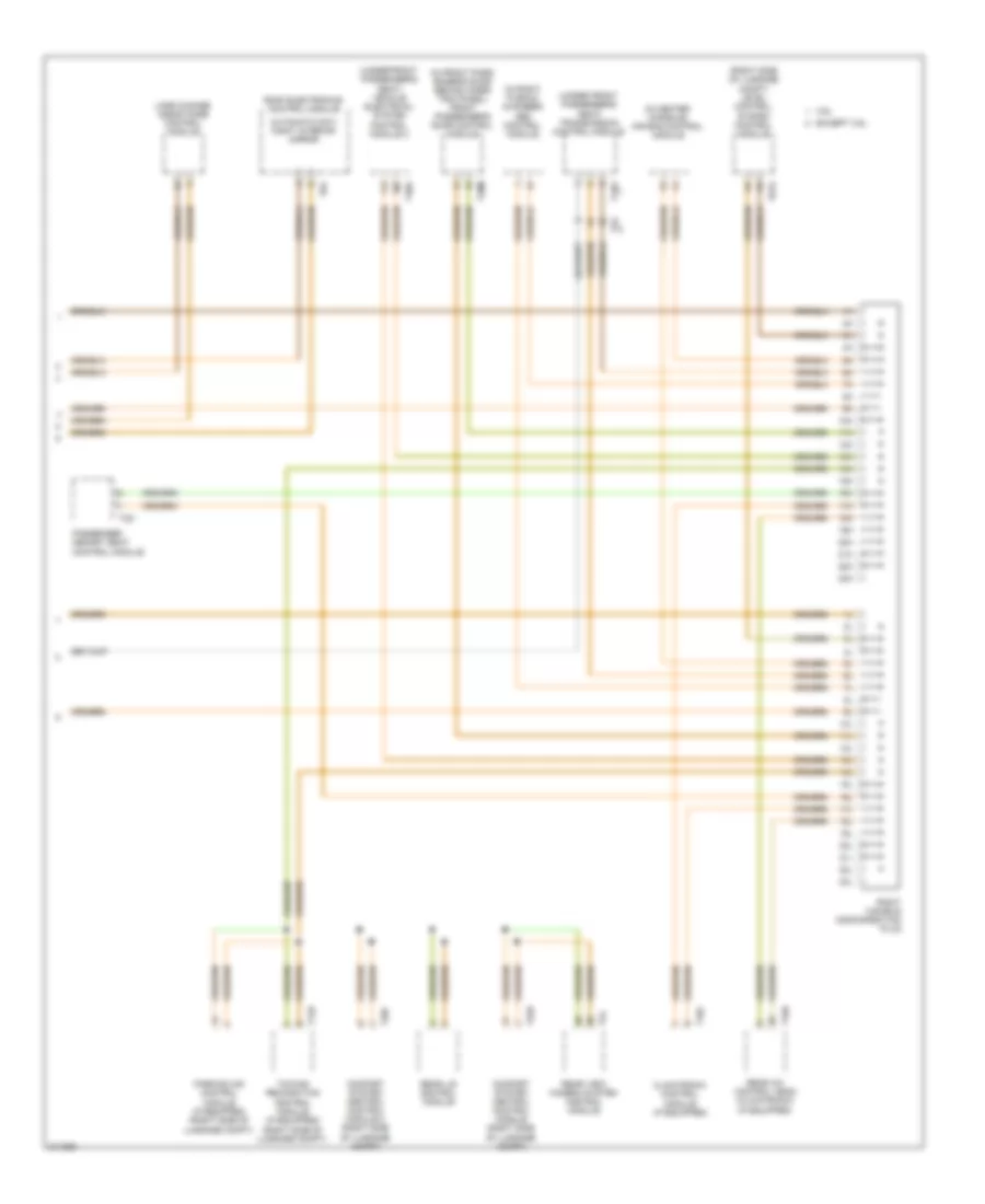
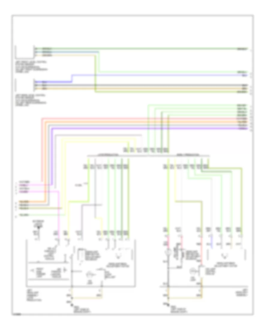
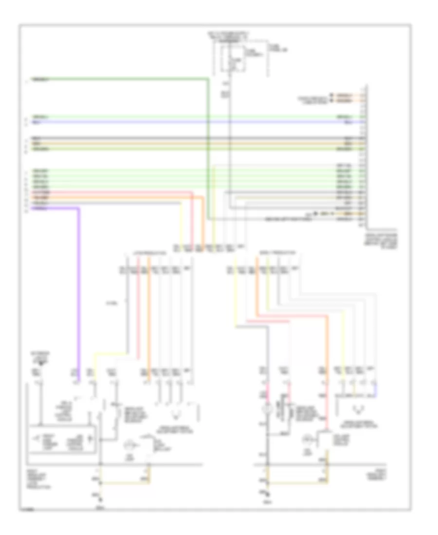
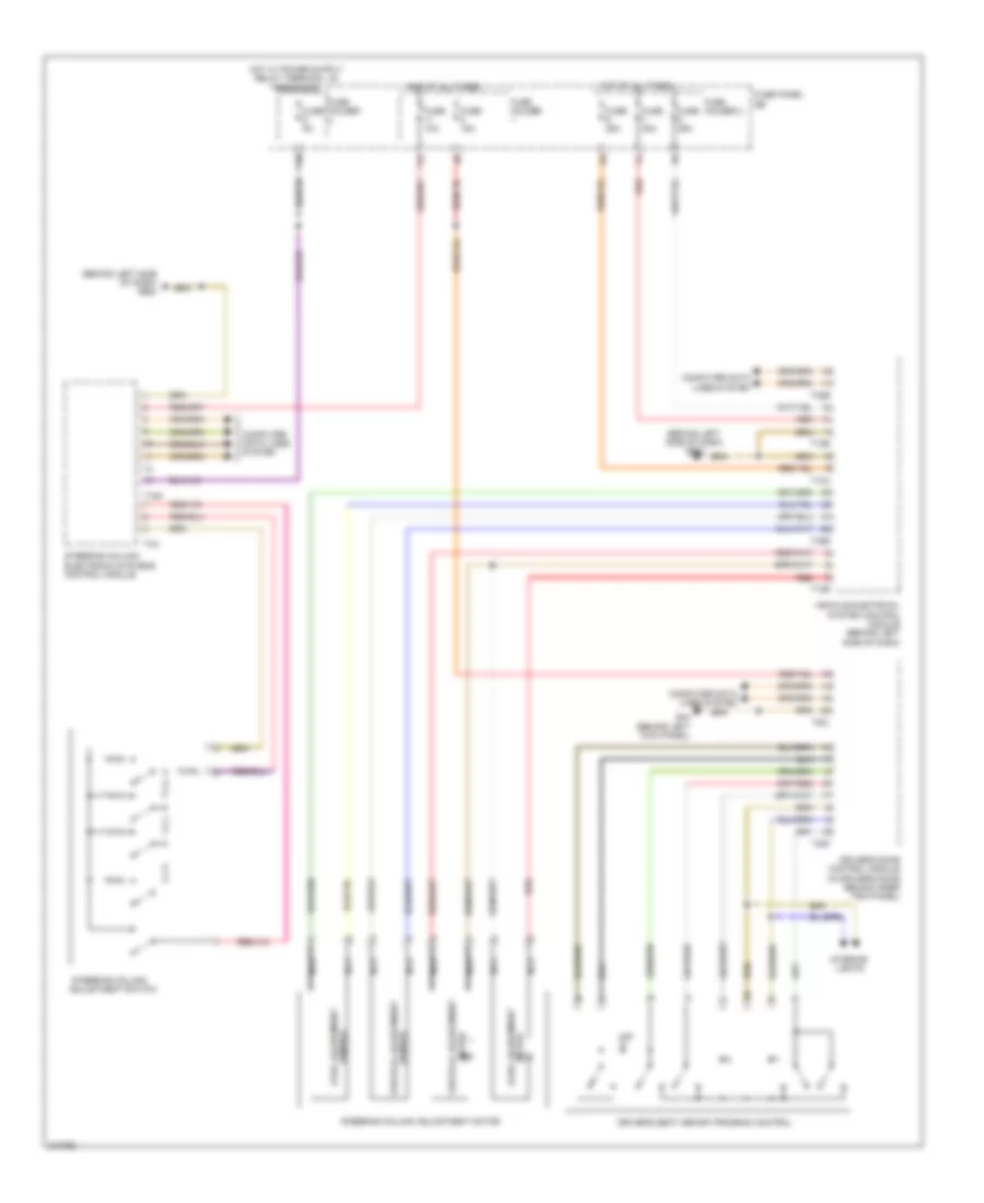
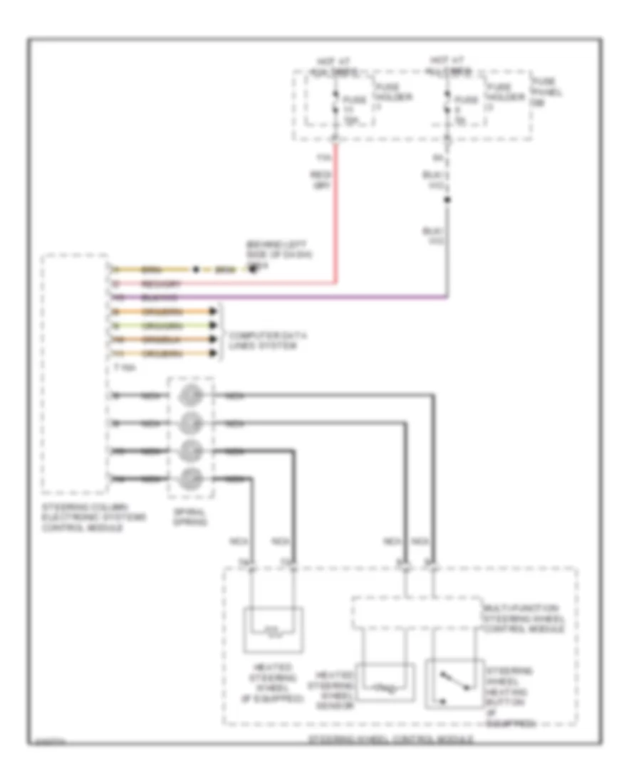
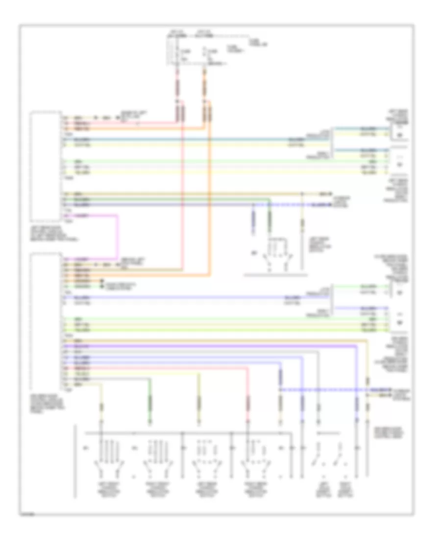
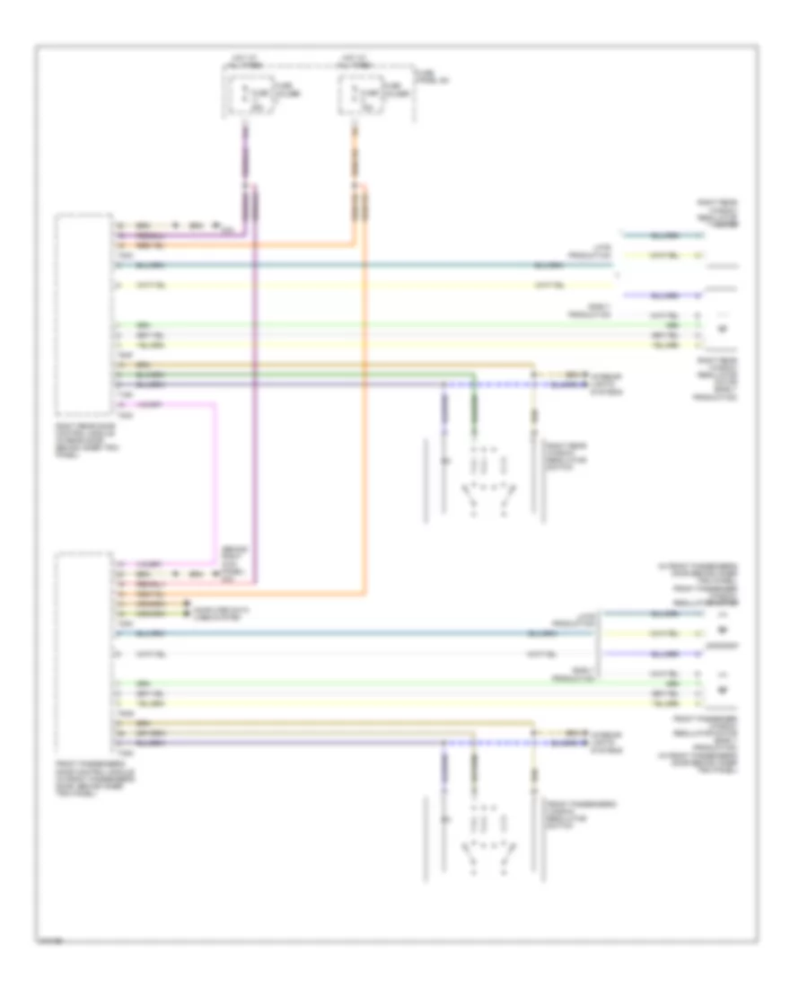
Steering Column Electronic Systems Control Module Wiring Diagram for Audi Q7 4.2 2009
List of elements for Steering Column Electronic Systems Control Module Wiring Diagram for Audi Q7 4.2 2009:
- (behind left side of dash)
- (behind left side of dash) vehicle electrical system control module
- 11a
- Air bag spiral spring/ return spring w/ slip ring
- Axial adjustment motor
- Axial adjustment sensor
- Computer data lines system
- Cruise control switch (if equipped)
- Directional stabilization assistance button (if equipped)
- Driver's air bag igniter
- Driver's air bag igniter 2
- Engine control system
- Fuse 10a
- Fuse 5a
- Fuse holder st1
- Fuse holder st3
- Fuse panel sb
- G664
- Heated steering wheel (if equipped)
- Heated steering wheel button (if equipped)
- Heated steering wheel sensor
- Hot at all times
- Left multi-function buttons
- Multi-function steering wheel control module
- Nca
- Red
- Right multi-function buttons
- Servotronic solenoid valve
- Shorting contact
- Signal horn activation
- Spiral spring
- Steering angle sensor
- Steering column adjustment assembly
- Steering column adjustment switch
- Steering column electronic systems control module
- Steering wheel control unit
- Steering wheel vibration motor
- T12b
- T16a
- T32b
- T4a
- Tiptronic downshift button
- Tiptronic upshift button
- Turn signal/ headlight flasher switch
- Vehicle electrical system control module 2 (under front passenger's seat)
- Vertical adjustment motor
- Vertical adjustment sensor
- Windshield wiper/washer switch
COMPUTER DATA LINES
Computer Data Lines Wiring Diagram (1 of 3) for Audi Q7 4.2 2009
List of elements for Computer Data Lines Wiring Diagram (1 of 3) for Audi Q7 4.2 2009:
- (behind left side of dash) headlamp range control module
- (integral to steering column lock actuator) access/start control module
- (right rear of engine compt) engine control module (ecm)
- (w/ adaptive cruise control (acc)) distance regulation control module
- 10h
- 10l
- 11h
- 11l
- 12h
- 12l
- 13h
- 13l
- 14h
- 14l
- 15h
- 15l
- 16h
- 16l
- 17h
- 17l
- 18h
- 18l
- 19h
- 19l
- 20h
- 20l
- 21h
- 21l
- 22h
- 22l
- 23h
- 23l
- Battery monitoring control module
- Driver's door control module (in driver's door behind inner trim panel)
- Generator
- Instrument cluster control module
- Left can-bus disconnection plug
- Memory seat/ steering column adjustment control module
- Steering column electronic systems control module
- T16a
- T20e
- T20l
- T32b
- T32e
- T32h
- T94
- Tire pressure monitoring control module (if equipped) (behind left side of dash)
- Vehicle electrical system control module (behind left side of dash)
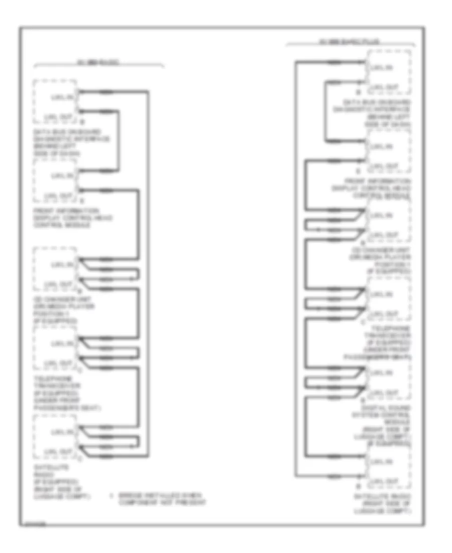
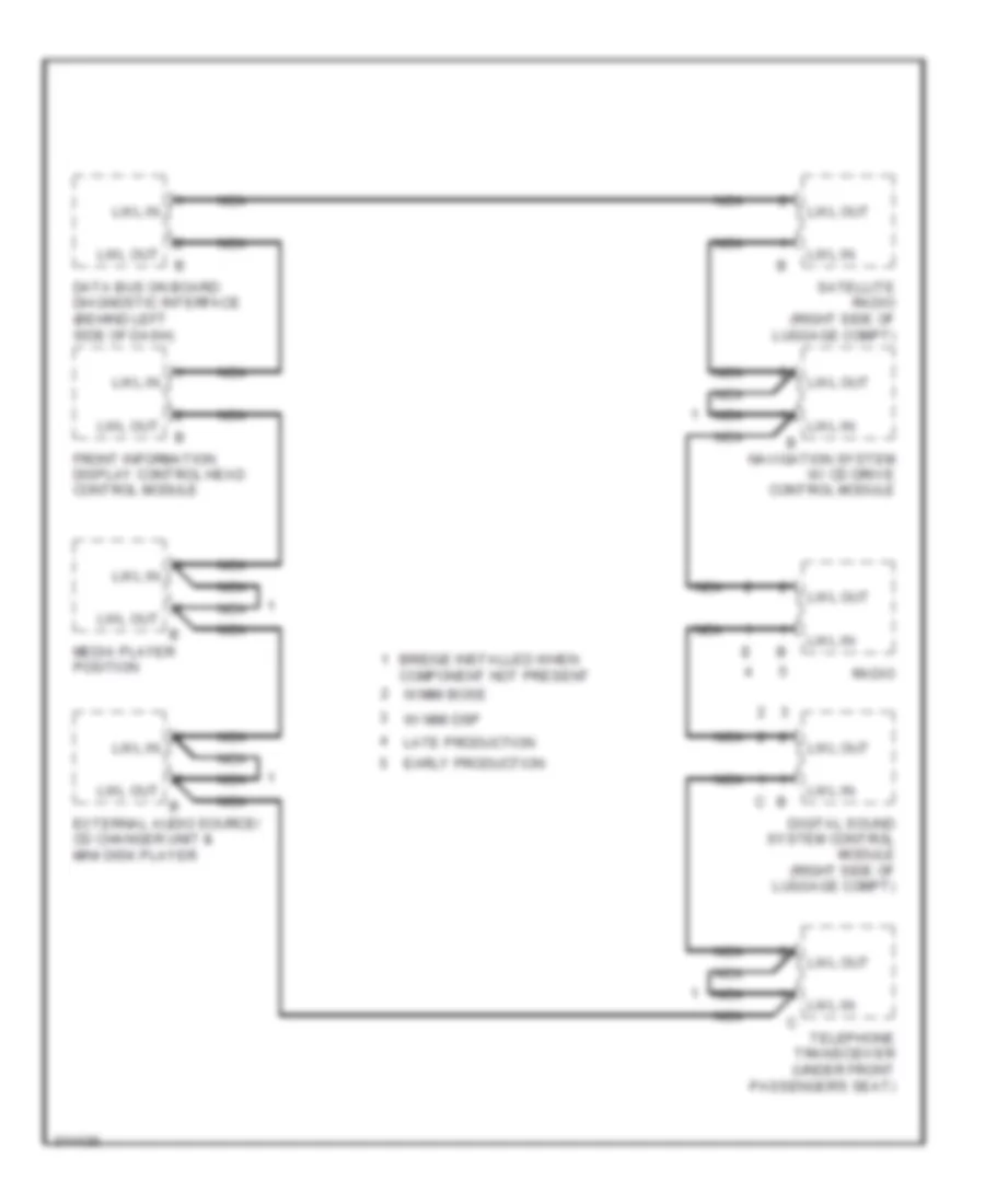
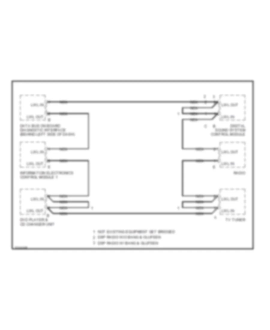
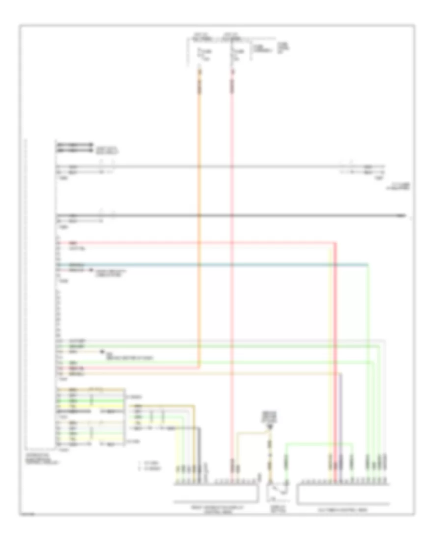
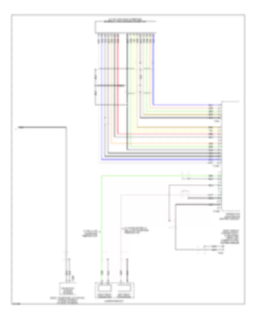
Computer Data Lines Wiring Diagram (2 of 3) for Audi Q7 4.2 2009
List of elements for Computer Data Lines Wiring Diagram (2 of 3) for Audi Q7 4.2 2009:
- (behind left side of dash) data bus on board diagnostic interface
- 10a
- 11a
- 12a
- Data link connector
- Digital sound system control module (right side of luggage compt)
- Directional stabilization assistance control module
- Dvd player
- Early production
- External audio source connection
- Front information display control head control module
- Fuse 10a
- Fuse 5a
- Fuse holder 2
- Fuse holder 3
- Fuse panel sb
- G44 (behind left kick panel)
- G664 (behind left side of dash)
- Hot at all times
- Information electronics control module 1
- Late production
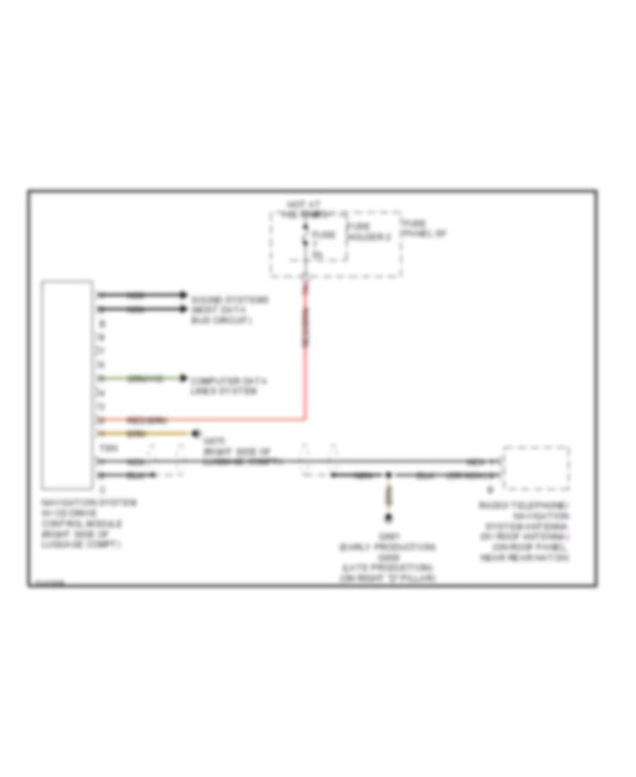
- Navigation system w/ cd drive control module (right side of luggage compt)
- Nca
- Radio
- Satellite radio (if equipped) (right side of luggage compt)
- Sound systems
- T10a
- T12p
- T20k
- T32c
- T8k
- T8n
- T8p
- Telephone transceiver (under front passenger's seat)
- W/ basic mmi
- W/ basic plus mmi
- W/ bose radio
- W/ dsp radio
- W/ standard mmi
Computer Data Lines Wiring Diagram (3 of 3) for Audi Q7 4.2 2009
List of elements for Computer Data Lines Wiring Diagram (3 of 3) for Audi Q7 4.2 2009:
- (in center console) air bag control module
- (in front pass- enger's door behind inner trim panel) front passenger's door control module
- (in right plenum chamber) abs control module
- (right side of luggage compt) level control system control module
- (under front passenger's seat) transmission control module
- (under front passenger's seat) vehicle electrical system control module 2
- 10h
- 10l
- 11h
- 11l
- 12h
- 12l
- 13h
- 13l
- 14h
- 14l
- 15h
- 15l
- 16h
- 16l
- 17h
- 17l
- 18h
- 18l
- 19h
- 19l
- 20h
- 20l
- 21h
- 21l
- 22h
- 22l
- 23h
- 23l
- 3.6l
- Automatic day/ night interior mirror
- Climatronic control module (if equipped)
- Comfort system central control module (right side of luggage compt)
- Comfort system central control module 2 (right side of luggage compt)
- Except 3.6l
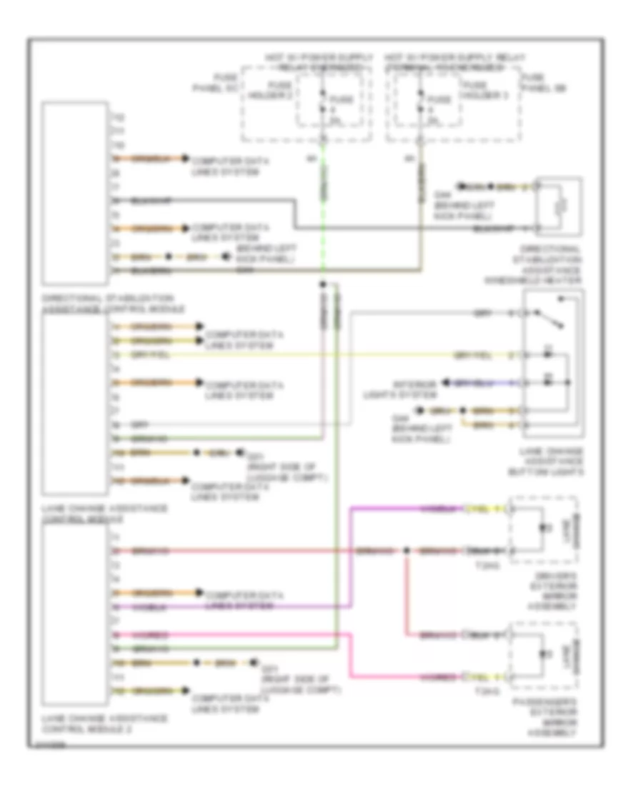
- Lane change assistance control module
- Parking aid control module (if equipped) (right side of luggage compt)
- Passenger memory seat control module
- Rear a/c control head (climatronic) (if equipped)
- Rear lid control module
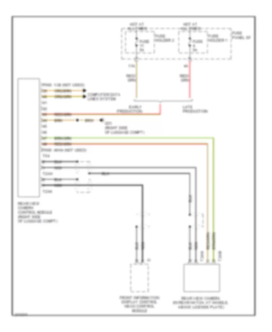
- Rear view camera system control module
- Right can-bus disconnection plug
- Roof electronics control module
- T12d
- T16c
- T16g
- T16h
- T20f
- T20m
- T32d
- T32i
- T40a
- T52
- T54
- T81a
- T8x
- Towing recognition control module (if equipped) (right side of luggage compt)
COOLING FAN
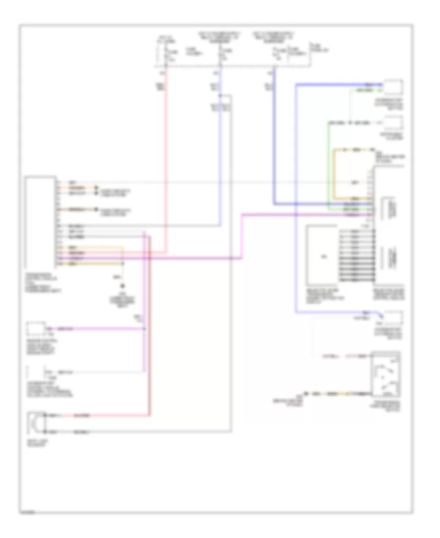
Cooling Fan Wiring Diagram (1 of 2) for Audi Q7 4.2 2009
List of elements for Cooling Fan Wiring Diagram (1 of 2) for Audi Q7 4.2 2009:
- (behind right kick panel) g43
- (except 3.6l) coolant circulation pump relay
- 3.6l
- Climatronic control module
- Cooler
- Cooler fuse
- Except 3.6l
- Fresh air blower (behind glove box, in hvac housing)
- Fresh air blower control module (under passenger's side dash panel)
- Fuse 15a
- Fuse 30a
- Fuse 40a
- Fuse holder
- Fuse panel sc
- G609 (right side of plenum chamber)
- G62 (base of right "c" pillar)
- High pressure sensor
- Hot at all times
- Relay & fuse panel instrument panel center (behind center of dash)
- T16c
- T16d
- T2q
- T3c
- T6ai
Cooling Fan Wiring Diagram (2 of 2) for Audi Q7 4.2 2009
List of elements for Cooling Fan Wiring Diagram (2 of 2) for Audi Q7 4.2 2009:
- 10a
- 13a
- 19a
- 19b
- 19c
- 19d
- 19e
- 3.0l
- 3.6l
- 4.2l
- Computer data lines system
- Coolant fan
- Coolant fan 2
- Coolant fan control module
- Coolant fan control module 2
- Coolant pump (in left front wheel well)
- Ect sensor
- Engine control module (right rear of engine compt)
- Engine coolant temperature (ect) sensor (on radiator) (3.0l: right side of radiator) (except 3.0l: in upper radiator hose)
- Except 3.0l
- Except 3.6l
- Fuse 10a
- Fuse 15a
- Fuse 40a
- Fuse 5a
- Fuse 60a
- G609 (3.6l) (right side of plenum chamber)
- G640 (except 3.6l) (left side of engine compt)
- G671 (on left front long member)
- Recirculation pump relay (3.6l)
- Relay & fuse panel e-box (left side of plenum chamber)
- T60
- T94
CRUISE CONTROL
Cruise Control Wiring Diagram for Audi Q7 4.2 2009
List of elements for Cruise Control Wiring Diagram for Audi Q7 4.2 2009:
- (behind left side of dash) g664
- 11a
- 3.6l & 4.2l
- 3.ol
- Brake light switch & brake pedal switch
- Computer data lines system
- Cruise control switch (if equipped)
- Distance regulation control module (if equipped)
- Distance regulation sensor heater
- Engine control module (ecm) (right rear of engine compt)
- Engine controls system
- Fuse 10a
- Fuse 15a
- Fuse 5a
- Fuse holder
- Fuse panel sb
- G44 (behind left kick panel)
- G609 (right side of plenum chamber)
- G640 (left side of engine compt)
- Hot at all times
- Nca
- Relay & fuse panel e-box (left side of plenum chamber)
- Steering column electronic systems control module
- T16a
- T60
- T94
- Throttle position (tp) sensor & accelerator pedal position sensor 2 (in accelerator pedal assembly)
- Throttle valve control module (3.0l) (at back of intake manifold)
- Throttle valve control module (3.6l & 4.2l) (at back of intake manifold)
- Transmission control module (tcm) (except 3.0l) (under front passenger's seat)
- Transmission input speed (rpm) sensor
- Transmission output speed (rpm) sensor
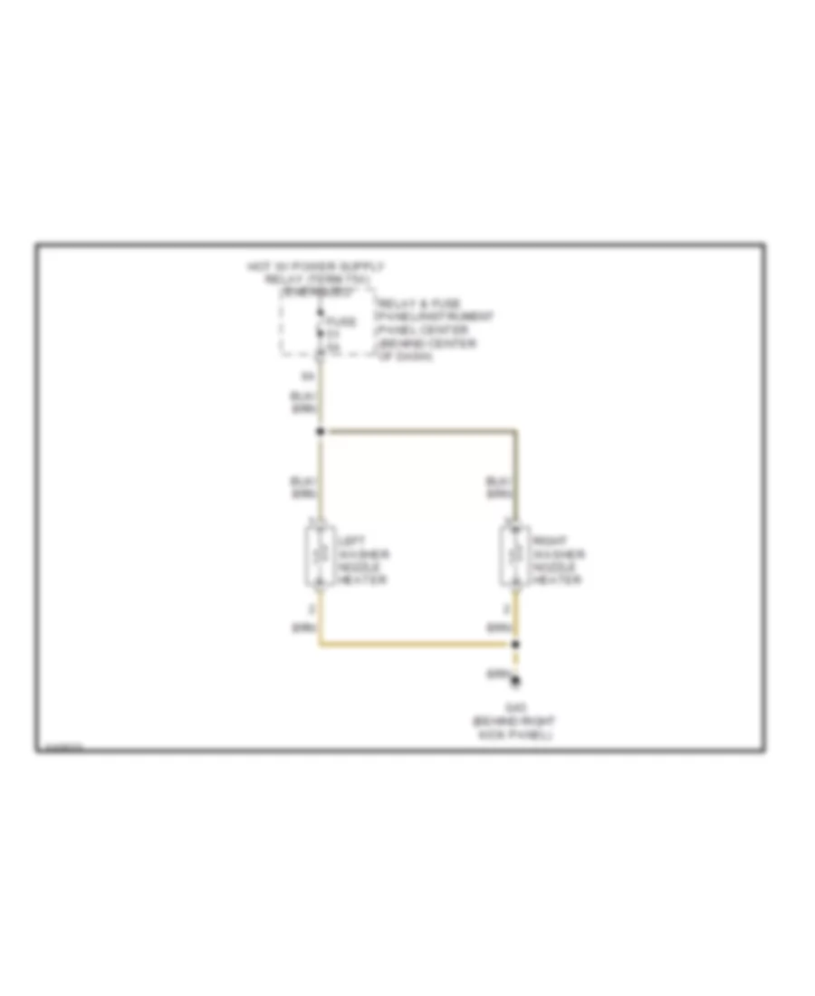
DEFOGGERS
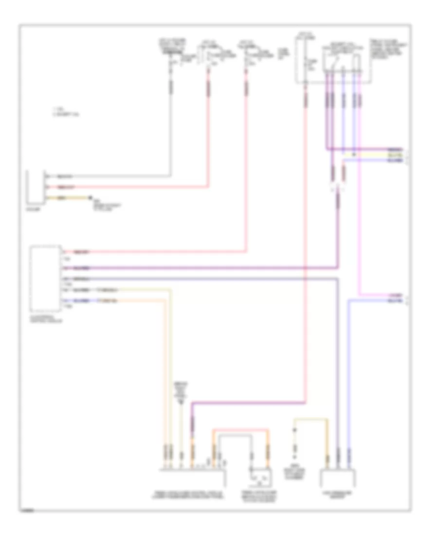
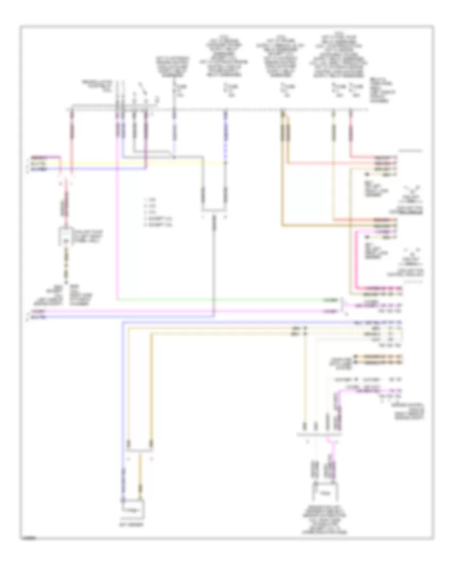
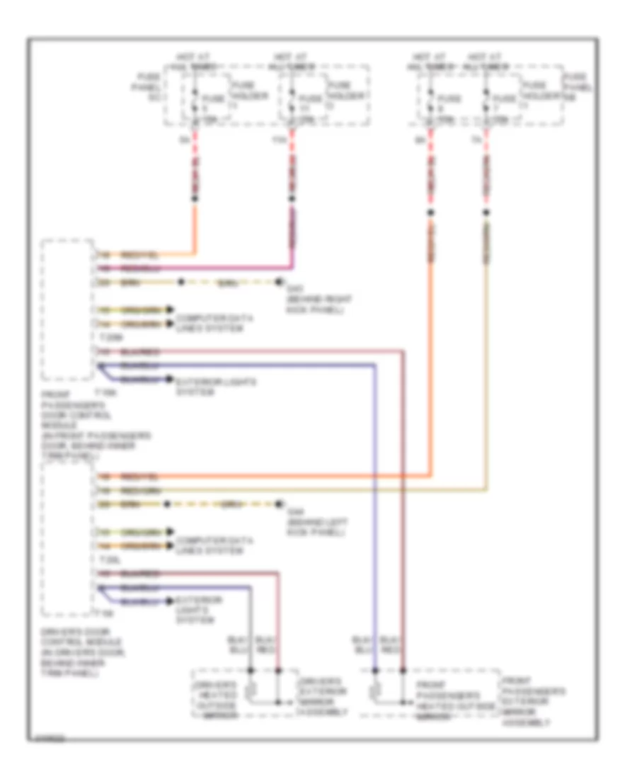
Heated Mirrors Wiring Diagram for Audi Q7 4.2 2009
List of elements for Heated Mirrors Wiring Diagram for Audi Q7 4.2 2009:
- 11a
- Computer data lines system
- Driver's door control module (in driver's door, behind inner trim panel)
- Driver's exterior mirror assembly
- Driver's heated outside mirror
- Exterior lights system
- Front passenger's door control module (in front passenger's door, behind inner trim panel)
- Front passenger's exterior mirror assembly
- Front passenger's heated outside mirror
- Fuse 15a
- Fuse 35a
- Fuse holder
- Fuse panel sb
- Fuse panel sc
- G43 (behind right kick panel)
- G44 (behind left kick panel)
- Hot at all times
- T16i
- T16k
- T20l
- T20m
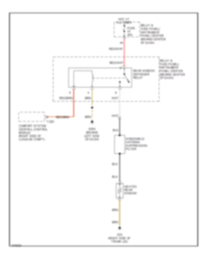
Rear Defogger Wiring Diagram for Audi Q7 4.2 2009
List of elements for Rear Defogger Wiring Diagram for Audi Q7 4.2 2009:
- Comfort system central control module (right side of luggage compt)
- Fuse 40a
- G53 (right side of trunk lid)
- G664 (behind left side of dash)
- Heated rear window
- Hot at all times
- Rear window defogger relay
- Relay & fuse panel/ instrument panel center (behind center of dash)
- T32d
- Windshield antenna suppression filter
ELECTRONIC POWER STEERING
Electronic Power Steering Wiring Diagram for Audi Q7 4.2 2009
List of elements for Electronic Power Steering Wiring Diagram for Audi Q7 4.2 2009:
- (behind left side of dash)
- (behind left side of dash) vehicle electrical system control module
- 11a
- Air bag spiral spring/ return spring w/ slip ring
- Axial adjustment motor
- Axial adjustment sensor
- Computer data lines system
- Cruise control switch (if equipped)
- Directional stabilization assistance button (if equipped)
- Driver's air bag igniter
- Driver's air bag igniter 2
- Engine control system
- Fuse 10a
- Fuse 5a
- Fuse holder st1
- Fuse holder st3
- Fuse panel sb
- G664
- Heated steering wheel (if equipped)
- Heated steering wheel button (if equipped)
- Heated steering wheel sensor
- Hot at all times
- Left multi-function buttons
- Multi-function steering wheel control module
- Nca
- Red
- Right multi-function buttons
- Servotronic solenoid valve
- Shorting contact
- Signal horn activation
- Spiral spring
- Steering angle sensor
- Steering column adjustment assembly
- Steering column adjustment switch
- Steering column electronic systems control module
- Steering wheel control unit
- Steering wheel vibration motor
- T12b
- T16a
- T32b
- T4a
- Tiptronic downshift button
- Tiptronic upshift button
- Turn signal/ headlight flasher switch
- Vehicle electrical system control module 2 (under front passenger's seat)
- Vertical adjustment motor
- Vertical adjustment sensor
- Windshield wiper/washer switch
ELECTRONIC SUSPENSION
Electronic Suspension Wiring Diagram (1 of 3) for Audi Q7 4.2 2009
List of elements for Electronic Suspension Wiring Diagram (1 of 3) for Audi Q7 4.2 2009:
- (partial)
- (right side of luggage compt) g51
- Accumulator valves
- Comfort system central control module (right side of luggage compt)
- Fuse 15a
- Fuse 5a
- Fuse panel c
- Fuse panel f
- Hot at all times
- Interior lights system
- Level control pressure sensor
- Level control system control module (right side of luggage compt)
- Load level button
- Suppression strut valves
- T32d
- T81a
- Valve body
Electronic Suspension Wiring Diagram (2 of 3) for Audi Q7 4.2 2009
List of elements for Electronic Suspension Wiring Diagram (2 of 3) for Audi Q7 4.2 2009:
- (partial)
- Compressor motor
- Computer data lines system
- Fuse 40a
- G35 (under front passenger's seat)
- Hot at all times
- Left front level control system sensor (on left front suspension upper link)
- Left rear level control system sensor (on left rear suspension upper link)
- Level control system assembly
- Level control system compressor relay
- Level control system control module (right side of luggage compt)
- Pump temperature sensor
- Red
- Relay & fuse panel/instrument panel center (behind center of dash)
- Right front level control system sensor
- Self- leveling system fuse
- Solenoid
- T2i
- T4i
- T81a
Electronic Suspension Wiring Diagram (3 of 3) for Audi Q7 4.2 2009
List of elements for Electronic Suspension Wiring Diagram (3 of 3) for Audi Q7 4.2 2009:
- Left front body acceleration sensor (in left front wheelwell)
- Left front dampening adjustment valve (on left front strut)
- Left rear dampening adjustment valve (on left rear suspension strut)
- Level control system control module (right side of luggage compt)
- Nca
- Rear body acceleration sensor (in luggage compt, on left side of floor)
- Red
- Right front body acceleration sensor (above right front wheelwell liner)
- Right front dampening adjustment valve (on right front strut assembly)
- Right rear dampening adjustment valve (on right rear strut assembly)
- Right rear level control system sensor (on right rear suspension upper link)
- T40b
ENGINE PERFORMANCE
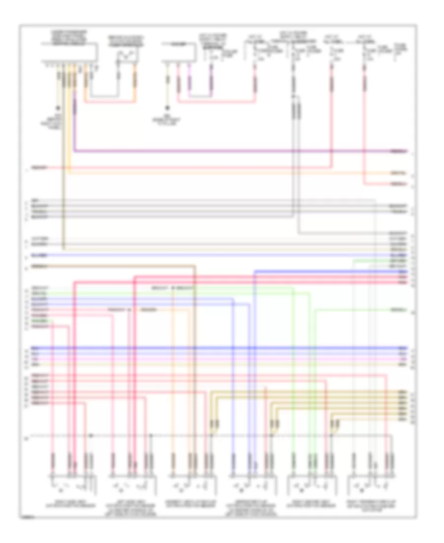
3.0L TURBO
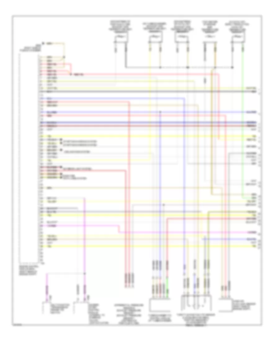
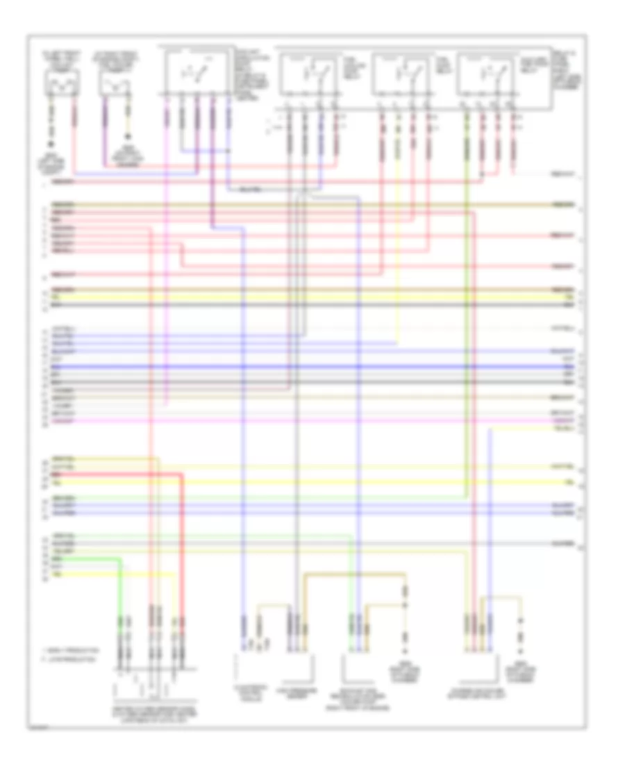
3.0L Turbo, Engine Performance Wiring Diagram (1 of 8) for Audi Q7 4.2 2009
List of elements for 3.0L Turbo, Engine Performance Wiring Diagram (1 of 8) for Audi Q7 4.2 2009:
- (downstream of catalyst) exhaust gas temperature (egt) sensor 3
- (downstream of particle filter) exhaust gas temperature (egt) sensor 4
- (in catalyst) (early production) catalyst temperature sensor 1
- (on turbocharger) exhaust gas temperature (egt) sensor 1
- (top center of engine) egr temperature sensor
- Access/ start control module (integral to steering column lock actuator)
- Computer
- Cooling fans system
- Data lines system
- Differential pressure sensor & exhaust pressure sensor 1 (exhaust pressure sensor 1: upstream of particle filter)
- Engine control module (ecm) (right rear of engine compt)
- Exterior light system
- G609 (right side of plenum chamber)
- Mass air flow (maf) sensor (right side of engine compt)
- Multi-function transmission range (tr) switch
- Red
- Starting/charging system
- T10p
- T20e
- T94
- Throttle position (tp) sensor & accelerator pedal position sensors 2 (in accelerator pedal assembly)
- Turbocharger (tc) control module (at turbocharger)
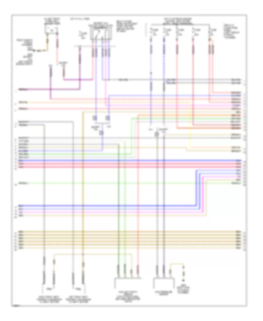
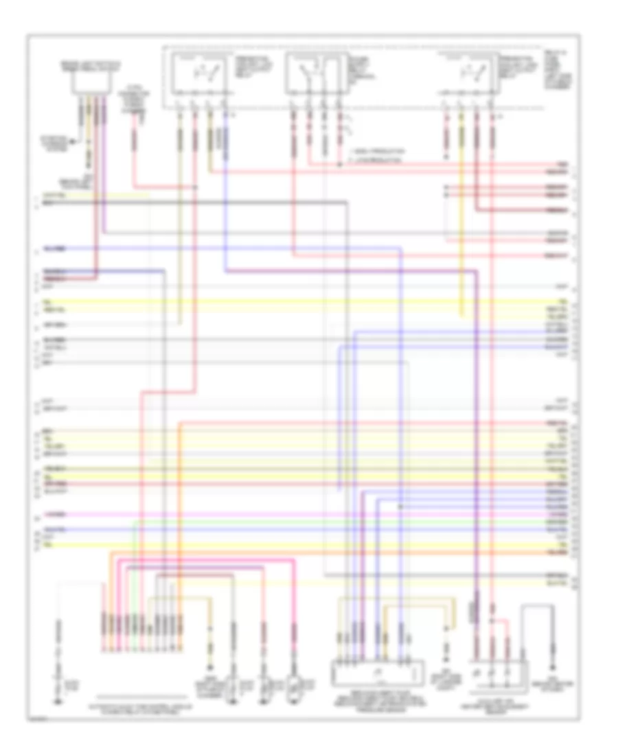
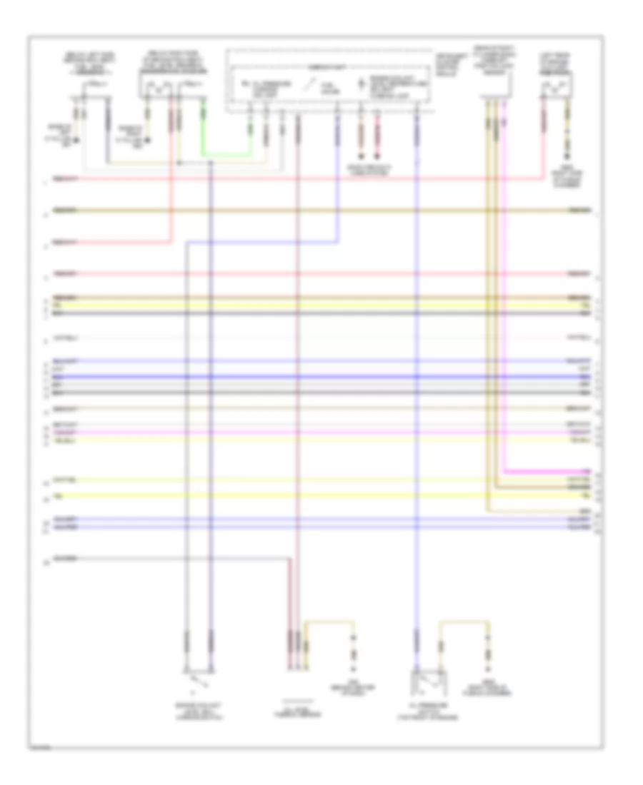
3.0L Turbo, Engine Performance Wiring Diagram (2 of 8) for Audi Q7 4.2 2009
List of elements for 3.0L Turbo, Engine Performance Wiring Diagram (2 of 8) for Audi Q7 4.2 2009:
- 10 pin connector in e-box plenum chamber
- 20a
- 20b
- 20c
- 20d
- Automatic glow time control module (in e-box relay & fuse panel)
- Auxiliary air heater heating element sensor
- Brake light switch & break pedal switch
- Early production
- G44 (behind left kick panel)
- G45 (behind center of dash)
- G51 (right side of luggage compt)
- G609 (right side of plenum chamber)
- Glow plug
- Late production
- Preheating coolant, high heat output relay
- Preheating coolant, low heat output relay
- Red
- Reducing agent pump, reducing agent pump heater & reducing agent metering system pressure sensor
- Relay & fuse panel e-box (left side of plenum chamber)
- Starting/ charging system
- T10e
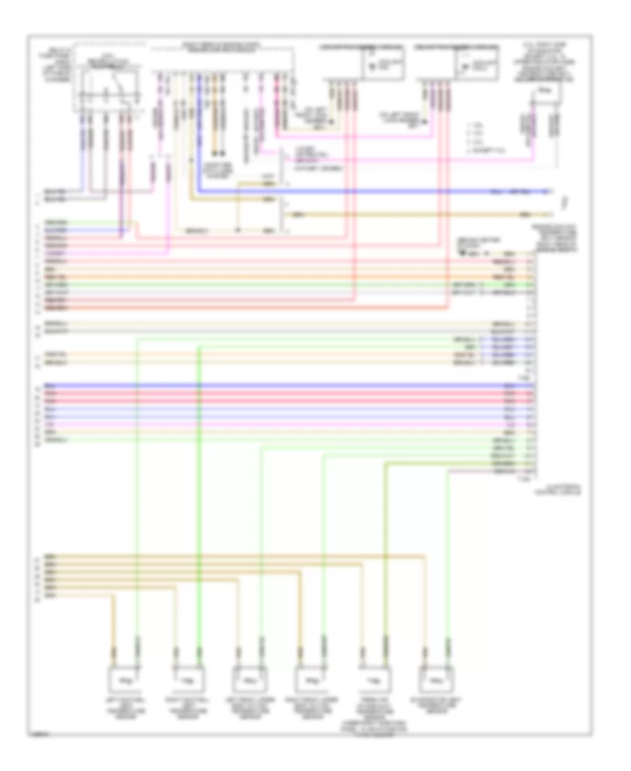
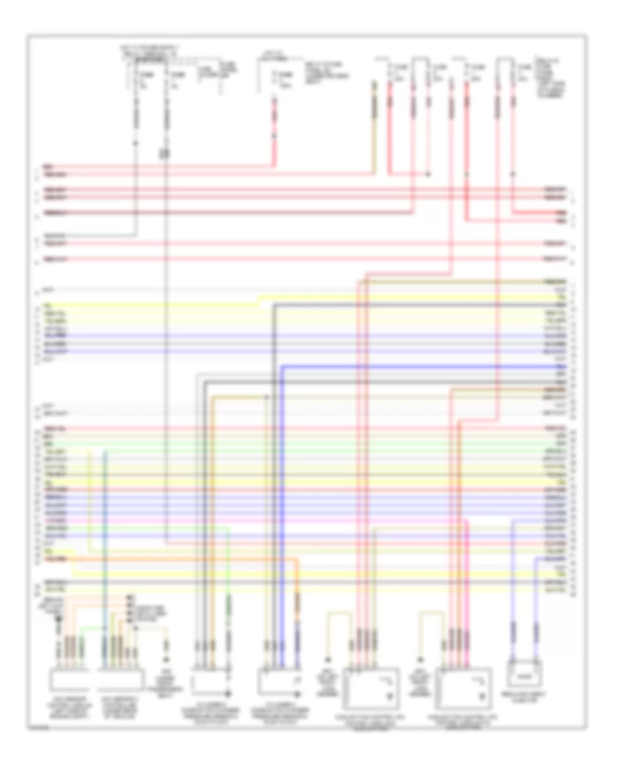
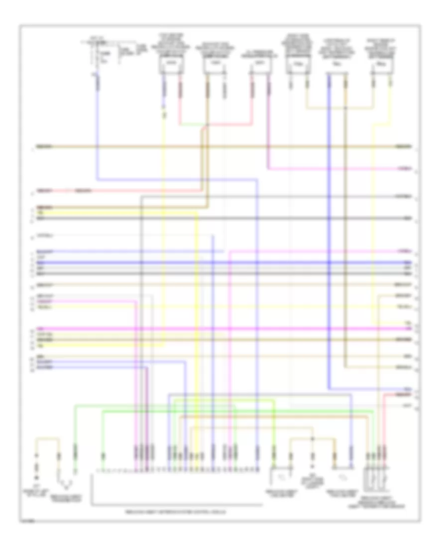
3.0L Turbo, Engine Performance Wiring Diagram (3 of 8) for Audi Q7 4.2 2009
List of elements for 3.0L Turbo, Engine Performance Wiring Diagram (3 of 8) for Audi Q7 4.2 2009:
- (behind left kick panel) g44
- (under front passenger's seat)
- Computer data lines system
- Coolant fan control (fc) control module & coolant fan
- Coolant fan control (fc) control module 2 & coolant fan
- Cylinder 2 combustion chamber pressure sensor & glow plug 2
- Cylinder 5 combustion chamber pressure sensor & glow plug 5
- Fuse 40a
- Fuse 60a
- Fuse 80a
- Fuse fuse 150a
- Fuse fuse 5a
- Fuse holder
- Fuse panel sb
- G35
- G671 (on left front long member)
- Hot at all times
- Injector
- Nox sensor 2 controller (under rear of vehicle)
- Nox sensor control module (left side of engine compt)
- Red
- Reducing agent
- Relay & fuse panel e-box (left side of plenum chamber)
- Relay & fuse panel sd (under driver's seat)
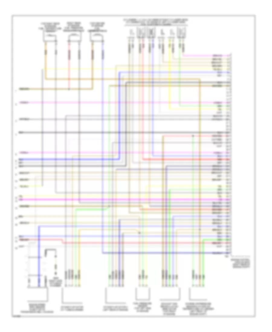
3.0L Turbo, Engine Performance Wiring Diagram (4 of 8) for Audi Q7 4.2 2009
List of elements for 3.0L Turbo, Engine Performance Wiring Diagram (4 of 8) for Audi Q7 4.2 2009:
- 10a
- 11a
- 12a
- 13a
- 14a
- 15a
- 16a
- 17a
- 18a
- Computer data lines system
- Cruise control switch
- Engine control module (ecm) (right rear of engine compt)
- Fuse 10a
- Fuse 15a
- Fuse 20a
- Fuse 5a
- Fuse 80a
- G609 (right side of plenum chamber)
- Hot w/ starter relay energized
- Oil pressure switch (top front of engine)
- Red
- Relay & fuse panel e-box (left side of plenum chamber)
- Starting/ charging system
- T94
- Throttle valve control module (left side of engine)
3.0L Turbo, Engine Performance Wiring Diagram (5 of 8) for Audi Q7 4.2 2009
List of elements for 3.0L Turbo, Engine Performance Wiring Diagram (5 of 8) for Audi Q7 4.2 2009:
- (at right front of engine compt) fuel cooler pump
- (in left front wheel well)
- 19a
- 19c
- 19e
- 20a
- 20b
- 20c
- 20d
- Auxiliary fuel pump relay
- Charge air cooler bypass control unit
- Climatronic control module
- Coolant circulation pump relay (in relay & fuse panel/ instrument panel center)
- Coolant pump
- Early production
- Exhaust gas recirculation (egr) cooler pump (right front of engine)
- Fuel cooling pump relay
- Fuel pump relay
- G609 (right side of plenum chamber)
- G640 (left side of engine compt)
- G685 (on right front long member)
- Heated oxygen sensor (ho2s) & oxygen sensor (o2s) heater (upstream of catalyst)
- High pressure sensor
- Late production
- Nca
- Red
- Relay & fuse panel e-box (left side of plenum chamber)
- T16c
- T16d
3.0L Turbo, Engine Performance Wiring Diagram (6 of 8) for Audi Q7 4.2 2009
List of elements for 3.0L Turbo, Engine Performance Wiring Diagram (6 of 8) for Audi Q7 4.2 2009:
- (base of left "c" pillar) g61
- (base of right "c" pillar) g62
- (below left side second row seat) fuel level sensor 2
- (below right side of second row seat) fuel level sender & transfer fuel pump (fp)
- (left rear of engine) auxiliary fuel pump
- (rear of right cylinder bank) camshaft position (cmp) sensor
- Computer data lines system
- Display unit
- Engine coolant
- Engine coolant level/temperature (ecl/ect) warning lamp
- Fuel gauge
- G45 (behind center of dash)
- G609 (right side of plenum chamber)
- Instrument cluster control module
- Level (ecl) warning switch
- Oil level thermal sensor
- Oil pressure
- Oil pressure warning ind lamp
- Switch (top front of engine)
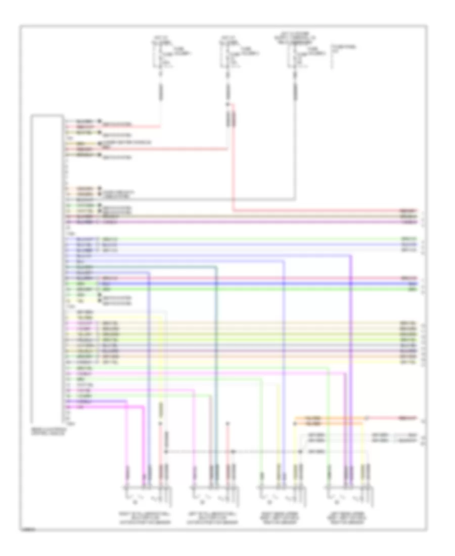
3.0L Turbo, Engine Performance Wiring Diagram (7 of 8) for Audi Q7 4.2 2009
List of elements for 3.0L Turbo, Engine Performance Wiring Diagram (7 of 8) for Audi Q7 4.2 2009:
- (base of left "b" pillar)
- (on radiator)
- (right rear of engine) engine coolant temperature (ect) sensor
- (right side of radiator) engine coolant temperature (ect) sensor
- (top center of engine) exhaust gas recirculation (egr) cooler switch over valve
- (upstream of catalyst) bank 1 exhaust gas temperature (egt) sensor 2
- Exhaust gas recirculation (egr) cooler switch over valve 2
- Fuse fuse 30a
- Fuse holder
- Fuse panel sf
- G51 (right side of luggage compt)
- G77
- Hot at all times
- Oil pressure regulation valve
- Reducing agent line heater
- Reducing agent metering system control module
- Reducing agent sensor & reducing agent temperature sensor
- Reducing agent tank heater
- Reducing agent transfer pump
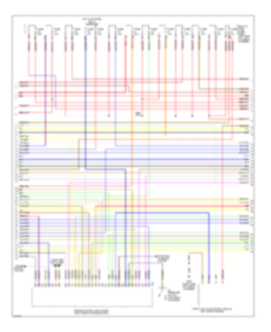
3.0L Turbo, Engine Performance Wiring Diagram (8 of 8) for Audi Q7 4.2 2009
List of elements for 3.0L Turbo, Engine Performance Wiring Diagram (8 of 8) for Audi Q7 4.2 2009:
- (cylinders 1, 2, 3 & 4: on inside of right cylinder head) (cylinders 5 & 6 : on inside of left cylinder head) fuel injector cylinders
- (right rear of engine) fuel pressure regulator valve
- (top center of engine) fuel metering valve
- (top right rear of engine) fuel temperature sensor
- Charge air pressure sensor & intake air temperature (iat) sensor (left front of engine compt)
- Engine control module (ecm) (right rear of engine compt)
- Engine speed (rpm) sensor (in bottom of transmission bell housing)
- Exhaust gas recirculation (egr) motor (top front of engine)
- Fuel pressure sensor (top left side of engine)
- G609 (right side of plenum chamber)
- Intake flap motor (at turbocharger)
- Intake flap motor 2 (left rear of engine)
- Red
- T60
3.6L
3.6L, Engine Performance Wiring Diagram (1 of 5) for Audi Q7 4.2 2009
List of elements for 3.6L, Engine Performance Wiring Diagram (1 of 5) for Audi Q7 4.2 2009:
- (in upper radiator hose) engine coolant temperature (ect) sensor (radiator)
- (rear of engine compt) low fuel pressure sensor
- Air conditioning system
- Anti-theft system
- Brake light & brake pedal switch
- Comfort system central control module (right side of luggage compt)
- Cooling fans system
- Cruise control system
- Engine control module (ecm) (right rear of engine compt)
- Exterior lights system
- Fuse 5a
- Fuse holder 3
- Fuse panel sb
- G44 (behind left kick panel)
- G609 (right side of plenum chamber)
- Leak detection pump (ldp)
- Nca
- Oxygen sensor (o2s) heater 1 (in right exhaust pipe, after catalytic converter)
- Oxygen sensor (o2s) heater 2 (in left exhaust pipe, before catalytic converter)
- Starting/charging system
- T10g
- T94
- Transmissions system
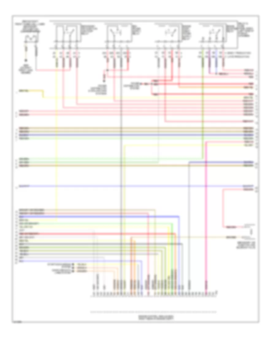
3.6L, Engine Performance Wiring Diagram (2 of 5) for Audi Q7 4.2 2009
List of elements for 3.6L, Engine Performance Wiring Diagram (2 of 5) for Audi Q7 4.2 2009:
- 1b red
- 1h a (late production)
- 20a
- 20b
- 20c
- 20d c
- 2b red
- 2f a
- 3b a (early production)
- Heated oxygen sensor (ho2s)
- Heated oxygen sensor (ho2s) 2
- Mass air flow (maf)/intake air temperature (iat) sensor (in right air intake duct at filter housing)
- Nca
- Power distribution & cooling fans systems
- Power distribution system
- Red
- Relay & fuse panel e-box (left side of plenum chamber)
- Throttle position (tp) sensor & accelerator pedal position (app) sensor 2 (in accelerator pedal assembly)
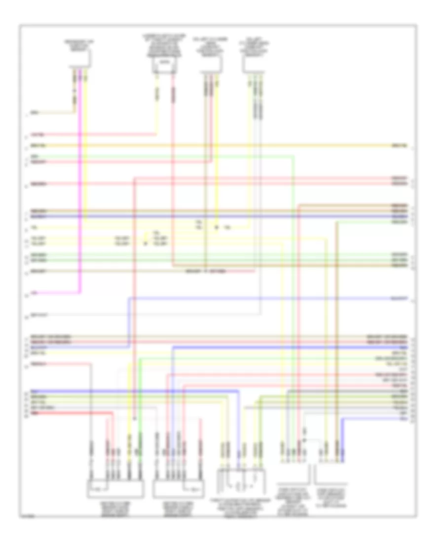
3.6L, Engine Performance Wiring Diagram (3 of 5) for Audi Q7 4.2 2009
List of elements for 3.6L, Engine Performance Wiring Diagram (3 of 5) for Audi Q7 4.2 2009:
- Air conditioning system
- Computer data lines system
- Cooling fans system
- Engine control module (ecm) (right rear of engine compt)
- Fuse 10a
- Fuse 15a
- Fuse 30a
- Fuse 5a
- Red
- Relay & fuse panel e-box (left side of plenum chamber)
- Starting/ charging system
- T94
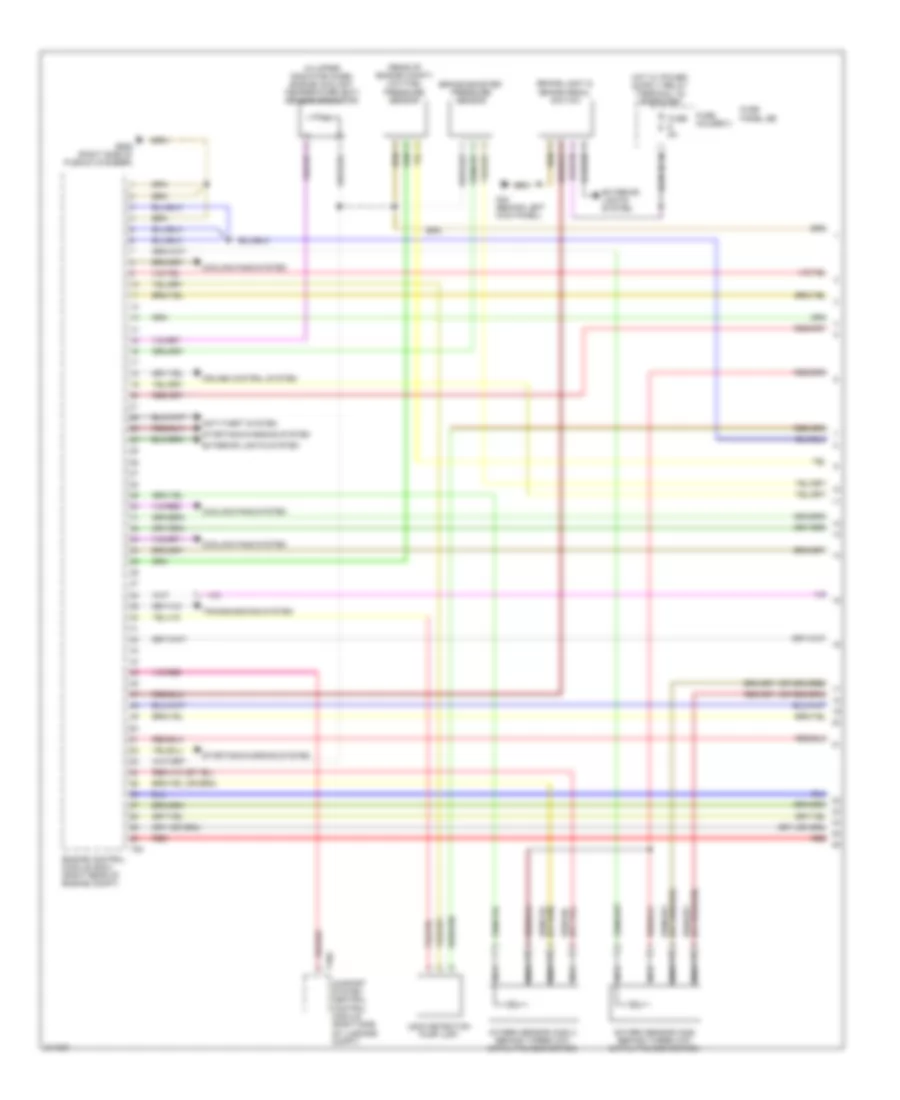
3.6L, Engine Performance Wiring Diagram (4 of 5) for Audi Q7 4.2 2009
List of elements for 3.6L, Engine Performance Wiring Diagram (4 of 5) for Audi Q7 4.2 2009:
- (below right side of second row seat) transfer fuel pump (fp)
- (on left cylinder head) camshaft position (cmp) sensor 2
- (on rear of right cylinder head) camshaft adjustment valve 1 (exhaust)
- (on right cylinder head) camshaft position (cmp) sensor
- (on right cylinder head) fuel pressure sensor
- (on right rear cylinder head near intake manifold) camshaft adjustment valve 1
- (right rear of engine compt) engine coolant temperature (ect) sensor
- (under vehicle at front of fuel tank) fuel pump (fp) control module
- Engine speed (rpm) sensor (in bottom of transmission bell housing)
- G609 (right side of plenum chamber)
- G62 (base of right "c" pillar)
- Knock sensor (ks) 1 (under intake manifold, on inside of right cylinder head)
- Knock sensor (ks) 2 (under intake manifold, on inside of right cylinder head)
- Positive crankcase ventilation (pcv) heating element
- Red
- Throttle valve control module (at back of intake manifold)
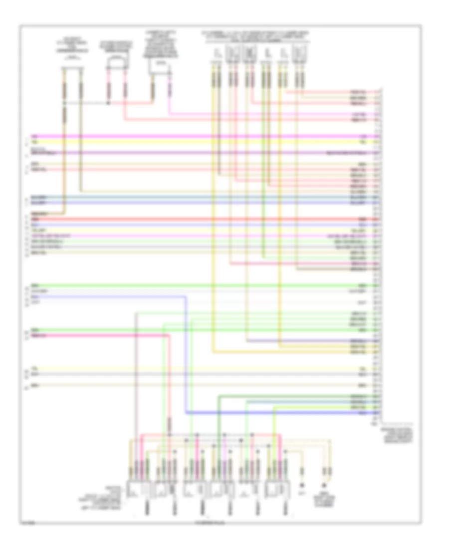
3.6L, Engine Performance Wiring Diagram (5 of 5) for Audi Q7 4.2 2009
List of elements for 3.6L, Engine Performance Wiring Diagram (5 of 5) for Audi Q7 4.2 2009:
- (cylinders 1, 2, 3 & 4: on inside of right cylinder head) (cylinders 5 & 6 : on inside of left cylinder head) fuel injector cylinders
- (on right cylinder head) fuel metering valve
- (under plastic cover by throttle body) evaporative emission (evap) canister purge regulator valve
- Engine control module (ecm) (right rear of engine compt)
- G17
- G609 (right side of plenum chamber)
- Ignition coils (coils 1, 2, 3 & 4: on right cylinder head) (coils 5 & 6: on left cylinder head)
- Intake manifold runner control (imrc) valve
- Nca
- Red
- T60
- To spark plug
4.2L
4.2L, Engine Performance Wiring Diagram (1 of 6) for Audi Q7 4.2 2009
List of elements for 4.2L, Engine Performance Wiring Diagram (1 of 6) for Audi Q7 4.2 2009:
- (in upper radiator hose) engine coolant temperature (ect) sensor (radiator)
- (rear of engine compt) low fuel pressure sensor
- Anti-theft system
- Brake booster pressure sensor
- Brake light & brake pedal switch
- Comfort system central control module (right side of luggage compt)
- Cooling fans system
- Cruise control system
- Engine control module (ecm) (right rear of engine compt)
- Exterior lights system
- Fuse 5a
- Fuse holder 3
- Fuse panel sb
- G44 (behind left kick panel)
- G609 (right side of plenum chamber)
- Leak detection pump (ldp)
- Nca
- Oxygen sensor (o2s) (behind three way catalytic converter)
- Oxygen sensor (o2s) 2 (behind three way catalytic converter)
- Red
- Starting/charging system
- T10g
- T94
- Transmissions system
4.2L, Engine Performance Wiring Diagram (2 of 6) for Audi Q7 4.2 2009
List of elements for 4.2L, Engine Performance Wiring Diagram (2 of 6) for Audi Q7 4.2 2009:
- (on left cylinder head) camshaft position (cmp) sensor 2
- (on left cylinder head) camshaft position (cmp) sensor 4
- (under plastic cover by throttle body) evaporative emission (evap) canister purge regulator valve
- Heated oxygen sensor (ho2s) (right side of engine compt)
- Heated oxygen sensor (ho2s) 2 (right side of engine compt)
- Mass air flow (maf) sensor 2 (in air intake duct at filter housing)
- Mass air flow (maf)/intake air temperature (iat) sensor (in right air intake duct at filter housing)
- Nca
- Red
- Secondary air injection sensor 1
- Throttle position (tp) sensor & accelerator pedal position (app) sensor 2 (in accelerator pedal assembly)
4.2L, Engine Performance Wiring Diagram (3 of 6) for Audi Q7 4.2 2009
List of elements for 4.2L, Engine Performance Wiring Diagram (3 of 6) for Audi Q7 4.2 2009:
- (behind right front wheelwell liner) secondary air injection (air) pump motor
- (early production)
- (late production)
- 19d c
- 1b red
- 1h a
- 20a
- 20b
- 20c
- 20d c
- 2b red
- 2f a
- 3b a
- 4a a
- 5d a
- Brake booster relay
- Computer data lines system
- Engine control module (ecm) (right rear of engine compt)
- G685 (on right front long member)
- Power distribution & cooling fans systems
- Power distribution system
- Red
- Relay & fuse panel e-box (left side of plenum chamber)
- Secondary air injection (air) pump relay
- Secondary air injection (air) solenoid valve
- Starting/charging system
- T94
4.2L, Engine Performance Wiring Diagram (4 of 6) for Audi Q7 4.2 2009
List of elements for 4.2L, Engine Performance Wiring Diagram (4 of 6) for Audi Q7 4.2 2009:
- (at right front of engine compt) brake system vacuum pump
- Air conditioning & cooling fans systems
- Cooling fans system
- Engine control module (ecm) (right rear of engine compt)
- Fuel injector cylinders (cylinders 1, 2, 3 & 4: on inside of right cylinder head) (cylinders 5 , 6, 7 & 8 : on inside of left cylinder head)
- Fuse 10a
- Fuse 15a
- Fuse 30a
- Fuse 50a
- Fuse 5a
- G685 (on right front long member)
- Red
- Relay & fuse panel e-box (left side of plenum chamber)
- T60
4.2L, Engine Performance Wiring Diagram (5 of 6) for Audi Q7 4.2 2009
List of elements for 4.2L, Engine Performance Wiring Diagram (5 of 6) for Audi Q7 4.2 2009:
- (below a/c compressor) map controlled engine cooling thermostat
- (below right side of second row seat) transfer fuel pump (fp)
- (on left front of intake manifold) intake manifold runner position sensor 2
- (on right cylinder head) camshaft position (cmp) sensor
- (on right cylinder head) camshaft position (cmp) sensor 3
- (on right cylinder head) fuel pressure sensor
- (on right front of intake manifold) intake manifold runner position sensor
- (right rear of engine compt) engine coolant temperature (ect) sensor
- (under vehicle at front of fuel tank) fuel pump control module
- Engine speed (rpm) sensor (in bottom of transmission bell housing)
- G62 (base of right "c" pillar)
- Knock sensor (ks) 1 (under intake manifold, on inside of right cylinder head)
- Knock sensor (ks) 2 (under intake manifold, on inside of right cylinder head)
- Knock sensor (ks) 3 (under intake manifold, on inside of left cylinder head)
- Knock sensor (ks) 4 (under intake manifold, on inside of left cylinder head)
- Nca
- Red
- Throttle valve control module (at back of intake manifold)
4.2L, Engine Performance Wiring Diagram (6 of 6) for Audi Q7 4.2 2009
List of elements for 4.2L, Engine Performance Wiring Diagram (6 of 6) for Audi Q7 4.2 2009:
- (on left cylinder head) camshaft adjustment valve 2
- (on left cylinder head, (in high pressure pump) fuel metering valve 2
- (on rear of left cylinder head) camshaft adjustment valve 2 (exhaust)
- (on rear of right cylinder head) camshaft adjustment valve 1 (exhaust)
- (on right cylinder head) fuel metering valve
- (on right rear cylinder head near intake manifold) camshaft adjustment valve 1
- Engine control module (ecm) (right rear of engine compt)
- G600
- G601
- G609 (right side of plenum chamber)
- Ignition coils (coils 1, 2, 3 & 4: on right cylinder head) (coils 5, 6, 7 & 8: on left cylinder head)
- Intake manifold runner control (imrc) valve
- Intake manifold runner control (imrc) valve 2
- Nca
- Red
- Secondary air injection (air) solenoid valve 2
- T60
- To spark plug
EXTERIOR LIGHTS
Backup Lamps Wiring Diagram for Audi Q7 4.2 2009
List of elements for Backup Lamps Wiring Diagram for Audi Q7 4.2 2009:
- Automatic day/night interior mirror
- Backup
- Comfort system central control module (right side of luggage compt)
- Comfort system central control module 2 (right side of luggage compt)
- Computer data lines system
- Fuse 15a
- Fuse 5a
- Fuse holder 1
- Fuse holder 2
- Fuse panel sc
- Fuse panel sf
- G51 (right side of luggage compt)
- Hot at all times
- Left taillamp assembly
- Multi-function transmission range switch
- Nca
- Right taillamp assembly
- T32d
- T6v
- Transmission control module (except 3.6l) (under front passenger's seat)
Exterior Lamps Wiring Diagram (1 of 2) for Audi Q7 4.2 2009
List of elements for Exterior Lamps Wiring Diagram (1 of 2) for Audi Q7 4.2 2009:
- (behind left side of dash) g664
- (right side of luggage compt) comfort system central control module 2
- 10a
- 11a
- 12a
- Backup
- Backup lamps circuit
- Comfort system central control module (right side of luggage compt)
- Computer data lines system
- Fog
- Fuse 10a
- Fuse 15a
- Fuse 20a
- Fuse 30a
- Fuse 5a
- Fuse holder
- Fuse holder 1
- Fuse panel sb
- Fuse panel sc
- Fuse panel sf
- G51 (right side of luggage compt)
- G668 (on left "d" pillar)
- Hot at all times
- Instrument cluster control module
- Left front side marker lamp (late production)
- Left taillamp assembly 1
- Left taillamp assembly 2
- Nca
- Right front side marker lamp (late production)
- Right taillamp assembly 1
- Right taillamp assembly 2
- Side marker
- Steering column electronic systems control module
- T10g
- T15a
- T16a
- T32d
- Tail/stop
- Tail/stop/turn
- Turn
- Turn signal/ headlight flasher switch
Exterior Lamps Wiring Diagram (2 of 2) for Audi Q7 4.2 2009
List of elements for Exterior Lamps Wiring Diagram (2 of 2) for Audi Q7 4.2 2009:
- (behind left side of dash) g664
- 3.0l
- 3.6l
- 4.2l
- Abs control module (in right plenum chamber)
- Access/start authorization switch
- Brake light disable relay (esp)
- Brake light/ brake pedal switch
- Computer data lines system
- Emergency flasher button
- Engine control module (right rear of engine compt)
- Fog lp sw
- Fr fog light
- Fuse 25a
- Fuse 30a
- Fuse 5a
- Fuse holder
- Fuse panel sb
- G43 (behind right kick panel)
- G44 (behind left kick panel)
- G644
- G658 (top of left "d"pillar)
- G664 (behind left side of dash)
- G668 (on left "d" pillar)
- Hdlamp sw light
- High- mount brake light
- Hot at all times
- Interior lights system
- Left front side marker/ turn signal lamp
- Left side turn signal lamp (early production) driver exterior mirror turn t2af signal lamp (late production)
- License plate light
- Light switch
- Passenger's exterior mirror turn signal lamp (late production) right side turn signal lamp t2af (early production)
- Prk lamp light
- Rear fog lp sw
- Red
- Relay & fuse panel/ instrument panel center (behind center of dash)
- Right front side marker/ turn signal lamp
- Rr fog light
- Suppr- essor
- T12b
- T12d
- T2af
- T2s
- T2t
- T2u
- T2v
- T32b
- T8a
- T94
- Towing recognition control module (right side of luggage compt)
- Vehicle electrical system control module (behind left side of dash)
Trailer Tow Wiring Diagram for Audi Q7 4.2 2009
List of elements for Trailer Tow Wiring Diagram for Audi Q7 4.2 2009:
- 10a
- 11a
- Abs control module (in right plenum chamber)
- Brake booster
- Brake light disable relay (esp)
- Comfort system central control module (right side of luggage compt)
- Computer data lines system
- Exterior lamps circuit
- Fuse 15a
- Fuse 20a
- Fuse 30a
- Fuse 5a
- Fuse holder 3
- Fuse panel sb
- Fuse panel sf
- G44 (behind left kick panel)
- G51 (right side of luggage compt)
- G664 (behind left side of dash)
- G675 (right side of luggage compt)
- Hot at all times
- Multimedia control module
- Red
- Relay & fuse panel/ instrument panel center (behind center of dash)
- T12d
- T16e
- T26e
- T32d
- Towing recognition control module (right side of luggage compt)
- Trailer socket
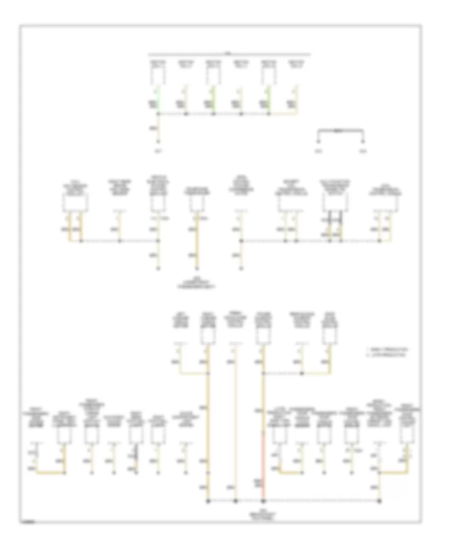
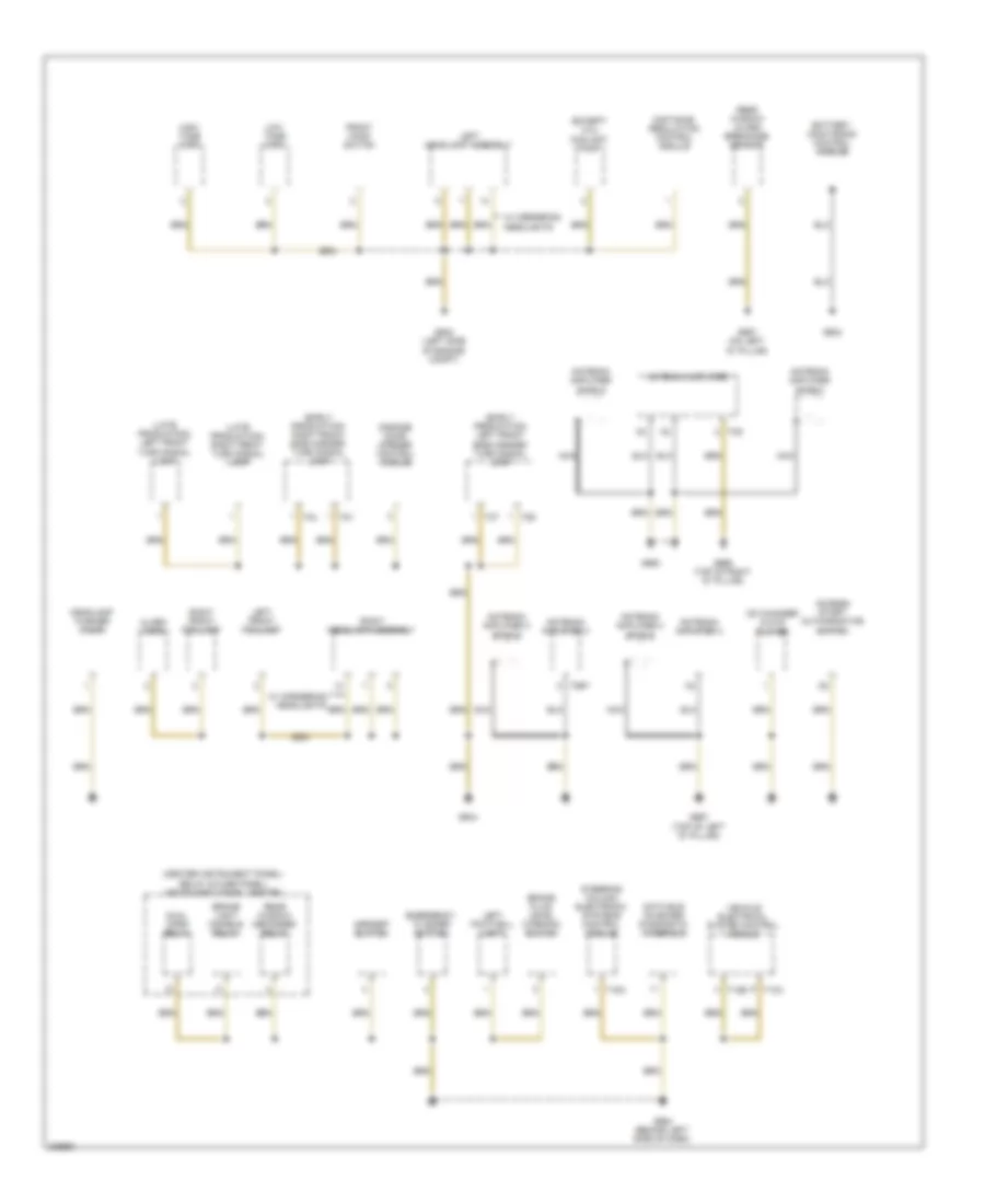
GROUND DISTRIBUTION
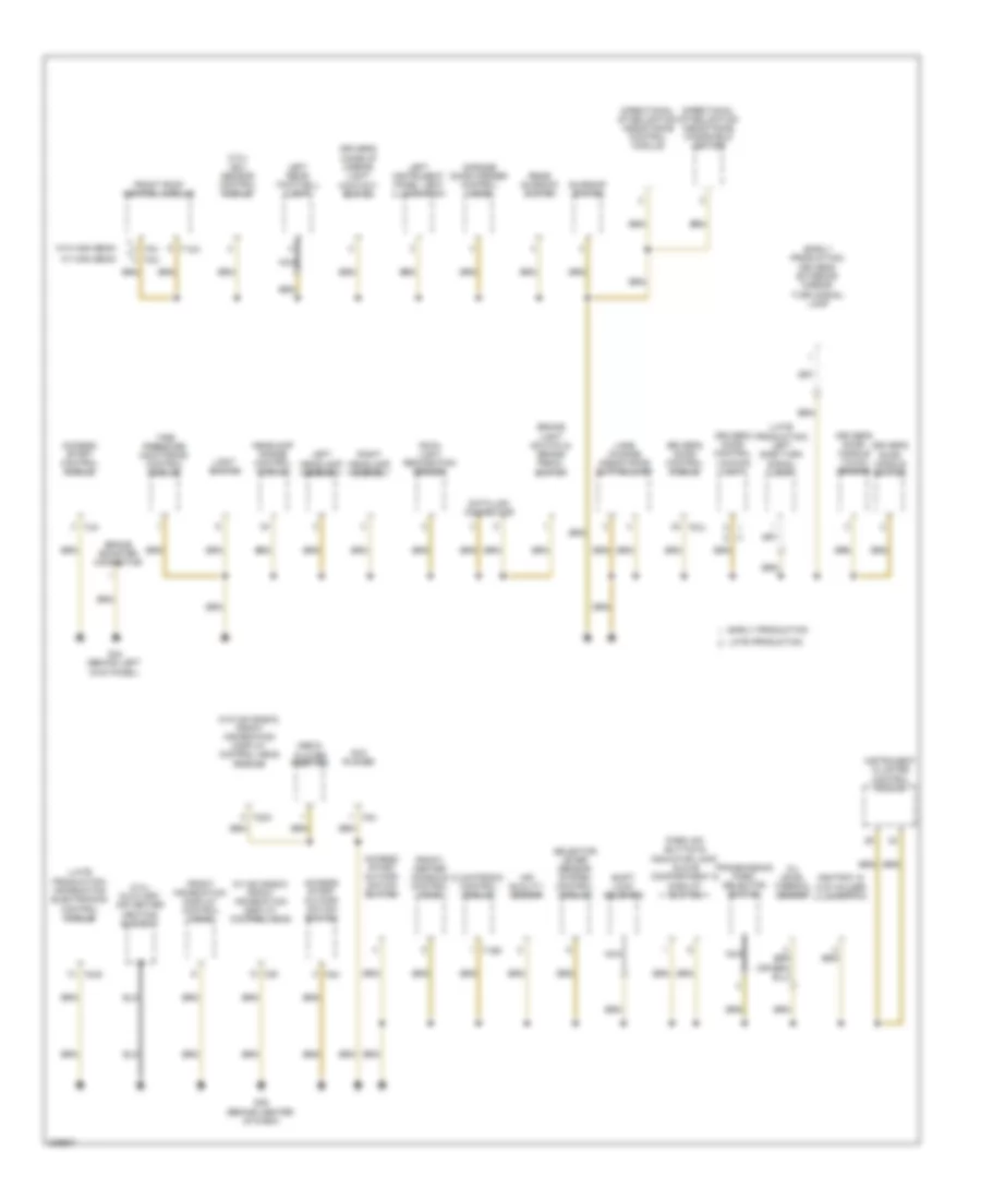
Ground Distribution Wiring Diagram (1 of 7) for Audi Q7 4.2 2009
List of elements for Ground Distribution Wiring Diagram (1 of 7) for Audi Q7 4.2 2009:
- (3.0l) nox sensor control module 2
- (3.6l) transmission control module
- (early production) front passenger's exterior mirror turn signal lamp
- (except 3.6l) transmission control module
- (late production) right side turn signal lamp
- 3.6l
- Early production
- Fresh air blower control module
- Front passenger's door control locking unit
- Front passenger's door control module
- Front passenger's make-up mirror light contact switch
- Front passenger's side air bag igniter
- G13
- G17
- G18
- G35 (under front passenger's seat)
- G43 (behind right kick panel)
- Glove box unlock motor
- Glove compartment lamp switch
- Ignition coil 1
- Ignition coil 2
- Ignition coil 3
- Ignition coil 4
- Ignition coil 5
- Ignition coil 6
- Late production
- Left washer nozzle heater
- Level control system compressor motor
- Multi-function transmission range (tr) switch
- Nca
- Passenger's door handle switch
- Passenger's door handle touch sensor
- Power sunroof control module
- Rear sliding sunroof control module
- Right footwell light
- Right instrument panel vent illumination
- Right rear brake pad wear sensor
- Right rear footwell light
- Right washer nozzle heater
- Roof blind control module
- T20m
- T40a
- T54a
- Telephone transceiver
- Vehicle electrical system control module 2
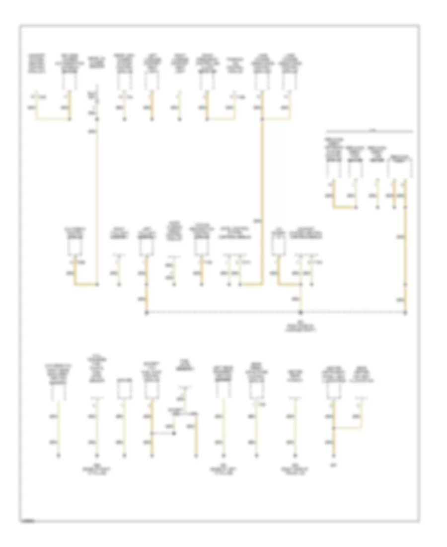
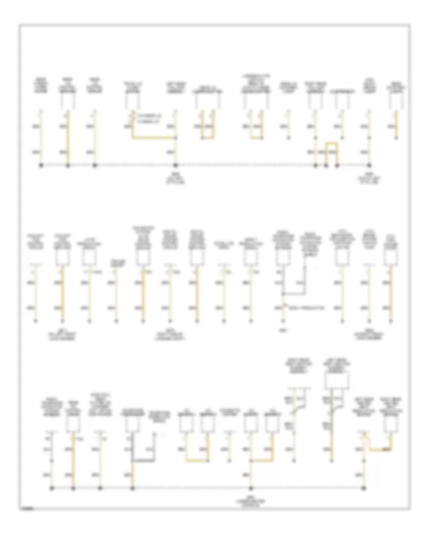
Ground Distribution Wiring Diagram (2 of 7) for Audi Q7 4.2 2009
List of elements for Ground Distribution Wiring Diagram (2 of 7) for Audi Q7 4.2 2009:
- (3.0l) auxiliary air heater heating element
- (3.0l) nox sensor control module
- (early production) driver's exterior mirror turn signal lamp
- (late production) information electronics control module
- (late production) left side turn signal lamp
- (w/ mmi basic) front information display control head
- (w/o mmi basic) front information display control head module
- Access/ start author- ization button
- Access/ start author- ization switch
- Access/ start control module
- Air quality sensor
- Ashtray & cup holder illumination
- Brake booster connector
- Brake light switch & brake pedal switch
- Climatronic control module
- Data link connector
- Directional stabilization assistance control module
- Directional stabilization assistance windshield heater
- Driver's door control locking unit
- Driver's door control module
- Driver's door handle switch
- Driver's door handle touch sensor
- Driver's make-up mirror light contact switch
- Dvd player
- Early production
- Front information display control head
- Front roof control module
- Front/ center console control head
- G44 (behind left kick panel)
- G45 (behind center of dash)
- Garage door opener control head
- Headlamp range control module
- Instrument cluster control module
- Lane change assistance button/lamp
- Late production
- Left headlamp assembly
- Left instrument panel vent illumination
- Left rear footwell light
- Light switch
- Media player position
- Nca
- Oil level thermal sensor
- Park aid button & indicator lamp, glove compartment & display button
- Rain/ light recognition sensor
- Rear sunroof switch
- Right headlamp assembly
- Selector lever sensor system control module
- Shift lock solenoid
- Sunroof switch
- T12a
- T16d
- T20k
- T20l
- T3a
- T6a
- T6v
- T8af
- T8h
- T8p
- T8x
- Tire pressure monitoring control module
- Transmission park selector switch
- W/ high beam
- W/o high beam
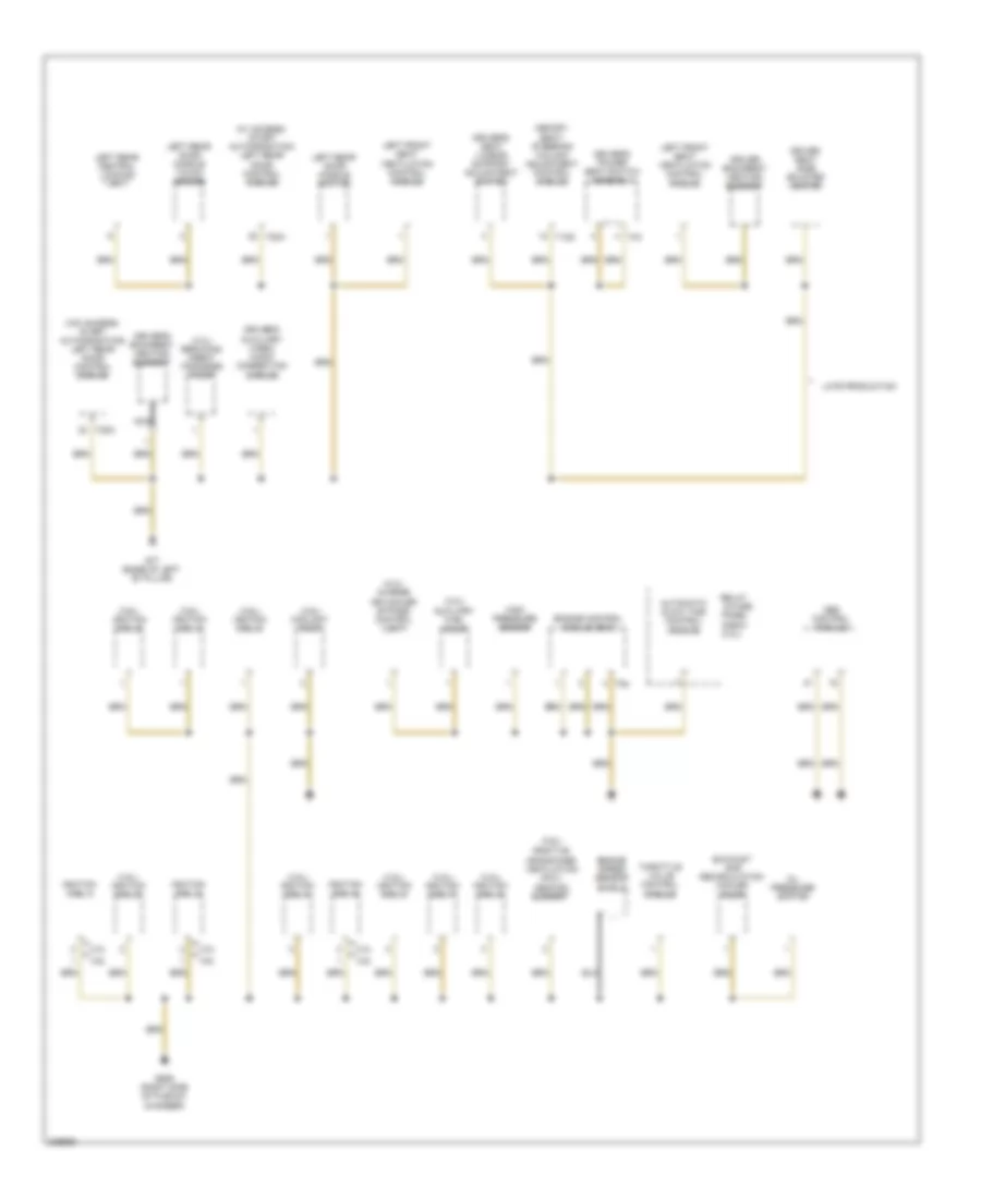
Ground Distribution Wiring Diagram (3 of 7) for Audi Q7 4.2 2009
List of elements for Ground Distribution Wiring Diagram (3 of 7) for Audi Q7 4.2 2009:
- (3.0l) transfer fuel pump & fuel level sensor
- (except 3.0l) fuel pump control module
- (w/o rear a/c) right rear back rest heating element
- 12v socket
- 3.0l
- Center instrument panel vent illumination
- Comfort system central control module
- Comfort system central control module 2
- Cooler
- Door closing assist control module
- Except 3.0l
- Fuel level sensor 2
- G51 (right side of luggage compt)
- G53 (right side of trunk lid)
- G61 (base of left "c" pillar)
- G62 (base of right "c" pillar)
- G67
- Heated rear window
- Keyless access authorization antenna reader
- Lane change assistance control module
- Lane change assistance control module 2
- Left luggage compart- ment light
- Left rear backrest heating element
- Left taillight assembly
- Level control system control module
- Multimedia control module
- Parking aid control module
- Radio frequency controlled clock receiver
- Rear center air vent illumination
- Rear fresh air blower control module
- Rear lid closed sensor
- Rear view camera system control module
- Reducing agent
- Reducing agent line heater
- Reducing agent metering system control module
- Reducing agent tank heater
- Right luggage compart- ment light
- Right taillight assembly
- T10g
- T12d
- T16b
- T20f
- T26e
- T2r
- T54
- T81a
- Towing recognition control module
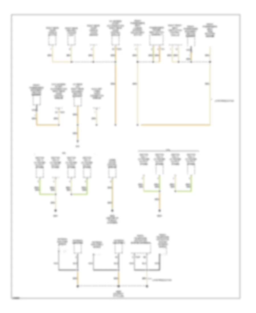
Ground Distribution Wiring Diagram (4 of 7) for Audi Q7 4.2 2009
List of elements for Ground Distribution Wiring Diagram (4 of 7) for Audi Q7 4.2 2009:
- & fuse panel e-box
- (3.0l)
- (3.0l) charge air cooler bypass control unit
- (3.0l) reducing agent transfer pump
- (3.6l)
- (3.6l) coolant pump
- (3.6l) ignition coil 2
- (3.6l) ignition coil 4
- (3.6l) ignition coil 6
- (4.2l) ignition coil 2
- (4.2l) ignition coil 4
- (4.2l) ignition coil 6
- (4.2l) ignition coil 7
- (4.2l) ignition coil 8
- (w/ access/ start authorization) left rear door control module
- (w/o access/ start authorization) left rear door control module
- 3.6l
- 4.2l
- Abs control module
- Automatic glow time control module
- Auxiliary fuel pump
- Driver backrest heating element
- Driver seat side bolster heater
- Driver's auxiliary video/ audio connection module
- Driver's backrest heating element
- Driver's power seat switch assembly
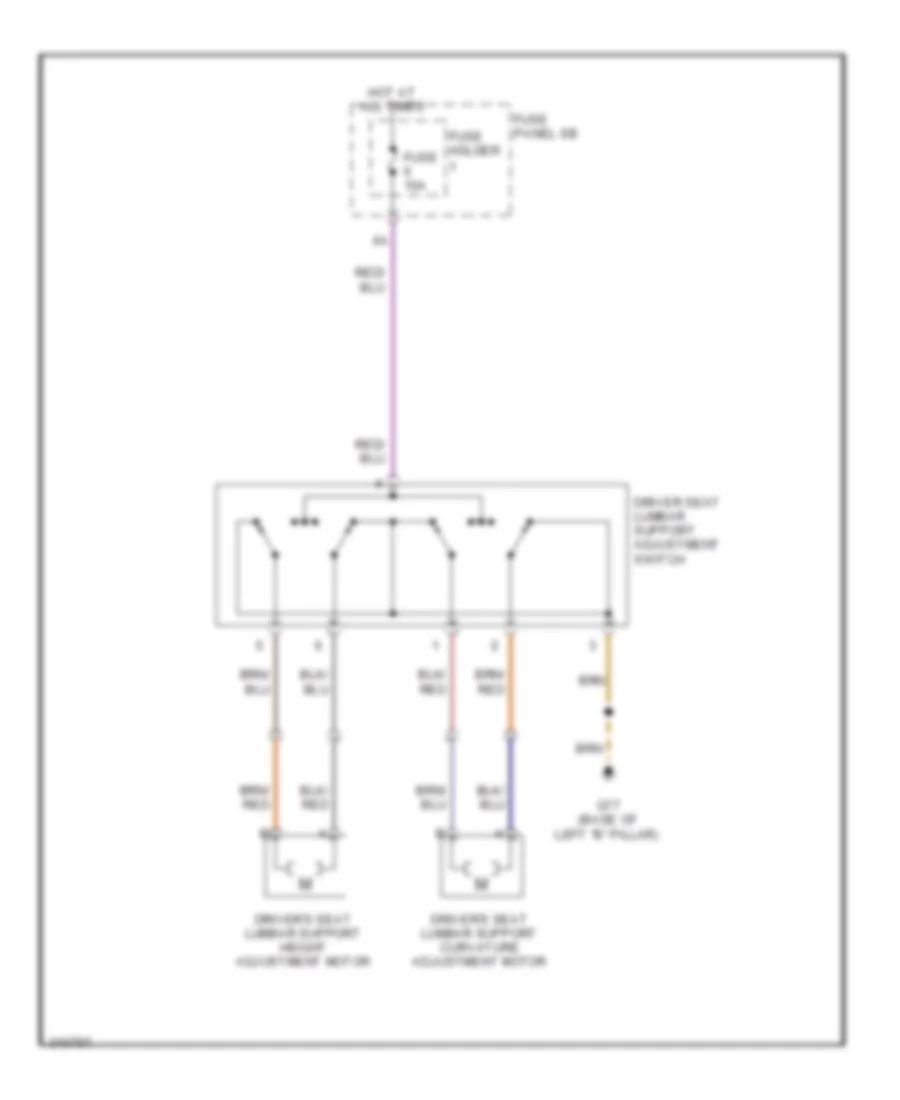
- Driver's seat lumbar support adjustment switch
- Engine control module (ecm)
- Engine speed sensor shield
- Exhaust gas recirculation cooler pump
- G609 (right side of plenum chamber)
- G77 (base of left "b" pillar)
- High pressure sensor
- Ignition coil 1
- Ignition coil 3
- Ignition coil 5
- Late production
- Left front seat ventilation control module
- Left rear central locking unit
- Left rear door handle switch
- Left rear door handle touch sensor
- Memory seat/ steering column adjustment control module
- Nca
- Oil pressure switch
- Positive crankcase ventilation (pcv) heating element
- Relay
- T12s
- T20n
- T4x
- T94
- Throttle valve control module
Ground Distribution Wiring Diagram (5 of 7) for Audi Q7 4.2 2009
List of elements for Ground Distribution Wiring Diagram (5 of 7) for Audi Q7 4.2 2009:
- (w/ access/ start authorization) right rear door control module
- (w/ rear a/c) right rear backrest heating element
- (w/o access/ start authorization) right rear door control module
- 4.2l
- Antenna amplifier
- Antenna amplifier 2
- Antenna amplifier 2 shield
- Antenna amplifier shield
- Auxiliary video/ audio connection module
- Front passenger's backrest heating element
- Front passenger's seat lumbar support adjustment switch
- Front passenger's seat side bolster heater
- G600
- G601
- G608 (center of plenum chamber)
- G669 (on right "d" pillar)
- G78
- Ignition coil 1 (w/ power output stage)
- Ignition coil 2 (w/ power output stage)
- Ignition coil 3 (w/ power output stage)
- Ignition coil 4 (w/ power output stage)
- Ignition coil 5 (w/ power output stage)
- Ignition coil 6 (w/ power output stage)
- Ignition coil 7 (w/ power output stage)
- Ignition coil 8 (w/ power output stage)
- Late production
- Nca
- Passenger's power seat switch assembly
- Radio, telephone, navigation system antenna
- Radio, telephone, navigation system antenna shield
- Right front seat ventilation control module
- Right rear central locking unit
- Right rear door handle switch
- Right rear door handle touch sensor
- T20o
- T2cf
- T4x
- Wiper motor control module
Ground Distribution Wiring Diagram (6 of 7) for Audi Q7 4.2 2009
List of elements for Ground Distribution Wiring Diagram (6 of 7) for Audi Q7 4.2 2009:
- (center instrument panel) relay & fuse panel/ instrument panel center
- (early production) left front side marker/ turn signal lamp
- (early production) right front side marker/ turn signal lamp
- (except 3.0l) coolant pump
- (late production) left front turn signal lamp
- (late production) right front turn signal lamp
- Access/ start authorization switch
- Alarm horn
- Antenna amplifier
- Antenna amplifier 3
- Antenna amplifier 3 shield
- Antenna amplifier 4
- Antenna amplifier 4 shield
- Antenna amplifier shield
- Asr/esp button
- Battery monitoring control module
- Brake fluid level warning switch
- Brake light disable relay
- Cd changer & dvd player
- Data bus on board diagnostic interface
- Distance regulation control module
- Dual horn relay
- Emergency flasher button
- Front hood switch
- G624
- G640 (left side of engine compt)
- G644
- G657 (on left "d" pillar)
- G663
- G664 (behind left side of dash)
- G666 (top of right "d" pillar)
- G667 (top of left "d" pillar)
- Garage door opener control module
- Headlamp washer pump
- High tone horn
- Left footwell light
- Left front fog lamp
- Left headlamp assembly
- Low tone horn
- Nca
- Rear window defogger relay
- Rear window glass breakage sensor
- Right front fog lamp
- Right headlamp assembly
- Steering column electronic systems control module
- T10a
- T12b
- T16a
- T2by
- T2s
- T2t
- T2u
- T2v
- T3q
- Vehicle electrical system control module
- W/ cornering headlights
Ground Distribution Wiring Diagram (7 of 7) for Audi Q7 4.2 2009
List of elements for Ground Distribution Wiring Diagram (7 of 7) for Audi Q7 4.2 2009:
- (3.0l) fuel cooler pump
- (4.2l) brake system vacuum pump
- (4.2l) secondary air injection (air) pump motor
- (early production) radio
- (late production) radio
- 12v socket
- 12v socket 2
- 12v socket 3
- 12v socket 4
- Cigarette lighter
- Coolant fan control module
- Coolant fan control module 2
- Digital sound system control module
- Digital sound system control module 2
- Early production
- G658 (top of left "d" pillar)
- G668 (on left "d" pillar)
- G671 (on left front long member)
- G675 (right side of luggage compt)
- G681
- G685 (on right front long member)
- G687 (under center console)
- High mount brake light
- Left rear heated seat regulating switch
- Left rear seat heating element assembly
- Left rear taillamp assembly
- License plate lights & rear lid lock cylinder unlock button
- Navigation system w/ cd drive control module
- Nca
- Position 2 media player, cd changer unit, or mini disk player
- Radio, telephone navigation system antenna
- Radio, telephone navigation system antenna shield
- Rear a/c control head
- Rear courtesy light
- Rear lid closing button
- Rear lid control module
- Rear lid control module 2
- Rear lid courtesy lamp
- Rear window wiper motor
- Right rear heated seat regulating switch
- Right rear seat heating element assembly
- Right rear taillamp assembly
- Satellite radio
- Suppressor
- T10aa
- T16h
- T32c
- T8i
- T8k
- T8l
- T8n
- Telephone baseplate shield
- Telephone transceiver
- Trailer socket
- Trunk lid alarm switch
- W/ rear lid
- W/o rear lid
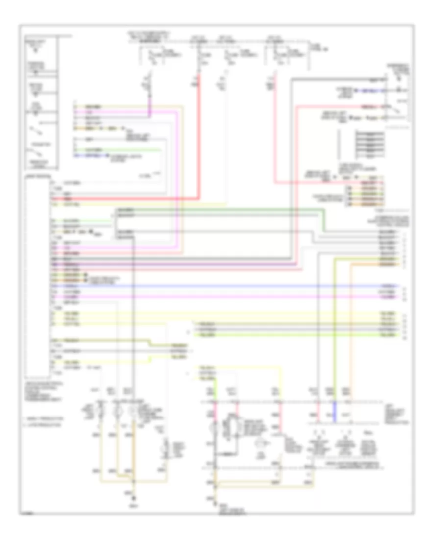
HEADLIGHTS
Headlights Wiring Diagram, with Cornering Headlights (1 of 3) for Audi Q7 4.2 2009
List of elements for Headlights Wiring Diagram, with Cornering Headlights (1 of 3) for Audi Q7 4.2 2009:
- (behind left side of dash) g664
- (if equipped) drl lamp
- 11a
- Computer data lines system
- Dynamic cornering light motor
- Early production
- Emergency flasher button
- Fog lp ind
- Fog lp sw
- Fuse 10a
- Fuse 25a
- Fuse 30a
- Fuse 5a
- Fuse holder 1
- Fuse holder 2
- Fuse holder 3
- Fuse panel sb
- G44 (behind left kick panel)
- G640 (left side of engine compt)
- G644
- G664
- Headlamp beam adjustment motor
- Headlamp range/cornering lamp control module
- Headlamp reflector adjustment solenoid
- Headlight sw ill
- Hid lamp
- Hid lamp control module
- Hot at all times
- Interior lights system
- Late production
- Left front fog lamp
- Left front side marker/ turn signal lamp
- Left headlight assembly (early production)
- Light switch
- Nca
- Parking light ind
- Rear fog lp sw
- Red
- Right front fog lamp
- Rr fog lp ind
- Steering column electronic systems control module
- Swivel module position sensor
- T10a
- T12b
- T16a
- T2s
- T2t
- T32b
- Turn signal/ headlight flasher switch
- Vehicle electrical system control module (under front passenger's seat)
- W/ drl
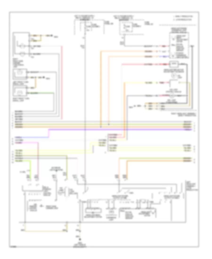
Headlights Wiring Diagram, with Cornering Headlights (2 of 3) for Audi Q7 4.2 2009
List of elements for Headlights Wiring Diagram, with Cornering Headlights (2 of 3) for Audi Q7 4.2 2009:
- Cornering lamp
- Drl & parking light control module
- Drl lamp (if equipped)
- Dynamic cornering light motor
- Early production
- Exterior lights system
- Front side marker lamp
- Fuse 10a
- Fuse holder 2
- Fuse holder 3
- Fuse panel sb
- Fuse panel sc
- G640 (left side of engine compt)
- G644
- Headlamp adjustment motor
- Headlamp beam adjustment motor
- Headlamp power output stage
- Headlamp power output stage 2
- Headlamp range/ cornering lamp control module
- Headlamp reflector adjustment solenoid
- Hid lamp
- Hid lamp ballast
- Hid lamp control module
- Late production
- Led parking lamp/drl module
- Left front turn signal lamp
- Left headlamp assembly (late production)
- Red
- Right front side marker/ turn signal lamp
- Right front turn signal lamp
- Right headlight assembly (early production)
- Swivel module position sensor
- T12
- T2u
- T2v
- T4ba
- T4bb
- W/ drl
Headlights Wiring Diagram, with Cornering Headlights (3 of 3) for Audi Q7 4.2 2009
List of elements for Headlights Wiring Diagram, with Cornering Headlights (3 of 3) for Audi Q7 4.2 2009:
- 12a
- Computer data lines system
- Cornering lamp
- Drl & parking light control module
- Early production
- Exterior lights system
- Front side marker lamp
- Fuse 10a
- Fuse 5a
- Fuse holder 2
- Fuse holder 3
- Fuse panel sb
- Fuse panel sc
- G44 (behind left kick panel)
- G644
- Headlamp adjustment motor
- Headlamp beam adjustment motor
- Headlamp power output stage
- Headlamp power output stage 2
- Headlamp range control module (behind left side of dash)
- Hid lamp
- Hid lamp ballast
- Late production
- Led parking lamp/drl module
- Left front level control system sensor (w/o air suspension) (on left front suspension upper link)
- Left rear level control system sensor (w/o air suspension) (on left rear suspension upper link)
- Right headlamp assembly (late production)
- Swivel module position sensor
- T12
- T4ba
- T4bb
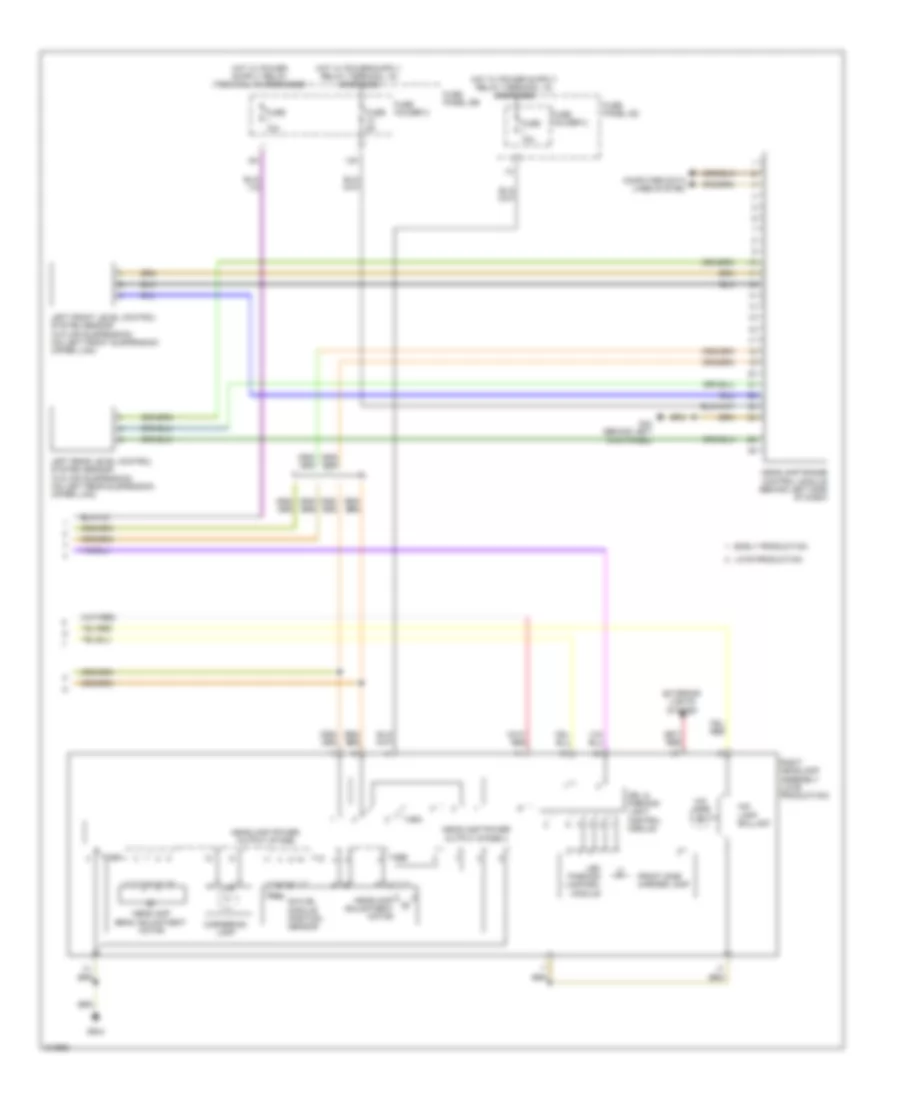
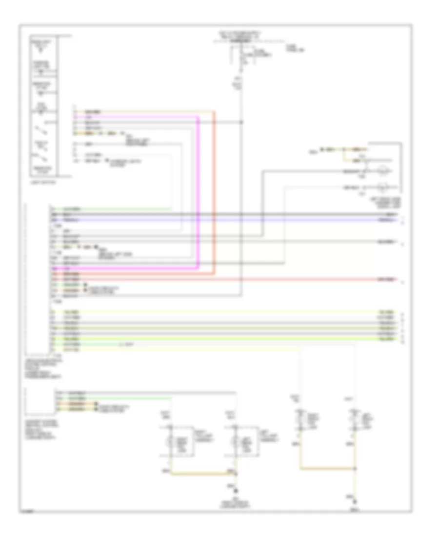
Headlights Wiring Diagram, with Standard Headlights (1 of 2) for Audi Q7 4.2 2009
List of elements for Headlights Wiring Diagram, with Standard Headlights (1 of 2) for Audi Q7 4.2 2009:
- Comfort system central control module 2 (right side of luggage compt)
- Computer data lines system
- Fog lp ind
- Fog lp sw
- Fuse 5a
- Fuse holder 3
- Fuse panel sb
- G44 (behind left kick panel)
- G51 (right side of luggage compt)
- G644
- G664 (behind left side of dash)
- Headlight sw ill
- Interior lights system
- Left front fog lamp
- Left front side marker/turn signal lamp
- Left rear fog lamp
- Left taillamp assembly
- Light switch
- Parking light ind
- Rear fog lp ind
- Rear fog lp sw
- Right front fog lamp
- Right rear fog lamp
- Right taillamp assembly
- T10a
- T12b
- T2s
- T2t
- T32b
- Vehicle electrical system control module (under front passenger's seat)
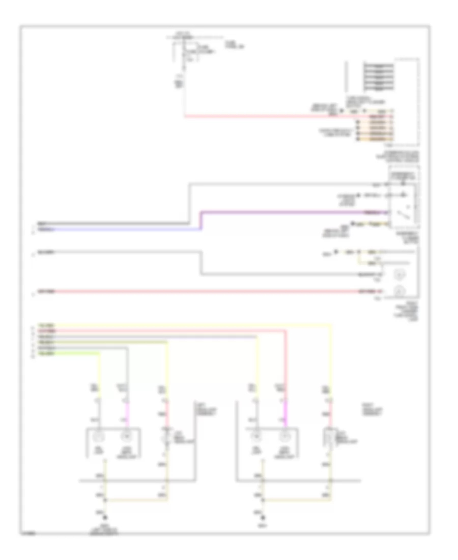
Headlights Wiring Diagram, with Standard Headlights (2 of 2) for Audi Q7 4.2 2009
List of elements for Headlights Wiring Diagram, with Standard Headlights (2 of 2) for Audi Q7 4.2 2009:
- (behind left side of dash) g664
- 11a
- Computer data lines system
- Drl lamp
- Emergency flasher button
- Emergency flasher ind
- Fuse 10a
- Fuse holder 1
- Fuse panel sb
- G640 (left side of engine compt)
- G644
- G664 (behind left side of dash)
- High beam headlamp
- Hot at all times
- Interior lights system
- Left headlamp assembly
- Low beam headlamp
- Nca
- Red
- Right front side marker/ turn signal lamp
- Right headlamp assembly
- Steering column electronic systems control module
- T16a
- T2t
- T2u
- T2v
- Turn signal/ headlight flasher switch
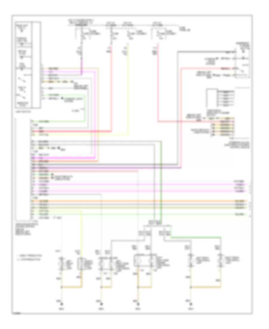
Headlights Wiring Diagram, without Cornering Headlights (1 of 3) for Audi Q7 4.2 2009
List of elements for Headlights Wiring Diagram, without Cornering Headlights (1 of 3) for Audi Q7 4.2 2009:
- (behind left side of dash) g664
- 11a
- Computer data lines system
- Early production
- Emergency flasher button
- Fog lp ind
- Fog lp sw
- Fuse 10a
- Fuse 25a
- Fuse 30a
- Fuse 5a
- Fuse holder 1
- Fuse holder 2
- Fuse holder 3
- Fuse panel sb
- G44 (behind left kick panel)
- G644
- G664
- Headlight sw ill
- Hot at all times
- Interior lights system
- Late production
- Left front fog lamp
- Left front side marker/ turn signal lamp
- Left front turn signal lamp
- Light switch
- Nca
- Parking light ind
- Rear fog lp sw
- Red
- Right front fog lamp
- Right front side marker/ turn signal lamp
- Right front turn signal lamp
- Rr fog lp ind
- Steering column electronic systems control module
- T10a
- T12b
- T16a
- T2s
- T2t
- T2u
- T2v
- T32b
- Turn signal/ headlight flasher switch
- Vehicle electrical system control module (behind left side of dash)
- W/ drl
Headlights Wiring Diagram, without Cornering Headlights (2 of 3) for Audi Q7 4.2 2009
List of elements for Headlights Wiring Diagram, without Cornering Headlights (2 of 3) for Audi Q7 4.2 2009:
- (if equipped) drl lamp
- Drl & parking light control module
- Early production
- Exterior lights system
- Front side marker lamp
- G640 (left side of engine compt)
- Headlamp beam adjustment motor
- Headlamp reflector adjustment solenoid
- Hid lamp
- Hid lamp ballast
- Hid lamp control module
- Late production
- Led parking lamp/drl module
- Left front level control system sensor (w/o air suspension) (on left front suspension upper link)
- Left headlamp assembly (late production)
- Left headlight assembly
- Left rear level control system sensor (w/o air suspension) (on left rear suspension upper link)
- Red
- W/ drl
Headlights Wiring Diagram, without Cornering Headlights (3 of 3) for Audi Q7 4.2 2009
List of elements for Headlights Wiring Diagram, without Cornering Headlights (3 of 3) for Audi Q7 4.2 2009:
- (if equipped) drl lamp
- 12a
- Computer data lines system
- Drl & parking light control module
- Early production
- Exterior lights system
- Front side marker lamp
- Fuse 5a
- Fuse holder 3
- Fuse panel sb
- G44 (behind left kick panel)
- G644
- Headlamp beam adjustment motor
- Headlamp range control module (behind left side of dash)
- Headlamp reflector adjustment solenoid
- Hid lamp
- Hid lamp ballast
- Hid lamp control module
- Late production
- Led parking lamp/drl module
- Red
- Right headlamp assembly (late production)
- Right headlight assembly
- W/ drl
HORN
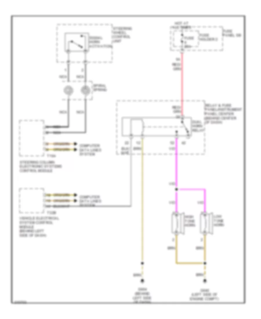
Horn Wiring Diagram for Audi Q7 4.2 2009
List of elements for Horn Wiring Diagram for Audi Q7 4.2 2009:
- Computer data lines system
- Dual horn relay
- Fuse 25a
- Fuse holder 2
- Fuse panel sb
- G640 (left side of engine compt)
- G664 (behind left side of dash)
- High tone horn
- Hot at all times
- Low tone horn
- Nca
- Relay & fuse panel/instrument panel center (behind center of dash)
- Signal horn activation
- Spiral spring
- Steering column electronic systems control module
- Steering wheel control unit
- T16a
- T32b
- Vehicle electrical system control module (behind left side of dash)
INSTRUMENT CLUSTER
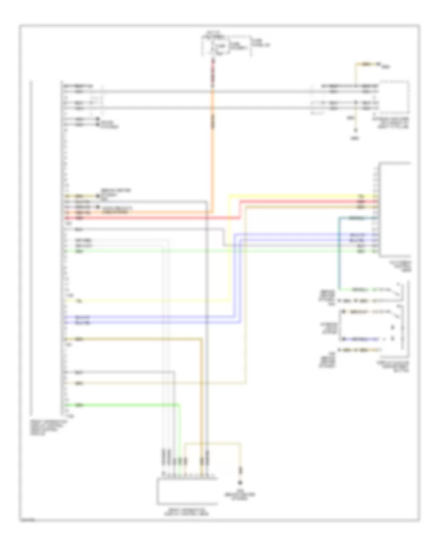
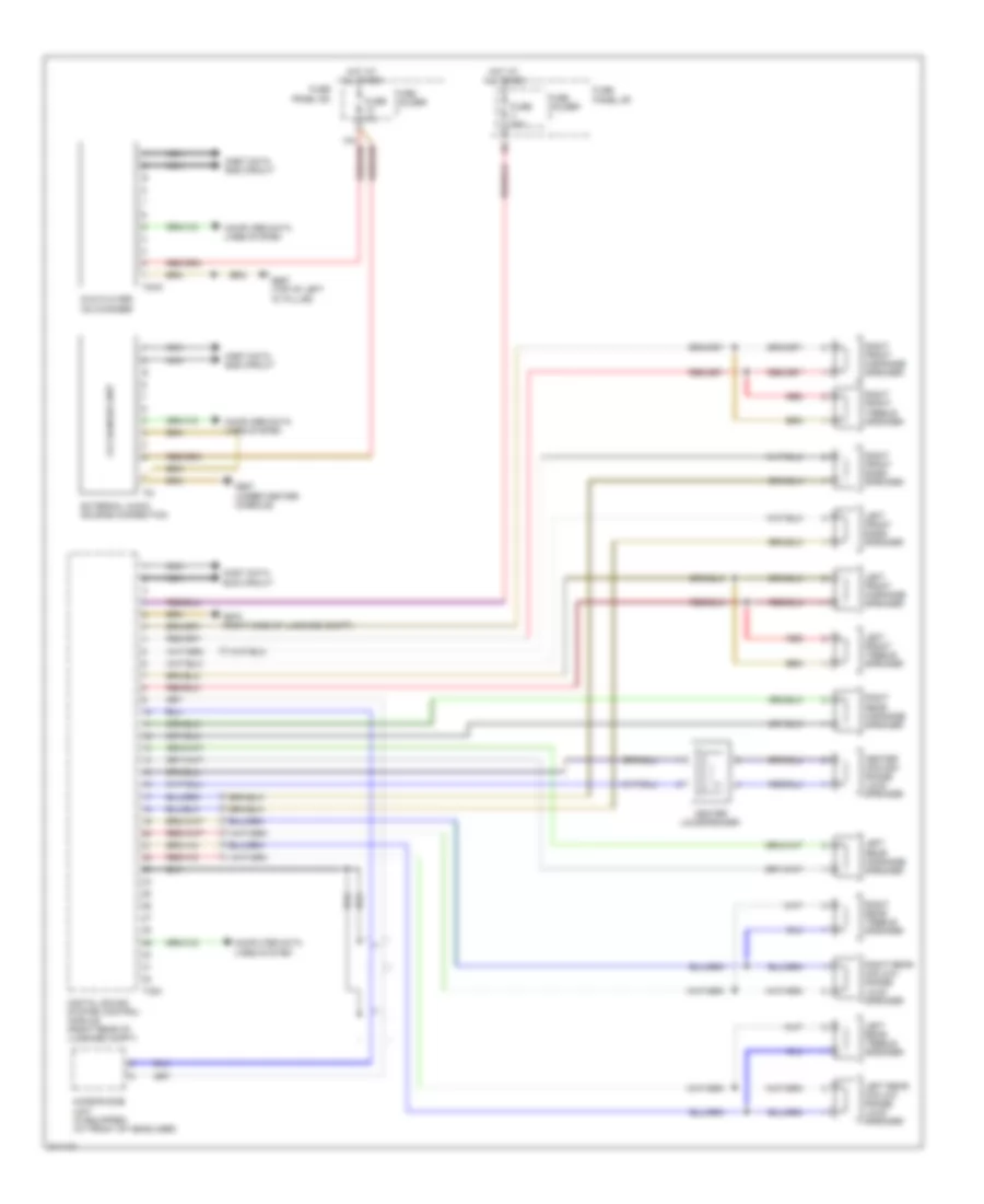
Front Information Display Control Module Wiring Diagram, Basic Plus for Audi Q7 4.2 2009
List of elements for Front Information Display Control Module Wiring Diagram, Basic Plus for Audi Q7 4.2 2009:
- (behind center of dash) g45
- Antenna amplifier (on window at right "c" pillar)
- Computer data lines system
- Display & glove compartment button
- Front information display control head
- Front information display control head control module
- Fuse 15a
- Fuse holder 3
- Fuse panel sc
- G45 (behind center of dash)
- G663
- Hot at all times
- Interior lights system
- Multimedia control head
- Nca
- Red
- Sound systems
- T12p
- T12q
- T8o
- T8p
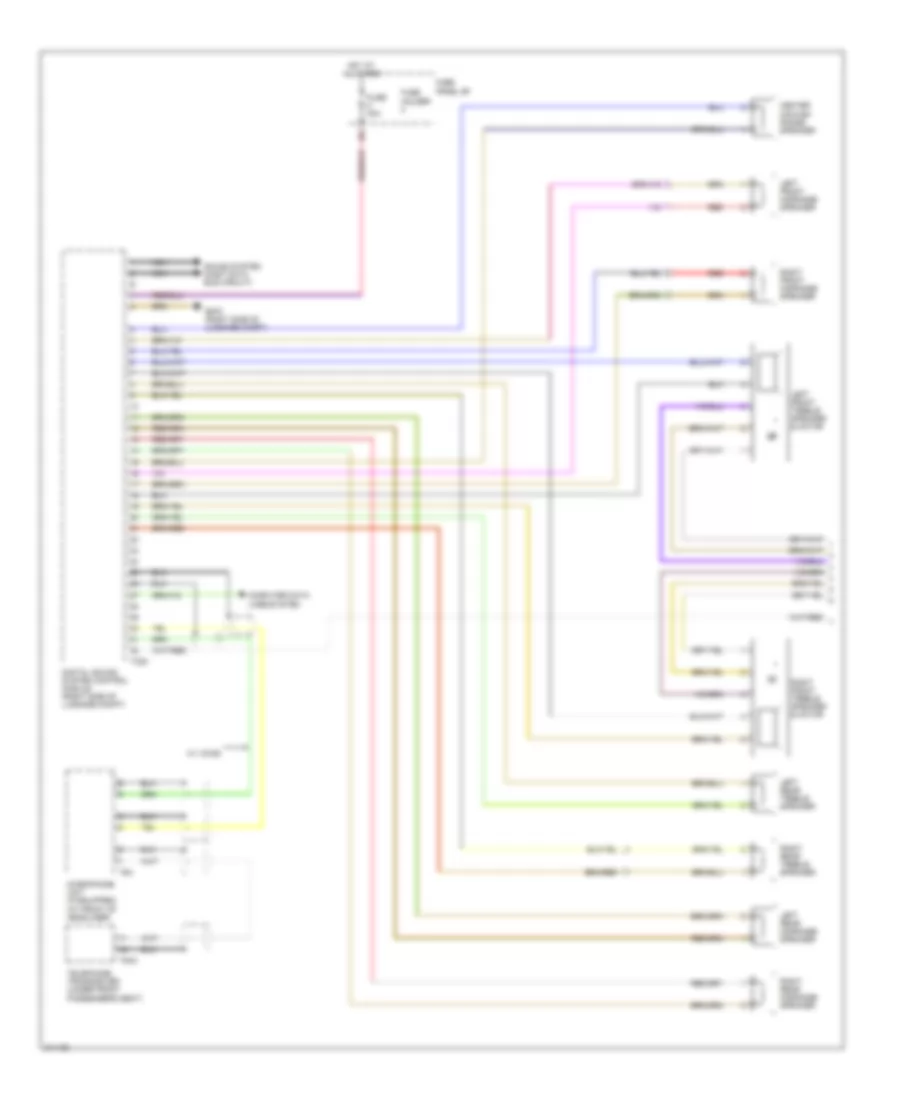
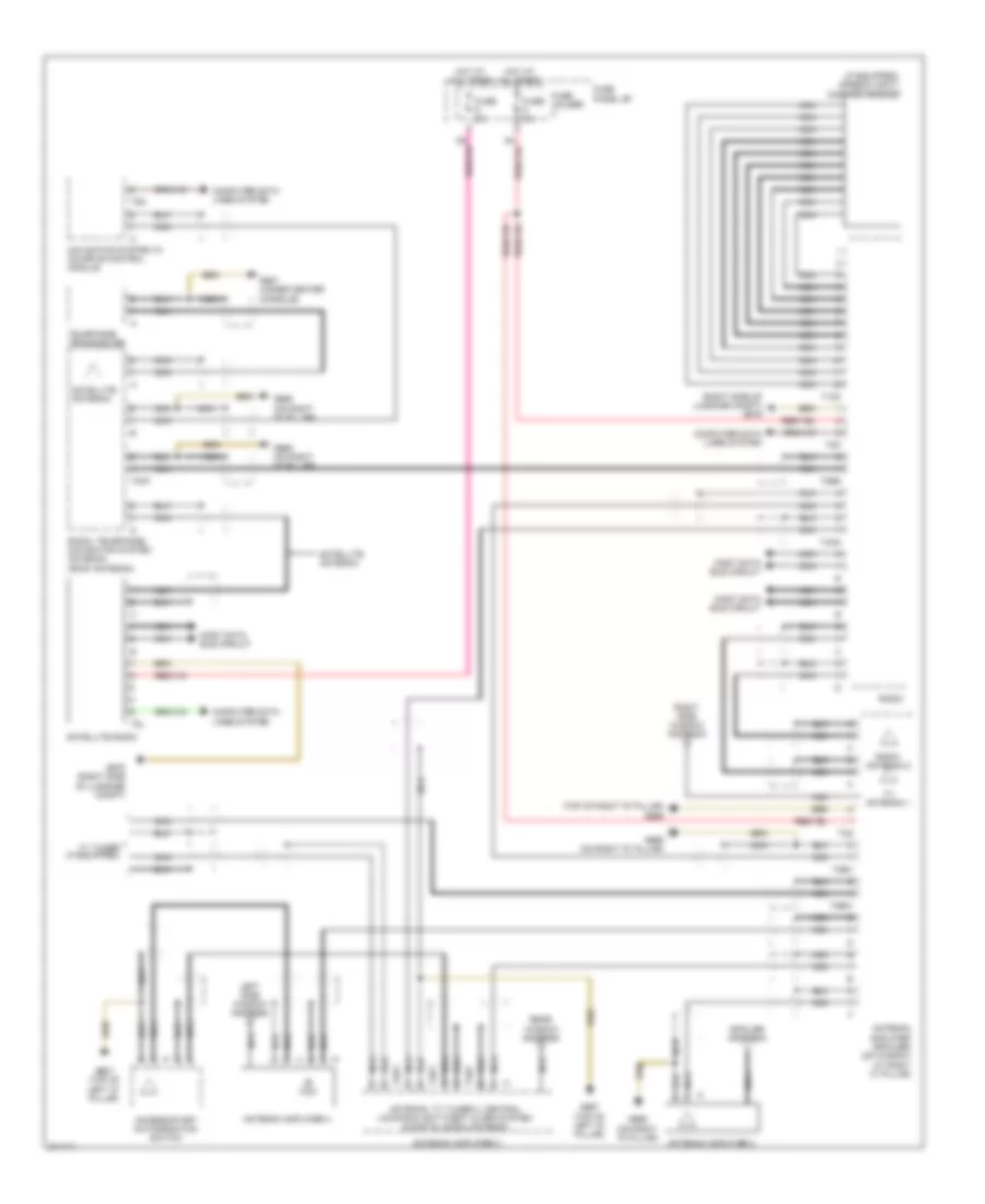
Front Information Display Control Module Wiring Diagram, Basic for Audi Q7 4.2 2009
List of elements for Front Information Display Control Module Wiring Diagram, Basic for Audi Q7 4.2 2009:
- (behind center of dash) g45
- (on window at right "c" pillar) antenna amplifier
- Computer data lines system
- Display & glove compartment button
- Front information display control head
- Front information display control head control module
- Fuse 15a
- Fuse holder 3
- Fuse panel sc
- G45 (behind center of dash)
- G663
- Hot at all times
- Interior lights system
- Left front bass speaker
- Left front treble speaker
- Left rear mid/low range loud- speaker
- Left rear treble speaker
- Multimedia control head
- Nca
- Red
- Right front bass speaker
- Right front treble speaker
- Right rear mid/low range loud- speaker
- Right rear treble speaker
- Sound systems
- T12p
- T12q
- T8o
- T8p
Front Information Display Control Module Wiring Diagram, Standard for Audi Q7 4.2 2009
List of elements for Front Information Display Control Module Wiring Diagram, Standard for Audi Q7 4.2 2009:
- Computer data lines system
- Display button
- Front information display control head
- Front information display control head control module
- Fuse 5a
- Fuse holder 3
- Fuse panel sc
- G45 (behind center of dash)
- Hot at all times
- Multimedia control head
- Nca
- Pnk
- Red
- Sound systems
- T20k
- T22b
Instrument Cluster Wiring Diagram (1 of 2) for Audi Q7 4.2 2009
List of elements for Instrument Cluster Wiring Diagram (1 of 2) for Audi Q7 4.2 2009:
- (base of right "c" pillar) (3.6l & 4.2l w/ fuel tank) g62 (base of left "c" pillar) (4.2l w/o fuel tank) g61
- (right side luggage compt) g51
- 10a
- Brake pad wear ind lamp
- Brake system warning ind lamp
- Computer data lines system
- Directional stabilization assistance ind lamp
- Display unit
- Engine controls system
- Engine coolant level (ecl) sensor
- Engine coolant level/temperature (ecl/ect) warning lamp
- Fuel gauge
- Fuel level sender & transfer fuel pump (transfer fuel pump: below right side second row seat)
- Fuel level sensor 2 (below left side second row seat)
- Fuse 10a
- Fuse holder 2
- Fuse panel sb
- G45 (behind center of dash)
- Hot at all times
- Instrument cluster control module
- Interior lights system
- Oil pressure warning ind lamp
- Outside air temperature display
- Outside air temperature sensor (behind front bumper, in front condenser)
- Parking brake ind lamp
- Radio frequency controlled clock receiver
- Transmissions system
- Windshield washer fluid level sensor
Instrument Cluster Wiring Diagram (2 of 2) for Audi Q7 4.2 2009
List of elements for Instrument Cluster Wiring Diagram (2 of 2) for Audi Q7 4.2 2009:
- (top front of engine)
- Brake fluid level warning switch
- Front/center console control head
- Fuse 5a
- Fuse holder 3
- Fuse panel sb
- G35 (under front passenger's seat)
- G45 (behind center of dash)
- G664 (behind left side of dash)
- Hot at all times
- Interior lights system
- Left front brake pad wear sensor
- Left rear brake pad wear sensor
- Oil level thermal sensor
- Oil pressure switch
- Parking brake contact switch
- Right front brake pad wear sensor
- Right rear brake pad wear sensor
INTERIOR LIGHTS
Courtesy Lamps Wiring Diagram (1 of 2) for Audi Q7 4.2 2009
List of elements for Courtesy Lamps Wiring Diagram (1 of 2) for Audi Q7 4.2 2009:
- Comfort system central control module (right side of luggage compt)
- Computer data lines system
- Driver's make-up mirror light/ contact switch/ driver's illumination make-up mirror light
- Front pass- enger's make-up mirror light/ front pass- enger's make-up mirror contact switch
- G43 (behind right kick panel)
- G44 (behind left kick panel)
- G51 (right side of luggage compt)
- G664 (behind left side of dash)
- G668 (on left "d" pillar)
- G77 (base of left "b" pillar)
- G78
- Glove compart- ment lamp switch
- Glove compart- ment light
- Instrument illumination circuit
- Left footwell light
- Left luggage compartment light
- Left rear central locking unit
- Left rear door ambient lighting (w/ additional illumination) (late production)
- Left rear door control module (in left rear door behind inner trim panel)
- Left rear door warning light (w/ additional illumination)
- Left rear entry light (w/ additional illumination)
- Left rear footwell light
- Rear lid courtesy light
- Right footwell light
- Right luggage compartment light
- Right rear central locking unit
- Right rear door ambient lighting (w/ additional illumination) (late production)
- Right rear door control module (in rear door behind inner trim panel)
- Right rear door warning light (w/ additional illumination)
- Right rear entry light (w/ additional illumination)
- Right rear footwell light
- T15a
- T16i
- T16m
- T20n
- T20o
- T32b
- T32d
- Vehicle electrical system control module (behind left side of dash)
Courtesy Lamps Wiring Diagram (2 of 2) for Audi Q7 4.2 2009
List of elements for Courtesy Lamps Wiring Diagram (2 of 2) for Audi Q7 4.2 2009:
- Comfort system central control module 2 (right side of luggage compt)
- Computer data lines system
- Driver door ambient lighting (w/ additional illumination) (late production)
- Driver's door central locking lock unit
- Driver's door control module (in driver's door behind inner trim panel)
- Driver's door warning light (w/ additional illumination)
- Driver's map/reading light
- Early production
- Front passenger door ambient lighting (late production) (w/ additional illumination)
- Front passenger's door central locking lock unit
- Front passenger's door control module (in front passenger's door, behind inner trim panel)
- Front passenger's map/reading light
- Front roof control module
- G43 (behind right kick panel)
- G44 (behind left kick panel)
- G658 (top of left "d" pillar)
- Instrument cluster control module
- Instrument illumination circuit
- Interior lights system (instrument illumination circuit)
- Late production
- Left front entry light
- Left interior light
- Mirror system
- Passenger's door warning light (w/ additional illumination)
- Rear courtesy light
- Rear interior lights assembly
- Right front entry light
- Right interior light
- T12a
- T20f
- T20l
- T20m
- T2x
- T32f
- T32g
- W/ additional illumination
- W/ light switch
- W/o light switch
Instrument Illumination Wiring Diagram (1 of 2) for Audi Q7 4.2 2009
List of elements for Instrument Illumination Wiring Diagram (1 of 2) for Audi Q7 4.2 2009:
- (4)
- 12v socket (w/ left rear center console)
- 12v socket (w/ right rear center console)
- 12v socket 2 (w/ right front center console)
- Ashtray & cup holder light
- Asr/esp button
- Center instru- ment panel vent illumi- nation
- Cigarette lighter
- Computer data lines system
- Control module
- Display & glove compart- ment button
- Emergency flasher button
- Equipped)
- Front roof
- Front/ center console control head
- G43 (behind right kick panel)
- G44 (behind left kick panel)
- G45 (behind center of dash)
- G664 (behind left side of dash)
- G67
- G687 (under center console)
- Garage door opener control head
- Instrument cluster control module
- Lane change assist- ance button (if
- Left instru- ment panel vent illumi- nation
- Left rear heated seat regu- lating switch
- Level control system control module (right side of luggage compt)
- Light switch
- Load level button
- Rear center air vent illumi- nation
- Rear sunroof switch
- Right instru- ment panel vent illumi- nation
- Right rear heated seat regu- lating switch
- Sunroof switch
- Sunroof switch illumination (if equipped)
- T12a
- T12b
- T2x
- T2y
- T32b
- T81a
- Vehicle electrical system control module (behind left side of dash)
- W/ daytime running light
Instrument Illumination Wiring Diagram (2 of 2) for Audi Q7 4.2 2009
List of elements for Instrument Illumination Wiring Diagram (2 of 2) for Audi Q7 4.2 2009:
- (w/ additional equipment) left rear entry light
- Alarm system off switch
- Central locking safe indicator lamp
- Computer
- Computer data lines system
- Data lines
- Driver door opener illumi- nation
- Driver's door control module (in driver's door behind inner trim panel)
- Driver's door warning light
- Driver's interior lock switch
- Driver's seat memory program switch (if equipped)
- Front passenger interior lock switch
- Front passenger's door control module (in front passenger's door, behind inner trim panel)
- Front passenger's door warning light (w/ additional illumination)
- Left front entry light
- Left rear ashtray illumi- nation
- Left rear door control module (in left rear door behind inner trim panel)
- Left rear door opener illumi- nation
- Left rear door warning light
- Left rear interior lock switch
- Left rear window switch
- Mirror adjust- ment switch
- Passenger door opener illumination
- Passenger door window regulator switch
- Power window control head
- Rear lid remote control lock switch
- Right front entry light
- Right rear ashtray illumi- nation
- Right rear door control module (in rear door behind inner trim panel)
- Right rear door opener illumination
- Right rear door warning light
- Right rear entry light
- Right rear interior lock switch
- Right rear window switch
- System
- T16i
- T16m
- T20l
- T20m
- T20n
- T20o
- T32f
- T32g
- W/ additional equipment
MEMORY SYSTEMS
Memory Mirrors Wiring Diagram (1 of 2) for Audi Q7 4.2 2009
List of elements for Memory Mirrors Wiring Diagram (1 of 2) for Audi Q7 4.2 2009:
- Adjustment switch
- Computer data lines system
- Day/night
- Driver's door control module (in driver's door behind inner trim panel)
- Driver's exterior mirror assembly
- Entry lamp
- Exterior lights system
- Fold away switch
- Fold-in
- Fuse 15a
- Fuse 35a
- Fuse holder
- Fuse panel sb
- G44 (behind left kick panel)
- Heater
- Horizontal
- Hot at all times
- Interior lights system
- Lane change
- Mirror adjustment switch assembly
- Navigation system
- Pnk
- Red
- Selector switch
- T16i
- T1a
- T1b
- T20l
- T2ac
- T2ad
- T2ae
- T2af
- T2ag
- T32f
- T8f
- Turn signal
- Vertical
Memory Mirrors Wiring Diagram (2 of 2) for Audi Q7 4.2 2009
List of elements for Memory Mirrors Wiring Diagram (2 of 2) for Audi Q7 4.2 2009:
- 11a
- Computer data lines system
- Day/night
- Driver's seat memory program control
- Entry lamp
- Exterior lights system
- Fold-in
- Front passenger's door control module (in front passenger's door behind inner trim panel)
- Front passenger's exterior mirror assembly
- Fuse 15a
- Fuse 35a
- Fuse holder 1
- Fuse holder 3
- Fuse panel
- G43
- Heater
- Horizontal
- Hot at all times
- Lane change
- Navigation system
- Off
- Pnk
- Red
- T16k
- T1a
- T1b
- T20m
- T2ae
- T2af
- T2ag
- T8f
- Turn signal
- Vertical
Memory Seat Wiring Diagram (1 of 2) for Audi Q7 4.2 2009
List of elements for Memory Seat Wiring Diagram (1 of 2) for Audi Q7 4.2 2009:
- Computer data lines system
- Driver's power seat adjustment circuit breaker 30a
- Driver's seat backrest adjustment motor
- Driver's seat fore/aft motor
- Driver's seat height adjustment motor
- Driver's seat inclination adjustment motor
- Driver's seat lumbar support adjustment switch
- Driver's seat lumbar support curvature adjustment motor
- Driver's seat lumbar support height adjustment motor
- G77 (base of left "b" pillar)
- Hot at all times
- Memory seat/ steering column adjustment control module
- Relay & fuse/ panel instrument panel center (behind center of dash)
- T12s
- T32h
Memory Seat Wiring Diagram (2 of 2) for Audi Q7 4.2 2009
List of elements for Memory Seat Wiring Diagram (2 of 2) for Audi Q7 4.2 2009:
- Backrest
- Computer data lines system
- Driver's door control module (in driver's door behind inner trim panel)
- Driver's power seat switch assembly
- Driver's seat memory program control
- Fore/aft
- Fuse 15a
- Fuse 35a
- Fuse holder 1
- Fuse panel sb
- G44 (behind left kick panel)
- Height
- Hot at all times
- Interior lights system
- T20l
- T32f
- Tilt
Steering Column Memory Wiring Diagram for Audi Q7 4.2 2009
List of elements for Steering Column Memory Wiring Diagram for Audi Q7 4.2 2009:
- (behind left side of dash) g664
- 11a
- Adjustment switch
- Computer data lines system
- Driver's door control module (in driver's door behind inner trim panel)
- Driver's seat memory program control
- Fuse 10a
- Fuse 15a
- Fuse 25a
- Fuse 30a
- Fuse 5a
- Fuse holder
- Fuse holder 2
- Fuse panel sb
- G44 (behind left kick panel)
- Hot at all times
- Interior lights
- Motor
- Motor axial adjustment
- Nca
- Off
- Red
- Sensor
- Sensor axial adjustment
- Steering column
- Steering column adjustment motor
- Steering column electronic systems control module
- T10a
- T12b
- T16a
- T20l
- T32b
- T32f
- T4a
- Vehicle electrical system control module (behind left side of dash)
- Vertical adjustment
NAVIGATION
Lane Change Assistance Wiring Diagram for Audi Q7 4.2 2009
List of elements for Lane Change Assistance Wiring Diagram for Audi Q7 4.2 2009:
- (behind left kick panel) g44
- Change lane
- Computer data lines system
- Directional stabilization assistance control module
- Directional stabilization assistance windshield heater
- Driver's exterior mirror assembly
- Fuse 5a
- Fuse holder 2
- Fuse holder 3
- Fuse panel sb
- Fuse panel sc
- G44 (behind left kick panel)
- G51 (right side of luggage compt)
- Interior lights system
- Lane change
- Lane change assistance button/ lights
- Lane change assistance control module
- Lane change assistance control module 2
- Passenger's exterior mirror assembly
- T2ag
Navigation Wiring Diagram for Audi Q7 4.2 2009
List of elements for Navigation Wiring Diagram for Audi Q7 4.2 2009:
- (or nca)
- Computer data lines system
- Fuse 5a
- Fuse holder 2
- Fuse panel sf
- G675 (right side of luggage compt)
- G681 (early production) g669 (late production) (on right "d" pillar)
- Hot at all times
- Navigation system w/ cd drive control module (right side of luggage compt)
- Nca
- Radio/ telephone/ navigation system antenna (w/ roof antenna) (on roof panel, near rear hatch)
- Sound systems (most data bus circuit)
- T8n
Parking Assistant Wiring Diagram for Audi Q7 4.2 2009
List of elements for Parking Assistant Wiring Diagram for Audi Q7 4.2 2009:
- Buzzer
- Computer data lines system
- Front
- Front/ center console control head
- Fuse 5a
- Fuse holder 1
- Fuse holder 2
- Fuse panel sc
- Fuse panel sf
- G45 (behind center of dash)
- G51 (right side of luggage compt)
- Hot at all times
- Left front center parking aid sensor
- Left front parking aid sensor
- Left rear
- Left rear center parking aid sensor
- Parking aid
- Parking aid button
- Parking aid control module (right side of luggage compt)
- Parking aid ind
- Rear parking aid warning buzzer
- Red
- Right front center parking aid sensor
- Right front parking aid sensor
- Right rear center parking aid sensor
- Right rear parking aid
- Sensor
- T12e
- T12f
- T16b
- Warning
Rear Camera Wiring Diagram for Audi Q7 4.2 2009
List of elements for Rear Camera Wiring Diagram for Audi Q7 4.2 2009:
- 11a
- Computer data lines system
- Early production
- Front information display control head control module
- Fuse 5a
- Fuse holder 1
- Fuse holder 2
- Fuse panel sf
- G51 (right side of luggage compt)
- Hot at all times
- Late production
- Nca
- Pins: 1-38 (not used)
- Pins: 49-54 (not used)
- Rear view camera (in rear hatch, at handle, above license plate)
- Rear view camera control module (right side of luggage compt)
- T2ah
- T2ak
- T2am
- T2an
- T54
POWER DISTRIBUTION
3.0L TURBO
3.0L Turbo, Power Distribution Wiring Diagram (1 of 6) for Audi Q7 4.2 2009
List of elements for 3.0L Turbo, Power Distribution Wiring Diagram (1 of 6) for Audi Q7 4.2 2009:
- 10a
- 11a
- 12a
- 20a
- 20b
- 20c
- 20d
- Access/ start control module
- Air bag control module
- Automatic day/night interior sensor
- Battery
- Battery interrupt igniter
- Battery monitoring control module
- Brake light switch
- Comfort system central control module
- Data bus on board diagnostic interface
- Data link connector
- Directional stabilization assistance control module
- Distance regulation control module
- Distance regulation sensor heater
- Driver's auxiliary video/audio connection module
- Early production
- Engine control module (ecm)
- Front passenger's auxiliary video/audio connection module
- Fuse 10a
- Fuse 150a
- Fuse 150a (or 125a)
- Fuse 40a
- Fuse 50a
- Fuse 5a
- Fuse 5a (or 10a)
- Fuse 60a
- Fuse holder
- Fuse panel sb
- Garage door opener control head
- Garage door opener control module
- Generator
- Headlamp range control module
- Late production
- Left headlamp
- Level control system compressor relay
- Multimedia control module
- Nca
- Oil level thermal sensor
- Red
- Relay & fuse panel e-box (left side of plenum chamber)
- Relay & fuse panel sd (under driver's seat)
- Relay & fuse panel/instrument panel center (behind center of dash)
- Starter
- Starter relay
- Starter relay 2
- Steering column electronic systems control module
- T10v
- T12d
- T16
- T16a
- T20
- T20e
- T26b
- T26e
- T2au
- T32d
- T6v
- T75a
- T8x
- T94
- Terminal 30 wire junction 2
- To fuse & relay panel e-box (diagram 5 of 6)
- To fuse panel sb (diagram 2 of 6)
- To fuse panel sc (diagram 2 of 6)
- To fuse panel sc (diagram 3 of 6)
- To fuse panel sc (diagram 4 of 6)
- To fuse panel sf (diagram 4 of 6)
- To fuse panel sf (diagram 6 of 6)
- To relay & fuse panel e-box (diagram 5 of 6)
- To relay & fuse panel instrument panel center (diagram 6 of 6)
- To right fuse panel instrument panel (diagram 6 of 6)
- Towing recog- nition control module
- W/ high beam
- W/o high beam
3.0L Turbo, Power Distribution Wiring Diagram (2 of 6) for Audi Q7 4.2 2009
List of elements for 3.0L Turbo, Power Distribution Wiring Diagram (2 of 6) for Audi Q7 4.2 2009:
- (or 15a)
- 10a
- 11a
- 12a
- 12v socket 2
- 12v socket 3
- 12v socket 4
- Abs control module
- Access/ start authorization switch
- Access/ start control module
- Alarm horn
- Brake light switch
- Cigarette lighter
- Climatronic control module
- Driver's door control module
- Driver's seat lumbar support adjustment switch
- Early production
- Fresh air blower control module
- Fresh air blower rear
- From relay & fuse panel sd (diagram 1 of 6)
- Front passenger's door control module
- Front passenger's seat lumbar support adjustment switch
- Fuse 10a
- Fuse 10a (or 5a)
- Fuse 15a
- Fuse 20a
- Fuse 25a
- Fuse 30a
- Fuse 35a
- Fuse 40a
- Fuse 5a
- Fuse 5a (or 15a)
- Fuse holder
- Fuse holder 1
- Fuse panel sb
- Fuse panel sc
- G687 (under center console)
- Interior lights system
- Late production
- Left rear door control module
- Left rear heated seat regulating switch
- Nca
- Rear a/c control head (w/ rear climatronic)
- Rear window defogger relay
- Red
- Relay & fuse panel/ instrument panel center (behind center of dash)
- Right front seat ventilation control module
- Right rear door control module
- Right rear heated seat regulating switch
- Steering column electronic systems control module
- Suppressor
- T16a
- T16d
- T20i
- T20m
- T20n
- T20o
- T2a
- T3c
- T3h
- T40a
- T47a
- T6a
- T6ai
- Tire pressure monitoring control module
- To fuse panel sb (diagram 3 of 6)
- Transmission control module (tcm)
- Vehicle electrical system control module 2
3.0L Turbo, Power Distribution Wiring Diagram (3 of 6) for Audi Q7 4.2 2009
List of elements for 3.0L Turbo, Power Distribution Wiring Diagram (3 of 6) for Audi Q7 4.2 2009:
- (not used)
- 10a
- 11a
- 12a
- 26b
- Abs control module
- Air bag control module
- Air quality sensor
- Asr/esp button
- Brake booster
- Brake light disable relay (esp)
- Climatronic control module
- Data bus on board diagnostic interface
- Data link connector
- Dual horn relay
- Early production
- From fuse panel sb (diagram 2 of 6)
- From fuse r panel sb (diagram 2 of 6)
- Front pass- enger's air bag disabled indicator lamp
- Fuse 10a
- Fuse 15a
- Fuse 25a
- Fuse 30a
- Fuse 5a
- Fuse holder
- Fuse panel sb
- Fuse panel sc
- Headlamp washer relay
- Instrument cluster control module
- Lane change assis- tance control module
- Lane change assis- tance control module 2
- Late production
- Left front seat ventilation control module (late production)
- Left rear heated seat regul- ating switch
- Level control system control module
- Multi- function transmission range (tr) switch
- Nca
- Parking aid control module
- Rain/light recognition sensor
- Rear a/c control head (climatronic)
- Red
- Relay & fuse panel/ instrument panel center (behind center of dash)
- Right head lamp
- Right rear heated seat regul- ating switch
- Seat occupied recognition control module
- Selector lever sensor system control module
- T10a
- T12b
- T12l
- T12m
- T16
- T16b
- T16d
- T16h
- T20
- T47a
- T4y
- T75a
- T81a
- Transmission control module (tcm)
- Vehicle electrical system control module
- Wiper motor control module
3.0L Turbo, Power Distribution Wiring Diagram (4 of 6) for Audi Q7 4.2 2009
List of elements for 3.0L Turbo, Power Distribution Wiring Diagram (4 of 6) for Audi Q7 4.2 2009:
- (not used)
- 10a
- 11a
- 12a
- 12v socket
- Comfort system central control module
- Comfort system central control module 2
- Cooler
- Dvd player
- External audio source connection
- From relay & fuse panel sd (diagram 1 of 6)
- Front information display control head
- Front information display control head control module
- Front passenger's door control module
- Fuse 10a
- Fuse 15a
- Fuse 15a (or 7.5a)
- Fuse 20a
- Fuse 30a
- Fuse 35a
- Fuse 5a
- Fuse holder
- Fuse holder 1
- Fuse panel sc
- Fuse panel sf
- G51 (right side of luggage compt)
- Keyless access authorization antenna reader
- Level control system control module
- Nca
- Parking aid control module
- Power sunroof control module
- Rear a/c control head (climatronic)
- Rear fresh air blower control module
- Rear sliding sunroof control module
- Rear view camera system control module (late production)
- Red
- Reducing agent metering system control module
- Right rear door control module
- Roof blind control module
- T10g
- T16b
- T16h
- T20g
- T20k
- T20m
- T2o0
- T40
- T54
- T81a
- T8ad
- T8af
- Telephone transceiver (if equipped)
- W/ mmi basic
- W/o mmi basic
3.0L Turbo, Power Distribution Wiring Diagram (5 of 6) for Audi Q7 4.2 2009
List of elements for 3.0L Turbo, Power Distribution Wiring Diagram (5 of 6) for Audi Q7 4.2 2009:
- 10 pin connector
- 10a
- 11a
- 12a
- 13a
- 14a
- 15a
- 16a
- 17a
- 18a
- 1d b
- 20a
- 20b
- 20d
- 3d b c
- 4c b
- Automatic glow time control module
- Charge air cooler bypass control unit
- Coolant fan control (fc) control
- Coolant fan control (fc) control module
- Coolant fan control (fc) control module 2
- Early production
- Engine control module (ecm)
- Exhaust gas recirculation (egr) cooler switch-over valve
- Exhaust gas recirculation (egr) cooler switch-over valve 2
- From terminal 30 wire junction (diagram 1 of 6)
- Fuel metering valve
- Fuel pressure regulator valve
- Fuel pump (fp) relay
- Fuse 10a
- Fuse 15a
- Fuse 20a
- Fuse 40a
- Fuse 5a
- Fuse 60a
- Fuse 80a
- Late production
- Mass air flow (maf) sensor
- Module 2
- Nca
- Nox sensor 2 control module
- Nox sensor control module
- Oil pressure regulation valve
- Oxygen sensor (o2s) heater
- Preheating coolant, high heat output relay
- Preheating coolant, low heat output relay
- Red
- Reducing agent pump
- Relay & fuse panel e-box (left side of plenum chamber)
- T10e
- T94
- Throttle valve control module
- To relay & fuse panel e-box (diagram 6 of 6)
- Transfer fuel pump (fp)
3.0L Turbo, Power Distribution Wiring Diagram (6 of 6) for Audi Q7 4.2 2009
List of elements for 3.0L Turbo, Power Distribution Wiring Diagram (6 of 6) for Audi Q7 4.2 2009:
- (not used)
- 10a
- 10g
- 11a
- 12a
- 19e
- Access/start control module
- Antenna amplifier
- Auxiliary fuel pump relay
- B 5c
- C 19c
- Cb 30a
- Comfort system central control module
- Coolant circulation pump relay
- Cooler
- Digital sound system control module
- Digital sound system control module (late production)
- Digital sound system control module 2
- Digital sound system control module 2 (late production)
- Driver's power seat adjustment circuit breaker
- Driver's power seat switch assembly (w/o memory)
- Driver's seat lumbar support adjustment switch
- Early production
- Exhaust gas recirculation (egr) cooler pump
- From relay & fuse panel e-box (diagram 5 of 6)
- From relay & fuse panel sd (diagram 1 of 6)
- Front passenger's power seat switch assembly (w/o memory)
- Front passenger's seat lumbar support adjustment switch (w/o memory)
- Fuel cooling pump/relay
- Fuse 15a
- Fuse 20a
- Fuse 25a
- Fuse 30a
- Fuse 35a
- Fuse 5a
- Fuse holder 2
- Fuse holder 3
- Fuse panel sf
- High pressure sensor
- Late production
- Left washer nozzle heater
- Memory seat/ steering column adjustment control module
- Multimedia control module
- Navigation system w/ cd drive control module
- Nca
- Radio
- Radio (late production)
- Rear lid control module
- Rear lid control module 2
- Rear view camera system control module (early production)
- Rear window wiper motor
- Red
- Relay & fuse panel e-box (left side of plenum chamber)
- Relay & fuse panel/instrument panel center (behind center of dash)
- Right fuse panel instrument panel
- Right washer nozzle heater
- Satellite radio (if equipped)
- T10aa
- T12d
- T12s
- T20e
- T32c
- T4x
- T54
- Towing recognition control module
3.6L
3.6L, Power Distribution Wiring Diagram (1 of 6) for Audi Q7 4.2 2009
List of elements for 3.6L, Power Distribution Wiring Diagram (1 of 6) for Audi Q7 4.2 2009:
- 11a
- 12a
- 15)
- 16a
- 17a
- 18a
- 19c
- 19e
- 20a
- 20b
- 20c
- 20d
- 3.6l
- 4.2l
- Access/ start control module
- Air bag control module
- Battery
- Battery interrupt igniter
- Battery monitoring control module
- Brake booster relay
- Coolant fan control (fc) control module
- Coolant fan control (fc) control module 2
- Early production
- Engine control module (ecm)
- Fuel pump (fp) control module
- Fuse 150a
- Fuse 150a (or 125a)
- Fuse 15a
- Fuse 30a
- Fuse 40a
- Fuse 50a
- Fuse 5a
- Fuse 60a
- Generator
- Ignition coil 1 w/ power output stage
- Ignition coil 2 w/ power output stage
- Ignition coil 3 w/ power output stage
- Ignition coil 4 w/ power output stage
- Ignition coil 5 w/ power output stage
- Ignition coil 6 w/ power output stage
- Ignition coil 7 w/ power output stage (4.2l)
- Ignition coil 8 w/ power output stage (4.2l)
- Inal
- Late production
- Level control system compressor relay
- Mass air flow (maf) sensor (3.6l)
- Positive crankcase ventilation (pcv) heating element
- Red
- Relay & fuse panel e-box (4.2l) (left side of plenum chamber)
- Relay & fuse panel e-box (left side of plenum chamber)
- Relay & fuse panel sd (under driver's seat)
- Relay & fuse panel/ instrument panel center (behind center of dash)
- Secondary air injection (air) pump relay
- Starter
- Starter relay
- Starter relay 2
- T20e
- T2au
- T75a
- T94
- Terminal 30 wire junction 2
- To fuse panel sb (diagram 2 of 6)
- To fuse panel sb (diagram 3 of 6)
- To fuse panel sb (diagram 5 of 6)
- To fuse panel sc (diagram 2 of 6)
- To fuse panel sc (diagram 3 of 6)
- To fuse panel sc (diagram 5 of 6)
- To fuse panel sf (diagram 4 of 6)
- To fuse panel sf (diagram 5 of 6)
- To fuse panel sf (diagram 6 of 6)
- To relay & fuse panel e-box (diagram 4 of 6)
- To relay & fuse panel instrument panel center (diagram 6 of 6)
3.6L, Power Distribution Wiring Diagram (2 of 6) for Audi Q7 4.2 2009
List of elements for 3.6L, Power Distribution Wiring Diagram (2 of 6) for Audi Q7 4.2 2009:
- (3.6l)
- (4.2l)
- (behind center of dash)
- (early production) fuse panel sb
- (early production) fuse panel sc
- (not used)
- (or 15a)
- 10a
- 11a
- 12a
- 12v socket 2
- 12v socket 3
- 12v socket 4
- Abs control module
- Access/ start authorization switch
- Access/ start control module
- Alarm horn
- Brake light switch
- Cigarette lighter
- Climatronic control module
- Driver's door control module
- Driver's seat lumbar support adjustment switch
- Early production
- Fresh air blower control module
- Fresh air blower rear
- From relay & fuse panel sd (diagram 1 of 6)
- Front passenger's door control module
- Front passenger's seat lumbar support adjustment switch
- Fuse 10a
- Fuse 10a (or 5a)
- Fuse 15a
- Fuse 20a
- Fuse 25a
- Fuse 30a
- Fuse 35a
- Fuse 40a
- Fuse 5a
- Fuse 5a (or 15a)
- Fuse holder
- Fuse holder 1
- G687 (under center console)
- Interior lights system
- Late production
- Left rear door control module
- Left rear heated seat regulating switch
- Nca
- Rear a/c control head (w/ rear climatronic)
- Rear window defogger relay
- Red
- Relay & fuse panel/ instrument panel center
- Relay & fuse panel/ instrument panel center (behind center of dash)
- Right front seat ventilation control module
- Right rear door control module
- Right rear heated seat regulating switch
- Steering column electronic systems control module
- Suppressor
- T16a
- T16d
- T20i
- T20m
- T20n
- T20o
- T2a
- T3c
- T3h
- T40a
- T47a
- T6a
- T6ai
- Tire pressure monitoring control module
- To fuse panel sb (diagram 3 of 6)
- To relay & fuse panel instrument panel (diagram 3 of 6)
- Transmission control module (tcm)
- Vehicle electrical system control module 2
3.6L, Power Distribution Wiring Diagram (3 of 6) for Audi Q7 4.2 2009
List of elements for 3.6L, Power Distribution Wiring Diagram (3 of 6) for Audi Q7 4.2 2009:
- (3.6l) fuse panel sc
- (not used)
- 10a
- 11a
- 12a
- 26b
- 3.6l
- Abs control module
- Air bag control module
- Air quality sensor
- Asr/esp button
- Auxiliary fuel pump relay
- Brake booster
- Brake light disable relay (esp)
- Climatronic control module
- Cooler
- Data bus on board diagnostic interface
- Data link connector
- Dual horn relay
- Early production
- Except 3.6l
- From fuse panel sb (diagram 2 of 6)
- From power
- Front pass- enger's air bag disabled indicator lamp
- Fuse 10a
- Fuse 15a
- Fuse 20a (or 5a)
- Fuse 25a
- Fuse 30a
- Fuse 5a
- Fuse holder
- Fuse panel sb
- Headlamp washer relay
- Instrument cluster control module
- Lane change assis- tance control module
- Lane change assis- tance control module 2
- Late production
- Left front seat ventilation control module (late production)
- Left rear heated seat regul- ating switch
- Level control system control module
- Multi- function transmission range (tr) switch
- Nca
- Parking aid control module
- Rain/light recognition sensor
- Rear a/c control head (climatronic)
- Red
- Relay & fuse panel e-box (left side of plenum chamber)
- Relay & fuse panel/ instrument panel center (behind center of dash)
- Right fuse panel instrument panel
- Right head lamp
- Right rear heated seat regul- ating switch
- Seat occupied recognition control module
- Selector lever sensor system control module
- Shift lock solenoid
- T10a
- T12b
- T12l
- T12m
- T16
- T16b
- T16d
- T16h
- T20
- T47a
- T4y
- T75a
- T81a
- To relay & fuse panel e-box (diagram 4 of 6)
- Transmission control module (tcm)
- Vehicle electrical system control module
- Wiper motor control module
3.6L, Power Distribution Wiring Diagram (4 of 6) for Audi Q7 4.2 2009
List of elements for 3.6L, Power Distribution Wiring Diagram (4 of 6) for Audi Q7 4.2 2009:
- (not used)
- 10a
- 11a
- 12a
- 12v socket 5
- 13a
- 14a
- 15a
- 18a
- 19a
- 19d
- 1a (not used)
- 3.6l
- 4.2l
- Camshaft adjustment valve 1
- Camshaft adjustment valve 1 (4.2l)
- Camshaft adjustment valve 1 (exhaust)
- Camshaft adjustment valve 1 (exhaust) (4.2l)
- Camshaft adjustment valve 2 (4.2l)
- Camshaft adjustment valve 2 (exhaust) (4.2l)
- Comfort system central control module
- Comfort system central control module 2
- Coolant circulation pump relay (4.2l)
- Coolant fan control (fc) control module
- Coolant fan control (fc) control module 2
- Early production
- Engine control module (ecm)
- Evaporative emission (evap) canister purge regulator valve
- From auxialry fuse pump relay (diagram 3 of 6)
- From relay & fuse panel e-box (diagram 4 of 6)
- From relay & fuse panel sd (diagram 1 of 6)
- From terminal 30 wire junction 2 (diagram 1 of 6)
- Fuel metering valve
- Fuse 10a
- Fuse 15a
- Fuse 20a
- Fuse 30a
- Fuse 5a
- Fuse holder
- Fuse panel sf
- G51 (right side of luggage compt)
- High pressure sensor
- Intake air temperature (iat) sensor (4.2l)
- Intake manifold runner control (imrc) valve
- Intake manifold runner control (imrc) valve (4.2l)
- Intake manifold runner control (imrc) valve 2 (4.2l)
- Keyless access authorization antenna reader
- Late production
- Leak detection pump (ldp)
- Level control system control module
- Map control engine cooling thermostat (4.2l)
- Mass air flow (maf) sensor (4.2l)
- Nca
- Oxygen sensor (o2s) heater
- Oxygen sensor (o2s) heater 1 (behind three way catalytic converter)
- Oxygen sensor (o2s) heater 2
- Oxygen sensor (o2s) heater 2 (behind three way catalytic converter)
- Parking aid control module
- Rear view camera system control module (late production)
- Recirculation pump relay
- Red
- Reducing agent metering system control module
- Relay & fuse panel e-box (left side of plenum chamber)
- Relay & fuse panel/ instrument panel center (behind center of dash)
- Secondary air injection (air) pump relay (4.2l)
- Secondary air injection (air) solenoid valve (4.2l)
- T10g
- T16b
- T20g
- T54
- T81a
- T94
- To map control engine cooling (diagram 4 of 6)
- To relay & fuse panel e-box (diagram 4 of 6)
- To relay & fuse panel e-box (diagram 6 of 6)
3.6L, Power Distribution Wiring Diagram (5 of 6) for Audi Q7 4.2 2009
List of elements for 3.6L, Power Distribution Wiring Diagram (5 of 6) for Audi Q7 4.2 2009:
- (not used)
- 10a
- 10g
- 11a
- 12a
- Access/ start control module
- Automatic day/night interior sensor
- Brake light switch
- Comfort system central control module
- Cooler
- Data bus on board diagnostic interface
- Data link connector
- Digital sound system control module (late production)
- Digital sound system control module 2 (late production)
- Directional stabilization assistance control module
- Distance regulation control module
- Distance regulator sensor heater
- Driver's auxiliary video/audio connection module
- Dvd player
- Early production
- External audio source connection
- From relay & fuse panel sd (diagram 1 of 6)
- From relay & fuse panel sd g (diagram 1 of 6)
- From relay & k fuse panel sd (diagram 1 of 6)
- Front information display control head
- Front information display control head control module
- Front passenger's auxiliary video/audio connection module
- Front passenger's door control module
- Fuse 10a
- Fuse 15a
- Fuse 15a (or 7.5a)
- Fuse 20a
- Fuse 25a
- Fuse 30a
- Fuse 35a
- Fuse 5a
- Fuse 5a (or 10a)
- Fuse holder
- Fuse holder 3
- Fuse panel sb
- Fuse panel sc
- Fuse panel sf
- Garage door opener control head
- Garage door opener control module
- Headlamp range control module
- Late production
- Left headlamp
- Multimedia control module
- Nca
- Oil level thermal sensor
- Power sunroof control module
- Radio (late production)
- Rear a/c control head (climatronic)
- Rear fresh air blower control module
- Rear lid control module
- Rear lid control module 2
- Rear sliding sunroof control module
- Red
- Right rear door control module
- Roof blind control module
- Steering column electronics systems control module
- T10aa
- T10v
- T12d
- T16
- T16a
- T16h
- T20
- T20e
- T20k
- T20m
- T26b
- T26e
- T2o0
- T32c
- T32d
- T40
- T6v
- T8ad
- T8af
- T8x
- Telephone transceiver (if equipped)
- Towing recog- nition control module
- Towing recognition control module
- W/ high beam
- W/ mmi basic
- W/o high beam
- W/o mmi basic
3.6L, Power Distribution Wiring Diagram (6 of 6) for Audi Q7 4.2 2009
List of elements for 3.6L, Power Distribution Wiring Diagram (6 of 6) for Audi Q7 4.2 2009:
- (not used)
- 10a
- 11a
- 19e
- Access/start control module
- Antenna amplifier
- B 5c
- C 19c
- Cb 30a
- Coolant circulation pump relay
- Digital sound system control module
- Digital sound system control module 2
- Driver's power seat adjustment circuit breaker
- Driver's power seat switch assembly (w/o memory)
- Driver's seat lumbar support adjustment switch
- Early production
- Exhaust gas recirculation (egr) cooler pump
- From relay & fuse panel e-box (diagram 4 of 6)
- From relay & fuse panel sd (diagram 1 of 6)
- Front passenger's power seat switch assembly (w/o memory)
- Front passenger's seat lumbar support adjustment switch (w/o memory)
- Fuel cooling pump/relay
- Fuse 15a
- Fuse 30a
- Fuse 35a
- Fuse 5a
- Fuse holder
- Fuse panel sf
- High pressure sensor
- Late production
- Left washer nozzle heater
- Memory seat/ steering column adjustment control module
- Navigation system w/ cd drive control module
- Nca
- Radio
- Rear view camera system control module (early production)
- Rear window wiper motor
- Red
- Relay & fuse panel e-box (left side of plenum chamber)
- Relay & fuse panel/instrument panel center (behind center of dash)
- Right washer nozzle heater
- Satellite radio (if equipped)
- T12s
- T20e
- T32c
- T4x
- T54
4.2L
4.2L, Power Distribution Wiring Diagram (1 of 6) for Audi Q7 4.2 2009
List of elements for 4.2L, Power Distribution Wiring Diagram (1 of 6) for Audi Q7 4.2 2009:
- 11a
- 12a
- 15)
- 16a
- 17a
- 18a
- 19c
- 19e
- 20a
- 20b
- 20c
- 20d
- 3.6l
- 4.2l
- Access/ start control module
- Air bag control module
- Battery
- Battery interrupt igniter
- Battery monitoring control module
- Brake booster relay
- Coolant fan control (fc) control module
- Coolant fan control (fc) control module 2
- Early production
- Engine control module (ecm)
- Fuel pump (fp) control module
- Fuse 150a
- Fuse 150a (or 125a)
- Fuse 15a
- Fuse 30a
- Fuse 40a
- Fuse 50a
- Fuse 5a
- Fuse 60a
- Generator
- Ignition coil 1 w/ power output stage
- Ignition coil 2 w/ power output stage
- Ignition coil 3 w/ power output stage
- Ignition coil 4 w/ power output stage
- Ignition coil 5 w/ power output stage
- Ignition coil 6 w/ power output stage
- Ignition coil 7 w/ power output stage (4.2l)
- Ignition coil 8 w/ power output stage (4.2l)
- Inal
- Late production
- Level control system compressor relay
- Mass air flow (maf) sensor (3.6l)
- Positive crankcase ventilation (pcv) heating element
- Red
- Relay & fuse panel e-box (4.2l) (left side of plenum chamber)
- Relay & fuse panel e-box (left side of plenum chamber)
- Relay & fuse panel sd (under driver's seat)
- Relay & fuse panel/ instrument panel center (behind center of dash)
- Secondary air injection (air) pump relay
- Starter
- Starter relay
- Starter relay 2
- T20e
- T2au
- T75a
- T94
- Terminal 30 wire junction 2
- To fuse panel sb (diagram 2 of 6)
- To fuse panel sb (diagram 3 of 6)
- To fuse panel sb (diagram 5 of 6)
- To fuse panel sc (diagram 2 of 6)
- To fuse panel sc (diagram 3 of 6)
- To fuse panel sc (diagram 5 of 6)
- To fuse panel sf (diagram 4 of 6)
- To fuse panel sf (diagram 5 of 6)
- To fuse panel sf (diagram 6 of 6)
- To relay & fuse panel e-box (diagram 4 of 6)
- To relay & fuse panel instrument panel center (diagram 6 of 6)
4.2L, Power Distribution Wiring Diagram (2 of 6) for Audi Q7 4.2 2009
List of elements for 4.2L, Power Distribution Wiring Diagram (2 of 6) for Audi Q7 4.2 2009:
- (3.6l)
- (4.2l)
- (behind center of dash)
- (early production) fuse panel sb
- (early production) fuse panel sc
- (not used)
- (or 15a)
- 10a
- 11a
- 12a
- 12v socket 2
- 12v socket 3
- 12v socket 4
- Abs control module
- Access/ start authorization switch
- Access/ start control module
- Alarm horn
- Brake light switch
- Cigarette lighter
- Climatronic control module
- Driver's door control module
- Driver's seat lumbar support adjustment switch
- Early production
- Fresh air blower control module
- Fresh air blower rear
- From relay & fuse panel sd (diagram 1 of 6)
- Front passenger's door control module
- Front passenger's seat lumbar support adjustment switch
- Fuse 10a
- Fuse 10a (or 5a)
- Fuse 15a
- Fuse 20a
- Fuse 25a
- Fuse 30a
- Fuse 35a
- Fuse 40a
- Fuse 5a
- Fuse 5a (or 15a)
- Fuse holder
- Fuse holder 1
- G687 (under center console)
- Interior lights system
- Late production
- Left rear door control module
- Left rear heated seat regulating switch
- Nca
- Rear a/c control head (w/ rear climatronic)
- Rear window defogger relay
- Red
- Relay & fuse panel/ instrument panel center
- Relay & fuse panel/ instrument panel center (behind center of dash)
- Right front seat ventilation control module
- Right rear door control module
- Right rear heated seat regulating switch
- Steering column electronic systems control module
- Suppressor
- T16a
- T16d
- T20i
- T20m
- T20n
- T20o
- T2a
- T3c
- T3h
- T40a
- T47a
- T6a
- T6ai
- Tire pressure monitoring control module
- To fuse panel sb (diagram 3 of 6)
- To relay & fuse panel instrument panel (diagram 3 of 6)
- Transmission control module (tcm)
- Vehicle electrical system control module 2
4.2L, Power Distribution Wiring Diagram (3 of 6) for Audi Q7 4.2 2009
List of elements for 4.2L, Power Distribution Wiring Diagram (3 of 6) for Audi Q7 4.2 2009:
- (3.6l) fuse panel sc
- (not used)
- 10a
- 11a
- 12a
- 26b
- 3.6l
- Abs control module
- Air bag control module
- Air quality sensor
- Asr/esp button
- Auxiliary fuel pump relay
- Brake booster
- Brake light disable relay (esp)
- Climatronic control module
- Cooler
- Data bus on board diagnostic interface
- Data link connector
- Dual horn relay
- Early production
- Except 3.6l
- From fuse panel sb (diagram 2 of 6)
- From power
- Front pass- enger's air bag disabled indicator lamp
- Fuse 10a
- Fuse 15a
- Fuse 20a (or 5a)
- Fuse 25a
- Fuse 30a
- Fuse 5a
- Fuse holder
- Fuse panel sb
- Headlamp washer relay
- Instrument cluster control module
- Lane change assis- tance control module
- Lane change assis- tance control module 2
- Late production
- Left front seat ventilation control module (late production)
- Left rear heated seat regul- ating switch
- Level control system control module
- Multi- function transmission range (tr) switch
- Nca
- Parking aid control module
- Rain/light recognition sensor
- Rear a/c control head (climatronic)
- Red
- Relay & fuse panel e-box (left side of plenum chamber)
- Relay & fuse panel/ instrument panel center (behind center of dash)
- Right fuse panel instrument panel
- Right head lamp
- Right rear heated seat regul- ating switch
- Seat occupied recognition control module
- Selector lever sensor system control module
- Shift lock solenoid
- T10a
- T12b
- T12l
- T12m
- T16
- T16b
- T16d
- T16h
- T20
- T47a
- T4y
- T75a
- T81a
- To relay & fuse panel e-box (diagram 4 of 6)
- Transmission control module (tcm)
- Vehicle electrical system control module
- Wiper motor control module
4.2L, Power Distribution Wiring Diagram (4 of 6) for Audi Q7 4.2 2009
List of elements for 4.2L, Power Distribution Wiring Diagram (4 of 6) for Audi Q7 4.2 2009:
- (not used)
- 10a
- 11a
- 12a
- 12v socket 5
- 13a
- 14a
- 15a
- 18a
- 19a
- 19d
- 1a (not used)
- 3.6l
- 4.2l
- Camshaft adjustment valve 1
- Camshaft adjustment valve 1 (4.2l)
- Camshaft adjustment valve 1 (exhaust)
- Camshaft adjustment valve 1 (exhaust) (4.2l)
- Camshaft adjustment valve 2 (4.2l)
- Camshaft adjustment valve 2 (exhaust) (4.2l)
- Comfort system central control module
- Comfort system central control module 2
- Coolant circulation pump relay (4.2l)
- Coolant fan control (fc) control module
- Coolant fan control (fc) control module 2
- Early production
- Engine control module (ecm)
- Evaporative emission (evap) canister purge regulator valve
- From auxialry fuse pump relay (diagram 3 of 6)
- From relay & fuse panel e-box (diagram 4 of 6)
- From relay & fuse panel sd (diagram 1 of 6)
- From terminal 30 wire junction 2 (diagram 1 of 6)
- Fuel metering valve
- Fuse 10a
- Fuse 15a
- Fuse 20a
- Fuse 30a
- Fuse 5a
- Fuse holder
- Fuse panel sf
- G51 (right side of luggage compt)
- High pressure sensor
- Intake air temperature (iat) sensor (4.2l)
- Intake manifold runner control (imrc) valve
- Intake manifold runner control (imrc) valve (4.2l)
- Intake manifold runner control (imrc) valve 2 (4.2l)
- Keyless access authorization antenna reader
- Late production
- Leak detection pump (ldp)
- Level control system control module
- Map control engine cooling thermostat (4.2l)
- Mass air flow (maf) sensor (4.2l)
- Nca
- Oxygen sensor (o2s) heater
- Oxygen sensor (o2s) heater 1 (behind three way catalytic converter)
- Oxygen sensor (o2s) heater 2
- Oxygen sensor (o2s) heater 2 (behind three way catalytic converter)
- Parking aid control module
- Rear view camera system control module (late production)
- Recirculation pump relay
- Red
- Reducing agent metering system control module
- Relay & fuse panel e-box (left side of plenum chamber)
- Relay & fuse panel/ instrument panel center (behind center of dash)
- Secondary air injection (air) pump relay (4.2l)
- Secondary air injection (air) solenoid valve (4.2l)
- T10g
- T16b
- T20g
- T54
- T81a
- T94
- To map control engine cooling (diagram 4 of 6)
- To relay & fuse panel e-box (diagram 4 of 6)
- To relay & fuse panel e-box (diagram 6 of 6)
4.2L, Power Distribution Wiring Diagram (5 of 6) for Audi Q7 4.2 2009
List of elements for 4.2L, Power Distribution Wiring Diagram (5 of 6) for Audi Q7 4.2 2009:
- (not used)
- 10a
- 10g
- 11a
- 12a
- Access/ start control module
- Automatic day/night interior sensor
- Brake light switch
- Comfort system central control module
- Cooler
- Data bus on board diagnostic interface
- Data link connector
- Digital sound system control module (late production)
- Digital sound system control module 2 (late production)
- Directional stabilization assistance control module
- Distance regulation control module
- Distance regulator sensor heater
- Driver's auxiliary video/audio connection module
- Dvd player
- Early production
- External audio source connection
- From relay & fuse panel sd (diagram 1 of 6)
- From relay & fuse panel sd g (diagram 1 of 6)
- From relay & k fuse panel sd (diagram 1 of 6)
- Front information display control head
- Front information display control head control module
- Front passenger's auxiliary video/audio connection module
- Front passenger's door control module
- Fuse 10a
- Fuse 15a
- Fuse 15a (or 7.5a)
- Fuse 20a
- Fuse 25a
- Fuse 30a
- Fuse 35a
- Fuse 5a
- Fuse 5a (or 10a)
- Fuse holder
- Fuse holder 3
- Fuse panel sb
- Fuse panel sc
- Fuse panel sf
- Garage door opener control head
- Garage door opener control module
- Headlamp range control module
- Late production
- Left headlamp
- Multimedia control module
- Nca
- Oil level thermal sensor
- Power sunroof control module
- Radio (late production)
- Rear a/c control head (climatronic)
- Rear fresh air blower control module
- Rear lid control module
- Rear lid control module 2
- Rear sliding sunroof control module
- Red
- Right rear door control module
- Roof blind control module
- Steering column electronics systems control module
- T10aa
- T10v
- T12d
- T16
- T16a
- T16h
- T20
- T20e
- T20k
- T20m
- T26b
- T26e
- T2o0
- T32c
- T32d
- T40
- T6v
- T8ad
- T8af
- T8x
- Telephone transceiver (if equipped)
- Towing recog- nition control module
- Towing recognition control module
- W/ high beam
- W/ mmi basic
- W/o high beam
- W/o mmi basic
4.2L, Power Distribution Wiring Diagram (6 of 6) for Audi Q7 4.2 2009
List of elements for 4.2L, Power Distribution Wiring Diagram (6 of 6) for Audi Q7 4.2 2009:
- (not used)
- 10a
- 11a
- 19e
- Access/start control module
- Antenna amplifier
- B 5c
- C 19c
- Cb 30a
- Coolant circulation pump relay
- Digital sound system control module
- Digital sound system control module 2
- Driver's power seat adjustment circuit breaker
- Driver's power seat switch assembly (w/o memory)
- Driver's seat lumbar support adjustment switch
- Early production
- Exhaust gas recirculation (egr) cooler pump
- From relay & fuse panel e-box (diagram 4 of 6)
- From relay & fuse panel sd (diagram 1 of 6)
- Front passenger's power seat switch assembly (w/o memory)
- Front passenger's seat lumbar support adjustment switch (w/o memory)
- Fuel cooling pump/relay
- Fuse 15a
- Fuse 30a
- Fuse 35a
- Fuse 5a
- Fuse holder
- Fuse panel sf
- High pressure sensor
- Late production
- Left washer nozzle heater
- Memory seat/ steering column adjustment control module
- Navigation system w/ cd drive control module
- Nca
- Radio
- Rear view camera system control module (early production)
- Rear window wiper motor
- Red
- Relay & fuse panel e-box (left side of plenum chamber)
- Relay & fuse panel/instrument panel center (behind center of dash)
- Right washer nozzle heater
- Satellite radio (if equipped)
- T12s
- T20e
- T32c
- T4x
- T54
POWER DOOR LOCKS
Power Door Locks Wiring Diagram (1 of 3) for Audi Q7 4.2 2009
List of elements for Power Door Locks Wiring Diagram (1 of 3) for Audi Q7 4.2 2009:
- (base of left "b" pillar) g77
- Comfort system central control module (right side of luggage compt)
- Computer data lines system
- Driver's door central locking lock unit
- Driver's door control module (in driver's door behind inner trim panel)
- Driver's door handle switch
- Driver's outside door handle central locking button & touch sensor
- Early production
- Fuse 15a
- Fuse 35a
- Fuse holder 1
- Fuse panel sb
- G44 (behind left kick panel)
- G77 (base of left "b" pillar)
- Hot at all times
- Keyless access authorization antenna reader (right side of luggage compt)
- Late production
- Left rear central locking lock unit
- Left rear door control module (in left rear door behind inner trim panel)
- Left rear door handle switch
- Left rear outside door handle central locking button & touch sensor
- T10g
- T15a
- T16i
- T20l
- T20n
- T32d
- T32f
Power Door Locks Wiring Diagram (2 of 3) for Audi Q7 4.2 2009
List of elements for Power Door Locks Wiring Diagram (2 of 3) for Audi Q7 4.2 2009:
- Central locking safe- indicator lamp
- Driver's interior locking switch
- Exterior lights system
- Front passenger's interior lock switch
- Fuel tank lid unlock motor
- G43 (behind right kick panel)
- G668 (on left "d" pillar)
- Glove box unlock motor
- Interior lights system
- Interior lights, mirrors, memory & power windows systems
- Left rear interior lock switch
- License plate light & rear lid lock cylinder unlock button
- Lock
- Rear lid control module 2
- Rear lid remote control lock switch & fuel tank lid unlock button
- Trunk lid alarm switch & decklid central locking system motor
- Un- lock
- W/ rear lid opening
- W/o rear lid opening
Power Door Locks Wiring Diagram (3 of 3) for Audi Q7 4.2 2009
List of elements for Power Door Locks Wiring Diagram (3 of 3) for Audi Q7 4.2 2009:
- (behind center of dash) g45
- (behind right kick panel) g43
- 11a
- Computer data lines system
- Early production
- Front passenger's door central locking lock unit
- Front passenger's door control module (in front passenger's door, behind inner trim panel)
- Front passenger's outside door handle central locking button & touch sensor
- Fuse 15a
- Fuse 35a
- Fuse holder
- Fuse panel sc
- G43 (behind right kick panel)
- G78
- Glove compartment & display button
- Hot at all times
- Instrument cluster system
- Interior lights system
- Late production
- Passenger's door handle switch
- Right rear central locking lock unit
- Right rear door control module (in rear door behind inner trim panel)
- Right rear door handle switch
- Right rear interior lock switch
- Right rear outside door handle central locking button & touch sensor
- T16m
- T20m
- T20o
- T32g
- T40a
- Vehicle electrical system control module 2 (under front passenger's seat)
POWER MIRRORS
Automatic Day/Night Mirror Wiring Diagram for Audi Q7 4.2 2009
List of elements for Automatic Day/Night Mirror Wiring Diagram for Audi Q7 4.2 2009:
- Automatic day/night interior mirror
- Day/night
- Driver's door control module (in driver's door behind inner trim panel)
- Driver's exterior mirror assembly
- Front passenger's door control module (in front passenger's door behind inner trim panel)
- Front roof control module
- Fuse 5a
- Fuse holder
- Fuse panel sb
- G44 (behind left kick panel)
- Interior lights system
- Passenger's exterior mirror assembly
- T12a
- T16i
- T16k
- T20l
- T20m
- T2ac
- T32b
- T6v
- Transmissions system
- Vehicle electrical system control module (behind left side of dash)
Power Mirrors Wiring Diagram (1 of 2) for Audi Q7 4.2 2009
List of elements for Power Mirrors Wiring Diagram (1 of 2) for Audi Q7 4.2 2009:
- Adjustment switch
- Computer data lines system
- Day/night
- Driver's door control module (in driver's door behind inner trim panel)
- Driver's exterior mirror assembly
- Entry lamp
- Exterior lights system
- Fold away switch
- Fuse 15a
- Fuse 35a
- Fuse holder
- Fuse panel sb
- G44 (behind left kick panel)
- Heater
- Horizontal
- Hot at all times
- Interior lights system
- Lane change
- M fold-in
- Mirror adjustment switch assembly
- Navigation system
- Pnk
- Red
- Selector switch
- T16i
- T1a
- T1b
- T20l
- T2ac
- T2ad
- T2ae
- T2af
- T2ag
- T32f
- T8f
- Turn signal
- Vertical
Power Mirrors Wiring Diagram (2 of 2) for Audi Q7 4.2 2009
List of elements for Power Mirrors Wiring Diagram (2 of 2) for Audi Q7 4.2 2009:
- 11a
- Computer data lines system
- Day/night
- Entry lamp
- Exterior lights system
- Front passenger's door control module (in front passenger's door behind inner trim panel)
- Front passenger's exterior mirror assembly
- Fuse 15a
- Fuse 35a
- Fuse holder 1
- Fuse holder 3
- Fuse panel sc
- G43 (behind right kick panel)
- Heater
- Horizontal
- Hot at all times
- Lane change
- M fold-in
- Navigation system
- Pnk
- Red
- T16k
- T1a
- T1b
- T20m
- T2ac
- T2ad
- T2ae
- T2af
- T2ag
- T8f
- Turn signal
- Vertical
POWER SEATS
Driver"s Lumbar Wiring Diagram for Audi Q7 4.2 2009
List of elements for Driver"s Lumbar Wiring Diagram for Audi Q7 4.2 2009:
- Driver seat lumbar support adjustment switch
- Driver's seat lumbar support curvature adjustment motor
- Driver's seat lumbar support height adjustment motor
- Fuse 10a
- Fuse holder
- Fuse panel sb
- G77 (base of left "b" pillar)
- Hot at all times
Front Heated Seats Wiring Diagram, with Ventilation for Audi Q7 4.2 2009
List of elements for Front Heated Seats Wiring Diagram, with Ventilation for Audi Q7 4.2 2009:
- Climatronic control module
- Driver backrest heating element
- Driver seat backrest blower fan
- Driver seat backrest blower fan 2
- Driver seat cushion blower fan
- Front passenger backrest heating element
- Front passenger seat backrest blower fan
- Front passenger seat cushion blower fan
- Fuse 15a
- Fuse holder
- Fuse panel sb
- Fuse panel sc
- G77 (base of left "b" pillar)
- G78
- Heating element
- Hot at all times
- Left front seat heater
- Left front seat ventilation control module
- Passenger seat backrest blower fan 2
- Red
- Right front seat heater
- Right front seat ventilation control module
- Seat temperature sensor
- Side bolster heater
- T16c
- Temperature sensor heater
Front Heated Seats Wiring Diagram, without Ventilation for Audi Q7 4.2 2009
List of elements for Front Heated Seats Wiring Diagram, without Ventilation for Audi Q7 4.2 2009:
- Air conditioning system
- Climatronic control module
- Driver's backrest heating element
- Front passenger's backrest heating element
- Fuse 30a
- Fuse holder
- Fuse panel sc
- G77 (base of left "b" pillar)
- G78
- Heater element
- Hot at all times
- Left front heated seat
- Right front heated seat
- T16c
- T16d
- T3c
- Temper- ature sensor
Heated Steering Wheel Wiring Diagram for Audi Q7 4.2 2009
List of elements for Heated Steering Wheel Wiring Diagram for Audi Q7 4.2 2009:
- (behind left side of dash) g664
- 11a
- Computer data lines system
- Fuse 10a
- Fuse 5a
- Fuse holder
- Fuse panel sb
- Heated steering wheel (if equipped)
- Heated steering wheel sensor
- Hot at all times
- Multi-function steering wheel control module
- Nca
- Spiral spring
- Steering column electronic systems control module
- Steering wheel control module
- Steering wheel heating button (if equipped)
- T16a
Passenger"s Lumbar Wiring Diagram for Audi Q7 4.2 2009
List of elements for Passenger"s Lumbar Wiring Diagram for Audi Q7 4.2 2009:
- Front passenger seat lumbar support curvature adjustment motor
- Front passenger seat lumbar support height adjustment motor
- Front passenger's seat lumbar support adjustment switch
- Fuse 10a
- Fuse holder 1
- Fuse panel sc
- G78
- Hot at all times
Power Seats Wiring Diagram for Audi Q7 4.2 2009
List of elements for Power Seats Wiring Diagram for Audi Q7 4.2 2009:
- Backrest
- Driver's power seat adjustment circuit breaker 30a
- Driver's power seat switch assembly
- Driver's seat backrest adjustment motor
- Driver's seat fore/aft adjustment motor
- Driver's seat height adjustment motor
- Driver's seat inclination adjustment motor
- Driver's seat lumbar support adjustment switch
- Driver's seat lumbar support curvature adjustment motor
- Driver's seat lumbar support height adjustment motor
- Fore/aft
- Front passenger's seat backrest adjustment motor
- Front passenger's seat fore/aft adjustment motor
- Front passenger's seat height adjustment motor
- Front passenger's seat inclination adjustment motor
- Front passenger's seat lumbar support adjustment switch
- Front passenger's seat lumbar support curvature adjustment motor
- Front passenger's seat lumbar support height adjustment motor
- G77 (base of left "b" pillar)
- G78
- Height
- Hot at all times
- Passenger's power seat switch assembly
- Relay & fuse panel/ instrument panel center (behind center of dash)
- T10u
- T4x
- Tilt
Rear Heated Seats Wiring Diagram, with Rear Climatronic for Audi Q7 4.2 2009
List of elements for Rear Heated Seats Wiring Diagram, with Rear Climatronic for Audi Q7 4.2 2009:
- Fuse 20a
- Fuse holder 1
- Fuse panel sc
- G61 (base of left "c" pillar)
- G78
- Heater element
- Hot at all times
- Left rear backrest heating element
- Left rear heated seat
- Occupied sensor
- Rear a/c control head (climatronic)
- Right rear backrest heating element
- Right rear heated seat
- T12h
- T16h
- T3h
- Temper- ature sensor
Rear Heated Seats Wiring Diagram, without Rear Climatronic for Audi Q7 4.2 2009
List of elements for Rear Heated Seats Wiring Diagram, without Rear Climatronic for Audi Q7 4.2 2009:
- 11a
- Fuse 20a
- Fuse 5a
- Fuse holder
- Fuse panel sc
- G61 (base of left "c" pillar)
- G62 (base of right "c" pillar)
- G687 (under center console)
- Heater element
- Hot at all times
- Interior lights system
- Left rear backrest heating element
- Left rear heated seat
- Left rear heated seat regulating switch
- Occupied sensor
- Right rear backrest heating element
- Right rear heated seat
- Right rear heated seat regulating switch
- Temper- ature sensor
POWER TOP/SUNROOF
Power Top/Sunroof Wiring Diagram for Audi Q7 4.2 2009
List of elements for Power Top/Sunroof Wiring Diagram for Audi Q7 4.2 2009:
- 12-pin
- Comfort system central control module 2 (right side of luggage compt)
- Connector
- Fuse 20a
- Fuse holder
- Fuse panel sc
- G43 (behind right kick panel)
- Hot at all times
- Interior lights system
- Power sunroof control module (front of headliner, integral with sunroof motor)
- Rear sliding sunroof control module
- Rear sunroof switch
- Roof blind control module
- Sunroof regulator
- Sunroof switch
- T12i (not used)
- T20f
- T2y
- T6ag
POWER WINDOWS
Power Windows Wiring Diagram (1 of 2) for Audi Q7 4.2 2009
List of elements for Power Windows Wiring Diagram (1 of 2) for Audi Q7 4.2 2009:
- (base of left "b" pillar) g77
- (behind left kick panel) g44
- (in driver's door, behind inner trim panel) driver's window regulator motor
- Computer data lines system
- Driver's door control module (in driver's door behind inner trim panel)
- Driver's door power window control head
- Driver's window regulator motor (early production) (in driver's door, behind inner trim panel)
- Early production
- Fuse 35a
- Fuse 5a (or 15a)
- Fuse holder 1
- Fuse panel sb
- Hot at all times
- Interior lights system
- Interior lights systems
- Late production
- Left child safety button
- Left front window regulator switch
- Left rear door control module (in left rear door behind inner trim panel)
- Left rear window regulator motor
- Left rear window regulator motor (early production)
- Left rear window regulator switch
- Right child safety button
- Right front window regulator switch
- Right rear window regulator switch
- T16l
- T20l
- T20n
- T32f
- T6ac
- T6ae
Power Windows Wiring Diagram (2 of 2) for Audi Q7 4.2 2009
List of elements for Power Windows Wiring Diagram (2 of 2) for Audi Q7 4.2 2009:
- (behind right kick panel) g43
- (in front passenger's door behind inner trim panel) front passenger window regulator motor
- 11a
- Computer data lines system
- Early production
- Front passenger window regulator motor (early production) (in front passenger's door behind inner trim panel)
- Front passenger's door control module (in front passenger's door, behind inner trim panel)
- Front passenger's window regulator switch
- Fuse 15a
- Fuse 35a
- Fuse holder
- Fuse panel sc
- G78
- Hot at all times
- Interior lights systems
- Late production
- Right rear door control module (in rear door behind inner trim panel)
- Right rear window regulator motor
- Right rear window regulator motor (early production)
- Right rear window regulator switch
- T16m
- T20m
- T20o
- T32g
- T6ad
- T6af
RADIO
MOST Data Bus Wiring Diagram, Basic & Basic Plus for Audi Q7 4.2 2009
List of elements for MOST Data Bus Wiring Diagram, Basic & Basic Plus for Audi Q7 4.2 2009:
- Bridge installed when
- Cd changer unit (or) media player position 1 (if equipped)
- Component not present
- Data bus on board diagnostic interface (behind left side of dash)
- Digital sound system control module (right side of luggage compt) (if equipped)
- Front information display control head control module
- Lwl in
- Lwl out
- Nca
- Satellite radio (if equipped) (right side of luggage compt)
- Satellite radio (right side of luggage compt)
- Telephone transceiver (if equipped) (under front passenger's seat)
- W/ mmi basic
- W/ mmi basic plus
MOST Data Bus Wiring Diagram, Bose & DSP Radio for Audi Q7 4.2 2009
List of elements for MOST Data Bus Wiring Diagram, Bose & DSP Radio for Audi Q7 4.2 2009:
- Bridge installed when component not present
- Data bus on board diagnostic interface (behind left side of dash)
- Digital sound system control module (right side of luggage compt)
- Early production
- External audio source/ cd changer unit & mini disk player
- Front information display control head control module
- Late production
- Lwl in
- Lwl out
- Media player position
- Navigation system w/ cd drive control module
- Nca
- Radio
- Satellite radio (right side of luggage compt)
- Telephone transceiver (under front passenger's seat)
- W/ mmi dsp
- W/mmi bose
MOST Data Bus Wiring Diagram, MMI 3 Generation for Audi Q7 4.2 2009
List of elements for MOST Data Bus Wiring Diagram, MMI 3 Generation for Audi Q7 4.2 2009:
- Data bus on board diagnostic interface (behind left side of dash)
- Digital sound system control module
- Dsp radio w/ bang & olufsen
- Dsp radio w/o bang & olufsen
- Dvd player & cd changer unit
- Information electronics control module 1
- Lwl in
- Lwl out
- Nca
- Not existing equipment get bridged
- Radio
- Tv tuner
Multimedia Interface Wiring Diagram (1 of 2) for Audi Q7 4.2 2009
List of elements for Multimedia Interface Wiring Diagram (1 of 2) for Audi Q7 4.2 2009:
- (behind center of dash) g45
- Computer data lines system
- Display button
- Front information display control head
- Fuse 5a
- Fuse 7.5a
- Fuse carrier 3
- Fuse panel sc
- G45 (behind center of dash)
- Hot at all times
- Information electronics control module 1
- Most data bus circuit
- Multimedia control head
- Nca
- Red
- T2bn
- T2bo
- T2bt
- T4av
- T4aw
- T4ax
- T4ay
- T8ad
- T8ae
- T8af
- Tv tuner (if equipped)
- W/ basic
- W/ high
Multimedia Interface Wiring Diagram (2 of 2) for Audi Q7 4.2 2009
List of elements for Multimedia Interface Wiring Diagram (2 of 2) for Audi Q7 4.2 2009:
- (right side of luggage compt) (if equipped) rear view camera system control module
- (w/ ami audi music interface) external audio source connection
- Information electronics control module 1
- Left front microphone
- Microphone unit
- Navigation system antenna
- Nca
- Radio, telephone, navigation system antenna (w/ roof antenna)
- Red
- Right front microphone
- T12ab
- T12ac
- T2ak
- T2bm
- T4au
- W/ cellular telephone preparation
- W/ voice control & cellular telephone preparation
Radio Wiring Diagram, Early Production DSP Radio with Bang & Olufsen (1 of 3) for Audi Q7 4.2 2009
List of elements for Radio Wiring Diagram, Early Production DSP Radio with Bang & Olufsen (1 of 3) for Audi Q7 4.2 2009:
- Center mid/high range speaker
- Computer data lines system
- Digital sound system control module (right side of luggage compt)
- Fuse 30a
- Fuse holder
- Fuse panel sf
- G675 (right side of luggage compt)
- Hot at all times
- Left front midrange speaker
- Left front treble speaker & motor
- Left rear midrange speaker
- Left rear treble speaker
- Microphone unit (if equipped) (at front of headliner)
- Nca
- Red
- Right front midrange speaker
- Right front treble speaker & motor
- Right rear midrange speaker
- Right rear treble speaker
- Sound system (most data bus circuit)
- T32c
- T54a
- T6x
- Telephone transceiver (under front passenger's seat)
- W/ voice
Radio Wiring Diagram, Early Production DSP Radio with Bang & Olufsen (2 of 3) for Audi Q7 4.2 2009
List of elements for Radio Wiring Diagram, Early Production DSP Radio with Bang & Olufsen (2 of 3) for Audi Q7 4.2 2009:
- 10a
- Bass speaker
- Digital sound system control module (right rear of luggage compt)
- Digital sound system control module 2
- Fuse 30a
- Fuse holder
- Fuse panel f2
- G675 (right side of luggage compt)
- Hot at all times
- Left front bass speaker
- Left rear mid/low range speaker
- Red
- Right front bass speaker
- Right rear mid/low range speaker
- T32m
- T32n
Radio Wiring Diagram, Early Production DSP Radio with Bang & Olufsen (3 of 3) for Audi Q7 4.2 2009
List of elements for Radio Wiring Diagram, Early Production DSP Radio with Bang & Olufsen (3 of 3) for Audi Q7 4.2 2009:
- (right side of luggage compt) g675
- 10a
- Access/start authorization switch
- Antenna amplifier (on window at right "c" pillar)
- Antenna amplifier 2
- Antenna amplifier 3
- Antenna amplifier 4
- Cd changer
- Computer data lines system
- Dvd player/ cd changer
- External audio source & media player position 2
- Fuse 5a
- Fuse holder
- Fuse panel sc
- Fuse panel sf
- G666
- G667 (top of left "d" pillar)
- G675 (right side of luggage compt)
- G681
- G687 (under center console)
- Hot at all times
- Left side window antenna
- Navigation system w/ cd drive control module
- Nca
- Radio
- Radio/telephone/ navigation system antenna
- Rear window antenna
- Satellite radio
- Sound system (most data bus circuit)
- Sound systems (most data bus circuit)
- Speech input control module (if equipped)
- Spoiler antenna
- T12o
- T3q
- T8ah
- T8i
- T8k
- T8l
- Telephone transceiver
- W/ dsp & bose radio
Radio Wiring Diagram, Early Production DSP Radio without Bang & Olufsen (1 of 2) for Audi Q7 4.2 2009
List of elements for Radio Wiring Diagram, Early Production DSP Radio without Bang & Olufsen (1 of 2) for Audi Q7 4.2 2009:
- (right side of luggage compt)
- Center mid/high range loud- speaker
- Computer data lines system
- Digital sound system control module (right side of luggage compt)
- Fuse 30a
- Fuse holder
- Fuse panel sf
- G675
- Hot at all times
- Left front bass speaker
- Left front midrange speaker
- Left front treble speaker
- Left rear mid/low range loud speaker
- Left rear treble speaker
- Microphone unit (if equipped) (at front of headliner)
- Nca
- Red
- Right front bass speaker
- Right front midrange speaker
- Right front treble speaker
- Right rear mid/low range loud speaker
- Right rear treble speaker
- Sound system (most data bus circuit)
- T32c
- T54a
- T6x
- Telephone transceiver (under front passenger's seat)
- W/ voice
Radio Wiring Diagram, Early Production DSP Radio without Bang & Olufsen (2 of 2) for Audi Q7 4.2 2009
List of elements for Radio Wiring Diagram, Early Production DSP Radio without Bang & Olufsen (2 of 2) for Audi Q7 4.2 2009:
- (right side of luggage compt) g675
- 10a
- Access/start authorization switch
- Antenna amplifier (on window at right "c" pillar)
- Antenna amplifier 2
- Antenna amplifier 3
- Antenna amplifier 4
- Cd changer
- Computer data lines system
- Dvd player/ cd changer
- External audio source & media player position 2
- Fuse 5a
- Fuse holder
- Fuse panel sc
- Fuse panel sf
- G666
- G667 (top of left "d" pillar)
- G675 (right side of luggage compt)
- G681
- G687 (under center console)
- Hot at all times
- Left side window antenna
- Navigation system w/ cd drive control module
- Nca
- Radio
- Radio/telephone/ navigation system antenna
- Rear window antenna
- Satellite radio
- Sound system (most data bus circuit)
- Sound systems (most data bus circuit)
- Speech input control module (if equipped)
- Spoiler antenna
- T12o
- T3q
- T8h
- T8i
- T8k
- T8l
- Telephone transceiver
- W/ dsp & bose radio
Radio Wiring Diagram, Early Production with Bose (1 of 2) for Audi Q7 4.2 2009
List of elements for Radio Wiring Diagram, Early Production with Bose (1 of 2) for Audi Q7 4.2 2009:
- Center loudspeaker
- Center mid/high range loud- speaker
- Computer data lines system
- Digital sound system control module (right rear of luggage compt)
- Fuse 30a
- Fuse holder
- Fuse panel sf
- G675 (right side of luggage compt)
- Hot at all times
- Left front bass speaker
- Left front midrange speaker
- Left front treble speaker
- Left rear mid/low range loud speaker
- Left rear midrange speaker
- Left rear treble speaker
- Microphone unit (if equipped)
- Nca
- Red
- Right front bass speaker
- Right front midrange speaker
- Right front treble speaker
- Right rear mid/low range loud speaker
- Right rear midrange speaker
- Right rear treble speaker
- Sound systems (most data bus circuit)
- T32c
- T54a
- T6x
- Telephone transceiver (under front passenger's seat)
Radio Wiring Diagram, Early Production with Bose (2 of 2) for Audi Q7 4.2 2009
List of elements for Radio Wiring Diagram, Early Production with Bose (2 of 2) for Audi Q7 4.2 2009:
- (right side of luggage compt) g675
- 10a
- Access/start authorization switch
- Antenna amplifier (on window at right "c" pillar)
- Antenna amplifier 2
- Antenna amplifier 3
- Antenna amplifier 4
- Cd changer
- Computer data lines system
- Dvd player/ cd changer
- External audio source & media player position 2
- Fuse 5a
- Fuse holder
- Fuse panel sc
- Fuse panel sf
- G666
- G667 (top of left "d" pillar)
- G675 (right side of luggage compt)
- G681
- G687 (under center console)
- Hot at all times
- Left side window antenna
- Navigation system w/ cd drive control module
- Nca
- Radio
- Radio/telephone/ navigation system antenna
- Rear window antenna
- Satellite radio
- Sound system (most data bus circuit)
- Sound systems (most data bus circuit)
- Speech input control module (if equipped)
- Spoiler antenna
- T12o
- T3q
- T8ah
- T8i
- T8k
- T8l
- Telephone transceiver
- W/ dsp & bose radio
Radio Wiring Diagram, Late Production DSP Radio with Bang & Olufsen (1 of 3) for Audi Q7 4.2 2009
List of elements for Radio Wiring Diagram, Late Production DSP Radio with Bang & Olufsen (1 of 3) for Audi Q7 4.2 2009:
- Center mid/high range speaker
- Computer data lines system
- Digital sound system control module (right rear of luggage compt)
- Fuse 30a
- Fuse holder
- Fuse panel sf
- G675 (right side of luggage compt)
- Hot at all times
- Left front midrange speaker
- Left front treble speaker & motor
- Left rear midrange speaker
- Left rear treble speaker
- Microphone unit (at front of headliner)
- Most data bus circuit
- Nca
- Red
- Right front midrange speaker
- Right front treble speaker & motor
- Right rear midrange speaker
- Right rear treble speaker
- T32c
Radio Wiring Diagram, Late Production DSP Radio with Bang & Olufsen (2 of 3) for Audi Q7 4.2 2009
List of elements for Radio Wiring Diagram, Late Production DSP Radio with Bang & Olufsen (2 of 3) for Audi Q7 4.2 2009:
- Bass speaker
- Cd changer unit
- Computer data lines system
- Digital sound system control module (right side of luggage compt)
- Digital sound system control module 2
- Dvd player/ cd changer
- External audio source connection
- Fuse 30a
- Fuse 5a
- Fuse holder
- Fuse panel sc
- Fuse panel sf
- G667 (top of left "d" pillar)
- G675 (right side of luggage compt)
- G687 (under center console)
- Hot at all times
- Left front bass speaker
- Left rear mid/low range speaker
- Most data bus circuit
- Nca
- Red
- Right front bass speaker
- Right rear mid/low range speaker
- T32m
- T32n
- T8ah
- T8i
Radio Wiring Diagram, Late Production DSP Radio with Bang & Olufsen (3 of 3) for Audi Q7 4.2 2009
List of elements for Radio Wiring Diagram, Late Production DSP Radio with Bang & Olufsen (3 of 3) for Audi Q7 4.2 2009:
- (right side of luggage compt) g675
- (top of right "d" pillar) g666
- (w/ voice control) speech input control module
- Access/start authorization switch
- Antenna amplifier (spoiler) (on window at right "c" pillar)
- Antenna amplifier 2
- Antenna amplifier 3
- Antenna amplifier 4
- Antenna, tv tuner 2, central locking & anti-theft alarm system & digital radio antenna
- Computer data lines system
- Fuse 5a
- Fuse holder
- Fuse panel sf
- G667 (top of left "d" pillar)
- G669 (on right "d" pillar)
- G669 (on right "d' pillar)
- G675 (right side of luggage compt)
- G687 (under center console)
- Hot at all times
- Left side window antenna
- Most data bus circuit
- Navigation system w/ cd drive control module
- Nca
- Radio
- Radio antenna 2
- Radio, telephone, navigation system antenna (roof antenna)
- Rear window antenna
- Right side window antenna
- Satellite antenna
- Satellite radio
- Spoiler antenna
- T12o
- T2bs
- T2bv
- T2bw
- T2bx
- T2by
- T2bz
- T2cf
- T3q
- T4an
- T8k
- T8l
- T8n
- Telephone transceiver
- Tv antenna 1
- Tv tuner (if equipped)
Radio Wiring Diagram, Late Production DSP Radio without Bang & Olufsen (1 of 2) for Audi Q7 4.2 2009
List of elements for Radio Wiring Diagram, Late Production DSP Radio without Bang & Olufsen (1 of 2) for Audi Q7 4.2 2009:
- (right side of luggage compt) g675
- Access/start authorization switch
- Antenna amplifier (spoiler) (on window at right "c" pillar)
- Antenna amplifier 3
- Antenna, tv antenna 2, central locking, anti-theft alarm system antenna & digital radio antenna
- Center mid/high range loud- speaker
- Computer data lines system
- Fuse 5a
- Fuse holder
- Fuse panel sf
- G667 (top of left "d" pillar)
- G669 (on right "d" pillar)
- Hot at all times
- Left front bass speaker
- Left front midrange speaker
- Left front treble speaker
- Left rear mid/low range loud- speaker
- Left rear treble speaker
- Most data bus circuit
- Nca
- Radio
- Radio antenna 2
- Radio, telephone, navigation system antenna (roof antenna)
- Red
- Right front bass speaker
- Right front midrange speaker
- Right front treble speaker
- Right rear mid/low range loud- speaker
- Right rear treble speaker
- Satellite antenna
- T10aa
- T2bs
- T2bv
- T2bw
- T2bx
- T2by
- T2bz
- T2cf
- T4an
- T8ag
- Tv antenna 1
- Tv tuner (if equipped)
Radio Wiring Diagram, Late Production DSP Radio without Bang & Olufsen (2 of 2) for Audi Q7 4.2 2009
List of elements for Radio Wiring Diagram, Late Production DSP Radio without Bang & Olufsen (2 of 2) for Audi Q7 4.2 2009:
- (right side of luggage compt) g675
- (top of right "d" pillar) g666
- Access/start authorization switch
- Antenna amplifier (on window at right "c" pillar)
- Antenna amplifier 2
- Antenna amplifier 3
- Antenna amplifier 4
- Cd changer unit
- Computer data lines system
- Dvd player/ cd changer
- External audio source connector
- Fuse 5a
- Fuse holder
- Fuse panel sc
- Fuse panel sf
- G667 (top of left "d" pillar)
- G669 (on right "d" pillar)
- G675 (right side of luggage compt)
- G687 (under center console)
- Hot at all times
- Left side window antenna
- Most data bus circuit
- Navigation system w/ cd drive control module
- Nca
- Radio
- Radio/telephone/ navigation antenna (roof antenna)
- Rear window antenna
- Right side window antenna
- Satellite antenna
- Satellite radio
- Speech input control module (if equipped)
- Spoiler antenna
- T12o
- T3q
- T8ah
- T8i
- T8k
- T8l
- T8n
- Telephone transceiver
Radio Wiring Diagram, Late Production with Bose (1 of 2) for Audi Q7 4.2 2009
List of elements for Radio Wiring Diagram, Late Production with Bose (1 of 2) for Audi Q7 4.2 2009:
- Cd changer unit
- Center loudspeaker
- Center mid/high range loud- speaker
- Computer data lines system
- Digital sound system control module (right rear of luggage compt)
- Dvd player/ cd changer
- External audio source connection
- Fuse 30a
- Fuse 5a
- Fuse holder
- Fuse panel sc
- Fuse panel sf
- G667 (top of left "d" pillar)
- G675 (right side of luggage compt)
- G687 (under center console)
- Hot at all times
- Left front bass speaker
- Left front midrange speaker
- Left front treble speaker
- Left rear mid/low range loud- speaker
- Left rear midrange speaker
- Left rear treble speaker
- Microphone unit (if equipped) (at front of headliner)
- Most data bus circuit
- Nca
- Red
- Right front bass speaker
- Right front midrange speaker
- Right front treble speaker
- Right rear mid/low range loud- speaker
- Right rear midrange speaker
- Right rear treble speaker
- T32c
- T8ah
- T8i
Radio Wiring Diagram, Late Production with Bose (2 of 2) for Audi Q7 4.2 2009
List of elements for Radio Wiring Diagram, Late Production with Bose (2 of 2) for Audi Q7 4.2 2009:
- (if equipped) speech input control module
- (right side of luggage compt) g675
- (top of right "d" pillar) g666
- Access/start authorization switch
- Antenna amplifier (spoiler) (on window at right "c" pillar)
- Antenna amplifier 2
- Antenna amplifier 3
- Antenna amplifier 4
- Antenna, tv tuner 2, central locking & anti-theft alarm system & digital radio antenna
- Computer data lines system
- Fuse 5a
- Fuse holder
- Fuse panel sf
- G667 (top of left "d" pillar)
- G669 (on right "d" pillar)
- G669 (on right "d' pillar)
- G675 (right side of luggage compt)
- G687 (under center console)
- Hot at all times
- Left side window antenna
- Most data bus circuit
- Navigation system w/ cd drive control module
- Nca
- Radio
- Radio antenna 2
- Radio, telephone, navigation system antenna (roof antenna)
- Rear window antenna
- Right side window antenna
- Satellite antenna
- Satellite radio
- Spoiler antenna
- T12o
- T2bs
- T2bv
- T2bw
- T2bx
- T2by
- T2bz
- T2cf
- T3q
- T4an
- T8k
- T8l
- T8n
- Telephone transceiver
- Tv antenna 1
- Tv tuner (if equipped)
Rear Seat Entertainment Wiring Diagram for Audi Q7 4.2 2009
List of elements for Rear Seat Entertainment Wiring Diagram for Audi Q7 4.2 2009:
- 12d
- 16e
- Auxiliary video/audio connection module
- Fuse 15a
- Fuse 5a
- Fuse holder
- Fuse panel sb
- Fuse panel sf
- G51 (right side of luggage compt)
- G77 (base of left "b" pillar)
- G78
- Hot at all times
- Left multimedia headphones
- Multimedia control module
- Multimedia display unit
- Multimedia display unit 1
- Nca
- Rear dvd changer
- Red
- Right multimedia headphones
- T26d
- T26e
- T3ae
- T3af
- Towing recognition control module (right side of luggage compt)
- Trailer socket
- W/o trailer coupling
- W/trailer coupling
SHIFT INTERLOCK
3.0L TURBO
3.0L Turbo, Shift Interlock Wiring Diagram for Audi Q7 4.2 2009
List of elements for 3.0L Turbo, Shift Interlock Wiring Diagram for Audi Q7 4.2 2009:
- (right rear of engine compt) engine control module (ecm)
- (under front passenger's seat) g35
- Access/start authorization button
- Access/start control module (integral to steering column lock actuator)
- Brake light switch & brake pedal switch
- Engine controls system
- Fuse 20a
- Fuse 5a
- Fuse holder
- Fuse holder 1
- Fuse holder 2
- Fuse panel sb
- Fuse panel sc
- G35 (under front passenger's seat)
- G44 (behind left kick panel)
- G45 (behind center of dash)
- Hot at all times
- Instrument cluster
- Multi-function transmission range (tr) switch
- Nca
- Selector lever sensor system control module
- Selector lever transmission range (tr) position display
- Shift lock solenoid
- T20e
- T32a
- T94
- Tiptronic switch
- Transmission control module (tcm) (under front passenger's seat)
3.6L
3.6L, Shift Interlock Wiring Diagram for Audi Q7 4.2 2009
List of elements for 3.6L, Shift Interlock Wiring Diagram for Audi Q7 4.2 2009:
- (under front passeng- er's seat) g35
- 3.6l
- 4.6l
- Access/start authoritation button
- Access/start control module (integral to steering column lock actuator)
- Brake light switch & brake pedal switch
- Computer data lines system
- Engine control module (ecm) (right rear of engine compt)
- Engine controls system
- Fuse 5a
- Fuse holder
- Fuse panel sb
- Fuse panel sc
- G44 (behind left kick panel)
- Instrument cluster
- Nca
- Selector lever sensor system control module
- Selector lever transmission range (tr) position display
- Shift lock solenoid
- T20e
- T32a
- T94
- Tiptronic switch
- Transmission control module (tcm) (under front passenger's seat)
4.2L
4.2L, Shift Interlock Wiring Diagram for Audi Q7 4.2 2009
List of elements for 4.2L, Shift Interlock Wiring Diagram for Audi Q7 4.2 2009:
- (under front passeng- er's seat) g35
- 3.6l
- 4.6l
- Access/start authoritation button
- Access/start control module (integral to steering column lock actuator)
- Brake light switch & brake pedal switch
- Computer data lines system
- Engine control module (ecm) (right rear of engine compt)
- Engine controls system
- Fuse 5a
- Fuse holder
- Fuse panel sb
- Fuse panel sc
- G44 (behind left kick panel)
- Instrument cluster
- Nca
- Selector lever sensor system control module
- Selector lever transmission range (tr) position display
- Shift lock solenoid
- T20e
- T32a
- T94
- Tiptronic switch
- Transmission control module (tcm) (under front passenger's seat)
STARTING/CHARGING
Charging Wiring Diagram for Audi Q7 4.2 2009
List of elements for Charging Wiring Diagram for Audi Q7 4.2 2009:
- 3.6l
- Battery
- Battery interrupt igniter
- Battery jump start terminal
- Battery monitoring control module
- Computer data lines system
- Data bus on board diagnostic interface (behind left side of dash)
- Display unit
- Except 3.6l
- G624
- Generator & voltage regulator
- Instrument cluster control
- Module
- Red
- Relay & fuse panel sd (under driver's seat)
- Solid state
- Starter
Starting Wiring Diagram for Audi Q7 4.2 2009
List of elements for Starting Wiring Diagram for Audi Q7 4.2 2009:
- 3.0l
- 3.0l early production
- 3.6l
- 3.6l & 4.2l
- 4.2l
- Access/start authorization button
- Access/start control module (integral to steering column lock actuator)
- Battery
- Battery interrupt igniter
- Battery jump start terminal
- Battery monitoring control module
- Charging circuit
- Computer data lines system
- Early production
- Engine control module (ecm) (right rear of engine compt)
- Except 3.6l
- G624
- Generator & voltage regulator
- Instrument cluster control module
- Late production
- Red
- Relay & fuse panel e-box (left side of plenum chamber)
- Relay & fuse panel sd (under driver's seat)
- Selector lever sensor system control module
- Solid state
- Starter
- Starter relay
- Starter relay 2
- T94
- Tiptronic switch
- Transmission control module (tcm) (under front passenger's seat)
SUPPLEMENTAL RESTRAINTS
Supplemental Restraints Wiring Diagram (1 of 3) for Audi Q7 4.2 2009
List of elements for Supplemental Restraints Wiring Diagram (1 of 3) for Audi Q7 4.2 2009:
- 10a
- Air bag control module (in center console)
- Air bag spiral spring/return spring w/slip ring
- Battery interrupt igniter (under driver's seat near battery)
- Driver's air bag igniter
- Driver's air bag igniter 2
- Driver's head curtain air bag igniter
- Driver's side air bag igniter
- Front passenger's side air bag igniter
- Fuse 5a
- Fuse panel c
- G43 (behind right kick panel)
- Hot in on or start
- Igniter
- Nca
- Power distribution system
- Rear passenger's side air bag (driver's side) igniter
- Rear passenger's side air bag (front passenger's side) igniter
- Red
- Short circuit bridge (it shorts the pins when connector is unplugged)
- Solid state
Supplemental Restraints Wiring Diagram (2 of 3) for Audi Q7 4.2 2009
List of elements for Supplemental Restraints Wiring Diagram (2 of 3) for Audi Q7 4.2 2009:
- Driver's safety belt tensioner igniter 1
- Front passenger's head curtain air bag igniter (above front of headliner)
- Front passenger's safety belt tensioner igniter 1
- Front passenger's side air bag igniter
- Nca
- Rear safety belt (driver's side) tensioner igniter
- Rear safety belt (front passenger's side) tensioner igniter
- Red
- Seat occupied recognition control module
- Seat occupied recognition pressure sensor
- Solid state
Supplemental Restraints Wiring Diagram (3 of 3) for Audi Q7 4.2 2009
List of elements for Supplemental Restraints Wiring Diagram (3 of 3) for Audi Q7 4.2 2009:
- Air bag control module (in center console)
- Comfort system central control module (right side of luggage compt)
- Computer data lines system
- Driver's front air- bag crash sensor (between driver's side headlight & radiator)
- Driver's safety belt switch
- Driver's side air bag crash sensor (at base of driver's "b" pillar)
- Front passenger's air bag crash sensor (between passenger's side headlight & radiator)
- Front passenger's air bag disabled indicator lamp
- Front passenger's safety belt switch & seat occupied recognition safety belt force sensor
- Front passenger's side air bag crash sensor (base of right "b" pillar)
- Rear side air bag crash sensor (driver's side) (on left "c" pillar)
- Rear side air bag crash sensor sensor (front passenger's side)
- Red
- Solid state
- State solid
- T32d
TRANSMISSION
3.0L TURBO
3.0L Turbo, A/T Wiring Diagram (1 of 2) for Audi Q7 4.2 2009
List of elements for 3.0L Turbo, A/T Wiring Diagram (1 of 2) for Audi Q7 4.2 2009:
- Computer data lines system
- Fluid temperature sensor
- Fuse 10a
- Fuse 20a
- Fuse 5a
- Fuse holder 1
- Fuse holder 2
- Fuse panel sc
- G35 (under front passenger's seat)
- G45 (behind center of dash)
- Hot at all times
- Input speed sensor
- Late production
- Nca
- Output speed sensor
- Shift lock solenoid
- Solenoid valves
- T14g
- T8g
- Transmission assembly
- Transmission control module (tcm) (under front passenger's seat)
3.0L Turbo, A/T Wiring Diagram (2 of 2) for Audi Q7 4.2 2009
List of elements for 3.0L Turbo, A/T Wiring Diagram (2 of 2) for Audi Q7 4.2 2009:
- (integral to steering column lock actuator) access/start control module
- (right rear of engine compt) engine control module (ecm)
- Access/ start author- ization switch
- Access/start authorization button
- Bck up switch
- G35 (under front passenger's seat)
- G45 (behind center of dash)
- Instrument cluster
- Late production
- Multi-function transmission range (tr) switch
- Nca
- P/n
- Range switch
- Selector lever
- Selector lever sensor system control module
- Selector lever transmission range (tr) position display
- T20e
- T32a
- T6a
- T94
- Tiptronic switch
- Transmission park selector switch
3.6L
3.6L, A/T Wiring Diagram for Audi Q7 4.2 2009
List of elements for 3.6L, A/T Wiring Diagram for Audi Q7 4.2 2009:
- Access/start authorization button
- Access/start authorization switch
- Access/start control module (integral to steering column lock actuator)
- Computer data lines system
- Engine control module (ecm) (right rear of engine compt)
- Fuse 10a
- Fuse 5a
- Fuse holder 1
- Fuse holder 2
- Fuse panel sc
- G35 (under front passenger's seat)
- G45 (behind center of dash)
- Hot at all times
- Instrument cluster
- Nca
- Selector lever
- Selector lever sensor system control module
- Selector lever transmission range (tr) position display
- Shift lock solenoid
- Switch tiptronic
- T10h
- T20e
- T8a
- T94
- Transmission control module (tcm) (under front passenger's seat)
- Transmission park selector switch
4.2L
4.2L, A/T Wiring Diagram (1 of 2) for Audi Q7 4.2 2009
List of elements for 4.2L, A/T Wiring Diagram (1 of 2) for Audi Q7 4.2 2009:
- Computer data lines system
- Fluid temperature sensor
- Fuse 10a
- Fuse 20a
- Fuse 5a
- Fuse holder 1
- Fuse holder 2
- Fuse panel sc
- G35 (under front passenger's seat)
- G45 (behind center of dash)
- Hot at all times
- Input speed sensor
- Late production
- Nca
- Output speed sensor
- Shift lock solenoid
- Solenoid valves
- T14g
- T8g
- Transmission assembly
- Transmission control module (tcm) (under front passenger's seat)
4.2L, A/T Wiring Diagram (2 of 2) for Audi Q7 4.2 2009
List of elements for 4.2L, A/T Wiring Diagram (2 of 2) for Audi Q7 4.2 2009:
- (integral to steering column lock actuator) access/start control module
- (right rear of engine compt) engine control module (ecm)
- Access/ start author- ization switch
- Access/start authorization button
- Bck up switch
- G35 (under front passenger's seat)
- G45 (behind center of dash)
- Instrument cluster
- Late production
- Multi-function transmission range (tr) switch
- Nca
- P/n
- Range switch
- Selector lever
- Selector lever sensor system control module
- Selector lever transmission range (tr) position display
- T20e
- T32a
- T6a
- T94
- Tiptronic switch
- Transmission park selector switch
TRUNK, TAILGATE, FUEL DOOR
Trunk & Fuel Door Release Wiring Diagram for Audi Q7 4.2 2009
List of elements for Trunk & Fuel Door Release Wiring Diagram for Audi Q7 4.2 2009:
- (on left "d" pillar) g668
- (right side of luggage compt) g51
- 10a
- 12a
- Comfort system central control module (right side of luggage compt)
- Comfort system central control module 2 (right side of luggage compt)
- Computer data lines system
- Door closing assist control module
- Driver's door control module (in driver's door behind inner trim panel)
- Fuel tank lid unlock motor
- Fuse 15a
- Fuse 20a
- Fuse 30a
- Fuse 35a
- Fuse holder
- Fuse panel sb
- G44 (behind left kick panel)
- G51 (right side of luggage compt)
- G668 (on left "d" pillar)
- Hot at all times
- Interior lights system
- Lock
- Rear lid closed sensors 1 & 2
- Rear lid control module
- Rear lid control module 2
- Rear lid lock button
- Rear lid lock cylinder unlock switch
- Rear lid remote control lock switch & fuel tank lid unlock button
- Red
- Relay & fuse panel (sf) (right side of luggage compt)
- T10g
- T15a
- T20f
- T20l
- T32d
- T32f
- Trunk lid alarm switch/ decklid central locking system motor
- Trunk lid release motor
- Unlock
- W/ rear lid opening
- W/o rear lid opening
WARNING SYSTEMS
Warning Systems Wiring Diagram for Audi Q7 4.2 2009
List of elements for Warning Systems Wiring Diagram for Audi Q7 4.2 2009:
- (behind left kick panel) g44
- Computer data lines system
- Fuse 5a
- Fuse holder 1
- Fuse panel sb
- Hot at all times
- Instrument cluster control module
- Left front tire pressure monitoring sensor
- Left front tire pressure monitoring transmitter
- Left rear tire pressure monitoring sensor
- Left rear tire pressure monitoring transmitter
- Rear tire pressure monitoring antenna (under sill on right side, above plastic cladding)
- Red
- Right front tire pressure monitoring sensor
- Right front tire pressure monitoring transmitter
- Right rear tire pressure monitoring sensor
- Right rear tire pressure monitoring transmitter
- Tire pressure monitoring control module (behind left side of dash)
WIPER/WASHER
Jet Heater Wiring Diagram for Audi Q7 4.2 2009
List of elements for Jet Heater Wiring Diagram for Audi Q7 4.2 2009:
- Fuse 5a
- G43 (behind right kick panel)
- Left washer nozzle heater
- Relay & fuse panel/instrument panel center (behind center of dash)
- Right washer nozzle heater
Wiper/Washer/Headlamp Washer Wiring Diagram for Audi Q7 4.2 2009
List of elements for Wiper/Washer/Headlamp Washer Wiring Diagram for Audi Q7 4.2 2009:
- 10a
- 11a
- Computer data lines system
- Fuse 10a
- Fuse 15a
- Fuse 25a
- Fuse 30a
- Fuse 5a
- Fuse holder
- Fuse panel sb
- G44 (behind left kick panel)
- G608 (center of plenum chamber)
- G644
- G664 (behind left side of dash)
- G668 (on left "d" pillar)
- Headlight washer pump (if equipped)
- Headlight washer relay
- Holder
- Hot at all times
- Instrument cluster
- Instrument cluster system
- Nca
- Rain/light recognition sensor (on front windshield at base of rear view mirror)
- Rear window wiper motor
- Red
- Relay & fuse panel/instrument panel center (behind center of dash)
- Steering column electronic systems control module
- T10a
- T12b
- T16a
- T32b
- Vehicle electrical system control module (behind left side of dash)
- Windshield & rear window washer pump
- Windshield washer fluid level sensor
- Windshield wiper/washer switch
- Wiper motor control module