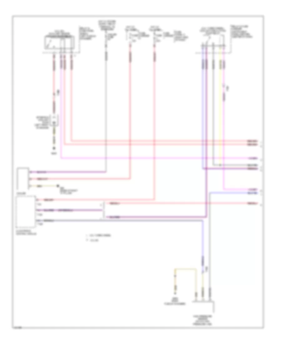
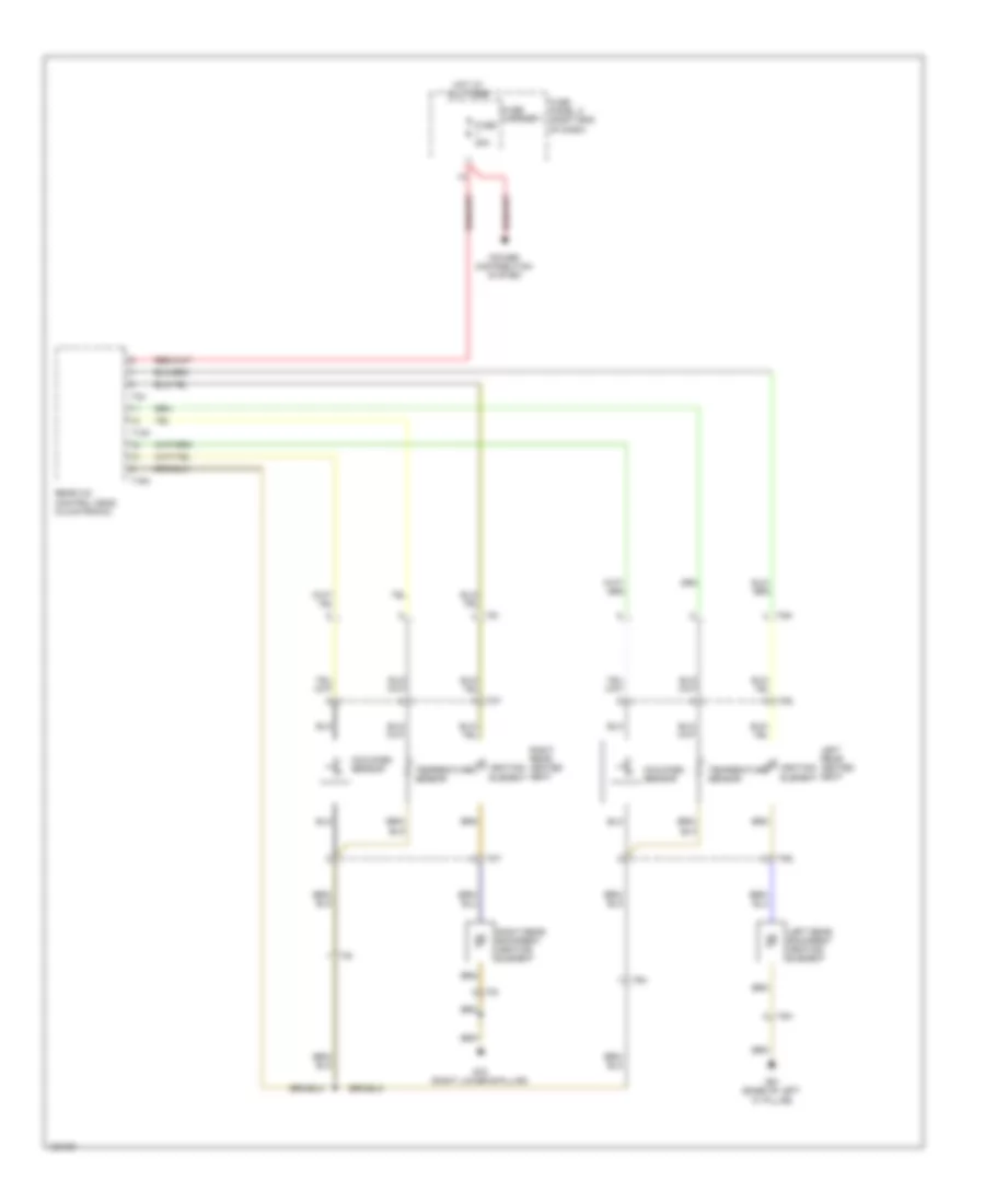
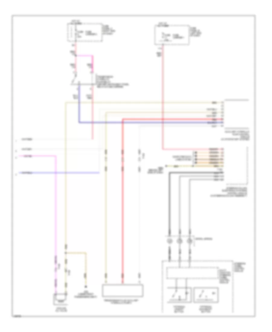
AIR CONDITIONING
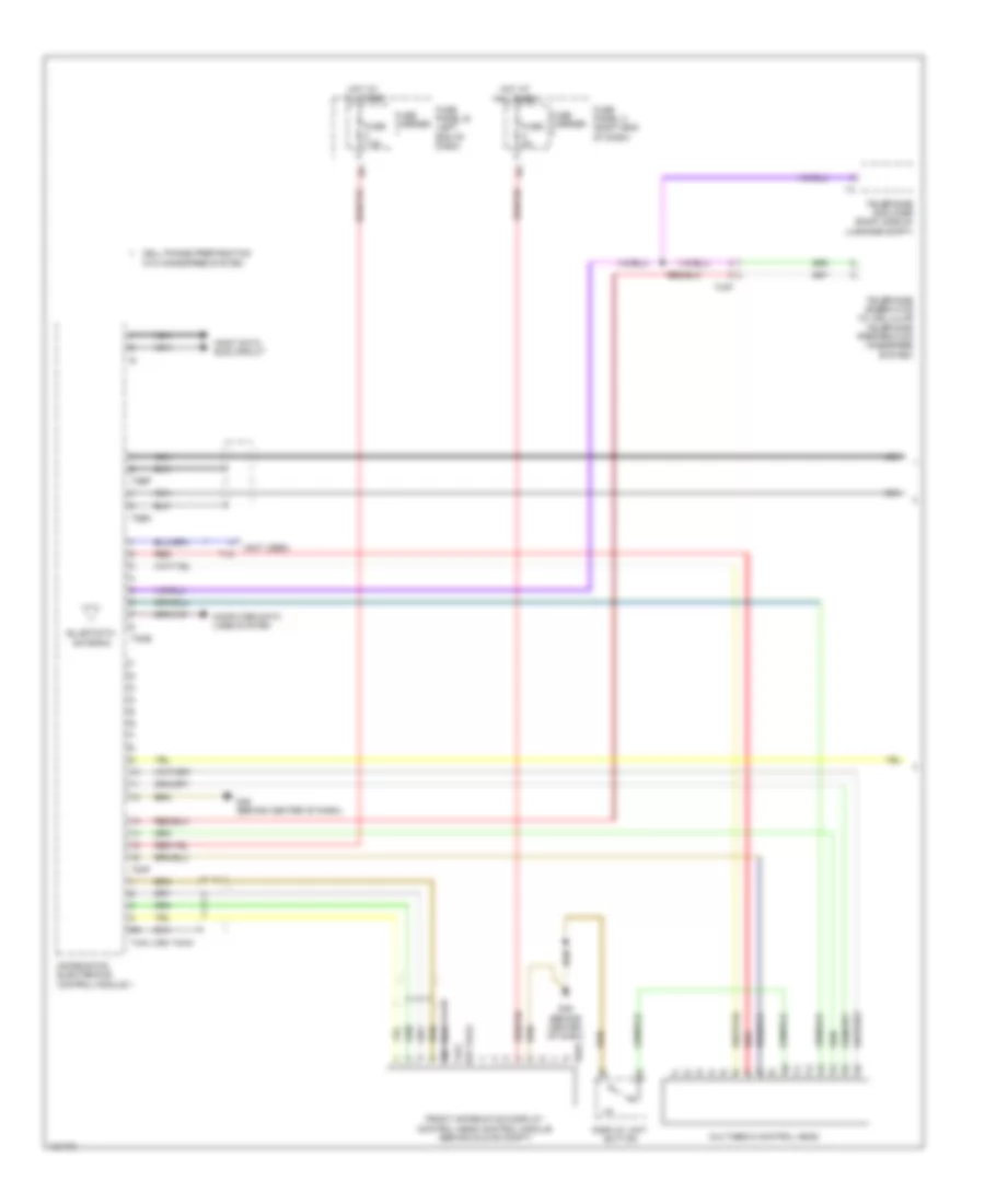
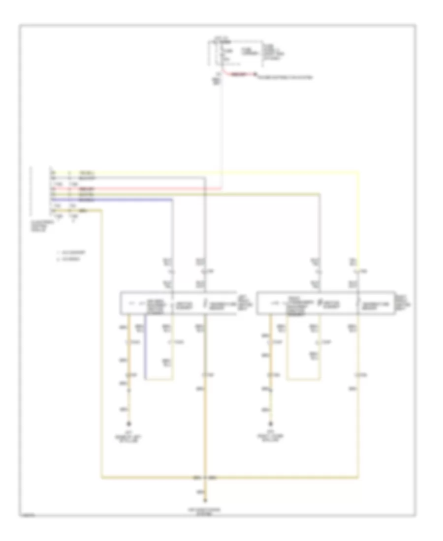
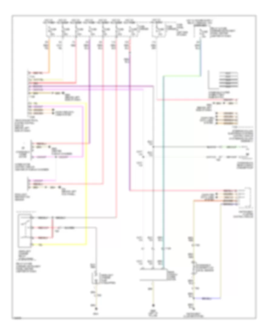
Automatic A/C Wiring Diagram, Basic (1 of 2) for Audi Q7 Prestige 2014

List of elements for Automatic A/C Wiring Diagram, Basic (1 of 2) for Audi Q7 Prestige 2014:
- (behind center of dash) g45
- (left side of engine compt) g640
- (right plenum chamber) g609
- 10a
- 12a
- 13a
- 3.0l sc
- 3.0l turbo diesel
- A/c regulator compressor valve (rear of compressor)
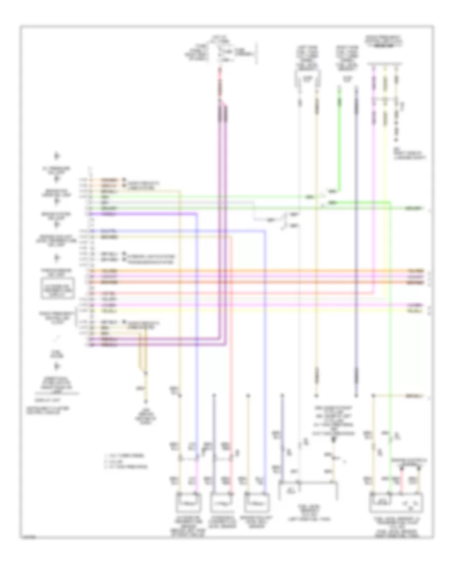
- Climatronic control module
- Computer data lines system
- Coolant circulation pump relay (3.ol turbo diesel)
- Coolant pump (in left front wheel housing)
- Display unit
- Engine coolant level/ temperature ind lamp
- Engine coolant temperature sensor (on radiator outlet)
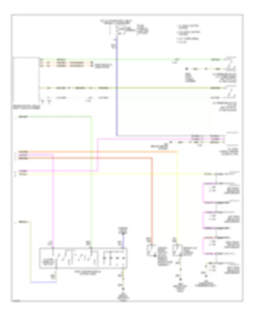
- Fresh air blower (behind right side of dash)
- Fresh air blower control module
- Fresh air blower fuse 1 40a
- Fuse 10a
- Fuse 15a
- Fuse 30a
- Fuse 5a
- Fuse carrier
- Fuse panel c (right end of dash)
- G43 (behind right kick panel)
- High pressure sensor (on a/c high pressure line)
- Hot at all times
- Instrument cluster control module
- Left temperature flap motor & potentiometer/ actuator (integral to left temperature flap motor)
- Relay & fuse carrier (instrument panel-center) (center of dash)
- Relay & fuse panel (e-box) (left plenum chamber)
- Seats system
- Suppressor
- T10d
- T10f
- T16d
- T17k
- T20i
- T2q
- T3c
- T4t
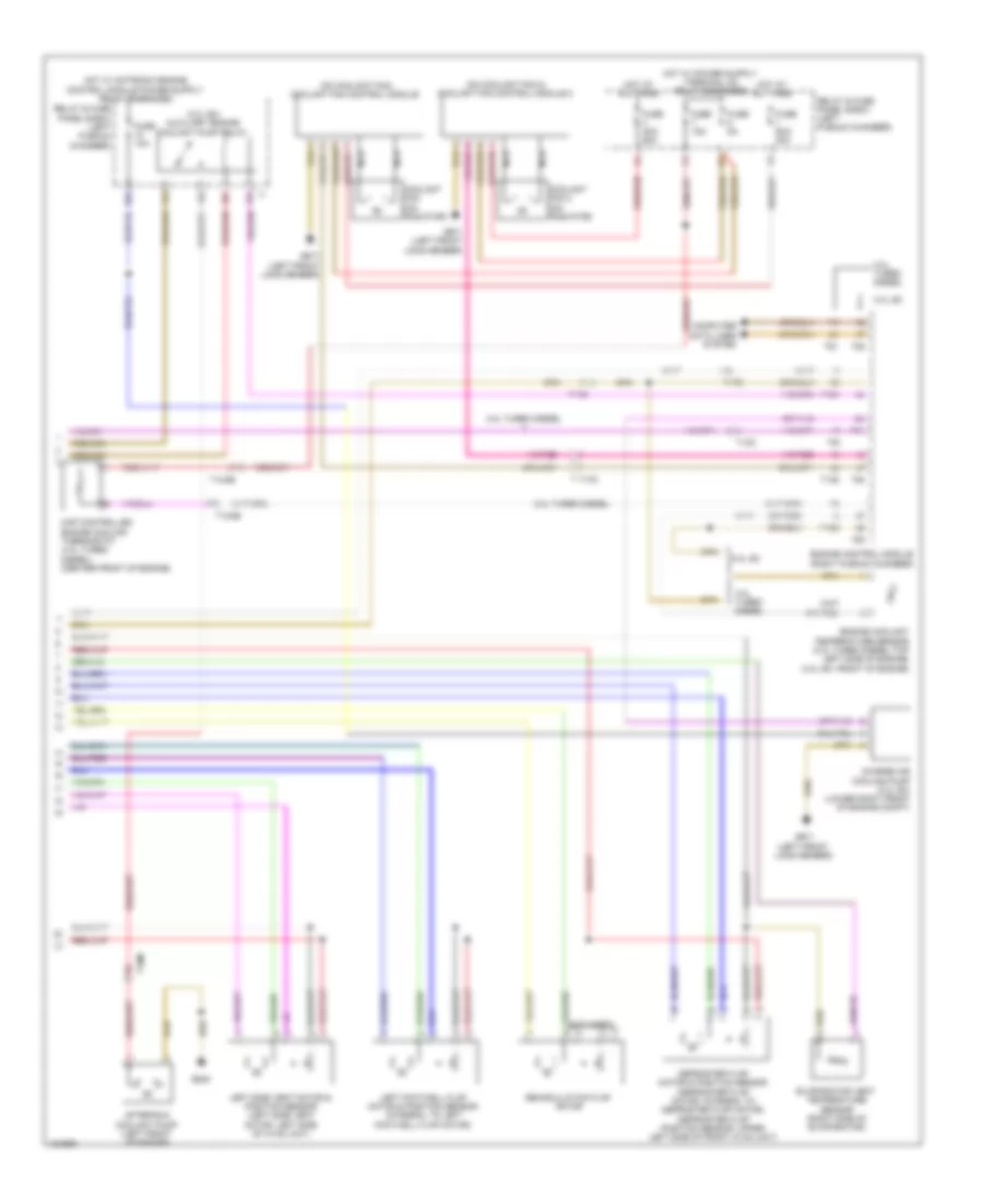
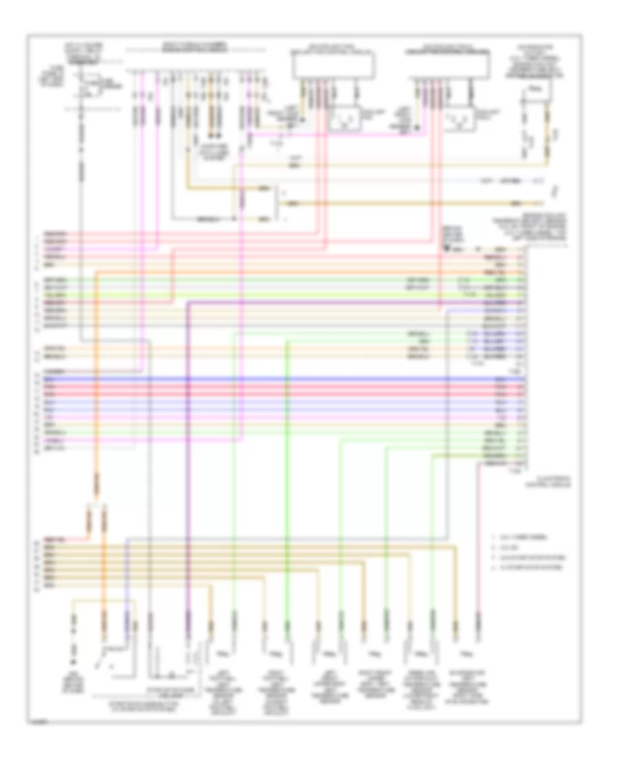
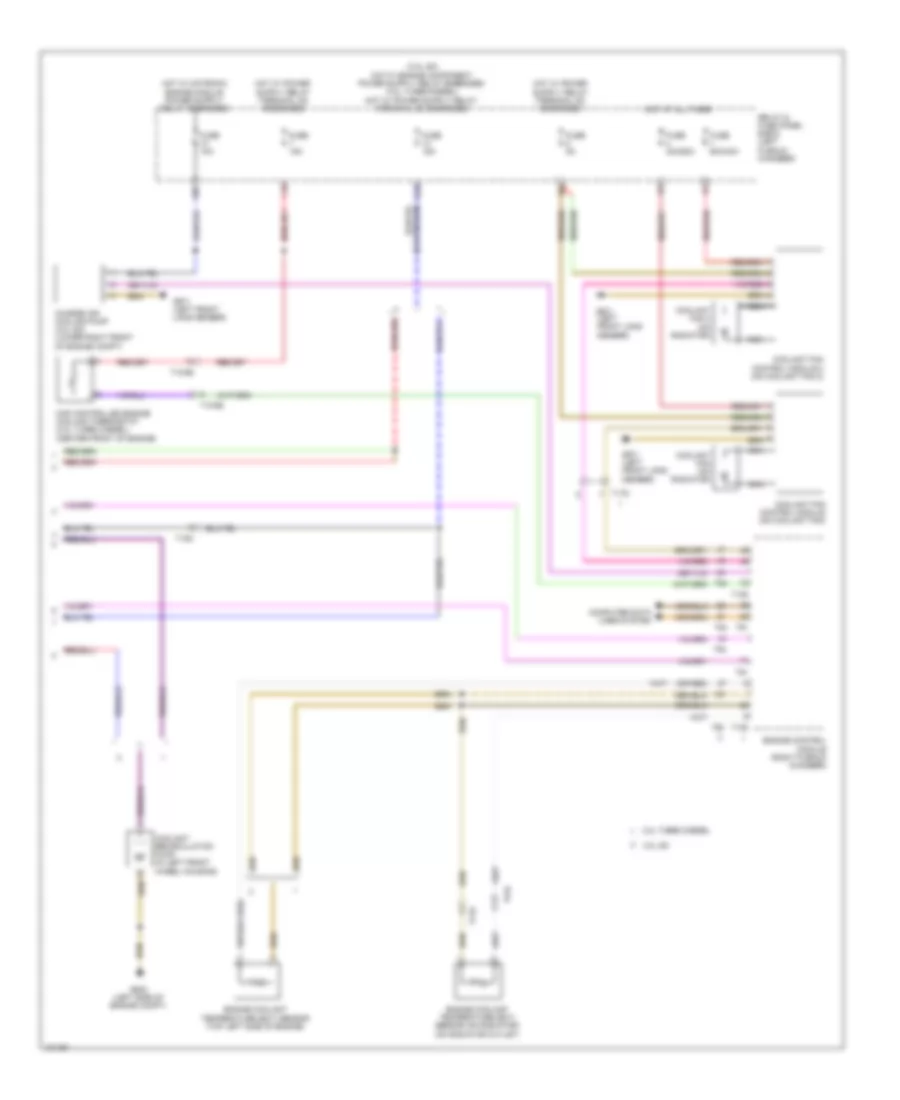
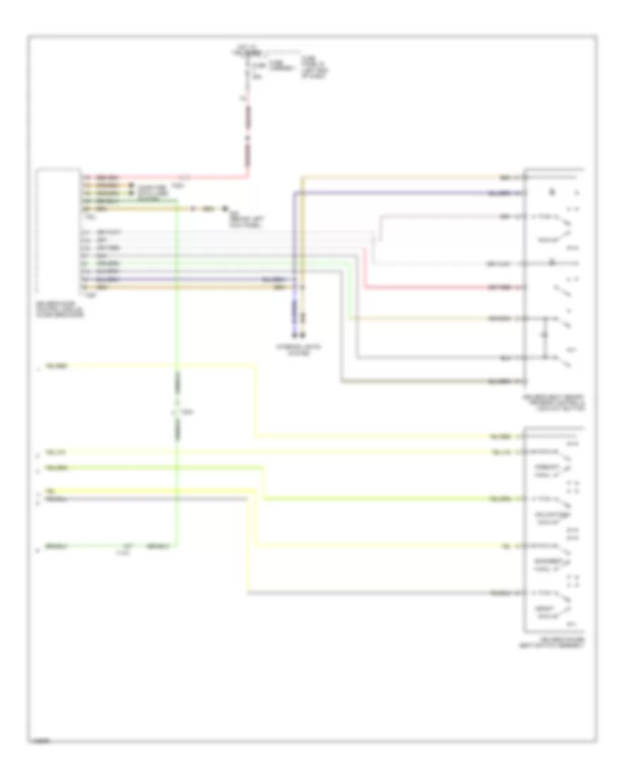
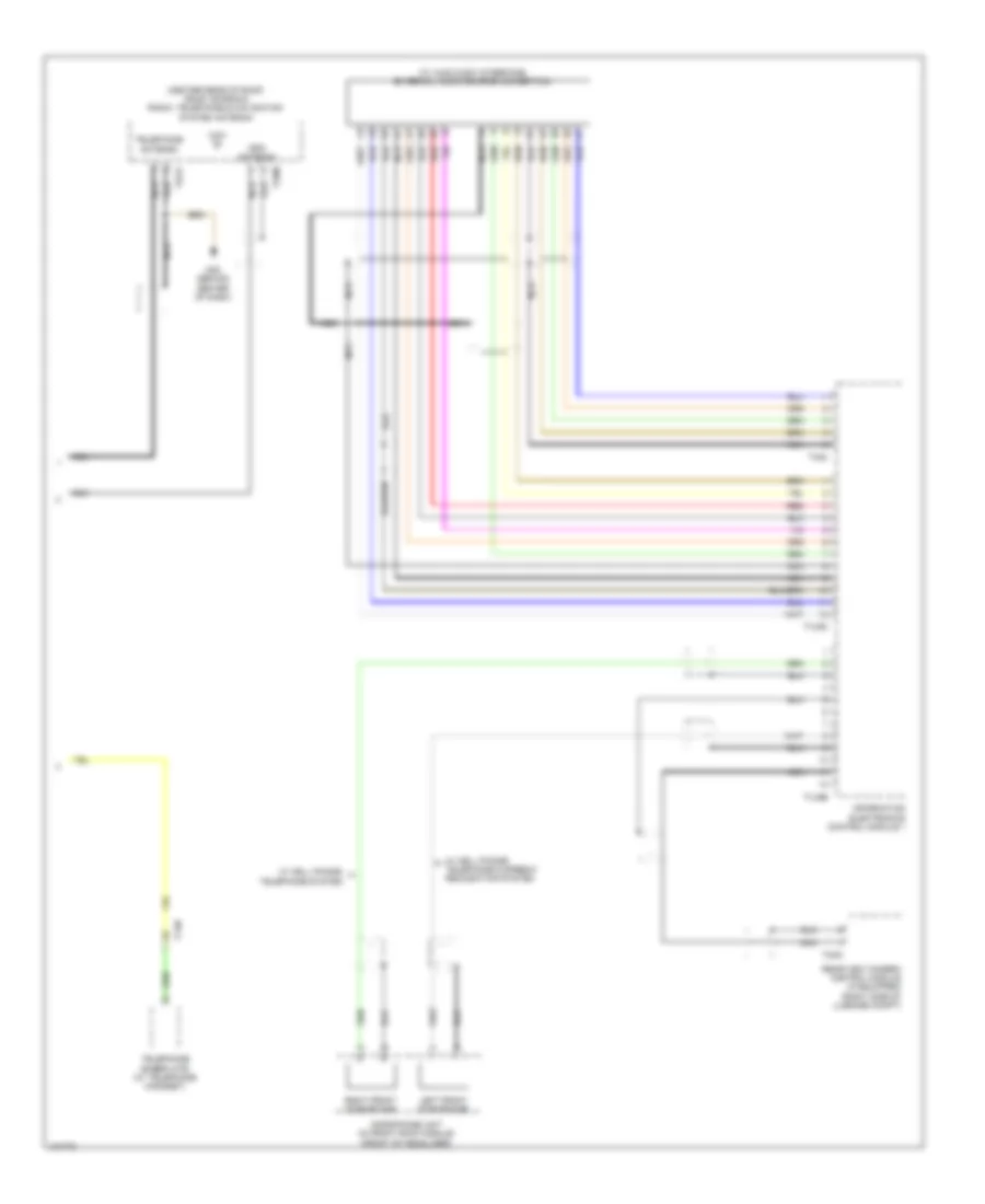
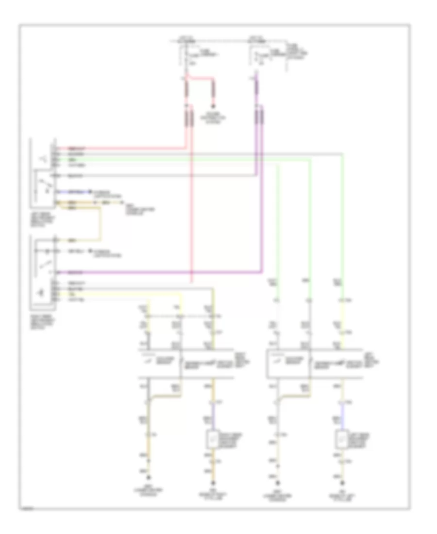
Automatic A/C Wiring Diagram, Basic (2 of 2) for Audi Q7 Prestige 2014
List of elements for Automatic A/C Wiring Diagram, Basic (2 of 2) for Audi Q7 Prestige 2014:
- (3.0l sc) auxiliary engine coolant pump relay
- (on coolant fan 2) coolant fan control module 2
- (on coolant fan) coolant fan control module
- (or red)
- 10a
- 19a
- 19c
- 19d
- 19e
- 3.0l sc
- 3.0l turbo diesel
- After-run coolant pump (left front of engine)
- Charge air cooling pump (3.0l sc) (lower right front of engine compt)
- Computer data lines system
- Coolant fan (on radiator)
- Coolant fan 2 (on radiator)
- Defroster flap motor & position sensor (defroster flap motor: integral to defroster flap motor) (defroster flap position sensor: upper left side of front hvac unit)
- Engine control module (right plenum chamber)
- Engine coolant temperature sensor (3.0l turbo diesel:top left side of engine) (3.0l sc: front of engine)
- Evaporator vent temperature sensor (right side of evaporator)
- Fuse 10a
- Fuse 15a
- Fuse 40a/ 60a
- Fuse 5a
- Fuse 60a/ 40a
- G645
- G671 (left front long member)
- Hot at all times
- Left footwell flap motor & position sensor (integral to left footwell flap motor)
- Left side vent motor & position sensor (left side vent motor: left side of hvac unit)
- Map controlled engine cooling thermostat (3.0l turbo diesel) (center front of engine)
- Nca
- Recirculation flap motor
- Relay & fuse panel e-box (left plenum chamber)
- T105
- T10ab
- T10c
- T10m
- T17d
- T60
- T91
- T94
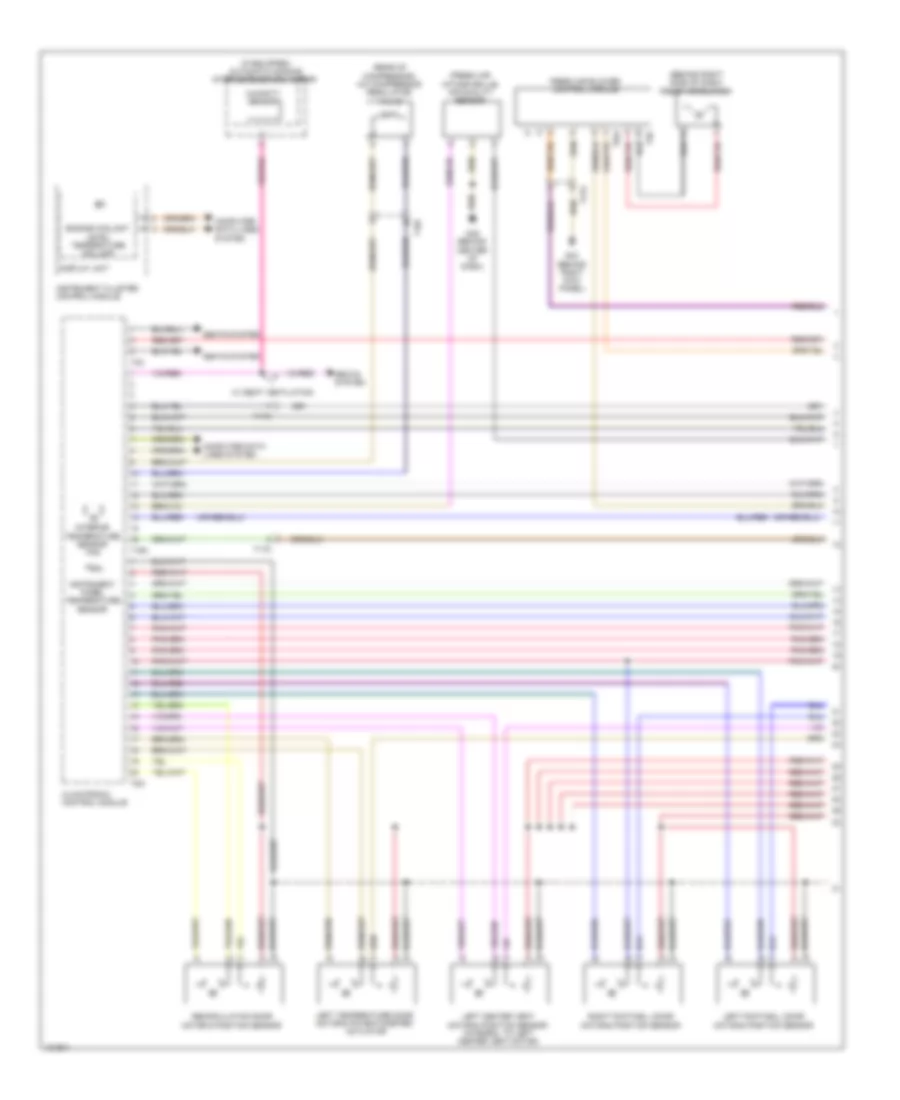
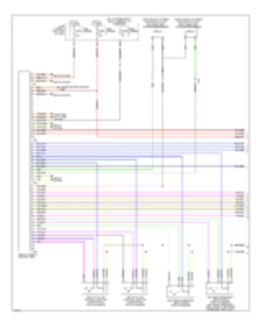
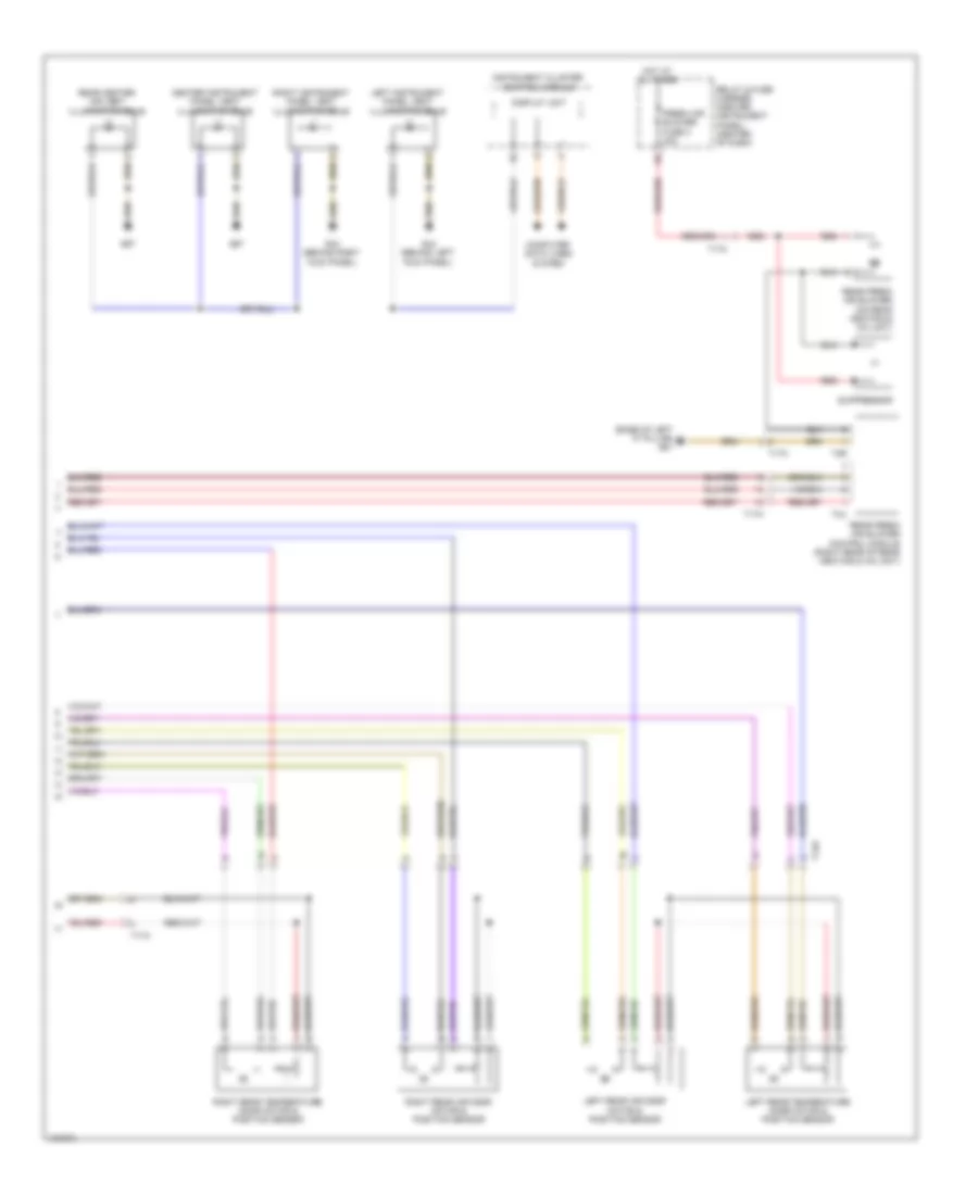
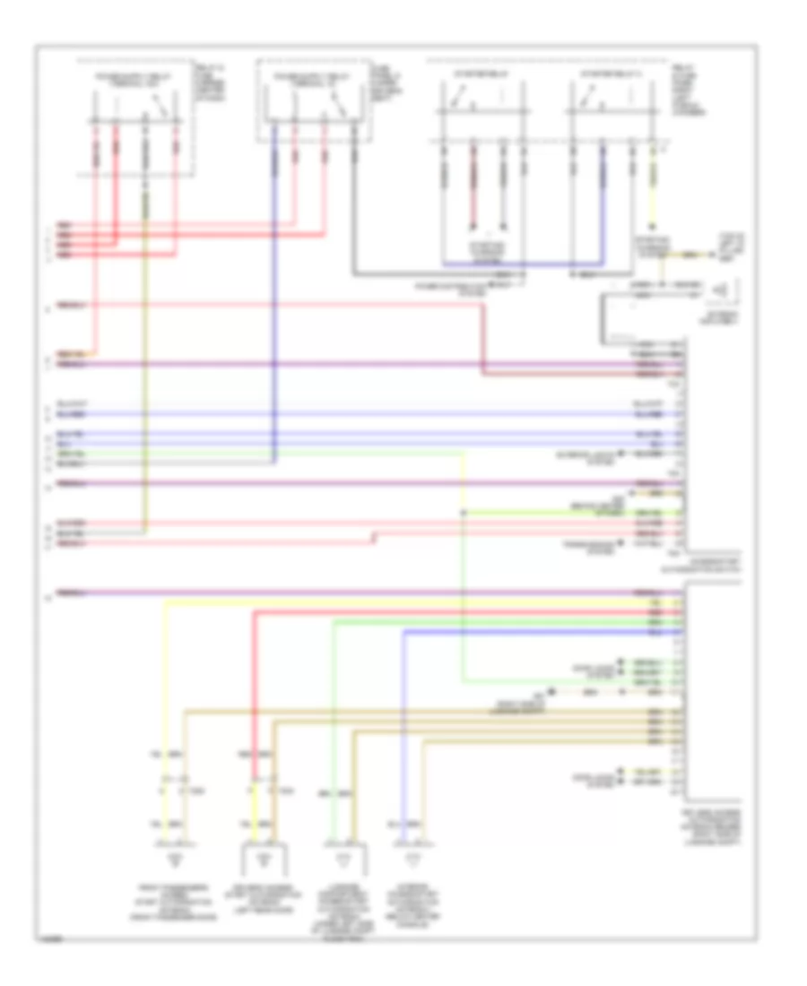
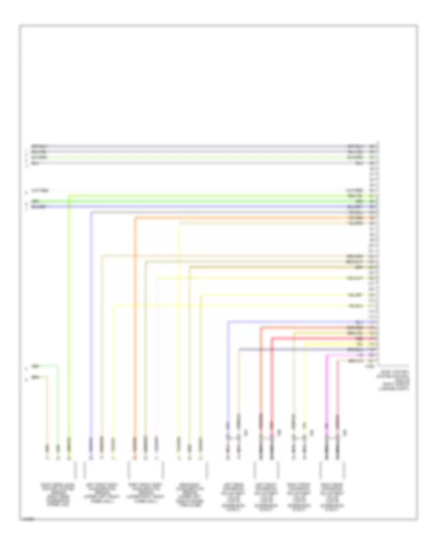
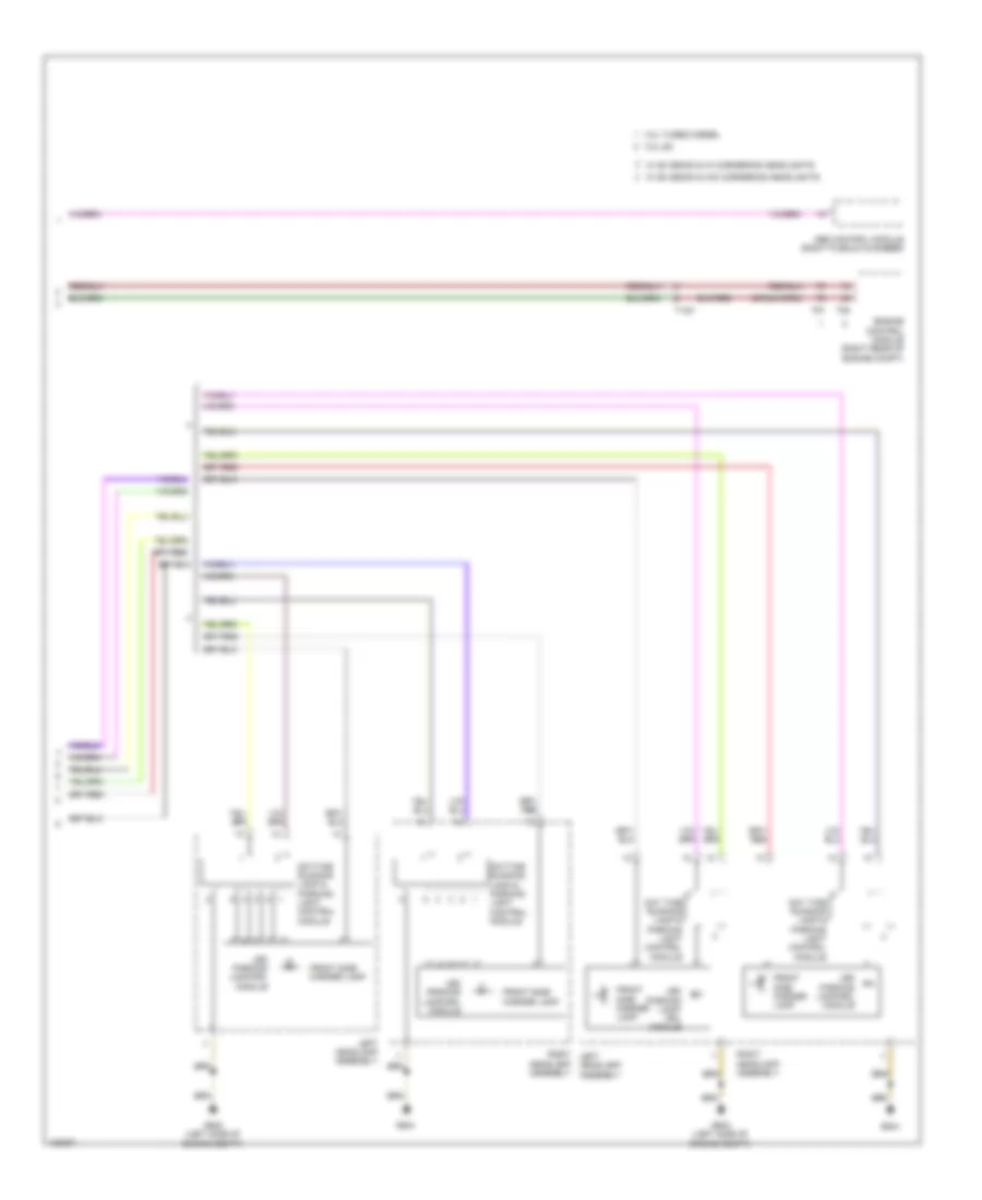
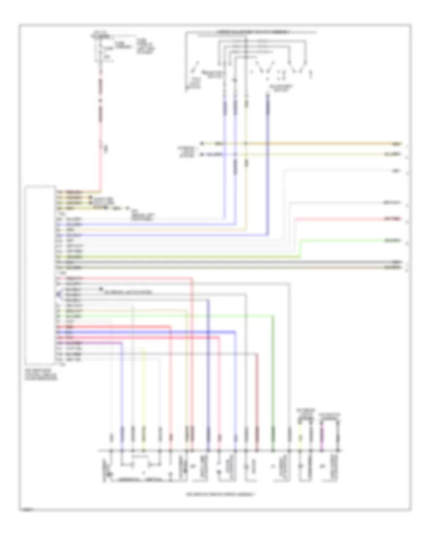
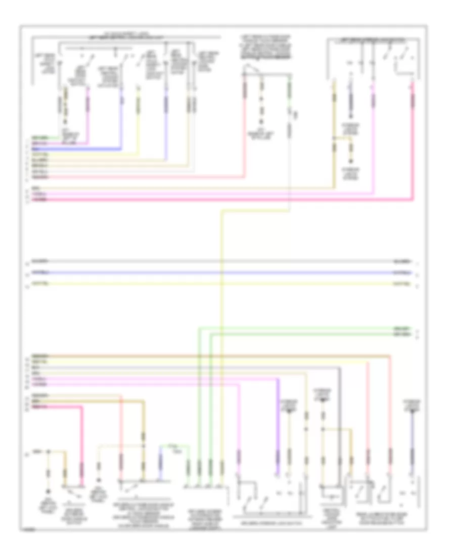
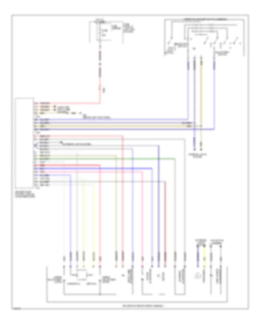
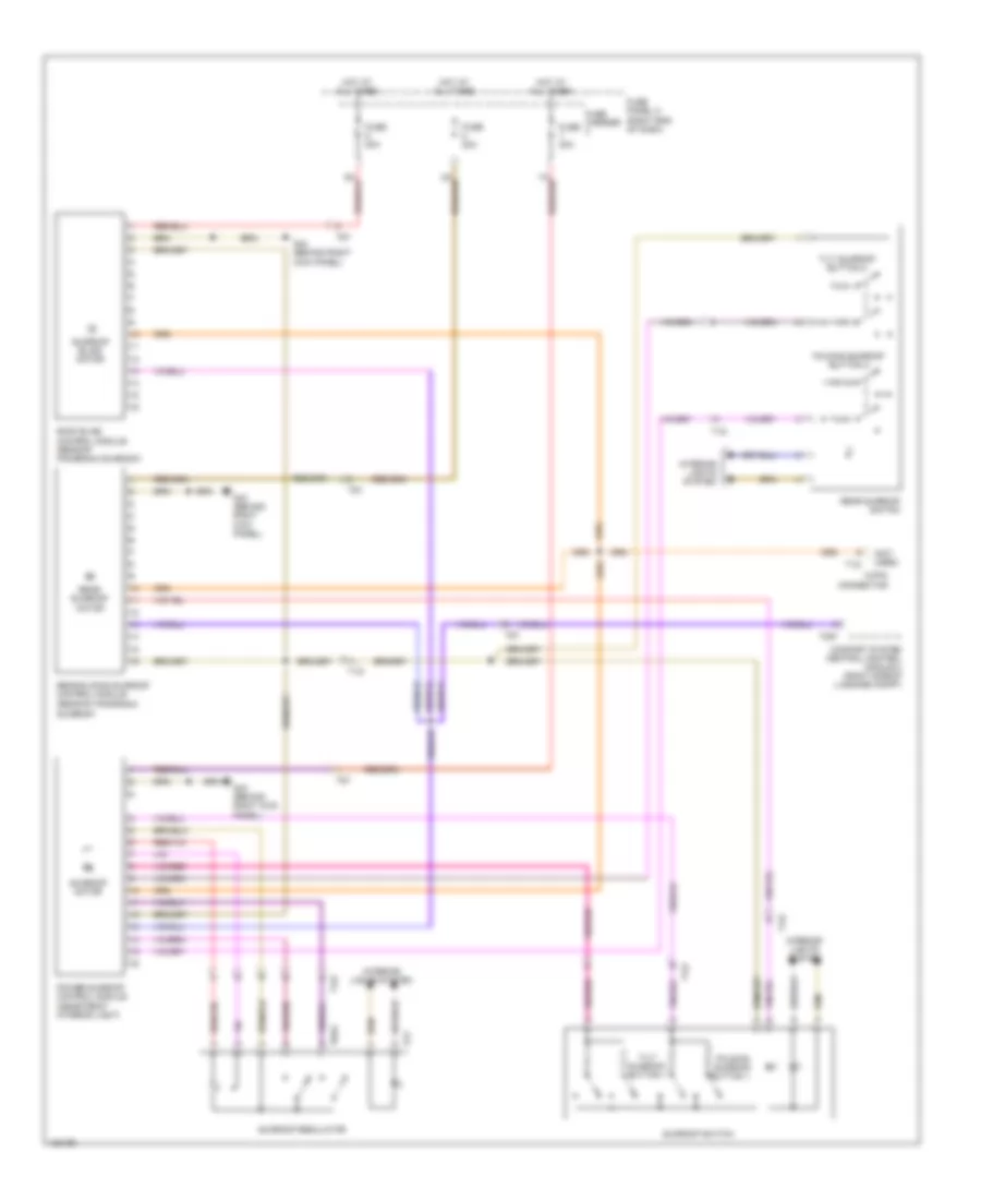
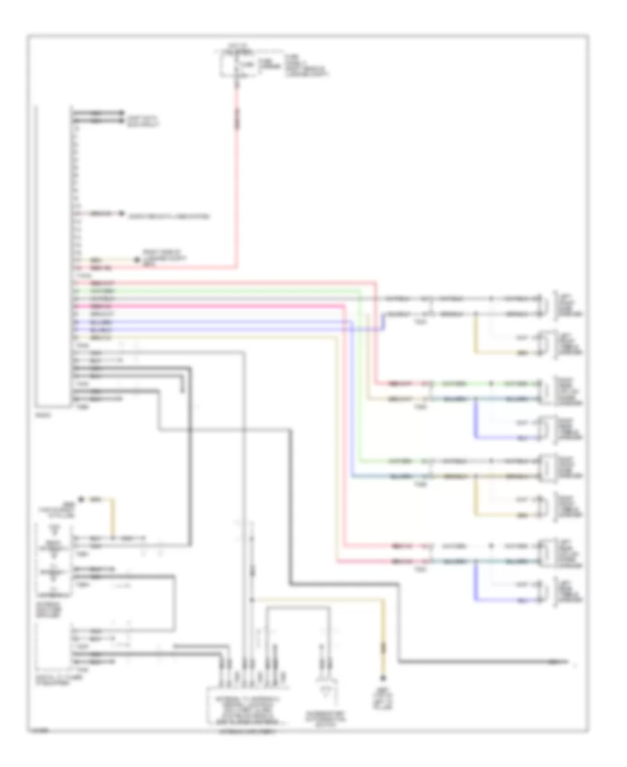
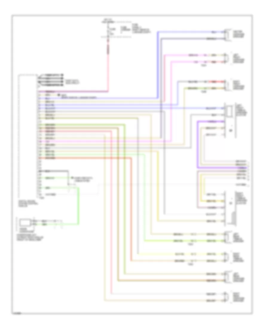
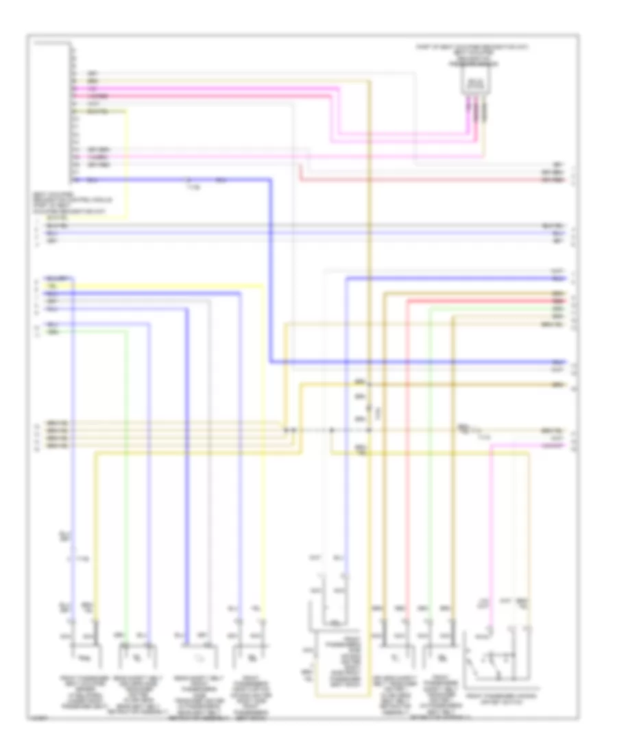
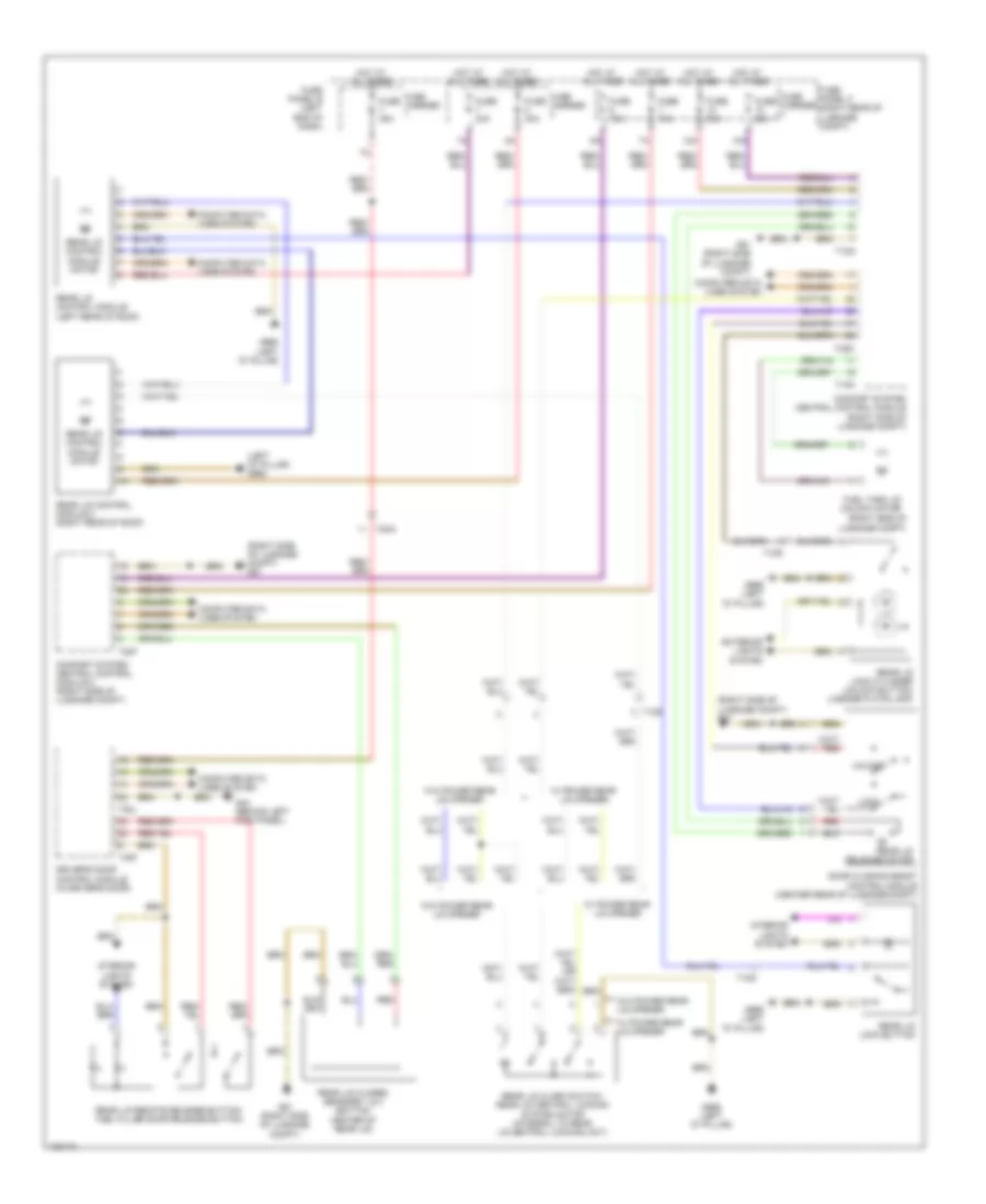
Automatic A/C Wiring Diagram, Comfort (1 of 4) for Audi Q7 Prestige 2014
List of elements for Automatic A/C Wiring Diagram, Comfort (1 of 4) for Audi Q7 Prestige 2014:
- (behind right side of dash) fresh air blower
- (fresh air intake grille) air quality sensor
- (if equipped) automatic dimming interior rearview mirror
- (rear of compressor) a/c compressor regulator valve
- Climatronic control module
- Computer data lines system
- Display unit
- Engine coolant level/ temperature ind lamp
- Fresh air blower control module
- G43 (behind right kick panel)
- G45 (behind center of dash)
- Humidity sensor
- Instrument cluster control module
- Instrument panel temperature sensor
- Interior temperature sensor fan
- Left center vent motor & position sensor (integral to left center vent motor)
- Left footwell door motor & position sensor
- Left temperature door motor & potentiometer/ actuator
- Recirculation door motor & position sensor
- Right footwell door motor & position sensor
- Seats system
- T10f
- T16c
- T17k
- T20i
- T2q
- T3c
- T6ai
- W/ seat ventilation
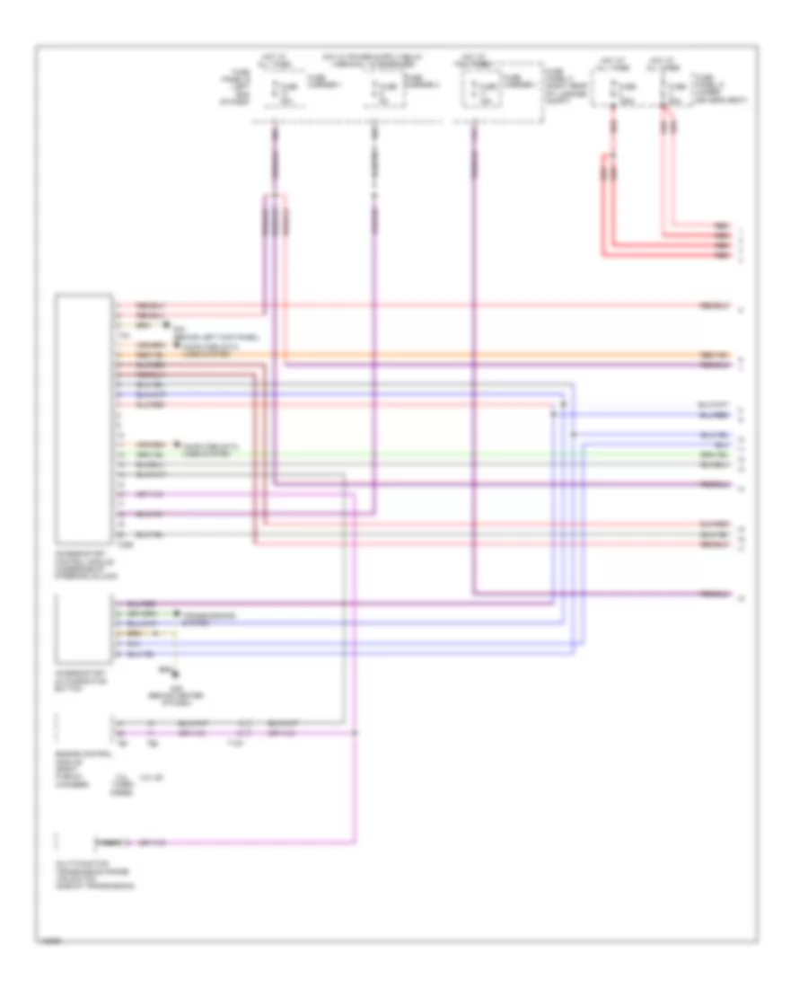
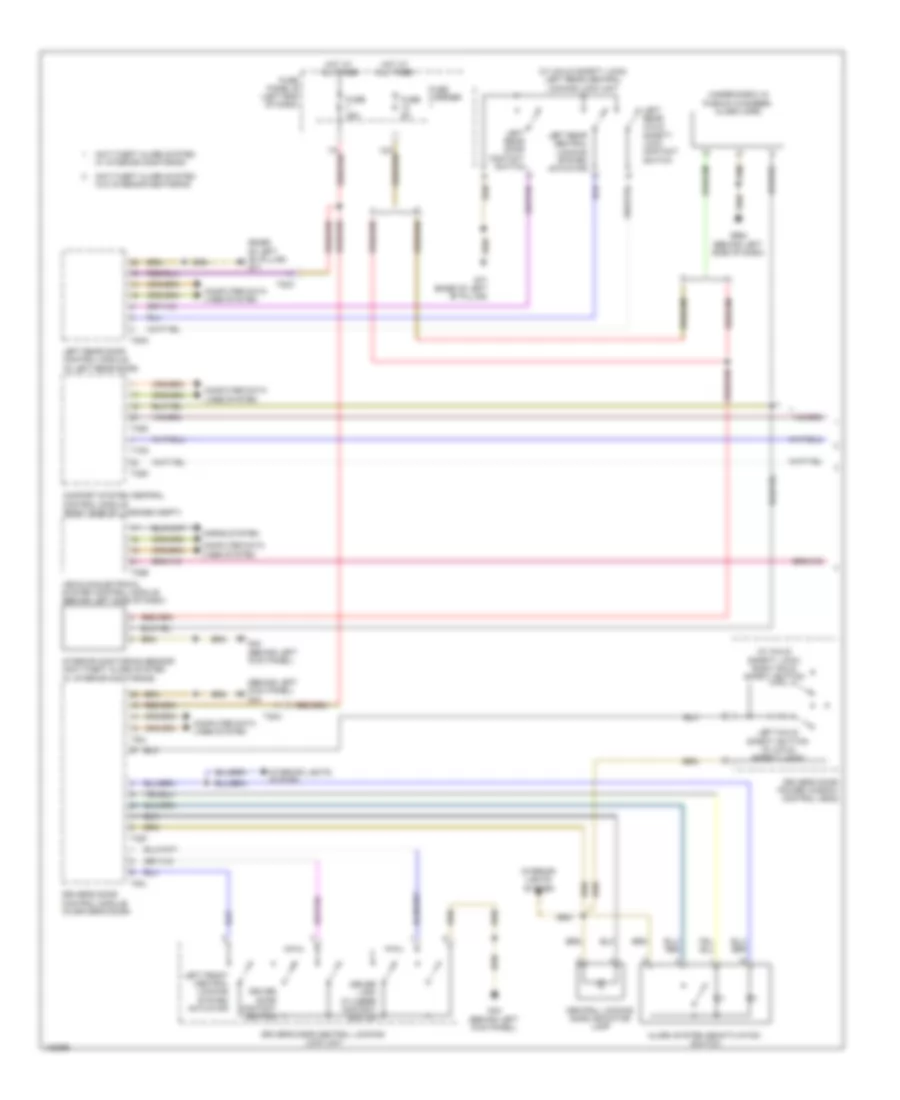
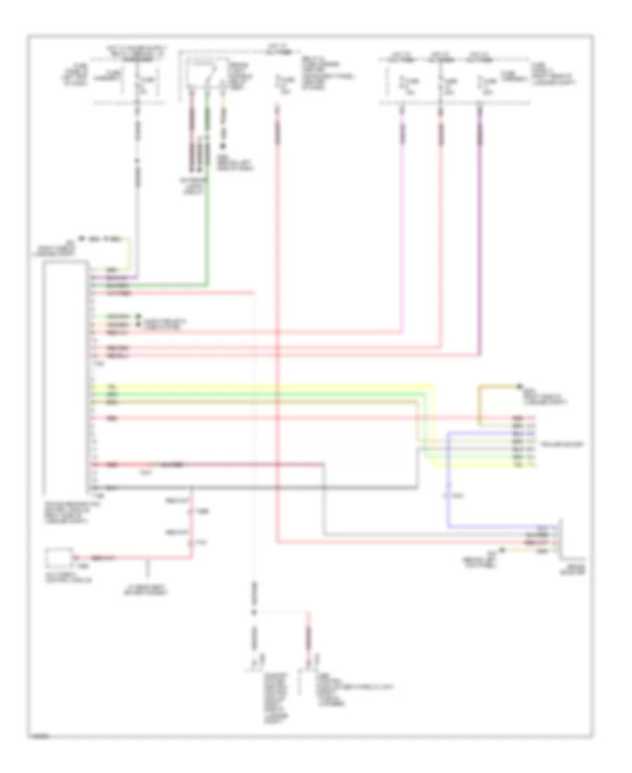
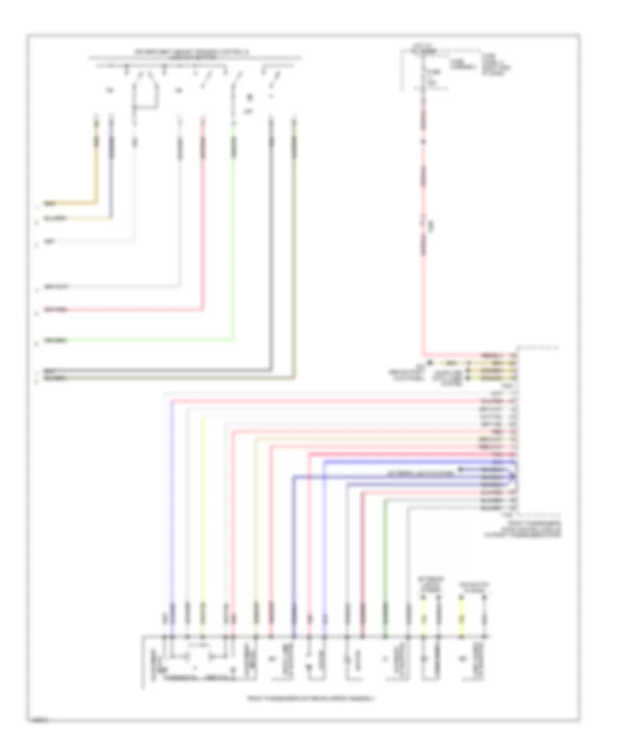
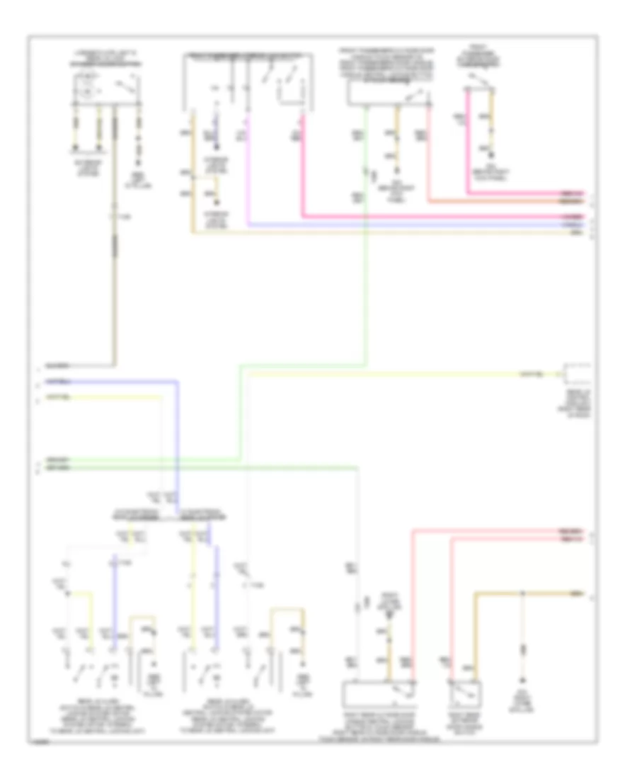
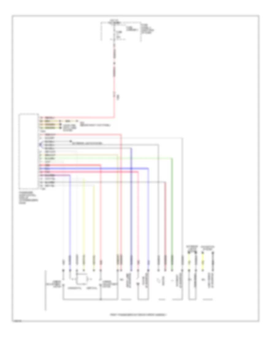
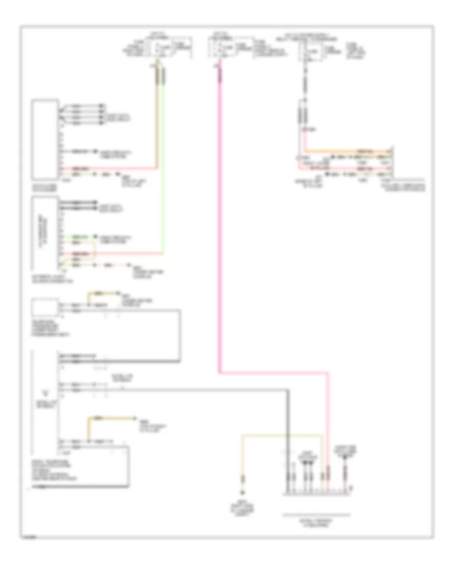
Automatic A/C Wiring Diagram, Comfort (2 of 4) for Audi Q7 Prestige 2014
List of elements for Automatic A/C Wiring Diagram, Comfort (2 of 4) for Audi Q7 Prestige 2014:
- (3.0l turbo diesel) coolant circulation pump relay
- 10a
- 12a
- 3.0l sc
- 3.0l turbo diesel
- Coolant recirculation pump
- Cooler
- Cooler fuse 5a
- Defroster door motor & position sensor
- Fuse 10a
- Fuse 15a
- Fuse 30a
- Fuse 40a
- Fuse 5a
- Fuse carrier
- Fuse panel c (right end of dash)
- G62 (base of right "c" pillar)
- G640 (left side of engine compt)
- Hot at all times
- Indirect ventilation door motor & position sensor
- Left side vent motor & position sensor (integral to left side vent motor)
- Pnk
- Relay & fuse carrier (center instrument panel) (center of dash)
- Right center vent motor & position sensor
- Right side vent motor & position sensor (integral to right side vent motor)
- Right temperature door motor & potentiometer/ actuator
- T10c
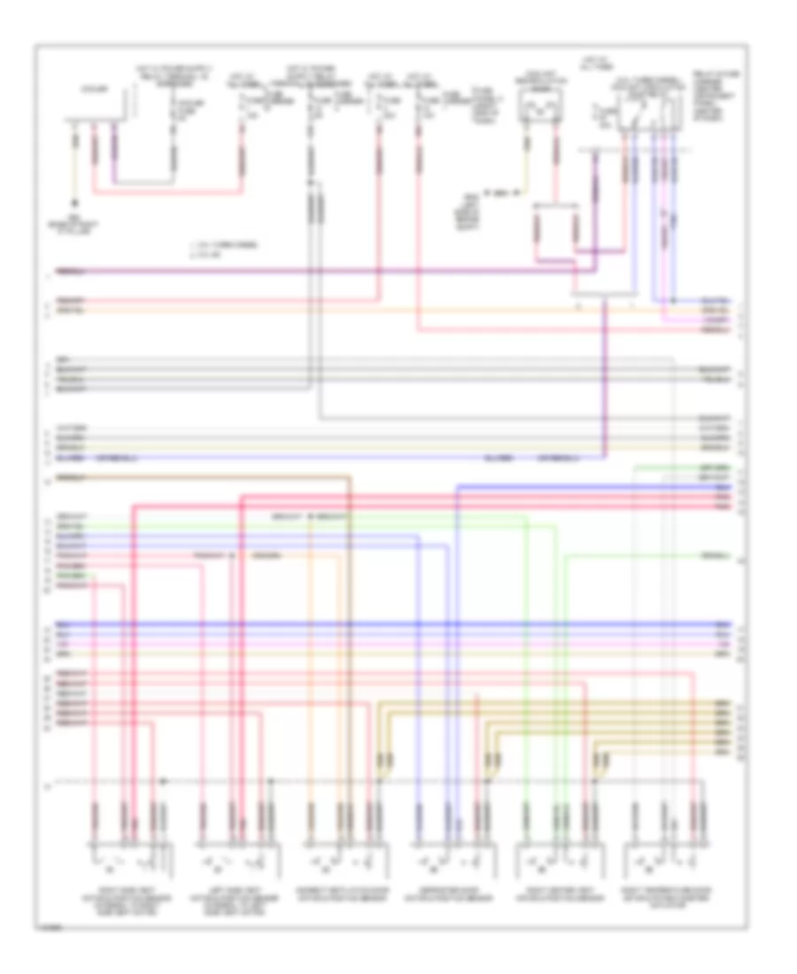
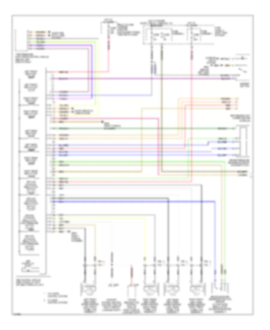
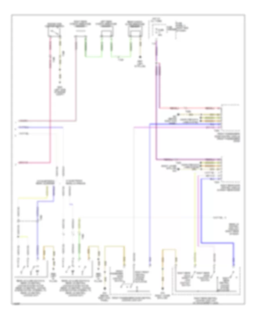
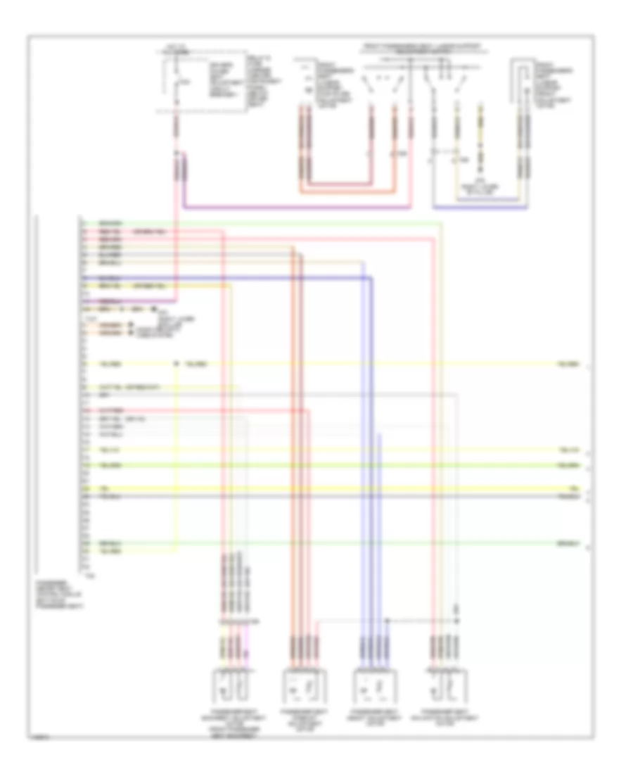
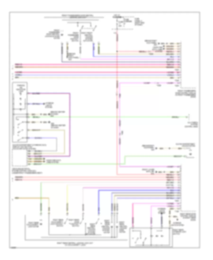
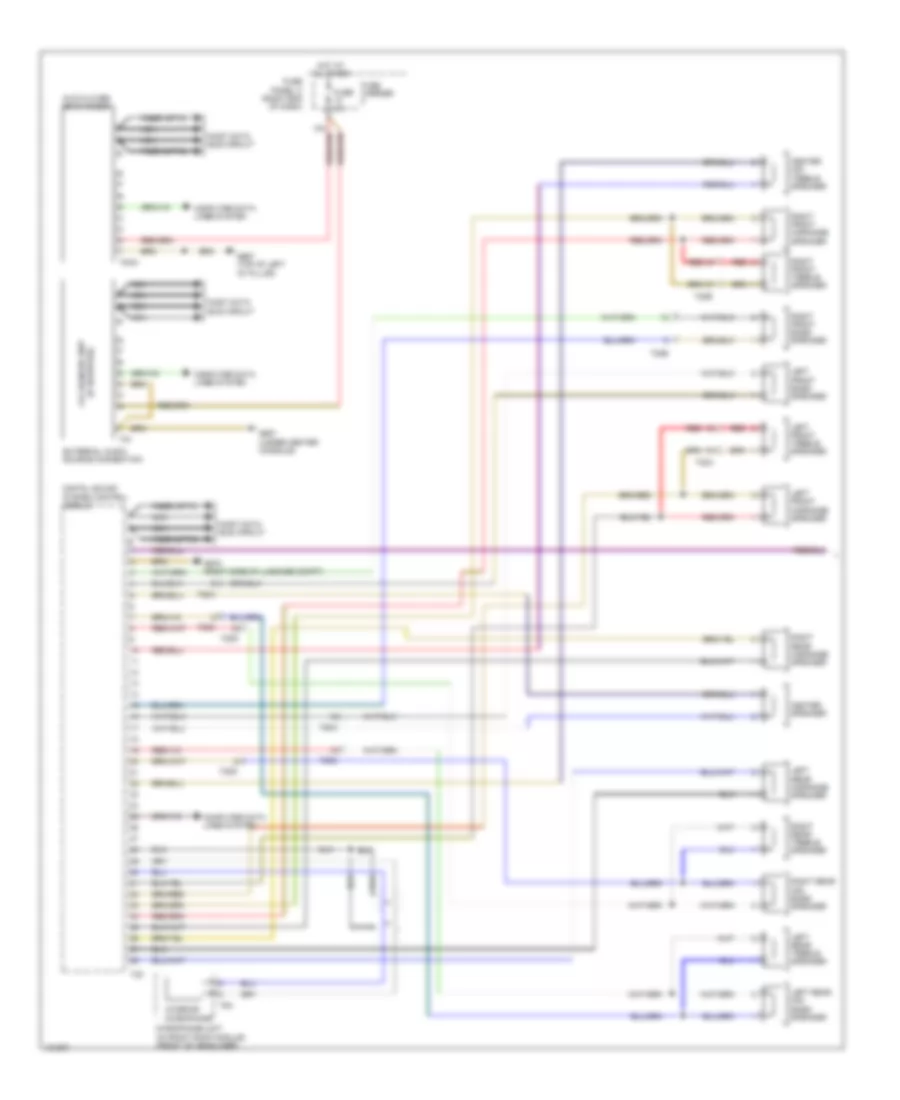
Automatic A/C Wiring Diagram, Comfort (3 of 4) for Audi Q7 Prestige 2014
List of elements for Automatic A/C Wiring Diagram, Comfort (3 of 4) for Audi Q7 Prestige 2014:
- (3.0l sc) auxiliary engine coolant pump relay
- (left front long member) g671
- (lower right front of engine compt) (3.0l sc) charge air cooling pump
- 10a
- 13a
- 19a
- 19c
- 19d
- 19e
- 3.0l sc
- 3.0l turbo diesel
- After-run coolant pump (left front of engine)
- Engine coolant shift-off valve relay (3.0l turbo diesel)
- Fuse 10a
- Fuse 15a
- Fuse 40a/ 60a
- Fuse 5a
- Fuse 60a/ 40a
- G609 (right plenum chamber)
- G645
- High pressure sensor (on a/c high pressure line)
- Hot at all times
- Left front seat temperature sensor (w/ auxiliary heater) (under driver's seat)
- Map controlled engine cooling thermostat (3.0l turbo diesel) (center front of engine)
- Pnk
- Relay & fuse panel (e-box) (left plenum chamber)
- Right front seat temperature sensor (w/ auxiliary heater) (under right front seat)
- Sunlight photo sensor (top of dash panel, between defroster vents)
- T10ab
- T10d
- T10m
- T6f
- T6g
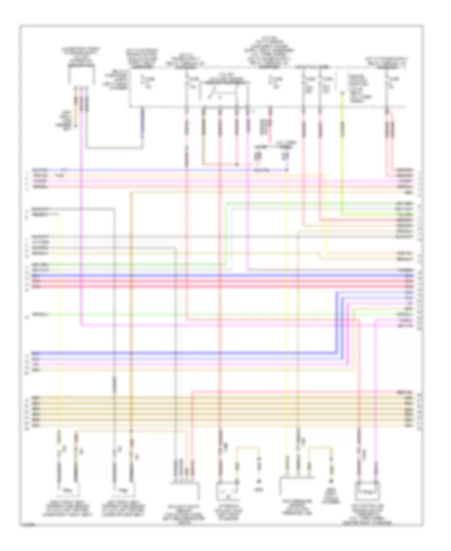
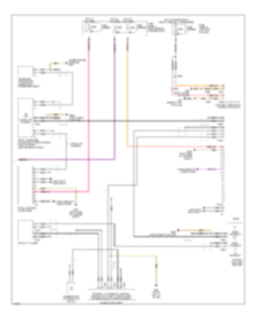
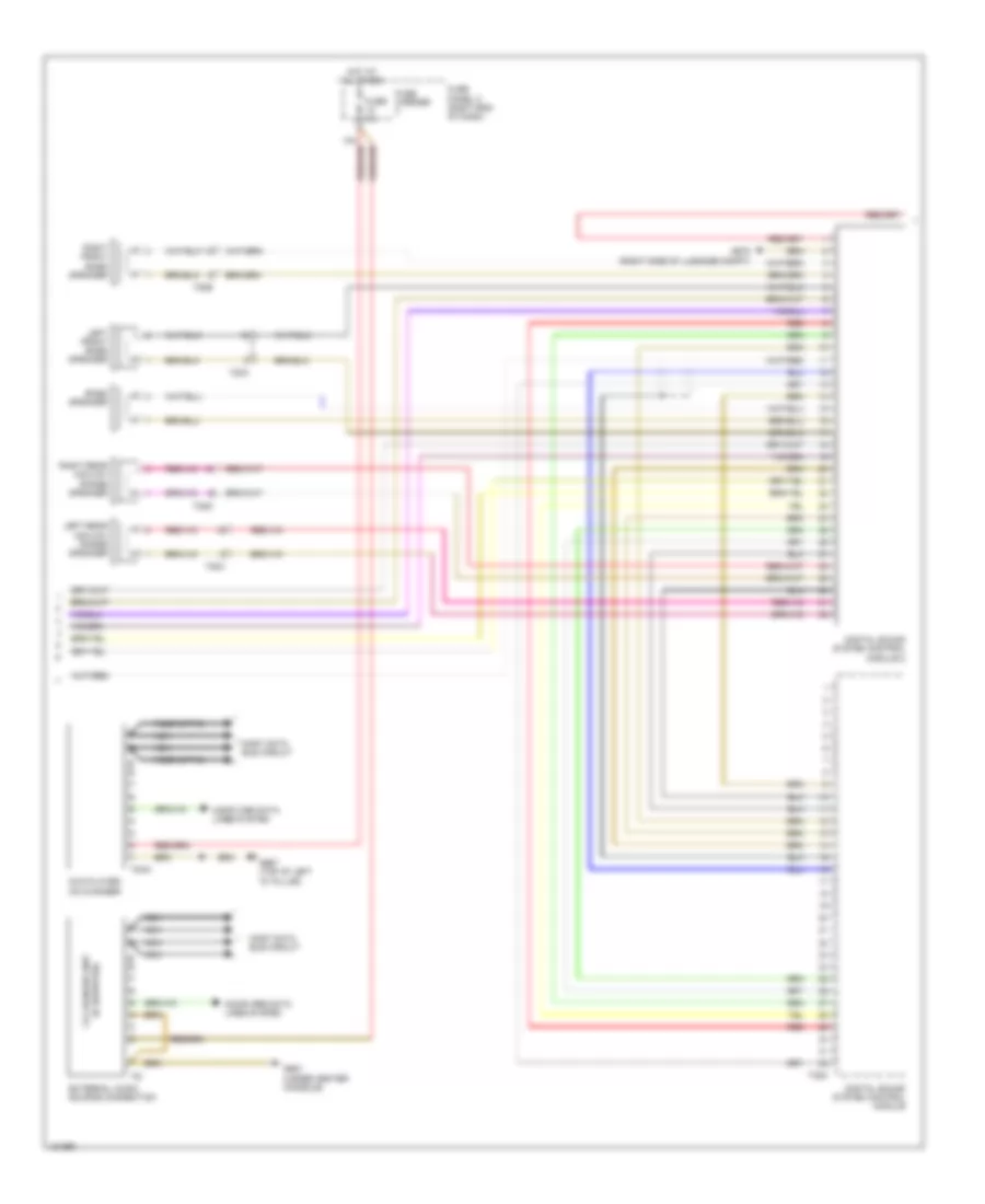
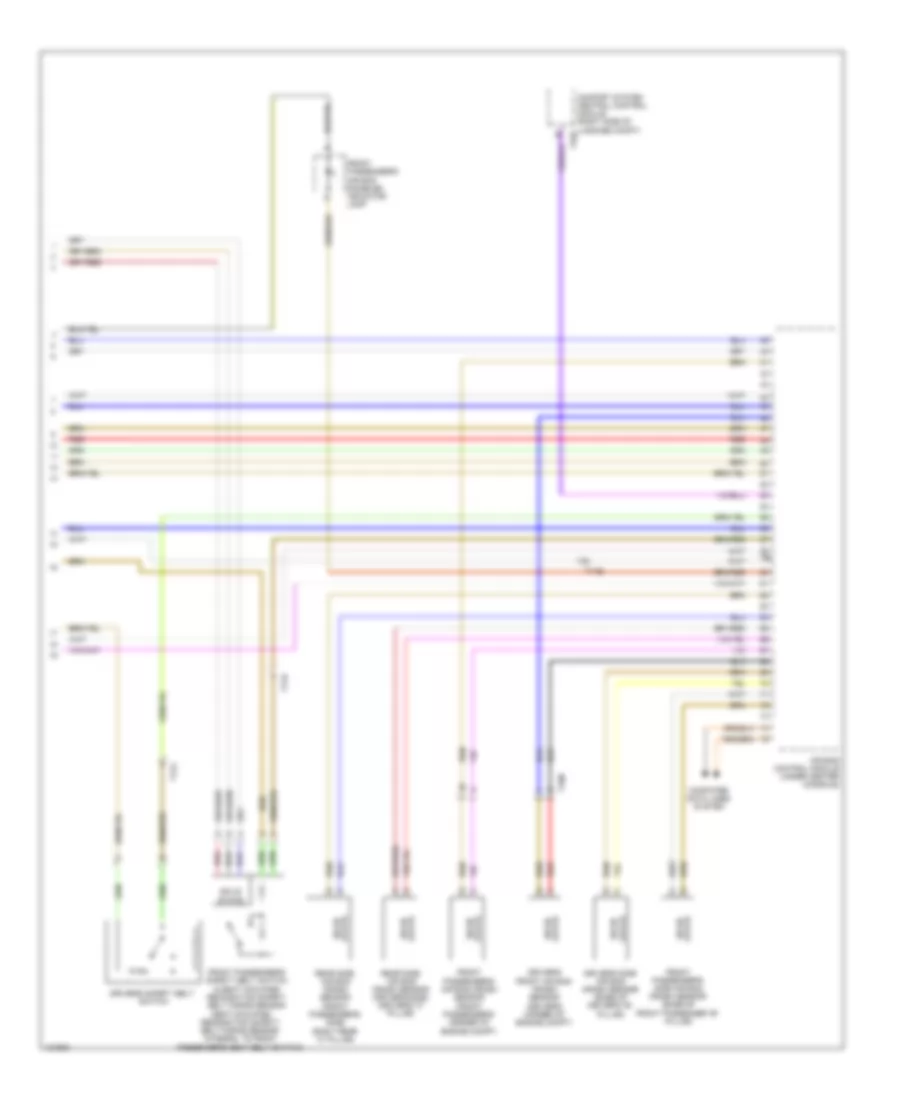
Automatic A/C Wiring Diagram, Comfort (4 of 4) for Audi Q7 Prestige 2014
List of elements for Automatic A/C Wiring Diagram, Comfort (4 of 4) for Audi Q7 Prestige 2014:
- (behind center of dash) g45
- (left front long member) g671
- (on coolant fan 2) coolant fan control module 2
- (on coolant fan) coolant fan control module
- (on radiator outlet) (3.0l turbo diesel) engine coolant temperature (ect) sensor (on radiator)
- (or red)
- (right plenum chamber) engine control module
- 3.0l sc
- 3.0l turbo diesel
- Climatronic control module
- Computer data lines system
- Coolant fan
- Coolant fan 2
- Engine coolant temperature (ect) sensor (3.0l sc: front of engine) (3.0l turbo diesel: top left side of engine)
- Evaporator vent temperature sensor (right side of evaporator)
- Fresh air intake duct temperature sensor (lower right rear of hvac unit)
- Fuse 5a
- Fuse carrier
- Fuse panel b (left end of dash)
- G45 (behind center of dash)
- Left footwell vent temperature sensor (in left footwell air duct)
- Left front upper body vent temperature sensor
- Nca
- Pnk
- Right footwell vent temperature sensor (in right footwell air duct)
- Right front upper body vent temperature sensor
- Start/stop mode button (w/ start/stop system)
- Start/stop mode ind lamp
- T105
- T10ab
- T12g
- T16d
- T17d
- T17k
- T60
- T91
- T94
- W/ start/stop system
- W/o start/stop system
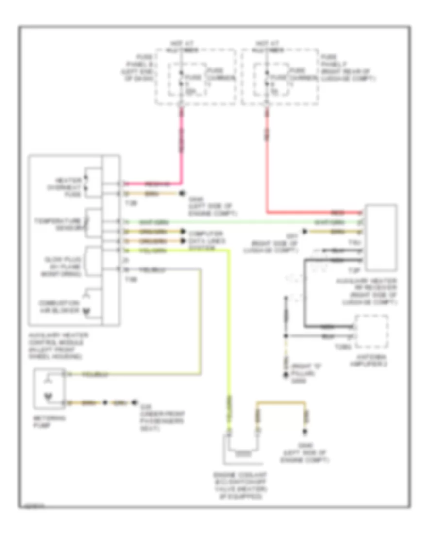
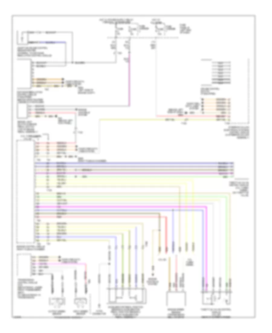
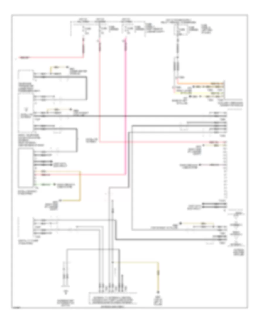
Auxiliary Heater Wiring Diagram for Audi Q7 Prestige 2014
List of elements for Auxiliary Heater Wiring Diagram for Audi Q7 Prestige 2014:
- (right "d" pillar) g669
- Antenna amplifier 2
- Auxiliary heater control module (in left front wheel housing)
- Auxiliary heater rf receiver (right side of luggage compt)
- Combustion air blower
- Computer data lines system
- Engine coolant (ec) switch-off valve (heater) (if equipped)
- Fuse 20a
- Fuse 5a
- Fuse carrier
- Fuse panel b (left end of dash)
- Fuse panel f (right rear of luggage compt)
- G35 (under front passenger's seat)
- G51 (right side of luggage compt)
- G640 (left side of engine compt)
- Glow plug (w/ flame monitoring)
- Heater overheat fuse
- Hot at all times
- Metering pump
- Nca
- Red
- T2b
- T2bq
- T2p
- T6b
- T6u
- Temperature sensor
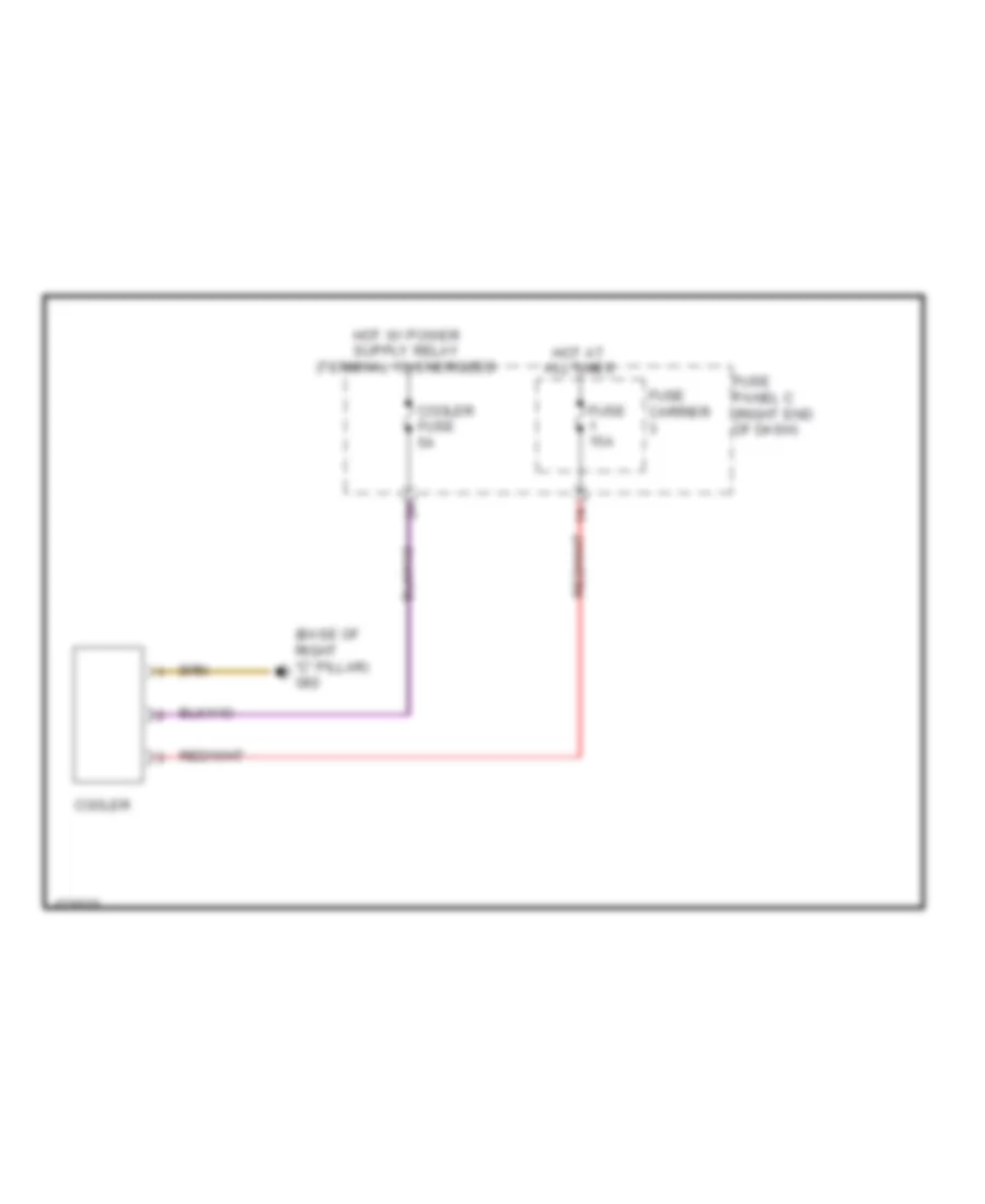
Cool Box Wiring Diagram for Audi Q7 Prestige 2014
List of elements for Cool Box Wiring Diagram for Audi Q7 Prestige 2014:
- (base of right "c" pillar) g62
- Cooler
- Cooler fuse 5a
- Fuse 15a
- Fuse carrier
- Fuse panel c (right end of dash)
- Hot at all times
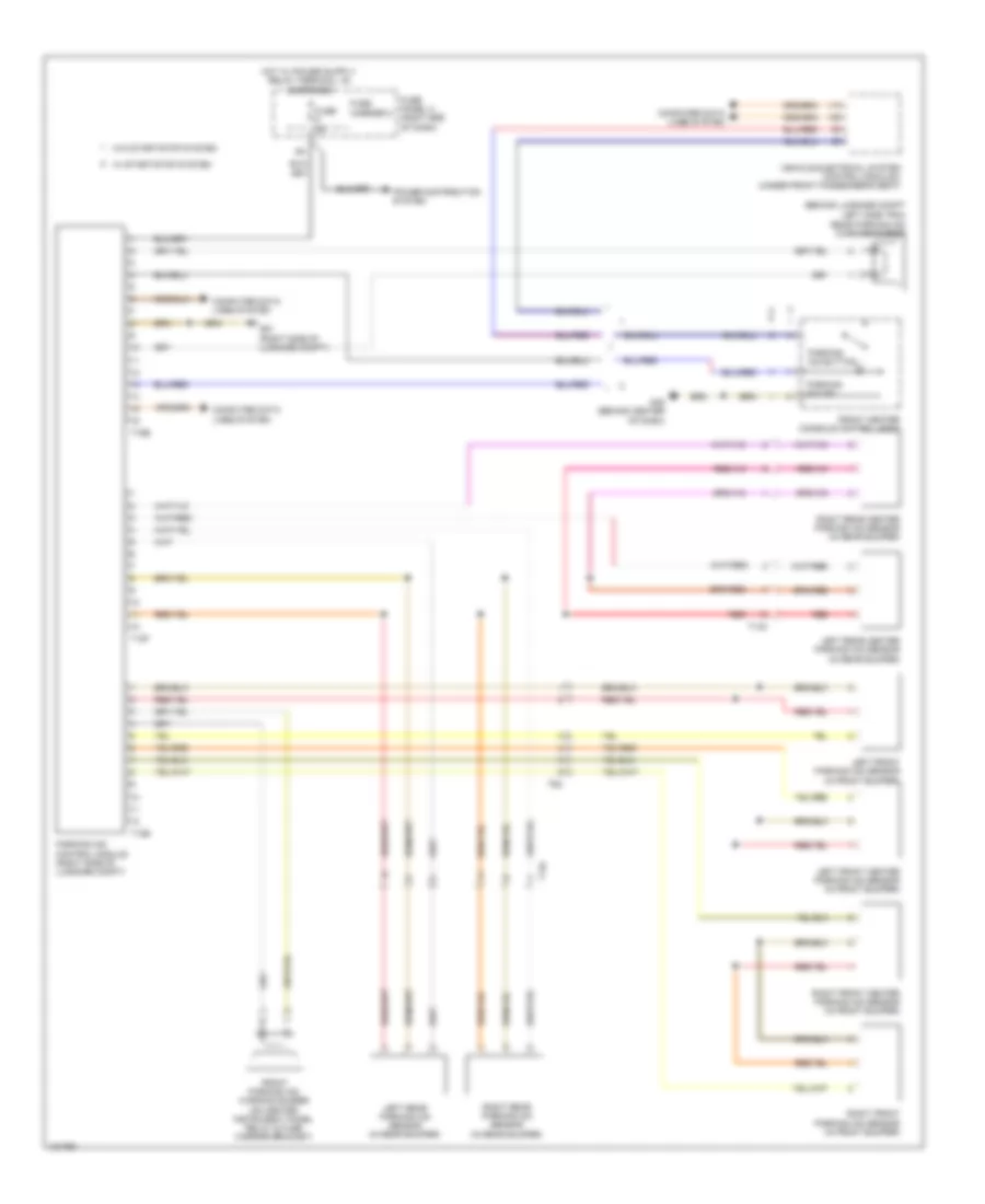
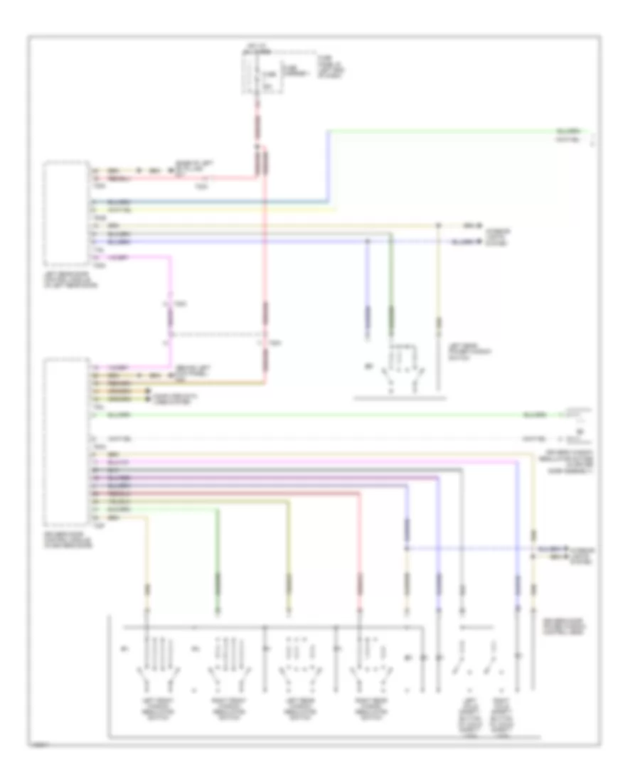
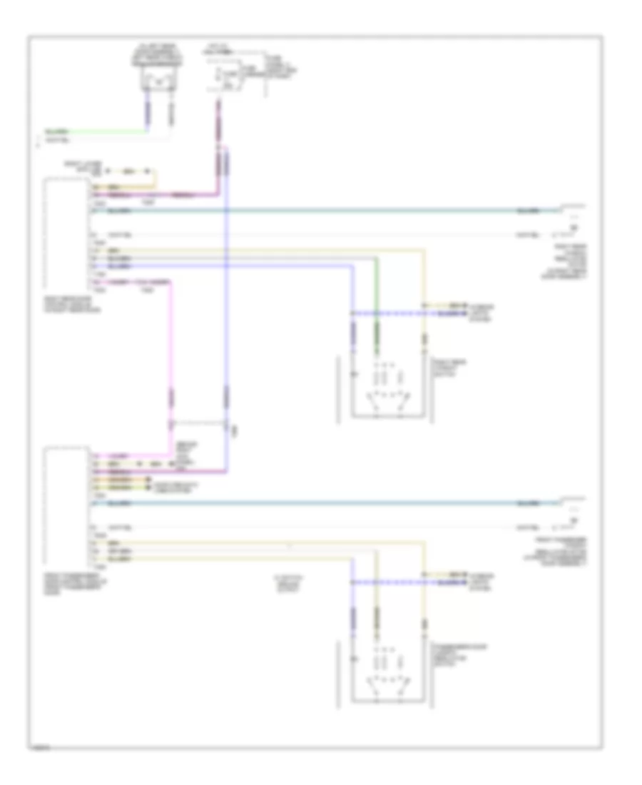
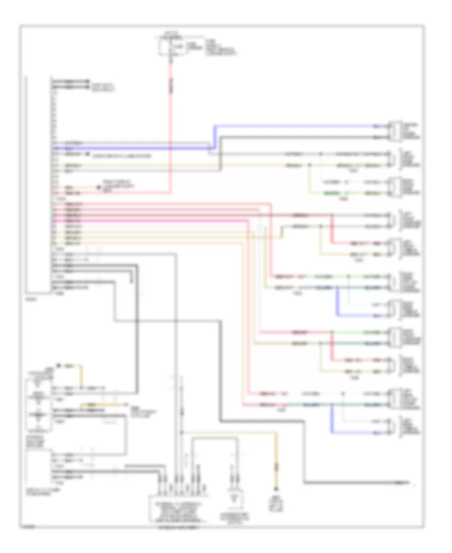
Rear A/C Wiring Diagram (1 of 2) for Audi Q7 Prestige 2014
List of elements for Rear A/C Wiring Diagram (1 of 2) for Audi Q7 Prestige 2014:
- (left air duct of rear heating & a/c unit) left rear vent temperature sensor
- (right air duct of rear heating & a/c unit) right rear vent temperature sensor
- (under center console) g687
- 12a
- Computer data lines system
- Fuse 10a
- Fuse 20a
- Fuse 5a
- Fuse carrier
- Fuse panel c (right end of dash)
- Hot at all times
- Left "b" pillar/ footwell shut-off door motor & position sensor
- Left rear upper body vent motor & position sensor (left rear upper body vent motor: in left rear upper body vent duct)
- Rear a/c display control head
- Right "b" pillar/ footwell shut-off door motor & position sensor
- Right rear upper body vent motor & position sensor
- Seats system
- T12h
- T16h
- T17h
- T20h
- T3h
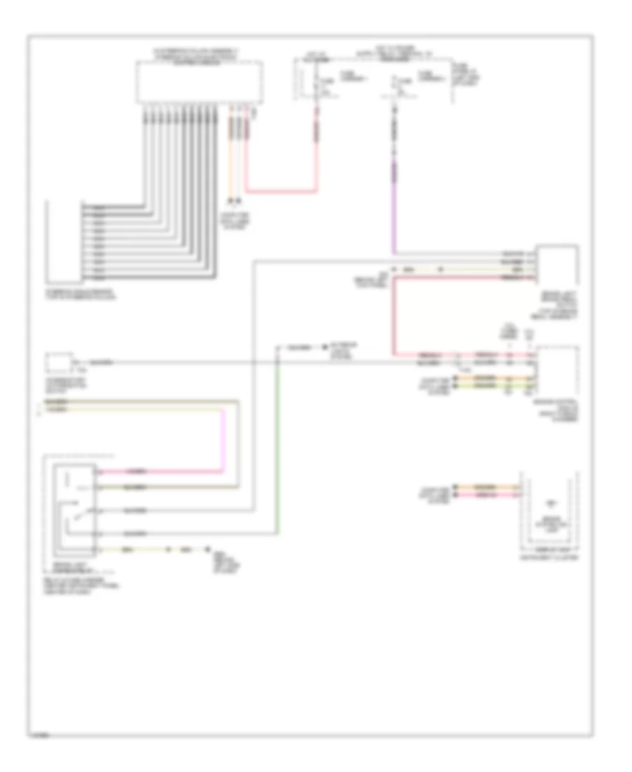
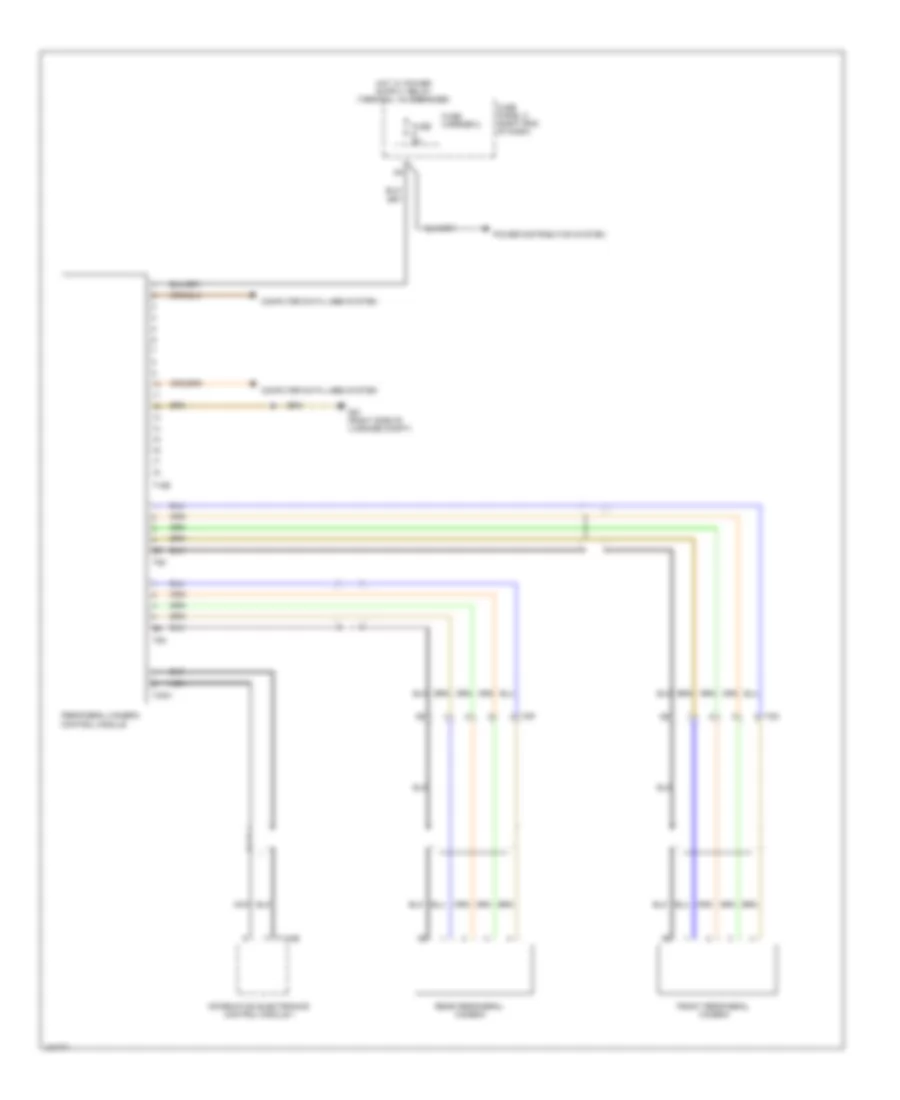
Rear A/C Wiring Diagram (2 of 2) for Audi Q7 Prestige 2014
List of elements for Rear A/C Wiring Diagram (2 of 2) for Audi Q7 Prestige 2014:
- (base of left "c" pillar) g61
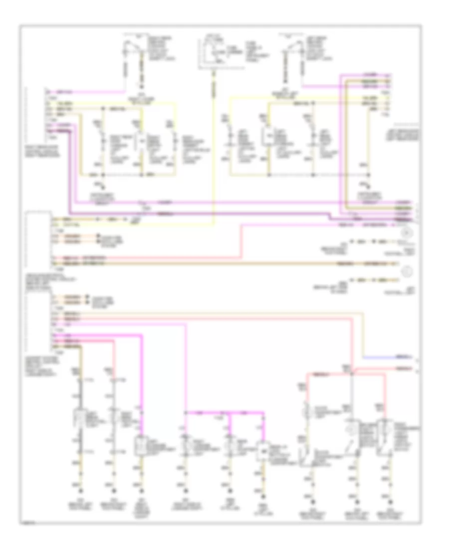
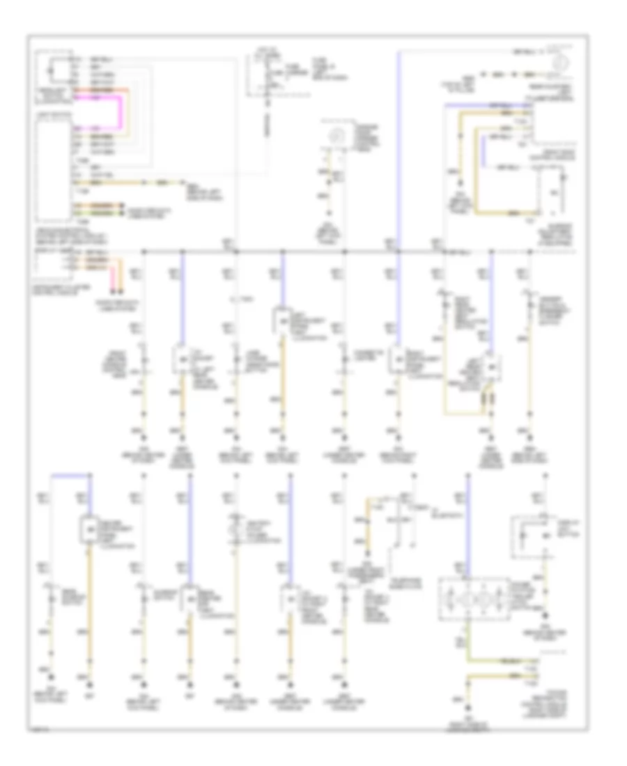
- Center instrument panel vent illumination bulb
- Computer data lines system
- Display unit
- Fresh air blower fuse 2 40a
- G43 (behind right kick panel)
- G44 (behind left kick panel)
- G67
- Hot at all times
- Instrument cluster control module
- Left instrument panel vent illumination bulb
- Left rear air door motor & position sensor
- Left rear temperature door motor & position sensor
- Rear center air vent illumination bulb
- Rear fresh air blower (on rear heating & a/c unit)
- Rear fresh air blower control module (right rear of rear heating & a/c unit)
- Red
- Relay & fuse carrier (center instrument panel) (center of dash)
- Right instrument panel vent illumination bulb
- Right rear air door motor & position sensor
- Right rear temperature door motor & position sensor
- Suppressor
- T12k
- T17h
- T2r
- T4u
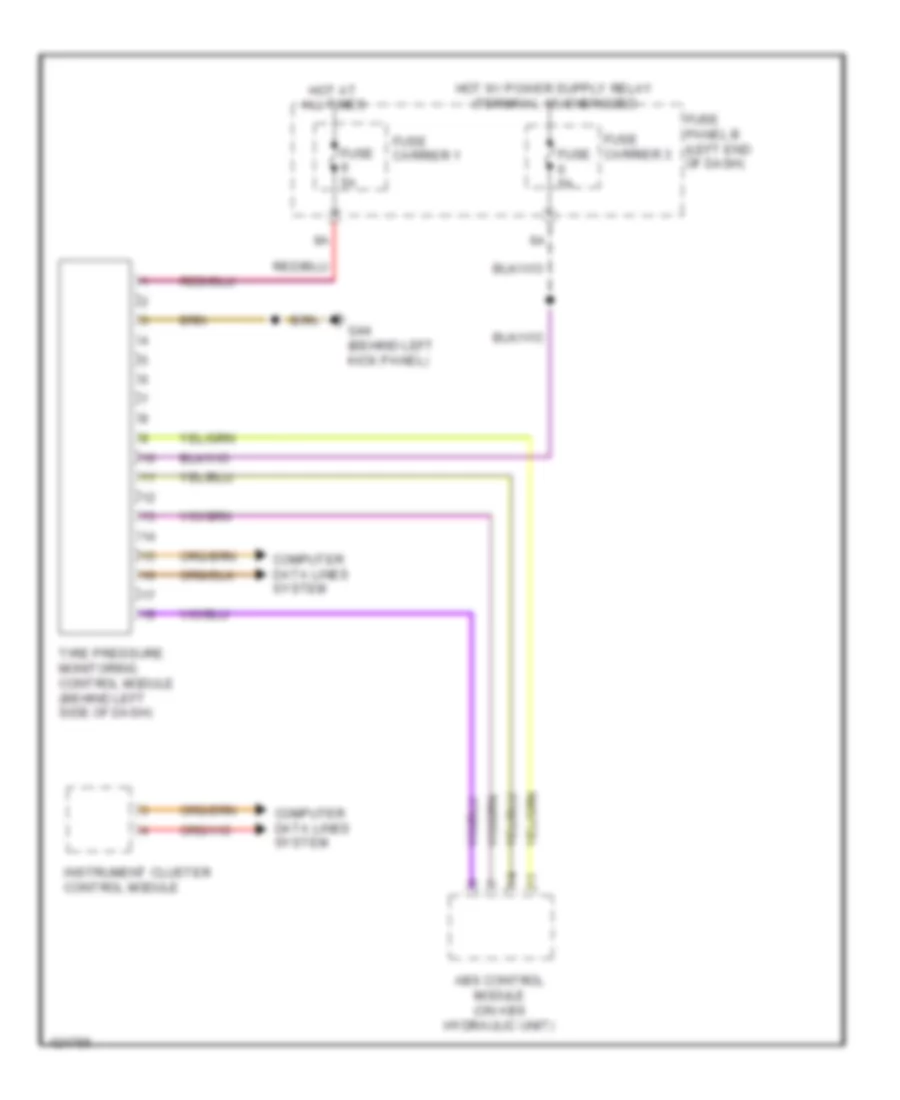
ANTI-LOCK BRAKES
Anti-lock Brakes Wiring Diagram (1 of 2) for Audi Q7 Prestige 2014
List of elements for Anti-lock Brakes Wiring Diagram (1 of 2) for Audi Q7 Prestige 2014:
- Abs control module (abs hydraulic unit) (on abs hydraulic unit)
- Abs hydraulic pump
- Asr/esp button
- Brake booster membrane position sensor (w/ distance regulation) (on brake booster assembly)
- Brake pressure release solenoid & magnetic coil
- Comfort system central control module (right side of luggage compt)
- Computer data lines system
- Driving dynamics regulation high pressure switch valve 1
- Driving dynamics regulation high pressure switch valve 2
- Driving dynamics regulation switch valve 1
- Driving dynamics regulation switch valve 2
- Esp sensor unit (under center console)
- Fuse 20a
- Fuse 40a
- Fuse 5a
- Fuse carrier 1
- Fuse carrier 2
- Fuse panel c (right end of dash)
- G609 (right plenum chamber)
- G664 (behind left side of dash)
- Hot at all times
- Interior lights system
- Left front abs inlet valve
- Left front abs outlet valve
- Left front abs wheel speed sensor (left front wheel hub assembly)
- Left rear abs inlet valve
- Left rear abs outlet valve
- Left rear abs wheel speed sensor (left rear wheel hub assembly)
- Nca
- Red
- Relay & fuse carrier (center instrument panel) (center of dash)
- Right front abs inlet valve
- Right front abs outlet valve
- Right front abs wheel speed sensor (right front wheel hub assembly)
- Right rear abs inlet valve
- Right rear abs outlet valve
- Right rear abs wheel speed sensor (right rear wheel hub assembly)
- T12d
- T32d
- T4n
- T4o
- T4p
- T4q
- T6n
- T6o
- T6p
- T6q
- Tire pressure monitoring control module (behind left side of dash)
- Towing recognition control module (right side of luggage compt)
- W/ level control system
- W/o level control system
Anti-lock Brakes Wiring Diagram (2 of 2) for Audi Q7 Prestige 2014
List of elements for Anti-lock Brakes Wiring Diagram (2 of 2) for Audi Q7 Prestige 2014:
- (in steering column assembly) steering column electronic control module
- 11a
- 3.0l sc
- 3.0l turbo diesel
- Access/start authorization switch
- Brake light disable relay
- Brake light/ brake pedal switch (top of brake pedal assembly)
- Brake system ind lamp
- Computer data lines system
- Display unit
- Engine control module (right plenum chamber)
- Exterior lights system
- Fuse 10a
- Fuse 5a
- Fuse carrier 1
- Fuse carrier 3
- Fuse panel b (left end of dash)
- G44 (behind left kick panel)
- G664 (behind left side of dash)
- Hot at all times
- Instrument cluster
- Nca
- Relay & fuse carrier (center instrument panel) (center of dash)
- Steering angle sensor (top of steering column)
- T10c
- T16a
- T8a
- T91
- T94
ANTI-THEFT
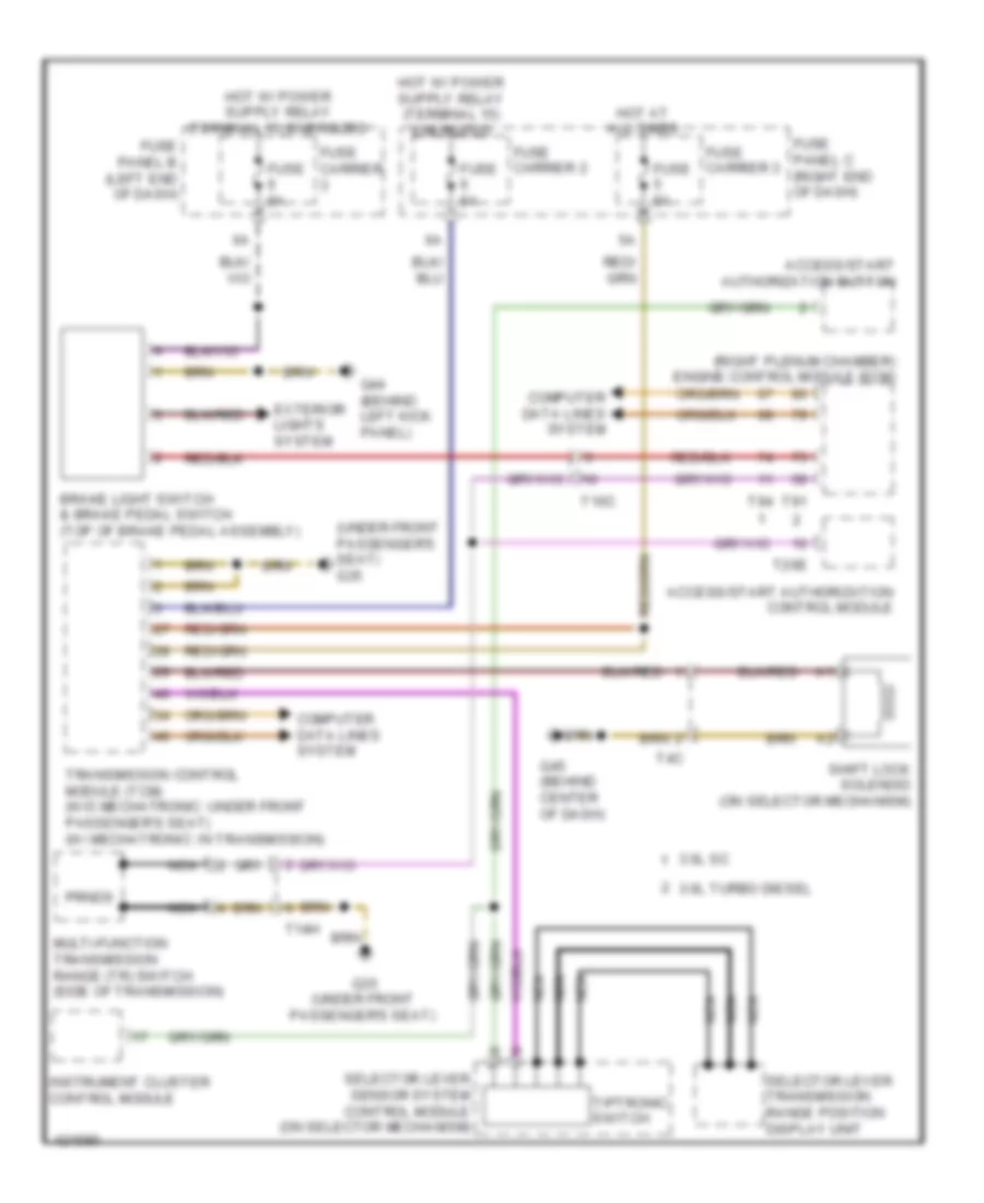
Access/Start Wiring Diagram (1 of 2) for Audi Q7 Prestige 2014
List of elements for Access/Start Wiring Diagram (1 of 2) for Audi Q7 Prestige 2014:
- 10a
- 11a
- 3.0l sc
- 3.0l turbo diesel
- Access/start authorization button
- Access/start control module (underside of steering column)
- Computer data lines system
- Engine control module (right plenum chamber)
- Fuse 150a
- Fuse 15a
- Fuse 30a
- Fuse 5a
- Fuse 60a
- Fuse carrier 1
- Fuse carrier 3
- Fuse panel b (left end of dash)
- Fuse panel d (under driver's seat)
- Fuse panel f (right rear of luggage compt)
- G44 (behind left kick panel)
- G45 (behind center of dash)
- Hot at all times
- Multi-function transmission range (tr) switch (side of transmission)
- Nca
- Red
- T10c
- T20e
- T3a
- T91
- T94
- Transmissions system
Access/Start Wiring Diagram (2 of 2) for Audi Q7 Prestige 2014
List of elements for Access/Start Wiring Diagram (2 of 2) for Audi Q7 Prestige 2014:
- (top of left "d" pillar) g667
- Access/start authorization switch
- Antenna amplifier 4
- Door locks system
- Driver's access/ start authorization antenna (left rear door)
- Exterior lights system
- Front passenger's access/ start authorization antenna (front passenger door)
- Fuse panel d (under driver's seat)
- G45 (behind center of dash)
- G51 (right side of luggage compt)
- Interior access/start authorization antenna 1 (below center console)
- Keyless access authorization antenna reader (right side of luggage compt)
- Luggage compartment access/start authorization antenna (under left side of luggage compt floor trim)
- Nca
- Power distribution system
- Red
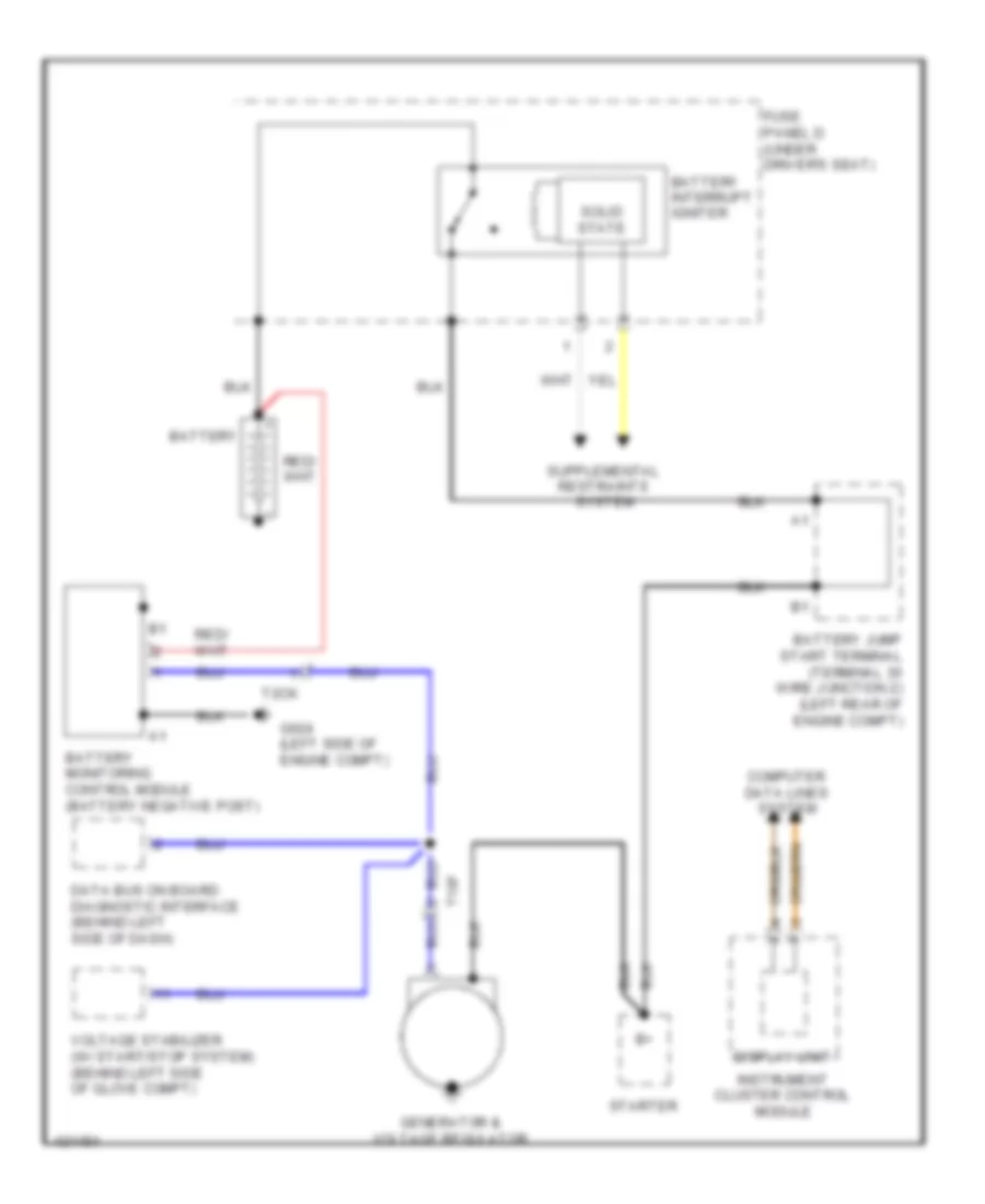
- Relay & fuse carrier (center of dash)
- Relay & fuse panel e-box (left plenum chamber)
- Starter relay
- Starter relay 2
- Starting/ charging system
- T20c
- T20d
- T2a
- T6a
- T8a
- Transmissions system
Anti-theft Wiring Diagram (1 of 2) for Audi Q7 Prestige 2014
List of elements for Anti-theft Wiring Diagram (1 of 2) for Audi Q7 Prestige 2014:
- (base of left "b" pillar) g77
- (behind left kick panel) g44
- (under e-box in plenum chamber) alarm horn
- (w/ child safety lock) left rear central locking lock unit
- (w/ child safety lock) right child safety button
- Alarm system deactivation switch
- Anti-theft alarm system w/ interior monitoring
- Anti-theft alarm system w/o interior monitoring
- Central locking safe indicator lamp
- Comfort system central control module (right side of luggage compt)
- Computer data lines system
- Driver door contact switch
- Driver lock cylinder contact switch
- Driver's door central locking lock unit
- Driver's door control module (in driver's door)
- Driver's door power window control head
- Fuse 35a
- Fuse 5a
- Fuse carrier
- Fuse panel b (left end of dash)
- G44 (behind left kick panel)
- G664 (behind left side of dash)
- G77 (base of left "b" pillar)
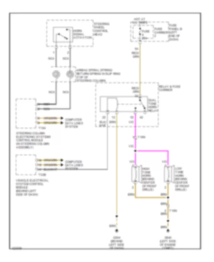
- Horns system
- Hot at all times
- Interior lights system
- Interior monitoring sensor (anti-theft alarm system w/ interior monitoring)
- Left child safety button (w/ child safety lock)
- Left front central locking system actuator
- Left rear central locking ststem actuator
- Left rear child safety lock contact switch
- Left rear door contact switch
- Left rear door control module (in left rear door)
- T10g
- T20a
- T20c
- T20l
- T20n
- T32b
- T32d
- T32f
- Vehicle electrical system control module (behind left side of dash)
Anti-theft Wiring Diagram (2 of 2) for Audi Q7 Prestige 2014
List of elements for Anti-theft Wiring Diagram (2 of 2) for Audi Q7 Prestige 2014:
- (right lower b-pillar) g78
- 11a
- Computer data lines system
- Engine hood contact switch
- Front passenger door contact switch
- Front passenger's door central locking lock unit
- Front passenger's door control module (front passenger's door)
- Fuse 35a
- Fuse carrier
- Fuse panel c (right end of dash)
- G43 (behind right kick panel)
- G640 (left side of engine compt)
- G657 (left "d" pillar)
- G668 (left "d" pillar)
- G78 (right lower b-pillar)
- Hot at all times
- Left rear window breakage sensor
- Rear lid alarm switch & rear lid central locking system motor (rear lid central locking system motor: integral to rear lid central locking unit)
- Rear lid control module 2 (right rear of roof)
- Rear window glass breakage sensor
- Right front central locking system actuator
- Right rear central locking lock unit (w/ child safety lock)
- Right rear central locking system actuator
- Right rear child safety lock contact switch
- Right rear door contact switch
- Right rear door control module (in right rear door)
- Right rear window breakage sensor
- T10n
- T10r
- T10s
- T20b
- T20d
- T20m
- T20o
- W/ electronic rear lid opening
- W/o electronic rear lid opener
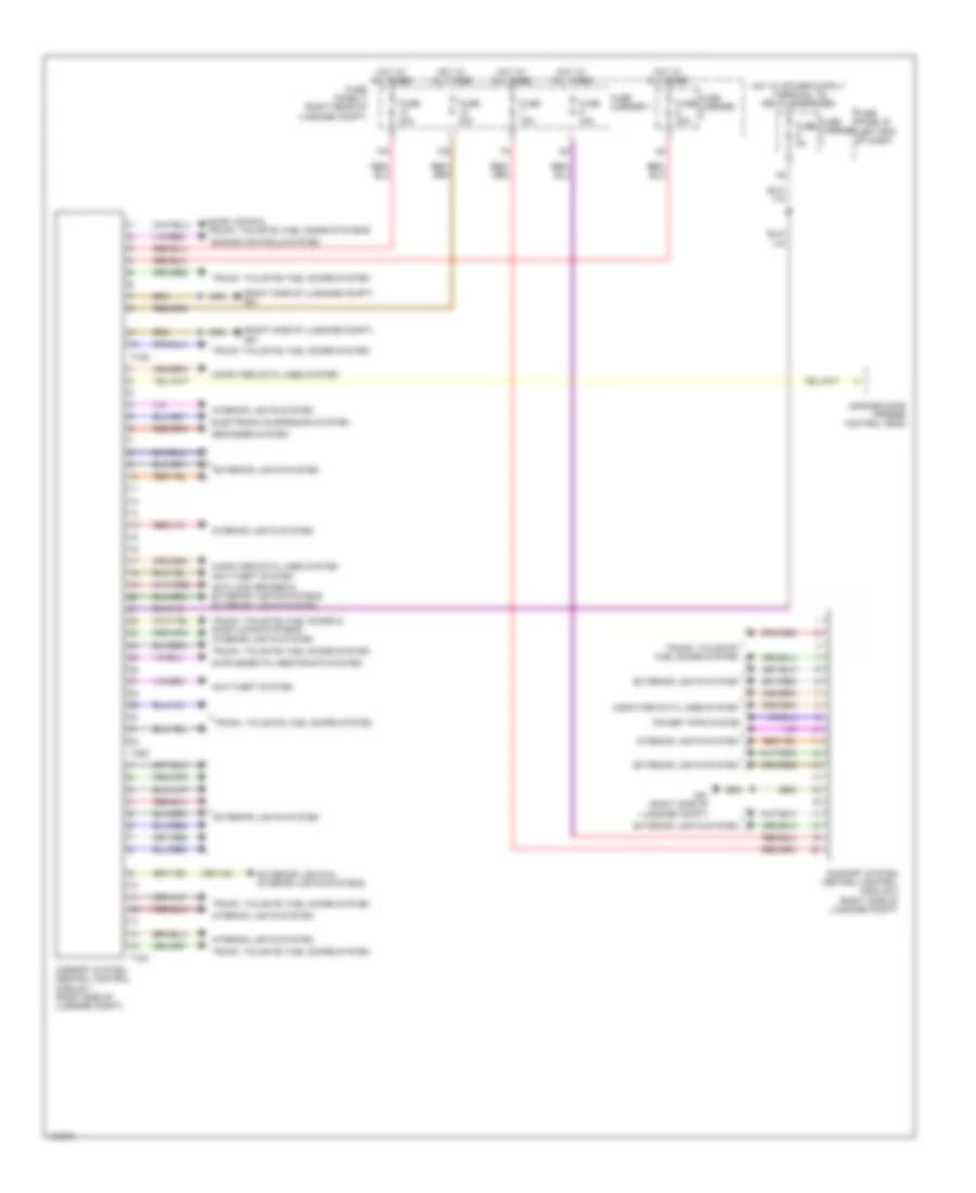
BODY CONTROL MODULES
Comfort System Central Control Module Wiring Diagram for Audi Q7 Prestige 2014
List of elements for Comfort System Central Control Module Wiring Diagram for Audi Q7 Prestige 2014:
- (right side of luggage compt) g51
- 10a
- 12a
- Anti-lock brakes & exterior lights systems
- Anti-theft system
- Comfort system central control module 1 (right side of luggage compt)
- Comfort system central control module 2 (right side of luggage compt)
- Computer data lines system
- Defogger system
- Door locks & trunk, tailgate, fuel doors systems
- Electronic suspension system
- Engine controls system
- Exterior lights & interior lights systems
- Exterior lights system
- Fuse 15a
- Fuse 20a
- Fuse 30a
- Fuse 5a
- Fuse carrier
- Fuse carrier 1
- Fuse panel b (left end of dash)
- Fuse panel f (right rear of luggage compt)
- G51 (right side of luggage compt)
- Garage door opener control head
- Hot at all times
- Interior lights system
- Power tops system
- T10g
- T15a
- T32d
- Trunk, tailgate, fuel doors & door locks systems interior lights system
- Trunk, tailgate, fuel doors system
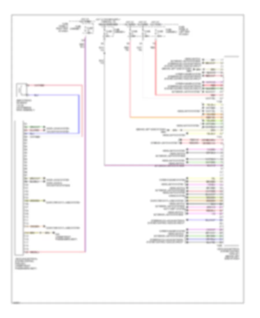
Vehicle Electrical System Control Module Wiring Diagram for Audi Q7 Prestige 2014
List of elements for Vehicle Electrical System Control Module Wiring Diagram for Audi Q7 Prestige 2014:
- (behind left side of dash) g664
- 12a
- Anti-theft system
- Computer data lines system
- Door locks & navigation systems
- Door locks system
- Exterior lights system
- Fuse 15a
- Fuse 25a
- Fuse 30a
- Fuse 5a
- Fuse carrier 1
- Fuse carrier 2
- Fuse carrier 3
- Fuse panel b (left end of dash)
- Fuse panel c (right end of dash)
- G35 (under front passenger's seat)
- Headlights & exterior lights systems
- Headlights & exterior lights systems headlights system
- Headlights system
- Horns system
- Hot at all times
- Interior lights system
- Navigation system
- Red
- Servotronic solenoid valve (on steering rack assembly)
- Steering column electronic system control module circuit
- T10a
- T12b
- T32b
- Vehicle electrical system control module 1 (behind left side of dash)
- Vehicle electrical system control module 2 (under front passenger's seat)
- Wiper/washer system
- Wiper/washer system steering column electronic system control module circuit
COMPUTER DATA LINES
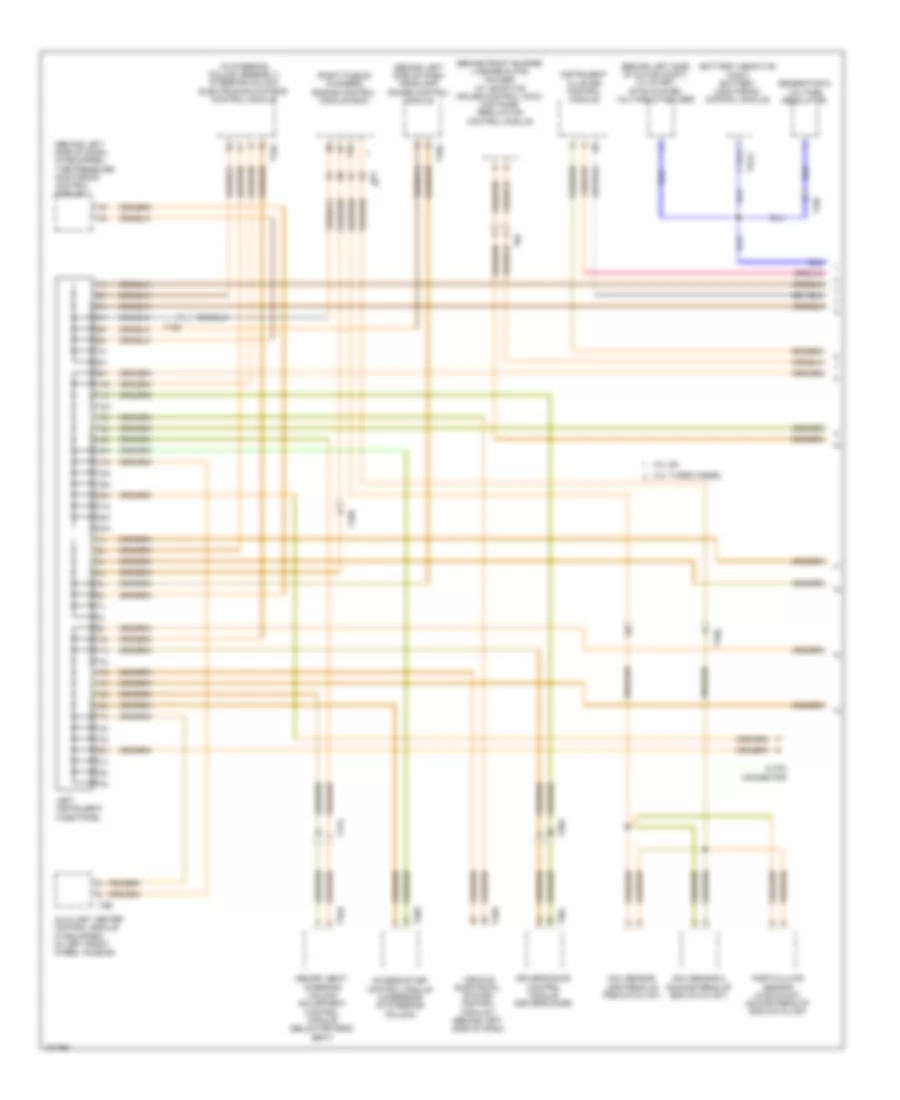
Computer Data Lines Wiring Diagram (1 of 3) for Audi Q7 Prestige 2014
List of elements for Computer Data Lines Wiring Diagram (1 of 3) for Audi Q7 Prestige 2014:
- (behind front bumper license plate holder) (w/ adaptive cruise control (acc)) distance regulation control module
- (behind left side of dash) (if equipped) tire pressure monitoring control module
- (behind left side of dash) headlamp range control module
- (behind left side of glove compt) (w/ start/ stop system) voltage stabilizer
- (in steering column assembly) steering column electronics systems control module
- (right plenum chamber) engine control module (ecm)
- 10h
- 10l
- 11h
- 11l
- 12 pin connector
- 12h
- 12l
- 13h
- 13l
- 14h
- 14l
- 15h
- 15l
- 16h
- 16l
- 17h
- 17l
- 18h
- 18l
- 19h
- 19l
- 20h
- 20l
- 21h
- 21l
- 22h
- 22l
- 23h
- 23l
- 3.0l sc
- 3.0l turbo diesel
- Access/start control module (underside of steering column)
- Auxiliary heater control module (if equipped) (in left front wheel housing)
- Driver's door control module (driver's door)
- Generator & voltage regulator
- Instrument cluster control module
- Left instrument fuse panel
- Memory seat/ steering column adjustment control module (below driver's seat)
- Nox sensor (upstream of pre-catalyst)
- Nox sensor 2 (downstream of scr catalyst)
- Particulate sensor (in exhaust, downstream of scr catalyst)
- T10d
- T10e
- T10f
- T16a
- T17a
- T20a
- T20e
- T20l
- T26a
- T2ck
- T32b
- T32h
- T6b
- T8c
- T91
- T94
- Vehicle electrical system control module 1 (behind left side of dash)
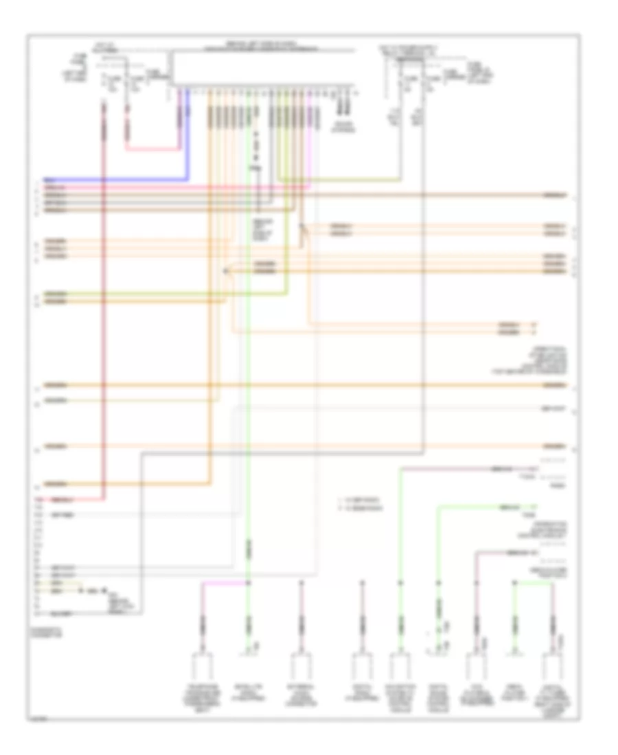
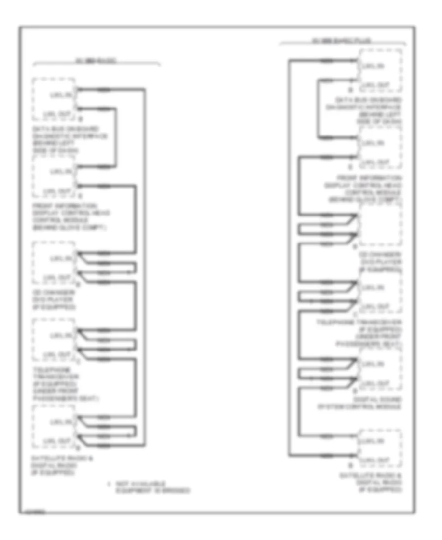
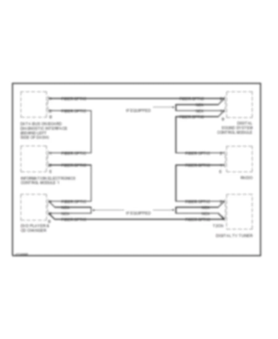
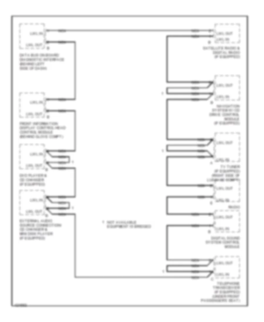
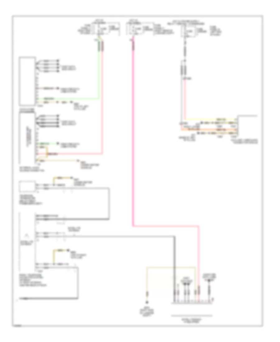
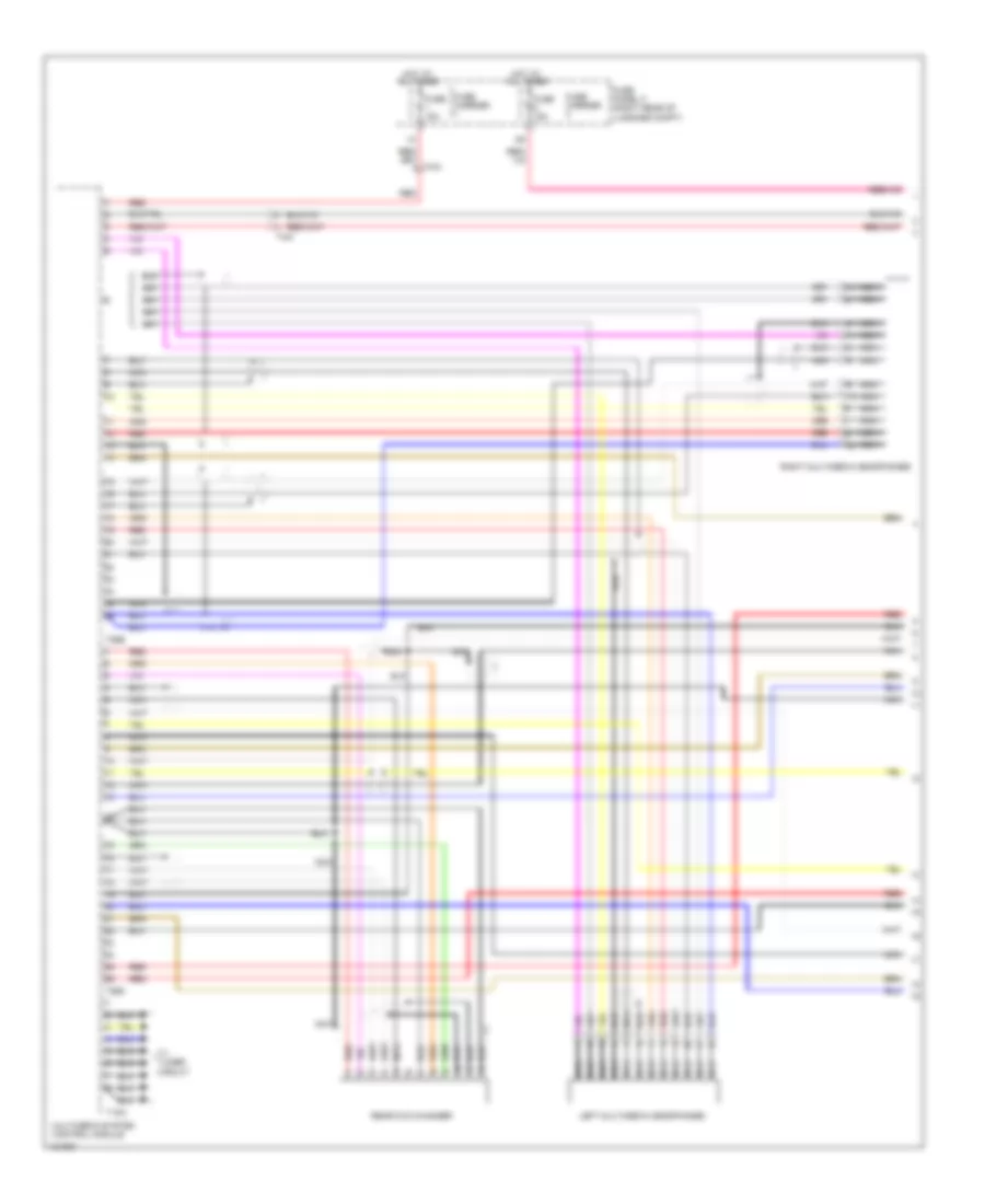
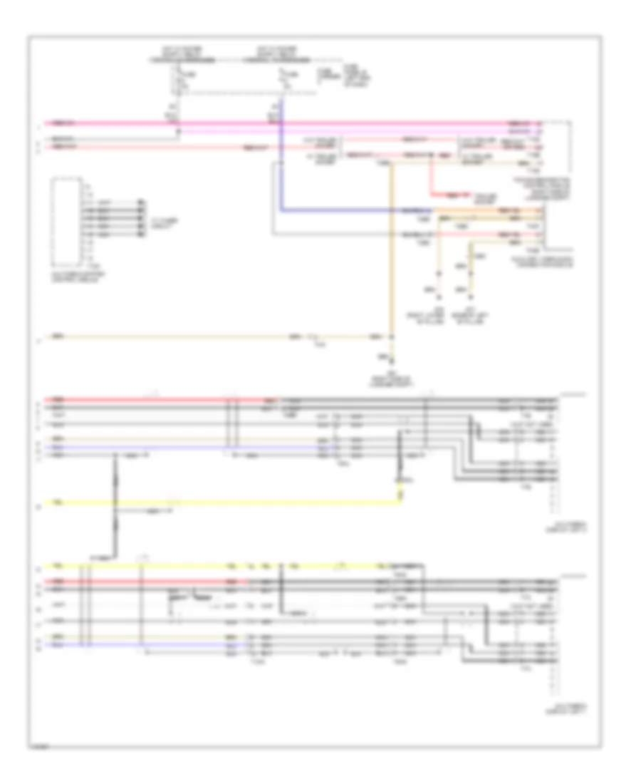
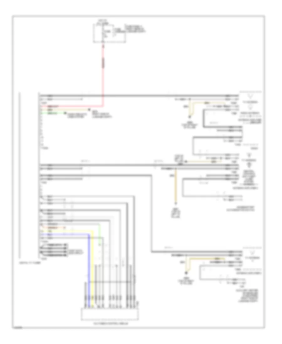
Computer Data Lines Wiring Diagram (2 of 3) for Audi Q7 Prestige 2014
List of elements for Computer Data Lines Wiring Diagram (2 of 3) for Audi Q7 Prestige 2014:
- (behind left side of dash)
- (behind left side of dash) data bus on board diagnostic interface
- (under front passenger's seat)
- 10a
- 11a
- 12a
- Diagnostic connector
- Digital radio (if equipped)
- Digital sound system control module
- Digital tv tuner (if equipped) (right side of luggage compt)
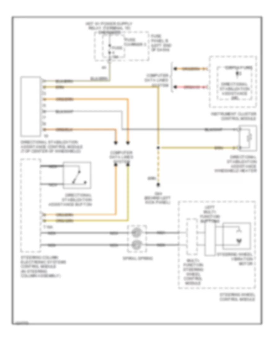
- Directional stabilization assistance control module (top center of windshield)
- Dvd player & cd changer (if equipped)
- External audio source connector
- Fuse 10a
- Fuse 5a
- Fuse carrier
- Fuse panel b (left end of dash)
- G44 (behind left kick panel)
- G664
- Hot at all times
- Information electronics control module 1
- Media player position 1
- Media player position 2
- Navigation system w/ cd drive control module
- Nca
- Radio
- Satellite radio (if equipped)
- Sound systems
- T10aa
- T12ag
- T20
- T32c
- T38
- T8ae
- T8ah
- T8l
- Telephone transceiver
- W/ bose radio
- W/ dsp radio
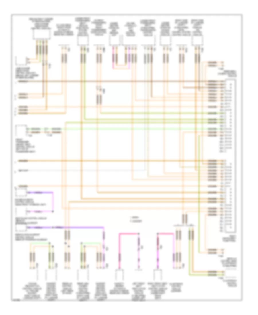
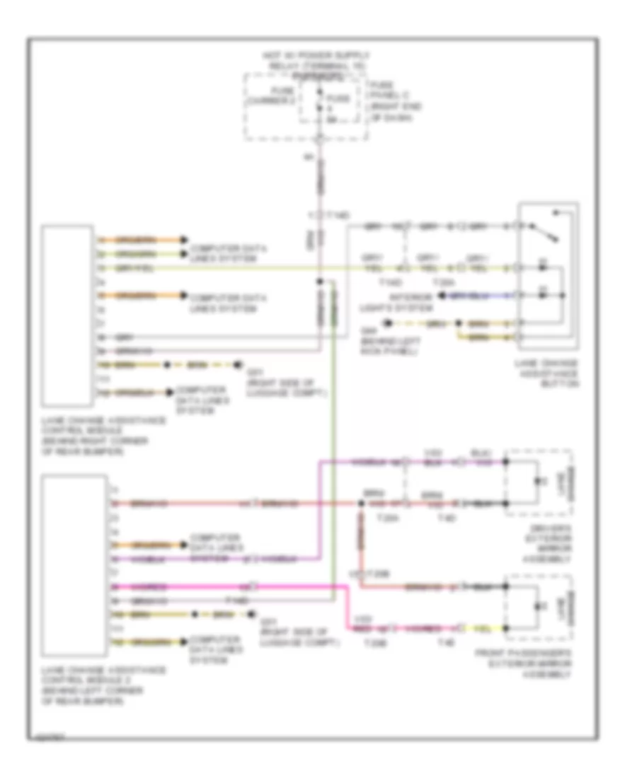
Computer Data Lines Wiring Diagram (3 of 3) for Audi Q7 Prestige 2014
List of elements for Computer Data Lines Wiring Diagram (3 of 3) for Audi Q7 Prestige 2014:
- (behind right corner of rear bumper) lane change assistance control module 1
- (in front passenger's door) front passenger's door control module
- (near front interior light)
- (on abs hydraulic unit) abs control module
- (right side of luggage compt) (if equipped) level control system control module
- (right side of luggage compt) parking aid control module
- (under center console) air bag control module
- (under center console) esp sensor unit
- (under front passenger's seat) (if equipped) transmission control module
- (under front passenger's seat) vehicle electrical system control module 2
- (w/ high beam assistance) automatic dimming interior rearview mirror
- 10h
- 10l
- 11h
- 11l
- 12h
- 12l
- 13h
- 13l
- 14h
- 14l
- 15h
- 15l
- 16h
- 16l
- 17h
- 17l
- 18h
- 18l
- 19h
- 19l
- 20h
- 20l
- 21h
- 21l
- 22h
- 22l
- 23h
- 23l
- Basic
- Climatronic control module
- Climatronic control module (comfort)
- Comfort
- Comfort system central control module 1 (right side of luggage compt)
- Comfort system central control module 2 (right side of luggage compt)
- Front passenger memory seat control module (bottom of passenger seat)
- Humidity sensor/ automatic dimming interior rearview mirror
- Lane change assistance control module 2 (behind left corner of rear bumper)
- Left front seat ventilation control module (if equipped) (under left front seat)
- Peripheral camera control module
- Power sunroof control module
- Rear a/c control head (climatronic) (if equipped)
- Rear lid control module (left rear of roof)
- Rear sliding sunroof control module (rear of panorama sunroof)
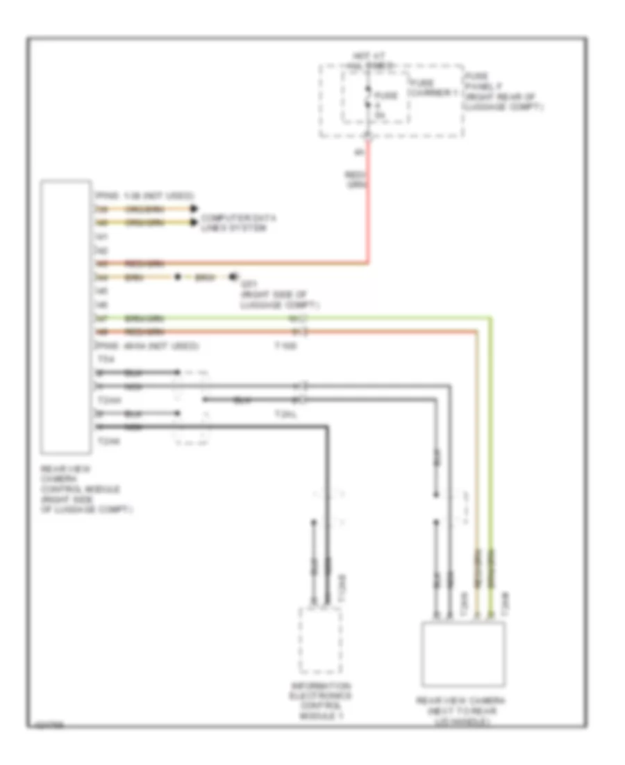
- Rear view camera control module (if equipped) (right side of luggage compt)
- Right front seat ventilation control module (if equipped) (under right front seat)
- Right instrument fuse panel
- Roof blind control module (rear of panorama sunroof)
- T12d
- T14d
- T16b
- T16c
- T16d
- T16h
- T17b
- T18e
- T20b
- T20f
- T20m
- T32d
- T32i
- T40a
- T52
- T54
- T6f
- T6g
- T6y
- T75
- T81a
- T8x
- Towing recognition control module (w/ trailer socket) (right side of luggage compt)
COOLING FAN
Cooling Fan Wiring Diagram (1 of 2) for Audi Q7 Prestige 2014
List of elements for Cooling Fan Wiring Diagram (1 of 2) for Audi Q7 Prestige 2014:
- (3.0l sc) auxiliary engine coolant pump relay
- (3.0l turbo diesel) coolant circulation pump relay
- 19a
- 19c
- 19d
- 19e
- 3.0l sc
- 3.0l turbo diesel
- After-run coolant pump (left front of engine)
- Climatronic control module
- Cooler
- Cooler fuse 5a
- Fuse 15a
- Fuse 30a
- Fuse carrier
- Fuse panel c (right end of dash)
- G609 (right plenum chamber)
- G62 (base of right "c" pillar)
- G645
- High pressure sensor (on a/c high pressure line)
- Hot at all times
- Relay & fuse carrier (instrument panel-center) (center of dash)
- Relay & fuse panel (e-box) (left plenum chamber)
- T10c
- T10d
- T10m
- T16c
- T16d
- T3c
Cooling Fan Wiring Diagram (2 of 2) for Audi Q7 Prestige 2014
List of elements for Cooling Fan Wiring Diagram (2 of 2) for Audi Q7 Prestige 2014:
- (or red)
- 10a
- 13a
- 3.0l sc
- 3.0l turbo diesel
- Charge air cooling pump (3.0l sc) (lower right front of engine compt)
- Computer data lines system
- Coolant fan (on radiator)
- Coolant fan 2 (on radiator)
- Coolant fan control module (on coolant fan)
- Coolant fan control module 2 (on coolant fan 2)
- Coolant recirculation pump (in left front wheel housing)
- Engine control module (right plenum chamber)
- Engine coolant temperature (ect) sensor (on radiator) (on radiator outlet)
- Engine coolant temperature (ect) sensor (top left side of engine)
- Fuse 10a
- Fuse 15a
- Fuse 40a/60a
- Fuse 5a
- Fuse 60a/40a
- G640 (left side of engine compt)
- G671 (left front long member)
- Hot at all times
- Map controlled engine cooling thermostat (3.0l turbo diesel) (center front of engine)
- Nca
- Relay & fuse panel e-box (left plenum chamber)
- T105
- T10ab
- T10d
- T17d
- T60
- T91
- T94
CRUISE CONTROL
Cruise Control Wiring Diagram for Audi Q7 Prestige 2014
List of elements for Cruise Control Wiring Diagram for Audi Q7 Prestige 2014:
- (behind left side of dash) g664
- 11a
- 12 pin connector
- 3.0l sc
- 3.0l turbo diesel
- 3.ol turbo diesel
- Accelerator pedal position sensor & accelerator pedal position sensor 2 (top of accelerator pedal assembly)
- Adaptive cruise control sensor heater (integral to distance regulation control module)
- Brake light switch & brake pedal switch (top of brake pedal assembly)
- Computer data lines system
- Cruise control switch (if equipped)
- Distance regulation control module (if equipped) (behind front bumper license plate holder)
- Engine control module (right plenum chamber)
- Engine controls system
- Engine speed sensor (transmission bell housing)
- Fuse 10a
- Fuse 5a
- Fuse carrier
- Fuse panel b (left end of dash)
- G44 (behind left kick panel)
- G609 (right plenum chamber)
- G640 (left side of engine compt)
- Hot at all times
- Input speed sensor
- Nca
- Output speed sensor
- Red
- Steering column electronic systems control module (in steering column assembly)
- T105
- T10c
- T10d
- T10e
- T16a
- T60
- T8c
- T8g
- T91
- T94
- Throttle valve control module (3.0l sc) (rear of supercharger)
- Throttle valve control module (3.0l turbo diesel) (on throttle valve)
- Transmission assembly
- Transmission control module (w/o mechatronic: under front passenger's seat) (w/ mechatronic: in transmission)
DEFOGGERS
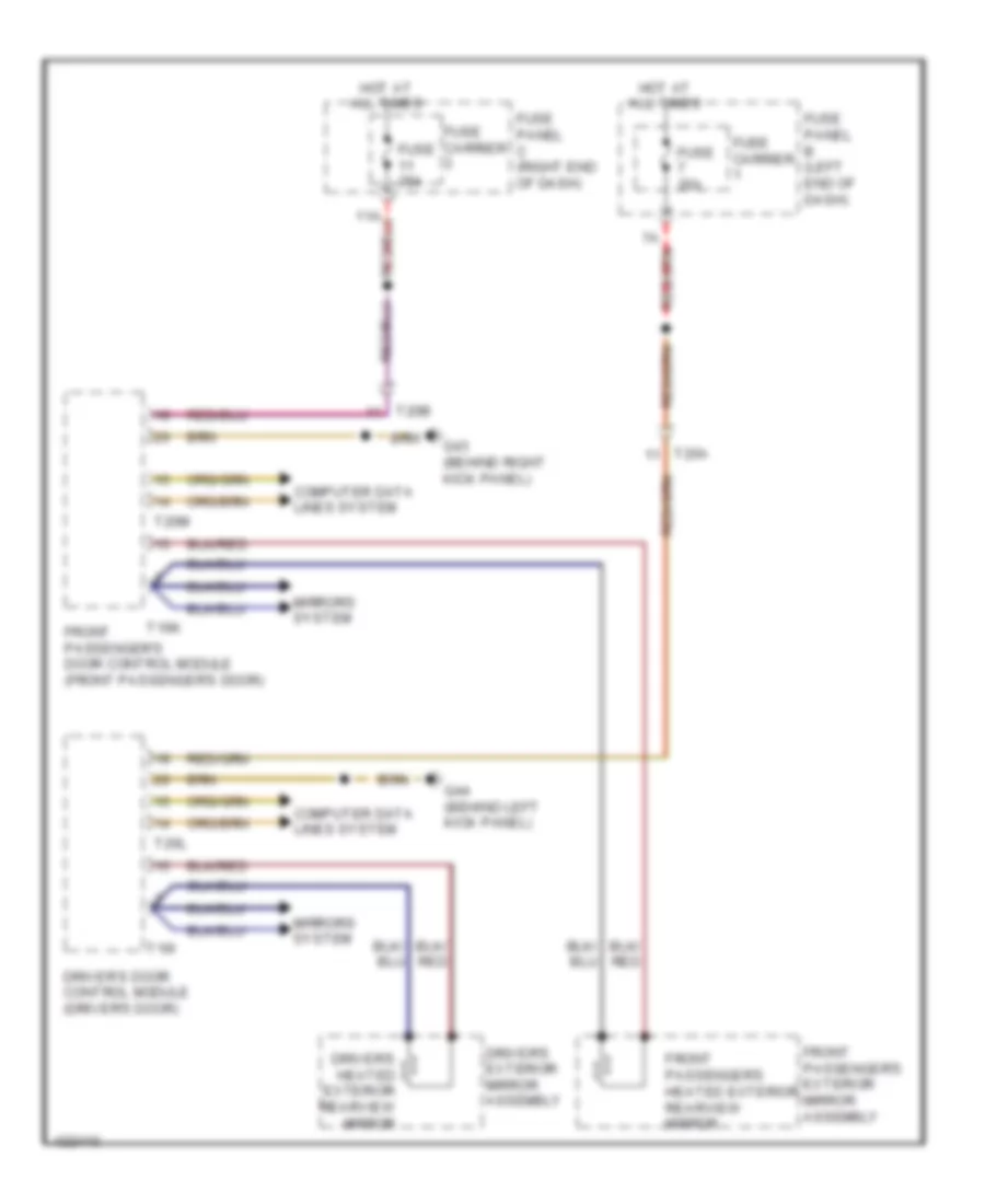
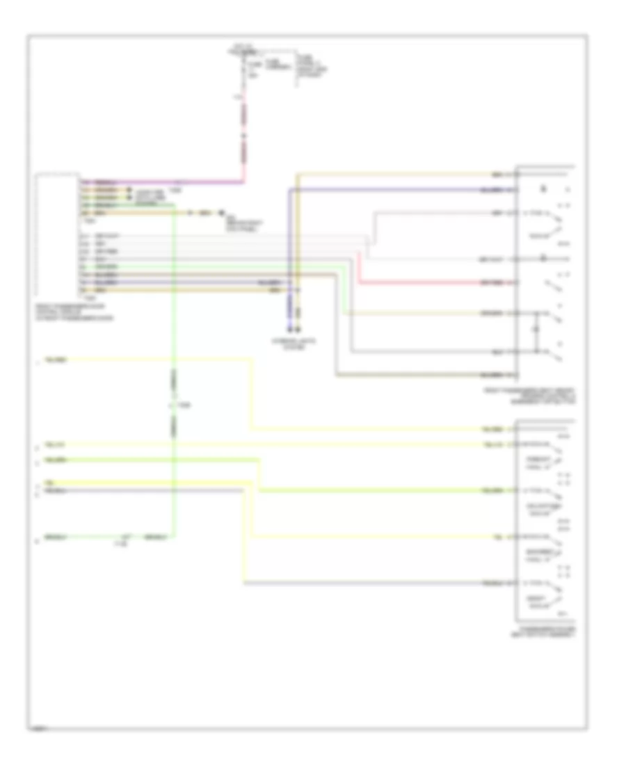
Heated Mirrors Wiring Diagram for Audi Q7 Prestige 2014
List of elements for Heated Mirrors Wiring Diagram for Audi Q7 Prestige 2014:
- 11a
- Computer data lines system
- Driver's door control module (driver's door)
- Driver's exterior mirror assembly
- Driver's heated exterior rearview mirror
- Front passenger's door control module (front passenger's door)
- Front passenger's exterior mirror assembly
- Front passenger's heated exterior rearview mirror
- Fuse 35a
- Fuse carrier
- Fuse panel b (left end of dash)
- Fuse panel c (right end of dash)
- G43 (behind right kick panel)
- G44 (behind left kick panel)
- Hot at all times
- Mirrors system
- T16i
- T16k
- T20a
- T20b
- T20l
- T20m
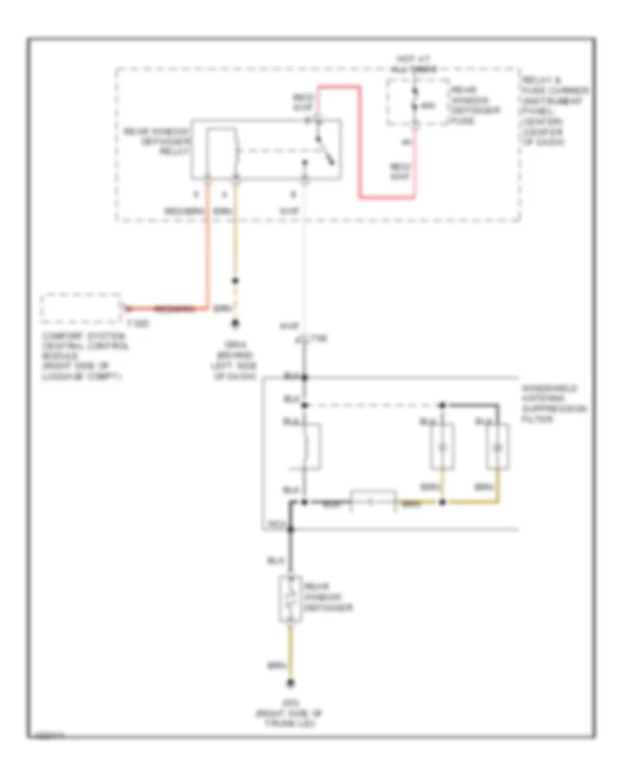
Rear Defogger Wiring Diagram for Audi Q7 Prestige 2014
List of elements for Rear Defogger Wiring Diagram for Audi Q7 Prestige 2014:
- 40a
- Comfort system central control module (right side of luggage compt)
- G53 (right side of trunk lid)
- G664 (behind left side of dash)
- Hot at all times
- Nca
- Rear window defogger
- Rear window defogger fuse
- Rear window defogger relay
- Relay & fuse carrier (instrument panel- center) (center of dash)
- T32d
- T6e
- Windshield antenna suppression filter
ELECTRONIC POWER STEERING
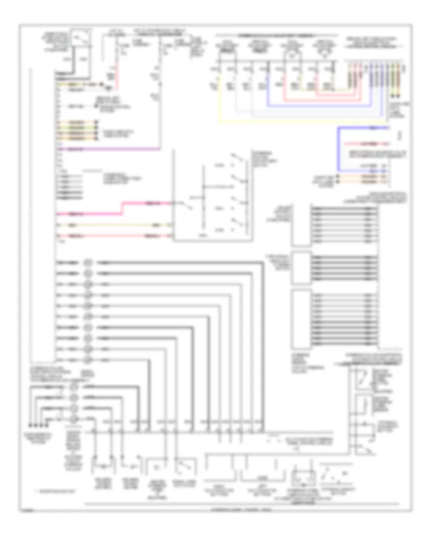
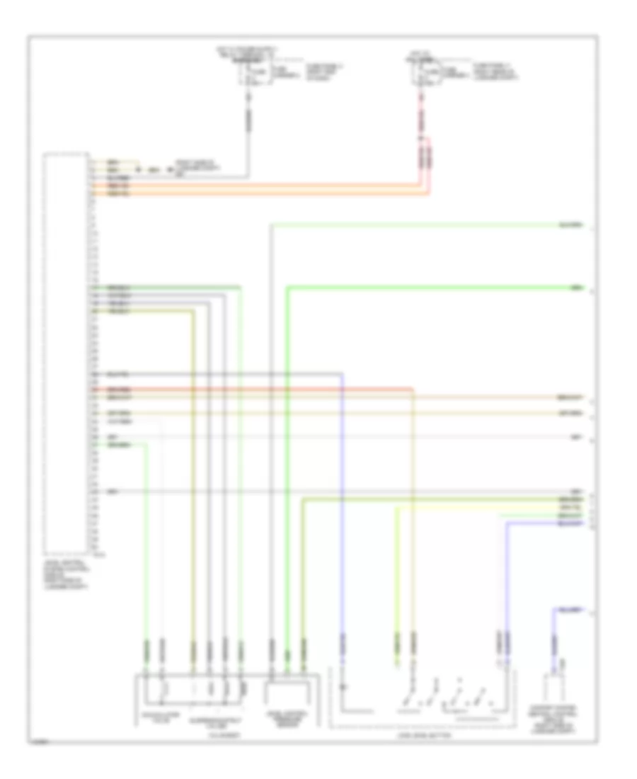
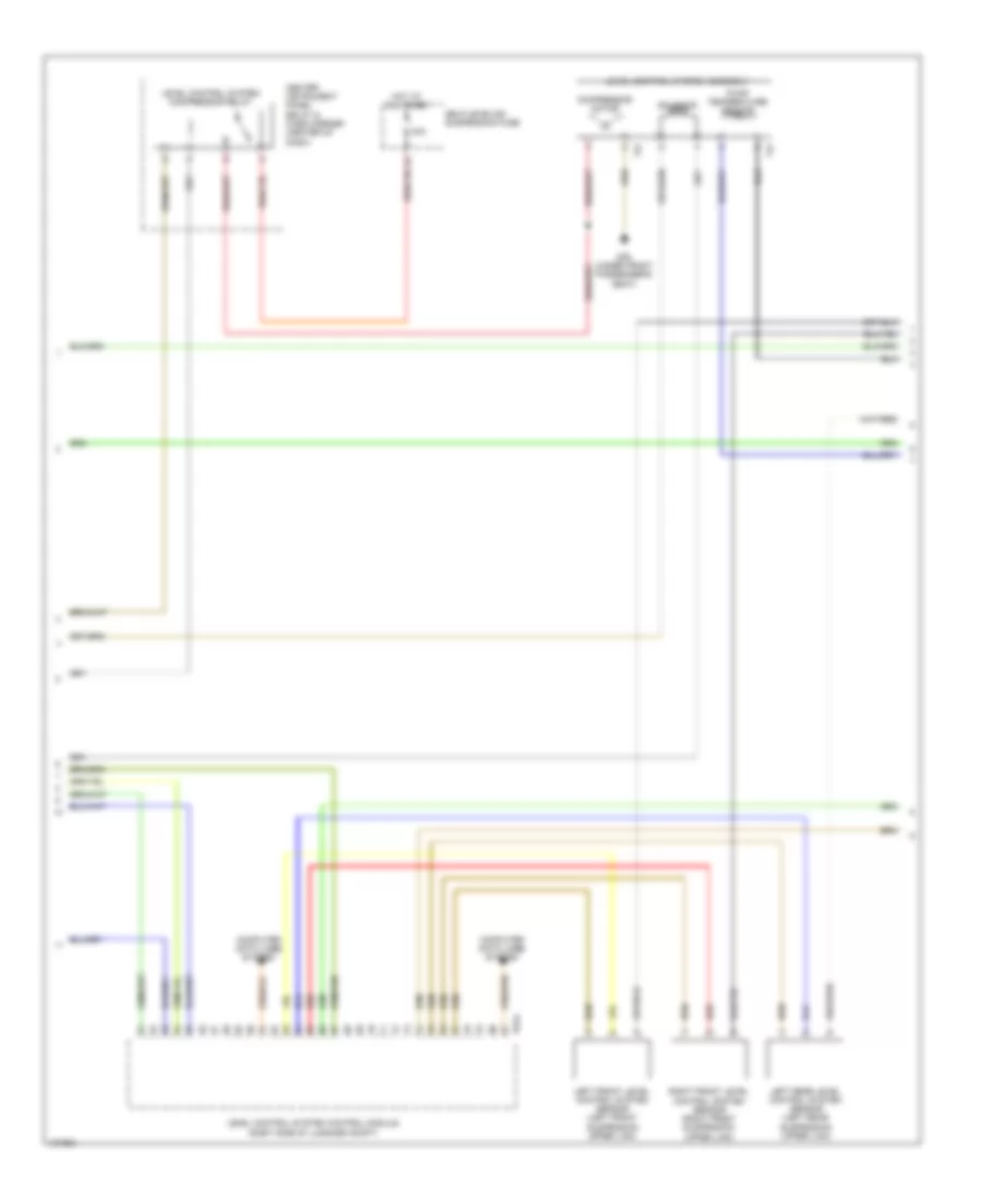
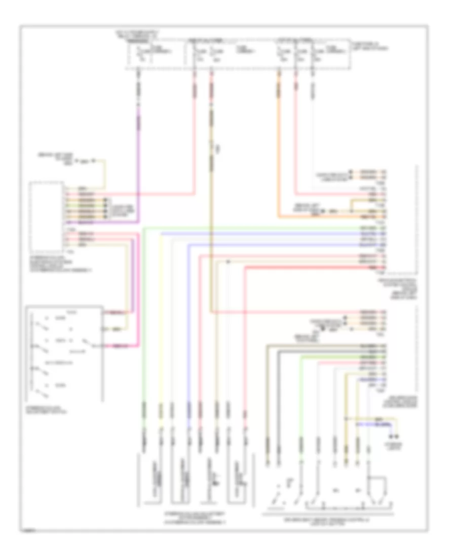
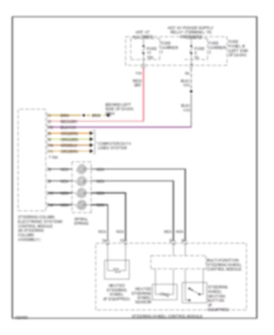
Electronic Power Steering Wiring Diagram for Audi Q7 Prestige 2014
List of elements for Electronic Power Steering Wiring Diagram for Audi Q7 Prestige 2014:
- (behind left side of dash)
- (behind left side of dash) vehicle electrical system control module
- (top of steering column)
- 11a
- Air bag spiral spring/ return spring w/ slip ring (top of steering column)
- Axial adjustment motor
- Axial adjustment sensor
- Computer data lines system
- Cruise control switch (if equipped)
- Directional stabilization assistance button (if equipped)
- Driver's air bag igniter
- Driver's air bag igniter 2
- Engine control system
- Fuse 10a
- Fuse 5a
- Fuse carrier
- Fuse carrier 1
- Fuse panel b (left end of dash)
- G664
- Heated steering wheel (if equipped)
- Heated steering wheel button (if equipped)
- Heated steering wheel sensor
- Hot at all times
- Hot w/ power suply relay (terminal 15) energized
- Left multi-function buttons
- Mode
- Multi-function steering wheel control module
- Nca
- Red
- Right multi-function buttons
- Servotronic solenoid valve (on steering rack assembly)
- Shorting contact
- Signal horn activation
- Spiral spring
- Steering angle sensor
- Steering column adjustment assembly
- Steering column adjustment switch
- Steering column electronic systems control module (in steering column assembly)
- Steering wheel control head
- Steering wheel vibration motor (w/ directional stabilization assistance)
- T12b
- T16a
- T32b
- T4a
- Tiptronic downshift button
- Tiptronic upshift button
- Turn signal/ headlight flasher switch
- Vehicle electrical system control module 2 (under front passenger's seat)
- Vertical adjustment motor
- Vertical adjustment sensor
- Windshield wiper intermittent mode switch
ELECTRONIC SUSPENSION
Electronic Suspension Wiring Diagram (1 of 3) for Audi Q7 Prestige 2014
List of elements for Electronic Suspension Wiring Diagram (1 of 3) for Audi Q7 Prestige 2014:
- (right side of luggage compt) g51
- Accumulator valve
- Comfort system central control module (right side of luggage compt)
- Fuse 15a
- Fuse 5a
- Fuse carrier 2
- Fuse carrier 3
- Fuse panel c (right end of dash)
- Fuse panel f (right rear of luggage compt)
- Hot at all times
- Level control pressure sensor
- Level control system control module (right side of luggage compt)
- Load level button
- Suspension strut valves
- T32d
- T81a
- Valve body
Electronic Suspension Wiring Diagram (2 of 3) for Audi Q7 Prestige 2014
List of elements for Electronic Suspension Wiring Diagram (2 of 3) for Audi Q7 Prestige 2014:
- 40a
- Center instrument panel relay & fuse carrier (center of dash)
- Compressor motor
- Computer data lines system
- G35 (under front passenger's seat)
- Hot at all times
- Left front level control system sensor (left front suspension upper link)
- Left rear level control system sensor (left rear suspension upper link)
- Level control system assembly
- Level control system compressor relay
- Level control system control module (right side of luggage compt)
- Pump temperature sensor
- Red
- Right front level control system sensor (right front suspension upper link)
- Self-leveling suspension fuse
- Solenoid
- T2i
- T4i
- T81a
Electronic Suspension Wiring Diagram (3 of 3) for Audi Q7 Prestige 2014
List of elements for Electronic Suspension Wiring Diagram (3 of 3) for Audi Q7 Prestige 2014:
- Left front body acceleration sensor (upper left front wheelwell)
- Left front dampening adjustment valve (top of suspension strut)
- Left rear dampening adjustment valve (top of suspension strut)
- Level control system control module (right side of luggage compt)
- Nca
- Rear body acceleration sensor (under left side of spare tire cover)
- Red
- Right front body acceleration sensor (upper right front wheelwell)
- Right front dampening adjustment valve (top of suspension strut)
- Right rear dampening adjustment valve (top of suspension strut)
- Right rear level control system sensor (right rear suspension upper link)
- T40b
- T6n
- T6o
- T6p
- T6q
ENGINE PERFORMANCE
3.0L SC
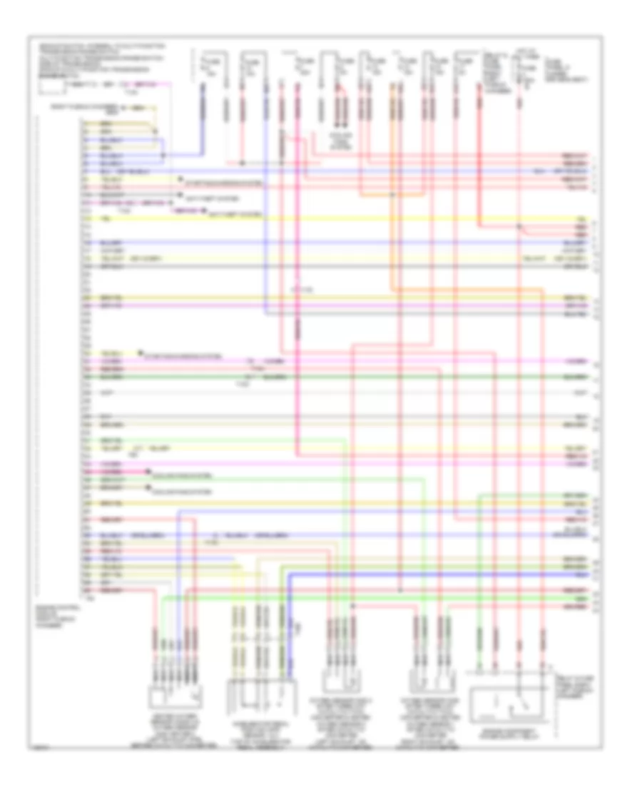
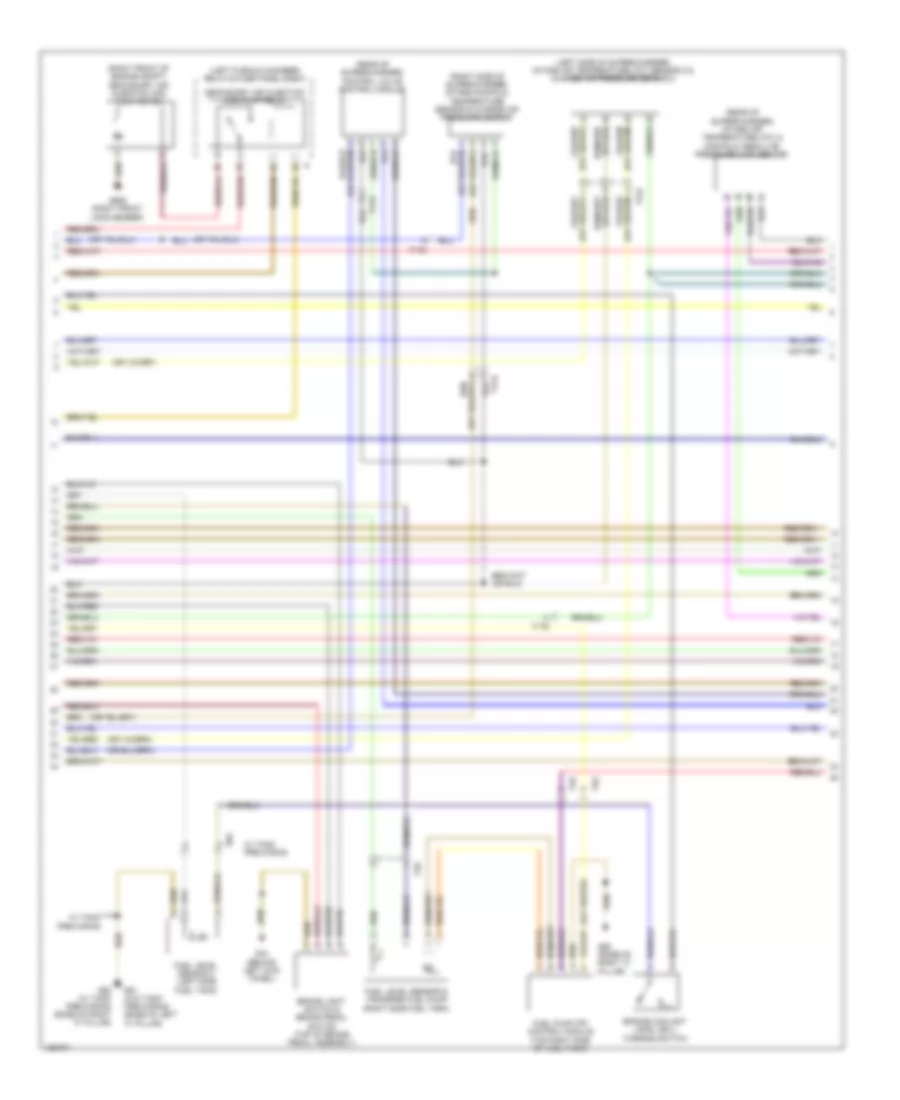
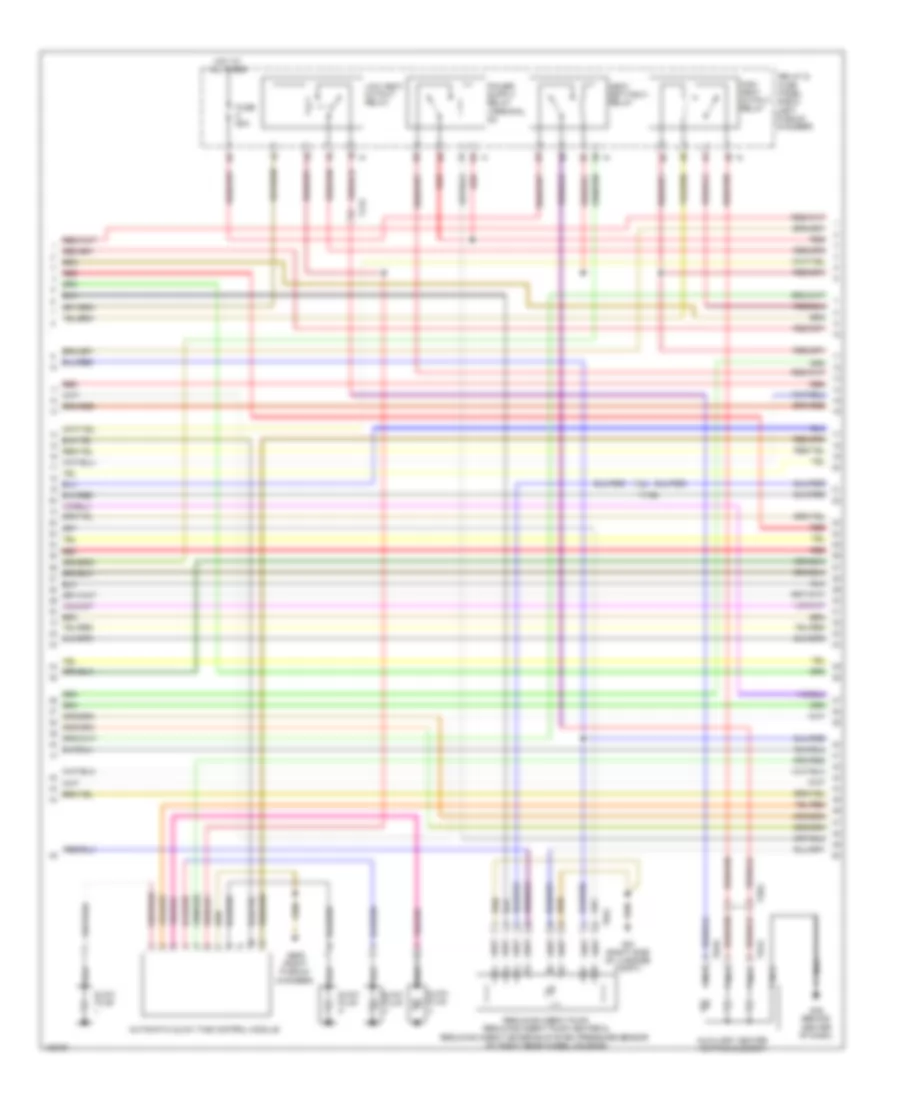
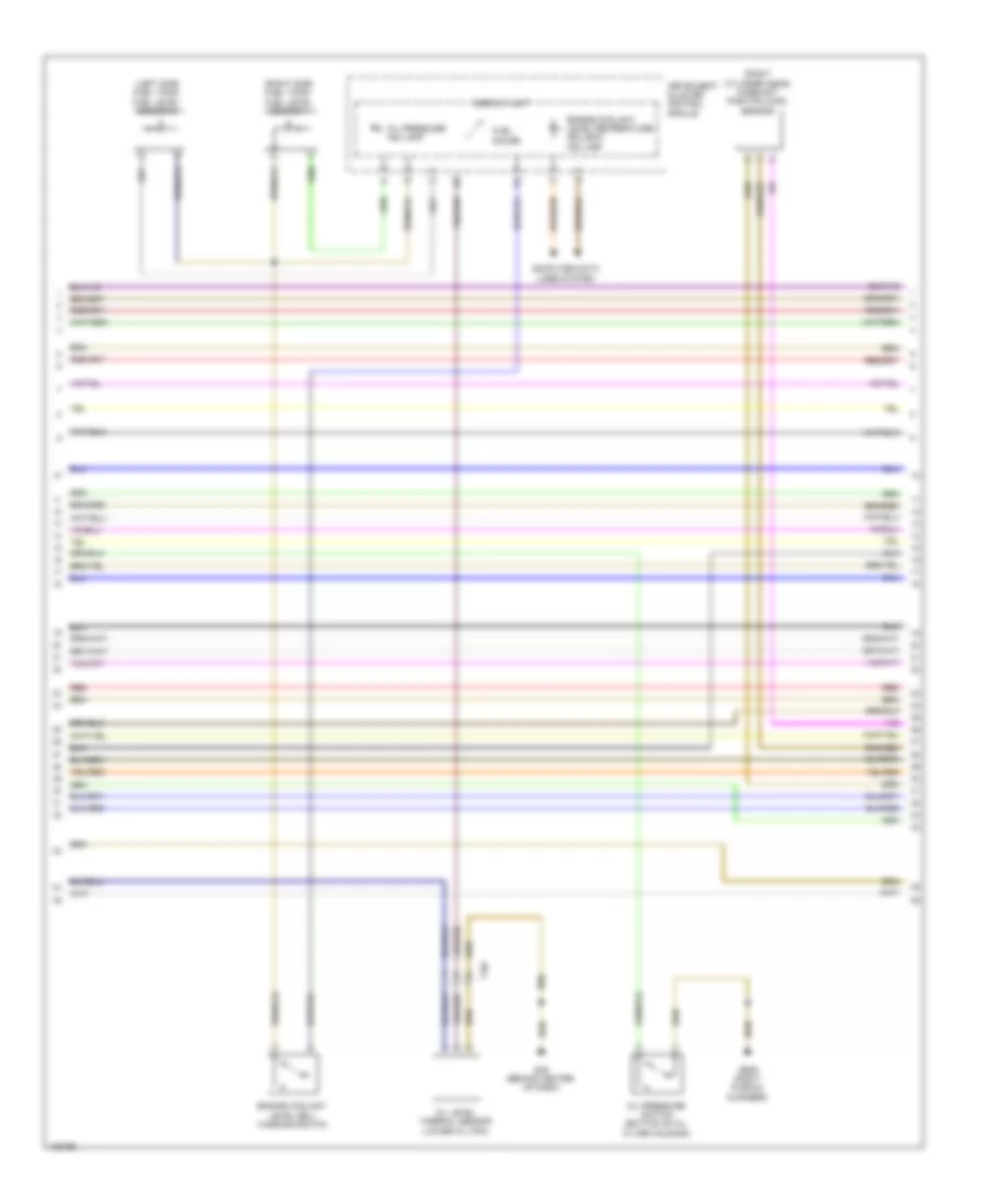
3.0L SC, Engine Performance Wiring Diagram (1 of 6) for Audi Q7 Prestige 2014
List of elements for 3.0L SC, Engine Performance Wiring Diagram (1 of 6) for Audi Q7 Prestige 2014:
- (backup switch: integral to multi-function transmission range switch multi-function transmission range switch: side of transmission) backup & multi-function transmission range switch
- (right exhaust, on catalytic converter)
- (right plenum chamber) g609
- 10a
- 13a
- 14a
- 15a
- 17a
- Accelerator pedal position (app) sensor 1 & 2 (top of accelerator pedal assembly)
- Anti-theft system
- Cooling fans system
- Engine control module (right plenum chamber)
- Fuse 10a
- Fuse 150a
- Fuse 15a
- Fuse 20a
- Fuse 5a
- Fuse panel d (under driver's seat)
- Heated oxygen sensor (ho2s) 2 & oxygen sensor (o2s) heater 2 (left exhaust pipe, before catalytic converter)
- Hot at all times
- Nca
- Oxygen sensor (02s) 2 after three way catalytic (twc) converter & heated oxygen sensor 2 after catalytic converter (left exhaust, on catalytic converter)
- Oxygen sensor (o2s) after three way catalytic (twc) converter & heated oxygen sensor 1 after catalytic converter
- Red
- Relay & fuse panel e-box (left plenum chamber)
- Starting/charging system
- T10c
- T10e
- T10m
- T14h
- T17d
- T6k
- T94
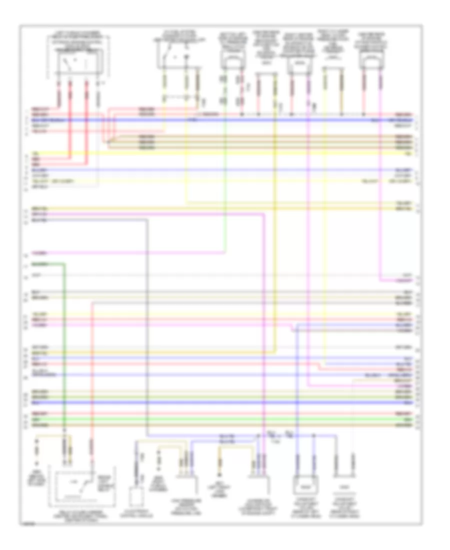
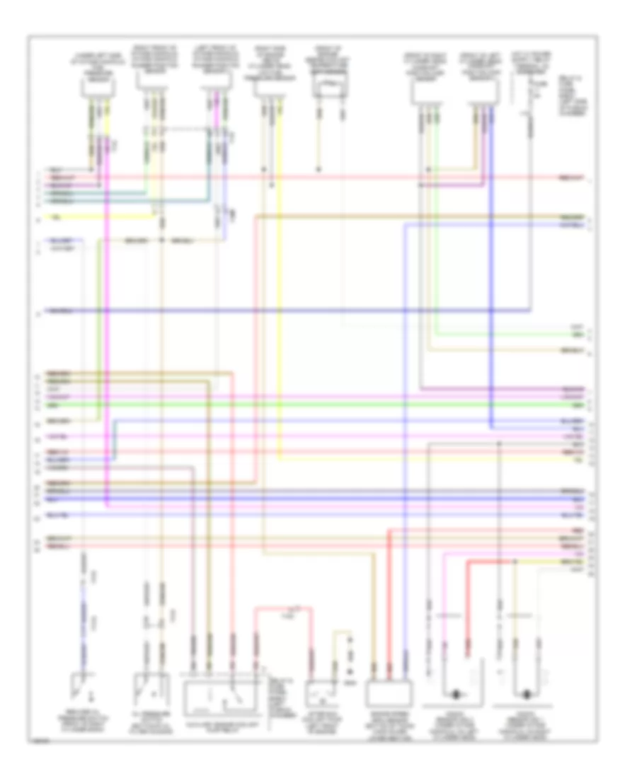
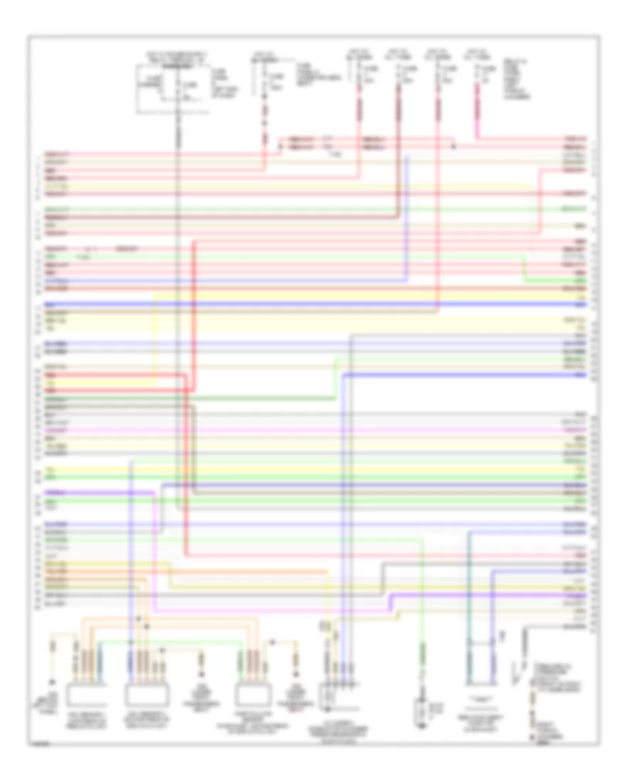
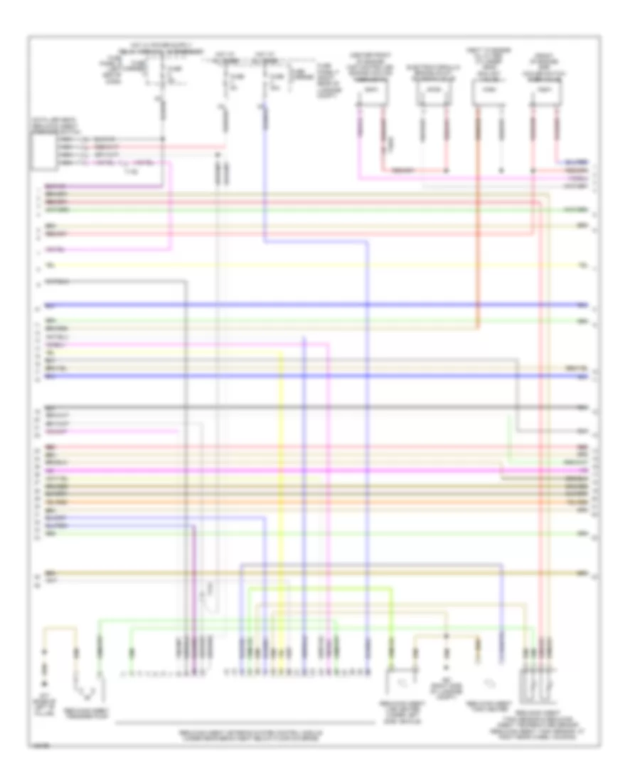
3.0L SC, Engine Performance Wiring Diagram (2 of 6) for Audi Q7 Prestige 2014
List of elements for 3.0L SC, Engine Performance Wiring Diagram (2 of 6) for Audi Q7 Prestige 2014:
- (bottom left side of engine) oil pressure regulation valve
- (center rear of engine) intake manifold runner control (imrc) valve
- (center rear of engine) secondary air injection (air) solenoid valve
- (left plenum chamber) relay & fuse panel e-box
- (rear of right cylinder head)
- (right center rear of engine) evaporative emission (evap) canister purge regulator valve 1
- (right cylinder head, in high pressure pump) fuel metering valve 1
- (w/ fuel system diagnostic pump) leak detection pump (ldp)
- Brake light disable relay
- Camshaft adjustment valve 1
- Camshaft adjustment valve 2 (rear of left cylinder head)
- Charge air cooling pump (lower right front of engine compt)
- Climatronic control module
- G609 (right plenum chamber)
- G664 (behind left side of dash)
- G671 (left front long member)
- High pressure sensor (on a/c high pressure line)
- Red
- Relay & fuse carrier (center instrument panel) (center of dash)
- T10d
- T10e
- T10m
- T14l
- T16d
- T17d
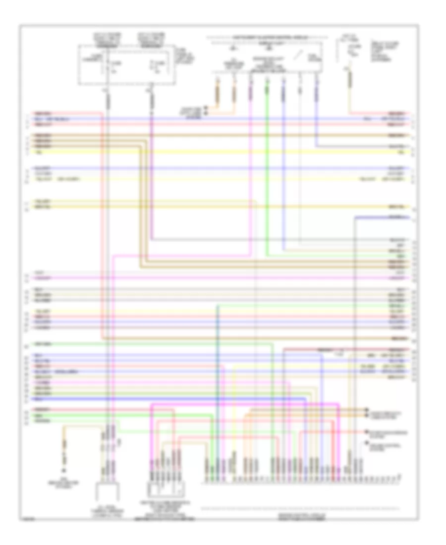
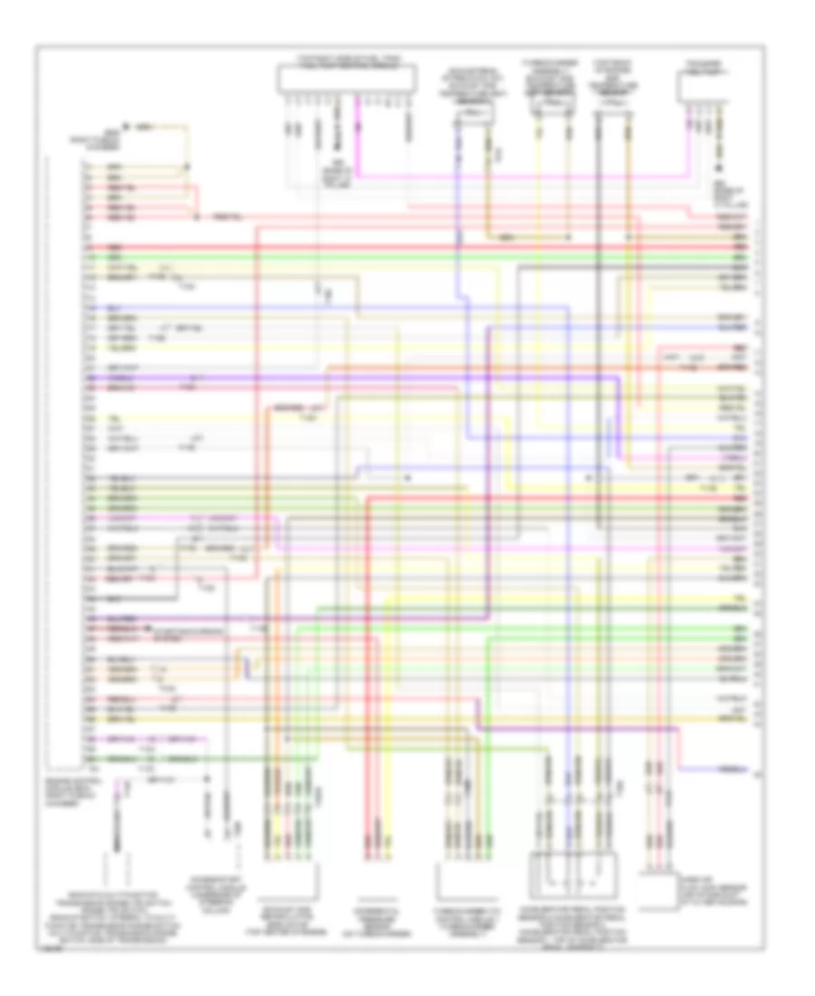
3.0L SC, Engine Performance Wiring Diagram (3 of 6) for Audi Q7 Prestige 2014
List of elements for 3.0L SC, Engine Performance Wiring Diagram (3 of 6) for Audi Q7 Prestige 2014:
- Computer data lines system
- Cruise control system
- Display unit
- Engine control module (right plenum chamber)
- Engine coolant level/ temperature (ecl/ect) ind lamp
- Fuel gauge
- Fuse 50a
- Fuse 5a
- Fuse carrier 3
- Fuse panel b (left end of dash)
- G45 (behind center of dash)
- Heated oxygen sensor & oxygen sensor (o2s) heater (right exhaust pipe, before catalytic converter)
- Hot at all times
- Instrument cluster control module
- Nca
- Oil level thermal sensor (lower oil pan)
- Oil pressure ind lamp
- Red
- Relay & fuse panel e-box (left plenum chamber)
- Starting/charging system
- T10c
- T10f
- T94
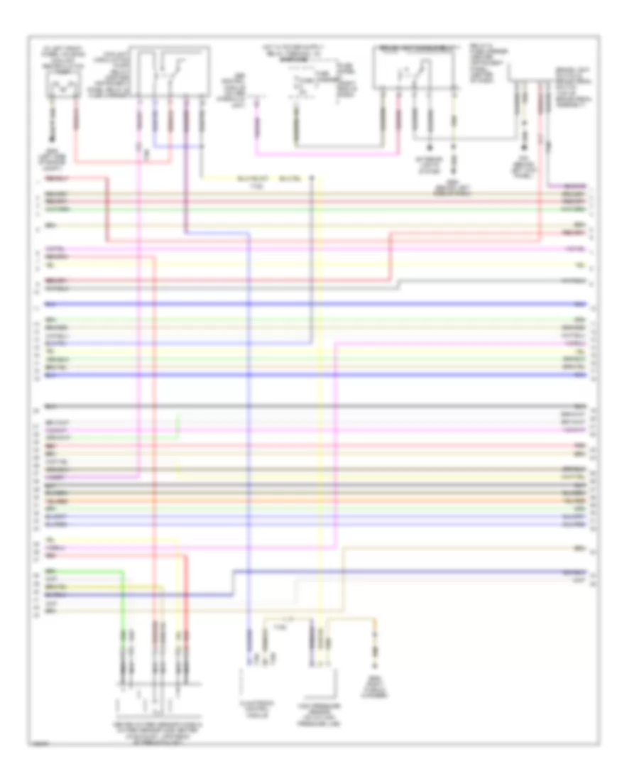
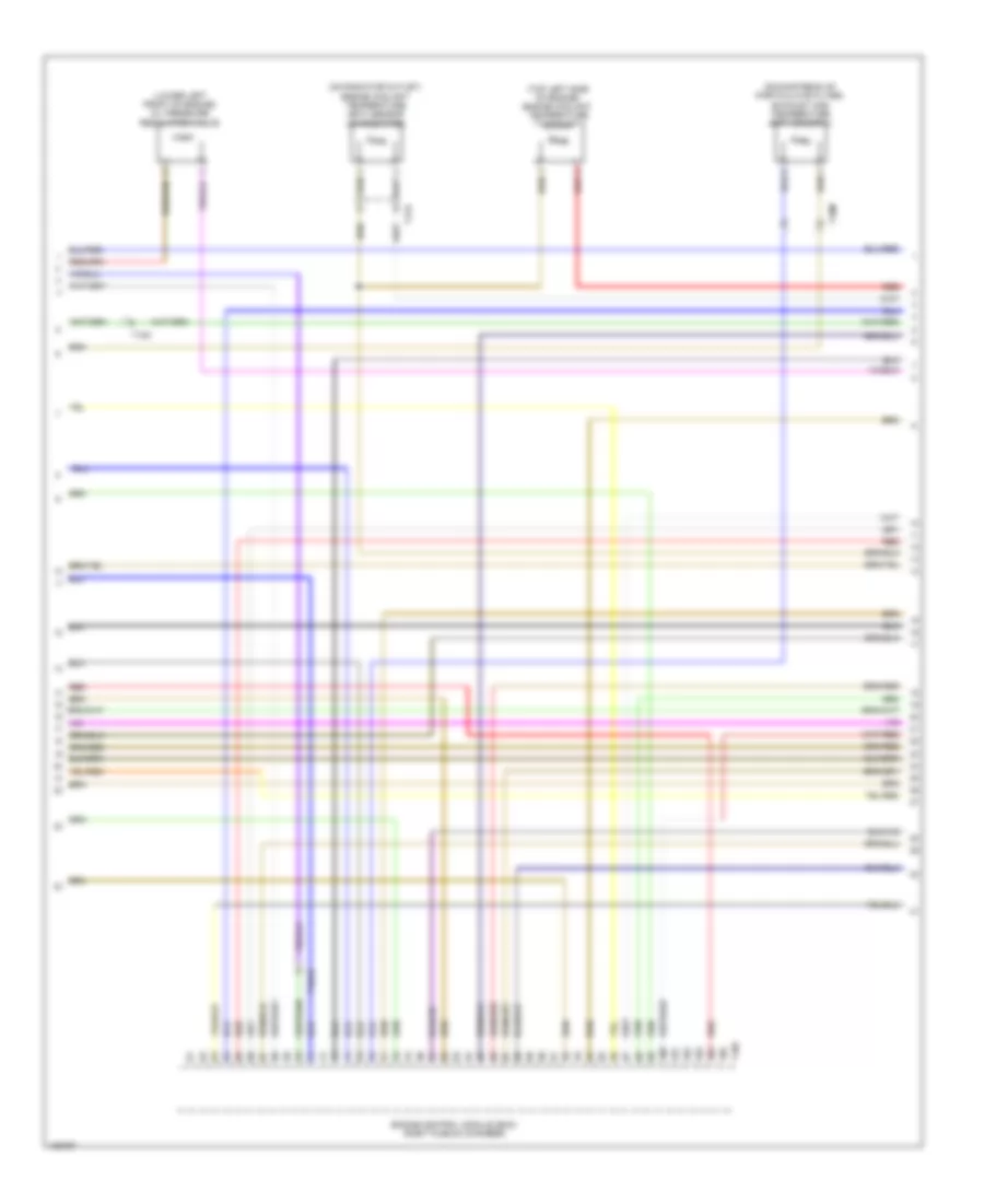
3.0L SC, Engine Performance Wiring Diagram (4 of 6) for Audi Q7 Prestige 2014
List of elements for 3.0L SC, Engine Performance Wiring Diagram (4 of 6) for Audi Q7 Prestige 2014:
- (left plenum chamber) relay & fuse panel e-box
- (left side of supercharger) intake air temperature (iat) sensor 2 & charge air pressure sensor 2
- (rear of supercharger) control valve control module
- (rear of supercharger) intake air temperature (iat) & manifold absolute pressure (map) sensor
- (right front of engine compt) secondary air injection (air) pump motor
- (right side of supercharger) intake manifold temperature sensor & charge air pressure sensor
- Brake light switch & brake pedal switch (top of brake pedal assembly)
- Engine coolant level (ecl) warning switch
- Fuel level sensor & transfer fuel pump (right side fuel tank)
- Fuel level sensor 2 (left side fuel tank)
- Fuel pump (fp) control module (top right side of fuel tank)
- G44 (behind left kick panel)
- G61 (w/o tank pre-wiring) (base of left "c" pillar)
- G62 (base of right "c" pillar)
- G62 (w/ tank pre-wiring) (base of right "c" pillar)
- G685 (right front long member)
- Secondary air injection (air) pump relay
- T17d
- T2k
- T5k
- W/ tank pre-wiring
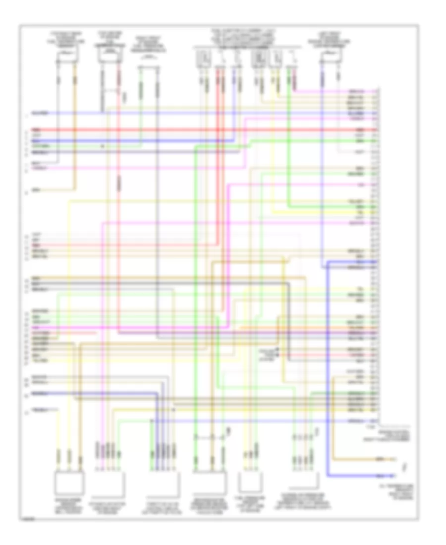
3.0L SC, Engine Performance Wiring Diagram (5 of 6) for Audi Q7 Prestige 2014
List of elements for 3.0L SC, Engine Performance Wiring Diagram (5 of 6) for Audi Q7 Prestige 2014:
- (front of engine) engine coolant temperature (ect) sensor
- (front of left cylinder head) camshaft position (cmp) sensor 2
- (front of right cylinder head) camshaft position (cmp) sensor
- (left front of intake manifold) intake manifold runner position sensor 2
- (right front of intake manifold) intake manifold runner position sensor
- (right side of engine above cylinder head) low fuel pressure sensor
- (under left side of intake manifold) fuel pressure sensor
- 19a
- 19c
- 19d
- 19e
- After run coolant pump (left front of engine)
- Auxiliary engine coolant pump relay
- Engine speed (rpm) sensor (bottom of timing chain guard lower section)
- Fuse 5a
- G645
- Knock sensor (ks) 1 (under intake manifold, on right cylinder head)
- Knock sensor (ks) 2 (under intake manifold, on left cylinder head)
- Oil pressure switch (bottom of oil filter housing)
- Red
- Reduced oil pressure switch (front of right cylinder bank)
- Relay & fuse panel e-box (left plenum chamber)
- Relay & fuse panel e-box (left side of plenum chamber)
- T10m
- T114l
- T14f
- T14l
- T17d
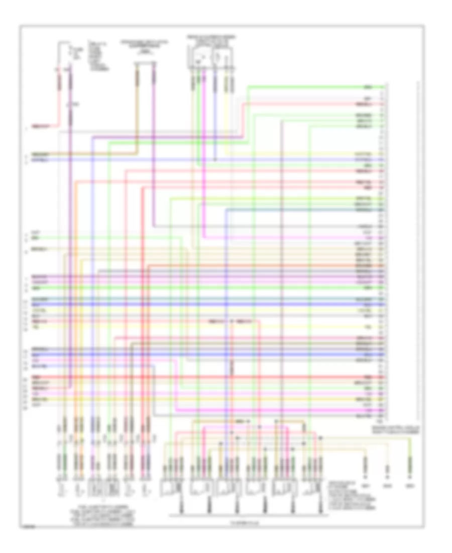
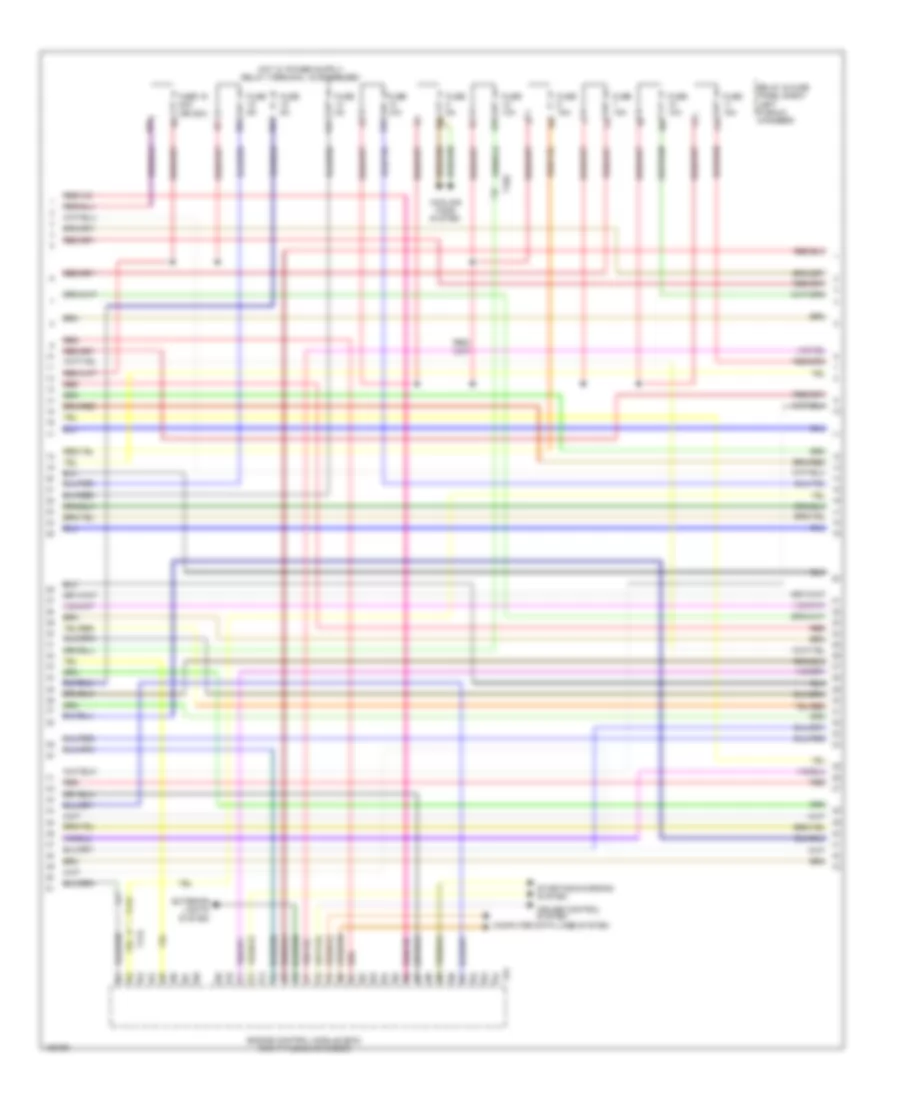
3.0L SC, Engine Performance Wiring Diagram (6 of 6) for Audi Q7 Prestige 2014
List of elements for 3.0L SC, Engine Performance Wiring Diagram (6 of 6) for Audi Q7 Prestige 2014:
- (rear of supercharger) throttle valve control module
- 16a
- Crankcase ventilation shut-off valve
- Engine control module (right plenum chamber)
- Fuel injector cylinders (fuel injector cylinders 1, 2 & 3: top of 1, 2 & 3 bank 1 cylinder) (fuel injector cylinders 4, 5 & 6: top of 4, 5 & 6 bank 2 cylinder)
- Fuse 20a
- G600
- G601
- G645
- Ignition coils w/ power output stage (top of ignition coils 1, 2 & 3: bank 1 cylinder) (top of ignition coils 4, 5 & 6: bank 2 cylinder)
- Nca
- Red
- Relay & fuse panel e-box (left plenum chamber)
- T14f
- T14l
- T60
- T6k
- To spark plug
3.0L TURBO DIESEL
3.0L Turbo Diesel, Engine Performance Wiring Diagram (1 of 9) for Audi Q7 Prestige 2014
List of elements for 3.0L Turbo Diesel, Engine Performance Wiring Diagram (1 of 9) for Audi Q7 Prestige 2014:
- (base of
- (downstream of pre-catalyst) exhaust gas temperature (egt) sensor 3
- (top front of engine) egr temperature sensor
- (top right side of fuel tank) fuel pump control module
- (turbocharger assembly) exhaust gas temperature (egt) sensor 1
- Accelerator pedal position sensor & accelerator pedal position sensor 2 (accelerator pedal position sensor 1: top of accelerator pedal assembly)
- Access/start control module (underside of steering column)
- Backup & multi-function transmission range (tr) switch range (tr) switch (backup switch: integral to multi- function transmission range switch multi-function transmission range switch: side of transmission)
- Differential pressure sensor (on turbocharger)
- Engine control module (ecm) (right plenum chamber)
- Exhaust gas recirculation (egr) motor (top center of engine)
- G609 (right plenum chamber)
- G62
- G62 (base of right "c" pillar)
- Mass air flow (maf) sensor (air intake duct at filter housing)
- Nca
- Red
- Right "c" pillar)
- Starting/charging system
- T10ab
- T10c
- T10d
- T10e
- T10m
- T10d
- T14h
- T17d
- T17e
- T20e
- T91
- Transfer fuel pump
- Turbocharger (tc) control module 1 (turbocharger assembly)
3.0L Turbo Diesel, Engine Performance Wiring Diagram (2 of 9) for Audi Q7 Prestige 2014
List of elements for 3.0L Turbo Diesel, Engine Performance Wiring Diagram (2 of 9) for Audi Q7 Prestige 2014:
- Automatic glow time control module
- Auxiliary heater heating element
- Fuse 60a
- G45 (behind center of dash)
- G51 (right side of luggage compt)
- G609 (right plenum chamber)
- Glow plug
- Heat setting 3 relay
- High heat output relay
- Hot at all times
- Low heat output relay
- Nca
- Red
- Reducing agent pump, reducing agent pump heater & reducing agent metering system pressure sensor (at right rear wheel housing)
- Relay & fuse panel e-box (left plenum chamber)
- T17e
- T2bg
- T2cq
- T6ar
- T8al
3.0L Turbo Diesel, Engine Performance Wiring Diagram (3 of 9) for Audi Q7 Prestige 2014
List of elements for 3.0L Turbo Diesel, Engine Performance Wiring Diagram (3 of 9) for Audi Q7 Prestige 2014:
- (right plenum chamber) g609
- 17a
- Cylinder 2 combustion chamber pressure sensor & glow plug 2
- Fuse 150a
- Fuse 40a
- Fuse 5a
- Fuse 60a
- Fuse 80a
- Fuse carrier
- Fuse panel b (left end of dash)
- Fuse panel d (under driver's seat)
- G35 (under front passenger's seat)
- G44 (behind left kick panel)
- Glow plug
- Hot at all times
- Nox sensor 1 (upstream of pre-catalyst)
- Nox sensor 2 (downstream of scr catalyst)
- Particulate sensor (in exhaust, downstream of scr catalyst)
- Red
- Reduced oil pressure switch (front of right cylinder bank)
- Reducing agent injector (in exhaust)
- Relay & fuse panel e-box (left plenum chamber)
- T10c
- T10m
- T6t
3.0L Turbo Diesel, Engine Performance Wiring Diagram (4 of 9) for Audi Q7 Prestige 2014
List of elements for 3.0L Turbo Diesel, Engine Performance Wiring Diagram (4 of 9) for Audi Q7 Prestige 2014:
- 10a
- 11a
- 12a
- 13a
- 14a
- 15a
- 16a
- 18a
- Computer data lines system
- Cooling fans system
- Cruise control system
- Engine control module (ecm) (right plenum chamber)
- Exterior lights system
- Fuse 10a
- Fuse 15a
- Fuse 16 20a (or 25a)
- Fuse 5a
- Red
- Relay & fuse panel e-box (left plenum chamber)
- Starting/charging system
- T10e
- T17d
- T17e
- T91
3.0L Turbo Diesel, Engine Performance Wiring Diagram (5 of 9) for Audi Q7 Prestige 2014
List of elements for 3.0L Turbo Diesel, Engine Performance Wiring Diagram (5 of 9) for Audi Q7 Prestige 2014:
- (in left front wheel housing) coolant recirculation pump
- Abs control module (on abs hydraulic unit)
- Brake light disable relay
- Brake light switch & brake pedal switch (top of brake pedal assembly)
- Climatronic control module
- Coolant circulation pump relay (center instrument panel relay & fuse carrier)
- Exterior lights system
- Fuse 5a
- Fuse carrier
- Fuse panel c (right end of dash)
- G44 (behind left kick panel)
- G609 (right plenum chamber)
- G640 (left side of engine compt)
- G664 (behind left side of dash)
- Heated oxygen sensor (ho2s) & oxygen sensor (o2s) heater (in exhaust, upstream of pre-catalyst)
- High pressure sensor (on a/c high pressure line)
- Nca
- Red
- Relay & fuse carrier (center instrument panel) (center of dash)
- T10c
- T10d
- T16c
- T16d
3.0L Turbo Diesel, Engine Performance Wiring Diagram (6 of 9) for Audi Q7 Prestige 2014
List of elements for 3.0L Turbo Diesel, Engine Performance Wiring Diagram (6 of 9) for Audi Q7 Prestige 2014:
- (left side fuel tank) fuel level sensor 2
- (right cylinder head) camshaft position (cmp) sensor
- (right side fuel tank) fuel level sensor 1
- Computer data lines system
- Display unit
- Engine coolant
- Engine coolant level/temperature (ecl/ect) ind lamp
- Fuel gauge
- G45 (behind center of dash)
- G609 (right plenum chamber)
- Instrument cluster control module
- Level (ecl) warning switch
- Oil level thermal sensor (lower oil pan)
- Oil pressure ind lamp
- Oil pressure switch (bottom of oil filter housing)
- Red
- T10f
3.0L Turbo Diesel, Engine Performance Wiring Diagram (7 of 9) for Audi Q7 Prestige 2014
List of elements for 3.0L Turbo Diesel, Engine Performance Wiring Diagram (7 of 9) for Audi Q7 Prestige 2014:
- (center front of engine) map controlled engine cooling thermostat
- (front of engine) egr cooler switch over valve
- (next to engine oil filter) cylinder head coolant valve
- (on filler neck) reducing agent tank cap switch
- (reducing agent tank sensor: at right rear wheel housing)
- Electrohydraulic engine mount solenoid valve
- Fuse 30a
- Fuse 5a
- Fuse carrier
- Fuse panel b (left end of dash)
- Fuse panel f (right rear of luggage compt)
- G51 (right side of luggage compt)
- G77 (base of left "b" pillar)
- Hot at all times
- Nca
- Red
- Reducing agent line heater (under left side vehicle)
- Reducing agent metering system control module (under rear bench seat below floor covering)
- Reducing agent tank heater
- Reducing agent tank sensor & reducing agent temperature sensor
- Reducing agent transfer pump
- T10ab
- T17e
3.0L Turbo Diesel, Engine Performance Wiring Diagram (8 of 9) for Audi Q7 Prestige 2014
List of elements for 3.0L Turbo Diesel, Engine Performance Wiring Diagram (8 of 9) for Audi Q7 Prestige 2014:
- (downstream of particulate filter) exhaust gas temperature (ect) sensor 4
- (lower left front of engine) oil pressure regulation valve
- (on radiator outlet) engine coolant temperature (ect) sensor (on radiator)
- (top left side of engine) engine coolant temperature sensor
- Engine control module (ecm) (right plenum chamber)
- Red
- T105
- T10ab
- T10m
- T17d
3.0L Turbo Diesel, Engine Performance Wiring Diagram (9 of 9) for Audi Q7 Prestige 2014
List of elements for 3.0L Turbo Diesel, Engine Performance Wiring Diagram (9 of 9) for Audi Q7 Prestige 2014:
- (fuel injector cylinders 1, 2 & 3: top of 1, 2 & 3 bank 1 cylinder) (fuel injector cylinders 4, 5 & 6: top of 4, 5 & 6 bank 2 cylinder) fuel injector cylinders
- (left front of engine) engine temperature control sensor
- (right front of engine) fuel pressure regulator valve
- (top center of engine) fuel metering valve
- (top right rear of engine) fuel temperature sensor
- Brake booster pressure sensor (on brake booster vacuum hose)
- Charge air pressure sensor & intake air temperature (iat) sensor (left front of engine compt)
- Cooling fans system
- Engine control module (ecm) (right plenum chamber)
- Engine speed sensor (transmission bell housing)
- Fuel pressure sensor (top left side of engine)
- Intake flap motor (center front of engine)
- Oil temperature sensor 2 (right front of engine)
- Red
- T105
- T10ab
- T10m
- T17d
- Throttle valve control module (on throttle valve)
EXTERIOR LIGHTS
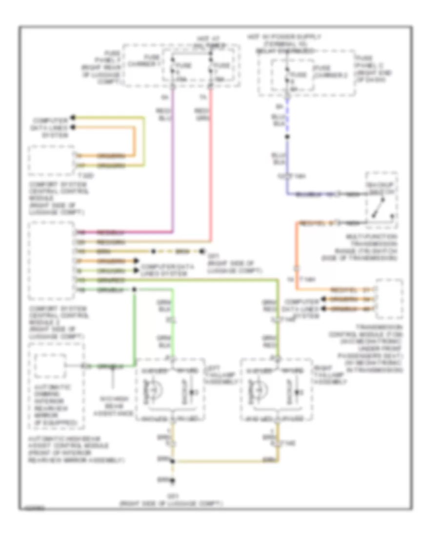
Backup Lamps Wiring Diagram for Audi Q7 Prestige 2014
List of elements for Backup Lamps Wiring Diagram for Audi Q7 Prestige 2014:
- Automatic dimming interior rearview mirror (if equipped)
- Automatic high beam assist control module (front of interior rearview mirror assembly)
- Backup
- Backup switch
- Comfort system central control module (right side of luggage compt)
- Comfort system central control module 2 (right side of luggage compt)
- Computer data lines system
- Fuse 15a
- Fuse 5a
- Fuse carrier 1
- Fuse carrier 2
- Fuse panel c (right end of dash)
- Fuse panel f (right rear of luggage compt)
- G51 (right side of luggage compt)
- Hot at all times
- Left taillamp assembly
- Multi-function transmission range (tr) switch (side of transmission)
- Nca
- Right taillamp assembly
- T14e
- T14h
- T32d
- Transmission control module (tcm) (w/o mechatronic: under front passenger's seat) (w/ mechatronic: in transmission)
- W/ led
- W/o high beam assistance
- W/o led
Exterior Lamps Wiring Diagram (1 of 4) for Audi Q7 Prestige 2014
List of elements for Exterior Lamps Wiring Diagram (1 of 4) for Audi Q7 Prestige 2014:
- 10a
- 11a
- 12a
- Backup
- Backup lamps circuit
- Comfort system central control module (right side of luggage compt)
- Comfort system central control module 2 (right side of luggage compt)
- Computer data
- Computer data lines system
- Front passenger's exterior mirror assembly
- Fuse 10a
- Fuse 15a
- Fuse 20a
- Fuse 30a
- Fuse 35a
- Fuse carrier
- Fuse panel b (left instrument panel)
- Fuse panel f (right side luggage compt)
- G51 (right side of luggage compt)
- G664 (behind left side of dash)
- G668 (left "d" pillar)
- Headlight flasher
- Hot at all times
- Lamp brake/tail
- Left taillamp assembly
- Left taillamp assembly 2
- Lines system
- Marker rear side
- Nca
- Rear fog
- Signal bulb rear turn
- Signal rear turn
- Steering column electronic systems control module (in steering column assembly)
- Switch
- T10g
- T10r
- T10s
- T14e
- T15a
- T16a
- T20a
- T2ac
- T32d
- T6e
- Tail/brake
- Turn signal
- Turn signal tail/brake/rear
- Turn signal/
- W/ led
- W/o led
Exterior Lamps Wiring Diagram (2 of 4) for Audi Q7 Prestige 2014
List of elements for Exterior Lamps Wiring Diagram (2 of 4) for Audi Q7 Prestige 2014:
- (left "d" pillar) g668
- 11a
- Backup
- Backup lamps circuit
- Computer data lines system
- Display unit
- Driver's door control module (driver's door)
- Driver's exterior mirror assembly
- Front passenger's door control module (front passenger's door)
- Fuse 35a
- Fuse 5a
- Fuse carrier
- Fuse panel c (right rear engine compt)
- G43 (behind right kick panel)
- G44 (behind left kick panel)
- G51 (right side of luggage compt)
- G668 (left "d" pillar)
- Hot in all times
- Instrument cluster control module
- Marker rear side
- Mirrors system
- Rear fog
- Rear turn signal
- Right taillamp assembly
- Right taillamp assembly 2
- T14e
- T16i
- T16k
- T208
- T20l
- T20m
- T2ac
- Tail/brake
- Turn signal
- Turn signal tail/brake/rear
- W/ led
- W/o led
Exterior Lamps Wiring Diagram (3 of 4) for Audi Q7 Prestige 2014
List of elements for Exterior Lamps Wiring Diagram (3 of 4) for Audi Q7 Prestige 2014:
- (behind left side of dash) g664
- (brake light switch: brake pedal assembly) brake light/ brake pedal switch
- Access/start authorization switch (center console, right side of steering wheel)
- Asr/esp button/ emergency flasher button
- Brake light disable relay
- Computer data lines system
- Fog lp ind
- Fog lp switch
- Fuse 25a
- Fuse 30a
- Fuse 5a
- Fuse carrier
- Fuse panel b (left instrument panel)
- G44 (behind left kick panel)
- G644
- G658 (top of left "d" pillar)
- G664 (behind left side of dash)
- G668 (left "d" pillar)
- Headlamp sw ill
- High- mounted brake light
- Hot at all times
- Interior lights system
- Left front side marker/ turn signal lamp (w/o bi-xenon headlamps)
- Left front turn signal lamp
- License plate light
- Light switch
- Parking light ind
- Rear fog lp switch
- Red
- Relay & fuse carrier (center instrument panel)
- Right front side marker/ turn signal lamp (w/o bi-xenon headlamps)
- Right front turn signal lamp
- Rr fog lp ind
- Suppressor
- T10a
- T10o
- T10r
- T12b
- T12d
- T2s
- T2t
- T2u
- T2v
- T32b
- T6e
- T8a
- Towing recognition control module (right side of luggage compt)
- Vehicle electrical system control module
- W/ bi-xenon headlamps
- W/ cornering headlights
- W/ drl
- W/o bi-xenon headlamps
Exterior Lamps Wiring Diagram (4 of 4) for Audi Q7 Prestige 2014
List of elements for Exterior Lamps Wiring Diagram (4 of 4) for Audi Q7 Prestige 2014:
- 3.0l sc
- 3.0l turbo diesel
- Abs control module (right plenum chamber)
- Day time running lamp & parking light control module
- Daytime running lamp & parking light control module
- Engine control module (right rear of engine compt)
- Front side marker lamp
- G640 (left side of engine compt)
- G644
- Headlamp assembly
- Led parking lamp/ drl module
- Led parking lamp/drl module
- Left headlamp assembly
- Right headlamp assembly
- Right left headlamp assembly
- T10c
- T91
- T94
- W/ bi-xenon & w/ cornering headlights
- W/ bi-xenon & w/o cornering headlights
Trailer Tow Wiring Diagram for Audi Q7 Prestige 2014
List of elements for Trailer Tow Wiring Diagram for Audi Q7 Prestige 2014:
- 10a
- 11a
- Abs control module (abs hydrolic unit) (right plenum chamber)
- Brake booster
- Brake light disable relay (esp)
- Comfort system central control module (right side of luggage compt)
- Computer data lines system
- Exterior lamps circuit
- Fuse 15a
- Fuse 20a
- Fuse 30a
- Fuse 5a
- Fuse carrier 3
- Fuse panel b (left end of dash)
- Fuse panel f (right rear of luggage compt)
- G44 (behind left kick panel)
- G51 (right side of luggage compt)
- G664 (behind left side of dash)
- G675 (right side of luggage compt)
- Hot at all times
- Multimedia control module
- Red
- Relay & fuse carrier (center instrument panel) (center of dash)
- T12d
- T16e
- T26e
- T2ay
- T2be
- T32d
- T47a
- T4ai
- Towing recognition control module (right side of luggage compt)
- Trailer socket
- W/ rear seat entertainment
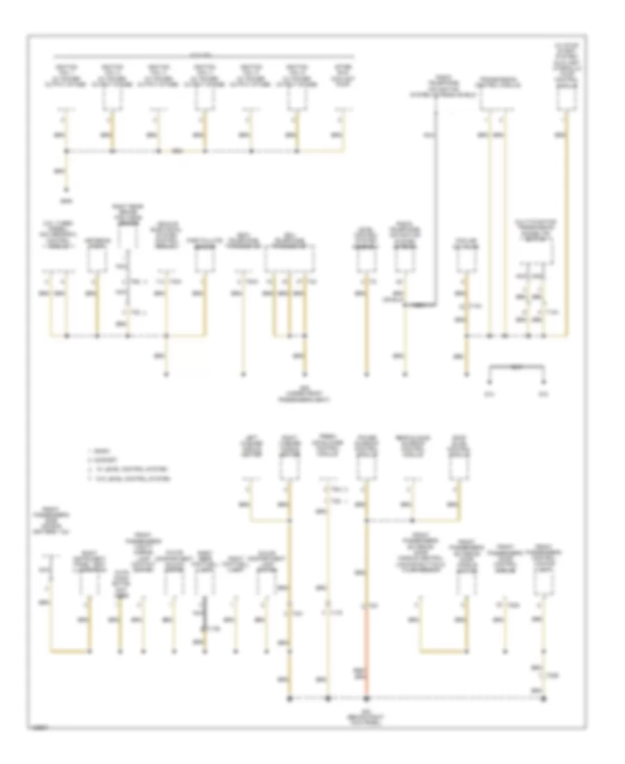
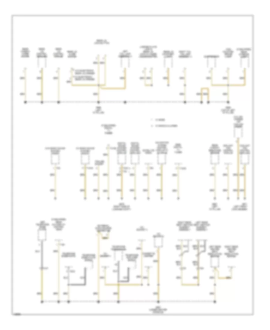
GROUND DISTRIBUTION
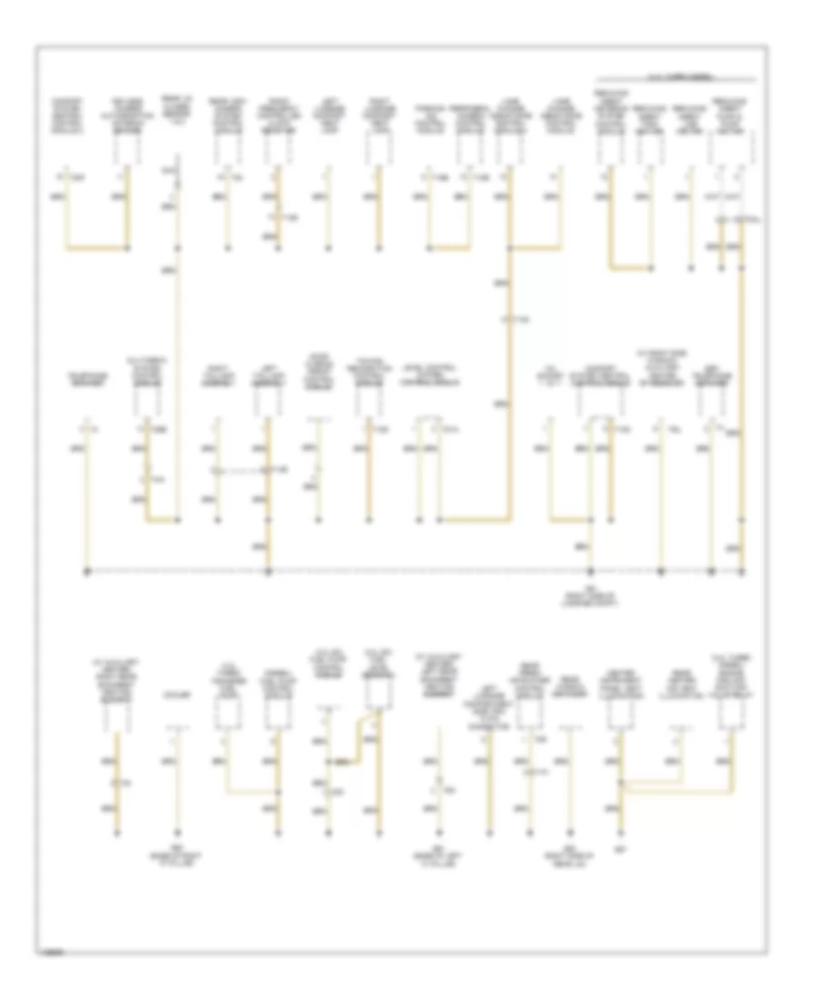
Ground Distribution Wiring Diagram (1 of 7) for Audi Q7 Prestige 2014
List of elements for Ground Distribution Wiring Diagram (1 of 7) for Audi Q7 Prestige 2014:
- (3.0l sc)
- (3.0l turbo diesel) nox sensor 2 control module
- (9zj) telephone transceiver
- (9zw) telephone transceiver
- (w/ stop/ start) system) auxiliary hydraulic pump control module
- 18 pin conn- ector (not used)
- After run- coolant pump
- Basic
- Comfort
- Cooling oil valve
- Fresh air blower control module
- Front passenger's control locking unit
- Front passenger's door control module
- Front passenger's exterior door handle central locking button & touch sensor
- Front passenger's exterior door handle switch
- Front passenger's side air bag igniters 1 & 2
- Front passenger's vanity mirror lamp contact switch
- G13
- G18
- G35 (under front passenger's seat)
- G43 (behind right kick panel)
- G645
- Glove compartment lamp switch
- Glove compartment unlock motor
- Ignition coil 1 (w/ power output stage)
- Ignition coil 2 (w/ power output stage)
- Ignition coil 3 (w/ power output stage)
- Ignition coil 4 (w/ power output stage)
- Ignition coil 5 (w/ power output stage)
- Ignition coil 6 (w/ power output stage)
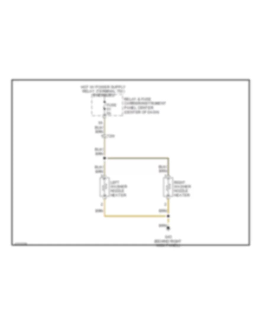
- Left washer nozzle heater
- Level control system assembly
- Metering pump
- Multi-function transmission range (tr) switch
- Nca
- Particulate sensor
- Power sunroof control module
- Radio telephone, navigation system antenna shield
- Radio, telephone, navigation system antenna
- Rear sliding sunroof control module
- Right footwell lamp
- Right instrument panel vent illumination
- Right rear brake pad wear sensor
- Right rear footwell lamp
- Right washer nozzle heater
- Roof blind control module
- T14h
- T17b
- T17k
- T20b
- T20m
- T2i
- T2q
- T2w
- T40a
- T42
- T4q
- T54a
- T6ai
- T6q
- T6y
- Transmission control module
- Vehicle electrical system control module 2
- W/ level control system
- W/o level control system
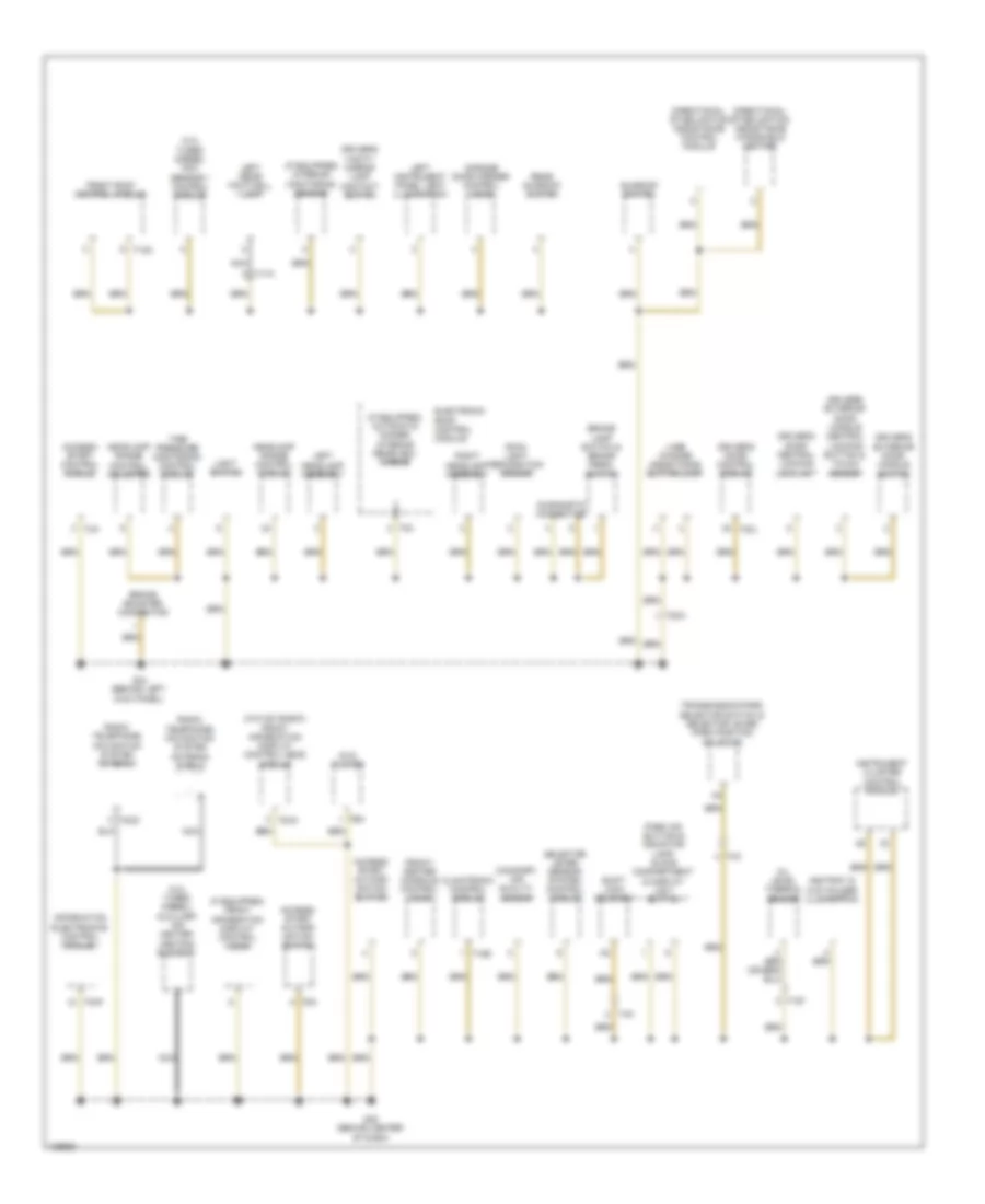
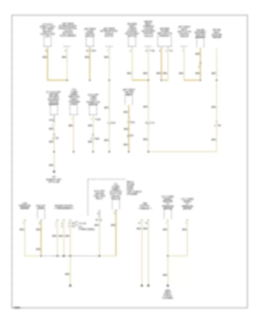
Ground Distribution Wiring Diagram (2 of 7) for Audi Q7 Prestige 2014
List of elements for Ground Distribution Wiring Diagram (2 of 7) for Audi Q7 Prestige 2014:
- (3.0l turbo diesel) auxiliary air heater heating element
- (3.0l turbo diesel) nox sensor 1 control module
- (comfort) air quality sensor
- (if equipped) automatic dimmer interior rearview mirror
- (if equipped) front information display control head
- (if equipped) interior monitoring sensor
- (w/o mmi basic) front information display control head module
- Access/ start author- ization button
- Access/ start author- ization switch
- Access/ start control module
- Ashtray & cup holder illumination
- Brake booster connector
- Brake lamp switch & brake pedal switch
- Climatronic control module
- Diagnostic connector
- Directional stabilization assistance control module
- Directional stabilization assistance windshield heater
- Driver's door central locking lock unit
- Driver's door control module
- Driver's exterior door handle central locking button & touch sensor
- Driver's exterior door handle switch
- Driver's vanity mirror lamp contact switch
- Dvd player
- Electronic roof control module
- Front roof control module
- Front/ center console control head
- G44 (behind left kick panel)
- G45 (behind center of dash)
- Garage door opener control head
- Headlamp range control adjuster
- Headlamp range control module
- Information electronics control module 1
- Instrument cluster control module
- Lane change assistance button/lamp
- Left headlamp assembly
- Left instrument panel vent illumination
- Left rear footwell lamp
- Light switch
- Nca
- Oil level thermal sensor
- Park aid button & indicator lamp, glove compartment & display unit button
- Radio, telephone, navigation system antenna
- Radio, telephone, navigation system antenna shield
- Rain/ light recognition sensor
- Rear sunroof switch
- Right headlamp assembly
- Selector lever sensor system control module
- Shift lock solenoid
- Sunroof switch
- T10f
- T12a
- T16d
- T17a
- T20a
- T20k
- T20l
- T2cd
- T3a
- T4c
- T6a
- T8af
- T8x
- Tbh
- Tire pressure monitoring control module
- Transmission park selector switch & selector lever park position solenoid
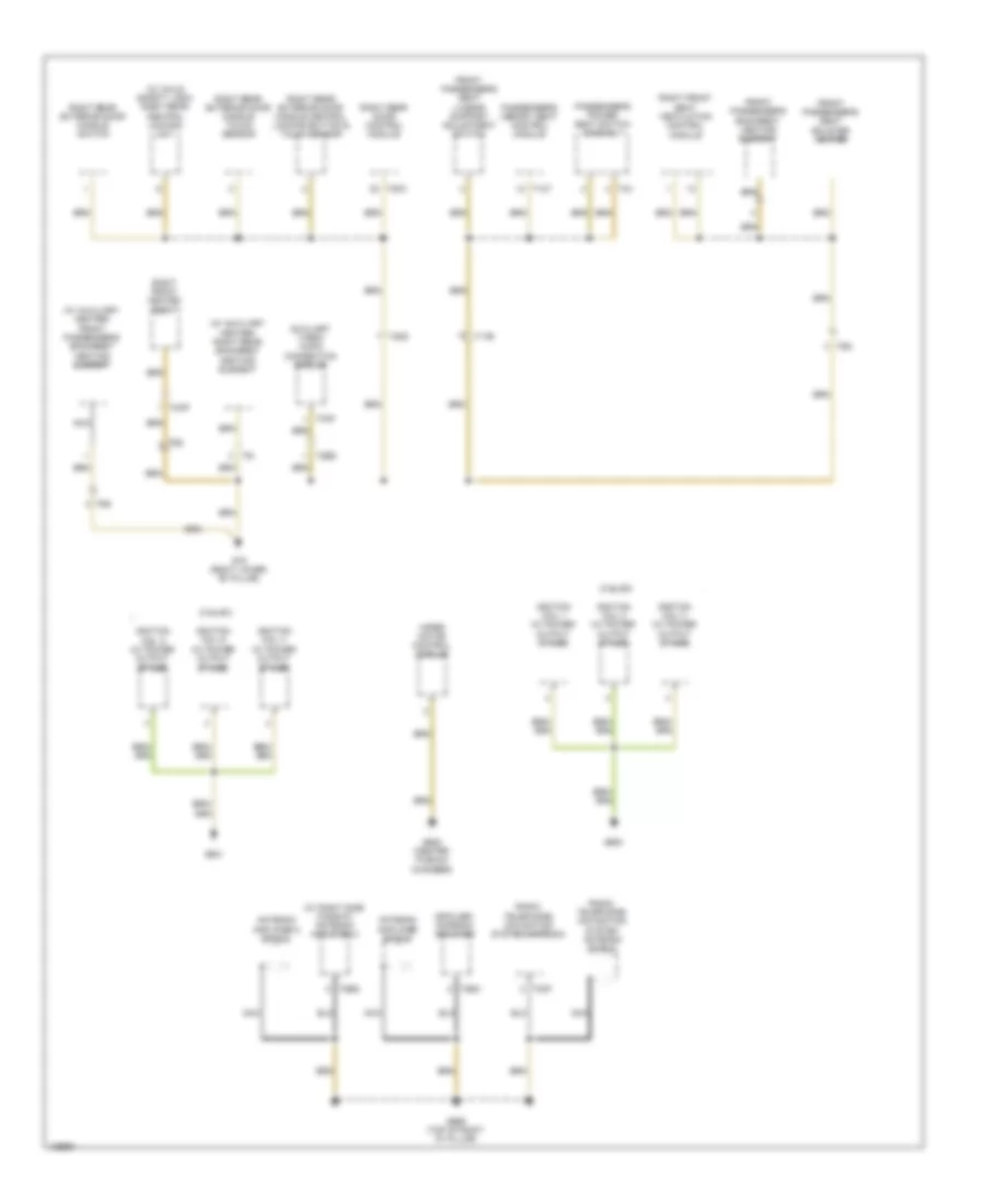
Ground Distribution Wiring Diagram (3 of 7) for Audi Q7 Prestige 2014
List of elements for Ground Distribution Wiring Diagram (3 of 7) for Audi Q7 Prestige 2014:
- (3.0l sc) fuel level sensor 2
- (3.0l sc) fuel pump control module
- (3.0l turbo diesel)
- (3.0l turbo diesel) engine coolant shut-off valve relay
- (3.0l turbo) transfer fuel pump
- (9zf) telephone amplifier
- (diesel) fuel pump control module
- (w/ auxiliary heater) left rear backrest heating element
- (w/ auxiliary heater) right rear backrest heating element
- (w/ right side window) auxiliary heater rf receiver
- 12v socket
- Center instrument panel vent illumination
- Comfort system central control module
- Comfort system central control module 2
- Cooler
- Door closing assist control module
- G51 (right side of luggage compt)
- G53 (right side of rear lid)
- G61 (base of left "c" pillar)
- G62 (base of right "c" pillar)
- G67
- Keyless access authorization antenna reader
- Lane change assistance control module
- Lane change assistance control module 2
- Left luggage compart- ment lamp
- Left luggage compartment side trim 12 pin connector
- Left taillamp assembly
- Level control system control module
- Multimedia system control module
- Nca
- Parking aid control module
- Peripheral camera control module
- Radio frequency controlled clock receiver
- Rear center air vent illumination
- Rear fresh air blower control module
- Rear lid closed sensor 1 & 2
- Rear view camera system control module
- Rear window defogger
- Reducing agent line heater
- Reducing agent metering system control module
- Reducing agent pump & pump heater
- Reducing agent tank heater
- Right luggage compart- ment lamp
- Right taillamp assembly
- T10g
- T12d
- T14d
- T14e
- T16b
- T17h
- T18e
- T20f
- T26e
- T2k
- T2r
- T4ai
- T54
- T6h
- T6i
- T6u
- T81a
- T8al
- Telephone amplifier
- Towing recognition control module
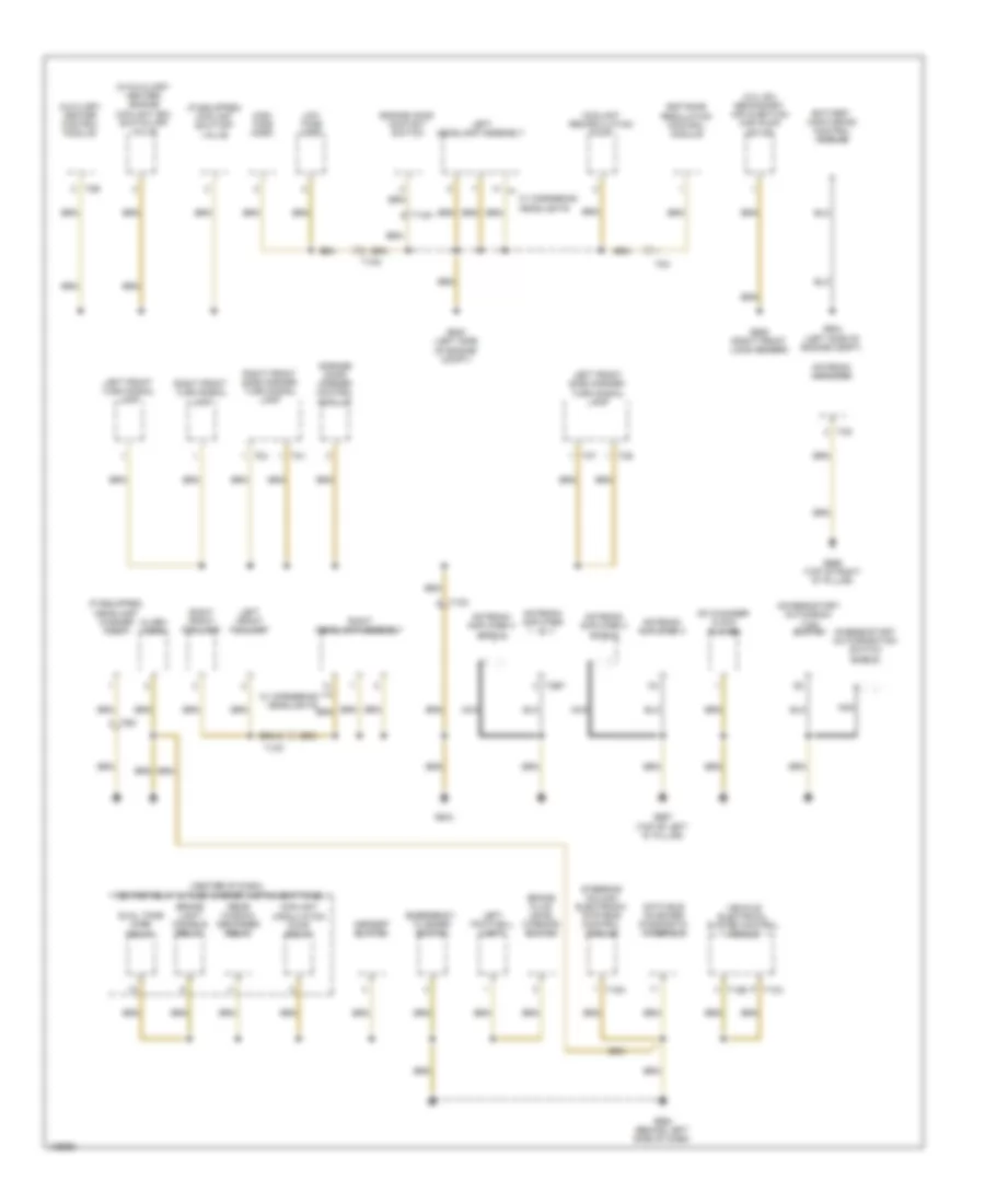
Ground Distribution Wiring Diagram (4 of 7) for Audi Q7 Prestige 2014
List of elements for Ground Distribution Wiring Diagram (4 of 7) for Audi Q7 Prestige 2014:
- (3.0l turbo diesel) oil pressure switch
- (3.0l turbo diesel) reduced oil pressure switch
- (3.0l turbo diesel) reducing agent transfer pump
- (w/ auxiliary heater) driver's backrest heating element
- (w/ child safety lock) left rear central locking lock unit
- 3.0l (turbo diesel)
- 3.0l (turbo diesel) automatic glow time control module
- 3.0l sc
- 5a b
- Abs control module
- Auxiliary
- Auxiliary video/ audio connection module
- Coolant pump
- Driver backrest heating element
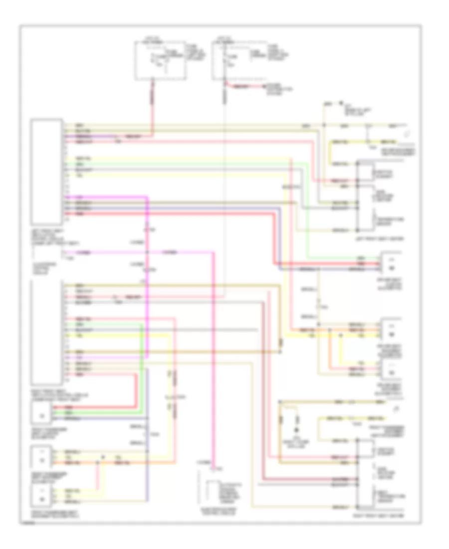
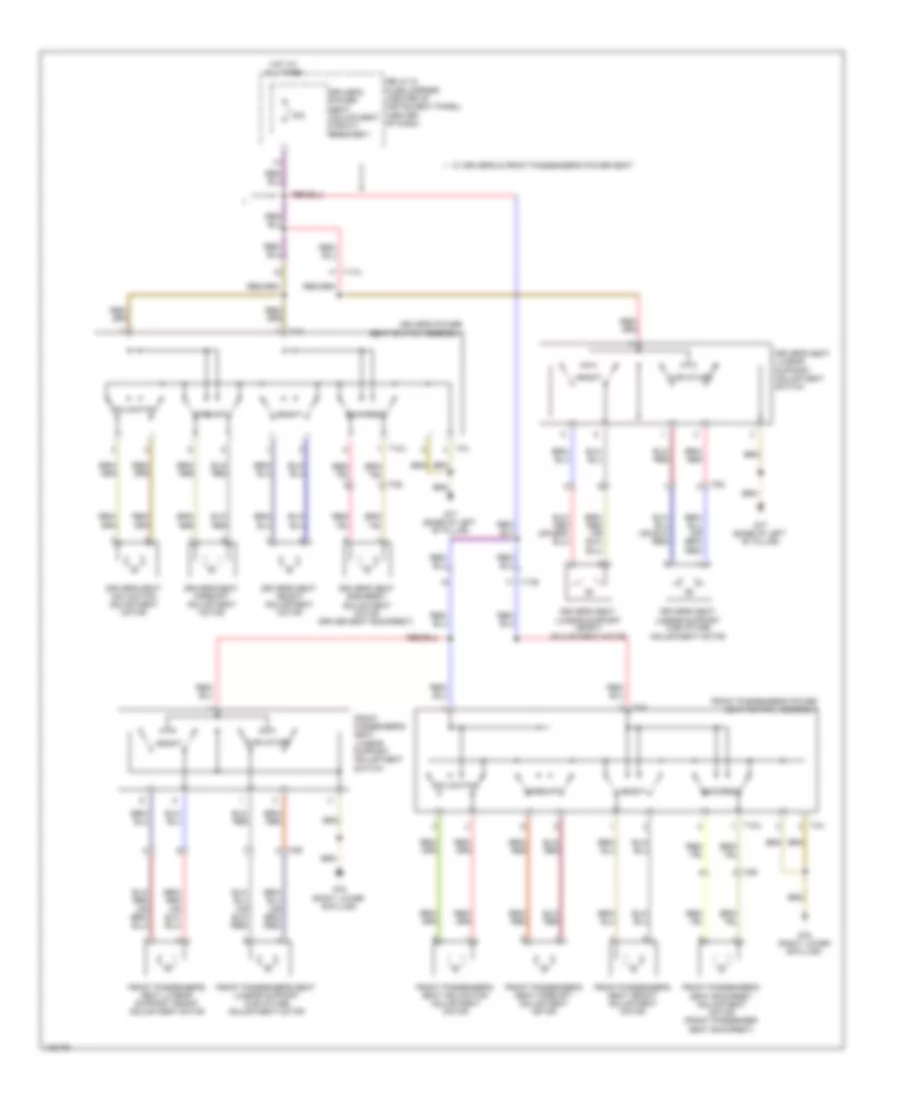
- Driver seat bolster heater
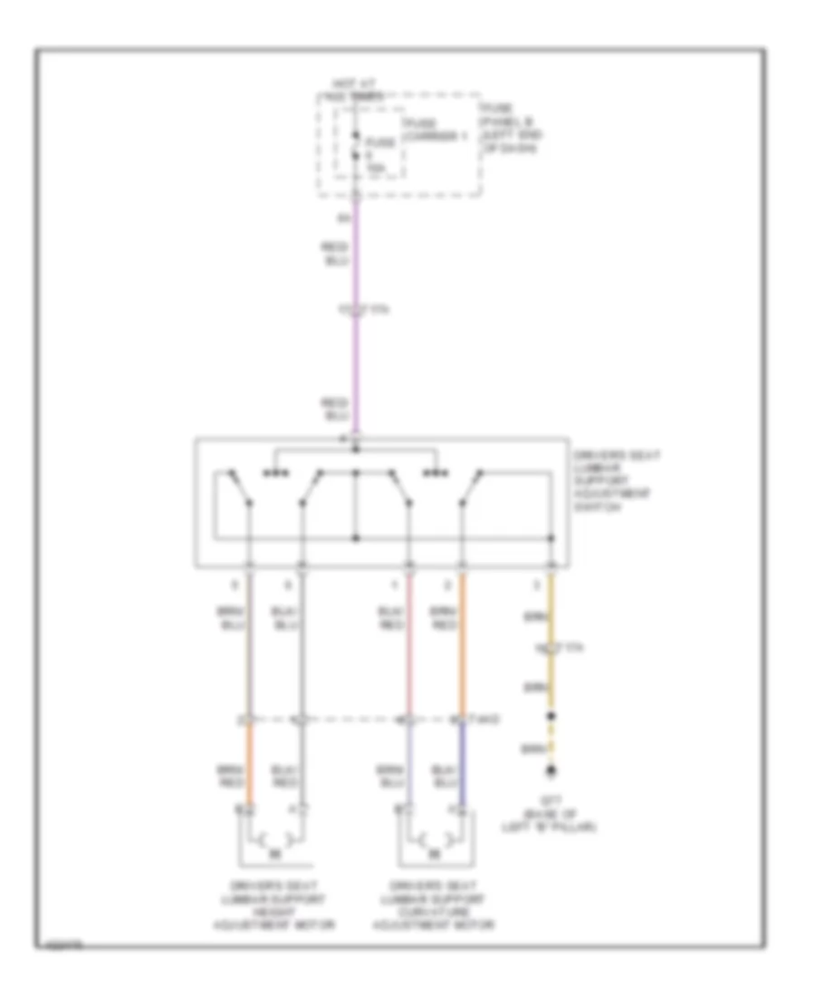
- Driver's power seat switch assembly
- Driver's seat lumbar support adjustment switch
- Engine control module (ecm)
- G609 (right plenum chamber)
- G77 (base of left "b" pillar)
- Heater fuel pump relay
- High pressure sensor
- Left front heated seat
- Left front seat ventilation control module
- Left rear door control module
- Left rear exterior door handle central locking button & touch sensor
- Left rear exterior door handle switch
- Memory seat/ steering column adjustment control module
- Nca
- Relay & fuse panel e-box (left plenum chamber)
- T12s
- T17a
- T20c
- T20n
- T2ao
- T2bc
- T3ae
- T4x
- T6f
- T91
- T94
Ground Distribution Wiring Diagram (5 of 7) for Audi Q7 Prestige 2014
List of elements for Ground Distribution Wiring Diagram (5 of 7) for Audi Q7 Prestige 2014:
- (3.0l sc)
- (spoiler) antenna amplifier
- (w/ auxiliary heater) front passenger's backrest heating element
- (w/ auxiliary heater) right rear backrest heating element
- (w/ child safety lock) right rear central locking unit
- (w/ right side window) antenna amplifier 2
- Antenna amplifier 2 shield
- Antenna amplifier shield
- Auxiliary video/ audio connection module
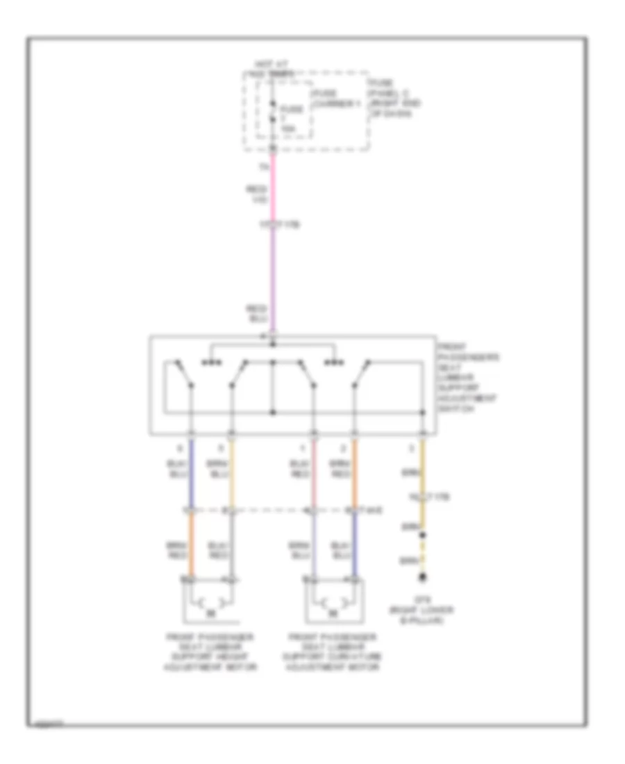
- Front passenger's backrest heating element
- Front passenger's seat bolster heater
- Front passenger's seat lumbar support adjustment switch
- G600
- G601
- G608 (center plenum chamber)
- G669 (top of right "d" pillar)
- G78 (right lower "b" pillar)
- Ignition coil 1 (w/ power output stage)
- Ignition coil 2 (w/ power output stage)
- Ignition coil 3 (w/ power output stage)
- Ignition coil 4 (w/ power output stage)
- Ignition coil 5 (w/ power output stage)
- Ignition coil 6 (w/ power output stage)
- Nca
- Passenger's memory seat control module
- Passenger's power seat switch assembly
- Radio, telephone, navigation system antenna
- Radio, telephone, navigation system antenna shield
- Right front heated seat
- Right front seat ventilation control module
- Right rear door control module
- Right rear exterior door handle central locking button & touch sensor
- Right rear exterior door handle switch
- Right rear exterior door handle touch sensor
- T12t
- T17b
- T20d
- T20o
- T2ap
- T2bd
- T2bq
- T2bx
- T2cf
- T3af
- T4x
- T6g
- T6i
- Wiper motor control module
Ground Distribution Wiring Diagram (6 of 7) for Audi Q7 Prestige 2014
List of elements for Ground Distribution Wiring Diagram (6 of 7) for Audi Q7 Prestige 2014:
- (3.0l sc) secondary air injection (air) pump motor
- (center of dash)
- (if equipped) coolant shut-off valve
- (if equipped) headlamp washer pump
- (w/auxiliory heater) engine coolant (ec) switch off valve
- Access/start authoriza- tion switch
- Access/start authorization switch shield
- Alarm horn
- Antenna amplifier
- Antenna amplifier 3 shield
- Antenna amplifier 4
- Antenna amplifier 4 shield
- Asr/esp button
- Auxiliary heater control module
- Battery monitoring control module
- Brake fluid level warning switch
- Brake light disable relay
- Cd changer & dvd player
- Center relay & fuse carrier instrument panel
- Coolant circulation pump relay
- Coolant recirculation pump
- Data bus on board diagnostic interface
- Distance regulation control module
- Dual tone horn relay
- Emergency flasher switch
- Engine hood contact switch
- G624 (left side of engine compt)
- G640 (left side of engine compt)
- G644
- G664 (behind left side of dash)
- G666 (top of right "d" pillar)
- G667 (top of left "d" pillar)
- G685 (right front long member)
- Garage door opener control module
- High tone horn
- Left footwell light
- Left front fog lamp
- Left front side marker/ turn signal lamp
- Left front turn signal lamp
- Left headlamp assembly
- Low tone horn
- Nca
- Rear window defogger relay
- Right front fog lamp
- Right front side marker/ turn signal lamp
- Right front turn signal lamp
- Right headlamp assembly
- Steering column electronic systems control module
- T10a
- T10n
- T10o
- T12b
- T16a
- T2b
- T2by
- T2s
- T2t
- T2u
- T2v
- T3q
- T6d
- T8c
- Vehicle electrical system control module
- W/ cornering headlights
Ground Distribution Wiring Diagram (7 of 7) for Audi Q7 Prestige 2014
List of elements for Ground Distribution Wiring Diagram (7 of 7) for Audi Q7 Prestige 2014:
- (3.0l sc) charge air cooling pump
- (9zf) telephone base plate
- (if equipped) digital tv tuner
- (if equipped) rear a/c display control head
- (if equipped) rear interior lamp
- (rse) digital tv tuner
- (w/ basic sound system) radio
- (w/o basic sound system) radio
- 12v socket 2
- 12v socket 3
- 12v socket 4
- Cigarette lighter
- Coolant fan control module
- Coolant fan control module 2
- Digital sound system control module
- Digital sound system control module 2
- External audio source connector
- G657 (left "d" pillar)
- G658 (top of left "d" pillar)
- G668 (left "d" pillar)
- G671 (left front long member)
- G675 (right side of luggage compt)
- G687 (under center console)
- High mounted brake lamp
- Left rear heated seat regulating switch
- Left rear seat heating element assembly
- Left tail lamp assembly 2
- License plate lamp & rear lid lock cylinder unlock button
- Navigation system control module w/ cd drive
- Nca
- Rear lid alarm switch
- Rear lid control module
- Rear lid control module 2
- Rear lid courtesy lamp
- Rear lid lock button
- Rear window breakage sensor
- Rear window wiper motor
- Right rear heated seat regulating switch
- Right rear seat heating element assembly
- Right tail taillamp assembly 2
- Satellite radio
- Suppressor
- T10aa
- T12ag
- T16h
- T2cc
- T32c
- T38
- T4at
- T6h
- T6i
- T8k
- T8n
- Telephone amplifier shield
- Telephone base plate
- Telephone base plate shield
- Telephone transceiver
- Trailer socket
- W/ bang & olufsen
- W/ bose
- W/ electronic rear lid opener
- W/o electronic rear lid opener
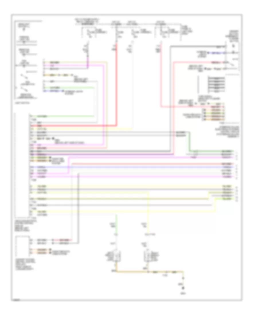
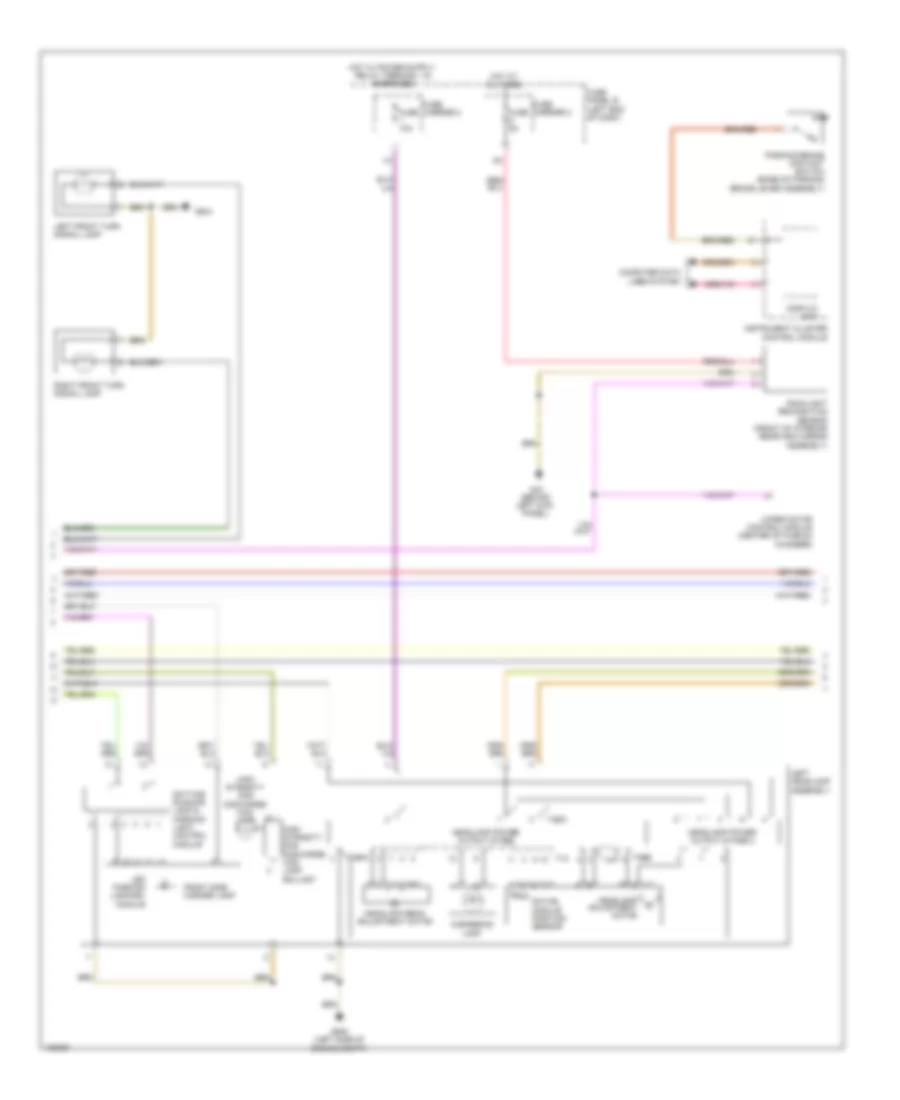
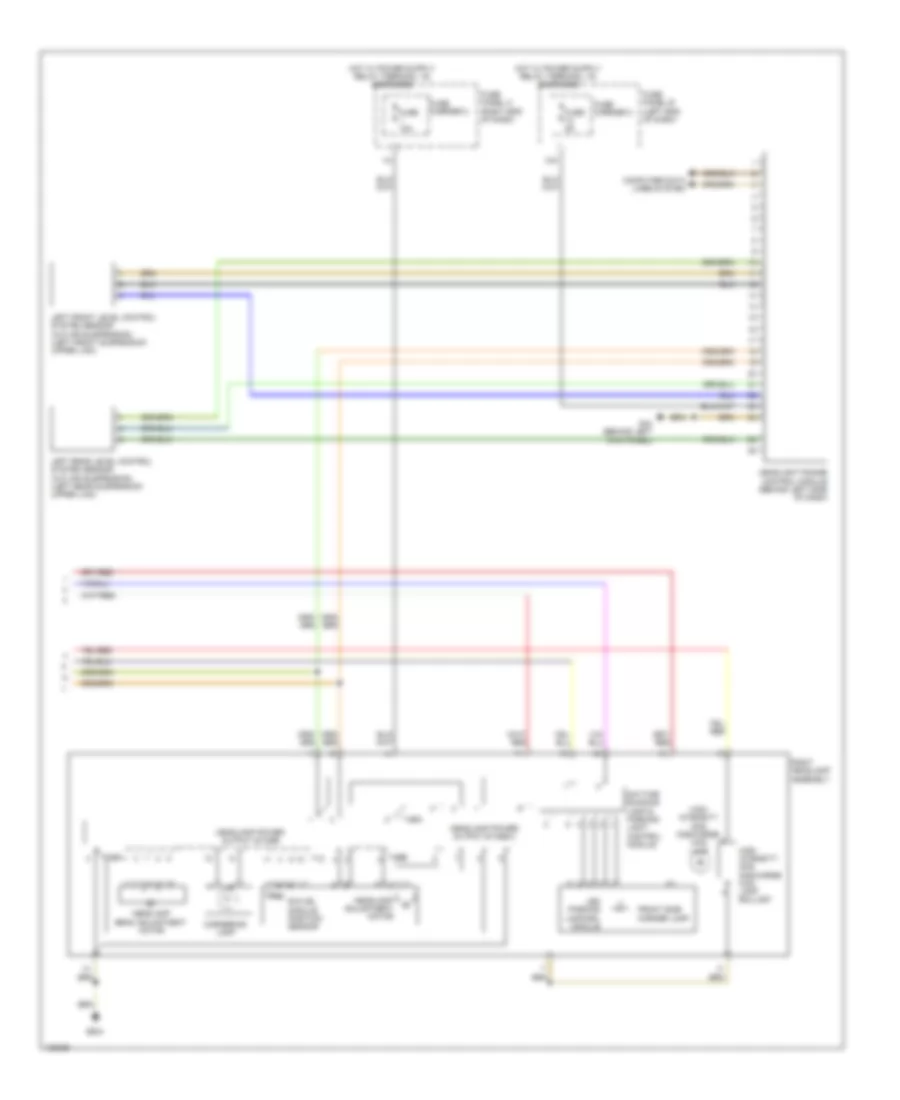
HEADLIGHTS
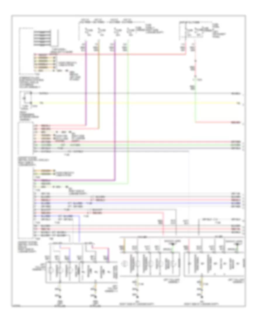
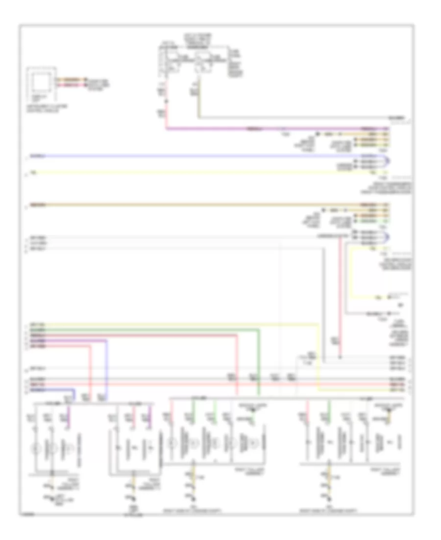
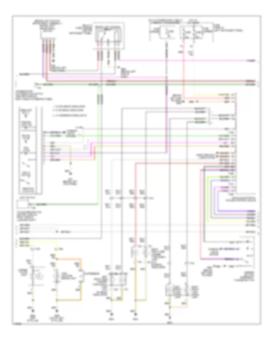
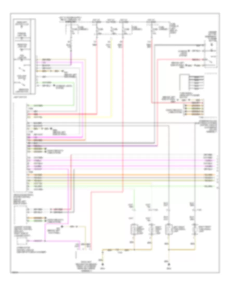
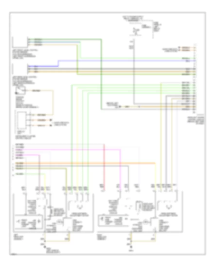
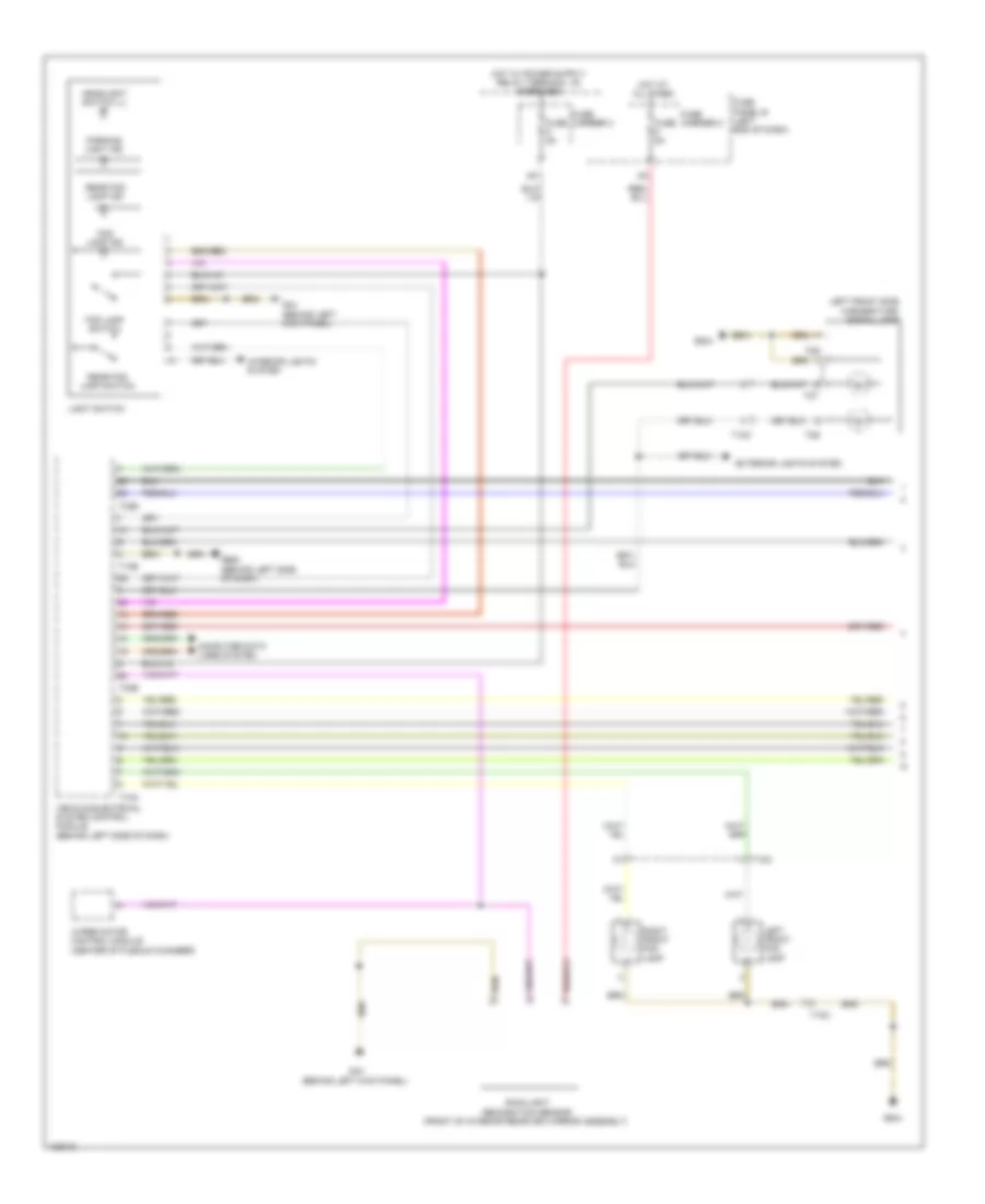
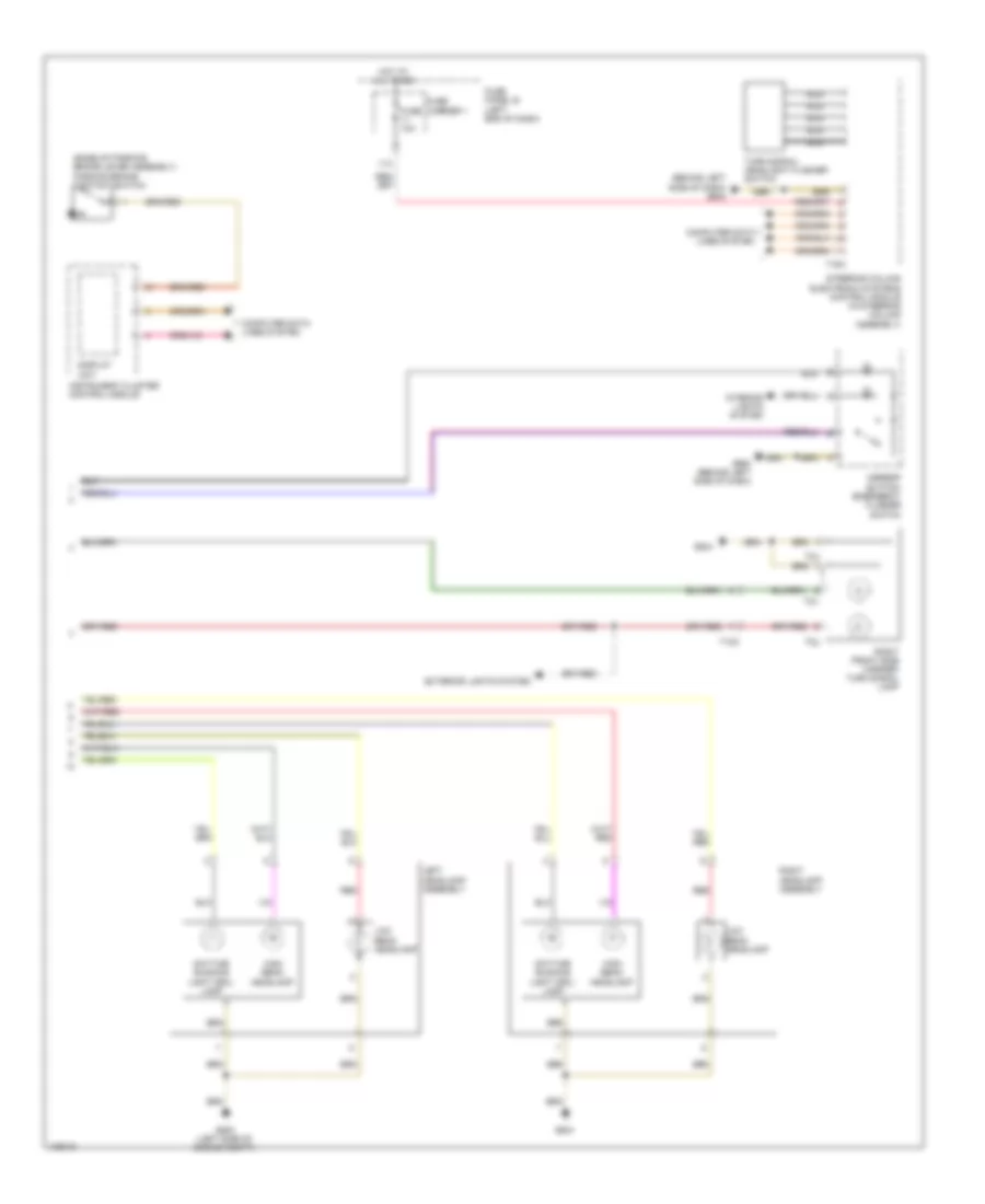
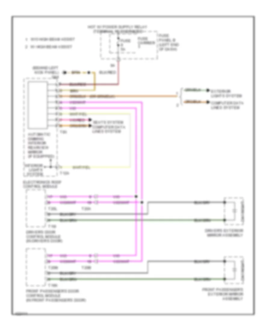
Headlights Wiring Diagram, with Bi-Xenon with Cornering Headlights (1 of 3) for Audi Q7 Prestige 2014
List of elements for Headlights Wiring Diagram, with Bi-Xenon with Cornering Headlights (1 of 3) for Audi Q7 Prestige 2014:
- (behind left side of dash) g664
- 11a
- Asr/esp button/ emergency flasher button
- Comfort system central control module 2 (right side of luggage compt)
- Computer data lines system
- Fog lamp ind
- Fog lamp switch
- Fuse 10a
- Fuse 25a
- Fuse 30a
- Fuse 5a
- Fuse carrier 1
- Fuse carrier 2
- Fuse carrier 3
- Fuse panel b (left end dash)
- G44 (behind left kick panel)
- G644
- G664 (behind left side of dash)
- Headlight switch ill
- Hot at all times
- Interior lights system
- Left front fog lamp
- Light switch
- Nca
- Parking light ind
- Rear fog lamp ind
- Rear fog lamp switch
- Red
- Right front fog lamp
- Steering column electronic systems control module (in steering column assembly)
- T10a
- T10o
- T12b
- T16a
- T32b
- Turn signal/ headlight flasher switch
- Vehicle electrical system control module (behind left side of dash)
Headlights Wiring Diagram, with Bi-Xenon with Cornering Headlights (2 of 3) for Audi Q7 Prestige 2014
List of elements for Headlights Wiring Diagram, with Bi-Xenon with Cornering Headlights (2 of 3) for Audi Q7 Prestige 2014:
- Computer data lines system
- Cornering lamp
- Daytime running lamp & parking light control module
- Display unit
- Front side marker lamp
- Fuse 10a
- Fuse 5a
- Fuse carrier 2
- Fuse carrier 3
- Fuse panel b (left end of dash)
- G44 (behind left kick panel)
- G640 (left side of engine compt)
- G644
- Headlamp adjustment motor
- Headlamp beam adjustment motor
- Headlamp power output stage
- Headlamp power output stage 2
- High intensity gas discharge (hid) lamp
- High intensity gas discharge (hid) lamp ballast
- Hot at all times
- Instrument cluster control module
- Led parking lamp/drl module
- Left front turn signal lamp
- Left headlamp assembly
- Parking brake contact switch (base of parking brake lever assembly)
- Rain/light recognition sensor (front of interior rearview mirror assembly)
- Right front turn signal lamp
- Swivel module position sensor
- T12
- T4ba
- T4bb
- Wiper motor control module (center of plenum chamber)
Headlights Wiring Diagram, with Bi-Xenon with Cornering Headlights (3 of 3) for Audi Q7 Prestige 2014
List of elements for Headlights Wiring Diagram, with Bi-Xenon with Cornering Headlights (3 of 3) for Audi Q7 Prestige 2014:
- 12a
- Computer data lines system
- Cornering lamp
- Daytime running lamp & parking light control module
- Front side marker lamp
- Fuse 10a
- Fuse 5a
- Fuse carrier 2
- Fuse carrier 3
- Fuse panel b (left end of dash)
- Fuse panel c (right end of dash)
- G44 (behind left kick panel)
- G644
- Headlamp adjustment motor
- Headlamp beam adjustment motor
- Headlamp power output stage
- Headlamp power output stage 2
- Headlight range control module (behind left side of dash)
- High intensity gas discharge (hid) lamp
- High intensity gas discharge (hid) lamp ballast
- Led parking lamp/drl module
- Left front level control system sensor (w/o air suspension) (left front suspension upper link)
- Left rear level control system sensor (w/o air suspension) (left rear suspension upper link)
- Right headlamp assembly
- Swivel module position sensor
- T12
- T4ba
- T4bb
Headlights Wiring Diagram, with Bi-Xenon without Cornering Headlights (1 of 2) for Audi Q7 Prestige 2014
List of elements for Headlights Wiring Diagram, with Bi-Xenon without Cornering Headlights (1 of 2) for Audi Q7 Prestige 2014:
- (behind left kick panel)
- (behind left side of dash) g664
- 11a
- Asr/esp button/ emergency flasher button
- Comfort system central control module 2 (right side of luggage compt)
- Computer data lines system
- Fog lamp ind
- Fog lamp switch
- Fuse 10a
- Fuse 25a
- Fuse 30a
- Fuse 5a
- Fuse carrier 1
- Fuse carrier 2
- Fuse carrier 3
- Fuse panel b (left end of dash)
- G44
- G44 (behind left kick panel)
- G644
- G664 (behind left side of dash)
- Headlight switch illum
- Hot at all times
- Interior lights system
- Left front fog lamp
- Left front turn signal lamp
- Light switch
- Nca
- Parking light ind
- Rain/light recognition sensor (front of interior rearview mirror assembly)
- Rear fog lamp ind
- Rear fog lamp switch
- Red
- Right front fog lamp
- Right front turn signal lamp
- Steering column electronic systems control module (in steering column assembly)
- T10a
- T10o
- T12b
- T16a
- T32b
- Turn signal/ headlight flasher switch
- Vehicle electrical system control module (behind left side of dash)
- Wiper motor control module (center of plenum chamber)
Headlights Wiring Diagram, with Bi-Xenon without Cornering Headlights (2 of 2) for Audi Q7 Prestige 2014
List of elements for Headlights Wiring Diagram, with Bi-Xenon without Cornering Headlights (2 of 2) for Audi Q7 Prestige 2014:
- (behind left kick panel) g44
- 12a
- Computer data lines system
- Day time running lamp & parking light control module
- Display unit
- Front side marker lamp
- Fuse 5a
- Fuse carrier 3
- Fuse panel b (left end of dash)
- G640 (left side of engine compt)
- G644
- Headlamp beam adjustment motor
- Headlamp reflector adjustment solenoid
- Headlight range control module (behind left side of dash)
- High intensity gas discharge (hid) lamp
- High intensity gas discharge (hid) lamp ballast
- Instrument cluster control module
- Led parking lamp/ drl module
- Led parking lamp/drl module
- Left front level control system sensor (w/o air suspension) (left front suspension upper link)
- Left headlamp assembly
- Left rear level control system sensor (w/o air suspension) (left rear suspension upper link)
- Parking brake contact switch (base of parking brake lever assembly)
- Right headlamp assembly
Headlights Wiring Diagram, without Bi-Xenon Headlights (1 of 2) for Audi Q7 Prestige 2014
List of elements for Headlights Wiring Diagram, without Bi-Xenon Headlights (1 of 2) for Audi Q7 Prestige 2014:
- Computer data lines system
- Exterior lights system
- Fog lamp ind
- Fog lamp switch
- Fuse 5a
- Fuse carrier 2
- Fuse carrier 3
- Fuse panel b (left end of dash)
- G44 (behind left kick panel)
- G644
- G664 (behind left side of dash)
- Headlight switch ill
- Hot at all times
- Interior lights system
- Left front fog lamp
- Left front side marker/turn signal lamp
- Light switch
- Parking light ind
- Rain/light recognition sensor (front of interior rearview mirror assembly)
- Rear fog lamp ind
- Rear fog lamp switch
- Right front fog lamp
- T10a
- T10o
- T12b
- T2s
- T2t
- T32b
- Vehicle electrical system control module (behind left side of dash)
- Wiper motor control module (center of plenum chamber)
Headlights Wiring Diagram, without Bi-Xenon Headlights (2 of 2) for Audi Q7 Prestige 2014
List of elements for Headlights Wiring Diagram, without Bi-Xenon Headlights (2 of 2) for Audi Q7 Prestige 2014:
- (base of parking brake lever assembly) parking brake contact switch
- (behind left side of dash) g664
- 11a
- Asr/esp button/ emergency flasher switch
- Computer data lines system
- Daytime running light (drl) lamp
- Display unit
- Exterior lights system
- Fuse 10a
- Fuse carrier 1
- Fuse panel b (left end of dash)
- G640 (left side of engine compt)
- G644
- G664 (behind left side of dash)
- High beam headlamp
- Hot at all times
- Instrument cluster control module
- Interior lights system
- Left headlamp assembly
- Low beam headlamp
- Nca
- Red
- Right front side marker/ turn signal lamp
- Right headlamp assembly
- Steering column electronic systems control module (in steering column assembly)
- T10o
- T16a
- T2u
- T2v
- Turn signal/ headlight flasher switch
HORN
Horn Wiring Diagram for Audi Q7 Prestige 2014
List of elements for Horn Wiring Diagram for Audi Q7 Prestige 2014:
- Airbag spiral spring/ return spring w/slip ring (top of steering column)
- Computer data lines system
- Dual tone horn relay
- Fuse 25a
- Fuse carrier
- Fuse panel b (left end of dash)
- G640 (left side of engine compt)
- G664 (behind left side of dash)
- High tone horn (behind center of front grille)
- Horn signal activation
- Hot at all times
- Low tone horn (behind center of front grille)
- Nca
- Relay & fuse carrier
- Steering column electronic systems control module (in steering column assembly)
- Steering wheel control head
- T10n
- T16a
- T32b
- Vehicle electrical system control module (behind left side of dash)
INSTRUMENT CLUSTER
Instrument Cluster Wiring Diagram (1 of 2) for Audi Q7 Prestige 2014
List of elements for Instrument Cluster Wiring Diagram (1 of 2) for Audi Q7 Prestige 2014:
- (g62: base of right "c" pillar) (g61: base of left "c" pillar) (w/ tank prewiring) g62 (w/o tank prewiring) g61
- (left side fuel tank) (3.0l turbo diesel) fuel level sensor 2
- (right side fuel tank) (3.0l turbo diesel) fuel level sensor 1
- 3.0l sc
- 3.0l turbo diesel
- Brake pad wear ind lamp
- Brake system ind lamp
- Computer data lines system
- Directional stabilization assistance ind lamp
- Display unit
- Engine controls system
- Engine coolant level (ecl) sensor
- Engine coolant level/temperature ind lamp
- Fuel gauge
- Fuel level sensor 1 & transfer fuel pump (3.0l sc) (fuel level sensor: right side fuel tank)
- Fuel level sensor 2 (3.0l sc) (left side fuel tank)
- Fuse 10a
- Fuse carrier 3
- Fuse panel c (right end of dash)
- G45 (behind center of dash)
- G51 (right side of luggage compt)
- Hot at all times
- Instrument cluster control module
- Interior lights system
- Oil pressure ind lamp
- Outside air temperature display
- Outside air temperature sensor (behind left side of front grille)
- Parking brake ind lamp
- Radio frequency controlled clock
- Radio frequency controlled clock receiver
- T10n
- T14e
- T5k
- T6d
- Transmissions system
- W/ tank prewiring
- Windshield washer fluid level sensor
Instrument Cluster Wiring Diagram (2 of 2) for Audi Q7 Prestige 2014
List of elements for Instrument Cluster Wiring Diagram (2 of 2) for Audi Q7 Prestige 2014:
- (lower oil pan)
- 3.0l sc
- 3.0l turbo diesel
- Brake fluid level warning switch
- Cluster operation button
- Computer data lines system
- Engine control module (right plenum chamber)
- Front center console control head
- Fuse 5a
- Fuse carrier 3
- Fuse panel b (left end of dash)
- G35 (under front passenger's seat)
- G45 (behind center of dash)
- G609 (right plenum chamber)
- G664 (behind left side of dash)
- Interior lights system
- Left front brake pad wear sensor
- Left rear brake pad wear sensor
- Nca
- Oil level thermal sensor
- Oil pressure switch (3.0l sc) (bottom of oil filter housing)
- Oil pressure switch (3.0l turbo diesel) (bottom of oil filter housing)
- Parking brake contact switch (base of parking brake lever assembly)
- Right front brake pad wear sensor
- Right rear brake pad wear sensor
- System
- T10f
- T17d
- T4n
- T4o
- T4p
- T4q
- T6n
- T6o
- T6p
- T6q
- T91
- T94
- W/ level control
- W/o level control
INTERIOR LIGHTS
Courtesy Lamps Wiring Diagram (1 of 2) for Audi Q7 Prestige 2014
List of elements for Courtesy Lamps Wiring Diagram (1 of 2) for Audi Q7 Prestige 2014:
- (left "d" pillar)
- Comfort system central control module 1 (right side of luggage compt)
- Computer data lines system
- Driver's vanity mirror lamp & contact switch
- Front passenger's vanity mirror lamp & contact switch
- Fuse 25a
- Fuse carrier
- Fuse panel b (left instrument panel)
- G43 (behind right kick panel)
- G44 (behind left kick panel)
- G51 (right side of luggage compt)
- G664
- G664 (behind left side of dash)
- G668
- G668 (left "d" pillar)
- G77 (base of left "b" pillar)
- G78 (right lower "b" pillar)
- Glove compartment lamp switch
- Glove compartment light
- Hot at all times
- Instrument illumination circuit
- Left footwell light
- Left luggage compartment light
- Left rear central locking lock unit (w/ child safety lock)
- Left rear door ambient lighting (w/ auxiliary lamps)
- Left rear door control module (left rear door)
- Left rear door warning light (w/ auxiliary lamps)
- Left rear entry light (w/ auxiliary lamps)
- Left rear footwell light
- Nca
- Rear lid courtesy lamp
- Rear lid lock button in luggage compartment
- Right footwell light
- Right luggage compartment light
- Right rear central locking lock unit (w/ child safety lock)
- Right rear door ambient lighting bulb (w/ auxiliary lamps)
- Right rear door control module (right rear door)
- Right rear door warning light (w/ auxiliary lamps)
- Right rear entry light (w/ auxiliary lamps)
- Right rear footwell light
- T10s
- T12b
- T15a
- T16l
- T16m
- T17a
- T17b
- T20c
- T20d
- T20n
- T20o
- T32b
- T32d
- Vehicle electrical system control module 1 (behind left side of dash)
Courtesy Lamps Wiring Diagram (2 of 2) for Audi Q7 Prestige 2014
List of elements for Courtesy Lamps Wiring Diagram (2 of 2) for Audi Q7 Prestige 2014:
- (behind right kick panel)
- 11a
- Comfort system central control module 2 (right side of luggage compt)
- Computer data lines system
- Display unit
- Driver door ambient lighting (w/ auxiliary lamps)
- Driver's door central locking lock unit
- Driver's door control module (in driver's door)
- Driver's door warning light (w/ auxiliary lamps)
- Driver's reading light
- Front passenger door ambient lighting (w/ auxiliary lamps)
- Front passenger's door central locking lock unit
- Front passenger's door control module (in front passenger's door)
- Front passenger's door warning light (w/ auxiliary lamps)
- Front passenger's reading light
- Front roof control module
- Fuse 35a
- Fuse carrier
- Fuse panel b (left end of dash)
- Fuse panel c (right end of dash)
- G43
- G43 (behind right kick panel)
- G44 (behind left kick panel)
- G658 (top of left "d" pillar)
- Hot at all times
- Illumination circuit
- Instrument
- Instrument cluster control module
- Instrument illumination circuit
- Left front entry light
- Left interior light
- Left rear interior lamp
- Left rear interior lamp switch 1
- Mirrors system
- Rear courtesy light
- Rear interior lamp switch
- Rear interior lights assembly
- Right front entry light
- Right interior light
- Right rear interior lamp
- T10r
- T10s
- T12a
- T20a
- T20b
- T20c
- T20l
- T20m
- T2x
- T32f
- T32g
- W/ auxiliary lamps
- W/ light switch
- W/o light switch
Instrument Illumination Wiring Diagram (1 of 3) for Audi Q7 Prestige 2014
List of elements for Instrument Illumination Wiring Diagram (1 of 3) for Audi Q7 Prestige 2014:
- (4)
- 12v socket (w/ left rear center console)
- 12v socket 2 (w/ right front center console)
- 12v socket 4 (w/ right rear center console)
- Ashtray & cup holder illumination
- Asr/esp button & emergency flasher switch
- Center instrument panel vent illumination
- Cigarette lighter
- Computer data lines system
- Control module
- Display unit
- Display unit button
- Front center console control head
- Front roof
- Fuse 25a
- Fuse carrier
- Fuse panel b (left end of dash)
- G35 (under front passenger's seat)
- G43 (behind right kick panel)
- G44 (behind left kick panel)
- G45 (behind center of dash)
- G51 (right side of luggage compt)
- G658 (top of left "d" pillar)
- G664 (behind left side of dash)
- G67
- G687 (under center console)
- Garage door opener control head
- Headlight switch illumination
- Hot at all times
- Instrument cluster control module
- Lane change assistance button
- Left instrument panel vent illumination
- Left rear heated seat regulating switch
- Light switch
- Power pivoting trailer hitch switch
- Rear center air vent illumination
- Rear courtesy light (w/ light switch)
- Rear sunroof switch
- Right instrument panel vent illumination
- Right rear heated seat regulating switch
- Sunroof adjustment regulator (if equipped)
- Sunroof switch
- T12a
- T12b
- T12c
- T12d
- T12n
- T20a
- T2x
- T2y
- T32b
- Telephone base plate
- Towing recognition control module (right side of luggage compt)
- Vehicle electrical system control module 1 (behind left side of dash)
Instrument Illumination Wiring Diagram (2 of 3) for Audi Q7 Prestige 2014
List of elements for Instrument Illumination Wiring Diagram (2 of 3) for Audi Q7 Prestige 2014:
- (w/ auxiliary lamps) left rear entry light
- 11a
- Fuse 35a
- Fuse carrier
- Fuse panel b (left end of dash)
- Fuse panel c (right end of dash)
- Hot at all times
- Left rear ashtray illumination
- Left rear door ambient lighting (w/ auxiliary lamps)
- Left rear door control module (in left rear door)
- Left rear door opener illumination
- Left rear door warning light (w/ auxiliary lamps)
- Left rear interior lock switch
- Left rear power window switch
- Right rear ashtray illumination
- Right rear door ambient lighting (w/ auxiliary lamps)
- Right rear door control module (in right rear door)
- Right rear door opener illumination
- Right rear door warning light (w/ auxiliary lamps)
- Right rear entry light (w/ auxiliary lamps)
- Right rear interior lock switch
- Right rear power window switch
- T16l
- T16m
- T20c
- T20d
- T20n
- T20o
Instrument Illumination Wiring Diagram (3 of 3) for Audi Q7 Prestige 2014
List of elements for Instrument Illumination Wiring Diagram (3 of 3) for Audi Q7 Prestige 2014:
- (behind right kick panel) g43
- Central locking safe indicator lamp
- Computer
- Computer data lines system
- Data lines
- Driver door opener illumination
- Driver door power window control head
- Driver's door ambient lighting (w/ auxiliary lamps)
- Driver's door control module (in driver's door)
- Driver's door warning light (w/ auxiliary lamps)
- Driver's interior lock switch
- Driver's memory seat control head (if equipped)
- Front passenger door opener illumination
- Front passenger interior lock switch
- Front passenger memory seat control head
- Front passenger's door ambient lighting (w/ auxiliary lamps)
- Front passenger's door control module (in front passenger's door)
- Front passenger's door warning light (w/ auxiliary lamps)
- G44 (behind left kick panel)
- Left front entry light
- Mirror adjustment switch
- Passenger door window regulator switch
- Rear lid remote release button
- Right front entry light
- System
- T20a
- T20b
- T20l
- T20m
- T32f
- T32g
MEMORY SYSTEMS
Driver"s Memory Seat Wiring Diagram (1 of 2) for Audi Q7 Prestige 2014
List of elements for Driver"s Memory Seat Wiring Diagram (1 of 2) for Audi Q7 Prestige 2014:
- 30a
- Computer data lines system
- Driver's power seat adjustment circuit breaker 1
- Driver's seat backrest adjustment motor (driver seat backrest)
- Driver's seat fore/aft adjustment motor
- Driver's seat height adjustment motor
- Driver's seat inclination adjustment motor
- Driver's seat lumbar support adjustment switch
- Driver's seat lumbar support curvature adjustment motor
- Driver's seat lumbar support height adjustment motor
- G77 (base of left "b" pillar)
- Hot at all times
- Memory seat/ steering column adjustment control module (below driver's seat)
- Relay & fuse carrier (center instrument panel) (below driver seat)
- T12s
- T32h
- T8q
Driver"s Memory Seat Wiring Diagram (2 of 2) for Audi Q7 Prestige 2014
List of elements for Driver"s Memory Seat Wiring Diagram (2 of 2) for Audi Q7 Prestige 2014:
- Backrest
- Computer data lines system
- Driver's door control module (in driver's door)
- Driver's power seat switch assembly
- Driver's seat memory program control & lock out button
- Fore/aft
- Fuse 35a
- Fuse carrier 1
- Fuse panel b (left end of dash)
- G44 (behind left kick panel)
- Height
- Hot at all times
- Inclination
- Interior lights system
- T17a
- T20a
- T20l
- T32f
Memory Mirrors Wiring Diagram (1 of 2) for Audi Q7 Prestige 2014
List of elements for Memory Mirrors Wiring Diagram (1 of 2) for Audi Q7 Prestige 2014:
- (if equipped) day/night
- (if equipped) entry lamp
- (if equipped) fold-in
- (if equipped) lane change
- Adjustment switch
- Computer data lines system
- Driver's door control module (in driver's door)
- Driver's exterior mirror assembly
- Exterior lights system
- Fold away switch
- Fuse 35a
- Fuse carrier 1
- Fuse panel b (left end of dash)
- G44 (behind left kick panel)
- Heater
- Horizontal
- Hot at all times
- Interior lights system
- Mirror adjustment switch assembly
- Motor adjustment
- Navigation system
- Pnk
- Red
- Selector switch
- T16i
- T20a
- T20l
- T32f
- Turn signal
- Vertical
Memory Mirrors Wiring Diagram (2 of 2) for Audi Q7 Prestige 2014
List of elements for Memory Mirrors Wiring Diagram (2 of 2) for Audi Q7 Prestige 2014:
- (if equipped) day/night
- (if equipped) entry lamp
- (if equipped) lane change
- 11a
- Computer data lines system
- Driver's seat memory program control & lock out button
- Exterior lights system
- Fold-in
- Front passenger's door control module (in front passenger's door)
- Front passenger's exterior mirror assembly
- Fuse 35a
- Fuse carrier 3
- Fuse panel c (right end of dash)
- G43 (behind right kick panel)
- Heater
- Horizontal
- Hot at all times
- Motor adjustment
- Navigation system
- Off
- Pnk
- Red
- T16k
- T20b
- T20m
- Turn signal
- Vertical
Passenger"s Memory Seat Wiring Diagram (1 of 2) for Audi Q7 Prestige 2014
List of elements for Passenger"s Memory Seat Wiring Diagram (1 of 2) for Audi Q7 Prestige 2014:
- 30a
- Computer data lines system
- Driver's power seat adjustment circuit breaker 1
- Front passenger's seat lumbar support adjustment switch
- Front passenger's seat lumbar support curvature adjustment motor
- Front passenger's seat lumbar support height adjustment motor
- G78 (right lower "b" pillar)
- G78 (right lower b-pillar)
- Hot at all times
- Passenger memory seat control module (bottom of passenger seat)
- Passenger seat backrest adjustment motor (front passenger seat backrest)
- Passenger seat fore/aft adjustment motor
- Passenger seat height adjustment motor
- Passenger seat inclination adjustment motor
- Relay & fuse carrier (center instrument panel) (below driver seat)
- T12t
- T32i
- T8r
Passenger"s Memory Seat Wiring Diagram (2 of 2) for Audi Q7 Prestige 2014
List of elements for Passenger"s Memory Seat Wiring Diagram (2 of 2) for Audi Q7 Prestige 2014:
- 11a
- Backrest
- Computer data lines system
- Fore/aft
- Front passenger's door control module (in front passenger's door)
- Front passenger's seat memory program control & emergency-off button
- Fuse 35a
- Fuse carrier 3
- Fuse panel c (right end of dash)
- G43 (behind right kick panel)
- Height
- Hot at all times
- Inclination
- Interior lights system
- Passenger's power seat switch assembly
- T17b
- T20b
- T20m
- T32g
Steering Column Memory Wiring Diagram for Audi Q7 Prestige 2014
List of elements for Steering Column Memory Wiring Diagram for Audi Q7 Prestige 2014:
- (behind left side of dash) g664
- 11a
- Computer data lines system
- Driver's door control module (in driver's door)
- Driver's seat memory program control & lock out button
- Fuse 10a
- Fuse 25a
- Fuse 30a
- Fuse 35a
- Fuse 5a
- Fuse carrier 1
- Fuse carrier 2
- Fuse carrier 3
- Fuse panel b (left end of dash)
- G44 (behind left kick panel)
- Hot at all times
- Interior lights
- Motor
- Motor axial adjustment
- Nca
- Off
- Red
- Sensor
- Sensor axial adjustment
- Steering column adjustment motor assembly (in steering column assembly)
- Steering column adjustment switch
- Steering column electronic systems control module (in steering column assembly)
- T10a
- T12b
- T16a
- T20a
- T20l
- T32b
- T32f
- T4a
- Vehicle electrical system control module (behind left side of dash)
- Vertical adjustment
NAVIGATION
Lane Change Assistance Wiring Diagram for Audi Q7 Prestige 2014
List of elements for Lane Change Assistance Wiring Diagram for Audi Q7 Prestige 2014:
- Change lane
- Computer data lines system
- Driver's exterior mirror assembly
- Front passenger's exterior mirror assembly
- Fuse 5a
- Fuse carrier 2
- Fuse panel c (right end
- G44 (behind left kick panel)
- G51 (right side of luggage compt)
- Interior lights system
- Lane change
- Lane change assistance button
- Lane change assistance control module (behind right corner of rear bumper)
- Lane change assistance control module 2 (behind left corner of rear bumper)
- Of dash)
- T14d
- T20a
- T20b
- T4d
- T4e
Lane Departure Warning Wiring Diagram for Audi Q7 Prestige 2014
List of elements for Lane Departure Warning Wiring Diagram for Audi Q7 Prestige 2014:
- (in steering column assembly)
- Computer data lines
- Computer data lines system
- Directional stabilization assistance button
- Directional stabilization assistance control module (top center of windshield)
- Directional stabilization assistance ind
- Directional stabilization assistance windshield heater
- Display unit
- Fuse 10a
- Fuse carrier 3
- Fuse panel b (left end of dash)
- G44 (behind left kick panel)
- Instrument cluster control module
- Left multi- function buttons
- Multi- function steering wheel control module
- Nca
- Spiral spring
- Steering column electronic systems control module
- Steering wheel control module
- Steering wheel vibration motor
- System
- T16a
Navigation Wiring Diagram (1 of 2) for Audi Q7 Prestige 2014
List of elements for Navigation Wiring Diagram (1 of 2) for Audi Q7 Prestige 2014:
- (not used)
- (or t4ax)
- Cell phone preparation w/o handsfree system
- Computer data lines system
- Display unit button
- Front information display control head control module (behind glove compt)
- Fuse 5a
- Fuse 7.5a
- Fuse carrier
- Fuse panel b (left end of dash)
- Fuse panel c (right end of dash)
- G45 (behind center of dash)
- Hot at all times
- Information electronics control module 1
- Most data bus circuit
- Multimedia control head
- Nca
- Red
- T18
- T2bn
- T2bp
- T4at
- T4av (or) t4aw
- T4ay
- T8ad
- T8ae
- T8af
- Telephone amplifier (right side of luggage compt)
- Telephone baseplate (w/ cellular telephone preparation handsfree system)
Navigation Wiring Diagram (2 of 2) for Audi Q7 Prestige 2014
List of elements for Navigation Wiring Diagram (2 of 2) for Audi Q7 Prestige 2014:
- (center rear of roof) (roof antenna) radio, telephone & navigation system antenna
- (w/ audi music interface) external audio source connection
- G45 (behind center of dash)
- Gps antenna
- Information electronics control module 1
- Left front microphone
- Microphone unit (in front roof module) (front of headliner)
- Nca
- Rear view camera control module (if equipped) (right side of luggage compt)
- Red
- Right front microphone
- T12ab
- T12ac
- T12n
- T2ak
- T2bm
- T2cd
- T4au
- Telephone antenna
- Telephone baseplate (w/ telephone handset)
- W/ cell phone/ telephone & speech recognition system
- W/ cell phone/ telephone system
Parking Assistant Wiring Diagram for Audi Q7 Prestige 2014
List of elements for Parking Assistant Wiring Diagram for Audi Q7 Prestige 2014:
- (behind luggage compt left side trim)
- Computer data lines system
- Front center console control head
- Front parking aid warning buzzer (on center instrument panel relay & fuse carrier bracket)
- Fuse 5a
- Fuse carrier 2
- Fuse panel c (right end of dash)
- G45 (behind center of dash)
- G51 (right side of luggage compt)
- Left front center parking aid sensor (in front bumper)
- Left front parking aid sensor (in front bumper)
- Left rear center parking aid sensor (in rear bumper)
- Left rear parking aid sensor (in rear bumper)
- Parking aid button
- Parking aid control module (right side of luggage compt)
- Parking aid ind
- Power distribution system
- Rear parking aid warning buzzer
- Red
- Right front center parking aid sensor (in front bumper)
- Right front parking aid sensor (in front bumper)
- Right rear center parking aid sensor (in rear bumper)
- Right rear parking aid sensor (in rear bumper)
- T12e
- T12f
- T14c
- T16b
- T6c
- Vehicle electrical system control module 2 (under front passenger's seat)
- W/ start/stop system
- W/o start/stop system
Peripheral Camera Wiring Diagram for Audi Q7 Prestige 2014
List of elements for Peripheral Camera Wiring Diagram for Audi Q7 Prestige 2014:
- Computer data lines system
- Front peripheral camera
- Fuse 5a
- Fuse carrier 2
- Fuse panel c (right end of dash)
- G51 (right side of luggage compt)
- Information electronics control module 1
- Nca
- Peripheral camera control module
- Power distribution system
- Rear peripheral camera
- T12ab
- T18e
- T2cm
- T5m
- T5n
- T5o
- T5p
Rear Camera Wiring Diagram for Audi Q7 Prestige 2014
List of elements for Rear Camera Wiring Diagram for Audi Q7 Prestige 2014:
- Computer data lines system
- Fuse 5a
- Fuse carrier 1
- Fuse panel f (right rear of luggage compt)
- G51 (right side of luggage compt)
- Hot at all times
- Information electronics control module 1
- Nca
- Pins: 1-38 (not used)
- Pins: 49-54 (not used)
- Rear view camera (next to rear lid handle)
- Rear view camera control module (right side of luggage compt)
- T10s
- T12ab
- T2ah
- T2ak
- T2al
- T2am
- T2an
- T54
POWER DISTRIBUTION
3.0L SC
3.0L SC, Power Distribution Wiring Diagram (1 of 7) for Audi Q7 Prestige 2014
List of elements for 3.0L SC, Power Distribution Wiring Diagram (1 of 7) for Audi Q7 Prestige 2014:
- 11a
- 15)
- 16a
- 17a
- Access/start authorization control module
- Air bag control module
- Battery
- Battery interrupt igniter
- Battery jump start terminal
- Battery monitoring control module
- Coolant fan control (fc) control module
- Coolant fan control module 2
- Engine control module (ecm)
- Fuel pump (fp) control module
- Fuse 125a
- Fuse 150a
- Fuse 20a
- Fuse 30a
- Fuse 40a/60a
- Fuse 50a
- Fuse 5a
- Fuse 60a
- Fuse 60a/40a
- Fuse panel d (under driver's seat)
- Generator & voltage regulator
- Ignition coil 1 w/ power output stage
- Ignition coil 2 w/ power output stage
- Ignition coil 3 w/ power output stage
- Ignition coil 4 w/ power output stage
- Ignition coil 5 w/ power output stage
- Ignition coil 6 w/ power output stage
- Level control system compressor relay
- Red
- Relay & fuse carrier (center instrument panel) (center of dash)
- Relay & fuse carrier (driver's seat) (below driver seat)
- Relay & fuse carrier (e-box) (left plenum chamber)
- Secondary air injection (air) pump relay
- Self- leveling suspension fuse 40a
- Starter
- Starter relay
- Starter relay 2
- T10d
- T17d
- T20e
- T2k
- T6k
- T94
- To fuse panel b (diagram 2 of 7)
- To fuse panel b (diagram 5 of 7)
- To fuse panel c (diagram 2 of 7)
- To fuse panel c (diagram 3 of 7)
- To fuse panel c (diagram 6 of 7)
- To fuse panel f (diagram 5 of 7)
- To fuse panel f (diagram 6 of 7)
- To fuse panel f (diagram 7 of 7)
- To relay & fuse carrier (diagram 7 of 7)
- To relay & fuse carrier (e-box) (diagram 4 of 7)
3.0L SC, Power Distribution Wiring Diagram (2 of 7) for Audi Q7 Prestige 2014
List of elements for 3.0L SC, Power Distribution Wiring Diagram (2 of 7) for Audi Q7 Prestige 2014:
- (left end of dash) fuse panel b
- (not used)
- (right end of dash) fuse panel c
- 10a
- 11a
- 12a
- 12v socket 2
- 12v socket 3
- 12v socket 4
- Abs control module
- Alarm horn
- Auxiliary heater control module
- Basic a/c
- Cigarette lighter
- Climatronic control module
- Comfort a/c
- Driver's door control module
- Driver's seat lumbar support adjustment switch
- Fresh air blower
- Fresh air blower control module
- Fresh air blower control module (basic a/c)
- Fresh air blower fuse 40a
- From fuse panel d (diagram 1 of 7)
- Front passenger's seat lumbar support adjustment switch
- Fuse
- Fuse 10a
- Fuse 15a
- Fuse 20a
- Fuse 25a
- Fuse 30a
- Fuse 30a/15a
- Fuse 35a
- Fuse 40a
- Fuse 5a
- Fuse 7.5a
- Fuse carrier
- G687 (under center console)
- Heated rear window fuse 40a
- Information electronics control module 1
- Interior lights system
- Interior monitoring sensor (if equipped)
- Left rear door control module
- Left rear heated seat regulating switch
- Nca
- Rear a/c display control head (climatronic)
- Rear fresh air blower
- Rear window defogger relay
- Red
- Relay & fuse carrier (center instrument panel) (center of dash)
- Relay & fuse carrier center instrument panel) (center of dash)
- Right front seat ventilation control module
- Right rear heated seat regulating switch
- Steering column electronic systems control module
- Suppressor
- T16a
- T16d
- T17a
- T17b
- T17h
- T17k
- T20a
- T20c
- T20l
- T20n
- T2b
- T3c
- T3h
- T40a
- T4t
- T6ai
- T6g
- T8af
- Tire pressure monitoring control module
- To access/ start authorization switch (diagram 6 of 7)
- To fuse panel b (diagram 3 of 7)
- To relay & fuse carrier (diagram 3 of 7)
- Vehicle electrical system control module 2
- W/ interior monitoring
- W/ rear a/c
- W/o interior monitoring
- W/o rear a/c
3.0L SC, Power Distribution Wiring Diagram (3 of 7) for Audi Q7 Prestige 2014
List of elements for 3.0L SC, Power Distribution Wiring Diagram (3 of 7) for Audi Q7 Prestige 2014:
- (right end of dash) fuse panel c
- 10a
- 11a
- 12 pin connector
- 12a
- 18 pin connector
- Abs control module
- Air bag control module
- Air quality sensor
- Asr/esp button/ emergency flasher switch
- Brake booster
- Brake light disable relay
- Climatronic control module
- Cooler
- Cooler fuse 5a
- Data bus on board diagnostic interface
- Data link connector
- Dual horn relay
- From fuse panel b (diagram 2 of 7)
- From relay & fuse carrier (e-box) (diagram 1 of 7)
- Front passenger's air bag disabled indicator lamp
- Fuse 10a
- Fuse 15a
- Fuse 25a
- Fuse 30a
- Fuse 5a
- Fuse 5a/20a
- Fuse carrier
- Fuse panel b (left end of dash)
- Fuse panel c (right end of dash)
- Headlamp washer relay (if equipped)
- Lane change assistance control module
- Lane change assistance control module 2
- Left front seat ventilation control module
- Left rear heated seat regulating switch
- Level control system control module
- Multi- function transmission range (tr) switch/ backup switch
- Nca
- Parking aid control module
- Peripheral camera control module
- Rain/light recognition sensor
- Rear a/c display control head (w/ climatronic display & control head)
- Red
- Relay & fuse carrier (center instrument panel) (center of dash)
- Relay & fuse carrier (driver's seat) (below driver seat)
- Relay & fuse carrier (instrument panel- center) (center of dash)
- Right headlamp assembly
- Right rear heated seat regulating switch
- Seat occupied recognition control module
- Selector lever sensor system control module
- T10a
- T12b
- T14d
- T14h
- T16b
- T16d
- T16h
- T17b
- T18e
- T6f
- T81a
- Transmission control module (tcm)
- Vehicle electrical system control module
- Vehicle positioning system fuse 5a
- Wiper motor control module
3.0L SC, Power Distribution Wiring Diagram (4 of 7) for Audi Q7 Prestige 2014
List of elements for 3.0L SC, Power Distribution Wiring Diagram (4 of 7) for Audi Q7 Prestige 2014:
- 10a
- 13a
- 14a
- 15a
- 19c c
- 19e
- 1b a
- 1h a
- Auxiliary engine coolant pump relay
- Camshaft adjustment valve 1
- Camshaft adjustment valve 2
- Charge air cooling pump
- Coolant fan control (fc) control module
- Coolant fan control module 2
- Crankcase ventilation shut-off valve
- Engine control module (ecm)
- Evaporative emission (evap) canister purge regulator valve 1
- From battery jump start terminal (diagram 1 of 7)
- From relay & fuse carrier (e-box) (diagram 1 of 7)
- From relay & fuse carrier (e-box) (diagram 4 of 7)
- Fuel metering valve
- Fuse 10a
- Fuse 15a
- Fuse 5a
- Heated oxygen sensor 1
- Heated oxygen sensor 2
- High pressure sensor
- Intake manifold runner control (imrc) valve
- Leak detection pump (ldp) (if equipped)
- Nca
- Oil pressure regulation valve
- Oxygen sensor (o2s) heater
- Oxygen sensor (o2s) heater 2
- Red
- Relay & fuse carrier (e-box) (left plenum chamber)
- Secondary air injection (air) pump relay
- Secondary air injection (air) solenoid valve
- Secondary air injection solenoid valve 2
- T10e
- T10m
- T14l
- T94
- To relay & fuse carrier (e-box) (diagram 4 of 7)
3.0L SC, Power Distribution Wiring Diagram (5 of 7) for Audi Q7 Prestige 2014
List of elements for 3.0L SC, Power Distribution Wiring Diagram (5 of 7) for Audi Q7 Prestige 2014:
- 10a
- 10g
- 11a
- 12a
- Access/ start control module
- Adaptive cruise control sensor heater
- Auxiliary video/audio connection module
- Brake light/ brake pedal switch
- Comfort system central control module
- Data bus on board diagnostic interface
- Data link connector
- Digital sound system control module
- Digital sound system control module 2
- Digital tv tuner
- Directional stabilization assistance control module
- Distance regulation control module
- Electronics roof control module
- Engine coolant shut-off valve relay
- From fuse panel d (diagram 1 of 7)
- From relay & fuse carrier g (e-box) (diagram 1 of 7)
- Fuse 10a
- Fuse 15a
- Fuse 20a
- Fuse 25a
- Fuse 30a
- Fuse 5a
- Fuse carrier
- Fuse carrier 3
- Fuse panel b (left end of dash)
- Fuse panel f (right rear of luggage compt)
- Garage door opener control head
- Garage door opener control module
- Headlamp range control module
- Left headlamp assembly
- Level control system control module
- Light switch
- Multimedia system control module
- Nca
- Oil level thermal sensor
- Radio
- Rear lid control module
- Rear lid control module 2
- Red
- Reducing agent tank cap switch
- Steering column electronics systems control module
- T10aa
- T10f
- T10o
- T12ag
- T12c
- T12d
- T16a
- T20e
- T26e
- T2bc
- T2bd
- T32b
- T32c
- T32d
- T38
- T3ae
- T3af
- T4ai
- T81a
- T8c
- Tire pressure monitoring control module
- Towing recognition control module
- Vehicle electrical system control module
- W/ bang & olufsen
- W/ bose
3.0L SC, Power Distribution Wiring Diagram (6 of 7) for Audi Q7 Prestige 2014
List of elements for 3.0L SC, Power Distribution Wiring Diagram (6 of 7) for Audi Q7 Prestige 2014:
- (not used)
- (or 30a)
- (right end of dash) fuse panel c
- 10a
- 11a
- 12a
- 12v socket 5
- 18-pin connector
- Access/start authorization button
- Access/start authorization switch
- Access/start control module
- Auxiliary heater rf recever
- Comfort system central control module
- Comfort system central control module 2
- Cooler
- Dvd player & cd changer
- External audio source connector
- From fuse k panel d (diagram 1 of 7)
- From fuse o panel b (diagram 2 of 7)
- From fuse panel d (diagram 1 of 7)
- Front information display control head
- Front information display control head control module
- Front passenger's door control module
- Fuse 10a
- Fuse 15a
- Fuse 15a (or 10a)
- Fuse 20a
- Fuse 30a
- Fuse 35a
- Fuse 5a
- Fuse carrier
- Fuse panel f (right rear of luggage compt)
- G45 (behind center of dash)
- G51 (right side of luggage compt)
- Instrument cluster control module
- Keyless access authorization antenna reader
- Multimedia system control module
- Nca
- Power sunroof control module
- Rear a/c display control head (climatronic)
- Rear fresh air blower control module
- Rear sliding sunroof control module
- Rearview camera system control module
- Red
- Reducing agent metering system control module
- Reducing agent tank cap switch
- Right rear door control module
- Roof blind control module
- Selector lever sensor control module
- T10g
- T16h
- T17h
- T18
- T20b
- T20d
- T20e
- T20k
- T20m
- T20o
- T2a
- T3a
- T4ai
- T4u
- T54
- T6a
- T6y
- T8a
- T8ad
- T8i
- Telephone base plate
- Telephone transceiver
- Transmission control module
- Transmission hydraulic pump relay
3.0L SC, Power Distribution Wiring Diagram (7 of 7) for Audi Q7 Prestige 2014
List of elements for 3.0L SC, Power Distribution Wiring Diagram (7 of 7) for Audi Q7 Prestige 2014:
- (not used)
- 11a
- 30a
- Access/start control module
- Antenna amplifier
- Digital sound system control module
- Driver's power seat adjustment circuit breaker 1
- Driver's power seat switch assembly (w/o memory)
- Driver's seat lumbar support adjustment switch
- From fuse panel d (diagram 1 of 7)
- Front passenger's power seat switch assembly (w/o memory)
- Front passenger's seat lumbar support adjustment switch (w/o memory)
- Fuse
- Fuse 15a
- Fuse 30a
- Fuse 5a
- Fuse carrier
- Fuse panel f (right rear of luggage compt)
- Left washer nozzle heater
- Memory seat/ steering column adjustment control module (w/ memory)
- Navigation system control module (w/ cd drive)
- Nca
- Passenger's memory seat control module (w/ memory)
- Radio
- Rear window wiper motor
- Red
- Relay & fuse carrier (center instrument panel) (center of dash)
- Right washer nozzle heater
- Satellite radio (if equipped)
- T10r
- T12s
- T12t
- T17a
- T17b
- T20e
- T2w
- T32c
- T3q
- T4x
- T8k
- T8l
- T8n
- W/ front passenger's power seat
3.0L TURBO DIESEL
3.0L Turbo Diesel, Power Distribution Wiring Diagram (1 of 7) for Audi Q7 Prestige 2014
List of elements for 3.0L Turbo Diesel, Power Distribution Wiring Diagram (1 of 7) for Audi Q7 Prestige 2014:
- 2b a
- Access/start authorization control module
- Air bag control module
- Battery
- Battery interrupt igniter
- Battery jump start terminal
- Battery monitoring control module
- Cooler
- Cooler fuse 5a
- Engine control module (ecm)
- Fuse 125a
- Fuse 150a
- Fuse 50a
- Fuse 60a
- Fuse panel c (right end of dash)
- Fuse panel d (under driver's seat)
- Generator & voltage regulator
- Level control system compressor relay
- Red
- Relay & fuse carrier (center instrument panel) (center of dash)
- Relay & fuse carrier (driver's seat) (below driver seat)
- Relay & fuse carrier (e-box) (left plenum chamber)
- Self- leveling suspension fuse 40a
- Starter
- Starter relay
- Starter relay 2
- T10d
- T20e
- T91
- To fuse panel b (diagram 2 of 7)
- To fuse panel b (diagram 3 of 7)
- To fuse panel c (diagram 3 of 7)
- To fuse panel c (diagram 4 of 7)
- To fuse panel c (diagram 5 of 7)
- To fuse panel f (diagram 5 of 7)
- To fuse panel f (diagram 7 of 7)
- To relay & fuse carrier (diagram 7 of 7)
- To relay & fuse carrier (e-box) (diagram 6 of 7)
3.0L Turbo Diesel, Power Distribution Wiring Diagram (2 of 7) for Audi Q7 Prestige 2014
List of elements for 3.0L Turbo Diesel, Power Distribution Wiring Diagram (2 of 7) for Audi Q7 Prestige 2014:
- (left end of dash) fuse panel b
- 10a
- 11a
- 12a
- Access/ start control module
- Access/start authorization button
- Access/start authorization switch
- Access/start control module
- Adaptive cruise control sensor heater
- Auxiliary video/ audio connection module
- Brake light/ brake pedal switch
- Comfort system central control module
- Data bus on board diagnostic interface
- Data link connector
- Directional stabilization assistance control module
- Distance regulation control module
- Electronics roof control module
- Engine coolant shut-off valve relay
- From fuse panel b (diagram 3 of 7)
- From relay t & fuse carrier (e-box) (diagram 1 of 7)
- Fuse 10a
- Fuse 5a
- Fuse carrier
- G45 (behind center of dash)
- Garage door opener control head
- Garage door opener control module
- Headlamp range control module
- Instrument cluster control
- Left headlamp assembly
- Light switch
- Module
- Multimedia system control module
- Nca
- Oil level thermal sensor
- Reducing agent tank cap switch
- Selector lever sensor control module
- Steering column electronic systems control module
- T10f
- T10o
- T12d
- T16a
- T20e
- T26e
- T2a
- T2bc
- T2bd
- T32b
- T32d
- T3a
- T3ae
- T3af
- T4ai
- T6a
- T8a
- T8c
- Tire pressure monitoring control module
- Towing recognition control module
- Vehicle electrical system control module
3.0L Turbo Diesel, Power Distribution Wiring Diagram (3 of 7) for Audi Q7 Prestige 2014
List of elements for 3.0L Turbo Diesel, Power Distribution Wiring Diagram (3 of 7) for Audi Q7 Prestige 2014:
- (left end of dash) fuse panel b
- (not used)
- (right end of dash) fuse panel c
- 10a
- 11a
- 12a
- 12v socket 2
- 12v socket 3
- 12v socket 4
- 2a (not used)
- Abs control module
- Alarm horn
- Auxiliary heater control module
- Basic a/c
- Cigarette lighter
- Climatronic control module
- Comfort a/c
- Driver's door control module
- Driver's seat lumbar support adjustment switch
- Fresh air blower
- Fresh air blower control module
- Fresh air blower control module (basic a/c)
- Fresh air blower fuse 40a
- From fuse panel d (diagram 1 of 7)
- Front passenger's seat lumbar support adjustment switch
- Fuse
- Fuse 10a
- Fuse 15a
- Fuse 20a
- Fuse 25a
- Fuse 30a
- Fuse 30a/15a
- Fuse 35a
- Fuse 40a
- Fuse 5a
- Fuse 7.5a
- Fuse carrier
- G687 (under center console)
- Heated rear window fuse 40a
- Information electronics control module 1
- Interior lights system
- Interior monitoring sensor (if equipped)
- Left rear door control module
- Left rear heated seat regulating switch
- Nca
- Rear a/c display control head (climatronic)
- Rear fresh air blower
- Rear window defogger relay
- Red
- Relay & fuse carrier (center instrument panel) (center of dash)
- Right front seat ventilation control module
- Right rear heated seat regulating switch
- Steering column electronic systems control module
- Suppressor
- T16a
- T16d
- T17a
- T17b
- T17h
- T17k
- T20a
- T20c
- T20l
- T20n
- T2b
- T3c
- T3h
- T40a
- T4t
- T6ai
- T6g
- T8af
- Tire pressure monitoring control module
- To access/start authorization switch (diagram 2 of 7)
- To fuse panel b (diagram 4 of 7)
- To relay & fuse carrier (diagram 4 of 7)
- Vehicle electrical system control module 2
- W/ interior monitoring
- W/ rear a/c
- W/o interior monitoring
- W/o rear a/c
3.0L Turbo Diesel, Power Distribution Wiring Diagram (4 of 7) for Audi Q7 Prestige 2014
List of elements for 3.0L Turbo Diesel, Power Distribution Wiring Diagram (4 of 7) for Audi Q7 Prestige 2014:
- (left end of dash) fuse panel b
- (right end of dash) fuse panel c
- 10a
- 11a
- 12 pin connector
- 12a
- 18 pin connector
- Abs control module
- Air bag control module
- Air quality sensor
- Asr/esp button/emergency flasher switch
- Brake booster
- Brake light disable relay
- Climatronic control module
- Data bus on board diagnostic interface
- Data link connector
- Dual tone horn relay
- From fuse panel b (diagram 3 of 7)
- From fuse r panel b (diagram 3 of 7)
- From relay & fuse carrier (e-box) (diagram 1 of 7)
- Front passenger's air bag disabled indicator lamp
- Fuse 10a
- Fuse 15a
- Fuse 25a
- Fuse 30a
- Fuse 5a
- Fuse 5a/20a
- Fuse carrier
- Headlamp washer relay (if equipped)
- Lane change assistance control module
- Lane change assistance control module 2
- Left front seat ventilation control module
- Left rear heated seat regulating switch
- Level control system control module
- Multi- function transmission range switch/ backup switch
- Nca
- Parking aid control module
- Peripheral camera control module
- Rain/light recognition sensor
- Rear a/c display control head (w/ climatronic display & control head)
- Red
- Relay & fuse carrier (center instrument panel) (center of dash)
- Relay & fuse carrier (driver's seat) (below driver seat)
- Right headlamp assembly
- Right rear heated seat regulating switch
- Seat occupied recognition control module
- Selector lever sensor system control module
- T10a
- T12b
- T14d
- T14h
- T16b
- T16d
- T16h
- T17b
- T18e
- T6f
- T81a
- Transmission control module (tcm)
- Vehicle electrical system control module
- Vehicle positioning system fuse 5a
- Wiper motor control module
3.0L Turbo Diesel, Power Distribution Wiring Diagram (5 of 7) for Audi Q7 Prestige 2014
List of elements for 3.0L Turbo Diesel, Power Distribution Wiring Diagram (5 of 7) for Audi Q7 Prestige 2014:
- (not used)
- (right end of dash) fuse panel c
- 10a
- 11a
- 12a
- 12v socket
- 18-pin connector
- Auxiliary heater rf recever
- Comfort system central control module
- Comfort system central control module 2
- Cooler
- Dvd player & cd changer
- External audio source connector
- From fuse panel d (diagram 1 of 7)
- Front information display control head
- Front information display control head control module
- Front passenger's door control module
- Fuse
- Fuse 10a
- Fuse 15a
- Fuse 15a (or 10a)
- Fuse 20a
- Fuse 30a
- Fuse 35a
- Fuse 5a
- Fuse 7.5a (or 30a)
- Fuse carrier
- Fuse panel f (right rear of luggage compt)
- G51 (right side of luggage compt)
- Instrument cluster control module
- Keyless access authorization antenna reader
- Multimedia system control module
- Nca
- Power sunroof control module
- Rear a/c display control head (climatronic)
- Rear fresh air blower control module
- Rear sliding sunroof control module
- Rearview camera system control module
- Red
- Reducing agent metering system control module
- Reducing agent tank cap switch
- Right rear door control module
- Roof blind control module
- T10g
- T16h
- T17h
- T18
- T20b
- T20d
- T20k
- T20m
- T20o
- T4ai
- T4u
- T54
- T6y
- T8ad
- T8i
- Telephone base plate
- Telephone transceiver
- Transmission control module
- Transmission hydraulic pump relay
3.0L Turbo Diesel, Power Distribution Wiring Diagram (6 of 7) for Audi Q7 Prestige 2014
List of elements for 3.0L Turbo Diesel, Power Distribution Wiring Diagram (6 of 7) for Audi Q7 Prestige 2014:
- 10a
- 11a
- 12a
- 13a
- 14a
- 15a
- 16a
- 17a
- 18a
- 1d b
- 4c b
- 8al
- Automatic glow time control module
- B 1b
- B 3a
- B 3c
- B 4a
- Coolant circulation pump relay
- Coolant fan control (fc) control module
- Coolant fan control (fc) control module 2
- Coolant fan control module
- Coolant fan control module 2
- Cylinder head coolant valve
- Electro hydraulic engine mount solenoid valve
- Engine control module (ecm)
- Exhaust gas recirculation (egr) cooler switch-over valve
- From battery jump start terminal (diagram 1 of 7)
- From relay & fuse carrier (e-box) (diagram 1 of 7)
- Fuel metering valve
- Fuel pressure regulator valve
- Fuel pump control module
- Fuse 10a
- Fuse 15a
- Fuse 20a (or 25a)
- Fuse 40a
- Fuse 40a 60a
- Fuse 5a
- Fuse 60a
- Fuse 80a
- Heat setting relay 3
- High heat output relay
- High pressure sensor
- Low heat output relay
- Map controlled engine cooling thermostat
- Mass air flow (maf) sensor
- Nca
- Nox sensor control module
- Nox sensor control module 2
- Oil pressure regulation valve
- Oxygen sensor (o2s) heater
- Particulate sensor
- Red
- Reducing agent pump
- Relay & fuse carrier (center instrument panel) (center of dash)
- Relay & fuse carrier (e-box) (left plenum chamber)
- T10ab
- T10d
- T10e
- T10m
- T17e
- T91
- W/ trailer coupling
- W/o trailer coupling
3.0L Turbo Diesel, Power Distribution Wiring Diagram (7 of 7) for Audi Q7 Prestige 2014
List of elements for 3.0L Turbo Diesel, Power Distribution Wiring Diagram (7 of 7) for Audi Q7 Prestige 2014:
- (diagram 1 of 7)
- (not used)
- 10a
- 10g
- 11a
- 12a
- 30a
- Access/start control module
- Antenna amplifier
- Comfort system central control module
- Digital sound system control module
- Digital sound system control module 2
- Digital tv tuner
- Driver's power seat adjustment circuit breaker 1
- Driver's power seat switch assembly (w/o memory)
- Driver's seat lumbar support adjustment switch
- From fuse panel d (diagram 1 of 7)
- From fuse panel d w
- Front passenger's power seat switch assembly (w/o memory)
- Front passenger's seat lumbar support adjustment switch (w/o memory)
- Fuse 15a
- Fuse 20a
- Fuse 25a
- Fuse 30a
- Fuse 5a
- Fuse carrier
- Fuse panel f (right rear of luggage compt)
- Left washer nozzle heater
- Level control system control module
- Memory seat/ steering column adjustment control module (w/ memory)
- Navigation system control module w/ cd drive
- Nca
- Passenger's memory seat control module (w/ memory)
- Radio
- Rear lid control module
- Rear lid control module 2
- Rear window wiper motor
- Red
- Relay & fuse carrier (center instrument panel) (center of dash)
- Right washer nozzle heater
- Satellite radio (if equipped)
- T10aa
- T10r
- T12ag
- T12c
- T12d
- T12s
- T12t
- T17a
- T17b
- T20e
- T2w
- T32c
- T38
- T3q
- T4x
- T81a
- T8k
- T8l
- T8n
- Towing recognition control module
- W/ bang & olufsen
- W/ bose
- W/ front passenger's power seat
POWER DOOR LOCKS
Power Door Locks Wiring Diagram (1 of 4) for Audi Q7 Prestige 2014
List of elements for Power Door Locks Wiring Diagram (1 of 4) for Audi Q7 Prestige 2014:
- (base of left "b" pillar) g77
- (in left rear door) left rear door control module
- (right side of luggage compt) g51
- Comfort system central control module (right side of luggage compt)
- Computer data lines system
- Driver door central locking system motor
- Driver door contact switch
- Driver door control module (in driver door)
- Driver lock cylinder contact switch
- Driver's door central locking lock unit
- Fuel filter door unlock motor
- Fuse 35a
- Fuse 5a
- Fuse carrier 1
- Fuse carrier 3
- Fuse panel b (left end of dash)
- G44 (behind left kick panel)
- G77 (base of left "b" pillar)
- Hot at all times
- Left front central locking system actuator
- Left rear exterior door handle switch
- T10g
- T15a
- T16i
- T20a
- T20c
- T20l
- T20n
- T32d
- T32f
Power Door Locks Wiring Diagram (2 of 4) for Audi Q7 Prestige 2014
List of elements for Power Door Locks Wiring Diagram (2 of 4) for Audi Q7 Prestige 2014:
- (left rear outside door handle touch sensor: in left rear door handle) left rear outside door handle central locking button & touch sensor
- (w/ child safety lock) left rear central locking lock unit
- Central locking safe indicator lamp
- Driver's exterior door handle switch
- Driver's interior lock switch
- Driver's outside door handle central locking button & touch sensor (driver's outside door handle touch sensor: on driver's door handle)
- G44 (behind left kick panel)
- G77 (base of left "b" pillar)
- Interior lights system
- Keyless access authorization antenna reader (right side of luggage compt)
- Left rear central locking m
- Left rear central locking system actuator
- Left rear central locking system motor
- Left rear child safety lock contact switch
- Left rear child safety lock motor
- Left rear door contact switch
- Left rear interior lock switch
- Rear lid remote release button & fuel filler door release button
- Safe motor
- T20a
- T20c
Power Door Locks Wiring Diagram (3 of 4) for Audi Q7 Prestige 2014
List of elements for Power Door Locks Wiring Diagram (3 of 4) for Audi Q7 Prestige 2014:
- (front passenger's outside door handle touch sensor: on front passenger's door handle) front passenger's outside door handle central locking button & touch sensor
- (right lower b-pillar) g78
- Exterior lights system
- Front passenger exterior door handle switch
- Front passenger interior lock switch
- G43 (behind right kick panel)
- G668 (left "d" pillar)
- G78 (right lower b-pillar)
- Interior lights system
- License plate light & rear lid lock cylinder unlock button
- Rear lid alarm switch & rear lid central locking system motor (rear lid central locking system motor: integral to rear lid central locking unit)
- Rear lid control module 2 (right rear of roof)
- Right rear exterior door handle switch
- Right rear outside door handle central locking button & touch sensor (right rear outside door handle touch sensor: on right rear door handle)
- T10r
- T10s
- T20b
- T20d
- W/ electronic rear lid opener
- W/o electronic rear lid opener
Power Door Locks Wiring Diagram (4 of 4) for Audi Q7 Prestige 2014
List of elements for Power Door Locks Wiring Diagram (4 of 4) for Audi Q7 Prestige 2014:
- (behind center of dash) g45
- (behind right kick panel) g43
- (right lower b-pillar) g78
- Computer data lines system
- Front passenger door central locking system motor
- Front passenger door contact switch
- Front passenger's door central locking lock unit
- Front passenger's door control module (in front passenger's door)
- Fuse 35a
- Fuse carrier
- Fuse panel c (right end of dash)
- G45 (behind center of dash)
- Glove compartment & parking aid & display unit button (w/o start/stop system)
- Glove compartment unlock motor
- Hot at all times
- Interior
- Interior lights system
- Lights system
- Multimedia system control head
- Parking aid indicator lamp
- Right front central locking system actuator
- Right rear central locking lock unit (w/ child safety lock)
- Right rear central locking safe motor
- Right rear central locking system actuator
- Right rear child safety lock contact switch
- Right rear child safety lock motor
- Right rear door central locking system motor
- Right rear door contact switch
- Right rear door control module (in right rear door)
- Right rear interior lock switch
- T16m
- T20b
- T20d
- T20m
- T20o
- T32g
- Vehicle electrical system control module 2 (under front passenger's seat)
POWER MIRRORS
Automatic Day/Night Mirror Wiring Diagram for Audi Q7 Prestige 2014
List of elements for Automatic Day/Night Mirror Wiring Diagram for Audi Q7 Prestige 2014:
- (behind left kick panel) g44
- Automatic dimming interior rearview mirror (if equipped)
- Computer data lines system
- Day/night
- Driver's door control module (in driver's door)
- Driver's exterior mirror assembly
- Electronics roof control module
- Exterior lights system
- Front passenger's door control module (in front passenger's door)
- Front passenger's exterior mirror assembly
- Fuse 5a
- Fuse carrier
- Fuse panel b (left end of dash)
- Interior lights system
- Seats system computer data lines system
- T12a
- T16i
- T16k
- T20a
- T20b
- T20l
- T20m
- T8x
- W/ high beam assist
- W/o high beam assist
Power Mirrors Wiring Diagram (1 of 2) for Audi Q7 Prestige 2014
List of elements for Power Mirrors Wiring Diagram (1 of 2) for Audi Q7 Prestige 2014:
- (if equipped)
- (if equipped) entry lamp
- Adjustment switch
- Computer data lines system
- Day/night
- Driver's door control module (in driver's door)
- Driver's exterior mirror assembly
- Exterior lights system
- Fold away switch
- Fuse 35a
- Fuse carrier
- Fuse panel b (left end of dash)
- G44 (behind left kick panel)
- Heater
- Horizontal
- Hot at all times
- Interior lights system
- Lane change
- M fold-in
- Mirror adjustment m
- Mirror adjustment switch assembly
- Motor
- Navigation system
- Pnk
- Red
- Selector switch
- T16i
- T20a
- T20l
- T32f
- Turn signal
- Vertical
Power Mirrors Wiring Diagram (2 of 2) for Audi Q7 Prestige 2014
List of elements for Power Mirrors Wiring Diagram (2 of 2) for Audi Q7 Prestige 2014:
- (if equipped)
- (if equipped) entry lamp
- 11a
- Computer data lines system
- Day/night
- Exterior lights system
- Front passenger's exterior mirror assembly
- Fuse 35a
- Fuse carrier 3
- Fuse panel c (right end of dash)
- G43 (behind right kick panel)
- Heater
- Horizontal
- Hot at all times
- Lane change
- M fold-in
- Mirror adjustment m
- Motor
- Navigation system
- Passenger door control module (in passenger's door)
- Pnk
- Red
- T16k
- T20b
- T20m
- Turn signal
- Vertical
POWER SEATS
Driver"s Lumbar Wiring Diagram for Audi Q7 Prestige 2014
List of elements for Driver"s Lumbar Wiring Diagram for Audi Q7 Prestige 2014:
- Driver's seat lumbar support adjustment switch
- Driver's seat lumbar support curvature adjustment motor
- Driver's seat lumbar support height adjustment motor
- Fuse 10a
- Fuse carrier 1
- Fuse panel b (left end of dash)
- G77 (base of left "b" pillar)
- Hot at all times
- T17a
- T4ad
Front Heated Seats Wiring Diagram, with Ventilation for Audi Q7 Prestige 2014
List of elements for Front Heated Seats Wiring Diagram, with Ventilation for Audi Q7 Prestige 2014:
- Automatic dimming interior rearview mirror
- Climatronic control module
- Driver backrest heating element
- Driver seat backrest blower fan
- Driver seat backrest blower fan 2
- Driver seat cushion blower fan
- Electronics roof control module
- Front passenger backrest heating element
- Front passenger seat backrest blower fan
- Front passenger seat backrest blower fan 2
- Front passenger seat cushion blower fan
- Fuse 15a
- Fuse 30a
- Fuse carrier
- Fuse panel b (left end of dash)
- Fuse panel c (right end of dash)
- G77 (base of left "b" pillar)
- G78 (right lower b-pillar)
- Heating element
- Hot at all times
- Left front seat heater
- Left front seat ventilation control module (under left front seat)
- Power distribution system
- Red
- Right front seat heater
- Right front seat ventilation control module (under right front seat)
- Seat temperature sensor
- Side bolster heater
- T16c
- T6f
- T6g
- T8ai
- T8ak
- T8x
- Temperature sensor
Front Heated Seats Wiring Diagram, without Ventilation for Audi Q7 Prestige 2014
List of elements for Front Heated Seats Wiring Diagram, without Ventilation for Audi Q7 Prestige 2014:
- A/c basic
- A/c comfort
- Air conditioning system
- Climatronic control module
- Driver's backrest heating element
- Front passenger's backrest heating element
- Fuse 30a
- Fuse carrier 1
- Fuse panel c (right end of dash)
- G77 (base of left "b" pillar)
- G78 (right lower b-pillar)
- Heating element
- Hot at all times
- Left front heated seat
- Power distribution system
- Right front heated seat
- T16c
- T16d
- T2ao
- T2ap
- T3c
- T6f
- T6g
- Temperature sensor
Heated Steering Wheel Wiring Diagram for Audi Q7 Prestige 2014
List of elements for Heated Steering Wheel Wiring Diagram for Audi Q7 Prestige 2014:
- (behind left side of dash) g664
- 11a
- Computer data lines system
- Fuse 10a
- Fuse 5a
- Fuse carrier
- Fuse panel b (left end of dash)
- Heated steering wheel (if equipped)
- Heated steering wheel sensor
- Hot at all times
- Multi-function steering wheel control module
- Nca
- Spiral spring
- Steering column electronic systems control module (in steering column assembly)
- Steering wheel control module
- Steering wheel heating button (if equipped)
- T16a
Passenger"s Lumbar Wiring Diagram for Audi Q7 Prestige 2014
List of elements for Passenger"s Lumbar Wiring Diagram for Audi Q7 Prestige 2014:
- Front passenger seat lumbar support curvature adjustment motor
- Front passenger seat lumbar support height adjustment motor
- Front passenger's seat lumbar support adjustment switch
- Fuse 10a
- Fuse carrier 1
- Fuse panel c (right end of dash)
- G78 (right lower b-pillar)
- Hot at all times
- T17b
- T4ae
Power Seats Wiring Diagram for Audi Q7 Prestige 2014
List of elements for Power Seats Wiring Diagram for Audi Q7 Prestige 2014:
- 30a
- Backrest
- Curvature
- Driver's power seat adjustment circuit breaker 1
- Driver's power seat switch assembly
- Driver's seat backrest adjustment motor (driver seat backrest)
- Driver's seat fore/aft adjustment motor
- Driver's seat height adjustment motor
- Driver's seat inclination adjustment motor
- Driver's seat lumbar support adjustment switch
- Driver's seat lumbar support curvature adjustment motor
- Driver's seat lumbar support height adjustment motor
- Fore/aft
- Front passenger's power seat switch assembly
- Front passenger's seat backrest adjustment motor (front passenger seat backrest)
- Front passenger's seat fore/aft adjustment motor
- Front passenger's seat height adjustment motor
- Front passenger's seat inclination adjustment motor
- Front passenger's seat lumbar support adjustment switch
- Front passenger's seat lumbar support curvature adjustment motor
- Front passenger's seat lumbar support height adjustment motor
- G77 (base of left "b" pillar)
- G78 (right lower b-pillar)
- Height
- Hot at all times
- Inclination
- Relay & fuse carrier (center of instrument panel) (center of dash)
- T10u
- T17a
- T17b
- T4x
- T8q
- T8r
- W/ driver's & front passenger's power seat
Rear Heated Seats Wiring Diagram, with Rear Climatronic for Audi Q7 Prestige 2014
List of elements for Rear Heated Seats Wiring Diagram, with Rear Climatronic for Audi Q7 Prestige 2014:
- Fuse 20a
- Fuse carrier 1
- Fuse panel c (right end of dash)
- G61 (base of left "c" pillar)
- G78 (right lower b-pillar)
- Heating element
- Hot at all times
- Left rear backrest heating element
- Left rear heated seat
- Occupied sensor
- Power distribution system
- Rear a/c control head (climatronic)
- Right rear backrest heating element
- Right rear heated seat
- T12h
- T16h
- T3h
- T6h
- T6i
- T8s
- T8t
- Temperature sensor
Rear Heated Seats Wiring Diagram, without Rear Climatronic for Audi Q7 Prestige 2014
List of elements for Rear Heated Seats Wiring Diagram, without Rear Climatronic for Audi Q7 Prestige 2014:
- Fuse 20a
- Fuse 5a
- Fuse carrier
- Fuse carrier 1
- Fuse panel c (right end of dash)
- G61 (base of left "c" pillar)
- G62 (base of right "c" pillar)
- G687 (under center console)
- Heating element
- Hot at all times
- Interior lights system
- Left rear backrest heating element
- Left rear heated seat
- Left rear heated seat regulating switch
- Occupied sensor
- Power distribution system
- Right rear backrest heating element
- Right rear heated seat
- Right rear heated seat regulating switch
- T6h
- T6i
- T8s
- T8t
- Temperature sensor
POWER TOP/SUNROOF
Power Top/Sunroof Wiring Diagram for Audi Q7 Prestige 2014
List of elements for Power Top/Sunroof Wiring Diagram for Audi Q7 Prestige 2014:
- (not used)
- 12-pin connector
- Comfort system central control module 2 (right side of luggage compt)
- Folding sunroof button 1
- Folding sunroof button 2
- Fuse 20a
- Fuse carrier
- Fuse panel c (right end of dash)
- G43 (behind right kick panel)
- Hot at all times
- Interior lights system
- Power sunroof control module (near front interior light)
- Rear sliding sunroof control module (rear of panorama
- Rear sunroof motor
- Rear sunroof switch
- Roof blind control module (rear of panorama sunroof)
- Sunroof blind motor
- Sunroof motor
- Sunroof regulator
- Sunroof switch
- Sunroof)
- T12i
- T20f
- T2y
- T6ag
- T6y
- Tilt sunroof button 1
- Tilt sunroof button 2
POWER WINDOWS
Power Windows Wiring Diagram (1 of 2) for Audi Q7 Prestige 2014
List of elements for Power Windows Wiring Diagram (1 of 2) for Audi Q7 Prestige 2014:
- (base of left "b" pillar) g77
- (behind left kick panel) g44
- Computer data lines system
- Driver's door control module (in driver's door)
- Driver's door power window control head
- Driver's window regulator motors (in driver door assembly)
- Fuse 35a
- Fuse carrier 1
- Fuse panel b (left end of dash)
- Hot at all times
- Interior lights system
- Left child safety button (w/ child safety lock)
- Left front window regulator switch
- Left rear door control module (in left rear door)
- Left rear power window switch
- Left rear window regulator switch
- Right child safety button (w/ child safety lock)
- Right front window regulator switch
- Right rear window regulator switch
- T16l
- T20a
- T20c
- T20l
- T20n
- T32f
- T6ac
- T6ae
Power Windows Wiring Diagram (2 of 2) for Audi Q7 Prestige 2014
List of elements for Power Windows Wiring Diagram (2 of 2) for Audi Q7 Prestige 2014:
- (behind right kick panel) g43
- (in left rear door assembly) left rear window regulator motor
- (right lower b-pillar) g78
- 11a
- Computer data lines system
- Front passenger window regulator motor (in front passenger's door assembly)
- Front passenger's door control module (front passenger's door)
- Fuse 35a
- Fuse carrier
- Fuse panel c (right end of dash)
- Hot at all times
- Interior lights system
- Passenger's door window regulator switch
- Right rear door control module (in right rear door)
- Right rear window regulator motor (in right rear door assembly)
- Right rear window switch
- T16m
- T20b
- T20d
- T20m
- T20o
- T32g
- T6ad
- T6af
- W/ switch ground output
RADIO
MOST Data Bus Wiring Diagram, Basic & Basic Plus for Audi Q7 Prestige 2014
List of elements for MOST Data Bus Wiring Diagram, Basic & Basic Plus for Audi Q7 Prestige 2014:
- Cd changer/ dvd player (if equipped)
- Data bus on board diagnostic interface (behind left side of dash)
- Digital sound system control module
- Equipment is bridged
- Front information display control head control module (behind glove compt)
- Lwl in
- Lwl out
- Nca
- Not available
- Satellite radio & digital radio (if equipped)
- Telephone transceiver (if equipped) (under front passenger's seat)
- W/ mmi basic
- W/ mmi basic plus
MOST Data Bus Wiring Diagram, Bose & DSP Radio for Audi Q7 Prestige 2014
List of elements for MOST Data Bus Wiring Diagram, Bose & DSP Radio for Audi Q7 Prestige 2014:
- Data bus on board diagnostic interface (behind left side of dash)
- Digital sound system control module
- Digital tv tuner
- Dvd player & cd changer
- Fiber optic
- If equipped
- Information electronics control module 1
- Nca
- Radio
- T2cn
MOST Data Bus Wiring Diagram, with MMI for Audi Q7 Prestige 2014
List of elements for MOST Data Bus Wiring Diagram, with MMI for Audi Q7 Prestige 2014:
- Data bus on board diagnostic interface (behind left side of dash)
- Digital sound system control module
- Dvd player & cd changer (if equipped)
- External audio source connection/ cd changer & mini disk player (if equipped)
- Front information display control head control module (behind glove compt)
- Lwl in
- Lwl out
- Navigation system w/ cd drive control module (if equipped)
- Nca
- Not available equipment is bridged
- Radio
- Satellite radio & digital radio (if equipped)
- Telephone transceiver (if equipped) (under front passenger's seat)
- Tv tuner (if equipped) (right side of luggage compt)
Multimedia Interface Wiring Diagram (1 of 2) for Audi Q7 Prestige 2014
List of elements for Multimedia Interface Wiring Diagram (1 of 2) for Audi Q7 Prestige 2014:
- (not used)
- (or t4ax)
- Cell phone preparation w/o handsfree system
- Computer data lines system
- Display unit button
- Front information display control head control module (behind glove compt)
- Fuse 5a
- Fuse 7.5a
- Fuse carrier
- Fuse panel b (left end of dash)
- Fuse panel c (right end of dash)
- G45 (behind center of dash)
- Hot at all times
- Information electronics control module 1
- Most data bus circuit
- Multimedia control head
- Nca
- Red
- T18
- T2bn
- T2bp
- T4at
- T4av (or) t4aw
- T4ay
- T8ad
- T8ae
- T8af
- Telephone amplifier (right side of luggage compt)
- Telephone baseplate (w/ cellular telephone preparation handsfree system)
Multimedia Interface Wiring Diagram (2 of 2) for Audi Q7 Prestige 2014
List of elements for Multimedia Interface Wiring Diagram (2 of 2) for Audi Q7 Prestige 2014:
- (center rear of roof) (roof antenna) radio, telephone & navigation system antenna
- (w/ audi music interface) external audio source connection
- G45 (behind center of dash)
- Gps antenna
- Information electronics control module 1
- Left front microphone
- Microphone unit (in front roof module) (front of headliner)
- Nca
- Rear view camera control module (if equipped) (right side of luggage compt)
- Red
- Right front microphone
- T12ab
- T12ac
- T12n
- T2ak
- T2bm
- T2cd
- T4au
- Telephone antenna
- Telephone baseplate (w/ telephone handset)
- W/ cell phone/ telephone & speech recognition system
- W/ cell phone/ telephone system
Radio Wiring Diagram, Basic (1 of 2) for Audi Q7 Prestige 2014
List of elements for Radio Wiring Diagram, Basic (1 of 2) for Audi Q7 Prestige 2014:
- (right side of luggage compt) g675
- Access/start authorization switch
- Antenna amplifier (spoiler)
- Antenna amplifier 3
- Antenna, tv antenna 2, central locking & anti-theft alarm system antenna & digital radio antenna
- Computer data lines system
- Digital tv tuner (if equipped)
- Fuse 5a
- Fuse carrier
- Fuse panel f (right rear of luggage compt)
- G667 (top of left "d" pillar)
- G669 (top of right "d" pillar)
- Hot at all times
- Left front bass speaker
- Left front treble speaker
- Left rear mid/low range speaker
- Left rear treble speaker
- Most data bus circuit
- Nca
- Radio
- Radio antenna 2
- Right front bass speaker
- Right front treble speaker
- Right rear mid/low range speaker
- Right rear treble speaker
- T10aa
- T20a
- T20b
- T20c
- T20d
- T2bs
- T2bv
- T2bw
- T2bx
- T2by
- T2bz
- T2cp
- T4an
- T4az
- T8ag
- Tv antenna 1
- Tv antenna 3
Radio Wiring Diagram, Basic (2 of 2) for Audi Q7 Prestige 2014
List of elements for Radio Wiring Diagram, Basic (2 of 2) for Audi Q7 Prestige 2014:
- Auxiliary video/audio connection module
- Cd changer unit (if equipped)
- Computer data lines system
- Dvd player/ cd changer
- External audio source connection
- Fuse 5a
- Fuse carrier
- Fuse panel b (left end of dash)
- Fuse panel c (right end of dash)
- Fuse panel f (right rear of luggage compt)
- G667 (top of left "d" pillar)
- G669 (top of right "d" pillar)
- G675 (right side of luggage compt)
- G687 (under center console)
- G77 (base of left "b" pillar)
- G78 (right lower "b" pillar)
- Hot at all times
- Most data bus circuit
- Nca
- Radio, telephone, navigation system antenna (w/ roof antenna) (center rear of roof)
- Satellite antenna
- Satellite radio (if equipped)
- T2bc
- T2bd
- T2cf
- T3ae
- T3af
- T8ah
- T8i
- T8l
- Telephone transceiver (under front passenger's seat)
Radio Wiring Diagram, Bose (1 of 2) for Audi Q7 Prestige 2014
List of elements for Radio Wiring Diagram, Bose (1 of 2) for Audi Q7 Prestige 2014:
- Cd changer unit (if equipped)
- Center mid- treble speaker
- Center speaker
- Computer data lines system
- Digital sound system control module
- Dvd player/ cd changer
- External audio source connection
- Fiber optic
- Fuse 5a
- Fuse carrier
- Fuse panel c (right end of dash)
- G667 (top of left "d" pillar)
- G675 (right side of luggage compt)
- G687 (under center console)
- Hot at all times
- Interior microphone
- Left front bass speaker
- Left front midrange speaker
- Left front treble speaker
- Left rear mid- bass speaker
- Left rear midrange speaker
- Left rear treble speaker
- Microphone unit (in front roof module) (front of headliner)
- Most data bus circuit
- Nca
- Red
- Right front bass speaker
- Right front midrange speaker
- Right front treble speaker
- Right rear mid- bass speaker
- Right rear midrange speaker
- Right rear treble speaker
- T20a
- T20b
- T20c
- T20d
- T38
- T6x
- T81
- T8ah
Radio Wiring Diagram, Bose (2 of 2) for Audi Q7 Prestige 2014
List of elements for Radio Wiring Diagram, Bose (2 of 2) for Audi Q7 Prestige 2014:
- (under center console) g687
- Access/start authorization switch
- Antenna amplifier (spoiler)
- Antenna amplifier 3
- Antenna, tv antenna 2, central locking & anti-theft alarm system antenna & digital radio antenna
- Auxiliary video/audio connection module
- Computer data lines system
- Digital tv tuner
- Fuse 30a
- Fuse 5a
- Fuse carrier
- Fuse panel b (left end of dash)
- Fuse panel f (right rear of luggage compt)
- G667 (top of left "d" pillar)
- G669 (top of right "d" pillar)
- G675 (right side of luggage compt)
- G77 (base of left "b" pillar)
- G78 (right lower "b" pillar)
- Hot at all times
- Most data bus circuit
- Nca
- Radio
- Radio antenna 2
- Radio antenna 3
- Radio, telephone, navigation system antenna (roof antenna) (center rear of roof)
- Satellite antenna
- Satellite radio (if equipped)
- T10aa
- T2bc
- T2bd
- T2bs
- T2bv
- T2bw
- T2bx
- T2by
- T2bz
- T2cf
- T2cp
- T3ae
- T3af
- T4an
- T4az
- T8l
- Telephone transceiver (under front passenger's seat)
- Tv antenna 1
Radio Wiring Diagram, DSP Radio with Bang & Olufsen (1 of 3) for Audi Q7 Prestige 2014
List of elements for Radio Wiring Diagram, DSP Radio with Bang & Olufsen (1 of 3) for Audi Q7 Prestige 2014:
- Center midrange speaker
- Computer data lines system
- Digital sound system control module
- Fiber optic
- Fuse 30a
- Fuse carrier
- Fuse panel f (right rear of luggage compt)
- G675 (right side of luggage compt)
- Hot at all times
- Inside microphone
- Left front midrange speaker
- Left front treble speaker & motor
- Left rear midrange speaker
- Left rear treble speaker
- Microphone unit (in front roof module) (front of headliner)
- Most data bus circuit
- Nca
- Red
- Right front midrange speaker
- Right front treble speaker & motor
- Right rear midrange speaker
- Right rear treble speaker
- T20a
- T20b
- T20c
- T20d
- T32c
Radio Wiring Diagram, DSP Radio with Bang & Olufsen (2 of 3) for Audi Q7 Prestige 2014
List of elements for Radio Wiring Diagram, DSP Radio with Bang & Olufsen (2 of 3) for Audi Q7 Prestige 2014:
- (if equipped) cd changer unit
- Bass speaker
- Computer data lines system
- Digital sound system control module
- Digital sound system control module 2
- Dvd player/ cd changer
- External audio source connection
- Fiber optic
- Fuse 5a
- Fuse carrier
- Fuse panel c (right end of dash)
- G667 (top of left "d" pillar)
- G675 (right side of luggage compt)
- G687 (under center console)
- Hot at all times
- Left front bass speaker
- Left rear mid/low range speaker
- Most data bus circuit
- Nca
- Red
- Right front bass speaker
- Right rear mid/low range speaker
- T20a
- T20b
- T20c
- T20d
- T32m
- T8ah
- T8i
Radio Wiring Diagram, DSP Radio with Bang & Olufsen (3 of 3) for Audi Q7 Prestige 2014
List of elements for Radio Wiring Diagram, DSP Radio with Bang & Olufsen (3 of 3) for Audi Q7 Prestige 2014:
- Access/start authorization switch
- Antenna amplifier (spoiler)
- Antenna amplifier 3
- Antenna, tv antenna 2, central locking & anti-theft alarm system antenna & digital radio antenna
- Auxiliary video/audio connection module
- Computer data lines system
- Digital tv tuner (if equipped)
- Fuse 30a
- Fuse 5a
- Fuse carrier
- Fuse panel b (left end of dash)
- Fuse panel f (right rear of luggage compt)
- G667 (top of left "d" pillar)
- G669 (top of right "d" pillar)
- G675 (right side of luggage compt)
- G687 (under center console)
- G77 (base of left "b" pillar)
- G78 (right lower "b" pillar)
- Hot at all times
- Most data bus circuit
- Nca
- Radio
- Radio antenna 2
- Radio, telephone, navigation system antenna (roof antenna) (center rear of roof)
- Satellite antenna
- Satellite radio (if equipped)
- T10aa
- T2bc
- T2bd
- T2bs
- T2bv
- T2bw
- T2bx
- T2by
- T2bz
- T2cf
- T2cp
- T3ae
- T3af
- T4an
- T4az
- T8l
- Telephone transceiver (under front passenger's seat)
- Tv antenna 1
- Tv antenna 3
Radio Wiring Diagram, Standard (1 of 2) for Audi Q7 Prestige 2014
List of elements for Radio Wiring Diagram, Standard (1 of 2) for Audi Q7 Prestige 2014:
- (right side of luggage compt) g675
- Access/start authorization switch
- Antenna amplifier (spoiler)
- Antenna amplifier 3
- Antenna, tv antenna 2, central locking & anti-theft alarm system antenna & digital radio antenna
- Center mid range speaker
- Computer data lines system
- Digital tv tuner (if equipped)
- Fuse 5a
- Fuse carrier
- Fuse panel f (right rear of luggage compt)
- G667 (top of left "d" pillar)
- G669 (top of right "d" pillar)
- Hot at all times
- Left front bass speaker
- Left front midrange speaker
- Left front treble speaker
- Left rear mid/low range speaker
- Left rear treble speaker
- Most data bus circuit
- Nca
- Radio
- Radio antenna 2
- Red
- Right front bass speaker
- Right front midrange speaker
- Right front treble speaker
- Right rear mid/low range speaker
- Right rear treble speaker
- T10aa
- T20a
- T20b
- T20c
- T20d
- T2bs
- T2bv
- T2bw
- T2bx
- T2by
- T2bz
- T2cp
- T4an
- T4az
- T8ag
- Tv antenna 1
- Tv antenna 3
Radio Wiring Diagram, Standard (2 of 2) for Audi Q7 Prestige 2014
List of elements for Radio Wiring Diagram, Standard (2 of 2) for Audi Q7 Prestige 2014:
- Auxiliary video/audio connection module
- Cd changer unit (if equipped)
- Computer data lines system
- Dvd player/ cd changer
- External audio source connection
- Fuse 5a
- Fuse carrier
- Fuse panel b (left end of dash)
- Fuse panel c (right end of dash)
- Fuse panel f (right rear of luggage compt)
- G667 (top of left "d" pillar)
- G669 (top of right "d" pillar)
- G675 (right side of luggage compt)
- G687 (under center console)
- G77 (base of left "b" pillar)
- G78 (right lower "b" pillar)
- Hot at all times
- Most data bus circuit
- Nca
- Radio, telephone, navigation system antenna (w/ roof antenna) (center rear of roof)
- Satellite antenna
- Satellite radio (if equipped)
- T2bc
- T2bd
- T2cf
- T3ae
- T3af
- T8ah
- T8i
- T8l
- Telephone transceiver (below front passenger's seat)
Rear Seat Entertainment Wiring Diagram (1 of 2) for Audi Q7 Prestige 2014
List of elements for Rear Seat Entertainment Wiring Diagram (1 of 2) for Audi Q7 Prestige 2014:
- Fuse 15a
- Fuse carrier
- Fuse panel f (right rear of luggage compt)
- Hot at all times
- Left multimedia headphones
- Multimedia system control module
- Nca
- Rear dvd changer
- Red
- Right multimedia headphones
- T18a
- T26d
- T26e
- T4ai
- Tv tuner circuit
Rear Seat Entertainment Wiring Diagram (2 of 2) for Audi Q7 Prestige 2014
List of elements for Rear Seat Entertainment Wiring Diagram (2 of 2) for Audi Q7 Prestige 2014:
- (12-27 not used)
- Auxiliary video/audio connection module
- Fuse 5a
- Fuse carrier
- Fuse panel b (left end of dash)
- G51 (right side of luggage compt)
- G77 (base of left "b" pillar)
- G78 (right lower "b" pillar)
- Multimedia display unit 1
- Multimedia display unit 2
- Multimedia system control module
- Nca
- Red
- T12d
- T12w
- T16e
- T18a
- T2ba
- T2bb
- T2bc
- T2bd
- T2be
- T3ae
- T3af
- T4ai
- T6ak
- T6al
- T7a
- T7b
- Towing recognition control module (right side of luggage compt)
- Trailer socket
- Tv tuner circuit
- W/ trailer socket
- W/o trailer socket
TV Tuner Wiring Diagram for Audi Q7 Prestige 2014
List of elements for TV Tuner Wiring Diagram for Audi Q7 Prestige 2014:
- (top of left "d" pillar) g667
- Access/start authorization switch
- Antenna amplifier (spoiler)
- Antenna amplifier 2
- Antenna amplifier 3
- Auxiliary heater rf receiver (if equipped) (right side of luggage compt)
- Central locking & anti-theft alarm system antenna
- Computer data lines system
- Digital tv tuner
- Fiber optic
- Fuse 5a
- Fuse carrier
- Fuse panel f (right rear of luggage compt)
- G667 (top of left "d" pillar)
- G669 (top of right "d" pillar)
- G675 (right side of luggage compt)
- Hot at all times
- Most data bus circuit
- Multimedia control module
- Nca
- Radio
- Radio antenna
- T12ag
- T12ah
- T18a
- T2bq
- T2bu
- T2bv
- T2bw
- T2bx
- T2by
- T2bz
- T2cn
- T2cp
- T2p
- T4an
- T4az
- Tv antenna
SHIFT INTERLOCK
Shift Interlock Wiring Diagram for Audi Q7 Prestige 2014
List of elements for Shift Interlock Wiring Diagram for Audi Q7 Prestige 2014:
- (right plenum chamber) engine control module (ecm)
- (under front passenger's seat) g35
- 3.0l sc
- 3.0l turbo diesel
- Access/start authorization button
- Access/start authorization control module
- Brake light switch & brake pedal switch (top of brake pedal assembly)
- Computer data lines system
- Exterior lights system
- Fuse 5a
- Fuse carrier
- Fuse carrier 2
- Fuse carrier 3
- Fuse panel b (left end of dash)
- Fuse panel c (right end of dash)
- G35 (under front passenger's seat)
- G44 (behind left kick panel)
- G45 (behind center of dash)
- Hot at all times
- Instrument cluster control module
- Multi-function transmission range (tr) switch (side of transmission)
- Nca
- Prnds
- Selector lever sensor system control module (on selector mechanism)
- Selector lever transmission range position display unit
- Shift lock solenoid (on selector mechanism)
- T10c
- T14h
- T20e
- T4c
- T91
- T94
- Tiptronic switch
- Transmission control module (tcm) (w/o mechatronic: under front passenger's seat) (w/ mechatronic: in transmission)
STARTING/CHARGING
Charging Wiring Diagram for Audi Q7 Prestige 2014
List of elements for Charging Wiring Diagram for Audi Q7 Prestige 2014:
- Battery
- Battery interrupt igniter
- Battery jump start terminal (terminal 30 wire junction 2) (left rear of engine compt)
- Computer data lines system
- Data bus on board diagnostic interface (behind left side of dash)
- Display unit
- Fuse panel d (under driver's seat)
- G624 (left side of engine compt)
- Generator & voltage regulator
- Instrument cluster control module
- Solid state
- Starter
- T10f
- T2ck
- Voltage stabilizer (w/ start/stop system) (behind left side of glove compt)
Starting Wiring Diagram for Audi Q7 Prestige 2014
List of elements for Starting Wiring Diagram for Audi Q7 Prestige 2014:
- 3.0l sc
- 3.0l turbo diesel
- Access/start authorization button
- Access/start control module (underside of steering column)
- Battery
- Battery interrupt igniter
- Battery jump start terminal (terminal 30 wire junction 2) (left rear of engine compt)
- Charging circuit
- Computer data lines system
- Engine control module (ecm) (right plenum chamber)
- Engine controls system
- Fuse 60a
- Fuse panel d (under driver's seat)
- G624 (left side of engine compt)
- Generator & voltage regulator
- Hot at all times
- Instrument cluster control module
- Power distribution system
- Red
- Relay & fuse panel e-box (left plenum chamber)
- Selector lever sensor system control module (on selector mechanism)
- Solid state
- Starter
- Starter relay
- Starter relay 2
- T10d
- T17d
- T20e
- T91
- T94
- Tiptronic switch
- Transmission control module (tcm) (w/ mechatronic: in transmission) (w/o mechatronic: under front passenger's seat)
SUPPLEMENTAL RESTRAINTS
Supplemental Restraints Wiring Diagram (1 of 3) for Audi Q7 Prestige 2014
List of elements for Supplemental Restraints Wiring Diagram (1 of 3) for Audi Q7 Prestige 2014:
- 10a
- Air bag control module (under center console)
- Air bag spiral spring/return spring w/ slip ring (top of steering column)
- Battery interrupt igniter (under driver seat)
- Driver air bag igniter 1
- Driver air bag igniter 2
- Driver's head curtain air bag igniter (above left "b" pillar)
- Driver's side air bag igniter (left side driver's seat back)
- Front passenger's side air bag igniter (right side front passenger seat back)
- Fuse 5a
- Fuse carrier
- Fuse panel c (right end of dash)
- G43 (behind right kick panel)
- Igniter
- Nca
- Power distribution system
- Rear passenger's side air bag (front passenger's side) igniter (right side rear seat back)
- Rear side air bag driver's side) igniter (left side of rear seat back)
- Red
- Shorting bar
- Solid state
- Steering wheel control head
- T17b
- T4b
Supplemental Restraints Wiring Diagram (2 of 3) for Audi Q7 Prestige 2014
List of elements for Supplemental Restraints Wiring Diagram (2 of 3) for Audi Q7 Prestige 2014:
- (part of seat occupied recognition mat) seat occupied recognition pressure sensor
- Driver's safety belt tensioner igniter 1 (in driver's seat belt retractor assembly)
- Front passenger air bag off-key switch
- Front passenger seat occupied sensor (if equipped) (under front passenger seat)
- Front passenger's head curtain air bag igniter (right side front passenger's seat back)
- Front passenger's safety belt tensioner igniter 1 (in passenger's seat belt retractor assembly)
- Front passenger's side air bag igniter (right side front passenger seat back)
- Nca
- Rear safety belt (driver's side) tensioner igniter (in driver's rear seat belt retractor assembly)
- Rear safety belt (front passenger's side) tensioner igniter (in passenger's rear seat belt retractor assembly)
- Red
- Seat occupied recognition control module (part of seat occupied recognition mat)
- Solid state
- T17a
- T17b
Supplemental Restraints Wiring Diagram (3 of 3) for Audi Q7 Prestige 2014
List of elements for Supplemental Restraints Wiring Diagram (3 of 3) for Audi Q7 Prestige 2014:
- (seat occupied recognition safety belt force sensor: integral to front passenger's seat belt switch)
- Air bag control module (under center console)
- Comfort system central control module (right side of luggage compt) t32d
- Computer data lines system
- Driver's front air bag crash sensor (driver's corner of engine compt)
- Driver's safety belt switch
- Driver's side air bag crash sensor (base of driver's "b" pillar)
- Front passenger's air bag crash sensor (front passenger's corner of engine compt)
- Front passenger's air bag disabled indicator lamp
- Front passenger's safety belt switch & seat occupied recognition safety belt force sensor
- Front passenger's side air bag crash sensor (base of front passenger "b" pillar)
- Rear side air bag crash sensor (driver's side) (driver's "c" pillar)
- Rear side air bag crash sensor (front passenger's side) (right rear "c" pillar)
- Red
- Solid state
- State solid
- T10n
- T17a
- T17b
TRANSMISSION
Transmission Wiring Diagram (1 of 3) for Audi Q7 Prestige 2014
List of elements for Transmission Wiring Diagram (1 of 3) for Audi Q7 Prestige 2014:
- Automatic transmission pressure regulating valves
- Computer data lines system
- Fluid temperature sensor
- Fuse 15a
- Fuse 5a
- Fuse carrier 2
- Fuse carrier 3
- Fuse panel b (left end of dash)
- Fuse panel c (right end of dash)
- G35 (under front passenger's seat)
- G45 (behind center of dash)
- Hot at all times
- Input speed sensor
- Nca
- Output speed sensor
- Shift lock solenoid (on selector mechanism)
- Solenoid valves
- T14g
- T4c
- T8g
- Transmission assembly
- Transmission control module (w/o mechatronic: under front passenger's seat) (w/ mechatronic: in transmission)
Transmission Wiring Diagram (2 of 3) for Audi Q7 Prestige 2014
List of elements for Transmission Wiring Diagram (2 of 3) for Audi Q7 Prestige 2014:
- (right plenum chamber) engine control module (ecm)
- (top of brake pedal assembly) brake light/ brake pedal switch
- (under side of steering column) access/start control module
- 3.0l sc
- 3.0l turbo diesel
- Access/start authorization button
- Access/start authorization switch
- Backup & multi-function transmission range switch
- Brake light disable relay (esp)
- Computer data lines system
- G35 (under front passenger's seat)
- G44 (behind left kick panel)
- G45 (behind center of dash)
- Instrument cluster control module
- Nca
- Relay & fuse panel/ instrument panel center (center of dash)
- Selector lever
- Selector lever sensor system control module (on selector mechanism)
- Selector lever transmission range position display unit
- Sndrp
- T10c
- T14h
- T20e
- T4c
- T6a
- T91
- T94
- Tiptronic switch
- Transmission park selector switch & selector lever park position solenoid (integral to selector mechanism function unit)
Transmission Wiring Diagram (3 of 3) for Audi Q7 Prestige 2014
List of elements for Transmission Wiring Diagram (3 of 3) for Audi Q7 Prestige 2014:
- 11a
- Auxiliary hydraulic pump control module (w/ stop/start system)
- Computer data lines system
- Cooling oil valve
- Fuse 10a
- Fuse 30a
- Fuse carrier 1
- Fuse carrier 3
- Fuse panel b (left end of dash)
- Fuse panel c (right end of dash)
- G35 (under front passenger's seat)
- G664 (behind left side of dash)
- Hot at all times
- Multi- function steering wheel control module
- Nca
- Red
- Spiral spring
- Steering column electronic systems control module (in steering column assembly)
- Steering wheel control module
- T14h
- T16a
- Tiptronic downshift button
- Tiptronic upshift button
- Transmission fluid auxiliary hydraulic pump 2
- Transmission hydraulic pump relay (center instrument panel relay & fuse carrier)
TRUNK, TAILGATE, FUEL DOOR
Trunk & Fuel Door Release Wiring Diagram for Audi Q7 Prestige 2014
List of elements for Trunk & Fuel Door Release Wiring Diagram for Audi Q7 Prestige 2014:
- (left "d" pillar) g668
- (right side of luggage compt)
- (right side of luggage compt) g51
- 10a
- 12a
- Comfort system central control module (right side of luggage compt)
- Comfort system central control module 2 (right side of luggage compt)
- Computer data lines system
- Door closing assist control module (center rear of luggage compt)
- Driver's door control module (in driver's door)
- Exterior lights system
- Fuel tank lid unlock motor
- Fuse 15a
- Fuse 20a
- Fuse 30a
- Fuse 35a
- Fuse carrier
- Fuse panel b (left end of dash)
- Fuse panel f (right rear of luggage compt)
- G44 (behind left kick panel)
- G51 (right side of luggage compt)
- G668 (left "d" pillar)
- Hot at all times
- Interior lights system
- Lock
- Rear lid alarm switch/ rear lid central locking system motor (integral to rear lid central locking unit)
- Rear lid closed sensors 1 & 2 (bottom center of rear lid)
- Rear lid control module (left rear of roof)
- Rear lid control module 2 (right rear of roof)
- Rear lid control module motor
- Rear lid lock button
- Rear lid lock cylinder unlock button/ license plate lamp
- Rear lid release motor
- Rear lid remote release button/ fuel filler door release button
- Red
- T10g
- T10r
- T10s
- T15a
- T20a
- T20f
- T20l
- T32d
- T32f
- Unlock
- W/ power rear lid opener
- W/o power rear lid opener
WARNING SYSTEMS
Warning Systems Wiring Diagram for Audi Q7 Prestige 2014
List of elements for Warning Systems Wiring Diagram for Audi Q7 Prestige 2014:
- Abs control module (on abs hydraulic unit)
- Computer data lines system
- Fuse 5a
- Fuse carrier 1
- Fuse carrier 3
- Fuse panel b (left end of dash)
- G44 (behind left kick panel)
- Hot at all times
- Instrument cluster control module
- Tire pressure monitoring control module (behind left side of dash)
WIPER/WASHER
Jet Heater Wiring Diagram for Audi Q7 Prestige 2014
List of elements for Jet Heater Wiring Diagram for Audi Q7 Prestige 2014:
- Fuse 5a
- G43 (behind right kick panel)
- Left washer nozzle heater
- Relay & fuse carrier/instrument panel center (center of dash)
- Right washer nozzle heater
Wiper/Washer Wiring Diagram for Audi Q7 Prestige 2014
List of elements for Wiper/Washer Wiring Diagram for Audi Q7 Prestige 2014:
- 10a
- 11a
- Computer data lines system
- Fuse 10a
- Fuse 15a
- Fuse 25a
- Fuse 30a
- Fuse 5a
- Fuse carrier
- Fuse panel b (left end of dash)
- G44 (behind left kick panel)
- G608 (center plenum chamber)
- G644
- G664 (behind left side of dash)
- G668 (left "d" pillar)
- Headlight washer pump (if equipped)
- Headlight washer relay (if equipped)
- Hot at all times
- Instrument cluster control module
- Instrument cluster system
- Nca
- Rain/light recognition sensor
- Rear window wiper motor
- Red
- Relay & fuse carrier instrument panel center (center of dash)
- Relay & fuse carrier/instrument panel center (center of dash)
- Steering column electronic systems control module (in steering column assembly)
- T10a
- T10r
- T12b
- T16a
- T32b
- T6d
- Vehicle electrical system control module (behind left side of dash)
- Windshield & rear window washer pump
- Windshield washer fluid level sensor
- Windshield wiper intermittent mode switch
- Windshield wiper motor
- Wiper motor control module (center of plenum chamber)