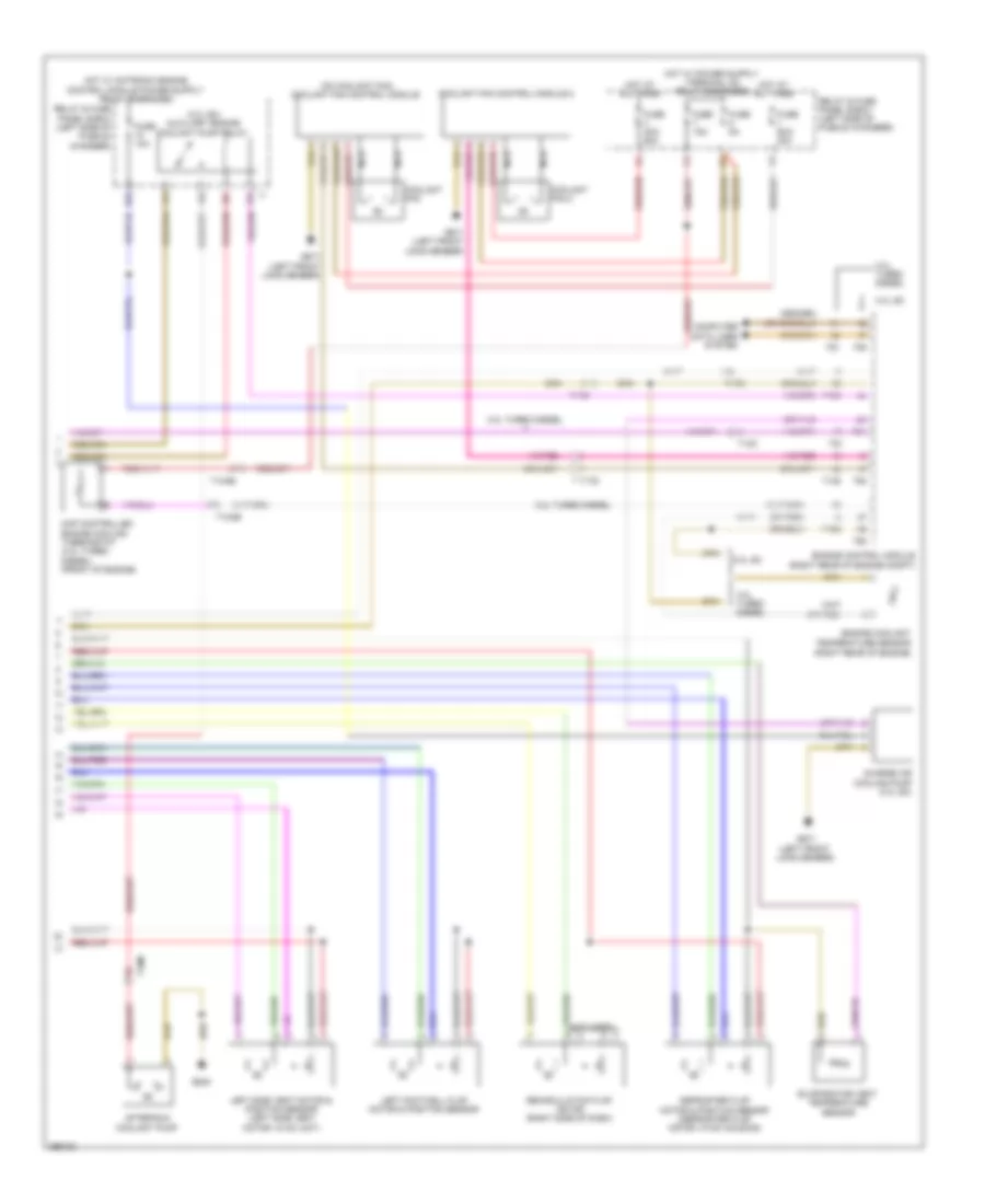
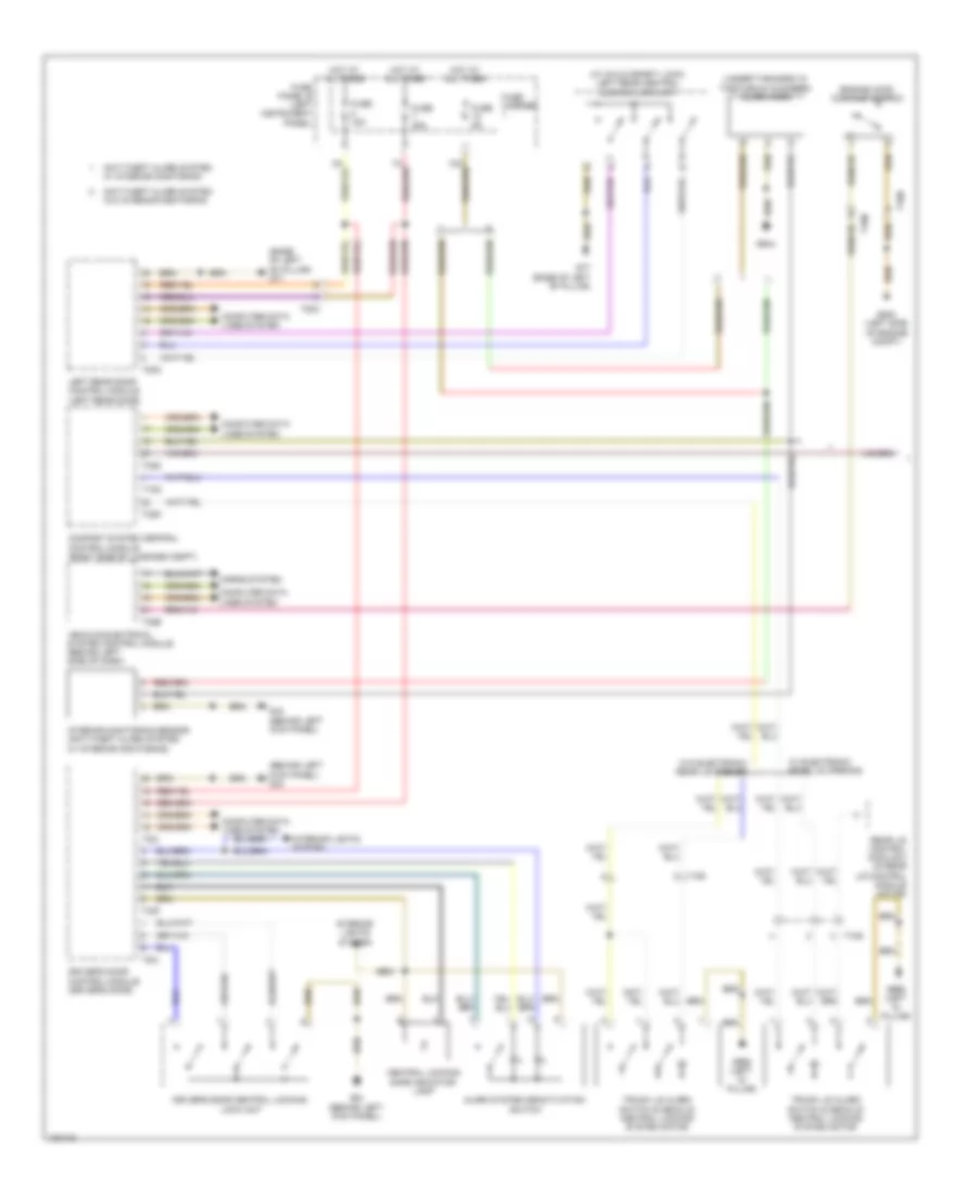
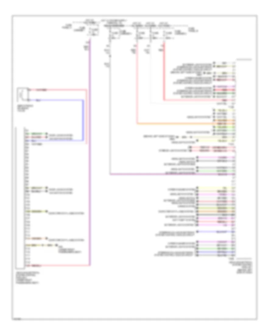
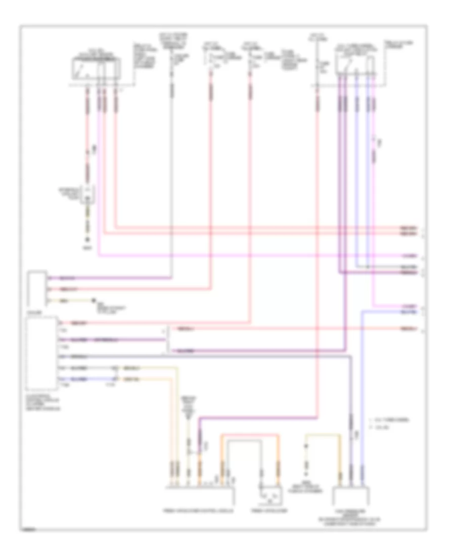
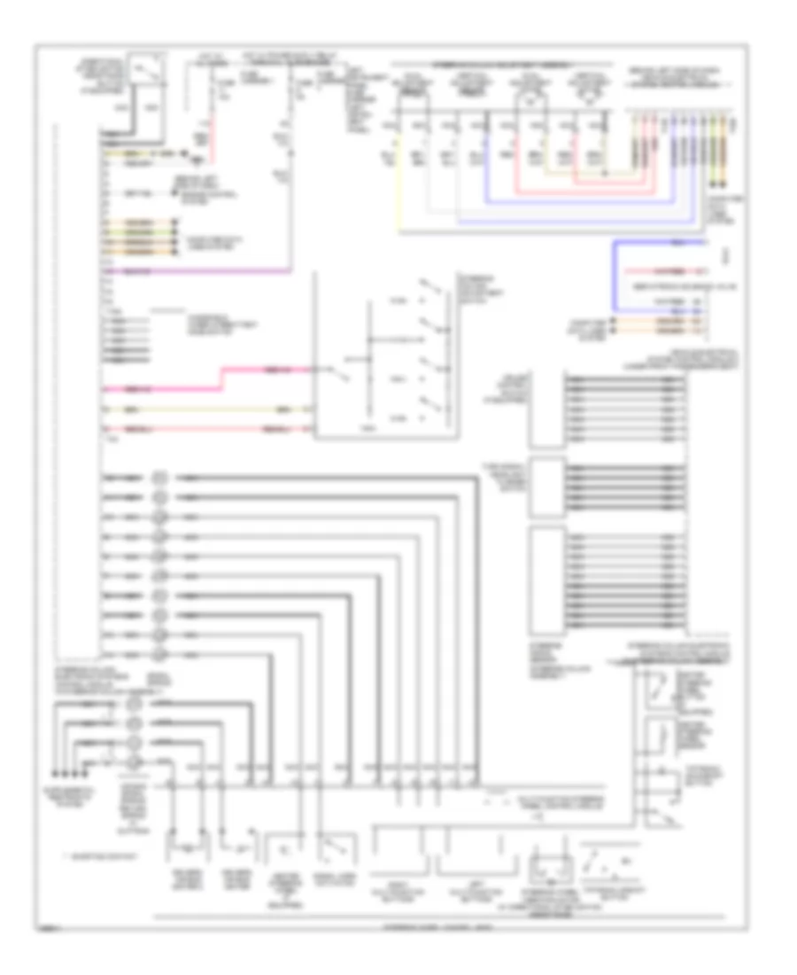
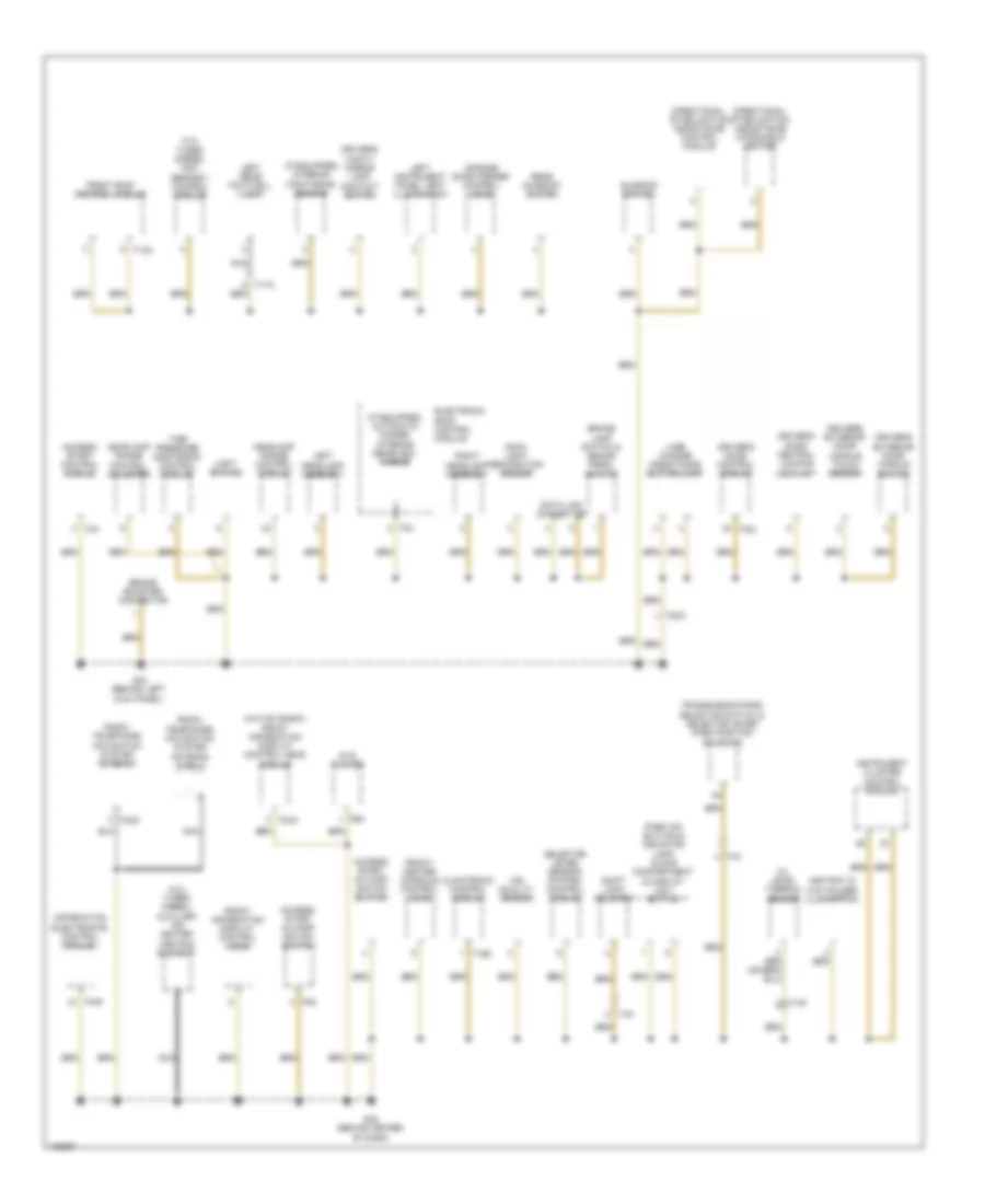
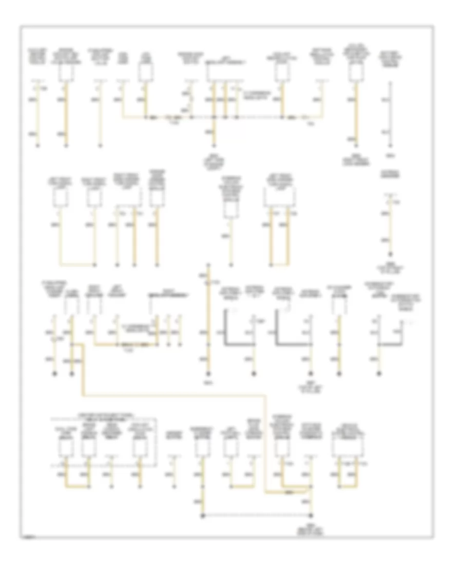
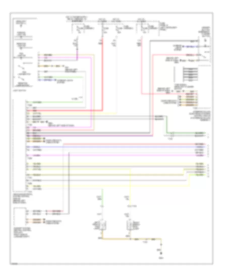
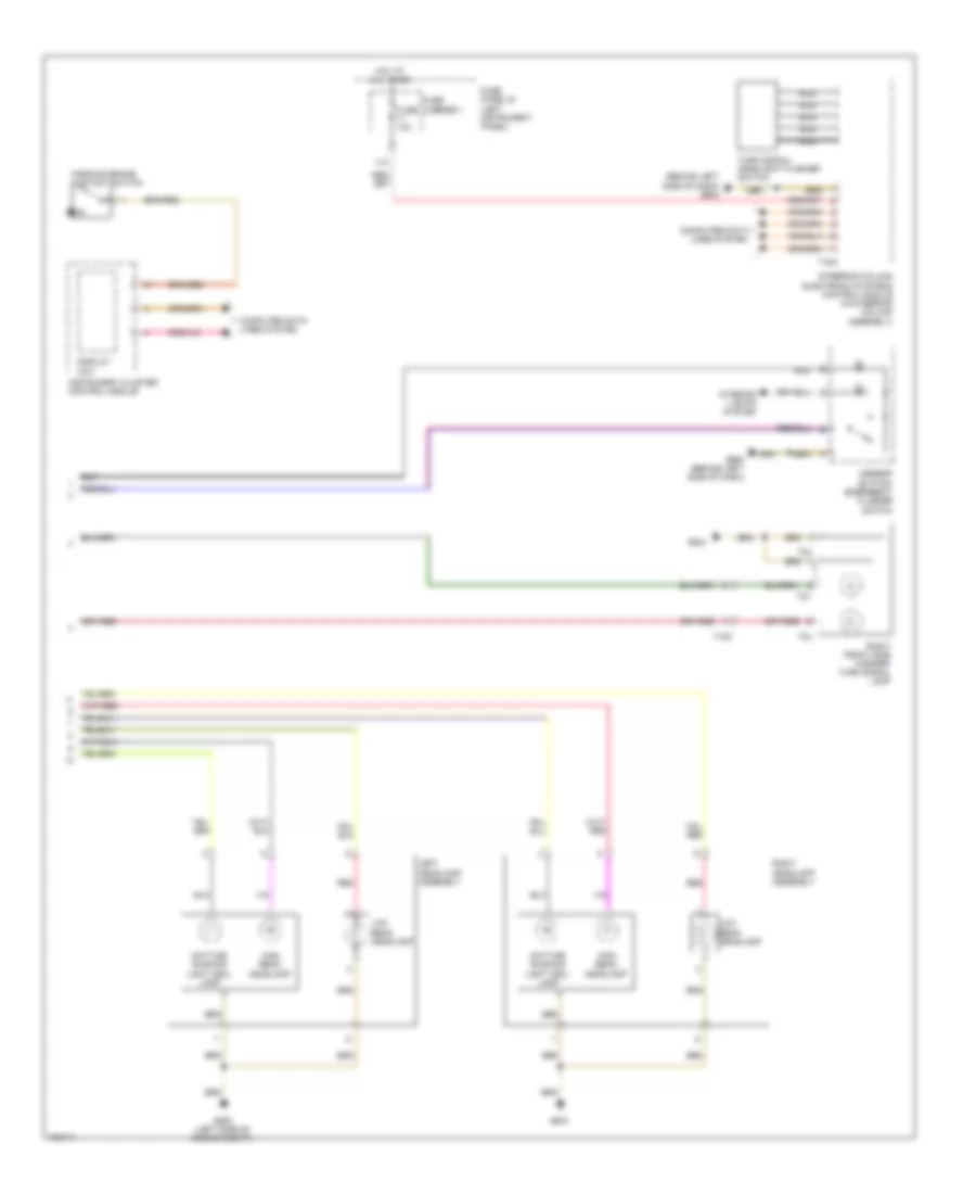
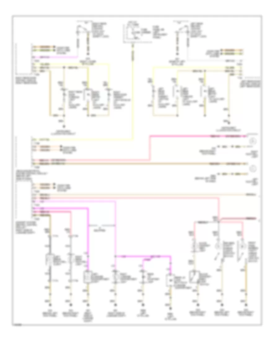
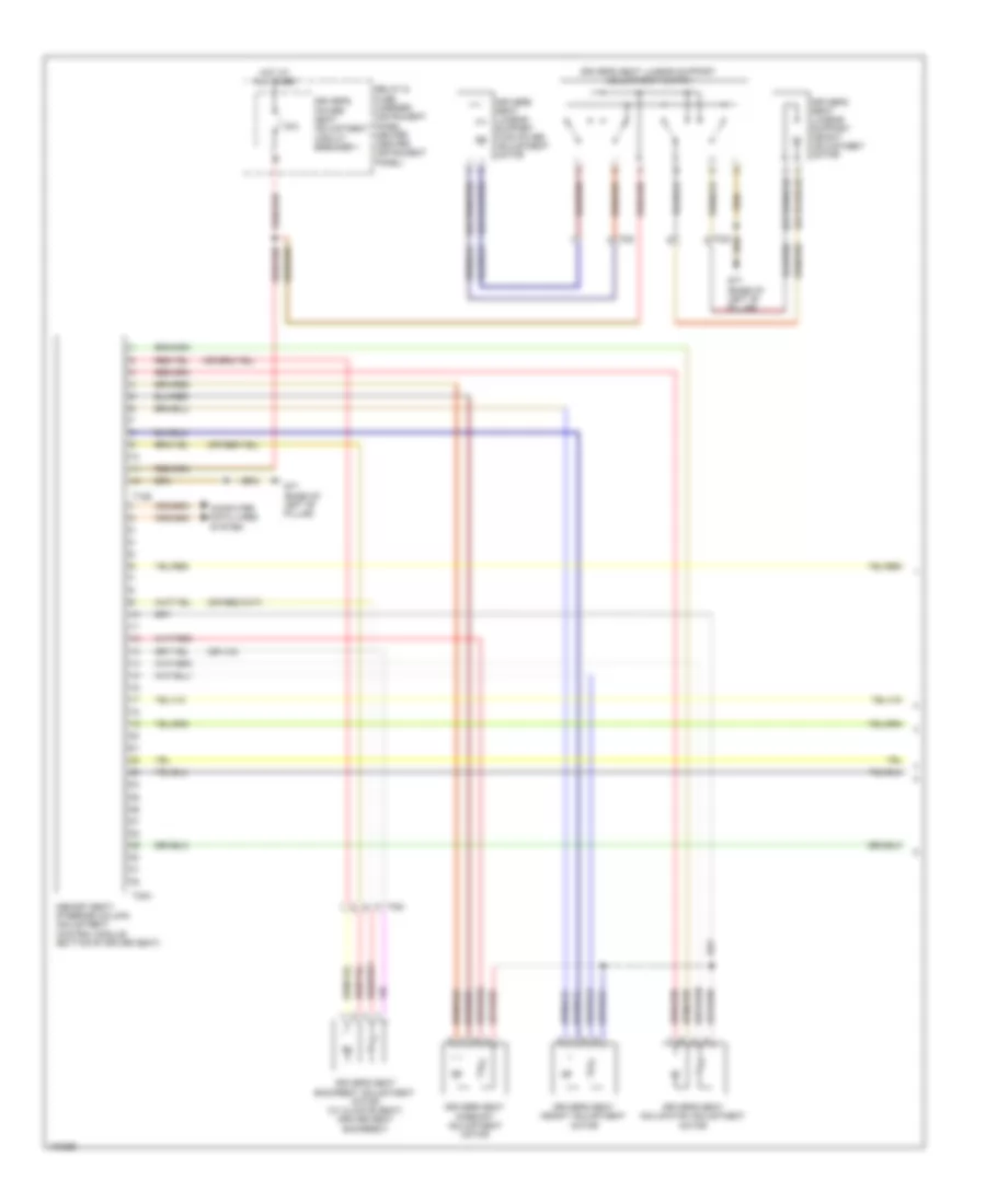
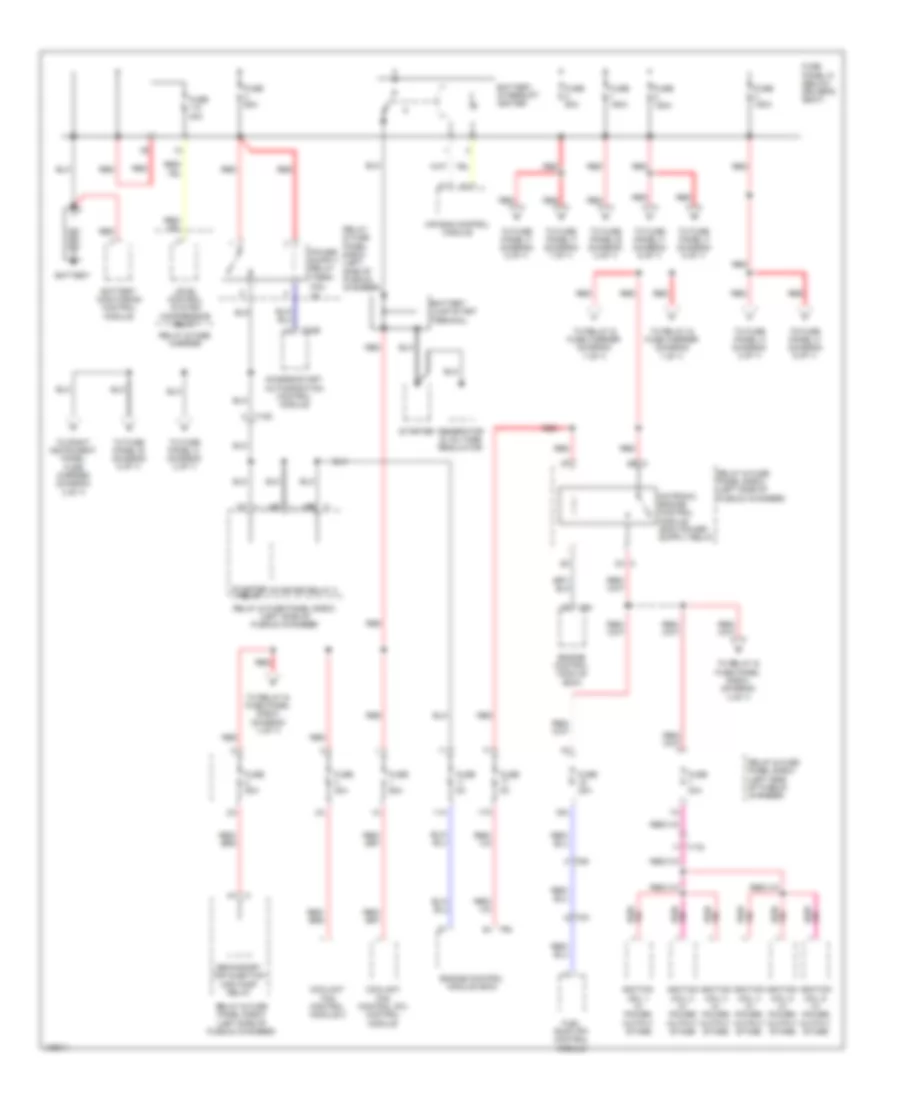
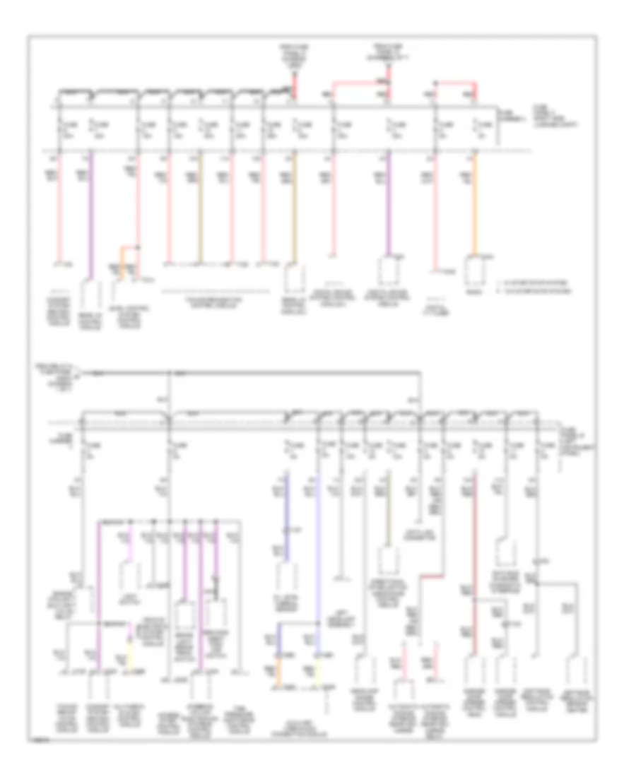
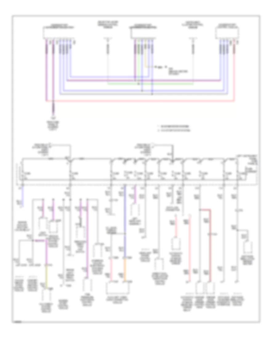
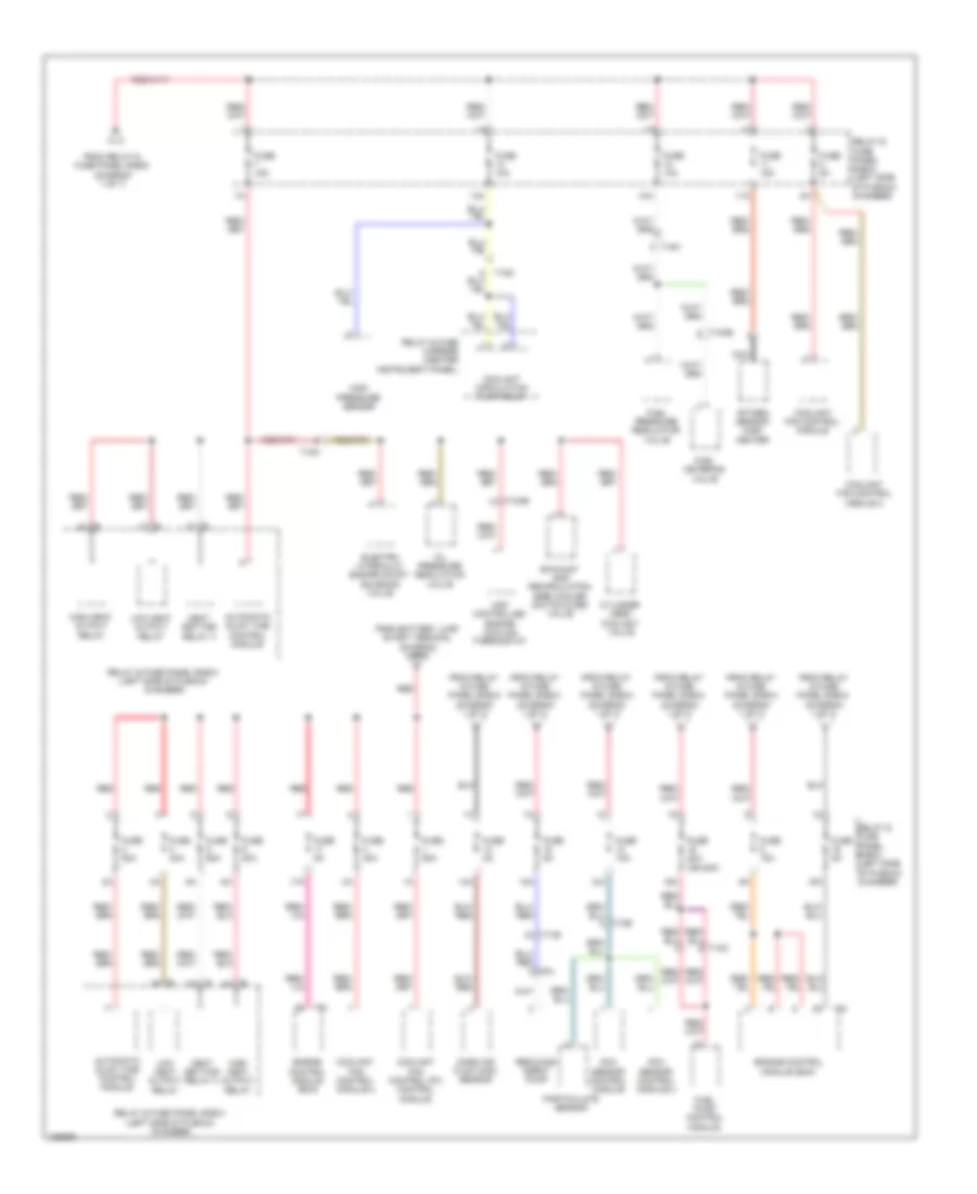
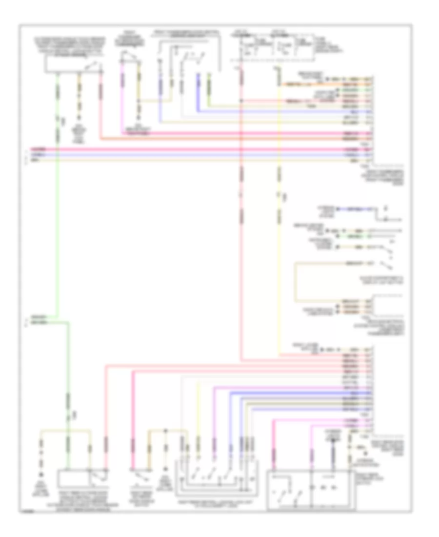
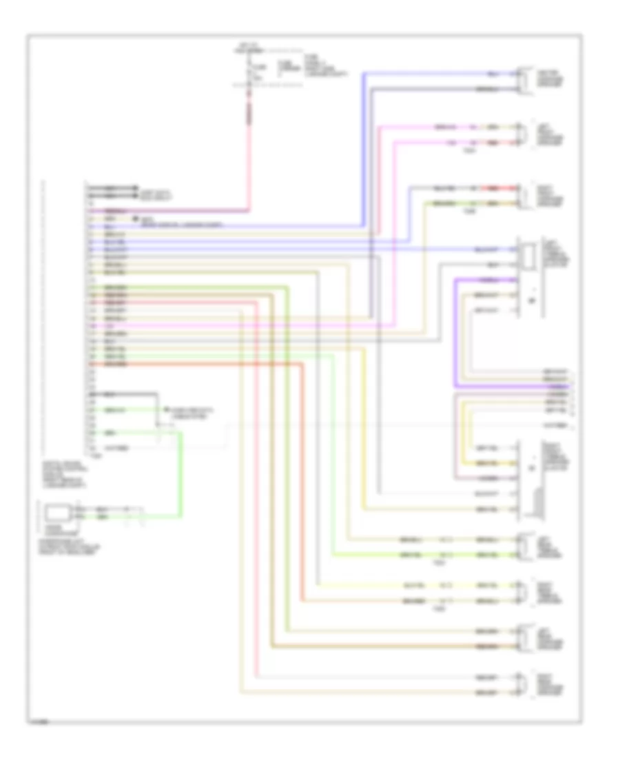
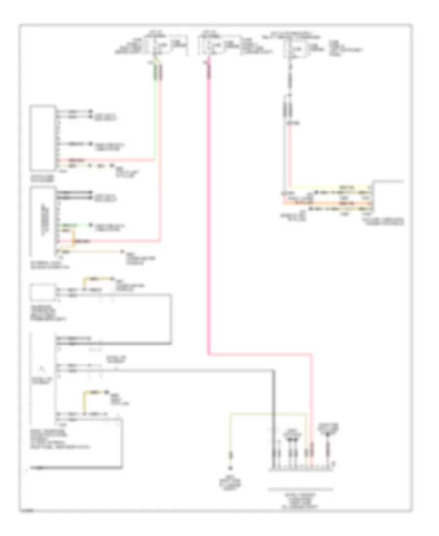
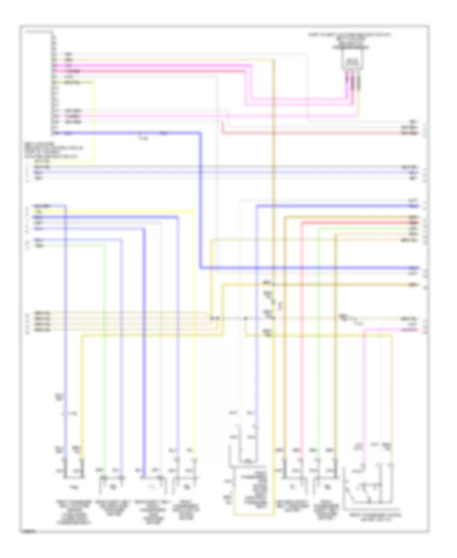
AIR CONDITIONING
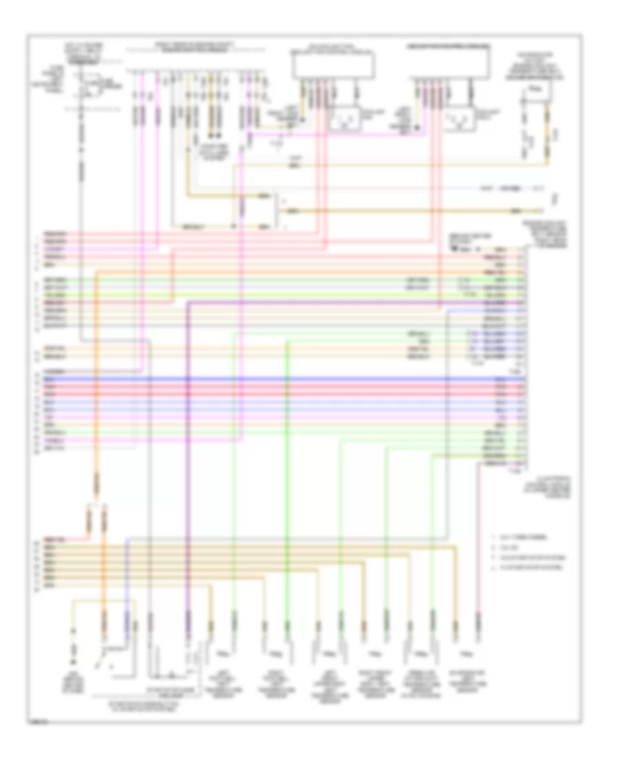
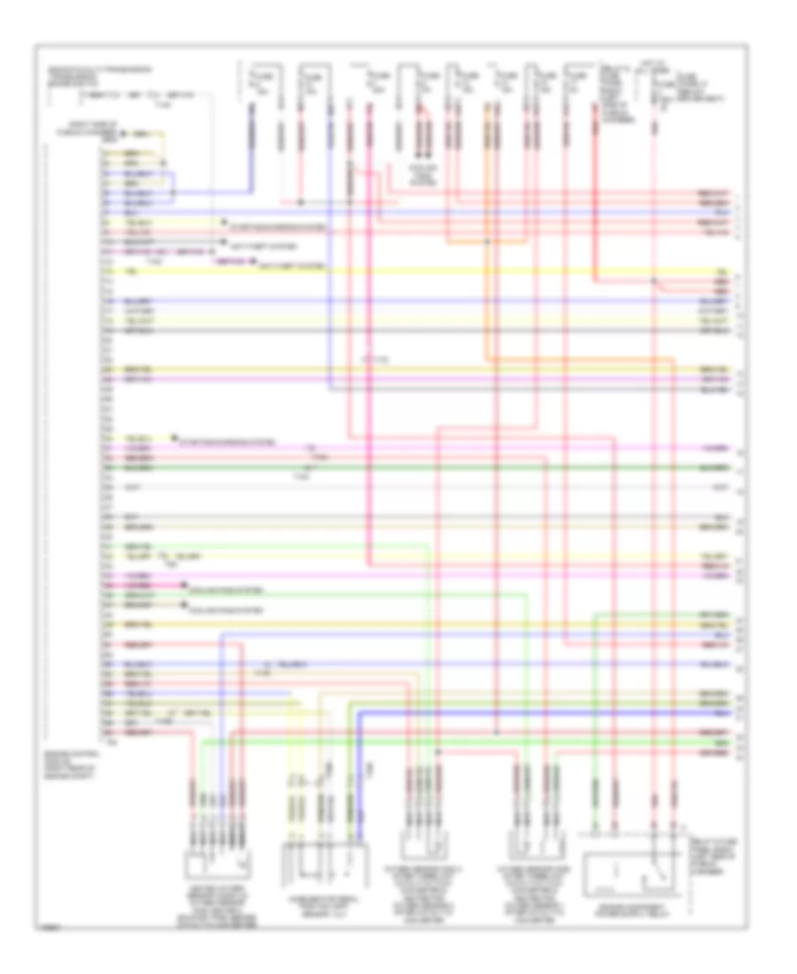
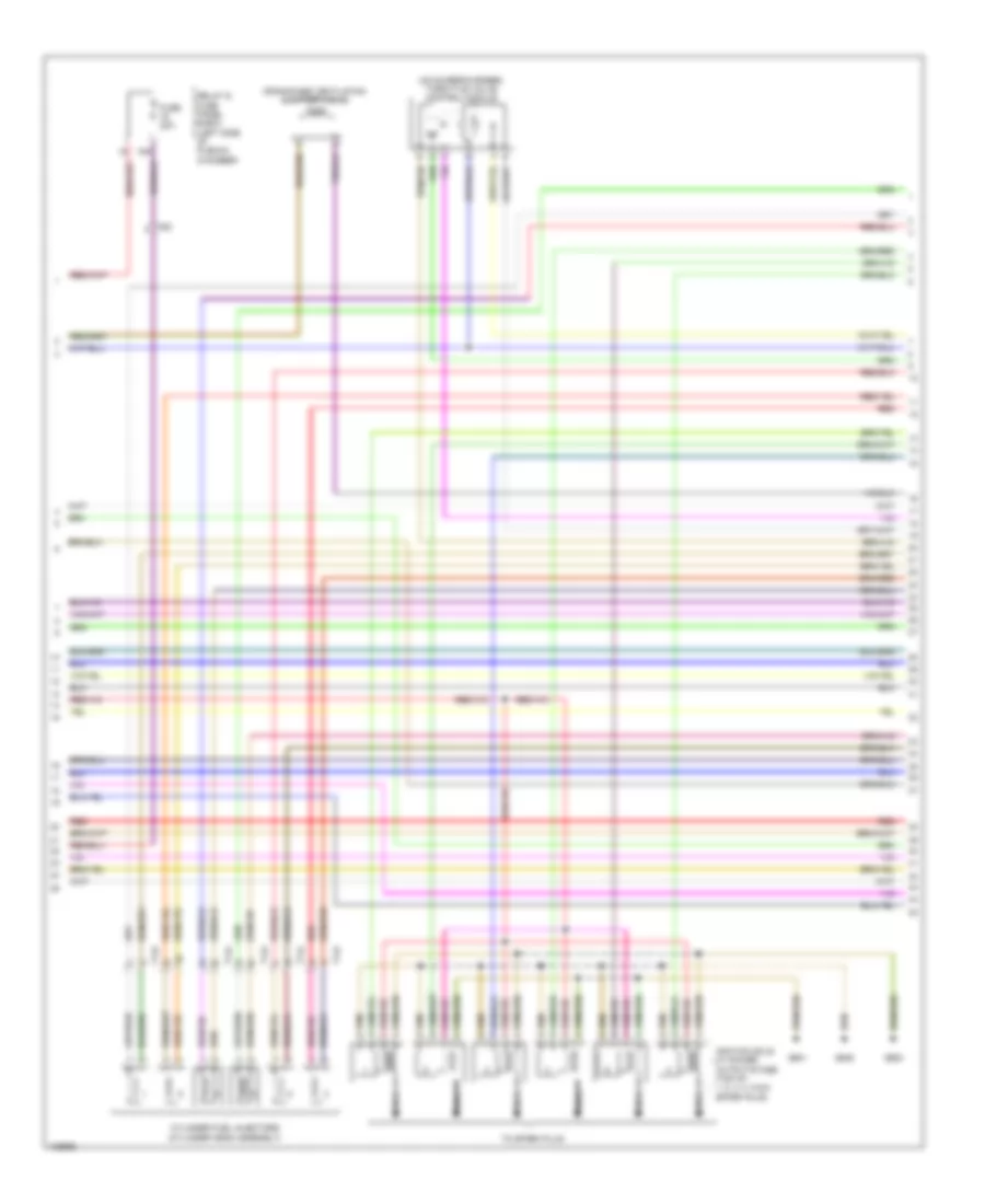
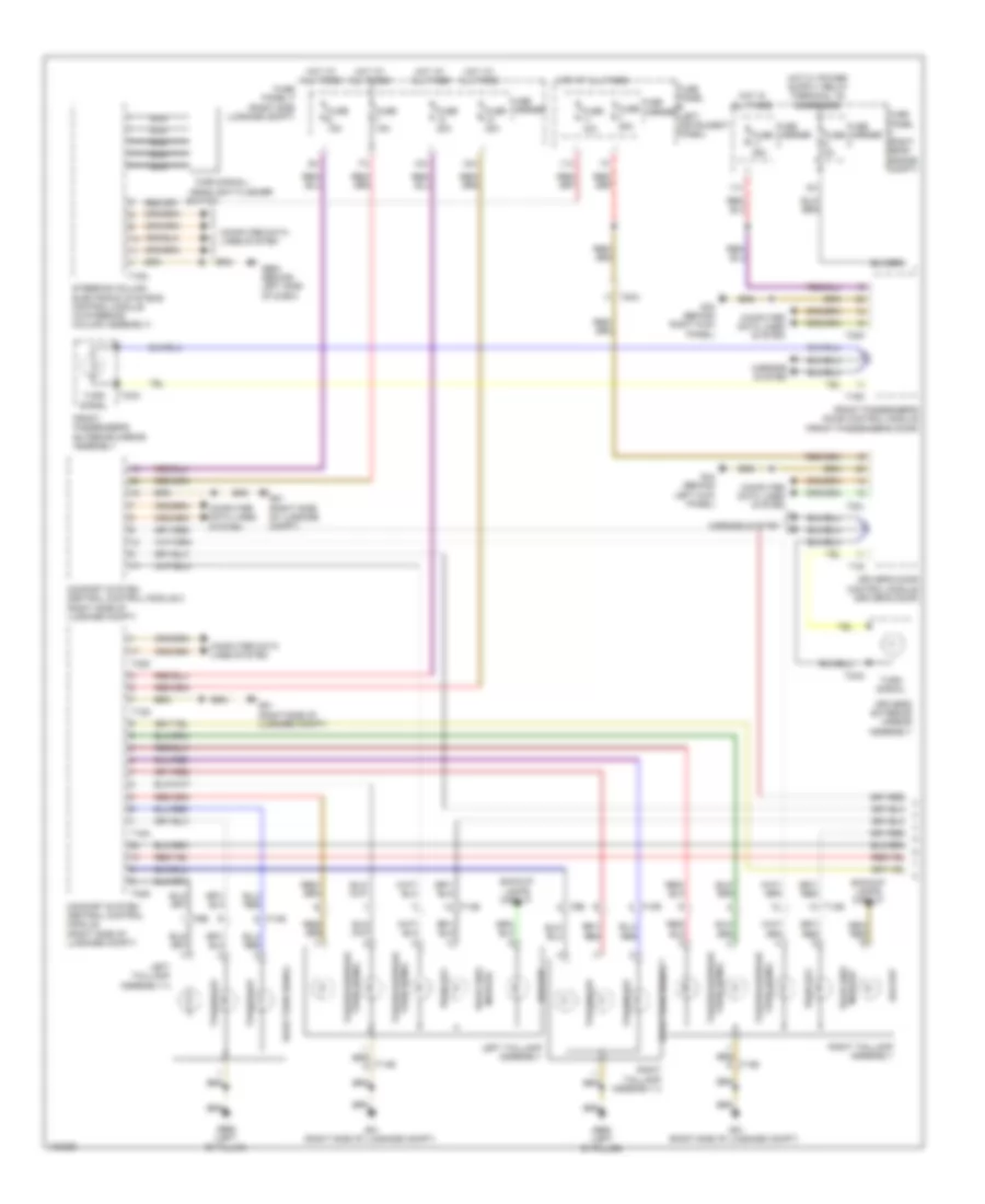
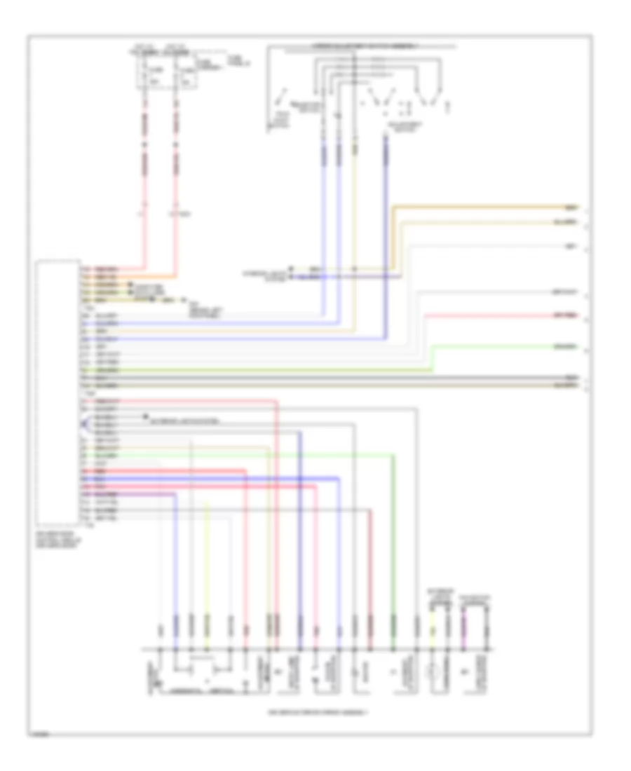
Automatic A/C Wiring Diagram, Basic (1 of 2) for Audi Q7 Prestige S 2013

List of elements for Automatic A/C Wiring Diagram, Basic (1 of 2) for Audi Q7 Prestige S 2013:
- (behind center of dash) g45
- (behind right kick panel) g43
- (left side of engine compt) g640
- (rear of engine) coolant pump
- (right side of plenum chamber) g609
- 10a
- 12a
- 13a
- 3.0l sc
- 3.0l turbo diesel
- A/c compressor regulator valve
- Climatronic control module (in upper center console)
- Computer data lines system
- Coolant circulation pump relay (3.ol turbo diesel)
- Engine temperature sensor (on radiator outlet)
- Fresh air blower
- Fresh air blower control module
- Fresh air blower fuse 1 40a
- Fuse 10a
- Fuse 15a
- Fuse 30a
- Fuse 5a
- Fuse carrier
- Fuse panel c (right rear engine compt)
- High pressure sensor (evaporator expansion valve, under right side of dash)
- Hot at all times
- Left temperature flap motor & potentiometer/ actuator (left temperature flap motor: hvac housing)
- Relay & fuse carrier
- Relay & fuse panel e-box (left side of plenum chamber)
- Seats system
- Suppressor
- T10d
- T10f
- T16d
- T17k
- T20i
- T2q
- T3c
- T4t
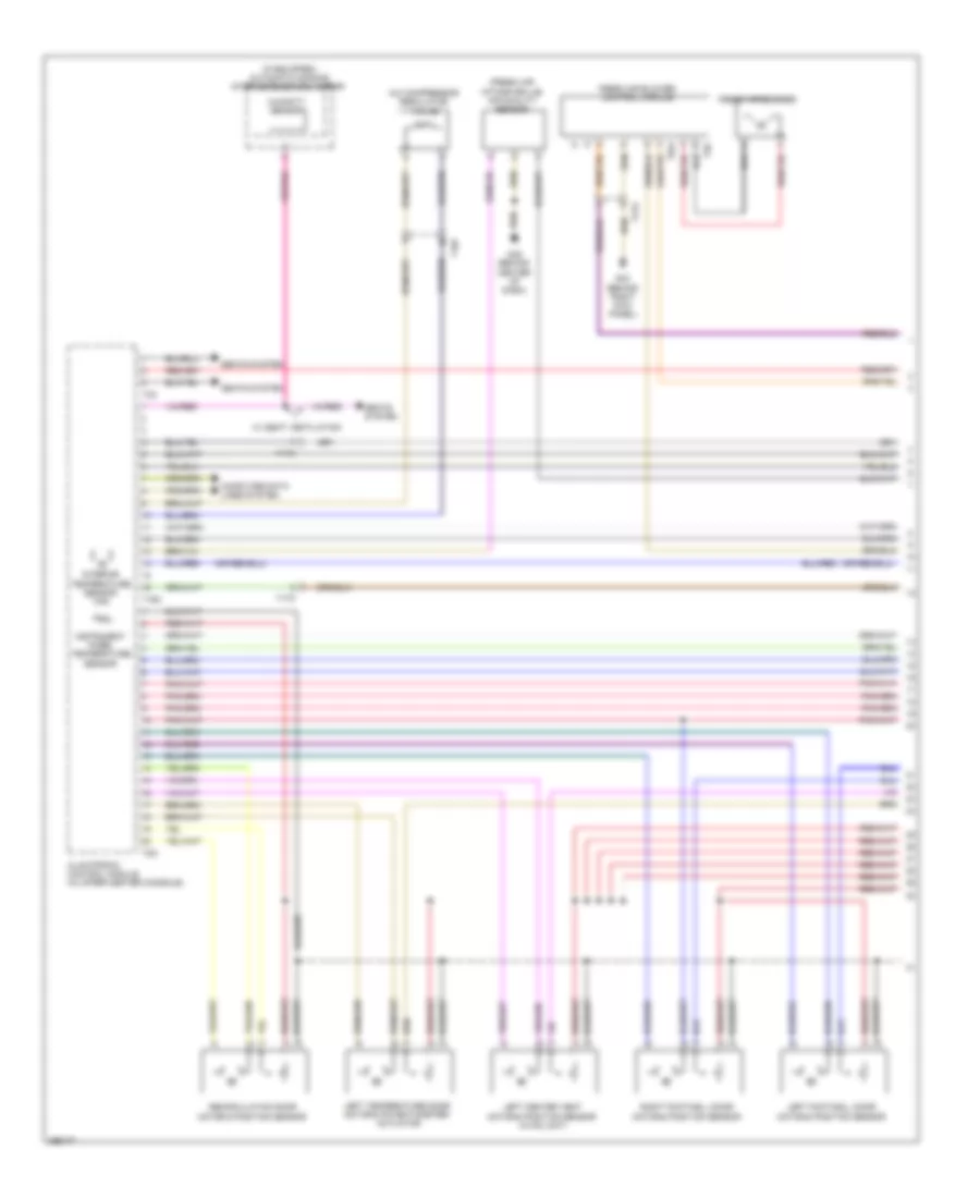
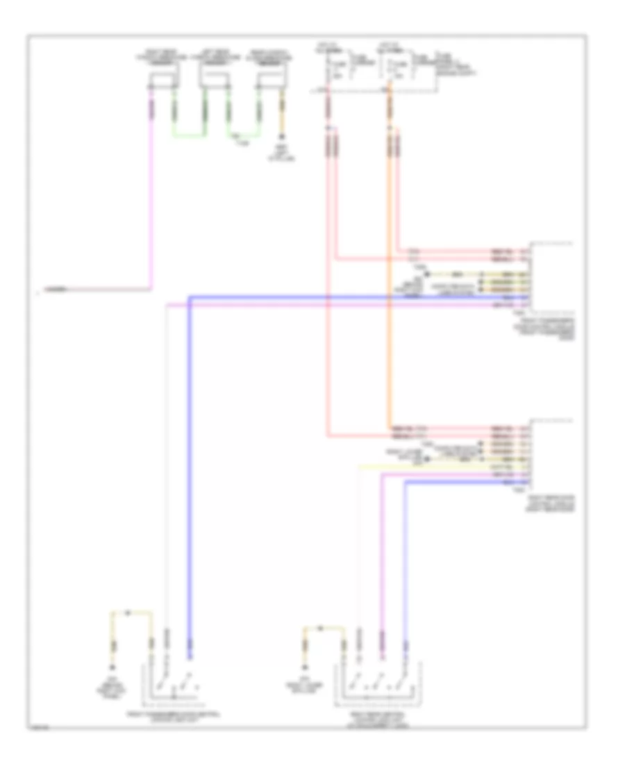
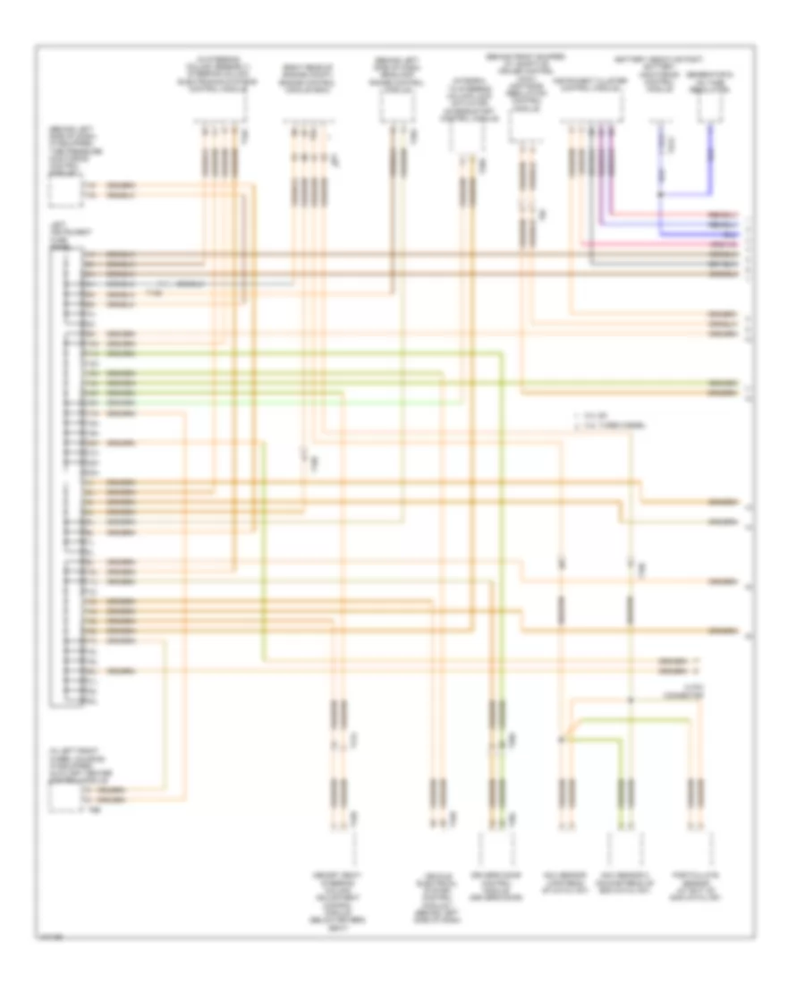
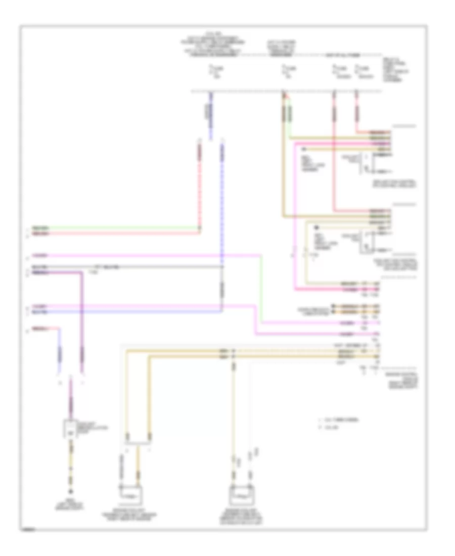
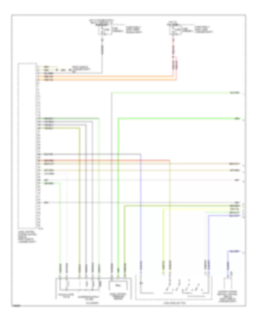
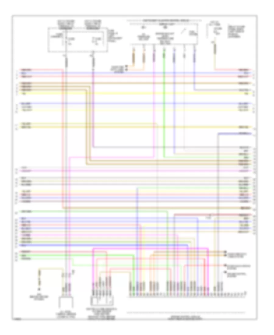
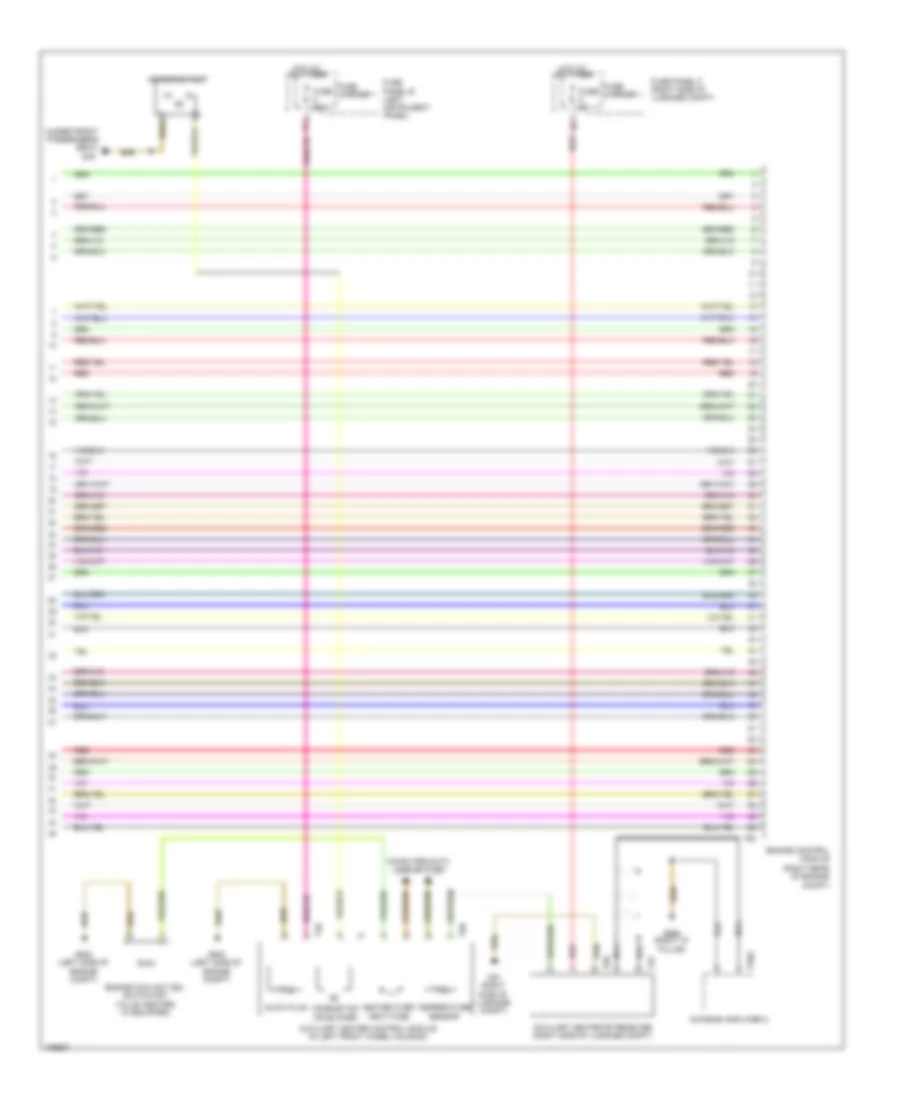
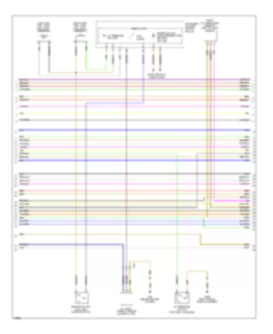
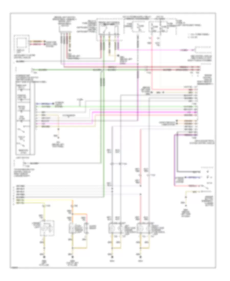
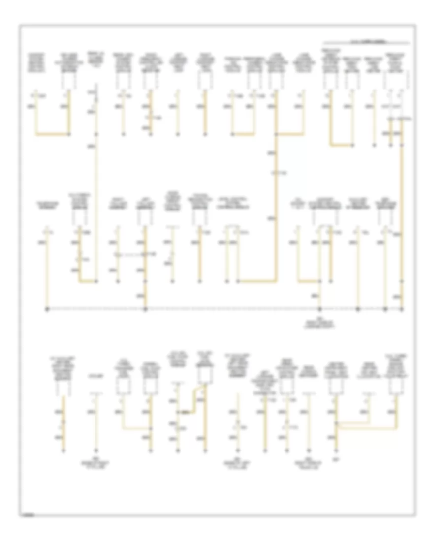
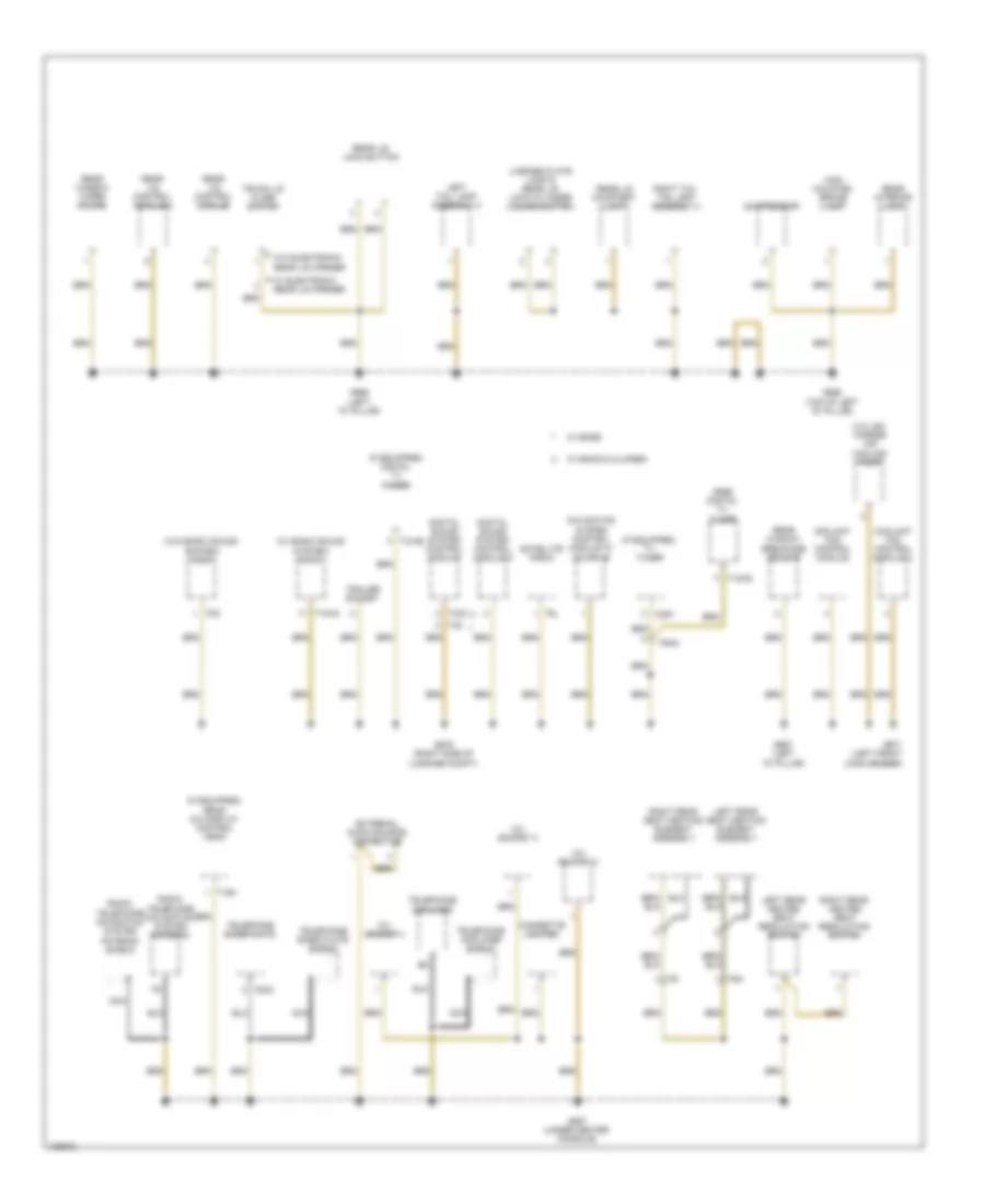
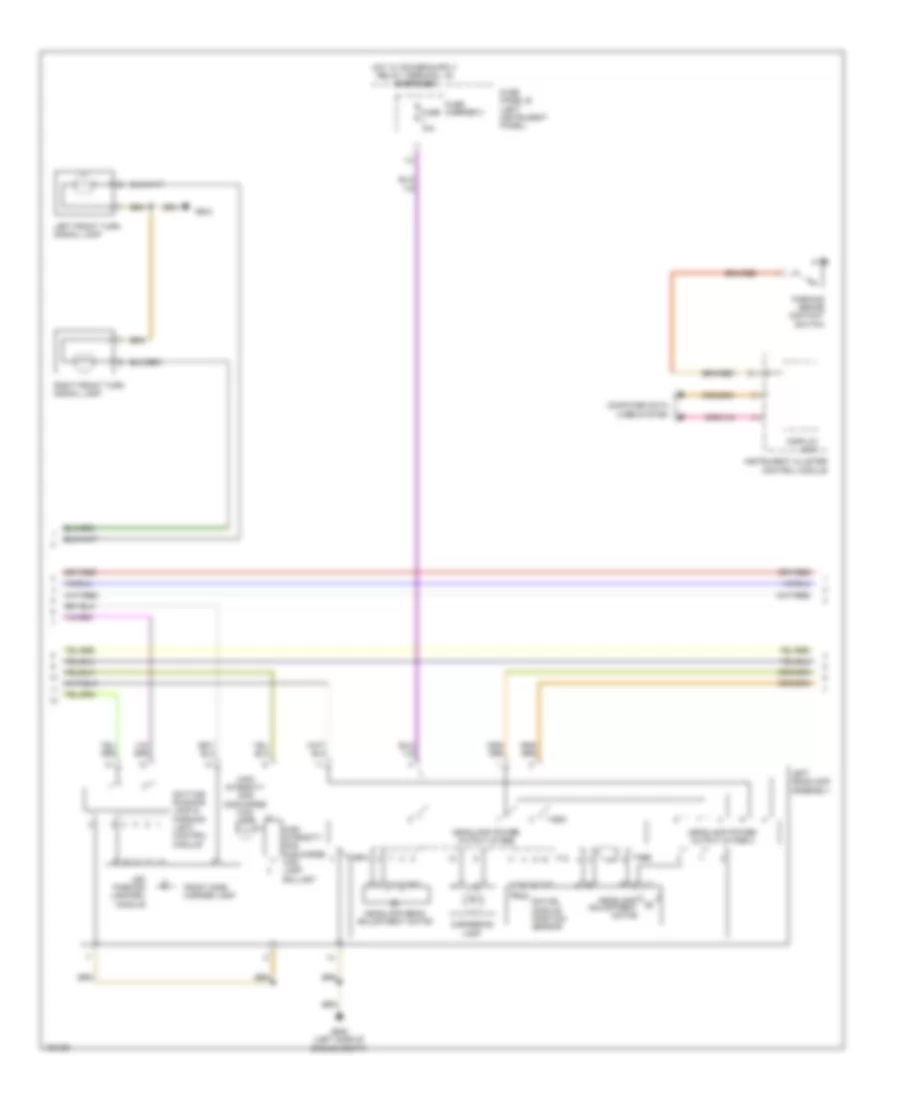
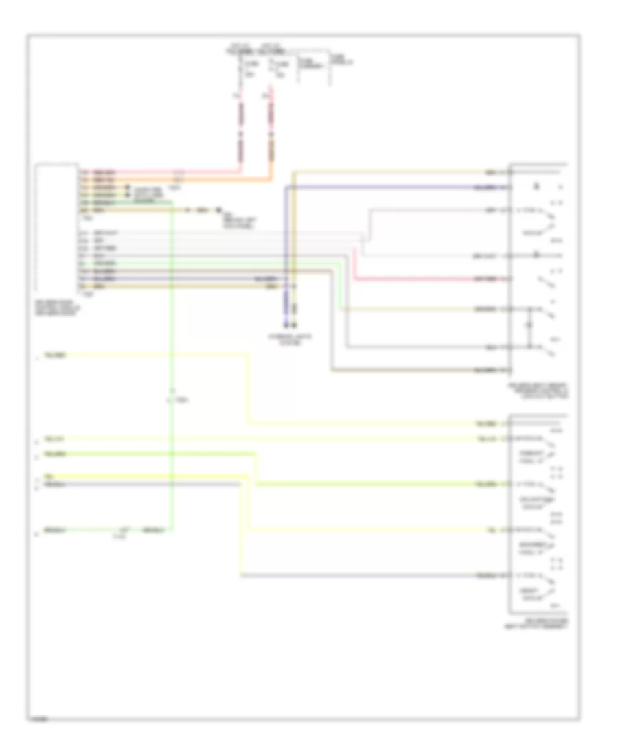
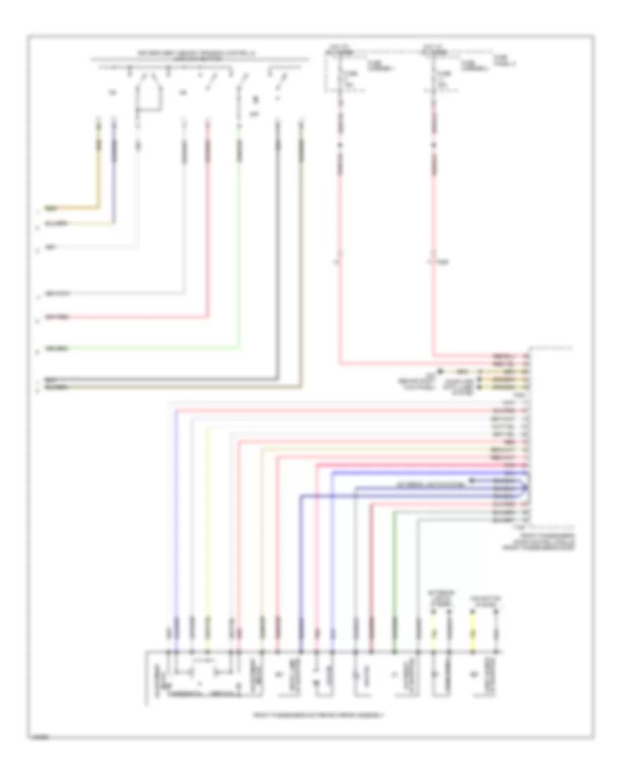
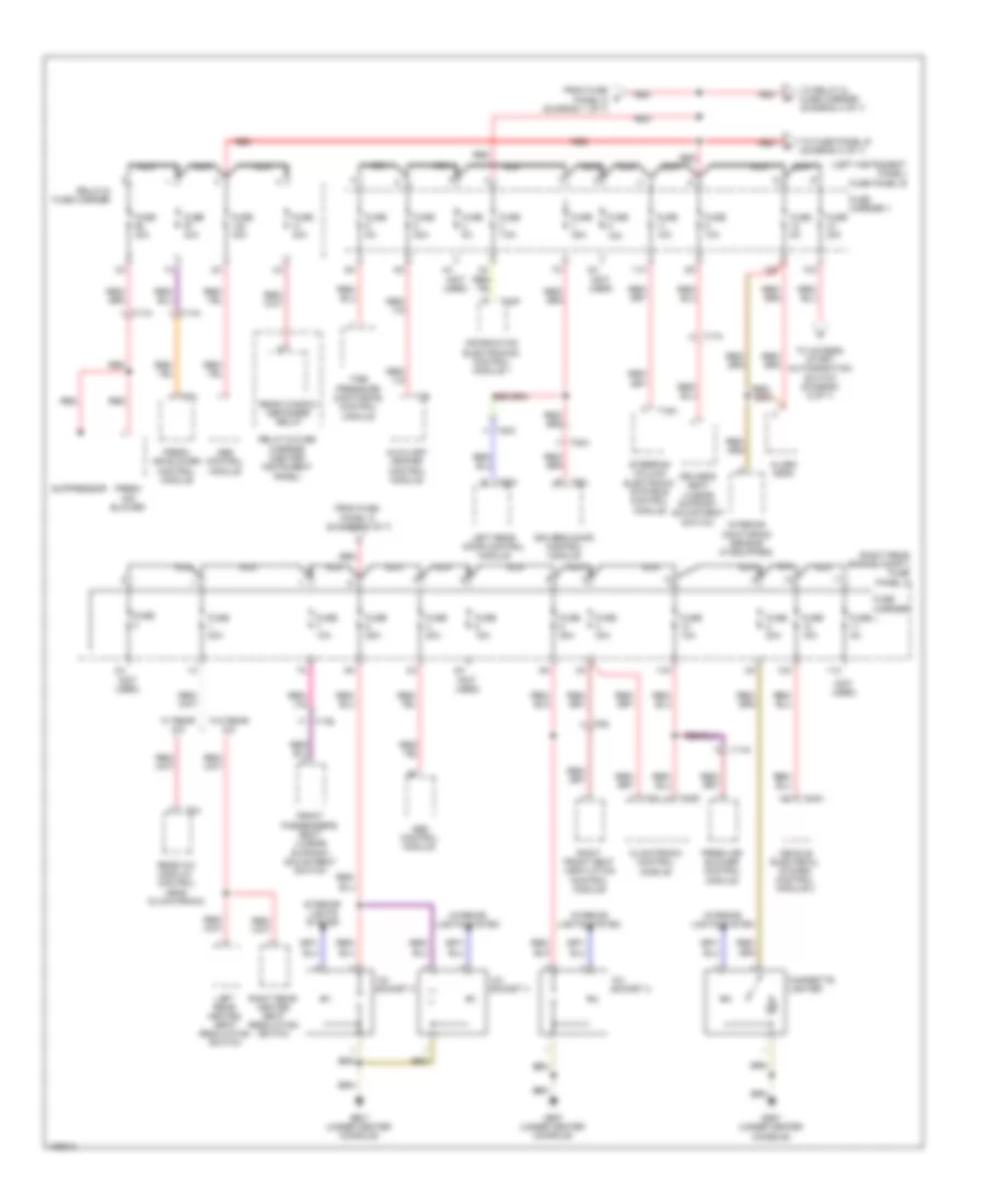
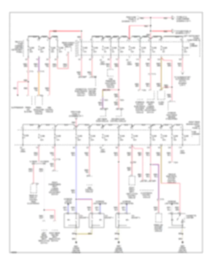
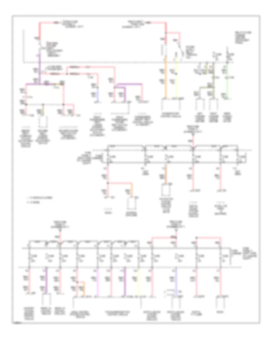
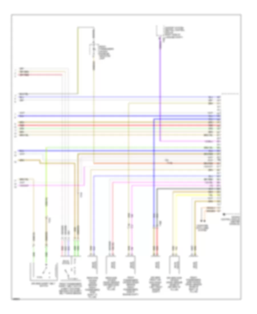
Automatic A/C Wiring Diagram, Basic (2 of 2) for Audi Q7 Prestige S 2013
List of elements for Automatic A/C Wiring Diagram, Basic (2 of 2) for Audi Q7 Prestige S 2013:
- (3.0l sc) auxiliary engine coolant pump relay
- (on coolant fan) coolant fan control module
- (or red)
- (right rear of engine)
- 10a
- 19a
- 19c
- 19d
- 19e
- 3.0l sc
- 3.0l turbo diesel
- After-run coolant pump
- Charge air cooling pump (3.0l sc)
- Computer data lines system
- Coolant fan
- Coolant fan 2
- Coolant fan control module 2
- Defroster flap motor & position sensor (defroster flap motor: hvac housing)
- Engine control module (right rear of engine compt)
- Engine coolant temperature sensor
- Evaporator vent temperature sensor
- Fuse 10a
- Fuse 15a
- Fuse 40a/ 60a
- Fuse 5a
- Fuse 60a/ 40a
- G645
- G671 (left front long member)
- Hot at all times
- Left footwell flap motor & position sensor
- Left side vent motor & position sensor (left side vent motor: hvac unit)
- Map controlled engine cooling thermostat (3.0l turbo diesel) (front of engine)
- Nca
- Recirculation flap motor (right side of dash)
- Relay & fuse panel e-box (left side of plenum chamber)
- T105
- T10ab
- T10c
- T10m
- T17d
- T60
- T91
- T94
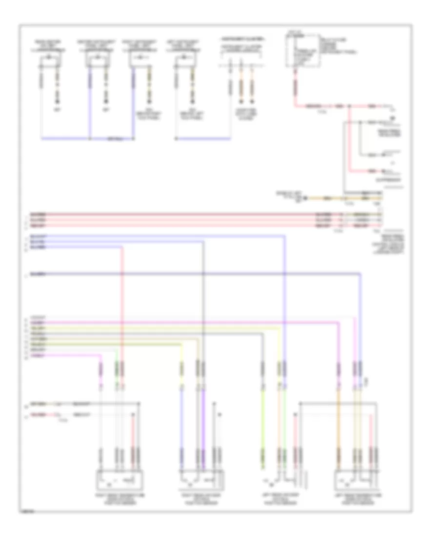
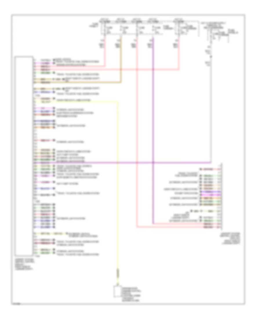
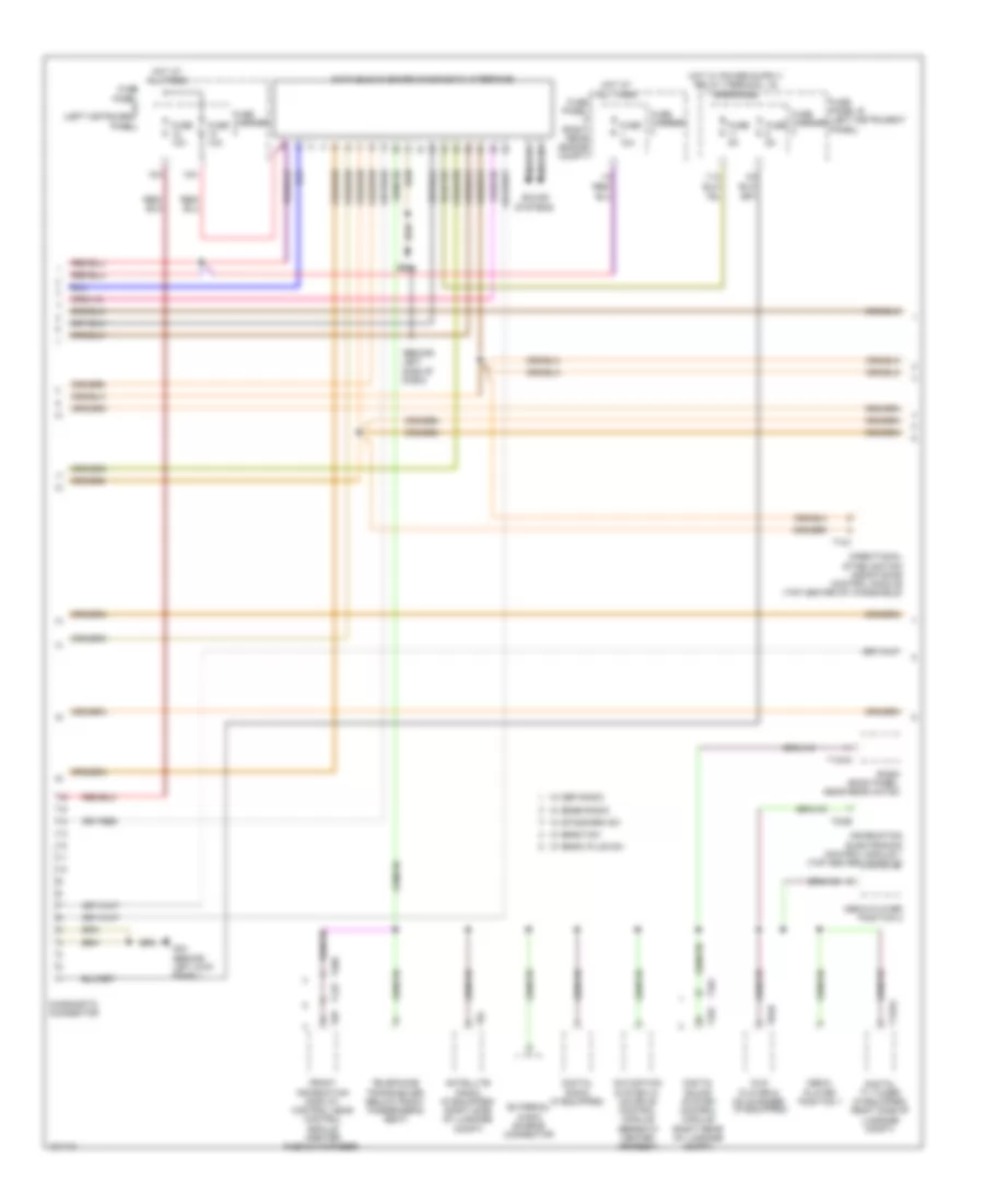
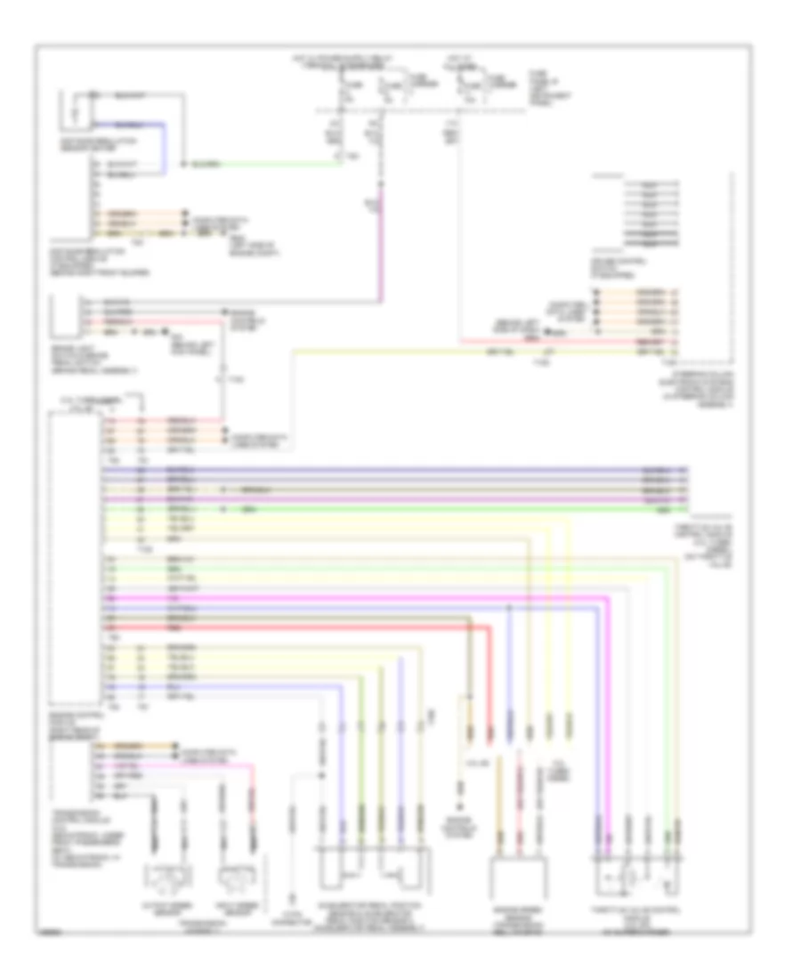
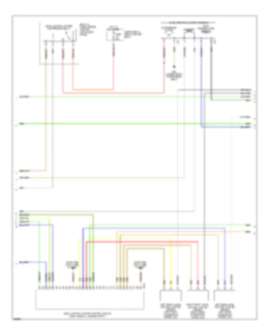
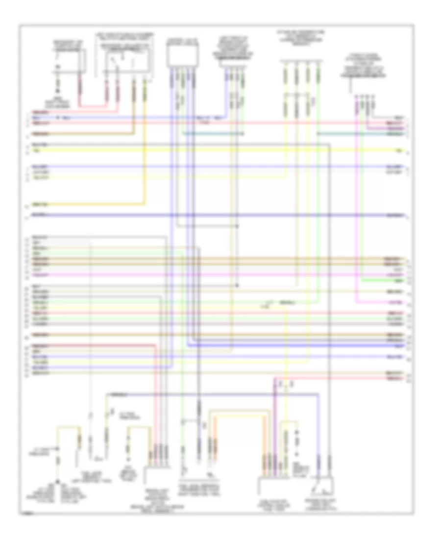
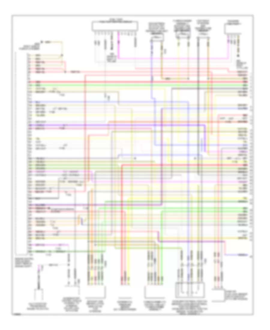
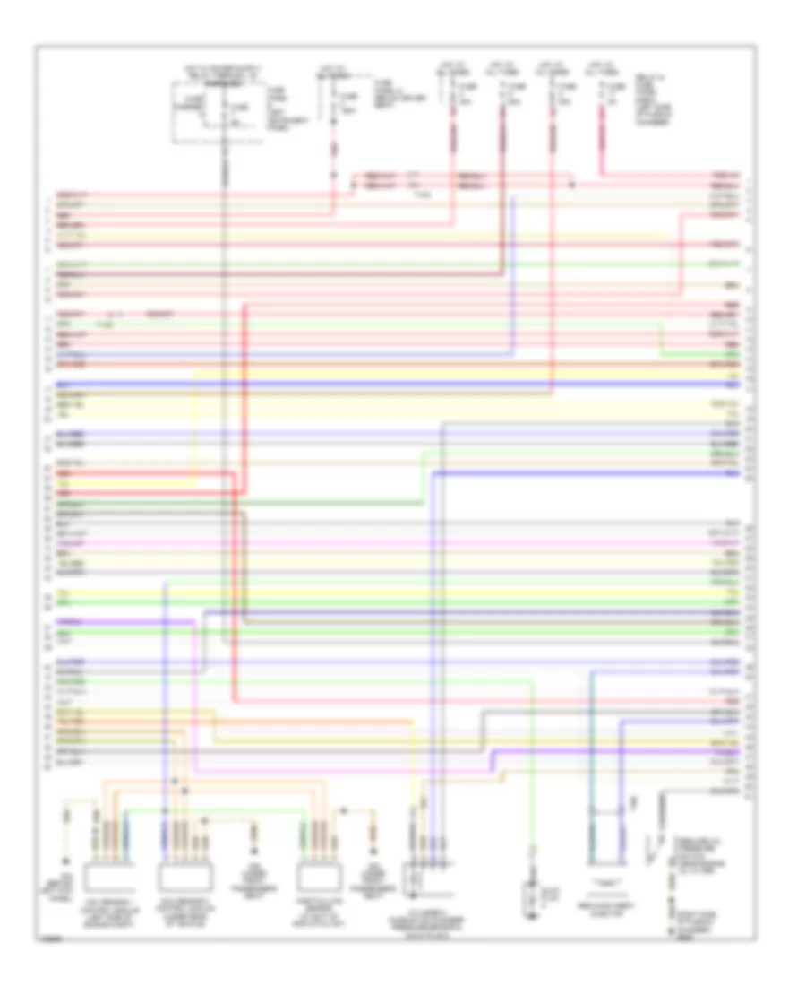
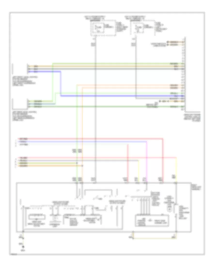
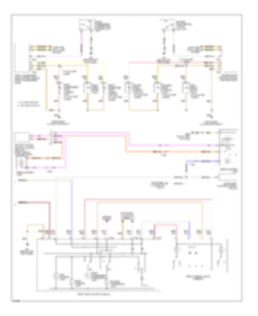
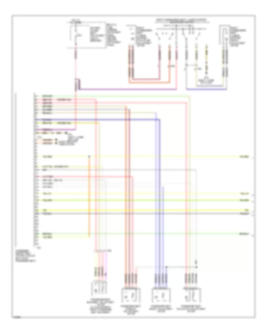
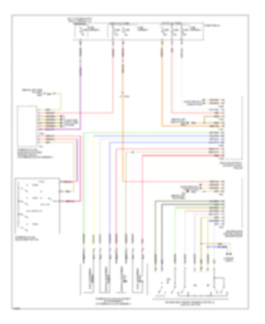
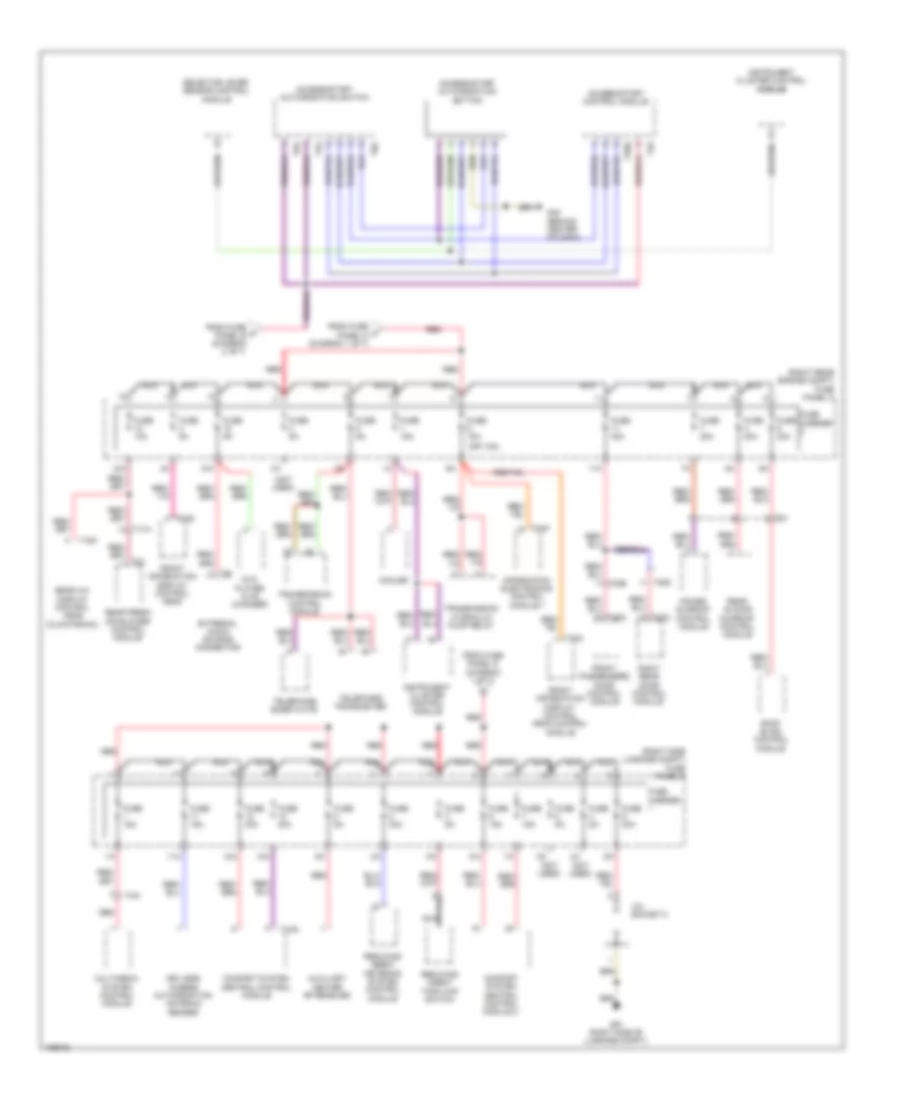
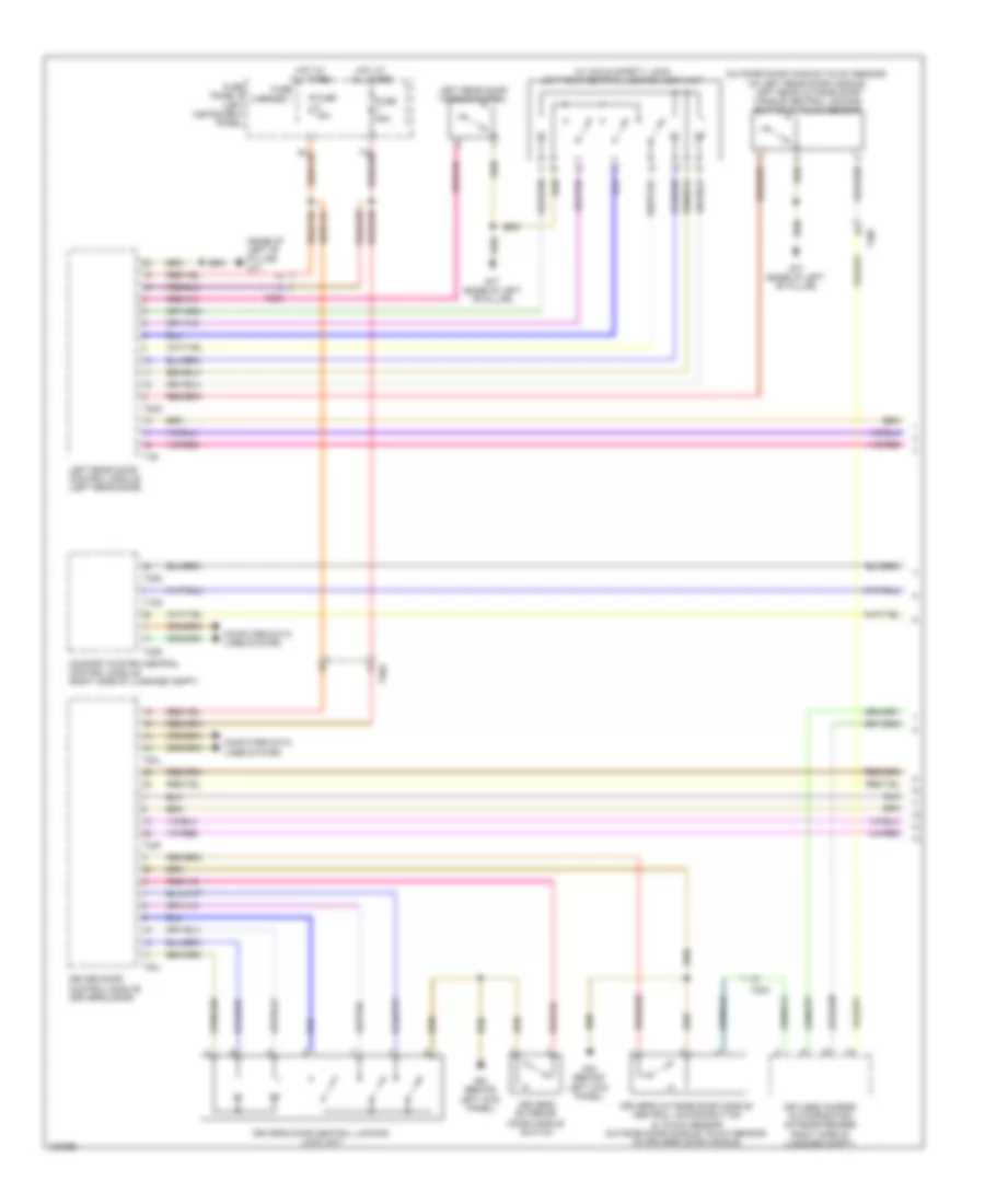
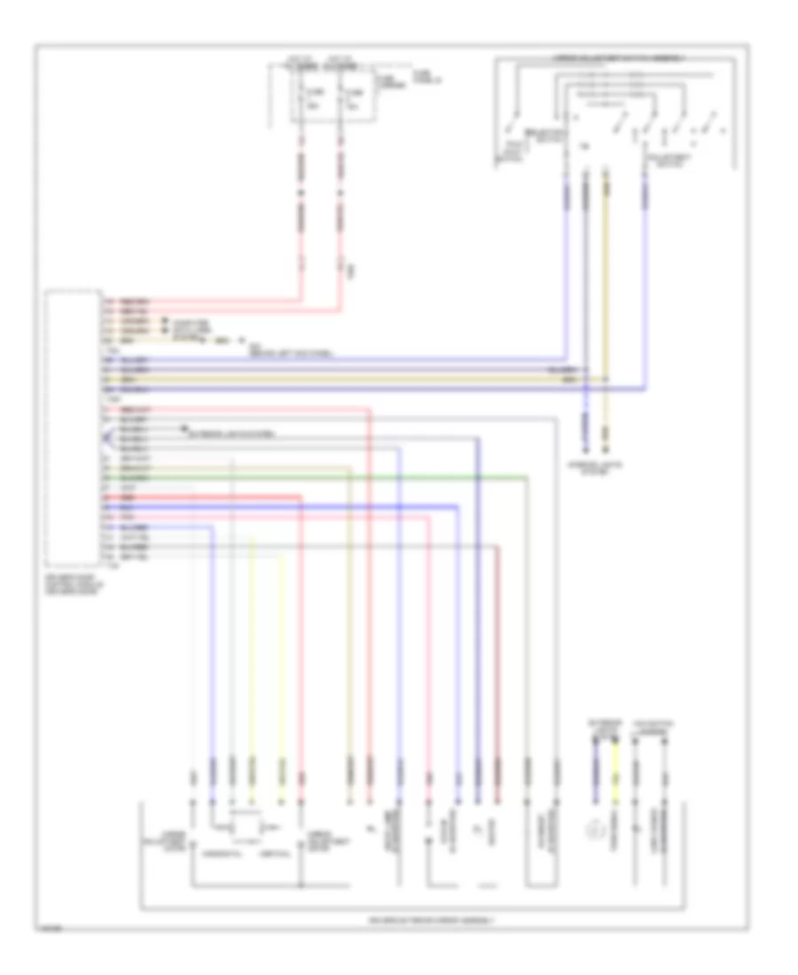
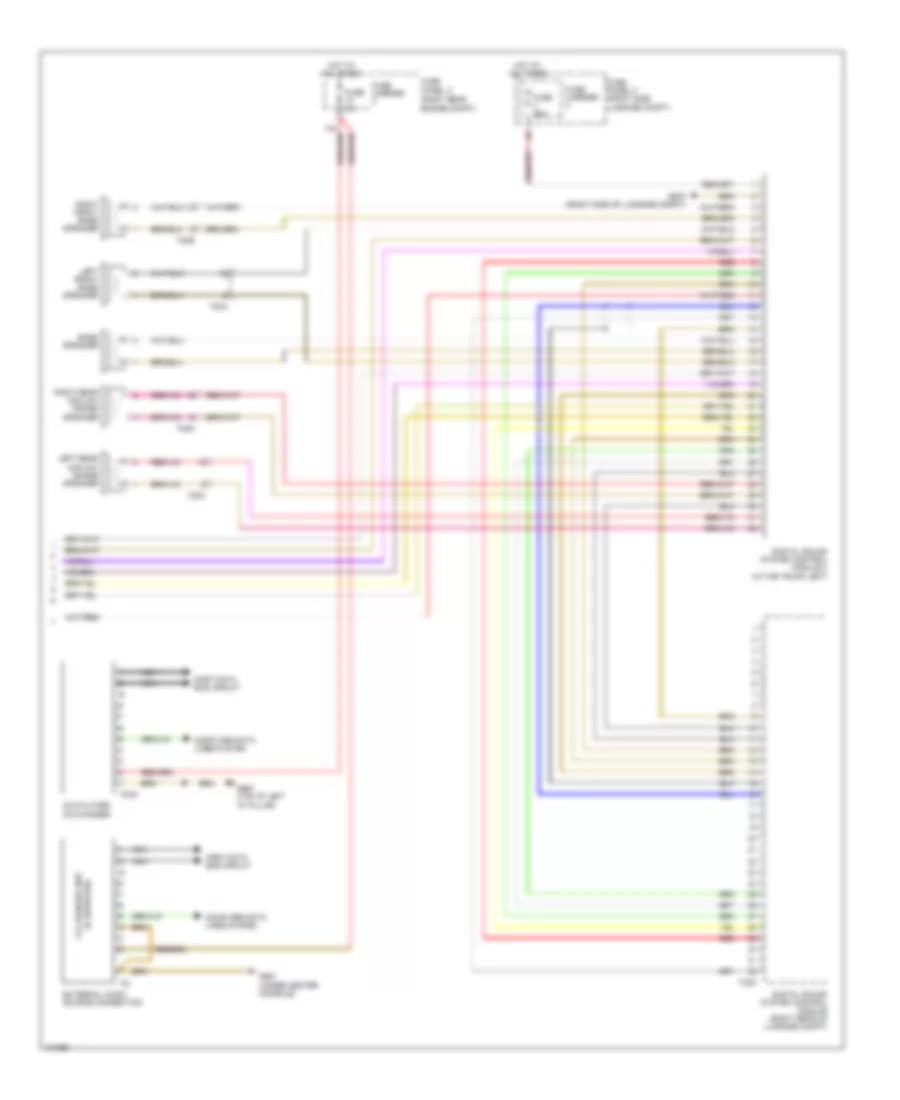
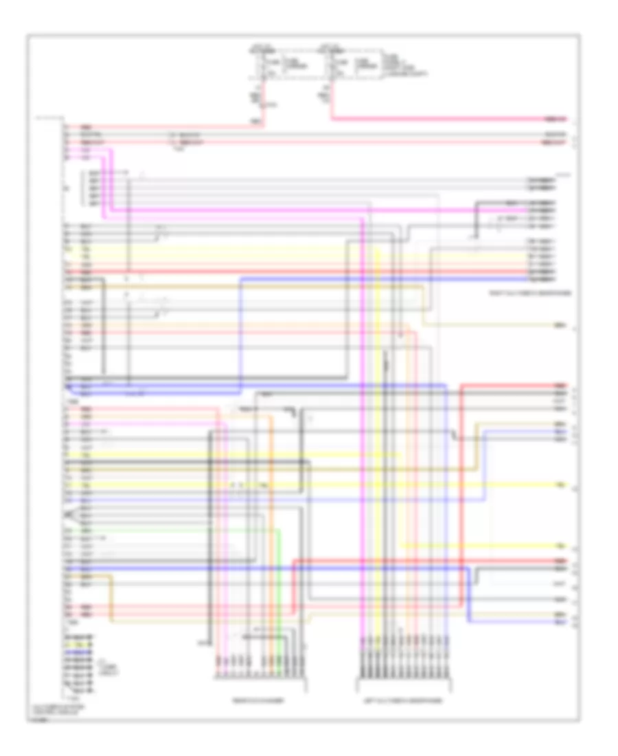
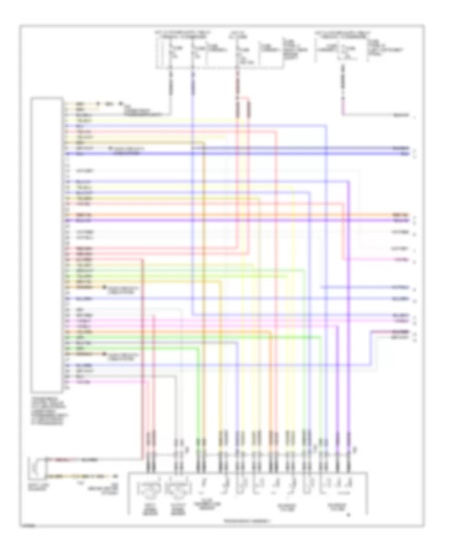
Automatic A/C Wiring Diagram, Comfort (1 of 4) for Audi Q7 Prestige S 2013
List of elements for Automatic A/C Wiring Diagram, Comfort (1 of 4) for Audi Q7 Prestige S 2013:
- (fresh air intake grille) air quality sensor
- (if equipped) automatic dimming interior rearview mirror
- A/c compressor regulator valve
- Climatronic control module (in upper center console)
- Computer data lines system
- Fresh air blower
- Fresh air blower control module
- G43 (behind right kick panel)
- G45 (behind center of dash)
- Humidity sensor
- Instrument panel temperature sensor
- Interior temperature sensor fan
- Left center vent motor & position sensor (hvac unit)
- Left footwell door motor & position sensor
- Left temperature door motor & potentiometer/ actuator
- Recirculation door motor & position sensor
- Right footwell door motor & position sensor
- Seats system
- T10f
- T16c
- T17k
- T20i
- T2q
- T3c
- T6ai
- W/ seat ventilation
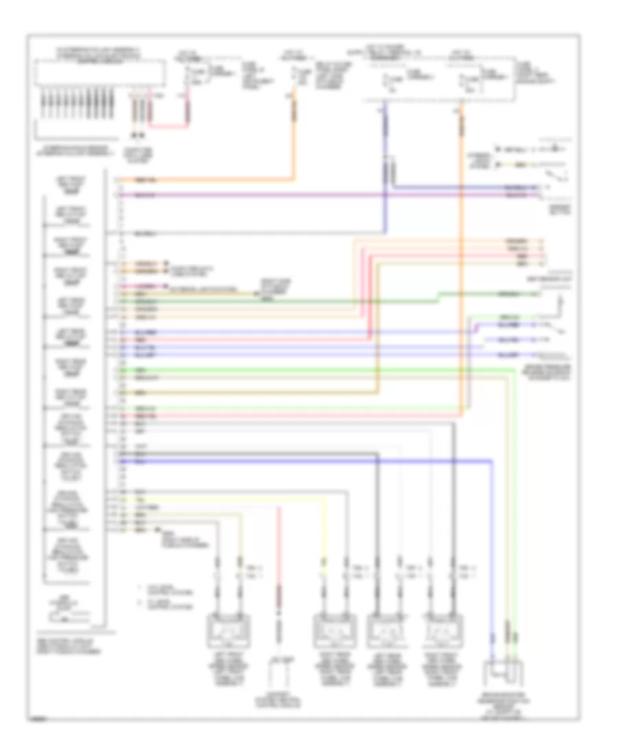
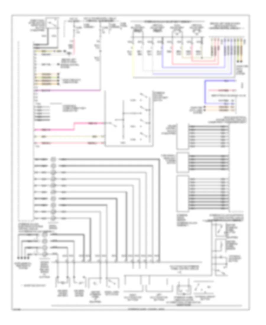
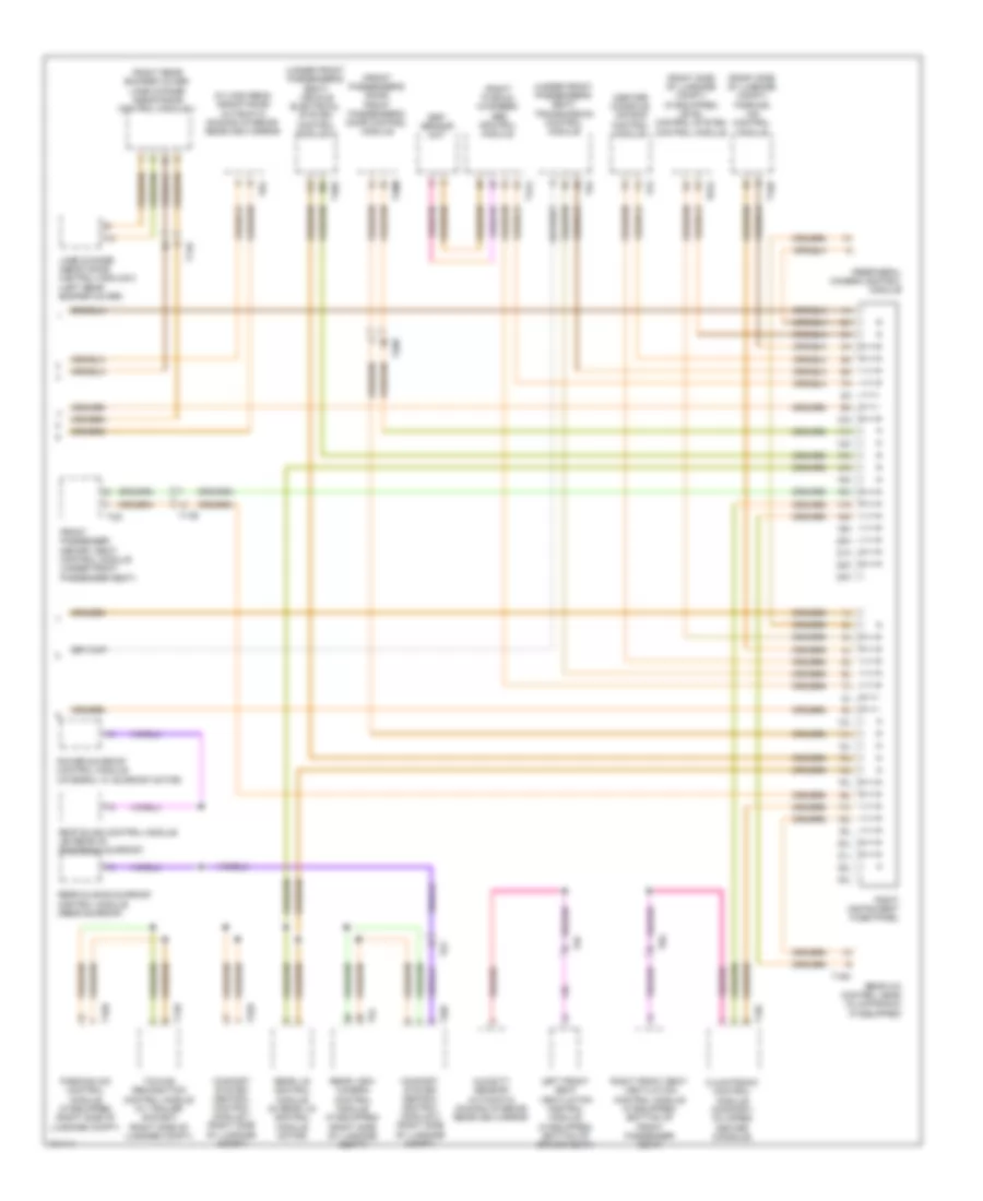
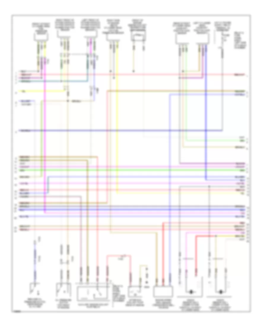
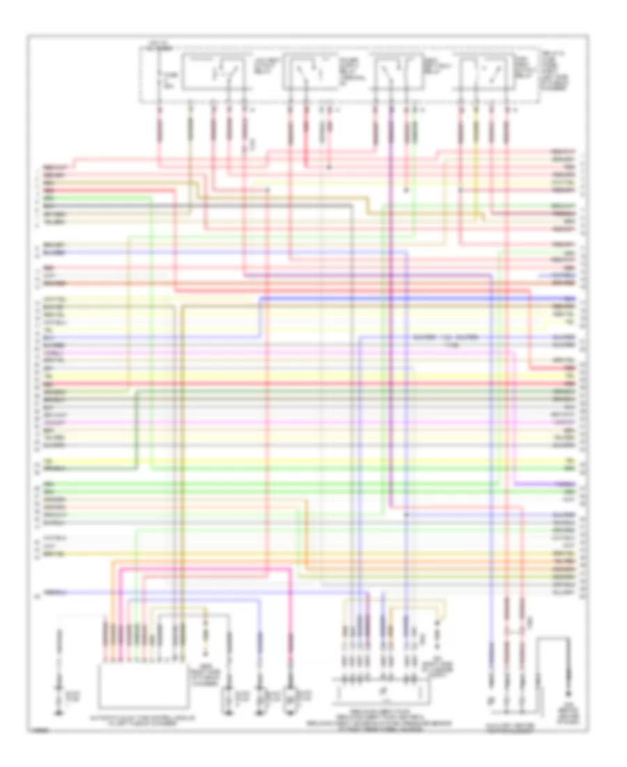
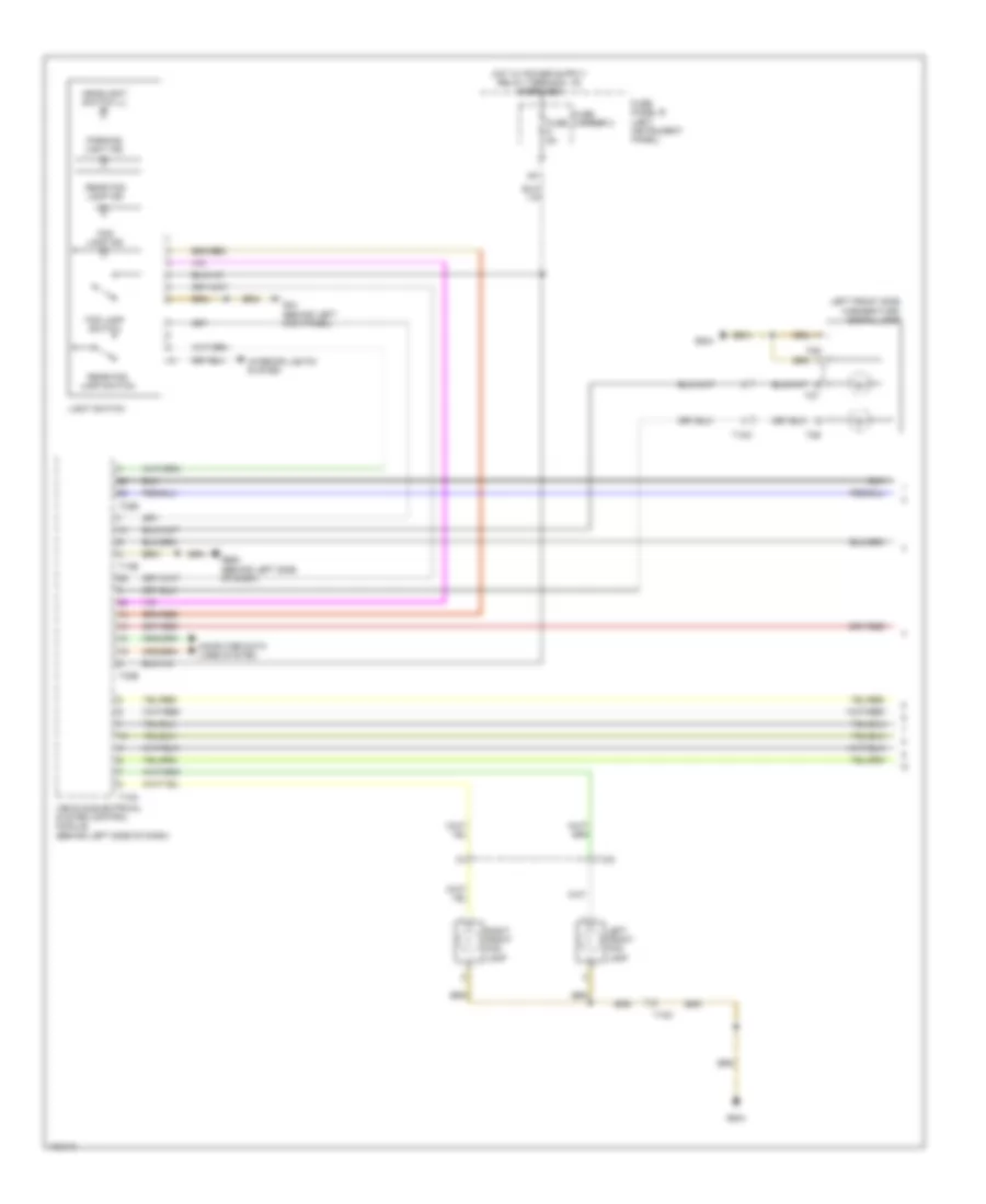
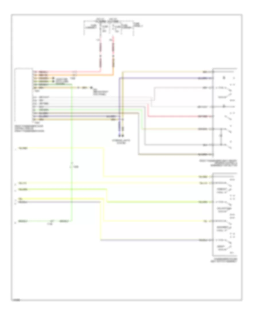
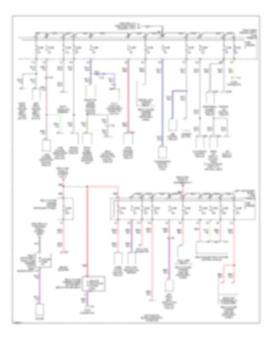
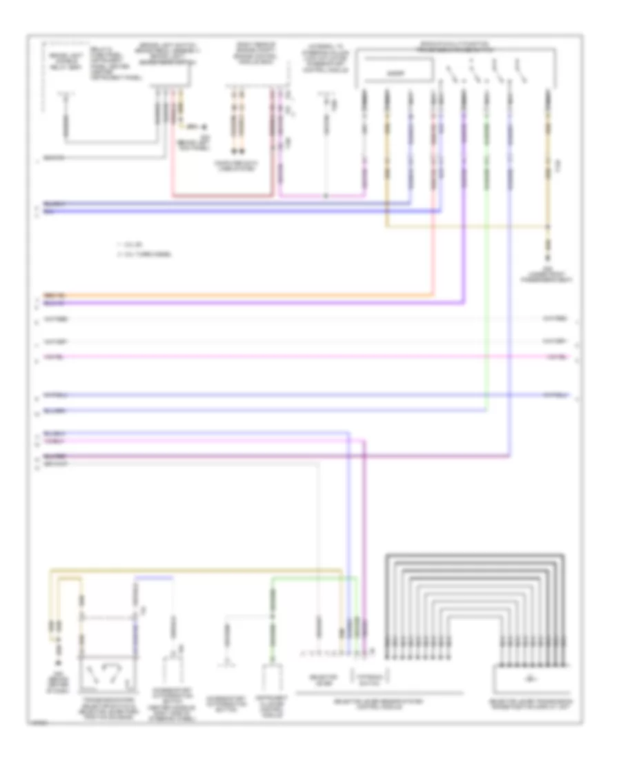
Automatic A/C Wiring Diagram, Comfort (2 of 4) for Audi Q7 Prestige S 2013
List of elements for Automatic A/C Wiring Diagram, Comfort (2 of 4) for Audi Q7 Prestige S 2013:
- (3.0l turbo diesel) coolant circulation pump relay
- 10a
- 12a
- 3.0l sc
- 3.0l turbo diesel
- Coolant recircu- lation pump
- Cooler
- Cooler fuse 5a
- Defroster door motor & position sensor
- Fuse 10a
- Fuse 15a
- Fuse 30a
- Fuse 40a
- Fuse 5a
- Fuse carrier
- Fuse panel c (right rear engine compt)
- G62 (base of right "c" pillar)
- G640 (left side of engine compt)
- Hot at all times
- Indirect ventilation door motor & position sensor
- Left side vent motor & position sensor (hvac unit)
- Pnk
- Relay & fuse carrier (center instrument panel)
- Right center vent motor & position sensor (hvac unit)
- Right side vent motor & position sensor (right end of hvac unit)
- Right temperature door motor & potentiometer/ actuator
- T10c
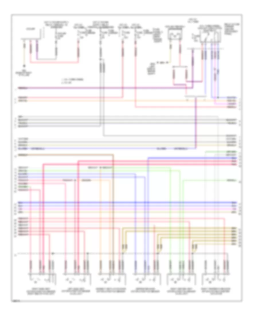
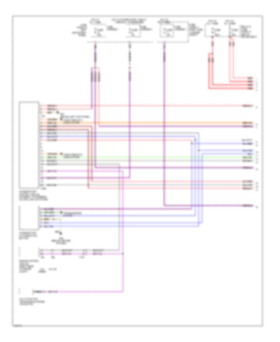
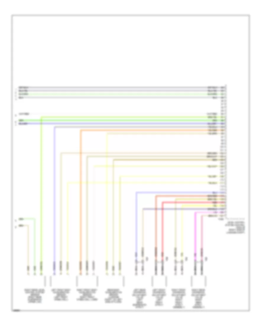
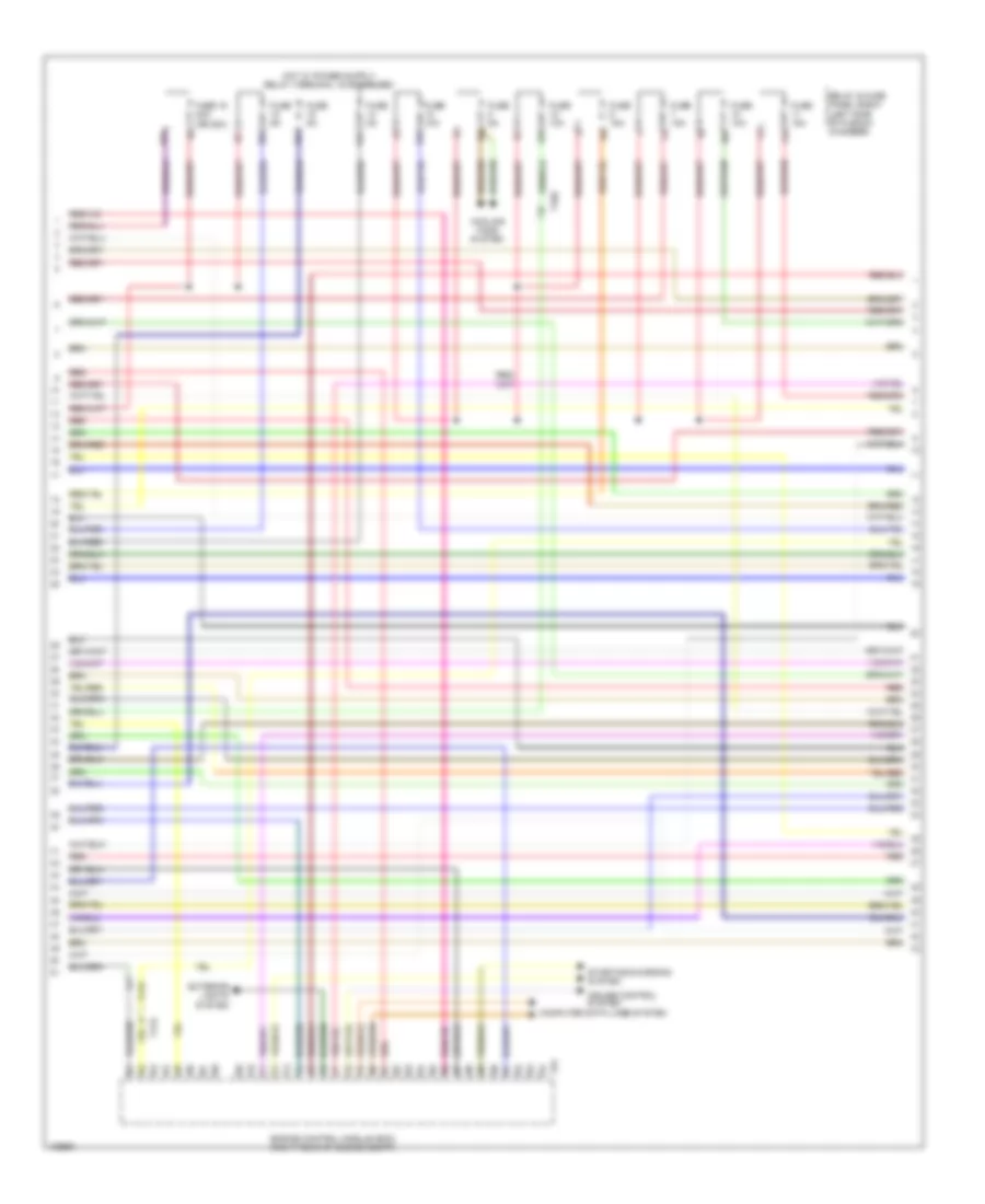
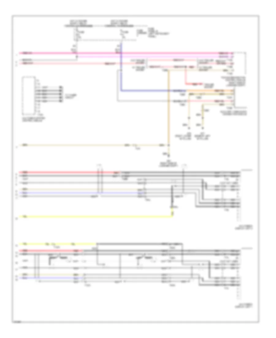
Automatic A/C Wiring Diagram, Comfort (3 of 4) for Audi Q7 Prestige S 2013
List of elements for Automatic A/C Wiring Diagram, Comfort (3 of 4) for Audi Q7 Prestige S 2013:
- (3.0l sc) auxiliary engine coolant pump relay
- (3.0l sc) charge air cooling pump
- (left front long member) g671
- 10a
- 13a
- 19a
- 19c
- 19d
- 19e
- 3.0l sc
- 3.0l turbo diesel
- After-run coolant pump
- Engine coolant shift-off valve relay (3.0l turbo diesel)
- Fuse 10a
- Fuse 15a
- Fuse 40a/ 60a
- Fuse 5a
- Fuse 60a/ 40a
- G609 (right side of plenum chamber)
- G645
- High pressure sensor (evaporator expansion valve, under right side of dash)
- Hot at all times
- Left front seat temperature sensor (w/ auxiliary heater) (under driver's seat)
- Map controlled engine cooling thermostat (3.0l turbo diesel)
- Pnk
- Relay & fuse panel e-box (left side of plenum chamber)
- Right front seat temperature sensor (w/ auxiliary heater) (under right front seat)
- Sunlight photo sensor (top of dash panel, between defroster vents)
- T10ab
- T10d
- T10m
- T6f
- T6g
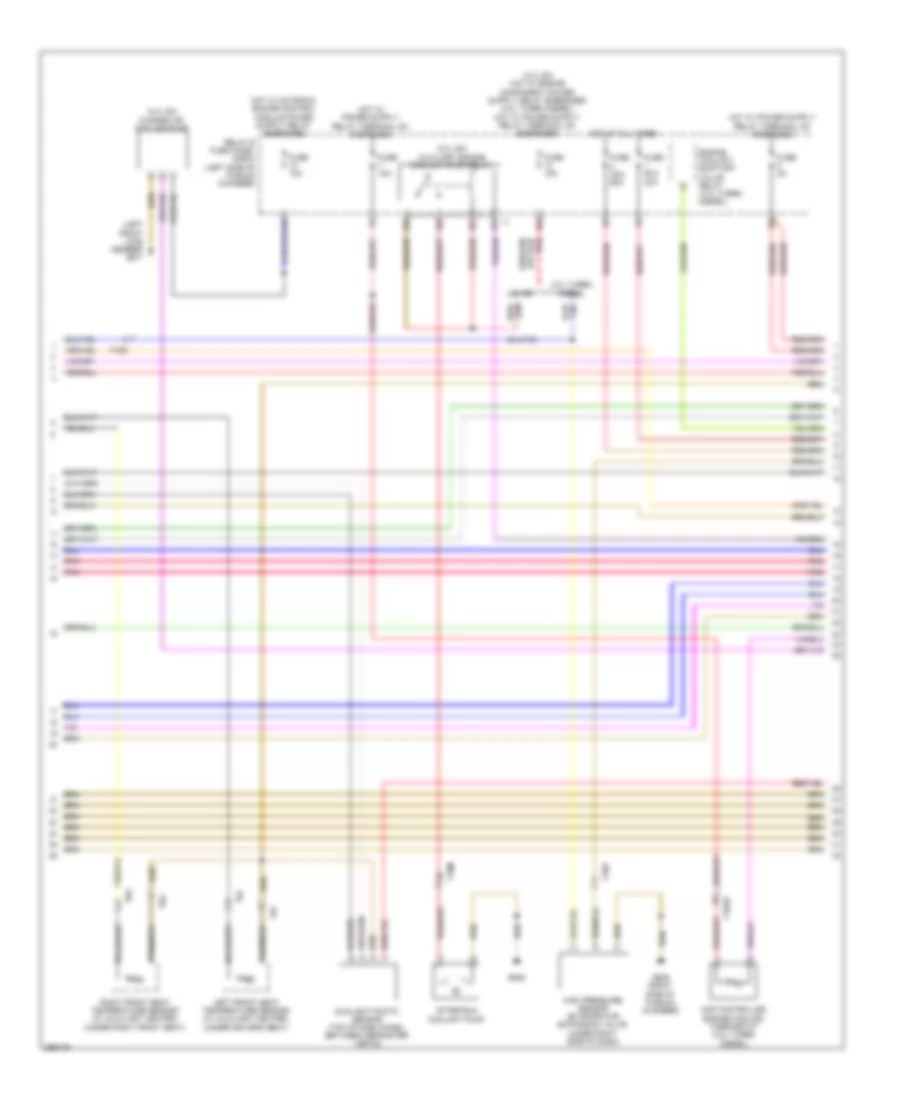
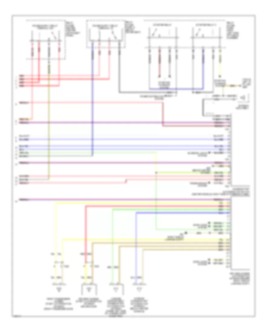
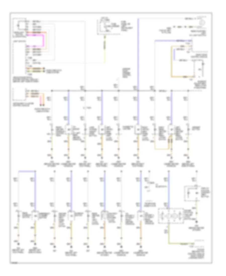
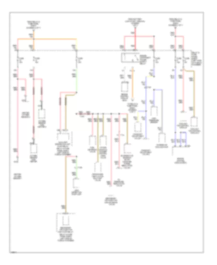
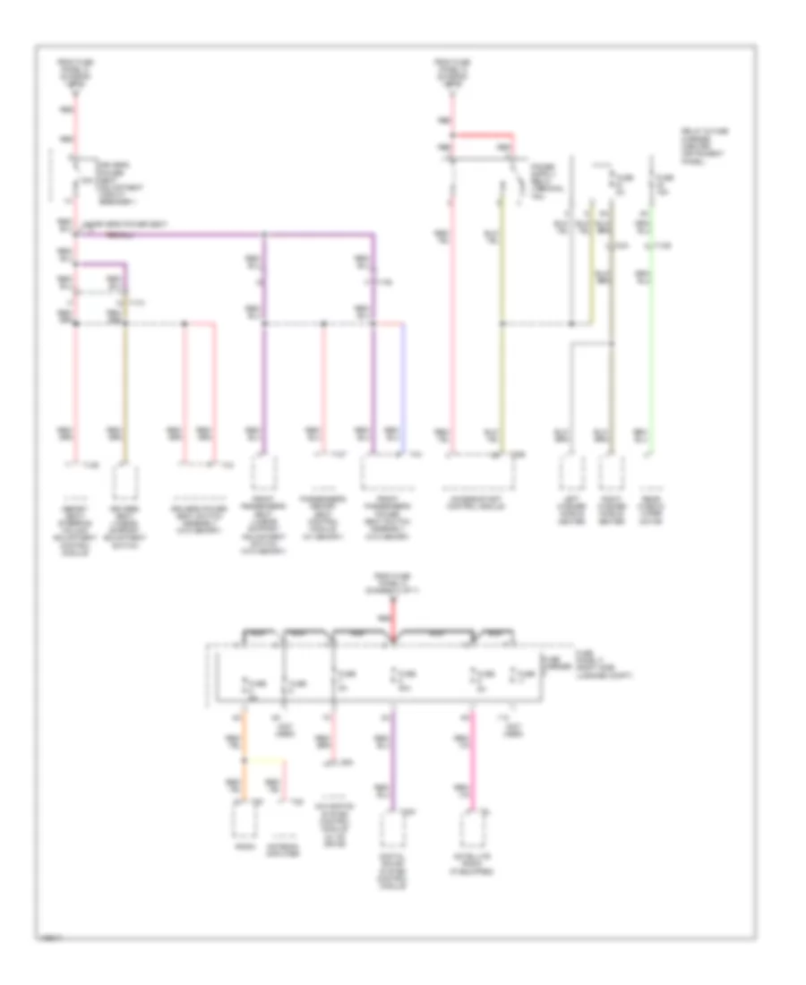
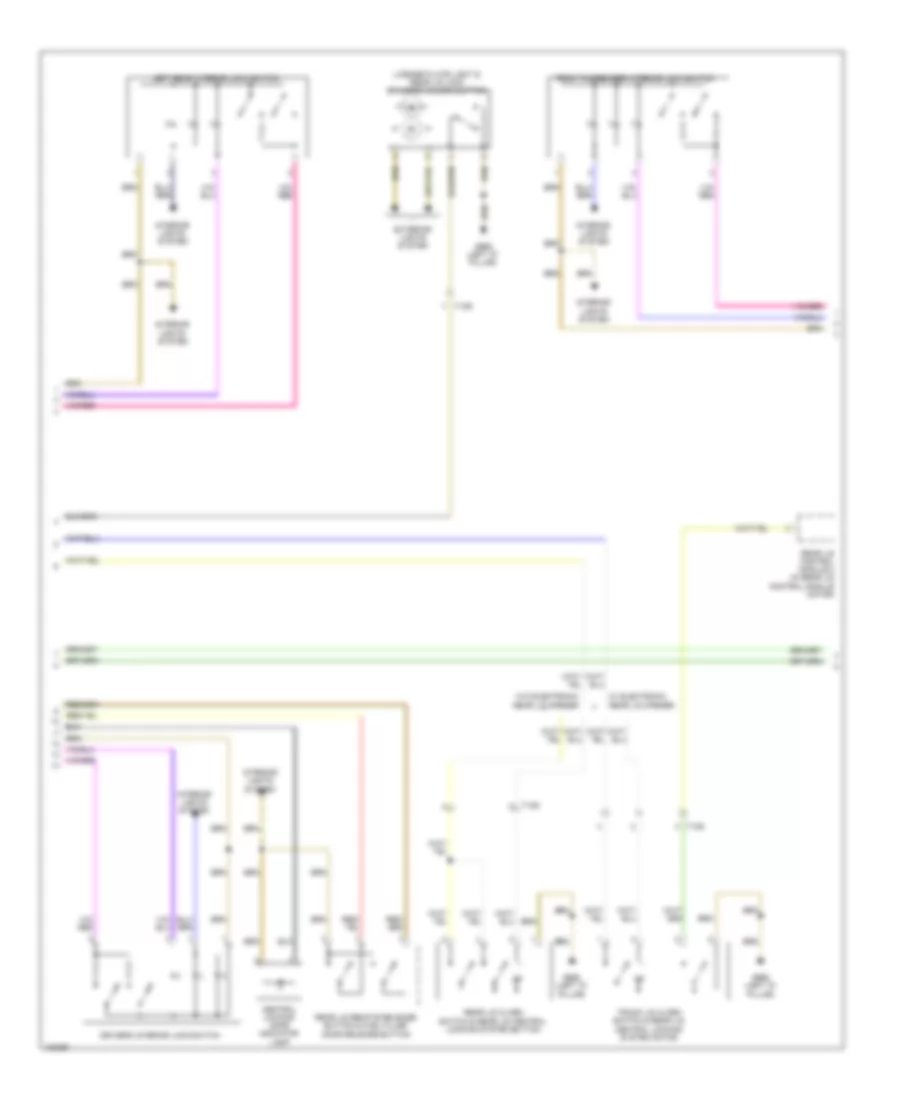
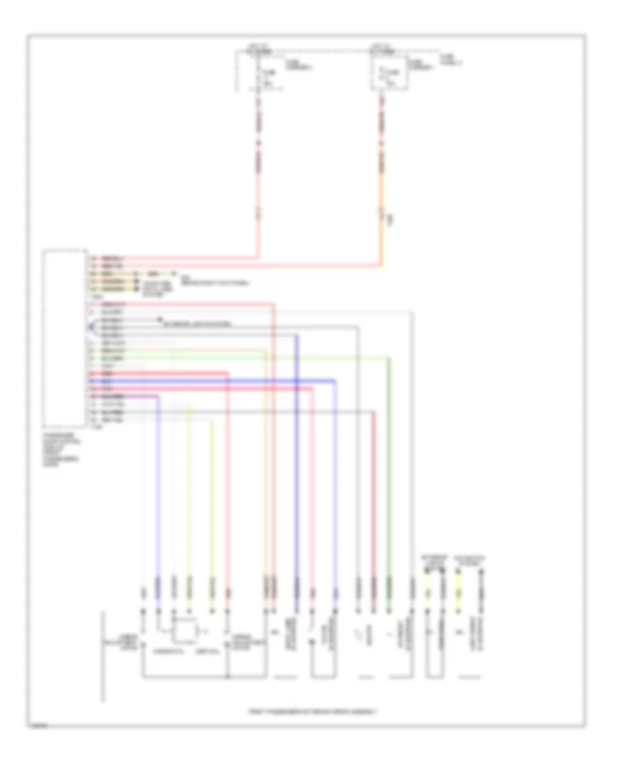
Automatic A/C Wiring Diagram, Comfort (4 of 4) for Audi Q7 Prestige S 2013
List of elements for Automatic A/C Wiring Diagram, Comfort (4 of 4) for Audi Q7 Prestige S 2013:
- (behind center of dash) g45
- (left front long member) g671
- (on coolant fan) coolant fan control module
- (on radiator outlet) engine coolant temperature (ect) sensor (on radiator)
- (or red)
- (right rear of engine compt) engine control module
- 3.0l sc
- 3.0l turbo diesel
- Climatronic control module (in upper center console)
- Computer data lines system
- Coolant fan
- Coolant fan 2
- Coolant fan control module 2
- Engine coolant temperature (ect) sensor (right rear of engine)
- Evaporator vent temperature sensor
- Fresh air intake duct temperature sensor (hvac housing)
- Fuse 5a
- Fuse carrier
- Fuse panel b (left instrument panel)
- G45 (behind center of dash)
- Left footwell vent temperature sensor
- Left front upper body vent temperature sensor
- Nca
- Pnk
- Right footwell vent temperature sensor
- Right front upper body vent temperature sensor
- Start/stop mode button (w/ start/stop system)
- Start/stop mode ind lamp
- T105
- T10ab
- T12g
- T16d
- T17d
- T17k
- T60
- T91
- T94
- W/ start/stop system
- W/o start/stop system
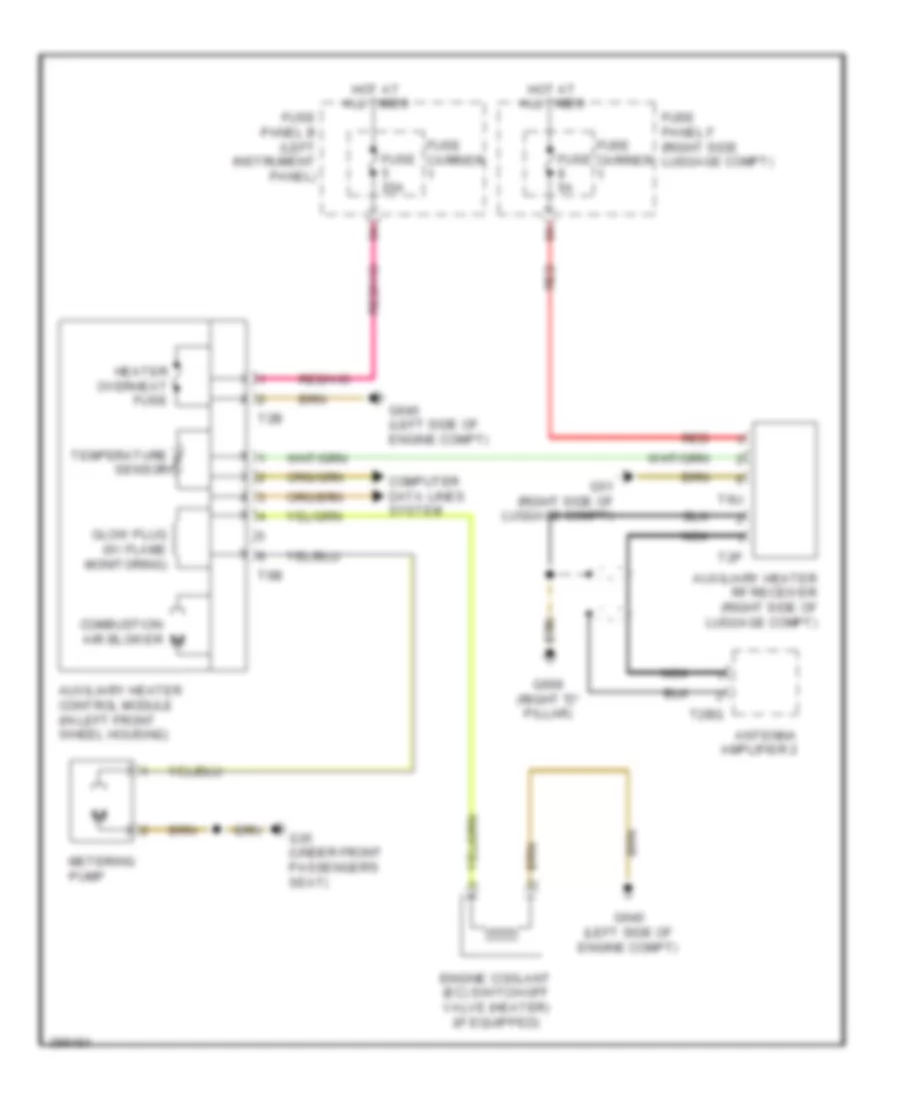
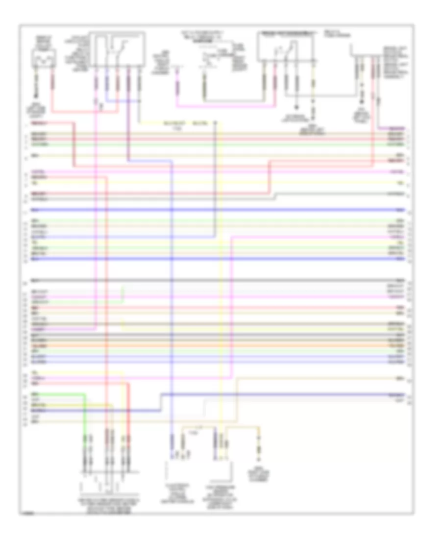
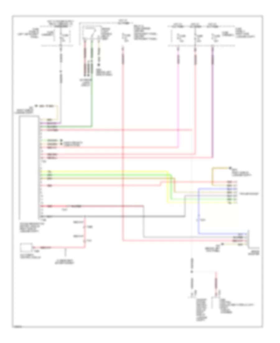
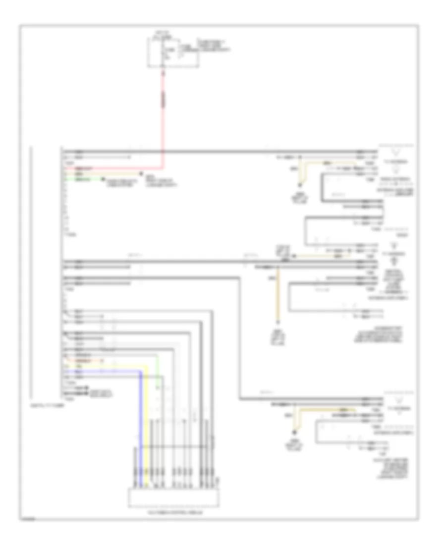
Auxiliary Heater Wiring Diagram for Audi Q7 Prestige S 2013
List of elements for Auxiliary Heater Wiring Diagram for Audi Q7 Prestige S 2013:
- Antenna amplifier 2
- Auxiliary heater control module (in left front wheel housing)
- Auxiliary heater rf receiver (right side of luggage compt)
- Combustion air blower
- Computer data lines system
- Engine coolant (ec) switch-off valve (heater) (if equipped)
- Fuse 20a
- Fuse 5a
- Fuse carrier
- Fuse panel b (left instrument panel)
- Fuse panel f (right side luggage compt)
- G35 (under front passenger's seat)
- G51 (right side of luggage compt)
- G640 (left side of engine compt)
- G669 (right "d" pillar)
- Glow plug (w/ flame monitoring)
- Heater overheat fuse
- Hot at all times
- Metering pump
- Nca
- Red
- T2b
- T2bq
- T2p
- T6b
- T6u
- Temperature sensor
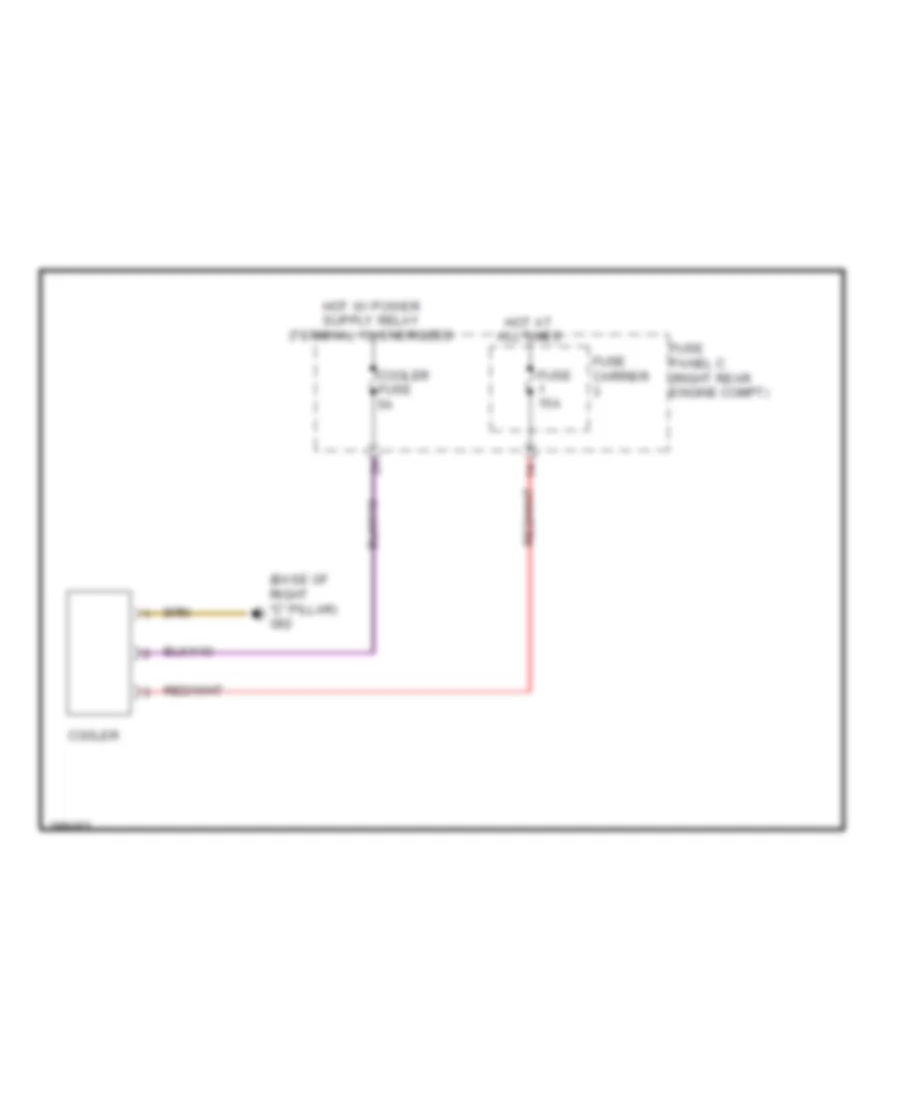
Cool Box Wiring Diagram for Audi Q7 Prestige S 2013
List of elements for Cool Box Wiring Diagram for Audi Q7 Prestige S 2013:
- (base of right "c" pillar) g62
- Cooler
- Cooler fuse 5a
- Fuse 15a
- Fuse carrier
- Fuse panel c (right rear engine compt)
- Hot at all times
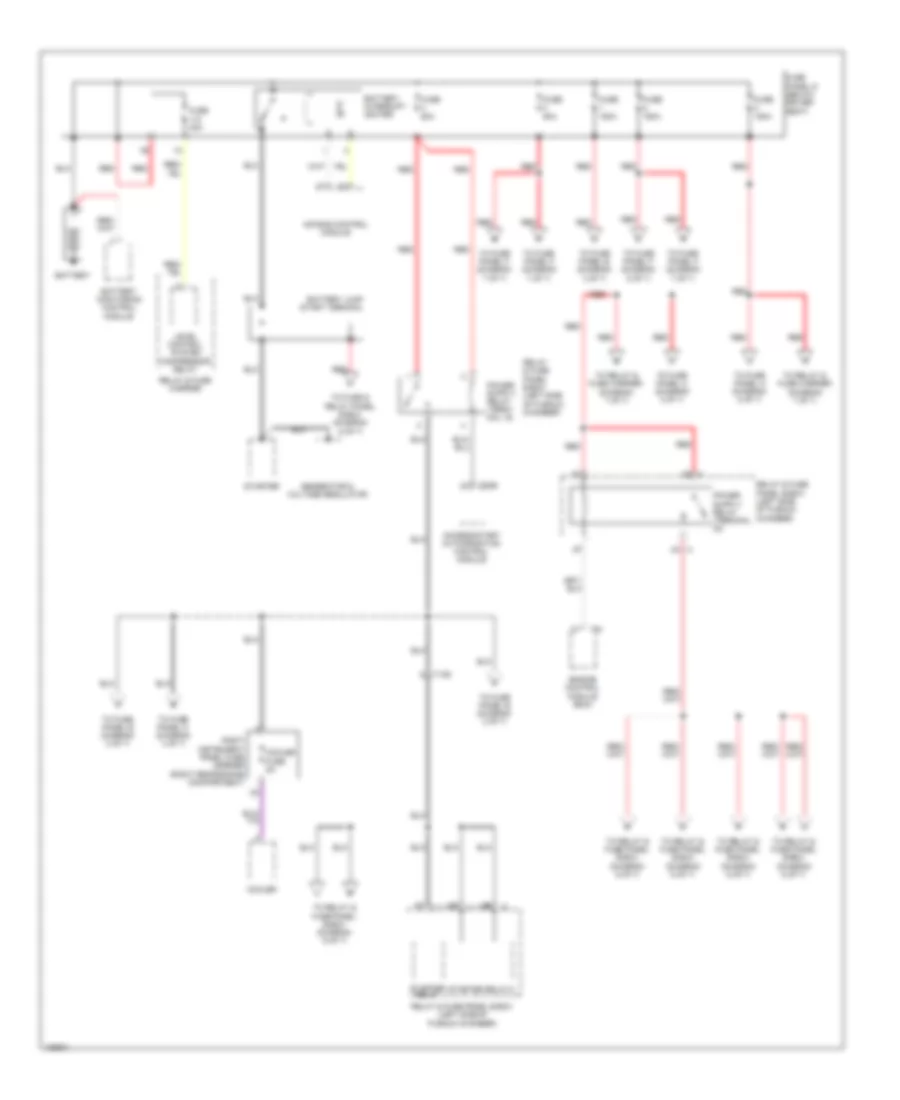
Rear A/C Wiring Diagram (1 of 2) for Audi Q7 Prestige S 2013
List of elements for Rear A/C Wiring Diagram (1 of 2) for Audi Q7 Prestige S 2013:
- (in rear air duct channel) left rear vent temperature sensor
- (in rear air duct channel) right rear vent temperature sensor
- (under center console) g687
- 12a
- Computer data lines system
- Fuse 10a
- Fuse 20a
- Fuse 5a
- Fuse carrier
- Fuse panel c (right rear engine compt)
- Hot at all times
- Left "b" pillar/ footwell shut-off door motor & position sensor
- Left rear upper body vent motor & position sensor (left rear upper body vent motor: hvac unit)
- Rear a/c display control head
- Right "b" pillar/ footwell shut-off door motor & position sensor
- Right rear upper body vent motor & position sensor
- Seats system
- T12h
- T16h
- T17h
- T20h
- T3h
Rear A/C Wiring Diagram (2 of 2) for Audi Q7 Prestige S 2013
List of elements for Rear A/C Wiring Diagram (2 of 2) for Audi Q7 Prestige S 2013:
- (base of left "c" pillar) g61
- Center instrument panel vent illumination bulb
- Computer data lines system
- Fresh air blower fuse 2 40a
- G43 (behind right kick panel)
- G44 (behind left kick panel)
- G67
- Hot at all times
- Instrument cluster
- Instrument cluster control module
- Left instrument panel vent illumination bulb
- Left rear air door motor & position sensor
- Left rear temperature door motor & position sensor
- Rear center air vent illumination bulb
- Rear fresh air blower
- Rear fresh air blower control module (left rear of luggage compt)
- Red
- Relay & fuse carrier (center instrument panel)
- Right instrument panel vent illumination bulb
- Right rear air door motor & position sensor
- Right rear temperature door motor & position sensor
- Suppressor
- T12k
- T17h
- T2r
- T4u
ANTI-LOCK BRAKES
Anti-lock Brakes Wiring Diagram for Audi Q7 Prestige S 2013
List of elements for Anti-lock Brakes Wiring Diagram for Audi Q7 Prestige S 2013:
- (in steering column assembly) steering column electronics control module
- (right side of plenum chamber) g609
- Abs control module (abs hydraulic unit) (right plenum chamber)
- Abs hydraulic pump
- Asr/esp button
- Brake booster membrane position sensor (w/ adaptive cruise control)
- Brake pressure release solenoid & magnetic coil
- Comfort system central control module
- Computer data lines system
- Driving dynamics regulation high pressure switch valve 1
- Driving dynamics regulation high pressure switch valve 2
- Driving dynamics regulation switch valve 1
- Driving dynamics regulation switch valve 2
- Esp sensor unit
- Exterior lights system
- Fuse 10a
- Fuse 20a
- Fuse 40a
- Fuse 5a
- Fuse carrier 1
- Fuse carrier 2
- Fuse panel b (left instrument panel)
- Fuse panel c (right rear engine compt)
- G609 (right side of plenum chamber)
- Hot at all times
- Interior lights system
- Left front abs inlet valve
- Left front abs outlet valve
- Left front abs wheel speed sensor (left front wheel hub assembly)
- Left rear abs inlet valve
- Left rear abs outlet valve
- Left rear abs wheel speed sensor (left rear wheel hub assembly)
- Nca
- Red
- Relay & fuse panel e-box (left side of plenum chamber)
- Right front abs inlet valve
- Right front abs outlet valve
- Right front abs wheel speed sensor (right front wheel hub assembly)
- Right rear abs inlet valve
- Right rear abs outlet valve
- Right rear abs wheel speed sensor (right rear wheel hub assembly)
- Steering angle sensor (steering column assembly)
- T16a
- T32d
- T4n
- T4o
- T4p
- T4q
- T6n
- T6o
- T6p
- T6q
- W/ level control system
- W/o level control system
ANTI-THEFT
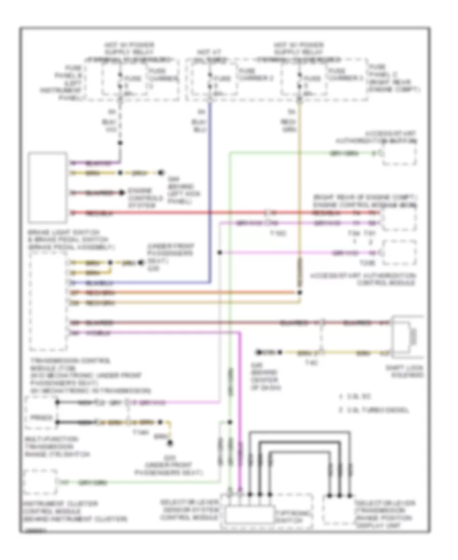
Access/Start Wiring Diagram (1 of 2) for Audi Q7 Prestige S 2013
List of elements for Access/Start Wiring Diagram (1 of 2) for Audi Q7 Prestige S 2013:
- 10a
- 11a
- 3.0l diesel
- 3.0l sc
- Access/start authorization button
- Access/start control module (integral to steering column lock actuator)
- Computer data lines system
- Engine control module (right rear of engine compt)
- Fuse 150a
- Fuse 15a
- Fuse 30a
- Fuse 5a
- Fuse 60a
- Fuse carrier 1
- Fuse carrier 3
- Fuse panel b (left instrument panel)
- Fuse panel f (right side luggage compt)
- G44 (behind left kick panel)
- G45 (behind center of dash)
- Hot at all times
- Multi-function transmission range (tr) switch
- Nca
- Red
- Relay & fuse panel d (below driver seat)
- T10c
- T20e
- T3a
- T91
- T94
- Transmissions system
Access/Start Wiring Diagram (2 of 2) for Audi Q7 Prestige S 2013
List of elements for Access/Start Wiring Diagram (2 of 2) for Audi Q7 Prestige S 2013:
- (top of left "d" pillar) g667
- Access/start authorization switch (center console, right side of steering wheel)
- Antenna amplifier 4
- Door locks system
- Driver's access/ start authorization antenna (driver door)
- Exterior lights system
- Front passenger's access/ start authorization antenna (front passenger door)
- G45 (behind center of dash)
- G51 (right side of luggage compt)
- Interior access/start authorization antenna 1 (below center console)
- Keyless access authorization antenna reader (right side of luggage compt)
- Luggage compartment access/start authorization antenna (under left side of luggage compt floor trim)
- Nca
- Power distribution system
- Red
- Relay & fuse center (center instrument panel)
- Relay & fuse panel d (below driver seat)
- Relay & fuse panel e-box (left side of plenum chamber)
- Starter relay
- Starter relay 2
- Starting/ charging system
- T20c
- T20d
- T2a
- T6a
- T8a
- Transmissions system
Anti-theft Wiring Diagram (1 of 2) for Audi Q7 Prestige S 2013
List of elements for Anti-theft Wiring Diagram (1 of 2) for Audi Q7 Prestige S 2013:
- (base of left "b" pillar) g77
- (behind left kick panel) g44
- (under the e-box in the plenum chamber) alarm horn
- (w/ child safety lock) left rear central locking lock unit
- Alarm system deactivation switch
- Anti-theft alarm system w/ interior monitoring
- Anti-theft alarm system w/o interior monitoring
- Central locking safe indicator lamp
- Comfort system central control module (right side of luggage compt)
- Computer data lines system
- Driver's door central locking lock unit
- Driver's door control module (driver's door)
- Engine hood contact switch
- Fuse 15a
- Fuse 35a
- Fuse 5a
- Fuse carrier
- Fuse panel b (left instrument panel)
- G44 (behind left kick panel)
- G640 (left side of engine compt)
- G644
- G668 (left "d" pillar)
- G77 (base of left "b" pillar)
- Horns system
- Hot at all times
- Interior lights system
- Interior monitoring sensor (anti-theft alarm system w/ interior monitoring)
- Left rear door control module (left rear door)
- Rear lid control module 2 (in rear lid control module motor)
- T10g
- T10n
- T10s
- T20c
- T20l
- T20n
- T32b
- T32d
- T32f
- Trunk lid alarm switch & decklid central locking system motor
- Vehicle electrical system control module (behind left side of dash)
- W/ electronic rear lid opening
- W/o electronic rear lid opener
Anti-theft Wiring Diagram (2 of 2) for Audi Q7 Prestige S 2013
List of elements for Anti-theft Wiring Diagram (2 of 2) for Audi Q7 Prestige S 2013:
- (right lower b-pillar) g78
- 11a
- Computer data lines system
- Front passenger's door central locking lock unit
- Front passenger's door control module (front passenger's door)
- Fuse 15a
- Fuse 35a
- Fuse carrier
- Fuse panel c (right rear engine compt)
- G43 (behind right kick panel)
- G657 (left "d" pillar)
- G78 (right lower b-pillar)
- Hot at all times
- Left rear window breakage sensor
- Rear window glass breakage sensor
- Right rear central locking lock unit (w/ child safety lock)
- Right rear door control module (right rear door)
- Right rear window breakage sensor
- T10r
- T20b
- T20d
- T20m
- T20o
BODY CONTROL MODULES
Comfort System Central Control Module Wiring Diagram for Audi Q7 Prestige S 2013
List of elements for Comfort System Central Control Module Wiring Diagram for Audi Q7 Prestige S 2013:
- (right side of luggage compt) g51
- 10a
- 12a
- Anti-theft system
- Comfort system central control module 1 (right side of luggage compt)
- Comfort system central control module 2 (right side of luggage compt)
- Computer data lines system
- Defogger system
- Door locks & trunk, tailgate, fuel doors systems
- Electronic suspension system
- Engine controls system
- Exterior lights & interior lights systems
- Exterior lights system
- Fuse 15a
- Fuse 20a
- Fuse 30a
- Fuse 5a
- Fuse carrier
- Fuse carrier 1
- Fuse panel b
- Fuse panel f
- G51 (right side of luggage compt)
- Garage door opener control module (located under the front bumper cover)
- Hot at all times
- Interior lights system
- Power tops system
- T10g
- T15a
- T32d
- Trunk, tailgate, fuel doors & door locks systems interior lights system
- Trunk, tailgate, fuel doors system
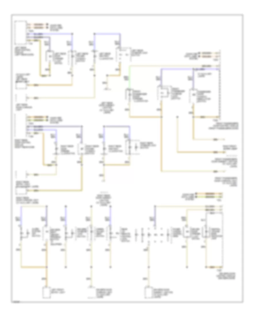
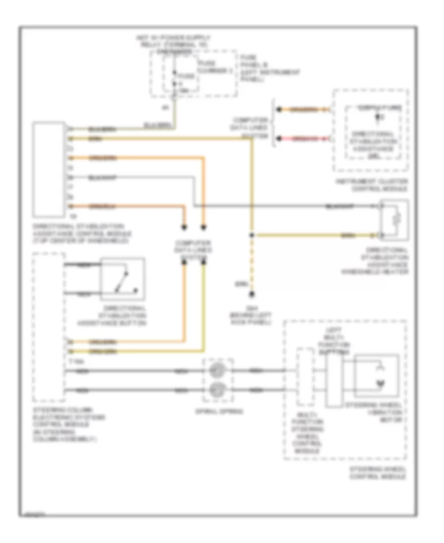
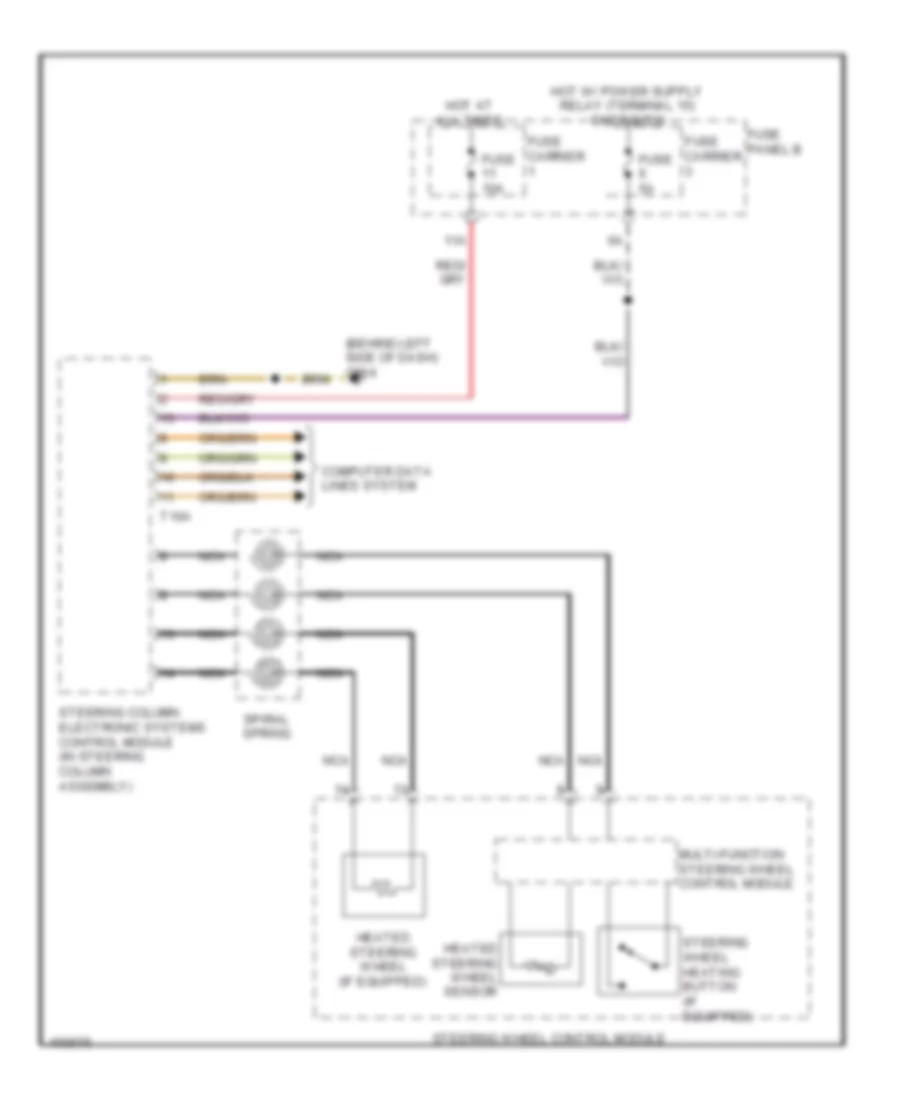
Steering Column Electronic Systems Control Module Wiring Diagram for Audi Q7 Prestige S 2013
List of elements for Steering Column Electronic Systems Control Module Wiring Diagram for Audi Q7 Prestige S 2013:
- (behind left side of dash)
- (behind left side of dash) vehicle electrical system control module 1
- (steering column assembly)
- 11a
- Air bag spiral spring/ return spring w/ slip ring
- Axial adjustment motor
- Axial adjustment sensor
- Computer data lines system
- Cruise control switch (if equipped)
- Directional stabilization assistance button (if equipped)
- Driver's air bag igniter
- Driver's air bag igniter 2
- Engine control system
- Fuse 10a
- Fuse 5a
- Fuse carrier
- Fuse carrier 1
- Fuse panel b
- G664
- Heated steering wheel (if equipped)
- Heated steering wheel button (if equipped)
- Heated steering wheel sensor
- Hot at all times
- Left multi-function buttons
- Multi-function steering wheel control module
- Nca
- Red
- Right multi-function buttons
- Servotronic solenoid valve
- Shorting contact
- Signal horn activation
- Spiral spring
- Steering angle sensor
- Steering column adjustment assembly
- Steering column adjustment switch
- Steering column electronic systems control module (in steering column assembly)
- Steering wheel control head
- Steering wheel vibration motor (w/ directional stabilization assistance)
- T12b
- T16a
- T32b
- T4a
- Tiptronic downshift button
- Tiptronic upshift button
- Turn signal/ headlight flasher switch
- Vehicle electrical system control module 2 (under front passenger's seat)
- Vertical adjustment motor
- Vertical adjustment sensor
- Windshield wiper intermittent mode switch
Vehicle Electrical System Control Module Wiring Diagram for Audi Q7 Prestige S 2013
List of elements for Vehicle Electrical System Control Module Wiring Diagram for Audi Q7 Prestige S 2013:
- (behind left side of dash) g664
- 12a
- Anti-theft system
- Computer data lines system
- Door locks system
- Exterior lights system
- Exterior lights system steering column electronic system control module circuit
- Fuse 15a
- Fuse 25a
- Fuse 30a
- Fuse 5a
- Fuse carrier 1
- Fuse carrier 2
- Fuse carrier 3
- Fuse panel b
- Fuse panel c
- G35 (under front passenger's seat)
- Headlights & exterior lights systems
- Headlights & exterior lights systems headlights system
- Headlights system
- Horns system
- Hot at all times
- Interior lights system
- Navigation system
- Red
- Servotronic solenoid valve
- Steering column electronic system control module circuit
- T10a
- T12b
- T32b
- Vehicle electrical system control module 1 (behind left side of dash)
- Vehicle electrical system control module 2 (under front passenger's seat)
- Wiper/washer system
- Wiper/washer system steering column electronic system control module circuit
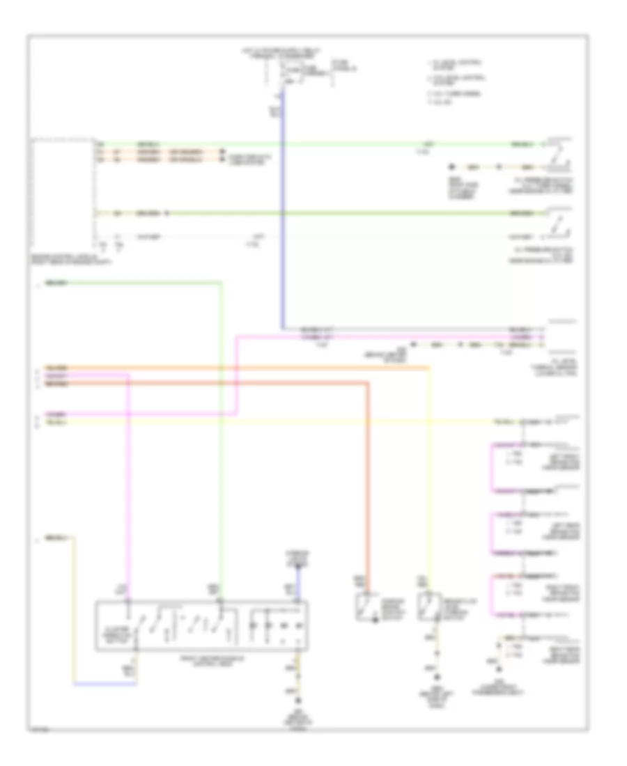
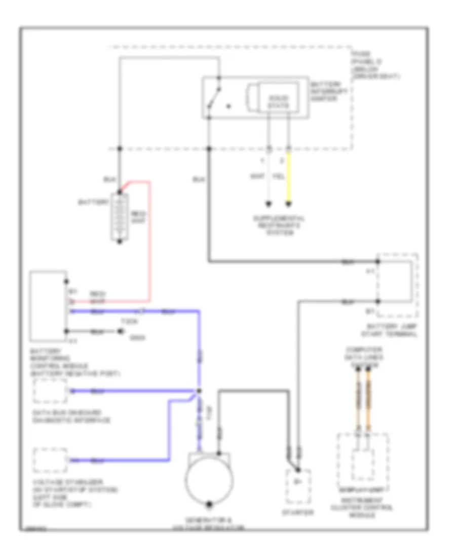
COMPUTER DATA LINES
Computer Data Lines Wiring Diagram (1 of 3) for Audi Q7 Prestige S 2013
List of elements for Computer Data Lines Wiring Diagram (1 of 3) for Audi Q7 Prestige S 2013:
- (behind front bumper) (w/ adaptive cruise control (acc)) distance regulation control module
- (behind left side of dash) (if equipped) tire pressure monitoring control module
- (behind left side of dash) headlamp range control module
- (in left front wheel housing) (if equipped) auxiliary heater control module
- (in steering column assembly) steering column electronics systems control module
- (integral to steering column lock actuator) access/start control module
- (right rear of engine compt) engine control module (ecm)
- 10h
- 10l
- 11h
- 11l
- 12 pin connector
- 12h
- 12l
- 13h
- 13l
- 14h
- 14l
- 15h
- 15l
- 16h
- 16l
- 17h
- 17l
- 18h
- 18l
- 19h
- 19l
- 20h
- 20l
- 21h
- 21l
- 22h
- 22l
- 23h
- 23l
- 3.0l sc
- 3.0l turbo diesel
- Driver's door control module (driver's door)
- Generator & voltage regulator
- Instrument cluster control module
- Left instrument fuse panel
- Memory seat/ steering column adjustment control module (below driver's seat)
- Nox sensor (upstream of catalyst)
- Nox sensor 2 (downstream of scr catalyst)
- Particulate sensor (at exit of scr catalyst)
- T10d
- T10e
- T16a
- T17a
- T20a
- T20e
- T20l
- T26a
- T2ck
- T32b
- T32h
- T6b
- T8c
- T91
- T94
- Vehicle electrical system control module 1 (behind left side of dash)
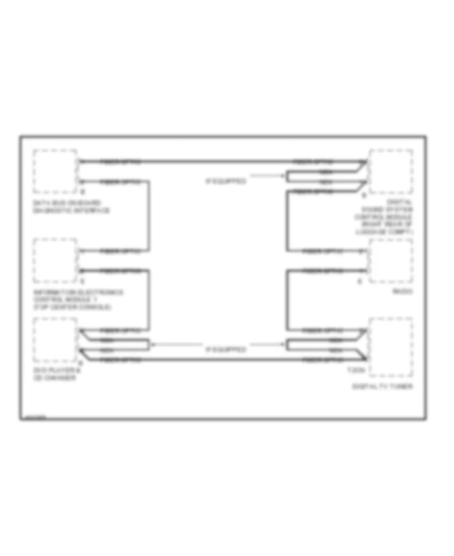
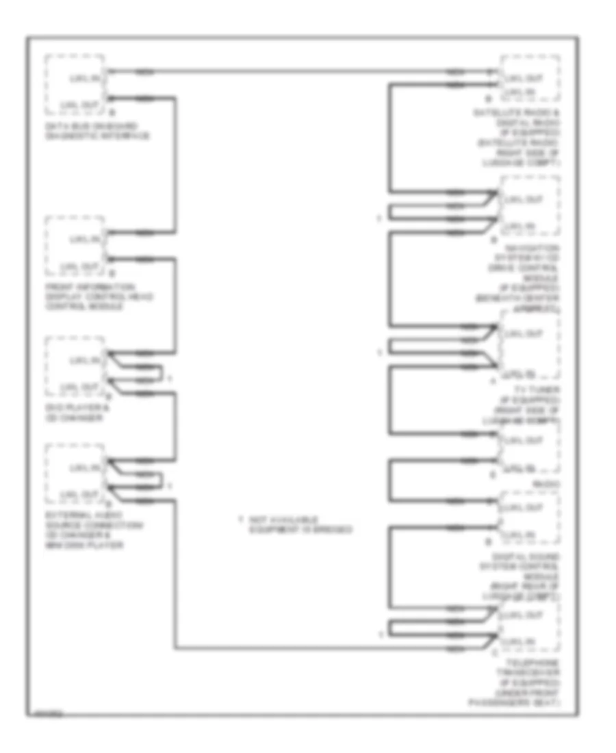
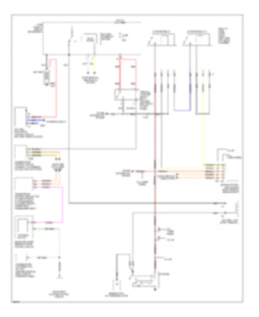
Computer Data Lines Wiring Diagram (2 of 3) for Audi Q7 Prestige S 2013
List of elements for Computer Data Lines Wiring Diagram (2 of 3) for Audi Q7 Prestige S 2013:
- (behind left side of dash)
- 10a
- 11a
- 12a
- Data bus on board diagnostic interface
- Diagnostic connector
- Digital radio (if equipped)
- Digital sound system control module (right rear of luggage compt)
- Digital tv tuner (if equipped) (right side of luggage compt)
- Directional stabilization assistance control module (top center of windshield)
- Dvd player & cd changer (if equipped)
- External audio source connector
- Front information display control head control module (center plenum chamber)
- Fuse 10a
- Fuse 5a
- Fuse carrier
- Fuse panel b (left instrument panel)
- Fuse panel c (right rear engine compt)
- G44 (behind left kick panel)
- G664
- Hot at all times
- Information electronics control module 1 (top center console)
- Media player position 1
- Media player position 2
- Navigation system w/ cd drive control module (beneath center armrest)
- Nca
- Radio (roof panel, near rear hatch)
- Satellite radio (if equipped) (right side of luggage compt)
- Sound systems
- T10aa
- T10v
- T12ag
- T12p
- T20k
- T32c
- T8ae
- T8ah
- T8l
- T8p
- Telephone transceiver (below front passenger's seat)
- W/ basic mmi
- W/ basic plus mmi
- W/ bose radio
- W/ dsp radio
- W/ standard mmi
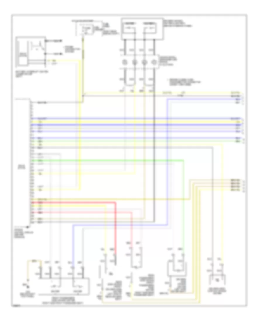
Computer Data Lines Wiring Diagram (3 of 3) for Audi Q7 Prestige S 2013
List of elements for Computer Data Lines Wiring Diagram (3 of 3) for Audi Q7 Prestige S 2013:
- (center console) air bag control module
- (front passenger's door) front passenger's door control module
- (integral w/ sunroof motor)
- (right plenum chamber) abs control module
- (right rear bumper cover) lane change assistance control module 1
- (right side of luggage compt) (if equipped) level control system control module
- (right side of luggage compt) parking aid control module
- (under front passenger's seat) transmission control module
- (under front passenger's seat) vehicle electrical system control module 2
- (w/ high beam assistance) automatic dimming interior rearview mirror
- 10h
- 10l
- 11h
- 11l
- 12h
- 12l
- 13h
- 13l
- 14h
- 14l
- 15h
- 15l
- 16h
- 16l
- 17h
- 17l
- 18h
- 18l
- 19h
- 19l
- 20h
- 20l
- 21h
- 21l
- 22h
- 22l
- 23h
- 23l
- Climatronic control module (comfort) (in upper center console)
- Comfort system central control module 1 (right side of luggage compt)
- Comfort system central control module 2 (right side of luggage compt)
- Esp sensor unit
- Front passenger memory seat control module (under front passenger seat)
- Humidity sensor/ automatic dimming interior rearview mirror
- Lane change assistance control module 2 (left rear bumper cover)
- Left front seat ventilation control module (if equipped) (bottom of driver seat)
- Parking aid control module (if equipped) (right side of luggage compt)
- Peripheral camera control module
- Power sunroof control module
- Rear a/c control head (climatronic) (if equipped)
- Rear lid control module (in rear lid control module motor)
- Rear sliding sunroof control module (rear sunroof)
- Rear view camera control module (if equipped) (right side of luggage compt)
- Right front seat ventilation control module (if equipped) (bottom of front passenger seat)
- Right instrument fuse panel
- Roof blind control module (on rear of panorama sunroof)
- T12d
- T14d
- T16b
- T16c
- T16h
- T17b
- T20b
- T20f
- T20m
- T32d
- T32i
- T40a
- T47a
- T52
- T54
- T6f
- T6g
- T6y
- T75
- T81a
- T8x
- Towing recognition control module (w/ trailer socket) (right side of luggage compt)
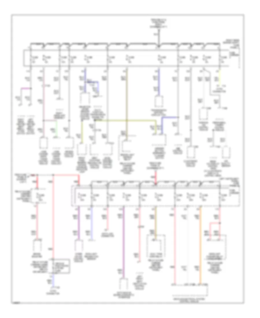
COOLING FAN
Cooling Fan Wiring Diagram (1 of 2) for Audi Q7 Prestige S 2013
List of elements for Cooling Fan Wiring Diagram (1 of 2) for Audi Q7 Prestige S 2013:
- (3.0l sc) auxiliary engine coolant pump relay
- (3.0l turbo diesel) coolant circulation pump relay
- (behind right kick panel) g43
- 19a
- 19c
- 19d
- 19e
- 3.0l sc
- 3.0l turbo diesel
- After-run coolant pump
- Climatronic control module (in upper center console)
- Cooler
- Cooler fuse 5a
- Fresh air blower
- Fresh air blower control module
- Fuse 15a
- Fuse 30a
- Fuse 40a
- Fuse carrier
- Fuse panel c (right rear engine compt)
- G609 (right side of plenum chamber)
- G62 (base of right "c" pillar)
- G645
- High pressure sensor (evaporator expansion valve, under right side of dash)
- Hot at all times
- Relay & fuse carrier
- Relay & fuse panel e-box (left side of plenum chamber)
- T10c
- T10d
- T10m
- T16c
- T16d
- T17k
- T2q
- T3c
- T6ai
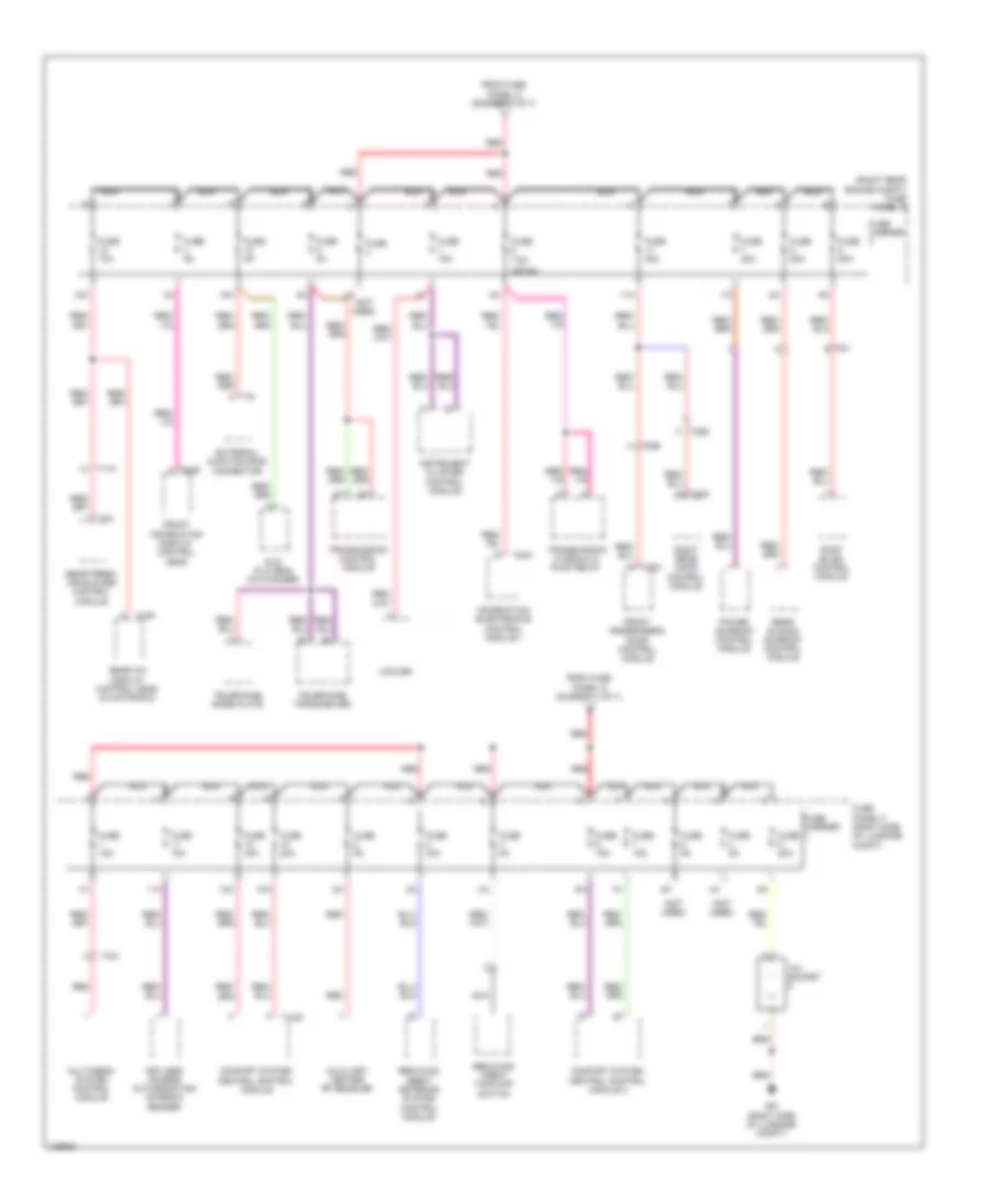
Cooling Fan Wiring Diagram (2 of 2) for Audi Q7 Prestige S 2013
List of elements for Cooling Fan Wiring Diagram (2 of 2) for Audi Q7 Prestige S 2013:
- (or red)
- 13a
- 3.0l sc
- 3.0l turbo diesel
- Computer data lines system
- Coolant fan
- Coolant fan 2
- Coolant fan control (fc) control module (on coolant fan)
- Coolant fan control (fc) control module 2
- Coolant recirculation pump
- Engine control module (right rear of engine compt)
- Engine coolant temperature (ect) sensor (on radiator) (on radiator outlet)
- Engine coolant temperature (ect) sensor (right rear of engine)
- Fuse 15a
- Fuse 40a/60a
- Fuse 5a
- Fuse 60a/40a
- G640 (left side of engine compt)
- G671 (left front long member)
- Hot at all times
- Nca
- Relay & fuse panel e-box (left side of plenum chamber)
- T105
- T10d
- T17d
- T60
- T91
- T94
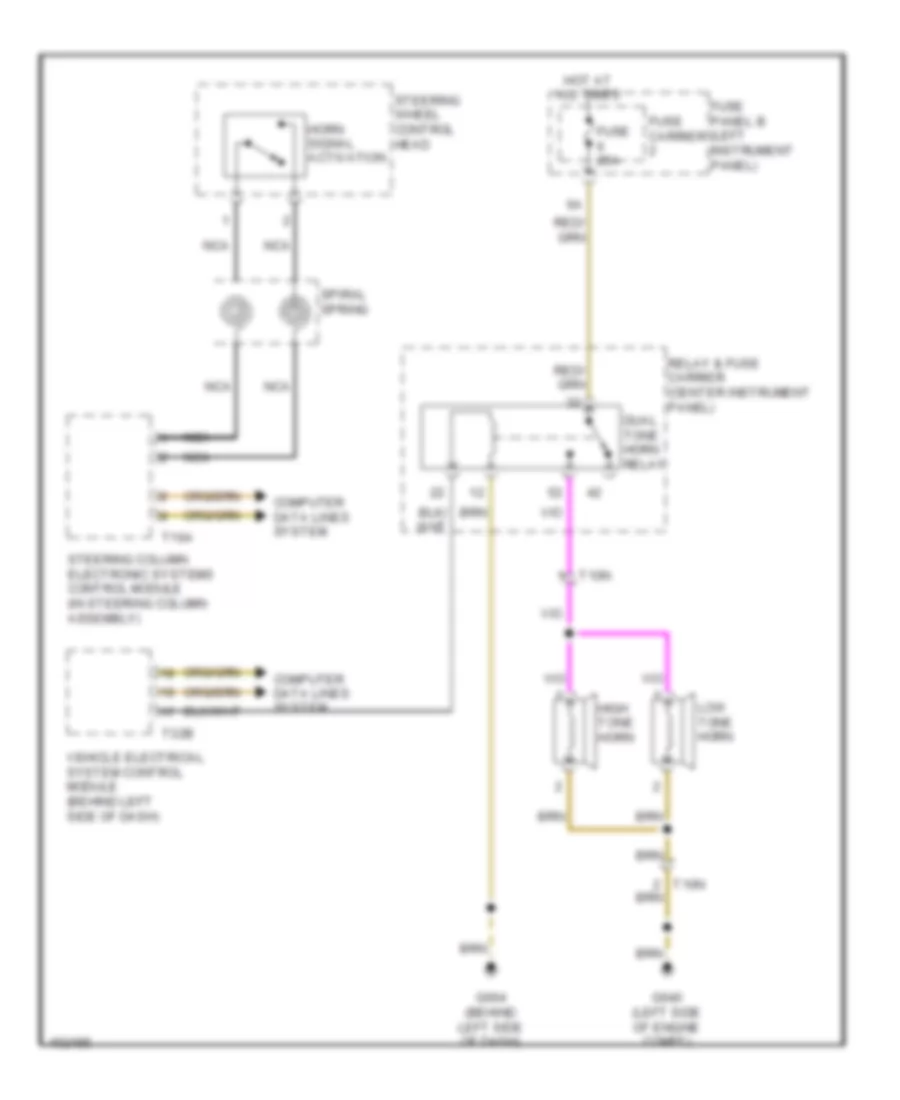
CRUISE CONTROL
Cruise Control Wiring Diagram for Audi Q7 Prestige S 2013
List of elements for Cruise Control Wiring Diagram for Audi Q7 Prestige S 2013:
- (behind left side of dash) g664
- 11a
- 12 pin connector
- 3.0l sc
- 3.0l turbo diesel
- 3.ol turbo diesel
- Accelerator pedal position sensor & accelerator pedal position sensor 2 (accelerator pedal assembly)
- Brake light switch & brake pedal switch (brake pedal assembly)
- Computer data lines system
- Cruise control switch (if equipped)
- Distance regulation control module (if equipped) (behind right front bumper)
- Distance regulation sensor heater
- Engine control module (right rear of engine compt)
- Engine controls system
- Engine speed sensor (transmission bell housing)
- Fuse 10a
- Fuse 5a
- Fuse carrier
- Fuse panel b (left instrument panel)
- G44 (behind left kick panel)
- G640 (left side of engine compt)
- Hot at all times
- Input speed sensor
- Nca
- Output speed sensor
- Red
- Steering column electronic systems control module (in steering column assembly)
- T105
- T10c
- T10d
- T10e
- T16a
- T60
- T8c
- T91
- T94
- Throttle valve control module (3.0l sc) (on supercharger)
- Throttle valve control module (3.0l turbo diesel) (on throttle valve)
- Transmission assembly
- Transmission control module (w/o mechatronic: under front passenger's seat) (w/ mechatronic: in transmission)
DEFOGGERS
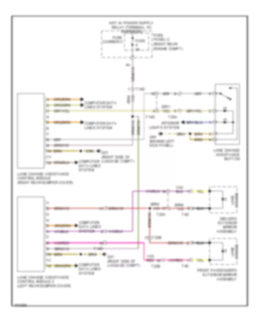
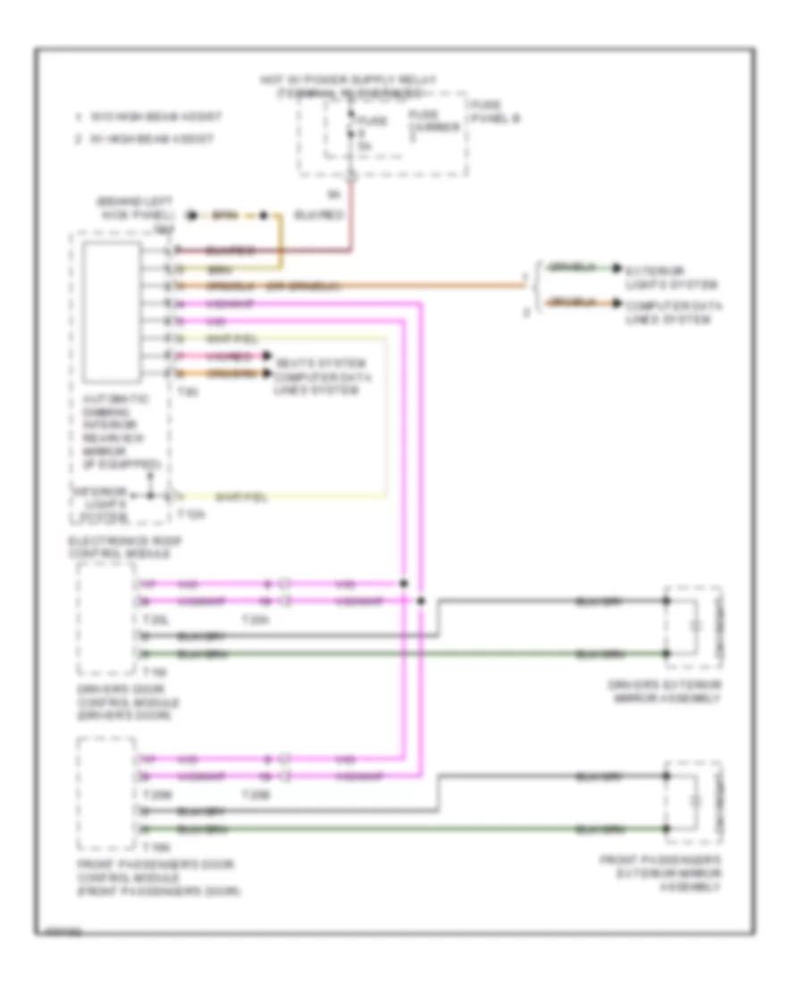
Heated Mirrors Wiring Diagram for Audi Q7 Prestige S 2013
List of elements for Heated Mirrors Wiring Diagram for Audi Q7 Prestige S 2013:
- 11a
- Computer data lines system
- Driver's door control module (driver's door)
- Driver's exterior mirror assembly
- Driver's heated exterior rearview mirror
- Front passenger's door control module (front passenger's door)
- Front passenger's exterior mirror assembly
- Front passenger's heated exterior rearview mirror
- Fuse 35a
- Fuse carrier
- Fuse panel b (left instrument panel)
- Fuse panel c (right rear engine compt)
- G43 (behind right kick panel)
- G44 (behind left kick panel)
- Hot at all times
- Mirrors system
- T16i
- T16k
- T20a
- T20b
- T20l
- T20m
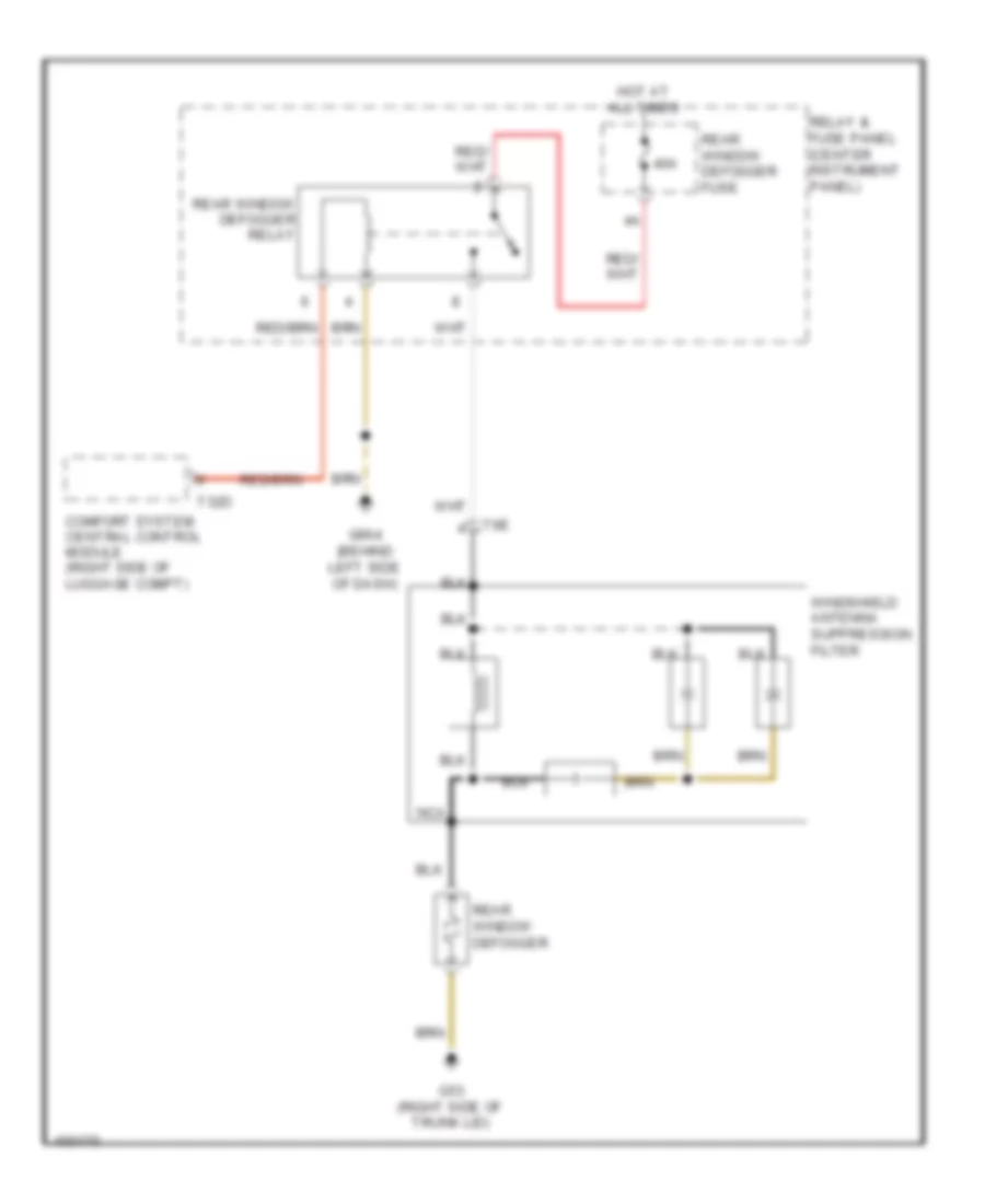
Rear Defogger Wiring Diagram for Audi Q7 Prestige S 2013
List of elements for Rear Defogger Wiring Diagram for Audi Q7 Prestige S 2013:
- 40a
- Comfort system central control module (right side of luggage compt)
- G53 (right side of trunk lid)
- G664 (behind left side of dash)
- Hot at all times
- Nca
- Rear window defogger
- Rear window defogger fuse
- Rear window defogger relay
- Relay & fuse panel (center instrument panel)
- T32d
- T6e
- Windshield antenna suppression filter
ELECTRONIC POWER STEERING
Electronic Power Steering Wiring Diagram for Audi Q7 Prestige S 2013
List of elements for Electronic Power Steering Wiring Diagram for Audi Q7 Prestige S 2013:
- (behind left side of dash)
- (behind left side of dash) vehicle electrical system control module
- (steering column assembly)
- 11a
- Air bag spiral spring/ return spring w/ slip ring
- Axial adjustment motor
- Axial adjustment sensor
- Computer data lines system
- Cruise control switch (if equipped)
- Directional stabilization assistance button (if equipped)
- Driver's air bag igniter
- Driver's air bag igniter 2
- Engine control system
- Fuse 10a
- Fuse 5a
- Fuse carrier
- Fuse carrier 1
- G664
- Heated steering wheel (if equipped)
- Heated steering wheel button (if equipped)
- Heated steering wheel sensor
- Hot at all times
- Hot w/ power suply relay (terminal 15) energized
- Left instrument panel fuse carrier (left instru- ment panel)
- Left multi-function buttons
- Multi-function steering wheel control module
- Nca
- Red
- Right multi-function buttons
- Servotronic solenoid valve
- Shorting contact
- Signal horn activation
- Spiral spring
- Steering angle sensor
- Steering column adjustment assembly
- Steering column adjustment switch
- Steering column electronic systems control module (in steering column assembly)
- Steering wheel control head
- Steering wheel vibration motor (w/ directional stabilization assistance)
- T12b
- T16a
- T32b
- T4a
- Tiptronic downshift button
- Tiptronic upshift button
- Turn signal/ headlight flasher switch
- Vehicle electrical system control module 2 (under front passenger's seat)
- Vertical adjustment motor
- Vertical adjustment sensor
- Windshield wiper intermittent mode switch
ELECTRONIC SUSPENSION
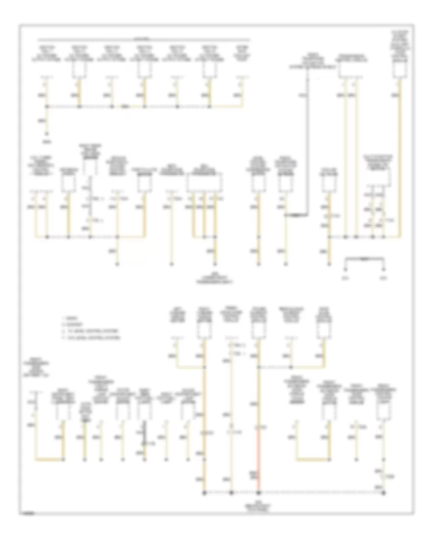
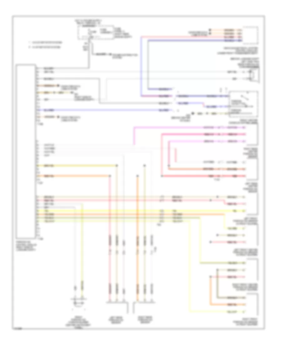
Electronic Suspension Wiring Diagram (1 of 3) for Audi Q7 Prestige S 2013
List of elements for Electronic Suspension Wiring Diagram (1 of 3) for Audi Q7 Prestige S 2013:
- (right side of luggage compt) g51
- Accumulator valve
- Comfort system central control module (right side of luggage compt)
- Fuse 15a
- Fuse 5a
- Fuse carrier 2
- Fuse carrier 3
- Fuse panel c (right rear engine compt)
- Fuse panel f (right side luggage compt)
- Hot at all times
- Level control pressure sensor
- Level control system control module (right side of luggage compt)
- Load level button
- Suspension strut valves
- T32d
- T81a
- Valve body
Electronic Suspension Wiring Diagram (2 of 3) for Audi Q7 Prestige S 2013
List of elements for Electronic Suspension Wiring Diagram (2 of 3) for Audi Q7 Prestige S 2013:
- Compressor motor
- Computer data lines system
- Fuse 40a
- Fuse panel d (below driver seat)
- G35 (under front passenger's seat)
- Hot at all times
- Left front level control system sensor (left front suspension upper link)
- Left rear level control system sensor (left rear suspension upper link)
- Level control system assembly
- Level control system compressor relay
- Level control system control module (right side of luggage compt)
- Pump temperature sensor
- Red
- Relay & fuse carrier (center instrument panel)
- Right front level control system sensor (right front suspension upper link)
- Solenoid
- T2i
- T4i
- T81a
Electronic Suspension Wiring Diagram (3 of 3) for Audi Q7 Prestige S 2013
List of elements for Electronic Suspension Wiring Diagram (3 of 3) for Audi Q7 Prestige S 2013:
- Left front body acceleration sensor (left front wheelwell)
- Left front dampening adjustment valve (left front strut)
- Left rear dampening adjustment valve (left rear suspension strut)
- Level control system control module (right side of luggage compt)
- Nca
- Rear body acceleration sensor (luggage compt, on left side of floor)
- Red
- Right front body acceleration sensor (right front wheelwell liner)
- Right front dampening adjustment valve (right front strut assembly)
- Right rear dampening adjustment valve (right rear strut assembly)
- Right rear level control system sensor (right rear suspension upper link)
- T40b
- T6n
- T6o
- T6p
- T6q
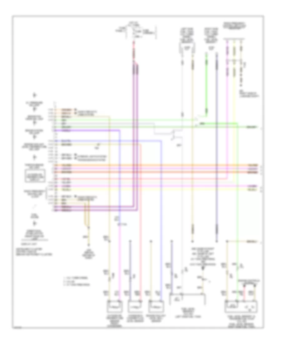
ENGINE PERFORMANCE
3.0L SC
3.0L SC, Engine Performance Wiring Diagram (1 of 7) for Audi Q7 Prestige S 2013
List of elements for 3.0L SC, Engine Performance Wiring Diagram (1 of 7) for Audi Q7 Prestige S 2013:
- (right side of plenum chamber) g609
- 10a
- 13a
- 14a
- 15a
- 17a
- Accelerator pedal position (app) sensor 1 & 2
- Anti-theft system
- Backup & multi-transmission transmission range switch
- Cooling fans system
- Engine control module (right rear of engine compt)
- Fuse 10a
- Fuse 150a
- Fuse 15a
- Fuse 20a
- Fuse 5a
- Fuse panel d (below driver seat)
- Heated oxygen sensor (ho2s) 2 & oxygen sensor (o2s) heater 2 (exhaust pipe, before catalytic converter)
- Hot at all times
- Nca
- Oxygen sensor (02s) 2 after three way catalytic (twc) converter & heater for oxygen sensor 2 after catalytic converter
- Oxygen sensor (o2s) after three way catalytic (twc) converter & heater for oxygen sensor 1 after catalytic converter
- Red
- Relay & fuse panel e-box (left side of plenum chamber)
- Starting/charging system
- T10c
- T10e
- T10m
- T14h
- T17d
- T6k
- T94
3.0L SC, Engine Performance Wiring Diagram (2 of 7) for Audi Q7 Prestige S 2013
List of elements for 3.0L SC, Engine Performance Wiring Diagram (2 of 7) for Audi Q7 Prestige S 2013:
- (left engine compt) oil pressure regulation valve
- (left side of plenum chamber) relay & fuse panel e-box
- (rear of right cylinder head)
- (right cylinder head, in high pressure pump) fuel metering valve
- (w/ fuel system diagnostic pump) leak detection pump (ldp)
- Brake light disable relay
- Camshaft adjustment valve 1
- Camshaft adjustment valve 2 (rear of left cylinder head)
- Charge air cooling pump
- Climatronic control module (in upper center console)
- Evaporative emission (evap) canister purge regulator valve
- G609 (right side of plenum chamber)
- G664 (behind left side of dash)
- G671 (left front long member)
- High pressure sensor (evaporator expansion valve, under right side of dash)
- Intake manifold runner control (imrc) valve
- Red
- Relay & fuse carrier (center instrument panel)
- Secondary air injection (air) solenoid valve
- T10d
- T10e
- T10m
- T14l
- T16d
- T17d
3.0L SC, Engine Performance Wiring Diagram (3 of 7) for Audi Q7 Prestige S 2013
List of elements for 3.0L SC, Engine Performance Wiring Diagram (3 of 7) for Audi Q7 Prestige S 2013:
- Computer data lines system
- Cruise control system
- Display unit
- Engine control module (right rear of engine compt)
- Engine coolant level/ temperature (ecl/ect) ind lamp
- Fuel gauge
- Fuse 50a
- Fuse 5a
- Fuse carrier 3
- Fuse panel b (left instrument panel)
- G45 (behind center of dash)
- Heated oxygen sensor & oxygen sensor (o2s) heater (exhaust pipe, before catalytic converter)
- Hot at all times
- Instrument cluster control module
- Nca
- Oil level thermal sensor (lower oil pan)
- Oil pressure ind lamp
- Red
- Relay & fuse panel e-box (left side of plenum chamber)
- Starting/charging system
- T10c
- T10f
- T94
3.0L SC, Engine Performance Wiring Diagram (4 of 7) for Audi Q7 Prestige S 2013
List of elements for 3.0L SC, Engine Performance Wiring Diagram (4 of 7) for Audi Q7 Prestige S 2013:
- (left front of engine compt) intake manifold temperature sensor & charge air pressure sensor
- (left side of plenum chamber) relay & fuse panel e-box
- (throttle end of supercharger)
- Brake light switch & brake pedal switch (brake light switch: brake pedal assembly)
- Control valve control module
- Engine coolant level (ecl) warning switch
- Fuel level sensor & transfer fuel pump (right side fuel tank)
- Fuel level sensor 2 (left side fuel tank)
- Fuel pump (fp) control module (fuel tank)
- G44 (behind left kick panel)
- G61 (w/o tank prewiring) (base of left 'c' pillar)
- G62 (base of right "c" pillar)
- G62 (w/ tank prewiring) (base of right 'c' pillar)
- G685 (right front long member)
- Intake air temperature (iat) & manifold absolute pressure (map) sensor
- Intake air temperature (iat) sensor 2 & charge air pressure sensor 2
- Secondary air injection (air) pump motor
- Secondary air injection (air) pump relay
- T17d
- T2k
- T5k
- W/ tank prewiring
3.0L SC, Engine Performance Wiring Diagram (5 of 7) for Audi Q7 Prestige S 2013
List of elements for 3.0L SC, Engine Performance Wiring Diagram (5 of 7) for Audi Q7 Prestige S 2013:
- (front of engine) engine coolant temperature (ect) sensor
- (front of right cylinder head) fuel pressure sensor
- (left cylinder head) camshaft position (cmp) sensor 2
- (left front of intake manifold) intake manifold runner position sensor 2
- (rear of right cylinder head) camshaft position (cmp) sensor
- (right front of intake manifold) intake manifold runner position sensor
- (right side of engine above cylinder head) low fuel pressure sensor
- 19a
- 19c
- 19d
- 19e
- After run coolant pump (rear of engine)
- Auxiliary engine coolant pump relay
- Engine speed (rpm) sensor (transmission bell housing)
- Fuse 5a
- G645
- Knock sensor (ks) 1 (under intake manifold, on right cylinder head)
- Knock sensor (ks) 2 (under intake manifold, on right cylinder head)
- Oil pressure switch (top front of engine)
- Red
- Reduced oil pressure switch (near engine oil filter)
- Relay & fuse panel e-box (left side of plenum chamber)
- T10m
- T114l
- T14f
- T14l
- T17d
3.0L SC, Engine Performance Wiring Diagram (6 of 7) for Audi Q7 Prestige S 2013
List of elements for 3.0L SC, Engine Performance Wiring Diagram (6 of 7) for Audi Q7 Prestige S 2013:
- (on supercharger) throttle valve control module
- 16a
- Crankcase ventilation shut-off valve
- Cylinder fuel injectors (cylinder head assembly)
- Fuse 20a
- G600
- G601
- G645
- Ignition coils w/ power output stage (top of 1, 2, 3, 4, 5 & 6 spark plug)
- Nca
- Red
- Relay & fuse panel e-box (left side of plenum chamber)
- T14f
- T14l
- T6k
- To spark plug
3.0L SC, Engine Performance Wiring Diagram (7 of 7) for Audi Q7 Prestige S 2013
List of elements for 3.0L SC, Engine Performance Wiring Diagram (7 of 7) for Audi Q7 Prestige S 2013:
- (right rear of engine compt)
- (under front passenger's seat)
- Air blower
- Antenna amplifier 2
- Auxiliary heater control module (in left front wheel housing)
- Auxiliary heater rf receiver (right side of luggage compt)
- Combustion
- Computer data lines system
- Engine control module
- Engine coolant (ec) switch-off valve (heater) (if equipped)
- Fuse 20a
- Fuse 5a
- Fuse carrier 1
- Fuse panel b (left instrument panel)
- Fuse panel f (right side of luggage compt)
- G35
- G51 (right side of luggage compt)
- G640 (left side of engine compt)
- G669 (right "d" pillar)
- Glow plug
- Heat fuse
- Heater over
- Hot at all times
- Metering pump
- Nca
- Red
- Sensor
- T2b
- T2bq
- T2p
- T60
- T6b
- T6u
- Temperature
3.0L TURBO DIESEL
3.0L Turbo Diesel, Engine Performance Wiring Diagram (1 of 9) for Audi Q7 Prestige S 2013
List of elements for 3.0L Turbo Diesel, Engine Performance Wiring Diagram (1 of 9) for Audi Q7 Prestige S 2013:
- (base of
- (downstream of catalyst) exhaust gas temperature (egt) sensor 3
- (fuel tank) fuel pump control module
- (top front of engine) egr temperature sensor
- (turbocharger assembly) exhaust gas temperature (egt) sensor 1
- Accelerator pedal position sensor & accelerator pedal position sensor 2 (accelerator pedal position sensor: accelerator pedal assembly)
- Access/start control module (integral to steering column lock actuator)
- Differential pressure sensor (on turbocharger)
- Engine control module (ecm) (right rear of engine compt)
- Exhaust gas recirculation (egr) motor (top of engine)
- G609 (right side of plenum chamber)
- G62
- G62 (base of right "c" pillar)
- Mass air flow (maf) sensor (air intake duct at filter housing)
- Multi-function transmission range (tr) switch
- Nca
- Red
- Right "c" pillar)
- Starting/charging system
- T10ab
- T10b
- T10c
- T10d
- T10e
- T10m
- T14h
- T17d
- T17e
- T20e
- T91
- Transfer fuel pump
- Turbocharger (tc) control module 1 (turbocharger assembly)
3.0L Turbo Diesel, Engine Performance Wiring Diagram (2 of 9) for Audi Q7 Prestige S 2013
List of elements for 3.0L Turbo Diesel, Engine Performance Wiring Diagram (2 of 9) for Audi Q7 Prestige S 2013:
- Automatic glow time control module (in left plenum chamber)
- Auxiliary heater heating element
- Fuse 60a
- G45 (behind center of dash)
- G51 (right side of luggage compt)
- G609 (right side of plenum chamber)
- Glow plug
- Heat setting 3 relay
- High heat output relay
- Hot at all times
- Low heat output relay
- Nca
- Red
- Reducing agent pump, reducing agent pump heater & reducing agent metering system pressure sensor (at right rear wheel housing)
- Relay & fuse panel e-box (left side of plenum chamber)
- T17e
- T2bg
- T8al
3.0L Turbo Diesel, Engine Performance Wiring Diagram (3 of 9) for Audi Q7 Prestige S 2013
List of elements for 3.0L Turbo Diesel, Engine Performance Wiring Diagram (3 of 9) for Audi Q7 Prestige S 2013:
- (right side of plenum chamber) g609
- 17a
- Cylinder 2 combustion chamber pressure sensor & glow plug 2
- Fuse 150a
- Fuse 40a
- Fuse 5a
- Fuse 60a
- Fuse 80a
- Fuse carrier
- Fuse panel b (left instrument panel)
- Fuse panel d (below driver seat)
- G35 (under front passenger's seat)
- G44 (behind left kick panel)
- Glow plug
- Hot at all times
- Injector
- Nox sensor 1 control module (left side of engine compt)
- Nox sensor 2 control module (under rear of vehicle)
- Particulate sensor (at exit of scr catalyst)
- Red
- Reduced oil pressure switch (near engine oil filter)
- Reducing agent
- Relay & fuse panel e-box (left side of plenum chamber)
- T10c
- T10m
- T6t
3.0L Turbo Diesel, Engine Performance Wiring Diagram (4 of 9) for Audi Q7 Prestige S 2013
List of elements for 3.0L Turbo Diesel, Engine Performance Wiring Diagram (4 of 9) for Audi Q7 Prestige S 2013:
- 10a
- 11a
- 12a
- 13a
- 14a
- 15a
- 16a
- 18a
- Computer data lines system
- Cooling fans system
- Cruise control system
- Engine control module (ecm) (right rear of engine compt)
- Exterior lights system
- Fuse 10a
- Fuse 15a
- Fuse 16 20a (or 25a)
- Fuse 5a
- Red
- Relay & fuse panel e-box (left side of plenum chamber)
- Starting/charging system
- T10e
- T17d
- T17e
- T91
3.0L Turbo Diesel, Engine Performance Wiring Diagram (5 of 9) for Audi Q7 Prestige S 2013
List of elements for 3.0L Turbo Diesel, Engine Performance Wiring Diagram (5 of 9) for Audi Q7 Prestige S 2013:
- (rear of engine) coolant pump
- Abs control module (right plenum chamber)
- Brake light disable relay
- Brake light switch & brake pedal switch (brake light switch: brake pedal assembly)
- Climatronic control module (in upper center console)
- Coolant circulation pump relay (relay & fuse panel/ instrument panel center)
- Exterior lights system
- Fuse 5a
- Fuse carrier
- Fuse panel c (right rear engine compt)
- G44 (behind left kick panel)
- G609 (right side of plenum chamber)
- G640 (left side of engine compt)
- G664 (behind left side of dash)
- Heated oxygen sensor (ho2s) & oxygen sensor (o2s) heater (exhaust pipe, before catalytic converter)
- High pressure sensor (evaporator expansion valve, under right side of dash)
- Nca
- Red
- Relay & fuse carrier
- T10c
- T10d
- T16c
- T16d
3.0L Turbo Diesel, Engine Performance Wiring Diagram (6 of 9) for Audi Q7 Prestige S 2013
List of elements for 3.0L Turbo Diesel, Engine Performance Wiring Diagram (6 of 9) for Audi Q7 Prestige S 2013:
- (left side fuel tank) fuel level sensor 2
- (right cylinder head) camshaft position (cmp) sensor
- (right side fuel tank) fuel level sensor 1
- Computer data lines system
- Display unit
- Engine coolant
- Engine coolant level/temperature (ecl/ect) ind lamp
- Fuel gauge
- G45 (behind center of dash)
- G609 (right side of plenum chamber)
- Instrument cluster control module
- Level (ecl) warning switch
- Oil level thermal sensor (lower oil pan)
- Oil pressure
- Oil pressure ind lamp
- Red
- Switch (top front of engine)
- T10f
3.0L Turbo Diesel, Engine Performance Wiring Diagram (7 of 9) for Audi Q7 Prestige S 2013
List of elements for 3.0L Turbo Diesel, Engine Performance Wiring Diagram (7 of 9) for Audi Q7 Prestige S 2013:
- (front of engine) map controlled engine cooling thermostat
- (next to engine oil filter) cylinder head coolant valve
- (on filler neck) reducing agent tank cap switch
- (reducing agent tank sensor: at right rear wheel housing)
- (top center of engine) exhaust gas recirculation (egr) cooler switch over valve
- Electrohydraulic engine mount solenoid valve
- Fuse 30a
- Fuse 5a
- Fuse carrier
- Fuse panel b (left instrument panel)
- Fuse panel f (right side of luggage compt)
- G51 (right side of luggage compt)
- G77 (base of left "b" pillar)
- Hot at all times
- Nca
- Red
- Reducing agent line heater (under left side vehicle)
- Reducing agent metering system control module (under the rear bench seat below floor covering)
- Reducing agent tank heater
- Reducing agent tank sensor & reducing agent temperature sensor
- Reducing agent transfer pump (under left side vehicle)
- T10ab
- T17e
3.0L Turbo Diesel, Engine Performance Wiring Diagram (8 of 9) for Audi Q7 Prestige S 2013
List of elements for 3.0L Turbo Diesel, Engine Performance Wiring Diagram (8 of 9) for Audi Q7 Prestige S 2013:
- (downstream of particle filter) exhaust gas temperature (ect) sensor 4
- (left engine compt) oil pressure regulation valve
- (on radiator outlet) engine coolant temperature (ect) sensor (on radiator)
- (right rear of engine) engine coolant temperature sensor
- Engine control module (ecm) (right rear of engine compt)
- Red
- T105
- T10ab
- T10m
- T17d
3.0L Turbo Diesel, Engine Performance Wiring Diagram (9 of 9) for Audi Q7 Prestige S 2013
List of elements for 3.0L Turbo Diesel, Engine Performance Wiring Diagram (9 of 9) for Audi Q7 Prestige S 2013:
- (cylinder head assembly) fuel injector cylinders
- (left front of engine) engine temperature control sensor
- (right front of engine) fuel pressure regulator valve
- (top center of engine) fuel metering valve
- (top right rear of engine) fuel temperature sensor
- Brake booster pressure sensor (brake booster assembly)
- Charge air pressure sensor & intake air temperature (iat) sensor (left front of engine compt)
- Cooling fans system
- Engine control module (ecm) (right rear of engine compt)
- Engine speed sensor (transmission bell housing)
- Fuel pressure sensor (top left side of engine)
- Intake flap motor (top front of engine)
- Oil temperature sensor 2 (right front of engine)
- Red
- T105
- T10ab
- T10m
- T17d
- Throttle valve control module (on throttle valve)
EXTERIOR LIGHTS
Backup Lamps Wiring Diagram for Audi Q7 Prestige S 2013
List of elements for Backup Lamps Wiring Diagram for Audi Q7 Prestige S 2013:
- Automatic dimming interior rearview mirror (if equipped)
- Automatic high beam assist control module (behind rearview mirror)
- Backup
- Backup switch
- Comfort system central control module (right side of luggage compt)
- Comfort system central control module 2 (right side of luggage compt)
- Computer data lines system
- Fuse 15a
- Fuse 5a
- Fuse carrier 1
- Fuse carrier 2
- Fuse panel c (right rear engine compt)
- Fuse panel f (right side luggage compt)
- G51 (right side of luggage compt)
- Hot at all times
- Left taillamp assembly
- Multi-function transmission range (tr) switch
- Nca
- Right taillamp assembly
- T14e
- T14h
- T32d
- Transmission control module (tcm) (w/o mechatronic: under front passenger's seat) (w/ mechatronic: in transmission)
- W/o high beam assistance
Exterior Lamps Wiring Diagram (1 of 2) for Audi Q7 Prestige S 2013
List of elements for Exterior Lamps Wiring Diagram (1 of 2) for Audi Q7 Prestige S 2013:
- 10a
- 11a
- 12a
- Backup
- Backup lamps circuit
- Comfort system central control module (right side of luggage compt)
- Comfort system central control module 2 (right side of luggage compt)
- Computer data
- Computer data lines system
- Driver's door control module (driver's door)
- Driver's exterior mirror assembly
- Front passenger's door control module (front passenger's door)
- Front passenger's exterior mirror assembly
- Fuse 10a
- Fuse 15a
- Fuse 20a
- Fuse 30a
- Fuse 35a
- Fuse 5a
- Fuse carrier
- Fuse panel b (left instrument panel)
- Fuse panel c (right rear engine compt)
- Fuse panel f (right side luggage compt)
- G43 (behind right kick panel)
- G44 (behind left kick panel)
- G51 (right side of luggage compt)
- G664 (behind left side of dash)
- G668 (left "d" pillar)
- Headlight flasher
- Hot at all times
- Hot in all times
- Left taillamp assembly
- Left taillamp assembly 2
- Lines system
- Marker rear side
- Mirrors system
- Nca
- Rear fog
- Rear turn signal
- Right taillamp assembly
- Right taillamp assembly 2
- Steering column electronic systems control module (in steering column assembly)
- Switch
- T10g
- T10r
- T10s
- T14e
- T15a
- T16a
- T16i
- T16k
- T20a
- T20l
- T20m
- T2ac
- T32d
- T6e
- Tail/brake
- Turn signal
- Turn signal tail/brake/rear
- Turn signal/
Exterior Lamps Wiring Diagram (2 of 2) for Audi Q7 Prestige S 2013
List of elements for Exterior Lamps Wiring Diagram (2 of 2) for Audi Q7 Prestige S 2013:
- (behind left side of dash) g664
- (brake light switch: brake pedal assembly) brake light/ brake pedal switch
- 3.0l (turbo diesel)
- 3.0l sc
- Abs control module (abs hydraulic unit) (right plenum chamber)
- Access/start authorization switch (center console, right side of steering wheel)
- Asr/esp button/ emergency flasher button
- Brake light disable relay (esp)
- Computer data lines system
- Display unit
- Engine control module (right rear of engine compt)
- Fog lp ind
- Fog lp sw
- Fuse 25a
- Fuse 30a
- Fuse 5a
- Fuse carrier
- Fuse panel b (left instrument panel)
- G44 (behind left kick panel)
- G644
- G658 (top of left "d" pillar)
- G664 (behind left side of dash)
- G668 (left "d" pillar)
- Headlamp sw ill
- High- mount brake light
- Hot at all times
- Instrument cluster control module
- Interior lights system
- Left front side marker/ turn signal lamp
- License plate light
- Light switch
- Parking light ind
- Rear fog lp sw
- Red
- Relay & fuse carrier (center instrument panel) (center instrument panel)
- Right front side marker/ turn signal lamp
- Rr fog lp ind
- Suppr- essor
- T10c
- T10o
- T10r
- T12b
- T12d
- T2s
- T2t
- T2u
- T2v
- T32b
- T6e
- T8a
- T91
- T94
- Towing recognition control module (right side of luggage compt)
- Vehicle electrical system control module
- W/ drl
- W/o bi-xenon
Trailer Tow Wiring Diagram for Audi Q7 Prestige S 2013
List of elements for Trailer Tow Wiring Diagram for Audi Q7 Prestige S 2013:
- 10a
- 11a
- Abs control module (abs hydrolic unit) (right plenum chamber)
- Brake booster
- Brake light disable relay (esp)
- Comfort system central control module (right side of luggage compt)
- Computer data lines system
- Exterior lamps circuit
- Fuse 15a
- Fuse 20a
- Fuse 30a
- Fuse 5a
- Fuse carrier 3
- Fuse panel b (left instrument panel)
- Fuse panel f (right side luggage compt)
- G44 (behind left kick panel)
- G51 (right side of luggage compt)
- G664 (behind left side of dash)
- G675 (right side of luggage compt)
- Hot at all times
- Multimedia control module
- Red
- Relay & fuse carrier (center instrument panel) (center instrument panel)
- T12d
- T16e
- T26e
- T2ay
- T2be
- T32d
- T47a
- T4ai
- Towing recognition control module (right side of luggage compt)
- Trailer socket
- W/ rear seat entertainment
GROUND DISTRIBUTION
Ground Distribution Wiring Diagram (1 of 7) for Audi Q7 Prestige S 2013
List of elements for Ground Distribution Wiring Diagram (1 of 7) for Audi Q7 Prestige S 2013:
- (3.0l sc)
- (3.0l turbo diesel) nox sensor 2 control module
- (9zj) telephone transceiver
- (9zw) telephone transceiver
- (w/ stop/ start) system) auxiliary hydraulic pump control module
- 18 pin conn- ector (not used)
- After run- coolant pump
- Basic
- Comfort
- Cooling oil valve
- Fresh air blower control module
- Front passenger's control locking unit
- Front passenger's door control module
- Front passenger's exterior door handle switch
- Front passenger's exterior door handle touch sensor
- Front passenger's side air bag igniters 1 & 2
- Front passenger's vanity mirror lamp contact switch
- G13
- G18
- G35 (under front passenger's seat)
- G43 (behind right kick panel)
- G645
- Glove compartment lamp switch
- Glove compartment unlock motor
- Ignition coil 1 (w/ power output stage)
- Ignition coil 2 (w/ power output stage)
- Ignition coil 3 (w/ power output stage)
- Ignition coil 4 (w/ power output stage)
- Ignition coil 5 (w/ power output stage)
- Ignition coil 6 (w/ power output stage)
- Left washer nozzle heater
- Level control system compressor motor
- Metering pump
- Multi-function transmission range (tr) switch
- Nca
- Particulate sensor
- Power sunroof control module
- Radio telephone, navigation system antenna shield
- Radio, telephone, navigation system antenna
- Rear sliding sunroof control module
- Right footwell lamp
- Right instrument panel vent illumination
- Right rear brake pad wear sensor
- Right rear footwell lamp
- Right washer nozzle heater
- Roof blind control module
- T14h
- T17b
- T17k
- T20b
- T20m
- T2q
- T2w
- T40a
- T42
- T4q
- T54a
- T6ai
- T6q
- T6y
- Transmission control module
- Vehicle electrical system control module 2
- W/ level control system
- W/o level control system
Ground Distribution Wiring Diagram (2 of 7) for Audi Q7 Prestige S 2013
List of elements for Ground Distribution Wiring Diagram (2 of 7) for Audi Q7 Prestige S 2013:
- (3.0l turbo diesel) auxiliary air heater heating element
- (3.0l turbo diesel) nox sensor 1 control module
- (if equipped) automatic dimmer interior rearview mirror
- (if equipped) interior monitoring sensor
- (w/o mmi basic) front information display control head module
- Access/ start author- ization button
- Access/ start author- ization switch
- Access/ start control module
- Air quality sensor
- Ashtray & cup holder illumination
- Brake booster connector
- Brake lamp switch & brake pedal switch
- Climatronic control module
- Data link connector
- Directional stabilization assistance control module
- Directional stabilization assistance windshield heater
- Driver's door central locking lock unit
- Driver's door control module
- Driver's exterior door handle switch
- Driver's exterior door handle touch sensor
- Driver's vanity mirror lamp contact switch
- Dvd player
- Electronic roof control module
- Front information display control head
- Front roof control module
- Front/ center console control head
- G44 (behind left kick panel)
- G45 (behind center of dash)
- Garage door opener control head
- Headlamp range control adjuster
- Headlamp range control module
- Information electronics control module 1
- Instrument cluster control module
- Lane change assistance button/lamp
- Left headlamp assembly
- Left instrument panel vent illumination
- Left rear footwell lamp
- Light switch
- Nca
- Oil level thermal sensor
- Park aid button & indicator lamp, glove compartment & display unit button
- Radio, telephone, navigation system antenna
- Radio, telephone, navigation system antenna shield
- Rain/ light recognition sensor
- Rear sunroof switch
- Right headlamp assembly
- Selector lever sensor system control module
- Shift lock solenoid
- Sunroof switch
- T10f
- T12a
- T16d
- T17a
- T20a
- T20k
- T20l
- T2cd
- T3a
- T4c
- T6a
- T8af
- T8x
- Tbh
- Tire pressure monitoring control module
- Transmission park selector switch & selector lever park position solenoid
Ground Distribution Wiring Diagram (3 of 7) for Audi Q7 Prestige S 2013
List of elements for Ground Distribution Wiring Diagram (3 of 7) for Audi Q7 Prestige S 2013:
- (3.0l sc) fuel level sensor 2
- (3.0l sc) fuel pump control module
- (3.0l turbo diesel)
- (3.0l turbo diesel) engine coolant shut-off valve relay
- (3.0l turbo) transfer fuel pump
- (9zf) telephone amplifier
- (diesel) fuel pump control module
- (w/ auxiliary heater) left rear backrest heating element
- (w/ auxiliary heater) right rear backrest heating element
- 12v socket
- Auxiliary heater rf receiver
- Center instrument panel vent illumination
- Comfort system central control module
- Comfort system central control module 2
- Cooler
- Door closing assist control module
- G51 (right side of luggage compt)
- G53 (right side of trunk lid)
- G61 (base of left "c" pillar)
- G62 (base of right "c" pillar)
- G67
- Keyless access authorization antenna reader
- Lane change assistance control module
- Lane change assistance control module 2
- Left luggage compart- ment lamp
- Left luggage compartment side trim 12 pin connector
- Left taillamp assembly
- Level control system control module
- Multimedia system control module
- Nca
- Parking aid control module
- Peripheral camera control module
- Radio frequency controlled clock receiver
- Rear center air vent illumination
- Rear fresh air blower control module
- Rear lid closed sensor 1 & 2
- Rear view camera system control module
- Rear window defogger
- Reducing agent line heater
- Reducing agent metering system control module
- Reducing agent pump & pump heater
- Reducing agent tank heater
- Right luggage compart- ment lamp
- Right taillamp assembly
- T10g
- T12d
- T12z
- T14d
- T14e
- T16b
- T17h
- T18e
- T20f
- T26e
- T2k
- T2r
- T4ai
- T54
- T6h
- T6u
- T81a
- T8al
- Telephone antenna
- Towing recognition control module
Ground Distribution Wiring Diagram (4 of 7) for Audi Q7 Prestige S 2013
List of elements for Ground Distribution Wiring Diagram (4 of 7) for Audi Q7 Prestige S 2013:
- (3.0l turbo diesel) oil pressure switch
- (3.0l turbo diesel) reduced oil pressure switch
- (3.0l turbo diesel) reducing agent transfer pump
- (w/ auxiliary heater) driver's backrest heating element
- (w/ child safety lock) left rear central locking lock unit
- 3.0l (turbo diesel)
- 3.0l (turbo diesel) automatic glow time control module
- 3.0l sc
- 5a b
- Abs control module
- Auxiliary
- Auxiliary video/ audio connection module
- Coolant pump
- Driver backrest heating element
- Driver seat bolster heater
- Driver's power seat switch assembly
- Driver's seat lumbar support adjustment switch
- Engine control module (ecm)
- G609 (right side of plenum chamber)
- G77 (base of left "b" pillar)
- Heater fuel pump relay
- High pressure sensor
- Left front heated seat
- Left front seat ventilation control module
- Left rear door control module
- Left rear door handle switch
- Left rear exterior door handle touch sensor
- Memory seat/ steering column adjustment control module
- Nca
- Relay & fuse panel e-box (left side of plenum chamber)
- T12s
- T17a
- T20c
- T20n
- T2ao
- T2bc
- T3ae
- T4x
- T6f
- T91
- T94
Ground Distribution Wiring Diagram (5 of 7) for Audi Q7 Prestige S 2013
List of elements for Ground Distribution Wiring Diagram (5 of 7) for Audi Q7 Prestige S 2013:
- (3.0l sc)
- (w/ auxiliary heater) front passenger's backrest heating element
- (w/ auxiliary heater) right rear backrest heating element
- (w/ child safety lock) right rear central locking unit
- (w/ right side window) antenna amplifier 2
- Antenna amplifier
- Antenna amplifier 2 shield
- Antenna amplifier shield
- Auxiliary video/ audio connection module
- Front passenger's backrest heating element
- Front passenger's seat bolster heater
- Front passenger's seat lumbar support adjustment switch
- G600
- G601
- G608 (center of plenum chamber)
- G669 (right "d" pillar)
- G78 (right lower "b" pillar)
- Ignition coil 1 (w/ power output stage)
- Ignition coil 2 (w/ power output stage)
- Ignition coil 3 (w/ power output stage)
- Ignition coil 4 (w/ power output stage)
- Ignition coil 5 (w/ power output stage)
- Ignition coil 6 (w/ power output stage)
- Nca
- Passenger's memory seat control module
- Passenger's power seat switch assembly
- Radio, telephone, navigation system antenna
- Radio, telephone, navigation system antenna shield
- Right front heated seat
- Right front seat ventilation control module
- Right rear door control module
- Right rear exterior door handle switch
- Right rear exterior door handle touch sensor
- Right rear outside door handle central locking button & touch sensor
- T12t
- T17b
- T20d
- T20o
- T2ap
- T2bd
- T2bq
- T2bx
- T2cf
- T3af
- T4x
- T6g
- T6i
- Wiper motor control module
Ground Distribution Wiring Diagram (6 of 7) for Audi Q7 Prestige S 2013
List of elements for Ground Distribution Wiring Diagram (6 of 7) for Audi Q7 Prestige S 2013:
- (3.0l sc) secondary air injection (air) pump motor
- (center instrument panel) relay & fuse panel
- (if equipped) coolant shut-off valve
- (if equipped) headlamp washer pump
- Access/start authoriza- tion switch
- Access/start authorization switch shield
- Alarm horn
- Antenna amplifier
- Antenna amplifier 3 shield
- Antenna amplifier 4
- Antenna amplifier 4 shield
- Asr/esp button
- Auxiliary heater control module
- Battery monitoring control module
- Brake fluid level warning switch
- Brake light disable relay
- Cd changer & dvd player
- Coolant circulation pump relay
- Coolant recirculation pump
- Data bus on board diagnostic interface
- Distance regulation control module
- Dual tone horn relay
- Emergency flasher button
- Engine coolant (ec) switch off valve (heater)
- Engine hood contact switch
- G624
- G640 (left side of engine compt)
- G644
- G664 (behind left side of dash)
- G666 (top of right "d" pillar)
- G667 (top of left "d" pillar)
- G685 (right front long member)
- Garage door opener control module
- High tone horn
- Left footwell light
- Left front fog lamp
- Left front side marker/ turn signal lamp
- Left front turn signal lamp
- Left headlamp assembly
- Low tone horn
- Nca
- Rear window defogger relay
- Right front fog lamp
- Right front side marker/ turn signal lamp
- Right front turn signal lamp
- Right headlamp assembly
- Steering column electronic systems control module
- T10a
- T10n
- T10o
- T12b
- T16a
- T2b
- T2by
- T2s
- T2t
- T2u
- T2v
- T3q
- T6d
- T8c
- Vehicle electrical system control module
- W/ cornering headlights
Ground Distribution Wiring Diagram (7 of 7) for Audi Q7 Prestige S 2013
List of elements for Ground Distribution Wiring Diagram (7 of 7) for Audi Q7 Prestige S 2013:
- (3.0l sc) charge air cooling pump
- (if equipped) digital tv tuner
- (if equipped) rear a/c display control head
- (if equipped) tv tuner
- (rse) digital tv tuner
- (w/ basic sound system) radio
- (w/o basic sound system) radio
- 12v socket 2
- 12v socket 3
- 12v socket 4
- Cigarette lighter
- Coolant fan control module
- Coolant fan control module 2
- Digital sound system control module
- Digital sound system control module 2
- External audio source connector
- G657 (left "d" pillar)
- G658 (top of left "d" pillar)
- G668 (left "d" pillar)
- G671 (left front long member)
- G675 (right side of luggage compt)
- G687 (under center console)
- High mounted brake lamp
- Left rear heated seat regulating switch
- Left rear seat heating element assembly
- Left tail lamp assembly 2
- License plate lamp & rear lid lock cylinder unlock button
- Navigation system control module w/ cd drive
- Nca
- Radio, telephone navigation system antenna
- Radio, telephone navigation system antenna shield
- Rear interior lamp
- Rear lid control module
- Rear lid control module 2
- Rear lid courtesy lamp
- Rear lid lock button
- Rear window breakage sensor
- Rear window wiper motor
- Right rear heated seat regulating switch
- Right rear seat heating element assembly
- Right tail taillamp assembly 2
- Satellite radio
- Suppressor
- T10aa
- T12ag
- T16h
- T20p
- T2cc
- T32c
- T38
- T6am
- T6h
- T6i
- T8k
- T8l
- Telephone amplifier
- Telephone amplifier shield
- Telephone base plate
- Telephone base plate shield
- Trailer socket
- Trunk lid alarm switch
- W/ bang & olufsen
- W/ bose
- W/ electronic rear lid opener
- W/o electronic rear lid opener
HEADLIGHTS
Headlights Wiring Diagram, with Bi-Xenon without Cornering Headlights (1 of 2) for Audi Q7 Prestige S 2013
List of elements for Headlights Wiring Diagram, with Bi-Xenon without Cornering Headlights (1 of 2) for Audi Q7 Prestige S 2013:
- (behind left side of dash) g664
- 11a
- Asr/esp button/ emergency flasher button
- Comfort system central control module 2 (right side of luggage compt)
- Computer data lines system
- Fog lamp ind
- Fog lamp switch
- Fuse 10a
- Fuse 25a
- Fuse 30a
- Fuse 5a
- Fuse carrier 1
- Fuse carrier 2
- Fuse carrier 3
- Fuse panel b (left instrument panel)
- G44 (behind left kick panel)
- G644
- G664 (behind left side of dash)
- Headlight switch illum
- Hot at all times
- Interior lights system
- Left front fog lamp
- Left front turn signal lamp
- Light switch
- Nca
- Parking light ind
- Rear fog lamp ind
- Rear fog lamp switch
- Red
- Right front fog lamp
- Right front turn signal lamp
- Steering column electronic systems control module (in steering column assembly)
- T10a
- T10o
- T12b
- T16a
- T32b
- Turn signal/ headlight flasher switch
- Vehicle electrical system control module (behind left side of dash)
- W/ drl
Headlights Wiring Diagram, with Bi-Xenon without Cornering Headlights (2 of 2) for Audi Q7 Prestige S 2013
List of elements for Headlights Wiring Diagram, with Bi-Xenon without Cornering Headlights (2 of 2) for Audi Q7 Prestige S 2013:
- (behind left kick panel) g44
- 12a
- Computer data lines system
- Day time running lamp & parking light control module
- Display unit
- Front side marker lamp
- Fuse 5a
- Fuse carrier 3
- Fuse panel b (left instrument panel)
- G640 (left side of engine compt)
- G644
- Headlamp beam adjustment motor
- Headlamp reflector adjustment solenoid
- Headlight range control module (behind left side of dash)
- High intensity gas discharge (hid) lamp
- High intensity gas discharge (hid) lamp ballast
- Instrument cluster control module
- Led parking lamp/ drl module
- Led parking lamp/drl module
- Left front level control system sensor (w/o air suspension) (left front suspension upper link)
- Left headlamp assembly
- Left rear level control system sensor (w/o air suspension) (left rear suspension upper link)
- Parking brake contact switch
- Right headlamp assembly
Headlights Wiring Diagram, with Bi-Xenon, with Cornering Headlights (1 of 3) for Audi Q7 Prestige S 2013
List of elements for Headlights Wiring Diagram, with Bi-Xenon, with Cornering Headlights (1 of 3) for Audi Q7 Prestige S 2013:
- (behind left side of dash) g664
- 11a
- Asr/esp button/ emergency flasher button
- Comfort system central control module 2 (right side of luggage compt)
- Computer data lines system
- Fog lamp ind
- Fog lamp switch
- Fuse 10a
- Fuse 25a
- Fuse 30a
- Fuse 5a
- Fuse carrier 1
- Fuse carrier 2
- Fuse carrier 3
- Fuse panel b (left instrument panel)
- G44 (behind left kick panel)
- G644
- G664 (behind left side of dash)
- Headlight switch ill
- Hot at all times
- Interior lights system
- Left front fog lamp
- Light switch
- Nca
- Parking light ind
- Rear fog lamp ind
- Rear fog lamp switch
- Red
- Right front fog lamp
- Steering column electronic systems control module (in steering column assembly)
- T10a
- T10o
- T12b
- T16a
- T32b
- Turn signal/ headlight flasher switch
- Vehicle electrical system control module (behind left side of dash)
- W/ drl
Headlights Wiring Diagram, with Bi-Xenon, with Cornering Headlights (2 of 3) for Audi Q7 Prestige S 2013
List of elements for Headlights Wiring Diagram, with Bi-Xenon, with Cornering Headlights (2 of 3) for Audi Q7 Prestige S 2013:
- Computer data lines system
- Cornering lamp
- Daytime running lamp & parking light control module
- Display unit
- Front side marker lamp
- Fuse 10a
- Fuse carrier 3
- Fuse panel b (left instrument panel)
- G640 (left side of engine compt)
- G644
- Headlamp adjustment motor
- Headlamp beam adjustment motor
- Headlamp power output stage
- Headlamp power output stage 2
- High intensity gas discharge (hid) lamp
- High intensity gas discharge (hid) lamp ballast
- Instrument cluster control module
- Led parking lamp/drl module
- Left front turn signal lamp
- Left headlamp assembly
- Parking brake contact switch
- Right front turn signal lamp
- Swivel module position sensor
- T12
- T4ba
- T4bb
Headlights Wiring Diagram, with Bi-Xenon, with Cornering Headlights (3 of 3) for Audi Q7 Prestige S 2013
List of elements for Headlights Wiring Diagram, with Bi-Xenon, with Cornering Headlights (3 of 3) for Audi Q7 Prestige S 2013:
- 12a
- Computer data lines system
- Cornering lamp
- Daytime running lamp & parking light control module
- Front side marker lamp
- Fuse 10a
- Fuse 5a
- Fuse carrier 2
- Fuse carrier 3
- Fuse panel b (left instrument panel)
- Fuse panel c (right rear of engine compt)
- G44 (behind left kick panel)
- G644
- Headlamp adjustment motor
- Headlamp beam adjustment motor
- Headlamp power output stage
- Headlamp power output stage 2
- Headlight range control module (behind left side of dash)
- High intensity gas discharge (hid) lamp
- High intensity gas discharge (hid) lamp ballast
- Led parking lamp/drl module
- Left front level control system sensor (w/o air suspension) (left front suspension upper link)
- Left rear level control system sensor (w/o air suspension) (left rear suspension upper link)
- Right headlamp assembly
- Swivel module position sensor
- T12
- T4ba
- T4bb
Headlights Wiring Diagram, without Bi-Xenon Headlights (1 of 2) for Audi Q7 Prestige S 2013
List of elements for Headlights Wiring Diagram, without Bi-Xenon Headlights (1 of 2) for Audi Q7 Prestige S 2013:
- Computer data lines system
- Fog lamp ind
- Fog lamp switch
- Fuse 5a
- Fuse carrier 3
- Fuse panel b (left instrument panel)
- G44 (behind left kick panel)
- G644
- G664 (behind left side of dash)
- Headlight switch ill
- Interior lights system
- Left front fog lamp
- Left front side marker/turn signal lamp
- Light switch
- Parking light ind
- Rear fog lamp ind
- Rear fog lamp switch
- Right front fog lamp
- T10a
- T10o
- T12b
- T2s
- T2t
- T32b
- Vehicle electrical system control module (behind left side of dash)
Headlights Wiring Diagram, without Bi-Xenon Headlights (2 of 2) for Audi Q7 Prestige S 2013
List of elements for Headlights Wiring Diagram, without Bi-Xenon Headlights (2 of 2) for Audi Q7 Prestige S 2013:
- (behind left side of dash) g664
- 11a
- Asr/esp button/ emergency flasher switch
- Computer data lines system
- Daytime running light (drl) lamp
- Display unit
- Fuse 10a
- Fuse carrier 1
- Fuse panel b (left instrument panel)
- G640 (left side of engine compt)
- G644
- G664 (behind left side of dash)
- High beam headlamp
- Hot at all times
- Instrument cluster control module
- Interior lights system
- Left headlamp assembly
- Low beam headlamp
- Nca
- Parking brake contact switch
- Red
- Right front side marker/ turn signal lamp
- Right headlamp assembly
- Steering column electronic systems control module (in steering column assembly)
- T10o
- T16a
- T2u
- T2v
- Turn signal/ headlight flasher switch
HORN
Horn Wiring Diagram for Audi Q7 Prestige S 2013
List of elements for Horn Wiring Diagram for Audi Q7 Prestige S 2013:
- Computer data lines system
- Dual tone horn relay
- Fuse 25a
- Fuse carrier
- Fuse panel b (left instrument panel)
- G640 (left side of engine compt)
- G664 (behind left side of dash)
- High tone horn
- Horn signal activation
- Hot at all times
- Low tone horn
- Nca
- Relay & fuse carrier (center instrument panel)
- Spiral spring
- Steering column electronic systems control module (in steering column assembly)
- Steering wheel control head
- T10n
- T16a
- T32b
- Vehicle electrical system control module (behind left side of dash)
INSTRUMENT CLUSTER
Instrument Cluster Wiring Diagram (1 of 2) for Audi Q7 Prestige S 2013
List of elements for Instrument Cluster Wiring Diagram (1 of 2) for Audi Q7 Prestige S 2013:
- (g62: base of right "c" pillar) (g61: base of left "c" pillar) (w/ tank prewiring) g62 (w/o tank prewiring) g61
- (left side fuel tank) (3.0l turbo diesel) fuel level sensor 2
- (right side fuel tank) (3.0l turbo diesel) fuel level sensor 1
- 3.0l sc
- 3.0l turbo diesel
- Brake pad wear ind lamp
- Brake system ind lamp
- Computer data lines system
- Directional stabilization assistance ind lamp
- Display unit
- Engine controls system
- Engine coolant level (ecl) sensor
- Engine coolant level/temperature ind lamp
- Fuel gauge
- Fuel level sensor 1 & transfer fuel pump (3.0l sc) (fuel level sensor: right side fuel tank)
- Fuel level sensor 2 (3.0l sc) (left side fuel tank)
- Fuse 15a
- Fuse carrier 3
- Fuse panel c
- G45 (behind center of dash)
- G51 (right side of luggage compt)
- Hot at all times
- Instrument cluster control module (behind instrument cluster)
- Interior lights system
- Oil pressure ind lamp
- Outside air temperature display
- Outside air temperature sensor (front condenser)
- Parking brake ind lamp
- Radio frequency controlled clock
- Radio frequency controlled clock receiver
- T10n
- T14e
- T5k
- T6d
- Transmissions system
- W/ tank prewiring
- Windshield washer fluid level sensor
Instrument Cluster Wiring Diagram (2 of 2) for Audi Q7 Prestige S 2013
List of elements for Instrument Cluster Wiring Diagram (2 of 2) for Audi Q7 Prestige S 2013:
- (lower oil pan)
- 3.0l sc
- 3.0l turbo diesel
- Brake fluid level warning switch
- Cluster operation button
- Computer data lines system
- Engine control module (right rear of engine compt)
- Front center console control head
- Fuse 5a
- Fuse carrier 3
- Fuse panel b
- G35 (under front passenger's seat)
- G45 (behind center of dash)
- G609 (right side of plenum chamber)
- G664 (behind left side of dash)
- Interior lights system
- Left front brake pad wear sensor
- Left rear brake pad wear sensor
- Nca
- Oil level thermal sensor
- Oil pressure switch (3.0l sc) (near engine oil filter)
- Oil pressure switch (3.0l turbo diesel) (near engine oil filter)
- Parking brake contact switch
- Right front brake pad wear sensor
- Right rear brake pad wear sensor
- System
- T10f
- T17d
- T4n
- T4o
- T4p
- T4q
- T6n
- T6o
- T6p
- T6q
- T91
- T94
- W/ level control
- W/o level control
INTERIOR LIGHTS
Courtesy Lamps Wiring Diagram (1 of 2) for Audi Q7 Prestige S 2013
List of elements for Courtesy Lamps Wiring Diagram (1 of 2) for Audi Q7 Prestige S 2013:
- (left "d" pillar)
- Comfort system central control module 1 (right side of luggage compt)
- Computer data lines system
- Driver's vanity mirror lamp & contact switch
- Front pass- enger's vanity mirror lamp & contact switch
- Fuse 25a
- Fuse carrier
- Fuse panel sb (left instrument panel)
- G43 (behind right kick panel)
- G44 (behind left kick panel)
- G51 (right side of luggage compt)
- G664 (behind left side of dash)
- G668
- G668 (left "d" pillar)
- G77 (base of left "b" pillar)
- G78 (right lower "b" pillar)
- Glove compart- ment lamp switch
- Glove compart- ment light
- Hot at all times
- If equipped
- Instrument illumination circuit
- Left footwell light
- Left luggage compartment light
- Left rear central locking lock unit (w/ child safety lock)
- Left rear door ambient lighting (w/ auxiliary lamps)
- Left rear door control module (left rear door)
- Left rear door warning light (w/ auxiliary lamps)
- Left rear entry light (w/ auxiliary lamps)
- Left rear footwell light
- Nca
- Rear lid courtesy lamp
- Rear lid lock button in luggage compartment
- Right footwell light
- Right luggage compartment light
- Right rear central locking lock unit (w/ child safety lock)
- Right rear door ambient lighting bulb (w/ auxiliary lamps)
- Right rear door control module (right rear door)
- Right rear door warning light (w/ auxiliary lamps)
- Right rear entry light (w/ auxiliary lamps)
- Right rear footwell light
- T10s
- T12b
- T15a
- T16i
- T16m
- T17a
- T17b
- T20n
- T20o
- T32b
- T32d
- Vehicle electrical system control module 1 (behind left side of dash)
Courtesy Lamps Wiring Diagram (2 of 2) for Audi Q7 Prestige S 2013
List of elements for Courtesy Lamps Wiring Diagram (2 of 2) for Audi Q7 Prestige S 2013:
- Comfort system central control module 2 (right side of luggage compt)
- Computer data lines system
- Driver door ambient lighting (w/ auxiliary lamps)
- Driver's door central locking lock unit
- Driver's door control module (driver's door)
- Driver's door warning light (w/ auxiliary lamps)
- Driver's map/reading light
- Front passenger door ambient lighting (w/ auxiliary lamps)
- Front passenger's door central locking lock unit
- Front passenger's door control module (front passenger's door)
- Front passenger's door warning light (w/ auxiliary lamps)
- Front passenger's map/reading light
- Front roof control module
- G43 (behind right kick panel)
- G44 (behind left kick panel)
- G658 (top of left "d" pillar)
- Instrument cluster control module
- Instrument illumination circuit
- Left front entry light (w/ auxiliary lamps)
- Left interior light
- Mirrors system
- Rear courtesy light
- Rear interior lights assembly
- Right front entry light
- Right interior light
- T10r
- T10s
- T12a
- T20l
- T20m
- T2x
- T32f
- T32g
- W/ auxiliary lamps
- W/ light switch
- W/o light switch
Instrument Illumination Wiring Diagram (1 of 2) for Audi Q7 Prestige S 2013
List of elements for Instrument Illumination Wiring Diagram (1 of 2) for Audi Q7 Prestige S 2013:
- (4)
- 12v socket (w/ left rear center console)
- 12v socket 2 (w/ right front center console)
- 12v socket 4 (w/ right rear center console)
- Ashtray & cup holder illumi- nation
- Asr/esp button
- Center instru- ment panel vent illumi- nation
- Cigarette lighter
- Computer data lines system
- Control module
- Display & glove compart- ment button
- Emergency flasher button
- Front center console control head
- Front roof
- Fuse 25a
- Fuse carrier
- Fuse panel sb (left instrument panel)
- G43 (behind right kick panel)
- G44 (behind left kick panel)
- G45 (behind center of dash)
- G658 (top of left "d" pillar)
- G664 (behind left side of dash)
- G67
- G687 (under center console)
- Garage door opener control head
- Headlight switch illumination
- Hot at all times
- Instrument cluster control module
- Lane change assist- ance button
- Left instru- ment panel vent illumi- nation
- Left rear heated seat regu- lating switch
- Light switch
- Power pivoting trailer hitch switch
- Rear center air vent illumi- nation
- Rear courtesy light (w/ light switch)
- Rear sunroof switch
- Right instru- ment panel vent illumi- nation
- Right rear heated seat regu- lating switch
- Sunroof adjustment regulator (if equipped)
- Sunroof switch
- T12a
- T12b
- T12c
- T12n
- T20a
- T2x
- T2y
- T32b
- Telephone base plate
- Towing recognition control module (right side of luggage compt)
- Vehicle electrical system control module 1 (behind left side of dash)
Instrument Illumination Wiring Diagram (2 of 2) for Audi Q7 Prestige S 2013
List of elements for Instrument Illumination Wiring Diagram (2 of 2) for Audi Q7 Prestige S 2013:
- (w/ auxiliary lamps) left rear entry light
- Alarm system off switch
- Central locking safe indicator lamp
- Computer
- Computer data lines system
- Data lines
- Driver door opener illumi- nation
- Driver's door ambient lighting (w/ auxiliary lamps)
- Driver's door control module (driver's door)
- Driver's door warning light (w/ auxiliary lamps)
- Driver's interior lock switch
- Driver's seat memory program switch (if equipped)
- Front passenger door opener illumination
- Front passenger interior lock switch
- Front passenger's door ambient lighting (w/ auxiliary lamps)
- Front passenger's door control module (front passenger's door)
- Front passenger's door warning light (w/ auxiliary lamps)
- Left front entry light
- Left rear ashtray illumination
- Left rear door ambient lighting (w/ auxiliary lamps)
- Left rear door control module (left rear door)
- Left rear door opener illumi- nation
- Left rear door warning light
- Left rear interior lock switch
- Left rear power window switch
- Mirror adjust- ment switch
- Passenger door window regulator switch
- Power window control head
- Rear lid remote control lock switch
- Right front entry light
- Right rear ashtray illumination
- Right rear door ambient lighting (w/ auxiliary lamps)
- Right rear door control module (right rear door)
- Right rear door opener illumination
- Right rear door warning light (w/ auxiliary lamps)
- Right rear entry light (w/ auxiliary lamps)
- Right rear interior lock switch
- Right rear power window switch
- System
- T16i
- T16m
- T20l
- T20m
- T20n
- T20o
- T32f
- T32g
- W/ auxiliary lamps
MEMORY SYSTEMS
Driver"s Memory Seat Wiring Diagram (1 of 2) for Audi Q7 Prestige S 2013
List of elements for Driver"s Memory Seat Wiring Diagram (1 of 2) for Audi Q7 Prestige S 2013:
- 30a
- Computer data lines system
- Driver's power seat adjustment circuit breaker 1
- Driver's seat backrest adjustment motor (w/ climate seat) (driver seat backrest)
- Driver's seat fore/aft adjustment motor
- Driver's seat height adjustment motor
- Driver's seat inclination adjustment motor
- Driver's seat lumbar support adjustment switch
- Driver's seat lumbar support curvature adjustment motor
- Driver's seat lumbar support height adjustment motor
- G77 (base of left "b" pillar)
- Hot at all times
- Memory seat/ steering column adjustment control module (bottom of driver seat)
- Relay & fuse carrier/ instrument panel center (center instrument panel)
- T12s
- T32h
- T8q
Driver"s Memory Seat Wiring Diagram (2 of 2) for Audi Q7 Prestige S 2013
List of elements for Driver"s Memory Seat Wiring Diagram (2 of 2) for Audi Q7 Prestige S 2013:
- Backrest
- Computer data lines system
- Driver's door control module (driver's door)
- Driver's power seat switch assembly
- Driver's seat memory program control & lock out button
- Fore/aft
- Fuse 15a
- Fuse 35a
- Fuse carrier 1
- Fuse panel b
- G44 (behind left kick panel)
- Height
- Hot at all times
- Inclination
- Interior lights system
- T17a
- T20a
- T20l
- T32f
Front Passenger"s Memory Seat Wiring Diagram (1 of 2) for Audi Q7 Prestige S 2013
List of elements for Front Passenger"s Memory Seat Wiring Diagram (1 of 2) for Audi Q7 Prestige S 2013:
- 30a
- Computer data lines system
- Driver's power seat adjustment circuit breaker 1
- Front passenger's seat lumbar support adjustment switch
- Front passenger's seat lumbar support curvature adjustment motor
- Front passenger's seat lumbar support height adjustment motor
- G78 (right lower "b" pillar)
- G78 (right lower b-pillar)
- Hot at all times
- Passenger memory seat control module (bottom of passenger seat)
- Passenger seat backrest adjustment motor (w/ climate seat) (front passenger seat backrest)
- Passenger seat fore/aft adjustment motor
- Passenger seat height adjustment motor
- Passenger seat inclination adjustment motor
- Relay & fuse carrier/ instrument panel center (center instrument panel)
- T12t
- T32i
- T8r
Front Passenger"s Memory Seat Wiring Diagram (2 of 2) for Audi Q7 Prestige S 2013
List of elements for Front Passenger"s Memory Seat Wiring Diagram (2 of 2) for Audi Q7 Prestige S 2013:
- 11a
- Backrest
- Computer data lines system
- Fore/aft
- Front passenger's door control module (front passenger's door)
- Front passenger's seat memory program control & emergency-off button
- Fuse 15a
- Fuse 35a
- Fuse carrier 1
- Fuse carrier 3
- Fuse panel c
- G43 (behind right kick panel)
- Height
- Hot at all times
- Inclination
- Interior lights system
- Passenger's power seat switch assembly
- T17b
- T20b
- T20m
- T32g
Memory Mirrors Wiring Diagram (1 of 2) for Audi Q7 Prestige S 2013
List of elements for Memory Mirrors Wiring Diagram (1 of 2) for Audi Q7 Prestige S 2013:
- (if equipped) day/night
- (if equipped) entry lamp
- (if equipped) fold-in
- (if equipped) lane change
- Adjustment switch
- Computer data lines system
- Driver's door control module (driver's door)
- Driver's exterior mirror assembly
- Exterior lights system
- Fold away switch
- Fuse 15a
- Fuse 35a
- Fuse carrier 1
- Fuse panel b
- G44 (behind left kick panel)
- Heater
- Horizontal
- Hot at all times
- Interior lights system
- Mirror adjustment switch assembly
- Motor adjustment
- Navigation system
- Pnk
- Red
- Selector switch
- T16i
- T20a
- T20l
- T32f
- Turn signal
- Vertical
Memory Mirrors Wiring Diagram (2 of 2) for Audi Q7 Prestige S 2013
List of elements for Memory Mirrors Wiring Diagram (2 of 2) for Audi Q7 Prestige S 2013:
- (if equipped) day/night
- (if equipped) entry lamp
- (if equipped) lane change
- 11a
- Computer data lines system
- Driver's seat memory program control & lock out button
- Exterior lights system
- Fold-in
- Front passenger's door control module (front passenger's door)
- Front passenger's exterior mirror assembly
- Fuse 15a
- Fuse 35a
- Fuse carrier 1
- Fuse carrier 3
- Fuse panel c
- G43 (behind right kick panel)
- Heater
- Horizontal
- Hot at all times
- Motor adjustment
- Navigation system
- Off
- Pnk
- Red
- T16k
- T20b
- T20m
- Turn signal
- Vertical
Steering Column Memory Wiring Diagram for Audi Q7 Prestige S 2013
List of elements for Steering Column Memory Wiring Diagram for Audi Q7 Prestige S 2013:
- (behind left side of dash) g664
- 11a
- Computer data lines system
- Driver's door control module (driver's door)
- Driver's seat memory program control & lock out button
- Fuse 10a
- Fuse 15a
- Fuse 25a
- Fuse 30a
- Fuse 5a
- Fuse carrier 1
- Fuse carrier 2
- Fuse carrier 3
- Fuse panel b
- G44 (behind left kick panel)
- Hot at all times
- Interior lights
- Motor
- Motor axial adjustment
- Nca
- Off
- Red
- Sensor
- Sensor axial adjustment
- Steering column adjustment motor assembly (in steering column assembly)
- Steering column adjustment switch
- Steering column electronic systems control module (in steering column assembly)
- T10a
- T12b
- T16a
- T20a
- T20l
- T32b
- T32f
- T4a
- Vehicle electrical system control module
- Vertical adjustment
NAVIGATION
Lane Change Assistance Wiring Diagram for Audi Q7 Prestige S 2013
List of elements for Lane Change Assistance Wiring Diagram for Audi Q7 Prestige S 2013:
- Change lane
- Computer data lines system
- Driver's exterior mirror assembly
- Engine compt)
- Front passenger's exterior mirror assembly
- Fuse 5a
- Fuse carrier 2
- Fuse panel c (right rear
- G44 (behind left kick panel)
- G51 (right side of luggage compt)
- Interior lights system
- Lane change
- Lane change assistance button
- Lane change assistance control module (right rear bumper cover)
- Lane change assistance control module 2 (left rear bumper cover)
- T14d
- T20a
- T20b
- T4d
- T4e
Lane Departure Warning Wiring Diagram for Audi Q7 Prestige S 2013
List of elements for Lane Departure Warning Wiring Diagram for Audi Q7 Prestige S 2013:
- (in steering column assembly)
- Computer data lines
- Computer data lines system
- Directional stabilization assistance button
- Directional stabilization assistance control module (top center of windshield)
- Directional stabilization assistance ind
- Directional stabilization assistance windshield heater
- Display unit
- Fuse 10a
- Fuse carrier 3
- Fuse panel b (left instrument panel)
- G44 (behind left kick panel)
- Instrument cluster control module
- Left multi- function buttons
- Multi- function steering wheel control module
- Nca
- Spiral spring
- Steering column electronic systems control module
- Steering wheel control module
- Steering wheel vibration motor
- System
- T16a
Navigation Wiring Diagram (1 of 2) for Audi Q7 Prestige S 2013
List of elements for Navigation Wiring Diagram (1 of 2) for Audi Q7 Prestige S 2013:
- (not used)
- Cell phone preparation w/o handsfree system
- Computer data lines system
- Display unit button
- Front information display control head
- Fuse 5a
- Fuse 7.5a
- Fuse carrier
- Fuse panel b (left instrument panel)
- Fuse panel c (right rear engine compt)
- G45 (behind center of dash)
- Hot at all times
- Information electronics control module 1 (top center console)
- Most data bus circuit
- Multimedia control head
- Nca
- Or t4ax
- Red
- T18
- T2bn
- T2bp
- T4at
- T4av
- T4ay
- T8ad
- T8ae
- T8af
- Telephone amplifier
- Telephone baseplate (w/ celluar telephone preparation handsfree system)
Navigation Wiring Diagram (2 of 2) for Audi Q7 Prestige S 2013
List of elements for Navigation Wiring Diagram (2 of 2) for Audi Q7 Prestige S 2013:
- (roof panel, near rear hatch) (roof antenna) radio, telephone & navigation system antenna
- (w/ audi music interface) external audio source connection
- G45 (behind center of dash)
- Gps antenna
- Information electronics control module 1 (top center console)
- Left front microphone
- Microphone unit (front of headliner)
- Nca
- Rear view camera control module (if equipped) (right side of luggage compt)
- Red
- Right front microphone
- T12ab
- T12ac
- T12n
- T2ak
- T2bm
- T2cp
- T4au
- Telephone antenna
- Telephone baseplate (w/ telephone handset)
- W/ cell phone/ telephone & speech recognition system
- W/ cell phone/ telephone system
Parking Assistant Wiring Diagram for Audi Q7 Prestige S 2013
List of elements for Parking Assistant Wiring Diagram for Audi Q7 Prestige S 2013:
- (behind luggage compt left side trim)
- (right rear engine compt)
- Computer data lines system
- Front center console control head
- Front parking aid warning buzzer (center instrument panel)
- Fuse 5a
- Fuse carrier 2
- Fuse panel c
- G45 (behind center of dash)
- G51 (right side of luggage compt)
- Left front center parking aid sensor (in front bumper)
- Left front parking aid sensor (in front bumper)
- Left rear center parking aid sensor
- Left rear parking aid sensor
- Parking aid button
- Parking aid control module (right side of luggage compt)
- Parking aid ind
- Power distribution system
- Rear parking aid warning buzzer
- Red
- Right front center parking aid sensor (in front bumper)
- Right front parking aid sensor (in front bumper)
- Right rear center parking aid sensor
- Right rear parking aid sensor
- T12e
- T12f
- T14c
- T16b
- T6c
- Vehicle electrical system control module 2 (under front passenger's seat)
- W/ start/stop system
- W/o start/stop system
Peripheral Camera Wiring Diagram for Audi Q7 Prestige S 2013
List of elements for Peripheral Camera Wiring Diagram for Audi Q7 Prestige S 2013:
- (top center console)
- Computer data lines system
- Front peripheral camera
- Fuse 5a
- Fuse carrier 2
- Fuse panel c (right rear engine compt)
- G51 (right side of luggage compt)
- Information electronics control module 1
- Nca
- Peripheral camera control module
- Power distribution system
- Rear peripheral camera
- T12ab
- T18e
- T2cm
- T5m
- T5n
- T5o
- T5p
Rear Camera Wiring Diagram for Audi Q7 Prestige S 2013
List of elements for Rear Camera Wiring Diagram for Audi Q7 Prestige S 2013:
- Computer data lines system
- Fuse 5a
- Fuse carrier 1
- Fuse panel f (right side luggage compt)
- G51 (right side of luggage compt)
- Hot at all times
- Information electronics control module 1 (top center console)
- Nca
- Pins: 1-38 (not used)
- Pins: 49-54 (not used)
- Rear view camera
- Rear view camera control module (right side of luggage compt)
- T10s
- T12ab
- T2ah
- T2ak
- T2al
- T2am
- T2an
- T54
POWER DISTRIBUTION
3.0L SC
3.0L SC, Power Distribution Wiring Diagram (1 of 7) for Audi Q7 Prestige S 2013
List of elements for 3.0L SC, Power Distribution Wiring Diagram (1 of 7) for Audi Q7 Prestige S 2013:
- 11a
- 15)
- 16a
- 17a
- Access/start authorization control module
- Air bag control module
- Battery
- Battery interrupt igniter
- Battery jump start terminal
- Battery monitoring control module
- Coolant fan control (fc) control module
- Coolant fan control module 2
- Engine control module (ecm)
- Fuel pump (fp) control module
- Fuse 150a
- Fuse 30a
- Fuse 40a
- Fuse 50a
- Fuse 5a
- Fuse 60a
- Fuse panel d (below driver's seat)
- Generator & voltage regulator
- Ignition coil 1 w/ power output stage
- Ignition coil 2 w/ power output stage
- Ignition coil 3 w/ power output stage
- Ignition coil 4 w/ power output stage
- Ignition coil 5 w/ power output stage
- Ignition coil 6 w/ power output stage
- Inal
- Level control system compressor relay
- Red
- Relay & fuse carrier
- Relay & fuse panel e-box (left side of plenum chamber)
- Secondary air injection (air) pump relay
- Starter
- Starter relay
- Starter relay 2
- T10d
- T17d
- T20e
- T2k
- T6k
- T94
- To fuse panel b (diagram 2 of 7)
- To fuse panel b (diagram 5 of 7)
- To fuse panel c (diagram 2 of 7)
- To fuse panel c (diagram 3 of 7)
- To fuse panel c (diagram 6 of 7)
- To fuse panel f (diagram 5 of 7)
- To fuse panel f (diagram 6 of 7)
- To fuse panel f (diagram 7 of 7)
- To relay & fuse carrier (diagram 7 of 7)
- To relay & fuse panel e-box (diagram 4 of 7)
- To right instrument panel fuse carrier (diagram 3 of 7)
3.0L SC, Power Distribution Wiring Diagram (2 of 7) for Audi Q7 Prestige S 2013
List of elements for 3.0L SC, Power Distribution Wiring Diagram (2 of 7) for Audi Q7 Prestige S 2013:
- (left instrument panel) fuse panel b
- (not used)
- (right rear engine compt) fuse panel c
- 10a
- 11a
- 12a
- 12v socket 2
- 12v socket 3
- 12v socket 4
- Abs control module
- Alarm horn
- Auxiliary heater control module
- Cigarette lighter
- Climatronic control module
- Driver's door control module
- Driver's seat lumbar support adjustment switch
- Fresh air blower
- Fresh air blower control module
- From fuse panel d (diagram 1 of 7)
- Front passenger's seat lumbar support adjustment switch
- Fuse
- Fuse 10a
- Fuse 15a
- Fuse 20a
- Fuse 25a
- Fuse 30a
- Fuse 35a
- Fuse 40a
- Fuse 5a
- Fuse 7.5a
- Fuse carrier
- Fuse carrier 1
- G687 (under center console)
- Information electronics control module 1
- Interior lights system
- Interior monitoring sensor (if equipped)
- Left rear door control module
- Left rear heated seat regulating switch
- Nca
- Rear a/c display control head (climatronic)
- Rear window defogger relay
- Red
- Relay & fuse carrier
- Relay & fuse carrier (center instrument panel)
- Right front seat ventilation control module
- Right rear heated seat regulating switch
- Steering column electronic systems control module
- Suppressor
- T16a
- T16d
- T17a
- T17b
- T17h
- T17k
- T20a
- T20c
- T20l
- T20n
- T2b
- T3c
- T3h
- T40a
- T6ai
- T6g
- T8af
- Tire pressure monitoring control module
- To access/ start authorization switch (diagram 6 of 7)
- To fuse panel b (diagram 3 of 7)
- To relay & fuse carrier (diagram 3 of 7)
- Vehicle electrical system control module 2
- W/ rear a/c
- W/o rear a/c
3.0L SC, Power Distribution Wiring Diagram (3 of 7) for Audi Q7 Prestige S 2013
List of elements for 3.0L SC, Power Distribution Wiring Diagram (3 of 7) for Audi Q7 Prestige S 2013:
- (left instrument panel) fuse panel b
- (right rear engine compt) fuse panel c
- 10a
- 11a
- 12 pin connector
- 12a
- 18 pin connector
- Abs control module
- Air bag control module
- Air quality sensor
- Asr/esp button
- Brake booster
- Brake light disable relay
- Climatronic control module
- Cooler
- Cooler fuse 5a
- Data bus on board diagnostic interface
- Data link connector
- Dual horn relay
- From fuse panel b (diagram 2 of 7)
- From relay & fuse panel e-box (diagram 1 of 7)
- Front pass- enger's air bag disabled indicator lamp
- Fuse 10a
- Fuse 15a
- Fuse 25a
- Fuse 30a
- Fuse 5a
- Fuse carrier
- Headlamp washer relay (if equipped)
- Lane change assistance control module
- Lane change assistance control module 2
- Left front seat ventilation control module
- Left rear heated seat regul- ating switch
- Level control system control module
- Multi- function transmission range (tr) switch
- Nca
- Parking aid control module
- Peripheral camera control module
- Rain/light recognition sensor
- Rear a/c display control head (w/ climatronic display & control head)
- Red
- Relay & fuse carrier (center instrument panel)
- Relay & fuse carrier under driver seat (below driver seat)
- Right headlamp assembly
- Right instrument panel fuse carrier (right rear engine compt)
- Right rear heated seat regul- ating switch
- Seat occupied recognition control module
- Selector lever sensor system control module
- T10a
- T12b
- T12z
- T14d
- T14h
- T16b
- T16d
- T16h
- T17b
- T18
- T18e
- T4y
- T6f
- T81a
- Transmission control module (tcm)
- Vehicle electrical system control module
- Vehicle positioning system fuse 5a
- Wiper motor control module
3.0L SC, Power Distribution Wiring Diagram (4 of 7) for Audi Q7 Prestige S 2013
List of elements for 3.0L SC, Power Distribution Wiring Diagram (4 of 7) for Audi Q7 Prestige S 2013:
- 10a
- 13a
- 14a
- 15a
- 19c c
- 19e
- 1b a
- 1h a
- Auxiliary engine coolant pump relay
- Camshaft adjustment valve 1
- Camshaft adjustment valve 2
- Charge air cooling pump
- Coolant fan control module
- Coolant fan control module 2
- Crankcase ventilation shut-off valve
- Engine control module (ecm)
- Evaporative emission (evap) canister purge regulator valve 1
- From battery jump start terminal (diagram 1 of 7)
- From relay & fuse panel e-box (diagram 1 of 7)
- From relay & fuse panel e-box (diagram 4 of 7)
- Fuel metering valve
- Fuse 10a
- Fuse 15a
- Fuse 5a
- Heated oxygen sensor 1
- Heated oxygen sensor 2
- High pressure sensor
- Intake manifold runner control (imrc) valve
- Leak detection pump (ldp)
- Nca
- Oil pressure regulation valve
- Oxygen sensor (o2s) heater
- Oxygen sensor (o2s) heater 2
- Red
- Relay & fuse panel e-box (left side of plenum chamber)
- Secondary air injection (air) pump relay
- Secondary air injection (air) solenoid
- T10e
- T10m
- T14l
- T94
- To relay & fuse panel e-box (diagram 4 of 7)
- Valve
3.0L SC, Power Distribution Wiring Diagram (5 of 7) for Audi Q7 Prestige S 2013
List of elements for 3.0L SC, Power Distribution Wiring Diagram (5 of 7) for Audi Q7 Prestige S 2013:
- 10a
- 10g
- 11a
- 12a
- Access/ start control module
- Automatic dimming interior rearview mirror
- Automatic dimming interior rearview mirror relay
- Auxiliary video/audio connection module
- Brake light/ brake pedal switch
- Comfort system central control module
- Data bus on board diagnostic interface
- Data link connector
- Digital sound system control module
- Digital sound system control module 2
- Digital tv tuner
- Directional stabilization assistance control module
- Distance regulation control module
- Distance regulation sensor heater
- Engine coolant shut-off valve relay
- From fuse panel d (diagram 1 of 7)
- From relay & fuse panel g e-box (diagram 1 of 7)
- Fuse 10a
- Fuse 15a
- Fuse 20a
- Fuse 25a
- Fuse 30a
- Fuse 5a
- Fuse carrier
- Fuse carrier 3
- Fuse panel b (left instrument panel)
- Fuse panel f (right side luggage compt)
- Garage door opener control head
- Garage door opener control module
- Headlamp range control module
- Left headlamp assembly
- Level control system control module
- Light switch
- Multimedia system control module
- Nca
- Oil level thermal sensor
- Radio
- Rear lid control module
- Rear lid control module 2
- Red
- Reducing agent tank cap switch
- Steering column electronics systems control module
- T10aa
- T10f
- T10o
- T12ag
- T12c
- T12d
- T16a
- T20e
- T26e
- T2bc
- T2bd
- T32b
- T32c
- T32d
- T3ae
- T3af
- T4ai
- T81a
- T8c
- Tire pressure monitoring control module
- Towing recog- nition control module
- Towing recognition control module
- Vehicle electrical system control module
- W/ start/stop system
- W/o start/stop system
3.0L SC, Power Distribution Wiring Diagram (6 of 7) for Audi Q7 Prestige S 2013
List of elements for 3.0L SC, Power Distribution Wiring Diagram (6 of 7) for Audi Q7 Prestige S 2013:
- (not used)
- (or 7.5a)
- (right rear engine compt) fuse panel c
- (right side luggage compt) fuse panel f
- 10a
- 11a
- 12a
- 12v socket 5
- 4a (not used)
- Access/start authorization
- Access/start authorization switch
- Access/start control module
- Auxiliary heater rf recever
- Button
- Comfort system central control module
- Comfort system central control module 2
- Cooler
- Dvd player & cd changer
- External audio source connector
- From fuse k panel d (diagram 1 of 7)
- From fuse o panel b (diagram 2 of 7)
- From fuse panel d (diagram 1 of 7)
- Front information display control head
- Front information display control head control module
- Front passenger's door control module
- Fuse 10a
- Fuse 15a
- Fuse 20a
- Fuse 30a
- Fuse 35a
- Fuse 5a
- Fuse carrier
- G45 (behind center of dash)
- G51 (right side of luggage compt)
- Information electronics control module 1
- Instrument cluster control
- Instrument cluster control module
- Keyless access authorization antenna reader
- Module
- Multimedia system control module
- Nca
- Power sunroof control module
- Rear a/c display control head (climatronic)
- Rear fresh air blower control module
- Rear sliding sunroof control module
- Red
- Reducing agent metering system control module
- Reducing agent tank cap switch
- Right rear door control module
- Roof blind control module
- Selector lever sensor control module
- T10g
- T16h
- T17h
- T20b
- T20d
- T20e
- T20k
- T20m
- T20o
- T2a
- T3a
- T4ai
- T4u
- T6a
- T6y
- T8a
- T8ad
- T8af
- T8i
- Telephone base plate
- Telephone transceiver
- Transmission control module
- Transmission hydraulic pump relay
3.0L SC, Power Distribution Wiring Diagram (7 of 7) for Audi Q7 Prestige S 2013
List of elements for 3.0L SC, Power Distribution Wiring Diagram (7 of 7) for Audi Q7 Prestige S 2013:
- (not used)
- 11a
- 30a
- Access/start control module
- Antenna amplifier
- Digital sound system control module
- Driver's power seat adjustment circuit breaker 1
- Driver's power seat switch assembly (w/o memory)
- Driver's seat lumbar support adjustment switch
- From fuse panel d (diagram 1 of 7)
- Front passenger's power seat switch assembly (w/o memory)
- Front passenger's seat lumbar support adjustment switch (w/o memory)
- Fuse
- Fuse 15a
- Fuse 30a
- Fuse 5a
- Fuse carrier
- Fuse panel f (right side luggage compt)
- Left washer nozzle heater
- Memory seat/ steering column adjustment control module
- Navigation system control module (w/ cd drive)
- Nca
- Passenger's memory seat control module (w/ memory)
- Radio
- Rear window wiper motor
- Red
- Relay & fuse carrier (center instrument panel)
- Right washer nozzle heater
- Satellite radio (if equipped)
- T10r
- T12s
- T12t
- T17a
- T17b
- T20e
- T2w
- T32c
- T3q
- T4x
- T8k
- T8l
- T8n
- W/ driver's power seat
3.0L TURBO DIESEL
3.0L Turbo Diesel, Power Distribution Wiring Diagram (1 of 7) for Audi Q7 Prestige S 2013
List of elements for 3.0L Turbo Diesel, Power Distribution Wiring Diagram (1 of 7) for Audi Q7 Prestige S 2013:
- 2b a
- Access/start authorization control module
- Air bag control module
- Battery
- Battery interrupt igniter
- Battery jump start terminal
- Battery monitoring control module
- Cooler
- Cooler fuse 5a
- Engine control module (ecm)
- Fuse 150a
- Fuse 40a
- Fuse 50a
- Fuse 60a
- Fuse panel d (below driver seat)
- Generator & voltage regulator
- Level control system compressor relay
- Red
- Relay & fuse carrier
- Relay & fuse panel e-box (left side of plenum chamber)
- Right instrument panel fuse carrier (right rear engine compartment)
- Starter
- Starter relay
- Starter relay 2
- T10d
- T20e
- T91
- To fuse & relay panel e-box (diagram 6 of 7)
- To fuse panel b (diagram 2 of 7)
- To fuse panel b (diagram 3 of 7)
- To fuse panel c (diagram 3 of 7)
- To fuse panel c (diagram 4 of 7)
- To fuse panel c (diagram 5 of 7)
- To fuse panel f (diagram 5 of 7)
- To fuse panel f (diagram 7 of 7)
- To relay & fuse carrier (diagram 7 of 7)
- To relay & fuse panel e-box (diagram 6 of 7)
3.0L Turbo Diesel, Power Distribution Wiring Diagram (2 of 7) for Audi Q7 Prestige S 2013
List of elements for 3.0L Turbo Diesel, Power Distribution Wiring Diagram (2 of 7) for Audi Q7 Prestige S 2013:
- (left instrument panel) fuse panel b
- 10a
- 11a
- 12a
- Access/ start control module
- Access/start authorization button
- Access/start authorization switch
- Access/start control module
- Automatic dimming interior rearview mirror
- Automatic dimming interior rearview mirror relay
- Auxiliary video/ audio connection module
- Brake light/ brake pedal switch
- Comfort system central control module
- Data bus on board diagnostic interface
- Data link connector
- Directional stabilization assistance control module
- Distance regulation control module
- Distance regulation sensor heater
- Engine coolant shut-off valve relay
- From fuse panel b (diagram 3 of 7)
- From relay t & fuse panel e-box (diagram 1 of 7)
- From relay x & fuse panel e-box (diagram 1 of 7)
- Fuse 10a
- Fuse 5a
- Fuse carrier
- G45 (behind center of dash)
- Garage door opener control head
- Garage door opener control module
- Headlamp range control module
- Instrument cluster control
- Left headlamp assembly
- Light switch
- Module
- Multimedia system control module
- Nca
- Oil level thermal sensor
- Reducing agent tank cap switch
- Selector lever sensor control module
- Steering column electronic systems control module
- T10f
- T10o
- T12d
- T16a
- T20e
- T26e
- T2a
- T2bc
- T2bd
- T32b
- T32d
- T3a
- T3ae
- T3af
- T4ai
- T6a
- T8a
- T8c
- Tire pressure monitoring control module
- Towing recog- nition control module
- Vehicle electrical system control module
- W/ start/stop system w/ start/stop system
- W/o start/stop system
3.0L Turbo Diesel, Power Distribution Wiring Diagram (3 of 7) for Audi Q7 Prestige S 2013
List of elements for 3.0L Turbo Diesel, Power Distribution Wiring Diagram (3 of 7) for Audi Q7 Prestige S 2013:
- (left instrument panel) fuse panel b
- (not used)
- (right rear engine compt) fuse panel c
- 10a
- 11a
- 12a
- 12v socket 2
- 12v socket 3
- 12v socket 4
- 2a (not used)
- Abs control module
- Alarm horn
- Auxiliary heater control module
- Cigarette lighter
- Climatronic control module
- Driver's door control module
- Driver's seat lumbar support adjustment switch
- Fresh air blower
- Fresh air blower control module
- From fuse panel d (diagram 1 of 7)
- Front passenger's seat lumbar support adjustment switch
- Fuse
- Fuse 10a
- Fuse 15a
- Fuse 20a
- Fuse 25a
- Fuse 30a
- Fuse 35a
- Fuse 40a
- Fuse 5a
- Fuse 7.5a
- Fuse carrier
- G687 (under center console)
- Information electronics control module 1
- Interior lights system
- Interior monitoring sensor (if equipped)
- Left rear door module
- Left rear heated seat regulating switch
- Nca
- Rear a/c display control head (climatronic)
- Rear window defogger relay
- Red
- Relay & fuse carrier (center instrument panel)
- Right front seat ventilation control module
- Right rear heated seat regulating switch
- Steering column electronic systems control module
- Suppressor
- T16a
- T16d
- T17a
- T17b
- T17h
- T17k
- T20a
- T20c
- T20l
- T20n
- T2b
- T3c
- T3h
- T40a
- T6ai
- T6g
- T8af
- Tire pressure monitoring control module
- To access/start authorization switch (diagram 2 of 7)
- To fuse panel b (diagram 4 of 7)
- To relay & fuse carrier (diagram 4 of 7)
- Vehicle electrical system control module 2
- W/ rear a/c
- W/o rear a/c
3.0L Turbo Diesel, Power Distribution Wiring Diagram (4 of 7) for Audi Q7 Prestige S 2013
List of elements for 3.0L Turbo Diesel, Power Distribution Wiring Diagram (4 of 7) for Audi Q7 Prestige S 2013:
- (left instrument panel) fuse panel b
- (right rear engine compt) fuse panel c
- 10a
- 11a
- 12 pin connector
- 12a
- 18 pin connector
- Abs control module
- Air bag control module
- Air quality sensor
- Asr/esp button/ emergency flasher switch
- Brake booster
- Brake light disable relay
- Climatronic control module
- Data bus on board diagnostic interface
- Data link connector
- Dual tone horn relay
- From fuse panel b (diagram 3 of 7)
- From fuse r panel b (diagram 3 of 7)
- From relay & fuse panel e-box (diagram 1 of 7)
- Front pass- enger's air bag disabled indicator lamp
- Fuse 10a
- Fuse 15a
- Fuse 25a
- Fuse 30a
- Fuse 5a
- Fuse carrier
- Headlamp washer relay (if equipped)
- Lane change assis- tance control module
- Lane change assis- tance control module 2
- Left front seat ventilation control module
- Left rear heated seat regul- ating switch
- Level control system control module
- Multi- function transmission range (tr) switch
- Nca
- Parking aid control module
- Peripheral camera control module
- Rain/light recognition sensor
- Rear a/c display control head (w/ climatronic display & control head)
- Red
- Relay & fuse carrier (center instrument panel)
- Relay & fuse carrier under driver seat (below driver seat)
- Right headlamp assembly
- Right rear heated seat regul- ating switch
- Seat occupied recognition control module
- Selector lever sensor system control module
- T10a
- T12b
- T12z
- T14d
- T14h
- T16b
- T16d
- T16h
- T17b
- T18
- T18e
- T4y
- T6f
- T81a
- Transmission control module (tcm)
- Vehicle electrical system control module
- Vehicle positioning system fuse 5a
- Wiper motor control module
3.0L Turbo Diesel, Power Distribution Wiring Diagram (5 of 7) for Audi Q7 Prestige S 2013
List of elements for 3.0L Turbo Diesel, Power Distribution Wiring Diagram (5 of 7) for Audi Q7 Prestige S 2013:
- (not used)
- (or 5a)
- (right rear engine compt) fuse panel c
- 10a
- 11a
- 12a
- 12v socket
- Auxiliary heater rf recever
- Comfort system central control module
- Comfort system central control module 2
- Cooler
- Dvd player & cd changer
- External audio source connector
- From fuse panel d (diagram 1 of 7)
- Front information display control head
- Front passenger's door control module
- Fuse
- Fuse 10a
- Fuse 15a
- Fuse 20a
- Fuse 30a
- Fuse 35a
- Fuse 5a
- Fuse 7.5a
- Fuse carrier
- Fuse panel f (right side of luggage compt)
- G51 (right side of luggage compt)
- Information electronics control module 1
- Instrument cluster control module
- Keyless access authorization antenna reader
- Multimedia system control module
- Nca
- Power sunroof control module
- Rear a/c display control head (climatronic)
- Rear fresh air blower control module
- Rear sliding sunroof control module
- Red
- Reducing agent metering system control module
- Reducing agent tank cap switch
- Right rear door control module
- Roof blind control module
- T10g
- T16h
- T17h
- T20b
- T20d
- T20m
- T2o0
- T4ai
- T4u
- T6y
- T8ad
- T8af
- T8i
- Telephone base plate
- Telephone transceiver
- Transmission control module
- Transmission hydraulic pump relay
3.0L Turbo Diesel, Power Distribution Wiring Diagram (6 of 7) for Audi Q7 Prestige S 2013
List of elements for 3.0L Turbo Diesel, Power Distribution Wiring Diagram (6 of 7) for Audi Q7 Prestige S 2013:
- 10a
- 11a
- 12a
- 13a
- 14a
- 15a
- 16a
- 17a
- 18a
- 1d b
- 4c b
- 8al
- Automatic glow time control module
- B 1b
- B 3a
- B 3c
- B 4a
- Coolant circulation pump relay
- Coolant fan control (fc) control module
- Coolant fan control module
- Coolant fan control module 2
- Cylinder head coolant valve
- Electro hydraulic engine mount solenoid valve
- Engine control module (ecm)
- Exhaust gas recirculation (egr) cooler switch-over valve
- From battery jump start terminal (diagram 1 of 7)
- From relay & fuse panel e-box (diagram 1 of 7)
- Fuel metering valve
- Fuel pressure regulator valve
- Fuel pump control module
- Fuse 10a
- Fuse 15a
- Fuse 20a (or 25a)
- Fuse 40a
- Fuse 5a
- Fuse 60a
- Fuse 80a
- Heat setting relay 3
- High heat output relay
- High pressure sensor
- Low heat output relay
- Map controlled engine cooling thermostat
- Mass air flow (maf) sensor
- Nca
- Nox sensor control module
- Nox sensor control module 2
- Oil pressure regulation valve
- Oxygen sensor (o2s) heater
- Particulate sensor
- Red
- Reducing agent pump
- Relay & fuse carrier (center instrument panel)
- Relay & fuse panel e-box (left side of plenum chamber)
- T10ab
- T10d
- T10e
- T10m
- T17e
- T91
3.0L Turbo Diesel, Power Distribution Wiring Diagram (7 of 7) for Audi Q7 Prestige S 2013
List of elements for 3.0L Turbo Diesel, Power Distribution Wiring Diagram (7 of 7) for Audi Q7 Prestige S 2013:
- (diagram 1 of 7)
- (not used)
- 10a
- 10g
- 11a
- 12a
- 30a
- Access/start control module
- Antenna amplifier
- Comfort system central control module
- Digital sound system control module
- Digital sound system control module 2
- Digital tv tuner
- Driver's power seat adjustment circuit breaker 1
- Driver's power seat switch assembly (w/o memory)
- Driver's seat lumbar support adjustment switch
- From fuse panel d (diagram 1 of 7)
- From fuse panel d w
- Front passenger's power seat switch assembly (w/o memory)
- Front passenger's seat lumbar support adjustment switch (w/o memory)
- Fuse 15a
- Fuse 20a
- Fuse 25a
- Fuse 30a
- Fuse 5a
- Fuse carrier
- Fuse panel f (right side of luggage compt)
- Left washer nozzle heater
- Level control system control module
- Memory seat/ steering column adjustment control module
- Navigation system control module w/ cd drive
- Nca
- Passenger's memory seat control module (w/ memory)
- Radio
- Rear lid control module
- Rear lid control module 2
- Rear window wiper motor
- Red
- Relay & fuse carrier (center instrument panel)
- Right washer nozzle heater
- Satellite radio (if equipped)
- T10aa
- T10r
- T12ag
- T12c
- T12d
- T12s
- T12t
- T17a
- T17b
- T20e
- T2w
- T32c
- T38
- T3q
- T4x
- T81a
- T8k
- T8l
- T8n
- Towing recognition control module
- W/ bang & olufsen
- W/ bose
- W/ driver's power seat
POWER DOOR LOCKS
Power Door Locks Wiring Diagram (1 of 3) for Audi Q7 Prestige S 2013
List of elements for Power Door Locks Wiring Diagram (1 of 3) for Audi Q7 Prestige S 2013:
- (base of left "b" pillar) g77
- (outside door handle touch sensor: on left rear door handle) left rear outside door handle central locking button & touch sensor
- (w/ child safety lock) left rear central locking lock unit
- Comfort system central control module (right side of luggage compt)
- Computer data lines system
- Driver door control module (driver's door)
- Driver's door central locking lock unit
- Driver's exterior door handle switch
- Driver's outside door handle central locking button & touch sensor (outside door handle touch sensor: on driver's door handle)
- Fuse 15a
- Fuse 35a
- Fuse carrier 1
- Fuse panel b (left instrument panel)
- G44 (behind left kick panel)
- G77 (base of left "b" pillar)
- Hot at all times
- Keyless access authorization antenna reader (right side of luggage compt)
- Left rear door control module (left rear door)
- Left rear door handle switch
- T10g
- T16i
- T20a
- T20c
- T20l
- T20n
- T32d
- T32f
Power Door Locks Wiring Diagram (2 of 3) for Audi Q7 Prestige S 2013
List of elements for Power Door Locks Wiring Diagram (2 of 3) for Audi Q7 Prestige S 2013:
- Central locking safe indicator lamp
- Driver's interior lock switch
- Exterior lights system
- Front passenger interior lock switch
- G668 (left "d" pillar)
- Interior lights system
- Left rear interior lock switch
- License plate light & rear lid lock cylinder unlock button
- Rear lid alarm switch & rear lid central locking system button
- Rear lid control module 2 (in rear lid control module motor)
- Rear lid remote release button & fuel filler door release button
- T10r
- T10s
- Trunk lid alarm switch & rear lid central locking system motor
- W/ electronic rear lid opener
- W/o electronic rear lid opener
Power Door Locks Wiring Diagram (3 of 3) for Audi Q7 Prestige S 2013
List of elements for Power Door Locks Wiring Diagram (3 of 3) for Audi Q7 Prestige S 2013:
- (behind center of dash) g45
- (behind right kick panel) g43
- (outside door handle touch sensor: on front passenger's door handle) front passenger's outside door handle central locking button & touch sensor
- (right lower b-pillar) g78
- Computer data lines system
- Front passenger exterior door handle switch
- Front passenger's door central locking lock unit
- Front passenger's door control module (front passenger's door)
- Fuse 15a
- Fuse 35a
- Fuse carrier
- Fuse panel c (right rear engine compt)
- G43 (behind right kick panel)
- G78 (right lower b-pillar)
- Glove compartment & display unit button
- Hot at all times
- Instrument cluster system
- Interior lights system
- Right rear central locking lock unit (w/ child safety lock)
- Right rear door control module (right rear door)
- Right rear exterior door handle switch
- Right rear interior lock switch
- Right rear outside door handle central locking button & touch sensor (outside door handle touch sensor: on right rear door handle)
- T16m
- T20b
- T20d
- T20m
- T20o
- T32g
- T40a
- Vehicle electrical system control module 2 (under front passenger's seat)
POWER MIRRORS
Automatic Day/Night Mirror Wiring Diagram for Audi Q7 Prestige S 2013
List of elements for Automatic Day/Night Mirror Wiring Diagram for Audi Q7 Prestige S 2013:
- (behind left kick panel) g44
- Automatic dimming interior rearview mirror (if equipped)
- Computer data lines system
- Day/night
- Driver's door control module (driver's door)
- Driver's exterior mirror assembly
- Electronics roof control module
- Exterior lights system
- Front passenger's door control module (front passenger's door)
- Front passenger's exterior mirror assembly
- Fuse 5a
- Fuse carrier
- Fuse panel b
- Interior lights system
- Seats system computer data lines system
- T12a
- T16i
- T16k
- T20a
- T20b
- T20l
- T20m
- T8x
- W/ high beam assist
- W/o high beam assist
Power Mirrors Wiring Diagram (1 of 2) for Audi Q7 Prestige S 2013
List of elements for Power Mirrors Wiring Diagram (1 of 2) for Audi Q7 Prestige S 2013:
- (if equipped)
- (if equipped) entry lamp
- Adjustment switch
- Computer data lines system
- Day/night
- Driver's door control module (driver's door)
- Driver's exterior mirror assembly
- Exterior lights system
- Fold away switch
- Fuse 15a
- Fuse 35a
- Fuse carrier
- Fuse panel b
- G44 (behind left kick panel)
- Heater
- Horizontal
- Hot at all times
- Interior lights system
- Lane change
- M fold-in
- Mirror adjustment m
- Mirror adjustment switch assembly
- Motor
- Navigation system
- Pnk
- Red
- Selector switch
- T16i
- T20a
- T20l
- T32f
- Turn signal
- Vertical
Power Mirrors Wiring Diagram (2 of 2) for Audi Q7 Prestige S 2013
List of elements for Power Mirrors Wiring Diagram (2 of 2) for Audi Q7 Prestige S 2013:
- (if equipped)
- (if equipped) entry lamp
- 11a
- Computer data lines system
- Day/night
- Exterior lights system
- Front passenger's exterior mirror assembly
- Fuse 15a
- Fuse 35a
- Fuse carrier 1
- Fuse carrier 3
- Fuse panel c
- G43 (behind right kick panel)
- Heater
- Horizontal
- Hot at all times
- Lane change
- M fold-in
- Mirror adjustment m
- Motor
- Navigation system
- Passenger door control module (front passenger's door)
- Pnk
- Red
- T16k
- T20b
- T20m
- Turn signal
- Vertical
POWER SEATS
Driver"s Lumbar Wiring Diagram for Audi Q7 Prestige S 2013
List of elements for Driver"s Lumbar Wiring Diagram for Audi Q7 Prestige S 2013:
- Driver's seat lumbar support adjustment switch
- Driver's seat lumbar support curvature adjustment motor
- Driver's seat lumbar support height adjustment motor
- Fuse 10a
- Fuse carrier 1
- Fuse panel b
- G77 (base of left "b" pillar)
- Hot at all times
- T17a
- T4ad
Front Heated Seats Wiring Diagram, with Ventilation for Audi Q7 Prestige S 2013
List of elements for Front Heated Seats Wiring Diagram, with Ventilation for Audi Q7 Prestige S 2013:
- Automatic dimming interior rearview mirror
- Climatronic control module (in upper center console)
- Driver backrest heating element
- Driver seat backrest blower fan
- Driver seat backrest blower fan 2
- Driver seat cushion blower fan
- Electronics roof control module
- Front passenger backrest heating element
- Front passenger seat backrest blower fan
- Front passenger seat cushion blower fan
- Fuse 15a
- Fuse 15a (or 30a)
- Fuse carrier
- Fuse panel b
- Fuse panel c
- G77 (base of left "b" pillar)
- G78 (right lower b-pillar)
- Heating element
- Hot at all times
- Left front seat heater
- Left front seat ventilation control module (bottom of driver seat)
- Passenger seat backrest blower fan 2
- Power distribution system
- Red
- Right front seat heater
- Right front seat ventilation control module (bottom of front passenger seat)
- Seat temperature sensor
- Side bolster heater
- T16c
- T6f
- T6g
- T8ai
- T8ak
- T8x
- Temperature sensor
Front Heated Seats Wiring Diagram, without Ventilation for Audi Q7 Prestige S 2013
List of elements for Front Heated Seats Wiring Diagram, without Ventilation for Audi Q7 Prestige S 2013:
- A/c basic
- A/c comfort
- Air conditioning system
- Climatronic control module (in upper center console)
- Driver's backrest heating element
- Front passenger's backrest heating element
- Fuse 15a (or 30a)
- Fuse carrier 1
- Fuse panel c
- G77 (base of left "b" pillar)
- G78 (right lower b-pillar)
- Heating element
- Hot at all times
- Left front heated seat
- Power distribution system
- Right front heated seat
- T16c
- T16d
- T2ao
- T2ap
- T3c
- T6f
- T6g
- Temper- ature sensor
Heated Steering Wheel Wiring Diagram for Audi Q7 Prestige S 2013
List of elements for Heated Steering Wheel Wiring Diagram for Audi Q7 Prestige S 2013:
- (behind left side of dash) g664
- 11a
- Computer data lines system
- Fuse 10a
- Fuse 5a
- Fuse carrier
- Fuse panel b
- Heated steering wheel (if equipped)
- Heated steering wheel sensor
- Hot at all times
- Multi-function steering wheel control module
- Nca
- Spiral spring
- Steering column electronic systems control module (in steering column assembly)
- Steering wheel control module
- Steering wheel heating button (if equipped)
- T16a
Passenger"s Lumbar Wiring Diagram for Audi Q7 Prestige S 2013
List of elements for Passenger"s Lumbar Wiring Diagram for Audi Q7 Prestige S 2013:
- Front passenger seat lumbar support curvature adjustment motor
- Front passenger seat lumbar support height adjustment motor
- Front passenger's seat lumbar support adjustment switch
- Fuse 10a
- Fuse carrier 1
- Fuse panel c
- G78 (right lower b-pillar)
- Hot at all times
- T17b
- T4ae
Power Seats Wiring Diagram for Audi Q7 Prestige S 2013
List of elements for Power Seats Wiring Diagram for Audi Q7 Prestige S 2013:
- 30a
- Backrest
- Curvature
- Driver's power seat adjustment circuit breaker 1
- Driver's power seat switch assembly
- Driver's seat backrest adjustment motor (driver seat backrest)
- Driver's seat fore/aft adjustment motor
- Driver's seat height adjustment motor
- Driver's seat inclination adjustment motor
- Driver's seat lumbar support adjustment switch
- Driver's seat lumbar support curvature adjustment motor
- Driver's seat lumbar support height adjustment motor
- Fore/aft
- Front passenger's power seat switch assembly
- Front passenger's seat backrest adjustment motor (front passenger seat backrest)
- Front passenger's seat fore/aft adjustment motor
- Front passenger's seat height adjustment motor
- Front passenger's seat inclination adjustment motor
- Front passenger's seat lumbar support adjustment switch
- Front passenger's seat lumbar support curvature adjustment motor
- Front passenger's seat lumbar support height adjustment motor
- G77 (base of left "b" pillar)
- G78 (right lower b-pillar)
- Height
- Hot at all times
- Incli- nation
- Relay & fuse carrier/ instrument panel center (center instrument panel)
- T10u
- T17a
- T17b
- T4x
- T8q
- T8r
- W/ driver's & front passenger's power seat
Rear Heated Seats Wiring Diagram, with Rear Climatronic for Audi Q7 Prestige S 2013
List of elements for Rear Heated Seats Wiring Diagram, with Rear Climatronic for Audi Q7 Prestige S 2013:
- Fuse 20a
- Fuse carrier 1
- Fuse panel c
- G61 (base of left "c" pillar)
- G78 (right lower b-pillar)
- Heating element
- Hot at all times
- Left rear backrest heating element
- Left rear heated seat
- Occupied sensor
- Power distribution system
- Rear a/c control head (climatronic)
- Right rear backrest heating element
- Right rear heated seat
- T12h
- T16h
- T3h
- T6h
- T6i
- T8s
- T8t
- Temper- ature sensor
Rear Heated Seats Wiring Diagram, without Rear Climatronic for Audi Q7 Prestige S 2013
List of elements for Rear Heated Seats Wiring Diagram, without Rear Climatronic for Audi Q7 Prestige S 2013:
- Fuse 20a
- Fuse 5a
- Fuse carrier
- Fuse carrier 1
- Fuse panel c
- G61 (base of left "c" pillar)
- G62 (base of right "c" pillar)
- G687 (under center console)
- Heating element
- Hot at all times
- Interior lights system
- Left rear backrest heating element
- Left rear heated seat
- Left rear heated seat regulating switch
- Occupied sensor
- Power distribution system
- Right rear backrest heating element
- Right rear heated seat
- Right rear heated seat regulating switch
- T6h
- T6i
- T8s
- T8t
- Temper- ature sensor
POWER TOP/SUNROOF
Power Top/Sunroof Wiring Diagram for Audi Q7 Prestige S 2013
List of elements for Power Top/Sunroof Wiring Diagram for Audi Q7 Prestige S 2013:
- 12-pin
- Comfort system central control module 2 (right side of luggage compt)
- Connector
- Folding sunroof button 1
- Folding sunroof button 2
- Fuse 20a
- Fuse carrier
- Fuse panel c (right rear engine compt)
- G43 (behind right kick panel)
- Hot at all times
- Interior lights system
- Power sunroof control module (integral w/ sunroof motor)
- Rear sliding sunroof control module (rear sunroof)
- Rear sunroof motor
- Rear sunroof switch
- Roof blind control module (on rear of panorama sunroof)
- Sunroof blind motor
- Sunroof motor
- Sunroof regulator
- Sunroof switch
- T12i
- T12i (not used)
- T20f
- T2y
- T6ag
- T6y
- Tilt sunroof button 1
- Tilt sunroof button 2
POWER WINDOWS
Power Windows Wiring Diagram (1 of 2) for Audi Q7 Prestige S 2013
List of elements for Power Windows Wiring Diagram (1 of 2) for Audi Q7 Prestige S 2013:
- (base of left "b" pillar) g77
- (behind left kick panel) g44
- Computer data lines system
- Driver's door control module (driver's door)
- Driver's door power window control head
- Driver's window regulator motor (in driver door assembly)
- Fuse 15a
- Fuse 35a
- Fuse carrier 1
- Fuse panel b (left instrument panel)
- Hot at all times
- Interior lights system
- Left child safety button (w/ child safety lock)
- Left front window regulator switch
- Left rear door control module (left rear door)
- Left rear power window switch
- Left rear window regulator switch
- Right child safety button (w/ child safety lock)
- Right front window regulator switch
- Right rear window regulator switch
- T16l
- T20a
- T20c
- T20l
- T20n
- T32f
- T6ac
- T6ae
Power Windows Wiring Diagram (2 of 2) for Audi Q7 Prestige S 2013
List of elements for Power Windows Wiring Diagram (2 of 2) for Audi Q7 Prestige S 2013:
- (behind right kick panel) g43
- (in left rear door assembly) left rear window regulator motor
- (in right rear
- (right lower b-pillar) g78
- 11a
- Computer data lines system
- Door assembly)
- Front passenger window regulator motor (in front passenger's door assembly)
- Front passenger's door control module (front passenger's door)
- Fuse 15a
- Fuse 35a
- Fuse carrier
- Fuse panel c (right rear engine compt)
- Hot at all times
- Interior lights system
- Passenger's door window regulator switch
- Right rear door control module (right rear door)
- Right rear window regulator motor
- Right rear window switch
- T16m
- T20b
- T20d
- T20m
- T20o
- T32g
- T6ad
- T6af
RADIO
MOST Data Bus Wiring Diagram, Basic & Basic Plus for Audi Q7 Prestige S 2013
List of elements for MOST Data Bus Wiring Diagram, Basic & Basic Plus for Audi Q7 Prestige S 2013:
- Cd changer/ dvd player
- Cd changer/ dvd player (if equipped)
- Data bus on board diagnostic interface
- Digital sound system control module (if equipped) (right rear of luggage compt)
- Equipment is bridged
- Front information display control head control module
- Lwl in
- Lwl out
- Nca
- Not available
- Satellite radio & digital radio (if equipped) (satellite radio: right side of luggage compt)
- Telephone transceiver (if equipped) (under front passenger's seat)
- W/ mmi basic
- W/ mmi basic plus
MOST Data Bus Wiring Diagram, Bose & DSP Radio for Audi Q7 Prestige S 2013
List of elements for MOST Data Bus Wiring Diagram, Bose & DSP Radio for Audi Q7 Prestige S 2013:
- Data bus on board diagnostic interface
- Digital sound system control module (right rear of luggage compt)
- Digital tv tuner
- Dvd player & cd changer
- Fiber optic
- If equipped
- Information electronics control module 1 (top center console)
- Nca
- Radio
- T2cn
MOST Data Bus Wiring Diagram, with MMI for Audi Q7 Prestige S 2013
List of elements for MOST Data Bus Wiring Diagram, with MMI for Audi Q7 Prestige S 2013:
- Data bus on board diagnostic interface
- Digital sound system control module (right rear of luggage compt)
- Dvd player & cd changer
- External audio source connection/ cd changer & mini disk player
- Front information display control head control module
- Lwl in
- Lwl out
- Navigation system w/ cd drive control module (if equipped) (beneath center armrest)
- Nca
- Not available equipment is bridged
- Radio
- Satellite radio & digital radio (if equipped) (satellite radio: right side of luggage compt)
- Telephone transceiver (if equipped) (under front passenger's seat)
- Tv tuner (if equipped) (right side of luggage compt)
Multimedia Interface Wiring Diagram (1 of 2) for Audi Q7 Prestige S 2013
List of elements for Multimedia Interface Wiring Diagram (1 of 2) for Audi Q7 Prestige S 2013:
- (not used)
- Cell phone preparation w/o handsfree system
- Computer data lines system
- Display unit button
- Front information display control head
- Fuse 5a
- Fuse 7.5a
- Fuse carrier
- Fuse panel b (left instrument panel)
- Fuse panel c (right rear engine compt)
- G45 (behind center of dash)
- Hot at all times
- Information electronics control module 1 (top center console)
- Most data bus circuit
- Multimedia control head
- Nca
- Or t4ax
- Red
- T18
- T2bn
- T2bp
- T4at
- T4av
- T4ay
- T8ad
- T8ae
- T8af
- Telephone amplifier
- Telephone baseplate (w/ celluar telephone preparation handsfree system)
Multimedia Interface Wiring Diagram (2 of 2) for Audi Q7 Prestige S 2013
List of elements for Multimedia Interface Wiring Diagram (2 of 2) for Audi Q7 Prestige S 2013:
- (roof panel, near rear hatch) (roof antenna) radio, telephone & navigation system antenna
- (w/ audi music interface) external audio source connection
- G45 (behind center of dash)
- Gps antenna
- Information electronics control module 1 (top center console)
- Left front microphone
- Microphone unit (front of headliner)
- Nca
- Rear view camera control module (if equipped) (right side of luggage compt)
- Red
- Right front microphone
- T12ab
- T12ac
- T12n
- T2ak
- T2bm
- T2cp
- T4au
- Telephone antenna
- Telephone baseplate (w/ telephone handset)
- W/ cell phone/ telephone & speech recognition system
- W/ cell phone/ telephone system
Radio Wiring Diagram, Basic (1 of 2) for Audi Q7 Prestige S 2013
List of elements for Radio Wiring Diagram, Basic (1 of 2) for Audi Q7 Prestige S 2013:
- (right side of luggage compt) g675
- Access/start authorization switch (center console, right side of steering wheel)
- Antenna amplifier (spoiler)
- Antenna amplifier 3
- Antenna, tv antenna 2, central locking & anti-theft alarm system antenna & digital radio antenna
- Computer data lines system
- Digital tv tuner (if equipped)
- Fuse 5a
- Fuse carrier
- Fuse panel f (right side luggage compt)
- G667 (top of left "d" pillar)
- G669 (right "d" pillar)
- Hot at all times
- Left front bass speaker
- Left front treble speaker
- Left rear mid/low range speaker
- Left rear treble speaker
- Most data bus circuit
- Nca
- Radio
- Radio antenna 2
- Right front bass speaker
- Right front treble speaker
- Right rear mid/low range speaker
- Right rear treble speaker
- T10aa
- T20a
- T20b
- T20c
- T20d
- T2bs
- T2bv
- T2bw
- T2bx
- T2by
- T2bz
- T2cp
- T4an
- T4az
- T8ag
- Tv antenna 1
- Tv antenna 3
Radio Wiring Diagram, Basic (2 of 2) for Audi Q7 Prestige S 2013
List of elements for Radio Wiring Diagram, Basic (2 of 2) for Audi Q7 Prestige S 2013:
- Auxiliary video/audio connection module
- Cd changer unit (if equipped)
- Computer data lines system
- Dvd player/ cd changer
- External audio source connection
- Fuse 5a
- Fuse carrier
- Fuse panel b (left instrument panel)
- Fuse panel c (right rear engine compt)
- Fuse panel f (right side luggage compt)
- G667 (top of left "d" pillar)
- G669 (right "d" pillar)
- G675 (right side of luggage compt)
- G687 (under center console)
- G77 (base of left "b" pillar)
- G78 (right lower "b" pillar)
- Hot at all times
- Most data bus circuit
- Nca
- Radio, telephone, navigation system antenna (w/ roof antenna) (roof panel, near rear hatch)
- Satellite antenna
- Satellite radio (if equipped) (right side of luggage compt)
- T2bc
- T2bd
- T2cf
- T3ae
- T3af
- T8ah
- T8i
- T8l
- Telephone transceiver (under front passenger's seat)
Radio Wiring Diagram, Bose (1 of 2) for Audi Q7 Prestige S 2013
List of elements for Radio Wiring Diagram, Bose (1 of 2) for Audi Q7 Prestige S 2013:
- (right rear of luggage compt) digital sound system control module
- Cd changer unit (if equipped)
- Center mid- treble speaker
- Computer data lines system
- Dvd player/ cd changer
- External audio source connection
- Fuse 30a
- Fuse 5a
- Fuse carrier
- Fuse panel c (right rear engine compt)
- Fuse panel f (right side luggage compt)
- G667 (top of left "d" pillar)
- G675 (right side of luggage compt)
- G687 (under center console)
- Hot at all times
- Interior microphone
- Left front bass speaker
- Left front midrange speaker
- Left front treble speaker
- Left rear mid- bass speaker
- Left rear midrange speaker
- Left rear treble speaker
- Microphone unit (in front roof module) (front of headliner)
- Most data bus circuit
- Nca
- Red
- Right front bass speaker
- Right front midrange speaker
- Right front treble speaker
- Right rear mid- bass speaker
- Right rear midrange speaker
- Right rear treble speaker
- Speaker center
- T20a
- T20b
- T20c
- T20d
- T38
- T6x
- T8ah
- T8h
Radio Wiring Diagram, Bose (2 of 2) for Audi Q7 Prestige S 2013
List of elements for Radio Wiring Diagram, Bose (2 of 2) for Audi Q7 Prestige S 2013:
- Access/start authorization switch (center console, right side of steering wheel)
- Antenna amplifier (spoiler)
- Antenna amplifier 3
- Antenna, tv antenna 2, central locking & anti-theft alarm system antenna & digital radio antenna
- Auxiliary video/audio connection module
- Computer data lines system
- Digital tv tuner
- Fuse 5a
- Fuse carrier
- Fuse panel b (left instrument panel)
- Fuse panel f (right side luggage compt)
- G667 (top of left "d" pillar)
- G669 (right "d" pillar)
- G675 (right side of luggage compt)
- G687 (under center console)
- G77 (base of left "b" pillar)
- G78 (right lower "b" pillar)
- Hot at all times
- Most data bus circuit
- Nca
- Radio
- Radio antenna 2
- Radio antenna 3
- Radio, telephone, navigation system antenna (roof antenna) (roof panel, near rear hatch)
- Satellite antenna
- Satellite radio (if equipped) (right side of luggage compt)
- T10aa
- T2bc
- T2bd
- T2bs
- T2bv
- T2bw
- T2bx
- T2by
- T2bz
- T2cf
- T2cp
- T3ae
- T3af
- T4an
- T4az
- T8l
- Telephone transceiver (under front passenger's seat)
- Tv antenna 1
Radio Wiring Diagram, DSP Radio with Bang & Olufsen (1 of 3) for Audi Q7 Prestige S 2013
List of elements for Radio Wiring Diagram, DSP Radio with Bang & Olufsen (1 of 3) for Audi Q7 Prestige S 2013:
- Center midrange speaker
- Computer data lines system
- Digital sound system control module (right rear of luggage compt)
- Fuse 30a
- Fuse carrier
- Fuse panel f (right side luggage compt)
- G675 (right side of luggage compt)
- Hot at all times
- Inside microphone
- Left front midrange speaker
- Left front treble speaker & motor
- Left rear midrange speaker
- Left rear treble speaker
- Microphone unit (in front roof module) (front of headliner)
- Most data bus circuit
- Nca
- Red
- Right front midrange speaker
- Right front treble speaker & motor
- Right rear midrange speaker
- Right rear treble speaker
- T20a
- T20b
- T20c
- T20d
- T32c
Radio Wiring Diagram, DSP Radio with Bang & Olufsen (2 of 3) for Audi Q7 Prestige S 2013
List of elements for Radio Wiring Diagram, DSP Radio with Bang & Olufsen (2 of 3) for Audi Q7 Prestige S 2013:
- (if equipped) cd changer unit
- (right rear engine compt)
- Bass speaker
- Computer data lines system
- Digital sound system control module (right rear of luggage compt)
- Digital sound system control module 2 (in the trunk left)
- Dvd player/ cd changer
- External audio source connection
- Fuse 30a
- Fuse 5a
- Fuse carrier
- Fuse panel c
- Fuse panel f (right side luggage compt)
- G667 (top of left "d" pillar)
- G675 (right side of luggage compt)
- G687 (under center console)
- Hot at all times
- Left front bass speaker
- Left rear mid/low range speaker
- Most data bus circuit
- Nca
- Red
- Right front bass speaker
- Right rear mid/low range speaker
- T20a
- T20b
- T20c
- T20d
- T32m
- T8ah
- T8i
Radio Wiring Diagram, DSP Radio with Bang & Olufsen (3 of 3) for Audi Q7 Prestige S 2013
List of elements for Radio Wiring Diagram, DSP Radio with Bang & Olufsen (3 of 3) for Audi Q7 Prestige S 2013:
- Access/start authorization switch (center console, right side of steering wheel)
- Antenna amplifier (spoiler)
- Antenna amplifier 3
- Antenna, tv antenna 2, central locking & anti-theft alarm system antenna & digital radio antenna
- Auxiliary video/audio connection module
- Computer data lines system
- Digital tv tuner (if equipped)
- Fuse 5a
- Fuse carrier
- Fuse panel b (left instrument panel)
- Fuse panel f (right side luggage compt)
- G667 (top of left "d" pillar)
- G669 (right "d" pillar)
- G675 (right side of luggage compt)
- G687 (under center console)
- G77 (base of left "b" pillar)
- G78 (right lower "b" pillar)
- Hot at all times
- Most data bus circuit
- Nca
- Radio
- Radio antenna 2
- Radio, telephone, navigation system antenna (roof antenna) (roof panel, near rear hatch)
- Satellite antenna
- Satellite radio (if equipped) (right side of luggage compt)
- T10aa
- T2bc
- T2bd
- T2bs
- T2bv
- T2bw
- T2bx
- T2by
- T2bz
- T2cf
- T2cp
- T3ae
- T3af
- T4an
- T4az
- T8l
- Telephone tranceiver (under front passenger's seat)
- Tv antenna 1
- Tv antenna 3
Radio Wiring Diagram, Standard (1 of 2) for Audi Q7 Prestige S 2013
List of elements for Radio Wiring Diagram, Standard (1 of 2) for Audi Q7 Prestige S 2013:
- (right side of luggage compt) g675
- Access/start authorization switch (center console, right side of steering wheel)
- Antenna amplifier (spoiler)
- Antenna amplifier 3
- Antenna, tv antenna 2, central locking & anti-theft alarm system antenna & digital radio antenna
- Center mid range speaker
- Computer data lines system
- Digital tv tuner (if equipped)
- Fuse 5a
- Fuse carrier
- Fuse panel f (right side luggage compt)
- G667 (top of left "d" pillar)
- G669 (right "d" pillar)
- Hot at all times
- Left front bass speaker
- Left front midrange speaker
- Left front treble speaker
- Left rear mid/low range speaker
- Left rear treble speaker
- Most data bus circuit
- Nca
- Radio
- Radio antenna 2
- Red
- Right front bass speaker
- Right front midrange speaker
- Right front treble speaker
- Right rear mid/low range speaker
- Right rear treble speaker
- T10aa
- T20a
- T20b
- T20c
- T20d
- T2bs
- T2bv
- T2bw
- T2bx
- T2by
- T2bz
- T2cp
- T4an
- T4az
- T8ag
- Tv antenna 1
- Tv antenna 3
Radio Wiring Diagram, Standard (2 of 2) for Audi Q7 Prestige S 2013
List of elements for Radio Wiring Diagram, Standard (2 of 2) for Audi Q7 Prestige S 2013:
- Auxiliary video/audio connection module
- Cd changer unit (if equipped)
- Computer data lines system
- Dvd player/ cd changer
- External audio source connection
- Fuse 5a
- Fuse carrier
- Fuse panel b (left instrument panel)
- Fuse panel c (right rear engine compt)
- Fuse panel f (right side luggage compt)
- G667 (top of left "d" pillar)
- G669 (right "d" pillar)
- G675 (right side of luggage compt)
- G687 (under center console)
- G77 (base of left "b" pillar)
- G78 (right lower "b" pillar)
- Hot at all times
- Most data bus circuit
- Nca
- Radio, telephone, navigation system antenna (w/ roof antenna) (roof panel, near rear hatch)
- Satellite antenna
- Satellite radio (if equipped) (right side of luggage compt)
- T2bc
- T2bd
- T2cf
- T3ae
- T3af
- T8ah
- T8i
- T8l
- Telephone transceiver (below front passenger's seat)
Rear Seat Entertainment Wiring Diagram (1 of 2) for Audi Q7 Prestige S 2013
List of elements for Rear Seat Entertainment Wiring Diagram (1 of 2) for Audi Q7 Prestige S 2013:
- Fuse 15a
- Fuse carrier
- Fuse panel f (right side luggage compt)
- Hot at all times
- Left multimedia headphones
- Multimedia system control module
- Nca
- Rear dvd changer
- Red
- Right multimedia headphones
- T18a
- T26d
- T26e
- T4ai
- Tv tuner circuit
Rear Seat Entertainment Wiring Diagram (2 of 2) for Audi Q7 Prestige S 2013
List of elements for Rear Seat Entertainment Wiring Diagram (2 of 2) for Audi Q7 Prestige S 2013:
- (12-27 not used)
- Auxiliary video/audio connection module
- Fuse 5a
- Fuse carrier
- Fuse panel b (left instrument panel)
- G51 (right side of luggage compt)
- G77 (base of left "b" pillar)
- G78 (right lower "b" pillar)
- Multimedia display unit 1
- Multimedia display unit 2
- Multimedia system control module
- Nca
- Red
- T12d
- T12w
- T16e
- T18a
- T2ba
- T2bb
- T2bc
- T2bd
- T2be
- T3ae
- T3af
- T4ai
- T6ak
- T6al
- T7a
- T7b
- Towing recognition control module (right side of luggage compt)
- Trailer socket
- Tv tuner circuit
- W/ trailer socket
- W/o trailer socket
TV Tuner Wiring Diagram for Audi Q7 Prestige S 2013
List of elements for TV Tuner Wiring Diagram for Audi Q7 Prestige S 2013:
- (top of left "d" pillar) g667
- Access/start authorization switch (center console, right side of steering wheel)
- Antenna amplifier (spoiler)
- Antenna amplifier 2
- Antenna amplifier 3
- Auxiliary heater rf receiver (if equipped) (right side of luggage compt)
- Central locking & anti-theft alarm system antenna
- Computer data lines system
- Digital tv tuner
- Fuse 5a
- Fuse carrier
- Fuse panel f (right side luggage compt)
- G667 (top of left "d" pillar)
- G669 (right "d" pillar)
- G675 (right side of luggage compt)
- Hot at all times
- Most data bus circuit
- Multimedia control module
- Nca
- Radio
- Radio antenna
- T12ag
- T12ah
- T18a
- T2bq
- T2bu
- T2bv
- T2bw
- T2bx
- T2by
- T2bz
- T2cn
- T2cp
- T2p
- T4an
- T4az
- Tv antenna
SHIFT INTERLOCK
Shift Interlock Wiring Diagram for Audi Q7 Prestige S 2013
List of elements for Shift Interlock Wiring Diagram for Audi Q7 Prestige S 2013:
- (right rear of engine compt) engine control module (ecm)
- (under front passenger's seat) g35
- 3.0l sc
- 3.0l turbo diesel
- Access/start authorization button
- Access/start authorization control module
- Brake light switch & brake pedal switch (brake pedal assembly)
- Engine controls system
- Fuse 5a
- Fuse carrier
- Fuse carrier 2
- Fuse carrier 3
- Fuse panel b (left instrument panel)
- Fuse panel c (right rear engine compt)
- G35 (under front passenger's seat)
- G44 (behind left kick panel)
- G45 (behind center of dash)
- Hot at all times
- Instrument cluster control module (behind instrument cluster)
- Multi-function transmission range (tr) switch
- Nca
- Prnds
- Selector lever sensor system control module
- Selector lever transmission range position display unit
- Shift lock solenoid
- T10c
- T14h
- T20e
- T4c
- T91
- T94
- Tiptronic switch
- Transmission control module (tcm) (w/o mechatronic: under front passenger's seat) (w/ mechatronic: in transmission)
STARTING/CHARGING
Charging Wiring Diagram for Audi Q7 Prestige S 2013
List of elements for Charging Wiring Diagram for Audi Q7 Prestige S 2013:
- Battery
- Battery interrupt igniter
- Battery jump start terminal
- Computer data lines system
- Data bus on board diagnostic interface
- Display unit
- Fuse panel d (below driver seat)
- G624
- Generator & voltage regulator
- Instrument cluster control module
- Solid state
- Starter
- T10f
- T2ck
- Voltage stabilizer (w/ start/stop system) (left side of glove compt)
Starting Wiring Diagram for Audi Q7 Prestige S 2013
List of elements for Starting Wiring Diagram for Audi Q7 Prestige S 2013:
- 3.0l sc
- 3.0l turbo diesel
- Access/start authorization button (center console, right side of steering wheel)
- Access/start control module (integral to steering column lock actuator)
- Battery
- Battery interrupt igniter
- Battery jump start terminal
- Charging circuit
- Computer data lines system
- Engine control module (ecm) (right rear of engine compt)
- Fuse 60a
- Fuse panel d (below driver seat)
- G624
- Generator & voltage regulator
- Hot at all times
- Instrument cluster control module
- Power distribution system
- Red
- Relay & fuse panel e-box (left side of plenum chamber)
- Selector lever sensor system control module
- Solid state
- Starter
- Starter relay
- Starter relay 2
- T10d
- T17d
- T20e
- T91
- T94
- Tiptronic switch
- Transmission control module (tcm) (w/ mechatronic: in transmission) (w/o mechatronic: under front passenger's seat)
SUPPLEMENTAL RESTRAINTS
Supplemental Restraints Wiring Diagram (1 of 3) for Audi Q7 Prestige S 2013
List of elements for Supplemental Restraints Wiring Diagram (1 of 3) for Audi Q7 Prestige S 2013:
- 10a
- Air bag control module (center console)
- Air bag spiral spring/return spring w/ slip ring
- Battery interrupt igniter (under driver seat)
- Bridge closes when disconnecting connector (safety features)
- Driver's air bag igniter & igniter 2 (behind steering wheel)
- Driver's head curtain air bag igniter
- Driver's side air bag igniter (left side driver seat)
- Front passenger's side air bag igniter (right side front passenger seat)
- Fuse 5a
- Fuse carrier
- Fuse panel c (right rear engine compt)
- G43 (behind right kick panel)
- Hot in on or start
- Igniter
- Igniter 2
- Nca
- Power distribution system
- Rear passenger's side air bag (front passenger's side) igniter (right side rear passenger seat)
- Rear side air bag (front driver's side) igniter (left side of rear driver's seat)
- Red
- Solid state
- T17b
Supplemental Restraints Wiring Diagram (2 of 3) for Audi Q7 Prestige S 2013
List of elements for Supplemental Restraints Wiring Diagram (2 of 3) for Audi Q7 Prestige S 2013:
- (part of seat occupied recognition mat) seat occupied recognition pressure sensor
- Driver's safety belt tensioner igniter 1
- Front passenger air bag off-key switch
- Front passenger seat occupied sensor (if equipped) (under front passenger seat)
- Front passenger's head curtain air bag igniter
- Front passenger's safety belt tensioner igniter 1
- Front passenger's side air bag igniter (right side front passenger seat)
- Nca
- Rear safety belt (driver's side) tensioner igniter
- Rear safety belt (front passenger's side) tensioner igniter
- Red
- Seat occupied recognition control module (part of the seat occupied recognition mat)
- Solid state
- T17a
- T17b
Supplemental Restraints Wiring Diagram (3 of 3) for Audi Q7 Prestige S 2013
List of elements for Supplemental Restraints Wiring Diagram (3 of 3) for Audi Q7 Prestige S 2013:
- Air bag control module (center console)
- Comfort system central control module (right side of luggage compt) t32d
- Computer data lines system
- Driver's front air- bag crash sensor (left front engine compt)
- Driver's safety belt switch
- Driver's side air bag crash sensor (base of driver's "b" pillar)
- Front passenger's air bag crash sensor (front passenger's side of engine compt)
- Front passenger's air bag disabled indicator lamp
- Front passenger's safety belt switch & seat occupied recognition safety belt force sensor
- Front passenger's side air bag crash sensor (base of right "b" pillar)
- Rear side air bag crash sensor (driver's side) (left "c" pillar)
- Rear side air bag crash sensor (front passenger's side) (right "c" pillar)
- Red
- Solid state
- State solid
- T10n
- T17a
- T17b
TRANSMISSION
Transmission Wiring Diagram (1 of 3) for Audi Q7 Prestige S 2013
List of elements for Transmission Wiring Diagram (1 of 3) for Audi Q7 Prestige S 2013:
- Computer data lines system
- Fluid temperature sensor
- Fuse 10a (or 15a)
- Fuse 5a
- Fuse carrier 2
- Fuse carrier 3
- Fuse panel b (left instrument panel)
- Fuse panel c (right rear engine compt)
- G35 (under front passenger's seat)
- G45 (behind center of dash)
- Hot at all times
- Input speed sensor
- Nca
- Output speed sensor
- Shift lock solenoid
- Solenoid valves
- T14g
- T4c
- T8g
- Transmission assembly
- Transmission control module (w/o mechatronic: under front passenger's seat) (w/ mechatronic: in transmission)
Transmission Wiring Diagram (2 of 3) for Audi Q7 Prestige S 2013
List of elements for Transmission Wiring Diagram (2 of 3) for Audi Q7 Prestige S 2013:
- (brake light switch: brake pedal assembly) brake light/ brake pedal switch
- (integral to steering column lock actuator) access/start control module
- (right rear of engine compt) engine control module (ecm)
- 3.0l sc
- 3.0l turbo diesel
- Access/start authorization button
- Access/start authorization switch (center console, right side of steering wheel)
- Backup & multi-function transmission range switch
- Brake light disable relay (esp)
- Computer data lines system
- G35 (under front passenger's seat)
- G44 (behind left kick panel)
- G45 (behind center of dash)
- Instrument cluster control module
- Nca
- Relay & fuse panel/ instrument panel center (center instrument panel)
- Selector lever
- Selector lever sensor system control module
- Selector lever transmission range position display unit
- Sndrp
- T10c
- T14h
- T20e
- T4c
- T6a
- T91
- T94
- Tiptronic switch
- Transmission park selector switch & selector lever park position solenoid
Transmission Wiring Diagram (3 of 3) for Audi Q7 Prestige S 2013
List of elements for Transmission Wiring Diagram (3 of 3) for Audi Q7 Prestige S 2013:
- 11a
- Auxiliary hydraulic pump control module (w/ stop/start system)
- Computer data lines system
- Cooling oil valve
- Fuse 10a
- Fuse 30a
- Fuse carrier 1
- Fuse carrier 3
- Fuse panel b (left instrument panel)
- Fuse panel c (right rear engine compt)
- G35 (under front passenger's seat)
- G664 (behind left side of dash)
- Hot at all times
- Multi- function steering wheel control module
- Nca
- Red
- Spiral spring
- Steering column electronic systems control module (in steering column assembly)
- Steering wheel control module
- T14h
- T16a
- Tiptronic downshift button
- Tiptronic upshift button
- Transmission fluid auxiliary hydraulic pump 2
- Transmission hydraulic pump relay
TRUNK, TAILGATE, FUEL DOOR
Trunk & Fuel Door Release Wiring Diagram for Audi Q7 Prestige S 2013
List of elements for Trunk & Fuel Door Release Wiring Diagram for Audi Q7 Prestige S 2013:
- (left "d" pillar) g668
- (right side of luggage compt) g51
- 10a
- 12a
- Comfort system central control module (right side of luggage compt)
- Comfort system central control module 2 (right side of luggage compt)
- Computer data lines system
- Door closing assist control module (on closing aid assembly)
- Driver's door control module (driver's door)
- Exterior lights system
- Fuel filler door unlock motor
- Fuse 15a
- Fuse 20a
- Fuse 30a
- Fuse 35a
- Fuse carrier
- Fuse panel b (left instrument panel)
- Fuse panel f (right side luggage compt)
- G44 (behind left kick panel)
- G51 (right side of luggage compt)
- G668 (left "d" pillar)
- Hot at all times
- Interior lights system
- Lock
- Rear lid alarm switch/ rear lid central locking system motor (rear lid latch assembly)
- Rear lid closed sensors 1 & 2 (sensor 1: underside of trim edge of luggage compt still, at latch assembly) (sensor 2: underside of trim at rear edge of luggage compt still, at latch assembly)
- Rear lid control module (in rear lid control module motor)
- Rear lid control module 2 (in rear lid control module motor)
- Rear lid control module motor
- Rear lid lock button
- Rear lid lock cylinder unlock button/ license plate lamp
- Rear lid release motor
- Rear lid remote release button/ fuel filler door release button
- Red
- T10g
- T10r
- T10s
- T15a
- T20a
- T20f
- T20l
- T32d
- T32f
- Unlock
- W/ power rear lid opener
- W/o power rear lid opener
WARNING SYSTEMS
Warning Systems Wiring Diagram for Audi Q7 Prestige S 2013
List of elements for Warning Systems Wiring Diagram for Audi Q7 Prestige S 2013:
- Abs control module (right plenum chamber)
- Computer data lines system
- Fuse 5a
- Fuse carrier 1
- Fuse carrier 3
- Fuse panel b (left instrument panel)
- G44 (behind left kick panel)
- Hot at all times
- Instrument cluster control module
- Tire pressure monitoring control module (behind left side of dash)
WIPER/WASHER
Jet Heater Wiring Diagram for Audi Q7 Prestige S 2013
List of elements for Jet Heater Wiring Diagram for Audi Q7 Prestige S 2013:
- Fuse 5a
- G43 (behind right kick panel)
- Left washer nozzle heater
- Relay & fuse carrier/instrument panel center (center instrument panel)
- Right washer nozzle heater
Wiper/Washer Wiring Diagram for Audi Q7 Prestige S 2013
List of elements for Wiper/Washer Wiring Diagram for Audi Q7 Prestige S 2013:
- 10a
- 11a
- Computer data lines system
- Fuse 10a
- Fuse 15a
- Fuse 25a
- Fuse 30a
- Fuse 5a
- Fuse carrier
- Fuse panel sb (left instrument panel)
- G44 (behind left kick panel)
- G608 (center of plenum chamber)
- G644
- G664 (behind left side of dash)
- G668 (left "d" pillar)
- Headlight washer pump (if equipped)
- Headlight washer relay (if equipped)
- Hot at all times
- Instrument cluster control module
- Instrument cluster system
- Nca
- Rain/light recognition sensor (behind rearview mirror)
- Rear window wiper motor
- Red
- Relay & fuse carrier instrument panel center (center instrument panel)
- Relay & fuse carrier/instrument panel center (center instrument panel)
- Steering column electronic systems control module (in steering column assembly)
- T10a
- T10r
- T12b
- T16a
- T32b
- T6d
- Vehicle electrical system control module 1 (behind left side of dash)
- Windshield & rear window washer pump
- Windshield washer fluid level sensor
- Windshield wiper intermittent mode switch
- Windshield wiper motor
- Wiper motor control module (center cowl panel)