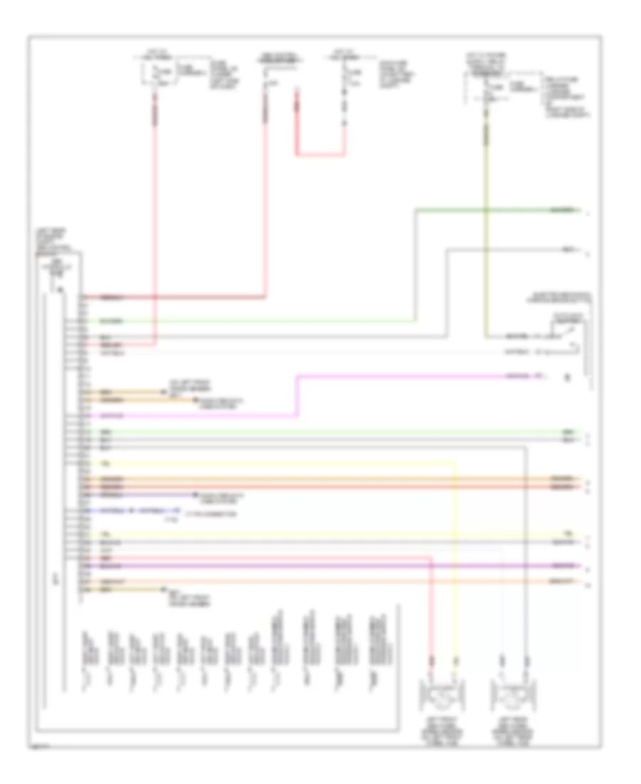
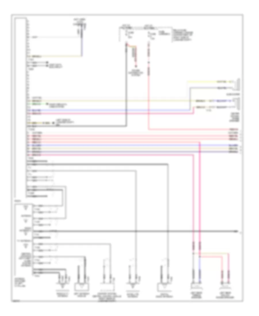
AIR CONDITIONING
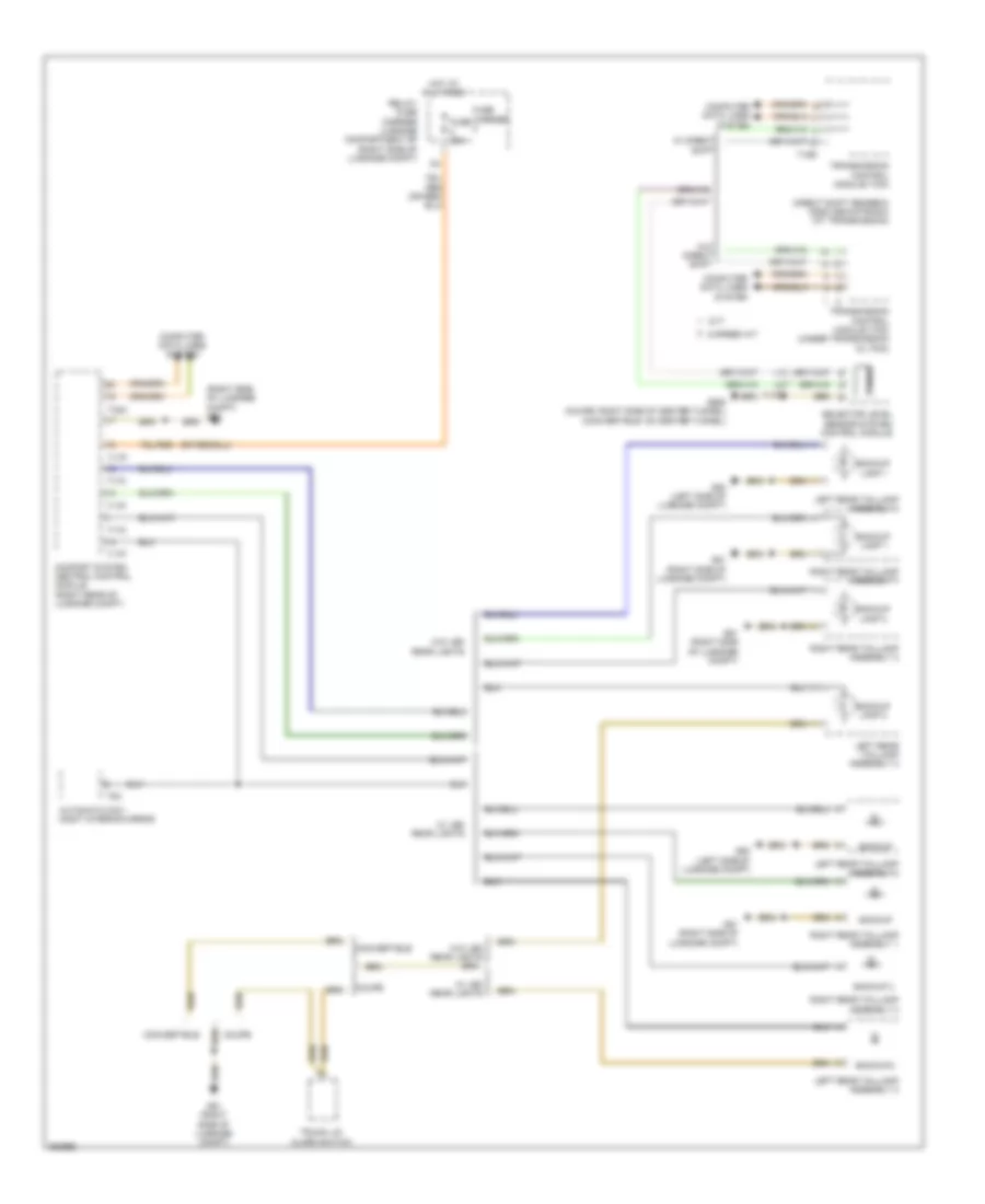
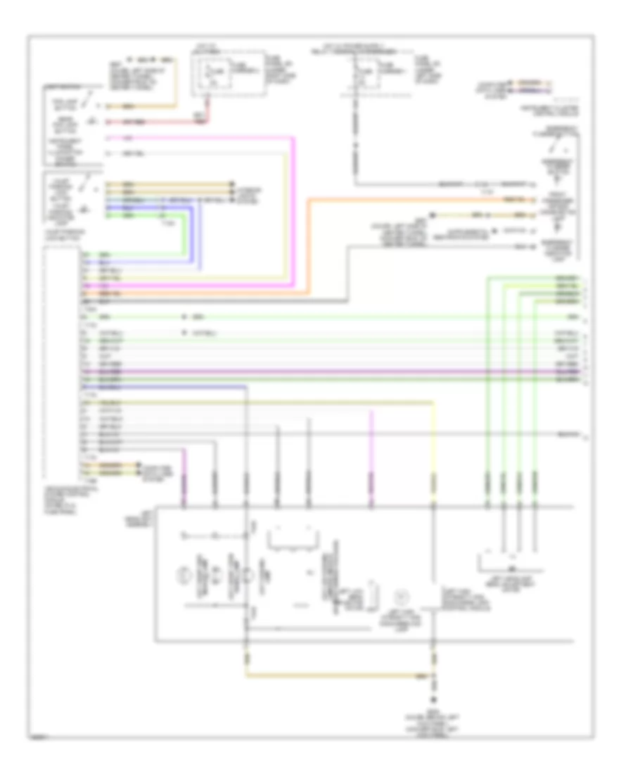
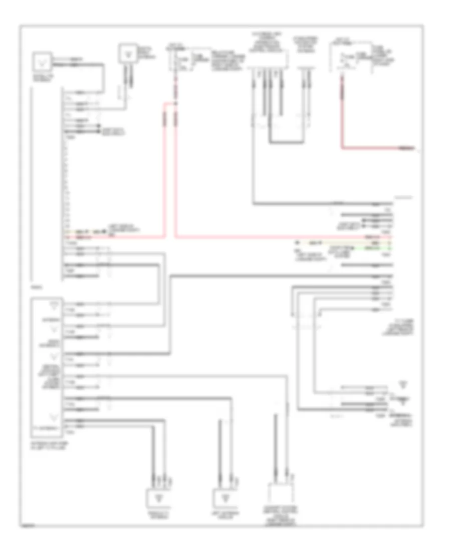
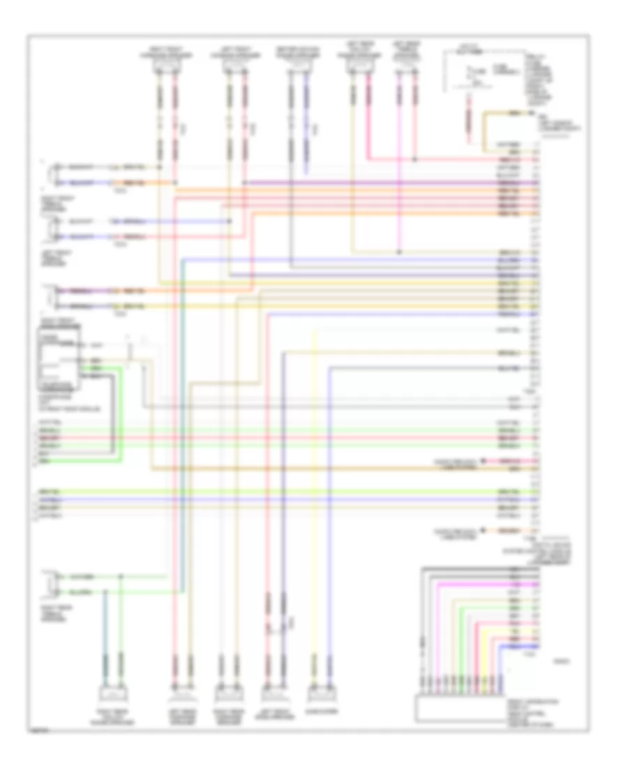
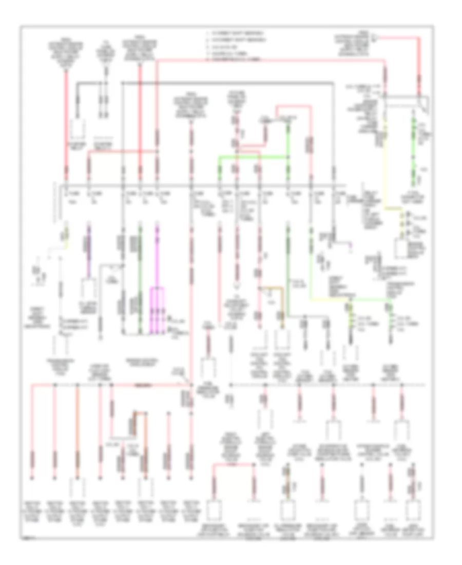
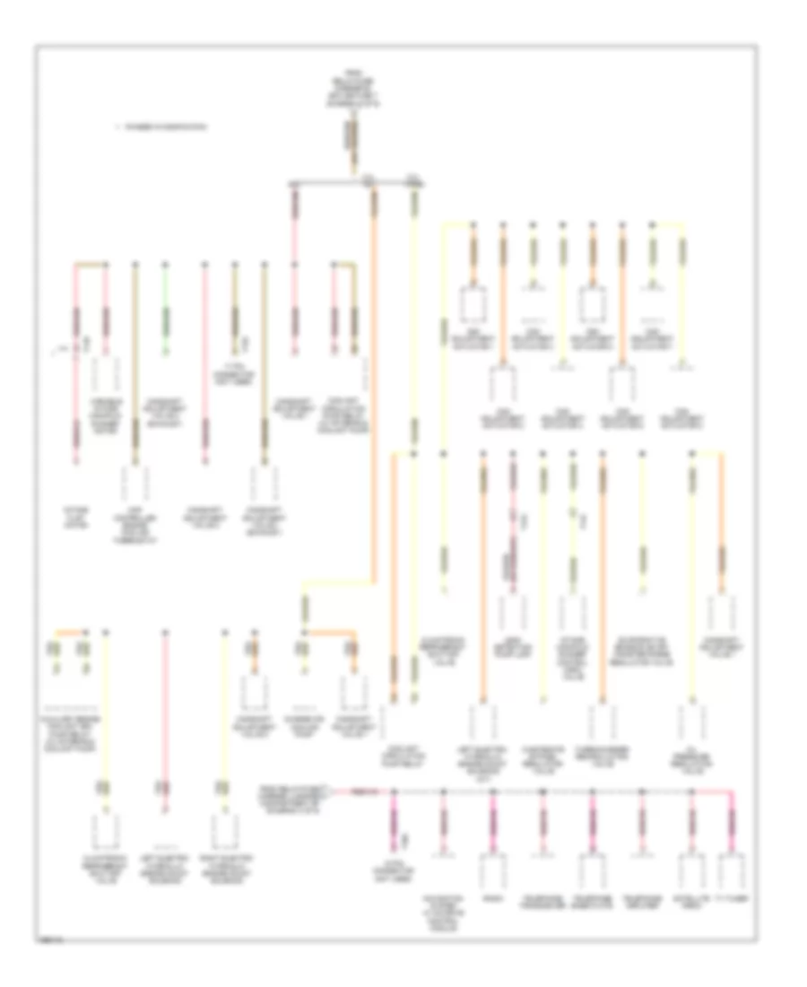
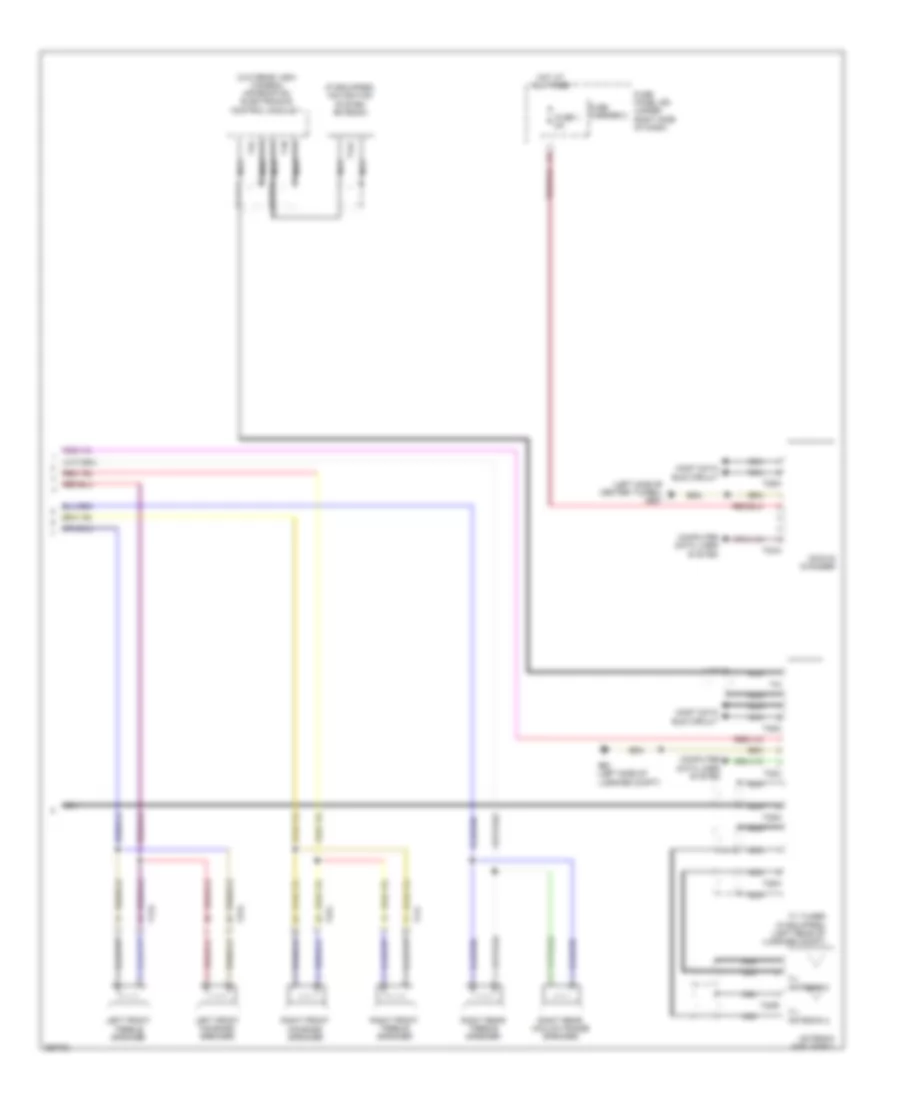
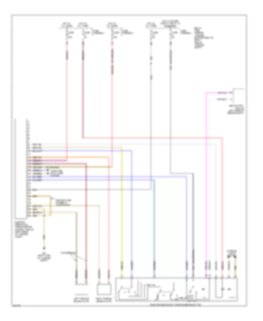
Automatic A/C Wiring Diagram, Basic (1 of 2) for Audi S5 4.2 2011

List of elements for Automatic A/C Wiring Diagram, Basic (1 of 2) for Audi S5 4.2 2011:
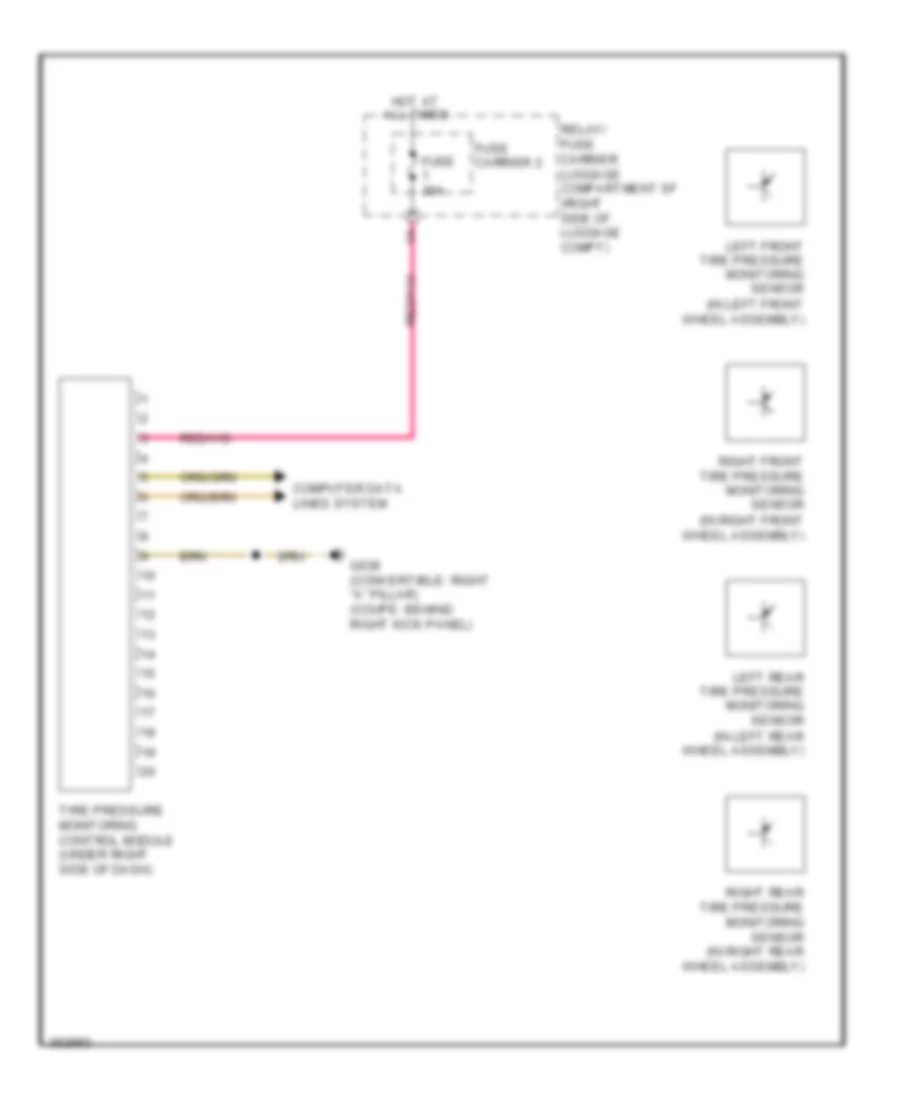
- (left side of center tunnel) g687
- 10a
- 12a
- A/c compressor regulator valve
- A/c control head climatronic control module (behind center of dash)
- A/c pressure/ temperature sensor
- Air flow door motor (left side of air intake housing)
- Brake light switch (on brake pedal assembly)
- Center outlet temperature sensor (center front of a/c unit)
- Center vent adjustment motor (right side of a/c unit)
- Computer data lines system
- Defroster door motor (left side of a/c unit)
- Engine coolant level (ecl) sensor
- Evaporator vent temperature sensor (right side of a/c unit)
- Footwell door motor (left side of a/c unit)
- Footwell outlet temperature sensor (lower left side of a/c unit)
- Fuse 10a
- Fuse 40a
- Fuse 5a
- Fuse carrier
- Fuse panel sc (under left side of dash)
- Fuse panel sd (under right side of dash)
- G639 (behind left kick panel)
- Hot at all times
- Outside air temperature sensor
- Recirculation door motor (left side of air intake housing)
- Red
- Solid state
- Sunlight photo sensor
- T16b
- T16i
- T17i
- T17r
- T20e
- T32b
- Temperature regulator door motor (lower left side of a/c unit)
- Vehicle electrical system control module (on relay & fuse panel)
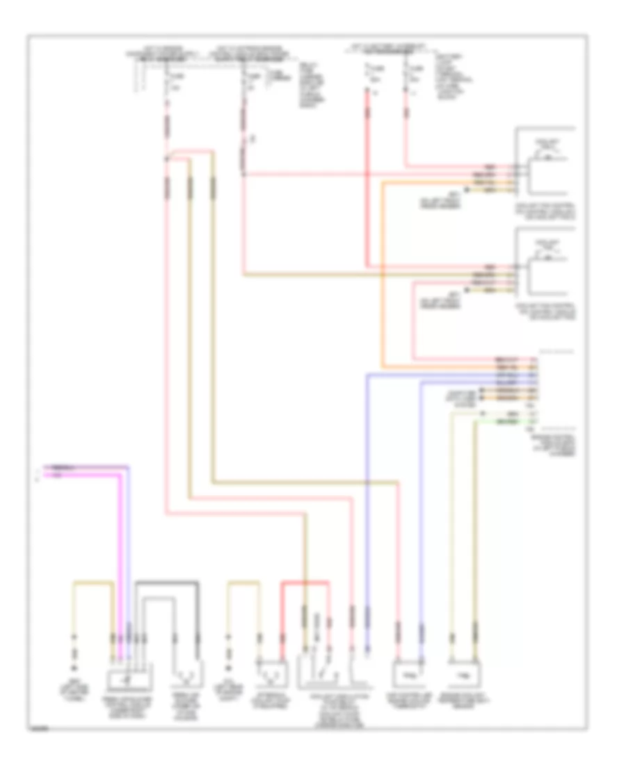
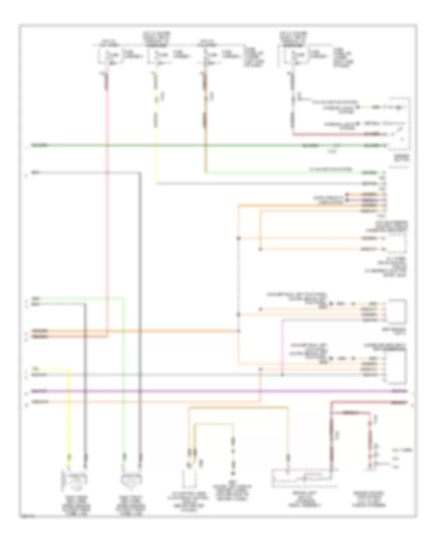
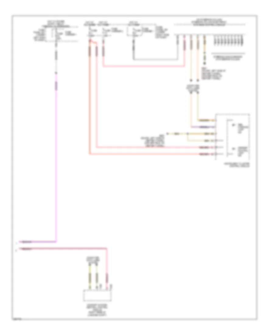
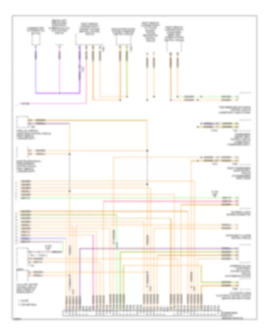
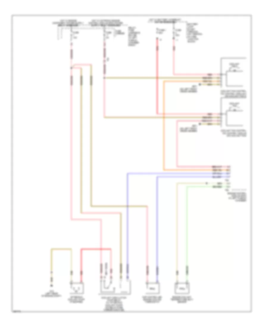
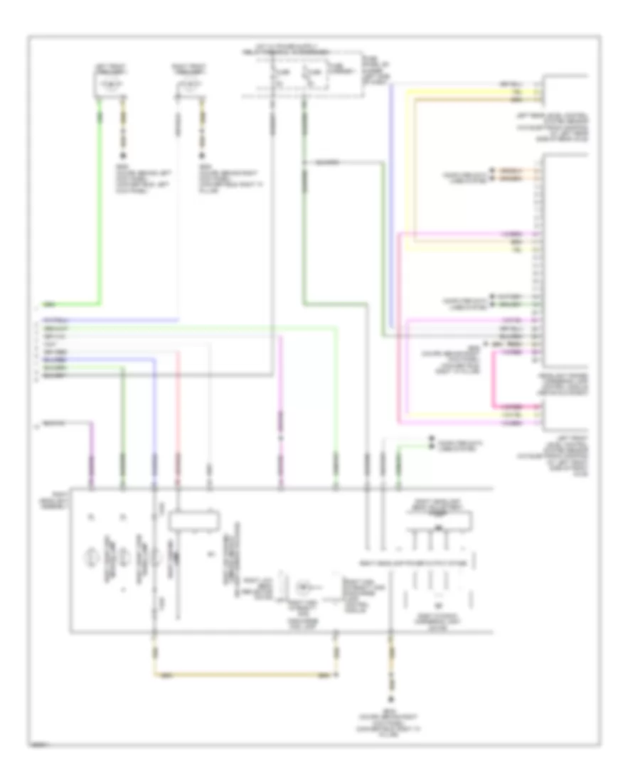
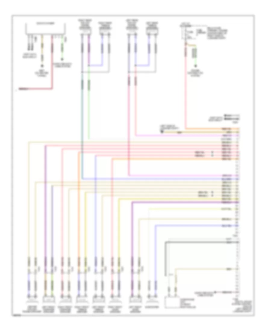
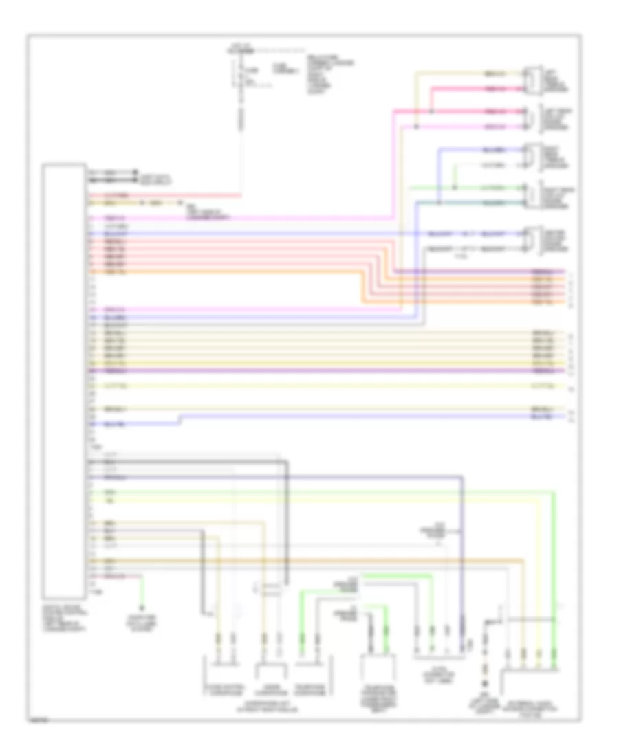
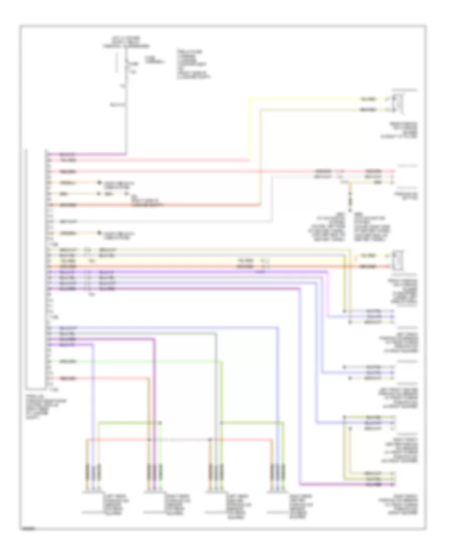
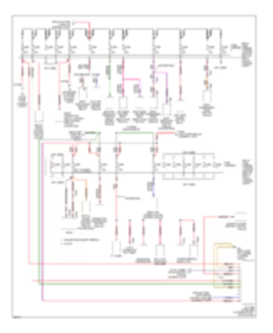
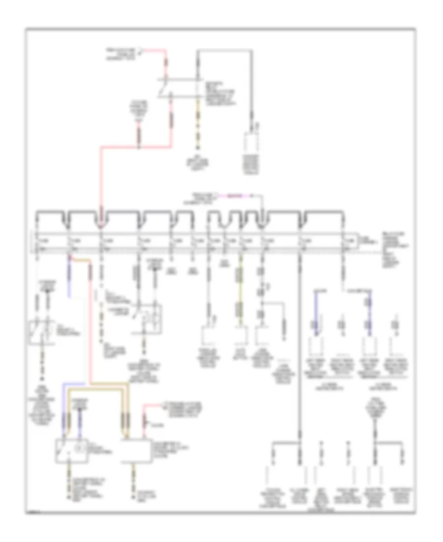
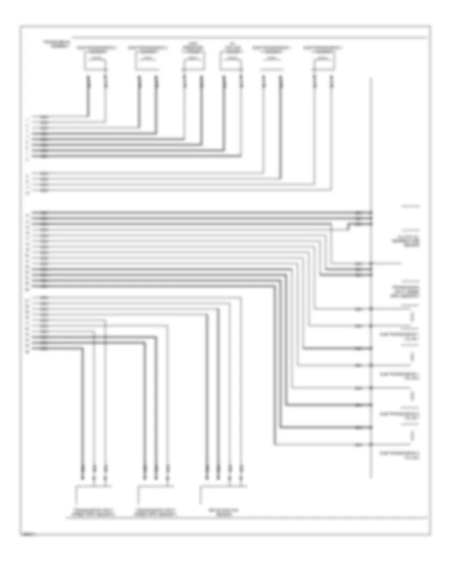
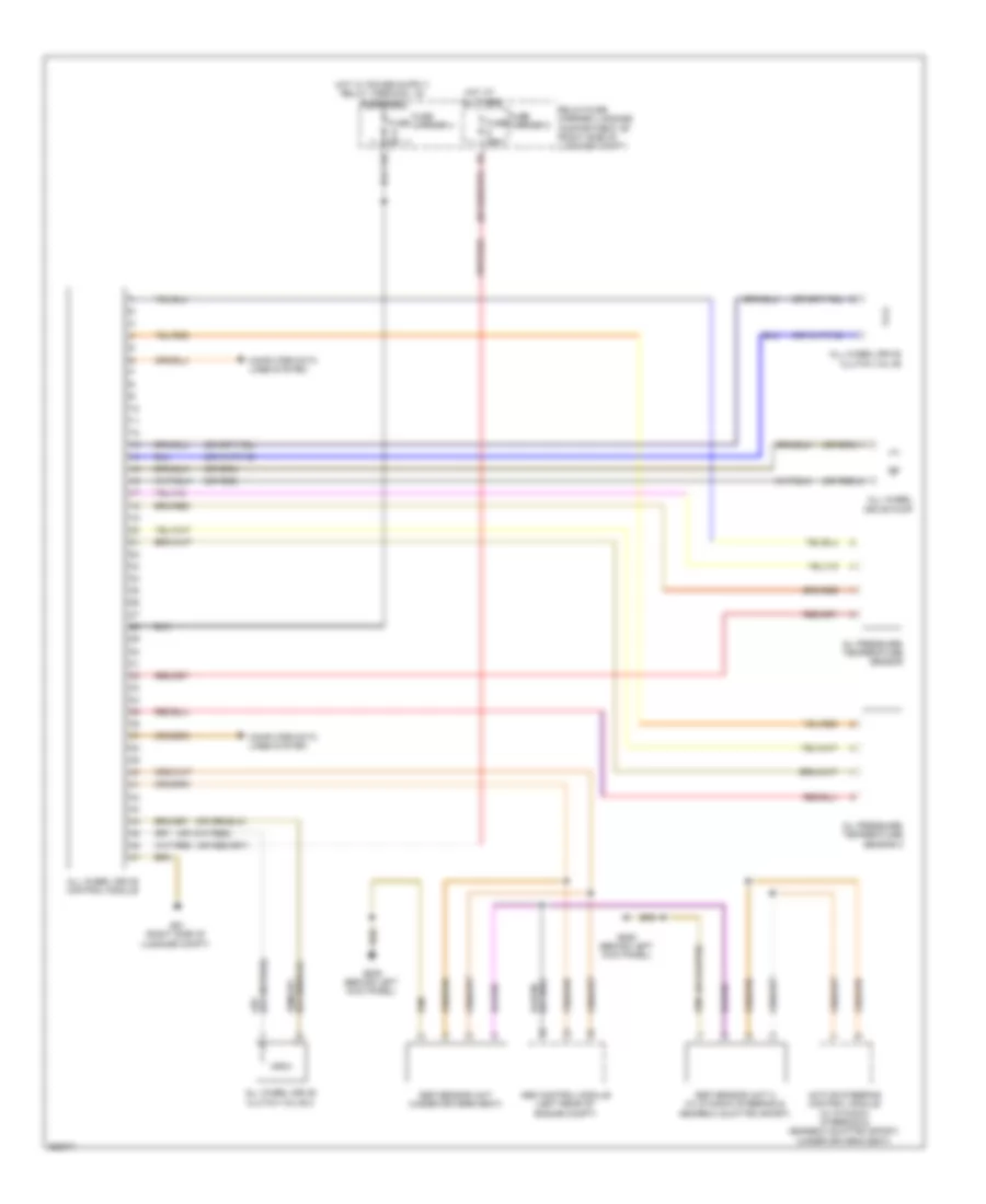
Automatic A/C Wiring Diagram, Basic (2 of 2) for Audi S5 4.2 2011
List of elements for Automatic A/C Wiring Diagram, Basic (2 of 2) for Audi S5 4.2 2011:
- (not used)
- 11a
- After-run coolant pump (if equipped)
- Battery jump start terminal (on terminal 30 wire junction block)
- Computer data lines system
- Coolant circulation pump relay (w/ after-run coolant pump) (on relay/fuse carrier e-box-sb)
- Coolant fan
- Coolant fan 2
- Coolant fan control (fc) control module (on coolant fan)
- Coolant fan control (fc) control module 2 (on coolant fan 2)
- Engine control module (ecm) (in left plenum chamber)
- Engine coolant temperature (ect) sensor
- Fresh air blower (under air intake housing)
- Fresh air blower control module (under right side of dash)
- Fuse 10a
- Fuse 40a
- Fuse 5a
- Fuse 60a
- Fuse carrier
- G12 (left rear of engine compt)
- G671 (on left front cross member)
- G687 (left side of center tunnel)
- Hot w/ battery interrupt igniter energized
- Map controlled engine cooling thermostat
- Nca
- Red
- Relay/ fuse carrier e-box sb (in left plenum chamber e-box)
- T5i
- T60
- T94
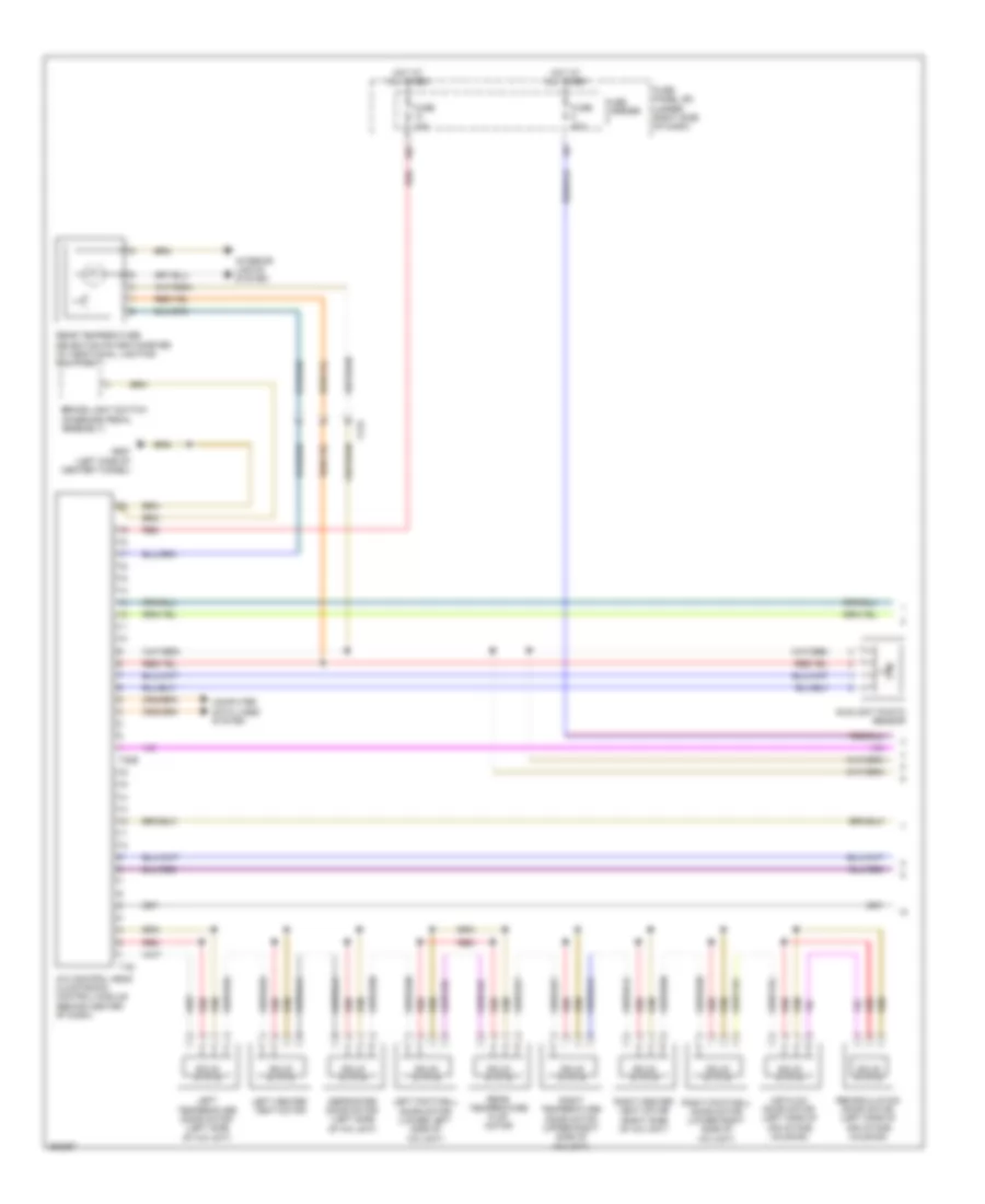
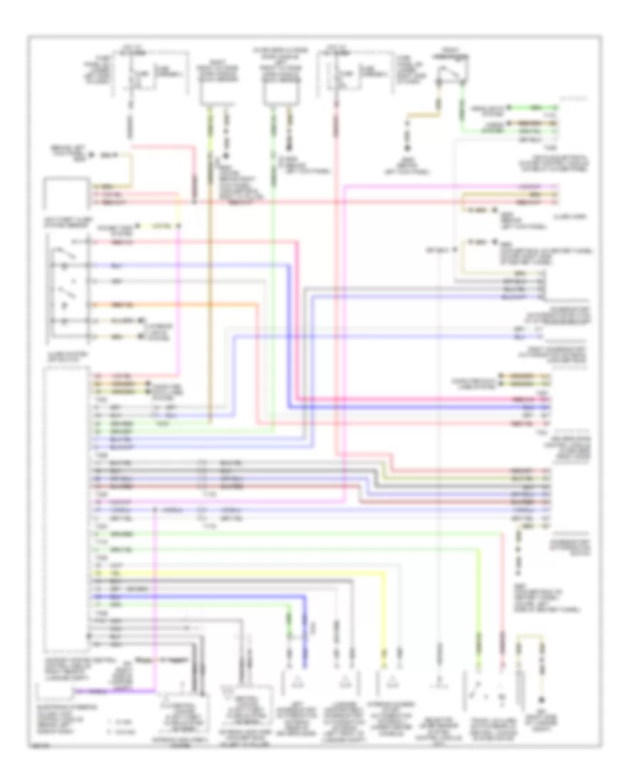
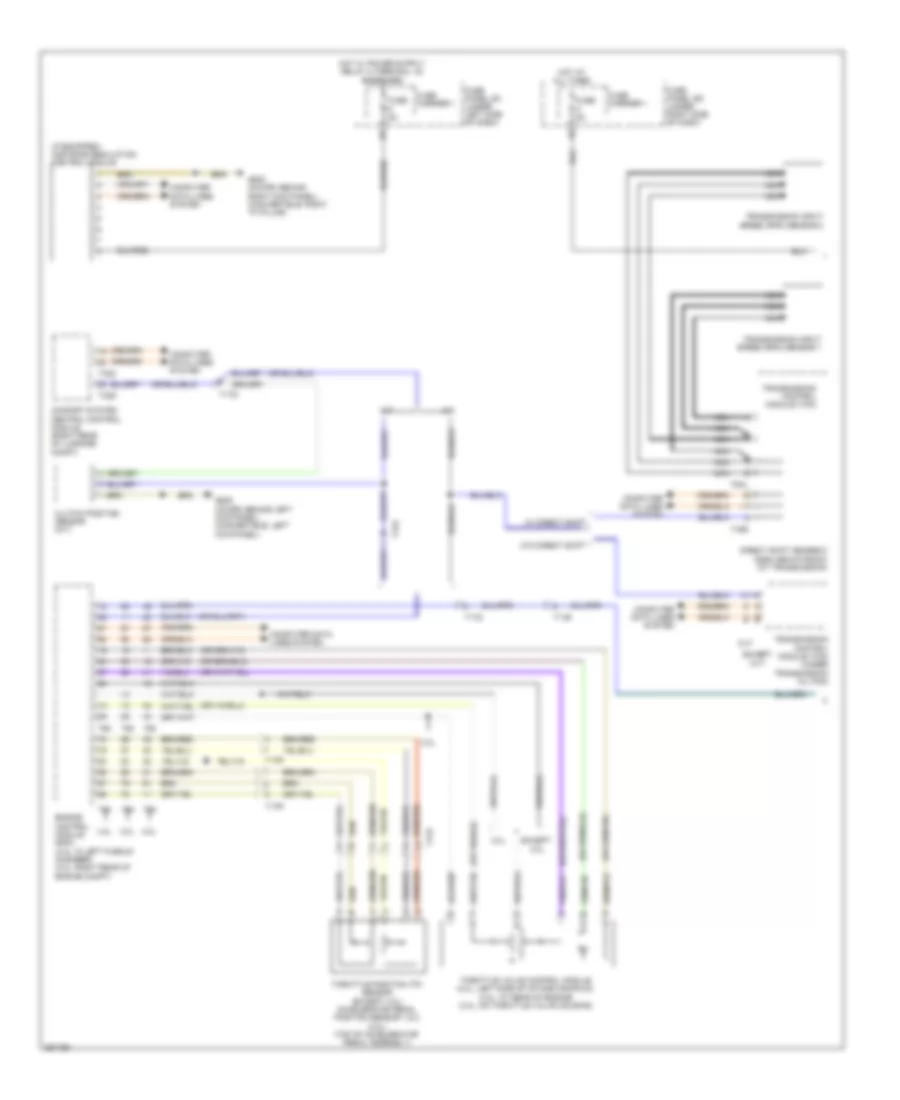
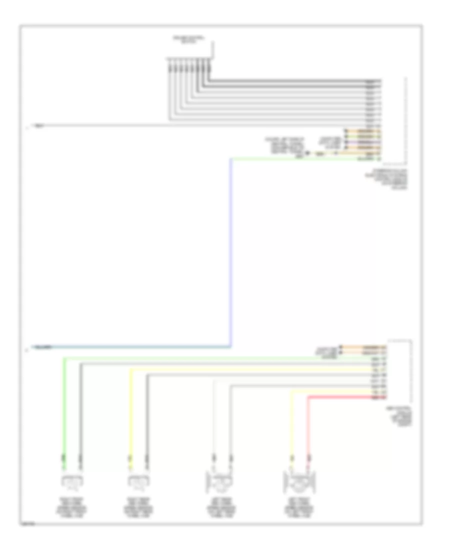
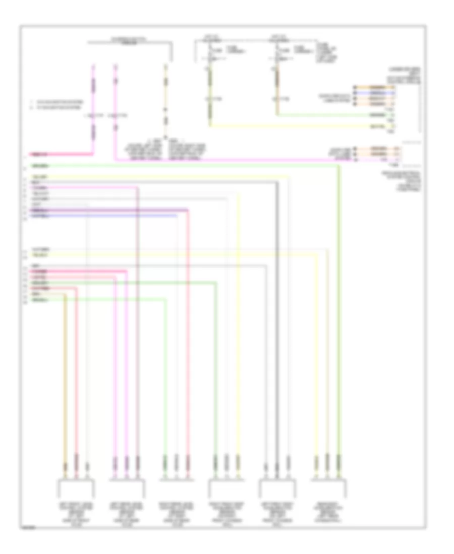
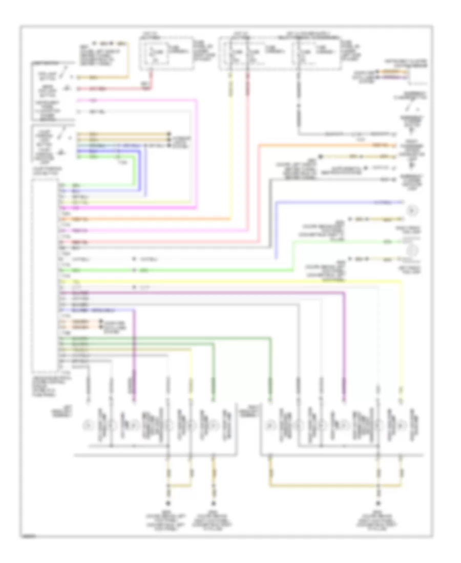
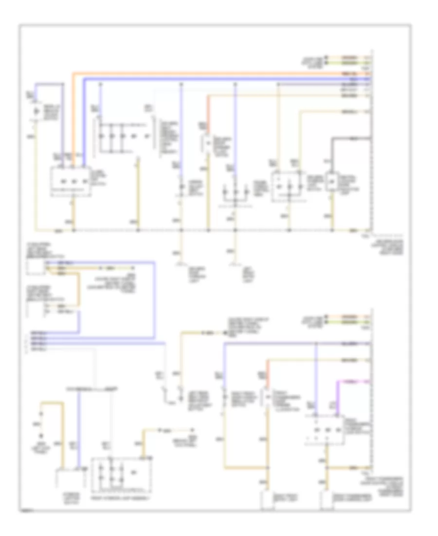
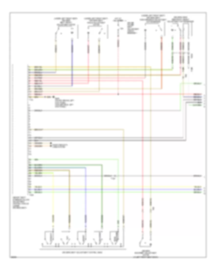
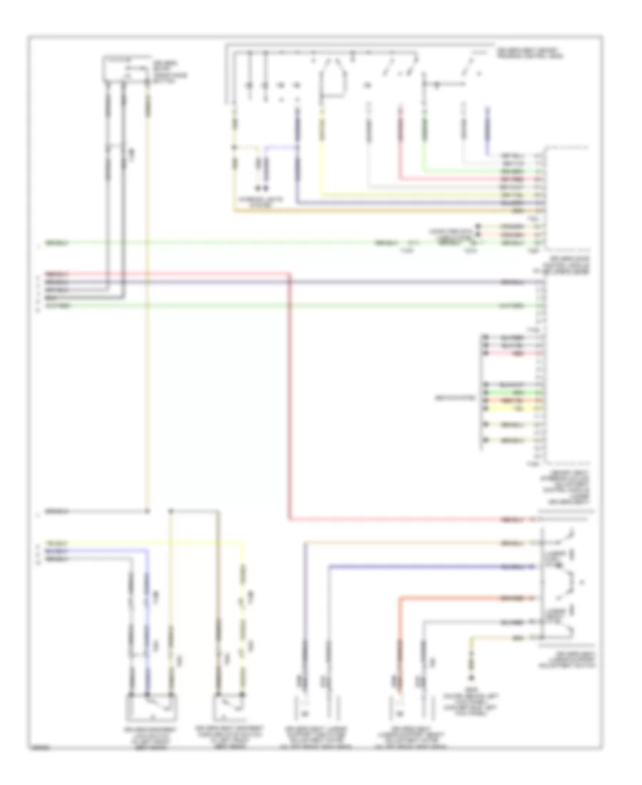
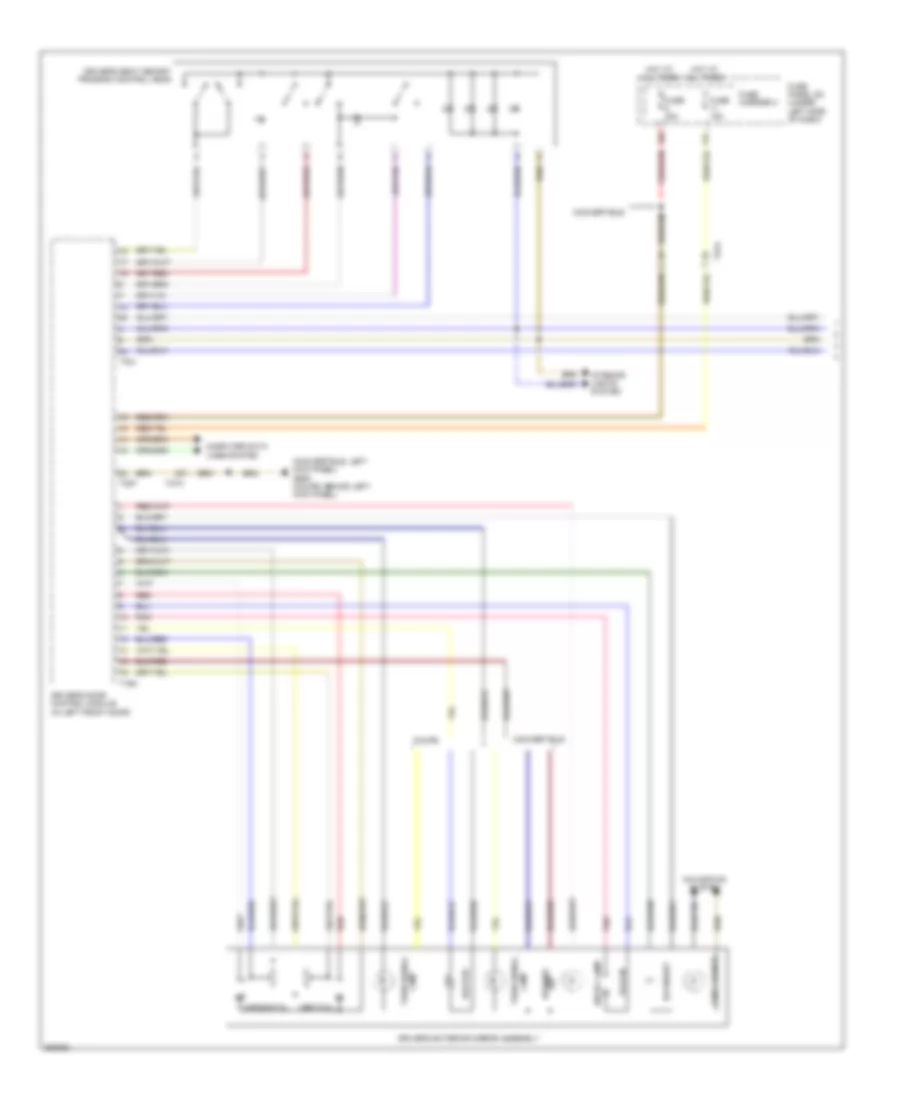
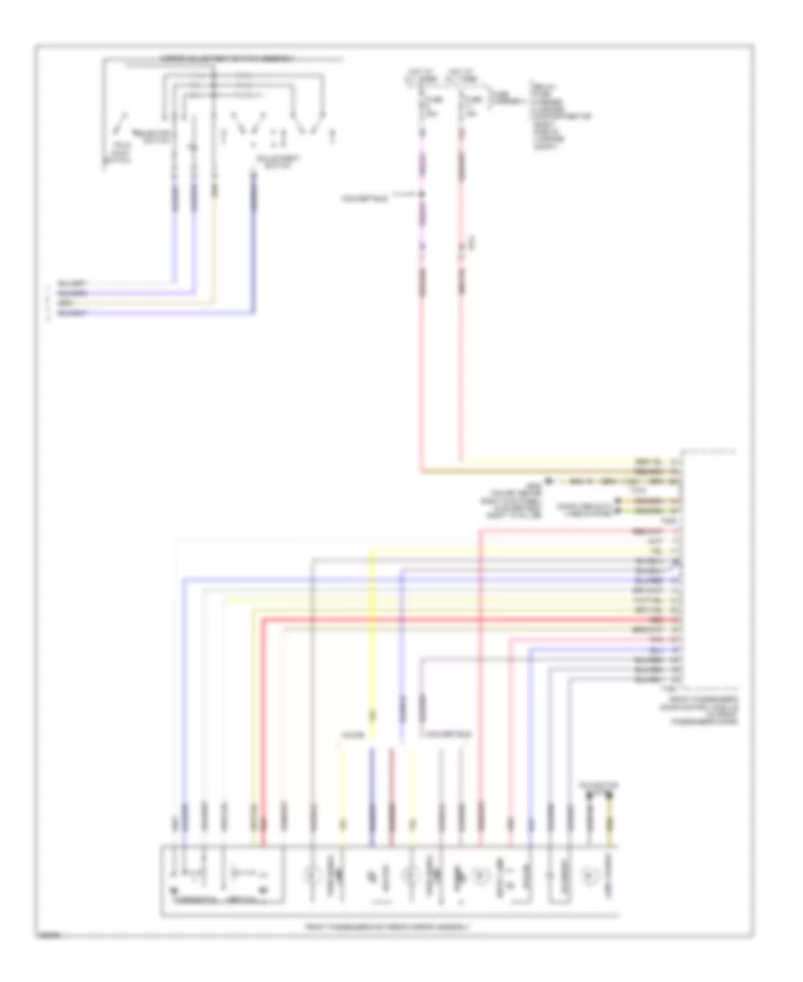
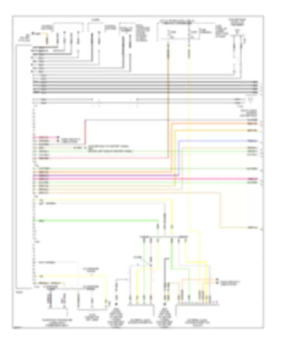
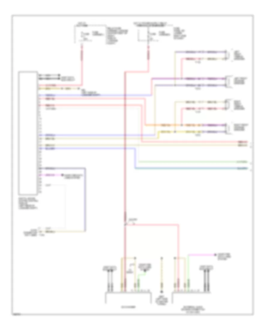
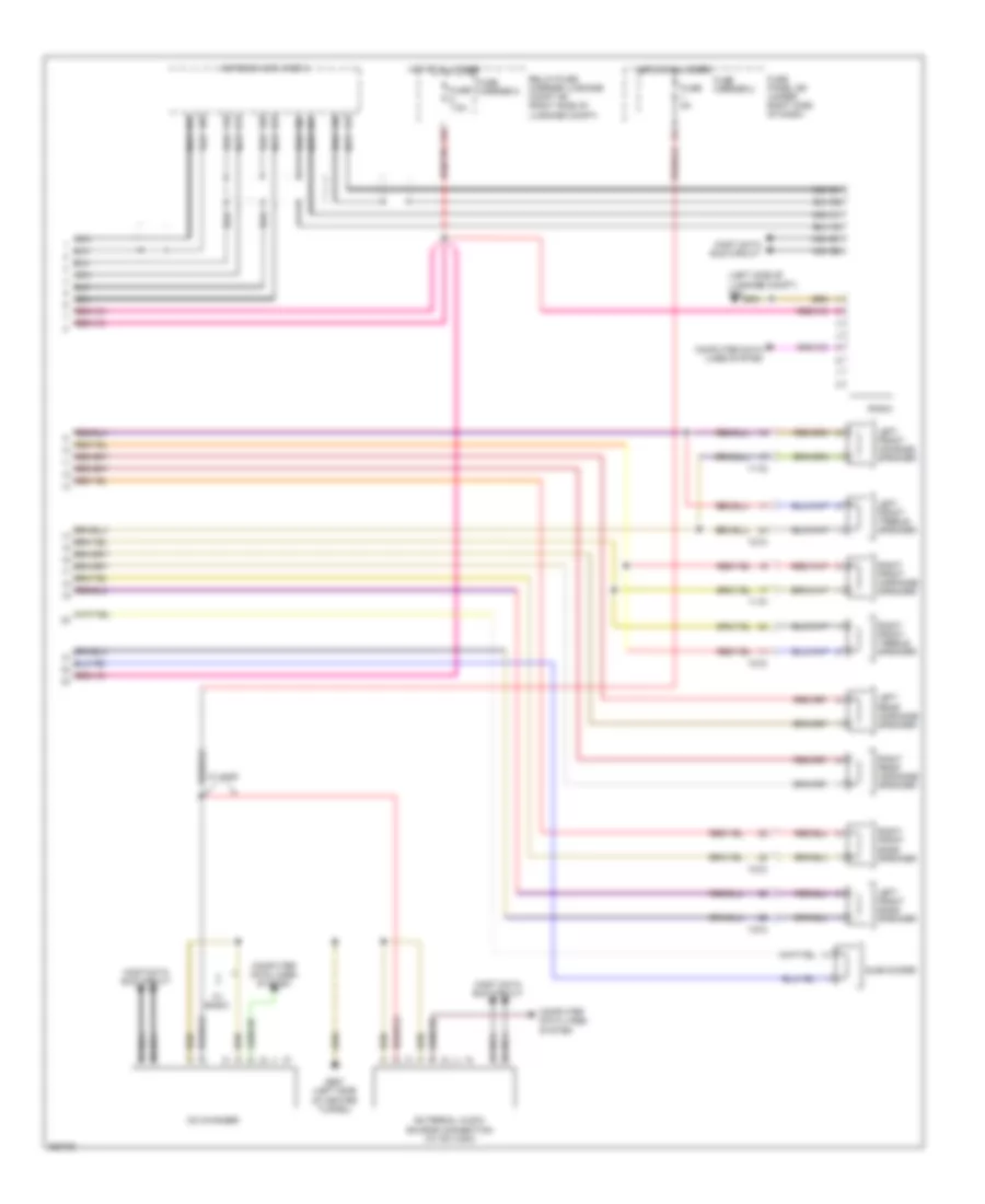
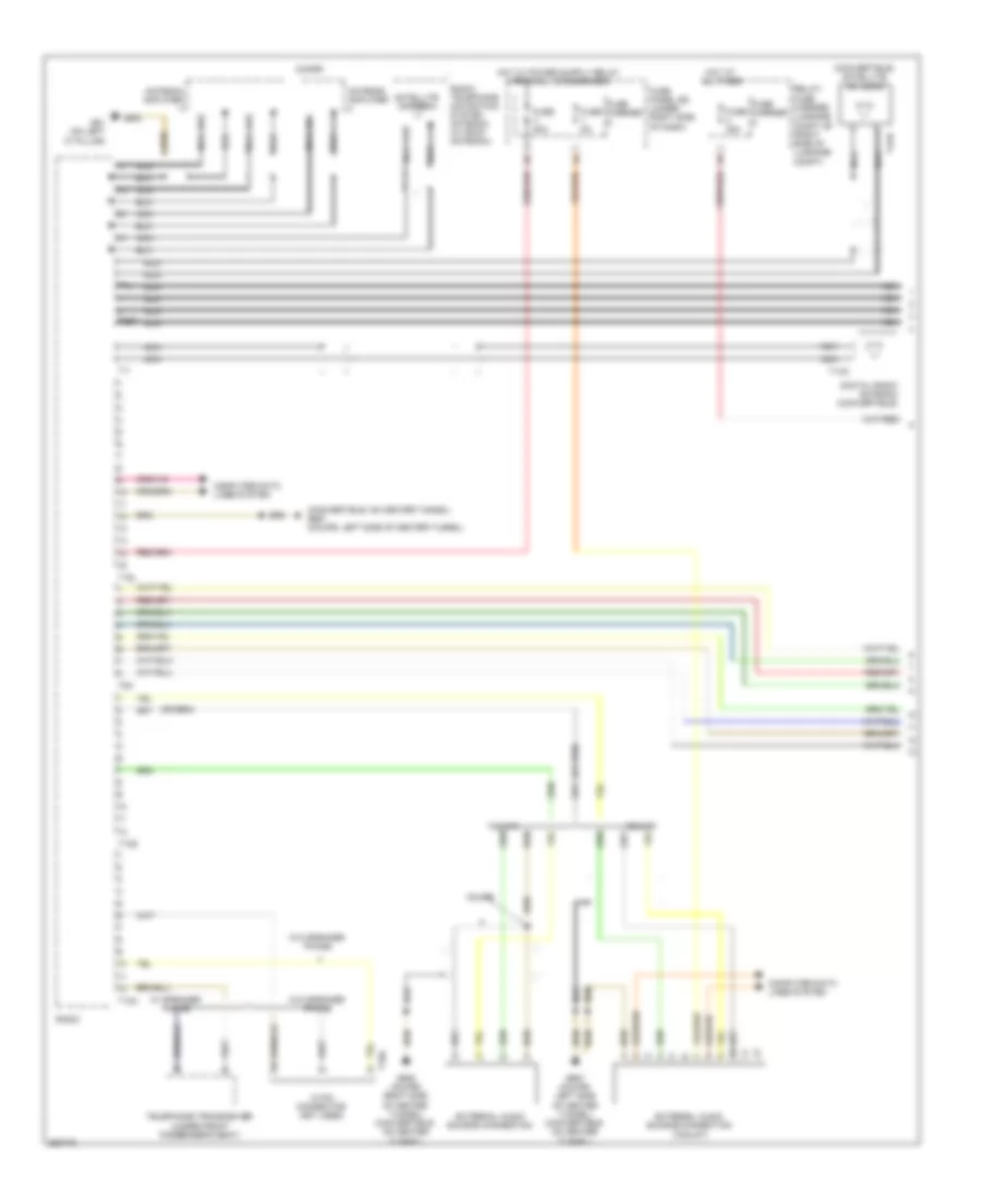
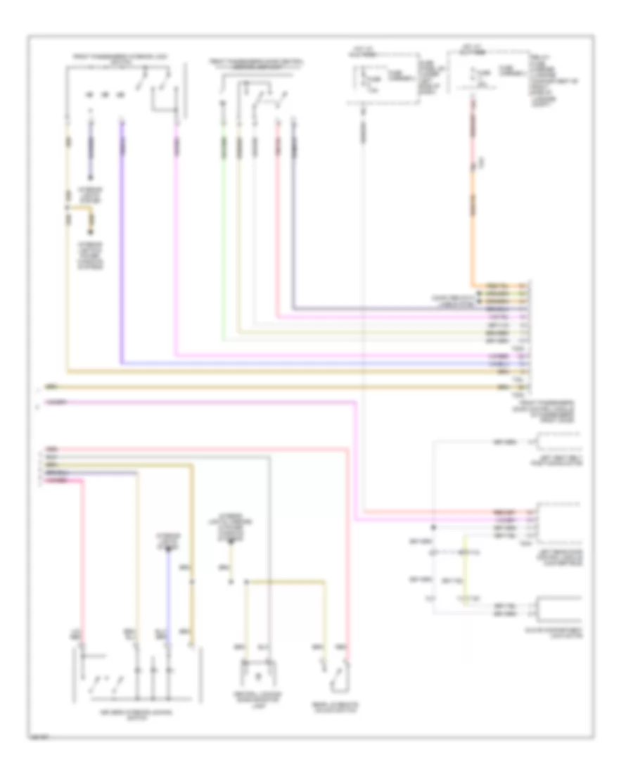
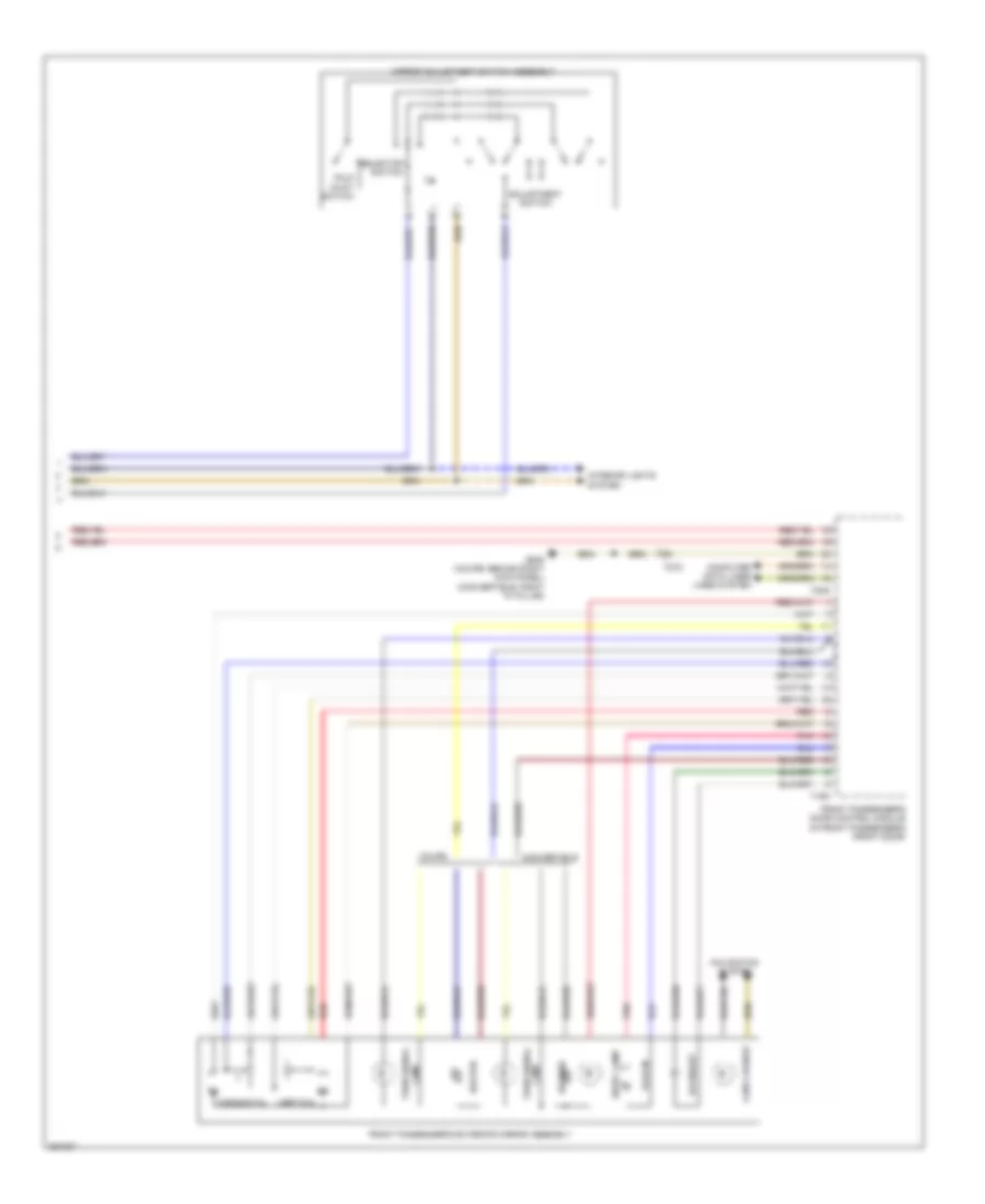
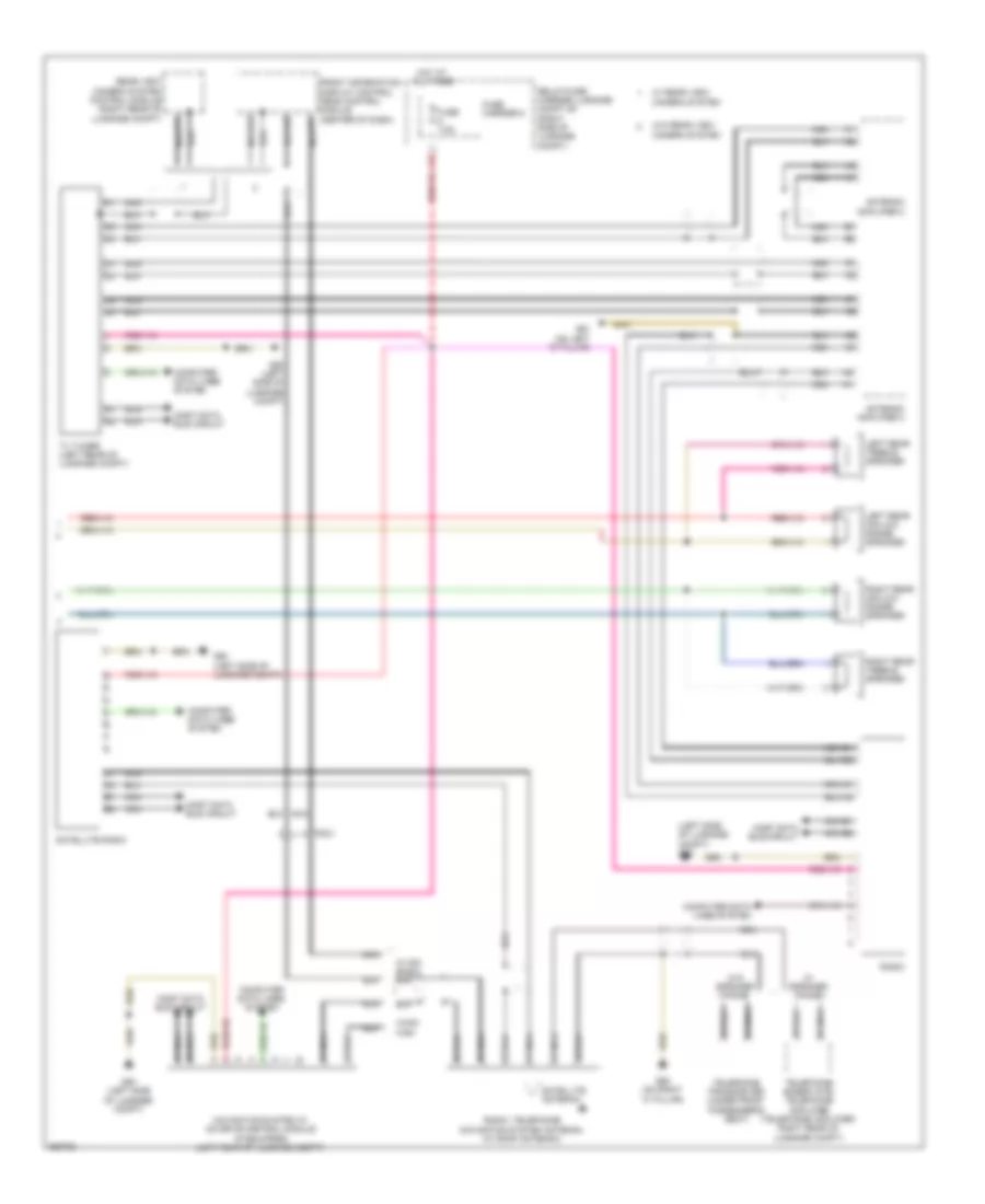
Automatic A/C Wiring Diagram, Comfort (1 of 3) for Audi S5 4.2 2011
List of elements for Automatic A/C Wiring Diagram, Comfort (1 of 3) for Audi S5 4.2 2011:
- 10a
- A/c control head climatronic control module (behind center of dash)
- Air flow door motor (left side of air intake housing)
- Brake light switch (on brake pedal assembly)
- Computer data lines system
- Defroster door motor (left side of a/c unit)
- Fuse 10a
- Fuse 40a
- Fuse carrier
- Fuse panel sd (under right side of dash)
- G687 (left side of center tunnel)
- Hot at all times
- Interior lights system
- Left center vent motor
- Left footwell door motor (lower left side of a/c unit)
- Left temperature door motor (left side of a/c unit)
- Rear temperature flap motor
- Rear temperature selection potentiometer (w/ additional lighting equipment)
- Recirculation door motor (left side of air intake housing)
- Red
- Right center vent motor (right side of a/c unit)
- Right footwell door motor (lower right side of a/c unit)
- Right temperature door motor (upper right side of a/c unit)
- Solid state
- Sunlight photo sensor
- T16i
- T17d
- T20e
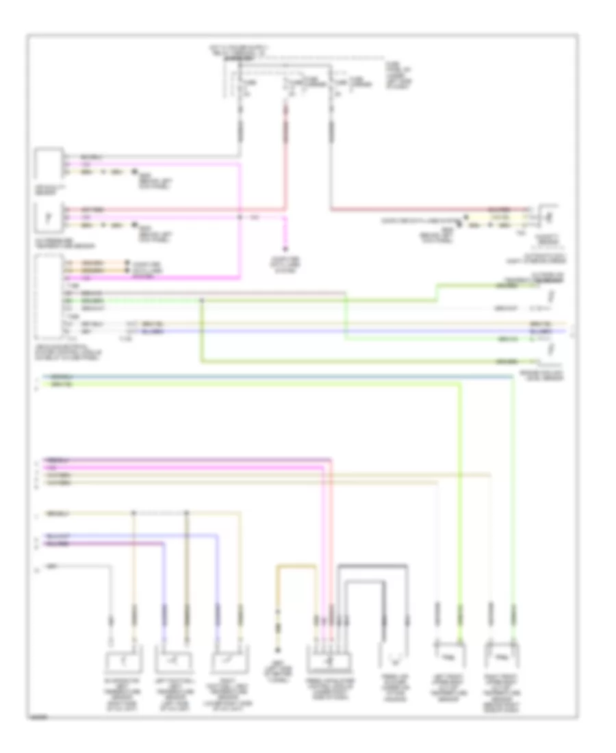
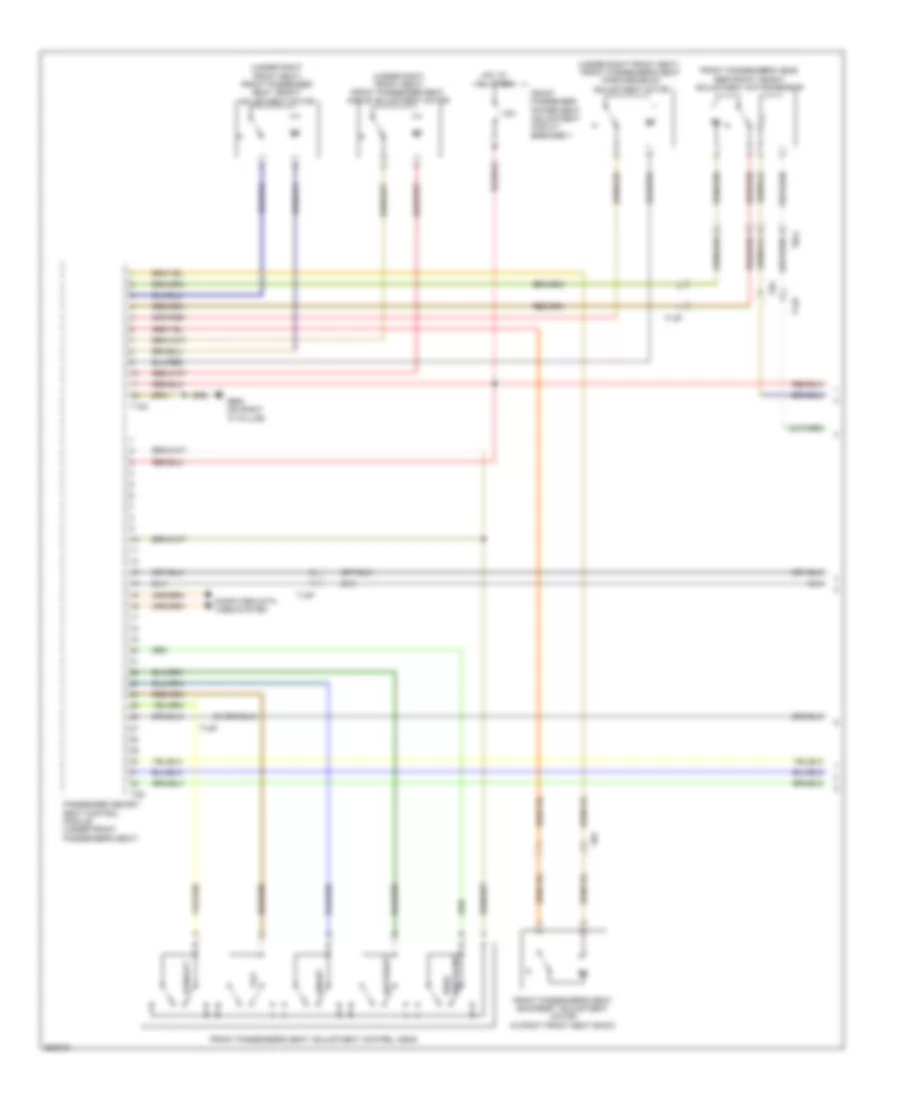
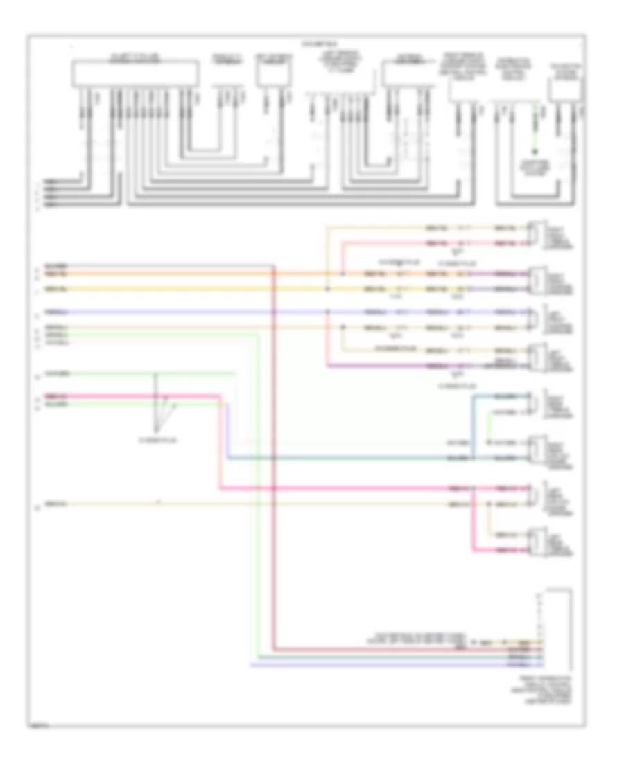
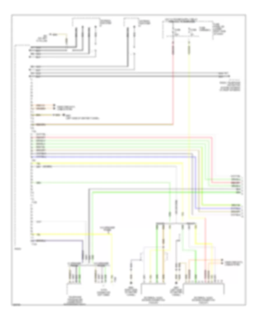
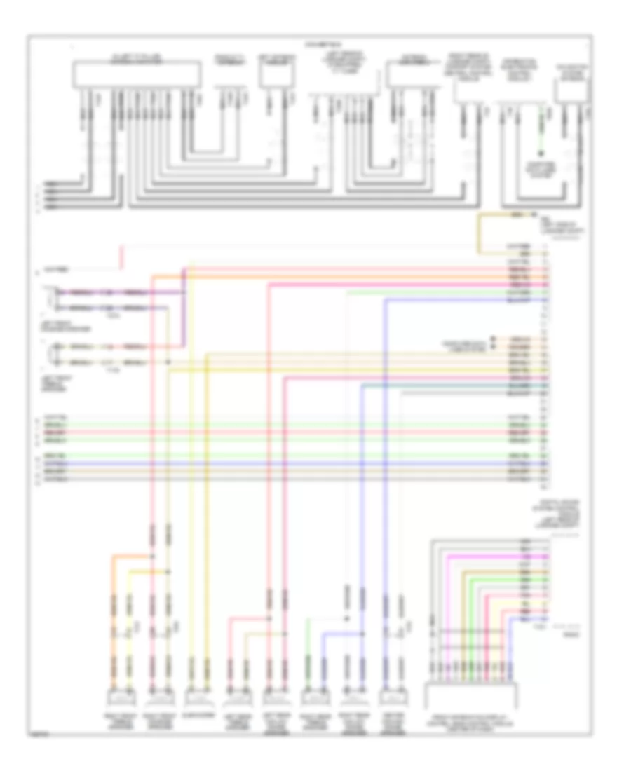
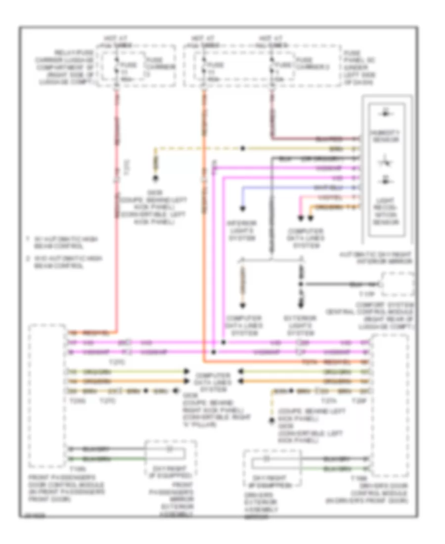
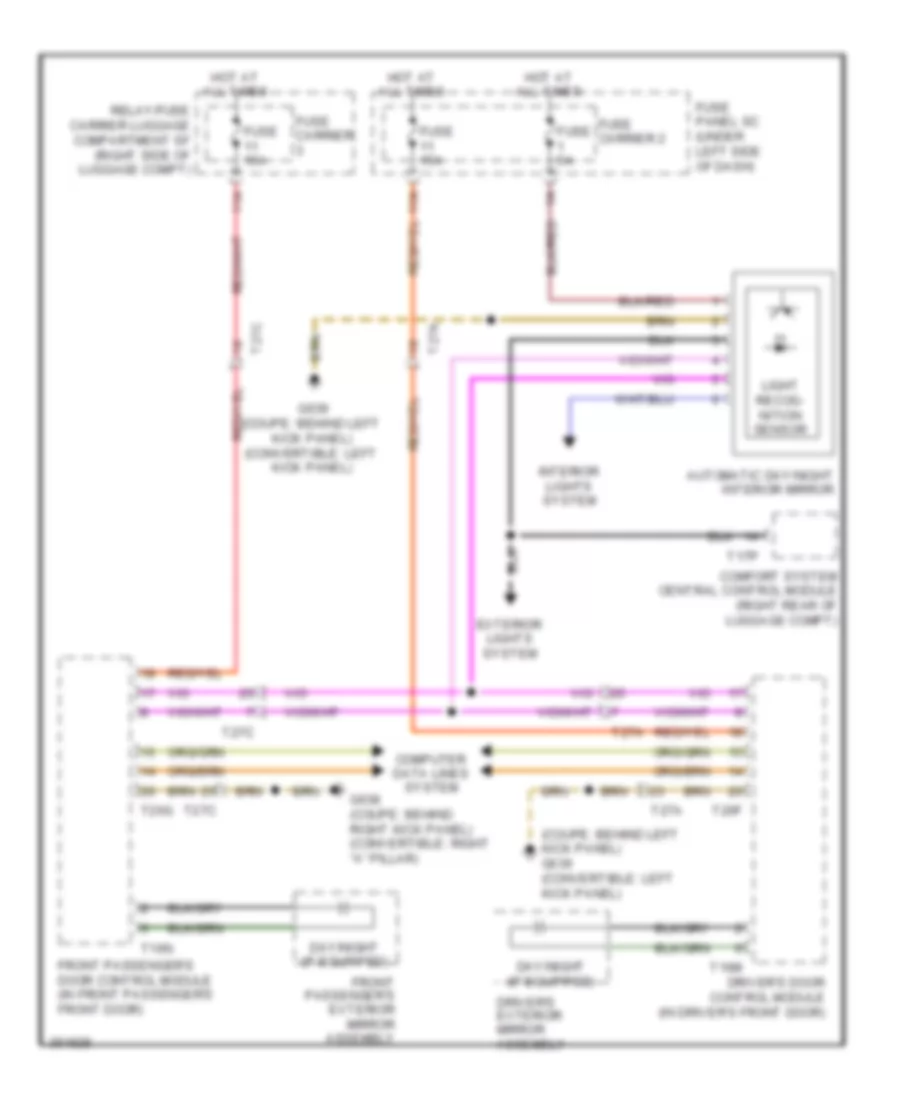
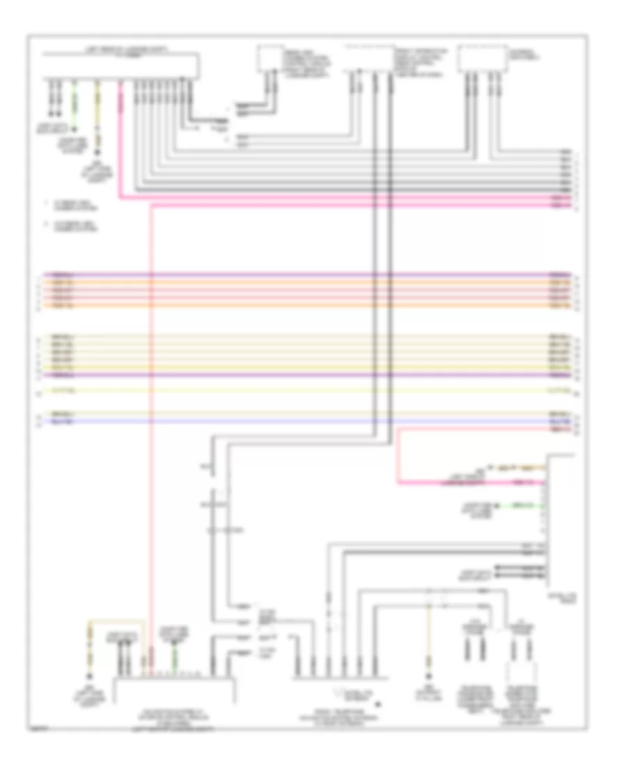
Automatic A/C Wiring Diagram, Comfort (2 of 3) for Audi S5 4.2 2011
List of elements for Automatic A/C Wiring Diagram, Comfort (2 of 3) for Audi S5 4.2 2011:
- 12a
- A/c pressure/ temperature sensor
- Air quality sensor
- Automatic day/ night interior mirror
- Computer data lines system
- Engine coolant level sensor
- Evaporator vent temperature sensor (right side of a/c unit)
- Fresh air blower (under air intake housing)
- Fresh air blower control module (under right side of dash)
- Fuse 5a
- Fuse carrier
- Fuse panel sc (under left side of dash)
- G639 (behind left kick panel)
- G687 (left side of center tunnel)
- Humidity sensor
- Left footwell vent temperature sensor (left side of a/c unit)
- Left front upper body outlet temperature sensor
- Nca
- Outside air temperature sensor
- Right footwell vent temperature sensor (lower right side of a/c unit)
- Right front upper body outlet temperature sensor (behind right side of dash)
- T16b
- T17i
- T17r
- T32b
- T8c
- Vehicle electrical system control module (on relay & fuse panel)
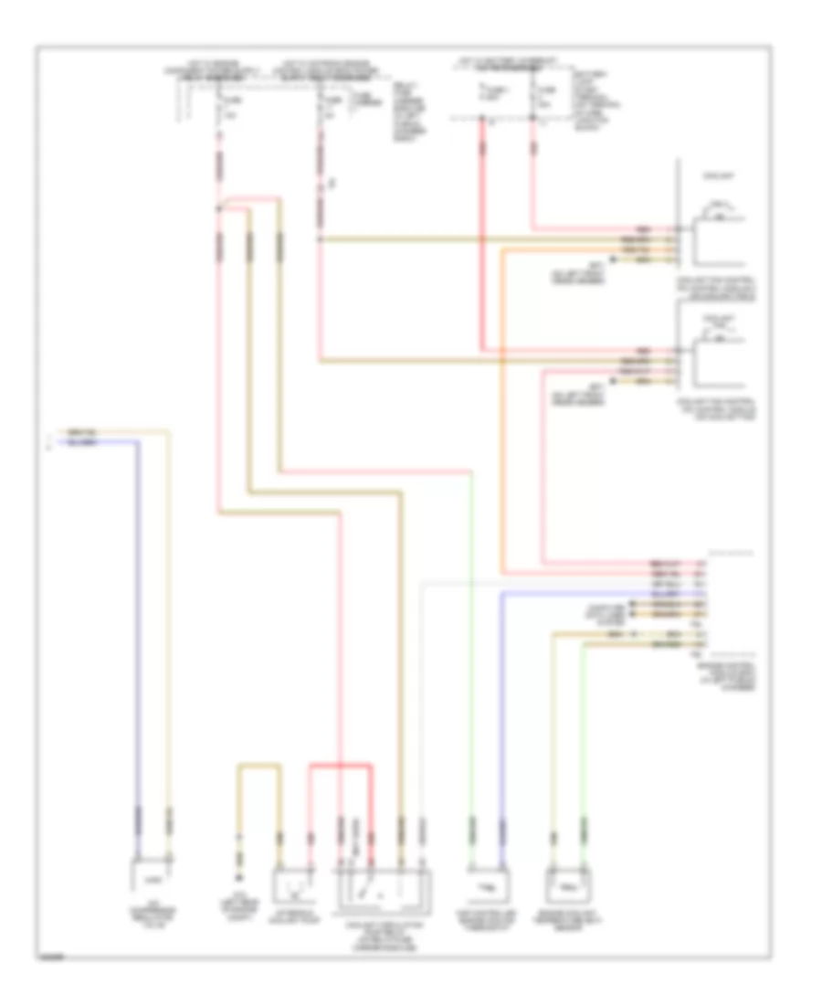
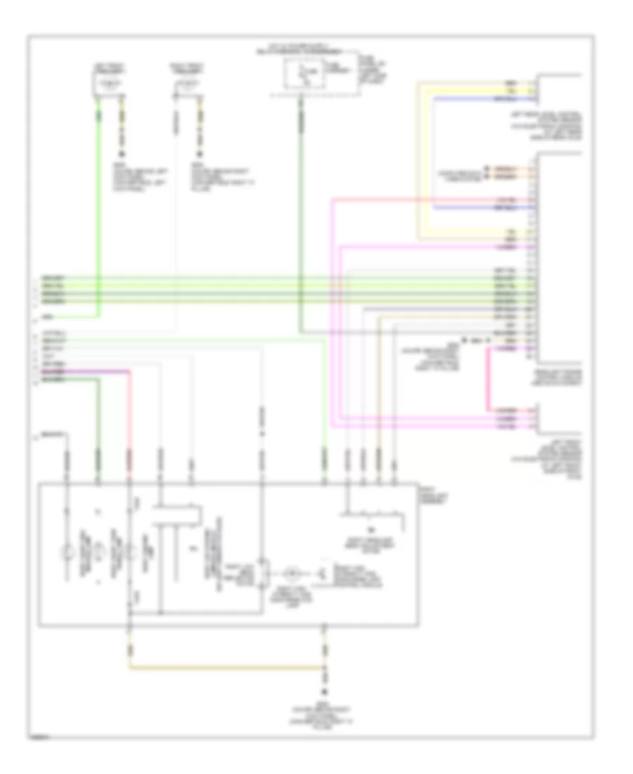
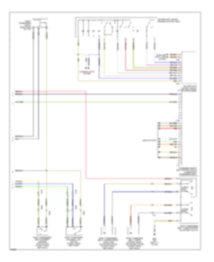
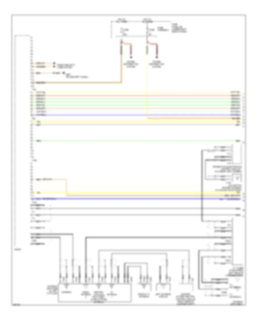
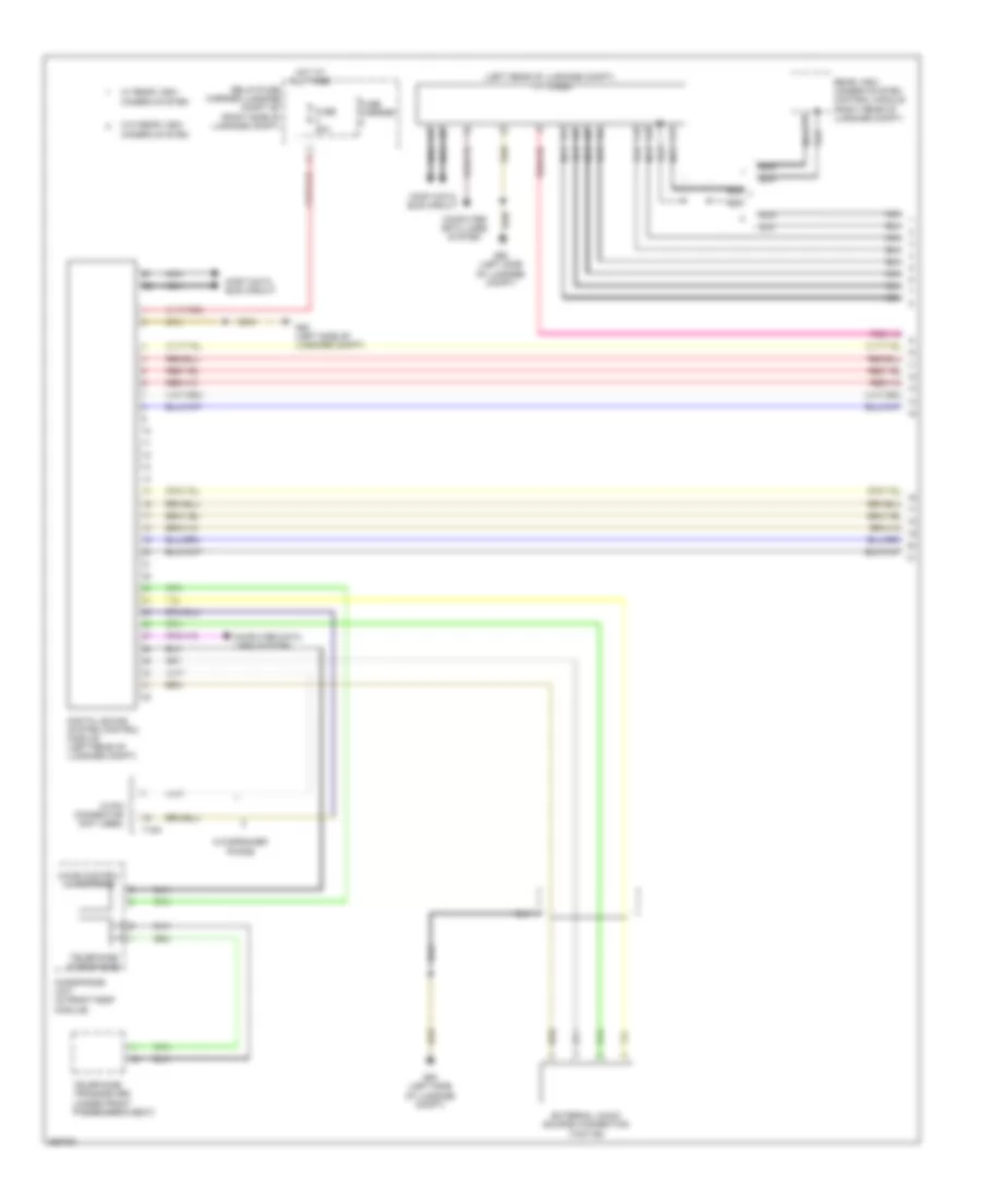
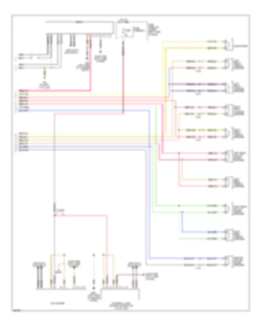
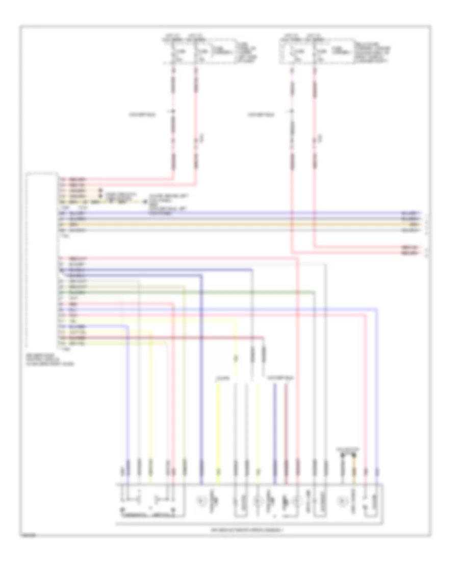
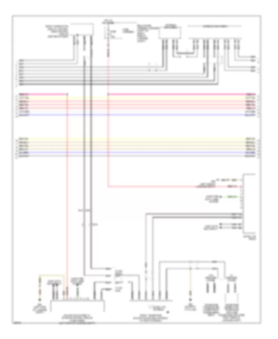
Automatic A/C Wiring Diagram, Comfort (3 of 3) for Audi S5 4.2 2011
List of elements for Automatic A/C Wiring Diagram, Comfort (3 of 3) for Audi S5 4.2 2011:
- (not used)
- 11a
- A/c compressor regulator valve
- After-run coolant pump
- Battery jump start terminal (on terminal 30 wire junction block)
- Computer data lines system
- Coolant
- Coolant circulation pump relay (on relay/fuse carrier e-box-sb)
- Coolant fan
- Coolant fan control (fc) control module (on coolant fan)
- Coolant fan control (fc) control module 2 (on coolant fan 2)
- Engine control module (ecm) (in left plenum chamber)
- Engine coolant temperature (ect) sensor
- Fan 2
- Fuse 1 60a
- Fuse 10a
- Fuse 40a
- Fuse 5a
- Fuse carrier
- G12 (left rear of engine compt)
- G671 (on left front cross member)
- Hot w/ battery interrupt igniter energized
- Map controlled engine cooling thermostat
- Red
- Relay/ fuse carrier e-box sb (in left plenum chamber e-box)
- T5i
- T60
- T94
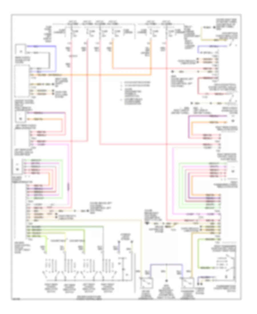
ANTI-LOCK BRAKES
Anti-lock Brakes Wiring Diagram (1 of 3) for Audi S5 4.2 2011
List of elements for Anti-lock Brakes Wiring Diagram (1 of 3) for Audi S5 4.2 2011:
- (17 pin connector)
- (left rear of engine compt) abs control module
- (on left front cross member)
- 40a
- Abs control module fuse 1
- Abs hydraulic pump
- Abs inlet left rear
- Abs outlet left rear
- Auto hold button
- Computer data lines system
- Driving dynamics regulation high pressure switch valve 2
- Electro-mechanical parking brake button
- Fuse 10a
- Fuse 110a
- Fuse 5a
- Fuse carrier 2
- Fuse carrier 4
- Fuse panel sc (under left side of dash)
- G671
- G671 (on left front cross member)
- Hot at all times
- Left front abs inlet valve
- Left front abs outlet valve
- Left front abs wheel speed sensor (on left front wheel hub)
- Left rear abs wheel speed sensor (on left rear wheel hub)
- Main fuse panel sa (on battery, in luggage compt)
- Red
- Regulation high driving dynamics
- Regulation switch driving dynamics
- Relay/fuse carrier luggage compartment sf (right side of luggage compt)
- Right front abs inlet valve
- Right front abs outlet valve
- Right rear abs inlet valve
- Right rear abs outlet valve
- T17d
- Valve
- Valve 1
- Valve 1 pressure switch
- Valve 2
Anti-lock Brakes Wiring Diagram (2 of 3) for Audi S5 4.2 2011
List of elements for Anti-lock Brakes Wiring Diagram (2 of 3) for Audi S5 4.2 2011:
- (convertible: left kick panel) (coupe: behind left kick panel) g639
- (under driver's seat) esp sensor unit
- 2.0l turbo
- 3.0l
- 4.2l
- A/c control head climatronic control module (behind center of dash)
- Active steering control module (under driver's seat)
- All wheel drive control module (w/ gearbox quattro sport (gh2))
- Asr/esp button
- Brake light switch (on brake pedal assembly)
- Computer data
- Engine control module (ecm) (4.2l: in left plenum chamber)
- Esp sensor unit 2
- Fuse 25a
- Fuse 35a
- Fuse 5a
- Fuse carrier 1
- Fuse carrier 2
- Fuse carrier 3
- Fuse panel sc (under left side of dash)
- Fuse panel sd (under right side of dash)
- G687 (coupe: left side of center tunnel) (convertible: on center tunnel)
- Hot at all times
- Interior lights system
- Lines system
- Right front abs wheel speed sensor (on right front wheel hub)
- Right rear abs wheel speed sensor (on right rear wheel hub)
- T10h
- T17b
- T17c
- T17e
- T17g
- T17r
- T20e
- T5d
- T8g
- T94
- W/ navigation system
- W/o navigation system
Anti-lock Brakes Wiring Diagram (3 of 3) for Audi S5 4.2 2011
List of elements for Anti-lock Brakes Wiring Diagram (3 of 3) for Audi S5 4.2 2011:
- (on steering column) steering column electronic systems control module
- 12a
- 15a
- Abs warning lamp ind
- Asr/esp control lamp ind
- Comfort system central control module (right rear of luggage compt)
- Computer data lines system
- Fuse 25a
- Fuse 5a
- Fuse carrier 1
- Fuse carrier 2
- Fuse panel sc (under left side of dash)
- Fuse panel sd (under right side of dash)
- G687 (coupe: left side of center tunnel) (convertible: on center tunnel)
- Hot at all times
- Instrument cluster control module
- Nca
- Steering angle sensor (in steering column)
- T32c
- T32d
ANTI-THEFT
Anti-theft Wiring Diagram for Audi S5 4.2 2011
List of elements for Anti-theft Wiring Diagram for Audi S5 4.2 2011:
- (behind left kick panel) g639
- (in driver's outside door handle) left front outside door handle touch sensor
- 12a
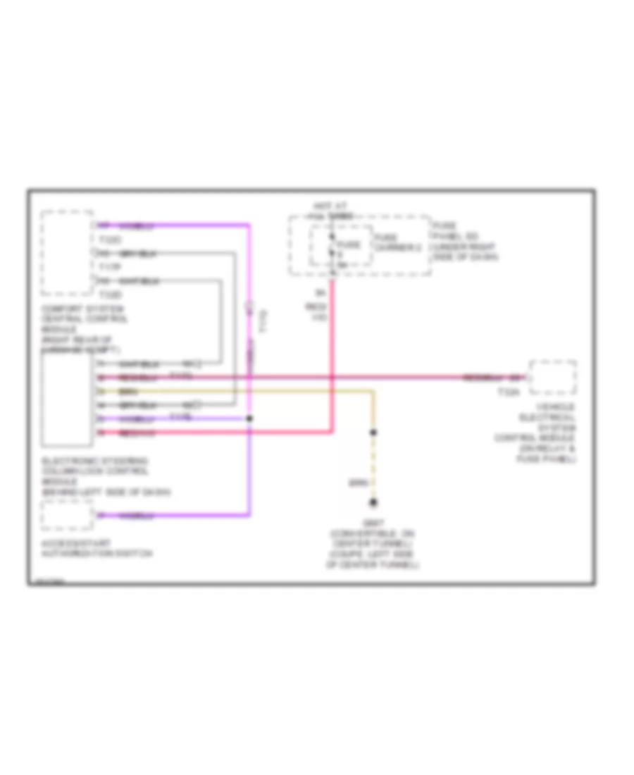
- Access/start authorization button (w/ start/stop button)
- Access/start authorization switch
- Alarm horn
- Alarm system off switch
- Antenna amplifier (convertible) (in left "c" pillar)
- Antenna amplifier 3 (coupe)
- Anti-theft alarm system sensor
- Central locking & anti-theft alarm system antenna
- Comfort system central control module (right rear of luggage compt)
- Computer data lines system
- Driver's door control module (in driver's front door)
- Electronic steering column lock control module (behind left side of dash)
- Front hood switch
- Fuse 5a
- Fuse carrier 2
- Fuse carrier 3
- Fuse panel sc (under left side of dash)
- Fuse panel sd (under right side of dash)
- G51 (right side of luggage compt)
- G638 (coupe: behind right kick panel) (convertible: right "a" pillar)
- G639 (behind left kick panel)
- G687 (convertible: on center tunnel) (coupe: left side of center tunnel)
- G688 (convertible: on center tunnel) (coupe: right side of center tunnel)
- Headlights system
- Horns system
- Hot at all times
- Interior access/ start authorization antenna 1 (under center console)
- Interior lights system
- Left access/start authorization antenna (rear of driver's door)
- Luggage compartment access/start authorization antenna (left front of luggage compt)
- Nca
- Power tops system
- Right access/start authorization antenna (convertible)
- Right front outside door handle touch sensor
- Selector lever sensor system control module (a/t)
- T17g
- T17m
- T17o
- T1as
- T1h
- T20f
- T27a
- T27c
- T32b
- T32c
- T32d
- T32e
- T32j
- Trunk lid alarm switch/rear lid central locking system motor
- Vehicle electrical system control module (on relay & fuse panel)
- W/ mmi
- W/o mmi
BODY CONTROL MODULES
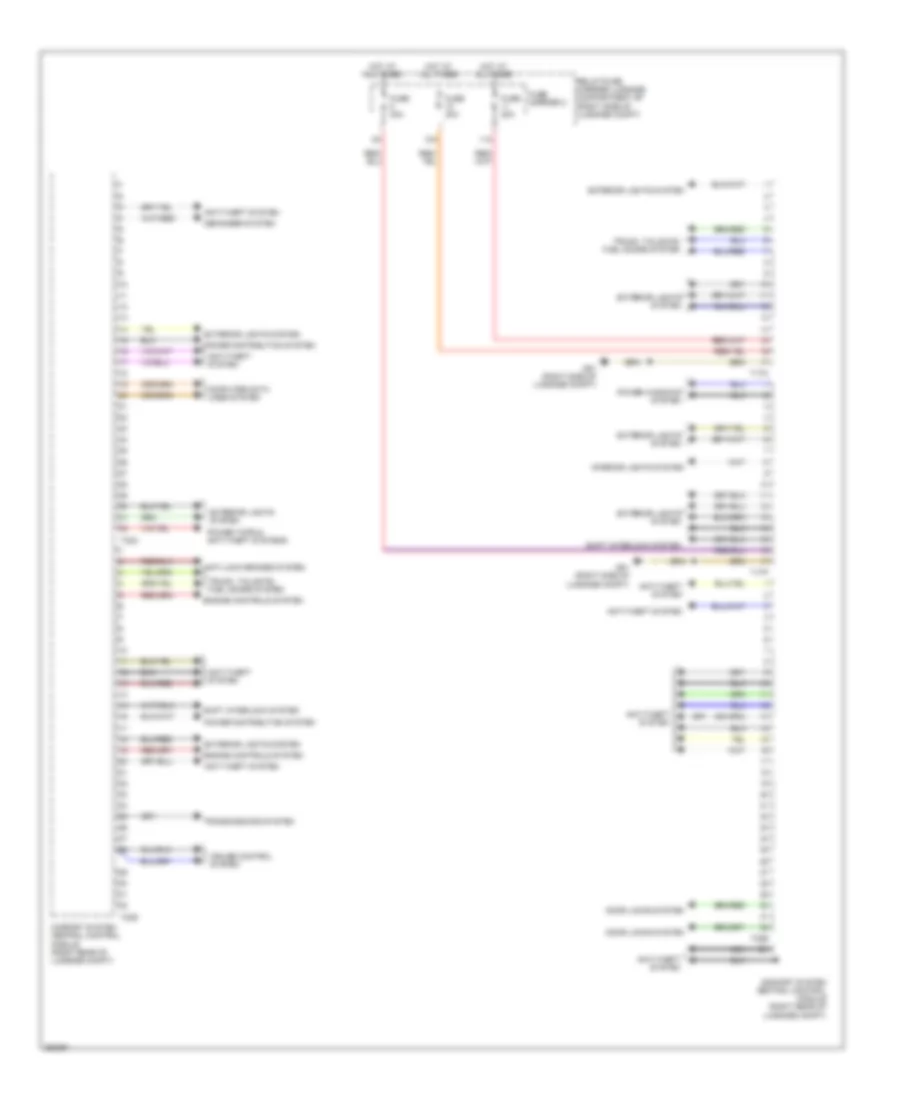
Comfort System Central Control Module Wiring Diagram for Audi S5 4.2 2011
List of elements for Comfort System Central Control Module Wiring Diagram for Audi S5 4.2 2011:
- 10a
- 11a
- Anti-lock brakes system
- Anti-theft system
- Comfort system central control module (right rear of luggage compt)
- Computer data lines system
- Cruise control system
- Defogger system
- Door locks system
- Engine controls system
- Exterior lights system
- Fuse 20a
- Fuse 30a
- Fuse carrier 2
- G51 (right side of luggage compt)
- Hot at all times
- Interior lights system
- Nca
- Power distribution system
- Power tops & anti-theft systems
- Power windows system
- Relay/fuse carrier luggage compartment sf (right side of luggage compt)
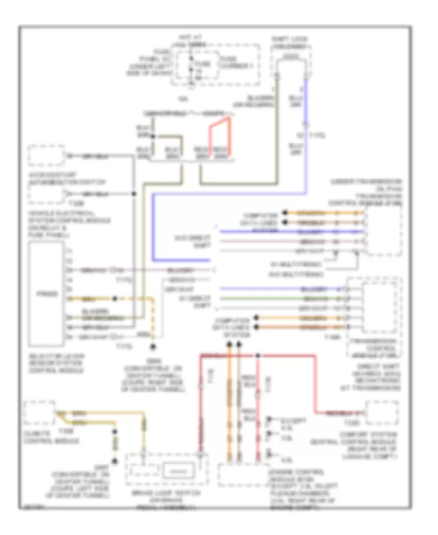
- Shift interlock system
- T17o
- T17p
- T32c
- T32d
- T32e
- Transmissions system
- Trunk, tailgate, fuel doors system
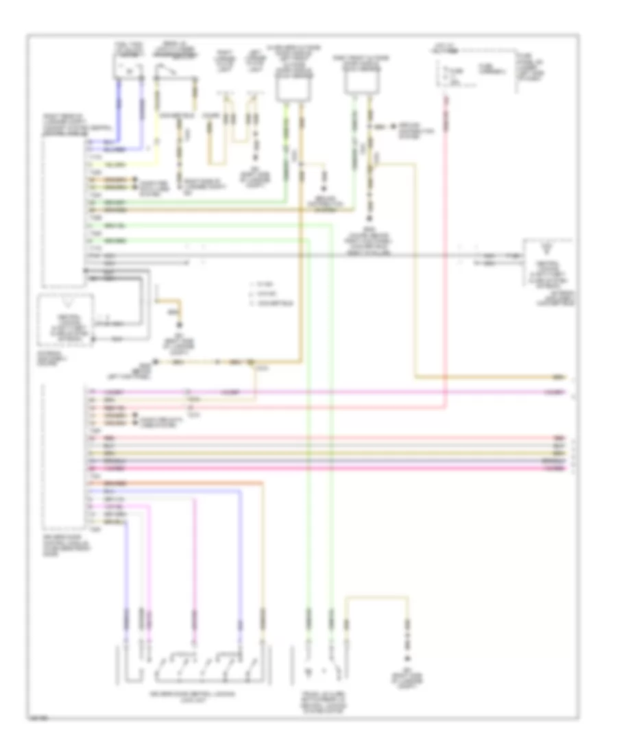
Steering Column Electronic Systems Control Module Wiring Diagram for Audi S5 4.2 2011
List of elements for Steering Column Electronic Systems Control Module Wiring Diagram for Audi S5 4.2 2011:
- (convertible: on center tunnel) (coupe: left side of center tunnel) g687
- 12a
- Air bag control module (under center console)
- Air bag spiral spring/return spring w/ slip ring
- Computer data lines system
- Cruise control switch
- Driver's air bag igniter
- Driver's air bag igniter 2
- Engine controls system
- Fuse 5a
- Fuse carrier 1
- Fuse carrier 2
- Fuse panel sd (under right side of dash)
- Hot at all times
- Left multi- function buttons
- Mode
- Multi-function steering wheel control module
- Nca
- Right multi-function buttons
- Signal horn activation
- Steering angle sensor (in steering column)
- Steering column electronic systems control module (on steering column)
- Steering wheel control module
- Steering wheel vibration motor (w/ directional stabilization assistance)
- T17x
- T4ac
- Tiptronic downshift button (if equipped)
- Tiptronic upshift button (if equipped)
- Turn signal switch
- W/ directional stabilization assistance
- W/ tiptronic
- Windshield wiper/ washer switch
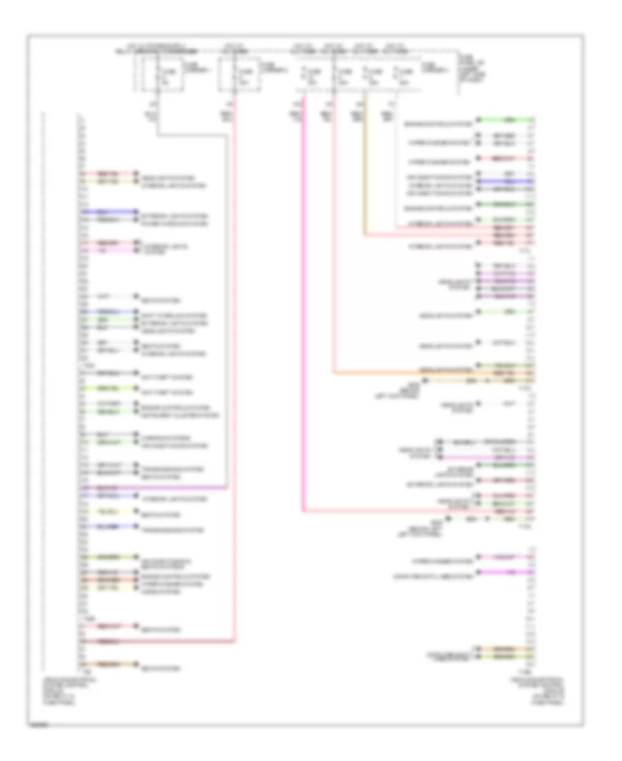
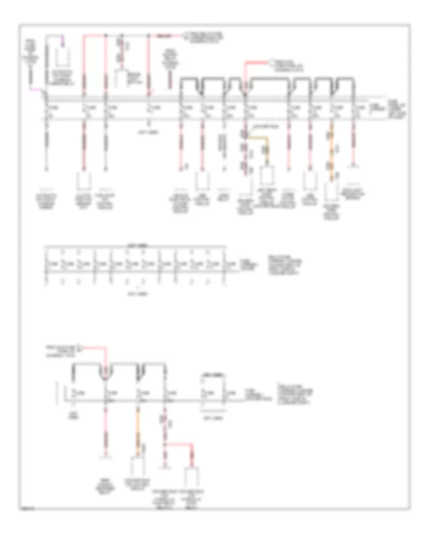
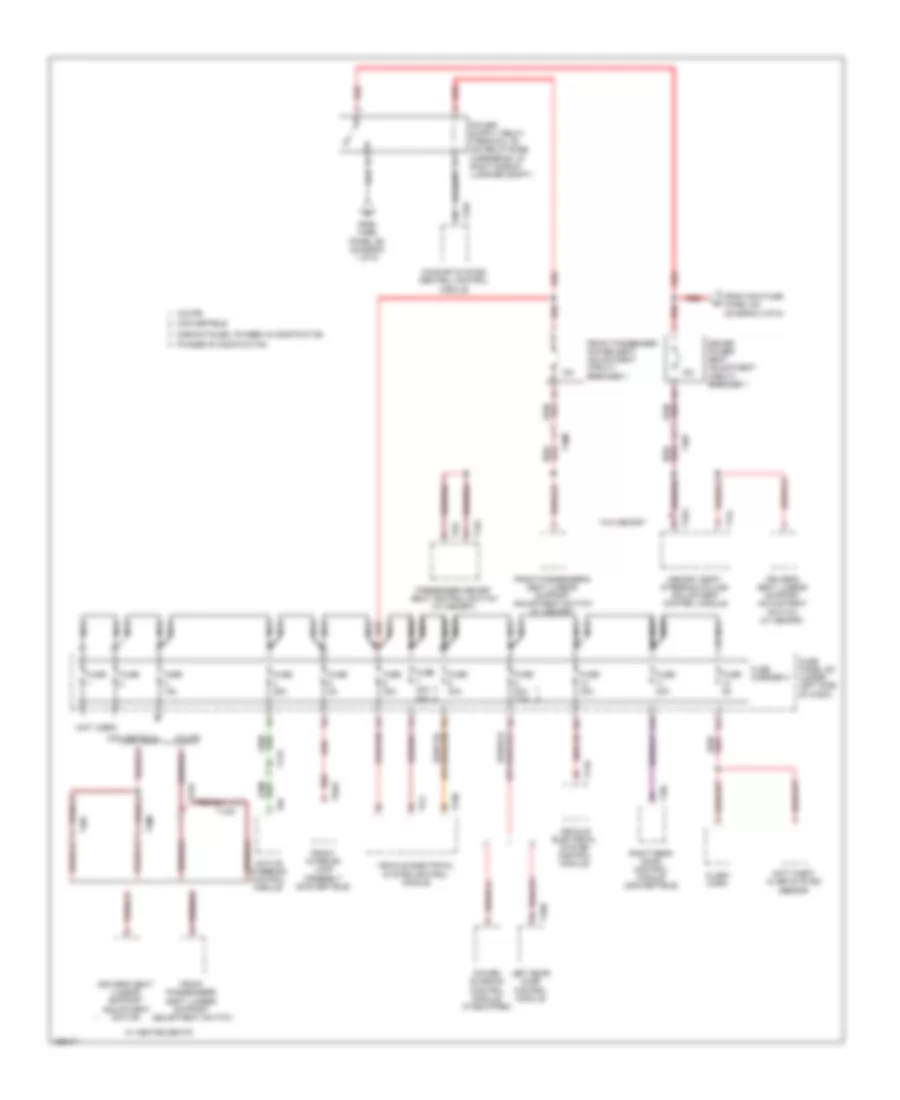
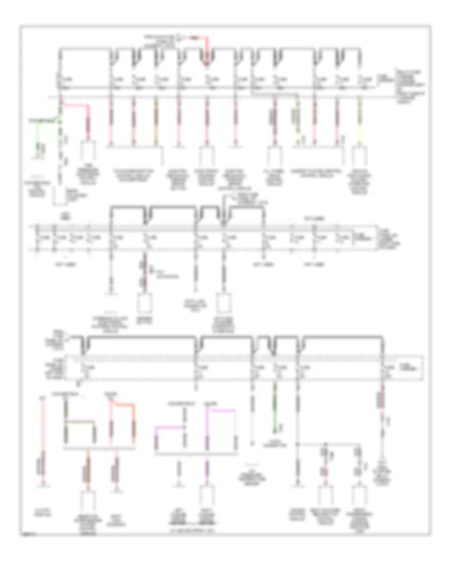
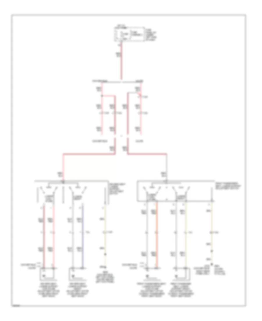
Vehicle Electrical System Control Module Wiring Diagram for Audi S5 4.2 2011
List of elements for Vehicle Electrical System Control Module Wiring Diagram for Audi S5 4.2 2011:
- 10a
- Air conditioning & seats systems
- Air conditioning system
- Anti-theft system
- Computer data lines system
- Engine controls system
- Exterior lights system
- Fuse 20a
- Fuse 30a
- Fuse 35a
- Fuse 5a
- Fuse carrier 1
- Fuse carrier 2
- Fuse carrier 3
- Fuse panel sc (under left side of dash)
- G639 (behind left kick panel)
- G639 (behind left left kick panel)
- Headlights system
- Horns system
- Hot at all times
- Instrument cluster system
- Interior lights system
- Power windows system
- Seats system
- Shift interlock system
- T16b
- T17l
- T17m
- T17n
- T32a
- T32b
- T6f
- Transmissions system
- Vehicle electrical system control module (on relay & fuse panel)
- Warning systems
- Wiper/washer system
COMPUTER DATA LINES
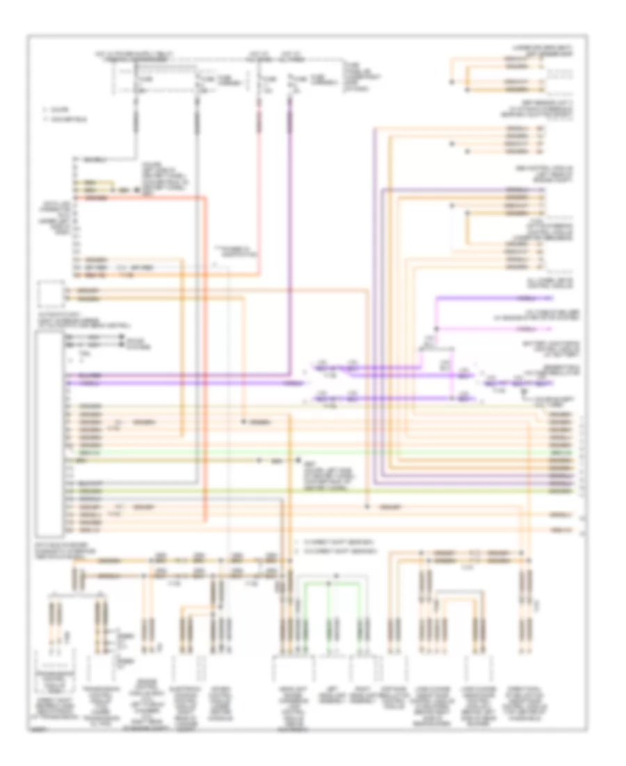
Computer Data Lines Wiring Diagram (1 of 3) for Audi S5 4.2 2011
List of elements for Computer Data Lines Wiring Diagram (1 of 3) for Audi S5 4.2 2011:
- (coupe: left side of center tunnel) (convertible: on center tunnel) g687
- (under driver's seat) esp sensor unit
- 11a
- Abs control module (left rear of engine compt)
- Active steering control module (under driver's seat)
- Air bag control module (under center console)
- All wheel drive control module
- Automatic day/ night interior mirror (w/ automatic high beam control)
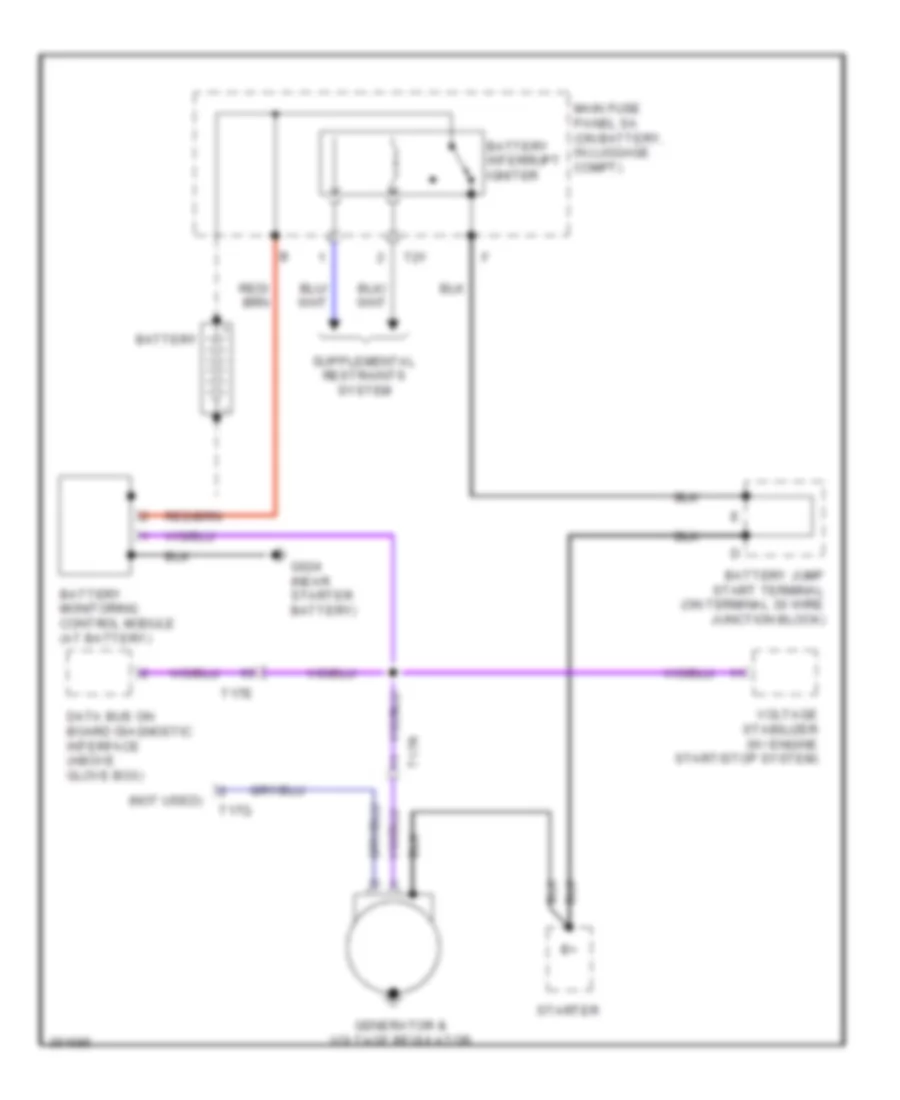
- Battery monitoring control module (at battery)
- Convertible
- Coupe
- Coupe except 2.0l turbo
- Data bus on board diagnostic interface (above glove box)
- Data link connector (dlc) (under left
- Direct shift gearbox (dsg) mechatronic (at transmission)
- Directional stabilization assistance control module (top center of windshield)
- Distance regulation control module
- Electronic damping control module (right rear of luggage compt)
- Engine control module (ecm) (4.2l: left plenum chamber) (3.0l: right rear of engine compt)
- Esp sensor unit 2 (w/ dynamic steering & gear box quattro sport)
- Fuse 10a
- Fuse 5a
- Fuse carrier 1
- Fuse carrier 2
- Fuse panel sd (under right side of dash)
- G687 (coupe: left side of center tunnel) (convertible: on center tunnel)
- Generator & voltage regulator
- Headlight range/ cornering lamp control module (above glove box)
- Hot at all times
- Lane change assistance control module (if equipped) (behind right side of rear bumper)
- Lane change assistance control module 2 (behind left side of rear bumper)
- Left headlamp assembly
- Nca
- Phased in modification
- Right headlamp assembly
- Side of dash)
- Sound systems
- Speed a/t
- Speed a/t cvt
- T10h
- T12e
- T16r
- T17b
- T17c
- T17e
- T17f
- T17r
- T17w
- T2dl
- T5i
- T94
- Transmission control module (tcm)
- Transmission control module (tcm) (under transmission oil pan)
- Voltage stabilizer (w/ engine start/stop system)
- W/ direct shift gear box
- W/o direct shift gear box
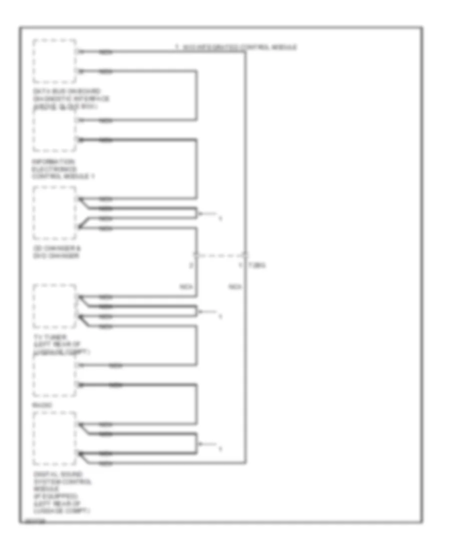
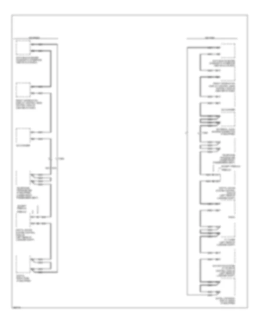
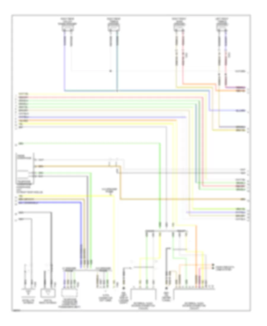
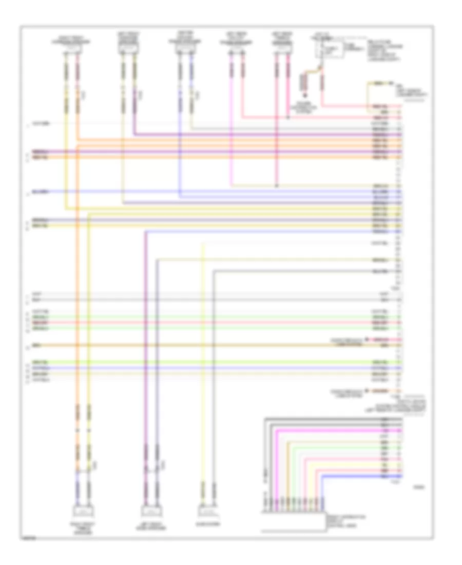
Computer Data Lines Wiring Diagram (2 of 3) for Audi S5 4.2 2011
List of elements for Computer Data Lines Wiring Diagram (2 of 3) for Audi S5 4.2 2011:
- (behind left side of front bumper) garage door opener control module
- (center front of roof) (if equipped) power sunroof control module
- (convertible) left head space heating control module
- (convertible) right head space heating control module
- (premium) air quality sensor
- (w/ humidity sensor) automatic day/ night interior mirror
- 10h
- 10l
- 11h
- 11l
- 12h
- 12l
- 13h
- 13l
- 14h
- 14l
- 15h
- 15l
- 16h
- 16l
- 17h
- 17l
- 18h
- 18l
- 19h
- 19l
- 20h
- 20l
- 21h
- 21l
- 22h
- 22l
- 23h
- 23l
- A/c pressure/ temperature sensor
- Anti-theft alarm system sensor
- Base
- Cd changer (coupe) cd changer & dvd changer (convertible)
- Charisma switch module
- Convertible
- Convertible top control module (right rear of luggage comp)
- Digital radio
- Digital sound system control module (left rear of luggage comp)
- Driver's door control module (in driver's front door)
- Driver's side can separating plug
- Front information display control head control module (center of dash)
- Garage door opener control head
- Information electronics control module (convertible)
- Memory seat/ steering column adjustment control module (under driver's seat)
- Navigation system w/ cd drive control module (left rear of luggage compt)
- Premium
- Satellite radio (if equipped)
- T10p
- T16b
- T16j
- T16u
- T17b
- T17c
- T17d
- T17e
- T18b
- T20b
- T20f
- T27a
- T32g
- T32h
- T6k
- T6l
- T8ah
- Telephone transceiver (under front passenger's seat)
- Tv tuner (left rear of luggage compt)
- Vehicle electrical system control module (on relay & fuse panel)
- W/ mmi basic
- W/ mmi high
Computer Data Lines Wiring Diagram (3 of 3) for Audi S5 4.2 2011
List of elements for Computer Data Lines Wiring Diagram (3 of 3) for Audi S5 4.2 2011:
- (behind left side of dash) electronic steering column lock control module
- (right rear of luggage compt) (if equipped) rear view camera system control module
- (right rear of luggage compt) (w/ tailor socket) towing recognition control module
- (right rear of luggage compt) comfort system central control module
- 10h
- 10l
- 11h
- 11l
- 12h
- 12l
- 13h
- 13l
- 14h
- 14l
- 15h
- 15l
- 16h
- 16l
- 17h
- 17l
- 18h
- 18l
- 19h
- 19l
- 20h
- 20l
- 21h
- 21l
- 22h
- 22l
- 23h
- 23l
- A/c control head climatronic control module (behind center of dash)
- Access/start authorization switch
- Auxiliary heater control module (right front of engine compt)
- Convertible
- Coupe
- Electro mechanical parking brake control module (right rear of luggage compt)
- External audio source connection
- Front passenger's door control module (in passenger's front door)
- Instrument cluster control module
- Parallel parking assistance control module (right rear of luggage compt)
- Passenger's memory seat control module (under front passenger's seat)
- Passenger's side can separating plug
- Radio
- Steering column electronic system control module (on steering column)
- T10ag
- T12u
- T16e
- T16i
- T17f
- T17g
- T20e
- T20g
- T27c
- T310m
- T32c
- T32i
- T8m
- Tire pressure monitoring control module (under right side of dash)
- Vehicle positioning system interface control module
- W/ mmi high
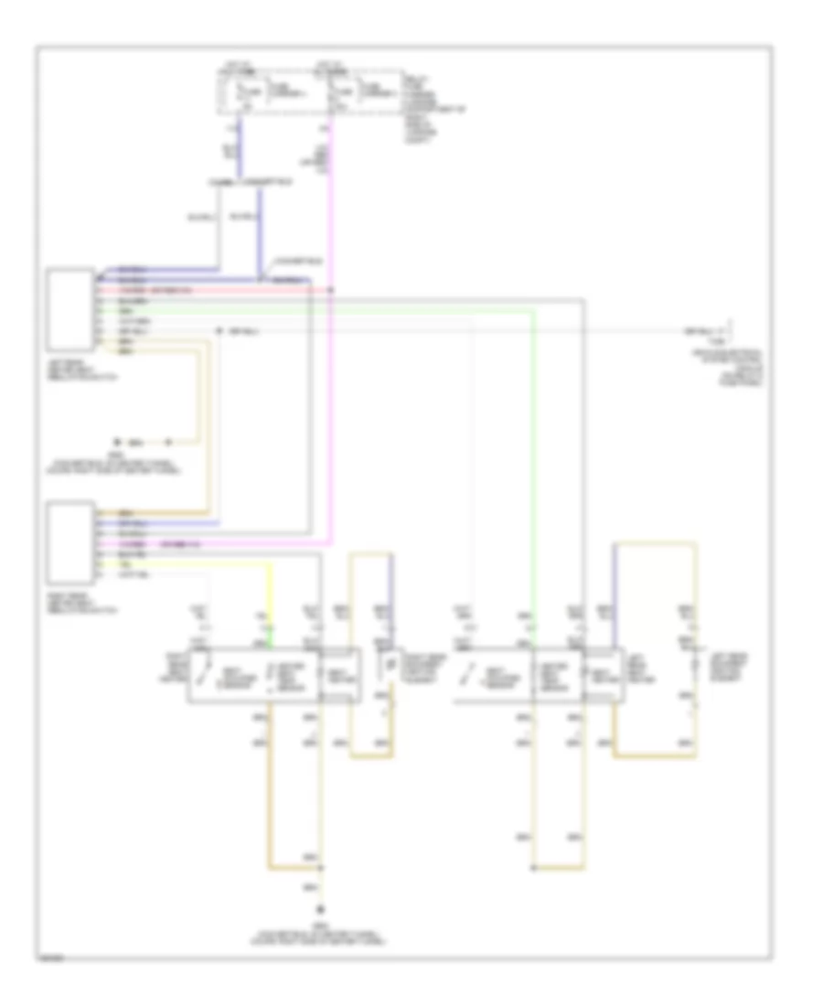
COOLING FAN
Cooling Fan Wiring Diagram for Audi S5 4.2 2011
List of elements for Cooling Fan Wiring Diagram for Audi S5 4.2 2011:
- (not used)
- 11a
- After-run coolant pump (if eqipped)
- Battery jump start terminal (on terminal 30 wire junction block)
- Coolant circulation pump relay (w/ after run coolant pump) (on relay/fuse carrier e-box-sb)
- Coolant fan
- Coolant fan 2
- Coolant fan control (fc) control module (on coolant fan)
- Coolant fan control (fc) control module 2 (on coolant fan 2)
- Engine control module (ecm) (in left plenum chamber)
- Engine coolant temperature (ect) sensor
- Fuse 1 60a
- Fuse 10a
- Fuse 40a
- Fuse 5a
- Fuse carrier
- G12 (left rear of engine compt)
- G671 (on left front cross member)
- Hot w/ battery interrupt igniter energized
- Map controlled engine cooling thermostat
- Red
- Relay/ fuse carrier e box sb (in left plenum chamber e-box)
- T5i
- T60
- T94
CRUISE CONTROL
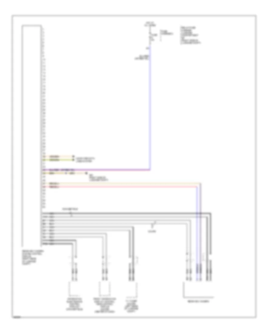
Cruise Control Wiring Diagram (1 of 2) for Audi S5 4.2 2011
List of elements for Cruise Control Wiring Diagram (1 of 2) for Audi S5 4.2 2011:
- (if equipped) distance regulation control module
- 2.0l
- 3.0l
- 4.2l
- A/t
- Clutch position sensor (m/t)
- Comfort system central control module (right rear of luggage compt)
- Computer data lines system
- Cvt
- Direct shift gearbox (dsg) mechatronic (at transmission)
- Engine control module (ecm) (4.2l: in left plenum chamber) (3.0l: right rear of engine compt)
- Except 3.0l
- Except cvt
- Fuse 5a
- Fuse carrier 1
- Fuse panel sc (under left side of dash)
- Fuse panel sd (under right side of dash)
- G638 (coupe: behind right kick panel) (convertible: right "a" pillar)
- G639 (coupe: behind left kick panel) (convertible: left kick panel)
- Hot at all times
- M/t
- Nca
- T16r
- T17b
- T17e
- T17q
- T17r
- T32c
- T32d
- T60
- T8al
- T94
- Throttle position (tp) sensor (except 3.0l) accelerator pedal position sensor 1 & 2 (3.0l) (top of accelerator pedal assembly)
- Throttle valve control module (2.0l: left side of intake manifold) (4.2l: at rear of engine) (3.0l: on throttle valve housing)
- Transmission control module (tcm)
- Transmission control module (tcm) (under transmission oil pan)
- Transmission input speed (rpm) sensor 1
- Transmission input speed (rpm) sensor 2
- W/ direct shift
- W/o direct shift
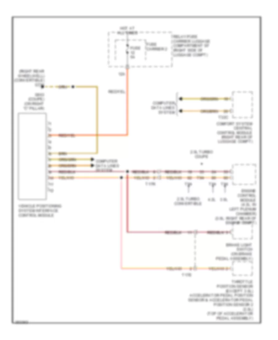
Cruise Control Wiring Diagram (2 of 2) for Audi S5 4.2 2011
List of elements for Cruise Control Wiring Diagram (2 of 2) for Audi S5 4.2 2011:
- (coupe: left side of central tunnel) (convertible: on central tunnel) g687
- Abs control module (left rear of engine compt)
- Computer data lines system
- Cruise control switch
- Left front abs wheel speed sensor (on left front wheel hub)
- Left rear abs wheel speed sensor (on left rear wheel hub)
- Nca
- Red
- Right front abs wheel speed sensor (on right front wheel hub)
- Right rear abs wheel speed sensor (on right rear wheel hub)
- Steering column electronic systems control module (on steering column)
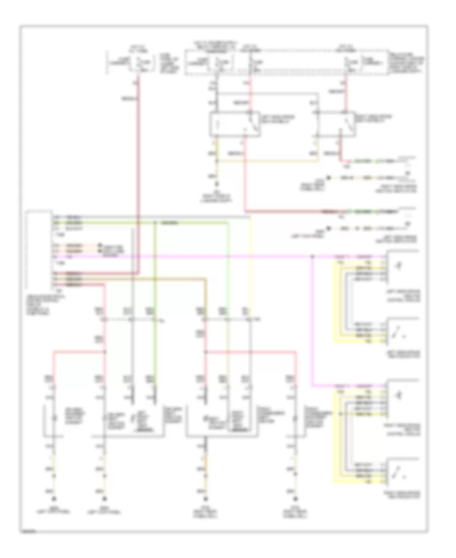
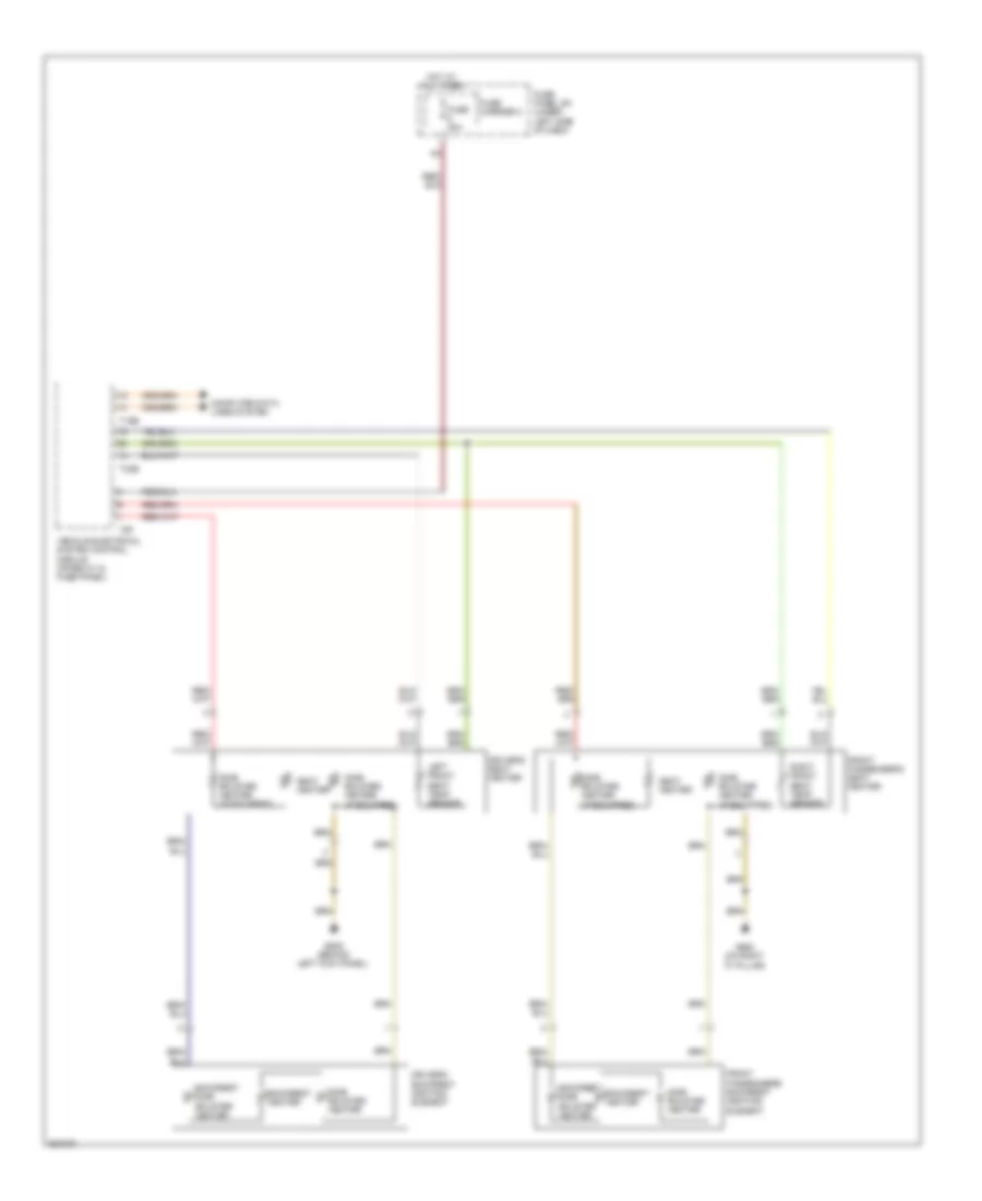
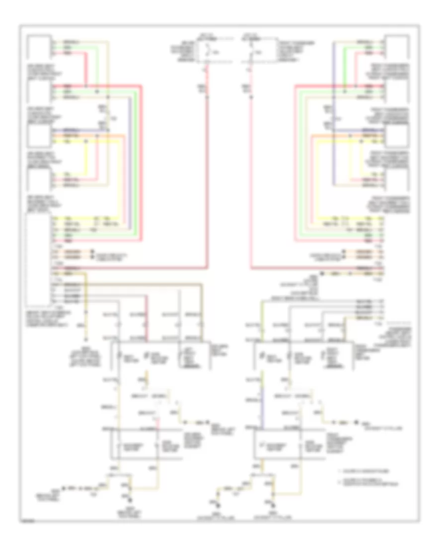
DEFOGGERS
Defoggers Wiring Diagram for Audi S5 4.2 2011
List of elements for Defoggers Wiring Diagram for Audi S5 4.2 2011:
- (left side of luggage compt) (convertible) g50
- 10a
- 11a
- 40a
- Comfort system central control module (right rear of luggage compt)
- Computer data lines system
- Convertible
- Coupe
- Door locks system
- Driver's door control module (in driver's front door)
- Driver's exterior mirror assembly
- Driver's heated outside mirror
- Fm frequency filter (in positive wire)
- Front passenger's door control module (in passenger's front door)
- Front passenger's exterior mirror assembly
- Front passenger's heated outside mirror
- Fuse 15a
- Fuse 30a
- Fuse 40a
- Fuse carrier
- Fuse panel sc (under left side of dash)
- G51 (right side of luggage compt)
- G638 (coupe: behind right kick panel) (convertible: right "a" pillar)
- G639 (coupe: behind left kick panel) (convertible: left "a" pillar)
- G657 (coupe)
- Heated rear window
- Hot at all times
- Mirrors system
- Nca
- Rear window defogger fuse
- Rear window defogger relay (on relay/fuse carrier - sf, at right side of luggage compt)
- Relay/fuse carrier luggage compartment sf (right side of luggage compt)
- T16m
- T16n
- T17o
- T20f
- T20g
- T27a
- T27c
- T32c
- Windshield antenna suppression filter (w/ trap circuit)
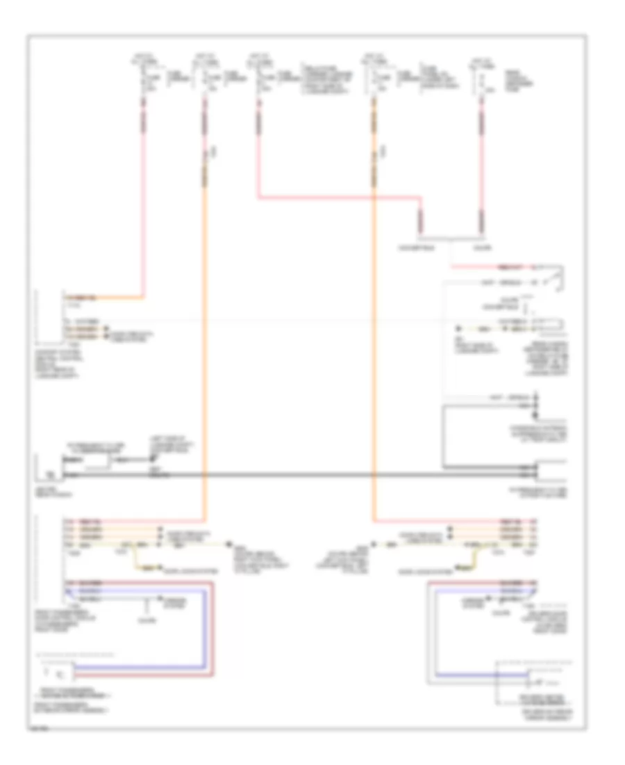
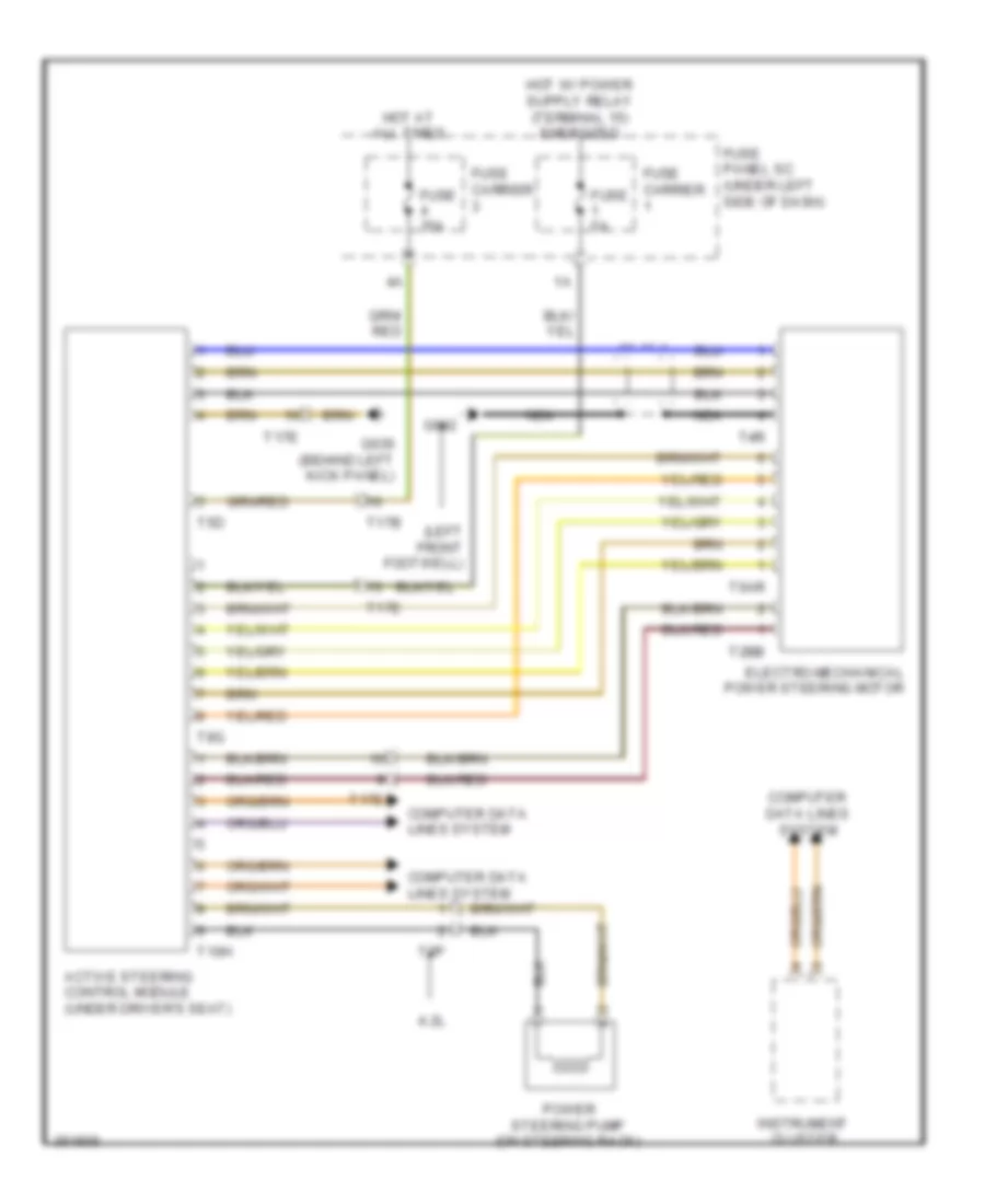
ELECTRONIC POWER STEERING
Active Steering Control Module Wiring Diagram for Audi S5 4.2 2011
List of elements for Active Steering Control Module Wiring Diagram for Audi S5 4.2 2011:
- (left front footwell)
- 4.2l
- Active steering control module (under driver's seat)
- Computer data lines system
- Electro-mechanical power steering motor
- Fuse 35a
- Fuse 5a
- Fuse carrier
- Fuse panel sc (under left side of dash)
- G602
- G639 (behind left kick panel)
- Hot at all times
- Instrument cluster
- Nca
- Power steering pump (on steering rack)
- T10h
- T17b
- T17e
- T2bb
- T2p
- T4r
- T5d
- T6ar
- T8g
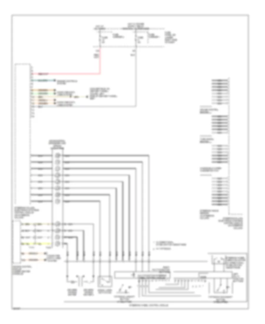
Electronic Power Steering Wiring Diagram for Audi S5 4.2 2011
List of elements for Electronic Power Steering Wiring Diagram for Audi S5 4.2 2011:
- (convertible: on center tunnel) (coupe: left side of center tunnel) g687
- 12a
- Air bag control module (under center console)
- Air bag spiral spring/return spring w/ slip ring
- Computer data lines system
- Cruise control switch
- Driver's air bag igniter
- Driver's air bag igniter 2
- Engine controls system
- Fuse 5a
- Fuse carrier 1
- Fuse carrier 2
- Fuse panel sd (under right side of dash)
- Hot at all times
- Left multi- function buttons
- Mode
- Multi-function steering wheel control module
- Nca
- Right multi-function buttons
- Signal horn activation
- Steering angle sensor (in steering column)
- Steering column electronic systems control module (on steering column)
- Steering wheel control module
- Steering wheel vibration motor (w/ directional stabilization assistance)
- T17x
- T4ac
- Tiptronic downshift button (if equipped)
- Tiptronic upshift button (if equipped)
- Turn signal switch
- W/ directional stabilization assistance
- W/ tiptronic
- Windshield wiper/ washer switch
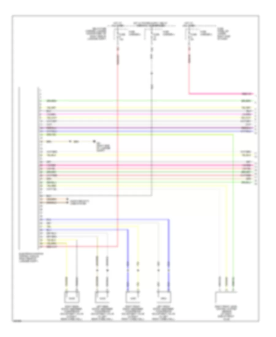
ELECTRONIC SUSPENSION
Electronic Suspension Wiring Diagram (1 of 2) for Audi S5 4.2 2011
List of elements for Electronic Suspension Wiring Diagram (1 of 2) for Audi S5 4.2 2011:
- 12a
- Computer data lines system
- Electronic damping control module (right rear of luggage compt)
- Fuse 15a
- Fuse 5a
- Fuse carrier 2
- Fuse carrier 4
- Fuse panel sd (under right side of dash)
- G51 (right side of luggage compt)
- Hot at all times
- Left front shock absorber w/dampening adjustment valve (in left front wheelwell)
- Left rear shock absorber w/dampening adjustment valve (in left rear wheelwell)
- Relay/fuse carrier luggage compartment sf (right side of luggage compt)
- Right front level control system sensor (at right side of front axle)
- Right front shock absorber w/dampening adjustment valve (in right front wheelwell)
- Right rear shock absorber w/dampening adjustment valve (in right rear wheelwell)
Electronic Suspension Wiring Diagram (2 of 2) for Audi S5 4.2 2011
List of elements for Electronic Suspension Wiring Diagram (2 of 2) for Audi S5 4.2 2011:
- (under driver's seat) active steering control module
- Charisma switch module
- Computer data
- Computer data lines system
- Fuse 35a
- Fuse 5a
- Fuse carrier 1
- Fuse carrier 3
- Fuse panel sc (under left side of dash)
- G687 (coupe: left side of center tunnel) (convertible: on center tunnel)
- G688 (coupe: right side of center tunnel) (convertible: on center tunnel)
- Hot at all times
- Left front body acceleration sensor (on left front chassis rail)
- Left front level control system sensor (at left side of front axle)
- Left rear level control system sensor (at left side of rear axle)
- Lines system
- Rear body acceleration sensor (left rear chassis rail)
- Right front body acceleration sensor (on right front chassis rail)
- Right rear level control system sensor (at right side of rear axle)
- T10h
- T16b
- T17b
- T17d
- T17e
- T17f
- T5d
- T8g
- Vehicle electrical system control module (on relay & fuse panel)
- W/ navigation system
- W/o navigation system
ENGINE PERFORMANCE
3.0L SC
3.0L SC, Engine Performance Wiring Diagram (1 of 8) for Audi S5 4.2 2011
List of elements for 3.0L SC, Engine Performance Wiring Diagram (1 of 8) for Audi S5 4.2 2011:
- (left side of engine compt) g12
- (left side of engine) left electro hydraulic engine mount solenoid valve
- (right rear of luggage compt) comfort system central control module
- Accelerator pedal position position sensor & sensor 2 (top of accelerator pedal assembly)
- Cooling fans system
- Engine control module (ecm) (right rear of engine compartment)
- Fuse 15a
- Fuse 20a
- Fuse 5a
- Fuse carrier 1
- G12 (left side of engine compt)
- Heated oxygen sensor (h02s) (in exhaust, at turbocharger exit)
- Heated oxygen sensor (ho2s) 2 (upstream of cylinder bank 2)
- Nca
- Oil level thermal sensor
- Red
- Relay/ fuse carrier e-box sb (in left plenum chamber e-box)
- Right electro hydraulic engine mount solenoid valve (right side of engine)
- Sensor 1
- Sensor 2
- Starting/ charging system
- Starting/charging system
- T14e
- T17e
- T17q
- T17r
- T32d
- T94
- Transmissions system
3.0L SC, Engine Performance Wiring Diagram (2 of 8) for Audi S5 4.2 2011
List of elements for 3.0L SC, Engine Performance Wiring Diagram (2 of 8) for Audi S5 4.2 2011:
- 10a
- Battery interrupt igniter
- Battery jump start terminal (on terminal 30 wire junction block)
- Control valve control module (rear of engine)
- Fuse 110a
- Fuse 15a
- Fuse carrier 1
- G12 (left side of engine compt)
- Hot at all times
- Main fuse panel sa (on battery, in luggage compt)
- Red
- Reduced oil oil pressure switch
- Relay/ fuse carrier e box sb (in left plenum chamber e-box)
- Suppressor
- T17q
3.0L SC, Engine Performance Wiring Diagram (3 of 8) for Audi S5 4.2 2011
List of elements for 3.0L SC, Engine Performance Wiring Diagram (3 of 8) for Audi S5 4.2 2011:
- Fuse 25a
- Fuse 5a
- Fuse carrier
- Fuse carrier 1
- Fuse panel sc (under left side of dash)
- G12 (left side of engine compt)
- Red
- Relay/ fuse carrier e-box sb (in left plenum chamber e-box)
- Starting/ charging system
- T17e
- T17i
- T17q
- T32b
- Transmission range gear recognition switch
- Vehicle electrical system control module (on relay & fuse panel)
3.0L SC, Engine Performance Wiring Diagram (4 of 8) for Audi S5 4.2 2011
List of elements for 3.0L SC, Engine Performance Wiring Diagram (4 of 8) for Audi S5 4.2 2011:
- (in exhaust, at turbocharger exit) oxygen sensor (o2s) heater
- (integral to heated oxygen sensor 2) oxygen sensor (o2s) heater 2
- (on brake pedal assembly) brake light switch
- (right rear of luggage compt) comfort system central control module
- (right rear wheelwell) g730
- A/c control climatronic control module (behind center of dash)
- Coil
- Engine coolant level sensor
- Fuel pump (fp) control module
- Fuse 5a
- Fuse carrier
- G12 (left side of engine compt)
- G687 (on center tunnel)
- Nca
- Oil pressure switch
- Red
- Servotronic solenoid valve
- T17b
- T17e
- T17q
- T17r
- T20e
- T32d
- Transfer fuel pump & fuel level sensor
3.0L SC, Engine Performance Wiring Diagram (5 of 8) for Audi S5 4.2 2011
List of elements for 3.0L SC, Engine Performance Wiring Diagram (5 of 8) for Audi S5 4.2 2011:
- (awd) fuel level sensor 2
- (manifold absolute pressure sensor: rear of engine) manifold absol- manifold absolute pressure sensor/ intake air temperature ensor
- Auxiliary engine coolant (ec) pump relay
- Camshaft adjustment valve 1 (rear of cylinder bank 1)
- Camshaft adjustment valve 2 (rear of cylinder bank 2)
- Charge air cooling pump
- Charge air pressure sensor & intake manifold temperature sensor (charge air pressure sensor: in bank 1 intake manifold)
- Climatronic refrigerant shut-off valve
- Computer data lines system
- Fuse 5a
- Fuse carrier
- Fuse panel sd (under right side of dash)
- G12 (left side of engine compt)
- G687 (on center tunnel)
- Hot at all times
- Instrument cluster control module
- Intake air temperature sensor 2 & charge air pressure sensor 2 (charge air pressure sensor 2: in bank 2 intake manifold)
- Red
- T17f
3.0L SC, Engine Performance Wiring Diagram (6 of 8) for Audi S5 4.2 2011
List of elements for 3.0L SC, Engine Performance Wiring Diagram (6 of 8) for Audi S5 4.2 2011:
- (front of cylinder bank 1) camshaft position (cmp) sensor
- (front of cylinder bank 2) camshaft position (cmp) sensor 2
- (left rear of engine) engine speed (rpm) sensor
- (on high pressure pump) low fuel pressure sensor
- (right rear of engine) secondary air injection sensor 1
- (under intake manifold) fuel pressure sensor
- Engine control module (ecm) (right rear of engine compt)
- Engine coolant temperature (ect) sensor
- Intake manifold runner position sensor (in bank 1 intake manifold)
- Knock sensor (ks) 1 (under intake manifold, on cylinder bank 1)
- Knock sensor (ks) 2 (under intake manifold, on cylinder bank 2)
- Nca
- Red
- T14e
- T14g
- T60
3.0L SC, Engine Performance Wiring Diagram (7 of 8) for Audi S5 4.2 2011
List of elements for 3.0L SC, Engine Performance Wiring Diagram (7 of 8) for Audi S5 4.2 2011:
- 50a
- Evap canister purge regulator valve 1 (rear of engine)
- Fuel metering valve (on high pressure pump)
- G615 (on left strut tower)
- Intake manifold runner control valve (rear of engine)
- Intake manifold runner position sensor 2 (in bank 2 intake manifold)
- Leak detection pump (ldp)
- Oil pressure regulation valve (left front of engine)
- Red
- Second- ary air injection (air) pump fuse
- Secondary air injection (air) pump motor (right front of engine compartment)
- Secondary air injection (air) pump relay (on relay/ fuse carrier e-box-sb)
- Secondary air injection (air) solenoid valve (rear of engine)
- Secondary air injection (air) solenoid valve 2 (rear of engine)
- T14e
- T14g
- T17q
3.0L SC, Engine Performance Wiring Diagram (8 of 8) for Audi S5 4.2 2011
List of elements for 3.0L SC, Engine Performance Wiring Diagram (8 of 8) for Audi S5 4.2 2011:
- (above 1, 2 & 3 bank 1 cylinders) fuel injectors
- (above 4, 5 & 6 bank 2 cylinders) fuel injectors
- Coil 1
- Coil 2
- Coil 3
- Coil 4
- Coil 5
- Coil 6
- Computer data lines system
- Cruise control system
- Engine control module (ecm) (right rear of engine compt)
- G600
- G601
- G615 (on left strut tower)
- Ignition coil w/ power output stage (coils 1, 2 & 3 : above 1, 2 & 3 bank 1 cylinders) (coils 4, 5 & 6 : above 4, 5 & 6 bank 2 cylinders)
- Nca
- Red
- Starting/charging system
- T14e
- T14g
- T17r
- T60
- T94
- Throttle valve control module (on throttle valve housing)
- To spark plug
- Vehicle positioning system interface control module
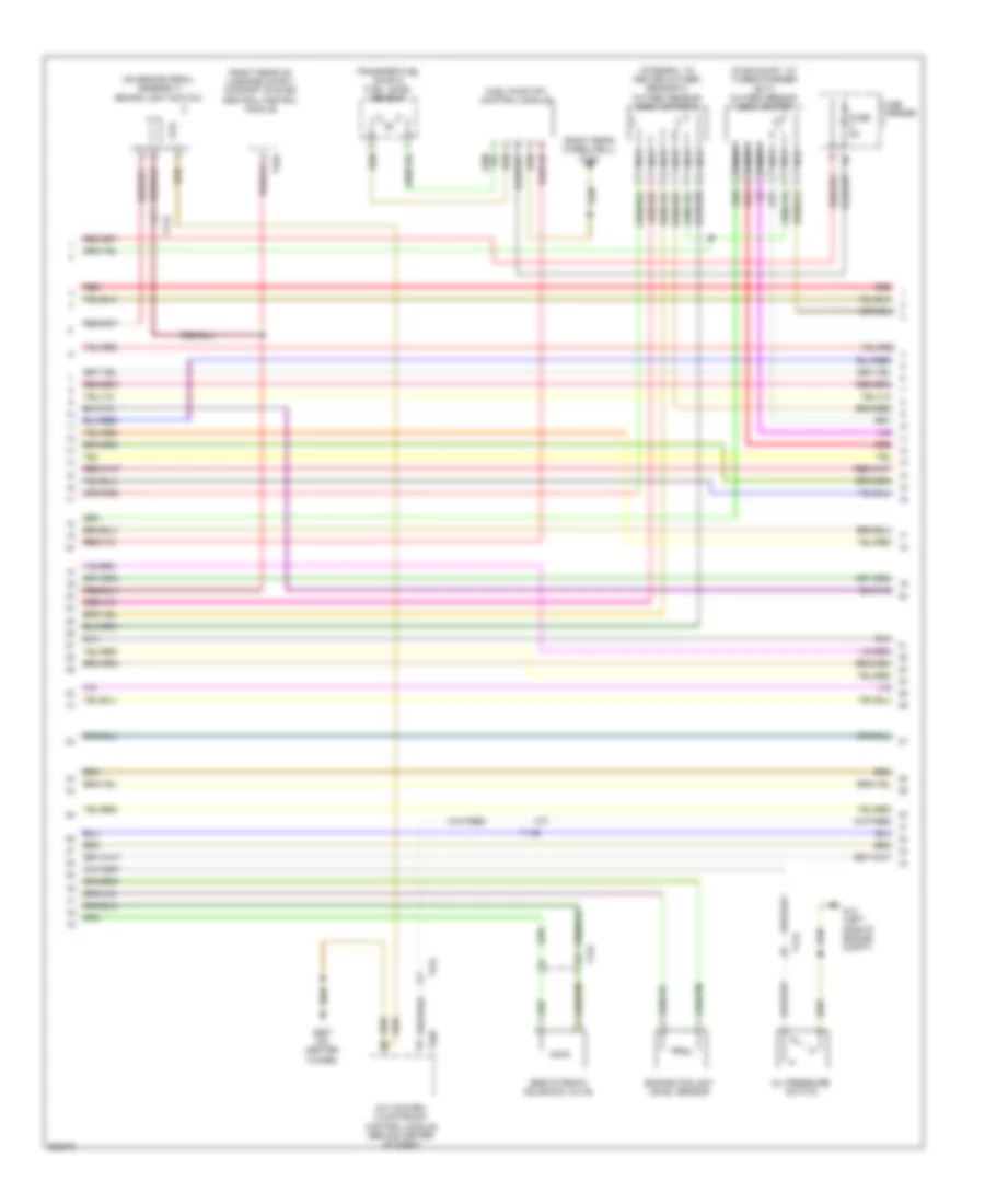
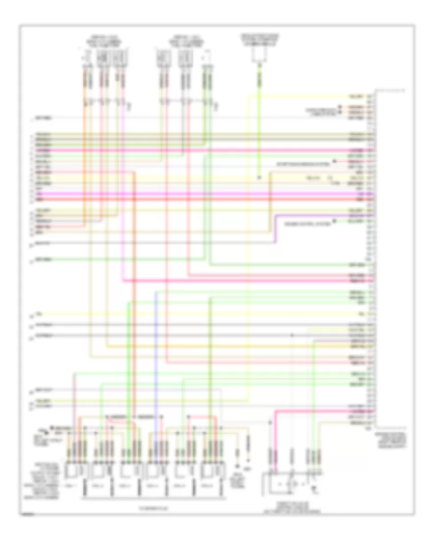
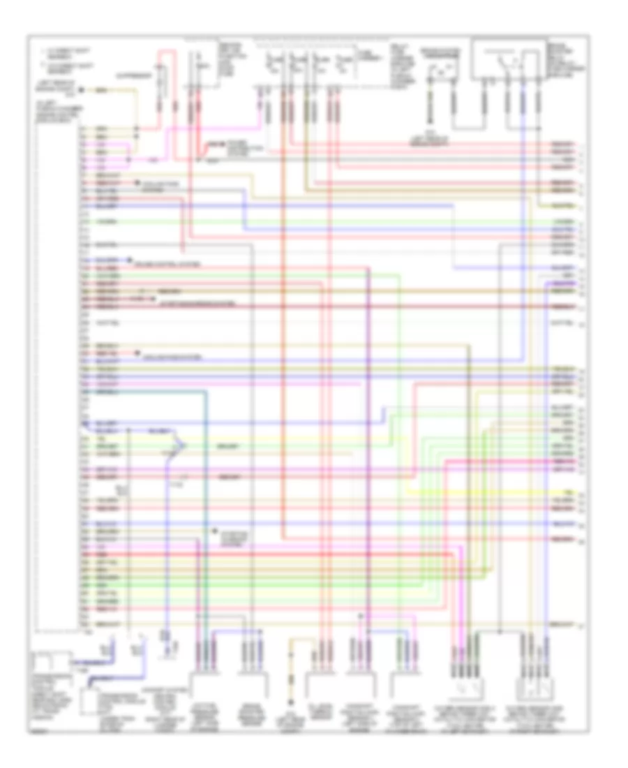
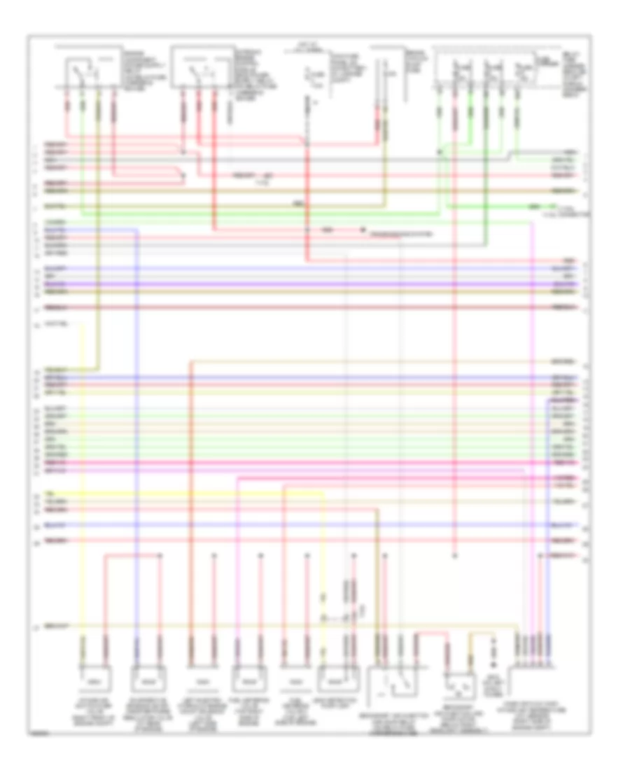
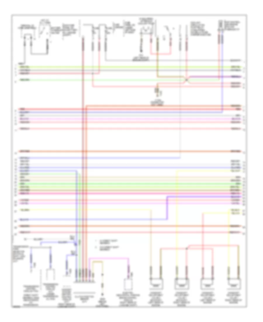
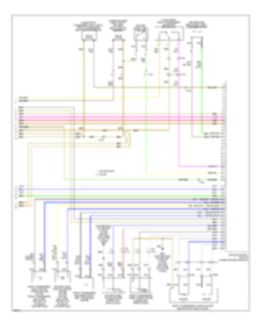
4.2L
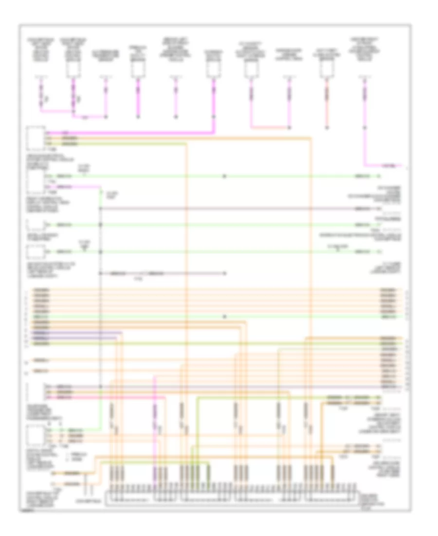
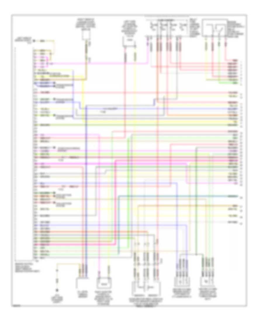
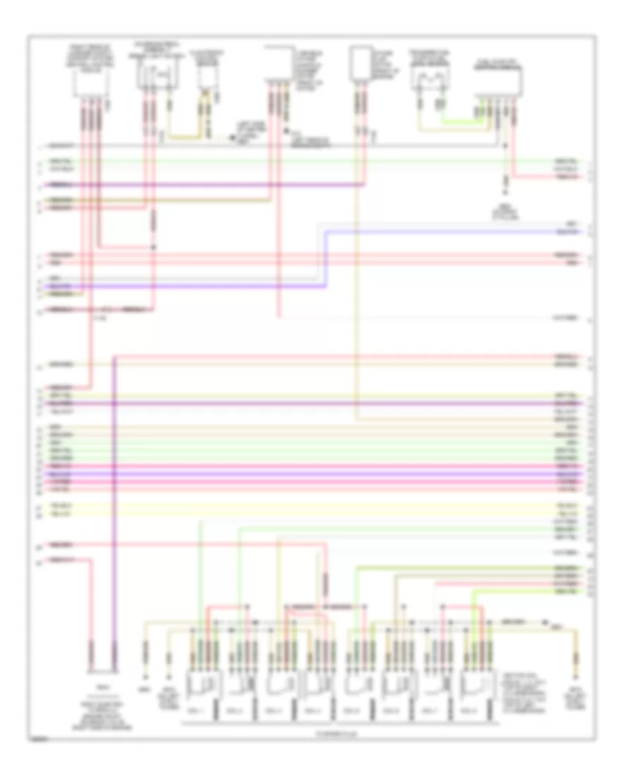
4.2L, Engine Performance Wiring Diagram (1 of 7) for Audi S5 4.2 2011
List of elements for 4.2L, Engine Performance Wiring Diagram (1 of 7) for Audi S5 4.2 2011:
- (in left plenum chamber) engine control module (ecm)
- (left rear of engine compt) g12
- 50a
- Brake booster pressure sensor
- Brake booster relay (on relay/ fuse carrier e-box-sb)
- Brake system vacuum pump
- Camshaft position (cmp) sensor 2 (top of left cylinder bank)
- Camshaft position (cmp) sensor 4 (left side of engine)
- Comfort system central control module (a/t) (right rear of luggage compt)
- Cooling fans system
- Cruise control system
- Direct shift gear box (dsg) mechatronic (at trans- mission)
- Fuse 10a
- Fuse 15a
- Fuse 30a
- Fuse 5a
- Fuse carrier 1
- G12 (left rear of engine compt)
- Gearbox
- Low fuel pressure sensor (left side of engine)
- Nca
- Oil level thermal sensor
- Oxygen sensor (02s) 2 behind three way catalytic convertor (twc) heater (in left exhaust)
- Oxygen sensor (o2s) behind three way catalytic convertor (twc) heater (in right exhaust)
- Power distribution system
- Red
- Relay/ fuse carrier e-box-sb (in left plenum chamber e box)
- Second- ary air injection (air) pump fuse
- Starting/ charging system
- Starting/charging system
- Suppressor
- T16r
- T17q
- T17r
- T32d
- T94
- Transmission control module
- Transmission control module (tcm) (a/t) (under tran- smission oil pan)
- W/ direct shift
- W/o direct shift gearbox
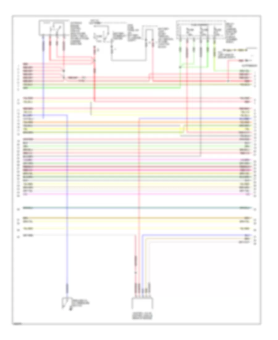
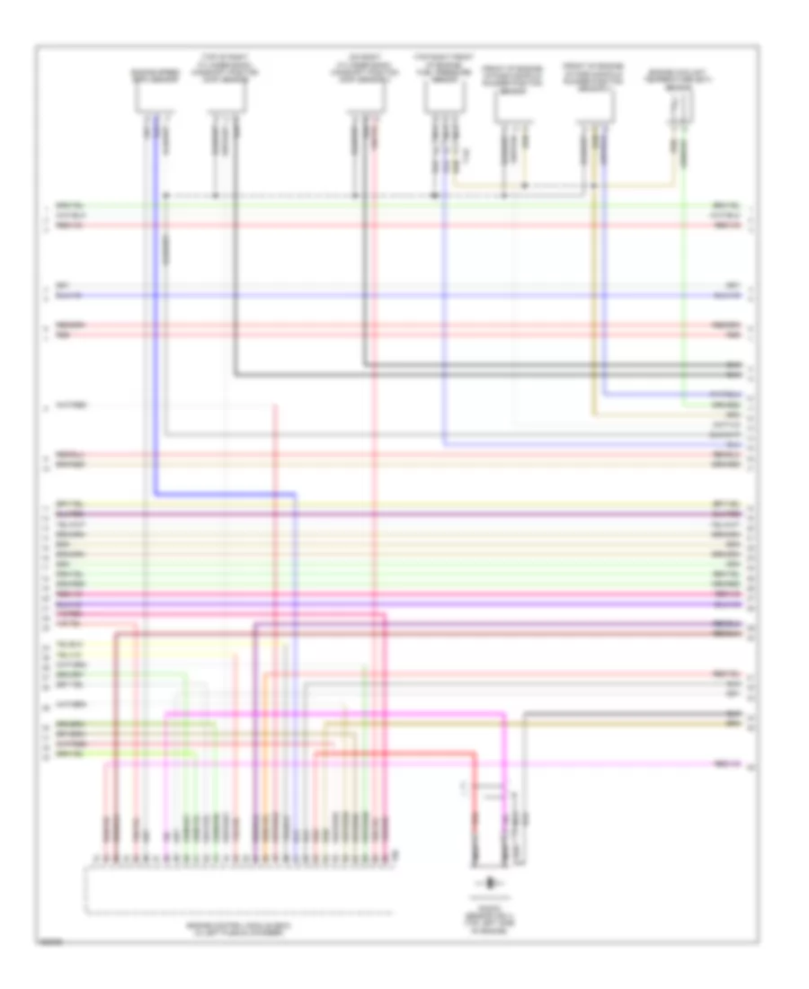
4.2L, Engine Performance Wiring Diagram (2 of 7) for Audi S5 4.2 2011
List of elements for 4.2L, Engine Performance Wiring Diagram (2 of 7) for Audi S5 4.2 2011:
- 10a
- 15a
- 17 pin connector t17q
- Brake vacuum pump fuse
- Evaporative emission (evap) canister purge regulator valve (at rear of engine)
- Fuel metering valve (top right side of engine)
- Fuel metering valve 2 (top left side of engine)
- Fuse 110a
- Fuse 15a
- Fuse carrier
- G615 (on left strut tower)
- Hot at all times
- Intake air switch-over valve (right front of engine compt)
- Leak detection pump (ldp)
- Left electro- hydraulic engine mount solenoid valve (left side of engine)
- Main fuse panel sa (on battery, in luggage compt)
- Mass air flow (maf)/ intake air temperature (iat) sensor (right side of engine compt)
- Nca
- Red
- Relay/ fuse carrier e-box sb (in left plenum chamber e-box)
- Secondary air injection (air) pump motor (below right headlight assembly)
- Secondary air injection (air) pump relay (on relay/fuse carrier e-box-sb)
- T17q
- Transmissions system
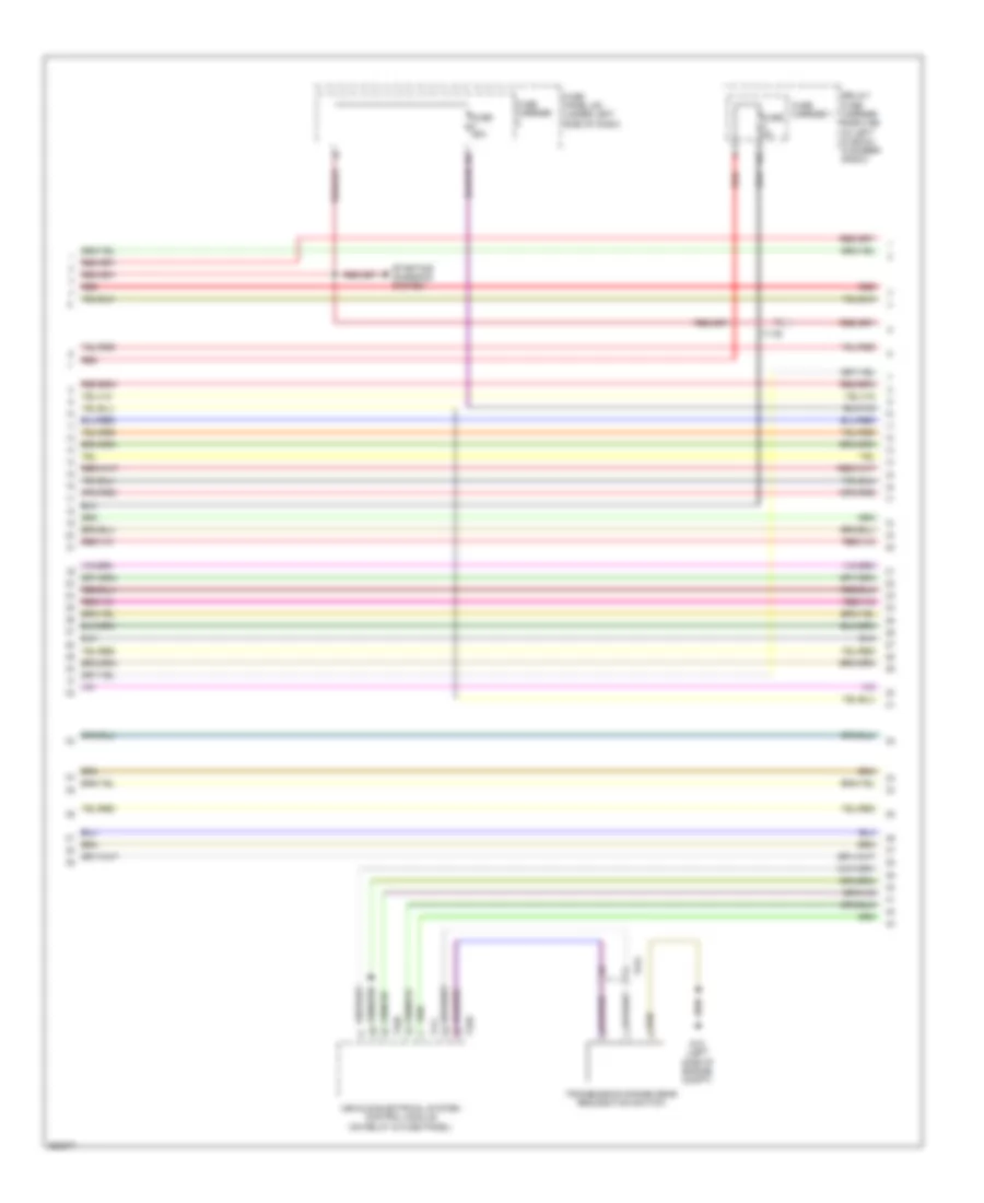
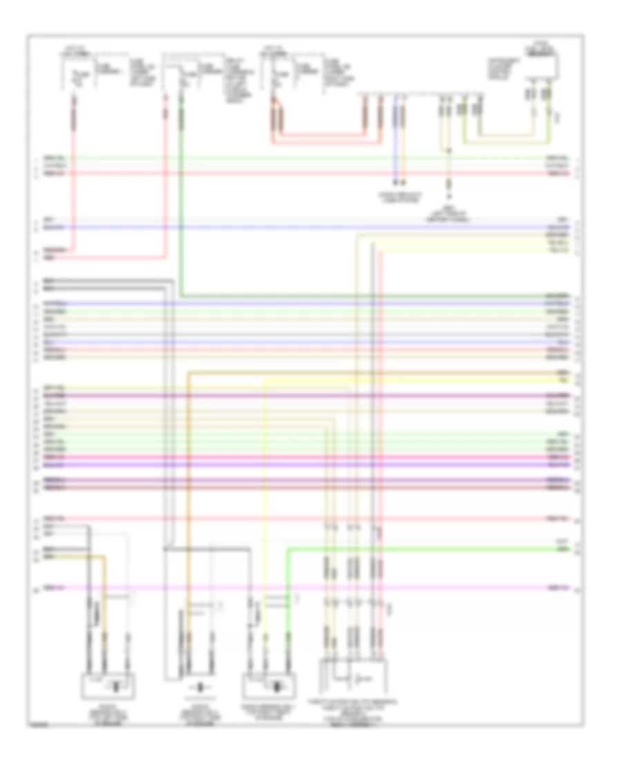
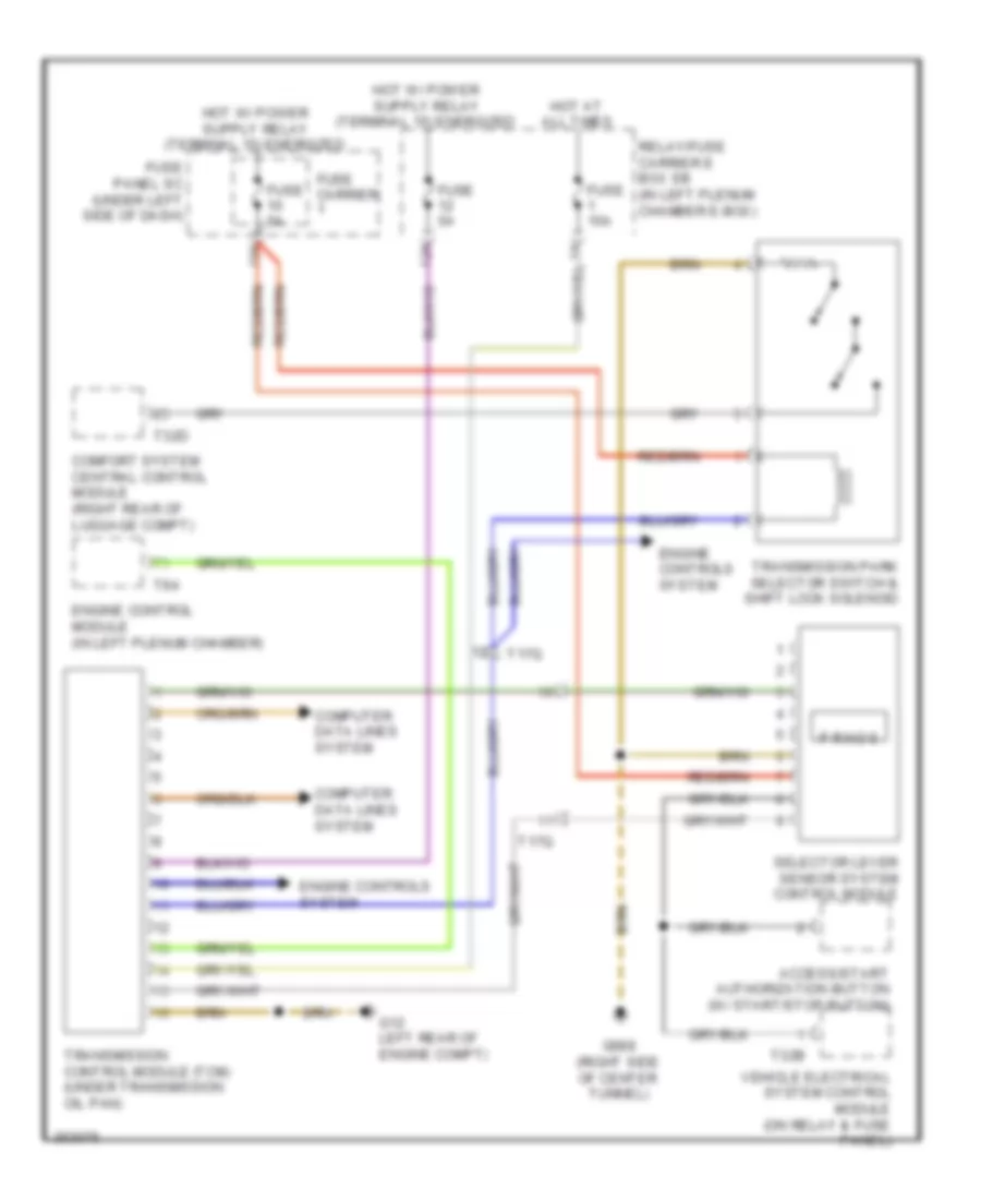
4.2L, Engine Performance Wiring Diagram (3 of 7) for Audi S5 4.2 2011
List of elements for 4.2L, Engine Performance Wiring Diagram (3 of 7) for Audi S5 4.2 2011:
- (if equipped) after-run coolant pump
- 17 pin connector (not used)
- Battery interrupt igniter
- Camshaft adjustment valve 1 (exhaust) (right rear of engine)
- Camshaft adjustment valve 1 (right rear of engine)
- Camshaft adjustment valve 2 (exhaust) (left rear of engine)
- Camshaft adjustment valve 2 (left rear of engine)
- Clutch position sensor (m/t)
- Comfort system central control module (m/t) (right rear of luggage compt)
- Coolant circulation pump relay (if equipped) (on relay/fuse carrier e-box-sb)
- Direct shift gearbox (dsg) mechatronic (at ransmission)
- Electro- mechanical parking brake control module (right rear of luggage compt)
- Fuse 25a
- Fuse 5a
- Fuse carrier
- Fuse panel sc (under left side of dash)
- G12 (left rear of engine compt)
- G639 (behind left kick panel)
- Hot at all times
- Main fuse panel sa (on battery, in luggage compt)
- Map control- led engine cooling thermostat
- Nca
- Red
- T16r
- T17q
- T30a
- T32d
- Terminal 30 wire junction 2
- Transmission control module (a/t) (under transmission oil pan)
- Transmission control module (tcm)
- Transmission park selector switch & shift lock solenoid (a/t)
- W/ direct shift gearbox
- W/o direct shift gearbox
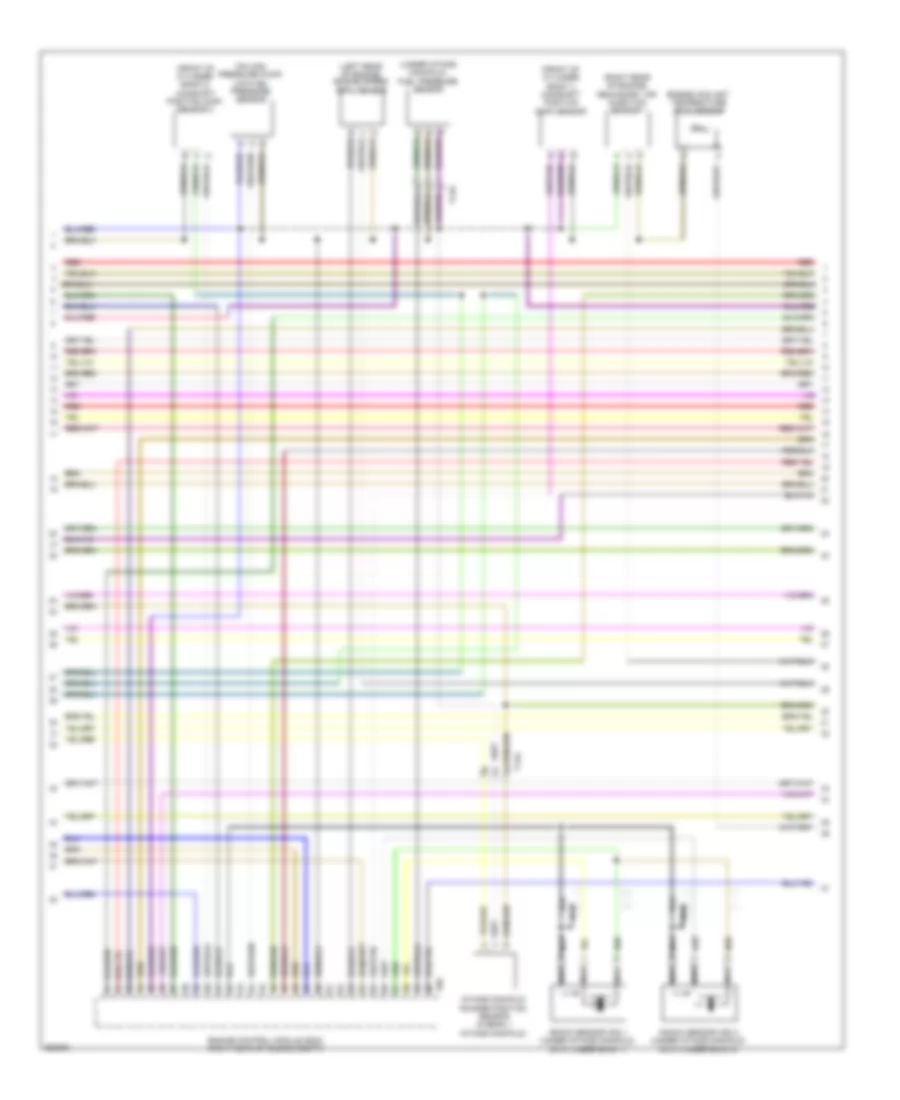
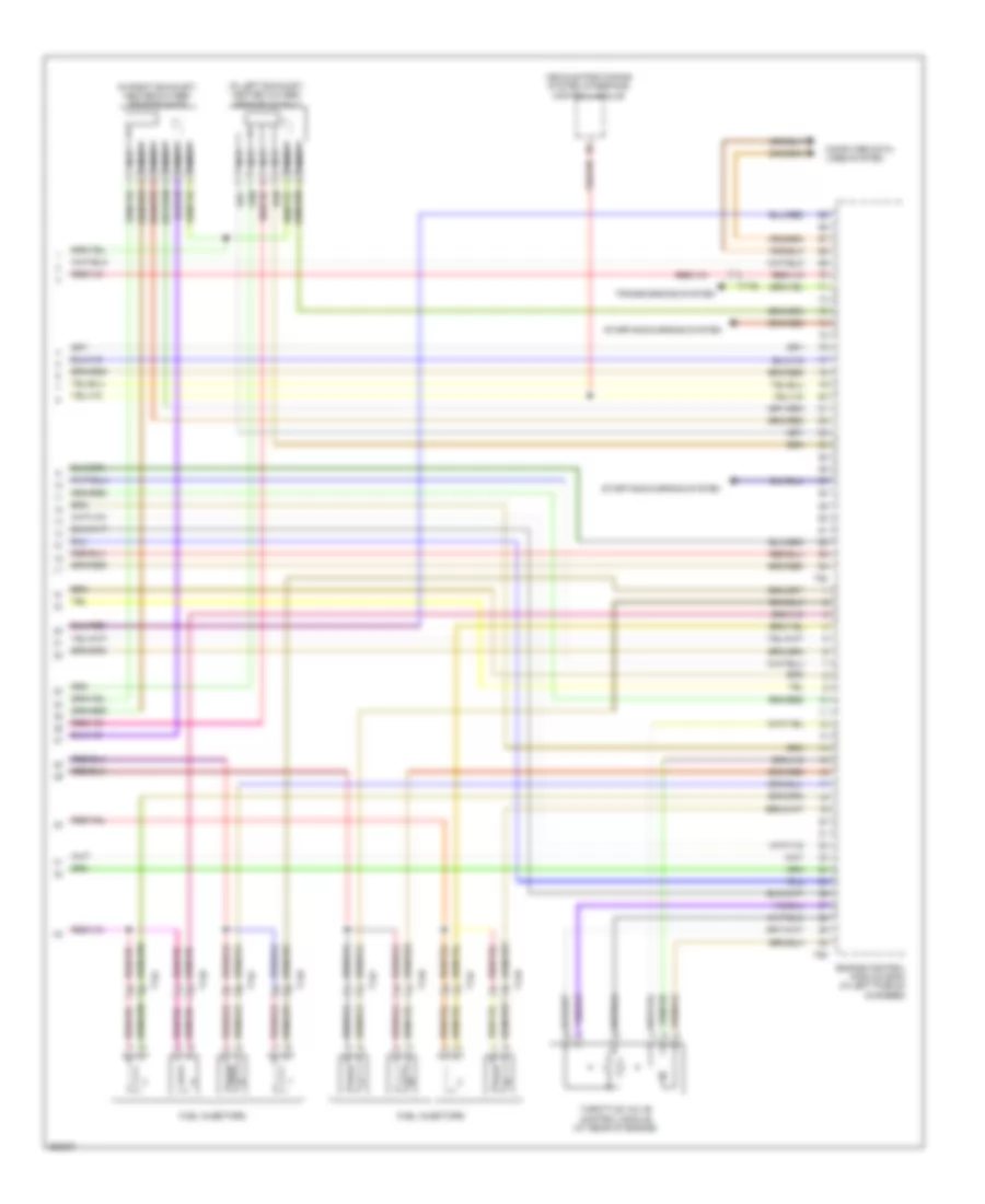
4.2L, Engine Performance Wiring Diagram (4 of 7) for Audi S5 4.2 2011
List of elements for 4.2L, Engine Performance Wiring Diagram (4 of 7) for Audi S5 4.2 2011:
- (left side of center tunnel) g687
- (on brake pedal assembly) brake light switch
- (right rear of luggage compt) comfort system central control module
- Climatronic control module
- Coil
- Coil 1
- Coil 2
- Coil 3
- Coil 4
- Coil 5
- Coil 6
- Coil 7
- Coil 8
- Fuel pump (fp) control module
- G12 (left rear of engine compt)
- G600
- G601
- G615 (on left strut tower)
- G663 (on right "c" pillar)
- Ignition coil (coils: 1, 2, 3 & 4 top of right cylinder bank) (coils: 5, 6, 7 & 8 top of left cylinder bank)
- Intake flap motor (front of engine)
- Nca
- Red
- Right electro- hydraulic engine mount solenoid valve (right side of engine)
- T14d
- T17e
- T17r
- T20e
- T32d
- To spark plug
- Transfer fuel pump & fuel level sensor
- Variable intake manifold runner motor (front of motor)
4.2L, Engine Performance Wiring Diagram (5 of 7) for Audi S5 4.2 2011
List of elements for 4.2L, Engine Performance Wiring Diagram (5 of 7) for Audi S5 4.2 2011:
- (front of engine) intake manifold runner position sensor
- (front of engine) intake manifold runner position sensor 2
- (on right cylinder bank) camshaft position (cmp) sensor 3
- (top of right cylinder bank) camshaft position (cmp) sensor
- (top right front of engine) fuel pressure sensor
- Engine control module (ecm) (in left plenum chamber)
- Engine coolant temperature (ect) sensor
- Engine speed (rpm) sensor
- Knock sensor (ks) 4 (top left side of engine)
- Nca
- Red
- T14c
- T60
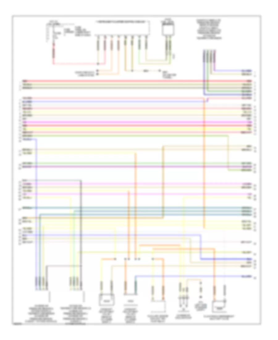
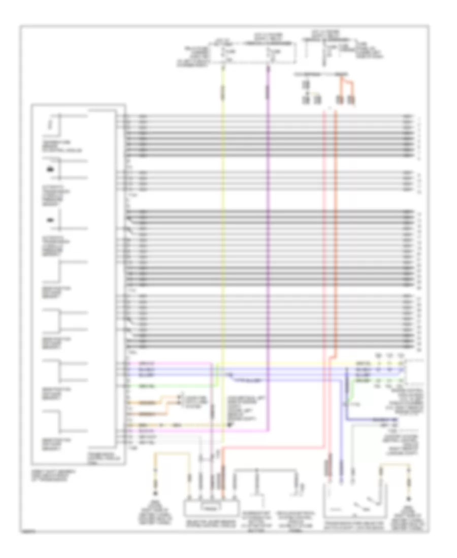
4.2L, Engine Performance Wiring Diagram (6 of 7) for Audi S5 4.2 2011
List of elements for 4.2L, Engine Performance Wiring Diagram (6 of 7) for Audi S5 4.2 2011:
- (awd) fuel level sensor 2
- 10a
- Computer data lines system
- Fuse 5a
- Fuse carrier
- Fuse carrier 1
- Fuse panel sc (under left side of dash)
- Fuse panel sd (under right side of dash)
- G687 (left side of center tunnel)
- Hot at all times
- Instrument cluster control module
- Knock sensor (ks) 1 (top right front of engine)
- Knock sensor (ks) 2 (top right side of engine)
- Knock sensor (ks) 3 (top left side of engine)
- Nca
- Red
- Relay/ fuse carrier e box sb (in left plenum chamber e-box)
- T17e
- T17f
- T17r
- Throttle position (tp) sensor & throttle position (tp) sensor 2 (top of accelerator pedal assembly)
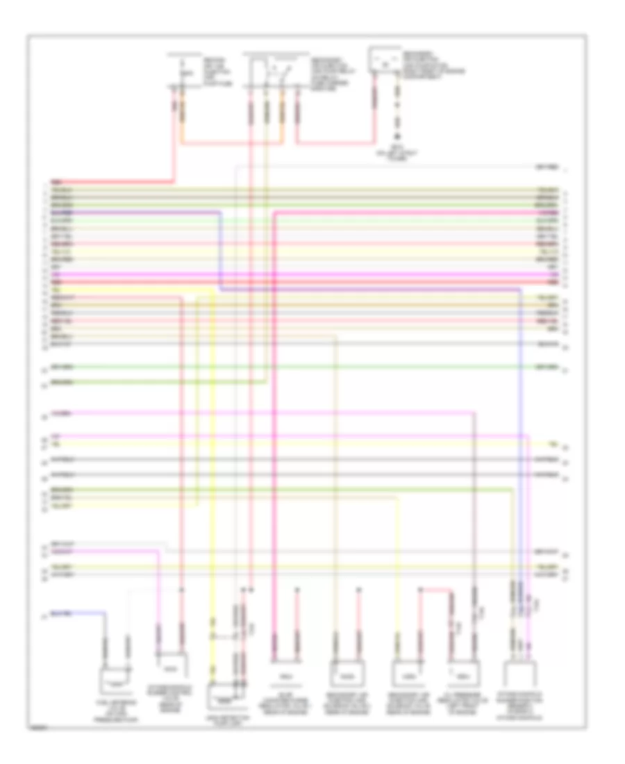
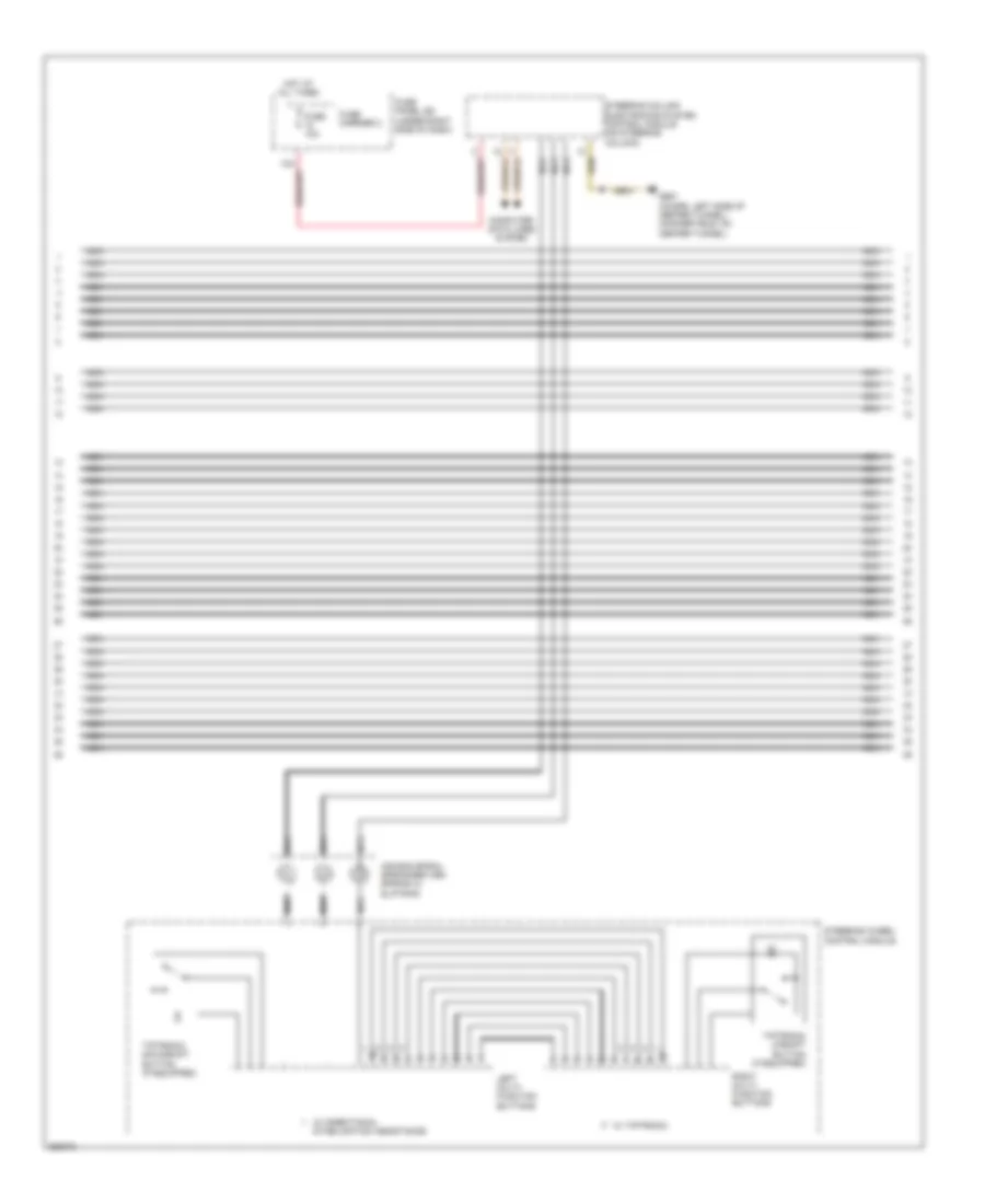
4.2L, Engine Performance Wiring Diagram (7 of 7) for Audi S5 4.2 2011
List of elements for 4.2L, Engine Performance Wiring Diagram (7 of 7) for Audi S5 4.2 2011:
- (in left exhaust) heated oxygen sensor (ho2s) 2
- (in right exhaust) heated oxygen sensor (h02s)
- Computer data lines system
- Engine control module (ecm) (in left plenum chamber)
- Fuel injectors
- Nca
- Starting/charging system
- T14c
- T14d
- T17q
- T60
- T94
- Throttle valve control module (at rear of engine)
- Transmissions system
- Vehicle positioning system interface control module
EXTERIOR LIGHTS
Backup Lamps Wiring Diagram for Audi S5 4.2 2011
List of elements for Backup Lamps Wiring Diagram for Audi S5 4.2 2011:
- (right side of luggage compt) g51
- 6 speed a/t
- Automatic day/ night interior mirror
- Backup
- Backup 2
- Backup lamp 1
- Backup lamp 2
- Comfort system central control module (right rear of luggage compt)
- Computer data lines system
- Convertible
- Coupe
- Cvt
- Direct shift gearbox (dsg) mechatronic (at transmission)
- Fuse 30a
- Fuse carrier
- G50 (left side of luggage compt)
- G51 (right side of luggage compt)
- G688 (coupe: right side of center tunnel) (convertible: on center tunnel)
- Hot at all times
- Left rear taillamp assembly 1
- Left rear taillamp assembly 2
- Prnds
- Relay/ fuse carrier luggage compartment sf (right side of luggage compt)
- Right rear taillamp assembly 1
- Right rear taillamp assembly 2
- Selector level sensor system control module
- T16r
- T17o
- T17p
- T17q
- T32c
- T8c
- Transmission control module (tcm)
- Transmission control module (tcm) (under transmission oil pan)
- Trunk lid alarm switch
- W/ direct shift
- W/ led rear lights
- W/o direct shift
- W/o led rear lights
Exterior Lamps Wiring Diagram (1 of 3) for Audi S5 4.2 2011
List of elements for Exterior Lamps Wiring Diagram (1 of 3) for Audi S5 4.2 2011:
- (convertible: on center tunnel) (coupe: left side of center tunnel) g687
- (convertible: on center tunnel) g687 (coupe: left side of center tunnel)
- (w/o bi-xenon)
- 12a
- 14a
- 2.0l turbo
- 3.0l
- 4.2l
- A/c control head climatronic control module (behind center of dash)
- Brake light switch (on brake pedal assembly)
- Computer data lines system
- Emergency flasher button
- Emergency flasher ind lamp
- Engine control module (ecm) (3.0: right rear of engine compt) (2.0l turbo & 4.2l: in left plenum chamber)
- Fog lamp button
- Front side marker lamp
- Front turn signal lamp
- Front turn signal/ side marker lamp
- Fuse 30a
- Fuse 5a
- Fuse carrier
- Fuse panel sc (under side of dash)
- Fuse panel sd (under right side of dash)
- G638 (convertible: right "a" pillar) (coupe: behind right kick panel)
- G639 (convertible: left kick panel) (coupe: behind left kick panel)
- G687 (convertible: on center tunnel) (coupe: left side of center tunnel)
- Hot at all times
- Instrument panel illumination dimmer switch
- Left headlight assembly
- Light switch
- Nca
- Park ing lamp
- Park- ing lamp
- Power distribution system
- Rear fog lamp button
- Relay/ fuse carrier luggage compartment sf (right side of luggage compt)
- Right headlight assembly
- Steering column electronic systems control module (on steering column)
- T12d
- T12k
- T16b
- T16f
- T17e
- T17f
- T17m
- T17n
- T17r
- T20e
- T32a
- T94
- Towing recognition control module (right rear of luggage compt)
- Turn signal switch
- Vehicle electrical system control module (on relay & fuse panel)
- W/ bi-xenon
- W/o bi-xenon
Exterior Lamps Wiring Diagram (2 of 3) for Audi S5 4.2 2011
List of elements for Exterior Lamps Wiring Diagram (2 of 3) for Audi S5 4.2 2011:
- Backup lamp 2
- Backup lamps circuit
- Brake/ turn signal/ taillamp 2
- Clutch position sensor (m/t)
- Comfort system central control module (right rear of luggage compt)
- Convertible
- Coupe
- Front side marker lamp
- Front turn single lamp
- G51 (right side of luggage compt)
- G638 (convertible: right "a" pillar) (coupe: behind right kick panel)
- G639 (convertible: left kick panel) (coupe: behind left kick panel)
- Interior lights system
- Left headlight assembly (w/ bi-xenon)
- Left rear taillamp assembly 2 (w/ led rear lights)
- Left rear taillamp assembly 2 (w/o led rear lights)
- Parking lamp
- Parking/ fog lamp
- Right headlight assembly (w/ bi-xenon)
- T17o
- T17p
- T32c
- T32d
- T4ad
- T4ae
- Trunk lid alarm switch
- Valet parking ind lamp
- Valet parking lock button
- W/ led rear lights
- W/o led rear lights
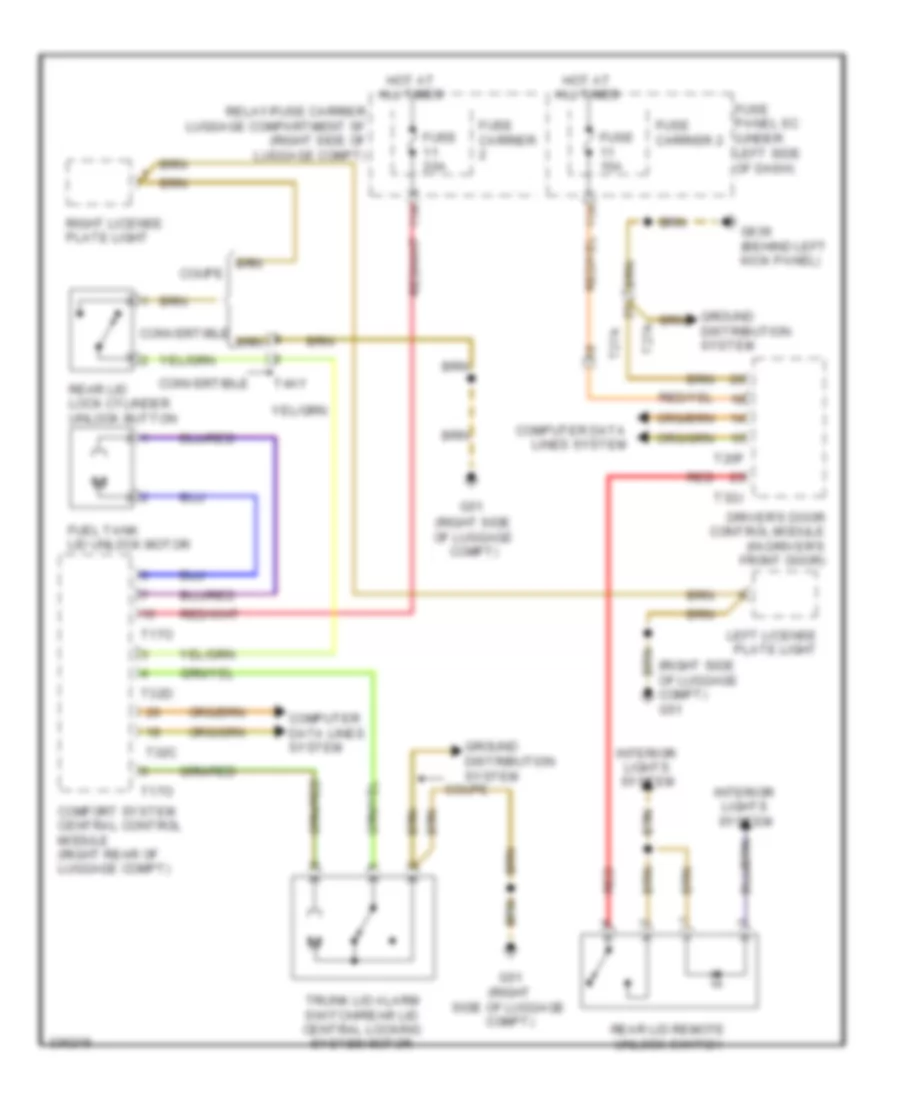
Exterior Lamps Wiring Diagram (3 of 3) for Audi S5 4.2 2011
List of elements for Exterior Lamps Wiring Diagram (3 of 3) for Audi S5 4.2 2011:
- (right side of luggage compt)
- (w/ led rear lights)
- Backup lamp 1
- Backup lamp 2
- Backup lamps circuit
- Brake/ turn signal lamp
- Brake/ turn signal lamp 2
- Brake/ turn signal/ tail lamp
- Brake/ turn signal/ tail lamp 2
- Convertible
- Coupe
- G50 (left side of luggage compt)
- G51
- G51 (right side of luggage compt)
- G690
- High-mount brake light
- Left license plate light
- Left rear taillamp assembly 1
- Left rear taillamp assembly 1 (w/o led rear lights)
- Parking/ fog lamp
- Rear lid lock cylinder unlock button
- Right license plate light
- Right rear taillamp assembly 1 (w/ led rear lights)
- Right rear taillamp assembly 1 (w/o led rear lights)
- Right rear taillamp assembly 2 (w/ led rear lights)
- Right rear taillamp assembly 2 (w/o led rear lights)
- Side marker lamp
- T4ay
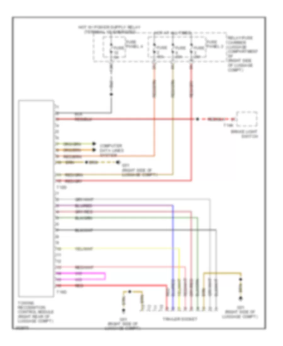
Trailer Tow Wiring Diagram for Audi S5 4.2 2011
List of elements for Trailer Tow Wiring Diagram for Audi S5 4.2 2011:
- (right side of luggage compt)
- 12a
- Brake light switch
- Computer data lines system
- Fuse 15a
- Fuse 20a
- Fuse 5a
- Fuse panel 2
- Fuse panel 4
- G51
- G51 (right side of luggage compt)
- Hot at all times
- Red
- Relay/fuse carrier luggage compartment sf (right side of luggage compt)
- T12d
- T14k
- T16d
- Towing recognition control module (right rear of luggage compt)
- Trailer socket
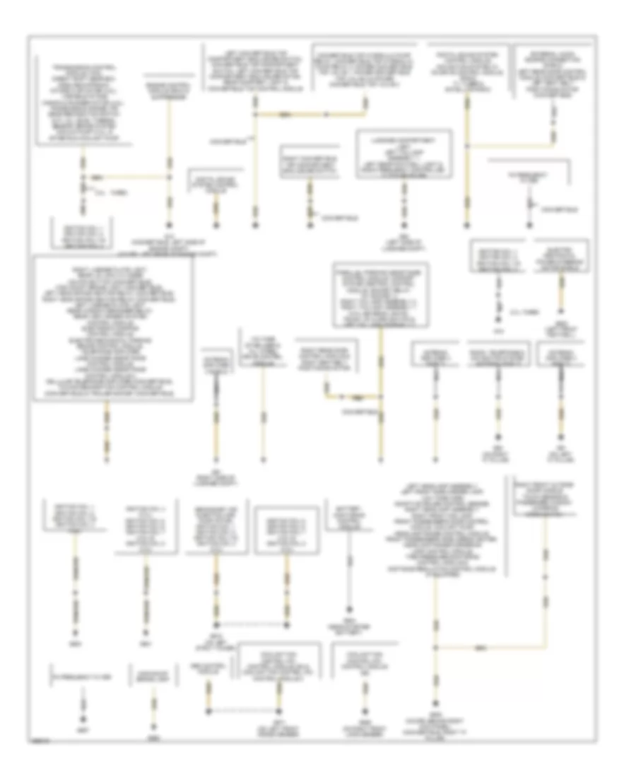
GROUND DISTRIBUTION
Ground Distribution Wiring Diagram (1 of 2) for Audi S5 4.2 2011
List of elements for Ground Distribution Wiring Diagram (1 of 2) for Audi S5 4.2 2011:
- (on right "c" pillar)
- 2.0l
- 2.0l turbo
- Abs control module
- Antenna amplifier 3 shield
- Battery monitoring control module
- Convertible
- Convertible top hydraulic pump relay, convertible top hydraulic pump relay 2, power convertible top valve 1, power convertible top valve 2 & power convertible top valve 3
- Coolant fan control (fc) control module (a5) & coolant fan control (fc) control module 2
- Coolant fan control (fc) control module (s5)
- Digital sound system control module
- Digital sound system control module, navigation system w/ cd drive control module, radio, tv tuner & satellite radio
- Electro mechanical power steering motor shield
- Engine control module (ecm) & suppressor
- External audio source connection shield, left rear door control module (convertible) & left seat belt positioning motor (convertible)
- Fm frequency filter
- G12 (convertible: left side of engine compt) (coupe: left rear of engine compt)
- G15
- G50 (left side of luggage compt)
- G51 (right side of luggage compt)
- G600
- G601
- G602 (left front footwell)
- G61 (on left "c" pillar)
- G615 (on left strut tower)
- G62
- G624 (near starter battery)
- G638 (coupe: behind right kick panel) (convertible: right "a" pillar)
- G657
- G671 (on left front cross member)
- G685 (on right front long member)
- G690
- High-mount brake light
- Ignition coil 1, ignition coil 2, ignition coil 3 & ignition coil 4
- Ignition coil 1, ignition coil 2, ignition coil 3 & ignition coil 4 (4.2l)
- Ignition coil 4 (3.2l), ignition coil 5, ignition coil 6, ignition coil 7 (4.2l) & ignition coil 8 (4.2l)
- Ignition coil 5, ignition coil 6, ignition coil 7 (4.2l) & ignition coil 8 (4.2l)
- Left convertible top compartment enclosure switch, convertible top compartment switch, left convertible top compartment enclosure motor, rear courtesy light & convertible top control module
- Left headlamp assembly, left front side marker lamp, low tone horn, adaptive cruise control sensor, right headlamp assembly, right front fog lamp, front passenger's door control module, coolant pump, headlamp range control module, front passenger's side airbag igniter, headlamp range/cornering lamp control module, tire pressure monitoring control module & distance regulation control module (if equipped)
- Luggage compartment light, left taillamp assembly 1, left rear footwell light & radio frequency controlled clock receiver
- Nca
- Parallel parking assistance control module, comfort system central control module, socket relay, 12v socket 3, right taillamp assembly 2, right taillamp assembly 1 (w/o led rear lights), trunk lid alarm switch & left taillamp assembly 2
- Radio, telephone & navigation system antenna shield
- Right convertible top compartment enclosure switch
- Right front outside door handle touch sensor & passenger window lowering micro switch
- Right license plate light, rear lid lock cylinder unlock button (convertible), high mount brake light (convertible), left head space heating relay (convertible), right head space heating relay (convertible), left license plate light, rear window defogger relay, rear view camera system control module, electronic damping control module, electro-mechanical parking brake control module, telephone amplifier, lane change assistance control module, lane change assistance control module 2, cellular telephone amplifier (convertible), towing recognition control module (convertible) & trailer socket (convertible)
- Right rear door control module & right seat belt positioning motor
- Secondary air injection (air) pump motor, ignition coil 1, ignition coil 2, ignition coil 3 & ignition coil 4 (4.2l)
- Transmission control module (tcm), direct shift gear box (dsg) mechatronic, intake flap motor (4.2l), variable intake manifold runner motor (4.2l), transmission range (tr) gear recognition switch (m/t), oil level thermal sensor, brake system vacuum pump (4.2l), & after run coolant pump
- Turbo
- Voltage stabilizer & all wheel drive control module
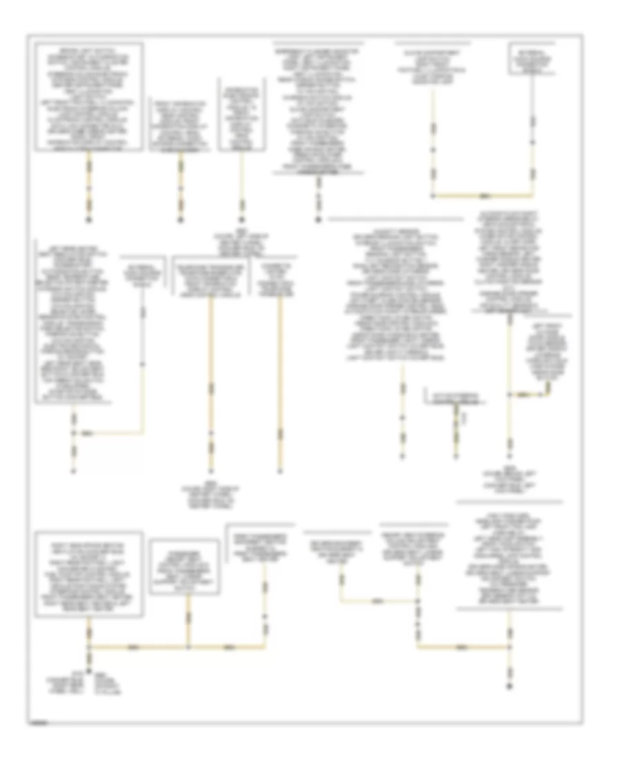
Ground Distribution Wiring Diagram (2 of 2) for Audi S5 4.2 2011
List of elements for Ground Distribution Wiring Diagram (2 of 2) for Audi S5 4.2 2011:
- Active steering control module
- Automatic day/night interior mirror relay, vehicle electrical system control module, wiper motor control module, alarm horn, left front brake pad wear sensor, left washer nozzle heater, right washer nozzle heater, driver's door control module, clutch position sensor (m/t), garage door opener control module, air quality sensor & esp sensor unit
- Brake light switch, access/start authorization switch, instrument cluster control module, steering column electronic systems control module, center instrument panel vent illumination, light switch, left front footwell illumination, electronic steering column lock control module climatronic control module, data link connector (dlc), driver's knee airbag igniter, radio, front information display control head & 12-pin connector
- Cigarette lighter, 18 pin connector & telephone transceiver
- Driver's backrest heating element & driver's seat
- Emergency flasher indicator lamp, left instrument panel vent illumination, right instrument panel vent illumination, rear window shade switch, asr/esp button, (w/ navigation), charisma switch module (w/ navigation), glove compartment lamp switch, data bus on board diagnostic interface, parking aid button (w/ navigation), front passenger's knee air bag igniter, fresh air blower control module & front passenger's knee air bag igniter
- External audio source connection shield
- Front information display control head control module, front information display control head, external audio source connection & cd changer
- Front passenger's backrest heating element & front passenger's seat heater
- G639 (coupe: behind left kick panel) (convertible: left kick panel)
- G663 (coupe) (on right "c" pillar)
- G687 (coupe: left side of center tunnel) (convertible: on center tunnel)
- G688 (coupe: right side of center tunnel) (convertible: on center tunnel)
- G730 (convertible) (right rear wheel well)
- Glove compartment lamp switch, right front footwell illumination & valet parking indicator lamp
- Heater
- High tone horn, headlamp washer pump, left front fog lamp, horn relay, left headlamp assembly, front hood switch, left high intensity gas discharge lamp control module, driver's side air bag igniter, driver's seat lumbar support adjustment switch, a/c pressure/ temperature sensor, esp sensor unit 2 & driver's seat heater
- Humidity sensor, driver's reading light button, interior illumination switch, front passenger's reading light button, tilt sunroof button 1, rain/light recognition sensor, driver's make up mirror, light contact switch, front passenger's make up mirror, light contact switch, power sunroof control module, anti-theft alarm system sensor, garage door opener control head, automatic day/night interior mirror, directional stabilization assistance control module & directional stabilization assistance windshield heater, front passenger vanity mirror, light contact switch (covertible), driver vanity mirror & light contact switch (covertible),
- Information electronics control module 1 & front information display control head control module
- Left front outside door handle touch sensor, driver window lowering micro switch & lane change assistance button
- Left rear heated seat regulating switch (convertible), access/start authorization button, rear temperature selection potentiometer, charisma switch module, (w/o navigation) asr/esp button, (w/o navigation) selector lever sensor system control module, transmission park selector switch, parking aid button, (w/o navigation) electro-mechanical parking brake button, 12v socket, left rear seat head restraint adjustment button & convertible top operation switch (if equipped) start/stop mode button (convertible)
- Memory seat/steering column adjustment control module & driver's seat lumbar support adjustment switch
- Passenger memory seat control module & front passenger's seat lumbar support adjustment switch
- Right head space heating ventilation (convertible), 12v socket 2, right rear footwell light, converter w/ socket, fuel pump (fp) control module, right rear footwell light, vehicle positioning system interface control module, front passenger's seat heater, right rear seat heater & left rear seat heater
- T17e
- Telephone transceiver, telephone baseplate, 18-pin connector & front information display control head control module
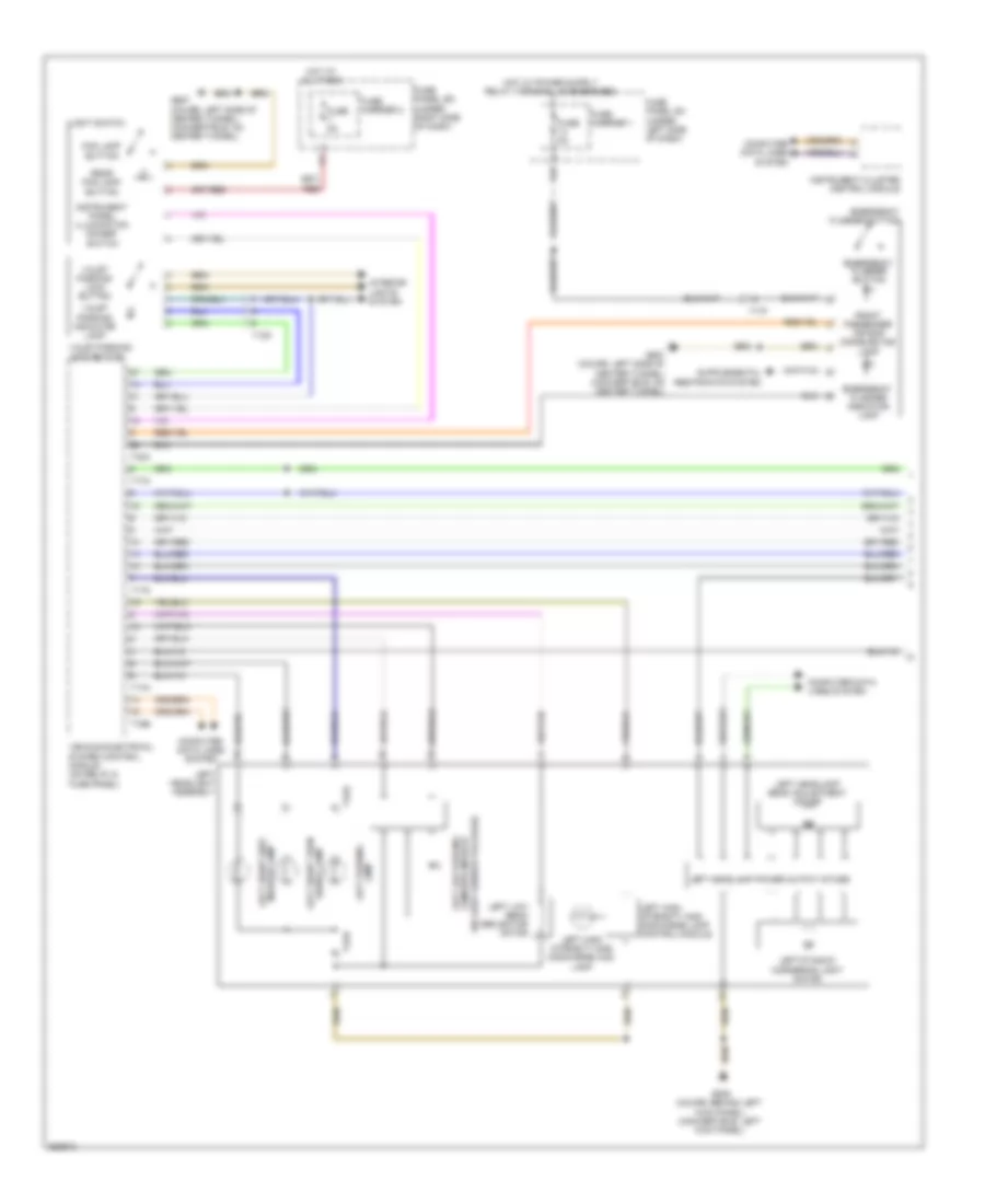
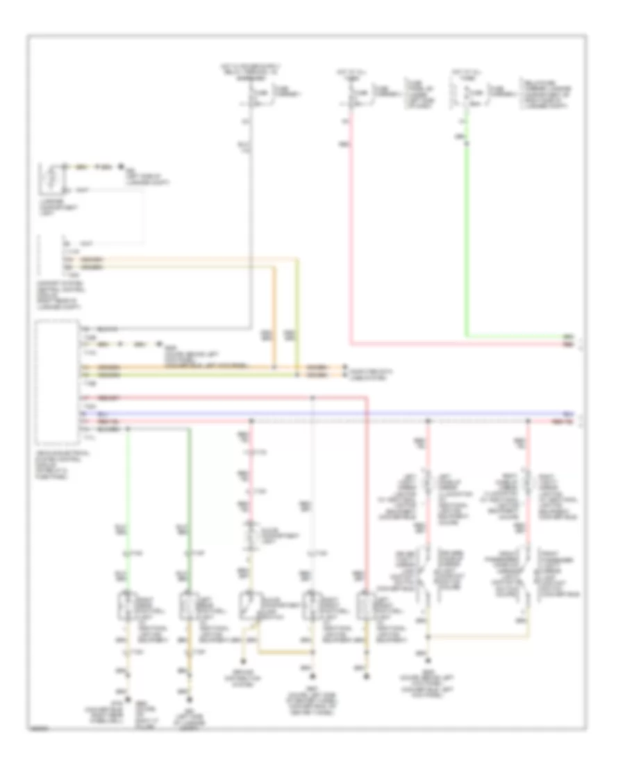
HEADLIGHTS
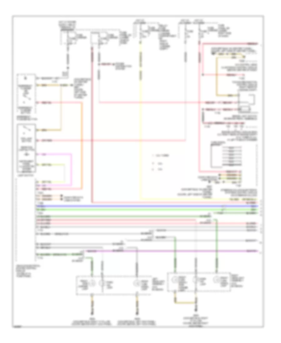
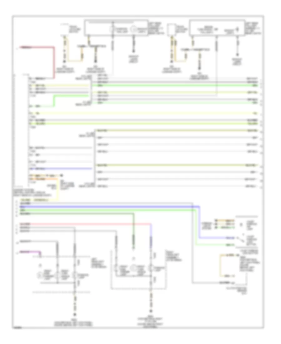
Headlights Wiring Diagram, with Bi-Xenon with Cornering Headlights (1 of 2) for Audi S5 4.2 2011
List of elements for Headlights Wiring Diagram, with Bi-Xenon with Cornering Headlights (1 of 2) for Audi S5 4.2 2011:
- (w/ light sensor package) lamp/drl module left led parking
- 14a
- Computer data lines system
- Emergency flasher button
- Emergency flasher indicator lamp
- Fog lamp button
- Front passenger air bag disabled ind lamp
- Fuse 5a
- Fuse carrier 1
- Fuse carrier 2
- Fuse panel sc (under left side of dash)
- Fuse panel sd (under right side of dash)
- G639 (coupe: behind left kick panel) (convertible: left kick panel)
- G687 (coupe: left side of center tunnel) (convertible: on center tunnel)
- Hot at all times
- Instrument cluster control module
- Instrument panel illumination dimmer switch
- Interior lights system
- Left dynamic cornering light motor
- Left headlamp beam adjustment motor
- Left headlamp power output stage
- Left headlight assembly
- Left high intensity gas discharge (hid) lamp
- Left high intensity gas discharge lamp control module
- Left low beam reflector motor
- Left parking lamp
- Light switch
- Marker lamp left front side
- Rear fog lamp button
- Signal lamp left front turn
- T12k
- T16b
- T17f
- T17m
- T17n
- T32a
- T4ad
- Valet parking indicator lamp
- Valet parking lock button
- Vehicle electrical system control module (on relay & fuse panel)
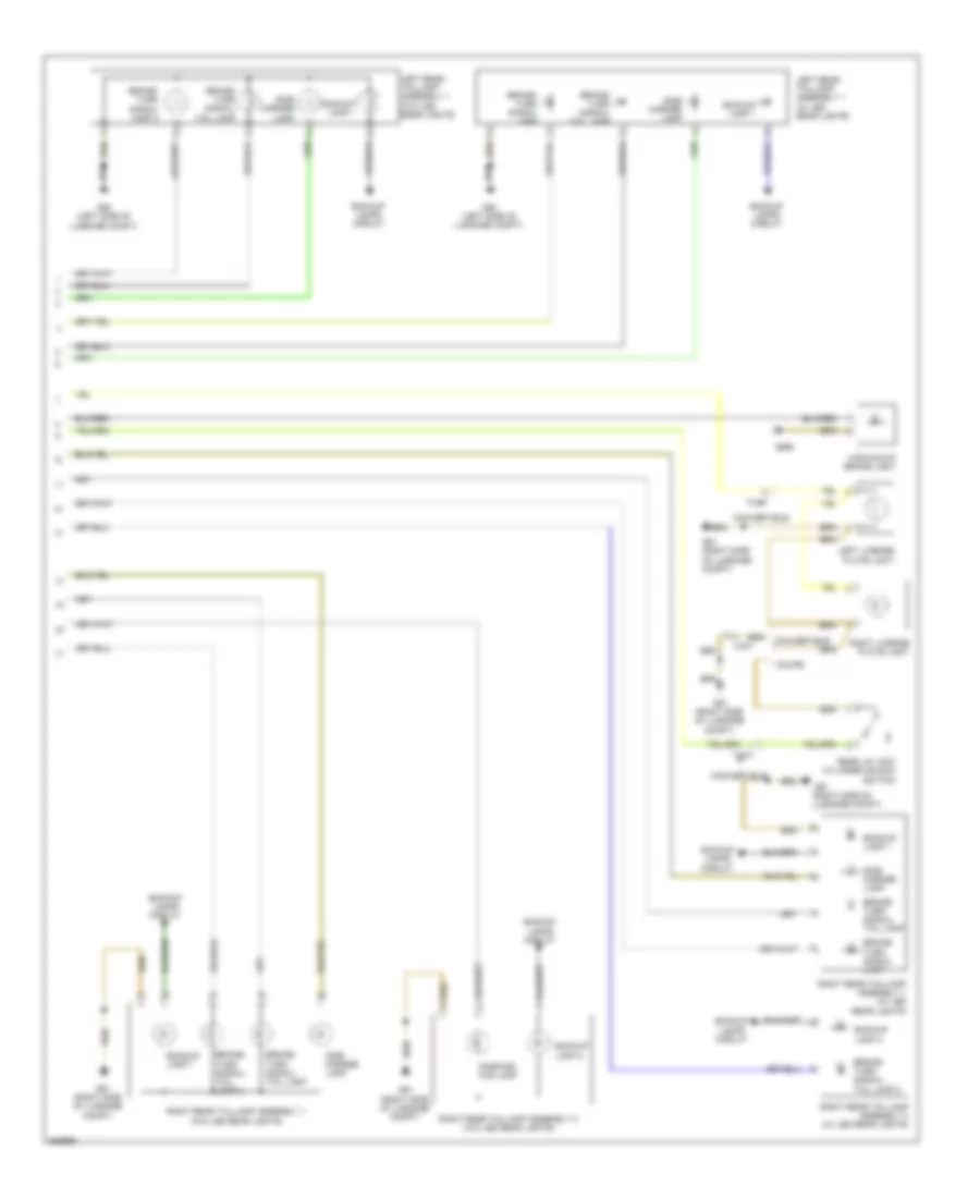
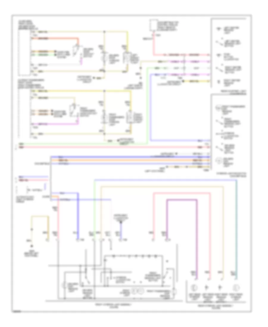
Headlights Wiring Diagram, with Bi-Xenon with Cornering Headlights (2 of 2) for Audi S5 4.2 2011
List of elements for Headlights Wiring Diagram, with Bi-Xenon with Cornering Headlights (2 of 2) for Audi S5 4.2 2011:
- (w/ light sensor package) lamp/drl module right led parking
- Computer data lines system
- Discharge (hid) lamp
- Fuse 5a
- Fuse carrier 1
- Fuse panel sc (under left side of dash)
- G638 (coupe: behind right kick panel) (convertible: right "a" pillar)
- G639 (coupe: behind left kick panel) (convertible: left kick panel)
- Headlight range/ cornering lamp control module (above glove box)
- Lamp
- Left front fog lamp
- Left front level control system sensor (w/o electronic damping) (at left front side of front axle)
- Left rear level control system sensor (w/o electronic damping) (at left rear side of rear axle)
- Marker lamp right front side
- Right dynamic cornering light motor
- Right front fog lamp
- Right front turn signal lamp
- Right headlamp beam adjustment motor
- Right headlamp power output stage
- Right headlight assembly
- Right high intensity gas
- Right high intensity gas discharge lamp control module
- Right low beam reflector motor
- Right parking
- T4ae
Headlights Wiring Diagram, with Bi-Xenon without Cornering Headlights (1 of 2) for Audi S5 4.2 2011
List of elements for Headlights Wiring Diagram, with Bi-Xenon without Cornering Headlights (1 of 2) for Audi S5 4.2 2011:
- (w/ light sensor package)
- 14a
- Computer data lines system
- Emergency flasher button
- Emergency flasher indicator lamp
- Fog lamp button
- Front passenger air bag disabled ind lamp
- Fuse 5a
- Fuse carrier 1
- Fuse carrier 2
- Fuse panel sc (under left side of dash)
- Fuse panel sd (under right side of dash)
- G639 (coupe: behind left kick panel) (convertible: left kick panel)
- G687 (coupe: left side of center tunnel) (convertible: on center tunnel)
- Hot at all times
- Instrument cluster control module
- Instrument panel illumination dimmer switch
- Interior lights system
- Lamp/drl module left led parking
- Left headlamp beam adjustment motor
- Left headlight assembly
- Left high intensity gas discharge (hid) lamp
- Left high intensity gas discharge lamp control module
- Left low beam reflector motor
- Left parking lamp
- Light switch
- Marker lamp left front side
- Rear fog lamp button
- Signal lamp left front turn
- T12k
- T16b
- T17f
- T17m
- T17n
- T32a
- T4ad
- Valet parking indicator lamp
- Valet parking lock button
- Vehicle electrical system control module (on relay & fuse panel)
Headlights Wiring Diagram, with Bi-Xenon without Cornering Headlights (2 of 2) for Audi S5 4.2 2011
List of elements for Headlights Wiring Diagram, with Bi-Xenon without Cornering Headlights (2 of 2) for Audi S5 4.2 2011:
- (w/ light sensor package) lamp/drl module right led parking
- Computer data lines system
- Fuse 5a
- Fuse carrier 1
- Fuse panel sc (under left side of dash)
- G638 (coupe: behind right kick panel) (convertible: right "a" pillar)
- G639 (coupe: behind left kick panel) (convertible: left kick panel)
- Headlight range control module (above glove box)
- Left front fog lamp
- Left front level control system sensor (w/o electronic damping) (at left front side of front axle)
- Left rear level control system sensor (w/o electronic damping) (at left rear side of rear axle)
- Marker lamp right front side
- Right front fog lamp
- Right front turn signal lamp
- Right headlamp beam adjustment motor
- Right headlight assembly
- Right high intensity gas discharge (hid) lamp
- Right high intensity gas discharge lamp control module
- Right low beam reflector motor
- Right parking lamp
- T4ae
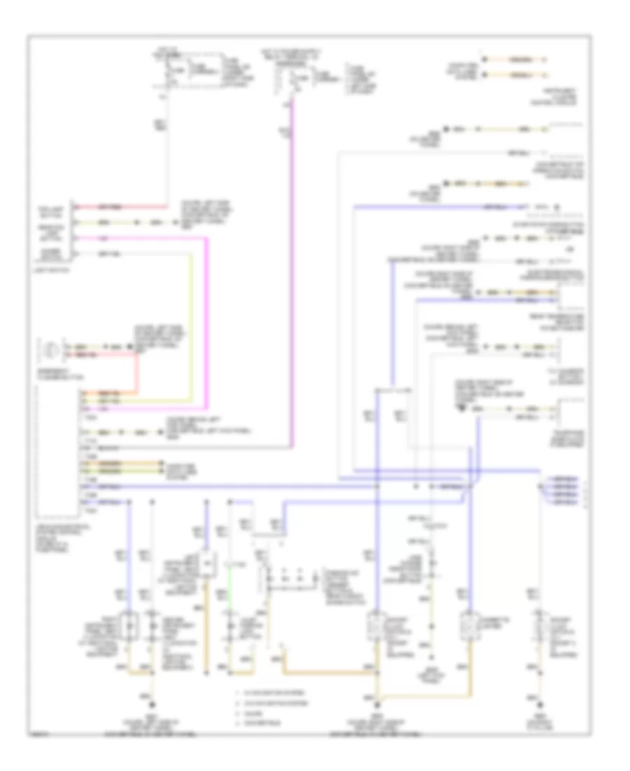
Headlights Wiring Diagram, without Bi-Xenon Headlights for Audi S5 4.2 2011
List of elements for Headlights Wiring Diagram, without Bi-Xenon Headlights for Audi S5 4.2 2011:
- 10a
- 14a
- Computer data lines system
- Emergency flasher button
- Emergency flasher indicator lamp
- Fog lamp button
- Front passenger air bag disabled ind lamp
- Fuse 30a
- Fuse 5a
- Fuse carrier 1
- Fuse carrier 2
- Fuse carrier 3
- Fuse panel sc (under left side of dash)
- Fuse panel sd (under right side of dash)
- G638 (coupe: behind right kick panel) (convertible: right "a" pillar)
- G639 (coupe: behind left kick panel) (convertible: left kick panel)
- G687 (coupe: left side of center tunnel) (convertible: on center tunnel)
- Headlamp right low beam
- Hot at all times
- Instrument cluster control module
- Instrument panel illumination dimmer switch
- Interior lights system
- Lamp left parking
- Lamp right parking
- Left front fog lamp
- Left front side marker lamp
- Left headlight assembly
- Left high beam headlamp
- Left low beam headlamp
- Light switch
- Marker lamp
- Rear fog lamp button
- Right front fog lamp
- Right headlight assembly
- Right high beam headlamp
- Sensor package) (w/ light (drl) lamp running light left daytime
- Sensor package) (w/ light (drl) lamp running light right daytime
- Signal lamp left front turn
- Signal lamp right front turn
- Signal/side left front turn
- T12k
- T16b
- T17f
- T17m
- T17n
- T32a
- Valet parking indicator lamp
- Valet parking lock button
- Vehicle electrical system control module (on relay & fuse panel)
HORN
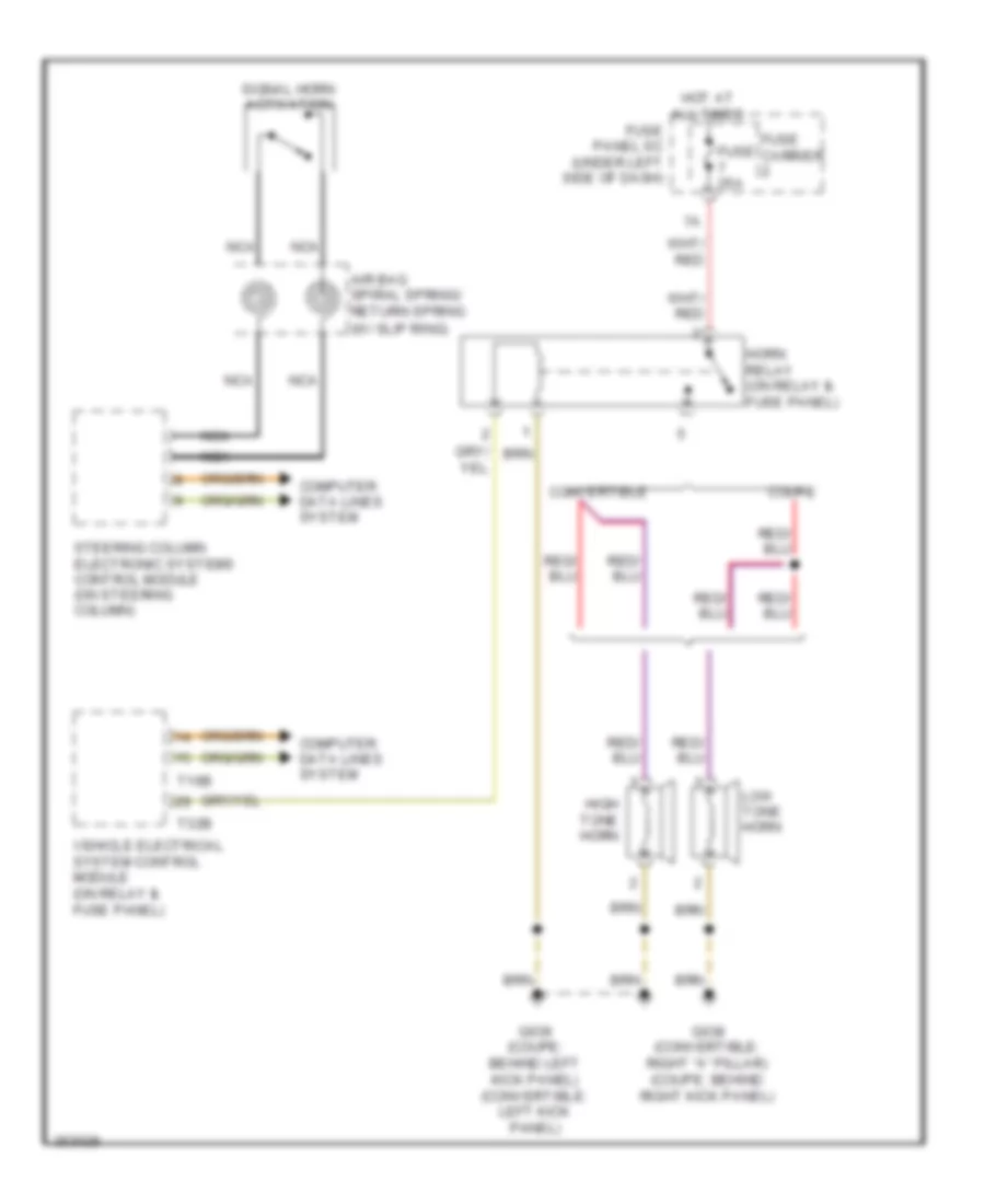
Horn Wiring Diagram for Audi S5 4.2 2011
List of elements for Horn Wiring Diagram for Audi S5 4.2 2011:
- Air bag spiral spring/ return spring (w/ slip ring)
- Computer data lines system
- Convertible
- Coupe
- Fuse 25a
- Fuse carrier
- Fuse panel sc (under left side of dash)
- G638 (convertible: right "a" pillar) (coupe: behind right kick panel)
- G639 (coupe: behind left kick panel) (convertible: left kick panel)
- High tone horn
- Horn relay (on relay & fuse panel)
- Hot at all times
- Low tone horn
- Nca
- Signal horn activation
- Steering column electronic systems control module (on steering column)
- T16b
- T32b
- Vehicle electrical system control module (on relay & fuse panel)
INSTRUMENT CLUSTER
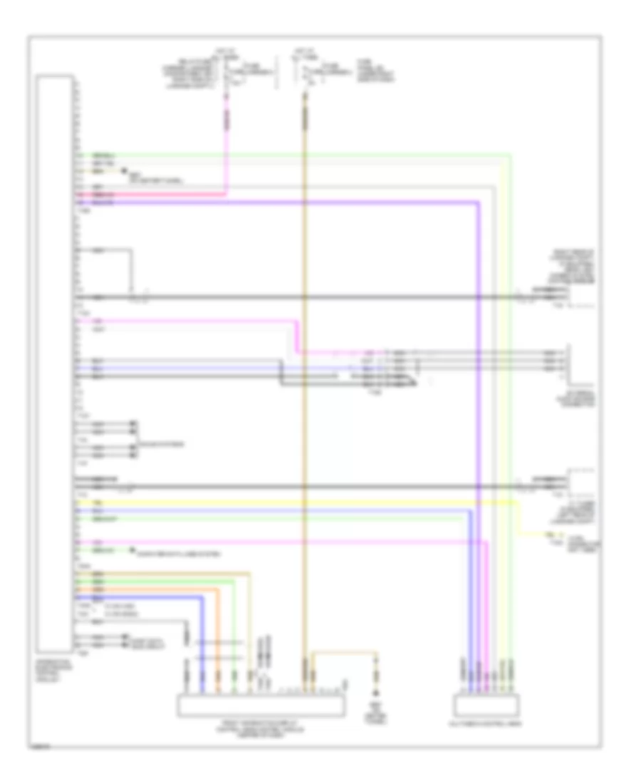
Front Information Display Control Module Wiring Diagram, Convertible for Audi S5 4.2 2011
List of elements for Front Information Display Control Module Wiring Diagram, Convertible for Audi S5 4.2 2011:
- (right rear of luggage compt) (if equipped) rear view camera system control module
- 18 pin connector (not used)
- Computer data lines system
- External audio source connection
- Front information display control head control module (center of dash)
- Fuse 5a
- Fuse 7.5a
- Fuse carrier 2
- Fuse carrier 5
- Fuse panel sd (under right side of dash)
- G687 (on center tunnel)
- Hot at all times
- Information electronics control module 1
- Most data bus circuit
- Multimedia control head
- Nca
- Relay/fuse carrier luggage compartment sf (right side of luggage compt)
- Sound systems
- T12x
- T12y
- T15g
- T16q
- T18a
- T1m
- T1n
- T1o
- T1p
- T1s
- T2di
- T4ai
- T4am
- T4an
- T4ao
- T8ah
- T8ai
- Tv tuner (if equipped) (left rear of luggage compt)
- W/ mmi basic
- W/ mmi high
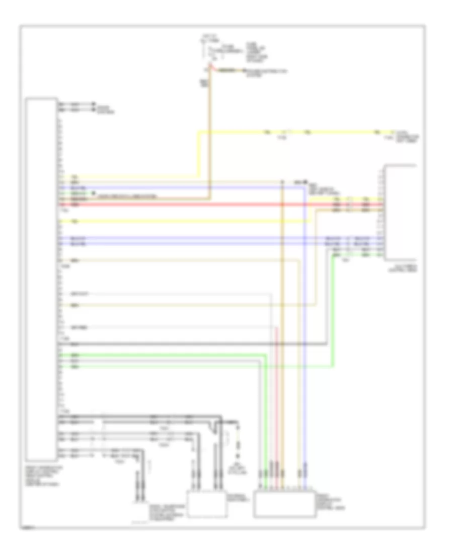
Front Information Display Control Module Wiring Diagram, Coupe Basic for Audi S5 4.2 2011
List of elements for Front Information Display Control Module Wiring Diagram, Coupe Basic for Audi S5 4.2 2011:
- 18 pin connector t18a (not used)
- Antenna amplifier 3
- Computer data lines system
- Front information display control head
- Front information display control head control module (center of dash)
- Fuse 5a
- Fuse carrier 2
- Fuse panel sd (under right side of dash)
- G61 (on left "c" pillar)
- G687 (left side of center tunnel)
- Hot at all times
- Multimedia control head
- Nca
- Power distribution system
- Radio, telephone & navigation system antenna (if equipped)
- Red
- Sound systems
- T12q
- T12r
- T16j
- T17b
- T2cv
- T2cw
- T2cx
- T8ab
- T8h
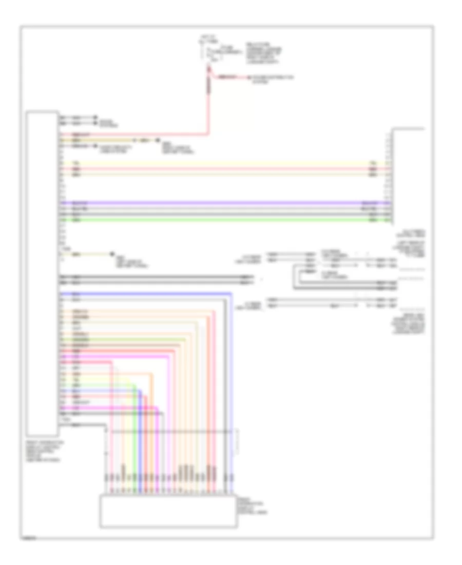
Front Information Display Control Module Wiring Diagram, Coupe High for Audi S5 4.2 2011
List of elements for Front Information Display Control Module Wiring Diagram, Coupe High for Audi S5 4.2 2011:
- (left rear of luggage compt) (if equipped) tv tuner
- Computer data lines system
- Front information display control head
- Front information display control head control module (center of dash)
- Fuse 30a
- Fuse carrier 3
- G687 (left side of center tunnel)
- G688 (right side of center tunnel)
- Hot at all times
- Multimedia control head
- Nca
- Pnk
- Power distribution system
- Rear view camera system control module (right rear of luggage compt)
- Red
- Relay/fuse carrier luggage compartment sf (right side of luggage compt)
- Sound systems
- T20b
- T22a
- W/ rear view camera
- W/o rear view camera
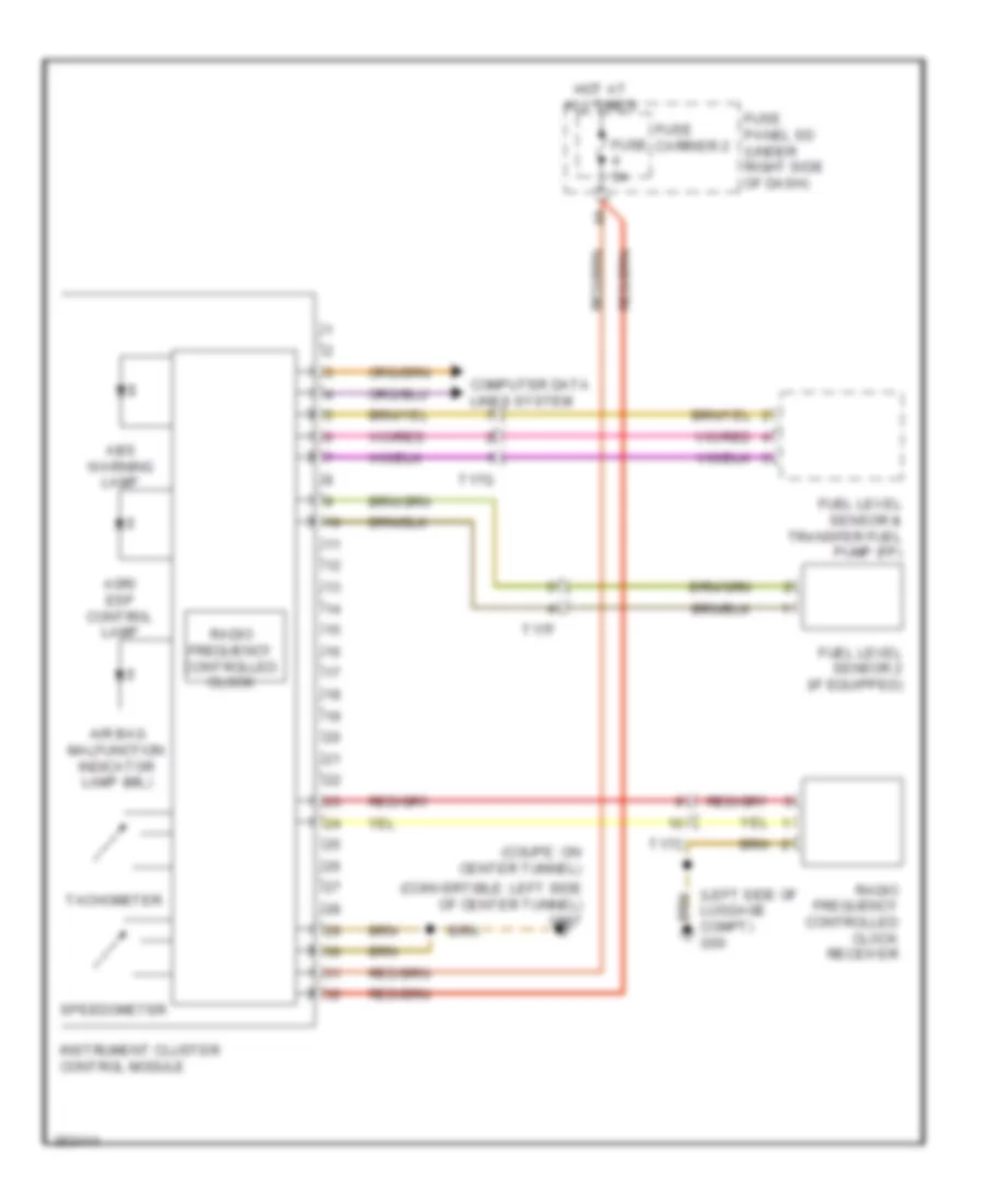
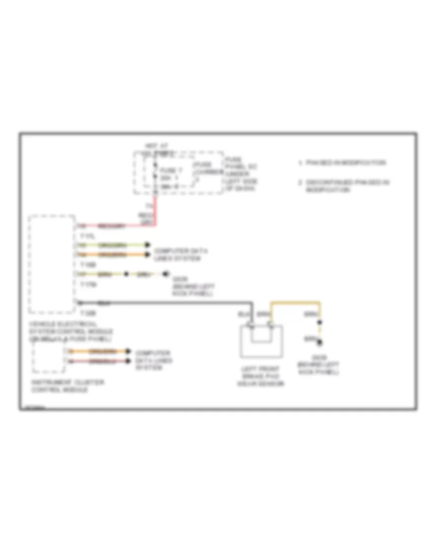
Instrument Cluster Wiring Diagram for Audi S5 4.2 2011
List of elements for Instrument Cluster Wiring Diagram for Audi S5 4.2 2011:
- (convertible: left side of center tunnel) g687
- (coupe: on center tunnel)
- (left side of luggage compt) g50
- Abs warning lamp
- Air bag malfunction indicator lamp (mil)
- Asr/ esp control lamp
- Computer data lines system
- Fuel level sensor & transfer fuel pump (fp)
- Fuel level sensor 2 (if equipped)
- Fuse 5a
- Fuse carrier 2
- Fuse panel sd (under right side of dash)
- Hot at all times
- Instrument cluster control module
- Radio frequency controlled clock
- Radio frequency controlled clock receiver
- Speedometer
- T17c
- T17f
- T17g
- Tachometer
INTERIOR LIGHTS
Courtesy Lamps Wiring Diagram (1 of 2) for Audi S5 4.2 2011
List of elements for Courtesy Lamps Wiring Diagram (1 of 2) for Audi S5 4.2 2011:
- Comfort system central control module (right rear of luggage compt)
- Computer data lines system
- Driver vanity mirror lamp contact switch (convertible)
- Driver's make-up mirror light contact switch (coupe)
- Front passenger make-up mirror light contact switch (coupe)
- Front passenger vanity mirror lamp contact switch (convertible)
- Fuse 10a
- Fuse 5a
- Fuse carrier 1
- Fuse carrier 2
- Fuse carrier 3
- Fuse panel sc (under left side of dash)
- G50 (left side of luggage compt)
- G639 (coupe: behind left kick panel) (convertible: left kick panel)
- G663 (coupe) (on right "c" pillar)
- G687 (coupe: left side of center tunnel) (convertible: on center tunnel)
- G730 (convertible) (right rear wheelwell)
- Glove compartment lamp switch
- Glove compartment light
- Ground distribution system
- Hot at all times
- Left front footwell light (w/ additional lighting equipment)
- Left make-up mirror illumination (w/ additional lighting equipment) (coupe)
- Left rear footwell light (w/ additional lighting equipment)
- Left vanity mirror lighting (w/ additional lighting equipment) (convertible)
- Luggage compartment light
- Red
- Relay/fuse carrier luggage compartment sf (right side of luggage compt)
- Right front footwell light (w/ additional lighting equipment)
- Right make-up mirror illumination (w/ additional lighting equipment) (coupe)
- Right rear footwell light (w/ additional lighting equipment)
- Right vanity mirror lighting (w/ additional lighting equipment) (convertible)
- T10m
- T10p
- T12k
- T16b
- T17g
- T17l
- T17m
- T17p
- T32a
- T32b
- T32c
- Vehicle electrical system control module (on relay & fuse panel)
Courtesy Lamps Wiring Diagram (2 of 2) for Audi S5 4.2 2011
List of elements for Courtesy Lamps Wiring Diagram (2 of 2) for Audi S5 4.2 2011:
- (in driver's front door) driver's door control module
- (in front passenger's front door) front passenger's door control module
- Automatic day/ night interior mirror
- Computer data lines system
- Convertible
- Convertible top control module (right rear of luggage compt)
- Coupe
- Driver's door contact switch
- Driver's door warning light
- Driver's map/ reading light
- Driver's reading light button
- Front interior lamp assembly (coupe)
- Front interior light
- Front passenger's door contact switch
- Front passenger's door warning light
- Front passenger's map/ reading light
- Front passenger's reading light button
- G50 (left side of luggage compt)
- G639 (behind left kick panel)
- G639 (left kick panel)
- Instrument illumination circuit
- Interior illumination switch
- Interior lighting switch (convertible)
- Left center reading light
- Left center reading light button
- Left front entry light
- Left rear interior light
- Left rear reading light switch
- Push button illumination
- Rear courtesy light (convertible)
- Rear interior lamp assembly (coupe)
- Red
- Right center reading light
- Right center reading light button
- Right front entry light
- Right rear interior light
- Right rear reading light switch 1
- T17v
- T20f
- T20g
- T20k
- T32j
- T32l
- T3x
- T6bb
- T6bi
- T8b
Instrument Illumination Wiring Diagram (1 of 2) for Audi S5 4.2 2011
List of elements for Instrument Illumination Wiring Diagram (1 of 2) for Audi S5 4.2 2011:
- (convertible)
- (coupe: behind left kick panel) (convertible: left kick panel)
- (coupe: behind left kick panel) (convertible: left kick panel) g639
- (coupe: left side of center tunnel) (convertible: on
- (coupe: right side of center tunnel) (convertible: on center tunnel)
- (coupe: right side of center tunnel) (convertible: on center tunnel) g688
- (w/ additional lighting equipment)
- Center instrument panel vent illumination
- Center tunnel) g687
- Cigarette lighter
- Computer data lines system
- Convertible
- Convertible top operation switch (convertible)
- Coupe
- Dimmer switch
- Electromechanical parking brake button
- Emergency flasher button
- Fog lamp button
- Fuse 5a
- Fuse carrier 1
- Fuse carrier 2
- Fuse panel sc (under left side of dash)
- Fuse panel sd (under right side of dash)
- G639
- G639 (left kick panel)
- G663 (on right "c" pillar)
- G687 (coupe: left side of center tunnel) (convertible: on center tunnel)
- G688
- G688 (coupe: right side of center tunnel) (convertible: on center tunnel)
- G688 (on center tunnel)
- Hot at all times
- Instrument cluster control module
- Lane change assistance button (convertible)
- Left instrument panel vent illumination (w/ additional lighting equipment)
- Light switch
- Parking aid button, asr/esp button & rear window shade switch
- Rear fog lamp button
- Rear temperature selection potentiometer
- Right instrument panel vent illumination (w/ additional lighting equipment)
- Socket illumi- nation & 12 v socket (if equipped)
- Socket illumi- nation & 12 v socket 2 (if equipped)
- Start/stop mode button
- T12k
- T16b
- T17m
- T27a
- T32a
- T32b
- Telephone base plate (if equipped)
- Tilt sunroof button 1 (w/ sunroof)
- Valet parking lock button
- Vehicle electrical system control module (on relay & fuse panel)
- W/ navigation system
- W/o navigation system
Instrument Illumination Wiring Diagram (2 of 2) for Audi S5 4.2 2011
List of elements for Instrument Illumination Wiring Diagram (2 of 2) for Audi S5 4.2 2011:
- (coupe: right side of center tunnel) (convertible: on center tunnel) g688
- (if equipped) left rear heated seat regulating switch
- (if equipped) right rear heated seat regulating switch
- Alarm system off switch
- Central locking- safe- indicator lamp
- Computer data lines system
- Convertible
- Coupe
- Driver's door control module (in driver's front door)
- Driver's door opener illumi- nation
- Driver's door warning light
- Driver's interior lock switch
- Driver's seat memory program control head (w/ memory)
- Front interior lamp assembly
- Front passenger's door control module (in front passenger's front door)
- Front passenger's door opener illumination
- Front passenger's door warning light
- Front passenger's interior lock switch
- G639 (behind left kick panel)
- G639 (left kick panel)
- G688 (coupe: right side of center tunnel) (convertible: on center tunnel)
- Interior lighting switch
- Left front entry light
- Left rear seat head restraint adjustment button
- Mirror adjust- ment switch
- Power window control head
- Rear lid remote unlock switch
- Right front door window regulation switch
- Right front entry light
- T20f
- T20g
- T32j
- T32l
- T6b
- T8b
MEMORY SYSTEMS
Driver"s Memory Seat Wiring Diagram (1 of 2) for Audi S5 4.2 2011
List of elements for Driver"s Memory Seat Wiring Diagram (1 of 2) for Audi S5 4.2 2011:
- (under left front seat) driver's seat angle adjustment motor
- (under left front seat) driver's seat forward/back adjustment motor/sensor
- (under left front seat) driver's seat height adjustment motor
- 15a
- Backrest
- Computer data lines system
- Driver power seat adjustment circuit breaker 1
- Driver's backrest adjustment motor (in left front seat back)
- Driver's head restraint height adjustment motor/sensor
- Driver's seat adjustment control head
- Fore/aft
- G639 (coupe: behind left kick panel) (convertible: left kick panel)
- Head restraint
- Height
- Hot at all times
- Memory seat/ steering column adjustment control module (under driver's seat)
- T12l
- T12m
- T32g
- T6ah
- T8u
- Tilt
Driver"s Memory Seat Wiring Diagram (2 of 2) for Audi S5 4.2 2011
List of elements for Driver"s Memory Seat Wiring Diagram (2 of 2) for Audi S5 4.2 2011:
- Computer data lines system
- Driver's backrest lock switch (in left front seat back)
- Driver's door control module (in left front door)
- Driver's entry assistance button
- Driver's seat backrest forward stop switch (in left front seat back)
- Driver's seat lumbar support adjustment switch
- Driver's seat lumbar support curvature adjustment motor (in left front seat back)
- Driver's seat lumbar support height adjustment motor (in left front seat back)
- Driver's seat memory program control head
- G639 (coupe: behind left kick panel) (convertible: left kick panel)
- Interior lights system
- Lumbar curv- ature
- Lumbar height
- Memory seat/ steering column adjustment control module (under driver's seat)
- Red
- Seats system
- T10p
- T10q
- T12m
- T16h
- T20f
- T27a
- T32j
- T6ai
- T8u
Memory Mirrors Wiring Diagram (1 of 2) for Audi S5 4.2 2011
List of elements for Memory Mirrors Wiring Diagram (1 of 2) for Audi S5 4.2 2011:
- (convertible: left kick panel) g639 (coupe: behind left kick panel)
- 11a
- Computer data lines system
- Convertible
- Coupe
- Day/night
- Driver's door control module (in left front door)
- Driver's exterior mirror assembly
- Driver's seat memory program control head
- Entry lamp
- Fold-in
- Fuse 15a
- Fuse 30a
- Fuse carrier 2
- Fuse panel sc (under left side of dash)
- Heater
- Horizontal
- Hot at all times
- Interior lights system
- Lane change
- Navigation system
- Pnk
- Red
- T16m
- T20f
- T27a
- T32j
- Turn signal lamp
- Vertical
Memory Mirrors Wiring Diagram (2 of 2) for Audi S5 4.2 2011
List of elements for Memory Mirrors Wiring Diagram (2 of 2) for Audi S5 4.2 2011:
- 11a
- Adjustment switch
- Computer data lines system
- Convertible
- Coupe
- Day/night
- Entry lamp
- Fold away switch
- Fold-in
- Front passenger's door control module (in front passenger's door)
- Front passenger's exterior mirror assembly
- Fuse 15a
- Fuse 30a
- Fuse carrier 3
- G638 (coupe: behind right kick panel) (convertible: right "a" pillar)
- Heater
- Horizontal
- Hot at all times
- Lane change
- Mirror adjustment switch assembly
- Navigation system
- Pnk
- Red
- Relay/ fuse carrier luggage compartment sf (right side of luggage compt)
- Selector switch
- T16n
- T20g
- T27c
- Turn signal lamp
- Vertical
Passenger"s Memory Seat Wiring Diagram (1 of 2) for Audi S5 4.2 2011
List of elements for Passenger"s Memory Seat Wiring Diagram (1 of 2) for Audi S5 4.2 2011:
- (under right front seat) front passenger seat angle adjustment motor
- (under right front seat) front passenger seat height adjustment motor
- (under right front seat) front passenger's seat forward/back adjustment motor
- 15a
- Backrest
- Computer data lines system
- Fore/aft
- Front passenger power seat adjustment circuit breaker 1
- Front passenger's head restraint height adjustment motor/sensor
- Front passenger's seat adjustment control head
- Front passenger's seat backrest adjustment motor (in right front seat back)
- G663 (on right "c" pillar)
- Height
- Hot at all times
- Passenger memory seat control module (under front passenger's seat)
- Restraint head
- T12o
- T12p
- T32i
- T6aj
- T8v
- Tilt
Passenger"s Memory Seat Wiring Diagram (2 of 2) for Audi S5 4.2 2011
List of elements for Passenger"s Memory Seat Wiring Diagram (2 of 2) for Audi S5 4.2 2011:
- Computer data links system
- Driver's door control module (in left front door)
- Driver's seat memory program control head
- Front passenger seat lumbar support height adjustment motor (in right front seat back)
- Front passenger's backrest lock switch (in right front seat back)
- Front passenger's entry assistance button
- Front passenger's seat backrest forward stop switch (in right front seat back)
- Front passenger's seat lumbar support adjustment switch
- Front passenger's seat lumbar support curvature adjustment motor (in right front seat back)
- G663 (on right "c" pillar)
- Interior lights system
- Lumbar curv- ature
- Lumbar height
- Passenger memory seat control module (under front passenger's seat)
- Red
- Seats system
- T10r
- T12p
- T16i
- T20f
- T32j
- T6ak
- T8v
NAVIGATION
Lane Departure Warning Wiring Diagram for Audi S5 4.2 2011
List of elements for Lane Departure Warning Wiring Diagram for Audi S5 4.2 2011:
- (coupe: behind left kick panel) (convertible: left kick panel) g639
- 10a
- Computer data lines system
- Directional stabilization assistance control module (top center of windshield)
- Directional stabilization assistance windshield heater
- Driver's lane change assistance warning lamp
- Front passenger's lane change assistance warning lamp
- Fuse 10a
- Fuse 5a
- Fuse carrier 1
- Fuse carrier 4
- Fuse panel sc (under left side of dash)
- G51 (right side of luggage compt)
- G639 (coupe: behind left kick panel) (convertible: left kick panel)
- Interior lights system
- Lane change assistance button
- Lane change assistance control module (behind right side of rear bumper)
- Lane change assistance control module 2 (behind left side of rear bumper)
- Nca
- Relay/fuse carrier luggage compartment sf (right side of luggage compt)
- T12f
- T27a
- T27c
Navigation Wiring Diagram, Basic Infotainment (1 of 2) for Audi S5 4.2 2011
List of elements for Navigation Wiring Diagram, Basic Infotainment (1 of 2) for Audi S5 4.2 2011:
- (convertible) satellite antenna
- (convertible: on center tunnel) g687 (coupe: left side of center tunnel)
- 18 pin connector (not used)
- 7a3/uf0
- 7d3/uf7
- Antenna amplifier
- Computer data lines system
- Coupe
- Digital radio antenna (convertible)
- External audio source connection
- External audio source connection (7d3/uf7)
- Fuse 20a
- Fuse 5a
- Fuse carrier 2
- Fuse panel sd (under right side of dash)
- G61 (on left "c" pillar)
- G687 (coupe: left side of center tunnel) (convertible: on center tunnel)
- G688 (coupe: right side of center tunnel) (convertible: on center tunnel)
- Nca
- Radio
- Radio, telephone navigation system antenna (w/ roof antenna)
- Satellite antenna
- T12a
- T12s
- T16l
- T18a
- T1ac
- T1ah
- T1i
- T1l
- T2df
- T8k
- Telephone transceiver (under front passenger's seat)
- W/ speaker phone
- W/o speaker phone
Navigation Wiring Diagram, Basic Infotainment (2 of 2) for Audi S5 4.2 2011
List of elements for Navigation Wiring Diagram, Basic Infotainment (2 of 2) for Audi S5 4.2 2011:
- (convertible: on center tunnel) (coupe: left side of center tunnel) g687
- (in left "c" pillar) antenna amplifier
- (left rear of luggage compt) (if equipped) tv tuner
- (right rear of luggage compt) comfort system central control module
- Antenna amplifier 2
- Computer data lines system
- Convertible
- Front information display control head control module (if equipped) (center of dash)
- Information electronics control module 1
- Left antenna module
- Left front mid-bass speaker
- Left front treble speaker
- Left rear mid/low range speaker
- Left rear treble speaker
- Navigation system antenna
- Nca
- Radio & tv antenna
- Right front mid-bass speaker
- Right front treble speaker
- Right rear mid/low range speaker
- Right rear treble speaker
- T17c
- T17d
- T17f
- T1af
- T1ai
- T1ao
- T1ap
- T1as
- T1at
- T1au
- T1av
- T1aw
- T1h
- T1n
- T27a
- T27c
- T2dh
- T2dn
- T2dr
- T3av
- T8ah
- W/ basic plus
- W/o basic plus
Navigation Wiring Diagram, Convertible Premium Infotainment (1 of 3) for Audi S5 4.2 2011
List of elements for Navigation Wiring Diagram, Convertible Premium Infotainment (1 of 3) for Audi S5 4.2 2011:
- Antenna
- Antenna amplifier (in left "c" pillar)
- Antenna amplifier 2
- Central locking & anti-theft alarm system antenna
- Comfort system central control module (right rear of luggage compt)
- Computer data lines system
- Fuse 20a
- Fuse 5a
- Fuse carrier 2
- Fuse panel sd (under right side of dash)
- G687 (on center tunnel)
- Hot at all times
- Information electronics control module 1 (w/o rear view camera)
- Left antenna module
- Navigation system antenna (w/ navigation system)
- Nca
- Power distribution system
- Radio
- Radio & tv antenna
- Radio antenna
- T12a
- T12s
- T16l
- T1af
- T1ai
- T1ao
- T1ap
- T1as
- T1at
- T1au
- T1aw
- T1h
- T1i
- T1l
- T1n
- T1o
- T2df
- T2dh
- T2dn
- T2dr
- T3av
- T8k
- Tim
- Tv antenna
- Tv antenna 2
- Tv antenna 3
- Tv tuner (if equipped) (left rear of luggage compt)
Navigation Wiring Diagram, Convertible Premium Infotainment (2 of 3) for Audi S5 4.2 2011
List of elements for Navigation Wiring Diagram, Convertible Premium Infotainment (2 of 3) for Audi S5 4.2 2011:
- 18 pin connector (not used)
- 7a3/uf0
- 7d3/uf7
- Computer data lines system
- Digital radio antenna
- External audio source connection (7a3/uf0)
- External audio source connection (7d3/uf7)
- G50 (left side of luggage compt)
- G687 (on center tunnel)
- Inside microphone
- Left front treble speaker
- Microphone unit (in front roof module)
- Nca
- Right front bass speaker
- Right rear mid/low range speaker
- Right rear treble speaker
- Satellite antenna
- T18a
- T1ac
- T1ah
- T27a
- T27c
- T54a
- Telephone microphone
- Telephone transceiver (under front passenger's seat)
- W/ speaker phone
- W/o speaker phone
Navigation Wiring Diagram, Convertible Premium Infotainment (3 of 3) for Audi S5 4.2 2011
List of elements for Navigation Wiring Diagram, Convertible Premium Infotainment (3 of 3) for Audi S5 4.2 2011:
- Center mid/high range speaker
- Computer data lines system
- Digital sound system control module (left rear of luggage compt)
- Front information display control head
- Fuse 3 30a
- Fuse carrier 3
- G50 (left side of luggage compt)
- Hot at all times
- Left front bass speaker
- Left front midrange speaker
- Left rear mid/low range speaker
- Left rear treble speaker
- Nca
- Pnk
- Power distribution system
- Radio
- Red
- Relay/fuse carrier luggage compt sf (right side of luggage compt)
- Right front midrange speaker
- Right front treble speaker
- Subwoofer
- T10v
- T17c
- T17d
- T17f
- T18b
- T27a
- T27c
- T32h
Navigation Wiring Diagram, Convertible Premium MMI (1 of 2) for Audi S5 4.2 2011
List of elements for Navigation Wiring Diagram, Convertible Premium MMI (1 of 2) for Audi S5 4.2 2011:
- (if equipped) navigation system antenna
- (left side of
- (left side of luggage compt) g50
- (w/o rear view camera) information electronics control module 1
- Antenna
- Antenna amplifier (in left "c" pillar)
- Antenna amplifier 2
- Central locking & anti-theft alarm system anteena
- Comfort system central control module (right rear of luggage compt)
- Computer data lines system
- Digital radio antenna
- Fuse 5a
- Fuse 7.5a
- Fuse carrier
- Fuse panel sd (under right side of dash)
- G50
- Hot at all times
- Left antenna module
- Luggage compt)
- Most data bus circuit
- Nca
- Radio
- Radio & tv antenna
- Radio antenna 2
- Relay/fuse carrier luggage compartment sf (right side of luggage compt)
- Satellite antenna
- T10ag
- T1ac
- T1af
- T1ah
- T1ai
- T1ao
- T1ap
- T1as
- T1at
- T1au
- T1aw
- T1h
- T1i
- T1l
- T1n
- T1o
- T20c
- T2df
- T2dg
- T2dh
- T2dn
- T2do
- T2dr
- T3av
- Tim
- Tv antenna 1
- Tv antenna 2
- Tv antenna 3
- Tv tuner (if equipped) (left rear of luggage compt)
Navigation Wiring Diagram, Convertible Premium MMI (2 of 2) for Audi S5 4.2 2011
List of elements for Navigation Wiring Diagram, Convertible Premium MMI (2 of 2) for Audi S5 4.2 2011:
- (left side of luggage compt) g50
- Cd/dvd chager
- Center mid/high range speaker
- Computer data lines system
- Digital sound system control module (left rear of luggage compt)
- Fuse 30a
- Fuse carrier
- G687 (on center tunnel)
- Hot at all times
- Left front bass speaker
- Left front midrange speaker
- Left front treble speaker
- Left rear mid/low range speaker
- Left rear treble speaker
- Microphone unit (in front roof module)
- Most data bus circuit
- Nca
- Power distribution system
- Relay/fuse carrier luggage compartment sf (right side of luggage compt)
- Right front bass speaker
- Right front midrange speaker
- Right front treble speaker
- Right rear mid/low range speaker
- Right rear treble speaker
- Subwoofer
- T17c
- T17d
- T17f
- T18b
- T27a
- T27c
- T2dk
- T2dm
- T32h
- T8aa
Navigation Wiring Diagram, Convertible Standard MMI & Basic MMI (1 of 2) for Audi S5 4.2 2011
List of elements for Navigation Wiring Diagram, Convertible Standard MMI & Basic MMI (1 of 2) for Audi S5 4.2 2011:
- (left side of luggage compt) g50
- (not used) 18 pin connector
- Antenna
- Antenna amplifier (in left "c" pillar)
- Center mid/high range speaker
- Central locking & anti-theft alarm system antenna
- Comfort system central control module (right rear of luggage compt)
- Computer data lines system
- Digital radio antenna
- Fuse 30a
- Fuse 7.5a
- Fuse carrier 5
- Hot at all times
- Left antenna module
- Left rear mid/low range speaker
- Left rear treble speaker
- Most data bus circuit
- Nca
- Power distribution system
- Radio
- Radio & tv antenna
- Radio antenna 2
- Relay/fuse carrier luggage compartment sf (right side of luggage compt)
- Satellite antenna
- Subwoofer
- T10ag
- T12df
- T12w
- T17c
- T18a
- T1ac
- T1ah
- T1ai
- T1ao
- T1ap
- T1as
- T1at
- T1au
- T1av
- T1aw
- T1h
- T1i
- T1l
- T2dg
- T3av
- T8ag
- Tv antenna 1
Navigation Wiring Diagram, Convertible Standard MMI & Basic MMI (2 of 2) for Audi S5 4.2 2011
List of elements for Navigation Wiring Diagram, Convertible Standard MMI & Basic MMI (2 of 2) for Audi S5 4.2 2011:
- (if equipped) navigation system antenna
- (left side of center tunnel) g687
- (w/o rear view camera) information electronics control module 1
- Antenna amplifier 2
- Cd/dvd changer
- Computer data lines system
- Fuse 1 5a
- Fuse carrier 2
- Fuse panel sd (under right side of dash)
- G50 (left side of luggage compt)
- Hot at all times
- Left front mid-bass speaker
- Left front treble speaker
- Most data bus circuit
- Nca
- Right front mid-bass speaker
- Right front treble speaker
- Right rear mid/low range speaker
- Right rear treble speaker
- T17d
- T17f
- T1af
- T1n
- T1o
- T20c
- T27a
- T27c
- T2dh
- T2dm
- T2dn
- T2do
- T2dr
- T8aa
- Tim
- Tv antenna 2
- Tv antenna 3
- Tv tuner (if equipped) (left rear of luggage compt)
Navigation Wiring Diagram, Coupe Basic MMI (1 of 2) for Audi S5 4.2 2011
List of elements for Navigation Wiring Diagram, Coupe Basic MMI (1 of 2) for Audi S5 4.2 2011:
- 18 pin connector (not used)
- Cd changer
- Computer data lines system
- Digital sound system control module (left rear of luggage compt)
- External audio source connection (w/ mmi high)
- Fuse 40a
- Fuse 5a
- Fuse carrier 2
- Fuse carrier 3
- Fuse panel sd (under right side of dash)
- G50 (left side of luggage compt)
- G687 (left side of center tunnel)
- Hot at all times
- Left front mid-bass speaker
- Left front treble speaker
- Most data bus circuit
- Nca
- Relay/fuse carrier luggage compartment sf (right side of luggage compt)
- Right front mid-bass speaker
- Right front treble speaker
- T17d
- T17f
- T18a
- T27a
- T27c
- W/ basic
- W/ high
Navigation Wiring Diagram, Coupe Basic MMI (2 of 2) for Audi S5 4.2 2011
List of elements for Navigation Wiring Diagram, Coupe Basic MMI (2 of 2) for Audi S5 4.2 2011:
- (left side of luggage compt) g50
- Antenna amplifier 2
- Antenna amplifier 3
- Computer data lines system
- Front information display control head control module (center of dash)
- Fuse 7.5a
- Fuse carrier 5
- G50 (left side of luggage compt)
- G61 (on left "c" pillar)
- G62 (on right "c" pillar)
- Hot at all times
- Left rear mid/low range speaker
- Left rear treble speaker
- Most data bus circuit
- Navigation system w/ cd drive control module (if equipped) (left rear of luggage compt)
- Nca
- Radio
- Radio, telephone navigation system antenna (w/ roof antenna)
- Rear view camera system control module (right rear of luggage compt)
- Relay/fuse carrier luggage compt sf (right side of luggage compt)
- Right rear mid/low range speaker
- Right rear treble speaker
- Satellite antenna
- Satellite radio
- T2cx
- Telephone baseplate/ telephone amplifier (telephone amplifier: right rear of luggage compt)
- Telephone transceiver (under front passenger's seat)
- Tv tuner (left rear of luggage compt)
- W/ mmi basic
- W/ rear view camera system
- W/ speaker phone
- W/mmi high
- W/o rear view camera system
- W/o speaker phone
Navigation Wiring Diagram, Coupe Premium Infotainment (1 of 2) for Audi S5 4.2 2011
List of elements for Navigation Wiring Diagram, Coupe Premium Infotainment (1 of 2) for Audi S5 4.2 2011:
- 18 pin connector (not used)
- 7a3/uf0
- 7d3/uf7
- Antenna amplifier
- Computer data lines system
- External audio source connection (7a3/uf0)
- External audio source connection (7d3/uf7)
- Fuse 20a
- Fuse 5a
- Fuse carrier 2
- Fuse panel sd (under right side of dash)
- G61 (on left "c" pillar)
- G687 (left side of center tunnel)
- G688 (right side of center tunnel)
- Nca
- Radio
- Radio, telephone navigation system antenna (w/ roof antenna)
- T12a
- T12s
- T16l
- T18a
- T8k
- Telephone transceiver (under front passenger's seat)
- W/ speaker phone
- W/o speaker phone
Navigation Wiring Diagram, Coupe Premium Infotainment (2 of 2) for Audi S5 4.2 2011
List of elements for Navigation Wiring Diagram, Coupe Premium Infotainment (2 of 2) for Audi S5 4.2 2011:
- Center mid/high range speaker
- Computer data lines system
- Digital sound system control module (left rear of luggage compt)
- Front information display head control module (center of dash)
- Fuse 40a
- Fuse carrier 3
- G50 (left side of luggage compt)
- Hot at all times
- Inside microphone
- Left front bass speaker
- Left front mid-bass speaker
- Left front treble speaker
- Left rear mid/low range speaker
- Left rear midrange speaker
- Left rear treble speaker
- Microphone unit (in front roof module)
- Nca
- Pnk
- Radio
- Red
- Relay/ fuse carrier luggage compt sf (right side of luggage compt)
- Right front bass speaker
- Right front midrange speaker
- Right front treble speaker
- Right rear mid/low range speaker
- Right rear midrange speaker
- Right rear treble speaker
- Subwoofer
- T10v
- T17c
- T17d
- T17f
- T18b
- T27a
- T27c
- T32h
- Telephone microphone
Navigation Wiring Diagram, Coupe Premium MMI (1 of 3) for Audi S5 4.2 2011
List of elements for Navigation Wiring Diagram, Coupe Premium MMI (1 of 3) for Audi S5 4.2 2011:
- 18 pin connector (not used)
- Center mid/high range speaker
- Computer data lines system
- Digital sound system control module (left rear of luggage compt)
- External audio source connection (7a3/7a6)
- Fuse 40a
- Fuse carrier 3
- G50 (left side of luggage compt)
- Hot at all times
- Inside microphone
- Left rear mid/low range speaker
- Left rear treble speaker
- Microphone unit (in front roof module)
- Most data bus circuit
- Nca
- Relay/fuse carrier luggage compt sf (right side of luggage compt)
- Right rear mid/low range speaker
- Right rear treble speaker
- T17c
- T18a
- T18b
- T32h
- Telephone microphone
- Telephone transceiver (under front passenger's seat)
- Voice control microphone
- W/ speaker phone
- W/o speaker phone
Navigation Wiring Diagram, Coupe Premium MMI (2 of 3) for Audi S5 4.2 2011
List of elements for Navigation Wiring Diagram, Coupe Premium MMI (2 of 3) for Audi S5 4.2 2011:
- (left rear of luggage compt) tv tuner
- Antenna amplifier 2
- Computer data lines system
- Front information display control head control module (center of dash)
- G50 (left side of luggage compt)
- G62 (on right "c" pillar)
- Most data bus circuit
- Navigation system w/ cd drive control module (if equipped) (left rear of luggage compt)
- Nca
- Radio, telephone navigation system antenna (w/ roof antenna)
- Rear view camera system control module (right rear of luggage compt)
- Satellite antenna
- Satellite radio
- T2cx
- Telephone baseplate/ telephone amplifier (telephone amplifier: right rear of luggage compt)
- Telephone transceiver (under front passenger's seat)
- W/ mmi basic
- W/ mmi high
- W/ rear view camera system
- W/ speaker phone
- W/o rear view camera system
- W/o speaker phone
Navigation Wiring Diagram, Coupe Premium MMI (3 of 3) for Audi S5 4.2 2011
List of elements for Navigation Wiring Diagram, Coupe Premium MMI (3 of 3) for Audi S5 4.2 2011:
- (left side of luggage compt) g50
- Antenna amplifier 3
- Cd changer
- Computer data lines system
- External audio source connection (w/ mmi high)
- Fuse 5a
- Fuse 7.5a
- Fuse carrier 2
- Fuse carrier 5
- Fuse panel sd (under right side of dash)
- G687 (left side of center tunnel)
- Hot at all times
- Left front bass speaker
- Left front mid-bass speaker
- Left front treble speaker
- Left rear midrange speaker
- Most data bus circuit
- Nca
- Radio
- Relay/fuse carrier luggage compt sf (right side of luggage compt)
- Right front bass speaker
- Right front midrange speaker
- Right front treble speaker
- Right rear midrange speaker
- Subwoofer
- T17d
- T17f
- T27a
- T27c
- W/ basic
- W/ high
Navigation Wiring Diagram, Coupe Standard MMI (1 of 3) for Audi S5 4.2 2011
List of elements for Navigation Wiring Diagram, Coupe Standard MMI (1 of 3) for Audi S5 4.2 2011:
- (left rear of luggage compt) tv tuner
- 18 pin connector (not used)
- Computer data lines system
- Digital sound system control module (left rear of luggage compt)
- External audio source connection (7a3/7a6)
- Fuse 40a
- Fuse carrier
- G50 (left side of luggage compt)
- Hot at all times
- Microphone unit (in front roof module)
- Most data bus circuit
- Nca
- Rear view camera system control module (right rear of luggage compt)
- Relay/fuse carrier luggage compt sf (right side of luggage compt)
- T18a
- Telephone microphone
- Telephone transceiver (under front passenger's seat)
- Voice control microphone
- W/ rear view camera system
- W/o rear view camera system
- W/o speaker phone
Navigation Wiring Diagram, Coupe Standard MMI (2 of 3) for Audi S5 4.2 2011
List of elements for Navigation Wiring Diagram, Coupe Standard MMI (2 of 3) for Audi S5 4.2 2011:
- Antenna amplifier 2
- Antenna amplifier 3
- Computer data lines system
- Front information display control head control module (center of dash)
- Fuse 7.5a
- Fuse carrier 5
- G50 (left side of luggage compt)
- G62 (on right "c" pillar)
- Hot at all times
- Most data bus circuit
- Navigation system w/ cd drive control module (if equipped) (left rear of luggage compt)
- Nca
- Radio, telephone navigation system antenna (w/ roof antenna)
- Relay/fuse carrier luggage compt sf (right side of luggage compt)
- Satellite antenna
- Satellite radio
- T2cx
- Telephone baseplate/ telephone amplifier (telephone amplifier: right rear of luggage compt)
- Telephone transceiver (under front passenger's seat)
- W/ mmi basic
- W/ mmi high
- W/ speaker phone
- W/o speaker phone
Navigation Wiring Diagram, Coupe Standard MMI (3 of 3) for Audi S5 4.2 2011
List of elements for Navigation Wiring Diagram, Coupe Standard MMI (3 of 3) for Audi S5 4.2 2011:
- Cd changer
- Center mid/high range speaker
- Computer data lines system
- External audio source connection (w/ mmi high)
- Fuse 5a
- Fuse carrier 2
- Fuse panel sd (under right side of dash)
- G50 (left side of luggage compt)
- G61 (on left "c" pillar)
- G687 (left side of center tunnel)
- Hot at all times
- Left front mid-bass speaker
- Left front treble speaker
- Left rear mid/low range speaker
- Left rear treble speaker
- Most data bus circuit
- Nca
- Radio
- Right front mid-bass speaker
- Right front treble speaker
- Right rear mid/low range speaker
- Right rear treble speaker
- Subwoofer
- T17c
- T17d
- T17f
- T27a
- T27c
- W/ basic
- W/ high
Navigation Wiring Diagram, Standard Infotainment (1 of 2) for Audi S5 4.2 2011
List of elements for Navigation Wiring Diagram, Standard Infotainment (1 of 2) for Audi S5 4.2 2011:
- (convertible) satellite antenna
- (convertible: on center tunnel) g687 (coupe: left side of center tunnel)
- 18 pin connector (not used)
- 7a3/uf0
- 7d3/uf7
- Antenna amplifier
- Computer data lines system
- Coupe
- Digital radio antenna (convertible)
- External audio source connection
- External audio source connection (7d3/uf7)
- Fuse 20a
- Fuse 30a
- Fuse 5a
- Fuse carrier
- Fuse panel sd (under right side of dash)
- G61 (on left "c" pillar)
- G687 (coupe: left side of center tunnel) (convertible: on center tunnel)
- G688 (coupe: right side of center tunnel) (convertible: on center tunnel)
- Hot at all times
- Nca
- Radio
- Radio, telephone navigation system antenna (w/ roof antenna)
- Relay/ fuse carrier luggage compt sf (right side of luggage compt)
- Satellite antenna
- T12a
- T12s
- T16l
- T18a
- T1ac
- T1ah
- T1i
- T1l
- T2df
- T8k
- Telephone transceiver (under front passenger's seat)
- W/ speaker phone
- W/o speaker phone
Navigation Wiring Diagram, Standard Infotainment (2 of 2) for Audi S5 4.2 2011
List of elements for Navigation Wiring Diagram, Standard Infotainment (2 of 2) for Audi S5 4.2 2011:
- (in left "c" pillar) antenna amplifier
- (left rear of luggage compt) (if equipped) tv tuner
- (right rear of luggage compt) comfort system central control module
- Antenna amplifier 2
- Center mid/high range speaker
- Computer data lines system
- Convertible
- Digital sound system control module (left rear of luggage compt)
- Front information display control head control module (center of dash)
- G50 (left side of luggage compt)
- Information electronics control module 1
- Left antenna module
- Left front mid-bass speaker
- Left front treble speaker
- Left rear mid/low range speaker
- Left rear treble speaker
- Navigation system antenna
- Nca
- Pnk
- Radio
- Radio & tv antenna
- Red
- Right front mid-bass speaker
- Right front treble speaker
- Right rear mid/low range speaker
- Right rear treble speaker
- Subwoofer
- T10v
- T17c
- T17d
- T17f
- T1af
- T1ai
- T1ao
- T1ap
- T1as
- T1at
- T1au
- T1av
- T1aw
- T1h
- T1n
- T27a
- T27c
- T2dh
- T2dn
- T2dr
- T3av
- T8ah
Parking Assistant Wiring Diagram for Audi S5 4.2 2011
List of elements for Parking Assistant Wiring Diagram for Audi S5 4.2 2011:
- (convertible: on center tunnel)
- Computer data lines system
- Front parking aid warning buzzer (if equipped) (under left side of dash)
- Fuse 7.5a
- Fuse carrier 4
- G51 (right side of luggage compt)
- G687 (w/ navigation system) (coupe: left side of center tunnel)
- G688 (w/o navigation system) (coupe: right side of center tunnel)
- Left front center parking aid sensor (w/ front & rear parking aid) (in front bumper)
- Left front parking aid sensor (w/ front & rear parking aid) (in front bumper)
- Left rear center parking aid sensor (on rear bumper)
- Left rear parking aid sensor (on rear bumper)
- Parallel parking assistance control module (right rear of luggage compt)
- Parking aid button
- Rear parking aid warning buzzer (in right "d" pillar)
- Relay/fuse carrier luggage compartment sf (right side of luggage compt)
- Right front center parking aid sensor (w/ front & rear parking aid) (on front bumper)
- Right front parking aid sensor (w/ front & rear parking aid) (front bumper)
- Right rear center parking aid sensor (on rear bumper)
- Right rear parking aid sensor (on rear bumper)
- T12e
- T12g
- T16e
- T17f
- T6v
Rear Camera Wiring Diagram for Audi S5 4.2 2011
List of elements for Rear Camera Wiring Diagram for Audi S5 4.2 2011:
- Computer data lines system
- Convertible
- Coupe
- Front information display control head control module (coupe) (center of dash)
- Fuse 5a
- Fuse carrier 5
- G51 (right side of luggage compt)
- Hot at all times
- Information electronics control module 1 (convertible)
- Nca
- Rearview camera
- Rearview camera system control module (right rear of luggage compt)
- Relay/fuse carrier luggage compartment sf (right side of luggage compt)
- T1r
- T1s
- T1y
- Tv tuner (coupe) (left rear of luggage compt)
Vehicle Positioning Interface Control Module Wiring Diagram for Audi S5 4.2 2011
List of elements for Vehicle Positioning Interface Control Module Wiring Diagram for Audi S5 4.2 2011:
- (right rear wheelwell) (convertible) g730
- 12a
- 2.0l turbo convertible
- 2.0l turbo coupe
- 3.0l
- 4.2l
- Brake light switch (on brake pedal assembly)
- Comfort system central control module (right rear of luggage compt)
- Computer data lines system
- Engine control module (4.2l: in left plenum chamber) (3.0l: right rear of engine compt)
- Fuse 5a
- Fuse carrier 2
- G663 (coupe) (on right "c" pillar)
- Hot at all times
- Relay/fuse carrier luggage compartment sf (right side of luggage compt)
- T17e
- T17r
- T32c
- T94
- Throttle position sensor (except 3.0l) accelerator pedal position sensor & accelerator pedal position sensor 2 (3.0l) (top of accelerator pedal assembly)
- Vehicle positioning system interface control module
POWER DISTRIBUTION
Power Distribution Wiring Diagram (1 of 9) for Audi S5 4.2 2011
List of elements for Power Distribution Wiring Diagram (1 of 9) for Audi S5 4.2 2011:
- (convertible: on center tunnel) (coupe: right side of center tunnel) g688
- (not used)
- 15a
- 4.2l
- 40a
- Abs control module
- Access/start authorization button
- Active steering control module
- Air quality sensor (comfort)
- Automatic day/night interior mirror relay
- Battery
- Battery monitoring control module (at battery)
- Comfort system central control module (right rear of luggage compt)
- Computer data lines system
- Convertible
- Coupe
- Data bus on board diagnostic interface
- Directional stabilization assistance control module
- Distance regulation control module
- Fuse
- Fuse 10a
- Fuse 110a
- Fuse 25a
- Fuse 5a
- Fuse carrier 1
- Fuse panel sc (under left side of dash)
- G624 (near starter battery)
- Garage door opener control head
- Garage door opener control module
- Generator & voltage regulator
- Headlamp range control module
- Headlamp range/ cornering lamp control module
- Left headlamp assembly (w/ bi-xenon w/ cornering headlights)
- Main fuse panel sa (on battery, in luggage compt)
- Nca
- Rear window defogger fuse (coupe)
- Rear window defogger relay
- Red
- Right headlight assembly
- Selector lever sensor system control module (a/t)
- T15l
- T16b
- T17c
- T17e
- T17m
- T17n
- T17r
- T32b
- T32c
- T8g
- To fuse 2 (diagram 2 of 9)
- To fuse panel sc (diagram 7 of 9)
- To fuse panel sc (diagram 9 of 9)
- To fuse panel sd (diagram 9 of 9)
- To relay/ fuse carrier luggage compartment sf (diagram 3 of 9)
- To relay/ fuse carrier luggage compartment sf (diagram 4 of 9)
- To relay/ fuse carrier luggage compartment sf (diagram 7 of 9)
- To relay/ fuse carrier luggage compartment sf (diagram 9 of 9)
- To sockets relay (diagram 4 of 9)
- To voltage stabilizer (diagram 3 of 9)
- Vehicle electrical system control module
- W/ bi-xenon w/ cornering headlights
- W/o bi-xenon w/ cornering headlights
Power Distribution Wiring Diagram (2 of 9) for Audi S5 4.2 2011
List of elements for Power Distribution Wiring Diagram (2 of 9) for Audi S5 4.2 2011:
- (400w)
- (except 400w)
- (w/ mmi) (radio)
- 10a
- 11a
- 12a
- 15a
- 2.0l turbo & 3.0l sc
- 3.0l sc
- 4.2l
- 4.2l & 2.0l turbo
- 4.2l & 3.0l sc
- 40a
- 50a
- Abs control module
- Abs control module fuse 1
- Access/ start authorization switch
- Air bag control module
- Automatic day/night interior mirror relay
- Battery interrupt igniter
- Battery jump start terminal (on terminal 30 wire junction block)
- Brake booster relay
- Brake vacuum pump fuse (4.2l)
- Cd/dvd changer
- Charisma switch module
- Climatronic control module
- Coolant fan control (fc) control module
- Coolant fan control (fc) control module 2 (coupe)
- Coupe w/ mmi high
- Data bus on board diagnostic interface
- Data link connector (dlc)
- Electronic steering column lock control module
- Engine control module (ecm)
- External audio source connection
- External audio source connection (w/ mmi high)
- Fresh air blower control module
- From a fuse 1 (diagram 1 of 9)
- Front information display control head (convertible)
- Front information display control head control module (coupe basic)
- Fuse 1 40a 60a
- Fuse 10a
- Fuse 110a
- Fuse 3 5a 20a
- Fuse 40a
- Fuse 40a (1000w)
- Fuse 5a
- Fuse carrier
- Fuse panel sd (under right side of dash)
- Generator & voltage regulator
- Instrument cluster control
- Light switch
- Main fuse panel sa (on battery, in luggage compt)
- Nca
- Radio
- Red
- Secondary air injection (air) pump fuse
- Secondary air injection (air) pump relay
- Starter
- Steering column electronic systems control module
- Suppressor
- T16j
- T16l
- T17f
- T17w
- T20e
- T8ai
- T94
- To fuse panel sc (diagram 7 of 9)
- To fuse panel sc (diagram 8 of 9)
- To relay/ fuse carrier e box sb (diagram 5 of 9)
- To relay/ fuse carrier e e box sb (diagram 5 of 9)
- To relay/fuse carrier luggage compartment sf (diagram 3 of 9)
- W/ engine start/stop system
- W/ navigation
- W/o engine start/stop system
- W/o navigation
Power Distribution Wiring Diagram (3 of 9) for Audi S5 4.2 2011
List of elements for Power Distribution Wiring Diagram (3 of 9) for Audi S5 4.2 2011:
- (diagram 2 of 9)
- (not used)
- (w/ basic) (w/o basic)
- 10a
- 11a
- 12a
- 18 pin connector (not used)
- Auxiliary heater control module
- Cellular telephone amplifier
- Comfort system central control module
- Convertible
- Convertible except premium
- Coupe
- Digital sound system control module (convertible)
- Digital sound system control module (coupe)
- Electro- mechanical parking brake control module
- From battery monitoring control module t (diagram 1 of 9)
- From fuse panel sd z
- From main fuse panel sa (diagram 1 of 9)
- Front information display control head control module (coupe high)
- Front passenger's door control module
- Fuse
- Fuse 15a
- Fuse 20a 30a
- Fuse 30a
- Fuse 40a
- Fuse 5a
- Fuse 7.5a
- Fuse carrier
- Fuse carrier 5
- G51 (right side of luggage luggage compt)
- Information electronics control module 1
- Left head space heating relay
- Left rear heated seat regulating switch
- Module (diagram 4 of 9)
- Nca
- Radio
- Rear view camera system control module
- Red
- Relay/ fuse carrier luggage compart- ment sf (right side of luggage compt)
- Right head space heating relay
- Right rear door control module (convertible)
- Right rear heated seat regulating switch
- T10ag
- T16l
- T17q
- T17w
- T18a
- T20g
- T20i
- T27c
- T4aj
- Telephone base plate
- Telephone transceiver
- To 18 pin conne- ctor (diagram 6 of 9)
- To all wheel drive control x
- To converter w/ socket 12v & 230v (diagram 4 of 9)
- Tv tuner
- Voltage stabilizer (w/ engine start/ stop system)
- W/ rear heated seats
- W/o mmi
Power Distribution Wiring Diagram (4 of 9) for Audi S5 4.2 2011
List of elements for Power Distribution Wiring Diagram (4 of 9) for Audi S5 4.2 2011:
- (convertible: on center tunnel) (coupe: right side of center tunnel) g688
- (not used)
- (on right "c" pillar) g663
- 10a
- 11a
- 12 v socket (if equipped)
- 12 v socket 2 (if equipped)
- 12 v socket 3 (if equipped)
- 12a
- All wheel drive control module
- Auto hold- button
- Cigarette lighter
- Comfort system central control module
- Converter w/ socket, 12v & 230v (if equipped) (coupe)
- Convertible
- Coupe
- Electro- mechanical parking brake button
- Electronic damping control module
- From fuse k panel sc (diagram 1 of 9)
- From main fuse panel sa (diagram 1 of 9)
- From relay/fuse carrier luggage compartment sf (diagram 3 of 9)
- From voltage stabilizer (diagram 3 of 9)
- Fuse
- Fuse 15a
- Fuse 5a
- Fuse carrier 4
- G51 (right side of luggage compt)
- G663 (coupe) g688 (convertible) (coupe: on right "c" pillar) (convertible: on center tunnel)
- G688 (convertible: on center tunnel) (coupe: right side of center tunnel)
- Interior lights system
- Lane change assistance control module
- Lane change assistance control module 2
- Left head space heating relay (convertible)
- Left rear heated seat regulating switch
- Nca
- Parallel parking assistance control module
- Red
- Relay/fuse carrier luggage compartment sf (right side of luggage compt)
- Right head space heating realy (convertible)
- Right rear heated seat regulating switch
- Sockets relay (on relay/fuse carrier-sf, at right side of luggage compt)
- T12f
- T16e
- T32c
- To fuse panel sc (diagram 7 of 9)
- Towing recognition control module (convertible)
- W/ rear heated seats
Power Distribution Wiring Diagram (5 of 9) for Audi S5 4.2 2011
List of elements for Power Distribution Wiring Diagram (5 of 9) for Audi S5 4.2 2011:
- (4.2l)
- (4.2l) 3.0l sc & 2.0l turbo)
- (6 speed a/t)
- (6 speed a/t) (cvt)
- (8 speed a/t)
- (cvt)
- 10a
- 11a
- 12a
- 15a
- 17 pin connector (not used)
- 2.0l turbo
- 2.0l turbo & 3.0l sc
- 2.0l turbo & 4.2l
- 3.0l sc
- 3.0l sc & 4.2l
- 4.2l
- 4.2l & 2.0l turbo
- 4.2l & 3.0l sc
- Convertible 2.0l turbo
- Coolant fan control (fc) control module
- Coolant fan control (fc) control module 2 (4.2l)
- Coupe 2.0l turbo
- Direct shift gearbox (dsg) mechatronic
- Engine control module (ecm)
- Evaporative emission (evap) canister purge regulator valve
- Fuel metering valve
- Fuel metering valve 2 (4.2l)
- Fuel pressure regulator valve
- Fuse
- Fuse 10a 15a (3.0l sc & 2.0l turbo)
- Fuse 10a 20a
- Fuse 15a
- Fuse 30a 20a
- Fuse 5a
- Fuse carrier
- Ignition coil 1
- Ignition coil 2
- Ignition coil 3
- Ignition coil 4
- Ignition coil 5 w/ power output stage
- Ignition coil 6 w/ power output stage
- Ignition coil 7 w/ power output stage (4.2l)
- Ignition coil 8 w/ power output stage (4.2l)
- Intake air switch over valve (4.2l)
- Intake manifold runner control valve (3.0l sc)
- Leak detection pump (ldp)
- Left electro hydraulic engine mount solenoid valve (4.2l)
- Mass air flow (maf) sensor (2.0l turbo)
- Mass air flow (maf) sensor (4.2l)
- Nca
- Oil level thermal sensor
- Oil pressure regulation valve (3.0l sc)
- Oxygen sensor (o2s) heater
- Oxygen sensor (o2s) heater 2
- Red
- Relay/ fuse carrier e-box
- Right electro hydraulic engine mount solenoid valve (4.2l)
- Sb (in left plenum chamber e-box)
- Secondary air injection (air) pump relay
- Secondary air injection (air) solenoid valve 2 (3.0l sc)
- Secondary air injection solenoid valve (3.0l sc)
- Starter relay
- Starter relay 2
- T14e
- T16r
- T17q
- T5i
- T94
- To camshaft adjustment valve 1 (diagram 6 of 9)
- To fuse panel sc (diagram 7 of 9)
- To fuse panel sc (diagram 9 of 9)
- Transmission control module (tcm)
- Twc oxygen sensor 1
- Twc oxygen sensor 2
- W/ direct shift gear box
- W/ power output stage
- W/o direct shift gear box
Power Distribution Wiring Diagram (6 of 9) for Audi S5 4.2 2011
List of elements for Power Distribution Wiring Diagram (6 of 9) for Audi S5 4.2 2011:
- 17 pin connector (not used)
- 18 pin connector (not used)
- 2.0l turbo
- 3.0l sc
- 4.2l
- Auxiliary engine coolant (ec) pump relay (w/ after-run coolant pump)
- Cam adjustment actuator 1
- Cam adjustment actuator 2
- Cam adjustment actuator 3
- Cam adjustment actuator 4
- Cam adjustment actuator 5
- Cam adjustment actuator 6
- Cam adjustment actuator 7
- Cam adjustment actuator 8
- Camshaft adjustment valve 1
- Camshaft adjustment valve 1 (exhaust)
- Camshaft adjustment valve 2
- Camshaft adjustment valve 2 (exhaust)
- Charge air cooling pump
- Climatronic refrigerant shut-off valve
- Compartment sf (diagram 3 of 9)
- Coolant circulation pump relay
- Coolant circulation pump relay (w/ after-run coolant pump)
- Evaporative emission (evap) canister purge regulator valve
- From relay/fuse carrier e- box sb fuse 7 (diagram 5 of 9)
- From relay/fuse carrier luggage i
- Intake flap motor
- Intake manifold runner control (imrc) valve
- Leak detection pump (ldp)
- Left electro- hydraulic engine mount solenoid
- Left electro- hydraulic engine mount solenoid (a/t)
- Map controlled engine cooling thermostat
- Navigation system w/ cd drive control module
- Oil pressure regulation valve
- Phased in modification
- Radio
- Right electro- hydraulic engine mount solenoid
- Satellite radio
- T14d
- T14f
- T17q
- T18a
- Telephone amplifier
- Telephone base plate
- Telephone transceiver
- Turbocharger recirculating valve
- Tv tuner
- Variable intake manifold runner motor
- Wastegate bypass regulator valve
Power Distribution Wiring Diagram (7 of 9) for Audi S5 4.2 2011
List of elements for Power Distribution Wiring Diagram (7 of 9) for Audi S5 4.2 2011:
- (not used)
- 10a
- 11a
- 12a
- Abs control module
- Automatic day/night interior mirror
- Automatic day/night interior mirror relay
- Brake light switch
- Clutch position sensor (m/t)
- Convertible
- Convertible top control module
- Convertible top hydraulic pump relay
- Convertible top hydraulic pump relay relay 2
- Driver's door control module
- From fuse panel sc (diagram 1 of 9)
- From main fuse panel sa (diagram 1 of 9)
- From main fuse panel sa (diagram 2 of 9)
- From relay/fuse carrier e-box sb (diagram 5 of 9)
- From socket relay (diagram 4 of 9)
- Fuel pump (fp) control module
- Fuse
- Fuse 10a
- Fuse 15a
- Fuse 25a
- Fuse 30a
- Fuse 40a
- Fuse 50a
- Fuse 5a
- Fuse carrier
- Fuse carrier 1 (convertible)
- Fuse carrier 1 (coupe)
- Fuse panel sc (under left side of dash)
- Horn relay
- Left rear door control module (convertible)
- Nca
- Rain/light recognition sensor
- Rear window defogger relay
- Red
- Relay/fuse carrier luggage compartment sf (right side of luggage compt)
- T10ah
- T17e
- T20f
- T27a
- T6f
- Tw2
- Vehicle electrical system control module
- Wiper motor control module
Power Distribution Wiring Diagram (8 of 9) for Audi S5 4.2 2011
List of elements for Power Distribution Wiring Diagram (8 of 9) for Audi S5 4.2 2011:
- (not used)
- 10a
- 11a
- 12a
- 15a
- 30a
- Active steering control module
- Alarm horn
- Anti-theft alarm system sensor
- Comfort system central control module
- Convertible
- Coupe
- Discontinued, phased in modification
- Driver power seat adjustment circuit breaker 1
- Driver's seat lumbar support adjustment switch
- Driver's seat lumbar support adjustment switch (w/ memory)
- From fuse panel sc (diagram 1 of 9)
- From main fuse panel sa (diagram 2 of 9)
- Front interior lamp assembly (convertible)
- Front passenger power seat adjustment circuit breaker 1
- Front passenger's seat lumbar support adjustment switch
- Front passenger's seat lumbar support adjustment switch (w/ memory)
- Fuse
- Fuse 10a
- Fuse 20a
- Fuse 20a 7.5a
- Fuse 30a
- Fuse 35a
- Fuse 5a
- Fuse carrier 3
- Fuse panel sc (under left side of dash)
- Left rear door control module
- Memory seat/ steering column adjustment control module
- Nca
- Passenger memory seat control switch (w/ memory)
- Phased in modification
- Power sunroof control module (if equipped)
- Red
- Right rear door control module (convertible)
- T10m
- T10p
- T12l
- T12o
- T17b
- T17l
- T17m
- T17n
- T1om
- T20h
- T20i
- T32d
- T32g
- T32i
- T5d
- T6bb
- Vehicle electrical system control module
- W/ heated seats
- W/o memory
Power Distribution Wiring Diagram (9 of 9) for Audi S5 4.2 2011
List of elements for Power Distribution Wiring Diagram (9 of 9) for Audi S5 4.2 2011:
- (diagram 1 of 9)
- (not used)
- (w/ heated spray jet)
- 10a
- 11a
- 12a
- 13a
- 14a
- 16a
- 18-pin connector
- A/c pressure/ temperature sensor
- Air bag control module
- All wheel drive control module
- Asr/esp button
- Clutch position
- Comfort system central control module
- Convertible
- Convertible a/t
- Convertible top control module
- Coupe
- Coupe a/t
- Data bus on board diagnostic interface
- Data link connector (dlc)
- Electro- mechanical parking brake button
- Electro- mechanical parking brake control module
- Electronic damping control module
- From fuse panel sc (diagram 1 of 9)
- From fuse panel sc w
- From main fuse panel sa (diagram 1 of 9)
- From starter relay (diagram 5 of 9)
- Front passenger's air bag disabled indicator lamp
- Fuse
- Fuse 15a
- Fuse 20a
- Fuse 30a
- Fuse 35a
- Fuse 40a
- Fuse 5a
- Fuse carrier
- Fuse carrier 1
- Fuse panel sc (under left side of dash)
- Fuse panel sd (under right side of dash)
- Left washer nozzle heater
- M/t
- Nca
- Rear courtesy light
- Red
- Relay/fuse carrier luggage compartment sf (right side of luggage compt)
- Right washer nozzle heater
- Seat occupied recognition control module
- Selector lever sensor system control module
- Shift lock solenoid
- Steering column electronic systems control module
- T10ah
- T10n
- T17f
- T17g
- T17o
- T17p
- T17r
- T17v
- T18a
- T6bi
- Tire pressure monitoring control module
- Towing recognition control module (convertible)
- Vehicle positioning system interface control module
- W/o navigation
POWER DOOR LOCKS
Power Door Locks Wiring Diagram (1 of 2) for Audi S5 4.2 2011
List of elements for Power Door Locks Wiring Diagram (1 of 2) for Audi S5 4.2 2011:
- (in driver's outside door handle) left front outside door handle touch sensor
- (right rear of luggage compt) comfort system central control module
- (right side of luggage compt) g51
- 11a
- Antenna amplifier 3 (convertible)
- Antenna amplifier 3 (coupe)
- Central locking & anti-theft alarm system antenna
- Computer data lines system
- Convertible
- Coupe
- Driver's door central locking lock unit
- Driver's door control module (in driver's front door)
- Fuel tank lid unlock motor
- Fuse 15a
- Fuse carrier 2
- Fuse panel sc (under left side of dash)
- G51 (right side of luggage compt)
- G638 (coupe: behind right kick panel) (convertible: right "a" pillar)
- G639 (behind left kick panel)
- Ground distribution system
- Hot at all times
- Left license plate light
- Nca
- Rear lid lock cylinder unlock button
- Red
- Right front outside door handle touch sensor
- Right license plate light
- T17o
- T1as
- T1h
- T20f
- T27a
- T27c
- T32c
- T32d
- T32e
- T32j
- T4ay
- Trunk lid alarm switch/rear lid central locking system motor
- W/ mmi
- W/o mmi
Power Door Locks Wiring Diagram (2 of 2) for Audi S5 4.2 2011
List of elements for Power Door Locks Wiring Diagram (2 of 2) for Audi S5 4.2 2011:
- 11a
- Central locking- safe-indicator lamp
- Computer data lines system
- Driver's interior locking switch
- Front passenger's door central locking lock unit
- Front passenger's door control module (in passenger's front door)
- Front passenger's interior lock switch
- Fuse 15a
- Fuse 7.5a
- Fuse carrier 3
- Fuse panel sc (under left side of dash)
- Glove compartment lock motor
- Hot at all times
- Interior lights & power windows systems
- Interior lights system
- Interior lights, mirrors & power windows systems
- Left rear door control module (convertible)
- Left seat belt positioning motor
- Rear lid remote unlock switch
- Red
- Relay/ fuse carrier luggage compartment sf (right side of luggage compt)
- T12k
- T17c
- T20g
- T20h
- T27c
- T32l
POWER MIRRORS
Automatic Day/Night Mirror Wiring Diagram, with Humidity Sensor for Audi S5 4.2 2011
List of elements for Automatic Day/Night Mirror Wiring Diagram, with Humidity Sensor for Audi S5 4.2 2011:
- (coupe: behind left kick panel) g639 (convertible: left kick panel)
- 11a
- Automatic day/night interior mirror
- Comfort system central control module (right rear of luggage compt)
- Computer data lines system
- Day/night (if equipped)
- Driver's door control module (in driver's front door)
- Driver's exterior assembly mirror
- Exterior lights system
- Front passenger's door control module (in front passenger's front door)
- Front passenger's mirror exterior assembly
- Fuse 15a
- Fuse 5a
- Fuse carrier
- Fuse carrier 2
- Fuse panel sc (under left side of dash)
- G638 (coupe: behind right kick panel) (convertible: right "a" pillar)
- G639 (coupe: behind left kick panel) (convertible: left kick panel)
- Hot at all times
- Humidity sensor
- Interior lights system
- Light recog- nition sensor
- Relay/fuse carrier luggage compartment sf (right side of luggage compt)
- T16m
- T16n
- T17p
- T20f
- T20g
- T27a
- T27c
- W/ automatic high beam control
- W/o automatic high beam control
Automatic Day/Night Mirror Wiring Diagram, without Humidity Sensor for Audi S5 4.2 2011
List of elements for Automatic Day/Night Mirror Wiring Diagram, without Humidity Sensor for Audi S5 4.2 2011:
- (coupe: behind left kick panel) g639 (convertible: left kick panel)
- 11a
- Automatic day/night interior mirror
- Comfort system central control module (right rear of luggage compt)
- Computer data lines system
- Day/night (if equipped)
- Driver's door control module (in driver's front door)
- Driver's exterior mirror assembly
- Exterior lights system
- Front passenger's door control module (in front passenger's front door)
- Front passenger's exterior mirror assembly
- Fuse 15a
- Fuse 5a
- Fuse carrier
- Fuse carrier 2
- Fuse panel sc (under left side of dash)
- G638 (coupe: behind right kick panel) (convertible: right "a" pillar)
- G639 (coupe: behind left kick panel) (convertible: left kick panel)
- Hot at all times
- Interior lights system
- Light recog- nition sensor
- Relay/fuse carrier luggage compartment sf (right side of luggage compt)
- T16m
- T16n
- T17p
- T20f
- T20g
- T27a
- T27c
Power Mirrors Wiring Diagram (1 of 2) for Audi S5 4.2 2011
List of elements for Power Mirrors Wiring Diagram (1 of 2) for Audi S5 4.2 2011:
- (coupe: behind left kick panel) g639 (convertible: left kick panel)
- 11a
- Computer data lines system
- Convertible
- Coupe
- Day/night
- Driver's door control module (in driver's front door)
- Driver's exterior mirror assembly
- Entry lamp
- Fold-in
- Fuse 15a
- Fuse 30a
- Fuse carrier 2
- Fuse carrier 3
- Fuse panel sc (under left side of dash)
- Heater
- Horizontal
- Hot at all times
- Lane change
- Navigation system
- Pnk
- Red
- Relay/fuse carrier luggage compartment sf (right side of luggage compt)
- T16m
- T20f
- T27a
- T27c
- T32j
- Turn signal lamp
- Vertical
Power Mirrors Wiring Diagram (2 of 2) for Audi S5 4.2 2011
List of elements for Power Mirrors Wiring Diagram (2 of 2) for Audi S5 4.2 2011:
- Adjustment switch
- Computer data lines lines system
- Convertible
- Coupe
- Day/night
- Entry lamp
- Fold away switch
- Fold-in
- Front passenger's door control module (in front passenger's front door)
- Front passenger's exterior mirror assembly
- G638 (coupe: behind right kick panel) (convertible: right "a" pillar)
- Heater
- Horizontal
- Interior lights system
- Lane change
- Mirror adjustment switch assembly
- Navigation system
- Pnk
- Red
- Selector switch
- T16n
- T20g
- T27c
- Turn signal lamp
- Vertical
POWER SEATS
Front Heated Seats Wiring Diagram, Convertible without Memory for Audi S5 4.2 2011
List of elements for Front Heated Seats Wiring Diagram, Convertible without Memory for Audi S5 4.2 2011:
- 10a
- 12a
- Computer data lines system
- Driver's backrest heating element
- Driver's seat heating element
- Front passenger's backrest heating element
- Front passenger's seat heater
- Fuse 30a
- Fuse 5a
- Fuse carrier 2
- Fuse carrier 3
- Fuse carrier 4
- Fuse panel sc (under left side of dash)
- G51 (right side of luggage compt)
- G639 (left kick panel)
- G730 (right rear wheelwell)
- Hot at all times
- Left front seat temp sensor
- Left head space heating control module
- Left head space heating relay
- Left head space heating switch
- Left head space heating ventilation
- Nca
- Relay/fuse carrier luggage compartment sf (right side of luggage compt)
- Right front seat temp sensor
- Right head space heating control module
- Right head space heating relay
- Right head space heating switch
- Right head space heating ventilation
- Seat heating element
- T16b
- T32b
- T6f
- T6k
- T6l
- Vehicle electrical system control module (on relay & fuse panel)
Front Heated Seats Wiring Diagram, Coupe without Memory for Audi S5 4.2 2011
List of elements for Front Heated Seats Wiring Diagram, Coupe without Memory for Audi S5 4.2 2011:
- Backrest heater
- Backrest side bolster heater
- Computer data lines system
- Driver's backrest heating element
- Driver's seat heater
- Front passenger's backrest heating element
- Front passenger's seat heater
- Fuse 30a
- Fuse carrier 2
- Fuse panel sc (under left side of dash)
- G639 (behind left kick panel)
- G663 (on right "c" pillar)
- Hot at all times
- Left front seat temp sensor
- Right front seat temp sensor
- Seat heater
- Side bolster heater
- Side bolster heater (if equipped)
- T16b
- T32b
- T6f
- Vehicle electrical system control module (on relay & fuse panel)
Front Heated Seats Wiring Diagram, with Memory for Audi S5 4.2 2011
List of elements for Front Heated Seats Wiring Diagram, with Memory for Audi S5 4.2 2011:
- (on right "c" pillar)
- (right rear wheelwell)
- 15a
- Backrest heater
- Computer data lines system
- Coupe w/ discontinued
- Coupe w/ phased in modification & convertible
- Driver power seat adjustment circuit breaker
- Driver's backrest heating element
- Driver's seat backrest fan (in driver's front seat back)
- Driver's seat backrest fan 2 (in driver's front seat back)
- Driver's seat cushion fan (in driver's front seat cushion)
- Driver's seat cushion fan 2 (in driver's front seat cushion)
- Driver's seat heater
- Front passenger power seat adjustment circuit breaker 1
- Front passenger's backrest heating element
- Front passenger's seat backrest fan (in front passenger's front seat cushion)
- Front passenger's seat backrest fan 2 (in front passenger's front seat cushion)
- Front passenger's seat cushion fan (in front passenger's front seat cushion)
- Front passenger's seat cushion fan 2 (in front passenger's front seat cushion)
- Front passenger's seat heater
- G639 (behind left kick panel)
- G639 (convertible: left kick panel) (coupe: behind left kick panel)
- G663
- G663 (coupe) (on right "c" pillar) g730 (convertible)
- G663 (on right "c" pillar)
- Hot at all times
- Left front seat temp sensor
- Memory seat/steering column adjustment control module (under driver's seat)
- Passenger memory seat control module (under front passenger's seat)
- Red
- Right front seat temp sensor
- Seat heater
- Side bolster heater
- T12l
- T12o
- T16h
- T16i
- T32g
- T32i
- T8y
- T8z
Lumbar Wiring Diagram for Audi S5 4.2 2011
List of elements for Lumbar Wiring Diagram for Audi S5 4.2 2011:
- (coupe)
- (on right "c" pillar)
- (right rear wheelwell)
- Convertible
- Coupe
- Driver's seat lumbar support adjustment switch
- Driver's seat lumbar support curvature adjustment motor (in driver's front seat back)
- Driver's seat lumbar support height adjustment motor (in driver's front seat back)
- Front passenger seat lumbar support height adjustment motor (in front passenger's front seat back)
- Front passenger's seat lumbar support adjustment switch
- Front passenger's seat lumbar support curvature adjustment motor (in front passenger's front seat back)
- Fuse 10a
- Fuse carrier 3
- Fuse panel sc (under left side of dash)
- G639 (convertible: left kick panel) (coupe: behind left kick panel)
- G663
- G730 (convertible)
- Hot at all times
- Lumbar curv- ature
- Lumbar height
- T10m
- T10p
- T4u
- T4v
Rear Heated Seats Wiring Diagram for Audi S5 4.2 2011
List of elements for Rear Heated Seats Wiring Diagram for Audi S5 4.2 2011:
- 11a
- Convertible
- Coupe
- Fuse 30a
- Fuse 5a
- Fuse carrier 3
- Fuse carrier 4
- G688 (convertible: on center tunnel) (coupe: right side of center tunnel)
- Heated seat temp sensor
- Hot at all times
- Left rear backrest heating element
- Left rear heated seat regulating switch
- Left rear seat heater
- Relay/ fuse carrier luggage compartment sf (right side of luggage compt)
- Right rear backrest heating element
- Right rear heated seat regulating switch
- Right rear seat heater
- Seat heater
- Seat occupied sensor
- T32b
- Vehicle electrical system control module (on relay & fuse panel)
POWER TOP/SUNROOF
Sunroof Wiring Diagram for Audi S5 4.2 2011
List of elements for Sunroof Wiring Diagram for Audi S5 4.2 2011:
- Computer data lines system
- Fuse 20a
- Fuse carrier 3
- Fuse panel sc (under left side of dash)
- G639 (behind left kick panel)
- Hot at all times
- Interior lights system
- Power sunroof control module (if equipped) (center front of roof)
- Sunroof motor
- Tilt sunroof button 1 (if equipped)
POWER WINDOWS
Power Windows Wiring Diagram for Audi S5 4.2 2011
List of elements for Power Windows Wiring Diagram for Audi S5 4.2 2011:
- (convertible) window regulator central switch
- (coupe: behind left kick panel) (convertible: left kick panel) g639
- (coupe: behind right kick panel) (convertible; right "a" pillar) g638
- (coupe: right side of center tunnel) (convertible: on center tunnel) g688
- (right side of luggage compt) g51
- 11a
- Comfort system central control module (right rear of luggage compt)
- Computer data lines system
- Convertable
- Convertiable & coupe phased in modification
- Coupe disconnected, phased in modification
- Driver window lowering microswitch
- Driver's door control module (in left front door)
- Driver's door power window control head
- Driver's window regulator motor
- Front passenger's door control module (in right front door)
- Front passenger's window regulator motor
- Fuse 15a
- Fuse 20a
- Fuse 30a
- Fuse 7.5a
- Fuse carrier
- Fuse carrier 2
- Fuse panel sc (under left side of dash)
- G638 (coupe: behind right kick panel) (convertible; right "a" pillar)
- G639 (coupe: behind left kick panel) (convertible: left kick panel)
- G687 (left side of center tunnel)
- G688 (right side of center tunnel)
- Ground distribution system
- Hot at all times
- Interior lights system
- Left front window regulator switch
- Left rear door control module (convertible)
- Left rear window regulator motor
- Left rear window regulator switch
- Passenger door window regulator switch
- Passenger window lowering microswitch
- Rear window shade motor (coupe)
- Rear window shade switch (coupe)
- Relay/ fuse carrier luggage compartment sf (right side of luggage compt)
- Right front window regulator switch
- Right rear door control module (convertible)
- Right rear window regulator motor
- Right rear window regulator switch
- T16b
- T17g
- T17m
- T17o
- T17p
- T20f
- T20g
- T20h
- T20i
- T27a
- T27c
- T32a
- T32b
- T32c
- T32j
- T32l
- T6am
- T6ao
- T6au
- T6av
- Vehicle electrical system control module (on relay & fuse panel)
- W/ navigation system
- W/o navigation system
RADIO
MOST Data Bus Wiring Diagram, Convertible for Audi S5 4.2 2011
List of elements for MOST Data Bus Wiring Diagram, Convertible for Audi S5 4.2 2011:
- Cd changer & dvd changer
- Data bus on board diagnostic interface (above glove box)
- Digital sound system control module (if equipped) (left rear of luggage compt)
- Information electronics control module 1
- Nca
- Radio
- T2bg
- Tv tuner (left rear of luggage compt)
- W/o integrated control module
MOST Data Bus Wiring Diagram, Coupe for Audi S5 4.2 2011
List of elements for MOST Data Bus Wiring Diagram, Coupe for Audi S5 4.2 2011:
- Cd changer
- Data bus on board diagnostic interface (above glove box)
- Digital radio (dab) (if equipped)
- Digital sound system control module (left rear of luggage compt)
- Except premium
- External audio source connection (if equipped)
- Front information display control head control module (center of dash)
- Mmi basic
- Mmi high
- Navigation system w/ cd drive control module (left rear of luggage compt)
- Nca
- Premium
- Radio
- Satellite radio/ digital radio (if equipped)
- T2bg
- Telephone transceiver (if equipped) (under front passenger's seat)
- Telephone transceiver (under front passenger's seat)
- Tv tuner (left rear of luggage compt)
Radio Wiring Diagram, Basic Infotainment (1 of 2) for Audi S5 4.2 2011
List of elements for Radio Wiring Diagram, Basic Infotainment (1 of 2) for Audi S5 4.2 2011:
- (convertible) satellite antenna
- (convertible: on center tunnel) g687 (coupe: left side of center tunnel)
- 18 pin connector (not used)
- 7a3/uf0
- 7d3/uf7
- Antenna amplifier
- Computer data lines system
- Coupe
- Digital radio antenna (convertible)
- External audio source connection
- External audio source connection (7d3/uf7)
- Fuse 20a
- Fuse 5a
- Fuse carrier 2
- Fuse panel sd (under right side of dash)
- G61 (on left "c" pillar)
- G687 (coupe: left side of center tunnel) (convertible: on center tunnel)
- G688 (coupe: right side of center tunnel) (convertible: on center tunnel)
- Nca
- Radio
- Radio, telephone navigation system antenna (w/ roof antenna)
- Satellite antenna
- T12a
- T12s
- T16l
- T18a
- T1ac
- T1ah
- T1i
- T1l
- T2df
- T8k
- Telephone transceiver (under front passenger's seat)
- W/ speaker phone
- W/o speaker phone
Radio Wiring Diagram, Basic Infotainment (2 of 2) for Audi S5 4.2 2011
List of elements for Radio Wiring Diagram, Basic Infotainment (2 of 2) for Audi S5 4.2 2011:
- (convertible: on center tunnel) (coupe: left side of center tunnel) g687
- (in left "c" pillar) antenna amplifier
- (left rear of luggage compt) (if equipped) tv tuner
- (right rear of luggage compt) comfort system central control module
- Antenna amplifier 2
- Computer data lines system
- Convertible
- Front information display control head control module (if equipped) (center of dash)
- Information electronics control module 1
- Left antenna module
- Left front mid-bass speaker
- Left front treble speaker
- Left rear mid/low range speaker
- Left rear treble speaker
- Navigation system antenna
- Nca
- Radio & tv antenna
- Right front mid-bass speaker
- Right front treble speaker
- Right rear mid/low range speaker
- Right rear treble speaker
- T17c
- T17d
- T17f
- T1af
- T1ai
- T1ao
- T1ap
- T1as
- T1at
- T1au
- T1av
- T1aw
- T1h
- T1n
- T27a
- T27c
- T2dh
- T2dn
- T2dr
- T3av
- T8ah
- W/ basic plus
- W/o basic plus
Radio Wiring Diagram, Convertible Premium Infotainment (1 of 3) for Audi S5 4.2 2011
List of elements for Radio Wiring Diagram, Convertible Premium Infotainment (1 of 3) for Audi S5 4.2 2011:
- Antenna
- Antenna amplifier (in left "c" pillar)
- Antenna amplifier 2
- Central locking & anti-theft alarm system antenna
- Comfort system central control module (right rear of luggage compt)
- Computer data lines system
- Fuse 20a
- Fuse 5a
- Fuse carrier 2
- Fuse panel sd (under right side of dash)
- G687 (on center tunnel)
- Hot at all times
- Information electronics control module 1 (w/o rear view camera)
- Left antenna module
- Navigation system antenna (w/ navigation system)
- Nca
- Power distribution system
- Radio
- Radio & tv antenna
- Radio antenna
- T12a
- T12s
- T16l
- T1af
- T1ai
- T1ao
- T1ap
- T1as
- T1at
- T1au
- T1aw
- T1h
- T1i
- T1l
- T1n
- T1o
- T2df
- T2dh
- T2dn
- T2dr
- T3av
- T8k
- Tim
- Tv antenna
- Tv antenna 2
- Tv antenna 3
- Tv tuner (if equipped) (left rear of luggage compt)
Radio Wiring Diagram, Convertible Premium Infotainment (2 of 3) for Audi S5 4.2 2011
List of elements for Radio Wiring Diagram, Convertible Premium Infotainment (2 of 3) for Audi S5 4.2 2011:
- 18 pin connector (not used)
- 7a3/uf0
- 7d3/uf7
- Computer data lines system
- Digital radio antenna
- External audio source connection (7a3/uf0)
- External audio source connection (7d3/uf7)
- G50 (left side of luggage compt)
- G687 (on center tunnel)
- Inside microphone
- Left front treble speaker
- Microphone unit (in front roof module)
- Nca
- Right front bass speaker
- Right rear mid/low range speaker
- Right rear treble speaker
- Satellite antenna
- T18a
- T1ac
- T1ah
- T27a
- T27c
- T54a
- Telephone microphone
- Telephone transceiver (under front passenger's seat)
- W/ speaker phone
- W/o speaker phone
Radio Wiring Diagram, Convertible Premium Infotainment (3 of 3) for Audi S5 4.2 2011
List of elements for Radio Wiring Diagram, Convertible Premium Infotainment (3 of 3) for Audi S5 4.2 2011:
- Center mid/high range speaker
- Computer data lines system
- Digital sound system control module (left rear of luggage compt)
- Front information display control head
- Fuse 3 30a
- Fuse carrier 3
- G50 (left side of luggage compt)
- Hot at all times
- Left front bass speaker
- Left front midrange speaker
- Left rear mid/low range speaker
- Left rear treble speaker
- Nca
- Pnk
- Power distribution system
- Radio
- Red
- Relay/fuse carrier luggage compt sf (right side of luggage compt)
- Right front midrange speaker
- Right front treble speaker
- Subwoofer
- T10v
- T17c
- T17d
- T17f
- T18b
- T27a
- T27c
- T32h
Radio Wiring Diagram, Convertible Premium MMI (1 of 2) for Audi S5 4.2 2011
List of elements for Radio Wiring Diagram, Convertible Premium MMI (1 of 2) for Audi S5 4.2 2011:
- (if equipped) navigation system antenna
- (left side of
- (left side of luggage compt) g50
- (w/o rear view camera) information electronics control module 1
- Antenna
- Antenna amplifier (in left "c" pillar)
- Antenna amplifier 2
- Central locking & anti-theft alarm system anteena
- Comfort system central control module (right rear of luggage compt)
- Computer data lines system
- Digital radio antenna
- Fuse 5a
- Fuse 7.5a
- Fuse carrier
- Fuse panel sd (under right side of dash)
- G50
- Hot at all times
- Left antenna module
- Luggage compt)
- Most data bus circuit
- Nca
- Radio
- Radio & tv antenna
- Radio antenna 2
- Relay/fuse carrier luggage compartment sf (right side of luggage compt)
- Satellite antenna
- T10ag
- T1ac
- T1af
- T1ah
- T1ai
- T1ao
- T1ap
- T1as
- T1at
- T1au
- T1aw
- T1h
- T1i
- T1l
- T1n
- T1o
- T20c
- T2df
- T2dg
- T2dh
- T2dn
- T2do
- T2dr
- T3av
- Tim
- Tv antenna 1
- Tv antenna 2
- Tv antenna 3
- Tv tuner (if equipped) (left rear of luggage compt)
Radio Wiring Diagram, Convertible Premium MMI (2 of 2) for Audi S5 4.2 2011
List of elements for Radio Wiring Diagram, Convertible Premium MMI (2 of 2) for Audi S5 4.2 2011:
- (left side of luggage compt) g50
- Cd/dvd chager
- Center mid/high range speaker
- Computer data lines system
- Digital sound system control module (left rear of luggage compt)
- Fuse 30a
- Fuse carrier
- G687 (on center tunnel)
- Hot at all times
- Left front bass speaker
- Left front midrange speaker
- Left front treble speaker
- Left rear mid/low range speaker
- Left rear treble speaker
- Microphone unit (in front roof module)
- Most data bus circuit
- Nca
- Power distribution system
- Relay/fuse carrier luggage compartment sf (right side of luggage compt)
- Right front bass speaker
- Right front midrange speaker
- Right front treble speaker
- Right rear mid/low range speaker
- Right rear treble speaker
- Subwoofer
- T17c
- T17d
- T17f
- T18b
- T27a
- T27c
- T2dk
- T2dm
- T32h
- T8aa
Radio Wiring Diagram, Convertible Standard MMI & Basic MMI (1 of 2) for Audi S5 4.2 2011
List of elements for Radio Wiring Diagram, Convertible Standard MMI & Basic MMI (1 of 2) for Audi S5 4.2 2011:
- (left side of luggage compt) g50
- (not used) 18 pin connector
- Antenna
- Antenna amplifier (in left "c" pillar)
- Center mid/high range speaker
- Central locking & anti-theft alarm system antenna
- Comfort system central control module (right rear of luggage compt)
- Computer data lines system
- Digital radio antenna
- Fuse 30a
- Fuse 7.5a
- Fuse carrier 5
- Hot at all times
- Left antenna module
- Left rear mid/low range speaker
- Left rear treble speaker
- Most data bus circuit
- Nca
- Power distribution system
- Radio
- Radio & tv antenna
- Radio antenna 2
- Relay/fuse carrier luggage compartment sf (right side of luggage compt)
- Satellite antenna
- Subwoofer
- T10ag
- T12df
- T12w
- T17c
- T18a
- T1ac
- T1ah
- T1ai
- T1ao
- T1ap
- T1as
- T1at
- T1au
- T1av
- T1aw
- T1h
- T1i
- T1l
- T2dg
- T3av
- T8ag
- Tv antenna 1
Radio Wiring Diagram, Convertible Standard MMI & Basic MMI (2 of 2) for Audi S5 4.2 2011
List of elements for Radio Wiring Diagram, Convertible Standard MMI & Basic MMI (2 of 2) for Audi S5 4.2 2011:
- (if equipped) navigation system antenna
- (left side of center tunnel) g687
- (w/o rear view camera) information electronics control module 1
- Antenna amplifier 2
- Cd/dvd changer
- Computer data lines system
- Fuse 1 5a
- Fuse carrier 2
- Fuse panel sd (under right side of dash)
- G50 (left side of luggage compt)
- Hot at all times
- Left front mid-bass speaker
- Left front treble speaker
- Most data bus circuit
- Nca
- Right front mid-bass speaker
- Right front treble speaker
- Right rear mid/low range speaker
- Right rear treble speaker
- T17d
- T17f
- T1af
- T1n
- T1o
- T20c
- T27a
- T27c
- T2dh
- T2dm
- T2dn
- T2do
- T2dr
- T8aa
- Tim
- Tv antenna 2
- Tv antenna 3
- Tv tuner (if equipped) (left rear of luggage compt)
Radio Wiring Diagram, Coupe Basic MMI (1 of 2) for Audi S5 4.2 2011
List of elements for Radio Wiring Diagram, Coupe Basic MMI (1 of 2) for Audi S5 4.2 2011:
- 18 pin connector (not used)
- Cd changer
- Computer data lines system
- Digital sound system control module (left rear of luggage compt)
- External audio source connection (w/ mmi high)
- Fuse 40a
- Fuse 5a
- Fuse carrier 2
- Fuse carrier 3
- Fuse panel sd (under right side of dash)
- G50 (left side of luggage compt)
- G687 (left side of center tunnel)
- Hot at all times
- Left front mid-bass speaker
- Left front treble speaker
- Most data bus circuit
- Nca
- Relay/fuse carrier luggage compartment sf (right side of luggage compt)
- Right front mid-bass speaker
- Right front treble speaker
- T17d
- T17f
- T18a
- T27a
- T27c
- W/ basic
- W/ high
Radio Wiring Diagram, Coupe Basic MMI (2 of 2) for Audi S5 4.2 2011
List of elements for Radio Wiring Diagram, Coupe Basic MMI (2 of 2) for Audi S5 4.2 2011:
- (left side of luggage compt) g50
- Antenna amplifier 2
- Antenna amplifier 3
- Computer data lines system
- Front information display control head control module (center of dash)
- Fuse 7.5a
- Fuse carrier 5
- G50 (left side of luggage compt)
- G61 (on left "c" pillar)
- G62 (on right "c" pillar)
- Hot at all times
- Left rear mid/low range speaker
- Left rear treble speaker
- Most data bus circuit
- Navigation system w/ cd drive control module (if equipped) (left rear of luggage compt)
- Nca
- Radio
- Radio, telephone navigation system antenna (w/ roof antenna)
- Rear view camera system control module (right rear of luggage compt)
- Relay/fuse carrier luggage compt sf (right side of luggage compt)
- Right rear mid/low range speaker
- Right rear treble speaker
- Satellite antenna
- Satellite radio
- T2cx
- Telephone baseplate/ telephone amplifier (telephone amplifier: right rear of luggage compt)
- Telephone transceiver (under front passenger's seat)
- Tv tuner (left rear of luggage compt)
- W/ mmi basic
- W/ rear view camera system
- W/ speaker phone
- W/mmi high
- W/o rear view camera system
- W/o speaker phone
Radio Wiring Diagram, Coupe Premium Infotainment (1 of 2) for Audi S5 4.2 2011
List of elements for Radio Wiring Diagram, Coupe Premium Infotainment (1 of 2) for Audi S5 4.2 2011:
- 18 pin connector (not used)
- 7a3/uf0
- 7d3/uf7
- Antenna amplifier
- Computer data lines system
- External audio source connection (7a3/uf0)
- External audio source connection (7d3/uf7)
- Fuse 20a
- Fuse 5a
- Fuse carrier 2
- Fuse panel sd (under right side of dash)
- G61 (on left "c" pillar)
- G687 (left side of center tunnel)
- G688 (right side of center tunnel)
- Nca
- Radio
- Radio, telephone navigation system antenna (w/ roof antenna)
- T12a
- T12s
- T16l
- T18a
- T8k
- Telephone transceiver (under front passenger's seat)
- W/ speaker phone
- W/o speaker phone
Radio Wiring Diagram, Coupe Premium Infotainment (2 of 2) for Audi S5 4.2 2011
List of elements for Radio Wiring Diagram, Coupe Premium Infotainment (2 of 2) for Audi S5 4.2 2011:
- Center mid/high range speaker
- Computer data lines system
- Digital sound system control module (left rear of luggage compt)
- Front information display head control module (center of dash)
- Fuse 40a
- Fuse carrier 3
- G50 (left side of luggage compt)
- Hot at all times
- Inside microphone
- Left front bass speaker
- Left front mid-bass speaker
- Left front treble speaker
- Left rear mid/low range speaker
- Left rear midrange speaker
- Left rear treble speaker
- Microphone unit (in front roof module)
- Nca
- Pnk
- Radio
- Red
- Relay/ fuse carrier luggage compt sf (right side of luggage compt)
- Right front bass speaker
- Right front midrange speaker
- Right front treble speaker
- Right rear mid/low range speaker
- Right rear midrange speaker
- Right rear treble speaker
- Subwoofer
- T10v
- T17c
- T17d
- T17f
- T18b
- T27a
- T27c
- T32h
- Telephone microphone
Radio Wiring Diagram, Coupe Premium MMI (1 of 3) for Audi S5 4.2 2011
List of elements for Radio Wiring Diagram, Coupe Premium MMI (1 of 3) for Audi S5 4.2 2011:
- 18 pin connector (not used)
- Center mid/high range speaker
- Computer data lines system
- Digital sound system control module (left rear of luggage compt)
- External audio source connection (7a3/7a6)
- Fuse 40a
- Fuse carrier 3
- G50 (left side of luggage compt)
- Hot at all times
- Inside microphone
- Left rear mid/low range speaker
- Left rear treble speaker
- Microphone unit (in front roof module)
- Most data bus circuit
- Nca
- Relay/fuse carrier luggage compt sf (right side of luggage compt)
- Right rear mid/low range speaker
- Right rear treble speaker
- T17c
- T18a
- T18b
- T32h
- Telephone microphone
- Telephone transceiver (under front passenger's seat)
- Voice control microphone
- W/ speaker phone
- W/o speaker phone
Radio Wiring Diagram, Coupe Premium MMI (2 of 3) for Audi S5 4.2 2011
List of elements for Radio Wiring Diagram, Coupe Premium MMI (2 of 3) for Audi S5 4.2 2011:
- (left rear of luggage compt) tv tuner
- Antenna amplifier 2
- Computer data lines system
- Front information display control head control module (center of dash)
- G50 (left side of luggage compt)
- G62 (on right "c" pillar)
- Most data bus circuit
- Navigation system w/ cd drive control module (if equipped) (left rear of luggage compt)
- Nca
- Radio, telephone navigation system antenna (w/ roof antenna)
- Rear view camera system control module (right rear of luggage compt)
- Satellite antenna
- Satellite radio
- T2cx
- Telephone baseplate/ telephone amplifier (telephone amplifier: right rear of luggage compt)
- Telephone transceiver (under front passenger's seat)
- W/ mmi basic
- W/ mmi high
- W/ rear view camera system
- W/ speaker phone
- W/o rear view camera system
- W/o speaker phone
Radio Wiring Diagram, Coupe Premium MMI (3 of 3) for Audi S5 4.2 2011
List of elements for Radio Wiring Diagram, Coupe Premium MMI (3 of 3) for Audi S5 4.2 2011:
- (left side of luggage compt) g50
- Antenna amplifier 3
- Cd changer
- Computer data lines system
- External audio source connection (w/ mmi high)
- Fuse 5a
- Fuse 7.5a
- Fuse carrier 2
- Fuse carrier 5
- Fuse panel sd (under right side of dash)
- G687 (left side of center tunnel)
- Hot at all times
- Left front bass speaker
- Left front mid-bass speaker
- Left front treble speaker
- Left rear midrange speaker
- Most data bus circuit
- Nca
- Radio
- Relay/fuse carrier luggage compt sf (right side of luggage compt)
- Right front bass speaker
- Right front midrange speaker
- Right front treble speaker
- Right rear midrange speaker
- Subwoofer
- T17d
- T17f
- T27a
- T27c
- W/ basic
- W/ high
Radio Wiring Diagram, Coupe Standard MMI (1 of 3) for Audi S5 4.2 2011
List of elements for Radio Wiring Diagram, Coupe Standard MMI (1 of 3) for Audi S5 4.2 2011:
- (left rear of luggage compt) tv tuner
- 18 pin connector (not used)
- Computer data lines system
- Digital sound system control module (left rear of luggage compt)
- External audio source connection (7a3/7a6)
- Fuse 40a
- Fuse carrier
- G50 (left side of luggage compt)
- Hot at all times
- Microphone unit (in front roof module)
- Most data bus circuit
- Nca
- Rear view camera system control module (right rear of luggage compt)
- Relay/fuse carrier luggage compt sf (right side of luggage compt)
- T18a
- Telephone microphone
- Telephone transceiver (under front passenger's seat)
- Voice control microphone
- W/ rear view camera system
- W/o rear view camera system
- W/o speaker phone
Radio Wiring Diagram, Coupe Standard MMI (2 of 3) for Audi S5 4.2 2011
List of elements for Radio Wiring Diagram, Coupe Standard MMI (2 of 3) for Audi S5 4.2 2011:
- Antenna amplifier 2
- Antenna amplifier 3
- Computer data lines system
- Front information display control head control module (center of dash)
- Fuse 7.5a
- Fuse carrier 5
- G50 (left side of luggage compt)
- G62 (on right "c" pillar)
- Hot at all times
- Most data bus circuit
- Navigation system w/ cd drive control module (if equipped) (left rear of luggage compt)
- Nca
- Radio, telephone navigation system antenna (w/ roof antenna)
- Relay/fuse carrier luggage compt sf (right side of luggage compt)
- Satellite antenna
- Satellite radio
- T2cx
- Telephone baseplate/ telephone amplifier (telephone amplifier: right rear of luggage compt)
- Telephone transceiver (under front passenger's seat)
- W/ mmi basic
- W/ mmi high
- W/ speaker phone
- W/o speaker phone
Radio Wiring Diagram, Coupe Standard MMI (3 of 3) for Audi S5 4.2 2011
List of elements for Radio Wiring Diagram, Coupe Standard MMI (3 of 3) for Audi S5 4.2 2011:
- Cd changer
- Center mid/high range speaker
- Computer data lines system
- External audio source connection (w/ mmi high)
- Fuse 5a
- Fuse carrier 2
- Fuse panel sd (under right side of dash)
- G50 (left side of luggage compt)
- G61 (on left "c" pillar)
- G687 (left side of center tunnel)
- Hot at all times
- Left front mid-bass speaker
- Left front treble speaker
- Left rear mid/low range speaker
- Left rear treble speaker
- Most data bus circuit
- Nca
- Radio
- Right front mid-bass speaker
- Right front treble speaker
- Right rear mid/low range speaker
- Right rear treble speaker
- Subwoofer
- T17c
- T17d
- T17f
- T27a
- T27c
- W/ basic
- W/ high
Radio Wiring Diagram, Standard Infotainment (1 of 2) for Audi S5 4.2 2011
List of elements for Radio Wiring Diagram, Standard Infotainment (1 of 2) for Audi S5 4.2 2011:
- (convertible) satellite antenna
- (convertible: on center tunnel) g687 (coupe: left side of center tunnel)
- 18 pin connector (not used)
- 7a3/uf0
- 7d3/uf7
- Antenna amplifier
- Computer data lines system
- Coupe
- Digital radio antenna (convertible)
- External audio source connection
- External audio source connection (7d3/uf7)
- Fuse 20a
- Fuse 30a
- Fuse 5a
- Fuse carrier
- Fuse panel sd (under right side of dash)
- G61 (on left "c" pillar)
- G687 (coupe: left side of center tunnel) (convertible: on center tunnel)
- G688 (coupe: right side of center tunnel) (convertible: on center tunnel)
- Hot at all times
- Nca
- Radio
- Radio, telephone navigation system antenna (w/ roof antenna)
- Relay/ fuse carrier luggage compt sf (right side of luggage compt)
- Satellite antenna
- T12a
- T12s
- T16l
- T18a
- T1ac
- T1ah
- T1i
- T1l
- T2df
- T8k
- Telephone transceiver (under front passenger's seat)
- W/ speaker phone
- W/o speaker phone
Radio Wiring Diagram, Standard Infotainment (2 of 2) for Audi S5 4.2 2011
List of elements for Radio Wiring Diagram, Standard Infotainment (2 of 2) for Audi S5 4.2 2011:
- (in left "c" pillar) antenna amplifier
- (left rear of luggage compt) (if equipped) tv tuner
- (right rear of luggage compt) comfort system central control module
- Antenna amplifier 2
- Center mid/high range speaker
- Computer data lines system
- Convertible
- Digital sound system control module (left rear of luggage compt)
- Front information display control head control module (center of dash)
- G50 (left side of luggage compt)
- Information electronics control module 1
- Left antenna module
- Left front mid-bass speaker
- Left front treble speaker
- Left rear mid/low range speaker
- Left rear treble speaker
- Navigation system antenna
- Nca
- Pnk
- Radio
- Radio & tv antenna
- Red
- Right front mid-bass speaker
- Right front treble speaker
- Right rear mid/low range speaker
- Right rear treble speaker
- Subwoofer
- T10v
- T17c
- T17d
- T17f
- T1af
- T1ai
- T1ao
- T1ap
- T1as
- T1at
- T1au
- T1av
- T1aw
- T1h
- T1n
- T27a
- T27c
- T2dh
- T2dn
- T2dr
- T3av
- T8ah
SHIFT INTERLOCK
Park Brake Release Wiring Diagram for Audi S5 4.2 2011
List of elements for Park Brake Release Wiring Diagram for Audi S5 4.2 2011:
- 12a
- Abs control module (left rear of engine compt)
- Auto hold button
- Computer data lines system
- Convertible
- Discontinued phased in modification
- Electro- mechanical parking brake control module (right rear of luggage compt)
- Electro-mechanical parking brake button
- Fuse 30a
- Fuse 5a
- Fuse carrier 2
- Fuse carrier 3
- Fuse carrier 4
- G51 (right side of luggage compt)
- Hot at all times
- Interior lights system
- Left parking brake motor
- Relay/ fuse carrier luggage compartment sf (right side of luggage compt)
- Right parking brake motor
Shift Interlock Wiring Diagram for Audi S5 4.2 2011
List of elements for Shift Interlock Wiring Diagram for Audi S5 4.2 2011:
- (under transmission oil pan) transmission control module (tcm)
- 10a
- 3.0l
- 4.2l
- Access/start authorization switch
- Brake light switch (on brake pedal assembly)
- Climate control module
- Comfort system central control module (right rear of luggage compt)
- Computer data lines system
- Convertible
- Coupe
- Direct shift gearbox (dsg) mechatronic (at transmission)
- Engine control module (ecm) (except 3.0l: in left plenum chamber) (3.0l: right rear of engine compt)
- Except 4.2l
- Fuse 5a
- Fuse carrier 1
- Fuse panel sc (under left side of dash)
- G687 (convertible: on center tunnel) (coupe: left side of center tunnel)
- G688 (convertible: on center tunnel) (coupe: right side of center tunnel)
- Hot at all times
- Prnds
- Selector lever sensor system control module
- Shift lock solenoid
- T16r
- T17e
- T17q
- T17r
- T20e
- T32b
- T32d
- T94
- Transmission control module (tcm)
- Vehicle electrical system control module (on relay & fuse panel)
- W/ direct shift
- W/ multitronic
- W/o direct shift
- W/o multitronic
Steering Column Wiring Diagram for Audi S5 4.2 2011
List of elements for Steering Column Wiring Diagram for Audi S5 4.2 2011:
- Access/start authorization switch
- Comfort system central control module (right rear of luggage compt)
- Electronic steering column lock control module (behind left side of dash)
- Fuse 5a
- Fuse carrier 2
- Fuse panel sd (under right side of dash)
- G687 (convertible: on center tunnel) (coupe: left side of center tunnel)
- Hot at all times
- T17e
- T17g
- T17p
- T32a
- T32c
- T32d
- Vehicle electrical system control module (on relay & fuse panel)
STARTING/CHARGING
Charging Wiring Diagram, Convertible for Audi S5 4.2 2011
List of elements for Charging Wiring Diagram, Convertible for Audi S5 4.2 2011:
- (not used)
- Battery
- Battery interrupt igniter
- Battery jump start terminal (on terminal 30 wire junction block)
- Battery monitoring control module (at battery)
- Data bus on board diagnostic interface (above glove box)
- G624 (near starter battery)
- Generator & voltage regulator
- Main fuse panel sa (on battery, in luggage compt)
- Starter
- T17e
- T17q
- T17r
- T2y
- Voltage stabilizer (w/ engine start/stop system)
Charging Wiring Diagram, Coupe for Audi S5 4.2 2011
List of elements for Charging Wiring Diagram, Coupe for Audi S5 4.2 2011:
- (not used)
- 2.0l turbo
- Battery
- Battery interrupt igniter
- Battery jump start terminal (on terminal 30 wire junction block)
- Battery monitoring control module (at battery)
- Data bus on board diagnostic interface (above glove box)
- Except 2.0l turbo
- G624 (near starter battery)
- Generator & voltage regulator
- Main fuse panel sa (on battery, in luggage compt)
- Starter
- T17e
- T17q
- T17r
- T2y
- T5i
- Voltage stabilizer (w/ engine start/stop system)
Starting Wiring Diagram for Audi S5 4.2 2011
List of elements for Starting Wiring Diagram for Audi S5 4.2 2011:
- (convertible: on center tunnel) (coupe: right side of center tunnel) g688
- (under transmission oil pan) transmission control module (tcm)
- 10a
- 16a
- 2.0l
- 3.0l
- 4.2l
- Access/start authorization button (w/ start/stop button)
- Battery
- Battery interrupt igniter
- Battery jump start terminal (on terminal 30 wire junction block)
- Battery monitoring control module (at battery)
- Charging circuit
- Clutch position sensor (m/t)
- Comfort system central control module (right rear of luggage compt)
- Computer data lines system
- Control
- Cvt
- Direct shift gearbox (dsg) mechatronic (at transmission)
- Engine control module (ecm) (4.2l: in left plenum chamber)
- Except 3.0l
- Except cvt
- Fuse 110a
- Fuse 3 5a
- Fuse 40a
- Fuse 5a
- Fuse carrier 1
- Fuse panel sc (under left side of dash)
- G624 (near starter battery)
- G639 (left kick panel)
- G688 (convertible: on center tunnel) (coupe: right side of center tunnel)
- Main fuse panel sa (on battery, in luggage compt)
- Module (tcm)
- Prnds
- Red
- Relay/ fuse carrier e box sb (in left plenum chamber e-box)
- Selector lever sensor system control module
- Sf, at right side of luggage compt)
- Start/stop mode button
- Starter
- Starter relay (on relay/fuse carrier e-box-sb)
- Starter relay 2 (on relay/fuse carrier e-box-sb)
- Steering column electronic systems control module (on steering column)
- T16f
- T16r
- T17b
- T17q
- T17r
- T2y
- T32a
- T32b
- T32c
- T32d
- T32e
- T5l
- T94
- Transmission
- Vehicle electrical system control module (on relay & fuse panel)
- W/ direct shift
- W/o direct shift
SUPPLEMENTAL RESTRAINTS
Supplemental Restraints Wiring Diagram (1 of 3) for Audi S5 4.2 2011
List of elements for Supplemental Restraints Wiring Diagram (1 of 3) for Audi S5 4.2 2011:
- 14a
- Air bag control module (under center console)
- Air bag spiral spring/ return spring (w/ slip ring)
- Battery interrupt igniter
- Computer data lines system
- Driver's air bag igniter (in steering wheel)
- Driver's front air bag crash sensor
- Driver's side air bag crash sensor
- Driver's side rear air bag crash sensor
- Front passenger's air bag disabled indicator lamp
- Front passenger's front air bag crash sensor
- Front passenger's side air bag crash sensor
- Front passenger's side rear air bag crash sensor
- Fuse 5a
- Fuse carrier
- Fuse panel sc (under left side of dash)
- Hot at all times
- Igniter
- Igniter 2
- Main fuse panel sa (on battery, in luggage compt)
- Nca
- Power distribution system
- Solid state
- T10n
- T12k
- T17f
- T17g
- T17x
- T27a
- T27c
- T4ac
Supplemental Restraints Wiring Diagram (2 of 3) for Audi S5 4.2 2011
List of elements for Supplemental Restraints Wiring Diagram (2 of 3) for Audi S5 4.2 2011:
- (convertible: on center tunnel) (coupe: right side of center tunnel) g688
- (on relay & fuse panel) vehicle electrical system control module
- Air bag malfunction indicator
- Computer data lines systems
- Coupe discontinued phased in modification
- Coupe phased in modification & convertible
- Driver's safety belt tensioner igniter 1& driver's belt force limiter
- Driver's side air bag igniter (left side of driver's seat back)
- Force limiter
- Front passenger's safety belt switch & seat occupied recognition safety belt force sensor
- Front passenger's safety belt tensioner igniter 1 & front passenger's belt force limiter
- Front passenger's side air bag igniter (right side of front passenger's seat back)
- Fuse 5a
- Fuse carrier 2
- Fuse panel sd (under right side of dash)
- G638 (convertible: right "a" pillar) (coupe: behind right kick panel)
- G639 (coupe: behind left kick panel) (convertible: left kick panel)
- G687 (convertible: on center tunnel) (coupe: left side of center tunnel)
- Hot at all times
- Igniter
- Instrument cluster
- Instrument cluster control module
- Interior lights system
- Left rear seat head restraint adjustment button
- Nca
- Red
- Seat occupied recognition control module
- Seat occupied recognition pressure sensor
- Solid state
- T10n
- T16b
- T17b
- T2ai
- T2ca
- T2cd
- T2ce
- T32a
- T32f
Supplemental Restraints Wiring Diagram (3 of 3) for Audi S5 4.2 2011
List of elements for Supplemental Restraints Wiring Diagram (3 of 3) for Audi S5 4.2 2011:
- (convertible: on center tunnel) (coupe: left side of center tunnel) g687
- (if equipped) front passenger's air bag-off key switch
- (under driver's front seat) driver's seat position sensor
- (under front passenger's front seat) front passenger's seat position sensor
- Air bag control module (under center console)
- Convertible
- Coupe
- Driver's head curtain air bag igniter (coupe) driver rollover protection solenoid (convertible)
- Driver's knee air bag igniter (under left side of dash)
- Driver's safety belt switch
- Driver's side rear safety belt tensioner igniter
- Front passenger's air bag igniter (behind right side of dash)
- Front passenger's head curtain air bag igniter (coupe) front passenger's rollover protection solenoid (convertible)
- Front passenger's knee air bag igniter (under right side of dash)
- Front passenger's side rear safety belt tensioner igniter
- G687 (convertible: on center tunnel) (coupe: left side of center tunnel)
- Igniter
- Nca
- Red
- Solid state
- T10n
- T10o
- T12k
- T17g
- T17x
- T2bh
- T2cl
- T5a
TRANSMISSION
A/T Wiring Diagram, 6 Speed A/T for Audi S5 4.2 2011
List of elements for A/T Wiring Diagram, 6 Speed A/T for Audi S5 4.2 2011:
- 10a
- 12a
- Access/start authorization button (w/ start/stop button)
- Comfort system central control module (right rear of luggage compt)
- Computer data lines system
- Engine control module (in left plenum chamber)
- Engine controls system
- Fuse 15a
- Fuse 5a
- Fuse carrier
- Fuse panel sc (under left side of dash)
- G12 left rear of engine compt)
- G688 (right side of center tunnel)
- Hot at all times
- P r n d s
- Relay/fuse carrier e box sb (in left plenum chamber e-box)
- Selector lever sensor system control module
- T17q
- T32b
- T32d
- T94
- Transmission control module (tcm) (under transmission oil pan)
- Transmission park selector switch & shift lock solenoid
- Vehicle electrical system control module (on relay & fuse panel)
A/T Wiring Diagram, with Direct Shift (1 of 3) for Audi S5 4.2 2011
List of elements for A/T Wiring Diagram, with Direct Shift (1 of 3) for Audi S5 4.2 2011:
- (convertible: left side of engine compt) (coupe: left rear of engine compt) g12
- 10a
- 12a
- 2.0l
- 3.0l
- 4.2l
- Access/start authorization button (w/ start/stop button)
- Automatic transmission hydraulic pressure sensor 1
- Automatic transmission hydraulic pressure sensor 2
- Comfort system central control module (right rear of luggage compt)
- Computer data lines system
- Convertible
- Coupe
- Direct shift gearbox (dsg) mechatronic (at transmission)
- Engine control module (ecm) (4.2l: in left plenum chamber) (3.0l: right rear of engine compt)
- Fuse 15a
- Fuse 5a
- Fuse carrier
- Fuse panel sc (under left side of dash)
- G688 (coupe: right side of center tunnel) (convertible: on center tunnel)
- Gear position distance sensor 1
- Gear position distance sensor 2
- Gear position distance sensor 3
- Gear position distance sensor 4
- Hot at all times
- Nca
- Prnds
- Relay/fuse carrier e box sb (in left plenum chamber e-box)
- Selector lever sensor system control module
- T14h
- T14i
- T16r
- T17q
- T32b
- T32d
- T8al
- T94
- Temperature sensor (in control module)
- Transmission control module (tcm)
- Transmission park selector switch & shift lock solenoid
- Vehicle electrical system control module (on relay & fuse panel)
A/T Wiring Diagram, with Direct Shift (2 of 3) for Audi S5 4.2 2011
List of elements for A/T Wiring Diagram, with Direct Shift (2 of 3) for Audi S5 4.2 2011:
- 12a
- Air bag spiral spring/return spring w/ slip ring
- Computer data lines system
- Fuse 10a
- Fuse carrier 2
- Fuse panel sd (under right side of dash)
- G687 (coupe: left side of center tunnel) (convertible: on center tunnel)
- Hot at all times
- Left multi- function buttons
- Nca
- Right multi- function buttons
- Stabilization assistance
- Steering column electronics system control module (on steering column)
- Steering wheel control module
- Tiptronic downshift button (if equipped)
- Tiptronic upshift button (if equipped)
- W/ directional
- W/ tiptronic
A/T Wiring Diagram, with Direct Shift (3 of 3) for Audi S5 4.2 2011
List of elements for A/T Wiring Diagram, with Direct Shift (3 of 3) for Audi S5 4.2 2011:
- Clutch oil temperature sensor
- Drive position sensor
- Main pressure valve
- Nca
- Oil cooling valve
- Sub-transmission 1 valve 1
- Sub-transmission 1 valve 2
- Sub-transmission 1 valve 3
- Sub-transmission 1 valve 4
- Sub-transmission 2 valve 1
- Sub-transmission 2 valve 2
- Sub-transmission 2 valve 3
- Sub-transmission 2 valve 4
- Transmission assembly
- Transmission input speed (rpm) sensor 1
- Transmission input speed (rpm) sensor 2
- Transmission input speed (rpm) sensor 3
AWD Wiring Diagram for Audi S5 4.2 2011
List of elements for AWD Wiring Diagram for Audi S5 4.2 2011:
- (or red)
- 12a
- Abs control module (left rear of engine compt)
- Active steering control module (w/ dynamic steering & gearbox quattro sport) (under driver's seat)
- All wheel drive clutch valve
- All wheel drive clutch valve 2
- All wheel drive control module
- All wheel drive pump
- Computer data lines system
- Esp sensor unit (under driver's seat)
- Esp sensor unit 2 (w/ dynamic steering & gearbox quattro sport)
- Fuse 35a
- Fuse 5a
- Fuse carrier 2
- Fuse carrier 4
- G51 (right side of luggage compt)
- G639 (behind left kick panel)
- Hot at all times
- Oil pressure/ temperature sensor
- Oil pressure/ temperature sensor 2
- Relay/fuse carrier luggage compartment sf (right side of luggage compt)
TRUNK, TAILGATE, FUEL DOOR
Trunk & Fuel Door Release Wiring Diagram for Audi S5 4.2 2011
List of elements for Trunk & Fuel Door Release Wiring Diagram for Audi S5 4.2 2011:
- (right side of luggage compt)
- (right side of luggage compt) g51
- 11a
- Comfort system central control module (right rear of luggage compt)
- Computer data lines system
- Convertible
- Coupe
- Driver's door control module (in driver's front door)
- Fuel tank lid unlock motor
- Fuse 15a
- Fuse 20a
- Fuse carrier
- Fuse carrier 2
- Fuse panel sc (under left side of dash)
- G51
- G51 (right side of luggage compt)
- G639 (behind left kick panel)
- Ground distribution system
- Hot at all times
- Interior lights system
- Left license plate light
- Rear lid lock cylinder unlock button
- Rear lid remote unlock switch
- Red
- Relay/fuse carrier luggage compartment sf (right side of luggage compt)
- Right license plate light
- T17o
- T20f
- T27a
- T32c
- T32d
- T32j
- T4ay
- Trunk lid alarm switch/rear lid central locking system motor
WARNING SYSTEMS
Brake Wear Sensor Wiring Diagram for Audi S5 4.2 2011
List of elements for Brake Wear Sensor Wiring Diagram for Audi S5 4.2 2011:
- 30a
- Computer data lines system
- Discontinued phased in modification
- Fuse 7 20a
- Fuse carrier
- Fuse panel sc (under left side of dash)
- G639 (behind left kick panel)
- Hot at all times
- Instrument cluster control module
- Left front brake pad wear sensor
- Phased in modification
- T16b
- T17l
- T17m
- T32b
- Vehicle electrical system control module (on relay & fuse panel)
Tire Pressure Monitoring Wiring Diagram for Audi S5 4.2 2011
List of elements for Tire Pressure Monitoring Wiring Diagram for Audi S5 4.2 2011:
- (in left front wheel assembly)
- (in left rear wheel assembly)
- (in right front wheel assembly)
- Computer data lines system
- Fuse 30a
- Fuse carrier 2
- G638 (convertible: right "a" pillar) (coupe: behind right kick panel)
- Hot at all times
- Left front tire pressure monitoring sensor
- Left rear tire pressure monitoring sensor
- Relay/ fuse carrier luggage compartment sf (right side of luggage compt)
- Right front tire pressure monitoring sensor
- Right rear tire pressure monitoring sensor (in right rear wheel assembly)
- Tire pressure monitoring control module (under right side of dash)
WIPER/WASHER
Jet Heater Wiring Diagram for Audi S5 4.2 2011
List of elements for Jet Heater Wiring Diagram for Audi S5 4.2 2011:
- 11a
- Convertible
- Coupe
- Fuse 5a
- Fuse carrier 1
- Fuse panel sc (under left side of dash)
- G639 (behind left kick panel)
- Left washer nozzle heater
- Right washer nozzle heater
Wiper/Washer Wiring Diagram for Audi S5 4.2 2011
List of elements for Wiper/Washer Wiring Diagram for Audi S5 4.2 2011:
- 12a
- Computer data lines system
- Fuse 30a
- Fuse 5a
- Fuse carrier 1
- Fuse carrier 2
- Fuse panel sc (under left side of dash)
- Fuse panel sd (under right side of dash)
- G639 (behind left kick panel)
- G687 (coupe: left side of center tunnel) (convertible: on center tunnel)
- Headlight washer pump (if equipped)
- Hot at all times
- Instrument cluster control module
- Nca
- Rain/light recognition sensor
- Steering column electronic systems control module (on steering column)
- T16b
- T17l
- T17m
- T17n
- T32b
- Vehicle electrical system control module (on relay & fuse panel)
- Windshield washer fluid level sensor
- Windshield washer pump
- Windshield wiper/ washer switch
- Wiper motor control module (in left plenum chamber)