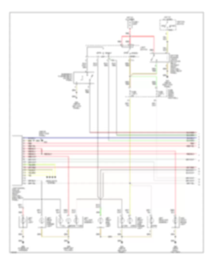
AIR CONDITIONING
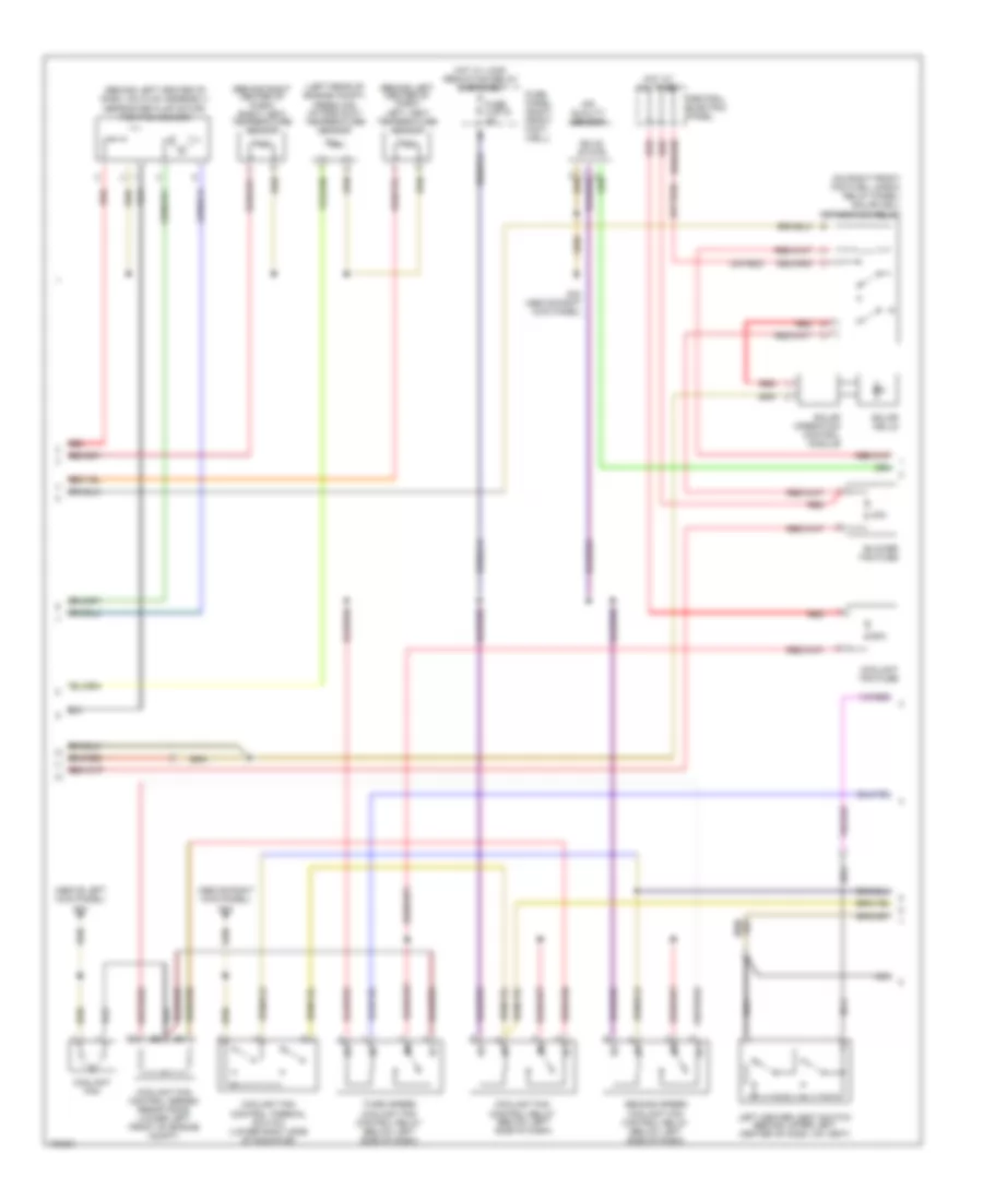
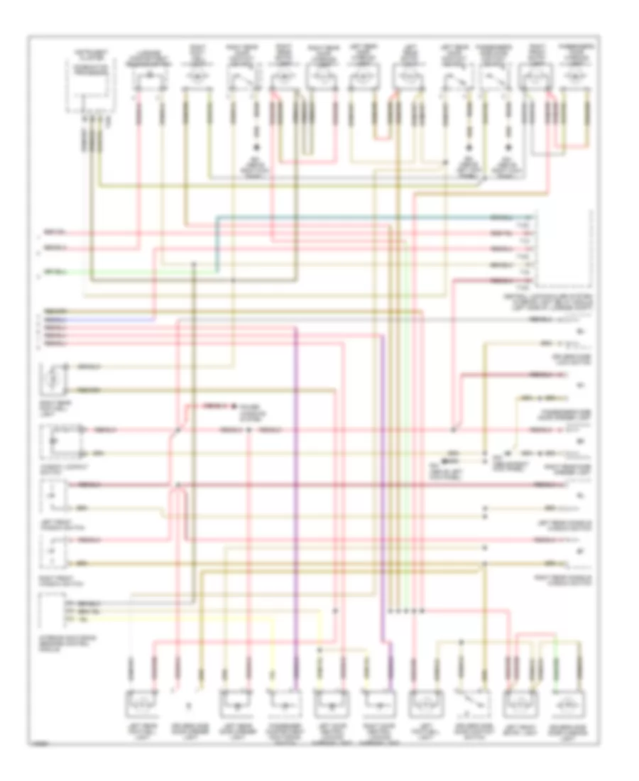
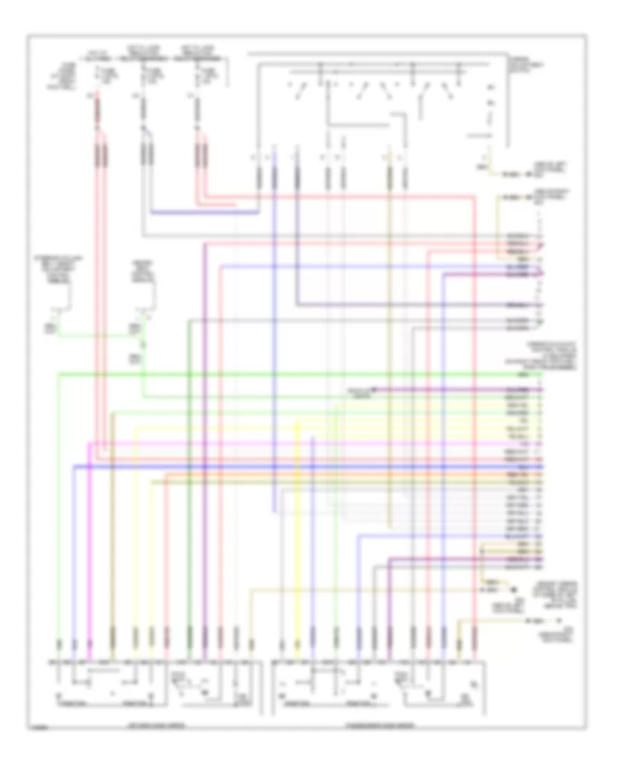
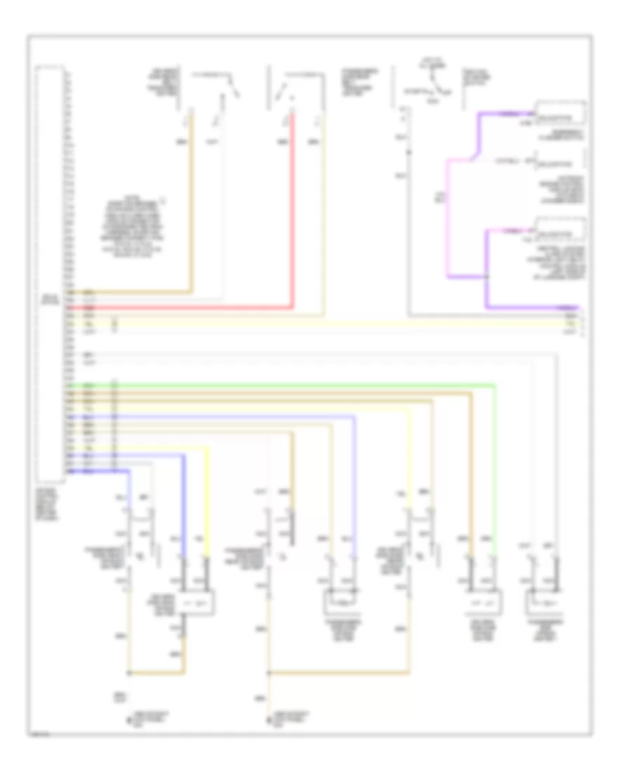
Automatic A/C Wiring Diagram (1 of 3) for Audi S8 2003

List of elements for Automatic A/C Wiring Diagram (1 of 3) for Audi S8 2003:
- (behind lower left center of dash, on hvac assembly)
- (behind lower left center of dash, on hvac assembly) left footwell flap motor/position sensor
- (behind lower right center of dash, on hvac assembly) right footwell flap motor/position sensor
- (behind right center of dash, on hvac assembly) flap motor temperature regulator/position sensor
- (left rear of engine compt)
- (left rear of engine compt) recirculation flap motor/ position sensor
- 1/+
- 2/-
- A/c control head
- A10
- A11
- A12
- A13
- A14
- A15
- A16
- A17
- A18
- A19
- A20
- A21
- A22
- A23
- A24
- Air flow flap motor/ back pressure flap motor position sensor
- B10
- B11
- B12
- B13
- B14
- B15
- B16
- B17
- B18
- B19
- B20
- B21
- B22
- Center vent adjusting motor/position sensor
- Fresh air blower (center rear of engine compt)
- Fresh air blower control module (right rear of engine compt)
- G43 (above right kick panel)
- Interior monitoring sensors control module
- Left center vent motor/position sensor (behind upper left center of dash, on hvac assembly)
- Rear footwell vent motor/position sensor (behind lower left center of dash, on hvac assembly)
- Red
- Right center vent motor/position sensor (behind upper right center of dash, on hvac assembly)
- Solid state
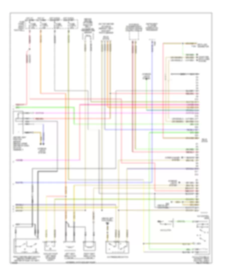
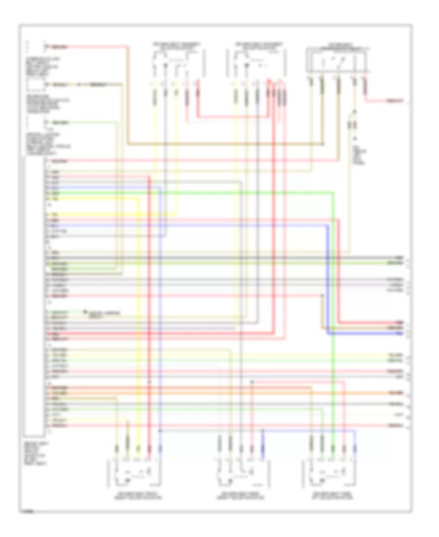
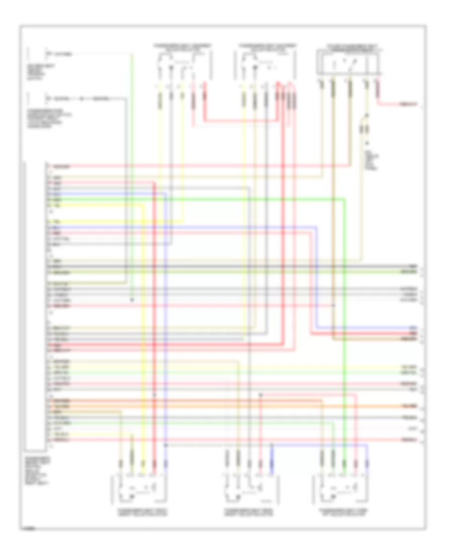
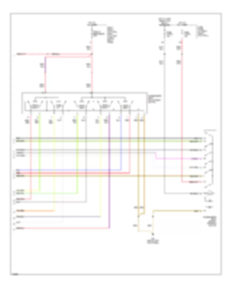
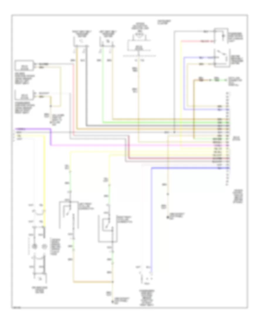
Automatic A/C Wiring Diagram (2 of 3) for Audi S8 2003
List of elements for Automatic A/C Wiring Diagram (2 of 3) for Audi S8 2003:
- (above left kick panel) g44
- (above right kick panel) g43
- (behind left center of dash) left vent temperature sensor
- (behind left center of dash, on hvac assembly) defroster flap motor/ position sensor
- (behind right center of dash) right vent temperature sensor
- (left rear of engine compt) fresh air intake duct temperature sensor
- (on right front footwell e-box relay panel) solar cell separation relay
- (or red)
- 40a
- 60a
- Air quality sensor
- Blower fan fuse
- Central electric panel
- Coolant fan
- Coolant fan control relay (below left side of dash)
- Coolant fan control series resistance (lower left front of engine compt)
- Coolant fan control thermal switch (lower right side of radiator)
- Coolant fan fuse
- Fuse 4 (st2) 5a
- Fuse panel (right front foot- well)
- G43 (above right kick panel)
- Hot at all times
- Hot w/ load reduction relay energized
- Left center vent switch (behind upper left center of dash, on vent)
- Nca
- Red
- Second speed coolant fan control relay (below left side of dash)
- Solar cells
- Solar operation control module
- Solid state
- Third speed coolant fan control relay (below left side of dash)
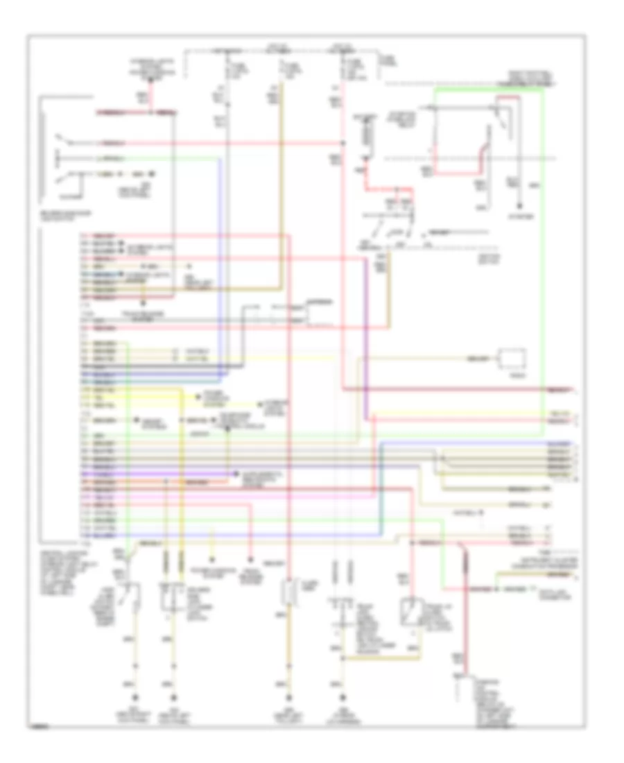
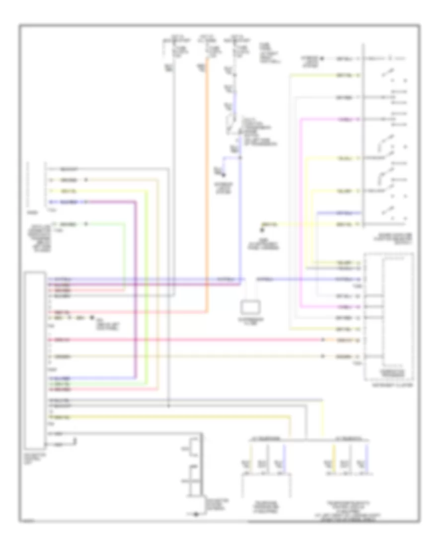
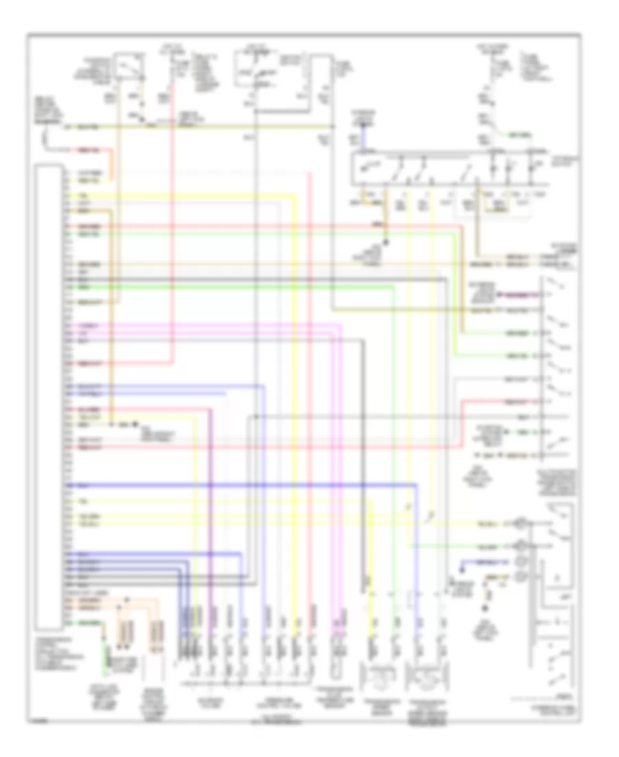
Automatic A/C Wiring Diagram (3 of 3) for Audi S8 2003
List of elements for Automatic A/C Wiring Diagram (3 of 3) for Audi S8 2003:
- (2000)
- (above left kick panel) g43
- (behind center of lower radiator grill) outside air temperature sensor
- (in plenum chamber e-box) motronic engine control module
- (integral with coolant pump)
- (on top center
- 1/+
- 2/-
- A/c clutch
- A/c clutch relay (on right front footwell e-box relay panel)
- A/c control head
- A/c pressure switch
- C10
- C11
- C12
- C13
- C14
- C15
- C16
- C17
- C18
- C19
- C20
- C21
- C22
- C23
- C24
- Center vent position sensor (behind upper center of dash, on hvac assembly)
- Computer data lines system
- Coolant pump (left rear of engine compt)
- D10
- D11
- D12
- E10
- E11
- E12
- Fuse 4 (st3) 10a
- Fuse 5 (st3) 10a
- Fuse 7 (st3) 15a
- Fuse 8 (st3) 10a
- Fuse panel (right front footwell)
- G43 (above left kick panel)
- Hot at all times
- Hot in run and start
- Instrument cluster combination processor
- Interior lights system
- Left heat regulating valve
- Nca
- Of middle defrost vent) sunlight photo sensor
- Right center vent switch (behind upper right center of dash, on vent)
- Right heat regulating valve
- Solid state
- T16a
- T32b
- Wiper/washer system
ANTI-THEFT
Power Door Locks Wiring Diagram (1 of 2) for Audi S8 2003
List of elements for Power Door Locks Wiring Diagram (1 of 2) for Audi S8 2003:
- 2002-03
- 50b
- 86s
- Acc
- Alarm
- All times
- Antenna
- B12
- Battery
- Central locking/ alarm system/ interior light delay control module (at left side of luggage compt, near wheelwell)
- Data link connector
- Driver's side door lock switch
- Driver's side lock cylinder lock switch
- Exterior lights system
- Fuse 3 (st5) 15a (or 10a)
- Fuse 4 (st5) 10a
- Fuse 5 (st5) 15a
- Fuse panel
- G43 (above right
- G44 (above left
- G44 (above left kick panel)
- G59 (near left taillight)
- G98 (in rear
- Hood alarm switch (on right rear of engine compt)
- Horn
- Hot at
- Hot in run
- Ignition switch
- Instrument cluster combination processor
- Interior lights system
- Interior lights system, power windows system
- Key switch
- Kick panel)
- Lid harness)
- Memory systems
- Nca
- Off
- Parking aid control module (below cd changer unit, on left side of luggage compartment)
- Power windows system
- Radio
- Red
- Right footwell e-box auxiliary fuse & relay panel
- Start
- Starter
- Starting interlock relay
- T10o
- T12
- T16
- T26b
- Telephone/ telematic control module
- Trunk lid alarm switch (in trunk lid latch)
- Trunk lock alarm/ central locking switch (on trunk lock cylinder housing)
- Trunk release system
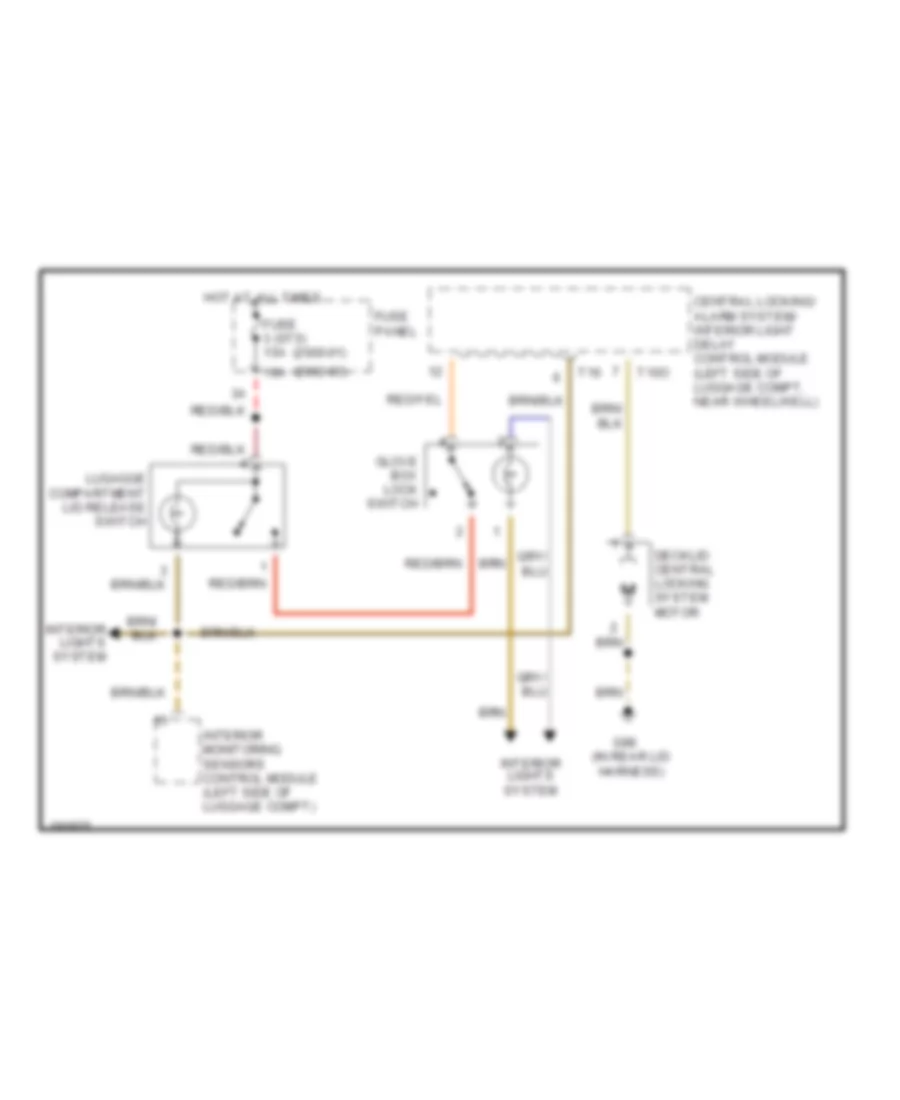
Power Door Locks Wiring Diagram (2 of 2) for Audi S8 2003
List of elements for Power Door Locks Wiring Diagram (2 of 2) for Audi S8 2003:
- All times
- Blower motor
- Driver's side door contact switch (on door latch mechanism)
- Fuse 1 (st5) 10a
- Fuse panel
- G43 (above right
- G44 (above left
- G59 (near left taillight)
- Hot at
- Interior monitoring sensor
- Interior monitoring sensors (ultra sound) control module (left side of luggage compt)
- Interior monitoring switch
- Interior monitoring transmitter
- Kick panel)
- Left door warning light
- Motor blower
- Passenger's side door contact switch (on door latch mechanism)
- Right door warning light
- T4aa
- T4ab
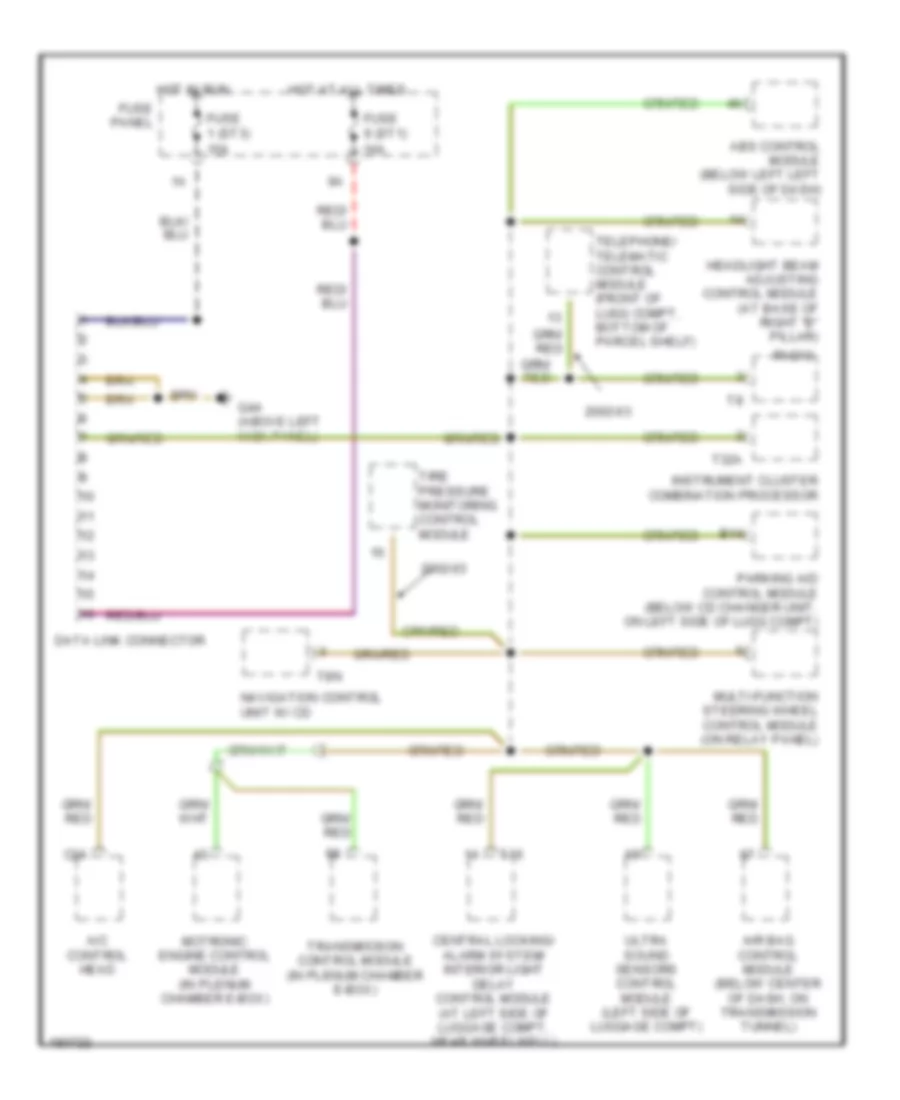
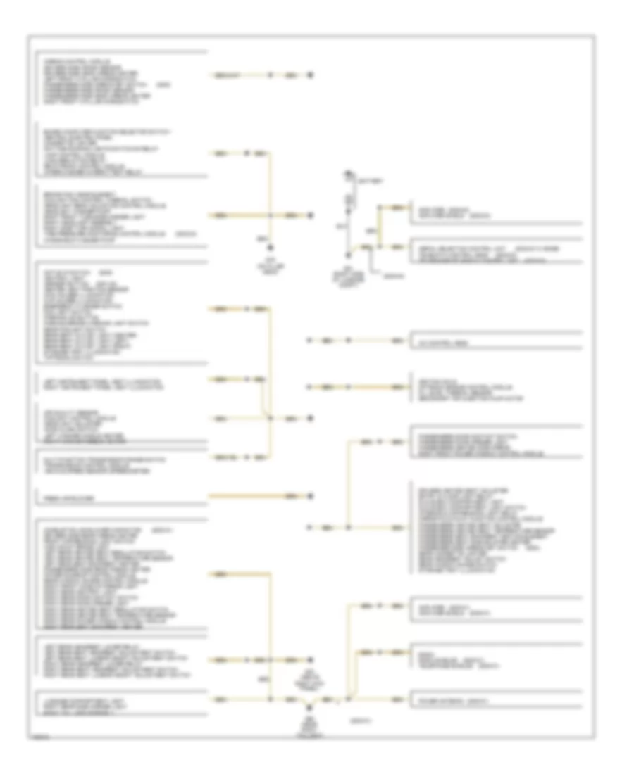
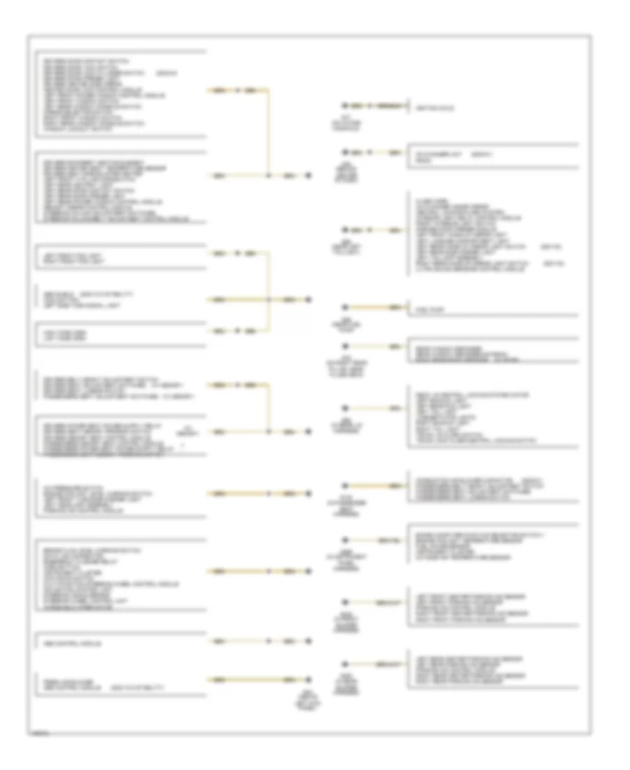
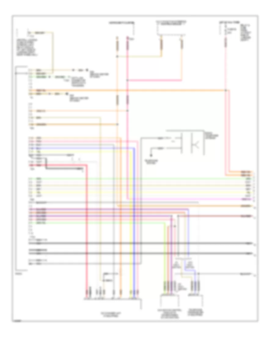
COMPUTER DATA LINES
Computer Data Lines Wiring Diagram for Audi S8 2003
List of elements for Computer Data Lines Wiring Diagram for Audi S8 2003:
- 2002-03
- A/c control head
- Abs control module (below left left side of dash)
- Air bag control module (below center of dash, on transmission tunnel)
- B14
- C24
- Central locking/ alarm system/ interior light delay control module (at left side of luggage compt, near wheelwell)
- Data link connector
- Fuse 1 (st3) 15a
- Fuse 9 (st1) 10a
- Fuse panel
- G44 (above left kick panel)
- Headlight beam adjusting control module (at base of right "b" pillar)
- Hot at all times
- Hot in run
- Instrument cluster combination processor
- Motronic engine control module (in plenum chamber e-box)
- Multi-function steering wheel control module (on relay panel)
- Navigation control unit w/ cd
- Parking aid control module (below cd changer unit, on left side of lugg compt)
- Radio
- T16
- T32a
- T8n
- Telephone/ telematic control module (front of lugg compt, bottom of parcel shelf)
- Tire pressure monitoring control module
- Transmission control module (in plenum chamber e-box)
- Ultra sound sensors control module (left side of luggage compt)
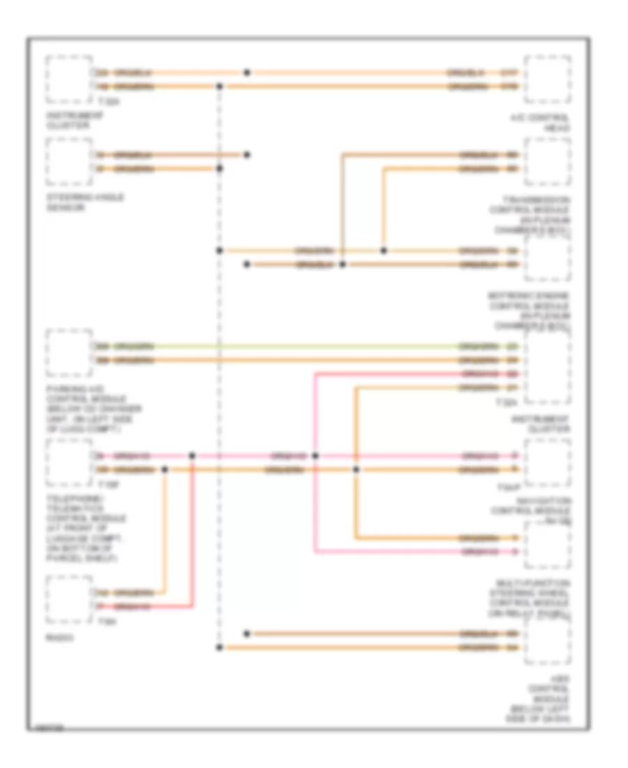
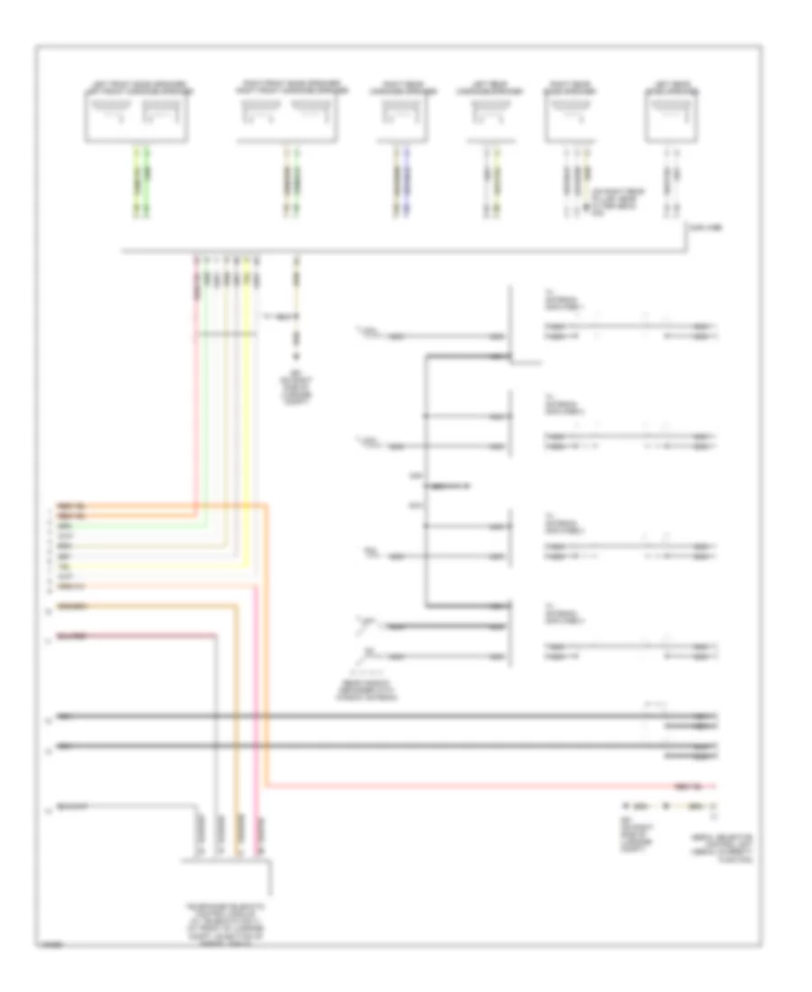
High/Low Bus Wiring Diagram for Audi S8 2003
List of elements for High/Low Bus Wiring Diagram for Audi S8 2003:
- A/c control head
- Abs control module (below left side of dash)
- C17
- C18
- Instrument cluster
- Motronic engine control module (in plenum chamber e-box)
- Multi-function steering wheel control module (on relay panel)
- Navigation control module w/ cd
- Parking aid control module (below cd changer unit, on left side of lugg compt)
- Radio
- Steering angle sensor
- T10f
- T32a
- T6ap
- T6h
- Telephone/ telematics control module (at front of luggage compt, on bottom of parcel shelf)
- Transmission control module (in plenum chamber e-box)
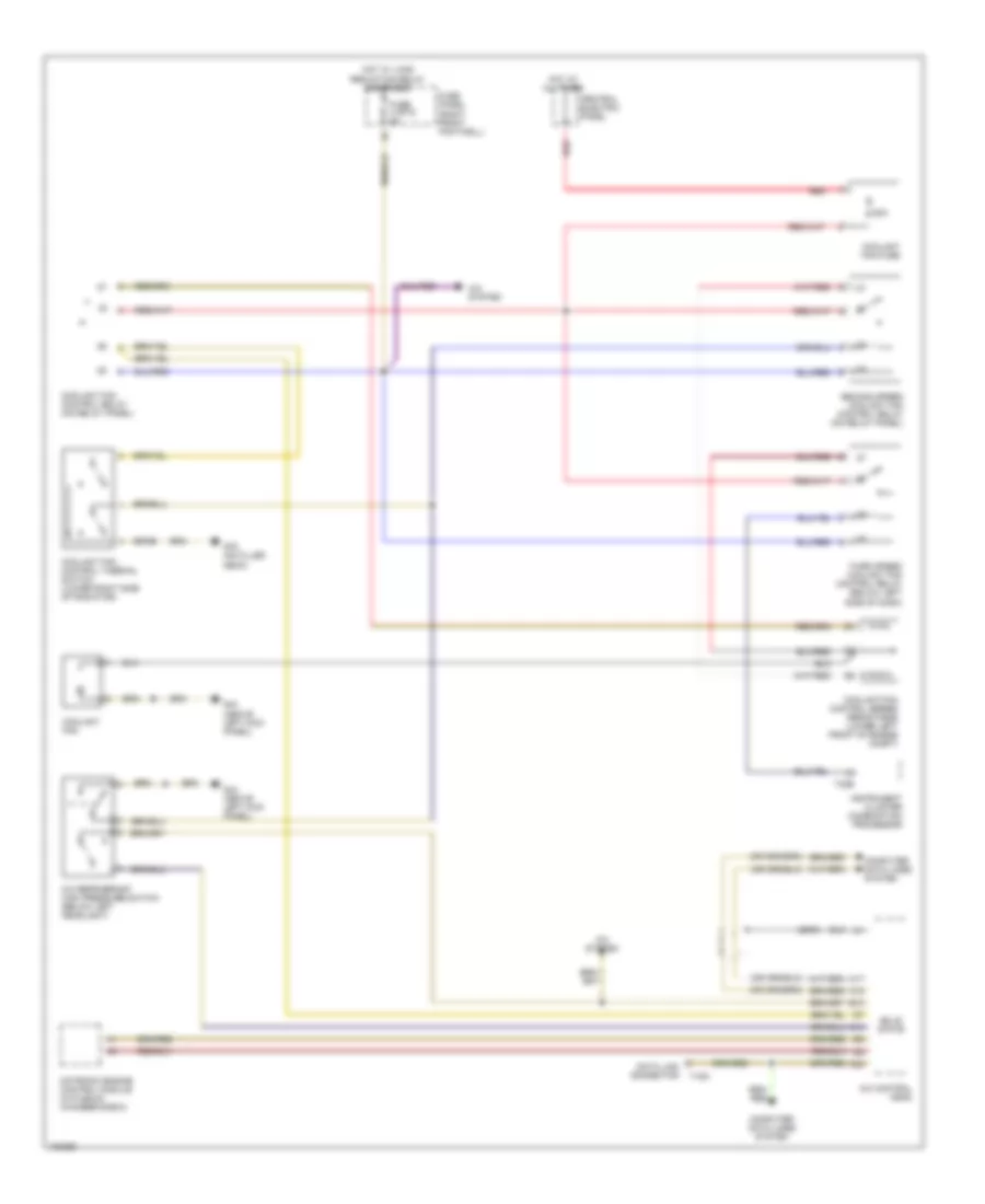
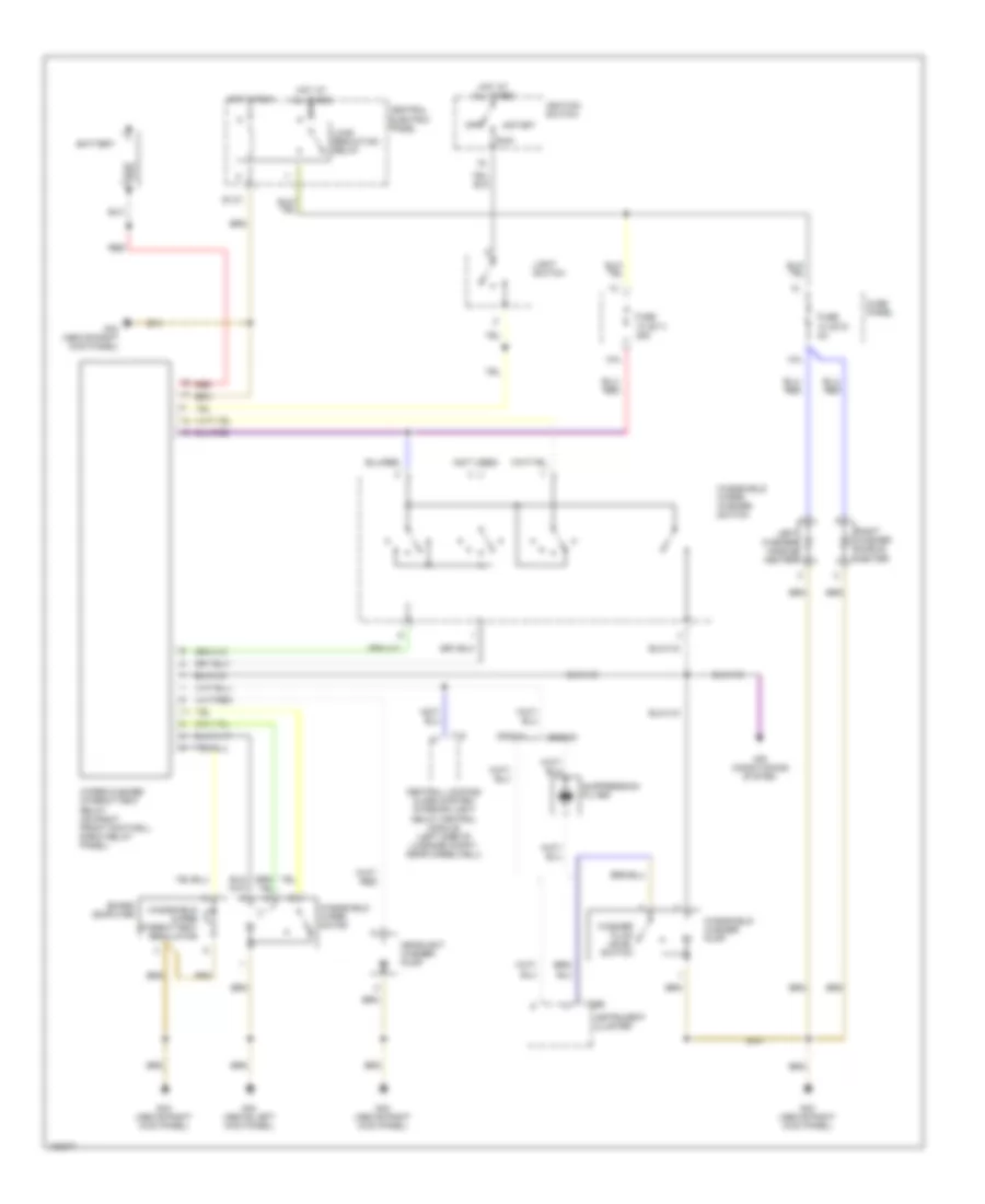
COOLING FAN
Cooling Fan Wiring Diagram for Audi S8 2003
List of elements for Cooling Fan Wiring Diagram for Audi S8 2003:
- (2000)
- 60a
- A/c control head
- A/c refrigerant high pressure switch (below left headlight)
- A/c system
- C17
- C18
- C24
- Central electric panel
- Computer data lines system
- Coolant fan
- Coolant fan control relay (on relay panel)
- Coolant fan control series resistance (lower left front of engine compt)
- Coolant fan control thermal switch (lower right side of radiator)
- Coolant fan fuse
- D10
- Data link connector
- E12
- Fuse 4 (st2) 5a
- Fuse panel (right front footwell)
- G44 (above left kick panel)
- G79 (on filler neck)
- Hot at all times
- Hot w/ load reduction relay energized
- Instrument cluster combination processor
- Motronic engine control module (in plenum chamber e-box)
- Red
- Second speed coolant fan control relay (on relay panel)
- Solid state
- T16a
- T32b
- Third speed coolant fan control relay (below left side of dash)
CRUISE CONTROL
Cruise Control Wiring Diagram for Audi S8 2003
List of elements for Cruise Control Wiring Diagram for Audi S8 2003:
- 10a
- Anti-lock brakes system
- Brakelight switch (above brake pedal, on bracket)
- Computer data lines system
- Cruise control switch
- Exterior lights system
- Fuse 1 (st3) 15a
- Fuse 10 (st4) 10a
- Fuse 5a
- Fuse 6 (st3) 10a
- Fuse 9 (st2) 10a
- Fuse panel (right front footwell)
- G43 (above right kick panel)
- Hot at all times
- Hot in run or start
- Instrument cluster
- Motronic engine control module (in plenum chamber e-box)
- Plenum chamber e-box relay & fuse panel (in plenum chamber e-box)
- Speedometer vehicle speed sensor (on left side of transmission)
- T32
- T32a
- T32b
- Throttle position sensor/ accelerator pedal position sensor (above accelerator pedal)
- Throttle valve control module (on throttle body, left front of eng)
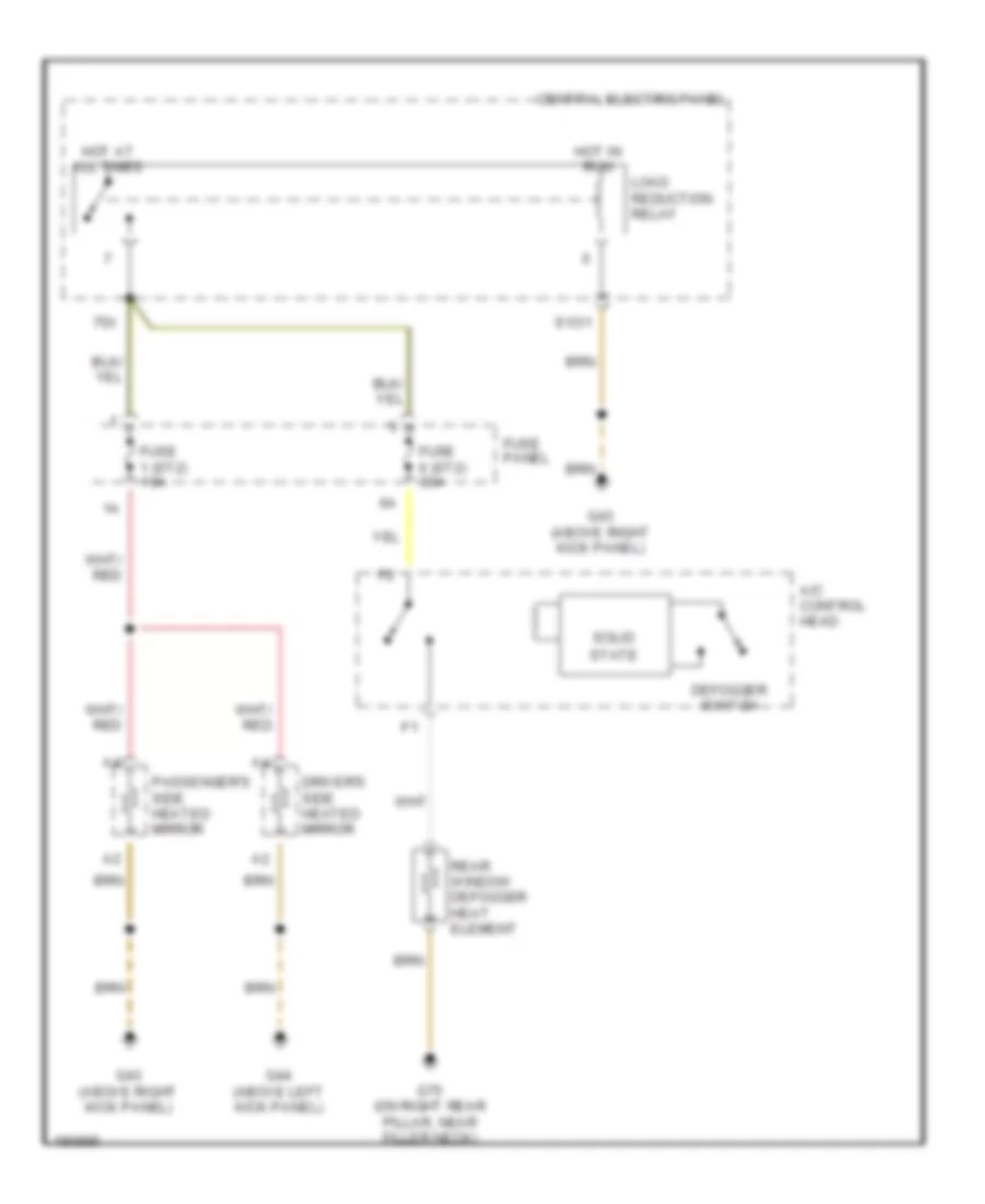
DEFOGGERS
Defoggers Wiring Diagram for Audi S8 2003
List of elements for Defoggers Wiring Diagram for Audi S8 2003:
- 75x
- A/c control head
- Central electric panel
- Defogger switch
- Driver's side heated mirror
- Fuse 1 (st2) 10a
- Fuse 6 (st2) 30a
- Fuse panel
- G43 (above right kick panel)
- G44 (above left kick panel)
- G75 (on right rear pillar, near filler neck)
- Hot at all times
- Hot in run
- Load reduction relay
- Passenger's side heated mirror
- Rear window defogger heat element
- S1/31
- Solid state
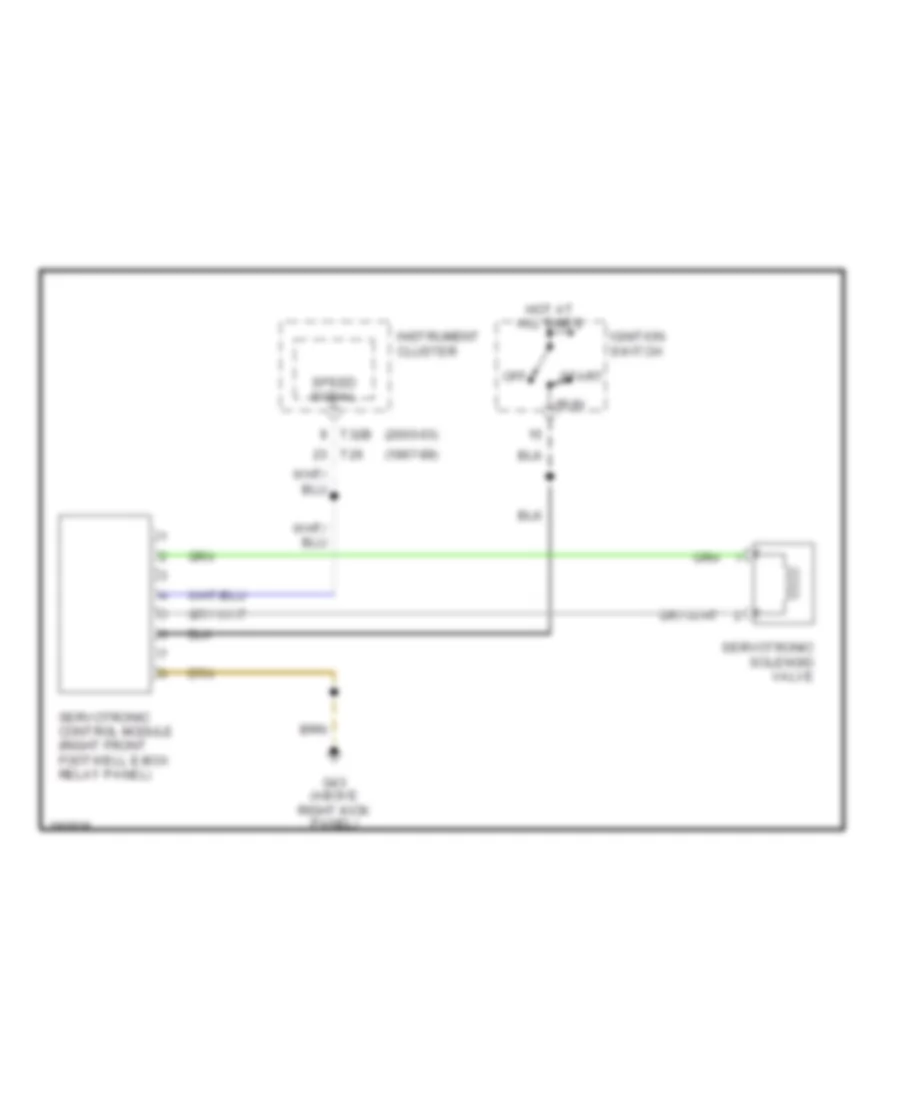
ELECTRONIC POWER STEERING
Electronic Power Steering Wiring Diagram for Audi S8 2003
List of elements for Electronic Power Steering Wiring Diagram for Audi S8 2003:
- (1997-99)
- (2000-03)
- G43 (above right kick panel)
- Hot at all times
- Ignition switch
- Instrument cluster
- Off
- Run
- Servotronic control module (right front footwell e-box relay panel)
- Servotronic solenoid valve
- Speed signal
- Start
- T26
- T32b
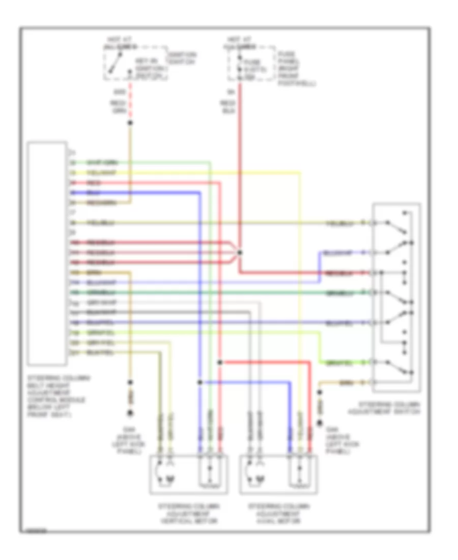
Power Steering Column Wiring Diagram for Audi S8 2003
List of elements for Power Steering Column Wiring Diagram for Audi S8 2003:
- 86s
- Fuse 9 (st5) 20a
- Fuse panel (right front footwell)
- G44 (above left kick panel)
- Hot at all times
- Ignition switch
- Key-in ignition switch
- Red
- Steering column adjustment axial motor
- Steering column adjustment switch
- Steering column adjustment vertical motor
- Steering column/ belt height adjustment control module (below left front seat)
ENGINE PERFORMANCE
4.2L
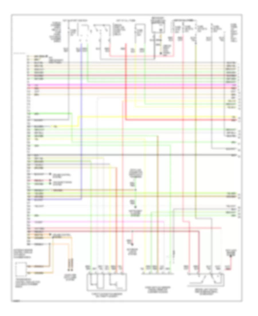
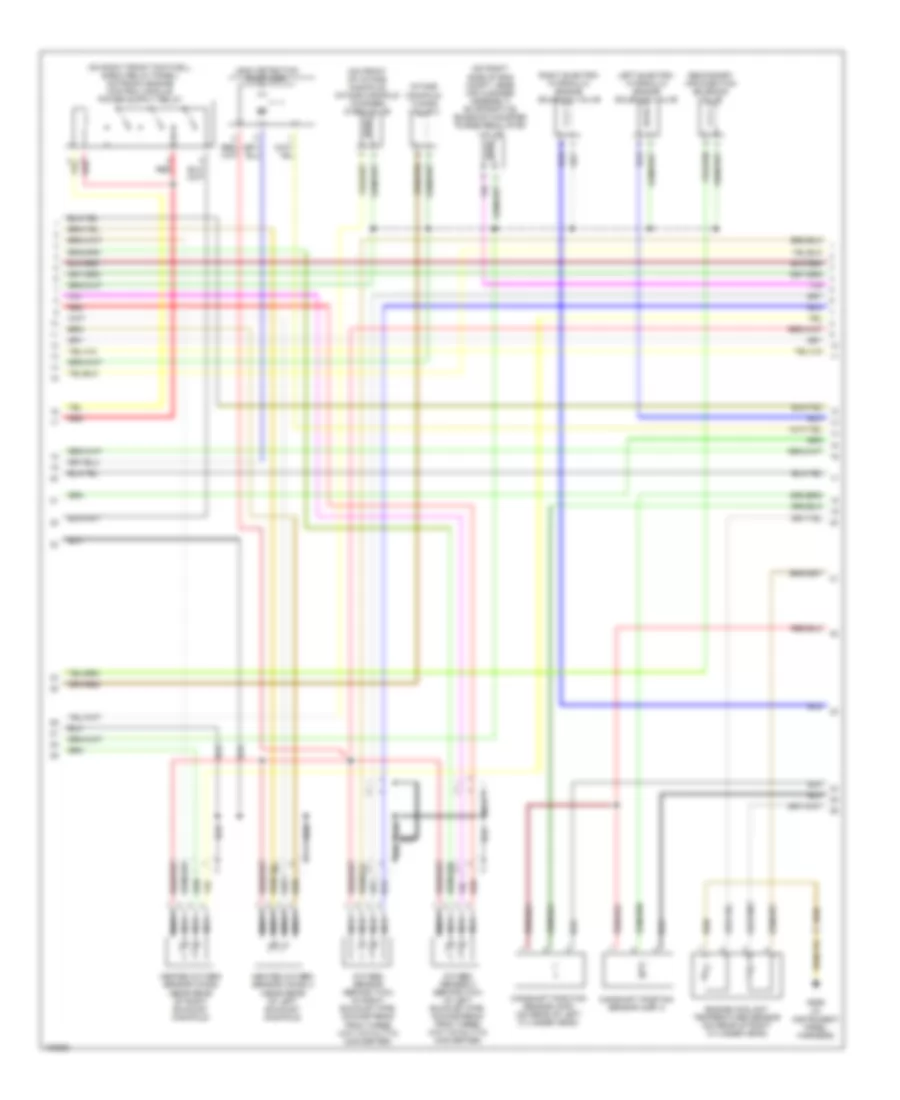
4.2L, Engine Performance Wiring Diagram (1 of 4) for Audi S8 2003
List of elements for 4.2L, Engine Performance Wiring Diagram (1 of 4) for Audi S8 2003:
- (above right kick panel) g43
- Air conditioning system
- Anti-lock brakes system
- Brake light switch (above brake pedal, on bracket)
- Computer data lines system
- Cruise control system
- Data link connector (rapid data transfer)
- Exterior lights system
- Fuse panel (at right front of foot- well)
- Fuse s10 (st4) 10a
- Fuse s102 5a
- Fuse s117 20a
- Fuse s130 50a
- Fuse s2 (st4) 30a
- Fuse s9 (st2) 10a
- G43 (above right kick panel)
- Hot at all times
- Hot in start and run
- Instrument cluster system
- Mass air flow sensor (inside upper air cleaner housing)
- Motronic engine control module (in plenum chamber e-box)
- Plenum chamber e-box relay & fuse panel (in plenum chamber e-box)
- Red
- Secon- dary air injection pump relay
- Secondary air injection pump motor
- Throttle position sensor (on throttle body)
- Transmission control module (tcm) (in plenum chamber e-box)
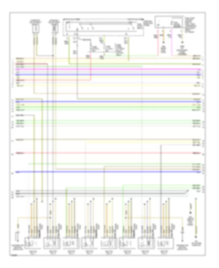
4.2L, Engine Performance Wiring Diagram (2 of 4) for Audi S8 2003
List of elements for 4.2L, Engine Performance Wiring Diagram (2 of 4) for Audi S8 2003:
- (on front of intake manifold) intake manifold changed over valve
- (on right side of eng compt, near air cleaner assembly) evaporative emission canister purge regulator valve
- Camshaft position sensor (cmp) (on rear of left cylinder head)
- Camshaft position sensor (cmp) 2
- Engine coolant temperature sensor (on rear of right cylinder head)
- G269 (in instrument panel harness)
- Heated oxygen sensor (ho2s) (near rear of right exhaust manifold)
- Heated oxygen sensor (ho2s) 2 (near rear of left exhaust manifold)
- Intake manifold tuning valve 2
- Leak detection pump (ldp)
- Left electro- hydraulic engine solenoid valve
- Nca
- Oxygen sensor (behind twc) (in right exhaust pipe, downstream from three way catalytic converter)
- Oxygen sensor 2 (behind twc) (in left exhaust pipe, downstream from three way catalytic converter)
- Red
- Right electro- hydraulic engine solenoid valve
- Secondary air injection solenoid valve
4.2L, Engine Performance Wiring Diagram (3 of 4) for Audi S8 2003
List of elements for 4.2L, Engine Performance Wiring Diagram (3 of 4) for Audi S8 2003:
- 87a
- 87f
- Camshaft adjustment valve 1
- Camshaft adjustment valve 2
- Central electric panel
- Distributor ignition capacitor
- Dti
- Fuel gauge sender
- Fuel pump (in right side of fuel tank, accessible from right front of trunk)
- Fuel pump relay
- Fuse panel (at right front of foot- well)
- Fuse s1 (st4) 20a
- Fuse s3 (st4) 20a
- G17 (on intake manifold)
- G269 (in instrument panel harness)
- G43 (above right kick panel)
- G49 (near fuel pump)
- Hot at all times
- Ignition coil 1
- Ignition coil 2
- Ignition coil 3
- Ignition coil 4
- Ignition coil 5
- Ignition coil 6
- Ignition coil 7
- Ignition coil 8
- Nca
- Plug spark
- Spark plug
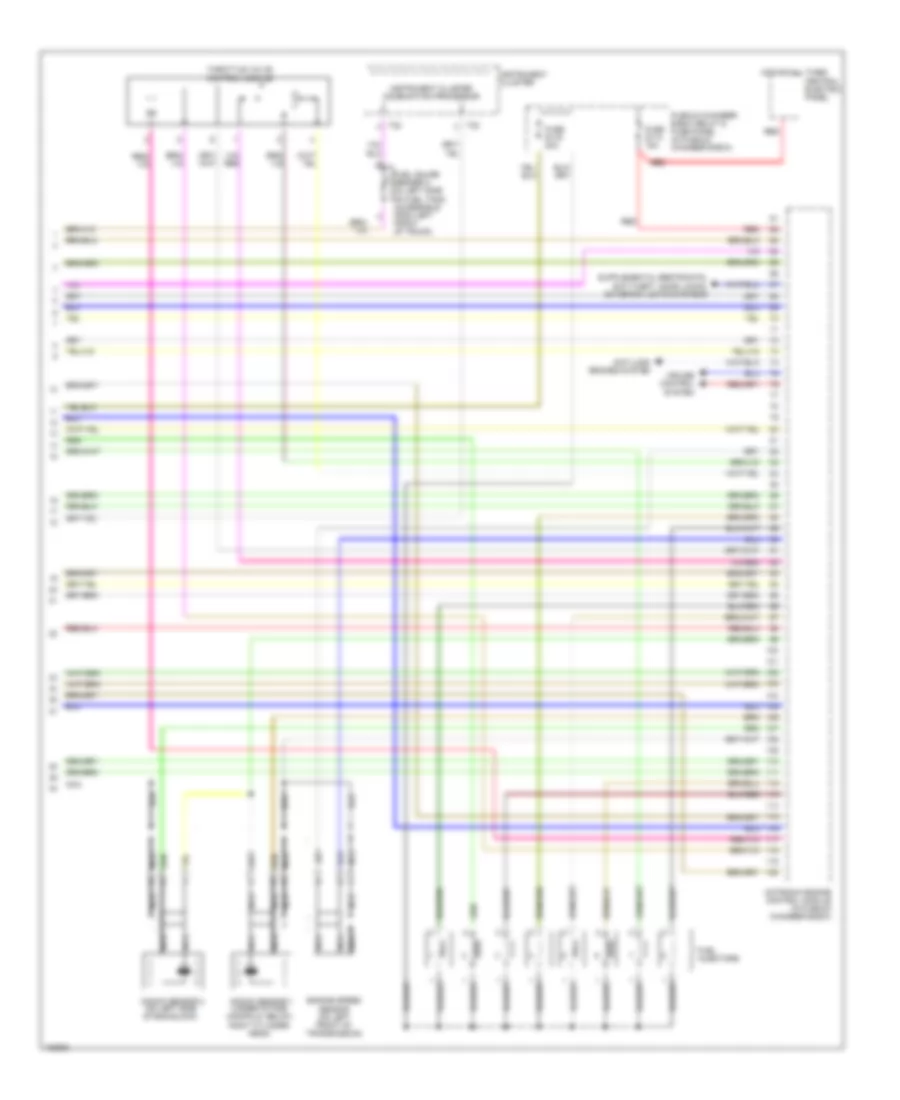
4.2L, Engine Performance Wiring Diagram (4 of 4) for Audi S8 2003
List of elements for 4.2L, Engine Performance Wiring Diagram (4 of 4) for Audi S8 2003:
- Anti-lock brakes system
- Central electric panel
- Cruise control system
- Engine speed sensor (on left front of transmission)
- Fuel gauge sender 2 (in left side of fuel tank, accessible from left front of trunk)
- Fuel injectors
- Fuse s113 15a
- Fuse s116 20a
- Hot at all times
- Instrument cluster
- Instrument cluster combination processor
- Knock sensor 1 (under intake manifold, below right cylinder head)
- Knock sensor 2 (on left side of eng block)
- Motronic engine control module (in plenum chamber e-box)
- Nca
- Plenum chamber e-box relay & fuse panel (in plenum chamber e-box)
- Red
- T32
- Throttle valve control module
EXTERIOR LIGHTS
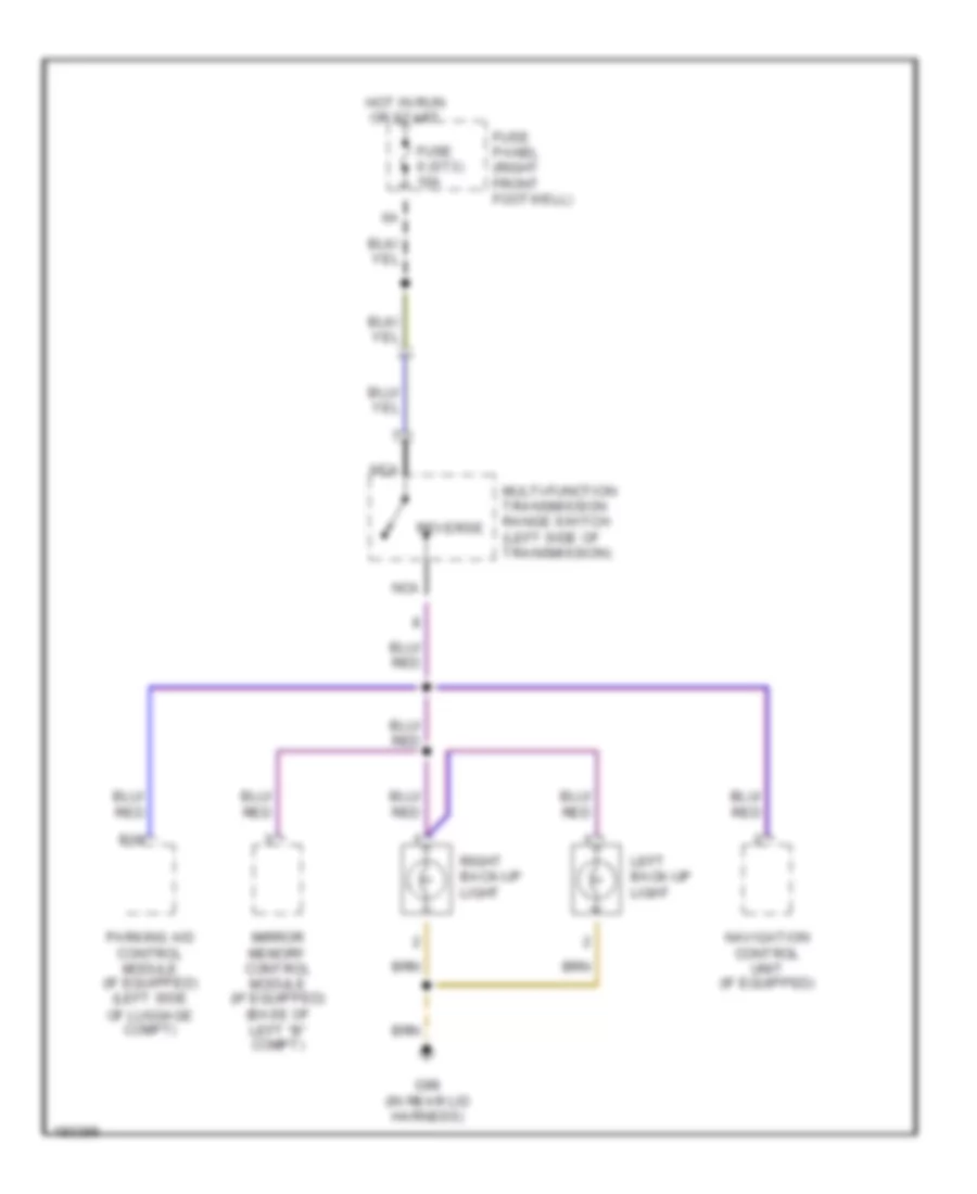
Back-up Lamps Wiring Diagram for Audi S8 2003
List of elements for Back-up Lamps Wiring Diagram for Audi S8 2003:
- B18
- Fuse 6 (st3) 10a
- Fuse panel (right front footwell)
- G98 (in rear lid harness)
- Hot in run or start
- Left back-up light
- Mirror memory control module (if equipped) (base of left "b" compt)
- Multi-function transmission range switch (left side of transmission)
- Navigation control unit (if equipped)
- Nca
- Parking aid control module (if equipped) (left side of luggage compt)
- Reverse
- Right back-up light
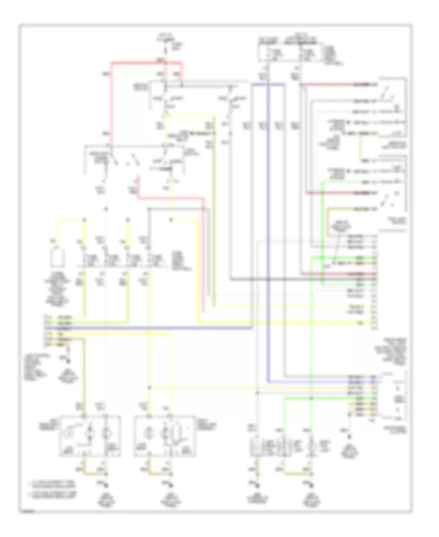
Exterior Lamps Wiring Diagram, with DRL (1 of 2) for Audi S8 2003
List of elements for Exterior Lamps Wiring Diagram, with DRL (1 of 2) for Audi S8 2003:
- (above right kick panel)
- Brake
- Daytime running lights switch-on relay (on right front footwell e-box relay panel)
- Emergency flasher relay (on relay panel)
- Fuse 1 (st1) 5a
- Fuse 1 200a
- Fuse 2 (st1) 5a
- Fuse panel (right front footwell)
- G43
- G43 (above right kick panel)
- G44 (above left kick panel)
- G59 (near left taillight)
- G60 (near right taillight)
- G98 (in rear lid harness)
- Head
- Headlights system
- High mount brake light
- Hot at all times
- Ignition switch
- Lamp control module (on right front footwell e-box relay panel)
- Left
- Left front side turn light
- Left front turn/ side marker light
- Left headlamp assembly
- Left rear side marker light
- Left tail light
- Left taillamp assembly
- Light switch
- Mark
- Off
- Park
- Red
- Right
- Run
- Start
- T14
- Tail
- Turn
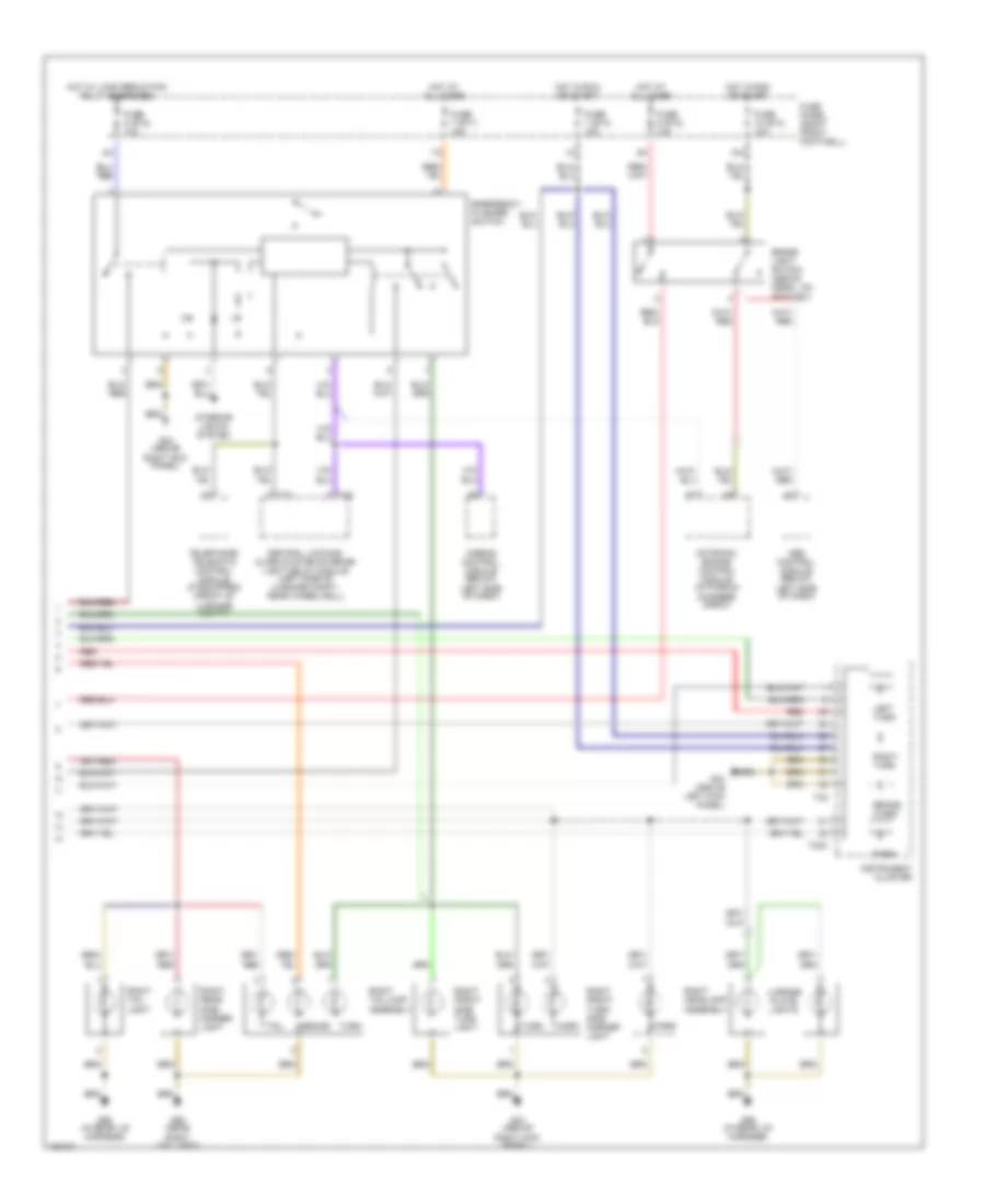
Exterior Lamps Wiring Diagram, with DRL (2 of 2) for Audi S8 2003
List of elements for Exterior Lamps Wiring Diagram, with DRL (2 of 2) for Audi S8 2003:
- 10a
- Abs control module (below left side of dash)
- Airbag control module (below left side of dash)
- Brake
- Brake light switch (above pedal, on bracket)
- Brake warn
- Central locking/ alarm system/interior light delay module (left side of luggage compt, near wheelwell)
- Emergency flasher switch
- Fuse 1 (st3) 15a
- Fuse 10 (st4) 10a
- Fuse 7 (st1) 15a
- Fuse 8 (st2) 10a
- Fuse 9 (st2) 10a
- Fuse panel (right front footwell)
- G43 (above right kick panel)
- G44 (above left kick panel)
- G60 (near right taillight)
- G98 (in rear lid harness)
- Hot at all times
- Hot in run or start
- Hot w/ load reduction relay energized
- Instrument cluster
- Interior lights system
- Left turn
- License plate lights
- Mark
- Motronic engine control module (in plenum chamber e-box)
- Park
- Red
- Right front side turn light
- Right front turn/ side marker light
- Right headlamp assembly
- Right rear side marker light
- Right tail light
- Right taillamp assembly
- Right turn
- T10
- T16
- T32
- T32a
- Tail
- Telephone/ telematic control module (if equipped) (front of luggage compt)
- Turn
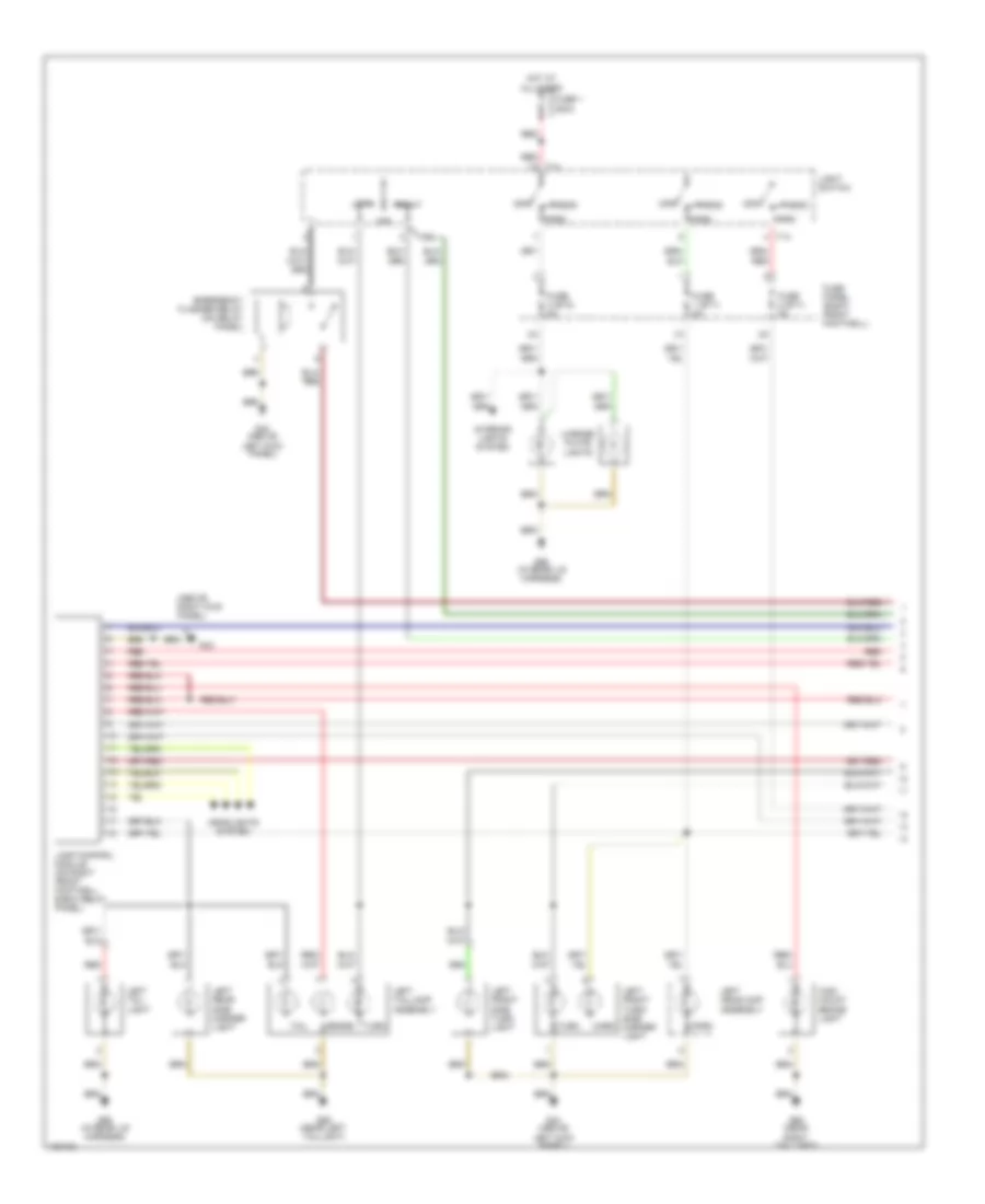
Exterior Lamps Wiring Diagram, without DRL (1 of 2) for Audi S8 2003
List of elements for Exterior Lamps Wiring Diagram, without DRL (1 of 2) for Audi S8 2003:
- (above right kick panel)
- Brake
- Emergency flasher relay (on relay panel)
- Fuse 1 (st1) 5a
- Fuse 1 200a
- Fuse 2 (st1) 5a
- Fuse 3 (st2) 5a
- Fuse panel (right front footwell)
- G43
- G44 (above left kick panel)
- G59 (near left taillight)
- G60 (near right taillight)
- G98 (in rear lid harness)
- Head
- Headlights system
- High mount brake light
- Hot at all times
- Interior lights system
- Lamp control module (on right front footwell e-box relay panel)
- Left
- Left front side turn light
- Left front turn/ side marker light
- Left headlamp assembly
- Left rear side marker light
- Left tail light
- Left taillamp assembly
- License plate lights
- Light switch
- Mark
- Off
- Park
- Red
- Right
- T14
- Tail
- Turn
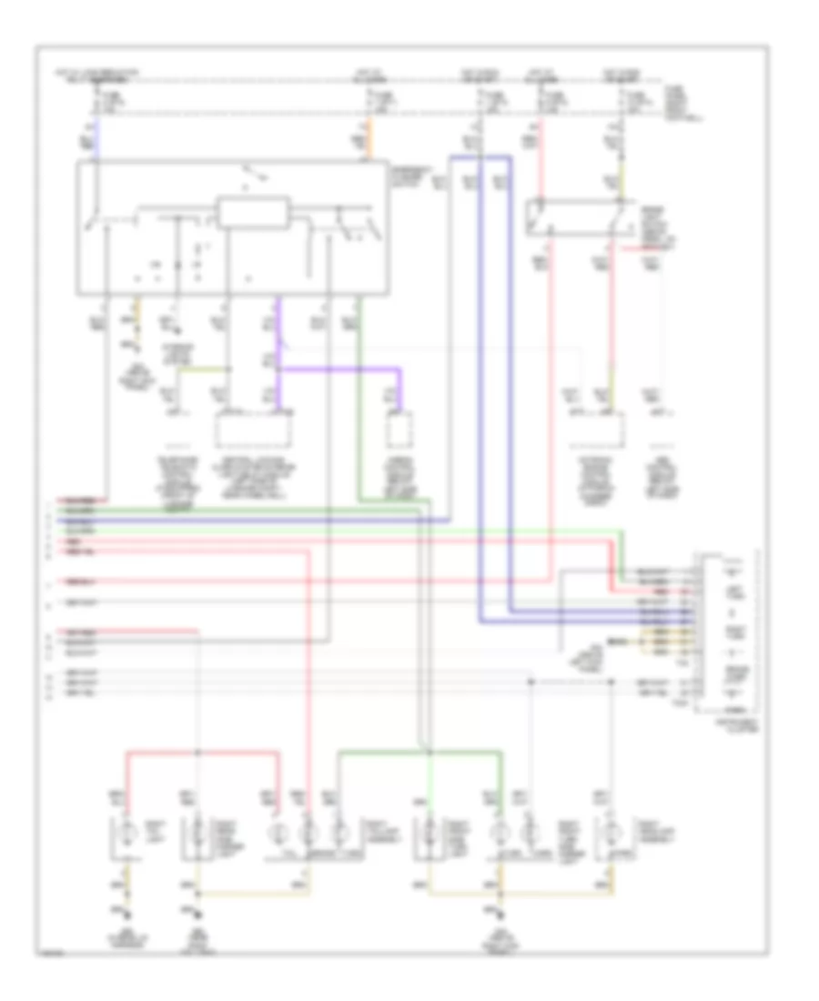
Exterior Lamps Wiring Diagram, without DRL (2 of 2) for Audi S8 2003
List of elements for Exterior Lamps Wiring Diagram, without DRL (2 of 2) for Audi S8 2003:
- 10a
- Abs control module (below left side of dash)
- Airbag control module (below left side of dash)
- Brake
- Brake light switch (above pedal, on bracket)
- Brake warn
- Central locking/ alarm system/interior light delay module (left side of luggage compt, near wheelwell)
- Emergency flasher switch
- Fuse 1 (st3) 15a
- Fuse 10 (st4) 10a
- Fuse 7 (st1) 15a
- Fuse 8 (st2) 10a
- Fuse 9 (st2) 10a
- Fuse panel (right front footwell)
- G43 (above right kick panel)
- G44 (above left kick panel)
- G60 (near right taillight)
- G98 (in rear lid harness)
- Hot at all times
- Hot in run or start
- Hot w/ load reduction relay energized
- Instrument cluster
- Interior lights system
- Left turn
- Mark
- Motronic engine control module (in plenum chamber e-box)
- Park
- Red
- Right front side turn light
- Right front turn/ side marker light
- Right headlamp assembly
- Right rear side marker light
- Right tail light
- Right taillamp assembly
- Right turn
- T10
- T16
- T32
- T32a
- Tail
- Telephone/ telematic control module (if equipped) (front of luggage compt)
- Turn
GROUND DISTRIBUTION
Ground Distribution Wiring Diagram (1 of 2) for Audi S8 2003
List of elements for Ground Distribution Wiring Diagram (1 of 2) for Audi S8 2003:
- (2000)
- (2000-01)
- (2001-03)
- (2002-03 w/ bose)
- (2002-03)
- A/c control head
- Aerial selection control unit telematic control head telephone/telematic control unit
- Air quality sensor foglight control module headlight adjuster hood alarm switch left washer nozzle heater right washer nozzle heater
- Airbag control module drivers side crash sensor drivers side head airbag igniter left front a pillar microswitch passengers side airbag key switch passengers side crash sensor passengers side head airbag igniter right front a pillar microswitch
- Amplifier amplifier shield
- Anti-slip switch ashtray light asr/esp button center vent position sensor coin holder illumination cup holder illumination emergency flasher switch fog light switch parking aid button parking brake warning light switch rear foglight switch rear seat outlet light (center) rear seat outlet light (left) rear seat outlet light (right) storage tray illumination tiptronic switch
- Battery
- Board computer function selector switch i central electric panel cigarette lighter daytime running lights switch-on relay lamp control module load reduction relay sevotronic control module wiper/washer intermittent relay
- Brake pad wear element coolant fan control thermal switch headlight beam adjusting control module headlght washer pump right front turn/side marker light right headlamp assembly right side turn signal light tire pressure monitoring control module windshield washer pump
- Combustion air blower capacitor drivers side rear airbag igniter front map/reading light switch high mount brake light left rear heated seat regulating switch left rear heated seat temperature sensor left rear seat backrest heater passengers side rear airbag igniter power sunroof control module rear window shade control module right front make-up mirror light right rear ashtray light right rear door contact switch right rear door opener light right rear heated seat regulating switch right rear heated seat temperature sensor right rear power window control module right rear seat backrest heater
- Drivers heated seat adjuster entry & floor light relay glove box compartment light glove box compartment light switch interior & map/reading light relay mirror fold-away function control module passengers heated seat adjuster passengers heated seat temperature sensor passengers seat backrest heating element passengers seat side bolster heater passenger side airbag key switch rear cigarette lighter rear headrest adjust switch rear window shade switch storage tray illumination
- Fresh air blower
- G43 (above right kick panel)
- G51 (right side of luggage compt)
- G60 (near right taillight)
- G79 (on filler neck)
- Ignition coils motronic engine control module oil level thermal sensor secondary air injection pump motor
- Left instrument panel vent illumination right instrument panel vent illumination
- Left rear headrest lower relay left rear seat headrest adjustment switch left rear seat lumbar height adjustment switch right rear headrest lower relay right rear seat headrest adjustment switch right rear seat lumbar height adjustment switch
- Luggage compartment light right rear side marker light right taillamp assembly
- Multi-function transmission range switch transmission control module vehicle speed sensor (speedometer)
- Passengers door contact switch passengers door opener light passengers heated side mirror right front power window control module
- Power antenna
- Radio radio shields telephone shields
Ground Distribution Wiring Diagram (2 of 2) for Audi S8 2003
List of elements for Ground Distribution Wiring Diagram (2 of 2) for Audi S8 2003:
- (2000 w/o stability)
- (2000-01)
- (2001-03)
- (2002-03)
- (w/ bose)
- (w/ memory)
- A/c pressure switch engine coolant level warning switch left front turn/side marker light left headlamp assembly parking aid control module
- Abs control module
- Abs shield coolant fan left side turn signal light
- Alarm horn auto dimmer inside mirror central locking/alarm system/ interior light delay control module front interior light switch garage door opener module left front make-up mirror light left luggage compartment light left rear make-up mirror light switch left rear side marker light left taillamp assembly right rear make-up mirror light switch ultra sound sensors control module
- Board computer function selector switch ii engine coolant temperature sensor fuel gauge sensor instrument cluster outside air temperature sensor
- Brake fluid level warning switch data link connector emergency flasher relay horn button instrument cluster kick down switch multi-function steering wheel control module navigation control unit steering angle sensor steering wheel control unit windshield wiper motor
- Cd changer unit radio
- Combustion air blower capacitor passengers belt height adjustment switch passengers seat adjustment switches passengers seat lumbar switch
- Deck lid central locking system motor left backup light left rear fog light left tail light license plate lights right backup light right tail light trunk lid alarm switch trunk lock alarm/central locking switch
- Drivers backrest heating element drivers heated seat temperature sensor drivers seat side bolster heater left front a pillar microswitch left rear ashtray light left rear door contact switch left rear door opener light left rear power window control module memory mirror control module steering column adjustment switches steering column/belt adjustment control module
- Drivers belt height adjustment switch drivers seat adjustment switches drivers seat lumbar switch passengers seat adjustment switches
- Drivers door contact switch drivers door lock switch drivers door lock cylinder switch drivers door opener light drivers heated side mirror heated door lock control module left front power window control module left front window switch left rear window console switch mirror selector switch right front window switch right rear window console switch window lockout switch
- Fresh air blower abs control module
- Fuel pump
- G140 (in passenger seat harness)
- G17 (on intake manifold)
- G269 (in instrument panel harness)
- G348 (in front bumper harness)
- G352 (in rear bumper harness)
- G44 (above left kick panel)
- G45 (behind center of dash)
- G49 (near fuel pump)
- G59 (near left taillight)
- G75 (on right rear pillar, near filler neck)
- G98 (in rear lid harness)
- High tone horn low tone horn
- Ignition coils
- Left front center parking aid sensor left front parking aid sensor parking aid control module right front center parking aid sensor right front parking aid sensor
- Left front fog light right front fog light
- Left rear center parking aid sensor left rear parking aid sensor parking aid control module right rear center parking aid sensor right rear parking aid sensor
- Rear window defogger rear window defogger/antenna right rear bass speaker
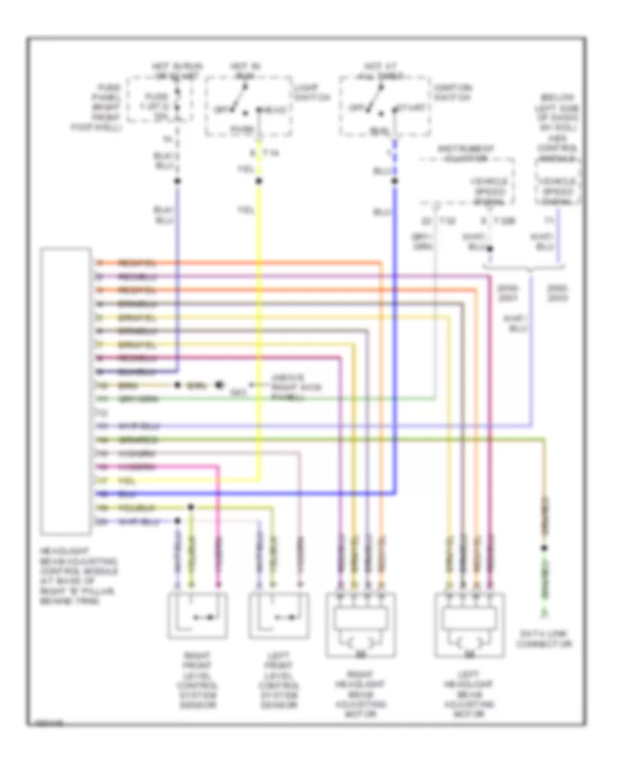
HEADLIGHTS
Headlamp Beam Adjustment Wiring Diagram for Audi S8 2003
List of elements for Headlamp Beam Adjustment Wiring Diagram for Audi S8 2003:
- (above right kick panel)
- (below
- 2000-
- 2002-
- Abs control module
- Data link connector
- Fuse 1 (st3) 15a
- Fuse panel (right front footwell)
- G43
- Head
- Headlight beam adjusting control module (at base of right "b" pillar, behind trim)
- Hot at all times
- Hot in run
- Hot in run or start
- Ignition switch
- Instrument cluster
- Left front level control system sensor
- Left headlight beam adjusting motor
- Left side of dash) (w/ edl)
- Light switch
- Off
- Park
- Right front level control system sensor
- Right headlight beam adjusting motor
- Run
- Start
- T14
- T32
- T32b
- Vehicle speed signal
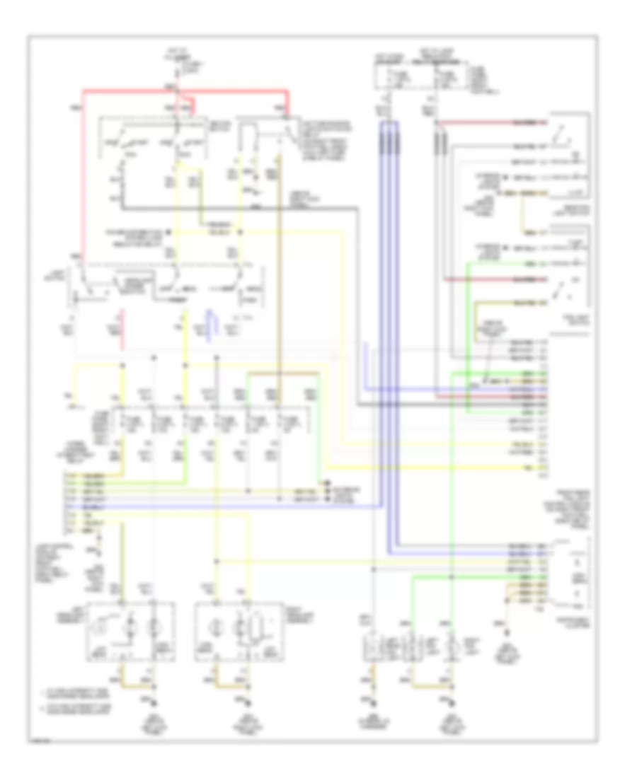
Headlamps & Fog Lamps Wiring Diagram, with DRL for Audi S8 2003
List of elements for Headlamps & Fog Lamps Wiring Diagram, with DRL for Audi S8 2003:
- (above
- (above right kick panel)
- Daytime running lights switch-on relay (on right front footwell e-box auxiliary fuse & relay panel)
- Exterior lights system
- Fog
- Fog light switch
- Front/rear fog light control module (on right front footwell e-box relay panel)
- Fuse 1 (st1) 5a
- Fuse 1 (st3) 15a
- Fuse 1 200a
- Fuse 2 (st1) 5a
- Fuse 3 (st1) 15a
- Fuse 4 (st1) 15a
- Fuse 5 (st1) 10a
- Fuse 5 (st2) 15a
- Fuse 6 (st1) 10a
- Fuse panel (right front foot- well)
- Fuse panel (right front footwell)
- G43
- G43 (above right kick panel)
- G44 (above
- G44 (above left kick panel)
- G98 (in rear lid harness)
- Head
- Headlamp dimmer switch
- High beam
- Hot at all times
- Hot in run or start
- Hot w/ load reduction relay energized
- Ignition switch
- Illum
- Instrument cluster
- Interior lights system
- Lamp control module (on right front footwell e-box relay panel)
- Left fog light
- Left headlamp assembly
- Left kick panel)
- Left rear fog light
- Light switch
- Low beam
- Off
- Park
- Power distribution system (load reduction relay)
- Rear fog light switch
- Red
- Right fog light
- Right headlamp assembly
- Right kick panel)
- Run
- Start
- T14
- T32
- W/ high intensity gas discharge headlamps
- W/o high intensity gas discharge headlamps
- Wiper/ washer intermittent relay
Headlamps & Fog Lamps Wiring Diagram, without DRL for Audi S8 2003
List of elements for Headlamps & Fog Lamps Wiring Diagram, without DRL for Audi S8 2003:
- (above
- Dimmer switch
- Fog
- Fog light switch
- Front/rear fog light control module (on right front footwell e-box relay panel)
- Fuse 1 (st3) 15a
- Fuse 1 200a
- Fuse 3 (st1) 15a
- Fuse 4 (st1) 15a
- Fuse 5 (st1) 10a
- Fuse 5 (st2) 15a
- Fuse 6 (st1) 10a
- Fuse panel (right front footwell)
- G43
- G43 (above right kick panel)
- G44 (above
- G44 (above left kick panel)
- G98 (in rear lid harness)
- Head
- Headlamp
- High beam
- Hot at all times
- Hot in run or start
- Hot w/ load reduction relay energized
- Ignition switch
- Illum
- Instrument cluster
- Interior lights system
- Lamp control module (on right front footwell e-box relay panel)
- Left fog light
- Left headlamp assembly
- Left kick panel)
- Left rear fog light
- Light switch
- Load reduction relay
- Low beam
- Off
- Park
- Rear fog light switch
- Red
- Right fog light
- Right headlamp assembly
- Right kick panel)
- Run
- Start
- T14
- T32
- W/ high intensity gas discharge headlamps
- W/o high intensity gas discharge headlamps
- Wiper/ washer intermittent relay (on right front footwell e-box relay panel)
HORN
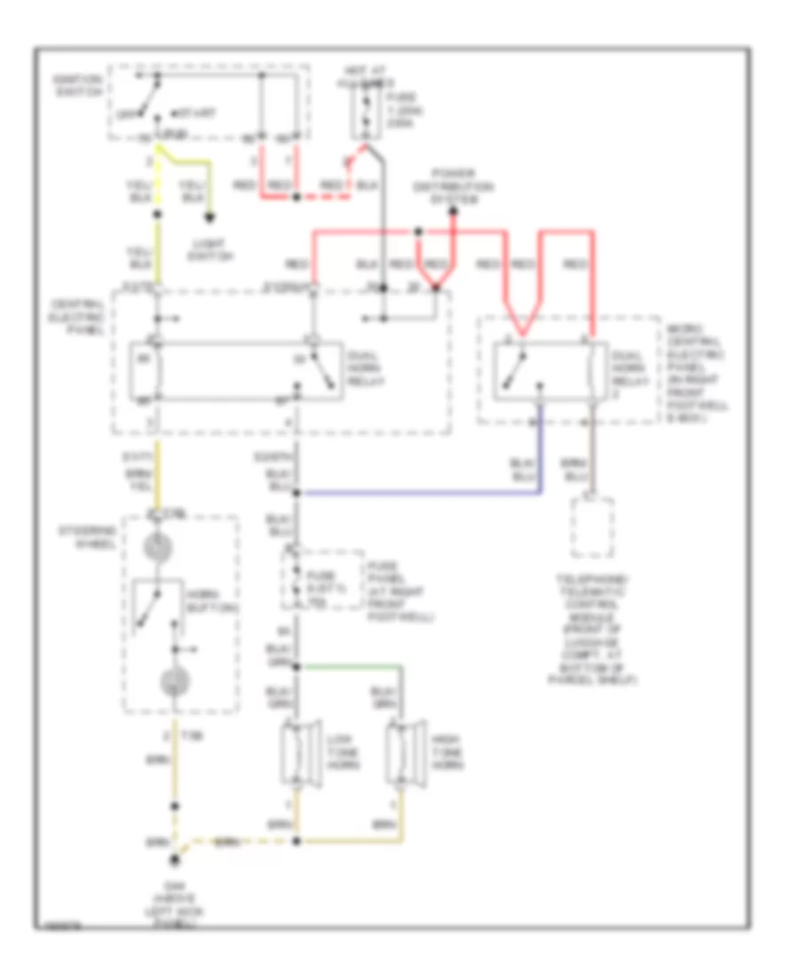
Horn Wiring Diagram, with Telematics for Audi S8 2003
List of elements for Horn Wiring Diagram, with Telematics for Audi S8 2003:
- Central electric panel
- Dual horn relay
- Fuse 1 (204) 200a
- Fuse 8 (st1) 15a
- Fuse panel (at right front footwell)
- G44 (above left kick panel)
- High tone horn
- Horn button
- Hot at all times
- Ignition switch
- Light switch
- Low tone horn
- Micro central electric panel (in right front footwell e-box)
- Off
- Power distribution system
- Red
- Run
- S1/30ah
- S1/71
- S1/75
- S2/87h
- Start
- Steering wheel
- T5b
- Telephone/ telematic control module (front of luggage compt, at bottom of parcel shelf)
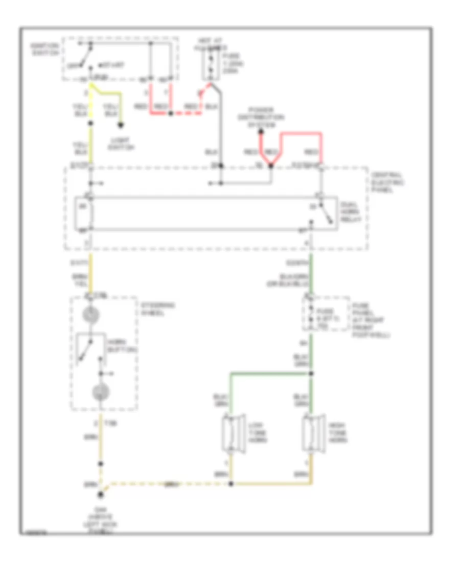
Horn Wiring Diagram, without Telematics for Audi S8 2003
List of elements for Horn Wiring Diagram, without Telematics for Audi S8 2003:
- Central electric panel
- Dual horn relay
- Fuse 1 (204) 200a
- Fuse 8 (st1) 15a
- Fuse panel (at right front footwell)
- G44 (above left kick panel)
- High tone horn
- Horn button
- Hot at all times
- Ignition switch
- Light switch
- Low tone horn
- Off
- Power distribution system
- Red
- Run
- S1/30ah
- S1/71
- S1/75
- S2/87h
- Start
- Steering wheel
- T5b
INSTRUMENT CLUSTER
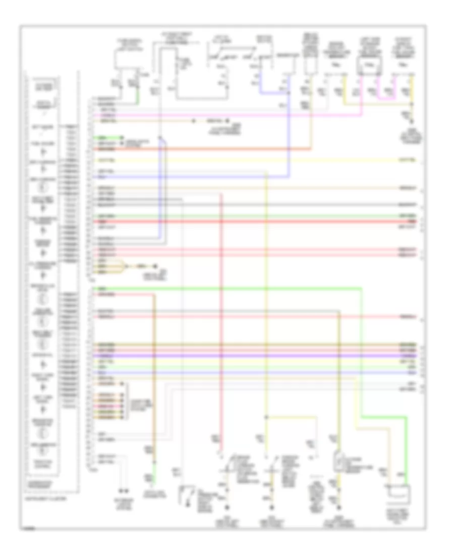
Instrument Cluster Wiring Diagram (1 of 3) for Audi S8 2003
List of elements for Instrument Cluster Wiring Diagram (1 of 3) for Audi S8 2003:
- (at right front footwell) fuse panel
- (below center of dash) airbag control module
- (in right side of fuel tank)
- (left side of engine block) fuel gauge sensor 2
- (turn signal switch)
- Abs control module (w/edl) (below left side of dash)
- Abs warning
- Air bag mil
- Anti-theft immobilizer
- Anti-theft immobilizer induction coil
- Brake fluid level
- Brake fluid warning switch (on brake fluid reservoir)
- Brake pad wear ind
- Combination processor
- Computer data lines system
- Data link connector
- Digital clock
- Ect gauge
- Engine coolant temperature sensor
- Epc warning
- Exterior lights system
- Fuel gauge
- Fuel gauge sensor
- Fuel reserve warning
- Fuse 1 (st3) 15a
- G269 (in instru- ment panel harness)
- G269 (in instrument panel harness)
- G43 (above right kick panel)
- G44 (above left kick panel)
- Gen warning
- Generator
- Headlights system
- Hot at all times
- Ignition switch
- Instrument cluster
- Left turn signal
- Light switch
- Off
- Oil pressure switch (right side of engine)
- Oil pressure warning
- Outside air temp
- Outside air temperature sensor
- Parking brake
- Parking brake warning light switch (below brake lever)
- Red
- Right turn signal
- Run
- Seat belt warning
- Start
- T32
- T32/1
- T32/10
- T32/12
- T32/14
- T32/15
- T32/17
- T32/18
- T32/19
- T32/2
- T32/20
- T32/22
- T32/23
- T32/24
- T32/26
- T32/27
- T32/28
- T32/29
- T32/3
- T32/30
- T32/31
- T32/32
- T32/4
- T32/5
- T32/8
- T32/9
- T32a
- T32a/1
- T32a/11
- T32a/12
- T32a/13
- T32a/14
- T32a/15
- T32a/16
- T32a/17
- T32a/18
- T32a/2
- T32a/20
- T32a/21
- T32a/22
- T32a/23
- T32a/24
- T32a/27
- T32a/28
- T32a/31
- T32a/32
- T32a/5
- T32a/6
- T3ar
- Traction control
- Trailer operation
Instrument Cluster Wiring Diagram (2 of 3) for Audi S8 2003
List of elements for Instrument Cluster Wiring Diagram (2 of 3) for Audi S8 2003:
- (at right front footwell)
- 86s
- Board computer function selector switch
- Board computer function selector switch ii
- Fuse 4 (st3) 10a
- Fuse 6 (st1) 10a
- Fuse 8 (st4) 5a
- Fuse panel
- G269 (in instru- ment panel harness)
- G43 (above right kick panel)
- G79 (on filler neck)
- Hot at all times
- Hot with high beams on
- Ignition switch
- Interior lights system
- Key switch
- Left brake pad wear indicator element
- Nca
- Oil level thermal sensor (sri)
- Red
- Right brake pad wear indicator element
Instrument Cluster Wiring Diagram (3 of 3) for Audi S8 2003
List of elements for Instrument Cluster Wiring Diagram (3 of 3) for Audi S8 2003:
- (at base of right "b" pillar) headlight beam adjusting control module
- (on left side of transmission) speedometer vehicle speed sensor
- (on right front footwell e-box relay panel)
- (on right front footwell e-box relay panel) lamp control module
- Abs control module (w/edl) (below left side of dash)
- Brake warning
- Central locking/alarm system/interior light delay control module (left side of luggage compt)
- Combination processor
- Coolant level/temp
- Cooling fans system
- Driver side door contact switch (on driver door latch mechanism)
- Engine coolant level warning switch (bottom of coolant reservoir)
- G43 (above right kick panel)
- G44 (above left kick panel)
- G98 (in rear lid harness)
- Headlight high beam
- Hood alarm switch (right rear of engine compt)
- Instrument cluster
- Interior lights system
- Left front "a" pillar micro- switch
- Nca
- Park light
- Red
- Speedometer
- Suppressor filter
- T12
- T16
- T32b
- T32b/10
- T32b/11
- T32b/14
- T32b/15
- T32b/16
- T32b/18
- T32b/19
- T32b/2
- T32b/20
- T32b/23
- T32b/24
- T32b/25
- T32b/26
- T32b/27
- T32b/28
- T32b/29
- T32b/3
- T32b/30
- T32b/31
- T32b/5
- T32b/7
- T32b/9
- Trunk lid alarm switch (in trunk lid latch)
- Washer fluid level
- Wiper/washer intermittent relay
- Wiper/washer system
INTERIOR LIGHTS
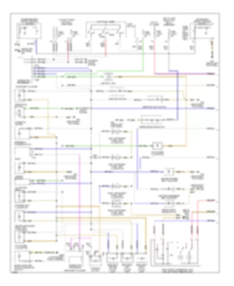
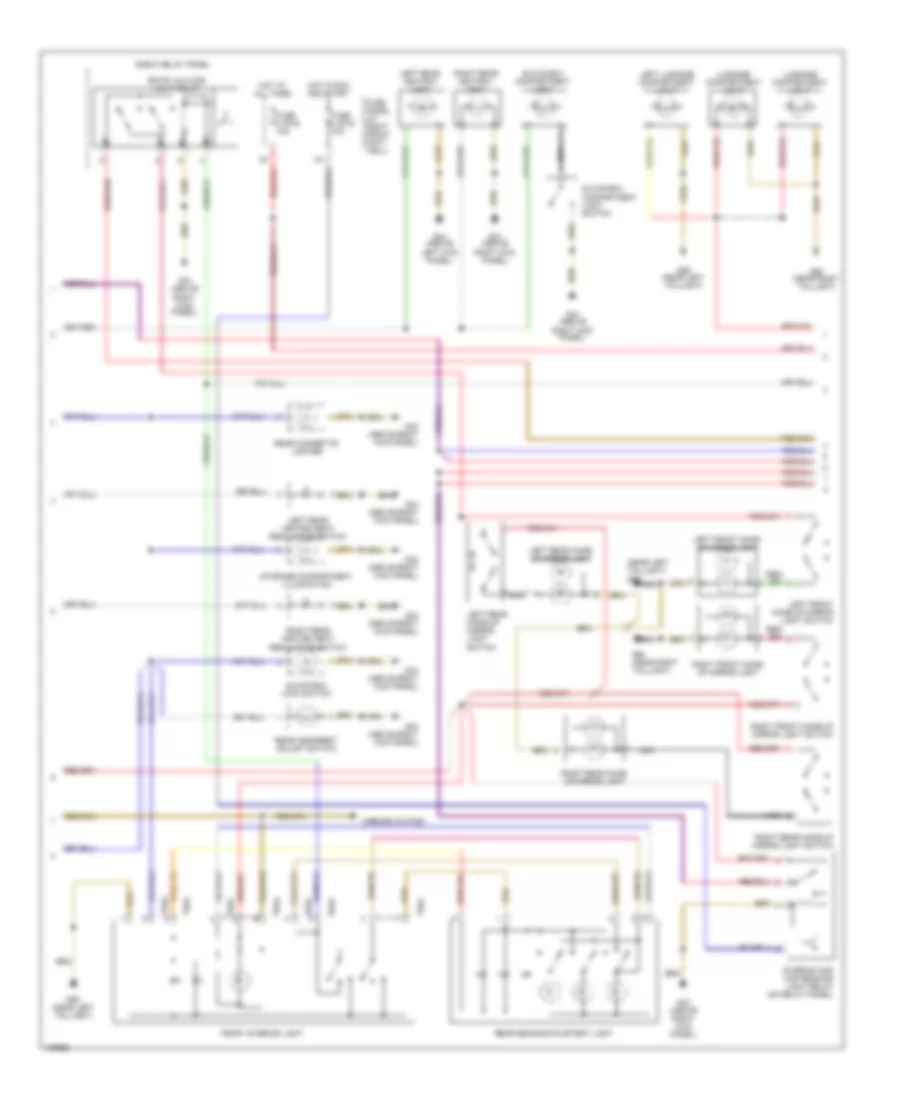
Interior Lights Wiring Diagram (1 of 3) for Audi S8 2003
List of elements for Interior Lights Wiring Diagram (1 of 3) for Audi S8 2003:
- (above left kick panel) g44
- (above right kick panel) g43
- (at right front footwell) fuse panel
- A/c control head
- Ashtray light
- Asr/esp button
- Board computer function selector switch ii
- Center instrument panel vent illumination
- Cigarette lighter
- Coin holder illumination
- Combination processor
- Cup holder illumination
- Driver seat memory program switch
- Emergency flasher switch
- Exterior lights system
- Fog light switch
- Fuse 1 (st1) 5a
- Fuse 1 (st5) 10a
- Fuse 2 (st1) 5a
- Fuse 2 (st5) 10a
- Fuse 3 (st2) 5a
- Fuse panel (at right front foot- well)
- G269 (in instrument panel harness)
- G43 (above right kick panel)
- G44 (above left kick panel)
- Head
- Heated driver's seat adjuster
- Heated passenger's seat adjuster
- Hot at all times
- Hot w/ load reduction relay energized
- Instrument cluster
- Left instrument panel vent illumination
- Light switch
- Mirror selector switch
- Off
- Park
- Parking aid button
- Passenger seat memory program switch
- Radio
- Rear fog light switch
- Rear seat center outlet light
- Rear seat left outlet light
- Rear seat right outlet light
- Rear window shade switch
- Right front map/reading light and left front reading light
- Right instrument panel vent illumination
- Storage tray illumination
- T10u
- T32a
- T32b
- T5n
- Tiptronic switch
Interior Lights Wiring Diagram (2 of 3) for Audi S8 2003
List of elements for Interior Lights Wiring Diagram (2 of 3) for Audi S8 2003:
- (near left taillight) g59
- E-box relay panel
- Entry & floor light relay
- Front interior light
- Fuse 3 (st5) 10a
- Fuse 4 (st5) 10a
- Fuse panel (at right front foot- well)
- G43 (above right kick panel)
- G44 (above left kick panel)
- G59 (near left taillight)
- G60 (near right taillight)
- Glove box compartment light
- Glove box compartment light switch
- Glove box lock switch
- Hot at all times
- Hot in run and start
- Interior and map reading light relay (on relay panel)
- Left front make- up mirror light
- Left front make-up mirror light switch
- Left luggage compartment light
- Left rear ashtray light
- Left rear heated seat regulating switch
- Left rear make- up mirror light
- Left rear make-up mirror light switch
- Luggage compartment light
- Mirrors system
- Nca
- Rear cigarette lighter
- Rear headrest adjust switch
- Rear reading/courtesy light
- Right front make- up mirror light
- Right front make-up mirror light switch
- Right rear ashtray light
- Right rear heated seat regulating switch
- Right rear make- up mirror light
- Right rear make-up mirror light switch
- Storage compartment illumination
- T6aa
- T6ac
Interior Lights Wiring Diagram (3 of 3) for Audi S8 2003
List of elements for Interior Lights Wiring Diagram (3 of 3) for Audi S8 2003:
- Central locking/alarm system/ interior light delay module (left side of luggage compt)
- Combination processor
- Driver's door lock switch
- Driver's side door contact switch
- Driver's side door opener light
- Driver's side door warning light
- G43 (above right kick panel)
- G44 (above left kick panel)
- Instrument cluster
- Interior monitoring sensors control module
- Left door central locking warning light
- Left footwell light
- Left front entry light
- Left front window switch
- Left rear console window switch
- Left rear door contact switch
- Left rear door opener light
- Left rear door warning light
- Left rear entry light
- Left rear footwell light
- Luggage compartment release switch
- Passenger compartment monitoring switch
- Passenger's door warning light
- Passenger's side door contact switch
- Passenger's side door opener light
- Power windows system
- Right door central locking warning light
- Right foot- well light
- Right front entry light
- Right front window switch
- Right rear console window switch
- Right rear door contact switch
- Right rear door opener light
- Right rear door warning light
- Right rear entry light
- Right rear footwell light
- T10o
- T12
- T16
- T32b
- Window lockout switch
MEMORY SYSTEMS
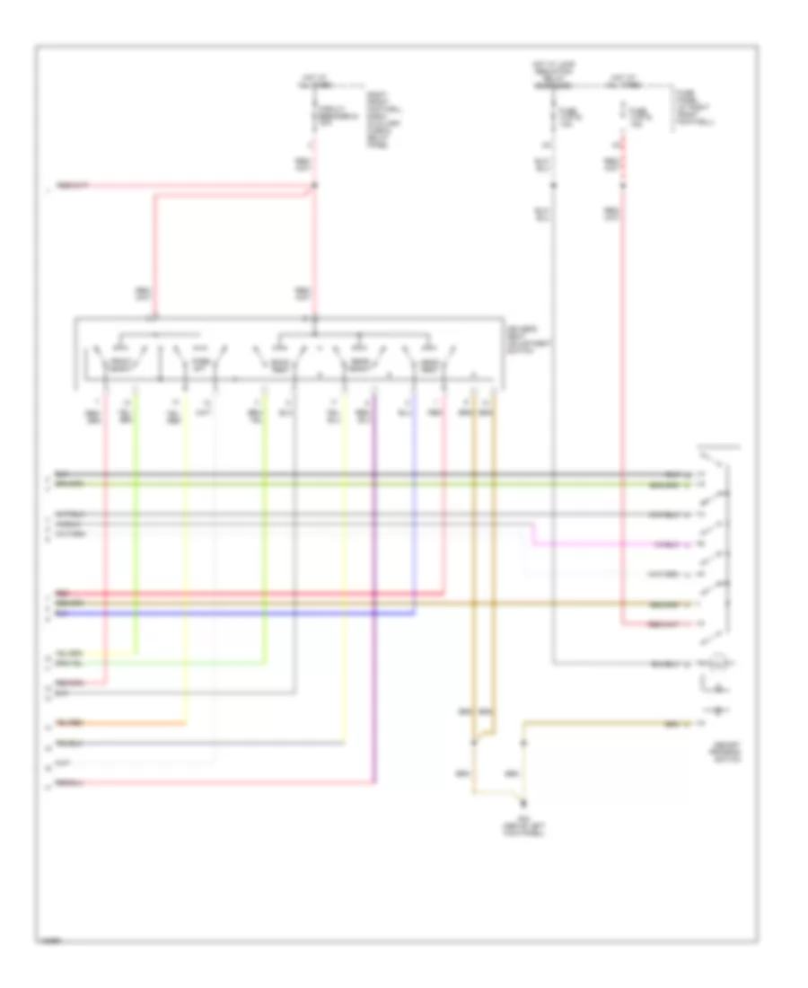
Driver"s Memory Seat Wiring Diagram (1 of 2) for Audi S8 2003
List of elements for Driver"s Memory Seat Wiring Diagram (1 of 2) for Audi S8 2003:
- Central locking/ alarm system/ interior light delay control module (left side of luggage compt)
- Driver side door contact switch (on driver door latch mechanism, inside door)
- Driver's seat backrest adjusting motor
- Driver's seat fore/ aft adjusting motor
- Driver's seat front height adjusting motor
- Driver's seat headrest adjusting motor
- Driver's seat rear height adjusting motor
- G44 (above left kick panel)
- Memory mirrors circuit
- Memory seat control module (on bottom of left front seat)
- Red
- Steering column/ belt height control module (below left front seat)
- T16
Driver"s Memory Seat Wiring Diagram (2 of 2) for Audi S8 2003
List of elements for Driver"s Memory Seat Wiring Diagram (2 of 2) for Audi S8 2003:
- Back- rest
- Circuit breaker 44 30a
- Driver's seat adjustment switch
- Fore/ aft
- Front height
- Fuse 2 (st5) 10a
- Fuse 3 (st5) 15a
- Fuse panel (at right front footwell)
- G44 (above left kick panel)
- Head- rest
- Hot at all times
- Hot w/ load reduction relay energized
- Memory program switch
- Rear height
- Red
- Right front footwell e-box auxiliary fuse & relay panel
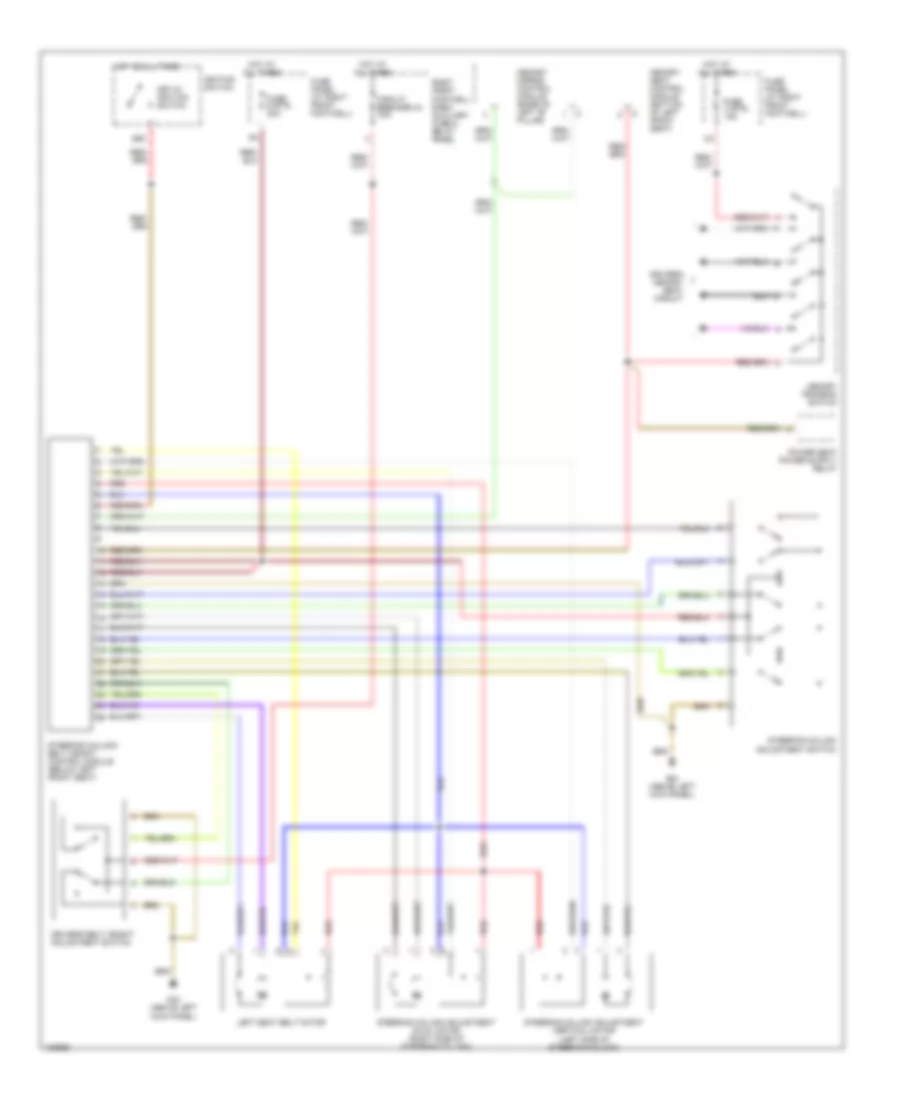
Memory Column & Belt Height Wiring Diagram for Audi S8 2003
List of elements for Memory Column & Belt Height Wiring Diagram for Audi S8 2003:
- 86s
- Circuit breaker 44 30a
- Driver's belt height adjustment switch
- Driver's memory seat circuit
- Fuse 3 (st5) 15a
- Fuse 9 (st5) 20a
- Fuse panel (at right front footwell)
- G44 (above left kick panel)
- Hot at all times
- Ignition switch
- Key-in ignition switch
- Left seat belt motor
- Memory mirror control module (base of left "b" pillar)
- Memory program switch
- Memory seat control module (bottom of left front seat)
- Red
- Right front footwell e-box auxiliary fuse & relay panel
- Steering column adjustment axial motor (right side of steering column)
- Steering column adjustment switch
- Steering column adjustment vertical motor (left side of steering column)
- Steering column/ belt height control module (below left front seat)
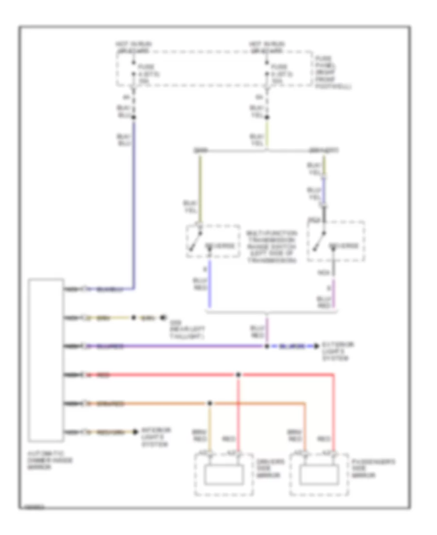
Memory Mirrors Wiring Diagram for Audi S8 2003
List of elements for Memory Mirrors Wiring Diagram for Audi S8 2003:
- (above left kick panel) g44
- (above right kick panel) g43
- A10
- B10
- Back-up lights
- De- fog
- Driver's side mirror
- Fold- away
- Fuse 1 (st2) 10a
- Fuse 2 (st5) 10a
- Fuse 3 (st5) 15a
- Fuse panel (at right front footwell)
- G43 (above right kick panel)
- G44 (above left kick panel)
- Hot at all times
- Hot w/ load reduction relay energized
- Memory mirror control module (at base of left "b" pillar, behind trim)
- Memory seat control module
- Mirror adjustment switch
- Mirror fold-away control module (if equipped) (on right front footwell e-box relay panel)
- Passenger's side mirror
- Position
- Steering column/ belt height adjustment control module
Passenger"s Memory Seat Wiring Diagram (1 of 2) for Audi S8 2003
List of elements for Passenger"s Memory Seat Wiring Diagram (1 of 2) for Audi S8 2003:
- Driver's seat memory program switch
- G44 (above left kick panel)
- Passenger's memory seat control module (on bottom of right front seat)
- Passenger's seat backrest adjusting motor
- Passenger's seat fore/ aft adjusting motor
- Passenger's seat front height adjusting motor
- Passenger's seat headrest adjusting motor
- Passenger's seat rear height adjusting motor
- Passenger's side door contact switch (on right front latch mechanism, inside door)
- Red
Passenger"s Memory Seat Wiring Diagram (2 of 2) for Audi S8 2003
List of elements for Passenger"s Memory Seat Wiring Diagram (2 of 2) for Audi S8 2003:
- Back- rest
- Circuit breaker 80 30a
- Fore/ aft
- Front height
- Fuse 2 (st5) 10a
- Fuse 3 (st5) 15a
- Fuse panel (at right front footwell)
- G44 (above left kick panel)
- Head- rest
- Hot at all times
- Hot w/ load reduction relay energized
- Passenger's seat adjustment switch
- Passenger's seat memory program switch
- Rear height
- Red
- Right front footwell e-box auxiliary fuse & relay panel
NAVIGATION
Navigation Wiring Diagram for Audi S8 2003
List of elements for Navigation Wiring Diagram for Audi S8 2003:
- (at right front footwell)
- Board computer function selector switch ii
- Combination processor
- Data link connector (rapid data transfer) (below left side of dash)
- Exterior lights system
- Fuse 5 (st4) 5a
- Fuse 6 (st2) 5a
- Fuse 6 (st4) 10a
- Fuse panel
- G269 (in instrument panel harness)
- G44 (above left kick panel)
- Hot at all times
- Hot in run or start
- Instrument cluster
- Interior lights system
- Multi- function transmission range switch (on left side of transmission)
- Navigation control unit
- Navigation system antenna
- Nca
- Radio
- Suppressor filter
- T10u
- T16a
- T32a
- T32b
- T6ap
- T8m
- T8n
- Telephone transceiver (if equipped)
- Telephone/telematic control module (if equipped) (at left front of luggage compt, on bottom of parcel shelf)
- W/ telematic
- W/ telephone
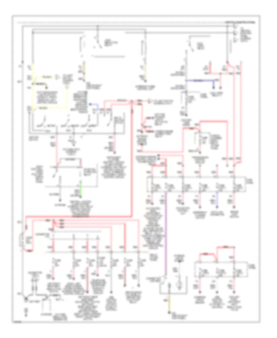
POWER DISTRIBUTION
Power Distribution Wiring Diagram (1 of 4) for Audi S8 2003
List of elements for Power Distribution Wiring Diagram (1 of 4) for Audi S8 2003:
- 50b
- 86s
- A/c control head, instrument multi-function parking aid control module, instrument cluster, solar cell separation relay, multi- function steering wheel control module, tire pressure monitor control module
- A34
- Abs control module (w/ stability control)
- Abs control module (without stability control)
- Abs solenoid valve relay, abs return flow pump relay
- Battery
- Brake light switch
- Central electric panel
- Central locking/ alarm system/ interior light delay control module, multi-function transmission range switch
- Cigarette lighter
- Connector tv1
- Connector tv2
- Coolant pump, left/right heat regulating valve
- D50/a32
- Data link connector
- Daytime running lights switch on relay
- Daytime running lights switch on relay, front/ rear fog light control module
- Dual horn relay
- Dual horn relay 2
- E20/a32
- Emergency flasher switch
- Fuse 15a
- Fuse 15a (or 5a)
- Fuse 200a
- Fuse 20a
- Fuse 25a
- Fuse 3 (st3) 15a
- Fuse 4 (st3) 10a
- Fuse 6 (st4) 10a
- Fuse 60a
- Fuse 7 (st1) 15a
- Fuse 7 (st2) 5a
- Fuse 7 (st3) 15a
- Fuse 8 (st1) 15a
- Fuse 9 (st1) 10a
- Fuse 9 (st2) 10a
- Fuse 9 (st4) 25a
- Fuse panel
- G43 (above right kick panel)
- Ignition switch
- Instrument cluster, central locking/ alarm system/ interior light delay control module, radio, steering column/belt height control module
- Interior lights system
- Key-in ignition switch
- Left/right rear head rest adjustment switch, left/right rear head rest lower relay, left/right rear seat lumbar support height adjustment switch
- Left/right rear seat regulating switch
- Load reduction relay
- Low/high tone horns
- Motronic engine control module
- Navigation control unit
- Off
- Plenum chamber e-box relay & fuse panel
- Radio, left rear woofer, power antenna, antenna selection control module
- Red
- Red red
- Relay & fuse panel
- Right footwell e-box auxiliary fuse & relay panel
- Run
- S1/
- S1/ 30ah
- S2/ 87h
- S3/
- Start
- Starter
- Starting interlock relay
- Steering angle sensor
- Steering wheel control unit
- Telephone transceiver, telephone/ telematic control module
- To central electric panel (diagram 2 of 4)
- To fuse 6 (st3) (diagram 3 of 4)
- To light switch (diagram 2 of 4)
- Transmission control module
- Voltage regulator/ generator
- Voltage regulator/ generator, instrument cluster, headlight adjusting beam control module
- Wiper/washer intermittent relay
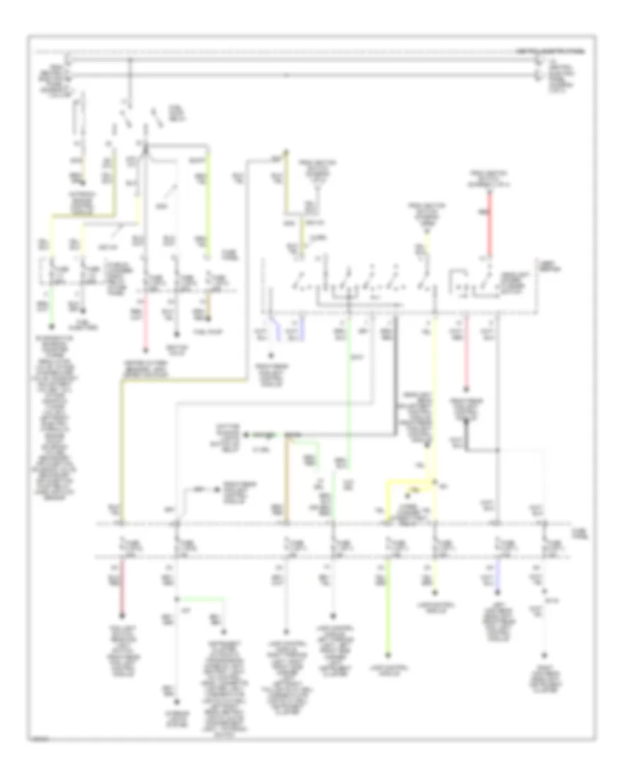
Power Distribution Wiring Diagram (2 of 4) for Audi S8 2003
List of elements for Power Distribution Wiring Diagram (2 of 4) for Audi S8 2003:
- 2001-03
- 75x
- 87f/ dti
- A from central electric b panel (diagram c 1 of 4)
- A37
- A51
- Central electric panel
- Daytime running lights switch on relay
- E107
- E108
- E116
- Evaporative emission canister purge regulator valve, intake change-over valve, camshaft adjustment valves 1 & 2, intake manifold tuning valve 2, left/right electro- hydraulic engine mount solenoid valves, secondary air injection solenoid valve, secondary air injection pump relay, mass air flow sensor
- Fog light switch, rear fog light switch, front/rear fog light control module
- From ignition switch (diagram 1 of 4)
- Front/rear foglight control module
- Fuel injectors
- Fuel pump
- Fuel pump relay
- Fuse 1 (st1) 5a
- Fuse 1 (st4) 20a
- Fuse 2 (st1) 5a
- Fuse 2 (st4) 30a
- Fuse 20a
- Fuse 3 (st1) 15a
- Fuse 3 (st2) 5a
- Fuse 3 (st4) 20a
- Fuse 4 (st1) 15a
- Fuse 5 (st1) 10a
- Fuse 5 (st2) 15a
- Fuse 6 (st1) 10a
- Fuse panel
- Headlight beam adjustment control module, front/rear foglight control module
- Headlight dimmer/ flasher switch
- Heated oxygen sensors, leak detection pump
- Ignition coils
- Instrument cluster, automatic transmission console light, ashtray light, a/c control head, cigarette lighter light, license plate lights (w/o drl), left/right rear ashtray lights, glove compartment light, tiptronic switch
- Interior lights system
- Lamp control module
- Lamp control module, right parking light, right front side marker light left/right taillights (w/ drl), license plate lights (w/ drl), instrument cluster
- Lamp control module, left parking light, left front side marker light, instrument cluster
- Left high beam headlight, front/rear fog light control module
- Light light switch switch
- Motronic engine control module
- Plenum chamber e-box relay & fuse panel
- Red
- Right high beam headlight, instrument cluster
- S2/87f
- S3/ 87a
- S3/s
- To central electric panel (diagram 3 of 4)
- W/ drl
- W/o drl
- Wiper/ washer intermittent relay
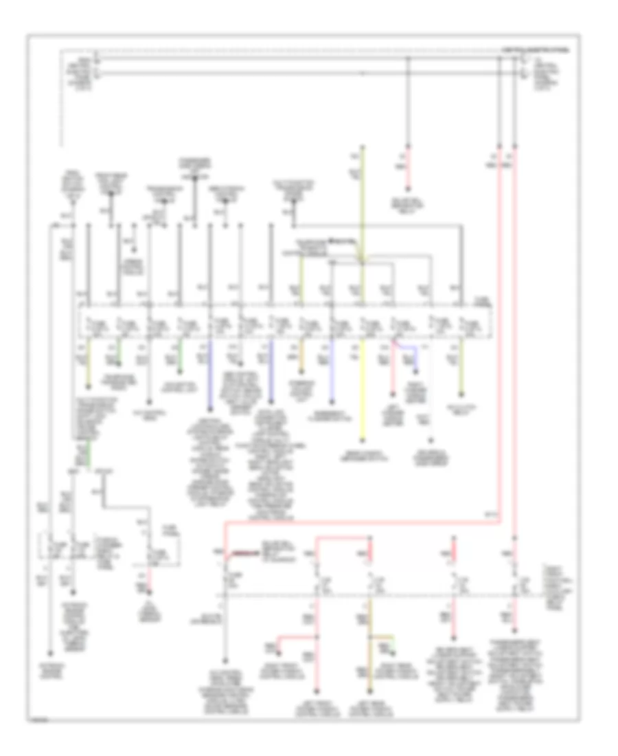
Power Distribution Wiring Diagram (3 of 4) for Audi S8 2003
List of elements for Power Distribution Wiring Diagram (3 of 4) for Audi S8 2003:
- 10a
- 2001-03
- 75x
- A/c clutch relay
- A/c control head
- A/c control head, fresh air blower, interior monitoring sensors control module, ultra sound sensors control module
- A80
- Abs control module, anti- slip control switch, brake switch vacuum vent valve, asr/esp switch
- Airbag control module
- B110
- C.b. 30a
- Central electric panel
- Central electric panel (diagram 2 of 4)
- Central locking/alarm system/interior lights delay control module, rear window shade switch, automatic dimmer inside mirror, garage door opener control module, interior & map/reading light relay
- Data link connector, instrument cluster, lamp control module, multi- function steering wheel control module, radio, left/ right headlight beam adjusting motor, headlight beam adjusting control module, parking aid control module, tire pressure monitoring control module
- Driver's & passenger's side mirror
- Emergency flasher switch
- From g
- From ignition switch (diagram 1 of 4)
- Front/rear fog light control module
- Fuse 1 (st2) 10a
- Fuse 1 (st3) 15a
- Fuse 10 (st2) 5a
- Fuse 10 (st4) 10a
- Fuse 15a
- Fuse 2 (st3) 5a
- Fuse 4 (st5) 10a
- Fuse 40a
- Fuse 5 (st3) 10a
- Fuse 5 (st4) 5a
- Fuse 5a
- Fuse 6 (st2) 30a
- Fuse 6 (st3) 10a
- Fuse 8 (st2) 10a
- Fuse 8 (st3) 10a
- Fuse 8 (st4) 5a
- Fuse 9 (st3) 5a
- Fuse panel
- Left front power window control module
- Left rear power window control module
- Left washer nozzle heater
- Motronic engine control
- Motronic engine control module, fuel injectors, oil level thermal sensor
- Multi-function transmission range switch
- Multi-function transmission range switch, shift lock solenoid, cruise control switch
- Navigation control unit
- Oil level thermal sensor
- Passenger side airbag off indicator
- Plenum chamber e-box relay & fuse panel
- Rear window defogger switch
- Red
- Right front footwell e-box auxiliary fuse & relay panel
- Right front power window control module
- Right rear power window control module
- Right washer nozzle heater
- Servotronic control module
- Solar cell separation relay
- Solar cell separation relay (w/ sunroof)
- Steering column control unit
- Telephone transceiver, radio
- Telephone/ telematic control module
- To central electric panel (diagram 4 of 4)
- Transmission control module
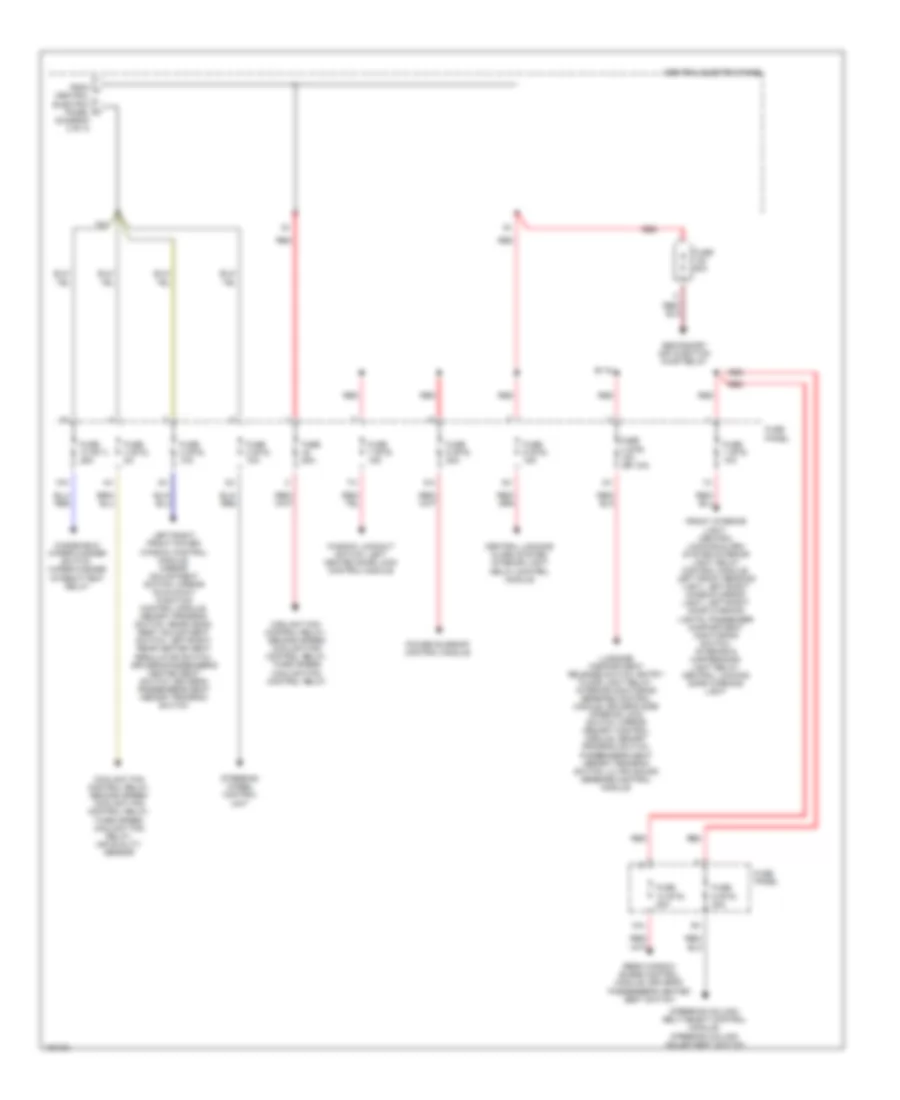
Power Distribution Wiring Diagram (4 of 4) for Audi S8 2003
List of elements for Power Distribution Wiring Diagram (4 of 4) for Audi S8 2003:
- (diagram 3 of 4)
- 10a
- 75x
- B115
- Central electric panel
- Central locking/ alarm system/ interior light delay control module
- Coolant fan control relay, second speed coolant fan control relay, third speed coolant fan control relay
- Coolant fan control relay, second speed coolant fan control relay, third speed coolant fan relay, air quality sensor
- From j central electric panel k
- Front interior light, central locking/alarm system/interior light delay control module, left front reading light, left/right makeup mirror light, left/right door warning lights, passenger compartment monitoring switch, interior & map/reading light relay, central locking safe warning light
- Fuse 1 (st5) 10a
- Fuse 10 (st1) 25a
- Fuse 10 (st5) 20a
- Fuse 2 (st2) 10a
- Fuse 2 (st5) 10a
- Fuse 3 (st5) 15a (or 10a)
- Fuse 4 (st2) 5a
- Fuse 5 (st5) 15a
- Fuse 50a
- Fuse 6 (st5) 20a
- Fuse 60a
- Fuse 7 (st5) 15a
- Fuse 9 (st5) 20a
- Fuse panel
- Left/right front power window control module, mirror adjustment switch, mirror fold-away function control module, memory program switch, rear head- rest adjustment switch, left/right rear heated seat regulator switch, driver's/passenger's heated seat switch, driver's/ passenger's seat memory program switch
- Luggage compartment release switch, entry/ floor light relay, interior monitoring sensors control module, driver's side interior lock switch, mirror memory control module, memory program switch, passenger's seat memory program switch, ultra sound sensors control module
- Power sunroof control module
- Rear window shade control module, driver's/ passenger's heated seat switch
- Red
- Secondary air injection pump relay
- Steering column/ belt height control module, steering column adjustment switch
- Steering wheel control unit
- Window lockout switch, left heated door lock control module
- Windshield wiper/washer switch, wiper/washer intermittent relay
POWER MIRRORS
Automatic Day/Night Mirror Wiring Diagram for Audi S8 2003
List of elements for Automatic Day/Night Mirror Wiring Diagram for Audi S8 2003:
- 2001-2003
- Automatic dimmer inside mirror
- Driver's side mirror
- Exterior lights system
- Fuse 4 (st5) 10a
- Fuse 6 (st3) 10a
- Fuse panel (right front footwell)
- G59 (near left taillight)
- Hot in run or start
- Interior lights system
- Multi-function transmission range switch (left side of transmission)
- Nca
- Passenger's side mirror
- Red
- Reverse
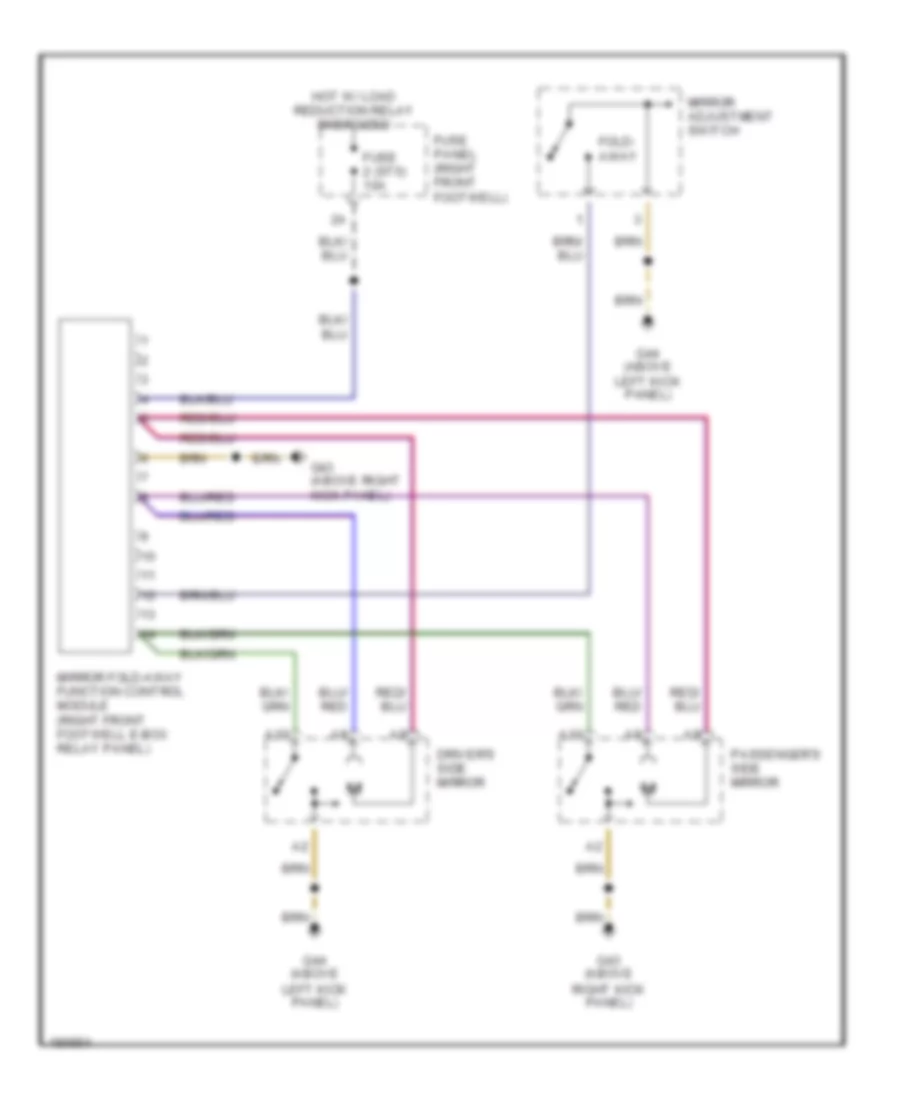
Fold-back Mirrors Wiring Diagram for Audi S8 2003
List of elements for Fold-back Mirrors Wiring Diagram for Audi S8 2003:
- A10
- Driver's side mirror
- Fold- away
- Fuse 2 (st5) 10a
- Fuse panel (right front footwell)
- G43 (above right kick panel)
- G44 (above left kick panel)
- Hot w/ load reduction relay energized
- Mirror adjustment switch
- Mirror fold-away function control module (right front footwell e-box relay panel)
- Passenger's side mirror
POWER SEATS
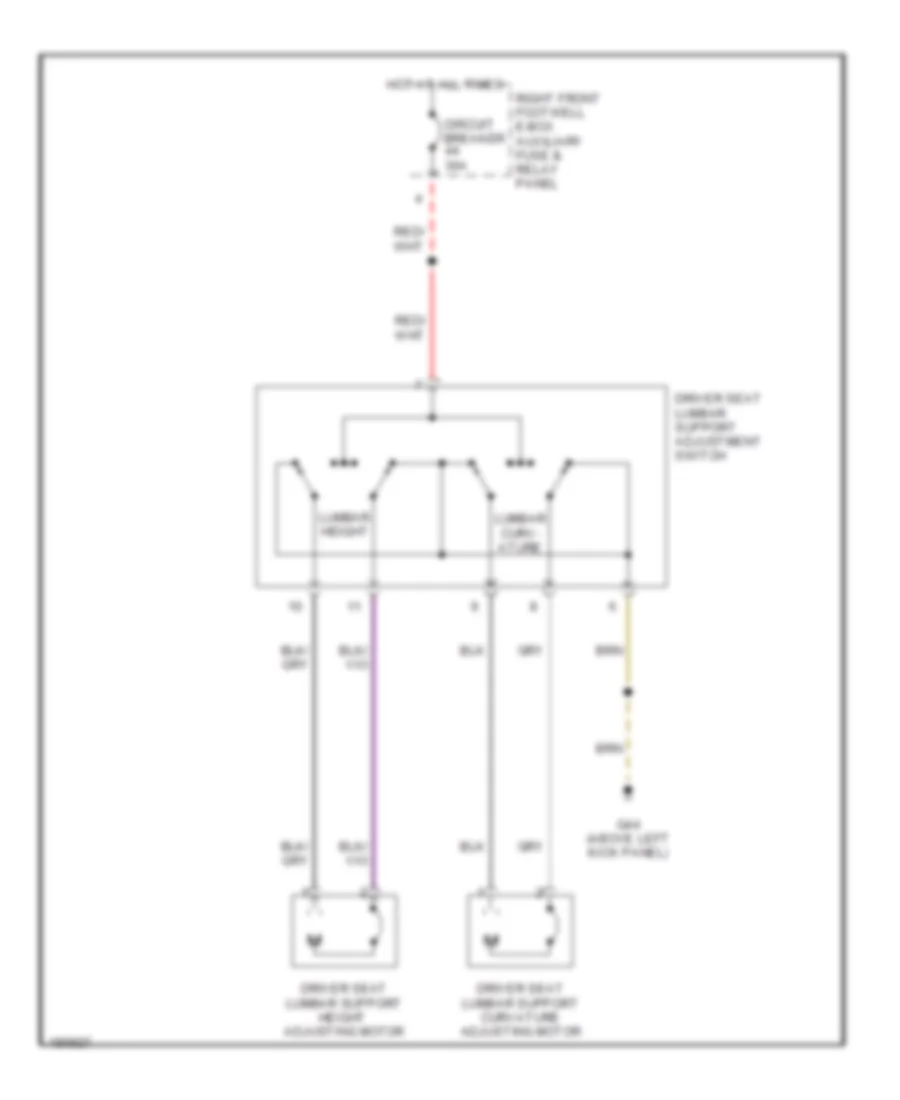
Driver"s Lumbar Wiring Diagram for Audi S8 2003
List of elements for Driver"s Lumbar Wiring Diagram for Audi S8 2003:
- Circuit breaker 30a
- Driver seat lumbar support adjustment switch
- Driver seat lumbar support curvature adjusting motor
- Driver seat lumbar support height adjusting motor
- G44 (above left kick panel)
- Hot at all times
- Lumbar curv- ature
- Lumbar height
- Right front footwell e-box auxiliary fuse & relay panel
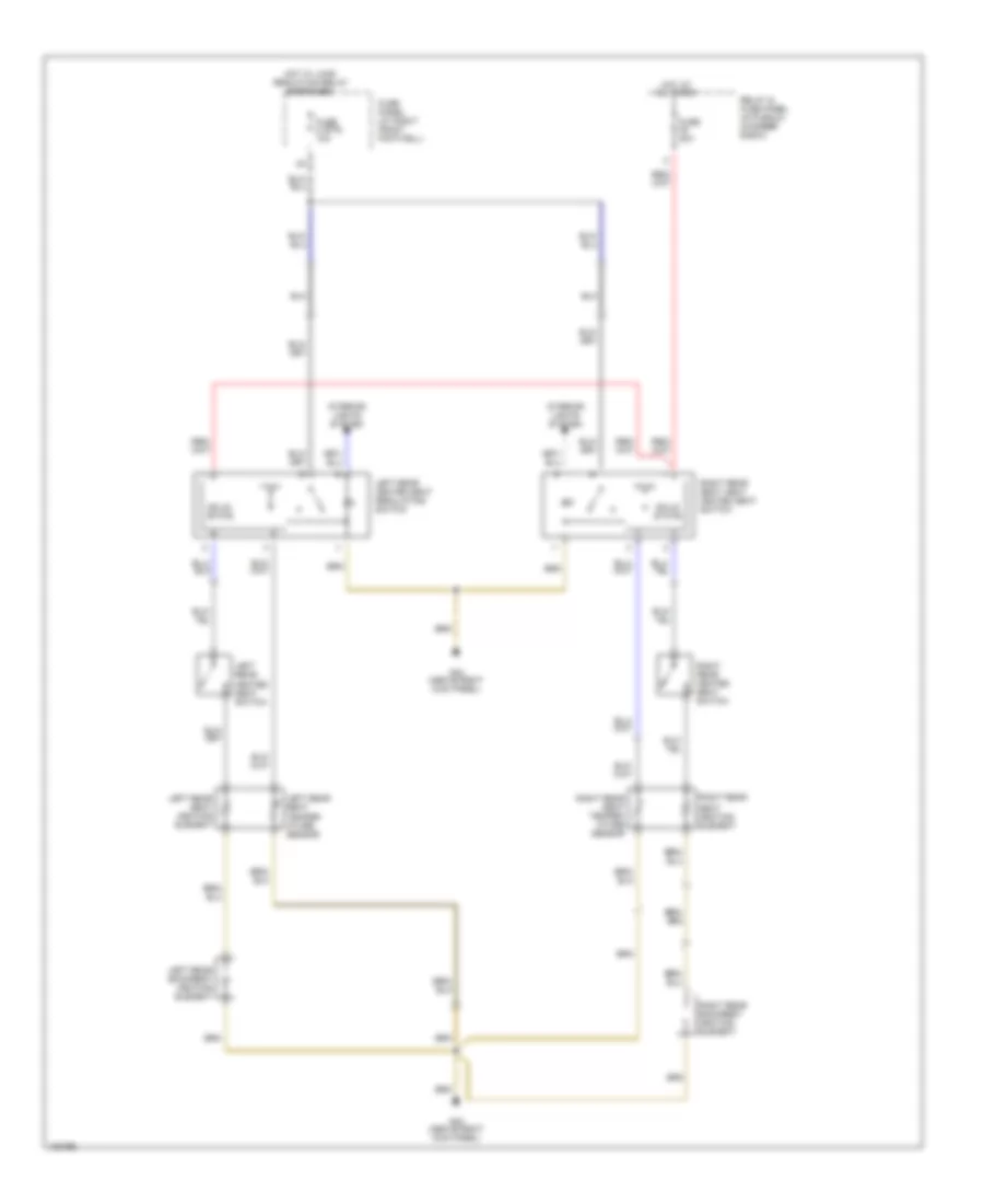
Front Seat Heater Wiring Diagram for Audi S8 2003
List of elements for Front Seat Heater Wiring Diagram for Audi S8 2003:
- 10a
- All times
- Drivers backrest heating element
- Drivers heated seat adjuster
- Drivers heated seat temper- ature sensor
- Drivers seat backrest side bolster heater
- Drivers seat heating element
- Drivers seat side bolster heater
- Fuse 10 (st5) 20a
- Fuse 2 (st5) 10a
- Fuse panel (at right front footwell)
- G43 (above right kick panel)
- G44 (above left kick panel)
- Heated steering wheel circuit
- Hot at
- Hot w/ load reduction relay energized
- Interior lights system
- Nca
- Passengers backrest heating element
- Passengers heated seat adjuster
- Passengers heated seat temper- ature sensor
- Passengers seat backrest side bolster heater
- Passengers seat heating element
- Passengers seat side bolster heater
- Solid state
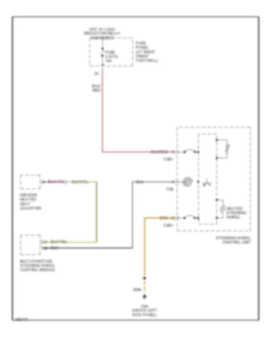
Heated Steering Wheel Wiring Diagram for Audi S8 2003
List of elements for Heated Steering Wheel Wiring Diagram for Audi S8 2003:
- Drivers heated seat adjuster
- Fuse 2 (st2) 10a
- Fuse panel (at right front footwell)
- G44 (above left kick panel)
- Heated steering wheel
- Hot w/ load reduction relay energized
- Multi-function steering wheel control module
- Steering wheel control unit
- T2bv
- T5b
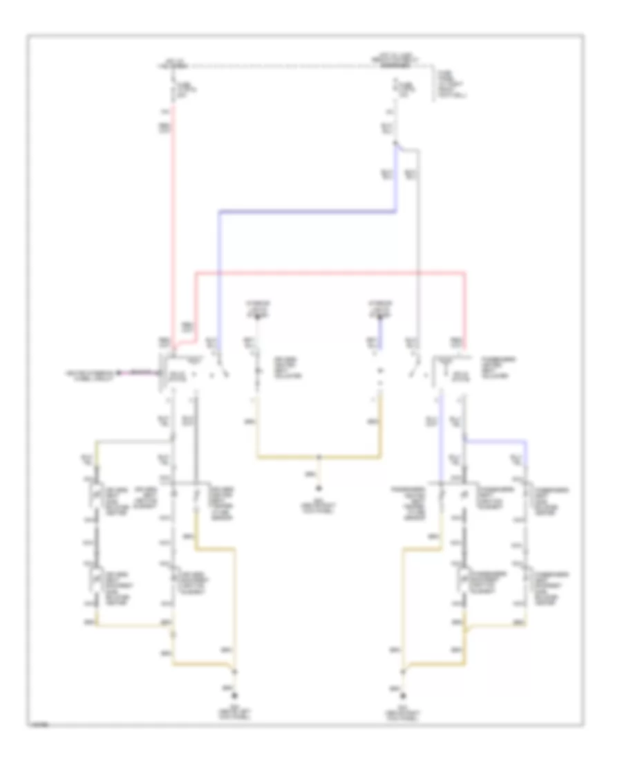
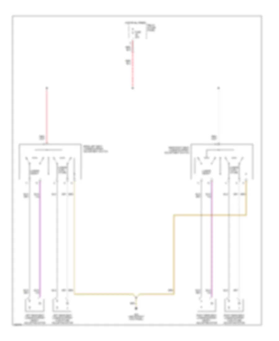
Rear Heated Seats Wiring Diagram for Audi S8 2003
List of elements for Rear Heated Seats Wiring Diagram for Audi S8 2003:
- All times
- Fuse 2 (st5) 10a
- Fuse 20a
- Fuse panel (at right front footwell)
- G43 (above right kick panel)
- Hot at
- Hot w/ load reduction relay energized
- Interior lights system
- Left rear backrest heating element
- Left rear heated seat regulating switch
- Left rear heated seat switch
- Left rear seat heating element
- Left rear seat temper- ature sensor
- Relay & fuse panel (in plenum chamber e-box)
- Right rear
- Right rear backrest heating element
- Right rear heated seat switch
- Right rear seat heat heated seat switch
- Right rear seat temper- ature sensor
- Seat heating element
- Solid state
Rear Lumbar Wiring Diagram for Audi S8 2003
List of elements for Rear Lumbar Wiring Diagram for Audi S8 2003:
- Fuse 20a
- G43 (above right kick panel)
- Hot at all times
- Left rear seat lumbar support curvature adjusting motor
- Left rear seat lumbar support height adjusting motor
- Lumbar curv- ature
- Lumbar height
- Rear left seat lumbar support adjustment switch
- Rear right seat lumbar support adjustment switch
- Relay & fuse panel
- Right rear seat lumbar support curvature adjusting motor
- Right rear seat lumbar support height adjusting motor
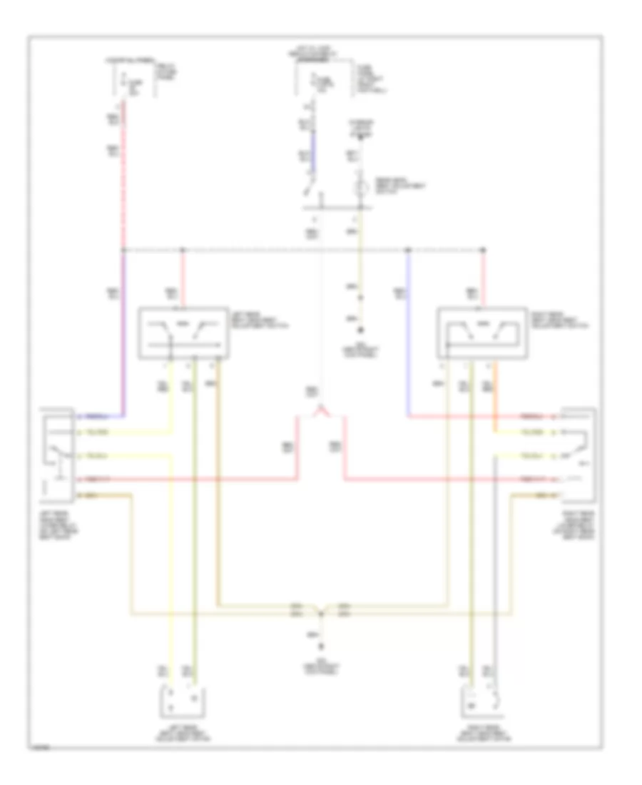
Rear Power Headrest Wiring Diagram for Audi S8 2003
List of elements for Rear Power Headrest Wiring Diagram for Audi S8 2003:
- Fuse 2 (st5) 10a
- Fuse 20a
- Fuse panel (at right front footwell)
- G43 (above right kick panel)
- Hot at all times
- Hot w/ load reduction relay energized
- Interior lights system
- Left rear head rest lower relay (on left rear seat back)
- Left rear seat head rest adjustment motor
- Left rear seat head rest adjustment switch
- Rear head- rest adjustment switch
- Relay & fuse panel
- Right rear head rest lower relay (on right rear seat back)
- Right rear seat head rest adjustment motor
- Right rear seat head rest adjustment switch
POWER TOP/SUNROOF
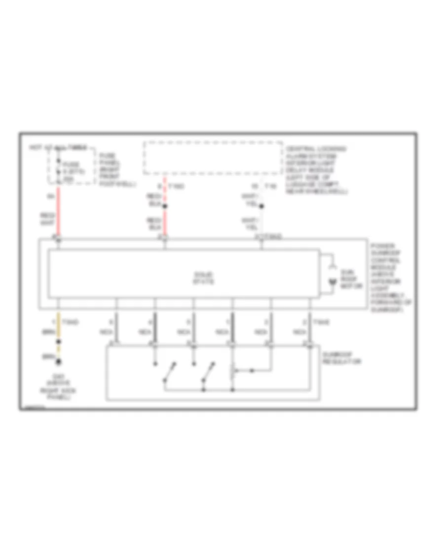
Sunroof Wiring Diagram for Audi S8 2003
List of elements for Sunroof Wiring Diagram for Audi S8 2003:
- Central locking/ alarm system/ interior light delay module (left side of luggage compt, near wheelwell)
- Fuse 6 (st5) 20a
- Fuse panel (right front footwell)
- G43 (above right kick panel)
- Hot at all times
- Nca
- Power sunroof control module (above interior light assembly, forward of sunroof)
- Solid state
- Sun roof motor
- Sunroof regulator
- T10o
- T16
- T6ad
- T6ae
POWER WINDOWS
Power Windows Wiring Diagram (1 of 2) for Audi S8 2003
List of elements for Power Windows Wiring Diagram (1 of 2) for Audi S8 2003:
- All times
- C.b. 37 30a
- Central locking/ alarm system/ interior light delay control module (at left side of luggage compt)
- Fuse 2 (st5) 10a
- Fuse panel
- G44 (above left kick panel)
- Hot at
- Hot in run
- Left front window switch
- Left window motor
- Power sunroof control module
- Right front footwell e-box auxiliary fuse & relay panel
- T10o
- T12
- T16
- Window motor
Power Windows Wiring Diagram (2 of 2) for Audi S8 2003
List of elements for Power Windows Wiring Diagram (2 of 2) for Audi S8 2003:
- (1997-99)
- (2000-03)
- 2000-03
- All times
- C.b. 43 30a
- Fuse 7 (st5) 15a
- Fuse panel
- G43 (above right kick panel)
- G44 (above left kick panel)
- Hot at
- Interior lights system
- Left rear door window motor
- Left rear door window switch (center console)
- Left rear door window switch (door)
- Rear cigarette lighter
- Right front door window switch
- Right front door window switch (right door)
- Right front footwell e-box auxiliary fuse & relay panel
- Right rear door window motor
- Right rear door window switch (center console)
- Right rear door window switch (door)
- Right window motor
- Window lockout switch
- Window m motor
- Window motor
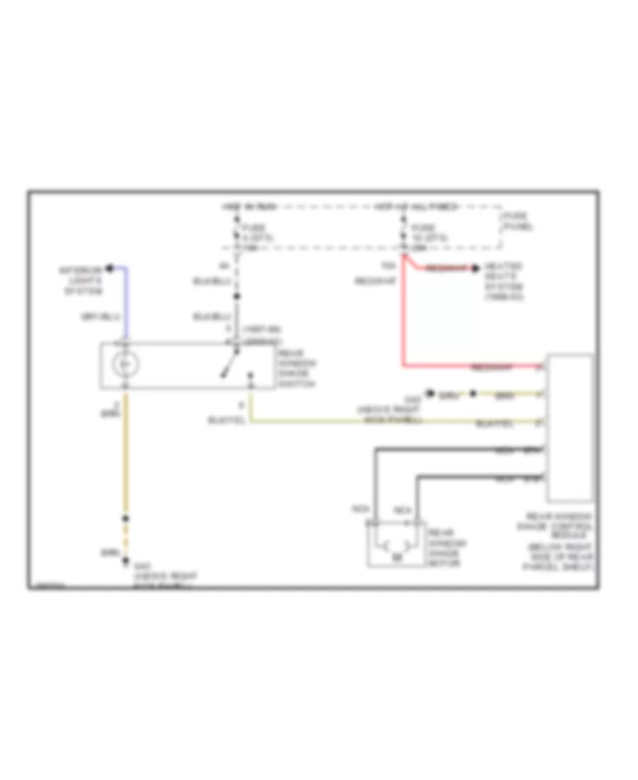
Rear Window Sun Shade Wiring Diagram for Audi S8 2003
List of elements for Rear Window Sun Shade Wiring Diagram for Audi S8 2003:
- (1997-99)
- (2000-03)
- (below right side of rear parcel shelf)
- 10a
- 87a
- 87b
- Fuse 10 (st5) 20a
- Fuse 4 (st5) 10a
- Fuse panel
- G43 (above right kick panel)
- Heated seats system (1998-03)
- Hot at all times
- Hot in run
- Interior lights system
- Nca
- Rear window shade control module
- Rear window shade motor
- Rear window shade switch
RADIO
Radio Wiring Diagram (1 of 2) for Audi S8 2003
List of elements for Radio Wiring Diagram (1 of 2) for Audi S8 2003:
- (if equipped)
- (w/ navi- gation)
- 20a
- Cd changer unit
- Central locking/ alarm system/ interior light delay module (at left side of luggage compt, near wheelwell)
- Data link connector (rapid data transfer)
- Fuse 92
- G45 (behind center of dash)
- Hot at all times
- Instrument cluster
- Multi-function steering control module
- Navigation control module (w/ cd-mechanism) (w/ navigation)
- Nca
- Pnk
- Radio
- Radio/ telephone antenna
- Red
- Relay & fuse panel (at right side of luggage compt)
- T10u
- T16
- T16a
- T32a
- T6g
- T6h
- T8a
- Telephone system
- Telephone transceiver (if equipped)
- W/ navi- gation
- W/o navi- gation
Radio Wiring Diagram (2 of 2) for Audi S8 2003
List of elements for Radio Wiring Diagram (2 of 2) for Audi S8 2003:
- (on right rear pillar, near filter neck) g75
- Aerial selection control unit (aerial diversity function)
- Amplifier
- Fm1
- Fm2
- Fm3
- Fm4
- G51 (on right side of luggage compt)
- Left front bass speaker/ left front midrange speaker
- Left rear bass speaker
- Left rear midrange speaker
- Nca
- Rear window defogger with window antenna
- Right front bass speaker/ right front midrange speaker
- Right rear bass speaker
- Right rear midrange speaker
- Telephone/telematic control module (w/ telematic only) (at front of luggage compt, on bottom of parcel shelf)
- Tv antenna amplifier 1
- Tv antenna amplifier 2
- Tv antenna amplifier 3
- Tv antenna amplifier 4
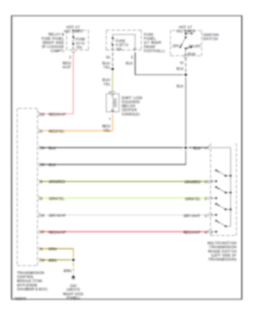
SHIFT INTERLOCK
Shift Interlock Wiring Diagram for Audi S8 2003
List of elements for Shift Interlock Wiring Diagram for Audi S8 2003:
- Fuse 6 (st3) 10a
- Fuse panel (at right front footwell)
- Fuse s113 15a
- G43 (above right kick panel)
- Hot at all times
- Ignition switch
- Multifunction transmission range switch (left side of transmission)
- Off
- Relay & fuse panel (right side of luggage compt)
- Run
- Shift lock solenoid (below center console)
- Start
- Transmission control module (tcm) (in plenum chamber e-box)
STARTING/CHARGING
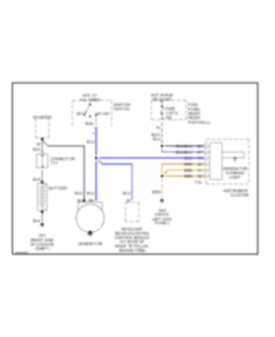
Charging Wiring Diagram for Audi S8 2003
List of elements for Charging Wiring Diagram for Audi S8 2003:
- Battery
- Connector tv1
- Fuse 1 (st3) 15a
- Fuse panel (right front footwell)
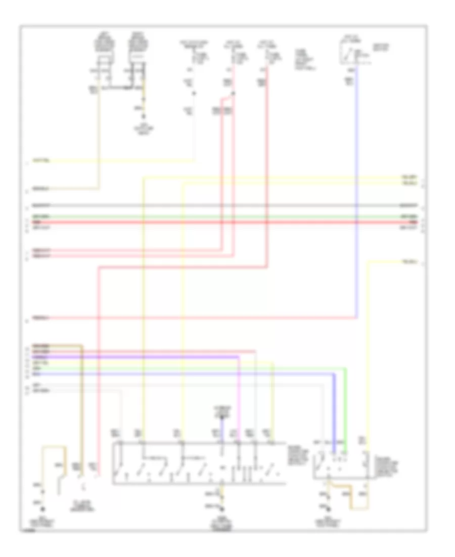
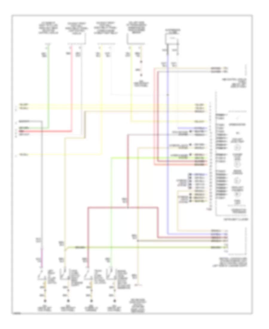
- G44 (above
- G51 (right side of luggage compt)
- Generator
- Generator warning light
- Headlight beam adjusting control module (at base of right "b" pillar, behind trim)
- Hot at all times
- Hot in run or start
- Ignition switch
- Instrument cluster
- Left kick panel)
- Off
- Run
- Start
- Starter
- T32
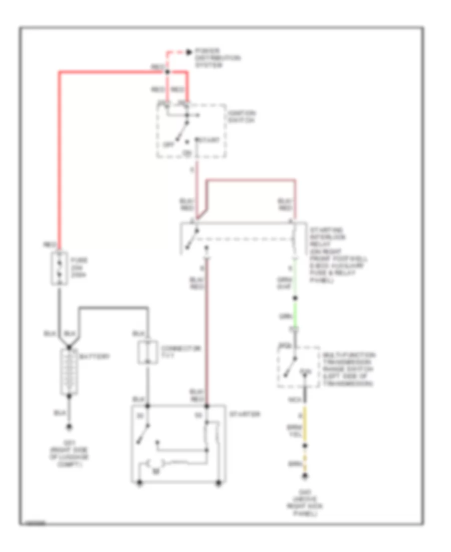
Starting Wiring Diagram for Audi S8 2003
List of elements for Starting Wiring Diagram for Audi S8 2003:
- Battery
- Connector tv1
- Fuse 200a
- G43 (above right kick panel)
- G51 (right side of luggage compt)
- Ignition switch
- Multi-function transmission range switch (left side of transmission)
- Nca
- Off
- P/n
- Power distribution system
- Red
- Start
- Starter
- Starting interlock relay (on right front footwell e-box auxiliary fuse & relay panel)
SUPPLEMENTAL RESTRAINTS
Supplemental Restraints Wiring Diagram (1 of 2) for Audi S8 2003
List of elements for Supplemental Restraints Wiring Diagram (1 of 2) for Audi S8 2003:
- (+)
- (-)
- (above right kick panel) g43
- 8/ab
- Air bag control module (below center of dash)
- Central locking/ alarm system/ interior light delay control module (left side of of luggage compt)
- Driver's side head air bag igniter
- Driver's side rear belt tensioner igniter
- Driver's side side air bag igniter
- Driver's side side rear air bag igniter
- Emergency flasher switch
- Hot at all times
- Ignition starter/ switch
- Motronic engine control module (ecm) (in plenum chamber e-box)
- Nca
- Note: shorting bridges on air bag control module close when module connector is disconnected from harness. shorting bridges connect pins: 33 & 34, 41 & 42 43 & 44, 45 & 46, 47 & 48, 49 & 50, 51 & 52
- Off
- Passenger's side air bag igniter 1
- Passenger's side head air bag igniter
- Passenger's side rear belt tensioner igniter
- Passenger's side side air bag igniter
- Passenger's side side rear air bag igniter
- Red
- Run
- Solid state
- Start
- T16
Supplemental Restraints Wiring Diagram (2 of 2) for Audi S8 2003
List of elements for Supplemental Restraints Wiring Diagram (2 of 2) for Audi S8 2003:
- (+)
- (+) 2
- (-)
- (-) 1
- (above right kick panel) g43
- (on lower part of right "a" pillar) g43
- Air bag control module (below center of dash)
- Air bag malfunction indicator lamp (mil)
- Air bag spiral spring/ return spring w/slip ring
- Center rear belt tensioner igniter
- Data link connector (dlc) (partial)
- Driver's side air bag igniter
- Driver's side side air bag crash sensor (below left front seat)
- Instrument cluster
- Left front "a" pillar microswitch
- Left seat belt tensioner igniter
- Nca
- Passenger side air bag off warning light
- Passenger's side seat occupied sensor (in bottom of right front seat)
- Passenger's side side air bag crash sensor (below right front seat)
- Right front "a" pillar microswitch
- Right seat belt tensioner igniter
- Solid state
- T32
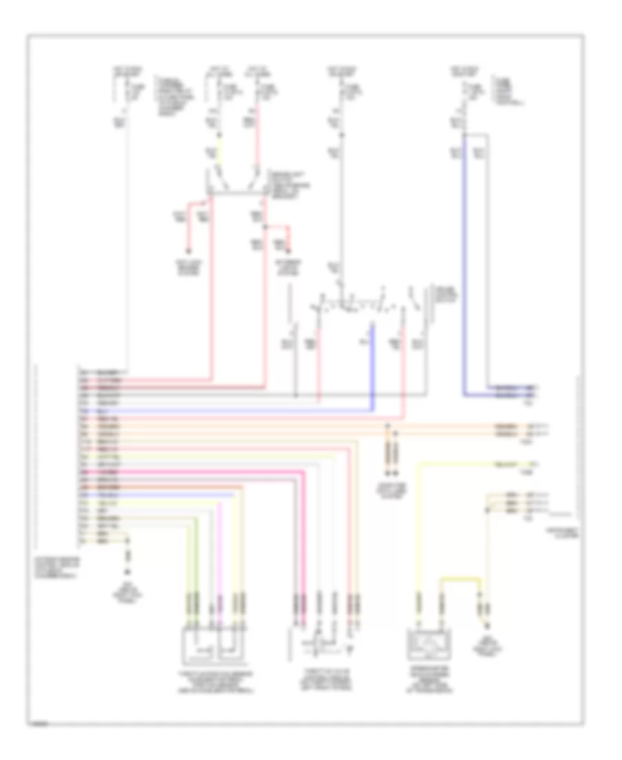
TRANSMISSION
A/T Wiring Diagram for Audi S8 2003
List of elements for A/T Wiring Diagram for Audi S8 2003:
- (56-84 not used)
- (above left kick panel)
- (below center console) shift lock solenoid
- +/-
- Blocking diode
- Computer data lines system
- Data link connector (below left side of dash)
- Engine control module (in plenum chamber e-box)
- Exterior lights system (backup)
- Fuse 3 (st2) 5a
- Fuse 6 (st3) 10a
- Fuse panel (at right front footwell)
- Fuse s113 15a
- G43 (above right kick panel)
- G44
- G44 (above left kick panel)
- Hot at all times
- Hot in park or head
- Ignition switch
- Illum
- Ind
- Interior lights system
- Kickdown switch (integral w/ accelerator cable)
- Left
- Multifunction transmission range switch (left side of transmission)
- Nca
- Off
- Pressure control valves
- Relay & fuse panel (right side of luggage compt)
- Right
- Run
- Solenoid valves
- Start
- Starting system (interlock relay)
- Steering wheel control unit
- T2af
- T5g
- T5n
- Tfi
- Tiptronic switch
- Transmission control module (tcm) (01l transmission) (in plenum chamber e-box)
- Transmission fluid temperature sensor
- Transmission output speed sensor (right side of transmission)
- Transmission speed sensor
- Valve body (01l transmission)
TRUNK, TAILGATE, FUEL DOOR
Trunk Release Wiring Diagram for Audi S8 2003
List of elements for Trunk Release Wiring Diagram for Audi S8 2003:
- (2000-01)
- (2002-03)
- 10a
- Central locking/ alarm system/ interior light delay control module (left side of luggage compt, near wheelwell)
- Decklid central locking system motor
- Fuse 3 (st5) 15a
- Fuse panel
- G98 (in rear lid harness)
- Glove box lock switch
- Hot at all times
- Interior lights system
- Interior monitoring sensors control module (left side of luggage compt)
- Lugagge compartment lid release switch
- T10o
- T16
WIPER/WASHER
Wiper/Washer Wiring Diagram for Audi S8 2003
List of elements for Wiper/Washer Wiring Diagram for Audi S8 2003:
- (not used)
- 10a
- 2000-01
- 2002-03
- Air conditioning system
- Battery
- Board computer
- Central electric panel
- Central locking/ alarm system/ interior light delay control module (left side of luggage compt, near wheelwell)
- Fuse 10 (st1) 25a
- Fuse 10 (st2) 5a
- Fuse panel
- G43 (above right kick panel)
- G44 (above left kick panel)
- Headlight washer pump
- Hot at all times
- Hot in run
- Ignition switch
- Instrument cluster
- Left washer nozzle heater
- Light switch
- Load reduction relay
- Off
- Red
- Right washer nozzle heater
- Run
- S1/31
- Start
- Suppression filter
- T16
- T26b
- Washer fluid level switch
- Windshield washer pump
- Windshield wiper intermittent regulator
- Windshield wiper motor
- Windshield wiper/ washer switch
- Wiper/washer intermittent relay (on right front footwell e-box relay panel)