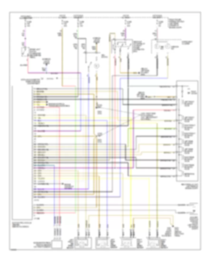
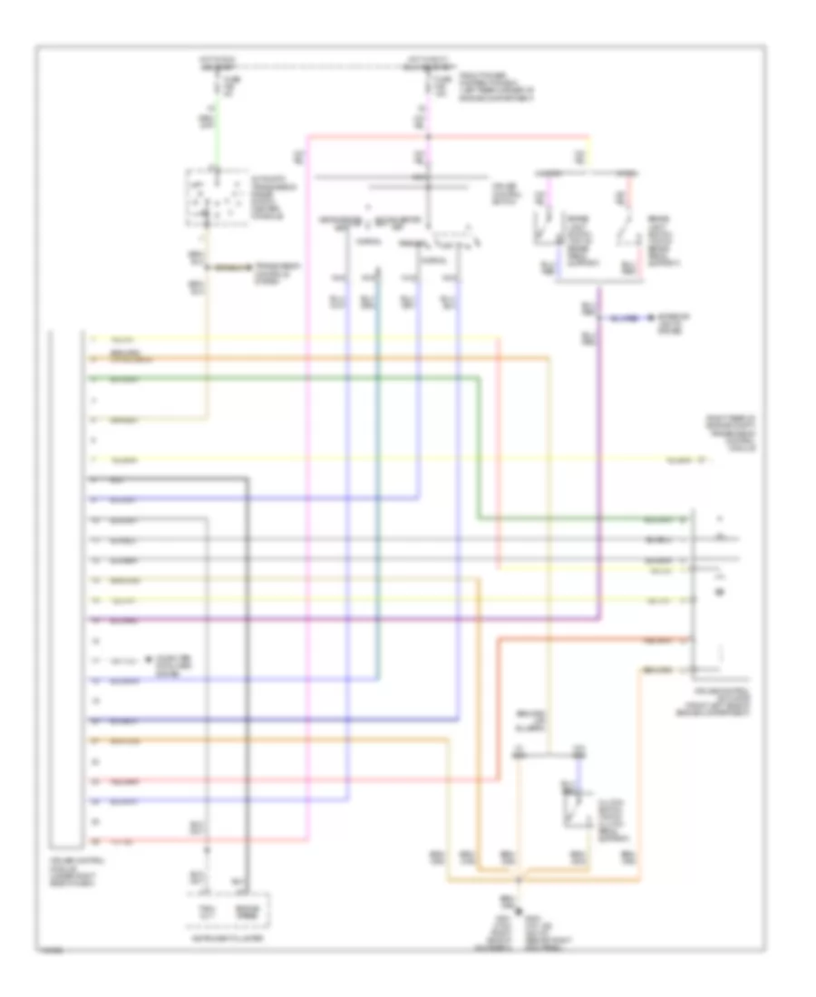
AIR CONDITIONING
Air Conditioning Wiring Diagrams for BMW 318ti 1998

List of elements for Air Conditioning Wiring Diagrams for BMW 318ti 1998:
- & start
- (right side of glove box) g201
- 1) above 88 deg c 2) above 80 deg c
- 15 bar pressure
- A/c
- Above 18 bar pressure
- Above 2.6 bar
- Above 30 bar
- Acc
- Air conditioning compressor
- All times
- Auxiliary fan motor
- Auxiliary fuse box (below left side of dash)
- Below 1.5 bar
- Below 21 bar
- Blower motor
- Blower relay (in power distribution box)
- Blower resistors (center of dash)
- Blower switch
- Climate control switch illumination
- Compressor control relay (in power distribution box)
- Defogger system
- Double temperature switch (near right headlight assy)
- Engine control module (dme) (right rear side of engine compartment)
- Evaporator temperature sensor (right side of left footwell)
- Fresh air recirculation motor (center of dash)
- Front power distribution box (left rear side of engine compartment)
- Fuse 30a
- Fuse 40a
- Fuse 5a
- Fuse 7.5a
- G100 (left front side of engine compartment)
- G201 (right side of glove box)
- G202 (below left side of dash)
- High speed relay (in power distribution box)
- Hot at
- Hot at all times
- Hot in run
- Ignition switch
- Ihks control switch
- Integrated heating & climate control module (center of dash)
- Interior lights system
- Nca
- Normal speed relay (in power distribution box)
- Off
- Pressure switch (near right headlight assy)
- Recirc
- Rr defog
- Run
- Solid state
- Start
- Temperature wheel switch
- Transmission control module (egs) (right rear side of engine compartment)
- Water valve (left rear of engine compt)
- X10016
- X10017
- X10018
- X1588
ANTI-LOCK BRAKES
Anti-lock Brake Wiring Diagrams, with Traction Control for BMW 318ti 1998
List of elements for Anti-lock Brake Wiring Diagrams, with Traction Control for BMW 318ti 1998:
- (318ti - right side of glove box) (318i - behind right kick panel)
- (318ti) g201
- (below left side of dash) g202
- Abs hydraulic unit (left rear of engine compt)
- Abs ind
- Abs pump motor relay (in front power distributon box)
- Accelerator pedal position sensor (on throttle body)
- Asc switch
- Auxiliary throttle position motor (left front of engine compt)
- Brake light switch (on bracket, above brake pedal)
- Data link connector (rear of engine compartment)
- Engine controls systems
- Engine controls, transmissions systems
- Exterior lights system
- Front power distribution box (left rear corner of engine compt)
- Fuse f10 30a
- Fuse f21 15a
- Fuse f27 5a
- Fuse f38 30a
- Fuse f46 15a
- G201 (318ti) (right side of glove box)
- G203 (318i)
- G203 (318i) (behind right kick panel)
- Hot at all times
- Hot in accy, run and start
- Hot in run and start
- Instrument cluster
- Interior lights system
- Left front abs speed sensor
- Left front solenoid valve
- Left rear abs speed sensor
- Left rear solenoid valve
- Nca
- Pump motor
- Right front abs speed sensor
- Right front solenoid valve
- Right rear abs speed sensor
- Right rear solenoid valve
- Separating valve
- Slip control module (abs/asc) (behind glove box)
- Warning ind
- X11395
- X1170
Anti-lock Brake Wiring Diagrams, without Traction Control for BMW 318ti 1998
List of elements for Anti-lock Brake Wiring Diagrams, without Traction Control for BMW 318ti 1998:
- Abs control module/ hydraulic unit (left rear of engine compartment)
- Abs ind
- Brake light switch
- Data link connector (318ti - left rear of engine compt) (318, 323, 328, m3 - right rear of engine compt)
- Engine controls system
- Exterior lights system
- Front power distribution box (left rear corner of engine compartment)
- Fuse f10 30a
- Fuse f21 5a
- Fuse f27 5a
- Fuse f38 30a
- Fuse f46 15a
- G202 (318ti) (below left side of dash)
- G203 (318, 323, 328, m3) (behind right kick panel)
- Hot at all times
- Hot in accy, run and start
- Hot in run and start
- Instrument cluster
- Left front abs speed sensor
- Left rear abs speed sensor
- Nca
- Right front abs speed sensor
- Right rear abs speed sensor
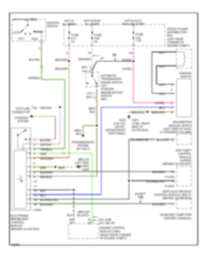
ANTI-THEFT
Drive-Away Protection (EWS II) for BMW 318ti 1998
List of elements for Drive-Away Protection (EWS II) for BMW 318ti 1998:
- (a/t)
- (below left side of dash) g202
- (m/t)
- 318, 318ti 323, 328, m3
- A/t
- Acc
- Anti-theft control module (alpine) (behind glove box)
- Automatic transmission range switch (a/t) starter immobilization switch (m/t)
- Body electronics control module (zke iv) (behind glove box)
- Data link connector
- Electronic immobilizer control module (behind glove box)
- Engine control module (dme) (right rear corner of engine compt)
- Except 318ti
- Front power distribution box (left rear corner of engine compt)
- Fuse f28 5a
- Fuse f31 5a
- Fuse f45 7.5a
- G201 (318ti - right side of glove box)
- G203 (318, 323, 328, m3 - behind right kick panel)
- Hot at all times
- Hot in accy, run and start
- Hot in run all start
- Ignition switch
- Lock
- M/t
- Nca
- On-board computer (center console)
- Run
- Start
- Starting system
- Transmissions system (a/t only)
- Transmitter module (ews ii) (left side of dash, at steering column)
- X10182
- X13253
- X1659
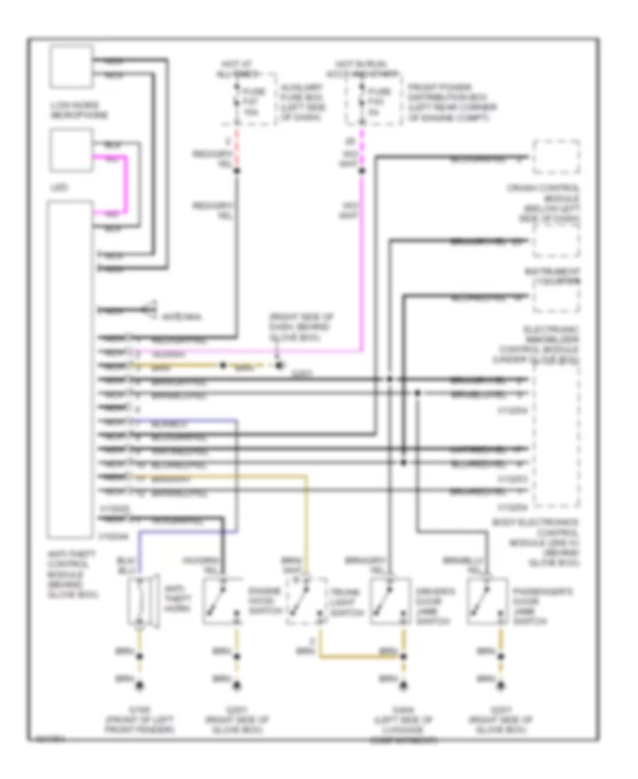
Forced Entry Wiring Diagram for BMW 318ti 1998
List of elements for Forced Entry Wiring Diagram for BMW 318ti 1998:
- (right side of dash, behind glove box)
- Antenna
- Anti- theft horn
- Anti-theft control module (behind glove box)
- Auxiliary fuse box (left side of dash)
- Body electronics control module (zke iv) (behind glove box)
- Crash control module (below left side of dash)
- Driver's door jamb switch
- Electronic immobilizer control module (under glove box)
- Engine hood switch
- Front power distribution box (left rear corner of engine compt)
- Fuse f43 5a
- Fuse f47 15a
- G100 (front of left front fender)
- G201
- G201 (right side of glove box)
- G404 (left side of luggage compartment)
- Hot at all times
- Hot in run, accy and start
- Instrument cluster
- Led
- Low-noise microphone
- Nca
- Passenger's door jamb switch
- Trunk light switch
- X10244
- X13025
- X13253
- X13254
BODY COMPUTER
Body Computer Module Wiring Diagram for BMW 318ti 1998
List of elements for Body Computer Module Wiring Diagram for BMW 318ti 1998:
- (1996)
- (1997, 98)
- (1998)
- (behind glove box) (partial) body electronics control module (zke iv)
- Acc
- Anti-theft
- Computer data lines
- Door locks
- Exterior lights
- Front power distribution box (left rear corner of engine compartment)
- Fuse f14 30a
- Fuse f33 10a
- Fuse f35 25a
- Fuse f43 5a
- G201 (behind glove box)
- G201 (right side of glovebox)
- Hot at all times
- Hot in accy, run and start
- Ignition switch
- Interior lights
- Lock
- On-board computer
- Power tops
- Power windows
- Red
- Run
- Start
- Starting/charging
- X10182
- X13252
- X13253
- X13254
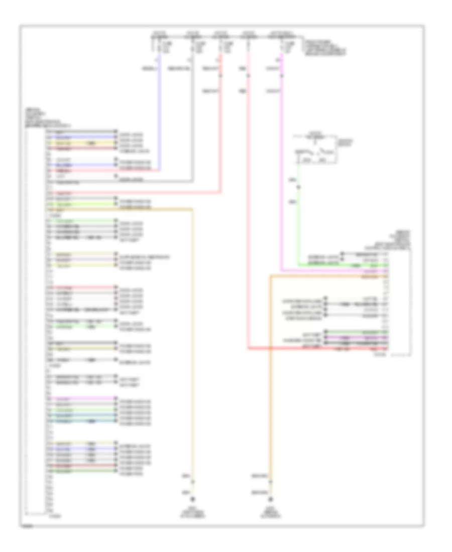
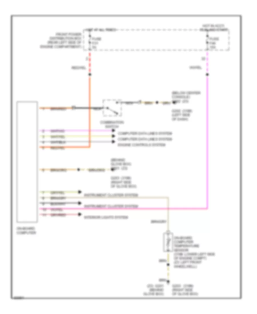
On-Board Computer Wiring Diagram for BMW 318ti 1998
List of elements for On-Board Computer Wiring Diagram for BMW 318ti 1998:
- (318ti)
- (behind glove box) g201
- (below center console) g302
- (z3)
- Combination switch
- Computer data lines system
- Engine controls system
- Front power distribution box (rear left side of engine compartment)
- Fuse f31 5a
- Fuse f46 15a
- G201 (behind glove box)
- G202 (left side of dash)
- G203 (right side of glove box)
- Hot at all times
- Hot in accy, run and start
- Instrument cluster system
- Interior lights system
- Nca
- On-board computer
- On-board computer temperature sensor (318ti: lower left side of engine compt) (z3: left front wheelwell)
COMPUTER DATA LINES
Computer Data Lines for BMW 318ti 1998
List of elements for Computer Data Lines for BMW 318ti 1998:
- (left rear of engine compartment) data link connector
- Abs control module/ hydraulic unit (left rear of engine compt)
- Battery
- Board computer (center of dash, in center console)
- Body electronics control module (zke iv) (behind glove box)
- Cruise control module (behind glove box)
- Electronic immobilizer control module (under glove box)
- Engine control module (dme) (right rear corner of engine compartment)
- Front power distribution box (left rear corner of engine compt)
- Fuse 10a
- Fuse f26 10a
- Fuse f46 15a
- G103 (back of right shock tower)
- G201 (right side of glove box)
- G202 (below left side of dash)
- Generator
- Hot at all times
- Hot in accy, start and run
- Hot in run and start
- Instrument cluster
- Obd ii connector (under left side of dash)
- Ohms
- Red
- Slip control module (behind glove box)
- Telephone connector (center console)
- Transmission control module (egs) (right rear corner of engine compartment)
- W/ asc
- W/o asc
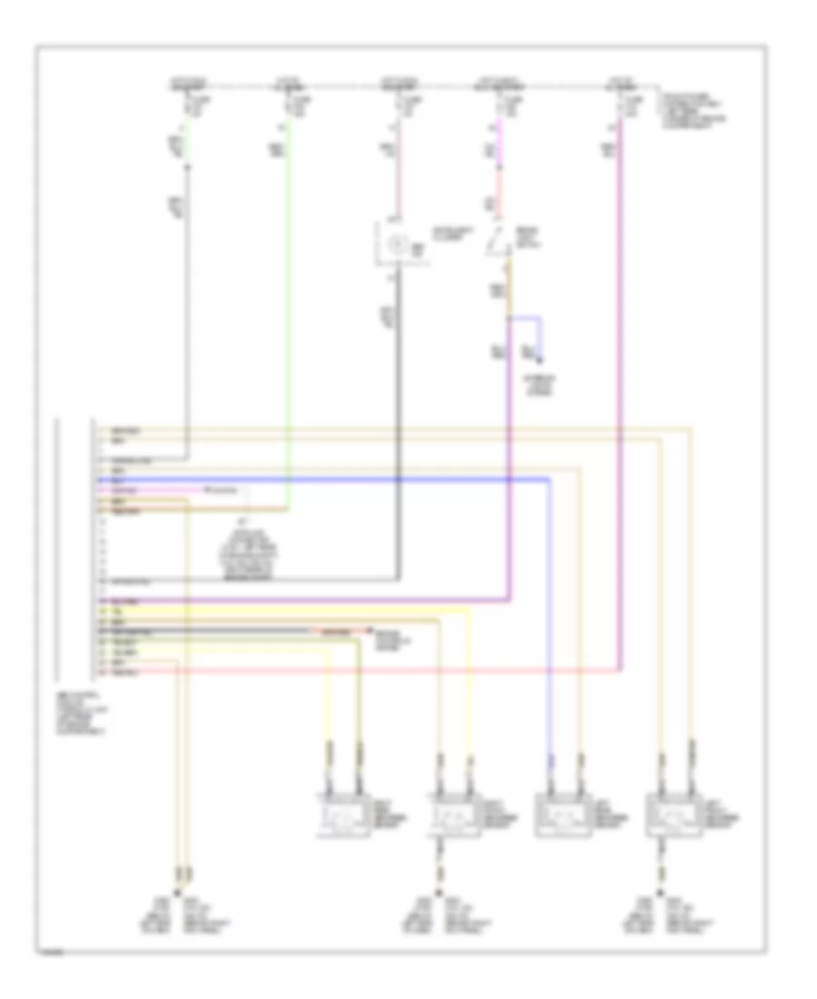
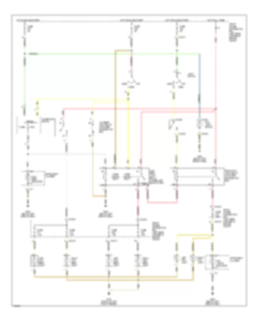
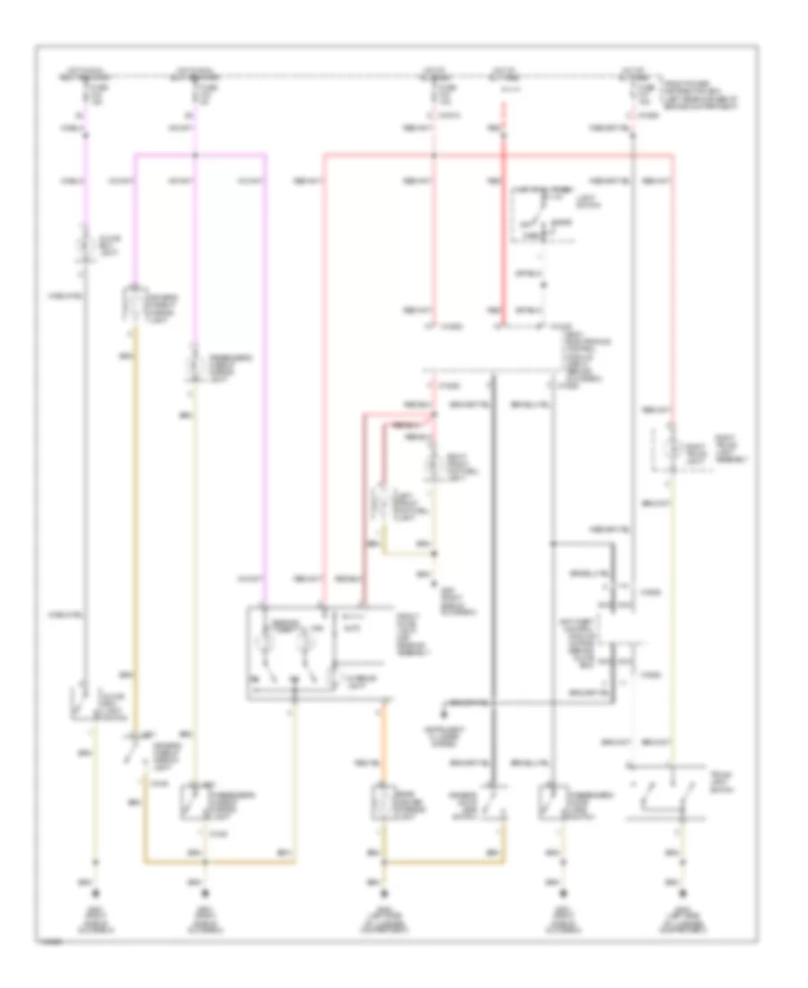
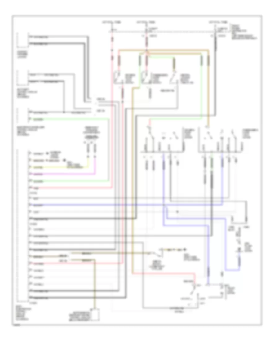
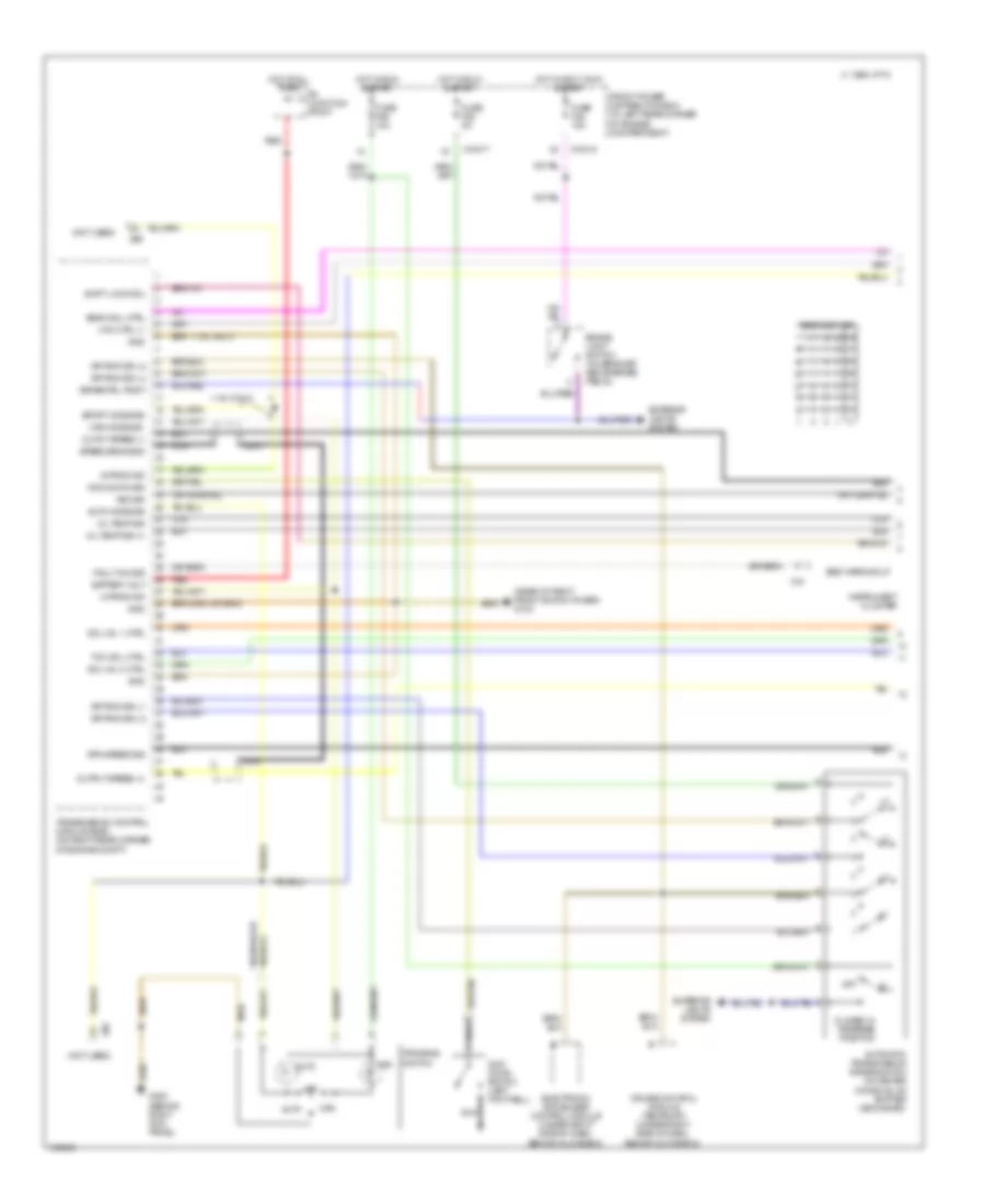
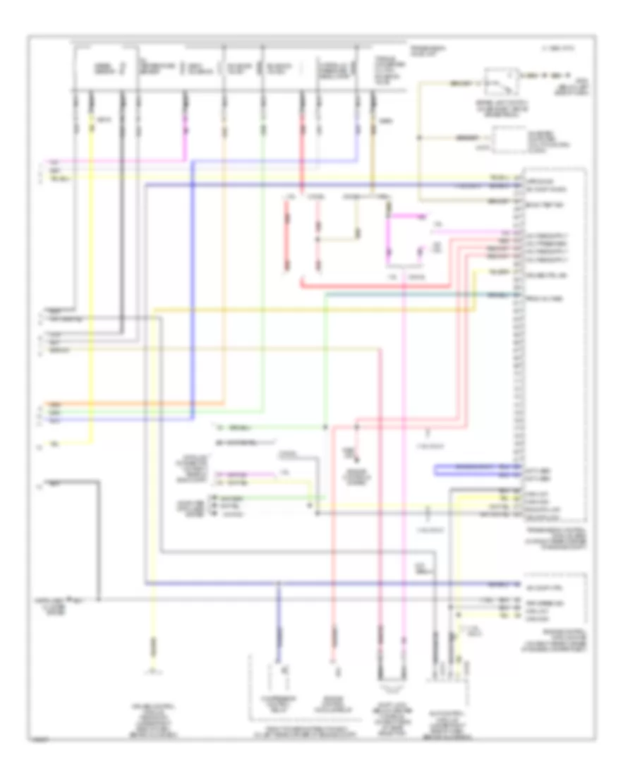
COOLING FAN
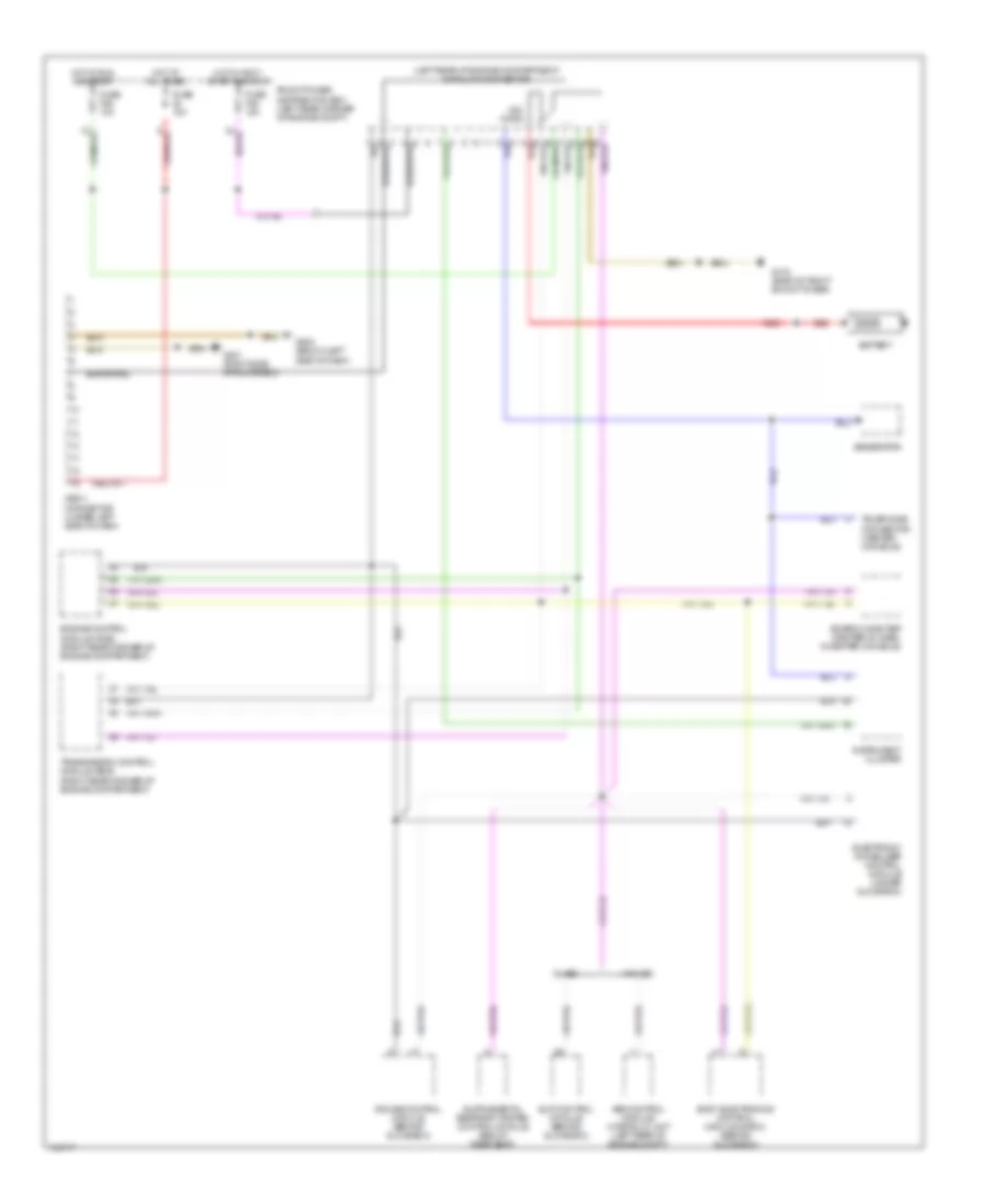
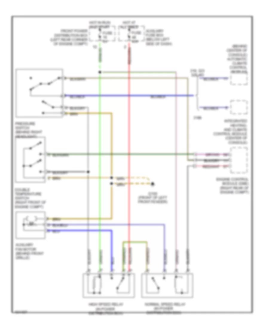
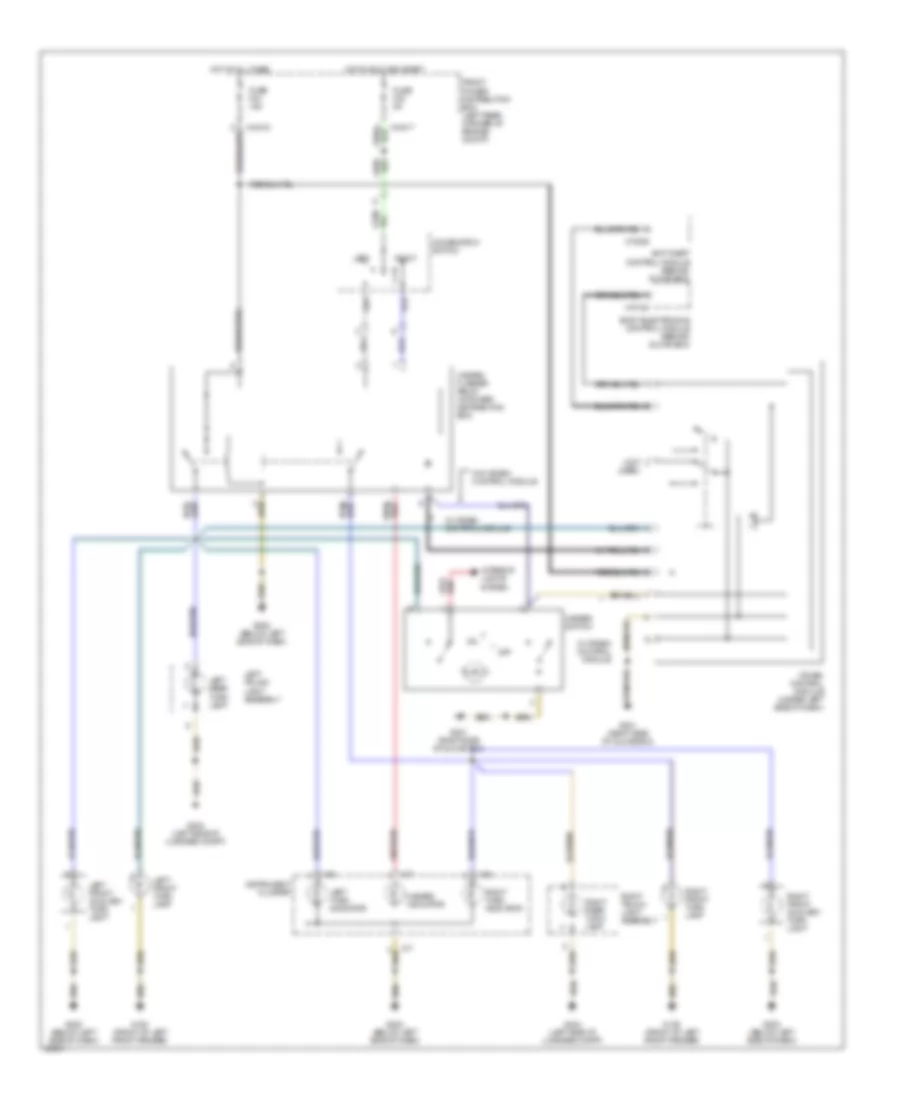
Cooling Fan Wiring Diagram for BMW 318ti 1998
List of elements for Cooling Fan Wiring Diagram for BMW 318ti 1998:
- (behind center of console) automatic climate control module
- (in power
- 318, 323 328, m3
- 318ti
- Auxiliary fan motor (behind front grille)
- Auxiliary fuse box (below left side of dash)
- Distribution box)
- Double temperature switch (right front of engine compt)
- Engine control module (dme) (right rear of engine compt)
- Front power distribution box (left rear corner of engine compt)
- Fuse 40a
- Fuse 5a
- G100 (front of left front fender)
- High speed relay
- Hot at all times
- Hot in run and start
- Integrated heating- and climate control module (center of console)
- Normal speed relay
- Pressure switch (behind right headlight)
CRUISE CONTROL
Cruise Control Wiring Diagram for BMW 318ti 1998
List of elements for Cruise Control Wiring Diagram for BMW 318ti 1998:
- (right rear of engine compt) transmission control module
- Acccelerate/ set
- Automatic transmission range switch (center console)
- Brake light switch (top of brake pedal support)
- Clutch switch (top of clutch pedal support)
- Computer data lines system
- Cruise control actuator (front left side of engine compartment)
- Cruise control module (under right side of dash)
- Cruise control switch
- Decelerate/ set
- Engine speed
- Exterior lights system
- Front power distribution box (left rear corner of engine compartment)
- Fuse f28 5a
- Fuse f46 15a
- G201 (318ti) (right side of glove box)
- G203 (318, 323, 328, m3) (behind right kick panel)
- Hot in accy, run and start
- Hot in run and start
- Instrument cluster
- Nca
- Normal
- Off
- Resume
- Tach out
- Transmission controls system
- W/ ccm
- W/ egs
- W/o ccm
- W/o egs
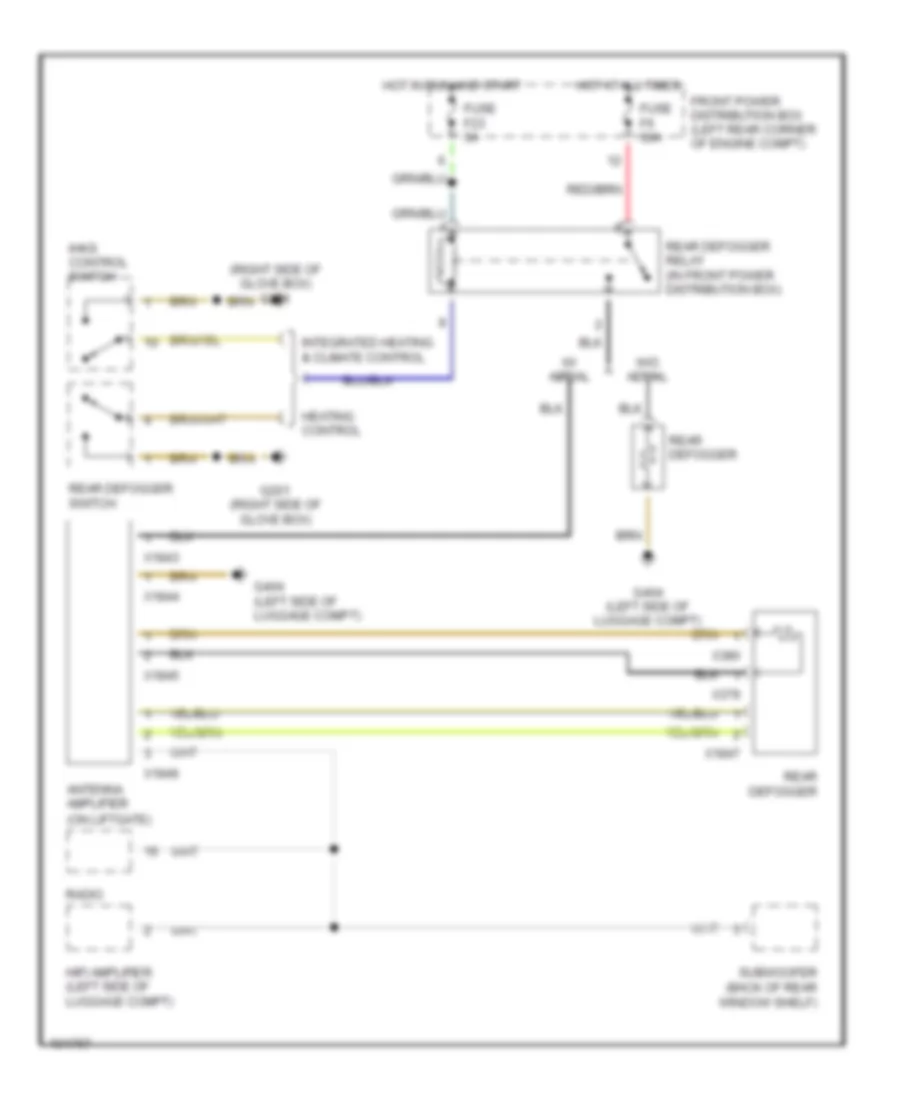
DEFOGGERS
Defogger Wiring Diagram for BMW 318ti 1998
List of elements for Defogger Wiring Diagram for BMW 318ti 1998:
- (right side of glove box) g201
- Antenna amplifier (on liftgate)
- Front power distribution box (left rear corner of engine compt)
- Fuse f23 5a
- Fuse f6 30a
- G201 (right side of glove box)
- G404 (left side of luggage compt)
- Heating control
- Hifi amplifier (left side of luggage compt)
- Hot at all times
- Hot in run and start
- Ihks control switch
- Integrated heating & climate control
- Radio
- Rear defogger
- Rear defogger relay (in front power distribution box)
- Rear defogger switch
- Subwoofer (back of rear window shelf)
- W/ aerial
- W/o aerial
- X1843
- X1844
- X1845
- X1846
- X1847
- X379
- X380
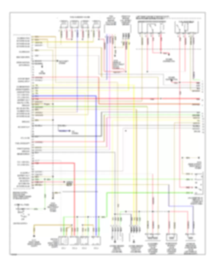
ENGINE PERFORMANCE
1.9L
1.9L, Engine Performance Wiring Diagrams (1 of 2) for BMW 318ti 1998
List of elements for 1.9L, Engine Performance Wiring Diagrams (1 of 2) for BMW 318ti 1998:
- (front of engine) hall effect camshaft sensor
- (left rear corner of engine compt) front power distribution box
- (rear of right front shock tower)
- (top front of engine) hot film air mass meter
- A/c comp cut
- A/c system
- Acc
- Activate a/c
- Activate fan
- Activate valve
- Anti-theft system
- Battery volt
- Camshaft pos
- Crank pos/rpm
- Cyl 1
- Cyl 1 ign coil
- Cyl 2
- Cyl 2 ign coil
- Cyl 3
- Cyl 3 ign coil
- Cyl 3-4 ks
- Cyl 4
- Cyl 4 ign coil
- Drive away sig
- Ecm rly ctrl
- Eng indicator
- Engine control module (dme) (right rear corner of engine compt)
- Engine control module relay
- Evaporative emission valve (left side of engine compt)
- Fuel consumpt
- Fuel injection valves
- Fuel pump relay
- G103
- G103 (rear of right front shock tower)
- G117 (right rear side of engine compt)
- Ground
- Hot at all times
- Idle speed control valve (left rear of engine compt)
- Ign ground
- Ign switch
- Ignition coils (right side of engine compt)
- Ignition switch
- Inj ground
- Intake air resonance changeover valve (left rear of engine compt)
- Intk air temp
- Isc valve ctrl
- Nca
- Normal speed relay
- O2 sens htng
- O2 sensor sig
- Off
- Oxygen sensor (behind catalytic converter)
- Oxygen sensor (in front of catalytic converter)
- Power distribution
- Red
- Run
- Signal input
- Splice
- Start
- Throttle pos
- Unloader relay terminal 15 (under left side of dash)
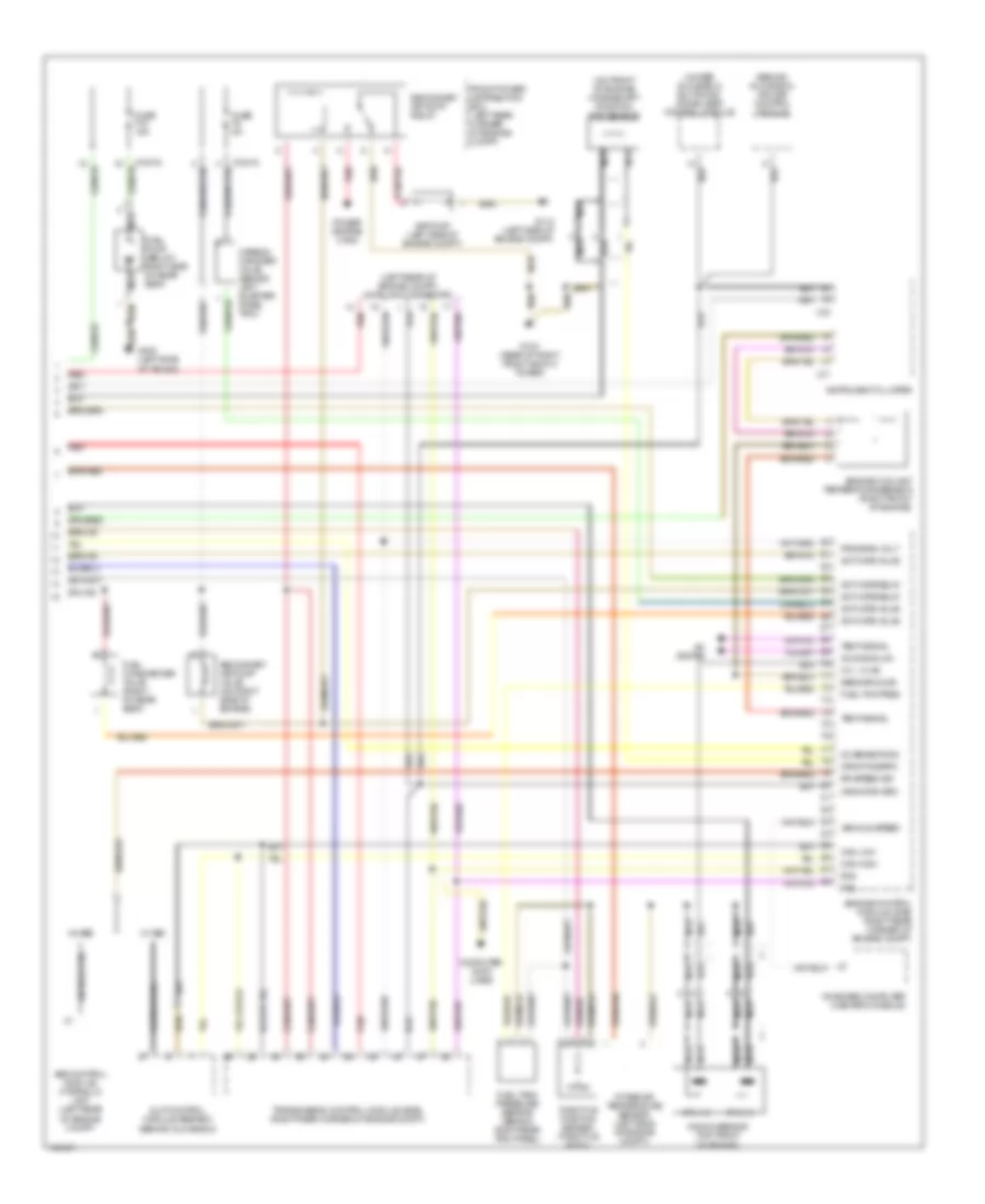
1.9L, Engine Performance Wiring Diagrams (2 of 2) for BMW 318ti 1998
List of elements for 1.9L, Engine Performance Wiring Diagrams (2 of 2) for BMW 318ti 1998:
- (behind glove box) cruise control module
- (left rear of engine compt) data link connector
- (on front of engine) crankshaft position/ rpm sensor
- (under glove box) elctronic immobilizer control module
- A/c signal on
- A/c system
- Abs control module/ hydraulic unit (left rear of engine compt)
- Activate relay
- Activate valve
- Air pump (left side of engine compt)
- Can high
- Can low
- Carbon canister valve (behind left quarter panel trim)
- Computer data lines
- Crnk pos/rpm
- Crnk rpm spd
- Cyl 1-2
- Cyl 1-2 ks
- Cyl 3-4
- Engine control module (dme) (right rear corner of engine compt)
- Engine coolant temperature sensor (right front of engine)
- Front power distribution box (left rear corner of engine compt)
- Fuel changeover valve (right of rear seat)
- Fuel pump (below right side of rear seat)
- Fuel tank pressure sensor (behind right rear trim panel)
- Fuel tnk pres
- Fuse f18 15a
- Fuse f2 5a
- G103 (rear of right front shock tower)
- G112 (left side of engine compt)
- G400 (left side of trunk)
- Instrument cluster
- Intake air temperature sensor (left side of engine compt)
- Knock sensor (top front of engine)
- Nca
- O2 sensor sig
- On-board computer (center console)
- Power distrib- ution
- Program volt
- Red
- Rr speed sig
- Rxd
- Secondary air pump relay
- Secondary air pump valve (on right side of engine)
- Sens ground
- Slip control module (abs/asc) (behind glove box)
- Splice
- Temp signal
- Throttle position sensor (throttle body)
- Transmission control module (egs) (right rear corner of engine compt)
- Txd
- Vehicle speed
- W/ abs
- W/ asc
- X10015
- X10016
- X16
- X17
EXTERIOR LIGHTS
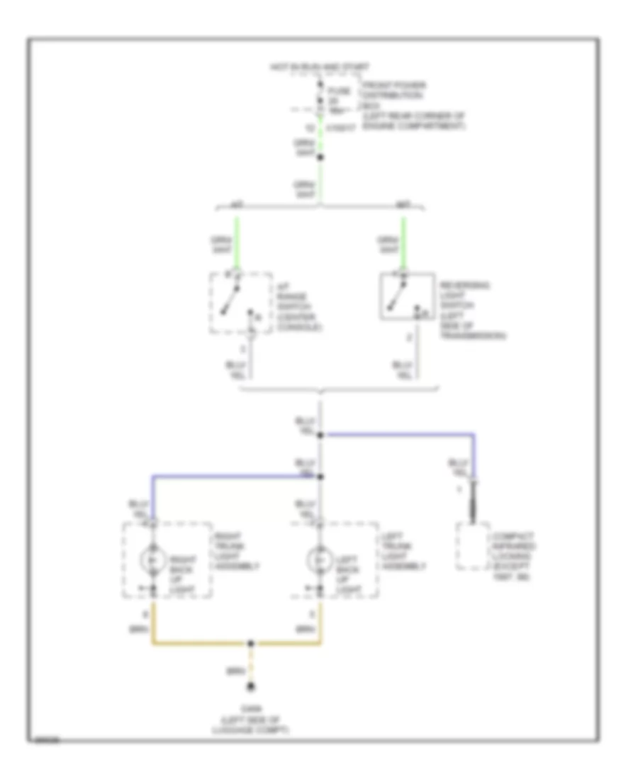
Back-up Lamps Wiring Diagram for BMW 318ti 1998
List of elements for Back-up Lamps Wiring Diagram for BMW 318ti 1998:
- (left side of luggage compt)
- A/t
- A/t range switch (center console)
- Compact infrared locking (except 1997, 98)
- Front power distribution box (left rear corner of engine compartment)
- Fuse 10a
- G404
- Hot in run and start
- Left back up light
- Left trunk light assembly
- M/t
- Nca
- Reversing light switch (left side of transmission)
- Right back up light
- Right trunk light assembly
- X10017
Exterior Light Wiring Diagram (1 of 2) for BMW 318ti 1998
List of elements for Exterior Light Wiring Diagram (1 of 2) for BMW 318ti 1998:
- (not used)
- Anti-theft control module (behind glove box)
- Body electronics control module (behind glove box)
- Combination switch
- Crash control module (under left side of dash)
- Front power distribution box (left rear corner of engine compt)
- Fuse f23 5a
- Fuse f34 15a
- G100 (front of left front fender)
- G201 (right side of glove box)
- G202 (below left side of dash)
- G404 (left side of luggage compt)
- Hazard flasher relay (in power distribution box)
- Hazard indicator
- Hazard switch
- Hot at all times
- Hot in run and start
- Instrument cluster
- Interior lights system
- Left
- Left front auxiliary turn light
- Left front turn lamp
- Left rear turn lamp
- Left trunk light assembly
- Left turn indicator
- Off
- Right
- Right front auxiliary turn light
- Right front turn lamp
- Right rear turn lamp
- Right trunk light assembly
- Right turn indicator
- W/ crash control module
- W/o crash control module
- X10017
- X10018
- X10182
- X13025
- X16
- X17
Exterior Light Wiring Diagram (2 of 2) for BMW 318ti 1998
List of elements for Exterior Light Wiring Diagram (2 of 2) for BMW 318ti 1998:
- (1997, 98) (others)
- (left side of luggage compt.)
- Abs control module/ hydraulic unit (left rear of engine compt)
- Acc.
- Brake light switch (brake pedal support)
- Combination switch
- Cruise control module (behind glove box)
- Except 1997, 98
- Front power distribution box (left rear corner of engine compartment)
- Fuse 10a
- Fuse 15a
- G100 (front of left front fender)
- G404
- G404 (left side of luggage compt)
- Head
- High level stop light
- Hot at all times
- Hot in accy, run and start
- Ignition switch
- Left brake light
- Left front light assembly
- Left license plate light
- Left park light
- Left tail light
- Left trunk light assembly
- Light switch
- Module (behind glove box)
- Off
- Park
- Right brake light
- Right front light assembly
- Right license plate light
- Right park light
- Right tail light
- Right trunk light assembly
- Slip control
- Transmission control module (right rear of engine compt)
- X10018
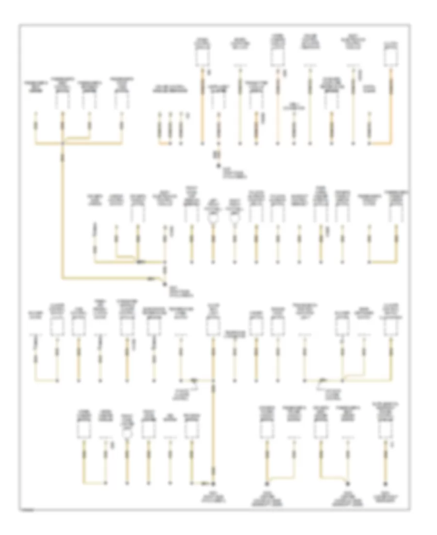
GROUND DISTRIBUTION
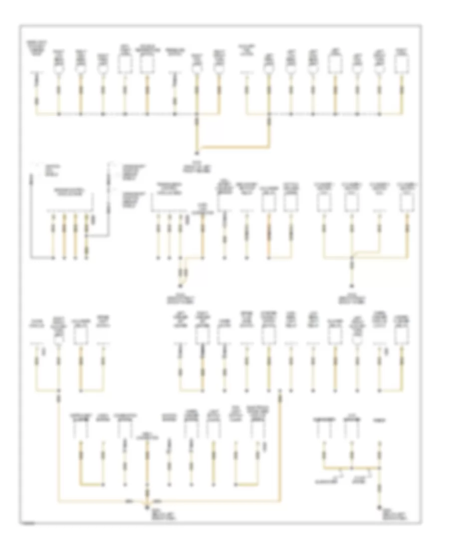
Ground Distribution Wiring Diagram (1 of 3) for BMW 318ti 1998
List of elements for Ground Distribution Wiring Diagram (1 of 3) for BMW 318ti 1998:
- Anti- theft horn
- Auxiliary fan motor
- Blower relay
- Brake fluid level switch
- Brake light switch
- Chime module
- Combination switch
- Crankshaft position sensor shield
- Cylinder 1 ignition coil
- Cylinder 2 ignition coil
- Cylinder 3 ignition coil
- Cylinder 4 ignition coil
- Data link connector
- Double temperature switch
- Electronic immobilizer module (ews ii)
- Engine control module (dme)
- Fog light switch illum
- G100 (front of left front fender)
- G103 (back of right shock tower)
- G202 (below left side of dash)
- Hall effect camshaft sensor
- Hazard flasher relay
- Headlight/ foglight washer pump
- Hi-fi amplifier
- High beam light relay
- Horn switch
- Hot film air mass meter
- Ignition coil shield
- Ignition switch
- Instrument cluster
- Left fog light
- Left front auxiliary turn light
- Left front turn light
- Left high beam light
- Left horn
- Left low beam light
- Left park light
- Left washer jet heater
- Light switch illum
- Low beam light relay
- Nca
- Obd ii connector
- Pressure switch
- Radio
- Right fog light
- Right front auxiliary turn light
- Right front turn light
- Right high beam light
- Right horn
- Right low beam light
- Right park light
- Right washer jet heater
- Secondary air pump relay
- Starter immobili- zation switch
- Subwoofer
- Transmission control module (egs)
- Unloader relay
- W/ hifi system
- W/ subwoofer
- Wiper motor
- Wiper/ washer module (low ii)
- Wiper/ washer switch
- X1659
- X285
- X522
- X6000
- X8500
Ground Distribution Wiring Diagram (2 of 3) for BMW 318ti 1998
List of elements for Ground Distribution Wiring Diagram (2 of 3) for BMW 318ti 1998:
- Asc switch
- Blower motor
- Board computer (bc-low)
- Body electronics control module
- Climate control switch illum
- Climate control switch illumination
- Clutch switch
- Crash control module
- Cruise control actuator (tempomat)
- Cruise control module (tempomat)
- Digital clock
- Driver's makeup mirror switch
- Driver's power window switch
- Driver's seat heater switch
- Driver's side mirror
- Driver's window motor
- Engine hood switch
- Evaporator temperature sensor
- Folding sunroof comfort relay
- Folding sunroof switch
- Fresh air/ recirc- ulation motor
- Front cigar lighter
- Front cigar lighter light
- Front dome/ map reading assembly
- G201 (right side of glovebox)
- G302 (center console, near gearshift lever)
- G303 (under right rear seat)
- Glove box light switch
- Hazard switch
- Ihks control switch
- Instrument cluster
- Integrated heating/ climate control module
- Left front footwell light
- Mirror control switch
- Nca
- Obd ii connector
- On-board computer temperature sensor
- Passenger's door jamb switch
- Passenger's makeup mirror switch
- Passenger's power window switch
- Passenger's seat control switch
- Passenger's seat heater
- Passenger's seat heater switch
- Passenger's seatback heater
- Passenger's window motor
- Program switch
- Rear defogger switch
- Rear wiper/ washer interval module
- Right front footwell light
- Sunroof control assembly
- Telephone connector
- Temperature wheel switch
- Transmission position indicator light
- Transmitter module (ews ii)
- W/ auto climate control
- W/o auto climate control
- Wiper/ washer module
- Wiper/ washer module (low ii)
- Wiper/ washer switch
- X10182
- X10260
- X11250
- X13057
- X13252
- X22
- X285
- X65
- X74
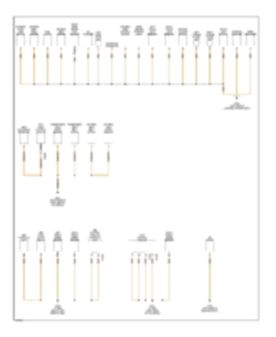
Ground Distribution Wiring Diagram (3 of 3) for BMW 318ti 1998
List of elements for Ground Distribution Wiring Diagram (3 of 3) for BMW 318ti 1998:
- Abs control module/ hydraulic unit
- Abs hydraulic unit
- Abs pump motor relay
- Air pump
- Antenna amplifier
- Anti- theft control module
- Cd changer
- Central locking switch
- Driver's door jamb switch
- Driver's seat belt switch
- Driver's seat control switch
- Driver's seat heater
- Driver's seat- back heater
- Driver's side impact sensor
- Fuel pump
- G104 (left rear of engine compt)
- G201 (right side of dash, behind glove box)
- G201 (w/ asc) (right side of glove box)
- G202 (w/ abs) (below left side of dash)
- G404 (left side of luggage compartment)
- High level stop light
- Left front speed sensor
- Left license plate light
- Left trunk light assembly
- Nca
- Passenger's seat belt switch
- Passenger's side impact sensor
- Rear center interior light
- Rear defogger
- Right front speed sensor
- Right license plate light
- Right rear brake pad sensor
- Right trunk light assembly
- Seat occupancy detector
- Slip control module
- Telephone connector
- Trunk light switch
- X11394
- X11395
- X1170
- X13025
HEADLIGHTS
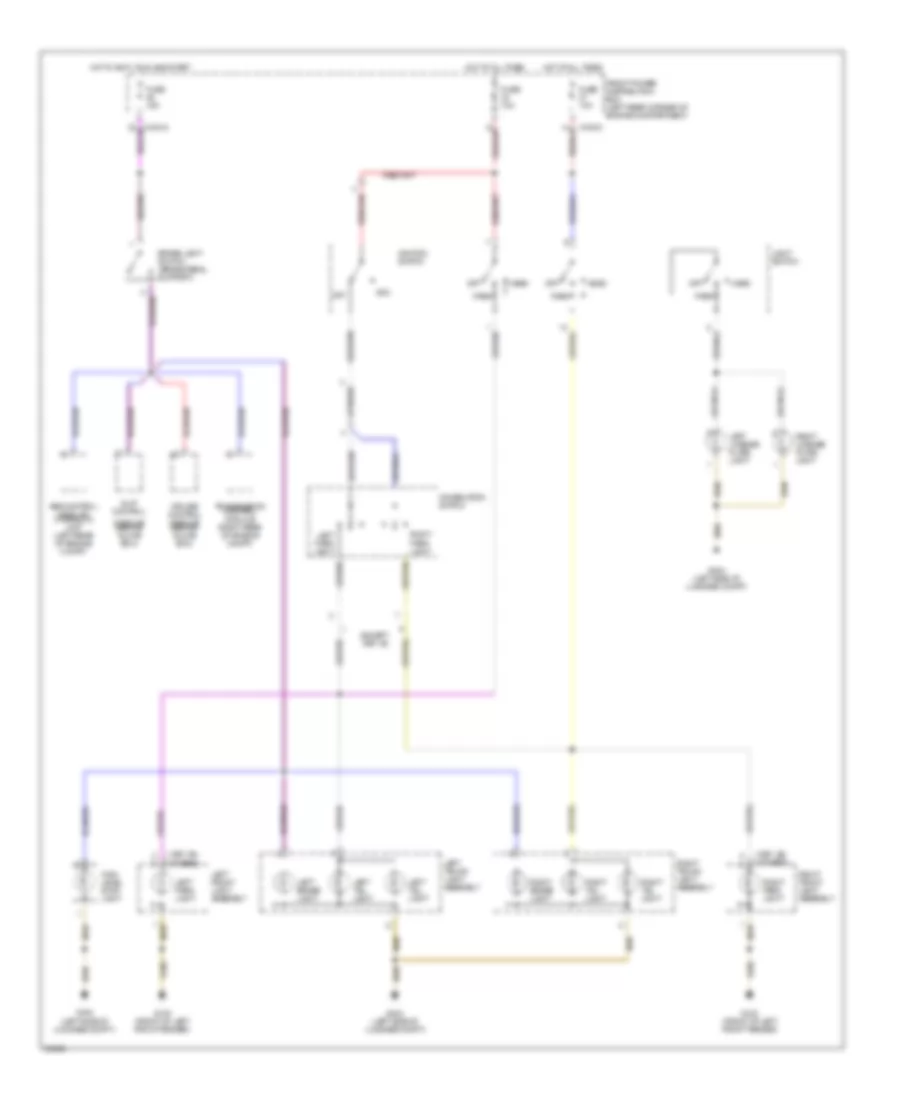
Headlight Wiring Diagram for BMW 318ti 1998
List of elements for Headlight Wiring Diagram for BMW 318ti 1998:
- (used canada only)
- 87b
- Combination switch
- Flash
- Fog light switch
- Fog lights indicator
- Front fog light relay (in power distribution box)
- Front power distribution box (left rear corner of engine compt)
- Fuse f11 7.5a
- Fuse f12 7.5a
- Fuse f15 7.5a
- Fuse f22 5a
- Fuse f23 5a
- Fuse f25 5a
- Fuse f29 7.5a
- Fuse f30 7.5a
- G100 (front of left front fender)
- G202 (below left side of dash)
- Head
- High
- High beam indicator
- High beam light relay (under left side of dash)
- Hot at all times
- Hot in run and start
- Instrument cluster
- Left fog light
- Left high beam light
- Left low beam light
- Light switch
- Low beam light relay (in power distribution box)
- Normal
- Off
- Park
- Red
- Right fog light
- Right high beam light
- Right low beam light
- X10016
- X10017
- X10035
- X10036
- X16
- X17
- X18334
- X18338
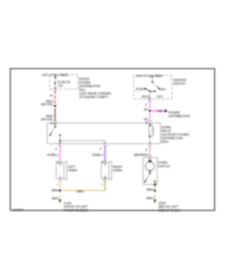
HORN
Horn Wiring Diagram for BMW 318ti 1998
List of elements for Horn Wiring Diagram for BMW 318ti 1998:
- Acc
- Front power distribution box (left rear corner of engine compt)
- Fuse f8 15a
- G100 (front of left front fender)
- G202 (below left side of dash)
- Horn relay (in front power distribution box)
- Horn switch
- Hot at all times
- Ignition switch
- Left horn
- Off
- Power distribution
- Right horn
- Run
- Start
INSTRUMENT CLUSTER
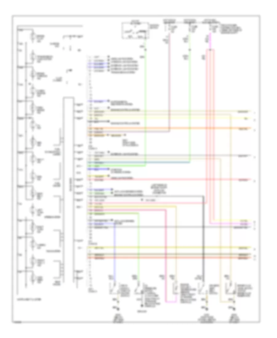
Instrument Cluster Wiring Diagram (1 of 2) for BMW 318ti 1998
List of elements for Instrument Cluster Wiring Diagram (1 of 2) for BMW 318ti 1998:
- (left rear of engine compt) data link connector
- (right front of engine below intake manifold)
- A14
- A16
- A17
- A18
- A19
- A20
- A22
- A23
- A24
- Abs ind
- Acc
- Anti-lock brakes system
- Asc+t ind
- B12
- B13
- B14
- B15
- B16
- B17
- B18
- B19
- B21
- B22
- B23
- Brake fluid ind
- Brake fluid level switch (top of brake fluid reservoir)
- Brake warning ind
- Charge
- Check engine ind
- Driver's seat belt switch
- Engine controls system
- Engine coolant temperature sensor (right front of engine, below intake manifold)
- Exterior lights system
- Front fog lt ind
- Front power distribution box (rear left side of engine compt)
- Fuel consumption meter
- Fuel gauge
- Fuse f23 5a
- Fuse f27 5a
- Fuse f46 15a
- G201 (right side of dash, behind glove box)
- G201 (right side of glove box)
- G202 (below left side of dash)
- Ground
- Hazard ind
- Headlights system
- High beam ind
- Hot at all times
- Hot in acc, run and start
- Hot in run and start
- Ignition switch
- Illum (3 used)
- Ind
- Instrument cluster
- Interior lights system
- Key-in switch (part of ignition switch)
- Left turn ind
- Lock
- Nca
- Oil ind
- Oil pressure switch 1) normal 2) 0.2-0.5 bar
- Park brake ind
- Right turn ind
- Run
- Seat belt ind
- Solid state
- Speedometer
- Srs ind
- Start
- Starting/ charging system
- Tachometer
- Temp gauge
- Transmission malfunction ind
- Transmission system
- X16 conn a
- X17 conn b
- X271 conn c
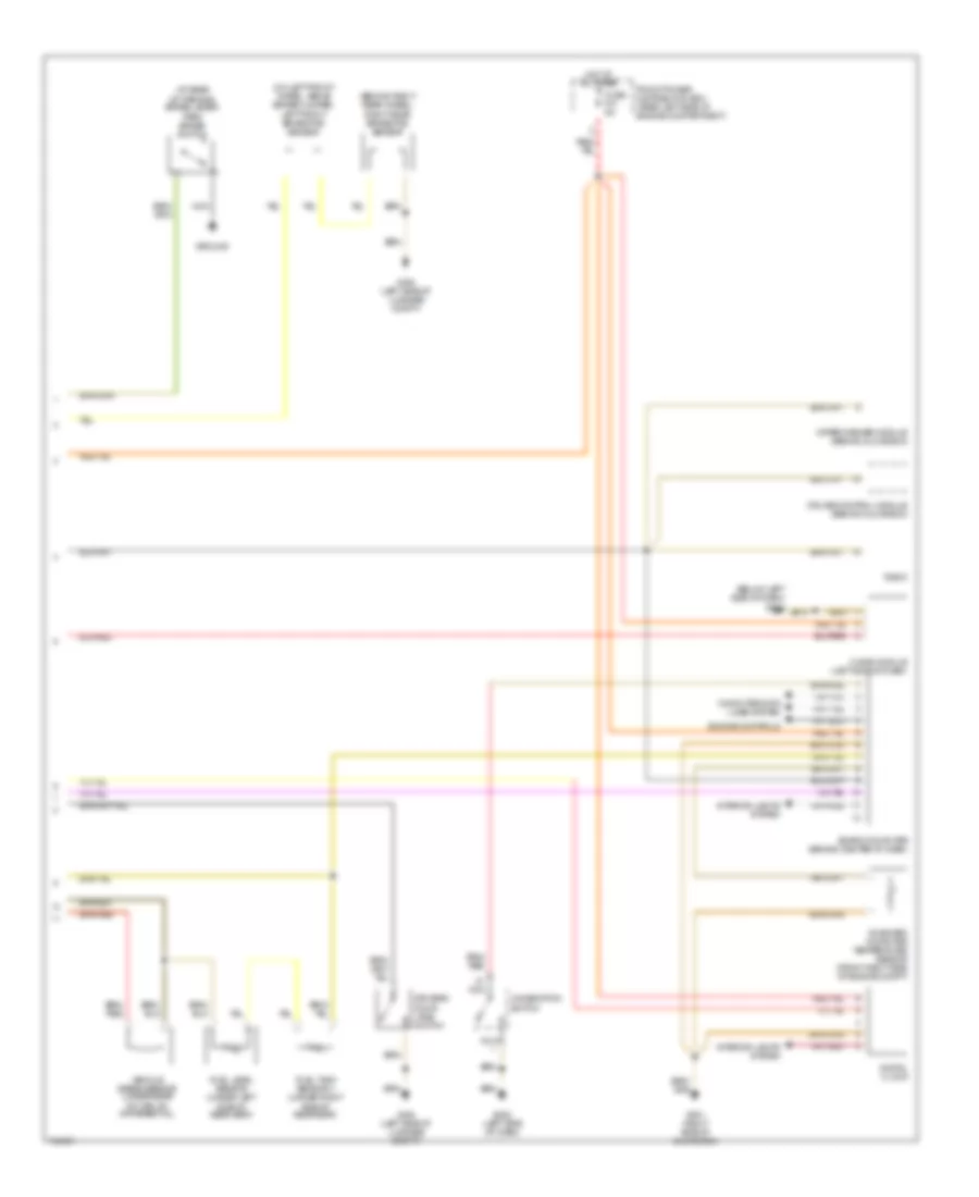
Instrument Cluster Wiring Diagram (2 of 2) for BMW 318ti 1998
List of elements for Instrument Cluster Wiring Diagram (2 of 2) for BMW 318ti 1998:
- (at base of parking brake lever) park brake switch
- (behind right rear wheel) right rear brake pad sensor
- (below left side of dash) g202
- (on left front wheel, above brake caliper) left front brake pad sensor
- Board computer (behind center of dash)
- Chime module (left sdie of dash)
- Combination switch
- Computer data lines system
- Cruise control module (behind glove box)
- Digital clock
- Drivers door jamb switch
- Engine controls
- Front power distribution box (rear left side of engine compartment)
- Fuel level sensor (under left side of rear seat)
- Fuel tank sensor ii (under right side of rear seat)
- Fuse f31 5a
- G201 (right side of glove box)
- G202 (left side of dash)
- G404 (left side of luggage compt)
- Ground
- Hot at all times
- Interior lights system
- Nca
- On-board computer temperature sensor (front right side of engine compt)
- Radio
- Vehicle speed sensor (under rear of car, on differential)
- Wiper/washer module (behind glove box)
INTERIOR LIGHTS
Courtesy Lamps Wiring Diagram for BMW 318ti 1998
List of elements for Courtesy Lamps Wiring Diagram for BMW 318ti 1998:
- Anti-theft control module (alpine) (behind glove box)
- Auto
- Body electronics control module (zke iv) (behind glove box)
- Driver's door jamb switch
- Driver's makeup mirror light
- Front dome light/ map reading assembly
- Front power distribution box (left rear corner of engine compartment)
- Fuse f33 10a
- Fuse f43 5a
- Fuse f44 15a
- Fuse f47 15a
- G201 (right
- G201 (right side of glove box)
- G404 (left side
- Glove box light
- Glove box light switch
- Head
- Hot at all times
- Hot in run, accy and start
- Instrument cluster system
- Interior light
- Left front footwell light
- Light switch
- Man
- Nca
- Of luggage compartment)
- Off
- Park
- Passenger's door jamb switch
- Passenger's makeup mirror light
- Reading light
- Rear center interior light
- Red
- Right front footwell light
- Right trunk light
- Right trunk light assembly
- Side of glove box)
- Trunk light switch
- X10018
- X10182
- X10250
- X1245
- X13025
- X13252
- X13254
- X401
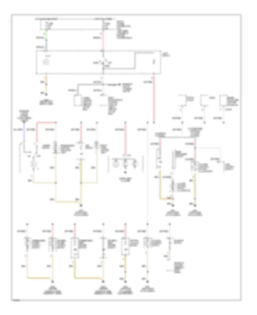
Instrument Illumination Wiring Diagram for BMW 318ti 1998
List of elements for Instrument Illumination Wiring Diagram for BMW 318ti 1998:
- Asc switch
- Board computer (center console)
- Body electronics control module (zke iv) (behind glove box)
- Central locking switch
- Climate control switch illumination
- Digital clock
- Driver's power window switch
- Driver's seat heater switch
- Exterior lights (license lights)
- Exterior lights system (turn/hazard lights)
- Folding sunroof switch
- Front cigar lighter light
- Front power distribution box (left rear corner of engine compartment)
- Fuse f23 5a
- Fuse f37 10a
- G201 (right side of glove box)
- G202 (below left side of dash)
- G302 (center console, near gearshift lever)
- G404 (left side of luggage compartment)
- Hazard switch
- Head
- Hot at all times
- Hot in run and start
- Ihks control switch
- Instrument cluster
- Light switch
- Off
- Park
- Passenger's power window switch
- Passenger's seat heater switch
- Radio
- Rear defogger switch
- Sunroof control assembly (roof panel)
- Sunroof switch
- Transmission position indicator light
- W/ heating control
- W/ integrated heating & climate control
- Wiper/ washer module (behind glove box)
- X10245
- X16
POWER DISTRIBUTION
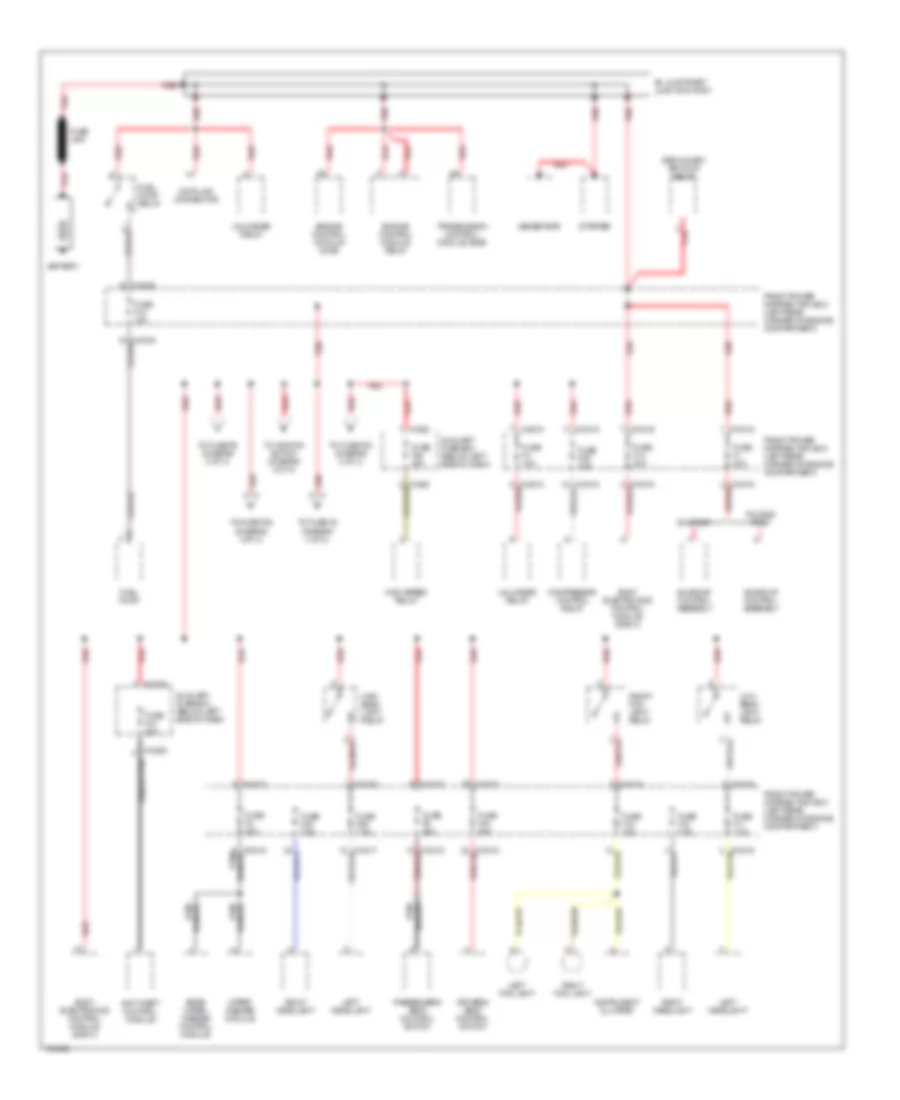
Power Distribution Wiring Diagram (1 of 3) for BMW 318ti 1998
List of elements for Power Distribution Wiring Diagram (1 of 3) for BMW 318ti 1998:
- Anti-theft control module
- Auxiliary fuse box (below left side of dash)
- B+ jump start junction point
- Battery
- Body electronics control module (zke iv)
- Compressor control relay
- Data link connector
- Driver's seat control switch
- Engine control module (dme)
- Engine control module relay
- Folding roof
- Front fog light relay
- Front power distribution box (left rear corner of engine compartment)
- Fuel pump
- Fuel pump relay
- Fuse f1 30a
- Fuse f11 7.5a
- Fuse f12 7.5a
- Fuse f14 30a
- Fuse f15 15a
- Fuse f18 15a
- Fuse f29 7.5a
- Fuse f3 30a
- Fuse f30 7.5a
- Fuse f39 7.5a
- Fuse f4 15a
- Fuse f40 30a
- Fuse f47 30a
- Fuse f48 40a
- Fuse f5 30a
- Fuse link
- Generator
- High beam light relay
- High speed relay
- Instrument cluster
- Left fog light
- Left headlight
- Low beam light relay
- Passenger's seat control switch
- Rear wiper/ washer control module
- Red
- Right fog light
- Right headlight
- Secondary air pump relay
- Starter
- Sunroof
- Sunroof control assembly
- To fuse f20 (diagram 2 of 3)
- To fuse f36 (diagram 3 of 3)
- To fuse f6 (diagram 2 of 3)
- To fuse f8 (diagram 3 of 3)
- To ignition switch (diagram 2 of 3)
- Transmission control module (egs)
- Unloader relay
- Wiper/ washer module
- X10015
- X10016
- X10018
- X10035
- X10036
- X10250
- X1588
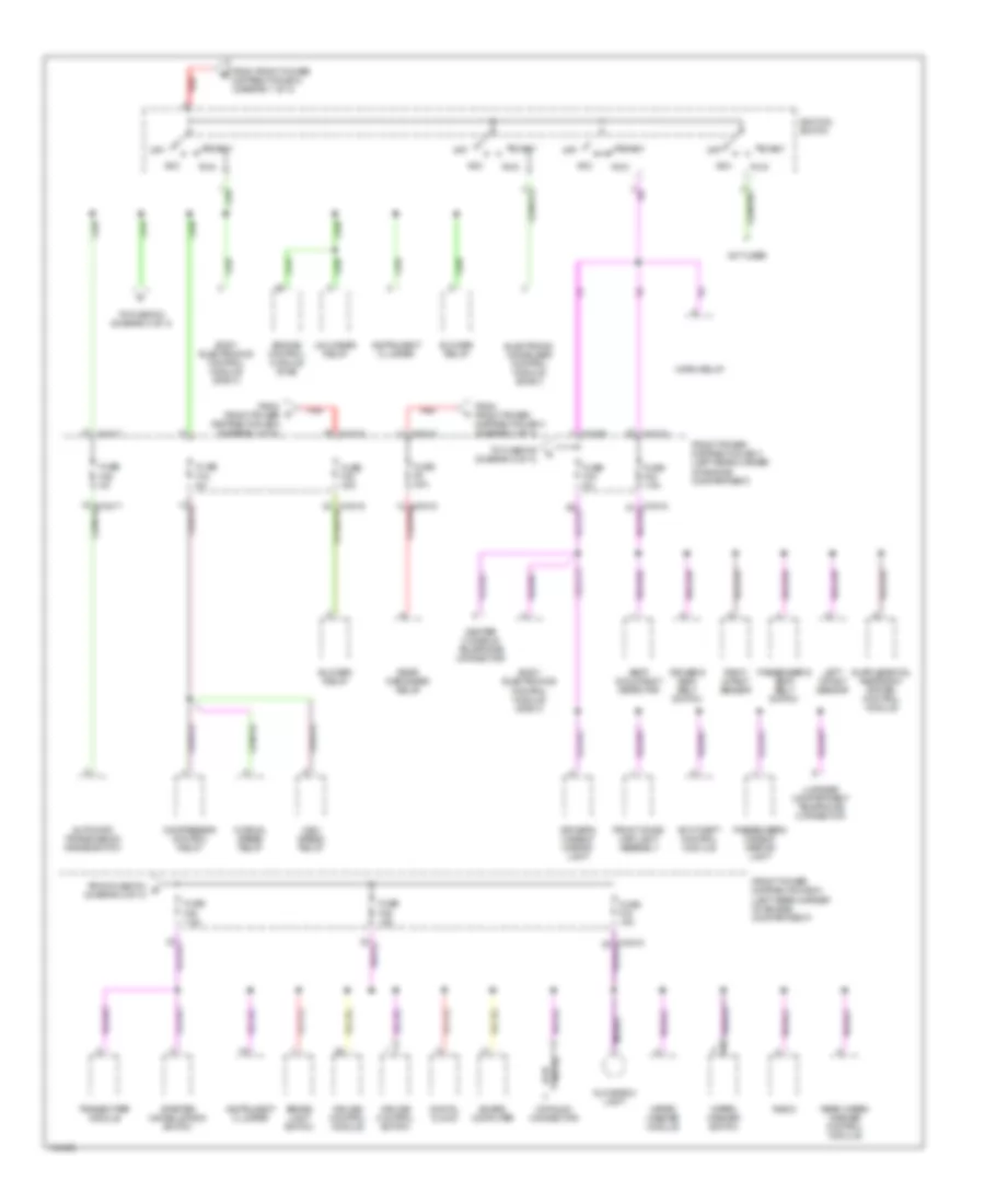
Power Distribution Wiring Diagram (2 of 3) for BMW 318ti 1998
List of elements for Power Distribution Wiring Diagram (2 of 3) for BMW 318ti 1998:
- Acc
- Anti-theft control module
- Automatic transmission range switch
- Blower relay
- Board computer
- Body electronics control module (zke iv)
- Brake light switch
- Center console telephone connector
- Compressor control relay
- Cruise control module
- Cruise control switch
- Datalink connector
- Digital clock
- Driver's makeup mirror light
- Driver's seat belt switch
- Electronic immoblizer control module (ews ii)
- Engine control module (dme)
- From front power distribution box (diagram 1 of 3)
- From fuse f43 g (diagram 2 of 3)
- Front dome/ map light assembly
- Front power distribution box (left rear corner of engine compartment)
- Fuse f16 5a
- Fuse f20 30a
- Fuse f28 5a
- Fuse f42 7.5a
- Fuse f43 5a
- Fuse f44 15a
- Fuse f45 7.5a
- Fuse f46 15a
- Fuse f6 30a
- Glove box light
- High speed relay
- Horn relay
- Ignition switch
- Instrument cluster
- Left impact sensor
- Luggage compartment telephone connector
- Normal speed relay
- Not used
- Off
- Passenger's makeup mirror light
- Passenger's seat belt switch
- Radio
- Rear defogger relay
- Rear wiper/ washer control module
- Red
- Right impact sensor
- Run
- Seat occupancy detector
- Start
- Starter immobilization switch
- To fuse f24 (diagram 3 of 3)
- To fuse f45 (diagram 2 of 3)
- Transmitter module
- Unloader relay
- Wiper/ washer module
- Wiper/ washer switch
- X10015
- X10016
- X10017
- X10018
- X10258
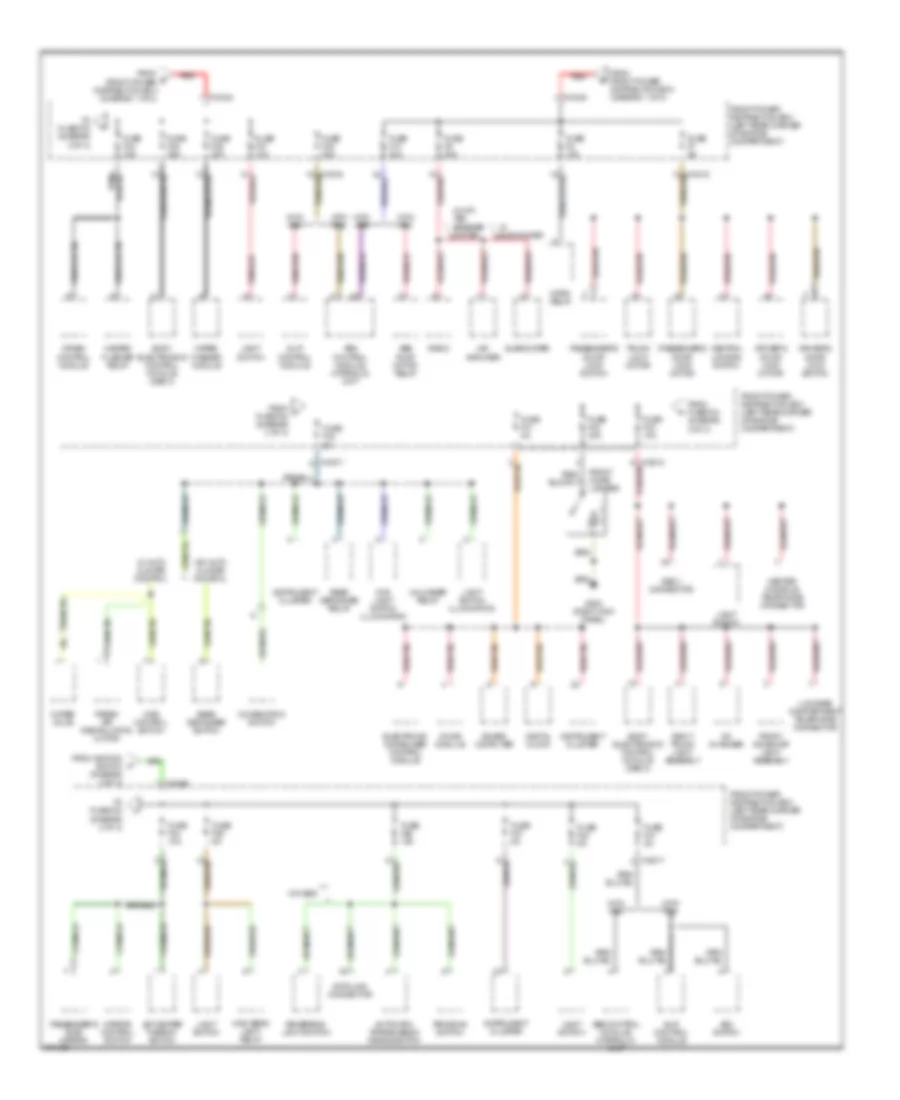
Power Distribution Wiring Diagram (3 of 3) for BMW 318ti 1998
List of elements for Power Distribution Wiring Diagram (3 of 3) for BMW 318ti 1998:
- Abs control module/ hydraulic unit
- Abs pump motor relay
- Asc switch
- Automatic transmission range switch
- Board computer
- Body electronics control module (zke iv)
- Cd changer
- Center console telephone connector
- Central locking switch
- Chime module
- Combination switch
- Crash control module
- Data link connector
- Digital clock
- Driver's door lock motor
- Driver's door lock switch
- Electronic immobilizer control module
- Fog light switch illumination
- Fresh air recirulation motor
- From d front power distribution box (diagram 1 of 3)
- From front power distribution box (diagram 1 of 3)
- From fuse f34 (diagram 3 of 3)
- From ignition switch (diagram 2 of 3)
- From j fuse f24 (diagram 3 of 3)
- Front cigar lighter
- Front dome/map light assembly
- Front power distribution box (left rear corner of engine compartment)
- Fuse f10 30a
- Fuse f21 5a
- Fuse f22 5a
- Fuse f23 5a
- Fuse f24 10a
- Fuse f25 5a
- Fuse f26 10a
- Fuse f27 5a
- Fuse f31 5a
- Fuse f32 30a
- Fuse f33 10a
- Fuse f34 15a
- Fuse f35 25a
- Fuse f36 30a
- Fuse f37 10a
- Fuse f38 30a
- Fuse f7 5a
- Fuse f8 15a
- Fuse f9 20a
- G203 (right kick panel)
- Hazard flasher relay
- Hifi amplifier
- High beam light relay
- Horn relay
- Ihks control switch
- Instrument cluster
- Jet heater thermo- switch
- Light switch
- Light switch illumination
- Luggage compartment telephone connector
- Mirror control switch
- Obd ii connector
- Passenger's door lock motor
- Passenger's door lock switch
- Passenger's side mirror
- Program switch
- Radio
- Rear defogger relay
- Rear defogger switch
- Red
- Reversing light switch
- Right trunk light assembly
- Slip control module
- Subwoofer
- To fuse f23 (diagram 3 of 3)
- To fuse f33 (diagram 3 of 3)
- Trunk lock motor
- Unloader relay
- W/ auto climate control
- W/ hifi, ten speaker system
- W/ subwoofer
- W/o auto climate control
- W/o egs
- Water valve
- Wiper/ washer module
- With abs
- With asc
- X10017
- X10026
- X10030
- X10034
POWER DOOR LOCKS
Power Door Lock Wiring Diagram for BMW 318ti 1998
List of elements for Power Door Lock Wiring Diagram for BMW 318ti 1998:
- (1995, 96, 97)
- (1998)
- (rear right of engine compartment)
- 1995, 96
- 1997, 98
- Anti-theft control module (behind glove box)
- Body electronics control module (behind glove box)
- Central locking switch (1996, 97, 98)
- Compact infrared locking
- Data link connector
- Driver's door lock motor
- Driver's door lock switch
- Electronic immobilizer control module (behind glove box)
- Exterior lights system
- Front power distribution box (left rear side of engine compartment)
- Fuse f35 25a
- Fuse f7 5a
- G201 (right side of glove box)
- G203 (right side of glove box)
- Gas filler lock motor
- Hot at all times
- Inertia switch (lower right "a" pillar)
- Lock
- Nca
- Passenger's door lock motor
- Passenger's door lock switch
- Red
- Trunk lock motor
- Unlock
- X10015
- X10018
- X10182
- X13252
- X13253
- X311
- X315
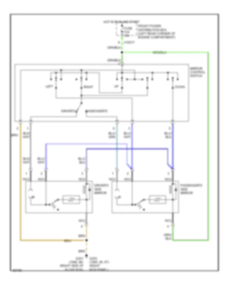
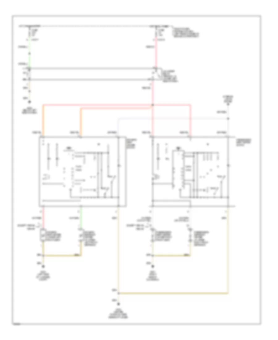
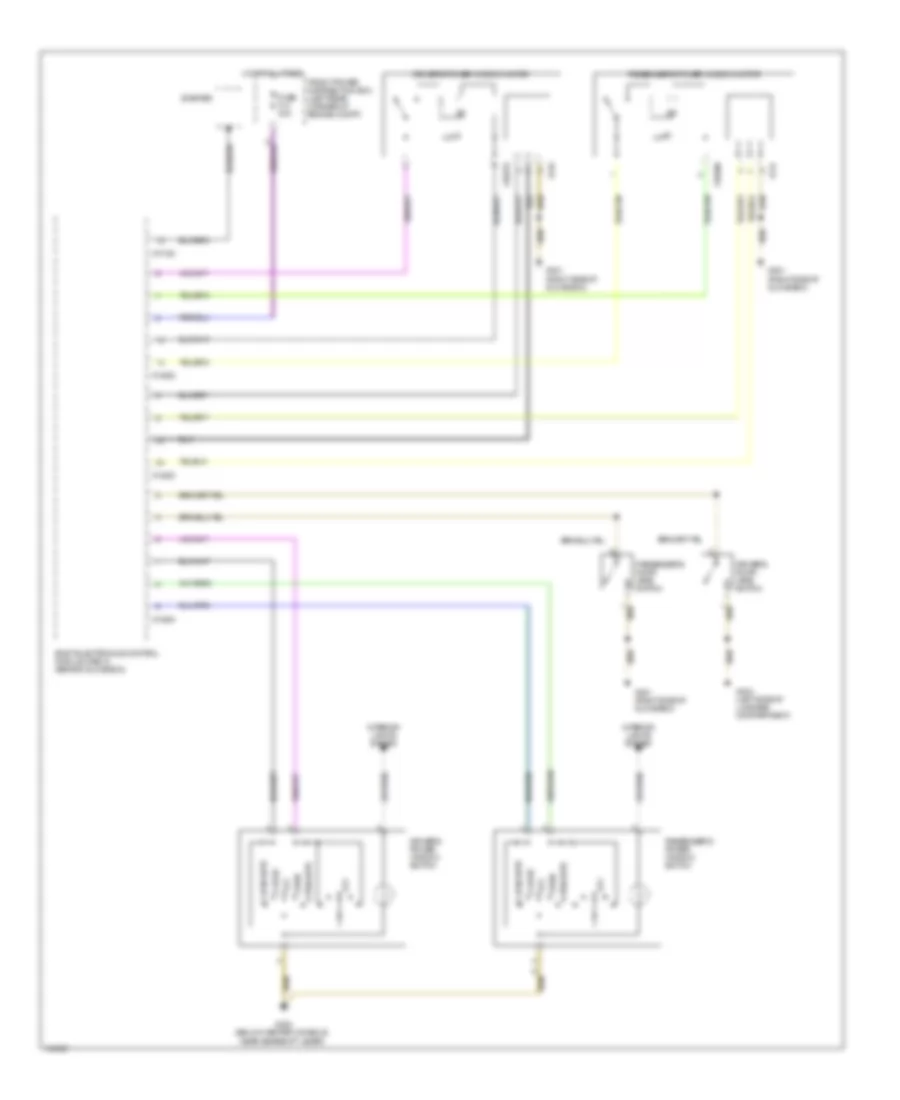
POWER MIRRORS
Power Mirror Wiring Diagram for BMW 318ti 1998
List of elements for Power Mirror Wiring Diagram for BMW 318ti 1998:
- Down
- Driver's
- Driver's side mirror
- Front power distribution box (left rear corner of engine compartment)
- Fuse f24 10a
- G201 (1998, 99) (right side of glove box)
- G203 (1995, 96, 97) (right kick panel)
- Hot in run and start
- Left
- Mirror control switch
- Nca
- Passenger's
- Passenger's side mirror
- Right
- X10017
POWER SEATS
Heated Seats Wiring Diagram for BMW 318ti 1998
List of elements for Heated Seats Wiring Diagram for BMW 318ti 1998:
- 1998-99
- Driver's seat heater (under left front seat)
- Driver's seat heater switch
- Driver's seatback heater (in upper left front seatback)
- Except 1998-99
- Front power distribution box (left rear corner of engine compartment)
- Fuse f23 5a
- Fuse f4 15a
- G201 (right side of glove box)
- G202 (below left side of dash)
- G302 (center console, near gearshift lever)
- G404 (left side of luggage compt)
- Hot at all times
- Hot in run & start
- Interior lights system
- Max
- Min
- Passenger's seat heater (under right front seat)
- Passenger's seat heater switch
- Passenger's seatback heater (in upper right front seatback)
- Test
- Unloader relay, terminal 15 (under left side of dash)
- X10015
- X10017
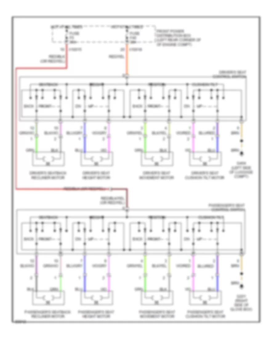
Power Seat Wiring Diagram for BMW 318ti 1998
List of elements for Power Seat Wiring Diagram for BMW 318ti 1998:
- Back
- Cushion tilt
- Driver's seat control switch
- Driver's seat cushion tilt motor
- Driver's seat height motor
- Driver's seat movement motor
- Driver's seatback recliner motor
- Front
- Front power distribution box (left rear corner of of engine compt)
- Fuse f40 30a
- Fuse f5 30a
- G201 (right side of glove box)
- G404 (left side of luggage compt)
- Height
- Hot at all times
- Passenger's seat control switch
- Passenger's seat cushion tilt motor
- Passenger's seat height motor
- Passenger's seat movement motor
- Passenger's seatback recliner motor
- Position
- Seatback
- X10015
- X10018
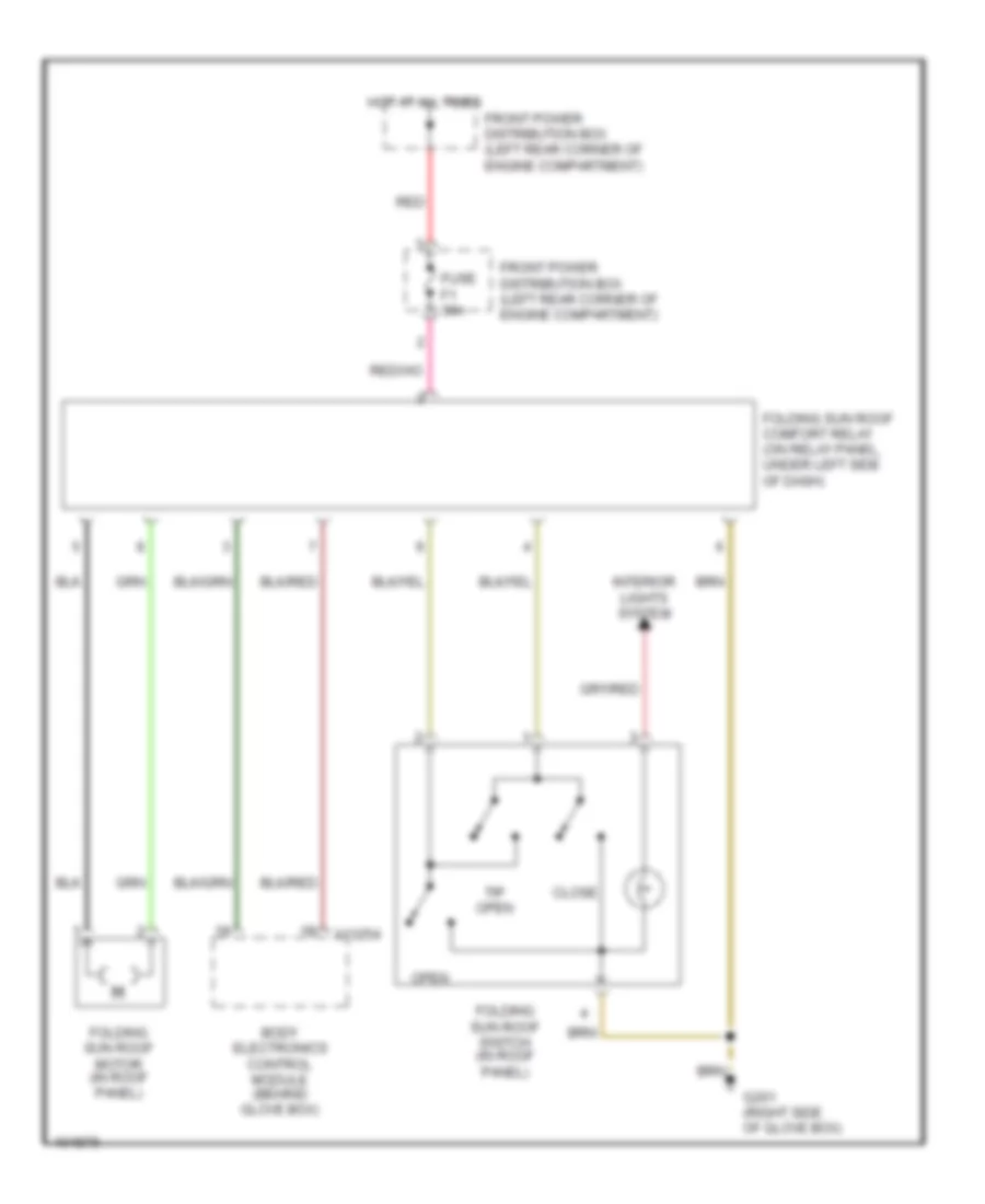
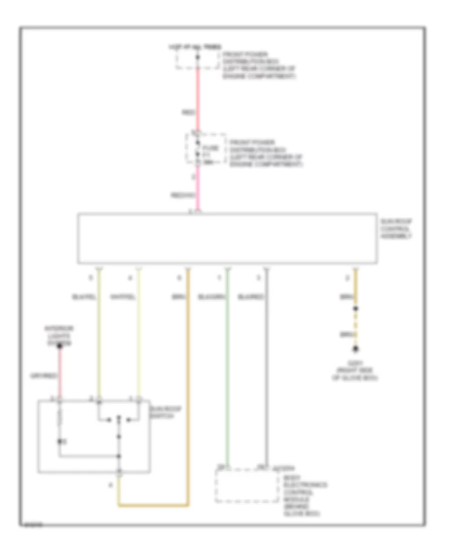
POWER TOP/SUNROOF
Electric Folding Sunroof for BMW 318ti 1998
List of elements for Electric Folding Sunroof for BMW 318ti 1998:
- Body electronics control module (behind glove box)
- Close
- Folding sun roof comfort relay (on relay panel, under left side of dash)
- Folding sun roof motor (in roof panel)
- Folding sun roof switch (in roof panel)
- Front power distribution box (left rear corner of engine compartment)
- Fuse f1 30a
- G201 (right side of glove box)
- Hot at all times
- Interior lights system
- Open
- Red
- Tip open
- X13254
Sunroof Wiring Diagram for BMW 318ti 1998
List of elements for Sunroof Wiring Diagram for BMW 318ti 1998:
- Body electronics control module (behind glove box)
- Front power distribution box (left rear corner of engine compartment)
- Fuse f1 30a
- G201 (right side of glove box)
- Hot at all times
- Interior lights system
- Red
- Sun roof control assembly
- Sun roof switch
- X13254
POWER WINDOWS
Power Window Wiring Diagram for BMW 318ti 1998
List of elements for Power Window Wiring Diagram for BMW 318ti 1998:
- Body electronics control module (zke iv) (behind glove box)
- Close
- Close auto
- Driver's door jamb switch
- Driver's power window motor
- Driver's power window switch
- Front power distribution box (left rear corner of engine compt)
- Fuse f14 30a
- G201 (right side of glove box)
- G302 (below center console, near gearshift lever)
- G404 (left side of luggage compartment)
- Hot at all times
- Interior lights system
- Off
- Open
- Open auto
- Passenger's door jamb switch
- Passenger's power window motor
- Passenger's power window switch
- Starter
- X10182
- X13252
- X13253
- X13254
- X18279
- X18280
- X744
- X749
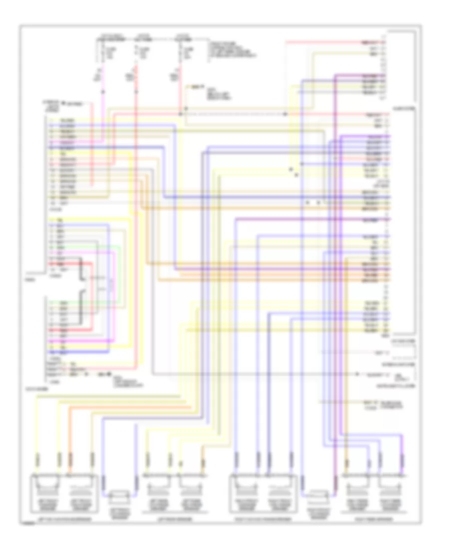
RADIO
Radio Wiring Diagrams, 10 Speaker with CD Changer System for BMW 318ti 1998
List of elements for Radio Wiring Diagrams, 10 Speaker with CD Changer System for BMW 318ti 1998:
- Antenna amplifier
- Cd changer
- Front power distribution box (in left rear corner of engine compartment)
- Fuse f33 10a
- Fuse f44 15a
- Fuse f9 20a
- G202 (below left side of dash)
- G404 (left side of luggage compt)
- Hifi amplifier
- Hot at all times
- Hot in accy, run and start
- Instrument cluster
- Interior lights system
- Left front high range speaker
- Left front low range speaker
- Left front midrange speaker
- Left mid-high range speaker
- Left rear high range speaker
- Left rear low range speaker
- Left rear speaker
- Nca
- Radio
- Red
- Right front high range speaker
- Right front low range speaker
- Right front midrange speaker
- Right mid-high range speaker
- Right rear high range speaker
- Right rear low range speaker
- Right rear speaker
- Subwoofer
- Telephone connector x13305
- Vss output
- X17179 (or x605)
- X18126
- X18520
- X18521
- X1892
- X606
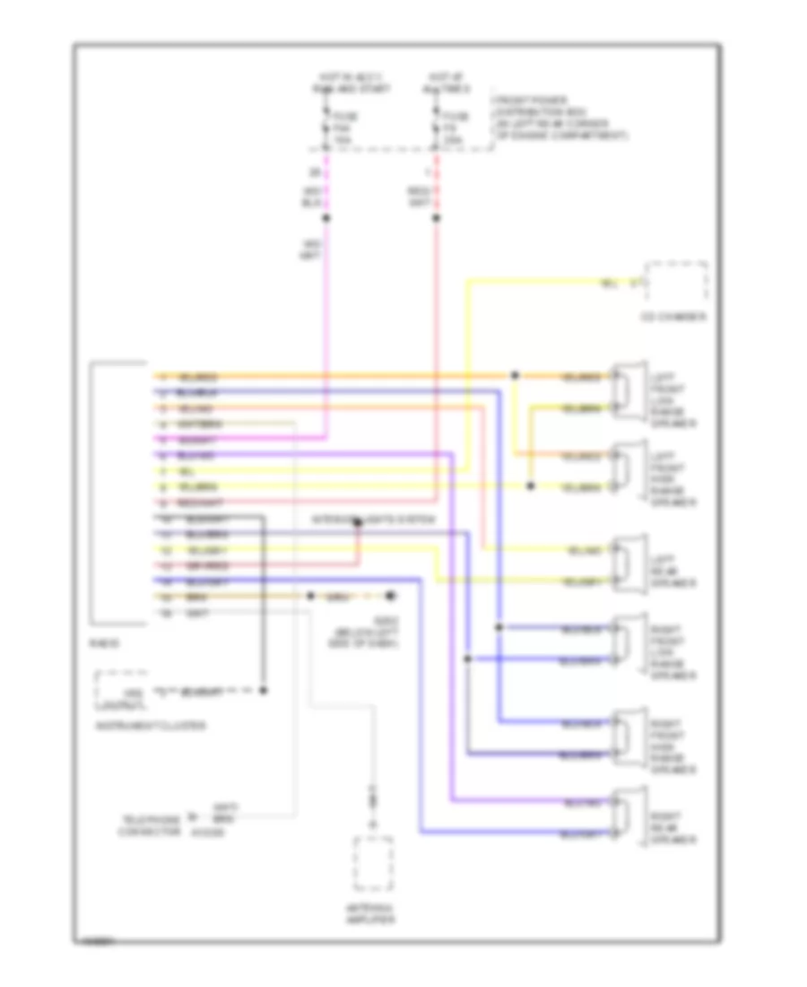
Radio Wiring Diagrams, 6 Speaker System for BMW 318ti 1998
List of elements for Radio Wiring Diagrams, 6 Speaker System for BMW 318ti 1998:
- Antenna amplifier
- Cd chamger
- Front power distribution box (in left rear corner of engine compartment)
- Fuse f44 15a
- Fuse f9 20a
- G202 (below left side of dash)
- Hot at all times
- Hot in accy, run and start
- Instrument cluster
- Interior lights system
- Left front high range speaker
- Left front low range speaker
- Left rear speaker
- Radio
- Right front high range speaker
- Right front low range speaker
- Right rear speaker
- Telephone connector x13305
- Vss output
SHIFT INTERLOCKS
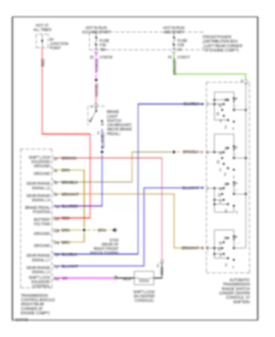
Shift Interlock Wiring Diagram for BMW 318ti 1998
List of elements for Shift Interlock Wiring Diagram for BMW 318ti 1998:
- Automatic transmission range switch (under center console, at shifter)
- B+ junction point
- Battery voltage
- Brake light switch (on bracket, above brake pedal)
- Brake pedal position
- Front power distribution box (left rear corner of engine compt)
- Fuse f28 5a
- Fuse f46 15a
- G103 (rear of right front shock tower)
- Gear range signal l1
- Gear range signal l2
- Gear range signal l3
- Gear range signal l4
- Ground
- Hot at all times
- Hot in run acc and start
- Hot in run and start
- Nca
- Red
- Shift lock solenoid control
- Shift lock solenoid ground
- Shift-lock (in center console)
- Transmission control module (right rear corner of engine compt)
- X10017
- X10018
STARTING/CHARGING
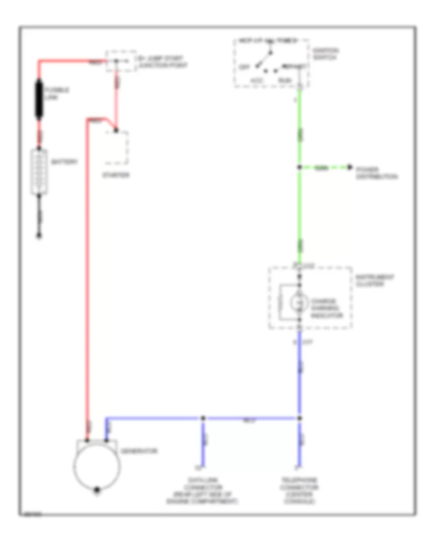
Charging Wiring Diagram for BMW 318ti 1998
List of elements for Charging Wiring Diagram for BMW 318ti 1998:
- Acc
- B+ jump start junction point
- Battery
- Charge warning indicator
- Data link connector (rear left side of engine compartment)
- Fusible link
- Generator
- Hot at all times
- Ignition switch
- Instrument cluster
- Nca
- Off
- Power distribution
- Red
- Run
- Start
- Starter
- Telephone connector (center console)
- X17
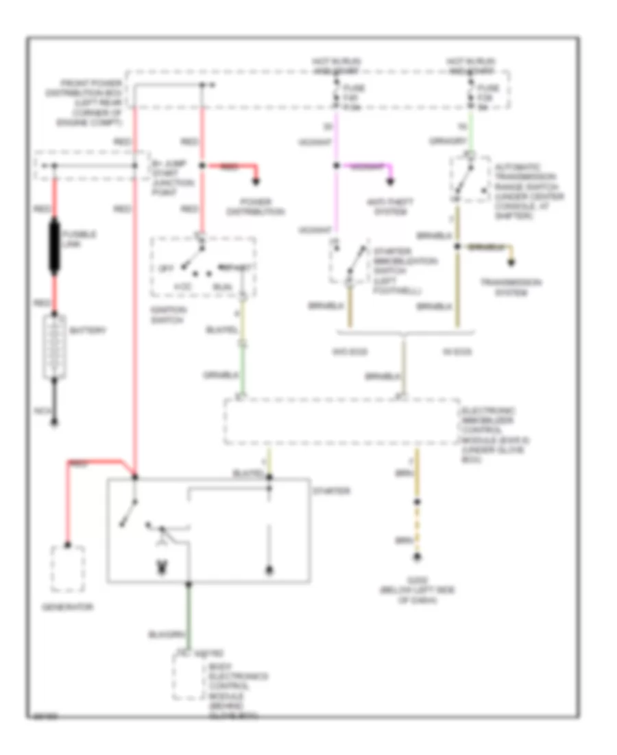
Starting Wiring Diagram for BMW 318ti 1998
List of elements for Starting Wiring Diagram for BMW 318ti 1998:
- Acc
- Anti-theft system
- Automatic transmission range switch (under center console, at shifter)
- B+ jump start junction point
- Battery
- Body electronics control module (behind glove box)
- Electronic immobilizer control module (ews ii) (under glove box)
- Front power distribution box (left rear corner of engine compt)
- Fuse f28 5a
- Fuse f45 7.5a
- Fusible link
- G202 (below left side of dash)
- Generator
- Hot in run and start
- Ignition switch
- Nca
- Off
- Power distribution
- Red
- Run
- Start
- Starter
- Starter immobilization switch (left footwell)
- Transmission system
- W/ egs
- W/o egs
- X10182
SUPPLEMENTAL RESTRAINTS
Supplemental Restraint Wiring Diagram for BMW 318ti 1998
List of elements for Supplemental Restraint Wiring Diagram for BMW 318ti 1998:
- (318ti)
- (behind glove box) g201
- Air bag indicator
- Body electronics control module (behind glove box)
- Contact rings
- Data link connector (rear of engine compartment)
- Driver's airbag gas generator
- Driver's seat belt switch
- Driver's side impact sensor
- Driver's side pyrotechnical belt tensioner
- Front power distribution box (left rear corner of engine compartment)
- Fuse f27 5a
- Fuse f42 7.5a
- G201 (318ti) (behind glove box)
- G203 (318, 323, 328, m3) (behind right kick panel)
- G303 (under right rear seat)
- Hot in acc, run or start
- Hot in run or start
- Instrument cluster
- Left side air bag gas generator (in driver's door)
- Nca
- Passenger's airbag gas generator
- Passenger's seat belt switch
- Passenger's side impact sensor
- Passenger's side pyrotechnical belt tensioner
- Right side air bag gas generator (in passenger's door)
- Seat belt indicator
- Seat occupancy detector (under right front seat)
- X10017
- X10018
- X16
- X17
TRANSMISSION
A/T Wiring Diagram (1 of 2) for BMW 318ti 1998
List of elements for A/T Wiring Diagram (1 of 2) for BMW 318ti 1998:
- (1.9l only)
- (behind right kick panel)
- (not used)
- (rear of right front shock tower) g103
- Asc sig
- Auto
- Auto mode sig
- Automatic transmission range switch (in center console, on shifter mechanism)
- B+ junction point
- Band sol ctrl
- Battery volt
- Brake light switch (on bracket, above brake pedal)
- Brake pdl posit
- C 1995 vftc
- Closed in reverse position
- Clr
- Cruise control module (tempomat) (under right side of dash, behind glove box)
- Egs a4s 310r
- Egs warning lp
- Electronic immobilizer control module (under right side of dash, behind glove box)
- Exterior lights system
- Fault ind sig
- Front power distribution box (in left rear corner of engine compartment)
- Fuse f26 10a
- Fuse f28 5a
- Fuse f46 15a
- G203
- Gnd
- Gr rng sig l1
- Gr rng sig l2
- Gr rng sig l3
- Gr rng sig l4
- Hot at all times
- Hot in accy, run & start
- Hot in run & start
- Hyd ctrl (-)
- Instrument cluster
- Kick down switch (left footwell)
- Kick-down sig
- M-prog ind
- Man
- Man mode sig
- Nca
- Off
- Oil temp sig
- Oil temp sig (+)
- Ouput speed (-)
- Output speed (+)
- Program switch
- Red
- Rpm speed sig
- S-prog ind
- Shift-lock sol
- Sol val 1 ctrl
- Sol val 2 ctrl
- Speed sens shd
- Sport mode sig
- Tcc sol ctrl
- Transmission control module (egs) (on right rear corner of engine compt)
- X10017
- X10018
- X16
- X69
A/T Wiring Diagram (2 of 2) for BMW 318ti 1998
List of elements for A/T Wiring Diagram (2 of 2) for BMW 318ti 1998:
- (1.9l only)
- (1.9l)
- (2.5/ 2.8l)
- (2.5l/2.8l only)
- (below left side of dash)
- 1.9l
- 2.5/ 2.8l
- 2.5/2.8l
- 87a
- A-prog ind
- A/c comp ctrl
- A/c comp on sig
- Band solenoid
- Bk sw test sig
- Brake light switch (on bracket, above brake pedal)
- C 1995 vftc
- Can-high
- Can-low
- Clr
- Compressor control relay
- Computer data lines system
- Cruise control module (tempomat) (under right side of dash, behind glove box)
- Cruise ctrl sig
- Data link connector (on right rear of eng compt)
- Engine control module (dme) (on right rear corner of engine compartment)
- Engine control module relay
- Engine controls system
- Front power distribution box (in left rear corner of engine compt)
- G202
- Hydraulic pressure regulator
- Instrument cluster system
- Nca
- Not used
- Oil temperature sensor
- On-board computer (multi-function clock)
- Prog voltage
- Red
- Rpm speed sig
- Rxd data link
- Shift lock (below center console, on right side of gear selector)
- Slip control module (under right side of dash, behind glove box)
- Solenoid valve 1
- Solenoid valve 2
- Speed sensor
- Torque converter clutch solenoid valve
- Transmission control module (egs) (on right rear corner of engine compt)
- Transmission valve unit
- Txd data link
- Volt press reg
- X1070
- X1170
- X1171
- X8505
- X8516
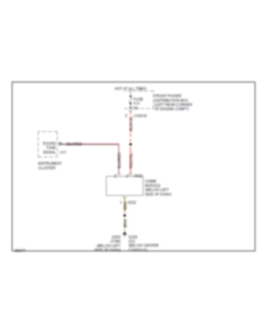
WARNING SYSTEMS
Warning System Wiring Diagrams for BMW 318ti 1998
List of elements for Warning System Wiring Diagrams for BMW 318ti 1998:
- Chime module (below left side of dash)
- Front power distribution box (left rear corner of engine compt)
- Fuse f31 5a
- G202 (318ti) (below left side of dash)
- G302 (z3) (below center console)
- Hot at all times
- Instrument cluster
- Sound
- Tone signal x17
- X10018
- X522
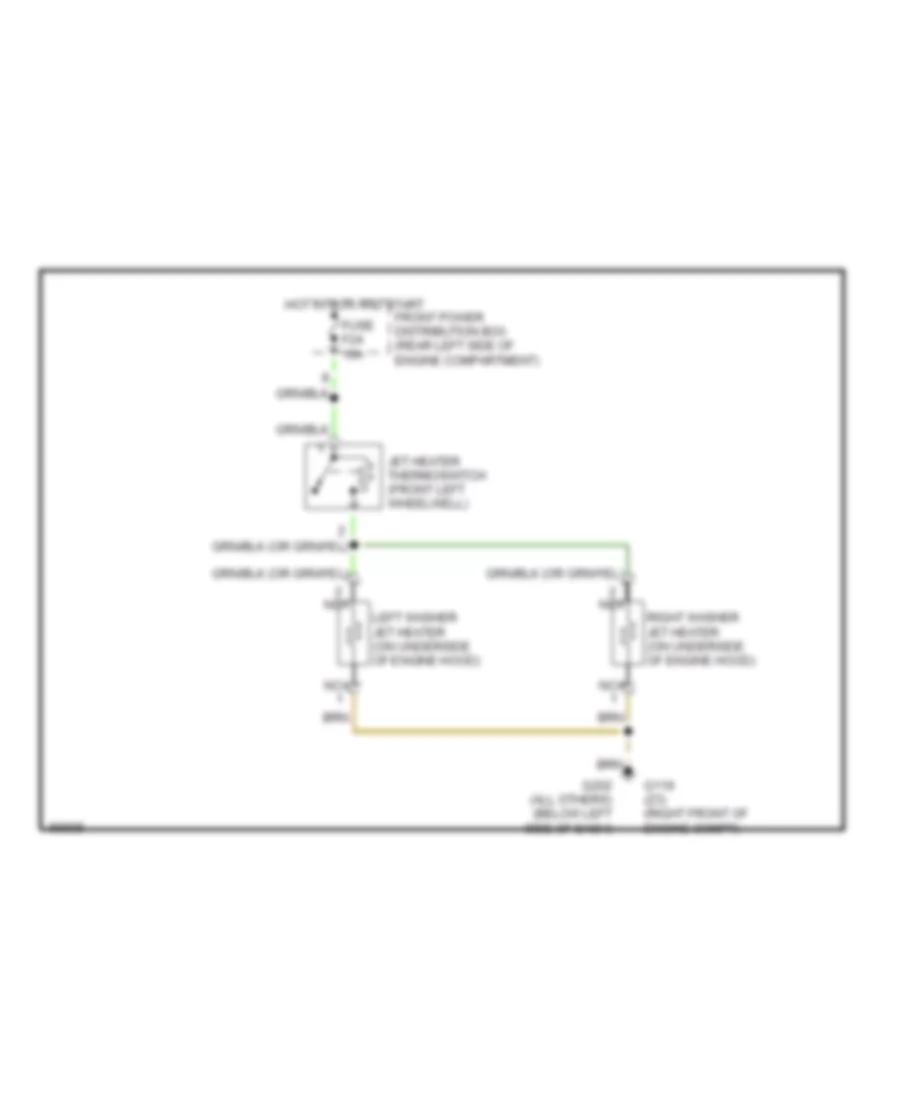
WIPER/WASHER
Washer Jet Heater Wiring Diagram for BMW 318ti 1998
List of elements for Washer Jet Heater Wiring Diagram for BMW 318ti 1998:
- Front power distribution box (rear left side of engine compartment)
- Fuse f24 10a
- G119 (z3) (right front of engine compt)
- G202 (all others) (below left side of dash)
- Hot in run and start
- Jet heater thermoswitch (front left wheelwell)
- Left washer jet heater (on underside of engine hood)
- Nca
- Right washer jet heater (on underside of engine hood)
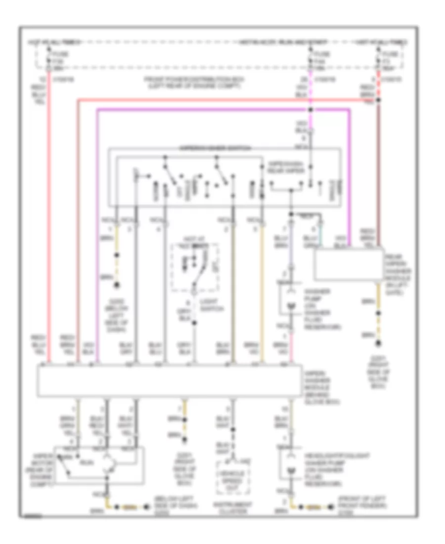
Wiper/Washer Wiring Diagram, Canada for BMW 318ti 1998
List of elements for Wiper/Washer Wiring Diagram, Canada for BMW 318ti 1998:
- (below left side of dash) g202
- (front of left front fender) g100
- Fast
- Front power distribution box (left rear of engine compt)
- Fuse f3 30a
- Fuse f36 30a
- Fuse f44 15a
- G201 (right side of glove box)
- G202 (below left side of dash)
- Head
- Headlight/foglight waher pump (on washer fluid reservoir)
- Hot at all times
- Hot in accy, run and start
- Instrument cluster
- Int
- Light switch
- Nca
- Norm
- Off
- Park
- Rear wiper/ washer module (in lift- gate)
- Run
- Single wipe
- Vehicle speed out
- Wash
- Washer pump (on washer fluid reservoir)
- Wipe/wash- rear wiper
- Wiper motor (rear of engine compt)
- Wiper/ washer module (behind glove box)
- Wiper/washer switch
- X10015
- X10018
- X17
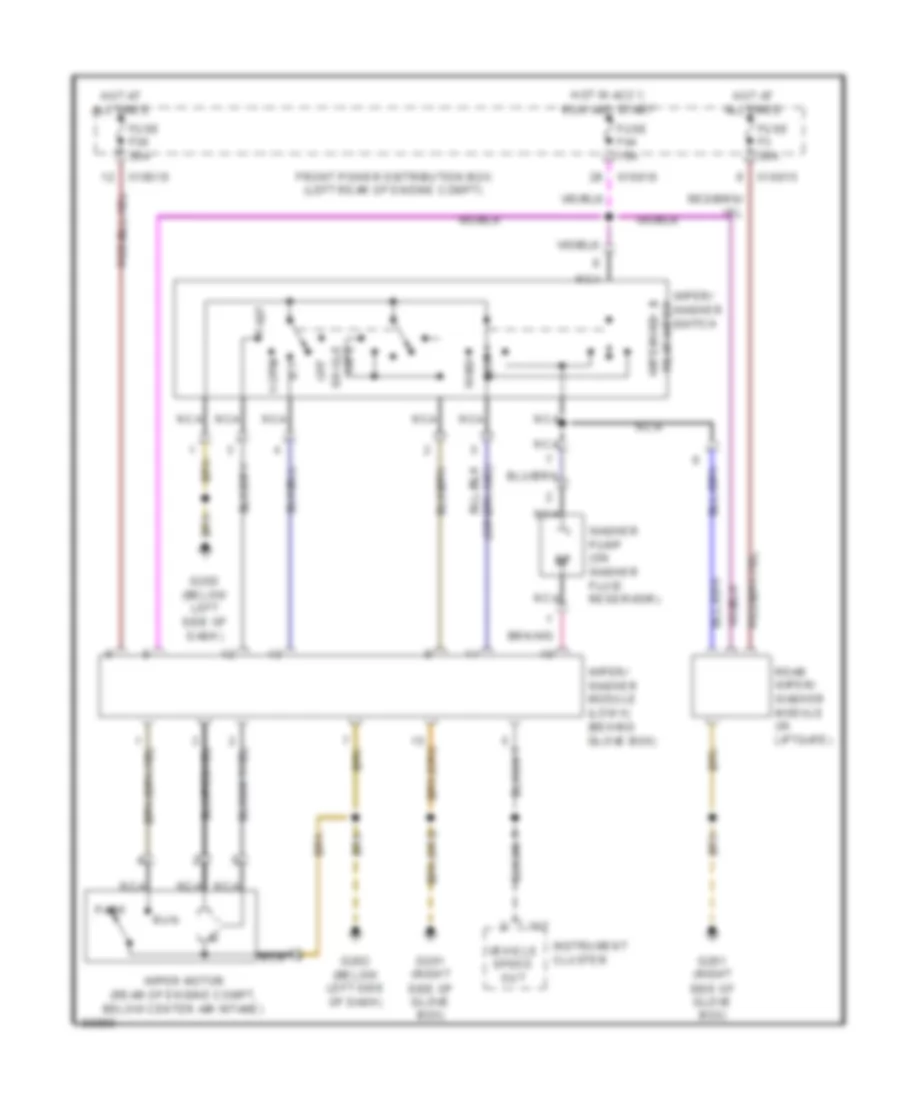
Wiper/Washer Wiring Diagram, USA for BMW 318ti 1998
List of elements for Wiper/Washer Wiring Diagram, USA for BMW 318ti 1998:
- Fast
- Front power distribution box (left rear of engine compt)
- Fuse f3 30a
- Fuse f36 30a
- Fuse f44 15a
- G201 (right side of glove box)
- G202 (below left side of dash)
- Hot at all times
- Hot in accy, run and start
- Instrument cluster
- Int
- Nca
- Norm
- Off
- Park
- Rear wiper/ washer module (in liftgate)
- Run
- Vehicle speed out
- Wash
- Washer pump (on washer fluid reservoir)
- Wipe single
- Wipe/wash & rear wiper
- Wiper motor (rear of engine compt, below center air intake)
- Wiper/ washer module (low ii) (behind glove box)
- Wiper/ washer switch
- X10015
- X10018
- X17