Diagram sections — 15 (30 total)
ANTI-LOCK BRAKES COMPUTER DATA LINES CRUISE CONTROL DEFOGGERS ENGINE PERFORMANCE GROUND DISTRIBUTION HORN POWER DISTRIBUTION POWER DOOR LOCKS POWER MIRRORS POWER WINDOWS RADIO STARTING/CHARGING TRANSMISSION TRUNK, TAILGATE, FUEL DOOR
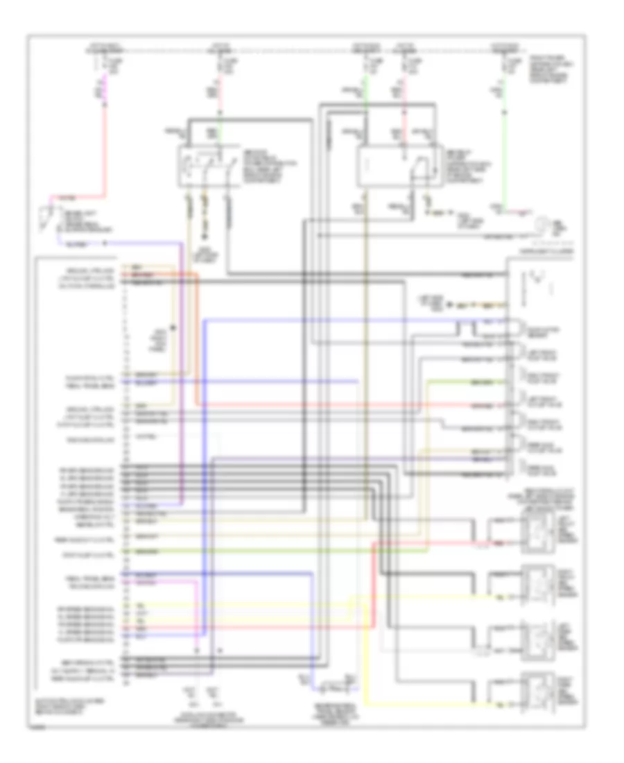
ANTI-LOCK BRAKES Anti-lock Brake Wiring Diagrams for BMW 325i 1993 List of elements for Anti-lock Brake Wiring Diagrams for BMW 325i 1993: 60 (left side of dash) g202 Abs brake pedal travel sensor (near brake fluid reservoir) Abs hydraulic unit (rear left side of engine compartment behind left shock tower) Abs pump motor relay (power distribution box) (rear left side of engine compartment) Abs relay (power distribution box) (rear left side of engine compartment) Abs relay ctrl Abs warn ind Abs warning lp ctrl Brake light switch (brake pedal support bracket) Brake pedal position Data link connector (rear right side of engine compartment) Fl spd sens ground Fl speed sens signal Fr spd sens ground Fr speed sens signal Front power distribution box (rear left side of engine compartment) Fuse f10 30a Fuse f21 5a Fuse f27 5a Fuse f38 30a Fuse f46 30a G202 (left side of dash) G203 (right kick panel) Ground, ctrl mod Hot at all times Hot in accy, run and start Hot in run and start Instrument cluster L fnt inlet vlv ctrl L fnt outlet vlv ctrl Left front abs speed sensor Left front inlet valve Left front outlet valve Left rear abs speed sensor Nca Operating volt Pedal travel sens Pump motor sensor Pump mtr rly ctrl Pump mtr sens shield Pump mtr sens signal R fnt inlet vlv ctrl R fnt outlet vlv ctrl Rear axle inlet valve Rear axle inlet vlv ctrl Rear axle out vlv ctrl Rear axle outlet valve Red Right front abs speed sensor Right front inlet valve Right front outlet valve Right rear abs speed sensor Rl spd sens ground Rl speed sens signal Rr spd sens ground Rr speed sens signal Rxd diag data link Slip control module (abs) (right side of dash, behind glove box) Txd diag data link Volt mon, hydraulics Anti-lock Brake Wiring Diagrams, without Traction Control for BMW 325i 1993 List of elements for Anti-lock Brake Wiring Diagrams, without Traction Control for BMW 325i 1993: 60 (left side of dash) g202 Abs brake pedal travel sensor (near brake fluid reservoir) Abs hydraulic unit (rear left side of engine compartment behind left shock tower) Abs pump motor relay (power distribution box) (rear left side of engine compartment) Abs relay (power distribution box) (rear left side of engine compartment) Abs relay ctrl Abs warn ind Abs warning lp ctrl Brake light switch (brake pedal support bracket) Brake pedal position Data link connector (rear right side of engine compartment) Fl spd sens ground Fl speed sens signal Fr spd sens ground Fr speed sens signal Front power distribution box (rear left side of engine compartment) Fuse f10 30a Fuse f21 5a Fuse f27 5a Fuse f38 30a Fuse f46 30a G202 (left side of dash) G203 (right kick panel) Ground, ctrl mod Hot at all times Hot in accy, run and start Hot in run and start Instrument cluster L fnt inlet vlv ctrl L fnt outlet vlv ctrl Left front abs speed sensor Left front inlet valve Left front outlet valve Left rear abs speed sensor Nca Operating volt Pedal travel sens Pump motor sensor Pump mtr rly ctrl Pump mtr sens shield Pump mtr sens signal R fnt inlet vlv ctrl R fnt outlet vlv ctrl Rear axle inlet valve Rear axle inlet vlv ctrl Rear axle out vlv ctrl Rear axle outlet valve Red Right front abs speed sensor Right front inlet valve Right front outlet valve Right rear abs speed sensor Rl spd sens ground Rl speed sens signal Rr spd sens ground Rr speed sens signal Rxd diag data link Slip control module (abs) (right side of dash, behind glove box) Txd diag data link Volt mon, hydraulics
COMPUTER DATA LINES Data Link Connector Wiring Diagram for BMW 325i 1993 List of elements for Data Link Connector Wiring Diagram for BMW 325i 1993: 31 1992, 1993 325 1993 325 Acc B+ junction point Central locking module (behind glove box) Data link connector (rear right side of engine compartment) Engine control module (dme) (rear right side of engine compartment) Except 1993 late production Front power distribution box (rear left side of engine compartment) Fuse f26 15a (1992) 10a (1993) G101 (right side of engine compartment) Generator Hot at all times Hot in start and run Ignition switch Instrument cluster Integrated climate regulation control module (center console) Late production 1993 Lock On-board computer (center console) Others Red Run Slip control module (abs) (behind glove box) Srs control module (under rear seat) (1993 late production) (behind glove box) (others) Start Starter Starter relay Transmission control module (egs) (rear right side of engine compartment) W/ egs W/o egs
CRUISE CONTROL Cruise Control Wiring Diagram for BMW 325i 1993 List of elements for Cruise Control Wiring Diagram for BMW 325i 1993: 34 Automatic transmission range switch (center console) Brake light switch (top of brake pedal support) Check control * Clutch switch (top of clutch pedal support) Cruise control actuator (left front side of engine comp.) Cruise control module (right side of i/p) Cruise control switch Decelerate/ set Exterior lights system (brake lights) Front power distribution box (rear left side of engine comp.) Fuse f28 5a Fuse f46 15a G111 (front left side G203 (right Hot in acc, run and start Hot in run and start Instrument cluster Kick panel) Module Module transmission control ** Nca Normal Of engine comp.) Off Resume Set accelerate/ Vehicle speed sensor W/ ccm W/ egs W/ egs ** W/o ccm W/o ccm * W/o egs X17
DEFOGGERS Defogger Wiring Diagram for BMW 325i 1993 List of elements for Defogger Wiring Diagram for BMW 325i 1993: 25 (1992 318 & 325 series) (not used) Antenna amplifier am/fm (upper left "c" pillar) Front power distribution box (left rear side of engine compartment) Fuse 23 5a Fuse 6 20a G201 (below right side of dash) G203 (right kick panel) G310 (sedan) (upper right rear seatback) G312 (coupe) (upper left rear seatback) Ground Hot at all times Hot in run and start Ihkr control panel Integrated climate regulation control module (center console) Nca Rear defogger relay (front power distribution box) Rear defogger switch Rear defogger/ antenna Rear window defogger activation Rear window defogger switch Suppression filter (upper right "c" pillar) X18155 X18156 X18157
ENGINE PERFORMANCE
2.5L 2.5L, Engine Performance Wiring Diagrams (1 of 2) for BMW 325i 1993 List of elements for 2.5L, Engine Performance Wiring Diagrams (1 of 2) for BMW 325i 1993: 66 87a A/c comp ctrl Acc B+ junc- tion point Battery Cam act ctrl Cam pos sens Camshaft actuator (front of engine) Check eng ind Crnkshft pos Cyl 1 Cyl 1 ign coil Cyl 1 inj ctrl Cyl 1-6 fuel pump relay Cyl 2 Cyl 2 ign coil Cyl 2 inj ctrl Cyl 3 Cyl 3 ign coil Cyl 3 inj ctrl Cyl 4 Cyl 4 ign coil Cyl 4 inj ctrl Cyl 5 Cyl 5 ign coil Cyl 5 inj ctrl Cyl 6 Cyl 6 ign coil Cyl 6 inj ctrl Ecm rly ctrl Ee valve ctrl Engine control module (dme) (right rear side of engine compt in e-box) Engine control module relay Evaporative emission valve (right of left shock tower) Fp rly ctrl Front power distribution box Fuel cons Fuel injection valves G117 (right rear side of engine compt) G119 (right front of engine) Ground Hot at all times Hot fam mtr Idle speed control valve (below intake manifold) Ign ground Ign switch Ign timing Ignition coil (top right side of engine) Ignition switch Inj ground Is ctrl valve Nca O2s htr ctrl O2s sig O2s sig gnd Off Red Resistor (240 ohm) Run Sens ground Shield gnd Shield ground Start T valve pos Veh speed sig W/ egs 2.5L, Engine Performance Wiring Diagrams (2 of 2) for BMW 325i 1993 List of elements for 2.5L, Engine Performance Wiring Diagrams (2 of 2) for BMW 325i 1993: 49 A/c press sig A/c switch A/c system Automatic transmission range switch Check engine Crankshaft position/ rpm sensor (rear of radiator) Cyl 1-3 knock sensor (top front of engine) Cyl 1-3 ks Cyl 4-6 knock sensor (top front of engine) Cyl 4-6 ks Data link connector (front of battery) Drive range Drive-away sig Eng cool temp Engine control module (dme) (right rear side of engine compt in e-box) Engine coolant temperature sensor (right front of engine) Front power distribution box Fuel pump (below right side of rear seat) Fuse f18 15a Fuse f27 5a Fuse f28 5a G117 (right rear side of engine compt) G312 (behind left rear seat) Hall effect camshaft sensor (front of engine) Heated oxygen sensor (under center of car) Hot film air mass meter (top front of engine) Hot in run and start Instrument cluster Intake air temperature sensor (near oil level stick) Intk air temp Ks ground Nca On-board computer On-board computer, instrument cluster Oxygen sensor relay Program volt Red Rxd data T pos sens Throttle position sensor (left side of engine) Transmission control module (egs) (right rear side of engine compt, in e-box) Txd data Vehicle speed output W/ egs W/o egs X10016 X10017 X16 X17
GROUND DISTRIBUTION Ground Distribution Wiring Diagram (1 of 5) for BMW 325i 1993 List of elements for Ground Distribution Wiring Diagram (1 of 5) for BMW 325i 1993: 42 Auxiliary fan motor Blower relay Brake light switch Cassette box light Chime module Cruise control actuator Dimmer Dimmer switch Engine coolant level switch From left washer jet heater (diagram 2 of 5) G111 (front left side of engine compartment) G202 (left side of i/p) Headlight/ fog light washer pump (canada) Horn switch (combination switch) Ignition switch Instrument cluster Left fog light Left front turn light Left high beam light Left horn Left low beam light Left park light Left park light relay Left seat heater switch Light switch On-board computer Only Pressure switch Right fog light Right front auxiliary turn light Right front park light Right front turn light Right high beam light Right horn Right low beam light Right seat heater switch Starter relay Temperature switch Unloader relay Washer fluid level switch (usa) Washer pump (canada) Wiper/ washer switch Ground Distribution Wiring Diagram (2 of 5) for BMW 325i 1993 List of elements for Ground Distribution Wiring Diagram (2 of 5) for BMW 325i 1993: 41 Abs relay Blower relay Brake fluid level switch Central locking module Comfort relay Front dome/ map light assembly G203 (right kick panel) G302 (center console) Hazard flasher relay High beam light relay Inertia switch Left door jamb switch Left front auxiliary turn light Left makeup mirror switch Left power window module Left power window switch Left rear door power window switch (console) Left seat belt switch Left seatback heater Left side mirror Left washer jet heater (canada) Left window retraction door handle contract switch (early production) Low beam light relay Mirror control switch Only Right door jamb switch Right makeup mirror switch Right power window module Right power window switch Right rear door power window switch (console) Right seat belt switch Right seat control switch Right seatback heater Right side mirror Right washer jet heater (canada) Right window retraction door handle contract switch (early production) Sunroof control assembly To g202 (diagram 1 of 5) Wiper motor Wiper relay (canada) Wiper/ washer module (usa) Ground Distribution Wiring Diagram (3 of 5) for BMW 325i 1993 List of elements for Ground Distribution Wiring Diagram (3 of 5) for BMW 325i 1993: 28 Abs hydraulic unit Abs pump motor relay Camshaft position sensor shield Crankshaft position/ rpm sensor shield Data link connector Engine control module Engine control module (dme) G123 (318 series) (rear right side of engine compartment) G123 (325 series) (rear right side of engine compartment) G202 (left side of i/p) G203 (right kick panel) Hall effect camshaft sensor Heated oxygen sensor Heated oxygen sensor shield Hot film air mass meter Ignition coil 1 shield Ignition coil 2 Ignition coil 2 shield Ignition coil 3 Ignition coil 3 shield Ignition coil 4 Ignition coil 4 shield Ignition coil shield Ignition coil1 Nca Only Shield Transmission control module (egs) Ground Distribution Wiring Diagram (4 of 5) for BMW 325i 1993 List of elements for Ground Distribution Wiring Diagram (4 of 5) for BMW 325i 1993: 41 Anti- theft horn Blower motor Cassette box light Charging socket Crash control module (usa) Cruise control module Engine control module (dme) Engine control module shield Engine hood switch Front ashtray light Front cigar lighter Front cigar lighter light G119 (325) (right front of engine) G203 (right kick panel) Glove box light switch Hazard switch horn Headlight/ foglight cleaning module (sra) (canada) Ignition coil 1 Ignition coil 2 Ignition coil 3 Ignition coil 4 Ignition coil 5 Ignition coil 6 Ihkr control module Instrument cluster Integrated climate regulation control module Intensive wash pump Multi- function clock Nca On-board computer On-board computer temperature sensor Only Program switch (w/ egs) Radio micro- switch Rear ashtray light Resistor (1993 only) Right park/ license light relay (canada) Transmission position indicator light Twin relay module (canada) Wiper/ washer module (canada) Wiper/ washer module (usa) Ground Distribution Wiring Diagram (5 of 5) for BMW 325i 1993 List of elements for Ground Distribution Wiring Diagram (5 of 5) for BMW 325i 1993: 38 Anti- theft control module Cd changer Check control module Fuel pump G202 (left side of i/p) G203 (right kick panel) G312 (upper left rear seatback) Hifi amplifier High level stop light Left back-up light Left brake light Left front door jamb switch (4 door) Left license light Left rear door contact Left rear fog light Left rear turn light Left seat control switch Left seat heater Left seatback heater Left tail light Left trunk light assembly Only Radio Right back-up light Right brake light Right door jamb switch Right license light Right rear brake pad sensor Right rear door contact Right rear fog light Right rear turn light Right tail light Right trunk light assembly Seat load assembly Suppression filter (2 door) Telephone trans- ceiver W/ hifi, ten speaker system W/ stereo 6 speaker system
HORN Horn Wiring Diagram for BMW 325i 1993 List of elements for Horn Wiring Diagram for BMW 325i 1993: 15 Acc Front power distribution box (left rear side of engine compt) Fuse f8 15a G111 (left front side of engine compt) G202 (below left side of i/p) Horn relay (power distribution box) Horn switch Hot at all times Ignition switch Left horn Off Power distribution Right horn Run Start
POWER DISTRIBUTION Power Distribution Wiring Diagram (1 of 7) for BMW 325i 1993 List of elements for Power Distribution Wiring Diagram (1 of 7) for BMW 325i 1993: 46 1993 w/ engine compartment mounted battery 1993 w/ trunk mounted battery Auxiliary connector B+ junction point B+jump start junction point (rear right side of engine compartment) Battery (318) Canada Data link connector Engine control module Engine control module relay F18 fuse 15a Front fog light relay Front power distribution box (rear left side of engine compartment) Fuel pump Fuel pump relay Fuse f14 30a Fuse f2 25a Fuse f4 30a Fuse link Generator High beam light relay Left power window module Low beam light relay On-board computer horn relay Oxygen sensor relay (4cyl) Red Right power window module Starter To comfort relay (diagram 7 of 7) To fuse f11 (diagram 6 of 7) To fuse f15 (diagram 6 of 7) To fuse f17 (diagram 6 of 7) To fuse f19 (diagram 6 of 7) To fuse f20 (diagram 6 of 7) To fuse f29 (diagram 6 of 7) To fuse f3 (diagram 6 of 7) To fuse f35 (diagram 5 of 7) To fuse f39 (diagram 6 of 7) To fuse f40 (diagram 6 of 7) To fuse f41 (diagram 6 of 7) To fuse f5 (diagram 6 of 7) To fuse f8 (diagram 5 of 7) To ignition switch (diagram 3 of 7) Transmission control module (egs) W/ engine compartment mounted battery W/ trunk mounted battery Power Distribution Wiring Diagram (2 of 7) for BMW 325i 1993 List of elements for Power Distribution Wiring Diagram (2 of 7) for BMW 325i 1993: 41 Auxiliary connector B+ junction point B+jump start junction point (rear right side of engine compartment) Battery (325) Canada Data link connector Engine control module Engine control module relay F18 fuse 15a Front fog light relay Front power distribution box (rear left side of engine compartment) Fuel pump Fuel pump relay Fuse f14 30a Fuse f2 25a Fuse f4 30a Fusible link Generator High beam light relay Left power window module Low beam light relay On-board computer horn relay Red Right power window module Starter To comfort relay (diagram 7 of 7) To fuse f11 (diagram 6 of 7) To fuse f15 (diagram 6 of 7) To fuse f17 (diagram 6 of 7) To fuse f19 (diagram 6 of 7) To fuse f20 (diagram 6 of 7) To fuse f29 (diagram 6 of 7) To fuse f3 (diagram 6 of 7) To fuse f35 (diagram 5 of 7) To fuse f39 (diagram 6 of 7) To fuse f40 (diagram 6 of 7) To fuse f41 (diagram 6 of 7) To fuse f5 (diagram 6 of 7) To fuse f8 (diagram 5 of 7) To ignition switch (diagram 3 of 7) Transmission control module (egs) Power Distribution Wiring Diagram (3 of 7) for BMW 325i 1993 List of elements for Power Distribution Wiring Diagram (3 of 7) for BMW 325i 1993: 50 1993 only 4 cyl only 6 cyl only Acc Anti-theft control module Blower relay Central locking module Engine control module (dme) From front power distribution box (diagram 1 & 2 of 7) Front dome/ map light assembly Front power distribution box (rear left side of engine compartment) Fuse f42 7.5a Fuse f43 5a Fuse f44 15a Glove box light Horn relay Ignition coil #1 Ignition coil #2 Ignition coil #3 Ignition coil #4 Ignition coil #5 (6 cyl) Ignition coil #6 (6 cyl) Ignition switch Instrument cluster Left makeup mirror light Not used Off Radio Red Right makeup mirror light Run Seat load assembly (late production) Srs control module (early production) Srs control module (late production) Start Starter Starter relay Telephone transceiver To fuse f16 (diagram 4 of 7) To fuse f24 (diagram 4 of 7) To fuse f28 (diagram 4 of 7) To fuse f45 (diagram 4 of 7) To fuse f46 (diagram 4 of 7) Twin relay module (canada) Unloader relay W/egs W/o egs Washer pump (usa) Wiper/washer module (canada) Wiper/washer module (usa) Power Distribution Wiring Diagram (4 of 7) for BMW 325i 1993 List of elements for Power Distribution Wiring Diagram (4 of 7) for BMW 325i 1993: 49 1993 only Abs relay Abs slip control module Automatic transmission range switch Auxiliary connector Brake light switch Canada Check control module Combination switch Compressor control relay Cruise control module Cruise control switch Data link connector Daytime running lights coding diode From ignition n switch (diagram 3 of 7) From ignition switch (diagram 3 of 7) From ignition t switch (diagram 3 of 7) From ignition u switch (diagram 3 of 7) From q fuse f24 (diagram 3 of 7) Front power distribution box (left rear side of engine compartment) Fuse f16 5a Fuse f21 5a Fuse f22 5a Fuse f23 5a Fuse f24 10a Fuse f25 5a Fuse f26 10a Fuse f27 5a Fuse f28 5a Fuse f45 7.5a Fuse f46 15a High speed relay Instrument cluster Integrated climate regulation control module Jet heater thermoswitch Light switch Low beam light relay Mirror control switch Multi- function clock Normal speed relay On-board computer Program switch Rear defogger relay Reversing light switch To fuse f23 (diagram 4 of 7) Unloader relay W/o egs only Wiper motor relay Wiper relay Power Distribution Wiring Diagram (5 of 7) for BMW 325i 1993 List of elements for Power Distribution Wiring Diagram (5 of 7) for BMW 325i 1993: 63 Abs pump motor relay Abs relay Anti-theft control module Canada Cd changer Central locking module Charging socket Chime module Crash control module From front power distribution box (diagram 1 & 2 of 7) From front power i distribution box (diagram 1 & 2 of 7) From fuse f34 (diagram 5 of 7) Front cigar lighter Front dome/ map light assembly Front power distribution box (left rear side of engine compartment) Front power distribution box (rear left side of engine compartment) Fuse f10 30a Fuse f31 5a Fuse f32 30a Fuse f33 10a Fuse f34 15a Fuse f35 25a Fuse f36 30a Fuse f37 10a Fuse f38 30a Fuse f6 20a Fuse f7 5a Fuse f8 15a Fuse f9 20a G203 (right kick panel) Hazard flasher relay Hifi amplifier Horn relay Ihkr control panel Instrument cluster Integrated climate recirculation control module Left door lock motor Left door lock switch Left park light relay Left power window module Left rear interior light Light switch Light switch (usa) Multi- function clock Only Radio Rear defogger relay Red Right door lock motor Right door lock switch Right park/ license plate light relay (canada) Right rear interior light Telephone transceiver To fuse f33 (diagram 5 of 7) Trunk compartment light Trunk lock motor Unloader relay Usa W/ crash control module W/ hifi, ten speaker system W/ stereo 6-speaker system Wiper relay Wiper/ washer module Power Distribution Wiring Diagram (6 of 7) for BMW 325i 1993 List of elements for Power Distribution Wiring Diagram (6 of 7) for BMW 325i 1993: 41 1992 or 1993 w/o park ventilation 1993 w/ park ventilation Blower relay Canada Check control module Compressor control relay From front fog light relay (diagram 1 & 2 of 7) From front power distribution box (diagram 1 & 2 of 7) From high beam light relay (diagram 1 & 2 of 7) From low beam light relay (diagram 1 & 2 of 7) Front power distribution box (rear left side of engine compartment) Fuse f11 7.5a Fuse f12 7.5a Fuse f15 15a Fuse f17 10a Fuse f19 15a Fuse f20 30a Fuse f29 7.5a Fuse f3 30a Fuse f30 7.5a Fuse f39 7.5a Fuse f40 30a Fuse f41 30a Fuse f5 30a Headlight/ foglight cleaning module (spa) (canada) High speed relay Instrument cluster Left fog light Left high beam light Left low beam headlight Left seat control switch Not used Park heating ventilation relay box Rear fog light switch Red Right fog light Right high beam light Right low beam headlight Right seat control switch W/ ccm W/o ccm Power Distribution Wiring Diagram (7 of 7) for BMW 325i 1993 List of elements for Power Distribution Wiring Diagram (7 of 7) for BMW 325i 1993: 16 Automatic cut-out (left side of dash) Central locking module Child protection control (console) Comfort relay (below left side of dash) From front power distribution box (diagram 1 & 2 of 7) Front power distribution box (rear left side of engine compartment) Fuse f1 30a G202 (left side of i/p) Left power window module Left power window switch Left rear door power window switch (console) Nca Red Right power window switch Right rear door power window switch (console) Sunroof control assembly
POWER DOOR LOCKS Power Door Lock Wiring Diagram for BMW 325i 1993 List of elements for Power Door Lock Wiring Diagram for BMW 325i 1993: 67 (lower right a-pillar) inertia switch 2 door 2 door early production 4 door 4 door 4 door only Activation of interior lights Alpine Anti-theft control module (alpine) (right side of i/p) Anti-theft system Battery voltage for zv motor drive Central locking module (right side of i/p) Comfort relay control Crash signal Data link connector (front of battery) Driver's door handle switch Driver's door handle switch (w/ cold/wet package only) Driver's door jamb switch Driver's door lock motor Driver's door lock switch Driver's door open Driver's side power window module (2 door) (left front door) Driver's window retraction door handle contact switch Exterior lights system Front power distribution box (left rear side of engine compt) Fuse f35 25a Fuse f43 5a Fuse f7 5a G203 (right kick panel) G310 (upper right rear seat) G312 (upper left rear seat) Ground for interior lights Ground for zv motor drive Ground, electronics Hot at all times Hot in acc, run and start Instrument cluster Interface to anti-theft module (alpine) Interior lights system Left rear door contact (4 door) Left rear door jamb switch Left rear door lock motor Lock contact for arrest Lock/unlock control Nca Parking light detection Passenger's door jamb switch Passenger's door lock motor Passenger's door lock motor locked driver's door lock motor locked Passenger's door lock motor unlocked driver's door lock motor unlocked Passenger's door lock switch Passenger's side power window module (2 door) (right front door) Passenger's window retraction door handle contact switch Power windows system Rear doors open Right rear door contact (4 door) Right rear door jamb switch Right rear door lock motor Rxd diag. data link Trunk lock motor Trunk lock motor locked Trunk lock motor unlocked Txd diag. data link W/o alpine X13012 X13013 X13014
POWER MIRRORS Power Mirror Wiring Diagram for BMW 325i 1993 List of elements for Power Mirror Wiring Diagram for BMW 325i 1993: 15 (coupe only) Down Driver's Driver's side mirror Front power distribution box (left rear side of engine compartment) Fuse f24 10a G203 (right kick panel) Hot in run and start Left Mirror control switch Nca Passenger's Passenger's side mirror Right X10017
POWER WINDOWS Power Window Wiring Diagram for BMW 325i 1993 List of elements for Power Window Wiring Diagram for BMW 325i 1993: 33 Automatic cutout (left side of i/p) Central locking module (right side of i/p) Child off protection control (console) Close Close auto Close window Comfort relay (below left side of dash) Comfort relay control Driver's power window switch Driver's side power window module (lower left front door) Front power distribution box (left rear side of engine compt) Fuse f33 10a G202 (left side of i/p) G203 (right kick panel) G302 (center console) Hot at all times Left rear door power window switch (console) Left rear window motor Left rear window switch Off Open Open auto Open window Open window off Passenger's power window switch Passenger's window motor Power tops system Red Right rear door power window switch (console) Right rear window motor Right rear window switch Window close Window open
RADIO 10-Speaker System Wiring Diagram, Early Production for BMW 325i 1993 List of elements for 10-Speaker System Wiring Diagram, Early Production for BMW 325i 1993: 38 Antenna amplifier am/fm Cd changer Front power distribution box (left rear side of engine compartment) Fuse f44 15a Fuse f9 20a G202 (below left side of dash) Hifi amplifier Hot at all times Hot in accy, run and start Instrument cluster Interior lights system Left front high range speaker Left front low range speaker Left front midrange speaker Left mid-high range speaker Left rear high range speaker Left rear low range speaker Left rear speaker Nca Radio Red Right front high range speaker Right front low range speaker Right front midrange speaker Right mid-high range speaker Right rear high range speaker Right rear low range speaker Right rear speaker Telephone transceiver Vss output X10015 X10018 X18126 X18180 X18520 X18521 X605 X606 10-Speaker System Wiring Diagram, Late Production for BMW 325i 1993 List of elements for 10-Speaker System Wiring Diagram, Late Production for BMW 325i 1993: 37 Antenna Antenna amplifier am/fm Cd changer Front power distribution box (left rear side of engine compartment) Fuse f44 15a Fuse f9 20a G202 (below left side of i/p) Hifi amplifier Hot at all times Hot in accy, run and start Instrument cluster Interior lights system Left front high range speaker Left front low range speaker Left front midrange speaker Left mid-high range speaker Left rear high range speaker Left rear low range speaker Left rear speaker Nca Radio Red Right front high range speaker Right front low range speaker Right front midrange speaker Right mid-high range speaker Right rear high range speaker Right rear low range speaker Right rear speaker Telephone transceiver Vss output X18126 X18180 X18520 X18521 X605 X606 6-Speaker System Wiring Diagram for BMW 325i 1993 List of elements for 6-Speaker System Wiring Diagram for BMW 325i 1993: 22 (1992 only) Antenna amplifier am/fm Front power distribution box (left rear side of engine compt) Fuse f44 15a Fuse f9 20a G202 (below left side of dash) Hot at all times Hot in accy, run and start Instrument cluster Interior lights system Left front high range speaker Left front low range speaker Left rear speaker Radio Right front high range speaker Right front low range speaker Right rear speaker Telephone transceiver Unloader relay terminal r (1992 only) (behind left side of dash) Vss output X10015 X10018
STARTING/CHARGING Charging Wiring Diagram for BMW 325i 1993 List of elements for Charging Wiring Diagram for BMW 325i 1993: 15 Acc B+ junction block (front right side of engine compt) Battery Charge warning ind Data link connector (back right side of shock tower) Generator Hot at all times Ignition switch Instrument cluster Integrated climate regulation control module (above center console) Off Red Run Start Starter Starting Wiring Diagram for BMW 325i 1993 List of elements for Starting Wiring Diagram for BMW 325i 1993: 24 A/t range switch (w/ egs) (center console) Acc B+ jump start junction point (right rear side of engine compt) Battery Data link connector (right rear side of engine compt) F28 fuse 5a Front power distribution box (left rear side of engine compartment) Fusible link G202 (left side of i/p) Generator Hot in run and start Ignition switch Integrated climate regulation control module (above center console) Off On-board computer (center console) Red Run Start Starter Starter relay (below left side of i/p) Transmission system W/ egs W/o egs Wiper/washer module (canada) (right side of i/p)
TRANSMISSION
TRUNK, TAILGATE, FUEL DOOR Trunk, Tailgate, Fuel Door Wiring Diagrams, Except Convertible for BMW 325i 1993 List of elements for Trunk, Tailgate, Fuel Door Wiring Diagrams, Except Convertible for BMW 325i 1993: 15 Central locking module (right side of dash, behind glove box) Door locks system Front power distribution box (left rear side of engine compartment) Fuse f35 25a Fuse f7 5a G203 (right kick panel) Gas filler lock motor Hot at all times Trunk lock motor X10015 X10018 X13012 X13013 X311 X315