COOLING FAN
Auxiliary Cooling Fan Wiring Diagram for BMW 525i 1991

List of elements for Auxiliary Cooling Fan Wiring Diagram for BMW 525i 1991:
- 1989 only
- 1989/
- 1989/1990
- 1991/1992
- 1991/1992 only
- 525i
- 535i/ m5
- 85b
- Air conditioning relay (1989 only)
- Auxiliary fan motor
- Compressor control relay
- Engine control module (dme) (rear right side of engine compartment)
- Ex 1989
- Front power distribution box (rear left side of engine compartment)
- Fuse f25 30a
- Fuse f29 7.5a
- G100 (front left side of engine compartment)
- G101 (front right side of engine compartment, ahead of wheelwell)
- High speed relay (rear left side of engine compartment)
- Hot in start and run
- Ihkr
- Ihkr 2
- Integrated climate regulation control module
- Integrated climate regulation control module (1990)
- Normal speed relay (rear left side of engine compartment)
- Only
- Pressure switch (right front side of engine compartment)
- Temperature switch (top right of radiator)
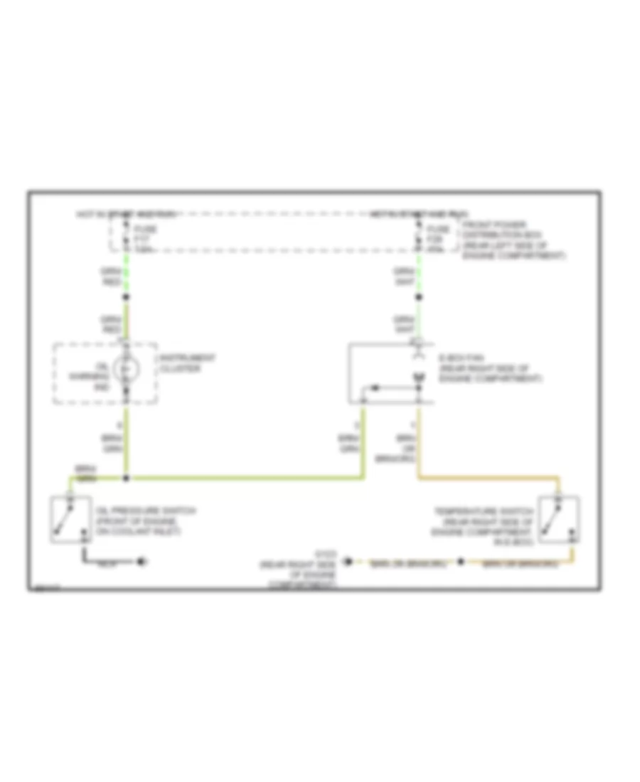
Electrical Box Fan Wiring Diagram for BMW 525i 1991
List of elements for Electrical Box Fan Wiring Diagram for BMW 525i 1991:
- E-box fan (rear right side of engine compartment)
- Front power distribution box (rear left side of engine compartment)
- Fuse f17 7.5a
- Fuse f28 15a
- G123 (rear right side of engine compartment)
- Hot in start and run
- Instrument cluster
- Nca
- Oil pressure switch (front of engine, on coolant inlet)
- Oil warning ind
- Temperature switch (rear right side of engine compartment, in e-box)
DEFOGGERS
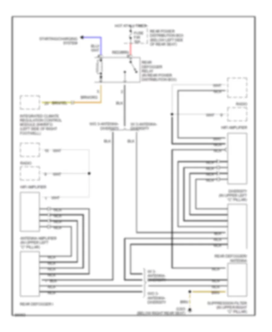
Defogger Wiring Diagram for BMW 525i 1991
List of elements for Defogger Wiring Diagram for BMW 525i 1991:
- Antenna amplifier (in upper left "c" pillar)
- Diversity (in upper left "c" pillar)
- Fuse f46 30a
- G303 (below right rear seat)
- Hifi amplifier
- Hot at all times
- Integrated climate regulation control module (ihkr/f3) (left side of right footwell)
- Nca
- Radio
- Rear defogger i
- Rear defogger relay (in rear power distribution box)
- Rear defogger/ antenna
- Rear power distribution box (below left side of rear seat)
- Starting/charging system
- Suppression filter (in upper right "c" pillar)
- W/ 3- antenna- diversity
- W/ 3-antenna- diversity
- W/o 3- antenna- diversity
- W/o 3-antenna- diversity
HORN
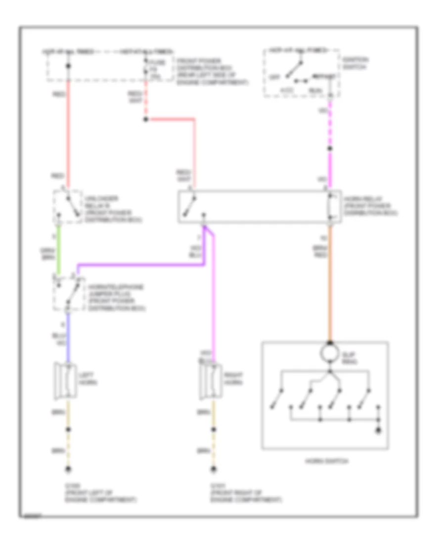
Horn Wiring Diagram for BMW 525i 1991
List of elements for Horn Wiring Diagram for BMW 525i 1991:
- Acc
- Front power distribution box (rear left side of engine compartment)
- Fuse f9 15a
- G100 (front left of engine compartment)
- G101 (front right of engine compartment)
- Horn relay (front power disribution box)
- Horn switch
- Horn/telephone jumper plug (front power distribution box)
- Hot at all times
- Ignition switch
- Left horn
- Off
- Red
- Right horn
- Run
- Slip ring
- Start
- Unloader relay r (front power distribution box)
MEMORY SYSTEMS
Memory Mirrors Wiring Diagram for BMW 525i 1991
List of elements for Memory Mirrors Wiring Diagram for BMW 525i 1991:
- (driver's seat, seat control switch)
- (driver's thigh support switch)
- (memory seats)
- Adjust hor
- Adjust l/r
- Adjust vert
- Anti- theft system
- Automatic transmission range switch (front of gearshift selector)
- Back back
- Back fwd
- Backup light switch (below center console)
- Computer data lines system
- Cushion
- Data
- Down
- Driver's
- Driver's door jamb switch
- Driver's side memory mirror
- Front power distribution box (rear left side of engine compartment)
- Funct illum
- Fuse f12 15a
- Fuse f16 30a
- Fuse f18 15a
- G202 (left side of i/p)
- G303 (below right rear seat)
- Gnd
- Ground
- Head dn
- Head up
- Headrest
- Height dn
- Height up
- Hor/vert
- Hot in accy, run and start
- Hot in run and start
- Illumination
- L/r and u/d
- Left
- Lf door
- Mem switch
- Mem1
- Mem2
- Mem3
- Memory mirrors control switch
- Memory seat/ mirrors switch
- Memory systems
- Memory systems (driver's seat, seat control switch)
- Nca
- Passenger's
- Passenger's side memory mirror
- Position
- Potentiomtr
- Power
- Program
- Pwr/gnd
- Rear height
- Reverse
- Right
- Seat back
- Seat fwd
- Seat height
- Seat/mirror memory control module (underside of left front seat)
- Select
- Thigh back
- Thigh fwd
- Thigh spprt
- Tilt dn
- Tilt up
- W/ egs
- W/o egs
- X18181
- X601
- X602
- X648
- X649
- X653
- X654
- X655
- X656
- X657
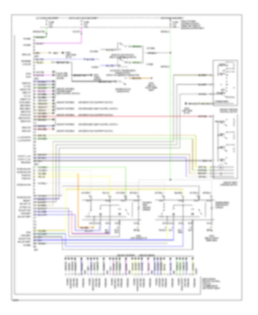
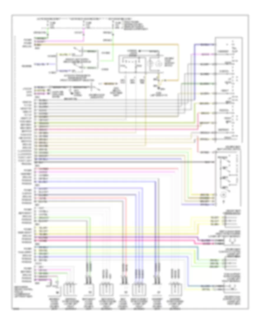
Memory Seat Wiring Diagram for BMW 525i 1991
List of elements for Memory Seat Wiring Diagram for BMW 525i 1991:
- (lower left front seatback)
- Anti- theft system
- Automatic transmission range selector (front of gearshift selector)
- Back
- Back back
- Back fwd
- Backup light switch (below center console)
- Computer data lines system
- Cushion
- Data
- Down
- Driver's door jamb switch
- Driver's seat cushion tilt motor (under left front seat)
- Driver's seat, seat control switch
- Driver's thigh support motor (under left front seat)
- Driver's thigh support switch
- Front
- Front power distribution box (rear left side of engine compartment)
- Funct light
- Fuse f12 15a
- Fuse f16 30a
- Fuse f18 15a
- Fwd
- G202 (left side of i/p)
- G303 (below right rear seat)
- Ground
- Head dn
- Head up
- Headrest
- Headrest motor (under driver's seat)
- Headrest potentiometer (lower left front seatback)
- Height
- Height dn
- Height up
- Hot in accy, run and start
- Hot in run and start
- Illumination
- Interior lights system
- Lf door
- Mem switch
- Mem1
- Mem2
- Mem3
- Memory seat/ mirrors switch
- Nca
- Position
- Power
- Program
- Pwr/gnd
- Rear height
- Reverse
- Rwd
- Seat back
- Seat cushion rear height potentiometer (lower left front seatback)
- Seat fwd
- Seat height
- Seat height motor (under driver's seat)
- Seat height potentiometer
- Seat motor (under driver's seat)
- Seat movement potentiometer (lower left front seatback)
- Seat/mirror memory control module (underside of left front seat)
- Seatback
- Seatback motor (under driver's seat)
- Seatback potentiometer (lower left front seatback)
- Thigh back
- Thigh fwd
- Thigh spprt
- Thigh support potentiometer (lower left front seatback)
- Tilt dn
- Tilt up
- W/ egs
- W/o egs
- X18181
- X602
- X648
- X649
- X653
- X654
- X655
- X656
- X657
POWER DOOR LOCKS
Power Door Lock Wiring Diagram for BMW 525i 1991
List of elements for Power Door Lock Wiring Diagram for BMW 525i 1991:
- Arrest central
- Central arrest
- Drivers door lock motor
- Drivers door lock switch
- Electric power protection relay (rear power distribution box)
- Fuse f30 7.5a
- Fuse f31 7.5a
- Fuse f47 30a
- G303 (below right rear seat)
- G303 (below right side of rear seat)
- Gas filler lock motor
- Hot at all times
- Inertia switch (below center of rear seat)
- Interior lights system
- Left rear door lock motor
- Not used
- Off
- Passengers door lock motor
- Passengers door lock switch
- Power windows system
- Rear power distribution box (below left rear seat)
- Relay module (rear power distribution box)
- Right rear door lock motor
- Trunk lock motor
- Unlk
- X253
- X254
- X255
- X332
POWER MIRRORS
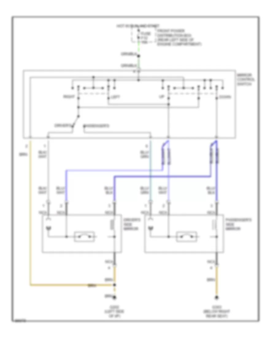
Power Mirror Wiring Diagram for BMW 525i 1991
List of elements for Power Mirror Wiring Diagram for BMW 525i 1991:
- Down
- Driver's
- Driver's side mirror
- Front power distribution box (rear left side of engine compartment)
- Fuse f12 15a
- G202 (left side of i/p)
- G303 (below right rear seat)
- Hot in run and start
- Left
- Mirror control switch
- Nca
- Passenger's
- Passenger's side mirror
- Right
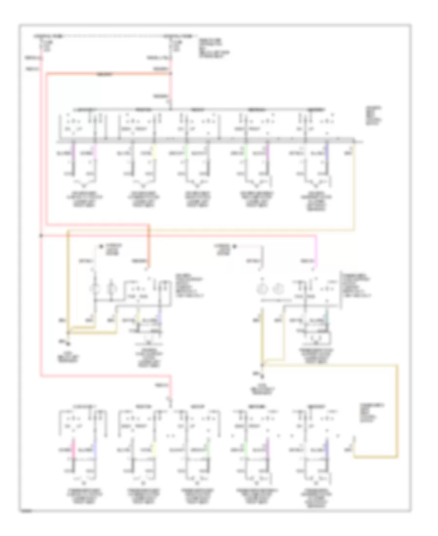
POWER SEATS
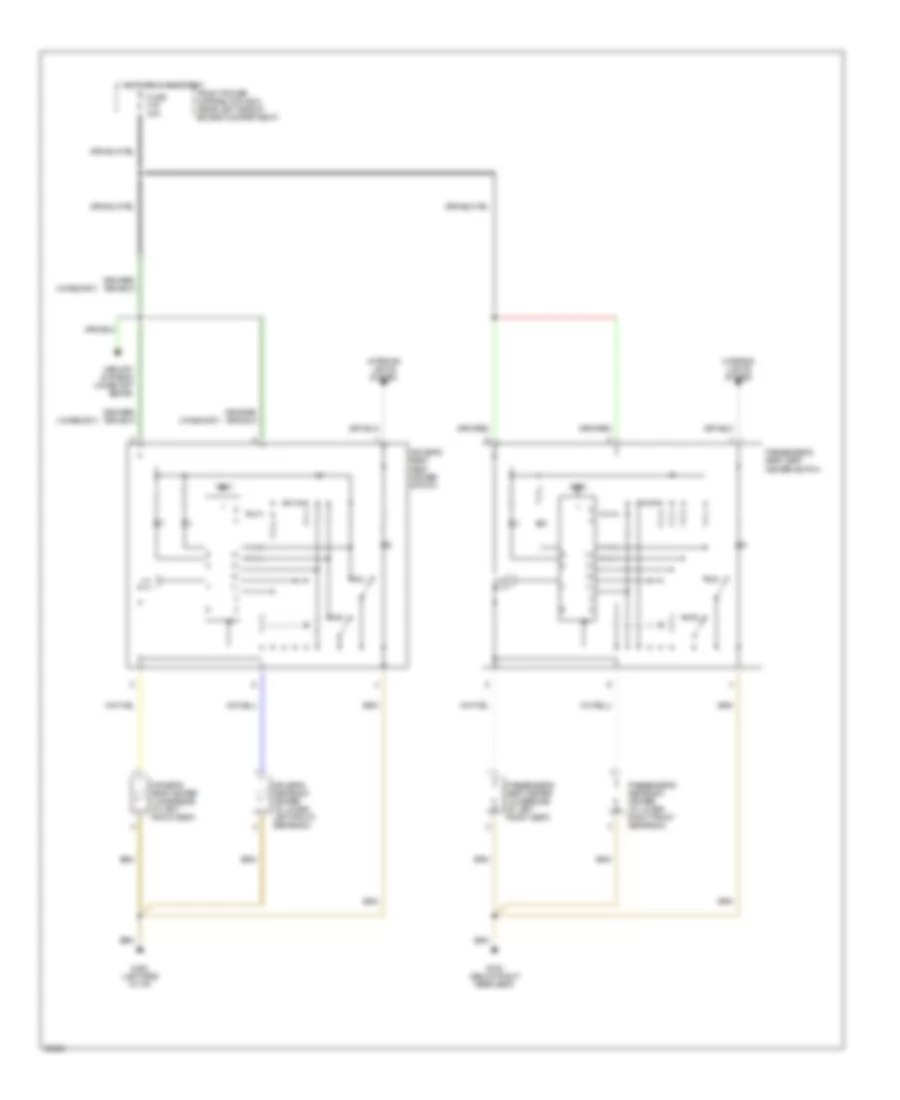
Heated Seats Wiring Diagram for BMW 525i 1991
List of elements for Heated Seats Wiring Diagram for BMW 525i 1991:
- (w/memory)
- Driver's seat heater (underside of left front seat)
- Driver's seat, seat heater switch
- Driver's seatback heater (in lower left front seatback)
- Front power distribution box (rear left side of engine compartment)
- Fuse f16 30a
- G202 (left side of i/p)
- G303 (below right rear seat)
- Hot in run and start
- Interior lights system
- Max
- Memory systems (w/memory seats)
- Min
- Passenger's seat heater (underside of left front seat)
- Passenger's seat, seat heater switch
- Passenger's seatback heater (in lower right front seatback)
- Test
Power Seats Wiring Diagram for BMW 525i 1991
List of elements for Power Seats Wiring Diagram for BMW 525i 1991:
- Back
- Cushion tilt
- Driver's headrest motor (in upper left front seatback)
- Driver's seat cushion tilt motor (under left front seat)
- Driver's seat height motor (under left front seat)
- Driver's seat movement motor (under left front seat)
- Driver's seat, seat control switch
- Driver's seatback recliner motor (under left front seat)
- Driver's thigh support motor (under left front seat)
- Driver's thigh support switch (w/sport seats only) (1991/1992 only)
- Front
- Fuse f42 30a
- Fuse f43 30a
- Fwd
- G303 (below right rear seat)
- G304 (below left rear seat)
- Headrest
- Height
- Hot at all times
- Interior lights system
- Nca
- Passenger's headrest motor (in upper right front seatback)
- Passenger's seat cushion tilt motor (under right front seat)
- Passenger's seat height motor (under right front seat)
- Passenger's seat movement motor (under right front seat)
- Passenger's seat, seat control switch
- Passenger's seatback recliner motor (under right front seat)
- Passenger's thigh support motor (under right front seat)
- Passenger's thigh support switch (w/sport seats only) (1991/1992 only)
- Position
- Rear power distribution box (below left side of rear seat)
- Rwd
- Seatback
POWER WINDOWS
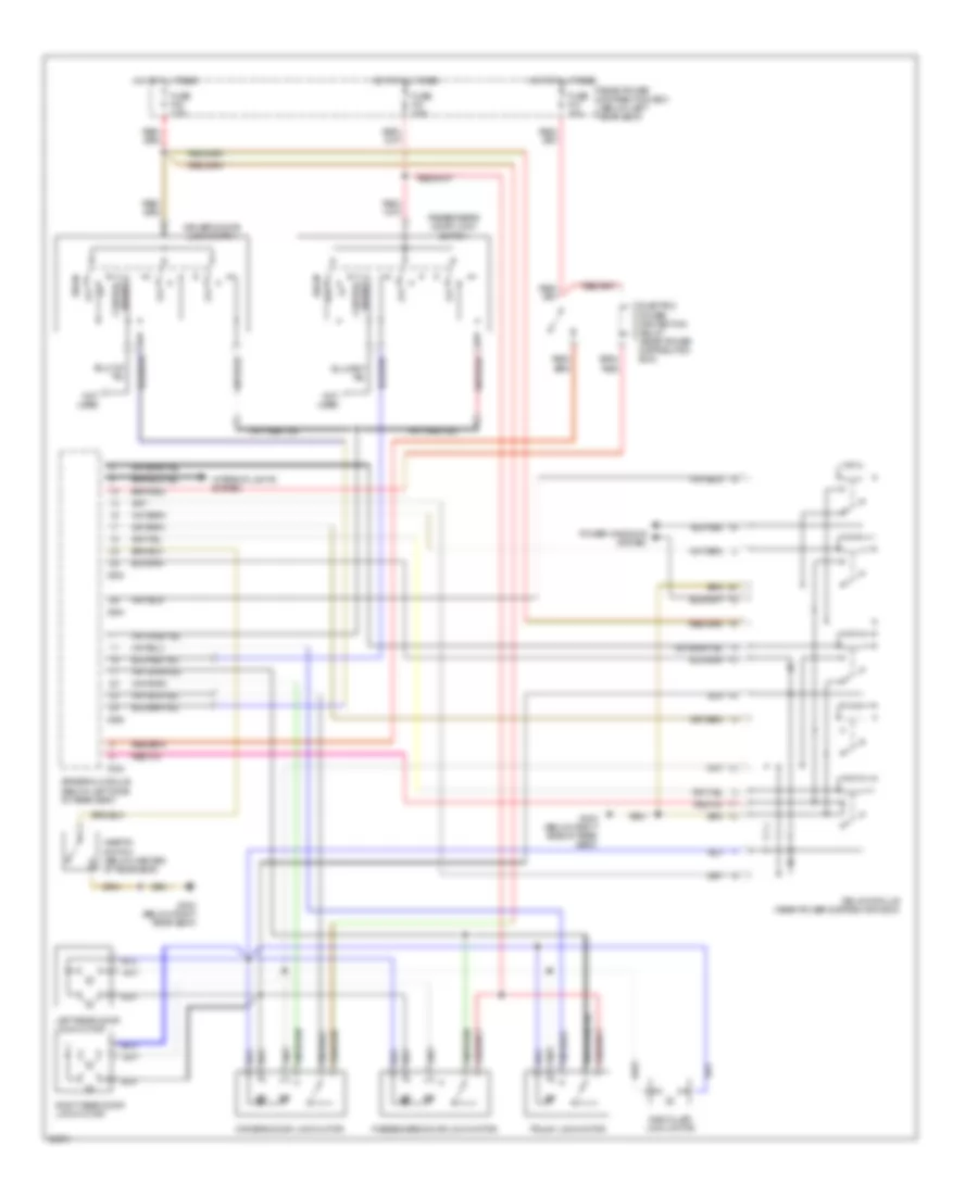
Power Window Wiring Diagram for BMW 525i 1991
List of elements for Power Window Wiring Diagram for BMW 525i 1991:
- (below g303
- (below right g303
- (left side g202
- (not used)
- Child safety lock switch
- Close
- Close left rear window signal
- Close off
- Close pass. window signal
- Close right rear window signal
- Close right rear window signal close left rear window signal driver's window motor control
- Data line
- Driver's & left rear window control/ sunroof motor control
- Driver's window limit switch
- Driver's window motor
- Driver's window open signal
- Driver's window switch
- Electric power control protection relay control
- Electric power protection relay (rear power distribution box)
- Front console window switch assembly
- Front power distribution box (left rear side of engine comp.)
- Fuse f17 7.5a
- Fuse f30 7.5a
- Fuse f47 30a
- General module (left side of
- Hot at all times
- Hot in run and start
- Left rear window
- Left rear window motor
- Left rear window motor control
- Left rear window open signal
- Left rear window switch
- Limit switch
- Of i/p)
- Off
- Open
- Open driver's window signal close driver's window signal right rear window open signal
- Open left rear window signal open passenger's window signal
- Open right rear window signal
- Pass. window open signal
- Passenger's and right rear window motor control
- Passenger's window limit switch
- Passenger's window motor
- Passenger's window motor control
- Passenger's window switch
- Power for electronics
- Power input
- Power tops system
- Rear power distribution box (below left side of rear seat)
- Rear seat)
- Red
- Red/
- Relay module (left side of rear seat)
- Right rear seat)
- Right rear window limit switch
- Right rear window motor
- Right rear window switch
- X253
- X254
- X255
- X258
- X259
- X316
- X317
- X332
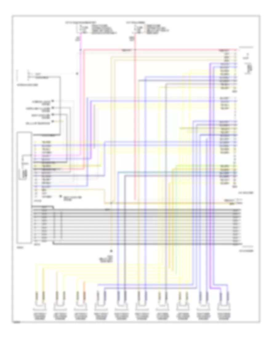
RADIO
Radio Wiring Diagrams for BMW 525i 1991
List of elements for Radio Wiring Diagrams for BMW 525i 1991:
- 10a
- 6.3a
- Antenna amplifier
- Body computer system
- Cd changer
- Cellular telephone
- Coax cable
- Front power distribution box (rear left side of engine compartment)
- Fuse f18 15a
- Fuse f36 30a
- G304 (below left rear seat)
- Hifi amplifier
- Hot at all times
- Hot in accy, run and start
- Instrument cluster system
- Interior lights system
- Left front high range speaker
- Left front low range speaker
- Left front midrange speaker
- Left rear high range speaker
- Left rear low range speaker
- Nca
- Power input
- Radio
- Rear power distribution box (below left side of rear seat)
- Right front high range speaker
- Right front low range speaker
- Right front midrange speaker
- Right rear high range speaker
- Right rear low range speaker
- X18126
- X605
- X606
- X8075
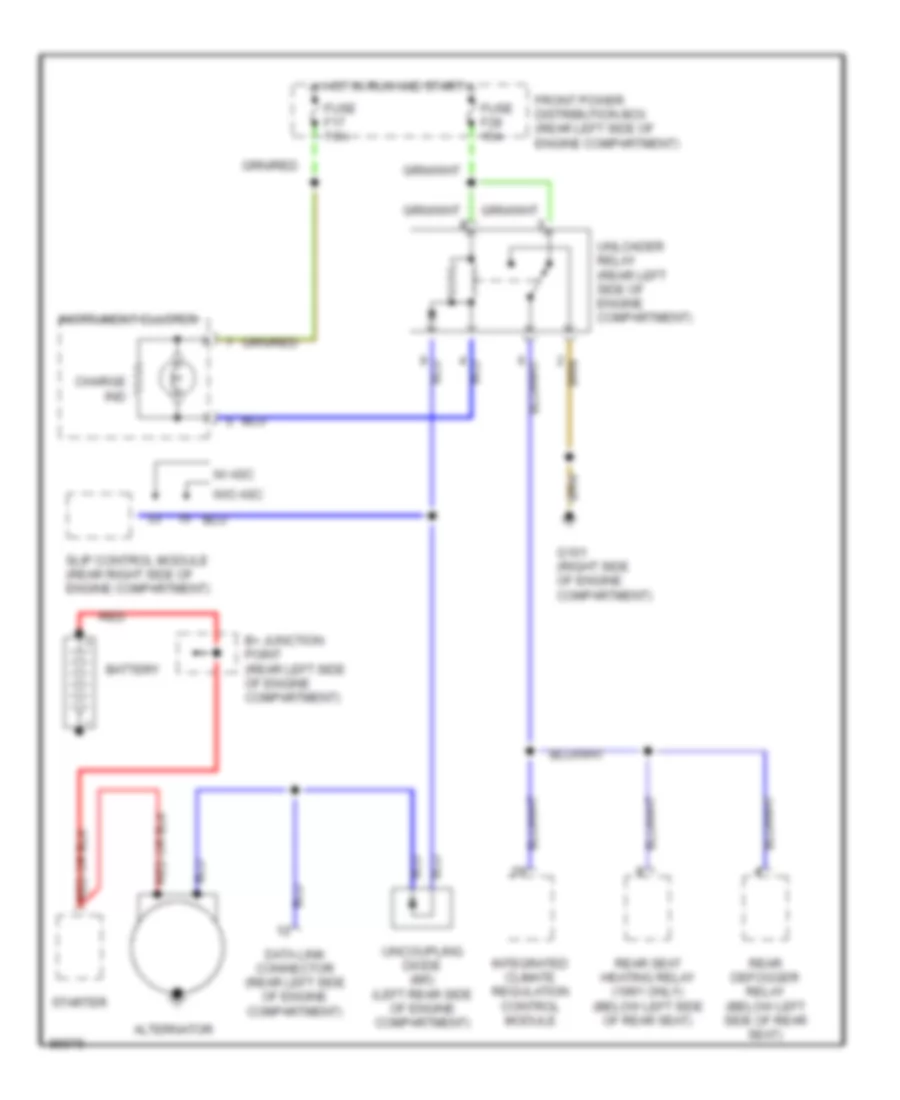
STARTING/CHARGING
Charging Wiring Diagram for BMW 525i 1991
List of elements for Charging Wiring Diagram for BMW 525i 1991:
- Alternator
- B+ junction point (rear left side of engine compartment)
- Battery
- Charge ind
- Data link connector (rear left side of engine compartment)
- Front power distribution box (rear left side of engine compartment)
- Fuse f17 7.5a
- Fuse f28 15a
- G101 (right side of engine compartment)
- Hot in run and start
- Instrument cluster
- Integrated climate regulation control module
- Rear defogger relay (below left side of rear seat)
- Rear seat heating relay (1991 only) (below left side of rear seat)
- Red
- Slip control module (rear right side of engine compartment)
- Starter
- Uncoupling diode (m5) (left rear side of engine compartment)
- Unloader relay (rear left side of engine compartment)
- W/ asc
- W/o asc
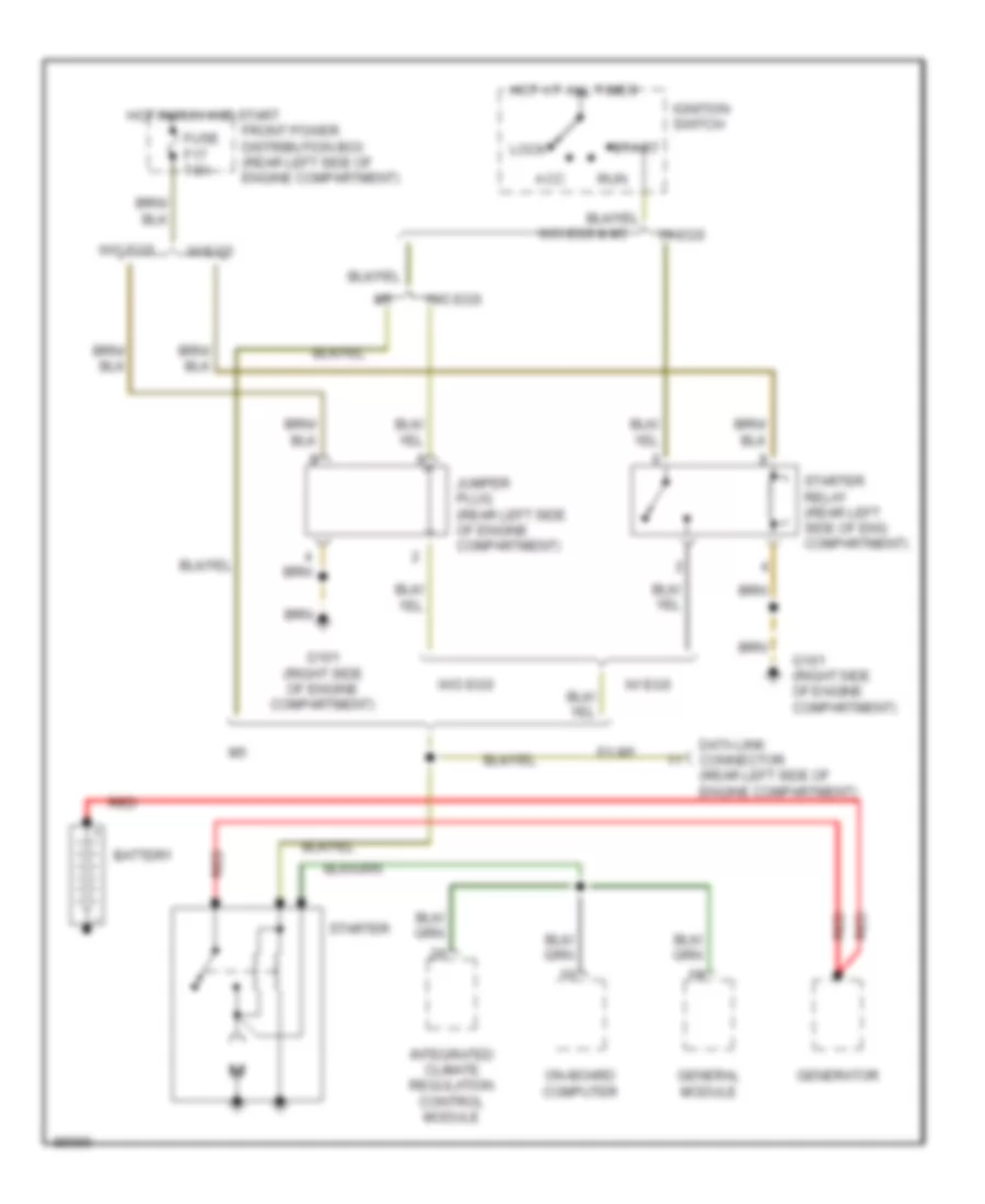
Starting Wiring Diagram for BMW 525i 1991
List of elements for Starting Wiring Diagram for BMW 525i 1991:
- Acc
- Battery
- Data link connector (rear left side of engine compartment)
- Ex m5
- Front power distribution box (rear left side of engine compartment)
- Fuse f17 7.5a
- G101 (right side of engine compartment)
- General module
- Generator
- Hot at all times
- Hot in run and start
- Ignition switch
- Integrated climate regulation control module
- Jumper plug (rear left side of engine compartment)
- Lock
- On-board computer
- Red
- Run
- Start
- Starter
- Starter relay (rear left side of eng compartment)
- W/ egs
- W/o egs
- W/o egs & m5
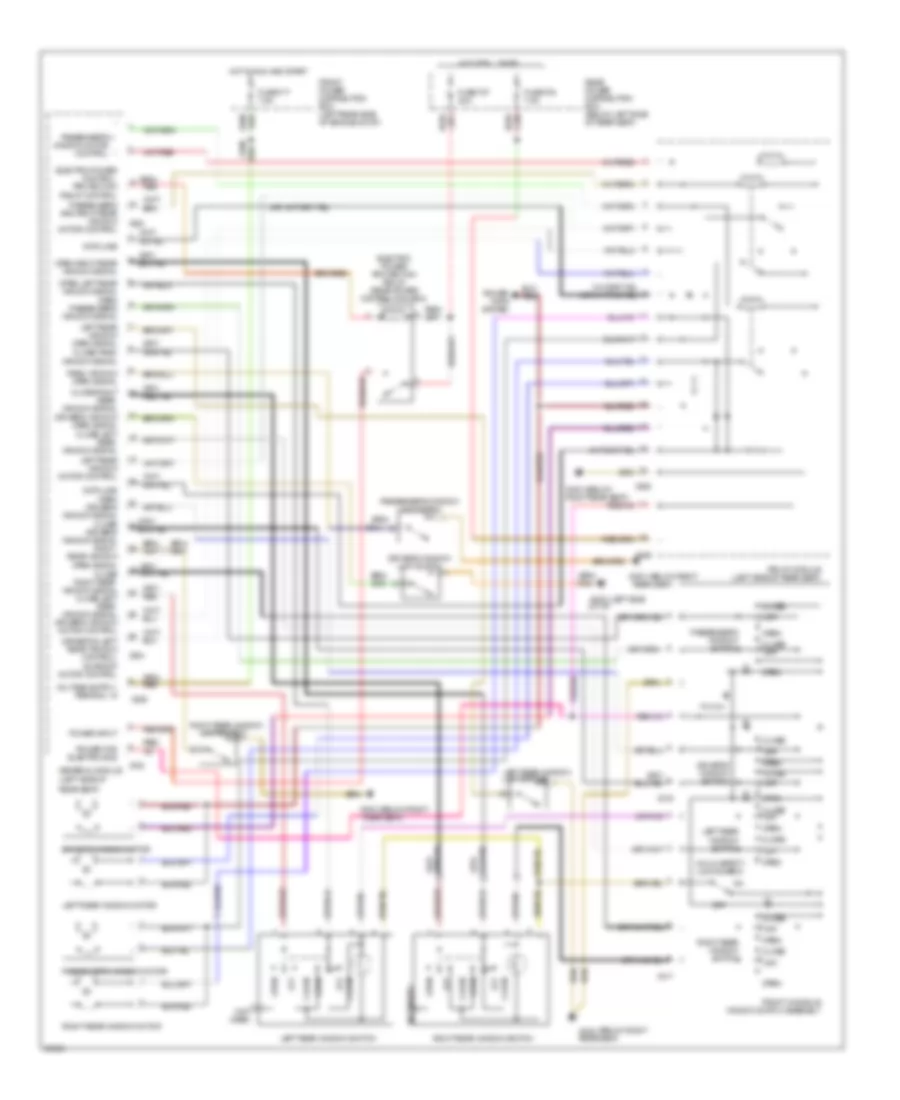
TRANSMISSION
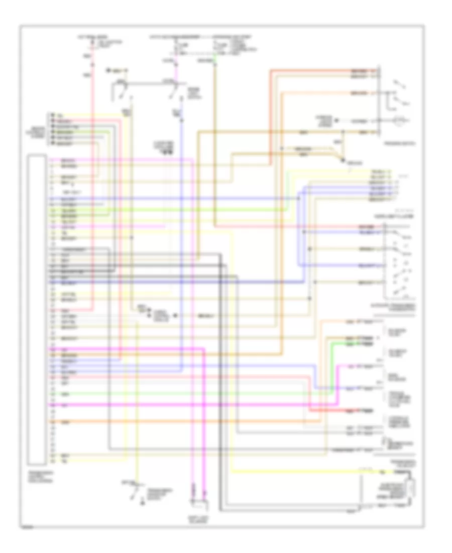
Transmission Wiring Diagram, 4 Speed with Overdrive for BMW 525i 1991
List of elements for Transmission Wiring Diagram, 4 Speed with Overdrive for BMW 525i 1991:
- 1991 only
- Automatic transmission range switch
- B+ junction point
- Band solenoid
- Brake light switch
- Check control module
- Computer data lines system
- Electronic transmission engine speed sensor
- Engine controls system
- Front power distribution box
- Fuse f1 15a
- Fuse f17 7.5a
- Ground
- Hot at all times
- Hot in accy, run and start
- Hot in run and start
- Hydraulic pressure regulator
- Instrument cluster
- Interior lights system
- Nca
- Oil temperature sensor
- Program switch
- Red
- Shift lock solenoid
- Solenoid valve 1
- Solenoid valve 2
- Torque converter clutch sol valve
- Transmission control module (egs)
- Transmission kickdown switch
- Transmission valve unit
- Transparent
WIPER/WASHER
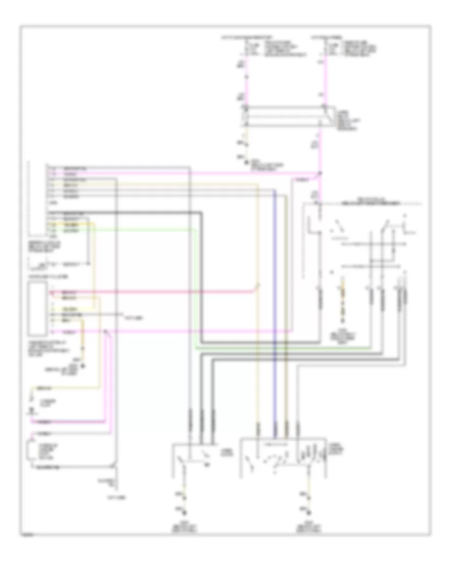
Wiper/Washer Wiring Diagram for BMW 525i 1991
List of elements for Wiper/Washer Wiring Diagram for BMW 525i 1991:
- Fast
- Front power distribution box (left rear of engine compartment)
- Fuse f15 7.5a
- Fuse f44 30a
- G202 (behind left side of dash)
- G303 (below right side of rear seat)
- G304 (below left side of rear seat)
- General module (below left side of rear seat)
- Hot at all times
- Hot in accy, run and start
- Instrument cluster
- Intensive washer pump (ex usa)
- Not used
- Off
- Pause
- Rear power distribution box (below left side of rear seat)
- Relay module (below left side of rear seat)
- Single
- Slow
- Vss output
- Washer pump
- Washer pump relay (left rear of engine compartment) (ex usa)
- Wiper motor
- Wiper relay (below left side of rear seat)
- Wiper/ washer switch
- X253
- X255