AIR CONDITIONING
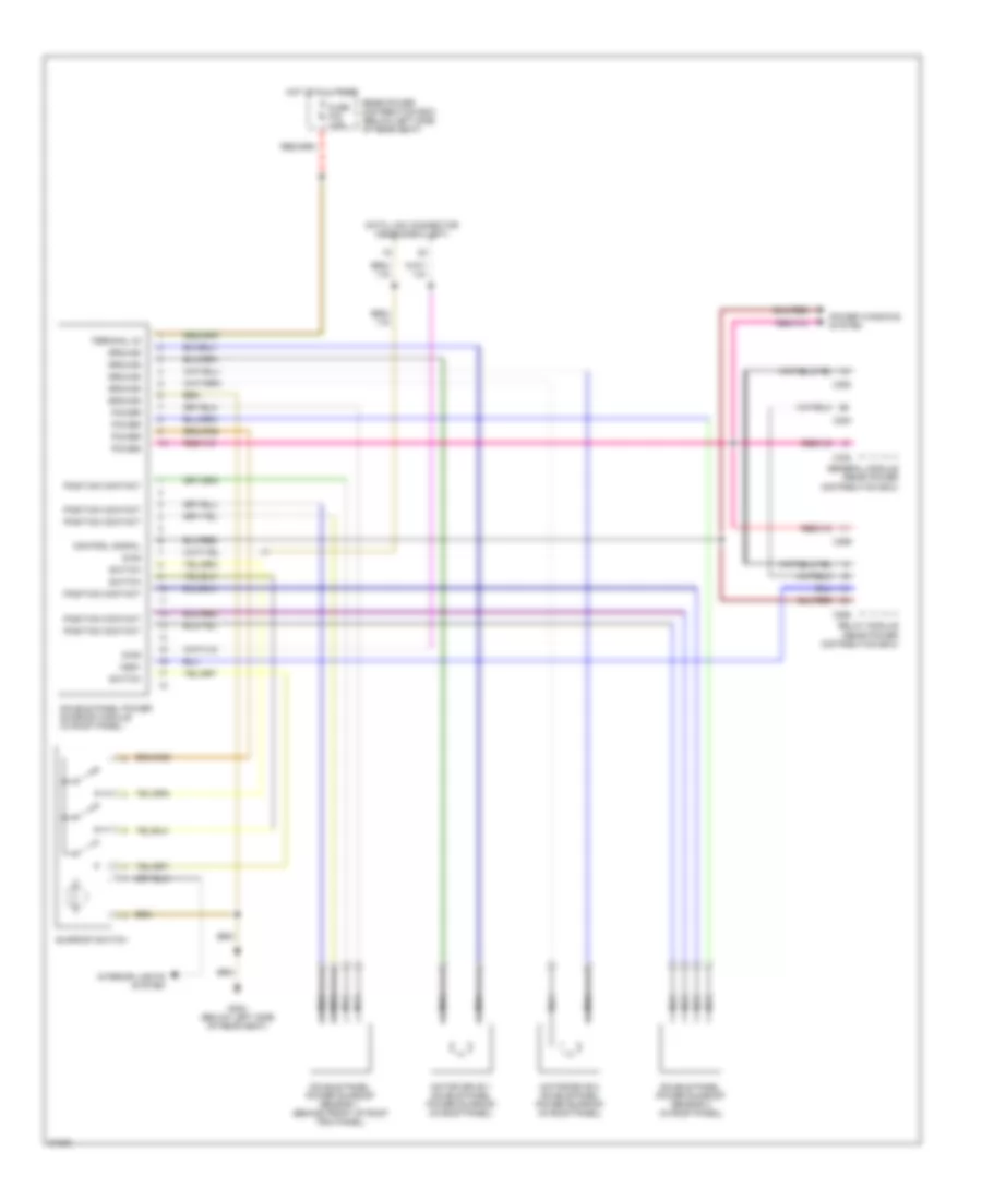
Air Conditioning Wiring Diagrams (1 of 3) for BMW 530i 1994

List of elements for Air Conditioning Wiring Diagrams (1 of 3) for BMW 530i 1994:
- (1994) (1995)
- (left side of dash)
- A/c switch
- Alternator
- Auxiliary fan signal
- Battery
- Box
- C 1995 vftc
- Charging system
- Circulation switch
- Defog switch
- Defogger switch
- Distribution
- Evaporator temp
- Evaporator temperature sensor (below left side of dash)
- Front power
- Function light recirc
- Function light-a/c
- Function light-defogger
- Function light-recirc
- Fuse 10a 15a
- Fuse 15a
- Fuse 30a
- Fuse 7.5a
- G202
- Ground
- Heater temp-left
- Heater temp-right
- Hot at all times
- Hot in run or start
- Ignition
- Illumination
- Independent ventilation
- Inside temp sensor
- Instrument cluster
- Integrated climate regulation control module (above center console)
- Interior lights system
- Left heat exchanger temperature sensor (right side of left footwell)
- Nca
- Nominal air flow value
- Nominal temp value-left
- Nominal temp value-right
- Outside temp
- Outside temperature sensor (near left headlight assembly)
- Recirc switch
- Right heat exchanger temperature sensor (right side of plenum)
- Starter
- Starting system
- Switching unit
- Vehicle speed
- Voltage
- Voltage for func lights
- Water valve act
- Water valve act-right
- Water valve assembly (left side of engine bulkhead)
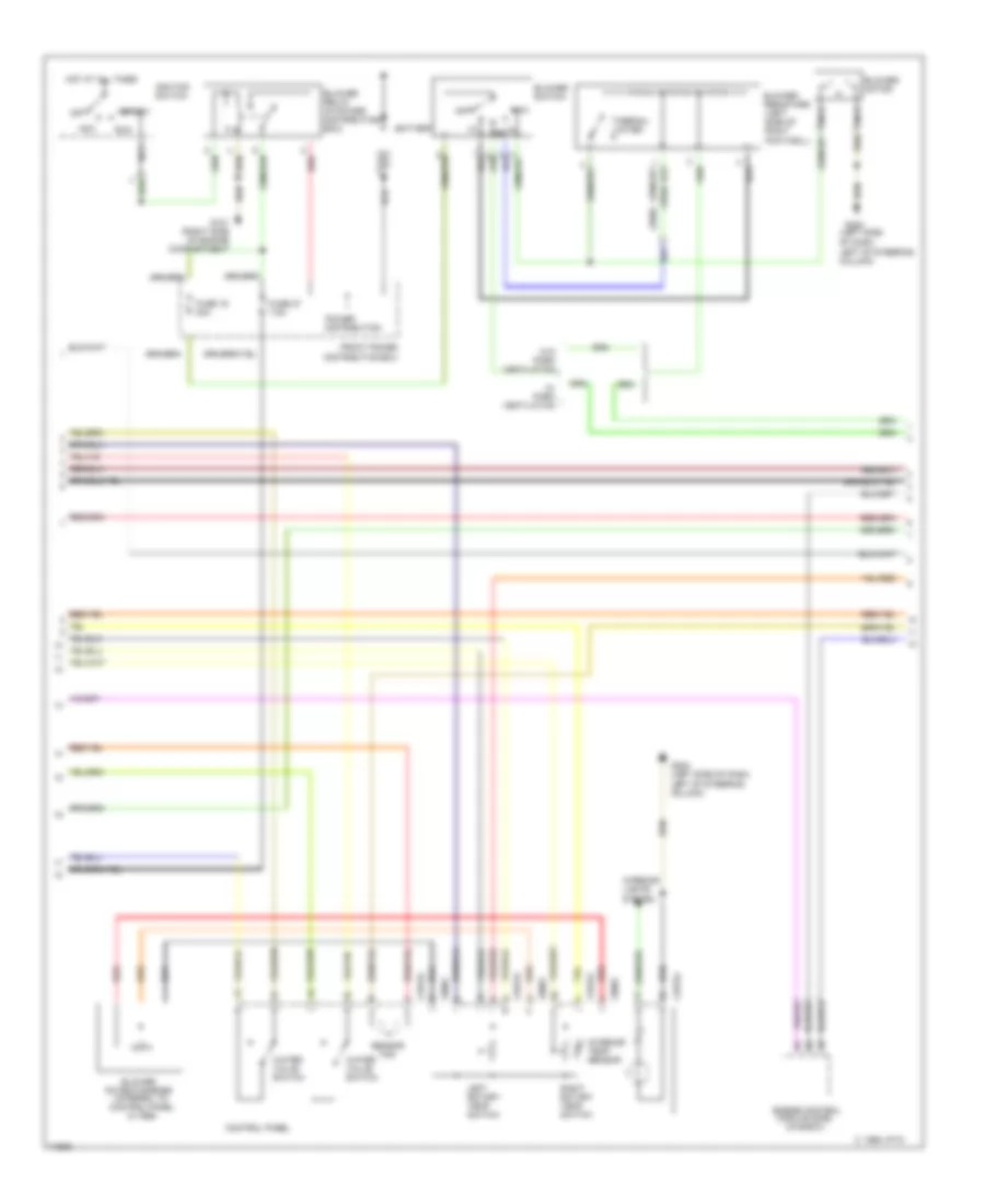
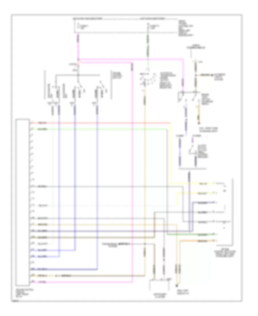
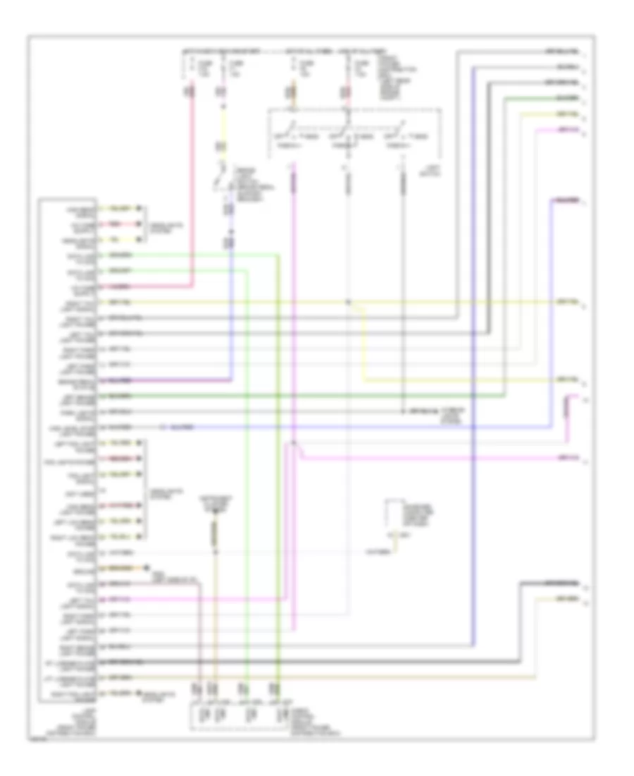
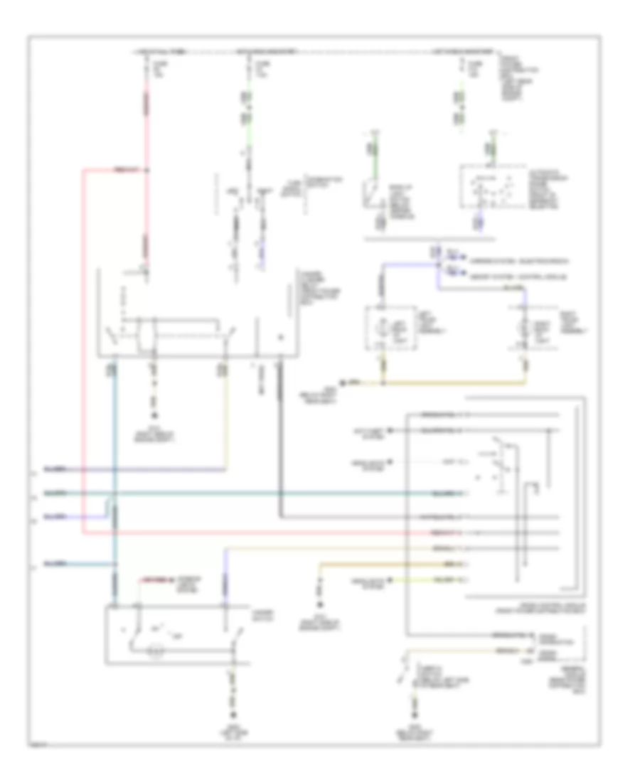
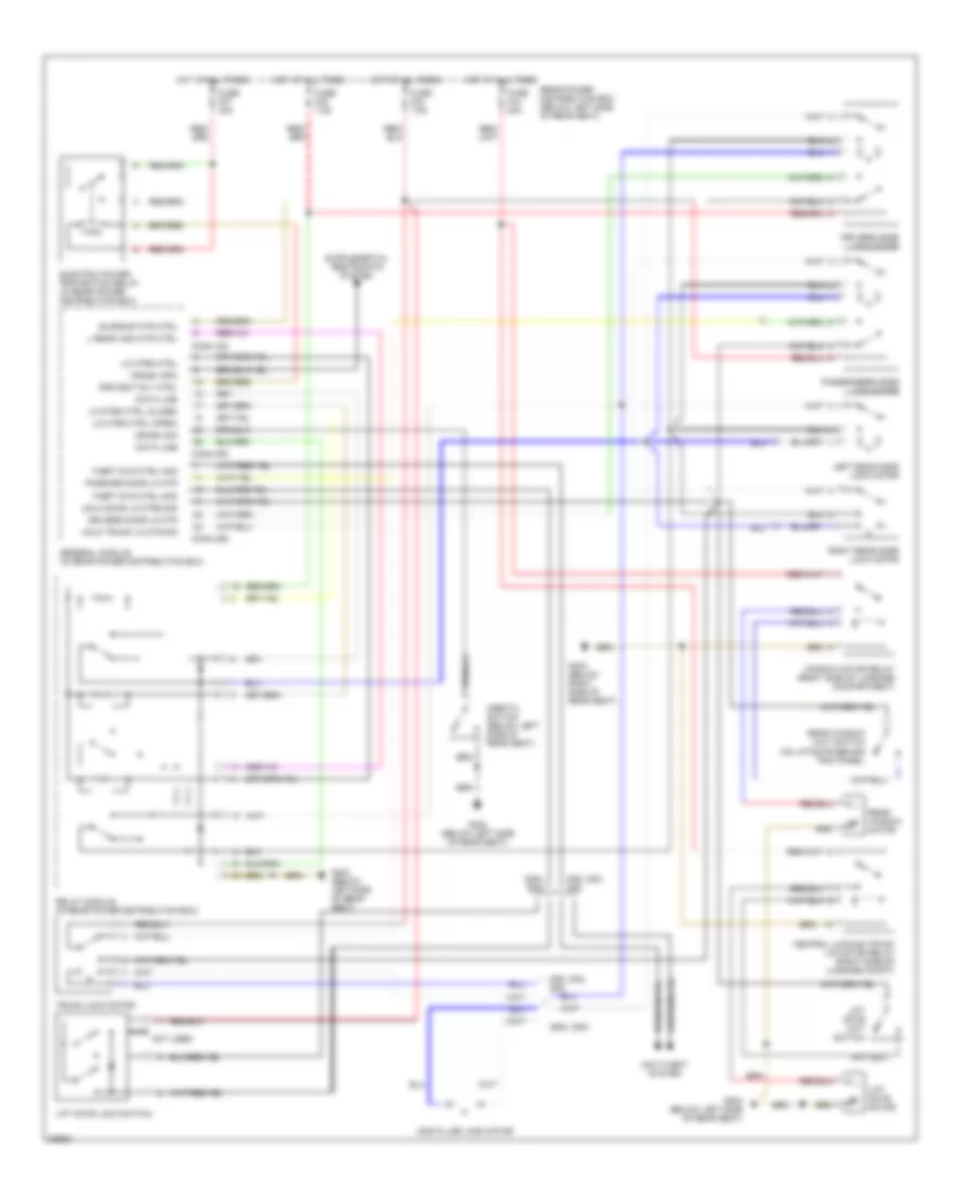
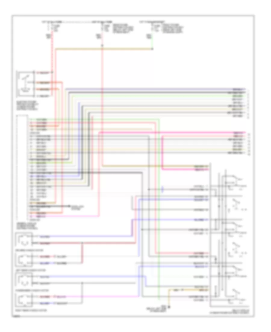
Air Conditioning Wiring Diagrams (2 of 3) for BMW 530i 1994
List of elements for Air Conditioning Wiring Diagrams (2 of 3) for BMW 530i 1994:
- (1994)
- (1995)
- (left side
- Acc
- Battery
- Blower motor
- Blower potentiometer (internal to control panel in 1995)
- Blower relay (in power distribution box)
- Blower resistors (left side of right footwell)
- Blower switch
- C 1995 vftc
- Control panel
- Engine control module (dme) (in e-box)
- Fan
- Front power distribution box
- Fuse 19 30a
- Fuse 27 7.5a
- G101 (right side of engine compartment
- G202
- G202 (left side of dash, left of steering column)
- Hot at all times
- Ignition switch
- Interior lights system
- Interior temp sensor
- Left of steering column)
- Left rotary temp switch
- Max
- Nca
- Of dash,
- Off
- Power distribution
- Red
- Right rotary temp switch
- Run
- Sensor
- Start
- Thermal limiter
- W/ park ventilation
- W/o park ventilation
- Water valve switch
- X18154
- X9001
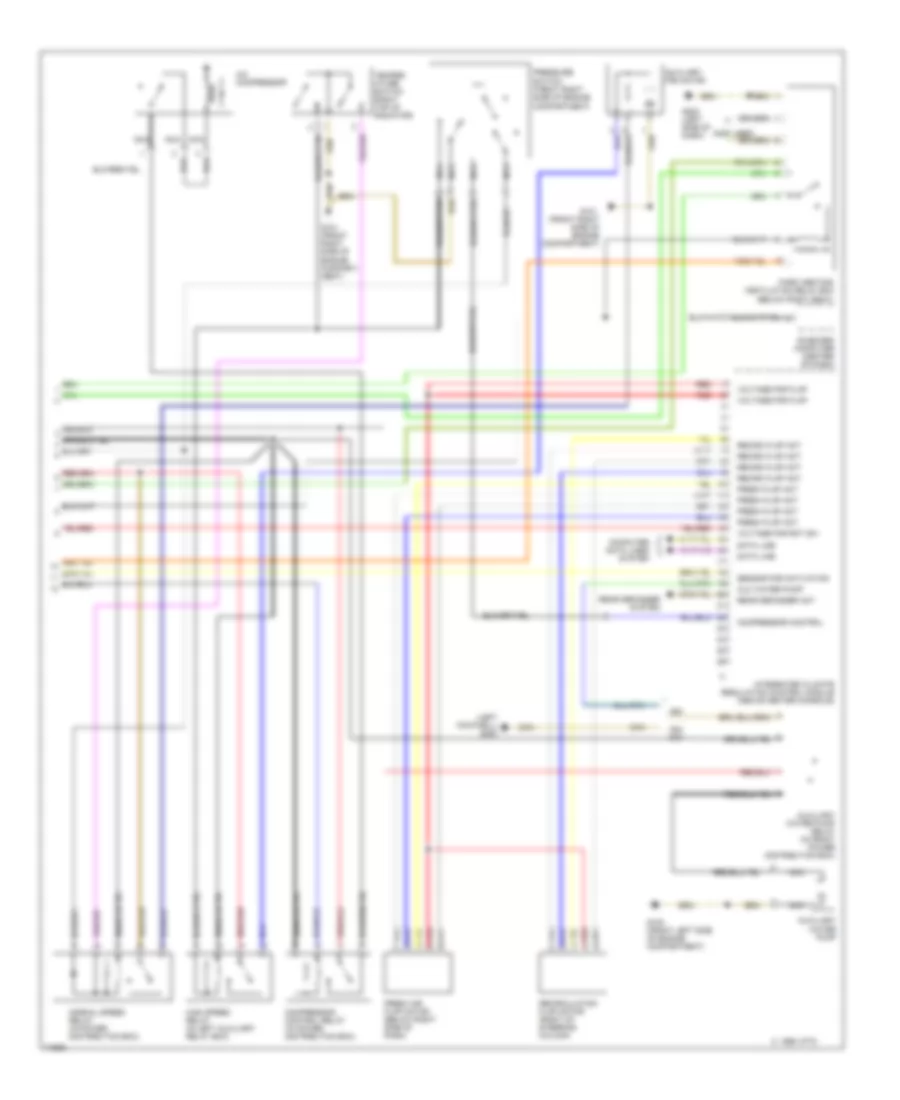
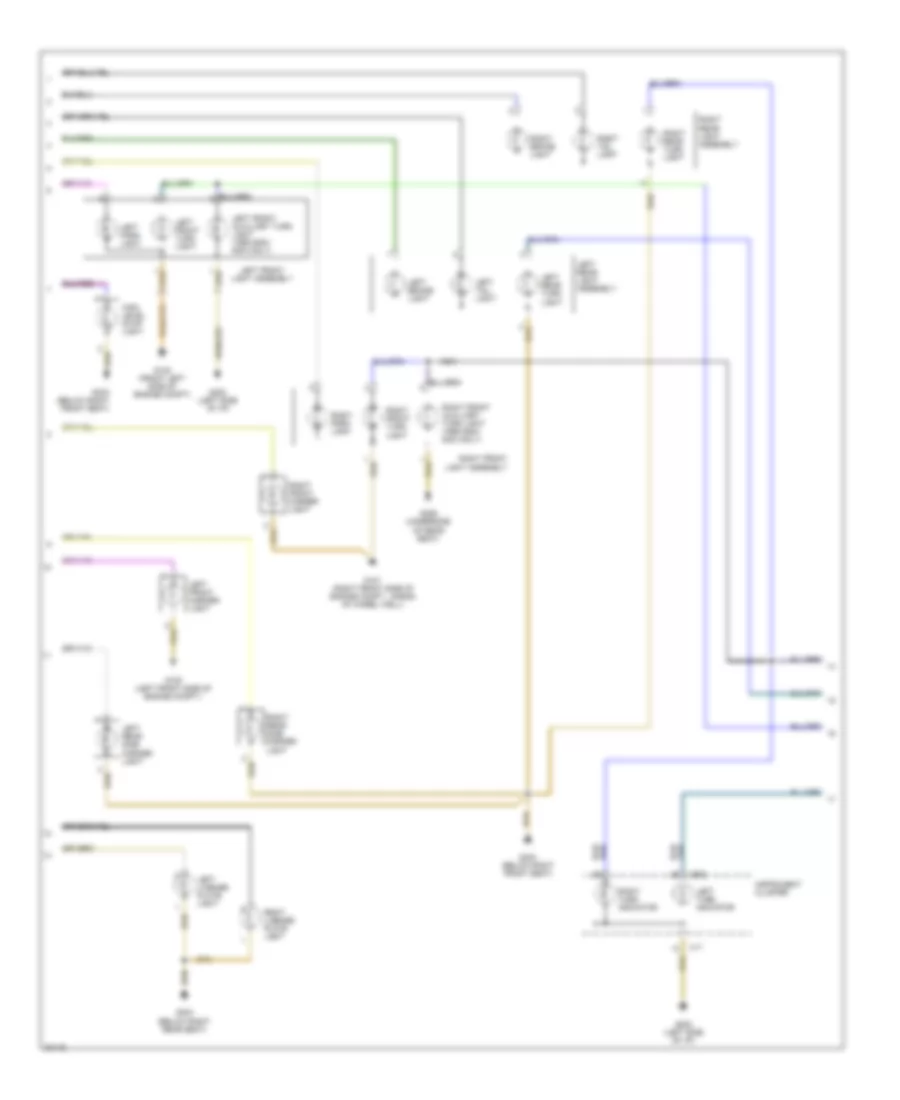
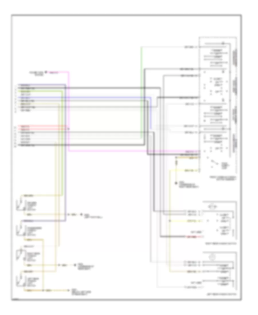
Air Conditioning Wiring Diagrams (3 of 3) for BMW 530i 1994
List of elements for Air Conditioning Wiring Diagrams (3 of 3) for BMW 530i 1994:
- (below right seat)
- (left footwell) g200
- (not used)
- 530,
- A/c compressor
- Aux water pump
- Auxiliary fan motor
- Auxiliary water pump
- Auxiliary water pump relay (in front power distribution box)
- C 1995 vftc
- Compartment)
- Compressor control
- Compressor control relay (in power distribution box)
- Computer data lines system
- Data line
- Fresh air flap motor (below right side of dash)
- Fresh flap act
- G100 (front left side of engine compartment)
- G101 (front right side of engine compart- ment)
- G101 (front right side of engine compartment)
- G202 (left side of dash)
- High speed relay (in left auxiliary relay box)
- Integrated climate regulation control module (above center console)
- Nca
- Normal speed relay (in power distribution box)
- On-board computer (center of dash)
- Park heating/ ventilation relay box
- Pressure
- Rear defogger act
- Rear defogger system
- Recirc flap act
- Recirculation flap motor (right of steering column)
- Red
- Sensor for activation
- Switch (front right side of engine
- Temper- ature switch (right top of radiator)
- Voltage for flap
- Voltage for rot sw
ANTI-LOCK BRAKES
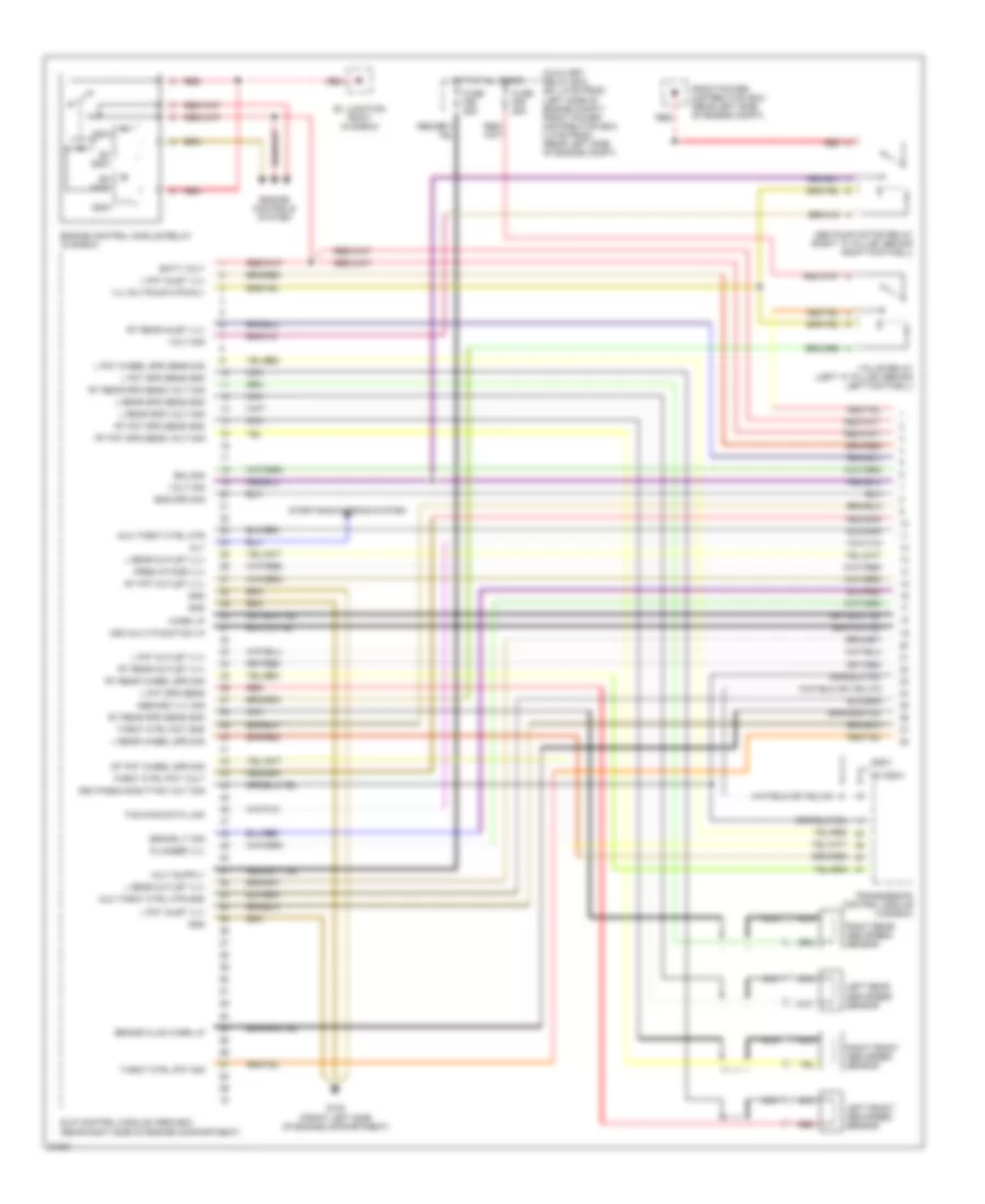
Anti-lock Brake Wiring Diagrams (1 of 2) for BMW 530i 1994
List of elements for Anti-lock Brake Wiring Diagrams (1 of 2) for BMW 530i 1994:
- 525i/t
- Abs pump motor relay (right "a" pillar, behind right footwell)
- Abs/asc vlv sig
- Alt
- Asc multi-function lp
- Asc passive button volt sig
- Aux throt ctrl mtr
- Aux throt ctrl mtr gnd
- Auxiliary relay box (ex late prod) (left side of engine compt) front power distribution box (late prod) (rear left side of engine compt)
- B+ junction point (in e-box)
- Batt volt
- Brake fluid warn lp
- Brake lt sig
- Eml-sig
- Eng spd sig
- Engine control module relay (in e-box)
- Engine controls system
- Ex 525i/t
- Front power distribution box (rear left side of engine compt)
- Fuse f55 50a
- Fuse f56 25a
- G100 (front left side of engine compartment)
- Gnd
- Hot at all times
- L fnt inlet vlv
- L fnt outlet vlv
- L fnt spd sens
- L fnt spd sens gnd
- L fnt wheel spd sens sig
- L rear outlet vlv
- L rear spd sens gnd
- L rear spd volt sig
- L rear wheel spd sig
- Left front abs speed sensor
- Left rear abs speed sensor
- Nca
- Plunger vlv
- Pres intake vlv
- Red
- Right front abs speed sensor
- Right rear abs speed sensor
- Rt fnt outlet vlv
- Rt fnt spd sens gnd
- Rt fnt spd sens volt sig
- Rt fnt wheel spd sig
- Rt rear inlet vlv
- Rt rear outlet vlv
- Rt rear spd sens gnd
- Rt rear spd sens volt sig
- Rt rear wheel spd sig
- Slip control module (abs/asc) (rear right side of engine compartment)
- Starting/charging system
- Throt ctrl pot gnd
- Throt ctrl pot sig
- Throt ctrl pot volt
- Transmission control module (in e-box)
- Txd diag data link
- Valve relay (left "a" pillar, behind left footwell)
- Vlv rly/pump mtr rly
- Volt sig
- Warn lp
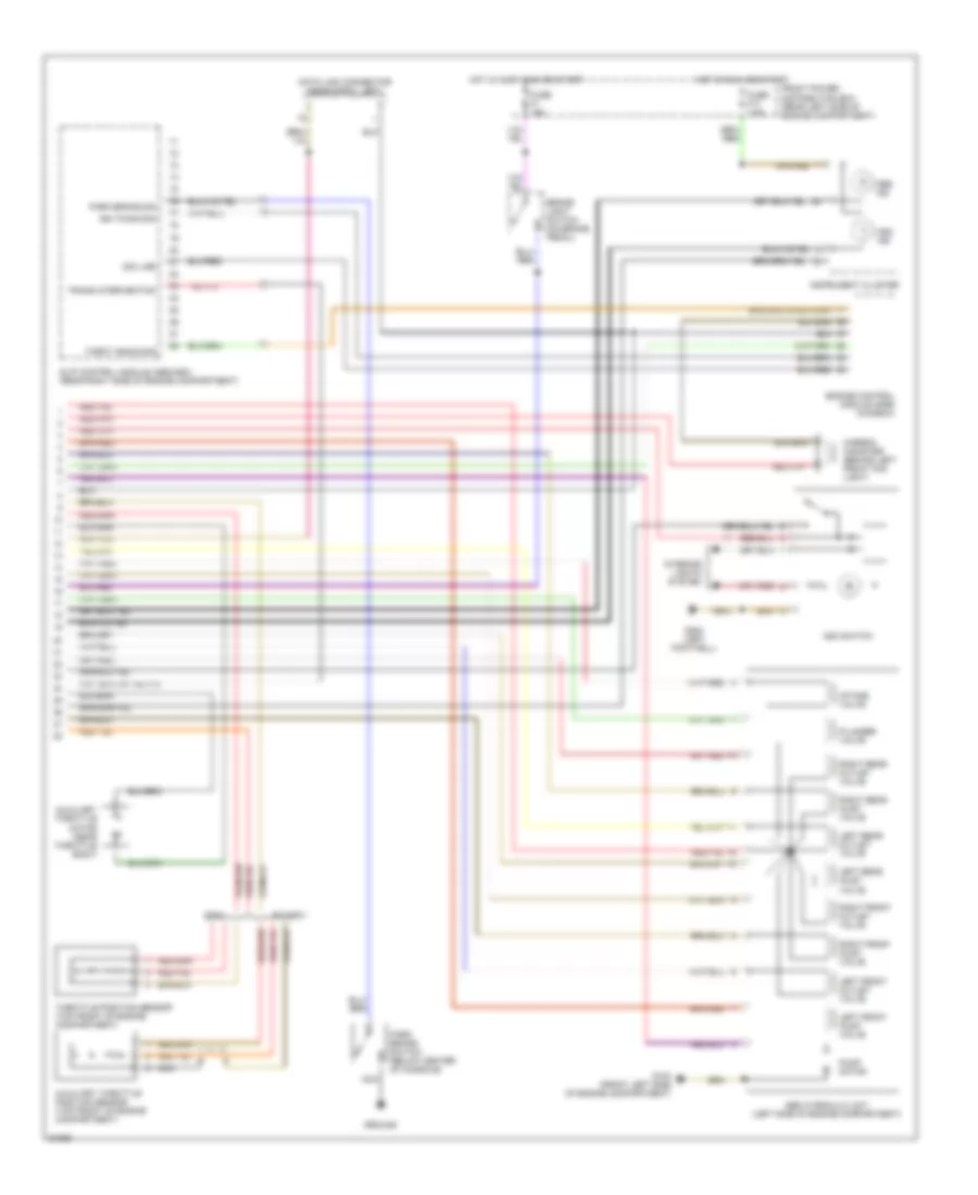
Anti-lock Brake Wiring Diagrams (2 of 2) for BMW 530i 1994
List of elements for Anti-lock Brake Wiring Diagrams (2 of 2) for BMW 530i 1994:
- 525i/t
- Abs hydraulic unit (left side of engine compartment)
- Abs ind
- Asc ind
- Asc switch
- Auxiliary throttle motor (near throttle body)
- Auxiliary throttle position sensor (top front of engine compartment)
- Brake light switch (on brake pedal)
- Carbon canister (behind left front fog light)
- Data link connector (near e-box, left)
- Engine control module (dme) (in e-box)
- Ex 525i/t
- Front power distribution box (rear left side of engine compartment)
- Fuse f1 15a
- Fuse f17 7.5a
- G100 (front left side of engine compartment)
- G200 (left footwell)
- Ground
- Hot in accy, run or start
- Hot in run and start
- Ign timing sig
- Instrument cluster
- Intake valve
- Interior lights system
- Left front inlet valve
- Left front outlet valve
- Left rear inlet valve
- Left rear outlet valve
- Nca
- Park brake sig
- Park brake switch (below center of console)
- Plunger valve
- Pump motor
- Right front inlet valve
- Right front outlet valve
- Right rear inlet valve
- Right rear outlet valve
- Sig line
- Slip control module (abs/asc) (rear right side of engine compartment)
- Throt angle sig
- Throttle position sensor (top front of engine compartment)
- Trans intervention
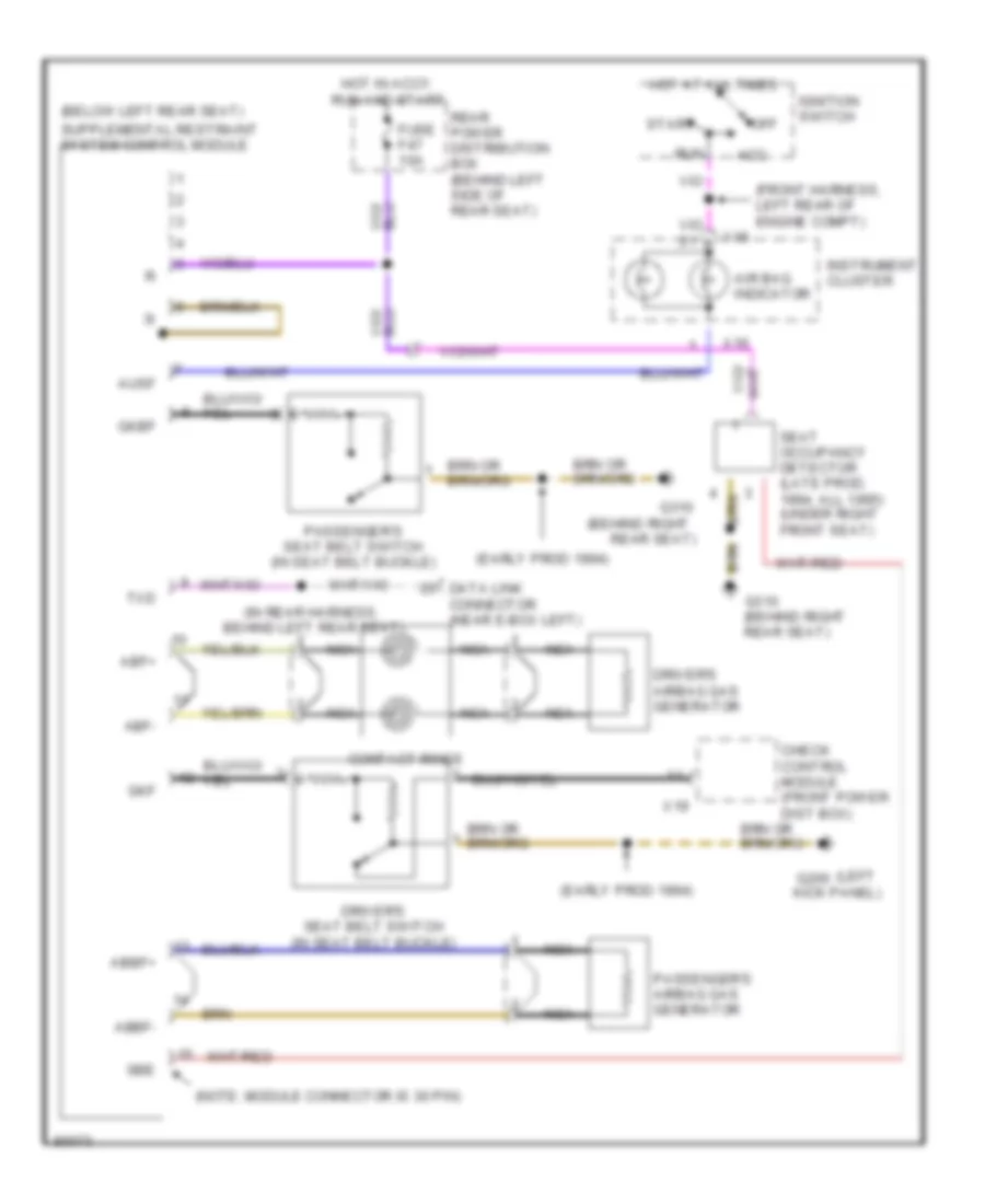
ANTI-THEFT
Anti-theft Wiring Diagram for BMW 530i 1994
List of elements for Anti-theft Wiring Diagram for BMW 530i 1994:
- 10a
- Anti- theft horn relay
- Anti-theft control module (below right side of rear seat)
- Anti-theft horn (rear right side of engine compartment)
- Anti-theft led
- Check control module (front power distribution box)
- Crash control module (front power distribution box)
- Drivers door handle switch
- Drivers door jamb switch
- Engine hood switch
- Exterior lights system
- Front power distribution box (rear left side of engine compartment)
- Fuse f18 15a
- Fuse f37 30a
- G200 (left footwell)
- G303 (underside of right rear seat)
- G304 (underside of left rear seat)
- General module (rear power distribution box)
- Hot at all times
- In-line fuse
- Left rear door jamb switch
- Lift gate lock switch (early production)
- On-board computer (center of dash)
- On-board computer horn relay (below left side of rear seat)
- Passengers door jamb switch
- Rear power distribution box (below left side of rear seat)
- Red
- Right rear door jamb switch
- Seat/mirror memory control module (underside of left front seat)
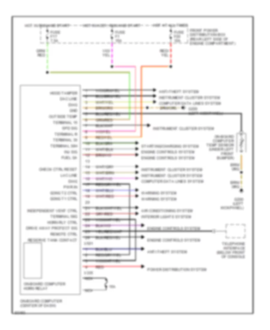
BODY COMPUTER
Body Computer Wiring Diagrams for BMW 530i 1994
List of elements for Body Computer Wiring Diagrams for BMW 530i 1994:
- 15a
- Air conditioning system
- Anti-theft system
- Check ctrl reset
- Computer data lines system
- Dac line
- Diag
- Drive away protect sig
- Engine controls system
- Front power distribution box (rear left side of engine compartment)
- Fuel ga
- Fuse f1 15a
- Fuse f17 7.5a
- Fuse f20 10a
- G200 (left kickpanel)
- Gnd
- Gong t1 ctrl
- Gong t2 ctrl
- Hood tamper
- Horn rly ctrl
- Hot at all times
- Hot in accy, run and start
- Hot in run and start
- Independent vent ctrl
- Inj sig
- Instrument cluster system
- Interior lights system
- Lac line
- Nca
- On-board computer (center of dash)
- On-board computer horn relay
- On-board computer temp sensor (under left front bumper)
- Outside temp
- Power distribution system
- Pwr in
- Red
- Remote ctrl
- Reserve tank contact
- Spd sig
- Starting/charging system
- Telephone interface (below front of console
- Terminal 15
- Terminal 30
- Terminal 30h
- Terminal 58g
- Terminal r
- Warning system
- X335
- X501
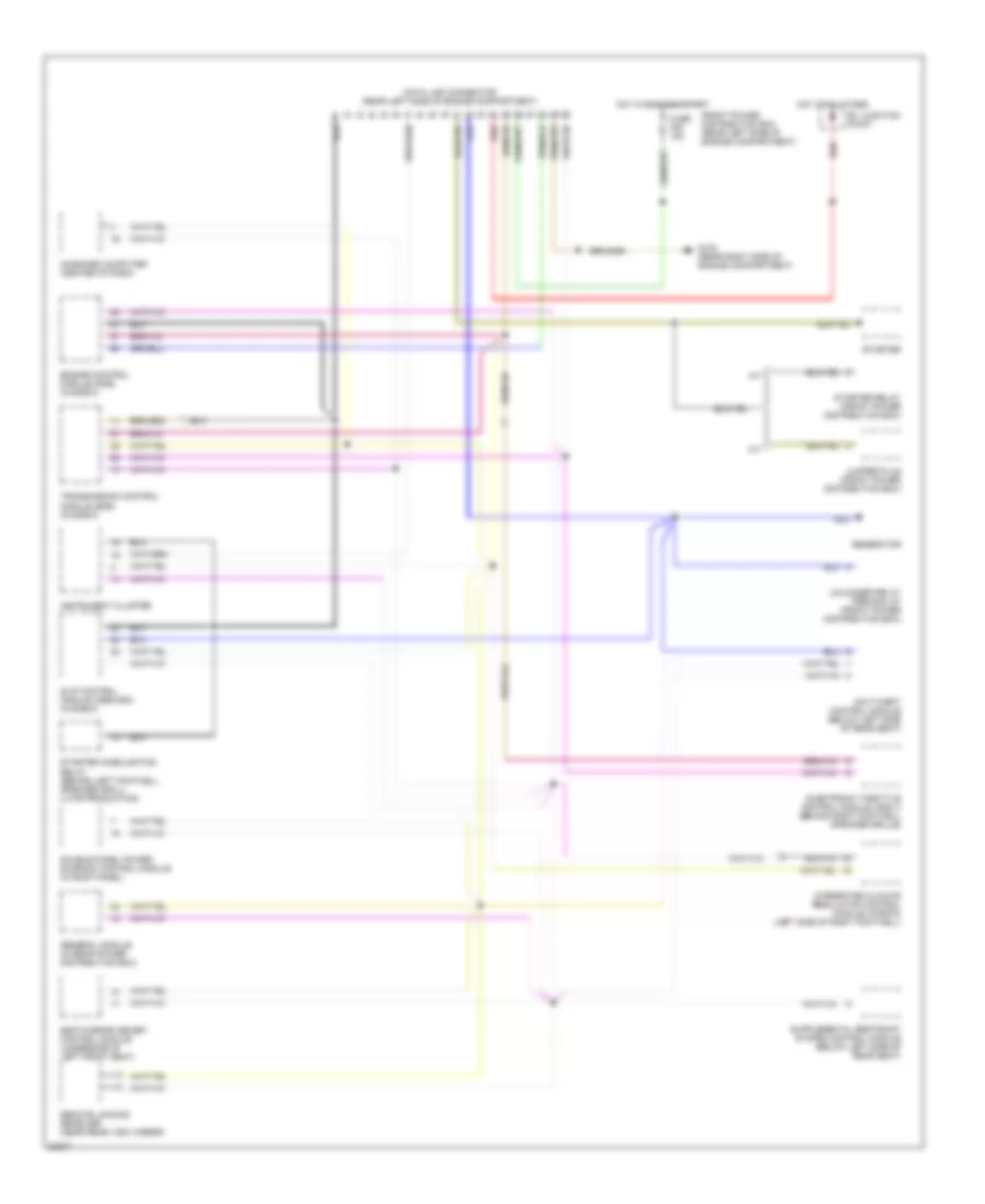
COMPUTER DATA LINES
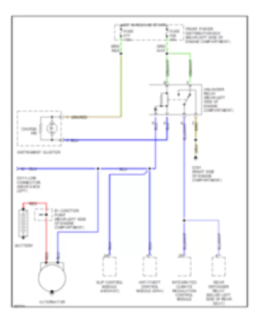
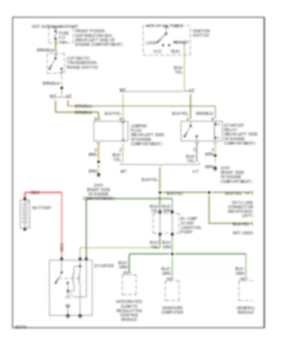
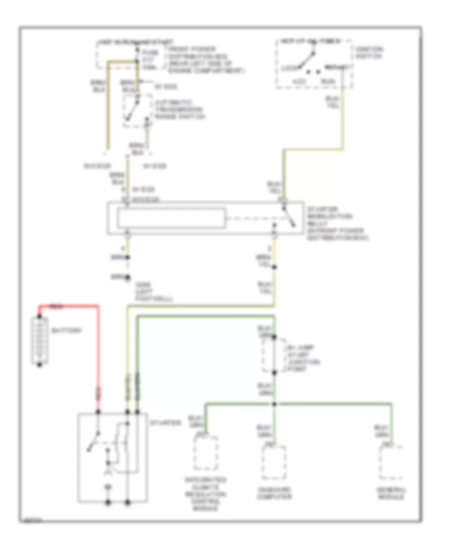
Computer Data Lines for BMW 530i 1994
List of elements for Computer Data Lines for BMW 530i 1994:
- A/t
- Anti-theft control module (below left side of rear seat)
- B+ junction point
- Data link connector (rear left side of engine compartment)
- Double panel power sunroof control module (in roof panel)
- Electronic throttle control module (ads ii) (behind right footwell speaker grille)
- Engine control module (dme) (in e-box)
- Front power distribution box (rear left side of engine compartment)
- Fuse f28 15a
- G103 (rear right side of engine compartment)
- General module (in rear power distribution box)
- Generator
- Hot at all times
- Hot in run and start
- Instrument cluster
- Integrated climate regulation control module (ihkr/f3) (left side of right footwell)
- Jumper plug (front power distribution box)
- M/t
- On-board computer (center of dash)
- Red
- Remote locking receiver (near rear view mirror)
- Seat/mirror memory control module (underside of left front seat)
- Slip control module (abs/asc) (in e-box)
- Starter
- Starter imobilization relay (behind left footwell speaker grill) (late production)
- Starter relay (front power distribution box)
- Transmission control module (egs) (in e-box)
- Unloader relay terminal 61 (front power distribution box)
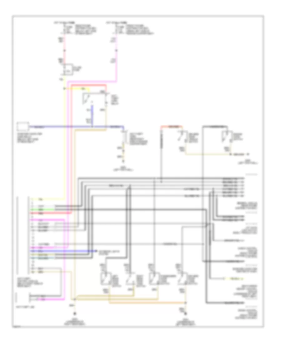
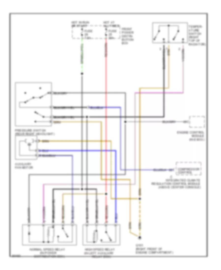
COOLING FAN
Auxiliary Cooling Fan Wiring Diagram for BMW 530i 1994
List of elements for Auxiliary Cooling Fan Wiring Diagram for BMW 530i 1994:
- (in power
- Auxiliary fan motor
- Compressor control
- Distribution box)
- Engine control module (in e-box)
- Front power distri- bution box
- Fuse 30a
- Fuse 7.5a
- G101 (right front of engine compartment)
- High speed relay (in left auxiliary
- Hot at all times
- Hot in run or start
- Integrated climate regulation control module (above center console)
- Normal speed relay
- Pressure switch (rear right headlight)
- Relay box)
- Temper- ature switch (right top of radiator)
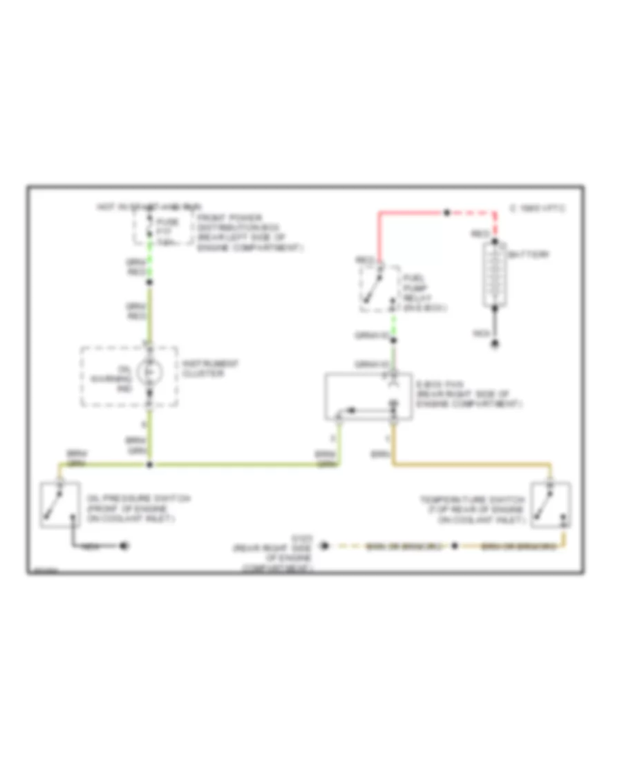
Electrical Box Fan Wiring Diagram for BMW 530i 1994
List of elements for Electrical Box Fan Wiring Diagram for BMW 530i 1994:
- 1995 vftc c
- Battery
- E-box fan (rear right side of engine compartment)
- Front power distribution box (rear left side of engine compartment)
- Fuel pump relay (in e-box)
- Fuse f17 7.5a
- G123 (rear right side of engine compartment)
- Hot in start and run
- Instrument cluster
- Nca
- Oil pressure switch (front of engine on coolant inlet)
- Oil warning ind
- Red
- Temperature switch (top rear of engine on coolant inlet)
CRUISE CONTROL
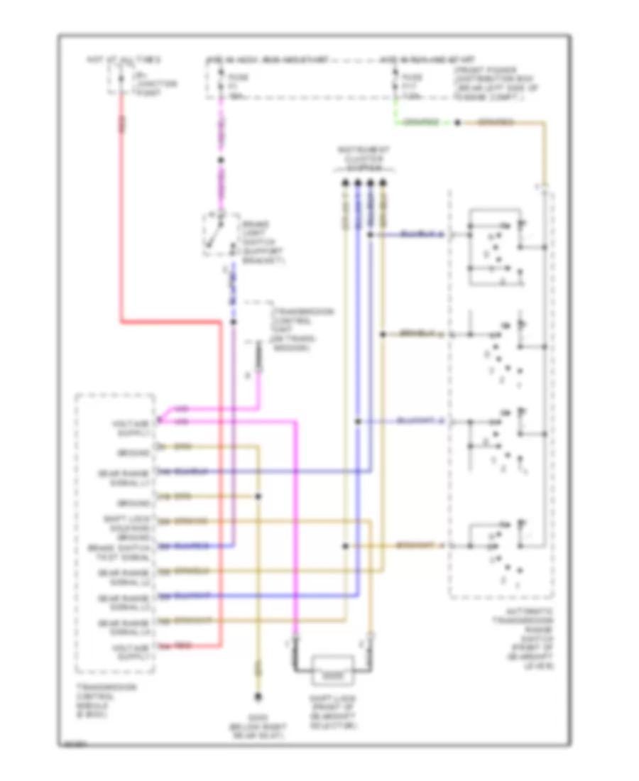
Cruise Control Wiring Diagram for BMW 530i 1994
List of elements for Cruise Control Wiring Diagram for BMW 530i 1994:
- (front of gear shift selector)
- Automatic transmission range switch
- Brake light switch (on brake pedal)
- Check control module
- Clutch switch (clutch pedal support bracket)
- Cruise control actuator (front left side of engine comp.)
- Cruise control module (left front of i/p)
- Cruise control switch
- Decelerate/ set
- Exterior lights system
- Front power distribution box (rear left side of engine comp.)
- Fuse f1 15a
- Fuse f17 7.5a
- G101 (right side
- G202 (left
- Hot in acc, run and start
- Hot in run and start
- Instrument cluster
- Nca
- Normal
- Of engine comp.)
- Off
- Resume
- Set accelerate/
- Side of i/p)
- Transmission system
- W/ egs
- W/o egs
- X19
- X502
DEFOGGERS
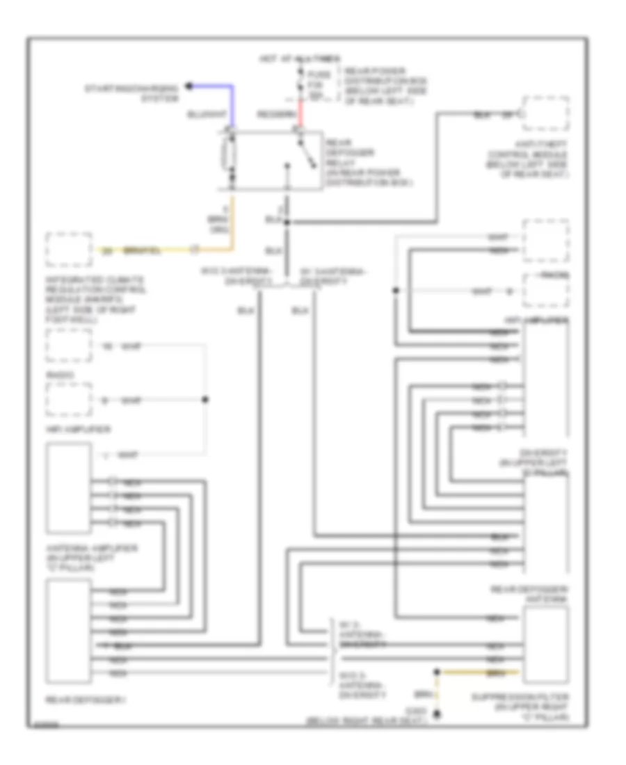
Defogger Wiring Diagram for BMW 530i 1994
List of elements for Defogger Wiring Diagram for BMW 530i 1994:
- Antenna amplifier (in upper left "c" pillar)
- Anti-theft control module (below left side of rear seat)
- Diversity (in upper left "c" pillar)
- Fuse f35 30a
- G303 (below right rear seat)
- Hifi amplifier
- Hot at all times
- Integrated climate regulation control module (ihkr/f3) (left side of right footwell)
- Nca
- Radio
- Rear defogger i
- Rear defogger relay (in rear power distribution box)
- Rear defogger/ antenna
- Rear power distribution box (below left side of rear seat)
- Starting/charging system
- Suppression filter (in upper right "c" pillar)
- W/ 3- antenna- diversity
- W/ 3-antenna- diversity
- W/o 3- antenna- diversity
- W/o 3-antenna- diversity
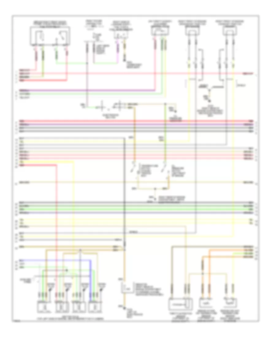
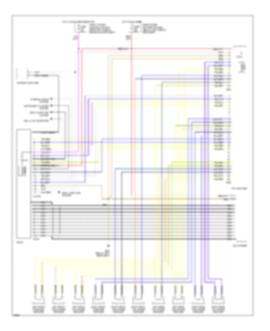
ENGINE PERFORMANCE
3.0L
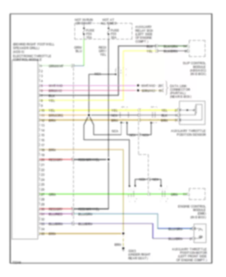
3.0L, Electronic Throttle Control Wiring Diagram for BMW 530i 1994
List of elements for 3.0L, Electronic Throttle Control Wiring Diagram for BMW 530i 1994:
- (behind right footwell speaker grill) (ads ii)
- Auxiliary relay box (left side of engine compt.)
- Auxiliary throttle position motor (left front side of engine compt.)
- Auxiliary throttle position sensor
- Data link connector (partial) (near e-box)
- Electronic throttle control module
- Engine control module (dme) (in e-box)
- Fuse f55 30a
- Fuse f56 15a
- G303 (under right rear seat)
- Hot at all times
- Hot in run or start
- Nca
- Slip control module (abs/asc) (in e-box)
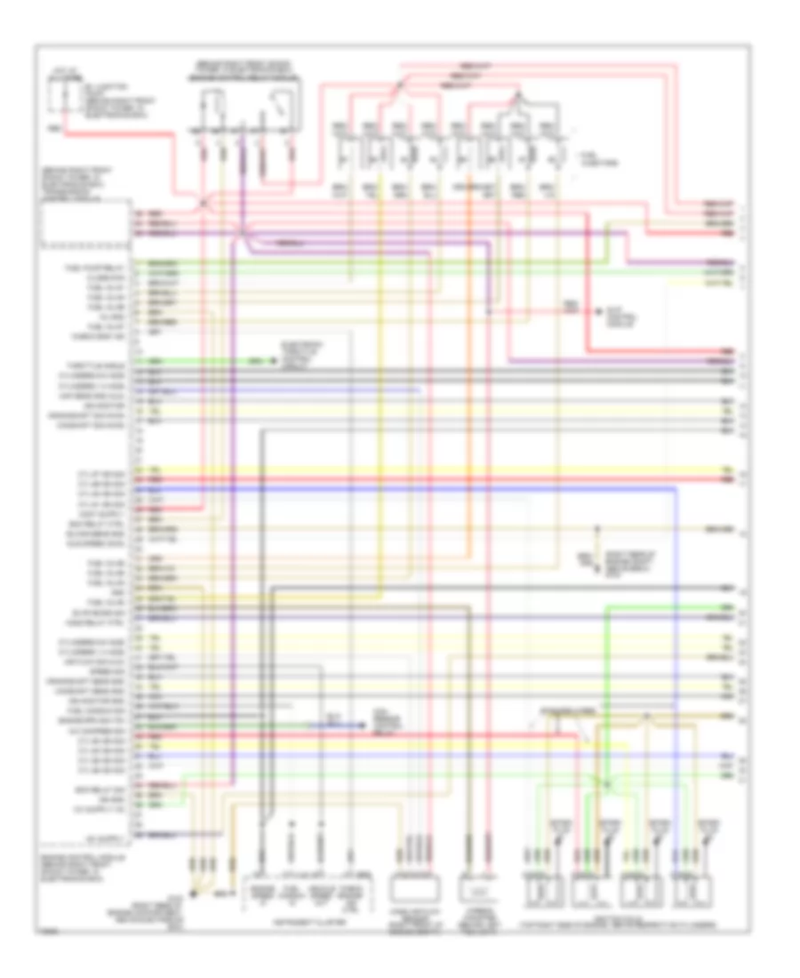
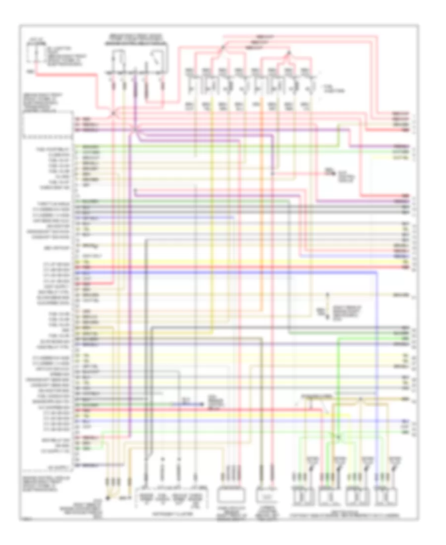
3.0L, Engine Performance Wiring Diagrams, Early Production (1 of 3) for BMW 530i 1994
List of elements for 3.0L, Engine Performance Wiring Diagrams, Early Production (1 of 3) for BMW 530i 1994:
- "check eng" ind
- "check engine" ind ctrl
- (behind right front shock tower, in electronics box) engine control relay module
- (behind right front shock tower, in electronics box) transmission control module
- (right rear of engine compt., above e-box) g103
- A/c compres sig
- Air flow sig (hlm)
- B+ junction point (behind right front shock tower, in electronics box)
- Camshaft sens gnd
- Camshaft sig (nwg)
- Carbon canister (behind left fog light)
- Close zwd
- Com- ressor control relay
- Crankshaft sens gnd
- Crankshaft sig (kwg)
- Cyl #1 ign sig
- Cyl #2 ign sig
- Cyl #3 ign sig
- Cyl #4 ign sig
- Cyl #5 ign sig
- Cyl #6 ign sig
- Cyl #7 ign sig
- Cyl #8 ign sig
- Cylinders 1-4 ho2s
- Cylinders 5-8 ho2s
- Ecm relay ctrl
- Ecm relay sig
- Elc/sh/sens gnd
- Electronic throttle control circuit
- Engine control module (behind right front shock tower, in electronics box)
- Engine rpm sig (td)
- Engine speed in
- Evap emiss sig
- Fuel consum in
- Fuel consum sig
- Fuel inj #1
- Fuel inj #2
- Fuel inj #3
- Fuel inj #4
- Fuel inj #5
- Fuel inj #6
- Fuel inj #7
- Fuel inj #8
- Fuel injectors
- Fuel pump relay
- G103 (right rear of engine compartment, above electronics box)
- Gnd
- Ho2s relay ctrl
- Hot at all times
- Idle speed (zwd)
- Ign gnd
- Ign monitor
- Ign monitor gnd
- Ignition coils (top right side of engine, above respective cylinders)
- Inj gnd
- Instrument cluster
- Maf sens gnd (hlm)
- Mass air flow sensor (right front of engine compt.)
- Nca
- Red
- Shielded wires
- Slip control module
- Spark plug #1
- Spark plug #2
- Spark plug #3
- Spark plug #4
- Speed sig
- Throttle angle
- Vehicle speed out
- X16
- X502
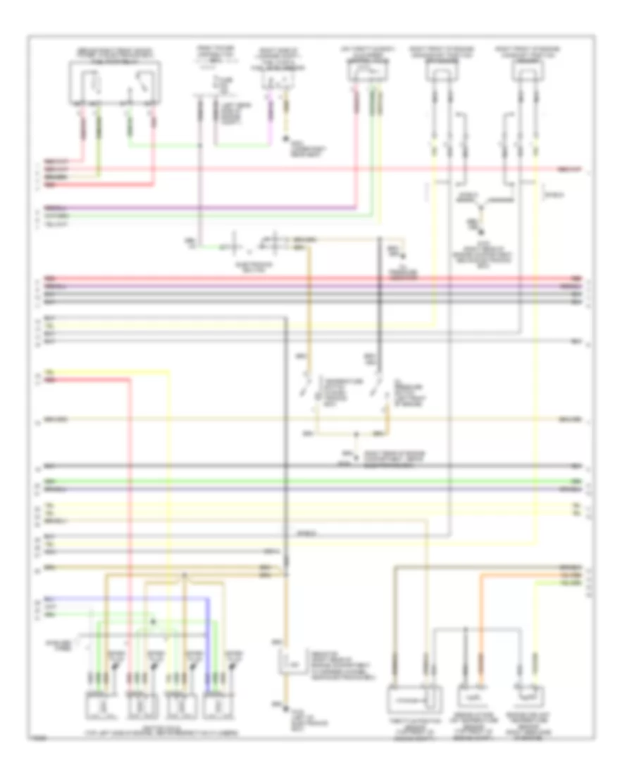
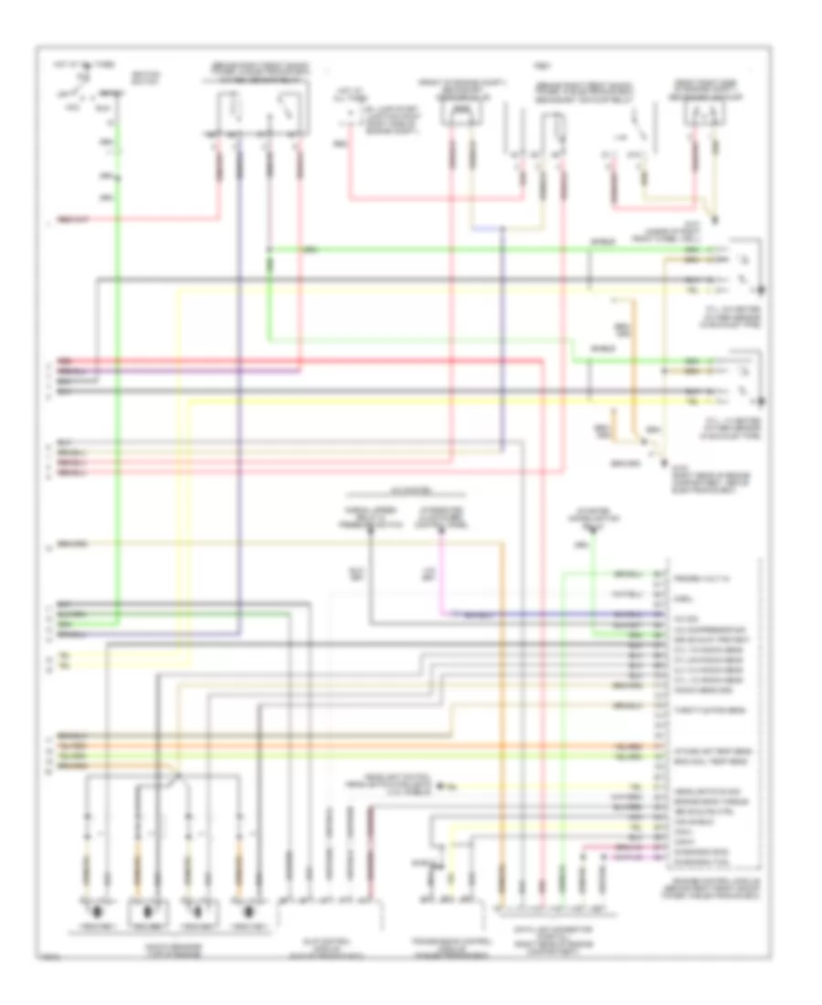
3.0L, Engine Performance Wiring Diagrams, Early Production (2 of 3) for BMW 530i 1994
List of elements for 3.0L, Engine Performance Wiring Diagrams, Early Production (2 of 3) for BMW 530i 1994:
- (behind right front shock tower, in electronics box) fuel pump relay
- (left rear side of engine compt.)
- (on throttle body) idle speed control valve
- (right front of engine) camshaft position sensor
- (right front of engine) crankshaft position/ rpm sensor
- (right rear of engine compartment, above electronics box)
- (right side of luggage compt.) fuel fump & fuel level sensor
- Electronics box fan
- Engine coolant temperature sensor (right rear side of engine)
- Engine intake air temperature sensor (top front of engine compt.)
- Front power distribution box
- Fuse f23 15a
- G103
- G103 (right rear of engine compartment, above electronics box)
- G123 (left of electronics box)
- G303 (under right rear seat)
- Ignition coils (top left side of engine, above respective cylinders)
- Nca
- Oil pressure indicator
- Oil pressure switch (left front of engine)
- Red
- Resistor (right rear of engine compartment, in harness channel, near electronics box)
- Shield
- Shielded wires
- Spark plug #5
- Spark plug #6
- Spark plug #7
- Spark plug #8
- Temperature switch (in elec- tronics box)
- Throttle position sensor (top front of engine compt.)
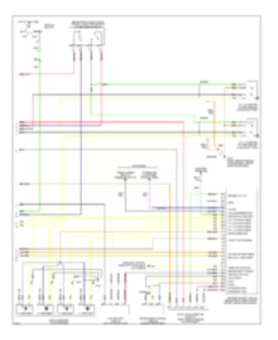
3.0L, Engine Performance Wiring Diagrams, Early Production (3 of 3) for BMW 530i 1994
List of elements for 3.0L, Engine Performance Wiring Diagrams, Early Production (3 of 3) for BMW 530i 1994:
- (behind right front shock tower, in electronics box) oxygen sensor relay
- A/c compressor sig
- A/c sig
- A/c system
- Acc
- Can shield
- Can-h
- Can-l
- Cly 3-4 knock sens
- Cyl 1-2 knock sens
- Cyl 5-6 knock sens
- Cyl 7-8 knock sens
- Cyl. 1-2
- Cyl. 1-4 heated oxygen sensor (in exhaust pipe)
- Cyl. 3-4
- Cyl. 5-6
- Cyl. 5-8 heated oxygen sensor (in exhaust pipe)
- Cyl. 7-8
- Data link connector (partial) (right rear of engine compartment)
- Diagnosis (rxd)
- Diagnosis (txd)
- Drive slips ctrl
- Drive-away protect
- Eng cool temp sens
- Engine drag torque
- Enigine control module (behind right front shock tower, in electronics box)
- G103
- G103 (right rear of engine compartment, above electronics box)
- Headlight switch, headlight & foglights (u.s. models)
- Headlights on sig
- Hot at all times
- Ignition switch
- Intake air temp sens
- Integrated climate reg. control panel
- Knock sens gnd
- Knock sensors (top of engine)
- Nca
- Normal speed relay & pressure switch
- Off
- On-board computer
- Progrm volt in
- Red
- Run
- S-eml
- Shield
- Slip control module (in electronics box)
- Start
- Throttle pos sens
- Transmission control module (in electronics box)
3.0L, Engine Performance Wiring Diagrams, Late Production (1 of 3) for BMW 530i 1994
List of elements for 3.0L, Engine Performance Wiring Diagrams, Late Production (1 of 3) for BMW 530i 1994:
- "check eng" ind
- "check engine" ind ctrl
- (behind right front shock tower, in electronics box) engine control relay module
- (behind right front shock tower, in electronics box) transmission control module
- (right rear of engine compt., above e-box) g103
- 530i/t only
- A/c compres sig
- Air flow sig (hlm)
- B+ junction point (behind right front shock tower, in electronics box)
- Camshaft sens gnd
- Camshaft sig (nwg)
- Carbon canister (behind left fog light)
- Close zwd
- Com- ressor control relay
- Crankshaft sens gnd
- Crankshaft sig (kwg)
- Cyl #1 ign sig
- Cyl #2 ign sig
- Cyl #3 ign sig
- Cyl #4 ign sig
- Cyl #5 ign sig
- Cyl #6 ign sig
- Cyl #7 ign sig
- Cyl #8 ign sig
- Cylinders 1-4 ho2s
- Cylinders 5-8 ho2s
- Ecm relay ctrl
- Ecm relay sig
- Elc/sh/sens gnd
- Engine control module (behind right front shock tower, in electronics box)
- Engine rpm sig (td)
- Engine speed in
- Evap emiss sig
- Fuel consum in
- Fuel consum sig
- Fuel inj #1
- Fuel inj #2
- Fuel inj #3
- Fuel inj #4
- Fuel inj #5
- Fuel inj #6
- Fuel inj #7
- Fuel inj #8
- Fuel injectors
- Fuel pump relay
- G103 (right rear of engine compartment, above electronics box)
- Gnd
- Ho2s relay ctrl
- Hot at all times
- Idle speed (zwd)
- Ign gnd
- Ign monitor
- Ign monitor gnd
- Ignition coils (top right side of engine, above respective cylinders)
- Inj gnd
- Instrument cluster
- Maf sens gnd (hlm)
- Mass air flow sensor (right front of engine compt.)
- Nca
- Red
- Sec air pump
- Shielded wires
- Slip control module
- Spark plug #1
- Spark plug #2
- Spark plug #3
- Spark plug #4
- Speed sig
- Throttle angle
- Vehicle speed out
- X16
- X502
3.0L, Engine Performance Wiring Diagrams, Late Production (2 of 3) for BMW 530i 1994
List of elements for 3.0L, Engine Performance Wiring Diagrams, Late Production (2 of 3) for BMW 530i 1994:
- (behind right front shock tower, in electronics box) fuel pump relay
- (left rear side of engine compt.)
- (on throttle body) idle speed control valve
- (right front of engine) camshaft position sensor
- (right front of engine) crankshaft position/ rpm sensor
- (right rear of engine compartment, above electronics box)
- (right side of luggage compt.) fuel fump & fuel level sensor
- Electronics box fan
- Engine coolant temperature sensor (right rear side of engine)
- Engine intake air temperature sensor (top front of engine compt.)
- Front power distribution box
- Fuse f23 15a
- G103
- G103 (right rear of engine compartment, above electronics box)
- G123 (left of electronics box)
- G303 (under right rear seat)
- Ignition coils (top left side of engine, above respective cylinders)
- Nca
- Oil pressure indicator
- Oil pressure switch (left front of engine)
- Red
- Resistor (right rear of engine compartment, in harness channel, near electronics box)
- Shield
- Shielded wires
- Spark plug #5
- Spark plug #6
- Spark plug #7
- Spark plug #8
- Temperature switch (in elec- tronics box)
- Throttle position sensor (top front of engine compt.)
3.0L, Engine Performance Wiring Diagrams, Late Production (3 of 3) for BMW 530i 1994
List of elements for 3.0L, Engine Performance Wiring Diagrams, Late Production (3 of 3) for BMW 530i 1994:
- (behind right front shock tower, in electronics box) oxygen sensor relay
- (behind right front shock tower, in electronics box) secondary air pump relay
- (front of engine compt.) secondary air pump valve
- 530i/t
- 87a
- A/c compressor sig
- A/c sig
- A/c system
- Acc
- B+ jump start junction point (right side of engine compt.)
- Can shield
- Can-h
- Can-l
- Cly 3-4 knock sens
- Cyl 1-2 knock sens
- Cyl 5-6 knock sens
- Cyl 7-8 knock sens
- Cyl. 1-2
- Cyl. 1-4 heated oxygen sensor (in exhaust pipe)
- Cyl. 3-4
- Cyl. 5-6
- Cyl. 5-8 heated oxygen sensor (in exhaust pipe)
- Cyl. 7-8
- Data link connector (partial) (right rear of engine compartment)
- Diagnosis (rxd)
- Diagnosis (txd)
- Drive slips ctrl
- Drive-away protect
- Eng cool temp sens
- Engine drag torque
- Enigine control module (behind right front shock tower, in electronics box)
- Front right side of engine compt.) secondary air pump
- G101 (ahead of right front wheel well)
- G103 (right rear of engine compartment, above electronics box)
- Headlight switch, headlights & foglights (u.s. models)
- Headlights on sig
- Hot at all times
- Ignition switch
- Intake air temp sens
- Integrated climate reg. control panel
- Knock sens gnd
- Knock sensors (top of engine)
- Nca
- Normal speed relay & pressure switch
- Off
- Progrm volt in
- Red
- Run
- S-eml
- Shield
- Slip control module (in electronics box)
- Start
- Starter immobilization relay
- Throttle pos sens
- Transmission control module (in electronics box)
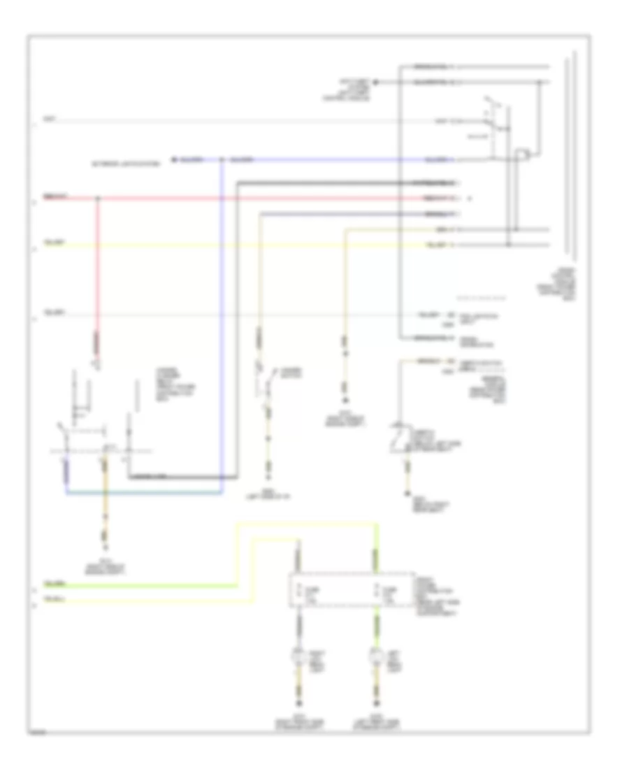
EXTERIOR LIGHTS
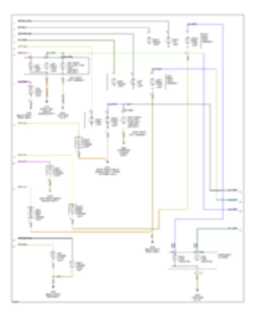
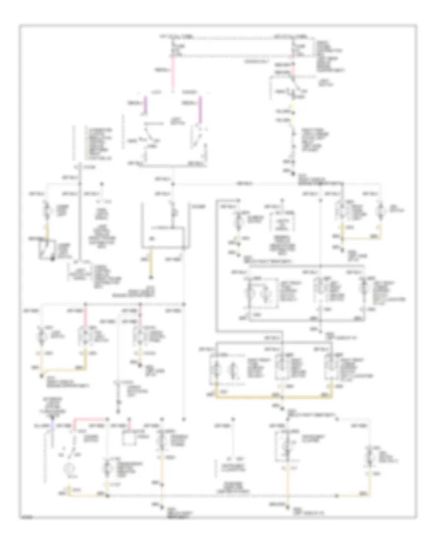
Exterior Light Wiring Diagram, Canada (1 of 3) for BMW 530i 1994
List of elements for Exterior Light Wiring Diagram, Canada (1 of 3) for BMW 530i 1994:
- (not used)
- (right side of engine compt.)
- Brake light switch (brake pedal support bracket)
- Brake pedal status
- Check control module (front power distribution box)
- Daat line
- Data line
- Data link to ccm
- Daytime running lights coding diode (left side of dash)
- Fog light signal
- Fog lights power
- Front power distribution box (left rear side of engine compt.)
- Fuse f1 15a
- Fuse f15 7.5a
- Fuse f2 7.5a
- Fuse f4 7.5a
- Fuse f5 10a
- G101
- G202 (left side of i/p)
- Ground
- Head
- Headlights signal
- Headlights system
- High beam light power
- High beam signal
- High level stop light power
- Hot at all times
- Hot in accy, run and start
- Hot in run and start
- Instrument cluster system
- Interior lights system
- Lac
- Lamp control module (front power distribution box)
- Left brake light power
- Left fog light power
- Left low beam power
- Left park light power
- Left park light relay (left side of dash)
- Left park light signal
- Left tail light power
- Left tail light signal
- Lft license plate light power
- Light switch
- Line data
- Off
- On-board computer (center of dash) line
- Park
- Park lights signal
- Red
- Right brake light power
- Right fog light power
- Right low beam power
- Right park light power
- Right park light signal
- Right park light/license plate light relay (left side of dash)
- Right tail light power
- Right tail light signal
- Rt license plate light power
- X18
- X19
- X501
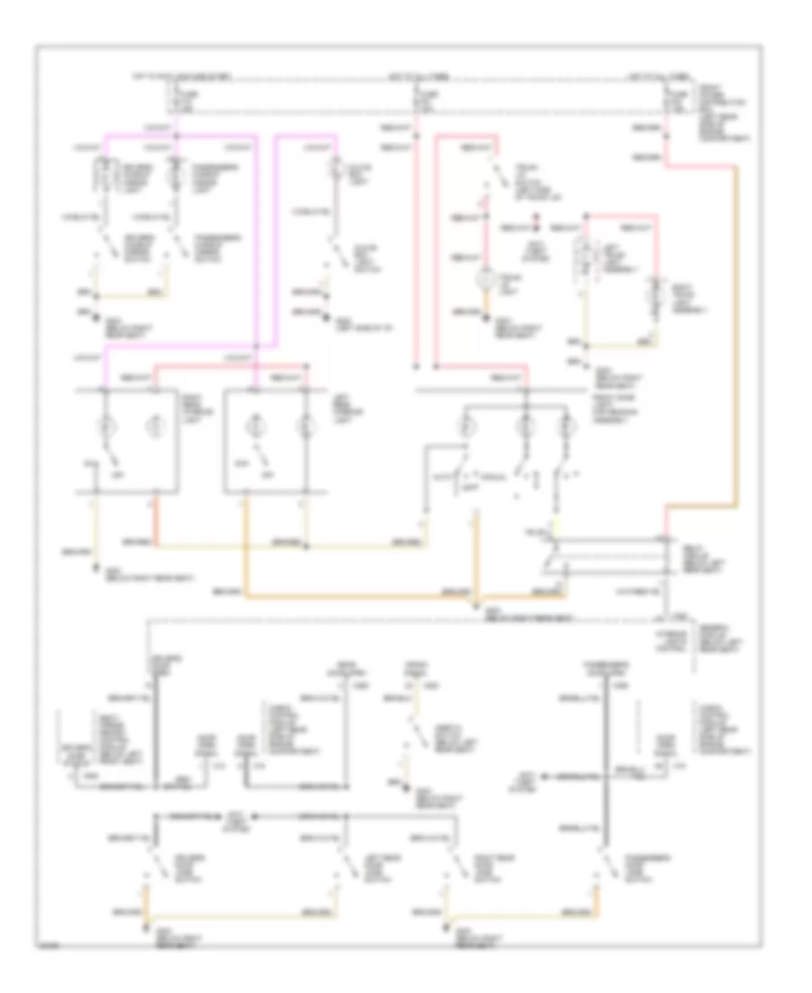
Exterior Light Wiring Diagram, Canada (2 of 3) for BMW 530i 1994
List of elements for Exterior Light Wiring Diagram, Canada (2 of 3) for BMW 530i 1994:
- G100 (front left side of engine compt)
- G100 (left front side of engine compt.)
- G101 (right front side of engine compt., ahead of wheel well)
- G202 (left side of i/p)
- G303 (below right front seat)
- G303 (below right rear seat)
- G306 (underside of rear seat)
- High level stop light
- Instrument cluster
- Left brake light
- Left front auxiliary turn light (1995 525it/ 530it only)
- Left front light assembly
- Left front marker light
- Left front turn light
- Left license plate light
- Left park light
- Left rear light assembly
- Left rear side marker light
- Left rear turn light
- Left tail light
- Left turn indicator
- Nca
- Right brake light
- Right front auxiliary turn light (1995 525it/ 530it only)
- Right front light assembly
- Right front marker light
- Right front turn light
- Right license plate light
- Right park light
- Right rear light assembly
- Right rear side marker light
- Right rear turn light
- Right tail light
- Right turn indicator
- X17
- X502
Exterior Light Wiring Diagram, Canada (3 of 3) for BMW 530i 1994
List of elements for Exterior Light Wiring Diagram, Canada (3 of 3) for BMW 530i 1994:
- (control module)
- (electrochromic)
- (not used)
- A/t
- Anti-theft system
- Automatic transmission range switch (front of gearshift selector)
- Back up light switch (below center console)
- Combination switch
- Crash control module (front power distribution box)
- Crash information
- Crash signal
- Front power distribution box (left rear side of engine compt.)
- Fuse f12 15a
- Fuse f3 7.5a
- Fuse f6 15a
- G101 (right side of engine compt.)
- G202 (left side of i/p)
- G303 (below right rear seat)
- General module (rear power distribution box)
- Hazard flasher relay (front power distribution box)
- Hazard switch
- Headlights system
- Hot at all times
- Hot in run and start
- Inertia switch (below left side of rear seat)
- Interior lights system
- Left
- Left back up light
- Left trunk light assembly
- M/t
- Memory system
- Mirrors system
- Nca
- Off
- Right
- Right back up light
- Right trunk light assembly
- Turn signal switch
- X253
Exterior Light Wiring Diagram, USA (1 of 3) for BMW 530i 1994
List of elements for Exterior Light Wiring Diagram, USA (1 of 3) for BMW 530i 1994:
- (not used)
- Brake light switch (brake pedal support bracket)
- Brake pedal status
- Check control module (front power distribution box)
- Daat line
- Data line
- Data link to ccm
- Fog light signal
- Fog lights power
- Front power distribution box (left rear side of engine compt.)
- Fuse f1 15a
- Fuse f15 7.5a
- Fuse f4 7.5a
- Fuse f5 10a
- G202 (left side of i/p)
- Ground
- Head
- Headlights signal
- Headlights system
- High beam light power
- High beam signal
- High level stop light power
- Hot at all times
- Hot in accy, run and start
- Instrument cluster system
- Interior lights system
- Lamp control module (front power distribution box)
- Left brake light power
- Left fog light power
- Left low beam power
- Left park light power
- Left park light signal
- Left tail light power
- Left tail light signal
- Lft license plate light power
- Light switch
- Line data
- Off
- On-board computer (center of dash)
- Park
- Park lights signal
- Red
- Right brake light power
- Right fog light power
- Right low beam power
- Right park light power
- Right park light signal
- Right tail light power
- Right tail light signal
- Rt license plate light power
- X18
- X19
- X501
Exterior Light Wiring Diagram, USA (2 of 3) for BMW 530i 1994
List of elements for Exterior Light Wiring Diagram, USA (2 of 3) for BMW 530i 1994:
- G100 (front left side of engine compt)
- G100 (left front side of engine compt.)
- G101 (right front side of engine compt., ahead of wheel well)
- G202 (left side of i/p)
- G303 (below right front seat)
- G303 (below right rear seat)
- G306 (underside of rear seat)
- High level stop light
- Instrument cluster
- Left brake light
- Left front auxiliary turn light (1995 525it/ 530it only)
- Left front light assembly
- Left front marker light
- Left front turn light
- Left license plate light
- Left park light
- Left rear light assembly
- Left rear side marker light
- Left rear turn light
- Left tail light
- Left turn indicator
- Nca
- Right brake light
- Right front auxiliary turn light (1995 525it/ 530it only)
- Right front light assembly
- Right front marker light
- Right front turn light
- Right license plate light
- Right park light
- Right rear light assembly
- Right rear side marker light
- Right rear turn light
- Right tail light
- Right turn indicator
- X17
- X502
Exterior Light Wiring Diagram, USA (3 of 3) for BMW 530i 1994
List of elements for Exterior Light Wiring Diagram, USA (3 of 3) for BMW 530i 1994:
- (control module)
- (electrochromic)
- (not used)
- A/t
- Anti-theft system
- Automatic transmission range switch (front of gearshift selector)
- Back up light switch (below center console)
- Combination switch
- Crash control module (front power distribution box)
- Crash information
- Crash signal
- Front power distribution box (left rear side of engine compt.)
- Fuse f12 15a
- Fuse f3 7.5a
- Fuse f6 15a
- G101 (right side of engine compt.)
- G202 (left side of i/p)
- G303 (below right rear seat)
- General module (rear power distribution box)
- Hazard flasher relay (front power distribution box)
- Hazard switch
- Headlights system
- Hot at all times
- Hot in run and start
- Inertia switch (below left side of rear seat)
- Interior lights system
- Left
- Left back up light
- Left trunk light assembly
- M/t
- Memory system
- Mirrors system
- Nca
- Off
- Right
- Right back up light
- Right trunk light assembly
- Turn signal switch
- X253
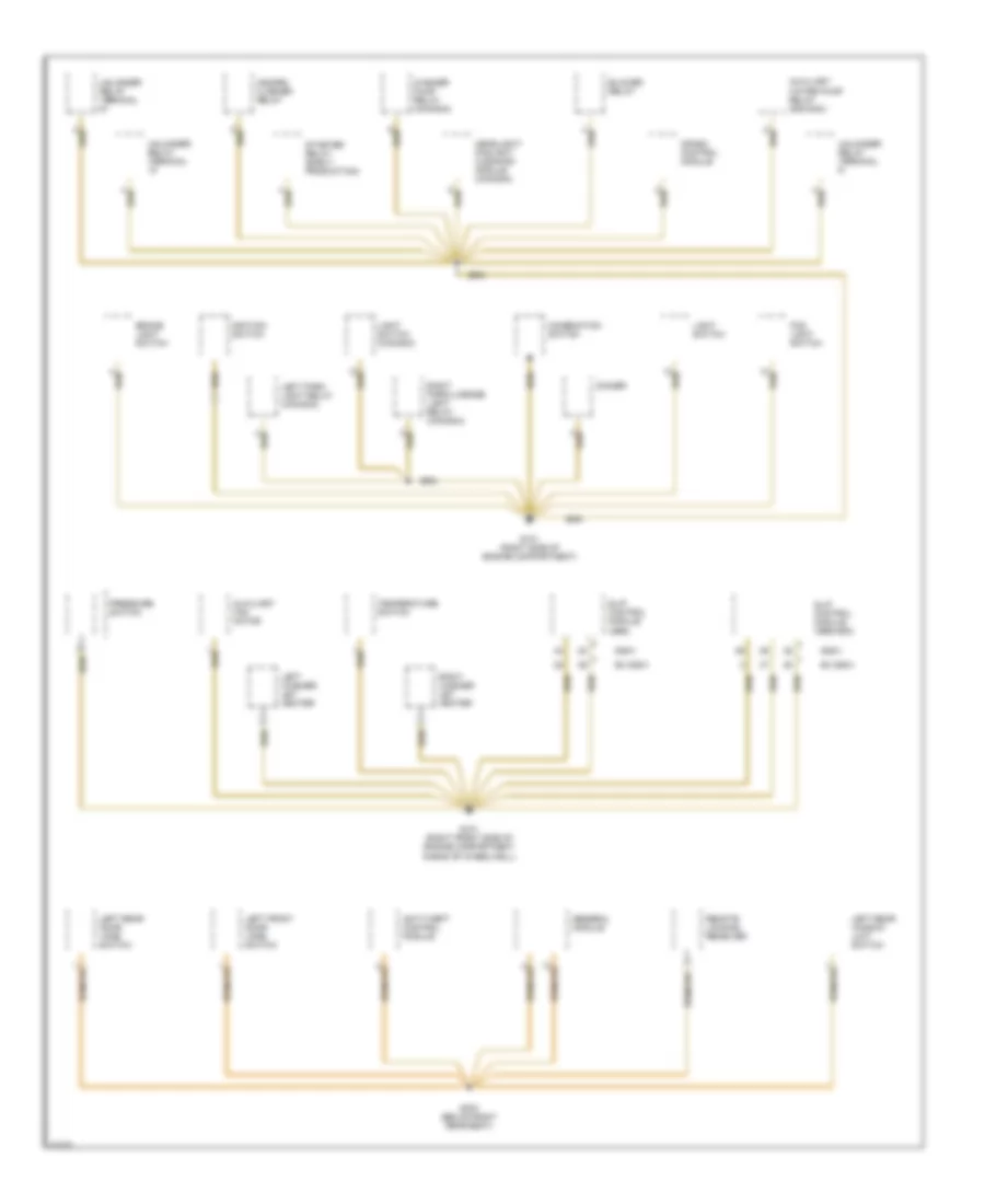
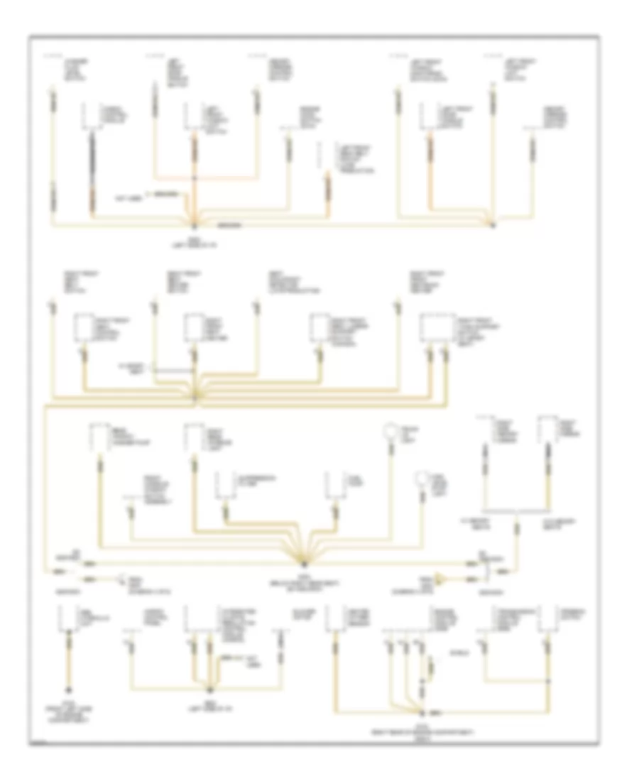
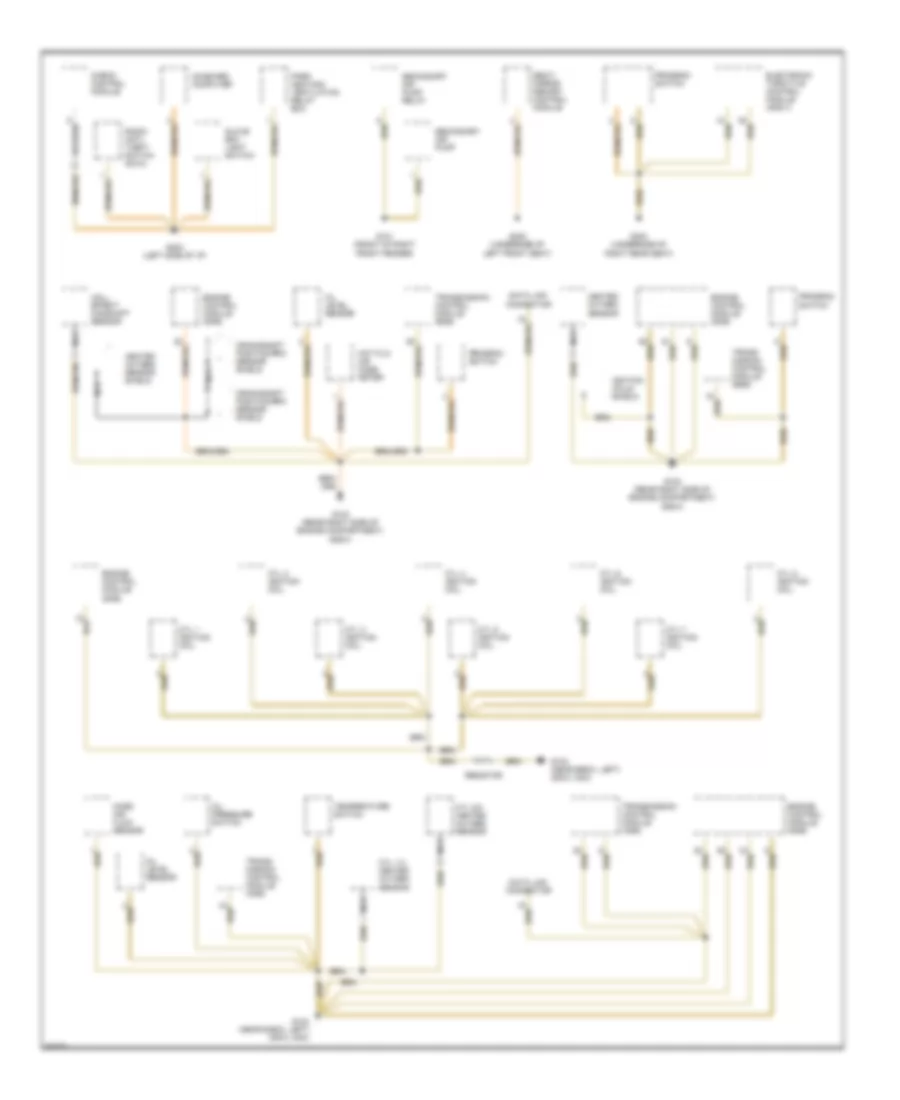
GROUND DISTRIBUTION
Ground Distribution Wiring Diagram (1 of 6) for BMW 530i 1994
List of elements for Ground Distribution Wiring Diagram (1 of 6) for BMW 530i 1994:
- 525i/t
- Anti-theft control module
- Auxiliary fan motor
- Auxiliary water pump relay (530i/540i)
- Blower relay
- Brake light switch
- Combination switch
- Crash control module
- Dimmer
- Ex 525i/t
- Fog light switch
- G101 (right front side of engine compartment ahead of wheelwell)
- G101 (right side of engine compartment)
- G303 (below right rear seat)
- General module
- Hazard flasher relay
- Headlight/ foglight cleaning module (canada)
- Ignition switch
- Left front door jamb switch
- Left park light relay (canada)
- Left rear door jamb switch
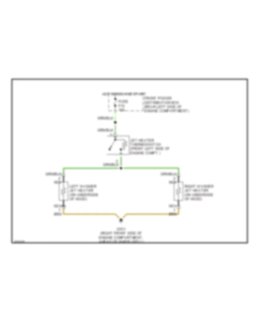
- Left rear window limit switch
- Left washer jet heater
- Light switch
- Light switch (canada)
- Pressure switch
- Remote locking receiver
- Right park/license light relay (canada)
- Right washer jet heater
- Slip control module (abs)
- Slip control module (abs/asc)
- Starter relay (early production)
- Temperature switch
- Unloader relay terminal
- Unloader relay terminal r
- Washer pump relay (canada)
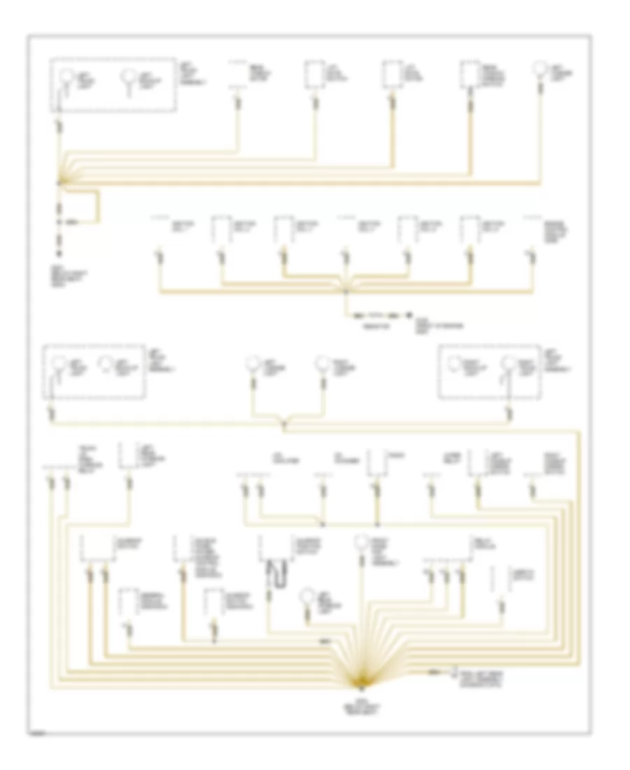
Ground Distribution Wiring Diagram (2 of 6) for BMW 530i 1994
List of elements for Ground Distribution Wiring Diagram (2 of 6) for BMW 530i 1994:
- 525it/530it
- Abs hydraulic unit
- Blower motor
- Check control module
- Engine control module (dme)
- Engine hood switch (dwa)
- Ex 525it/530it
- From c g303 (diagram 4 of 6)
- From g303 (diagram 4 of 6)
- Front console window switch assembly
- Fuel pump
- G100 (front left side of engine compartment)
- G103 (right rear of engine compartment) (525i/t)
- G202 (left side of i/p)
- G303 (below right rear seat) (ex 525it/530it)
- Heated oxygen sensor
- High level stop light
- Ihkr/f3 control panel
- Integrated climate regulation control module (ihkr/f3)
- Left front door handle switch
- Left front seat belt switch (late production)
- Left front window limit switch
- Left front window monitoring switch (dwa)
- Memory mirrors control switch
- Nca
- Not used
- Program switch
- Rear window washer pump
- Right front front seatback heater
- Right front seat belt switch
- Right front seat control switch
- Right front seat heater
- Right front seat heater switch
- Right front seat lumbar support switch (canada)
- Right front thigh support switch (w/ sport seat)
- Right rear interior light
- Right side memory mirror
- Right side mirror
- Seat occupancy detector (late production)
- Shield
- Suppression filter
- Transmission control module (egs)
- Trunk lid light
- W/ memory seats
- W/ sport seat
- W/o memory seats
- Washer fluid level switch
Ground Distribution Wiring Diagram (3 of 6) for BMW 530i 1994
List of elements for Ground Distribution Wiring Diagram (3 of 6) for BMW 530i 1994:
- Cd changer
- Double panel power sunroof control module (525it/530it)
- Engine control module (dme)
- From left rear light assembly (diagram 5 of 6)
- Front dome/ map light assembly
- G125 (front of engine) (525i)
- G303 (below right rear seat)
- G303 (below right rear seat) (525it)
- General module (525it/530it)
- Hifi amplifier
- Ignition coil 1
- Ignition coil 2
- Ignition coil 3
- Ignition coil 4
- Ignition coil 5
- Ignition coil 6
- Inertia switch
- Left back-up light
- Left license light
- Left makeup mirror switch
- Left rear interior light
- Left trunk light
- Left trunk light assembly
- Lift gate motor
- Lift gate switch
- Nca
- Radio
- Rear window motor
- Rear window opening switch
- Relay module
- Resistor
- Right back-up light
- Right license light
- Right makeup mirror switch
- Right trunk light
- Sunroof position switch
- Sunroof switch
- Sunroof switch (525it/530it)
- Trunk lid open warning relay
- Wiper relay
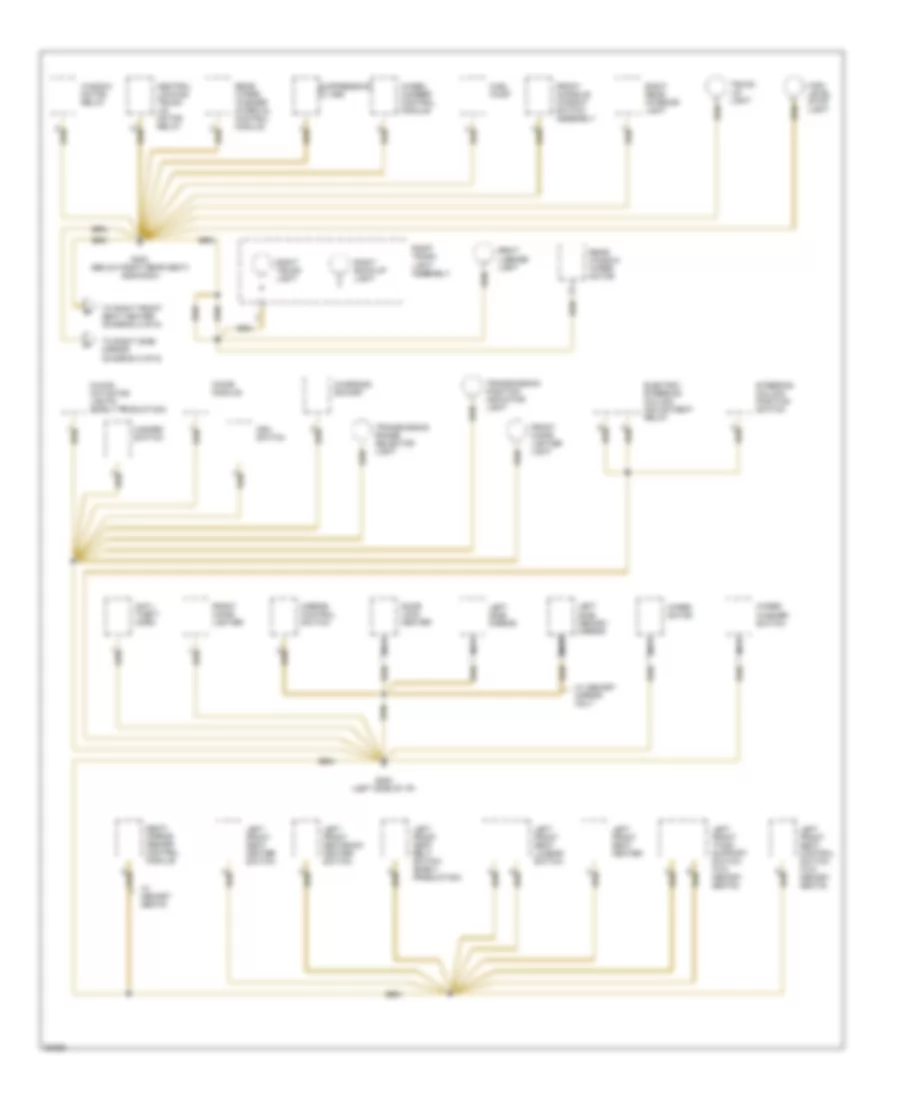
Ground Distribution Wiring Diagram (4 of 6) for BMW 530i 1994
List of elements for Ground Distribution Wiring Diagram (4 of 6) for BMW 530i 1994:
- (diagram 2 of 6)
- Anti- theft horn
- Asc switch
- Central locking trunk lid motor relay
- Charging socket
- Chime module
- Door lock heater
- Electric steering column adjustment relay
- Front cigar lighter
- Front cigar lighter light
- Front console window switch assembly
- Fuel pump
- G202 (left side of i/p)
- G303 (below right rear seat) (525it/530it)
- Hazard switch
- High level stop light
- Left front seat belt switch (early production)
- Left front seat control switch (w/o memory seats)
- Left front seat heater
- Left front seat heater switch
- Left front seat lumbar switch
- Left front seatback heater switch
- Left front thigh support switch (w/o memory seats)
- Left side memory mirror
- Left side mirror
- Mirror control switch
- Mixing actuator lights (early production)
- Nca
- Rear window wiper motor
- Rear wiper/ washer interval control module
- Right back-up light
- Right license light
- Right rear interior light
- Right trunk light
- Right trunk light assembly
- Seat/ mirror memory control module
- Steering column position switch
- Suppression filter
- To right front seat heater (diagram 2 of 6)
- To right side mirror
- Transmission position indicator light
- Transmission range selector light
- Trunk lid light
- W/ memory mirror only
- W/ memory seats
- Wheel camber control module
- Window motor relay
- Wiper motor
- Wiper/ washer switch
Ground Distribution Wiring Diagram (5 of 6) for BMW 530i 1994
List of elements for Ground Distribution Wiring Diagram (5 of 6) for BMW 530i 1994:
- 525it/530it
- Anti- theft control module
- Auxiliary fan motor
- Auxiliary water pump
- Brake fluid level switch
- Check control module
- Cruise control actuator
- Cruise control module
- Ex 525it/530it
- Fuel level sensor
- G100 (left front side of engine compartment)
- G101 (right front side of engine compartment ahead of wheel well)
- G202 (left side of i/p)
- G303 (below right rear seat)
- Headlight/ foglight cleaning module (sra)
- Instrument cluster
- Lamp control module
- Left brake light
- Left fog light
- Left front light assembly
- Left front marker light
- Left front turn light
- Left high beam light
- Left horn
- Left low beam light
- Left park light
- Left rear light assembly
- Left rear side marker light
- Left rear turn light
- Left tail light
- Nca
- On-board computer
- Pressure sensor/ plunger
- Rear wiper/ washer fluid level switch
- Right brake light
- Right fog light
- Right front door jamb switch
- Right front light assembly
- Right front marker light
- Right front seat belt switch (late production)
- Right front turn light
- Right front window limit switch
- Right front window monitoring switch (dwa)
- Right high beam light
- Right horn
- Right low beam light
- Right park light
- Right rear door jamb switch
- Right rear light assembly
- Right rear quarter window switch (dma)
- Right rear side marker light
- Right rear turn light
- Right rear window limit switch
- Right tail light
- Slip control module (abs/asc)
- Starter immobilization relay (late production)
- Telephone interface
- Telephone transceiver
- Throttle flap heater
- To ground g303 (diagram 3 of 6)
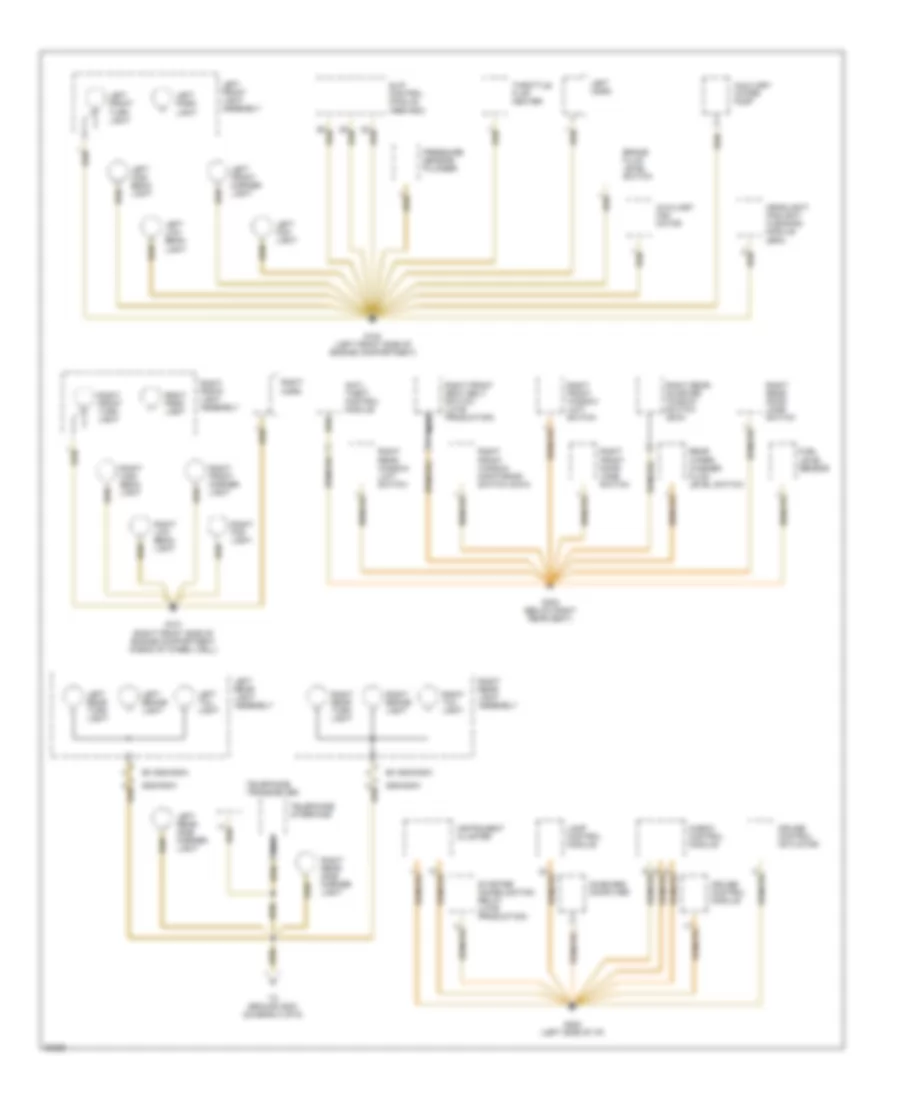
Ground Distribution Wiring Diagram (6 of 6) for BMW 530i 1994
List of elements for Ground Distribution Wiring Diagram (6 of 6) for BMW 530i 1994:
- (525i/t)
- Check control module
- Crankshaft position/rpm sensor shield
- Cyl 1 ignition coil
- Cyl 1-4 heated oxygen sensor
- Cyl 2 ignition coil
- Cyl 3 ignition coil
- Cyl 4 ignition coil
- Cyl 5 ignition coil
- Cyl 5-8 heated oxygen sensor
- Cyl 6 ignition coil
- Cyl 7 ignition coil
- Cyl 8 ignition coil
- Data link connector
- Electronic throttle control module (ads ii)
- Engine control module (dme)
- G101 (front of right front fender)
- G103 (rear right side of engine compartment)
- G104 (near e-box, left) (530i/t, 540i)
- G202 (left side of i/p)
- G300 (underside of left front seat)
- G303 (underside of right rear seat)
- Glove box light switch
- Hall effect camshaft sensor
- Heated oxygen sensor
- Heated oxygen sensor shield
- Hot film air mass meter
- Ignition coils shield
- Mass air flow sensor
- Nca
- Oil level sensor
- Oil pressure switch
- On-board computer
- Park heating/ ventilation relay box
- Program switch
- Radio anti- theft switch (dwa)
- Resistor
- Seat/ mirror memory control module
- Secondary air pump
- Secondary air pump relay
- Temperature switch
- Trans- mission control module (ags)
- Trans- mission control module (egs)
- Transmission control module (ags)
- Transmission control module (egs)
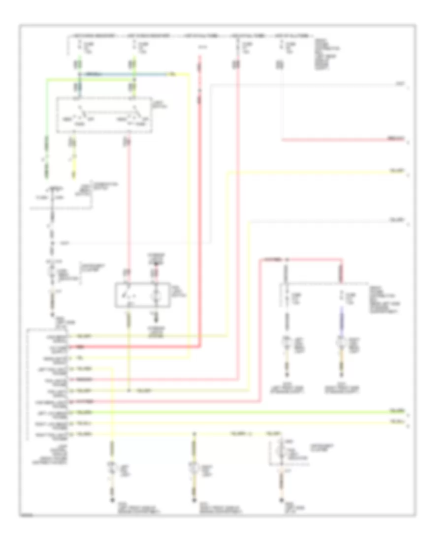
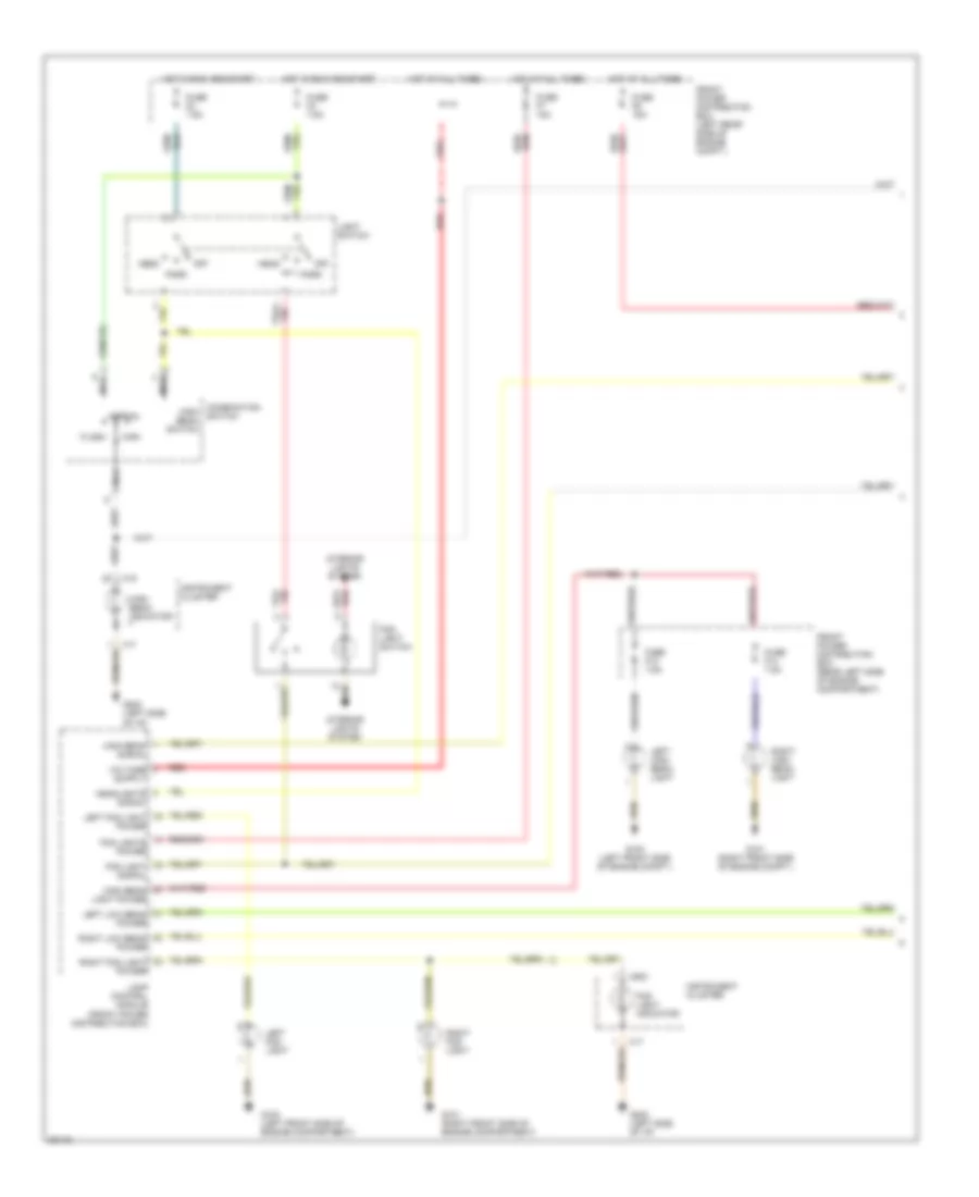
HEADLIGHTS
Headlight Wiring Diagram, with DRL (1 of 2) for BMW 530i 1994
List of elements for Headlight Wiring Diagram, with DRL (1 of 2) for BMW 530i 1994:
- Combination high beam switch
- Flash
- Fog light indicator
- Fog light signal
- Fog light switch
- Fog lights power
- Front power distribution box (left rear side of engine compt.)
- Front power distribution box (rear left side of engine compartment)
- Fuse f13 7.5a
- Fuse f14 7.5a
- Fuse f2 7.5a
- Fuse f3 7.5a
- Fuse f6 15a
- Fuse f7 15a
- G100 (left front side of engine compartment)
- G100 (left front side of engine compt.)
- G101 (right front side of engine compartment)
- G101 (right front side of engine compt.)
- G202 (left side of i/p)
- Head
- Headlights signal
- High
- High beam indicator
- High beam light power
- High beam signal
- Hot at all times
- Hot in run and start
- Instrument cluster
- Interior lights system
- Lamp control module (front power distribution box)
- Left fog light
- Left fog light power
- Left high beam light
- Left low beam power
- Light switch
- Nca
- Normal
- Off
- Park
- Red
- Right fog light
- Right fog light power
- Right high beam light
- Right low beam power
- Switch
- X16
- X17
- X502
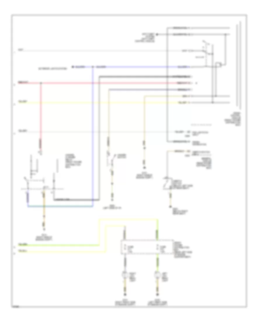
Headlight Wiring Diagram, with DRL (2 of 2) for BMW 530i 1994
List of elements for Headlight Wiring Diagram, with DRL (2 of 2) for BMW 530i 1994:
- Anti-theft system (anti-theft control module)
- Crash control module (front power distribution box)
- Crash information
- Exterior lights system
- Fog lights on input
- Front power distribution box (rear left side of engine compartment)
- Fuse f10 7.5a
- Fuse f11 7.5a
- G100 (left front side of engine compt.)
- G101 (right front side of engine compt.)
- G101 (right side of engine compt.)
- G202 (left side of i/p)
- G303 (below right rear seat)
- General module (rear power distribution box)
- Hazard flasher relay (front power distribution box)
- Hazard switch
- Inertia switch (below left side of rear seat)
- Inertia switch input
- Left low beam light
- Right low beam light
- X253
- X255
Headlight Wiring Diagram, without DRL (1 of 2) for BMW 530i 1994
List of elements for Headlight Wiring Diagram, without DRL (1 of 2) for BMW 530i 1994:
- Combination high beam switch
- Flash
- Fog light indicator
- Fog light signal
- Fog light switch
- Fog lights power
- Front power distribution box (left rear side of engine compt.)
- Front power distribution box (rear left side of engine compartment)
- Fuse f13 7.5a
- Fuse f14 7.5a
- Fuse f2 7.5a
- Fuse f3 7.5a
- Fuse f6 15a
- Fuse f7 15a
- G100 (left front side of engine compartment)
- G100 (left front side of engine compt.)
- G101 (right front side of engine compartment)
- G101 (right front side of engine compt.)
- G202 (left side of i/p)
- Head
- Headlights signal
- High
- High beam indicator
- High beam light power
- High beam signal
- Hot at all times
- Hot in run and start
- Instrument cluster
- Interior lights system
- Lamp control module (front power distribution box)
- Left fog light
- Left fog light power
- Left high beam light
- Left low beam power
- Light switch
- Nca
- Normal
- Off
- Park
- Red
- Right fog light
- Right fog light power
- Right high beam light
- Right low beam power
- Switch
- X16
- X17
- X502
Headlight Wiring Diagram, without DRL (2 of 2) for BMW 530i 1994
List of elements for Headlight Wiring Diagram, without DRL (2 of 2) for BMW 530i 1994:
- Anti-theft system (anti-theft control module)
- Crash control module (front power distribution box)
- Crash information
- Exterior lights system
- Fog lights on input
- Front power distribution box (rear left side of engine compartment)
- Fuse f10 7.5a
- Fuse f11 7.5a
- G100 (left front side of engine compt.)
- G101 (right front side of engine compt.)
- G101 (right side of engine compt.)
- G202 (left side of i/p)
- G303 (below right rear seat)
- General module (rear power distribution box)
- Hazard flasher relay (front power distribution box)
- Hazard switch
- Inertia switch (below left side of rear seat)
- Inertia switch input
- Left low beam light
- Right low beam light
- X253
- X255
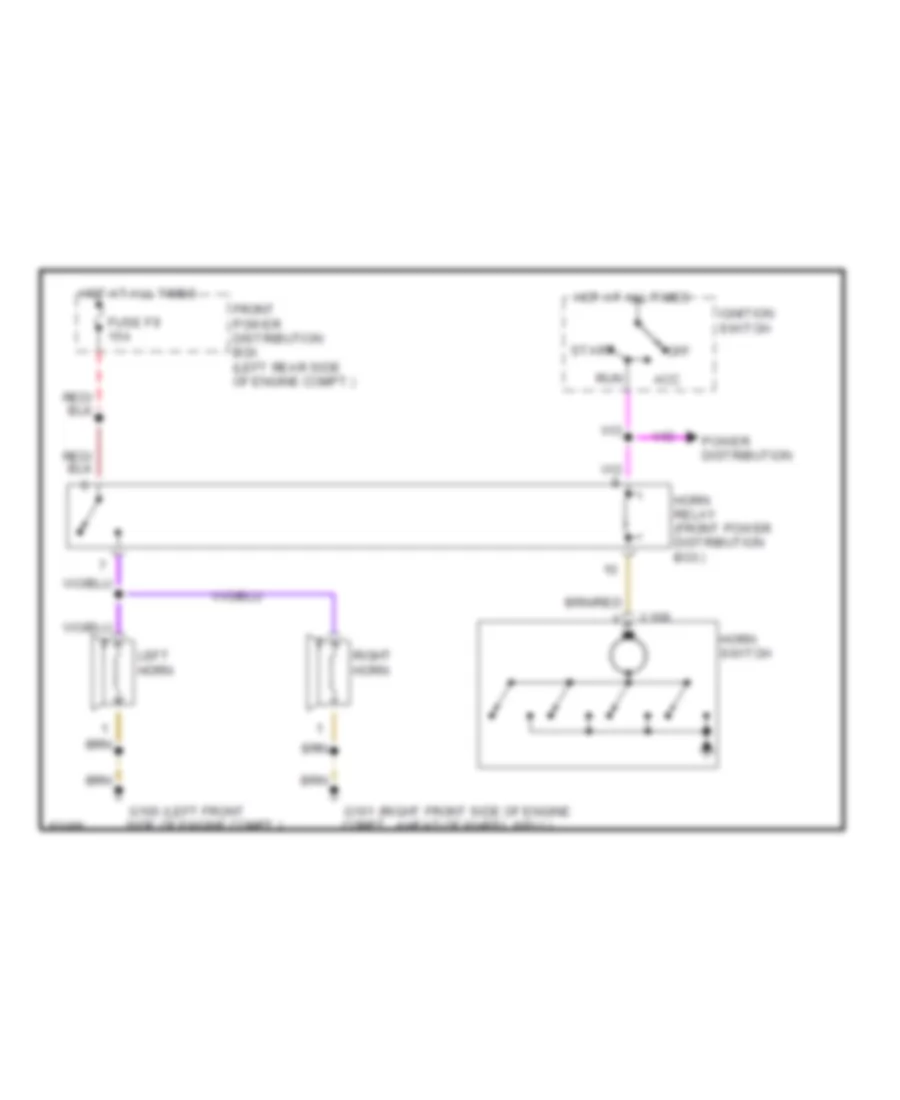
HORN
Horn Wiring Diagram for BMW 530i 1994
List of elements for Horn Wiring Diagram for BMW 530i 1994:
- (left front
- (right front side of engine
- Acc
- Front power distribution box (left rear side of engine compt.)
- Fuse f9 15a
- G100 side of engine compt.)
- G101 compt., ahead of wheel well)
- Horn relay (front power distribution box)
- Horn switch
- Hot at all times
- Ignition switch
- Left horn
- Off
- Power distribution
- Right horn
- Run
- Start
- X168
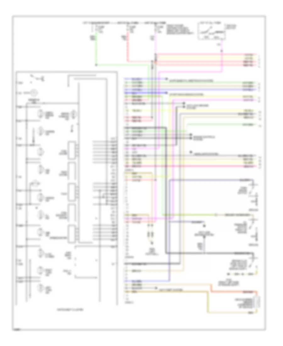
INSTRUMENT CLUSTER
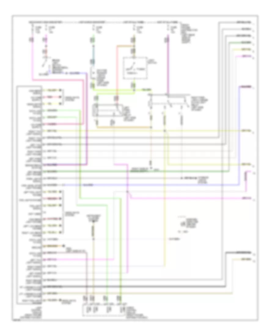
Instrument Cluster Wiring Diagram (1 of 2) for BMW 530i 1994
List of elements for Instrument Cluster Wiring Diagram (1 of 2) for BMW 530i 1994:
- A10
- A12
- A13
- A15
- A16
- A17
- A18
- A20
- A21
- A22
- A23
- A24
- A25
- A26
- Abs ind
- Acc
- Air bag ind
- Anti-lock brakes system
- Anti-theft system
- Asc ind
- B13
- B14
- B15
- Brake fluid level switch (left side of engine compt)
- Brake warning ind
- C10
- Charge ind
- Check engine ind
- Conn a
- Conn b
- Conn c
- D11
- D14
- D23
- D25
- D26
- Engine controls system
- Fog lt ind
- Front power distribution box (rear left side of engine compartment)
- Fuel economy gauge
- Fuel gauge
- Fuse f1 15a
- Fuse f17 7.5a
- Fuse f20 10a
- G100 (front left side of engine compt)
- G200 (left footwell)
- Ground
- Headlights system
- High beam ind
- Hot at all times
- Hot in run and start
- Ignition switch
- Illum (3 used)
- Instrument cluster
- Left turn ind
- Lock
- Nca
- Oil ind
- Oil pressure switch (front of engine)
- Park brake switch
- Reserve ind
- Right turn ind
- Run
- Speedometer
- Start
- Starting/charging system
- Tach
- Temp gauge
- Vehicle speed sensor (under rear of vehicle)
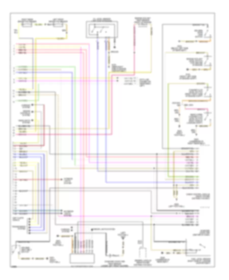
Instrument Cluster Wiring Diagram (2 of 2) for BMW 530i 1994
List of elements for Instrument Cluster Wiring Diagram (2 of 2) for BMW 530i 1994:
- (left footwell) g200
- 525i,530i, 540i
- 525it, 530it
- Check control module (front power distribution box)
- Data link connector (near e-box left)
- Drivers door jamb switch
- Drivers seat belt switch
- Engine controls system
- Engine coolant level switch (top center of engine)
- Engine coolant temp sensor (front of engine)
- Exterior lights system
- Fuel level sensor (right side of luggage compartment)
- G100 (front left side of engine compt)
- G103 (rear right side of engine compartment)
- G200 (left footwell)
- G203 (right footwell)
- G303 (underside of right rear seat)
- G304 (below left side of rear seat)
- G306 (underside of rear seat)
- General module (rear power distribution box)
- Ground
- Headlights system
- Inst clstr conn d
- Interior lights system
- Left front brake pad sensor
- Multi-function clock
- Nca
- Oil level sensor (left side of engine)
- On-board computer (center of dash)
- On-board computer temp sensor (under left front bumper)
- Rear wiper/ washer fluid level switch (right side of luggage compt)
- Right rear brake pad sensor
- Transmission system
- Warning system
- Washer fluid level switch (front right side of engine compt)
INTERIOR LIGHTS
Interior Light Wiring Diagram (1 of 2) for BMW 530i 1994
List of elements for Interior Light Wiring Diagram (1 of 2) for BMW 530i 1994:
- (3)
- Asc switch
- Asc switch (535i only)
- Canada
- Canada only
- Check control module (front power distribution box)
- Dimmer
- Exterior lights system (turn/hazard lights)
- Fog light switch
- Front cigar lighter light
- Front power distribution box (left rear side of engine compartment)
- Fuse f4 7.5a
- Fuse f5 10a
- G101 (right side of engine compartment)
- G202 (left side of i/p)
- G303 (below right rear seat)
- General module (rear power distribution box)
- Hazard switch
- Head
- Hot at all times
- Ihkr/f3 control panel
- Ihkr/f3 switching unit
- Instrument cluster
- Instrument illumination
- Integrated climate regulation control module (between front footwells)
- Lamp control module (front power distribution box)
- Left front lumbar support switch (not illuminated in u.s.)
- Left front seat heater switch
- Left front thigh support switch (m5 only)
- Light switch
- Light switch on signal
- Lights on signal
- Off
- On-board computer (center of dash)
- Park
- Park lights signal
- Program switch (w/egs)
- Radio
- Right front lumbar support switch (not illuminated in u.s.)
- Right front seat heater switch
- Right front thigh support switch (m5 only)
- Right park light/license plate light relay (left side of dash)
- Sunroof switch
- Transmission position indicator light
- U.s.a.
- Under hood light
- Under hood light switch
- X1127
- X1193
- X12
- X17
- X18126
- X18151
- X18154
- X18155
- X19
- X255
- X501
- X502
- X503
- X504
- X516
- X521
- X532
- X643
- X651
- X652
- X658
- X659
- X8503
- X880
- X881
Interior Light Wiring Diagram (2 of 2) for BMW 530i 1994
List of elements for Interior Light Wiring Diagram (2 of 2) for BMW 530i 1994:
- Anti- theft system
- Auto
- Check control module (left rear side of engine compartment)
- Crash signal
- Door open signal
- Driver's door jamb switch
- Driver's door open
- Driver's door status
- Driver's makeup mirror light
- Driver's makeup mirror switch
- Front dome light/ map reading assembly
- Front power distribution box (left rear side of engine compartment)
- Fuse f18 15a
- Fuse f21 10a
- Fuse f32 7.5a
- G202 (left side of i/p)
- G303 (below right rear seat)
- General module (below left rear seat)
- Glove box light
- Glove box light switch
- Hot at all times
- Hot in accy, run and start
- Inertia switch (below left rear seat)
- Interior lights control
- Left rear door jamb switch
- Left rear interior light
- Left trunk light assembly
- Manual
- Off
- Passenger's door jamb switch
- Passenger's door open
- Passenger's makeup mirror light
- Passenger's makeup mirror switch
- Rear door open
- Relay module (below left rear seat)
- Right rear door jamb switch
- Right rear interior light
- Right trunk light assembly
- Seat/ mirror memory control module (below left front seat)
- Trunk lid light
- Trunk lid switch (left side of trunk lid)
- X18
- X19
- X253
- X255
- X648
MEMORY SYSTEMS
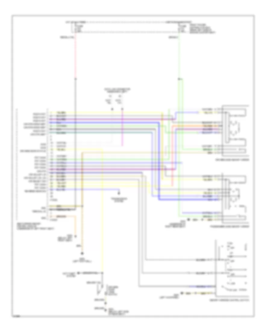
Memory Mirrors Wiring Diagram for BMW 530i 1994
List of elements for Memory Mirrors Wiring Diagram for BMW 530i 1994:
- Anti-theft system
- Data link connector (near e-box left)
- Diag
- Drivers door jamb switch
- Drivers door status
- Drivers side memory mirror
- Front power distribution box (rear left side of engine compartment)
- Fuse f12 15a
- Fuse f42 30a
- G200 (left footwell)
- G200 (left kickpanel)
- G300 (below left front seat)
- G303 (underside of right rear seat)
- G304 (below left side of rear seat)
- Gnd
- Hot at all times
- Hot in run and start
- L mir
- Memory mirrors control switch
- Mir adjust-l/r
- Mir adjust-l/r, u/d
- Mir mtr
- Mir mtr-horiz/vert
- Mir mtr-vert
- Mir select sig
- Off
- Passengers side memory mirror
- Postn pot
- Pot conn
- Reverse gear sig
- Rt mir
- Seat/mirror memory control module (underside of left front seat)
- Terminal 30
- Transmission system
- X18322
- X18323
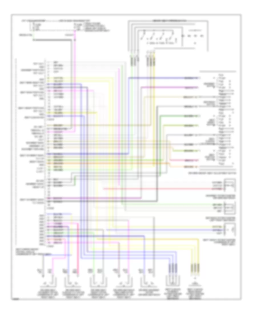
Memory Seat Wiring Diagram for BMW 530i 1994
List of elements for Memory Seat Wiring Diagram for BMW 530i 1994:
- Back
- Backrest back
- Backrest forward
- Drivers headrest motor (drivers seatback)
- Drivers memory seat adjustment switch
- Drivers seat cushion tilt motor (underside of left front seat)
- Drivers seat height motor (underside of left front seat)
- Drivers seat movement motor (underside of left front seat)
- Drivers seatback recliner motor (underside of left front seat)
- Fnt
- Front power distribution box (rear left side of engine compartment)
- Fuse f16 30a
- Fuse f18 15a
- Gnd
- Headrest down
- Headrest postn sig
- Headrest potentiometer (drivers seatback)
- Headrest switch
- Headrest up
- Height down
- Height up
- Hot in accy, run and start
- Hot in run and start
- Illum +
- Illum -
- Memory seat mirrors switch
- Off
- Pot volt
- Seat back postn sig
- Seat cushion movement potentiometer (left front seatback)
- Seat cushion rear height potentiometer (left front seatback)
- Seat cushion sig
- Seat cushion tilt switch
- Seat height postn sig
- Seat height potentiometer (underside of left front seat)
- Seat height switch
- Seat movement back
- Seat position switch
- Seat rear height sig
- Seat/mirror memory control module (underside of left front seat)
- Seatback potentiometer (left front seatback)
- Seatback switch
- Sw led +
- Sw led -
- Sw sig
- Terminal 15
- Terminal r
- Tilt down
- Tilt up
- Volt
- X18319
- X18320
- X18321
POWER DISTRIBUTION
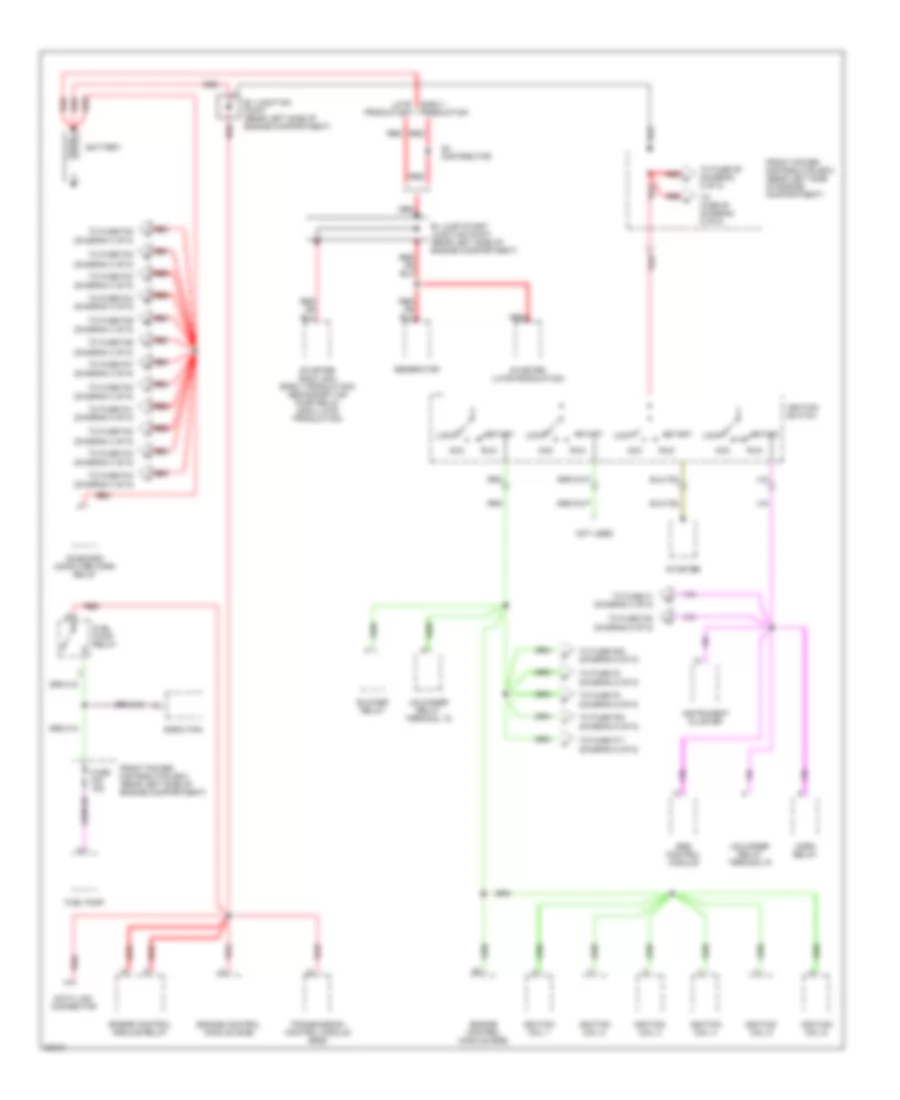
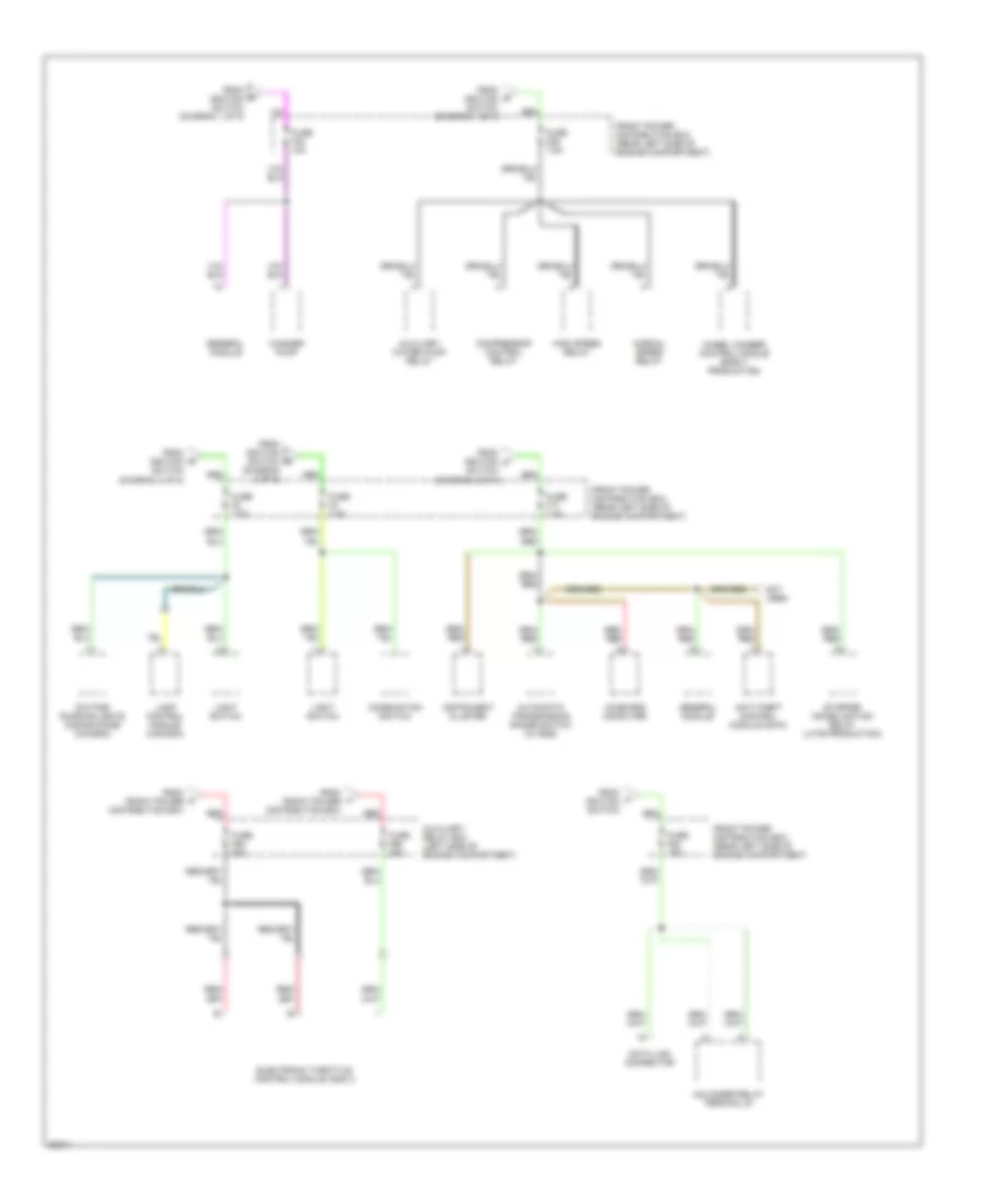
Power Distribution Wiring Diagram (1 of 5) for BMW 530i 1994
List of elements for Power Distribution Wiring Diagram (1 of 5) for BMW 530i 1994:
- (diagram 3 of 5)
- (diagram 5 of 5)
- Acc
- B+ distributor
- B+ jump start junction point (rear left side of engine compartment)
- B+ junction point (rear left side of engine compartment)
- Battery
- Blower relay
- Data link connector
- E-box fan
- Early production
- Engine control module (dme)
- Engine control module relay
- Front power distribution box (rear left side of engine compartment)
- Fuel pump
- Fuel pump relay
- Fuse f23 15a
- Generator
- Horn relay
- Ignition coil 1
- Ignition coil 2
- Ignition coil 3
- Ignition coil 4
- Ignition coil 5
- Ignition coil 6
- Ignition switch
- Instrument cluster
- Late production
- Lock
- Not used
- On-board computer horn relay
- Red
- Run
- Srs control module
- Start
- Starter
- Starter (530i/t, 540i early production) secondary air pump relay (530i/t late production)
- Starter (late production)
- To fuse f1 (diagram 4 of 5)
- To fuse f17
- To fuse f2 (diagram 5 of 5)
- To fuse f24
- To fuse f28 (diagram 5 of 5)
- To fuse f29 (diagram 5 of 5)
- To fuse f3
- To fuse f30 (diagram 3 of 5)
- To fuse f32
- To fuse f33
- To fuse f34 (diagram 3 of 5)
- To fuse f35
- To fuse f36
- To fuse f37 (diagram 3 of 5)
- To fuse f40
- To fuse f41 (diagram 3 of 5)
- To fuse f42
- To fuse f43 (diagram 3 of 5)
- To fuse f44
- To fuse f5 (diagram 2 of 5)
- To fuse f9 (diagram 2 of 5)
- Transmission control module (egs)
- Unloader relay terminal 15
- Unloader relay terminal r
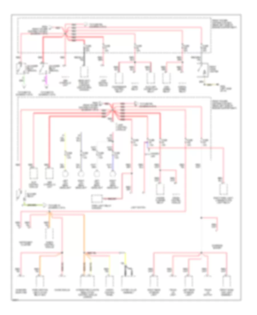
Power Distribution Wiring Diagram (2 of 5) for BMW 530i 1994
List of elements for Power Distribution Wiring Diagram (2 of 5) for BMW 530i 1994:
- (diagram 5 of 5)
- Abs hydraulic unit
- Auxiliary water pump relay
- Blower relay
- Canada
- Charging socket
- Check control module
- Chime module
- Compressor control relay
- Crash control module
- From front power distribution box (diagram 1 of 5)
- Front cigar lighter
- Front dome/ map light assembly
- Front power distribution box (rear left side of engine compartment)
- Fuse f10 7.5a
- Fuse f11 7.5a
- Fuse f13 7.5a
- Fuse f14 7.5a
- Fuse f20 10a
- Fuse f21 10a
- Fuse f22 30a
- Fuse f25 30a
- Fuse f26 30a
- Fuse f4 7.5a
- Fuse f5 7.5a
- Fuse f6 15a
- Fuse f7 15a
- Fuse f9 15a
- G202 (left side of i/p)
- Hazard flasher relay
- Headlight/ foglight cleaning module (sra) (canada)
- High speed relay
- Horn relay
- Ihkr/f3 control panel
- Instrument cluster
- Integrated climate regulation control module (ihkr/f3)
- Lamp control module
- Left high beam headlight
- Left low beam headlight
- Left rear interior light
- Light switch
- Nca
- Normal speed relay
- On-board computer
- Park heating ventilation relay box
- Park light relay (canada)
- Red
- Right high beam headlight
- Right low beam headlight
- Right park light/ license plate light relay
- Right rear interior light
- Slip control module
- To fuse 19 (diagram 3 of 5)
- To fuse f15 (diagram 3 of 5)
- To fuse f16 (diagram 4 of 5)
- To fuse f55
- To fuse f56 (diagram 5 of 5)
- Trunk lid light
- Trunk lid switch
- Unloader relay terminal
- Unloader relay terminal r
- Usa
- Water valve assembly
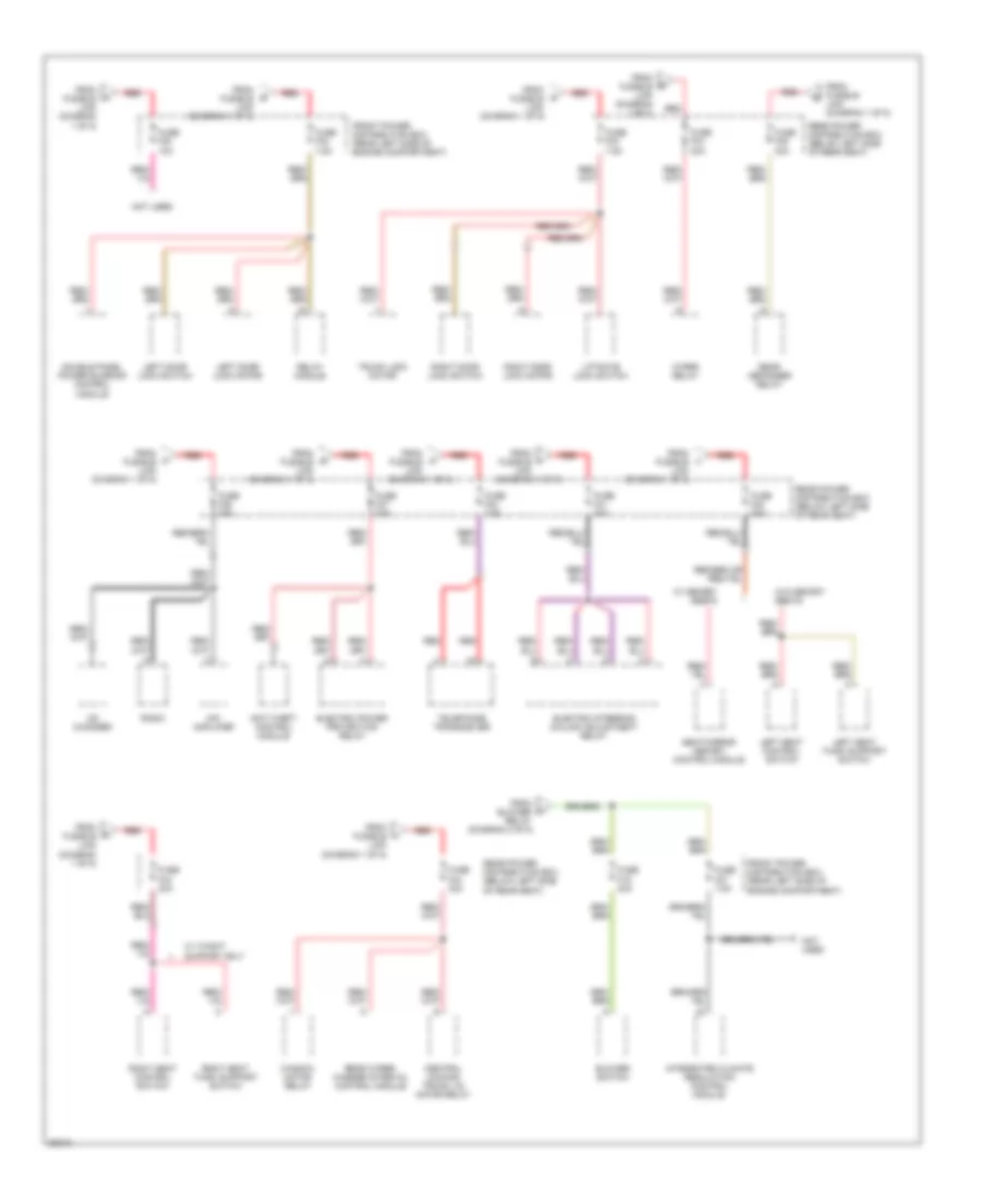
Power Distribution Wiring Diagram (3 of 5) for BMW 530i 1994
List of elements for Power Distribution Wiring Diagram (3 of 5) for BMW 530i 1994:
- (diagram 1 of 5)
- Anti-theft control module
- Blower switch
- Cd changer
- Central locking trunk lid motor relay
- Double panel power sunroof control module
- Electric power protection relay
- Electric steering column adjustment relay
- From blower relay (diagram 2 of 5)
- From fusible link
- From fusible link (diagram 1 of 5)
- Front power distribution box (rear left side of engine compartment)
- Fuse f19 30a
- Fuse f27 7.5a
- Fuse f30 10a
- Fuse f32 7.5a
- Fuse f33 7.5a
- Fuse f34 30a
- Fuse f35 30a
- Fuse f36 30a
- Fuse f37 30a
- Fuse f40 7.5a
- Fuse f41 30a
- Fuse f42 30a
- Fuse f43 30a
- Fuse f44 30a
- Hifi amplifier
- Integrated climate regulation control module
- Left door lock motor
- Left door lock switch
- Left seat control switch
- Left seat thigh support switch
- Liftgate lock switch
- Not used
- Radio
- Rear defogger relay
- Rear power distribution box (below left side of rear seat)
- Rear wiper/ washer interval control module
- Red
- Relay module
- Right door lock motor
- Right door lock switch
- Right seat control switch
- Right seat thigh support switch
- Seat/mirror memory control module
- Telephone transceiver
- Trunk lock motor
- W/ memory seats
- W/ thight support only
- W/o memory seats
- Window motor relay
- Wiper relay
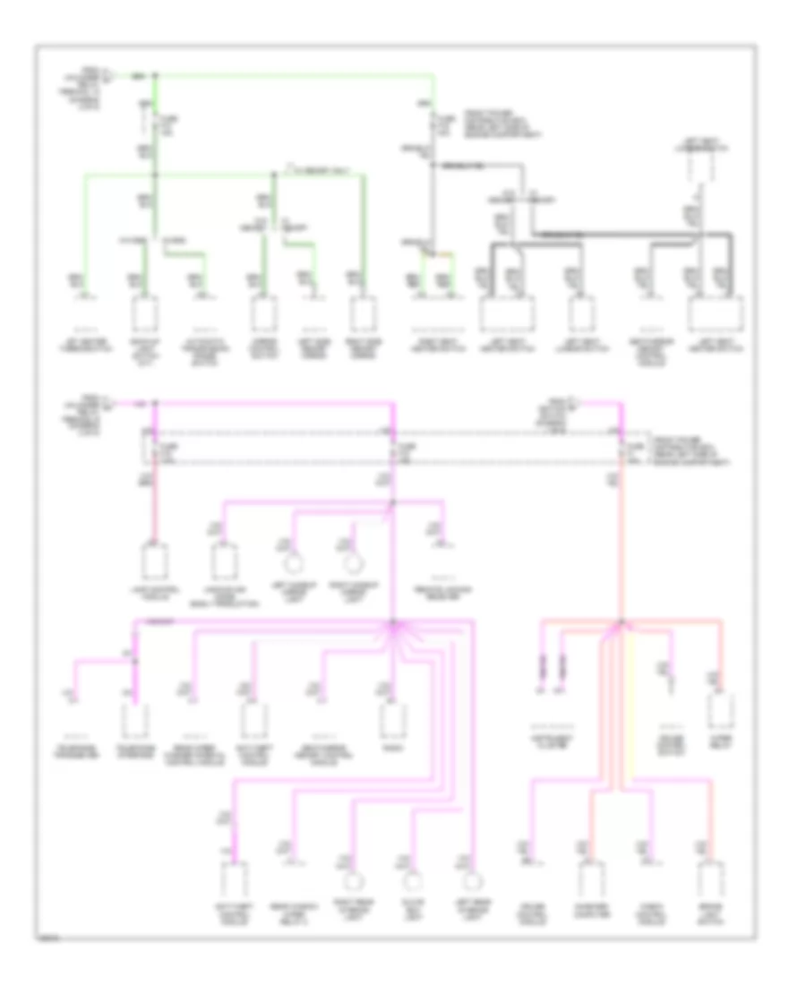
Power Distribution Wiring Diagram (4 of 5) for BMW 530i 1994
List of elements for Power Distribution Wiring Diagram (4 of 5) for BMW 530i 1994:
- Anti-theft control module
- Automatic transmission range switch
- Back-up light switch (m/t)
- Brake light switch
- Check control module
- Cruise control module
- Cruise control switch
- From ignition switch (diagram 1 of 5)
- From unloader v relay terminal 15 (diagram 2 of 5)
- From unloader w relay terminal r (diagram 2 of 5)
- Front power distribution box (rear left side of engine compartment)
- Fuse f1 15a
- Fuse f12 15a
- Fuse f15 7.5a
- Fuse f16 30a
- Fuse f18 15a
- Glove box light
- Instrument cluster
- Jet heater thermoswitch
- Lamp control module
- Left makeup mirror light
- Left rear interior light
- Left seat heater switch
- Left seat lumbar switch
- Left side memory mirror
- Mirror control switch
- On-board computer
- Radio
- Rear window wiper relay 2
- Rear wiper/ washer interval control module
- Remote locking receiver
- Right makeup mirror light
- Right rear interior light
- Right seat heater switch
- Right side memory mirror
- Seat/mirror memory control module
- Telephone interface
- Telephone transceiver
- Uncoupling diode (early production)
- W/ egs
- W/ memory
- W/ memory only
- W/o egs
- W/o memory
- Wiper relay
Power Distribution Wiring Diagram (5 of 5) for BMW 530i 1994
List of elements for Power Distribution Wiring Diagram (5 of 5) for BMW 530i 1994:
- Anti-theft control module (dwa)
- Automatic transmission range switch (w/ egs)
- Auxiliary relay box (left side of engine compartment)
- Auxiliary water pump relay
- Combination switch
- Compressor control relay
- Data link connector
- Daytime running lights coding diode (canada)
- Electronic throttle control module (ads ii)
- From front power distribution box
- From ignition switch
- From ignition switch (diagram 1 of 5)
- From ignition switch (diagram 2 of 5)
- Front power distribution box (rear left side of engine compartment)
- Fuse f17 7.5a
- Fuse f2 7.5a
- Fuse f24 10a
- Fuse f28 15a
- Fuse f29 7.5a
- Fuse f3 7.5a
- Fuse f55 50a
- Fuse f56 25a
- General module
- High speed relay
- Instrument cluster
- Lamp control module (canada)
- Light switch
- Normal speed relay
- Not used
- On-board computer
- Red
- Starter immobilization relay (late production)
- Unloader relay terminal 61
- Washer pump
- Wheel camber control module (early production)
POWER DOOR LOCKS
Power Door Lock Wiring Diagram for BMW 530i 1994
List of elements for Power Door Lock Wiring Diagram for BMW 530i 1994:
- 525i, 530i, 540i
- 525it, 530it
- Anti-theft system
- Central locking trunk lid motor relay (right side of luggage compt)
- Conn 253
- Conn 255
- Conn 332
- Crash info
- Crash sig
- Data line
- Drivers door lk mtr
- Drivers door lock motor
- Electric power protection relay (in rear power distribution box)
- Fuse f32 7.5a
- Fuse f33 7.5a
- Fuse f37 30a
- Fuse f44 20a
- G303 (below right side of rear seat)
- G304 (below left side of rear seat)
- Gas filler lock motor
- General module (in rear power distribution box)
- Hot at all times
- Inertia switch (below left side of rear seat)
- L rear wdo mtr ctrl
- Left rear door lock motor
- Lift gate limit switch
- Lift gate lock switch
- Lift gate motor
- Lk mtrs ctrl
- Lk mtrs ctrl (close)
- Lk mtrs ctrl (open)
- Not used
- Passengers door lock motor
- Passngr door lk mtr
- Protect rly ctrl
- Rear power distribution box (below left side of rear seat)
- Rear window limit switch (on liftgate behind trim panel)
- Rear window motor
- Relay module (in rear power distribution box)
- Right rear door lock motor
- Sunroof mtr ctrl
- Theft sys ctrl mod
- Trunk lock motor
- Unlk door lk mtrs sig
- Unlk trunk lk mtr sig
- Window motor relay (right side of luggage compartment)
POWER MIRRORS
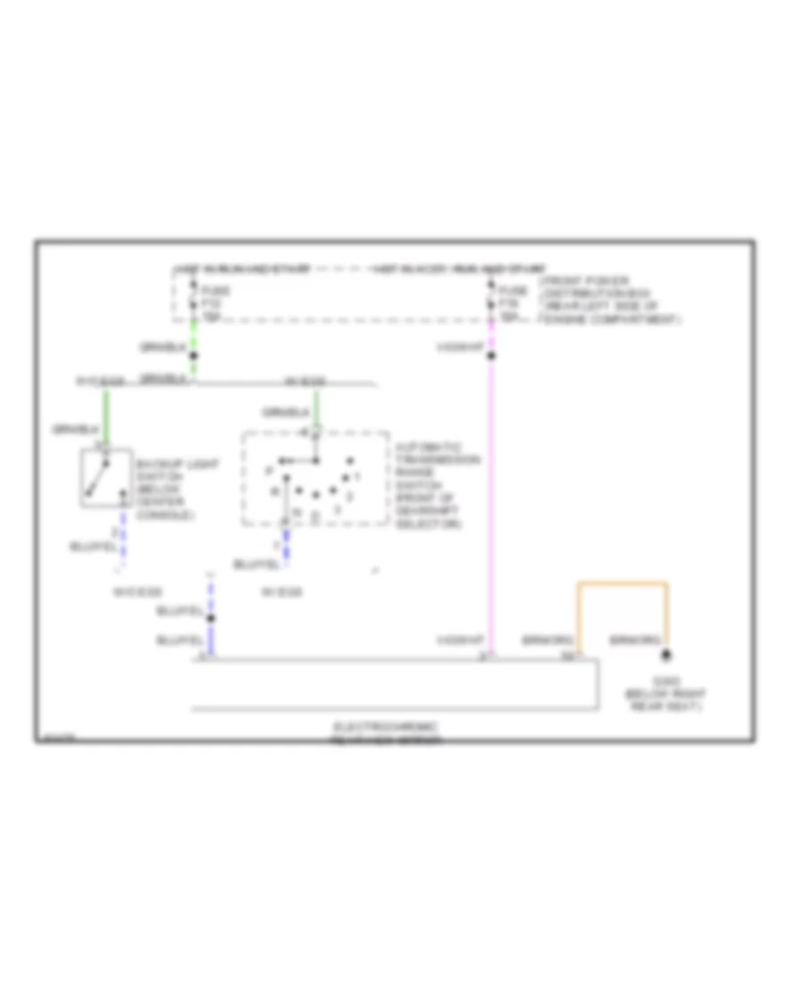
Electrochromic Mirror Wiring Diagram for BMW 530i 1994
List of elements for Electrochromic Mirror Wiring Diagram for BMW 530i 1994:
- Automatic transmission range switch (front of gearshift selector)
- Backup light switch (below center console)
- Electrochromic rear view mirror
- Front power distribution box (rear left side of engine compartment)
- Fuse f12 15a
- Fuse f18 15a
- G303 (below right rear seat)
- Hot in accy, run and start
- Hot in run and start
- W/ egs
- W/o egs
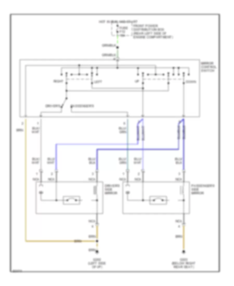
Power Mirror Wiring Diagram for BMW 530i 1994
List of elements for Power Mirror Wiring Diagram for BMW 530i 1994:
- Down
- Driver's
- Driver's side mirror
- Front power distribution box (rear left side of engine compartment)
- Fuse f12 15a
- G202 (left side of i/p)
- G303 (below right rear seat)
- Hot in run and start
- Left
- Mirror control switch
- Nca
- Passenger's
- Passenger's side mirror
- Right
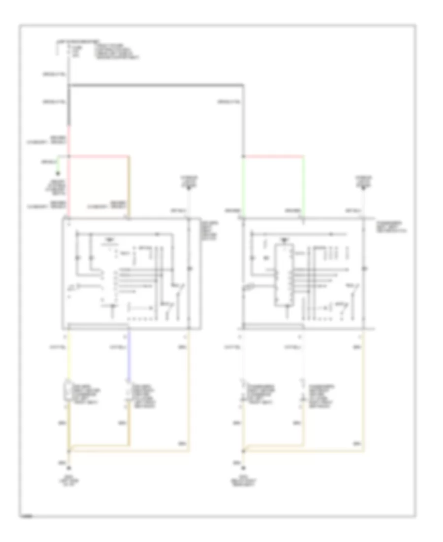
POWER SEATS
Heated Seats Wiring Diagram for BMW 530i 1994
List of elements for Heated Seats Wiring Diagram for BMW 530i 1994:
- (w/memory)
- Driver's seat heater (underside of left front seat)
- Driver's seat, seat heater switch
- Driver's seatback heater (in lower left front seatback)
- Front power distribution box (rear left side of engine compartment)
- Fuse f16 30a
- G202 (left side of i/p)
- G303 (below right rear seat)
- Hot in run and start
- Interior lights system
- Max
- Memory systems (w/memory seats)
- Min
- Passenger's seat heater (underside of left front seat)
- Passenger's seat, seat heater switch
- Passenger's seatback heater (in lower right front seatback)
- Test
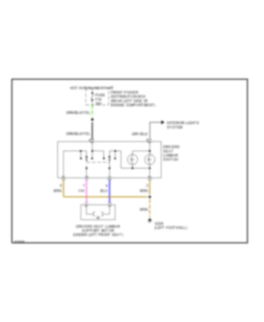
Lumbar Wiring Diagram for BMW 530i 1994
List of elements for Lumbar Wiring Diagram for BMW 530i 1994:
- Drivers seat lumbar support motor (under left front seat)
- Drivers seat lumbar switch
- Front power distribution box (rear left side of engine compartment)
- Fuse f16 30a
- G200 (left footwell)
- Hot in run and start
- Interior lights system
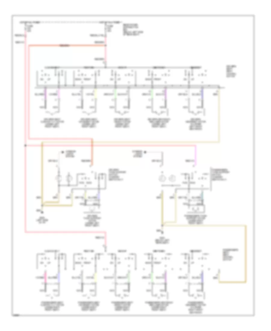
Power Seats Wiring Diagram for BMW 530i 1994
List of elements for Power Seats Wiring Diagram for BMW 530i 1994:
- Back
- Cushion tilt
- Driver's headrest motor (in upper left front seatback)
- Driver's seat cushion tilt motor (under left front seat)
- Driver's seat height motor (under left front seat)
- Driver's seat movement motor (under left front seat)
- Driver's seat, seat control switch
- Driver's seatback recliner motor (under left front seat)
- Driver's thigh support motor (under left front seat)
- Driver's thigh support switch (w/sport seats only)
- Front
- Fuse f42 30a
- Fuse f43 30a
- Fwd
- G202 (left side of i/p)
- G303 (below left rear seat)
- Headrest
- Height
- Hot at all times
- Interior lights system
- Nca
- Passenger's headrest motor (in upper right front seatback)
- Passenger's seat cushion tilt motor (under right front seat)
- Passenger's seat height motor (under right front seat)
- Passenger's seat movement motor (under right front seat)
- Passenger's seat, seat control switch
- Passenger's seatback recliner motor (under right front seat)
- Passenger's thigh support motor (under right front seat)
- Passenger's thigh support switch (w/sport seats only)
- Position
- Rear power distribution box (below left side of rear seat)
- Rwd
- Seatback
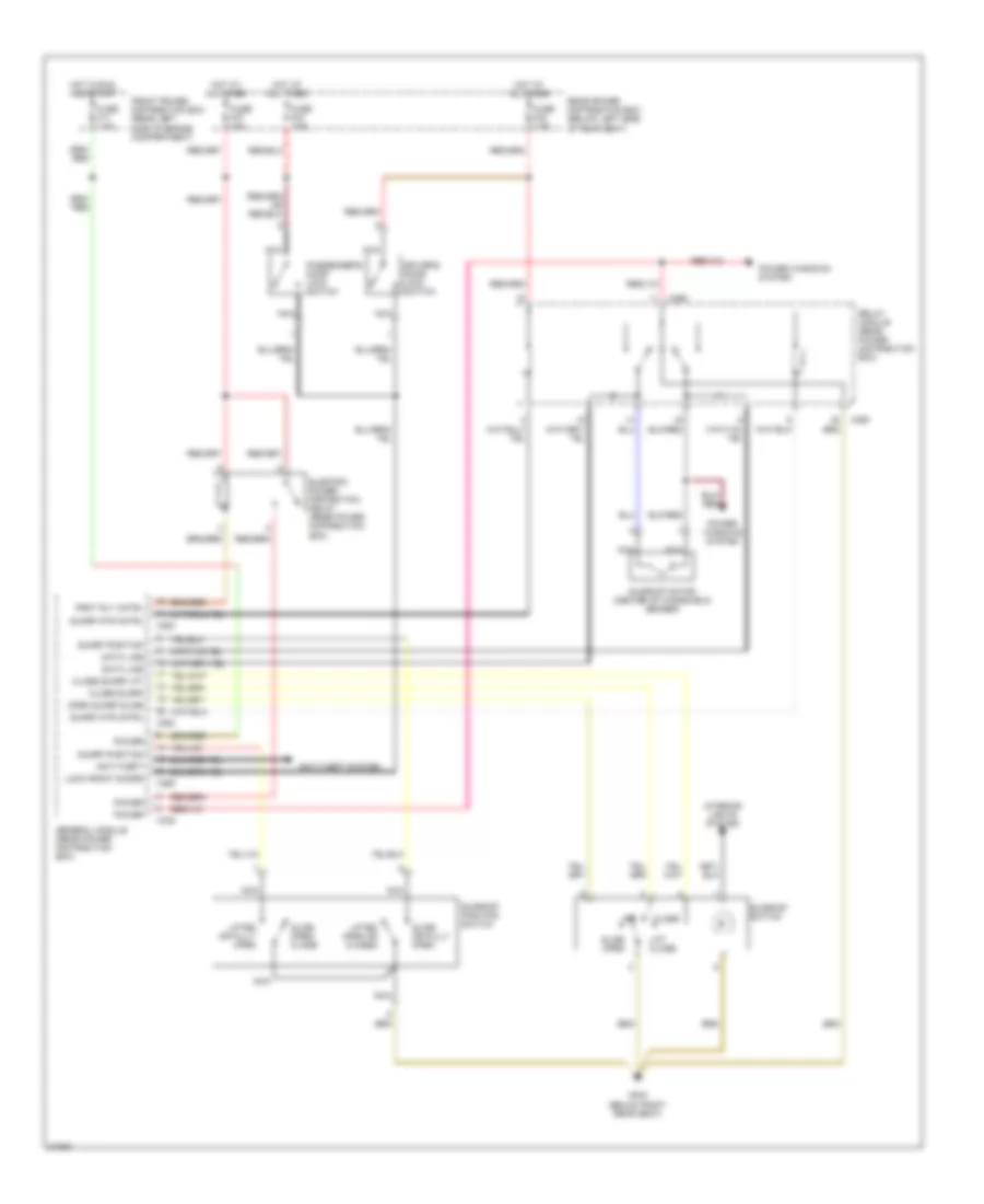
POWER TOP/SUNROOF
Sunroof Wiring Diagram, SHD for BMW 530i 1994
List of elements for Sunroof Wiring Diagram, SHD for BMW 530i 1994:
- Anti-theft
- Anti-theft system
- Close
- Close sunrf
- Close sunrf lft
- Data line
- Driver's door lock switch
- Electric power protection relay (rear power distribution box)
- Front power distribution box (rear left side of engine compartment)
- Fuse f17 7.5a
- Fuse f32 7.5a
- Fuse f33 7.5a
- Fuse f37 30a
- G303 (below right rear seat)
- General module (rear power distribution box)
- Hot at all times
- Hot in run and start
- Interior lights system
- Lift close
- Lifted open or closed
- Lifted or fully open
- Lock front doors
- Nca
- Off
- Open sunrf slide
- Passenger's door lock switch
- Power
- Power windows system
- Prot rly cntrl
- Rear power distribution box (below left side of rear seat)
- Relay module (rear power distribution box)
- Slide open
- Slide open/ close
- Slide or fully open
- Sunrf mtr cntrl
- Sunrf position
- Sunroof motor (center of windshield header)
- Sunroof position switch
- Sunroof switch
- X253
- X254
- X255
- X258
- X259
- X332
Sunroof Wiring Diagram, ZKE for BMW 530i 1994
List of elements for Sunroof Wiring Diagram, ZKE for BMW 530i 1994:
- Control signal
- Data link connector (near e-box left)
- Diag
- Double panel power sunroof module (in roof panel)
- Double panel power sunroof sensor 1 (behind front of roof trim panel)
- Double panel power sunroof sensor 2 (in roof panel)
- Fuse f32 7.5a
- G304 (below left side of rear seat)
- General module (rear power distribution box)
- Ground
- Hot at all times
- Interior lights system
- Motor drive 1 double panel power sunroof (in roof panel)
- Motor drive 2 double panel power sunroof (in roof panel)
- Msd+
- Nca
- Position contact
- Power
- Power windows system
- Rear power distribution box (below left side of rear seat)
- Relay module (rear power distribution box)
- Sunroof switch
- Switch
- Terminal 30
- X253
- X254
- X258
- X259
- X332
POWER WINDOWS
Power Window Wiring Diagram (1 of 2) for BMW 530i 1994
List of elements for Power Window Wiring Diagram (1 of 2) for BMW 530i 1994:
- Conn 253
- Conn 254
- Conn 255
- Conn 332
- Door lock system
- Drivers window motor
- Electric power protection relay (in rear power distribution box)
- Front power distribution box (rear left side of engine compt)
- Fuse f17 7.5a
- Fuse f32 7.5a
- Fuse f37 30a
- G304 (below left side of rear seat)
- General module (in rear power distribution box)
- Hot at all times
- Hot in run and start
- Left rear window motor
- Passengers window motor
- Rear power distribution box (below left side of rear seat)
- Relay module (in rear power distribution box)
- Right rear window motor
Power Window Wiring Diagram (2 of 2) for BMW 530i 1994
List of elements for Power Window Wiring Diagram (2 of 2) for BMW 530i 1994:
- Child safety lock
- Close
- Drivers window limit switch
- Drivers window switch
- Front console window switch assembly
- G200 (left footwell)
- G303 (underside of rear seat)
- G303 (underside of right rear seat)
- G304 (below left side of rear seat)
- Left rear window limit switch
- Left rear window switch
- Not used
- Off
- Open
- Passengers window limit switch
- Passengers window switch
- Power tops system
- Right rear window limit switch
- Right rear window switch
RADIO
Radio Wiring Diagrams for BMW 530i 1994
List of elements for Radio Wiring Diagrams for BMW 530i 1994:
- 10a
- 6.3a
- Antenna amplifier
- Body computer system
- Cd changer
- Cellular telephone
- Coax cable
- Front power distribution box (rear left side of engine compartment)
- Fuse f18 15a
- Fuse f36 30a
- G304 (below left rear seat)
- Hifi amplifier
- Hot at all times
- Hot in accy, run and start
- Instrument cluster system
- Interior lights system
- Left front high range speaker
- Left front low range speaker
- Left front midrange speaker
- Left rear high range speaker
- Left rear low range speaker
- Nca
- Power input
- Radio
- Rear power distribution box (below left side of rear seat)
- Right front high range speaker
- Right front low range speaker
- Right front midrange speaker
- Right rear high range speaker
- Right rear low range speaker
- X18126
- X605
- X606
- X8075
SHIFT INTERLOCKS
Shift Interlock Wiring Diagram for BMW 530i 1994
List of elements for Shift Interlock Wiring Diagram for BMW 530i 1994:
- Automatic transmission range switch (front of gearshift lever)
- B+ junction point
- Brake light switch (support bracket)
- Brake switch test signal
- Front power distribution box (rear left side of engine compt.)
- Fuse f1 15a
- Fuse f17 7.5a
- G303 (below right rear seat)
- Gear range signal l1
- Gear range signal l2
- Gear range signal l3
- Gear range signal l4
- Ground
- Hot at all times
- Hot in accy, run and start
- Hot in run and start
- Instrument cluster system
- Nca
- Red
- Shift lock solenoid ground
- Shift-lock (front of gearshift selector)
- Transmission control module (e-box)
- Transmission control unit (in trans- mission)
STARTING/CHARGING
Charging Wiring Diagram for BMW 530i 1994
List of elements for Charging Wiring Diagram for BMW 530i 1994:
- Alternator
- Anti-theft control module (dwa)
- B+ junction point (rear left side of engine compartment)
- Battery
- Charge ind
- Data link connector (near e-box left)
- Front power distribution box (rear left side of engine compartment)
- Fuse f17 7.5a
- Fuse f28 15a
- G101 (right side of engine compartment)
- Hot in run and start
- Instrument cluster
- Integrated climate regulation control module
- Rear defogger relay (below left side of rear seat)
- Red
- Slip control module (abs/asc)
- Unloader relay (rear left side of engine compartment)
Starting Wiring Diagram, Early Production for BMW 530i 1994
List of elements for Starting Wiring Diagram, Early Production for BMW 530i 1994:
- A/t
- Acc
- Automatic transmission range switch
- B+ jump start junction point
- Battery
- Data link connector (near e-box left)
- Front power distribution box (rear left side of engine compartment)
- Fuse f17 7.5a
- G101 (right side of engine compartment)
- General module
- Hot at all times
- Hot in run and start
- Ignition switch
- Integrated climate regulation control module
- Jumper plug (rear left side of engine compartment)
- Lock
- M/t
- Not used
- On-board computer
- Red
- Run
- Start
- Starter
- Starter relay (rear left side of engine compartment)
Starting Wiring Diagram, Late Production for BMW 530i 1994
List of elements for Starting Wiring Diagram, Late Production for BMW 530i 1994:
- Acc
- Automatic transmission range switch
- B+ jump start junction point
- Battery
- Front power distribution box (rear left side of engine compartment)
- Fuse f17 7.5a
- G200 (left footwell)
- General module
- Hot at all times
- Hot in run and start
- Ignition switch
- Integrated climate regulation control module
- Lock
- On-board computer
- Red
- Run
- Start
- Starter
- Starter imobilization relay (in front power distribution box)
- W/ egs
- W/o egs
SUPPLEMENTAL RESTRAINTS
Supplemental Restraint Wiring Diagram for BMW 530i 1994
List of elements for Supplemental Restraint Wiring Diagram for BMW 530i 1994:
- (behind right
- (below left rear seat)
- (early prod 1994)
- (front harness, left rear of engine compt)
- (in rear harness,
- (left g200
- (note: module connector is 30 pin)
- Abbf+
- Abbf-
- Abf+
- Abf-
- Acc
- Air bag indicator
- Ausf
- Behind left rear seat)
- Check control module (front power dist box)
- Contact rings
- Data link connector (near e-box left)
- Driver's airbag gas generator
- Driver's seat belt switch (in seat belt buckle)
- Fuse f47 10a
- G310
- G310 (behind right rear seat)
- Gkbf
- Gkf
- Hot at all times
- Hot in accy. run and start
- Ignition switch
- Instrument cluster
- Kick panel)
- Nca
- Off
- Passenger's airbag gas generator
- Passenger's seat belt switch (in seat belt buckle)
- Rear power distribution box (behind left side of rear seat)
- Rear seat)
- Run
- Sbe
- Seat occupancy detector (late prod. 1994, all 1995) (under right front seat)
- Start
- Txd
- X16
- X19
TRANSMISSION
Transmission Wiring Diagram, 4 Speed with Overdrive for BMW 530i 1994
List of elements for Transmission Wiring Diagram, 4 Speed with Overdrive for BMW 530i 1994:
- 1991 only
- Automatic transmission range switch
- B+ junction point
- Band solenoid
- Brake light switch
- Check control module
- Computer data lines system
- Electronic transmission engine speed sensor
- Engine controls system
- Front power distribution box
- Fuse f1 15a
- Fuse f17 7.5a
- Ground
- Hot at all times
- Hot in accy, run and start
- Hot in run and start
- Hydraulic pressure regulator
- Instrument cluster
- Interior lights system
- Nca
- Oil temperature sensor
- Program switch
- Red
- Shift lock solenoid
- Solenoid valve 1
- Solenoid valve 2
- Torque converter clutch sol valve
- Transmission control module (egs)
- Transmission kickdown switch
- Transmission valve unit
- Transparent
Transmission Wiring Diagram, 5 Speed with Overdrive for BMW 530i 1994
List of elements for Transmission Wiring Diagram, 5 Speed with Overdrive for BMW 530i 1994:
- Anti-lock brakes system
- B+ junction point
- Brake light switch
- Clr
- Data link connector
- Engine controls system
- Front power distribution box
- Fuse f1 15a
- Fuse f17 7.5a
- Ground
- Hot at all times
- Hot in accy, run and start
- Hot in run and start
- Instrument cluster
- Instrument cluster system
- Kick- down switch
- Nca
- Oil temperature sensor
- Pressure regulator
- Program switch
- Red
- Shift lock solenoid
- Solenoid valve 1
- Solenoid valve 2
- Solenoid valve 3
- Speed sensor shaft
- Speed sensor turbine
- Transmission control module (ags)
- Transmission range switch
- Transmission valve unit
- X8600
WARNING SYSTEMS
Warning System Wiring Diagrams for BMW 530i 1994
List of elements for Warning System Wiring Diagrams for BMW 530i 1994:
- Chime module (below left side of dash
- Front power distribution box (rear left side of engine compt.)
- Fuse f20 10a
- G202 (left side of i/p)
- Gong t1 control
- Gong t2 control
- Hot at all times
- Instrument cluster
- On-board computer (center console)
- Sound
- Tone signal x502
- X501
- X518
- X522
WIPER/WASHER
Jet Heater Wiring Diagram for BMW 530i 1994
List of elements for Jet Heater Wiring Diagram for BMW 530i 1994:
- Front power distribution box (rear left side of engine compartment)
- Fuse f12 15a
- G101 (right front side of engine compartment, ahead of wheelwell)
- Hot in run and start
- Jet heater thermoswitch (front left side of engine compt.)
- Left washer jet heater (on underside of hood)
- Nca
- Right washer jet heater (on underside of hood)
Rear Wiper/Washer Wiring Diagram for BMW 530i 1994
List of elements for Rear Wiper/Washer Wiring Diagram for BMW 530i 1994:
- Fast
- Front power distribution box (rear left side of engine compartment)
- Fuse f18 15a
- Fuse f44 20a
- G200 (left footwell)
- G303 (underside of right rear seat)
- G304 (below left side of rear seat)
- General module (rear power distribution box)
- Hot at all times
- Hot in accy, run and start
- Int
- Int (rear)
- Intensive
- Nca
- Norm
- Off
- Rear power distribution box (below left side of rear seat)
- Rear window opening switch
- Rear window washer pump (right side of luggage compartment)
- Rear window wiper motor
- Rear wiper/washer interval control module (right side of luggage compartment)
- Relay module (rear power distribution box)
- Single wipe
- Single wipe (rear)
- Wiper/washer switch
Wiper/Washer Wiring Diagram for BMW 530i 1994
List of elements for Wiper/Washer Wiring Diagram for BMW 530i 1994:
- Data line
- Fast
- Front power distribution box (rear left side of engine compartment)
- Fuse f1 15a
- Fuse f24 10a
- Fuse f34 30a
- G202 (left side of i/p)
- G303 (below left rear seat)
- General module (rear power distribution box)
- Hot in accy, run and start
- Instrument cluster
- Int wiper
- Inter
- Nca
- Normal
- Off
- Park
- Rear power distribution box (below left side of rear seat)
- Relay module (rear power distribution box)
- Run
- Single
- Speed sig
- Stnd wiper
- Vehicle speed signal
- Wash
- Wash signl
- Washer pump (washer fluid reservoir)
- Wiper motor
- Wiper mtr
- Wiper relay (rear power distribution box)
- Wiper/washer switch
- Wipers run
- X253
- X255
- X258
- X259
- X502