Diagram sections — 12 (17 total)
COOLING FAN DEFOGGERS HORN MEMORY SYSTEMS POWER DOOR LOCKS POWER MIRRORS POWER SEATS POWER WINDOWS RADIO STARTING/CHARGING TRANSMISSION WIPER/WASHER
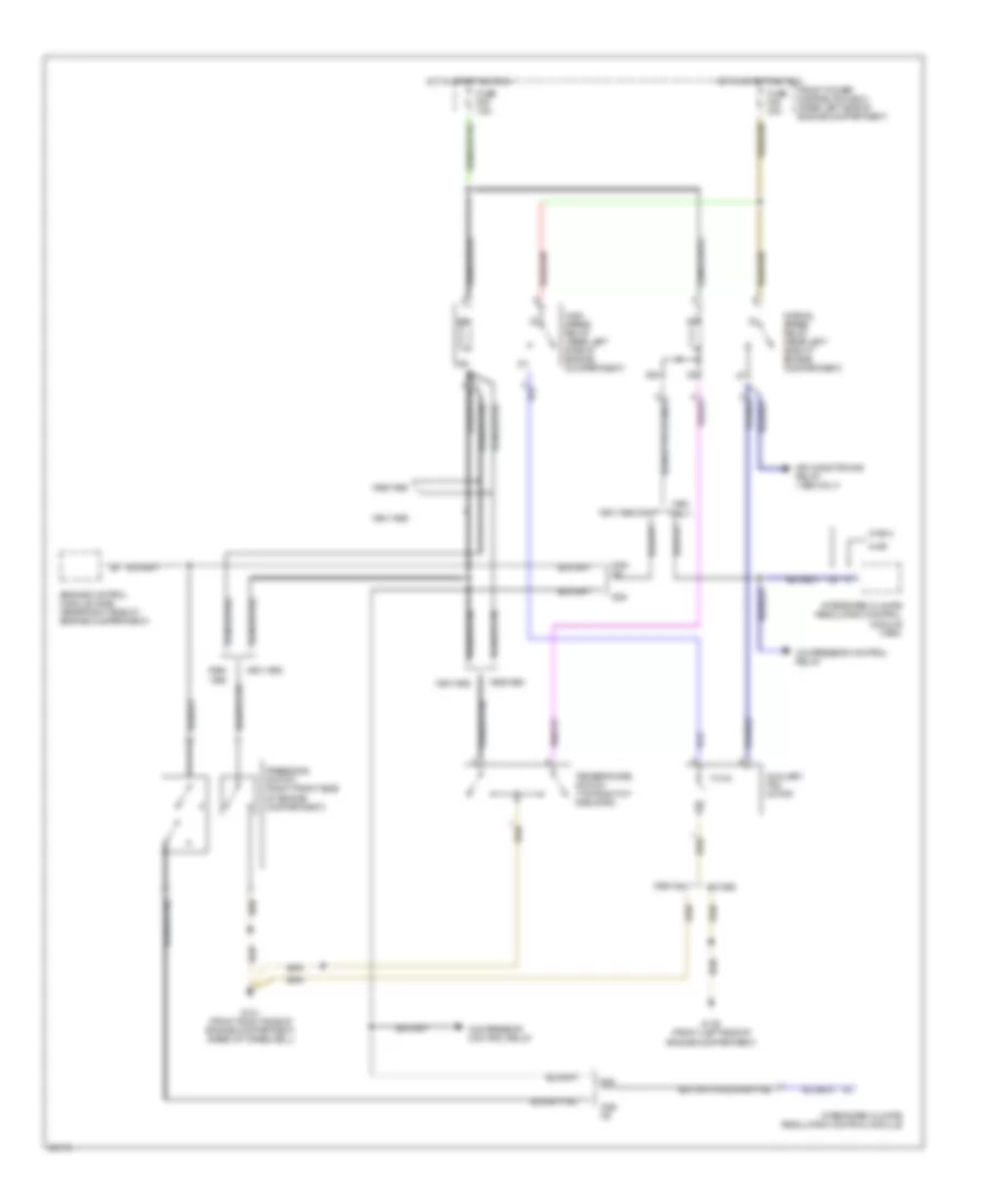
COOLING FAN Auxiliary Cooling Fan Wiring Diagram for BMW 535i 1991 List of elements for Auxiliary Cooling Fan Wiring Diagram for BMW 535i 1991: 28 1989 only 1989/ 1989/1990 1991/1992 1991/1992 only 525i 535i/ m5 85b Air conditioning relay (1989 only) Auxiliary fan motor Compressor control relay Engine control module (dme) (rear right side of engine compartment) Ex 1989 Front power distribution box (rear left side of engine compartment) Fuse f25 30a Fuse f29 7.5a G100 (front left side of engine compartment) G101 (front right side of engine compartment, ahead of wheelwell) High speed relay (rear left side of engine compartment) Hot in start and run Ihkr Ihkr 2 Integrated climate regulation control module Integrated climate regulation control module (1990) Normal speed relay (rear left side of engine compartment) Only Pressure switch (right front side of engine compartment) Temperature switch (top right of radiator) Electrical Box Fan Wiring Diagram for BMW 535i 1991 List of elements for Electrical Box Fan Wiring Diagram for BMW 535i 1991: 11 E-box fan (rear right side of engine compartment) Front power distribution box (rear left side of engine compartment) Fuse f17 7.5a Fuse f28 15a G123 (rear right side of engine compartment) Hot in start and run Instrument cluster Nca Oil pressure switch (front of engine, on coolant inlet) Oil warning ind Temperature switch (rear right side of engine compartment, in e-box)
DEFOGGERS Defogger Wiring Diagram for BMW 535i 1991 List of elements for Defogger Wiring Diagram for BMW 535i 1991: 19 Antenna amplifier (in upper left "c" pillar) Diversity (in upper left "c" pillar) Fuse f46 30a G303 (below right rear seat) Hifi amplifier Hot at all times Integrated climate regulation control module (ihkr/f3) (left side of right footwell) Nca Radio Rear defogger i Rear defogger relay (in rear power distribution box) Rear defogger/ antenna Rear power distribution box (below left side of rear seat) Starting/charging system Suppression filter (in upper right "c" pillar) W/ 3- antenna- diversity W/ 3-antenna- diversity W/o 3- antenna- diversity W/o 3-antenna- diversity
HORN Horn Wiring Diagram for BMW 535i 1991 List of elements for Horn Wiring Diagram for BMW 535i 1991: 18 Acc Front power distribution box (rear left side of engine compartment) Fuse f9 15a G100 (front left of engine compartment) G101 (front right of engine compartment) Horn relay (front power disribution box) Horn switch Horn/telephone jumper plug (front power distribution box) Hot at all times Ignition switch Left horn Off Red Right horn Run Slip ring Start Unloader relay r (front power distribution box)
MEMORY SYSTEMS Memory Mirrors Wiring Diagram for BMW 535i 1991 List of elements for Memory Mirrors Wiring Diagram for BMW 535i 1991: 80 (driver's seat, seat control switch) (driver's thigh support switch) (memory seats) Adjust hor Adjust l/r Adjust vert Anti- theft system Automatic transmission range switch (front of gearshift selector) Back back Back fwd Backup light switch (below center console) Computer data lines system Cushion Data Down Driver's Driver's door jamb switch Driver's side memory mirror Front power distribution box (rear left side of engine compartment) Funct illum Fuse f12 15a Fuse f16 30a Fuse f18 15a G202 (left side of i/p) G303 (below right rear seat) Gnd Ground Head dn Head up Headrest Height dn Height up Hor/vert Hot in accy, run and start Hot in run and start Illumination L/r and u/d Left Lf door Mem switch Mem1 Mem2 Mem3 Memory mirrors control switch Memory seat/ mirrors switch Memory systems Memory systems (driver's seat, seat control switch) Nca Passenger's Passenger's side memory mirror Position Potentiomtr Power Program Pwr/gnd Rear height Reverse Right Seat back Seat fwd Seat height Seat/mirror memory control module (underside of left front seat) Select Thigh back Thigh fwd Thigh spprt Tilt dn Tilt up W/ egs W/o egs X18181 X601 X602 X648 X649 X653 X654 X655 X656 X657 Memory Seat Wiring Diagram for BMW 535i 1991 List of elements for Memory Seat Wiring Diagram for BMW 535i 1991: 81 (lower left front seatback) Anti- theft system Automatic transmission range selector (front of gearshift selector) Back Back back Back fwd Backup light switch (below center console) Computer data lines system Cushion Data Down Driver's door jamb switch Driver's seat cushion tilt motor (under left front seat) Driver's seat, seat control switch Driver's thigh support motor (under left front seat) Driver's thigh support switch Front Front power distribution box (rear left side of engine compartment) Funct light Fuse f12 15a Fuse f16 30a Fuse f18 15a Fwd G202 (left side of i/p) G303 (below right rear seat) Ground Head dn Head up Headrest Headrest motor (under driver's seat) Headrest potentiometer (lower left front seatback) Height Height dn Height up Hot in accy, run and start Hot in run and start Illumination Interior lights system Lf door Mem switch Mem1 Mem2 Mem3 Memory seat/ mirrors switch Nca Position Power Program Pwr/gnd Rear height Reverse Rwd Seat back Seat cushion rear height potentiometer (lower left front seatback) Seat fwd Seat height Seat height motor (under driver's seat) Seat height potentiometer Seat motor (under driver's seat) Seat movement potentiometer (lower left front seatback) Seat/mirror memory control module (underside of left front seat) Seatback Seatback motor (under driver's seat) Seatback potentiometer (lower left front seatback) Thigh back Thigh fwd Thigh spprt Thigh support potentiometer (lower left front seatback) Tilt dn Tilt up W/ egs W/o egs X18181 X602 X648 X649 X653 X654 X655 X656 X657
POWER DOOR LOCKS Power Door Lock Wiring Diagram for BMW 535i 1991 List of elements for Power Door Lock Wiring Diagram for BMW 535i 1991: 29 Arrest central Central arrest Drivers door lock motor Drivers door lock switch Electric power protection relay (rear power distribution box) Fuse f30 7.5a Fuse f31 7.5a Fuse f47 30a G303 (below right rear seat) G303 (below right side of rear seat) Gas filler lock motor Hot at all times Inertia switch (below center of rear seat) Interior lights system Left rear door lock motor Not used Off Passengers door lock motor Passengers door lock switch Power windows system Rear power distribution box (below left rear seat) Relay module (rear power distribution box) Right rear door lock motor Trunk lock motor Unlk X253 X254 X255 X332
POWER MIRRORS Power Mirror Wiring Diagram for BMW 535i 1991 List of elements for Power Mirror Wiring Diagram for BMW 535i 1991: 14 Down Driver's Driver's side mirror Front power distribution box (rear left side of engine compartment) Fuse f12 15a G202 (left side of i/p) G303 (below right rear seat) Hot in run and start Left Mirror control switch Nca Passenger's Passenger's side mirror Right
POWER SEATS Heated Seats Wiring Diagram for BMW 535i 1991 List of elements for Heated Seats Wiring Diagram for BMW 535i 1991: 17 (w/memory) Driver's seat heater (underside of left front seat) Driver's seat, seat heater switch Driver's seatback heater (in lower left front seatback) Front power distribution box (rear left side of engine compartment) Fuse f16 30a G202 (left side of i/p) G303 (below right rear seat) Hot in run and start Interior lights system Max Memory systems (w/memory seats) Min Passenger's seat heater (underside of left front seat) Passenger's seat, seat heater switch Passenger's seatback heater (in lower right front seatback) Test Power Seats Wiring Diagram for BMW 535i 1991 List of elements for Power Seats Wiring Diagram for BMW 535i 1991: 33 Back Cushion tilt Driver's headrest motor (in upper left front seatback) Driver's seat cushion tilt motor (under left front seat) Driver's seat height motor (under left front seat) Driver's seat movement motor (under left front seat) Driver's seat, seat control switch Driver's seatback recliner motor (under left front seat) Driver's thigh support motor (under left front seat) Driver's thigh support switch (w/sport seats only) (1991/1992 only) Front Fuse f42 30a Fuse f43 30a Fwd G303 (below right rear seat) G304 (below left rear seat) Headrest Height Hot at all times Interior lights system Nca Passenger's headrest motor (in upper right front seatback) Passenger's seat cushion tilt motor (under right front seat) Passenger's seat height motor (under right front seat) Passenger's seat movement motor (under right front seat) Passenger's seat, seat control switch Passenger's seatback recliner motor (under right front seat) Passenger's thigh support motor (under right front seat) Passenger's thigh support switch (w/sport seats only) (1991/1992 only) Position Rear power distribution box (below left side of rear seat) Rwd Seatback
POWER WINDOWS Power Window Wiring Diagram for BMW 535i 1991 List of elements for Power Window Wiring Diagram for BMW 535i 1991: 65 (below g303 (below right g303 (left side g202 (not used) Child safety lock switch Close Close left rear window signal Close off Close pass. window signal Close right rear window signal Close right rear window signal close left rear window signal driver's window motor control Data line Driver's & left rear window control/ sunroof motor control Driver's window limit switch Driver's window motor Driver's window open signal Driver's window switch Electric power control protection relay control Electric power protection relay (rear power distribution box) Front console window switch assembly Front power distribution box (left rear side of engine comp.) Fuse f17 7.5a Fuse f30 7.5a Fuse f47 30a General module (left side of Hot at all times Hot in run and start Left rear window Left rear window motor Left rear window motor control Left rear window open signal Left rear window switch Limit switch Of i/p) Off Open Open driver's window signal close driver's window signal right rear window open signal Open left rear window signal open passenger's window signal Open right rear window signal Pass. window open signal Passenger's and right rear window motor control Passenger's window limit switch Passenger's window motor Passenger's window motor control Passenger's window switch Power for electronics Power input Power tops system Rear power distribution box (below left side of rear seat) Rear seat) Red Red/ Relay module (left side of rear seat) Right rear seat) Right rear window limit switch Right rear window motor Right rear window switch X253 X254 X255 X258 X259 X316 X317 X332
RADIO Radio Wiring Diagrams for BMW 535i 1991 List of elements for Radio Wiring Diagrams for BMW 535i 1991: 34 10a 6.3a Antenna amplifier Body computer system Cd changer Cellular telephone Coax cable Front power distribution box (rear left side of engine compartment) Fuse f18 15a Fuse f36 30a G304 (below left rear seat) Hifi amplifier Hot at all times Hot in accy, run and start Instrument cluster system Interior lights system Left front high range speaker Left front low range speaker Left front midrange speaker Left rear high range speaker Left rear low range speaker Nca Power input Radio Rear power distribution box (below left side of rear seat) Right front high range speaker Right front low range speaker Right front midrange speaker Right rear high range speaker Right rear low range speaker X18126 X605 X606 X8075
STARTING/CHARGING Charging Wiring Diagram for BMW 535i 1991 List of elements for Charging Wiring Diagram for BMW 535i 1991: 21 Alternator B+ junction point (rear left side of engine compartment) Battery Charge ind Data link connector (rear left side of engine compartment) Front power distribution box (rear left side of engine compartment) Fuse f17 7.5a Fuse f28 15a G101 (right side of engine compartment) Hot in run and start Instrument cluster Integrated climate regulation control module Rear defogger relay (below left side of rear seat) Rear seat heating relay (1991 only) (below left side of rear seat) Red Slip control module (rear right side of engine compartment) Starter Uncoupling diode (m5) (left rear side of engine compartment) Unloader relay (rear left side of engine compartment) W/ asc W/o asc Starting Wiring Diagram for BMW 535i 1991 List of elements for Starting Wiring Diagram for BMW 535i 1991: 24 Acc Battery Data link connector (rear left side of engine compartment) Ex m5 Front power distribution box (rear left side of engine compartment) Fuse f17 7.5a G101 (right side of engine compartment) General module Generator Hot at all times Hot in run and start Ignition switch Integrated climate regulation control module Jumper plug (rear left side of engine compartment) Lock On-board computer Red Run Start Starter Starter relay (rear left side of eng compartment) W/ egs W/o egs W/o egs & m5
TRANSMISSION Transmission Wiring Diagram, 4 Speed with Overdrive for BMW 535i 1991 List of elements for Transmission Wiring Diagram, 4 Speed with Overdrive for BMW 535i 1991: 31 1991 only Automatic transmission range switch B+ junction point Band solenoid Brake light switch Check control module Computer data lines system Electronic transmission engine speed sensor Engine controls system Front power distribution box Fuse f1 15a Fuse f17 7.5a Ground Hot at all times Hot in accy, run and start Hot in run and start Hydraulic pressure regulator Instrument cluster Interior lights system Nca Oil temperature sensor Program switch Red Shift lock solenoid Solenoid valve 1 Solenoid valve 2 Torque converter clutch sol valve Transmission control module (egs) Transmission kickdown switch Transmission valve unit Transparent
WIPER/WASHER Washer Jet Heater Wiring Diagram for BMW 535i 1991 List of elements for Washer Jet Heater Wiring Diagram for BMW 535i 1991: 6 Front power distribution box (left rear side of engine compartment) Fuse f12 15a G101 (right front of engine compartment) Hot in run and start Left washer jet heater (left rear of engine compartment hood) Right washer jet heater (right rear of engine compartment hood) Wiper/Washer Wiring Diagram for BMW 535i 1991 List of elements for Wiper/Washer Wiring Diagram for BMW 535i 1991: 27 Fast Front power distribution box (left rear of engine compartment) Fuse f15 7.5a Fuse f44 30a G202 (behind left side of dash) G303 (below right side of rear seat) G304 (below left side of rear seat) General module (below left side of rear seat) Hot at all times Hot in accy, run and start Instrument cluster Intensive washer pump (ex usa) Not used Off Pause Rear power distribution box (below left side of rear seat) Relay module (below left side of rear seat) Single Slow Vss output Washer pump Washer pump relay (left rear of engine compartment) (ex usa) Wiper motor Wiper relay (below left side of rear seat) Wiper/ washer switch X253 X255