AIR CONDITIONING
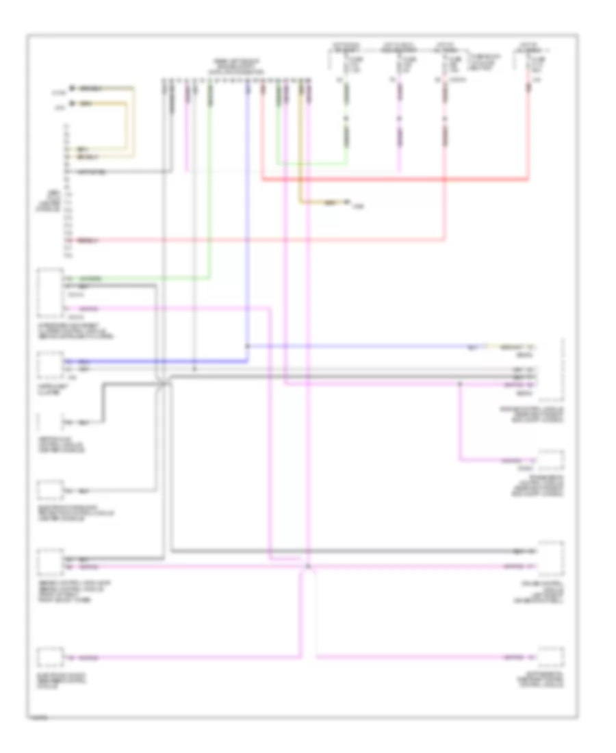
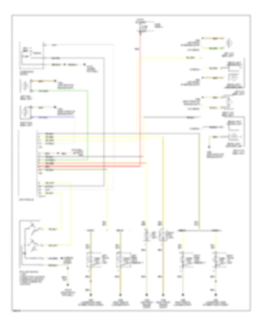
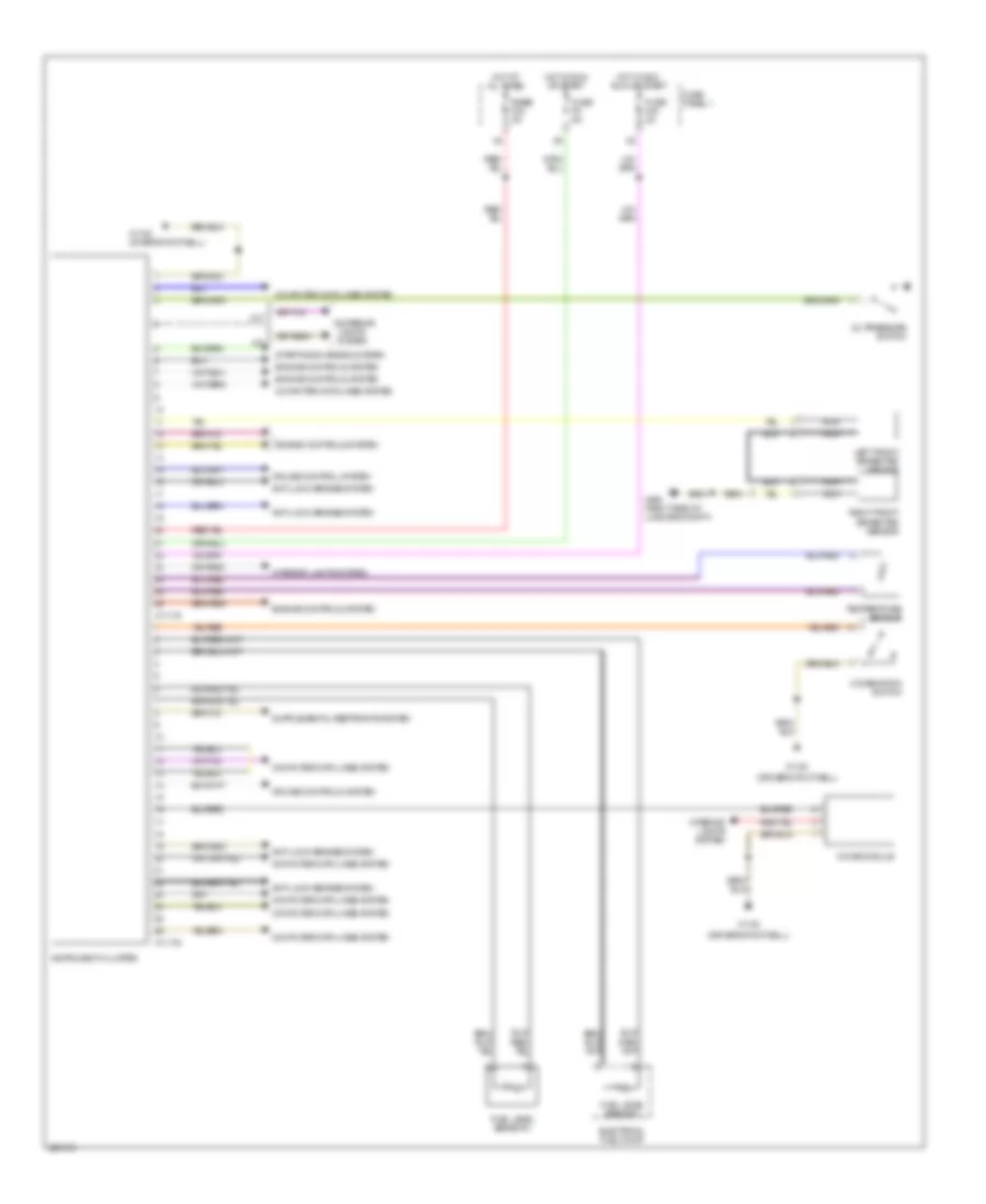
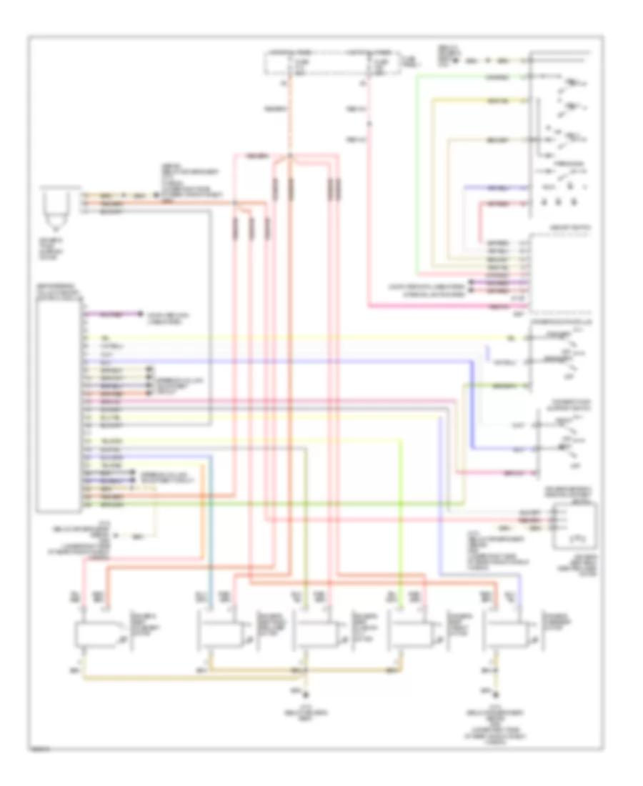
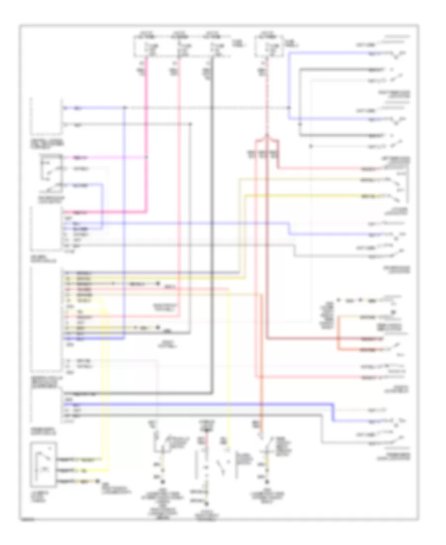
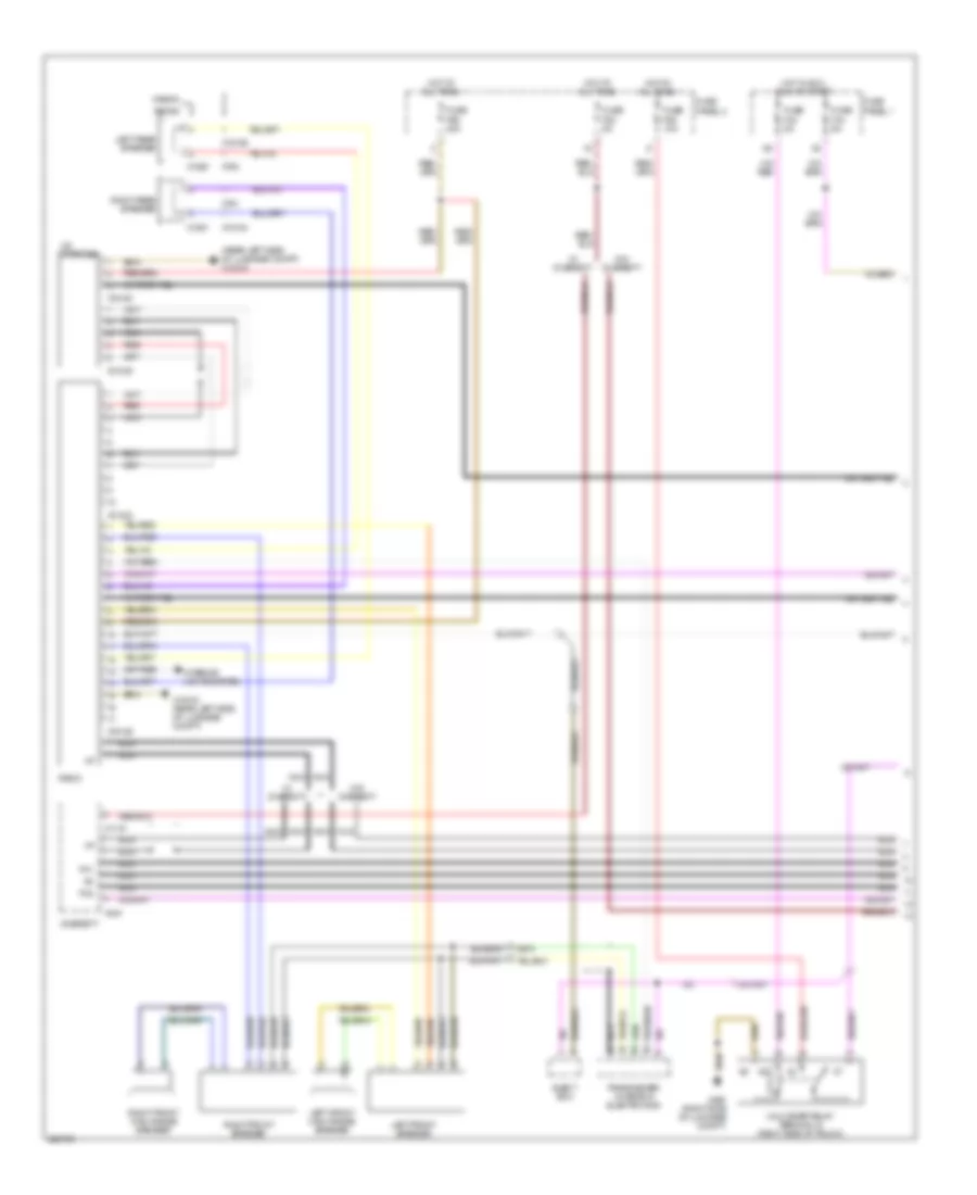
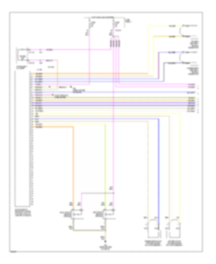
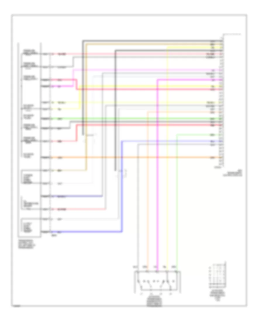
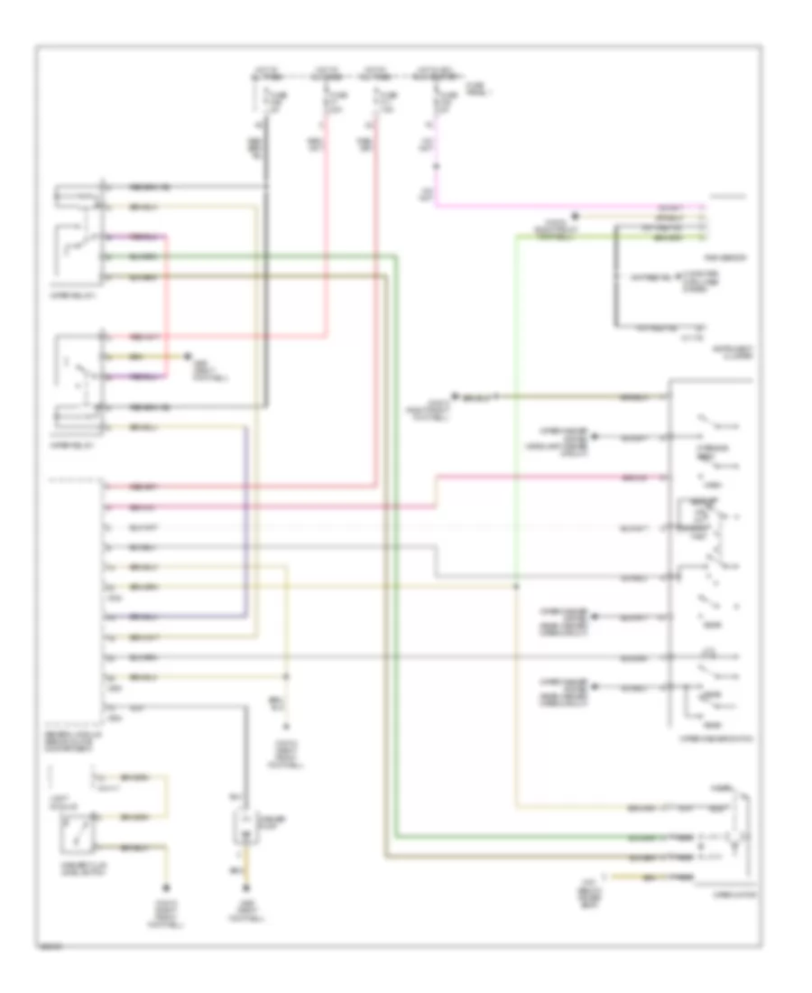
Automatic A/C Wiring Diagram (1 of 2) for BMW 540i 1997

List of elements for Automatic A/C Wiring Diagram (1 of 2) for BMW 540i 1997:
- 2.8l
- 4.4l
- A/c compressor
- Automatic air recirculation sensor
- Auxiliary water pump
- Computer data lines system
- Cooling fans system
- Defogger system
- Dual temperature sensor
- Engine control module (right rear of engine compt)
- Evaporator temperature sensor
- Fuse f20 5a
- Fuse f23 5a
- Fuse f9 15a
- Fuse panel (in glove box)
- Heating & a/c control module
- High pressure switch
- Hot at all times
- Hot in run or start
- Interior lights system
- Nca
- Ntc resistor steering angle sensor
- Red
- W/ latent heat accumulator
- Wiper/washer system
- X10015
- X173 (below driver's seat)
- X18153
- X18341
- X492 (driver door sill)
- X6000
- X610
- X611
- X613
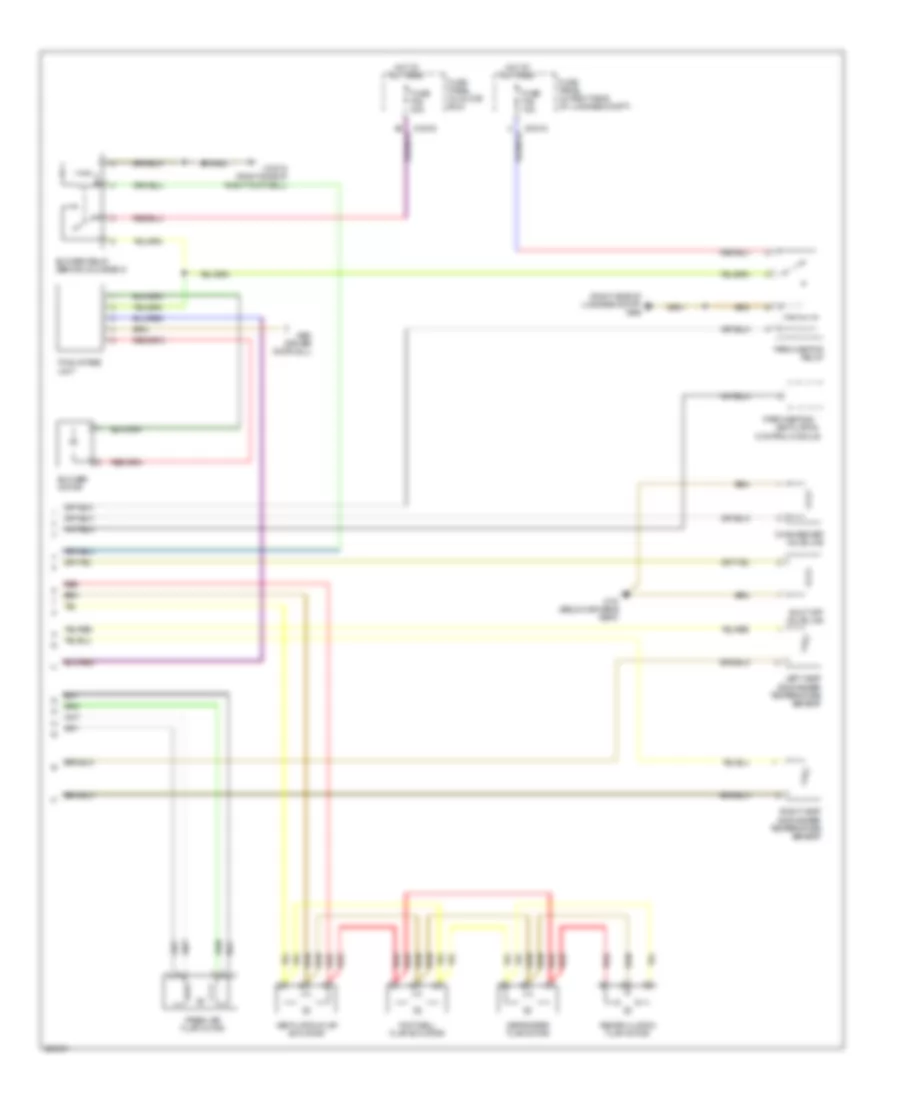
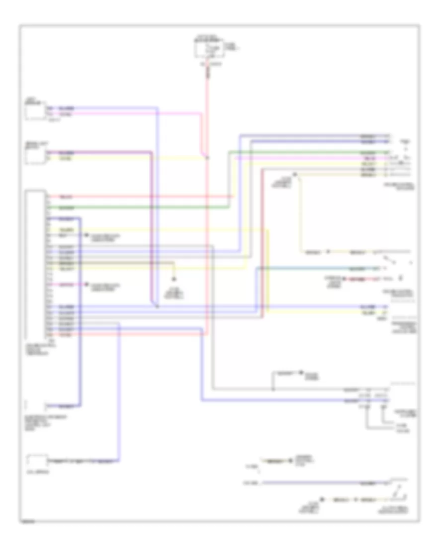
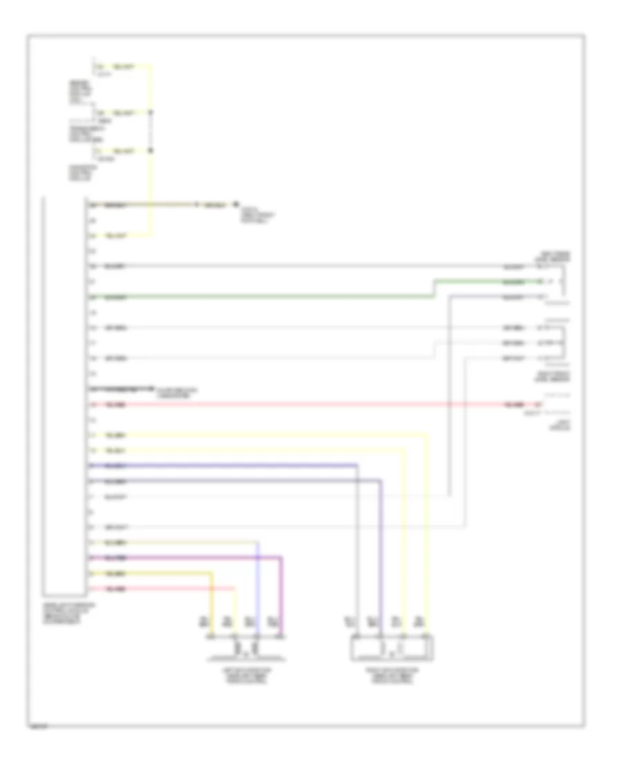
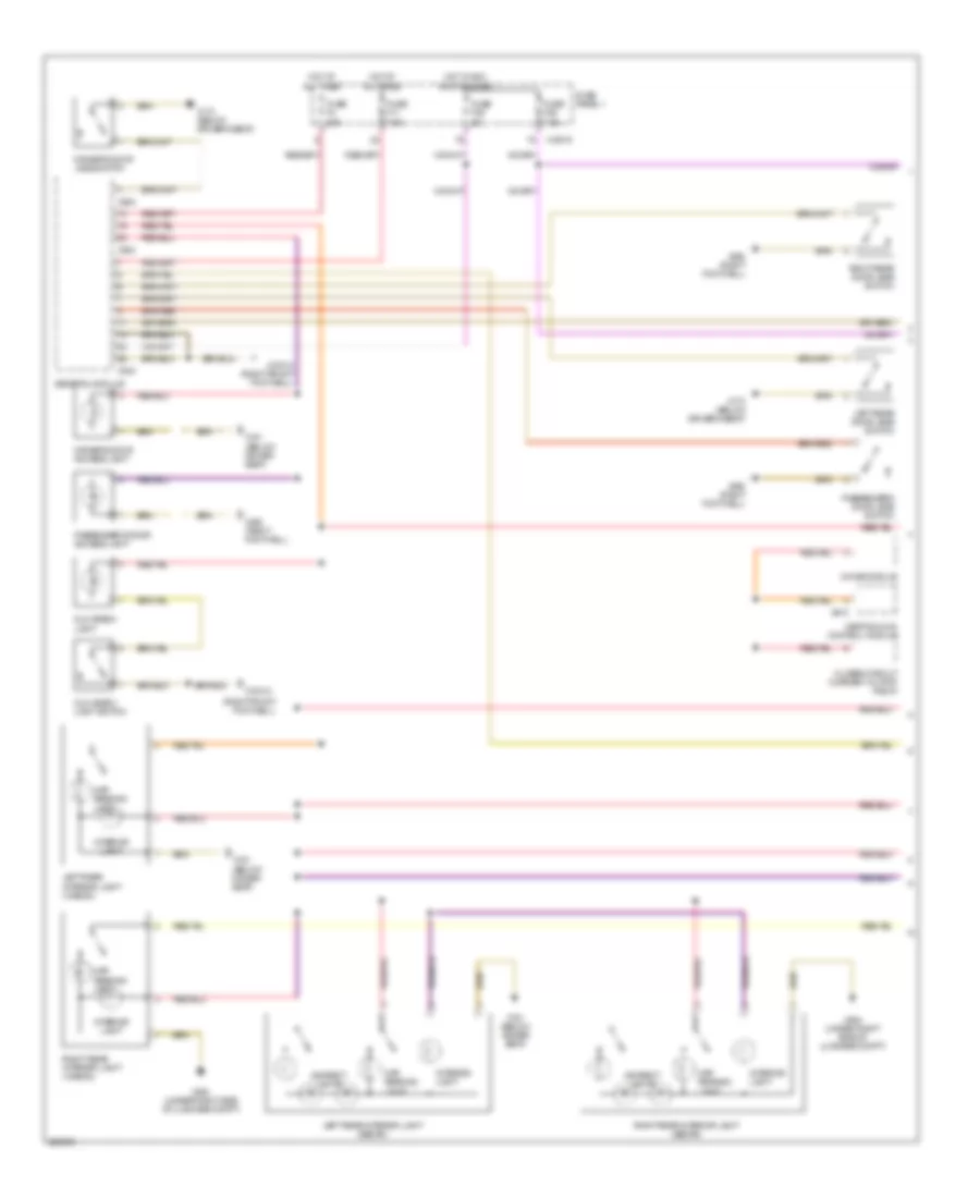
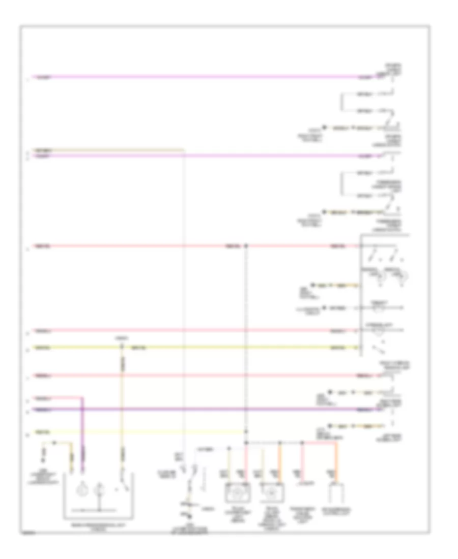
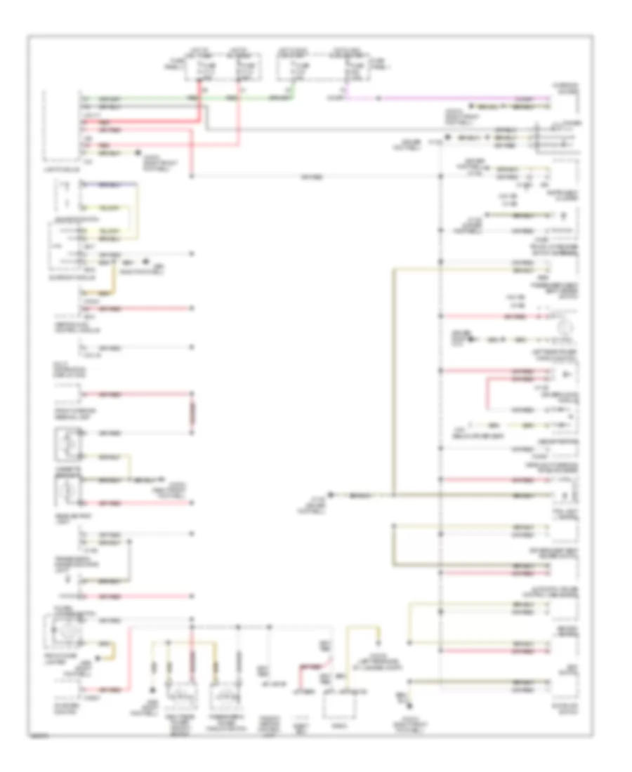
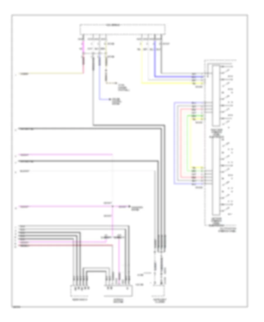
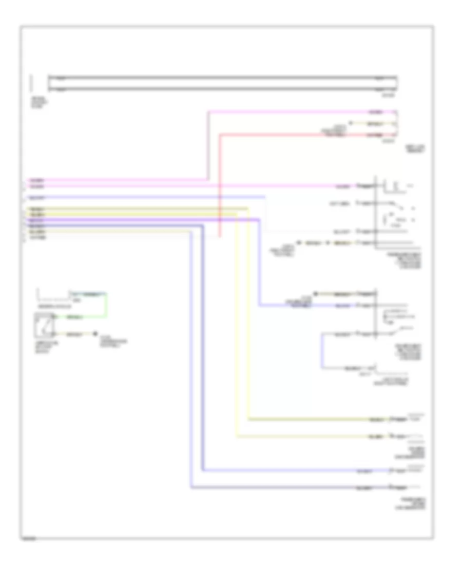
Automatic A/C Wiring Diagram (2 of 2) for BMW 540i 1997
List of elements for Automatic A/C Wiring Diagram (2 of 2) for BMW 540i 1997:
- (right side of luggage compt) x498
- Blower motor
- Blower relay (behind glove box)
- Changeover valve lws
- Control module
- Defroster flap motor
- Final stage unit
- Footwell flap actuator
- Fresh air flap motor
- Fuse f28 30a
- Fuse f46 15a
- Fuse panel (in glove box)
- Fuse panel (in right side of luggage compt)
- Hot at all times
- Left heat exchanger temperature sensor
- Park heating relay
- Park heating/
- Recirculation flap motor
- Red
- Right heat exchanger temperature sensor
- Shut off valve lws
- Ventilation
- Ventilation flap actuator
- X10012 (right side of right footwell)
- X10015
- X173 (below driver's seat)
- X490 (driver door sill)
ANTI-LOCK BRAKES
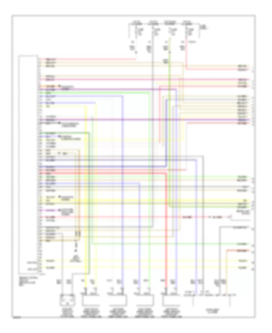
Anti-lock Brakes Wiring Diagram (1 of 2) for BMW 540i 1997
List of elements for Anti-lock Brakes Wiring Diagram (1 of 2) for BMW 540i 1997:
- Abs/asc control module (behind glove box)
- Auxiliary throttle position motor (ads)
- Brake light switch
- Can high
- Can low
- Computer data lines system
- Fuse f17 10a
- Fuse f30 25a
- Fuse f31 10a
- Fuse f8 25a
- Fuse panel 1
- Hot at all times
- Hot in run or start
- Instrument cluster
- Left front speed sensor (inside left front wheel hub)
- Left rear speed sensor (inside left rear wheel hub)
- Navigation system
- Nca
- Red
- Right front speed sensor (inside right front wheel hub)
- Right rear speed sensor (inside right rear wheel hub)
- Starting/ charging system
- W/ ike
- W/o ike
- X10015
- X11175
- X11176
- X1171
- X16
- X492 (right footwell)
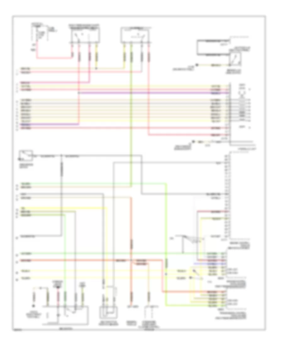
Anti-lock Brakes Wiring Diagram (2 of 2) for BMW 540i 1997
List of elements for Anti-lock Brakes Wiring Diagram (2 of 2) for BMW 540i 1997:
- (not used)
- (right rear engine compt) engine control relay
- 2.8l
- 4.4l
- Abs/asc control module (behind glove box)
- Asc switch
- Asc throttle position sensor
- Brake fluid level switch
- Can high
- Can low
- Engine control module (dme) (right rear engine compt)
- Fuse f108 5a
- Fuse panel 4
- General module
- Hot at all times
- Hydraulic unit
- Integrated instrument cluster control module
- Interior lights system
- Light module (right kick panel)
- Nca
- Park brake switch
- Red
- Transmission control module (ags) (right rear engine compt)
- Valve relay
- X10012 (right front footwell)
- X10114
- X1108 (driver footwell)
- X1171
- X1176
- X170
- X253
- X27
- X4 (right side of engine compt)
- X6000
- X8600
- X10117
ANTI-THEFT
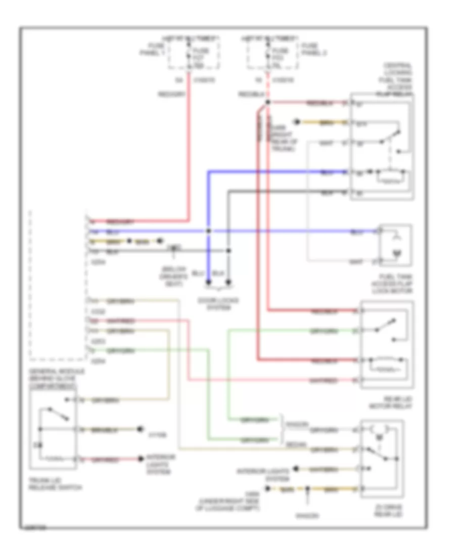
Forced Entry Wiring Diagram for BMW 540i 1997
List of elements for Forced Entry Wiring Diagram for BMW 540i 1997:
- Anti-theft horn (dwa)
- Computer data lines system
- Driver's door jamb switch
- Fuse f11 7.5a
- Fuse f38 5a
- Fuse f48 5a
- Fuse f53 5a
- Fuse panel 1
- Fuse panel 2
- General module (behind glove compartment)
- Hot acc, run or start
- Hot at all times
- Interior protection control module
- Left rear door jamb switch
- Liftgate lock switch
- Passenger's door jamb switch
- Radio-operated passenger compt protection control module
- Right rear door jamb switch
- Tilt sensor
- Underhood light switch
- X10012 (right front footwell)
- X173 (below driver's seat)
- X253
- X254
- X332
- X492 (right footwell)
- X494 (under right side of luggage compt)
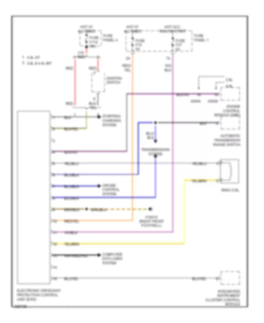
Immobilizer Wiring Diagram for BMW 540i 1997
List of elements for Immobilizer Wiring Diagram for BMW 540i 1997:
- 2.8l
- 2.8l & 4.4l m/t
- 4.4l
- 4.4l a/t
- Automatic transmission range switch
- Computer data lines system
- Cruise control system
- Electronic driveaway protection control unit (ews)
- Engine control module (dme)
- Fuse f114 50a
- Fuse f12 5a
- Fuse f37 5a
- Fuse panel 1
- Fuse panel 4
- Hot acc, run or start
- Hot at all times
- Ignition switch
- Integrated instrument cluster control module
- Red
- Ring coil
- Starting/ charging system
- Transmissions system
- X10 red
- X10012 (right front footwell)
- X6000
BODY CONTROL MODULES
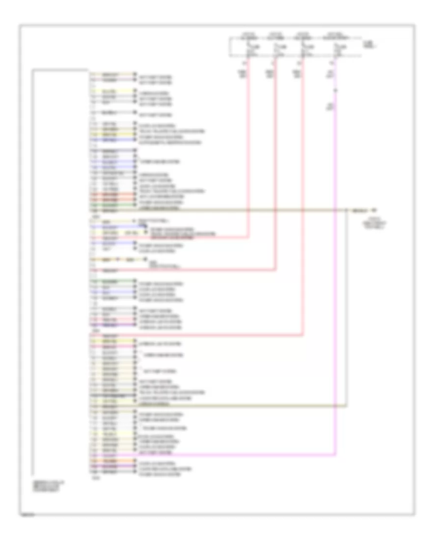
General Module Wiring Diagram for BMW 540i 1997
List of elements for General Module Wiring Diagram for BMW 540i 1997:
- (right footwell) x490
- Anti-lock brakes system
- Anti-theft system
- Computer data lines system
- Door locks system
- Fuse 20a
- Fuse 30a
- Fuse 5a
- Fuse 7.5a
- Fuse panel 1
- General module (behind glove compartment)
- Hot acc, run or start
- Hot at all times
- Interior lights system
- Mirror systems
- Mirrors system
- Power window system
- Power windows system
- Trunk, tailgate, fuel doors system
- Trunk, tailgate, fuel doors system (or door locks system)
- Warning system
- Wiper/washer system
- X10012 (right front footwell)
- X253
- X254
- X332
- X492 (right footwell)
COMPUTER DATA LINES
Computer Data Lines Wiring Diagram for BMW 540i 1997
List of elements for Computer Data Lines Wiring Diagram for BMW 540i 1997:
- (rear left side of engine compt) data link connector
- Abs/asc control module or abs/dsc control module (front of right front shock tower)
- Cruise control module (left side of driver's footwell)
- Electronic drive-away protection control module (center console)
- Electronic shock absorber control module
- Engine control module (rear right side of eng compt, in e-box)
- Fuse block (in glove box top)
- Fuse f114 50a
- Fuse f15 7.5a
- Fuse f25 7.5a
- Fuse f38 5a
- Heating & a/c control module (center console)
- Hot at all times
- Hot in accy, run or start
- Hot in run or start
- Instrument cluster
- Integrated insturment cluster control module (behind instrument cluster)
- Obdii plug (center console)
- Red
- Transmission control module (rear right side of eng compt, in e-box)
- X10
- X10015
- X10113
- X10114
- X1108
- X151
- X16
- X166
- X60002
- X60004
- X70001
CRUISE CONTROL
Cruise Control Wiring Diagram for BMW 540i 1997
List of elements for Cruise Control Wiring Diagram for BMW 540i 1997:
- (driver's footwell) x1108
- Brake light switch
- Clutch pedal position switch
- Coil spring
- Computer data lines system
- Cruise control actuator
- Cruise control main switch
- Cruise control module (tempormat)
- Electronic driveaway protection control unit (ews)
- Fuse f41 5a
- Fuse panel 1
- Hot in acc, run or start
- Instrument cluster
- Interior lights system
- Light module
- Nca
- Sound system
- Transmission control module (ags)
- W/ ags
- W/ ike
- W/o ags
- W/o ike
- X10015
- X10113
- X10117
- X1108 (driver's footwell)
- X11175
- X11176
- X16
- X22
- X8600
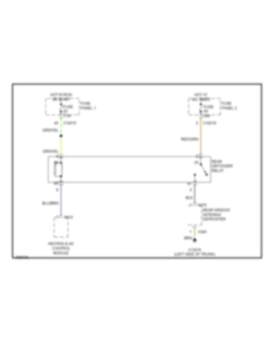
DEFOGGERS
Defoggers Wiring Diagram for BMW 540i 1997
List of elements for Defoggers Wiring Diagram for BMW 540i 1997:
- Fuse 40a
- Fuse 7.5a
- Fuse panel 1
- Fuse panel 2
- Heating & a/c control module
- Hot at all times
- Hot in run or start
- Rear defogger relay
- Rear window antenna/ defroster
- X10015
- X10019
- X13016 (left side of trunk)
- X379
- X380
- X610
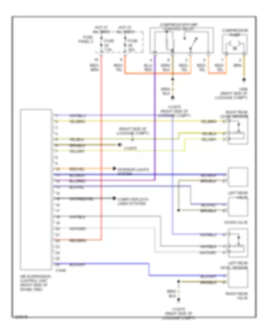
ELECTRONIC SUSPENSION
Electronic Air Suspension Wiring Diagram for BMW 540i 1997
List of elements for Electronic Air Suspension Wiring Diagram for BMW 540i 1997:
- (right side of luggage compt)
- Air suspension control unit (right side of spare tire)
- Compressor pump
- Compressor pump control relay
- Computer data lines stystem
- Down valve
- Fuse 30a
- Fuse 7.5a
- Fuse panel 2
- Hot at all times
- Interior lights system
- Left rear level sensor
- Left rear valve
- Right rear level sensor
- Right rear valve
- X13075
- X13075 (right side of luggage compt)
- X1448
- X498 (right side of luggage compt)
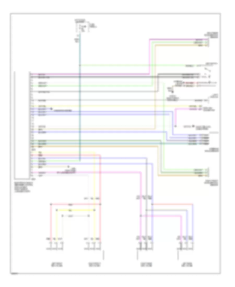
Electronic Damper Control Wiring Diagram for BMW 540i 1997
List of elements for Electronic Damper Control Wiring Diagram for BMW 540i 1997:
- Computer data lines system
- Data link connector
- Edc switch
- Electronic shock absorber control module (edc) (right side of luggage compt)
- Fuse 15a
- Fuse panel 2
- Hot in run or start
- Interior lights system
- Left front edc valves
- Left rear edc valves
- Light module
- Navigation system
- Nca
- Red
- Right front acceleration sensor
- Right front edc valves
- Right rear acceleration sensor
- Right rear edc valves
- Steering angle sensor
- X10012 (right front footwell)
- X263
- X498 (right side of luggage compt)
- X945
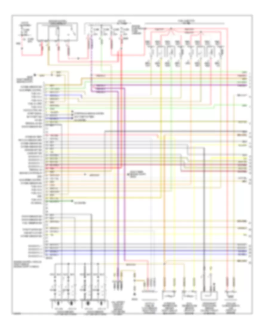
ENGINE PERFORMANCE
4.4L
4.4L, Engine Performance Wiring Diagram (1 of 3) for BMW 540i 1997
List of elements for 4.4L, Engine Performance Wiring Diagram (1 of 3) for BMW 540i 1997:
- (right rear engine compt) x6452
- A/c sig
- A/c signal
- A/c system
- Air flow sensor grd
- Anti-theft sig
- Anti-theft sytsem
- Camshaft sig
- Cooling characteristic map (front of engine)
- Crankshaft position/rpm sensor (on right front of engine)
- Crankshaft sig
- Cyl 1-2
- Cyl 3-4
- Cyl 5-6
- Cyl 7-8
- Dual temperature sensor (front of engine)
- Engine contr relay
- Engine control module (right side of engine compt in e-box)
- Engine control module relay
- Engine electronics fuse carrier
- Fuel inj 1
- Fuel inj 2
- Fuel inj 3
- Fuel inj 4
- Fuel inj 5
- Fuel inj 6
- Fuel inj 8
- Fuel inj grd
- Fuel injection valves
- Fuel reserve sig
- Fuse 30a
- Fuse 80a
- Fuse box
- Grd
- Hall effect camshaft position sensor (top center of eng)
- Hot at all times
- Hot-film mass air flow sensor (right front of engine)
- Idle speed control
- Ign sig cyl 1
- Ign sig cyl 2
- Ign sig cyl 3
- Ign sig cyl 4
- Ign sig cyl 5
- Ign sig cyl 6
- Ign sig cyl 7
- Ign sig cyl 8
- Intake air temp
- Intake air temperature sensor (right side of eng compt)
- Knock sensor (top center of eng)
- Knock sensor sig
- Malfunction ind
- Mas air flow sig
- Nca
- Oxygen sensor sig
- Red
- Start signal
- Starting/charging system
- Terminal 30
- Terminal 50 sig
- Throttle pos sig
- X60003
- X6452
- X6453 (right rear of engine compt)
- X8680 red
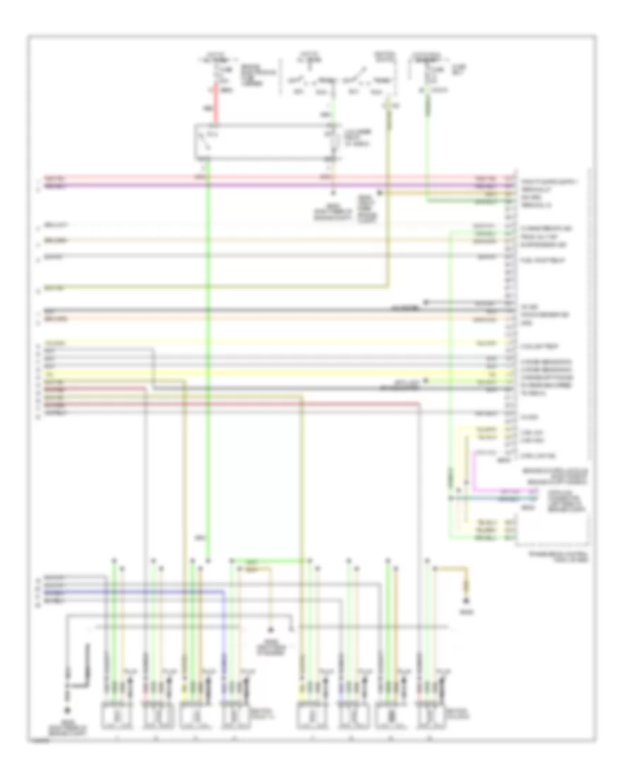
4.4L, Engine Performance Wiring Diagram (2 of 3) for BMW 540i 1997
List of elements for 4.4L, Engine Performance Wiring Diagram (2 of 3) for BMW 540i 1997:
- (left side of engine compt) fuel tank vent valve
- (right side of lugg compt) fuel pump relay
- (w/ ike) (behind instrument cluster) integrated instrument cluster control module
- Fuel pump
- Fuse 10a
- Fuse 15a
- Fuse 7.5a
- Fuse panel 1
- Fuse panel 2
- Heated oxygen sensor i (behind cat conv)
- Heated oxygen sensor i (front of cat conv)
- Heated oxygen sensor ii (behind cat conv)
- Heated oxygen sensor ii (front of cat conv)
- Hot at all times
- Hot in run or start
- Idle speed control valve (top side of engine)
- Instrument cluster
- Light module (right kick panel)
- Nca
- Oil level sensor (underside of oil pan)
- Throttle position sensor (top front of engine)
- W/ ike
- W/o ike
- X10015
- X10114
- X10117
- X11176
- X16
- X494
- X6452 (right rear of engine compt)
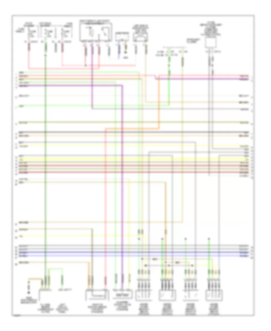
4.4L, Engine Performance Wiring Diagram (3 of 3) for BMW 540i 1997
List of elements for 4.4L, Engine Performance Wiring Diagram (3 of 3) for BMW 540i 1997:
- A/c sig
- A/c system
- Acc
- Anti-lock brakes system
- Can high
- Can low
- Characteristic sig
- Coolant temp
- Crankshaft pos sig
- Data link connector (left side of engine compt)
- Data link txd
- Engine control module (right side of engine compt in e-box)
- Engine electronics fuse carrier
- Evap emission sig
- Fuel pump relay
- Fuse 30a
- Fuse 5a
- Fuse box
- Grd
- Hot at all times
- Hot in run or start
- Ign grd
- Ignition coils 1-4
- Ignition coils 5-8
- Ignition switch
- Inj sig
- Knock sensor sig
- Nca
- Off
- Oxygen sensor sig
- Plug
- Prog volt inp
- Red
- Rh rear eng speed
- Run
- Start
- Td signal
- Terminal 15
- Terminal 87
- Transmission control module (ags)
- Unloader relay (in e box)
- X10015
- X33
- X6000
- X6002
- X6452 (right rear engine compt)
- X6452 (right rear of engine compt)
- X6453 (right rear of engine compt)
- X6455
- X6456 (right side of engine)
- X8680
EXTERIOR LIGHTS
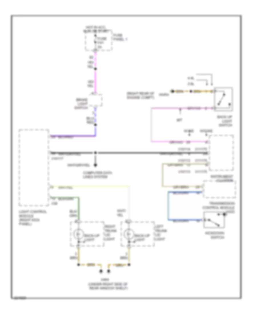
Backup Lamps Wiring Diagram, Sedan for BMW 540i 1997
List of elements for Backup Lamps Wiring Diagram, Sedan for BMW 540i 1997:
- 2.8l
- 4.4l
- Back up light switch
- Back-up light
- Brake light switch
- Computer data lines system
- Fuse f41 5a
- Fuse panel 1
- Hot in acc, run or start
- Instrument cluster
- Kickdown switch
- Left rear light assembly 1
- Light control module (right kick panel)
- M/t
- Right rear light assembly 1
- Transmission control module (ags)
- W/ ike
- W/o ike
- X10113
- X10114
- X10117
- X11175
- X11176
- X38
- X498 (right side of luggage compt)
- X6454 (right rear of engine compt)
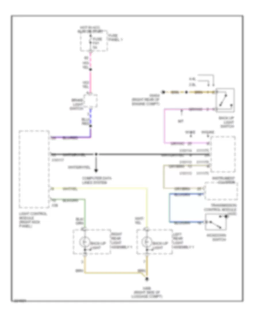
Backup Lamps Wiring Diagram, Wagon for BMW 540i 1997
List of elements for Backup Lamps Wiring Diagram, Wagon for BMW 540i 1997:
- (right rear of engine compt)
- (under right side of rear window shelf)
- 2.8l
- 4.4l
- Back up light switch
- Back-up light
- Brake light switch
- Computer data lines system
- Fuse f41 5a
- Fuse panel 1
- Hot in acc, run or start
- Instrument cluster
- Kickdown switch
- Left trunk lid light
- Light control module (right kick panel)
- M/t
- Right trunk lid light
- Transmission control module (ags)
- W/ ike
- W/o ike
- X10113
- X10114
- X10117
- X11175
- X11176
- X38
- X494
- X6454
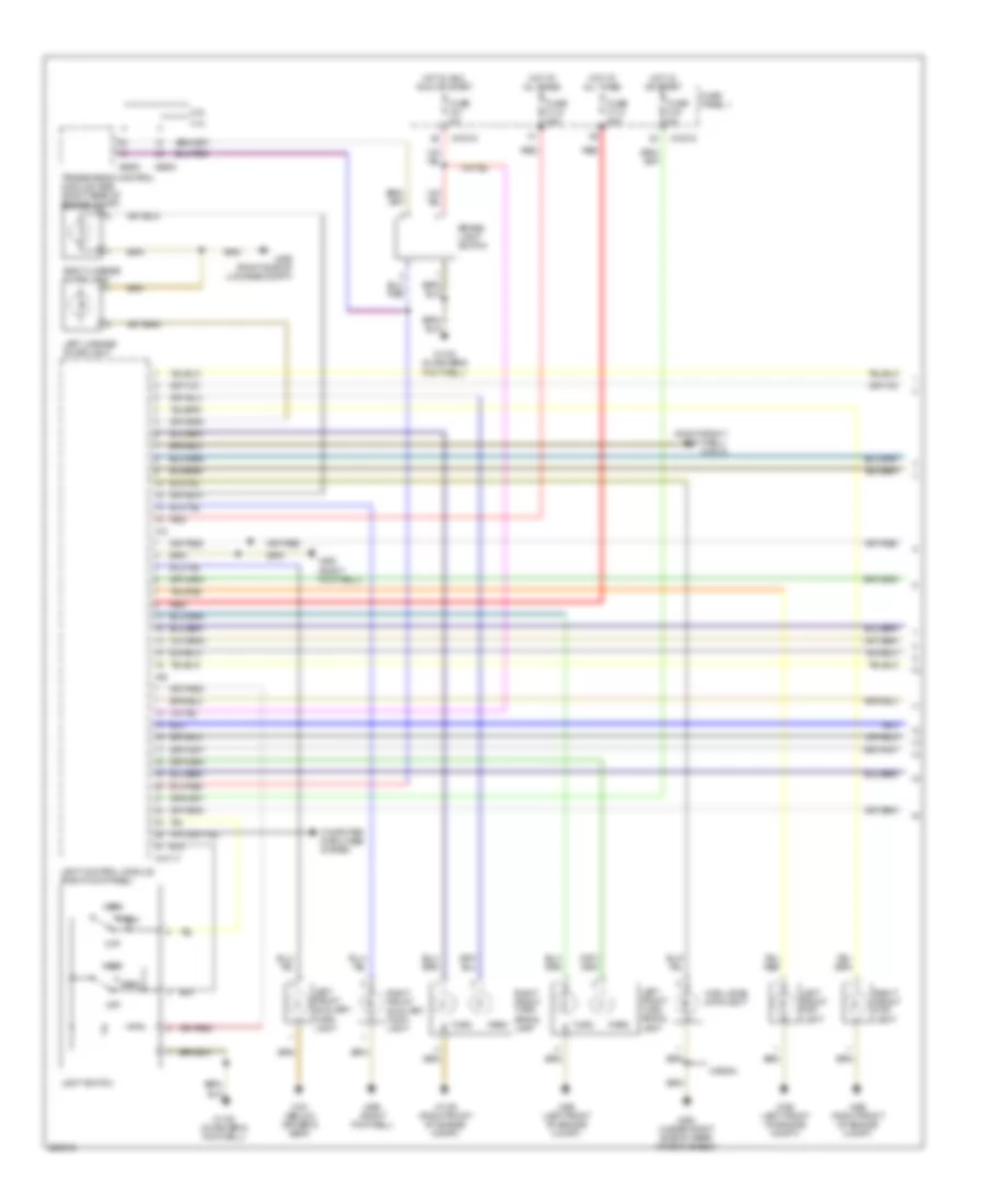
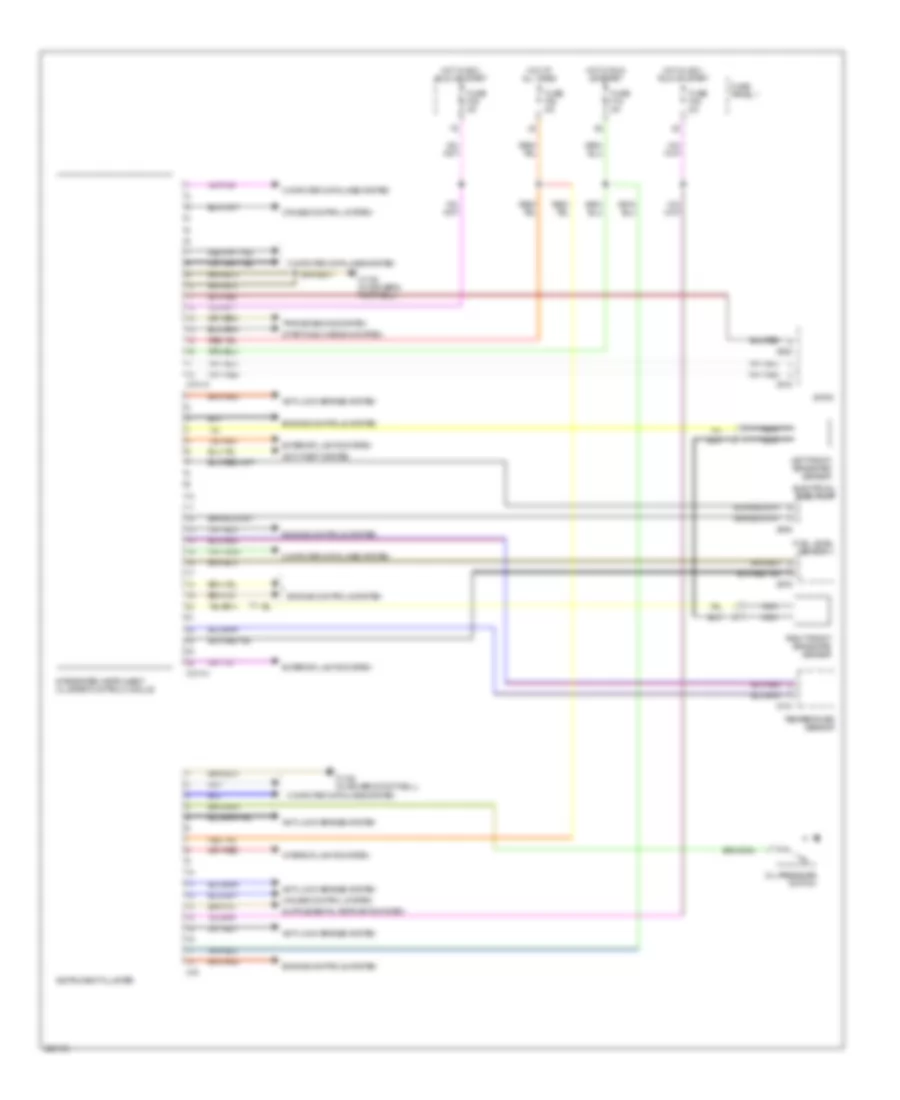
Exterior Lamps Wiring Diagram (1 of 2) for BMW 540i 1997
List of elements for Exterior Lamps Wiring Diagram (1 of 2) for BMW 540i 1997:
- (right front footwell) x10012
- 2.8l
- 4.4l
- Brake light switch
- Computer data lines system
- Fuse f112 80a
- Fuse f113 80a
- Fuse f16 5a
- Fuse f41 5a
- Fuse panel 1
- Head
- High level stoplight
- Hot at all times
- Hot in acc, run or start
- Hot in or start
- Left front auxiliary turn light
- Left front fog light
- Left front turn signal lamp
- Left license plate light
- Light control module (right kick panel)
- Light switch
- Off
- Park
- Red
- Right front auxiliary turn light
- Right front fog light
- Right front turn signal lamp
- Right license plate light
- Transmission control module (ags) (right rear of engine compt)
- Turn
- Wagon
- X10015
- X10117
- X1106 (right front of engine compt)
- X1108 (in driver's footwell)
- X12
- X151 (below driver's seat)
- X165 (left front of engine compt)
- X166 (right front of engine compt)
- X38
- X490 (right footwell)
- X492 (right footwell)
- X494 (under right side of rear window shelf)
- X498 (right side of luggage compt)
- X8600
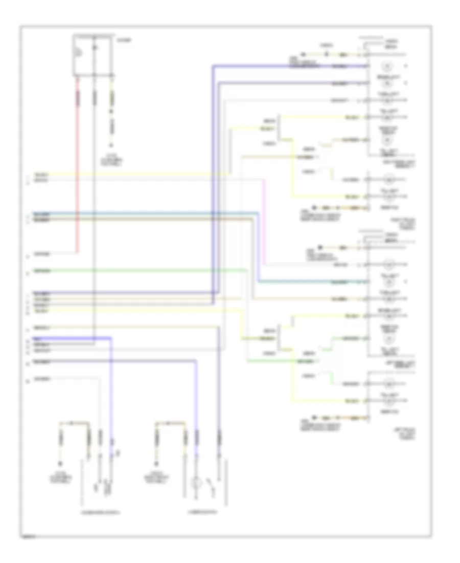
Exterior Lamps Wiring Diagram (2 of 2) for BMW 540i 1997
List of elements for Exterior Lamps Wiring Diagram (2 of 2) for BMW 540i 1997:
- Brake light
- Combination switch
- Dimmer
- Hazard switch
- Left
- Left rear light assembly 1
- Left trunk lid light (wagon)
- Rear fog
- Rear fog (sedan)
- Right
- Right rear light assembly 1
- Right trunk lid light (wagon)
- Sedan
- Tail light
- Tail light (sedan)
- Turn light
- Wagon
- X10012 (right front footwell)
- X1108 (in driver's footwell)
- X32
- X494 (under right side of rear window shelf)
- X498 (right side of luggage compt)
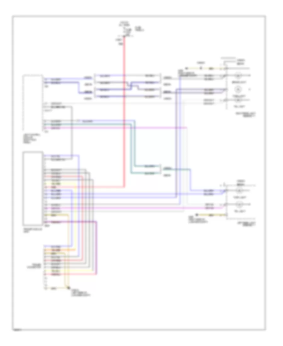
Trailer Tow Wiring Diagram for BMW 540i 1997
List of elements for Trailer Tow Wiring Diagram for BMW 540i 1997:
- Brake light
- Fuse f103 50a
- Fuse panel 5
- Hot at all times
- Left rear light assembly 1
- Light control module (right kick panel)
- Red
- Right rear light assembly 1
- Sedan
- Tail light
- Trailer connector
- Trailer module (ahm)
- Turn light
- Wagon
- X10117
- X12
- X19517
- X19518 (left rear of luggage compt)
- X38
- X498 (right side of luggage compt)
- X609
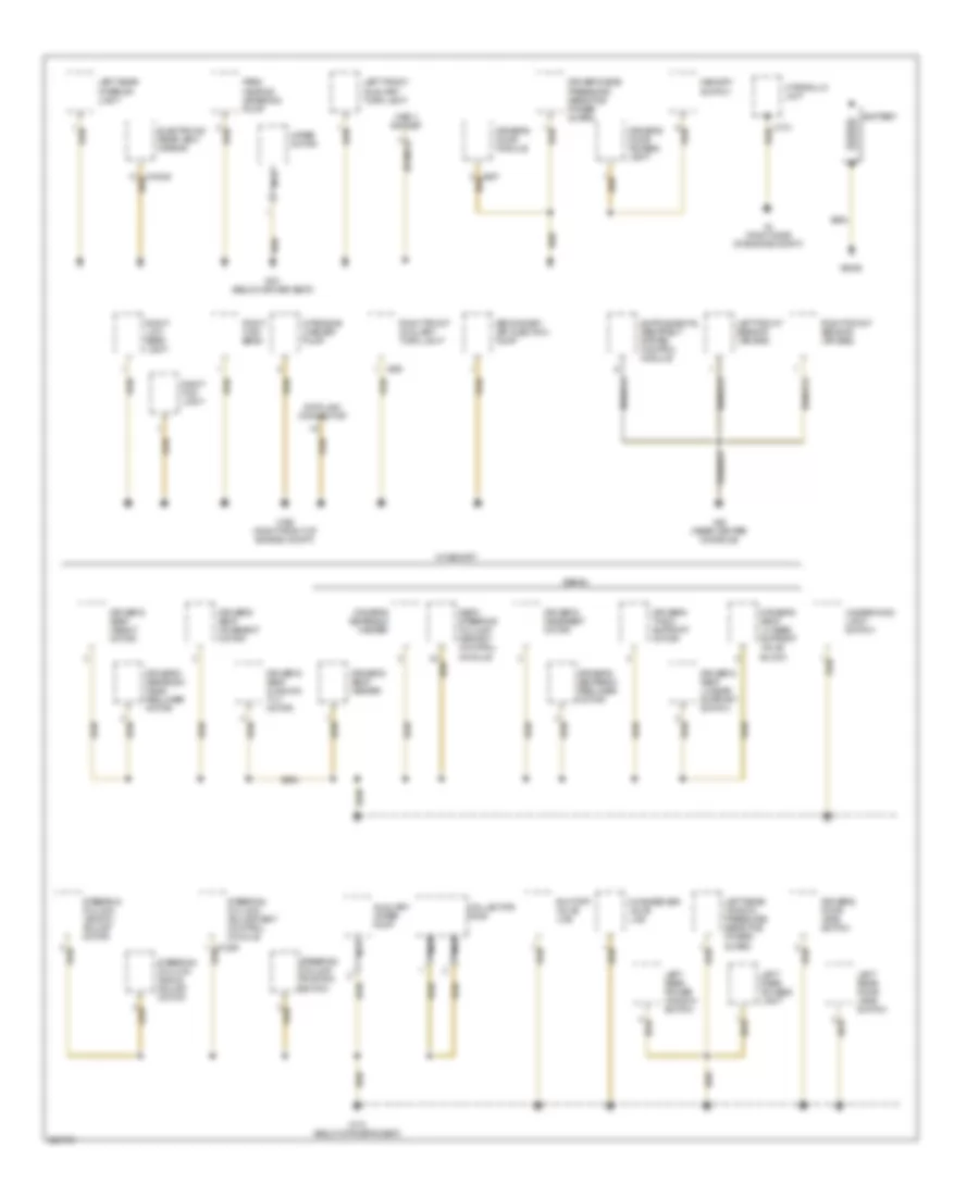
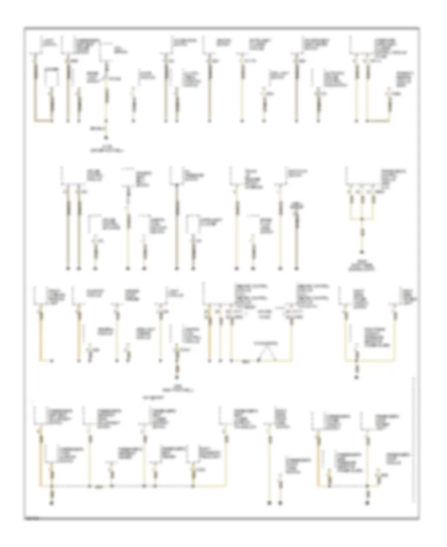
GROUND DISTRIBUTION
Ground Distribution Wiring Diagram (1 of 5) for BMW 540i 1997
List of elements for Ground Distribution Wiring Diagram (1 of 5) for BMW 540i 1997:
- Auxiliary water pump
- Battery
- Changeover valve lws
- Collector ring
- Data link connector
- Driver's door access light
- Driver's door jamb switch
- Driver's door module
- Driver's headrest motor
- Driver's seat cushion tilt motor
- Driver's seat heater
- Driver's seat height motor
- Driver's seat lumbar support switch
- Driver's seat lumbar support valve block
- Driver's seat movement motor
- Driver's seatback head recliner motor
- Driver's seatback heater
- Driver's seatback recliner motor
- Driver's side pressure sensitive finger guard
- Driver's thigh support motor
- Electronic rear view mirror
- Hydraulic unit
- Intensive washer pump
- Left front auxiliary turn light
- Left front sensor (air bag)
- Left rear access light
- Left rear door jamb switch
- Left rear interior light
- Left rear power window switch
- Left rear window pressure sensitive finger guard
- Memory switch
- Nca
- Obd ii socket
- Park heating metering pump
- Right fog light
- Right front auxiliary turn light
- Right front sensor (air bag)
- Right high beam
- Right low beam light
- Seat/ steering column memory control module
- Secondary air injection pump
- Sedan
- Shutoff valve lws
- Steering column adjustment control module
- Steering column angle adjust motor
- Steering column length adjust motor
- Steering column position switch
- Underhood light switch
- W/ memory
- Wiper motor
- X151 (below driver seat)
- X166 (right front of engine compt)
- X170
- X173 (below driver's seat)
- X390
- X4 (right side of engine compt)
- X46 (rear center console)
- X6406
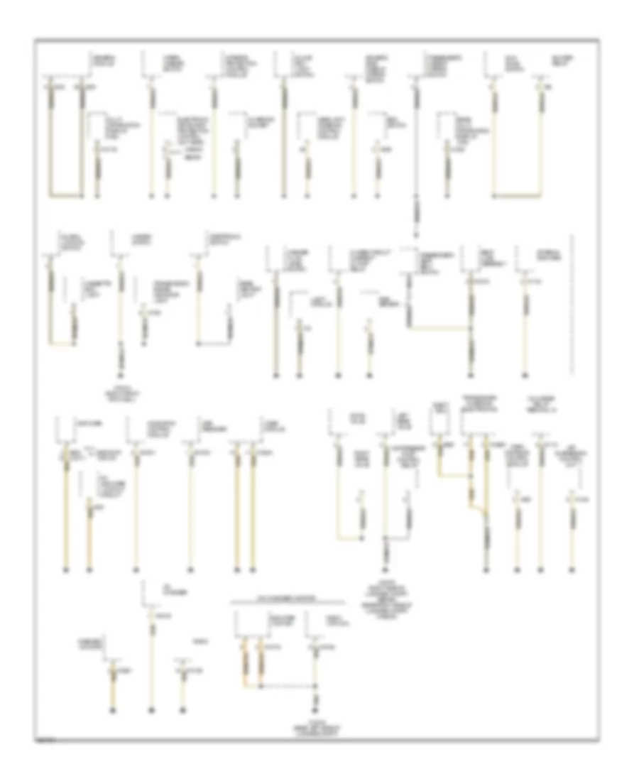
Ground Distribution Wiring Diagram (2 of 5) for BMW 540i 1997
List of elements for Ground Distribution Wiring Diagram (2 of 5) for BMW 540i 1997:
- Abs/dsc control module (4.4l) abs/asc control module (2.8l & 4.4l)
- Asc/dsc switch
- Automatic cruise control main switch
- Brake fluid level switch
- Brake light switch
- Chime module
- Clutch pedal position switch
- Coil spring
- Combination switch
- Cruise control actuator
- Cruise control module
- Dimmer
- Driver's seat belt switch
- Driver's seat seat heater switch
- Fog light switch
- Front interior/ reading lamp
- Garage door opener
- General module
- Headlight washer module
- Heating & a/c control module
- Inertia fuel shutoff switch
- Instrument cluster
- Instrument cluster (w/o ike)
- Integrated instrument cluster control module (w/ ike)
- Light module
- Light switch
- Nca
- Obd ii socket
- Oil pressure switch
- Passenger's door access light
- Passenger's door jamb switch
- Passenger's door module
- Passenger's power window switch
- Passenger's seat heater
- Passenger's seat lumbar support switch
- Passenger's seat lumbar support valve block
- Passenger's seat seat adjustment switch
- Passenger's seat seat heater switch
- Passenger's seatback head adjustment switch
- Passenger's seatback heater
- Passenger's side pressure sensitive finger guard
- Passenger's thigh support switch
- Right accessory table light
- Right rear access light
- Right rear door jamb switch
- Right rear power window switch
- Right rear window pressure sensitive finger guard
- Shiftlock switch
- Sunroof module
- Transmission control module (ags) (4.4l)
- Transmit/ receive module (ews)
- Trunk lid release switch (interior)
- W/ dsc
- W/ navigation
- W/o dsc
- W/o memory
- X01026
- X10113
- X1108 (driver footwell)
- X11175
- X1171
- X16
- X1660
- X1882
- X22
- X32
- X492 (right footwell)
- X504
- X521
- X6453 (right rear engine compt)
- X651
- X656
- X70
- X72
- X8600
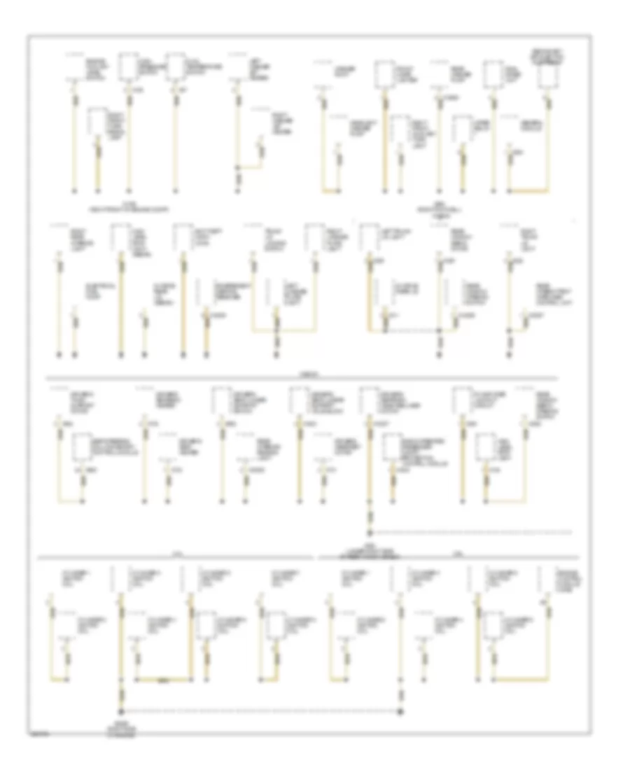
Ground Distribution Wiring Diagram (3 of 5) for BMW 540i 1997
List of elements for Ground Distribution Wiring Diagram (3 of 5) for BMW 540i 1997:
- Air suspension control unit
- Amplifier
- Amplifier (top hifi)
- Antenna amplifier
- Blower relay
- Cassette box light
- Cd changer
- Charging socket
- Closed circuit current cutoff relay
- Compressor pump control relay
- Down valve
- Driver's side makeup mirror switch
- Edc switch
- Eject box
- Electronic drive away protection control unit (ews)
- Fm amplifier lockout circuit
- General module
- Global locking switch
- Glove box light switch
- Gps receiver
- Hazard switch
- Headlight widening control module
- Interior protection control module
- Left rear valve
- Light module
- Multi- information display (mid)
- Navigation control module
- Nca
- Onboard monitor
- Park distance control module
- Passenger's makeup mirror switch
- Passenger's seat belt switch
- Radio
- Radio (top hifi)
- Radio/hifi top hifi
- Rain sensor
- Rear ashtray light
- Rear multi information display (mid)
- Right rear valve
- Seat load assembly
- Sedan
- Steptronic switch
- Sun blind switch
- Transceiver/ charging electronics
- Transmission range indicator light
- Unloader relay terminal 15
- Video module
- W/o on board monitor
- Wagon
- Washer fluid level switch
- Wiper/ washer switch
- X01001
- X10012 (right front footwell)
- X10119
- X10218
- X1143
- X1193
- X12
- X13016 (rear left side of luggage compt)
- X13075 (right side of luggage compt) (sedan) (rear right side of luggage compt) (wagon)
- X1309
- X1448
- X18180
- X18500
- X18771
- X18772
- X300
- X529
- X58
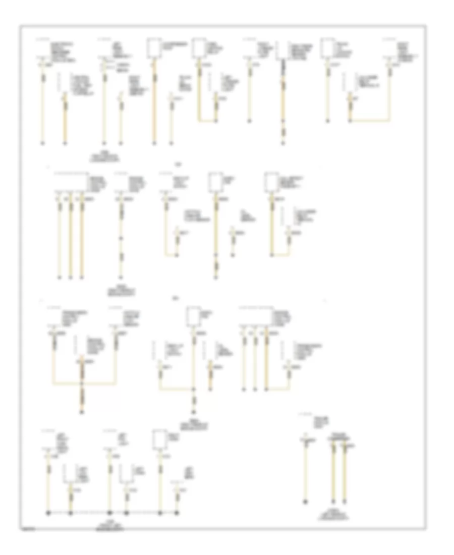
Ground Distribution Wiring Diagram (4 of 5) for BMW 540i 1997
List of elements for Ground Distribution Wiring Diagram (4 of 5) for BMW 540i 1997:
- 2.8l
- 4.4l
- Anti-theft horn (dwa)
- Cylinder 1 ignition coil
- Cylinder 2 ignition coil
- Cylinder 3 ignition coil
- Cylinder 4 ignition coil
- Cylinder 5 ignition coil
- Cylinder 6 ignition coil
- Cylinder 7 ignition coil
- Cylinder 8 ignition coil
- Driver's headrest motor
- Driver's seat heater
- Driver's seat lumbar support switch
- Driver's seat lumbar support valve block
- Driver's seatback head recliner motor
- Driver's seatback heater
- Driver's thigh support motor
- Dual temperature switch
- Electrical fuel pump
- Engine control module (dme)
- Engine coolant level switch
- Final stage unit
- Fm amplifier lockout circuit
- Front cigar lighter
- General module
- Headlight washer pump
- High level stop light
- High level stop light (sedan)
- High pressure switch
- Independent heating receiver
- Left license plate light
- Left trunk lid light
- Left washer jet heater
- Radio-operated passenger compt protection control module
- Rear interior/ reading light
- Rear intermittent wipe/wash control unit
- Rear washer pump
- Rear window opening switch
- Rear window servo motor
- Rear window servo opening switch
- Right front auxiliary turn light
- Right front turn signal lamp
- Right license plate light
- Right rear interior light
- Right trunk lid light
- Right washer jet heater
- Seat/steering column memory control module
- Secondary air injection pump relay
- Trunk lid locking switch
- Wagon
- Washer pump
- Wiper relay
- X1106 (right front of engine compt)
- X1253
- X126
- X13057
- X13059
- X138
- X1503
- X1644
- X18080
- X18307
- X254
- X311
- X380
- X490 (right footwell)
- X494 (under right side of rear window shelf)
- X6456 (right side of engine)
- X652
- X653
- X731
- X732
- X733
- X87
- X882
- Zv drive rear lid
- Zv drive rear lid (sedan)
Ground Distribution Wiring Diagram (5 of 5) for BMW 540i 1997
List of elements for Ground Distribution Wiring Diagram (5 of 5) for BMW 540i 1997:
- 2.8l
- 4.4l
- Back up light switch
- Central locking fuel tank access flap relay
- Compressor pump
- E-box fan
- Electronic shock absorber control module (edc)
- Engine control module (dme)
- Hall-effect sensor camshaft 1
- Hot-film mass air flow sensor
- Left fog light
- Left front turn signal light
- Left hign beam
- Left horn
- Left license plate light
- Left low beam light
- Left rear light assembly i
- Nca
- Oil level sensor
- Park heating relay
- Right horn
- Right license plate light
- Right rear brake pad sensor (w/o ike)
- Right rear light assembly 1 (wagon)
- Right rear light assembly i (sedan)
- Sedan
- Trailer connector
- Trailer module (ahm)
- Transmission control module (ags)
- Trunk lid locking switch
- Trunk lid servo motor
- Unloader relay terminal
- Unloader relay terminal r
- Wagon
- X1024
- X1211
- X128
- X130
- X131
- X132
- X133
- X1377
- X165 (front left engine compt)
- X19518 (left rear of luggage compt)
- X263
- X318
- X498 (right side of luggage compt)
- X57
- X6000
- X6217
- X6219
- X6254
- X6326
- X6452 (right rear of engine compt)
- X6454 (right rear of engine compt)
- X6506
- X709
- X710
- X768
- X8000
- X8511
- X8524
- X8600
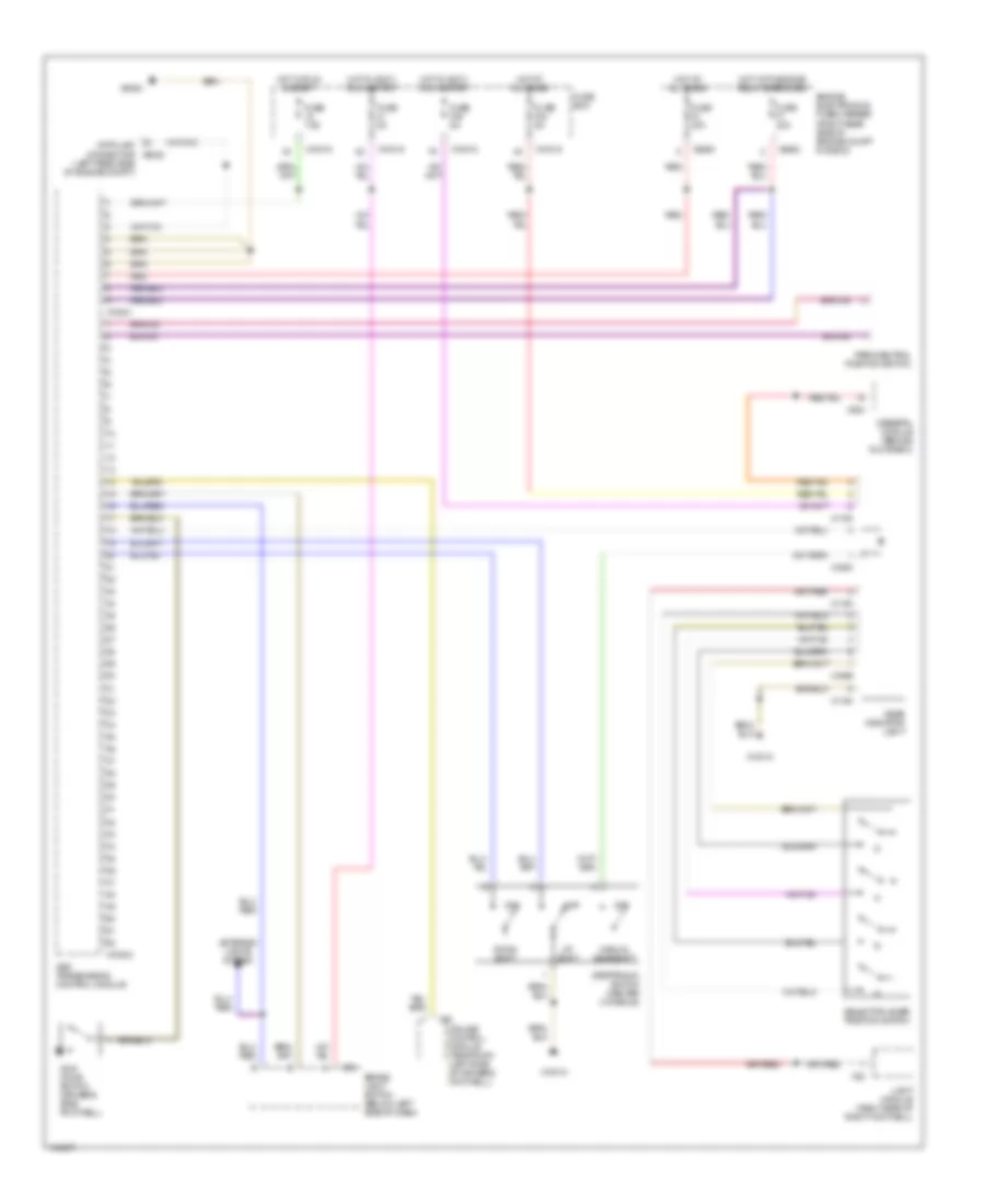
HEADLIGHTS
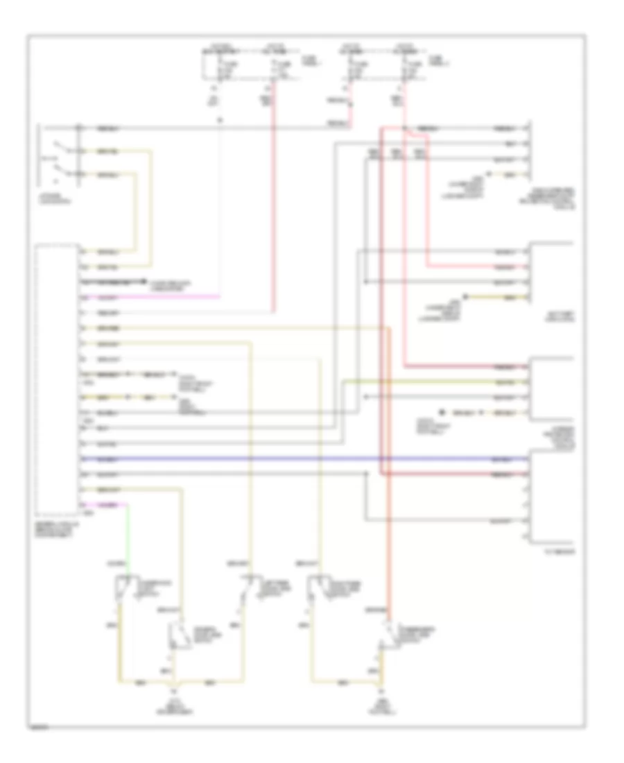
Headlamps & Fog Lamps Wiring Diagram for BMW 540i 1997
List of elements for Headlamps & Fog Lamps Wiring Diagram for BMW 540i 1997:
- (footwell right) x492
- 1) off 2) front fog lights on 3) rear fog lights on 4) front & rear fog lights on
- Combination switch
- Flash
- Fog light switch
- Fuse f113 80a
- Fuse panel 4
- High beam
- Hot at all times
- Interior lights system
- Left fog light
- Left high beam light
- Left low beam light
- Left rear light assembly 1
- Left trunk lid lamp
- Light module
- Normal
- Rear fog light
- Red
- Right fog light
- Right high beam light
- Right low beam light
- Right rear light assembly 1
- Right trunk lid lamp
- Sedan
- W/ o xenon
- W/ xenon
- Wagon
- X10012 (right front footwell)
- X10117
- X1108 (driver footwell)
- X12
- X165 (left front engine compt)
- X165 (left front of engine compt)
- X166 (right front engine compt)
- X166 (right front of engine compt)
- X38
- X494 (under right side of rear window shelf)
- X498 (right side of luggage compt)
- Xenon light control unit
- Xenon light indicator lamp
Headlamps Leveling Wiring Diagram for BMW 540i 1997
List of elements for Headlamps Leveling Wiring Diagram for BMW 540i 1997:
- Abs/asc control module (2.8l)
- Computer data lines system
- Headlight widening control module (behind glove compartment)
- Left actuator for headlight beam throw control
- Light module
- Navigation control module
- Right actuator for headlight beam throw control
- Right front level sensor
- Right rear level sensor
- Transmission control module (ags)
- X01002
- X10012 (right front footwell)
- X10117
- X1171
- X8600
HORN
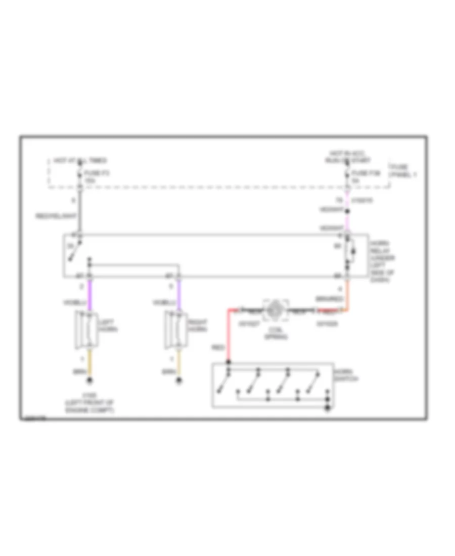
Horn Wiring Diagram for BMW 540i 1997
List of elements for Horn Wiring Diagram for BMW 540i 1997:
- Coil spring
- Fuse f3 15a
- Fuse f38 5a
- Fuse panel 1
- Horn relay (under left side of dash)
- Horn switch
- Hot at all times
- Hot in acc, run or start
- Left horn
- Nca
- Red
- Right horn
- X01026
- X01027
- X10015
- X165 (left front of engine compt)
INSTRUMENT CLUSTER
Instrument Cluster Wiring Diagram, with IKE for BMW 540i 1997
List of elements for Instrument Cluster Wiring Diagram, with IKE for BMW 540i 1997:
- Anti-lock brakes system
- Anti-theft system
- Computer data lines system
- Cruise control system
- Electrical fuel pump
- Engine controls system
- Exterior lights system
- Fuel level sensor ii
- Fuse f18 5a
- Fuse f24 5a
- Fuse f38 5a
- Fuse f40 5a
- Fuse panel 1
- Gong
- Hot at all times
- Hot in acc, run or start
- Hot in run or start
- Instrument cluster
- Integrated instrument cluster control module
- Interior lights system
- Left front brake pad sensor
- Nca
- Oil pressure switch
- Right front brake pad sensor
- Starting/charging system
- Temperature sensor
- Transmissions system
- X10113
- X10114
- X1108 (in driver's footwell)
- X16
- X518
- X522
- X638
- X679
- X770
Instrument Cluster Wiring Diagram, without IKE for BMW 540i 1997
List of elements for Instrument Cluster Wiring Diagram, without IKE for BMW 540i 1997:
- (driver's footwell)
- A/t
- Anti-lock brakes system
- Chime module
- Combination switch
- Computer data lines system
- Cruise control system
- Cruise controls system
- Electrical fuel pump
- Engine controls system
- Exterior lights system
- Fuel level sensor i
- Fuel level sensor ii
- Fuse f40 5a
- Fuse f8 5a
- Fuse fuse f24 5a
- Fuse panel 1
- Hot at all times
- Hot in acc, run or start
- Hot in run or start
- Instrument cluster
- Interior lights system
- Left front brake pad sensor
- M/t
- Nca
- Oil pressure switch
- Right front brake pad sensor
- Starting/charging system
- Temperature sensor
- X1108
- X1108 (diver's footwell)
- X11175
- X11176
- X498 (right side of luggage compt)
INTERIOR LIGHTS
Courtesy Lamps Wiring Diagram (1 of 2) for BMW 540i 1997
List of elements for Courtesy Lamps Wiring Diagram (1 of 2) for BMW 540i 1997:
- (right front footwell)
- Chime module
- Closed-circuit current cutoff relay
- Driver's door access light
- Driver's door jamb switch
- Fuse f11 7.5a
- Fuse f38 5a
- Fuse f39 7.5a
- Fuse f4 30a
- Fuse panel 1
- General module
- Glove box light
- Glove box light switch
- Heating & a/c control module
- Hot at all times
- Hot in acc, run or start
- Indirect lights
- Interior light
- Left rear door jamb switch
- Left rear interior light (sedan)
- Left rear interior light (wagon)
- Map reading light
- Passenger's door access light
- Passenger's door jamb switch
- Right rear door jamb switch
- Right rear interior light (sedan)
- Right rear interior light (wagon)
- X10012
- X10012 (right front footwell)
- X10015
- X151 (below driver seat)
- X173 (below driver's seat)
- X253
- X254
- X332
- X492 (right footwell)
- X494 (under right side of luggage compt)
- X610
Courtesy Lamps Wiring Diagram (2 of 2) for BMW 540i 1997
List of elements for Courtesy Lamps Wiring Diagram (2 of 2) for BMW 540i 1997:
- (right front footwell)
- Air suspension control unit
- Driver's
- Driver's makeup mirror light
- Front interior/ reading lamp
- Illumination circuit
- Interior lamp
- Left rear access light
- Makeup mirror switch
- Passenger's makeup mirror light
- Passenger's makeup mirror switch
- Reading lamp
- Rear interior/reading light (wagon)
- Right rear access light
- Toplight
- Transmission range indicator light
- Trunk compartment light (sedan)
- Trunk lid lamp (sedan) trunk lid warning light (wagon)
- Wagon
- X10012
- X1193
- X173 (below driver's seat)
- X492 (right footwell)
- X494 (under right side of luggage compt)
- Zv driver rear lid
Instrument Illumination Wiring Diagram for BMW 540i 1997
List of elements for Instrument Illumination Wiring Diagram for BMW 540i 1997:
- (below driver seat)
- (driver door sill) x173
- (driver footwell)
- Asc/dsc switch
- Automatic cruise control main switch
- Cassette box light
- Charging socket
- Dimmer
- Driver's door module
- Driver's seat seat heater switch
- Edc switch
- Eject box
- Fog light switch
- Front cigar lighter
- Front interior/ reading lamp
- Fuse f112 80a
- Fuse f113 80a
- Fuse f16 5a
- Fuse f39 7.5a
- Fuse panel 1
- Fuse panel 4
- Global locking switch
- Headlight widening potentiometer
- Heating & a/c control module
- Hot at all times
- Hot in acc, run or start
- Hot in run or start
- Instrument cluster
- Left rear power window switch
- Light module
- Memory switch
- Multi information display (mid)
- On board monitor
- Passenger's power window switch
- Passenger's seat seat heater switch
- Radio
- Rear ashtray light
- Red
- Right rear power window switch
- Sun blind switch
- Sunroof module
- Sunroof switch
- Transmission range indicator light
- Trunk lid release switch (interior)
- W/ ike
- W/o ike
- Window heating control unit
- X10012 (right front footwell)
- X10051
- X10117
- X10119
- X1108
- X1108 (driver footwell)
- X11175
- X1129
- X1193
- X12
- X1295
- X13016 (left rear side of luggage compt)
- X151
- X16
- X18126
- X18341
- X18801
- X3146
- X38
- X490 (right footwell)
- X492 (right footwell)
- X610
- X658
- X695
- X916
- X917
MEMORY SYSTEMS
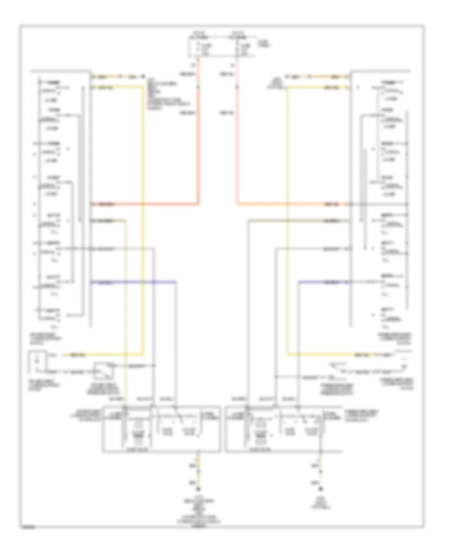
Driver"s Memory Seat Wiring Diagram for BMW 540i 1997
List of elements for Driver"s Memory Seat Wiring Diagram for BMW 540i 1997:
- (below driver's seat) x151
- (sedan) (below driver's seat) x173 (wagon) (under right side of rear window shelf) x494
- Back
- Backward
- Computer data lines system
- Driver's door module
- Driver's headrest motor
- Driver's seat back head recliner motor
- Driver's seat back recliner motor
- Driver's seat cushion tilt motor
- Driver's seat height motor
- Driver's seat movement motor
- Driver's setback head adjustment switch
- Driver's thigh support motor
- Driver's thigh support switch
- Forward
- Front
- Fuse f13 30a
- Fuse f29 30a
- Fuse panel 1
- Hot at all times
- Interior lights system
- Mem 1
- Mem 2
- Mem 3
- Memory switch
- Off
- Program
- Seat/steering column memory control module
- Steering column adjustment circuit
- X1129
- X173 (below driver's seat)
- X173 (below driver's seat) (sedan) x494 (under right side of rear window shelf) (wagon)
- X887
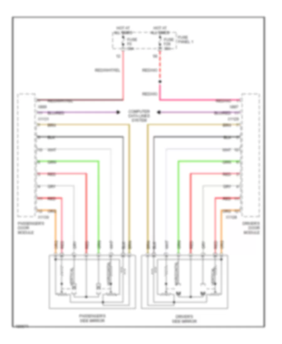
Memory Mirrors Wiring Diagram for BMW 540i 1997
List of elements for Memory Mirrors Wiring Diagram for BMW 540i 1997:
- Computer data lines system
- Driver's door module
- Driver's side mirror
- Fuse f29 30a
- Fuse f6 30a
- Fuse panel 1
- Horizontal
- Hot at all times
- Passenger's door module
- Passenger's side mirror
- Red
- Vertical
- X1128
- X1129
- X1130
- X1131
- X887
- X889
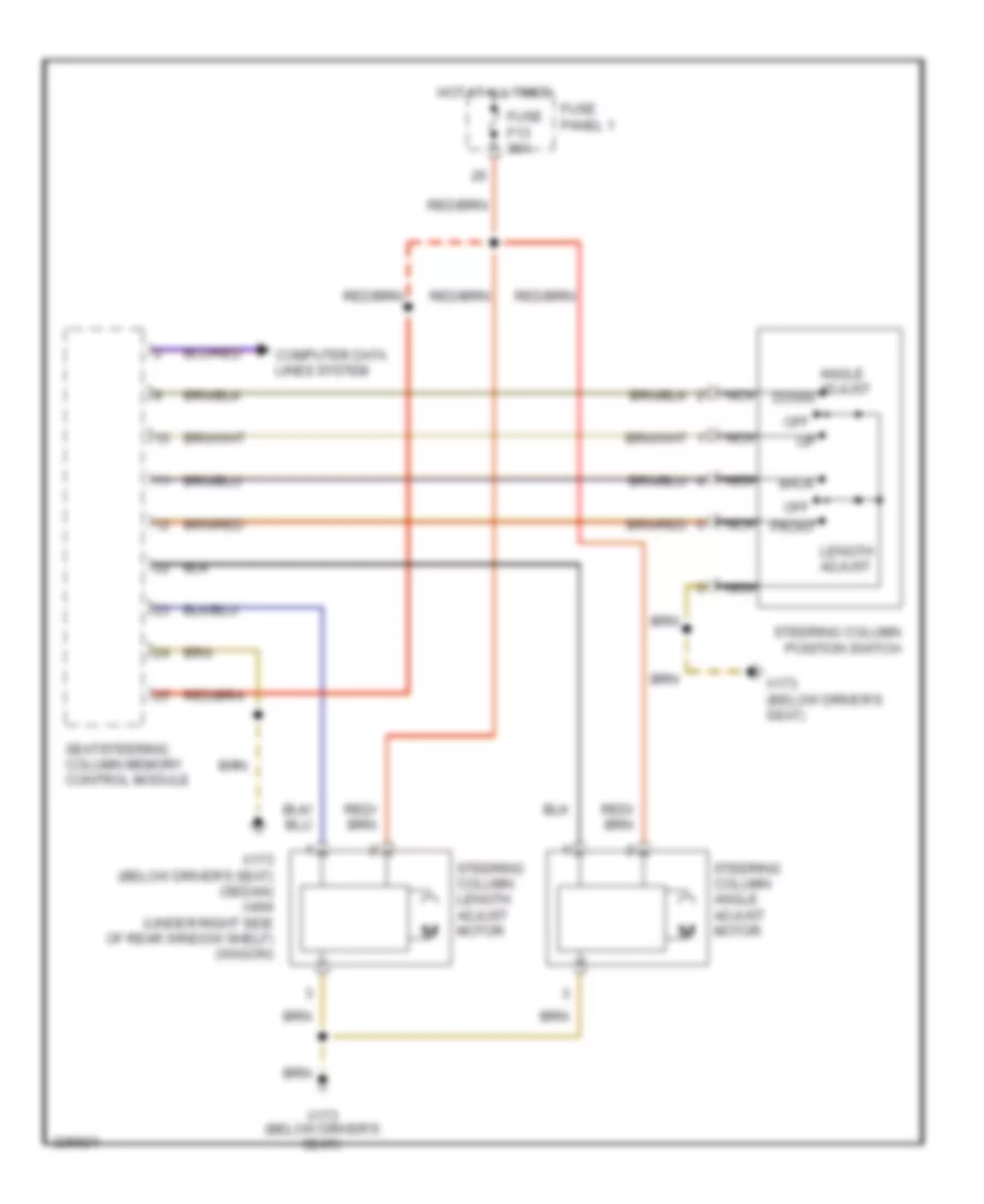
Steering Column Memory Wiring Diagram for BMW 540i 1997
List of elements for Steering Column Memory Wiring Diagram for BMW 540i 1997:
- Angle adjust down
- Back
- Computer data lines system
- Front
- Fuse f13 30a
- Fuse panel 1
- Hot at all times
- Length adjust
- Nca
- Off
- Seat/steering column memory control module
- Steering column angle adjust motor
- Steering column length adjust motor
- Steering column position switch
- X173 (below driver's seat)
- X173 (below driver's seat) (sedan) x494 (under right side of rear window shelf) (wagon)
NAVIGATION
Navigation Wiring Diagram for BMW 540i 1997
List of elements for Navigation Wiring Diagram for BMW 540i 1997:
- 30a
- Abs/asc control module
- Computer data lines system
- Electronic shock absorber control module (edc)
- F43
- F56
- F58
- Fuse
- Fuse panel 1
- Fuse panel 2
- Gps antenna
- Gps receiver
- Headlight widening control module
- Hot at all times
- Hot w/ retained accessory power
- Light module (right kick panel)
- Magnetic field sensor
- Navigation control module (left side of luggage compt)
- Nca
- Onboard monitor
- Radio
- Red
- Transmission control module (ags) (2.8l)
- Unloader relay, terminal r
- Video module (left rear of luggage compt)
- X01000
- X01001
- X01002
- X01003
- X01004
- X01007
- X01008
- X10015
- X10018
- X10117
- X10305
- X1108 (driver's footwell)
- X1171
- X13016 (left rear side of luggage compt)
- X13016 (left rear side of luggage compt)
- X18126
- X18801
- X18802
- X18804
- X18805
- X38
- X8600
- X945
- X991
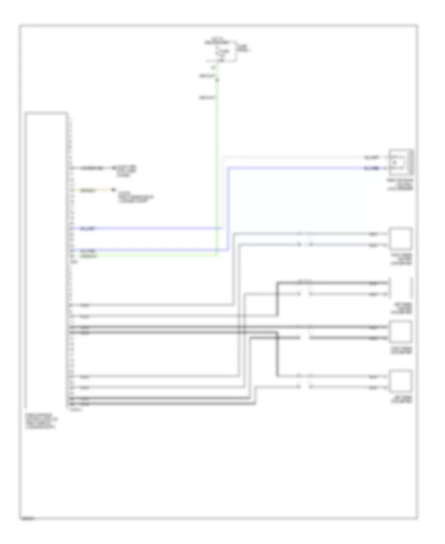
Parking Assistant Wiring Diagram, Sedan for BMW 540i 1997
List of elements for Parking Assistant Wiring Diagram, Sedan for BMW 540i 1997:
- Computer data lines system
- F21
- Fuse
- Fuse panel 1
- Hot in run or start
- Left rear center converter
- Left rear converter
- Nca
- Park distance control loud speaker
- Park distance control module (right side of luggage compt)
- Right rear center converter
- Right rear converter
- X13075 (right rear side of luggage compt)
- X18013
- X300
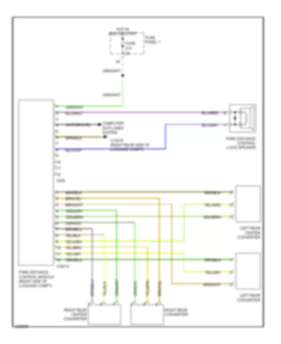
Parking Assistant Wiring Diagram, Wagon for BMW 540i 1997
List of elements for Parking Assistant Wiring Diagram, Wagon for BMW 540i 1997:
- Computer data lines system
- F21
- Fuse
- Fuse panel 1
- Hot in run or start
- Left rear center converter
- Left rear converter
- Park distance control loud speaker
- Park distance control module (right side of luggage compt)
- Right rear center converter
- Right rear converter
- X13075 (right rear side of luggage compt)
- X18013
- X300
POWER DISTRIBUTION
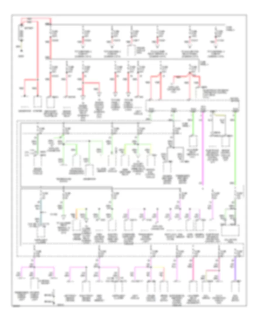
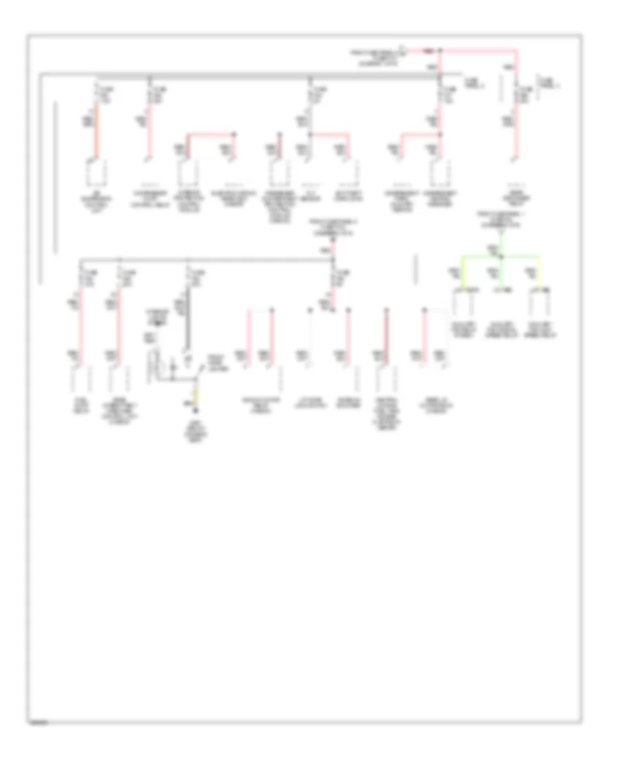
Power Distribution Wiring Diagram (1 of 6) for BMW 540i 1997
List of elements for Power Distribution Wiring Diagram (1 of 6) for BMW 540i 1997:
- (w/ ike)
- (w/o ike)
- (w/o ike) (w/ ike)
- 2.8l
- 4.4l
- Acc/ run/ start
- Automatic transmission range switch
- Battery
- Brake light switch
- Charging socket
- Coil spring
- Collector ring
- Cruise control module
- Data link connector
- Data link connector (2.8l)
- Driver's makeup mirror light
- Driver's seat seat heater switch
- Electro- chromic rear view mirror
- Electronic driveaway protection control unit
- Electronic driveaway protection control unit (ews) (4.4l)
- Electronic driveaway protection control unit (ews) (m/t)
- Engine control module
- Engine control module (dme) (a/t)
- Engine control relay
- Fuse 5a
- Fuse f100 200a
- Fuse f101 80a
- Fuse f102 80a
- Fuse f103 50a
- Fuse f104 50a
- Fuse f105 100a
- Fuse f106 80a
- Fuse f107 50a
- Fuse f108 50a
- Fuse f109 80a
- Fuse f110 80a
- Fuse f111 50a
- Fuse f112 80a
- Fuse f113 80a
- Fuse f114 50a
- Fuse f14 5a
- Fuse f15 7.5a
- Fuse f16 5a
- Fuse f19 5a
- Fuse f20 5a
- Fuse f21 5a
- Fuse f32 15a
- Fuse f34 10a
- Fuse f37 5a
- Fuse f38 5a
- Fuse f39 7.5a
- Fuse f40 5a
- Fuse f41 5a
- Fuse f42 5a
- Fuse f43 5a
- Fuse f44 5a
- Fuse f45 7.5a
- Fuse panel 1
- Fuse panel 4
- Fuse panel 5
- Garage door opener
- General module
- Generator
- Heating & a/c control module
- Horn relay
- Ignition switch
- Instrument cluster
- Integrated instrument cluster control module
- Left front sensor (air bag)
- Light module
- Multi information display (mid)
- Nca
- Oil level sensor
- Park distance control module
- Passenger's makeup mirror light
- Passenger's seat seat heater switch
- Rain sensor
- Rear defogger relay
- Red
- Right front sensor (air bag)
- Run/ start
- Seat load assembly
- Secondary air injection pump relay
- Sedan
- Shift lock switch (w/ ike)
- Start
- Starter
- Sun blind switch
- Temperature switch
- To auxiliary fan normal speed relay (diagram 3 of 6)
- To auxiliary fan relay stage 3 (diagram 2 of 6)
- To closed circuit current cutoff relay (diagram 2 of 6)
- To engine control module relay (diagram 5 of 6) (2.8l)
- To engine control module relay (diagram 6 of 6) (4.4l)
- To fuse panel 1 fuse f1 (diagram 2 of 6)
- To fuse panel 1 fuse f27 (diagram 2 of 6)
- To fuse panel 2 fuse f47 (diagram 3 of 6)
- To fuse panel 2 fuse f53 (diagram 3 of 6)
- To fuse panel 2 fuse f57 (diagram 4 of 6)
- To unloader relay terminal 15 (diagram 4 of 6)
- Trailer module (ahm)
- Transmission range indicator light
- Unloader relay terminal r (accessory)
- Unloader relay terminal15 (4.4l)
- Wagon
- X1 x1
- X10
- X10012
- X10013
- X10117
- X10209 red
- X10210 red
- X1026
- X11175
- X11238 red
- X1193
- X12
- X13030
- X16
- X1659
- X18075 red
- X18090 red
- X18261 red
- X18766
- X19517 red
- X22
- X27
- X300
- X332
- X6000
- X610
- X6304
- X6406
- X651
- X658
- X947
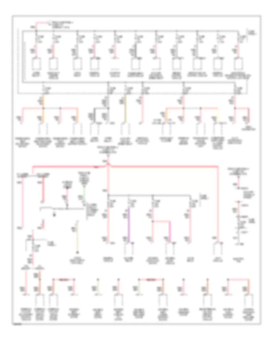
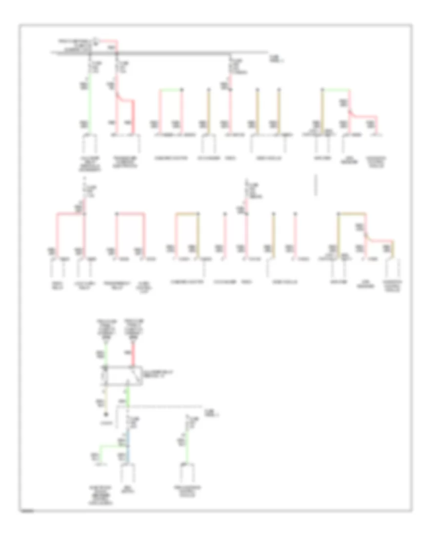
Power Distribution Wiring Diagram (2 of 6) for BMW 540i 1997
List of elements for Power Distribution Wiring Diagram (2 of 6) for BMW 540i 1997:
- (w/ ike)
- (w/o ike)
- Abs/asc control module
- Auxiliary fan high speed relay
- Auxiliary fan normal speed relay
- Auxiliary fan relay stage 3
- Blower relay
- Closed circuit current cutoff relay
- Driver's door lock switch
- Driver's door module
- Driver's headrest motor
- Driver's seat back head recliner motor
- Driver's seat back recliner motor
- Driver's seat cushion tilt motor
- Driver's seat height motor
- Driver's seat lumbar support switch
- Driver's seat movement motor
- Driver's thigh support motor
- Electric fan
- Electronic driveaway protection control unit (ews)
- From fuse panel 1 fuse f21 (diagram 1 of 6)
- From fuse panel 4 fuse f110 (diagram 1 of 6)
- From fuse panel 4 fuse f113 (diagram 1 of 6)
- From fuse panel 5 fuse f105 (diagram 1 of 6)
- Fuse f1 30a
- Fuse f10 30a
- Fuse f11 7.5a
- Fuse f12 5a
- Fuse f13 30a
- Fuse f2 30a
- Fuse f22 30a
- Fuse f23 7.5a
- Fuse f24 5a
- Fuse f25 7.5a
- Fuse f26 5a
- Fuse f27 30a
- Fuse f28 10a
- Fuse f29 30a
- Fuse f3 30a
- Fuse f30 25a
- Fuse f4 30a
- Fuse f5 20a
- Fuse f6 30a
- Fuse f7 20a
- Fuse f75 50a
- Fuse f8 25a
- Fuse f9 15a
- Fuse panel
- Fuse panel 1
- General module
- Headlight washer module
- Heating & a/c control module
- Heating and a/c control module
- Horn relay
- Instrument cluster
- Integrated instrument cluster control module
- Interior lights system
- Light module
- Multi information display (mid)
- Obd ii connector
- Passenger's door module
- Passenger's seat adjustment switch
- Passenger's seat back head adjustment switch
- Passenger's seat lumbar support switch
- Passenger's thigh support switch
- Red
- Seat/steering column memory control module
- Steering angle sensor
- Steering column adjustment control module
- Steering column angle adjust motor
- Steering column length adjust motor
- Sunroof module
- Transmission range indicator light
- Valve relay
- W/ lumbar support
- W/ memory
- W/o lumbar support
- W/o memory
- Wiper relay 1
- Wiper relay 2
- X10012 (right front footwell)
- X10017
- X10113
- X1082
- X11175
- X1171
- X16
- X18341
- X18815
- X18816
- X254
- X293
- X332
- X38
- X58
- X82
- X887
- X889
Power Distribution Wiring Diagram (3 of 6) for BMW 540i 1997
List of elements for Power Distribution Wiring Diagram (3 of 6) for BMW 540i 1997:
- (below driver's seat)
- Air suspension control unit
- Antenna amplifier
- Anti-theft horn (dwa)
- Auxiliary fan high speed relay
- Auxiliary fan normal speed relay
- Auxiliary fan relay stage 3
- Central locking fuel tank access flap relay (sedan)
- Compressor pump control relay
- Electrochromic rear view mirror
- From fuse panel 1 fuse f20 (diagram 1 of 6)
- From fuse panel 5 a fuse f101 (diagram 1 of 6)
- From fuse panel 5 fuse f102 (diagram 1 of 6)
- Front cigar lighter
- Fuel pump relay
- Fuse f47 15a
- Fuse f48 5a
- Fuse f49 30a
- Fuse f50 7.5a
- Fuse f52 30a
- Fuse f53 5a
- Fuse f54 15a
- Fuse f55 20a
- Fuse f66 40a
- Fuse panel 2
- Fuse panel 3
- Independent heating receiver
- Independent park/ auxiliary heating
- Interior lights system
- Interior protection control module
- Lift gate lock switch
- Passenger compartment protection control module (wagon)
- Rear defogger relay
- Rear intermittent wipe/wash control unit (wagon)
- Rear lid motor relay (wagon)
- Red
- Tilt sensor
- Window motor relay (wagon)
- X1732
- X490
- X52
- X53
Power Distribution Wiring Diagram (4 of 6) for BMW 540i 1997
List of elements for Power Distribution Wiring Diagram (4 of 6) for BMW 540i 1997:
- (hifi) (top hifi)
- Alarm control unit
- Amplifier
- Cd changer
- Edc switch
- Electronic shock absorber control module (edc)
- From fuse panel 1 fuse f19 (diagram 1 of 6)
- From fuse panel 5 fuse f104 (diagram 1 of 6)
- From fuse panel 5 fuse f106 (diagram 1 of 6)
- Fuse f56 30a (wagon)
- Fuse f57 10a
- Fuse f58 10a
- Fuse f60 30a
- Fuse f61 5a
- Fuse f63 7.5a
- Fuse f64 30a (sedan)
- Fuse panel 3
- Gps receiver
- Loud alarm relay
- Navigation control module
- Onboard monitor
- Park distance control module
- Radio
- Radio relay
- Red
- Transceiver/ charging electronics
- Transparency relay
- Unloader relay terminal 15
- Unloader relay terminal r (accessory)
- Video module
- X13075
- X18126
- X18801
- X18802
- X18804
- X1958
- X3335
- X3535
- X3536
- X605 x18771
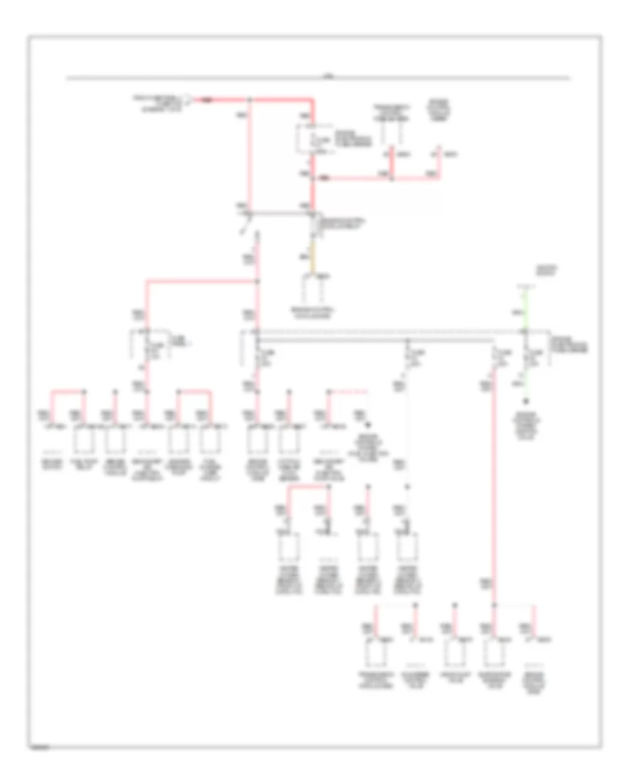
Power Distribution Wiring Diagram (5 of 6) for BMW 540i 1997
List of elements for Power Distribution Wiring Diagram (5 of 6) for BMW 540i 1997:
- (diagram 1 of 6)
- 2.8l
- Abs/asc control module
- Asc/dsc switch
- Engine control module (dme)
- Engine control module relay
- Engine controls system (fuel injection valves)
- Engine controls system (ignition coils)
- Engine electronics fuse carrier
- Evaporative emission valve
- From fuse panel 4 fuse f109 f
- Fuel change- over circuit
- Fuel pump relay
- Fuse f1 40a
- Fuse f2 30a
- Fuse f3 20a
- Fuse f31 10a
- Fuse f4 30a
- Fuse f5 30a
- Fuse panel 1
- Heated oxygen sensor 1 (behind of catalytic)
- Heated oxygen sensor 1 (front of catalytic)
- Heated oxygen sensor 2 (front of catalytic)
- Heated oxygen sensor 3 (behind of catalytic)
- Hot-film mass air flow sensor
- Idle speed control valve
- Ignition switch
- Leakage diagnosis pump
- Nca
- Red
- Secondary air injection pump relay
- Secondary air injection pump valve
- Transmission control module (ags)
- Vanos inlet valve
- X10156
- X1171
- X1713
- X1714
- X521
- X6000
- X6120
- X6130
- X6163
- X6207
- X6275
- X6304
- X8600
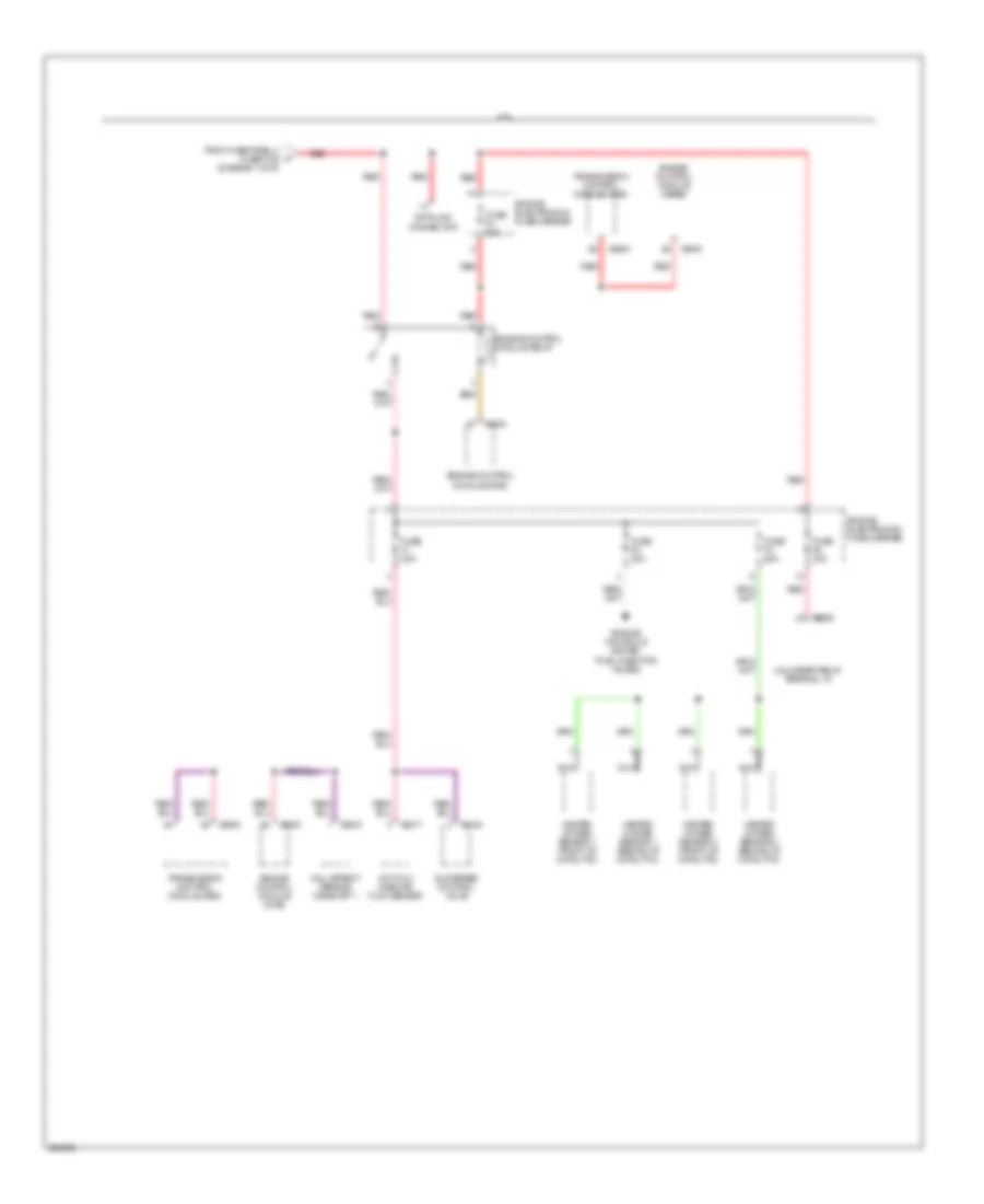
Power Distribution Wiring Diagram (6 of 6) for BMW 540i 1997
List of elements for Power Distribution Wiring Diagram (6 of 6) for BMW 540i 1997:
- (diagram 1 of 6)
- 4.4l
- Data link connector
- Engine control module (dme)
- Engine control module relay
- Engine controls system (fuel injection valves)
- Engine electronics fuse carrier
- From fuse panel 4 fuse f109 f
- Fuse f1 30a
- Fuse f2 30a
- Fuse f3 20a
- Fuse f4 30a
- Fuse f5 30a
- Hall-effect sensor camshaft 1
- Heated oxygen sensor 1 (behind of catalytic)
- Heated oxygen sensor 1 (front of catalytic)
- Heated oxygen sensor 2 (front of catalytic)
- Heated oxygen sensor 3 (behind of catalytic)
- Hot-film mass air flow sensor
- Idle speed control valve
- Nca
- Red
- Transmission control module (ags)
- Unloader relay terminal 15
- X6000
- X6130
- X6217
- X6219
- X6326
- X8600
POWER DOOR LOCKS
Power Door Locks Wiring Diagram for BMW 540i 1997
List of elements for Power Door Locks Wiring Diagram for BMW 540i 1997:
- (not used)
- (right footwell)
- (right front footwell)
- Central locking fuel tank access flap relay
- Driver's door lock motor
- Driver's door lock switch
- Driver's door module
- Fuse f27 30a
- Fuse f29 30a
- Fuse f53 5a
- Fuse f6 30a
- Fuse panel 1
- Fuse panel 2
- General module (behind glove compartment)
- Global locking switch
- Hot at all times
- Interior lights system
- Left rear door lock motor
- Lid servo motor (wagon)
- Lift gate lock switch
- Nca
- Passenger's door lock motor
- Passenger's door module
- Rear window servo motor
- Rear window servo opening switch
- Right rear door lock motor
- Trunk lid locking switch
- Window motor relay
- X10012
- X10012 (right front footwell)
- X1129
- X1131
- X253
- X254
- X332
- X492
- X494 (under right side of rear window shelf)
- X494 (under right side of rear window shelf) (wagon) x498 (right side of luggage compt) (sedan)
- X498 (right side of luggage compt)
- X887
- X889
POWER MIRRORS
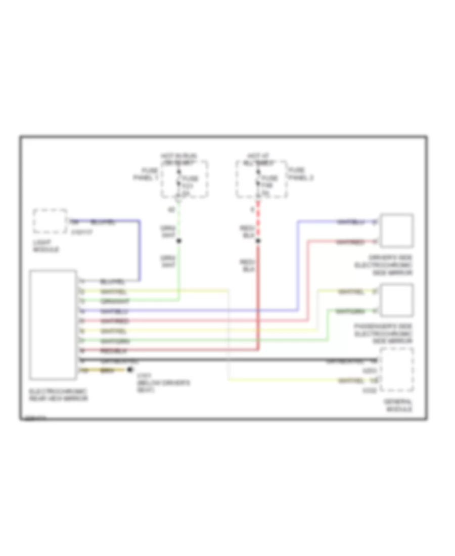
Electrochromic Mirror Wiring Diagram for BMW 540i 1997
List of elements for Electrochromic Mirror Wiring Diagram for BMW 540i 1997:
- Driver's side electrochromic side mirror
- Electrochromic rear view mirror
- Fuse f21 5a
- Fuse f48 5a
- Fuse panel 1
- Fuse panel 2
- General module
- Hot at all times
- Hot in run or start
- Light module
- Passenger's side electrochromic side mirror
- X10117
- X151 (below driver's seat)
- X253
- X332
POWER SEATS
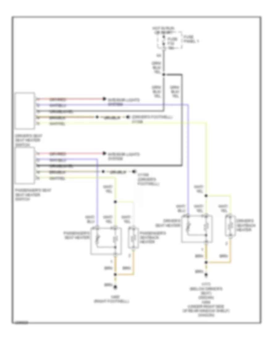
Heated Seats Wiring Diagram for BMW 540i 1997
List of elements for Heated Seats Wiring Diagram for BMW 540i 1997:
- (driver's footwell) x1108
- (right footwell)
- Driver's seat heater
- Driver's seat seat heater switch
- Driver's seatback heater
- Fuse f32 15a
- Fuse panel 1
- Hot in run or start
- Interior lights system
- Passenger's seat heater
- Passenger's seat seat heater switch
- Passenger's seatback heater
- X1108 (driver's footwell)
- X173 (below driver's seat) (sedan) x494 (under right side of rear window shelf) (wagon)
- X492
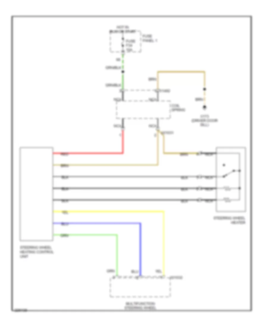
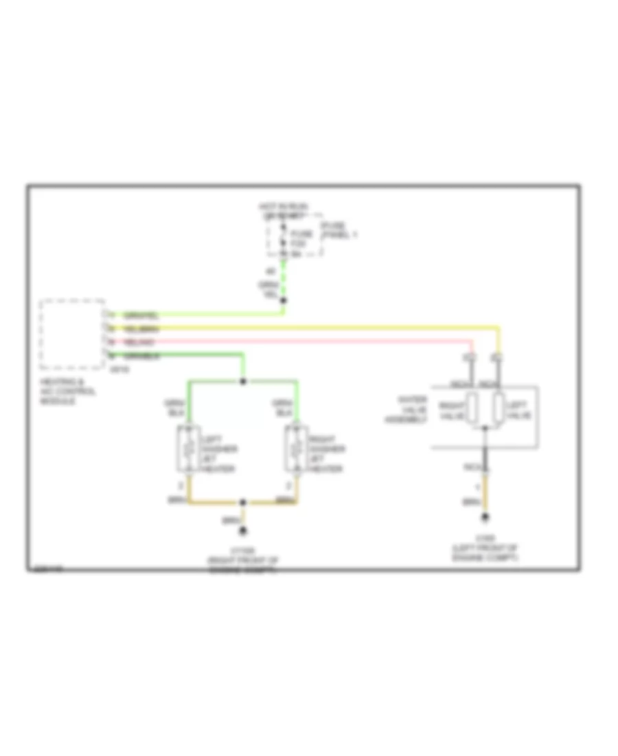
Heated Steering Wheel Wiring Diagram for BMW 540i 1997
List of elements for Heated Steering Wheel Wiring Diagram for BMW 540i 1997:
- Coil spring
- Fuse f34 10a
- Fuse panel 1
- Hot in run or start
- Multifunction steering wheel
- Nca
- Red
- Steering wheel heater
- Steering wheel heating control unit
- X01031
- X01032
- X1492
- X173 (driver door sill)
Lumbar Wiring Diagram for BMW 540i 1997
List of elements for Lumbar Wiring Diagram for BMW 540i 1997:
- (right footwell)
- Driver's seat lumbar support motor
- Driver's seat lumbar support pressure switch
- Driver's seat lumbar support switch
- Driver's seat lumbar support valve block
- Empty
- Fill
- Fuse f10 30a
- Fuse f13 30a
- Fuse panel 1
- Hot at all times
- Inlet valve
- Lower
- Lower chamber
- Nca
- Normal
- Outlet valve
- Passenger's seat lumbar support motor
- Passenger's seat lumbar support pressure switch
- Passenger's seat lumbar support switch
- Passenger's seat lumbar support valve block
- Raise
- Upper chamber
- X173 (below driver's seat) (sedan) x494 (under right side of rear window shelf) (wagon)
- X492
- X492 (right footwell)
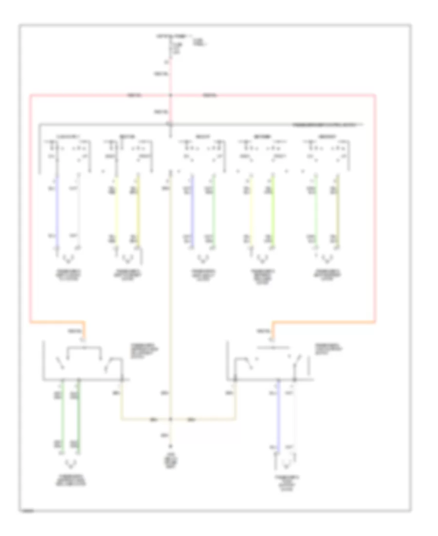
Passenger"s Power Seat Wiring Diagram for BMW 540i 1997
List of elements for Passenger"s Power Seat Wiring Diagram for BMW 540i 1997:
- Back
- Cushion tilt
- Front
- Fuse f10 30a
- Fuse panel 1
- Headrest
- Height
- Hot at all times
- Passenger's seat control switch
- Passenger's seat cushion tilt motor
- Passenger's seat headrest motor
- Passenger's seat height motor
- Passenger's seat movement motor
- Passenger's seatback head adjustment switch
- Passenger's seatback head recliner motor
- Passenger's seatback recliner motor
- Passenger's thigh support motor
- Passenger's thigh support switch
- Position
- Seatback
- X492 (below driver seat)
POWER TOP/SUNROOF
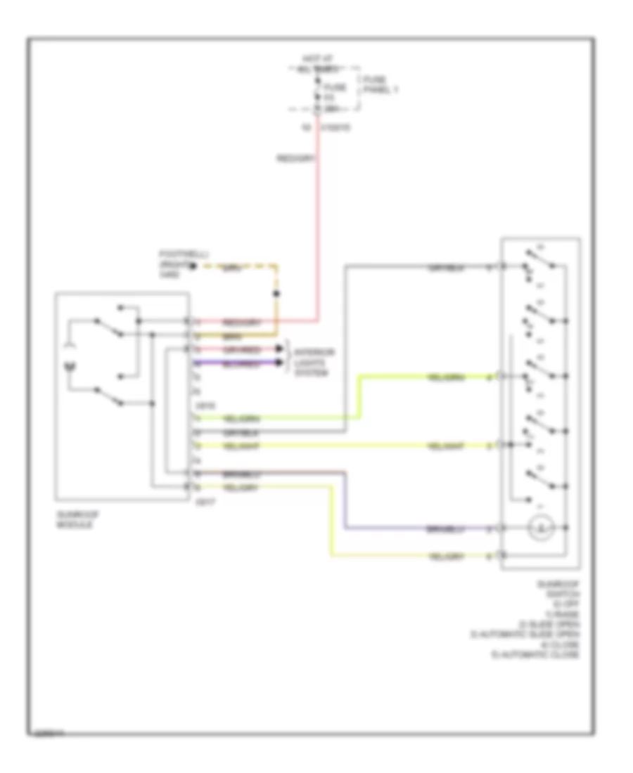
Sunroof Wiring Diagram for BMW 540i 1997
List of elements for Sunroof Wiring Diagram for BMW 540i 1997:
- Footwell) (right x492
- Fuse f5 20a
- Fuse panel 1
- Hot at all times
- Interior lights system
- Sunroof module
- Sunroof switch 0) off 1) raise 2) slide open 3) automatic slide open 4) close 5) automatic close
- X10015
- X916
- X917
POWER WINDOWS
Power Windows Wiring Diagram (1 of 2) for BMW 540i 1997
List of elements for Power Windows Wiring Diagram (1 of 2) for BMW 540i 1997:
- Auto close
- Auto open
- Close
- Driver's door module
- Driver's side pressure sensitive finger guard
- Driver's window motor
- Fuse f29 30a
- Fuse f6 30a
- Fuse panel 1
- Hot at all times
- Interior lights system
- Off
- Open
- Passenger's door module
- Passenger's power window switch
- Passenger's side pressure sensitive finger guard
- Passenger's window motor
- Seat/steering column memory control module
- Sunroof module
- To general module (diagram 2 of 2)
- X1129
- X1131
- X151 (below driver's seat)
- X492 (right footwell)
- X653
- X887
- X889
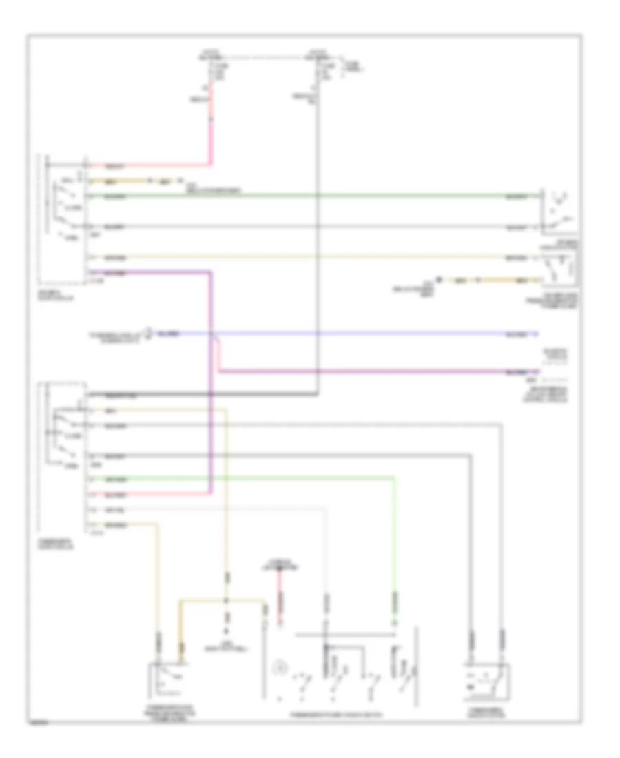
Power Windows Wiring Diagram (2 of 2) for BMW 540i 1997
List of elements for Power Windows Wiring Diagram (2 of 2) for BMW 540i 1997:
- (right footwell) x490
- Auto close
- Auto open
- Close
- From driver's module (diagram 1 of 2)
- Fuse f11 7.5a
- Fuse f27 30a
- Fuse panel 1
- General module (behind glove compartment)
- Hot at all times
- Interior lights system
- Left rear power window switch
- Left rear window motor
- Left rear window pressure sensitive finger guard
- Off
- Open
- Open auto
- Right rear power window switch
- Right rear window motor
- Right rear window pressure sensitive finger guard
- X173 (below driver's seat)
- X253
- X254
- X332
- X492 (right footwell)
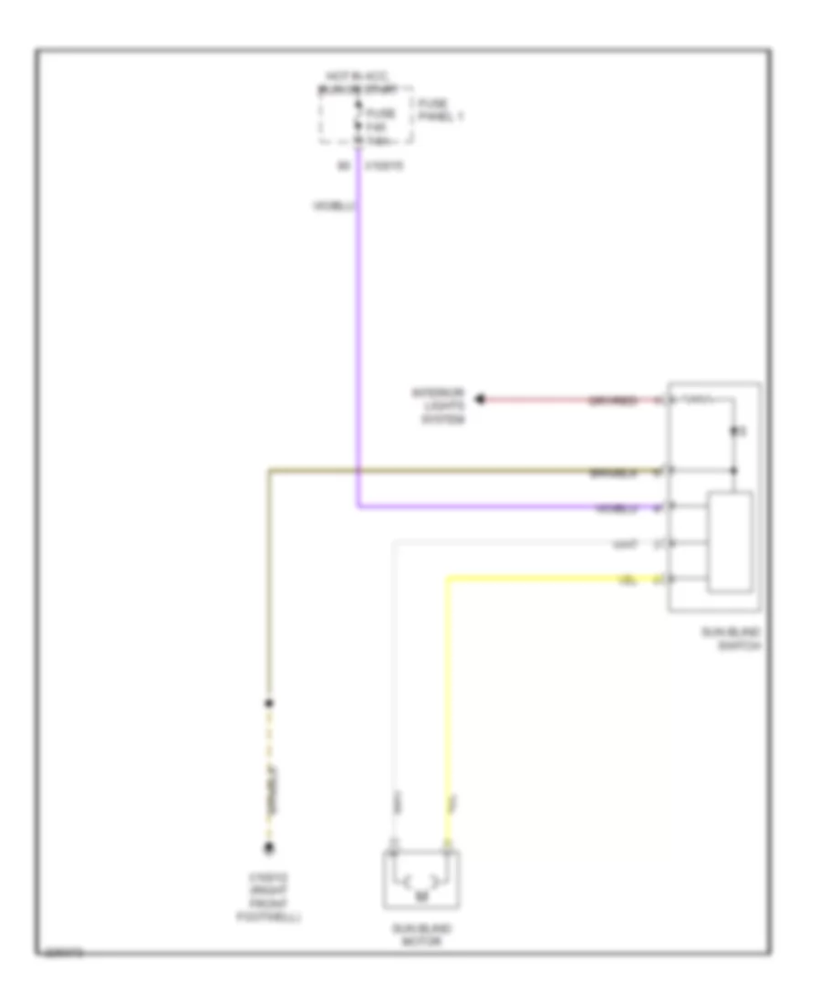
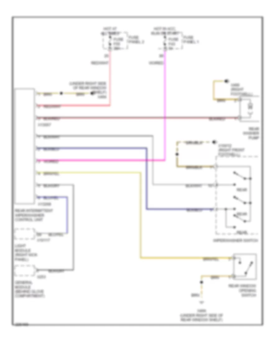
Rear Window Sun Shade Wiring Diagram for BMW 540i 1997
List of elements for Rear Window Sun Shade Wiring Diagram for BMW 540i 1997:
- Fuse f45 7.5a
- Fuse panel 1
- Hot in acc, run or start
- Interior lights system
- Sun blind motor
- Sun blind switch
- X10012 (right front footwell)
- X10015
RADIO
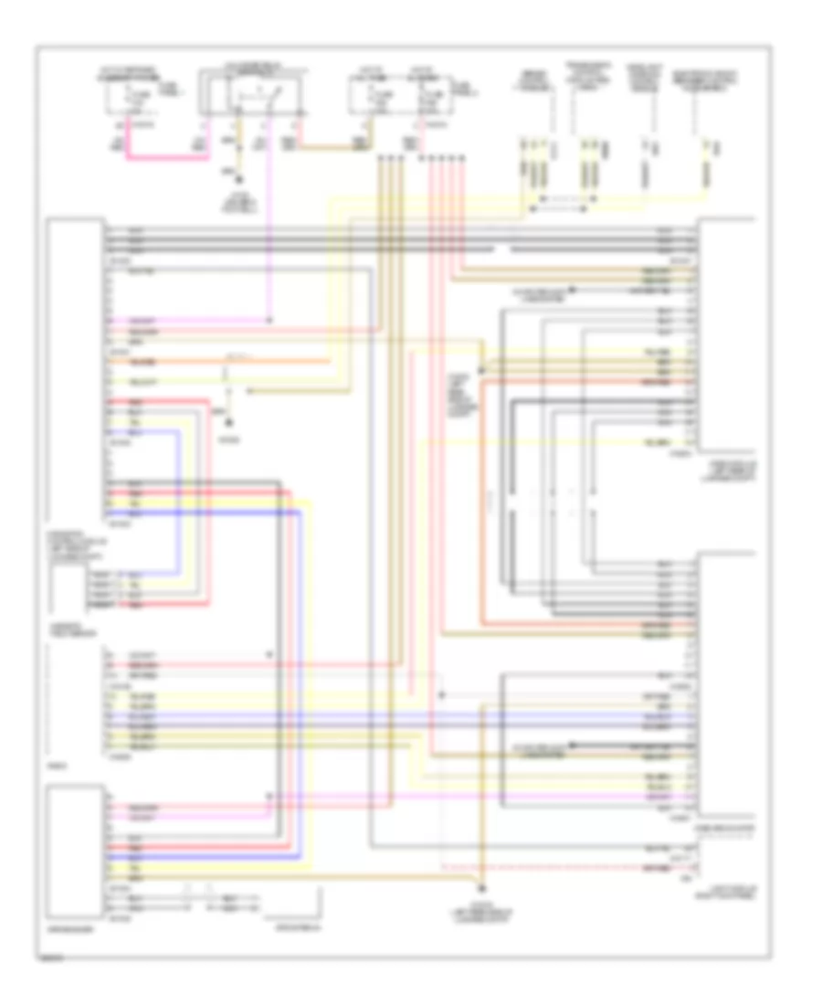
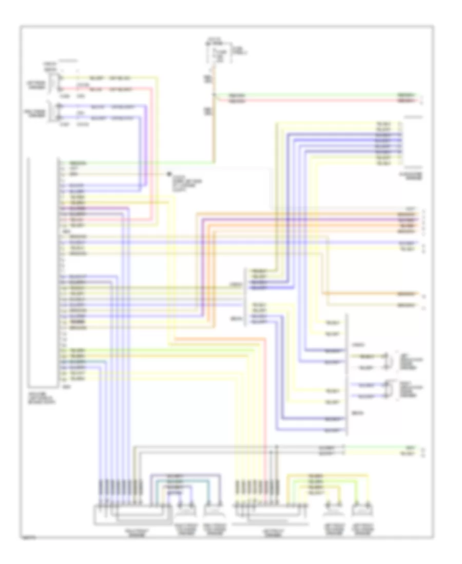
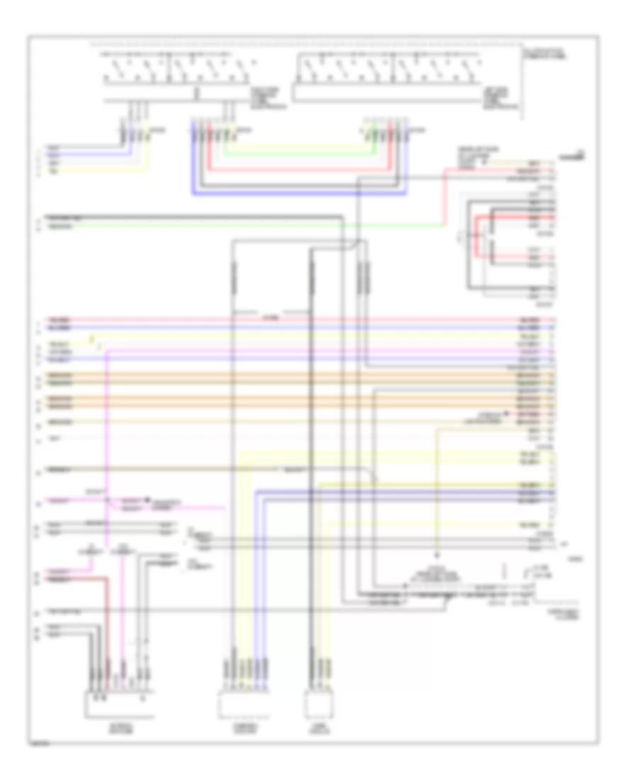
Radio Wiring Diagram, with HIFI Radio (1 of 3) for BMW 540i 1997
List of elements for Radio Wiring Diagram, with HIFI Radio (1 of 3) for BMW 540i 1997:
- Amplifier (left side of engine compt)
- Fuse f56 30a
- Fuse panel 2
- Hot at all times
- Left front high range speaker
- Left front mid range speaker
- Left front speaker
- Left medium/high range speaker
- Left rear speaker
- Right front high range speaker
- Right front mid range speaker
- Right front speaker
- Right medium/high range speaker
- Right rear speaker
- Sedan
- Subwoofer speaker
- Wagon
- X1260
- X1261
- X13016 (rear left side of luggage compt)
- X18184
- X18189
- X605
- X606
- X761
- X763
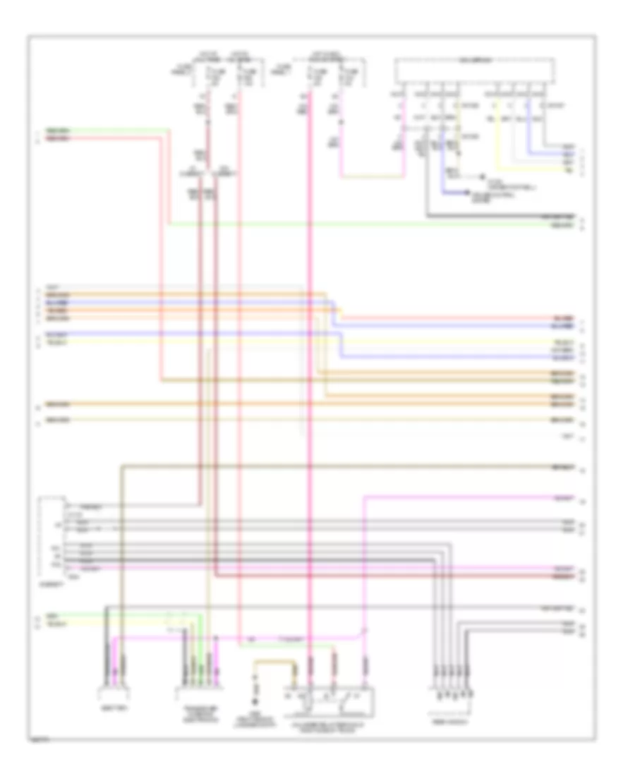
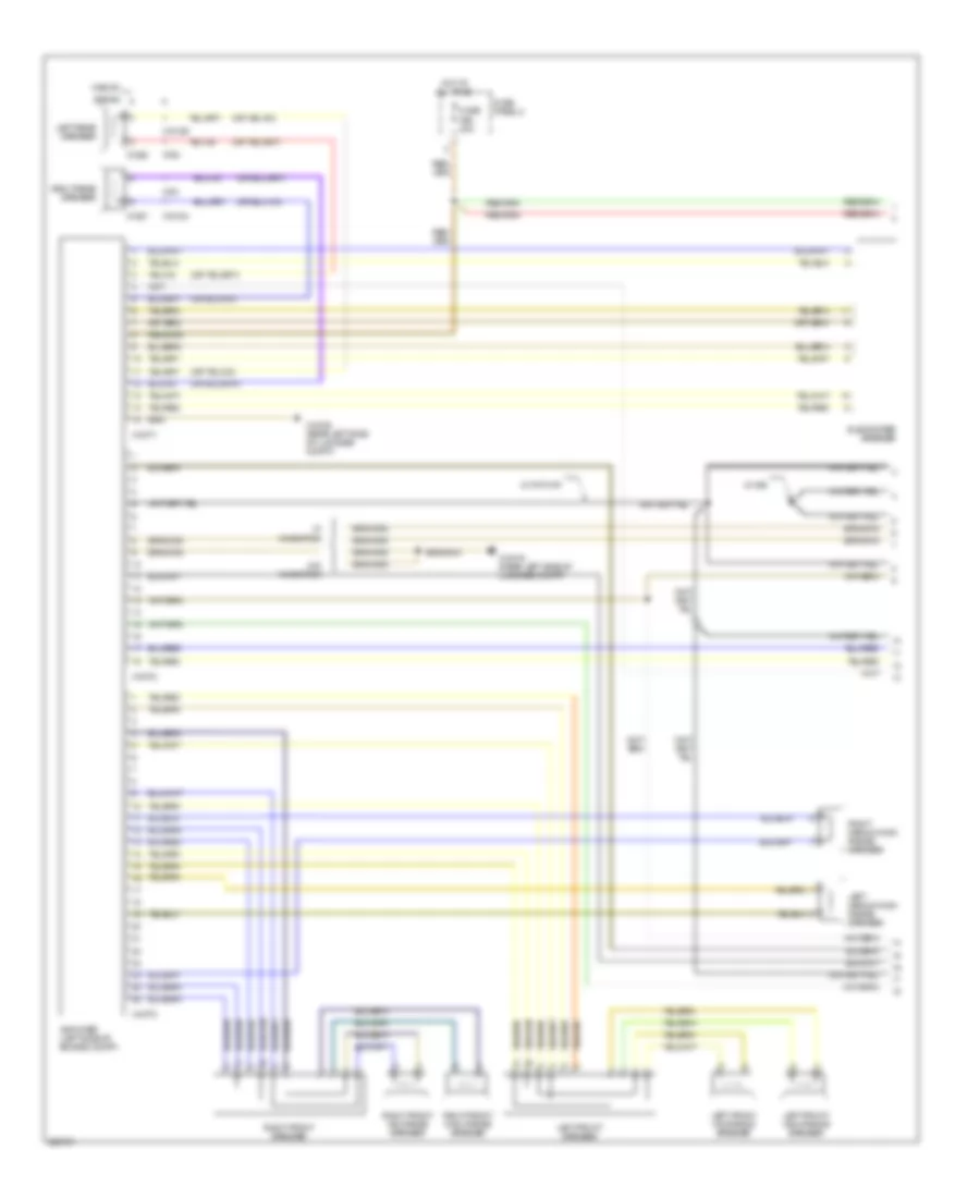
Radio Wiring Diagram, with HIFI Radio (2 of 3) for BMW 540i 1997
List of elements for Radio Wiring Diagram, with HIFI Radio (2 of 3) for BMW 540i 1997:
- Coil spring
- Cruise control system
- Diversity
- Eject box
- Fm1
- Fm2
- Fuse f43 5a
- Fuse f44 5a
- Fuse f53 5a
- Fuse f58 10a
- Fuse panel 1
- Fuse panel 2
- Hot at all times
- Hot in acc, run or start
- Nca
- Rear window
- Transceiver/ charging electronics
- Unloader relay terminal r (right side of trunk)
- W/ diversity
- W/o diversity
- X01026
- X01027
- X1108 (driver footwell)
- X1143
- X424
- X498 (right side of luggage compt)
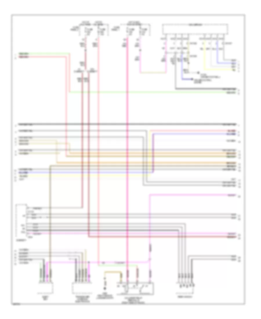
Radio Wiring Diagram, with HIFI Radio (3 of 3) for BMW 540i 1997
List of elements for Radio Wiring Diagram, with HIFI Radio (3 of 3) for BMW 540i 1997:
- (rear left side of luggage compt) x13016
- Antenna amplifier
- Cd changer
- Ibus
- Instrument cluster
- Interior lights system
- Left side steering wheel electronics
- Multifunction steering wheel
- Navigation system
- Nca
- Onboard monitor
- Radio
- Red
- Right side steering wheel electronics
- Video module
- W/ diversity
- W/ ike
- W/o diversity
- W/o ike
- X01028
- X01029
- X01030
- X01037
- X01038
- X10113
- X11176
- X1143
- X13016 (rear left side of luggage compt)
- X18126
- X18180
- X18805
- X424
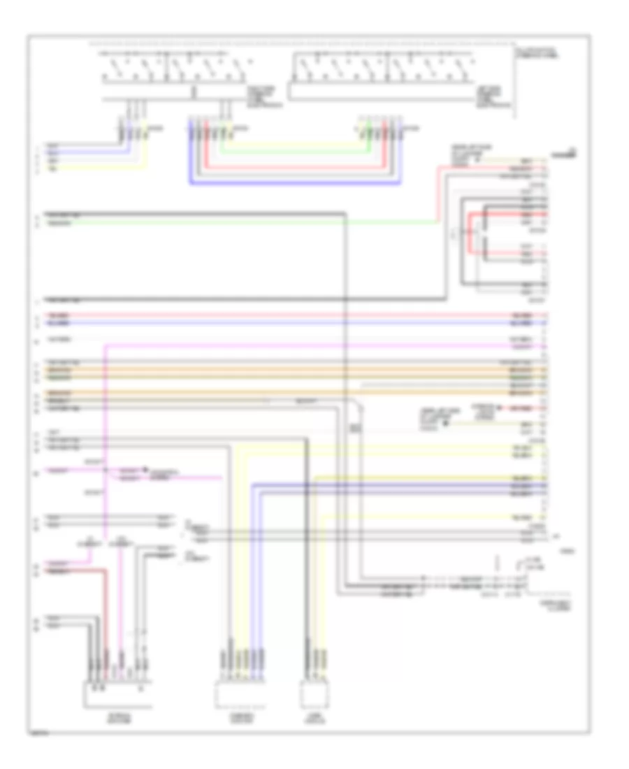
Radio Wiring Diagram, with Top HIFI Radio (1 of 3) for BMW 540i 1997
List of elements for Radio Wiring Diagram, with Top HIFI Radio (1 of 3) for BMW 540i 1997:
- Amplifier (left side of engine compt)
- Fuse f56 30a
- Fuse panel 2
- Hot at all times
- Left front high range speaker
- Left front mid range speaker
- Left front speaker
- Left medium/high range speaker
- Left rear speaker
- Right front high range speaker
- Right front mid range speaker
- Right front speaker
- Right medium/high range speaker
- Right rear speaker
- Sedan
- Subwoofer speaker
- W/ ike
- W/ navigation
- W/ top hifi
- W/o navigation
- Wagon
- X1260
- X1261
- X13016 (rear left side of luggage compt)
- X18184
- X18189
- X18771
- X18772
- X18773
- X761
- X763
Radio Wiring Diagram, with Top HIFI Radio (2 of 3) for BMW 540i 1997
List of elements for Radio Wiring Diagram, with Top HIFI Radio (2 of 3) for BMW 540i 1997:
- Coil spring
- Cruise control system
- Diversity
- Eject box
- Fm1
- Fm2
- Fuse f43 5a
- Fuse f44 5a
- Fuse f53 5a
- Fuse f58 10a
- Fuse panel 1
- Fuse panel 2
- Hot at all times
- Hot in acc, run or start
- Nca
- Rear window
- Transceiver/ charging electronics
- Unloader relay terminal r (right side of trunk)
- W/ diversity
- W/o diversity
- X01026
- X01027
- X1108 (driver footwell)
- X1143
- X424
- X498 (right side of luggage compt)
Radio Wiring Diagram, with Top HIFI Radio (3 of 3) for BMW 540i 1997
List of elements for Radio Wiring Diagram, with Top HIFI Radio (3 of 3) for BMW 540i 1997:
- (rear left side of luggage compt) x13016
- Antenna amplifier
- Cd changer
- Ibus
- Instrument cluster
- Interior lights system
- Left side steering wheel electronics
- Multifunction steering wheel
- Navigation system
- Nca
- Onboard monitor
- Radio
- Red
- Right side steering wheel electronics
- Video module
- W/ diversity
- W/ ike
- W/o diversity
- W/o ike
- X01028
- X01029
- X01030
- X01037
- X01038
- X10113
- X11176
- X1143
- X18126
- X18180
- X18805
- X424
Radio Wiring Diagram, without HIFI Radio without Top HIFI Radio (1 of 2) for BMW 540i 1997
List of elements for Radio Wiring Diagram, without HIFI Radio without Top HIFI Radio (1 of 2) for BMW 540i 1997:
- (rear left side of luggage compt) x13016
- Cd changer
- Diversity
- Eject box
- Fm1
- Fm2
- Fuse f43 5a
- Fuse f44 5a
- Fuse f53 5a
- Fuse f56 30a
- Fuse f58 10a
- Fuse panel 1
- Fuse panel 2
- Hot at all times
- Hot in acc, run or start
- Interior lights system
- Left front high range speaker
- Left front speaker
- Left rear speaker
- Nca
- Radio
- Red
- Right front high range speaker
- Right front speaker
- Right rear speaker
- Sedan
- Transceiver/ charging electronics
- Unloader relay terminal r (right side of trunk)
- W/ diversity
- W/o diversity
- Wagon
- X01022
- X01038
- X1143
- X1260
- X1261
- X13016 (rear left side of luggage compt)
- X18126
- X18180
- X18184
- X18189
- X424
- X498 (right side of luggage compt)
- X761
- X763
Radio Wiring Diagram, without HIFI Radio without Top HIFI Radio (2 of 2) for BMW 540i 1997
List of elements for Radio Wiring Diagram, without HIFI Radio without Top HIFI Radio (2 of 2) for BMW 540i 1997:
- Antenna amplifier
- Coil spring
- Cruise control system
- Fm1
- Fm2
- Instrument cluster
- Left side steering wheel electronics
- Multifunction steering wheel
- Navigation system
- Nca
- Rear window
- Red
- Right side steering wheel electronics
- W/ diversity
- W/ ike
- W/o diversity
- W/o ike
- X01026
- X01027
- X01028
- X01029
- X01030
- X10113
- X1108 (driver footwell)
- X11176
- X1143
- X424
SHIFT INTERLOCK
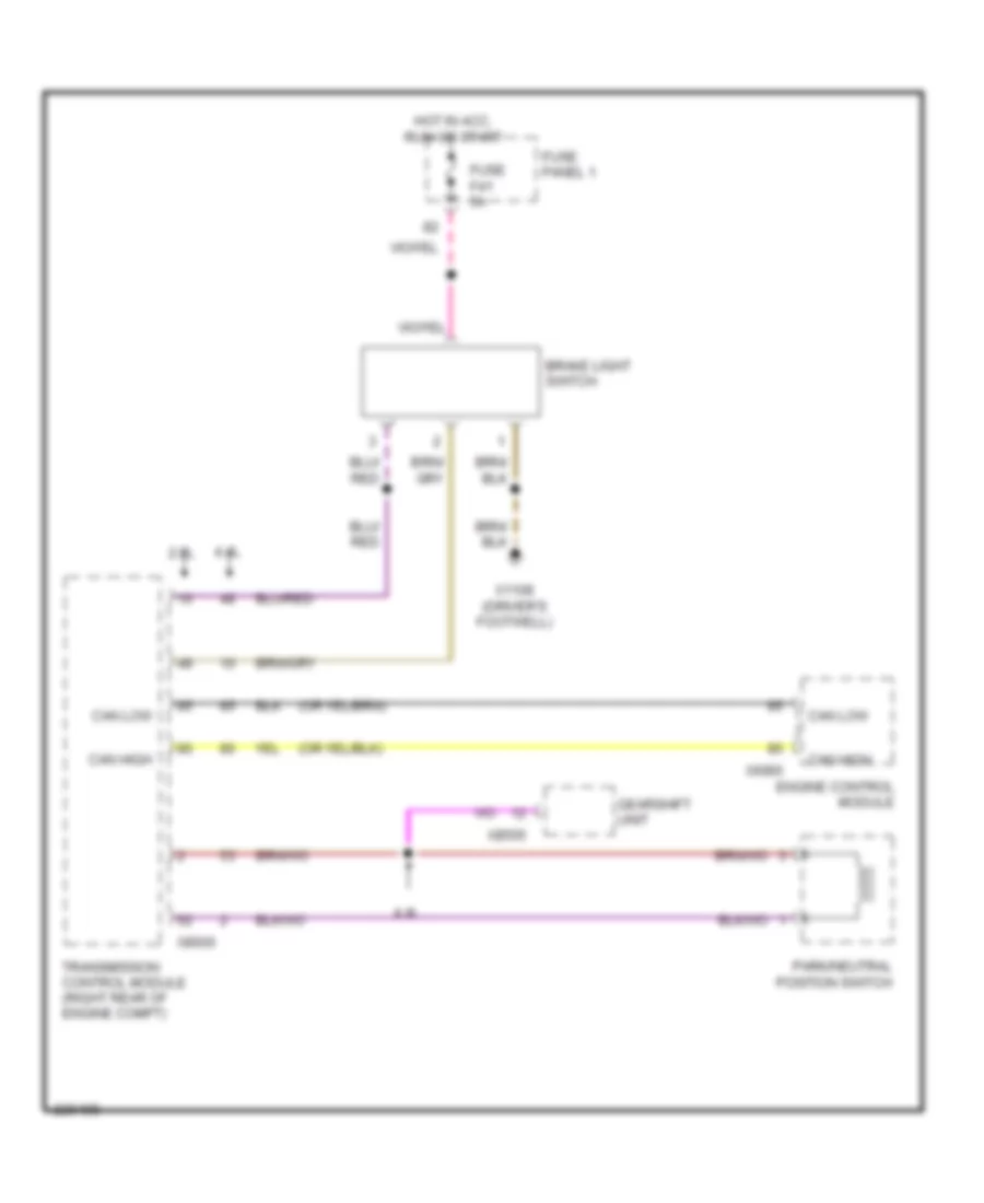
Shift Interlock Wiring Diagram for BMW 540i 1997
List of elements for Shift Interlock Wiring Diagram for BMW 540i 1997:
- 2.8l
- 4.4l
- Brake light switch
- Can high
- Can low
- Engine control module
- Fuse f41 5a
- Fuse panel 1
- Gearshift unit
- Hot in acc, run or start
- Park/neutral position switch
- Transmission control module (right rear of engine compt)
- X1108 (driver's footwell)
- X6000
- X8505
- X8600
STARTING/CHARGING
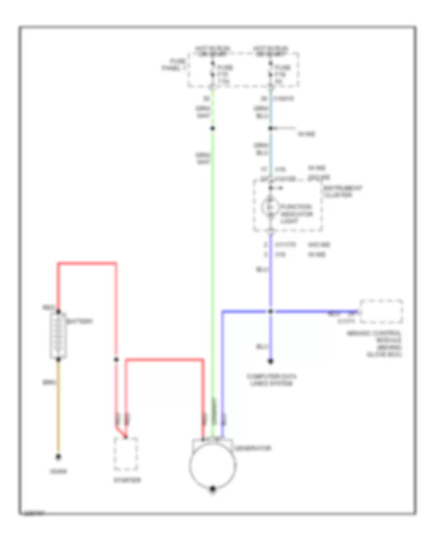
Charging Wiring Diagram for BMW 540i 1997
List of elements for Charging Wiring Diagram for BMW 540i 1997:
- Abs/asc control module (behind glove box)
- Battery
- Computer data lines system
- Function indicator light
- Fuse f15 7.5a
- Fuse f18 5a
- Fuse panel 1
- Generator
- Hot in run or start
- Instrument cluster
- Red
- Starter
- W/ ike
- W/o ike
- X10015
- X11175
- X1171
- X16
- X6406
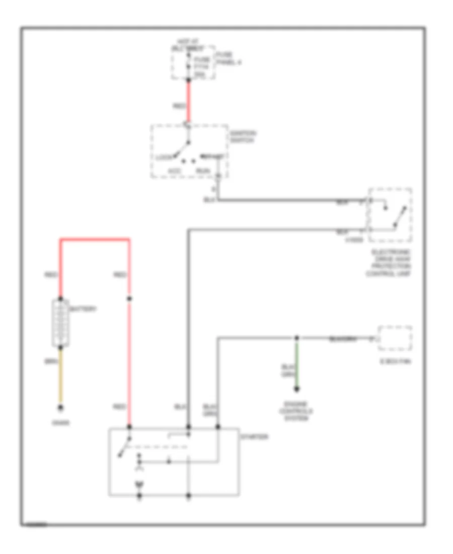
Starting Wiring Diagram for BMW 540i 1997
List of elements for Starting Wiring Diagram for BMW 540i 1997:
- Acc
- Battery
- E box fan
- Electronic drive away protection control unit
- Engine controls system
- Fuse f114 50a
- Fuse panel 4
- Hot at all times
- Ignition switch
- Lock
- Red
- Run
- Start
- Starter
- X1659
- X6406
SUPPLEMENTAL RESTRAINTS
Supplemental Restraints Wiring Diagram (1 of 2) for BMW 540i 1997
List of elements for Supplemental Restraints Wiring Diagram (1 of 2) for BMW 540i 1997:
- Air bag ind
- Computer data lines system
- Driver's door for side air bag inflator assembly
- Driver's seat belt tension generator
- Fuse f40 5a
- Fuse f42 5a
- Fuse panel 1
- Hot in acc, run or start
- Instrument cluster
- Left front sensor (air bag)
- Nca
- Passenger's door for side air bag inflator assembly
- Passenger's seat belt tension generator
- Right front sensor (air bag)
- W/ ike
- W/o ike
- X10015
- X11175
- X11176
- X16
- X46 (rear center console)
Supplemental Restraints Wiring Diagram (2 of 2) for BMW 540i 1997
List of elements for Supplemental Restraints Wiring Diagram (2 of 2) for BMW 540i 1997:
- (not used)
- Air bag contact plate
- Driver's air bag gas generator
- Driver's seat belt switch 1) unbuckled 2) buckled
- General module
- Inertia fuel shutoff switch
- Light module (right kick panel)
- Nca
- Passenger's air bag gas generator
- Passenger's seat belt switch 1) unbuckled 2) buckled
- Seat load assembly
- X01009
- X10012 (right front footwell)
- X10117
- X10218
- X1108 (driver's side footwell)
- X253
TRANSMISSION
Transmission Wiring Diagram (1 of 2) for BMW 540i 1997
List of elements for Transmission Wiring Diagram (1 of 2) for BMW 540i 1997:
- (left read side of engine compt)
- Ags transmission control module
- Brake light switch (below left side of dash)
- Cruise control module (tempomat) (left side of driver's footwell)
- Data link connector x6002
- Down shift
- Engine electronics fuse carrier (right rear side of engine compt in e box)
- Exterior lights system
- Fuse 5a
- Fuse 7.5a
- Fuse box
- Fuse f1 30a
- Fuse f24 5a
- Fuse f38 5a
- Fuse f4 30a
- Gear indicator light
- General module (behind glove box)
- Hot at all times
- Hot in accy, run & start
- Hot in run & start
- Hot with engine relay energized
- Kick down switch (driver's side footwell)
- Light module (right side of right footwell)
- Manual gearshift
- Off
- Park/neutral position switch
- Red
- Selector lever position switch
- Steptronic switch (center console)
- Up shift
- X10012
- X10015
- X1193
- X1599
- X1600
- X22
- X254
- X38
- X6453
- X70001
- X70003
- X78
- X8680
Transmission Wiring Diagram (2 of 2) for BMW 540i 1997
List of elements for Transmission Wiring Diagram (2 of 2) for BMW 540i 1997:
- Ags transmission control module
- Automatic transmission range switch (right side of transmission)
- Automatic transmission range switch 0 off 1 on
- Nca
- Oil temperature sensor
- Output shaft speed sensor
- Pnk
- Pressure regulator 1
- Pressure regulator 2
- Pressure regulator 3
- Pressure regulator 4
- Pressure regulator 5
- Red
- Solenoid valve 1
- Solenoid valve 2
- Solenoid valve 3
- Transmission control unit (on left side of transmission)
- Turbine shaft speed sensor
- X70004
- X8505
TRUNK, TAILGATE, FUEL DOOR
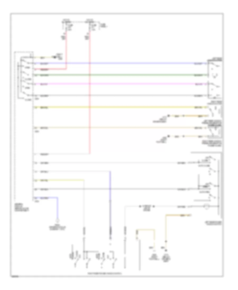
Trunk & Fuel Door Release Wiring Diagram for BMW 540i 1997
List of elements for Trunk & Fuel Door Release Wiring Diagram for BMW 540i 1997:
- (below driver's seat)
- 87a
- Central locking fuel tank access flap relay
- Door locks system
- Fuel tank access flap lock motor
- Fuse f27 30a
- Fuse f53 5a
- Fuse panel 1
- Fuse panel 2
- General module (behind glove compartment)
- Hot at all times
- Interior lights system
- Rear lid motor relay
- Sedan
- Trunk lid release switch
- Wagon
- X10015
- X10016
- X1108
- X253
- X254
- X332
- X492
- X494 (under right side of luggage compt)
- X498 (right rear of trunk)
- Zv drive rear lid
WARNING SYSTEMS
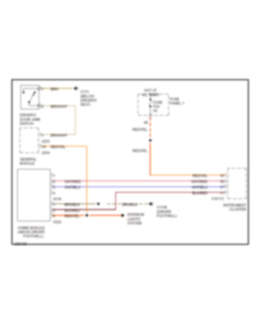
Chime Wiring Diagram, with IKE for BMW 540i 1997
List of elements for Chime Wiring Diagram, with IKE for BMW 540i 1997:
- Chime module (above driver
- Driver's door jamb switch
- Footwell)
- Fuse f24 5a
- Fuse panel 1
- General module
- Hot at all times
- Instrument cluster
- Interior lights system
- X10113
- X1108 (driver footwell)
- X173 (below driver's seat)
- X253
- X254
- X518
- X522
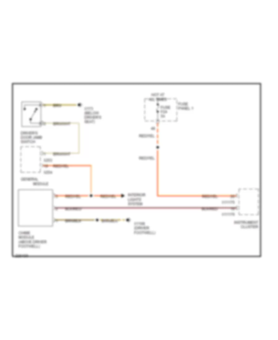
Chime Wiring Diagram, without IKE for BMW 540i 1997
List of elements for Chime Wiring Diagram, without IKE for BMW 540i 1997:
- Chime module (above driver footwell)
- Driver's door jamb switch
- Fuse f24 5a
- Fuse panel 1
- General
- Hot at all times
- Instrument cluster
- Interior lights system
- Module
- X1108 (driver footwell)
- X11175
- X11176
- X173 (below driver's seat)
- X253
- X254
WIPER/WASHER
Front Wiper/Washer Wiring Diagram for BMW 540i 1997
List of elements for Front Wiper/Washer Wiring Diagram for BMW 540i 1997:
- Computer data lines system
- Fast
- Fuse f1 30a
- Fuse f11 7.5a
- Fuse f26 5a
- Fuse f38 5a
- Fuse panel 1
- General module (behind glove compartment)
- Hot at all times
- Hot in acc, run or start
- Instrument cluster
- Int
- Intensive wash
- Light module
- Nca
- Normal
- Off
- Park
- Rain sensor
- Rear
- Run
- Single
- Wash
- Washer fluid level switch
- Washer pump
- Wiper motor
- Wiper relay i
- Wiper relay ii
- Wiper/washer switch
- Wiper/washer system (headlamp washer circuit)
- Wiper/washer system (rear washer/ wiper circuit)
- X10012 (right front footwell)
- X10117
- X11176
- X151 (below driver seat)
- X253
- X254
- X332
- X490 (right footwell)
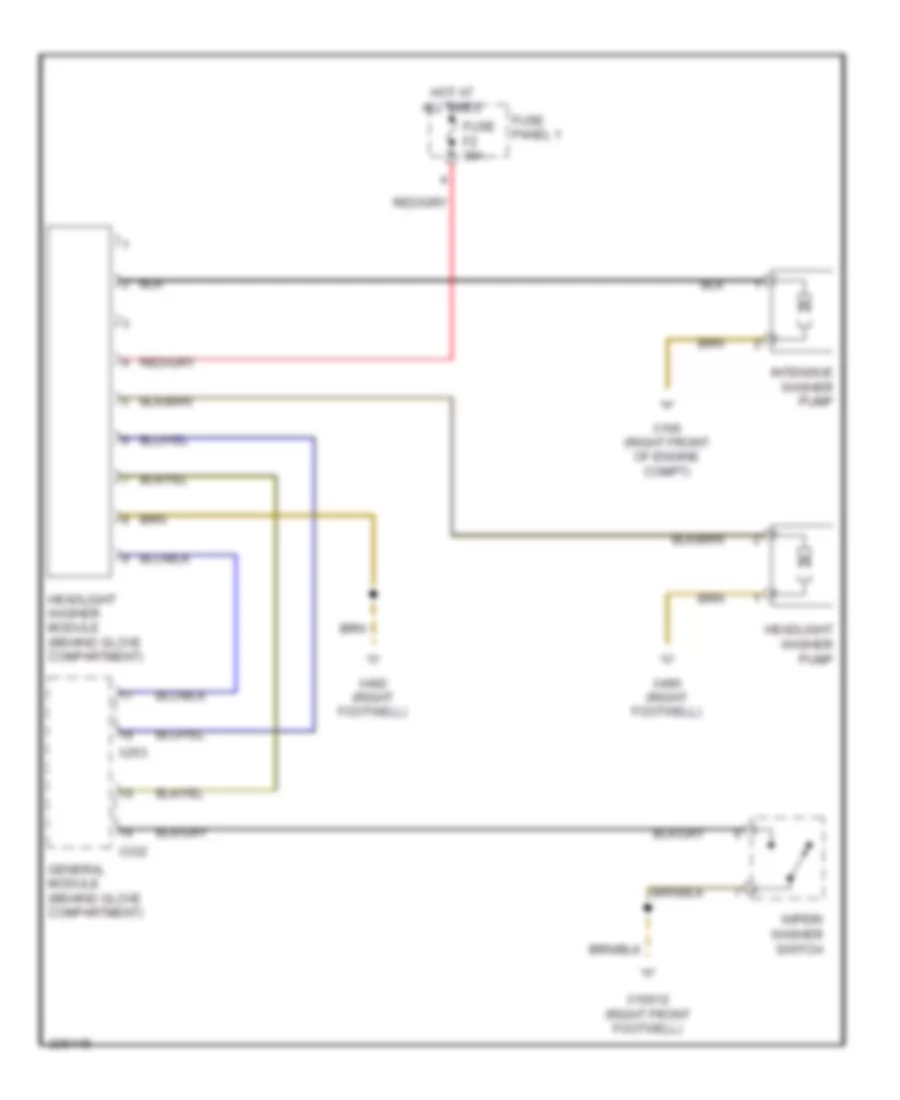
Headlamp Washer Wiring Diagram for BMW 540i 1997
List of elements for Headlamp Washer Wiring Diagram for BMW 540i 1997:
- Fuse f2 30a
- Fuse panel 1
- General module (behind glove compartment)
- Headlight washer module (behind glove compartment)
- Headlight washer pump
- Hot at all times
- Intensive washer pump
- Wiper/ washer switch
- X10012 (right front footwell)
- X166 (right front of engine compt)
- X253
- X332
- X490 (right footwell)
- X492 (right footwell)
Jet Heater Wiring Diagram for BMW 540i 1997
List of elements for Jet Heater Wiring Diagram for BMW 540i 1997:
- Fuse f20 5a
- Fuse panel 1
- Heating & a/c control module
- Hot in run or start
- Left valve
- Left washer jet heater
- Nca
- Right valve
- Right washer jet heater
- Water valve assembly
- X1106 (right front of engine compt)
- X165 (left front of engine compt)
- X610
Rear Wiper/Washer Wiring Diagram for BMW 540i 1997
List of elements for Rear Wiper/Washer Wiring Diagram for BMW 540i 1997:
- (under right side of rear window shelf) x494
- Fuse f43 5a
- Fuse f55 20a
- Fuse panel 1
- Fuse panel 2
- General module (behind glove compartment)
- Hot at all times
- Hot in acc, run or start
- Light module (right kick panel)
- Rear
- Rear intermittent wiper/washer control unit
- Rear washer pump
- Rear window opening switch
- Wiper/washer switch
- X10012 (right front footwell)
- X10117
- X13057
- X13268
- X253
- X490 (right footwell)
- X494 (under right side of rear window shelf)