AIR CONDITIONING
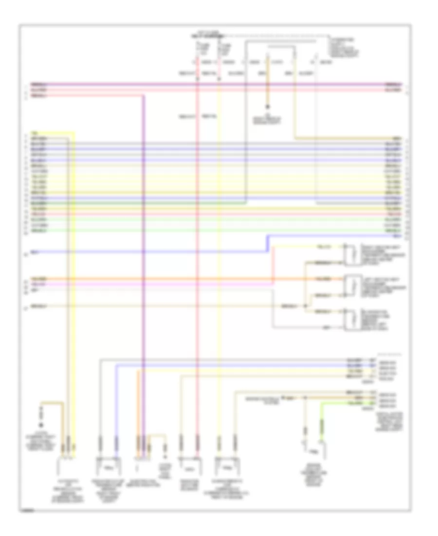
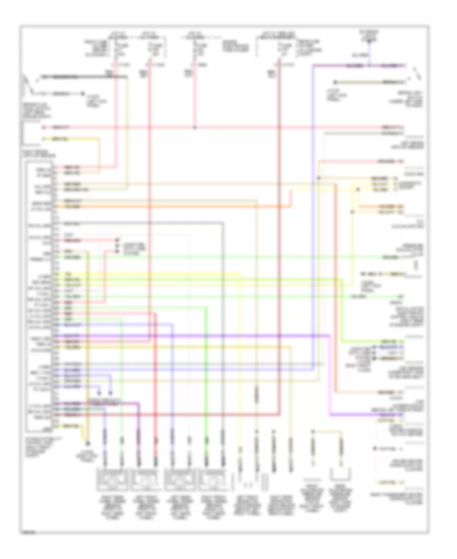
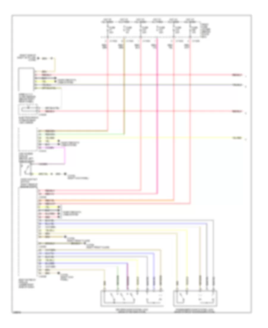
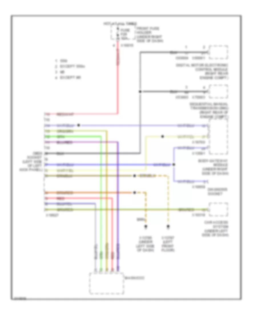
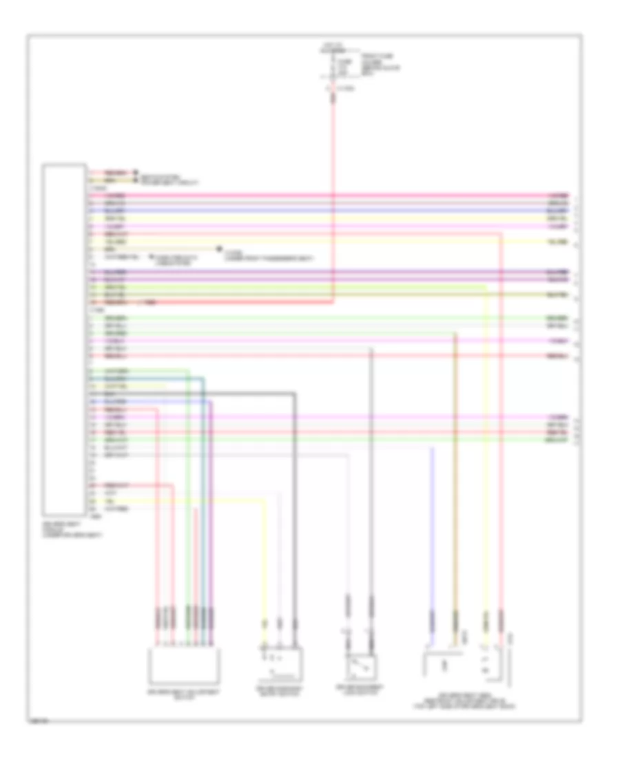
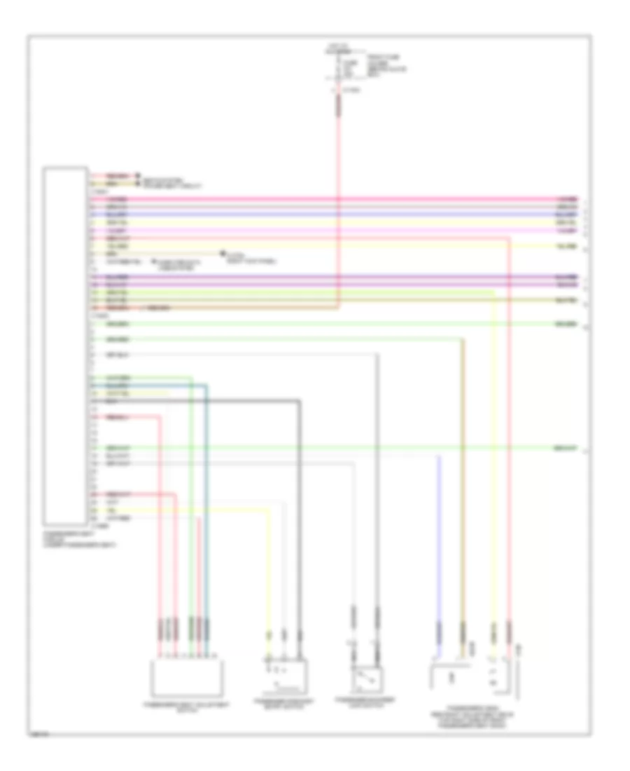
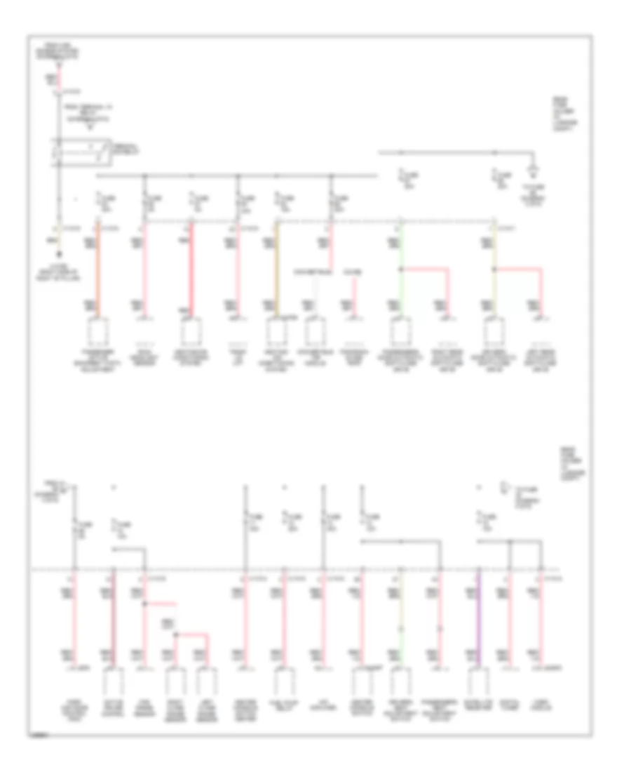
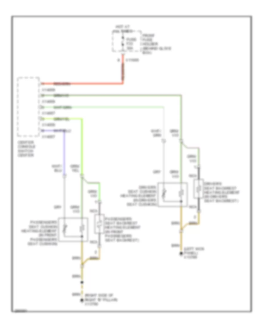
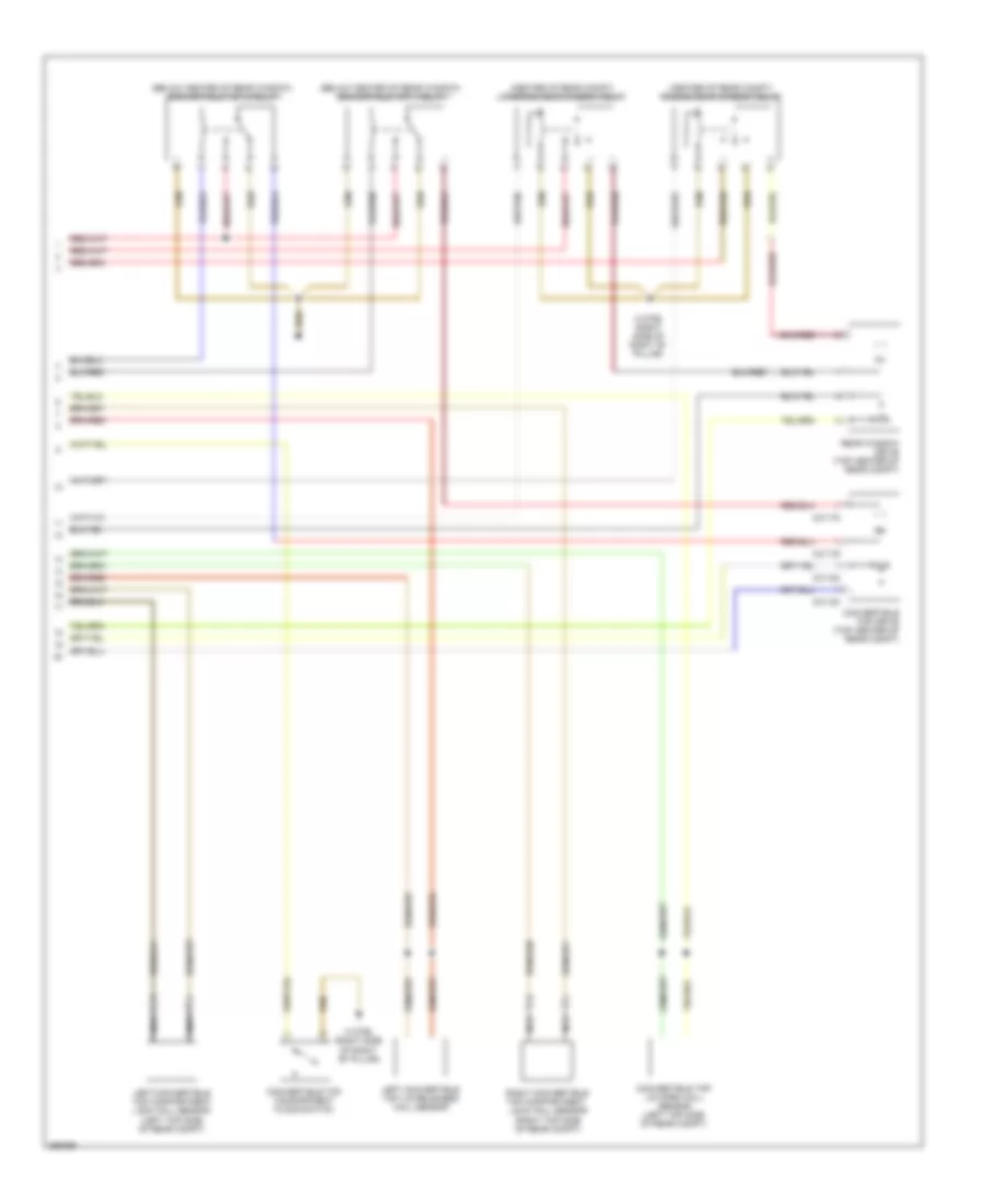
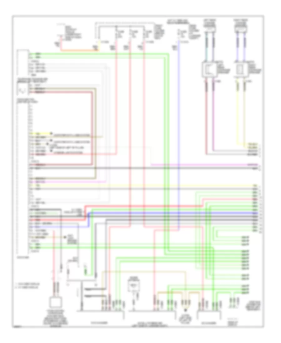
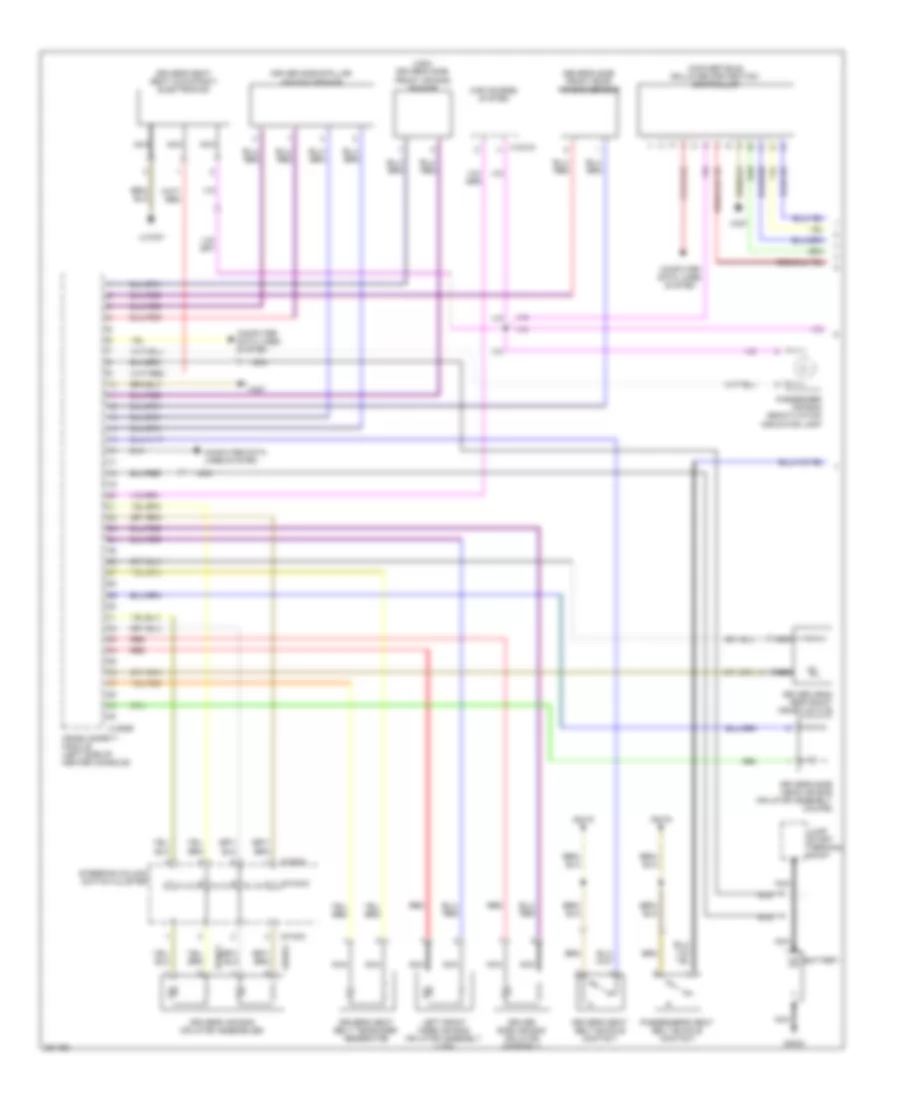
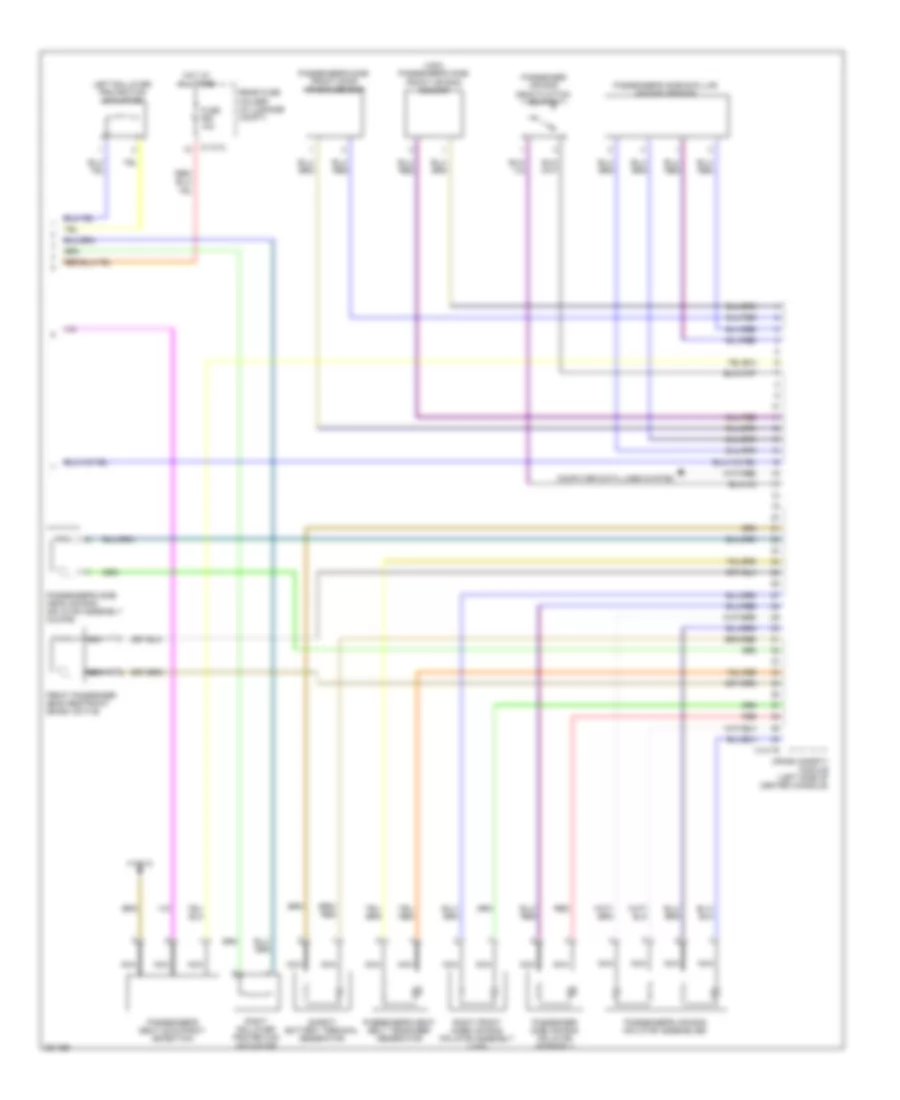
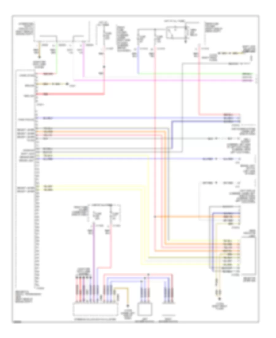
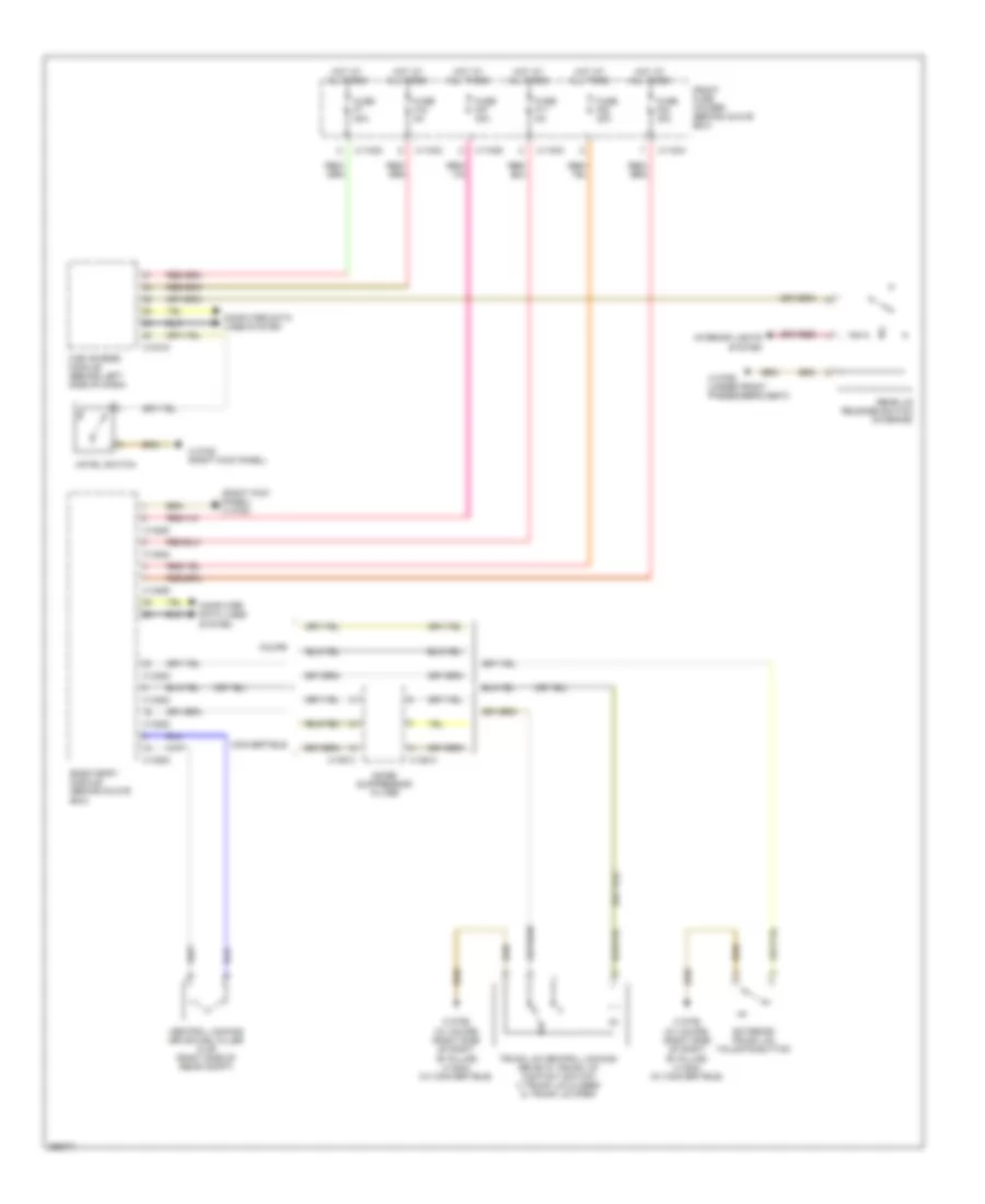
Automatic A/C Wiring Diagram (1 of 3) for BMW 650i 2010

List of elements for Automatic A/C Wiring Diagram (1 of 3) for BMW 650i 2010:
- (6 series: right kick panel) (5 series: right front floor)
- (top left side of dash)
- Can h
- Can l
- Cold air flap motor (behind right side of dash)
- Computer data lines system
- Defogger system
- Defrost sig
- Defroster flap actuator (behind left side of dash)
- Front fuse holder (5 series: under right side of dash) (6 series: behind glove box)
- Fuse f3 40a
- Fuse f64 15a
- Fuse f9 60a
- Ground
- Heating/air conditioning system (center of dash)
- Hot at all times
- Hot w/ term 30g relay energized
- Htd jets sig
- Left footwell flap motor (behind left side of dash)
- Left fresh air- recirculation air flap motor (behind left side of dash)
- Left ventilation flap motor (behind left side of dash)
- Lin bus sig
- Mtr grd
- Mtr sig
- Mtrs grd
- Mtrs sig
- Pmp sig
- Rear compartment mixing flap motor (5 series)
- Rear fuse holder (6 series: in luggage compt) (5 series: right side of rear compt)
- Red
- Right footwell flap motor (behind right side of dash)
- Right fresh air- recirculation (behind right side of dash)
- Right ventilation flap motor (behind right side of dash)
- Sens grd
- Sens sig
- Term 30g
- Valve sig
- X01130
- X11001
- X11002
- X11011
- X13765
- X13784
- X13784 (6 series: right kick panel) (5 series: right front floor)
- X1527
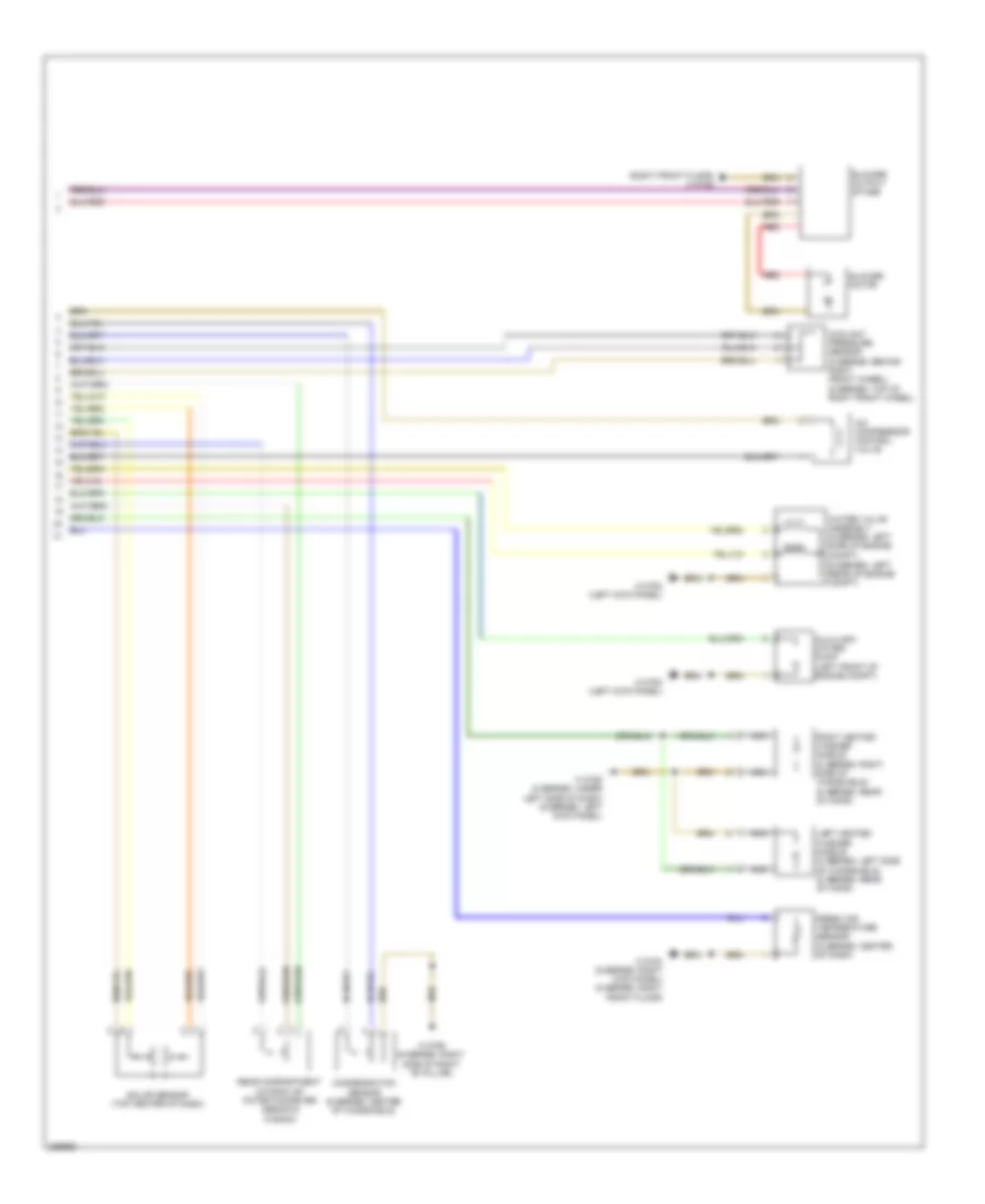
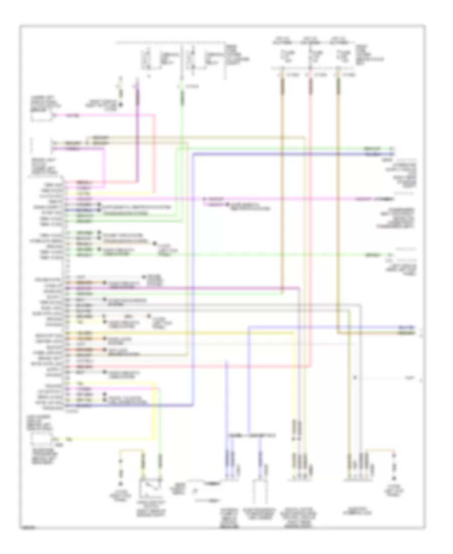
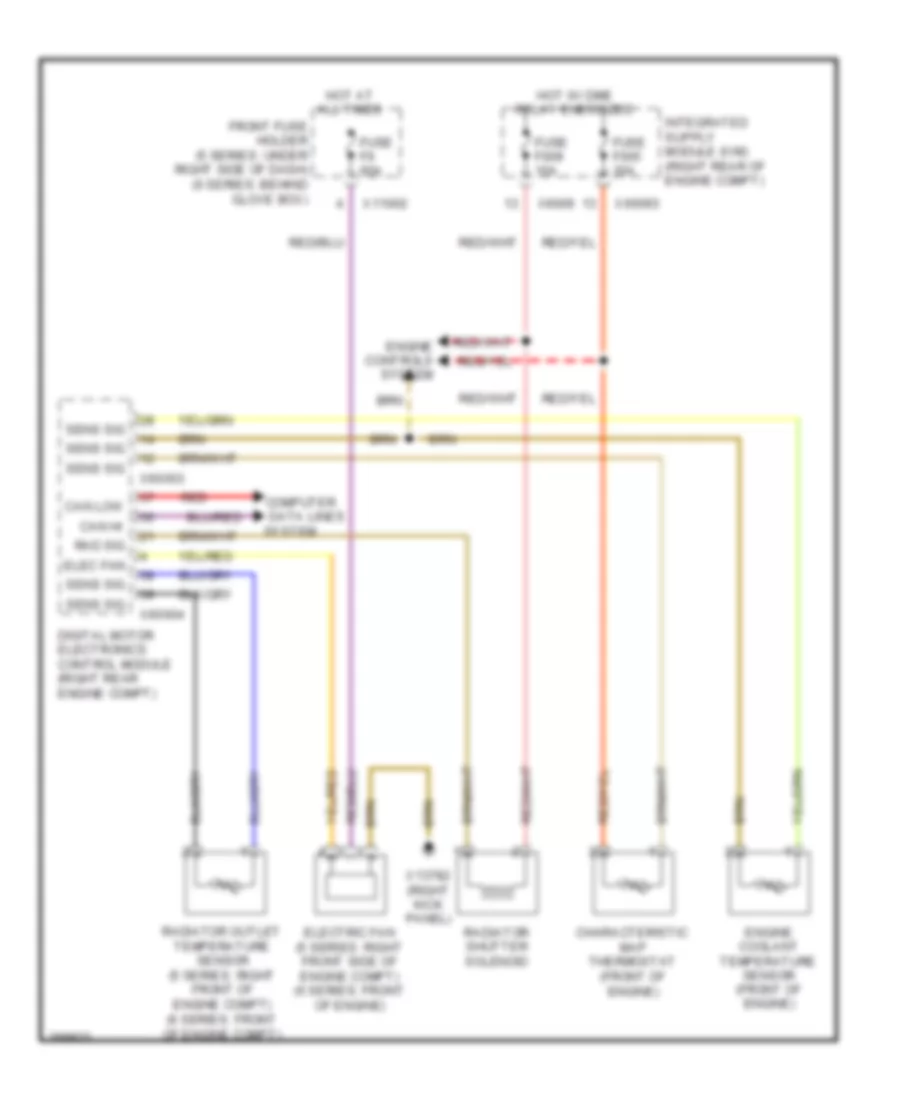
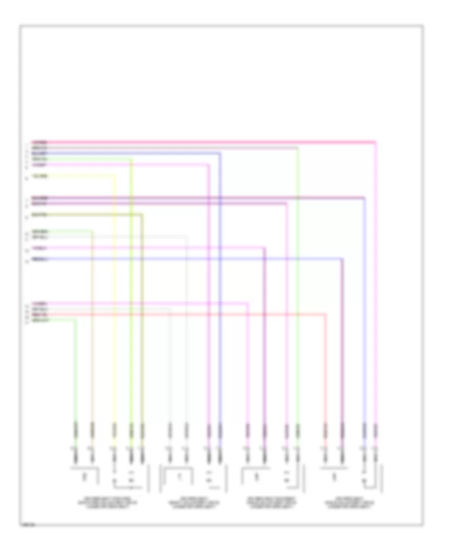
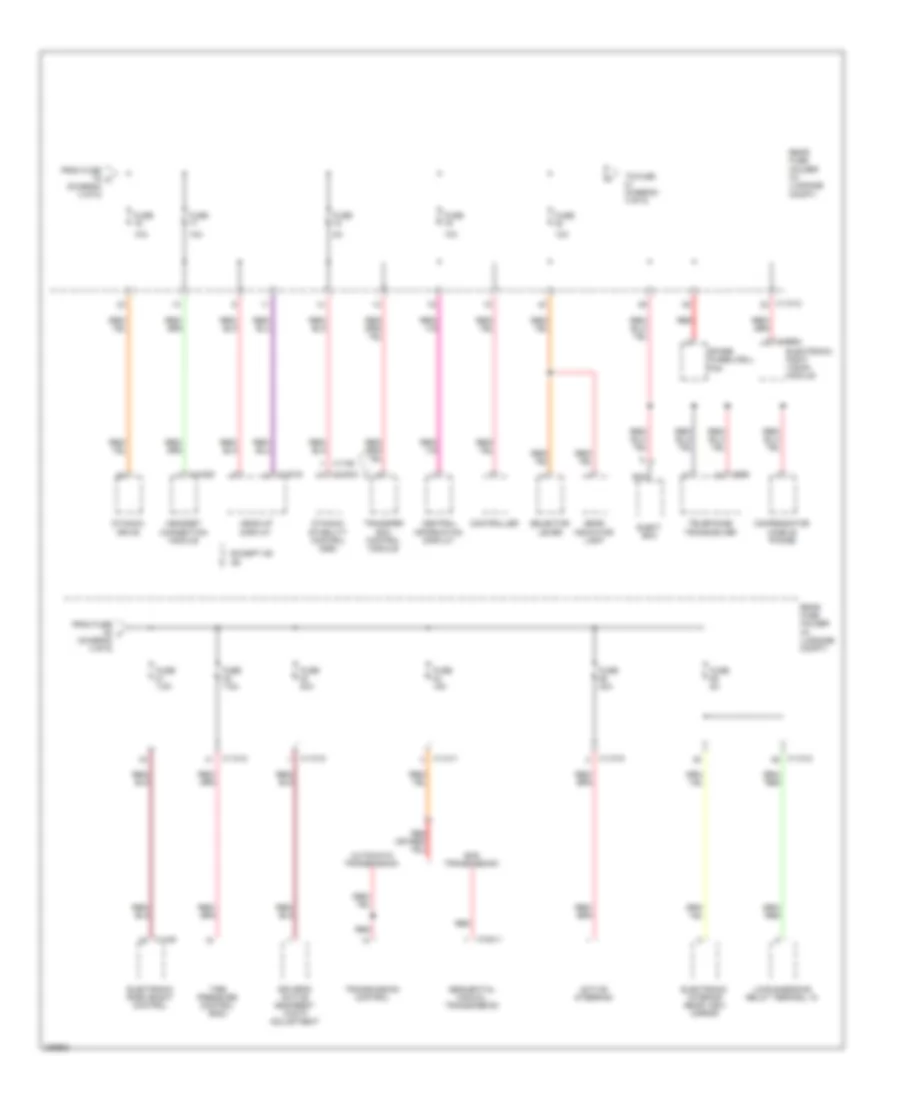
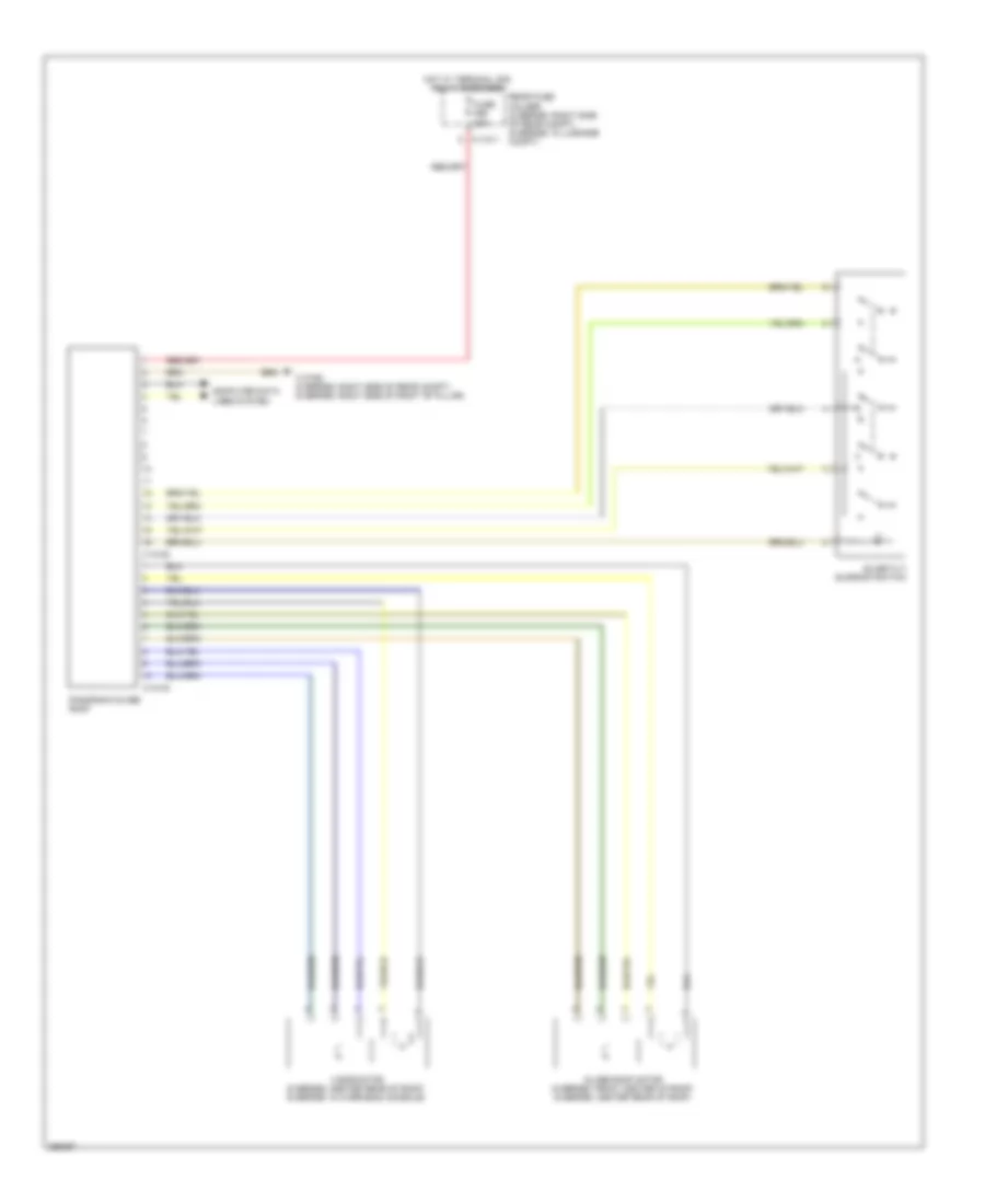
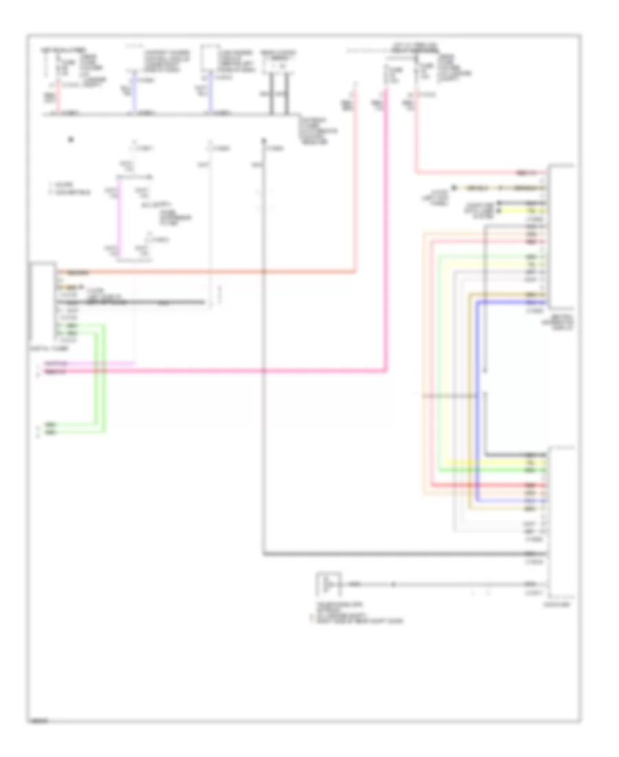
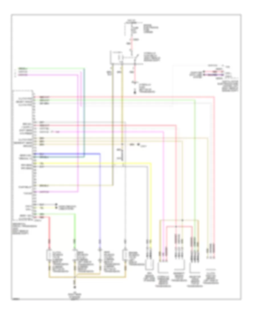
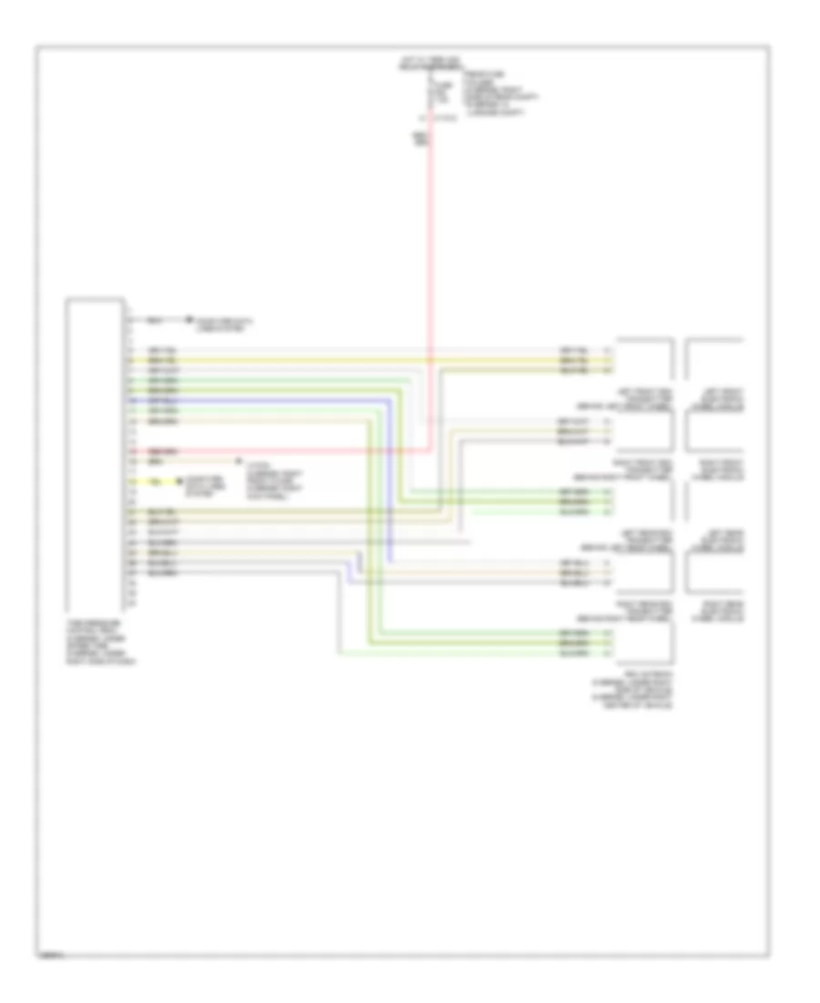
Automatic A/C Wiring Diagram (2 of 3) for BMW 650i 2010
List of elements for Automatic A/C Wiring Diagram (2 of 3) for BMW 650i 2010:
- Automatic air recirculation sensor (6 series: front of engine compt)
- Characteristic map thermostat (6 series & 5 series 4.8l: front of engine)
- Digital motor electronics control unit (right rear engine compt)
- Elec fan
- Electric fan (behind radiator)
- Engine controls system
- Engine coolant temperature sensor (front of engine)
- Evaporator temperature sensor (behind left side of dash)
- Fuse f005 30a
- Fuse f009 10a
- Hot w/ dme relay energized
- Left heating heat exchanger temperature sensor (behind center of dash)
- Rad sig
- Radiator outlet temperature sensor (right front of engine compt)
- Radiator shutter solenoid
- Right heating heat exchanger temperature sensor (behind center of dash)
- Sens sig
- X13701
- X13782 (right kick panel)
- X13784 (6 series: right kick panel) (5 series: right front floor)
- X6 (right rear of engine compt)
- X60003
- X60004
- X6009
- X60093
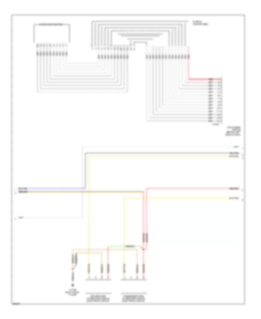
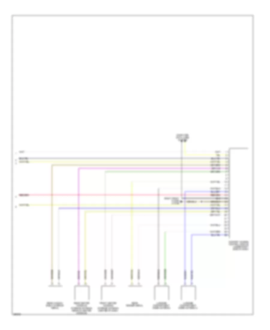
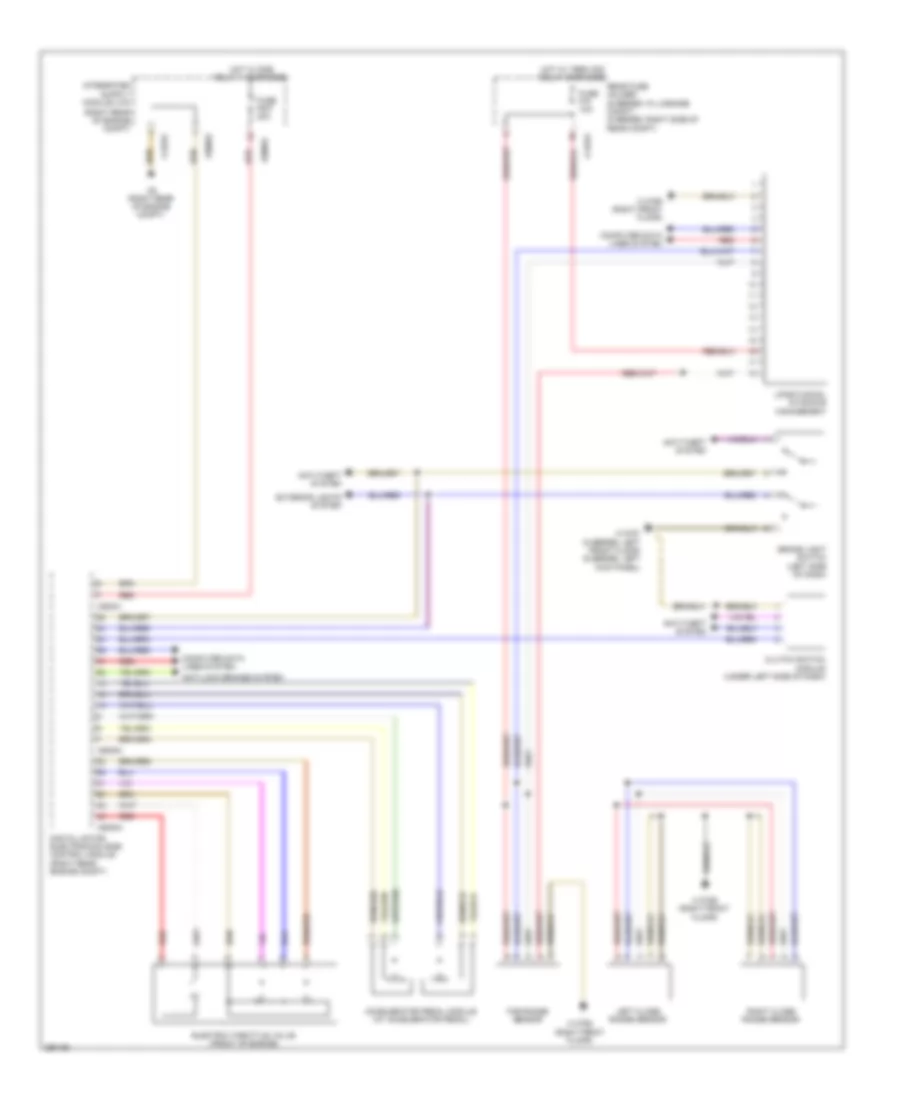
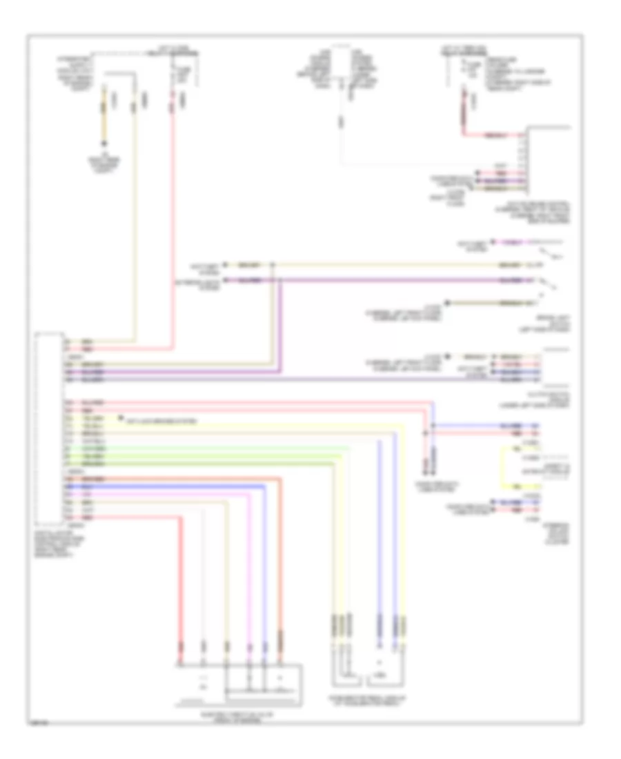
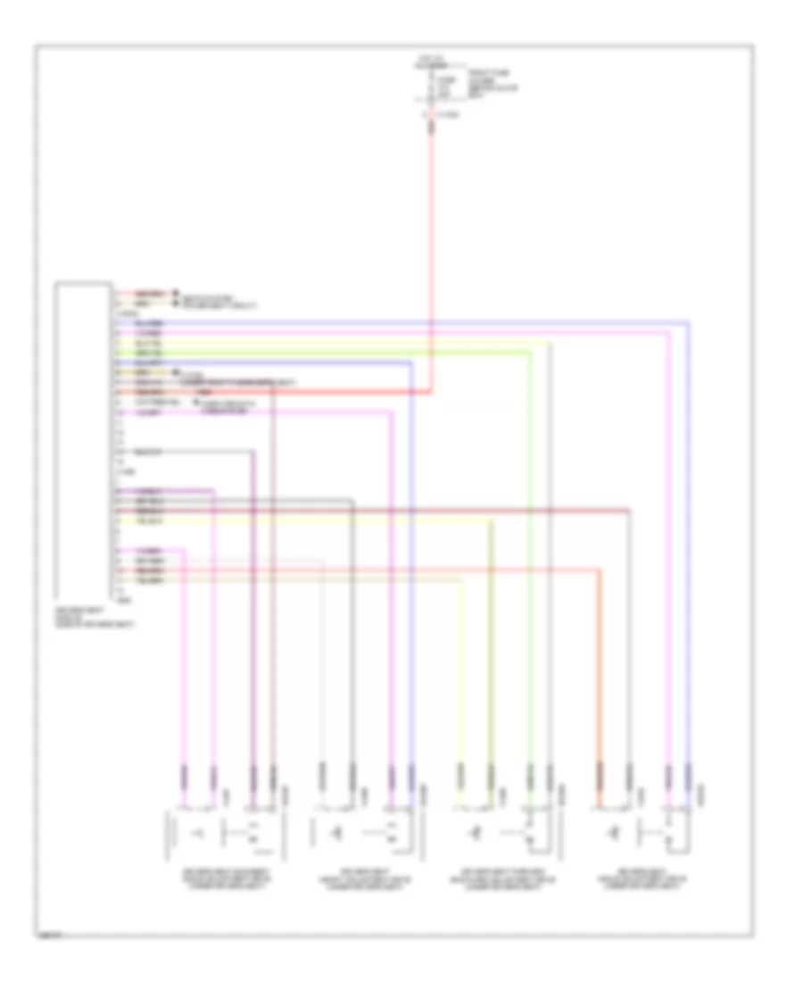
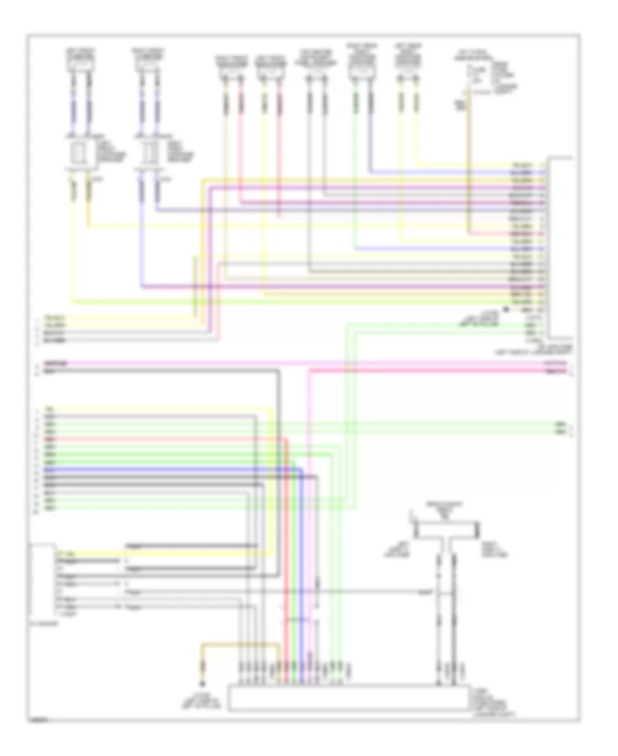
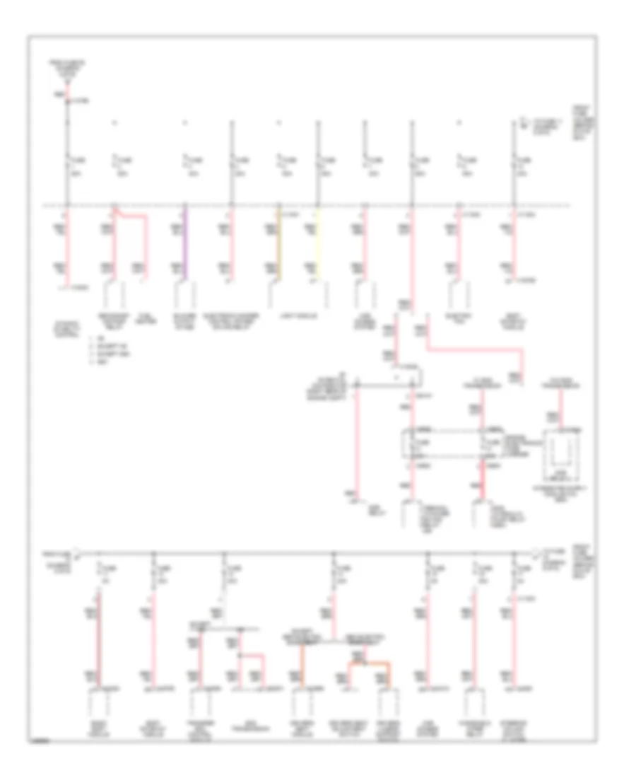
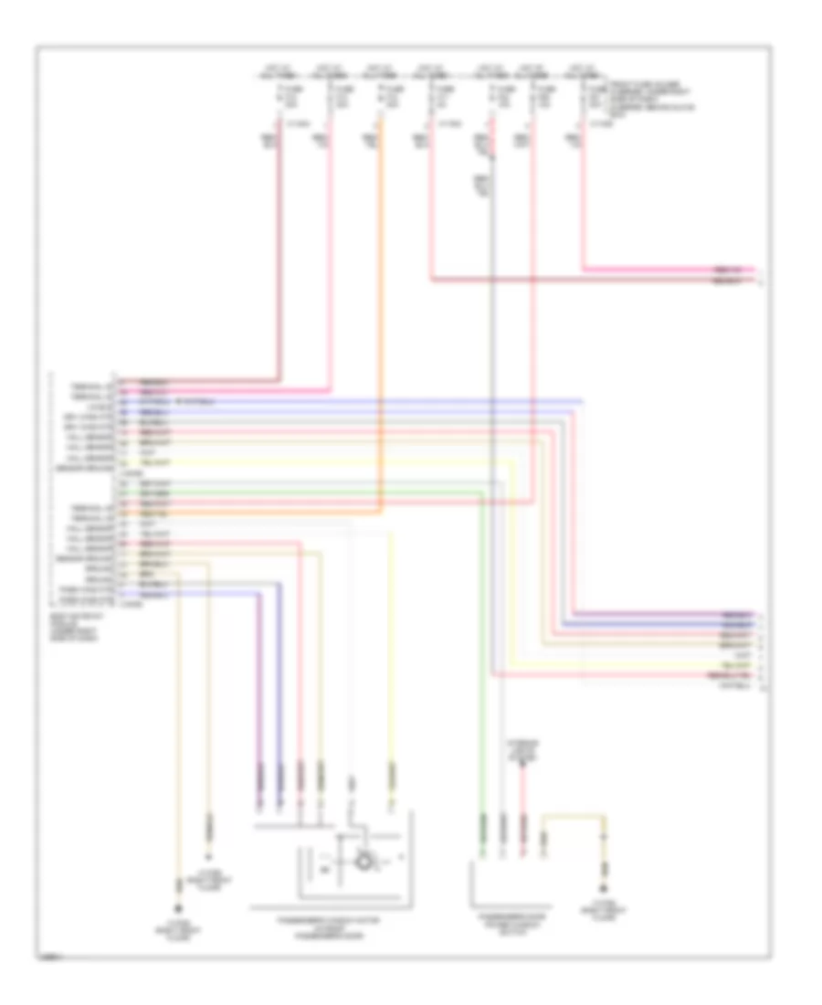
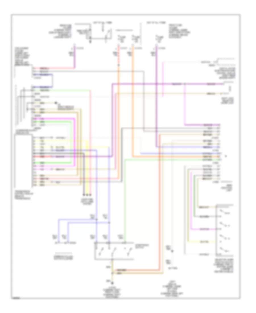
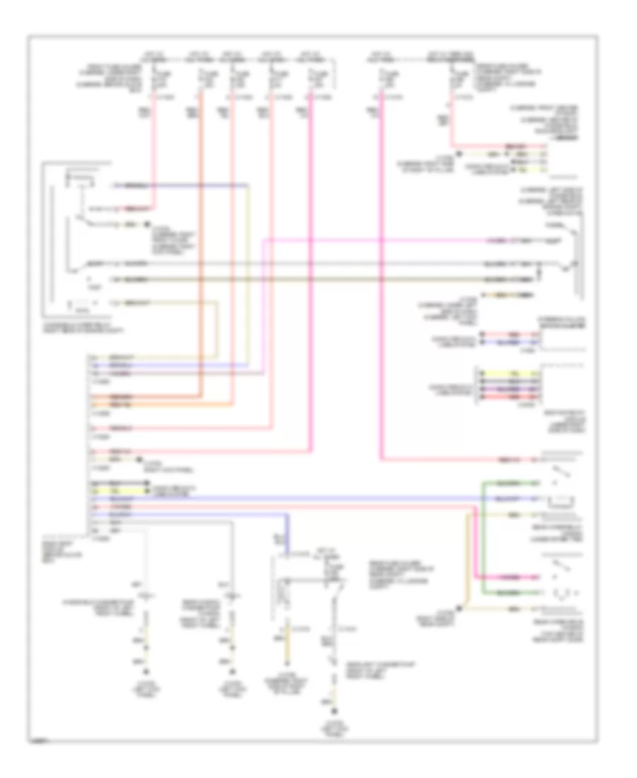
Automatic A/C Wiring Diagram (3 of 3) for BMW 650i 2010
List of elements for Automatic A/C Wiring Diagram (3 of 3) for BMW 650i 2010:
- (6 series: left rear of engine compt)
- (right front floor) x13788
- A/c compressor control valve
- Auxiliary water pump (left front of engine compt)
- Blower motor
- Blower output stage
- Condensation sensor (6 series: center of windshield)
- Coolant pressure sensor (5 series: behind right front wheel) (6 series: top of right front wheel)
- Fresh air temperature sensor (5 series: center of dash)
- Left heated washer nozzle (5 series: left side of windshield) (6 series: rear of hood)
- Nca
- Rear compartment mixing flap potentionmeter (sedan & wagon)
- Red
- Right heated washer nozzle (5 series: right side of windshield) (6 series: rear of hood)
- Solar sensor (top center of dash)
- Water valve assembly (5 series: left side of engine compt)
- X13783 (left kick panel)
- X13784 (6 series: right kick panel) (5 series: right front floor)
- X13785 (5 series: under left side of dash) (6 series: left kick panel)
- X13790 (6 series: right side of right "b" pillar)
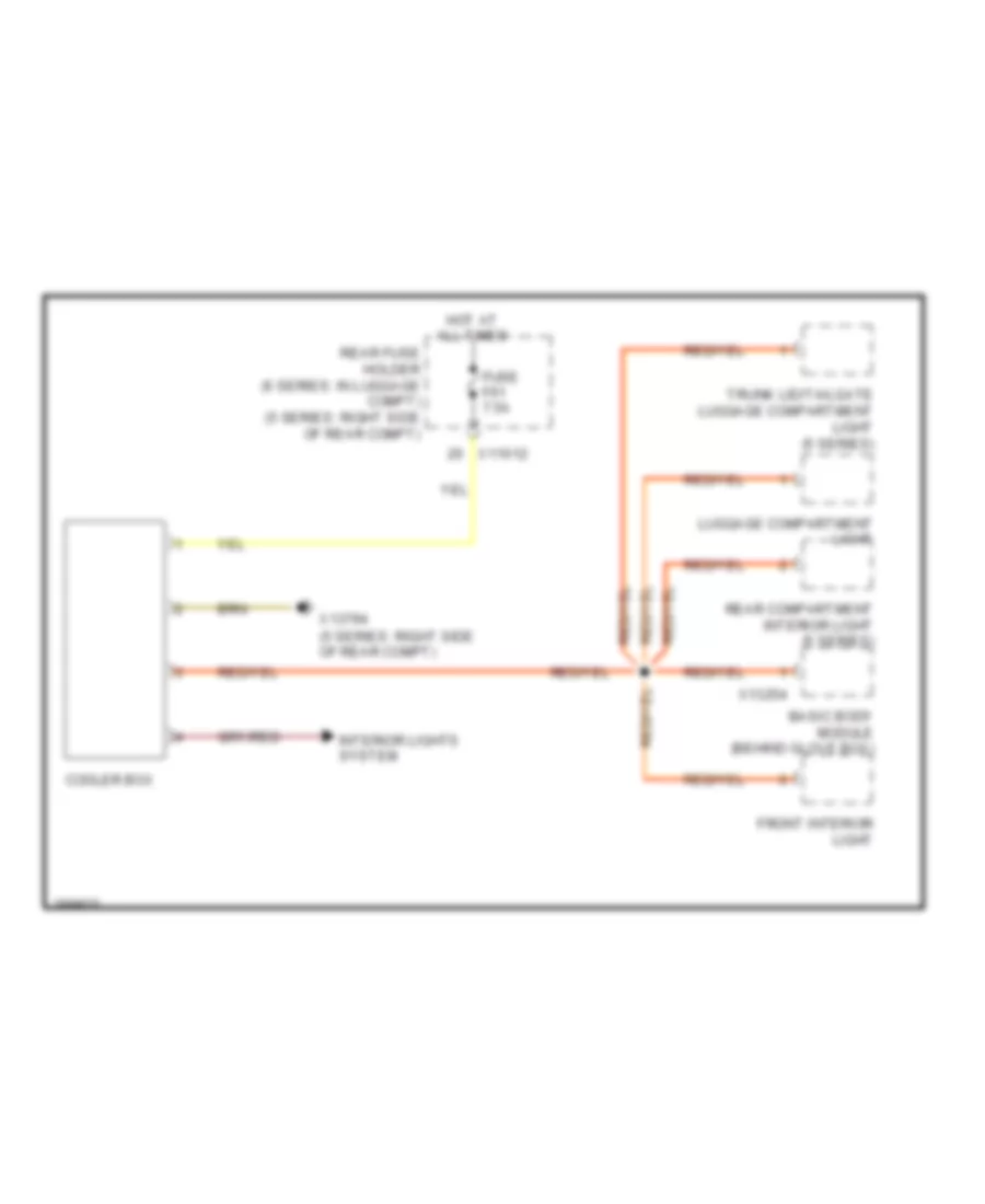
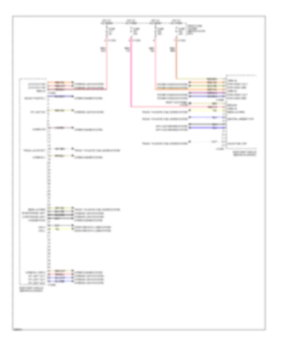
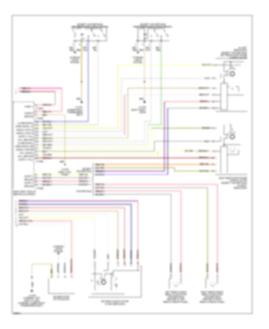
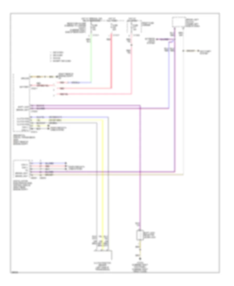
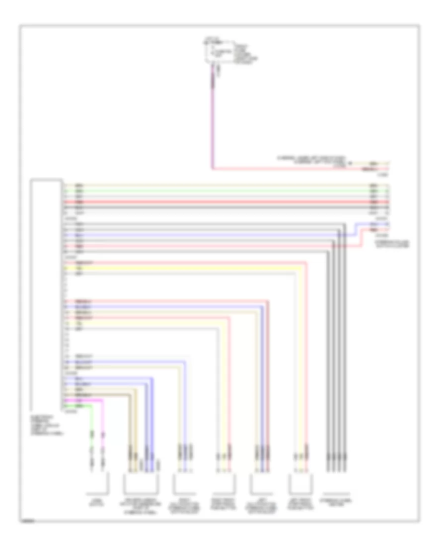
Cool Box Wiring Diagram for BMW 650i 2010
List of elements for Cool Box Wiring Diagram for BMW 650i 2010:
- Basic body module (behind glove box)
- Cooler box
- Front interior light
- Fuse f61 7.5a
- Hot at all times
- Interior lights system
- Luggage compartment light
- Rear compartment interior light (5 series)
- Rear fuse holder (6 series: in luggage compt) (5 series: right side of rear compt)
- Trunk lid/tailgate luggage compartment light (5 series)
- X11012
- X13254
- X13794 (5 series: right side of rear compt)
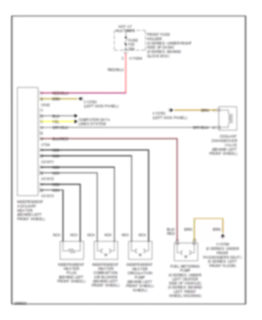
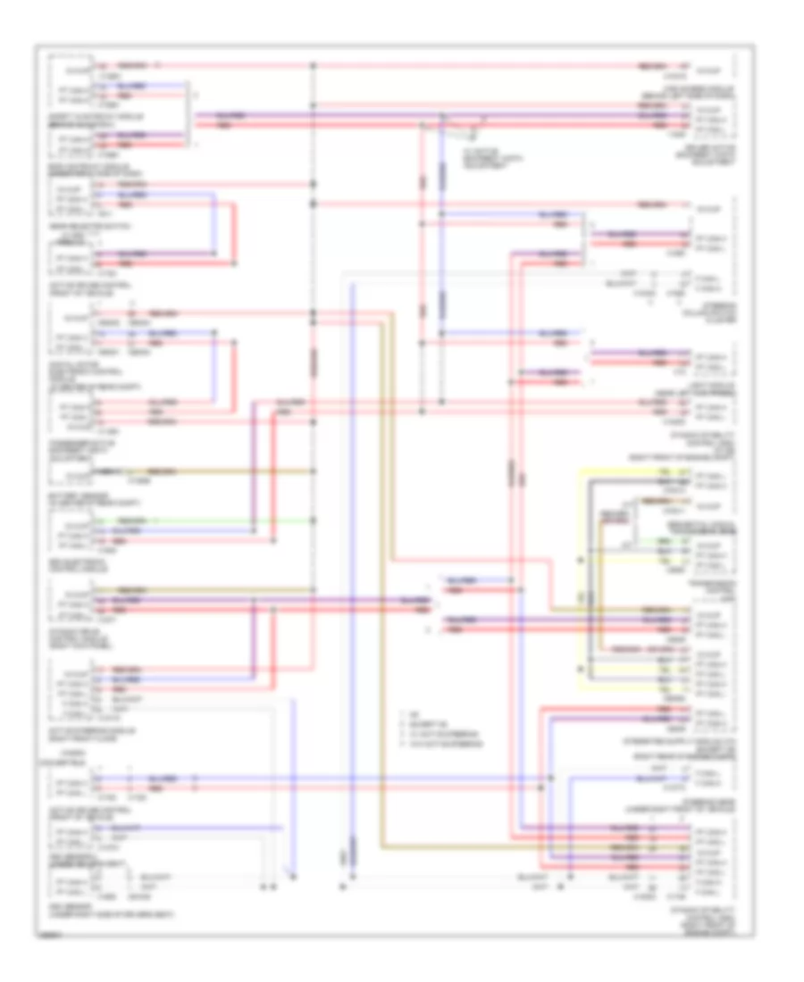
Independent Heating Wiring Diagram for BMW 650i 2010
List of elements for Independent Heating Wiring Diagram for BMW 650i 2010:
- Computer data lines system
- Coolant changeover valve (behind left front wheel)
- Front fuse holder (5 series: under right side of dash) (6 series: behind glove box)
- Fuel metering pump (6 series: under left center side of vehicle) (5 series: behind left front wheel housing)
- Fuse f20 20a
- Hot at all times
- Independent auxiliary heater (behind left front wheel)
- Independent heater circulation pump (behind left front wheel) wheel)
- Independent heater combustion air blower (behind left front wheel)
- Independent heater plug (behind left front wheel)
- Nca
- X01011
- X01012
- X01013
- X11004
- X13783 (left kick panel)
- X13789 (6 series: under front passenger's seat) (5 series: left front floor)
- X642
- X764
ANTI-LOCK BRAKES
Anti-lock Brakes Wiring Diagram for BMW 650i 2010
List of elements for Anti-lock Brakes Wiring Diagram for BMW 650i 2010:
- Brake fluid level switch (left rear engine compt)
- Brake light switch (under left side of dash)
- Brk fld
- Brk lt sig
- Car access module (behind left side of dash)
- Ccc/m-ask
- Center console switch center
- Computer data lines system
- Computer data lines system x13786 (right front floor)
- Deac. dsc
- Diagnostic socket
- Digital motor electronics control module (right rear of engine compt)
- Driver center console switch cluster
- Dsc sens
- Dsc sensor (under right side of driver's seat)
- Dynamic stability control (dsc) (right front of engine compt)
- Engine electronics fuse holder
- Exterior lights system
- F can h
- F can l
- Fr whl spd
- Front axle brake pressure sensor (top of right front wheel)
- Front fuse holder (behind glove box)
- Front passenger center console switch cluster
- Fuse f06 10a
- Fuse f1 50a
- Fuse f25 25a
- Fuse f78 5a
- Grd
- Hot at all times
- Hot w/ term 30g relay energized
- Left brake air flap sensor
- Left front brake pad wear sensor (behind left front wheel)
- Left front wheel speed sensor (front of left front wheel)
- Left rear wheel speed sensor (front of left rear wheel)
- Lf brk
- Lf whl sig
- Lf whl spd
- Lr wh spd
- Lr whl spd
- Nca
- Press vlv
- Pressure accumulator valve
- Pt can h
- Pt can l
- Rear axle brake pressure sensor (right side of engine compt)
- Rear fuse holder (in luggage compt)
- Red
- Rf whl spd
- Right brake air flap sensor
- Right front wheel speed sensor (front of right rear wheel)
- Right rear brake pad wear sensor (behind right rear wheel)
- Right rear wheel speed sensor (front of right rear wheel)
- Rr whl spd
- Rt brk
- Sens grd
- Tcu (w/o navigation)
- Term 30
- Term 30g
- Whl spd
- Wup
- X10318
- X11001
- X11004
- X11012
- X13782 (right kick panel)
- X13783 (left kick panel)
- X13787 (left kick panel)
- X16919
- X60004
- X8681
ANTI-THEFT
Access/Start Wiring Diagram (1 of 3) for BMW 650i 2010
List of elements for Access/Start Wiring Diagram (1 of 3) for BMW 650i 2010:
- (right side of right "b" pillar) x13790
- (under left side of dash) clutch switch module
- Antenna tuner w/ remote control receiver
- Anti-lock brakes system
- Brake lght
- Brake light switch (under left side of dash)
- Bus sig
- Can bus
- Car access module (behind left side of dash)
- Center lock
- Clutch sw
- Computer data lines system
- Convertible
- Coupe
- Crash safety
- Cruise cntrl
- Cruise control system
- Digital motor electronics (dme) control module (right rear engine compt)
- Door locks system
- Elec lock
- Elec str lock
- Electric steering lock
- Electrochromic interior rear view mirror
- Eng strt sig
- Front fuse holder (behind glove box)
- Fuse f15 5a
- Fuse f36 7.5a
- Fuse f7 30a
- Ground
- Hood contact switch (right rear of engine compt)
- Hot at all times
- Hotel sw sig
- Immob sig
- Interlock sens
- Lid contact
- Light module (near left kick panel)
- Nca
- Passenger's seat occupancy detection (under front passenger's seat)
- Power tops system
- Rear fuse holder (in luggage compt)
- Rear lid sig
- Rear window aerial
- Rmte cntrl sig
- Start sig
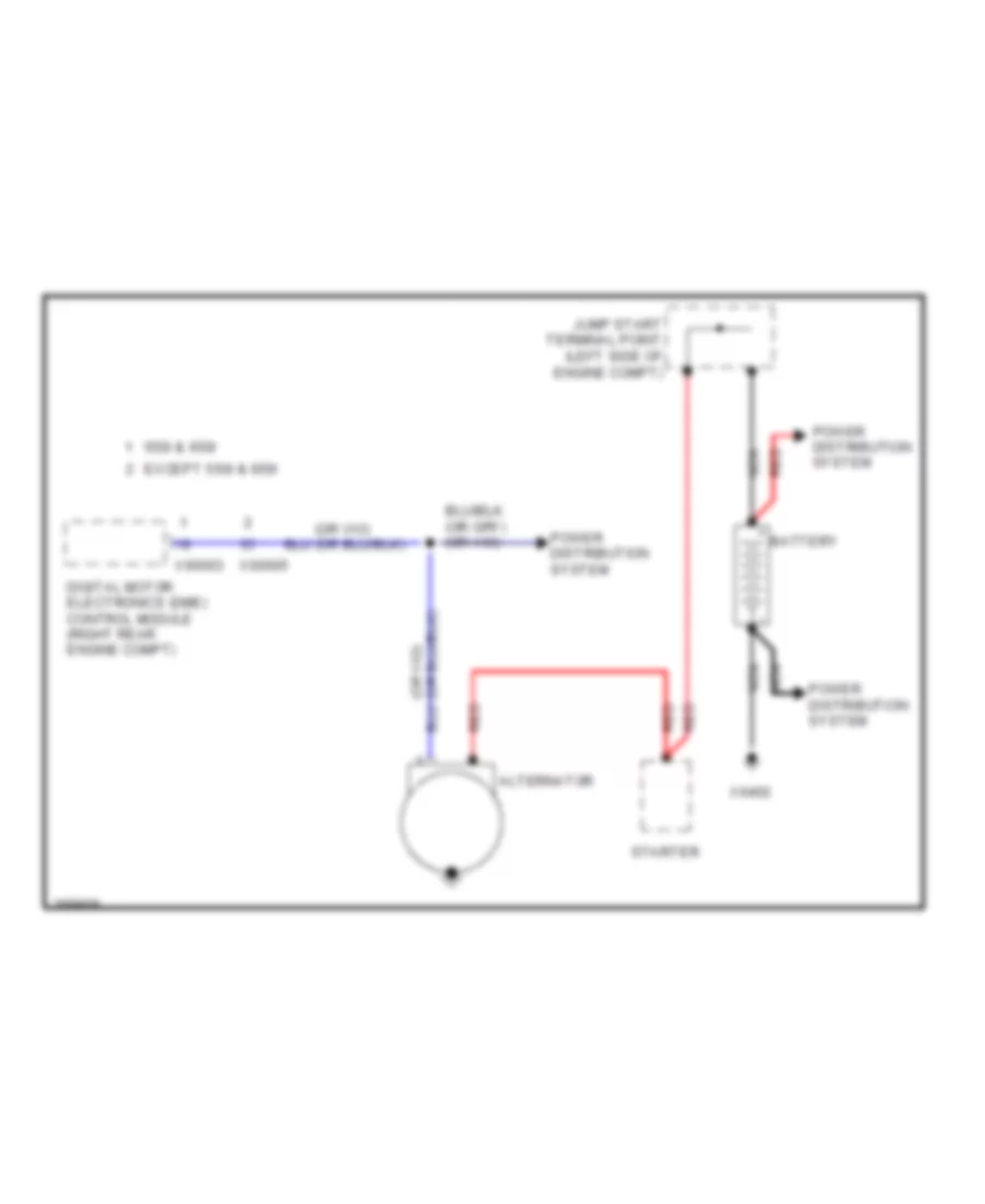
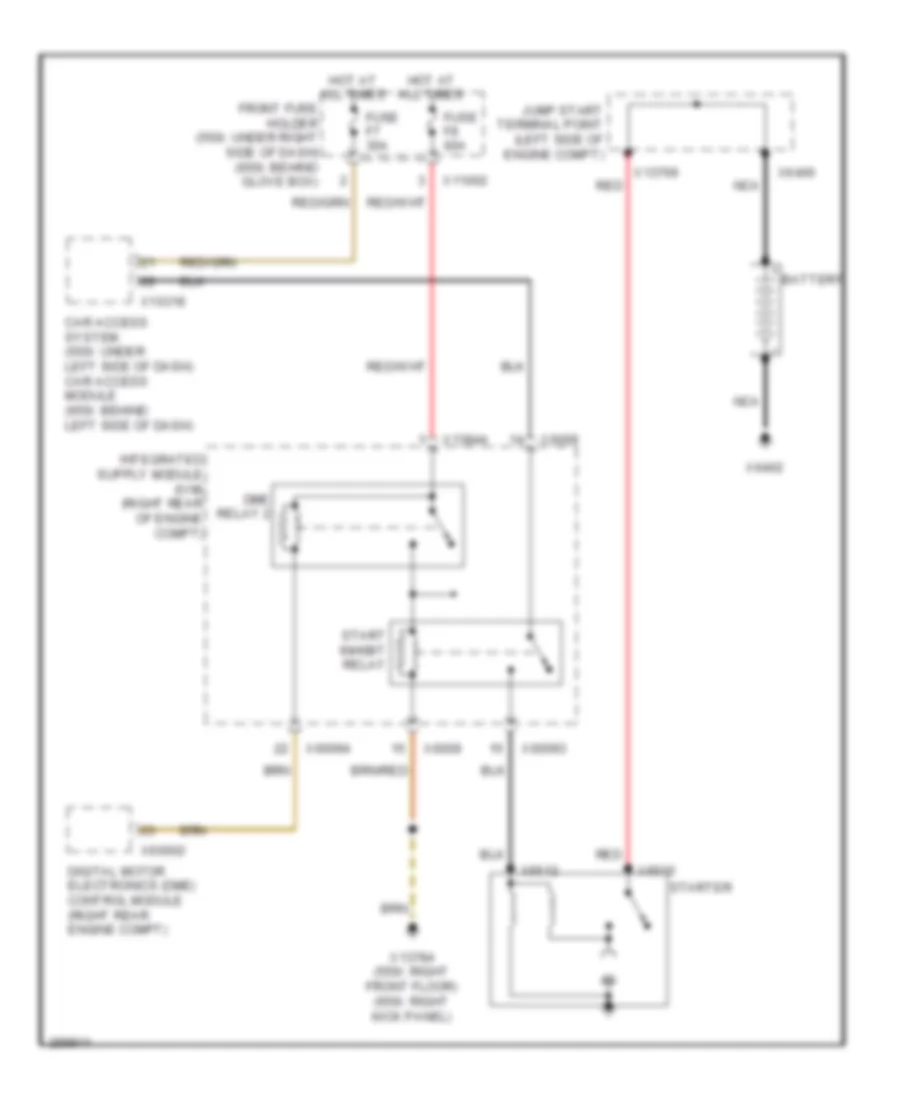
- Starting/charging system
- Suuply
- Tele sig
- Telephone transceiver (behind left rear seat)
- Term 15 sig
- Term 30g
- Term 50 sig
- Term r
- Term r sig
- Terminal 30g relay
- Terminal relay
- Trans sig
- Transmissions system
- Trunk, tailgate, fuel doors system
- Wake up
- Wheel spd sig
- X10318
- X10320
- X11002
- X11003
- X11006
- X11015
- X12
- X13782 (right kick panel)
- X13785 (left kick panel)
- X13787 (left kick panel)
- X13911
- X18426
- X60001
- X6009
- X695
Access/Start Wiring Diagram (2 of 3) for BMW 650i 2010
List of elements for Access/Start Wiring Diagram (2 of 3) for BMW 650i 2010:
- Car access module (behind left side of dash)
- Driver's side outer door handle electronic module
- Passenger's side outer door handle electronic module
- Red
- Slide-in compartment
- Start-stop button
- X13786 (right front floor)
- X14027
Access/Start Wiring Diagram (3 of 3) for BMW 650i 2010
List of elements for Access/Start Wiring Diagram (3 of 3) for BMW 650i 2010:
- (right front floor) x13786
- Comfort access control module (under right side of dash)
- Computer data lines system
- Front center console interior antenna (center of dash)
- Luggage compartment inner antenna
- Luggage compartment inner antenna 2
- Rear center console interior antenna (rear of center console)
- Rear fender aerial
- Rear window shelf interior aerial
Anti-theft & Central Locking Wiring Diagram (1 of 2) for BMW 650i 2010
List of elements for Anti-theft & Central Locking Wiring Diagram (1 of 2) for BMW 650i 2010:
- (right side of right "b" pillar) x13790
- Body-gateway module (under right side of dash)
- Car access module (behind left side of dash)
- Computer data lines system
- Driver's door system lock (rear of driver's door)
- Electrochromic interior rear view mirror
- Front fuse holder (behind glove box)
- Fuse f10 30a
- Fuse f12 30a
- Fuse f15 5a
- Fuse f18 30a
- Fuse f29 10a
- Fuse f7 30a
- Hood contact switch (right rear of engine compt)
- Hot at all times
- Passenger's door system lock (rear of front passenger's door)
- Red
- Siren & tilt alarm sensor (behind right rear wheel)
- X10318
- X11002
- X11003
- X11004
- X11005
- X13782 (right kick panel)
- X13786 (right front floor)
- X13788 (right front floor)
- X16759
- X16760
- X18246
Anti-theft & Central Locking Wiring Diagram (2 of 2) for BMW 650i 2010
List of elements for Anti-theft & Central Locking Wiring Diagram (2 of 2) for BMW 650i 2010:
- (right side of right "b" pillar)
- Driver's door automatic soft- close drive
- Driver's door microwave sensor (in driver's door)
- Fuse f51 5a
- Fuse f67 20a
- Fuse f68 20a
- Hazard warning/ central locking switch
- Hot at all times
- Hot w/ terminal 30g relay energized
- Left rear microwave sensor (left side of left "b" pillar)
- Passenger's door automatic soft- close drive
- Passenger's door microwave sensor (in passenger's door)
- Rear fuse holder (in luggage compt)
- Right rear microwave sensor (right side of right "b" pillar)
- X11011
- X11015
- X13782 (right kick panel)
- X13784 (right kick panel)
- X13785 (left kick panel)
- X13788 (right front floor)
- X13789 (under front passenger's seat)
- X13790
- X13791 (under front passenger's seat)
BODY CONTROL MODULES
Body Control Modules Wiring Diagram for BMW 650i 2010
List of elements for Body Control Modules Wiring Diagram for BMW 650i 2010:
- (right kick panel) x13782
- Anti-lock brakes system
- Basic body module (behind glove box)
- Can h
- Can l
- Central arrest mtr
- Computer data lines system
- Front fuse holder (behind glove box)
- Fuse f11 5a
- Fuse f22 30a
- Fuse f24 30a
- Fuse f27 30a
- Ground
- Hdlght pump rly
- Hot at all times
- Int lght sw
- Int lght volt
- Interior lights system
- Ld cutout sig
- Lf entrance light
- Power windows system
- Pwr wndw grd
- Pwr wndw volt
- Rear lid open
- Rf entrance light
- Term 30
- Trunk lid cntact
- Trunk, tailgate, fuel doors system
- Unlck fuel cap
- Washer pump
- Wiper mtr
- Wiper rly
- Wiper rly spd 2
- Wiper/washer system
- X11003
- X11004
- X11005
- X13252
- X13253
- X13254
- X13255
COMPUTER DATA LINES
Data Bus Wiring Diagram (1 of 2) for BMW 650i 2010
List of elements for Data Bus Wiring Diagram (1 of 2) for BMW 650i 2010:
- 15 wup
- A/t
- Active cruise control (front of vehicle)
- Active steering module (right front floor)
- Battery sensor (in center of rear compt)
- Body-gateway module (under right side of dash)
- Car access module (behind left side of dash)
- Convertible
- Digital motor electronic control module (in center of rear compt)
- Driver active backrest width adjustment
- Dsc sensor (under right side of driver's seat)
- Dsc sensor 2 (under driver's seat)
- Dynamic drive control module (right kick panel)
- Dynamic stability control (dsc) (right front of engine compt)
- Dynamic stability control (dsc) (w/ m6) (right front of engine compt)
- Edc electronic control module
- Except m6
- F can h
- F can l
- Gear selector switch
- Light module (near left kick panel)
- M/t
- Nca
- Passenger active backrest width adjustment
- Pt can h
- Pt can l
- Red
- Safety & gateway module (behind glove box)
- Sequential manual transmission (smg)
- Steering column switch cluster
- Steering gear (under right front of vehicle)
- Transmission control (a/t)
- W/ active backrest width adjustment
- W/ active steering
- W/ dsc premium
- W/o active steering
- Wagon
- X10318
- X10334
- X11551
- X12
- X13561
- X13581
- X13718
- X13721
- X13773
- X13895
- X1653
- X1746
- X1783
- X1808
- X18303
- X1877
- X1880
- X511
- X60001
- X60002
- X60004
- X6009
- X60094
- X61035
- X70011
- X70014
- X8500
Data Bus Wiring Diagram (2 of 2) for BMW 650i 2010
List of elements for Data Bus Wiring Diagram (2 of 2) for BMW 650i 2010:
- Basic a/c
- Basic body module (behind glove box)
- Body-gateway module (under right side of dash)
- Car access module (behind left side of dash)
- Ccc/m-ask
- Center console switch center
- Central information display
- Comfort access control module (under right side of dash)
- Controller
- Convertible top module (near left "c" pillar)
- Crash safety module (left side of center console)
- Driver seat adjustment switch
- Electrochromic interior rear view mirror (convertible)
- Electrochromic interior rear view mirror (coupe)
- Head-up display
- Heating/air conditioning system (center of dash)
- High a/c
- Instrument cluster control module
- K bus
- K can sh
- K can sl
- Light module (near left kick panel)
- Nca
- Panorama glass roof
- Park distance control module (pdc) (in luggage compt)
- Passenger's seat occupancy detection (under front passenger's seat)
- Passsenger seat adjustment switch
- Rain/headlight sensor (convertible) (center of windshield)
- Rain/headlight sensor (coupe) (center of windshield)
- Rollover protection controller
- Siren & tilt alarm sensor (behind right rear wheel)
- X10179
- X10218
- X10318
- X10387
- X12
- X13037
- X13044
- X13084
- X13252
- X13354
- X13812
- X13819
- X13822
- X14056
- X14102
- X14147
- X1527
- X16
- X16760
- X18069
- X18793
- X19594
- X300
- X603
- X604
Data Link Connector Wiring Diagram for BMW 650i 2010
List of elements for Data Link Connector Wiring Diagram for BMW 650i 2010:
- 550i
- Body-gateway module (under right side of dash)
- Car access system (under left side of dash)
- Digital motor electronic control module (right rear engine compt)
- Except 550ix
- Except m5
- Front fuse holder (under right side of dash)
- Fuse f29 1oa
- Hot at all times
- M-ask/ccc
- Obdii
- Red
- Sequential manual transmission (smg) (right rear of engine compt)
- Socket (left side of left kick panel)
- X10015
- X10318
- X10658 diagnosis socket
- X13581
- X13785 (under left side of dash)
- X13787 (left front floor)
- X16760
- X19527
- X53003
- X60001
- X60004
- X70003
COOLING FAN
Cooling Fan Wiring Diagram for BMW 650i 2010
List of elements for Cooling Fan Wiring Diagram for BMW 650i 2010:
- (6 series: front of engine compt)
- Can hi
- Can low
- Characteristic map thermostat (front of engine)
- Computer
- Data lines
- Digital motor electronics control module (right rear engine compt)
- Elec fan
- Electric fan (5 series: right front side of engine compt) (6 series: front of engine)
- Engine controls system
- Engine coolant temperature sensor (front of engine)
- Front fuse holder (5 series: under right side of dash) (6 series: behind glove box)
- Fuse f005 30a
- Fuse f009 10a
- Fuse f9 60a
- Hot at all times
- Hot w/ dme relay energized
- Rad sig
- Radiator outlet temperature sensor (5 series: right front of engine compt)
- Radiator shutter solenoid
- Red
- Sens sig
- System
- X11002
- X13782 (right kick panel)
- X60003
- X60004
- X6009
- X60093
CRUISE CONTROL
Cruise Control Wiring Diagram, with LRR for BMW 650i 2010
List of elements for Cruise Control Wiring Diagram, with LRR for BMW 650i 2010:
- (right rear of engine compt)
- Accelerator pedal module (at accelerator pedal)
- Anti-lock brakes system
- Anti-theft system
- Brake light switch (left side of dash)
- Clutch switch module (under left side of dash)
- Computer data lines system
- Digital motor electronics (dme) control module (right rear engine compt)
- Electric throttle valve (front of engine)
- Exterior lights system
- Far range sensor
- Fuse f007 20a
- Fuse f70 10a
- Hot w/ dme relay 1 energized
- Hot w/ term 30g relay energized
- Left close range sensor
- Longitudinal dynamics management
- Rear fuse holder (6 series: in luggage compt) (5 series: right side of rear compt)
- Red
- Right close range sensor
- X11015
- X13701
- X13786 (right front floor)
- X13787 (5 series: left front floor) (6 series: left kick panel)
- X6 (right rear of engine compt)
- X60001
- X60003
- X60004
- X60092
- X60094
Cruise Control Wiring Diagram, without LRR for BMW 650i 2010
List of elements for Cruise Control Wiring Diagram, without LRR for BMW 650i 2010:
- (right rear of engine compt)
- Accelerator pedal module (at accelerator pedal)
- Active cruise control (6 series: front of vehicle) (5 series: right front side of bumper)
- Anti-lock brakes system
- Anti-theft system
- Brake light switch (left side of dash)
- Car access module (6 series) (behind left side of dash)
- Car access system (5 series) (under left side of dash)
- Clutch switch module (under left side of dash)
- Computer data lines system
- Digital motor electronics (dme) control module (right rear engine compt)
- Electric throttle valve (front of engine)
- Exterior lights system
- Fuse f007 20a
- Fuse f70 10a
- Hot w/ dme relay 1 energized
- Hot w/ term 30g relay energized
- Rear fuse holder (6 series: in luggage compt) (5 series: right side of rear compt)
- Red
- Safety & gateway module
- Steering column switch cluster
- X10318
- X10334
- X11015
- X13581
- X13583
- X13701
- X13786 (right front floor)
- X13787 (5 series: left front floor) (6 series: lef kick panel)
- X1880
- X6 (right rear of engine compt)
- X60001
- X60003
- X60004
- X60092
- X60094
DEFOGGERS
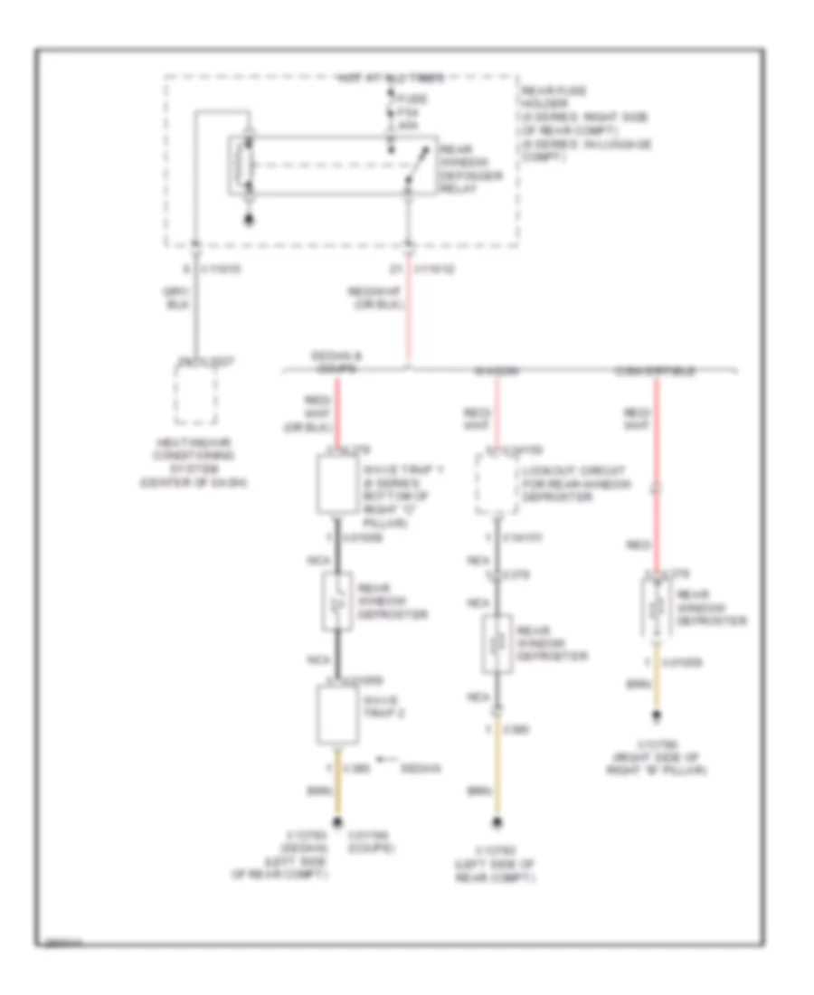
Defoggers Wiring Diagram for BMW 650i 2010
List of elements for Defoggers Wiring Diagram for BMW 650i 2010:
- Convertible
- Fuse f54 40a
- Heating/air conditioning system (center of dash)
- Hot at all times
- Lockout circuit for rear-window defroster
- Nca
- Rear fuse holder (5 series: right side of rear compt) (6 series: in luggage compt)
- Rear window defogger relay
- Rear window defroster
- Red
- Sedan
- Sedan & coupe
- Wagon
- Wave trap 1 (6 series: bottom of right "c" pillar)
- Wave trap 2
- X01058
- X01059
- X01194 (coupe)
- X11012
- X11015
- X13790 (right side of right "b" pillar)
- X13793 (left side of rear compt)
- X13793 (sedan) (left side of rear compt)
- X14150
- X14151
- X1527
- X379
- X380
ELECTRONIC POWER STEERING
Electronic Power Steering Wiring Diagram for BMW 650i 2010
List of elements for Electronic Power Steering Wiring Diagram for BMW 650i 2010:
- Active steering module (right front floor)
- Computer data lines system
- Eco valve
- Electric lock
- Fuse f86 40a
- Hot w/ term 30g relay energized
- Nca
- Rear fuse holder (6 series: in luggage compt) (5 series: right side of rear compt)
- Red
- Steering gear (6 series: under right front of vehicle) (5 series: right front wheel housing)
- X11015
- X120
- X13718
- X13719
- X13720
- X13772
- X13773
- X13788 (right front floor)
ELECTRONIC SUSPENSION
Air Suspension Wiring Diagram for BMW 650i 2010
List of elements for Air Suspension Wiring Diagram for BMW 650i 2010:
- (5 series: under spare tire) air suspension compressor relay
- Computer data lines system
- Electronic ride height control
- Fuse f52 40a
- Fuse f81 7.5a
- Hot at all times
- Hot w/ terminal 30g relay energized
- Left rear level sensor (front of left rear wheel)
- Rear fuse holder (5 series: right side of rear compt) (6 series: in luggage compt)
- Right rear level sensor (5 series: front of right rear wheel) (6 series: on right rear suspension)
- W/ xenon headlights
- W/o xenon headlights
- X11010
- X11012
- X14088
- X14089
- X14090
- X14191
Dynamic Drive Suspension Wiring Diagram for BMW 650i 2010
List of elements for Dynamic Drive Suspension Wiring Diagram for BMW 650i 2010:
- Computer data lines system
- Dynamic drive control module (5 series: right side of right footwell) (6 series: right kick panel)
- Dynamic drive lateral-acceleration sensor (5 series: under front passenger's seat) (6 series: under right side of driver's seat)
- Dynamic drive valve block (behind right front wheel)
- Fuse f76 10a
- Hot w/ term 30g relay energized
- Nca
- Oil level switch (right side of engine compt)
- Rear fuse holder (5 series: right side of rear compt) (6 series: in luggage compt)
- Red
- X10649
- X10650
- X10651
- X10652
- X10653
- X10654
- X10655
- X11012
- X13762
- X1710
- X1877
ENGINE PERFORMANCE
4.8L
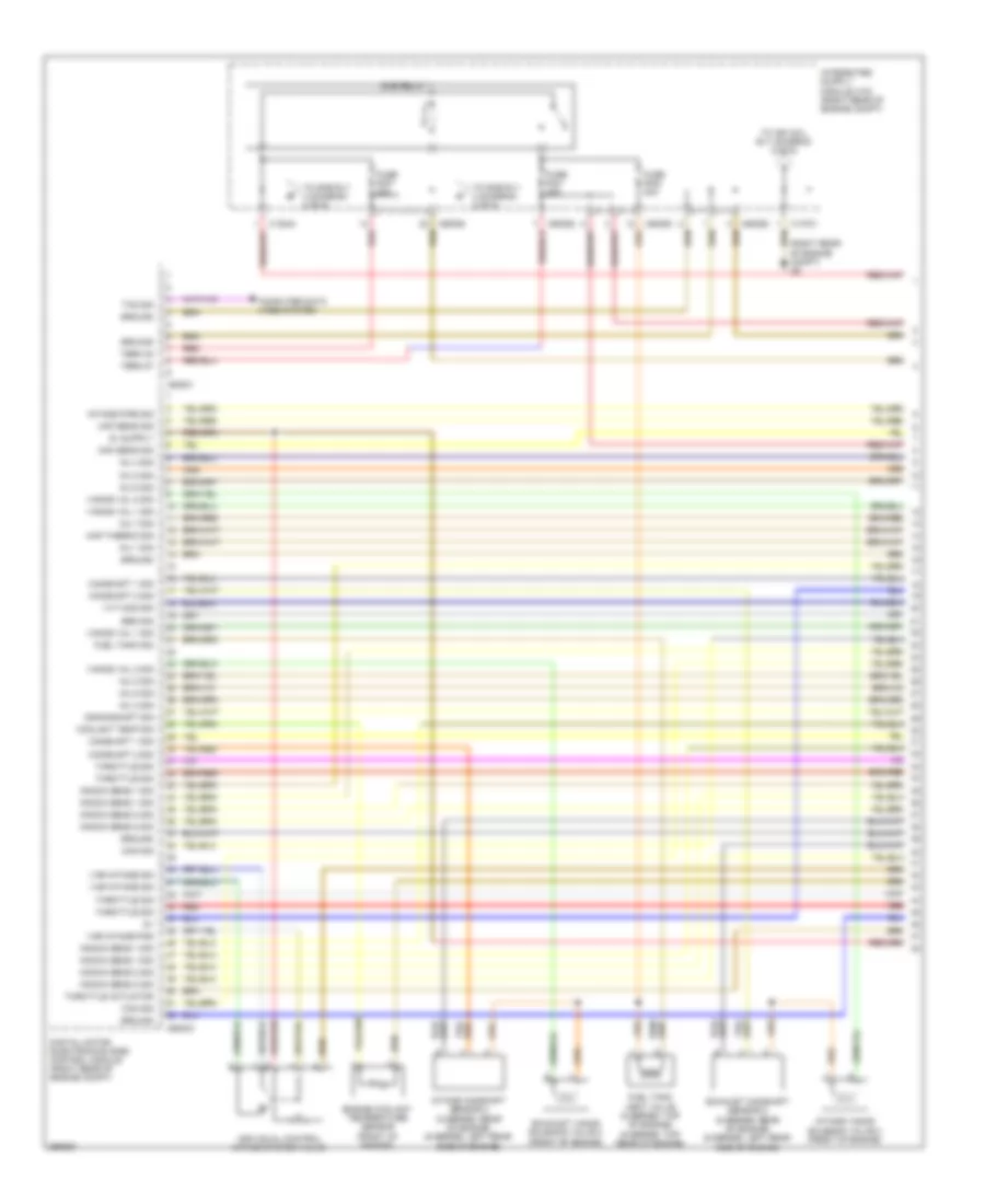
4.8L, Engine Performance Wiring Diagram (1 of 6) for BMW 650i 2010
List of elements for 4.8L, Engine Performance Wiring Diagram (1 of 6) for BMW 650i 2010:
- (right rear of engine compt) x6
- Bsd sig
- Camshaft 1 sig
- Camshaft 2 sig
- Can sig
- Computer data lines system
- Coolant temp sig
- Crankshaft sig
- Digital motor electronics (dme) control module (right rear of engine compt)
- Dme relay 1
- Engine coolant temperature sensor (front of engine)
- Exhaust camshaft sensor 2 (5 series: rear of engine) (6 series: left rear side of engine)
- Exhaust vanos solenoid valve 2 (front of engine)
- Fuel tank sig
- Fuel tank vent valve (5 series: top of engine) (6 series: top rear of engine)
- Fuse f001 30a
- Fuse f002 30a
- Fuse f007 20a
- Ground
- Individual control intake system valve
- Inj 1 sig
- Inj 2 sig
- Inj 3 sig
- Inj 4 sig
- Inj 5 sig
- Inj 6 sig
- Inj 7 sig
- Inj 8 sig
- Intake camshaft sensor 2 (5 series: rear of engine) (6 series: left rear side of engine)
- Intake pipe sig
- Intake vanos solenoid valve 2 (front of engine)
- Knock sens 1 sig
- Knock sens 2 sig
- Maf sens sig
- Map thermo sig
- Red
- Term 30
- Term 87
- Throttle actuator
- Throttle sig
- To dme rly 2 (diagram 2 of 6)
- To ign coil rly (diagram 5 of 6)
- Txd sig
- Vanos val 1 sig
- Vanos val 2 sig
- Var intake pos
- Var intake sig
- Vvt mod sig
- X13701
- X13844
- X60001
- X60003
- X60092
- X60093
- X60094
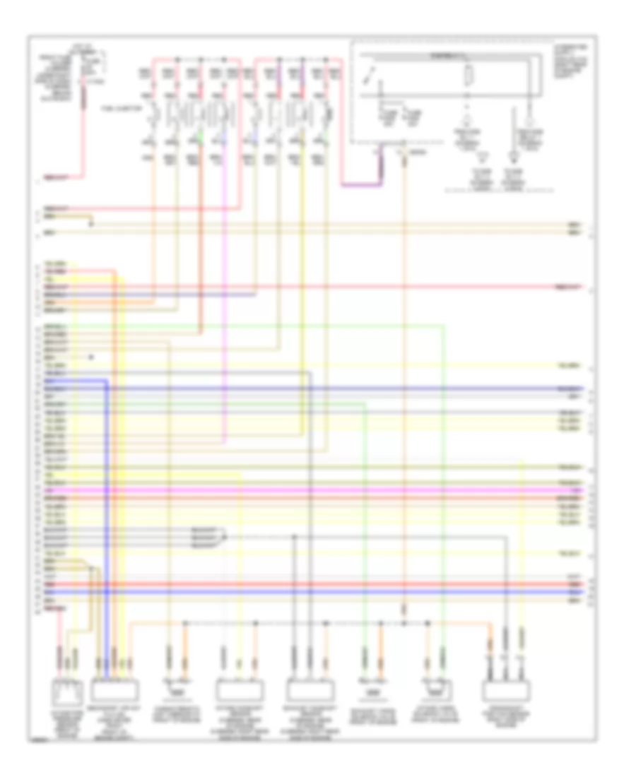
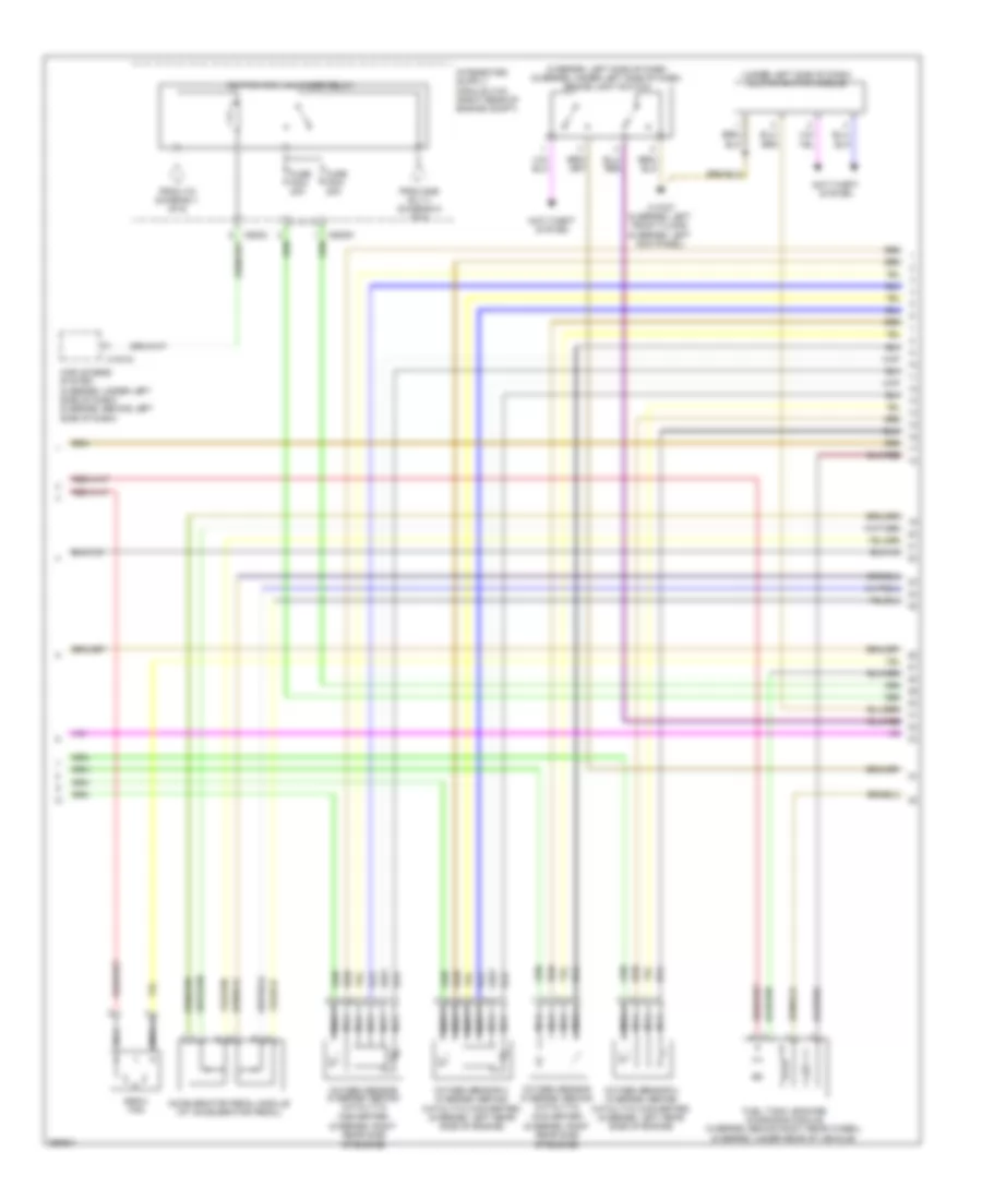
4.8L, Engine Performance Wiring Diagram (2 of 6) for BMW 650i 2010
List of elements for 4.8L, Engine Performance Wiring Diagram (2 of 6) for BMW 650i 2010:
- Characteristic map thermostat (front of engine)
- Crankshaft position sensor (right side of engine)
- Dme relay 2
- Exhaust camshaft sensor (5 series: rear of engine) (6 series: right rear side of engine)
- Exhaust vanos solenoid valve (front of engine)
- From dme relay 1 (diagram 1 of 6)
- From dme rly 1 (diagram 1 of 6)
- Front fuse holder (5 series: under right side of dash) (6 series: behind glove box)
- Fuel injector
- Fuse f005 30a
- Fuse f006 20a
- Fuse f8 60a
- Hot at all times
- Intake camshaft sensor (5 series: rear of engine) (6 series: right rear side of engine)
- Intake pipe pressure sensor (front of engine)
- Intake vanos solenoid valve (front of engine)
- Nca
- Red
- Secondary air hot film air mass meter (right front of engine compt)
- To dme rly 3 (diagram 4 of 6)
- X60093
4.8L, Engine Performance Wiring Diagram (3 of 6) for BMW 650i 2010
List of elements for 4.8L, Engine Performance Wiring Diagram (3 of 6) for BMW 650i 2010:
- (6 series: left rear of engine) eccentric shaft sensor 2
- Electronic throttle valve actuator (6 series: on top of engine)
- Fuse f010 40a
- Fuse f011 40a
- Knock sensor (5 series: right side of engine) (6 series: under intake manifold
- Knock sensor 2 (5 series: right side of engine) (6 series: under intake manifold
- Nca
- Red
- Variable valve timing gear control module (6 series: right rear of engine compt)
- Vvt relay
- Vvt relay 2
- X10681
- X60093
- X60095
- X60211
- X60212
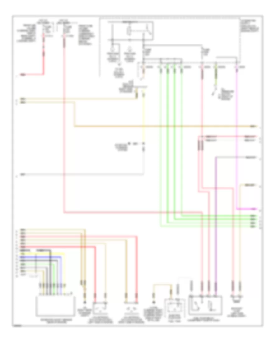
4.8L, Engine Performance Wiring Diagram (4 of 6) for BMW 650i 2010
List of elements for 4.8L, Engine Performance Wiring Diagram (4 of 6) for BMW 650i 2010:
- Dme relay 3
- Eccentric shaft sensor (rear of engine)
- Electric fule pump
- Exhaust flap (left side of rear compt)
- From dme rly 2 (diagram 2 of 6)
- Front fuse holder (5 series: under right side of dash) (6 series: behind glove box)
- Fuel pump relay (under right side of dash)
- Fuel tank
- Fuse f008 30a
- Fuse f009 10a
- Fuse f30 20a
- Fuse f91 100a
- Hot at all times
- Nca
- Oil pressure switch (front of engine)
- Oil quality sensor (right side of engine)
- Rear fuse holder (5 series: right side of rear compt) (6 series: in luggage compt)
- Red
- Starting/ charging system
- To ign coil rly (diagram 5 of 6)
- Valvetronic actuator motor (right side of engine)
- Valvetronic actuator motor 2 (left side of engine)
- X11014 red
- X13792 (5 series: right of rear compt) (6 series: right side of right "b" pillar)
- X6 (right rear of engine compt)
- X6009
- X60093
- X60094
4.8L, Engine Performance Wiring Diagram (5 of 6) for BMW 650i 2010
List of elements for 4.8L, Engine Performance Wiring Diagram (5 of 6) for BMW 650i 2010:
- (5 series: left side of dash) (6 series: under left side of dash) brake light switch
- (6 series: right rear side of engine)
- (under left side of dash) clutch switch module
- Accelerator pedal module (at accelerator pedal)
- Anti-theft system
- Car access system (5 series: under left side of dash) (6 series: behind left side of dash)
- E-box fan
- From dme rly 3 (diagram 5 of 6)
- From ivm (diagram 1 of 6)
- Fuel tank leakage diagnosis module (5 series: behind right rear wheel) (6 series: under rear of vehicle)
- Fuse f003 20a
- Fuse f004 20a
- Ignition coil unloader relay
- Nca
- Oxygen sensor (5 series: behind catalytic converter)
- Oxygen sensor 2 (5 series: behind catalytic converter) (6 series: left rear side of engine)
- X10318
- X13787 (5 series: left front floor) (6 series: left kick panel)
- X6009
- X60091
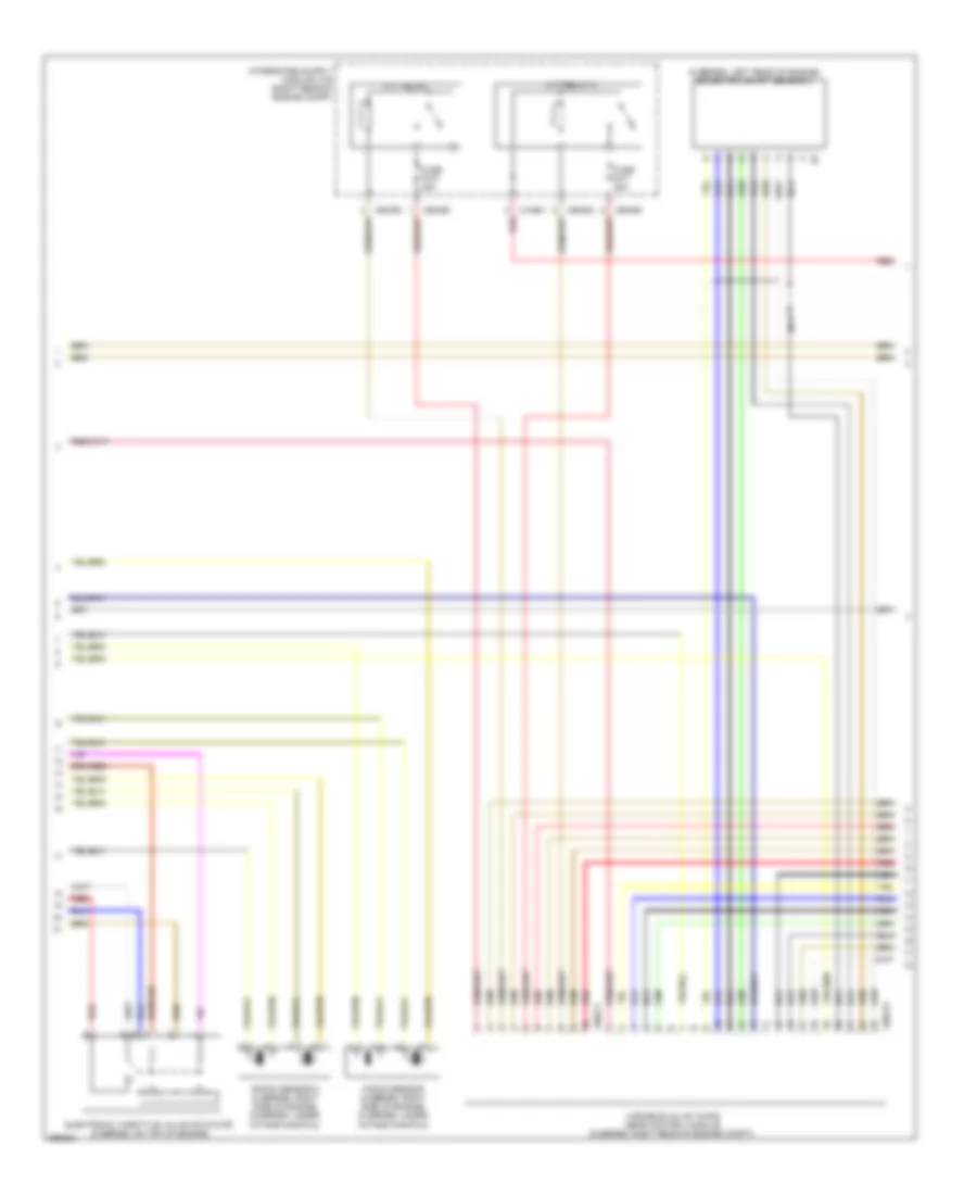
4.8L, Engine Performance Wiring Diagram (6 of 6) for BMW 650i 2010
List of elements for 4.8L, Engine Performance Wiring Diagram (6 of 6) for BMW 650i 2010:
- (6 series: 1: right front side of engine) (6 series: 2, 3: right side of engine) (6 series: 4: right rear of engine) (6 series: 5: left front side of engine) (6 series: 6, 7: left side of engine) (6 series: 8: left rear side of engine)
- Acc pdl sensor (+)
- Acc pdl sensor grd
- Accpdl sensor sig
- Anti-lock brakes system
- Anti-theft system
- Brake lt sig
- Can h
- Can l
- Clutch sw sig
- Computer data lines system
- Coolant temp sig
- Cooling fans system
- Digital motor electronics (dme) control module (right rear of engine compt)
- Ebox fan sig
- Elec immob sig
- Electric fan sig
- Exh flap sig
- Exterior lights system
- Fuel pmp rly (+)
- Ground
- Ho2s grd
- Ho2s sig
- Ign coil 1 sig
- Ign coil 2 sig
- Ign coil 3 sig
- Ign coil 4 sig
- Ign coil 5 sig
- Ign coil 6 sig
- Ign coil 7 sig
- Ign coil 8 sig
- Ignition coils (5 series: 1, 2, 3, 4: right side of engine) (5 series: 5, 6, 7, 8: left side of engine)
- Leak diag sig
- Nca
- Oil press sw sig
- Plug
- Radiator sig
- Red
- Start sig
- Td sig
- Term 15
- Term 87
- Wheel spd sensor sig
- X6 (right rear of engine compt)
- X60002
- X60004
- X60005
- X64561
- X64562
- X64563
- X64564
EXTERIOR LIGHTS
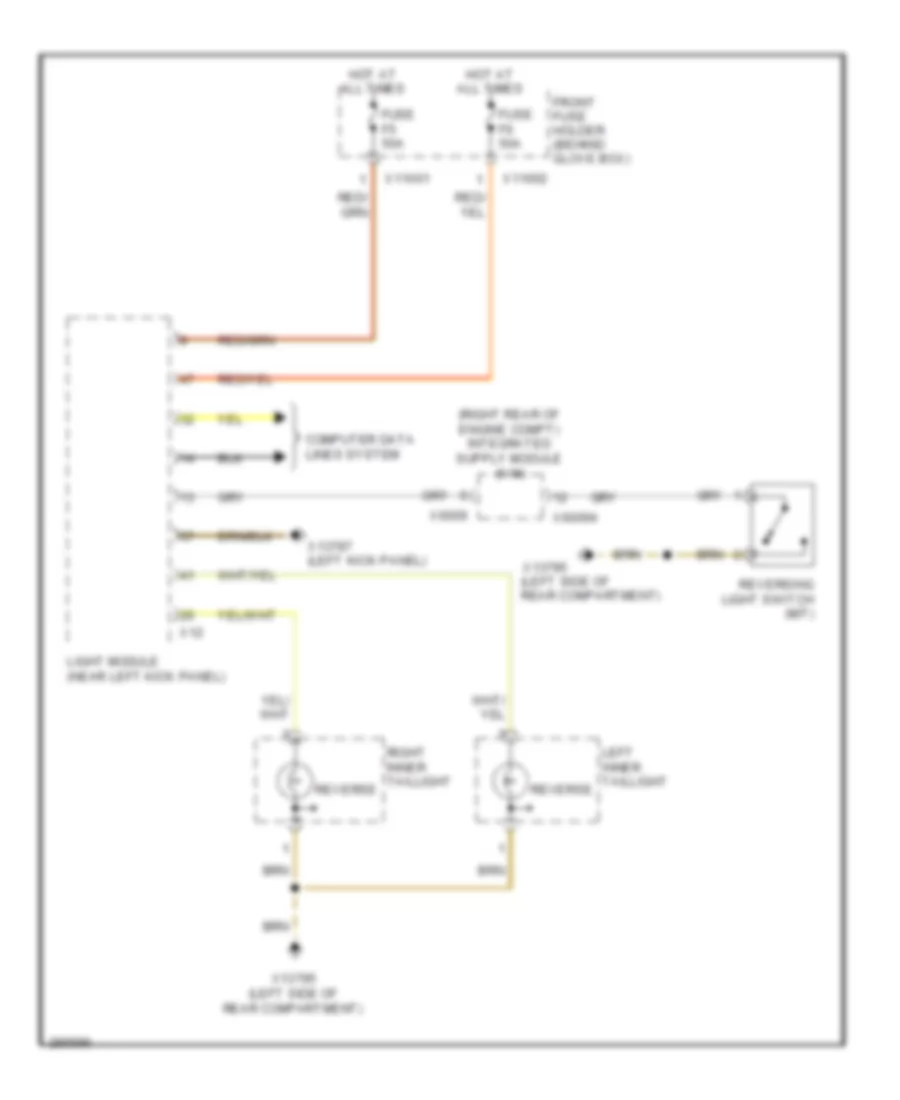
Backup Lamps Wiring Diagram for BMW 650i 2010
List of elements for Backup Lamps Wiring Diagram for BMW 650i 2010:
- Computer data lines system
- Front fuse holder (behind glove box)
- Fuse f5 50a
- Fuse f6 50a
- Hot at all times
- Left inner taillight
- Light module (near left kick panel)
- Reverse
- Reversing light switch (m/t)
- Right inner taillight
- X11001
- X11002
- X12
- X13787 (left kick panel)
- X13795 (left side of rear compartment)
- X6009
- X60094
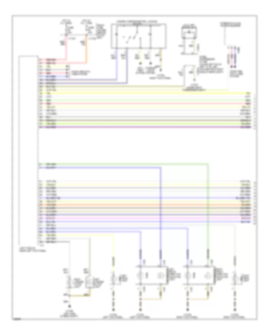
Exterior Lamps Wiring Diagram (1 of 2) for BMW 650i 2010
List of elements for Exterior Lamps Wiring Diagram (1 of 2) for BMW 650i 2010:
- Anti- theft system
- Auxiliary brake light
- Computer data lines system
- Front fuse holder (behind glove box)
- Fuse f5 50a
- Fuse f6 50a
- Hazard warning/central locking switch
- Hot at all times
- Interior lights system
- Left front direction indicator light
- Left head- light
- Left license plate light
- Light module (near left kick panel)
- Nca
- Noise suppressor filter (coupe: bottom of left "c" pillar) (convertible: right side of rear compt)
- Red
- Right front direction indicator light
- Right head- light
- Right license plate light
- Side
- Side marker
- Steering column switch cluster
- Turn
- X11001
- X11002
- X12
- X128
- X137
- X13782 (right kick panel)
- X13783 (left kick panel)
- X13791 (under front passenger's seat)
- X13795 (left side of rear compt)
- X13913
- X13914
- X1880
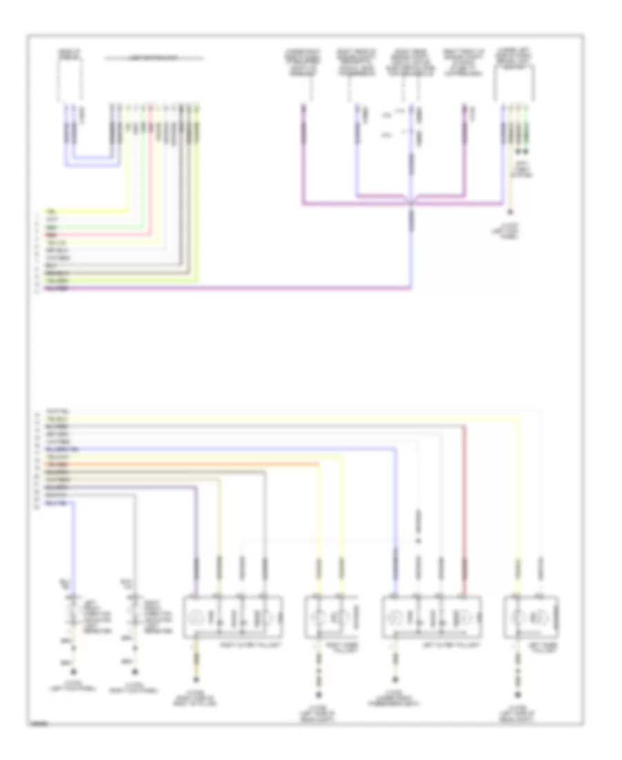
Exterior Lamps Wiring Diagram (2 of 2) for BMW 650i 2010
List of elements for Exterior Lamps Wiring Diagram (2 of 2) for BMW 650i 2010:
- (right front of engine compt) dynamic stability control (dsc)
- (right rear engine compt) digital motor electronics (dme) control module
- (right rear of engine compt) sequential manual (smg) transmission
- (under left side of dash) brake light switch
- (under right side of dash) (if equipped) adaptive headlight
- 4.8l
- 5.0l
- Anti- theft system
- Brake
- Fog
- Head-up display
- Left front direction indicator light repeater
- Left inner taillight
- Left outer taillight
- Light switch unit
- Red
- Reverse
- Right front direction indicator light repeater
- Right inner taillight
- Right outer taillight
- Tail
- Turn
- X13783 (left kick panel)
- X13784 (right kick panel)
- X13787 (left kick panel)
- X13791 (under front passenger's seat)
- X13792 (right side of right "b" pillar)
- X13795 (left side of rear compt)
- X13819
- X1746
- X60001
- X60004
- X70003
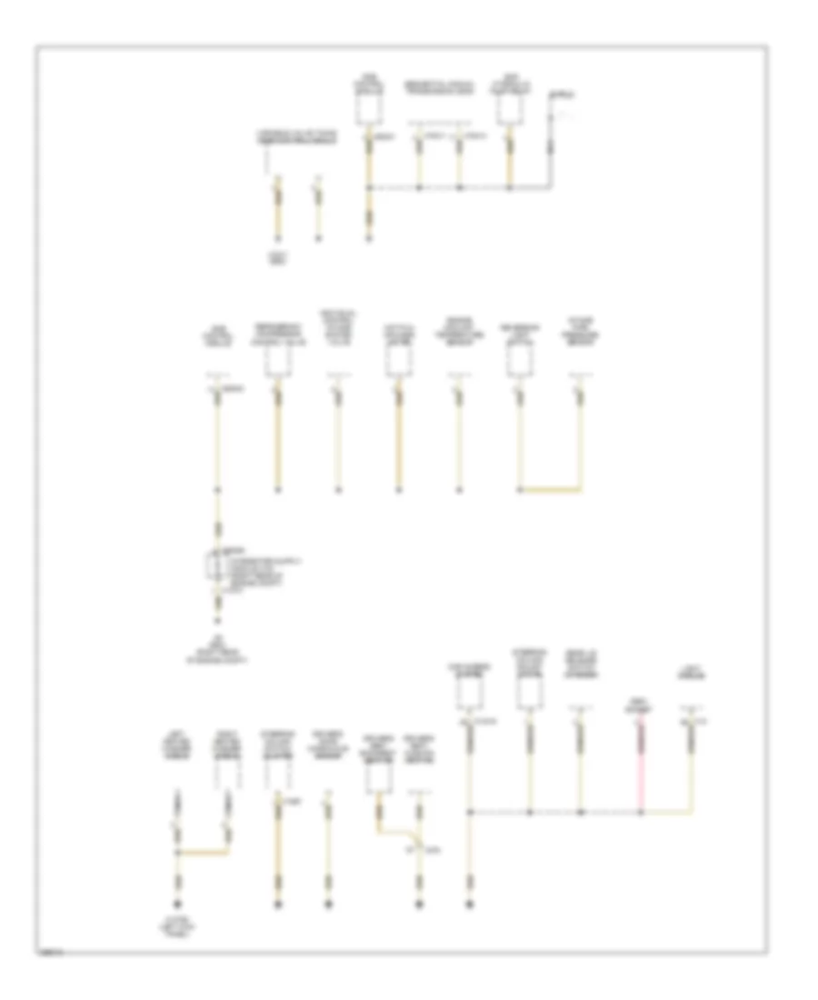
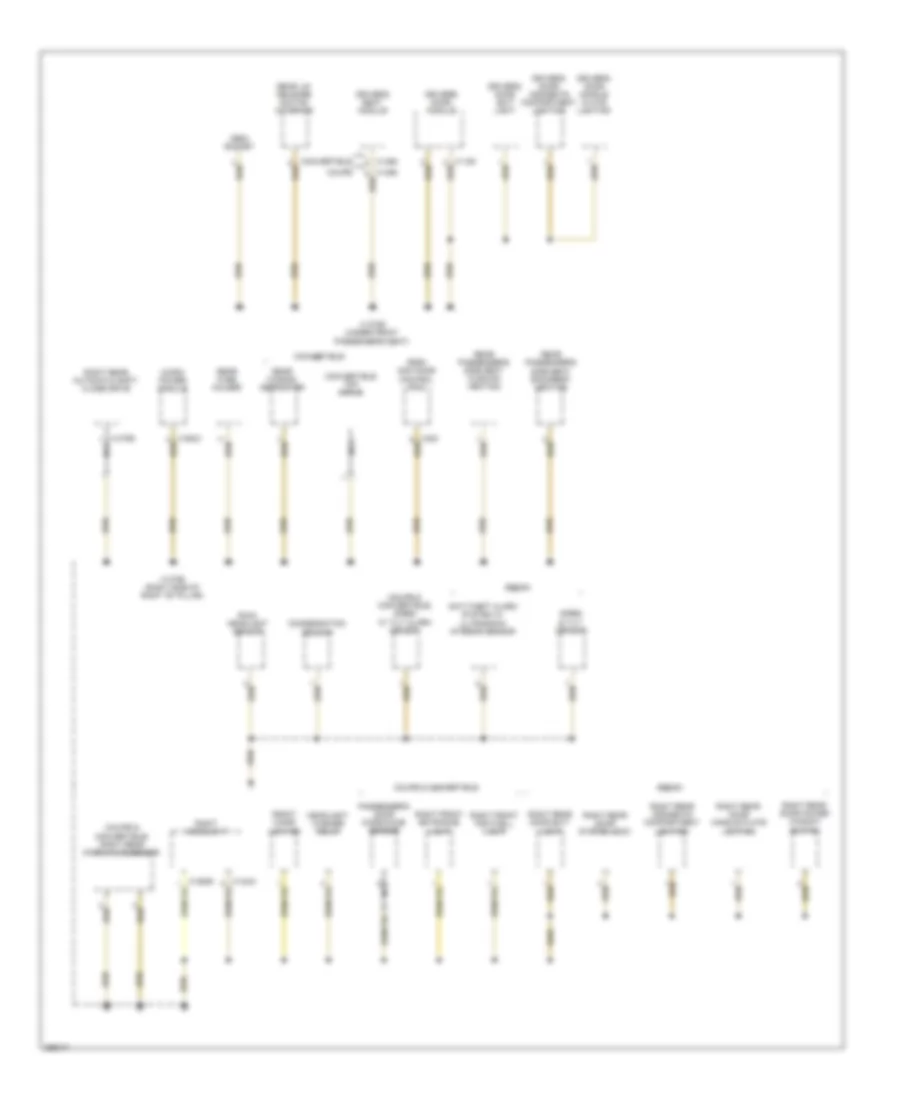
GROUND DISTRIBUTION
Ground Distribution Wiring Diagram (1 of 7) for BMW 650i 2010
List of elements for Ground Distribution Wiring Diagram (1 of 7) for BMW 650i 2010:
- Car access system
- Dme control module
- Driver's door microwave sensor
- Driver's seat backrest heating
- Driver's seat cushion heating
- Engine coolant temperature sensor
- Hot-film air mass meter
- Individual control intake system valve
- Intake pipe pressure sensor
- Left heated washer nozzle
- Light module
- Nca
- Obdii socket
- Rear lid release switch (interior)
- Refrigerant compressor control valve
- Reversing light switch
- Right heated washer nozzle
- Sequential manual transmission (smg)
- Shield
- Smg hydraulic pump relay
- Steering column adjust motor
- Steering column switch cluster
- Variable valve timing gear control module
- X13785 (left kick panel)
- X275
- X6 (650i) (right rear of engine compt)
- X60092
- X7517 (650i)
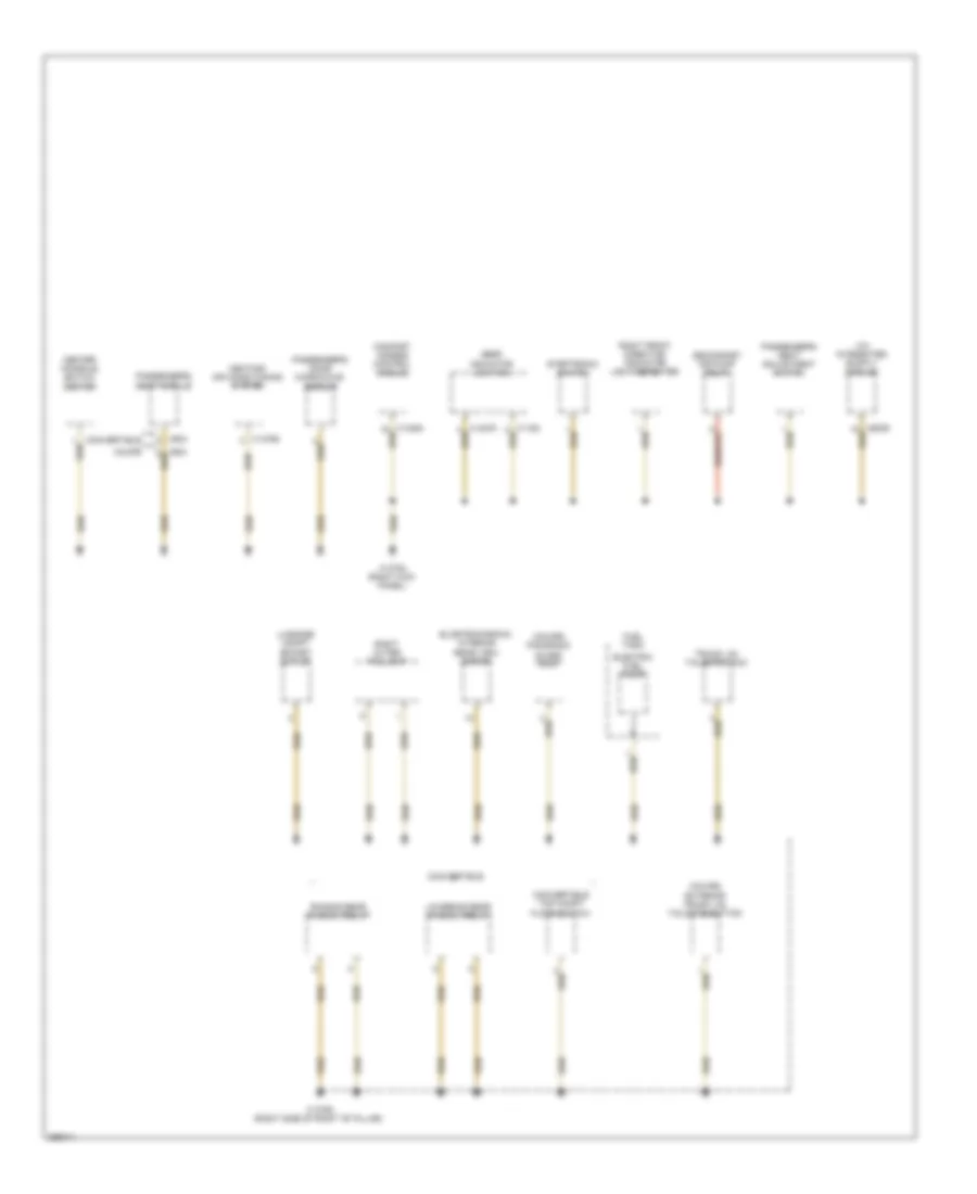
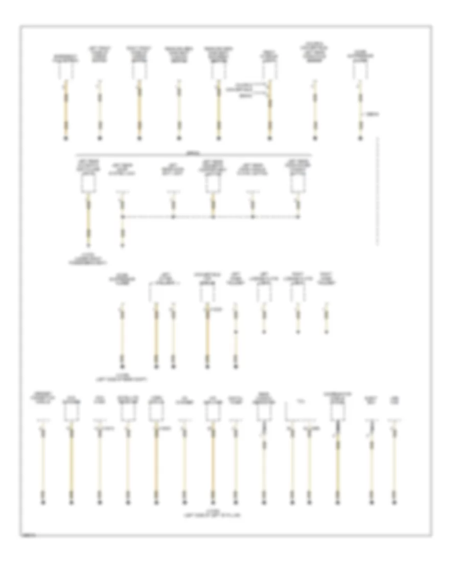
Ground Distribution Wiring Diagram (2 of 7) for BMW 650i 2010
List of elements for Ground Distribution Wiring Diagram (2 of 7) for BMW 650i 2010:
- (coupe)
- (coupe) panorama glass roof
- Center console switch center
- Comfort access control module
- Convertible
- Convertible top compt floor switch
- Coupe
- Elcetrochromic interior rear view mirror
- Electric fuel pump
- Exterior trunk lid/ tailgate button
- Fuel tank
- Gear indicator lighting
- Heating/ air conditioning system
- Lowering rear window relay
- Luggage compt socket outlet
- Passenger's door microwave sensor
- Passenger's seat adjustment switch
- Passenger's seat module
- Raising rear window relay
- Right front direction indicator light repeater
- Right outer taillight
- Secondary air pump relay
- Steptronic switch
- Trunk lid/ tailgate lock
- X13765
- X13784 (right kick panel)
- X13792 (right side of right "b" pillar)
- X604
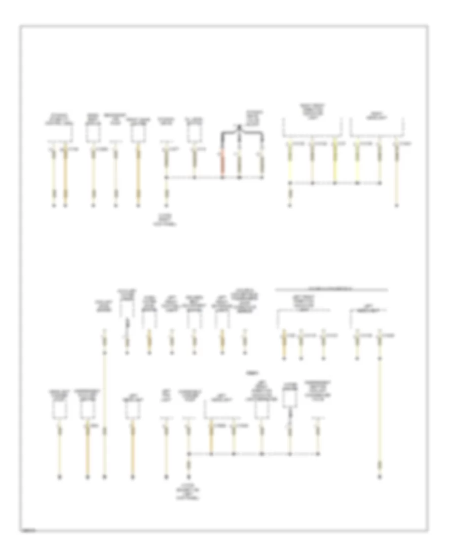
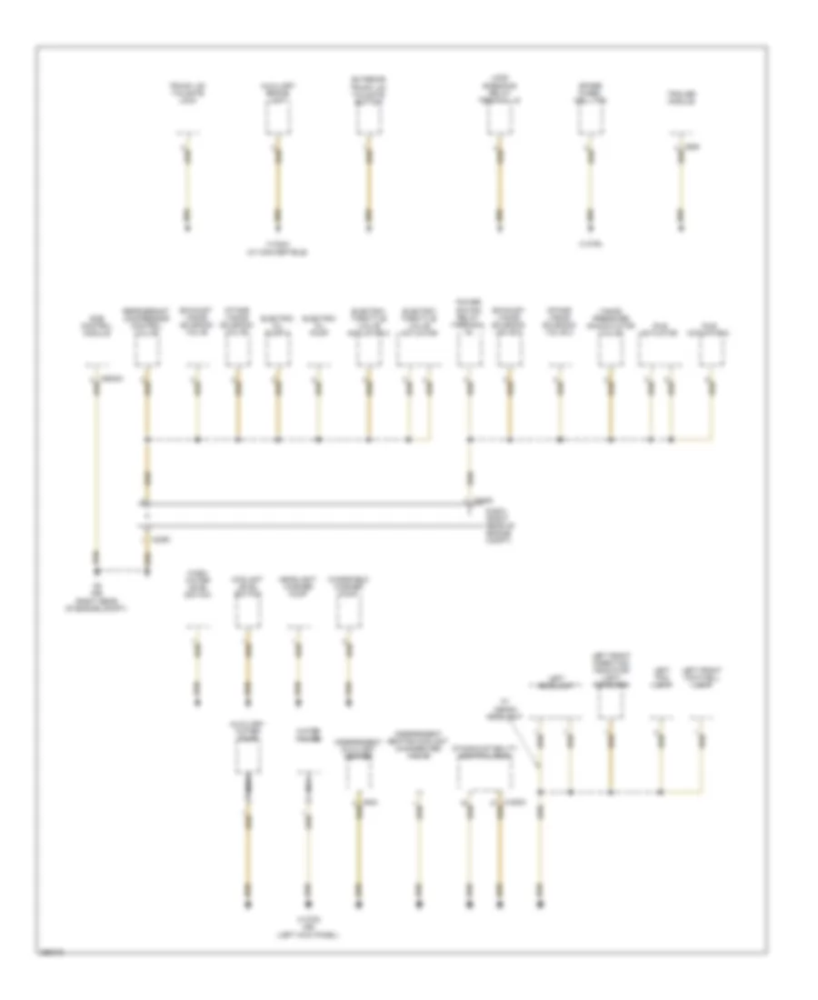
Ground Distribution Wiring Diagram (3 of 7) for BMW 650i 2010
List of elements for Ground Distribution Wiring Diagram (3 of 7) for BMW 650i 2010:
- (coupe & convertible) passenger's door microwave sensor
- Auxiliary water pump
- Basic body module
- Coolant level switch
- Coupe & convertible
- Driver's seat adjustment switch
- Dynamic drive
- Dynamic drive valve block
- Dynamic stability control (dsc)
- Front cigar lighter
- Headlight washer pump
- Independent auxiliary heater
- Independent heating coolant changeover valve
- Left fog light
- Left front direction indicator light
- Left front direction indicator light repeater
- Left front entrance light
- Left front footwell light
- Left head light
- Left headlight
- Nca
- Oil level switch
- Right front direction indicator light
- Right headlight
- Secondary air pump
- Sedan
- Wash water level switch
- Water valves
- Windshield washer pump
- X13782 (right kick panel)
- X13783 (except m6) (left kick panel)
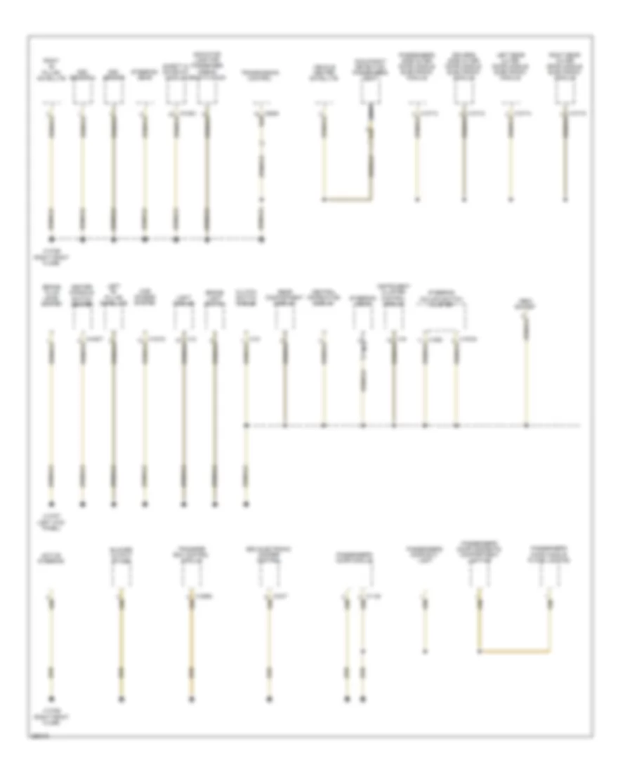
Ground Distribution Wiring Diagram (4 of 7) for BMW 650i 2010
List of elements for Ground Distribution Wiring Diagram (4 of 7) for BMW 650i 2010:
- Active steering
- Blower output stage
- Brake fluid level switch
- Brake light switch
- Car access system
- Center console switch center
- Central information display
- Clutch switch module
- Driver's side outer door handle electronic module
- Dsc sensor
- Dsc sensor 2
- Edc electronic damper control
- Indicator lamp for passenger airbag deactivation
- Instrument cluster control module
- Left "b" pillar satellite
- Left rear outer door handle electronic module
- Light module
- Nca
- Obdii socket
- Occupancy detection passenger's seat
- Passenger's door exit light
- Passenger's door handle plate lighting
- Passenger's door module
- Passenger's door oddments compartment lighting
- Passenger's side outer door handle electronic module
- Rear compartment display
- Right "b" pillar satellite
- Right rear outer door handle electronic module
- Safety & gateway module
- Steering column switch cluster
- Steering gear
- Transfer box control module
- Transmission control
- Vehicle center satellite
- X13786 (right front floor)
- X13787 (left kick panel)
- X13788 (right front floor)
Ground Distribution Wiring Diagram (5 of 7) for BMW 650i 2010
List of elements for Ground Distribution Wiring Diagram (5 of 7) for BMW 650i 2010:
- (coupe & convertible) right rear microwave sensor
- (coupe & convertible) siren w/ tilt alarm sensor
- Anti-theft alarm system w/ ultrasonic interior sensor
- Condensation sensor
- Convertible
- Convertible top drive
- Coupe
- Coupe & convertible
- Driver's door exit light
- Driver's door handle plate lighting
- Driver's door module
- Driver's door oddments compartment lighting
- Driver's seat module
- Front cigar lighter
- Headlight washer relay
- Micro- power module
- Nca
- Obdii socket
- Park distance control (pdc)
- Passenger's door microwave sensor
- Rain/ headlight sensor
- Rear fuse holder
- Rear lid release switch (interior)
- Rear passenger's side seat backrest heating
- Rear passenger's side seat cushion heating
- Rear window defroster
- Right front entrance light
- Right front footwell light
- Right headlight
- Right rear automatic soft- close drive
- Right rear door exit light
- Right rear door handle plate lighting
- Right rear door power window switch
- Right rear door system lock
- Right rear oddments compartment lighting
- Sedan
- Siren & tilt sensor
- X10760 nca
- X13789 (under front passenger's seat)
- X13790 (right side of right "b" pillar)
- X1465
Ground Distribution Wiring Diagram (6 of 7) for BMW 650i 2010
List of elements for Ground Distribution Wiring Diagram (6 of 7) for BMW 650i 2010:
- (coupe & convertible) left rear microwave sensor
- Ccc/ m-ask
- Cd changer
- Compensator (mobile phone)
- Convertible top module
- Coupe & convertible
- Digital tuner
- Dvd changer
- Eject box
- Emergency call button
- Front interior light
- Headset connection module
- Hifi amplifier
- Left front make-up mirror switch
- Left inner taillight
- Left license plate light
- Left outer taillight
- Left rear automatic soft-close drive
- Left rear door exit light
- Left rear door handle plate lighting
- Left rear door power window switch
- Left rear door system lock
- Left rear oddments compartment lighting
- Nca
- Noise suppressor filter
- Rear driver's side seat backrest heating
- Rear driver's side seat cushion heating
- Rear window defroster
- Right front make-up mirror switch
- Right inner taillight
- Right license plate light
- Satellite receiver
- Sedan
- Tcu
- Usb hub
- Video module
- X13791 (under front passenger's seat)
- X13793 (left side of left "b" pillar)
- X13795 (left side of rear compt)
Ground Distribution Wiring Diagram (7 of 7) for BMW 650i 2010
List of elements for Ground Distribution Wiring Diagram (7 of 7) for BMW 650i 2010:
- Auxiliary brake light
- Auxiliary water pump
- Coolant level switch
- Dme control module
- Dynamic stability control (dsc)
- E box (right rear of engine compt)
- Electric oil pump
- Electric oil pump 2
- Electric throttle valve actuator
- Electric throttle valve actuator 2
- Exhaust vanos solenoid valve
- Exhaust vanos solenoid valve 2
- Exterior trunk lid/ tailgate button
- Headlight washer pump
- Idle actuator
- Idle actuator 2
- Independent auxiliary heater
- Independent heating coolant changeover valve
- Intake vanos solenoid valve
- Intake vanos solenoid valve 2
- Left fog light
- Left front direction indicator light repeater
- Left front footwell light
- Left headlight
- Load shedding relay terminal 15
- Nca
- Power saving relay (terminal 15)
- Refrigerant compressor control valve
- Spare wheel well fan
- Trailer module
- Trunk lid/ tailgate lock
- Vanos pressure accumulator valve
- W/ xenon headlight
- Wash water level switch
- Water valves
- Windshield washer pump
- X13244 (w/ convertible)
- X13783 (m6) (left kick panel)
- X13794
- X2350
- X6 (m6) (right rear of engine compt)
- X6453
HEADLIGHTS
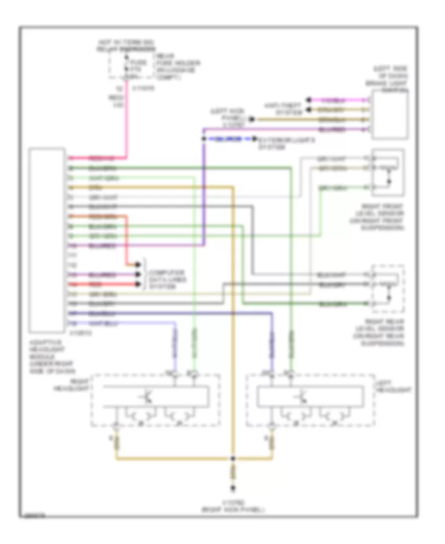
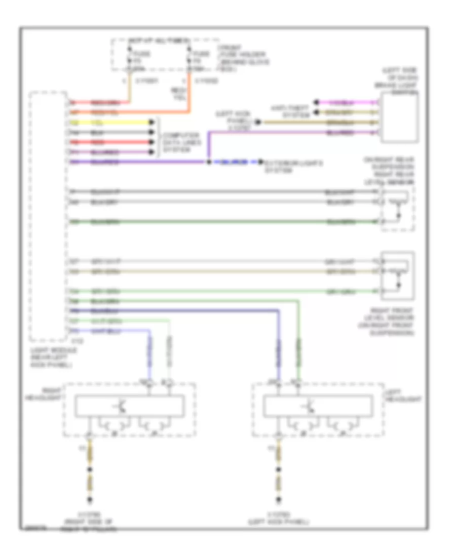
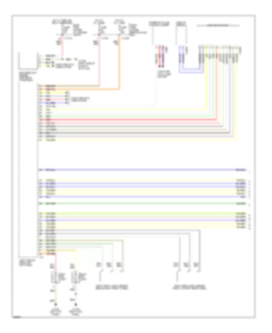
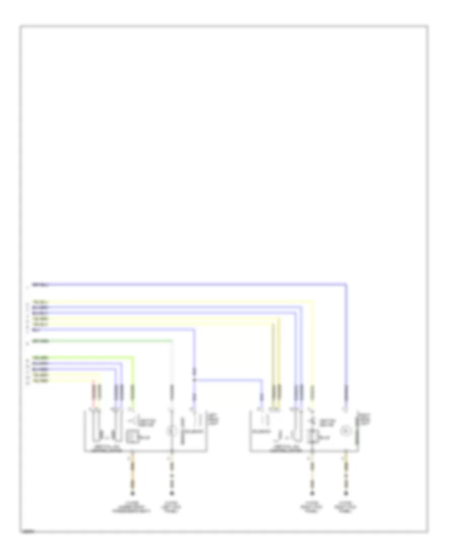
Adaptive Front Lighting Wiring Diagram, with Directional Headlights for BMW 650i 2010
List of elements for Adaptive Front Lighting Wiring Diagram, with Directional Headlights for BMW 650i 2010:
- (left kick panel) x13787
- (left side of dash) brake light switch
- Adaptive headlight module (under right side of dash)
- Anti-theft system
- Computer data lines system
- Exterior lights system
- Fuse f70 5a
- Hot w/ term 30g relay energized
- Left headlight
- Rear fuse holder (in luggage compt)
- Red
- Right front level sensor (on right front suspension)
- Right headlight
- Right rear level sensor (on right rear suspension)
- X10513
- X11015
- X13782 (right kick panel)
Adaptive Front Lighting Wiring Diagram, without Directional Headlights for BMW 650i 2010
List of elements for Adaptive Front Lighting Wiring Diagram, without Directional Headlights for BMW 650i 2010:
- (left kick panel) x13787
- (left side of dash) brake light switch
- Anti-theft system
- Computer data lines system
- Exterior lights system
- Front fuse holder (behind glove box)
- Fuse f5 50a
- Fuse f6 50a
- Hot at all times
- Left headlight
- Light module (near left kick panel)
- On right rear suspension right rear level sensor
- Red
- Right front level sensor (on right front suspension)
- Right headlight
- X11001
- X11002
- X12
- X13783 (left kick panel)
- X13790 (right side of right "b" pillar)
Headlamps Wiring Diagram (1 of 2) for BMW 650i 2010
List of elements for Headlamps Wiring Diagram (1 of 2) for BMW 650i 2010:
- Computer data lines system
- Front fuse holder (behind glove box)
- Fuse f5 50a
- Fuse f56 5a
- Fuse f6 50a
- Head-up display
- Hot at all times
- Hot w/ term 30g relay energized
- Left fog light
- Light module (near left kick panel)
- Light switch unit
- Rain/headlight sensor (center of windshield)
- Rear fuse holder (in luggage compt)
- Red
- Right fog light
- Right front level sensor (behind right front wheel)
- Right rear level sensor (front of right rear wheel)
- Steering column switch cluster
- X11001
- X11002
- X11012
- X12
- X13339
- X13782 (right kick panel)
- X13783 (left kick panel)
- X13790 (right side of of right "b" pillar)
- X13819
- X1880
Headlamps Wiring Diagram (2 of 2) for BMW 650i 2010
List of elements for Headlamps Wiring Diagram (2 of 2) for BMW 650i 2010:
- Bulb
- Ignition device
- Left head- light
- Right head- light
- Side/drl light
- Solenoid
- Vertical aim control motor
- X13782 (right kick panel)
- X13783 (left kick panel)
- X13789 (under front passenger's seat)
HORN
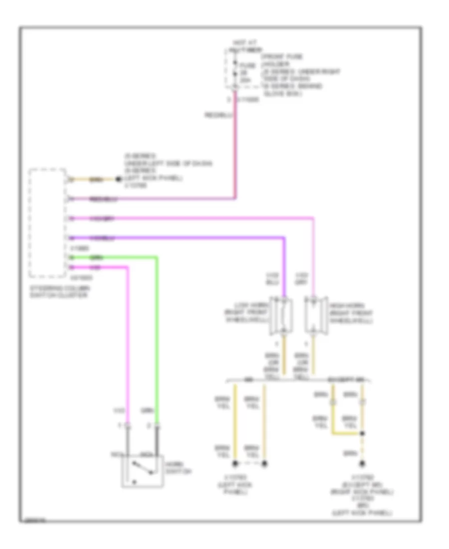
Horn Wiring Diagram for BMW 650i 2010
List of elements for Horn Wiring Diagram for BMW 650i 2010:
- (5-series: under left side of dash) (6-series: left kick panel) x13785
- Except m6
- Front fuse holder (5 series: under right side of dash) (6 series: behind glove box)
- Fuse 20a
- High horn (right front wheelwell)
- Horn switch
- Hot at all times
- Low horn (right front wheelwell)
- Nca
- Steering column switch cluster
- X01003
- X11005
- X13782 (except m5) (right kick panel) x13783 (m5) (left kick panel)
- X13783 (left kick panel)
- X1880
INSTRUMENT CLUSTER
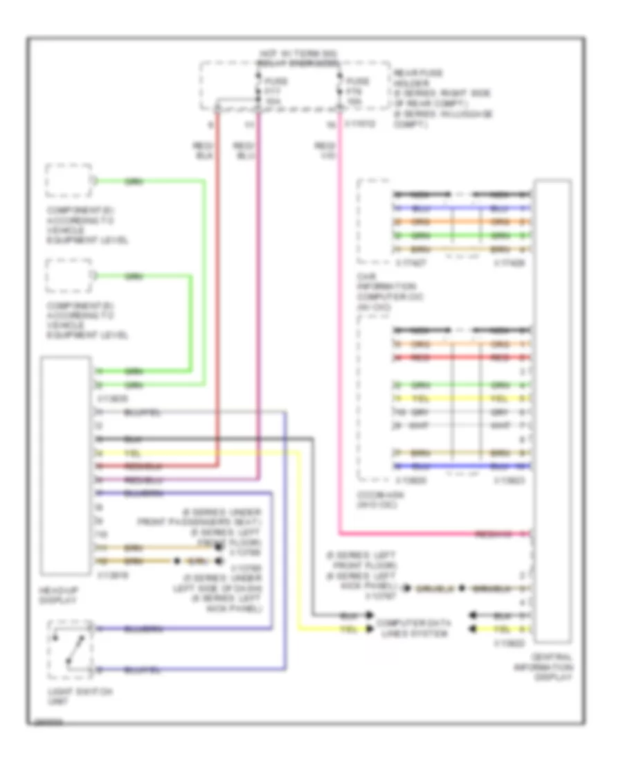
Display Wiring Diagram for BMW 650i 2010
List of elements for Display Wiring Diagram for BMW 650i 2010:
- (5 series: left front floor) (6 series: left kick panel) x13787
- (6 series: under front passenger's seat) (5 series: left front floor) x13789
- Car information computer cic (w/ cic)
- Ccc/m-ask (w/o cic)
- Central information display
- Component(s) according to vehicle equipment level
- Computer data lines system
- Fuse f77 10a
- Fuse f79 10a
- Head-up display
- Hot w/ term 30g relay energized
- Light switch unit
- Nca
- Rear fuse holder (5 series: right side of rear compt) (6 series: in luggage compt)
- Red
- X11012
- X13785 (5 series: under left side of dash) (6 series: left kick panel)
- X13819
- X13820
- X13822
- X13823
- X13835
- X17427
- X17428
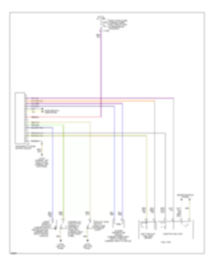
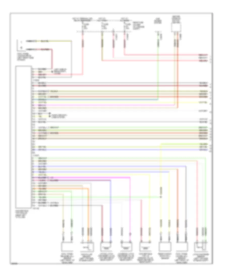
Instrument Cluster Wiring Diagram for BMW 650i 2010
List of elements for Instrument Cluster Wiring Diagram for BMW 650i 2010:
- Computer data lines system
- Coolant level switch (right side of engine compt)
- Electric fuel pump
- Engine controls system
- Front fuse holder (5 series: under right side of dash) (6 series behind glove box)
- Fuel tank
- Fuse 7.5a
- Hot at all times
- Instrument cluster control module
- Left tank half fuel level sensor
- Outside temperature sensor (5 series: under front right of vehicle) (6 series: front of vehicle)
- Park brake switch (5 series: rear center console) (6 series: left side of center console)
- Washer fluid level switch (6 series: in left front wheelwell) (5 series: front of left front wheel)
- X11006
- X13783 (left kick panel)
- X13787 (5 series: left front floor) (6 series: left kick panel)
- X16
INTERIOR LIGHTS
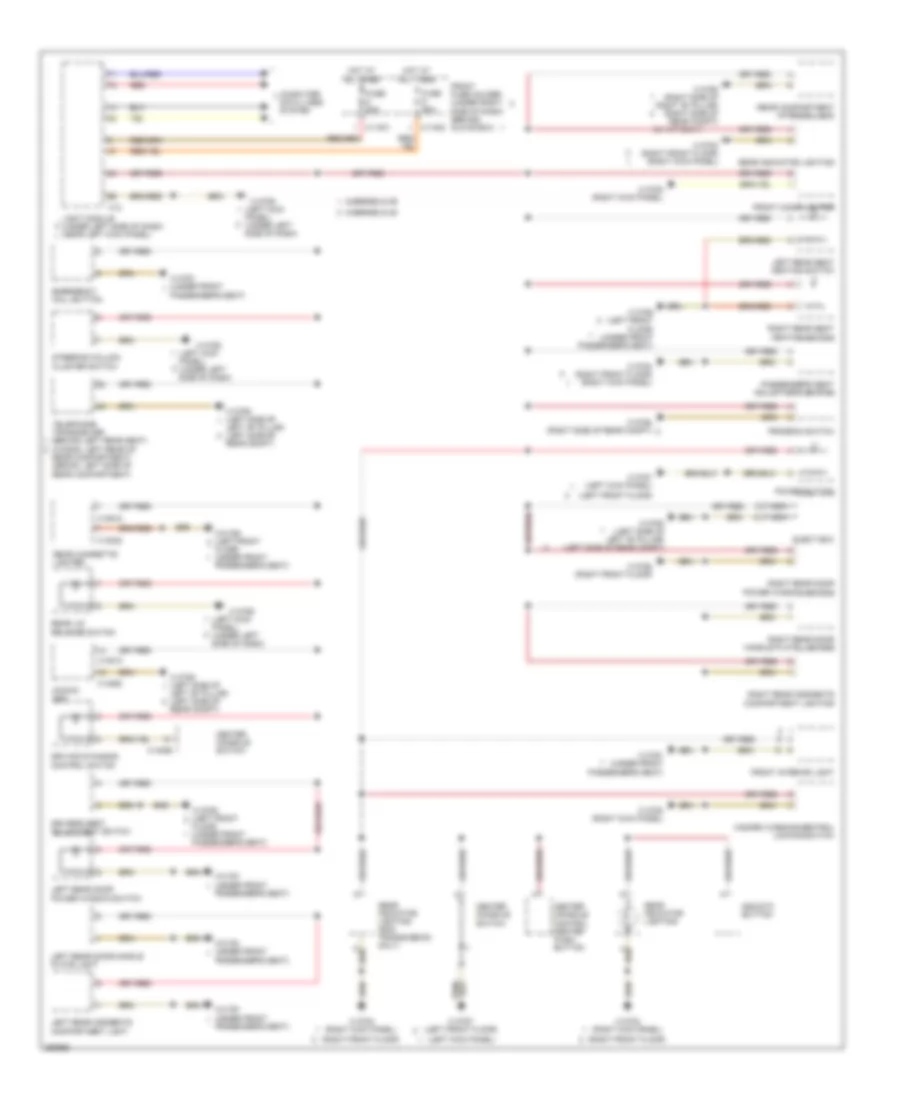
Courtesy Lamps Wiring Diagram for BMW 650i 2010
List of elements for Courtesy Lamps Wiring Diagram for BMW 650i 2010:
- Basic body module (behind glove box)
- Computer data lines system
- Convertible
- Coupe
- Except coupe
- Flashlight charging socket
- Front fuse holder (behind glove box)
- Front interior light
- Fuse 30a
- Fuse 5a
- Glove compartment light
- Glove compartment light switch
- Hot at all times
- Interior lights
- Interior lights system
- Left front entrance light
- Left front footwell light
- Left front make-up mirror light
- Left front make-up mirror switch
- Luggage compartment light
- Map reading lights
- Noise suppressor filter
- Right front entrance light
- Right front footwell light
- Right front make-up mirror light
- Right front make-up mirror switch
- Top light
- Trunk lid central locking drive w/ trunk lid contact switch
- W/ light package
- X11003
- X11004
- X11005
- X13252
- X13253
- X13254
- X13255
- X13782 (right kick panel)
- X13783 (left kick panel)
- X13790 (right side of right "b" pillar)
- X13791 (under front passenger's seat)
- X13792 (right side of right "b" pillar)
- X13913
- X13914
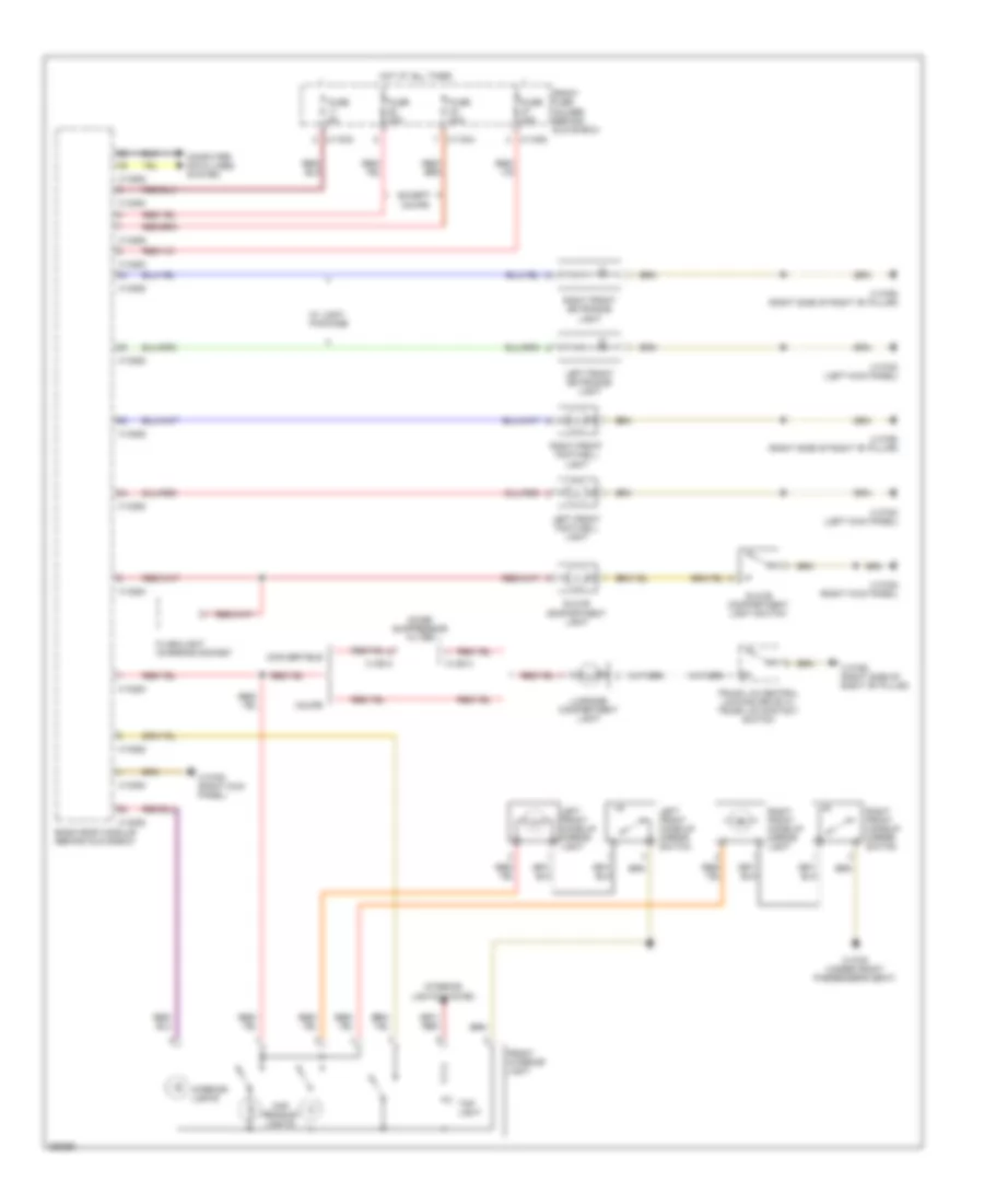
Instrument Illumination Wiring Diagram for BMW 650i 2010
List of elements for Instrument Illumination Wiring Diagram for BMW 650i 2010:
- (left front floor)
- (left kick
- (left kick panel)
- (right front floor)
- (w/ a/t only)
- 5-series & m5
- 6-series & m6
- Cccm/m ask
- Center console control center push- button
- Center console switch
- Computer data lines system
- Driver's seat adjustment switch
- Driving dynamics control switch
- Dsc/dtc button
- Eject box
- Emergency call button
- Floor) (under front passenger's seat)
- Front cigar lighter
- Front fuse holder (under right side of dash) (behind glove box)
- Front interior light
- Fuse 50a
- Gear indicator lighting
- Gear indicator lighting (smg transmission only)
- Hazard warning/central locking switch
- Hot at all times
- Left "b" pillar) (left side of rear compt)
- Left rear door handle plate light
- Left rear door power window switch
- Left rear oddments compartment light
- Left rear seat heating switch
- Light module (under left side of dash) (near left kick panel)
- Nca
- Panel) (under left side of dash)
- Passenger's seat adjustment switch
- Passenger's seat)
- Power button
- Program switch
- Rear cigarette lighter
- Rear compartment interior light
- Rear compartment) (sedan: left side of rear compartment)
- Rear lid release switch
- Red
- Right rear door handle plate lighting
- Right rear door power window switch
- Right rear oddments compartment lighting
- Right rear seat heating switch
- Steering column cluster switch
- Telephone transceiver (behind left rear seat) (wagon: left rear of
- X11001
- X11002
- X12
- X13023
- X13782 (right kick panel)
- X13784 (right front floor) (right kick panel)
- X13784 (right kick panel)
- X13785
- X13787 (left front floor)
- X13787 (left kick panel)
- X13788 (right front floor)
- X13789 (left front
- X13789 (left front floor) (under front passenger's seat)
- X13791 (under front
- X13791 (under front passenger's seat)
- X13792 (right side of right "b" pillar) (right side of rear compt)
- X13793 (left side of
- X13793 (left side of left "b" pillar) (left side of rear compt)
- X13794 (right side of rear compt)
- X13812
- X14056
- X14062
- X18818
MEMORY SYSTEMS
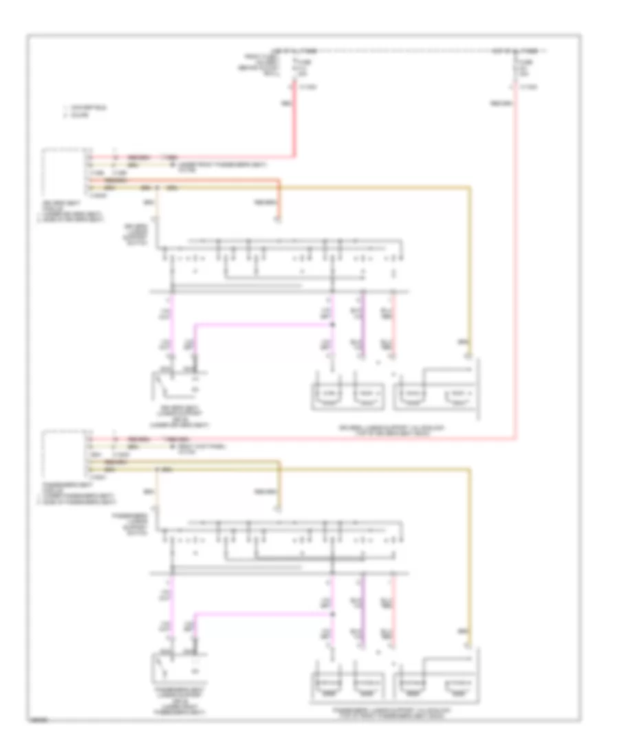
Driver"s Memory Seat Wiring Diagram, Convertible (1 of 2) for BMW 650i 2010
List of elements for Driver"s Memory Seat Wiring Diagram, Convertible (1 of 2) for BMW 650i 2010:
- Computer data lines system
- Driver backrest lock switch
- Driver side easy entry switch
- Driver's seat adjustment switch
- Driver's seat head restraint adjustment drive (top left side of driver's seat back)
- Driver's seat module (under driver's seat)
- Front fuse holder (behind glove box)
- Fuse f14 30a
- Hot at all times
- Nca
- Red
- Seats system (power seat circuit)
- X0731
- X11003
- X13789 (under front passenger's seat)
- X1465
- X18840
- X650
- X731
Driver"s Memory Seat Wiring Diagram, Convertible (2 of 2) for BMW 650i 2010
List of elements for Driver"s Memory Seat Wiring Diagram, Convertible (2 of 2) for BMW 650i 2010:
- Driver's seat angle adjustment drive (under driver's seat)
- Driver's seat backrest angle adjustment drive (under driver's seat)
- Driver's seat forward/ backward adjustment drive (under driver's seat)
- Driver's seat height adjustment drive (under driver's seat)
- Nca
Driver"s Memory Seat Wiring Diagram, Coupe for BMW 650i 2010
List of elements for Driver"s Memory Seat Wiring Diagram, Coupe for BMW 650i 2010:
- Computer data lines system
- Driver's seat angle adjustment drive (under driver's seat)
- Driver's seat backrest angle adjustment drive (under driver's seat)
- Driver's seat forward/ backward adjustment drive (under driver's seat)
- Driver's seat height adjustment drive (under driver's seat)
- Driver's seat module (side of driver's seat)
- Front fuse holder (behind glove box)
- Fuse f14 30a
- Hot at all times
- Red
- Seats system (power seat circuit)
- X01467
- X01468
- X01469
- X01533
- X11003
- X13789 (under front passenger's seat)
- X1465
- X1467
- X1468
- X1469
- X1533
- X18840
- X650
Passenger"s Memory Seat Wiring Diagram, Convertible (1 of 2) for BMW 650i 2010
List of elements for Passenger"s Memory Seat Wiring Diagram, Convertible (1 of 2) for BMW 650i 2010:
- Computer data lines system
- Front fuse holder (behind glove box)
- Fuse f21 30a
- Hot at all times
- Nca
- Passenger backrest lock switch
- Passenger side easy entry switch
- Passenger's head restraint adjustment drive (top right side of front passenger's seat back)
- Passenger's seat adjustment switch
- Passenger's seat module (under passenger's seat)
- Seats system (power seat circuit)
- X0738
- X11004
- X13784 (right kick panel)
- X13998
- X14000
- X18841
- X738
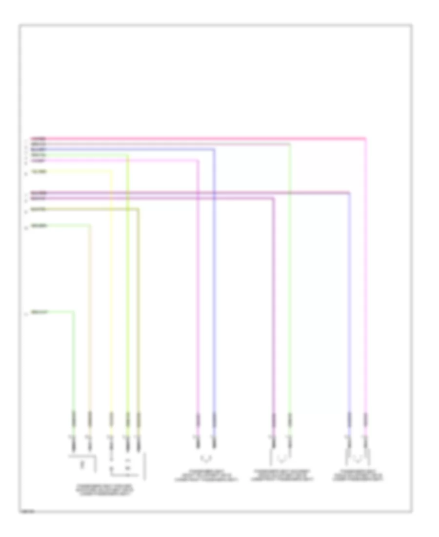
Passenger"s Memory Seat Wiring Diagram, Convertible (2 of 2) for BMW 650i 2010
List of elements for Passenger"s Memory Seat Wiring Diagram, Convertible (2 of 2) for BMW 650i 2010:
- Nca
- Passenger's seat angle adjustment drive (under passenger's seat)
- Passenger's seat backrest angle adjustment drive (under front passenger's seat)
- Passenger's seat forward/ backward adjustment drive (under passenger's seat)
- Passenger's seat height adjustment drive (under front passenger's seat)
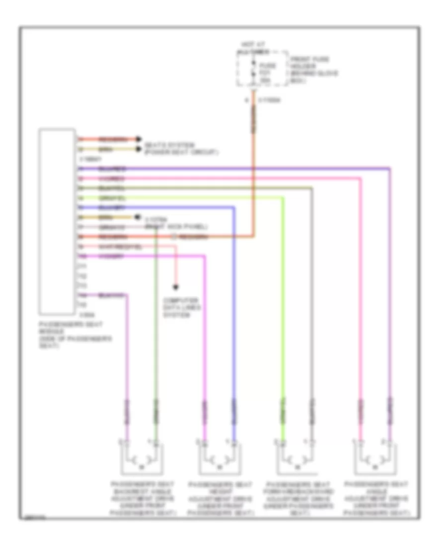
Passenger"s Memory Seat Wiring Diagram, Coupe for BMW 650i 2010
List of elements for Passenger"s Memory Seat Wiring Diagram, Coupe for BMW 650i 2010:
- Computer data lines system
- Front fuse holder (behind glove box)
- Fuse f21 30a
- Hot at all times
- Passenger's seat angle adjustment drive (under front passenger's seat)
- Passenger's seat backrest angle adjustment drive (under front passenger's seat)
- Passenger's seat forward/backward adjustment drive (under passenger's seat)
- Passenger's seat height adjustment drive (under front passenger's seat)
- Passenger's seat module (side of passenger's seat)
- Seats system (power seat circuit)
- X11004
- X13784 (right kick panel)
- X18841
- X604
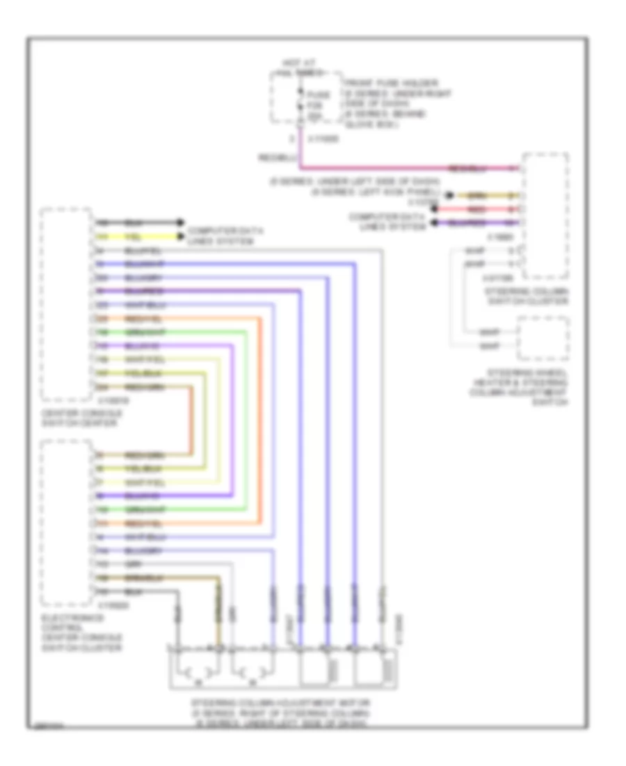
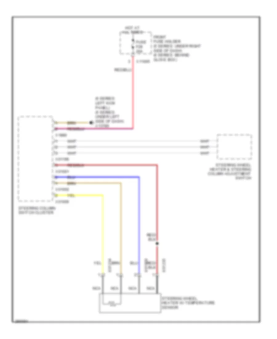
Steering Column Memory Wiring Diagram for BMW 650i 2010
List of elements for Steering Column Memory Wiring Diagram for BMW 650i 2010:
- (5 series: under left side of dash) (6 series: left kick panel) x13785
- Center console switch center
- Computer data lines system
- Electronics control center console switch cluster
- Front fuse holder (5 series: under right side of dash) (6 series: behind glove box)
- Fuse f28 20a
- Hot at all times
- Red
- Steering column adjustment motor (5 series: right of steering column) (6 series: under left side of dash)
- Steering column switch cluster
- Steering wheel heater & steering column adjustment switch
- X01196
- X11005
- X13846
- X13847
- X16919
- X16920
- X1880
NAVIGATION
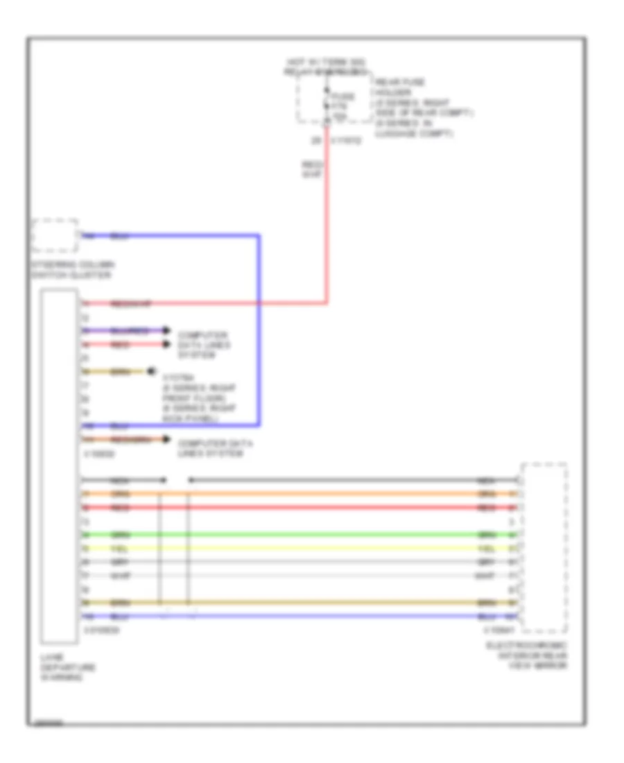
Lane Departure Warning Wiring Diagram for BMW 650i 2010
List of elements for Lane Departure Warning Wiring Diagram for BMW 650i 2010:
- Computer data lines system
- Electrochromic interior rear view mirror
- Fuse f79 10a
- Hot w/ term 30g relay energized
- Lane departure warning
- Nca
- Rear fuse holder (5 series: right side of rear compt) (6 series: in luggage compt)
- Red
- Steering column switch cluster
- X010930
- X10930
- X10941
- X11012
- X13784 (5 series: right front floor) (6 series: right kick panel)
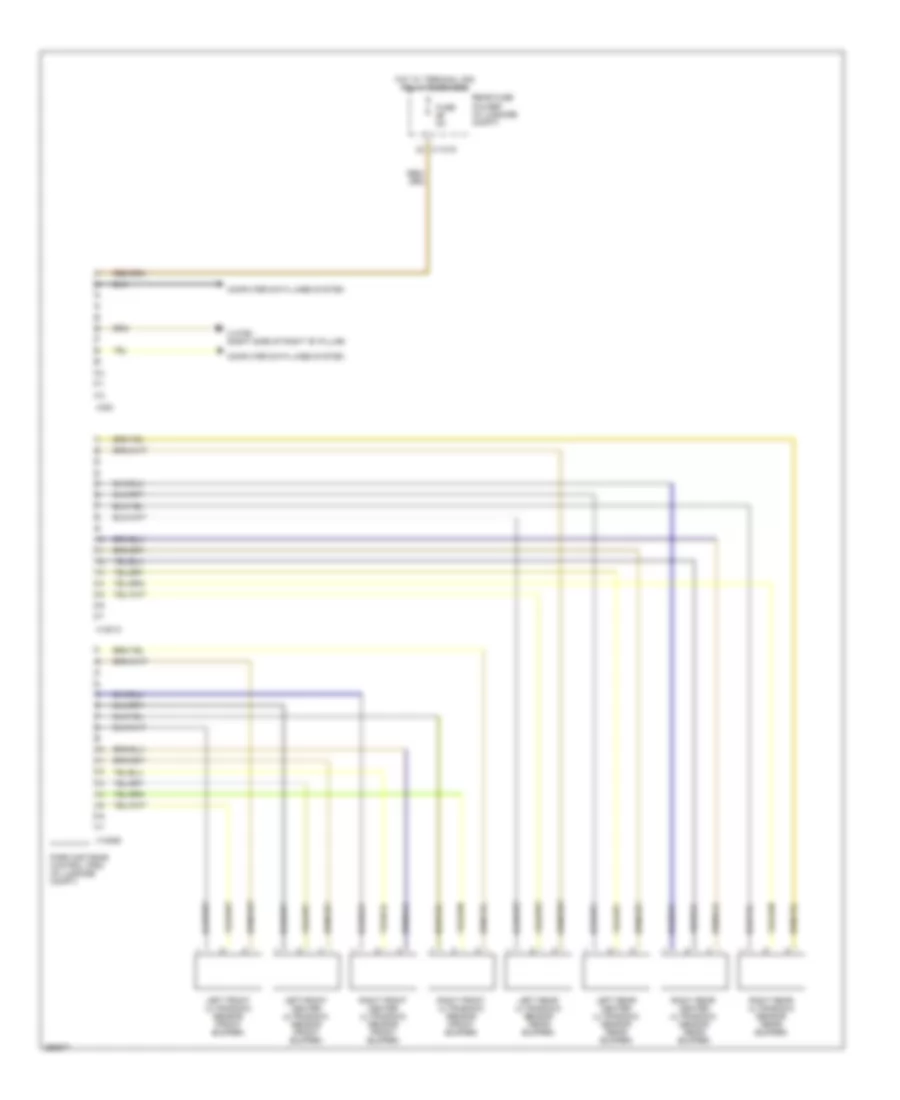
Navigation Wiring Diagram (1 of 3) for BMW 650i 2010
List of elements for Navigation Wiring Diagram (1 of 3) for BMW 650i 2010:
- (7-11 not used)
- Anti- lock brakes system
- Body gateway module (under right side of dash)
- Ccc/m-ask
- Ccc/m-ask fan (center of dash)
- Cd changer
- Computer data lines system
- Dvd changer
- Front fuse holder (behind glove box)
- Fuse 10a
- Fuse 20a
- Fuse 5a
- Head-up display
- Hot w/ term 30g relay energized
- Interior lights system
- Left rear hi-range speaker
- Left rear mid-range speaker
- Most bus connector (behind left rear seat)
- Nca
- Rear fuse holder (in luggage compt)
- Red
- Right rear hi-range speaker
- Right rear mid-range speaker
- Sat
- Satellite receiver (left side of luggage compt)
- Sdars antenna
- Telephone transceiver (behind left rear seat)
- Voice control microphone (convertible: behind right side of steering wheel) (coupe: in overhead console)
- W/ video module
- W/ video module w/ rgb line
- W/o video module
- X10389
- X10634
- X10637
- X10639
- X11006
- X11008
- X11012
- X116759
- X13793 (left side of left "b" pillar)
- X13812
- X13813
- X13814
- X13815
- X13835
- X14062
- X14063
- X14064
- X18180
- X18724
- X18730
- X695
Navigation Wiring Diagram (2 of 3) for BMW 650i 2010
List of elements for Navigation Wiring Diagram (2 of 3) for BMW 650i 2010:
- Av socket
- Fuse 30a
- Hifi amplifier (left side of luggage compt)
- Hot in run, acc or start
- Left front mid-range speaker
- Left front subwoofer
- Left front tweeter
- Left rear shelf mid-range speaker
- Left side tv amplifier
- Nca
- Rear fuse holder (in luggage compt)
- Rear window aerial
- Red
- Right front mid-range speaker
- Right front subwoofer
- Right front tweeter
- Right rear shelf mid-range speaker
- Right side tv amplifier
- Top center instrument panel speaker
- Video module (if equipped) (left side of luggage compt)
- X10633
- X10642
- X11010
- X13793 (left side of left "b" pillar)
- X13918
- X13919
- X18773
- X18803
- X18804
- X18807
- X746
- X753
Navigation Wiring Diagram (3 of 3) for BMW 650i 2010
List of elements for Navigation Wiring Diagram (3 of 3) for BMW 650i 2010:
- (right side of rear compt door)
- Antenna tuner with remote control receiver
- Car access module (behind left side of dash)
- Ccc/m-ask
- Central information display
- Comfort access control module (under right side of dash)
- Computer data lines system
- Convertible
- Coupe
- Digital tuner
- Fuse 10a
- Fuse 5a
- Hot at all times
- Hot w/ term 30g relay energized
- Nca
- Noise suppresor filter
- Rear fuse holder (in luggage compt)
- Rear window aerial
- Red
- Telephone & gps antenna (in luggage compt)
- X10318
- X11012
- X13354
- X13787 (left kick panel)
- X13793 (left side of left "b" pillar)
- X13816
- X13817
- X13820
- X13822
- X13823
- X13824
- X13911
- X13913
- X13914
- X14130
- X14131
- X14133
Parking Assistant Wiring Diagram for BMW 650i 2010
List of elements for Parking Assistant Wiring Diagram for BMW 650i 2010:
- Computer data lines system
- Fuse 5a
- Hot w/ terminal 30g relay energized
- Left front center ultrasonic sensor (front bumper)
- Left front ultrasonic sensor (front bumper)
- Left rear center ultrasonic sensor (rear bumper)
- Left rear ultrasonic sensor (rear bumper)
- Park distance control (pdc) (in luggage compt)
- Rear fuse holder (in luggage compt)
- Right front center ultrasonic sensor (front bumper)
- Right front ultrasonic sensor (front bumper)
- Right rear center ultrasonic sensor (rear bumper)
- Right rear ultrasonic sensor (rear bumper)
- X11015
- X13790 (right side of right "b" pillar)
- X18013
- X18362
- X300
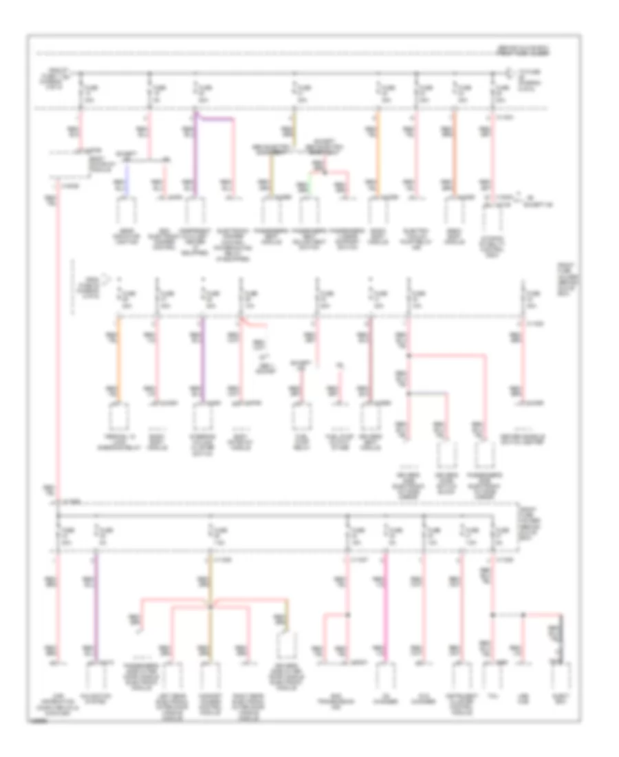
POWER DISTRIBUTION
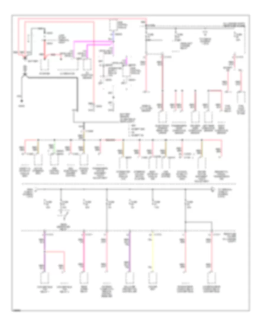
Power Distribution Wiring Diagram (1 of 6) for BMW 650i 2010
List of elements for Power Distribution Wiring Diagram (1 of 6) for BMW 650i 2010:
- (in luggage compt) rear fuse holder
- 20a
- 30a
- 40a
- 650i
- 7.5a
- Active steering (650i)
- Alternator
- Antenna tuner with remote control receiver
- Battery
- Battery sensor (in center of rear compt)
- Body gateway module (m6)
- Car access system
- Convertible top relay 1
- Convertible top relay 2
- Cooler box
- Dme control module
- Driver active backrest width adjustment
- Driver's door microwave sensor
- Dynamic drive (650i)
- Dynamic stability control (dsc)
- Edc electronic damper control
- Electronic interior rear view mirror
- Except 650i
- Except m6
- From a fuse 51 (diagram 1 of 6)
- Fuel pump output stage
- Fuel pump relay
- Fuse
- Headlight washer relay
- Jump start terminal point
- Left rear microwave sensor
- Lowering rear window relay (convertible)
- Nca
- Oil condition sensor
- Passenger's active backrest width adjustment
- Passenger's door microwave sensor
- Raising rear window relay (convertible)
- Rear defroster relay
- Rear fuse holder (in luggage compt)
- Rear wiper relay
- Red
- Right rear microwave sensor
- Rollover protection controller
- Safety & gateway module (650i)
- Sequential manual transmission (m6)
- Siren & tilt alarm sensor
- Starter
- Steering column switch cluster
- To fuse 52 (diagram 1 of 6)
- To terminal 15 relay (diagram 2 of 6)
- X10318
- X11010
- X11011
- X11012
- X11015
- X13581
- X13768
- X13895
- X16760
- X1746
- X1808
- X18303
- X1880
- X60001
- X60002
- X60003
- X60004
- X60005
- X6009
- X60093
- X6402
- X6404
- X6430
- X6624
- X9230
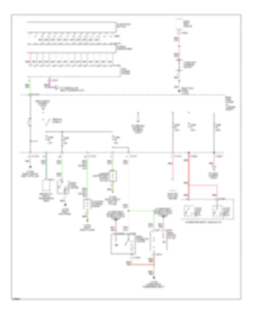
Power Distribution Wiring Diagram (2 of 6) for BMW 650i 2010
List of elements for Power Distribution Wiring Diagram (2 of 6) for BMW 650i 2010:
- (in luggage compt)
- (right kick panel) x13782
- (w/ rear seat entertainment) interior lights system
- 100a
- 200a
- 20a
- 7.5a
- Basic body module
- Car access system
- Electric auxiliary heater
- Flashlight charging socket
- From fuse 62 (diagram 1 of 6)
- Front cigar lighter
- Fuse
- Glove box charging socket
- Luggage compartment socket outlet
- Rear cigarette lighter
- Rear fuse holder
- Rear socket outlet
- Red
- Sequential manual transmission (smg)
- Slide-in compartment
- Start-stop button
- Terminal 15 relay
- To fuse 1 (diagram 5 of 6)
- To terminal 30g relay (diagram 3 of 6)
- Valve timing gear relay
- X10318
- X10681
- X10770
- X11011
- X11012
- X11013
- X11015
- X1247
- X13023
- X13254
- X13507
- X13782 (right kick panel)
- X13784 (right front floor)
- X13789 (under front passenger's seat)
- X13790 (right side of right "b" pillar)
- X13792 (right side of right "b" pillar)
- X13802
- X14027
- X18425
- X18492
- X18814
- X3560
- X387
- X70011
Power Distribution Wiring Diagram (3 of 6) for BMW 650i 2010
List of elements for Power Distribution Wiring Diagram (3 of 6) for BMW 650i 2010:
- 40a
- Active cruise control
- Center console switch
- Center console switch center
- Convertible
- Convertible top module
- Coupe
- Digital tuner
- Driver's door automatic soft-close drive
- Driver's seat adjustment switch
- Far range sensor
- From car access system (diagram 2 of 6)
- From s (diagram 3 of 6)
- From terminal 15 relay (diagram 2 of 6)
- Fuel pump relay
- Fuse
- Fuse 10a
- Fuse 15a
- Fuse 20a
- Fuse 30a
- Fuse 40a
- Fuse 5a
- Heating/ air conditioning system
- Heating/air conditioning system
- Hifi amplifier
- Left close range sensor
- Left rear automatic soft-close drive
- Panorama glass roof
- Park distance control (pdc)
- Passenger active backrest width adjustment
- Passenger's door automatic soft-close drive
- Passenger's seat adjustment switch
- Rain/ headlight sensor
- Rear fuse holder (in luggage compt)
- Red
- Right close range sensor
- Right rear automatic soft-close drive
- Satellite receiver
- Terminal 30g relay
- To fuse (diagram 3 of 6)
- To fuse (diagram 4 of 6)
- Trunk lid lift
- Video module
- X11010
- X11011
- X11012
- X11015
- X13765
- X13790 (right side of right "b" pillar)
- X14057
- X18803
- X300
Power Distribution Wiring Diagram (4 of 6) for BMW 650i 2010
List of elements for Power Distribution Wiring Diagram (4 of 6) for BMW 650i 2010:
- 10a
- Active steering
- Automatic transmission
- Central information display
- Compensator (mobile phone)
- Controller
- Driver's active backrest width adjustment
- Dynamic drive
- Dynamic stability control (dsc)
- Eject box
- Electronic interior rear view mirror
- Electronic night vision module
- Electronic ride height control
- Except m6
- From fuse u (diagram 3 of 6)
- From fuse v (diagram 4 of 6)
- Fuse
- Fuse 15a
- Fuse 30a
- Fuse 40a
- Fuse 5a
- Fuse 7.5a
- Gear indicator light
- Head-up display
- Headset connection module
- Load-shedding relay terminal 15
- Nca
- Rear fuse holder (in luggage compt)
- Red
- Selector lever
- Sequential manual transmission
- Smg transmission
- Spare wheelwell fan
- Telephone transceiver
- Tire pressure control (rdc)
- To fuse (diagram 4 of 6)
- Transfer box control module
- Transmission control
- X10385
- X11011
- X11012
- X11015
- X13819
- X1448
- X16664
- X1746
- X18303
- X695
- X70011
Power Distribution Wiring Diagram (5 of 6) for BMW 650i 2010
List of elements for Power Distribution Wiring Diagram (5 of 6) for BMW 650i 2010:
- 20a
- 30a
- 40a
- 50a
- 60a
- 650i
- B+ potential distributor (right rear of engine compt)
- Basic body module
- Blower output stage
- Body gateway module
- Car access system
- Dme relay
- Dme relay 1
- Driver's lumbar support switch
- Driver's seat adjustment switch
- Driver's seat module
- Dynamic stability control
- Electric fan
- Electronic damper control power- saving relay
- Engine electronics fuse carrier
- Except 650i
- Except m6
- Except semi-electric basic seat
- From fuse 90 (diagram 2 of 6)
- From fuse g (diagram 5 of 6)
- Front fuse holder (behind glove box)
- Fuel heater
- Fuse
- Light module
- Red
- Secondary air pump relay
- Semi-electric basic seat
- Smg hydraulic pump relay (650i)
- Smg transmission
- Steering column switch cluster
- Terminal 15 power- saving relay (m6)
- To fuse 11 (diagram 5 of 6)
- To fuse diagram 6 of 6)
- Transfer box control module
- W/ smg transmission
- W/o smg transmission
- Windshield wiper relay
- X10318
- X10594
- X11001
- X11002
- X11003
- X13254
- X13766
- X13844
- X13989
- X16759
- X16760
- X18303
- X18326
- X1880
- X53001
- X64101
- X8582
- X8683
Power Distribution Wiring Diagram (6 of 6) for BMW 650i 2010
List of elements for Power Distribution Wiring Diagram (6 of 6) for BMW 650i 2010:
- (behind glove box) front fuse holder
- 10a
- 15a
- 20a
- 30a
- 7.5a
- Basic body module
- Body gateway module
- Car information computer cic & cccm-ask
- Cd changer
- Center console switch center
- Comfort access control module
- Driver's door switch block
- Driver's seat module
- Driver's side electronic outside mirror
- Driver's side outer door handle electronic module
- Dvd changer
- Dynamic stability control (dsc)
- Edc electronic damper control
- Eject box
- Electric vacuum pump relay (m6)
- Electronic damper control power saving relay (if equipped)
- Except m6
- Except semi-electric basic seat
- From fuse 17 h diagram 5 of 6)
- From fuse 25 diagram 6 of 6)
- Front fuse holder (behind glove box)
- Fuel pump output stage
- Fuel pump relay
- Fuse
- Gear indicator lighting
- Indepedent auxiliary heater (if equipped)
- Instrument cluster control module
- Left rear electronic outer door handle module
- Navigation system
- Nca
- Obd ii socket
- Passenger's lumbar support switch
- Passenger's seat adjustment switch
- Passenger's seat module
- Passenger's side electronic outside mirror
- Passenger's side outer door handle electronic module
- Right rear electronic outer door handle module
- Semi-electric basic seat
- Smg transmission (m6)
- Steering column cluster switch
- Tcu
- Terminal 15 load- shedding relay
- To fuse diagram 6 of 6)
- Usb hub
- X11004
- X11005
- X11006
- X11007
- X11008
- X1312
- X13253
- X13255
- X13989
- X13990
- X14056
- X16759
- X16760
- X1746
- X1808
- X18303
- X1880
- X53001
- X695
POWER DOOR LOCKS
Power Door Locks Wiring Diagram (1 of 2) for BMW 650i 2010
List of elements for Power Door Locks Wiring Diagram (1 of 2) for BMW 650i 2010:
- (right side of right "b" pillar) x13790
- Body-gateway module (under right side of dash)
- Car access module (behind left side of dash)
- Computer data lines system
- Driver's door system lock (rear of driver's door)
- Electrochromic interior rear view mirror
- Front fuse holder (behind glove box)
- Fuse f10 30a
- Fuse f12 30a
- Fuse f15 5a
- Fuse f18 30a
- Fuse f29 10a
- Fuse f7 30a
- Hood contact switch (right rear of engine compt)
- Hot at all times
- Passenger's door system lock (rear of front passenger's door)
- Red
- Siren & tilt alarm sensor (behind right rear wheel)
- X10318
- X11002
- X11003
- X11004
- X11005
- X13782 (right kick panel)
- X13786 (right front floor)
- X13788 (right front floor)
- X16759
- X16760
- X18246
Power Door Locks Wiring Diagram (2 of 2) for BMW 650i 2010
List of elements for Power Door Locks Wiring Diagram (2 of 2) for BMW 650i 2010:
- (right side of right "b" pillar)
- Driver's door automatic soft- close drive
- Driver's door microwave sensor (in driver's door)
- Fuse f51 5a
- Fuse f67 20a
- Fuse f68 20a
- Hazard warning/ central locking switch
- Hot at all times
- Hot w/ terminal 30g relay energized
- Left rear microwave sensor (left side of left "b" pillar)
- Passenger's door automatic soft- close drive
- Passenger's door microwave sensor (in passenger's door)
- Rear fuse holder (in luggage compt)
- Right rear microwave sensor (right side of right "b" pillar)
- X11011
- X11015
- X13782 (right kick panel)
- X13784 (right kick panel)
- X13785 (left kick panel)
- X13788 (right front floor)
- X13789 (under front passenger's seat)
- X13790
- X13791 (under front passenger's seat)
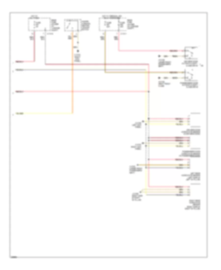
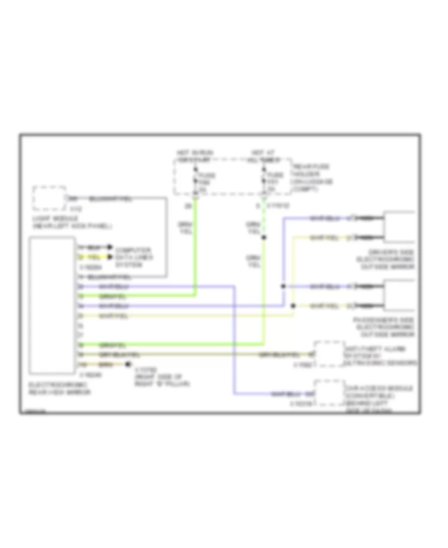
POWER MIRRORS
Electrochromic Mirror Wiring Diagram for BMW 650i 2010
List of elements for Electrochromic Mirror Wiring Diagram for BMW 650i 2010:
- Anti-theft alarm system w/ ultrasonic sensors
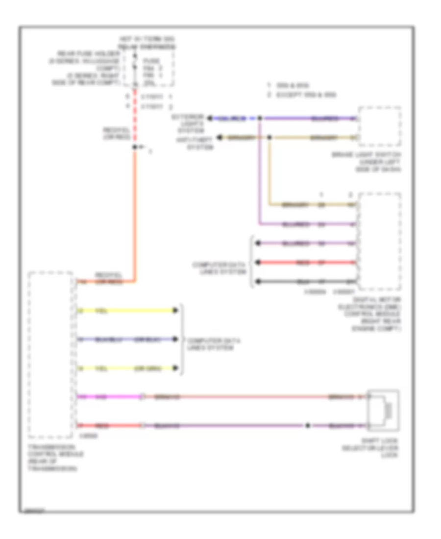
- Car access module (convertible) (behind left side of dash)
- Computer data lines system
- Driver's side electrochromic outside mirror
- Electrochromic rear view mirror
- Fuse f51 5a
- Fuse f89 5a
- Hot at all times
- Hot in run or start
- Light module (near left kick panel)
- Nca
- Passenger's side electrochromic outside mirror
- Rear fuse holder (in luggage compt)
- X10318
- X11012
- X12
- X13792 (right side of right "b" pillar)
- X1582
- X18246
- X18284
Power Mirrors Wiring Diagram, with Solid State Mirror for BMW 650i 2010
List of elements for Power Mirrors Wiring Diagram, with Solid State Mirror for BMW 650i 2010:
- Body-gateway module (under right side of dash)
- Driver's door switch block
- Front fuse holder (5 series: under right side of dash) (6 series: behind glove box)
- Fuse 10a
- Hot at all times
- Interior lights system
- Nca
- Outside mirror, driver's side
- Outside mirror, passenger's side
- X11005
- X13788 (right front floor)
- X13789 (5 series: left front floor) (6 series: under front passenger's seat)
- X16759
- X16760
Power Mirrors Wiring Diagram, without Solid State Mirror for BMW 650i 2010
List of elements for Power Mirrors Wiring Diagram, without Solid State Mirror for BMW 650i 2010:
- (under right side of dash) body-gateway module
- Computer data lines system
- Driver's door switch block
- Driver's side outside mirror
- Front fuse holder (5 series: under right side of dash) (6 series: behind glove box)
- Fuse 10a
- Hot at all times
- Interior lights system
- Nca
- Passenger's side outside mirror
- X11005
- X13789 (5 series: left front floor) (6 series: under front passenger's seat)
- X16759
- X16760
POWER SEATS
Heated Seats Wiring Diagram for BMW 650i 2010
List of elements for Heated Seats Wiring Diagram for BMW 650i 2010:
- (left kick panel) x13785
- Center console switch center
- Driver's seat backrest heating element (in driver's seat backrest)
- Driver's seat cushion heating element (in driver's seat cushion)
- Front fuse holder (behind glove box)
- Fuse f33 30a
- Hot at all times
- Nca
- Passenger's seat cushion heating element (in front passenger's seat cushion)
- X11005
- X14056
- X14057
Heated Steering Wheel Wiring Diagram for BMW 650i 2010
List of elements for Heated Steering Wheel Wiring Diagram for BMW 650i 2010:
- (6 series: left kick panel) (5 series: under left side of dash) x13785
- Front fuse holder (5 series: under right side of dash) (6 series: behind glove box)
- Fuse f28 20a
- Hot at all times
- Nca
- Steering column switch cluster
- Steering wheel heater & steering column adjustment switch
- Steering wheel heater w/ temperature sensor
- X01001
- X01002
- X01006
- X01009
- X01196
- X01234
- X01235
- X11005
- X1880
Power Seats Wiring Diagram for BMW 650i 2010
List of elements for Power Seats Wiring Diagram for BMW 650i 2010:
- (right kick panel) x13784
- (side of driver's seat)
- (side of passenger's seat)
- (under front passenger's seat) x13789
- Convertible
- Coupe
- Driver's lumbar support switch
- Driver's lumbar support valve block (top of driver's seat back)
- Driver's seat lumbar support drive (under driver's seat)
- Driver's seat module (under driver's seat)
- Front fuse holder (behind glove box)
- Fuse f14 30a
- Fuse f21 30a
- Hot at all times
- Nca
- Passenger's lumbar support switch
- Passenger's lumbar support valve block (top of front passenger's seat back)
- Passenger's seat lumbar support drive (under front passenger's seat)
- Passenger's seat module (under passenger's seat)
- Red
- X11003
- X11004
- X14000
- X1465
- X18840
- X18841
- X604
POWER TOP/SUNROOF
Convertible Top Wiring Diagram (1 of 2) for BMW 650i 2010
List of elements for Convertible Top Wiring Diagram (1 of 2) for BMW 650i 2010:
- (left side of rear compt) x13795
- Car access system
- Center console switch center
- Computer data lines system
- Convertible top lid opening valve (rear center of rear compt)
- Convertible top module (near left "c" pillar)
- Cowl panel locked hall sensor (left front of headliner)
- Cowl panel locking drive (left front side of roof)
- Cowl panel release hall sensor (left front of headliner)
- Fuse 20a
- Fuse 30a
- Fuse 40a
- Hot at all times
- Hot w/ terminal 30g relay energized
- Latch fastener sensor (left top side of rear compt)
- Lifting latch fastener valve (top center of rear compt)
- Lowering latch fastener valve (top center of rear compt)
- Main pillar sensor (left top side of rear compt)
- Nca
- Rear fuse holder (in luggage compt)
- Rear window down hall sensor
- X01180
- X10318
- X11010
- X11011
- X13037
- X13038
- X14058
Convertible Top Wiring Diagram (2 of 2) for BMW 650i 2010
List of elements for Convertible Top Wiring Diagram (2 of 2) for BMW 650i 2010:
- (below center of rear window) convertible top 1 relay
- (below center of rear window) convertible top 2 relay
- (center of rear compt) lowering rear window relay
- (center of rear compt) raising rear window relay
- Convertible top compartment floor switch
- Convertible top drive (top center of rear compt)
- Convertible top lid open hall sensor (left top side of rear compt)
- Left convertible top compartment lock hall sensor (left top side of rear compt)
- Left convertible top lid released hall sensor
- Nca
- Rear window drive (top center of rear compt)
- Right convertible top compartment lock hall sensor (right top side of rear compt)
- X01178
- X01179
- X01182
- X01183
- X13792 (right side of right "b" pillar)
Panoramic Roof Wiring Diagram for BMW 650i 2010
List of elements for Panoramic Roof Wiring Diagram for BMW 650i 2010:
- Computer data lines system
- Fuse f66 20a
- Glass roof motor (5 series: front center of roof) (6 series: center rear of roof)
- Hot w/ terminal 30g relay energized
- Panorama glass roof
- Rear fuse holder (5 series: right side of rear compt) (6 series: in luggage compt)
- Silde/tilt sunroof switch
- Visor motor (5 series: center rear of roof) (6 series: in overhead console)
- X11011
- X13792 (5 series: right side of rear compt) (6 series: right side of right "b" pillar)
- X14102
- X14103
POWER WINDOWS
Power Windows Wiring Diagram (1 of 2) for BMW 650i 2010
List of elements for Power Windows Wiring Diagram (1 of 2) for BMW 650i 2010:
- Body-gateway module (under right side of dash)
- Drv wind mtr
- Front fuse holder (5 series: under right side of dash) (6 series: behind glove box)
- Fuse f10 30a
- Fuse f11 5a
- Fuse f12 30a
- Fuse f18 30a
- Fuse f27 30a
- Fuse f29 10a
- Fuse f32 10a
- Ground
- Hall sensor
- Hot at all times
- Interior lights system
- Lin bus
- Pass wind mtr
- Passenger's door power window switch
- Passenger's window motor (in front passenger's door)
- Sensor ground
- Terminal 30
- X11003
- X11004
- X11005
- X13786 (right front floor)
- X13788 (right front floor)
- X16759
- X16760
Power Windows Wiring Diagram (2 of 2) for BMW 650i 2010
List of elements for Power Windows Wiring Diagram (2 of 2) for BMW 650i 2010:
- (except convertible) left rear door window switch
- (except convertible) right rear door window switch
- (in left rear door) (except convertible) left rear door power window motor
- Basic body module (behind glove box)
- Close signal
- Convertible
- Driver's door switch block
- Driver's window motor (in driver's door)
- Except convertible
- Fuse 11
- Fuse 27
- Ground
- Hall sen gnd
- Hall signal
- Interior lights system
- Left rear window regulator motor (convertible) (center of left rear interior panel)
- Open signal lr
- Open signal rr
- Right rear door power window motor (except convertible) (in right rear door)
- Right rear window regulator motor (convertible) (center of right rear interior panel)
- Signal pwr lr
- Signal pwr rr
- X13252
- X13253
- X13254
- X13255
- X13782 (right kick panel)
- X13788 (right front door)
- X13789 (5 series: left front floor) (6 series: under front passenger's seat)
- X13791 (under front passenger's seat)
RADIO
Radio Wiring Diagram (1 of 3) for BMW 650i 2010
List of elements for Radio Wiring Diagram (1 of 3) for BMW 650i 2010:
- (7-11 not used)
- Anti- lock brakes system
- Body gateway module (under right side of dash)
- Ccc/m-ask
- Ccc/m-ask fan (center of dash)
- Cd changer
- Computer data lines system
- Dvd changer
- Front fuse holder (behind glove box)
- Fuse 10a
- Fuse 20a
- Fuse 5a
- Head-up display
- Hot w/ term 30g relay energized
- Interior lights system
- Left rear hi-range speaker
- Left rear mid-range speaker
- Most bus connector (behind left rear seat)
- Nca
- Rear fuse holder (in luggage compt)
- Red
- Right rear hi-range speaker
- Right rear mid-range speaker
- Sat
- Satellite receiver (left side of luggage compt)
- Sdars antenna
- Telephone transceiver (behind left rear seat)
- Voice control microphone (convertible: behind right side of steering wheel) (coupe: in overhead console)
- W/ video module
- W/ video module w/ rgb line
- W/o video module
- X10389
- X10634
- X10637
- X10639
- X11006
- X11008
- X11012
- X116759
- X13793 (left side of left "b" pillar)
- X13812
- X13813
- X13814
- X13815
- X13835
- X14062
- X14063
- X14064
- X18180
- X18724
- X18730
- X695
Radio Wiring Diagram (2 of 3) for BMW 650i 2010
List of elements for Radio Wiring Diagram (2 of 3) for BMW 650i 2010:
- Av socket
- Fuse 30a
- Hifi amplifier (left side of luggage compt)
- Hot in run, acc or start
- Left front mid-range speaker
- Left front subwoofer
- Left front tweeter
- Left rear shelf mid-range speaker
- Left side tv amplifier
- Nca
- Rear fuse holder (in luggage compt)
- Rear window aerial
- Red
- Right front mid-range speaker
- Right front subwoofer
- Right front tweeter
- Right rear shelf mid-range speaker
- Right side tv amplifier
- Top center instrument panel speaker
- Video module (if equipped) (left side of luggage compt)
- X10633
- X10642
- X11010
- X13793 (left side of left "b" pillar)
- X13918
- X13919
- X18773
- X18803
- X18804
- X18807
- X746
- X753
Radio Wiring Diagram (3 of 3) for BMW 650i 2010
List of elements for Radio Wiring Diagram (3 of 3) for BMW 650i 2010:
- (right side of rear compt door)
- Antenna tuner with remote control receiver
- Car access module (behind left side of dash)
- Ccc/m-ask
- Central information display
- Comfort access control module (under right side of dash)
- Computer data lines system
- Convertible
- Coupe
- Digital tuner
- Fuse 10a
- Fuse 5a
- Hot at all times
- Hot w/ term 30g relay energized
- Nca
- Noise suppresor filter
- Rear fuse holder (in luggage compt)
- Rear window aerial
- Red
- Telephone & gps antenna (in luggage compt)
- X10318
- X11012
- X13354
- X13787 (left kick panel)
- X13793 (left side of left "b" pillar)
- X13816
- X13817
- X13820
- X13822
- X13823
- X13824
- X13911
- X13913
- X13914
- X14130
- X14131
- X14133
SHIFT INTERLOCK
6-Speed SMG Wiring Diagram for BMW 650i 2010
List of elements for 6-Speed SMG Wiring Diagram for BMW 650i 2010:
- (right rear of engine compt) x6
- 528i & 528xi
- 550i & 650i
- Anti-theft system
- Battery
- Brake light
- Brake light switch (under left side of dash)
- Can (+)
- Can (-)
- Clutch pos
- Clutch position sensor (left side of transmission)
- Computer data lines system
- Digital motor electronics (dme) control module (right rear engine compt)
- Except 550i & 650i
- Exterior lights system
- Front fuse carrier
- Fuse f17 15a
- Fuse f42 20a
- Fuse f84 15a
- Ground
- Hot at all times
- Hot w/ terminal 30g relay energized
- M5 & m6
- Rear fuse holder (6 series: in luggage compt) (5 series: right side of rear compt)
- Red
- Sequential manual transmission (smg) (right rear of engine compt)
- Shift lock
- Shift lock selector lever lock
- X11003
- X11011
- X11017
- X13784 (6 series: right kick panel) (5 series: right front floor)
- X60001
- X60004
- X70003
- X70011
- X70014
A/T Wiring Diagram for BMW 650i 2010
List of elements for A/T Wiring Diagram for BMW 650i 2010:
- 550i & 650i
- Anti-theft system
- Brake light switch (under left side of dash)
- Computer data lines system
- Digital motor electronics (dme) control module (right rear engine compt)
- Except 550i & 650i
- Exterior lights system
- Fuse f84 f86 15a
- Hot w/ term 30g relay energized
- Rear fuse holder (6 series: in luggage compt) (5 series: right side of rear compt)
- Red
- Shift lock selector lever lock
- Transmission control module (rear of transmission)
- X11011
- X60001
- X60004
- X8500
STARTING/CHARGING
Charging Wiring Diagram for BMW 650i 2010
List of elements for Charging Wiring Diagram for BMW 650i 2010:
- 550i & 650i
- Alternator
- Battery
- Digital motor electronics (dme) control module (right rear engine compt)
- Except 550i & 650i
- Jump start terminal point (left side of engine compt)
- Nca
- Power distribution system
- Red
- Starter
- X60003
- X60005
- X6402
Starting Wiring Diagram for BMW 650i 2010
List of elements for Starting Wiring Diagram for BMW 650i 2010:
- Battery
- Car access system (550i: under left side of dash) car access module (650i: behind left side of dash)
- Digital motor electronics (dme) control module (right rear engine compt)
- Dme relay 2
- Front fuse holder (550i: under right side of dash) (650i: behind glove box)
- Fuse f7 30a
- Fuse f8 60a
- Hot at all times
- Jump start terminal point (left side of engine compt)
- Nca
- Red
- Start inhibit relay
- Starter
- X10318
- X11002
- X13769
- X13784 (550i: right front floor) (650i: right kick panel)
- X13844
- X60002
- X6009
- X60093
- X60094
- X6402
- X6406
- X6510
- X6512
SUPPLEMENTAL RESTRAINTS
Supplemental Restraints Wiring Diagram (1 of 2) for BMW 650i 2010
List of elements for Supplemental Restraints Wiring Diagram (1 of 2) for BMW 650i 2010:
- (convertible) rollover protection controller
- (usa) driver's side front air bag sensor
- Battery
- Car access system
- Computer data lines system
- Crash safety module (left side of center console)
- Driver head restraint crash active
- Driver side air bag inflator assembly
- Driver side b-pillar air bag sensor
- Driver's air bag inflator assemblies
- Driver's seat belt buckle contact
- Driver's seat belt tensioner generator
- Driver's seat seat occupancy electronics
- Driver's side front door air bag sensor
- Driver's side head air bag inflator assembly (coupe)
- Jump start terminal point
- Left front knee air bag inflator assembly (usa)
- Nca
- Passenger air bag deactivation indicator lamp
- Passenger's seat belt buckle contact
- Red
- Steering column switch cluster
- X01003
- X010334
- X01071
- X01072
- X10318
- X10334
- X13787
- X18069
- X327
- X6402
- X6419
Supplemental Restraints Wiring Diagram (2 of 2) for BMW 650i 2010
List of elements for Supplemental Restraints Wiring Diagram (2 of 2) for BMW 650i 2010:
- (usa) passenger's side front air bag sensor
- Computer data lines system
- Crash safety module (left side of center console)
- Front passenger head restraint crash active
- Fuse f60 10a
- Hot at all times
- Left rollover protection actuator
- Nca
- Passenger air bag deactivation switch
- Passenger side air bag inflator assembly
- Passenger's air bag inflator assemblies
- Passenger's seat belt tensioner generator
- Passenger's seat occupancy detection
- Passenger's side b-pillar air bag sensor
- Passenger's side front door air bag sensor
- Passenger's side head air bag inflator assembly (coupe)
- Rear fuse holder (in luggage compt)
- Red
- Right front knee air bag inflator assembly (usa)
- Right rollover protection actuator
- Safety battery terminal generator
- X10012
- X10179
- X11012
TRANSMISSION
6-Speed SMG Wiring Diagram (1 of 2) for BMW 650i 2010
List of elements for 6-Speed SMG Wiring Diagram (1 of 2) for BMW 650i 2010:
- Brake light
- Brake light switch (left side of dash)
- Car access system (under left side of dash)
- Computer data lines system
- Front fuse holder (5 series: under right side of dash) (6 series: behind glove box)
- Front fuse holder (under right side of dash)
- Fuse f17 5a
- Fuse f28 20a
- Fuse f42 20a
- Fuse f83 5a
- Fuse f89 10a
- Gear indicator light
- Ground
- Hot at all times
- Immob sig
- Left rocker switch
- Light module (5 series: under left side of dash) (6 series: near left kick panel)
- Obd ii socket (5 series: left side of left kick panel) (6 series: near left kick panel)
- Park pos sig
- Rear fuse holder (right side of rear compt)
- Red
- Right rocker switch
- Select lever
- Selector lever asg
- Sensor grd
- Sequential manual transmission (smg) (right rear of engine compt)
- Shift lock
- Shift lock selector lever lock
- Steering column switch cluster
- Td sig
- Term 30g
- Term 30g relay
- Wake up sig
- X01001
- X10318
- X11003
- X11005
- X11007
- X11012
- X11015
- X12
- X13412
- X13726
- X13784 (right front floor)
- X13785 (under left side of dash)
- X1880
- X6009
- X60094
- X70003
- X70011
- X7517
- X78
6-Speed SMG Wiring Diagram (2 of 2) for BMW 650i 2010
List of elements for 6-Speed SMG Wiring Diagram (2 of 2) for BMW 650i 2010:
- Brakes solenoid valve (left side of transmission)
- Brk sol
- Can h
- Can l
- Clutch pos
- Clutch position sensor (left side of transmission)
- Clutch sol
- Clutch solenoid valve (5 series: rear of transmission) (6 series: bottom of transmission)
- Computer data lines system
- Digital motor electronics (dme) control unit (right rear of engine compt)
- Engine electronics fuse carrier
- Fuse f01 30a
- Gear 1 sol
- Gear 2 sol
- Gear solenoid valve 1 (5 series: left side of transmission) (6 series: rear of transmission)
- Gear solenoid valve 2 (5 series: rear of transmission) (6 series: bottom of transmission)
- Gearshift sens
- Gearshift sensor (top of transmission)
- Ground
- Hot at all times
- Hyd press
- Hydraulic pressure sensor (rear of transmission)
- Hydraulic pump (bottom of transmission)
- Hydraulic pump relay (right rear of engine compt)
- Nca
- Pump relay
- Red
- Rpm sens
- Rpm sensor (left side of engine)
- Select angle
- Selector angle sensor (top of transmission)
- Sequential manual transmission (smg) right rear of engine compt)
- Shift sens
- Terminal 15
- Txd
- Txd sig
- X6 (right rear of engine compt)
- X60001
- X60004
- X70014
- X7517
- X8683
A/T Wiring Diagram for BMW 650i 2010
List of elements for A/T Wiring Diagram for BMW 650i 2010:
- Car access system (under left side of dash) car access module (behind left side of dash)
- Computer data lines system
- Digital motor electronics (dme) control module (right rear engine compt)
- Front fuse holder (5 series: under right side of dash) (6 series: behind glove box)
- Fuse f19 5a
- Fuse f84 15a
- Fuse f89 10a
- Gear indicator light
- Hot at all times
- Light module (5 series: under left side of dash) (6 series: near left kick panel)
- Rear fuse holder (5 series: right side of rear compt) (6 series: in luggage compt)
- Red
- Selector lever position switch (5 series: part of shifter lever) (6 series: in center console)
- Shift lock selector lever lock
- Steering column switch cluster
- Steptronic switch
- Term 30g relay
- Transmission control module (rear of transmission)
- X10318
- X11004
- X11011
- X11015
- X1193
- X12
- X13701
- X13784 (5 series: right front floor) (6 series: right kick panel)
- X14275
- X1599
- X1600
- X1880
- X6 (right rear of engine compt)
- X60001
- X6009
- X60092
- X60094
Steering Wheel Control Switch Wiring Diagram for BMW 650i 2010
List of elements for Steering Wheel Control Switch Wiring Diagram for BMW 650i 2010:
- (5 series: under left side of dash) (6 series: left kick panel) x13785
- Driver's airbag inflator assemblies (part of steering wheel)
- Electronic steering wheel module (part of steering wheel)
- Front fuse holder (right side of dash)
- Fuse f28 20a
- Horn switch
- Hot at all times
- Left front steptronic push-button
- Left multifunction steering wheel switch block
- Nca
- Red
- Right front steptronic push-button
- Right multifunction steering wheel switch block
- Steering column switch cluster
- Steering wheel heater
- X01001
- X01002
- X01003
- X01006
- X01007
- X01009
- X01071
- X01072
- X11005
- X1880
TRUNK, TAILGATE, FUEL DOOR
Trunk & Fuel Door Release Wiring Diagram for BMW 650i 2010
List of elements for Trunk & Fuel Door Release Wiring Diagram for BMW 650i 2010:
- (right kick panel) x13782
- Basic body module (behind glove box)
- Car access module (behind left side of dash)
- Central locking drive fuel filler flap (right side of rear compt)
- Computer data lines system
- Convertible
- Coupe
- Exterior trunk lid/ tailgate button
- Front fuse holder (behind glove box)
- Fuse f11 5a
- Fuse f15 5a
- Fuse f22 30a
- Fuse f24 30a
- Fuse f27 30a
- Fuse f7 30a
- Hot at all times
- Hotel switch
- Interior lights system
- Noise suppressor filter
- Rear lid release switch (interior)
- Trunk lid central locking drive w/ trunk lid contact switch 1) trunk lid closed 2) trunk lid open
- X10318
- X11002
- X11003
- X11004
- X11005
- X13252
- X13253
- X13254
- X13255
- X13782 (right kick panel)
- X13789 (under front passenger's seat)
- X13792 (w/ coupe) (right side of right "b" pillar) x13244 (w/ convertible)
- X13913
- X13914
WARNING SYSTEMS
Warning Systems Wiring Diagram for BMW 650i 2010
List of elements for Warning Systems Wiring Diagram for BMW 650i 2010:
- Computer data lines system
- Fuse f82 7.5a
- Hot w/ term 30g relay energized
- Left front electronic wheel module
- Left front rdc transmitter (behind left front wheel)
- Left rear electronic wheel module
- Left rear rdc transmitter (behind left rear wheel)
- Rdc antenna (5 series: under right side of vehicle) (6 series: under right center of vehicle)
- Rear fuse holder (5 series: right side of rear compt) (6 series: in luggage compt)
- Right front electronic wheel module
- Right front rdc transmitter (behind right front wheel)
- Right rear electronic wheel module
- Right rear rdc transmitter (behind right rear wheel)
- Tire pressure control (rdc) (5 series: under spare tire) (6 series: under right side of dash)
- X11012
- X13784 (5 series: right front floor) (6 series: right kick panel)
WIPER/WASHER
Wiper/Washer Wiring Diagram for BMW 650i 2010
List of elements for Wiper/Washer Wiring Diagram for BMW 650i 2010:
- (5 series: front center of roof) (6 series: center of windshield) rain/headlight sensor
- (5 series: left side of windshield) (6 series: left rear of engine compt) wiper motor
- Basic body module (behind glove box)
- Body-gateway module (under right side of dash)
- Computer data lines system
- Fast
- Front fuse holder (5 series: under right side of dash) (6 series: behind glove box)
- Fuse f11 5a
- Fuse f16 30a
- Fuse f22 30a
- Fuse f24 30a
- Fuse f27 30a
- Fuse f50 30a
- Fuse f56 5a
- Fuse f58 20a
- Headlight washer pump (front of left front wheel)
- Hot at all times
- Hot w/ term 30g relay energized
- Nca
- Park
- Rear fuse holder (5 series: right side of rear compt) (6 series: in luggage compt)
- Rear window washer pump (wagon) (front of left front wheel)
- Rear wiper drive (wagon) (top center of rear compt door)
- Rear wiper relay (wagon) (under spare tire)
- Red
- Run
- Slow
- Steering column switch cluster
- Windshield washer pump (front of left front wheel)
- Windshield wiper relay (right rear of engine compt)
- X11003
- X11004
- X11005
- X11010
- X11012
- X11015
- X13252
- X13253
- X13254
- X13255
- X13782 (right kick panel)
- X13783 (left kick panel)
- X13784 (5 series: right front floor) (6 series: right kick panel)
- X13785 (5 series: under left side of dash) (6 series: left kick panel)
- X13790 (6 series: right side of right "b" pillar)
- X13790 (6-series: right side of right "b" pillar)
- X13794 (right side of rear compt)
- X16760
- X1880