ACTIVE BODYWORKS
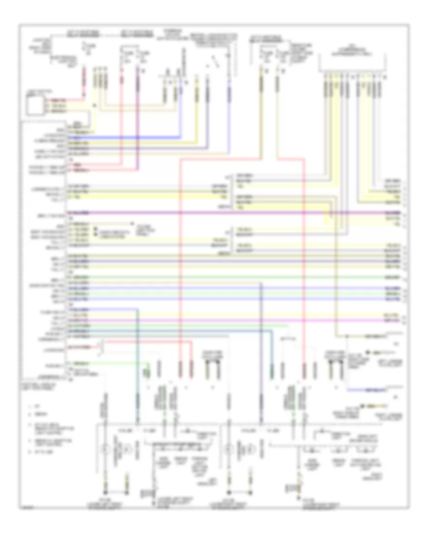
Active Bodyworks Wiring Diagram for BMW ActiveHybrid 5 2014

List of elements for Active Bodyworks Wiring Diagram for BMW ActiveHybrid 5 2014:
- (right side of cargo area) z10 8b
- 30b
- Fully automatic towing hitch button
- Fully automatic towing hitch drive
- Fuse 20a
- Gnd
- Hall sens sig
- Hot w/ terminal 30b relay energized
- Led activation
- Nca
- Rear fuse holder (right side of rear compt)
- Sw sig
- Towing hitch
- Trailer module (under spare tire)
- Trailer socket switch
- X268 1b
- X269 1b
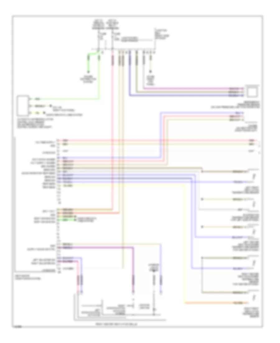
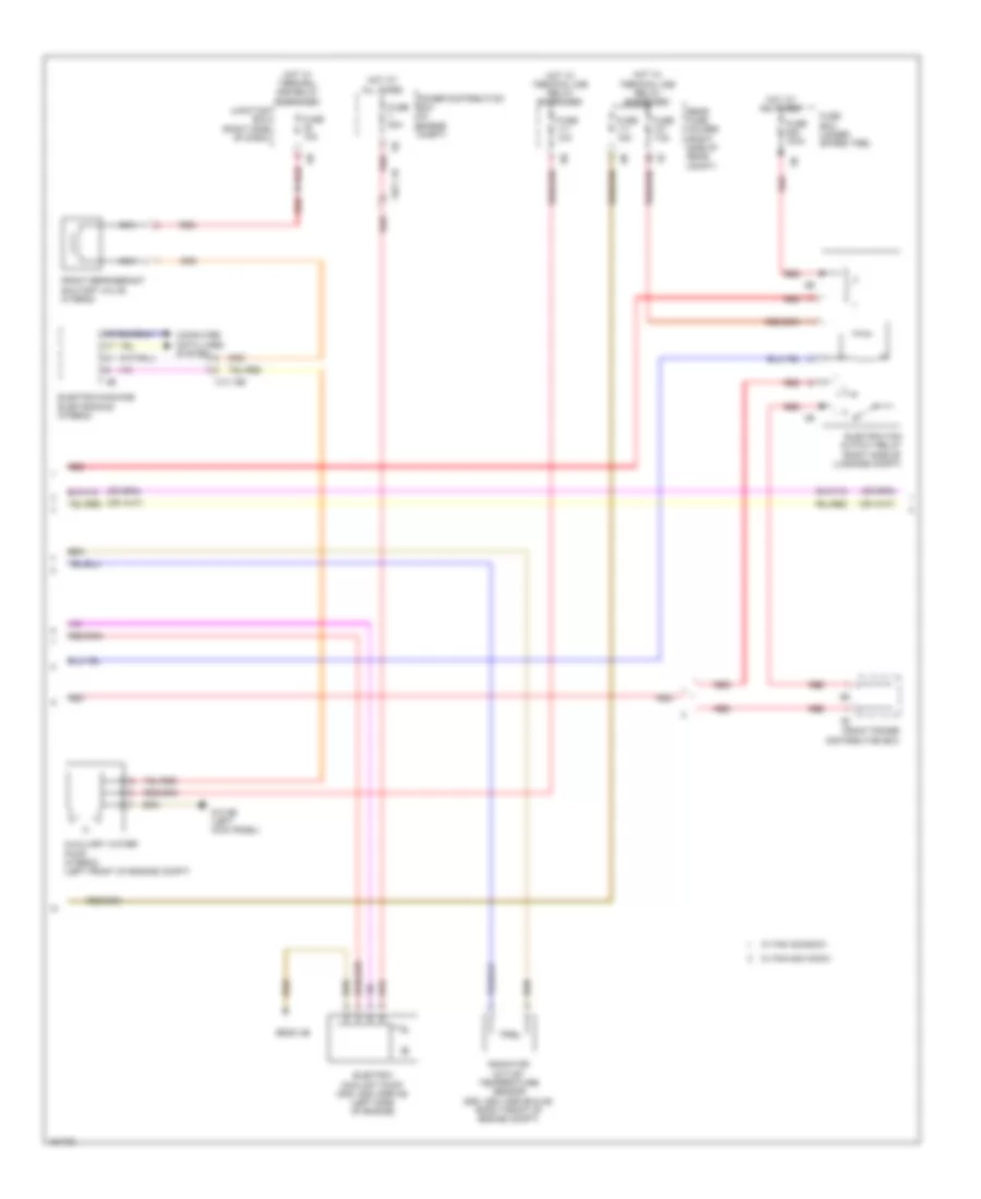
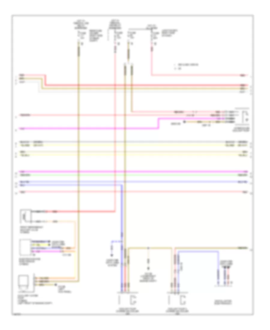
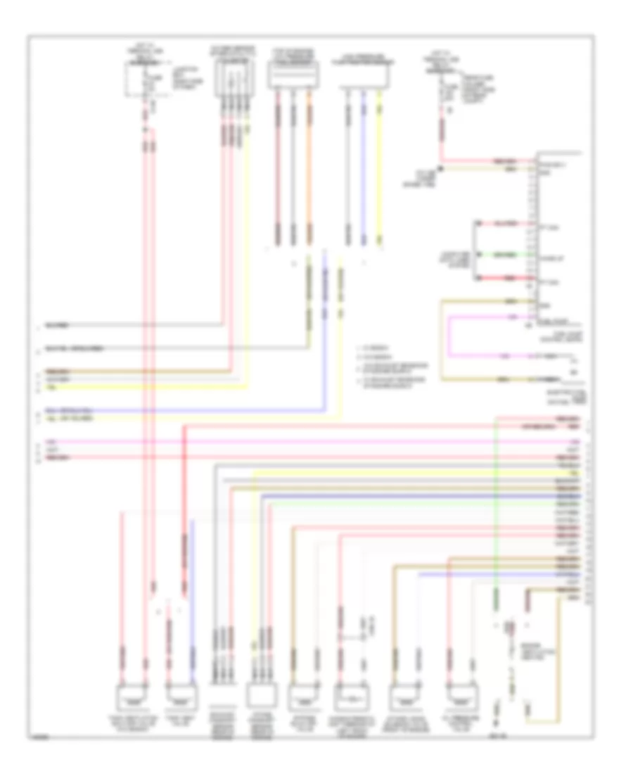
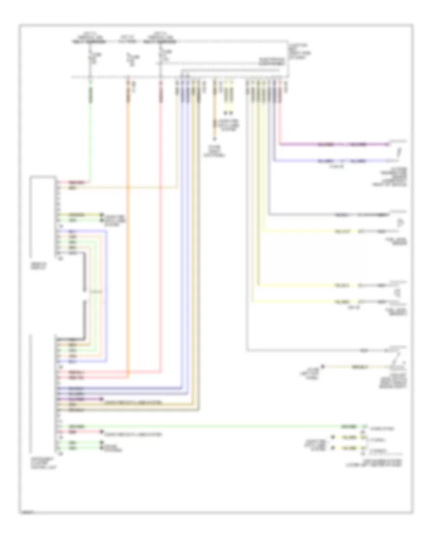
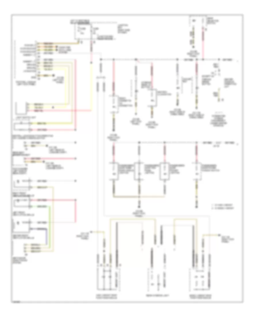
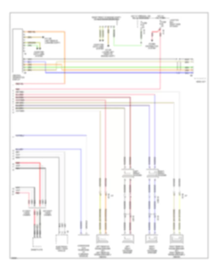
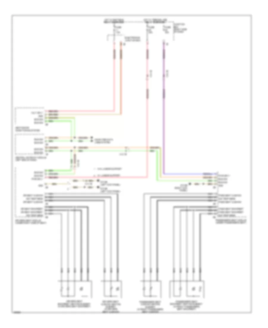
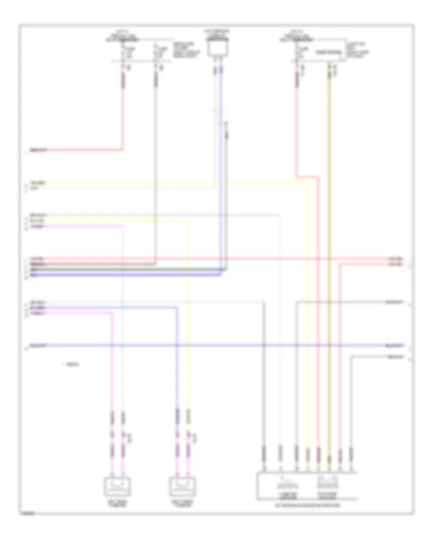
AIR CONDITIONING
Automatic A/C Wiring Diagram, with Rear Automatic Climate Control (1 of 6) for BMW ActiveHybrid 5 2014
List of elements for Automatic A/C Wiring Diagram, with Rear Automatic Climate Control (1 of 6) for BMW ActiveHybrid 5 2014:
- Activation ioniser
- Automatic air recirculation control (auc) sensor (on air recirculation control microfilter compt)
- Body can bus sig
- Computer data lines system
- Evaporator temperature sensor (top left side of dash)
- Front center ventilation grille
- Fuse 5a
- Fuse 7.5a
- Gnd
- Gnd ioniser
- Heating/air conditioning system
- Hot w/ bi-stable relay energized
- Hot w/ terminal 15n relay energized
- Interior lights system
- Ionizer (on heating & air conditioning unit)
- Junction box (right side of dash)
- Junction box electronics
- Left adjuster sig
- Left front ventilation temperature sensor
- Left heater heat exchanger temperature sensor (top center of dash)
- Left stratification actuator
- Lin bus sig
- Locator lighting
- Power distribution system
- Red
- Refrigerant pressure sensor (on high pressure line to evaporator)
- Right adjuster sig
- Right front ventilation temperature sensor
- Right heater heat exchanger temperature sensor (top center of dash)
- Right stratification actuator (hybrid)
- Sens gnd
- Sens sig
- Sig evaporator temp sens
- Sply volt
- Temp sens
- Z10 11b (right kick panel)
- Z10 6b (right kick panel)
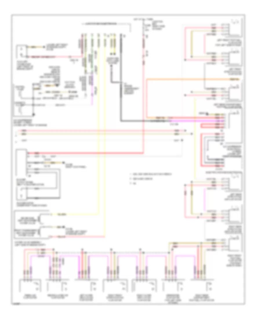
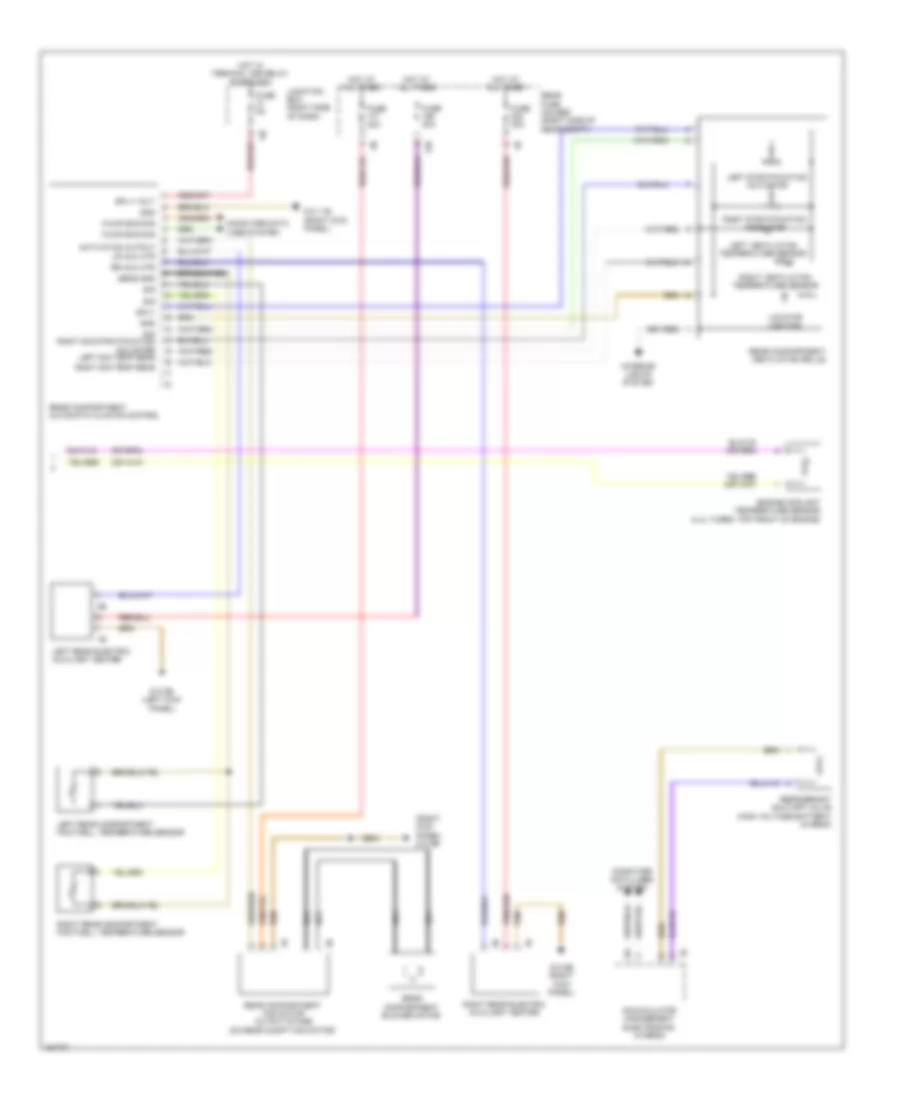
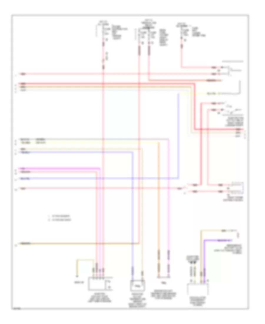
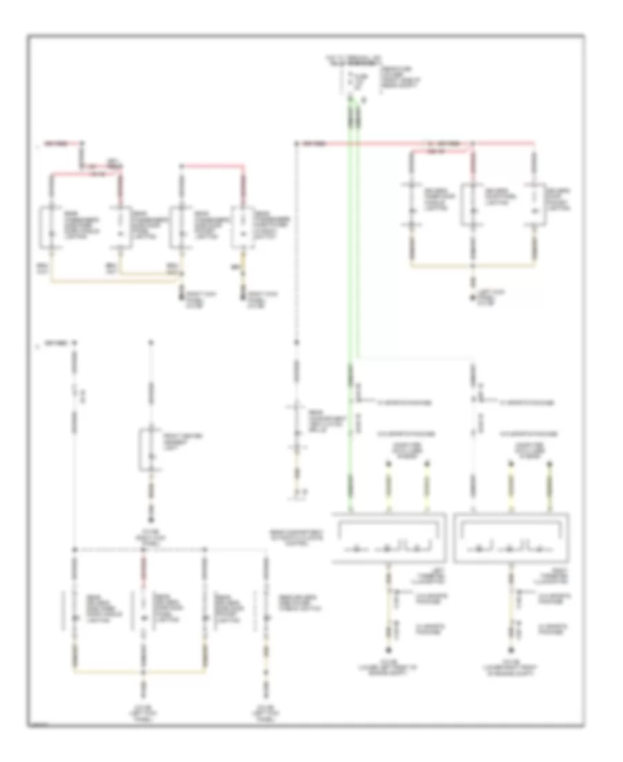
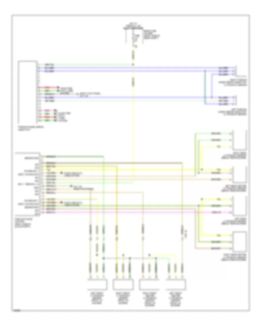
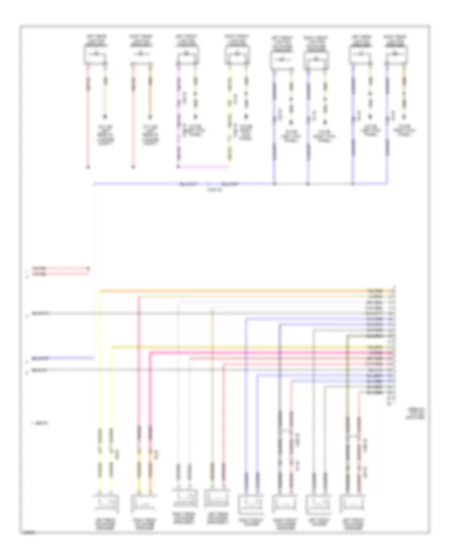
Automatic A/C Wiring Diagram, with Rear Automatic Climate Control (2 of 6) for BMW ActiveHybrid 5 2014
List of elements for Automatic A/C Wiring Diagram, with Rear Automatic Climate Control (2 of 6) for BMW ActiveHybrid 5 2014:
- (535i & 535i xdrive: rear of engine block) (550i & 550i xdrive) x6460 (535i & 535i xdrive) x6454
- (lower left front of engine compt) z10 2b
- 13b
- 535i, 535i xdrive & active hybrid 5
- 550i & 550i xdrive
- A/c compressor (electrical) (hybrid) (lower left front of engine)
- A/c compressor (except hybrid) (lower left front of engine)
- Auxiliary water pump (left front of engine compt)
- Blower motor (under right side of dash)
- Blower output stage (next to blower motor)
- Computer data lines system
- Control valve
- Defroster flap motor (top left side of dash)
- Driver side heat exchanger water valve
- Electric machine electronics
- Except m5
- Fresh air flap motor
- Front passenger's heat exchanger water valve
- Fuse 40a
- Hot at all times
- Junction box (right side of dash)
- Junction box electronics
- Left front footwell flap motor (top left side of dash)
- Left front stratification flap motor
- Left outer ventilation flap motor
- Left rear compartment footwell flap motor
- Left rear stratifying air flap motor
- Magnetic clutch
- N2 1b
- Nca
- Recirculated air flap motor
- Red
- Right front footwell flap motor (top right side of dash)
- Right front stratification flap motor
- Right outer ventilation flap motor
- Right rear compartment footwell flap motor
- Right rear stratifying air flap motor
- W/ engine independent heating element
- W/o twin clutch gear box
- Water valve assembly (left side of engine compt)
- X01001
- X13 10b
- X13 1b
- X14741
- X252 1b
- X697 1b
- Z10 2b (lower left front of engine compt)
- Z10 6b (right kick panel)
- Z6000 2b
- Z6000 5b
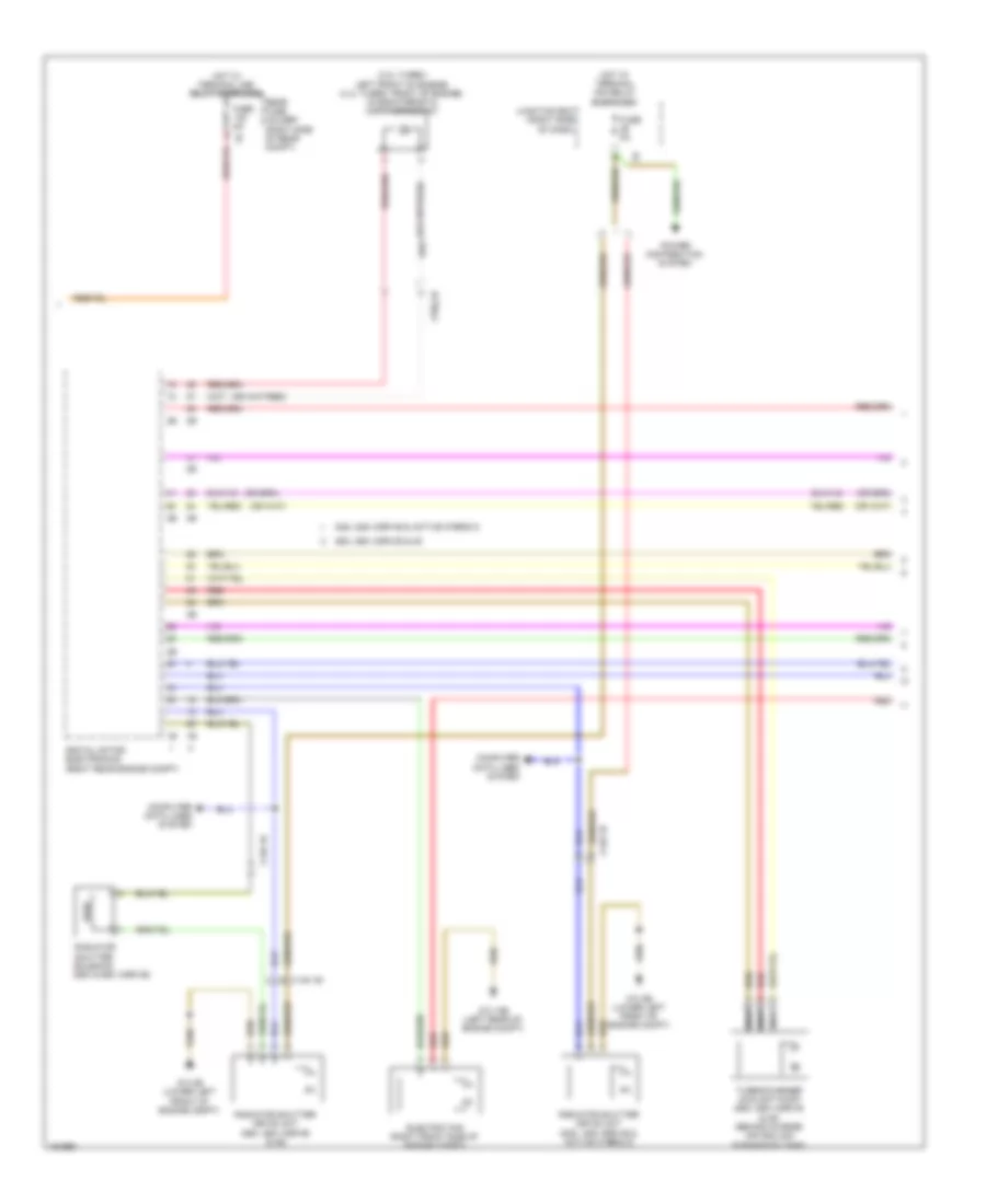
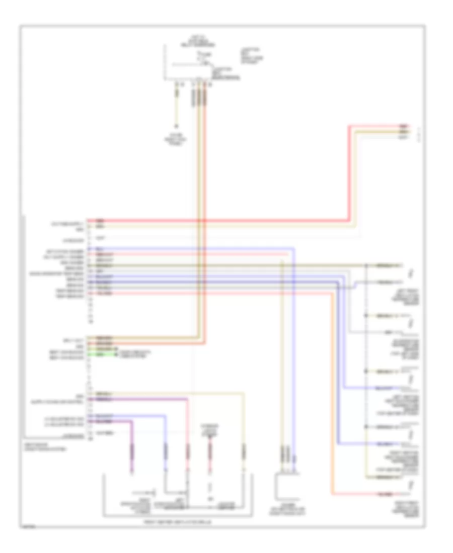
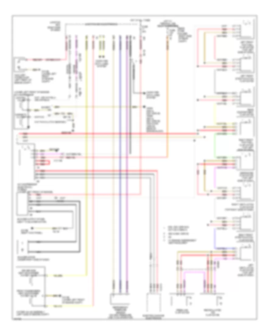
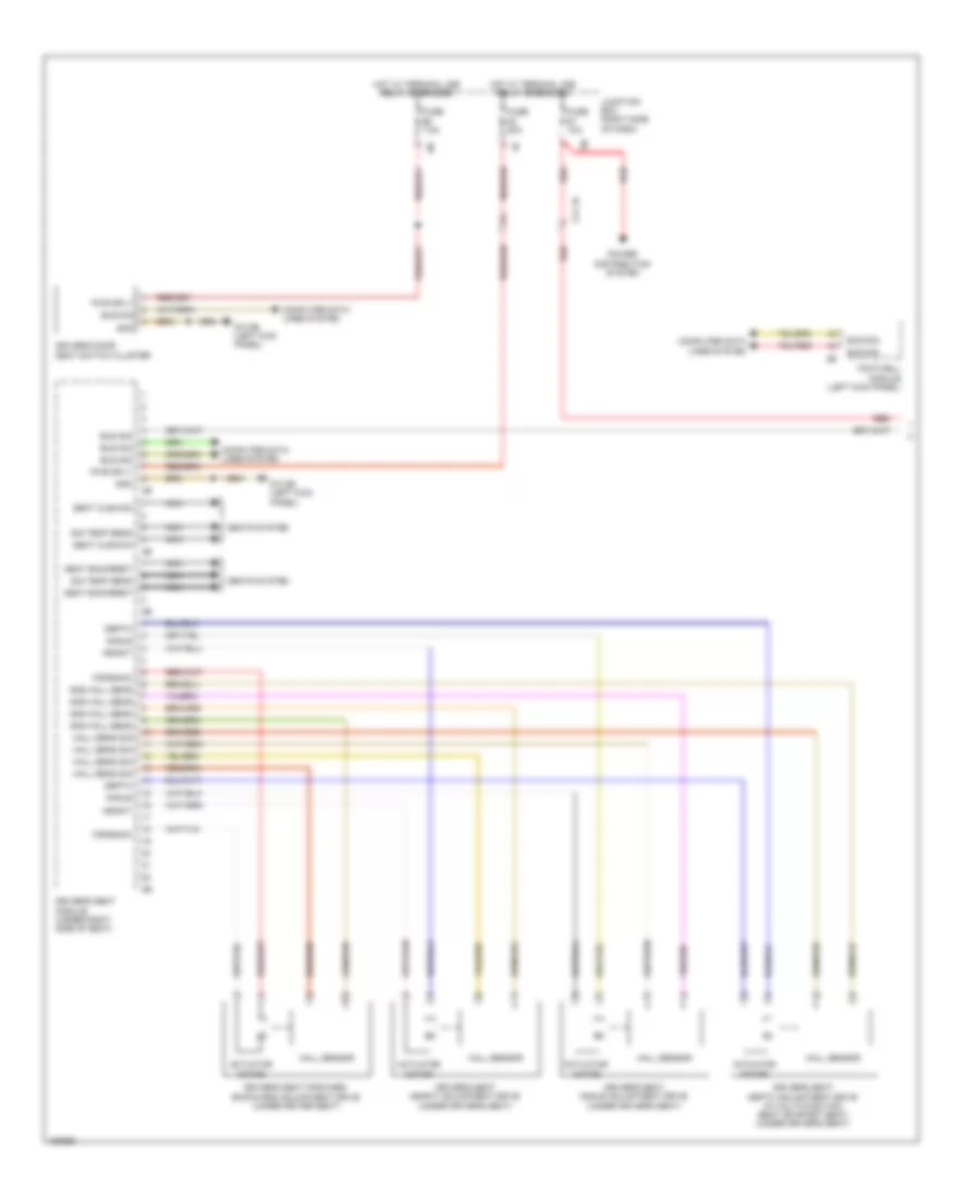
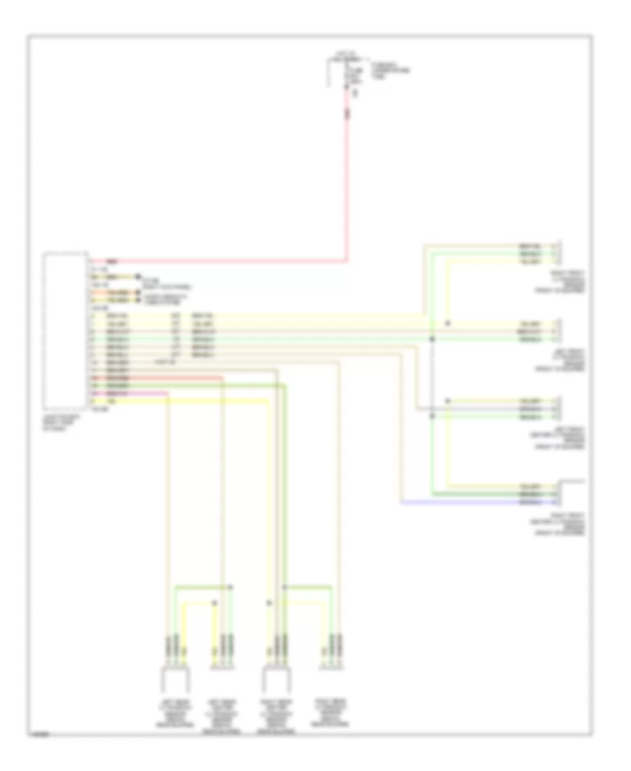
Automatic A/C Wiring Diagram, with Rear Automatic Climate Control (3 of 6) for BMW ActiveHybrid 5 2014
List of elements for Automatic A/C Wiring Diagram, with Rear Automatic Climate Control (3 of 6) for BMW ActiveHybrid 5 2014:
- (3.0l turbo: left front of engine) (4.4l turbo: front of engine) characteristic map thermostat
- 535i, 535i xdrive & active hybrid 5
- 550i, 550i xdrive & m5
- Computer data lines system
- Digital motor electronics (right rear engine compt)
- Electric fan (right front side of engine compt)
- Fuse 5a
- Hot w/ terminal 15n relay energized
- Hot w/ terminal 30b relay energized
- Junction box (right side of dash)
- Nca
- Power distribution system
- Radiator shutter drive unit (535i, 535i xdrive & active hybrid 5)
- Radiator shutter drive unit (550i, 550i xdrive & m5)
- Radiator shutter solenoid (550i & 550i xdrive)
- Rear fuse holder (right side of rear compt)
- Red
- Turbocharger coolant pump (550i, 550i xdrive & m5) (behind charge air cooling expansion tank)
- X148 1b
- X705 1b
- Z10 15b (left rear of engine compt)
- Z10 2b (lower left front of engine compt)
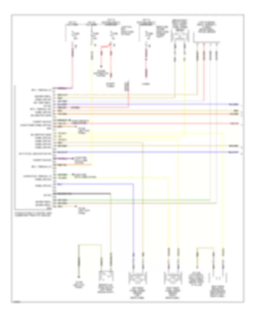
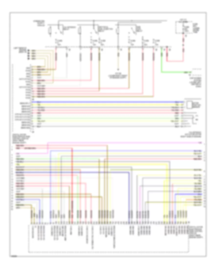
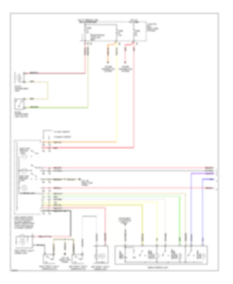
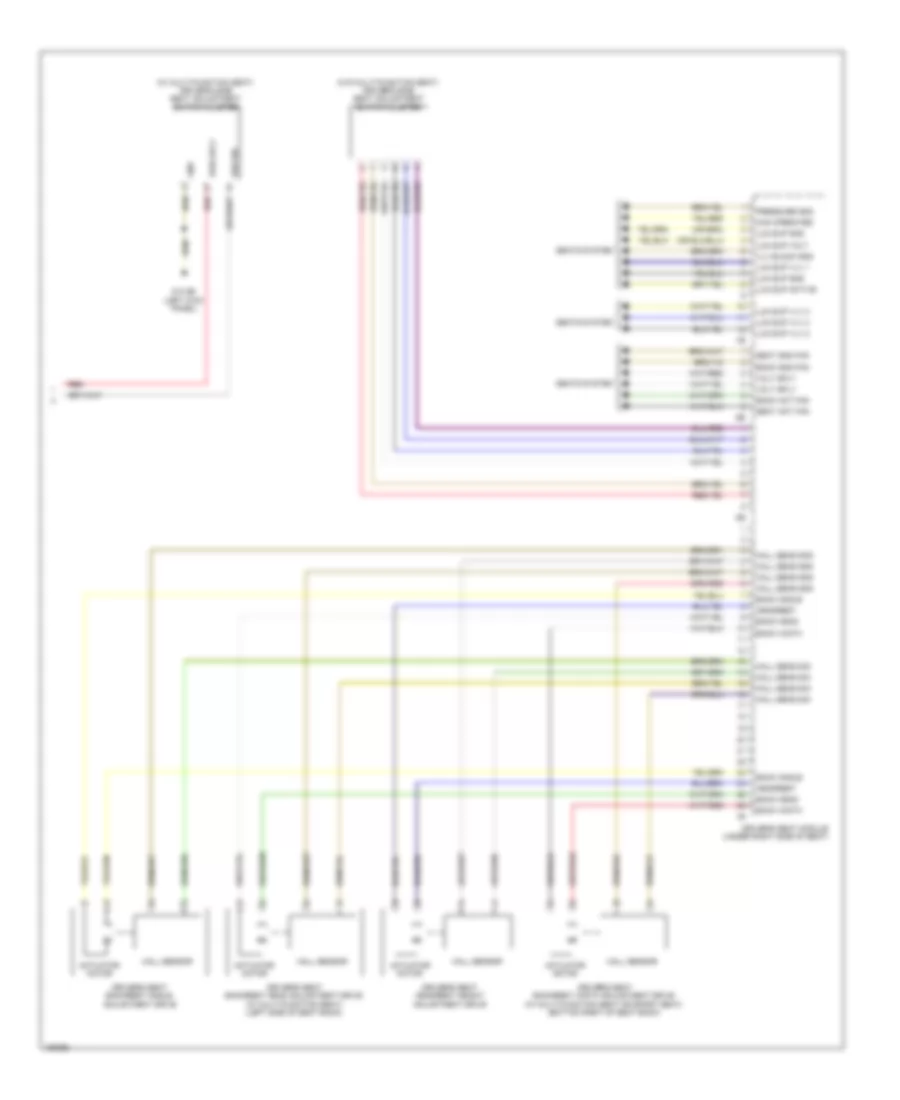
Automatic A/C Wiring Diagram, with Rear Automatic Climate Control (4 of 6) for BMW ActiveHybrid 5 2014
List of elements for Automatic A/C Wiring Diagram, with Rear Automatic Climate Control (4 of 6) for BMW ActiveHybrid 5 2014:
- 550i & 550i xdrive
- Charge air cooler coolant pump (m5)
- Charge air cooler coolant pump 2 (m5)
- Computer data lines system
- Digital motor electronics 2
- Fuse 10a
- Fuse 60a
- Hot at all times
- Intercooler coolant pump (550i & 550i xdrive)
- Junction box (right side of dash)
- Nca
- Red
- X13 1b
- X252 1b
- X697 1b
- Z10 3b (lower right front of engine compt)
- Z6000 5b
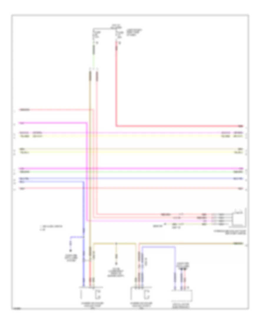
Automatic A/C Wiring Diagram, with Rear Automatic Climate Control (5 of 6) for BMW ActiveHybrid 5 2014
List of elements for Automatic A/C Wiring Diagram, with Rear Automatic Climate Control (5 of 6) for BMW ActiveHybrid 5 2014:
- Auxiliary water pump (hybrid) (left front of engine compt)
- Computer data lines system
- Electric coolant pump (535i, 535i xdrive) (left side of engine)
- Electric fan cutout relay (right side of luggage compt)
- Electric-machine electronics (hybrid)
- Front power distribution box
- Front refrigerant shutoff valve (hybrid)
- Fuse 100a
- Fuse 10a
- Fuse 15a
- Fuse 50a
- Fuse 7.5a
- Fuse box (under spare tire)
- Hot at all times
- Hot w/ terminal 30b relay energized
- Junction box (right side of dash)
- Nca
- Power distribution box (in engine compt)
- Radiator outlet temperature sensor (550i, 550i xdrive & m5) (right front of engine compt)
- Rear fuse holder (right side of rear compt)
- Red
- W/ fan 400/600w
- W/ fan 800/1000w
- X13 12b
- X671 1b
- Z10 5b (left kick panel)
- Z6000 4b
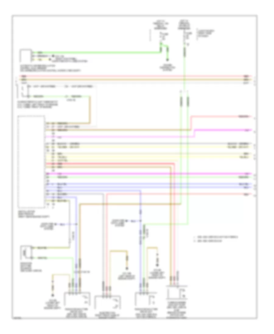
Automatic A/C Wiring Diagram, with Rear Automatic Climate Control (6 of 6) for BMW ActiveHybrid 5 2014
List of elements for Automatic A/C Wiring Diagram, with Rear Automatic Climate Control (6 of 6) for BMW ActiveHybrid 5 2014:
- (right kick panel) z10 6b
- 12b
- Accumulator management electronics (hybrid)
- Activation output
- Computer data lines system
- Engine coolant temperature sensor (4.4l turbo: top front of engine)
- Fuse 20a
- Fuse 30a
- Fuse 5a
- Gnd
- Hot at all times
- Hot w/ terminal 30b relay energized
- Interior lights system
- Junction box (right side of dash)
- K-can bus sig
- Left rear compartment footwell temperature sensor
- Left rear electric auxiliary heater
- Left sig temp sens
- Left stratification actuator
- Left ventilation temperature sensor
- Locator lighting
- Lr aux htr
- Nca
- Rear compartment automatic climate control
- Rear compartment blower motor
- Rear compartment fan motor output stage (on rear compt fan motor)
- Rear compartment ventilation grille
- Rear fuse holder (right side of rear compt)
- Refrigerant shutoff valve (high voltage battery) (hybrid)
- Right rear compartment footwell temperature sensor
- Right rear electric auxiliary heater
- Right sig temp sens
- Right stratification actuator
- Right ventilation temperature sensor
- Rr aux htr
- Sens gnd
- Sig
- Sig right sig stratification adjuster
- Sply
- Sply volt
- Z10 11b (right kick panel)
- Z10 5b (left kick panel)
- Z10 6b (right kick panel)
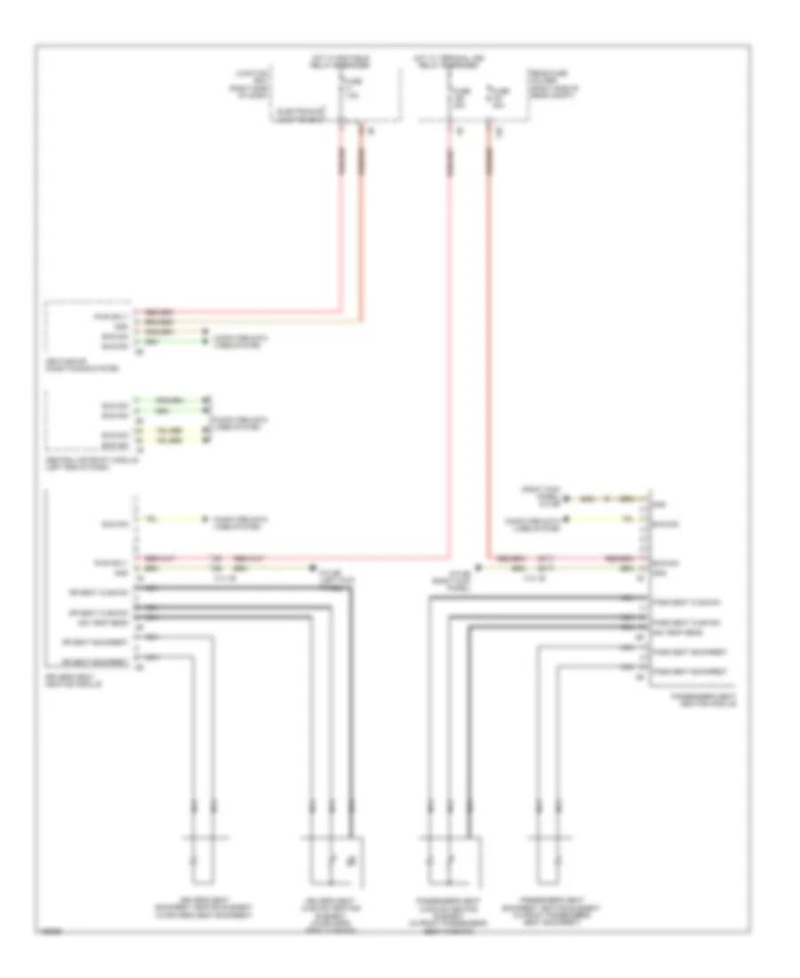
Automatic A/C Wiring Diagram, without Rear Automatic Climate Control (1 of 5) for BMW ActiveHybrid 5 2014
List of elements for Automatic A/C Wiring Diagram, without Rear Automatic Climate Control (1 of 5) for BMW ActiveHybrid 5 2014:
- Activation ioniser
- Body can bus sig
- Computer data lines system
- Evaporator temperature sensor (top left side of dash)
- Front center ventilation grille
- Fuse 7.5a
- Gnd
- Gnd ioniser
- Heating/air conditioning system
- Hot w/ bi-stable relay energized
- Interior lights system
- Ionizer (on heating & air conditioning unit)
- Junction box (right side of dash)
- Junction box electronics
- Left front ventilation temperature sensor
- Left heating heat exchanger temperature sensor (top center of dash)
- Left stratification actuator
- Lh adjuster sw sig
- Lin bus sig
- Locator lighting
- Red
- Right front ventilation temperature sensor
- Right heating heat exchanger temperature sensor (top center of dash)
- Right stratification actuator (hybrid)
- Sens gnd
- Sens sig
- Sig evaporator temp sens
- Sply volt
- Temp sens sig
- Z10 6b (right kick panel)
Automatic A/C Wiring Diagram, without Rear Automatic Climate Control (2 of 5) for BMW ActiveHybrid 5 2014
List of elements for Automatic A/C Wiring Diagram, without Rear Automatic Climate Control (2 of 5) for BMW ActiveHybrid 5 2014:
- 535i, 535i xdrive & active hybrid 5
- 550i, 550i xdrive & m5
- Automatic air recirculation control (auc) sensor (on air recirculation control microfilter compt)
- Characteristic map thermostat (3.0l turbo: left front of engine) (4.4l turbo: front of engine)
- Computer data lines system
- Digital motor electronics (right rear engine compt)
- Electric fan (right front side of engine compt)
- Fuse 5a
- Hot w/ terminal 15n relay energized
- Junction box (right side of dash)
- Power distribution system
- Radiator shutter drive unit (535i, 535i xdrive & active hybrid 5)
- Radiator shutter drive unit (550i, 550i xdrive 535i & 535i xdrive)
- Radiator shutter solenoid (550i & 550i xdrive)
- Red
- Turbocharger coolant pump (550i, 550i xdrive & m5) (behind charge air cooling expansion tank)
- X148 1b
- X705 1b
- Z10 11b (right kick panel)
- Z10 15b (left rear of engine compt)
- Z10 2b (lower left front of engine compt)
Automatic A/C Wiring Diagram, without Rear Automatic Climate Control (3 of 5) for BMW ActiveHybrid 5 2014
List of elements for Automatic A/C Wiring Diagram, without Rear Automatic Climate Control (3 of 5) for BMW ActiveHybrid 5 2014:
- 550i & 550i xdrive
- Auxiliary water pump (hybrid) (left front of engine compt)
- Computer data lines system
- Coolant pump 2 charge air cooler (m5)
- Coolant pump charge air cooler (m5)
- Digital motor electronics 2
- Electric-machine electronics (hybrid)
- Front refrigerant shutoff valve (hybrid)
- Fuse 10a
- Fuse 60a
- Hot at all times
- Hot w/ terminal 30b relay energized
- Intercooler coolant pump
- Junction box (right side of dash)
- Nca
- Rear fuse holder (right side of rear compt)
- Red
- X13 12b
- X13 1b
- X252 1b
- X697 1b
- Z10 3b (lower right front of engine compt)
- Z10 5b (left kick panel)
- Z6000 5b
Automatic A/C Wiring Diagram, without Rear Automatic Climate Control (4 of 5) for BMW ActiveHybrid 5 2014
List of elements for Automatic A/C Wiring Diagram, without Rear Automatic Climate Control (4 of 5) for BMW ActiveHybrid 5 2014:
- Accumulator management electronics (hybrid)
- Computer data lines system
- Electric coolant pump (535i, 535i xdrive) (left side of engine)
- Electric fan cut out relay (right side of luggage compt)
- Engine coolant temperature sensor (550i, 550i xdrive & m5) (top of engine)
- Front power distribution box
- Fuse 100a
- Fuse 15a
- Fuse 50a
- Fuse 7.5a
- Fuse box (under spare tire)
- Hot at all times
- Hot w/ terminal 30b relay energized
- Power distribution box (in engine compt)
- Radiator outlet temperature sensor (right front of engine compt)
- Rear fuse holder (right side of rear compt)
- Red
- Refrigerant shutoff valve (high voltage battery) (hybrid)
- W/ fan 400/600w
- W/ fan 800/1000w
- X671 1b
- Z6000 4b
Automatic A/C Wiring Diagram, without Rear Automatic Climate Control (5 of 5) for BMW ActiveHybrid 5 2014
List of elements for Automatic A/C Wiring Diagram, without Rear Automatic Climate Control (5 of 5) for BMW ActiveHybrid 5 2014:
- (lower left front of engine) a/c compressor
- 13b
- 535i, 535i xdrive & active hybrid 5
- 550i & 550i xdrive
- 697 1b
- A/c compressor (electrical) (hybrid) (lower left front of engine)
- Auxiliary water pump (left front of engine compt)
- Blower motor (under right side of dash)
- Blower output stage (next to blower motor)
- Computer data lines system
- Control valve
- Defroster flap motor (top left side of dash)
- Driver side heat exchanger water valve
- Electric machine electronics
- Except m5
- Fresh air flap motor
- Front passenger's heat exchanger water valve
- Fuse 40a
- Fuse 5a
- Hot at all times
- Hot w/ terminal 30b relay energized
- Junction box (right side of dash)
- Junction box electronics
- Left front footwell flap motor (top left side of dash)
- Left front stratification flap motor
- Left ventilation flap motor (top left side of dash)
- Magnetic clutch
- N2 1b
- Nca
- Rear compartment flap motor
- Rear fuse holder (right side of rear compt)
- Recirculated air flap motor
- Red
- Refrigerant pressure sensor (on high pressure line to evaporator)
- Right front footwell flap motor (top left side of dash)
- Right front stratification flap motor
- Right ventilation flap motor (top right side of dash)
- W/ engine independent heating elment
- W/o twin clutch gear box
- Water valve assembly (left side of engine compt)
- X01001
- X13 10b
- X13 1b
- X14741
- X6454 (535i & 535i xdrive) x6460 (550i & 550i xdrive) (535i & 535i xdrive: rear of engine block)
- X697 1b
- Z10 2b (lower left front of engine compt)
- Z10 6b (right kick panel)
- Z6000 2b
- Z6000 5b
Independent Heating Wiring Diagram for BMW ActiveHybrid 5 2014
List of elements for Independent Heating Wiring Diagram for BMW ActiveHybrid 5 2014:
- E85 2b
- Electronics junction box
- Fuse 20a
- Hot w/ terminal 30b relay energized
- Independent auxiliary heater (behind left front wheel)
- Independent heater circulation pump (behind left front wheel)
- Independent heater combustion air blower (behind left front wheel)
- Independent heater plug (behind left front wheel)
- Independent heating cooling changeover valve (behind left front wheel)
- Independent heating fuel metering pump (behind left front wheel housing)
- Junction box (right side of dash)
- Nca
- X218 1b
- X218 2b
- Z10 14b (sedan: left "c" pillar) (hatchback: left side of cargo area)
- Z10 2b (lower left front of engine compt)
ANTI-LOCK BRAKES
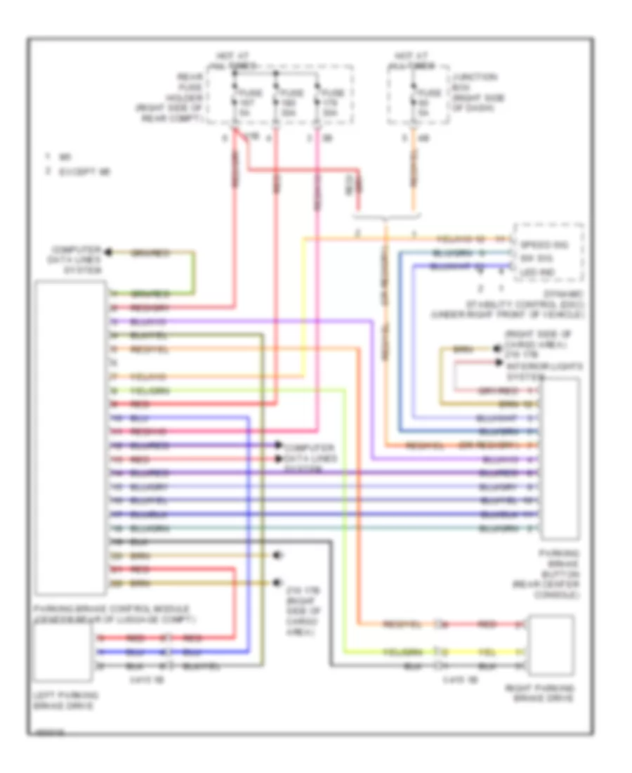
Anti-lock Brakes Wiring Diagram (1 of 2) for BMW ActiveHybrid 5 2014
List of elements for Anti-lock Brakes Wiring Diagram (1 of 2) for BMW ActiveHybrid 5 2014:
- (behind right front wheel) right front wheel speed sensor
- (or red)
- (top of brake pedal assembly) (hybrid) brake pedal travel sensor
- 13b
- Activation, led function ind
- Brake fluid level switch (left rear engine compt)
- Computer data lines system
- Conditioned wheel spd sig
- Dynamic stability control (dsc) (under right front of vehicle)
- Except hybrid
- Flexray bus sig
- Fuse 30a
- Fuse 50a
- Fuse 5a
- Gnd
- Gnd brk pedal
- Hot at all times
- Hot w/ bi-stable relay energized
- Hybrid
- Junction box (right side of dash)
- Left rear wheel speed sensor (left rear wheel)
- Nca
- Power distribution system
- Rear fuse holder (right side of rear compt)
- Red
- Right rear brake pad wear sensor (behind right rear wheel)
- Right rear wheel speed sensor (right rear wheel)
- Sig brk pedal
- Sig, brk pad wear
- Sply brk pedal
- Sply, terminal 30
- Sply, terminal 30f
- Sw sig
- Wake-up sig, terminal 15
- Wheel spd sig
- Z10 13b (hatchback: right side of cargo area) (sedan: right "c" pillar)
- Z10 4b (left kick panel)
- Z10 9b (left kick panel)
Anti-lock Brakes Wiring Diagram (2 of 2) for BMW ActiveHybrid 5 2014
List of elements for Anti-lock Brakes Wiring Diagram (2 of 2) for BMW ActiveHybrid 5 2014:
- (behind left front wheel) left front brake pad wear sensor
- (center rear of luggage compt) parking brake control module
- (left front wheel) left front wheel speed sensor
- (rear center console) parking brake button
- Brake light switch (left side of dash)
- Car access system (lower left center of dash)
- Computer data lines system
- Except gt
- Footwell module (left kick panel)
- Nca
- Pnk
- Steering column switch cluster
- Z10 2b (lower left front of engine compt)
- Z10 9b (left kick panel)
ANTI-THEFT
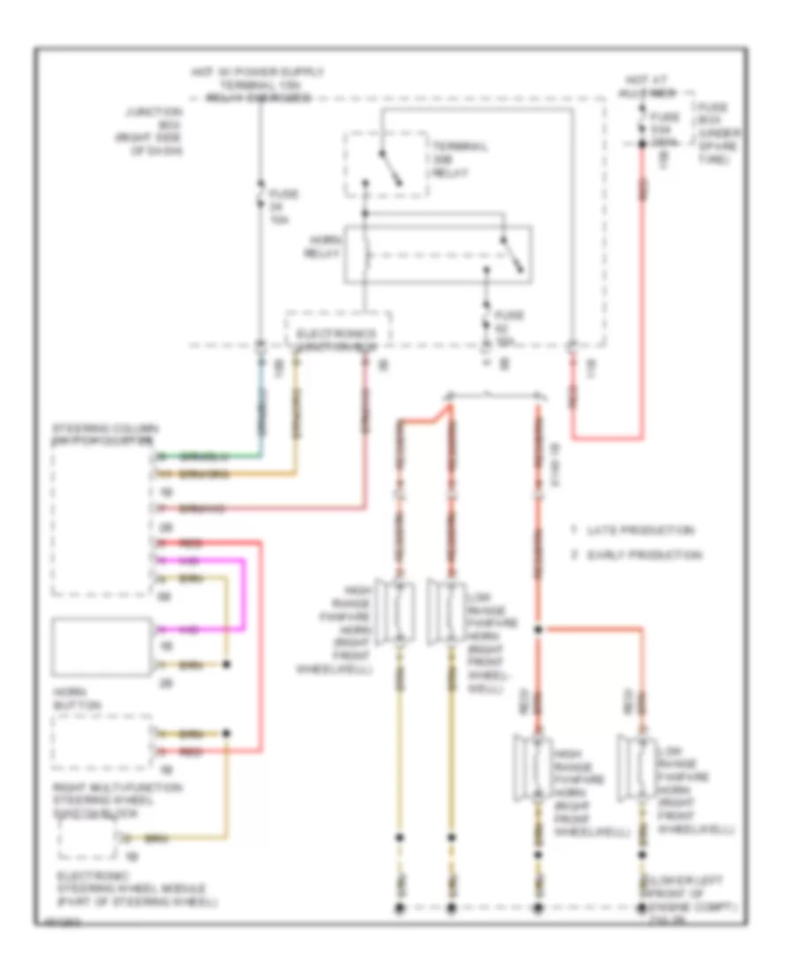
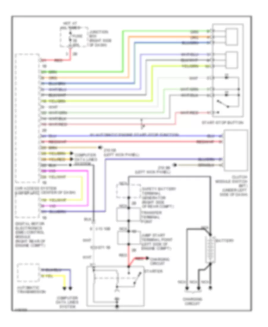
Access/Start Wiring Diagram (1 of 2) for BMW ActiveHybrid 5 2014
List of elements for Access/Start Wiring Diagram (1 of 2) for BMW ActiveHybrid 5 2014:
- (left kick panel) z10 9b
- (right side of dash) crash safety module
- 15n rly act
- 2.ol turbo
- 3.0l turbo & 3.0l turbo hybrid
- 3.ol turbo diesel
- 4.4l turbo
- Active starter
- Aerial sig
- Bonnet contact switch
- Brake light switch (left side of dash)
- Brk lt sw sig
- Bumper aerial
- Car access system (lower left center of dash)
- Cas bus
- Clutch module (m/t)
- Computer data lines system
- Digital motor electronics control module (except 3.0l turbo diesel) digital diesel electronics (3.0l turbo diesel) (2.0l turbo: top rear of engine) (3.0l turbo, 4.4l turbo & 3.0l turbo hybrid: right rear engine compt)
- Digital motor electronics control module 2 (4.4l turbo)
- Door locks system
- Electronics junction box
- Eng strt sig
- Exterior lights system
- Footwell module (left kick panel)
- Front center console interior aerial (center of dash)
- Fuse 40a
- Fuse 5a
- Ground
- Hot at all times
- Hot w/ bistable relay energized
- Junction box (right side of dash)
- K can 2-h
- K can 2-l
- Lin bus sig
- Luggage compartment aerial
- Luggage compartment aerial 2
- Power distribution system
- Rear center console interior aerial (rear of center console)
- Rear fuse holder (right side of rear compt)
- Rear window shelf interior aerial
- Red
- Rmte ctrl sig
- Sig
- Starting/charging system
- Sw sig
- Term 15 sig
- Term 15 sply
- Term 15n rly
- Term 30 sply
- Term 30b
- Term 30b sply
- Terminal 15n relay
- Terminal 30b relay
- Wake up sig
- X149 1b
- Z10 2b (lower left front of engine compt)
- Z10 5b (left kick panel)
- Z10 6b (right kick panel)
- Z10 8b (right side of cargo area)
- Z10 9b (left kick panel)
Access/Start Wiring Diagram (2 of 2) for BMW ActiveHybrid 5 2014
List of elements for Access/Start Wiring Diagram (2 of 2) for BMW ActiveHybrid 5 2014:
- (bottom center of steering column) (m/t) electric steering lock
- Aerial sig
- Can sub bus
- Car access system (lower left center of dash)
- Computer data lines system
- Door locks system computer data lines system
- Driver electronic outer door handle module
- Driver's side external aerial
- Front passenger's side external aerial
- Gnd
- Ground
- Hall sens sig
- Led act
- Led activation
- Passenger electronic outer door handle module
- Rear driver's side outer door handle electronic module
- Rear passenger's side outer door handle electronic module
- Red
- Ring aerial
- Sig
- Start-stop button
- Strg lck activ
- Strg lck gnd
- Strg lck sply
- Sw sig
- Term 15n rly
- Term 30b rly
- Trunk, tailgate, fuel doors system
- W/ automatic engine start stop function
- Wake up sig
- X28 1b
- X5 1b
- X8 1b
- X9 1b
- Z10 5b (left kick panel)
- Z10 6b (right kick panel)
Anti-theft & Central Locking Wiring Diagram (1 of 2) for BMW ActiveHybrid 5 2014
List of elements for Anti-theft & Central Locking Wiring Diagram (1 of 2) for BMW ActiveHybrid 5 2014:
- (right rear wheelwell) siren w/ tilt alarm sensor
- (right side of rear compt) central locking drive fuel filler flap
- Aerial diversity
- Anti-theft alarm system
- Boot lid/ tailgate lock
- Car access system (lower left center of dash)
- Central locking button hazard warning switch operating facility
- Computer data lines system
- Driver's door automatic soft-close drive
- Driver's door system lock (rear of driver's door)
- Electrochromic interior rearview mirror
- Electronics junction box
- Exterior boot lid button
- Footwell module (left kick panel)
- Fuse 15a
- Fuse 20a
- Hot at all times
- Hotel position switch
- Interior lights system
- Interior rear lid button
- Junction box (right side of dash)
- Nca
- Rear lid button
- Roof function center
- Trunk, tailgate, fuel doors system
- W/ automatic soft close system
- W/o automatic soft close system
- X188 1b
- X28 1b
- X5 1b
- X8 1b
- X9 1b
- Z10 11b (right kick panel)
- Z10 17b (right side of cargo area)
- Z10 5b (left kick panel)
Anti-theft & Central Locking Wiring Diagram (2 of 2) for BMW ActiveHybrid 5 2014
List of elements for Anti-theft & Central Locking Wiring Diagram (2 of 2) for BMW ActiveHybrid 5 2014:
- (left kick panel) z10 5b
- (right kick panel) z10 6b
- 11b
- Driver's side rear automatic soft-close drive
- Fuse 10a
- Fuse 5a
- Hot at all times
- Hot w/ terminal 30b relay energized
- Nca
- Passenger's door automatic soft-close drive
- Passenger's door system lock (rear of front passenger's door)
- Passenger's side rear automatic soft-close drive
- Power distribution system
- Rear driver's side door lock
- Rear fuse holder (right side of rear compt)
- Rear passenger's side door lock
- X28 1b
- X5 1b
- X8 1b
- X9 1b
- Z10 5b (left kick panel)
- Z10 6b (right kick panel)
BODY CONTROL MODULES
Body Control Modules Wiring Diagram (1 of 2) for BMW ActiveHybrid 5 2014
List of elements for Body Control Modules Wiring Diagram (1 of 2) for BMW ActiveHybrid 5 2014:
- Ambient lt
- Bi-xenon
- Brk lt act
- Computer data lines system
- Door locks, exterior lights & anti- theft systems
- Drv mod sply
- Exterior lights system
- Flash ind lt
- Fog lts act
- Foot lt act
- Footwell module (left kick panel)
- Fuse 40a
- Ground
- Haz sw sig
- Headlights & exterior
- Headlights & exterior lights systems
- Headlights system
- Headlights, exterior
- Hi beam hdlp act
- Hot w/ bi-stable relay energized
- Int lt act
- Interior lights system
- Junction box (right side of dash)
- K-can bus
- Led act
- Lights & interior lights systems
- Lights systems
- Lin bus sig
- Lo beam lt act
- Navigation system
- Pwr sply
- Rear fog lt
- Rev lt act
- Tail lt act
- Term 30f sply
- Turn sig/hi beam sw
- Z1 3b
- Z10 22b (left kick panel)
Body Control Modules Wiring Diagram (2 of 2) for BMW ActiveHybrid 5 2014
List of elements for Body Control Modules Wiring Diagram (2 of 2) for BMW ActiveHybrid 5 2014:
- (left kick panel) z10 5b
- Ambient lt
- Anti-theft system
- Brake lt act
- Brk lt act
- Brk sw sig
- Cons load sig
- Courtesy lt act
- Door locks system
- Dr contact sig
- Entrance lt act
- Exterior lights system
- Flash ind lt act
- Flash lt act
- Fog lt act
- Footwell module (left kick panel)
- Fuse 10a
- Fuse 30a
- Fuse 40a
- Ground
- Hall sens ground
- Hall sens sig
- Headlights & exterior lights systems
- Headlights system
- Hi beam lt act
- Hot w/ bi-stable relay energized
- Int lt sw sig
- Interior lights system
- Junction box (right side of dash)
- License plate lt act
- Low beam lt sig
- Memory systems
- Power windows system
- Pw drive act
- Rear fuse holder (right side of rear compt)
- Red
- Reversing lt act
- Right fog lt act
- Str clmn adj act
- Sw sig
- Tail lt act
- Term 15 sply
- Term 30f pwr sply
- Term 30f sply
- Z1 3b
- Z1 5b
- Z10 22b (left kick panel)
COMPUTER DATA LINES
Computer Data Lines Wiring Diagram (1 of 6) for BMW ActiveHybrid 5 2014
List of elements for Computer Data Lines Wiring Diagram (1 of 6) for BMW ActiveHybrid 5 2014:
- (m5) digital motor electronics 2
- (right footwell, under carpet) active steering module
- (right kick panel) vertical dynamics management
- (under center of luggage compt floor) regulated differential lock
- 535xi & 535xi gt
- 550xi & 550xi gt
- All-round vision camera (left rear of luggage compt)
- Awd
- Bus sig
- Can3 h
- Can3 l
- Central gateway module (left end of dash)
- Central information display
- Diagnosis bus signal
- Ethernet data signal
- Flexray bus signal
- Ground
- Head unit
- Head-up display
- Heating/air conditioning system
- Hifi amplifier (left side of rear compt)
- K-can bus signal
- Left front damper satellite
- Left rear damper satellite
- Most bus signal
- Nca
- Pnk
- Pnk/red
- Pt-can bus signal
- Rear axle king pin inclination control actuator (on rear axle assembly)
- Red
- Right front damper satellite
- Right rear damper satellite
- Sound systems
- Terminal 15
- Terminal 30f
- Video switch
- W/ active steering
- X13 10b
- X13 2b
- Z10 22b (left kick panel)
Computer Data Lines Wiring Diagram (2 of 6) for BMW ActiveHybrid 5 2014
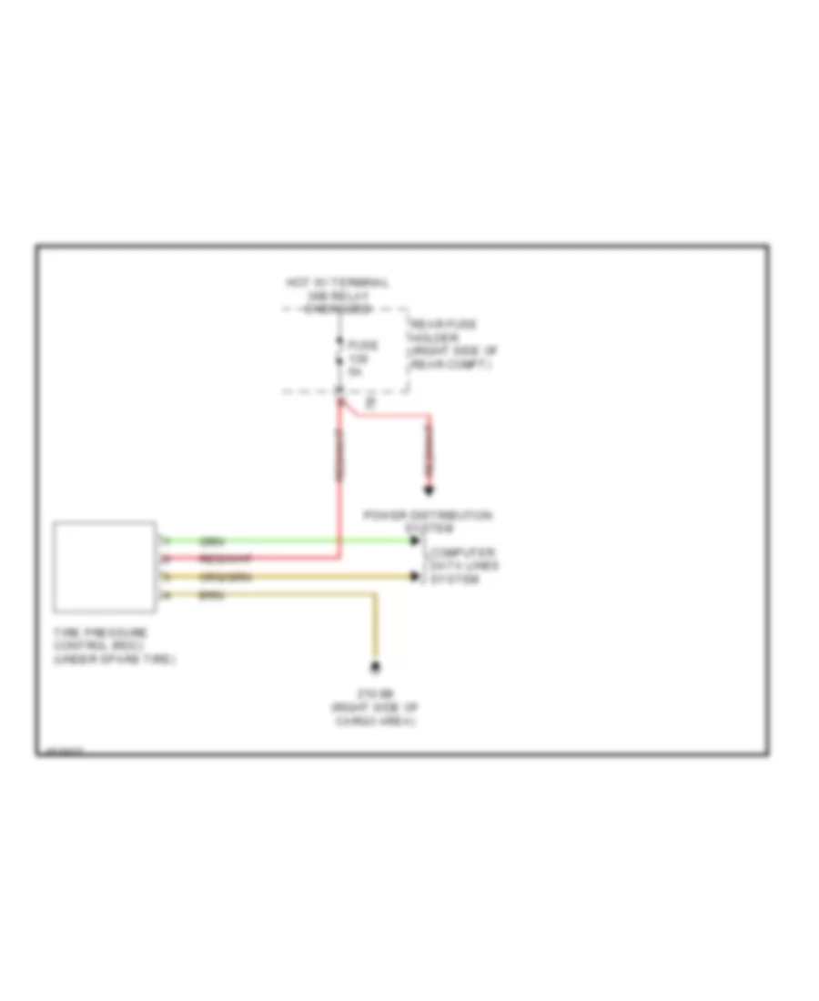
List of elements for Computer Data Lines Wiring Diagram (2 of 6) for BMW ActiveHybrid 5 2014:
- (behind right side of rear bumper) lane change warning
- (bottom rear of transmission) transfer box
- (on steering rack assembly) (if equipped) electromechanical power steering
- (under right front of vehicle) dynamic stability control (dsc)
- Diagnosis socket
- Except m5
- Fuse 5a
- Hot w/ bi-stable relay energized
- Instrument cluster control unit
- Junction box (right side of dash)
- Left headlight
- Left targeted illumination
- Maneuvering assistant
- Pnk
- Pnk/red
- Red
- Right headlight
- Right targeted illumination
- Steering column switch cluster
- Vehicle sound generator (right front of engine compt)
- W/ lane change warning
- W/ parking
- W/o parking
- X148 1b
- X149 1b
- Z1 5b
- Z10 22b (left kick panel)
- Z10 5b (left kick panel)
Computer Data Lines Wiring Diagram (3 of 6) for BMW ActiveHybrid 5 2014
List of elements for Computer Data Lines Wiring Diagram (3 of 6) for BMW ActiveHybrid 5 2014:
- Boot lid lift
- Car access system (lower left center of dash)
- Combox
- Controller
- Diagnosis socket terminating resistor
- Driver's door seat switch cluster
- Driver's door switch block
- Driver's seat module (under right side of seat)
- Electronic ride-height control
- Footwell module (left kick panel)
- Light switch unit
- Passenger's seat module (under passenger's seat)
- Pnk
- Pnk/red
- Rear compartment air conditioning system
- Rear compartment automatic climate control
- Rear compartment display
- Rear compartment display 2
- Red
- Right exterior mirror
- Telematic communication box
- Tire pressure control (under spare tire)
- Touchbox
- Trailer module (under spare tire)
- X12 1b
- X14 1b
- X188 1b
- X25 1b
- X28 1b
- X5 1b
Computer Data Lines Wiring Diagram (4 of 6) for BMW ActiveHybrid 5 2014
List of elements for Computer Data Lines Wiring Diagram (4 of 6) for BMW ActiveHybrid 5 2014:
- (rain/lights sensor: front center of roof) (solar sensor: top center of dash) rain/lights/ condensation/ solar sensor
- (right front of engine compt) (hybrid) air conditioning compressor (electrical)
- (right side of dash) junction box
- A34 1b
- A34 2b
- A34 3b
- Blower output stage (next to blower motor)
- Camera based driver assistance systems (left end of dash)
- Crash safety module (right side of dash)
- Electrochromic interior rearview mirror
- Electronics junction box
- Left front footwell flap motor (top left side of dash)
- Left reversible electromotive electrically motorized reel
- Night vision electronic module (under right side of dash)
- Pnk
- Pnk/red
- Rear compartment controller
- Rear driver's side door seat switch cluster
- Rear driver's side power window switch
- Rear driver's side seat module
- Rear passenger's side seat module
- Red
- Sedan
- W/ high variant roof function module
- Wiper module
- X01001
- X13 10b
- X167 1b
- X188 1b
- X8 1b
Computer Data Lines Wiring Diagram (5 of 6) for BMW ActiveHybrid 5 2014
List of elements for Computer Data Lines Wiring Diagram (5 of 6) for BMW ActiveHybrid 5 2014:
- (center rear of luggage compt) parking brake control unit
- (if equipped) high variant roof function module
- (on air recirculation control microfilter compt) automatic air recirculation control (auc) sensor
- (under center rear of luggage compt floor) scr control unit
- (under vehicle, near right front wheel) servotronic
- 4.4l except gt & 3.0l gt
- 4.4l gt & 3.0l except gt
- Driver's seat heating module
- Except gt
- Fuel pump control (ekps) (left rear of luggage compt)
- Gear selector switch
- Management electronics accumulator (hybrid)
- Parking assistant (on rear panel of spare wheel well)
- Passenger's seat heating module
- Pnk
- Pnk/red
- Rear driver's side seat heating module
- Rear driver's side seat heating switch
- Rear passenger's side seat heating module
- Rear passenger's side seat heating switch
- Red
- Regular rear axle differential lock (m5)
- W/ lane change warning
- W/o lane change warning
- W/o rear compartment automatic climate control
- W/o seat module
- X12 1b
- X14 1b
Computer Data Lines Wiring Diagram (6 of 6) for BMW ActiveHybrid 5 2014
List of elements for Computer Data Lines Wiring Diagram (6 of 6) for BMW ActiveHybrid 5 2014:
- (bottom rear of transmission) transfer box
- (hybrid) charging interface module
- (right front side of bumper) active cruise control
- (under center console) integrated chassis management
- 2.0l turbo
- 3.0l turbo
- 3.0l turbo diesel
- 4.4l turbo except gt
- 4.4l turbo gt & 3.0l turbo
- A/t
- Auxiliary battery charging controller (right side of luggage compt)
- Digital motor electronics (dme) control module (except 3.0l turbo diesel) digital diesel electronics (3.0l turbo diesel) (3.0l turbo, 4.4l turbo & 3.0l turbo hybrid: right rear engine compt) (2.0l turbo: top rear of engine)
- Digital motor electronics 2 (m5)
- Double clutch transmission (m5)
- Electronic machine electronics (hybrid)
- Electronic transmission control (right rear of transmission)
- Except gt 4.4l
- Except m5 4.4l turbo
- Gt 4.4l & 3.0l
- Intelligent battery sensor (below right side luggage compt)
- M5 4.4l turbo & 2.0l turbo
- Nca
- Pnk
- Pnk/red
- Pressurized full tank control module
- Radiator shutter drive unit
- Red
- Right reversible electromotive electrically motorized reel
- Starter/alternator electronics (hybrid)
- Terminating resistor
- Terminating resistor 2
- W/ twin clutch gearbox
- W/o twin clutch gearbox
- X13 10b
- X13 11b
- X13 3b
- X148 1b
- Z10 2b (lower left front of engine compt)
- Z10 6b (right kick panel)
COOLING FAN
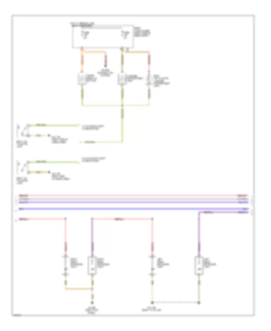
Cooling Fan Wiring Diagram for BMW ActiveHybrid 5 2014
List of elements for Cooling Fan Wiring Diagram for BMW ActiveHybrid 5 2014:
- (hybrid) front refrigerant shut-off valve
- (left side of engine) electric coolant pump
- (right front of battery compt) electric fan cutoff relay
- Accumulator management electronics (hybrid)
- Activation
- Auxiliary water pump (hybrid) (left front of engine compt)
- Bsd bus sig
- Characteristic map thermostat (left front of engine)
- Computer data lines system
- Coolant pmp sply
- Digital motor electronics (dme) control module (right rear engine compt)
- Ect sens gnd
- Electric fan (right front side of engine compt)
- Electric fan cutoff relay (right front of battery compt)
- Electric-machine electronics (hybrid)
- Engine coolant temperature sensor
- Fan activation
- Front power distribution box
- Fuse 100a
- Fuse 10a
- Fuse 50a
- Fuse 5a
- Fuse 60a
- Fuse 7.5a
- Fuse box (under spare tire)
- Hot at all times
- Hot w/ terminal 15n relay energized
- Hot w/ terminal 30b relay energized
- Junction box (right side of dash)
- Lin bus sig
- Nca
- Power distribution system
- Radiator shutter drive unit
- Rear fuse holder (right side of rear compt)
- Red
- Refrigerant shutoff valve (high voltage battery) (hybrid)
- Sens gnd
- Sply
- W/ fan 400/600w
- W/ fan 800/1000w
- X13 12b
- X148 1b
- X671 1b
- X705 1b
- Z10 15b (left rear of engine compt)
- Z10 2b (lower left front of engine compt)
- Z10 5b (left kick panel)
- Z6000 4b
CRUISE CONTROL
Cruise Control Wiring Diagram for BMW ActiveHybrid 5 2014
List of elements for Cruise Control Wiring Diagram for BMW ActiveHybrid 5 2014:
- (left side of dash) brake light switch
- 528i, 528i xdrive, m5
- 535i, 535i xdrive, 535i gt, 535i gt xdrive & active hybrid 5
- Accelerator pedal module (part of acceleration pedal assembly)
- Active cruise control (right front side of bumper)
- Active hybrid 5
- Car access system (lower left center of dash)
- Central gateway module (left end of dash)
- Clutch module (m/t) (under left side of dash)
- Computer data lines system
- Digital motor electronics (dme) control module (except 4cyl: right rear engine compt) (4 cyl: top rear of engine)
- Dynamic stability control (dsc) (under right front of vehicle)
- Electromotive throttle valve (front of engine)
- Except active hybrid 5
- Flexray bus sig
- Footwell module (left kick panel)
- Fuse 15a (0r 10a)
- Fuse 5a
- Gear selector switch
- Gnd
- Hall sensor gnd
- Hall sensor sig
- Hall sensor sply
- Hot w/ terminal 15n relay energized
- Hot w/ terminal 30b relay energized
- Integrated chassis management (under center console)
- Junction box (right side of dash)
- Pnk
- Power distribution system
- Pt-can bus sig
- Red
- S-can bus sig
- Sig
- Steering column switch cluster
- Terminal 30, sply
- Throttle vlv activ
- Throttle vlv gnd
- Throttle vlv sig
- Throttle vlv sply
- X148 1b
- Z10 2b (lower left front of engine compt)
- Z10 9b (left kick panel)
- Z6000 1b (3.0l turbo) z6000 4b (2.0l turbo) (3.0l turbo: left rear of engine)
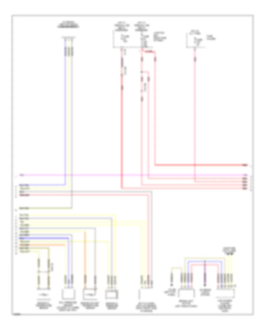
DEFOGGERS
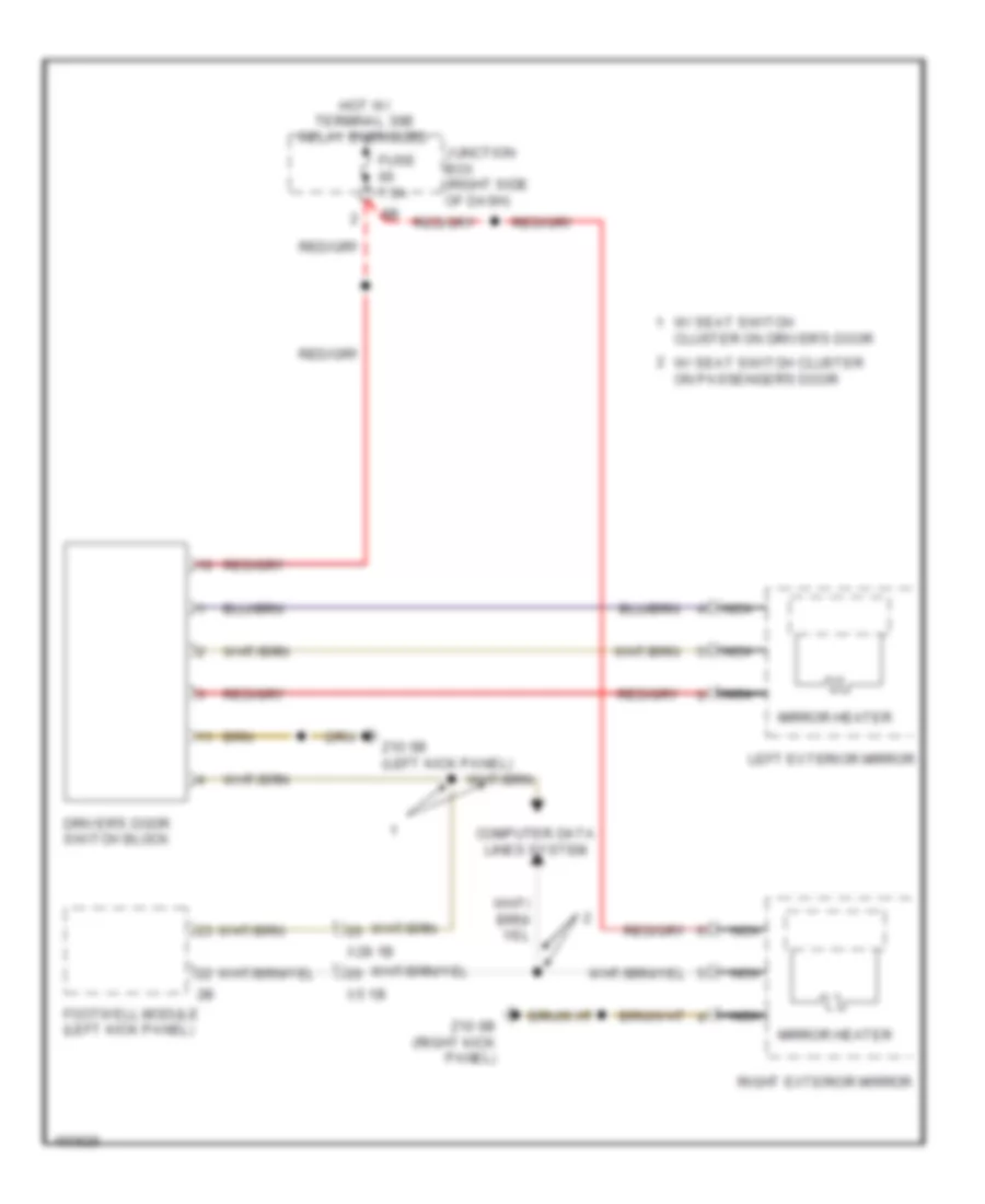
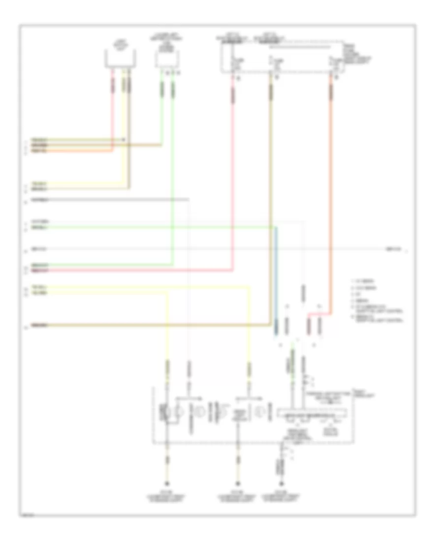
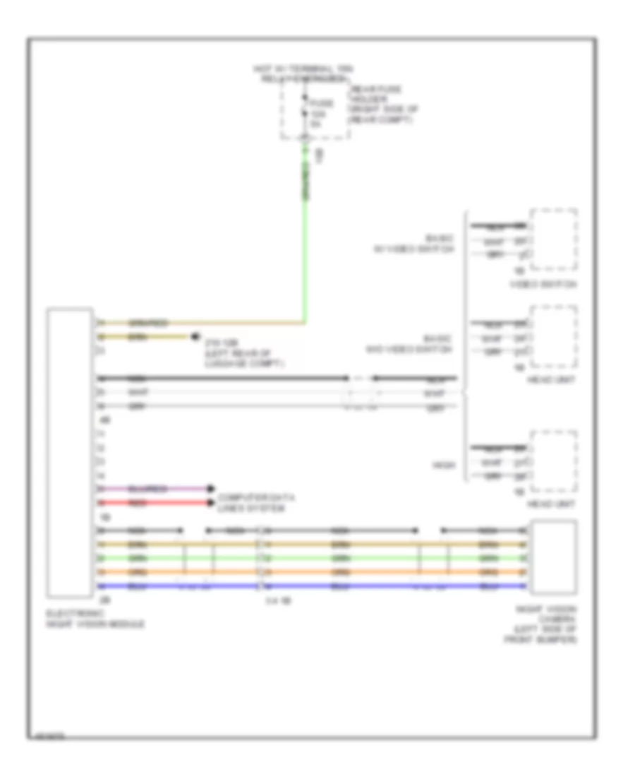
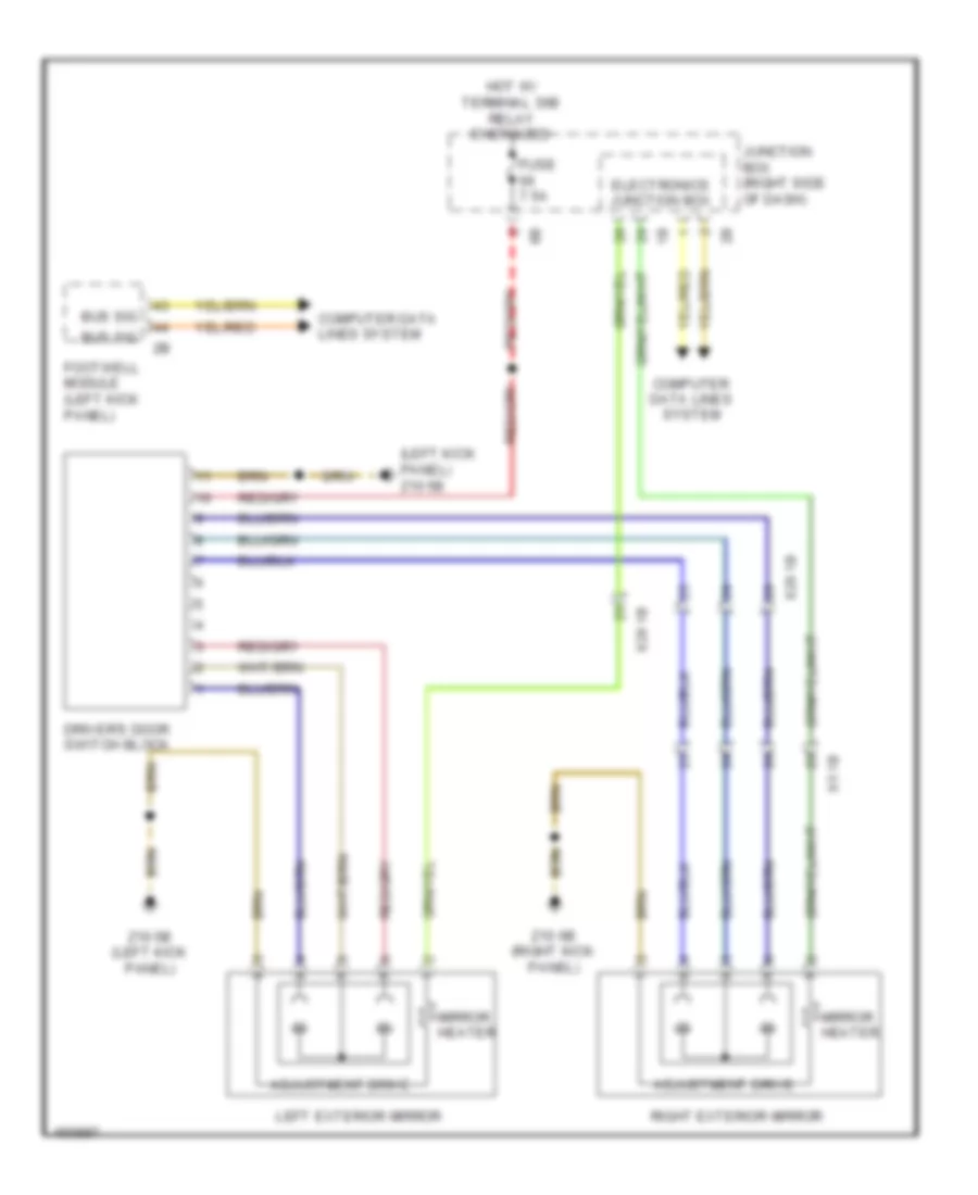
Heated Mirrors Wiring Diagram, with LIN bus Function for BMW ActiveHybrid 5 2014
List of elements for Heated Mirrors Wiring Diagram, with LIN bus Function for BMW ActiveHybrid 5 2014:
- Computer data lines system
- Driver's door switch block
- Footwell module (left kick panel)
- Fuse 7.5a
- Hot w/ terminal 30b relay energized
- Junction box (right side of dash)
- Left exterior mirror
- Mirror heater
- Nca
- Right exterior mirror
- W/ seat switch cluster on driver's door
- W/ seat switch cluster on passenger's door
- X28 1b
- X5 1b
- Z10 5b (left kick panel)
- Z10 6b (right kick panel)
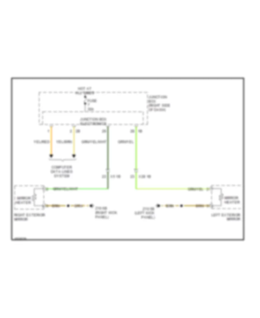
Heated Mirrors Wiring Diagram, without LIN bus Function for BMW ActiveHybrid 5 2014
List of elements for Heated Mirrors Wiring Diagram, without LIN bus Function for BMW ActiveHybrid 5 2014:
- Computer data lines system
- Fuse 30a
- Hot at all times
- Junction box (right side of dash)
- Junction box electronics
- Left exterior mirror
- Mirror heater
- Right exterior mirror
- X28 1b
- X5 1b
- Z10 5b (left kick panel)
- Z10 6b (right kick panel)
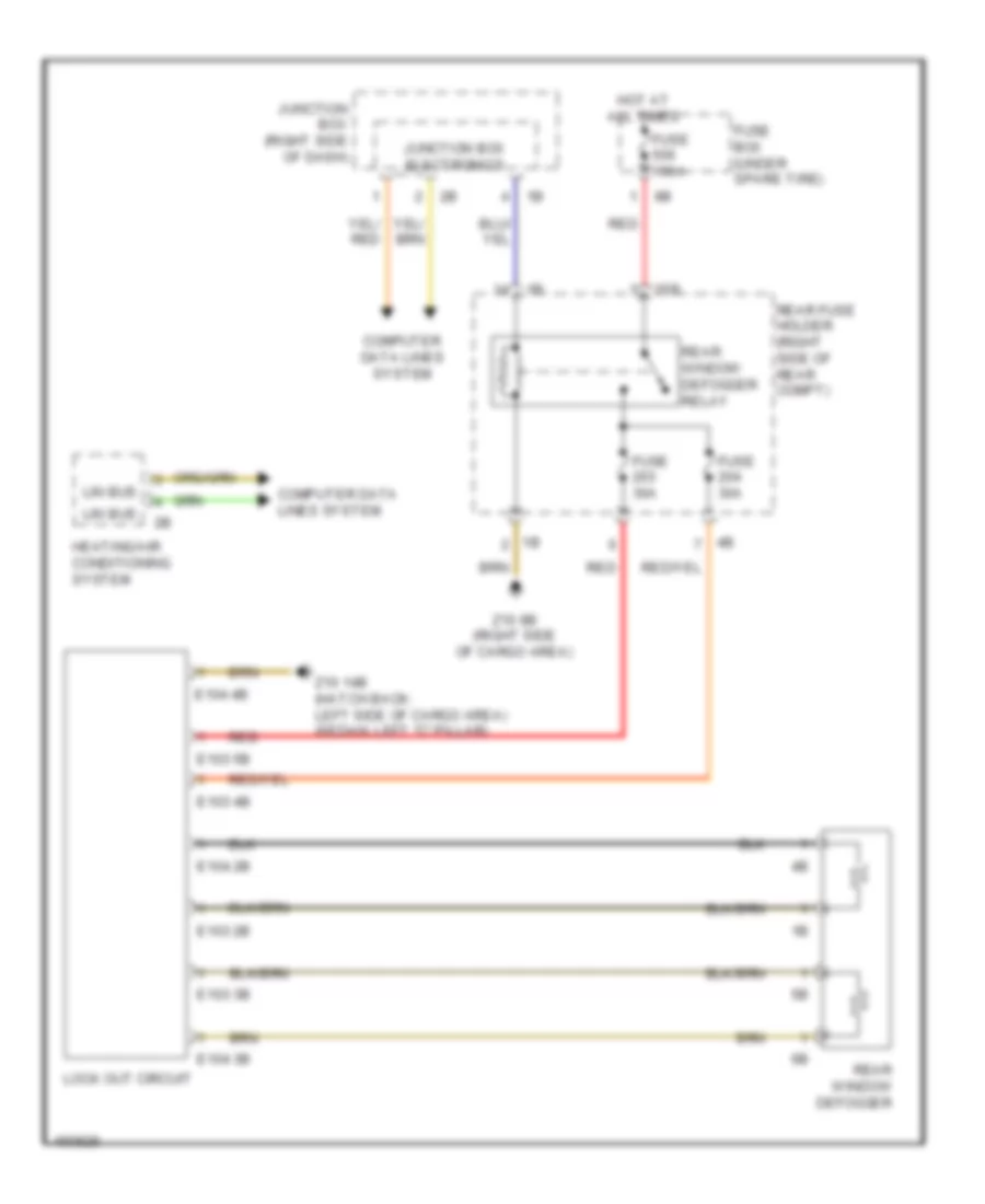
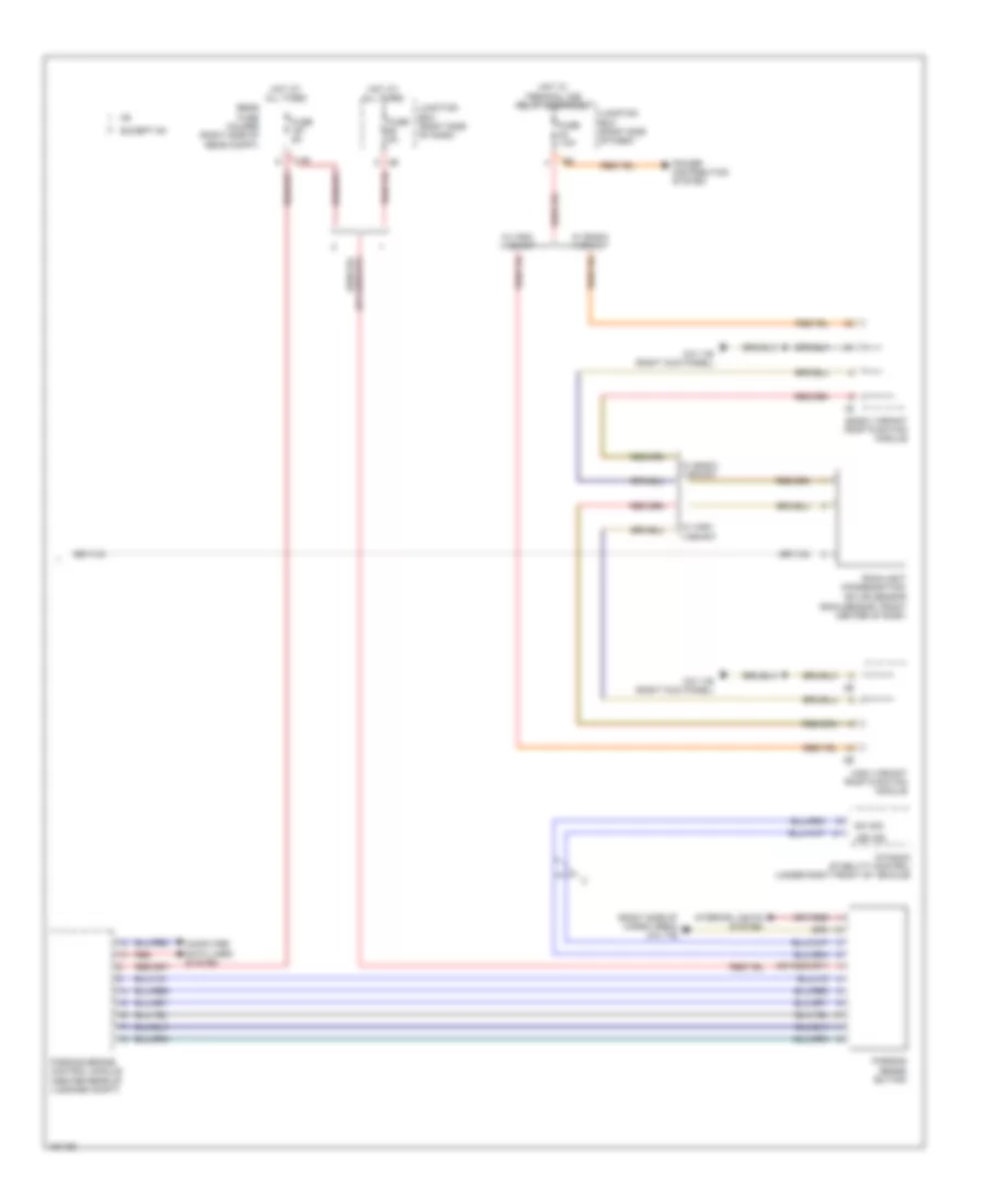
Rear Defogger Wiring Diagram for BMW ActiveHybrid 5 2014
List of elements for Rear Defogger Wiring Diagram for BMW ActiveHybrid 5 2014:
- 25b
- Computer data lines system
- E103 2b
- E103 3b
- E103 4b
- E103 5b
- E104 2b
- E104 3b
- E104 4b
- Fuse 150a
- Fuse 30a
- Fuse box (under spare tire)
- Heating/air conditioning system
- Hot at all times
- Junction box (right side of dash)
- Junction box electronics
- Lin bus
- Lock out circuit
- Rear fuse holder (right side of rear compt)
- Rear window defogger
- Rear window defogger relay
- Red
- Z10 14b (hatch back: left side of cargo area) (sedan: left "c" pillar)
- Z10 8b (right side of cargo area)
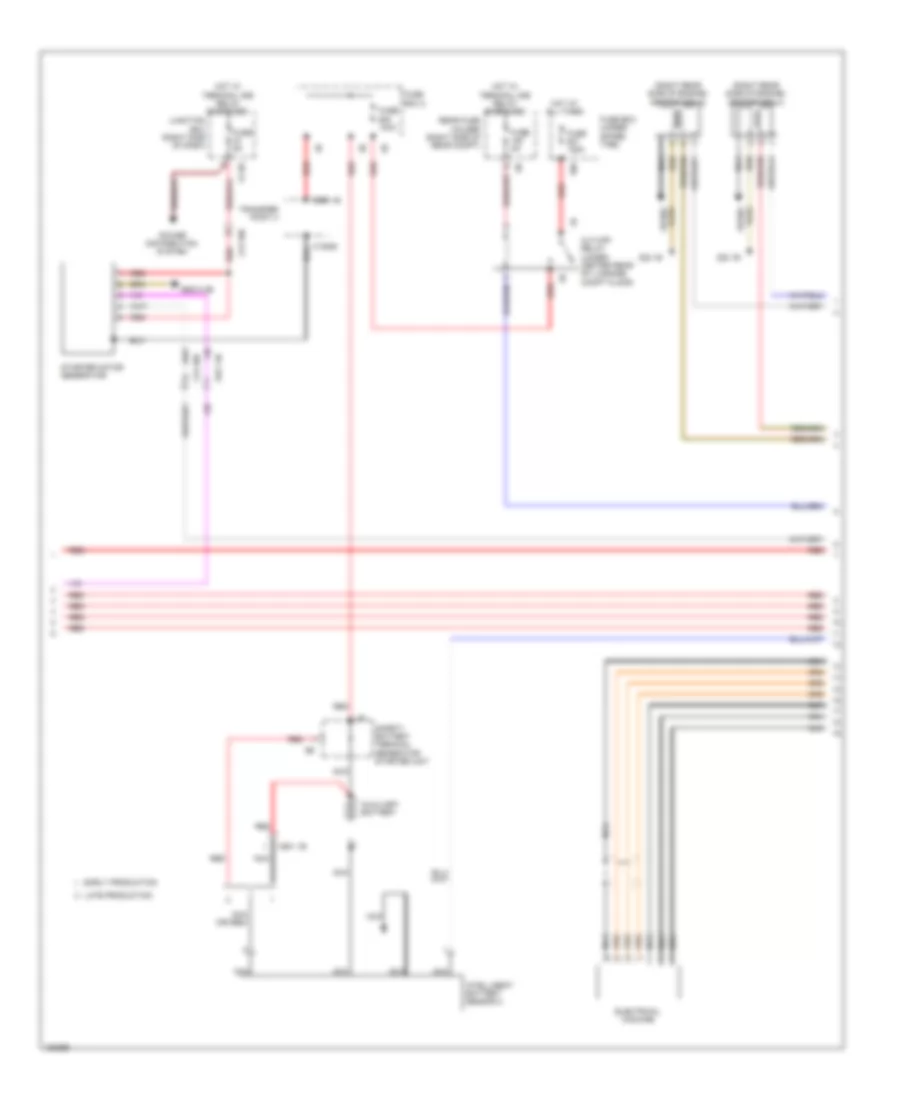
ELECTRONIC POWER STEERING
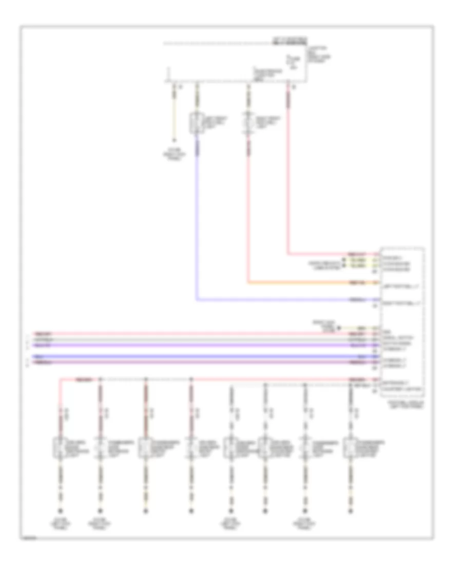
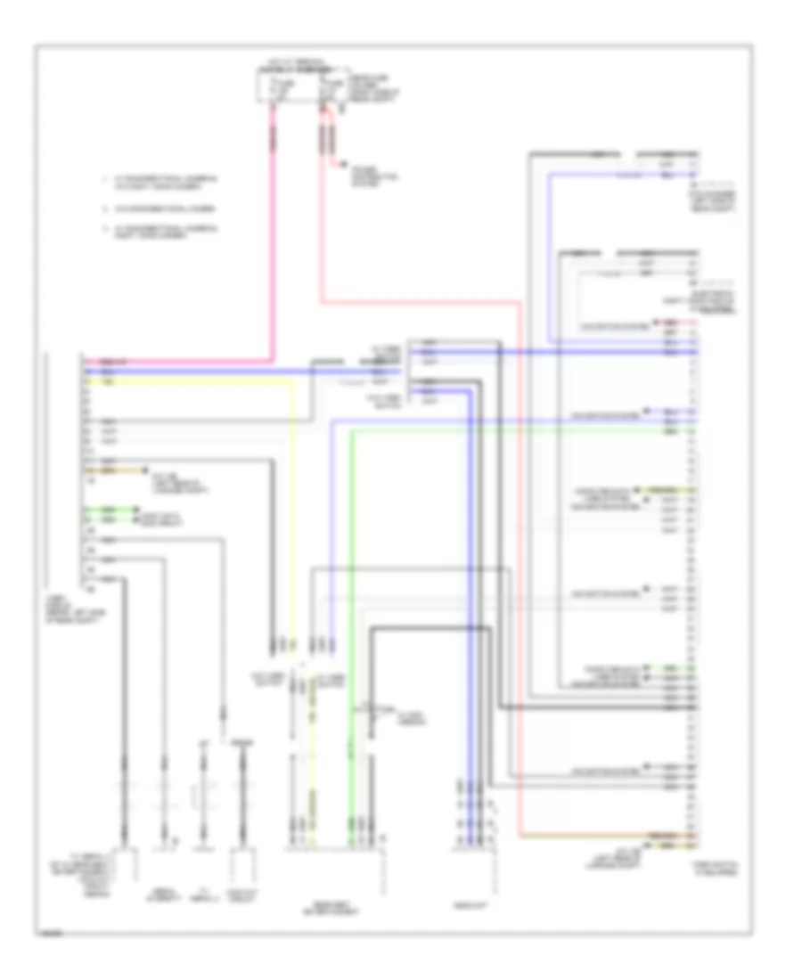
Active Power Steering Wiring Diagram for BMW ActiveHybrid 5 2014
List of elements for Active Power Steering Wiring Diagram for BMW ActiveHybrid 5 2014:
- (left kick panel) z10 5b
- Activation servomotor
- Active steering module (right footwell, under carpet)
- Active steering servo motor
- Central gateway module (left end of dash)
- Electric servo motor lock
- Flexray bus sig
- Fuse 40a
- Fuse 5a
- Gnd
- Hot at all times
- Hot w/ terminal 15n relay energized
- Junction box (right side of dash)
- Lock out
- Nca
- Pnk/red
- Rear axle king pin inclination control (on rear axle assembly)
- Servomotor sig
- Servomotor sig activation servomotor lock out
- Servomotor sply
- Terminal 15 sply
- Terminal 30 sply
- X87 1b
- Z10 50b
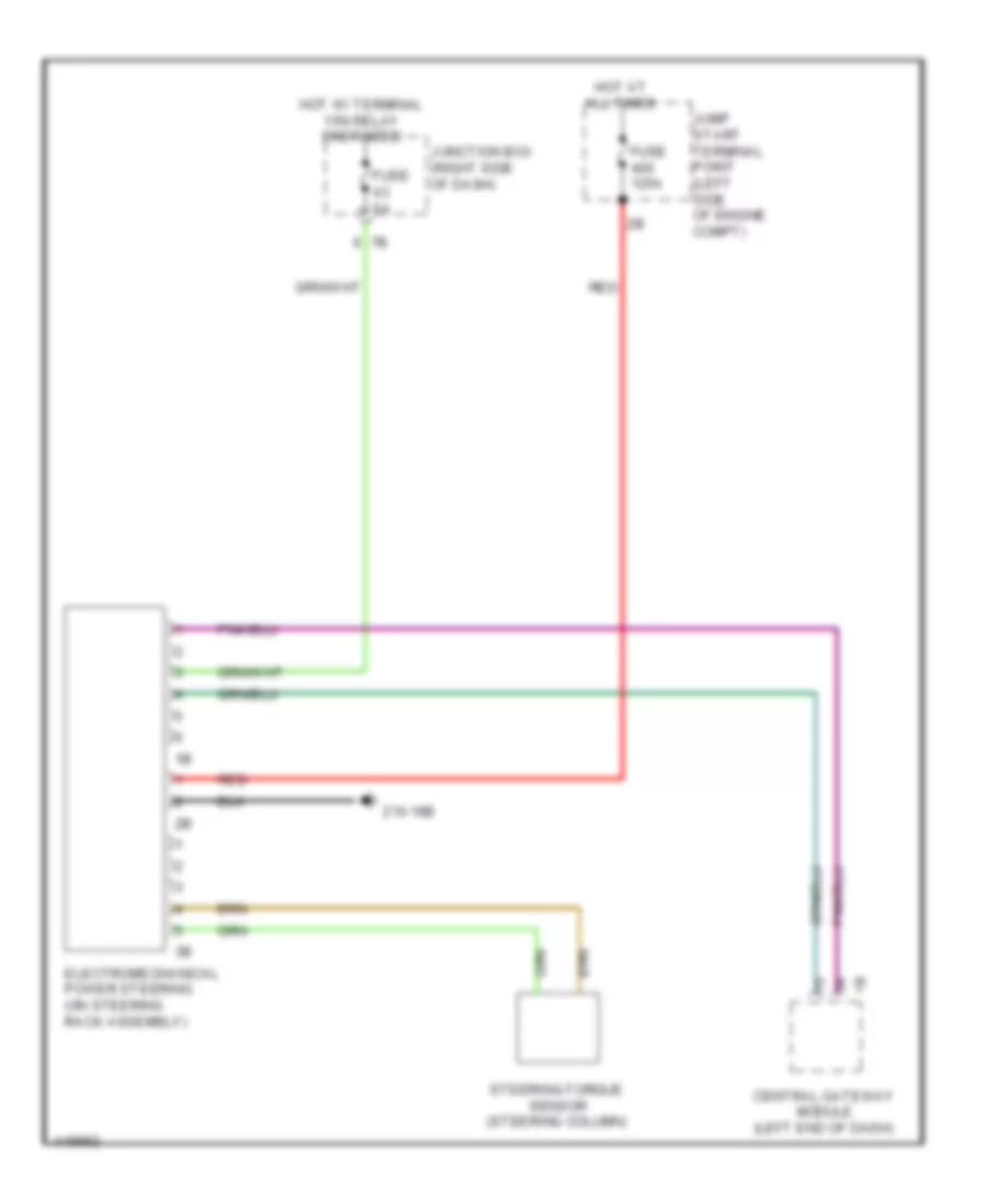
Electromechanical Power Steering Wiring Diagram for BMW ActiveHybrid 5 2014
List of elements for Electromechanical Power Steering Wiring Diagram for BMW ActiveHybrid 5 2014:
- Central gateway module (left end of dash)
- Electromechanical power steering (on steering rack assembly)
- Fuse 125a
- Fuse 5a
- Hot at all times
- Hot w/ terminal 15n relay energized
- Jump start terminal point (left side of engine compt)
- Junction box (right side of dash)
- Red
- Steering-torque sensor (steering column)
- Z10 19b
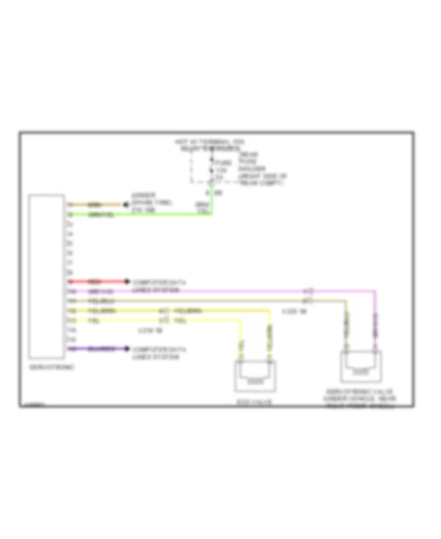
Servotronic Wiring Diagram for BMW ActiveHybrid 5 2014
List of elements for Servotronic Wiring Diagram for BMW ActiveHybrid 5 2014:
- (under spare tire) z10 16b
- Computer data lines system
- Eco valve
- Fuse 5a
- Hot w/ terminal 15n relay energized
- Rear fuse holder (right side of rear compt)
- Red
- Servotronic
- Servotronic valve (under vehicle, near right front wheel)
- X219 1b
- X335 1b
ELECTRONIC SUSPENSION
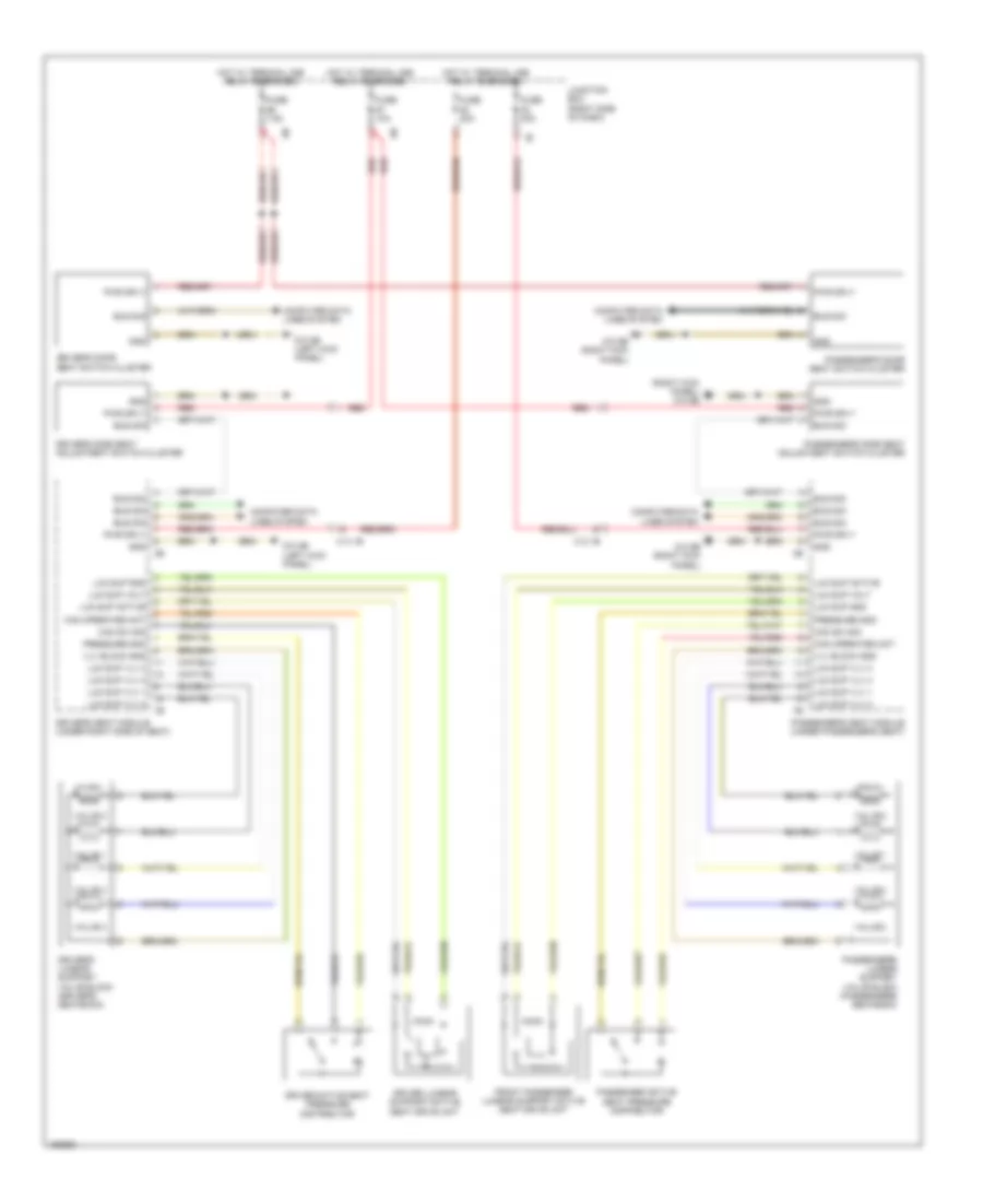
Air Suspension Wiring Diagram (1 of 2) for BMW ActiveHybrid 5 2014
List of elements for Air Suspension Wiring Diagram (1 of 2) for BMW ActiveHybrid 5 2014:
- (behind right front wheel) (w/ vertical dynamics management) right front level sensor
- (left end of dash) central gateway module
- (right kick panel) z10 11b
- (under front of center console) z10 10b
- 2.0l turbo & 4.4l turbo m5
- 3.0l turbo & 3.0l turbo hybrid
- 3.0l turbo diesel & 4.4 turbo except m5
- Center console operating unit
- Computer data lines system
- Digital motor electronics (dme) control module (except 3.0l turbo diesel) digital diesel electronics (3.0l turbo diesel) (2.0l turbo: top rear of engine) (4.4l turbo: right rear engine compt)
- Except m5
- Fuse 5a
- Hot w/ terminal 30b relay energized
- Integrated chassis management (under center console)
- Junction box (right side of dash)
- Left front level sensor (w/ vertical dynamics management & xenon light)
- Pnk
- Steering column switch cluster
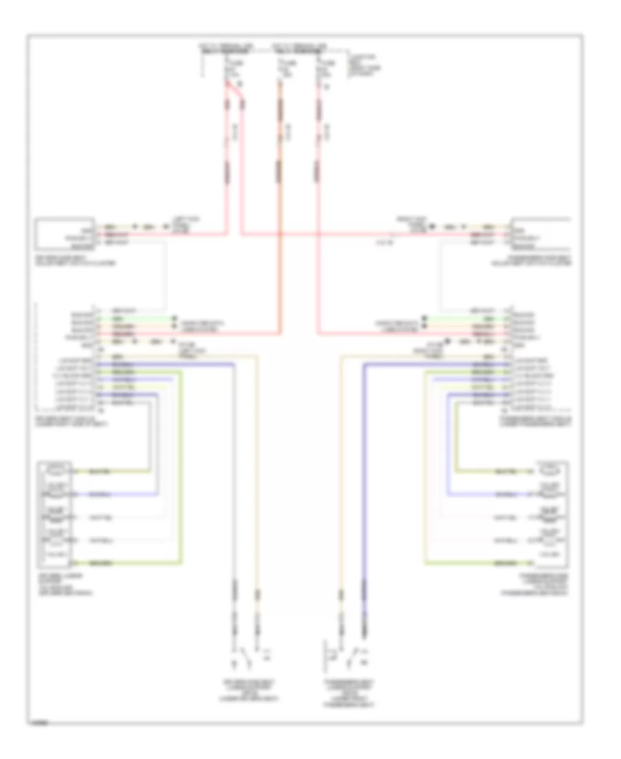
Air Suspension Wiring Diagram (2 of 2) for BMW ActiveHybrid 5 2014
List of elements for Air Suspension Wiring Diagram (2 of 2) for BMW ActiveHybrid 5 2014:
- Compressor relay
- Computer data lines system
- Electronic ride height control (gt)
- Fuse 40a
- Fuse 5a
- Hot at all times
- Hot w/ terminal 30b relay energized
- Left rear level sensor (w/ vertical dynamics management, xenon light & electronic ride height control) (front of left rear wheel)
- M6 1b
- M6 2b
- Nca
- Rear fuse holder (right side of rear compt)
- Right rear level sensor (w/ vertical dynamics management & electronic ride height control) (front of right rear wheel)
- Y25 1b
- Z10 17b (right side of cargo area)
- Z10 8b (right side of cargo area)
Dynamic Drive Suspension Wiring Diagram for BMW ActiveHybrid 5 2014
List of elements for Dynamic Drive Suspension Wiring Diagram for BMW ActiveHybrid 5 2014:
- (right kick panel) z10 6b
- 5v sply
- Act intake throttle valve
- Act valve block
- Central gateway module (left end of dash)
- Dynamic drive valve block (behind right front wheel)
- Flexray bus sig
- Fuse 30a
- Fuse 5a
- Gnd
- Hot at all times
- Hot w/ terminal 15n relay energized
- Intake throttle valve
- Junction box (right side of dash)
- Left front damper satellite
- Left rear damper satellite
- Nca
- Oil level sw sig
- Oil level switch (right side of engine compt)
- Pnk
- Pnk/red
- Power distribution system
- Pressure sens sig
- Right front damper satellite
- Right rear damper satellite
- Sens gnd
- Sply terminal 15
- Sply terminal 30
- Vertical dynamics management (right kick panel)
- Volt sply
- X158 1b
- X159 1b
- X219 1b
- Z10 14b (hatch back: left side of cargo area) (sedan: left "c" pillar)
- Z10 2b (lower left front of engine compt)
- Z10 3b (lower right front of engine compt)
- Z10 8b (right side of cargo area)
ENGINE PERFORMANCE
3.0L TURBO HYBRID
3.0L Turbo Hybrid, Engine Performance Wiring Diagram (1 of 8) for BMW ActiveHybrid 5 2014
List of elements for 3.0L Turbo Hybrid, Engine Performance Wiring Diagram (1 of 8) for BMW ActiveHybrid 5 2014:
- (right side of engine) knock sensor
- (top right rear of engine) wastegate valve pressure converter
- Act activation
- Bsd bus sig
- Bsd sig
- Coolant pump
- Cooling fans system
- Crankshaft position sensor (left rear side of engine)
- Cylinders 1-3
- Cylinders 4-6
- Digital motor electronics (dme) control module (right rear engine compt)
- Elec throttle act gnd
- Elec throttle act sig
- Electromotive throttle actuator
- Exhaust vanos solenoid valve (front of engine)
- Intake air temperature pressure sensor (right side of engine)
- Intake manifold pressure sensor (right side of engine)
- Knock sens sig
- Nca
- Oil level sensor
- Oxygen sensor before catalytic converter
- Quantity control valve
- Sens gnd
- Sens sig
- Sens sply
- Sply
- Vlv activation
- Vlv sply
3.0L Turbo Hybrid, Engine Performance Wiring Diagram (2 of 8) for BMW ActiveHybrid 5 2014
List of elements for 3.0L Turbo Hybrid, Engine Performance Wiring Diagram (2 of 8) for BMW ActiveHybrid 5 2014:
- (top of engine) low pressure fuel sensor
- Bypass blow off valve
- Characteristic map thermostat (left front of engine)
- Computer data lines system
- Electric fuel pump (on fuel tank)
- Engine ventilation heating
- Exhaust camshaft sensor (rear of engine)
- Fuel pump
- Fuel pump control (ekps)
- Fuse 20a
- Fuse 5a
- Gnd
- High pressure pump position sensor
- Hot w/ terminal 30b relay energized
- Intake camshaft sensor (rear of engine)
- Intake vanos solenoid valve (front of engine)
- Junction box (right side of dash)
- Nca
- Oil pressure control valve
- Oxygen sensor after catalytic converter
- Pt can
- Pwr sply
- Rear fuse holder (right side of rear compt)
- Red
- Standard euro 6
- Tank vent valve
- Tank ventilation shut-off valve (w/o bosch)
- W/ bosch
- W/ exhaust emissions
- W/o bosch
- W/o exhaust emissions standard euro 6
- Wake up
- X705 1b
- Z1 6b
- Z10 16b (under spare tire)
- Z23 1b
3.0L Turbo Hybrid, Engine Performance Wiring Diagram (3 of 8) for BMW ActiveHybrid 5 2014
List of elements for 3.0L Turbo Hybrid, Engine Performance Wiring Diagram (3 of 8) for BMW ActiveHybrid 5 2014:
- (left rear of engine) z6000 1b
- Activation
- Car access system (lower left center of dash)
- Digital motor electronics (dme) control module (right rear engine compt)
- Diverter vlv sply
- Dme main relay
- Fuse 100a
- Fuse 15a
- Fuse 20a
- Fuse 40a
- Fuse box (under spare tire)
- Gnd
- Heater sply
- Hot at all times
- Ignition & fuel injection relay
- Map activation
- Map sply
- Meter gnd
- Meter sig
- Meter sply
- Motor position sensor
- Mtr activation
- Mtr sply
- Oil press ctrl vlv sply
- Pwr
- Red
- Sens gnd
- Sens sig
- Sens sply
- Valvetronic actuator motor (right side of engine)
- Valvetronic relay
- Ventilation activation
- Vlv activation
- Vlv sply
- Z10 3b (lower right front of engine compt)
3.0L Turbo Hybrid, Engine Performance Wiring Diagram (4 of 8) for BMW ActiveHybrid 5 2014
List of elements for 3.0L Turbo Hybrid, Engine Performance Wiring Diagram (4 of 8) for BMW ActiveHybrid 5 2014:
- (w/ bosch) venturi nozzle pressure sensor
- Brake light switch (left side of dash)
- Car access system (lower left center of dash)
- Computer data lines system
- Engine coolant temperature sensor
- Engine oil pressure sensor
- Engine oil temperature sensor
- Exterior lights system
- Fuse 10a (or 15a)
- Fuse 40a
- Fuse 5a
- Fuse holder
- Hot at all times
- Hot film mass air flow sensor (right front side of engine)
- Hot w/ terminal 30b relay energized
- Junction box (right side of dash)
- Rail pressure sensor (on right cylinder head fuel rail)
- Red
- X13 12b
- X13 13b
- X704 1b
- Z1 1b
- Z1 6b
- Z10 9b (left kick panel)
3.0L Turbo Hybrid, Engine Performance Wiring Diagram (5 of 8) for BMW ActiveHybrid 5 2014
List of elements for 3.0L Turbo Hybrid, Engine Performance Wiring Diagram (5 of 8) for BMW ActiveHybrid 5 2014:
- (right rear side of engine) ignition coil 5
- (right rear side of engine) ignition coil 6
- 10b
- Auxiliary battery
- Cut-off relay (under center rear of luggage compt floor)
- Early production
- Electrical machine
- Fuse 100a
- Fuse 125a
- Fuse 5a
- Fuse box (under spare tire)
- Fuse box 2
- Hot at all times
- Hot w/ terminal 30b relay energized
- Intelligent battery sensor 2
- Junction box (right side of dash)
- Late production
- Nca
- Nca (or red)
- Plug spark
- Power distribution system
- Rear fuse holder (right side of rear compt)
- Red
- Safety battery terminal generator starter unit
- Spark plug
- Starter motor generator
- Transfer point 3
- X10885
- X13 10b
- X593 1b
- X601 1b
- X671 3b
- Z1 6b
- Z22 1b
- Z6000 2b
3.0L Turbo Hybrid, Engine Performance Wiring Diagram (6 of 8) for BMW ActiveHybrid 5 2014
List of elements for 3.0L Turbo Hybrid, Engine Performance Wiring Diagram (6 of 8) for BMW ActiveHybrid 5 2014:
- (high voltage battery) refrigerant shut-off valve
- Accumulator-management electronics
- Computer data lines system
- Cooling fans system
- Crash safety module
- Electric machine electronics
- Electric vacuum pump
- Front refrigerant shut-off valve
- Fuse 5a
- Hot w/ bistable relay energized
- Lines system computer data
- Nca
- Pnk
- Rear fuse holder (right side of rear compt)
- Red
- Rotor position sensor
- Temperature sensor (electrical machine)
- X13 12b
- Z10 8b (right side of cargo area)
- Z6000 1b (left rear of engine)
- Z6000 3b
- Z6000 5b
3.0L Turbo Hybrid, Engine Performance Wiring Diagram (7 of 8) for BMW ActiveHybrid 5 2014
List of elements for 3.0L Turbo Hybrid, Engine Performance Wiring Diagram (7 of 8) for BMW ActiveHybrid 5 2014:
- (right "c" pillar)
- (right center side of engine) ignition coil 3
- (right center side of engine) ignition coil 4
- (right front side of engine) ignition coil 1
- (right front side of engine) ignition coil 2
- (right rear of luggage compt) high voltage safety connector
- (right side of rear compt) safety battery terminal generator
- 11b
- Air conditioning system
- Battery
- Electric-machine electronics
- Fuel tank non return valve
- Fuel tank pressure sensor
- Fuse 5a
- Hot at all times
- Hot w/ terminal 30b relay energized
- Jump start terminal point (left side of engine compt)
- Natural vacuum leak detection (w/ bosch)
- Nca
- Plug spark
- Power distribution system
- Pressure switch
- Rear fuse holder (right side of rear compt)
- Red
- Reverse polarity protection
- Safety battery terminal generator
- Spark plug
- Starter
- System air conditioning
- Transfer terminal point
- X13 12b
- X14741
- Z10 13b
- Z20 1b
- Z21 1b
3.0L Turbo Hybrid, Engine Performance Wiring Diagram (8 of 8) for BMW ActiveHybrid 5 2014
List of elements for 3.0L Turbo Hybrid, Engine Performance Wiring Diagram (8 of 8) for BMW ActiveHybrid 5 2014:
- (pins: 16 to 18 not used)
- (top of engine) injector cylinders
- (under intake air collector) engine mount electric changeover valve
- Accelerator pedal module (part of acceleration pedal assembly)
- Anti-theft system
- Battery sensor (right side of rear compt)
- Brake vacuum pressure sensor (on brake servo booster)
- Car bus sig
- Change over valve
- Computer data lines system
- Cooling fans system
- Cut-out relay
- Diagnosis socket
- Digital motor electronics (dme) control module (right rear engine compt)
- Electric fan
- Flexray bus sig
- Fuel inj 1 activation
- Fuel inj 1 sply
- Fuel inj 2 activation
- Fuel inj 2 sply
- Fuel inj 3 activation
- Fuel inj 3 sply
- Fuel inj 4 activation
- Fuel inj 4 sply
- Fuel inj 5 activation
- Fuel inj 5 sply
- Fuel inj 6 activation
- Fuel inj 6 sply
- Fuel tank leakage
- Fuel tank leakage diagnostic module (w/ bosch) (behind right rear wheel)
- Fuse 5a
- Hall sens gnd
- Hall sens sig
- Hall sens sply
- Hot w/ terminal 15n relay energized
- Ign coil 1 activation
- Ign coil 1 sply
- Ign coil 2 activation
- Ign coil 2 sply
- Ign coil 3 activation
- Ign coil 3 sply
- Ign coil 4 activation
- Ign coil 4 sply
- Ign coil 5 activation
- Ign coil 5 sply
- Ign coil 6 activation
- Ign coil 6 sply
- Junction box (right side of dash)
- Lin bus sig
- Locking valve
- Nca
- Pnk
- Power distribution system
- Press sens sig
- Pt-can bus sig
- Radiator shutter drive unit
- Red
- Start sig
- Starter mtr
- Starting/charging system
- Term 15 sply
- Term 15 wake up sig
- Term 30 sply
- W/ bosch
- W/ vehicle sound generator
- W/o bosch
- X13 12b
- X148 1b
- X671 3b
- Z1 7b
- Z10 2b (lower left front of engine compt)
EXTERIOR LIGHTS
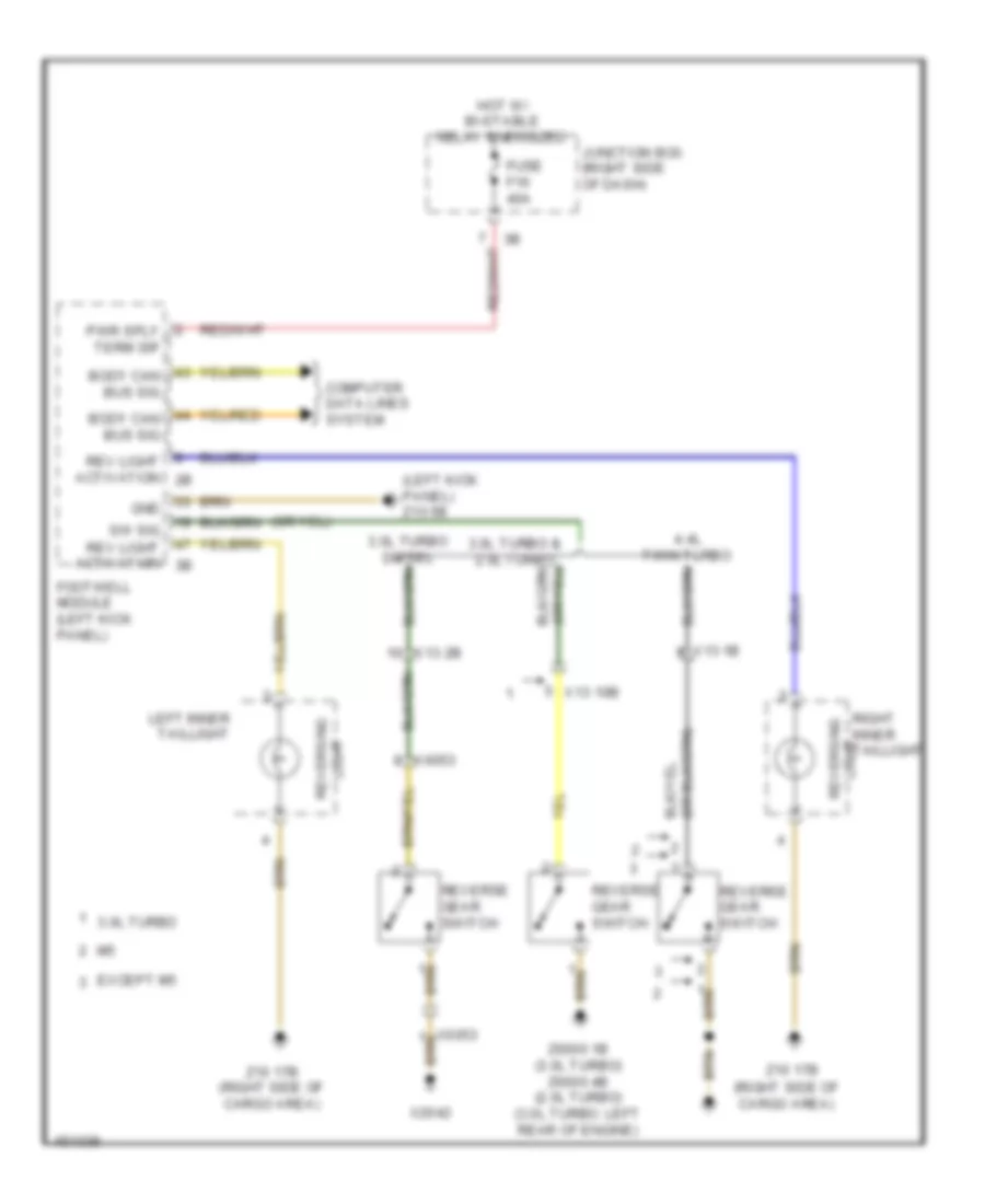
Backup Lamps Wiring Diagram for BMW ActiveHybrid 5 2014
List of elements for Backup Lamps Wiring Diagram for BMW ActiveHybrid 5 2014:
- (left kick panel) z10 5b
- (right side of cargo area)
- 3.0l turbo
- 3.0l turbo & 2.0l turbo
- 4.4l twin turbo
- Body can bus sig
- Computer data lines system
- Except m5
- Footwell module (left kick panel)
- Fuse f16 40a
- Gnd
- Hot w/ bi-stable relay energized
- Junction box (right side of dash)
- Left inner taillight
- Light reversing
- Pwr sply term 30f
- Rev light activation 2b
- Rev light activation 3b
- Reverse gear switch
- Right inner taillight light reversing
- Sw sig
- X13 10b
- X13 1b
- X13 2b
- X2042
- X6053
- Z10 17b
- Z10 17b (right side of cargo area)
- Z6000 1b (3.0l turbo) z6000 4b (2.0l turbo) (3.0l turbo: left rear of engine)
Exterior Lamps Wiring Diagram (1 of 2) for BMW ActiveHybrid 5 2014
List of elements for Exterior Lamps Wiring Diagram (1 of 2) for BMW ActiveHybrid 5 2014:
- (gt) interference suppressor filter 2
- (lower left front of engine compt) z10 2b
- (w/o led) cornering light
- Body can bus sig
- Brk lt
- Brk lt sw sig
- Central locking button hazard warning switch operating facility
- Computer data lines system
- Cornering lt
- Design light
- Direction
- Direction light
- Door contact sig
- Electronics junction box
- Flash ind lp
- Footwell module (left kick panel)
- Fuse 10a
- Fuse 30a
- Fuse 5a
- Gnd
- Gt w/ led
- Gt w/o led & sedan w/o adaptive light control
- Headlight driver module
- Hi beam redund
- Hi beam sw sig
- Hot w/ bi-stable relay energized
- Hot w/ bistable relay energized
- Ind lp
- Junction box (right side of dash)
- Led activation
- Left headlight
- Left license plate light
- License plate lt
- Light cornering
- Light switch unit
- Lin bus
- Lin bus sig
- Parking light/ daytime driving light
- Pwr sply
- Pwr sply term 30f
- Rear fuse holder (right side of rear compt)
- Red
- Right headlight
- Right license plate light
- Rr fog lt
- Sedan
- Sedan w/ adaptive light control
- Side marker light
- Steering column switch cluster
- Tail lt
- W/ led
- W/o led
- Warn lt sw sig
- Z10 17b (right side of cargo area)
- Z10 22b (left kick panel)
- Z10 2b (lower left front of engine compt)
- Z10 3b (lower right front of engine compt)
Exterior Lamps Wiring Diagram (2 of 2) for BMW ActiveHybrid 5 2014
List of elements for Exterior Lamps Wiring Diagram (2 of 2) for BMW ActiveHybrid 5 2014:
- (left side of dash) brake light switch
- (lower left center of dash) car access system
- (sedan: bottom of left "c" pillar) noise suppression filter
- Auxiliary brake light
- Brake dynamic
- Brake light
- Brk lt
- Can bus sig
- Cargo area)
- Computer data lines system
- Direction ind
- Except m5
- Flashing ind lp
- Left front direction indicator light repeater
- Left inner taillight
- Left outer taillight
- License plate light w/ rear lid button
- Light
- Light brake dynamic
- Light tail
- Power tailgate acoustic sensor
- Right front direction indicator light repeater
- Right inner taillight
- Right outer taillight
- Sedan
- Side marker light
- Tail light
- Trailer module (under spare tire)
- Z10 14b (sedan: left "c" pillar)
- Z10 17b (right side of
- Z10 17b (right side of cargo area)
- Z10 20b (top of right "c" pillar)
- Z10 2b (lower left front of engine compt)
- Z10 6b (right kick panel)
- Z10 8b (right side of cargo area)
- Z10 9b (left kick panel)
Trailer Tow Wiring Diagram for BMW ActiveHybrid 5 2014
List of elements for Trailer Tow Wiring Diagram for BMW ActiveHybrid 5 2014:
- Active bodyworks system
- Automatic towing hitch
- Body can bus sig
- Brake light activation
- Brk light
- Can bus signal
- Computer data lines system
- Exterior lamps circuit
- Flashing ind lamp
- Footwell module (left kick panel)
- Fuse 20a
- Fuse 30a
- Gnd
- Ground
- Hall sensor signal
- Hot w/ bi-stable relay energized
- Hot w/ terminal 30b relay energized
- Ind lp
- Junction box (right side of dash)
- Led activation
- Left taillight
- Left turn sig light
- Nca
- Noise suppressor filter (bottom of left "c" pillar)
- Rear fog light
- Rear fuse holder (right side of rear compt)
- Red
- Reversing light
- Right taillight
- Right turn sig light
- Sply term 30f
- Switch signal
- Terminal 30b
- Terminal 30f
- Trailer module (under spare tire)
- Trailer socket
- X268 1b
- X269 1b
- Z10 22b (left kick panel)
- Z10 8b (right side of cargo area)
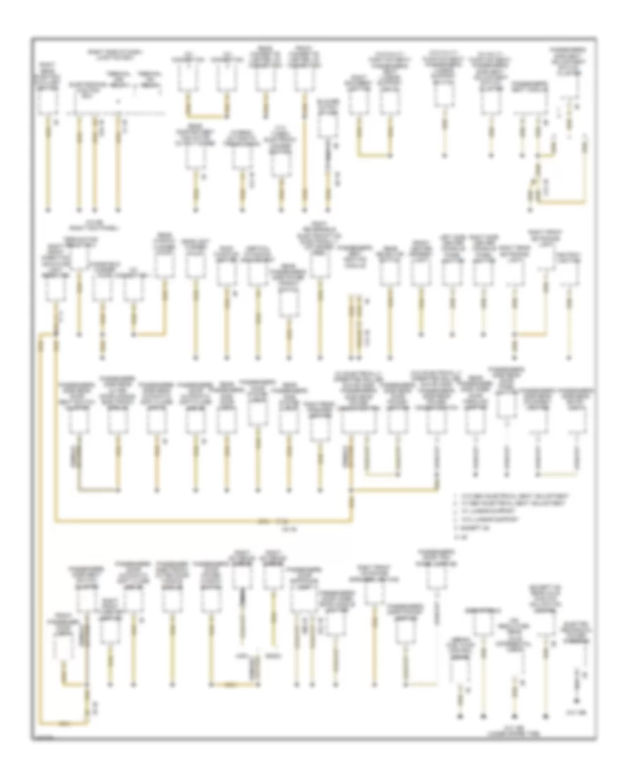
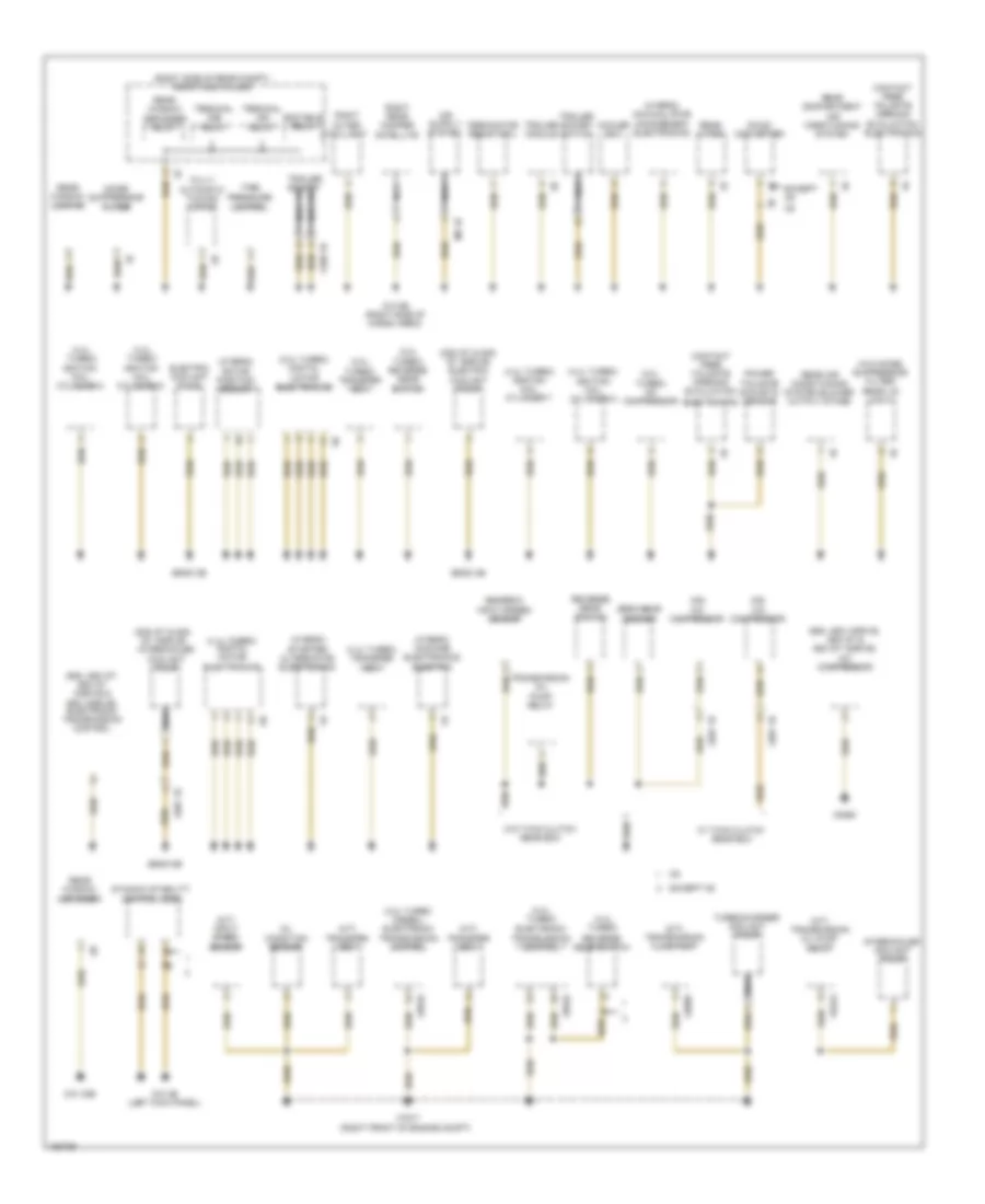
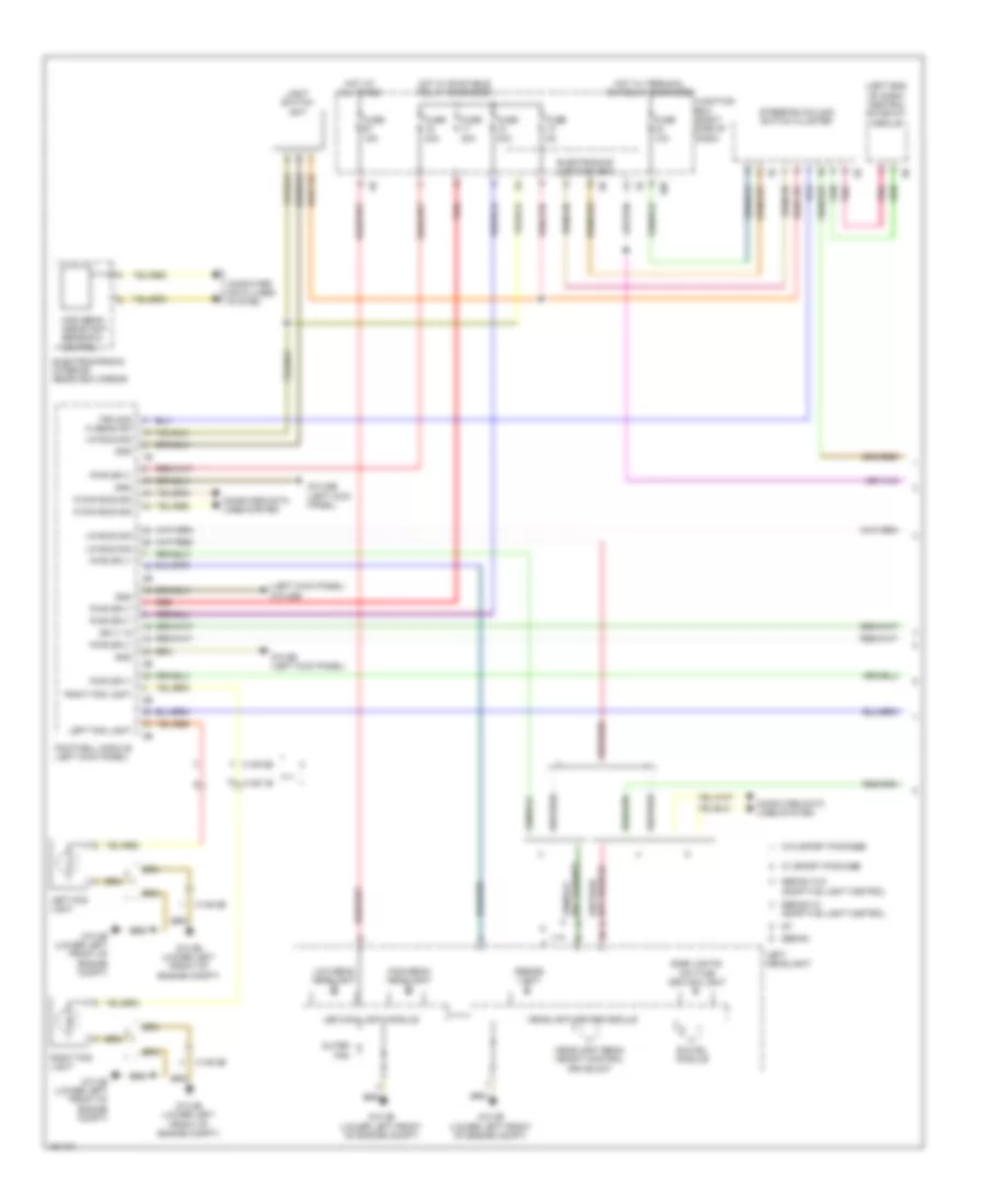
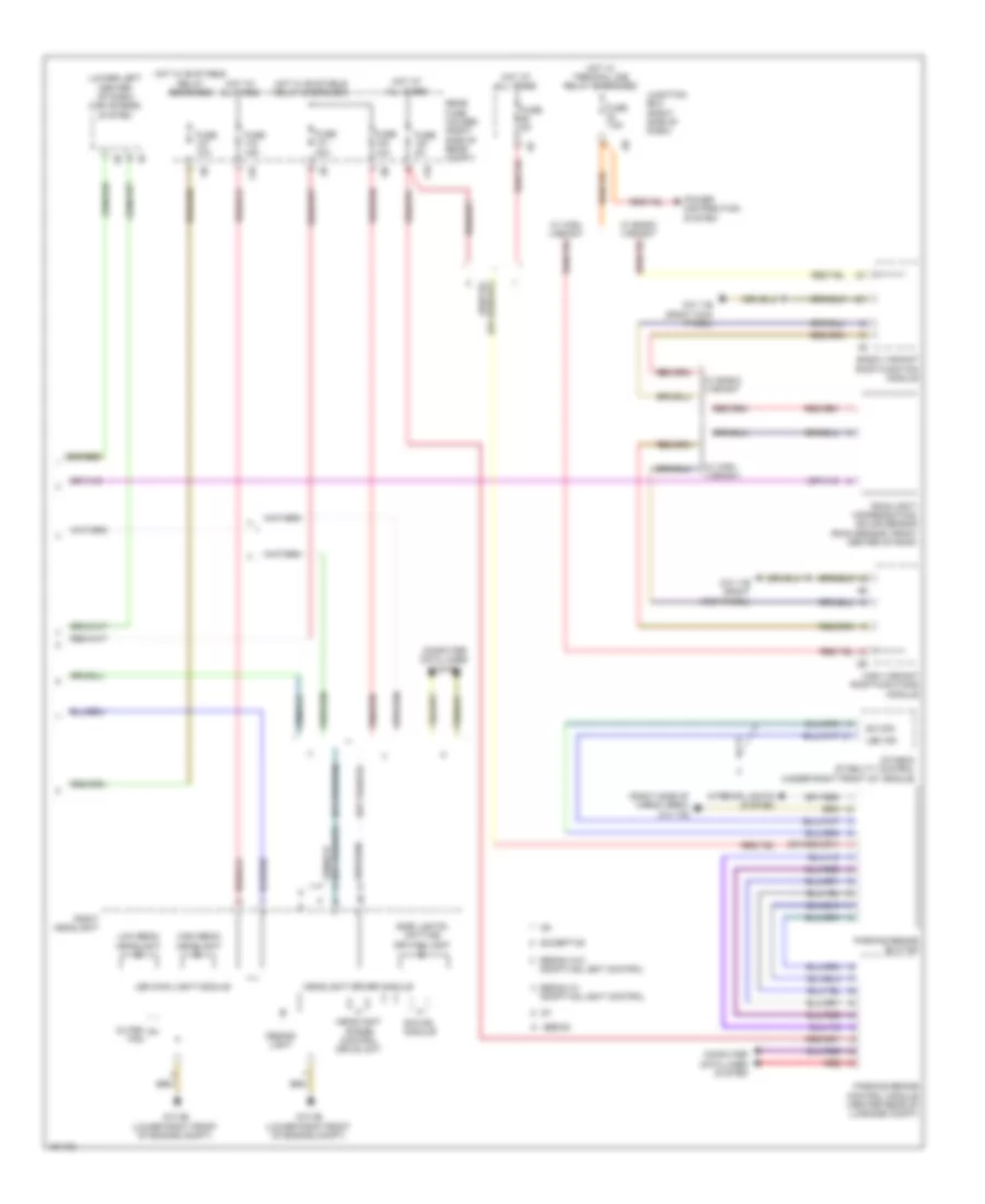
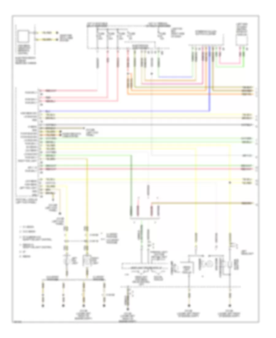
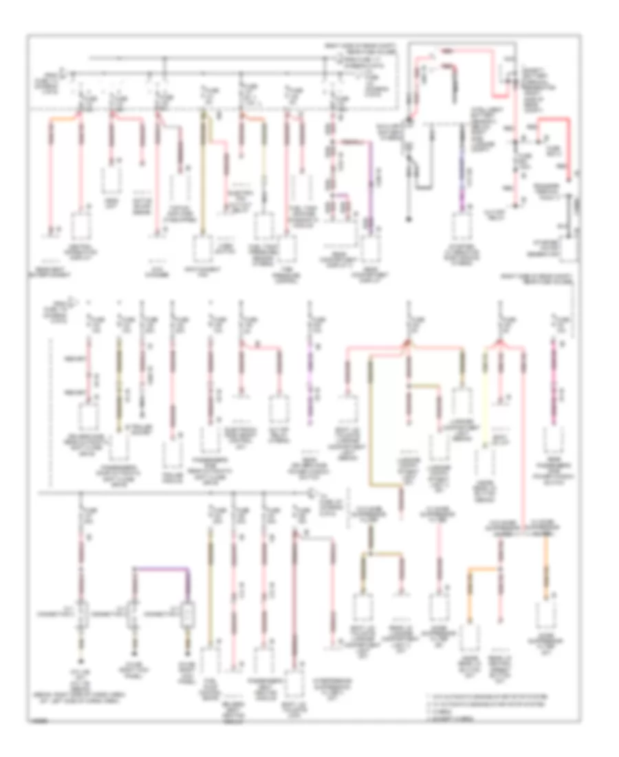
GROUND DISTRIBUTION
Ground Distribution Wiring Diagram (1 of 6) for BMW ActiveHybrid 5 2014
List of elements for Ground Distribution Wiring Diagram (1 of 6) for BMW ActiveHybrid 5 2014:
- (2.0l turbo) ignition coil cylinder 1
- (2.0l turbo) ignition coil cylinder 2
- (3.0l turbo & hybrid) digital motor electronics
- (3.0l turbo diesel) a/c compressor
- (3.0l turbo diesel, 2.0l turbo & 3.0l turbo) intelligent battery sensor
- (3.0l turbo)
- (3.0l turbo) reverse gear switch
- (3.0l turbo) transfer box
- (4.4l turbo sedan) digital motor electronics 2
- (4.4l turbo) ignition coil cylinder 1
- (except hybrid) automatic transmission
- (except hybrid) electronic transmission control
- (hybrid) auxiliary water pump
- (hybrid) electric vacuum pump
- (hybrid) intelligent battery sensor
- (hybrid) intelligent battery sensor 2
- (hybrid) polarity protection reverse
- (if equipped) driver's lumbar support switch
- (if equipped) driver's seat lumbar support drive
- (if equipped) engine ventilation heating
- (m/t) reverse gear switch
- (w/ electrically operated roller sun blinds) driver's side rear power window switch
- (w/o electrically operated roller sun blinds) driver's side rear power window switch
- Active steering module
- Auxiliary battery
- Battery
- Capacitor box
- Car access system
- Diagnosis socket
- Driver electronic outer door handle module
- Driver's door automatic soft close drive
- Driver's door entrance light
- Driver's door inner door handle lighting
- Driver's door panel lighting
- Driver's door pocket lighting
- Driver's door seat switch cluster
- Driver's door switch block
- Driver's door system lock
- Driver's seat heating module
- Driver's seat module
- Driver's side rear automatic soft close drive
- Driver's side rear courtesy lighting
- Driver's side rear door lock
- Driver's side rear door panel lighting
- Driver's side rear door pocket lighting
- Driver's side rear door seat switch cluster
- Driver's side rear entry light
- Driver's side rear outer door handle electronic module
- Driver's side seat adjustment switch cluster
- E37 1b
- E82 1b
- Footwell module
- Ignition coil cylinder 1
- Ignition coil cylinder 2
- Ignition coil cylinder 3
- Ignition coil cylinder 4
- Ignition coil cylinder 5
- Ignition coil cylinder 6
- Intelligent battery sensor 2
- Interior rear lid button
- Left backrest lighting
- Left exterior mirror
- Left front entrance light
- Left front midrange speaker lighting
- Left front tweeter lighting
- Left rear electric auxiliary heater
- Left rear entrance light
- Left rear speaker lighting
- Left reversible electromotive electrically motorized reel
- Nca
- Rear driver's side inner door handle lighting
- W/ lumbar support
- X14 1b
- X28 1b
- X8 1b
- Y21 1b
- Z10 28b
- Z10 5b (left kick panel)
- Z20 1b
- Z21 1b
- Z22 1b
- Z23 1b (3.0l turbo)
- Z6000 1b (left rear of engine)
- Z6000 6b
Ground Distribution Wiring Diagram (2 of 6) for BMW ActiveHybrid 5 2014
List of elements for Ground Distribution Wiring Diagram (2 of 6) for BMW ActiveHybrid 5 2014:
- (4.4l
- (except m5) rear axle king pin inclination control
- (hybrid) automatic transmission
- (m5) regulated rear axle differential lock
- (right side of dash) junction box
- (sedan) fuel pump control (ekps)
- (w/ electrically operated roller sun blinds) passenger's side rear power window switch
- (w/ multi- function seat) passenger's side seat adjustment switch cluster
- (w/o electrically operated roller sun blinds) passenger's side rear power window switch
- (w/o multi- function seat) passenger's lumbar support switch
- (w/o multi- function seat) passenger's seat lumbar support drive
- 12v connection
- 12v connection 1
- A34 1b
- Ashtray lighting
- Basic
- Blower output stage
- E21 1b
- E80 1b
- Electro- mechanical power steering
- Electronics junction box
- Except m5
- Front center armrest light
- Front cigarette lighter 12v connection
- Front passenger door lock
- Gear selector switch
- Headlight washer pump
- High
- Left side center console panel lighting
- N2 1b
- Nca
- Passenger electronic outer door handle module
- Passenger's door automatic soft close drive
- Passenger's door automatic soft-close drive
- Passenger's door entrance light
- Passenger's door inner door handle lighting
- Passenger's door pocket lighting
- Passenger's door power window switch
- Passenger's door seat switch cluster
- Passenger's door system lock
- Passenger's door trim panel lighting
- Passenger's seat heating module
- Passenger's seat module
- Passenger's side rear automatic soft close drive
- Passenger's side rear courtesy lighting
- Passenger's side rear door panel lighting
- Passenger's side rear door pocket lighting
- Passenger's side rear door seat switch cluster
- Passenger's side rear entry light
- Passenger's side rear outer door handle electronic module
- Passenger's side seat adjustment switch cluster
- Rear cigarette lighter 12v connection
- Rear compartment fan motor output stage
- Rear passenger's side door lock
- Rear passenger's side inner door handling lighting
- Rear passenger's side power window switch
- Rear passenger's side system lock
- Rear window washer pump
- Right backrest lighting
- Right exterior mirror
- Right front direction indicator light repeater
- Right front entrance light
- Right front mid-range speaker lighting
- Right front tweeter lighting
- Right rear electric auxiliary heater
- Right rear entrance light
- Right rear speaker lighting
- Right reversible electromotive electrically motorized reel
- Right side center console panel lighting
- Roof function center
- Servotronic
- Terminal 15n relay
- Terminal 30b relay
- Terminating resistor 2
- Turbo) electronic damper control
- Vertical dynamics management
- W/ lumbar support
- W/ semi electrical seat adjustment
- W/o lumbar support
- W/o semi electrical seat adjustment
- Windshield washer pump
- X12 1b
- X5 1b
- X9 1b
- Y21 1b
- Z1 1b
- Z10 16b (under spare tire)
- Z10 19b
- Z10 6b (right kick panel)
Ground Distribution Wiring Diagram (3 of 6) for BMW ActiveHybrid 5 2014
List of elements for Ground Distribution Wiring Diagram (3 of 6) for BMW ActiveHybrid 5 2014:
- (except m5) rear axle king pin inclination control actuator shield
- (if equipped) combox
- (if equipped) telematics communication box
- (m/t) clutch module
- (sedan) noise suppressor filter
- (sedan) rear window defogger rejector circuit
- (w/ rear lumbar seat) rear driver's side seat module (w/o rear lumbar seat) rear driver's side seat heating module
- (w/ rear lumbar seat) rear passenger's side seat module (w/o rear lumbar seat) rear passenger's side seat heating module
- 12v connection 2
- A/c compressor
- Active sound design
- All round vision camera
- Base plate
- Brake fluid level switch
- Brake light switch
- Brake pad wear sensor
- Car access system
- Central information display
- Coolant level switch
- Cut off relay
- Diesel particulate sensor
- Digital diesel electronics
- Driver's side rear seat adjustment switch cluster
- Dvd changer
- E104 4b
- Eject box
- Electronic night vision module
- Electronic transmission control
- Fuel tank pressure sensor
- Head unit
- Hifi amplifier
- Independent heating fuel metering pump
- Infotainment fan
- Interface box
- Left front entrance light
- Left outer tail light
- Left rear damper satellite
- Left rear entrance light
- Left rear footwell light
- Left rear lighting speaker 2
- Lockout circuit
- Luggage compartment seat adjustment switch cluster
- Natural vacuum leak detection
- Nca
- Nitrogen oxide sensor after scr catalytic converter
- Nitrogen oxide sensor before scr catalytic converter
- Passenger's side rear seat adjustment switch cluster
- Rear center armrest light
- Rear compartment controller
- Rear compartment display
- Rear eject box 1
- Rear eject box 2
- Rear seat entertainment
- Reverse gear switch
- Right rear
- Right rear footwell light
- Right rear lighting speaker 2
- S91 1b
- S92 1b
- Top hifi amplifier
- Touch box
- Transfer box
- Usb hub
- Video module
- Video switch
- W/ hifi amplifier
- W/ rear lumbar seat
- W/ top hifi amplifier
- W/o rear lumbar seat
- X10 1b
- X167 1b
- X2042 (3.0l turbo diesel)
- X230 1b
- X257 1b
- X6053
- X81 1b
- X82 1b
- Z10 12b (left rear of luggage compt)
- Z10 13b (sedan: right "c" pillar) (hatchback: right side of cargo area)
- Z10 14b (sedan: left "c" pillar) (hatchback: left side of cargo area)
- Z10 51b
- Z10 9b (left kick panel)
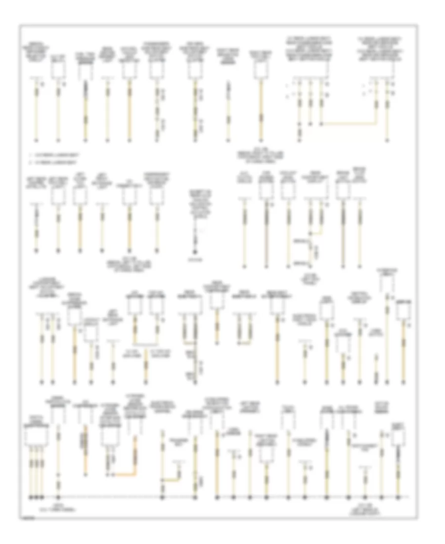
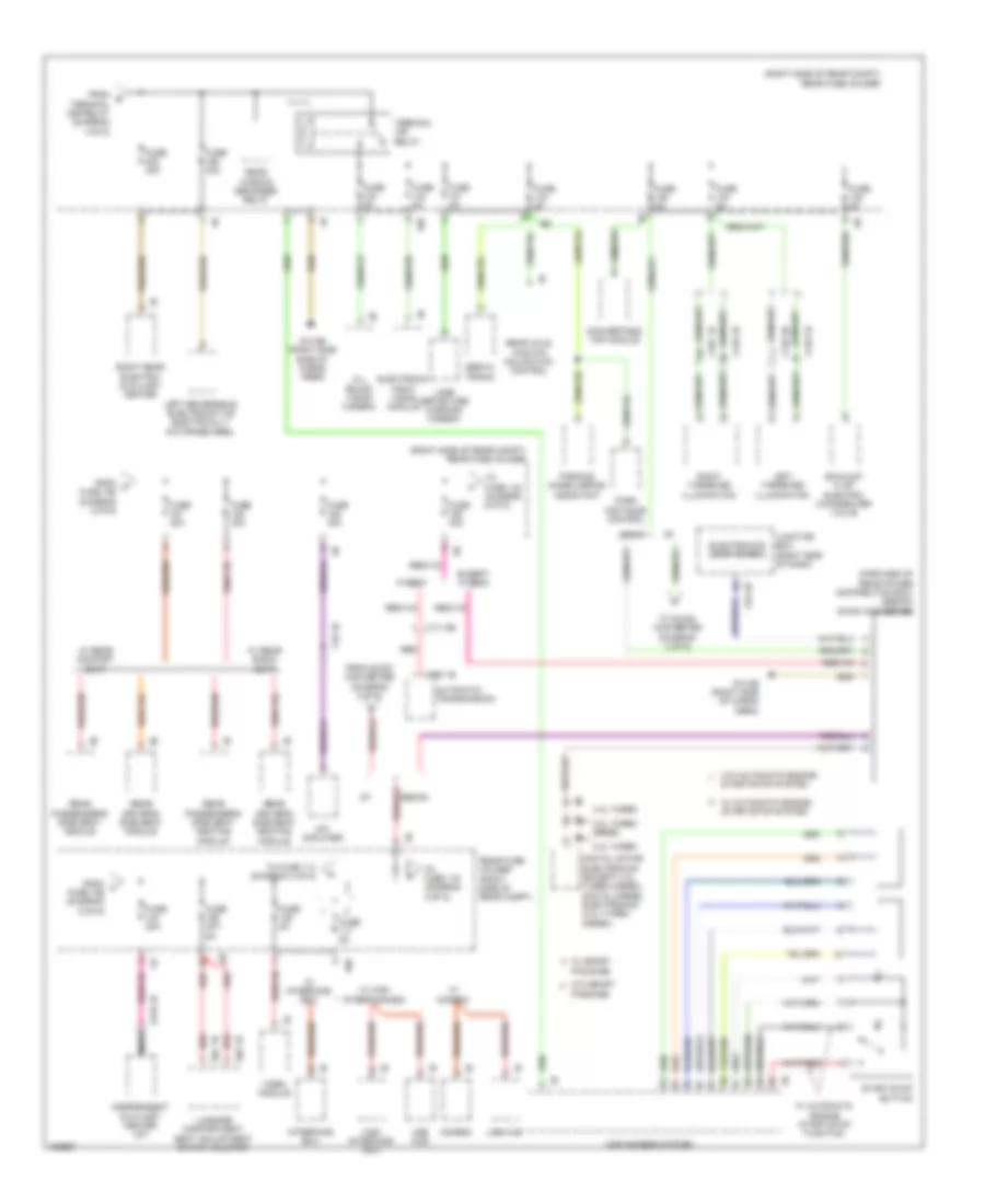
Ground Distribution Wiring Diagram (4 of 6) for BMW ActiveHybrid 5 2014
List of elements for Ground Distribution Wiring Diagram (4 of 6) for BMW ActiveHybrid 5 2014:
- (3.0l turbo diesel) scr control unit
- (3.0l turbo) a/c compressor
- (gt) automatic luggage compartment lid actuation
- (gt) fuel pump control (ekps)
- (if equipped) rear driver's side seat belt buckle contact
- (if equipped) rear passenger's side seat belt buckle contact
- (w/ panorama glass roof) left rear interior light
- (w/ panorama glass roof) right rear interior light
- (w/o rear compartment automatic climate control) driver's side rear seat heating switch
- (w/o rear compartment automatic climate control) passenger's side rear seat heating switch
- 12v connection 2
- Active steering servo motor shield
- Active tank fuel level sensor
- Auc sensor
- Automatic air recirculation control (auc) sensor
- Basic variant roof functions module
- Boot lid lift
- Boot lid/ tailgate lock
- Camera-based driver assistance systems
- Center console operating unit
- Center rear seat belt buckle contact
- Central gateway module
- Compressor relay
- Crash safety module
- Diagnosis socket
- Dosing line heating
- Driver's seat belt buckle contact
- Electrochromic interior rear view mirror
- Electronic ride height control
- Exterior boot lid button
- Footwell module
- High variant roof functions module
- Hotel position switch
- Integrated chassis management
- Lane change warning
- Left front vanity mirror switch
- Left inner tail light
- Left license plate light
- License plate light
- Nca
- Parking brake button
- Parking brake control unit
- Parking distance control
- Parking maneuvering assistant
- Passenger's seat belt buckle contact
- Passenger's seat occupancy deactivation sensor
- Premium top hifi amplifier
- Rear compartment automatic climate control
- Rear compartment display 2
- Rear lid lock 2
- Right front vanity mirror switch
- Right inner tail light
- Right license plate light
- Sedan
- Siren w/ tilt alarm sensor
- W/ automatic soft close system
- W/ basic variant
- W/ high variant
- W/ rear lid button
- W/o automatic soft close system
- Washer fluid level switch
- X12 1b
- X14 1b
- X231 1b
- X448 1b
- X6454 (rear of engine block)
- Y25 1b
- Z10 10b (under front of center console)
- Z10 11b (right kick panel)
- Z10 17b (right side of cargo area)
- Z10 18b
- Z10 20b (top of right "c" pillar)
- Z10 22b (left kick panel)
- Z10 50b
- Z10 58b
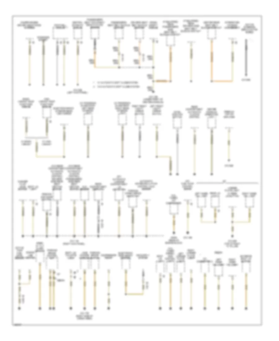
Ground Distribution Wiring Diagram (5 of 6) for BMW ActiveHybrid 5 2014
List of elements for Ground Distribution Wiring Diagram (5 of 6) for BMW ActiveHybrid 5 2014:
- (2.0l turbo) ignition coil cylinder 3
- (2.0l turbo) ignition coil cylinder 4
- (4.4l turbo) ignition coil cylinder 2
- (4.4l turbo) ignition coil cylinder 3
- (4.4l turbo) ignition coil cylinder 4
- (except m5) auxiliary water pump
- (hybrid) starter motor generator
- (m5) auxiliary water pump
- (m5) charge air cooler coolant pump
- (m5) charge air cooler coolant pump 2
- (not used)
- 2.0l turbo
- 3.0l turbo
- A/c compressor (electrical)
- Active cruise control
- Automatic transmission
- Bonnet contact switch
- Brake pad wear sensor
- Center washer nozzle heater
- Digital diesel electronics
- Electric fan
- Electronic transmission control
- Except m5
- Fuel filter heating
- High range fanfare horn
- Hybrid
- Independent auxiliary heater
- Independent heating coolant changeover valve
- Left fog light
- Left front
- Left front damper satellite
- Left front direction indicator light repeater
- Left headlight
- Left targeted illumination
- Left washer nozzle heater
- Low range fanfare horn
- M254 1b
- Nca
- Oil level switch
- Radiator shutter center drive unit
- Right fog light
- Right front damper satellite
- Right headlight
- Right targeted illumination
- Right washer nozzle heater
- Sedan
- Starter motor generator
- Terminating resistor 3
- Transmission oil pump
- Vehicle sound generator
- W/ alarm system & automatic air flap control
- W/ sport package
- W/o alarm system & automatic air flap control
- W/o sport package
- Water valve assembly
- Wiper module
- X148 1b
- X149 1b
- X149 2b
- X149 3b
- X187 1b
- X217 1b
- X218 2b
- X252 1b
- X690 1b
- Y21 1b
- Z10 15b (left rear of engine compt)
- Z10 2b (lower left front of engine compt)
- Z10 3b (lower right front of engine compt)
- Z6000 2b
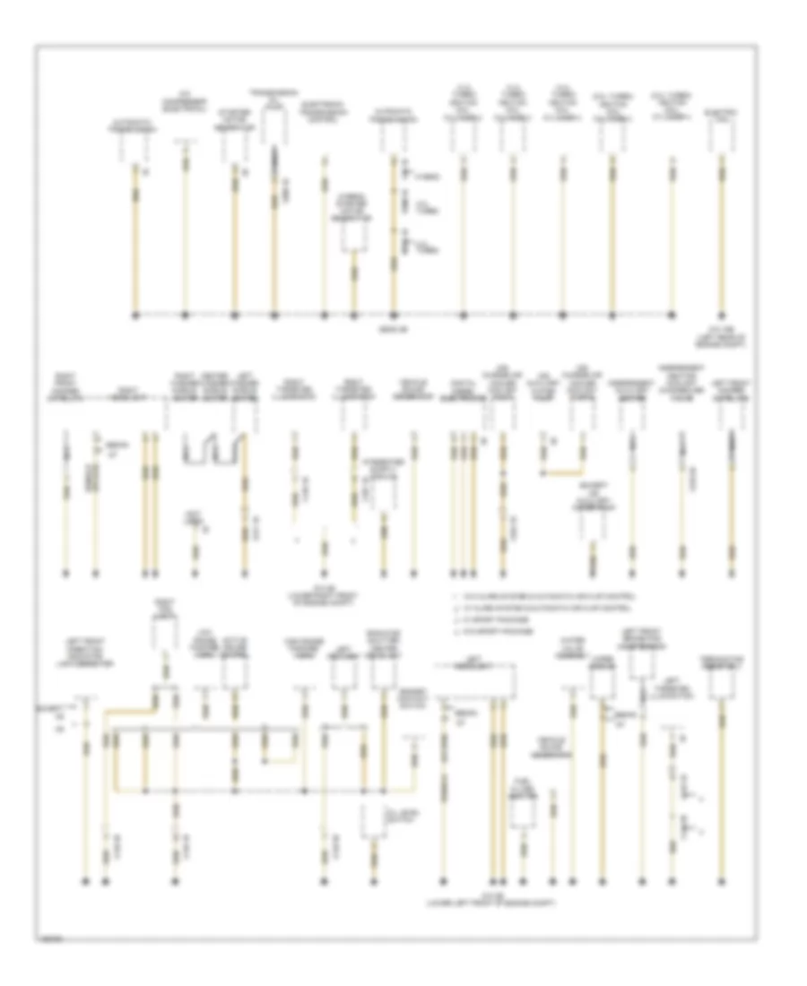
Ground Distribution Wiring Diagram (6 of 6) for BMW ActiveHybrid 5 2014
List of elements for Ground Distribution Wiring Diagram (6 of 6) for BMW ActiveHybrid 5 2014:
- (2.0l turbo) a/c compressor
- (2.0l turbo) digital motor electronics
- (2.0l turbo) reverse gear switch
- (2.0l turbo) transfer box
- (3.0l turbo diesel) electronic transmission control
- (4.4l turbo)
- (4.4l turbo) digital motor electronics
- (4.4l turbo) ignition coil cylinder 5
- (4.4l turbo) ignition coil cylinder 6
- (4.4l turbo) ignition coil cylinder 7
- (4.4l turbo) ignition coil cylinder 8
- (4.4l turbo) transfer box
- (535i gt & 535i gt xdrive) electric coolant pump
- (535i gt & 535i gt xdrive) intercooler coolant pump
- (550i, 550i gt, 550i gt xdrive & 550i xdrive) electronic transmission control
- (550i, 550i xdrive, 550i gt & 550i gt xdrive) a/c compressor
- (a/t) transfer box
- (hybrid) accumulator management electronics
- (hybrid) machine electronics electric
- (hybrid) rotor position sensor
- (hybrid) starter/ alternator electronics
- (m/t) input speed sensor
- (m/t) transfer box
- (m/t) transmission fluid pump
- (m/t) transmission oil pump relay
- (m5) a/c compressor
- (right side of rear compt) rear fuse holder
- (w/o noise suppressor filter) rear lid lock 2
- Bistable relay
- Contact free tailgate opening evaluation
- Contact free tailgate opening evaluation electronics
- Cooler box
- Dc/dc converter
- Dynamic stability control (dsc)
- Electric coolant pump
- Electronic transmission control
- Electronics
- Except m5
- Fully automatic towing hitch
- Gearbox input-speed sensor
- Intercooler coolant pump
- M6 1b
- Nca
- Noise suppressor filter
- Oil condition sensor
- Power tailgate acoustic sensor
- Pressure control
- Rear air conditioning system blower output stage
- Rear compartment air conditioning system
- Rear window defogger
- Rear window defogger relay
- Rear window locking
- Rear wiper
- Reverse gear switch
- Right outer taillight
- Right rear damper satellite
- Terminal 15n relay
- Terminal 30b relay
- Terminator resistor 2
- Tire
- Trailer module
- Trailer socket
- Trailer socket switch
- Transmission oil pump relay
- Turbocharger coolant pump
- W/ twin clutch gear box
- W/o twin clutch gear box
- X268 1b
- X6343
- X6460
- X697 1b
- X6985
- X7517 (right front of engine compt)
- X8532
- Z10 23b
- Z10 4b (left kick panel)
- Z10 8b (right side of cargo area)
- Z6000 3b
- Z6000 4b
- Z6000 5b
- Zero-gear sensor
HEADLIGHTS
Headlights Wiring Diagram, with LED Headlamps (1 of 2) for BMW ActiveHybrid 5 2014
List of elements for Headlights Wiring Diagram, with LED Headlamps (1 of 2) for BMW ActiveHybrid 5 2014:
- (left end of dash) central gateway module
- (left kick panel) z10 22b
- 10b
- Computer data lines system
- Design light
- Electrochromic interior rearview mirror
- Electronics junction box
- Footwell module (left kick panel)
- Fuse 10a
- Fuse 15a
- Fuse 30a
- Fuse 40a
- Fuse 5a
- Gnd
- Headlight beam height control drive unit
- Headlight driver module
- High beam assistant sensor & control
- High beam headlight
- Hot at all times
- Hot w/ bi-stable relay energized
- Hot w/ terminal 15n relay energized
- Junction box (right side of dash)
- K-can bus sig
- Led main light module
- Left fog light
- Left headlight
- Light switch unit
- Lin bus sig
- Low beam headlight
- Outer fan
- Pnk
- Pwr sply
- Red
- Right fog light
- Sedan
- Sedan w/ adaptive light control
- Sedan w/o adaptive light control
- Side lights/ daytime driving light
- Sply 15
- Steering column switch cluster
- Swivel module
- Trn sig/ hi beam sw
- W/ sport package
- W/o sport package
- X149 1b
- X149 2b
- Z10 22b (left kick panel)
- Z10 2b (lower left front of engine compt)
- Z10 5b (left kick panel)
Headlights Wiring Diagram, with LED Headlamps (2 of 2) for BMW ActiveHybrid 5 2014
List of elements for Headlights Wiring Diagram, with LED Headlamps (2 of 2) for BMW ActiveHybrid 5 2014:
- (lower left center of dash) car access system
- (right side of cargo area) z10 17b
- 11b
- Basic variant roof function module
- Computer data lines system
- Design light
- Dynamic stability control (under right front of vehicle)
- Except m5
- Fuse 10a
- Fuse 15a
- Fuse 40a
- Fuse 5a
- Fuse 7.5a
- Headlight driver module
- Headlight range control drive unit
- High beam headlight
- High variant roof functions module
- Hot at all times
- Hot w/ bi-stable
- Hot w/ bi-stable relay energized
- Hot w/ terminal 30b relay energized
- Interior lights system
- Junction box (right side of dash)
- Led ind
- Led main light module
- Low beam headlight
- Outer fan
- Parking brake button
- Parking brake control module (center rear of luggage compt)
- Power distribution system
- Rain/light/ condensation/ solar sensor (rain sensor: front center of roof)
- Rear fuse holder (right side of rear compt)
- Red
- Relay energized
- Right headlight
- Sedan
- Sedan w/ adaptive light control
- Sedan w/o adaptive light control
- Side lights/ daytime driving light
- Sw sig
- Swivel module
- W/ basic variant
- W/ high variant
- Z10 11b (right kick panel)
- Z10 3b (lower right front of engine compt)
Headlights Wiring Diagram, without LED Headlamps (1 of 3) for BMW ActiveHybrid 5 2014
List of elements for Headlights Wiring Diagram, without LED Headlamps (1 of 3) for BMW ActiveHybrid 5 2014:
- (left end of dash) central gateway module
- 10b
- Bi-xenon
- Computer data lines system
- Cornering light
- Electrochromic interior rearview mirror
- Electronics junction box
- Footwell module (left kick panel)
- Fuse 10a
- Fuse 30a
- Fuse 40a
- Fuse 5a
- Gnd
- Gt & sedan w/o adaptive light control
- Headlight driver module
- Headlight high beam drive control unit
- Hi beam
- High beam
- High beam assistant sensor & control
- High beam sw
- Hot w/ bi-stable relay energized
- Hot w/ terminal 15n relay energized
- Junction box (right side of dash)
- K-can bus sig
- Left fog light
- Left headlight
- Lin bus sig
- Low beam
- Parking light/ daytime driving light
- Pnk
- Pwr sply
- Red
- Right fog light
- Sedan
- Sedan w/ adaptive light control
- Shutter bi-xenon
- Sply 15
- Steering column switch cluster
- Swivel module
- W/ sport package
- W/ xenon
- W/o sport package
- W/o xenon
- X149 1b
- X149 2b
- Xenon lamp
- Xenon light module
- Z10 22b (left kick panel)
- Z10 2b (lower left front of engine compt)
- Z10 5b (left kick panel)
Headlights Wiring Diagram, without LED Headlamps (2 of 3) for BMW ActiveHybrid 5 2014
List of elements for Headlights Wiring Diagram, without LED Headlamps (2 of 3) for BMW ActiveHybrid 5 2014:
- (lower left center of dash) car access system
- Adaptive light control
- Cornering light
- Fuse 10a
- Fuse 40a
- Gt & sedan w/o adaptive light control
- Headlight driver module
- Headlight high beam drive control unit
- High beam
- Hot w/ bi-stable relay energized
- Light switch unit
- Low beam
- Parking light/daytime driving light
- Rear fuse holder (right side of rear compt)
- Right headlight
- Sedan
- Sedan w/
- Shutter bi-xenon
- Swivel module
- W/ xenon
- W/o xenon
- Xenon lamp
- Xenon light module
- Z10 3b (lower right front of engine compt)
Headlights Wiring Diagram, without LED Headlamps (3 of 3) for BMW ActiveHybrid 5 2014
List of elements for Headlights Wiring Diagram, without LED Headlamps (3 of 3) for BMW ActiveHybrid 5 2014:
- (rain sensor: front center of roof)
- (right side of cargo area) z10 17b
- 11b
- Basic variant roof function module
- Computer data lines system
- Dynamic stability control (under right front of vehicle)
- Except m5
- Fuse 5a
- Fuse 7.5a
- High variant roof function module
- Hot at all times
- Hot w/ terminal 30b relay energized
- Interior lights system
- Junction box (right side of dash)
- Led ind
- Parking brake button
- Parking brake control module (center rear of luggage compt)
- Power distribution system
- Rain/light condensation/ solar sensor
- Rear fuse holder (right side of rear compt)
- Red
- Sw sig
- W/ basic variant
- W/ high variant
- Z10 11b (right kick panel)
HORN
Horn Wiring Diagram for BMW ActiveHybrid 5 2014
List of elements for Horn Wiring Diagram for BMW ActiveHybrid 5 2014:
- 10b
- 11b
- 15b
- Early production
- Electronic steering wheel module (part of steering wheel)
- Electronics junction box
- Fuse 10a
- Fuse 15a
- Fuse 250a
- Fuse box (under spare tire)
- High range fanfare horn (right front wheelwell)
- Horn button
- Horn relay
- Hot at all times
- Junction box (right side of dash)
- Late production
- Low range fanfare horn (right front wheel- well)
- Low range fanfare horn (right front wheelwell)
- Red
- Right multi-function steering wheel switch block
- Steering column switch cluster
- Terminal 30b relay
- X149 1b
INSTRUMENT CLUSTER
Electronic Night Vision Wiring Diagram for BMW ActiveHybrid 5 2014
List of elements for Electronic Night Vision Wiring Diagram for BMW ActiveHybrid 5 2014:
- 10b
- Basic w/ video switch
- Basic w/o video switch
- Computer data lines system
- Electronic night vision module
- Fuse 5a
- Head unit
- High
- Hot w/ terminal 15n relay energized
- Nca
- Night vision camera (left side of front bumper)
- Rear fuse holder (right side of rear compt)
- Red
- Video switch
- X4 1b
- Z10 12b (left rear of luggage compt)
Instrument Cluster Wiring Diagram for BMW ActiveHybrid 5 2014
List of elements for Instrument Cluster Wiring Diagram for BMW ActiveHybrid 5 2014:
- A34 1b
- A34 2b
- A34 3b
- Car access system (lower left center of dash)
- Computer data lines system
- Coolant level switch (right side of engine compt)
- Electronics junction box
- Fuel level sensor
- Fuel level sensor 2
- Fuse 10a
- Fuse 5a
- Head-up display
- Hot at all times
- Hot w/ terminal 30b relay energized
- Instrument cluster control unit
- Junction box (right side of dash)
- K can2-h
- K can2-l
- Nca
- Outside temperature sensor (under right front of vehicle)
- Red
- Sound systems
- Wake up sig
- X149 1b
- X94 1b
- Z1 10b
- Z10 6b (right kick panel)
- Z10 9b (left kick panel)
INTERIOR LIGHTS
Courtesy Lamps Wiring Diagram (1 of 3) for BMW ActiveHybrid 5 2014
List of elements for Courtesy Lamps Wiring Diagram (1 of 3) for BMW ActiveHybrid 5 2014:
- Ambient light
- Electronics junction box
- Fuse 5a
- Fuse 7.5a
- Glove compartment light
- Glove compartment light switch
- High variant roof functions module (w/ high variant) basic variant roof functions module (w/ basic variant)
- Hot at all times
- Hot w/ terminal 30b relay energized
- Instrument illumination circuit
- Interior light
- Junction box (right side of dash)
- Left front vanity mirror light
- Left front vanity mirror switch
- Left map reading light
- Power distribution system
- Rear interior light
- Red
- Right front vanity mirror light
- Right front vanity mirror switch
- Right map reading light
- W/ basic variant
- W/ high variant
- Z10 11b (right kick panel)
Courtesy Lamps Wiring Diagram (2 of 3) for BMW ActiveHybrid 5 2014
List of elements for Courtesy Lamps Wiring Diagram (2 of 3) for BMW ActiveHybrid 5 2014:
- Boot lid/ tailgate lock
- Boot lid/tailgate luggage compartment light
- Fuse 5a
- Hot w/ terminal 30b relay energized
- Inside rear lid button
- Left front entrance light
- Left rear entrance light
- Luggage compartment light
- Power distribution system
- Rear fuse holder (right side of rear compt)
- Right front entrance light
- Right rear entrance light
- W/ automatic soft close system
- W/o automatic soft close system
- Z10 14b (right "c" pillar)
- Z10 17b (right side of cargo area)
- Z10 6b (right kick panel)
Courtesy Lamps Wiring Diagram (3 of 3) for BMW ActiveHybrid 5 2014
List of elements for Courtesy Lamps Wiring Diagram (3 of 3) for BMW ActiveHybrid 5 2014:
- (right kick panel) z10 6b
- Computer data lines system
- Courtesy lighting
- Driver's door entrance light
- Driver's side rear courtesy lighting
- Driver's side rear entry light
- Electronics junction box
- Entrance lt
- Footwell module (left kick panel)
- Fuse 40a
- Gnd
- Hot w/ bi-stable relay energized
- Interior lt
- Junction box (right side of dash)
- K-can bus sig
- Left footwell lt
- Left front footwell light
- Passenger's door entrance light
- Passenger's side rear courtesy lighting
- Passenger's side rear entry light
- Pwr sply
- Right footwell lt
- Right front footwell light
- Signal, switch
- Switch signal
- X28 1b
- X5 1b
- X8 1b
- X9 1b
- Z10 5b (left kick panel)
- Z10 6b (right kick panel)
Instrument Illumination Wiring Diagram (1 of 2) for BMW ActiveHybrid 5 2014
List of elements for Instrument Illumination Wiring Diagram (1 of 2) for BMW ActiveHybrid 5 2014:
- Ambient light
- Ambient lt
- Ashtray illumination
- Basic variant roof functions module
- Center console operating unit
- Center front ventilation grille
- Central locking button operating unit hazard warning switch
- Computer data lines system
- Cooler box
- Dvd changer (left side of rear compt)
- Except m5
- Footwell module (left kick panel)
- Front cigarette 12v connection
- Fuse 10a
- Fuse 5a
- Gear selector switch
- Gnd
- Ground
- Heating/air conditioning system
- High variant roof functions module
- Hot w/ bi-stable relay energized
- Integrated chassis management (under center console)
- Interior rear lid button
- Junction box (right side of dash)
- Junction box electronics
- K-can bus sig
- Left front ventilation grille
- Light switch unit
- Lin bus sig
- Parking brake button
- Passenger's door inner door handle lighting
- Passenger's door pocket lighting
- Passenger's door power window switch
- Passenger's door trim panel lighting
- Pwr sply
- Rear interior light
- Rear seat entertainment
- Right front ventilation grille
- W/ basic variant
- W/ high variant
- X5 1b
- Z10 11b (right kick panel)
- Z10 12b (left rear of luggage compt)
- Z10 17b (right side of cargo area)
- Z10 5b (left kick panel)
- Z10 6b (right kick panel)
- Z10 8b (right side of cargo area)
Instrument Illumination Wiring Diagram (2 of 2) for BMW ActiveHybrid 5 2014
List of elements for Instrument Illumination Wiring Diagram (2 of 2) for BMW ActiveHybrid 5 2014:
- (left kick panel) z10 5b
- (right kick panel) z10 6b
- Computer data lines system
- Driver's door panel lighting
- Driver's door pocket lighting
- Driver's inner door handle lighting
- Front center armrest light
- Fuse 5a
- Hot w/ terminal 15n relay energized
- Left targeted illumination
- Rear compartment automatic climate control
- Rear compartment ventilation grille
- Rear driver's side door panel lighting
- Rear driver's side door pocket lighting
- Rear driver's side inner door handle lighting
- Rear driver's side power window switch
- Rear fuse holder (right side of rear compt)
- Rear passenger's side door panel lighting
- Rear passenger's side door pocket lighting
- Rear passenger's side inner door handle lighting
- Rear passenger's side power window switch
- Right targeted illumination
- W/ sports package
- W/o sports package
- X148 1b
- X149 1b
- X149 3b
- X187 1b
- X28 1b
- X8 1b
- X9 1b
- Z10 2b (lower left front of engine compt)
- Z10 3b (lower right front of engine compt)
- Z10 5b (left kick panel)
- Z10 6b (right kick panel)
MEMORY SYSTEMS
Driver"s Memory Seat Wiring Diagram (1 of 2) for BMW ActiveHybrid 5 2014
List of elements for Driver"s Memory Seat Wiring Diagram (1 of 2) for BMW ActiveHybrid 5 2014:
- Actuator motor
- Angle
- Bus sig
- Computer data lines system
- Depth
- Driver's door seat switch cluster
- Driver's seat angle adjustment drive (under driver's seat)
- Driver's seat depth adjustment drive (w/ multi-function seat or sport seat) (under driver's seat)
- Driver's seat forward/ backward adjustment drive (under driver seat)
- Driver's seat height adjustment drive (under driver's seat)
- Driver's seat module (under right side of seat)
- Footwell module (left kick panel)
- For/back
- Fuse 10a
- Fuse 30a
- Fuse 7.5a
- Gnd
- Gnd hall sens
- Hall sens sig
- Hall sensor
- Height
- Hot w/ terminal 30b relay energized
- Junction box (right side of dash)
- Nca
- Power distribution system
- Pwr sply
- Red
- Seat backrest
- Seat cushion
- Seats system
- Sig temp sens
- X14 1b
- Z10 5b (left kick panel)
Driver"s Memory Seat Wiring Diagram (2 of 2) for BMW ActiveHybrid 5 2014
List of elements for Driver"s Memory Seat Wiring Diagram (2 of 2) for BMW ActiveHybrid 5 2014:
- (w/ multi-function seat) driver's side seat adjustment switch cluster
- (w/o multi-function seat) driver's side seat adjustment switch cluster
- Actuator motor
- Back act fan
- Back angle
- Back gnd fan
- Back head
- Back width
- Bus sig
- Cam operated
- Driver's seat backrest angle adjustment drive
- Driver's seat backrest head adjustment drive (w/ multi-function seat) (left side of seat back)
- Driver's seat backrest width adjustment drive (w/ multi-function seat or sport seat) (bottom right of seat back)
- Driver's seat headrest height adjustment drive
- Driver's seat module (under right side of seat)
- Gnd
- Hall sens gnd
- Hall sens sig
- Hall sensor
- Headrest
- Lum sup active
- Lum sup gnd
- Lum sup vlv 1
- Lum sup vlv 2
- Lum sup vlv 3
- Lum sup vlv 4
- Lum sup volt
- Pressure gnd
- Pwr sply
- Red
- Seat act fan
- Seat gnd fan
- Seats system
- Vlv block gnd
- Volt sply
- Z10 5b (left kick panel)
Memory Mirrors Wiring Diagram, with LIN bus Function for BMW ActiveHybrid 5 2014
List of elements for Memory Mirrors Wiring Diagram, with LIN bus Function for BMW ActiveHybrid 5 2014:
- (left kick panel) z10 5b
- Adjustment drive
- Bus sig
- Computer data lines system
- Driver's door switch block
- Footwell module (left kick panel)
- Fuse 7.5a
- Hot w/ terminal 30b relay energized
- In drive
- Junction box (right side of dash)
- Left exterior mirror
- Mirror fold- m
- Mirror heater
- Navigation system
- Nca
- Outside mirror camera
- Right exterior mirror
- X28 1b
- X5 1b
- Z10 6b (right kick panel)
Memory Mirrors Wiring Diagram, without LIN bus Function for BMW ActiveHybrid 5 2014
List of elements for Memory Mirrors Wiring Diagram, without LIN bus Function for BMW ActiveHybrid 5 2014:
- (left kick panel) z10 5b
- Adjustment drive
- Bus sig
- Computer data lines system
- Driver's door switch block
- Electronics junction box
- Footwell module (left kick panel)
- Fuse 7.5a
- Hot w/ terminal 30b relay energized
- Junction box (right side of dash)
- Left exterior mirror
- Mirror heater
- Right exterior mirror
- X28 1b
- X5 1b
- Z10 5b (left kick panel)
- Z10 6b (right kick panel)
Passenger"s Memory Seat Wiring Diagram (1 of 2) for BMW ActiveHybrid 5 2014
List of elements for Passenger"s Memory Seat Wiring Diagram (1 of 2) for BMW ActiveHybrid 5 2014:
- Actuator motor
- Angle
- Bus sig
- Computer data lines system
- Depth
- Footwell module (left kick panel)
- For/back
- Fuse 10a
- Fuse 30a
- Fuse 7.5a
- Gnd
- Gnd hall sens
- Hall sens sig
- Hall sensor
- Height
- Hot w/ terminal 30b relay energized
- Junction box (right side of dash)
- Nca
- Passenger's door seat switch cluster
- Passenger's seat angle adjustment drive (under front passenger's seat)
- Passenger's seat depth adjustment drive (w/ multi-function seat or sport seat) (under front passenger's seat)
- Passenger's seat forward/ backward adjustment drive
- Passenger's seat height adjustment drive (under front passenger's seat)
- Passenger's seat module (under passenger's seat)
- Power distribution system
- Pwr sply
- Red
- Seat backrest
- Seat cushion
- Seats system
- Sig temp sens
- X12 1b
- Z10 6b (right kick panel)
Passenger"s Memory Seat Wiring Diagram (2 of 2) for BMW ActiveHybrid 5 2014
List of elements for Passenger"s Memory Seat Wiring Diagram (2 of 2) for BMW ActiveHybrid 5 2014:
- (w/ multi-function seat) passenger's side seat adjustment switch cluster
- (w/o multi-function seat) passenger's side seat adjustment switch cluster
- Actuator motor
- Back act fan
- Back angle
- Back gnd fan
- Back head
- Back width
- Bus sig
- Cam operated
- Cam sw sig
- Gnd
- Hall sens gnd
- Hall sens sig
- Hall sensor
- Headrest
- Lum sup active
- Lum sup gnd
- Lum sup vlv 1
- Lum sup vlv 2
- Lum sup vlv 3
- Lum sup vlv 4
- Lum sup volt
- Passenger's seat backrest angle adjustment drive (right side of passenger's seat back)
- Passenger's seat backrest head adjustment drive (w/ multi-function seat) (right side of seat back)
- Passenger's seat backrest width adjustment drive (w/ multi-function seat or sport seat) (bottom left of seat back)
- Passenger's seat headrest height adjustment drive
- Passenger's seat module (under passenger's seat)
- Pressure gnd
- Pwr sply
- Red
- Seat act fan
- Seat gnd fan
- Seat sw gnd
- Seat sw sply
- Seats system
- Sw sig
- Vlv block gnd
- Volt sply
- Z10 6b (right kick panel)
Steering Column Memory Wiring Diagram for BMW ActiveHybrid 5 2014
List of elements for Steering Column Memory Wiring Diagram for BMW ActiveHybrid 5 2014:
- 10b
- Bus sig
- Column
- Computer data lines system
- Driver's door seat switch cluster
- Footwell module (left kick panel)
- Fuse 10a
- Fuse 30a
- Fuse 7.5a
- Gnd
- Hall sens
- Hall sens sig
- Hot w/ bistable relay energized
- Hot w/ terminal 15n relay energized
- Hot w/ terminal 30b relay energized
- Junction box (right side of dash)
- Pnk
- Pwr sply
- Red
- Sply
- Steering column adjustment motor (right of steering column)
- Steering column inclination motor
- Steering column switch cluster
- Steering wheel heater & steering column adjustment switch
- Z10 5b (left kick panel)
NAVIGATION
All Around Vision Camera Wiring Diagram for BMW ActiveHybrid 5 2014
List of elements for All Around Vision Camera Wiring Diagram for BMW ActiveHybrid 5 2014:
- (left rear of luggage compt) z10 12b
- 10b
- All-round vision camera (left rear of luggage compt)
- Computer data lines system
- Exterior mirror camera
- Fuse 5a
- Head unit
- Hot w/ terminal 15n relay energized
- Left bumper camera (left end of front fascia)
- Left exterior mirror
- Nca
- Rear fuse holder (right side of rear compt)
- Red
- Reversing camera (center rear of trunk lid)
- Right bumper camera (right end of front fascia)
- Right exterior mirror
- Sedan
- Video switch
- W/ video switch
- W/o video switch
- X198 1b
- X199 1b
Lane Departure Warning Wiring Diagram, with Camera for BMW ActiveHybrid 5 2014
List of elements for Lane Departure Warning Wiring Diagram, with Camera for BMW ActiveHybrid 5 2014:
- A34 3b
- Camera-based driver assistance systems (left end of dash)
- Camera-based driver support systems heating (left end of dash)
- Computer data lines system
- Driver assistance systems operating unit
- Electronics junction box
- Footwell module (left kick panel)
- Fuse 5a
- Hot w/ bistable relay energized
- Hot w/ terminal 15n relay energized
- Junction box (right side of dash)
- Lane departure warning camera (base of interior rearview mirror assembly)
- Nca
- Red
- Z1 7b
- Z10 22b (left kick panel)
Lane Departure Warning Wiring Diagram, without Camera for BMW ActiveHybrid 5 2014
List of elements for Lane Departure Warning Wiring Diagram, without Camera for BMW ActiveHybrid 5 2014:
- Central gateway module (left end of dash)
- Computer data lines system
- Footwell module (left kick panel)
- Fuse 5a
- Hot w/ terminal 15n relay energized
- Lane departure warning camera (base of interior rearview mirror assembly)
- Pnk
- Rear fuse holder (right side of rear compt)
- Slave lane departure warning
- Steering column switch cluster
- Z10 17b (right side of cargo area)
Navigation Wiring Diagram, with Hifi Radio without Active Sound Design (1 of 2) for BMW ActiveHybrid 5 2014
List of elements for Navigation Wiring Diagram, with Hifi Radio without Active Sound Design (1 of 2) for BMW ActiveHybrid 5 2014:
- (left rear of luggage compt) z10 12b
- (or red)
- (sedan: bottom of left "c" pillar) noise suppression filter
- 10b
- 11b
- 15b
- 16b
- Aerial diversity
- All-round vision camera (left rear of luggage compt)
- Aux-in connection
- Central gateway module (left end of dash)
- Computer data lines system
- Dvd changer (left side of rear compt)
- Entertainment
- Fuse 10a
- Fuse 15a
- Fuse 5a
- Glove compartment usb connection
- Head unit
- Hot w/ terminal 30b relay energized
- Interior lights system
- Most data bus circuit
- Nca
- Power distribution system
- Rear fuse holder (right side of rear compt)
- Rear seat entertainment
- Rear seat entertainment circuit
- Rear window aerial
- Red
- Roof aerial
- Video module (sedan: left side of rear compt)
- Video switch
- W/ dvd changer
- W/ night vision camera
- W/ phase diversity
- W/ rear seat
- W/ scan diversity
- W/ video module
- W/ video switch
- W/o night vision camera
- W/o video switch
- W/o video switch & all round vision camera
- W/o video switch & w/ all round vision camera
- W/o video switch, night vision camera & w/ all round vision camera
- X188 1b
Navigation Wiring Diagram, with Hifi Radio without Active Sound Design (2 of 2) for BMW ActiveHybrid 5 2014
List of elements for Navigation Wiring Diagram, with Hifi Radio without Active Sound Design (2 of 2) for BMW ActiveHybrid 5 2014:
- (lower left front of engine compt)
- Base plate
- Central information display
- Computer data lines system
- Electronic night vision module
- Front center mid- range speaker
- Front center tweeter
- Fuse 30a
- Fuse 5a
- Head unit
- Hifi amplifier (sedan: left side of rear compt)
- Hot at all times
- Hot w/ terminal 15n relay energized
- Hot w/ terminal 30b relay energized
- Junction box (right side of dash)
- Left front mid- range speaker
- Left front tweeter
- Left front woofer
- Left rear mid range speaker (gt) left 2b rear mid range speaker 2 (sedan)
- Left rear tweeter (gt) left rear tweeter 2 (sedan)
- Microphone (w/o telephone) (in overhead console)
- Nca
- Power distribution system
- Rear fuse holder (right side of rear compt)
- Red
- Right front mid- range speaker
- Right front tweeter
- Right front woofer
- Right rear mid range speaker (gt) right 2b rear mid range speaker 2 (sedan)
- Right rear tweeter (gt) right rear tweeter 2 (sedan)
- Vehicle sound generator (right front of engine compt)
- Vision camera
- W/ night vision camera
- W/o night
- X188 1b
- X19 1b
- X28 1b
- X5 1b
- X8 1b
- X9 1b
- Z1 4b
- Z1 7b
- Z10 12b (left rear of luggage compt)
- Z10 2b
Navigation Wiring Diagram, without Hifi Radio & Active Sound Design (1 of 2) for BMW ActiveHybrid 5 2014
List of elements for Navigation Wiring Diagram, without Hifi Radio & Active Sound Design (1 of 2) for BMW ActiveHybrid 5 2014:
- (left rear of luggage compt) z10 12b
- (or red)
- (sedan: bottom of left "c" pillar) noise suppression filter
- 10b
- 11b
- 15b
- 16b
- Aerial diversity
- All-round vision camera (left rear of luggage compt)
- Aux-in connection
- Central gateway module (left end of dash)
- Computer data lines system
- Dvd changer (left side of rear compt)
- Entertainment
- Fuse 10a
- Fuse 15a
- Fuse 5a
- Glove compartment usb connection
- Head unit
- Hot w/ terminal 30b relay energized
- Interior lights system
- Most data bus circuit
- Nca
- Power distri- bution system
- Power distribution system
- Rear fuse holder (right side of rear compt)
- Rear seat entertainment
- Rear seat entertainment circuit
- Rear window aerial
- Red
- Roof aerial
- Video module (sedan: left side of rear compt)
- Video switch
- W/ dvd changer
- W/ night vision camera
- W/ rear seat
- W/ video module
- W/ video switch
- W/o night vision camera
- W/o video switch
- W/o video switch & all round vision camera
- W/o video switch & w/ all round vision camera
- W/o video switch, night vision camera & w/ all round vision camera
- X188 1b
Navigation Wiring Diagram, without Hifi Radio & Active Sound Design (2 of 2) for BMW ActiveHybrid 5 2014
List of elements for Navigation Wiring Diagram, without Hifi Radio & Active Sound Design (2 of 2) for BMW ActiveHybrid 5 2014:
- (right front of engine compt) vehicle sound generator
- Base plate
- Central information display
- Computer data lines system
- Electronic night vision module
- Fuse 5a
- Head unit
- Hot at all times
- Hot w/ terminal 15n relay energized
- Junction box (right side of dash)
- Left front mid range speaker
- Left front woofer
- Left rear mid range speaker (gt) left rear mid range speaker 2 (sedan)
- Microphone (w/o telephone) (in overhead console)
- Nca
- Power distribution system
- Red
- Right front mid range speaker
- Right front woofer
- Right rear mid range speaker (gt) right rear mid range speaker 2 (sedan)
- W/ night vision camera
- W/o night vision camera
- X188 1b
- X28 1b
- X5 1b
- X8 1b
- X9 1b
- Z1 4b
- Z1 7b
- Z10 12b (left rear of luggage compt)
- Z10 2b (lower left front of engine compt)
Parking Assistant Wiring Diagram, with Parking Maneuvering Assistant for BMW ActiveHybrid 5 2014
List of elements for Parking Assistant Wiring Diagram, with Parking Maneuvering Assistant for BMW ActiveHybrid 5 2014:
- (right kick panel) z10 11b
- Body can bus sig
- Computer data lines system
- Fuse 5a
- Gnd
- Hot w/ terminal 15n relay energized
- Left front center ultrasonic sensor (front of bumper)
- Left front ultrasonic sensor (front of bumper)
- Left parking maneuvering assistant ultrasonic sensor
- Left rear centre ultrasonic sensor (sedan: rear bumper)
- Left rear ultrasonic sensor (sedan: rear bumper)
- Park distance control (right side of glove compt)
- Parking maneuvering assistant
- Pnk
- Power sply
- Rear fuse holder (right side of rear compt)
- Right front center ultrasonic sensor (front of bumper)
- Right front ultrasonic sensor (front of bumper)
- Right parking maneuvering assistant ultrasonic sensor
- Right rear centre ultrasonic sensor (sedan: rear bumper)
- Right rear ultrasonic sensor (sedan: rear bumper)
- Sensor gnd
- Sig
- Sply, terminal 15
- X187 1b
- Z10 11b (right kick panel)
Parking Assistant Wiring Diagram, without Parking Maneuvering Assistant for BMW ActiveHybrid 5 2014
List of elements for Parking Assistant Wiring Diagram, without Parking Maneuvering Assistant for BMW ActiveHybrid 5 2014:
- 15b
- A34 1b
- A34 2b
- A34 6b
- Computer data lines system
- Fuse 250a
- Fuse box (under spare tire)
- Hot at all times
- Junction box (right side of dash)
- Left front center ultrasonic sensor (front of bumper)
- Left front ultrasonic sensor (front of bumper)
- Left rear center ultrasonic sensor (sedan: rear bumper)
- Left rear ultrasonic sensor (sedan: rear bumper)
- Red
- Right front center ultrasonic sensor (front of bumper)
- Right front ultrasonic sensor (front of bumper)
- Right rear center ultrasonic sensor (sedan: rear bumper)
- Right rear ultrasonic sensor (sedan: rear bumper)
- X187 1b
- Z1 11b
- Z10 6b (right kick panel)
PASSIVE RESTRAINTS
Passive Restraints Wiring Diagram for BMW ActiveHybrid 5 2014
List of elements for Passive Restraints Wiring Diagram for BMW ActiveHybrid 5 2014:
- Computer data lines system
- Fuse 30a
- Fuse 5a
- Ground
- Hot at all times
- Hot w/ terminal 30b relay energized
- Junction box (right side of dash)
- Left reversible electromotive electrically motorized reel
- Power distribution system
- Pt can-h
- Pt can-l
- Rear fuse holder (right side of rear compt)
- Red
- Right reversible electromotive electrically motorized reel
- Term 30 sply
- Term 30b sply
- Z10 5b (left kick panel)
- Z10 6b (right kick panel)
POWER DISTRIBUTION
Power Distribution Wiring Diagram (1 of 6) for BMW ActiveHybrid 5 2014
List of elements for Power Distribution Wiring Diagram (1 of 6) for BMW ActiveHybrid 5 2014:
- (3.0l turbo diesel) dde main relay
- (hybrid) reverse polarity protection
- (right side of rear compt) rear fuse holder
- 10b
- 11b
- 12b
- 15b
- 17b
- 2.0l turbo
- 25b
- 3.0l turbo
- 3.0l turbo diesel
- 3b red) (or nca
- A34 1b
- A34 2b
- Accumulator management electronics (hybrid)
- Alternator
- Battery
- Bi-stable relay
- Boot lid lift
- Central gateway module
- Compr- essor relay
- Computer data lines system
- Contact free tailgate opening evaluation electronics
- Cut-off relay (hybrid)
- Diagnosis socket
- Dme main relay
- Driver electronic outer door handle module
- Dynamic stability control (dsc) (except hybrid)
- Dynamic stability control (hybrid)
- Electric coolant pump
- Electric fan cut-off relay (w/ fan 800/1000w)
- Electric machine electronics (hybrid)
- Electro- mechanical power steering
- Electronics junction box
- Except 3.0l turbo diesel
- Except 3.0l turbo diesel red/
- Except hybrid
- Footwell module
- From fuse box (diagram 1 of 6)
- Fuse 100a
- Fuse 10a
- Fuse 125a
- Fuse 150a
- Fuse 20a
- Fuse 250a
- Fuse 30a
- Fuse 40a
- Fuse 50a
- Fuse 50a 30a
- Fuse 5a
- Fuse 60a
- Fuse box (under spare tire)
- Fuse holder
- Fuse n/a
- Hybrid
- Ignition & fuel injection relay
- Intelligent battery sensor (below right side luggage compt)
- Jump start terminal point (left side of engine compt)
- Junction box (right side of dash)
- Left headlight
- Left rear electric auxiliary heater
- Natural vacuum leak detection
- Nca
- Parking brake control module
- Parking brake control module (sedan)
- Passenger electronic outer door handle module
- Pre-heating control unit (3.0l turbo diesel)
- Premium top hifi amplifier
- Rear axle king pin inclination control
- Rear compartment fan motor output stage
- Rear driver's side outer door handle electronic module
- Rear passenger's side outer door handle electronic module
- Red
- Right headlight
- Safety battery terminal generator (right side of rear compt) x2
- Sedan
- Siren w/ tilt sensor alarm
- Starter
- Starter/ alternator electronics (hybrid)
- To dc/dc converter (2 of 6)
- To dc/dc converter (diagram 2 of 6)
- To fuse (diagram 4 of 6)
- To fuse 14 (diagram 2 of 6)
- To fuse 4 (diagram 2 of 6)
- To rear fuse holder (diagram 1 of 6)
- Top hifi amplifier
- Trailer module
- Transfer box
- Transfer terminal point
- Valve- tronic relay
- W/ coolant pump 200w
- W/ coolant pump 400w
- X10272
- X13 10b
- X13 3b
- X19 1b
- X2 1b
- X28 1b
- X5 1b
- X664 2b
- X671 1b
- X8 1b
- X9 1b
- X9143
- Z1 11b
- Z1 5b
- Z10 8b (right side of cargo area)
Power Distribution Wiring Diagram (2 of 6) for BMW ActiveHybrid 5 2014
List of elements for Power Distribution Wiring Diagram (2 of 6) for BMW ActiveHybrid 5 2014:
- (right side of cargo area) z10 8b
- (right side of dash) junction box
- A34 2b
- A34 3b
- Active steering module
- Basic variant roof functions module
- Blower output stage
- Car access system
- Combox (if equipped)
- Controller
- Dc/dc converter (gt) (forward of rear power distribution box)
- Digital motor electr- onics
- Driver assistance systems operating unit
- Dynamic stability control (dsc)
- Elect- ronics junction box
- Electric fan cut-out relay (w/ fan 400/600w)
- Electronics junction box
- Footwell module
- From b bi-stable relay (diagram 1 of 6)
- From c fuse 1 (diagram 1 of 6)
- From e fuse 71 (diagram 2 of 6)
- From fuse box (diagram 1 of 6)
- From q
- From rear fuse holder (diagram 1 of 6)
- From rear fuse holder (diagram n 6 of 6)
- Fuel filter heating
- Fuse 10a
- Fuse 15a
- Fuse 20a
- Fuse 30a
- Fuse 31 (diagram 4 of 6)
- Fuse 40a
- Fuse 50a
- Fuse 5a
- Fuse 60a
- Fuse 7.5a
- Glove compartment light
- Head-up display
- Heating/air conditioning system
- High variant roof functions module
- Instrument cluster control
- Junction box (right side of dash)
- Left headlight
- Light switch unit
- Menu
- N2 1b
- Noise supp- ressor filter
- Parking brake button
- Prompting auxiliary module
- Rear compartment controller
- Rear fuse holder (right side of rear compt)
- Red
- Steering column switch cluster
- Telematics communication box (if equipped)
- Telematics control unit (if equipped)
- Terminal 30b relay
- To fuse (diagram 2 of 6)
- To fuse 66 (diagram 3 of 6)
- To junction box (diagram 4 of 6)
- To rear fuse holder (diagram 6 of 6)
- To terminal 15n relay (diagram 3 of 6)
- Touch box
- Trailer module
- Unit
- Vertical dynamics management
- W/ automatic engine start/stop system
- W/ basic variant roof
- W/ high variant roof
- W/o automatic engine start/stop system
- Washer pump relay
- X167 1b
- X2544
- Z1 10b
- Z1 12b
- Z1 13b
- Z1 1b
- Z1 2b
- Z1 3b
- Z1 4b
- Z1 5b
- Z1 9b
- Z10 6b (right kick panel)
Power Distribution Wiring Diagram (3 of 6) for BMW ActiveHybrid 5 2014
List of elements for Power Distribution Wiring Diagram (3 of 6) for BMW ActiveHybrid 5 2014:
- (gt)
- (right side of dash) junction box
- (sedan)
- 12 v con- nection
- 12 v conne- ction 4
- 12 v connection 1
- A34 3b
- Auc sensor
- Automatic transmission control (3.0l turbo diesel)
- Automatic transmission control (except 3.0l turbo diesel)
- B111 2b
- Basic variant roof functions module
- Camera based driver assistance systems
- Car access system
- Compressor bypass plate change over valve
- Coolant pump egr cooling
- Driver's door seat switch cluster
- Driver's door switch block
- Driver's door switch cluster
- Driver's lumbar support switch
- Driver's lumbar support valve block
- Driver's seat module
- Driver's side seat adjustment switch cluster
- Ecg cooler electric change over & bypass valve
- Elec- tronics junction box
- Electric change over valve engine mount (hybrid)
- Electrochromic interior rear view mirror
- Electronic machine electronics (hybrid)
- Engine breather heater (3.0l turbo diesel)
- Engine mount electric change over valve
- Engine mounts electric change over valve (hybrid)
- Except hybrid
- From f washer pump relay (diagram 2 of 6)
- From fuse 31 (diagram 4 of 6)
- From g fuse 29 (diagram 2 of 6)
- From h fuse 54 (diagram 3 of 6)
- Front cigar- ette lighter 12v connection
- Front cigarette lighter 12 v con- nection
- Fuse 10a
- Fuse 20a
- Fuse 20a (3.0l turbo diesel)
- Fuse 30a
- Fuse 30a (3.0l turbo diesel)
- Fuse 40a
- Fuse 5a
- Fuse 7.5a
- Gear selector switch
- High variant roof functions module
- Horn relay
- Hot-film air mass meter
- Hybrid
- Independent auxiliary heater
- Instrument cluster control unit
- Integrated chassis management
- Interior lights system
- Left rear vanity mirror light
- Low temperature egr cooling change over valve
- Nca
- Oil condition sensor
- Oxygen sensor after catalytic converter
- Oxygen sensor before catalytic converter
- Passenger's door seat switch cluster
- Passenger's lumbar support switch
- Passenger's lumbar support valve block
- Passenger's seat module
- Passenger's side seat adjustment switch cluster
- Rear cigarette lighter 12 v con- nection
- Rear cigarette lighter 12 v conne- ction
- Red
- Right exterior mirror
- Right rear vanity mirror light
- Roof function center
- Sedan
- Steering column switch cluster
- Terminal 15n relay
- To fuse 35 (diagram 4 of 6)
- To fuse 45 (diagram 4 of 6)
- To fuse 50 (diagram 3 of 6)
- Vehicle sound generator (hybrid)
- W/ automatic engine start/stop system
- W/ basic variant roof
- W/ high variant roof
- W/ multi- function seat
- W/ seat module
- W/ semi electrical seat adjustment
- W/ vehicle sound generator
- W/o automatic engine start/stop system
- W/o multi- function seat
- W/o seat module
- W/o semi electrical seat adjustment
- W/o vehicle sound generator
- Wastegate valve pressure converter
- Wiper module
- X12 1b
- X13 11b
- X13 12b
- X13 13b
- X13 1b
- X13 3b
- X14 1b
- X14 1b red
- X218 1b
- X28 1b
- X5 1b
- X671 3b
- Y21 1b
- Z1 10b
- Z1 1b
- Z1 2b
- Z1 4b
- Z1 6b
- Z1 7b
- Z1 8b
- Z10 6b (right kick panel)
- Z10 7b
Power Distribution Wiring Diagram (4 of 6) for BMW ActiveHybrid 5 2014
List of elements for Power Distribution Wiring Diagram (4 of 6) for BMW ActiveHybrid 5 2014:
- (except gt)
- (gt)
- (not used)
- (right side of dash) junction box
- (right side of rear compt) rear fuse holder
- 11b
- 2.0l turbo
- 3.0l turbo
- Accumulator management electronics (hybrid)
- Active cruise control
- Active steering module
- Air conditioning compressor (hybrid)
- Auxiliary egr cooler by pass flap change over valve (3.0l turbo diesel)
- Auxiliary water pump (hybrid)
- Base plate
- Camshaft sensor (3.0l turbo diesel)
- Car access system
- Charge air cooler coolant pump 2 (gt)
- Dde main relay (3.0l turbo diesel)
- Digital motor electronics (dme) control module
- Driver's door automatic soft close drive
- Eject box
- Electric machine electronics (hybrid)
- Electro- mecha- nical power steering (if equipped)
- Extendible dash board speaker
- From d fuse 178 (diagram 1 of 6)
- From dc/dc converter (diagram 2 of 6)
- From fuse (diagram 6 of 6)
- From fuse 42 r (diagram 3 of 6)
- From j fuse 67 (diagram 3 of 6)
- Front refrig- erent shut off valve (hybrid)
- Fuel tank non- return valve (hybrid)
- Fuse (gt) 5a
- Fuse 10a
- Fuse 10a 15a
- Fuse 15a
- Fuse 20a
- Fuse 30a
- Fuse 5a
- High voltage safety connector
- Left reversible electro- motive electrically automatic reel
- Nca
- Preheating control unit
- Radiator shutter drive unit
- Rail pressure control valve (3.0l turbo diesel)
- Rear compartment automatic climate control
- Rear driver's side door seat switch cluster
- Rear driver's side seat adjustment switch cluster
- Rear driver's side seat heating switch
- Rear eject box
- Rear eject box 2
- Rear passenger's side door seat switch cluster
- Rear passenger's side seat adjustment switch cluster
- Rear passenger's side seat heating switch
- Red
- Right headlight
- Right reversible electromotive electrically automatic reel
- Right reversible electromotive electrically motorized reel
- Safety battery terminal generator
- Scr control unit (3.0l turbo diesel)
- Starter motor generator (hybrid)
- Tank vent shutoff valve (w/o bosch)
- Tank vent valve (w/o bosch)
- Terminal 30b relay
- To fuse (diagram 5 of 6)
- To fuse (diagram 6 of 6)
- To fuse 29 (diagram 2 of 6)
- To fuse 32 (diagram 3 of 6)
- Transfer box (2.0l turbo & 3.0l turbo)
- Transfer box (3.0l turbo diesel)
- Vertical dynamics management
- Volume control valve (3.0l turbo diesel)
- W/ automatic engine start/stop system
- W/ rear compartment automatic climate control
- W/ rear keypad handset
- W/o automatic engine start/stop system
- W/o rear compartment automatic climate control
- X10 1b
- X13 10b
- X13 12b
- X13 1b
- X13 2b
- X148 1b
- X167 1b
- X2402
- X252 1b
- X257 1b
- X28 1b
- X664 1b
- X8 1b
- X81 1b
- X82 1b
- X9 1b
- Z1 10b
- Z1 3b
- Z1 6b
- Z1 7b
- Z10 8b (right side of cargo area)
Power Distribution Wiring Diagram (5 of 6) for BMW ActiveHybrid 5 2014
List of elements for Power Distribution Wiring Diagram (5 of 6) for BMW ActiveHybrid 5 2014:
- (right side of rear compt) rear fuse holder
- 10b
- 12 v connection 2
- 12 v connection 3
- 12 v connection 4
- 12b
- Active sound design
- Auxiliary battery (hybrid)
- Boot lid lift
- Boot lid/ tailgate lock
- Boot lid/ tailgate luggage compartment light (gt)
- Boot lid/ tailgate luggage compartment light (sedan)
- Central information display
- Cut off relay (hybrid)
- Cut-off relay
- Driver's seat heating module
- Driver's side rear automatic soft close drive
- Dvd changer
- Electric fan cut-out relay
- Electronic ride height control (gt)
- Except hybrid
- From fuse 117 (diagram 6 of 6)
- From t fuse 114 (diagram 4 of 6)
- From y fuse 116 (diagram 5 of 6)
- Fuel pump control (ekps)
- Fuel tank leakage diagnostic module
- Fuel tank pressure sensor (hybrid)
- Fuse 100a
- Fuse 10a
- Fuse 15a
- Fuse 20a
- Fuse 30a
- Fuse 5a
- Fuse 5a 7.5a
- Fuse 7.5a
- Fuse box 2
- Head unit
- Hybrid
- Infotainment fan
- Inside rear lid button (gt)
- Inside rear lid button (sedan)
- Intelligent battery sensor 2 (below right side luggage compt)
- Interference suppression filter 4 (gt)
- Luggage compa- rtment light (gt)
- Luggage compa- rtment light 2 (gt)
- Luggage compartment light (sedan)
- Nca
- Noise suppressor filter (gt)
- Passenger's door automatic soft close drive
- Passenger's seat heating module
- Passenger's side rear automatic soft close drive
- Rear compartment display
- Rear compartment display 2
- Rear driver's side power window switch
- Rear lid central arrest button (gt)
- Rear lid luggage compartment light 2 (gt)
- Rear passenger's side power window switch
- Rear seat entertainment
- Red
- Safety battery terminal 1b generator (right side of rear compt)
- Starter motor generator
- Starter/ alternator electronics (hybrid)
- Tire pressure control
- To fuse (diagram 5 of 6)
- To fuse 187 (diagram 6 of 6)
- Top-hifi amplifier (if equipped)
- Trailer module
- Trailer socket
- Transfer terminal point 3
- Video switch
- W/ automatic engine start/stop system
- W/ noise suppressor filter
- W/o automatic engine start/stop system
- W/o noise suppressor filter
- X10885
- X12 1b
- X13 12b
- X14 1b
- X230 1b
- X231 1b
- X268 1b
- X5 1b
- X601 1b
- X8 1b
- X9 1b
- Z10 14b (gt) z10 17b (sedan) (sedan: right side of cargo area) (gt: left side of cargo area)
- Z10 6b (right kick panel)
Power Distribution Wiring Diagram (6 of 6) for BMW ActiveHybrid 5 2014
List of elements for Power Distribution Wiring Diagram (6 of 6) for BMW ActiveHybrid 5 2014:
- (forward of rear power distribution box) (sedan) dc/dc converter
- (right side of rear compt) rear fuse holder
- 10b
- 2.0l turbo
- 3.0l turbo
- 3.0l turbo diesel
- A34 2b
- All round vision camera
- Automatic transmission
- Car access system
- Combox
- Convertible top module
- Digital motor electronics (except 3.0l turbo diesel) digital diesel electronics (3.0l turbo diesel)
- Electronic night vision module
- Electronics junction box
- Except hybrid
- Exhaust flap electric changeover valve
- From dc/dc converter (diagram 2 of 6)
- From s terminal 30b relay (diagram 4 of 6)
- From v fuse 186 (diagram 6 of 6)
- From x fuse 155 (diagram 5 of 6)
- Fuse (gt) 5a
- Fuse 20a
- Fuse 30a
- Fuse 5a
- Hifi amplifier
- High interface box
- Hybrid
- Independent auxiliary heater (gt)
- Interface box
- Junction box (right side of dash)
- Lane departure warning camera
- Left reversible electromotive electrically motorized reel
- Left targeted illumination
- Luggage compartment seat adjustment switch cluster
- Nca
- Package
- Park distance control
- Parking maneuvering assistant
- Rear axle king pin inclination control
- Rear driver's side seat heating module
- Rear driver's side seat module
- Rear fuse holder (right side of rear compt)
- Rear passenger's side seat heating module
- Rear passenger's side seat module
- Rear window defogger relay
- Red
- Right rear electric auxiliary heater
- Right targeted illumination
- S91 1b
- S92 1b
- Sedan
- Servo- tronic
- Start-stop button
- Terminal 15n relay
- To dc/dc converter (diagram 2 of 6)
- To fuse 114 (diagram 4 of 6)
- To fuse 116 (diagram 5 of 6)
- To fuse 142 (diagram 6 of 6)
- Usb hub
- Video module
- W/ automatic engine start-stop function
- W/ automatic engine start/stop system
- W/ combox
- W/ high interface box
- W/ interface box
- W/ rear basic seat
- W/ rear comfort seat
- W/ sport package
- W/o automatic engine start/stop system
- W/o sport
- X13 13b
- X148 1b
- X149 1b
- X149 3b
- X187 1b
- X19 1b
- X218 1b
- X690 1b
- Z10 8b (right side of cargo area)
- Z10 8b (right side side of cargo area)
POWER DOOR LOCKS
Power Door Locks Wiring Diagram (1 of 2) for BMW ActiveHybrid 5 2014
List of elements for Power Door Locks Wiring Diagram (1 of 2) for BMW ActiveHybrid 5 2014:
- (right rear wheelwell) siren w/ tilt alarm sensor
- (right side of rear compt) central locking drive fuel filler flap
- Aerial diversity
- Anti-theft alarm system
- Boot lid/ tailgate lock
- Car access system (lower left center of dash)
- Central locking button hazard warning switch operating facility
- Computer data lines system
- Driver's door automatic soft-close drive
- Driver's door system lock (rear of driver's door)
- Electrochromic interior rearview mirror
- Electronics junction box
- Exterior boot lid button
- Footwell module (left kick panel)
- Fuse 15a
- Fuse 20a
- Hot at all times
- Hotel position switch
- Interior lights system
- Interior rear lid button
- Junction box (right side of dash)
- Nca
- Rear lid button
- Roof function center
- Trunk, tailgate, fuel doors system
- W/ automatic soft close system
- W/o automatic soft close system
- X188 1b
- X28 1b
- X5 1b
- X8 1b
- X9 1b
- Z10 11b (right kick panel)
- Z10 17b (right side of cargo area)
- Z10 5b (left kick panel)
Power Door Locks Wiring Diagram (2 of 2) for BMW ActiveHybrid 5 2014
List of elements for Power Door Locks Wiring Diagram (2 of 2) for BMW ActiveHybrid 5 2014:
- (left kick panel) z10 5b
- (right kick panel) z10 6b
- 11b
- Driver's side rear automatic soft-close drive
- Fuse 10a
- Fuse 5a
- Hot at all times
- Hot w/ terminal 30b relay energized
- Nca
- Passenger's door automatic soft-close drive
- Passenger's door system lock (rear of front passenger's door)
- Passenger's side rear automatic soft-close drive
- Power distribution system
- Rear driver's side door lock
- Rear fuse holder (right side of rear compt)
- Rear passenger's side door lock
- X28 1b
- X5 1b
- X8 1b
- X9 1b
- Z10 5b (left kick panel)
- Z10 6b (right kick panel)
POWER MIRRORS
Power Mirrors Wiring Diagram for BMW ActiveHybrid 5 2014
List of elements for Power Mirrors Wiring Diagram for BMW ActiveHybrid 5 2014:
- Anti-theft alarm system
- Anti-theft system
- Computer data lines system
- Electrochromic interior rearview mirror
- Electronics junction box
- Fuse 5a
- High beam assistant sensor & control
- Hot w/ terminal 15n relay energized
- Junction box (right side of dash)
- Lin bus sig
- Power distribution system
- Ter 15 sply
- Z10 11b (right kick panel)
POWER SEATS
Front Heated Seats Wiring Diagram, with Memory for BMW ActiveHybrid 5 2014
List of elements for Front Heated Seats Wiring Diagram, with Memory for BMW ActiveHybrid 5 2014:
- Bus sig
- Central gateway module (left end of dash)
- Computer data lines system
- Dr seat backrest
- Dr seat cushion
- Driver's seat backrest heating element (in driver's seat backrest)
- Driver's seat cushion heating element (in driver's seat cushion)
- Driver's seat module (under right side of seat)
- Electronics junction box
- Fuse 30a
- Fuse 7.5a
- Gnd
- Heating/air conditioning system
- Hot w/ bistable relay energized
- Hot w/ terminal 30b relay energized
- Junction box (right side of dash)
- Nca
- Pass seat backrest
- Pass seat cushion
- Passenger's seat backrest heating element (in front passenger's seat backrest)
- Passenger's seat cushion heating element (in front passenger's seat cushion)
- Passenger's seat module (under passenger's seat)
- Pwr sply
- Sig temp sens
- Volt sply
- W/ lumbar support
- W/o lumbar support
- X12 1b
- X14 1b
- Z10 5b (left kick panel)
- Z10 6b (right kick panel)
Front Heated Seats Wiring Diagram, without Memory for BMW ActiveHybrid 5 2014
List of elements for Front Heated Seats Wiring Diagram, without Memory for BMW ActiveHybrid 5 2014:
- (right kick panel) z10 6b
- 12b
- Bus sig
- Central gateway module (left end of dash)
- Computer data lines system
- Dr seat backrest
- Dr seat cushion
- Driver's seat backrest heating element (in driver's seat backrest)
- Driver's seat cushion heating element (in driver's seat cushion)
- Driver's seat heating module
- Electronics junction box
- Fuse 30a
- Fuse 7.5a
- Gnd
- Heating/air conditioning system
- Hot w/ bistable relay energized
- Hot w/ terminal 30b relay energized
- Junction box (right side of dash)
- Nca
- Pass seat backrest
- Pass seat cushion
- Passenger's seat backrest heating element (in front passenger's seat backrest)
- Passenger's seat cushion heating element (in front passenger's seat cushion)
- Passenger's seat heating module
- Pwr sply
- Rear fuse holder (right side of rear compt)
- Sig temp sens
- X12 1b
- X14 1b
- Z10 5b (left kick panel)
- Z10 6b (right kick panel)
Front Lumbar Wiring Diagram, with Memory with Active Seats for BMW ActiveHybrid 5 2014
List of elements for Front Lumbar Wiring Diagram, with Memory with Active Seats for BMW ActiveHybrid 5 2014:
- (right kick panel) z10 6b
- Bus sig
- Cam operated mot
- Cam sw sig
- Computer data lines system
- Driver active seat pressure distributor
- Driver lumbar support-active seat drive unit
- Driver's door seat switch cluster
- Driver's lumbar support valve block (driver's seatback)
- Driver's seat module (under right side of seat)
- Driver's side seat adjustment switch cluster
- Front passenger lumbar support-active seat drive unit
- Fuse 10a
- Fuse 30a
- Fuse 7.5a
- Gnd
- Hot w/ terminal 30b relay energized
- Junction box (right side of dash)
- Lum sup active
- Lum sup gnd
- Lum sup vlv 1
- Lum sup vlv 2
- Lum sup vlv 3
- Lum sup vlv 4
- Lum sup volt
- Passenger active seat pressure distributor
- Passenger's door seat switch cluster
- Passenger's lumbar support valve block (passenger's seatback)
- Passenger's seat module (under passenger's seat)
- Passenger's side seat adjustment switch cluster
- Pressure gnd
- Pwr sply
- Red
- Valve 1
- Valve 2
- Valve 3
- Valve 4
- Vlv block gnd
- X12 1b
- X14 1b
- Z10 5b (left kick panel)
- Z10 6b (right kick panel)
Front Lumbar Wiring Diagram, with Memory without Active Seats for BMW ActiveHybrid 5 2014
List of elements for Front Lumbar Wiring Diagram, with Memory without Active Seats for BMW ActiveHybrid 5 2014:
- (left kick panel) z10 5b
- (right kick panel) z10 6b
- Bus sig
- Computer data lines system
- Driver's lumbar support valve block (driver's seatback)
- Driver's seat module (under right side of seat)
- Driver's side seat adjustment switch cluster
- Driver's side seat lumbar support drive (under driver's seat)
- Fuse 10a
- Fuse 30a
- Gnd
- Hot w/ terminal 30b relay energized
- Junction box (right side of dash)
- Lum sup gnd
- Lum sup vlv 1
- Lum sup vlv 2
- Lum sup vlv 3
- Lum sup vlv 4
- Lum sup volt
- Nca
- Passenger's seat lumbar support drive (under front passenger's seat)
- Passenger's seat module (under passenger's seat)
- Passenger's side lumbar support valve block (passenger's seatback)
- Passenger's side seat adjustment switch cluster
- Pwr sply
- Red
- Valve 1
- Valve 2
- Valve 3
- Valve 4
- Vlv block gnd
- X12 1b
- X14 1b
- Z10 5b (left kick panel)
- Z10 6b (right kick panel)
Front Lumbar Wiring Diagram, without Memory for BMW ActiveHybrid 5 2014
List of elements for Front Lumbar Wiring Diagram, without Memory for BMW ActiveHybrid 5 2014:
- Driver's lumbar support switch
- Driver's lumbar support valve block (driver's seatback)
- Driver's seat lumbar support drive (under driver's seat)
- Fuse 10a
- Hot w/ terminal 30b relay energized
- Junction box (right side of dash)
- Passenger's lumbar support switch
- Passenger's lumbar support valve block (passenger's seatback)
- Passenger's seat lumbar support drive (under front passenger's seat)
- Red
- Valve 1
- Valve 2
- Valve 3
- Valve 4
- X12 1b
- X14 1b
- Z10 5b (left kick panel)
- Z10 6b (right kick panel)
Front Seat Ventilation Wiring Diagram (1 of 2) for BMW ActiveHybrid 5 2014
List of elements for Front Seat Ventilation Wiring Diagram (1 of 2) for BMW ActiveHybrid 5 2014:
- Back act fan
- Back gnd fan
- Bus sig
- Central gateway module (left end of dash)
- Computer data lines system
- Driver's seat backrest fan 1 (in driver's seat back)
- Driver's seat backrest fan 2 (in driver's seat back)
- Driver's seat backrest fan 3 (in driver's seat back)
- Driver's seat backrest fan 4 (in driver's seat back)
- Driver's seat cushion fan 1 (in driver's seat cushion)
- Driver's seat cushion fan 2 (in driver's seat cushion)
- Driver's seat cushion fan 3 (in driver's seat cushion)
- Driver's seat cushion fan 4 (in driver's seat cushion)
- Driver's seat cushion fan 5 (in driver's seat cushion)
- Driver's seat module (under right side of seat)
- Electronics junction box
- Fuse 30a
- Fuse 7.5a
- Gnd
- Heating/air conditioning system
- Hot w/ bistable relay energized
- Hot w/ terminal 30b relay energized
- Junction box (right side of dash)
- Pwr sply
- Red
- Seat act fan
- Seat gnd fan
- Volt sply
- W/ lumbar support
- W/o lumbar support
- X12 1b
- X127 1b
- X128 1b
- X14 1b
- Z10 5b (left kick panel)
Front Seat Ventilation Wiring Diagram (2 of 2) for BMW ActiveHybrid 5 2014
List of elements for Front Seat Ventilation Wiring Diagram (2 of 2) for BMW ActiveHybrid 5 2014:
- Back act fan
- Back gnd fan
- Bus sig
- Gnd
- Passenger's seat backrest fan 1 (in passenger's seat back)
- Passenger's seat backrest fan 2 (in passenger's seat back)
- Passenger's seat backrest fan 3 (in passenger's seat back)
- Passenger's seat backrest fan 4 (in passenger's seat back)
- Passenger's seat cushion fan 1 (in front passenger's seat cushion)
- Passenger's seat cushion fan 2 (in front passenger's seat cushion)
- Passenger's seat cushion fan 3 (in front passenger's seat cushion)
- Passenger's seat cushion fan 4 (in front passenger's seat cushion)
- Passenger's seat cushion fan 5 (in front passenger's seat cushion)
- Passenger's seat module (under passenger's seat)
- Pwr sply
- Red
- Seat act fan
- Seat gnd fan
- Volt sply
- X12 1b
- X129 1b
- X130 1b
- Z10 6b (right kick panel)
Heated Steering Wheel Wiring Diagram for BMW ActiveHybrid 5 2014
List of elements for Heated Steering Wheel Wiring Diagram for BMW ActiveHybrid 5 2014:
- 10b
- Ausw
- Electronic steering wheel module (part of steering wheel)
- Electronics junction box
- Fuse 10a
- Gnd
- Horn button
- Hot w/ terminal 15n relay energized
- Junction box (right side of dash)
- Left steering wheel multi-function switch block
- Lhz+
- Lhz-
- Nca
- Pwr bfi
- Raendel
- Red
- Right steering wheel multi-function switch block
- Sply
- Steering column switch cluster
- Steering wheel heater
- Steering wheel heater & steering column adjustment switch
- T lhz+
- T lhz-
- Touch detection electronics
- Vibration actuator (in steering wheel spoke)
- Z10 6b (right kick panel)
Passenger Power Seat Wiring Diagram for BMW ActiveHybrid 5 2014
List of elements for Passenger Power Seat Wiring Diagram for BMW ActiveHybrid 5 2014:
- Angle
- Back
- Front
- Fuse 30a
- Fwd/bwd
- Headrest
- Height
- Hot w/ terminal 30b relay energized
- Junction box (right side of dash)
- Passenger's seat backrest angle adjustment drive (right side of passenger's seat back)
- Passenger's seat forward/ backward adjustment drive
- Passenger's seat headrest height adjustment drive
- Passenger's seat height adjustment drive (under front passenger's seat)
- Passenger's seat tilt adjustment drive
- Passenger's side seat adjustment switch cluster
- Tilt
- W/ semi-electrical seat adjustment
- W/o semi-electrical seat adjustment
- X12 1b
- Z10 6b (right kick panel)
Rear Heated Seats Wiring Diagram for BMW ActiveHybrid 5 2014
List of elements for Rear Heated Seats Wiring Diagram for BMW ActiveHybrid 5 2014:
- (hatch back: right side of cargo area) (sedan: right "c" pillar) z10 13b
- Auc sensor (on air recirculation control microfilter compt)
- Central gateway module (left end of dash)
- Computer data lines system
- Electronics junction box
- Fuse 30a
- Fuse 5a
- Hot w/ terminal 30b relay energized
- Junction box (right side of dash)
- Nca
- Rear compartment automatic climate control (if equipped)
- Rear driver's side seat backrest heating element (in left rear seat backrest)
- Rear driver's side seat cushion heating element (in left rear seat cushion)
- Rear driver's side seat heating module
- Rear driver's side seat heating switch (w/o rear compartment automatic climate control)
- Rear fuse holder (right side of rear compt)
- Rear passenger's side seat backrest heating element (in right rear seat backrest)
- Rear passenger's side seat cushion heating element (in right rear seat cushion)
- Rear passenger's side seat heating module
- Rear passenger's side seat heating switch (w/o rear compartment automatic climate control)
- Z10 11b (right kick panel)
- Z10 13b (hatch back: right side of cargo area) (sedan: right "c" pillar)
POWER TOP/SUNROOF
Power Top/Sunroof Wiring Diagram for BMW ActiveHybrid 5 2014
List of elements for Power Top/Sunroof Wiring Diagram for BMW ActiveHybrid 5 2014:
- Computer data lines system
- Fuse 20a
- Fuse 5a
- Fuse 7.5a
- Hot at all times
- Hot w/ terminal 30b relay energized
- Junction box (right side of dash)
- Power distribution system
- Red
- Roof function center
- Slide/tilt sunroof drive unit
- Sunroof shade drive (sedan) electric motor roller sunblind panorama glass roof (gt)
- Z10 11b (right kick panel)
- Z10 6b (right kick panel)
POWER WINDOWS
Power Windows Wiring Diagram for BMW ActiveHybrid 5 2014
List of elements for Power Windows Wiring Diagram for BMW ActiveHybrid 5 2014:
- (left kick panel) z10 5b
- Computer data lines system
- Driver's door switch block
- Driver's power window drive
- Driver's rear side power window drive
- Driver's rear side power window switch
- Electronics junction box
- Footwell module (left kick panel)
- Fuse 30a
- Fuse 40a
- Fuse 7.5a
- Hot at all times
- Hot w/ bi-stable relay energized
- Hot w/ terminal 30b relay energized
- Interior lights system
- Junction box (right side of dash)
- Passenger power window drive
- Passenger's door power window switch
- Passenger's rear side power window drive
- Passenger's rear side power window switch
- Power distribution system
- W/ electrically operated roller sun blinds
- W/o electrically operated roller sun blinds
- X28 1b
- X5 1b
- X8 1b
- X9 1b
- Z10 22b (left kick panel)
- Z10 5b (left kick panel)
- Z10 6b (right kick panel)
Roller Sun Blind Wiring Diagram for BMW ActiveHybrid 5 2014
List of elements for Roller Sun Blind Wiring Diagram for BMW ActiveHybrid 5 2014:
- (left kick panel) z10 5b
- Auxiliary seat functions w/ switch cluster
- Computer data lines system
- Driver's door switch block
- Electronics junction box
- Footwell module (left kick panel)
- Fuse 10a
- Fuse 30a
- Fuse 7.5a
- Hot at all times
- Hot w/ terminal 30b relay energized
- Junction box (right side of dash)
- Power distribution system
- Rear driver's side power window switch
- Rear driver's side roller sun blind drive
- Rear fuse holder (right side of rear compt)
- Rear passenger's side power window switch
- Rear passenger's side roller sun blind drive
- Rear window roller sun blind drive
- W/ seat switch block driver's door
- X28 1b
- X8 1b
- X9 1b
- Z10 5b (left kick panel)
- Z10 6b (right kick panel)
RADIO
Base Radio Wiring Diagram, with Active Sound Design (1 of 3) for BMW ActiveHybrid 5 2014
List of elements for Base Radio Wiring Diagram, with Active Sound Design (1 of 3) for BMW ActiveHybrid 5 2014:
- (left rear of luggage compt) z10 12b
- (or red)
- (sedan: bottom of left "c" pillar) noise suppression filter
- 10b
- 11b
- 15b
- 16b
- Aerial diversity
- Aux-in connection
- Central gateway module (left end of dash)
- Computer data lines system
- Fuse 10a
- Fuse 15a
- Fuse 5a
- Glove compartment usb connection
- Head unit
- Hot w/ terminal 30b relay energized
- Most data bus circuit
- Nca
- Power distribution system
- Rear fuse holder (right side of rear compt)
- Rear seat entertainment
- Rear seat entertainment circuit
- Rear window aerial
- Red
- Roof aerial
- X188 1b
Base Radio Wiring Diagram, with Active Sound Design (2 of 3) for BMW ActiveHybrid 5 2014
List of elements for Base Radio Wiring Diagram, with Active Sound Design (2 of 3) for BMW ActiveHybrid 5 2014:
- (left rear of luggage compt) z10 12b
- (or red)
- (right front of engine compt) vehicle sound generator
- All-round vision camera (left rear of luggage compt)
- Base plate
- Central information display
- Computer data lines system
- Dvd changer (left side of rear compt)
- Fuse 5a
- Head unit
- Hot at all times
- Hot w/ terminal 15n relay energized
- Interior lights system
- Junction box (right side of dash)
- Most data bus circuit
- Nca
- Power distribution system
- Red
- Video module (sedan: left side of rear compt)
- Video switch
- W/ dvd changer
- W/ night vision camera
- W/ rear seat entertainment
- W/ video module
- W/ video switch
- W/o night vision camera
- W/o video switch
- W/o video switch & all round vision camera
- W/o video switch & w/ all round vision camera
- W/o video switch, night vision camera & w/ all round vision camera
- Z1 4b
- Z1 7b
- Z10 12b (left rear of luggage compt)
- Z10 2b (lower left front of engine compt)
Base Radio Wiring Diagram, with Active Sound Design (3 of 3) for BMW ActiveHybrid 5 2014
List of elements for Base Radio Wiring Diagram, with Active Sound Design (3 of 3) for BMW ActiveHybrid 5 2014:
- Active sound design
- Computer data lines system
- Electronic night vision module
- Left front mid range speaker
- Left front woofer
- Left rear mid range speaker (gt) left rear mid range speaker 2 (sedan)
- Microphone (w/o telephone) (in overhead console)
- Nca
- Right front mid range speaker
- Right front woofer
- Right rear mid range speaker 2 (sedan) right rear mid range speaker (gt)
- X188 1b
- X28 1b
- X5 1b
- X8 1b
- X9 1b
- Z10 12b (left rear of luggage compt)
Base Radio Wiring Diagram, without Active Sound Design (1 of 2) for BMW ActiveHybrid 5 2014
List of elements for Base Radio Wiring Diagram, without Active Sound Design (1 of 2) for BMW ActiveHybrid 5 2014:
- (left rear of luggage compt) z10 12b
- (or red)
- (sedan: bottom of left "c" pillar) noise suppression filter
- 10b
- 11b
- 15b
- 16b
- Aerial diversity
- All-round vision camera (left rear of luggage compt)
- Aux-in connection
- Central gateway module (left end of dash)
- Computer data lines system
- Dvd changer (left side of rear compt)
- Entertainment
- Fuse 10a
- Fuse 15a
- Fuse 5a
- Glove compartment usb connection
- Head unit
- Hot w/ terminal 30b relay energized
- Interior lights system
- Most data bus circuit
- Nca
- Power distri- bution system
- Power distribution system
- Rear fuse holder (right side of rear compt)
- Rear seat entertainment
- Rear seat entertainment circuit
- Rear window aerial
- Red
- Roof aerial
- Video module (sedan: left side of rear compt)
- Video switch
- W/ dvd changer
- W/ night vision camera
- W/ rear seat
- W/ video module
- W/ video switch
- W/o night vision camera
- W/o video switch
- W/o video switch & all round vision camera
- W/o video switch & w/ all round vision camera
- W/o video switch, night vision camera & w/ all round vision camera
- X188 1b
Base Radio Wiring Diagram, without Active Sound Design (2 of 2) for BMW ActiveHybrid 5 2014
List of elements for Base Radio Wiring Diagram, without Active Sound Design (2 of 2) for BMW ActiveHybrid 5 2014:
- (right front of engine compt) vehicle sound generator
- Base plate
- Central information display
- Computer data lines system
- Electronic night vision module
- Fuse 5a
- Head unit
- Hot at all times
- Hot w/ terminal 15n relay energized
- Junction box (right side of dash)
- Left front mid range speaker
- Left front woofer
- Left rear mid range speaker (gt) left rear mid range speaker 2 (sedan)
- Microphone (w/o telephone) (in overhead console)
- Nca
- Power distribution system
- Red
- Right front mid range speaker
- Right front woofer
- Right rear mid range speaker (gt) right rear mid range speaker 2 (sedan)
- W/ night vision camera
- W/o night vision camera
- X188 1b
- X28 1b
- X5 1b
- X8 1b
- X9 1b
- Z1 4b
- Z1 7b
- Z10 12b (left rear of luggage compt)
- Z10 2b (lower left front of engine compt)
Hifi Radio Wiring Diagram, with Active Sound Design (1 of 3) for BMW ActiveHybrid 5 2014
List of elements for Hifi Radio Wiring Diagram, with Active Sound Design (1 of 3) for BMW ActiveHybrid 5 2014:
- (left rear of luggage compt) z10 12b
- (or red)
- (sedan: bottom of left "c" pillar) noise suppression filter
- 10b
- 11b
- 15b
- 16b
- Aerial diversity
- Aux-in connection
- Central gateway module (left end of dash)
- Computer data lines system
- Fuse 10a
- Fuse 15a
- Fuse 5a
- Glove compartment usb connection
- Head unit
- Hot w/ terminal 30b relay energized
- Most data bus circuit
- Nca
- Power distribution system
- Rear fuse holder (right side of rear compt)
- Rear seat entertainment
- Rear seat entertainment circuit
- Rear window antena
- Red
- Roof aerial
- W/ phase diversity
- W/ scan diversity
- X188 1b
Hifi Radio Wiring Diagram, with Active Sound Design (2 of 3) for BMW ActiveHybrid 5 2014
List of elements for Hifi Radio Wiring Diagram, with Active Sound Design (2 of 3) for BMW ActiveHybrid 5 2014:
- (left rear of luggage compt) z10 12b
- (or red)
- Active sound design
- All-round vision camera (left rear of luggage compt)
- Base plate
- Dvd changer (left side of rear compt)
- Interior lights system
- Most data bus circuit
- Nca
- Red
- System data lines computer
- Video module (sedan: left side of rear compt)
- Video switch
- W/ dvd changer
- W/ night vision camera
- W/ rear seat entertainment
- W/ video module
- W/ video switch
- W/o night vision camera
- W/o video switch
- W/o video switch & all round vision camera
- W/o video switch & w/ all round vision camera
- W/o video switch, night vision camera & w/ all round vision camera
- Z10 12b (left rear of luggage compt)
Hifi Radio Wiring Diagram, with Active Sound Design (3 of 3) for BMW ActiveHybrid 5 2014
List of elements for Hifi Radio Wiring Diagram, with Active Sound Design (3 of 3) for BMW ActiveHybrid 5 2014:
- (lower left front of engine compt)
- Central information display
- Computer data lines system
- Electronic night vision module
- Front center mid- range speaker
- Front center tweeter
- Fuse 30a
- Fuse 5a
- Head unit
- Hifi amplifier (left side of rear compt)
- Hot at all times
- Hot w/ terminal 15n relay energized
- Hot w/ terminal 30b relay energized
- Junction box (right side of dash)
- Left front mid- range speaker
- Left front tweeter
- Left front woofer
- Left rear mid range speaker (gt) left 2b rear mid range speaker 2 (sedan)
- Left rear tweeter (gt) left rear tweeter 2 (sedan)
- Microphone (w/o telephone) (in overhead console)
- Nca
- Power distribution system
- Rear fuse holder (right side of rear compt)
- Red
- Right front mid- range speaker
- Right front tweeter
- Right front woofer
- Right rear mid range speaker (gt) right 2b rear mid range speaker 2 (sedan)
- Right rear tweeter (gt) right rear tweeter 2 (sedan)
- Vehicle sound generator (right front of engine compt)
- X188 1b
- X19 1b
- X28 1b
- X5 1b
- X8 1b
- X9 1b
- Z1 4b
- Z1 7b
- Z10 12b (left rear of luggage compt)
- Z10 2b
Hifi Radio Wiring Diagram, without Active Sound Design (1 of 2) for BMW ActiveHybrid 5 2014
List of elements for Hifi Radio Wiring Diagram, without Active Sound Design (1 of 2) for BMW ActiveHybrid 5 2014:
- (left rear of luggage compt) z10 12b
- (or red)
- (sedan: bottom of left "c" pillar) noise suppression filter
- 10b
- 11b
- 15b
- 16b
- Aerial diversity
- All-round vision camera (left rear of luggage compt)
- Aux-in connection
- Central gateway module (left end of dash)
- Computer data lines system
- Dvd changer (left side of rear compt)
- Entertainment
- Fuse 10a
- Fuse 15a
- Fuse 5a
- Glove compartment usb connection
- Head unit
- Hot w/ terminal 30b relay energized
- Interior lights system
- Most data bus circuit
- Nca
- Power distribution system
- Rear fuse holder (right side of rear compt)
- Rear seat entertainment
- Rear seat entertainment circuit
- Rear window aerial
- Red
- Roof aerial
- Video module (sedan: left side of rear compt)
- Video switch
- W/ dvd changer
- W/ night vision camera
- W/ phase diversity
- W/ rear seat
- W/ scan diversity
- W/ video module
- W/ video switch
- W/ video switvh
- W/o night vision camera
- W/o video switch & all round vision camera
- W/o video switch & w/ all round vision camera
- W/o video switch, night vision camera & w/ all round vision camera
- W/o video switvh
- X188 1b
Hifi Radio Wiring Diagram, without Active Sound Design (2 of 2) for BMW ActiveHybrid 5 2014
List of elements for Hifi Radio Wiring Diagram, without Active Sound Design (2 of 2) for BMW ActiveHybrid 5 2014:
- (lower left front of engine compt)
- Base plate
- Central information display
- Computer data lines system
- Electronic night vision module
- Front center mid- range speaker
- Front center tweeter
- Fuse 30a
- Fuse 5a
- Head unit
- Hifi amplifier (sedan: left side of rear compt)
- Hot at all times
- Hot w/ terminal 15n relay energized
- Hot w/ terminal 30b relay energized
- Junction box (right side of dash)
- Left front mid- range speaker
- Left front tweeter
- Left front woofer
- Left rear mid range speaker (gt) left 2b rear mid range speaker 2 (sedan)
- Left rear tweeter (gt) left rear tweeter 2 (sedan)
- Microphone (w/o telephone) (in overhead console)
- Nca
- Power distribution system
- Rear fuse holder (right side of rear compt)
- Red
- Right front mid- range speaker
- Right front tweeter
- Right front woofer
- Right rear mid range speaker (gt) right 2b rear mid range speaker 2 (sedan)
- Right rear tweeter (gt) right rear tweeter 2 (sedan)
- Vehicle sound generator (right front of engine compt)
- Vision camera
- W/ night vision camera
- W/o night
- X188 1b
- X19 1b
- X28 1b
- X5 1b
- X8 1b
- X9 1b
- Z1 4b
- Z1 7b
- Z10 12b (left rear of luggage compt)
- Z10 2b
MOST Data Bus Wiring Diagram for BMW ActiveHybrid 5 2014
List of elements for MOST Data Bus Wiring Diagram for BMW ActiveHybrid 5 2014:
- Central gateway module (left end of dash)
- Combox
- Dvd changer (left side of rear compt)
- Head unit
- High interface box
- Instrument cluster control unit
- Interface box
- Rear seat entertainment
- Telematics control unit
- Top-hifi amplifier
- Video module (sedan: left side of rear compt)
- W/ combox
- W/ telematics control unit
- W/o telematics control unit & combox
Rear Seat Entertainment Wiring Diagram for BMW ActiveHybrid 5 2014
List of elements for Rear Seat Entertainment Wiring Diagram for BMW ActiveHybrid 5 2014:
- (left kick panel) z10 9b
- (right kick panel) z10 11b
- 10b
- A34 1b
- A34 3b
- Computer data lines system
- Controller
- Dvd changer (left side of rear compt)
- Electronic junction box
- Fuse 10a
- Fuse 5a
- Fuse 7.5a
- Head unit
- Hot w/ terminal 30b relay energized
- Interior lights system
- Junction box (right side of dash)
- Left infrared transmitter
- Left rear compartment operating unit
- Most data bus circuit
- Nca
- Rear compartment controller
- Rear compartment display
- Rear compartment display 2
- Rear fuse holder (right side of rear compt)
- Rear seat entertainment
- Red
- Right infrared transmitter
- Right rear compartment operating unit
- Touch box
- Video module (sedan: left side of rear compt)
- Video switch
- W/ dvd changer
- W/ high version
- W/ video module
- W/o video module & dvd changer
- X167 1b
- X188 1b
- X230 1b
- X230 2b
- X231 1b
- X231 2b
- Z1 10b
- Z10 12b (left rear of luggage compt)
- Z10 6b (right kick panel)
Top Hifi Radio Wiring Diagram, Except Premium with Active Sound Design (1 of 2) for BMW ActiveHybrid 5 2014
List of elements for Top Hifi Radio Wiring Diagram, Except Premium with Active Sound Design (1 of 2) for BMW ActiveHybrid 5 2014:
- 10b
- Active sound design
- Computer data lines system
- Fuse 15a
- Hot w/ terminal 30b relay energized
- Left rear mid range speaker
- Left rear tweeter
- Nca
- Noise suppressor filter (sedan: bottom of left "c" pillar)
- Rear fuse holder (right side of rear compt)
- Right rear mid range speaker
- Right rear mid range speaker 2
- Right rear tweeter
- Right rear tweeter 2
- X188 1b
- X8 1b
- X9 1b
- Z10 12b (left rear of luggage compt)
Top Hifi Radio Wiring Diagram, Except Premium with Active Sound Design (2 of 2) for BMW ActiveHybrid 5 2014
List of elements for Top Hifi Radio Wiring Diagram, Except Premium with Active Sound Design (2 of 2) for BMW ActiveHybrid 5 2014:
- 10b
- Front center mid range speaker
- Front center tweeter
- Fuse 40a
- Fuse 5a
- Hot at all times
- Hot w/ terminal 30b relay energized
- Left front mid range speaker
- Left front tweeter
- Left front woofer
- Left rear mid range speaker 2
- Left rear tweeter 2
- Most data bus circuit
- Nca
- Rear fuse holder (right side of rear compt)
- Right front mid range speaker
- Right front tweeter
- Right front woofer
- Top hifi amplifier
- X188 1b
- X19 1b
- X28 1b
- X5 1b
- Z10 12b (left rear of luggage compt)
Top Hifi Radio Wiring Diagram, Except Premium without Active Sound Design for BMW ActiveHybrid 5 2014
List of elements for Top Hifi Radio Wiring Diagram, Except Premium without Active Sound Design for BMW ActiveHybrid 5 2014:
- 10b
- 30b relay energized
- Front center mid- range speaker
- Front center tweeter
- Fuse 40a
- Fuse 5a
- Hot at all times
- Hot w/ terminal
- Infotainment fan
- Left front mid- range speaker
- Left front tweeter
- Left front woofer
- Left rear mid- range speaker
- Left rear mid- range speaker 2
- Left rear tweeter
- Left rear tweeter 2
- Most data bus circuit
- Nca
- Power distribution system
- Rear fuse holder (right side of rear compt)
- Right front mid- range speaker
- Right front tweeter
- Right front woofer
- Right rear mid- range speaker
- Right rear mid- range speaker 2
- Right rear tweeter
- Right rear tweeter 2
- Top-hifi amplifier
- X188 1b
- X19 1b
- X28 1b
- X5 1b
- X8 1b
- X9 1b
- Z10 12b (left rear of luggage compt)
Top Hifi Radio Wiring Diagram, Premium (1 of 3) for BMW ActiveHybrid 5 2014
List of elements for Top Hifi Radio Wiring Diagram, Premium (1 of 3) for BMW ActiveHybrid 5 2014:
- Active sound design
- Computer data lines system
- Fuse 5a
- Fuse box (under spare tire)
- Hot at all times
- Left front tweeter
- Left rear tweeter 2
- Most data bus circuit
- Nca
- Premium top hifi amplifier
- Red
- Right front tweeter
- Right rear tweeter 2
- X150 1b
- X28 1b
- X5 1b
- Z10 12b (left rear of luggage compt)
- Z10 58b
Top Hifi Radio Wiring Diagram, Premium (2 of 3) for BMW ActiveHybrid 5 2014
List of elements for Top Hifi Radio Wiring Diagram, Premium (2 of 3) for BMW ActiveHybrid 5 2014:
- (in overhead console) microphone
- 10b
- A34 3b
- Electronics
- Extendable dashboard speaker
- Fuse 15a
- Fuse 5a
- Hot w/ terminal 30b relay energized
- Junction box (right side of dash)
- Left rear tweeter
- Mid range speaker
- Nca
- Rear fuse holder (right side of rear compt)
- Right rear tweeter
- Sedan
- Tweeter speaker
- X8 1b
- X9 1b
- Z1 10b
Top Hifi Radio Wiring Diagram, Premium (3 of 3) for BMW ActiveHybrid 5 2014
List of elements for Top Hifi Radio Wiring Diagram, Premium (3 of 3) for BMW ActiveHybrid 5 2014:
- Left front lighting mid range speaker
- Left front lighting tweeter
- Left front mid range speaker
- Left front woofer
- Left rear lighting speaker
- Left rear lighting speaker 2
- Left rear mid range speaker
- Left rear mid range speaker 2
- Premium top hifi amplifier
- Right front lighting mid range speaker
- Right front lighting tweeter
- Right front mid range speaker
- Right front woofer
- Right rear lighting speaker
- Right rear lighting speaker 2
- Right rear mid range speaker
- Right rear mid range speaker 2
- Sedan
- X150 1b
- X188 1b
- X28 1b
- X5 1b
- X8 1b
- X9 1b
- Z10 12b (left rear of luggage compt)
- Z10 5b (left kick panel)
- Z10 6b (right kick panel)
Video System Wiring Diagram for BMW ActiveHybrid 5 2014
List of elements for Video System Wiring Diagram for BMW ActiveHybrid 5 2014:
- 10b
- Aerial diversity
- Computer data lines system
- Computer data lines system navigation system
- Dvd changer (left side of rear compt)
- Electronic night vision module (if equipped)
- Fuse 5a
- Head unit
- Hot w/ terminal 30b relay energized
- Lock out circuit
- Most data bus circuit
- Navigation system
- Nca
- Power distribution system
- Rear fuse holder (right side of rear compt)
- Rear seat entertainment
- Red
- Sedan
- Tv aerial 2
- Tv aerial 3 (gt w/ rear seat entertainment) lock out circuit (sedan)
- Video module (sedan: left side of rear compt)
- Video switch (if equipped)
- W/ high version
- W/ omnidirectional camera & night vision camera
- W/ omnidirectional camera & w/o night vision camera
- W/ video switch
- W/o omnidirectional camera
- W/o video switch
- Z10 12b (left rear of luggage compt)
SHIFT INTERLOCK
Shift Interlock Wiring Diagram for BMW ActiveHybrid 5 2014
List of elements for Shift Interlock Wiring Diagram for BMW ActiveHybrid 5 2014:
- (right side of cargo area) z10 17b
- 11b
- Computer data lines system
- Dynamic stability control (dsc) (under right front of vehicle)
- Except m5
- Fuse 30a
- Fuse 5a
- Hot at all times
- Interior lights system
- Junction box (right side of dash)
- Led ind
- Left parking brake drive
- Parking brake button (rear center console)
- Parking brake control module (center rear of luggage compt)
- Rear fuse holder (right side of rear compt)
- Red
- Right parking brake drive
- Speed sig
- Sw sig
- X415 1b
- Z10 17b (right side of cargo area)
STARTING/CHARGING
Starting Wiring Diagram for BMW ActiveHybrid 5 2014
List of elements for Starting Wiring Diagram for BMW ActiveHybrid 5 2014:
- Automatic transmission
- Battery
- Car access system (lower left center of dash)
- Charging circuit
- Clutch module switch (m/t) (under left side of dash)
- Computer data lines system
- Digital motor electronics (dme) control module (right rear of engine compt)
- Fuse 40a
- Hot at all times
- Jump start terminal point (left side of engine compt)
- Junction box (right side of dash)
- Nca
- Red
- Safety battery terminal generator (right side of rear compt)
- Start-stop button
- Starter
- Transfer terminal point
- W/ automatic engine start-stop function
- X13 10b
- X671 1b
- Z10 5b (left kick panel)
- Z10 9b (left kick panel)
SUPPLEMENTAL RESTRAINTS
Supplemental Restraints Wiring Diagram (1 of 3) for BMW ActiveHybrid 5 2014
List of elements for Supplemental Restraints Wiring Diagram (1 of 3) for BMW ActiveHybrid 5 2014:
- (behind left side of front bumper) left front air bag sensor
- (front of driver's door) left front door air bag sensor
- (front of front passenger's door) right front door air bag sensor
- (lower left center of dash) car access system
- Air bag ind lamp
- Combox
- Computer data lines system
- Crash safety module (right side of dash)
- Driver's air bag inflator assemblies (part of steering wheel)
- Driver's knee air bag inflator assembly (under left side of dash)
- Fuse 5a
- Fuse 7.5a
- Hot at all times
- Hot w/ terminal 30b relay energized
- Junction box (right side of dash)
- Nca
- Passenger's air bag inflator assemblies (top right side of dash)
- Passenger's knee air bag inflator assembly
- Power distribution system
- Red
- Roof function center
- Steering column switch cluster
- Telematic communication box
- W/ combox
- W/ telematic communication box
- X28 1b
- X5 1b
- Z10 10b (under front of center console)
Supplemental Restraints Wiring Diagram (2 of 3) for BMW ActiveHybrid 5 2014
List of elements for Supplemental Restraints Wiring Diagram (2 of 3) for BMW ActiveHybrid 5 2014:
- (behind right side of front bumper) right front air bag sensor
- (in driver's seat back) driver's seat active head restraint generator
- (in passenger's seat back) passenger's seat active head restraint generator
- (on driver's inner seat rail) driver's seat belt tensioner generator
- (on passenger inner seat rail) passenger seat belt tensioner generator
- (right side of rear compt) safety battery terminal generator
- (under passenger's seat) passenger's seat occupancy deactivation sensor
- Driver's seat belt buckle contact
- Integrated chassis management (under center console)
- Nca
- Passenger's seat belt buckle contact
- W/ quadruple-drilled wiring
- X12 1b
- X12 2b
- X14 1b
- X14 2b
- Z10 10b (under front of center console)
Supplemental Restraints Wiring Diagram (3 of 3) for BMW ActiveHybrid 5 2014
List of elements for Supplemental Restraints Wiring Diagram (3 of 3) for BMW ActiveHybrid 5 2014:
- (base of left "a" pillar) left head air bag inflator assembly
- (base of right "a" pillar) right head air bag inflator assembly
- (hybrid) battery safty terminal alternator starter unit
- (in left "b" pillar)
- (in right "b" pillar) right "b" pillar air bag sensor
- (right side of dash) crash safety module
- (top rear of driver's door) driver side air bag inflator assembly
- (top rear of front passenger's door) passenger side air bag inflator assembly
- Computer data lines system
- Left "b" pillar air bag sensor
- Left front seat belt force limiter generator
- Right front seat belt force limiter generator
- X12 2b
- X14 2b
TRANSMISSION
A/T Wiring Diagram for BMW ActiveHybrid 5 2014
List of elements for A/T Wiring Diagram for BMW ActiveHybrid 5 2014:
- Automatic transmission
- Computer data lines system
- Electronic transmission
- Fuse 10a
- Fuse 30a
- Fuse 7.5a
- Gear selector switch
- Hot w/ terminal 30b relay energized
- Junction box (right side of dash)
- Left shift paddle
- Nca
- Rear fuse holder (right side of rear compt)
- Red
- Right shift paddle
- Steering column switch cluster
- Transmission oil pump
- X13 11b
- X13 13b
- X690 1b
- Y21 1b
- Z1 8b
- Z10 6b (right kick panel)
- Z6000 2b
Rear Axle Wiring Diagram for BMW ActiveHybrid 5 2014
List of elements for Rear Axle Wiring Diagram for BMW ActiveHybrid 5 2014:
- (under spare tire) z10 16b
- Activation actr
- Active steering
- Central gateway module (left end of dash)
- Flexray bus sig
- Fuse 5a
- Fuse 60a
- Fuse box (under spare tire)
- Gnd
- Gnd actuator
- Hot at all times
- Hot w/ terminal 15n relay energized
- Nca
- Pnk/red
- Power distribution system
- Rear axle king pin inclination control
- Rear axle king pin inclination control actuator (on rear axle assembly)
- Rear fuse holder (right side of rear compt)
- Red
- Shield
- Sig actuator
- Sply
- Sply actuator
- Terminal 15 sply
- Z10 51b
TRUNK, TAILGATE, FUEL DOOR
Contact-Free Tailgate Opening Wiring Diagram for BMW ActiveHybrid 5 2014
List of elements for Contact-Free Tailgate Opening Wiring Diagram for BMW ActiveHybrid 5 2014:
- A34 2b
- Aerial sig
- Bumper aerial
- Car access system (lower left center of dash)
- Computer data lines system
- Contact-free tailgate opening evaluation electronics
- Contact-free tailgate opening lower sensor
- Contact-free tailgate opening upper sensor
- Electronic junction box
- Fuse 5a
- Hot w/ bistable relay energized
- Junction box (right side of dash)
- K-can bus sig
- Red
- W/ non-contacting tailgate closing
- Z1 5b
- Z10 8b (right side of cargo area)
Trunk & Fuel Door Release Wiring Diagram (1 of 2) for BMW ActiveHybrid 5 2014
List of elements for Trunk & Fuel Door Release Wiring Diagram (1 of 2) for BMW ActiveHybrid 5 2014:
- (right side of cargo area)
- Boot lid lift
- Computer data lines system
- Exterior lights system
- Fuse 15a
- Fuse 40a
- Fuse 5a
- Hot at all times
- Hot w/ terminal 30b relay energized
- Interference suppressor filter 2 (gt)
- Interior lights system
- Left rear lid lift drive
- License plate light w/ rear lid button (gt)
- Nca
- Power distribution
- Power tailgate acoustic sensor
- Rear fuse holder (right side of rear compt)
- Rear lid button on inside of rear lid
- Rear lid central arrest button (gt)
- Right rear lid lift drive
- Sedan
- System
- W/ non-contacting tailgate closing
- Z10 11b (right kick panel)
- Z10 17b (right side of cargo area)
- Z10 20b (top of right "c" pillar)
- Z10 8b
Trunk & Fuel Door Release Wiring Diagram (2 of 2) for BMW ActiveHybrid 5 2014
List of elements for Trunk & Fuel Door Release Wiring Diagram (2 of 2) for BMW ActiveHybrid 5 2014:
- (gt) interference suppressor filter 4
- (gt) rear lid lock 2
- (right side of cargo area) z10 17b
- (top of right "c" pillar) z10 20b
- A34 1b
- A34 2b
- Auxiliary brake light
- Boot lid automatic soft-close drive
- Boot lid/ tailgate lock
- Car access system (lower left center of dash)
- Computer data lines system
- E120 1b
- E120 2b
- E67 1b
- E67 2b
- Exterior boot lid button (sedan)
- Fuel filler flap central locking drive (sedan: right side of rear compt) (wagon: below right rear window)
- Hotel position switch
- Interior lights system
- Interior rear lid button
- Junction box (right side of dash)
- Junction box electronics
- Noise suppression filter (gt) (right rear of roof)
- Power tailgate acoustic sensor
- Rear lid 2 automatic soft-close drive
- Red
- Sedan
- Sedan w/ automatic soft close drive & gt
- Sedan w/o automatic soft close drive
- W/ noise filter
- W/o noise filter
- Z10 11b (right kick panel)
- Z10 17b (right side of cargo area)
- Z10 5b (left kick panel)
- Z10 8b (right side of cargo area)
WARNING SYSTEMS
Warning Systems Wiring Diagram for BMW ActiveHybrid 5 2014
List of elements for Warning Systems Wiring Diagram for BMW ActiveHybrid 5 2014:
- Computer data lines system
- Fuse 5a
- Hot w/ terminal 30b relay energized
- Power distribution system
- Rear fuse holder (right side of rear compt)
- Tire pressure control (rdc) (under spare tire)
- Z10 8b (right side of cargo area)