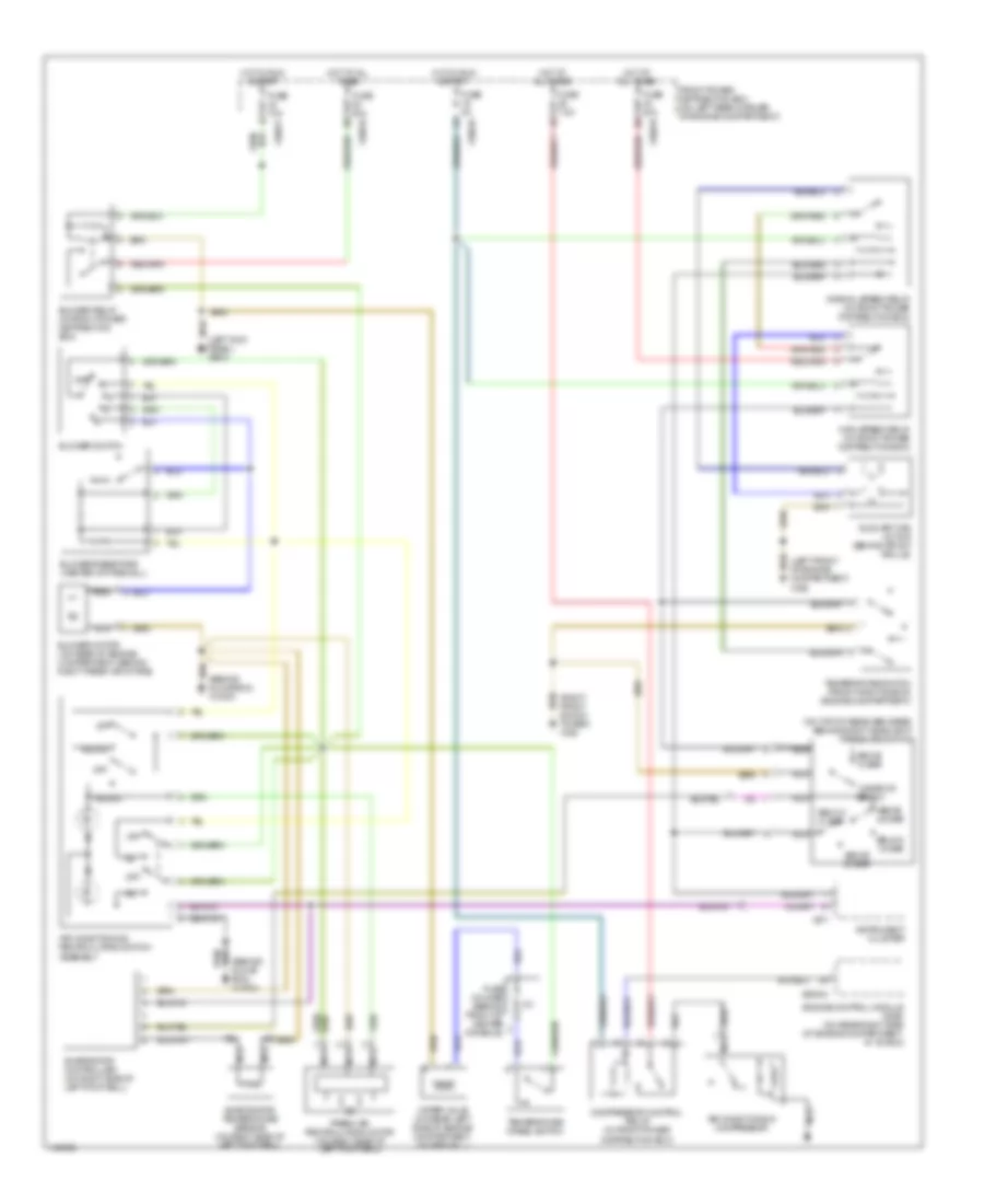
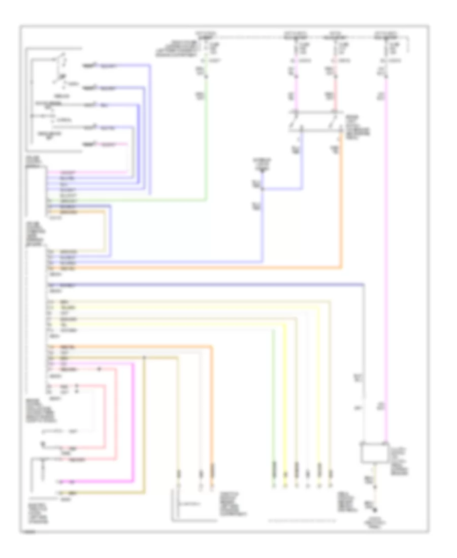
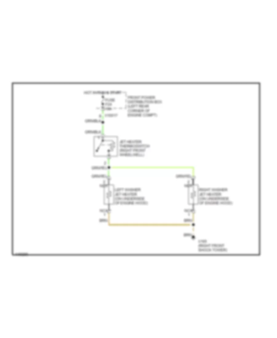
AIR CONDITIONING
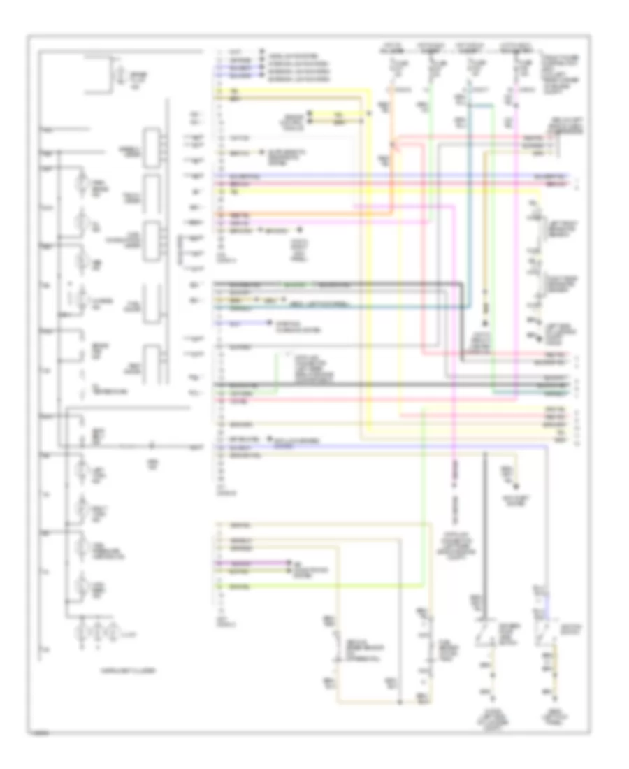
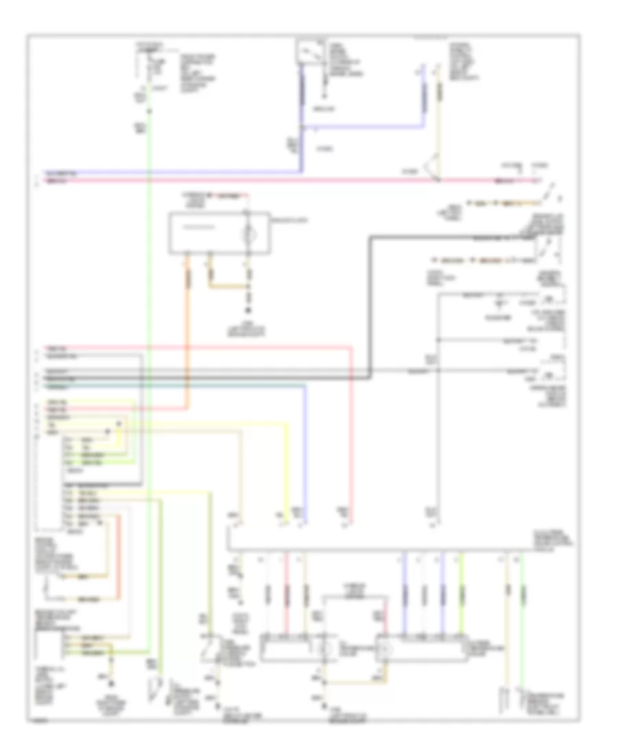
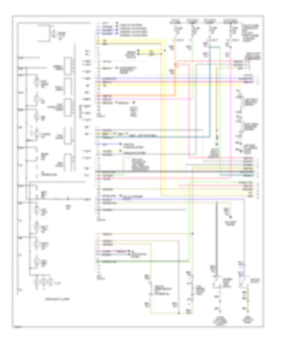
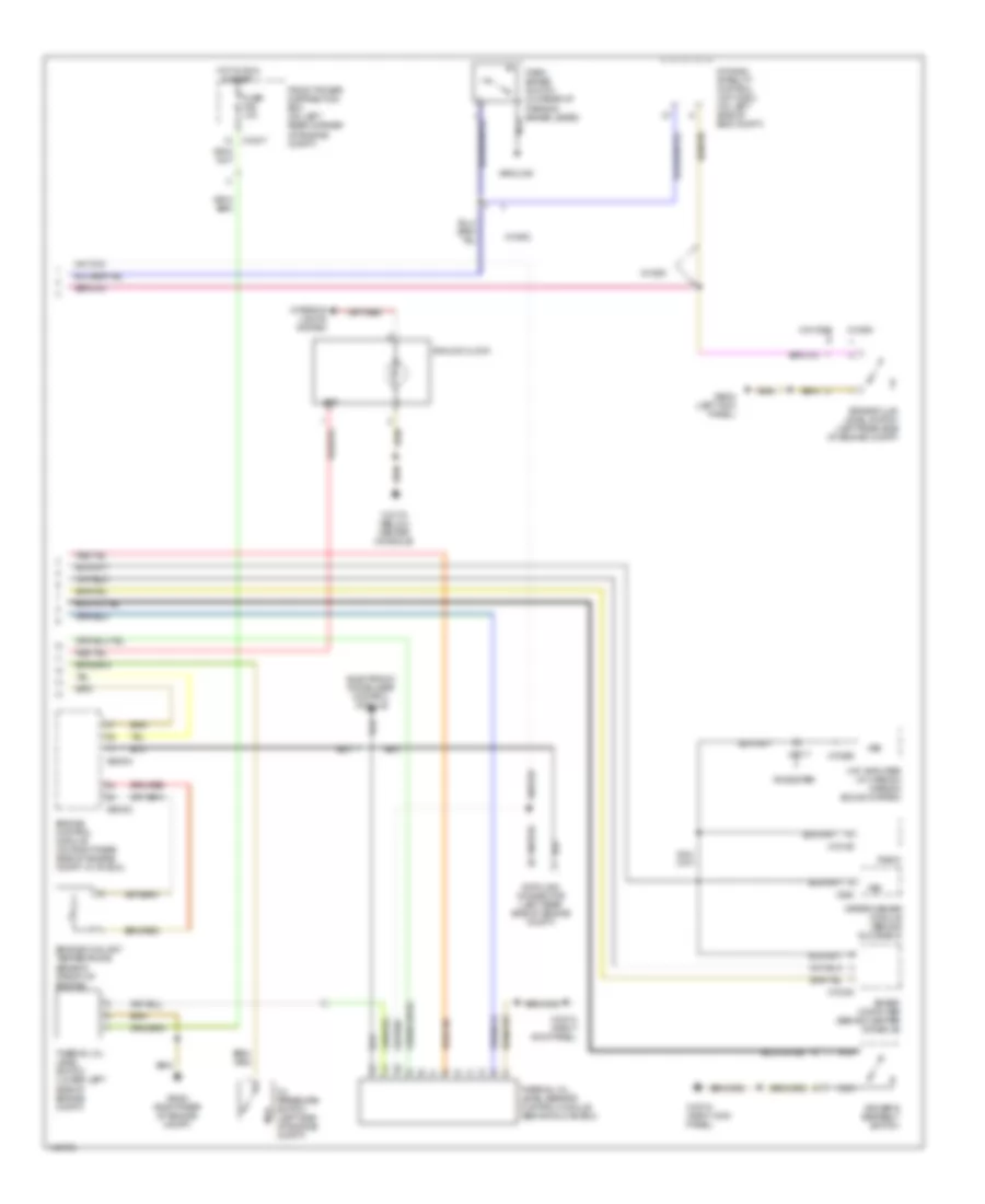
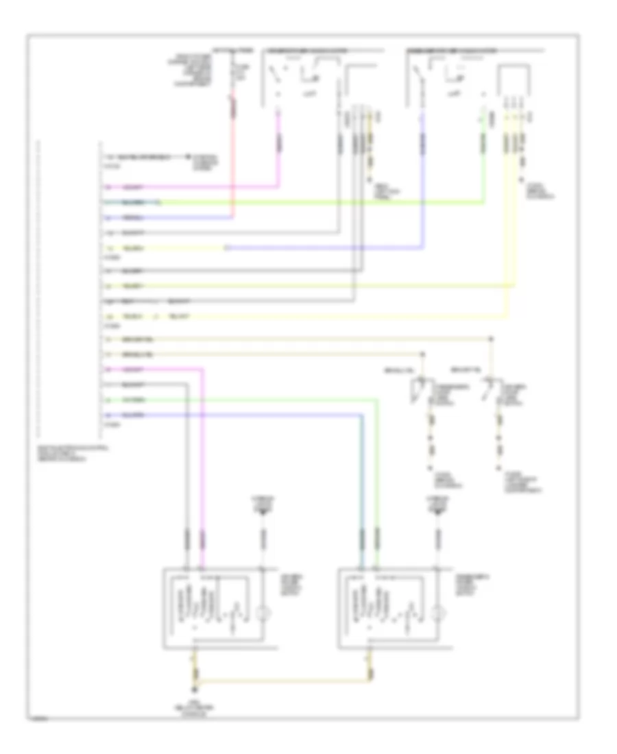
Manual A/C Wiring Diagram, M-Versions for BMW M Coupe 2002

List of elements for Manual A/C Wiring Diagram, M-Versions for BMW M Coupe 2002:
- & start
- (in front power distribution box) air conditioning relay, motronic
- (left kick panel) x9633
- (not used)
- (on top of receiver-drier, behind right headlight) pressure switch
- (right front shock tower) x165
- 15 bar or below
- A/c
- Above 18 bar
- Above 2.6 bar
- Above 30 bar
- Air conditioning compressor
- Air conditioning relay/ auxiliary water pump (in front power distribution box)
- Air conditioning/ recirculating switch assembly
- All times
- Auxiliary fan motor (behind front grille)
- Auxiliary fuse box (under left side of dash)
- Auxiliary water pump (left front of eng compt)
- Below 1.5 bar
- Below 21 bar
- Blower motor (on rear of engine compartment, behind right fresh air intake)
- Blower relay (in front power distribution box)
- Blower resistors (center of firewall)
- Blower switch
- Compressor control relay (in front power distribution box)
- Engine control module (dme) (on rear right side of engine compartment, in "e" box)
- Evaporator controller (on right side of left footwell)
- Evaporator temperature sensor (on right side of left footwell)
- Fresh air recirculation motor (on right side of left footwell)
- Front power distribution box (on left rear corner of eng compt)
- Fuse 10a
- Fuse 30a
- Fuse 40a
- Fuse 5a
- Fuse 7.5a
- Fuse holder (behind front of center console)
- High speed relay (in front power distribution box)
- Hot at
- Hot at all times
- Hot in run
- Hot in run & start
- Instrument cluster
- Nca
- Normal speed relay (in front power distribution box)
- Off
- Recirc
- Temperature switch (front right side of engine compartment)
- Temperature wheel switch
- Water valve (on rear left side of engine compartment, on firewall)
- X10016
- X10017
- X10018
- X166 (left front of eng compt)
- X19017
- X271
- X60004
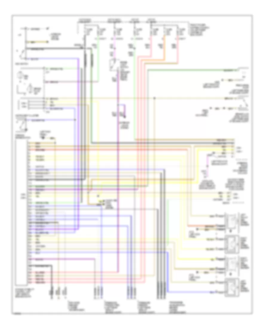
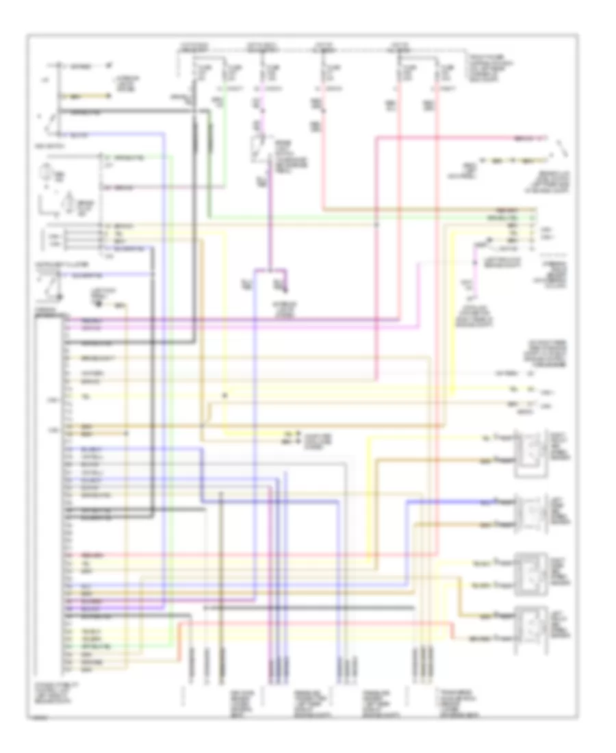
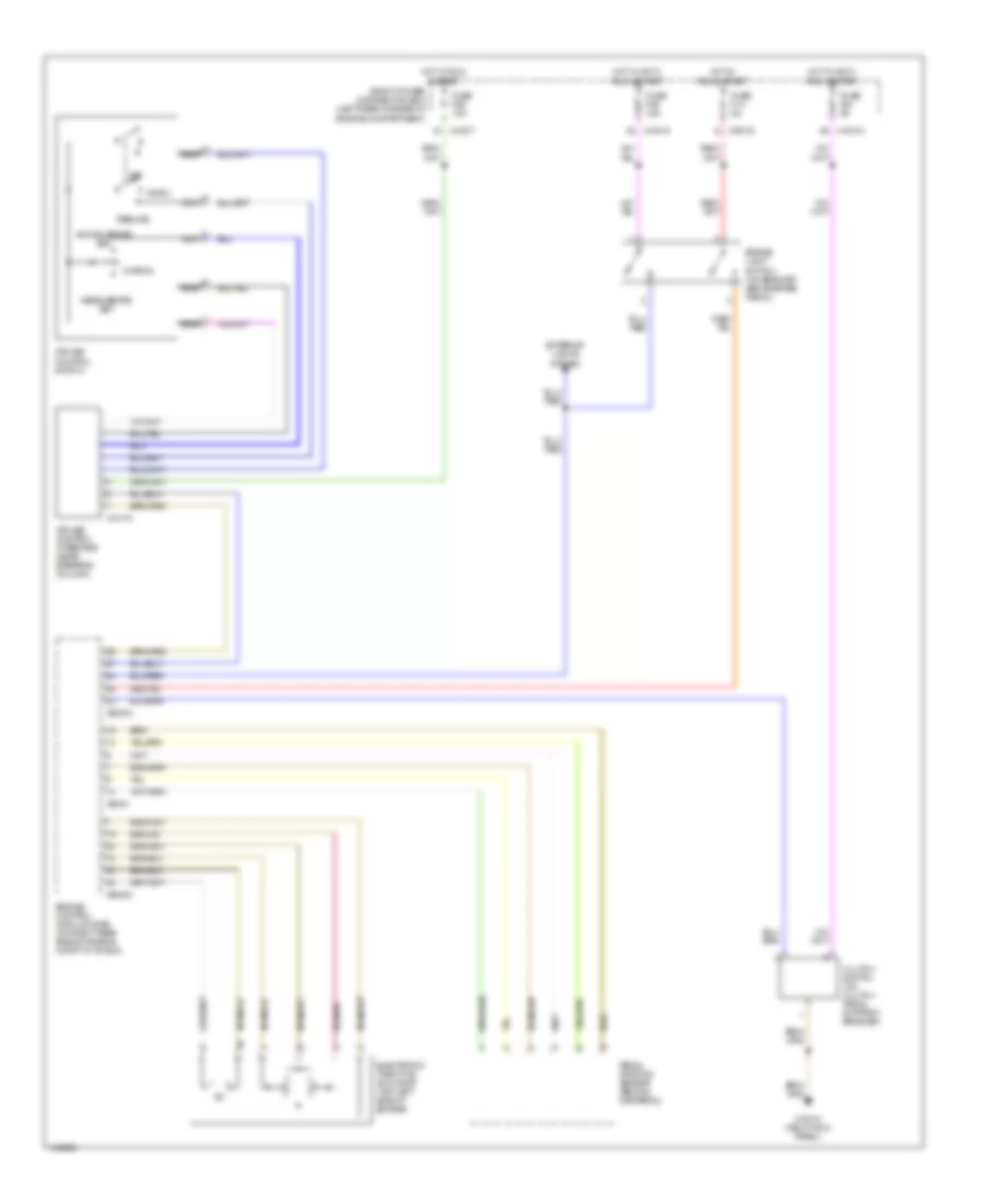
Manual A/C Wiring Diagram, Z3 Versions for BMW M Coupe 2002
List of elements for Manual A/C Wiring Diagram, Z3 Versions for BMW M Coupe 2002:
- & start
- (behind glove box) x13004
- (left front of engine compartment) x166
- (left kick panel) x9633
- (on top of receiver-drier, behind right headlight) pressure switch
- (right front shock tower) x165
- 15 bar or below
- A/c
- Above 18 bar
- Above 2.6 bar
- Above 30 bar
- Air conditioning compressor
- Air conditioning/ recirculating switch assembly
- All times
- Auxiliary fan motor (behind front grille)
- Below 1.5 bar
- Below 21 bar
- Blower motor (on rear of engine compartment, behind right fresh air intake)
- Blower relay (in front power distribution box)
- Blower resistors (center of firewall)
- Blower switch
- Compressor control relay (in front power distribution box)
- Engine control module (dme) (on rear right side of engine compartment, in "e" box)
- Evaporator controller (on right side of left footwell)
- Evaporator temperature sensor (on right side of left footwell)
- Fresh air recirculation motor (on right side of left footwell)
- Front power distribution box (on left rear corner of engine compartment)
- Fuse 10a
- Fuse 30a
- Fuse 5a
- Fuse 7.5a
- Fuse holder (behind front of center console)
- High speed relay (in front power distribution box)
- Hot at
- Hot at all times
- Hot in run
- Hot in run & start
- Instrument cluster
- Nca
- Normal speed relay (in front power distribution box)
- Off
- Recirc
- Temperature switch (front right side of engine compartment)
- Temperature wheel switch
- Water valve (on rear left side of engine compartment, on firewall)
- X10016
- X10017
- X10018
- X271
- X60004
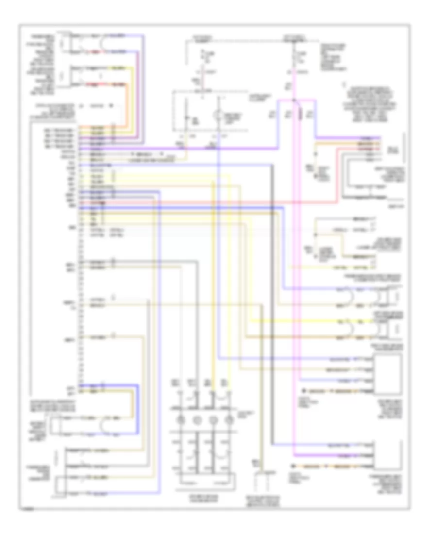
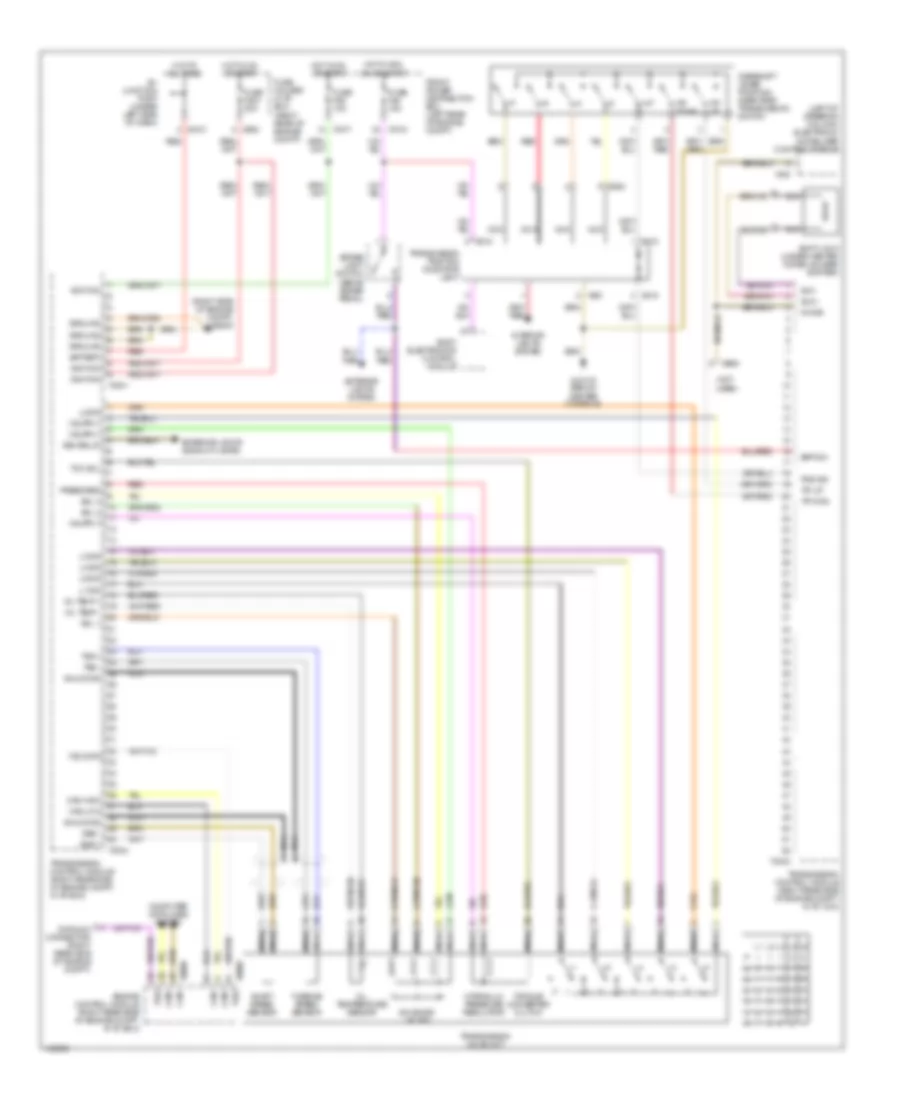
ANTI-LOCK BRAKES
Anti-lock Brakes Wiring Diagram, with DSC M Versions for BMW M Coupe 2002
List of elements for Anti-lock Brakes Wiring Diagram, with DSC M Versions for BMW M Coupe 2002:
- (left front of engine compt)
- (left kick panel) x170
- (on right rear side of engine compt, in "e" box) engine control module (dme)
- Abs ind
- Brake fluid ind
- Brake fluid level switch (left rear side of engine compt)
- Brake light switch (on bracket, above brake pedal)
- Can +
- Can -
- Computer data lines system
- Data link connector (right rear of engine compt)
- Dsc switch
- Dynamic stability control unit (left side of engine compt)
- Exterior lights system
- Front power distribution box (on left rear corner of eng compt)
- Fuse f21 5a
- Fuse f27 5a
- Fuse f46 15a
- Fuse f51 30a
- Fuse f52 30a
- Fuse f53 30a
- Fuse f7 5a
- Hot at all times
- Hot in accy, run & start
- Hot in run and start
- Instrument cluster
- Interior lights system
- Left front abs speed sensor
- Left rear abs speed sensor
- Nca
- Parking brake switch
- Precharge pump (left rear side of engine compt)
- Pressure sensor (left rear side of engine compt)
- Pressure transmitter (left rear side of engine compt)
- Right front abs speed sensor
- Right rear abs speed sensor
- Rpm rate sensor (under driver's seat)
- Steering angle sensor (on steering column)
- Transverse acceleration sensor (under drivers's seat)
- X10015
- X10017
- X10018
- X16
- X17
- X170 (left kick panel)
- X19017
- X492
- X492 (left front of engine compt)
- X60004
- X9633 (left kick panel)
Anti-lock Brakes Wiring Diagram, with DSC Z3 Versions for BMW M Coupe 2002
List of elements for Anti-lock Brakes Wiring Diagram, with DSC Z3 Versions for BMW M Coupe 2002:
- (left front of engine compt)
- (left kick panel) x170
- (on right rear side of engine compt, in "e" box) engine control module (dme)
- Abs ind
- Brake fluid ind
- Brake fluid level switch (left rear side of engine compt)
- Brake light switch (on bracket, above brake pedal)
- Can +
- Can -
- Computer data lines system
- Data link connector (right rear of engine compt)
- Dsc switch
- Dynamic stability control unit (left side of engine compt)
- Exterior lights system
- Front power distribution box (on left rear corner of eng compt)
- Fuse f21 5a
- Fuse f27 5a
- Fuse f46 15a
- Fuse f51 30a
- Fuse f52 30a
- Fuse f7 5a
- Hot at all times
- Hot in accy, run & start
- Hot in run and start
- Instrument cluster
- Interior lights system
- Left front abs speed sensor
- Left rear abs speed sensor
- Nca
- Parking brake switch
- Pressure sensor (left rear side of engine compt)
- Pressure transmitter (left rear side of engine compt)
- Right front abs speed sensor
- Right rear abs speed sensor
- Rpm rate sensor (under driver's seat)
- Steering angle sensor (on steering column)
- Transverse acceleration sensor (under drivers's seat)
- X10015
- X10017
- X10018
- X16
- X17
- X19017
- X492
- X60004
- X9633 (left kick panel)
Anti-lock Brakes Wiring Diagram, with Slip Control for BMW M Coupe 2002
List of elements for Anti-lock Brakes Wiring Diagram, with Slip Control for BMW M Coupe 2002:
- Abs ind
- Asc switch
- Brake light switch (on bracket, above brake pedal)
- Can +
- Can -
- Data link connector (on right rear side of engine compt)
- Engine control module (dme) (on right rear side of engine compt, in "e" box)
- Exterior lights system
- Front power distribution box (on left rear corner of engine compartment)
- Fuse f10 30a
- Fuse f21 5a
- Fuse f27 5a
- Fuse f38 30a
- Fuse f46 15a
- Hot at all times
- Hot in accy, run & start
- Hot in run & start
- Instrument cluster
- Interior lights system
- Left front abs speed sensor
- Left rear abs speed sensor
- Nca
- Right front abs speed sensor
- Right rear abs speed sensor
- Slip control module (in left front side of engine compt)
- X10015
- X10017
- X10018
- X16
- X17
- X170 (left kick panel)
- X60004
ANTI-THEFT
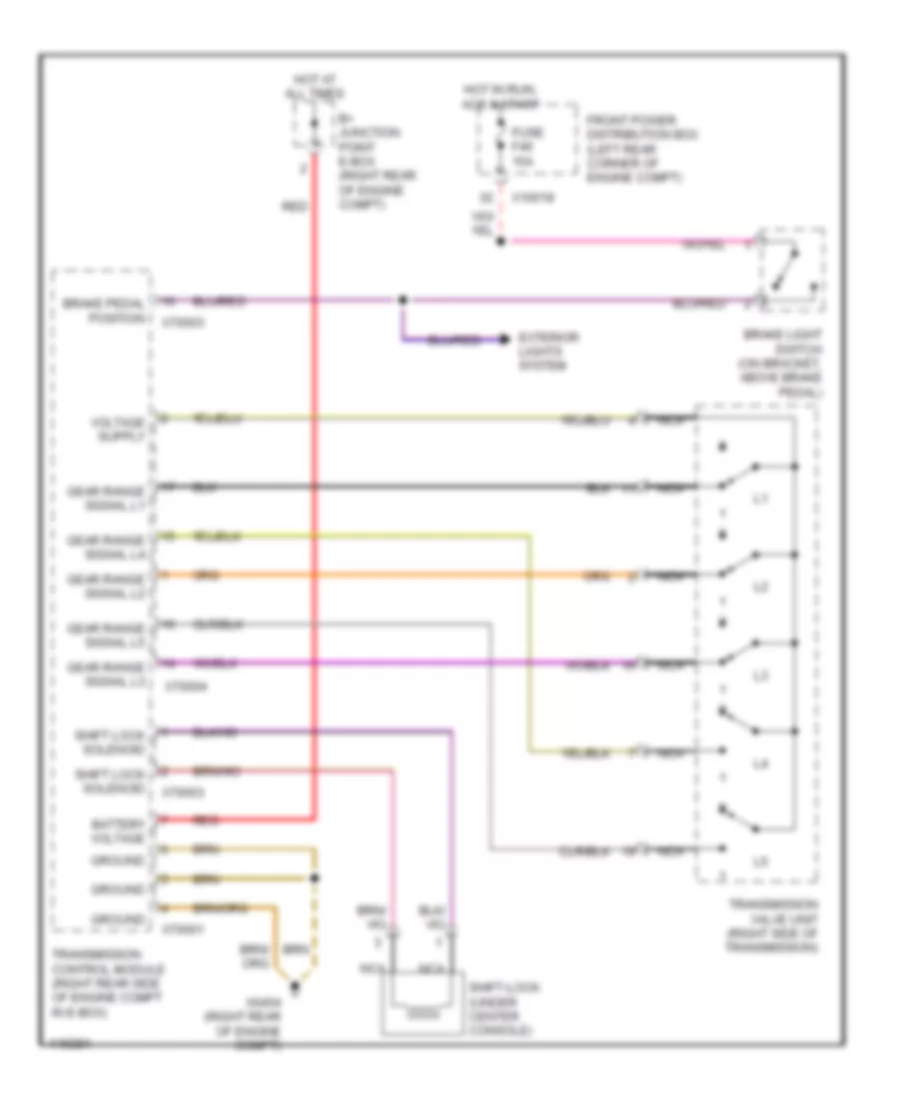
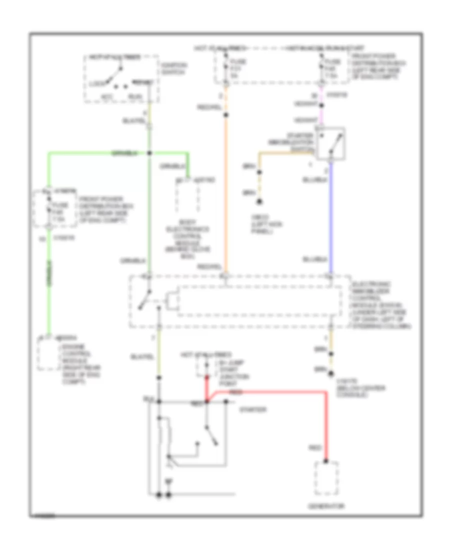
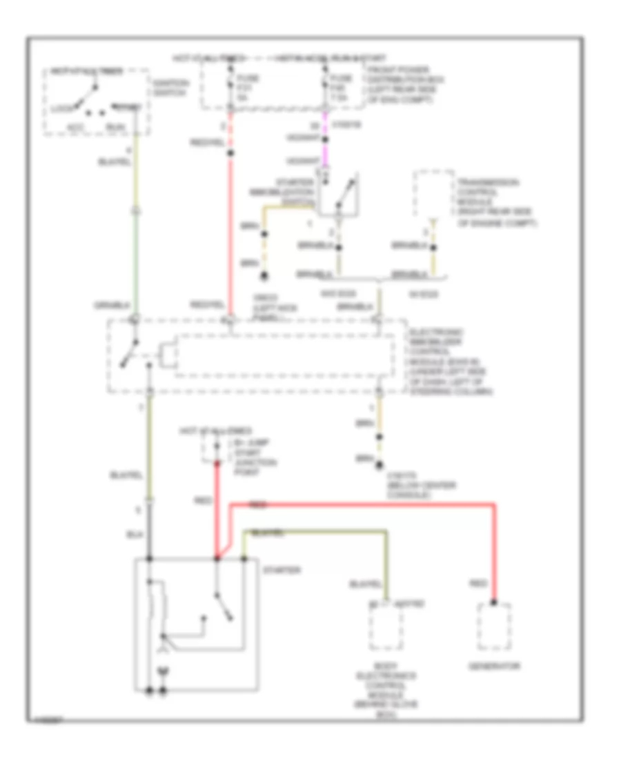
Drive-Away Protection Wiring Diagram for BMW M Coupe 2002
List of elements for Drive-Away Protection Wiring Diagram for BMW M Coupe 2002:
- (below center console) x18170
- Acc
- Anti-theft control module (behind glove box)
- Body electronics control module (zke iv) (behind glove box)
- Data link connector (on left rear side of engine compt)
- Electronic immobilizer control module (ews iii) (left side of steering column)
- Engine control module (dme) (on right rear side of engine compt, in "e" box)
- Ews toroidal coil
- Front power distribution box (on left rear corner of engine compt)
- Fuse f31 5a
- Fuse f45 7.5a
- Hot at all times
- Hot in accy, run & start
- Ignition switch
- Instrunment cluster system
- Nca
- Off
- Remote control module (in interior rear view mirror)
- Run
- Start
- Starter
- Starter immobilization switch (left footwell)
- Transmission control module (right rear side of engine compt)
- W/ alpine
- W/ dwa
- W/o egs
- With egs
- X10018
- X1659
- X60004
- X9633 (left kick panel)
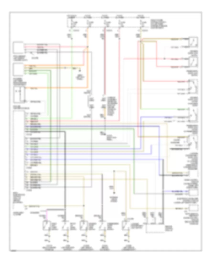
Forced Entry Wiring Diagram, Alpine for BMW M Coupe 2002
List of elements for Forced Entry Wiring Diagram, Alpine for BMW M Coupe 2002:
- (behind glove box) x10010
- Anti- theft horn
- Anti-theft control module (behind glove box)
- Body electronics control module (zke iv) (behind glove box)
- Crash control module (on relay panel, under left side of dash)
- Driver's door jamb switch
- Electronic immobilizer control module (under left side of dash)
- Engine hood switch
- Front power distribution box (on left rear corner of engine compartment)
- Fuse f31 5a
- Fuse f43 5a
- Hot at all times
- Hot in accy, run & start
- Instrument cluster
- Interior lights system
- Luggage compartment light switch
- Nca
- Passenger's door jamb switch
- Radio anti- theft switch
- X10018
- X10244
- X13004 (behind glove box)
- X13006 (left side of luggage compt)
- X13025
- X13253
- X13254
- X166 (left front of engine compt)
- X17
- X18170 (below center console)
- X9633 (left kick panel)
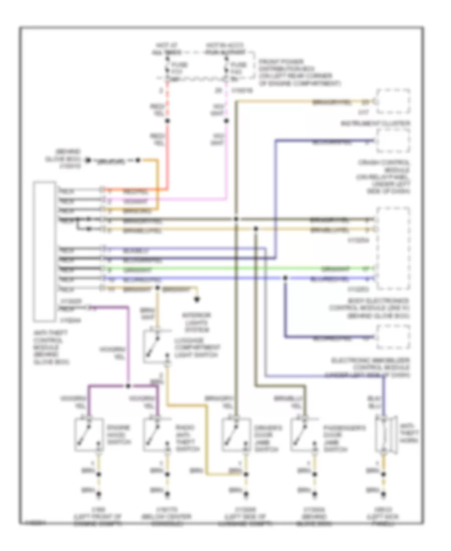
Forced Entry Wiring Diagram, DWA for BMW M Coupe 2002
List of elements for Forced Entry Wiring Diagram, DWA for BMW M Coupe 2002:
- (coupe)
- (not used)
- (under left side of dash)
- Body electronics control module (behind glove box)
- Coupe
- Crash control module (on relay panel, under left side of dash)
- Driver's door jamb switch
- Driver's door lock motor (in driver's door)
- Driver's door lock switch
- Dwa led (center console)
- Dwa siren (left rear side of engine compartment)
- Electronic immobilizer control module
- Exterior lights system
- Front lid micro switch
- Front power distribution box (on left rear corner of engine compartment)
- Fuse f16 5a
- Fuse f2 15a
- Fuse f31 5a
- Fuse f34 15a
- Fuse f7 5a
- Hot at all times
- Hot in run & start
- Instrument cluster
- Interior (not movement used) detector (roadster: right of center console, coupe: in roof panel)
- Luggage compartment door lock motor (in liftgate) (coupe) (rear side of luggage compt) (roadster)
- Luggage compartment light switch
- Nca
- Passenger's door jamb switch
- Passenger's door lock motor (in passenger's door)
- Passenger's door lock switch
- Pitch sensor (left side of luggage compt)
- Radio anti- theft switch
- Remote control module
- Roadster
- X10010 (right kick panel)
- X10015
- X10016
- X10018
- X10182
- X13004 (behind glove box)
- X13006 (left side of luggage compt)
- X13253
- X13254
- X166 (left radiator support)
- X17
- X18170 (below center console)
- X74
- X9633 (left kick panel)
BODY CONTROL MODULES
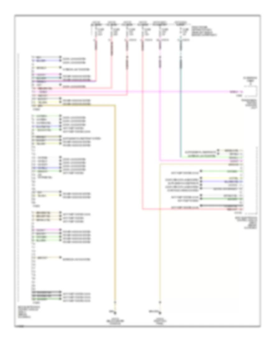
Body Control Modules Wiring Diagram for BMW M Coupe 2002
List of elements for Body Control Modules Wiring Diagram for BMW M Coupe 2002:
- Anti-theft system
- Anti-theft system (dwa)
- Body electronics control module (zke iv) (behind glove box)
- Computer data lines system
- Door locks system
- Exterior lights system
- Front power distribution box (rear left side of engine compartment)
- Fuse f14 30a
- Fuse f16 5a
- Fuse f2 15a
- Fuse f33 10a
- Fuse f35 25a
- Fuse f43 5a
- Hot at all times
- Hot in accy, run & start
- Hot in run & start
- Interior lights system
- Power windows system
- Starting/charging system
- Transmission position indicator light
- X10010 (right kick panel)
- X10015
- X10018
- X10182
- X13252
- X13253
- X13254
- X1600
- X18170 (below center console)
- Z3 versions w/egs
COMPUTER DATA LINES
Computer Data Lines Wiring Diagram for BMW M Coupe 2002
List of elements for Computer Data Lines Wiring Diagram for BMW M Coupe 2002:
- (behind center console)
- (behind glove box) body electronics control module (zke iv)
- (below center console)
- (right
- (right rear side of engine compartment) data link connector
- (z3 versions) (m versions)
- Battery
- Board computer
- Can +
- Can -
- Dynamic stability control unit (left side of engine compt)
- Electronic immobilizer control module (under left side of dash)
- Engine control module (dme) (right rear side of engine compartment, in "e" box)
- Front power distribution box (left rear corner of engine compartment)
- Fuse f26 10a
- Fuse f31 5a
- Hot at all times
- Hot in run & start
- Instrument cluster
- Kick panel)
- M versions only
- Nca
- Obd ii connector (right side of center console)
- Oil/outside temperature gauge control uniit (behind glove box) (m versions)
- Red
- Remote control module (in interior rear view mirror) (z3 versions)
- Slip control module (left front of engine compartment) (w/o dsc)
- Steering angle sensor (on base of steering column)
- Thermal oil level sensor (toens) control module (behind glove box) (z3 versions)
- Transmission control module (egs) (right rear side of engine compartment, in "e" box) (z3 versions)
- W/ dsc
- X10010
- X10182
- X10245
- X16
- X166 (left front of eng compt)
- X17
- X1805
- X18170
- X60002
- X60004
- X70004
- X74
COOLING FAN
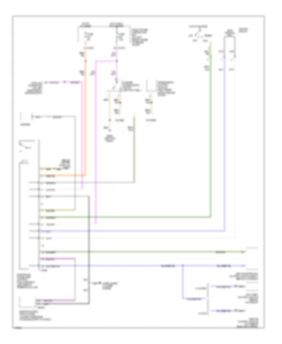
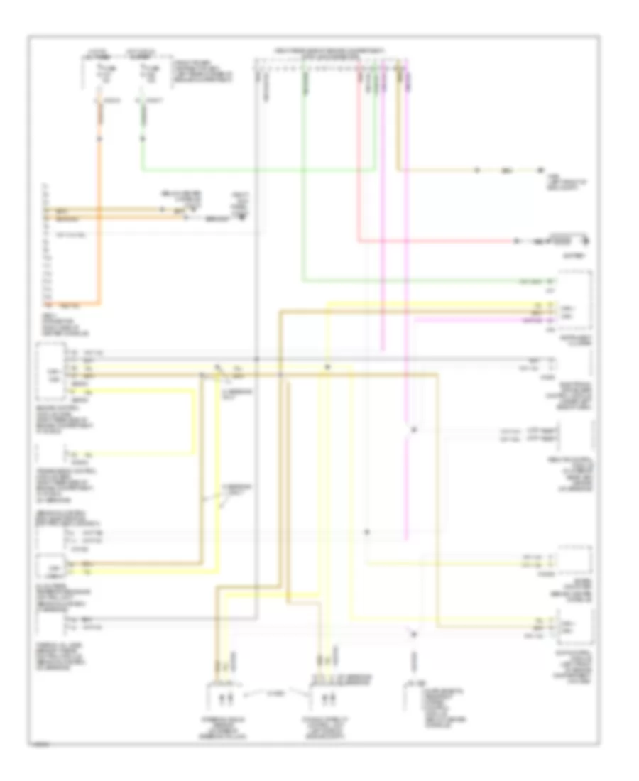
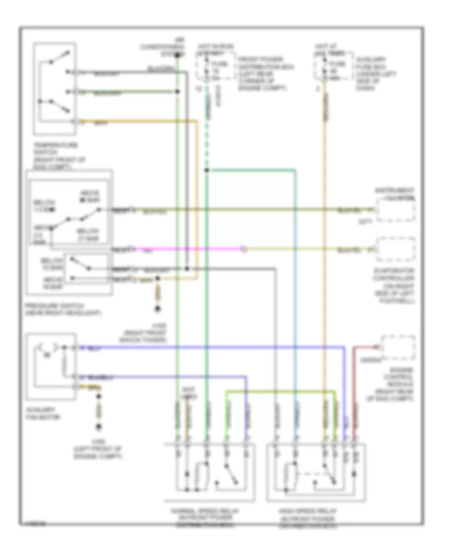
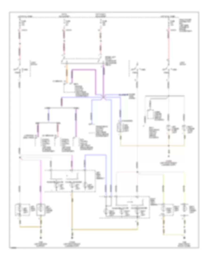
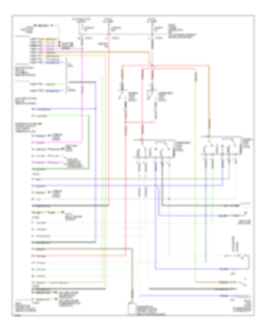
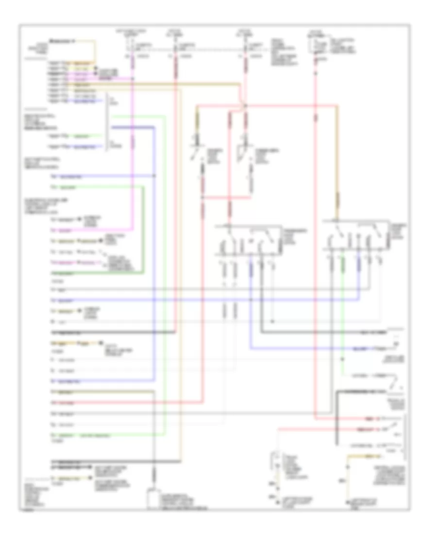
Cooling Fan Wiring Diagram, M-Versions for BMW M Coupe 2002
List of elements for Cooling Fan Wiring Diagram, M-Versions for BMW M Coupe 2002:
- (on right side of left footwell)
- 87a
- 87b
- Above 18 bar
- Above 2.6 bar
- Above 30 bar
- Air conditioning system
- Auxiliary fan motor
- Auxiliary fuse box (under left side of dash)
- Below 1.5 bar
- Below 15 bar
- Below 21 bar
- Engine control module (right rear of eng compt)
- Evaporator controller
- Front power distribution box (left rear corner of engine compt)
- Fuse 40a
- Fuse 5a
- High speed relay (in front power distribution box)
- Hot at all times
- Hot in run & start
- Instrument cluster
- Nca
- Normal speed relay (in front power distribution box)
- Not used
- Pressure switch (near right headlight)
- Temperature switch (right front of eng compt)
- X10016
- X165 (left front of engine compt)
- X165 (right front shock tower)
- X271
- X60004
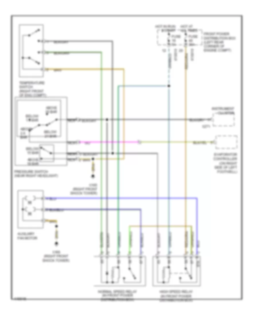
Cooling Fan Wiring Diagram, Z3 Versions for BMW M Coupe 2002
List of elements for Cooling Fan Wiring Diagram, Z3 Versions for BMW M Coupe 2002:
- (on right side of left footwell)
- 87a
- Above 18 bar
- Above 2.6 bar
- Above 30 bar
- Auxiliary fan motor
- Below 1.5 bar
- Below 15 bar
- Below 21 bar
- Evaporator controller
- Front power distribution box (left rear corner of engine compt)
- Fuse 30a
- Fuse 5a
- High speed relay (in front power distribution box)
- Hot at all times
- Hot in run & start
- Instrument cluster
- Nca
- Normal speed relay (in front power distribution box)
- Pressure switch (near right headlight)
- Temperature switch (right front of eng compt)
- X10016
- X10018
- X165 (right front shock tower)
- X166 (right front shock tower)
- X271
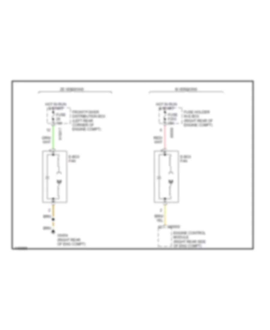
Electrical Box Fan Wiring Diagram for BMW M Coupe 2002
List of elements for Electrical Box Fan Wiring Diagram for BMW M Coupe 2002:
- E-box fan
- Engine control module (right rear side of eng compt)
- Front power distribution box (left rear corner of engine compt)
- Fuse 10a
- Fuse f203 20a
- Fuse holder in e-box (right rear of engine compt)
- Hot in run & start
- M versions
- X10017
- X60002
- X6454 (right rear of eng compt)
- X8680
- Ze versions
CRUISE CONTROL
Cruise Control Wiring Diagram, M-Versions for BMW M Coupe 2002
List of elements for Cruise Control Wiring Diagram, M-Versions for BMW M Coupe 2002:
- Acccelerate/ set
- Brake- light switch (on bracket, above brake pedal)
- Clutch switch (on clutch pedal support bracket)
- Cruise control interface (near steering column)
- Cruise control switch
- Decelerate/ set
- Electric throttle motor (left side of engine)
- Engine control module (dme) (on right rear side of engine compt in "e" box)
- Exterior lights system
- Front power distribution box (left rear corner of engine compartment)
- Fuse f13 5a
- Fuse f26 10a
- Fuse f44 15a
- Fuse f46 15a
- Hot in accy, run & start
- Hot in run & start
- Nca
- Norm
- Normal
- Off
- Pedal position sensor (behind gas pedal)
- Red
- Resume
- Throttle position sensor (left side of engine compartment)
- X10010 (right kick panel)
- X10016
- X10017
- X10018
- X10170
- X5392
- X5393
- X60001
- X60002
- X60003
- X60004
- X6004
Cruise Control Wiring Diagram, Z3 Versions for BMW M Coupe 2002
List of elements for Cruise Control Wiring Diagram, Z3 Versions for BMW M Coupe 2002:
- Acccelerate/ set
- Brake- light switch (on bracket, above brake pedal)
- Clutch switch (on clutch pedal support bracket)
- Cruise control interface (near steering column)
- Cruise control switch
- Decelerate/ set
- Electronic throttle actuator (top left side of engine)
- Engine control module (dme) (on right rear side of engine compt in "e" box)
- Exterior lights system
- Front power distribution box (left rear corner of engine compartment)
- Fuse f13 5a
- Fuse f26 10a
- Fuse f43 5a
- Fuse f46 15a
- Hot in accy, run & start
- Hot in run & start
- Nca
- Norm
- Normal
- Off
- Pedal position sensor (behind gas pedal)
- Resume
- X10010 (right kick panel)
- X10016
- X10017
- X10018
- X10170
- X60003
- X60004
- X6004
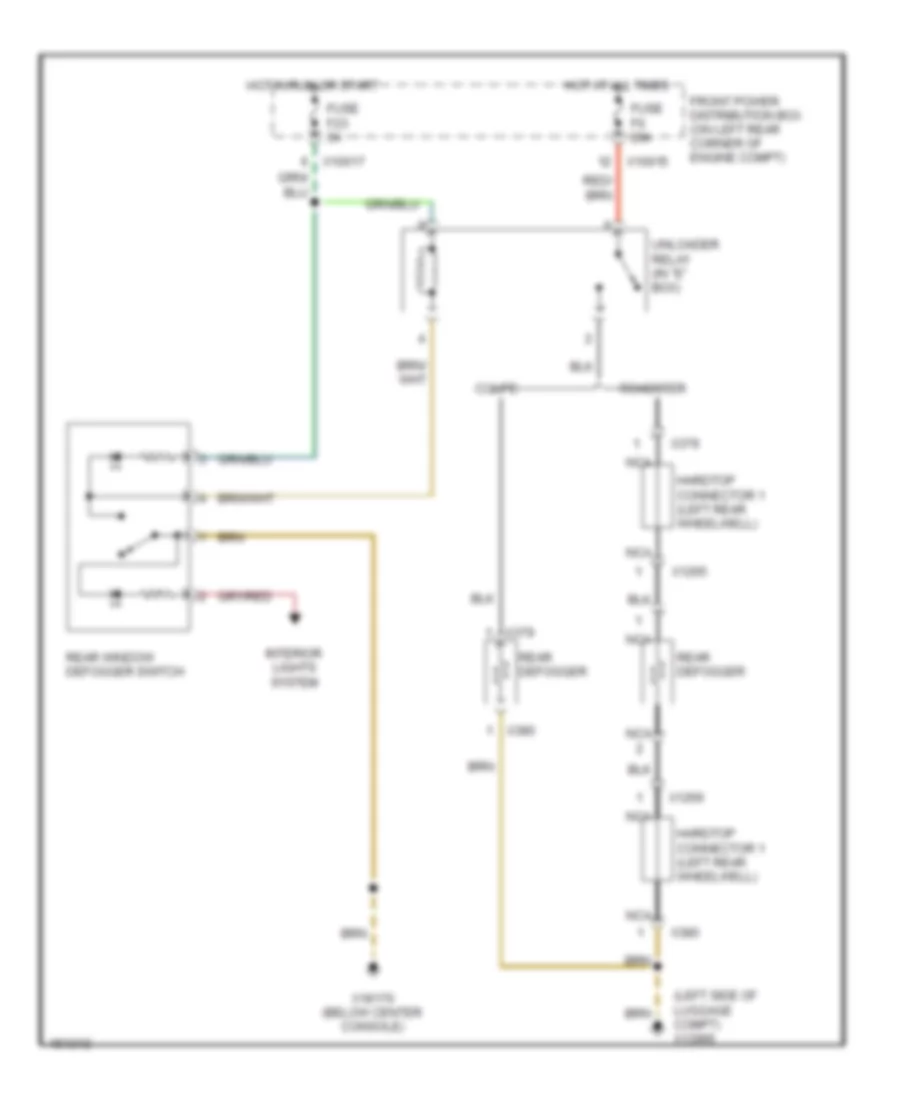
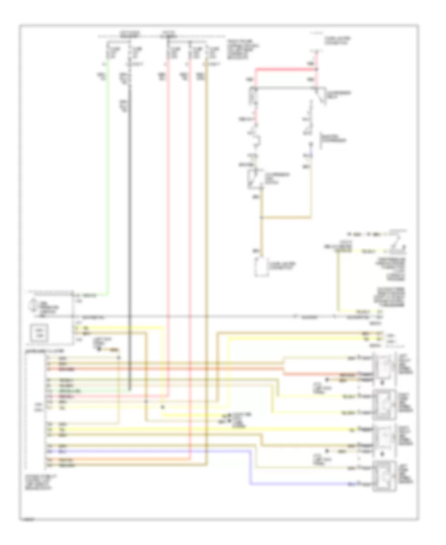
DEFOGGERS
Defoggers Wiring Diagram for BMW M Coupe 2002
List of elements for Defoggers Wiring Diagram for BMW M Coupe 2002:
- (left side of luggage compt) x13006
- Coupe
- Front power distribution box (on left rear corner of engine compt)
- Fuse f23 5a
- Fuse f6 20a
- Hardtop connector 1 (left rear wheelwell)
- Hot at all times
- Hot in run or start
- Interior lights system
- Nca
- Rear defogger
- Rear window defogger switch
- Roadster
- Unloader relay (in "e" box)
- X10015
- X10017
- X1265
- X1266
- X18170 (below center console)
- X379
- X380
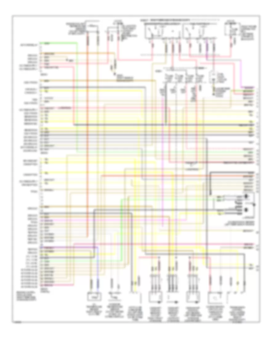
ENGINE PERFORMANCE
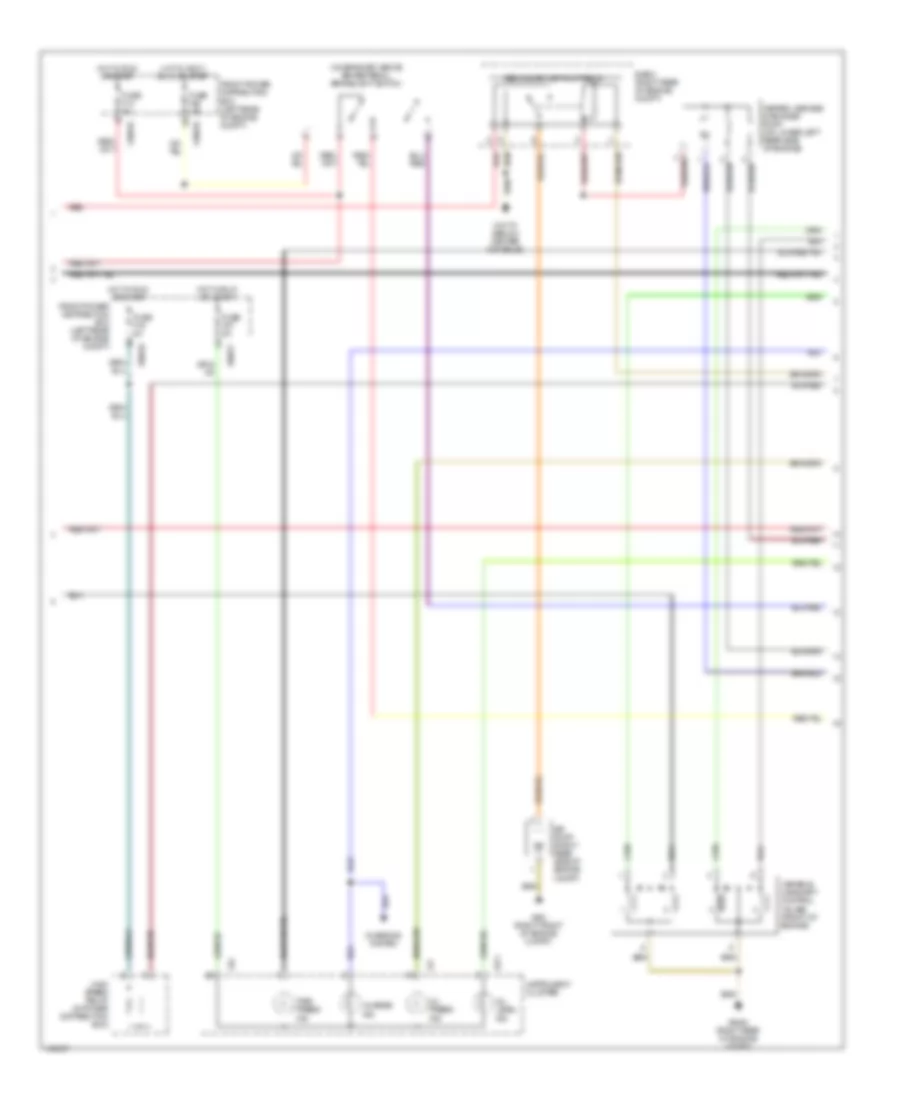
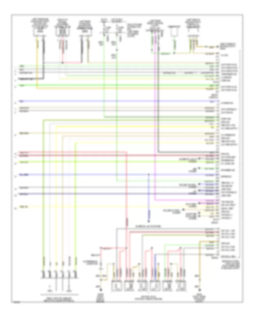
2.5L
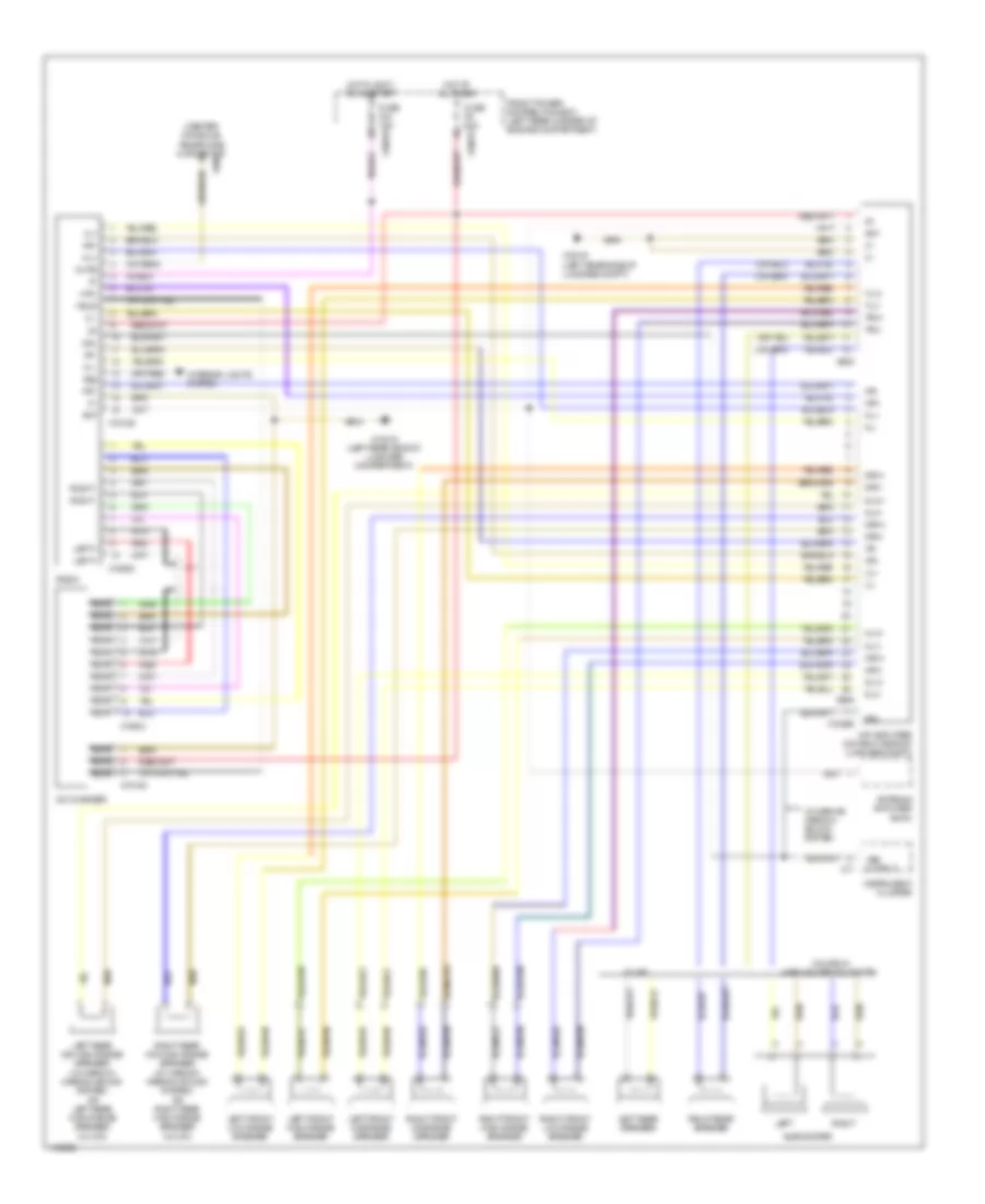
2.5L, Engine Performance Wiring Diagram (1 of 3) for BMW M Coupe 2002
List of elements for 2.5L, Engine Performance Wiring Diagram (1 of 3) for BMW M Coupe 2002:
- (late prod)
- (partial)
- (right rear side of engine compt)
- (under rear storage compt) x13032
- 8-11
- Activate relay
- Activate valve
- Air mass met
- B+ junction point e-box (in front power distribution box)
- Camshaft position sensor 1 (inlet) (on front of engine)
- Camshaft position sensor 2 (outlet) (right front of engine)
- Camshft sig
- Can bus (+)
- Can bus (-)
- Characteristic map cooling thermostat (on front of cylinder head)
- Crankshaft position/ rpm sensor (left rear side of engine compartment)
- Crnkshft sig
- Cyl 1-3
- Cyl 1-3 ks
- Cyl 4-6
- Cyl 4-6 ks
- Double knock sensor (left rear side of engine)
- E-box
- Engine control module (dme) (right rear side of engine compt)
- Engine control module relay
- Engine coolant temperature sensor (on left rear of eng compt)
- Front power distribution box (left rear corner of eng compt)
- Fuel pump (in fuel tank)
- Fuel pump relay
- Fuse f18 15a
- Fuse f201 30a
- Fuse f202 30a
- Fuse f203 20a
- Fuse f204 30a
- Ground
- Hot at all times
- Hot film air mass meter (on left side of eng compt, on air intake tube)
- Intake air temperature sensor (on top center of eng, on intake manifold)
- Nca
- O2s htd sig
- O2s htg sig
- Oil temperature sensor (right side of oil filter)
- Red
- Sensor sig
- Sig ground
- Temp sig
- Tp sig
- Transmission control module (egs) (right rear side of engine compt, in e-box)
- Txd2
- X10016
- X60001
- X60002
- X60003
- X64101
- X64102
- X6454 (right rear of engine compt)
- X8680
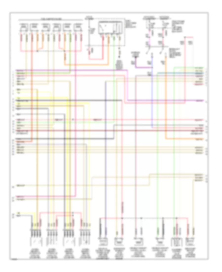
2.5L, Engine Performance Wiring Diagram (2 of 3) for BMW M Coupe 2002
List of elements for 2.5L, Engine Performance Wiring Diagram (2 of 3) for BMW M Coupe 2002:
- Brakelight switch (on bracket, above brake pedal)
- Cyl 1
- Cyl 2
- Cyl 3
- Cyl 4
- Cyl 5
- Cyl 6
- E-box (right rear side of eng compt)
- Evaporative emission valve (on left front of engine)
- Exterior lights system
- Front power distribution box (left rear corner of eng compt)
- Fuel injection valves
- Fuse f13 5a
- Fuse f205 30a
- Fuse f46 15a
- Hot at all times
- Hot in accy, run, or start
- Hot in run or start
- Idle speed control valve (left side of engine)
- Individual control intake system valve (left side of engine compartment)
- Injection valves relay
- Nca
- Oxygen sensor 1 (behind catalytic converter)
- Oxygen sensor 1 (in front of catalytic converter)
- Oxygen sensor 2 (behind catalytic converter)
- Oxygen sensor 2 (in front of catalytic converter)
- Red
- Secondary air pump valve (left rear of engine)
- Variable camshaft control valve 1 (inlet) (top front of engine)
- Variable camshaft control valve 2 (outlet) (front of cylinder head)
- X10016
- X10018
- X6454 (right rear of engine compt)
- X8680
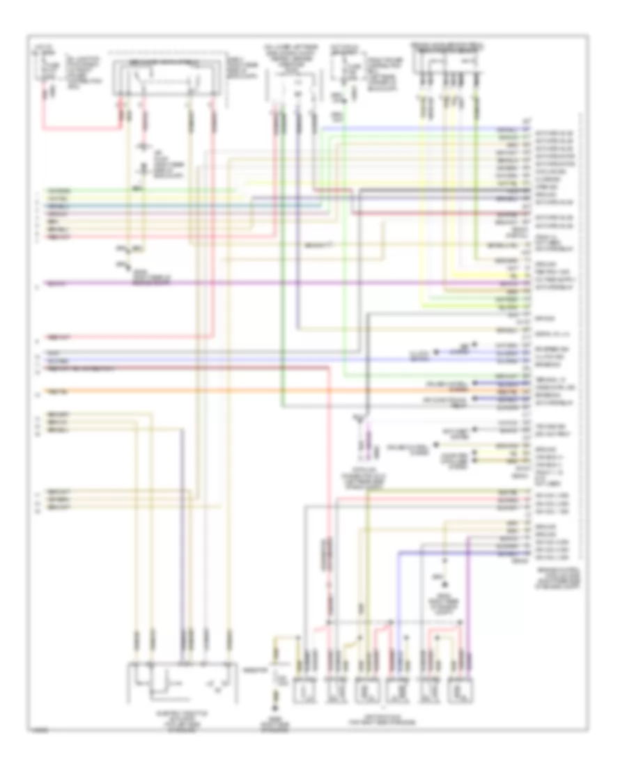
2.5L, Engine Performance Wiring Diagram (3 of 3) for BMW M Coupe 2002
List of elements for 2.5L, Engine Performance Wiring Diagram (3 of 3) for BMW M Coupe 2002:
- (behind accelerator pedal) pedal position sensor
- (on lower left rear side of eng compt) heated leakage diagnosis pump
- (partial)
- (pins 1-2 not used) activate relay
- (pins 11, 15, & 16 not used)
- 18-19
- 38-40
- 4-6
- Abs system
- Activate motor
- Activate relay
- Activate valve
- Air conditioning relay
- Air pump (right rear side of eng compt)
- Anti-theft system
- B+ junction point e-box (in front power distribution box)
- Brake sig
- Can bus (+)
- Can bus (-)
- Close sig
- Clutch sig
- Clutch switch
- Computer data lines system
- Cooling sig
- Crse cntrl sig
- Cruise control system
- Data link connector (dlc) (left rear side of eng compt)
- Drv awy prot
- E-box (right rear side of eng compt)
- Electric throttle actuator (top left side of engine)
- Engine control module (dme) (right rear side of engine compt)
- Front power distribution box (left rear corner of eng compt)
- Fuse f107 50a
- Fuse f26 10a
- Ground
- Hot at all times
- Hot in run or start
- Ign coil 1 sig
- Ign coil 2 sig
- Ign coil 3 sig
- Ign coil 4 sig
- Ign coil 5 sig
- Ign coil 6 sig
- Ignition coils (top right side of engine)
- Nca
- Ohm
- Open sig
- Ped pos 1 sig
- Red
- Resistor
- Rpm sig
- Rr speed sig
- Secondary air pump relay
- Signal oil lvl
- Terminal 15
- Txd diag sig
- X10017
- X1982
- X60003
- X60004
- X60005
- X6002
- X6454 (right rear of engine compt)
- X6455 (right rear of engine compt)
- X6456 (right side of engine)
3.0L
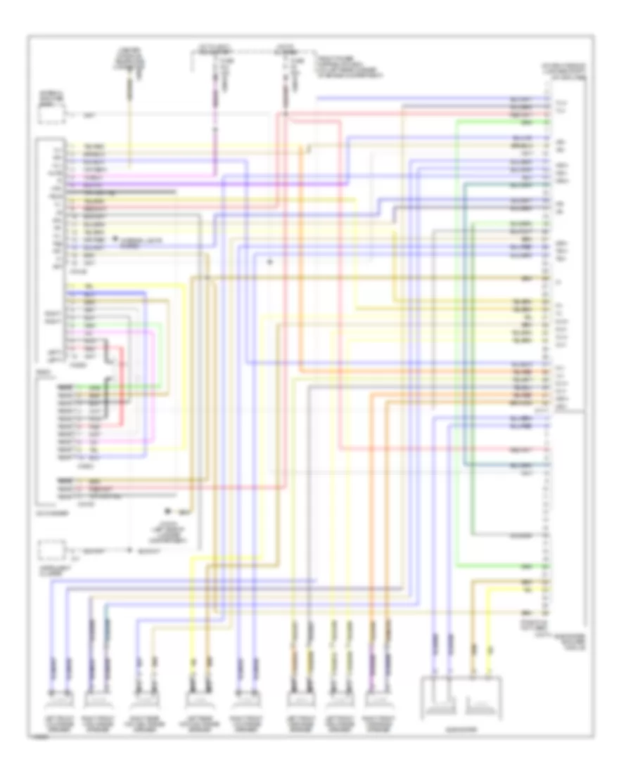
3.0L, Engine Performance Wiring Diagram (1 of 3) for BMW M Coupe 2002
List of elements for 3.0L, Engine Performance Wiring Diagram (1 of 3) for BMW M Coupe 2002:
- (late prod)
- (partial)
- (right rear side of engine compt)
- (under rear storage compt) x13032
- 8-11
- Activate relay
- Activate valve
- Air mass met
- B+ junction point e-box (in front power distribution box)
- Camshaft position sensor 1 (inlet) (on front of engine)
- Camshaft position sensor 2 (outlet) (right front of engine)
- Camshft sig
- Can bus (+)
- Can bus (-)
- Characteristic map cooling thermostat (on front of cylinder head)
- Crankshaft position/ rpm sensor (left rear side of engine compartment)
- Crnkshft sig
- Cyl 1-3
- Cyl 1-3 ks
- Cyl 4-6
- Cyl 4-6 ks
- Double knock sensor (left rear side of engine)
- E-box
- Engine control module (dme) (right rear side of engine compt)
- Engine control module relay
- Engine coolant temperature sensor (on left rear of eng compt)
- Front power distribution box (left rear corner of eng compt)
- Fuel pump (in fuel tank)
- Fuel pump relay
- Fuse f18 15a
- Fuse f201 30a
- Fuse f202 30a
- Fuse f203 20a
- Fuse f204 30a
- Ground
- Hot at all times
- Hot film air mass meter (on left side of eng compt, on air intake tube)
- Intake air temperature sensor (on top center of eng, on intake manifold)
- Nca
- O2s htd sig
- O2s htg sig
- Oil temperature sensor (right side of oil filter)
- Red
- Sensor sig
- Sig ground
- Temp sig
- Tp sig
- Transmission control module (egs) (right rear side of engine compt, in e-box)
- Txd2
- X10016
- X60001
- X60002
- X60003
- X64101
- X64102
- X6454 (right rear of engine compt)
- X8680
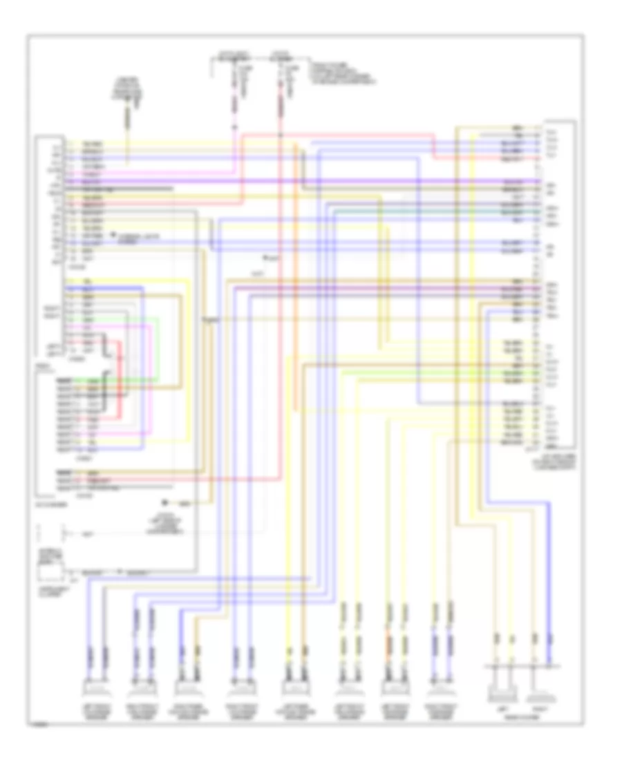
3.0L, Engine Performance Wiring Diagram (2 of 3) for BMW M Coupe 2002
List of elements for 3.0L, Engine Performance Wiring Diagram (2 of 3) for BMW M Coupe 2002:
- Brakelight switch (on bracket, above brake pedal)
- Cyl 1
- Cyl 2
- Cyl 3
- Cyl 4
- Cyl 5
- Cyl 6
- E-box (right rear side of eng compt)
- Evaporative emission valve (on left front of engine)
- Exterior lights system
- Front power distribution box (left rear corner of eng compt)
- Fuel injection valves
- Fuse f13 5a
- Fuse f205 30a
- Fuse f46 15a
- Hot at all times
- Hot in accy, run, or start
- Hot in run or start
- Idle speed control valve (left side of engine)
- Individual control intake system valve (left side of engine compartment)
- Injection valves relay
- Nca
- Oxygen sensor 1 (behind catalytic converter)
- Oxygen sensor 1 (in front of catalytic converter)
- Oxygen sensor 2 (behind catalytic converter)
- Oxygen sensor 2 (in front of catalytic converter)
- Red
- Secondary air pump valve (left rear of engine)
- Variable camshaft control valve 1 (inlet) (top front of engine)
- Variable camshaft control valve 2 (outlet) (front of cylinder head)
- X10016
- X10018
- X6454 (right rear of engine compt)
- X8680
3.0L, Engine Performance Wiring Diagram (3 of 3) for BMW M Coupe 2002
List of elements for 3.0L, Engine Performance Wiring Diagram (3 of 3) for BMW M Coupe 2002:
- (behind accelerator pedal) pedal position sensor
- (on lower left rear side of eng compt) heated leakage diagnosis pump
- (partial)
- (pins 1-2 not used) activate relay
- (pins 11, 15, & 16 not used)
- 18-19
- 38-40
- 4-6
- Abs system
- Activate motor
- Activate relay
- Activate valve
- Air conditioning relay
- Air pump (right rear side of eng compt)
- Anti-theft system
- B+ junction point e-box (in front power distribution box)
- Brake sig
- Can bus (+)
- Can bus (-)
- Close sig
- Clutch sig
- Clutch switch
- Computer data lines system
- Cooling sig
- Crse cntrl sig
- Cruise control system
- Data link connector (dlc) (left rear side of eng compt)
- Drv awy prot
- E-box (right rear side of eng compt)
- Electric throttle actuator (top left side of engine)
- Engine control module (dme) (right rear side of engine compt)
- Front power distribution box (left rear corner of eng compt)
- Fuse f107 50a
- Fuse f26 10a
- Ground
- Hot at all times
- Hot in run or start
- Ign coil 1 sig
- Ign coil 2 sig
- Ign coil 3 sig
- Ign coil 4 sig
- Ign coil 5 sig
- Ign coil 6 sig
- Ignition coils (top right side of engine)
- Nca
- Ohm
- Open sig
- Ped pos 1 sig
- Red
- Resistor
- Rpm sig
- Rr speed sig
- Secondary air pump relay
- Signal oil lvl
- Terminal 15
- Txd diag sig
- X10017
- X1982
- X60003
- X60004
- X60005
- X6002
- X6454 (right rear of engine compt)
- X6455 (right rear of engine compt)
- X6456 (right side of engine)
3.3L
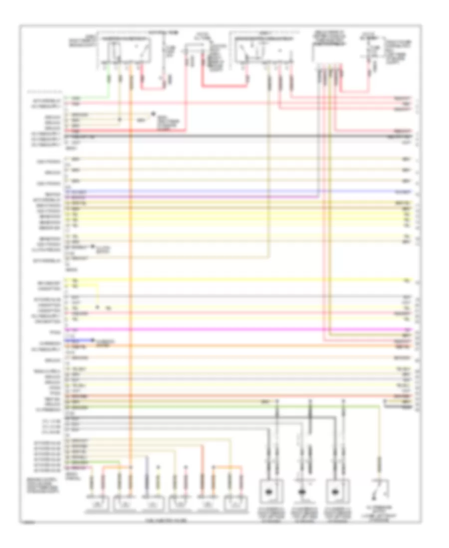
3.3L, Engine Performance Wiring Diagram (1 of 4) for BMW M Coupe 2002
List of elements for 3.3L, Engine Performance Wiring Diagram (1 of 4) for BMW M Coupe 2002:
- (below rear of center console) timed electric fuel pump relay
- (partial)
- 11-12
- 15-16
- 2-4
- 21-22
- 27-28
- 8-9
- Activate relay
- Activate valve
- Air mass met
- B+ junction point e-box (right rear of engine x64102 compt)
- Camshft sig
- Charge sig
- Charging system
- Clutch ped sig
- Clutch switch
- Crnkshft sig
- Cyl 1-2 ks
- Cyl 3-4 ks
- Cyl 5-6 ks
- Cylinders 1-2 knock sensor (top left side of engine)
- Cylinders 3-4 knock sensor (top left side of engine)
- Cylinders 5-6 knock sensor (top left side of engine)
- E-box
- E-box (right rear of engine compt)
- E-box fan sig
- Engine control module (dme) (right rear side of engine compt)
- Engine control module relay
- Front power distribution box (left rear of engine compt)
- Fuel injection valves
- Fuse f18 15a
- Fuse f205 30a
- Ground
- Hot at all times
- Iat sig
- Injection valves relay
- Nca
- O2s htg gnd
- Oil press sig
- Oil pressure switch (lower left front of engine)
- Red
- Sensor sig
- Teach-in proc
- Temp sig
- Tp sig
- X10016
- X60001
- X60002
- X60003
- X64101
- X6454 (right rear of engine compt)
- X8680
3.3L, Engine Performance Wiring Diagram (2 of 4) for BMW M Coupe 2002
List of elements for 3.3L, Engine Performance Wiring Diagram (2 of 4) for BMW M Coupe 2002:
- (behind catalytic converter) oxygen sensor 1
- (behind catalytic converter) oxygen sensor 2
- (in e-box) e-box fan
- (in front of catalytic converter) oxygen sensor 1
- (in front of catalytic converter) oxygen sensor 2
- (right side of engine compt) exhaust temperature sensor
- B+ junction point (under left side of dash)
- Camshaft position sensor 1 (inlet) (on front of engine)
- Camshaft position sensor 2 (outlet) (top rear of engine)
- Crankshaft position/rpm sensor (top rear of eng compt)
- E-box (right rear of engine compt)
- Electric throttle motor (on throttle body)
- Engine coolant temperature sensor (on front of engine)
- Fuel pump (in fuel tank)
- Fuse f107 50a
- Fuse f201 30a
- Fuse f202 30a
- Fuse f203 20a
- Fuse f204 30a
- Hot at all times
- Hot film air mass meter (on left side of engine compt, on air intake tube)
- Nca
- Red
- Throttle position sensor (left side of engine compt)
- Tire pressure warning system pushbutton (left side of dash)
- X13032 (under rear storage compt)
- X18170 (below center console)
- X1982
- X5392
- X5393
- X8680
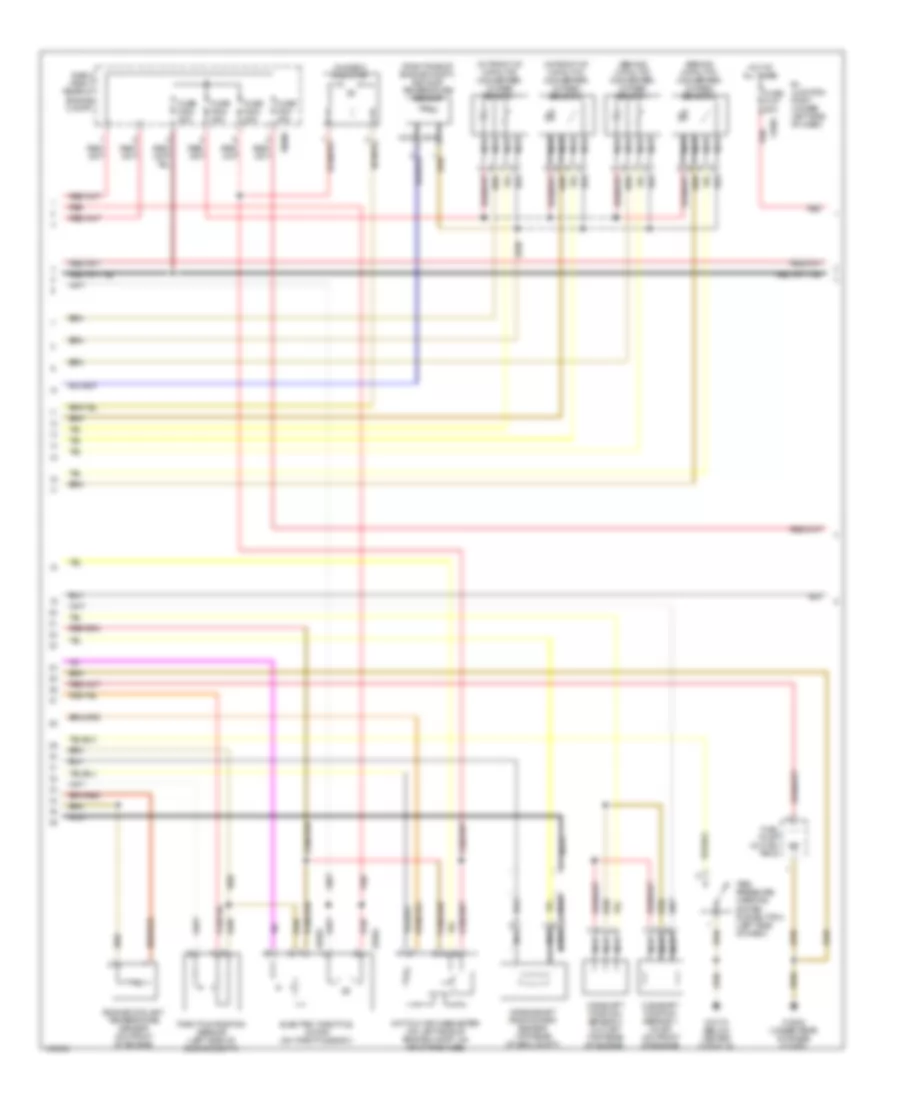
3.3L, Engine Performance Wiring Diagram (3 of 4) for BMW M Coupe 2002
List of elements for 3.3L, Engine Performance Wiring Diagram (3 of 4) for BMW M Coupe 2002:
- (on bracket, above brake pedal) brakelight switch
- Air pump (right rear side of engine compt)
- Charge ind
- Charging system
- E-box (right rear of engine compt)
- Front power distribution box (left rear of engine compt)
- Fuse f13 5a
- Fuse f16 5a
- Fuse f27 5a
- Fuse f46 15a
- Heated leakage diagnosis pump (on lower left rear side of engine)
- High speed relay (in power distribution box)
- Hot in accy, run, or start
- Hot in run or start
- Instrument cluster
- Oil level ind
- Oil press ind
- Red
- Secondary air pump relay
- Tire press ind
- Variable camshaft control valves (front of engine)
- X10016
- X10017
- X10018
- X16
- X17
- X18170 (below center console)
- X271
- X6454 (right rear of engine compt)
- X861 (right front of engine compt)
3.3L, Engine Performance Wiring Diagram (4 of 4) for BMW M Coupe 2002
List of elements for 3.3L, Engine Performance Wiring Diagram (4 of 4) for BMW M Coupe 2002:
- (front of engine) idle speed control valve
- (left rear of engine) evaporative emission valve
- (left rear side of engine compt) data link connector (dlc)
- (left rear side of engine compt) sucking jet pump solenoid valve
- (left side of engine compt) thermal oil level switch
- (partial)
- (right rear of engine compt) x6454
- 38-40
- 48-49
- A/c system
- Abs system
- Activate heat
- Activate motor
- Activate relay
- Activate valve
- Anti-theft system
- Aux fan sig
- Brake sig
- Can bus (+)
- Can bus (-)
- Charge ind
- Close sig
- Computer data lines system
- Cruise control system
- Cruise sig
- Drv awy prot
- Engine control module (dme) (right rear side of engine compt)
- Exterior lights system
- Front power distribution box (left rear of engine compt)
- Fuse f15 5a
- Fuse f26 10a
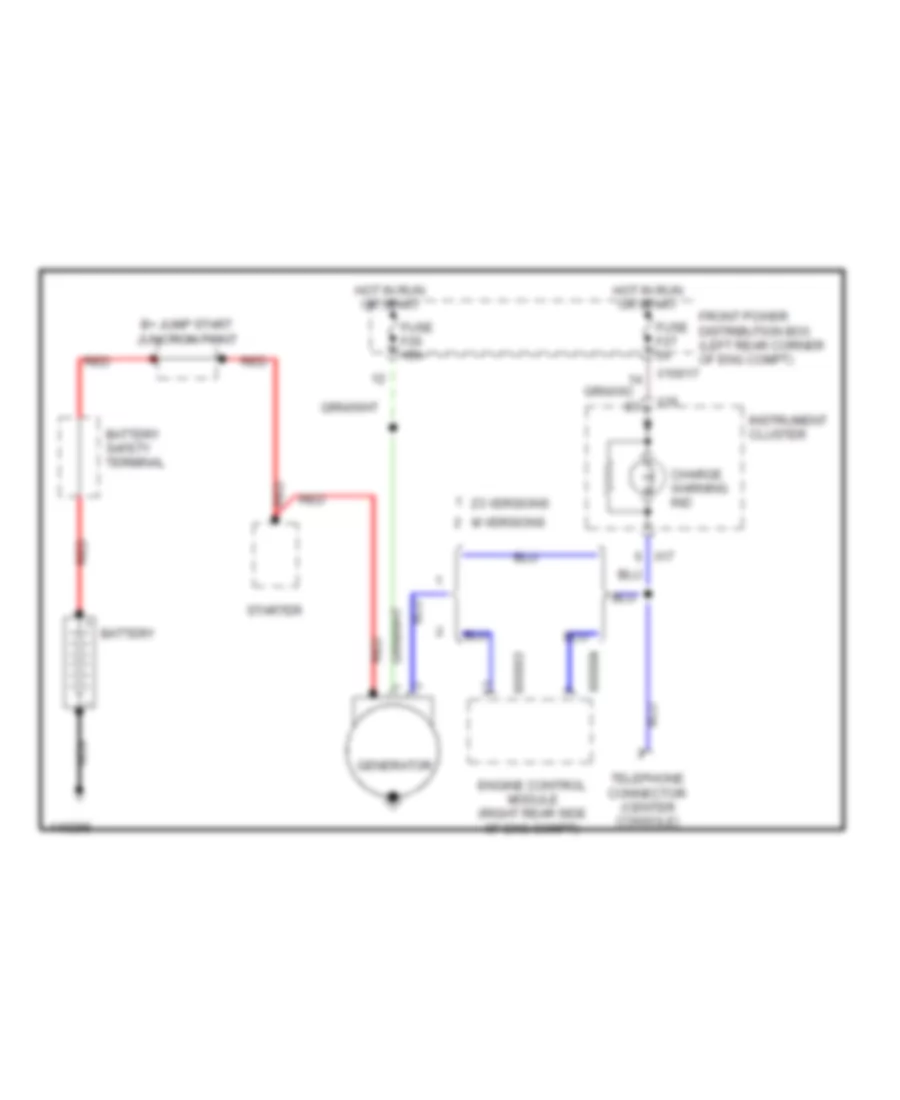
- Generator
- Ground
- Hot in run
- Hot in run or start
- Ign coil 1 sig
- Ign coil 2 sig
- Ign coil 3 sig
- Ign coil 4 sig
- Ign coil 5 sig
- Ign coil 6 sig
- Ignition coils (top right side of engine)
- Leak diag
- Nca
- Oil level sig
- Oil press sig
- Oil sig
- Open sig
- Ped pos 1 sig
- Ped pos 2 sig
- Pedal position sensor (behind accelerator pedal)
- Reverse sig
- Rpm sig
- Rr speed sig
- Signal test
- Start sig
- Suppression capacitor
- Terminal 15
- Tire press ind
- Txd diag sig
- X10016
- X10017
- X60003
- X60004
- X60005
- X6002
- X6454 (right rear of engine compt)
- X6456 (right side of engine)
EXTERIOR LIGHTS
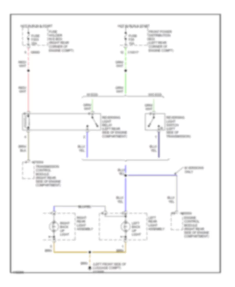
Back-up Lamps Wiring Diagram for BMW M Coupe 2002
List of elements for Back-up Lamps Wiring Diagram for BMW M Coupe 2002:
- (left front side of luggage compt) x13006
- Engine control module (right rear side of engine compartment)
- Front power distribution box (left rear corner of engine compt)
- Fuse f203 20a
- Fuse f26 10a
- Fuse holder in e-box (right rear corner of engine compt)
- Hot in run & start
- Left back up light
- Left rear light assembly
- M versions only
- Reversing light relay (left rear side of engine compartment)
- Reversing light switch (left side of transmission)
- Right back up light
- Right rear light assembly
- Transmission control module (right rear side of engine compartment)
- W/ egs
- W/o egs
- X10017
- X60004
- X70004
- X8680
Park, Stop, Tail & License Plate Lamps Wiring Diagram, Canada for BMW M Coupe 2002
List of elements for Park, Stop, Tail & License Plate Lamps Wiring Diagram, Canada for BMW M Coupe 2002:
- (m roadster)
- (m versions)
- (z3 versions)
- 86b
- 87b
- Body electronic control module (behind glove box)
- Brake light switch (on bracket, above brake pedal)
- Coupe roadster
- Dynamic stability control unit (left side of engine compartment
- Engine control module (right rear side of engine compartment)
- Front power distribution box (left rear corner of engine compartment)
- Fuse f13 5a
- Fuse f25 5a
- Fuse f33 10a
- Fuse f37 10a
- Fuse f46 15a
- Head
- High level stop light
- Hot at all times
- Hot in accy, run & start
- Hot in, run & start
- Left brake- light
- Left front marker light
- Left head- light
- Left license plate light
- Left park light
- Left park light relay (in power distribution box)
- Left rear light assembly
- Left tail- light
- Light switch
- Off
- Park
- Power top system
- Right brake- light
- Right front marker light
- Right head- light
- Right license plate light
- Right park light
- Right park light/ license light relay (in power distribution box)
- Right rear light assembly
- Right tail- light
- Roadster coupe
- Slip control module (left front side of engine compartment)
- Transmission control module (right rear side of engine compartment)
- Uncoupling diode (lights) (in power distribution box)
- W/ asc
- W/ dsc
- Wiper/ washer module (behind glove box)
- X10016
- X10017
- X10018
- X13006 (left front side of luggage compt)
- X1529
- X1530
- X166 (left radiator support)
- X6004
- X861 (right front shock tower)
- X9410
- X9411
- X9633 (left kick panel)
Park, Stop, Tail & License Plate Lamps Wiring Diagram, USA for BMW M Coupe 2002
List of elements for Park, Stop, Tail & License Plate Lamps Wiring Diagram, USA for BMW M Coupe 2002:
- (early prod)
- (late prod)
- (m roadster)
- (m version)
- (z3 versions)
- Body electronic control module (behind glove box)
- Brake light switch (on bracket, above brake pedal)
- Coupe roadster
- Dynamic stability control unit (left side of engine compartment)
- Engine control module (right rear side of engine compartment)
- Front power distribution box (left rear corner of engine compartment)
- Fuse f13 5a
- Fuse f33 10a
- Fuse f37 10a
- Fuse f46 15a
- Head
- High level stop light
- Hot at all times
- Hot in accy, run & start
- Hot in, run & start
- Left brake- light
- Left front marker light
- Left head- light
- Left license plate light
- Left park light
- Left rear light assembly
- Left tail- light
- Light switch
- Off
- Park
- Power tops system
- Right brake- light
- Right front marker light
- Right head- light
- Right license plate light
- Right park light
- Right rear light assembly
- Right tail- light
- Roadster coupe
- Slip control module (left front side of engine compartment)
- Transmission control module (right rear side of engine compartment)
- W/ asc
- W/ dsc
- Wiper/ washer module (behind glove box)
- X10016
- X10018
- X13006 (left front side of luggage compt)
- X165 (right front shock tower)
- X166 (left radiator support)
- X6004
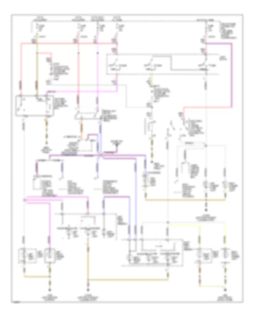
Turn & Hazard Lamps Wiring Diagram for BMW M Coupe 2002
List of elements for Turn & Hazard Lamps Wiring Diagram for BMW M Coupe 2002:
- (below center console) x18170
- (right kick panel) x10010
- Accessory connector
- Anti-theft system
- Body electronics control module (behind glove box)
- Combination switch
- Crash control module (under left side of dash)
- Front power distribution box (rear left corner of engine compartment)
- Fuse f23 5a
- Fuse f25 5a
- Fuse f34 15a
- Hazard flasher relay (in power distribution box)
- Hazard switch
- Head
- Headlights system
- Headlights system (low beam relay)
- Hot at all times
- Hot in run & start
- Instrument cluster
- Interior lights system
- Left front auxiliary turn light
- Left front turn light
- Left head- light
- Left rear light assembly
- Left rear turn light
- Left turn indicator
- Light switch
- Off
- Off left flash left flash (no detent) right flash (no detent) right flash
- Park
- Right front auxiliary turn light
- Right front turn light
- Right head- light
- Right rear light assembly
- Right rear turn light
- Right turn indicator
- X10017
- X10018
- X13004 (behind glove box)
- X13006 (left front side of luggage compt)
- X16
- X165 (right front shock tower)
- X166 (left radiator support)
- X17
- X9633 (left kick panel)
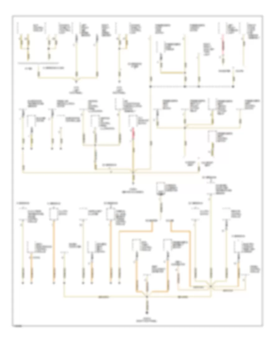
GROUND DISTRIBUTION
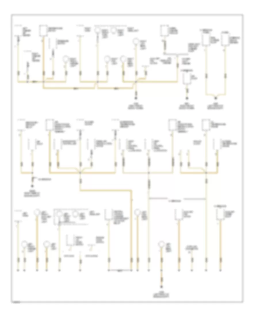
Ground Distribution Wiring Diagram (1 of 4) for BMW M Coupe 2002
List of elements for Ground Distribution Wiring Diagram (1 of 4) for BMW M Coupe 2002:
- Air conditioning/ recirculating switch assembly
- Air conditioning/ recirculation switch assembly
- Air pump
- Analog clock
- Auxiliary fan motor
- Auxiliary water pump
- Blower motor
- Central locking luggage compartment lid motor relay
- Data link connector
- Engine hood switch
- Evaporator controller
- Evaporator temperature sensor
- Fresh air recirculation motor
- Front lid micro switch
- Headlight/ foglight washer pump
- Heat/ a/c control panel illumination
- Left fog light
- Left front auxiliary turn light
- Left front marker light
- Left front turn light
- Left headlamp
- Left high beam light
- Left horn
- Left low beam light
- Left park light
- Left washer jet heater
- M versions
- M versions w/ dsc
- Nca
- Oil temperature gauge
- Outside temperature gauge
- Pre- charge pump
- Pressure switch
- Right fog light
- Right front marker light
- Right front turn light
- Right headlight
- Right high beam light
- Right horn
- Right low beam light
- Right park light
- Right washer jet heater
- Secondary air pump relay
- Steering angle sensor
- Temperature switch
- W/ dsc
- W/ head- light washer
- W/o headlight washer
- Wiper/ washer module
- With alpine
- With dwa
- X165 (right front shock tower)
- X166 (left front of engine compt)
- X492 (left front of engine compt)
- X6455 (right rear of engine compt)
- X861 (right front shock tower)
- Z3 versions
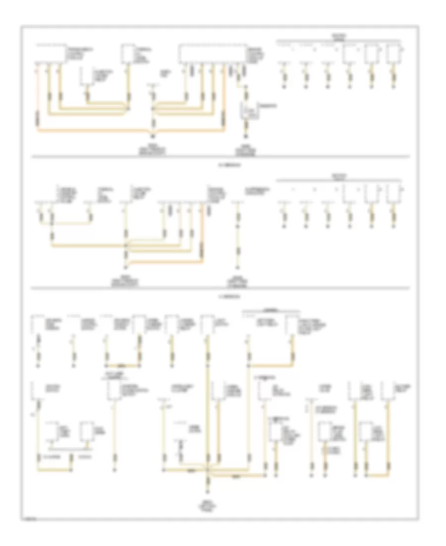
Ground Distribution Wiring Diagram (2 of 4) for BMW M Coupe 2002
List of elements for Ground Distribution Wiring Diagram (2 of 4) for BMW M Coupe 2002:
- (not used w/ egs)
- (w/ asc)
- (w/ dsc)
- (z3 version) (m version)
- A/c relay, motronic
- A/c relay/ auxiliary water pump
- Anti- theft horn
- Blower relay
- Brake fluid level switch
- Canada
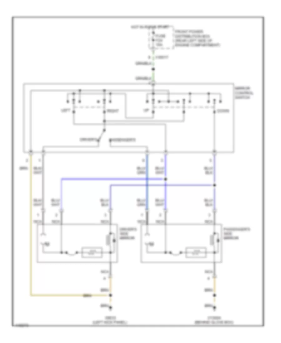
- Driver's side mirror
- Driver's window motor
- Dwa siren
- E-box fan
- Engine control module (dme)
- Hazard flasher relay
- High beam light relay
- Ignition coils
- Ignition switch
- Injection valves relay
- Instrument cluster
- Left park light relay
- Light switch
- Low beam light relay
- M versions
- Mirror control switch
- Nca
- Ohm
- Resistor
- Right park light/license plate light relay
- Starter immobilization switch
- Suppression capacitor
- Thermal oil level switch
- Transmission control module
- Variable camshaft control valves
- W/ alpine
- W/ dwa
- Water valve
- Wiper motor
- Wiper/ washer module
- Wiper/ washer switch
- X17
- X60001
- X60005
- X6454 (right rear of engine compt)
- X6456 (right side of engine)
- X9633 (left kick panel)
- Z3 versions
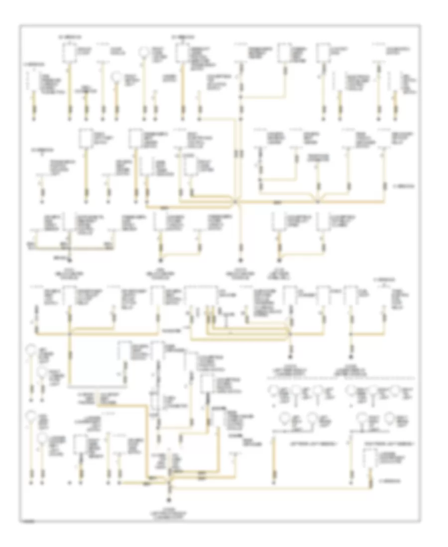
Ground Distribution Wiring Diagram (3 of 4) for BMW M Coupe 2002
List of elements for Ground Distribution Wiring Diagram (3 of 4) for BMW M Coupe 2002:
- (not used)
- Air conditioning recirculating switch assembly
- Anti- theft control module
- Blower motor
- Board computer
- Body electronics control module
- Clutch switch
- Coupe
- Crash control module
- Driver's seat belt switch
- Dynamic stability control unit
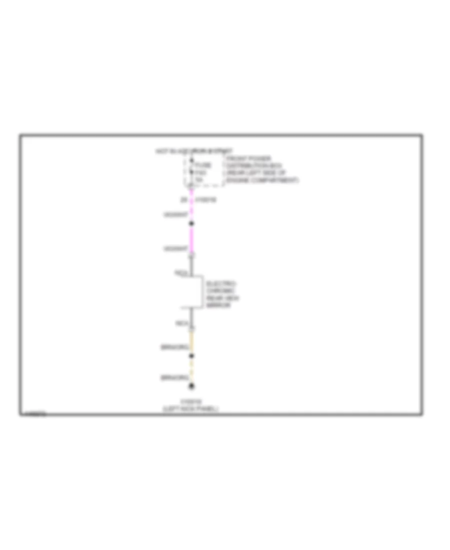
- Electro- chromic rear view mirror
- Evaporator controller
- Evaporator temperature sensor
- Fresh air recirculation motor
- Front dome light/ map reading assembly
- Heating/ a/c control panel illumination
- Instrument cluster
- Interior movement detector
- Left front abs speed sensor
- Left front interior light
- M versions
- M versions w/ dsc
- Nca
- Obd ii connector
- Oil/outside temperature gauge control module
- On-board computer temperature sensor
- Passenger's door jamb switch
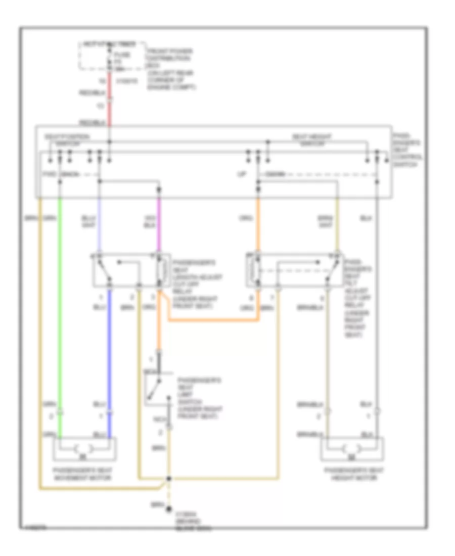
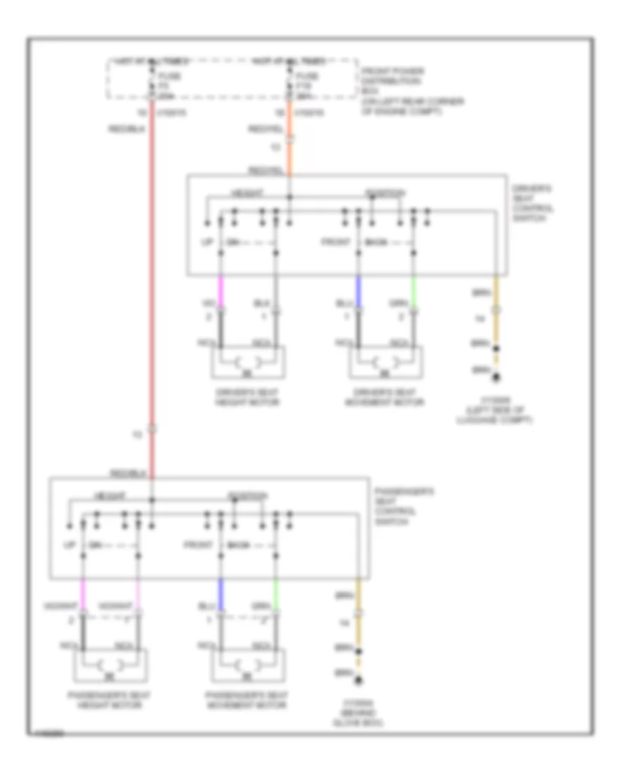
- Passenger's seat control switch
- Passenger's seat length adjust cut-off relay
- Passenger's seat limit switch
- Passenger's seat tilt adjust cut-off relay
- Passenger's seatbelt switch
- Passenger's side mirror
- Passenger's window motor
- Red
- Remote control module
- Right front abs speed sensor
- Right front auxiliary turn light
- Roadster
- Seat occupancy detector
- Slip control module
- Thermal oil level sensor (toens) control module
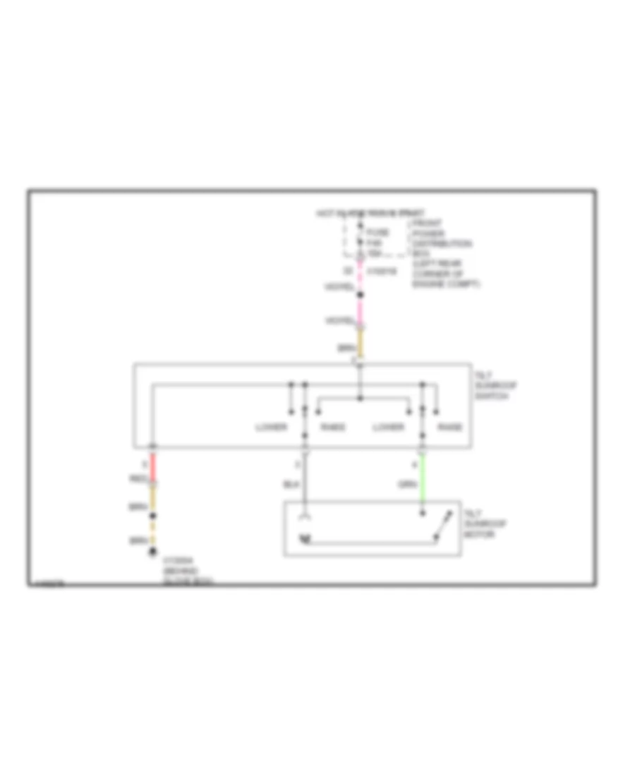
- Tilt sunroof switch
- W/ asc
- W/ sport seat
- W/o sport seat
- X10010 (right kick panel)
- X10182
- X13004 (behind glove box)
- X170 (left kick panel)
- Z3 versions
- Z3 versions w/ dsc
Ground Distribution Wiring Diagram (4 of 4) for BMW M Coupe 2002
List of elements for Ground Distribution Wiring Diagram (4 of 4) for BMW M Coupe 2002:
- (coupe)
- Analog clock
- Asc switch or dsc switch
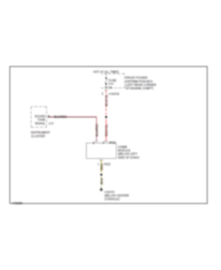
- Body electronics control module
- Cd changer
- Chime module
- Combination switch
- Contact ring
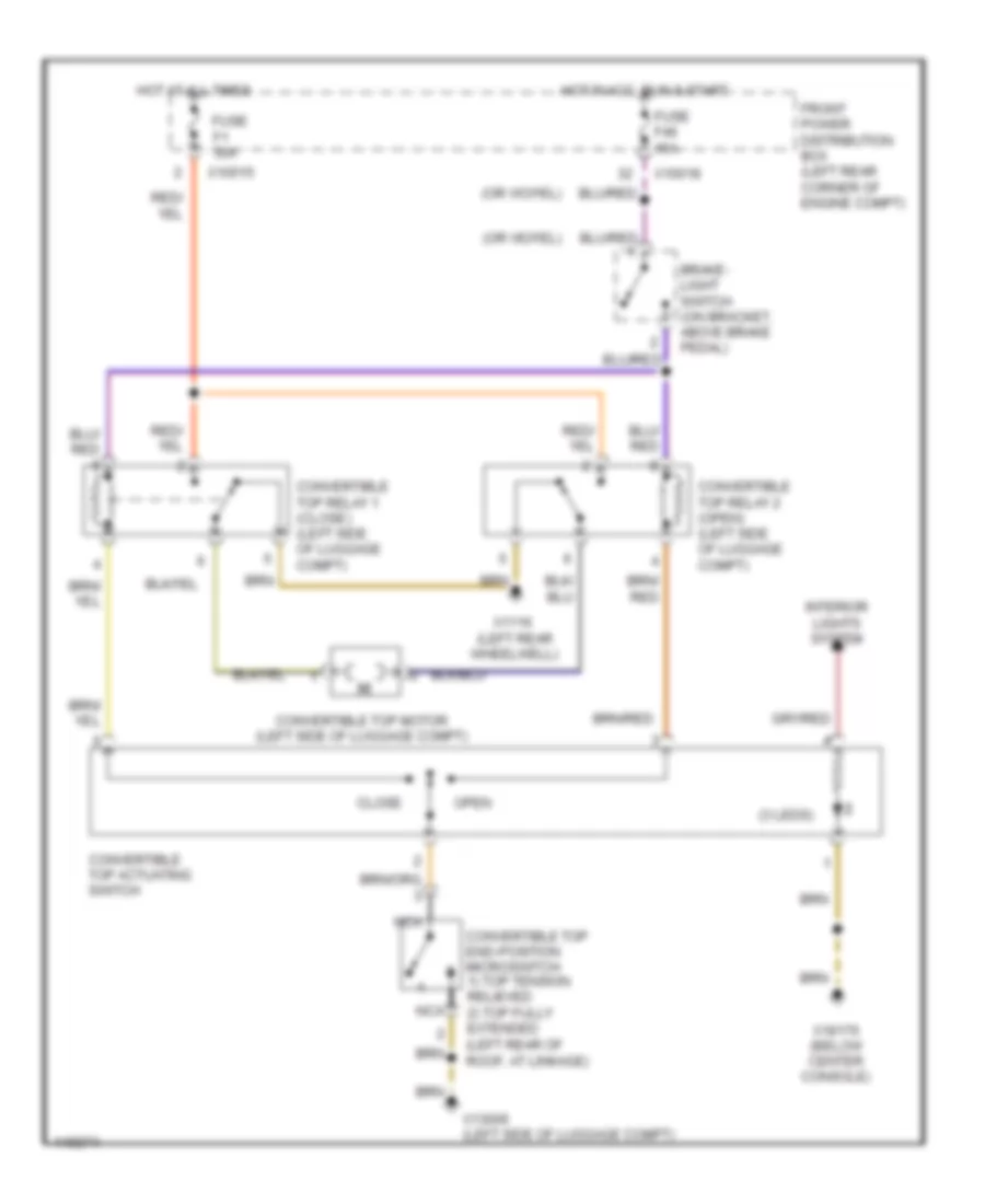
- Convertible top actuating switch
- Convertible top end- position micro switch
- Convertible top relay i (closed)
- Convertible top relay ii (open)
- Coupe
- Driver's door jamb switch
- Driver's power window switch
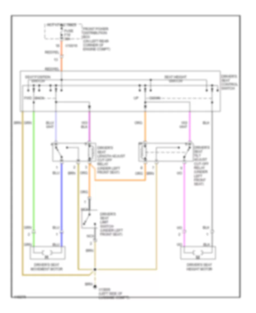
- Driver's seat control switch
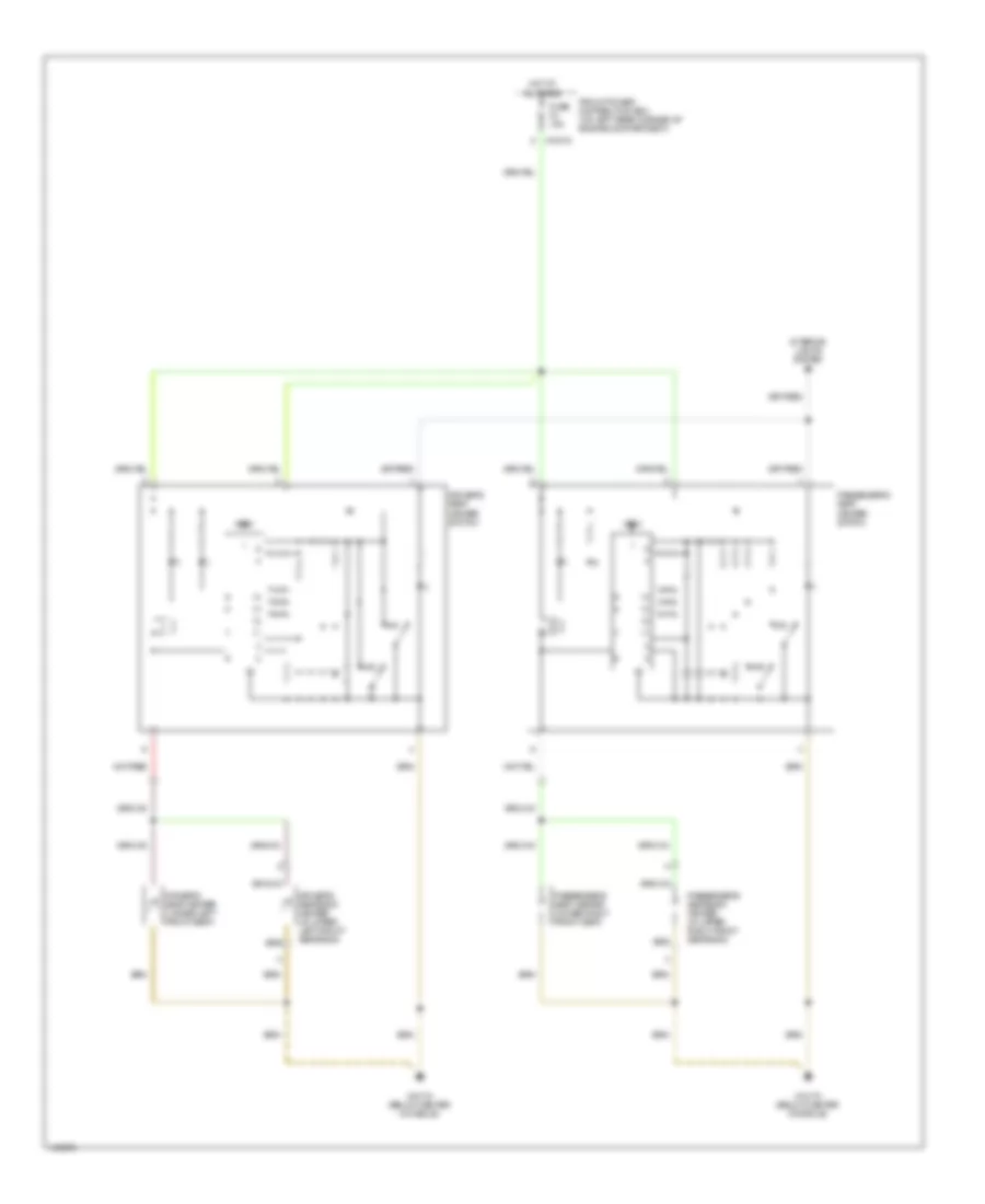
- Driver's seat heater
- Driver's seat heater switch
- Driver's seat length adjust cut-off relay
- Driver's seat limit switch
- Driver's seat tilt adjust cut-off relay
- Driver's seatback heater
- Driver's side impact sensor
- Electronic immobilizer control module
- Front ashtray light
- Front cigar lighter
- Front cigar lighter light
- Fuel pump
- Gear shift lever indicator
- Gearshift lever position/ gear step transmission switch
- Hard top connector
- Hazard switch
- Hifi amplifier
- High level stop light
- Left back- up light
- Left brake light
- Left license plate light
- Left rear light assembly
- Left rear turn light
- Left tail light
- Luggage compart- ment light (coupe)
- Luggage compartment light switch
- Luggage compartment lock motor
- M versions
- Nca
- Obd ii connector
- Passen- ger's seat heater
- Passenger's power window switch
- Passenger's seat heater switch
- Passenger's seatback heater
- Passenger's side impact sensor
- Radio
- Radio anti-theft switch
- Rear defogger
- Rear defogger 1
- Rear window defogger switch
- Rear wiper/washer interval control module
- Right back- up light
- Right brake light
- Right license plate light
- Right rear brake pad sensor
- Right rear light assembly
- Right rear turn light
- Right tail light
- Roadster
- Secondary air pump relay
- Subwoofer amplifier module (roadster w/ harmon kardon sound system)
- Telephone connector
- Timed electric fuel pump relay
- Tire pressure warning system pushbutton
- Transmission position indicator light
- W/ sport seat package
- W/o hard top pro- vision
- W/o sport seat package
- X1116 (left rear wheelwell)
- X13006 (left front side of luggage compt)
- X13016 (left rear side of luggage compt)
- X13032 (under rear of center console)
- X13252
- X1441 (below center console)
- X1717
- X18170 (below center console)
- X494 (below center console)
- X605
- Z3 versions
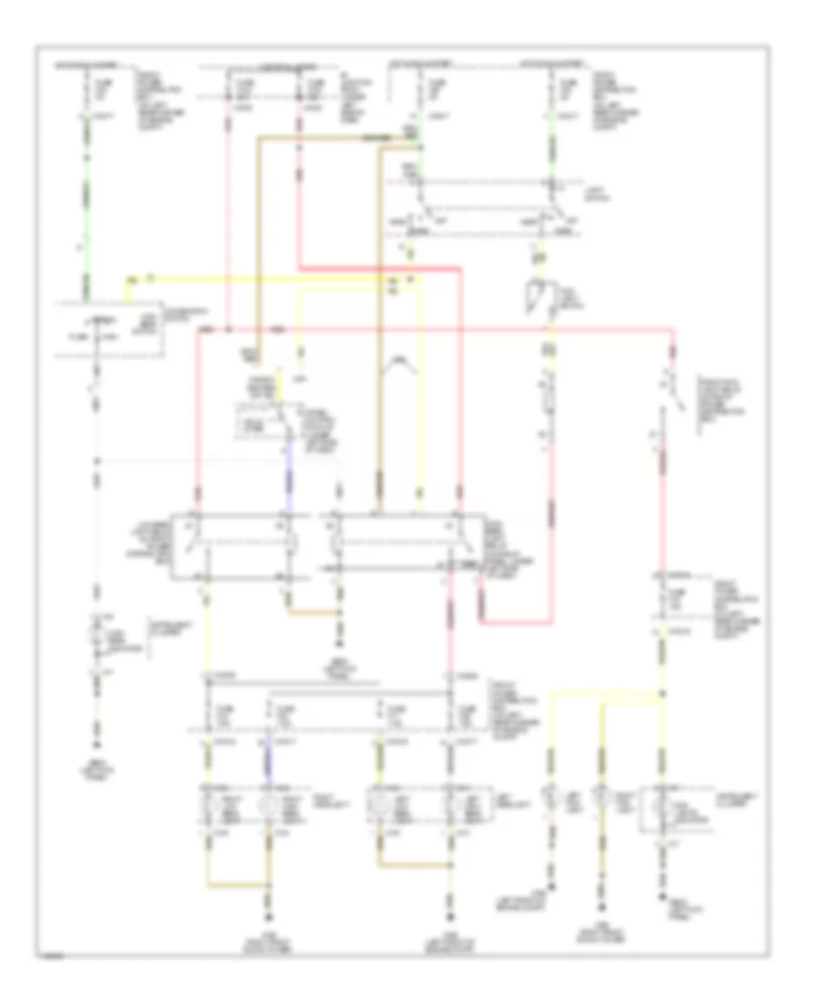
HEADLIGHTS
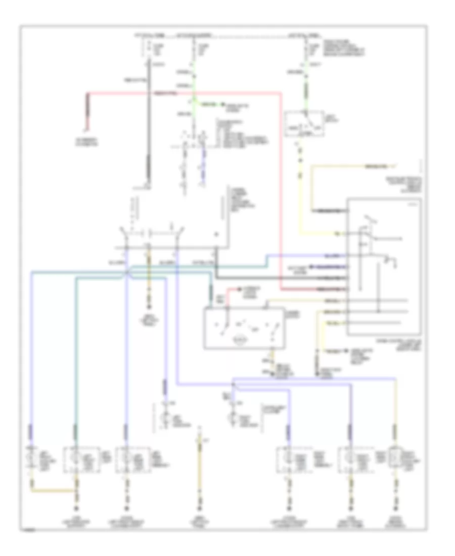
Headlights Wiring Diagram for BMW M Coupe 2002
List of elements for Headlights Wiring Diagram for BMW M Coupe 2002:
- 87b
- B+ junction point (under left side of dash)
- Canada
- Combination switch
- Crash control module (under left side of dash)
- Flash
- Fog- light switch
- Fog- lights indicator
- Front fog- light relay (in front power distribution box)
- Front power distribution box (on left rear corner of engine compt)
- Fuse f103 80a
- Fuse f104 80a
- Fuse f11 7.5a
- Fuse f12 7.5a
- Fuse f15 15a
- Fuse f22 5a
- Fuse f23 5a
- Fuse f25 5a
- Fuse f29 7.5a
- Fuse f30 7.5a
- Head
- High
- High beam indicator
- High beam light relay (on relay panel, under left side of dash)
- High beam switch
- Hot at all times
- Hot in run & start
- Instrument cluster
- Left fog- light
- Left headlight
- Left high beam light
- Left low beam light
- Light switch
- Low beam light relay (in front power distribution box)
- Normal
- Off
- Park
- Red
- Right fog- light
- Right headlight
- Right high beam light
- Right low beam light
- Solid state
- Usa
- X10016
- X10017
- X10035
- X10036
- X130
- X131
- X134
- X135
- X16
- X165 (right front shock tower)
- X166 (left front of engine compt)
- X17
- X1978
- X1979
- X9633 (left kick panel)
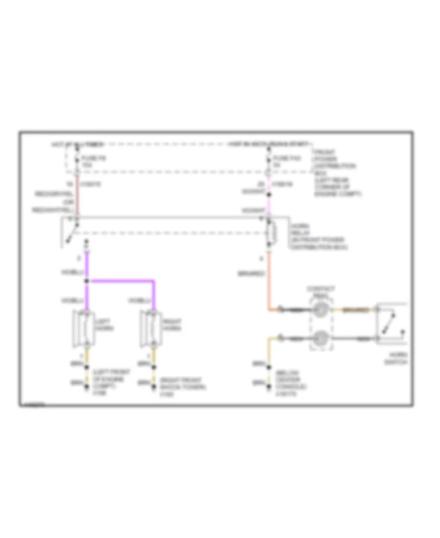
HORN
Horn Wiring Diagram for BMW M Coupe 2002
List of elements for Horn Wiring Diagram for BMW M Coupe 2002:
- (below center console) x18170
- (left front of engine compt) x166
- (or
- (right front shock tower) x165
- Contact ring
- Front power distribution box (left rear corner of engine compt)
- Fuse f43 5a
- Fuse f8 15a
- Horn relay (in front power distribution box)
- Horn switch
- Hot at all times
- Hot in accy, run & start
- Left horn
- Nca
- Right horn
- X10015
- X18018
INSTRUMENT CLUSTER
Instrument Cluster Wiring Diagram, M-Versions (1 of 2) for BMW M Coupe 2002
List of elements for Instrument Cluster Wiring Diagram, M-Versions (1 of 2) for BMW M Coupe 2002:
- (below left side of dash) chime module
- (left kick panel)
- (left side of luggage compt) x13006
- A14
- A17
- A18
- A19
- A22
- A23
- A24
- Abs ind
- Air conditioning system
- Anti-lock brakes system
- Anti-theft system
- B14
- B15
- B16
- B19
- B21
- B22
- B23
- B25
- Brake fluid
- Brake pad ind
- Charge ind
- Data link connector (left rear side of engine compartment)
- Data link connector (left rear side of engine compt)
- Drivers door jamb switch
- Engine control module
- Exterior lights system
- Front power distribution box (on left rear corner of engine compt)
- Fuel consumption meter
- Fuel gauge
- Fuel sensor (in fuel tank)
- Fuse f23 5a
- Fuse f27 5a
- Fuse f31 5a
- Fuse f46 15a
- Headlights system
- High beam ind
- Hot at all times
- Hot in accy, run & start
- Hot in run & start
- Ignition switch
- Illum
- Ind
- Instrument cluster
- Interior lights system
- Left front brake pad sensor
- Left turn ind
- Nca
- Oil ind
- Oil temperature
- Park brake ind
- Right rear brake pad sensor
- Right turn ind
- Seat belt ind
- Solid state
- Speedo- meter
- Srs ind
- Starting/ charging system
- Tacho- meter
- Temp gauge
- Tire pressure warning ind
- Vehicle speed sensor (on differential)
- X10010 (right kick panel)
- X10017
- X10018
- X13006 (left side of luggage compt)
- X16 conn a
- X17 conn b
- X18170 (below center console)
- X271 conn c
- X9633
- X9633 (left kick panel)
Instrument Cluster Wiring Diagram, M-Versions (2 of 2) for BMW M Coupe 2002
List of elements for Instrument Cluster Wiring Diagram, M-Versions (2 of 2) for BMW M Coupe 2002:
- Analog clock
- Brake fluid level switch (left rear side of engine compt)
- Driver's seatbelt switch
- Dynamic stability control unit (dsc) (on left side of eng compt)
- Engine control module (on right rear side of engine compt, in "e" box)
- Engine coolant temperature sensor (front of engine)
- Front power distribution box (on left rear corner of engine compt)
- Fuse f26 10a
- Ground
- Hifi amplifier (w/ harmon kardon sound system)
- Hot in run & start
- Interior lights system
- Nca
- Oil pressure switch (left side of engine compt)
- Oil temperature gauge
- Oil/outside temperature gauge control module
- Outside temperature gauge
- Park brake switch (on rear of parking brake lever)
- Radio
- Roadster
- Temperature sensor (left front wheelwell)
- Thermal oil level switch (lower left side of engine compt)
- Tire pressure warning system pushbutton
- Vss
- W/ dsc
- W/o dsc
- Wiper/washer module (behind glove box)
- X10010 (right kick panel)
- X10017
- X10266
- X166 (left front of engine compt)
- X1717
- X18126
- X18170 (below center console)
- X285
- X60003
- X60004
- X6454 (right rear of engine compt)
- X9633 (left kick panel)
Instrument Cluster Wiring Diagram, Z3 Versions (1 of 2) for BMW M Coupe 2002
List of elements for Instrument Cluster Wiring Diagram, Z3 Versions (1 of 2) for BMW M Coupe 2002:
- (below left side of dash) chime module
- (left kick panel)
- (left side of luggage compt) x13006
- A14
- A17
- A18
- A19
- A22
- A23
- A24
- Abs ind
- Air conditioning system
- Anti-lock brakes system
- Anti-theft system
- B14
- B15
- B16
- B19
- B21
- B22
- B23
- B25
- Brake fluid
- Brake pad ind
- Charge ind
- Data link connector (left rear side of engine compartment)
- Drivers door jamb switch
- Engine control module
- Exterior lights system
- Front fog lt ind
- Front power distribution box (on left rear corner of engine compt)
- Fuel consumption meter
- Fuel gauge
- Fuel sensor (in fuel tank)
- Fuse f23 5a
- Fuse f27 5a
- Fuse f31 5a
- Fuse f46 15a
- Headlights system
- High beam ind
- Hot at all times
- Hot in accy, run & start
- Hot in run & start
- Ignition switch
- Illum
- Ind
- Instrument cluster
- Interior lights system
- Left front brake pad sensor
- Left turn ind
- Nca
- Oil ind
- Oil temperature
- Park brake ind
- Right rear brake pad sensor
- Right turn ind
- Seat belt ind
- Solid state
- Speedo- meter
- Srs ind
- Starting/ charging system
- Tacho- meter
- Temp gauge
- Vehicle speed sensor (on differential)
- X10010 (right kick panel)
- X10017
- X10018
- X13006 (left side of luggage compt)
- X16 conn a
- X17 conn b
- X18170 (below center console)
- X271 conn c
- X9633
- X9633 (left kick panel)
Instrument Cluster Wiring Diagram, Z3 Versions (2 of 2) for BMW M Coupe 2002
List of elements for Instrument Cluster Wiring Diagram, Z3 Versions (2 of 2) for BMW M Coupe 2002:
- Analog clock
- Bat
- Board computer (behind center console)
- Brake fluid level switch (left rear side of engine compt)
- Data link connector (left rear side of engine compt)
- Driver's seatbelt switch
- Dynamic stability control unit (dsc) (on left side of eng compt)
- Electronic immobilizer control module
- Engine control module (on right rear side of engine compt, in "e" box)
- Engine coolant temperature sensor (front of engine)
- Front power distribution box (on left rear corner of engine compt)
- Fuse f26 10a
- Ground
- Hifi amplifier (w/ harmon kardon sound system)
- Hot in run & start
- Interior lights system
- Nca
- Oil pressure switch (left side of engine compt)
- Park brake switch (on rear of parking brake lever)
- Radio
- Roadster
- Thermal oil level sensor control module (behind glove box)
- Thermal oil level switch (lower left side of engine compt)
- Vss
- W/ dsc
- W/o dsc
- Wiper/washer module (behind glove box)
- X10010 (right kick panel)
- X10017
- X10245
- X10266
- X1717
- X18126
- X18170 (below center console)
- X285
- X60003
- X60004
- X6454 (right rear of engine compt)
- X9633 (left kick panel)
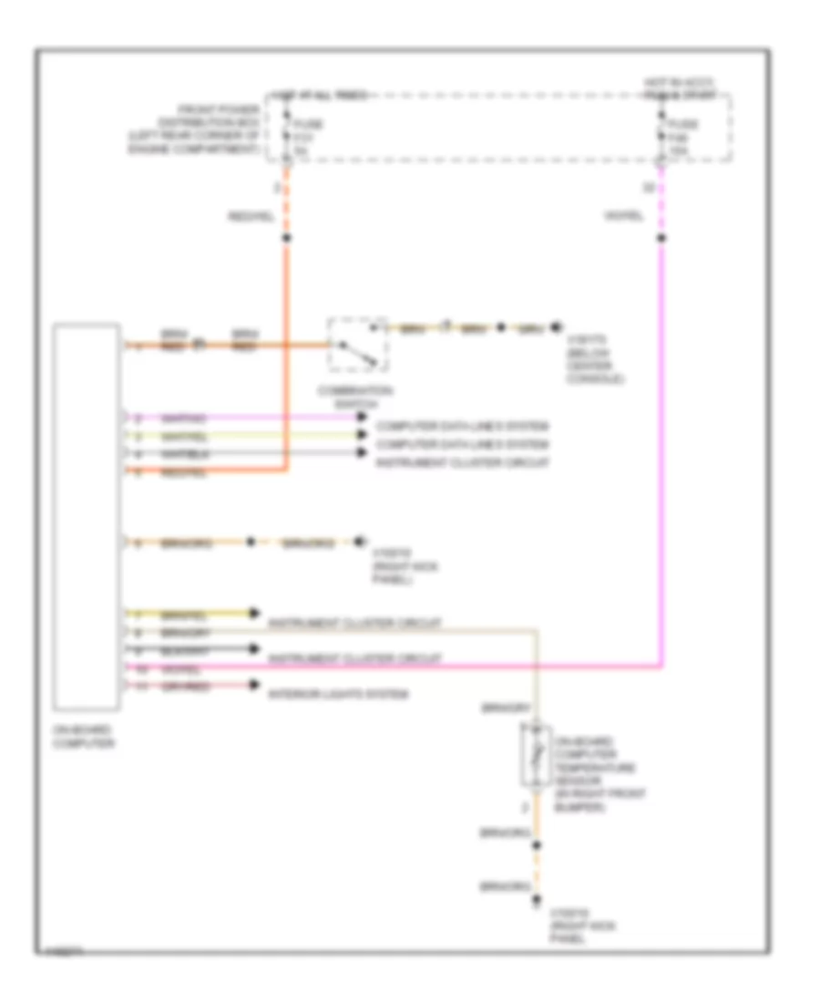
On-Board Computer Wiring Diagram for BMW M Coupe 2002
List of elements for On-Board Computer Wiring Diagram for BMW M Coupe 2002:
- Combination switch
- Computer data lines system
- Front power distribution box (left rear corner of engine compartment)
- Fuse f31 5a
- Fuse f46 15a
- Hot at all times
- Hot in accy, run & start
- Instrument cluster circuit
- Interior lights system
- On-board computer
- On-board computer temperature sensor (in right front bumper)
- X10010 (right kick panel
- X10010 (right kick panel)
- X18170 (below center console)
INTERIOR LIGHTS
Interior Lights Wiring Diagram for BMW M Coupe 2002
List of elements for Interior Lights Wiring Diagram for BMW M Coupe 2002:
- (coupe)
- (left front of eng compt) x166
- (m versions) x166 (left front of eng compt)
- (roadster)
- Analog clock
- Anti-theft control module (behind glove box)
- Anti-theft system
- Asc switch or dsc switch
- Auto
- Board computer (behind center console)
- Body electronics control module (behind glove box)
- Convertible top actuating switch
- Coupe
- Driver's door jamb switch
- Driver's power window switch
- Driver's seat heater switch
- Exterior lights (license plate lights)
- Exterior lights (turn/hazard lights)
- Front ashtray light
- Front cigar lighter light
- Front dome light/map reading assembly
- Front left interior light
- Front power distribution box (left rear corner of engine compartment)
- Fuse f2 10a
- Fuse f23 5a
- Fuse f33 10a
- Fuse f37 10a
- Fuse f43 5a
- Gear shift lever switch
- Hazard switch
- Head
- Heat/ a/c control panel illumination
- Hot at all times
- Hot in accy, run & start
- Hot in run & start
- Instrument cluster
- Interior
- Interior light switch
- Light switch
- Luggage compart- ment light
- Luggage compartment light switch
- M versions
- Manual
- Nca
- Off
- Oil temperature gauge
- Outside temperature gauge
- Park
- Passenger's door jamb switch
- Passenger's power window switch
- Passenger's seat heater switch
- Radio
- Reading
- Rear defogger switch
- Roadster
- Transmission position indicator light
- Wiper/ washer module (behind glove box)
- X10015
- X10017
- X10018
- X10182
- X10245
- X11104
- X11105
- X11106
- X13004 (behind glove box)
- X13004 (z3 versions) (behind glove box)
- X13006 (left side of luggage compt)
- X13025
- X13252
- X13254
- X16
- X18080
- X18170 (below center console)
- X712
- X9633 (left kick panel)
- Z3 versions
POWER DISTRIBUTION
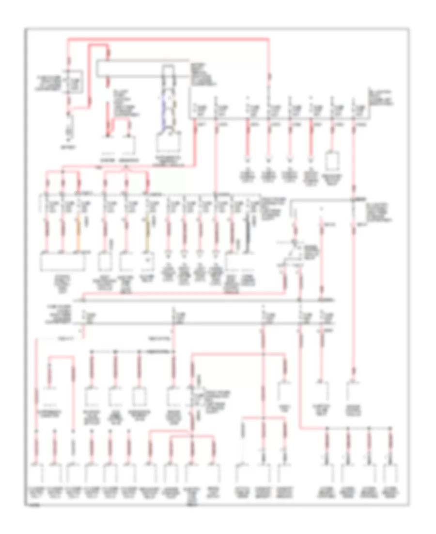
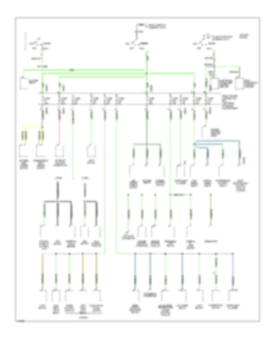
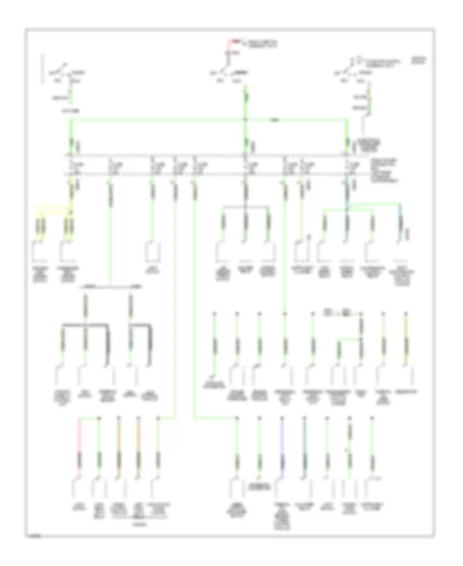
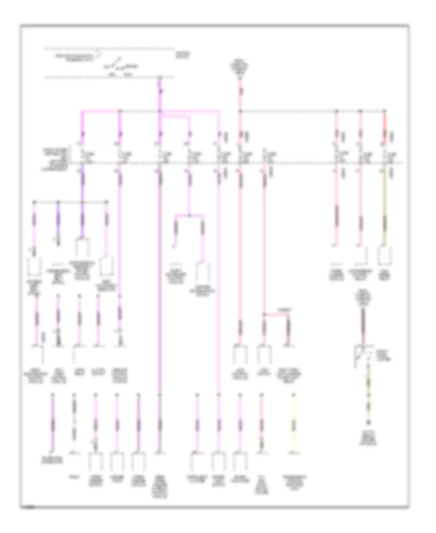
Power Distribution Wiring Diagram, M-Versions (1 of 4) for BMW M Coupe 2002
List of elements for Power Distribution Wiring Diagram, M-Versions (1 of 4) for BMW M Coupe 2002:
- B+ jump start junction point (right rear of engine compartment)
- B+ junction point (under left side of dash)
- B+ junction point e-box (right rear of engine compartment)
- Battery
- Battery safety terminal (right side of luggage compartment)
- Blower relay
- Body elec- tronics control module
- Body electronics control module
- Brake light switch
- Camshaft position sensor 1
- Camshaft position sensor 2
- Cylinder ignition coil 1
- Cylinder ignition coil 2
- Cylinder ignition coil 3
- Cylinder ignition coil 4
- Cylinder ignition coil 5
- Cylinder ignition coil 6
- Dynamic stability control (dsc) unit
- E-box fan
- Electric timed fuel pump relay
- Engine control module
- Engine control module (dme)
- Engine control module relay
- Evaporative emission valve
- Front power distribution box (left rear of engine compt)
- Fuse f100 200a
- Fuse f101 80a
- Fuse f102 80a
- Fuse f103 80a
- Fuse f104 80a
- Fuse f105 80a
- Fuse f106 50a
- Fuse f107 50a
- Fuse f108 80a
- Fuse f13 5a
- Fuse f14 30a
- Fuse f18 20a
- Fuse f20 30a
- Fuse f201 30a
- Fuse f202 30a
- Fuse f203 20a
- Fuse f204 30a
- Fuse f205 30a
- Fuse f31 5a
- Fuse f32 30a
- Fuse f33 10a
- Fuse f34 15a
- Fuse f35 25a
- Fuse f36 30a
- Fuse f51 30a
- Fuse f52 30a
- Fuse f53 30a
- Fuse holder (right side of luggage compartment)
- Fuse holder in e-box (right rear of engine compartment)
- Generator
- Hot film mass air meter
- Idle speed control valve
- Injection valves relay
- Leakage diagnosis pump
- Nca
- Oxygen sensor 1 (forward)
- Oxygen sensor 1 (rear)
- Oxygen sensor 2 (forward)
- Oxygen sensor 2 (rear)
- Red
- Red x8680
- Secondary air pump relay
- Solenoid valve sucking jet pump
- Starter
- Suppression capacitor
- To chime module (diag 2 of 4)
- To front cigar lighter (diag 4 of 4)
- To fuse f1 (diagram 2 of 4)
- To fuse f37 (diagram 4 of 4)
- To fuse f5 (diagram 2 of 4)
- To hazard flasher relay (diag 2 of 4)
- To ignition switch (diagram 3 of 4)
- To light switch (diag 2 of 4)
- Wiper/ washer module
- X10016
- X10018
- X10034
- X10422
- X13252
- X1746
- X19017
- X1976
- X1977
- X1978
- X1979
- X1980
- X1981
- X1982
- X64101
- X64102 red
- X64192
- X74
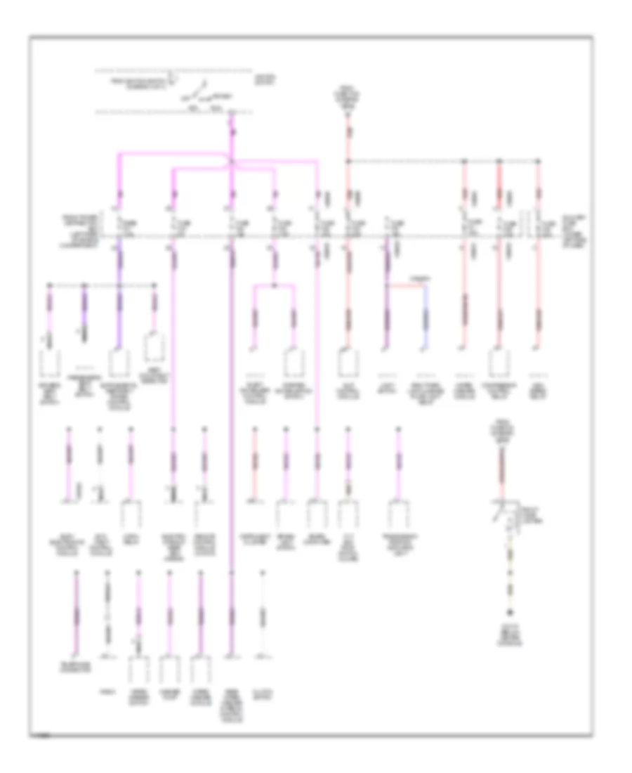
Power Distribution Wiring Diagram, M-Versions (2 of 4) for BMW M Coupe 2002
List of elements for Power Distribution Wiring Diagram, M-Versions (2 of 4) for BMW M Coupe 2002:
- (coupe)
- A red
- Accessory connector
- Analog clock
- Anti- theft control module
- B red
- Board computer
- Body electronics control module
- Cd changer
- Central locking luggage compartment lid motor relay (coupe)
- Chime module
- Conv top relay
- Coupe
- Crash control module
- Data link connector
- Driver's door lock motor
- Driver's door lock switch
- Drivers seat control switch
- Dwa led
- Dwa siren
- Electronic immobilizer control module
- From fuse f103 (diagram 1 of 4)
- From fuse f104 (diagram 1 of 4)
- From fuse f31 (diagram 1 of 4)
- From fuse f33 (diagram 1 of 4)
- From fuse f34 (diagram 1 of 4)
- Front dome light/ map reading assembly
- Front power distribution box (left rear of engine compartment)
- Fuse f1 30a
- Fuse f10 30a
- Fuse f11 7.5a
- Fuse f12 7.5a
- Fuse f19 30a
- Fuse f2 15a
- Fuse f29 7.5a
- Fuse f30 7.5a
- Fuse f5 30a
- Fuse f6 20a
- Fuse f7 5a
- Fuse f8 15a
- Fuse f9 20a
- Hazard flasher relay
- Hifi amplifier
- High beam light relay
- Horn relay
- Instrument cluster
- Interior light switch (roadster)
- Interior movement detector
- Left head- light
- Left headlight
- Left park light relay (canada)
- Light switch
- Low beam light relay
- Luggage compartment light
- Luggage compartment lock motor
- Nca
- Not used
- Obd ii connector
- Oil/ outside temper- ature gauge control module
- Pass- enger's door lock motor
- Passenger's door lock switch
- Passenger's seat control switch
- Pitch sensor
- Radio
- Rear wiper/ washer interval control module
- Red
- Remote control module
- Right head- light
- Right headlight
- Roadster
- Roadster w/ harmon kardon sound system
- Slip control module
- Steering angle sensor
- Subwoofer amplifier module
- Telephone connector
- Unloader relay
- W/ dsc
- W/ dwa
- W/o dwa
- X10015
- X10016
- X10017
- X10030
- X10035
- X10036
- X10182
- X13252
Power Distribution Wiring Diagram, M-Versions (3 of 4) for BMW M Coupe 2002
List of elements for Power Distribution Wiring Diagram, M-Versions (3 of 4) for BMW M Coupe 2002:
- A/c relay/ auxiliary water pump
- Acc
- Accessory connector
- Asc switch
- Blower relay
- Body electronic control module
- Body electronics control module (w/ dwa)
- Canada
- Combination switch
- Compressor control relay
- Crash control module
- Cruise control interface
- Data link connector
- Driver's seat heater switch
- Dsc switch
- Dynamic stability control unit
- Electronic immobilizer control module
- Engine control module
- Engine control module (dme)
- From fuse f106 (diagram 1 of 3)
- Front power distribution box (left rear of engine compartment)
- Fuse f15 5a
- Fuse f16 5a
- Fuse f21 5a
- Fuse f22 5a
- Fuse f23 5a
- Fuse f24 10a
- Fuse f25 5a
- Fuse f26 10a
- Fuse f27 5a
- Fuse f4 15a
- Fuse f54 30a
- Generator
- High beam light relay
- High speed relay
- Ignition switch
- Instrument cluster
- Jet heater thermo switch
- Left park light relay
- Light switch
- Mirror control switch
- Normal speed relay
- Not used
- Off
- Oil/outside temperature gauge control module
- Passenger's seat heater switch
- Rear window defogger switch
- Red
- Reversing light switch
- Run
- Slip control module
- Start
- Steering angle sensor
- Thermal oil level switch
- To ignition switch (diagram 4 of 4)
- Uncoupling diode (lights)
- Unloader relay
- W/asc
- W/dsc
- X10015
- X10016
- X10017
- X10026
- X10182
- X16
- X17
- X19017
- X209
Power Distribution Wiring Diagram, M-Versions (4 of 4) for BMW M Coupe 2002
List of elements for Power Distribution Wiring Diagram, M-Versions (4 of 4) for BMW M Coupe 2002:
- Acc
- Anti- theft control module
- Auxiliary fuse box (under left side of dash)
- Board computer
- Body electronics control module
- Brake- light switch
- Canada
- Clutch switch
- Compressor control relay
- Driver's seat belt switch
- Elect immobilizer control module
- Electro- chromic rear view mirror
- From fuse f105 (diagram 1 of 4)
- From fuse f32 (diagram 1 of 4)
- From ignition switch k (diagram 3 of 4)
- Front cigar lighter
- Front power distribution box (left rear of engine compartment)
- Fuse f3 30a
- Fuse f37 10a
- Fuse f38 30a
- Fuse f39 7.5a
- Fuse f43 5a
- Fuse f44 15a
- Fuse f45 7.5a
- Fuse f46 15a
- Fuse f48 40a
- Fuse fuse f41 7.5a
- High speed relay
- Horn relay
- Ignition switch
- Instrument cluster
- Light switch
- Nca
- Off
- Passenger's seat belt switch
- Radio
- Rear wiper/ washer interval control module
- Red
- Remote control module (w/ dwa)
- Right park light/license plate light relay
- Run
- Seat occupancy detector
- Slip control module
- Start
- Starter immobilization switch
- Telephone connector
- Tilt sun roof switch (coupe)
- Transmission position indicator light
- Washer pump
- Wiper/ washer module
- Wiper/ washer switch
- X10015
- X10018
- X10038
- X10182
- X18170 (below center console)
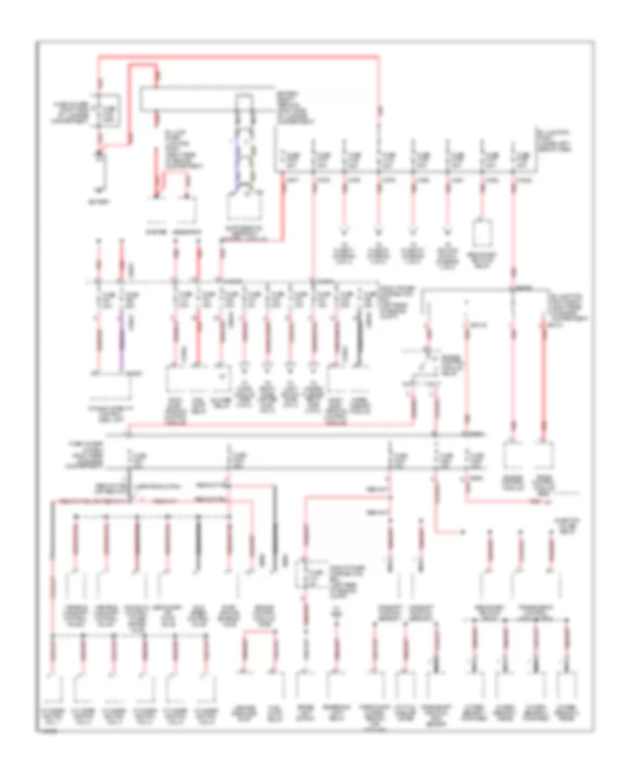
Power Distribution Wiring Diagram, Z3 Versions (1 of 4) for BMW M Coupe 2002
List of elements for Power Distribution Wiring Diagram, Z3 Versions (1 of 4) for BMW M Coupe 2002:
- (late production)
- B+ jump start junction point (right rear of engine compartment)
- B+ junction point (under left side of dash)
- B+ junction point e-box (right rear of engine compartment)
- Battery
- Battery safety terminal (right side of luggage compartment)
- Blower relay
- Body elec- tronics control module
- Brake light switch
- Camshaft position sensor 1
- Camshaft position sensor 2
- Crankshaft position/ rpm sensor
- Cylinder ignition coil 1
- Cylinder ignition coil 2
- Cylinder ignition coil 3
- Cylinder ignition coil 4
- Cylinder ignition coil 5
- Cylinder ignition coil 6
- Dynamic stability control (dsc) unit
- Engine control module
- Engine control module (dme)
- Engine control module relay
- Evap- orative emission valve
- Front power distribution box (left rear of engine compt)
- Fuel pump relay
- Fuse f100 200a
- Fuse f101 80a
- Fuse f102 80a
- Fuse f103 80a
- Fuse f104 80a
- Fuse f105 80a
- Fuse f106 50a
- Fuse f107 50a
- Fuse f108 80a
- Fuse f13 5a
- Fuse f14 30a
- Fuse f18 15a
- Fuse f20 30a
- Fuse f201 30a
- Fuse f202 30a
- Fuse f203 20a
- Fuse f204 30a
- Fuse f205 30a
- Fuse f31 5a
- Fuse f32 30a
- Fuse f33 10a
- Fuse f34 15a
- Fuse f35 25a
- Fuse f36 30a
- Fuse f51 30a
- Fuse f52 30a
- Fuse holder (right side of luggage compartment)
- Fuse holder in e-box (right rear of engine compartment)
- Generator
- Hot film mass air meter
- Idle speed control valve
- Individual control intake system valve
- Injection valves relay
- Leakage diagnosis pump
- Nca
- Oxygen sensor 1 (forward)
- Oxygen sensor 1 (rear)
- Oxygen sensor 2 (forward)
- Oxygen sensor 2 (rear)
- Red
- Red x8680
- Reversing light relay
- Secondary air pump relay
- Secondary air pump valve
- Starter
- Thermostat charac- teristic map cooling
- To chime module (diag 2 of 4)
- To front cigar lighter (diag 4 of 4)
- To fuse f1 (diagram 2 of 4)
- To fuse f37 (diagram 4 of 4)
- To fuse f5 (diagram 2 of 4)
- To hazard flasher relay (diag 2 of 4)
- To ignition switch (diagram 3 of 4)
- To light switch (diag 2 of 4)
- Trans control module (egs)
- Transmission control module (egs)
- Variable camshaft control valve 1
- Variable camshaft control valve 2
- W/ egs
- Wiper/ washer module
- X10016
- X10018
- X10034
- X10422
- X13252
- X18303
- X19017
- X1976
- X1977
- X1978
- X1979
- X1980
- X1981
- X1982
- X6001
- X6002
- X64101 red
- X64102 red
- X64192
- X74
- X8680 red
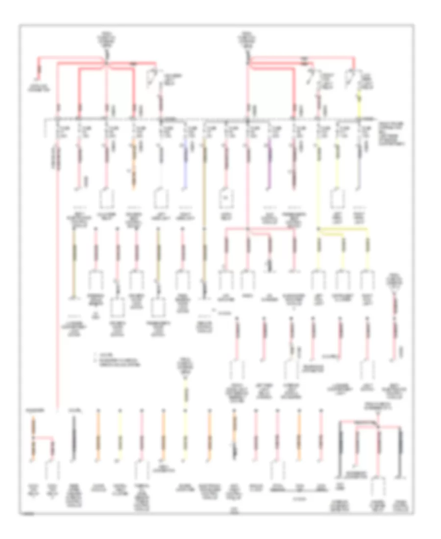
Power Distribution Wiring Diagram, Z3 Versions (2 of 4) for BMW M Coupe 2002
List of elements for Power Distribution Wiring Diagram, Z3 Versions (2 of 4) for BMW M Coupe 2002:
- (coupe)
- A red
- Accessory connector
- Analog clock
- Anti- theft control module
- B red
- Board computer
- Body electronics control module
- Cd changer
- Chime module
- Conv top relay
- Coupe
- Crash control module
- Data link connector
- Driver's door lock motor
- Driver's door lock switch
- Driver's seat control switch
- Dwa led
- Dwa siren
- Electronic immobilizer control module
- From fuse f103 (diagram 1 of 4)
- From fuse f104 (diagram 1 of 4)
- From fuse f31 (diagram 1 of 4)
- From fuse f33 (diagram 1 of 4)
- From fuse f34 (diagram 1 of 4)
- Front dome light/ map reading assembly (coupe)
- Front fog light relay
- Front power distribution box (left rear of engine compartment)
- Fuse f1 30a
- Fuse f10 30a
- Fuse f11 7.5a
- Fuse f12 7.5a
- Fuse f15 15a
- Fuse f19 30a
- Fuse f2 15a
- Fuse f29 7.5a
- Fuse f30 7.5a
- Fuse f5 30a
- Fuse f6 20a
- Fuse f7 5a
- Fuse f8 15a
- Fuse f9 20a
- Hazard flasher relay
- Hifi amplifier
- High beam light relay
- Horn relay
- Instru- ment cluster
- Instrument cluster
- Interior light switch (roadster)
- Interior movement detector
- Left fog- light
- Left head- light
- Left headlight
- Left park light relay (canada)
- Light switch
- Low beam light relay
- Luggage compartment light
- Luggage compartment lock motor
- Nca
- Not used
- Obd ii connector
- Pass- enger's door lock motor
- Passenger's door lock switch
- Passenger's seat control switch
- Pitch sensor
- Radio
- Rear wiper/ washer interval control module
- Red
- Remote control module
- Right fog- light
- Right head- light
- Right headlight
- Roadster
- Roadster w/ harmon kardon sound system
- Slip control module
- Steering angle sensor
- Subwoofer amplifier module
- Telephone connector
- Thermal oil level sensor (toens) control module
- Unloader relay
- W/ dsc
- W/ dwa
- W/o dwa
- X10015
- X10016
- X10017
- X10030
- X10035
- X10036
- X10182
- X11105
- X13252
Power Distribution Wiring Diagram, Z3 Versions (3 of 4) for BMW M Coupe 2002
List of elements for Power Distribution Wiring Diagram, Z3 Versions (3 of 4) for BMW M Coupe 2002:
- Acc
- Accessory connector
- Asc switch
- Blower relay
- Body electronics control module (w/ dwa)
- Canada
- Combin- ation switch
- Compressor control relay
- Crash control module
- Cruise control interface
- Data link connector
- Drivers seat heater switch
- Dsc switch
- Dynamic stability control unit
- E-box fan
- Electronic immobilizer control module
- Engine control module
- From fuse f106 (diagram 1 of 3)
- Front power distribution box (left rear of engine compartment)
- Fuse f16 5a
- Fuse f21 5a
- Fuse f22 5a
- Fuse f23 5a
- Fuse f24 10a
- Fuse f25 5a
- Fuse f26 10a
- Fuse f27 5a
- Fuse f4 15a
- Generator
- High beam light relay
- High speed relay
- Ignition switch
- Instrument cluster
- Jet heater thermo switch
- Left park light relay
- Light switch
- Mirror control switch
- Normal speed relay
- Not used
- Off
- Passenger seat heater switch
- Rear window defogger switch
- Red
- Reversing light relay (a/t)
- Reversing light switch (m/t)
- Run
- Slip control module
- Start
- Steering angle sensor
- Thermal oil level sensor (toens) control module
- Thermal oil level switch
- To ignition switch (diagram 4 of 4)
- Transmission control module (w/ egs)
- Uncoupling diode (lights)
- Unloader relay
- W/asc
- W/dsc
- X10015
- X10016
- X10017
- X10026
- X10182
- X16
- X17
- X209
Power Distribution Wiring Diagram, Z3 Versions (4 of 4) for BMW M Coupe 2002
List of elements for Power Distribution Wiring Diagram, Z3 Versions (4 of 4) for BMW M Coupe 2002:
- Acc
- Anti- theft control module
- Board computer
- Body electronics control module
- Brake- light switch
- Canada
- Clutch switch
- Compressor control relay
- Driver's seat belt switch
- Elect immobilizer control module
- From fuse f105 (diagram 1 of 4)
- From fuse f32 (diagram 1 of 4)
- From ignition switch i (diagram 3 of 4)
- Front cigar lighter
- Front power distribution box (left rear of engine compartment)
- Fuse f3 30a
- Fuse f37 10a
- Fuse f38 30a
- Fuse f39 7.5a
- Fuse f40 30a
- Fuse f41 7.5a
- Fuse f43 5a
- Fuse f44 15a
- Fuse f45 7.5a
- Fuse f46 15a
- High speed relay
- Horn relay
- Ignition switch
- Instrument cluster
- Light switch
- Nca
- Off
- Passenger's seat belt switch
- Radio
- Rear wiper/ washer interval control module
- Red
- Remote control module (w/ dwa)
- Right park light/license plate light relay
- Run
- Seat occupancy detector
- Slip control module
- Start
- Starter immobilization switch
- Telephone connector
- Tilt sun roof switch (coupe)
- Transmission position indicator light
- Washer pump
- Wiper/ washer module
- Wiper/ washer switch
- X10015
- X10018
- X10038
- X10182
- X18170 (below center console)
POWER DOOR LOCKS
Power Door Locks Wiring Diagram, Except M Version Coupe for BMW M Coupe 2002
List of elements for Power Door Locks Wiring Diagram, Except M Version Coupe for BMW M Coupe 2002:
- (below center console)
- (others)
- (right kick panel) x10010
- (z3 roadster)
- Anti-theft control module (behind glove box)
- Anti-theft system (driver's door jamb switch)
- Anti-theft system (passenger's door jamb switch)
- Body electronics control module (behind glove box)
- Computer data lines system
- Data link connector (rear of eng compartment)
- Driver's door lock motor
- Driver's door lock switch
- Electronic immobilizer control module (left side of steering column)
- Exterior lights system
- Front power distribution box (on left rear corner of engine compartment)
- Fuse f35 25a
- Fuse f43 5a
- Fuse f7 5a
- Gas filler lock motor
- Hot at all times
- Hot in accy, run & start
- Interior lights system
- Lock
- Nca
- Passenger's door lock motor
- Passenger's door lock switch
- Remote control module (in interior rear view mirror)
- Trunk lock motor (on rear side of luggage compt)
- Unlock
- W/ alpine
- W/ dwa
- X10010 (right kick panel)
- X10015
- X10018
- X10182
- X13252
- X13253
- X13254
- X18170
- X311
- X315
Power Door Locks Wiring Diagram, M Version Coupe for BMW M Coupe 2002
List of elements for Power Door Locks Wiring Diagram, M Version Coupe for BMW M Coupe 2002:
- (below center console)
- (left front of engine compt) x166
- (left front side of lugg compt) x13006
- (right kick panel) x10010
- Anti-theft control module (behind glove box)
- Anti-theft system (driver's door jamb switch)
- Anti-theft system (passenger's door jamb switch)
- B+ junction point (under left side of dash)
- Body electronics control module (behind glove box)
- Central locking luggage compt lid motor relay (in front power distribution box)
- Computer data lines system
- Data link connector (rear of eng compartment)
- Driver's door lock motor
- Driver's door lock switch
- Electronic immobilizer control module (left side of steering column)
- Exterior lights system
- Front power distribution box (on left rear corner of engine compt)
- Fuse f103 80a
- Fuse f35 25a
- Fuse f43 5a
- Fuse f7 5a
- Gas filler lock motor
- Hot at all times
- Hot in accy, run & start
- Interior lights system
- Lock
- Nca
- Passenger's door lock motor
- Passenger's door lock switch
- Red
- Remote control module (in interior rear view mirror)
- Trunk lid locking switch
- Trunk lock motor (on rear side of lugg compt)
- Unlock
- W/ alpine
- W/ dwa
- X10010 (right kick panel)
- X10015
- X10018
- X10182
- X13252
- X13253
- X13254
- X18170
- X1978 red
POWER MIRRORS
Electrochromic Mirror Wiring Diagram for BMW M Coupe 2002
List of elements for Electrochromic Mirror Wiring Diagram for BMW M Coupe 2002:
- Electro- chromic rear view mirror
- Front power distribution box (rear left side of engine compartment)
- Fuse f43 5a
- Hot in acc, run & start
- Nca
- X10010 (left kick panel)
- X10018
Power Mirror Wiring Diagram for BMW M Coupe 2002
List of elements for Power Mirror Wiring Diagram for BMW M Coupe 2002:
- Down
- Driver's
- Driver's side mirror
- Front power distribution box (rear left side of engine compartment)
- Fuse f24 10a
- Hot in run & start
- Left
- Mirror control switch
- Nca
- Passenger's
- Passenger's side mirror
- Right
- X10017
- X13004 (behind glove box)
- X9633 (left kick panel)
POWER SEATS
Driver"s Sport Seat Wiring Diagram for BMW M Coupe 2002
List of elements for Driver"s Sport Seat Wiring Diagram for BMW M Coupe 2002:
- Back
- Down
- Driver's seat control switch
- Driver's seat height motor
- Driver's seat length adjust cut-off relay (under left front seat)
- Driver's seat limit switch (under left front seat)
- Driver's seat movement motor
- Driver's seat tilt adjust cut-off relay (under left front seat)
- Front power distribution box (on left rear corner of engine compt)
- Fuse f19 30a
- Fwd
- Hot at all times
- Nca
- Seat height switch
- Seat position switch
- X10016
- X13006 (left side of luggage compt)
Heated Seats Wiring Diagram for BMW M Coupe 2002
List of elements for Heated Seats Wiring Diagram for BMW M Coupe 2002:
- Driver's seat heater (under left front seat)
- Driver's seat heater switch
- Driver's seatback heater (in upper left front seatback)
- Front power distribution box (on left rear corner of engine compartment)
- Fuse f4 15a
- Hot at all times
- Interior lights system
- Max
- Min
- Passenger's seat heater (under right front seat)
- Passenger's seat heater switch
- Passenger's seatback heater (in upper right front seatback)
- Test
- X10015
- X18170 (below center console)
Passenger"s Sport Seat Wiring Diagram for BMW M Coupe 2002
List of elements for Passenger"s Sport Seat Wiring Diagram for BMW M Coupe 2002:
- Back
- Down
- Front power distribution box (on left rear corner of engine compt)
- Fuse f5 30a
- Fwd
- Hot at all times
- Nca
- Pass- enger's seat control switch
- Pass- enger's seat tilt adjust cut-off relay (under right front seat)
- Passenger's seat height motor
- Passenger's seat length adjust cut-off relay (under right front seat)
- Passenger's seat limit switch (under right front seat)
- Passenger's seat movement motor
- Seat height switch
- Seat position switch
- X10015
- X13004 (behind glove box)
Power Seats Wiring Diagram for BMW M Coupe 2002
List of elements for Power Seats Wiring Diagram for BMW M Coupe 2002:
- Back
- Driver's seat control switch
- Driver's seat height motor
- Driver's seat movement motor
- Front
- Front power distribution box (on left rear corner of engine compt)
- Fuse f19 30a
- Fuse f5 30a
- Height
- Hot at all times
- Nca
- Passenger's seat control switch
- Passenger's seat height motor
- Passenger's seat movement motor
- Position
- X10015
- X10016
- X13004 (behind glove box)
- X13006 (left side of luggage compt)
POWER TOP/SUNROOF
Convertible Top Wiring Diagram for BMW M Coupe 2002
List of elements for Convertible Top Wiring Diagram for BMW M Coupe 2002:
- (3 leds)
- Brake- light switch (on bracket, above brake pedal)
- Close
- Convertible top actuating switch
- Convertible top end-position microswitch 1) top tension relieved 2) top fully extended (left rear of roof, at linkage)
- Convertible top motor (left side of luggage compt)
- Convertible top relay 1 (close) (left side of luggage compt)
- Convertible top relay 2 (open) (left side of luggage compt)
- Front power distribution box (left rear corner of engine compt)
- Fuse f1 30a
- Fuse f46 15a
- Hot at all times
- Hot in acc, run & start
- Interior lights system
- Nca
- Open
- X10015
- X10018
- X1116 (left rear wheelwell)
- X13006 (left side of luggage compt)
- X18170 (below center console)
Sunroof Wiring Diagram for BMW M Coupe 2002
List of elements for Sunroof Wiring Diagram for BMW M Coupe 2002:
- Front power distribution box (left rear corner of engine compt)
- Fuse f46 15a
- Hot in acc, run & start
- Lower
- Raise
- Red
- Tilt sunroof motor
- Tilt sunroof switch
- X10018
- X13004 (behind glove box)
POWER WINDOWS
Power Windows Wiring Diagram for BMW M Coupe 2002
List of elements for Power Windows Wiring Diagram for BMW M Coupe 2002:
- Body electronics control module (zke iv) (behind glove box)
- Close auto
- Close wdo
- Driver's door jamb switch
- Driver's power window motor
- Driver's power window switch
- Front power distribution box (left rear corner of engine compartment)
- Fuse f14 30a
- Hot at all times
- Interior lights system
- Off
- Open auto
- Open wdo
- Passenger's door jamb switch
- Passenger's power window motor
- Passenger's power window switch
- Starting/ charging system
- X10182
- X13004 (behind glove box)
- X13006 (left side of luggage compartment)
- X13252
- X13253
- X13254
- X18279
- X18280
- X494 (below center console)
- X744
- X749
- X9633 (left kick panel)
RADIO
Radio Wiring Diagram, Coupe for BMW M Coupe 2002
List of elements for Radio Wiring Diagram, Coupe for BMW M Coupe 2002:
- (center console) telephone connector
- 58g
- Ant
- Antenna amplifier am/fm
- Cd changer
- Coupe w/ harman kardon system
- Front power distribution box (left rear corner of engine compartment)
- Fuse f44 15a
- Fuse f9 20a
- Gal
- Hifi amplifier (on right side of luggage compt)
- Hl+
- Hl-
- Hlv+
- Hlv-
- Hot at all times
- Hot in accy, run & start
- Hr+
- Hr-
- Hrv+
- Hrv-
- I-bus
- Instrument cluster
- Interior lights system
- Left
- Left front high range speaker
- Left front low range speaker
- Left front midrange speaker
- Left rear mid-high range speaker (w/ harmon kardon sound system) or left rear high range speaker (w/ hifi)
- Left rear speaker
- Left+
- Mlh+
- Mlh-
- Mlv+
- Mlv-
- Mrh+
- Mrh-
- Mrv+
- Mrv-
- Mute
- Nca
- Radio
- Red
- Right
- Right front high range speaker
- Right front low range speaker
- Right front midrange speaker
- Right rear mid-high range speaker (w/ harmon kardon sound system) or right rear high range speaker (w/ hifi)
- Right rear speaker
- Right-
- Subwoofer
- Tlv+
- Tlv-
- Trv+
- Trv-
- Vl+
- Vl-
- Vr+
- Vr-
- Vss output
- W/ harman kardon sound system
- W/ hifi
- X10015
- X10018
- X10266
- X13016 (left rear side of luggage compartment)
- X13016 (left rear side of luggage compt)
- X17
- X18126
- X18180
- X18520
- X18521
- X400
- X605
- X606
Radio Wiring Diagram, Roadster with Harman Kardon for BMW M Coupe 2002
List of elements for Radio Wiring Diagram, Roadster with Harman Kardon for BMW M Coupe 2002:
- (center console) telephone connector
- (on right side of luggage compt) hifi amplifier
- (pins 27-42 not used)
- 58g
- Ant
- Antenna amplifier am/fm
- Cd changer
- Front power distribution box (on left rear corner of engine compartment)
- Fuse f44 15a
- Fuse f9 20a
- Gal
- Hl+
- Hl-
- Hlv+
- Hlv-
- Hot at all times
- Hot in accy, run & start
- Hr+
- Hr-
- Hrv+
- Hrv-
- I-bus
- Instrument cluster
- Interior lights system
- Left front high range speaker
- Left front low range speaker
- Left front midrange speaker
- Left rear mid-high range speaker
- Left+
- Mlh+
- Mlh-
- Mlv+
- Mlv-
- Mrh+
- Mrh-
- Mrv+
- Mrv-
- Mute
- Nca
- Radio
- Red
- Right front high range speaker
- Right front low range speaker
- Right front midrange speaker
- Right rear mid-high range speaker
- Right-
- Subwoofer
- Subwoofer amplifier module
- Tlv+
- Tlv-
- Trv+
- Trv-
- Vl+
- Vl-
- Vr+
- Vr-
- X10015
- X10018
- X13016 (left side of luggage compartment)
- X17
- X1717
- X18126
- X18180
- X18520
- X18521
- X18774
- X400
Radio Wiring Diagram, Roadster without Harman Kardon for BMW M Coupe 2002
List of elements for Radio Wiring Diagram, Roadster without Harman Kardon for BMW M Coupe 2002:
- (center console) telephone connector
- 58g
- Ant
- Antenna amplifier am/fm
- Cd changer
- Front power distribution box (on left rear corner of engine compartment)
- Fuse f44 15a
- Fuse f9 20a
- Gal
- Hifi amplifier (on right side of luggage compt)
- Hl+
- Hl-
- Hlv+
- Hlv-
- Hot at all times
- Hot in accy, run & start
- Hr+
- Hr-
- Hrv+
- Hrv-
- I-bus
- Instrument cluster
- Interior lights system
- Left
- Left front high range speaker
- Left front low range speaker
- Left front midrange speaker
- Left rear mid-high range speaker
- Left+
- Mlh+
- Mlh-
- Mlv+
- Mlv-
- Mrh+
- Mrh-
- Mrv+
- Mrv-
- Mute
- Nca
- Radio
- Rear woofer
- Red
- Right
- Right front high range speaker
- Right front low range speaker
- Right front midrange speaker
- Right rear mid-high range speaker
- Right-
- Tlh+
- Tlh-
- Tlv+
- Tlv-
- Trh+
- Trh-
- Trv+
- Trv-
- Vl+
- Vl-
- Vr+
- Vr-
- X10015
- X10018
- X13016 (left side of luggage compartment)
- X17
- X1717
- X18126
- X18180
- X18520
- X18521
- X400
SHIFT INTERLOCK
Shift Interlock Wiring Diagram for BMW M Coupe 2002
List of elements for Shift Interlock Wiring Diagram for BMW M Coupe 2002:
- B+ junction point e-box (right rear of engine compt)
- Battery voltage
- Brake light switch (on bracket, above brake pedal)
- Brake pedal position
- Exterior lights system
- Front power distribution box (left rear corner of engine compt)
- Fuse f46 15a
- Gear range signal l1
- Gear range signal l2
- Gear range signal l3
- Gear range signal l4
- Gear range signal l5
- Ground
- Hot at all times
- Hot in run, acc & start
- Nca
- Red
- Shift lock solenoid
- Shift-lock (under center console)
- Transmission control module (right rear side of engine compt in e-box)
- Transmission valve unit (right side of transmission)
- X10018
- X6454 (right rear of engine compt)
- X70001
- X70003
- X70004
STARTING/CHARGING
Charging Wiring Diagram for BMW M Coupe 2002
List of elements for Charging Wiring Diagram for BMW M Coupe 2002:
- B+ jump start junction point
- Battery
- Battery safety terminal
- Charge warning ind
- Engine control module (right rear side of eng compt)
- Front power distribution box (left rear corner of eng compt)
- Fuse f26 10a
- Fuse f27 5a
- Generator
- Hot in run or start
- Instrument cluster
- M versions
- Nca
- Red
- Starter
- Telephone connector (center console)
- X10017
- X16
- X17
- X60003
- X60004
- Z3 versions
Starting Wiring Diagram, M-Versions for BMW M Coupe 2002
List of elements for Starting Wiring Diagram, M-Versions for BMW M Coupe 2002:
- Acc
- B+ jump start junction point
- Body electronics control module (behind glove box)
- Electronic immobilizer control module (ews iii) (under left side of dash, left of steering column)
- Engine control module (right rear side of eng compt)
- Front power distribution box (left rear side of eng compt)
- Fuse f31 5a
- Fuse f45 7.5a
- Generator
- Hot at all times
- Hot in accy, run & start
- Ignition switch
- Lock
- Red
- Run
- Start
- Starter
- Starter immobilization switch
- X10016
- X10018
- X10182
- X18170 (below center console)
- X60064
- X9633 (left kick panel)
Starting Wiring Diagram, Z3 Versions for BMW M Coupe 2002
List of elements for Starting Wiring Diagram, Z3 Versions for BMW M Coupe 2002:
- Acc
- B+ jump start junction point
- Body electronics control module (behind glove box)
- Electronic immobilizer control module (ews iii) (under left side of dash, left of steering column)
- Front power distribution box (left rear side of eng compt)
- Fuse f31 5a
- Fuse f45 7.5a
- Generator
- Hot at all times
- Hot in accy, run & start
- Ignition switch
- Lock
- Of engine compt)
- Red
- Run
- Start
- Starter
- Starter immobilization switch
- Transmission control module (right rear side
- W/ egs
- W/o egs
- X10018
- X10182
- X18170 (below center console)
- X9633 (left kick panel)
SUPPLEMENTAL RESTRAINTS
Supplemental Restraints Wiring Diagram for BMW M Coupe 2002
List of elements for Supplemental Restraints Wiring Diagram for BMW M Coupe 2002:
- (right kick panel) x10010
- (under center console) x1441
- Abbf+
- Abbf-
- Abbf2+
- Abbf2-
- Abf+
- Abf-
- Abf2+
- Abf2-
- Air bag
- Awl
- Battery safety terminal (near battery)
- Belt tensioner +
- Belt tensioner -
- Body electronics control module (behind glove box)
- Bpt+
- Bpt-
- Contact ring
- Data link connector (dlc) (partial) (on left rear side of engine compartment)
- Driver's air bag gas generator
- Driver's seat belt switch (in driver's front seat belt buckle)
- Driver's side impact sensor (under left front seat)
- Driver's side pyrotechnical belt tensioner (in left front seat belt buckle)
- Front power distribution box (left rear corner of engine compartment)
- Fuse 5a
- Fuse 7.5a
- Gkbf
- Gkf
- Ground
- Hot in accy, run & start
- Hot in run & start
- Ignition
- Instrument cluster
- Left side air bag gas generator
- Nca
- Passenger side impact sensor (under right front seat)
- Passenger's air bag gas generator
- Passenger's seat belt switch (in passenger's front seat belt buckle)
- Passenger's side pyrotechnical belt tensioner (in right front seat belt buckle)
- Red
- Right side air bag gas generator
- Sbe
- Seat belt warning lamp
- Seat mat
- Seat occupancy detector (under right front seat)
- Solid state
- Txd
- X10010 (right kick panel)
- X10017
- X10018
- X13253
- X1441 (under center console)
- X16
- X17
TRANSMISSION
A/T Wiring Diagram for BMW M Coupe 2002
List of elements for A/T Wiring Diagram for BMW M Coupe 2002:
- (left of steering column) electronic immobilizer control module
- (not used)
- (right side of engine compt) g6454
- B+ junction port (under left side of dash)
- Battery
- Body electronics control module
- Bpp sw
- Brake light switch (above brake pedal)
- Can high
- Can low
- Can+
- Can-
- Center console)
- Computer data lines system
- Datalink connector (right rear side of engine compt)
- Engine control module (right rear side of engine compt, in "e" box)
- Exterior lights (back-up lamps)
- Exterior lights system
- Front power distribution box (left rear of engine compt)
- Fuse f204 30a
- Fuse f26 10a
- Fuse f46 15a
- Fuse holder in "e" box (right rear of engine compt)
- G18170 (below
- Gearshift lever position/ gear step transmission switch
- Ground
- Hot at all times
- Hot in acc, on or start
- Hot in on or start
- Hydraulic pressure regulator
- Ignition
- Immob
- Interior lights system
- L1 sig
- L2 sig
- L3 sig
- L4 sig
- L5 sig
- M/t
- Nca
- Oil temp +
- Oil temp -
- Oil temperature sensor
- Pos ind
- Press reg
- Red
- Rev relay
- Shaft speed sensor
- Shift lock (under center console, near shifter)
- Shld gnd
- Slm+
- Slm-
- Sol 1
- Sol 2
- Sol 3
- Solenoid valves
- Sss +
- Sss -
- Tcc sol
- Tip down
- Tip dwn
- Tip up
- Torque converter clutch
- Transmission control module (right rear side of engine compt, in "e" box)
- Transmission control module (right rear side of engine compt, in "e" cox)
- Transmission position indicator light
- Transmission valve unit
- Tss +
- Tss -
- Turbine speed sensor
- Txd data
- Txd2
WARNING SYSTEMS
Buzzer Wiring Diagram for BMW M Coupe 2002
List of elements for Buzzer Wiring Diagram for BMW M Coupe 2002:
- Chime module (below left side of dash)
- Front power distribution box (left rear corner of engine compt)
- Fuse f31 5a
- Hot at all times
- Instrument cluster
- Sound
- Tone signal x17
- X10018
- X18170 (below center console)
- X522
Tire Pressure Monitoring/Inflation Wiring Diagram for BMW M Coupe 2002
List of elements for Tire Pressure Monitoring/Inflation Wiring Diagram for BMW M Coupe 2002:
- (left kick panel) x170
- (on right rear side of engine compt, in "e" box) engine control module (dme)
- Can +
- Can -
- Cigar lighter connection
- Compressor main switch
- Compressor relay
- Computer data lines system
- Dynamic stability control unit (left side of engine compt)
- Electric compressor
- Front power distribution box (on left rear corner of eng compt)
- Fuse f21 5a
- Fuse f27 5a
- Fuse f51 30a
- Fuse f52 30a
- Fuse f53 30a
- Hot at all times
- Hot in run and start
- Instrument cluster
- Left front abs speed sensor
- Left rear abs speed sensor
- Nca
- Red
- Right front abs speed sensor
- Right rear abs speed sensor
- Tire pressure warning ind
- Tire pressure warning system pushbutton (1-off, 2-teach in process)
- X10017
- X16
- X17
- X170 (left kick panel)
- X18170 (below center console)
- X19017
- X60003
- X60004
WIPER/WASHER
Washer Jet Heater Wiring Diagram for BMW M Coupe 2002
List of elements for Washer Jet Heater Wiring Diagram for BMW M Coupe 2002:
- Front power distribution box (left rear corner of engine compt)
- Fuse f24 10a
- Hot in run & start
- Jet heater thermoswitch (right front wheelwell)
- Left washer jet heater (on underside of engine hood)
- Nca
- Right washer jet heater (on underside of engine hood)
- X165 (right front shock tower)
Wiper/Washer Wiring Diagram, Coupe for BMW M Coupe 2002
List of elements for Wiper/Washer Wiring Diagram, Coupe for BMW M Coupe 2002:
- & start
- (left kick panel) x9633
- (left side of luggage compt)
- Exterior lights (light switch)
- Fast
- Front power distribution box (left rear corner of engine compt)
- Fuse f1 30a
- Fuse f3 30a
- Fuse f36 30a
- Fuse f44 15a
- Headlight/ foglight washer pump (washer fluid reservoir)
- Hot at all times
- Hot in accy, run
- Instrument cluster
- Inter
- Nca
- Norm
- Off
- Park
- Rear wash
- Rear wiper/ washer interval control module (in liftgate)
- Run
- Single
- Vehicle speed signal
- W/ headlight washer
- W/o headlight washer
- Wash
- Washer pump (on washer fluid reservoir)
- Wiper motor (rear of engine compartment)
- Wiper/ washer module (behind glove box)
- Wiper/washer switch
- X10015
- X10018
- X13006
- X13057
- X13268
- X165 (right front shock tower)
- X17
- X9633 (left kick panel)
Wiper/Washer Wiring Diagram, Roadster for BMW M Coupe 2002
List of elements for Wiper/Washer Wiring Diagram, Roadster for BMW M Coupe 2002:
- Exterior lights (main light switch)
- Fast
- Front power distribution box (left rear corner of engine compt)
- Fuse f3 30a
- Fuse f36 30a
- Fuse f44 15a
- Headlight/ foglight washer pump (front right side of engine compt, on washer fluid reservoir)
- Hot at all times
- Hot in accy, run & start
- Instrument cluster
- Inter
- Nca
- Normal
- Off
- Park
- Run
- Single
- Vehicle speed signal
- W/ headlight washer
- W/o headlight washer
- Wash
- Washer pump (front right side of engine compt, on washer fluid reservoir)
- Wiper motor (rear of engine compartment)
- Wiper/washer module (behind glove box)
- Wiper/washer switch
- X10015
- X10018
- X165 (right front shock tower)
- X17
- X9633 (left kick panel)