Diagram sections — 28 (41 total)
AIR CONDITIONING ANTI-LOCK BRAKES ANTI-THEFT BODY CONTROL MODULES COMPUTER DATA LINES COOLING FAN CRUISE CONTROL DEFOGGERS ENGINE PERFORMANCE EXTERIOR LIGHTS GROUND DISTRIBUTION HEADLIGHTS HORN INSTRUMENT CLUSTER INTERIOR LIGHTS POWER DISTRIBUTION POWER DOOR LOCKS POWER MIRRORS POWER SEATS POWER WINDOWS RADIO SHIFT INTERLOCK STARTING/CHARGING SUPPLEMENTAL RESTRAINTS TRANSMISSION TRUNK, TAILGATE, FUEL DOOR WARNING SYSTEMS WIPER/WASHER
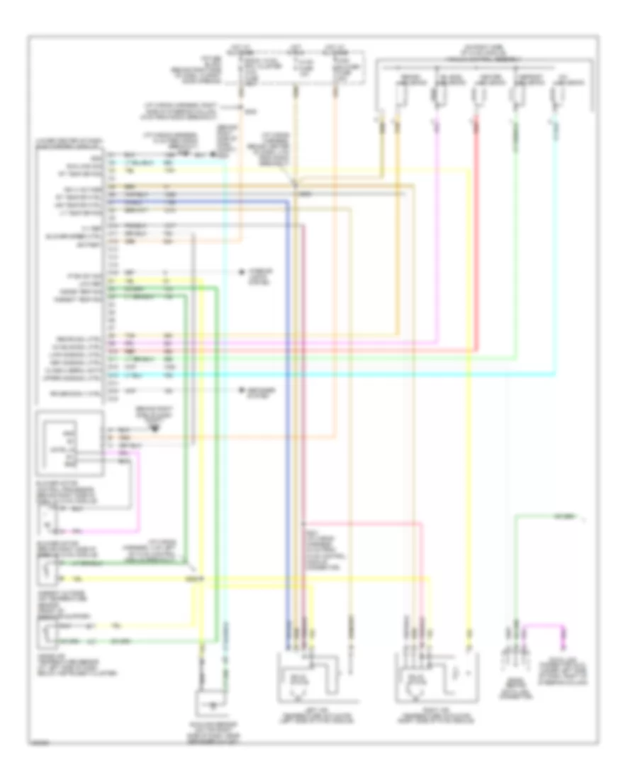
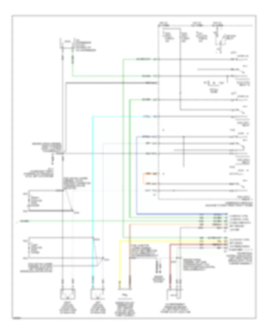
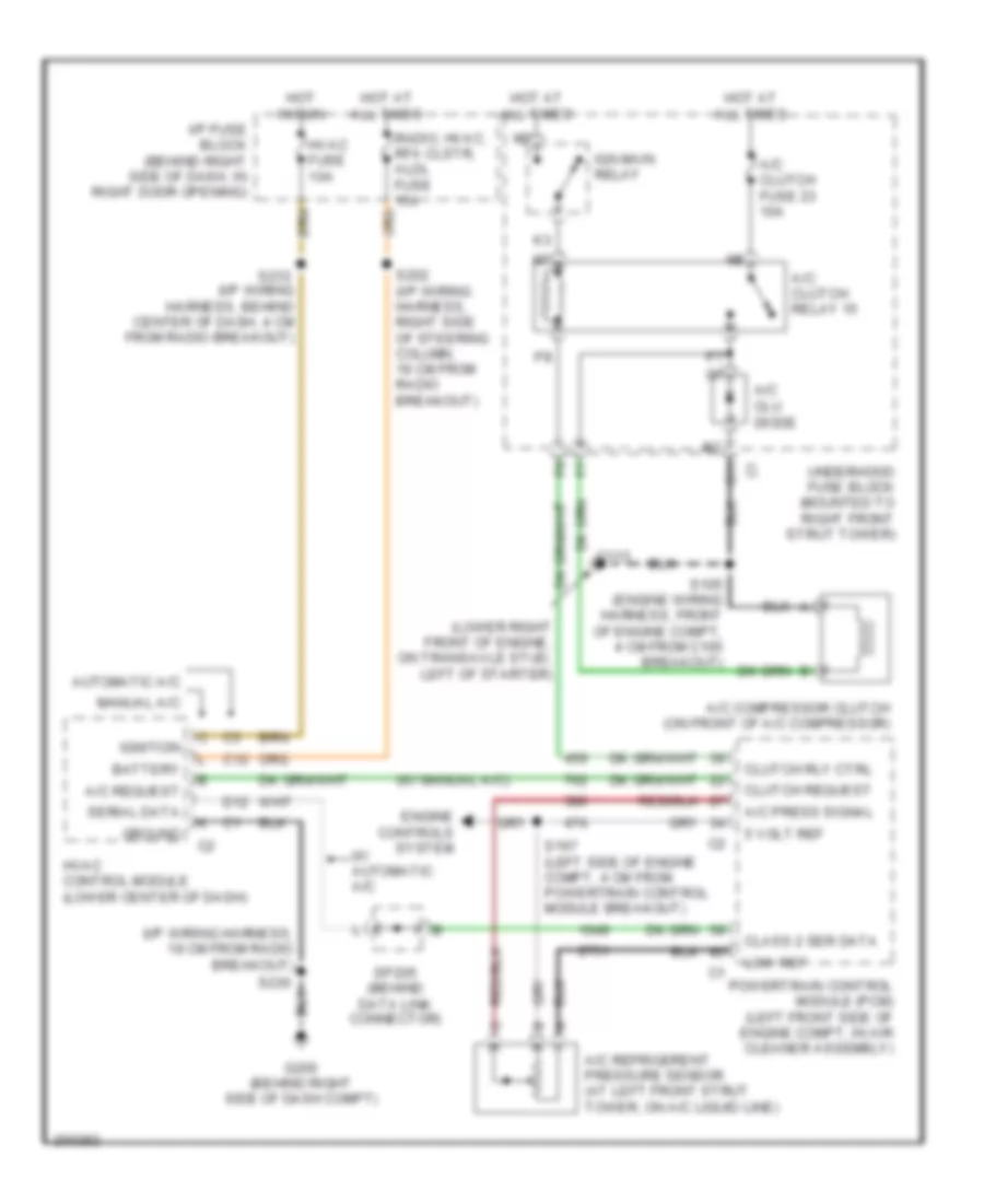
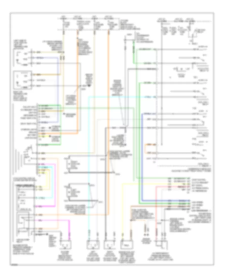
AIR CONDITIONING Automatic A/C Wiring Diagram (1 of 2) for Buick Century Limited 2005 List of elements for Automatic A/C Wiring Diagram (1 of 2) for Buick Century Limited 2005: 73 (behind right side of dash compt) g200 (i/p wiring harness, 18 cm from radio breakout) (i/p wiring harness, 4 cm left of hvac control module breakout) (i/p wiring harness, behind center of dash, 4 cm from radio breakout) (i/p wiring harness, right side of steering column, 19 cm from radio breakout) (lower center of dash) hvac control module (on right side of hvac module) vacuum control assembly 5 v ref A/c solenoid Air temp dr ctrl Ambient outside air temperature sensor (front of radiator support) Ambient temp sig Battery Bi-level solenoid Blower motor (behind right side of dash, in hvac module) Blower motor control processor (behind right side of dash, in hvac module) Blower speed ctrl C10 C11 C12 C13 C14 C15 C16 Class 2 serial data Cntrl in D10 D11 D12 D13 D14 D15 D16 Data link connector (dlc) (under left side of dash, right of steering column) Def mode sol ctrl Defogger system Defrost solenoid Gnd Heater solenoid High blower fuse 30a Hot at all times Hot in run Hvac fuse 10a I/p fuse block (behind right side of dash, in right door opening) Ign 3 voltage Inside air temperature sensor (at left side of dash, below instrument cluster) Inside temp sig Interior lights system Ip dim sw sig Left air temperature actuator (left side of hvac module) Low ref Lt temp dr pos Lwr mode sol ctrl Mix-blnd sol ctrl Radio, hvac, rfa, cluster aldl fuse 15a Recirc sol ctrl Recirc solenoid Red Right air temperature actuator (right side of hvac module) Rr defog rly ctrl Rt temp dr ctrl Rt temp dr pos S202 S230 S231 (i/p wiring harness, 33 cm from hvac control module connector) S233 S258 Solid state Sp205 (behind data link connector) Sun load sig Sunload sensor (on top right side of dash, near defogger outlet) Tan Upper mode sol ctrl Automatic A/C Wiring Diagram (2 of 2) for Buick Century Limited 2005 List of elements for Automatic A/C Wiring Diagram (2 of 2) for Buick Century Limited 2005: 57 (cooling fan jumper harness, 19.5 cm from right connector to engine cooling fan motor) (cooling fan jumper harness, 20 cm from left connector to engine cooling fan motor) (engine wiring harness, front of engine compt, 4 cm from c105 breakout) s105 (engine wiring harness, left side of engine compt, 4 cm from powertrain control module breakout) (fuel injector jumper harness, midway between fuel inj no 3 breakout & map sensor breakout) (top left side of engine, below throttle body) 5 volt ref A/c compressor clutch (on front of a/c compressor) A/c clu diode A/c clutch fuse 23 10a A/c clutch relay 15 A/c press signal A/c refrigerent pressure sensor (at left front strut tower, on a/c liquid line) A10 A11 C11 Class 2 ser data Clutch rly ctrl Cool fan 1 fuse 6 25a Cool fan 2 fuse 24 15a Cool fan 1 relay Cool fan 2 relay Cool fan 3 relay E10 Ect ground Ect signal Engine controls system Engine coolant temperature (ect) sensor F12 G113 (lower right front of engine, on transaxle stud, left of starter) Hi spd rly ctrl Hot at all times Ign main relay Left cooling fan diode Left cooling fan motor (on left side of radiator) Lo spd rly ctrl Low ref Nca P10 P11 Powertrain control module (pcm) (left front side of engine compt, in air cleaner assembly) R10 R11 Right cooling fan diode Right cooling fan motor (on right side of radiator) S101 S102 S103 S104 S121 S167 T10 T11 U11 Underhood fuse block (mounted to right front strut tower) V10 V11 Compressor Wiring Diagram for Buick Century Limited 2005 List of elements for Compressor Wiring Diagram for Buick Century Limited 2005: 43 (i/p wiring harness, 18 cm from radio breakout) (lower right front of engine, on transaxle stud, left of starter) (w/ manual a/c) 5 volt ref A/c clu diode A/c clutch fuse 23 10a A/c clutch relay 15 A/c compressor clutch (on front of a/c compressor) A/c press signal A/c refrigerent pressure sensor (at left front strut tower, on a/c liquid line) A/c request Automatic a/c Battery C11 C12 Class 2 ser data Clutch request Clutch rly ctrl D12 Engine controls system G113 G200 (behind right side of dash compt) Ground Hot at all times Hot in run Hvac control module (lower center of dash) Hvac fuse 10a I/p fuse block (behind right side of dash, in right door opening) Ign main relay Ignition Low ref Manual a/c Powertrain control module (pcm) (left front side of engine compt, in air cleaner assembly) Radio, hvac, rfa clstr, aldl fuse 15a S105 (engine wiring harness, front of engine compt, 4 cm from c105 breakout) S167 (left side of engine compt, 4 cm from powertrain control module breakout) S202 (i/p wiring harness, right side of steering column, 19 cm from radio breakout) S230 S233 (i/p wiring harness, behind center of dash, 4 cm from radio breakout) Serial data Sp205 (behind data link connector) Underhood fuse block (mounted to right front strut tower) W/ automatic a/c Manual A/C Wiring Diagram for Buick Century Limited 2005 List of elements for Manual A/C Wiring Diagram for Buick Century Limited 2005: 94 (behind right side of dash compt) g200 (cooling fan jumper harness, 19.5 cm from right connector to engine cooling fan motor) (cooling fan jumper harness, 20 cm from left connector to engine cooling fan motor) (engine wiring harness, front of engine compt, 4 cm from c105 breakout) (engine wiring harness, left side of engine compt, 4 cm from powertrain control module breakout) (fuel injector jumper harness, midway between fuel inj no 3 breakout & map sensor breakout) s121 (i/p wiring harness, 18 cm from radio breakout) (i/p wiring harness, behind center of dash, 4 cm from radio breakout) (left side of hvac module) left air temperature actuator (on left side of radiator) (on right side of radiator) (top left side of engine, below throttle body) +5v reference A/c compressor clutch (on front of a/c compressor) A/c clu diode A/c clutch fuse 10a A/c clutch relay 15 A/c press signal A/c refrigerant pressure sensor (at left front strut tower, on a/c liquid line) A/c request sig A10 A11 Battery Blower motor (behind right side of dash, in hvac module) Blower motor resistor assembly (under right side of dash, in right side of hvac module) C11 Clutch request Comp control Cool fan 1 fuse 25a Cool fan 2 fuse 15a Cool fan 1 relay Cool fan 2 relay Cool fan 3 relay Defogger on Defogger system Drvr temp ctrl E10 Ect gnd Ect signal Engine controls system Engine coolant temperature (ect) sensor F12 Fan off input G200 (behind right side of dash compt) Gnd Ground High blower fuse 30a High blower relay High speed Hot at all times Hot in run Hvac control module (lower center of dash) Hvac fuse 10a I/p fuse block (behind right side of dash, in right door opening) Ign Ign main relay Ignition Interior lights Interior lights system Lamp dim sig Left cooling fan diode Left cooling fan motor Low blower fuse 20a Low reference Low speed Nca Off P10 P11 Pass temp ctrl Pos Powertrain control module (pcm) (left front side of engine compt, in air cleaner assembly) R10 R11 Radio, hvac, rfa clstr, aldl fuse 15a Right air temperature actuator (right side of hvac module) Right cooling fan diode Right cooling fan motor S101 S102 S103 S104 S105 S167 S230 S233 T10 T11 Tan Thermal breakers U11 Underhood fuse block (mounted to right front strut tower) V10 V11
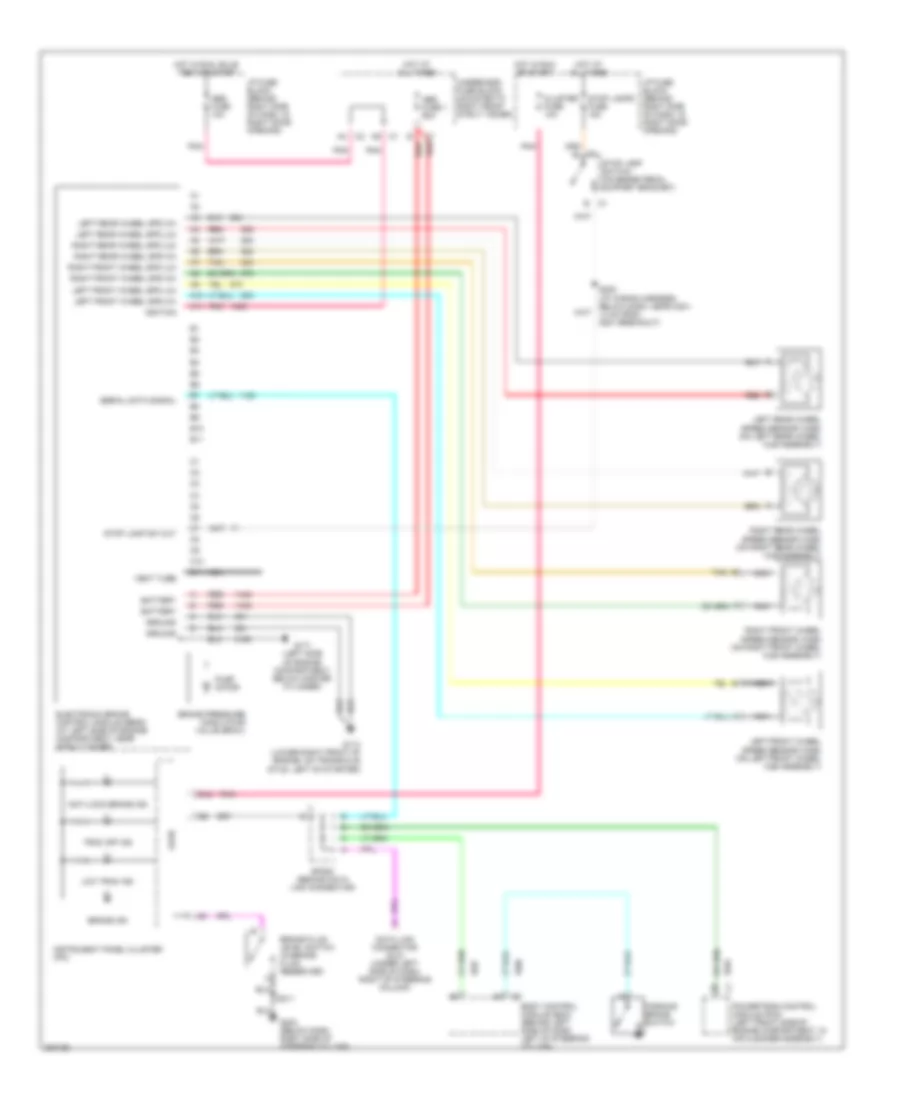
ANTI-LOCK BRAKES Anti-lock Brakes Wiring Diagram for Buick Century Limited 2005 List of elements for Anti-lock Brakes Wiring Diagram for Buick Century Limited 2005: 59 A10 A11 Abs fuse 1 60a Abs fuse 10a Anti-lock brake ind B10 B11 B12 Battery Body control module (bcm) (behind left side of dash left of steering column) Brake fluid level switch (in brake fluid reservoir) Brake ind Brake pressure modulator valve (bpmv) C10 C11 Cluster fuse 10a Data link connector (dlc) (under left side of dash, right of steering column) Electronic brake control module (ebcm) (at left side of engine compartment, near strut tower) G113 (lower right front of engine, on transaxle stud, left of starter) G171 (left side of engine compartment, below master cylinder) G203 (below dash, right side of steering column) Ground Hot at all times Hot in run or start Hot in run, bulb test or start I/p fuse block (behind right side of dash, in right door opening) Ignition Instrument panel cluster (ipc) Left front wheel spd (hi) Left front wheel spd (lo) Left front wheel speed sensor (wss) (on left front wheel hub assembly) Left rear wheel spd (hi) Left rear wheel spd (lo) Left rear wheel speed sensor (wss) (on left rear wheel hub assembly) Logic Low trac ind Nca Parking brake switch Pnk Powertrain control module (pcm) (left front side of engine compartment, in air cleaner assembly) Pump motor Red Right front wheel spd (hi) Right front wheel spd (lo) Right front wheel speed sensor (wss) (on right front wheel hub assembly) Right rear wheel spd (hi) Right rear wheel spd (lo) Right rear wheel speed sensor (wss) (on right rear wheel hub assembly) S205 (i/p wiring harness, below dash, near c201, 14 cm from g201 breakout) S211 Serial data signal Sp205 (behind data link connector) Stop lamp sw out Stop lamp switch (on brake pedal support bracket) Stop lamps fuse 15a Tan Trac off ind Underhood fuse block (mounted to right front strut tower) Vent tube
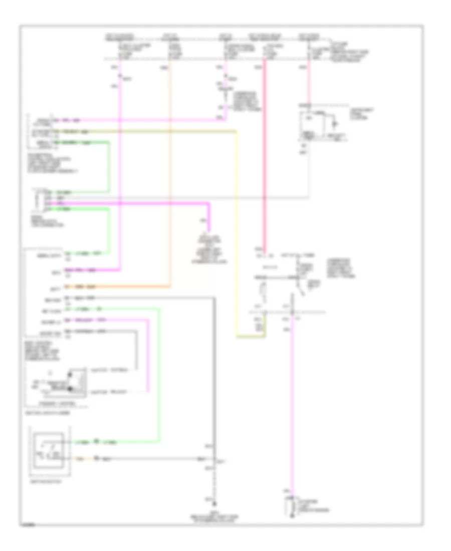
ANTI-THEFT Anti-theft Wiring Diagram for Buick Century Limited 2005 List of elements for Anti-theft Wiring Diagram for Buick Century Limited 2005: 52 B10 B12 Batt Bcm gnd Bcm pwr fuse 10a Body control module (bcm) (behind left side of dash, left of steering column) Cluster fuse 10a Crank fuse 2 40a Crank relay Crank signal bcm, cluster fuse 10a Crank voltage Data link connector (dlc) (under left side of dash, right of steering column) F10 G203 (below dash, right side of steering column) Hot at all times Hot in run or start Hot in run, bulb test or start Hot in start Hot in unlock, run or start I/p fuse block (behind right side of dash, in right door opening) Ign Ign 0 Ign 0: cluster pcm & bcm fuse 10a Ign key sig Ign ref lo Ignition lock cylinder Ignition switch Instrument panel cluster K10 K11 Key Key in Key in sig Key out Logic M10 M11 Passkey ii system Pcm bcm u/h fuse 10a Pnk Powertrain control module (pcm) (left front side of engine compt, in air cleaner assembly) Resistor pellet S211 S234 S270 Security ind Serial data Sp205 (behind data link connector) Starter (left side of engine) Starter rly ctrl Tan Underhood fuse block (mounted to right front strut tower)
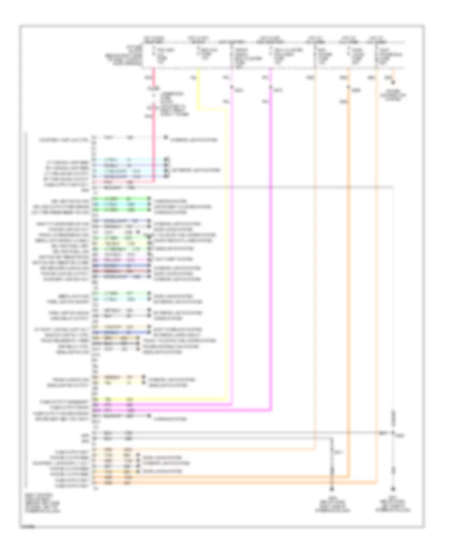
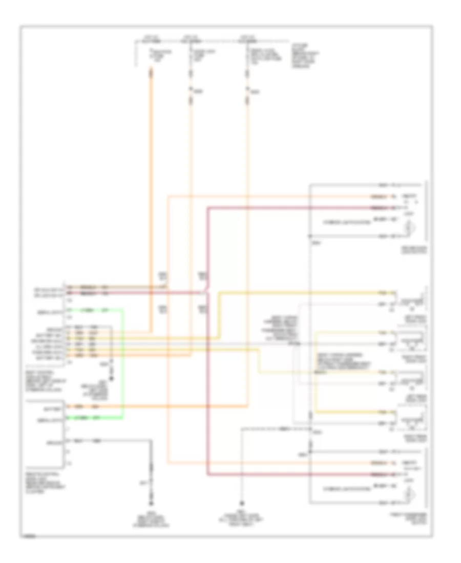
BODY CONTROL MODULES Body Control Modules Wiring Diagram for Buick Century Limited 2005 List of elements for Body Control Modules Wiring Diagram for Buick Century Limited 2005: 83 A/t shift lock sol sup volt A10 A11 A12 Accy power bus fuse 15a Anti-theft system B10 B11 B12 Backup lamp rly ctrl Bcm acc fuse 10a Bcm power fuse 10a Body control module (bcm) (behind left side of dash, left of steering column) C2 c2 Computer data lines system Courtesy lamp low ctrl Courtesy lamp sw out Crank, signal, bcm, cluster fuse 10a D2 c2 Door locks fuse 20a Door locks system Driver door ajar sw sig Driver seat belt sw input Drl mod output-park brake Drl photocell ret Drl photocell sig Exterior lamps circuit Exterior lights system Fuse output-acc/run/crank Fuse output-accessory Fuse output-bat Fuse output-crank Fuse output-ignition 1 G201 (below dash, left side of steering column) G203 (below dash, right side of steering column) Gnd Headlamp sw output Headlamp sw sig Headlights system Horn relay output Horns system Hot at all times Hot in acc or run Hot in off, run or start Hot in run or start Hot in start I/p fuse block (behind right side of dash, in right door opening) Ign 0, cluster, pcm & bcm fuse 10a Ignition key resistor lo ref Ignition key resistor sig Instrument cluster system Interior lights system Key ignition sw sig Lf turn sig lamp feed Lf turn sig sw output Low tire press reset sw sig Park lamp sw sig-off Park lamp sw sig-on Pcm, bcm u/h fuse 10a Pnk Power distribution system Pwr dr lk mtr feed Pwr dr lock sw out Pwr dr lock sw output Rap relay ctrl Rf turn sig lamp feed Rf turn sig sw output Right ft door open sw sig S211 S234 S269 S270 S283 Serial data sig Serial data signal class 2 Shift interlock system Tan Trunk ajar sw sig Trunk lid release sw sig Trunk release rly feed Trunk, tailgate, fuel doors system Underhood fuse block (mounted to right front strut tower) Warning system
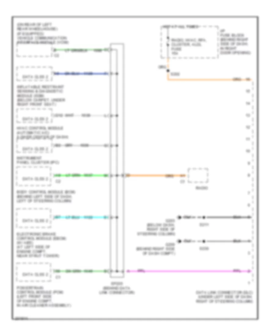
COMPUTER DATA LINES Computer Data Lines Wiring Diagram for Buick Century Limited 2005 List of elements for Computer Data Lines Wiring Diagram for Buick Century Limited 2005: 20 (on rear of left rear wheelhouse) (if equipped) vehicle communication interface module (vcim) Body control module (bcm) (behind left side of dash, left of steering column) D12 Data clss 2 Data link connector (dlc) (under left side of dash, right of steering column) Electronic brake control module (ebcm) (w/ abs) (at left side of engine compt, near strut tower) G200 (behind right side of dash compt) G203 (below dash, right side of steering column) Hot at all times Hvac control module (automatic a/c) (lower center of dash) I/p fuse block (behind right side of dash, in right door opening) Inflatable restraint sensing & diagnostic module (sdm) (below carpet, under right front seat) Instrument panel cluster (ipc) Powertrain control module (pcm) (left front side of engine compt, in air cleaner assembly) Radio Radio, hvac, rfa, cluster, aldl fuse 15a S202 S211 S230 Sp205 (behind data link connector)
COOLING FAN Cooling Fan Wiring Diagram for Buick Century Limited 2005 List of elements for Cooling Fan Wiring Diagram for Buick Century Limited 2005: 41 (cooling fan jumper harness, 19.5 cm from right connector to engine cooling fan motor) s103 (cooling fan jumper harness, 19.5 cm from right connector to engine cooling fan motor) s104 (cooling fan jumper harness, 20 cm from left connector to engine cooling fan motor) A10 A11 C11 Cool fan 1 fuse 25a Cool fan 2 fuse 15a Cool fan 1 relay Cool fan 2 relay Cool fan 3 relay E10 Ect gnd Ect sig Engine controls system Engine coolant temperature (ect) sensor (top left side of engine, below throttle body) F12 G113 (lower right front of engine, on transaxle stud, left of starter) High spd Hot at all times Left cooling fan diode Left cooling fan motor (on left side of radiator) Low spd Nca P10 P11 Powertrain control module (pcm) (left front side of engine compt, in air cleaner assembly) R10 R11 Right cooling fan diode Right cooling fan motor (on right side of radiator) S101 S102 S105 S121 (fuel injector jumper harness, midway between fuel injector no 3 breakout & map sensor breakout) T10 T11 U11 Underhood fuse block (mounted to right front strut tower) V10 V11
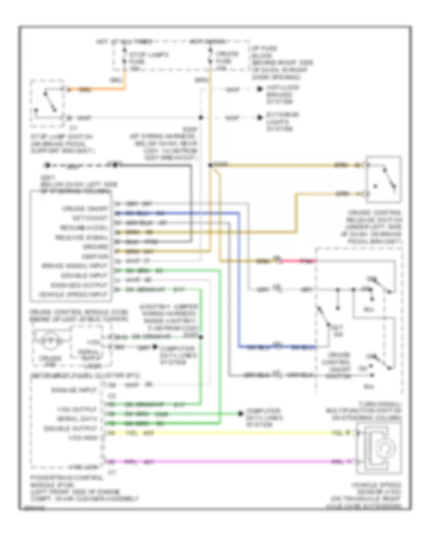
CRUISE CONTROL Cruise Control Wiring Diagram for Buick Century Limited 2005 List of elements for Cruise Control Wiring Diagram for Buick Century Limited 2005: 45 (ashtray jumper wiring harness, inside ashtray, 5 cm from c242) s295 Anti-lock brakes system B10 Brake signal input Computer data lines system Cruise control module (ccm) (front of left strut tower) Cruise control on/off switch Cruise control release switch (under left side of dash, on brake pedal bracket) Cruise fuse 10a Cruise ind Cruise on/off Disable input Disable output Engage input Engaged output Exterior lights system G201 (below dash, left side of steering column) Ground Hot at all times Hot in run I/p fuse block (behind right side of dash, in right door opening) Ignition Instrument panel cluster (ipc) Logic Off Pnk Powertrain control module (pcm) (left front side of engine compt, in air cleaner assembly R/a Release signal Resume/accel S205 (i/p wiring harness, below dash, near c201, 14 cm from g201 breakout) S240 S283 Serial data Set sw Set/coast Stop lamp switch (on brake pedal support bracket) Stop lamps fuse 15a Turn signal/ multifunction switch (in steering column) Vehicle speed input Vehicle speed sensor (vss) (on transaxle right axle case extension) Vss Vss high Vss low Vss output
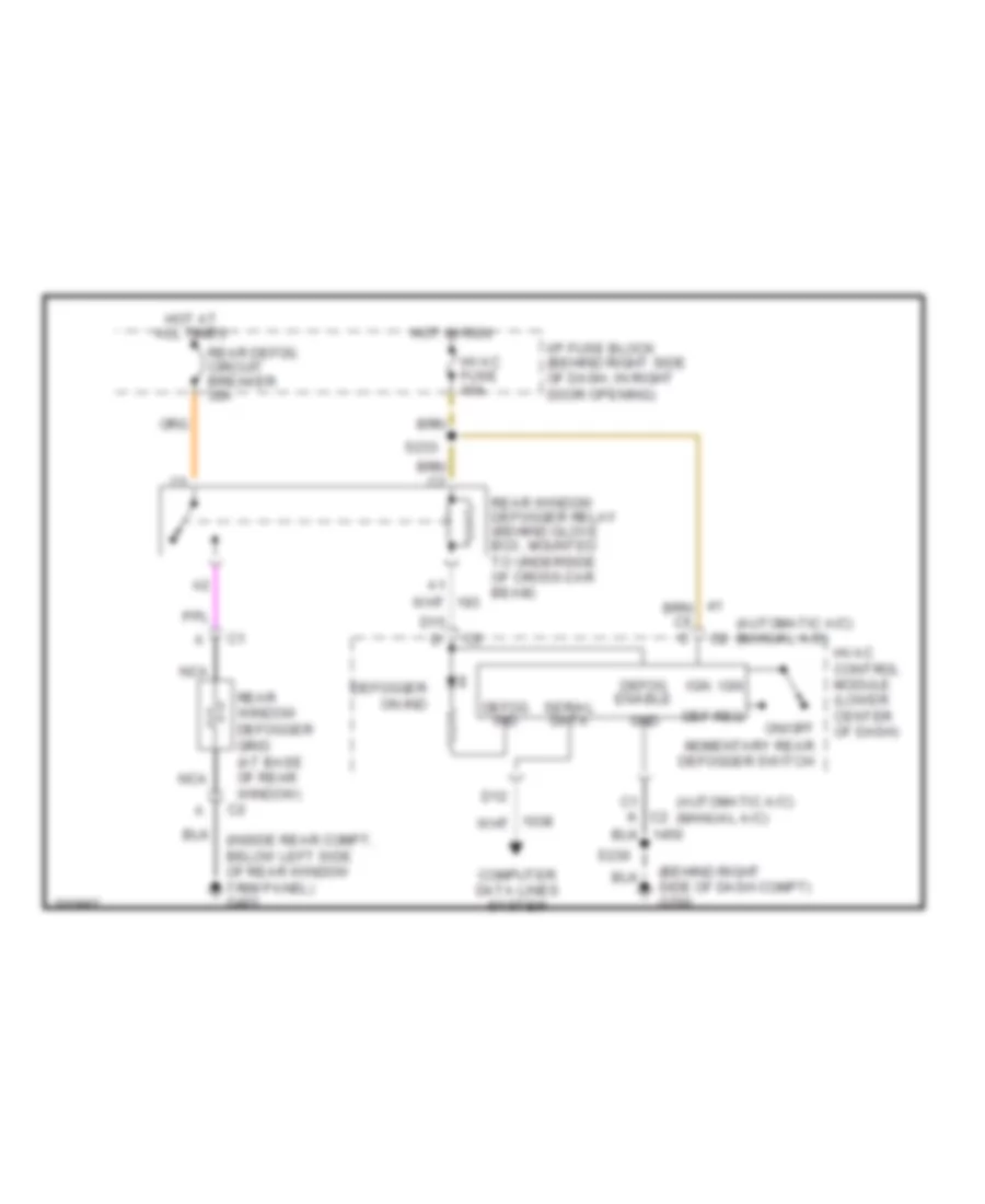
DEFOGGERS Defoggers Wiring Diagram for Buick Century Limited 2005 List of elements for Defoggers Wiring Diagram for Buick Century Limited 2005: 26 (automatic a/c) (manual a/c) (behind right side of dash compt) g200 (inside rear compt, below left side of rear window trim panel) g401 C1 k c2 Computer data lines system D12 D15 d Def req Defog enable Defog ind Defogger on ind Gnd Hot at all times Hot in run Hvac control module (lower center of dash) Hvac fuse 10a I/p fuse block (behind right side of dash, in right door opening) Ign Nca On/off momentary rear defogger switch Rear defog circuit breaker 30a Rear window defogger grid (at base of rear window) Rear window defogger relay (behind glove box, mounted to underside of cross-car beam) S230 S233 Serial data
ENGINE PERFORMANCE
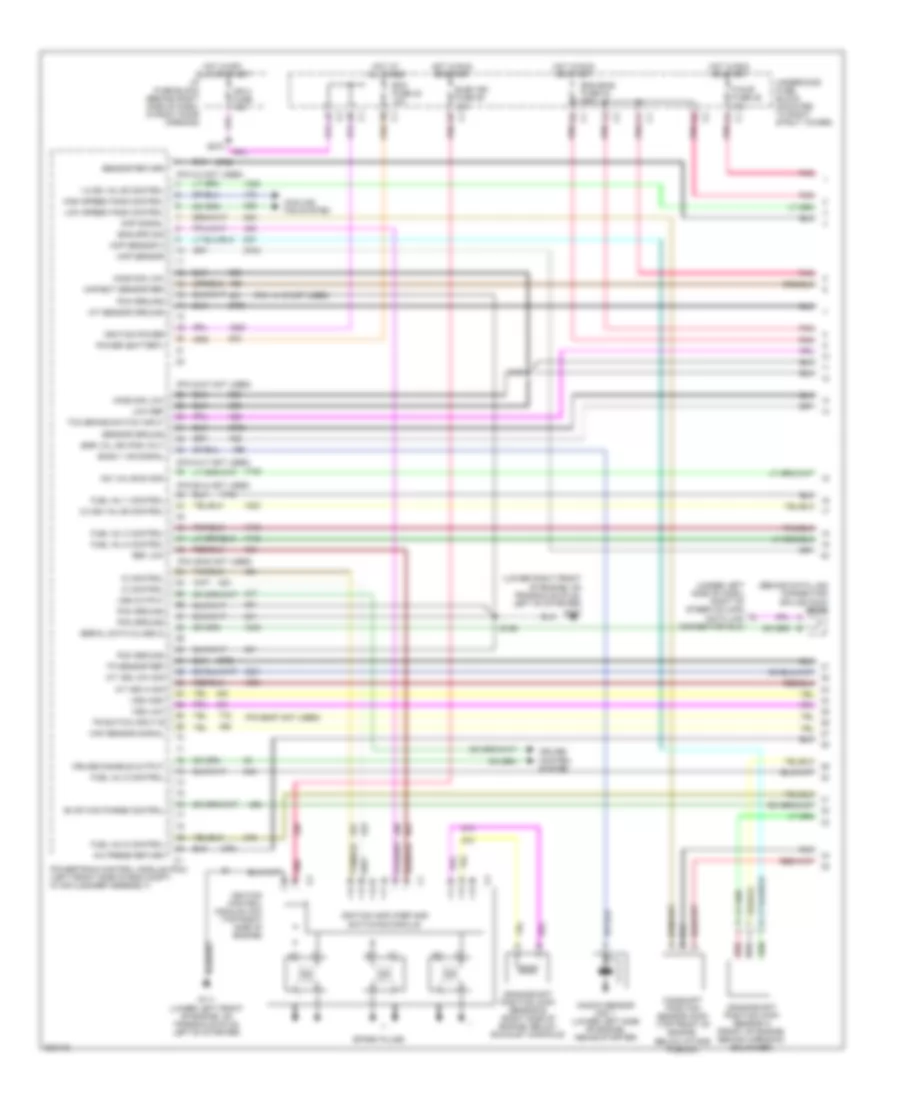
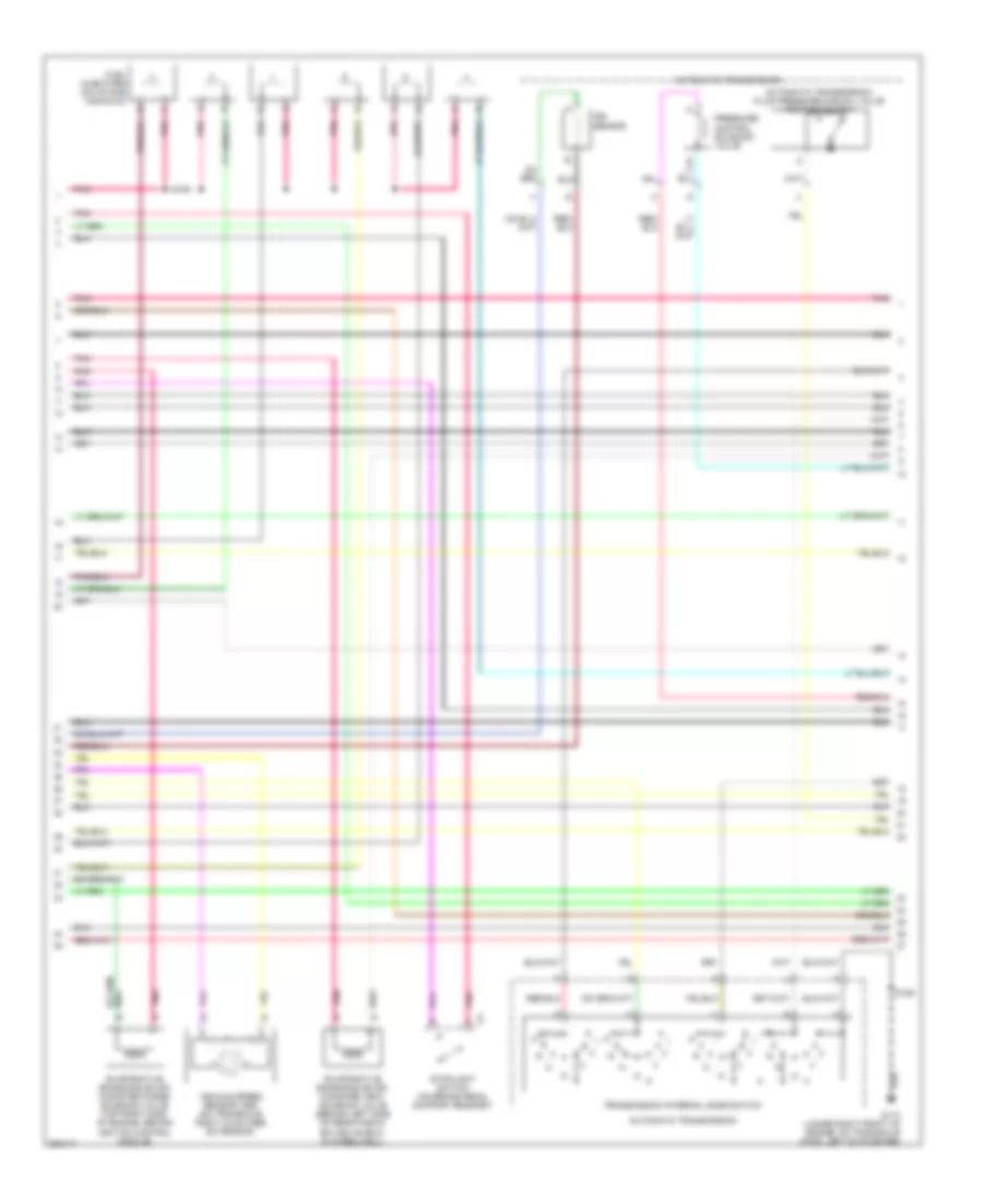
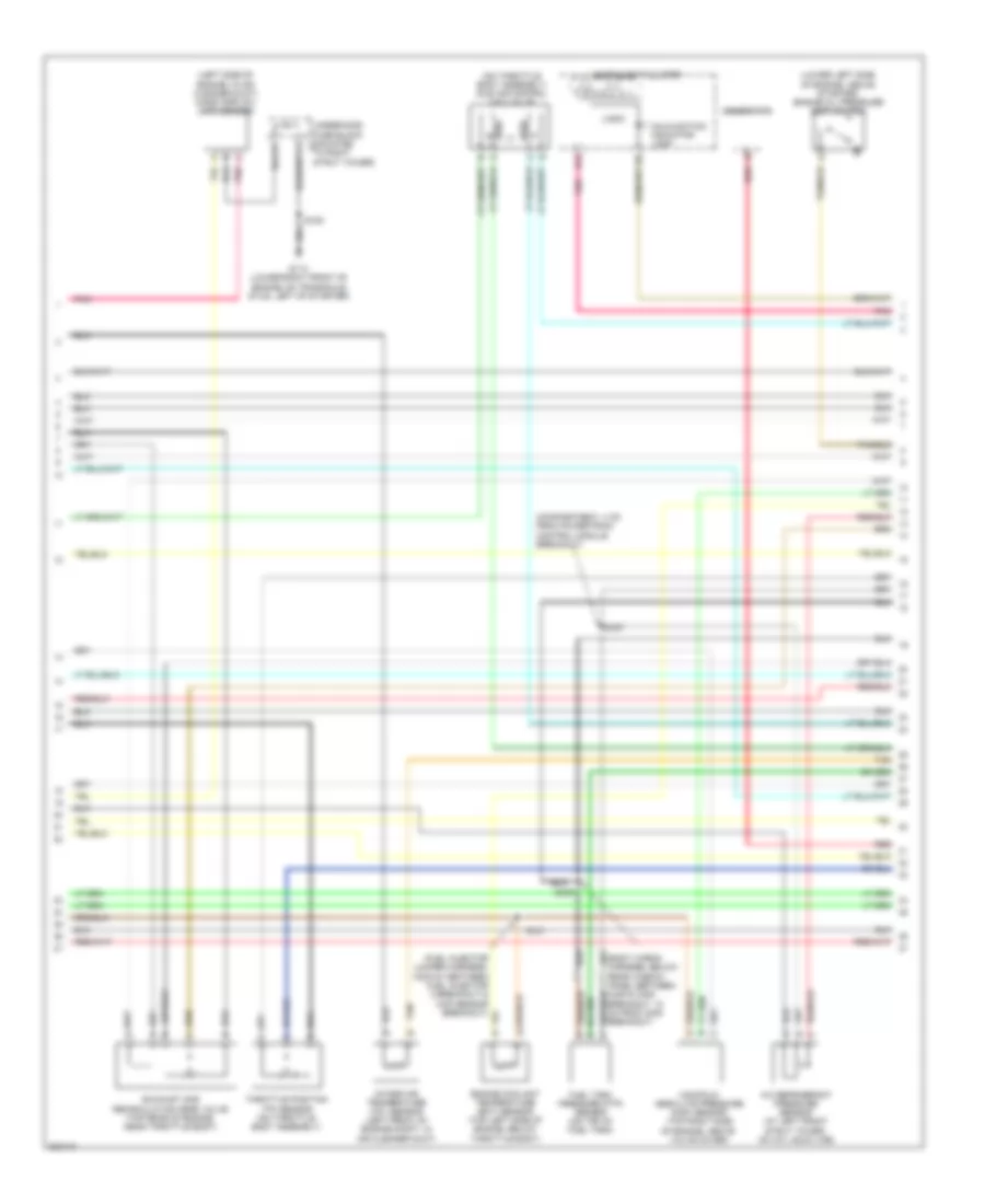
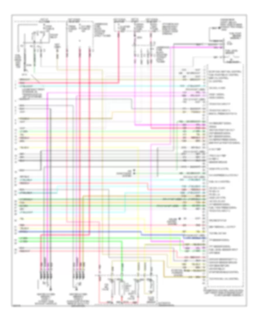
3.1L VIN J 3.1L VIN J, Engine Performance Wiring Diagram (1 of 4) for Buick Century Limited 2005 List of elements for 3.1L VIN J, Engine Performance Wiring Diagram (1 of 4) for Buick Century Limited 2005: 77 (behind data link connector) splice pack sp205 (lower right front of engine, on transaxle stud, left of starter) g113 (pin 14-15 not used) (pin 2-3 not used) (pin 23-27 not used) (pin 34-37 not used) (pin 39-42 not used) (pin 49-52 not used) (pin 66-67 not used) (under left side of dash, right of steer column) data link connector (dlc) 1-2 ss valve control 2-3 ss valve control A/c press return A/t iss hi sig A/t iss low sig Bank 1 ks signal Camshaft position sensor (cmp) (top front of engine, below intake plenum) Ckp sensor a Cmp signal Cooling fan system Crankshaft position (ckp) sensor a (front of engine, behind harmonic balancer) Crankshaft position (ckp) sensor b (right side of engine, below exhaust manifold) Cruise control system Cruise disable output Ecm fuse 22 10a Egr val ign pos volt Elek ign fuse 25 15a Eng emis fuse 30 10a Eng spd sig Evap can purge control F/injr fuse 28 15a Fuel inj 1 control Fuel inj 2 control Fuel inj 3 control Fuel inj 5 control Fuel inj 6 control G111 (lower left front of engine, on transaxle stud, left of starter) High speed fans control Ho2s sig low Hot at all times Hot in off, run or start Hot in run or start I/p fuse block (behind right side of dash, in right door opening) Iac valve b high Iat sensor ground Ic control Ign 0 fuse 10a Ignition amplifier and switching module Ignition control module (icm) (top right side of engine) Ignition power Knock sensor (ks) 1 (lower left side of engine, above starter) Low ref Low speed fans control Maf sensor signal Map sensor Map/ect sensor ref Pcm ground Pnk Pnk b Power (battery) Powertrain control module (pcm) (left front side of eng compt, in air cleaner assembly) Red Ref low S106 S187 S270 Sensor ground Sensor return Serial data (class 2) Spark plugs Tcc brake switch input Tp sensor ref Tr switch input b Underhood fuse block (mounted to right strut tower) Vss high Vss low Vss output 3.1L VIN J, Engine Performance Wiring Diagram (2 of 4) for Buick Century Limited 2005 List of elements for 3.1L VIN J, Engine Performance Wiring Diagram (2 of 4) for Buick Century Limited 2005: 14 Automatic transmission Automatic transmission fluid pressure manual valve position switch Evaporative emissions (evap) canister purge solenoid valve (top right side of engine, behind ignition control module) Evaporative emissions (evap) canister vent solenoid valve (behind left side of rear fascia splash shield, in wheelwell) Fuel injectors (on intake manifold) G113 (lower right front of engine, on transaxle stud, left of starter) Iss sensor Pnk Pressure control solenoid valve S106 S109 Stoplight switch (on brake pedal support bracket) Transmission internal mode switch Vehicle speed sensor (vss) (on transaxle right axle case extension) 3.1L VIN J, Engine Performance Wiring Diagram (3 of 4) for Buick Century Limited 2005 List of elements for 3.1L VIN J, Engine Performance Wiring Diagram (3 of 4) for Buick Century Limited 2005: 29 (compartment, 4 cm from powertrain control module breakout) (fuel injector jumper harness, midway between fuel injector 3 breakout & map sensor breakout) (left side of engine, in air cleaner duct) mass airflow (maf) sensor (lower left side of engine, above starter) engine oil pressure (eop) switch (on throttle body assembly) idle air control (iac) valve A/c refrigerant pressure sensor (at left front strut tower, on a/c liquid line) B12 Engine coolant temperature (ect) sensor (top left side of engine, below throttle body) Exhaust gas recirculation (egr) valve (top rear of engine, near throttle body) Fuel tank pressure (ftp) sensor (on top of fuel tank) G113 (lower right front of engine, on transaxle stud, left of starter) Generator Instrument cluster Intake air temperature (iat) sensor (left front of engine compt, in air cleaner duct) L b Logic Malfunction indicator lamp Manifold absolute pressure (map) sensor (top right side of engine, above valve cover) P r n Pnk Red S106 S121 S167 S409 Tan Throttle position (tp) sensor (on throttle body assembly) To right strut tower) Underhood fuse block (mounted c1 3.1L VIN J, Engine Performance Wiring Diagram (4 of 4) for Buick Century Limited 2005 List of elements for 3.1L VIN J, Engine Performance Wiring Diagram (4 of 4) for Buick Century Limited 2005: 94 (behind right side of dash, in right door opening) (inside rear compt, below right side of rear window trim panel) (lower right front of engine, on transaxle stud, left of starter) (not used) (pin 12-15 not used) (pin 31-32 not used) (pin 40-41 not used) (pin 47 not used) (pin 51-54 not used) (pin 64-65 not used) (pin 8-9 not used) 1-2 shift sol vlv 2-3 shift sol valve a 5 volt ref 5v ref a A/c compress clutch rly A/c refrig press signal A/c request signal A11 Air conditioning system Air pmp relay Automatic transmission Ckp sens Ckp sens return Cluster fuse 10a Cmp/ckp sensor batt (+) Cmp/ckp sensor ground Crank Crank signal fuse 10a Cruise control system Cruise status D10 Ect sensor signal Egr pintle position signal Egr val control Eng oil press switch in Evap can vent sol control F/pmp fuse 35 15a F/pump relay Fluid temp sensor Fuel inj 4 control Fuel level sensor Fuel level sensor input Fuel pump Fuel pump prime con- nec- tor Fuel pump relay control Fuel pump sender assembly Fuel tank press signal G113 G402 Gen terminal l output Heated oxygen sensor 1 (ho2s 1) (in right side exhaust manifold) Heated oxygen sensor 2 (ho2s 2) (in exhaust system, rear of catalytic converter) Ho2s 1 signal Ho2s 2 signal Ho2s htr lo ctrl Ho2s low ctrl Hot at all times Hot in run or start Hot in start I/p fuse block Iac coil a high Iac coil a low Iac coil b low Iat sensor signal Ignition positive volt Map sensor signal Mil control Nca Oxy sen fuse 29 15a Pc sol hi Pc sol lo Pcm- bcm fuse 10a Pnk Powertrain control module (pcm) (left front side of engine compt, in air cleaner assembly) Red S106 S115 red S234 Sensor ground Starter enable control Starting/ charging system Tan Tcc pwm sol val control Tcc rel sw sig Tcc sol valve Tft sensor signal Tp sensor signal Tps 5 volt ref Tr switch input a Tr switch input c Tr switch input p Trans fuse 26 10a Underhood fuse block (mounted to right strut tower)
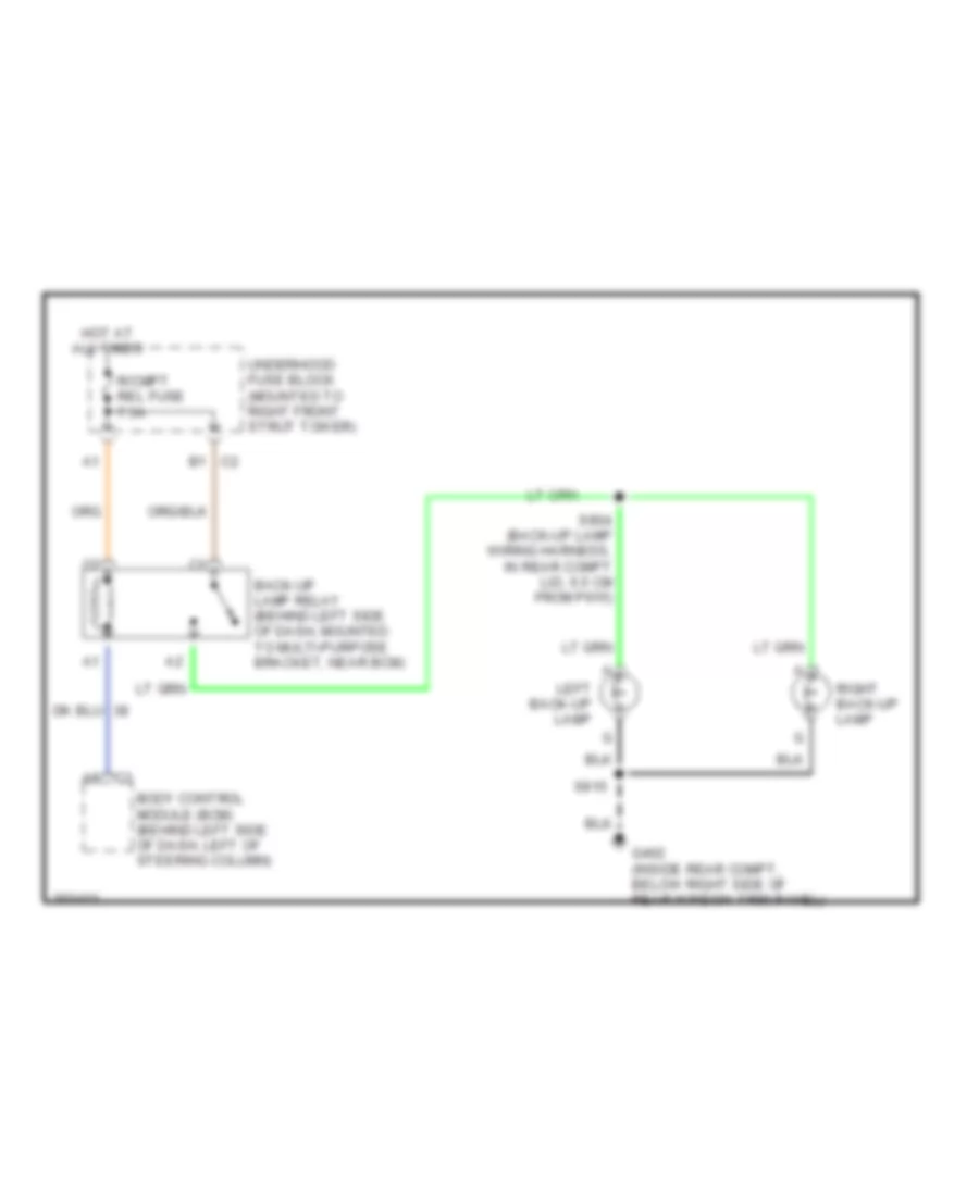
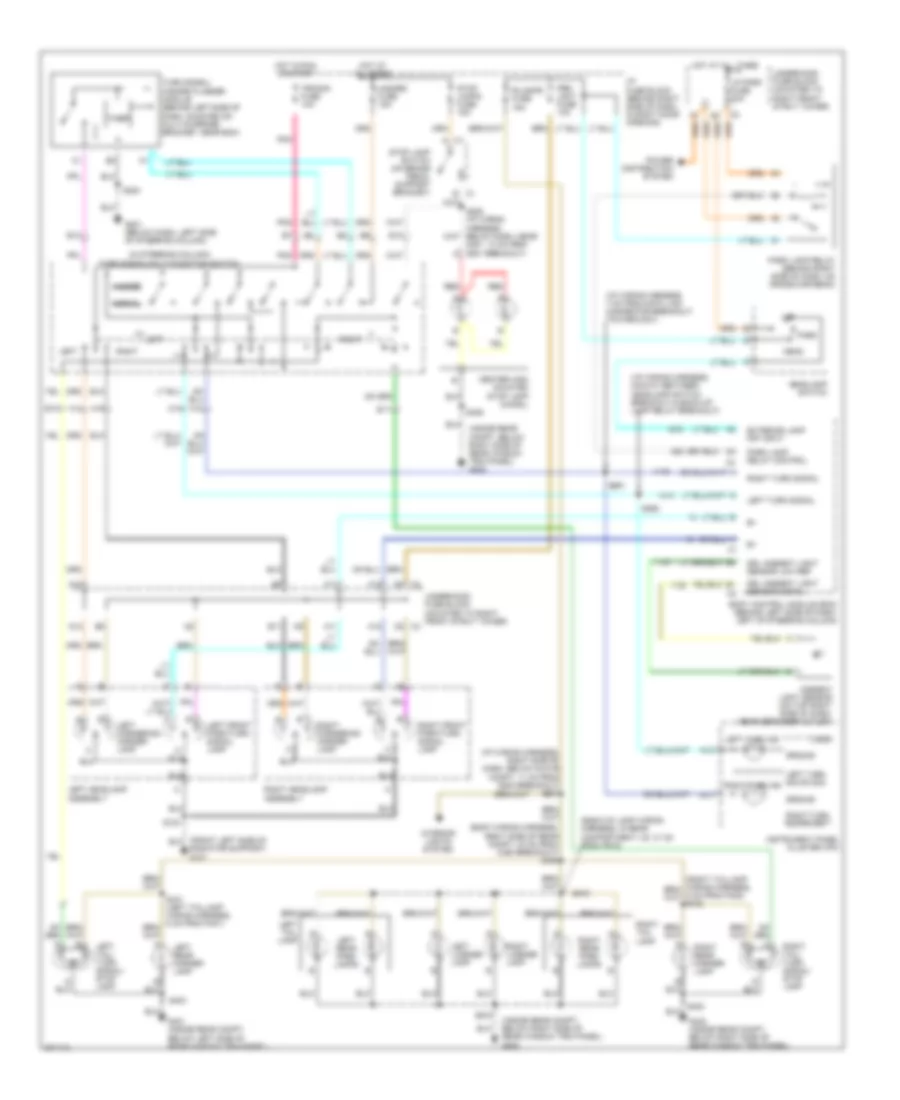
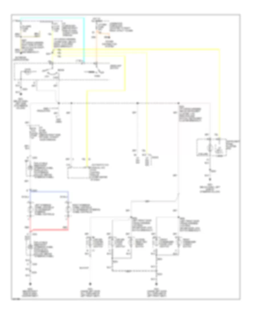
EXTERIOR LIGHTS Back-up Lamps Wiring Diagram for Buick Century Limited 2005 List of elements for Back-up Lamps Wiring Diagram for Buick Century Limited 2005: 12 A8 c3 B1 c2 Back-up lamp relay (behind left side of dash, mounted to multi-purpose bracket, near bcm) Body control module (bcm) (behind left side of dash, left of steering column) G402 (inside rear compt, below right side of rear window trim panel) Hot at all times Left back-up lamp R/cmpt rel fuse 7.5a Right back-up lamp S904 (back-up lamp wiring harness, in rear compt lid, 6.5 cm from p915) S915 Underhood fuse block (mounted to right front strut tower) Exterior Lamps Wiring Diagram for Buick Century Limited 2005 List of elements for Exterior Lamps Wiring Diagram for Buick Century Limited 2005: 96 (back-up lamp wiring harness, in rear compartment lid, 31 cm from p915) (body wiring harness, right side of rear compt, 33 cm from c390 breakout) s408 (i/p wiring harness, 7 cm from data link connector breakout, toward c201) (i/p wiring harness, midway between headlamp switch breakout & back-up lamp relay breakout) (i/p wiring harness, right side of dash, below glove compt, 11 cm from g200 breakout) s267 (in steering column) turn signal/multi-function switch (inside rear compt, below right side of rear window trim panel) g402 A10 A11 A12 A13 A14 A15 Ambient light sensor (on top right side of dash, near defogger outlet) B c1 Body control module (bcm) (behind left side of dash, left of steering column) C1 a C2 f8 C3 c5 Center high mounted stop lamp (chmsl) D12 Drl ambient light sensor low ref Drl ambient light sensor signal E10 E11 E12 E13 Exterior lamp off input F11 F12 G201 (below dash, left side of steering column) G401 (inside rear compt, below left side of rear window trim panel) G402 (inside rear compt, below right side of rear window trim panel) Ground Hazard Hazard fuse 15a Head Headlamp switch Hot at all times Hot in run or start I/p fuse block (behind right side of dash, in right door opening) Instrument panel cluster (ipc) Interior lights system Left Left cornering/ marker lamp Left front park/turn signal lamp Left headlamp assembly Left license lamp Left rear marker lamp Left rear park lamps Left tail lamp Left tail/ turn signal/ stop lamp Left turn ind Left turn sig sw sig Left turn signal Logic Lp park fuse 20a Normal Off Park Park lamp relay (behind right side of dash, on cross-car beam) Park lamp relay control Pnk Power distribution system Prk/ lght fuse 10a R/lamps fuse 15a Radiator support) g101 Red Right Right cornering/ marker lamp Right front park/turn signal lamp Right headlamp assembly Right license lamp Right rear marker lamp Right rear park lamps Right tail lamp Right tail/ turn signal/ stop lamp Right turn ind Right turn sig sw sig Right turn signal S124 S205 (i/p wiring harness, below dash, near c201, 14 cm from g201 breakout) a S283 S291 S292 S402 S403 S406 S915 S919 Stop lamp switch (on brake pedal support bracket) Stop lamps fuse 15a Timer Trn/sig fuse 10a Turn signal/ hazard flasher module (behind left side of dash, mounted on multi-purpose bracket, near bcm) Underhood fuse block (mounted to right front strut tower)
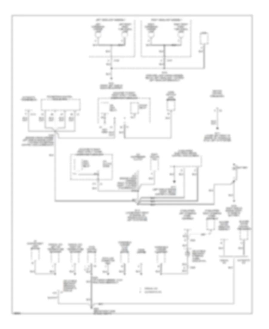
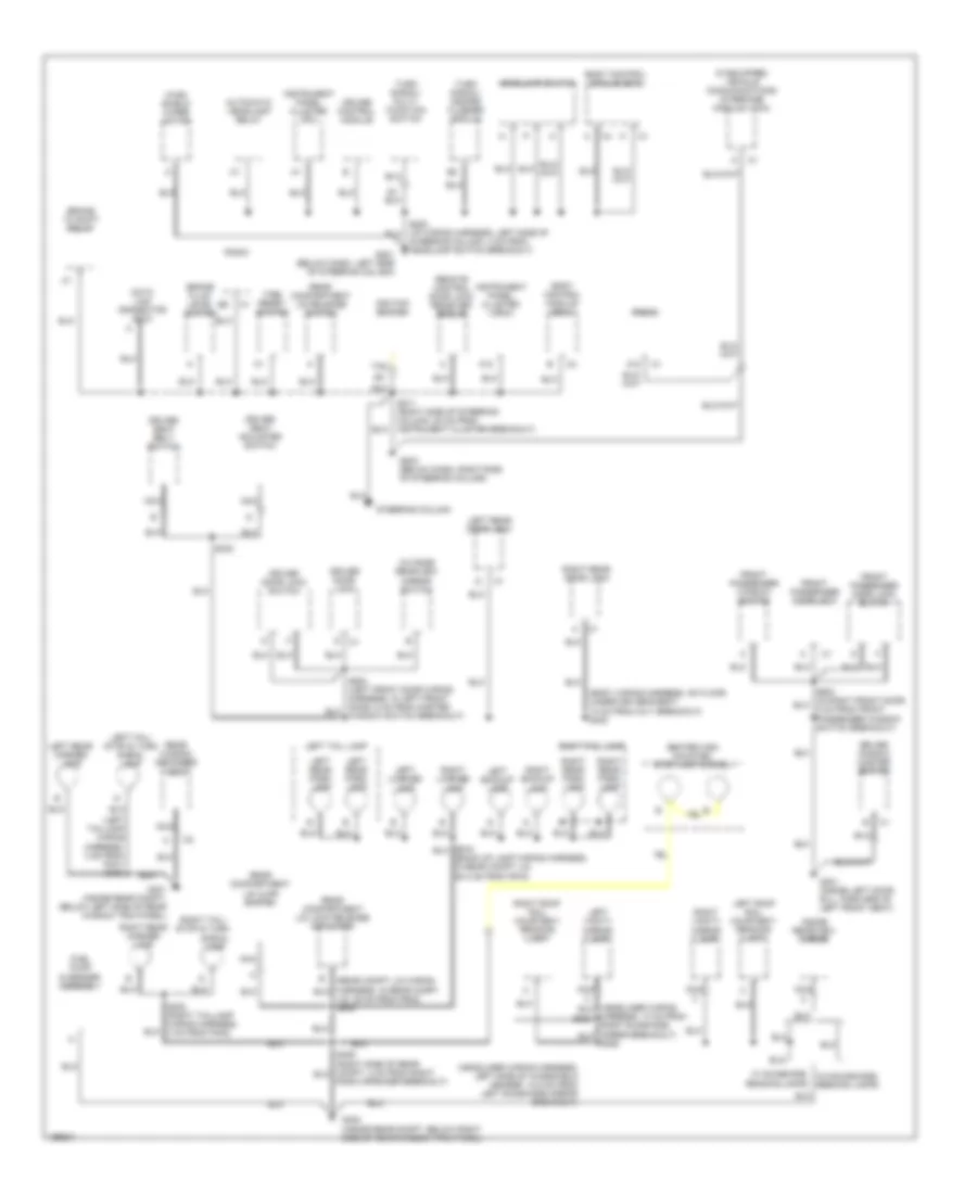
GROUND DISTRIBUTION Ground Distribution Wiring Diagram (1 of 2) for Buick Century Limited 2005 List of elements for Ground Distribution Wiring Diagram (1 of 2) for Buick Century Limited 2005: 54 (forward lamp wiring harness, below left headlamp, 7 cm from left headlamp breakout) (if equipped) electronic brake control module (ebcm) (if equipped) left steering wheel controls (if equipped) right steering wheel controls (manual a/c) left air temperature actuator (manual a/c) right air temperature actuator (mounted to right front strut tower) underhood fuse block (not used) A/c clutch diode A/c compressor clutch A18 Automatic a/c Automatic transmission Battery Blower motor control processor Blower motor resistor assembly C106 C107 C11 C113 C203 C205 Cigar lighter Cool fan 2 relay Data link connector (dlc) F/pump relay G100 (right side of engine compt, at base of battery) G101 (front left side of radiator support) G111 (lower left front of engine, on transaxle stud, left of starter) G113 (lower right front of engine, on transaxle stud, left of starter) G171 (left side of engine compt, below master cylinder) G200 (behind right side of dash compt) Horn Hvac control module I/p compartment lamp/ switch Ign main relay Ignition control module (icm) Inflatable restraint sensing & diagnostic module Inflatable restraint steering wheel module coil Left cornering/ marker lamp Left front park/ turn signal lamp Left headlamp assembly Manual a/c Mass air flow (maf) sensor Powertrain control module (pcm) Right cooling fan Right cornering/ marker lamp Right front park/ turn signal lamp Right headlamp assembly S106 (engine wiring harness, left side of engine compt, 7 cm from powertrain control module breakout) S124 T11 Windshield washer fluid level switch Windshield washer fluid pump Ground Distribution Wiring Diagram (2 of 2) for Buick Century Limited 2005 List of elements for Ground Distribution Wiring Diagram (2 of 2) for Buick Century Limited 2005: 74 (back-up lamp wiring harness, in rear compt lid, 29.5 cm from p915) (body wiring harness, on floor, under driver's seat, 10 cm from c311 breakout) s303 (headliner wiring harness, left side of windshield header, 10.5 cm from left sunshade mirror breakout) (if equipped) vehicle communications interface module (vcim) (left taillamp wiring A12 Automatic headlamp relay Body control module (bcm) Brake fluid level switch Brake to shift relay Center high mounted stop lamp (chmsl) Cruise control module Data link connector (dlc) Driver door lock Driver door lock switch Driver seat adjuster switch Driver seat belt switch Driver window master switch Front passenger door lock Front passenger door lock switch Front passenger window switch Fuel pump & sender assembly G201 (below dash, left side of steering column) G203 (below dash, right side of steering column) G301 (inside left door sill, forward of left front seat) G401 (inside rear compt, below left side of rear window trim panel) G402 (inside rear compt, below right side of rear window trim panel) Harness, 13 cm from s383 Harness, 3 cm from p401) s403 Headlamp switch Ignition switch Inside rearview mirror Instrument panel cluster (ipc) Left backup lamp Left license lamp Left rear door lock Left rear marker lamp Left rear park lamp Left roof rail courtesy/ reading lamp Left tail lamp Left tail/ stop & turn signal lamp Left vanity mirror lamp Lid, 38 cm from p932) s905 Nca Outside rearview mirror switch Radio Radio speaker breakout) Reading lamps Rear compartment lid ajar switch Rear compartment lid lock release actuator Rear compartment lid release switch Rear window defogger grid Remote control door lock receiver (rcdlr) Right backup lamp Right license lamp Right rear door lock Right rear marker lamp Right rear park lamp Right roof rail courtesy/ reading lamp Right tail lamp Right tail/ stop & turn Right vanity mirror lamp S211 (right side of steering column, 20 cm from instrument cluster breakout) S330 S402 (right taillamp wiring harness, 3 cm from p402) Signal lamp Steering column Steering column, 4 cm from headlamp switch breakout) Tan Tire reset switch Turn signal/ hazard flasher module Turn signal/ multi- function switch W/ sunshade, w/o sunshade, reading lamps Wind- shield wiper motor
HEADLIGHTS Headlights Wiring Diagram for Buick Century Limited 2005 List of elements for Headlights Wiring Diagram for Buick Century Limited 2005: 46 A10 A11 Ambient light sensor (on top right side of dash, near defogger outlet) Automatic headlamp relay B7 pnk Battery Body control module (bcm) (behind left side of dash, left of steering column) D11 F10 F2 c3 Flash to pass G201 (below dash, left side of steering column) Hdlp l fuse 15a Hdlp r fuse 15a Head Headlamp cntrl Headlamp dimmer switch Headlamp sw input Headlamp switch High High beam High beam indicator Hot at all times I/p fuse block (behind right side of dash, in right door opening) Ign Instrument panel cluster (ipc) Left headlamp assembly Light sens grd ref Light sensor sig Logic Low Low beam Lp park fuse 20a Off Park Park brk sw in Pnk Power distribution system Radio, hvac, rfa, cluster aldl fuse 15a Red Right headlamp assembly S202 S221 (i/p wiring harness, right side of steering column, 17 cm from data link connector breakout) S283 Turn signal/ multi-function switch (in steering column) Underhood fuse block (mounted to right front strut tower)
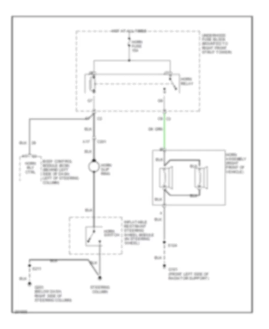
HORN Horn Wiring Diagram for Buick Century Limited 2005 List of elements for Horn Wiring Diagram for Buick Century Limited 2005: 18 A17 Body control module (bcm) (behind left side of dash, left of steering column) C201 C8 c3 G101 (front left side of radiator support) G203 (below dash, right side of steering column) Horn assembly (right front of vehicle) Horn fuse 15a Horn relay Horn rly ctrl Horn slip ring Horn switch Hot at all times Inflatable restraint steering wheel module (in steering wheel) S124 S211 Steering column Underhood fuse block (mounted to right front strut tower)
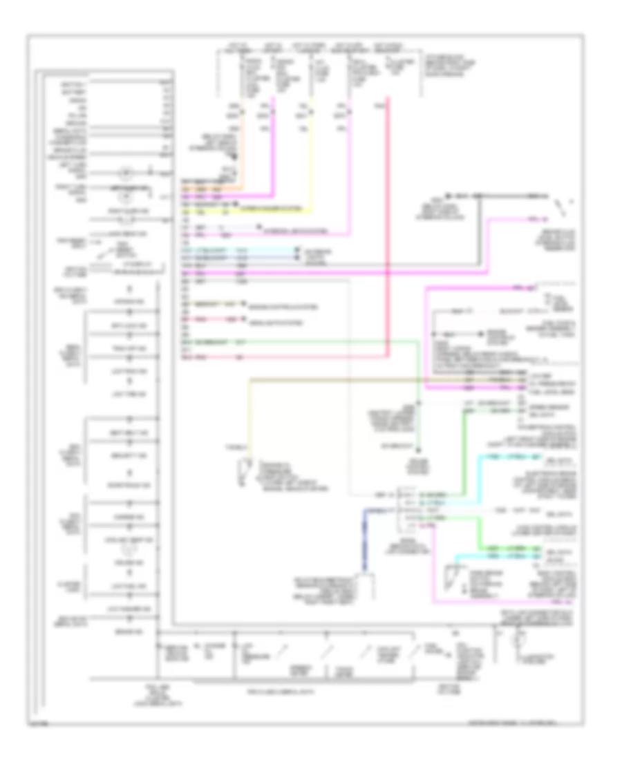
INSTRUMENT CLUSTER Instrument Cluster Wiring Diagram for Buick Century Limited 2005 List of elements for Instrument Cluster Wiring Diagram for Buick Century Limited 2005: 105 (below dash, left side of steering column) g201 (below dash, right side of steering column) A10 A11 A12 Air bag ind Anti-lock ind B10 B11 B12 Battery Bcm class 2 serial data Bcm or ipc serial data Body control module (bcm) (behind left side of dash, left of steering column) Brake fluid Brake fluid level switch (in brake fluid reservoir) Brake ind Change oil ind Charge ind Cluster fuse 10a Cluster logic Coolant temp ind Coolant temper- ature Crank Crank sig, bcm, cluster fuse 10a Cruise control system Cruise ind D12 Data link connector (dlc) (under left side of dash, right of steering column) Door/trunk ind Ebcm class 2 serial data Electronic brake control module (ebcm) (at left side of engine compartment, near strut tower) Engine controls system Engine oil pressure (eop) switch (lower left side of engine, above starter) Exterior lights system Fuel gauge Fuel level sens Fuel level sensor Fuel pump & sender assembly (in fuel tank) G203 Gnd Ground Headlights system High beam ind Hot at all times Hot in off, run or start Hot in run or start Hot in start Hot w/ park lamp on Hvac control module (lower center of dash) I/p fuse block (behind right side of dash, in right door opening) Ign Ign 0, cluster, pcm & bcm fuse 10a Ignition 1 Ignition voltage Illumination (5 bulbs) Inflatable restraint sensing & diagnostic module (sdm) (below carpet, under right front seat) Instrument panel cluster (ipc) Int/ illum fuse 7.5a Interior lights system Left turn ind Left turn signal Low fuel ind Low oil pressure ind Low ref Low tire ind Low trac ind Low washer ind Mal- function indicator lamp (mil) (service engine soon) Oil pressure sw On sig Park brake switch (on parking brake assembly) Pcm class 2 serial data Pcm, abs bcm & cluster logic serial data Pk lps Pnk Powertrain control module (pcm) (left front side of engine compt, in air cleaner assembly) Radio, hvac, rfa, cluster, aldl fuse 15a Right turn ind Right turn signal S202 S211 S234 S241 S270 S283 S295 (ashtray jumper wiring harness, inside ashtray, 5 cm from c242) S409 (body wiring harness, below rear window panel between c405 & c405 breakout, 10 cm from c405 breakout) Sdm class 2 ign serial data Seat belt ind Security ind Serial data Service vehicle soon ind Sp205 (behind data link connector) Speed sensor Speedo- meter Srl data Tacho- meter Trac off ind Trip reset input Trip reset switch Vehicle speed Vf display Windshield washer fluid Wiper/washer system
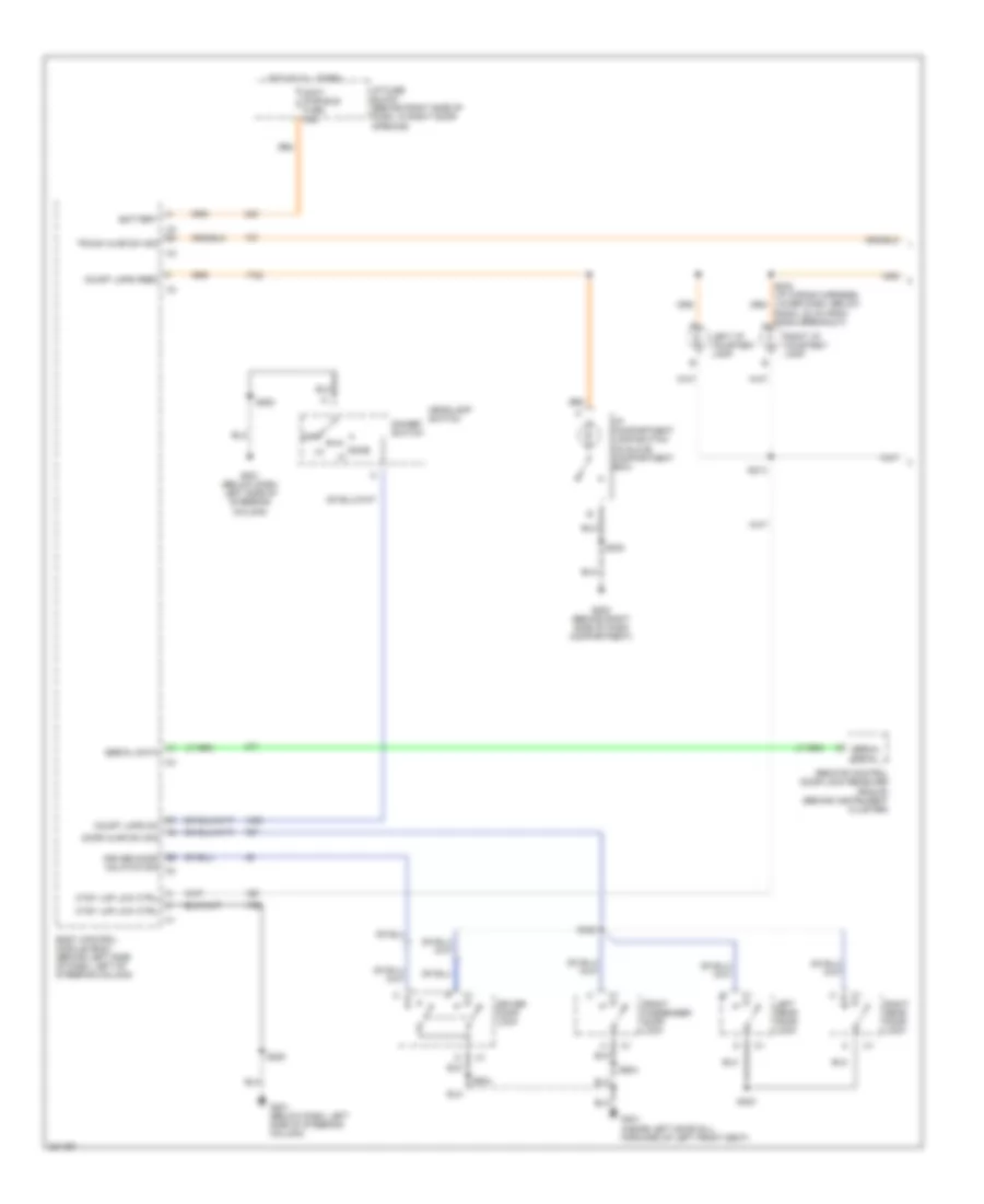
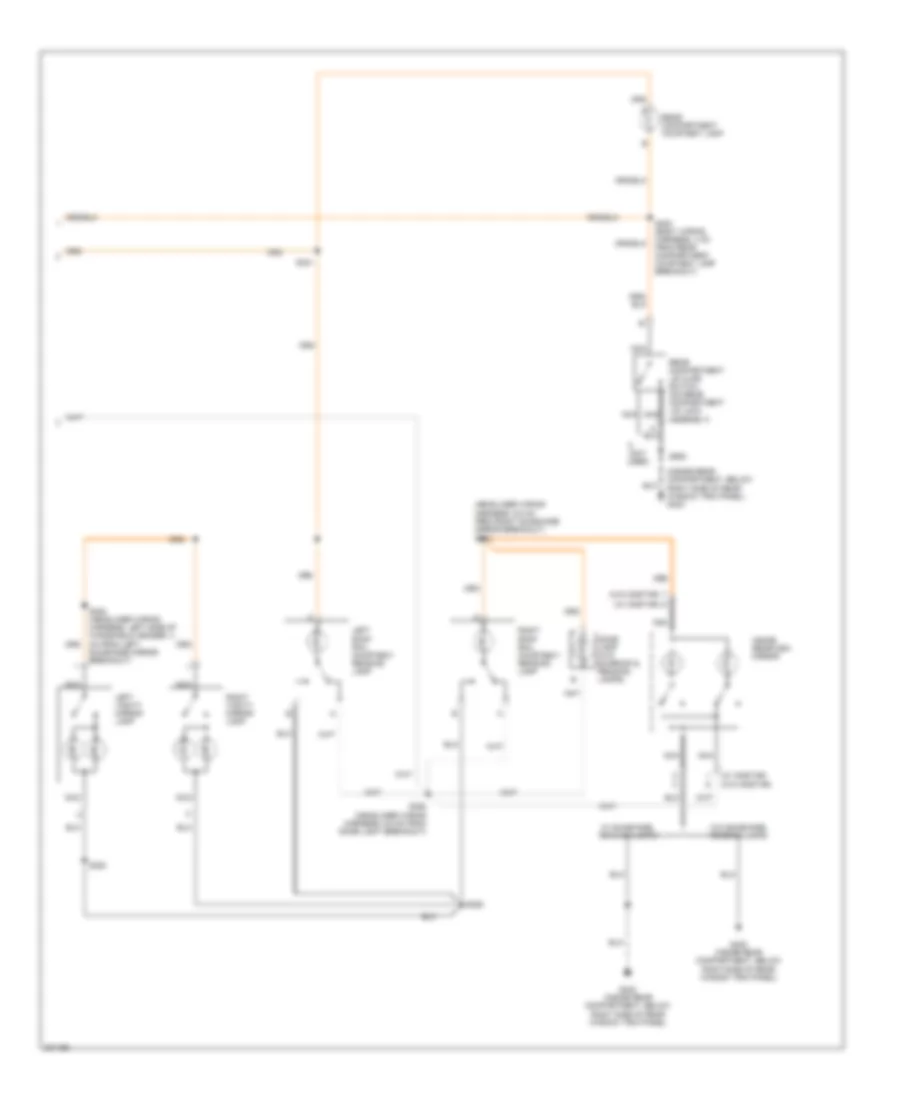
INTERIOR LIGHTS Courtesy Lamps Wiring Diagram (1 of 2) for Buick Century Limited 2005 List of elements for Courtesy Lamps Wiring Diagram (1 of 2) for Buick Century Limited 2005: 36 Accy pwr bus fuse 15a B5 driver door unlatch sig c2 Battery Body control module (bcm) (behind left side of dash, left of steering column) C4 b4 Court lmps feed Court lmps on Ctsy lmp low ctrl Dimmer switch Dome Door ajar sw sig Driver door lock Front passenger door lock G200 (behind right side of dash compartment) G201 (below dash, left side of steering column) G301 (inside left door sill, forward of left front seat) Headlamp switch Hot at all times I/p compartment lamp/switch (in glove compartment box) I/p fuse block (behind right side of dash, in right door opening) Left i/p courtesy lamp Left rear door lock Off Radio, 22 cm from radio breakout) a Remote control door lock receiver (rcdlr) (behind instrument cluster) Right i/p courtesy lamp Right rear door lock S214 S230 S283 S303 S322 S504 S604 Serial data Trunk ajar sw sig Courtesy Lamps Wiring Diagram (2 of 2) for Buick Century Limited 2005 List of elements for Courtesy Lamps Wiring Diagram (2 of 2) for Buick Century Limited 2005: 24 (headliner wiring harness, 6.5 cm from right sunshade mirror breakout) s386 (inside rear compartment, below right side of rear window trim panel) g402 (not used) (w/ onstar) (w/o onstar) Dome lamp (w/o sunroof & reading lamps) G402 (inside rear compartment, below right side of rear window trim panel) Inside rearview mirror Left roof rail courtesy/ reading lamp Left vanity mirror lamp Nca Rear compartment courtesy lamp Rear compartment lid ajar switch (on rear compartment lid lock assembly) Right roof rail courtesy/ reading lamp Right vanity mirror lamp S321 S382 (headliner wiring harness, left side of windshield header, 4 cm from left sunshade mirror breakout) S383 S385 S392 (headliner wiring harness, 6.5 cm from dome light breakout) S400 (body wiring harness, 4 cm from rear compartment courtesy lamp breakout) S905 W/ sunshade, reading lamps W/o sunshade, reading lamps Instrument Illumination Wiring Diagram for Buick Century Limited 2005 List of elements for Instrument Illumination Wiring Diagram for Buick Century Limited 2005: 55 (5 bulbs) (automatic a/c) (i/p wiring harness, lower dash, below radio, 15 cm from radio breakout) (manual a/c) (not used) B12 C16 C203 C205 Dome Driver door lock switch Driver master window switch Early production Exterior lights system Front passenger door lock switch Front passenger window switch G200 (behind right side of dash compartment) G200 breakout) G201 (below dash, left side of steering column) G301 (inside left door sill, forward of left front seat) Head Headlamp switch High Hot at all times Hvac control module (lower center of dash) I/p fuse block (behind right side of dash, in right door opening) Illum Inflatable restraint steering wheel module coil (in steering column, behind steering wheel) Instrument panel cluster (ipc) Int/ illum fuse 7.5a Left steering wheel controls (w/ accessory steering wheel controls) Logic Low Lp park fuse 20a Off Outside rear view mirror switch Park Power distribution system R/lamps fuse 15a Radio Red Right steering wheel controls (w/ accessory steering wheel controls) S230 S241 S283 S303 S504 S506 (left front door wiring harness, 4 cm from driver door lock switch breakout) S604 S606 (left front door wiring harness, 4 cm from driver door lock switch breakout) Str/ whl cntrl fuse 2a Underhood fuse block (mounted to right front strut tower) Vf dim dis sig Vf dim sig Vf sply volt-1
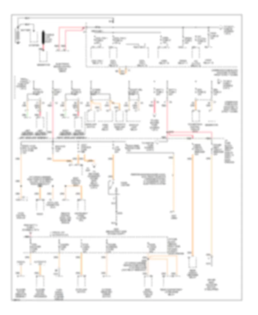
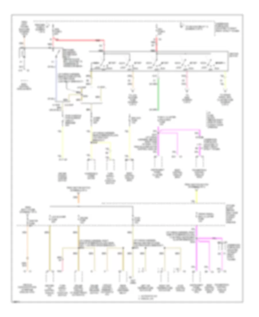
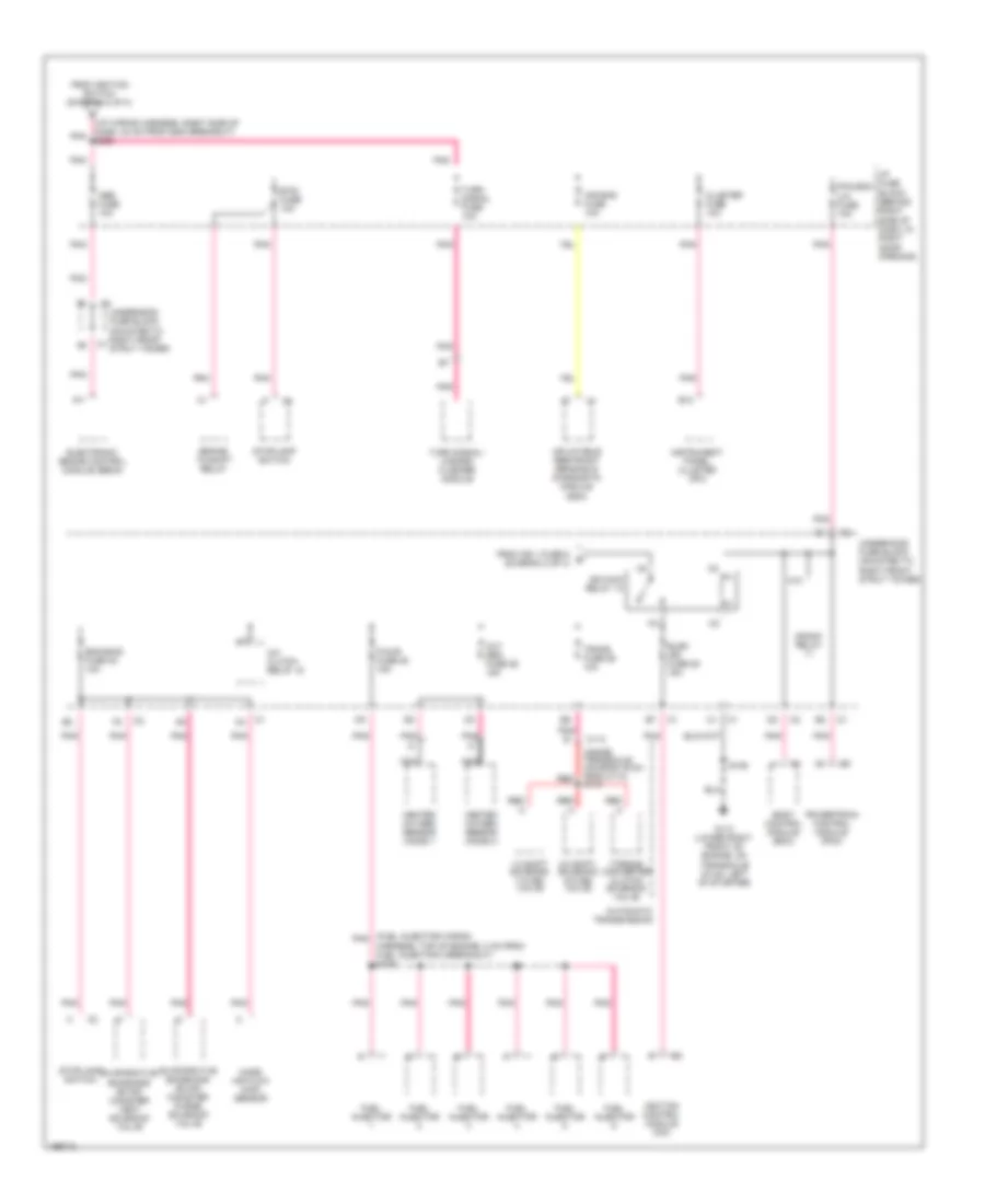
POWER DISTRIBUTION Power Distribution Wiring Diagram (1 of 3) for Buick Century Limited 2005 List of elements for Power Distribution Wiring Diagram (1 of 3) for Buick Century Limited 2005: 95 (i/p wiring harness, right side of steering column, 19 cm from radio breakout) s202 (not used) 60a A/c clutch fuse 23 10a A/c clutch relay 15 Abs fuse 1 Accy pwr bus fuse 15a Automatic a/c Automatic headlamp relay Back-up lamp relay Batt 1 fuse 7 60a Batt 2 fuse 4 60a Batt 3 fuse 3 60a Battery Bcm pwr fuse 10a Blower motor control processor Blower motor resistor assembly Body control module (bcm) C2 l c12 Cigar lighter Cool fan 1 fuse 6 25a Cool fan 1 relay 12 Cool fan 2 fuse 24 15a Cool fan 2 relay 9 Cool fan 3 relay 10 Crank fuse 2 40a Crank relay 11 Data link connector (dlc) Door locks fuse 20a Driver seat adjuster switch (if equipped) E10 Ecm fuse 22 10a Electronic brake control module (ebcm) F/pmp fuse 35 15a F/pmp relay 19 From batt 2 fuse 4 (diagram 1 of 3) From f/pmp a fuse 35 (diagram 1 of 3) Fusible link (10 ga- rust) G200 (behind right side of dash compt) Gen fuse 21 10a Generator Hazard fuse 15a Hdlp l fuse 36 15a Hdlp r fuse 32 15a Headlamp switch High blower fuse 30a Horn fuse 27 15a Horn relay 16 Hvac control module I/p fuse block (behind right side of dash, in right door opening) Instrument panel cluster (ipc) Left headlamp assembly Left high beam headlamp Left low beam headlamp Lp park fuse 34 20a Ltr fuse 20a M10 Manual a/c Nca Outside rearview mirror switch Park lamp relay Performance enhanced audio, dual front door mtd 4 speaker system, w/ accessory cont electronic system Power mirrors fuse 2a Power seat circuit breaker 30a Powertrain control module (pcm) R/cmpt rel fuse 33 7.5a R10 R11 Radio Radio prem sound fuse 15a Radio, hvac rfa, cluster aldl fuse 15a Rear compartment lid release relay Rear defog circuit breaker 30a Rear window defogger relay Red Red a Remote control door lock receiver (rcdlr) Right headlamp assembly Right high beam headlamp Right low beam headlamp S230 S269 (i/p wiring harness, near blower motor, 13 cm from door lock relay breakout) S275 Starter Stop lamps fuse 15a Stoplamp switch T10 To hdlp l fuse 36 (diagram 1 of 3) To high blower fuse (diagram 1 of 3) To ign 2 fuse 8 (diagram 2 of 3) To onstar fuse, diagram (2 of 3) To retained accessory power (rap) relay (diagram 2 of 3) Turn signal/ hazard flasher module Underhood fuse block (mounted to right front strut tower) W/ rap Power Distribution Wiring Diagram (2 of 3) for Buick Century Limited 2005 List of elements for Power Distribution Wiring Diagram (2 of 3) for Buick Century Limited 2005: 59 (i/p wiring harness, behind center of dash, 4 cm from radio breakout) s233 (i/p wiring harness, near blower motor, 4 cm from door lock relay breakout) (i/p wiring harness, right side of steering column near, c201, 1 cm from sp205 breakout) s240 (i/p wiring harness, right side of steering column, 13 cm from instrument cluster breakout) s234 (not used) A10 Acc Automatic a/c B10 Bcm acc fuse 10a Body control module (bcm) C5 c Crank signal, bcm, cluster fuse 10a Cruise control module (w/ electronic automatic) Cruise control release switch Cruise fuse 10a Driver window master switch From accy power bus fuse (diagram 1 of 3) From batt 3 fuse (diagram 1 of 3) From gen d fuse 21 (diagram 1 of 3) From ignition switch (diagram 2 of 3) Heater- a/c control (manual a/c) Hvac control module Hvac fuse 10a I/p fuse block (behind right side of dash, in right door opening) Ign 0, cluster, pcm & bcm fuse 10a Ign1 fuse 5 30a Ign2 fuse 8 60a Ignition switch Instrument panel cluster (ipc) Left air temperature actuator Lock Low blower fuse 20a Manual a/c Off Onstar fuse 5a Pnk Powertrain control module (pcm) Pwr windows pwr sunroof circuit breaker 30a Rear window defogger relay Red Retained accessory power (rap) relay (behind glove box, mounted to underside of cross-car beam) Right air temperature actuator Run S263 S270 (i/p wiring harness, behind right side of dash, 4 cm from blower motor control module) Start To crank signal bcm, cluster fuse (diagram 2 of 3) To ign main relay 13 (diagram 3 of 3) To low blower fuse (diagram 2 of 3) To s228 (diagram 3 of 3) Turn signal/ multi- function switch Underhood fuse block (mounted to right front strut tower) Vacuum control assembly (automatic a/c) Vehicle communications interface module (vcim) W/ rap W/o rap Windshield wiper motor Wiper fuse 25a Power Distribution Wiring Diagram (3 of 3) for Buick Century Limited 2005 List of elements for Power Distribution Wiring Diagram (3 of 3) for Buick Century Limited 2005: 50 (fuel injector wiring pnk (i/p wiring harness, right side of dash, 24 cm from g200 breakout) s228 (inside transaxle housing,19 cm from c113) s115 1-2 shift solenoid (1-2 ss) valve 2-3 shift solenoid (2-3 ss) valve A/c clutch relay 15 A11 Abs fuse 10a Air bag fuse 10a Automatic transmission B12 Body control module (bcm) Brake- to-shift relay Btsi fuse 10a C113 Cluster fuse 10a Crank relay Electronic brake control module (ebcm) Elek ign fuse 25 15a Eng emis fuse 30 10a Evaporative emissions (evap) canister purge solenoid valve Evaporative emissions (evap) canister vent solenoid valve F/injr fuse 28 15a From ign 1 fuse 5 e (diagram 2 of 3) From ignition switch (diagram 2 of 3) Fuel injector G113 (lower right front of engine, on transaxle stud, left of starter) Harness, top of engine, 2 cm from fuel injector 2 breakout) s109 Heated oxygen sensor (ho2s) 1 Heated oxygen sensor (ho2s) 2 I/p fuse block (behind right side of dash, in right door opening) Ign main relay 13 Ignition control module (icm) Inflatable restraint sensing & diagnostic module (sdm) Instrument panel cluster (ipc) K10 Mass air flow (maf) sensor Nca Oxy sen fuse 29 15a Pcm,bcm u/h fuse 10a Pnk Powertrain control module (pcm) Red S106 Stoplamp switch Torque converter clutch solenoid valve Trans fuse 26 10a Turn signal fuse 10a Turn signal/ hazard flasher module Underhood fuse block (mounted to right front strut tower)
POWER DOOR LOCKS Power Door Locks Wiring Diagram for Buick Century Limited 2005 List of elements for Power Door Locks Wiring Diagram for Buick Century Limited 2005: 38 (body wiring harness, below right front passenger seat, 35.5 cm from c311 breakout) s315 (body wiring harness, below right side of front passenger seat, 4 cm from g302 breakout) s314 Actuator All drs lock Battery Battery (b+) Bcm pwr fuse 10a Body control module (bcm) (behind left side of dash, left of steering column) Door lock fuse 20a Dr lock sw in Dr unlk sw in Driver door lock switch Driver dr unlk Front passenger door lock switch G201 (below dash, left side of steering column) G203 (below dash, right side of steering column) G301 (inside left door sill, forward of left front seat) Ground Hot at all times I/p fuse block (behind right of dash, in right door opening) Interior lights system Left front door lock Left rear door lock Lock Pass drs unlk Radio, hvac rfa, cluster, data link fuse 15a Remote control door lock receiver (rcdlr) (behind instrument cluster) Right front door lock Right rear door lock S202 S211 S269 S283 S303 S504 Serial data Tan Unlock
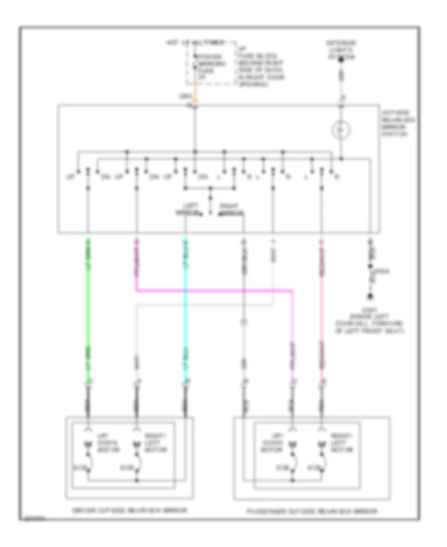
POWER MIRRORS Power Mirrors Wiring Diagram for Buick Century Limited 2005 List of elements for Power Mirrors Wiring Diagram for Buick Century Limited 2005: 15 Driver outside rearview mirror Ecb G301 (inside left door sill, forward of left front seat) Hot at all times I/p fuse block (behind right side of dash, in right door opening) Interior lights system Left mirror Nca Outside rearview mirror switch Passenger outside rearview mirror Power mirrors fuse 2a Right mirror Right/ left motor S504 Up/ down motor
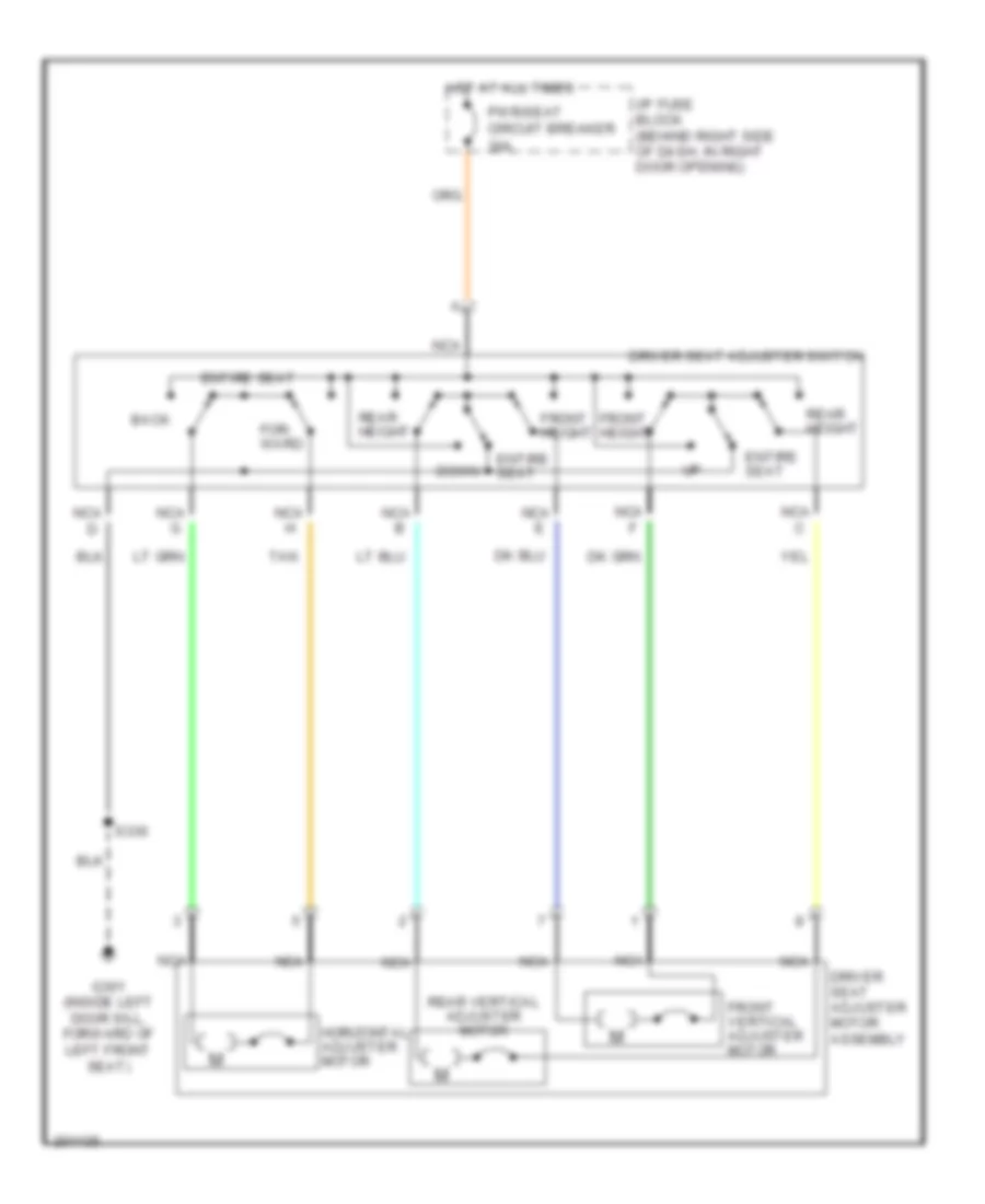
POWER SEATS 6-Way Power Seat Wiring Diagram for Buick Century Limited 2005 List of elements for 6-Way Power Seat Wiring Diagram for Buick Century Limited 2005: 21 Back Down Driver seat adjuster motor assembly Driver seat adjuster switch Entire seat For- ward Front height Front vertical adjuster motor G301 (inside left door sill, forward of left front seat) Horizontal adjuster motor Hot at all times I/p fuse block (behind right side of dash, in right door opening) Nca Nca b Nca e Nca g Pwr/seat circuit breaker 30a Rear height Rear vertical adjuster motor S330 Tan
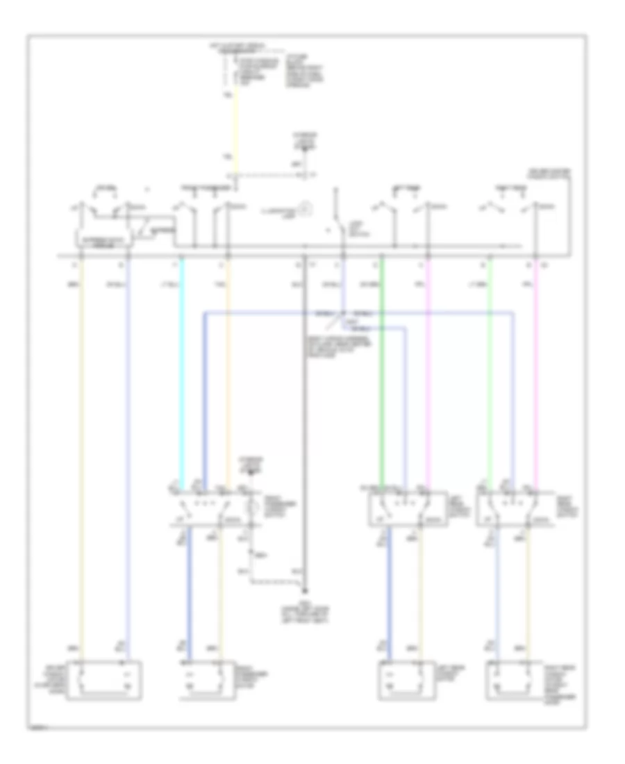
POWER WINDOWS Power Windows Wiring Diagram for Buick Century Limited 2005 List of elements for Power Windows Wiring Diagram for Buick Century Limited 2005: 27 (body wiring harness, on floor, near center of vehicle, 20 cm from c325) Down Driver Driver master window switch Driver window motor (in driver's door) Express Express down module Front passenger Front passenger window motor Front passenger window switch G301 (inside left door sill, forward of left front seat) Hot in start or run or during rap I/p fuse block (behind right side of dash, in right door opening) Illumination lamp Interior lights system Left rear Left rear window motor Left rear window switch Lock out switch Pwr windows pwr sunroof circuit breaker 30a Right rear Right rear window motor (in right rear passenger door) Right rear window switch S307 S604 Tan Tan e
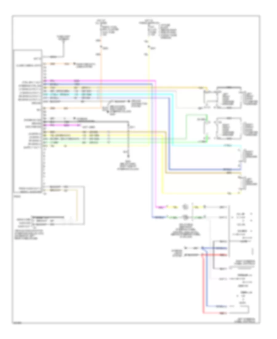
RADIO Radio Wiring Diagram for Buick Century Limited 2005 List of elements for Radio Wiring Diagram for Buick Century Limited 2005: 78 (not used) (or 1946) (or 1947) (or 1948) (or 1999) (or 511) (or 512) (or 546) (or 599) A c1 A10 A11 A12 Am/fm Amplifier sig Ant in Audio out Audio sig B c1 B(+) B10 B11 B12 Bare C1 a C2 a C2 b Class 2 serial data Coax Computer data lines system Ctrl sply volt Dimmer sw sig Drain wire Fixed mast antenna G203 (below dash, right side of steering column) Ground Ground distribution system Hot at all times Hot w/ parks lamps on I/p fuse block (behind right side of dash, in right door opening) Inflatable restraint steering wheel control module coil (behind steering wheel, in column) Int/ illum fuse 7.5a Interior lights system Left front door midrange speaker Left front door tweeter speaker Left rear speaker Left steering wheel controls Lf spkr output (+) Lf spkr output (-) Lr spkr (+) Lr spkr (-) Mute Nca Radio Radio audio out (-) Radio l audio sig Radio, hvac, rfa, cluster aldl fuse 15a Red Rf spkr (+) Rf spkr (-) Right front door midrange speaker Right front door tweeter speaker Right rear speaker Right steering wheel controls Rr spkr output (+) Rr spkr output (-) S202 S211 S241 Scan Seek dn Seek up Source Steering ctrl sig Tan Vehicle communication interface module (vcim) (on rear of left rear wheelhouse) Vol dn Vol up
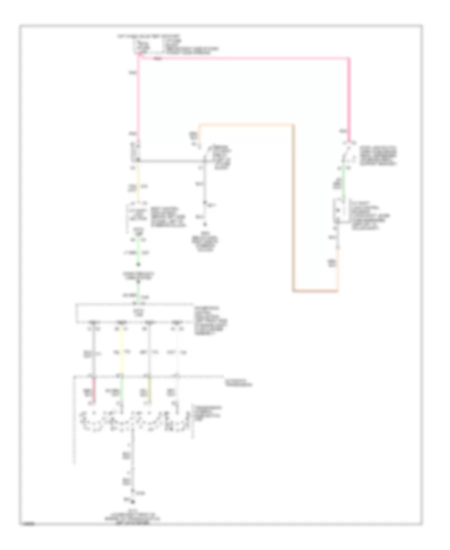
SHIFT INTERLOCK Shift Interlock Wiring Diagram for Buick Century Limited 2005 List of elements for Shift Interlock Wiring Diagram for Buick Century Limited 2005: 22 A/t shift lock control solenoid (locks shift lever when energized) (century: in column shift) A/t shift lock sol pwr Automatic transmission Body control module (bcm) (behind left side of dash, left of steering column) Brake to shift relay (left of i/p fuse block) Btsi fuse 10a Computer data lines system Data line G113 (lower right front of engine, on transaxle stud, left of starter) G203 (below dash, right side of steering column) Hot in run, bulb test or start I/p fuse block (behind right side of dash, in right door opening) Pnk Powertrain control module (pcm) (left front side of engine compt, in air cleaner assembly) S106 S211 Sig a Sig b Sig c Sig p Stop lamp switch (open when brake pedal depressed) (on brake pedal support bracket) Transmission internal mode switch (ims)
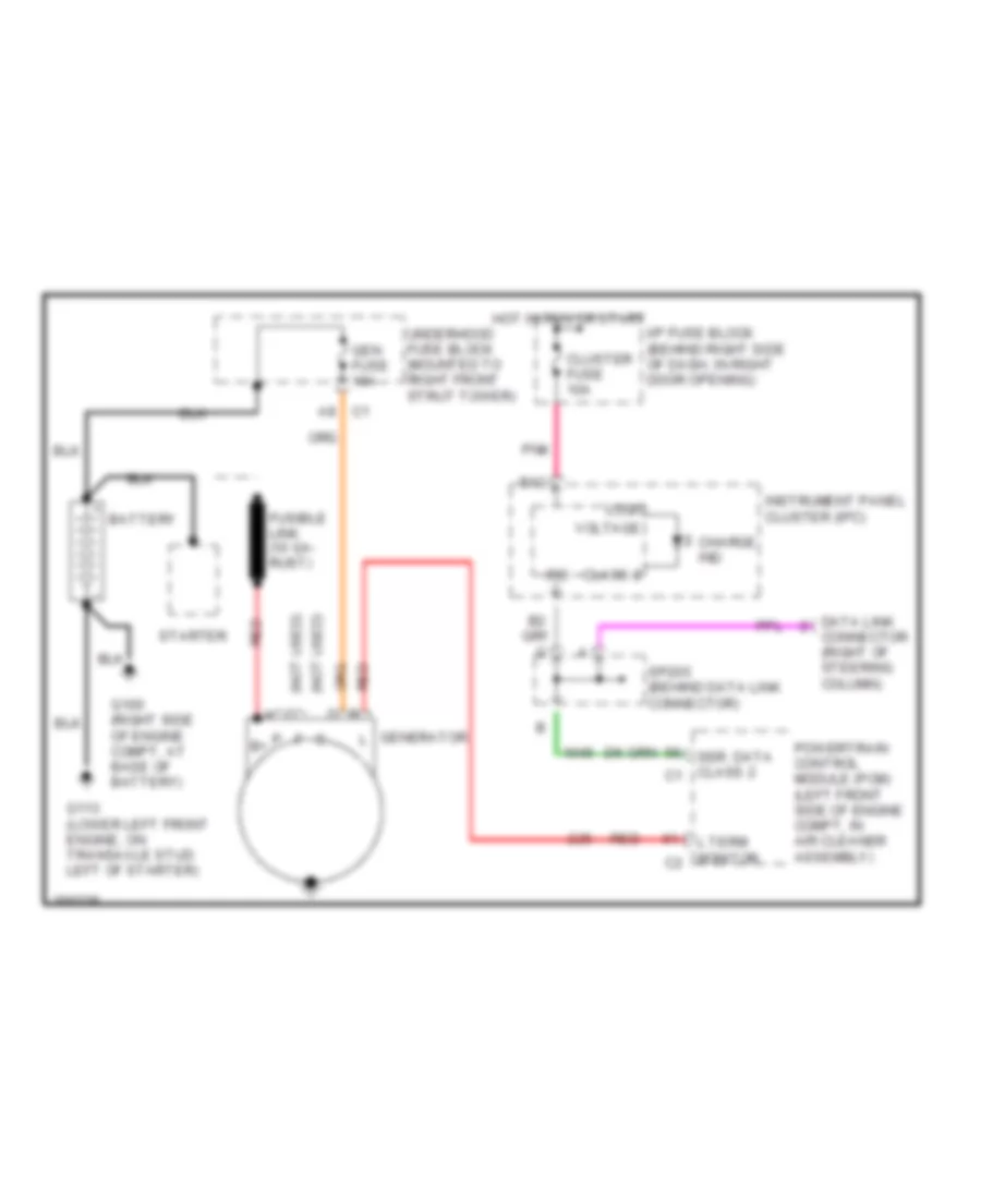
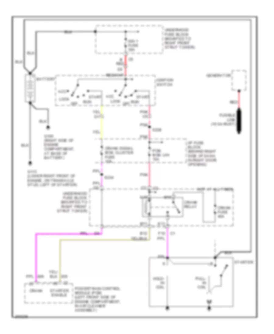
STARTING/CHARGING Charging Wiring Diagram for Buick Century Limited 2005 List of elements for Charging Wiring Diagram for Buick Century Limited 2005: 30 (not used) a (not used) c A8 c1 B12 Battery Charge ind Class 2 Cluster fuse 10a Connector (right of steering column) Data link Fusible link (10 ga- rust) G100 (right side of engine compt, at base of battery) G113 (lower left front engine, on transaxle stud left of starter) Gen fuse 10a Generator l Hot in run or start I/p fuse block (behind right side of dash, in right door opening) Instrument panel cluster (ipc) Ipc L term monitor c2 Logic P b+ Pnk Powertrain control module (pcm) (left front side of engine compt, in air cleaner assembly) Red Ser. data class 2 c1 Sp205 (behind data link connector) Starter Underhood fuse block (mounted to right front strut tower) Voltage Starting Wiring Diagram for Buick Century Limited 2005 List of elements for Starting Wiring Diagram for Buick Century Limited 2005: 37 Acc B red B12 Battery Crank Crank fuse 40a Crank relay Crank signal bcm, cluster fuse 1oa F10 Fusible link (10 ga-rust) G100 (right side of engine compartment, at base of battery) G113 (lower right front of engine, on transaxle stud, left of starter) Generator Hold- in coil Hot at all times I/p fuse block (behind right side of dash, in right door opening) Ign 1 fuse 30a Ignition switch K10 K11 Lock M10 M11 Off Pcm, bcm, u/h 10a Pnk Powertrain control module (pcm) (left front side of engine compartment, in air cleaner assembly) Pull- in coil Red Run Run off S228 S234 Start Starter Starter enable Underhood fuse block (mounted to right front strut tower)
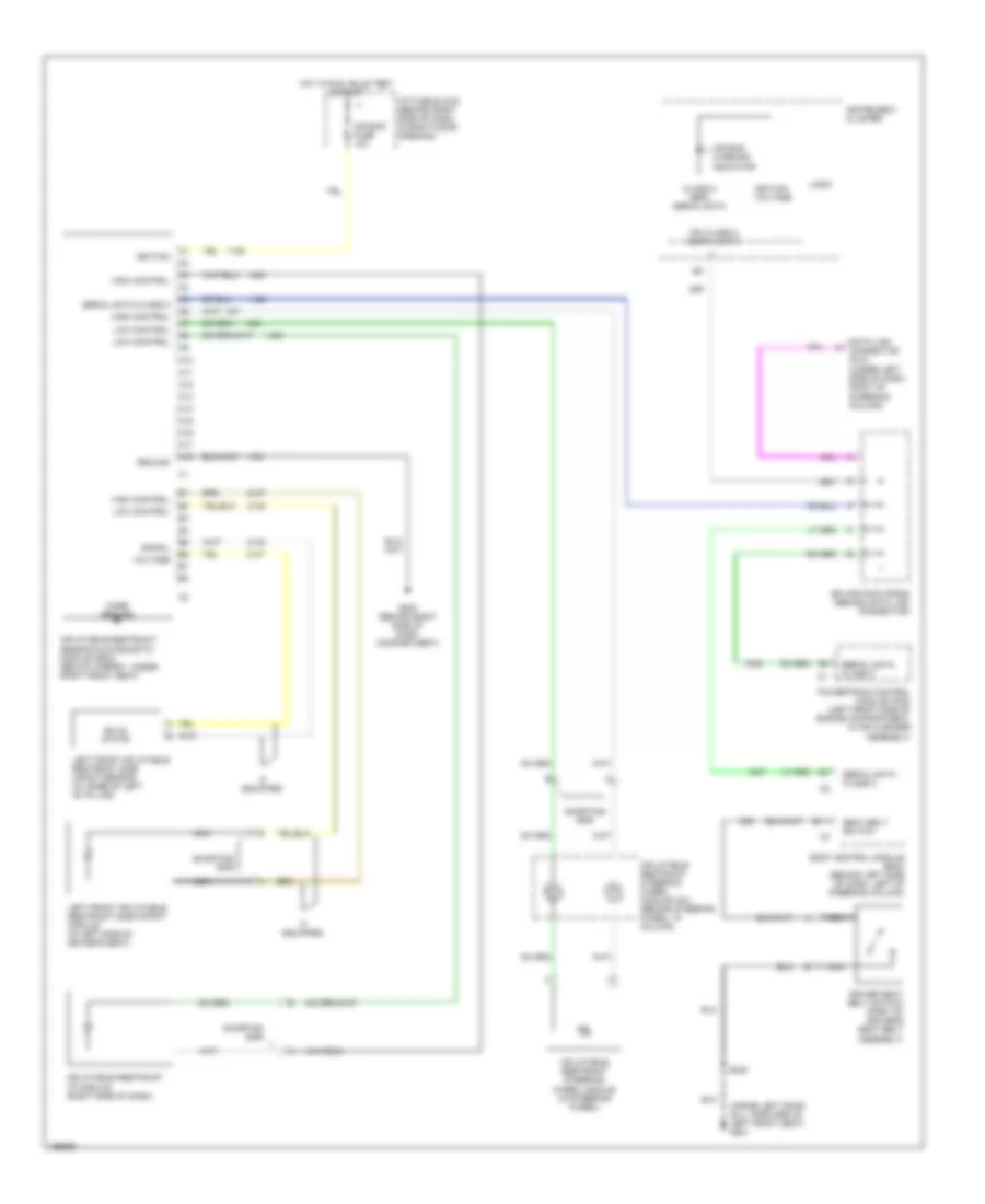
SUPPLEMENTAL RESTRAINTS Supplemental Restraints Wiring Diagram for Buick Century Limited 2005 List of elements for Supplemental Restraints Wiring Diagram for Buick Century Limited 2005: 46 (inside left door sill, forward of left front seat) g301 A10 A11 A12 A13 A14 A15 A16 A17 A18 Air bag fuse 10a Air bag warning indicator B11 Body control module (bcm) (behind left side of dash, left of steering column) Case ground Class 2 (sdm) serial data Data link connector (dlc) (under left side of dash, right of steering column) Driver seat belt switch (part of driver's seat belt assembly) G200 (behind right side of dash compartment) Ground High control Hot in run, bulb test & start I/p fuse block (behind right side of dash, in right door opening) If equipped Ignition Ignition voltage Inflatable restraint i/p module (right side of dash) Inflatable restraint sensing & diagnostic module (sdm) (below carpet, under right front seat) Inflatable restraint steering wheel module (in steering wheel) Inflatable restraint steering wheel module coil (behind steering wheel, in column) Instrument cluster Ipc class 2 serial data Left front inflatable restraint side impact module (in left side of driver's seat) Left front inflatable restraint side impact sensor (at base of left "b" pillar) Logic Low control Nca Powertrain control module (pcm) (left front side of engine compartment, in air cleaner assembly) S330 Seat belt switch Serial data class 2 Shorting bar Signal Solid state Splice pack sp205 (behind data link connector) Voltage
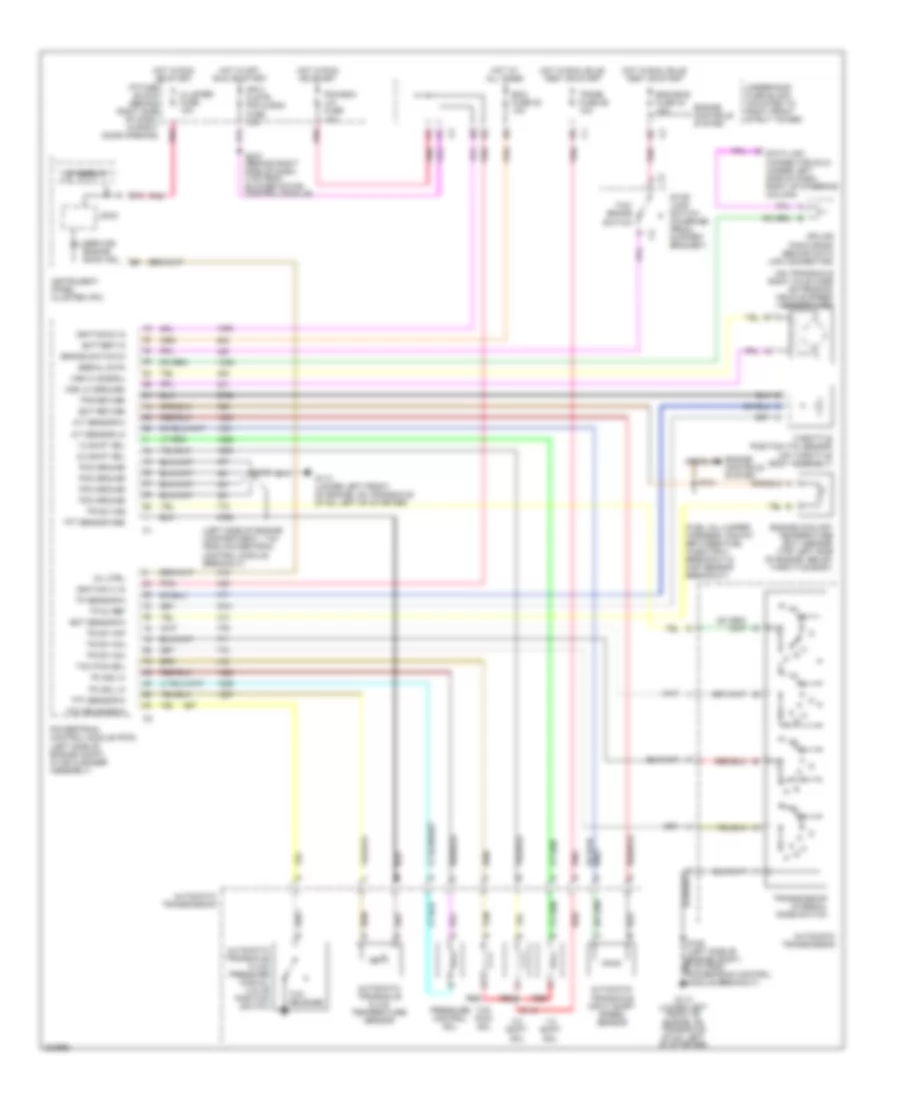
TRANSMISSION A/T Wiring Diagram for Buick Century Limited 2005 List of elements for A/T Wiring Diagram for Buick Century Limited 2005: 72 (fuel inj jumper harness, midway between fuel injector 3 breakout & map sensor breakout) (left side of engine compartment, 7 cm from powertrain control module breakout) (on transaxle right axle case extension) vehicle speed sensor (vss) 1-2 shift sol 2-3 shift sol A/t sensor hi A/t sensor lo Automatic transaxle fluid pressure manual valve position switch Automatic transaxle fluid temperature sensor Automatic transaxle input shaft speed sensor Automatic transmission B12 Battery in Brake switch in C2 c Cluster fuse 10a Data link connector (dlc) (under left side of dash, right of steering column) Ecm fuse 22 10a Ect return Ect sensor in Eng emis fuse 30 10a Engine controls system Engine coolant temperature (ect) sensor (top left side of engine, below throttle body) G113 (lower left front of engine, on transaxle stud, left of starter) Hot at all times Hot in off, run or start Hot in run or start Hot in run, bulb test or start I/p fuse block (behind right side of dash, in right door opening) Ign 0 clstr, pcm & bcm fuse 10a Ignition (0) in Ignition (1) in Instrument panel cluster (ipc) Logic Mil ctrl P r n Pc sol hi Pc sol lo Pcm ground Pcm-bcm u/h fuse 10a Pnk Powertrain control module (pcm) (left side of engine compt, in air cleaner assembly) Pressure control sol Red S115 S121 S270 (behind right side of dash, 4 cm from blower motor control module) Serial data Service engine soon ind Splice pack sp205 (behind data link connector) Stop lamp switch (on brake pedal support bracket) Tan Tcc pwm sol Tcc release Tcc release in Tcc/ brake switch Tft sensor gnd Tft sensor in Throttle position (tp) sensor (on throttle body assembly) Tp 5v ref Tp sensor in Tps return Tr sw in-a Tr sw in-b Tr sw in-c Tr sw in-p Trans fuse 26 10a Transmission internal mode switch Underhood fuse block (mounted to right front strut tower) Vf display Vss hi (signal) Vss lo (ground)
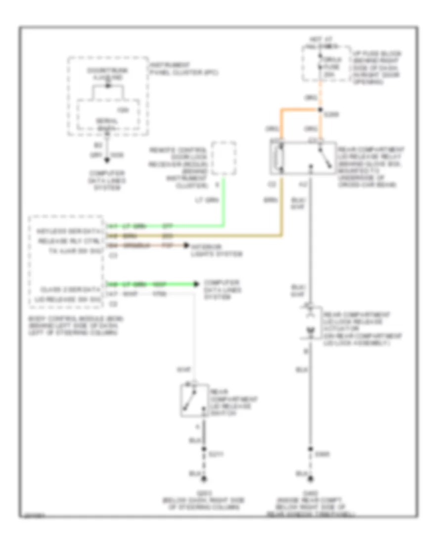
TRUNK, TAILGATE, FUEL DOOR Trunk Release Wiring Diagram for Buick Century Limited 2005 List of elements for Trunk Release Wiring Diagram for Buick Century Limited 2005: 24 Body control module (bcm) (behind left side of dash, left of steering column) Class 2 ser data Computer data lines system Door/trunk ajar ind Dr/lk fuse 20a G203 (below dash, right side of steering column) G402 (inside rear compt, below right side of rear window trim panel) Hot at all times I/p fuse block (behind right side of dash, in right door opening) Ign Instrument panel cluster (ipc) Interior lights system Keyless ser data Lid release sw sig Rear compartment lid lock release actuator (on rear compartment lid lock assembly) Rear compartment lid release relay (behind glove box, mounted to underside of cross-car beam) Rear compartment lid release switch Release rly ctrl Remote control door lock receiver (rcdlr) (behind instrument cluster) S211 S269 S905 Serial data Tk ajar sw sig
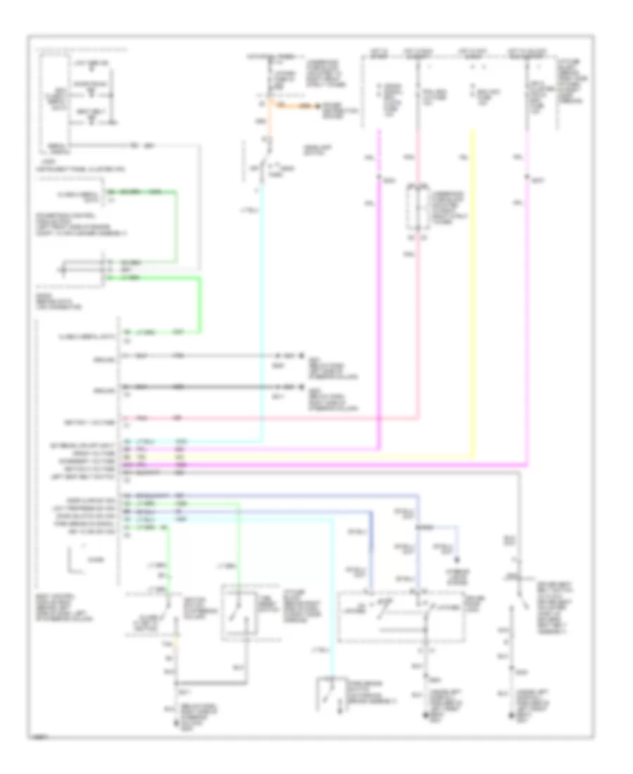
WARNING SYSTEMS Warning Systems Wiring Diagram for Buick Century Limited 2005 List of elements for Warning Systems Wiring Diagram for Buick Century Limited 2005: 67 door ajar sw sig (below dash, right side of steering column) g203 (close w/ key in ignition) (inside left door sill, forward of left front seat) g301 Accessory voltage Ajar B10 B11 Bcm acc fuse 10a Bcm class 2 serial data Body control module (bcm) (behind left side of dash, left of steering column) Chime Class 2 serial data Crank signal, bcm clstr fuse 10a Crank voltage Door unlatch sw sig Door/trunk ind Driver door lock Driver seat belt switch (w/ 6 way driver seat adjuster) (part of driver's seat belt assembly) Exterior lps off input G201 (below dash, left side of steering column) G203 (below dash, right side of steering column) Ground Head Headlamp switch Hot at all times Hot in acc & run Hot in run & start Hot in start Hot in unlock run & start I/p fuse block (behind right side of dash, in right door opening) Ign o, cluster, pcm & bcm fuse 10a Ignition 0 voltage Ignition 1 voltage Ignition switch (in steering column) Instrument panel cluster (ipc) Interior lights system Key in ign sw sig Latched Left seat belt switch Logic Low tire ind Low tire press sw sig Lp park fuse 34 20a Nca Off Park Park brake on signal Park brake switch (on parking brake assembly) Pcm, bcm u/h fuse 10a Pnk Power distribution system Powertrain control module (pcm) (left front side of engine compt, in air cleaner assembly) S211 S234 S270 S283 S322 S330 S504 Seat belt ind Serial data Sp205 (behind data link connector) Tan Tire reset switch Un- latched Underhood fuse block (mounted to right front strut tower)
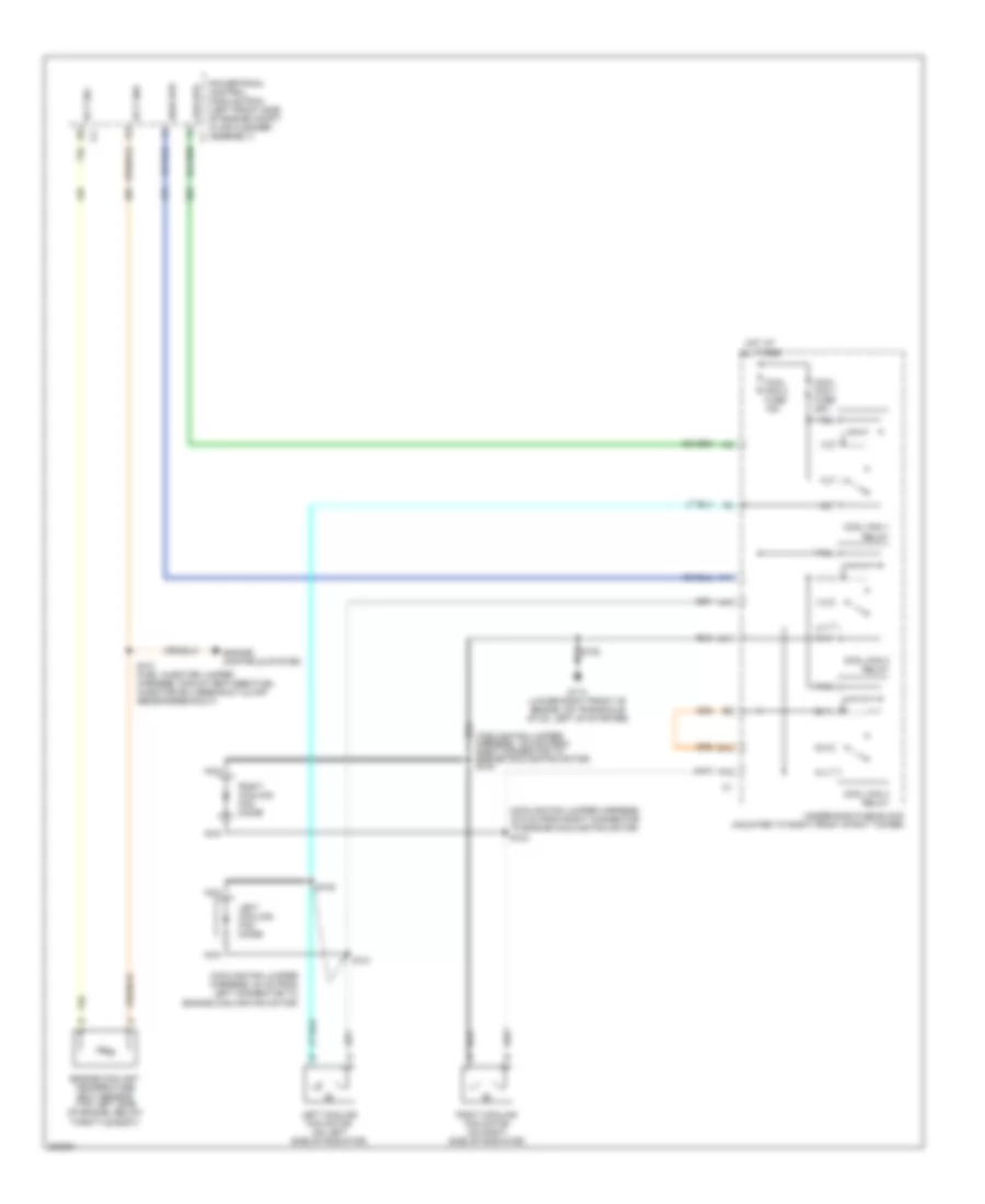
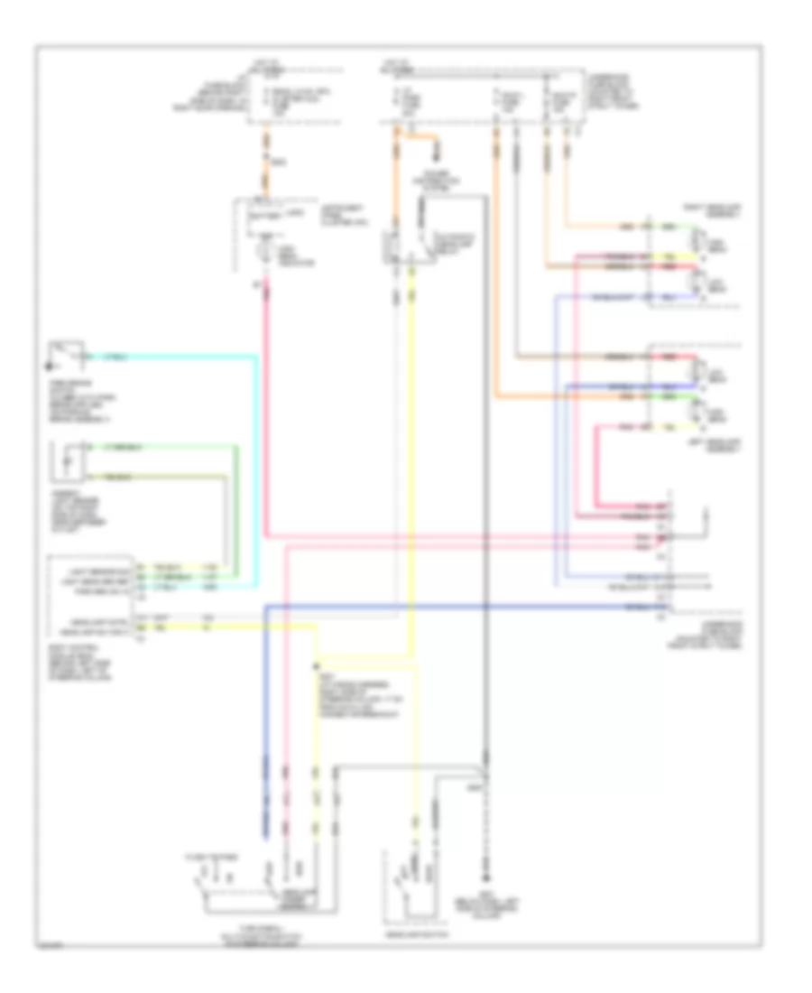
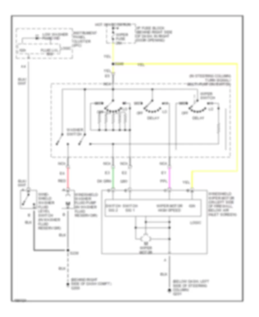
WIPER/WASHER Wiper/Washer Wiring Diagram for Buick Century Limited 2005 List of elements for Wiper/Washer Wiring Diagram for Buick Century Limited 2005: 27 (behind right side of dash compt) g200 (below dash, left side of steering column) g201 (in steering column) turn signal/ multi-funtion switch Delay Fluid lvl sig Hot in acc or run I/p fuse block (behind right side of dash, in right door opening) Ign Instrument panel cluster (ipc) Logic Low washer fluid ind Mist Nca Off Red S230 S249 Switch sig 1 Switch sig 2 Washer switch Wind- shield washer fluid level switch (in washer fluid reservoir) Windshield washer fluid pump (in washer fluid reservoir) Windshield wiper motor (on left side of firewall, below air inlet screen) Wiper fuse 25a Wiper motor Wiper motor high speed Wiper switch