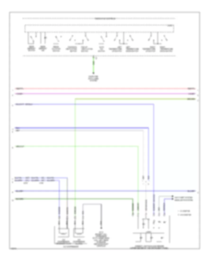
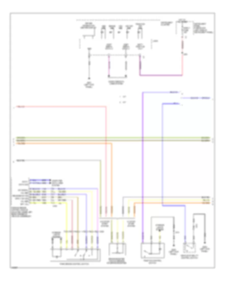
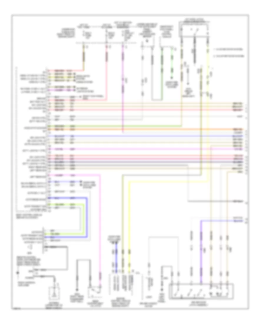
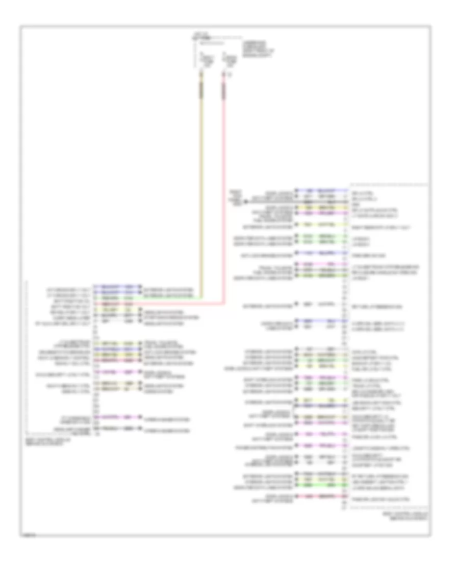
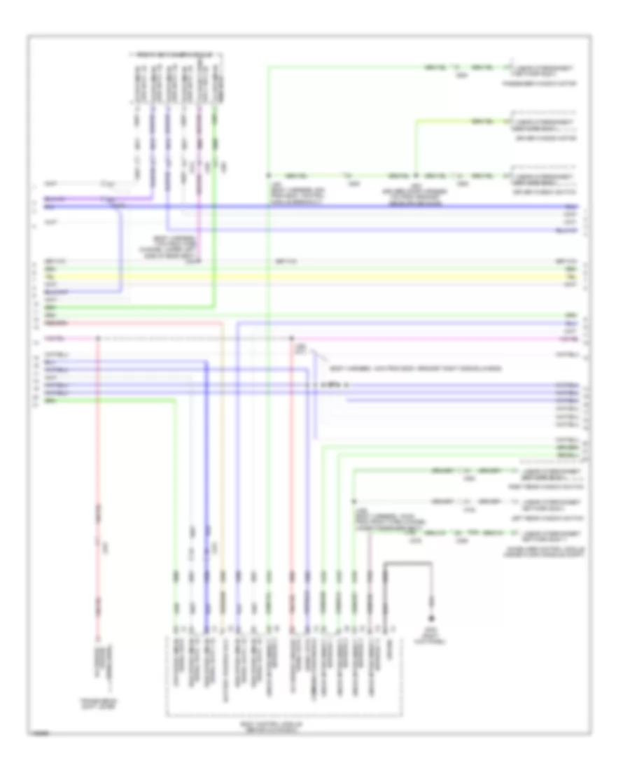
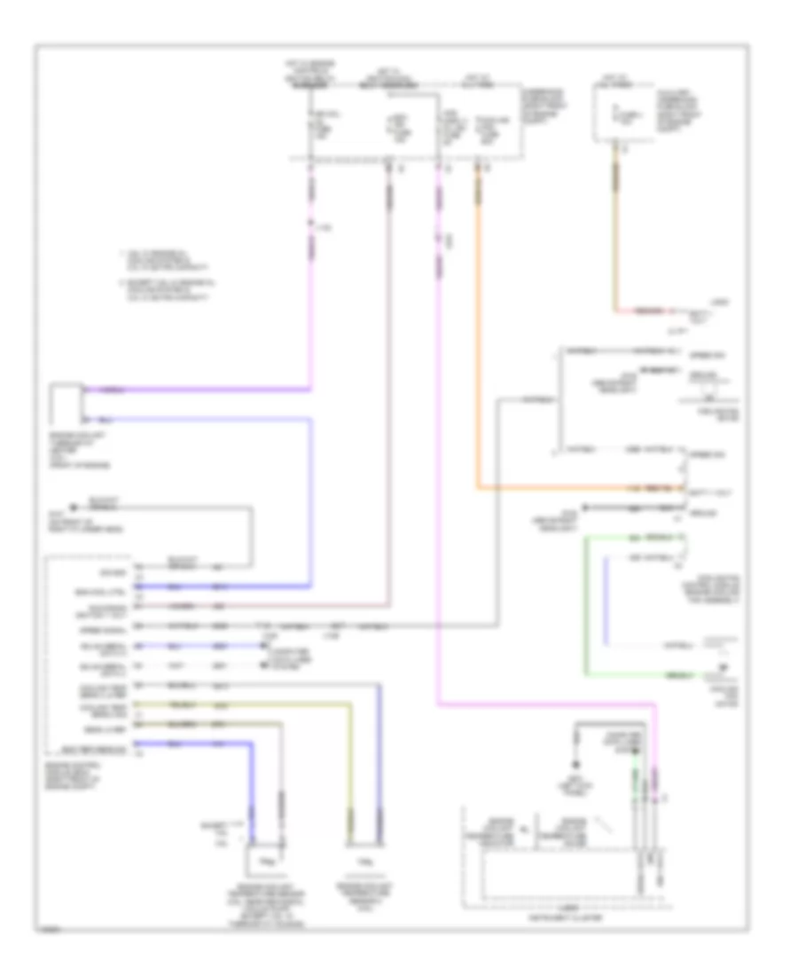
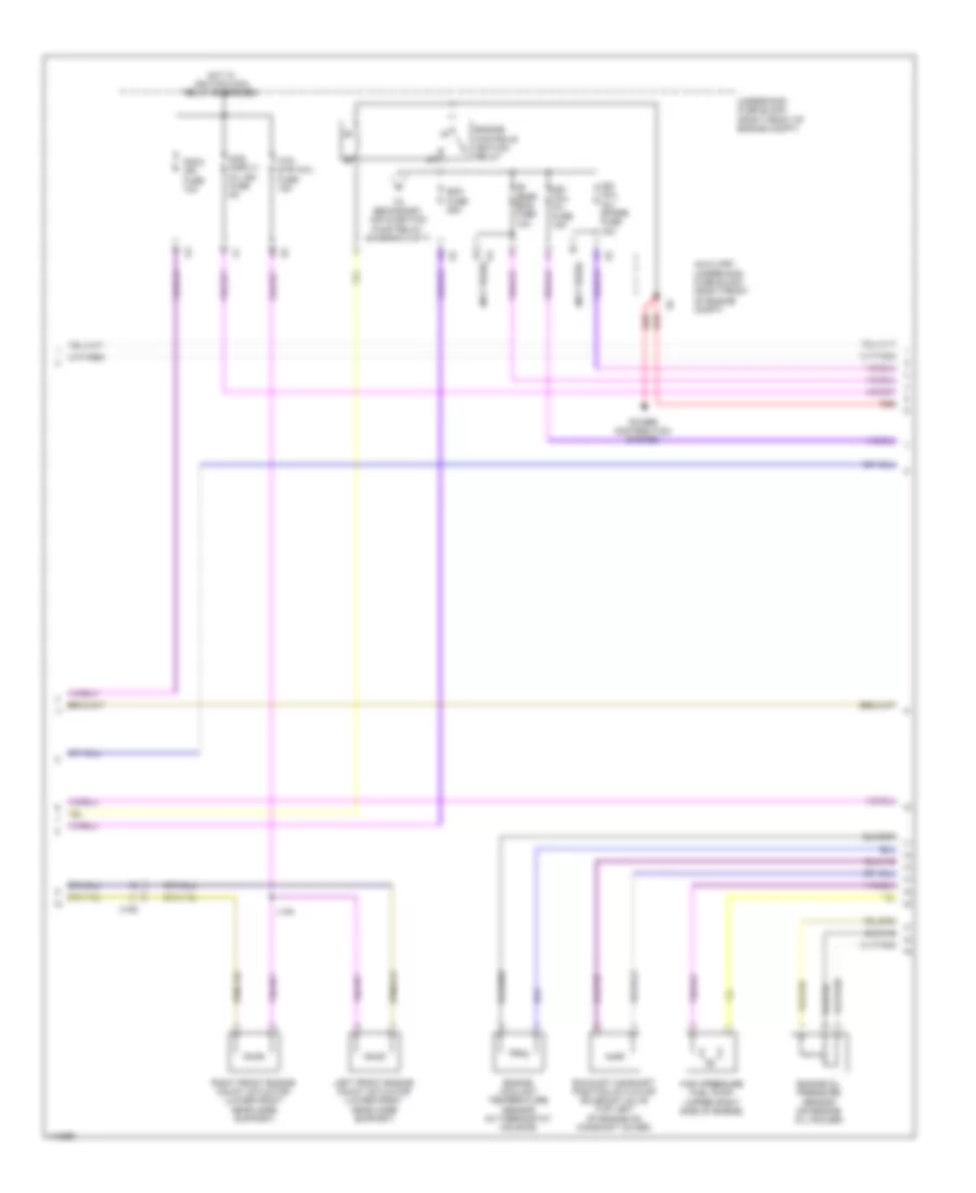
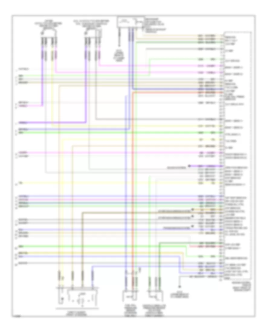
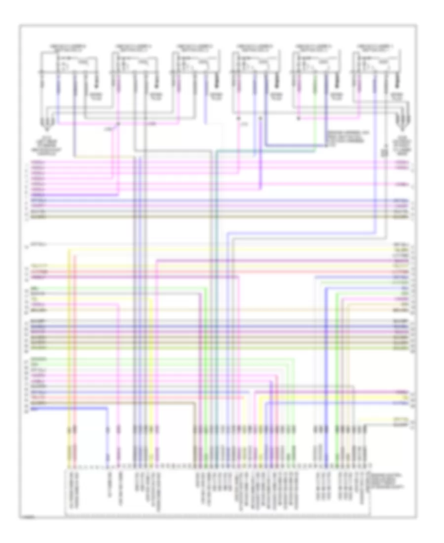
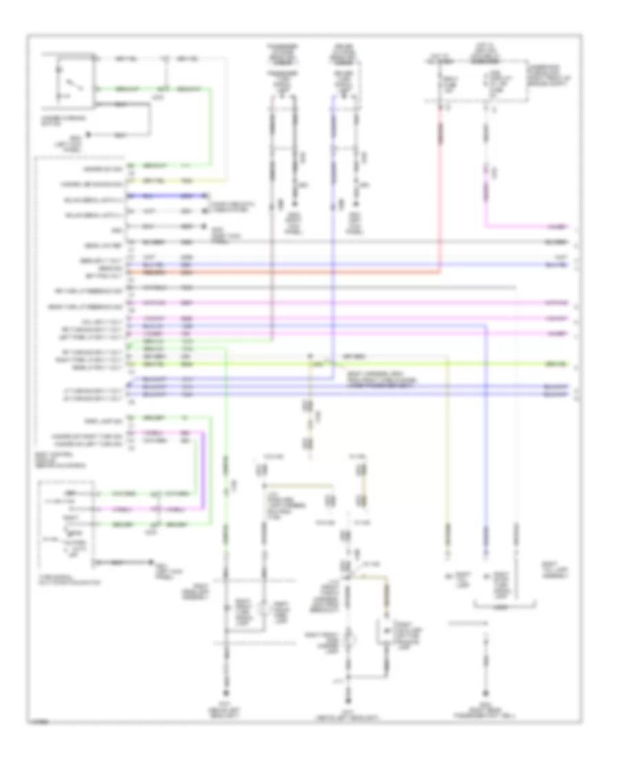
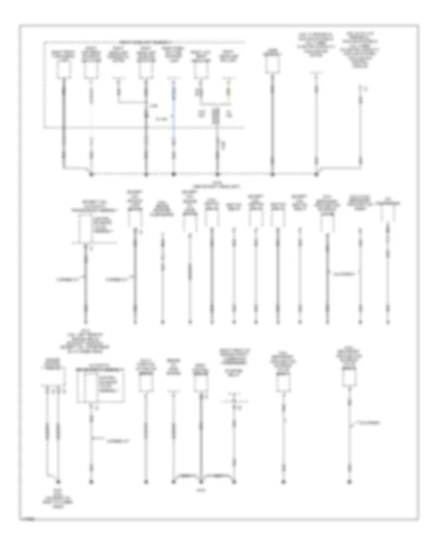
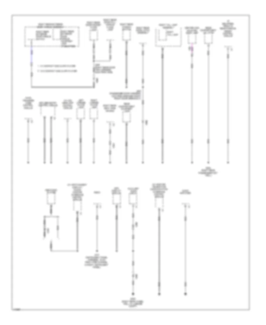
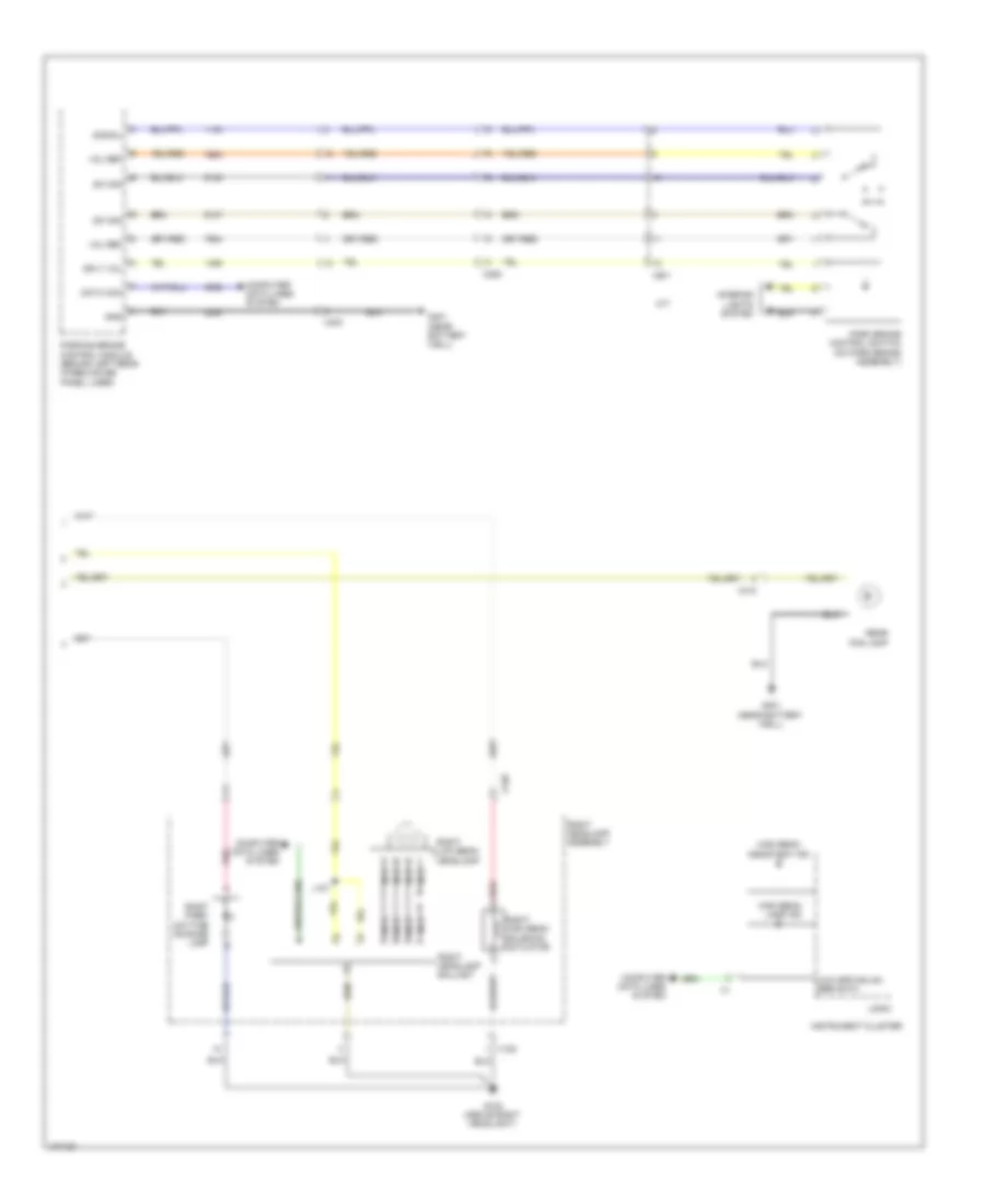
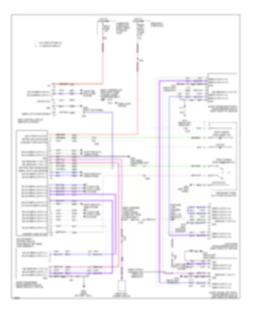
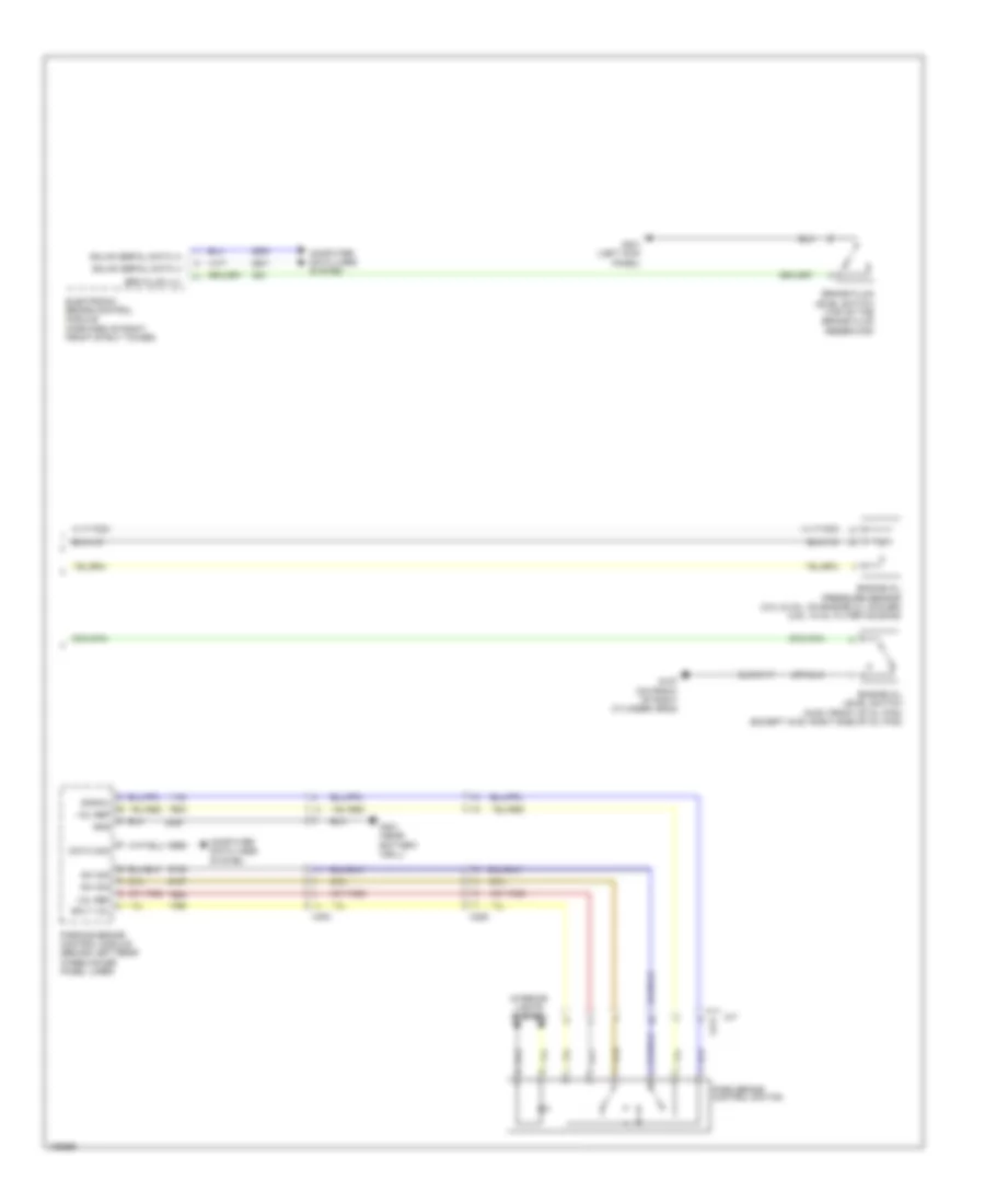
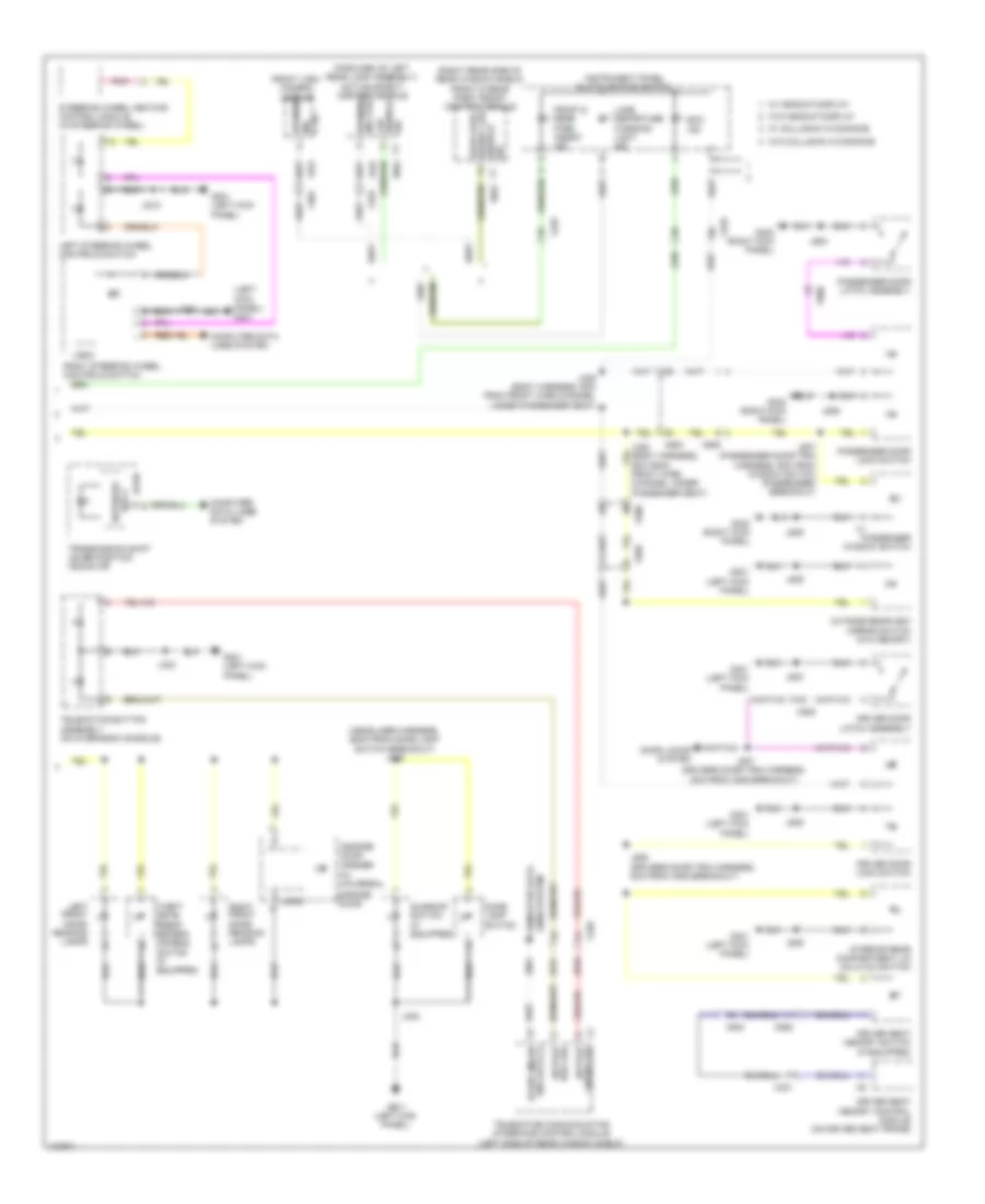
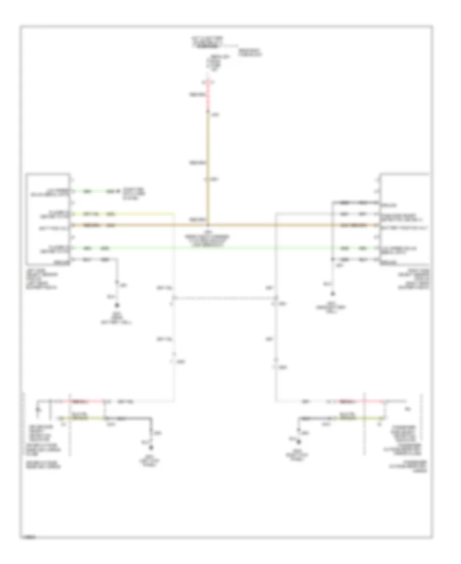
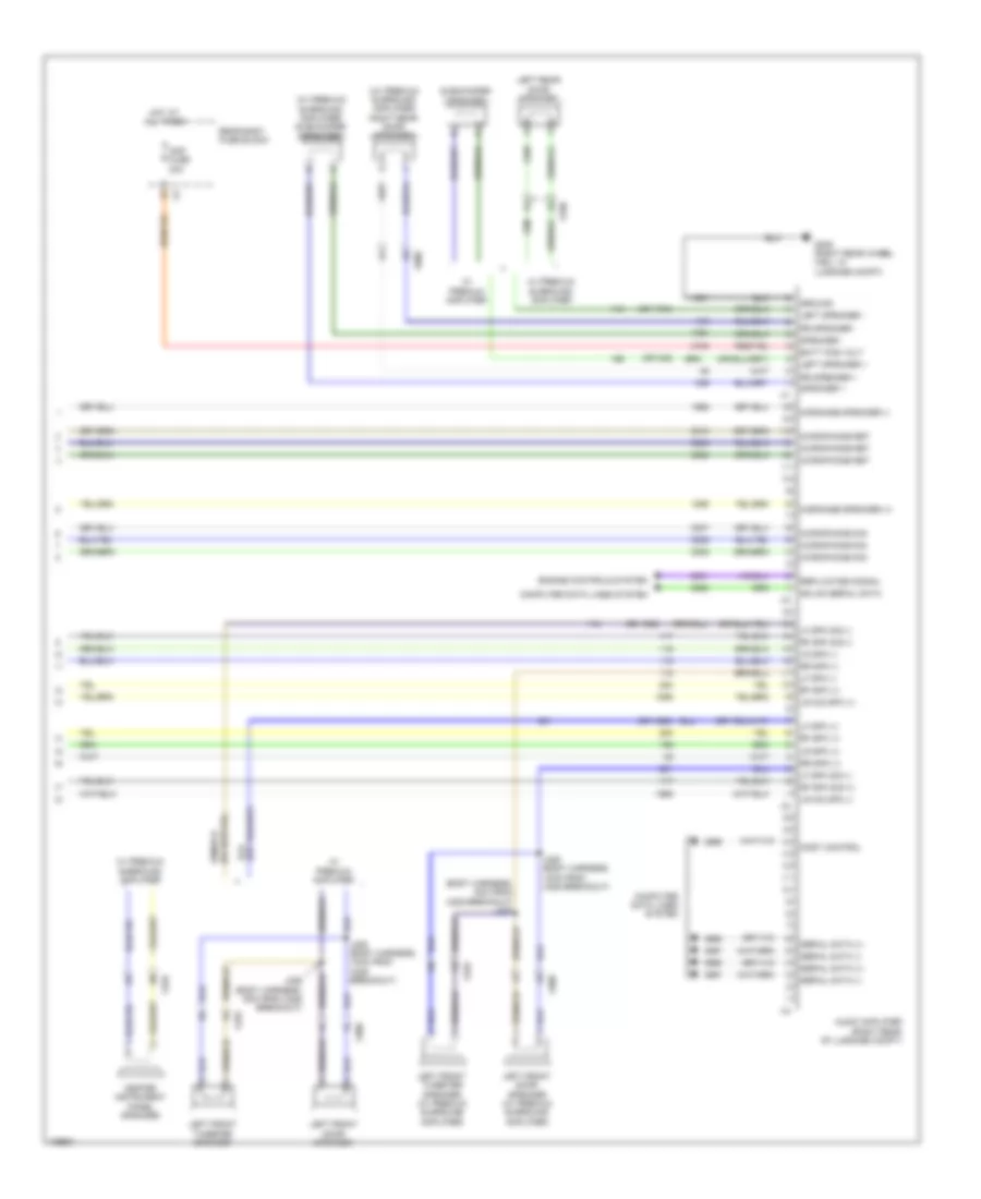
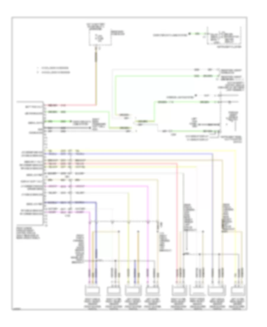
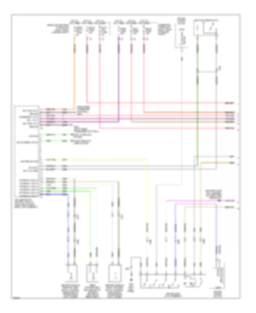
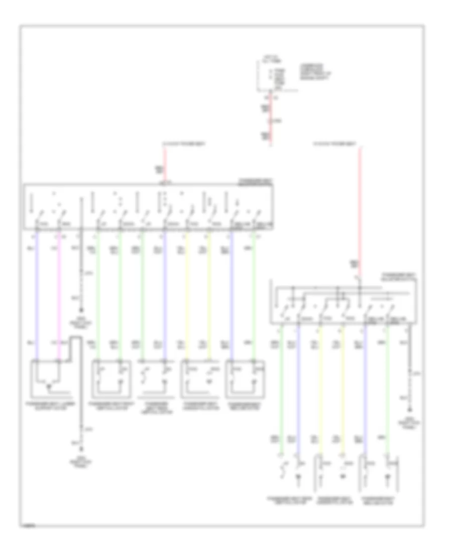
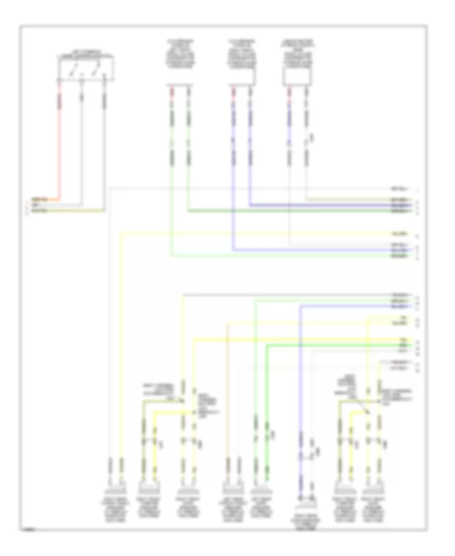
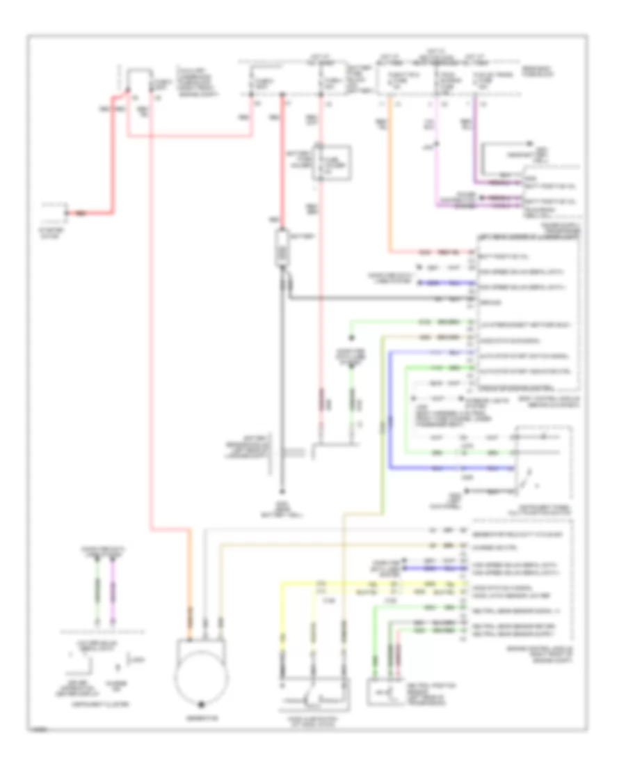
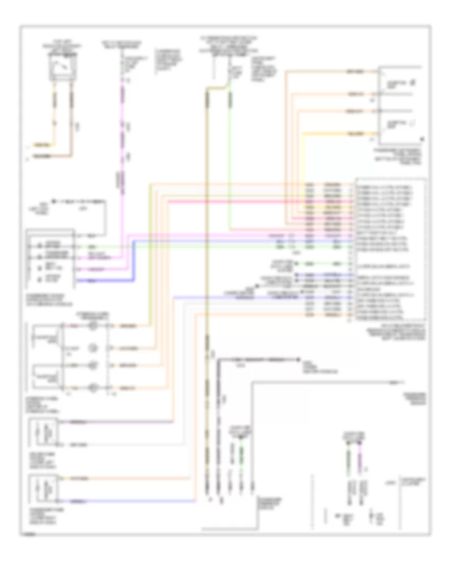
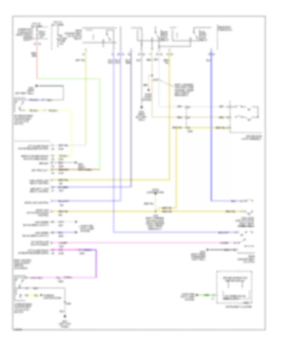
AIR CONDITIONING
Automatic A/C Wiring Diagram (1 of 4) for Cadillac ATS 2013

List of elements for Automatic A/C Wiring Diagram (1 of 4) for Cadillac ATS 2013:
- (awd)
- (left kick panel) g202
- (w/ pedestrian protection) hot w/ battery saver relay 1 energized (w/o pedestrian protection) hot at all times
- 5-volt ref
- Aos disply/ mil ign fuse 5a
- Battery positive voltage
- Blower mtr spd ctrl
- Computer data lines system
- Defogger system
- Electric variable displacement ctrl
- Electric variable displacement sply
- Frt hvac blwr fuse 40a
- Gnd
- Hot at all times
- Hot w/ ignition main relay energized
- Humidity sens sig
- Humidity temp sens sig
- Hvac cntrl fuse 15a
- Hvac control module (near right kick panel)
- Inside air temp sens sig
- Instrument panel fuse block (left side of instrument panel)
- Ip body ign fuse 10a
- J207
- Linear interconnect network bus 9
- Logic
- Low speed gmlan serial data
- Rdo/ hvac fuse 15a
- Rear defog rly ctrl
- Run/crank ignition 1 volt
- Solar sens combined sig
- Solar sens drv sig
- Solar sens low ref
- Solar sens pulsed sply volt
- Temp sens low ref
- Underhood fuse block (right front of engine compt)
- W/ headup display
- W/ start stop system
- W/o headup display
- W/o start stop system
- Windscreen temp sens sig
- Windshield temperature & inside moisture sensor (w/o air moisture & windshield temperature sensor) (center top of windshield)
- X275
- X301
- X305
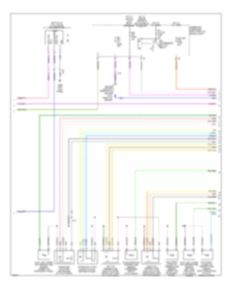
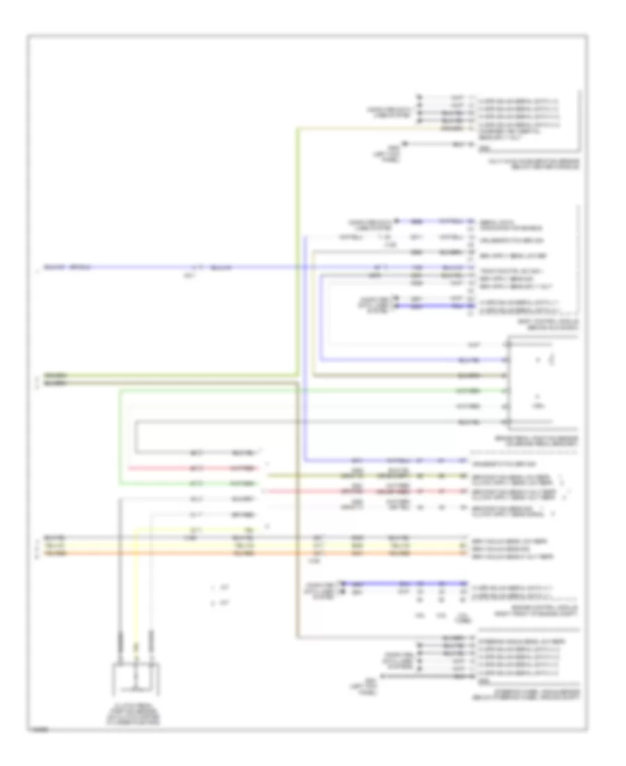
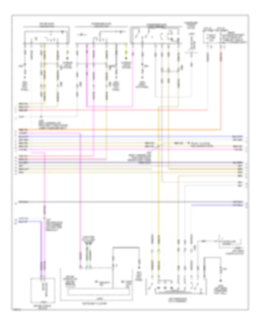
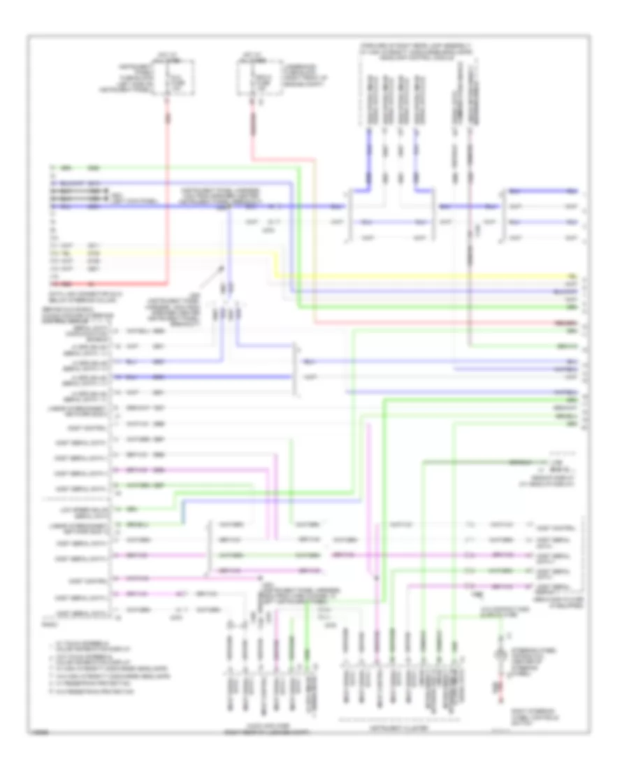
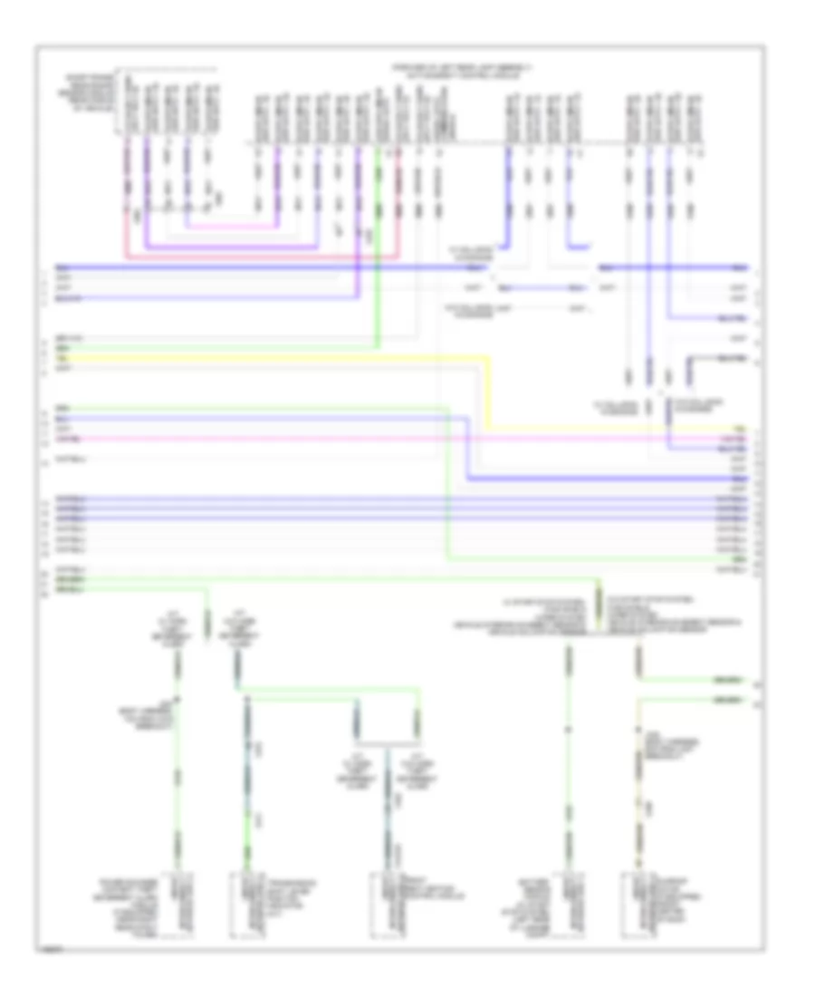
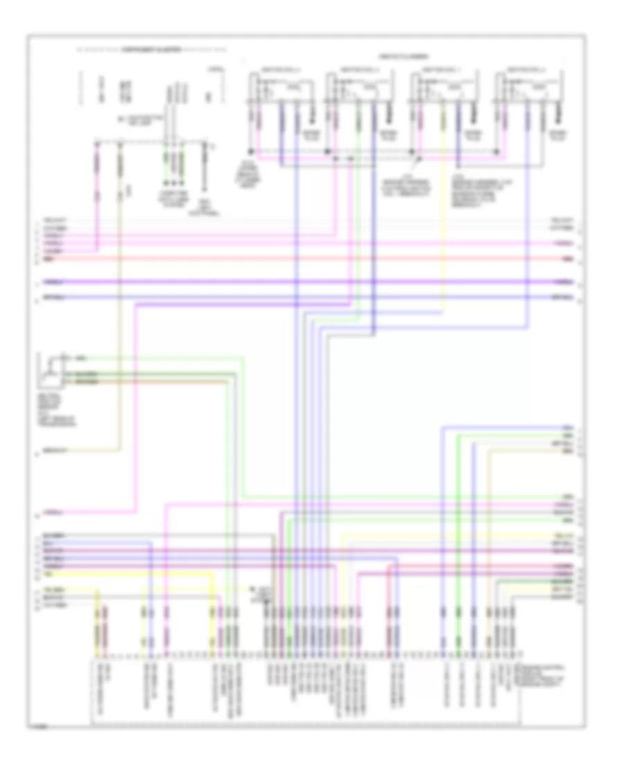
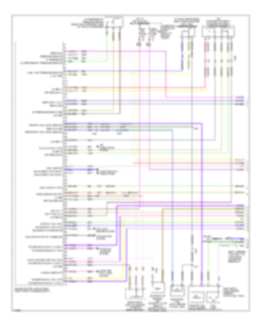
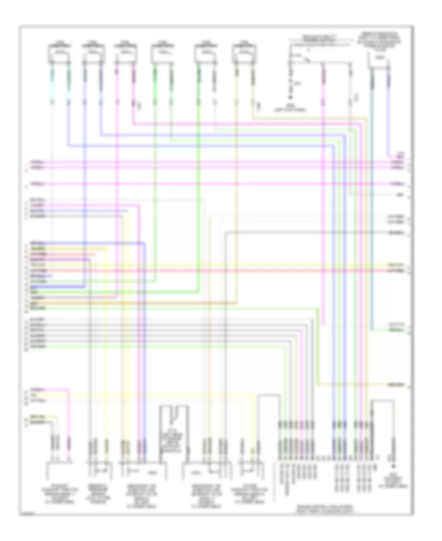
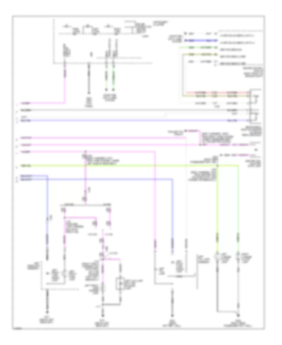
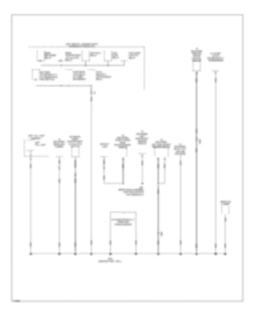
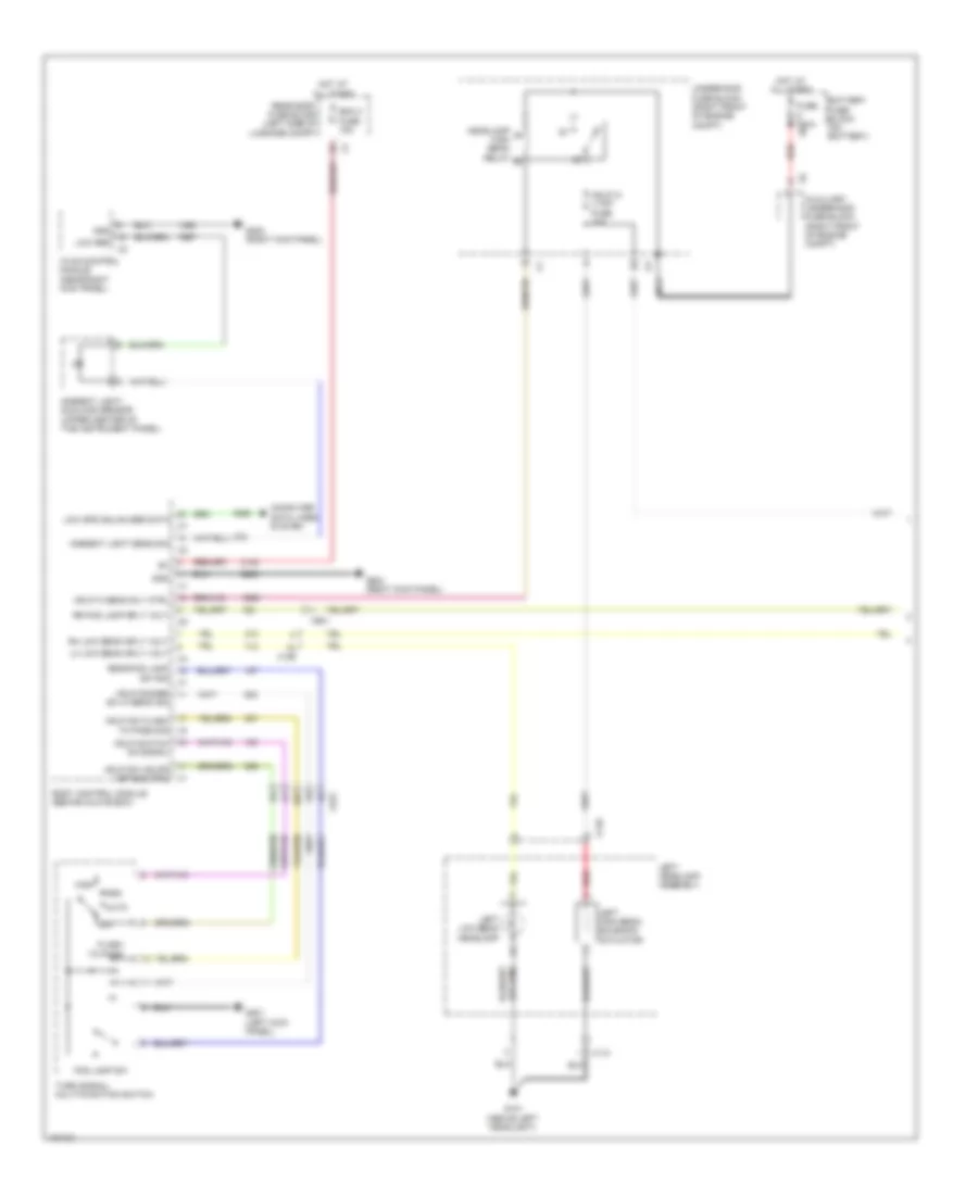
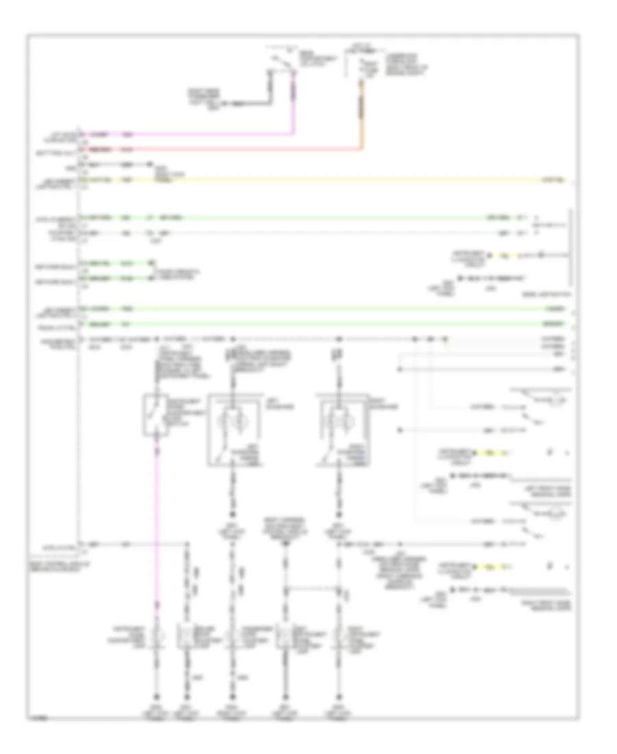
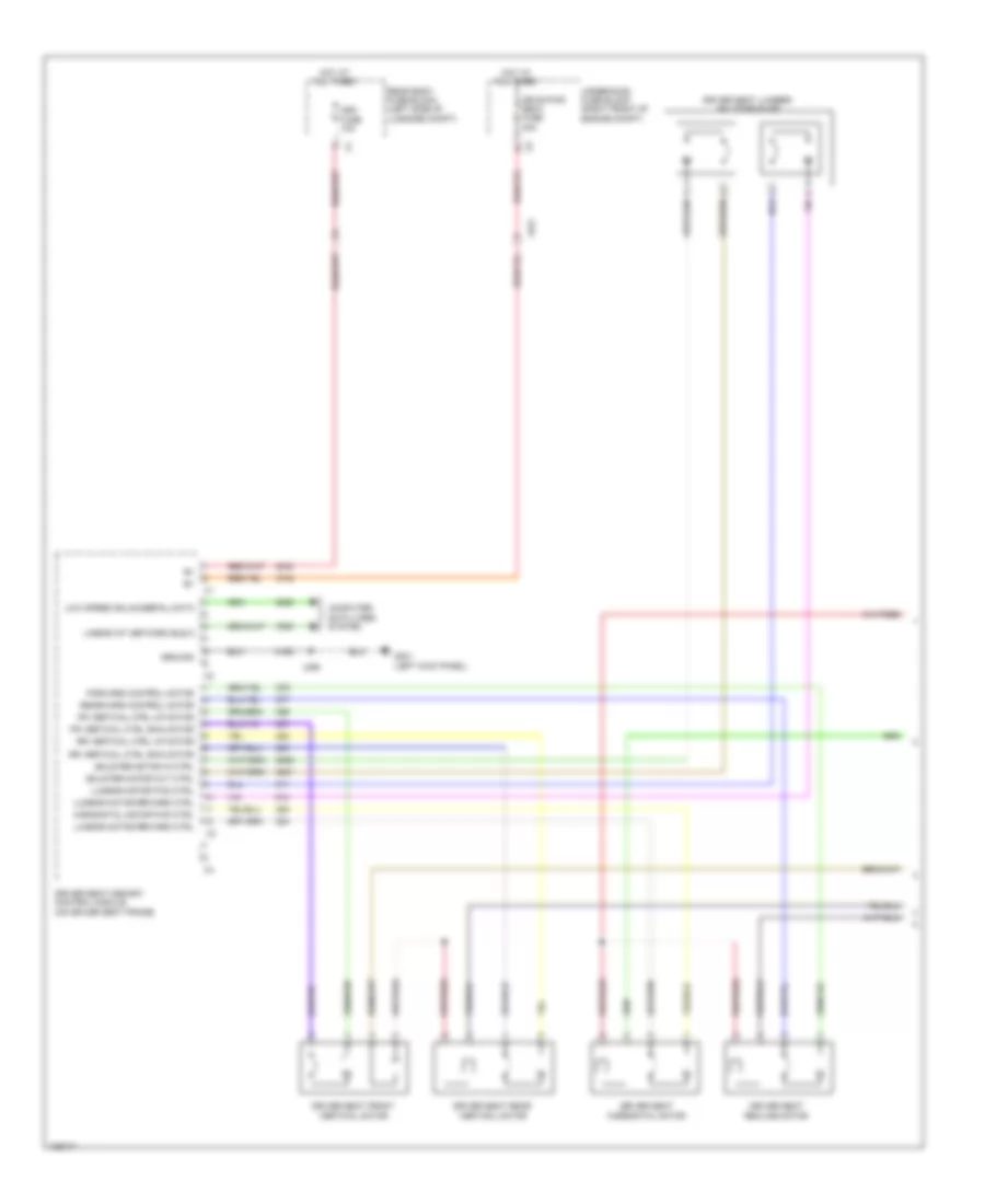
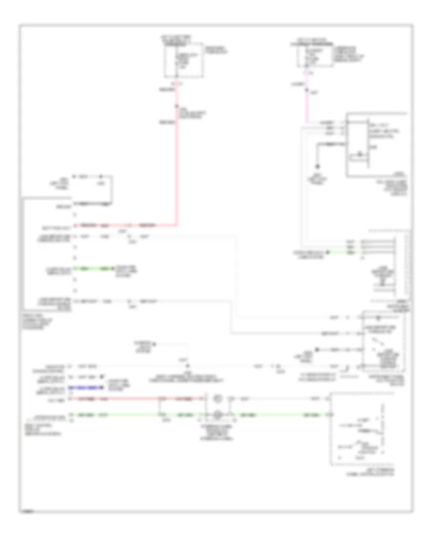
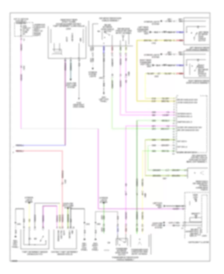
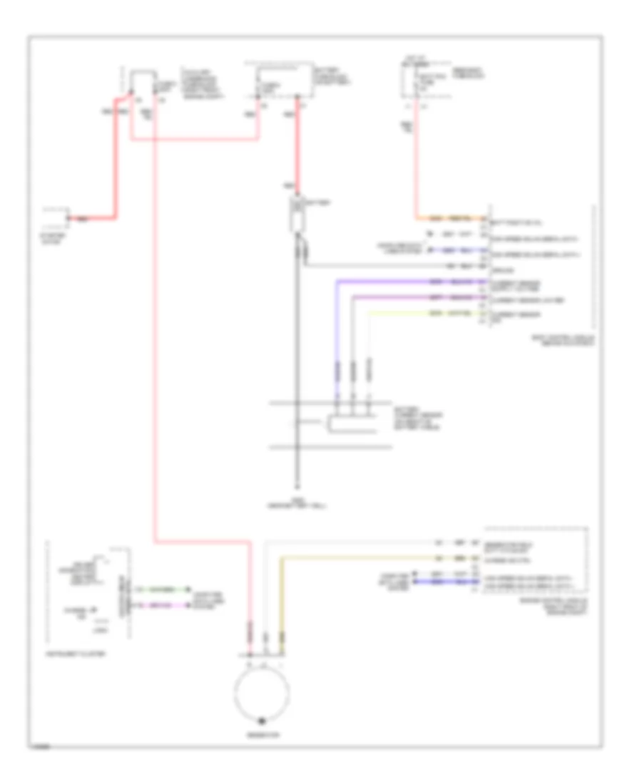
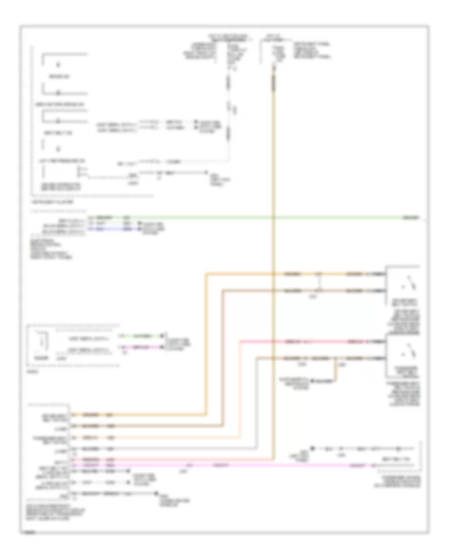
Automatic A/C Wiring Diagram (2 of 4) for Cadillac ATS 2013
List of elements for Automatic A/C Wiring Diagram (2 of 4) for Cadillac ATS 2013:
- A/c compressor
- A/c compressor clutch
- A/c compressor solenoid valve
- Ambient light/sunload sensor (upper center of the instrument panel)
- Anti-theft system
- Auto a/c switch
- Computer data lines system
- Fan down ventilating switch
- Fan up ventilating switch
- G110 (except 3.6l: upper rear of cylinder head) (3.6l: left rear of engine above exhaust manifold)
- Headlights system
- Left temperature down switch
- Left temperature up switch
- Logic
- Nca
- Radio/hvac controls
- Rear defrost ind
- Rear defrost switch
- Recir- culation switch
- Right temperature down switch
- Right temperature up switch
- W/ onstar
- W/o onstar
- X150
- X275
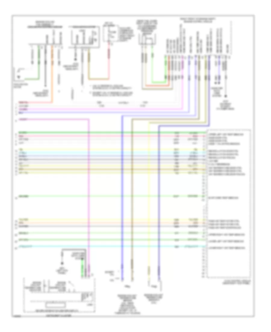
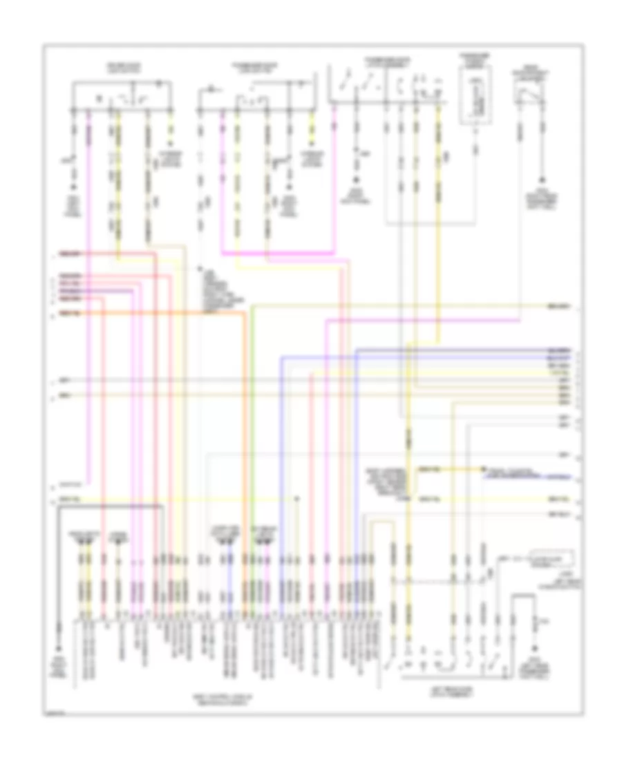
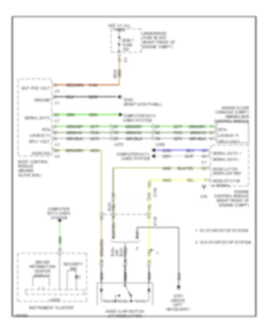
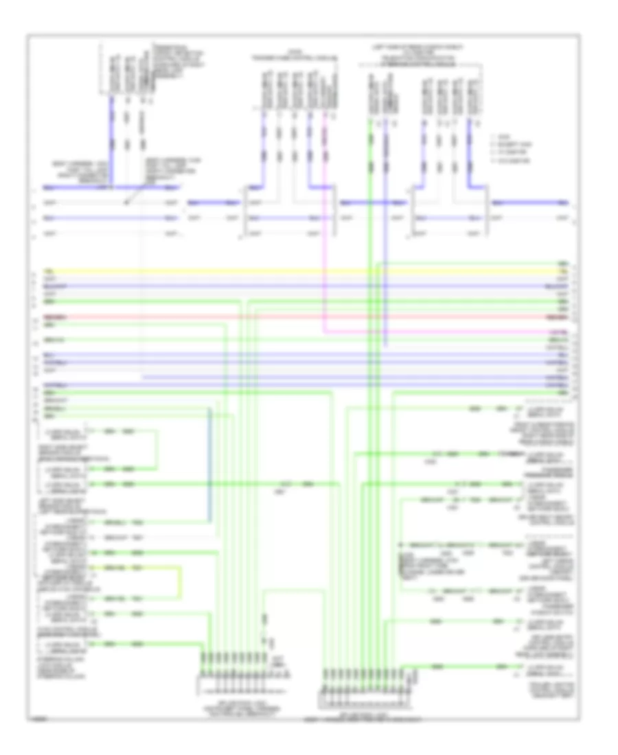
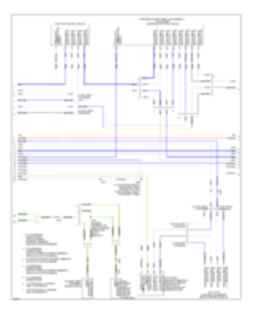
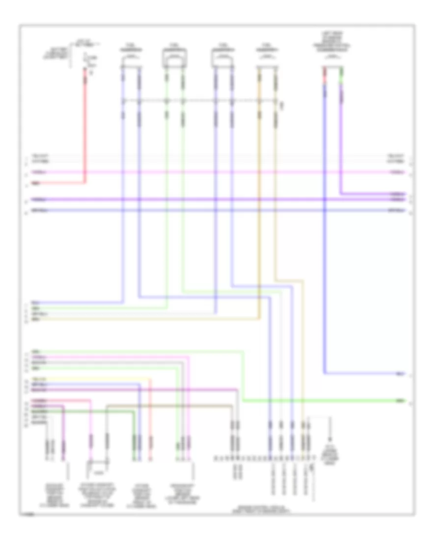
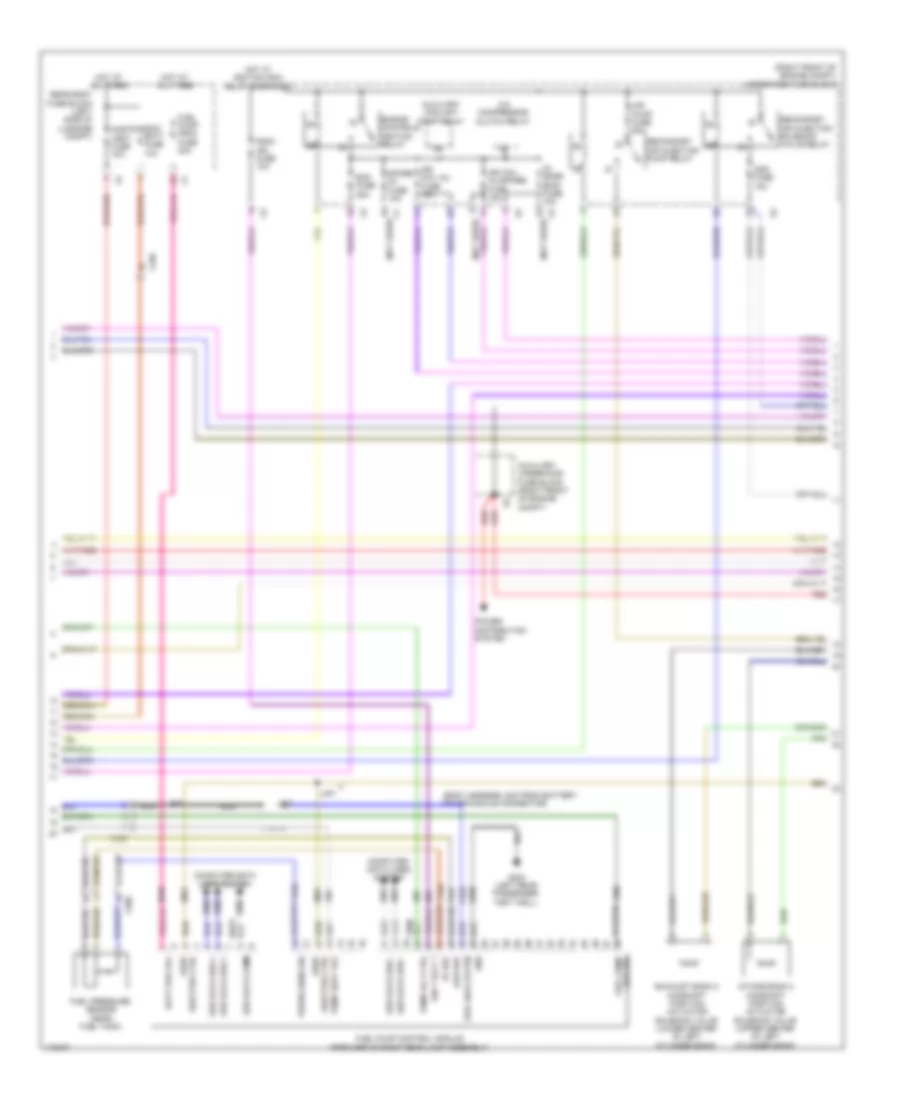
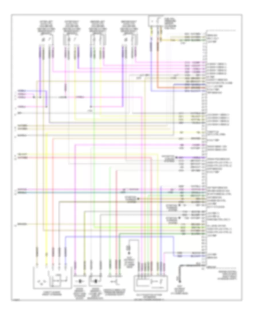
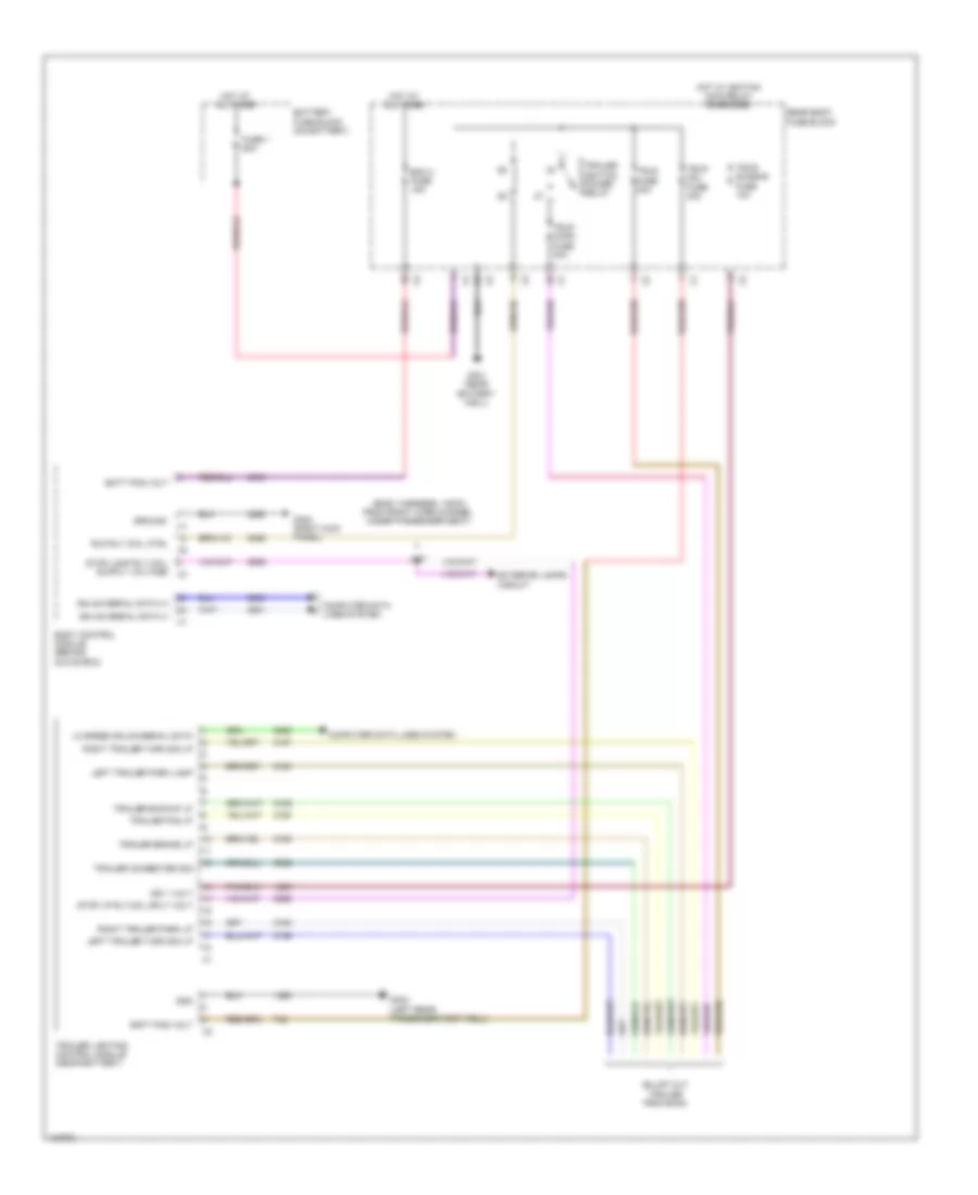
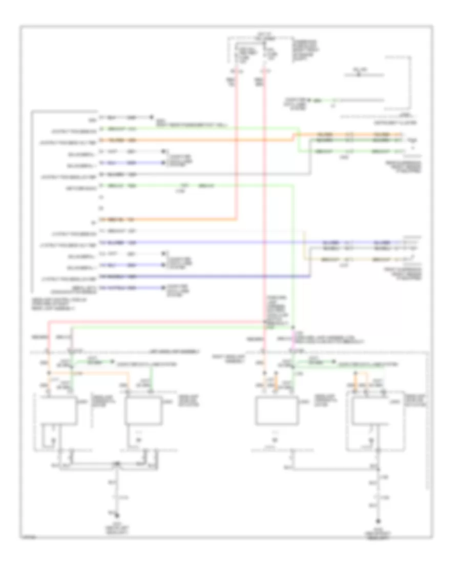
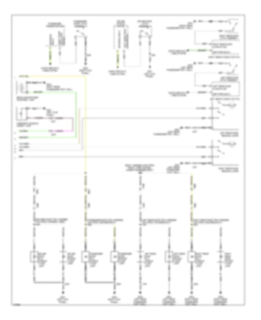
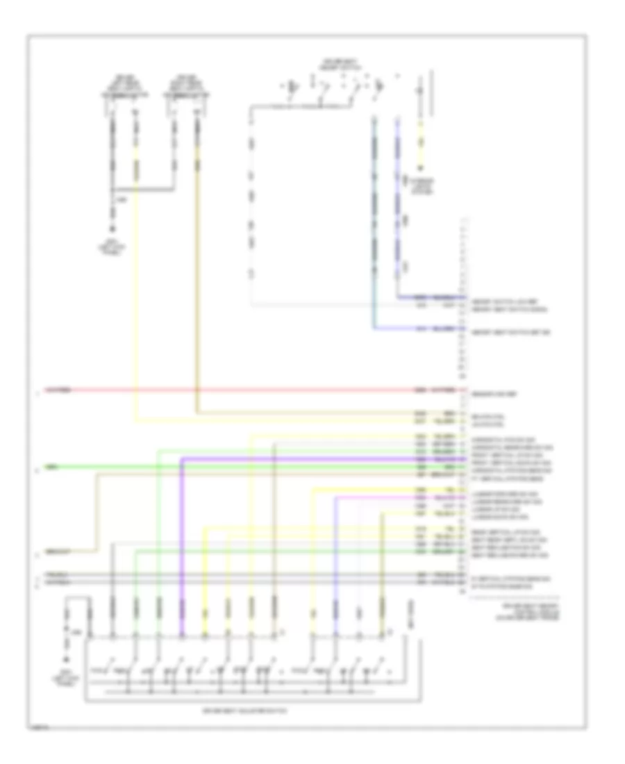
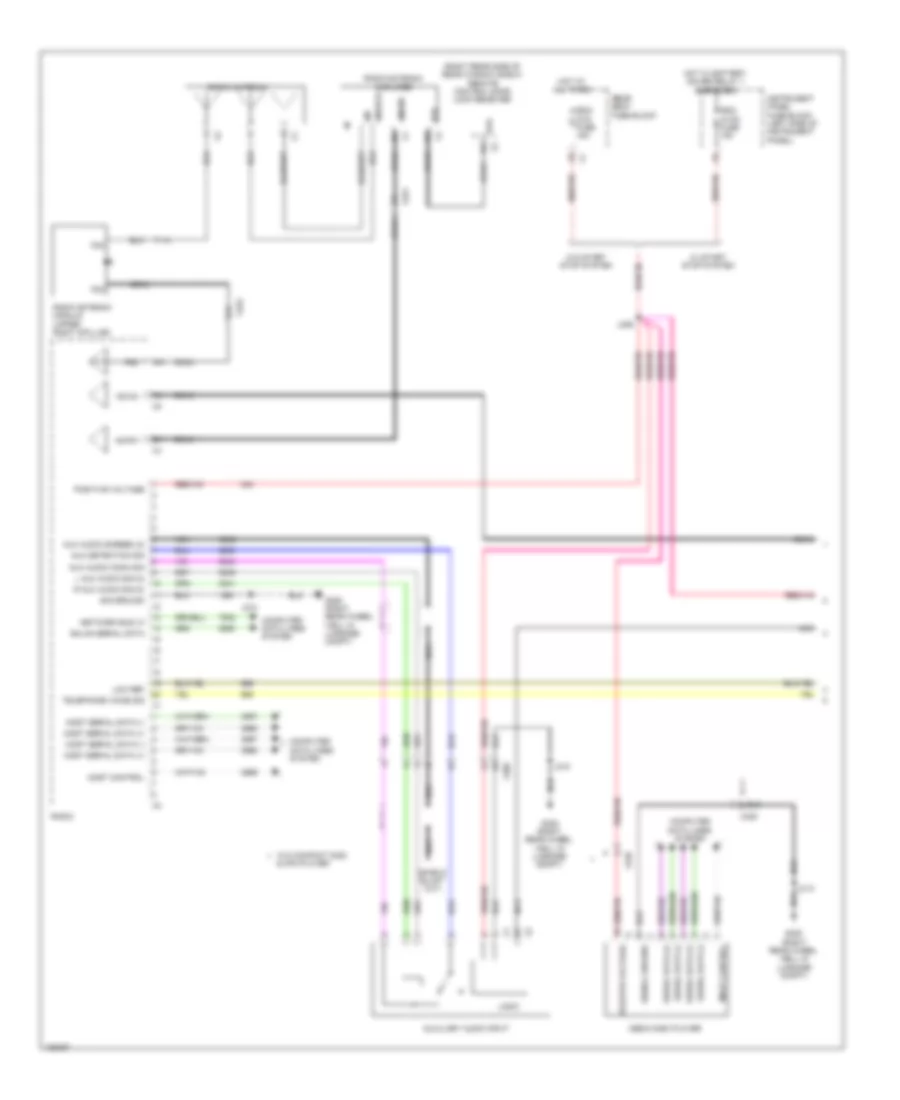
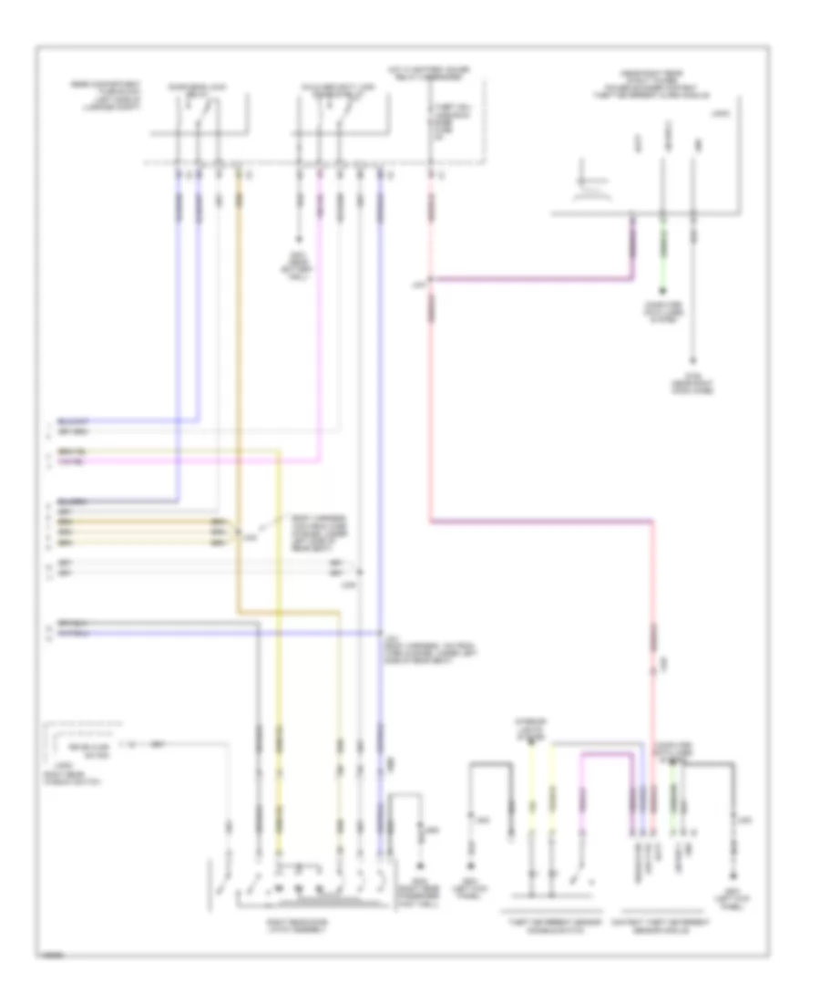
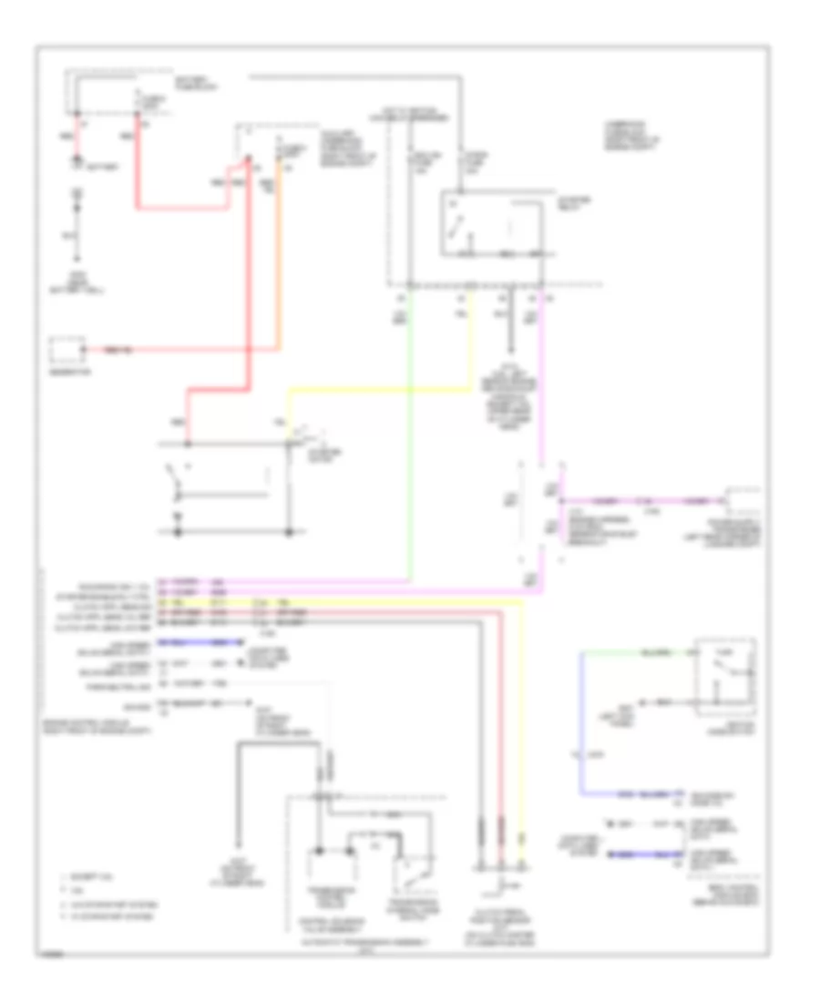
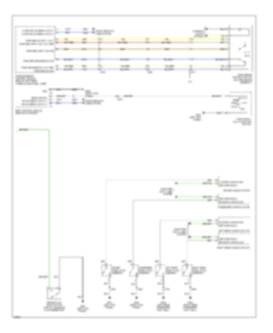
Automatic A/C Wiring Diagram (3 of 4) for Cadillac ATS 2013
List of elements for Automatic A/C Wiring Diagram (3 of 4) for Cadillac ATS 2013:
- (bottom of hvac casing) blower motor
- (front of engine)
- A/c clutch fuse 10a
- A/c compressor clutch relay
- A/c evaporator temperature sensor (passenger side of hvac casing)
- Air recirculation door actuator (center of dash)
- Batt pos volt
- Blower mtr spd ctrl
- Cooling fan fuse 60a
- Duct left lower air temperature sensor (left side module of hvac module casing)
- Duct left upper air temperature sensor (under the instrument panel)
- Duct right lower air temperature sensor (right side middle of hvac module casing)
- Duct right upper air temperature sensor (under the instrument panel)
- Ecm ign fuse 15a
- Engine coolant thermostat heater (2.5l)
- G202 (left kick panel)
- Gnd
- Hot at all times
- Hot w/ engine controls ignition relay energized
- Hot w/ ignition main relay energized
- Ign coil inj fuse 15a
- J132
- J214
- J215
- Left air temperature door actuator (middle left side of hvac casing)
- Logic
- Mode door actuator (driver side of hvac casing)
- Pnk
- Right air temperature door actuator (middle right side of hvac casing)
- Underhood fuse block (right front of engine compt)
- X224
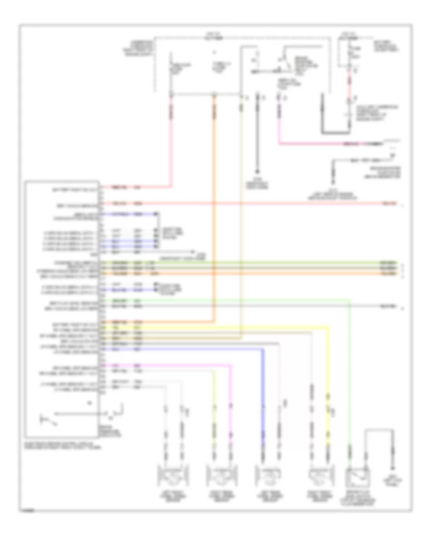
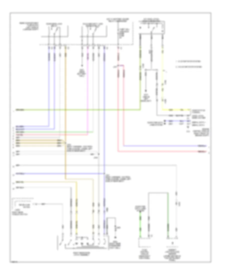
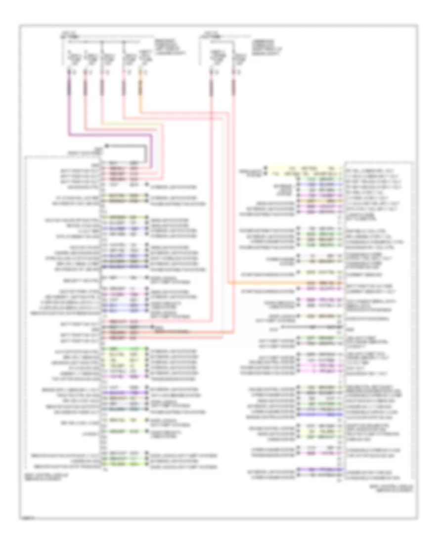
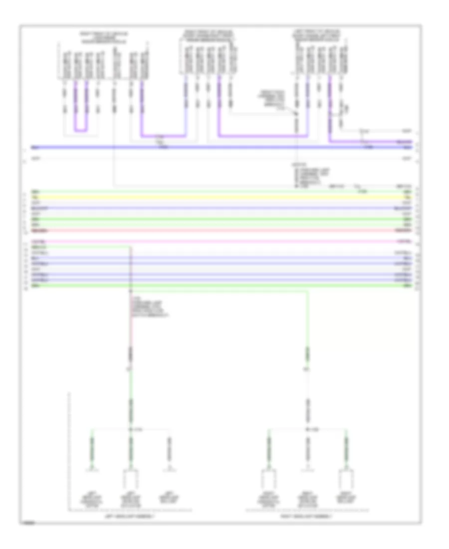
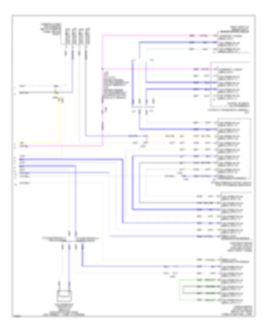
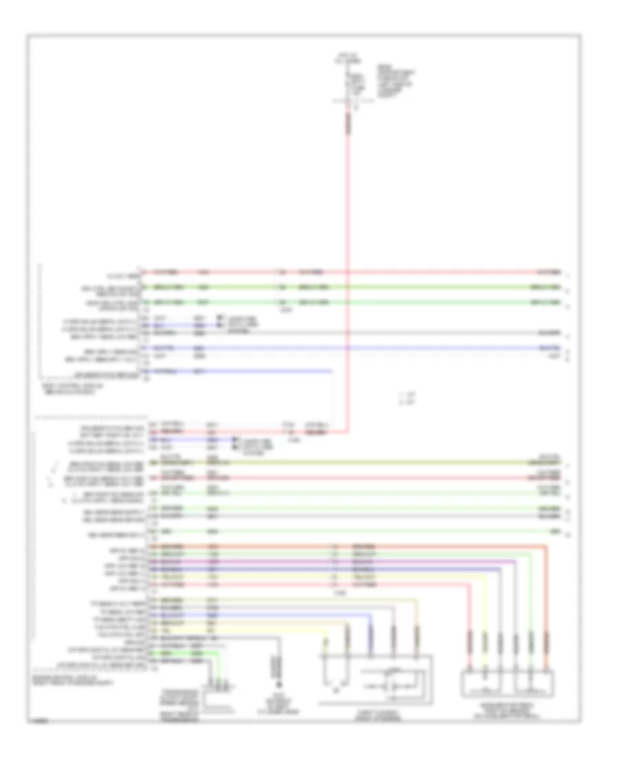
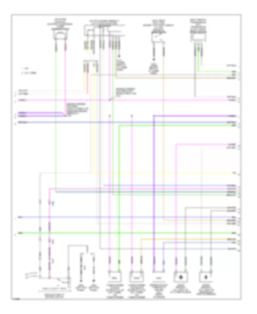
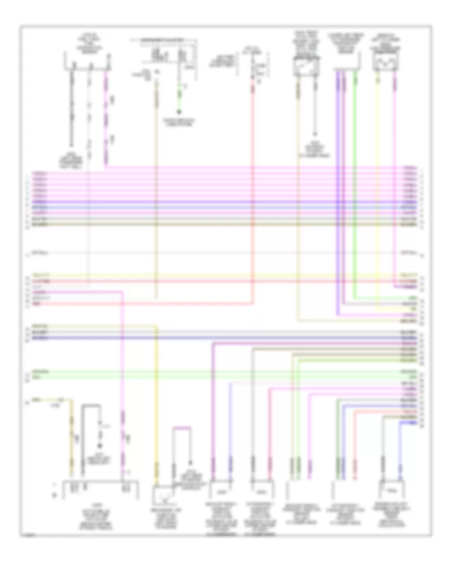
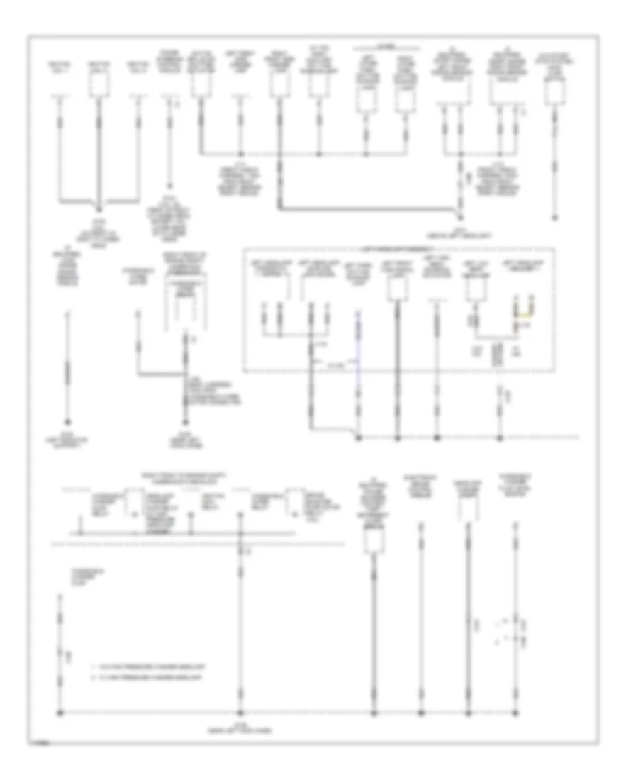
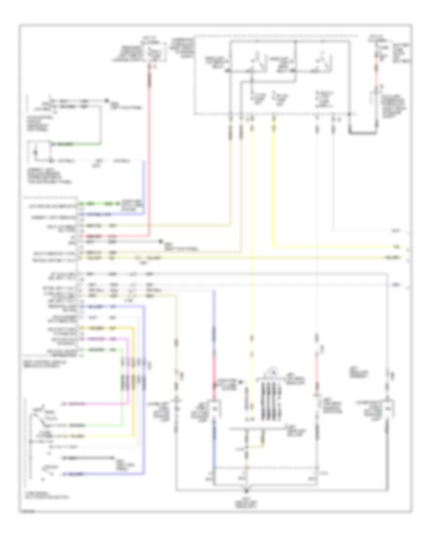
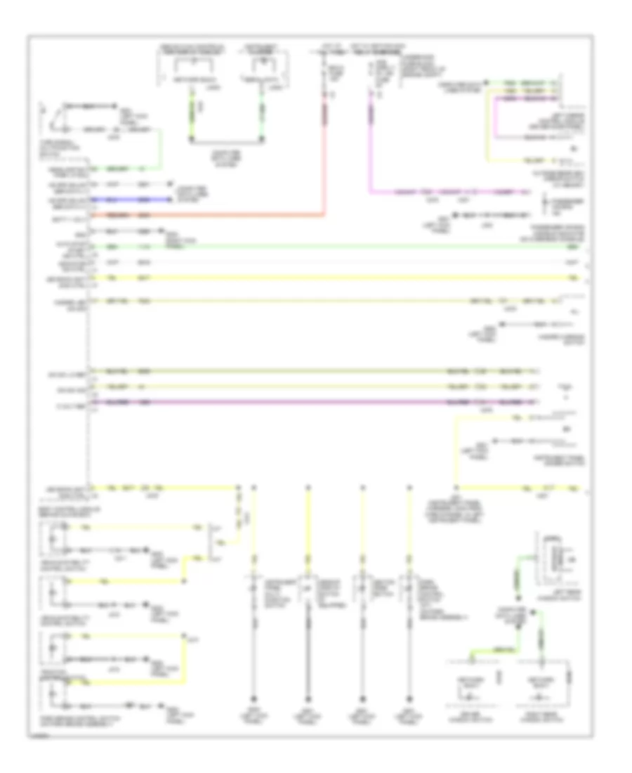
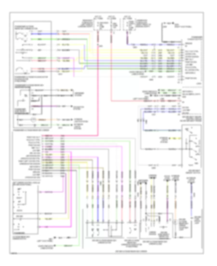
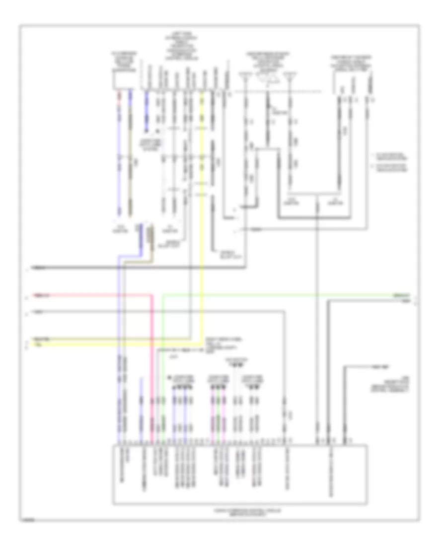
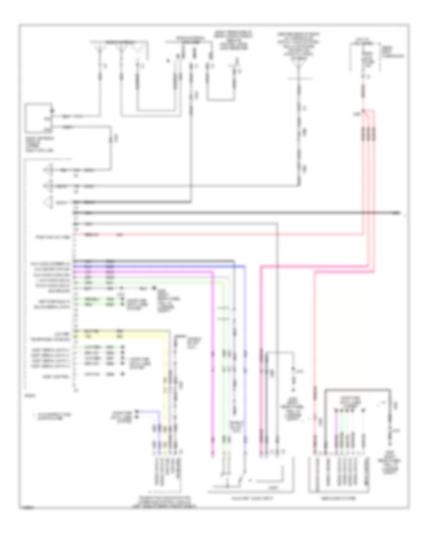
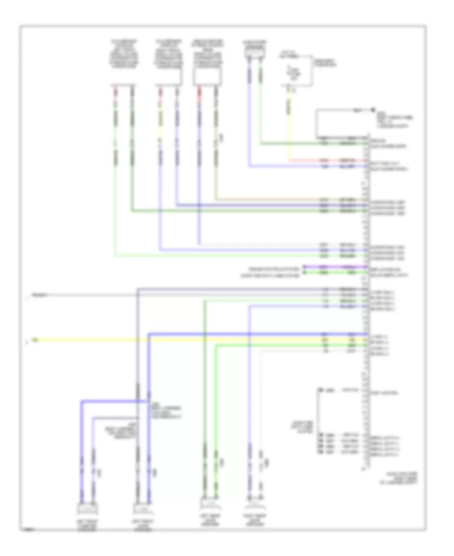
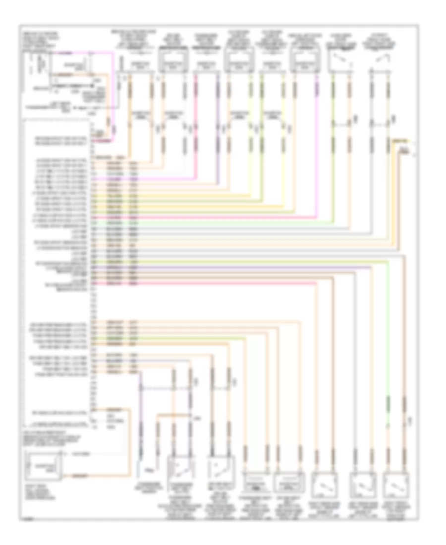
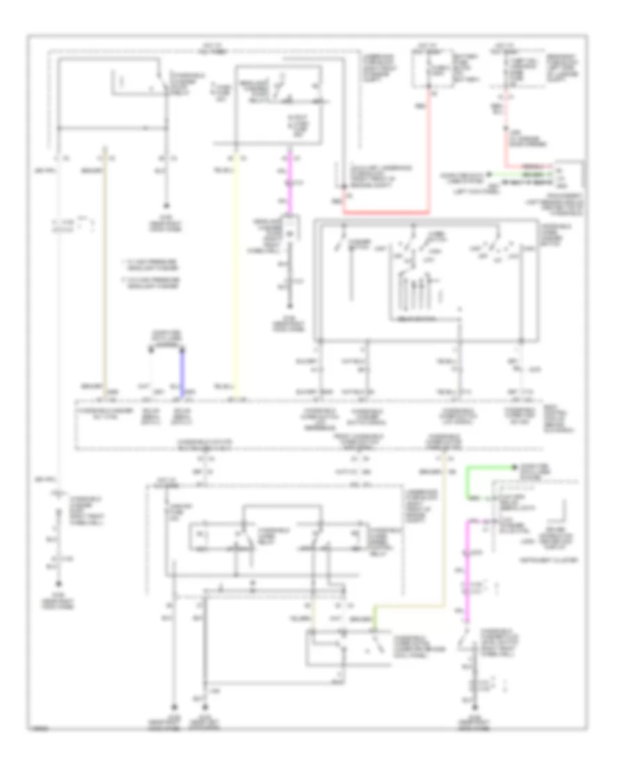
Automatic A/C Wiring Diagram (4 of 4) for Cadillac ATS 2013
List of elements for Automatic A/C Wiring Diagram (4 of 4) for Cadillac ATS 2013:
- (engine cooling fan assembly) cooling fan control module
- (near the lower right side of the a/c condenser) a/c refrigerant pressure sensor
- (right front of engine compt) engine control module
- 3.6l
- 3.6l w/ engine oil cooling
- 5 volt reference
- 5v volt ref
- A/c low ref
- A/c sens sig
- Air temperature door ctrl
- Air temperature door pos sig
- Auxiliary underhood fuse block (right front of engine compt)
- Batt + volt
- Cmprsr clutch rly ctrl
- Computer data lines system
- Cooling fan motor
- Data gnd
- Driver information center display
- Eng cool ctrl
- Eng temp sens sig
- Engine coolant temperature gauge
- Engine coolant temperature indicator
- Engine coolant temperature sensor (3.6l: near mechanical vacuum pump) (except 3.6l: in thermostat housing)
- Engine coolant temperature sensor 2 (2.5l)
- Evap core temp sens sig
- Except 3.6l
- Except 3.6l w/ engine oil cooling system & 2.0l w/ extra capacity
- Fuse 70a
- G102 (above right headlight)
- G107 (on front of right cylinder head)
- G201 (left kick panel)
- Gmlan serial data (+)
- Gmlan serial data (-)
- Ground
- Hot at all times
- Hvac control module (near right kick panel)
- Instrument cluster
- Logic
- Low ref
- Lower left air temp sens sig
- Lower right air temp sens sig
- Mode 1 valve pos sens sig
- Mode door ctrl
- Pass air temp door pos sig
- Pass air temp motor ctrl
- Pnk
- Recirculation door ctrl
- Recirculation pos sig
- Run/crank ign 1 volt
- Sens lo ref
- Serial
- Sig gnd
- Speed sig
- Speed signal
- System & 2.0l w/ extra capacity
- Temp sens low ref 2
- Temp sens sig 2
- Upper left air temp sens sig
- Upper right air temp sens sig
- Volt batt +
- X126
- X150
ANTI-LOCK BRAKES
Anti-lock Brakes Wiring Diagram (1 of 3) for Cadillac ATS 2013
List of elements for Anti-lock Brakes Wiring Diagram (1 of 3) for Cadillac ATS 2013:
- Abs pump fuse 60a
- Abs vlv fuse 30a
- Auxiliary underhood fuse block (right front of engine compt)
- Battery fuse block (on battery)
- Battery positive volt
- Brake booster pump motor (above generator)
- Brake booster pump motor relay (3.6l)
- Brake fluid level switch (top of the brake fluid reservoir)
- Brake pressure modulator
- Brk fluid level sens sig
- Brk vac pump fuse 30a
- Brk vacuum sens 5 volt refr
- Brk vacuum sens low refr
- Brk vacuum sens sig
- Brk vacuum sw sig
- Combined veh inertial
- Computer data lines system
- Electronic brake control module (forward of right front strut tower)
- Fuse 300a
- G106 (near right hood hinge)
- G110 (left rear of engine above exhaust manifold)
- G301 (left kick panel)
- Gnd
- Hi spd gmlan serial data (+) 2
- Hi spd gmlan serial data (-) 2
- Hi spd gmlan serial data + 1
- Hi spd gmlan serial data - 1
- Hot at all times
- Left front wheel speed sensor
- Left rear wheel speed sensor
- Lf wheel spd sens sig
- Lf wheel spd sens sply volt
- Lr wheel spd sens sig
- Lr wheel spd sens sply volt
- Nca
- Red
- Rf wheel spd sens sig
- Rf wheel spd sens sply volt
- Right front wheel speed sensor
- Right rear wheel speed sensor
- Rr wheel spd sens sig
- Rr wheel spd sens sply volt
- Sens sply volt steering angle sens low refr
- Serial data communication enable
- Underhood fuse block (right front of engine compt)
- X126
- X275
- X402
Anti-lock Brakes Wiring Diagram (2 of 3) for Cadillac ATS 2013
List of elements for Anti-lock Brakes Wiring Diagram (2 of 3) for Cadillac ATS 2013:
- A/t
- Abs ind
- Batt positive volt
- Brake booster vacuum sensor (on brake booster)
- Brake ind
- Computer data lines
- Computer data lines system
- Data -
- Data com
- Disply fuse 15a
- Driver information center display
- G201 (left kick panel)
- G202 (left kick panel)
- Gnd
- Hot at all times
- Instrument cluster
- Instrument panel fuse block (left side of instrument panel)
- Interior lights system
- J202
- J212
- Logic
- M/t
- Most serial data (+)
- Most serial data (-)
- Park brake control switch
- Parking brake control module (mounted under left rear corner of vehicle underbody)
- Release sw sig
- Spy vol
- Sw signal
- System
- Traction control switch
- Traction off ind
- Vehicle stability control switch
- Vol ref
- Vsc ind
- Vsc off ind
- W/ stop/ start system
- W/o stop/ start system
- X211
- X225
- X403
Anti-lock Brakes Wiring Diagram (3 of 3) for Cadillac ATS 2013
List of elements for Anti-lock Brakes Wiring Diagram (3 of 3) for Cadillac ATS 2013:
- (or 6109)
- (or 6110)
- (or 6111)
- 2.0l turbo
- 2.5l
- 3.6l
- A/t
- Body control module (behind glove box)
- Brake pedal position sensor (on brake pedal bracket)
- Brk vacuum sens 5 volt refr
- Brk vacuum sens low refr
- Brk vacuum sens sig
- Clutch pedal position sensor (on clutch master cylinder push rod)
- Combined veh inertial sens sply volt
- Computer data lines system
- Computer data lines systems
- Cruise/etc/tcc brk sig
- Engine control module (right front of engine compt)
- G201 (left kick panel)
- G202 (left kick panel)
- Gnd
- Hi spd gmlan serial data (+) 1
- Hi spd gmlan serial data (+) 2
- Hi spd gmlan serial data (-) 1
- Hi spd gmlan serial data (-) 2
- M/t
- Multi-axis acceleration sensor (below center console)
- Serial data communication enable x4
- Steering angle sens low refr
- Steering wheel angle sensor (below steering wheel around shaft)
- Traction ctrl sw sig 1
- X150
- X211
- X275
ANTI-THEFT
Forced Entry Wiring Diagram, with Passive Keyless Entry (1 of 4) for Cadillac ATS 2013
List of elements for Forced Entry Wiring Diagram, with Passive Keyless Entry (1 of 4) for Cadillac ATS 2013:
- (driver's door trim harness, 5cm from x505 breakout) j507
- (right rear passenger footwell) g304
- Accessory volt
- Antenna 1 sig hi
- Antenna 1 sig lo
- Antenna 2 sig hi
- Antenna 2 sig lo
- Antenna 3 sig hi
- Antenna 3 sig lo
- Bat pos volt
- Batt rvc fuse 5a
- Bcm 5 fuse 15a
- Bcm 7 fuse 10a
- Bcm 8 fuse 30a
- Center console front keyless entry antenna (forward of transmission shift lever)
- Center console rear keyless entry antenna (rearward of transmission shift lever)
- Computer data lines system
- Dr open sw sig
- Driver door latch assembly
- Driver window motor
- Driver window switch
- G301 (left kick panel)
- G304 (right rear passenger footwell)
- Gmlan serial data
- Ground
- Hot at all times
- Ign 1 volt
- Ignition mode switch
- J500
- Keyless entry control module (forward of right rear lamp assembly)
- Lock sig
- Logic
- Mtr status
- Peps fuse 30a
- Peps/ batt 1 fuse 5a
- Rear compartment fuse block (right front luggage compt)
- Rear compartment keyless entry antenna (center of rear compt)
- Shift interlock system
- Sw 2 low ref
- Sw sig
- Sw sig 2
- Sw sig lf dr ajar
- Underhood fuse block (right front of engine compt)
- X206
- X225
- X275
- X500
- X505
Forced Entry Wiring Diagram, with Passive Keyless Entry (2 of 4) for Cadillac ATS 2013
List of elements for Forced Entry Wiring Diagram, with Passive Keyless Entry (2 of 4) for Cadillac ATS 2013:
- (body harness, 9cm from side impact sensor (right rear) breakout) j339
- Accessory volt
- Actr unlock ctrl
- Bat pos volt
- Body control module (behind glove box)
- Computer data lines system
- Dr lock ctrl
- Dr lock ctrl (2)
- Driver door lock switch
- Exterior lights system
- G301 (left kick panel)
- G302 (right kick panel)
- G303 (left rear passenger foot well)
- G304 (right rear passenger foot well)
- Gmlan serial data (+)
- Gmlan serial data (-)
- Ground
- Head lp high rly ctrl
- Head lp low rly ctrl
- Headlights system
- Hood status b sig
- Horn rly ctrl
- Horns system
- Ign 1 volt
- Ind dim ctrl
- Interior lights system
- J329 (body harness, 5cm from front wire channel under passenger seat)
- J509
- J600
- J609
- J700
- Left rear door latch assembly
- Left rear sig
- Left rear window switch
- Lh park lp sply volt
- Liftgate ajar sw sig
- Logic
- Lr dr ajar sw sig
- Passenger door latch assembly
- Passenger door lock switch
- Passenger window motor
- Rear compartment lid latch
- Rf dr ajar sw sig
- Rh park lp sply volt
- Right rear sig
- Scty ind ctrl
- Scty lock rly ctrl
- Sw lock ctrl
- Sw lock sig
- Sw unlock ctrl
- Sw unlock sig
- Trunk, tailgate, fuel doors system
- X500
- X505
- X600
- X606
- X700
Forced Entry Wiring Diagram, with Passive Keyless Entry (3 of 4) for Cadillac ATS 2013
List of elements for Forced Entry Wiring Diagram, with Passive Keyless Entry (3 of 4) for Cadillac ATS 2013:
- (at hood latch) hood ajar switch
- 2.0l
- Ambient light/sunload sensor (upper center of the instrument panel)
- Child security lock disable relay
- Computer data lines system
- Door dead lock relay
- Engine control module (right front of engine compt)
- G101 (above left headlight)
- G304 (right rear passenger foot well)
- G401 (near battery well)
- Hood latch snsr low ref
- Hood status a signal
- Hot w/ battery saver relay 2 energized
- Hvac control module (near right kick panel)
- J341 (body harness, 1cm from wire channel under left side of rear seat)
- J343 (body harness, 12cm from wire channel under left side of rear seat)
- J345
- J347
- J600
- Logic
- Nca
- Rear compartment fuse block (left side of luggage compt)
- Right rear door latch assembly
- Right rear window switch
- Rr dr ajar sw sig
- Serial data +
- Serial data -
- Theft mdl/ ugdo/rain snsr fuse 5a
- W/ start/stop system
- W/o start/stop system
- X126
- X150
- X275
- X800
Forced Entry Wiring Diagram, with Passive Keyless Entry (4 of 4) for Cadillac ATS 2013
List of elements for Forced Entry Wiring Diagram, with Passive Keyless Entry (4 of 4) for Cadillac ATS 2013:
- (left kick panel) g201
- (left rear passenger foot well) g303
- (near right rear strut tower) power sounder content theft deterrent alarm module
- (right rear passenger foot well) g304
- Anetnna sig lo
- Ant sig hi
- Ant sig lo
- Antenna sig hi
- Antenna sig lo
- Aos display/ mil ign fuse 5a
- Batt
- Co-drv dr ant sig hi
- Co-drv dr handle sw sig
- Computer data lines system
- Content theft deterrent sensor module
- Disable sig
- Door lock ind
- Driver door handle keyless entry antenna
- Driver exterior door handle assembly
- Driver exterior door handle switch
- Driver information center display
- Drv dr handle sw sig
- G106 (near right hood hinge)
- G201 (left kick panel)
- G301 (left kick panel)
- G302 (right kick panel)
- Gnd
- Hot w/ ignition main relay energized
- Instrument cluster
- Interior lights system
- Interior system lights
- J302
- J500
- J600
- J700
- Keyless entry control module (forward of right rear lamp assembly)
- Led ctrl
- Left rear exterior door handle assembly
- Left rear exterior door handle switch
- Lin bus 1
- Lin bus 2
- Logic
- Lr dr handle sw sig
- Passenger door handle keyless entry antenna
- Passenger exterior door handle assembly
- Passenger exterior door handle switch
- Rear fascia keyless entry antenna (under rear fascia)
- Red
- Right rear exterior door handle assembly
- Right rear exterior door handle switch
- Rr dr handle sw sig
- Security ind
- Theft deterrent sensor disable switch
- Underhood fuse block (right front of engine compt)
- X275
- X337
- X500
- X600
- X700
- X800
- X901
Forced Entry Wiring Diagram, without Passive Keyless Entry (1 of 3) for Cadillac ATS 2013
List of elements for Forced Entry Wiring Diagram, without Passive Keyless Entry (1 of 3) for Cadillac ATS 2013:
- (at hood latch) hood ajar switch
- (near right kick panel) hvac control module
- (right kick panel) g302
- (upper center of the instrument panel) ambient light/sunload sensor
- 2.0l
- Actr receive sig
- Actr return
- Actr rtn
- Actr sply volt
- Actr transmit sig
- Actr unlock ctrl
- Antenna (upper part of rear window)
- Aos display/ mil ign fuse 5a
- Bat pos volt
- Bcm 5 fuse 15a
- Bcm 7 fuse 10a
- Body control module (behind glove box)
- Coax
- Computer data lines system
- Dr lock ctrl
- Dr lock ctrl (2)
- Driver door latch assembly
- Driver window motor
- Engine control module (right front of engine compt)
- Exterior
- Fm/rfr
- G101 (above left headlight)
- G301 (left kick panel)
- G304 (right rear passenger foot well)
- Gmlan serial data (+)
- Gmlan serial data (-)
- Ground
- Head lp high rly ctrl
- Head lp low rly ctrl
- Headlights system
- Hood latch
- Hood status a signal
- Hood status b sig
- Horn rly ctrl
- Horns system
- Hot at all times
- Hot w/ ignition main relay energized
- Ind dim ctrl
- J500
- Left rear sig
- Lf dr ajar sw sig
- Lh park lp sply volt
- Lights system
- Logic
- Nca
- Radio antenna amplifier
- Rear compartment lid latch
- Remote control door lock receiver (right rear side of rear window shelf)
- Rfr
- Rh park lp sply volt
- Right rear sig
- Scty ind ctrl
- Scty lock rly ctrl
- Sens low ref
- Serial data +
- Serial data -
- Sw lock ctrl
- Sw lock sig
- Sw unlock ctrl
- Sw unlock sig
- Underhood fuse block (right front of engine compt)
- W/ start/stop system
- W/o start/stop system
- X126
- X150
- X275
- X500
- X505
Forced Entry Wiring Diagram, without Passive Keyless Entry (2 of 3) for Cadillac ATS 2013
List of elements for Forced Entry Wiring Diagram, without Passive Keyless Entry (2 of 3) for Cadillac ATS 2013:
- Batt rvc fuse 5a
- Bcm 8 fuse 30a
- Computer data lines system
- Door lock ind
- Driver door lock switch
- Driver information center display
- Driver window switch
- G201 (left kick panel)
- G301 (left kick panel)
- G302 (right kick panel)
- G303 (left rear passenger foot well)
- Hot at all times
- Instrument cluster
- Interior lights system
- J329 (body harness, 5cm from front wire channel under passenger seat)
- J339 (body harness, 9cm from side impact sensor (right rear) breakout)
- J507 (driver's door trim harness, 5cm from x505 breakout)
- J509
- J600
- J609
- J700
- Left rear door latch assembly
- Left rear window switch
- Logic
- Lr dr ajar sw sig
- Mtr status
- Passenger door latch assembly
- Passenger door lock switch
- Passenger window motor
- Rear compartment fuse block (left side of luggage compt)
- Rf dr ajar sw sig
- Security ind
- Sw sig
- Trunk, tailgate, fuel doors system
- X500
- X505
- X600
- X606
- X700
Forced Entry Wiring Diagram, without Passive Keyless Entry (3 of 3) for Cadillac ATS 2013
List of elements for Forced Entry Wiring Diagram, without Passive Keyless Entry (3 of 3) for Cadillac ATS 2013:
- (body harness, 12cm from wire channel under left side of rear seat)
- (near right rear strut tower) power sounder content theft deterrent alarm module
- Batt
- Child security lock disable relay
- Computer data lines system
- Content theft deterrent sensor module
- Disable sig
- Door dead lock relay
- G106 (near right hood hinge)
- G201 (left kick panel)
- G304 (right rear passenger foot well)
- G401 (near battery well)
- Gnd
- Hot w/ battery saver relay 2 energized
- Interior lights system
- J302
- J341 (body harness, 1cm from wire channel under left side of rear seat)
- J343
- J345
- J347
- J600
- Led ctrl
- Lin bus 1
- Lin bus 2
- Logic
- Rear compartment fuse block (left side of luggage compt)
- Right rear door latch assembly
- Right rear window switch
- Rr dr ajar sw sig
- Theft deterrent sensor disable switch
- Theft mdl/ ugdo/rain snsr fuse 5a
- X337
- X800
Pass-Key Wiring Diagram for Cadillac ATS 2013
List of elements for Pass-Key Wiring Diagram for Cadillac ATS 2013:
- (inside floor console compt) immobilizer control module
- 2.0l
- Bat pos volt
- Bcm 7 fuse 10a
- Body control module (behind glove box)
- Computer data lines system
- Driver information center display
- Engine control module (right front of engine compt)
- G101 (above left headlight)
- G302 (right kick panel)
- Ground
- Hood ajar switch (at hood latch)
- Hood latch snsr low ref
- Hood sig
- Hood status a signal
- Hot at all times
- Instrument cluster
- Lin bus 11
- Logic
- Nca
- Rtn
- Security ind
- Serial data
- Serial data +
- Serial data -
- Sply volt
- Underhood fuse block (right front of engine compt)
- W/ start/stop system
- W/o start/stop system
- X126
- X150
- X206
- X275
BODY CONTROL MODULES
Body Control Modules Wiring Diagram (1 of 2) for Cadillac ATS 2013
List of elements for Body Control Modules Wiring Diagram (1 of 2) for Cadillac ATS 2013:
- (or 7538)
- 12 volt ref
- 5 volt ref
- Acc volt
- Acc wakeup serial data serial data communication enable
- Adaptive cruise ctrl gap up/down sw sig
- Ambient lt senr sig
- Anti-lock brakes system
- Anti-theft system
- Auto stop strt sw sig
- Auto stp str ind ctrl
- Batt positive volt
- Batt positive voltage
- Batt rvc fuse 5a
- Bcm 1/ spare fuse 10a
- Bcm 2 fuse 10a
- Bcm 3 fuse 15a
- Bcm 4 fuse 15a
- Bcm 5 fuse 15a
- Bcm 8 fuse 30a
- Body control module (behind glove box)
- Brk aply sens lo ref
- Brk aply sens sig
- Computer data lines system
- Cruise control system
- Cruise ctrl set/coast/ resume/accelerate sw sig
- Current sens sig
- Current sens sply volt
- Door locks & anti-theft systems
- Drv dr lk sw lk sig
- Drv dr lk sw unlk
- Engine controls system
- Exterior lights system
- G103
- G302 (right kick panel)
- Gnd
- Hazard led dimming sig
- Hazard sw lt turn sig
- Hazard sw rh turn sig
- Hazard sw sig
- Hdlp dimm sw hi beam sig
- Hdlp sw flash to pass sig
- Hdlp sw hdlps off sig ctrl
- Hdlp sw on sig
- Hdlp sw park lp sig
- Headlights system
- Hi spd gmlan serial data (+) (1)
- Hi spd gmlan serial data (-) (1)
- Hood status b signal
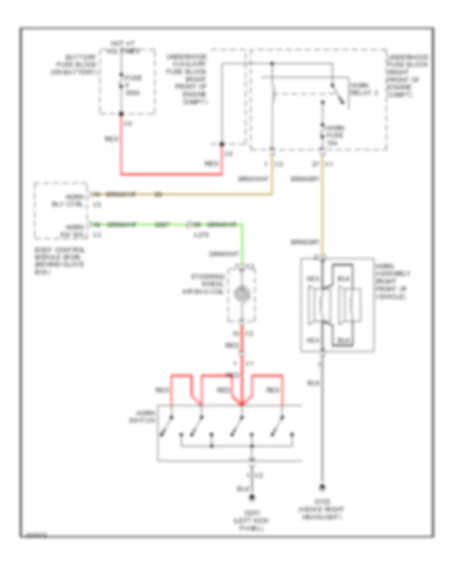
- Horn sw sig
- Horns system
- Hot at all times
- I/p lp dim sw sig
- I/p lp dimm sw low ref
- Ign mode sw acc led sig
- Ign mode sw mode volt
- Ign mode sw st led sig
- Ind dimming ctrl
- Interior lights system
- Intr lp defeat sw sig
- Led ambient lighting ctrl 2
- Led backlight dimg ctrl
- Lin bus 4
- Logistic mode rly close ctrl
- Lt auxiliary drl sply volt
- Lt hdlp lo beam sply volt
- Lt park lp sply volt
- Power distribution system
- Rap relay coil ctrl
- Rear body fuse block (left side of luggage compt)
- Remote function actr receive sig
- Remote function actr rtn
- Remote function actr suply volt
- Remote function actr trans sig
- Rr fog lp sw sig
- Rr license lp sply vol
- Rt frt trn sig lp sply volt
- Rt hdl lo beam spl volt
- Rt prk lp sply vol
- Rt rr turn sig lp sply volt
- Run/crank ign 1 volt
- Run/crank rly coil ctrl
- Security ind ctrl
- Shift interlock system
- Starting/charging system
- Stp lp rly coil sply volt
- Strg column lk status sig
- Tap up/tap down sw sig
- Traction ctrl sw sig
- Transmissions system
- Underhood fuse block (right front of engine compt)
- Veh anti-theft sym immobilizer rtrn lin bus 11
- Veh anti-theft sym immobilizer sply volt
- Windshield washer rly ctrl
- Windshield washer sw sig
- Windshield wiper mtr park sw sig
- Windshield wiper mtr rly coil sply volt
- Windshield wiper sw hi sig
- Windshield wiper sw lo ref
- Windshield wpr sw lo sig
- Wiper/washer system
Body Control Modules Wiring Diagram (2 of 2) for Cadillac ATS 2013
List of elements for Body Control Modules Wiring Diagram (2 of 2) for Cadillac ATS 2013:
- (right kick panel) g302
- Anti-lock brakes system
- Backup lp sply vol
- Batt positive vol
- Batt positive volt
- Bcm 6 fuse 10a
- Bcm 7 fuse 10a
- Body control module (behind glove box)
- Child security lk mtr status sig lt rr
- Child security lk mtr status sig rt rr
- Child security lk rly ctrl
- Computer data lines system
- Courtesy lp sw sig
- Cruise/etc/tcc brake sig
- Curnt sens lo ref
- Door locks & anti-theft systems
- Door locks & anti-theft systems interior lights system
- Door locks & anti-theft systems trunk, tailgate, fuel doors system
- Dr lk actr unlck ctrl
- Dr lk ctrl
- Dr lk ctrl 2
- Drv outside rr view mir puddle lp sply volt
- Exterior lights system
- Ft windshield wiper sw hi sig
- Fuel dr lk rly ctrl
- Gnd
- Hdlp hi beam rly ctrl
- Hdlp lo beam rly control
- Headlamp washer rly ctrl x5
- Headlights system
- Hi spd gml serl data (+) (1)
- Hi spd gml serl data (-) (1)
- Horn rly ctrl
- Horns system
- Hot at all times
- Inadvertent pwr ctrl
- Interior lights system
- Intr lp ctrl
- Key capture/column lk shift position sig
- Led ambient lighting ctrl 1
- Led backlight dimm ctrl
- Lf turn sig sply volt
- Lin bus 1
- Lin bus 2
- Lin bus 3
- Lo spd gmlan serial data
- Logistic mode rly open ctrl
- Lr turn sig sply volt
- Lt gate ajar sw sig (1)
- Lt glass/trunk
- Lt glass/trunk intr release sig
- Mtr release ctrl
- Park brk sw sig
- Park lk sold ctrl
- Pass dr lk sw lk ctrl
- Pass dr lock sw unlck ctrl
- Power distribution system
- Right rear stp lp sply volt
- Rr closure handle sw open sig
- Rr fog lp sply volt
- Rr turn lp feedback sig
- Rt auxiliary drl sply volt
- Rt rr turn lp feedback sig
- Run rly coil ctrl
- Security lk rly ctrl
- Shift interlock system
- Starting/charging system
- Trunk lp ctrl
- Trunk, tailgate, fuel doors system
- Underhood fuse block (right front of engine compt)
- Wiper/washer system
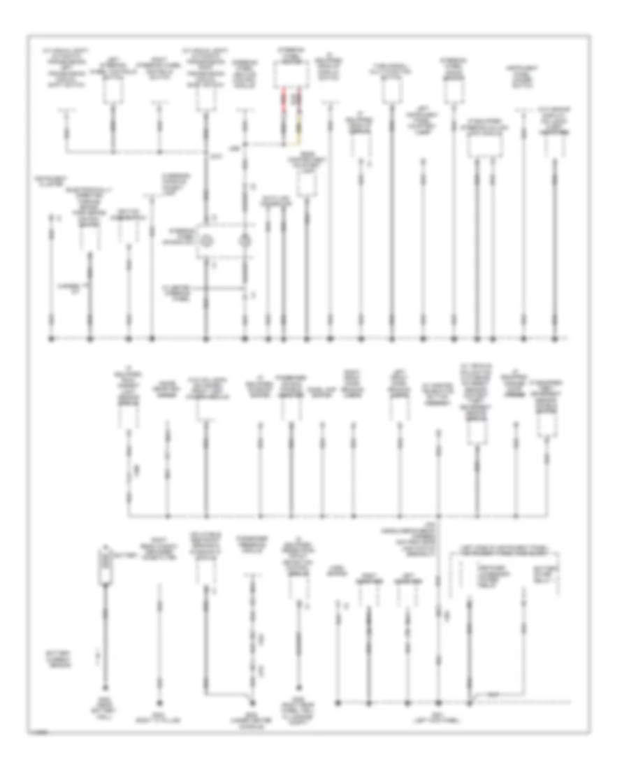
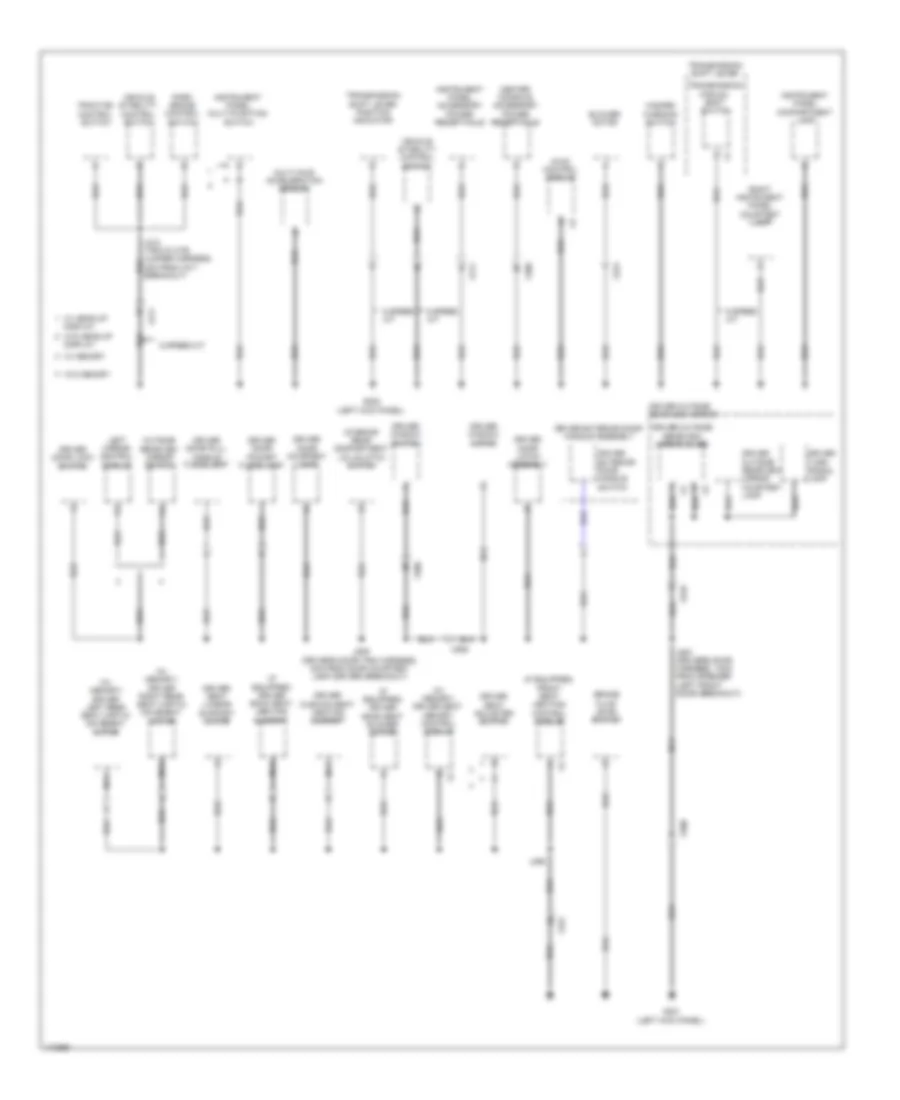
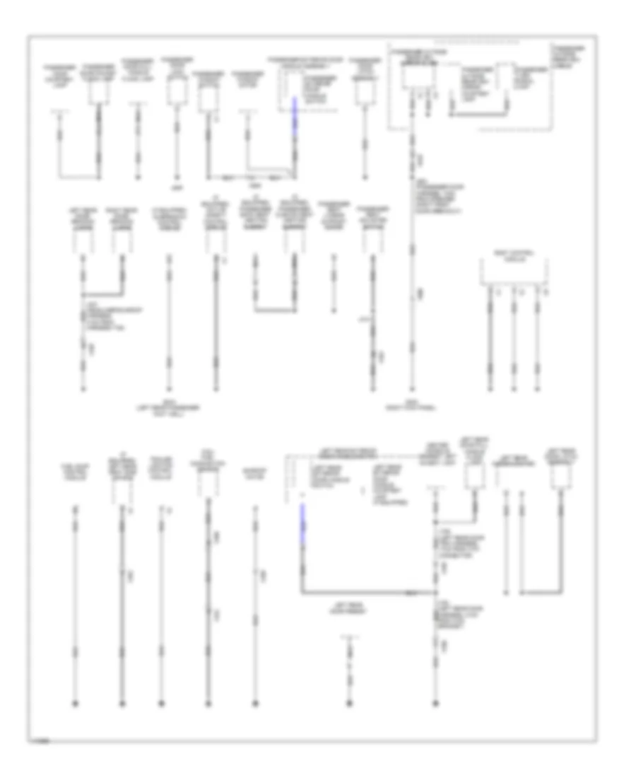
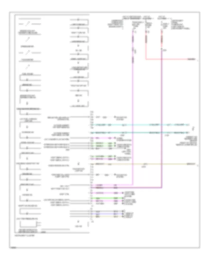
COMPUTER DATA LINES
Computer Data Lines Wiring Diagram (1 of 7) for Cadillac ATS 2013
List of elements for Computer Data Lines Wiring Diagram (1 of 7) for Cadillac ATS 2013:
- (behind glove box) human machine interface control module
- (forward of right rear lamp assembly) (w/ high intensity discharge headlamps) headlamp control module
- (instrument panel harness, 10cm from speaker (center instrument panel) breakout) j206
- Audio amplifier (right rear of luggage compt)
- Bcm 5 fuse 15a
- Color information display
- Communication enable serial data
- Data + most serial
- Data - most serial
- Data link connector (dlc) below steering column
- Dlc fuse 10a
- G201 (left kick panel)
- Headup display (w/ head-up display)
- Hi spd gmlan serial data + (1)
- Hi spd gmlan serial data - (1)
- Hot at all times
- Instrument cluster
- Instrument panel fuse block (left side of instrument panel)
- J204 (instrument panel harness, 39cm from wire channel in left instrument panel)
- J205 (instrument panel harness, 15cm from speaker (center instrument panel) breakout)
- Line bus 12
- Linear interconnect network bus 10
- Linear interconnect network bus 5
- Low speed gmlan serial data
- Media disc player (if equipped)
- Most control
- Most serial data +
- Most serial data -
- Network bus 12 interconnect linear network bus 12 interconnect linear
- Network bus 6 linear interconnect
- Radio
- Red
- Right steering wheel controls switch
- Serial data (+) (1) high speed gmlan
- Serial data (-) (1) high speed gmlan
- Serial data communication enable
- Serial data lo spd gmlan
- Steering wheel air bag coil (center of steering wheel) x2
- Underhood fuse block (right front of engine compt)
- W/ high intensity discharge headlamps
- W/ pedestrian protection
- W/ touch screen & color information display
- W/o compact disc & mp3 player
- W/o high intensity discharge headlamps
- W/o pedestrian protection
- W/o touch screen &
- X126
- X235
- X275
- X495
Computer Data Lines Wiring Diagram (2 of 7) for Cadillac ATS 2013
List of elements for Computer Data Lines Wiring Diagram (2 of 7) for Cadillac ATS 2013:
- (awd) tranfer case control module
- (body harness, 10cm past tail lamp (right) connector breakout) j406
- (body harness, 12cm past tail lamp (right) connector breakout) j407
- (body harness, 47cm from front wire channel under driver seat)
- (left side of rear window shelf) (w/ onstar) telematics communication interface control module
- (not used)
- Accessory
- Awd
- Communication enable
- Driver seat memory control module
- Except awd
- Front & rear parking assist control module (right rear side of rear window shelf)
- Hi spd gmlan ser data + (1)
- Hvac control module (near right kick panel)
- Info display module (above hvac controls)
- Keyless entry control module (forward of right rear lamp assembly)
- Left mirror control module (memory) (driver door panel)
- Left side object sensor module (left rear bumper facia)
- Linear interconnect network bus 10 linear interconnect network bus 8 lo spd gmlan serial data linear interconnect network bus 9
- Linear interconnect network bus 8
- Linear interconnect network bus 9
- Lo spd gmlan
- Lo spd gmlan serial data
- Low spd gmlan serial data
- Nca
- Passenger presence module
- Passenger window switch
- Pedestrian impact detection control module (forward of right rear lamp assembly)
- Right side object sensor module (right rear bumper facia)
- Ser data + (1) hi spd gmlan
- Ser data - (1) hi spd gmlan
- Serial data
- Serial data wakeup
- Splice pack jx201 (instrument panel harness, 15cm from e8j breakout)
- Splice pack jx301 (body harness, 25cm from k42 x1 breakout)
- Steering column lock module (near base of steering column)
- Trailer lighting control module (near battery)
- W/ onstar
- W/o onstar
- X225
- X321
- X322
- X500
- X506
- X600
- X606
- X901
Computer Data Lines Wiring Diagram (3 of 7) for Cadillac ATS 2013
List of elements for Computer Data Lines Wiring Diagram (3 of 7) for Cadillac ATS 2013:
- (forward lamp harness, 15cm from x125 breakout) j106
- (left front of vehicle) short range left front radar sensor module
- (right front of vehicle) long range radar sensor module
- (right front of vehicle) short range right front radar sensor module
- Fr object sens sply volt (2)
- Front facia harness, 5cm from x100 breakout j115
- Hi spd gmlan ser data + (4)
- Hi spd gmlan ser data - (4)
- J102 (forward lamp harness, 27cm from hood ajar switch breakout)
- J118
- J128
- Left headlamp assembly
- Left headlamp ballast
- Left headlamp horizontal motor
- Left headlamp leveling actuator
- Right headlamp assembly
- Right headlamp ballast
- Right headlamp horizontal motor
- Right headlamp leveling actuator
- Ser data + (4) hi spd gmlan
- Ser data - (4) hi spd gmlan
- X100
- X125
Computer Data Lines Wiring Diagram (4 of 7) for Cadillac ATS 2013
List of elements for Computer Data Lines Wiring Diagram (4 of 7) for Cadillac ATS 2013:
- (body harness, 10cm from body grommet right side bulkhead)
- (body harness, 17cm from wire channel under left side of rear seat) j344
- 255o
- Accessory wakeup
- Battery positive volt
- Body control module (behind glove box)
- Driver window motor
- Driver window switch
- Fr object sens sply volt (2)
- Frontview camera module
- G302 (right kick panel)
- Ground
- Hi spd gmlan ser data - (4)
- High speed gmlan
- Immobilizer control module (inside floor console compt)
- J220 (a/t)
- J322
- J336 (body harness, 104cm from front wire channel under passenger seat)
- J351 (body harness, 9cm from body control module breakout)
- J503 (drivers door harness, 7cm from grommet inside driver door)
- Left rear window switch
- Linear interconnect
- Linear interconnect network bus 11
- Linear interconnect network bus 3
- Linear interconnect network bus 4
- Low speed gmlan
- Network 1
- Passenger window motor
- Right rear window switch
- Ser data + (4) hi spd gmlan
- Ser data - (4) hi spd gmlan
- Ser data lo spd gmlan
- Serial data
- Serial data + (1)
- Serial data - (1)
- Serial data wakeup accessory
- Transmission shift lever
- X2 network 4 linear interconnect
- X206
- X214
- X225
- X275
- X3 network 11 linear interconnect
- X301
- X337
- X4 communication enable serial data
- X500
- X505
- X6 network 2
- X6 network 3 linear interconnect
- X600
- X700
- X800
Computer Data Lines Wiring Diagram (5 of 7) for Cadillac ATS 2013
List of elements for Computer Data Lines Wiring Diagram (5 of 7) for Cadillac ATS 2013:
- (forward of left rear lamp assembly) active safety control module
- A/t w/ horn theft deterrent alarm
- Battery sensor module (w/ start stop system) (left rear of luggage compt)
- Communication enable
- Fr object sens sply volt (1)
- Fr object sens sply volt (2)
- Front seat heating control module
- Hi spd gmlan ser data + (1)
- Hi spd gmlan ser data + (4)
- Hi spd gmlan ser data - (4)
- J224 (body harness, 7cm from x275 breakout)
- J348 (body harness, 6cm from x337 breakout)
- Low spd gmlan serial data
- M/t w/o horn theft deterrent alarm
- Network bus 1 interconnect linear
- Network bus 2 interconnect linear
- Power sounder content theft deterrent alarm module (if equipped) (near right rear strut tower)
- Ser data + (1) hi spd gmlan
- Ser data + (2) hi spd gmlan
- Ser data + (4) hi spd gmlan
- Ser data - (1) hi spd gmlan
- Ser data - (2) hi spd gmlan
- Ser data - (4) hi spd gmlan
- Serial data
- Short range rear radar sensor module (rear middle of vehicle)
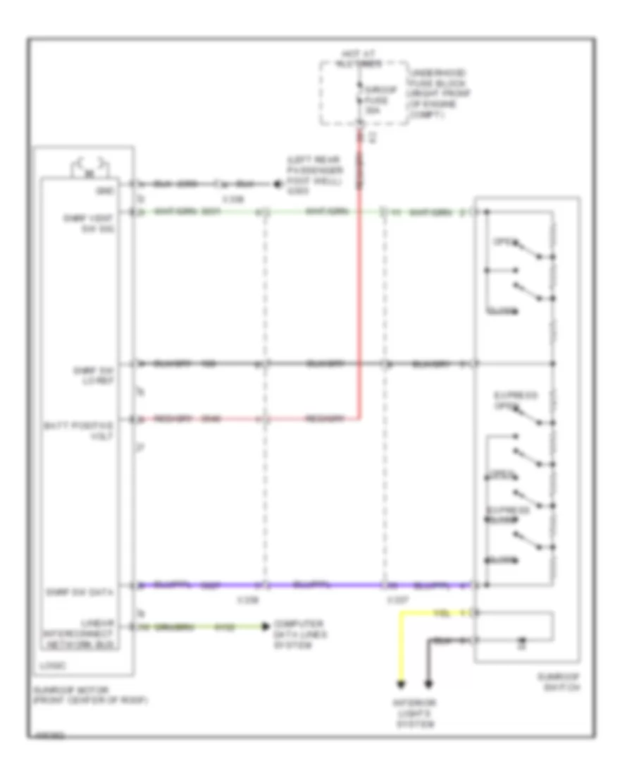
- Sunroof motor (if equipped) (front center of roof)
- Transmission shift lever position indicator (a/t)
- W/ collision avoidance
- W/ start stop system, wind shield wiper system vehicle interior movement sensor & vehicle inclination sensor
- W/o collision avoidance
- W/o start stop system, wind shield wiper system vehicle interior movement sensor & vehicle inclination sensor
- X211
- X225
- X275
- X322
- X338
- X901
Computer Data Lines Wiring Diagram (6 of 7) for Cadillac ATS 2013
List of elements for Computer Data Lines Wiring Diagram (6 of 7) for Cadillac ATS 2013:
- (forward of right rear lamp assembly) (if equipped) suspension control module
- (right) breakout)
- (sunroof harness, 7cm from sunshade mirror lamp
- Communication enable
- Content theft deterrent sensor module
- Enable communication serial data
- Fuel pump control module
- Hi spd gmlan ser data + (1)
- Hi spd gmlan ser data + (2) inflatable restraint sensing & diagnostic module (rearward of transmission shift lever on floor)
- Hi spd gmlan ser data - (2)
- High speed gmlan ser data + (2)
- High speed gmlan ser data - (2)
- J208 (w/ color info display) (instrument panel harness, 9cm from wire channel in right instrument panel)
- J303
- Lo spd gmlan serial data
- Multi-axis acceleration sensor (below center console)
- Network bus 1 interconnect linear
- Rain/ ambient light sensor module (center top of windshield)
- Ser data + (1) hi spd gmlan
- Ser data + (2) hi spd gmlan
- Ser data - (1) hi spd gmlan
- Serial data
- W/ collision avoidance
- W/ continously variable real time damping
- W/ vehicle interior movement sensor & vehicle inclination sensor
- W/ windshield wiper system
- W/ windshield wiper system, vehicle interior movement sensor & vehicle inclination sensor
- W/o collision avoidance
- W/o continously variable real time damping
- W/o windshield wiper system, vehicle interior movement sensor & vehicle inclination sensor
- X225
- X275
- X306
- X335
Computer Data Lines Wiring Diagram (7 of 7) for Cadillac ATS 2013
List of elements for Computer Data Lines Wiring Diagram (7 of 7) for Cadillac ATS 2013:
- (right front of engine compt) engine control module
- A/t
- Accessory wakeup serial data
- Automatic transmission assembly (a/t)
- Control solenoid valve assembly
- Electronic brake control module (forward of right front strut tower)
- Hi spd gmlan ser data - (2)
- High speed bus terminating resistor (forward of right rear lamp assembly, taped to harness)
- High speed gmlan serial data + (1)
- High speed gmlan serial data + (2)
- High speed gmlan serial data - (1)
- High speed gmlan serial data - (2)
- M/t
- Parking brake control module (behind left rear wheelhouse panel liner)
- Power steering control module (part of steering gear rack)
- Ser data + (2) hi spd gmlan
- Ser data - (2) hi spd gmlan
- Serial data communication enable
- Steering wheel angle sensor (below steering wheel around shaft)
- X150
- X275
- X403
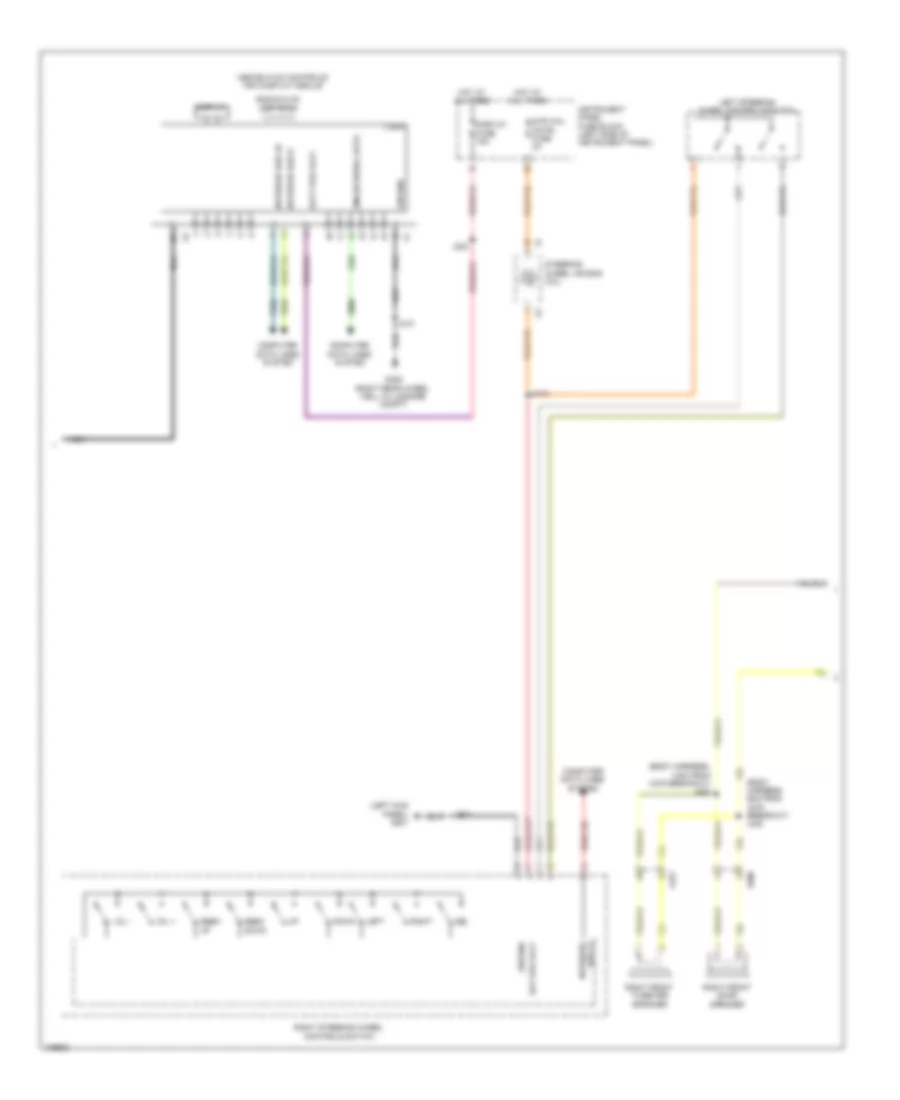
COOLING FAN
Cooling Fan Wiring Diagram for Cadillac ATS 2013
List of elements for Cooling Fan Wiring Diagram for Cadillac ATS 2013:
- 3.6l
- 3.6l w/ engine oil
- Aos disply/ mil ign fuse 5a
- Auxiliary underhood fuse block (right front of engine compt)
- Batt + volt
- Computer data lines system
- Cooling fan control module (engine cooling fan assembly)
- Cooling fan fuse 60a
- Cooling fan motor
- Cooling system & 2.0l w/ extra capacity
- Cooling temp sens 2 lo ref
- Cooling temp sens 2 sig
- Ecm ign fuse 15a
- Eng cool ctrl
- Eng temp sens sig
- Engine control module (ecm) (right front of engine compt)
- Engine coolant temperature gauge
- Engine coolant temperature indicator
- Engine coolant temperature sensor (3.6l: near mechanical vacuum pump) (except 3.6l: in thermostat housing)
- Engine coolant temperature sensor 2 (2.5l)
- Engine coolant thermostat heater (2.5l) (front of engine)
- Except 3.6l
- Except 3.6l w/ engine oil cooling system & 2.0l w/ extra capacity
- Fuse 4 70a
- G102 (above right headlight)
- G107 (on front of right cylinder head)
- G201 (left kick panel)
- Gmlan serial data (+)
- Gmlan serial data (-)
- Gnd
- Ground
- Hot at all times
- Hot w/ engine controls ignition relay energized
- Hot w/ ignition main relay energized
- Ign 1 volt
- Ign coil inj fuse 15a
- Instrument cluster
- J132
- Logic
- Run/crank ignition 1 volt
- Sens lo ref
- Serial data
- Sig gnd
- Speed sig
- Speed signal
- Underhood fuse block (right front of engine compt)
- X126
- X150
- X275
CRUISE CONTROL
Cruise Control Wiring Diagram (1 of 2) for Cadillac ATS 2013
List of elements for Cruise Control Wiring Diagram (1 of 2) for Cadillac ATS 2013:
- (behind glove box)
- (or 6109)
- (or 6110)
- (or 6111)
- 12 volt ref
- A/t
- Accelerator pedal position sensor (on accelerator pedal)
- Adap cru ctrl gap up/dwn sw sig x3
- App 5v ref (1)
- App 5v ref (2)
- App low ref (1)
- App low ref (2)
- App sig (1)
- App sig (2)
- Battery positive volt
- Body control module
- Computer data lines system
- Cru ctrl set/coast/ res/acc sw sig
- Cruise/etc/tcc brk sig
- Ecm/ batt fuse 10a
- Engine control module (right front of engine compt)
- G107 (on front of right cylinder head)
- Ground
- Hi spd gmlan serial data (+)
- Hi spd gmlan serial data (-)
- Hot at all times
- Logic
- M/t
- Neu gear sens return
- Neu gear sens sig (1)
- O/p spd (digital) 5v sens ref
- O/p spd (digital) 5v sens return
- O/p spd (digital) sig
- Rear compartment fuse block (left side of luggage compt)
- Tac mtr ctrl clse
- Tac mtr ctrl opn
- Throttle body (front of engine)
- Tp sens (sent1) sig
- Tp sens 5 volt refr
- Tp sens low ref
- Transmission output shaft speed sensor (m/t) (right rear of transmission)
- X150
- X275
Cruise Control Wiring Diagram (2 of 2) for Cadillac ATS 2013
List of elements for Cruise Control Wiring Diagram (2 of 2) for Cadillac ATS 2013:
- A/t
- Adaptive cruise ind
- Automatic transmission assembly (a/t)
- Batt positive volt
- Brake pedal position sensor (on brake pedal bracket)
- Cancel switch
- Clutch pedal position sensor (on clutch master cylinder push rod)
- Computer data lines system
- Control solenoid valve assembly
- Cruise ind
- Cruise switch
- Disply fuse 15a
- Driver information center display
- G201 (left kick panel)
- Gap up/down switch
- Gnd
- Hot at all times
- Instrument cluster
- Instrument panel fuse block (left side of instrument panel)
- J127
- J202
- Left steering wheel controls switch
- Logic
- M/t
- Most serial data (+)
- Most serial data (-)
- Neutral position sensor (2.0l turbo) (left rear of transmission)
- Red
- Res+
- Set-
- Steering wheel air bag coil
- Transmission control module
- Transmission input shaft speed sensor
- Transmission output shaft speed sensor
- X150
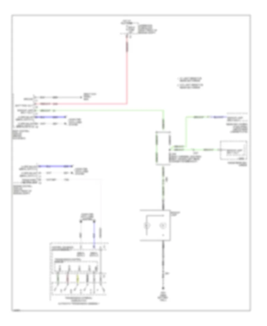
DEFOGGERS
Defoggers Wiring Diagram for Cadillac ATS 2013
List of elements for Defoggers Wiring Diagram for Cadillac ATS 2013:
- (left kick panel)
- 87b
- Battery fuse block (on battery)
- Computer data lines system
- Driver outside rearview mirror
- Driver outside rearview mirror glass
- Fuse 60a
- G301
- G302 (right kick panel)
- G401 (near battery well)
- G404 (right "c" pillar)
- Hot at all times
- Htd mir fuse 10a
- Hvac control module (near right kick panel)
- Info display module (above hvac controls)
- J500
- J600
- Left rear window defogger noise filter (on left "c" pillar)
- Logic
- Mirrors system
- Nca
- Network 9
- Passenger outside rearview mirror
- Passenger outside rearview mirror glass
- Rear body fuse block
- Rear defog fuse 40a
- Rear defog rly ctrl
- Rear defogger grid
- Rear defogger ind
- Rear defogger relay
- Rear defogger switch
- Right rear window defogger noise filter (on right "c" pillar)
- Serial data
- X275
- X500
- X510
- X600
- X610
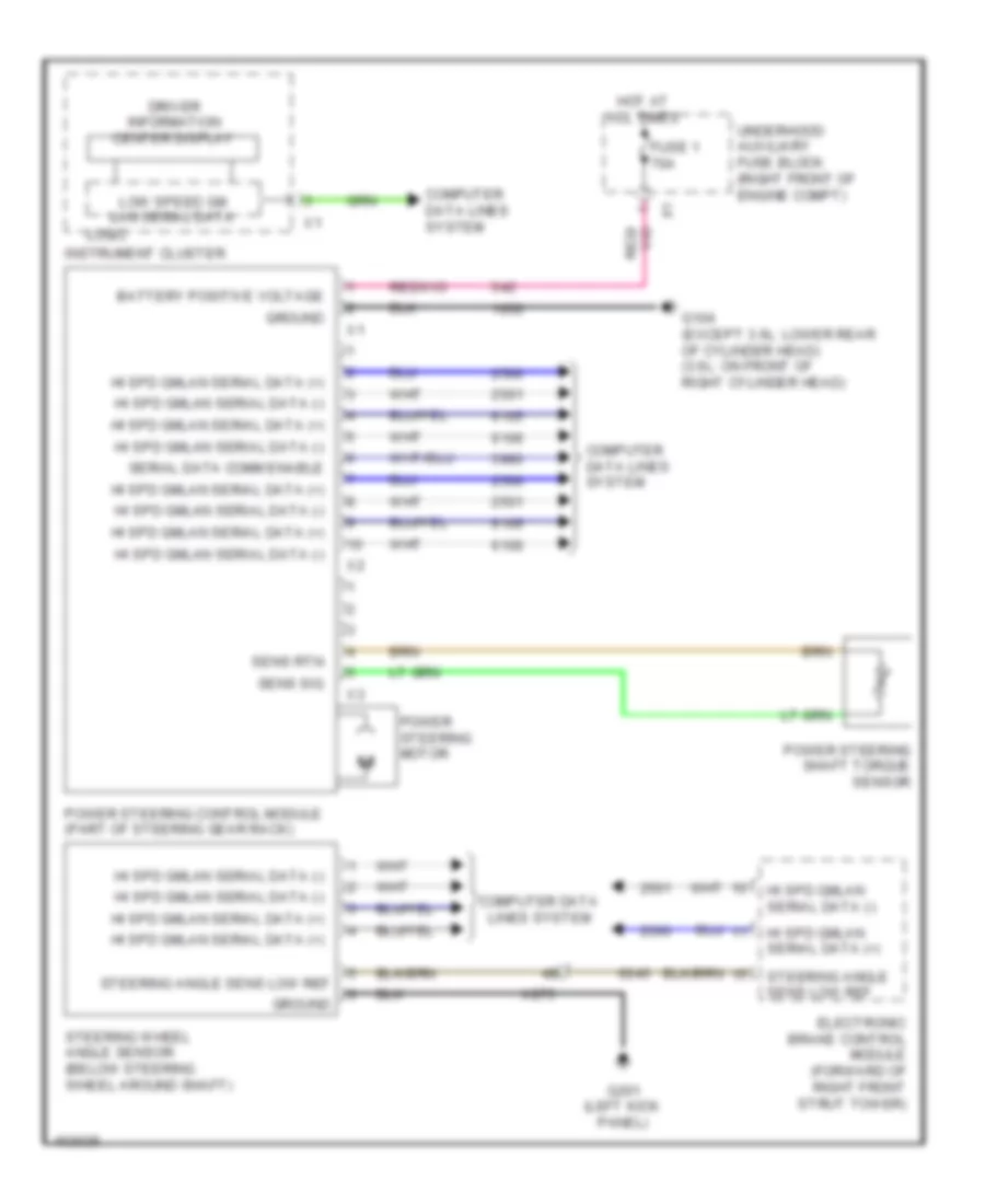
ELECTRONIC POWER STEERING
Electronic Power Steering Wiring Diagram for Cadillac ATS 2013
List of elements for Electronic Power Steering Wiring Diagram for Cadillac ATS 2013:
- Battery positive voltage
- Computer data lines system
- Driver information center display
- Electronic brake control module (forward of right front strut tower)
- Fuse 1 70a
- G104 (except 3.6l: lower rear of cylinder head) (3.6l: on front of right cylinder head)
- G201 (left kick panel)
- Ground
- Hi spd gmlan serial data (+)
- Hi spd gmlan serial data (-)
- Hot at all times
- Instrument cluster
- Logic
- Low speed gm lan serial data
- Power steering control module (part of steering gear rack)
- Power steering motor
- Power steering shaft torque sensor
- Sens rtn
- Sens sig
- Serial data comm enable
- Steering angle sens low ref
- Steering wheel angle sensor (below steering wheel around shaft)
- Underhood auxiliary fuse block (right front of engine compt)
- X275
ELECTRONIC SUSPENSION
Electronic Suspension Wiring Diagram for Cadillac ATS 2013
List of elements for Electronic Suspension Wiring Diagram for Cadillac ATS 2013:
- Battery positive volt
- Computer data lines system
- Driver information center display
- G303 (left rear passenger foot well)
- Gmlan ser data (+)
- Gmlan ser data (-)
- Gnd
- Hot at all times
- Instrument cluster
- Left front shock absorber actuator (on strut)
- Left front suspension position sensor (bottom of strut)
- Left rear shock absorber actuator (on strut)
- Left rear suspension position sensor (bottom of strut)
- Lf strut motor decrease damp ctrl
- Lf strut motor increase damp ctrl
- Lf strut pos snsr low ref
- Lf strut pos snsr sig
- Lf strut pos snsr volt ref
- Logic
- Lr strut motor decrease damp ctrl
- Lr strut motor increase damp ctrl
- Lr strut pos snsr low ref
- Lr strut pos snsr sig
- Lr strut pos snsr volt ref
- Nca
- Rear compartment fuse block (left side of luggage compartment)
- Rf strut motor decrease damp ctrl
- Rf strut motor increase damp ctrl
- Rf strut pos snsr low ref
- Rf strut pos snsr sig
- Rf strut pos snsr volt ref
- Right front shock absorber actuator (on strut)
- Right front suspension position sensor (bottom of strut)
- Right rear shock absorber actuator (on strut)
- Right rear suspension position sensor (bottom of strut)
- Rr strut motor decrease damp ctrl
- Rr strut motor increase damp ctrl
- Rr strut pos snsr low ref
- Rr strut pos snsr sig
- Rr strut pos snsr volt ref
- Sads fuse 25a
- Serial data comm enable
- Suspension control module (forward of right rear lamp assembly)
- X127
- X402
ENGINE PERFORMANCE
2.0L VIN X
2.0L VIN X, Engine Performance Wiring Diagram (1 of 7) for Cadillac ATS 2013
List of elements for 2.0L VIN X, Engine Performance Wiring Diagram (1 of 7) for Cadillac ATS 2013:
- (body harness, 95cm from front wire channel under passenger seat)
- (or 3200)
- (or 3201)
- (or 6109)
- (or 6110)
- (or 6111)
- (right rear frame near vapor canister) fuel tank pressure sensor
- 5 volt ref
- 5-v ref
- 5v ref
- A/c compressor clutch rly ctrl
- A/c press sens 5v ref
- A/c refrigerant press sens lo ref
- A/c refrigerant pressure sens sig
- A/c refrigerant pressure sensor (near the lower right side of the a/c condenser)
- A/t
- Accessory wakeup serial data
- Air conditioning system
- Air pressure sig
- Air pump rly coil ctrl
- Air solenoid rly coil ctrl
- App lo ref
- App low ref
- App sens sig (1)
- App sens sig (2)
- Batt pos volt
- Brake pedal position sensor (on brake pedal bracket)
- Brake vacuum sens low ref
- Brake vacuum sens sig
- Check engine ind ctrl
- Clutch pedal position sensor (on clutch master cylinder push rod)
- Cnstr vent fuse 10a
- Computer data lines system
- Coolant temp sens sig (2)
- Cooling fan rly ctrl spd sig
- Cooling fans system
- Cruise control system
- Cruise/etc/tcc brk sig
- Ecm/ batt fuse 10a
- Engine control module (right front of engine compt)
- Evap canister vent sol ctrl
- Evaporative emission vent solenoid valve (right rear frame near fuel tank)
- Fuel level sens lo ref
- Fuel pump fscm fuse 20a
- Fuel pump primary relay control
- Fuel tank pressure sens sig
- Hi spd gmlan serial data (+)
- Hi spd gmlan serial data (-)
- Hot at all times
- J335
- Low ref
- M/t
- Powertrain main rly fused sply (1)
- Powertrain main rly fused sply (2)
- Powertrain rly coil ctrl
- Pre-throttle air press & temp sig
- Primary fuel level sens sig
- Rear body fuse block (left side of luggage compt)
- Run/crank ign 1 volt
- Secondary fuel level sens lo ref
- Sens 2 low ref
- Sens sig
- Starter enable rly ctrl
- Starting/charging system
- X150
2.0L VIN X, Engine Performance Wiring Diagram (2 of 7) for Cadillac ATS 2013
List of elements for 2.0L VIN X, Engine Performance Wiring Diagram (2 of 7) for Cadillac ATS 2013:
- (on accelerator pedal) accelerator pedal position sensor
- (upper rear of cylinder head) g110
- 2.0l turbo
- 2.5l
- 5v ref
- Air pump fuse 50a
- Air sol fuse 15a
- Bare
- Batt
- Brake booster vacuum sensor (2.0l turbo) (on brake booster)
- Computer data lines system
- Data bus +
- Data bus -
- Ecm ign fuse 15a
- From engine controls a ignition relay (diagram 3 of 7)
- Fuel pressure sensor (near fuel tank)
- Fuel pump & level sensor assembly (top of fuel tank)
- Fuel pump control module (forward of right rear lamp assembly)
- G303 (left rear passenger foot well)
- Ground
- Hot at all times
- Hot w/ ignition main relay energized
- J404
- J405
- J411
- J412
- Low ref
- Motor
- Primary fuel level sensor
- Rly ctrl
- Run/crank volt
- Secondary air injection pump (2.5l) (left front of engine)
- Secondary air injection pump relay (2.5l)
- Secondary air injection solenoid valve relay (2.5l)
- Secondary fuel level sensor
- Sens sig
- Ser data enable
- Shield
- Sol ctrl 1
- Sol ctrl 2
- Sply volt
- Turbocharger boost/ intake air temperature sensor (2.0l turbo) (on inlet duct to throttle body)
- Underhood fuse block (right front of engine compt)
- X150
- X350
- X454
2.0L VIN X, Engine Performance Wiring Diagram (3 of 7) for Cadillac ATS 2013
List of elements for 2.0L VIN X, Engine Performance Wiring Diagram (3 of 7) for Cadillac ATS 2013:
- (not used)
- Aos disply/ mil ign fuse 5a
- Auxiliary underhood fuse block (right front of engine compt)
- Ecm fuse 25a
- Engine controls ignition relay
- Engine coolant temperature sensor (in thermostat housing)
- Engine oil pressure sensor (on engine oil cooler)
- Exhaust camshaft position actuator solenoid valve (top left of engine on camshaft cover)
- Fscm ign fuse 10a
- High pressure fuel pump (upper right side of engine)
- Hot w/ ignition main relay energized
- Htd str whl fuse 15a
- Ign coil inj fuse 15a
- Ign coil inj/ spare fuse 15a
- J140
- Left front engine mount actuator (lower front near core support)
- O2 snsr emis fuse 10a
- Power distribution system
- Red
- Right front engine mount actuator (lower front near core support)
- To secondary air injection pump relay (diagram 2 of 7)
- Underhood fuse block (right front of engine compt)
- X150
2.0L VIN X, Engine Performance Wiring Diagram (4 of 7) for Cadillac ATS 2013
List of elements for 2.0L VIN X, Engine Performance Wiring Diagram (4 of 7) for Cadillac ATS 2013:
- (above cylinders)
- 5v ref
- Actuator hi ctrl
- Actuator low ctrl
- Anti- theft system
- Cam exht sol (1)
- Cam intke sol (1)
- Cam pos exht sply
- Cam pos intke sens
- Cam pos intke sply
- Chk eng ind ctrl
- Computer data lines system
- Crnk 60x sens volt
- Crnk sens sig
- Data (+)
- Data (-)
- Dfi hi vol sply 1
- Dfi hi vol sply 2
- Dfi hi vol sply 3
- Dfi hi vol sply 4
- Ect sens sig
- Engine control module (right front of engine compt)
- G110 (upper rear of cylinder head)
- G201 (left kick panel)
- Gnd
- Hood status sig
- Ign 1 volt
- Ign ctrl (1)
- Ign ctrl (2)
- Ign ctrl (3)
- Ign ctrl (4)
- Ignition coil 1
- Ignition coil 2
- Ignition coil 3
- Ignition coil 4
- Instrument cluster
- J131 (engine harness, 6 cm from ignition coil 1 breakout)
- J133 (engine harness, 3 cm from evaporative emission purge solenoid valve breakout)
- Logic
- Low ref
- Low ref bank 1
- Malfunction ind lamp
- Nca
- Neu gear sens rtn
- Neu gear sens sply
- Neutral position sensor (m/t) (left rear of transmission)
- Oil press sens sig
- Red
- Sens lo ref
- Serial
- Spark plug
- Sply volt
- X275
2.0L VIN X, Engine Performance Wiring Diagram (5 of 7) for Cadillac ATS 2013
List of elements for 2.0L VIN X, Engine Performance Wiring Diagram (5 of 7) for Cadillac ATS 2013:
- (left rear of engine) engine oil pressure control solenoid valve
- Battery fuse block (on battery)
- Crankshaft position sensor (lower left rear of the engine)
- Dfi hi vol sply 1
- Dfi hi vol sply 2
- Dfi hi vol sply 3
- Dfi hi vol sply 4
- Engine control module (right front of engine compt)
- Exhaust camshaft position sensor (rear of cylinder head)
- Fuel
- Fuse 300a
- G110 (upper rear of cylinder head)
- Gnd
- Hot at all times
- Injector 1
- Injector 2
- Injector 3
- Injector 4
- Intake camshaft position actuator solenoid valve (top right of engine on camshaft cover)
- Intake camshaft position sensor (front of cylinder head)
- Low ref
- Red
- X160
2.0L VIN X, Engine Performance Wiring Diagram (6 of 7) for Cadillac ATS 2013
List of elements for 2.0L VIN X, Engine Performance Wiring Diagram (6 of 7) for Cadillac ATS 2013:
- (awd: front of oil pan) (except awd: right side of oil pan) engine oil level switch
- (engine harness, 21cm from main branch from x150) j134
- (engine harness, 37cm from manifold absolute pressure sensor breakout) j132
- (on air cleaner assembly) multi-function intake air sensor
- (on intake manifold) evaporative emission purge solenoid valve
- (right rear of transmission) (m/t) transmission output shaft speed sensor
- 2.0l turbo
- 2.5l
- A/t
- Engine coolant thermostat heater (2.5l) (front of engine)
- G110 (upper rear of cylinder head)
- G202 (left kick panel)
- Knock sensor 1 (2.0l: right of oil filter housing)
- Knock sensor 2 (2.0l: right of crankshaft position sensor)
- M/t
- Turbocharger bypass solenoid valve (2.0l turbo) (on turbocharger)
- Turbocharger wastegate solenoid valve (2.0l turbo) (on turbocharger)
- Vehicle stability control switch
- X150
- X211
- X275
2.0L VIN X, Engine Performance Wiring Diagram (7 of 7) for Cadillac ATS 2013
List of elements for 2.0L VIN X, Engine Performance Wiring Diagram (7 of 7) for Cadillac ATS 2013:
- (2.0l: in catalytic converter) (2.5l: in exhaust manifold) heated oxygen sensor 1
- (after catalytic converter) heated oxygen sensor 2
- 5v ref
- 5v ref fuel rail press sens sig
- Air temp sens sig
- Bank 1 sens (1)
- Bank 1 sens (2)
- Bank 1 snsr (1)
- Bank 1 snsr (2)
- Charge ind ctrl
- Crnk pos sens sig
- Ctrl bank (1)
- Drv mod sw sig
- Eng cool ctrl
- Engine control module (right front of engine compt)
- Fuel rail pressure sensor (on engine fuel rail)
- G110 (upper rear of cylinder head)
- Generator field
- Gnd
- Hi ref bank 1
- Iat sens low ref
- Knock sens (1)
- Knock sens (2)
- Knock sens sig (1)
- Knock sens sig (2)
- Logic
- Low ref
- Maf sens sig
- Manifold absolute pressure sensor (on intake manifold near throttle body)
- Map low ref
- Map sens sig
- Nca
- Neu gear sens sig
- Oil level sw sig
- Oil pmp sig
- Out spd 5v rtn
- Out spd sig
- Purge sol ctrl
- Secondary air injection solenoid valve (2.5l) (rear of exhaust manifold)
- Sens sig
- Sens sig bank (1)
- Sound systems
- Sply volt
- Starting/charging system
- Tac close
- Tac open
- Tac sens sig
- Throttle body (front of engine)
- Trans prk/neu sig
- Transmissions system
- Wast gat sol ctrl
- X160
2.5L VIN A
2.5L VIN A, Engine Performance Wiring Diagram (1 of 7) for Cadillac ATS 2013
List of elements for 2.5L VIN A, Engine Performance Wiring Diagram (1 of 7) for Cadillac ATS 2013:
- (body harness, 95cm from front wire channel under passenger seat)
- (or 3200)
- (or 3201)
- (or 6109)
- (or 6110)
- (or 6111)
- (right rear frame near vapor canister) fuel tank pressure sensor
- 5 volt ref
- 5-v ref
- 5v ref
- A/c compressor clutch rly ctrl
- A/c press sens 5v ref
- A/c refrigerant press sens lo ref
- A/c refrigerant pressure sens sig
- A/c refrigerant pressure sensor (near the lower right side of the a/c condenser)
- A/t
- Accessory wakeup serial data
- Air conditioning system
- Air pressure sig
- Air pump rly coil ctrl
- Air solenoid rly coil ctrl
- App lo ref
- App low ref
- App sens sig (1)
- App sens sig (2)
- Batt pos volt
- Brake pedal position sensor (on brake pedal bracket)
- Brake vacuum sens low ref
- Brake vacuum sens sig
- Check engine ind ctrl
- Clutch pedal position sensor (on clutch master cylinder push rod)
- Cnstr vent fuse 10a
- Computer data lines system
- Coolant temp sens sig (2)
- Cooling fan rly ctrl spd sig
- Cooling fans system
- Cruise control system
- Cruise/etc/tcc brk sig
- Ecm/ batt fuse 10a
- Engine control module (right front of engine compt)
- Evap canister vent sol ctrl
- Evaporative emission vent solenoid valve (right rear frame near fuel tank)
- Fuel level sens lo ref
- Fuel pump fscm fuse 20a
- Fuel pump primary relay control
- Fuel tank pressure sens sig
- Hi spd gmlan serial data (+)
- Hi spd gmlan serial data (-)
- Hot at all times
- J335
- Low ref
- M/t
- Powertrain main rly fused sply (1)
- Powertrain main rly fused sply (2)
- Powertrain rly coil ctrl
- Pre-throttle air press & temp sig
- Primary fuel level sens sig
- Rear body fuse block (left side of luggage compt)
- Run/crank ign 1 volt
- Secondary fuel level sens lo ref
- Sens 2 low ref
- Sens sig
- Starter enable rly ctrl
- Starting/charging system
- X150
2.5L VIN A, Engine Performance Wiring Diagram (2 of 7) for Cadillac ATS 2013
List of elements for 2.5L VIN A, Engine Performance Wiring Diagram (2 of 7) for Cadillac ATS 2013:
- (on accelerator pedal) accelerator pedal position sensor
- (upper rear of cylinder head) g110
- 2.0l turbo
- 2.5l
- 5v ref
- Air pump fuse 50a
- Air sol fuse 15a
- Bare
- Batt
- Brake booster vacuum sensor (2.0l turbo) (on brake booster)
- Computer data lines system
- Data bus +
- Data bus -
- Ecm ign fuse 15a
- From engine controls a ignition relay (diagram 3 of 7)
- Fuel pressure sensor (near fuel tank)
- Fuel pump & level sensor assembly (top of fuel tank)
- Fuel pump control module (forward of right rear lamp assembly)
- G303 (left rear passenger foot well)
- Ground
- Hot at all times
- Hot w/ ignition main relay energized
- J404
- J405
- J411
- J412
- Low ref
- Motor
- Primary fuel level sensor
- Rly ctrl
- Run/crank volt
- Secondary air injection pump (2.5l) (left front of engine)
- Secondary air injection pump relay (2.5l)
- Secondary air injection solenoid valve relay (2.5l)
- Secondary fuel level sensor
- Sens sig
- Ser data enable
- Shield
- Sol ctrl 1
- Sol ctrl 2
- Sply volt
- Turbocharger boost/ intake air temperature sensor (2.0l turbo) (on inlet duct to throttle body)
- Underhood fuse block (right front of engine compt)
- X150
- X350
- X454
2.5L VIN A, Engine Performance Wiring Diagram (3 of 7) for Cadillac ATS 2013
List of elements for 2.5L VIN A, Engine Performance Wiring Diagram (3 of 7) for Cadillac ATS 2013:
- (not used)
- Aos disply/ mil ign fuse 5a
- Auxiliary underhood fuse block (right front of engine compt)
- Ecm fuse 25a
- Engine controls ignition relay
- Engine coolant temperature sensor (in thermostat housing)
- Engine oil pressure sensor (on engine oil cooler)
- Exhaust camshaft position actuator solenoid valve (top left of engine on camshaft cover)
- Fscm ign fuse 10a
- High pressure fuel pump (upper right side of engine)
- Hot w/ ignition main relay energized
- Htd str whl fuse 15a
- Ign coil inj fuse 15a
- Ign coil inj/ spare fuse 15a
- J140
- Left front engine mount actuator (lower front near core support)
- O2 snsr emis fuse 10a
- Power distribution system
- Red
- Right front engine mount actuator (lower front near core support)
- To secondary air injection pump relay (diagram 2 of 7)
- Underhood fuse block (right front of engine compt)
- X150
2.5L VIN A, Engine Performance Wiring Diagram (4 of 7) for Cadillac ATS 2013
List of elements for 2.5L VIN A, Engine Performance Wiring Diagram (4 of 7) for Cadillac ATS 2013:
- (above cylinders)
- 5v ref
- Actuator hi ctrl
- Actuator low ctrl
- Anti- theft system
- Cam exht sol (1)
- Cam intke sol (1)
- Cam pos exht sply
- Cam pos intke sens
- Cam pos intke sply
- Chk eng ind ctrl
- Computer data lines system
- Crnk 60x sens volt
- Crnk sens sig
- Data (+)
- Data (-)
- Dfi hi vol sply 1
- Dfi hi vol sply 2
- Dfi hi vol sply 3
- Dfi hi vol sply 4
- Ect sens sig
- Engine control module (right front of engine compt)
- G110 (upper rear of cylinder head)
- G201 (left kick panel)
- Gnd
- Hood status sig
- Ign 1 volt
- Ign ctrl (1)
- Ign ctrl (2)
- Ign ctrl (3)
- Ign ctrl (4)
- Ignition coil 1
- Ignition coil 2
- Ignition coil 3
- Ignition coil 4
- Instrument cluster
- J131 (engine harness, 6 cm from ignition coil 1 breakout)
- J133 (engine harness, 3 cm from evaporative emission purge solenoid valve breakout)
- Logic
- Low ref
- Low ref bank 1
- Malfunction ind lamp
- Nca
- Neu gear sens rtn
- Neu gear sens sply
- Neutral position sensor (m/t) (left rear of transmission)
- Oil press sens sig
- Red
- Sens lo ref
- Serial
- Spark plug
- Sply volt
- X275
2.5L VIN A, Engine Performance Wiring Diagram (5 of 7) for Cadillac ATS 2013
List of elements for 2.5L VIN A, Engine Performance Wiring Diagram (5 of 7) for Cadillac ATS 2013:
- (left rear of engine) engine oil pressure control solenoid valve
- Battery fuse block (on battery)
- Crankshaft position sensor (lower left rear of the engine)
- Dfi hi vol sply 1
- Dfi hi vol sply 2
- Dfi hi vol sply 3
- Dfi hi vol sply 4
- Engine control module (right front of engine compt)
- Exhaust camshaft position sensor (rear of cylinder head)
- Fuel
- Fuse 300a
- G110 (upper rear of cylinder head)
- Gnd
- Hot at all times
- Injector 1
- Injector 2
- Injector 3
- Injector 4
- Intake camshaft position actuator solenoid valve (top right of engine on camshaft cover)
- Intake camshaft position sensor (front of cylinder head)
- Low ref
- Red
- X160
2.5L VIN A, Engine Performance Wiring Diagram (6 of 7) for Cadillac ATS 2013
List of elements for 2.5L VIN A, Engine Performance Wiring Diagram (6 of 7) for Cadillac ATS 2013:
- (awd: front of oil pan) (except awd: right side of oil pan) engine oil level switch
- (engine harness, 21cm from main branch from x150) j134
- (engine harness, 37cm from manifold absolute pressure sensor breakout) j132
- (on air cleaner assembly) multi-function intake air sensor
- (on intake manifold) evaporative emission purge solenoid valve
- (right rear of transmission) (m/t) transmission output shaft speed sensor
- 2.0l turbo
- 2.5l
- A/t
- Engine coolant thermostat heater (2.5l) (front of engine)
- G110 (upper rear of cylinder head)
- G202 (left kick panel)
- Knock sensor 1 (2.0l: right of oil filter housing)
- Knock sensor 2 (2.0l: right of crankshaft position sensor)
- M/t
- Turbocharger bypass solenoid valve (2.0l turbo) (on turbocharger)
- Turbocharger wastegate solenoid valve (2.0l turbo) (on turbocharger)
- Vehicle stability control switch
- X150
- X211
- X275
2.5L VIN A, Engine Performance Wiring Diagram (7 of 7) for Cadillac ATS 2013
List of elements for 2.5L VIN A, Engine Performance Wiring Diagram (7 of 7) for Cadillac ATS 2013:
- (2.0l: in catalytic converter) (2.5l: in exhaust manifold) heated oxygen sensor 1
- (after catalytic converter) heated oxygen sensor 2
- 5v ref
- 5v ref fuel rail press sens sig
- Air temp sens sig
- Bank 1 sens (1)
- Bank 1 sens (2)
- Bank 1 snsr (1)
- Bank 1 snsr (2)
- Charge ind ctrl
- Crnk pos sens sig
- Ctrl bank (1)
- Drv mod sw sig
- Eng cool ctrl
- Engine control module (right front of engine compt)
- Fuel rail pressure sensor (on engine fuel rail)
- G110 (upper rear of cylinder head)
- Generator field
- Gnd
- Hi ref bank 1
- Iat sens low ref
- Knock sens (1)
- Knock sens (2)
- Knock sens sig (1)
- Knock sens sig (2)
- Logic
- Low ref
- Maf sens sig
- Manifold absolute pressure sensor (on intake manifold near throttle body)
- Map low ref
- Map sens sig
- Nca
- Neu gear sens sig
- Oil level sw sig
- Oil pmp sig
- Out spd 5v rtn
- Out spd sig
- Purge sol ctrl
- Secondary air injection solenoid valve (2.5l) (rear of exhaust manifold)
- Sens sig
- Sens sig bank (1)
- Sound systems
- Sply volt
- Starting/charging system
- Tac close
- Tac open
- Tac sens sig
- Throttle body (front of engine)
- Trans prk/neu sig
- Transmissions system
- Wast gat sol ctrl
- X160
3.6L VIN 3
3.6L VIN 3, Engine Performance Wiring Diagram (1 of 6) for Cadillac ATS 2013
List of elements for 3.6L VIN 3, Engine Performance Wiring Diagram (1 of 6) for Cadillac ATS 2013:
- (at right rear frame near vapor canister) fuel tank pressure sensor
- (body harness, 10cm past tail lamp (right) connector breakout)
- (on accelerator pedal) accelerator pedal position sensor
- 5 volt ref
- 5v ref
- 5v ref (1)
- 5v ref (2)
- 5v reference
- A/c clutch rly ctrl
- A/c pressure sens 5v ref
- A/c refrigerant pressure sens sig
- A/c refrigerant pressure sensor (near the lower right side of the a/c condenser)
- Aero shutter fuse 10a
- Air conditioning system
- Anti-lock brakes system
- App sens sig (1)
- App sens sig (2)
- Batt pos volt
- Brake pedal position sensor (on brake pedal bracket)
- Brk pos sen sig
- Check engine ind ctrl
- Computer data lines system
- Cooling fan ctrl rly speed sig
- Cooling fans system
- Cruise/etc/tcc brake sig
- Ecm ign fuse 15a
- Engine control module (ecm) (right front of engine compt)
- Evap canister vent sol ctrl
- Evaporative emission vent solenoid valve (rear of engine on right cylinder head)
- Fuel pump
- Fuel pump & level sensor assembly (top of fuel tank)
- Fuel pump rly ctrl
- Fuel tank pressure sens sig
- Fuel temp sig
- Gmlan serial data bus +
- Gmlan serial data bus -
- Hot w/ ignition main relay energized
- Ign volt 1
- J335
- J406
- J412
- Low ref
- Low ref (1)
- Low ref (2)
- Powertrain main rly (1) sply
- Powertrain main rly (2) sply
- Powertrain main rly (3) sply
- Powertrain rly coil ctrl
- Pressure sens sig
- Primary fuel level sens sig
- Primary fuel level sensor
- Pump rly coil ctrl
- Secondary fuel level sens sig
- Secondary fuel level sensor (in fuel tank)
- Sens 2 gnd
- Sens 2 sply volt
- Sens low ref
- Sens sig 2
- Shield)
- Solenoid rly coil ctrl
- Starter enable rly ctrl
- Starting/ charging system
- Underhood fuse block (right front of engine compt)
- Wake-up ser data
- X150
- X275
- X454
3.6L VIN 3, Engine Performance Wiring Diagram (2 of 6) for Cadillac ATS 2013
List of elements for 3.6L VIN 3, Engine Performance Wiring Diagram (2 of 6) for Cadillac ATS 2013:
- (body harness, 5cm from battery saver module connector)
- (not used)
- (right front of engine compt) underhood fuse block
- 5v ref
- A/c compressor clutch relay
- Air pump fuse 50a
- Areo
- Auxiliary coolant pump relay
- Auxiliary underhood fuse block (right front of engine compt)
- Batt pos vol
- Cnstr vent fuse 10a
- Computer data lines system
- Ecm fuse 25a
- Ecm/ batt fuse 10a
- Engine controls ignition relay
- Exhaust bank 2 camshaft position actuator solenoid valve (lower center of left cylinder bank)
- Fscm ign fuse 10a
- Fuel pressure sensor (near fuel tank)
- Fuel pump control module (forward of right rear lamp assembly)
- Fuel pump fscm fuse 20a
- Fuel pump low ref
- Fuel shld extsn
- G303 (left rear passenger foot well)
- Gnd
- Hot at all times
- Hot w/ ignition main relay energized
- Ign 1 volt 1
- Ign coil inj fuse 15a
- Ign coil inj/spare fuse 15a
- Intake bank 2 camshaft position actuator solenoid valve (upper center of left cylinder bank)
- J401
- J404
- J405
- Low ref
- Nca
- Odd fuse 15a
- Power distribution system
- Press sens sig
- Pump rly ctrl
- Pump supy vol
- Rear body fuse block (left side of luggage compt)
- Red
- Secondary air injection pump relay
- Secondary air injection solenoid valve relay
- Ser data bus +
- Ser data bus -
- Ser data comm
- Shutter ctrl
- Snsr emis fuse 10a
- Spare pt fuse 10a
- X150
- X350
3.6L VIN 3, Engine Performance Wiring Diagram (3 of 6) for Cadillac ATS 2013
List of elements for 3.6L VIN 3, Engine Performance Wiring Diagram (3 of 6) for Cadillac ATS 2013:
- (awd: front of oil pan) (except awd: right side of oil pan) engine oil level switch
- (lower left rear of the engine) crankshaft position sensor
- (rear of left cylinder head) high pressure fuel pump
- (top of fuel tank) fuel composition sensor
- Active grille air shutter actuator (behind center of front fascia)
- Battery fuse block (on battery)
- Computer data lines system
- Ctrl aero
- Engine check
- Engine coolant temperature (ect) sensor (near mechanical vacuum pump)
- Exhaust bank 1 camshaft position actuator solenoid valve (lower center of right cylinder bank)
- Exhaust bank 2 camshaft position sensor (on left cylinder head)
- Fuse 300a
- G101 (above left headlight)
- G107 (on front of right cylinder head)
- G110 (left rear of engine above exhaust manifold)
- G303 (left rear passenger foot well)
- Gnd
- Hot at all times
- Ind ctrl
- Instrument cluster
- Intake bank 1 camshaft position actuator solenoid valve (upper center of right cylinder bank)
- Intake bank 1 camshaft position sensor (on right cylinder head)
- J111
- Logic
- Mal- function ind
- Red
- Secondary air injection (air) pump (left front of engine)
- Serial data
- Sig
- Sply (5)
- Volt ign 1
- X100
- X125
- X150
- X350
3.6L VIN 3, Engine Performance Wiring Diagram (4 of 6) for Cadillac ATS 2013
List of elements for 3.6L VIN 3, Engine Performance Wiring Diagram (4 of 6) for Cadillac ATS 2013:
- (above cylinder 1) ignition coil 1
- (above cylinder 2) ignition coil 2
- (above cylinder 3) ignition coil 3
- (above cylinder 4) ignition coil 4
- (above cylinder 5) ignition coil 5
- (above cylinder 6) ignition coil 6
- (engine harness, 4cm from ignition coil 5 on main harness) j133
- Actuator hi ctrl
- Actuator low ctrl
- Crk 6ox low ref
- Crk shf 6ox sens
- Ect sens sig
- Engine control module (ecm) (right front of engine compt)
- Exhaust sens 1 sig
- Exhaust sens 2 sig
- Exhaust solend (1)
- Exhaust solend (2)
- Exhaust sply (1)
- Fuel inj 1 ctrl
- Fuel inj 2 ctrl
- Fuel inj 3 ctrl
- Fuel inj 4 ctrl
- Fuel inj 5 ctrl
- Fuel inj 6 ctrl
- G109 (on front of right cylinder head)
- G110 (left rear of engine above exhaust manifold)
- Ign 1 ctrl
- Ign 2 ctrl
- Ign 3 ctrl
- Ign 4 ctrl
- Ign 5 ctrl
- Ign 6 ctrl
- Intake sens 1 sig
- Intake sens 2 sig
- Intake sens sply 1
- Intake sens sply 2
- Intake solend (1)
- Intake solend (2)
- J131
- J135
- J136
- Low ref
- Low ref (1)
- Low ref bank 1
- Low ref bank 2
- Nca
- Oil press sens sig
- Press sens 5v ref
- Press sens low ref
- Spark plug
3.6L VIN 3, Engine Performance Wiring Diagram (5 of 6) for Cadillac ATS 2013
List of elements for 3.6L VIN 3, Engine Performance Wiring Diagram (5 of 6) for Cadillac ATS 2013:
- (rear of engine on right cylinder head) evaporative emission purge solenoid valve
- Engine control module (ecm) (right front of engine compt)
- Engine oil pressure sensor (in oil filter housing)
- Exhaust camshaft position sensor (bank 1) (on right cylinder head)
- Exhaust sply (2)
- Fuel inj 1 ctrl
- Fuel inj 2 ctrl
- Fuel inj 3 ctrl
- Fuel inj 4 ctrl
- Fuel inj 5 ctrl
- Fuel inj 6 ctrl
- Fuel injector 1
- Fuel injector 2
- Fuel injector 3
- Fuel injector 4
- Fuel injector 5
- Fuel injector 6
- G107 (on front of right cylinder head)
- G110 (left rear of engine above exhaust manifold)
- G202 (left kick panel)
- Gnd
- Intake camshaft position sensor (bank 2) (on left cylinder head)
- J212
- Low ref
- Low ref (2)
- Secondary air injection (air) solenoid valve (bank 1) (on right cylinder head)
- Secondary air injection (air) solenoid valve (bank 2) (on left cylinder head)
- Vehicle stability control switch
- X160
- X161
- X211
3.6L VIN 3, Engine Performance Wiring Diagram (6 of 6) for Cadillac ATS 2013
List of elements for 3.6L VIN 3, Engine Performance Wiring Diagram (6 of 6) for Cadillac ATS 2013:
- (after left catalytic converter) heated oxygen sensor bank 2 sensor 2
- (after right catalytic converter) heated oxygen sensor bank 1 sensor 2
- (before left catalytic converter) heated oxygen sensor bank 2 sensor 1
- (before right catalytic converter) heated oxygen sensor bank 1 sensor 1
- 5-volt ref
- 5v ref
- Actuator ctrl close
- Air temp sens sig
- C tan
- Charge ind ctrl
- Crank pos sens sig
- Driver mode sw sig
- Duty cycle sig
- Engine control module (ecm) (right front of engine compt)
- Evap purge sol ctrl
- Frp sens sig
- Fuel rail pressure sensor (on engine fuel rail)
- G107 (on front of right cylinder head)
- Ground
- Hi bank 1 sens (1)
- Hi bank 1 sens (2)
- Hi bank 2 sens (1)
- Hi bank 2 sens (2)
- Ho2s htr low ctrl (1)
- Ho2s htr low ctrl (2)
- Humidity sens sig
- J132
- J134
- Knock sens 1 sig
- Knock sens 2 sig
- Knock sensor 1 (right side of engine block)
- Knock sensor 2 (lower left side of engine block)
- Logic
- Low bank 1 sens (1)
- Low bank 1 sens (2)
- Low bank 2 sens (1)
- Low bank 2 sens (2)
- Low ref
- Low ref (1)
- Low ref (2)
- Maf sens sig
- Manifold absolute pressure sensor (in engine compt)
- Map sens sig
- Multi-function intake air sensor (on air cleaner assembly)
- Navigation & sound systems
- Oil level sw sig
- Park/neutral sig (1)
- Sens sig
- Sply volt
- Starting/ charging system
- Tan
- Throttle actu ctrl open
- Throttle body (front of engine)
- Vlv 1 low ref
- X150
- X161
- X275
EXTERIOR LIGHTS
Backup Lamps Wiring Diagram for Cadillac ATS 2013
List of elements for Backup Lamps Wiring Diagram for Cadillac ATS 2013:
- (right kick panel) g302
- Automatic transmission assembly
- Backup lamp
- Backup lamp sply volt
- Batt pos volt
- Bcm 6 fuse 10a
- Body control module (behind glove box)
- Computer data lines system
- Control solenoid valve assembly
- Engine control module (right front of engine compt)
- G401 (near battery well)
- Gnd
- Ground
- Hi spd gmlan
- Hi spd gmlan serial data (+)
- Hi spd gmlan serial data (-) x1
- Hot at all times
- Inside rearview mirror
- J349 (body harness, 15cm from seat air bag (left rear) connector breakout)
- J901
- Logic
- Nca
- Rearview camera (if equipped) (above rear license plate)
- Rearview mirror
- Red
- Serial data (+)
- Serial data (-)
- Sig a
- Sig b
- Sig c
- Sig p
- Sply volt
- Trans park/ neutral sig x2
- Transmission control module
- Transmission internal mode switch
- Underhood fuse block (right front of engine compt)
- W/ light sensitive
- W/o light sensitive
- X337
- X901
Exterior Lamps Wiring Diagram (1 of 2) for Cadillac ATS 2013
List of elements for Exterior Lamps Wiring Diagram (1 of 2) for Cadillac ATS 2013:
- (body harness, 89cm from front wire channel under passenger seat)
- Aos display/ mil ign fuse 5a
- Auto
- Bat pos volt
- Bcm 5 fuse 15a
- Body control module (behind glove box)
- Coil sply volt
- Computer data lines system
- Driver outside rearview mirror
- Driver turn signal lamp
- G101 (above left headlight)
- G201 (left kick panel)
- G202 (left kick panel)
- G301 (left kick panel)
- G302 (right kick panel)
- G304 (right rear passenger foot well)
- Gmlan serial data (+)
- Gmlan serial data (-)
- Gnd
- Hazard led dimming sig
- Hazard sw left turn sig
- Hazard sw right turn sig
- Hazard sw sig
- Hazard warning switch
- Head
- Hot at all times
- Hot w/ ignition main relay energized
- J101 (forward lamp harness, 8cm from x126)
- J110 (front fascia harness, 22cm from breakout)
- J111
- J334
- J500
- J600
- Left
- Left park lp sply volt
- Lf turn sig sply volt
- Logic
- Lr turn sig sply volt
- Nca
- Off
- Park
- Park lamp sig
- Passenger outside rearview mirror
- Passenger turn signal lamp
- Rear lp sply volt
- Rear turn lp feedback sig
- Rf turn sig sply volt
- Right
- Right auxiliary daytime running lamp
- Right front park lamp
- Right front side marker lamp
- Right front turn signal lamp
- Right headlamp assembly
- Right park lp sply volt
- Right stop/ turn signal lamp
- Right tail lamp
- Right tail lamp assembly
- Rr turn lp feedback sig
- Rr turn sig sply volt
- Sens low ref
- Sens sig
- Sens sply volt
- Turn signal/ multi-function switch
- Underhood fuse block (right front of engine compt)
- W/ hid
- W/o hid
- X100
- X126
- X275
- X500
- X510
- X600
- X610
Exterior Lamps Wiring Diagram (2 of 2) for Cadillac ATS 2013
List of elements for Exterior Lamps Wiring Diagram (2 of 2) for Cadillac ATS 2013:
- (body harness, 108cm from front wire channel under passenger seat) (w/ trailer provisions) j337
- (on brake pedal bracket)
- Brake pedal position sensor
- Brk pos sens 5v ref
- Brk pos sens lo ref
- Brk pos sens sig
- Center high mounted stop lamp
- Computer data lines system
- Driver information center display
- Engine control module (right front of engine compt)
- G101 (above left headlight)
- G201 (left kick panel)
- G304 (right rear passenger foot well)
- G401 (near battery well)
- Gnd
- Hi spd gmlan serial data (+)
- Hi spd gmlan serial data (-)
- Instrument cluster
- J107 (forward lamp harness, 5cm down from x125)
- J111
- J116 (front fascia harness, 8cm down from daytime running lamp (left) breakout)
- J342 (body harness, 27cm from wire channel under left side of rear seat)
- J408 (body harness, 18cm from center high mounted stop lamp connector breakout)
- Left auxiliary daytime running lamp
- Left front park lamp
- Left front side marker lamp
- Left front turn signal lamp
- Left headlamp assembly
- Left license plate lamp
- Left stop/ turn signal lamp
- Left tail lamp
- Left tail lamp assembly
- Left turn ind
- Logic
- Nca
- Park lamps ind
- Right license plate lamp
- Right turn ind
- Run/crank ignition 1 volt
- Serial data (+) most
- Serial data (-) most
- Trailer tow circuit
- W/ hid
- W/o hid
- X100
- X126
- X150
Trailer Tow Wiring Diagram for Cadillac ATS 2013
List of elements for Trailer Tow Wiring Diagram for Cadillac ATS 2013:
- (body harness, 108cm from front wire channel under passenger seat)
- Batt pos volt
- Battery fuse block (on battery)
- Bcm 4 fuse 15a
- Body control module (behind glove box)
- Computer data lines system
- Exterior lamps circuit
- Fuse 1 60a
- G302 (right kick panel)
- G303 (left rear passenger foot well)
- G401 (near battery well)
- Gmlan serial data (+)
- Gmlan serial data (-)
- Gnd
- Ground
- Hot at all times
- Hot w/ ignition main relay energized
- Ign 1 volt
- J337
- Left trailer park lamp
- Left trailer turn sig lp
- Lo speed gmlan serial data
- Rear body fuse block
- Right trailer park lp
- Right trailer turn sig lp
- Run rly coil ctrl
- Stop lp rly coil sply volt
- Trailer backup lp
- Trailer brake lp
- Trailer connected sig
- Trailer fog lp
- Trailer ignition power relay
- Trailer lighting control module (near battery)
- Trlr conn fuse 30a
- Trlr fuse 30a
- Trlr mdl fuse 40a
- Trlr/ sunshd fuse 10a
GROUND DISTRIBUTION
Ground Distribution Wiring Diagram (1 of 7) for Cadillac ATS 2013
List of elements for Ground Distribution Wiring Diagram (1 of 7) for Cadillac ATS 2013:
- (if equipped) long range radar sensor module
- (if equipped) power sounder content theft deterrent alarm module
- (if equipped) short range left front radar sensor module
- (if equipped) short range right front radar sensor module
- (near left hood hinge)
- (right front of engine compt) underhood fuse block
- (w/ hid) right auxiliary day time running lamp
- (w/o start stop system) hood ajar switch
- Active grille air shutter actuator
- Brake booster pump motor relay (3.6l)
- Electronic brake control module
- G101 (above left headlight)
- G104 (3.6l: on front of right cylinder head) (except 3.6l: lower rear of cylinder head)
- G105
- G106 (near left hood hinge)
- G108 (left radiator support)
- G109 (3.6l) (on front of right cylinder head)
- Headlamp washer pump
- Headlamp washer pump relay (w/ high pressure headlamp washer)
- Ignition coil 1
- Ignition coil 3
- Ignition coil 5
- Ignition main relay
- J111 (front fascia harness, 14cm from front object sensor (right middle))
- J112 (front fascia harness, 23cm from front object sensor (right middle))
- J119
- Left front side marker lamp
- Left front turn signal lamp
- Left headlamp assembly
- Left headlamp ballast
- Left headlamp horizontal motor
- Left headlamp leveling actuator
- Left high beam solenoid actuator
- Left low beam headlamp
- Left lower park/ daytime running lamp
- Left park/ daytime running lamp
- Motor connector)
- Nca
- Power steering control module
- Right front side marker lamp
- Right lower park/ daytime running lamp
- W/ hid
- W/ high pressure washer-headlamp
- W/o hid
- W/o high pressure washer-headlamp
- Windshield washer fluid level switch
- Windshield washer pump
- Windshield washer pump relay
- Windshield wiper motor
- Windshield wiper relay
- X100
- X110
- X130
- X131
Ground Distribution Wiring Diagram (2 of 7) for Cadillac ATS 2013
List of elements for Ground Distribution Wiring Diagram (2 of 7) for Cadillac ATS 2013:
- (2.5l & 3.6l w/o engine oil cooling system & 2.0l turbo w/o extra capacity cooling system) cooling fan control module
- (2.5l & 3.6l) secondary air-injection pump
- (2.5l)
- (3.6l w/ engine oil cooling system & 2.0l turbo w/ extra capacity) cooling fan motor
- (3.6l) brake booster pump motor
- (3.6l) ignition coil 6
- (3.6l) secondary air-injection solenoid valve bank 1
- (3.6l) secondary air-injection solenoid valve bank 2
- (except 3.6l)
- (except 3.6l) automatic transmission assembly
- (except 3.6l) ignition coil 1
- (except 3.6l) ignition coil 3
- (right front of engine compt) underhood fuse block
- 6 speed a/t
- 6 speed m/t
- A/c compressor
- Automatic transmission assembly
- Backup lamp switch
- Body control module
- California
- Control solenoid valve assembly
- Engine control module
- Engine oil
- G102 (above right headlight)
- G103
- G107 (3.6l) (on front of right cylinder head)
- G110 (3.6l: left rear of engine above exhaust manifold (except 3.6l: upper rear of cylinder head)
- Horn assembly
- Ignition coil 2
- Ignition coil 4
- Intake air sensor
- J129
- Level switch
- Multi- function
- Nca
- Right front turn signal lamp
- Right headlamp assembly
- Right headlamp ballast
- Right headlamp horizontal motor
- Right headlamp leveling actuator
- Right high beam solenoid actuator
- Right low beam headlamp
- Right park/ daytime running lamp
- Secondary air-injection solenoid valve
- Starter relay
- W/ hid
- W/o hid
- X120
Ground Distribution Wiring Diagram (3 of 7) for Cadillac ATS 2013
List of elements for Ground Distribution Wiring Diagram (3 of 7) for Cadillac ATS 2013:
- (electronically operated parking brake) park brake control switch
- (if equipped) garage door opener
- (if equipped) head-up display
- (if equipped) head-up display switch
- (if equipped) pedestrian impact detection control module
- (if equipped) rain/ ambient light sensor module
- (if equipped) steering column lock module
- (if equipped) sunroof switch
- (if equipped) theft deterrent sensor disable switch
- (left side of instrument panel) instrument panel fuse block
- (w/ manual shift, automatic transmission) left transmission manual shift switch
- (w/ manual shift, automatic transmission) right transmission manual shift switch
- (w/ onstar) telematics button assembly
- (w/ vehicle inclination & interior movement sensor) content theft deterrent sensor module
- (w/o collision advanced) front view camera module
- (w/o headup display) collision alert indicators
- 6 speed a/t
- Battery
- Battery current sensor
- Battery saver relay 1
- Data link connector
- Dome lamp switch
- G201 (left kick panel)
- G205 (under center console)
- G306 (right rear wheel well in luggage compt)
- G400 (near battery well)
- G404 (right "c" pillar)
- Horn switch
- Ignition mode switch
- Inflatable restraint sensing & diagnostic module
- Inside rearview mirror
- Instrument cluster
- Instrument panel dimmer switch
- J299
- J2xx
- J302 (headliner/sunroof harness 5cm from dome lamp switch breakout)
- Left front dome/ reading lamps
- Left instrument panel courtesy lamp
- Left steering wheel controls switch
- Left sunshade
- Nca
- Overhead console accent lamp
- Passenger air bag disable indicator
- Passenger presence module
- Rear compartment courtesy lamp
- Red
- Retained accessory power relay
- Right front dome/ reading lamps
- Right rear window defogger noise filter
- Right steering wheel controls switch
- Right sunshade
- Steering wheel air bag coil
- Steering wheel angle sensor
- Steering wheel heater
- Steering wheel heating control module
- Turn signal/ multi-function switch
- W/ heated steering wheel
- X275
- X301
- X306
- X322
Ground Distribution Wiring Diagram (4 of 7) for Cadillac ATS 2013
List of elements for Ground Distribution Wiring Diagram (4 of 7) for Cadillac ATS 2013:
- (if equipped) driver back seat blower motor
- (if equipped) driver back seat heating element
- (if equipped) front seat heating control module
- (w/ memory) driver left rear seat haptic movement motor
- (w/ memory) driver right rear seat haptic movement motor
- (w/ memory) driver seat memory control module
- 6 speed a/t
- 6 speed m/t
- Blower motor
- Brake fluid level switch
- Center console accessory power receptacle
- Driver cushion seat heating element
- Driver door courtesy lamp
- Driver door latch assembly
- Driver door lock switch
- Driver door pocket flood lamp
- Driver door pull handle flood lamp
- Driver exterior door handle assembly
- Driver exterior door handle switch
- Driver outside rearview mirror
- Driver outside rearview mirror courtesy lamp
- Driver outside rearview mirror glass
- Driver seat adjuster switch
- Driver seat lumbar support motor
- Driver turn signal lamp
- Driver window motor
- Driver window switch
- G202 (left kick panel)
- G301 (left kick panel)
- Hazard warning switch
- Hvac control module
- Instrument panel accessory power receptacle
- Instrument panel compartment lamp
- Instrument panel multi-function switch
- Interior rear compartment lid unlatch switch
- J212 (trim plate jumper harness, 4cm from x211 breakout)
- J356
- J500 (driver's door harness, 13cm from speaker (left front door) breakout)
- J509 (driver's door trim harness, 3cm from door courtesy lamp (driver) breakout)
- Left mirror control module
- Multi-axis acceleration sensor
- Nca
- Outside rearview mirror switch
- Park brake control switch
- Right instrument panel courtesy lamp
- Traction control switch
- Transmission manual shift switch
- Transmission shift lever
- Transmission shift lever position indicator
- Vehicle stability control switch
- W/ head-up display
- W/ memory
- W/o head-up display
- W/o memory
- X206
- X211
- X224
- X321
- X500
- X506
- X510
Ground Distribution Wiring Diagram (5 of 7) for Cadillac ATS 2013
List of elements for Ground Distribution Wiring Diagram (5 of 7) for Cadillac ATS 2013:
- (3.6l) fuel composition sensor
- (if equipped) active safety control module
- (if equipped) left rear seat side air bag
- (if equipped) passenger back seat heating element
- (if equipped) passenger cushion seat heating element
- (if equipped) suspension control module
- Body control module
- Center console armrest left accent lamp
- Fuel pump control module
- G302 (right kick panel)
- G303 (left rear passenger foot well)
- J307 (headliner/sunroof harness, 41cm from harness tag)
- J374
- J600 (passenger door harness, 13cm from speaker (right front door) breakout)
- J609
- Left rear dome/ reading lamps
- Left rear door latch assembly
- Left rear door pocket
- Left rear door pull handle flood lamp
- Left rear exterior door handle courtesy lamp (if equipped)
- Left rear exterior door handle switch
- Left rear window switch
- Nca
- Passenger door courtesy lamp
- Passenger door latch assembly
- Passenger door lock switch
- Passenger door pocket flood lamp
- Passenger door pull handle flood lamp
- Passenger exterior door handle assembly
- Passenger exterior door handle switch
- Passenger outside rearview mirror
- Passenger outside rearview mirror courtesy lamp
- Passenger outside rearview mirror glass
- Passenger seat adjuster switch
- Passenger seat lumbar support motor
- Passenger turn signal lamp
- Passenger window motor
- Passenger window switch
- Right rear dome/ reading lamps
- Sunroof motor
- Trailer lighting control module
- Trim harness, 17cm from x707 connector)
- X322
- X335
- X338
- X350
- X352
- X454
- X600
- X606
- X610
- X700
- X705
Ground Distribution Wiring Diagram (6 of 7) for Cadillac ATS 2013
List of elements for Ground Distribution Wiring Diagram (6 of 7) for Cadillac ATS 2013:
- (awd) transfer case control module
- (if equipped) front & rear parking assist control module
- (w/ hid) headlamp control module
- (w/ infotainment display) human machine interface control module
- (w/ onstar) telematics communication interface control module
- Audio amplifier
- Auxiliary audio input
- Center high mounted stop lamp
- G304 (right rear passenger foot well)
- G305 (right rear wheel well in luggage compt)
- Info display module
- J210 (instrument panel harness, 19 cm from wire channel in right instrument panel)
- J600 (passenger door harness, 13cm from speaker (right front door) breakout)
- Keyless entry control module
- Left license plate lamp
- Media disc player
- Nca
- Radio
- Rear compartment courtesy lamp
- Rear compartment lid latch
- Right license plate lamp
- Right rear
- Right rear door latch assembly
- Right rear door pocket flood lamp
- Right rear door pull handle flood lamp
- Right rear exterior door handle assembly
- Right rear exterior door handle courtesy lamp (if equipped)
- Right rear exterior door handle switch
- Right rear window switch
- Right tail lamp
- Right tail lamp assembly
- Seat side air bag
- W/ compact disc & mp3 player
- W/o compact disc & mp3 player
- X206
- X209
- X235
- X353
- X800
- X805
Ground Distribution Wiring Diagram (7 of 7) for Cadillac ATS 2013
List of elements for Ground Distribution Wiring Diagram (7 of 7) for Cadillac ATS 2013:
- (if equipped) left side object sensor module
- (if equipped) parking brake control module
- (if equipped) rearview camera
- (if equipped) short range rear radar sensor module
- (left side of luggage compt) rear body fuse block
- Backup lamp
- Battery saver relay 2 (w/ pedestrian protection)
- Child security lock disable relay
- Door dead lock relay (w/ theft deterrent)
- Exterior rear compartment lid unlatch switch
- Fuel door unlatch relay
- Fuel pump relay
- G401 (near battery well)
- Ignition 2 relay
- J901 (rear fascia harness, 30cm from backup lamp breakout)
- Left tail lamp
- Left tail lamp assembly
- Nca
- Rear compartment lid unlatch relay
- Rear defogger relay
- Rear fog lamp
- W/o electronically operated parking brake
- X403
- X901
HEADLIGHTS
Adaptive Front Lighting Wiring Diagram for Cadillac ATS 2013
List of elements for Adaptive Front Lighting Wiring Diagram for Cadillac ATS 2013:
- (forward lamp harness. 5cm from hood ajar switch breakout) j104
- Afl ind
- Afs ahl/ ped prot fuse 10a
- Ahl fuse 10a
- Communication enable
- Computer data lines system
- Front suspension height sensor (if equipped)
- G101 (above left headlight)
- G102 (above right headlight)
- G304 (right rear passenger foot well)
- Gmlan serial +
- Gmlan serial -
- Gnd
- Headlamp control module (forward of right rear lamp assembly)
- Headlamp horizontal motor
- Headlamp leveling actuator
- Hot at all times
- Instrument cluster
- J117
- J118
- J119
- J127
- J128
- J129
- Left headlamp assembly
- Lf strut pos sens low ref
- Lf strut pos sens sig
- Lf strut pos sens volt ref
- Logic
- Lr strut pos sens low ref
- Lr strut pos sens sig
- Lr strut pos sens volt ref
- Network bus 6
- Rear suspension height sensor (if equipped)
- Right headlamp assembly
- Serial data
- Underhood fuse block (right front of engine compt)
- X110
- X120
- X126
- X127
- X402
Headlamps Wiring Diagram, with High Intensity Discharge (1 of 2) for Cadillac ATS 2013
List of elements for Headlamps Wiring Diagram, with High Intensity Discharge (1 of 2) for Cadillac ATS 2013:
- Ambient light sens sig
- Ambient light/ sunload sensor (upper center of the instrument panel)
- Auto
- Auxiliary underhood fuse block (right front of engine compt)
- Battery fuse block (on battery)
- Bcm 3 fuse 15a
- Body control module (behind glove box)
- Computer data lines system
- Drl sply volt
- Flash to pass
- Fog sw
- Fuse 300a x6
- G101 (above left headlight)
- G201 (left kick panel)
- G202 (left kick panel)
- G302 (right kick panel)
- Gnd
- Hdlp dimmer
- Hdlp hi beam rly ctrl
- Hdlp hi lt/rt fuse 10a
- Hdlp low beam rly ctrl x5
- Hdlp sw flash to pass sig x3
- Hdlp sw hdlps off sig ctrl
- Hdlp switch on signal
- Head
- Headlamp high beam relay
- Headlamp low beam relay
- Hot at all times
- Hvac control module (near right kick panel)
- J119
- Left headlamp assembly
- Left headlamp ballast
- Left high beam solenoid actuator
- Left low beam headlamp
- Left park/ daytime running lamp
- Lf drl sply volt lf auxiliary drl sply volt
- Low ref
- Low spd gmlan ser data
- Lower left park/ daytime running lamp
- Lower right park/ daytime running lamp
- Lt hid fuse 20a
- Nca
- Off
- Park
- Pnk
- Rear body fuse block (left side of luggage compt)
- Rear fog lamp
- Red
- Rf drl sply volt
- Rr fog lamp sply volt
- Rt auxiliary
- Rt hid fuse 20a
- Sw hi beam sig
- Sw sig
- Turn signal/ multi-function switch
- Underhood fuse block (right front of engine compt)
- X100
- X110
- X126
- X275
- X901
Headlamps Wiring Diagram, with High Intensity Discharge (2 of 2) for Cadillac ATS 2013
List of elements for Headlamps Wiring Diagram, with High Intensity Discharge (2 of 2) for Cadillac ATS 2013:
- Computer data lines system
- Data com
- G102 (above right headlight)
- G401 (near battery well)
- Gnd
- High beam assistant ind
- High beam lamp ind
- Instrument cluster
- Interior lights system
- J127
- Logic
- Low spd gmlan ser data
- M/t
- Nca
- Park brake control switch (on park brake assembly)
- Parking brake control module (behind left rear wheelhouse panel liner)
- Pnk
- Rear fog lamp
- Red
- Right headlamp assembly
- Right headlamp ballast
- Right high beam solenoid actuator
- Right low beam headlamp
- Right park/ daytime running lamp
- Signal
- Sply vol
- Sw sig
- Vol ref
- X120
- X211
- X225
- X403
- X412
Headlamps Wiring Diagram, without High Intensity Discharge (1 of 2) for Cadillac ATS 2013
List of elements for Headlamps Wiring Diagram, without High Intensity Discharge (1 of 2) for Cadillac ATS 2013:
- Ambient light sens sig
- Ambient light/ sunload sensor (upper center of the instrument panel)
- Auto
- Auxiliary underhood fuse block (right front of engine compt)
- Battery fuse block (on battery)
- Bcm 3 fuse 15a
- Body control module (behind glove box)
- Computer data lines system
- Flash to pass
- Fog lamp sw
- Fuse 300a x6
- G101 (above left headlight)
- G201 (left kick panel)
- G202 (right kick panel)
- G302 (right kick panel)
- Gnd
- Hdlp dimmer
- Hdlp hi beam rly ctrl
- Hdlp hi lt/rt fuse 10a
- Hdlp sw flash to pass sig x3
- Hdlp sw hdlps off sig ctrl
- Hdlp switch on signal
- Headlamp high beam relay
- High
- Hot at all times
- Hvac control module (near right kick panel)
- Left headlamp assembly
- Left high beam solenoid actuator
- Left low beam headlamp
- Lh low beam sply volt
- Low ref
- Low spd gmlan ser data
- Nca
- Off
- Park
- Rear body fuse block (left side of luggage compt)
- Rear fog lamp
- Red
- Rh low beam sply volt
- Rr fog lamp sply volt
- Sw hi beam sig
- Sw sig
- Turn signal/ multi-function switch
- Underhood fuse block (right front of engine compt)
- X110
- X126
- X275
- X901
Headlamps Wiring Diagram, without High Intensity Discharge (2 of 2) for Cadillac ATS 2013
List of elements for Headlamps Wiring Diagram, without High Intensity Discharge (2 of 2) for Cadillac ATS 2013:
- Computer data lines system
- G102 (above right headlight)
- G401 (near battery well)
- High beam assistant ind
- High beam ind
- Instrument cluster
- Left high beam solenoid actuator
- Left low beam headlamp
- Logic
- Low spd gmlan ser data
- Rear fog lamp
- Red
- Right headlamp assembly
- X120
- X412
HORN
Horn Wiring Diagram for Cadillac ATS 2013
List of elements for Horn Wiring Diagram for Cadillac ATS 2013:
- Battery fuse block (on battery)
- Body control module (bcm) (behind glove box)
- Fuse 300a
- G102 (above right headlight)
- G201 (left kick panel)
- Horn assembly (right front of vehicle)
- Horn fuse 15a
- Horn relay 3
- Horn rly ctrl
- Horn sw sig
- Horn switch
- Hot at all times
- Nca
- Red
- Steering wheel air bag coil
- Underhood auxiliary fuse block (right front of engine compt)
- Underhood fuse block (right front of engine compt)
- X275
INSTRUMENT CLUSTER
Collision Avoidance Wiring Diagram for Cadillac ATS 2013
List of elements for Collision Avoidance Wiring Diagram for Cadillac ATS 2013:
- (body harness, 17cm from wire channel under left side of rear seat) j344
- (body harness, 5cm from front wire channel under passenger seat) j329
- (forward lamp harness, 15cm from x125 breakout) j106
- (front fascia harness, 5cm from x100 breakout)
- Active safety control module (forward of left rear lamp assembly)
- Batt positive volt
- Bcm 5 fuse 15a
- Body control module (behind glove box)
- Computer data lines system
- Door locks system
- Front & rear
- Front & rear park assist switch
- Frontview camera module
- G101 (above left headlight)
- G108 (left radiator support)
- G202 (left kick panel)
- G302 (right kick panel)
- G303 (left rear passenger foot well)
- G401 (near battery well)
- Gmlan serial data (+)
- Gmlan serial data (+) 1
- Gmlan serial data (+) 2
- Gmlan serial data (+) 4
- Gmlan serial data (-)
- Gmlan serial data (-) 1
- Gmlan serial data (-) 2
- Gmlan serial data (-) 4
- Gnd
- Hot at all times
- Ind dim ctrl
- Instrument panel multi-function switch
- J112
- J115
- J322
- J402
- J901
- Lane dep warn ind ctrl
- Lane dep warn sw sig
- Ldw ind
- Ldw switch
- Long range radar sensor module (right front of vehicle)
- Low gmlan serial data
- Obj sens sply volt (1)
- Obj sens sply volt (2)
- Park assist ind
- Rear body fuse block
- Rr park assi disable sig
- Rr prk ass led dis sig
- Sbza/ ldw/ eocm fuse 15a
- Sens sply volt (1)
- Sens sply volt (2)
- Serial data (+) (4)
- Serial data (-) (4)
- Serial data comm enable
- Short range left front radar sensor module (left front of vehicle)
- Short range rear radar sensor module (rear middle of vehicle)
- Short range right front radar sensor module (right front of vehicle)
- Underhood fuse block (right front of engine comp)
- W/ head-up display
- W/o head-up display
- X100
- X125
- X225
- X275
- X337
- X901
Head-Up Display Wiring Diagram for Cadillac ATS 2013
List of elements for Head-Up Display Wiring Diagram for Cadillac ATS 2013:
- Batt pos volt
- Computer data lines system
- Disply fuse 15a
- G201 (left kick panel)
- Ground
- Head-up display
- Head-up display switch
- Hot at all times
- Hud sw low ref
- Hud sw sig
- Info
- Instrument cluster
- Instrument panel fuse block (left side of instrument panel)
- Interior lights system
- J202
- Linear interconn network bus 12
- Logic
- Nca
Instrument Cluster Wiring Diagram (1 of 3) for Cadillac ATS 2013
List of elements for Instrument Cluster Wiring Diagram (1 of 3) for Cadillac ATS 2013:
- Abs ind
- Adaptive cruise ind
- Afl ind
- Air bag ind
- Ambient air temperature sensor (front of vehicle, rear of lower grille)
- Aos disply/ mil ign fuse 5a
- Batt positive volt
- Bcm 5 fuse 15a
- Brake ind
- Charging ind
- Check engine ind ctrl
- Computer data lines system
- Cruise ind
- Disply fuse 15a
- Door lock ind
- Driver information center (dic) display
- Engine coolant temperature gauge
- Engine coolant temperature ind
- Forward collision alert led ctrl
- Fuel gauge
- G201 (left kick panel)
- Gnd
- Head-up display circuit
- High beam assistant ind
- High beam ind
- Hot at all times
- Hot w/ ignition main relay energized
- Ign 1 volt
- Instrument cluster
- Instrument panel fuse block (left side of instrument panel)
- Interconn network bus 12
- J202
- Lane departure warning ind
- Left turn ind
- Logic
- Low fuel warning lamp ind
- Low spd gmlan serial data
- Low tire pressure ind
- Low washer fluid ind crrl
- Malfunction lamp ind
- Most ctrl
- Most serial data (+)
- Most serial data (-)
- Navigation system
- Nca
- Oil level ind
- Outside ambient air temp sens sig
- Outside ambient temp sens low ref
- Park lamps ind
- Reflected led display dimming ctrl
- Right turn ind
- Seat belt ind
- Security ind
- Service park brake ind
- Speedometer
- Tachometer
- Traction off ind
- Underhood fuse block (right front of engine compt)
- Vsc ind
- Vsc off ind
- Wiper/ washer system
- X125
- X225
- X275
Instrument Cluster Wiring Diagram (2 of 3) for Cadillac ATS 2013
List of elements for Instrument Cluster Wiring Diagram (2 of 3) for Cadillac ATS 2013:
- Body control module (behind glove box)
- Brake ind
- Check engine ind ctrl
- Computer data lines system
- Driver door latch assembly
- Driver window motor
- Engine control module (right front of engine compt)
- Fuel lvl low ref
- Fuel pump & level sensor assembly (top of fuel tank)
- G202 (left kick panel)
- G301 (left kick panel)
- G302 (right kick panel)
- G303 (left rear passenger foot well)
- G304 (right rear passenger foot well)
- Gmlan serial data (+)
- Gmlan serial data (-)
- Gnd
- J335 (body harness, 95cm from front wire channel under passenger seat)
- J412
- J500
- J600
- J700
- Left rear door latch assembly
- Left rear window switch
- Lf door ajar sw sig
- Lift gate ajar sw sig 1
- Logic
- Lr door ajar sw sig
- Network bus 2
- Network bus 3
- Network bus 4
- Oil lvl sw sig
- Oil press sens low ref
- Oil press sens sig
- Passenger door latch assembly
- Passenger window motor
- Press sens 5 volt ref x3
- Primary fuel level sensor
- Primary fuel lvl sens
- Rap relay coil ctrl
- Rear compartment lid latch
- Rf door ajar sw sig
- Right rear door latch assembly
- Right rear window switch
- Rr door ajar sw sig
- Sec fuel lvl sens sig
- Secondary fuel level sensor
- Serial data +
- Serial data -
- Transmission shift lever position indicator
- X150
- X211
- X275
- X454
Instrument Cluster Wiring Diagram (3 of 3) for Cadillac ATS 2013
List of elements for Instrument Cluster Wiring Diagram (3 of 3) for Cadillac ATS 2013:
- Brake fluid level switch (top of the brake fluid reservoir)
- Brk fluid lvl
- Computer data lines system
- Data com
- Electronic brake control module (forward of right front strut tower)
- Engine oil level switch (awd: front of oil pan) (except awd: right side of oil pan)
- Engine oil pressure sensor (2.0l & 2.5l: on engine oil cooler) (3.6l: in oil filter housing)
- G107 (on front of right cylinder head)
- G301 (left kick panel)
- G401 (near battery well)
- Gmlan serial data (+)
- Gmlan serial data (-)
- Gnd
- Interior lights system
- M/t
- Park brake control switch
- Parking brake control module (behind left rear wheelhouse panel liner)
- Signal
- Sply vol
- Sw sig
- Vol ref
- X211
- X225
- X403
INTERIOR LIGHTS
Courtesy Lamps Wiring Diagram (1 of 2) for Cadillac ATS 2013
List of elements for Courtesy Lamps Wiring Diagram (1 of 2) for Cadillac ATS 2013:
- (body harness, 5cm from body control module breakout) j350
- (headliner harness, 23cm from sunshade mirror lamp (right) breakout) a
- (right rear passenger foot well) g304
- Batt pos volt
- Bcm7 fuse 10a
- Body control module (behind glove box)
- Computer data lines system
- Courtesy
- Dome lamp switch
- Driver door courtesy lamp
- G201 (left kick panel)
- G202 (left kick panel)
- G301 (left kick panel)
- G302 (right kick panel)
- Gnd
- Hot at all times
- Inadvertent pwr ctrl
- Instrument illumination circuit
- Instrument panel compartment lamp
- Instrument panel compartment lamp switch
- Intr lp ctrl
- Intr lp defeat sw sig x1
- J211 (instrument panel harness, 23cm from wire channel in left instrument panel)
- J301 (headliner harness, 4cm from dome/ reading lamps (front overhead console) breakout)
- J302
- J509
- J609
- Led ambient lighting ctrl 1 x7
- Led ambient lighting ctrl 2 x1
- Left front dome/ reading lamps
- Left instrument panel courtesy lamp
- Left sunshade
- Left sunshade mirror lamp
- Lift gate ajar sw sig x6
- Lp sw sig x7
- Nca
- Network bus 3
- Network bus 4
- Passenger door courtesy lamp
- Rear compartment lid latch
- Right front dome/ reading lamps
- Right instrument panel courtesy lamp
- Right sunshade
- Right sunshade mirror lamp
- Trunk lp ctrl
- Underhood fuse block (right front of engine compt)
- X275
- X301
- X335
- X337
- X500
- X505
- X600
- X606
Courtesy Lamps Wiring Diagram (2 of 2) for Cadillac ATS 2013
List of elements for Courtesy Lamps Wiring Diagram (2 of 2) for Cadillac ATS 2013:
- (body harness, 26cm from front wire channel under passenger seat) j333
- Ajar sw sig left front door
- Bus 3 network
- Computer data lines system
- Courtesy lamp
- Driver door latch assembly
- Driver door pocket flood lamp
- Driver door pull handle flood lamp
- Driver window motor
- G201 (left kick panel)
- G301 (left kick panel)
- G302 (right kick panel)
- G303 (left rear passenger foot well)
- G304 (right rear passenger foot well)
- J307
- J500
- J508
- J509
- J600
- J605
- J609
- J700
- J705
- J706
- J805
- J806
- Left rear dome/ reading lamps
- Left rear door ajar sw sig
- Left rear door latch assembly
- Left rear door pocket flood lamp
- Left rear door pull handle flood lamp
- Left rear window switch
- Nca
- Network bus 3
- Network bus 4
- Overhead console accent lamp
- Passenger door latch assembly
- Passenger door pocket flood lamp
- Passenger door pull handle flood lamp
- Passenger window motor
- Rear compartment
- Right rear dome/ reading lamps
- Right rear door ajar sw sig
- Right rear door latch assembly
- Right rear door pocket flood lamp
- Right rear door pull handle flood lamp
- Right rear window switch
- Sw sig door ajar right front
- X275
- X301
- X500
- X506
- X600
- X606
- X700
- X705
- X800
- X805
Instrument Illumination Wiring Diagram (1 of 2) for Cadillac ATS 2013
List of elements for Instrument Illumination Wiring Diagram (1 of 2) for Cadillac ATS 2013:
- (above hvac controls) info display module
- 5 volt ref
- A/t
- Aos disply/ mil ign fuse 5a
- Auto stop start ind ctrl
- Batt + volt
- Bcm 5 fuse 15a
- Body control module (behind glove box)
- Bus 4 network
- Computer data lines system
- Dim sw lo ref
- Dim sw sig
- Driver window switch
- G201 (left kick panel)
- G202 (left kick panel)
- G302 (right kick panel)
- Gnd
- Hazard led dim sig
- Hazard warning switch
- Headlamp sw park lp sig
- Headup display switch (if equipped)
- Hot at all times
- Hot w/ ignition main relay energized
- Hs spd gmlan ser data (+) x1
- Hs spd gmlan ser data (-)
- Ignition mode switch
- Indicator dim ctrl x1
- Instrument cluster
- Instrument panel dimmer switch
- Instrument panel multi- function switch
- J201 (instrument panel harness, 24cm from wire channel in left instrument panel)
- J212
- J213
- J302
- Led backlight dimm ctrl x2
- Led backlight dimm ctrl x7
- Left mirror control module (driver door panel)
- Left rear window switch
- Logic
- M/t
- Network bus 3
- Network bus 4
- Network bus 9
- Outside rearview mirror switch (w/ memory)
- Park brake control switch (a/t) (on park brake assembly)
- Park brake control switch (on park brake assembly)
- Passenger air bag disable indicator (on overhead console)
- Passenger air bag ind
- Right rear window switch
- Serial data
- Traction control switch
- Turn signal/ multifunction switch
- Underhood fuse block (right front of engine compt)
- Vehicle stability control switch
- X211
- X275
- X301
Instrument Illumination Wiring Diagram (2 of 2) for Cadillac ATS 2013
List of elements for Instrument Illumination Wiring Diagram (2 of 2) for Cadillac ATS 2013:
- (forward of left rear lamp assembly) active safety control module
- (headliner harness, 26cm from dome lamp switch breakout) j305
- (left kick panel) g201
- (right rear side of rear window shelf) front & rear park assist control module
- (w/ universal
- Assist led rear park
- Bus 2 network
- Computer data lines system
- Ctrl
- Disable sig
- Dome lamp switch
- Door locks system
- Driver door latch assembly
- Driver door lock switch
- Driver seat memory control module (on driver seat frame)
- Driver seat memory switch (if equipped)
- Eco ind
- Front & rear park assist ind
- Front view camera module
- G201 (left kick panel)
- G301 (left kick panel)
- G302 (right kick panel)
- Garage door opener
- Garage door)
- Green led keypad
- Ind ctrl warning
- Ind warning
- Instrument panel multifunction switch
- Interior rear compartment lid unlatch switch
- J2xx
- J302
- J328 (body harness, 9cm from front wire channel under passenger seat)
- J329 (body harness, 5cm from front wire channel under passenger seat)
- J500
- J506 (drivers door trim harness, 5cm from x505 breakout)
- J507 (drivers door trim harness, 5cm from x505 breakout)
- J509
- J600
- J607 (passenger door trim harness, 9cm from window switch (passenger) breakout)
- J609
- Lane departure warning light ind
- Led
- Left front dome/ reading lamps
- Left steering wheel controls switch
- Logic
- Outside rearview mirror switch (w/o memory)
- Passenger door latch assembly
- Passenger door lock switch
- Passenger window switch
- Pnk
- Red led keypad
- Right front dome/ reading lamps
- Right steering wheel controls switch
- Ser data (-) hi spd gmlan
- Steering wheel heating control module (in steering wheel)
- Sunroof switch (if equipped)
- Telematics button assembly (on overhead console)
- Telematics communication interface control module (left side of rear window shelf)
- Theft dete- rrent sensor disable switch (if equipped)
- Transmission shift lever position indicator
- W/ collision avoidance
- W/ headup display
- W/o collision avoidance
- W/o headup display
- X225
- X301
- X321
- X335
- X500
- X505
- X506
- X600
- X606
MEMORY SYSTEMS
Driver"s Memory Seat Wiring Diagram (1 of 2) for Cadillac ATS 2013
List of elements for Driver"s Memory Seat Wiring Diagram (1 of 2) for Cadillac ATS 2013:
- Bolster motor in ctrl
- Bolster motor out ctrl
- Computer data lines system
- Driver seat front vertical motor
- Driver seat horizontal motor
- Driver seat lumber/ bolster pump
- Driver seat memory control module (on driver seat frame)
- Driver seat rear vertical motor
- Driver seat recline motor
- Drvr pwr seat fuse 30a
- Forward control motor
- Fr vertical ctrl dwn motor
- Fr vertical ctrl up motor
- G301 (left kick panel)
- Ground
- Horizontal motor fwd ctrl
- Hot at all times
- J356
- Linear int network bus 8
- Low speed gmlan serial data
- Lumbar motor fwd ctrl
- Lumbar motor rrward ctrl
- Msm fuse 10a
- Rear body fuse block (left side of luggage compt)
- Rearward control motor
- Rr vertical ctrl dwn motor
- Rr vertical ctrl up motor
- Underhood fuse block (right front of engine compt)
- X321
Driver"s Memory Seat Wiring Diagram (2 of 2) for Cadillac ATS 2013
List of elements for Driver"s Memory Seat Wiring Diagram (2 of 2) for Cadillac ATS 2013:
- (not used)
- Driver left rear seat haptic movement motor
- Driver right rear seat haptic movement motor
- Driver seat adjuster switch
- Driver seat memory control module (on driver seat frame)
- Driver seat memory switch
- Front vertical down sw sig
- Front vertical up sw sig
- Ft vertical mtr pos sens
- Fwd
- G301 (left kick panel)
- Horizontal fwd sw sig
- Horizontal mtr pos sens sig
- Horizontal rearward sw sig
- Interior lights system
- J356
- Lr mtr ctrl
- Lumbar down sw sig
- Lumbar forward sw sig
- Lumbar rearward sw sig
- Lumbar up sw sig
- Mem
- Memory seat switch set sig
- Memory seat switch signal
- Memory switch low ref
- Nca
- R vertical mtr pos sens sig
- Rear vertical up sw sig
- Rr mtr ctrl
- Rwd
- Seat rear vertl dn sw sig
- Seat recline fwd sw sig
- Seat recline rward sw sig
- Sensor high ref
- Set
- St r mtr pos snsr sig
- X321
- X500
- X506
Memory Mirrors Wiring Diagram for Cadillac ATS 2013
List of elements for Memory Mirrors Wiring Diagram for Cadillac ATS 2013:
- Computer data lines system
- Defogger system
- Down
- Driver
- Driver outside rearview mirror
- Driver outside rearview mirror courtesy lamp
- Driver outside rearview mirror folding motor (if equipped)
- Driver outside rearview mirror glass
- Driver outside rearview mirror motor
- Driver seat memory control module (on driver seat frame)
- Driver seat memory switch
- Driver side object detection indicator
- Driver turn signal lamp
- Drv sw sig
- Exterior lights system
- Fold in ctrl
- Fold out ctrl
- Folt out ctrl
- G301 (left kick panel)
- G302 (right kick panel)
- Gmlan serial data
- Gnd
- Ground
- Hot at all times
- Interior lights system
- J356
- J505
- J509
- J609
- Led dimming sig
- Left
- Left mirror control module (driver door panel)
- Logic
- Low ref
- Mem
- Mir wndw mdl fuse 5a
- Mirror dimming
- Mirror motor common
- Mirrors system
- Motor common
- Motor ctrl
- Msm fuse 10a
- Navig- ation system
- Navigation system
- Network 8
- Outside rearview mirror switch
- Pass wndw sw fuse 10a
- Passenger
- Passenger outside folding motor folding motor (if equipped)
- Passenger outside rearview mirror
- Passenger outside rearview mirror motor
- Passenger outside rearview rearview glass
- Passenger side object detection ind
- Passenger window switch
- Position sig
- Positive volt
- R/l motor ctrl
- Rear body fuse block (left side of luggage compt)
- Ref volt
- Right
- Right/left motor ctrl
- Set
- Sw sig
- Underhood fuse block (right front of engine compt)
- Up/down motor ctrl
- Up/down sw sig
- X321
- X500
- X505
- X506
- X510
- X600
- X606
- X610
NAVIGATION
Blind Spot Monitoring Wiring Diagram for Cadillac ATS 2013
List of elements for Blind Spot Monitoring Wiring Diagram for Cadillac ATS 2013:
- Batt pos volt
- Battery positive volt
- Center to pin
- Computer data lines system
- Driver outside rearview mirror
- Driver outside rearview mirror glass
- Driver side object detection indicator
- G301 (left kick panel)
- G302 (right kick panel)
- G401 (near battery well)
- Gmlan serial data
- Ground
- Hot w/ battery saver relay 2 energized
- J402
- J500
- J600
- J901
- J904 (rear fascia harness, 13 cm from backup lamp breakout)
- Left side object sensor module (left rear bumper fascia)
- Low speed
- Low speed gmlan
- Pass side object detection led sig (1)
- Passenger outside rearview mirror
- Passenger outside rearview mirror glass
- Passenger side object detection indicator
- Placer in
- Rear body fuse block
- Right side object sensor module (right rear bumper fascia)
- Sbza/ldw/ eocm fuse 15a
- Serial data
- X500
- X510
- X600
- X610
- X901
Lane Departure Warning Wiring Diagram for Cadillac ATS 2013
List of elements for Lane Departure Warning Wiring Diagram for Cadillac ATS 2013:
- Alert led ctrl
- Batt pos volt
- Body control module (behind glove box)
- Collision alert indicators (w/o headup display)
- Computer data lines
- Computer data lines system
- Dimming ctrl
- Frontview camera module (w/o collision avoidance)
- G201 (left kick panel)
- G202 (left kick panel)
- Gap up/down switch
- Gnd
- Ground
- Hi spd gmlan serial data (+)
- Hi spd gmlan serial data (-)
- Hot w/ battery saver relay 2 energized
- Hot w/ ignition main relay energized
- Ign 1 volt
- Indicator dimming control
- Instrument cluster
- Instrument panel multifunction switch
- Interior lights system
- Ip body ign fuse 10a
- J207
- J302
- J329 (body harness, 5cm from front wire channel under passenger seat)
- J402 (w/ blind spot monitoring)
- Lane departure warning disable sw sig
- Lane departure warning disable switch
- Lane departure warning ind
- Lane departure warning ind ctrl
- Left steering wheel controls switch
- Lo spd gmlan serial data
- Logic
- Rear body fuse block
- Res+
- Sbza/ldw/ eocm fuse 15a
- Set-
- Steering wheel air bag coil (center of steering wheel)
- System
- Underhood fuse block (right front of engine compt)
- Up/down sw sig
- Volt ref
- W/ headup display
- W/o headup display
- X275
- X301
- X337
Navigation Wiring Diagram, with Touch Screen & Color Information Display (1 of 5) for Cadillac ATS 2013
List of elements for Navigation Wiring Diagram, with Touch Screen & Color Information Display (1 of 5) for Cadillac ATS 2013:
- & mp3 player
- (right rear side of rear window shelf) remote control door lock receiver
- Am/fm1
- Aux audio comm sig
- Aux audio screen (2)
- Aux detection sig
- Auxiliary audio input
- Coax
- Computer data lines system
- Fm1/rfr
- Fm2
- G305 (right rear wheel well in luggage compt)
- Gmlan serial data
- Hd/xm
- Hot at all times
- Hot w/ battery saver relay 1 energized
- Instrument panel fuse block (left side of instrument panel)
- J209
- J210
- L aux audio sig (2)
- Logic
- Low ref
- Media disc player
- Most control
- Most serial data (+)
- Most serial data (-)
- Nca
- Network bus 10
- Positive voltage
- R aux audio sig (2)
- Radio
- Radio antenna
- Radio antenna amplifier
- Radio antenna module (upper right c-pillar)
- Rdo/ dvd fuse 15a
- Rdo/ hvac fuse 15a
- Rear body fuse block
- Rfr
- Serial data (+)
- Serial data (-)
- Sig ground
- Signal ground
- Telephone voice sig
- W/ start stop system
- W/o compact disc
- W/o start stop system
- X206
- X221
- X222
- X235
Navigation Wiring Diagram, with Touch Screen & Color Information Display (2 of 5) for Cadillac ATS 2013
List of elements for Navigation Wiring Diagram, with Touch Screen & Color Information Display (2 of 5) for Cadillac ATS 2013:
- (center of the rear window shelf) navigation antenna signal splitter
- (center rear of roof) cellular phone, navigation & digital radio antenna
- (in overhead console) cellular phone microphone
- (left side of rear window shelf) telematics communication interface control module
- (or 5149)
- (or 654)
- (right rear wheel well in luggage compt) g305
- Audio sig
- Batt pos volt
- Camera signal +
- Camera signal -
- Coax
- Communication enable
- Computer data lines system
- Drain wire
- Gmlan serial data (+)
- Gmlan serial data (-)
- Gps
- Gps/cell
- Human interface control module (behind glove box)
- J210
- Low ref
- Microphone/audio
- Most control
- Most serial data (+)
- Most serial data (-)
- Navigation display sig (+)
- Navigation system
- Nca
- Network bus 5
- Red
- Ser data (+)
- Ser data (-)
- Signal ground
- Usb receptacle (behind radio/hvac control assembly)
- Usb srl data low ref
- Vehicle system
- Voice sig
- W/ navigation
- W/ onstar
- W/o navigation
- W/o onstar
- X210
- X213
- X225
- X301
- X303
- X304
- X308
- X309
Navigation Wiring Diagram, with Touch Screen & Color Information Display (3 of 5) for Cadillac ATS 2013
List of elements for Navigation Wiring Diagram, with Touch Screen & Color Information Display (3 of 5) for Cadillac ATS 2013:
- (above hvac controls) info display module
- (left kick panel) g201
- Bat pos volt
- Batt pos volt
- Bus 12 network
- Computer data lines system
- Display
- Display fuse 15a
- Down
- G305 (right rear wheel well in luggage compt)
- Gmlan serial data
- Ground
- Hot at all times
- Instrument panel fuse block (left side of instrument panel)
- J202
- J210
- J2xx
- Jxxx
- Left
- Logic
- Nca
- Network bus 10
- Network bus 5
- Network bus 9
- Radio/hvac controls
- Right
- Right steering wheel controls switch
- Seek down
- Seek up
- Sel
- Steering wheel air bag coil
- Str whl cntrl fuse 2a
- Vol +
- Vol -
Navigation Wiring Diagram, with Touch Screen & Color Information Display (4 of 5) for Cadillac ATS 2013
List of elements for Navigation Wiring Diagram, with Touch Screen & Color Information Display (4 of 5) for Cadillac ATS 2013:
- (above center of rear window) rear radio volume compensator interior noise microphone
- (body harness, 14cm from x275 breakout) j223
- (body harness, 6cm from x275 breakout)
- (body harness, 6cm from x275 breakout) j222
- (in overhead console)
- (in overhead console) left front radio volume compensator interior noise microphone
- J222
- Left rear door speaker (w/ premium amplifier)
- Left rear window shelf speaker (w/ premium surround amplifier)
- Left steering wheel controls switch
- Red
- Right front door speaker (w/ premium amplifier)
- Right front door speaker (w/ premium surround amplifier)
- Right front radio volume compensator interior noise microphone
- Right front tweeter speaker (w/ premium amplifier)
- Right front tweeter speaker (w/ premium surround amplifier)
- Right rear door speaker (w/ premium amplifier)
- Right rear window shelf speaker (w/ premium surround amplifier)
- X275
- X275 breakout) j223
- X335
- X600
- X700
- X800
Navigation Wiring Diagram, with Touch Screen & Color Information Display (5 of 5) for Cadillac ATS 2013
List of elements for Navigation Wiring Diagram, with Touch Screen & Color Information Display (5 of 5) for Cadillac ATS 2013:
- (body harness, 5cm from x225 breakout) j226
- (or 1794)
- (or 1860)
- (or 1960)
- (or 346)
- (w/ premium surround amplifier) right rear door speaker
- (w/ premium surround amplifier) subwoofer speaker
- Amp fuse 30a
- Audio amplifier (right rear of luggage compt)
- Batt pos volt
- Center instrument panel speaker
- Computer data lines system
- Engine controls system
- G305 (right rear wheel well in luggage compt)
- Gmlan serial data
- Ground
- Hot at all times
- J225 (body harness, 10cm from x225 breakout)
- J226 (body harness, 5cm from x225 breakout)
- Left front door speaker
- Left front door speaker (w/ premium surround amplifier)
- Left front tweeter speaker
- Left front tweeter speaker (w/ premium surround amplifier)
- Left rear door speaker
- Left speaker +
- Left speaker -
- Lf spk (+)
- Lf spk (-)
- Lf spk sig (-)
- Lr mid spk (+)
- Lr mid spk (-)
- Lr spk (+)
- Lr spk (-)
- Microphone ret
- Microphone sig
- Midrange speaker (+)
- Midrange speaker (-)
- Most control
- Rear body fuse block
- Replicated signal
- Rf spk (+)
- Rf spk sig (+)
- Rf spk sig (-)
- Rr speaker +
- Rr speaker -
- Rr spk (+)
- Rr spk (-)
- Serial data (+)
- Serial data (-)
- Speaker +
- Speaker -
- Subwoofer speaker
- W/ premium amplifier
- W/ premium surround amplifier
- X225
- X500
- X700
- X800
Navigation Wiring Diagram, without Touch Screen & Color Information Display (1 of 3) for Cadillac ATS 2013
List of elements for Navigation Wiring Diagram, without Touch Screen & Color Information Display (1 of 3) for Cadillac ATS 2013:
- & mp3 player
- (center rear of roof) (w/ s-band & hd digital audio system) cellular phone, navigation & digital radio antenna
- (right rear side of rear window shelf) remote control door lock receiver
- Am/fm1
- Aux audio comm sig
- Aux audio screen (2)
- Aux detection sig
- Auxiliary audio input
- Coax
- Computer data lines system
- Drain wire
- Fm1/rfr
- Fm2
- G205 (right rear wheel well in luggage compt)
- G305 (right rear wheel well in luggage compt)
- Gmlan serial data
- Hd/xm
- Hot at all times
- J209
- J210
- J212
- L aux audio sig (2)
- Logic
- Low ref
- Media disc player
- Most control
- Most serial data (+)
- Most serial data (-)
- Nca
- Network bus 10
- Positive voltage
- R aux audio sig (2)
- Radio
- Radio antenna
- Radio antenna amplifier
- Radio antenna module (upper right c-pillar)
- Rdo/ dvd fuse 15a
- Rear body fuse block
- Rfr
- Serial data (+)
- Serial data (-)
- Sig ground
- Signal ground
- Telematics communication interface control module (left side of rear window shelf)
- Telephone voice sig
- Voice sig
- W/o compact disc
- X206
- X221
- X222
- X225
- X235
- X303
- X309
Navigation Wiring Diagram, without Touch Screen & Color Information Display (2 of 3) for Cadillac ATS 2013
List of elements for Navigation Wiring Diagram, without Touch Screen & Color Information Display (2 of 3) for Cadillac ATS 2013:
- (above hvac controls) info display module
- (body harness, 14cm from x275 breakout) j223
- (body harness, 6cm from x275 breakout)
- (left kick panel) g201
- Bat pos volt
- Batt pos volt
- Bus 12 network
- Computer data lines system
- Display
- Display fuse 15a
- Down
- G305 (right rear wheel well in luggage compt)
- Gmlan serial data
- Ground
- Hot at all times
- Instrument panel fuse block (left side of instrument panel)
- J202
- J210
- J222
- J2xx
- Jxxx
- Left
- Left steering wheel controls switch
- Logic
- Nca
- Network bus 10
- Network bus 9
- Radio/hvac controls
- Right
- Right front door speaker
- Right front tweeter speaker
- Right steering wheel controls switch
- Seek down
- Seek up
- Sel
- Steering wheel air bag coil
- Str whl cntrl fuse 2a
- Vol +
- Vol -
- X275
- X600
Navigation Wiring Diagram, without Touch Screen & Color Information Display (3 of 3) for Cadillac ATS 2013
List of elements for Navigation Wiring Diagram, without Touch Screen & Color Information Display (3 of 3) for Cadillac ATS 2013:
- (above center of rear window) rear radio volume compensator interior noise microphone
- (in overhead console)
- (in overhead console) left front radio volume compensator interior noise microphone
- Amp fuse 30a
- Audio amplifier (right rear of luggage compt)
- Batt pos volt
- Computer data lines system
- Engine controls system
- G305 (right rear wheel well in luggage compt)
- Gmlan serial data
- Ground
- Hot at all times
- J225 (body harness, 10cm from x225 breakout)
- J226 (body harness, 5cm from x225 breakout)
- Left front door speaker
- Left front tweeter speaker
- Left rear door speaker
- Lf spk (+)
- Lf spk sig (-)
- Lr spk (+)
- Lr spk sig (-)
- Microphone 1 ret
- Microphone 1 sig
- Microphone 2 ret
- Microphone 2 sig
- Microphone 3 ret
- Microphone 3 sig
- Most control
- Rear body fuse block
- Red
- Replicated sig
- Rf spk (+)
- Rf spk sig (-)
- Right front radio volume compensator interior noise microphone
- Right rear door speaker
- Rr spk (+)
- Rr spk sig (-)
- Serial data (+)
- Serial data (-)
- Sub woofer spkr +
- Sub woofer spkr -
- Subwoofer speaker
- X225
- X335
- X500
- X700
- X800
Parking Assistant Wiring Diagram for Cadillac ATS 2013
List of elements for Parking Assistant Wiring Diagram for Cadillac ATS 2013:
- (front fascia harness, 23cm from radar sensor module (short range left front) breakout)
- (left
- (left kick panel) g202
- (rear bumper fascia)
- (rear fascia harness, 22cm from rear object sensor
- (right rear passenger foot well) g304
- Active safety control module (forward of left rear lamp assembly)
- Batt pos volt
- Computer data lines system
- Corner sens
- Disable sig
- Display supy volt
- Driver information center display
- Front & rear parking assist control module (right rear side of rear window shelf)
- Gmlan serial data
- Gnd
- Hot w/ battery saver relay 2 energized
- Instrument cluster
- Instrument panel multi-function switch
- Interior lights system
- J114 (front fascia harness, 12cm from x100 breakout)
- J902
- Led disable sig
- Left middle front object sensor (front bumper fascia)
- Left middle rear object sensor (rear bumper fascia)
- Left outer front object sensor (front bumper fascia)
- Left outer rear object sensor (rear bumper fascia)
- Lf corner parking
- Lf middle sens sig
- Logic
- Lr corner sen sig
- Lr middle sens sig
- Middle) breakout)
- Parking assist disable switch
- Rear body fuse block
- Rear park assist disable sig
- Rear park assist led dis sig x1
- Rf corner sens sig
- Rf middle sens sig
- Right middle front object sensor (front bumper fascia)
- Right middle rear object sensor
- Right outer front object sensor (front bumper fascia)
- Right outer rear object sensor (rear bumper fascia)
- Rr corner sens sig
- Rr middle sens sig
- Sens low ref
- Sens sply volt
- Serial data
- Upa fuse 10a
- W/ collision avoidance
- W/ headup display
- W/o collision avoidance
- W/o headup display
- X100
- X125
- X225
- X901
Rear View Camera Wiring Diagram for Cadillac ATS 2013
List of elements for Rear View Camera Wiring Diagram for Cadillac ATS 2013:
- (near battery well) g401
- Camera fuse 10a
- Camera sig +
- Camera sig -
- Exterior lights system
- Hot w/ ignition main relay energized
- Human machine interface control module (behind glove box)
- J403 (body harness, 22cm from breakout on tag leg)
- Nca
- Rear body fuse block
- Rearview camera (above rear license plate)
- X275
POWER DISTRIBUTION
Power Distribution Wiring Diagram (1 of 6) for Cadillac ATS 2013
List of elements for Power Distribution Wiring Diagram (1 of 6) for Cadillac ATS 2013:
- (not used)
- (on battery) battery fuse block
- (right front of engine compt) auxiliary underhood fuse block
- (right front of engine compt) underhood fuse block
- 5cm from hood ajar switch breakout)
- Abs pump fuse 60a
- Abs vlv fuse 30a
- Afs ahl/ ped prot fuse 10a
- Ahl fuse 10a
- Automatic transmission assembly
- Battery
- Battery fuse holder
- Battery sensor module
- Bcm 1/ spare fuse 10a
- Bcm 5 fuse 15a
- Bcm 6 fuse 10a
- Bcm 7 fuse 10a
- Body control module
- Control solenoid valve assembly
- Cool fan fuse 60a
- Cooling fan control module
- Cooling fan motor
- Driver seat adjuster switch
- Driver seat memory control module
- Drvr pwr seat fuse 30a
- Electronic brake control module
- Front seat heating control module (if equipped)
- Fuse 100a
- Fuse 200a
- Fuse 250a
- Fuse 300a
- Fuse 60a
- Fuse 70a
- Fuse 80a
- Fuse holder 5a
- Generator
- Headlamp control module (w/ hid)
- Ign
- Keyless entry control module
- Left headlamp assembly (w/ hid)
- Pass pwr seat fuse 30a
- Pass wndw sw fuse 10a
- Passenger seat adjuster switch
- Passenger window switch (w/ memory)
- Pedestrian impact detection control module (if equipped)
- Peps fuse 30a
- Power steering control module
- Red
- Right headlamp assembly (w/ hid)
- S/roof fuse 30a
- Spare/ htd seat2 fuse 15a
- Starter motor
- Starter relay
- Strtr fuse 30a
- Sunroof motor (if equipped)
- Tcm/spare fuse 15a
- To ignition main relay (diagram 2 of 6)
- To instrument panel fuse block (diagram 4 of 6)
- To rear body fuse block (diagram 2 of 6)
- W/ 6-way power seat
- W/ 8-way power seat
- W/ memory
- W/o memory
- X110
- X120
- X275
- X321
- X322
- X338
- X600
- X606
Power Distribution Wiring Diagram (2 of 6) for Cadillac ATS 2013
List of elements for Power Distribution Wiring Diagram (2 of 6) for Cadillac ATS 2013:
- (left side of luggage compt) rear body fuse block
- (not used)
- (right front of engine compt) underhood fuse block
- 87a
- A/c cltch fuse 10a
- A/c compressor clutch relay
- Air pump fuse 50a
- Amp fuse 30a
- Aos disply/ mil ign fuse 5a
- Audio amplifier
- Automatic transmission assembly
- Auxiliary coolant pump relay
- Batt rvc fuse 5a
- Bcm 2 fuse 10a
- Bcm 3 fuse 15a
- Bcm 4 fuse 15a
- Bcm 8 fuse 30a
- Body control module
- Brake booster pump motor relay
- Cnstr vent fuse 10a
- Control solenoid valve assembly
- Dc dc trans fuse 30a
- Driver window motor
- E/prk brk fuse 30a
- Ecm ign fuse 15a
- Engine control module
- Evaporative emission vent solenoid valve
- From afs ahl/ped prot fuse e (diagram 1 of 6)
- From battery fuse block (diagram 1 of 6)
- Front seat heating control module (w/o rear view camera)
- Frt wpr fuse 30a
- Fscm ign fuse 10a
- Fuel pump control module
- G106 (near right hood hinge)
- Headlamp high beam relay
- Headlamp low beam relay (w/ hid)
- Headlamp washer pump relay
- Horn relay
- Ign
- Ignition main relay
- Instrument cluster
- J330 (body harness, 46cm from front wire channel under passenger seat)
- Keyless entry control module
- Left rear window switch
- Lt wndw fuse 30a
- Parking brake control module (if equipped)
- Passenger air bag disable indicator
- Passenger window motor
- Peps/ batt 1 fuse 5a
- Rbec ign fuse 20a
- Right rear window switch
- Rt wndw fuse 30a
- Secondary air injection pump relay
- Secondary air injection solenoid valve relay
- Steering column lock module (if equipped)
- Str col lk fuse 5a
- Tcm ign fuse 15a
- To engine controls ignition relay (diagram 5 of 6)
- To ip body ign fuse (diagram 5 of 6)
- To mir wndw mdl fuse (diagram 3 of 6)
- To rear body fuse block (diagram 3 of 6)
- W/ rear view camera
- Wash fuse 20a
- Windshield washer pump relay
- Windshield wiper relay
- Windshield wiper speed control relay
- X275
- X301
- X322
- X403
- X500
- X600
- X700
- X800
Power Distribution Wiring Diagram (3 of 6) for Cadillac ATS 2013
List of elements for Power Distribution Wiring Diagram (3 of 6) for Cadillac ATS 2013:
- (drivers door trim harness, 13cm from x505 breakout) j505
- (instrument panel harness, 14cm from wire channel in right instrument panel) j209
- (left side of luggage compt) rear body fuse block
- (rear fascia harness, 13cm from backup lamp breakout) j904
- Active safety control module
- Auxiliary audio input
- Brake assist
- Camera fuse 10a
- Disc & mp3 player
- Driver seat memory control module (w/ memory)
- Driver window switch
- Ecm/ batt fuse 10a
- Engine control module
- From cnstr j vent fuse (diagram 2 of 6)
- From instrument panel fuse block (diagram 4 of 6)
- From splice j330 (diagram 2 of 6)
- Front & rear parking assist control module (if equipped)
- Front view camera module (w/o side obstacle detection)
- Fuel pump control module
- Fuel pump fscm fuse 20a
- Fuse 10a
- Human machine interface control module (if equipped)
- J402
- J403 (body harness, 22cm from breakout on tag leg)
- Left mirror control module (w/ memory)
- Left side object sensor module
- Media disc player
- Mir wndw mdl fuse 5a
- Msm fuse 10a
- Onstar fuse 10a
- Outside rear view mirror switch (w/o memory)
- Pnk
- Radio
- Rdo/ dvd fuse 15a
- Rear compartment lid unlatch relay
- Rear defogger relay
- Rearview camera (if equipped)
- Right side object sensor module
- Rr closr fuse 10a
- Sads fuse 25a
- Sbza/ldw/ eocm fuse 15a
- Suspension control module (if equipped)
- Tc cntrl mdl/rr cntrl mdl fuse 15a
- Telematics communication interface control module (w/ onstar)
- To theft mdl/ugdo/rain snsr fuse (diagram 6 of 6)
- Trailer ignition power relay (w/ pedestrian protection)
- Trailer lighting control module
- Transfer case control module (awd)
- Trlr fuse 30a
- Trlr mdl fuse 40a
- Trlr/ sunshd fuse 10a
- Upa fuse 10a
- W/ intelligent
- W/ side obstacle detection
- W/ start/stop system
- W/o compact
- W/o intelligent
- W/o start/ stop system
- W/o start/stop system
- X150
- X206
- X225
- X321
- X337
- X500
- X505
- X901
Power Distribution Wiring Diagram (4 of 6) for Cadillac ATS 2013
List of elements for Power Distribution Wiring Diagram (4 of 6) for Cadillac ATS 2013:
- (instrument panel harness, 29cm from wire channel in left instrument panel) j202
- (left side of instrument panel) instrument panel fuse block
- A/t
- Apo 1 fuse 20a
- Apo 2 fuse 20a
- Batt fuse 30a
- Blower motor
- Center console accessory power receptacle
- Data link connector
- Disply fuse 15a
- Dlc fuse 10a
- Escl fuse 15a
- From auxiliary underhood fuse block (diagram 1 of 6)
- Frt hvac blwr fuse 40a
- G201 (left kick panel)
- G202 (left kick panel)
- Headup display (if equipped)
- Hvac cntrl fuse 15a
- Hvac control module
- Hvac control module (w/ start/ stop system)
- Inflatable restraint sensing & diagnostic module
- Info display module
- Instrument cluster
- Instrument panel accessory power receptacle
- J203 (instrument panel harness, 34cm from wire channel in left instrument panel)
- Jxxx
- Left steering wheel control switch
- Passenger presence module
- Rap relay fuse 30a
- Rdo/hvac fuse 15a
- Red
- Retained accessory power relay
- Right steering wheel control switch
- Sdm/aos fuse 10a
- Steering column lock module (if equipped)
- Steering wheel air bag coil
- Str whl cntrl fuse 2a
- To body control module (diagram 6 of 6)
- To splice j209 (diagram 3 of 6)
- Transmission shift lever position indicator
- W/ start/ stop system
- W/o start/ stop system
- X206
- X211
- X224
- X275
- X322
Power Distribution Wiring Diagram (5 of 6) for Cadillac ATS 2013
List of elements for Power Distribution Wiring Diagram (5 of 6) for Cadillac ATS 2013:
- (body harness, 15cm from body grommet right side bulkhead) (awd) j221
- (diagram 2 of 6)
- (engine harness, 18cm from main branch from x150) j140
- (engine harness, under harness cover at front left side of engine) j136
- (except 3.6l: engine harness, 21cm from main branch from x150) (3.6l: engine harness, 4cm from heated oxygen sensor (bank 2 sensor 2) on main harness) j134
- (except 3.6l: engine harness, 37cm from manifold absolute pressure sensor breakout) (3.6l: engine harness, 8cm from breakout for evaporative emission purge solenoid valve) j132
- (instrument panel harness, 5cm from speaker (center instrument panel) breakout) (w/ headup display & w/o light sentive mirror) j207
- (not used)
- (right front of engine compt) underhood fuse block
- 3.6l
- 7.5a
- Active grille air shutter actuator
- Aero shutter fuse 10a
- Collision alert indicators (w/o headup display)
- Controls ignition relay
- Ecm fuse 25a
- Engine
- Engine control module
- Engine control module (3.6l)
- Engine coolant thermostat heater (2.5l)
- Engine oil pressure control solenoid valve (except 3.6l)
- Evaporative emission purge solenoid valve
- Except 2.5l
- Except 3.6l
- From headlamp washer l pump relay (diagram 2 of 6)
- From rbec ign fuse k
- Fuel composition sensor (3.6l)
- Heated oxygen sensor 1
- Heated oxygen sensor 1 bank 2 (3.6l)
- Heated oxygen sensor 2
- Heated oxygen sensor 2 bank 2 (3.6l)
- Heated oxygen sensor bank 1 sensor 1
- Heated oxygen sensor bank 1 sensor 2
- Htd str whl fuse 15a
- Htd str whl fuse 7.5a
- Hvac control module (w/o headup display & light sensitive mirror)
- Ign coil inj fuse 15a
- Ignition coil 2 (3.6l)
- Ignition coil 4 (3.6l)
- Ignition coil 6 (3.6l)
- Inside rearview mirror (w/ light sensitive mirror)
- Instrument panel fuse block (left side of instrument panel)
- Ip body ign fuse 10a
- Left engine mount actuator
- Multi-function intake air sensor
- Nca
- O2 snsr emis fuse 10a
- Red
- Right engine mount actuator
- Spare pt fuse 10a
- Steering column fuse holder (bottom of steering column)
- Steering wheel air bag coil
- Steering wheel heating control module (if equipped)
- To ign coil inj/spare fuse (diagram 6 of 6)
- Transfer case control module (awd)
- Turbo- charger bypass solenoid valve (2.0l turbo)
- Turbo- charger wastegate solenoid valve (2.0l turbo)
- X100
- X150
- X275
- X301
- X350
Power Distribution Wiring Diagram (6 of 6) for Cadillac ATS 2013
List of elements for Power Distribution Wiring Diagram (6 of 6) for Cadillac ATS 2013:
- (body harness, 40cm from x337 breakout) j347
- (except 3.6l: engine harness, 6cm from ignition coil 1 breakout) (3.6l: engine harness, 16cm from breakout near generator branch) j131
- (headliner & sunroof harness, 42cm & 26cm from dome/reading lamps (left rear) breakout)
- (left side of luggage compartment) rear body fuse block
- (not used)
- (right front of engine compt) underhood fuse block
- 3.6l
- A/c compressor clutch relay
- Acc ind
- Acc led sig ign mode sw
- Acc volt
- Accessory volt
- Auxiliary coolant pump relay
- Body control module
- Content theft deterent sensor module (w/ interior movement & inclination)
- Engine control module
- Engine start/stop
- Except 3.6l
- From ign coil inj fuse (diagram 5 of 6)
- From rdo/dvd fuse (diagram 3 of 6)
- From splice j203 (diagram 4 of 6)
- G201 (left kick panel)
- Garage door opener
- Ign 1 volt run/crank
- Ign coil inj/spare fuse 15a
- Ignition coil 1
- Ignition coil 2 (except 3.6l)
- Ignition coil 3
- Ignition coil 4 (except 3.6l)
- Ignition coil 5 (3.6l)
- Ignition mode switch
- Illu ind
- Interior lights system
- J306
- Keyless entry control module
- Mode volt ign mode sw
- Passive start sw sig 2
- Passive start sw sig 2 low reference
- Power sounder content theft deterrent alarm module (if equipped)
- Rain/ambient light sensor module (w/o universal garage door
- Rap rly coil ctrl
- Run/crank ign 1 volt
- Secondary air injection pump relay
- Secondary air injection solenoid valve relay
- Start ind
- Start led sig ign mode sw
- Theft mdl/ugdo/ rain snsr fuse 5a
- W/ horn theft deterent alarm
- W/ universal garage door
- W/o horn theft deterent alarm
- X225
- X275
- X306
- X335
- X337
POWER DOOR LOCKS
Power Door Locks Wiring Diagram, with Passive Keyless Entry (1 of 4) for Cadillac ATS 2013
List of elements for Power Door Locks Wiring Diagram, with Passive Keyless Entry (1 of 4) for Cadillac ATS 2013:
- (driver's door trim harness, 5cm from x505 breakout) j507
- (right rear passenger footwell) g304
- Accessory volt
- Antenna 1 sig hi
- Antenna 1 sig lo
- Antenna 2 sig hi
- Antenna 2 sig lo
- Antenna 3 sig hi
- Antenna 3 sig lo
- Bat pos volt
- Batt rvc fuse 5a
- Bcm 5 fuse 15a
- Bcm 7 fuse 10a
- Bcm 8 fuse 30a
- Center console front keyless entry antenna (forward of transmission shift lever)
- Center console rear keyless entry antenna (rearward of transmission shift lever)
- Computer data lines system
- Dr open sw sig
- Driver door latch assembly
- Driver window motor
- Driver window switch
- G301 (left kick panel)
- G304 (right rear passenger footwell)
- Gmlan serial data
- Ground
- Hot at all times
- Ign 1 volt
- Ignition mode switch
- J500
- Keyless entry control module (forward of right rear lamp assembly)
- Lock sig
- Logic
- Mtr status
- Peps fuse 30a
- Peps/ batt 1 fuse 5a
- Rear compartment fuse block (right front luggage compt)
- Rear compartment keyless entry antenna (center of rear compt)
- Shift interlock system
- Sw 2 low ref
- Sw sig
- Sw sig 2
- Sw sig lf dr ajar
- Underhood fuse block (right front of engine compt)
- X206
- X225
- X275
- X500
- X505
Power Door Locks Wiring Diagram, with Passive Keyless Entry (2 of 4) for Cadillac ATS 2013
List of elements for Power Door Locks Wiring Diagram, with Passive Keyless Entry (2 of 4) for Cadillac ATS 2013:
- (body harness, 9cm from side impact sensor (right rear) breakout) j339
- Accessory volt
- Actr unlock ctrl
- Bat pos volt
- Body control module (behind glove box)
- Computer data lines system
- Dr lock ctrl
- Dr lock ctrl (2)
- Driver door lock switch
- Exterior lights system
- G301 (left kick panel)
- G302 (right kick panel)
- G303 (left rear passenger foot well)
- G304 (right rear passenger foot well)
- Gmlan serial data (+)
- Gmlan serial data (-)
- Ground
- Head lp high rly ctrl
- Head lp low rly ctrl
- Headlights system
- Hood status b sig
- Horn rly ctrl
- Horns system
- Ign 1 volt
- Ind dim ctrl
- Interior lights system
- J329 (body harness, 5cm from front wire channel under passenger seat)
- J509
- J600
- J609
- J700
- Left rear door latch assembly
- Left rear sig
- Left rear window switch
- Lh park lp sply volt
- Liftgate ajar sw sig
- Logic
- Lr dr ajar sw sig
- Passenger door latch assembly
- Passenger door lock switch
- Passenger window motor
- Rear compartment lid latch
- Rf dr ajar sw sig
- Rh park lp sply volt
- Right rear sig
- Scty ind ctrl
- Scty lock rly ctrl
- Sw lock ctrl
- Sw lock sig
- Sw unlock ctrl
- Sw unlock sig
- Trunk, tailgate, fuel doors system
- X500
- X505
- X600
- X606
- X700
Power Door Locks Wiring Diagram, with Passive Keyless Entry (3 of 4) for Cadillac ATS 2013
List of elements for Power Door Locks Wiring Diagram, with Passive Keyless Entry (3 of 4) for Cadillac ATS 2013:
- (at hood latch) hood ajar switch
- 2.0l
- Ambient light/sunload sensor (upper center of the instrument panel)
- Child security lock disable relay
- Computer data lines system
- Door dead lock relay
- Engine control module (right front of engine compt)
- G101 (above left headlight)
- G304 (right rear passenger foot well)
- G401 (near battery well)
- Hood latch snsr low ref
- Hood status a signal
- Hot w/ battery saver relay 2 energized
- Hvac control module (near right kick panel)
- J341 (body harness, 1cm from wire channel under left side of rear seat)
- J343 (body harness, 12cm from wire channel under left side of rear seat)
- J345
- J347
- J600
- Logic
- Nca
- Rear compartment fuse block (left side of luggage compt)
- Right rear door latch assembly
- Right rear window switch
- Rr dr ajar sw sig
- Serial data +
- Serial data -
- Theft mdl/ ugdo/rain snsr fuse 5a
- W/ start/stop system
- W/o start/stop system
- X126
- X150
- X275
- X800
Power Door Locks Wiring Diagram, with Passive Keyless Entry (4 of 4) for Cadillac ATS 2013
List of elements for Power Door Locks Wiring Diagram, with Passive Keyless Entry (4 of 4) for Cadillac ATS 2013:
- (left kick panel) g201
- (left rear passenger foot well) g303
- (near right rear strut tower) power sounder content theft deterrent alarm module
- (right rear passenger foot well) g304
- Anetnna sig lo
- Ant sig hi
- Ant sig lo
- Antenna sig hi
- Antenna sig lo
- Aos display/ mil ign fuse 5a
- Batt
- Co-drv dr ant sig hi
- Co-drv dr handle sw sig
- Computer data lines system
- Content theft deterrent sensor module
- Disable sig
- Door lock ind
- Driver door handle keyless entry antenna
- Driver exterior door handle assembly
- Driver exterior door handle switch
- Driver information center display
- Drv dr handle sw sig
- G106 (near right hood hinge)
- G201 (left kick panel)
- G301 (left kick panel)
- G302 (right kick panel)
- Gnd
- Hot w/ ignition main relay energized
- Instrument cluster
- Interior lights system
- Interior system lights
- J302
- J500
- J600
- J700
- Keyless entry control module (forward of right rear lamp assembly)
- Led ctrl
- Left rear exterior door handle assembly
- Left rear exterior door handle switch
- Lin bus 1
- Lin bus 2
- Logic
- Lr dr handle sw sig
- Passenger door handle keyless entry antenna
- Passenger exterior door handle assembly
- Passenger exterior door handle switch
- Rear fascia keyless entry antenna (under rear fascia)
- Red
- Right rear exterior door handle assembly
- Right rear exterior door handle switch
- Rr dr handle sw sig
- Security ind
- Theft deterrent sensor disable switch
- Underhood fuse block (right front of engine compt)
- X275
- X337
- X500
- X600
- X700
- X800
- X901
Power Door Locks Wiring Diagram, without Passive Keyless Entry (1 of 3) for Cadillac ATS 2013
List of elements for Power Door Locks Wiring Diagram, without Passive Keyless Entry (1 of 3) for Cadillac ATS 2013:
- (at hood latch) hood ajar switch
- (near right kick panel) hvac control module
- (right kick panel) g302
- (upper center of the instrument panel) ambient light/sunload sensor
- 2.0l
- Actr receive sig
- Actr return
- Actr rtn
- Actr sply volt
- Actr transmit sig
- Actr unlock ctrl
- Antenna (upper part of rear window)
- Aos display/ mil ign fuse 5a
- Bat pos volt
- Bcm 5 fuse 15a
- Bcm 7 fuse 10a
- Body control module (behind glove box)
- Coax
- Computer data lines system
- Dr lock ctrl
- Dr lock ctrl (2)
- Driver door latch assembly
- Driver window motor
- Engine control module (right front of engine compt)
- Exterior
- Fm/rfr
- G101 (above left headlight)
- G301 (left kick panel)
- G304 (right rear passenger foot well)
- Gmlan serial data (+)
- Gmlan serial data (-)
- Ground
- Head lp high rly ctrl
- Head lp low rly ctrl
- Headlights system
- Hood latch
- Hood status a signal
- Hood status b sig
- Horn rly ctrl
- Horns system
- Hot at all times
- Hot w/ ignition main relay energized
- Ind dim ctrl
- J500
- Left rear sig
- Lf dr ajar sw sig
- Lh park lp sply volt
- Lights system
- Logic
- Nca
- Radio antenna amplifier
- Rear compartment lid latch
- Remote control door lock receiver (right rear side of rear window shelf)
- Rfr
- Rh park lp sply volt
- Right rear sig
- Scty ind ctrl
- Scty lock rly ctrl
- Sens low ref
- Serial data +
- Serial data -
- Sw lock ctrl
- Sw lock sig
- Sw unlock ctrl
- Sw unlock sig
- Underhood fuse block (right front of engine compt)
- W/ start/stop system
- W/o start/stop system
- X126
- X150
- X275
- X500
- X505
Power Door Locks Wiring Diagram, without Passive Keyless Entry (2 of 3) for Cadillac ATS 2013
List of elements for Power Door Locks Wiring Diagram, without Passive Keyless Entry (2 of 3) for Cadillac ATS 2013:
- Batt rvc fuse 5a
- Bcm 8 fuse 30a
- Computer data lines system
- Door lock ind
- Driver door lock switch
- Driver information center display
- Driver window switch
- G201 (left kick panel)
- G301 (left kick panel)
- G302 (right kick panel)
- G303 (left rear passenger foot well)
- Hot at all times
- Instrument cluster
- Interior lights system
- J329 (body harness, 5cm from front wire channel under passenger seat)
- J339 (body harness, 9cm from side impact sensor (right rear) breakout)
- J507 (driver's door trim harness, 5cm from x505 breakout)
- J509
- J600
- J609
- J700
- Left rear door latch assembly
- Left rear window switch
- Logic
- Lr dr ajar sw sig
- Mtr status
- Passenger door latch assembly
- Passenger door lock switch
- Passenger window motor
- Rear compartment fuse block (left side of luggage compt)
- Rf dr ajar sw sig
- Security ind
- Sw sig
- Trunk, tailgate, fuel doors system
- X500
- X505
- X600
- X606
- X700
Power Door Locks Wiring Diagram, without Passive Keyless Entry (3 of 3) for Cadillac ATS 2013
List of elements for Power Door Locks Wiring Diagram, without Passive Keyless Entry (3 of 3) for Cadillac ATS 2013:
- (body harness, 12cm from wire channel under left side of rear seat)
- (near right rear strut tower) power sounder content theft deterrent alarm module
- Batt
- Child security lock disable relay
- Computer data lines system
- Content theft deterrent sensor module
- Disable sig
- Door dead lock relay
- G106 (near right hood hinge)
- G201 (left kick panel)
- G304 (right rear passenger foot well)
- G401 (near battery well)
- Gnd
- Hot w/ battery saver relay 2 energized
- Interior lights system
- J302
- J341 (body harness, 1cm from wire channel under left side of rear seat)
- J343
- J345
- J347
- J600
- Led ctrl
- Lin bus 1
- Lin bus 2
- Logic
- Rear compartment fuse block (left side of luggage compt)
- Right rear door latch assembly
- Right rear window switch
- Rr dr ajar sw sig
- Theft deterrent sensor disable switch
- Theft mdl/ ugdo/rain snsr fuse 5a
- X337
- X800
POWER MIRRORS
Electrochromic Mirror Wiring Diagram for Cadillac ATS 2013
List of elements for Electrochromic Mirror Wiring Diagram for Cadillac ATS 2013:
- (behind glove box) body control module
- (body harness, 15cm from seat air bag (left rear) connector breakout) j349
- Backup lp sply volt run/crank ign 1 volt
- Driver outside rearview mirror
- Driver outside rearview mirror glass
- Exterior lights system
- G201 (left kick panel)
- Ground
- Hot w/ ignition main relay energized
- Inside rearview mirror
- Ip body ign fuse 10a
- J207
- J302
- Logic
- Low reference
- Mirror dimming
- Nca
- Sig
- Sply volt x7
- Underhood fuse block (right front of engine compt)
- X301
- X335
- X337
- X500
- X510
Power Mirrors Wiring Diagram for Cadillac ATS 2013
List of elements for Power Mirrors Wiring Diagram for Cadillac ATS 2013:
- (drivers door harness, 20cm from outside rearview mirror (driver) connector) j502
- Defogger system
- Down
- Driver outside rearview mirror
- Driver outside rearview mirror courtesy lamp
- Driver outside rearview mirror folding motor
- Driver outside rearview mirror glass
- Driver outside rearview mirror motor
- Driver side object detection indicator
- Driver turn signal lamp
- Electrochromic mirror circuit
- Exterior lights system
- Folding switch
- G301 (left kick panel)
- Hot at all times
- Ill
- Interior lights system
- J501 (drivers door harness, 8cm from speaker (left front door) breakout)
- J505
- J509
- Left
- Logic
- Mir wndw mdl fuse 5a
- Mirror dimming
- Navigation system
- Outside rearview mirror switch
- Passenger outside rearview mirror
- Passenger outside rearview mirror courtesy lamp
- Passenger outside rearview mirror folding motor
- Passenger outside rearview mirror glass
- Passenger outside rearview mirror motor
- Passenger side object detection ind
- Passenger turn signal lamp
- Rear body fuse block
- Right
- X500
- X505
- X506
- X510
- X600
- X610
POWER SEATS
Driver Power Seat Wiring Diagram for Cadillac ATS 2013
List of elements for Driver Power Seat Wiring Diagram for Cadillac ATS 2013:
- Down
- Driver seat adjuster switch
- Driver seat horizontal motor
- Driver seat lumbar support motor
- Driver seat rear vertical motor
- Driver seat recline motor
- Drvr pwr seat fuse 30a
- Fwd
- G301 (left kick panel)
- Hot at all times
- J356
- Recline fwd
- Recline rwd
- Rwd
- Underhood fuse block (right front of engine compt)
- X321
Heated Seats Wiring Diagram for Cadillac ATS 2013
List of elements for Heated Seats Wiring Diagram for Cadillac ATS 2013:
- Batt pos volt
- Computer data lines system
- Driver back heating seat element
- Driver cushion heating seat element
- Driver seat back switch
- Driver seat cushion switch
- Front seat heating control module
- G301 (left kick panel)
- G302 (right kick panel)
- Ground
- High heat ind
- Hot at all times
- Hot w/ ignition main relay energized
- J330 (w/ rear view camera)
- J356
- J374
- Linear interconnect network bus 2
- Logic
- Low heat ind
- Low speed gmlan serial data
- Medium heat ind
- Nca
- Passenger back heating seat element
- Passenger cushion heating seat element
- Passenger seat back switch
- Passenger seat cushion switch
- Radio/hvac controls
- Rbec ign fuse 15a
- Run/crank ign 1 volt
- Spare/htd seat 2 fuse 15a
- Sply volt
- Underhood fuse block (right front of engine compt)
- X321
- X322
Heated Steering Wheel Wiring Diagram for Cadillac ATS 2013
List of elements for Heated Steering Wheel Wiring Diagram for Cadillac ATS 2013:
- (center of steering wheel)
- 7.5a
- G201 (left kick panel)
- Gnd
- Heated steering wheel ind
- Heated steering wheel switch
- Heating steering wheel control module (in steering wheel)
- Hot w/ ignition main relay energized
- Htd str whl fuse 7.5a
- Ign
- Ind ctrl
- Instrument panel fuse block (left side of instrument panel)
- J299
- J2xx
- Left steering wheel control switch
- Logic
- Pnk
- Red
- Right steering wheel control switch
- Steering column fuse holder (bottom of steering column)
- Steering wheel air bag coil
- Steering wheel heater
- Steering wheel high ctrl
- Steering wheel sens sig
- Sw sply volt
Passenger Power Seat Wiring Diagram for Cadillac ATS 2013
List of elements for Passenger Power Seat Wiring Diagram for Cadillac ATS 2013:
- Down
- Fwd
- G302 (right kick panel)
- Hot at all times
- J374
- Pass pwr seat fuse 30a
- Passenger seat adjuster switch
- Passenger seat front vertical motor
- Passenger seat horizontal motor
- Passenger seat lumber support motor
- Passenger seat rear vertical motor
- Passenger seat recline motor
- Recline fwd
- Recline rwd
- Rwd
- Underhood fuse block (right front of engine compt)
- W/ 6-way power seat
- W/ 8-way power seat
- X322
POWER TOP/SUNROOF
Power Top/Sunroof Wiring Diagram for Cadillac ATS 2013
List of elements for Power Top/Sunroof Wiring Diagram for Cadillac ATS 2013:
- (left rear passenger foot well) g303
- Batt positive volt
- Close
- Computer data lines system
- Express close
- Express open
- Gnd
- Hot at all times
- Interior lights system
- Linear interconnect network bus
- Logic
- Open
- S/roof fuse 30a
- Snrf sw data
- Snrf sw lo ref
- Snrf vent sw sig
- Sunroof motor (front center of roof)
- Sunroof switch
- Underhood fuse block (right front of engine compt)
- X337
- X338
POWER WINDOWS
Power Windows Wiring Diagram for Cadillac ATS 2013
List of elements for Power Windows Wiring Diagram for Cadillac ATS 2013:
- (left kick panel) g301
- Body control module (behind glove box)
- Bus 3
- Computer data lines system
- Door lock key sw sig
- Door lock mtr status ctrl
- Door locks system
- Down
- Driver window motor
- Driver window switch
- Express
- G301 (left kick panel)
- G302 (right kick panel)
- G303 (left rear passenger foot well)
- G304 (right rear passenger foot well)
- Gnd
- Hot at all times
- J500
- J505
- J509
- J600
- J609
- J700
- Left front window down switch
- Left front window express switch
- Left front window up switch
- Left rear window down switch
- Left rear window express down switch
- Left rear window motor
- Left rear window switch
- Left rear window up switch
- Lf dr ajar sw sig
- Lin bus 3
- Lin bus 4
- Lock out ind
- Lock out switch
- Logic
- Lr down ctrl
- Lr dr ajar sw sig
- Lr up ctrl
- Lt wndw fuse 30a
- Mir wndw mdl fuse 5a
- N/w bus 3
- Passenger window motor
- Passenger window switch
- Rear body fuse block
- Rf dr ajar sw sig
- Right front window down switch
- Right front window express switch
- Right front window up switch
- Right rear window down switch
- Right rear window express down switch
- Right rear window motor
- Right rear window switch
- Right rear window up switch
- Rr down ctrl
- Rr dr ajar sw sig
- Rr up ctrl
- Rt wndw fuse 30a
- Sw down sig
- Sw drv down sig
- Sw drv exp sig
- Sw drv up sig
- Sw express sig
- Sw up sig
- X500
- X505
- X506
- X600
- X606
- X700
- X800
RADIO
Radio Wiring Diagram, with Touch Screen & Color Information Display (1 of 5) for Cadillac ATS 2013
List of elements for Radio Wiring Diagram, with Touch Screen & Color Information Display (1 of 5) for Cadillac ATS 2013:
- & mp3 player
- (right rear side of rear window shelf) remote control door lock receiver
- Am/fm1
- Aux audio comm sig
- Aux audio screen (2)
- Aux detection sig
- Auxiliary audio input
- Coax
- Computer data lines system
- Fm1/rfr
- Fm2
- G305 (right rear wheel well in luggage compt)
- Gmlan serial data
- Hd/xm
- Hot at all times
- Hot w/ battery saver relay 1 energized
- Instrument panel fuse block (left side of instrument panel)
- J209
- J210
- L aux audio sig (2)
- Logic
- Low ref
- Media disc player
- Most control
- Most serial data (+)
- Most serial data (-)
- Nca
- Network bus 10
- Positive voltage
- R aux audio sig (2)
- Radio
- Radio antenna
- Radio antenna amplifier
- Radio antenna module (upper right c-pillar)
- Rdo/ dvd fuse 15a
- Rdo/ hvac fuse 15a
- Rear body fuse block
- Rfr
- Serial data (+)
- Serial data (-)
- Sig ground
- Signal ground
- Telephone voice sig
- W/ start stop system
- W/o compact disc
- W/o start stop system
- X206
- X221
- X222
- X235
Radio Wiring Diagram, with Touch Screen & Color Information Display (2 of 5) for Cadillac ATS 2013
List of elements for Radio Wiring Diagram, with Touch Screen & Color Information Display (2 of 5) for Cadillac ATS 2013:
- (center of the rear window shelf) navigation antenna signal splitter
- (center rear of roof) cellular phone, navigation & digital radio antenna
- (in overhead console) cellular phone microphone
- (left side of rear window shelf) telematics communication interface control module
- (or 5149)
- (or 654)
- (right rear wheel well in luggage compt) g305
- Audio sig
- Batt pos volt
- Camera signal +
- Camera signal -
- Coax
- Communication enable
- Computer data lines system
- Drain wire
- Gmlan serial data (+)
- Gmlan serial data (-)
- Gps
- Gps/cell
- Human interface control module (behind glove box)
- J210
- Low ref
- Microphone/audio
- Most control
- Most serial data (+)
- Most serial data (-)
- Navigation display sig (+)
- Navigation system
- Nca
- Network bus 5
- Red
- Ser data (+)
- Ser data (-)
- Signal ground
- Usb receptacle (behind radio/hvac control assembly)
- Usb srl data low ref
- Vehicle system
- Voice sig
- W/ navigation
- W/ onstar
- W/o navigation
- W/o onstar
- X210
- X213
- X225
- X301
- X303
- X304
- X308
- X309
Radio Wiring Diagram, with Touch Screen & Color Information Display (3 of 5) for Cadillac ATS 2013
List of elements for Radio Wiring Diagram, with Touch Screen & Color Information Display (3 of 5) for Cadillac ATS 2013:
- (above hvac controls) info display module
- (left kick panel) g201
- Bat pos volt
- Batt pos volt
- Bus 12 network
- Computer data lines system
- Display
- Display fuse 15a
- Down
- G305 (right rear wheel well in luggage compt)
- Gmlan serial data
- Ground
- Hot at all times
- Instrument panel fuse block (left side of instrument panel)
- J202
- J210
- J2xx
- Jxxx
- Left
- Logic
- Nca
- Network bus 10
- Network bus 5
- Network bus 9
- Radio/hvac controls
- Right
- Right steering wheel controls switch
- Seek down
- Seek up
- Sel
- Steering wheel air bag coil
- Str whl cntrl fuse 2a
- Vol +
- Vol -
Radio Wiring Diagram, with Touch Screen & Color Information Display (4 of 5) for Cadillac ATS 2013
List of elements for Radio Wiring Diagram, with Touch Screen & Color Information Display (4 of 5) for Cadillac ATS 2013:
- (above center of rear window) rear radio volume compensator interior noise microphone
- (body harness, 14cm from x275 breakout) j223
- (body harness, 6cm from x275 breakout)
- (body harness, 6cm from x275 breakout) j222
- (in overhead console)
- (in overhead console) left front radio volume compensator interior noise microphone
- J222
- Left rear door speaker (w/ premium amplifier)
- Left rear window shelf speaker (w/ premium surround amplifier)
- Left steering wheel controls switch
- Red
- Right front door speaker (w/ premium amplifier)
- Right front door speaker (w/ premium surround amplifier)
- Right front radio volume compensator interior noise microphone
- Right front tweeter speaker (w/ premium amplifier)
- Right front tweeter speaker (w/ premium surround amplifier)
- Right rear door speaker (w/ premium amplifier)
- Right rear window shelf speaker (w/ premium surround amplifier)
- X275
- X275 breakout) j223
- X335
- X600
- X700
- X800
Radio Wiring Diagram, with Touch Screen & Color Information Display (5 of 5) for Cadillac ATS 2013
List of elements for Radio Wiring Diagram, with Touch Screen & Color Information Display (5 of 5) for Cadillac ATS 2013:
- (body harness, 5cm from x225 breakout) j226
- (or 1794)
- (or 1860)
- (or 1960)
- (or 346)
- (w/ premium surround amplifier) right rear door speaker
- (w/ premium surround amplifier) subwoofer speaker
- Amp fuse 30a
- Audio amplifier (right rear of luggage compt)
- Batt pos volt
- Center instrument panel speaker
- Computer data lines system
- Engine controls system
- G305 (right rear wheel well in luggage compt)
- Gmlan serial data
- Ground
- Hot at all times
- J225 (body harness, 10cm from x225 breakout)
- J226 (body harness, 5cm from x225 breakout)
- Left front door speaker
- Left front door speaker (w/ premium surround amplifier)
- Left front tweeter speaker
- Left front tweeter speaker (w/ premium surround amplifier)
- Left rear door speaker
- Left speaker +
- Left speaker -
- Lf spk (+)
- Lf spk (-)
- Lf spk sig (-)
- Lr mid spk (+)
- Lr mid spk (-)
- Lr spk (+)
- Lr spk (-)
- Microphone ret
- Microphone sig
- Midrange speaker (+)
- Midrange speaker (-)
- Most control
- Rear body fuse block
- Replicated signal
- Rf spk (+)
- Rf spk sig (+)
- Rf spk sig (-)
- Rr speaker +
- Rr speaker -
- Rr spk (+)
- Rr spk (-)
- Serial data (+)
- Serial data (-)
- Speaker +
- Speaker -
- Subwoofer speaker
- W/ premium amplifier
- W/ premium surround amplifier
- X225
- X500
- X700
- X800
Radio Wiring Diagram, without Touch Screen & Color Information Display (1 of 3) for Cadillac ATS 2013
List of elements for Radio Wiring Diagram, without Touch Screen & Color Information Display (1 of 3) for Cadillac ATS 2013:
- & mp3 player
- (center rear of roof) (w/ s-band & hd digital audio system) cellular phone, navigation & digital radio antenna
- (right rear side of rear window shelf) remote control door lock receiver
- Am/fm1
- Aux audio comm sig
- Aux audio screen (2)
- Aux detection sig
- Auxiliary audio input
- Coax
- Computer data lines system
- Drain wire
- Fm1/rfr
- Fm2
- G205 (right rear wheel well in luggage compt)
- G305 (right rear wheel well in luggage compt)
- Gmlan serial data
- Hd/xm
- Hot at all times
- J209
- J210
- J212
- L aux audio sig (2)
- Logic
- Low ref
- Media disc player
- Most control
- Most serial data (+)
- Most serial data (-)
- Nca
- Network bus 10
- Positive voltage
- R aux audio sig (2)
- Radio
- Radio antenna
- Radio antenna amplifier
- Radio antenna module (upper right c-pillar)
- Rdo/ dvd fuse 15a
- Rear body fuse block
- Rfr
- Serial data (+)
- Serial data (-)
- Sig ground
- Signal ground
- Telematics communication interface control module (left side of rear window shelf)
- Telephone voice sig
- Voice sig
- W/o compact disc
- X206
- X221
- X222
- X225
- X235
- X303
- X309
Radio Wiring Diagram, without Touch Screen & Color Information Display (2 of 3) for Cadillac ATS 2013
List of elements for Radio Wiring Diagram, without Touch Screen & Color Information Display (2 of 3) for Cadillac ATS 2013:
- (above hvac controls) info display module
- (body harness, 14cm from x275 breakout) j223
- (body harness, 6cm from x275 breakout)
- (left kick panel) g201
- Bat pos volt
- Batt pos volt
- Bus 12 network
- Computer data lines system
- Display
- Display fuse 15a
- Down
- G305 (right rear wheel well in luggage compt)
- Gmlan serial data
- Ground
- Hot at all times
- Instrument panel fuse block (left side of instrument panel)
- J202
- J210
- J222
- J2xx
- Jxxx
- Left
- Left steering wheel controls switch
- Logic
- Nca
- Network bus 10
- Network bus 9
- Radio/hvac controls
- Right
- Right front door speaker
- Right front tweeter speaker
- Right steering wheel controls switch
- Seek down
- Seek up
- Sel
- Steering wheel air bag coil
- Str whl cntrl fuse 2a
- Vol +
- Vol -
- X275
- X600
Radio Wiring Diagram, without Touch Screen & Color Information Display (3 of 3) for Cadillac ATS 2013
List of elements for Radio Wiring Diagram, without Touch Screen & Color Information Display (3 of 3) for Cadillac ATS 2013:
- (above center of rear window) rear radio volume compensator interior noise microphone
- (in overhead console)
- (in overhead console) left front radio volume compensator interior noise microphone
- Amp fuse 30a
- Audio amplifier (right rear of luggage compt)
- Batt pos volt
- Computer data lines system
- Engine controls system
- G305 (right rear wheel well in luggage compt)
- Gmlan serial data
- Ground
- Hot at all times
- J225 (body harness, 10cm from x225 breakout)
- J226 (body harness, 5cm from x225 breakout)
- Left front door speaker
- Left front tweeter speaker
- Left rear door speaker
- Lf spk (+)
- Lf spk sig (-)
- Lr spk (+)
- Lr spk sig (-)
- Microphone 1 ret
- Microphone 1 sig
- Microphone 2 ret
- Microphone 2 sig
- Microphone 3 ret
- Microphone 3 sig
- Most control
- Rear body fuse block
- Red
- Replicated sig
- Rf spk (+)
- Rf spk sig (-)
- Right front radio volume compensator interior noise microphone
- Right rear door speaker
- Rr spk (+)
- Rr spk sig (-)
- Serial data (+)
- Serial data (-)
- Sub woofer spkr +
- Sub woofer spkr -
- Subwoofer speaker
- X225
- X335
- X500
- X700
- X800
SHIFT INTERLOCK
Park Brake System Wiring Diagram for Cadillac ATS 2013
List of elements for Park Brake System Wiring Diagram for Cadillac ATS 2013:
- Computer data lines
- Computer data lines system
- Data +
- Data -
- Data com
- Driver infor- mation center display
- E/prk brk fuse 30a
- G401 (near battery well)
- Gnd
- Hot at all times
- Instrument panel cluster (ipc)
- Interior lights system
- Logic
- M/t
- Most serial data (+)
- Most serial data (-)
- Park brake control switch
- Park brake ind
- Parking brake control module (behind left rear wheelhouse panel liner)
- Rear body fuse block (left side of luggage compt)
- Signal
- Sply vol
- Sw sig
- System
- Vol ref
- X211
- X225
- X403
Shift Interlock Wiring Diagram for Cadillac ATS 2013
List of elements for Shift Interlock Wiring Diagram for Cadillac ATS 2013:
- (left kick panel) g202
- Automatic transmission assembly
- Bcm6 fuse 10a
- Body control module (behind glove box)
- Brake pedal position sensor (on brake pedal bracket)
- Brk posi sens 5 volt ref
- Brk posi sens low ref
- Brk posi sens sig
- Computer data lines system
- Control solenoid valve assembly
- Engine control module (right front of engine compt)
- G302 (right kick panel)
- Gnd
- Hi spd gmlan serial data (+)
- Hi spd gmlan serial data (-)
- Hi speed gmlan serial data (+) 1
- Hi speed gmlan serial data (-) 1
- Hot at all times
- Lock shift posi sig
- Park lck sol ctrl
- Park lock sol ctrl
- Park position switch
- Park/neutral sig (1)
- Red
- Sens low ref
- Serial data
- Transmission control module
- Transmission internal mode switch
- Transmission manual shift switch
- Transmission shift lever
- Transmission shift lock control solenoid actuator
- Underhood fuse block (right front of engine compt)
- X150
- X275
Steering Lock Wiring Diagram for Cadillac ATS 2013
List of elements for Steering Lock Wiring Diagram for Cadillac ATS 2013:
- Body control module (behind glove box)
- Computer data lines system
- Escl fuse 15a
- G201 (left kick panel)
- Gmlan serial data
- Gnd
- Hi speed gmlan serial data (+) 1
- Hi speed gmlan serial data (-) 1
- Hot at all times
- Hot w/ ignition main relay energized
- Instrument panel fuse block (left side of instrument panel)
- Keyless entry control module (forward of right rear lamp assembly)
- Logic
- Steering column lock module (near base of steering column)
- Steering column lock status sig off/accessory volt
- Steering column lock status sig x1
- Str col lk fuse 5a
- Str col lock sig
- Underhood fuse block (right front of engine compt)
- X225
- X275
STARTING/CHARGING
Charging Wiring Diagram, with Stop/Start System for Cadillac ATS 2013
List of elements for Charging Wiring Diagram, with Stop/Start System for Cadillac ATS 2013:
- Auto stop start indicator ctrl
- Auto stop start switch signal
- Auxiliary underhood fuse block (right front engine compt)
- Batt positive vol
- Batt positive vol x4
- Batt rvc fuse 5a
- Battery
- Battery fuse block (on battery)
- Battery fuse holder
- Battery sensor module (left rear of luggage compt)
- Body control module (behind glove box)
- Charge ind
- Charge ind ctrl
- Computer
- Computer data lines system
- Data lines system
- Dc dc trans fuse 30a
- Driver information center display
- Engine control module (right front of engine compt)
- Fuse 4 80a
- Fuse 5 200a
- Fuse 6 300a
- Fuse holder 5a
- G202 (left kick panel)
- G400 (near battery well)
- G401 (near battery well)
- Generator
- Generator field duty cycle sig
- Gnd
- Ground
- High speed gmlan serial data +
- High speed gmlan serial data + x6
- High speed gmlan serial data -
- Hood ajar switch (at hood latch)
- Hood latch sensor low ref
- Hood status a signal
- Hood status b signal
- Hot at all times
- Hot w/ ignition main relay energized
- Indicator dimming control
- Instrument cluster
- Instrument panel/ multi-function switch
- Interior lights system
- J329 (body harness, 5 cm from front wire channel under passenger seat)
- J403
- Lin interconnect network bus 1
- Logic
- Low spd gmlan serial data
- Motor
- Nca
- Neutral gear sensor return
- Neutral gear sensor signal (1)
- Neutral position sensor (left rear of transmission)
- Power distribution system
- Rear body fuse block
- Red
- Run/crank ign 1 vol
- Starter
- Trlr/ sunshd fuse 10a
- X126
- X150
- X225
- X275
Charging Wiring Diagram, without Stop/Start System for Cadillac ATS 2013
List of elements for Charging Wiring Diagram, without Stop/Start System for Cadillac ATS 2013:
- Auxiliary underhood fuse block (right front engine compt)
- Batt positive vol x4
- Batt rvc fuse 5a
- Battery
- Battery fuse block (on battery)
- Body control module (behind glove box)
- Charge ind
- Charge ind ctrl
- Computer
- Computer data lines system
- Current sensor low ref
- Current sensor sig
- Data lines system
- Driver information center display
- Engine control module (right front of engine compt)
- Fuse 5 200a
- Fuse 6 300a
- G400 (near battery well)
- Generator
- Generator field duty cycle sig
- Ground
- High speed gmlan serial data +
- High speed gmlan serial data + x6
- High speed gmlan serial data -
- Hot at all times
- Instrument cluster
- Logic
- Motor
- Rear body fuse block
- Red
- Serial data low spd gmlan
- Starter
Starting Wiring Diagram for Cadillac ATS 2013
List of elements for Starting Wiring Diagram for Cadillac ATS 2013:
- 3.6l
- Automatic transmission assembly (a/t)
- Auxiliary underhood fuse block (right front of engine compt)
- Battery
- Battery fuse block
- Body control module (bcm) (behind glove box)
- Clutch pedal position sensor (m/t) (on clutch master cylinder push rod)
- Computer data lines system
- Control solenoid valve assembly
- Ecm ign fuse 15a
- Engine control module (right front of engine compt)
- Except 3.6l
- Fuse 5 200a
- Fuse 6 300a
- G107 (on front of right cylinder head)
- G110 (3.6l: left rear of engine above exhaust manifold) (except 3.6l: upper rear of cylinder head)
- G201 (left kick panel)
- G400 (near battery well)
- Generator
- High speed gmlan serial data +
- High speed gmlan serial data -
- Hot w/ ignition main relay energized
- Ign mode sw mode vol
- Ignition mode switch
- Nca
- Park/neutral sig
- Red
- Run/crank ign 1 vol
- Sig gnd
- Starter enable rly ctrl
- Starter motor
- Starter relay
- Strtr fuse 30a
- Transmission control module
- Transmission internal mode switch
- Underhood fuse block (right front of engine compt)
- W/ stop/start system
- W/o stop/start system
- X150
- X275
SUPPLEMENTAL RESTRAINTS
Supplemental Restraints Wiring Diagram (1 of 2) for Cadillac ATS 2013
List of elements for Supplemental Restraints Wiring Diagram (1 of 2) for Cadillac ATS 2013:
- (above left door openings) left roof rail air bag
- (behind outboard side of seat back) (if equipped) left rear seat air bag
- (behind outboard side of seat back) (if equipped) right rear seat side air bag
- (in driver's door) left front side impact sensor
- (in right front door) right front side impact sensor
- (left rear passenger foot well) g303
- (outboard side of seat back) driver seat air bag
- (outboard side of seat back) passenger seat air bag
- Driver pretensioner hi ctrl
- Driver pretensioner lo ctrl
- Driver seat belt anchor pretensioner
- Driver seat belt buckle pretensioner (outboard rear side of seat cushion frame)
- Driver seat belt retractor pretensioner (base of left "b" pillar)
- Driver seat belt sw low ref
- Driver seat belt sw sig
- Driver seat belt switch
- G304 (right rear passenger foot well)
- Ground
- Inflatable restraint sensing & diagnostic module (rearward of transmission shift lever on floor)
- J360
- Left rear side impact sensor (base of left "c" pillar)
- Lf discriminating sens sig
- Lf head curtain mod hi ctrl
- Lf head curtain mod lo ctrl
- Lf side impact mod high ctrl
- Lf side impact mod lo ctrl
- Lf side impact sensing mod
- Lf st belt hi ctrl stage 2
- Lf st belt lo ctrl stage 2
- Lh middle side impact sensing mod sig low ref
- Low ref
- Low ref rf discriminating sens sig
- Low ref rh middle side impact sensing mod sig
- Lr side impact sir inf ctrl
- Lr side impact sir inf sply
- Nca
- Pass pretensioner hi ctrl
- Pass pretensioner lo ctrl
- Pass seat belt sw low ref
- Pass seat belt sw sig
- Pass seat position sw sig
- Passenger seat belt anchor pretensioner
- Passenger seat belt buckle pretensioner (outboard rear side of seat cushion frame)
- Passenger seat belt retractor pretensioner (base of right "b" pillar)
- Passenger seat belt switch
- Passenger seat position sensor
- Rf head curtain mod hi ctrl
- Rf side impact mod hi ctrl
- Rf side impact mod lo ctrl
- Rf side impact sensing mod
- Rf st belt hi ctrl stage 2
- Rf st belt lo ctrl stage 2
- Right front impact sensor (top right radiator support)
- Right rear side impact sensor (base of right "c" pillar)
- Right roof rail air bag (above right door openings)
- Rr side impact sir inf ctrl
- Rr side impact sir inf sply
- Shorting bar
- X126
- X321
- X322
- X352
- X353
- X500
- X600
Supplemental Restraints Wiring Diagram (2 of 2) for Cadillac ATS 2013
List of elements for Supplemental Restraints Wiring Diagram (2 of 2) for Cadillac ATS 2013:
- (not used)
- (top left radiator support) left front impact sensor
- (w/ pedestrian protection) hot w/ battery saver relay 1 energized (w/o pedestrian protection) hot at all times
- Air bag ind
- Air bag off ind
- Air bag on ind
- Aos disply/ mil ign fuse 5a
- Batt fuse 10a
- Batt positive volt
- Computer data lines system
- Driver knee air bag (lower left side of dash)
- Drv knee mod hi ctrl
- Drv knee mod lo ctrl
- G201 (left kick panel)
- G205 (under center console)
- Gnd
- Hi spd gmlan serial data (+)
- Hot w/ ignition main relay energized
- I/p mod hi ctrl stage 1
- I/p mod hi ctrl stage 2
- I/p mod lo ctrl stage 1
- I/p mod lo ctrl stage 2
- Inflatable restraint sensing & diagnostic module (rearward of transmission shift lever on floor)
- Instrument cluster
- Instrument panel fuse block (left side of instrument panel)
- J302
- Lo spd gmlan serial data
- Logic
- Most serial data (+)
- Most serial data (-)
- Nca
- Pass air bag off ind ctrl
- Pass air bag on ind ctrl
- Pass knee mod hi ctrl
- Pass knee mod lo ctrl
- Pass seat belt ind ctrl
- Passenger air bag disable indicator (on overhead console)
- Passenger air bag ind
- Passenger instrument panel air bag (bottom of instrument panel pad)
- Passenger knee air bag (lower right side of dash)
- Passenger presence module
- Passenger presence sensor
- Pnk
- Seat belt ind
- Serial data comm enable
- Shorting bar
- Sig ground
- Steer whl hi ctrl stage 1
- Steer whl hi ctrl stage 2
- Steer whl lo ctrl stage 1
- Steer whl lo ctrl stage 2
- Steering wheel air bag (center of steering wheel)
- Steering wheel air bag coil
- Tan
- Underhood fuse block (right front of engine compt)
- X125
- X275
- X301
- X322
TRANSMISSION
A/T Wiring Diagram (1 of 2) for Cadillac ATS 2013
List of elements for A/T Wiring Diagram (1 of 2) for Cadillac ATS 2013:
- (on front of right cylinder head) g107
- Accessory wakeup serial data
- Automatic transmission assembly
- Battery positive voltage
- Computer data lines system
- Control solenoid valve assembly
- Gnd
- Hi spd gmlan serial data bus (+)
- Hi spd gmlan serial data bus (-)
- Hot at all times
- Hot w/ ignition main relay energized
- Ign
- J127
- Pc 1 solenoid
- Pc 2 solenoid
- Pc 3 solenoid
- Pc 4 solenoid
- Pc 5 solenoid
- Pressure control solenoid valve 1
- Pressure control solenoid valve 2
- Pressure control solenoid valve 3
- Pressure control solenoid valve 4
- Pressure control solenoid valve 5
- Red
- Run/crank ignition 1 voltage
- Shift solenoid valve 1
- Shift solenoid valve 2
- Sig a
- Sig b
- Sig c
- Sig gnd transmiss park/neutral sig (1)
- Sig p
- Ss 1
- Ss 2
- Tcc solenoid
- Tcm ign fuse 15a
- Tcm/spare fuse 15a
- Tfp 1
- Tfp 3
- Tfp 4
- Tfp 5
- Torque converter clutch pressure control solenoid valve
- Transmission control module
- Transmission fluid pressure switch
- Transmission fluid temperature sensor
- Transmission input shaft speed sensor
- Transmission internal mode switch
- Transmission output shaft speed sensor
- Underhood fuse block (right front of engine compt)
A/T Wiring Diagram (2 of 2) for Cadillac ATS 2013
List of elements for A/T Wiring Diagram (2 of 2) for Cadillac ATS 2013:
- Body control module (behind glove box)
- Brake ind
- Computer data lines system
- Driver information center display
- Engine control module (right front of engine compt)
- G201 (left kick panel)
- G202 (left kick panel)
- Ground
- Hi spd gmlan serial data bus (+)
- Hi spd gmlan serial data bus (-)
- Instrument cluster
- J2xx
- Left transmission manual shift switch
- Linear interconnect network bus 2
- Logic
- Low speed gmlan serial data
- Park lck sol ctrl
- Park position switch
- Park/ neutral sig
- Rap relay coil control
- Rap relay coil ctrl
- Red
- Right transmission manual shift switch
- Serial data park lock sol ctrl
- Shift interlock system
- Steering wheel air bag coil (center of steering wheel)
- Tap up/tap down sw sig
- Transmission manual shift switch
- Transmission shift lever
- Transmission shift lever position indicator
- Transmission shift lock control solenoid actuator
- X211
- X275
Transfer Case Wiring Diagram for Cadillac ATS 2013
List of elements for Transfer Case Wiring Diagram for Cadillac ATS 2013:
- (w/ pedestrian protection) hot w/ battery saver relay 2 energized (w/o pedestrian protection) hot at all times
- Batt pos volt
- Clutch coil ctrl
- Clutch coil rtn
- Computer data lines system
- Driver information center display
- G304 (right rear passenger foot well)
- Gmlan serial data +
- Gmlan serial data -
- Ground
- Hi spd gmlan serial data +
- Hi spd gmlan serial data -
- Hot w/ ignition main relay energized
- Ign 1 volt
- Instrument panel cluster (ipc)
- Ip body ign fuse 10a
- J221
- Lo spd gmlan serial data
- Logic
- Nca
- Oil temp 5v ref
- Oil temp sens sig
- Rear body fuse block
- Tc cntrl mdl/rr cntrl mdl fuse 15a
- Transfer case clutch (inside rear of transfer case)
- Transfer case fluid temperature sensor (rear of transfer case)
- Transfer case shift control module (forward of right rear lamp assembly)
- Underhood fuse block (right front of engine compt)
- Wakeup serial
- X150
TRUNK, TAILGATE, FUEL DOOR
Trunk & Fuel Door Release Wiring Diagram for Cadillac ATS 2013
List of elements for Trunk & Fuel Door Release Wiring Diagram for Cadillac ATS 2013:
- (body harness, 12cm from wire channel under left side of rear seat)
- Bat pos volt
- Bcm 7 fuse 10a
- Body control module (bcm) (behind glove box)
- Computer data lines system
- Door dead lock relay
- Door lock actuator unlock control
- Door lock control
- Door locks system
- Driver door latch assembly
- Driver information center display
- Exterior rear compartment lid unlatch switch
- Fuel door lock actuator (right rear wheel well)
- Fuel door lock relay
- Fuel door lock relay control
- G301 (left kick panel)
- G302 (right kick panel)
- G304 (right rear passenger foot well)
- G401 (near battery well)
- Ground
- High speed gmlan serial data (+)
- High speed gmlan serial data (-)
- Hot at all times
- Instrument cluster
- Interior lights system
- Interior rear compartment lid unlatch switch
- J339 (body harness, 9cm from side impact sensor (right rear) breakout)
- J343
- J509
- Lift gate ajar
- Lift glass/trunk interior release signal x6
- Lift glass/trunk motor release control x5
- Logic
- Low speed gmlan serial data
- Rear body fuse block
- Rear closure handle switch open signal
- Rear compartment lid latch
- Rear compartment lid unlatch relay
- Rr closr fuse 10a
- Security lock relay control
- Switch signal
- Underhood fuse block (right front engine compt)
- X500
- X505
WARNING SYSTEMS
Warning Systems Wiring Diagram (1 of 2) for Cadillac ATS 2013
List of elements for Warning Systems Wiring Diagram (1 of 2) for Cadillac ATS 2013:
- Aos display/ mil ign fuse 5a
- Batt+
- Brake ind
- Brk fluid lvl
- Buzzer
- Computer data lines system
- Driver information center (dic) display
- Driver seat belt buckle pretensioner (outboard rear side of seat cushion frame)
- Driver seat belt sw sig
- Driver seat belt switch
- Electronic brake control module (forward of right front strut tower)
- G201 (left kick panel)
- G205 (under center console)
- Gmlan serial data (+)
- Gmlan serial data (-)
- Gnd
- Hi spd gmlan serial data (-) 2
- Hot at all times
- Hot w/ ignition main relay energized
- Ign 1 volt
- Inflatable restraint sensing & diagnostic module (rearward of transmission shift lever on floor)
- Instrument cluster
- Instrument panel fuse block (left side of instrument panel)
- J302
- J360
- Lo ref
- Logic
- Low tire pressure ind
- Most serial data (+)
- Most serial data (-)
- Nca
- Passenger air bag disable indicator (on overhead console)
- Passenger seat belt buckle pretensioner (outboard rear side of seat cushion frame)
- Passenger seat belt sw sig
- Passenger seat belt switch
- Radio
- Sdm/ aos fuse 10a
- Seat belt ind
- Seat belt ind hi spd gmlan serial data (+) 2
- Service park brake ind
- Underhood fuse block (right front of engine compt)
- X275
- X301
- X321
- X322
Warning Systems Wiring Diagram (2 of 2) for Cadillac ATS 2013
List of elements for Warning Systems Wiring Diagram (2 of 2) for Cadillac ATS 2013:
- Auto
- Body control module (behind glove box)
- Brake fluid level switch (top of the brake fluid reservoir)
- Computer data lines system
- Driver door latch assembly
- Driver window motor
- G201 (left kick panel)
- G301 (left kick panel)
- G302 (right kick panel)
- G303 (left rear passenger foot well)
- G304 (right rear passenger foot well)
- Gmlan serial data (+)
- Gmlan serial data (-)
- Gnd
- Head
- Headlamp sw
- Hi spd gmlan serial data +
- Hi spd gmlan serial data -
- Interior lights system
- J500
- J600
- J700
- Left rear door latch assembly
- Left rear window switch
- Lf door ajar sw sig
- Lr door ajar sw sig
- M/t
- Network bus 3
- Network bus 4
- Off
- Park
- Park brake control switch (on park brake assembly)
- Park brk release sw sig
- Park brk sw sig
- Park brk sw sply volt
- Park release sw volt ref
- Parking brake control module (behind left rear wheelhouse panel liner)
- Passenger door latch assembly
- Passenger window motor
- Rf door ajar sw sig
- Right rear door latch assembly
- Right rear window switch
- Rr door ajar sw sig
- Turn signal/ multi-function switch
- X211
- X225
- X275
- X403
WIPER/WASHER
Wiper/Washer Wiring Diagram for Cadillac ATS 2013
List of elements for Wiper/Washer Wiring Diagram for Cadillac ATS 2013:
- 87a
- Auxiliary underhood fuse block (right front of engine compt)
- Battery fuse block (on battery)
- Body control module (behind glove box)
- C x130
- Computer data lines system
- Delay switch
- Driver information center (dic) display
- F x131
- Front windshield wiper switch high signal
- Fuse 6 300a
- G105 (near left hood hinge)
- G106 (near right hood hinge)
- G201 (left kick panel)
- Gmlan serial data (+)
- Gmlan serial data (-)
- Gnd
- Hdlp wash fuse 25a
- Headlamp washer pump (right front wheelwell)
- Headlamp washer pump relay
- High
- Hot at all times
- Instrument cluster
- Int
- J150
- J306 (w/ garage door opener)
- Lin
- Logic
- Low
- Low spd gmlan serial data
- Low washer fluid ctrl
- Mist
- Off
- Rain/ambient light sensor module (center top of windshield)
- Rear body fuse block (left side of luggage compt)
- Red
- Theft mdl/ ugdo/rain snsr fuse 5a
- Underhood fuse block (right front of engine compt)
- W/ high pressure headlamp washer
- W/o high pressure headlamp washer
- Wash fuse 20a
- Washer switch
- Windshield washer fluid level switch (right front wheelwell)
- Windshield washer pump (right front wheelwell)
- Windshield washer pump relay
- Windshield washer rly ctrl
- Windshield washer switch signal
- Windshield wip mtr rly coil sply volt
- Windshield wiper high sw sig
- Windshield wiper motor (under driver side cowl panel)
- Windshield wiper motor park sw sig
- Windshield wiper relay
- Windshield wiper speed control relay
- Windshield wiper switch low reference
- Windshield wiper switch low signal
- Windshield wiper/ washer switch
- Wiper switch
- Wpr frt fuse 30a
- X130
- X130 b
- X131
- X131 e
- X275