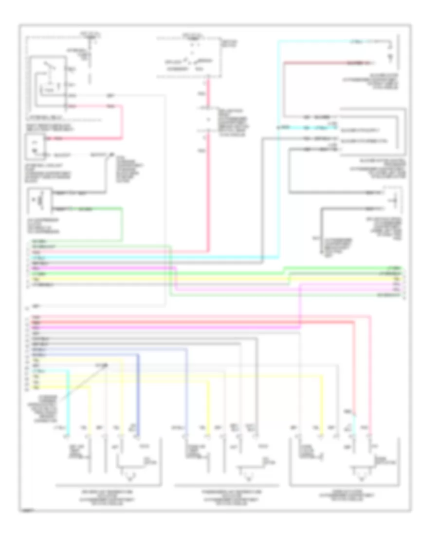
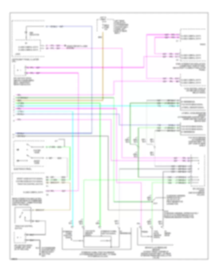
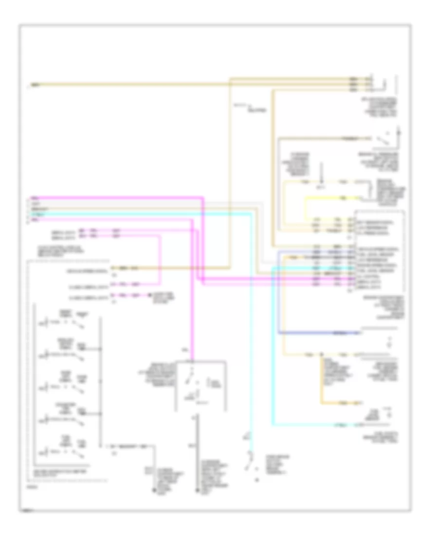
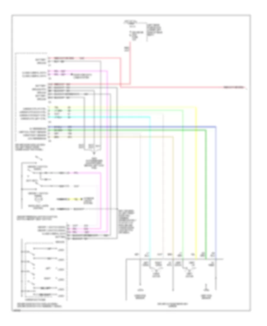
AIR CONDITIONING
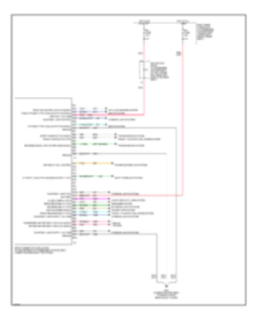
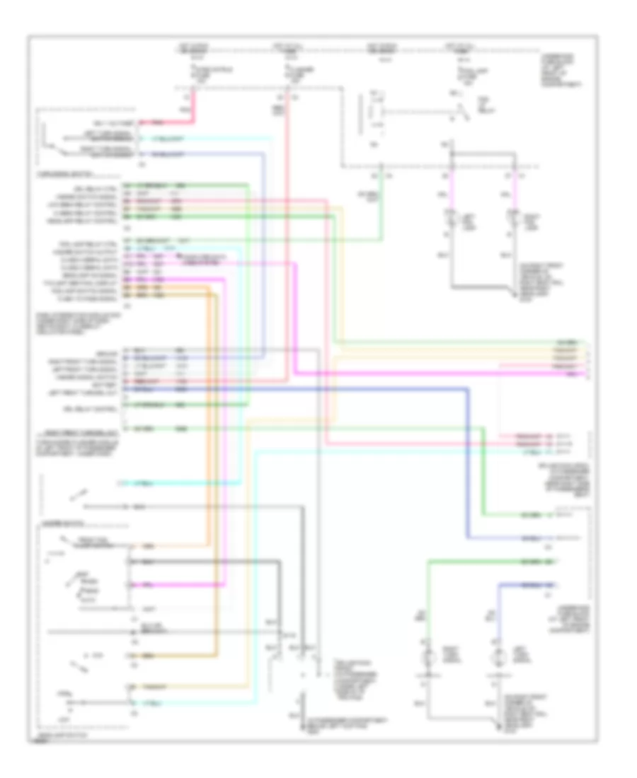
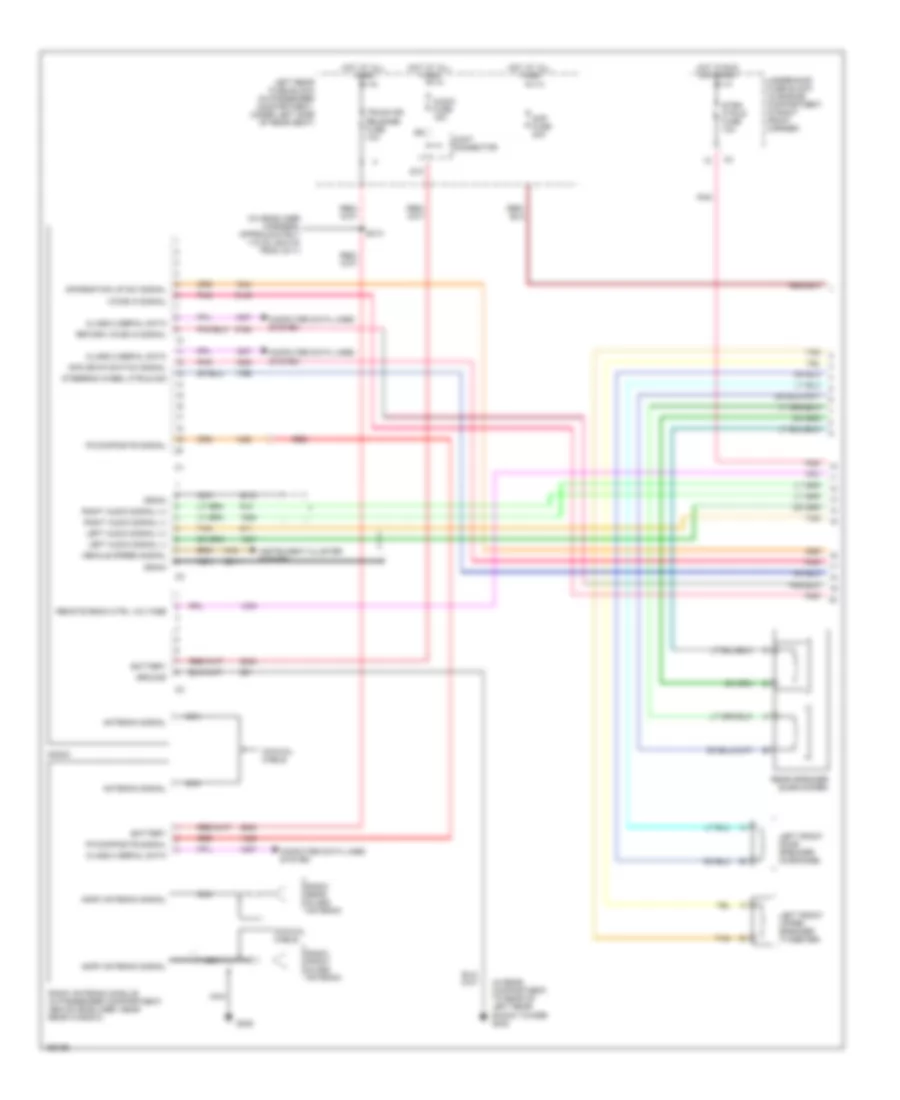
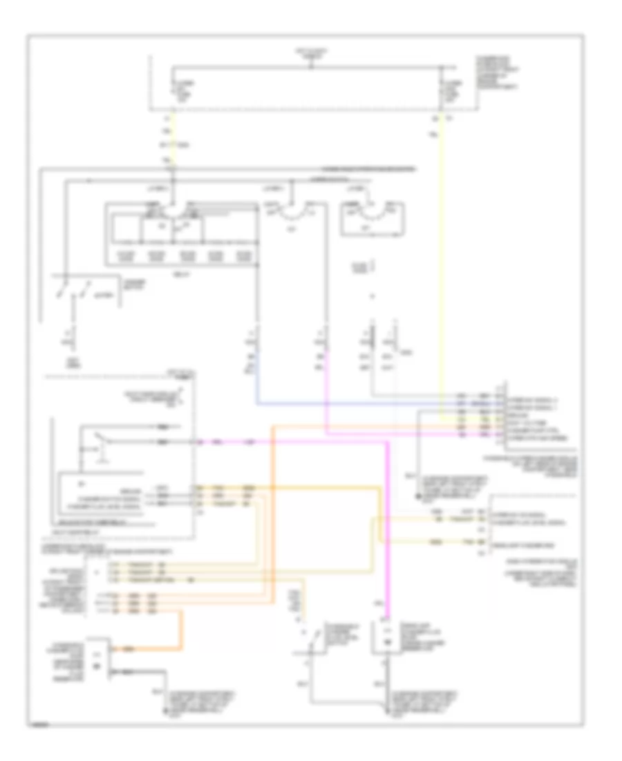
Automatic A/C Wiring Diagram (1 of 3) for Cadillac CTS 2003

List of elements for Automatic A/C Wiring Diagram (1 of 3) for Cadillac CTS 2003:
- 5 volt reference
- After boil pump relay ctrl
- Air inlet motor
- Amb air temp sensor sig
- Ambient light sensor signal
- Battery
- Blower fuse 40a
- Blower mtor speed ctrl
- Blower relay
- Blower relay ctrl
- Ccp fuse 10a
- Comp clutch fuse 10a
- Comp clutch relay
- Coolant level switch signal
- Door a
- Door b
- Dr air temp door ctrl b
- Driver air temp door ctrl a
- Driver air temp posit signal
- E10
- E11
- E12
- E13
- E14
- E15
- E16
- Evap low temp sens signal
- Evaporator temperature sensor
- F10
- F11
- F12
- F13
- F14
- F15
- F16
- G201 (in passenger compartment, behind right kick pad)
- Ground
- Hot at all times
- Hot in run
- Hvac control module (behind center of dash, below radio)
- Ign 3 fuse 10a
- Ignition 3 voltage
- Inside air temp sensor sig
- Inside air temperature sensor
- Left rear fuse block (below left rear seat)
- Left sunload sensor signal
- Low reference
- Mode door ctrl a
- Mode door ctrl b
- Mode door position signal
- Nca
- Pass air temp door ctrl a
- Pass air temp door ctrl b
- Pass air temp posit signal
- Pnk
- R51
- R52
- R53
- R54
- R55
- R56
- R57
- R58
- Recirc door ctrl a
- Recirc door ctrl b
- Recirculation actuator (on hvac module module, left of blower motor)
- Red
- Right sunload sensor signal
- S117
- Serial data
- Solid state
- Splice pack sp302 (in passenger compartment, on left frame rail, near left side of driver's seat)
- Sunload sensor (at front center of passenger compartment, on defroster grill)
- Underhood fuse block (at left front of engine compartment)
- Volt
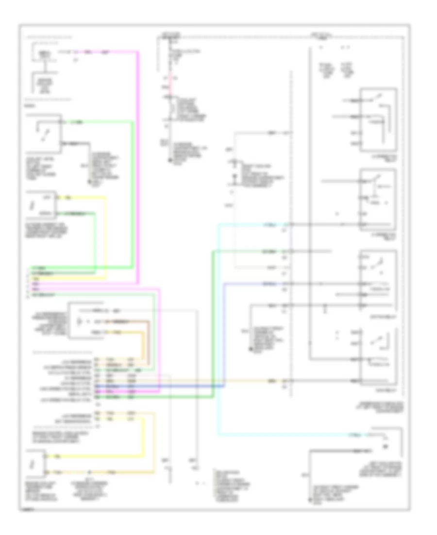
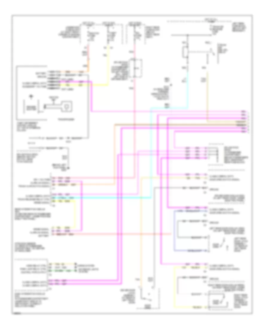
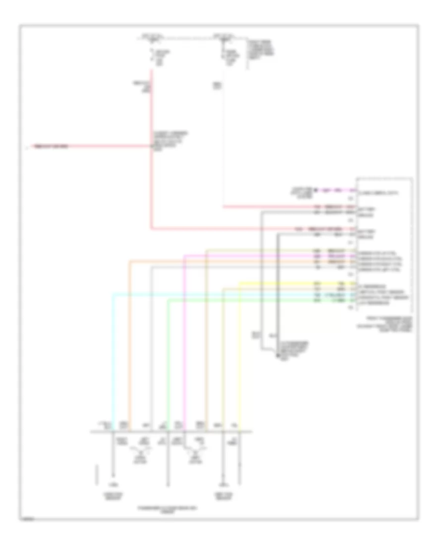
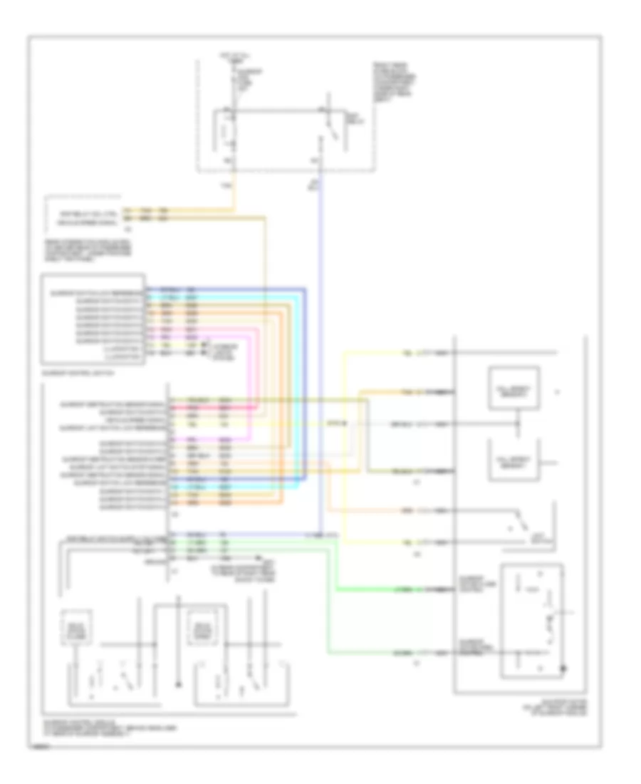
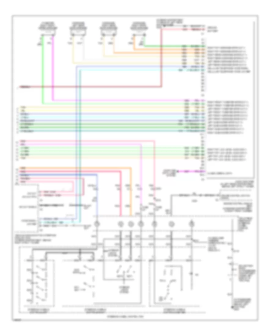
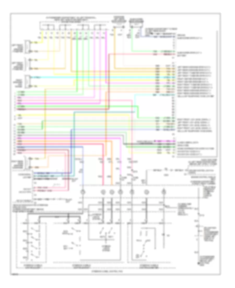
Automatic A/C Wiring Diagram (2 of 3) for Cadillac CTS 2003
List of elements for Automatic A/C Wiring Diagram (2 of 3) for Cadillac CTS 2003:
- (in engine harness, approximately 235 cm (98.3 in) from knock sensor 1 connector)
- (in passenger compartment, behind right kick pad) g201
- 2 (or 4)
- 4 (or 2)
- A/c
- A/c compressor clutch (on front of a/c compressor)
- Accessory
- After boil coolant pump (in engine compartment, on right side of engine block)
- After boil fuse 10a
- After boil relay
- Blower motor (in passenger compartment, on right side of hvac module)
- Blower motor control processor (in passenger compartment, on lower left side of blower motor)
- Blower mtr speed ctrl
- Cold
- Crank
- Def
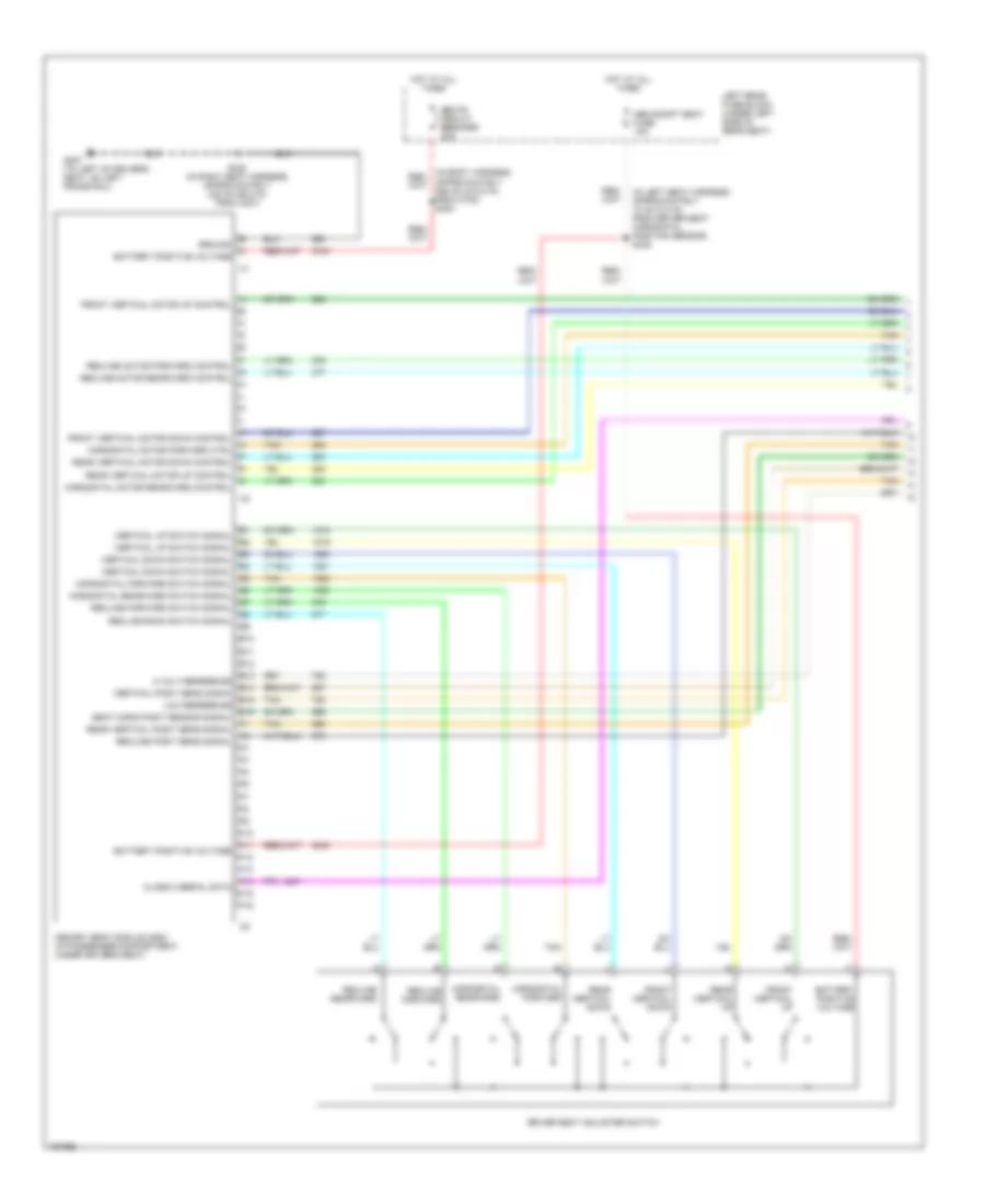
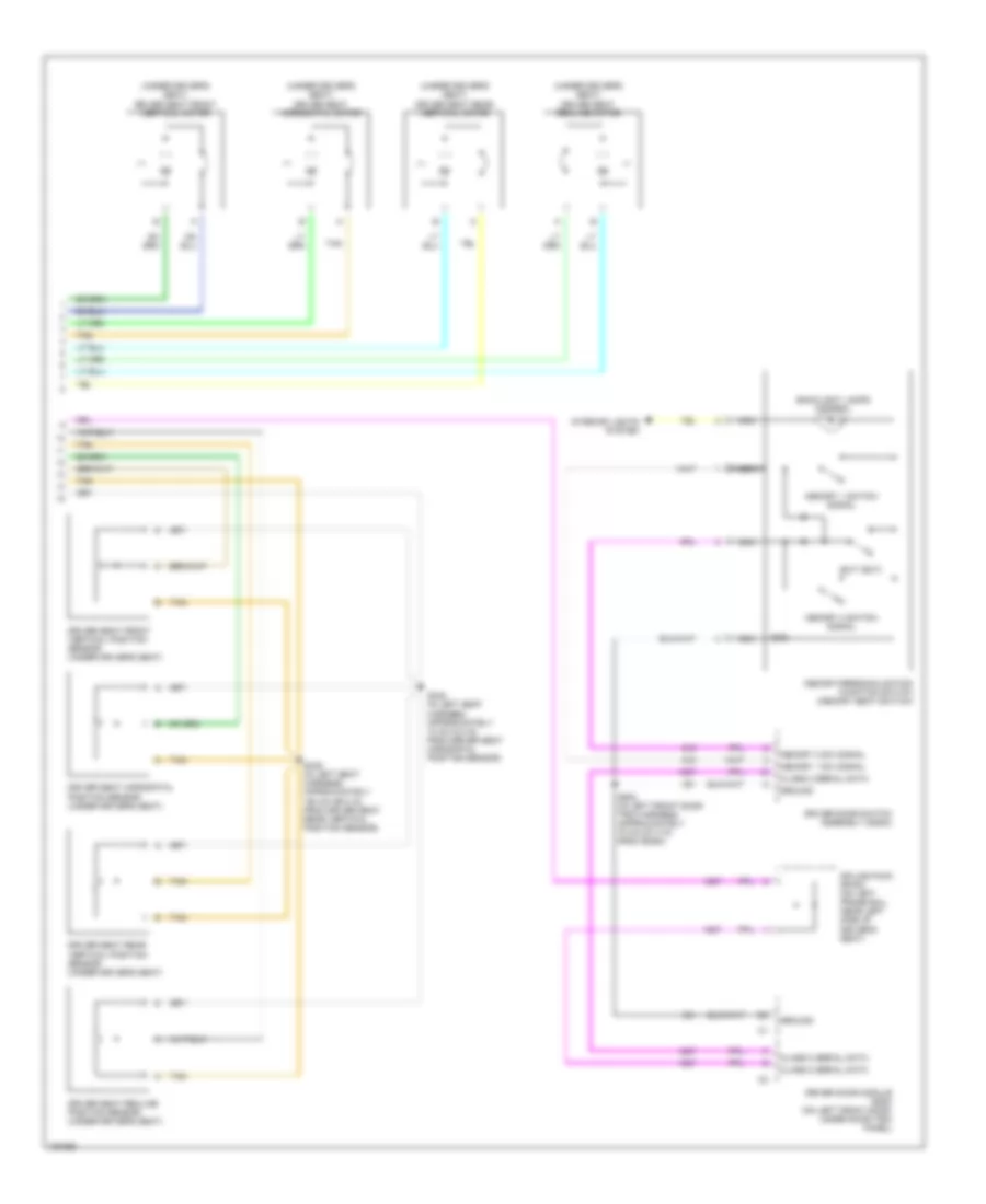
- Driver's air temperature actuator (in passenger compartment, on hvac module)
- Dry air temp signal
- G100 (in engine compartment, on engine block near starter motor)
- Hot
- Hot at all times
- Ignition switch
- Mix motor
- Mode actuator
- Mode actuator (in passenger compartment, on hvac module)
- Mode valve signal
- Nca
- Off/lock
- Pass air temp signal
- Passenger's air temperature actuator (in passenger compartment, on hvac module)
- Pnk
- R11
- R12
- R13
- R15
- Red
- Right rear fuse block (below right rear seat)
- Run
- S118
- S323
- Splice pack sp201 (in passenger compartment, behind ignition switch, near hvac module)
- Splice pack sp203 (in passenger compartment, under left side of dash trim pad)
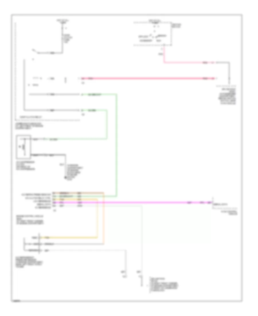
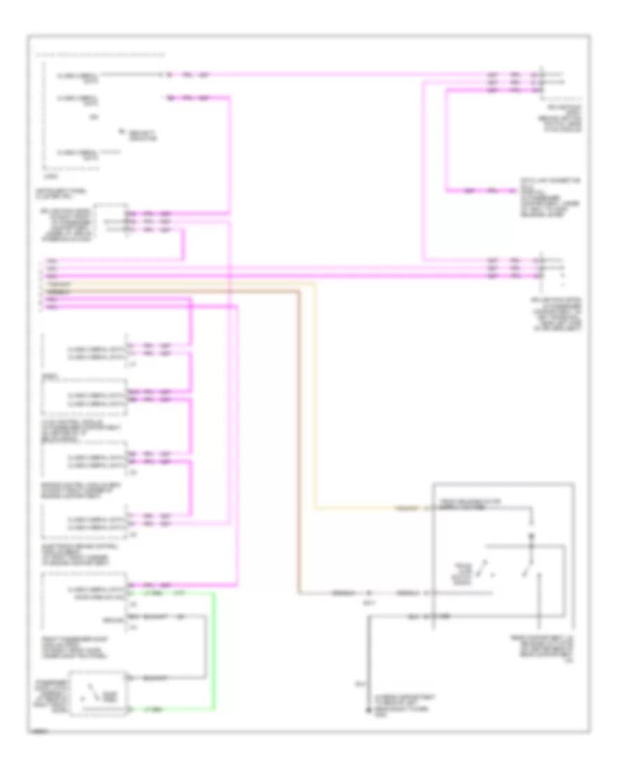
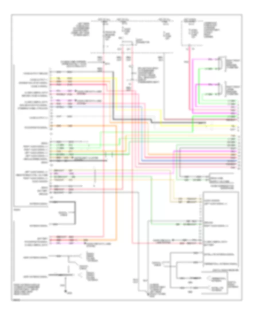
Automatic A/C Wiring Diagram (3 of 3) for Cadillac CTS 2003
List of elements for Automatic A/C Wiring Diagram (3 of 3) for Cadillac CTS 2003:
- (in engine compartment, near left front strut tower at bottom of inside fender well) g101
- (in engine compartment, on engine block near starter motor) g100
- (on right front corner of vehicle, on right body rail near right headlamp) g104
- 5v reference
- 87a
- A/c clutch relay ctrl
- A/c refrig press sensor
- A/c refrigerant pressure sensor (in engine compartment, near left front stut tower)
- Coolant bypass solenoid (at upper right corner of radiator)
- Coolant level switch (in left front corner of coolant surge tank)
- Ect sensor signal
- Engine control module (ecm) (at right front corner of engine compartment)
- Engine coolant low level
- Engine coolant temperature sensor (on top rear of intake manifold)
- Feed
- Hi speed fan relay
- High (or hi) fuse 30a
- High speed fan relay ctrl
- Hot at all times
- Hot in on or start
- Htr/vlv/cltch fuse 10a
- Left cooling fan (at front of engine compartment, in left side of fan assembly)
- Lo speed fan relay
- Low
- Low fan fuse 30a
- Low reference
- Low speed fan relay ctrl
- Main relay
- Main relay ctrl
- Outside ambient air temperature sensor (under front bumper, near front grille)
- Pnk
- R39
- R40
- R41
- R42
- R47
- R48
- R49
- R50
- Radio
- Right cooling fan (at front of engine compartment, in right side of fan assembly)
- Rtn
- S/p fan relay
- S111 (in engine harness, approximately 120 cm (31.5 in) from ho2s bank 2 sensor 1)
- Serial data
- Sig
- Signal
- Splice pack sp102 (in right front corner of engine compartment, in front of underhood fuse block
- Tan
- Underhood fuse block (at left front of engine compartment)
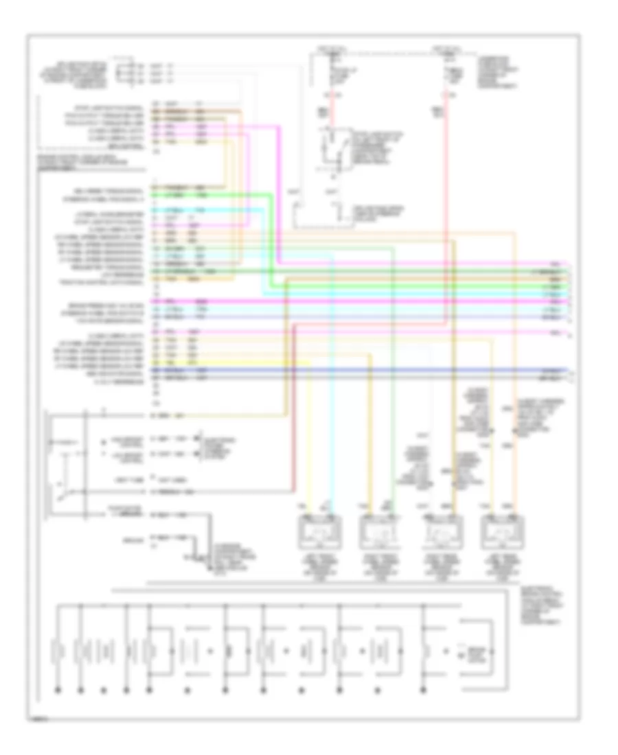
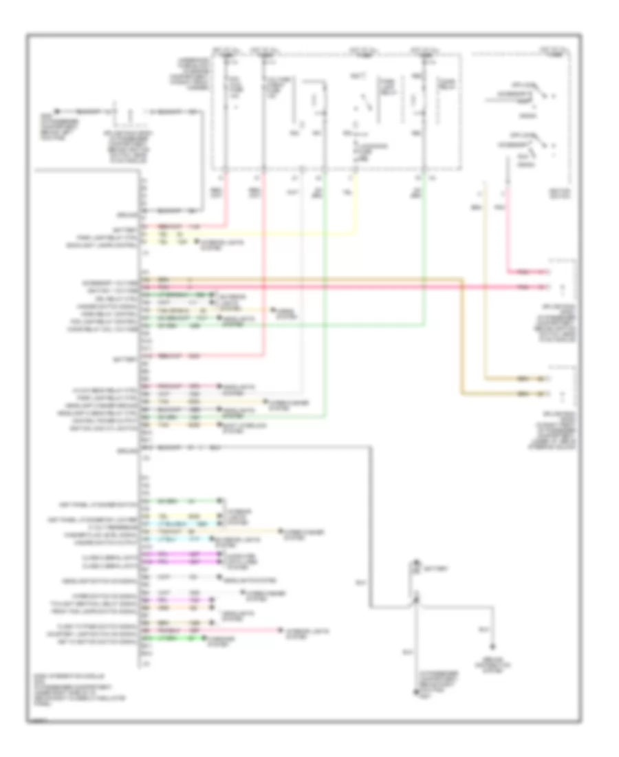
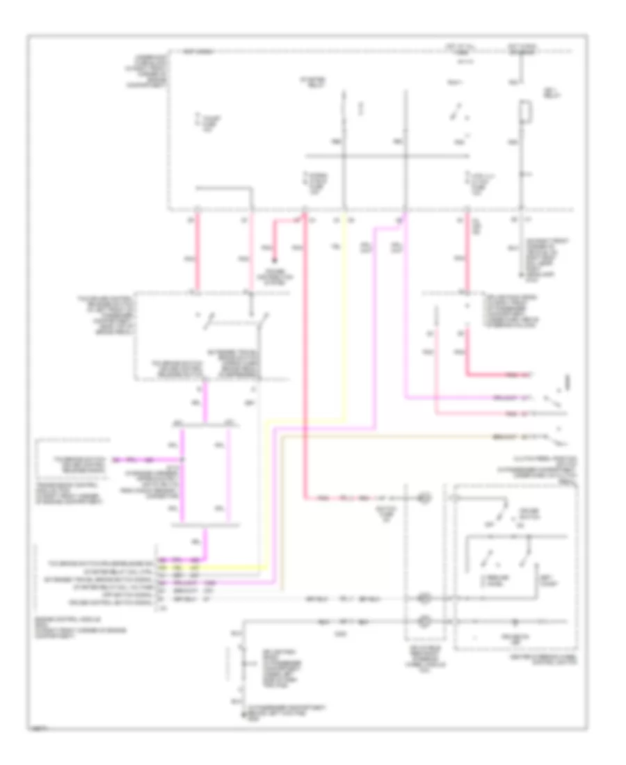
Compressor Wiring Diagram for Cadillac CTS 2003
List of elements for Compressor Wiring Diagram for Cadillac CTS 2003:
- (in engine compartment, on engine block near starter motor) g100
- 5v reference
- A/c clutch relay ctrl
- A/c compressor clutch (on front of a/c compressor)
- A/c refrig press sens sig
- A/c refrigerant pressure sensor (in engine compartment, near left front strut tower)
- Accessory
- Comp clutch fuse 10a
- Comp clutch relay
- Crank
- Engine control module (ecm) (at right front corner of engine compartment)
- Feed
- Hot at all times
- Hvac control module
- Ignition switch
- Low reference
- Nca
- Off/lock
- Pnk
- R55
- R56
- R57
- R58
- Return
- Run
- Serial data
- Sig
- Splice pack sp102 (in right front corner of engine compartment, in front of underhood fuse block)
- Splice pack sp201 (in passenger compartment, behind ignition switch, near hvac module)
- Tan
- Underhood fuse block (at left front of engine compartment)
ANTI-LOCK BRAKES
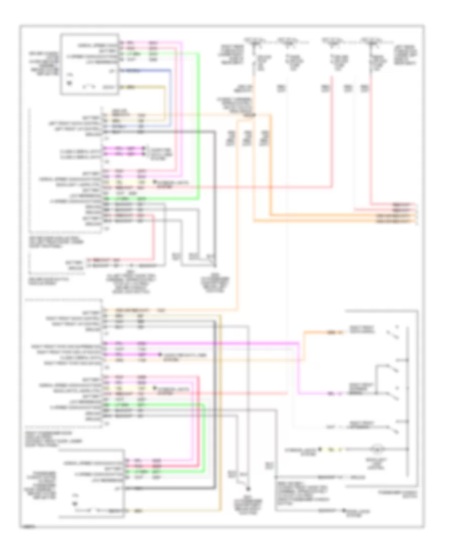
Anti-lock Brakes Wiring Diagram (1 of 2) for Cadillac CTS 2003
List of elements for Anti-lock Brakes Wiring Diagram (1 of 2) for Cadillac CTS 2003:
- (in body harness approx. 80 cm (31.4 in) from vcim connector) s300
- (in body harness, approx. 60 cm (23.3 in from p400) s301
- (in body harness, approx. 95 cm (37.4 in) from audio amplifier connector) s306
- (in engine compartment, on right frame rail, near abs module) g110
- (not used)
- 140 cm (55.1 in) from audio amplifier connector) s302
- 5 volt reference
- Abs indicator signal
- Brake press mod valve sig
- Brake pump motor
- Class 2 serial data
- Delivered torque signal
- Ebcm fuse 50a
- Edc control
- Electronic brake control module (ebcm) (at right front corner of engine compartment)
- Electronic power steering system
- Engine control module (ecm) (in right front corner of engine compartment)
- Ground
- High effort control
- Hot at all times
- Lateral accelerometer
- Left front wheel speed sensor (on inside of hub)
- Left rear wheel speed sensor (on inside of hub)
- Lf wheel speed sensor-low ref
- Lf wheel speed sensor-signal
- Low effort control
- Low reference
- Lr wheel speed sensor-low ref
- Lr wheel speed sensor-signal
- Pump motor ground
- Pwm output torque deliver
- Requested torque signal
- Rf wheel speed sensor-low ref
- Rf wheel speed sensor-signal
- Right front wheel speed sensor (on inside of hub)
- Right rear wheel speed sensor (on inside of hub)
- Rr wheel speed sensor-low ref
- Rr wheel speed sensor-signal
- Splice pack sp102 (in right front corner of engine compartment, in front of underhood fuse block)
- Splice pack sp200 (above steering column)
- Steering wheel pos signal a
- Steering wheel pos switch b
- Stop lamp switch (in left front of passenger compartment, near top of brake pedal)
- Stop lamp switch signal
- Stop lp fuse 20a
- Tan
- Traction control data signal
- Underhood fuse block (in right front corner of engine compartment)
- Vent tube
- Yaw rate sensor signal
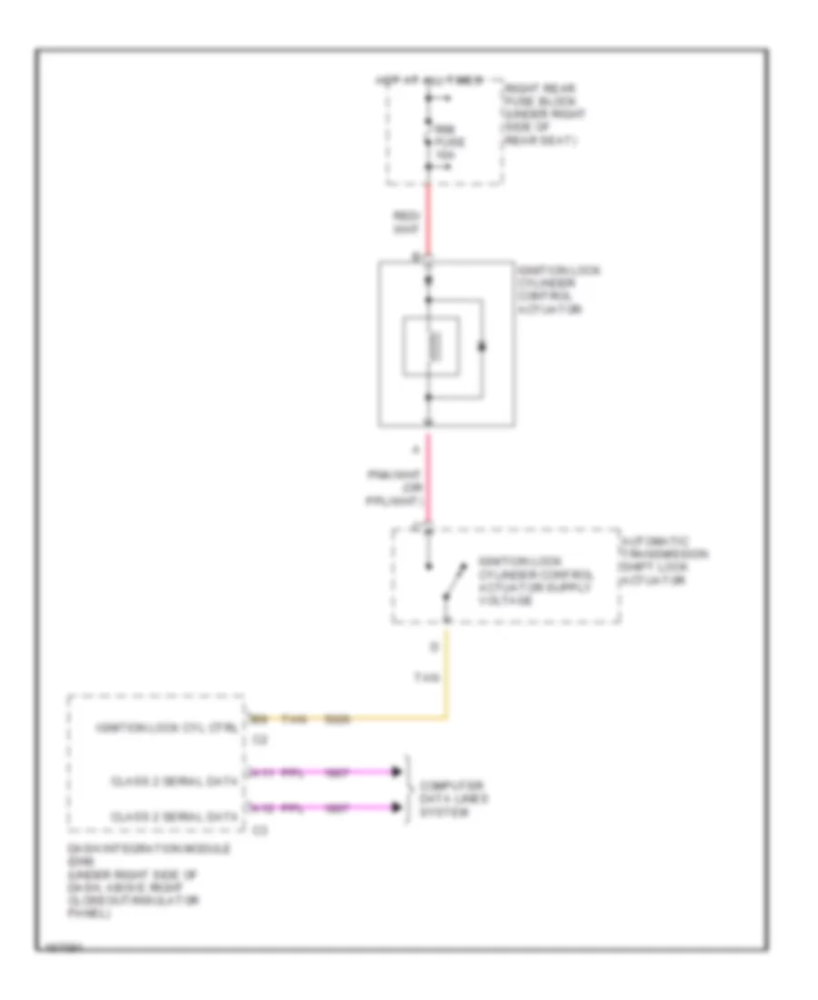
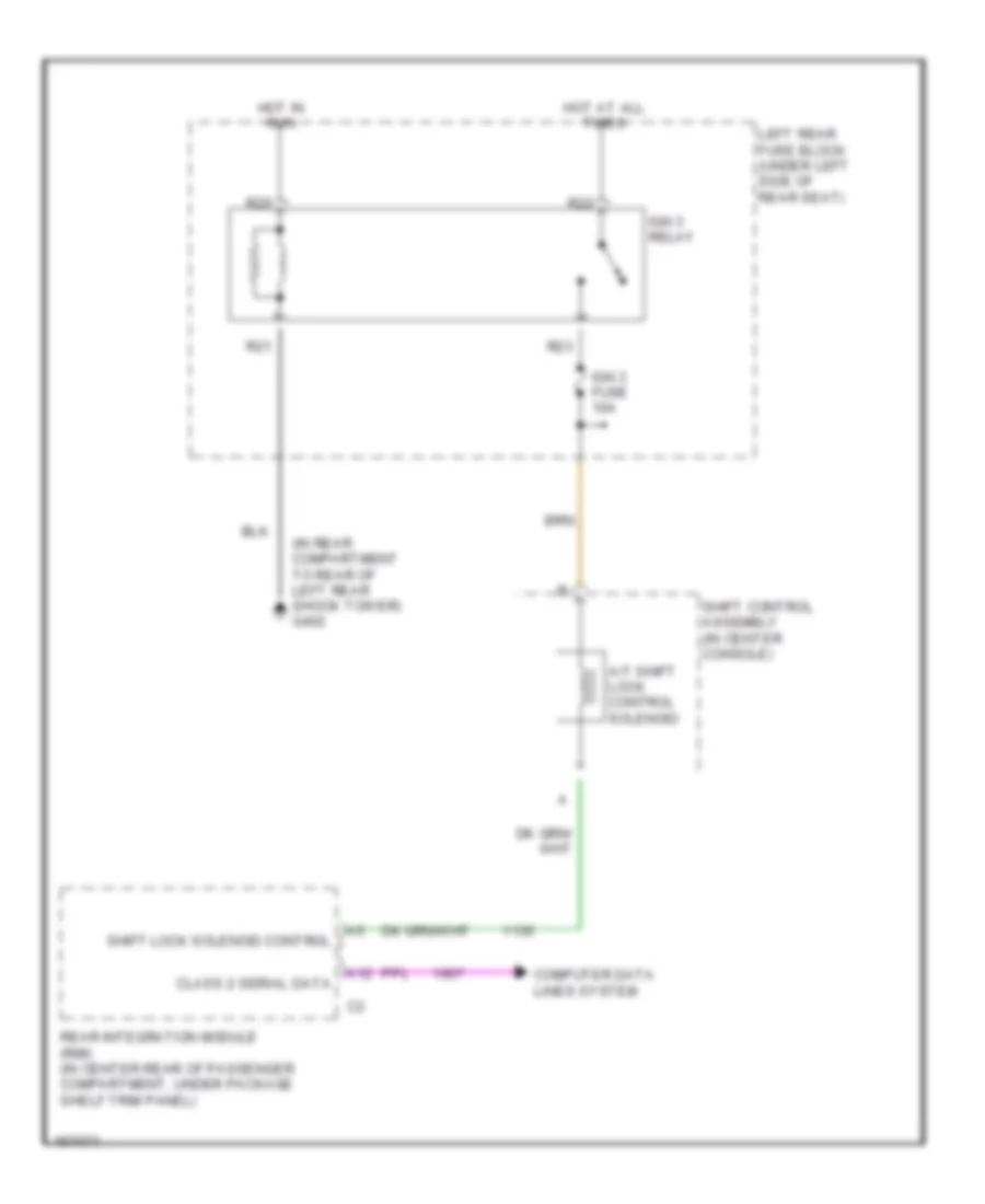
Anti-lock Brakes Wiring Diagram (2 of 2) for Cadillac CTS 2003
List of elements for Anti-lock Brakes Wiring Diagram (2 of 2) for Cadillac CTS 2003:
- (in engine harness, approximately 120 cm (47.2 in) from generator connector)
- (in passenger compartment, behind right kick pad) g201
- 5v refer- ence
- 5v reference
- A/t
- A11
- A12
- Abs indicator
- Brake fluid pressure sensor (in right front corner of engine compartment, on rear of brake pressure modulator valve)
- Class 2 serial data
- Computer data lines system
- Dash integration module (dim) (under right side of dash, above right closeout/insulator panel)
- E10
- Ebcm fuse 10a
- Electronic prndl
- Hot in run
- Hvac control module (on center of dash, below radio)
- Instrument panel cluster (ipc)
- Lateral accelerometer sensor (in passenger compartment, under center console behind sdm)
- Lateral sensor signal
- Left rear fuse block (in passenger compartment, under left side of rear seat)
- Logic
- Press
- Radio
- Rear integration module (rim) (in center rear of passenger compartment, under package shelf trim panel)
- S100 (in engine harness, approximately 80 cm (31.5 in) from brake fluid pressure sensor connector)
- S101
- Splice pack sp200 (above steering column)
- Splice pack sp203 (under left side of i/p trim pad)
- Splice pack sp303 (behind passenger's seat, near right rear fuse block)
- Sport mode
- Sport mode switch signal
- Steering wheel position sensor (in passenger compartment, at base of steering column)
- Steering wheel position signal a
- Steering wheel position signal b
- Traction control switch
- Winter mode
- Winter mode switch signal
- Yaw rate sens signal
- Yaw rate sensor (in passenger compartment, on left side of rear shelf)
- Yaw rate sensor signal
ANTI-THEFT
Anti-theft Wiring Diagram (1 of 2) for Cadillac CTS 2003
List of elements for Anti-theft Wiring Diagram (1 of 2) for Cadillac CTS 2003:
- (behind left kick panel) g200
- A11
- A12
- Accessory voltage
- Alarm on signal
- Armed signal
- B10
- Battery
- C (not used)
- Class 2 serial data
- Control pwr output
- Dash integration module (dim) (in passenger compartment, under right side of i/p above right closeout/ insulator panel)
- Door open
- Door open switch signal
- Driver door latch assembly (at rear of left front door)
- Driver door module (ddm) (in left front door, under door trim panel)
- Ecm/tcm fuse 10a
- Exterior lights system
- F (not used)
- Ground
- Horn relay ctrl
- Horns system
- Hot at all times
- Hot in acc or run
- Hot in run or start
- Ign 1 voltage
- Ignition key
- Intrusion sensor (at rear of passenger compartment, on center of headliner)
- Left rear door latch assembly (at rear of left rear door)
- Left rear door module (lrdm) (on left rear door, under door trim panel)
- Left rear fuse block (below left rear seat)
- Nca
- Park lamp relay ctrl
- Pnk
- R31
- R32
- R33
- R35
- Reader/ exciter
- Rear integration module (rim) (in center rear of passenger compartment, under package shelf trim panel)
- Right rear door latch assembly (at rear of right rear door)
- Right rear door module (rrdm) (on right rear door, under door trim panel)
- Right rear fuse block (below right rear seat)
- Rim fuse 10a
- S121
- S313 (in headliner harness, approximately 115 cm (45.6 in) from c311)
- Splice pack sp201 (behind ignition switch, near hvac module)
- Splice pack sp302 (in passenger compartment, on left frame rail, near left side of driver's seat)
- Splice pack sp303 (in passenger compartment, behind passenger's seat near right rear fuse block)
- Tan
- Theft deterrent control module (at top of steering column)
- Theft fuse 7.5a
- Transponder
- Trunk ajar switch signal
- Trunk dr rel sol relay
- Trunk dr release fuse 10a
- Trunk release relay ctrl
- Underhood fuse block (at right front corner of engine compartment)
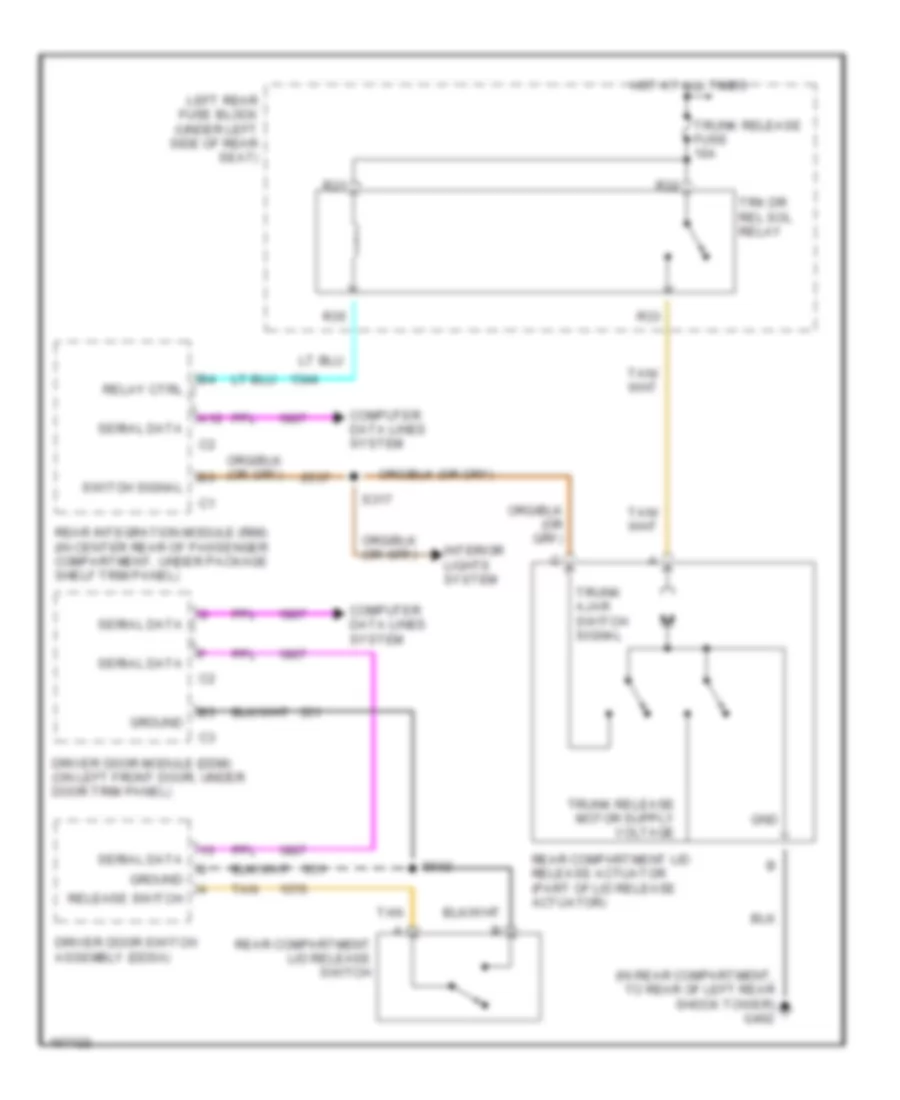
Anti-theft Wiring Diagram (2 of 2) for Cadillac CTS 2003
List of elements for Anti-theft Wiring Diagram (2 of 2) for Cadillac CTS 2003:
- (in rear compartment to rear of left rear shock tower) g402
- B10
- Class 2 serial data
- Data link connector (dlc) (partial) (in passenger compartment, under i/p, next to hood release lever)
- Door open
- Door open sw sig
- E10
- Electronic brake control module (ebcm) (at right front corner of engine compartment)
- Engine control module (ecm) (in right front corner of engine compartment)
- Front passenger door module (fpdm) (on right front door, under door trim panel)
- Gnd
- Ground
- Hvac control module (in passenger compartment, on center of i/p below radio)
- Ign
- Instrument panel cluster (ipc)
- Logic
- Passenger door latch assembly (at rear of right front door)
- Radio
- Rear compartment lid release actuator (on center rear of rear compartment lid)
- S317
- Security indicator
- Splice pack sp200 (in right front of passenger compartment, under i/p, above steering column)
- Splice pack sp201 (behind ignition switch, near hvac module)
- Splice pack sp300 (in passenger compartment, on left frame rail, near left side of driver's seat)
- Trunk ajar switch signal
BODY CONTROL MODULES
Dash Integration Module Wiring Diagram for Cadillac CTS 2003
List of elements for Dash Integration Module Wiring Diagram for Cadillac CTS 2003:
- (in passenger compartment, behind right kick pad) g201
- 5 volt reference
- A10
- A11
- A12
- Accessory
- Accessory voltage
- B10
- B11
- B12
- Backlight lamps control
- Battery
- Cigar relay
- Cigar relay coil voltage
- Class 2 serial data
- Computer data lines system
- Control power output
- Courtesy lamp switch on signal
- Crank
- Dash integration module (dim) (in passenger compartment, under right side of i/p above right closeout/insulator panel)
- Dim/ aldl fuse 10a
- Drl relay ctrl
- Exterior lights system
- Flash to pass switch signal
- Fog lamp relay control
- Front fog lamps switch signal
- G200 (in passenger compartment, behind left kick pad)
- Ground
- Ground distribution system
- Hazard switch output
- Hazard switch signal
- Headlamp hi beam relay ctrl
- Headlamp switch on signal
- Headlamp washer ground
- Headlights system
- Hi/low beam relay ctrl
- Horn relay control
- Horns system
- Hot at all times
- Ignition 1 voltage
- Ignition lock cyl switch
- Ignition switch
- Inst panel lp dimmer sw low ref
- Inst panel lp dimmer switch
- Interior lights system
- Key in ignition switch signal
- Lic/dimming fuse 15a
- Off/lock
- Park lamp relay
- Park lamp relay ctrl
- Pnk
- R31
- R32
- R33
- R34
- R59
- R62
- Run
- Shift interlock system
- Splice pack sp200 (in right front of passenger compartment, under i/p, above steering column)
- Splice pack sp201 (in passenger compartment, behind ignition switch, near hvac module)
- Tan
- Twilight sentinal delay signal
- Underhood fuse block (in engine compartment, in right front corner)
- Voltage check fuse 10a
- Warnings system
- Washer fluid level signal
- Wiper switch on signal
- Wiper/washer system
Rear Integration Module Wiring Diagram for Cadillac CTS 2003
List of elements for Rear Integration Module Wiring Diagram for Cadillac CTS 2003:
- 5007 (or 5053)
- A10
- A11
- A12
- Anti-lock brakes system
- B10
- B11
- B12
- Battery
- Class 2 serial data
- Computer data lines system
- Courtesy lamp control
- Courtesy lamp ctrl
- Defogger system
- Driver heated seat high/low signal
- Exterior lights system
- G401 (in rear compartment to rear of right rear shock tower)
- Ground
- Hot at all times
- Hot in on or start
- Htd seat ctrl module status signal
- Ignition 1 voltage
- Interior lights system
- Pass htd seat ctrl module status signal
- Passenger heated seat high/low signal
- Pnk
- Power distribution system
- Power tops system
- Rap relay coil control
- Rear defog relay ctrl
- Rear integration module (rim) (in center rear of passenger compartment, under package shelf trim panel)
- Reverse relay ctrl
- Reverse signal (or winter mode signal)
- Right rear fuse block (in passenger compartment, under right side of rear seat)
- Rim fuse 10a
- Rim fuse 15a
- Seats system
- Shift interlock system
- Splice pack sp302 (in passenger compartment, on left frame rail near left side of driver's seat)
- Sport mode switch signal
- Tan
- Traction control switch signal
- Transmissions system
- Trunk ajar switch ctrl
- Trunk release relay ctrl
- Trunk, tailgate, fuel doors system
- Vehicle speed signal
COMPUTER DATA LINES
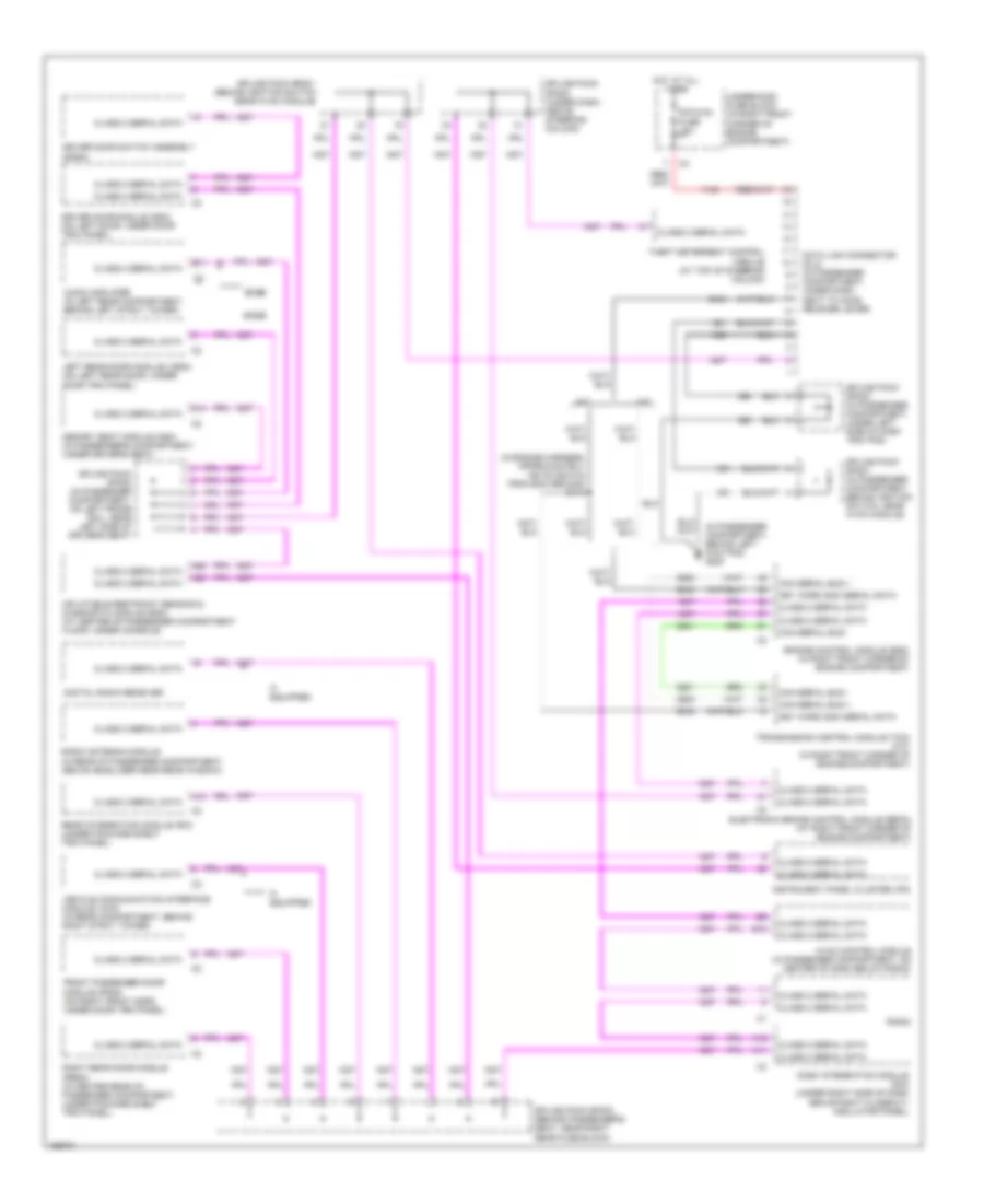
Computer Data Lines Wiring Diagram for Cadillac CTS 2003
List of elements for Computer Data Lines Wiring Diagram for Cadillac CTS 2003:
- (in engine harness, approximately 160 cm (62.9 in) from ecm ground) s114
- (in passenger compartment, behind left kick pad) g200
- A/t
- A11
- A12
- A22
- A23
- Audio amplifier (in left rear compartment, behind left strut tower)
- B11
- Base
- Bose
- Can serial bus +
- Can serial bus -
- Class 2 serial data
- D14
- Dash integration module (dim) (under right side of dash above right closeout/ insulator panel)
- Data link connector (dlc) (in passenger compartment, under dash next to hood release lever)
- Digital radio receiver
- Dim/aldl fuse 10a
- Driver door module (ddm) (on left door, under door trim panel)
- Driver door switch assembly (ddsa)
- E10
- Electronic brake control module (ebcm) (at right front corner of engine compartment)
- Engine control module (ecm) (in right front corner of engine compartment)
- Front passenger door module (fpdm) (on right front door, under door trim panel)
- Hot at all times
- Hvac control module (in passenger compartment, on center of dash below radio)
- If equipped
- Inflatable restraint sensing & diagnostic module (sdm) (at center of passenger compartment floor, under console)
- Instrument panel cluster (ipc)
- Key word 2000 serial data
- Left rear door module (lrdm) (on left rear door, under door trim panel)
- M/t
- Memory seat module (msm) (in passenger's compartment, under driver's seat)
- Radio
- Radio antenna module (in rear of passenger compartment, above headliner near rear window)
- Rear integration module (rim) (under package shelf trim panel)
- Right rear door module (rrdm) (in center rear of passenger compartment, under package shelf trim panel)
- Splice pack sp200 (under dash, above steering column)
- Splice pack sp201 (behind ignition switch near hvac module)
- Splice pack sp201 (in passenger compartment, behind ignition switch, near hvac module)
- Splice pack sp203 (in passenger compartment, under left side of dash trim pad)
- Splice pack sp300 (in passenger compartment, on left frame rail, near left side of driver's seat)
- Splice pack sp303 (behind passenger's seat, near right rear fuse block)
- Theft deterrent control module (at top of steering column)
- Transmission control module (tcm) (a/t) (in right front corner of engine compartment)
- Underhood fuse block (in right front corner of engine compartment)
- Vehicle communication interface module (vcim) (in rear compartment, behind right strut tower)
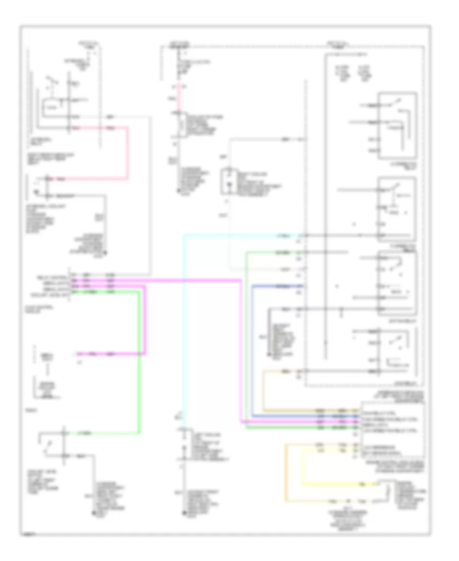
COOLING FAN
Cooling Fan Wiring Diagram for Cadillac CTS 2003
List of elements for Cooling Fan Wiring Diagram for Cadillac CTS 2003:
- (in engine compartment on engine block near starter motor) g100
- (in engine compartment, near left front strut tower at bottom of inside fender well) g101
- (in engine compartment, on engine block near starter motor) g100
- (on right front corner of vehicle, on right body rail near right headlamp) g104
- 87a
- After boil coolant pump (in engine compartment, on right side of engine block)
- After boil fuse 10a
- After boil relay
- Coolant by-pass solenoid (at upper right corner of radiator)
- Coolant level sw
- Coolant level switch (in left front corner of coolant surge tank)
- E10
- E11
- Ect sensor signal
- Engine control module (ecm) (at right front corner of engine compartment)
- Engine coolant low level
- Engine coolant temperature sensor (on top rear of intake manifold)
- Hi speed fan relay
- High fan fuse 30a
- High speed fan relay ctrl
- Hot at all times
- Hot in on or start
- Htr/vlv/cltch fuse 10a
- Hvac control module
- Left cooling fan (at front of engine compartment, in left side of fan assembly)
- Lo speed fan relay
- Low fan fuse 30a
- Low reference
- Low speed fan relay ctrl
- Main relay
- Main relay ctrl
- Pnk
- R11
- R12
- R13
- R15
- R39
- R40
- R41
- R42
- R47
- R48
- R49
- R50
- Radio
- Relay control
- Right cooling fan (at front of engine compartment, in right side of fan assembly)
- Right rear fuse block (below right rear seat)
- S/p fan relay
- S111 (in engine harness, approximately 120 cm (31.5 in) from ho2s bank 2 sensor 1)
- Serial data
- Tan
- Underhood fuse block (at left front of engine compartment)
CRUISE CONTROL
Cruise Control Wiring Diagram for Cadillac CTS 2003
List of elements for Cruise Control Wiring Diagram for Cadillac CTS 2003:
- (in passenger compartment, behind left kick pad) g200
- (on right front corner of vehicle, on right body rail near right headlamp) g104
- A/t
- C202
- C4 (or c5)
- Center steering wheel control switch
- Clutch pedal position switch (in passenger compartment, under dash, on clutch pedal)
- Cpp switch signal
- Cruise control switch signal
- Cruise on led
- Cruise switch
- Engine control module (ecm) (in right front corner of engine compartment)
- Extended travel brake switch (opens when brake pedal is depressed)
- Extended travel brake switch signal
- Hot at all times
- Hot in run
- Hot in run or crank
- Htr vlv/ cltch fuse 10a
- Ign 1 relay
- Inflatable restraint steering wheel module coil
- M/t
- Off
- Pnk
- Power distribution system
- R43
- R44
- R45
- R46
- R63
- R66
- Resume/ accel
- S118 (in engine harness, approximately 235 cm (98.3 in) from knock sensor 1 connector)
- Set/ coast
- Splice pack sp200 (in right front of passenger compartment, under dash above steering column)
- Splice pack sp203 (in passenger compartment, under left side of dash trim pad)
- Starter relay
- Starter relay coil ctrl
- Starter relay coil voltage
- Strng ctrls fuse 10a
- Switch fuse 2a
- Tcc brake switch/ cruise control release switch
- Tcc brake switch/cruise release sig
- Tcc/brake switch/ cruise control release signal
- Tcc/cruise control release switch (in left front of passenger compartment, near top of brake pedal)
- Tcc/et fuse 10a
- Transmission control module (tcm) (in right front corner of engine compartment)
- Underhood fuse block (in right front corner of engine compartment)
DEFOGGERS
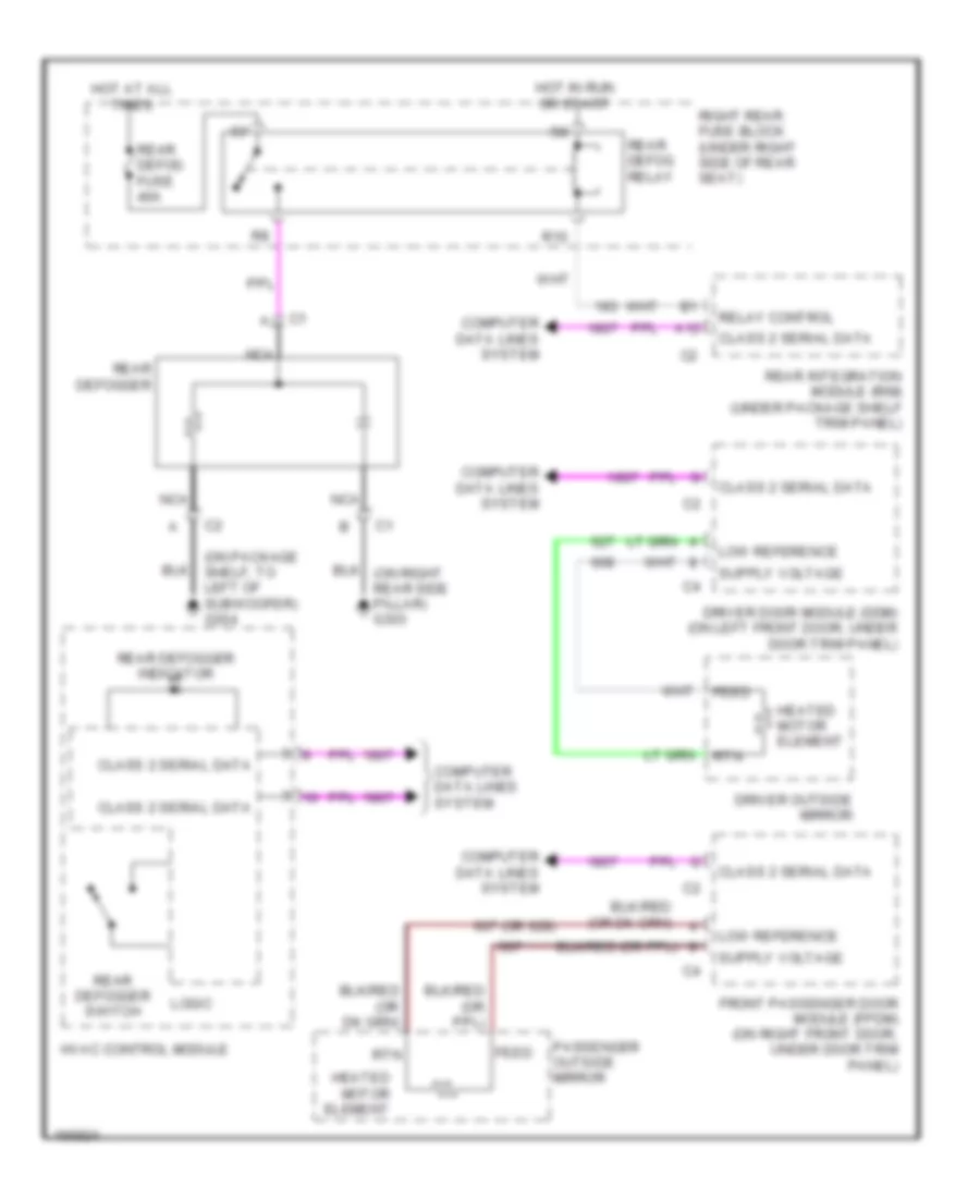
Defoggers Wiring Diagram for Cadillac CTS 2003
List of elements for Defoggers Wiring Diagram for Cadillac CTS 2003:
- (on package shelf, to left of subwoofer) g304
- 607 (or 628)
- A12
- Class 2 serial data
- Computer data lines system
- Driver door module (ddm) (on left front door, under door trim panel)
- Driver outside mirror
- Feed
- Front passenger door module (fpdm) (on right front door, under door trim panel)
- Heated motor element
- Hot at all times
- Hot in run or start
- Hvac control module
- Logic
- Low reference
- Nca
- Passenger outside mirror
- R10
- Rear defog fuse 40a
- Rear defog relay
- Rear defogger
- Rear defogger indicator
- Rear defogger switch
- Rear integration module (rim) (under package shelf trim panel)
- Relay control
- Right rear fuse block (under right side of rear seat)
- Rtn
ELECTRONIC POWER STEERING
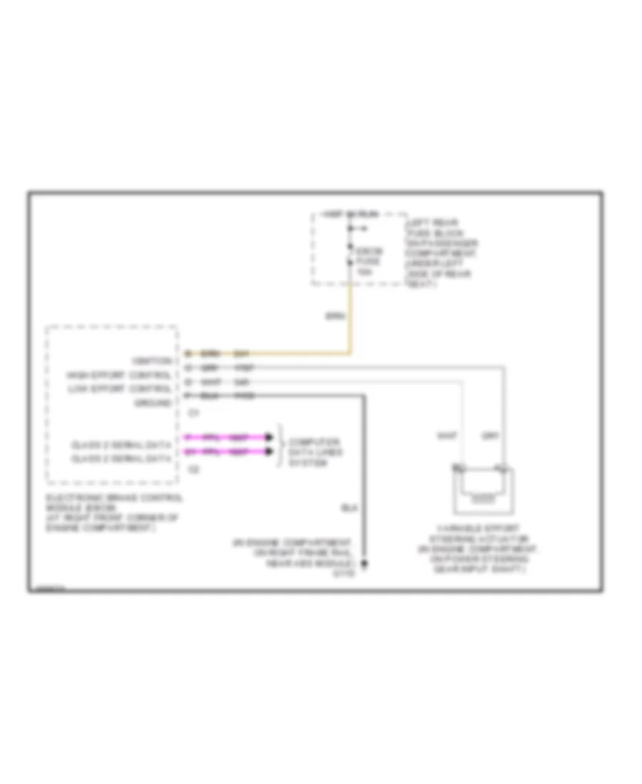
Electronic Power Steering Wiring Diagram for Cadillac CTS 2003
List of elements for Electronic Power Steering Wiring Diagram for Cadillac CTS 2003:
- (in engine compartment, on right frame rail, near abs module) g110
- Class 2 serial data
- Computer data lines system
- Ebcm fuse 10a
- Electronic brake control module (ebcm) (at right front corner of engine compartment)
- Ground
- High effort control
- Hot in run
- Ignition
- Left rear fuse block (in passenger compartment, under left side of rear seat)
- Low effort control
- Variable effort steering actuator (in engine compartment, on power steering gear input shaft)
ENGINE PERFORMANCE
3.2L VIN N
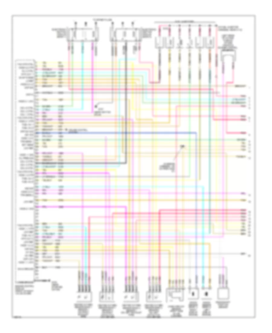
3.2L VIN N, Engine Performance Wiring Diagram (1 of 3) for Cadillac CTS 2003
List of elements for 3.2L VIN N, Engine Performance Wiring Diagram (1 of 3) for Cadillac CTS 2003:
- (in engine harness, 120 cm from ho2s 21)
- (in fuel injector harness, near c112)
- (left rear of intake plenum) intake manifold runner control solenoid
- (near ignition coils)
- +5v ref
- Case ground
- Ckp hi
- Ckp low
- Cmp sig
- Coil 1 ctrl
- Coil 2 ctrl
- Coil 3 ctrl
- Coil 4 ctrl
- Coil 5 ctrl
- Coil 6 ctrl
- Cpp sw sig
- Crankshaft position sensor
- Cruise control system
- Ect sens
- Electronic ignition module (bank 1)
- Electronic ignition module (bank 2)
- Engine control module (front of right valve cover)
- Evap purge
- Fuel inj 1
- Fuel inj 2
- Fuel inj 4
- Fuel inj 5
- Fuel inj 6
- Fuel injectors
- G100 (near starter motor)
- G107
- Heated oxygen sensor bank 1 sensor 1 (on right exhaust pipe)
- Heated oxygen sensor bank 1 sensor 2 (on right catalytic converter)
- Heated oxygen sensor bank 2 sensor 1 (on left exhaust pipe)
- Heated oxygen sensor bank 2 sensor 2 (on left catalytic converter)
- Ho2s 1,1 htr
- Ho2s 1,1 low
- Ho2s 1,1 sig
- Ho2s 1,2 hi
- Ho2s 1,2 htr
- Ho2s 1,2 lo
- Ho2s 2,1 htr
- Ho2s 2,1 low
- Ho2s 2,1 sig
- Ho2s 2,2 hi
- Ho2s 2,2 htr
- Ho2s 2,2 lo
- Iat sig
- Inj 3 ctrl
- Intk out 1
- Intk out 2
- Knock sensor (bank 1) (right side of engine)
- Knock sensor (bank 2) (left side of engine)
- Ks1 sig
- Ks2 sig
- Lo ref
- Low ref
- Maf sig
- Mass airflow sensor (right side of air cleaner)
- Nca
- Oil pres sig
- Pnk
- S108 pnk
- S111
- Shld ground
- Tac mtr ctrl
- Tan
- Tan/red
- To spark plugs
- Tps sens 1
- Tps sens 2
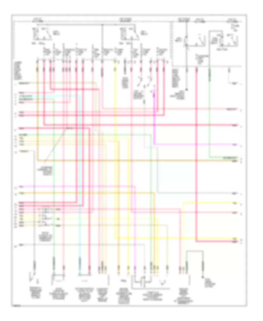
3.2L VIN N, Engine Performance Wiring Diagram (2 of 3) for Cadillac CTS 2003
List of elements for 3.2L VIN N, Engine Performance Wiring Diagram (2 of 3) for Cadillac CTS 2003:
- (in engine harness, 120 cm from ho2s 21)
- (in front of underhood fuse box)
- Camshaft position sensor (left front of engine)
- Canister vent fuse 10a
- Ecm fuse 15a
- Ecm/tcm fuse 10a
- Engine coolant temperature sensor (top rear of intake manifold)
- Engine oil pressure sensor (aboe oil filter)
- Evap canister purge solenoid (right side of engine)
- Fuel pump relay
- Fuse a 15a
- G100 (near starter motor)
- G104 (near right head- lamp)
- G401 (rear of right shock tower)
- Hot at all times
- Hot in run or start
- Ign 1 relay
- Ign mod fuse 15a
- Inj fuse 10a
- Intake manifold tuning valve solenoid (rear side of intake duct)
- Main relay
- Manifold fuse 10a
- Pnk
- Post 02 fuse 15a
- Pre fuse 15a
- R36
- R37
- R38
- R40
- R43
- R44
- R45
- R46
- R47
- R48
- R49
- R50
- Right rear fuse block (below right rear seat)
- S112
- Sp102
- Tan
- Tcc/ cruise release switch
- Tcc/et fuse 10a
- Tcm/ ipc fuse 15a
- Theft fuse 7.5a
- Throttle position sensor (top right front of engine)
- Under- hood fuse block (left front of eng compt)
- Vehicle speed sensor (m/t) (near rear of transmission assembly)
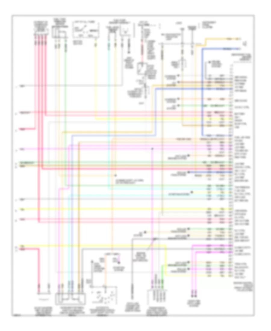
3.2L VIN N, Engine Performance Wiring Diagram (3 of 3) for Cadillac CTS 2003
List of elements for 3.2L VIN N, Engine Performance Wiring Diagram (3 of 3) for Cadillac CTS 2003:
- (engine harn, 160 cm from ecm ground)
- (in front of underhood fuse box) sp102
- (in rear compt lid harn, 237 cm from c401)
- +5v ref
- 1786 (or 1035)
- 2000 ser dat
- A/c pres
- A/c rly ctrl
- A/c system
- A/t
- Acc
- Acc volt
- Accelerator pedal
- Anti-lock brakes system
- App 2 sig
- App sens1
- Automatic transmission manual shift shaft switch assembly
- Battery
- Can bus +
- Can bus -
- Charging system
- Class 2 data
- Computer data lines system
- Cooling fans system
- Crank
- Cruise control system
- Data bus
- Data link connector (under left side of dash)
- Del tor sig
- Eng spd sig
- Engine control module (front of right valve cover)
- Engine speed
- Evap canister vent solenoid (above rear differential)
- Evap ctrl
- Ext brk sig
- F lev sig
- Fuel lev sns
- Fuel level sensor
- Fuel pump/ sender assembly
- Fuel tank pressure sensor (in fuel tank)
- G100 (near starter motor)
- G401 (rear of right shock tower)
- Gen on sig
- Gen signal
- Gmlan data
- Hot at all times
- Ign 1
- Ign 1 volt
- Ign voltage
- Ignition switch
- Instrument panel cluster
- Logic
- Low red
- Low ref
- M/t
- Main rly ctrl
- Malfunction indicator lamp
- Mil ctrl
- Off/ lock
- P/n sig
- Pnk
- Position sensor (above accelerator pedal)
- Req torq
- Res/accel
- Rly coil ctrl
- Rly ctrl
- Run
- S114
- S400
- Secondary fuel sender assembly
- Ser data
- Sp102 (in front of underhood fuse box)
- Sp202 (near ipc)
- Start
- Starting system
- Stop lamp switch (top of brake pedal)
- Stop lp sw fuse 15a
- Stp lp sw
- Tan
- Tcc brk sw
- Tcc/brk
- Tnk pres sig
- Trac ctrl
- Transmission control module (right front side of engine compt)
- Under- hood fuse block (left front of eng compt)
- Vss
- Vss signal
EXTERIOR LIGHTS
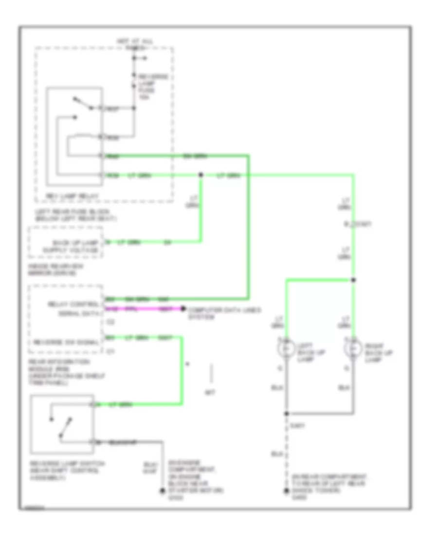
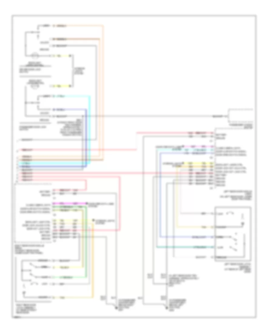
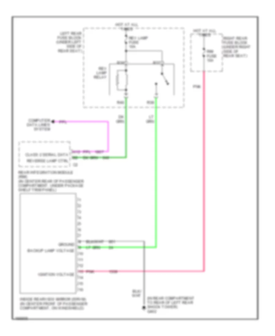
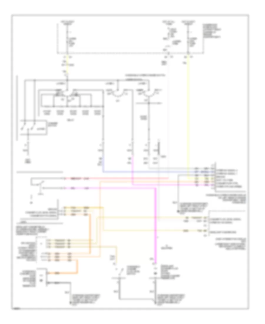
Back-up Lamps Wiring Diagram for Cadillac CTS 2003
List of elements for Back-up Lamps Wiring Diagram for Cadillac CTS 2003:
- (in engine compartment, on engine block near starter motor) g100
- (in rear compartment, to rear of left rear shock tower) g402
- A12
- C421
- Computer data lines system
- Hot at all times
- Inside rearview mirror (isrvm)
- Left back up lamp
- Left rear fuse block (below left rear seat)
- M/t
- R36
- R37
- R38
- R40
- Rear integration module (rim) (under package shelf trim panel)
- Relay control
- Rev lamp relay
- Reverse lamp fuse 10a
- Reverse lamp switch (near shift control assembly)
- Reverse sw signal
- Right back up lamp
- S401
- Serial data
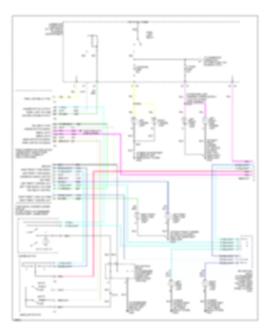
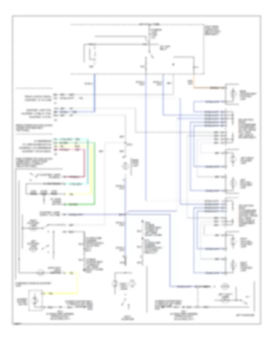
Exterior Lamps Wiring Diagram (1 of 2) for Cadillac CTS 2003
List of elements for Exterior Lamps Wiring Diagram (1 of 2) for Cadillac CTS 2003:
- (in forward lamp harness, approximately 10 cm (3.2 in) from horn assembly) s115
- (in passenger compartment, behind left kick pad) g200
- (in rear compartment to rear of left rear shock tower) g402
- (on right front corner of vehicle, on right body rail near right headlamp) g104
- A11
- A12
- Auto
- Battery
- Computer data lines system
- Control power output
- Dash integration module (dim) (under right side of dash, above right closeout/ insulator panel)
- Drl relay control
- Drl relay ctrl
- Ground
- Hazard sw signal switch
- Hazard switch
- Hazard switch output
- Hazard switch signal
- Hdlp
- Headlamp sw on signal
- Headlamp switch
- Hot at all times
- Left front park lamp
- Left front park/turn signal lamp
- Left front side marker lamp
- Left front turn signal
- Left front turn/drl out
- Left license lamp
- Left rear turn lamp
- Left turn signal voltage
- Lic/dimming fuse 15a
- Lt park fuse 10a
- Off
- Panel lamp voltage
- Park lamp relay
- Park lamp relay ctrl
- Park lamp sw on signal
- Pnk
- R31
- R32
- R33
- R34
- Right front park/turn signal lamp
- Right front turn signal
- Right front turn voltage
- Right front turn/drl out
- Right license lamp
- Right rear turn lamp
- S119
- S401
- S402
- Serial data
- Splice pack sp202 (in passenger compartment, under dash trim pad, near instrument panel cluster (ipc))
- Splice pack sp203 (in passenger compartment, under left side of dash trim pad)
- To underhood fuse block (rt park fuse, 10a) (diagram 2 of 2)
- Turn signal hazard flasher module (in left front of passenger compartment, under dash)
- Underhood fuse block (at left front of engine compartment)
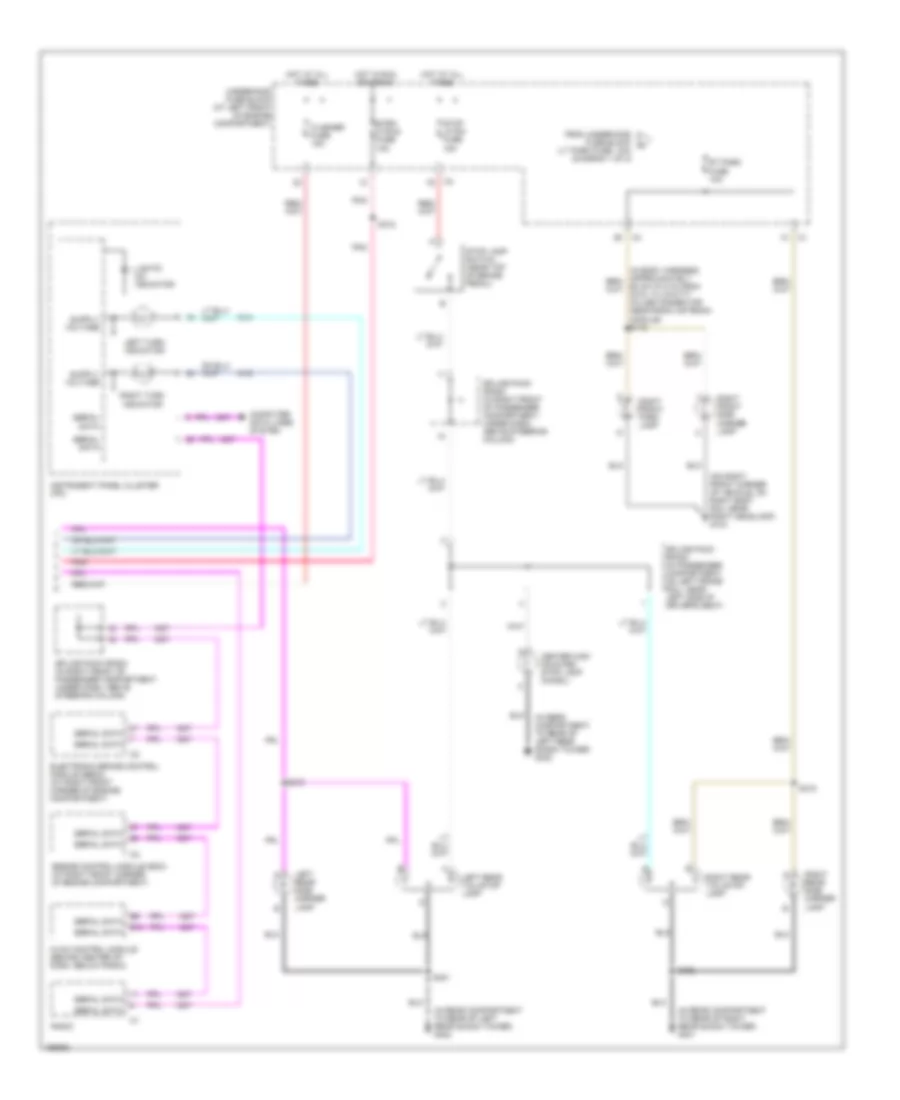
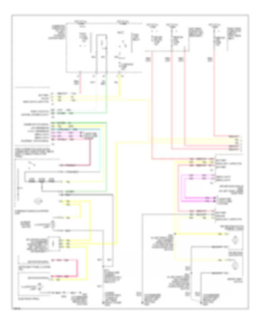
Exterior Lamps Wiring Diagram (2 of 2) for Cadillac CTS 2003
List of elements for Exterior Lamps Wiring Diagram (2 of 2) for Cadillac CTS 2003:
- (in rear compartment to rear of left rear shock tower) g402
- (in rear compartment to rear of right rear shock tower) g401
- (in rear compartment, to rear of left rear shock tower) g402
- (on right front corner of vehicle, on right body rail near right headlamp) g104
- Center high mounted stop lamp (chmsl)
- Computer data lines system
- E10
- Electronic brake control module (ebcm) (at right front corner of engine compartment)
- Engine control module (ecm) (at right front corner of engine compartment)
- Flasher fuse 15a
- From underhood fuse block (lt park fuse, 10a) (diagram 1 of 2)
- Hot at all times
- Hot in run or crank
- Hvac control module (behind center of dash, below radio)
- Instrument panel cluster (ipc)
- Left rear side marker lamp
- Left rear tail/stop lamp
- Left turn indicator
- Lights on indicator
- Pnk
- Radio
- Right front park lamp
- Right front side marker lamp
- Right rear side marker lamp
- Right rear tail/stop lamp
- Right turn indicator
- Rt park fuse 10a
- S315
- S316
- S318
- S401
- S402
- Serial data
- Splice pack sp200 (in right front of passenger compartment, under dash, above steering column)
- Splice pack sp302 (in passenger compartment, on left frame rail, near left side of driver's seat)
- Stop lamp switch (near top of brake pedal)
- Stop lp sw fuse 15a
- Strg ctrls fuse 10a
- Underhood fuse block (at left front of engine compartment)
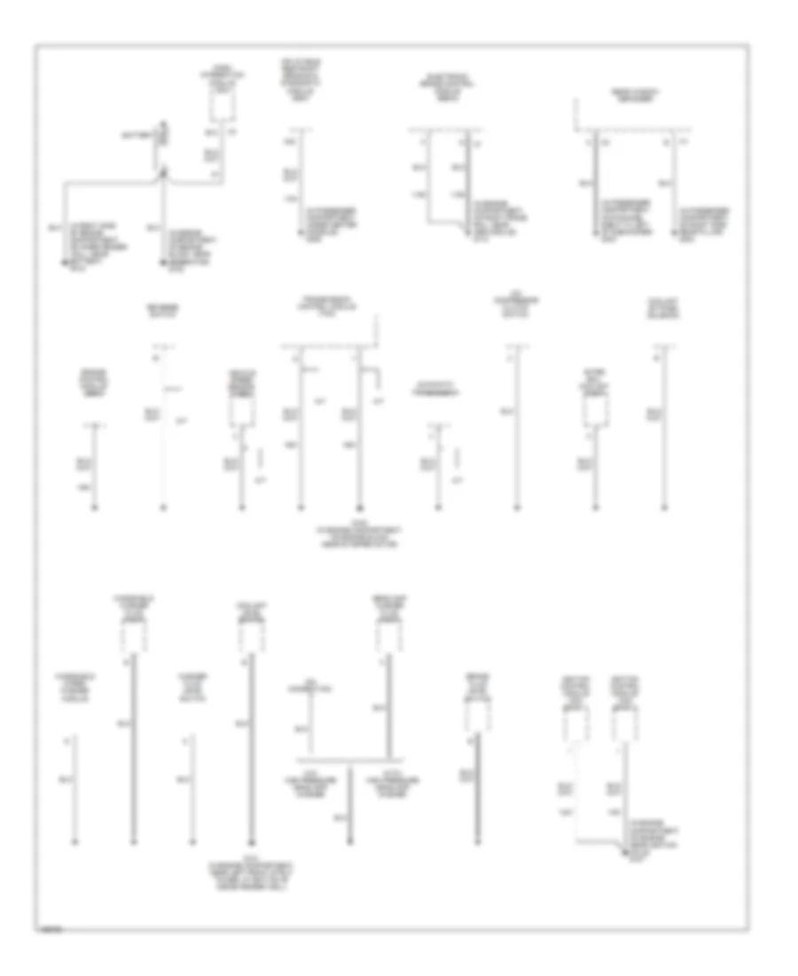
GROUND DISTRIBUTION
Ground Distribution Wiring Diagram (1 of 4) for Cadillac CTS 2003
List of elements for Ground Distribution Wiring Diagram (1 of 4) for Cadillac CTS 2003:
- (in engine compartment, on engine block, near generator) g102
- (in engine compartment, on engine near ignition coils) g107
- (in engine compartment, on right frame rail, near abs module) g110
- (in passenger compartment, on package shelf to left of subwoofer) g304
- (in passenger compartment, on right side rear pillar) g303
- (in passenger compartment, under center console) g306
- (in right side of engine compartment, on inner fender wall, near battery) g105
- (no connection)
- A/c compressor clutch switch
- A/t
- A32
- After boil coolant pump
- Automatic transmission
- B12
- Battery
- Brake fluid level switch
- Coolant by-pass solenoid
- Coolant level switch
- Dash integration module (dim)
- Electronic brake control module (ebcm)
- Engine control module (ecm)
- G100 (in engine compartment, on engine block near starter motor)
- G101 (in engine compartment, near left front strut tower, at bottom of inside fender well)
- Headlamp washer fluid pump
- Ignition control module (icm) bank 1
- Ignition control module (icm) bank 2
- Inflatable restraint sensing & diagnostic module (sdm)
- M/t
- Rear window defogger
- Reverse switch
- Transmission control module (tcm)
- Vehicle speed sensor (vss)
- W/o high pressure headlamp washer
- Washer fluid level switch
- Windshield washer fluid pump
- Windshield wiper/ washer module
- With/ high pressure headlamp washer
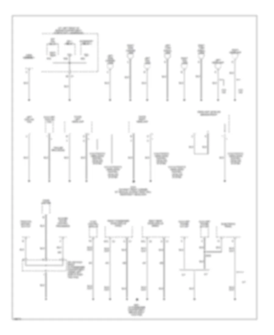
Ground Distribution Wiring Diagram (2 of 4) for Cadillac CTS 2003
List of elements for Ground Distribution Wiring Diagram (2 of 4) for Cadillac CTS 2003:
- (at left front of engine compartment) fuse block - underhood
- (w/hid) left headlamp
- (w/hid) right headlamp
- A/t
- Accessory relay
- Auxiliary cooling fan
- Auxiliary power outlet
- B12
- Blower motor control processor
- Cigar lighter
- Coil
- Cont- acts
- Electronic prndl
- Front passenger door module (fpdm)
- G104 (on right front corner of vehicle, on right body rail near right headlamp)
- G201 (in passenger compartment, behind right kick pad)
- Headlamp leveling sensor-front
- Horn assembly
- Hvac control module
- Ign 1 relay
- Left cooling fan
- Left fog lamp
- Left headlamp
- Left side marker lamp
- Left turn signal lamp
- M/t
- R16
- R35
- R46
- Right fog lamp
- Right headlamp
- Right rear door module (rrdm)
- Right side marker lamp
- Right turn signal lamp
- S/p fan relay
- S308
- Splice pack sp203 (in passenger compartment, under left side of dash trim pad)
- Traction control switch
- Trailer provisions
- W/automatic headlamps control leveling system
- W/o automatic headlamps control leveling system
- W/o hid
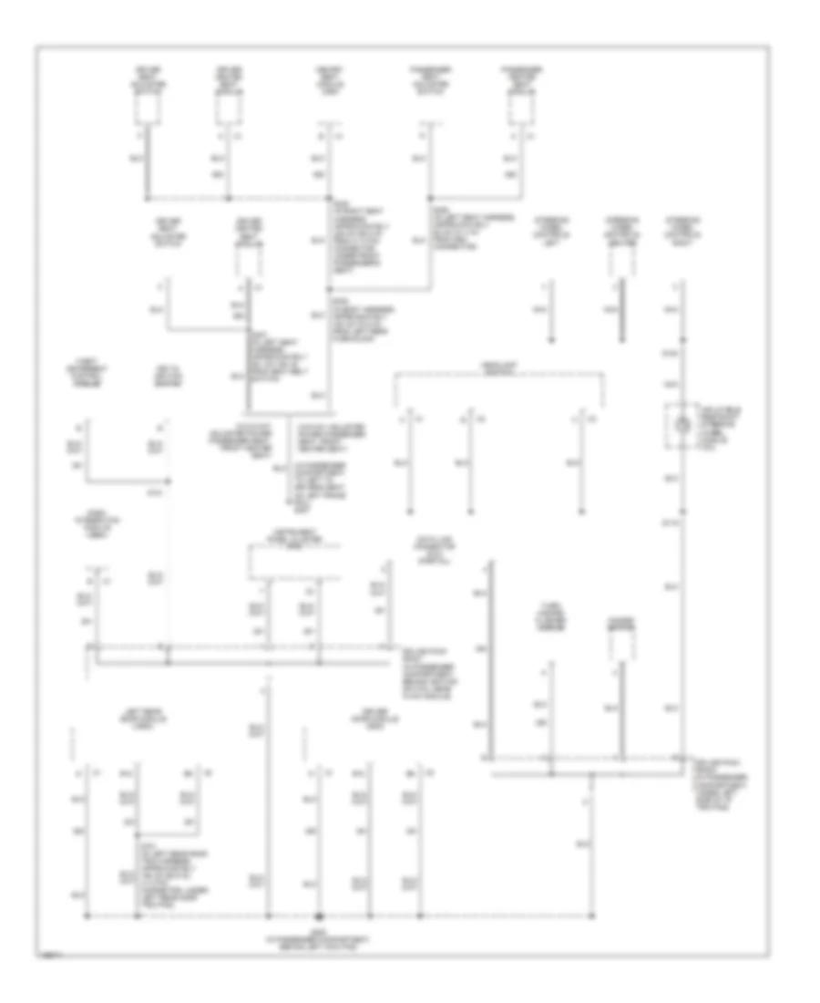
Ground Distribution Wiring Diagram (3 of 4) for Cadillac CTS 2003
List of elements for Ground Distribution Wiring Diagram (3 of 4) for Cadillac CTS 2003:
- (in passenger compartment, to left to driver's seat, on left frame rail) g307
- B12
- Connector)
- Dash integration module (dim)
- Data link connector (dlc) (partial)
- Driver door module (ddm)
- Driver heated seat module
- Driver seat adjuster switch
- G200 (in passenger compartment, behind left kick pad)
- Hazard switch
- Headlamp switch
- Inflatable restraint steering wheel module coil
- Instrument panel cluster (ipc)
- Key-in ignition switch
- Left rear door module (lrdm)
- Memory seat module (msm)
- Nca
- Passenger heated seat module
- Passenger seat adjuster switch
- S119
- S120
- S121
- S305 (in body harness, approximately 180 cm (70.8 in) from left rear fuse block)
- S307 (in left seat harness, approximately 381 cm (150 in) from seat belt switch)
- S320 (in right seat harness, approximately 235 cm (92.5 in) from a 14 pin connector under front passenger's seat)
- Splice pack sp201 (in passenger compartment, behind ignition switch, near hvac module)
- Splice pack sp203 (in passenger compartment, under left side of i/p trim pad)
- Steering wheel controls- center
- Steering wheel controls- left
- Steering wheel controls- right
- Theft deterrent control module
- Turn/ hazard flasher module
- W/8-way adjuster power passenger seat, front heater seat)
- W/o 8-way adjuster power passenger seat, front heater seat)
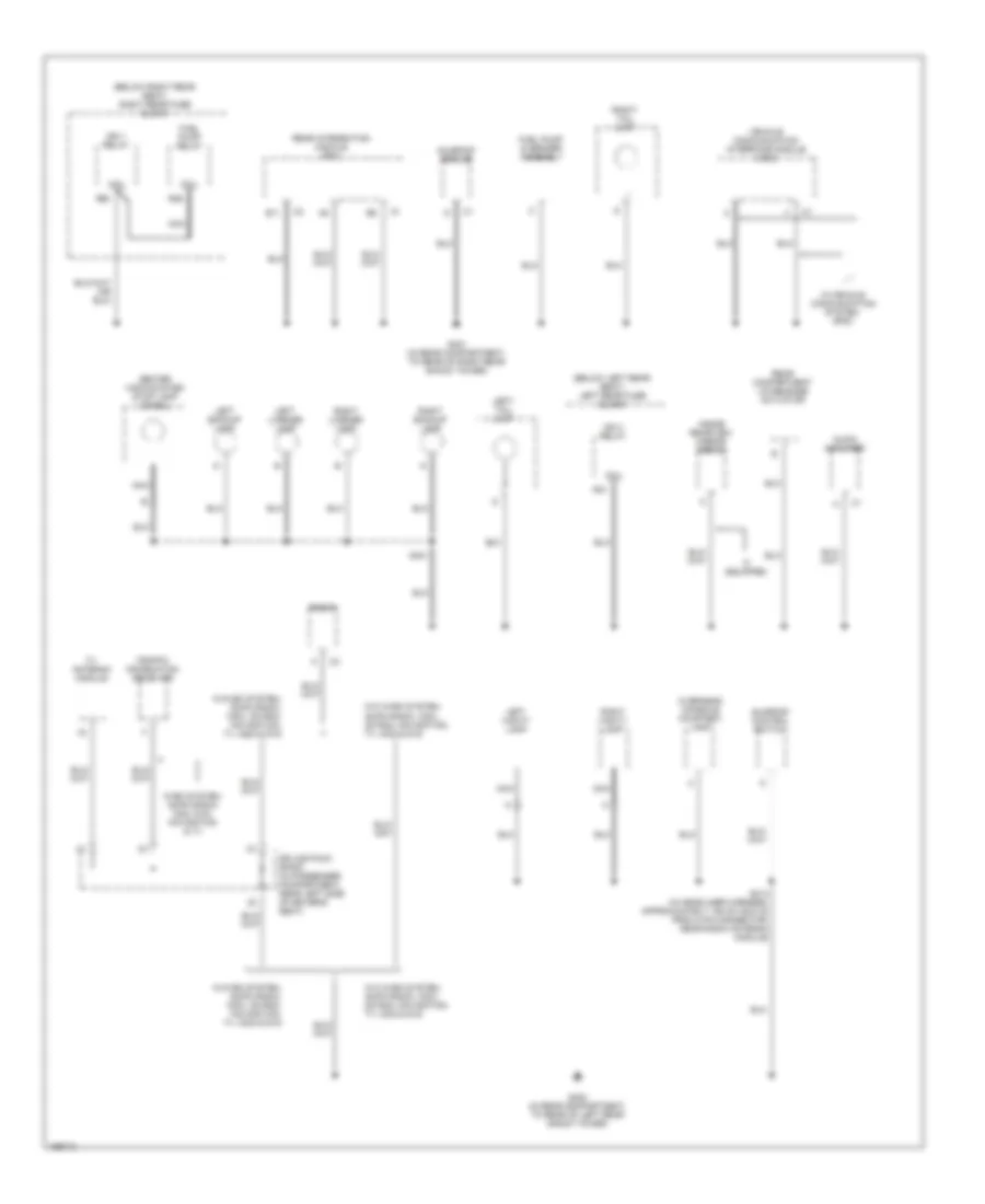
Ground Distribution Wiring Diagram (4 of 4) for Cadillac CTS 2003
List of elements for Ground Distribution Wiring Diagram (4 of 4) for Cadillac CTS 2003:
- (below left rear seat) left rear fuse block
- (below right rear seat) right rear fuse block
- Audio amplifier
- Avec system, am/fm radio, mcd, dvd, navigation & tv
- B11
- Center high mounted stop lamp (chmsl)
- Coil
- Fuel pump & sender assembly
- Fuel pump relay
- G401 (in rear compartment, to rear of right rear shock tower)
- G402 (in rear compartment, to rear of left rear shock tower)
- If equipped
- Ign 1 relay
- Ign 3 relay
- Inside rearview mirror (isrvm)
- Left backup lamp
- Left license lamp
- Left vanity lamp
- Left- tail lamp
- Nca
- Overhead console courtesy lamp
- R21
- R25
- R36
- Radio
- Rear compartment lid release actuator
- Rear integration module (rim)
- Right backup lamp
- Right license lamp
- Right vanity lamp
- Right- tail lamp
- S314 (in headliner harness, approximately 125 cm (49.8 in) from 2 pin connector, near radio antenna module)
- S401
- Splice pack sp300 (in passenger compartment, near left side of driver's seat)
- Sunroof control switch
- Sunroof module
- Traffic information receiver
- Tv antenna module
- Vehicle communication interface module (vcim)
- W/avec system, am/fm radio, icdx, cd rom, navigation, tv, mcd & dvd
- W/o avec system, am/fm radio, icdx, cd rom, navigation, tv, mcd & dvd
- W/vehicle communication system, gps1
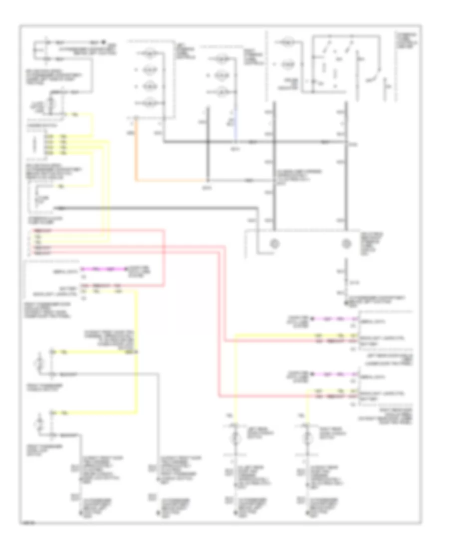
HEADLIGHTS
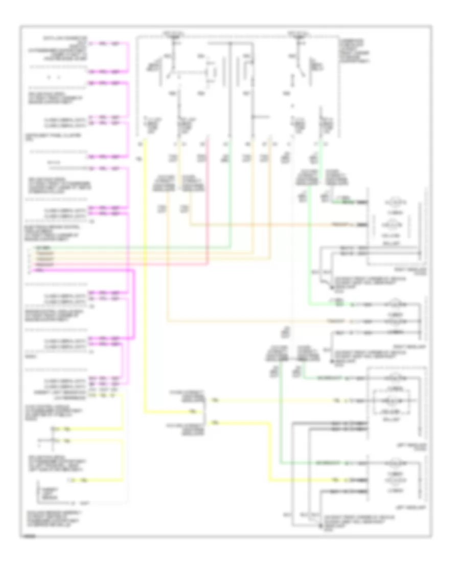
Headlights Wiring Diagram (1 of 2) for Cadillac CTS 2003
List of elements for Headlights Wiring Diagram (1 of 2) for Cadillac CTS 2003:
- (in passenger compartment, behind left kick pad) g200
- (on right front corner of vehicle, on right body rail near right headlamp) g104
- A11
- A12
- Auto
- Battery
- Class 2 serial data
- Computer data lines system
- Dash integration module (dim) (under right side of dash, above right closeout/ insulator panel)
- Drl relay control
- Drl relay ctrl
- Flash to pass signal
- Flasher fuse 15a
- Fog lamp fuse 15a
- Fog lamp relay ctrl
- Fog lamp switch signal
- Fog lp relay
- Front fog lamp switch
- Ftp
- Ground
- Hazard signal switch
- Hazard switch
- Hazard switch output
- Hazard switch signal
- Head
- Headlamp on signal
- Headlamp relay control
- Headlamp switch
- Hi beam relay control
- High
- Hot at all times
- Hot in run or crank
- Ign 1 voltage
- Left fog lamp
- Left front turn signal
- Left front turn/drl out
- Left turn signal switch signal
- Left turn- signal
- Low
- Low beam relay control
- Off
- Park
- Pnk
- Right fog lamp
- Right front turn signal
- Right front turn/drl out
- Right turn signal switch signal
- Right turn- signal
- S119
- Splice pack sp203 (in passenger compartment, under left side of i/p trim pad)
- Splice pack sp301 (in passenger compartment, near right side of passenger's seat)
- Strg cntrls fuse 10a
- Turn signal switch
- Turn/hazard flasher module (in left front of passenger compartment, under dash)
- Twilight sentinal display
- Underhood fuse block (at left front of engine compartment)
Headlights Wiring Diagram (2 of 2) for Cadillac CTS 2003
List of elements for Headlights Wiring Diagram (2 of 2) for Cadillac CTS 2003:
- (on right front corner of vehicle, on right body rail near right headlamp) g104
- Ambient light sensor
- Ambient light sensor sig
- Ballast
- Class 2 serial data
- Data link connector (dlc) (partial) (in passenger compartment, under i/p next to hood release lever)
- E10
- Electronic brake control module (ebcm) (at right front corner of engine compartment)
- Engine control module (ecm) (at right front corner of engine compartment)
- F13
- F15
- Hi beam
- Hi beam relay
- Hid lo bm
- Hot at all times
- Hvac control module (in passenger compartment, on center of i/p below radio)
- Instrument panel cluster (ipc)
- Left headlamp
- Left headlamp (w/hid)
- Lo beam
- Lo beam relay
- Low reference
- Lt hi beam fuse 10a
- Lt low beam fuse 20a
- Nca
- R23
- R24
- R25
- R26
- R27
- R28
- R29
- R30
- Radio
- Right headlamp
- Right headlamp (w/hid)
- Rt hi beam fuse 10a
- Rt low beam fuse 20a
- Splice pack sp200 (at right front of passenger compartment under i/p, above steering column)
- Splice pack sp201 (at right front corner of engine compartment)
- Splice pack sp302 (in passenger compartment, on left frame rail, near left side of driver's seat)
- Sunload sensor assembly (in front center of passenger compartment on defroster grille)
- Underhood fuse block (in right front corner of engine compartment)
- W/high intensity discharge headlamps
- W/o high intensity discharge headlamps
HORN
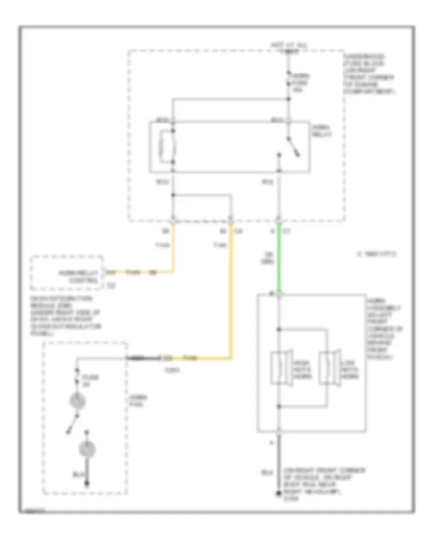
Horn Wiring Diagram for Cadillac CTS 2003
List of elements for Horn Wiring Diagram for Cadillac CTS 2003:
- (on right front corner of vehicle, on right body rail near right headlamp) g104
- 1995 vftc c
- C203
- Dash integration module (dim) (under right side of dash, above right closeout/insulator panel)
- Fuse 2a
- High note horn
- Horn assembly (in left front corner of vehicle, behind front fascia)
- Horn fuse 15a
- Horn pan
- Horn relay
- Horn relay control
- Hot at all times
- Low note horn
- Nca
- R10
- R11
- R12
- R13
- Tan
- Underhood fuse block (on right front corner of engine compartment)
INSTRUMENT CLUSTER
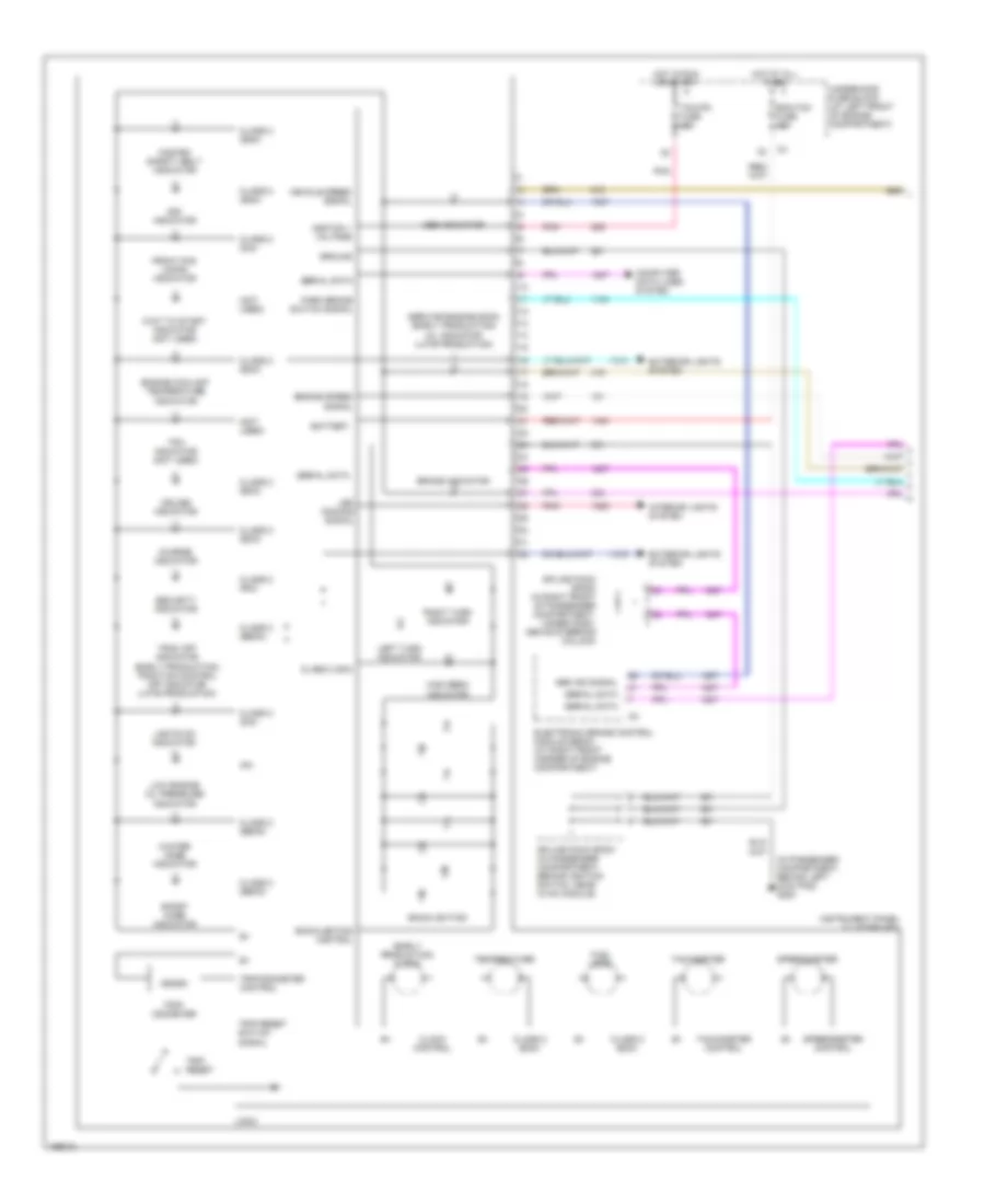
Instrument Cluster Wiring Diagram (1 of 2) for Cadillac CTS 2003
List of elements for Instrument Cluster Wiring Diagram (1 of 2) for Cadillac CTS 2003:
- (early production) clock
- (in passenger compartment, behind left kick pad) g200
- (not used)
- Abs ind signal
- Abs indicator
- Backlighting
- Backlighting control
- Battery
- Brake indicator
- Charge indicator
- Class 2 (dim)
- Class 2 (ebcm)
- Class 2 (ecm)
- Class 2 (rim)
- Class 2 (sdm)
- Clock control
- Computer data lines system
- Cruise indicator
- Ecm/tcm fuse 10a
- Electronic brake control module (ebcm) (at right front corner of engine compartment)
- Engine coolant temperature indicator
- Engine speed signal
- Exterior lights system
- Fasten safety belt indicator
- Front fog lamps indicator
- Fuel level
- Ground
- High beam indicator
- Hot at all times
- Hot in run or start
- Ignition 1 voltage
- Instrument panel cluster (ipc)
- Interior lights system
- Ipc
- Led dimming signal
- Left turn indicator
- Lights on indicator
- Logic
- Low engine oil pressure indicator
- Park brake switch signal
- Pnk
- Right turn indicator
- Security indicator
- Serial data
- Service engine soon (early production) mil indicator (late production)
- Sir indicator
- Speedometer
- Speedometer control
- Splice pack sp200 (in right front of passenger compartment, under dash, above steering column)
- Splice pack sp201 (in passenger compartment, behind ignition switch, near hvac module)
- Sport mode indicator
- Tachometer
- Tachometer control
- Tcm/ipc fuse 15a
- Temperature
- Tpm indicator (not used)
- Trac off indicator (early production) traction control off indicator (late production)
- Trip reset
- Trip reset switch signal
- Trip/ odometer
- Trip/odometer control
- Underhood fuse block (at left front of engine compartment)
- Vehicle speed signal
- Wait to start indicator (not used)
- Winter mode indicator
Instrument Cluster Wiring Diagram (2 of 2) for Cadillac CTS 2003
List of elements for Instrument Cluster Wiring Diagram (2 of 2) for Cadillac CTS 2003:
- (in engine compartment, near left front strut tower, at bottom of inside fender well) g101
- (in engine harness, aproximately 120 cm from ho2s bank 2 sensor 1)
- (in rear compartment to rear of left rear shock tower) g402
- 2.7 ohms
- Brake fluid level switch (at rear of engine compartment, on brake fluid reservoir)
- Class 2 serial data
- Computer data lines system
- Driver information center (dic) switch
- E10
- Ect sensor signal
- Eng/ met
- Engine compartment module (ecm) (at right front corner of engine compartment)
- Engine coolant temperature (ect) sensor (on top rear of intake manifold)
- Engine oil pressure (eop) switch (on front left side of engine, above oil filter)
- Engine speed signal
- English/ metric signal
- Fuel info
- Fuel info signal
- Fuel level sensor
- Fuel pump & sensor assembly (in fuel tank)
- Gage info
- Gage info signal
- Hvac control module (behind center of dash, below radio)
- If equipped
- Ign
- Low reference
- Mil control
- Odo/ trip
- Odometer/ trip signal
- Ohms
- Oil press signal
- Park brake switch (on park brake assembly)
- Radio
- Reset
- Reset signal
- S111
- S400 (in rear compartment lid harness, approximately 237 cm from c401)
- Secondary fuel sender assembly (under vehicle, in fuel tank)
- Serial data
- Splice pack sp202 (in passenger compartment, under dash trim pad, near ipc)
- Tan
- Vehicle speed signal
INTERIOR LIGHTS
Courtesy Lamps Wiring Diagram for Cadillac CTS 2003
List of elements for Courtesy Lamps Wiring Diagram for Cadillac CTS 2003:
- (in rear compartment, to rear of left rear shock tower) g402
- 125 cm from c311) s314
- 2,000 ohms
- 40,000 ohms
- 5v courtesy lamps on signal
- 5v reference
- A10
- B10
- Backlight lamps control
- Courtesy lamp ctrl
- Courtesy lp ctrl
- Courtesy lp relay ctrl
- Courtesy lp voltage
- Courtesy lps on signal
- Dash integration module (dim) (under right side of dash, above right closeout/ insulator panel)
- Dimmer sw low reference
- G402 (in rear compartment, to rear of left rear shock tower)
- Hot at all times
- I/p lamps dimmer switch
- Int lamp relay
- Interior lamp fuse 10a
- Left courtesy lamp
- Left footwell courtesy lamp
- Left front courtesy lamp
- Left sunshade
- Left vanity lamps
- Nca
- Overhead console courtesy lamp
- R16
- R17
- R18
- R20
- Rear compartment courtesy lamp
- Rear dome lamp
- Rear integration module (rim) (under package shelf trim panel)
- Right courtesy lamp
- Right footwell courtesy lamp
- Right front courtesy lamp
- Right rear fuse block (below right rear seat)
- Right sunshade
- Right vanity lamps
- S311 (in headliner harness, approximately 100 cm from c311)
- S312
- S314 (in headliner harness, approximately 125 cm from c311)
- S314 (in headliner harness, approximately 125 cm from from c311)
- S319
- Splice pack sp301 (in passenger compartment, on right frame rail, near right side of passenger's seat)
- Splice pack sp302 (in passenger compartment, on left frame rail, near left side of driver's seat)
- Sunroof control switch
- Trunk ajar sw signal
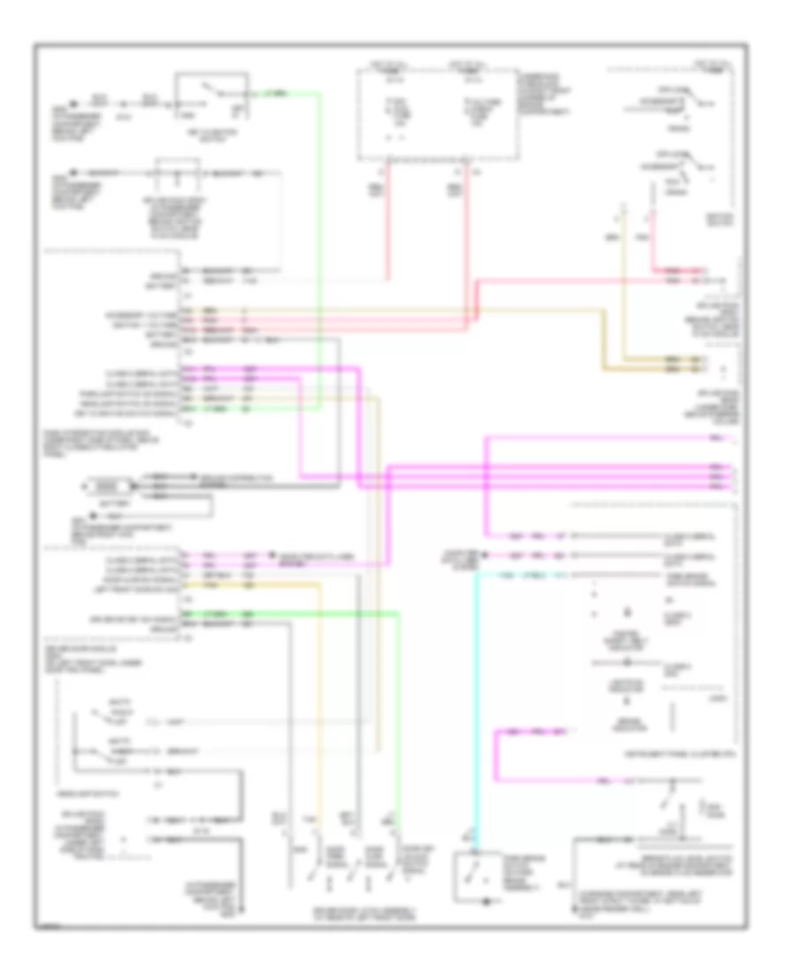
Instrument Illumination Wiring Diagram (1 of 2) for Cadillac CTS 2003
List of elements for Instrument Illumination Wiring Diagram (1 of 2) for Cadillac CTS 2003:
- (in passenger compartment, behind left kick pad) g200
- (in rear compartment, to rear of left rear shock tower) g402
- 2,000 ohms
- 40,000 ohms
- 5 volt reference
- A11
- A12
- B11
- Backlight lamps ctrl
- Backlights lamp ctrl
- Battery
- Computer data lines system
- Control power output
- Courtesy lps on signal
- Dash integration module (dim) (under right side of dash, above right closeout/insulator panel)
- Dim/ aldl fuse 10a
- Dimmer switch signal
- Driver door lock switch
- Driver door module (ddm) (on left door, under door trim)
- Driver door switch assembly (ddsa)
- Driver dr mod fuse 10a
- Electronic prndl
- G201 (in passenger compartment, behind right kick pad)
- Ground
- Hot at all times
- Illumination lamp
- Inc dim
- Instrument panel cluster (ipc)
- Led dimming signal
- Left rear fuse block (below left rear seat)
- Lic/dimming fuse 15a
- Low reference
- Memory seat switch
- Overhead console courtesy lamp
- Park i/p switch
- Park lamp relay
- Pnk
- Psgr dr mod fuse 10a
- R31
- R32
- R33
- R34
- Rear dr mod fuse 10a
- Right rear fuse block (below right rear seat)
- S308
- S314 (in headliner harness, approximately 125 cm (49.8 in) from c311)
- S501 (in left front door trim harness, approximately 70 cm from driver window/door lock switch)
- Serial data
- Splice pack sp302 (in passenger compartment, on left frame rail, near left side of driver's seat)
- Sunroof control switch
- Underhood fuse block (at left front of engine compartment)
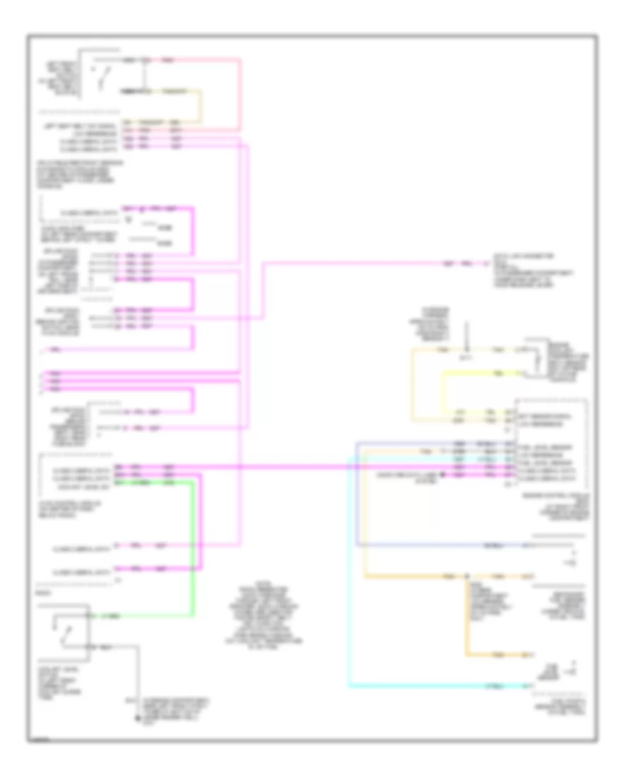
Instrument Illumination Wiring Diagram (2 of 2) for Cadillac CTS 2003
List of elements for Instrument Illumination Wiring Diagram (2 of 2) for Cadillac CTS 2003:
- (in headliner harness, approximately 110 cm from c311) s312
- (in left rear door trim harness, approximately 160 cm from c701) s701
- (in passenger compartment, behind left kick pad) g200
- (in passenger compartment, behind right kick pad) g201
- (in right front door trim harness, approximately 70 cm from driver window/door lock switch) s600
- (in right rear door trim harness, approximately 160 cm from c801) s801
- 70 cm from driver window/ door lock switch) s600
- 70 cm from front passenger window switch) s601
- A12
- Backlight lamps ctrl
- Battery
- Computer data lines system
- Cruise "on" indicator'
- Front passenger door lock switch
- Front passenger door module (fpdm) (on right front door, under door trim panel)
- Front passenger window switch
- Fuse 2a
- G200 (in passenger compartment, behind left kick pad)
- Gnd
- Hazard switch
- Illumi- nation lamp
- Inflatable restraint steering wheel module coil
- Left rear door module (lrdm) (under door trim panel)
- Left rear door window switch
- Left steering wheel controls
- Nca
- Off
- R/a
- Right rear door module (rrdm) (on right rear door, under door trim panel)
- Right rear door window switch
- Right steering wheel controls
- S/c
- S119
- S120
- S314
- S315
- Serial data
- Splice pack sp201 (in passenger compartment, behind ignition switch, near hvac module)
- Splice pack sp203 (in passenger compartment, under left side of dash trim pad)
- Steering cloumn fuse holder
- Steering wheel controls center
MEMORY SYSTEMS
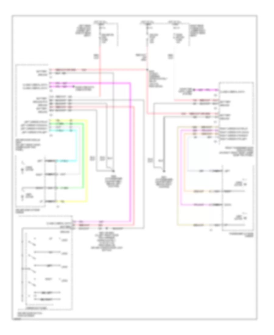
Memory Mirrors Wiring Diagram (1 of 2) for Cadillac CTS 2003
List of elements for Memory Mirrors Wiring Diagram (1 of 2) for Cadillac CTS 2003:
- 5v feed
- 5v reference
- 5v rtn
- A12
- B11
- B12
- Backlight lamps control
- Battery
- Class 2 serial data
- Computer data lines system
- Driver door module (ddm) (on left front door, under door trim panel)
- Driver door switch module (ddsm) (driver door switch assembly (ddsa))
- Driver dr mod fuse 10a
- Driver outside rearview mirror
- Exit (ext)
- G200 (in passenger compartment, behind left kick pad)
- Gnd
- Ground
- Ground rtn
- Horiz motor
- Horiz pos sensor
- Horiz posit sensor
- Hot at all times
- Interior lights system
- Left
- Left horiz
- Left rear fuse block (under left side of rear seat)
- Logic
- Low reference
- Memory 1 switch signal
- Memory 2 switch signal
- Memory/personalization function switch (memory seat switch)
- Mirror mtr down ctrl
- Mirror mtr left ctrl
- Mirror mtr right ctrl
- Mirror mtr up ctrl
- Mirror switches
- Nca
- Right
- Right horiz
- S501 (or s502) (in left front door trim harness, approximately 70 cm (27.3 in) from driver window/door lock switch (or ddsa))
- Sel left
- Sel right
- Vert down
- Vert motor
- Vert pos sensor
- Vert up
- Vertical posit sensor
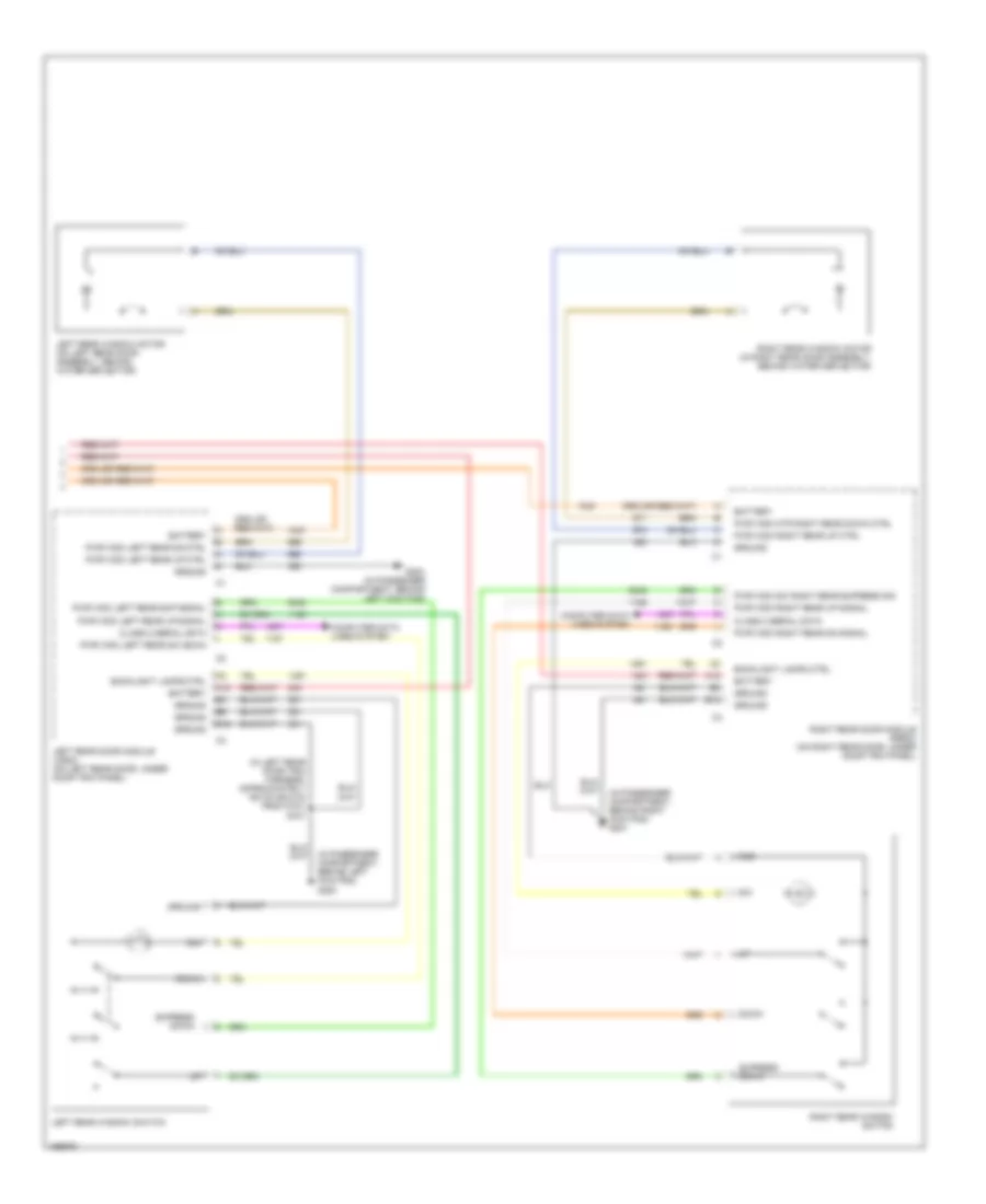
Memory Mirrors Wiring Diagram (2 of 2) for Cadillac CTS 2003
List of elements for Memory Mirrors Wiring Diagram (2 of 2) for Cadillac CTS 2003:
- (in body harness, approximately 255 cm (100.5 in) from sp303) s303
- (in passenger compartment, behind right kick pad) g201
- 5v feed
- 5v reference
- 5v rtn
- A12
- B12
- Battery
- Class 2 serial data
- Computer data lines system
- Dr mod pwr c/b 30a
- Front passenger door module (fpdm) (on right front door, under door trim panel)
- Ground
- Horiz motor
- Horiz pos sensor
- Horizontal posit sensor
- Hot at all times
- Left horiz
- Low reference
- Mirror mtr down ctrl
- Mirror mtr left ctrl
- Mirror mtr right ctrl
- Mirror mtr up ctrl
- Passenger outside rearview mirror
- Psgr dr mod fuse 10a
- Right horiz
- Right rear fuse block (under right side of rear seat)
- Vert down
- Vert motor
- Vert pos sensor
- Vert up
- Vertical posit sensor
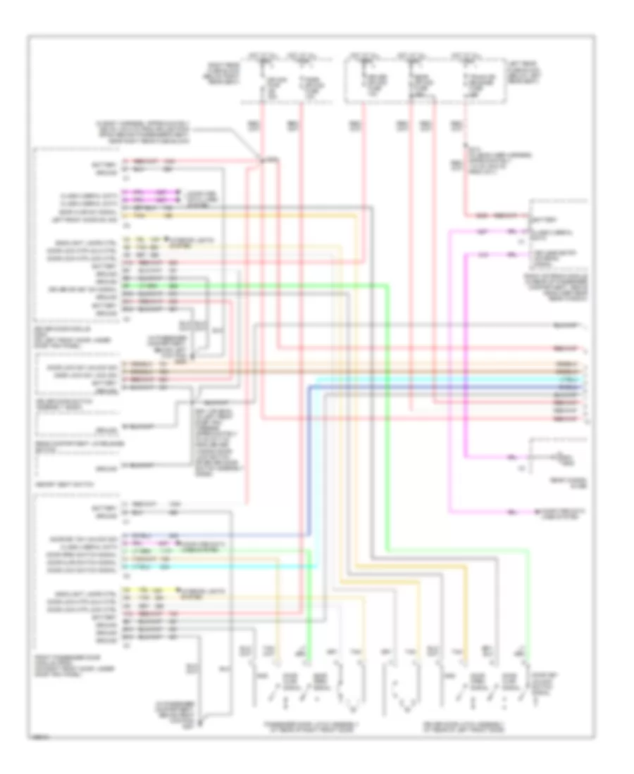
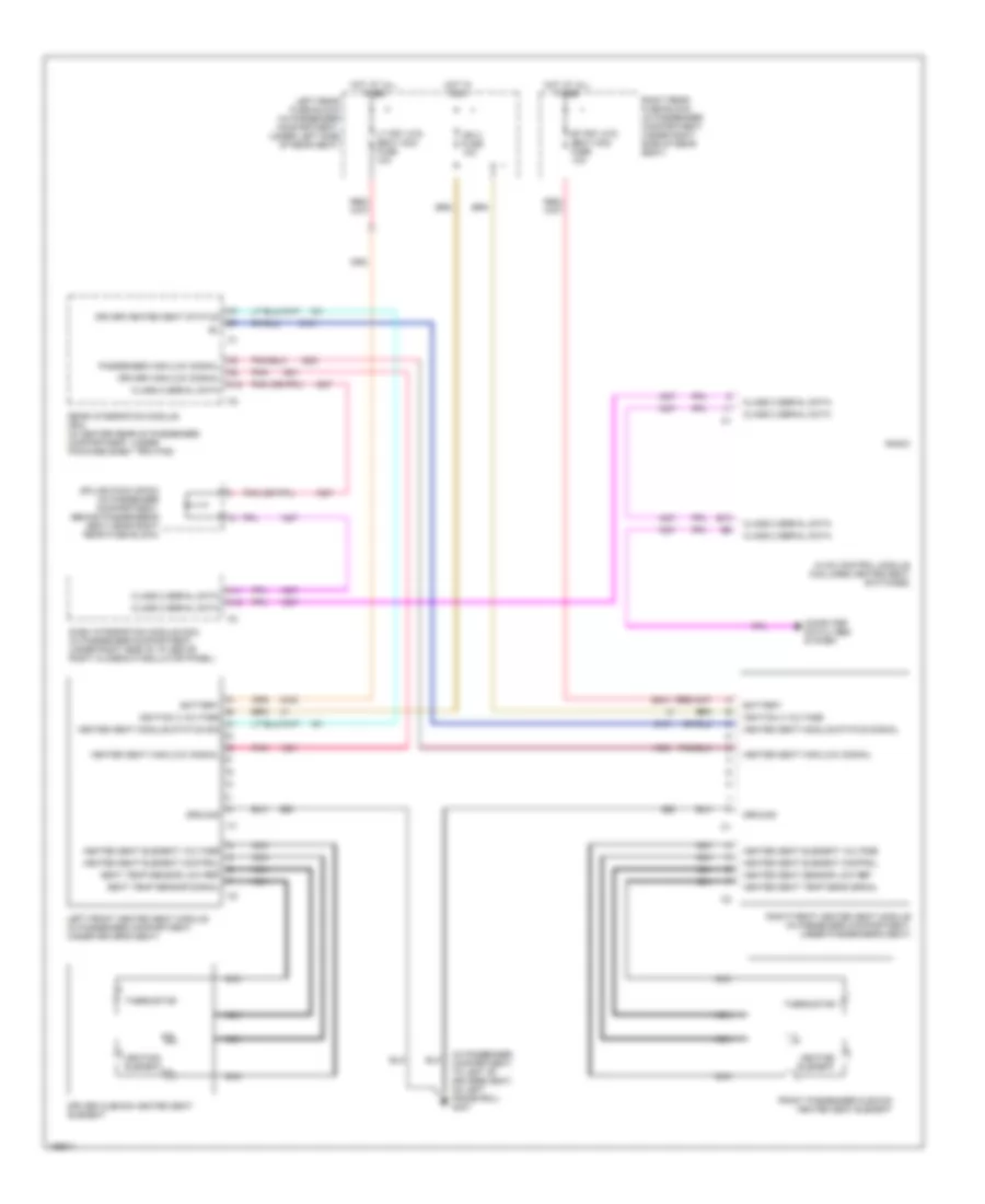
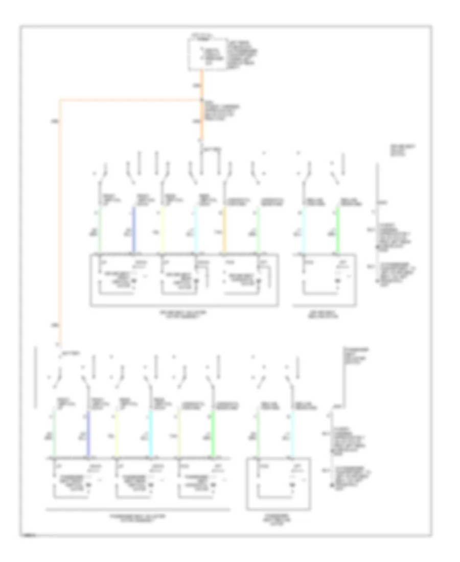
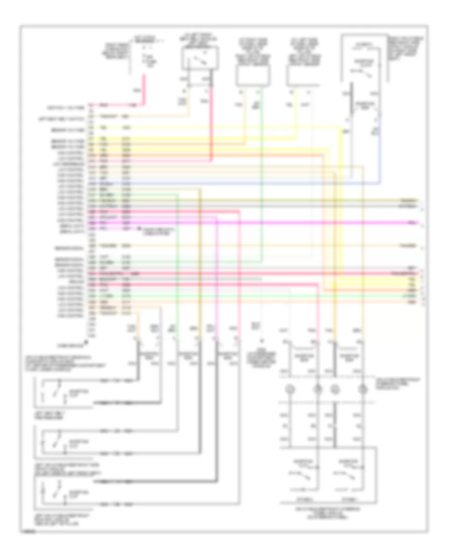
Memory Seat Wiring Diagram (1 of 2) for Cadillac CTS 2003
List of elements for Memory Seat Wiring Diagram (1 of 2) for Cadillac CTS 2003:
- (in body harness, approximately 555 cm (218.5 in) from c700) s304
- (in left seat harness, approximately 10 cm (3.2 in) from driver seat horizontal position sensor) s348
- 5 volt reference
- Battery positive voltage
- Class 2 serial data
- Driver seat adjuster switch
- E10
- E11
- E12
- E13
- E14
- E15
- E16
- F10
- F11
- F12
- F13
- F14
- F15
- F16
- Front vertical down
- Front vertical motor down control
- Front vertical motor up control
- Front vertical up
- G307 (to left of driver's seat, on left frame rail)
- Ground
- Horizontal forward
- Horizontal forward switch signal
- Horizontal motor forward ctrl
- Horizontal motor rearward control
- Horizontal rearward
- Horizontal rearward switch signal
- Hot at all times
- Left rear fuse block (under left side of rear seat)
- Low reference
- Mem/adapt seat fuse 10a
- Memory seat module (msm) (in passenger compartment, under driver's seat)
- Rear vertical down
- Rear vertical motor down control
- Rear vertical motor up control
- Rear vertical posit sens signal
- Rear vertical up
- Recline back switch signal
- Recline forward
- Recline forward switch signal
- Recline motor forward control
- Recline motor rearward control
- Recline posit sens signal
- Recline rearward
- S320 (in right seat harness, approximately 235 cm (92.5 in) from c307)
- Seat horiz posit sensor signal
- Seats circuit breaker 30a
- Tan
- Vertical down switch signal
- Vertical posit sens signal
- Vertical up switch signal
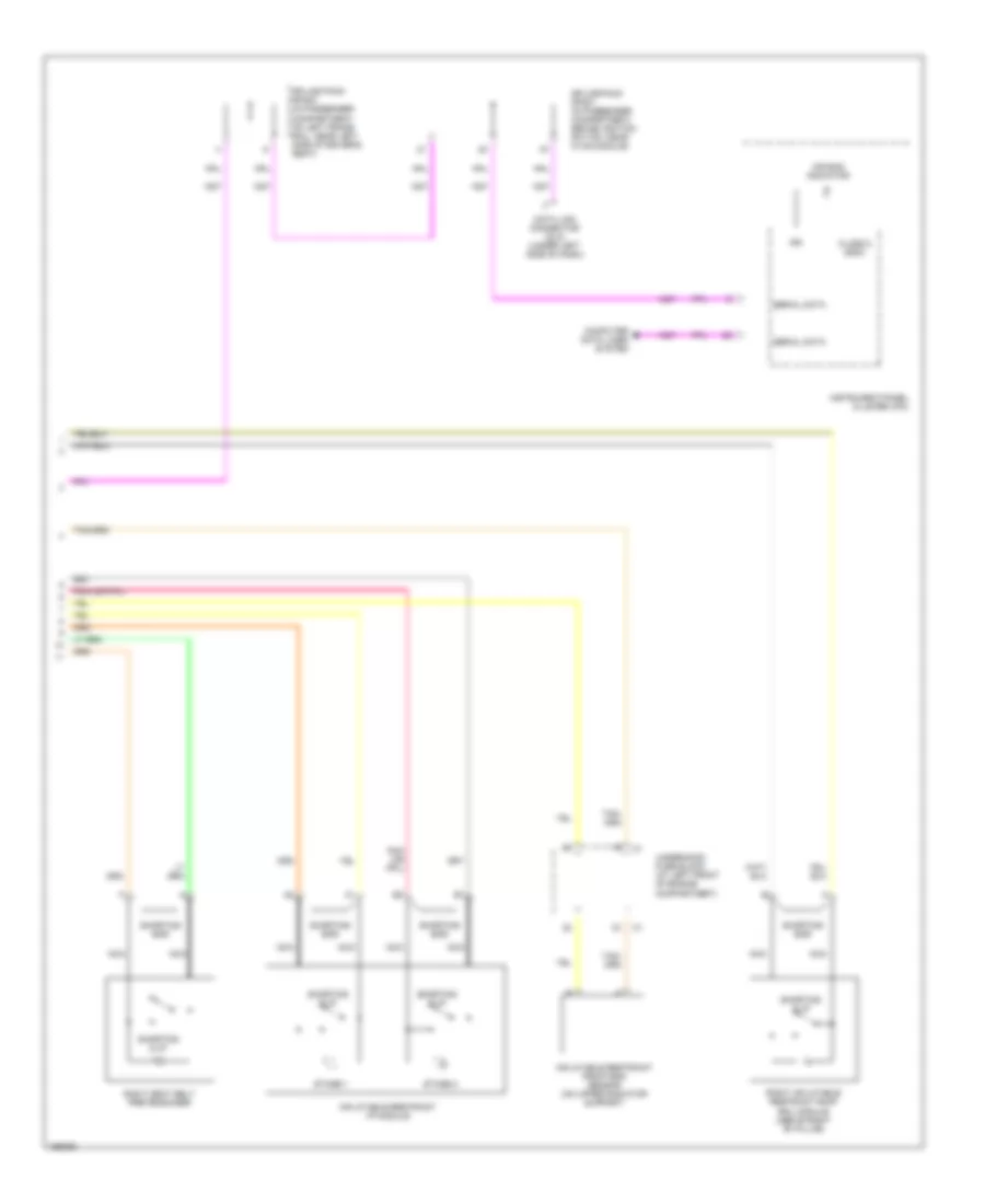
Memory Seat Wiring Diagram (2 of 2) for Cadillac CTS 2003
List of elements for Memory Seat Wiring Diagram (2 of 2) for Cadillac CTS 2003:
- (under driver's seat) driver seat front vertical motor
- (under driver's seat) driver seat horizontal motor
- (under driver's seat) driver seat rear vertical motor
- (under driver's seat) driver seat recline motor
- Backlight lamps control
- Class 2 serial data
- Driver door module (ddm) (on left front door, under door trim panel)
- Driver door switch assembly (ddsa)
- Driver seat front vertical position sensor (under driver's seat)
- Driver seat horizontal position sensor (under driver's seat)
- Driver seat rear vertical position sensor (under driver's seat)
- Driver seat recline position sensor (under driver's seat)
- Exit (ext)
- Gnd
- Ground
- Interior lights system
- Memory 1 sw signal
- Memory 1 switch signal
- Memory 2 sw signal
- Memory 2 switch signal
- Memory/personalization function switch (memory seat switch)
- Nca
- S348 (in left seat harness, approximately 10 cm (3.2 in) from driver seat horizontal position sensor)
- S349 (in left seat harness, approximately 150 cm (59.2 in) from driver seat rear vertical position sensor)
- S502 (in left front door trim harness, approximately 70 cm (27.3 in) from ddsa)
- Splice pack sp300 (on left frame rail, near left side of driver's seat)
- Tan
NAVIGATION
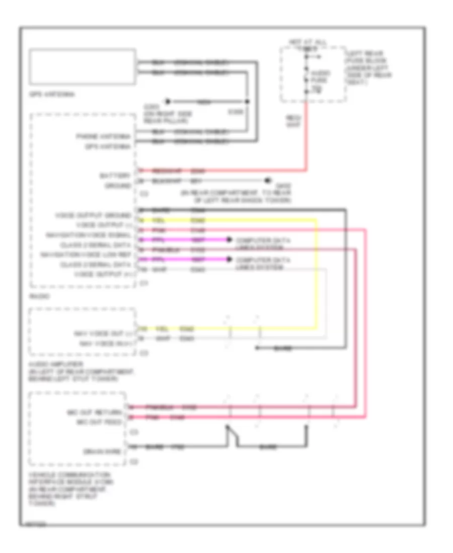
Navigation Wiring Diagram for Cadillac CTS 2003
List of elements for Navigation Wiring Diagram for Cadillac CTS 2003:
- (coaxial cable)
- Audio amplifier (in left of rear compartment, behind left stut tower)
- Audio fuse 10a
- Bare
- Battery
- Class 2 serial data
- Computer data lines system
- Drain wire
- G303 (on right side rear pillar)
- G402 (in rear compartment, to rear of left rear shock tower)
- Gps antenna
- Ground
- Hot at all times
- Left rear fuse block (under left side of rear seat)
- Mic out feed
- Mic out return
- Nav voice in (+)
- Nav voice out (-)
- Navigation voice low ref
- Navigation voice signal
- Nca
- Phone antenna
- Pnk
- Radio
- S309
- Vehicle communication interface module (vcim) (in rear compartment, behind right strut tower)
- Voice output (+)
- Voice output (-)
- Voice output ground
POWER DISTRIBUTION
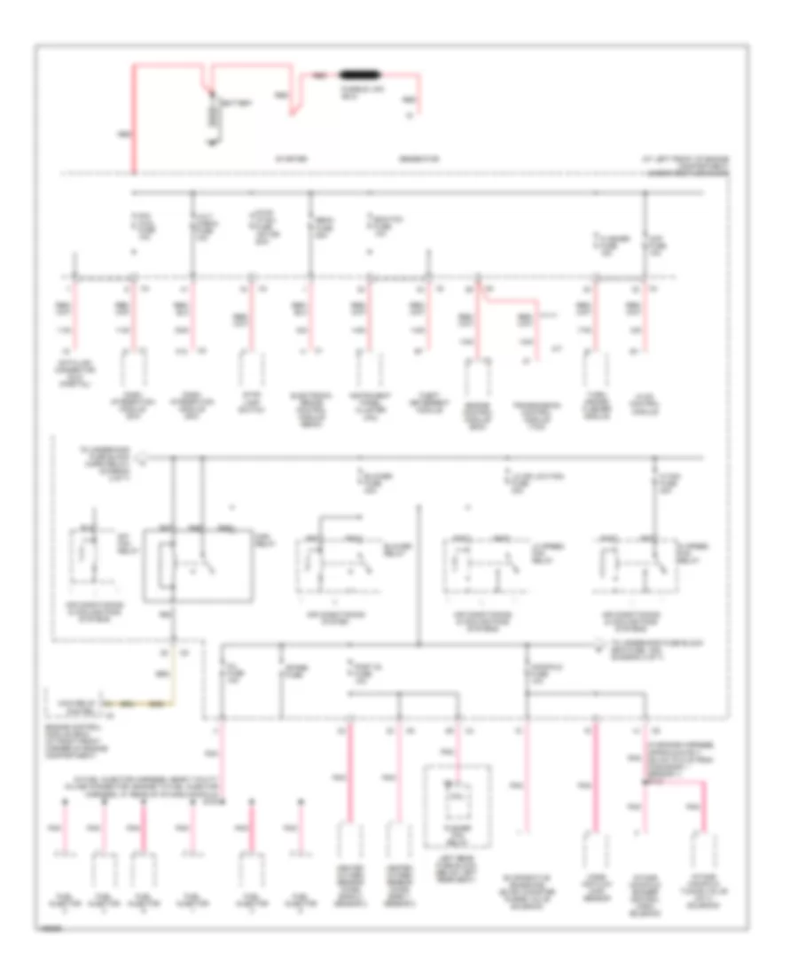
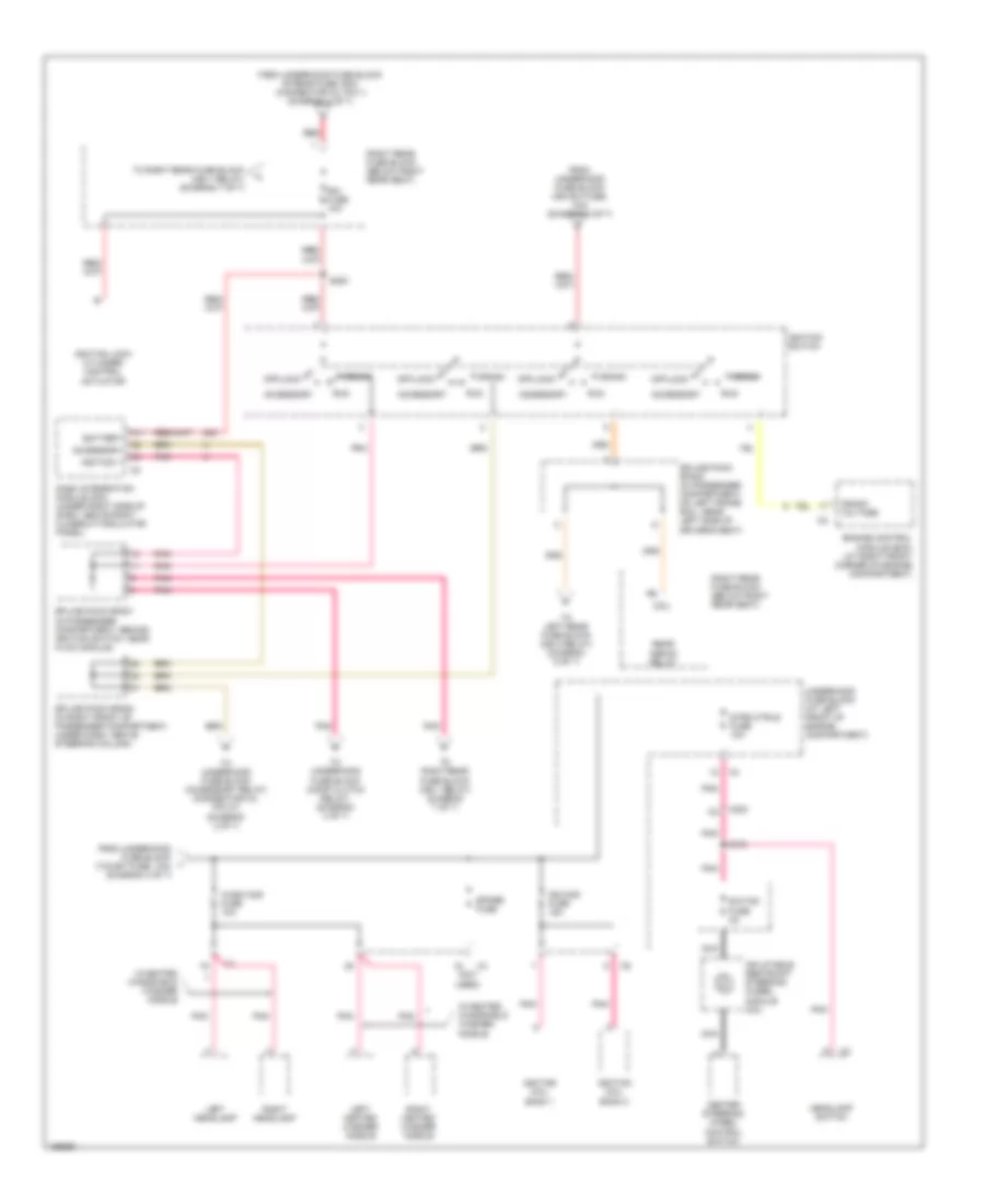
Power Distribution Wiring Diagram (1 of 7) for Cadillac CTS 2003
List of elements for Power Distribution Wiring Diagram (1 of 7) for Cadillac CTS 2003:
- (at left front of engine compartment) underhood fuse block
- (in engine harness, approximately 200 cm (78.5 in) from ho2s bank 1 sensor 1) s112
- (in fuel injector harness, near 7 cavity in-line connector, engine to fuel injector harness, at rear of intake manifold) s108
- A/t
- A12
- Air conditioning & cooling fans systems
- Air conditioning system
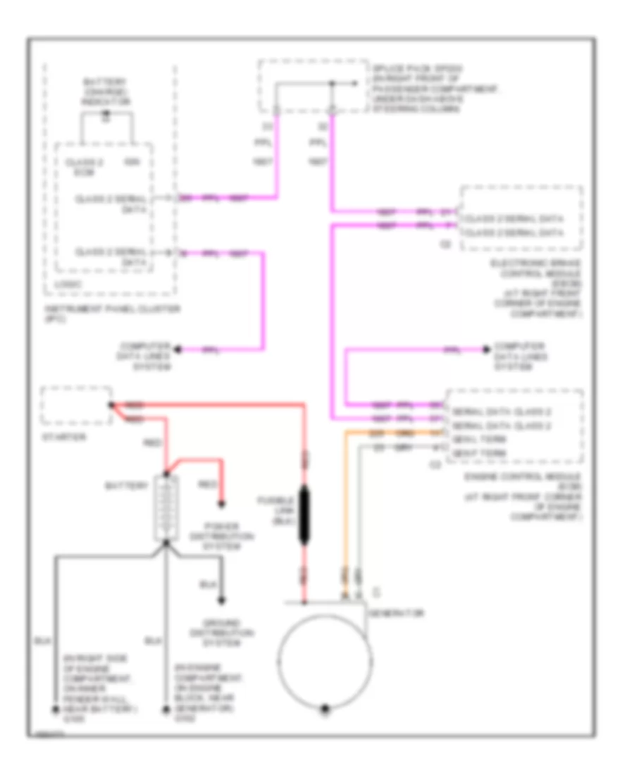
- Battery
- Blower fuse 40a
- Blower relay
- Ccp fuse 10a
- Coil
- Dash integration module (dim)
- Data link connector (dlc) (partial)
- Dim/ aldl fuse 10a
- Ebcm fuse 50a
- Ecm/tcm fuse 10a
- Electronic brake control module (ebcm)
- Engine control module (ecm)
- Engine control module (ecm) (at right front corner of engine compartment)
- Evaporative emissions (evap) canister purge valve solenoid
- Flasher fuse 15a
- Fuel injector
- Generator
- Heated oxygen sensor (ho2s) bank 1 sensor 2
- Heated oxygen sensor (ho2s) bank 2 sensor 2
- Hi fan fuse 30a
- Hi speed fan relay
- Hvac control module
- Inj fuse 10a
- Instrument panel cluster (ipc)
- Intake manifold runner control (imrc) solenoid
- Intake manifold tuning valve (imtv) solenoid
- Left rear fuse block (below left rear seat)
- Lo (or low fan) fuse 30a
- Lo speed fan relay
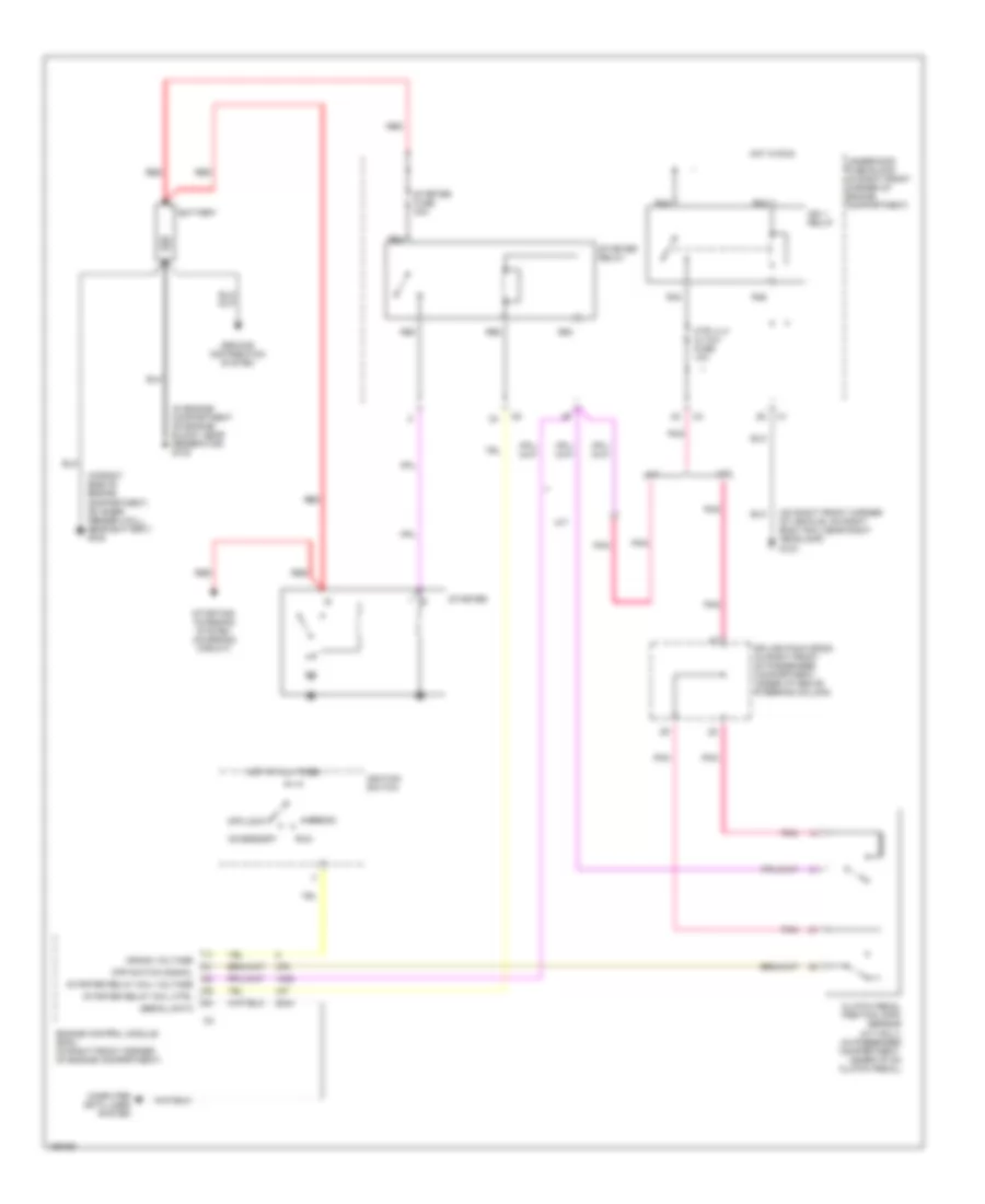
- Main relay
- Main relay control
- Manifold fuse 10a
- Mass air flow (maf) sensor
- Pnk
- Post 02 fuse 10a
- Pusher fan relay
- R14
- R19
- R20
- R39
- R40
- R47
- R48
- R49
- R50
- R51
- R52
- Red
- S/p fan relay
- Spare fuse
- Starter
- Stop lamp switch
- Stop lp sw fuse 15a (or 20a)
- Theft deterrent module
- To underhood fuse block (ecm fuse, 15a) (diagram 3 of 7)
- To underhood fuse block (horn relay) (diagram 2 of 7)
- Transmission control module (tcm)
- Turn/ hazard flasher module
- Volt check fuse 10a
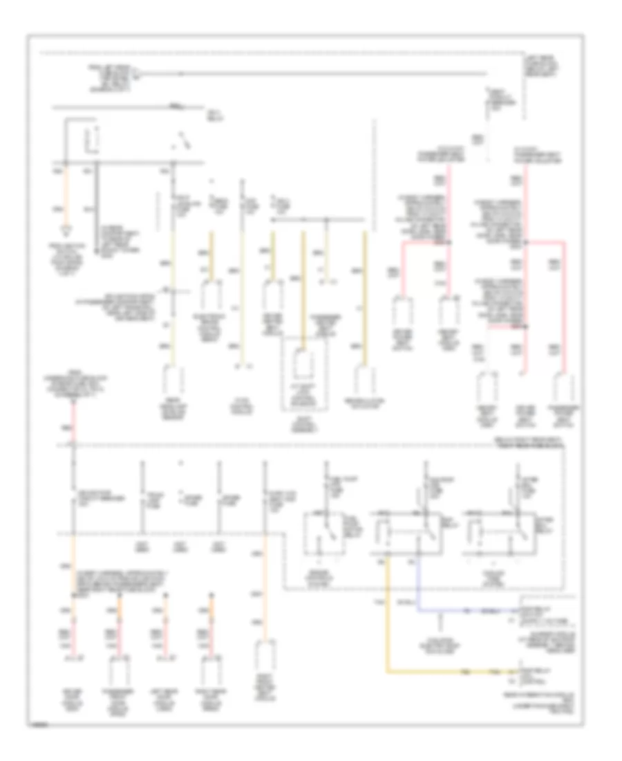
Power Distribution Wiring Diagram (2 of 7) for Cadillac CTS 2003
List of elements for Power Distribution Wiring Diagram (2 of 7) for Cadillac CTS 2003:
- (at left front of engine compartment) underhood fuse block
- (on right front corner of vehicle, on right body rail near right headlamp) g104
- A/t
- Accessory relay
- Air conditioning system
- Comp (clu) clutch relay
- Comp clutch fuse 10a
- Drl relay
- Early production before vin number
- Elec prndl fuse 10a
- Electronic prndl
- Engine control module (ecm)
- Exterior lights system
- Fog lamp fuse 15a
- Fog lamp relay
- From ignition switch (via splice pack sp200, pin 21) (diagram 4 of 7)
- From underhood fuse block a (main relay) (diagram 1 of 7)
- Hdlp wash circuit breaker 30a
- Hdlp washer relay
- Headlamp washer relay
- Headlights system
- High (hi) beam relay
- Horn fuse 15a
- Horn relay
- Horns system
- Ign sw fuse 10a
- Jumper wire
- L rear fuse 60a
- Late production vin 105858 & after
- Lo beam relay/ hid
- Park lamp relay
- R rear fuse 60a
- R10
- R11
- R24
- R28
- R30
- R32
- R35
- R36
- R37
- R56
- R67
- R68
- Red
- Spare fuse
- Theft deterrent control module
- Theft fuse 7.5a
- To ignition switch (pin 6) (diagram 4 of 7)
- To left rear fuse block (driver dr mod fuse, 10a) (diagram 5 of 7)
- To left rear fuse block (l position relay) (diagram 5 of 7)
- To right rear fuse block (dr mod pwr circuit breaker, 30a) (diagram 6 of 7)
- To right rear fuse block (rim fuse, 10a) (diagram 4 of 7)
- To underhood fuse block (cigar relay) (diagram 3 of 7)
- Transmission control module (tcm)
- Windshield wiper/ washer module
- Windshield wiper/ washer switch
- Wiper/ washer system
- Wpr mod fuse 30a
- Wpr sw fuse 10a
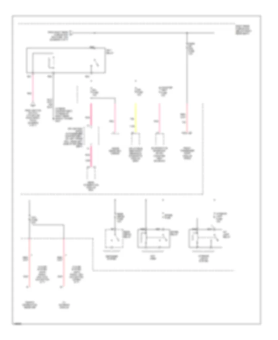
Power Distribution Wiring Diagram (3 of 7) for Cadillac CTS 2003
List of elements for Power Distribution Wiring Diagram (3 of 7) for Cadillac CTS 2003:
- (accessory relay) (diagram 2 of 7)
- (in passenger compartment, behind right kick pad) g201
- (on right front corner of vehicle, on right body rail near right headlamp) g104
- A/t
- Auxiliary power outlet
- B+ mode
- Battery saver mode
- Camshaft position (cmp) sensor
- Cigar lighter
- Cigar relay
- Clutch pedal position (cpp) sensor (m/t)
- Coil
- Comp clutch relay
- Coolant bypass valve
- Dash integration module (dim) (under right side of dash, above right closeout/insulator panel)
- Ecm fuse 15a
- Engine control module (ecm)
- Fog lamp relay
- From ignition switch (via splice pack sp201 (pin 8) (diagram 4 of 7)
- From underhood fuse block (manifold fuse, 10a) (diagram 1 of 7)
- From underhood fuse block h
- Heated oxygen sensor (ho2s) bank 1 sensor 1
- Heated oxygen sensor (ho2s) bank 2 sensor 1
- Htr vlv/ cltch fuse 10a
- I/p outlet fuse 20a
- Ign 1 relay
- Instrument panel cluster (ipc)
- M/t
- Outlet fuse 30a
- Pnk
- Pre 02 fuse 10a
- R43
- R44
- R45
- R46
- R55
- R59
- R60
- R61
- R62
- R63
- R64
- S308 (a/t)
- Splice pack sp 102 (in front of underhood fuse block)
- Splice pack sp200 (above steering column)
- Splice pack sp203 (in passenger compartment, under left side of dash trim pad)
- Starter fuse 30a
- Starter relay
- Starting/charging system
- Tcc/clutch release switch
- Tcc/et fuse 10a
- Tcm/ipc fuse 15a
- To underhood fuse block (wash noz fuse 10a, (diagram 4 of 7)
- Transmission control module (tcm)
- Underhood fuse block (at left front of engine compartment)
Power Distribution Wiring Diagram (4 of 7) for Cadillac CTS 2003
List of elements for Power Distribution Wiring Diagram (4 of 7) for Cadillac CTS 2003:
- (not used)
- A11
- Accessory
- Battery
- C202
- Center steering wheel control switch
- Coil
- Crank
- Crank voltage
- Dash integration module (dim) (under right side of dash, above right closeout/insulator panel)
- Engine control module (ecm) (at right front corner of engine compartment)
- From underhood fuse block (ign sw fuse, 10a) (diagram 2 of 7)
- From underhood fuse block (r rear fuse, 60a) (connector c3, pin 1) (diagram 2 of 7)
- From underhood fuse block (tcc/et fuse, 10a) (diagram 3 of 7)
- Headlamp switch
- Ign mod fuse 15a
- Ignition 1
- Ignition coil bank 1
- Ignition coil bank 2
- Ignition lock cylinder control actuator
- Ignition switch
- Inflatable restraint steering wheel module coil
- Left headlamp
- Left heated washer nozzle
- Nca
- Off/lock
- Pnk
- Rear defog relay
- Red
- Right headlamp
- Right heated washer nozzle
- Right rear fuse block (below right rear seat)
- Rim fuse 10a
- Run
- S200
- S318
- Spare fuse
- Splice pack sp200 (in right front of passenger compartment, under dash, above steering column)
- Splice pack sp201 (in passenger compartment, behind ignition switch, near hvac module)
- Splice pack sp302 (in passenger compartment, on left frame rail, near left side of driver's seat)
- Strg ctrls fuse 10a
- Switch fuse 2a
- To left rear fuse block (ign 3 relay) (diagram 6 of 7)
- To right rear fuse block (ign 1 relay) (diagram 7 of 7)
- To underhood fuse block (accessory relay) (connector c4, pin c7) (diagram 2 of 7)
- To underhood fuse block (comp clutch relay) (diagram 3 of 7)
- Underhood fuse block (at left front of engine compartment)
- W/heated windshield washer nozzle
- Wash noz fuse 10a
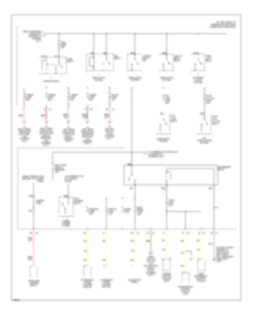
Power Distribution Wiring Diagram (5 of 7) for Cadillac CTS 2003
List of elements for Power Distribution Wiring Diagram (5 of 7) for Cadillac CTS 2003:
- (below left rear seat) left rear fuse block
- (not used)
- A12
- Amp fuse 30a
- Audio amplifier
- Audio fuse 10a (or 15a)
- Driver door module (ddm)
- Driver dr mod fuse 10a
- Driver power seat switch
- Driver seat heated seat module
- Exterior lights system
- F11
- From underhood fuse block (l rear fuse, 60a) (connector c2, pin 1) (diagram 2 of 7)
- From underhood fuse block (l rear fuse, 60a) (connector c2, pin 2) (diagram 2 of 7)
- L frt htd seat mod fuse 10a
- L position relay
- Left rear door module (lrdm)
- Left rear fuse block (ign 3 relay) (diagram 6 of 7)
- Mem/adapt seat fuse 10a
- Memory seat module
- Position lamp fuse 10a
- R position relay
- R13
- R15
- R18
- R20
- R26
- R27
- R29
- R31
- R32
- R36
- R37
- Radio
- Rear dr mod fuse 15a
- Red/ (in left seat harness, approximately 10 cm (3.2 in) from driver seat horizontal position sensor) s348
- Rev lamp relay
- Reverse lamp fuse 10a
- Right rear door module (rrdm)
- Spare fuse
- Spare relay
- Splice pack sp301 (near right side of passenger's seat)
- Standing lamp relay
- Trk dr rel sol relay
- Trunk dr release fuse 10a
- Trunk, tailgate & fuel door release system
- Vehicle communication interface module (vcim)
- W/ 8 speaker system
- W/o 8 speaker system
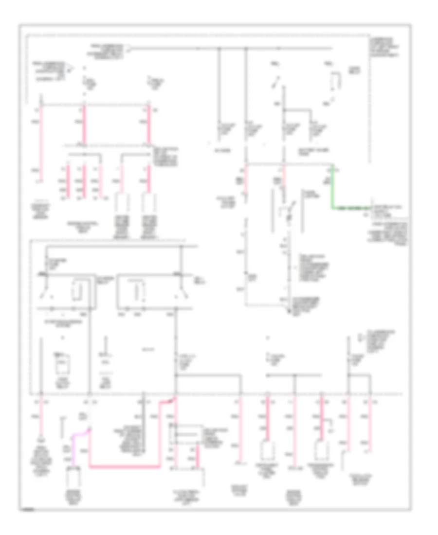
Power Distribution Wiring Diagram (6 of 7) for Cadillac CTS 2003
List of elements for Power Distribution Wiring Diagram (6 of 7) for Cadillac CTS 2003:
- (below right rear seat) right rear fuse block
- (in body harness, approximately 255 cm (100.5 in) from splice pack sp303 behind passenger's seat, near right rear fuse block) s303
- (in body harness, approximately 555 cm (218.5 in) from 14 cavity in-line connector, on left rear door jamb, near door hinges) s304
- (in rear compartment, to rear of left rear shock tower) g402
- (not used)
- A/t shift lock control solenoid
- After boil fuse 10a
- After boil relay
- Ccp fuse 10a
- Cooling fans system
- Dr mod pwr circuit breaker 30a
- Driver door module (ddm)
- Driver heated seat module
- Driver power seat switch
- Ebcm fuse 10a
- Electronic brake control module (ebcm)
- Engine controls system
- From ignition switch (via splice pack sp302) (diagram 4 of 7)
- From left rear fuse block (trk dr rel sol relay) (diagram 5 of 7)
- From underhood fuse block (r rear fuse, 60a) (connector c3, pin 2) (diagram 2 of 7)
- Fuel pump motor relay
- Fuel pump mtr fuse 15a
- Hdlp leveling fuse 10a
- Hvac control module
- Ign 3 fuse 10a
- Ign 3 relay
- Left rear door module (lrdm)
- Left rear fuse block (below left rear seat)
- Memory seat module (msm)
- Passenger front door module (pfdm)
- Passenger heated seat module
- Passenger power seat switch
- R frt htd seat mod fuse 10a
- R11
- R12
- R21
- R22
- R25
- R33
- R37
- Rap relay
- Rap relay coil control
- Rear headlamp leveling sensor
- Rear integration module (rim) (under package shelf trim pad)
- Recirculation actuator
- Red
- Right front heated seat module
- Right rear door module (rrdm)
- Seat circuit breaker 30a
- Shift control assembly
- Spare fuse
- Splice pack sp302 (in passenger compartment, on left frame rail, near left side of driver's seat)
- Sun roof mod fuse 30a
- Sunroof module (at rear of sun roof assembly, behind) headliner)
- Tan
- Trunk lamp fuse
- W/ 8-way passenger seat power adjuster
- W/o 8-way passenger seat power adjuster
- W/sliding electric roof sun glass
Power Distribution Wiring Diagram (7 of 7) for Cadillac CTS 2003
List of elements for Power Distribution Wiring Diagram (7 of 7) for Cadillac CTS 2003:
- (in rear compartment, to rear of right rear shock tower) g401
- A12
- Canister vent fuse 10a
- Defogger system
- Evaporative emissions (evap) canister vent solenoid
- From ignition switch (via splice pack sp201, pin 9) (diagram 4 of 7)
- From right rear fuse block (rim fuse, 10a) (diagram 4 of 7)
- Front passenger door module (fpdm)
- Ign 1 relay
- Inflatable restraint sensing & diagnostic module (sdm)
- Inside rearview mirror
- Int lamp relay
- Interior lamp fuse 10a
- Interior lights system
- Nav fuse 10a
- Not used
- Pgsr dr mod fuse 10a
- Pnk
- R16
- R17
- R21
- R22
- R23
- R25
- R26
- R27
- Rear defog fuse 10a
- Rear defog relay
- Rear integration module (rim)
- Right rear fuse block (below right rear seat)
- Rim fuse 10a
- Sir fuse 10a
- Spare fuse
- Spare relay
- Splice pack sp302 (in passenger compartment, on left frame rail, near left side of driver's seat)
- Traffic information receiver
- Tv antenna module
- W/avec system, am/fm radio, icdx navigation, cd-rom & tv
- W/avec system, am/fm radio, mcd, dvd, navigation & tv
POWER DOOR LOCKS
Power Door Locks Wiring Diagram (1 of 2) for Cadillac CTS 2003
List of elements for Power Door Locks Wiring Diagram (1 of 2) for Cadillac CTS 2003:
- (in body harness, approximately 255 cm (100.5 in) from splice pack sp303 behind passenger's seat, near right rear fuse block)
- (in passenger compartment, behind left kick pad) g200
- (in passenger compartment, behind right kick pad) g201
- 115 cm (45.6 in) from c311)
- A12
- B10
- B11
- B12
- Backlight lamps ctrl
- Battery
- Class 2 serial data
- Computer data lines system
- Door ajar signal
- Door ajar sw signal
- Door ajar switch signal
- Door key sw unlock sig
- Door key unlock switch signal
- Door lock mtr lock ctrl
- Door lock mtr unlk ctrl
- Door lock sw lock sig
- Door lock sw unlock sig
- Door lock switch signal
- Door open signal
- Door open switch signal
- Dr mod pwr cb 30a
- Driver door latch assembly (at rear of left front door)
- Driver door module (ddm) (on left front door, under door trim panel)
- Driver door switch assembly (ddsa)
- Driver dr key sw signal
- Driver dr mod fuse 10a
- Front passenger door module (fpdm) (on right front door, under door trim panel)
- Gnd
- Ground
- Hot at all times
- Interior lights system
- Keyless entry antenna signal
- Left front door sw sig
- Left rear fuse block (below left rear seat)
- Memory seat switch
- Passenger door latch assembly (at rear of right front door)
- Psgr dr mod fuse 10a
- Radio antenna module (in rear of passenger compartment, above headliner near rear window)
- Rear compartment lid release switch
- Rear dr mod fuse 15a
- Rear window glass
- Rfa grid
- Right rear fuse block (below right rear seat)
- S303
- S501 (or s502) (in left front door trim harness, approximately 70 cm (27.3 in) from driver window/door lock switch or driver door switch assembly (ddsa))
- Tan
- Trunk dr release fuse 10a
Power Door Locks Wiring Diagram (2 of 2) for Cadillac CTS 2003
List of elements for Power Door Locks Wiring Diagram (2 of 2) for Cadillac CTS 2003:
- (in left rear door trim harness, approximately 160 cm (62.9 in) from c701) s701
- (in passenger compartment, behind left kick pad) g200
- (in passenger compartment, behind right kick pad) g201
- A12
- Ajar
- B10
- B12
- Backlight lamp ctrl
- Backlight lamps control
- Backlight lamps ctrl
- Battery
- Class 2 serial data
- Computer data lines system
- Door act lock ctrl
- Door ajar switch signal
- Door lock act lock ctrl
- Door lock act unlk ctrl
- Door lock unlock ctrl
- Door open switch signal
- Driver door lock switch
- Ground
- Interior lights system
- Left rear door latch assembly (at rear of left rear door)
- Left rear door module (lrdm) (on left rear door, under door trim panel)
- Lock
- Open
- Passenger door lock switch
- Passenger window switch
- Right rear door latch assembly (at rear of right rear door)
- Right rear door module (rrdm) (on right rear door, under door trim panel)
- S601 (in right front door trim harness, approximately 70 cm (27.3 in) from front passenger window switch)
- Tan
- Unlock
POWER MIRRORS
Automatic Day/Night Mirror Wiring Diagram for Cadillac CTS 2003
List of elements for Automatic Day/Night Mirror Wiring Diagram for Cadillac CTS 2003:
- (in rear compartment to rear of left rear shock tower) g402
- A12
- Backup lamp voltage
- Class 2 serial data
- Computer data lines system
- Ground
- Hot at all times
- Ignition voltage
- Inside rearview mirror (isrvm) (in center front of passenger compartment, on windshield)
- Left rear fuse block (under left side of rear seat)
- Pnk
- R36
- R37
- R38
- R40
- Rear integration module (rim) (in center rear of passenger compartment, under package shelf trim panel)
- Rev lamp fuse 10a
- Rev lamp relay
- Reverse lamp ctrl
- Right rear fuse block (under right side of rear seat)
- Rim fuse 10a
Power Mirrors Wiring Diagram for Cadillac CTS 2003
List of elements for Power Mirrors Wiring Diagram for Cadillac CTS 2003:
- A12
- B11
- B12
- Battery
- Class 2 serial data
- Computer data lines system
- Down
- Dr mod pwr c/b 30a
- Driver door module (ddm) (on left front door, under door trim panel)
- Driver door switch module (ddsm)
- Driver dr mod fuse 10a
- Driver side outside mirror
- Front passenger door module (fpdm) (on right front door, under door trim panel)
- G200 (in passenger compartment, behind left kick pad)
- G201 (in passenger compartment, behind right kickpad)
- Ground
- Ground rtn
- Horiz motor
- Hot at all times
- Left
- Left mirror mtr-down
- Left mirror mtr-left
- Left mirror mtr-right
- Left mirror mtr-up
- Left rear fuse block (under left side of rear seat)
- Logic
- Mirror switches
- Nca
- Passenger outside mirror
- Psgr dr mod fuse 10a
- Right
- Right mirror motor-up
- Right mirror mtr -down
- Right mirror mtr-left
- Right mirror mtr-right
- Right rear fuse block (under right side of rear seat)
- S303 (in body harness, approximately 255 cm (100.5 in) from sp303)
- S501 or s502 (in left front door trim harness, approximately, 70 cm (27.3 in) from ddsa or driver window/door lock switch)
- Sel left
- Sel right
- Vert motor
POWER SEATS
Heated Seats Wiring Diagram for Cadillac CTS 2003
List of elements for Heated Seats Wiring Diagram for Cadillac CTS 2003:
- (in passenger compartment, to left of driver's seat, on left frame rail) g307
- A11
- A12
- Battery
- Class 2 serial data
- Computer data lines system
- Dash integration module (dim) (in passenger compartment, under right side of i/p above right closeout/insulator panel)
- Driver cushion heated seat element
- Driver heated seat status
- Driver high/low signal
- E10
- Front passenger cushion heated seat element
- Ground
- Heated seat element control
- Heated seat element voltage
- Heated seat high/low signal
- Heated seat module status sig
- Heated seat module status signal
- Heated seat sensor low ref
- Heated seat temp sens signal
- Heating element
- Hot at all times
- Hot in run
- Hvac control module (includes heated seat switches)
- Ign 3 fuse 10a
- Ignition 3 voltage
- Left front heated seat module (in passenger compartment, under driver's seat)
- Left rear fuse block (in passenger compartment, under left side of rear seat)
- Lt frt htd seat mod fuse 10a
- Nca
- Passenger high/low signal
- Pnk
- Radio
- Rear integration module (rim) (in center rear of passenger compartment, under package shelf trim pad)
- Right front heated seat module (in passenger compartment, under passenger's seat)
- Right rear fuse block (in passenger compartment, under right side of rear seat)
- Rt frt htd seat mod fuse 10a
- Seat temp sensor low ref
- Seat temp sensor signal
- Splice pack sp303 (in passenger compartment, behind passenger's seat near right rear fuse block)
- Thermistor
Power Seats Wiring Diagram for Cadillac CTS 2003
List of elements for Power Seats Wiring Diagram for Cadillac CTS 2003:
- (in passenger compartment, to left of driver's seat, on left frame rail) g307
- Aft
- Approximately 180 cm (70.8 in) from left rear fuse block) s305
- Battery
- Down
- Driver seat adjust switch
- Driver seat adjuster motor assembly
- Driver seat front m vertical motor
- Driver seat horizontal motor
- Driver seat rear vertical motor
- Driver seat recline motor
- Front vertical down
- Front vertical up
- Fwd
- Gnd
- Horizontal forward
- Horizontal rearward
- Hot at all times
- Left rear fuse block (in passenger compartment, under left side of rear seat)
- Passenger seat adjuster motor assembly
- Passenger seat adjuster switch
- Passenger seat front vertical motor
- Passenger seat horizontal motor
- Passenger seat rear vertical motor
- Passenger seat recline motor
- Rear vertical down
- Rear vertical up
- Recline forward
- Recline rearward
- S304 (in body harness, approximately 555 cm (218.5 in) from c700)
- Seats circuit breaker 30a
- Tan
POWER TOP/SUNROOF
Sunroof Wiring Diagram for Cadillac CTS 2003
List of elements for Sunroof Wiring Diagram for Cadillac CTS 2003:
- 1995 vftc c
- G401 (in rear compartment, to rear of right rear shock tower)
- Ground
- Hall effect sensor 1
- Hall effect sensor 2
- Hot at all times
- Illumination +
- Illumination -
- Interior lights system
- Limit switch
- Motor +
- Motor -
- Nca
- Pnk
- Rap relay
- Rap relay coil ctrl
- Rear integration module (rim) (in center rear of passenger compartment, under package shelf trim panel)
- Right rear fuse block (in passenger compartment, under right side of rear seat)
- S133
- Solid state (close)
- Solid state (open)
- Sun roof motor (on left front corner of sunroof module)
- Sunroof control module (in passenger compartment, behind headliner, at rear of sunroof assembly)
- Sunroof control switch
- Sunroof limit switch low reference
- Sunroof limit switch stop signal
- Sunroof mod fuse 30a
- Sunroof motor close control
- Sunroof motor open control
- Sunroof obstruction sensor 5vref
- Sunroof obstruction sensor signal
- Sunroof switch low reference
- Sunroof switch-data 1
- Sunroof switch-data 2
- Sunroof switch-data 3
- Sunroof switch-data 4
- Sunroof switch-data 5
- Sunroof switch-data 6
- Sunroof switch-low reference
- Tan
- Vehicle speed signal
POWER WINDOWS
Power Windows Wiring Diagram (1 of 2) for Cadillac CTS 2003
List of elements for Power Windows Wiring Diagram (1 of 2) for Cadillac CTS 2003:
- (in body harness, approximately 255 cm (100.5 in) from sp303) s303
- A12
- B11
- B12
- Backlight lamp control
- Backlight lamps ctrl
- Backlights lamps ctrl
- Battery
- Class 2 serial data
- Computer data lines system
- Door locks system
- Down
- Dr mod pwr cb 30a
- Driver door module (ddm) (on left front door, under door trim panel)
- Driver door switch module (ddsm)
- Driver dr mod fuse 10a
- Driver window motor (in driver door assembly, behind water deflector)
- Front passenger door module (fpdm) (on right front door, under door trim panel)
- G200 (in passenger compartment, behind left kick pad)
- G201 (in passenger compartment, behind right kick pad)
- Ground
- Hi speed communication
- Hi speed communications
- Hot at all times
- Interior lights system
- Left front down control
- Left front up control
- Left rear fuse block (under left side of rear seat)
- Low reference
- Nca
- Normal speed comm
- Normal speed communication
- Normal speed communications
- Passenger window motor (in front passenger door assembly, behind water deflector)
- Passenger window switch
- Pnk
- Psgr dr mod fuse 10a
- Rear dr mod fuse 15a
- Right front down control
- Right front down signal
- Right front express signal
- Right front pwr wdo dn sig
- Right front pwr wdo express sig
- Right front pwr wdo up sig sw
- Right front up control
- Right front up signal
- Right rear fuse block (under right side of rear seat)
- S501 (in left front door trim harness, approximately 70 cm (27.3 in) from driver window/ door lock switch)
- S600 (or s601) (in right front door trim harness, approximately 70 cm (27.3 in) from front passenger window switch)
Power Windows Wiring Diagram (2 of 2) for Cadillac CTS 2003
List of elements for Power Windows Wiring Diagram (2 of 2) for Cadillac CTS 2003:
- (in left rear door trim harness, approximately 160 cm (62.9 in) from c701) s701
- (in passenger compartment, behind left kick pad) g200
- (in passenger compartment, behind right kick pad) g201
- A12
- B12
- Backlight lamps ctrl
- Battery
- Class 2 serial data
- Computer data lines system
- Dim
- Down
- Express down
- G200 (in passenger compartment, behind left kick pad)
- Gnd
- Ground
- Left rear door module (lrdm) (on left rear door, under door trim panel)
- Left rear window motor (on left rear door assembly, behind water deflector)
- Left rear window switch
- Pwr wdo left rear dn ctrl
- Pwr wdo left rear exp signal
- Pwr wdo left rear sw down
- Pwr wdo left rear up ctrl
- Pwr wdo left rear up signal
- Pwr wdo mtr right rear down ctrl
- Pwr wdo right rear dn signal
- Pwr wdo right rear up ctrl
- Pwr wdo right rear up signal
- Pwr wdo sw right rear express sig
- Right rear door module (rrdm) (on right rear door, under door trim panel)
- Right rear window motor (in right rear door assembly, behind water deflector)
- Right rear window switch
RADIO
Radio Wiring Diagram, Base (1 of 2) for Cadillac CTS 2003
List of elements for Radio Wiring Diagram, Base (1 of 2) for Cadillac CTS 2003:
- (in headliner harness, approximately 115 cm (45.6 in) from c311)
- (in rear compartment, to rear of left rear shock tower) g402
- Am/fm antenna signal
- Amp fuse 30a
- Antenna signal
- Audio fuse 15a
- Battery
- Class 2 serial data
- Coaxial cable
- Computer data lines system
- Drain
- Fm composite signal
- G308
- Ground
- Hot at all times
- Hot in run or crank
- Info down switch signal
- Information up sw signal
- Instrument cluster system
- Joint connector
- Left audio signal (+)
- Left audio signal (-)
- Left front door speaker (midrange)
- Left front upper speaker (tweeter)
- Left rear fuse block (in passenger compartment, under left side of rear seat)
- Nca
- Pnk
- Radio
- Radio antenna module (in passenger compartment, above headliner, near rear window)
- Radio front glass antenna
- Radio rear glass antenna
- Rear speaker (subwoofer)
- Red
- Remote radio ctrl voltage
- Return voice in signal
- Right audio signal (+)
- Right audio signal (-)
- S10
- S313
- Steering wheel ctrls sig
- Strg ctrls fuse 10a
- Tan
- Trunk dr release fuse 10a
- Underhood fuse block (in engine compartment, in right front corner)
- Vehicle speed signal
- Voice in signal
Radio Wiring Diagram, Base (2 of 2) for Cadillac CTS 2003
List of elements for Radio Wiring Diagram, Base (2 of 2) for Cadillac CTS 2003:
- (in headliner harness, approximately 110 cm (39.8 in) from c311)
- (in passenger compartment, behind left kick pad) g200
- (in rear compartment to rear of left rear shock tower) g402
- (midrange) left rear door speaker
- (midrange) right front door speaker
- (midrange) right rear door speaker
- (tweeter) right front upper speaker
- A10
- A11
- Audio amplifier (in left rear compartment, behind left strut tower)
- B10
- B11
- B12
- Battery
- C203
- C203 c3
- Cellular telephone voice low ref
- Cellular telephone voice signal
- Class 2 serial data
- Computer data lines system
- Cruise control switch signal
- Engine control module (ecm) (in engine compartment, in right front corner)
- Fuse 2a
- Ground
- Inflatable restraint steering wheel module coil
- Interior lights system
- Left fnt low level audio sig (+)
- Left fnt low level audio sig (-)
- Left front midrange spkr out (+)
- Left front midrange spkr out (-)
- Left front tweeter spkr out (+)
- Left front tweeter spkr out (-)
- Left rear midrange spkr out (+)
- Left rear midrange spkr out (-)
- Left subwoofer spkr out (+)
- Left subwoofer spkr out (-)
- Low ref
- Mic out
- Mic out rtn
- Mic out shield
- Nca
- On/ off
- Pnk
- R/a
- Rdt1
- Rdt2
- Right fnt low level audio sig (+)
- Right fnt low level audio sig (-)
- Right fnt midrange spkr out (+)
- Right fnt midrange spkr out (-)
- Right front tweeter spkr out (+)
- Right front tweeter spkr out (-)
- Right rear midrange spkr out (+)
- Right rear midrange spkr out (-)
- Right subwoofer spkr out (+)
- Right subwoofer spkr out (-)
- S/c
- S119
- S312
- S318
- Splice pack sp203 (in passenger compartment, under left side of i/p trim pad)
- Steering wheel control pad
- Steering wheels controls-center
- Steering wheels controls-left
- Steering wheels controls-right
- Sw1 ent
- Sw2 back
- Sw3
- Sw4
- Sw5
- Sw6
- Tan
- Vehicle communication interface module (vcim) (in rear compartment, behind right strut tower)
- Voice signal
Radio Wiring Diagram, Luxury (1 of 2) for Cadillac CTS 2003
List of elements for Radio Wiring Diagram, Luxury (1 of 2) for Cadillac CTS 2003:
- (in headliner harness, approximately 115 cm (45.6 in) from c311)
- (in rear compartment, to rear of left rear shock tower) g402
- Am/fm antenna signal
- Amp fuse 30a
- Antenna signal
- Audio common
- Audio fuse 15a
- Battery
- Class 2 serial data
- Coaxial cable
- Computer data lines system
- Digital radio antenna
- Digital radio receiver
- Drain
- Drain wire
- Fm composite signal
- G308
- Ground
- Hot at all times
- Hot in run or crank
- Info down switch signal
- Information up sw signal
- Instrument cluster system
- Joint connector
- Left audio signal (+)
- Left audio signal (-)
- Left rear fuse block (in passenger compartment, under left side of rear seat)
- Nca
- Noise compensation microphone
- Pnk
- Radio
- Radio antenna module (in rear of passenger compartment, above headliner, near rear window)
- Radio front glass antenna
- Radio rear glass antenna
- Red
- Remote radio ctrl voltage
- Return voice in signal
- Right audio signal (+)
- Right audio signal (-)
- Right front door speaker (tweeter)
- Right front upper speaker (tweeter)
- S10
- S11
- S313
- Satellite antenna
- Satellite antenna signal
- Splice pack sp301 (in passenger compartment, on right frame rail, near right side of passenger's seat)
- Steering wheel ctrls sig
- Strg ctrls fuse 10a
- Tan
- Terrestrial antenna
- Terrestrial antenna signal
- Trunk dr release fuse 10a
- Underhood fuse block (in engine compartment, in right front corner)
- Vehicle speed signal
- Voice in signal
- Voice output (+)
- Voice output (-)
- Voice output ground
Radio Wiring Diagram, Luxury (2 of 2) for Cadillac CTS 2003
List of elements for Radio Wiring Diagram, Luxury (2 of 2) for Cadillac CTS 2003:
- (in headliner harness, approximately 110 cm (39.8 in) from c311)
- (in passenger compartment, behind left kick pad) g200
- (in passenger compartment, on left frame rail, near left side of driver's seat) splice pack sp300
- (in rear compartment to rear of left rear shock tower) g402
- (midrange) left rear door speaker
- (subwoofer) rear speaker
- A10
- A11
- A12
- Audio amplifier (in left rear compartment, behind left strut tower)
- B10
- B11
- B12
- Battery
- C203
- C203 c3
- Cellular telephone voice low ref
- Cellular telephone voice signal
- Class 2 serial data
- Computer data lines system
- Cruise control switch signal
- Drain wire
- Engine control module (ecm) (in engine compartment, in right front corner)
- Front center speaker out (+)
- Front center speaker out (-)
- Front speaker (mid- range)
- Fuse 2a
- Ground
- Inflatable restraint steering wheel module coil
- Interior lights system
- Left front door speaker (tweeter)
- Left front low level signal (+)
- Left front low level signal (-)
- Left front tweeter spkr out (+)
- Left front tweeter spkr out (-)
- Left front upper speaker (tweeter)
- Left rear midrange spkr out (+)
- Left rear midrange spkr out (-)
- Low ref
- Mic out
- Mic out rtn
- Mic out shield
- Navigation voice in (+)
- Navigation voice out (-)
- Nca
- Noise compensation micro voltage
- On/ off
- Pnk
- R/a
- Rdt1
- Rdt2
- Right front low level signal (+)
- Right front low level signal (-)
- Right front tweeter spkr out (+)
- Right front tweeter spkr out (-)
- Right rear door speaker (midrange)
- Right rear midrange spkr out (-)
- S/c
- S119
- S312
- S318
- Splice pack sp203 (in passenger compartment, under left side of i/p trim pad)
- Steering wheel control pad
- Steering wheels controls-center
- Steering wheels controls-left
- Steering wheels controls-right
- Subwoofer spkr out (+)
- Subwoofer spkr out (-)
- Sw1 ent
- Sw2 back
- Sw3
- Sw4
- Sw5
- Sw6
- Tan
- Vehicle communication interface module (vcim) (in rear compartment, behind right strut tower)
- Voice signal
SHIFT INTERLOCK
Ignition Lock Solenoid Wiring Diagram for Cadillac CTS 2003
List of elements for Ignition Lock Solenoid Wiring Diagram for Cadillac CTS 2003:
- A11
- A12
- Automatic transmission shift lock actuator
- Class 2 serial data
- Computer data lines system
- Dash integration module (dim) (under right side of dash, above right closeout/insulator panel)
- Hot at all times
- Ignition lock cyl ctrl
- Ignition lock cylinder control actuator
- Right rear fuse block (under right side of rear seat)
- Rim fuse 10a
- Tan
Shift Interlock Wiring Diagram for Cadillac CTS 2003
List of elements for Shift Interlock Wiring Diagram for Cadillac CTS 2003:
- (in rear compartment to rear of left rear shock tower) g402
- A/t shift lock control solenoid
- A12
- Class 2 serial data
- Computer data lines system
- Hot at all times
- Hot in run
- Ign 3 fuse 10a
- Ign 3 relay
- Left rear fuse block (under left side of rear seat)
- R21
- R22
- R23
- R25
- Rear integration module (rim) (in center rear of passenger compartment, under package shelf trim panel)
- Shift control assembly (in center console)
- Shift lock solenoid control
STARTING/CHARGING
Charging Wiring Diagram for Cadillac CTS 2003
List of elements for Charging Wiring Diagram for Cadillac CTS 2003:
- (in engine compartment, on engine block, near generator) g102
- (in right side of engine compartment, on inner fender wall, near battery) g105
- Battery
- Battery (charge) indicator
- Class 2 ecm
- Class 2 serial data
- Computer data lines system
- Electronic brake control module (ebcm) (at right front corner of engine compartment)
- Engine control module (ecm) (at right front corner of engine compartment)
- Gen f term
- Gen l term
- Generator
- Ground distribution system
- Ign
- Instrument panel cluster (ipc)
- Logic
- Power distribution system
- Red
- Serial data class 2
- Splice pack sp200 (in right front of passenger compartment, under dash above steering column)
- Starter
Starting Wiring Diagram for Cadillac CTS 2003
List of elements for Starting Wiring Diagram for Cadillac CTS 2003:
- (in engine compartment on engine block, near generator) g102
- (in right side of engine compartment, on inner fender wall, near battery) g105
- (on right front corner of vehicle, on right body rail near right headlamp) g104
- A/t
- Accessory
- Battery
- Clutch pedal position (cpp) sensor (m/t only) (in passenger compartment, under i/p on clutch pedal)
- Computer data lines system
- Cpp switch signal
- Crank
- Crank voltage
- Engine control module (ecm) (in right front corner of engine compartment)
- Ground distribution system
- Hot at all times
- Hot in run
- Htr vlv/ cltch fuse 10a
- Ign 1 relay
- Ignition switch
- M/t
- Off/lock
- Pnk
- R43
- R44
- R45
- R46
- R63
- R64
- R65
- R66
- Red
- Run
- Serial data
- Splice pack sp200 (in right front of passenger compartment, under i/p above steering column)
- Starter
- Starter fuse 30a
- Starter relay
- Starter relay coil ctrl
- Starter relay coil voltage
- Starting/ charging system (charging circuit)
- Underhood fuse block (in right front corner of engine compartment)
SUPPLEMENTAL RESTRAINTS
Supplemental Restraints Wiring Diagram (1 of 2) for Cadillac CTS 2003
List of elements for Supplemental Restraints Wiring Diagram (1 of 2) for Cadillac CTS 2003:
- (at left side of dash, near base of "b" pillar) left inflatable restraint side impact sensor
- (at right side of dash, near base of "b" pillar) right inflatable restraint side impact sensor
- (in left front seat belt buckle) left seat belt switch
- (in seat)
- A10
- A11
- A12
- A13
- A14
- A15
- A16
- A17
- A18
- A19
- A20
- A21
- A22
- A23
- A24
- A25
- A26
- A27
- A28
- A29
- A30
- A31
- A32
- A33
- A34
- A35
- A36
- A37
- A38
- A39
- A40
- A41
- A42
- Case ground
- Computer data lines system
- G306 (in passenger compartment, under center console)
- Ground
- High control
- Hot in run or crank
- Ignition 1 voltage
- Inflatable restraint sensing & diagnostic module (sdm) (at center of passenger compartment floor, under console)
- Inflatable restraint steering wheel module (on steering wheel)
- Inflatable restraint steering wheel module coil
- Left inflatable restraint roof rail module (above left "b" pillar)
- Left inflatable restraint side impact module (on left side of left front seat)
- Left seat belt pretensioner
- Left seat belt switch
- Low control
- Low reference
- Nca
- Pnk
- Right inflatable restraint side impact module (on right side of left front seat)
- Right rear fuse block (below right rear seat)
- Sensor signal
- Sensor voltage
- Serial data
- Shorting bar
- Shorting clip
- Sir fuse 10a
- Stage 1
- Stage 2
- Tan
Supplemental Restraints Wiring Diagram (2 of 2) for Cadillac CTS 2003
List of elements for Supplemental Restraints Wiring Diagram (2 of 2) for Cadillac CTS 2003:
- Air bag indicator
- Class 2 (sdm)
- Computer data lines system
- Data link connector (dlc) (under left side of dash)
- Ign
- Inflatable restraint front end sensor (on upper radiator support)
- Inflatable restraint i/p module
- Instrument panel cluster (ipc)
- Nca
- Right inflatable restraint roof rail module (above right "b" pillar)
- Right seat belt pretensioner
- Serial data
- Shorting bar
- Shorting clip
- Splice pack sp201 (in passenger compartment, behind ignition switch, near hvac module)
- Splice pack sp300 (in passenger compartment, on left frame rail, near left side of driver's seat)
- Stage 1
- Stage 2
- Underhood fuse block (at left front of engine compartment)
TRANSMISSION
3.2L VIN N
3.2L VIN N, A/T Wiring Diagram for Cadillac CTS 2003
List of elements for 3.2L VIN N, A/T Wiring Diagram for Cadillac CTS 2003:
- (can) +
- (can) -
- (on eng block, near starter motor)
- 1-2 shift sol
- 1-2 shift sol vlv
- 2-3 shift sol
- 2-3 shift sol vlv
- 4-5 shift sol
- 4-5 shift sol vlv
- A/t iss hi sig
- A/t iss lo sig
- Acc volt
- Battery
- Data link connector (dlc) (partial) (under left side of dash)
- Ecm/tcm fuse 10a
- Engine control module (ecm) (at right front corner of engine compt)
- G100
- G100 (on eng block, near starter motor)
- G104 (near right head- lamp)
- Ground
- Hot at all times
- Hot in run or start
- Ign 1 relay
- Ign volt
- Oss sens high
- Oss sens low
- P/n
- P/n sig
- Pc sol vlv hi ctrl
- Pc sol vlv lo ctrl
- Pnk
- Pressure control solenoid
- R43
- R44
- R45
- R46
- Red
- S114 (in engine harn, approximately 160 cm from ecm ground)
- S118 (in body harn, approximately 235 cm from knock sensor 1 connector)
- Ser data
- Ser data (can) +
- Ser data (can) -
- Serial data
- Sol pwr feed
- Tcc brake sw sig
- Tcc sol valve
- Tcc sol vlv ctrl
- Tcc sw
- Tcc/ cruise release switch
- Tcc/et fuse 10a
- Tcm/ ipc fuse 15a
- Tft sens lo ref
- Tft sens sig
- Theft fuse 7.5a
- Transmission
- Transmission control module (tcm) (at right front side of engine compt)
- Transmission fluid temperature sensor
- Transmission input shaft speed sensor
- Transmission manual shift shaft switch assembly
- Transmission output shaft speed sensor
- Trs sig a
- Trs sig b
- Trs sig c
- Trs sig p
- Under- hood fuse block (left front of eng compt)
3.2L VIN N, M/T Wiring Diagram for Cadillac CTS 2003
List of elements for 3.2L VIN N, M/T Wiring Diagram for Cadillac CTS 2003:
- (in front of under- hood fuse block)
- (under dash, above steering column) sp200
- Ccp switch
- Class 2 data
- Clutch pedal position switch (on clutch pedal bracket)
- Computer data lines system
- Engine control module (ecm) (at right front corner of engine compt)
- G100 (on eng block, near starter motor)
- G104 (near right head lamp)
- Hot at all times
- Hot in run or start
- Htr/vlv clutch fuse 10a
- Ign 1 relay
- Main relay
- Pnk
- Pre fuse 10a
- R43
- R44
- R45
- R46
- R48
- R49
- R63
- R64
- R65
- R66
- Rear integration module (rim) (under package shelf trim panel)
- Rev sw sig
- Reverse switch
- Sp102
- Start rly ctrl
- Start rly volt
- Starter fuse 30a
- Starter relay
- Starting/ charging system
- Under- hood fuse block (left front of eng compt)
- Vehicle speed sensor (near rear of trans- mission assembly)
- Vss sig
TRUNK, TAILGATE, FUEL DOOR
Trunk Release Wiring Diagram for Cadillac CTS 2003
List of elements for Trunk Release Wiring Diagram for Cadillac CTS 2003:
- (in rear compartment, to rear of left rear shock tower) g402
- A12
- Computer data lines system
- Driver door module (ddm) (on left front door, under door trim panel)
- Driver door switch assembly (ddsa)
- Gnd
- Ground
- Hot at all times
- Interior lights system
- Left rear fuse block (under left side of rear seat)
- R31
- R32
- R33
- R35
- Rear compartment lid release actuator (part of lid release actuator)
- Rear compartment lid release switch
- Rear integration module (rim) (in center rear of passenger compartment, under package shelf trim panel)
- Relay ctrl
- Release switch
- S317
- S602
- Serial data
- Switch signal
- Tan
- Trk dr rel sol relay
- Trunk ajar switch signal
- Trunk release fuse 10a
WARNING SYSTEMS
Warning Systems Wiring Diagram (1 of 2) for Cadillac CTS 2003
List of elements for Warning Systems Wiring Diagram (1 of 2) for Cadillac CTS 2003:
- (in engine compartment, near left front strut tower, at bottom of inside fender well) g101
- (in passenger compartment, behind left kick pad) g200
- 2.7 ohms
- A11
- A12
- Accessory
- Accessory voltage
- Auto
- B10
- B12
- Battery
- Brake fluid level switch (at rear of engine compartment, on brake fluid reservoir)
- Brake indicator
- Class 2 (dim)
- Class 2 (sdm)
- Class 2 serial data
- Computer data lines system
- Crank
- Dash integration module (dim) under right side of dash, above right closeout/insulator panel)
- Dim/ aldl fuse 10a
- Door ajar signal
- Door ajar sw signal
- Door key unlock switch signal
- Door open signal
- Driver door latch assembly (at rear of left front door)
- Driver door module (ddm) (on left front door, under door trim panel)
- Driver dr key sw signal
- Fasten safety belt indicator
- G200 (in passenger compartment, behind left kick pad)
- G201 (in passenger compartment, behind right kick pad)
- Gnd
- Ground
- Ground distribution system
- Hdlp
- Headlamp switch
- Headlamp switch on signal
- Hot at all times
- Ignition 1 voltage
- Ignition switch
- Instrument panel cluster (ipc)
- Key in
- Key in ignition switch
- Key in ignition switch signal
- Left front door sw sig
- Lights on indicator
- Logic
- Off
- Off/lock
- Ohms
- Park brake switch (on park brake assembly)
- Park brake switch signal
- Parklamp switch on signal
- Pnk
- Run
- S119
- S121
- Splice pack sp200 (under dash, above steering column)
- Splice pack sp201 (behind ignition switch, near hvac module)
- Splice pack sp201 (in passenger compartment, behind ignition switch, near hvac module)
- Splice pack sp203 (in passenger compartment, under left side of dash trim pad)
- Tan
- Underhood fuse block (in right front corner of engine compartment)
- Voltage check fuse 10a
Warning Systems Wiring Diagram (2 of 2) for Cadillac CTS 2003
List of elements for Warning Systems Wiring Diagram (2 of 2) for Cadillac CTS 2003:
- (in engine compartment, near left front strut tower at bottom of inside fender well) g101
- (in engine harness, aproximately 120 cm from ho2s bank 2 sensor 1)
- A11
- A22
- A23
- Audio amplifier (in left rear compartment, behind left strut tower)
- B11
- Base
- Bose
- Class 2 serial data
- Computer data lines system
- Coolant level sw
- Coolant level switch (in left front corner of coolant surge tank)
- Data link connector (dlc) (partial) (in passenger compartment, under dash next to hood release lever)
- E10
- E11
- Ect sensor signal
- Engine control module (ecm) (at right front corner of engine compartment)
- Engine coolant temperature (ect) sensor (on top rear of intake manifold)
- Fuel level sensor
- Fuel pump & sensor assembly (in fuel tank)
- Hvac control module (on center of dash, below radio)
- Inflatable restraint sensing & diagnostic module (sdm) (at center of passenger compartment floor, under console)
- Left front seat belt switch (in left front seat belt buckle)
- Left seat belt sw signal
- Low reference
- Nca
- Note: radio generates audio warnings through left front speaker. audio warning chimes are used for: fasten safety belt, key in ignition, lights on warning, park brake warning, hot coolant temperature & low fuel
- Pnk
- Radio
- S111
- S400 (in rear compartment lid harness, approximately 237 cm from c401)
- Secondary fuel sender assembly (under vehicle, in fuel tank)
- Splice pack sp201 (behind ignition switch, near hvac module)
- Splice pack sp300 (in passenger compartment, on left frame rail, near left side of driver's seat)
- Splice pack sp303 (behind passenger's seat, near right rear fuse block)
- Tan
WIPER/WASHER
Wiper/Washer Wiring Diagram, Early Production for Cadillac CTS 2003
List of elements for Wiper/Washer Wiring Diagram, Early Production for Cadillac CTS 2003:
- (in engine compartment, near left front strut tower, at bottom of inside fenderwell) g101
- (not used)
- 120,000 ohms
- 24,000 ohms
- 30,000 ohms
- 410,000 ohms
- 43,000 ohms
- 60,000 ohms
- Accy voltage
- B10
- B11
- B12
- C202
- Dash integration module (dim) (under right side of dash, above right closeout/ insulator panel)
- Delay
- Ground
- Hdlp wash cb 30a
- Headlamp washer fluid pump (w/ce4) (inside washer reservoir)
- Headlamp washer gnd
- Headlamp washer relay (in underhood bel assembly, near right front corner, under fuse block)
- Hot at all times
- Hot in accy or run
- If equipped
- Int
- Jumper wire
- Layer 1
- Layer 2
- Layer 3
- Lo d5
- Logic
- Mist
- Nca
- Off
- Off d1
- R67
- R68
- Splice pack sp200 (in right front of passenger compartment, under dash, above steering column)
- Tan
- Underhood fuse block (in right front corner of engine compartment)
- Wash
- Washer fluid level signal
- Washer pump ctrl
- Washer switch
- Washer switch signal
- Windshield washer fluid level switch
- Windshield washer fluid pump (near base of washer fluid reservoir)
- Windshield wiper/washer module (on left rear of engine compartment, near windshield)
- Windshield wiper/washer switch
- Wiper mod fuse 30a
- Wiper mtr high speed
- Wiper sw fuse 10a
- Wiper sw on signal
- Wiper sw signal 1
- Wiper sw signal 2
- Wiper switch
Wiper/Washer Wiring Diagram, Late Production for Cadillac CTS 2003
List of elements for Wiper/Washer Wiring Diagram, Late Production for Cadillac CTS 2003:
- (in engine compartment, near left front strut tower, at bottom of inside fenderwell) g101
- (not used)
- 120,000 ohms
- 24,000 ohms
- 30,000 ohms
- 410,000 ohms
- 43,000 ohms
- 60,000 ohms
- Accy voltage
- B10
- B11
- B12
- C202
- Dash integration module (dim) (under right side of dash, above right closeout/ insulator panel)
- Delay
- Ground
- Hdlp wshr module circuit breaker 30a
- Hdlp wshr relay
- Headlamp washer fluid pump (inside washer reservoir)
- Headlamp washer gnd
- Hot at all times
- Hot in accy or run
- Int
- Layer 1
- Layer 2
- Layer 3
- Lo d5
- Mist
- Nca
- Off
- Off d1
- R67
- R68
- R69
- R70
- R71
- Solid state timer relay
- Splice pack sp200 (in right front of passenger compartment, under dash, above steering column)
- Tan
- Underhood fuse block (in right front corner of engine compartment)
- Wash
- Washer fluid level signal
- Washer pump ctrl
- Washer switch
- Washer switch signal
- Windshield washer fluid level switch
- Windshield washer fluid pump (near base of washer fluid reservoir)
- Windshield wiper/washer module (on left rear of engine compartment, near windshield)
- Windshield wiper/washer switch
- Wiper mod fuse 30a
- Wiper mtr high speed
- Wiper sw fuse 10a
- Wiper sw on signal
- Wiper sw signal 1
- Wiper sw signal 2
- Wiper switch