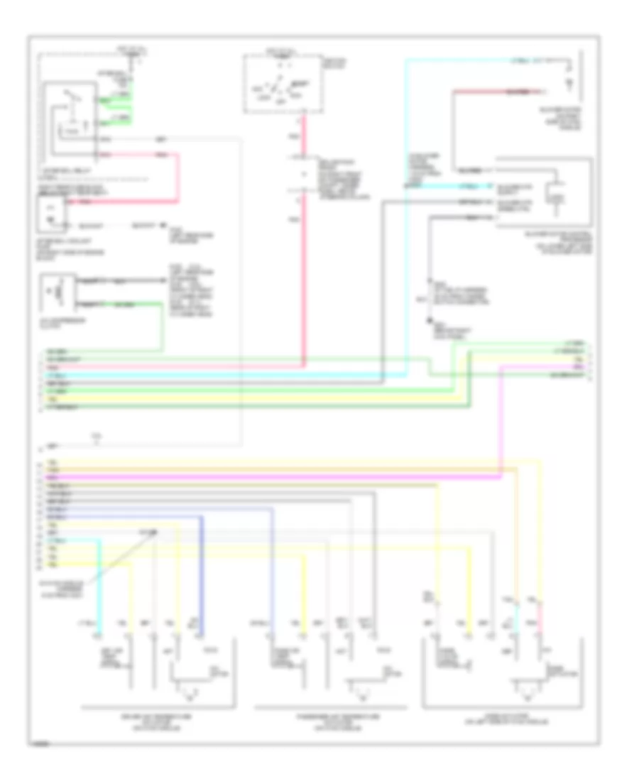
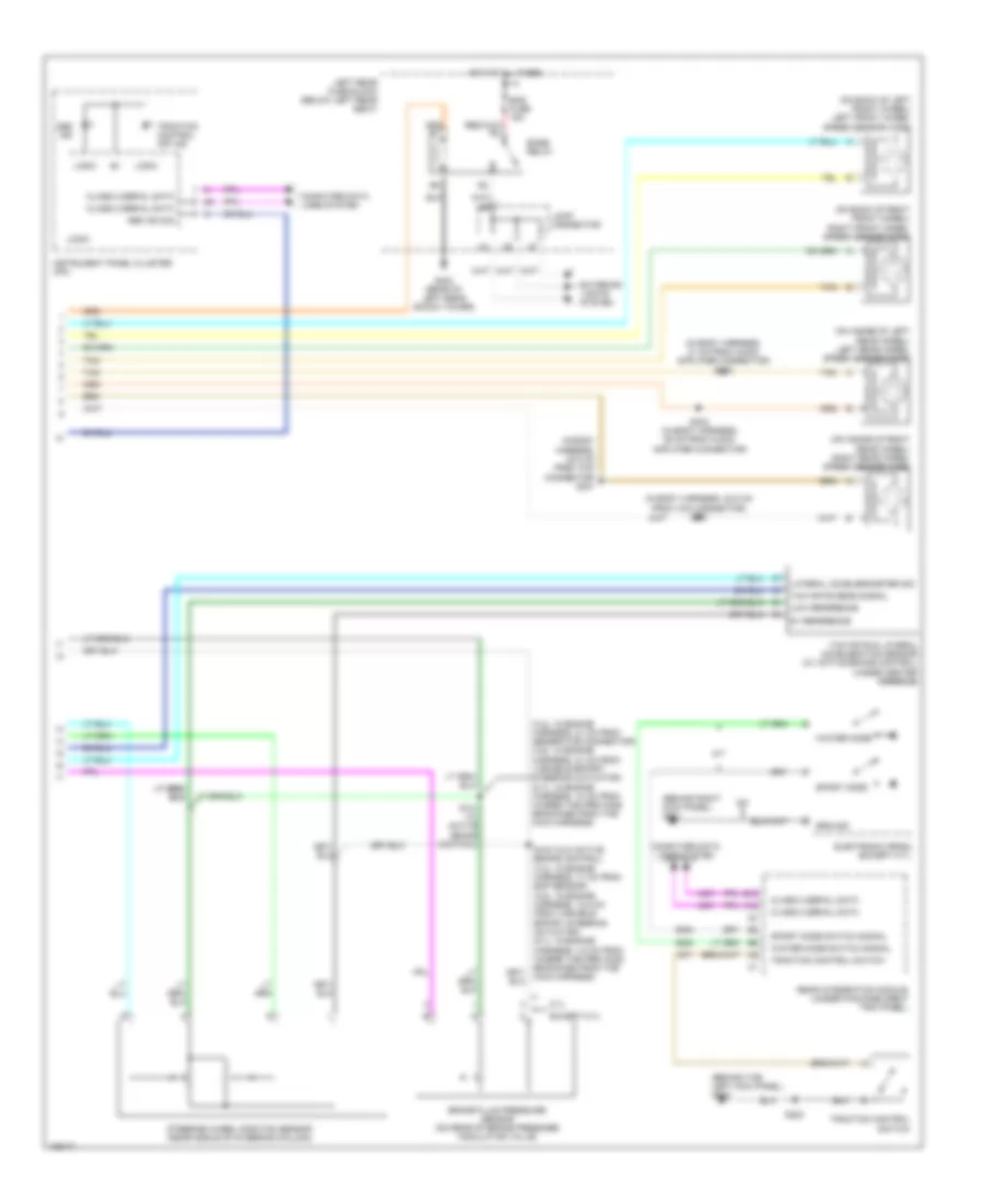
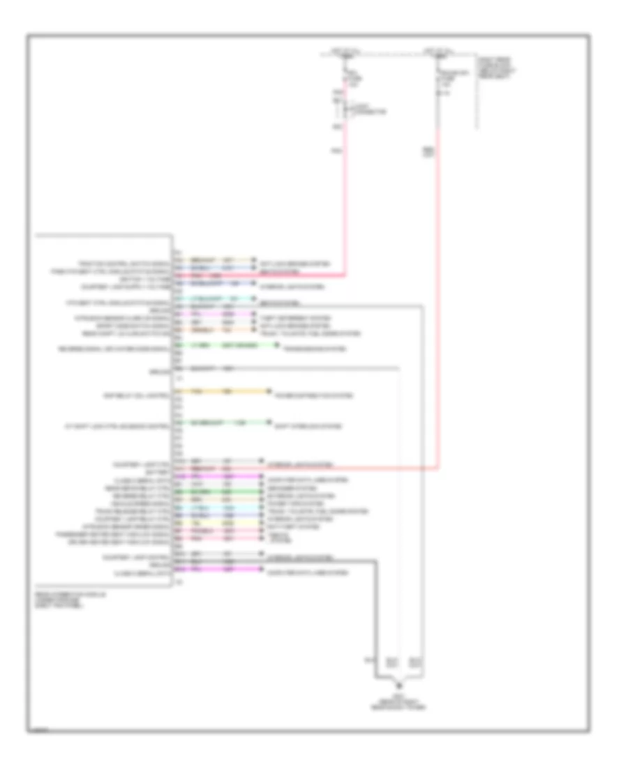
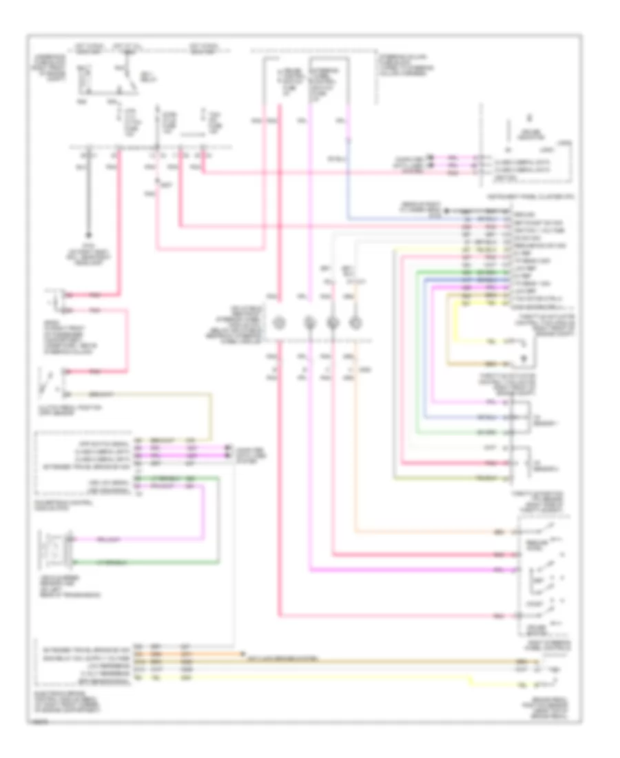
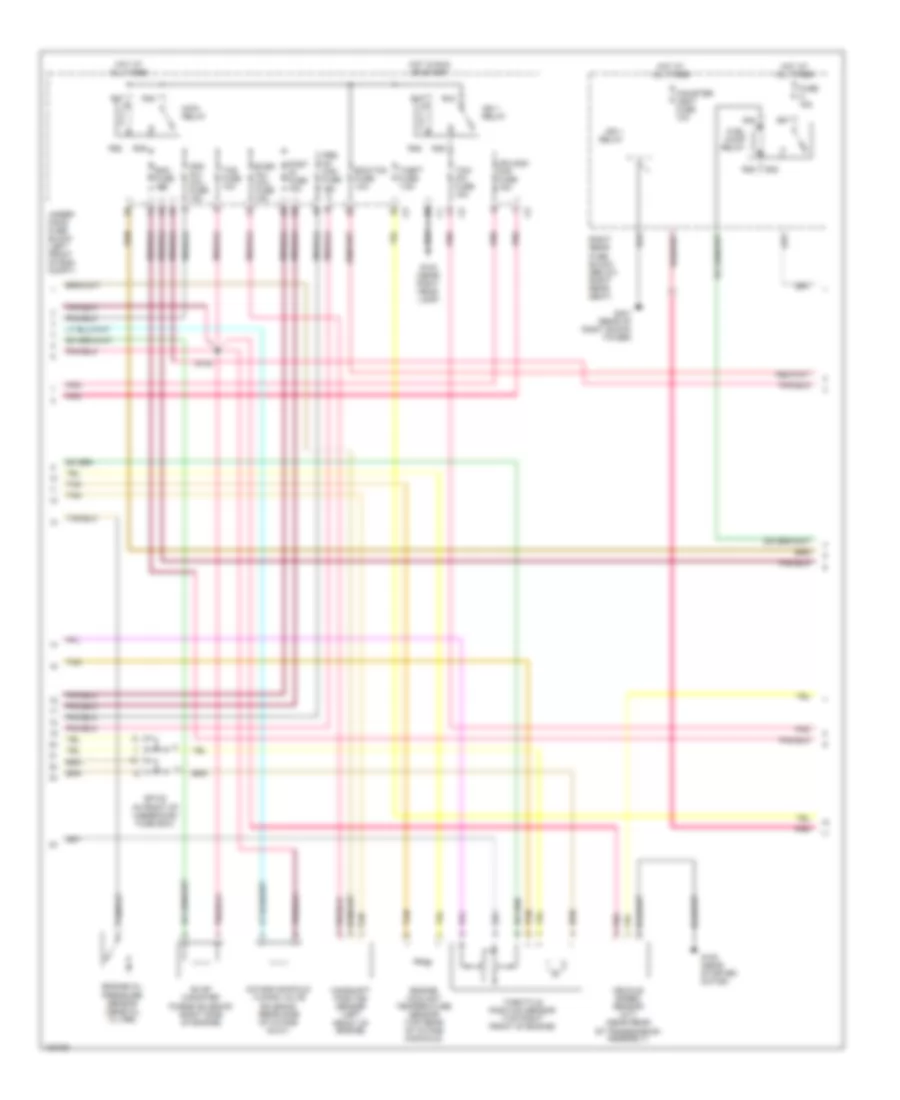
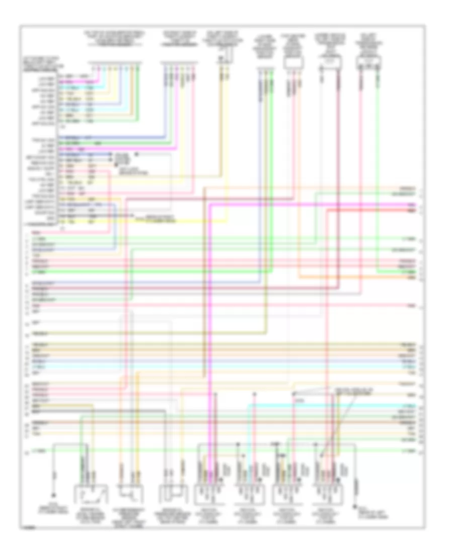
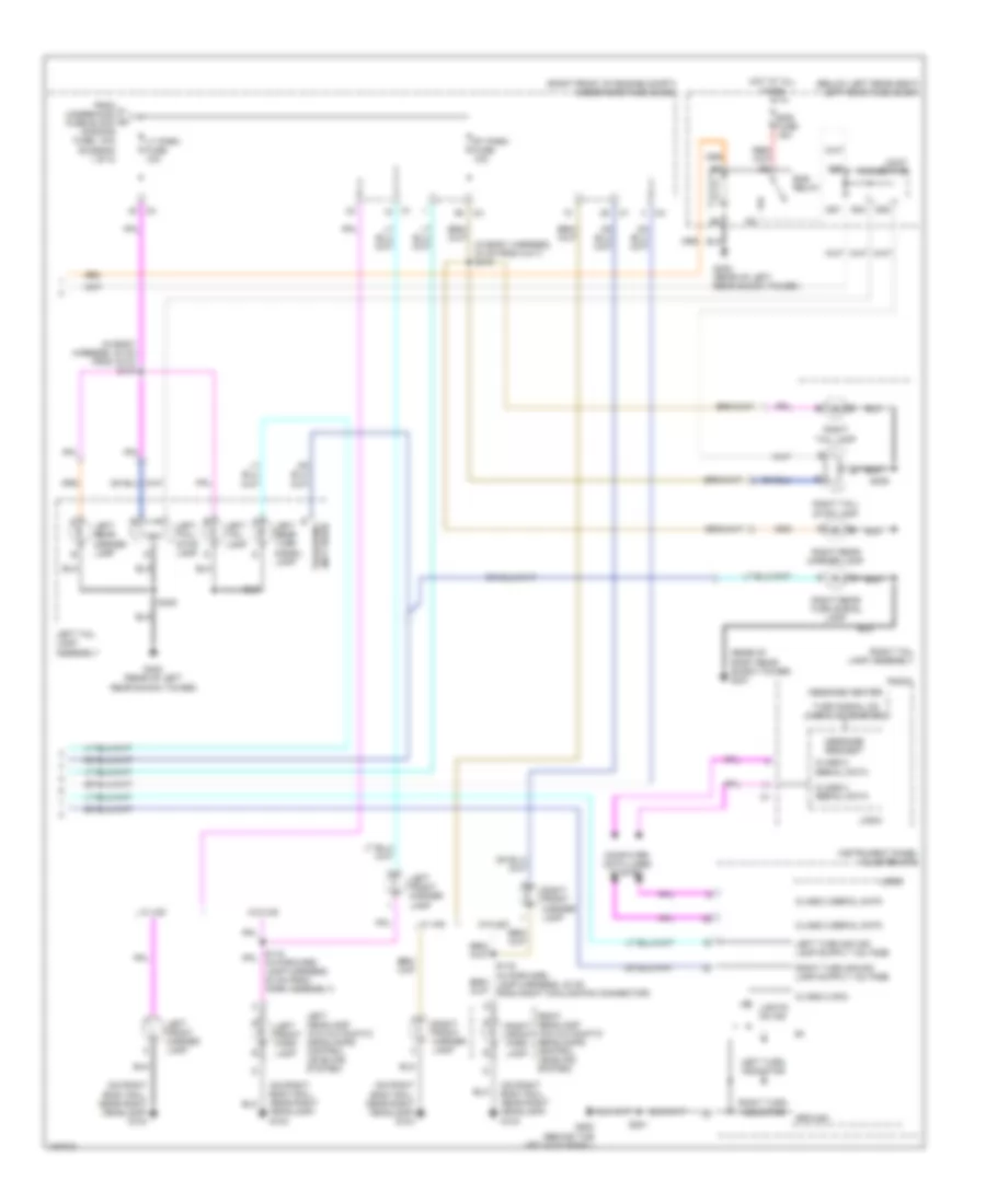
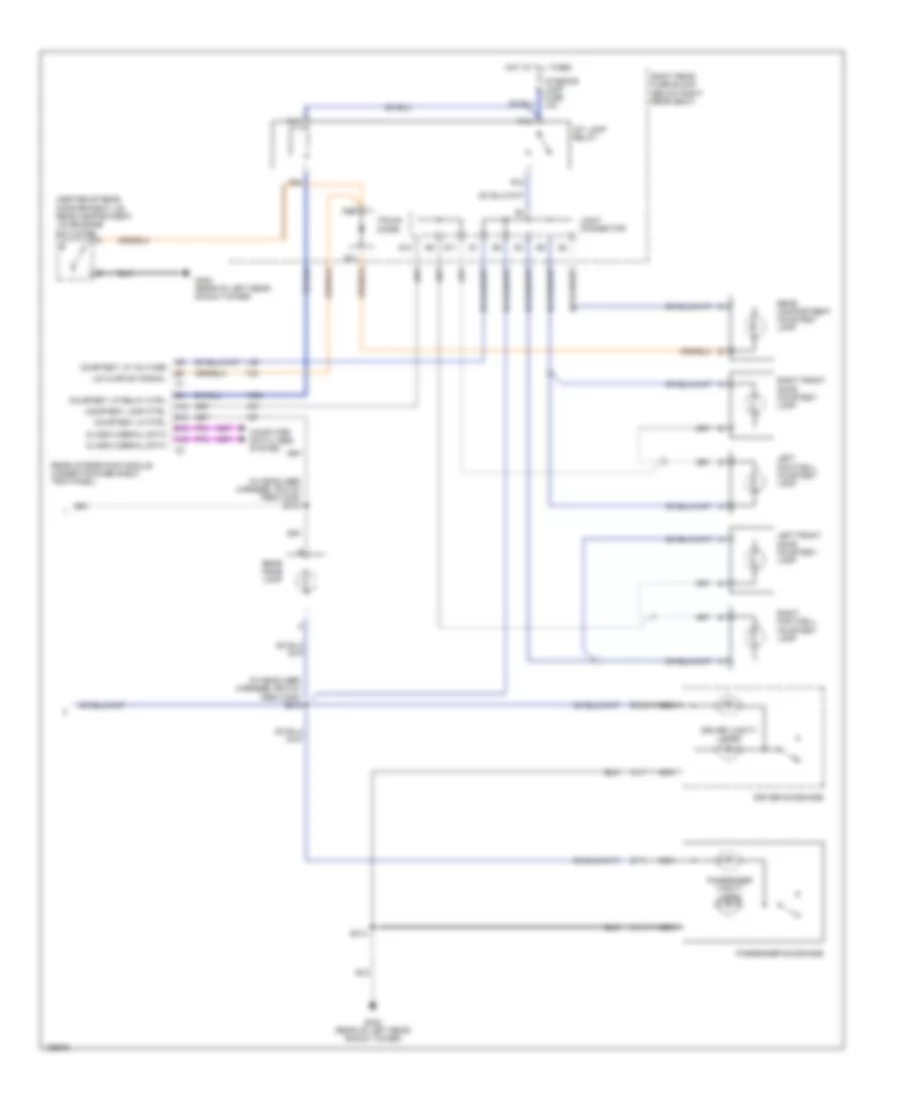
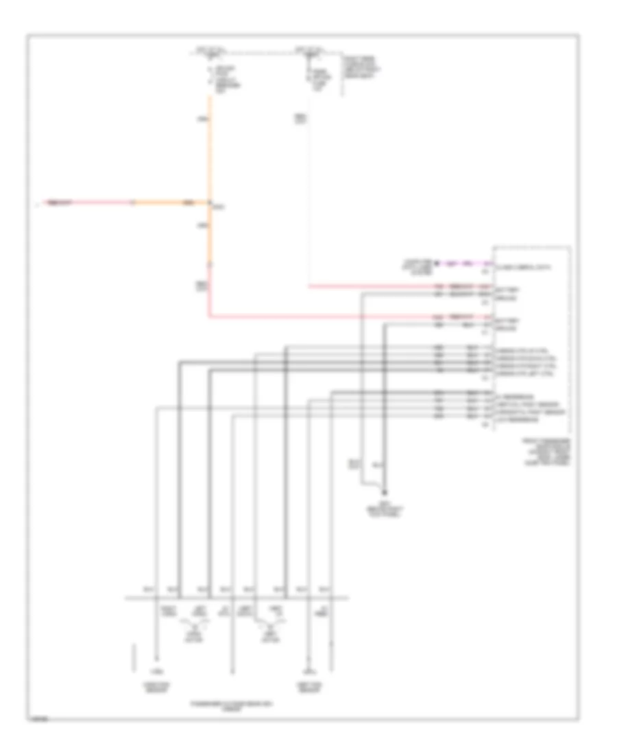
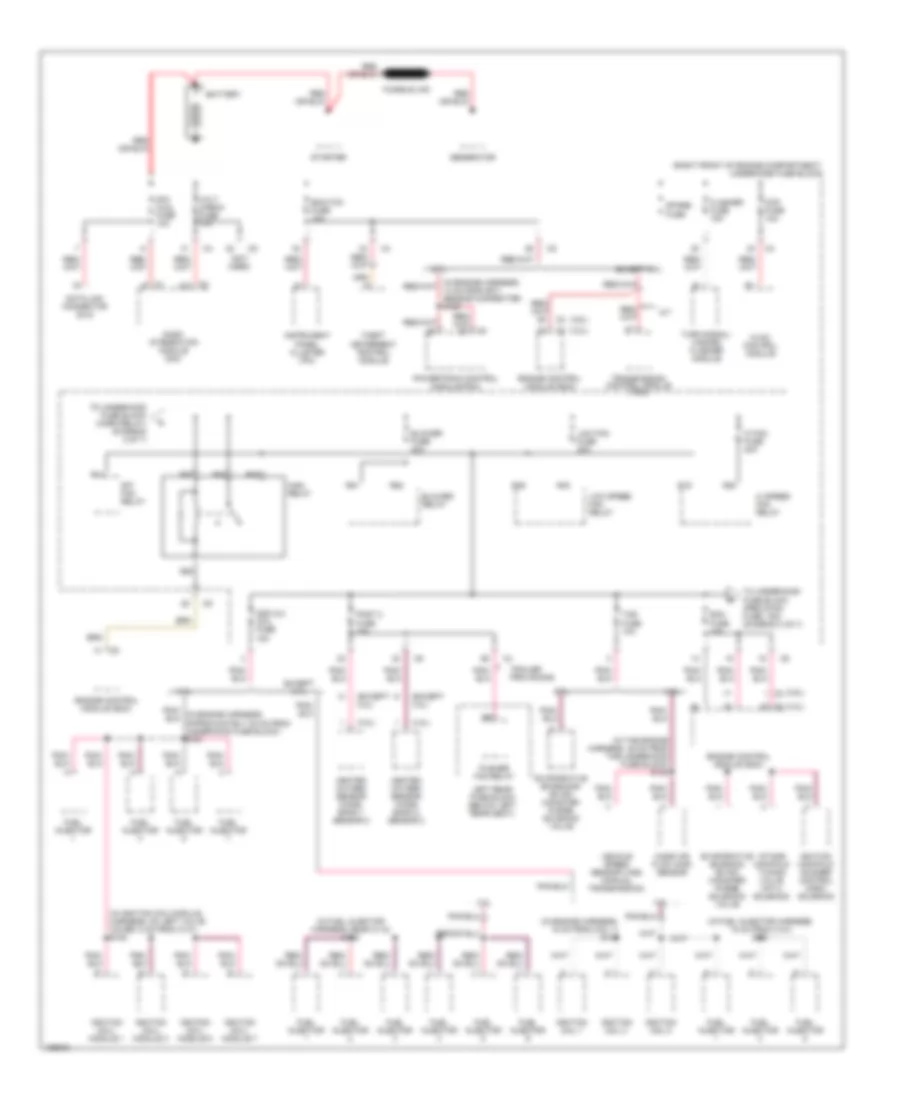
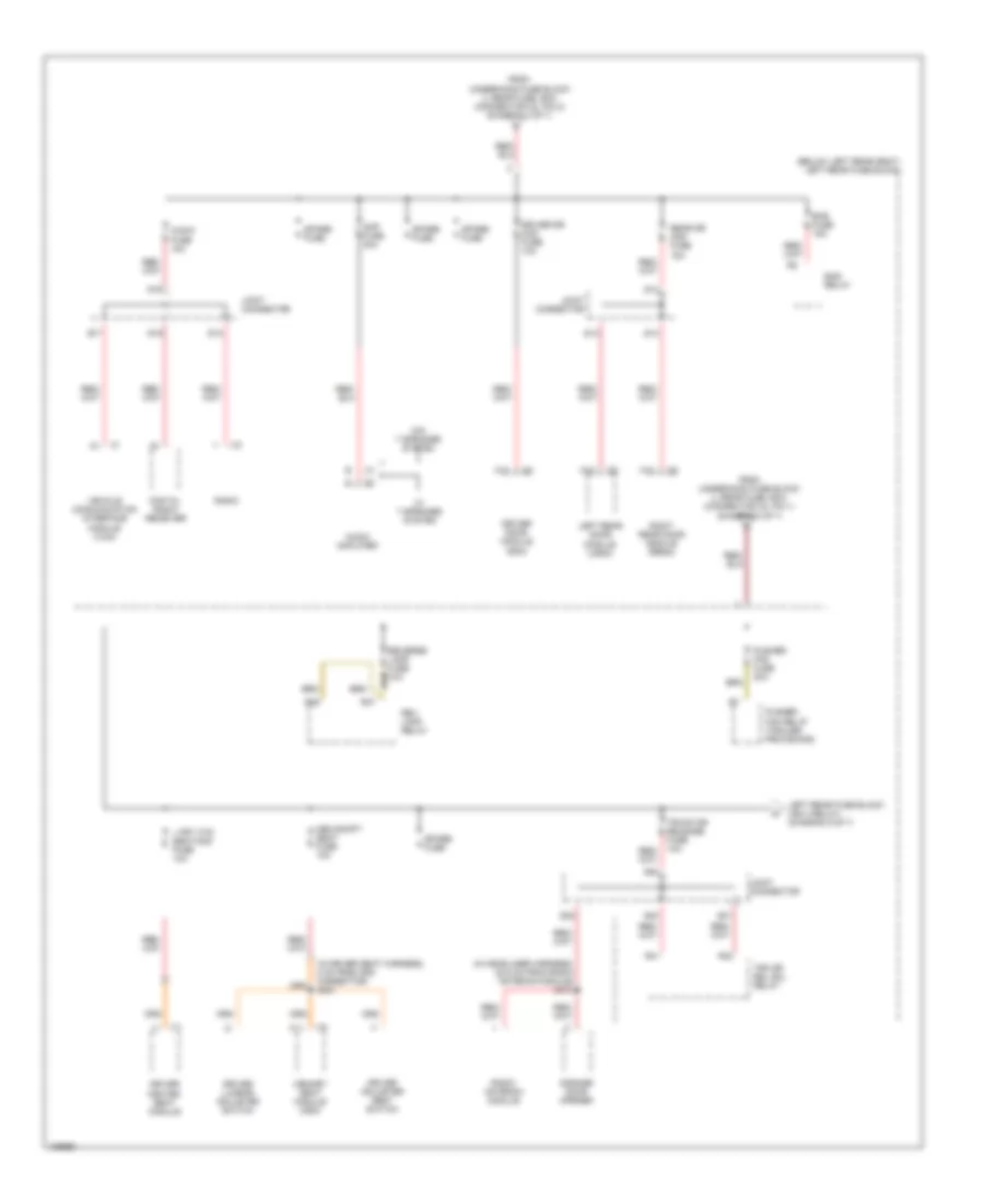
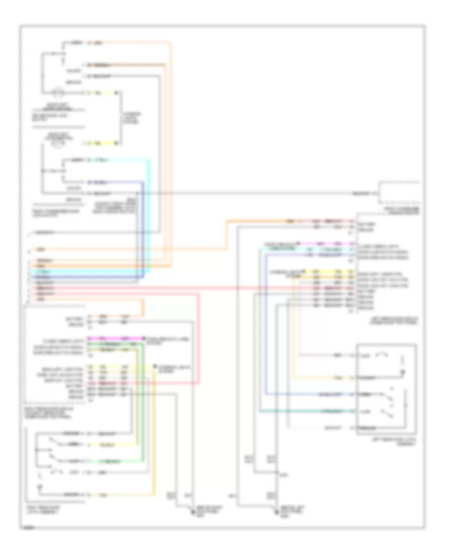
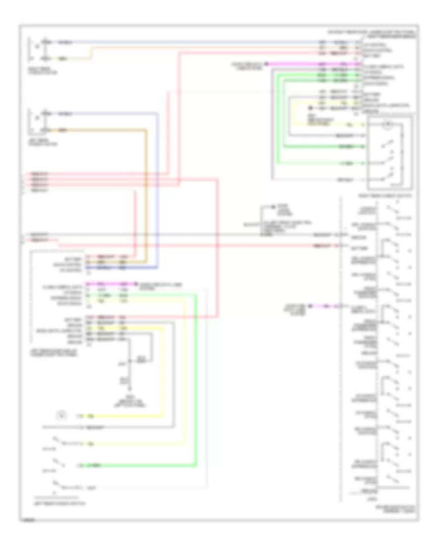
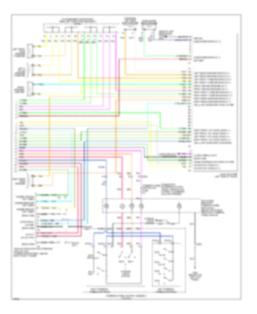
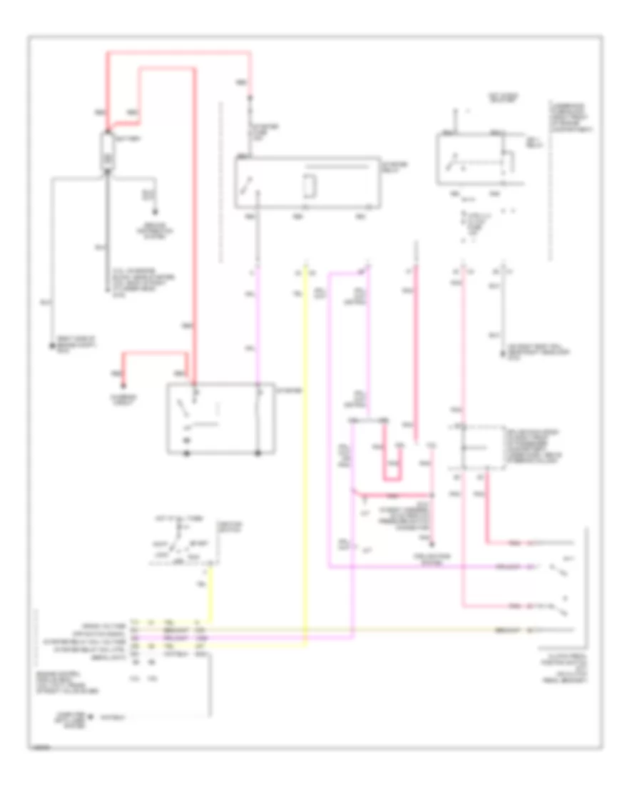
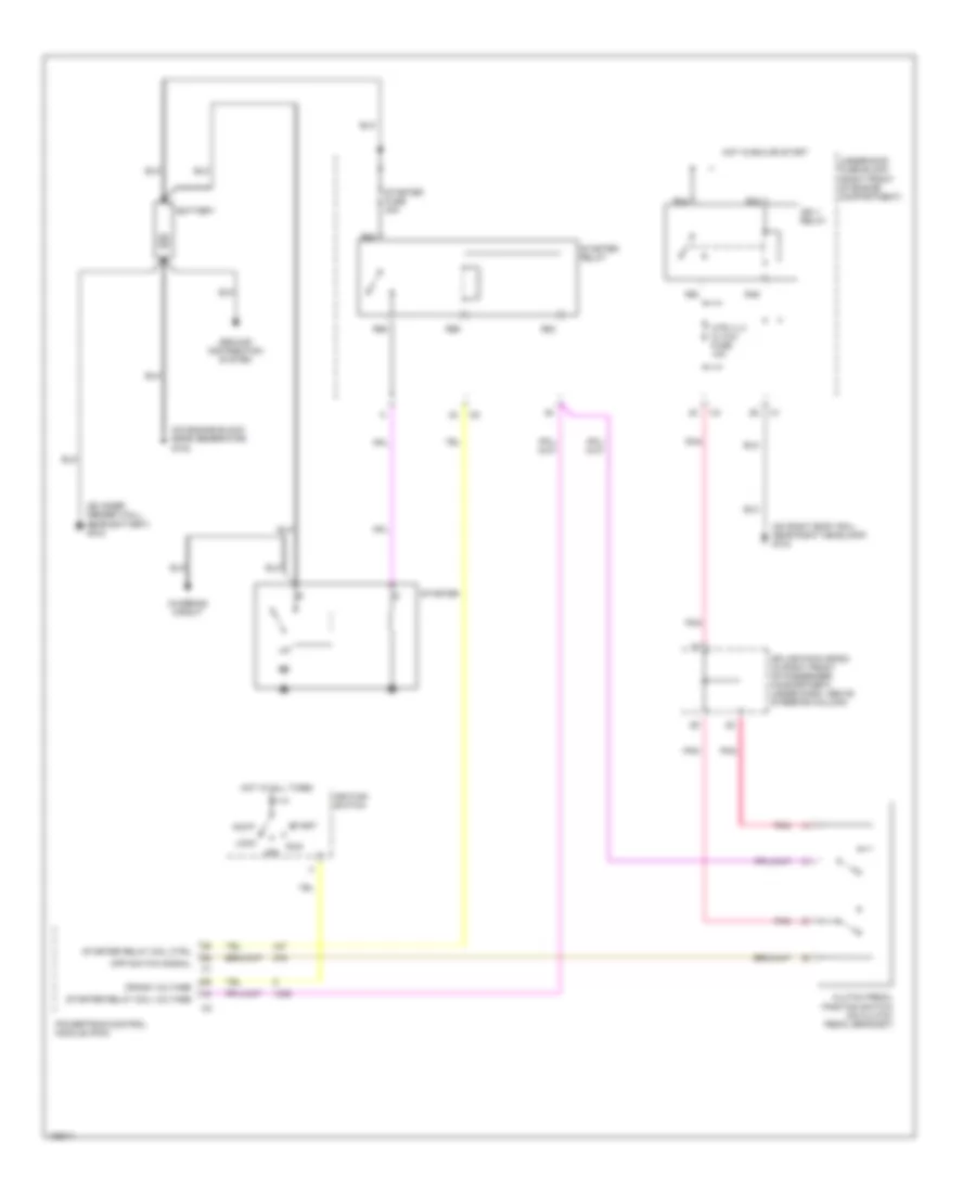
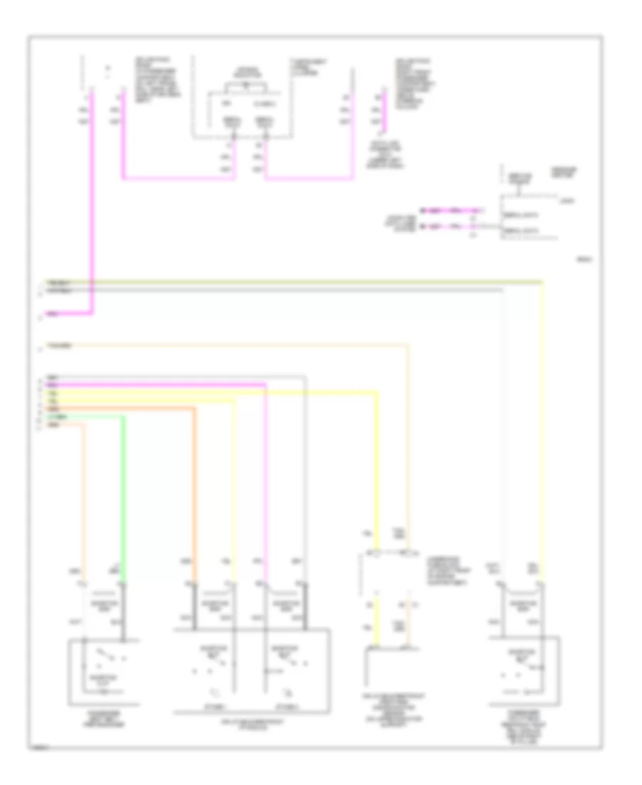
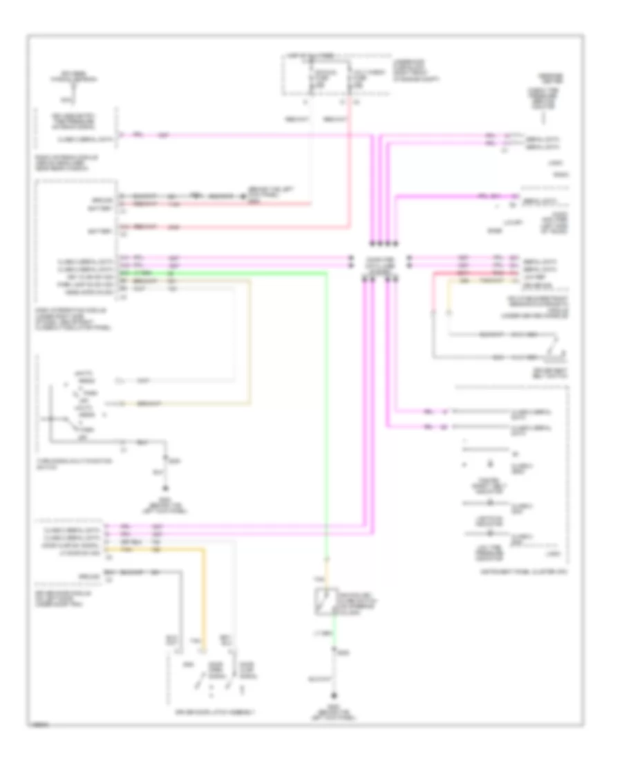
AIR CONDITIONING
Automatic A/C Wiring Diagram (1 of 3) for Cadillac CTS V 2004

List of elements for Automatic A/C Wiring Diagram (1 of 3) for Cadillac CTS V 2004:
- 3.2l
- 5 volt reference
- After boil pump relay ctrl
- Air inlet motor
- Amb air temp sensor sig
- Ambient light sensor signal
- Battery
- Blower fuse 40a
- Blower mtr speed ctrl
- Blower relay
- Blower relay ctrl
- Ccp fuse 10a
- Cmp clu relay
- Comp clutch fuse 10a
- Computer data lines system
- Coolant level switch signal
- Door a
- Door b
- Dr air temp door ctrl b
- Driver air temp door ctrl a
- Driver air temp posit signal
- E10
- E11
- E12
- E13
- E14
- E15
- E16
- Evap low temp sens signal
- Evaporator temperature sensor (on right side of evaporator case)
- F10
- F11
- F12
- F13
- F14
- F15
- F16
- G201 (behind right kick panel)
- Ground
- Hot at all times
- Hot in run
- Hvac control module (behind center of dash, below radio)
- Ign 3 fuse 10a
- Ignition 3 voltage
- Inside air temp sensor sig
- Inside air temperature sensor
- Joint connector
- Left rear fuse block (below left rear seat)
- Left sunload sensor signal
- Low reference
- Mode door ctrl a
- Mode door ctrl b
- Mode door position signal
- Nca
- Pass air temp door ctrl a
- Pass air temp door ctrl b
- Pass air temp posit signal
- Pnk
- R51
- R52
- R53
- R54
- R55
- R56
- R57
- R58
- Recirc door ctrl a
- Recirc door ctrl b
- Recirculation actuator (left side of the blower motor)
- Right sunload sensor signal
- S117
- Serial data
- Solid state
- Splice pack sp302
- Sunload sensor (top center of i/p, on defrost grill)
- Tan
- Underhood fuse block (right front of engine compartment)
- Volt
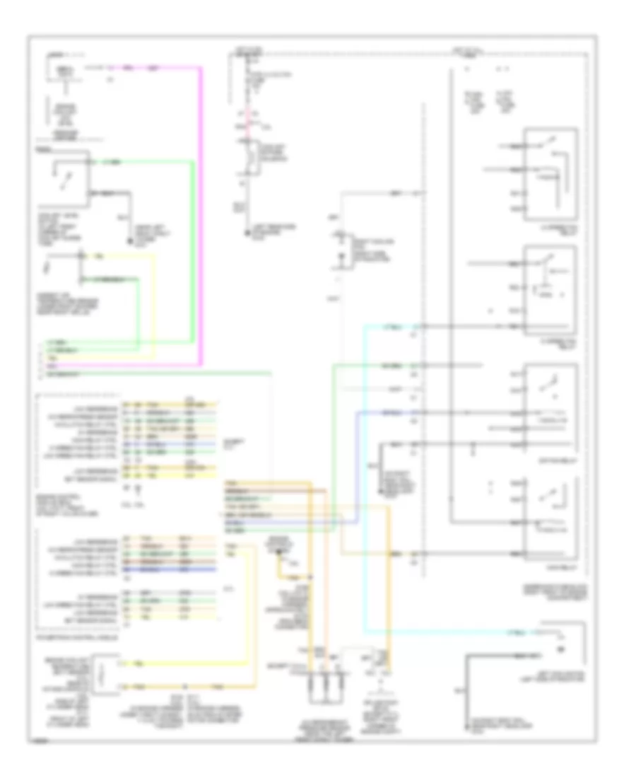
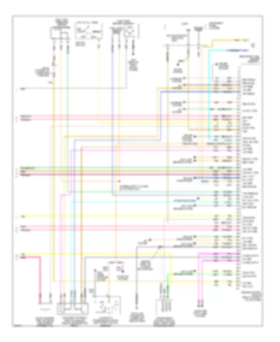
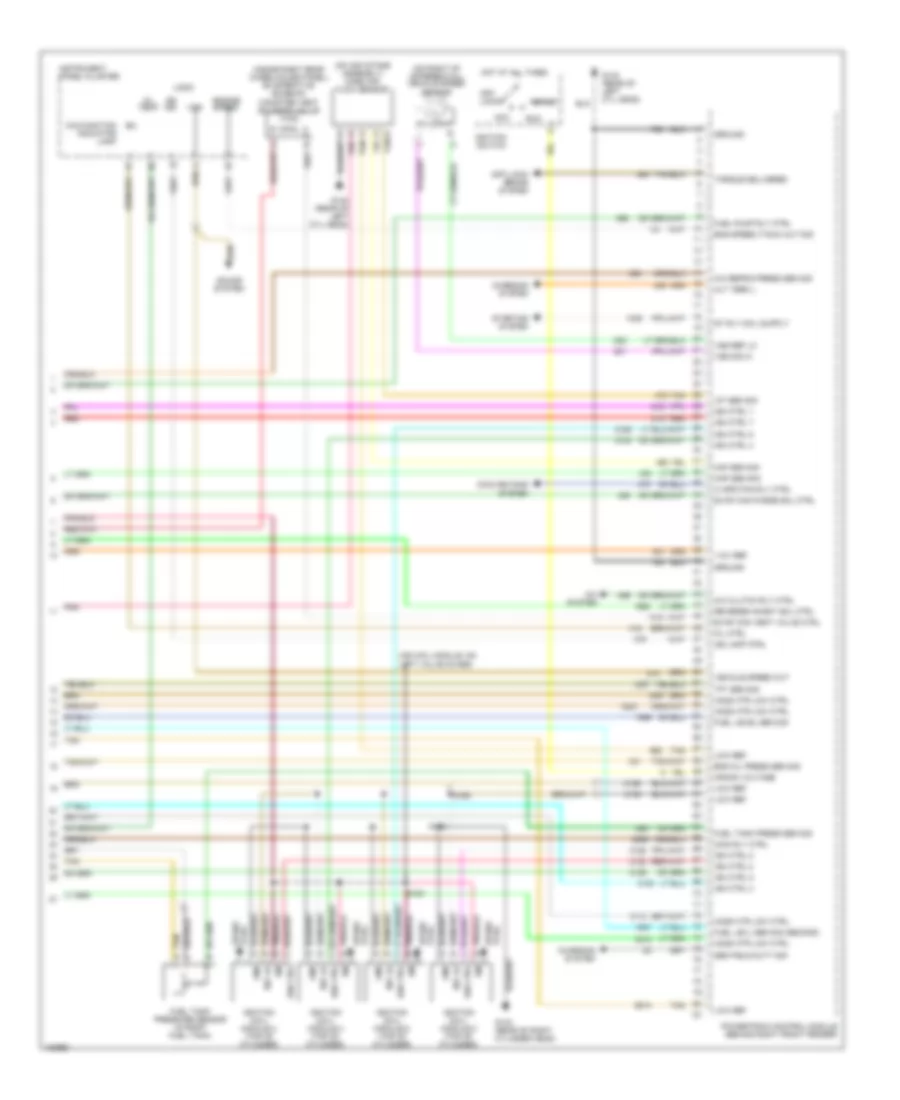
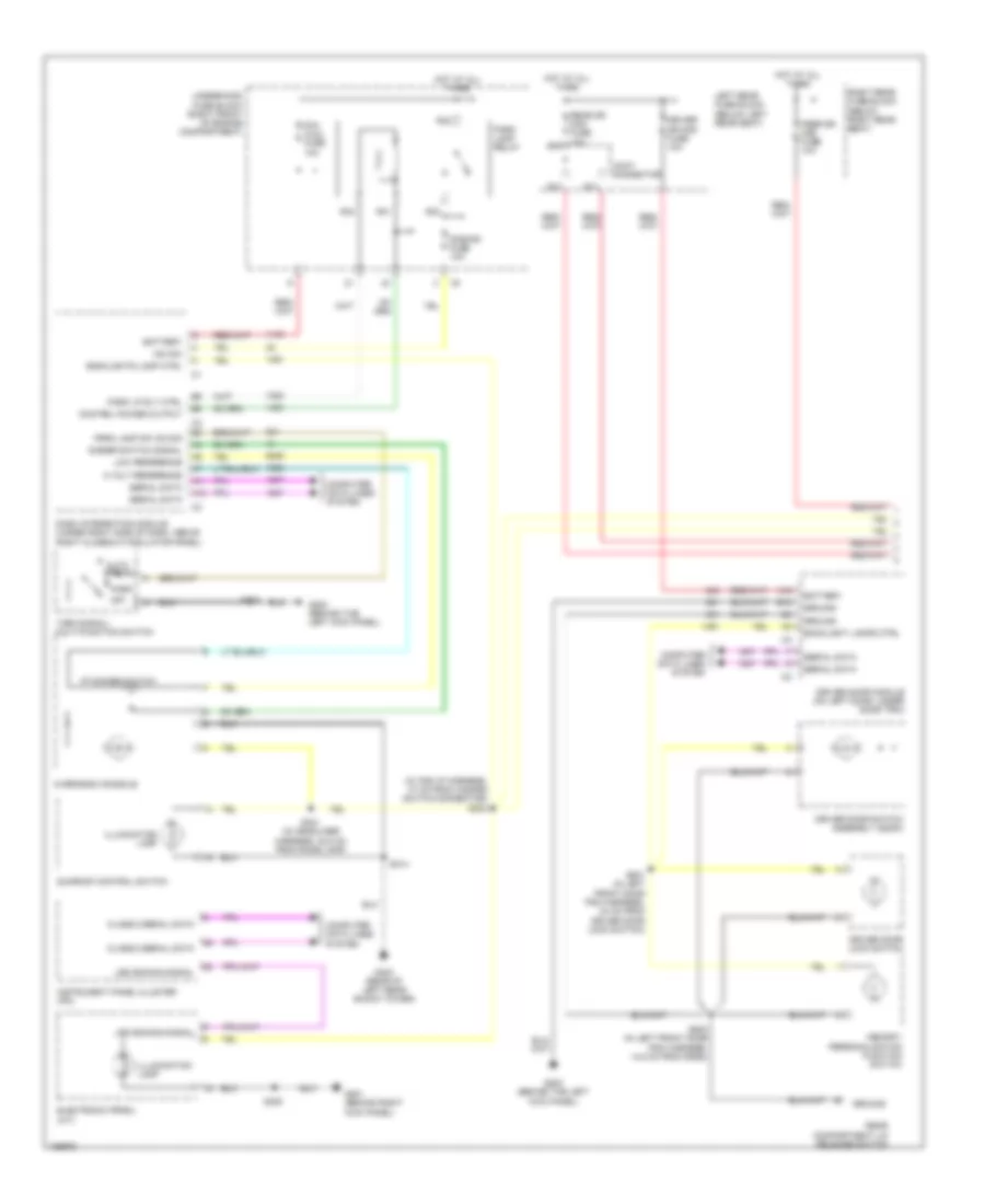
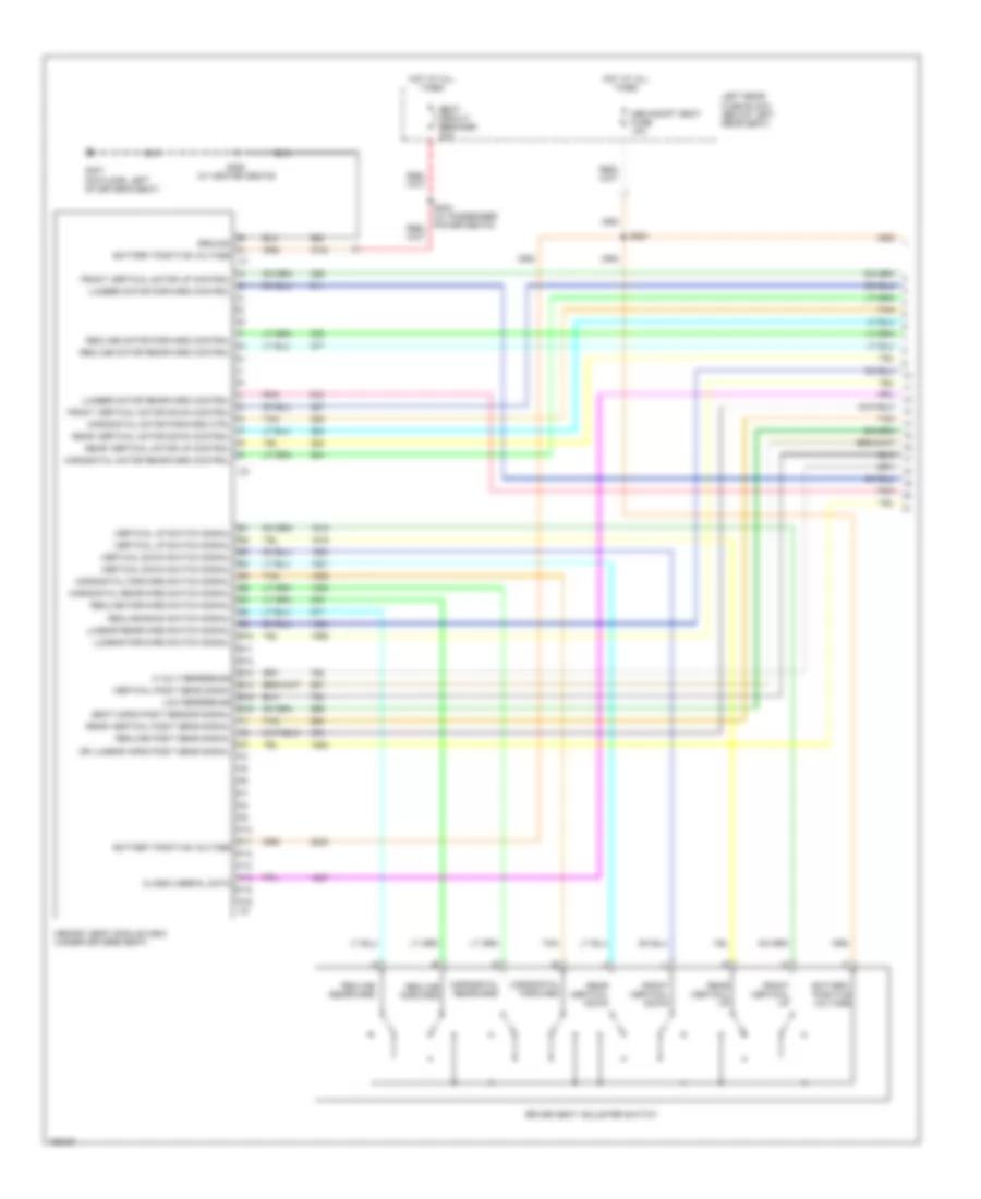
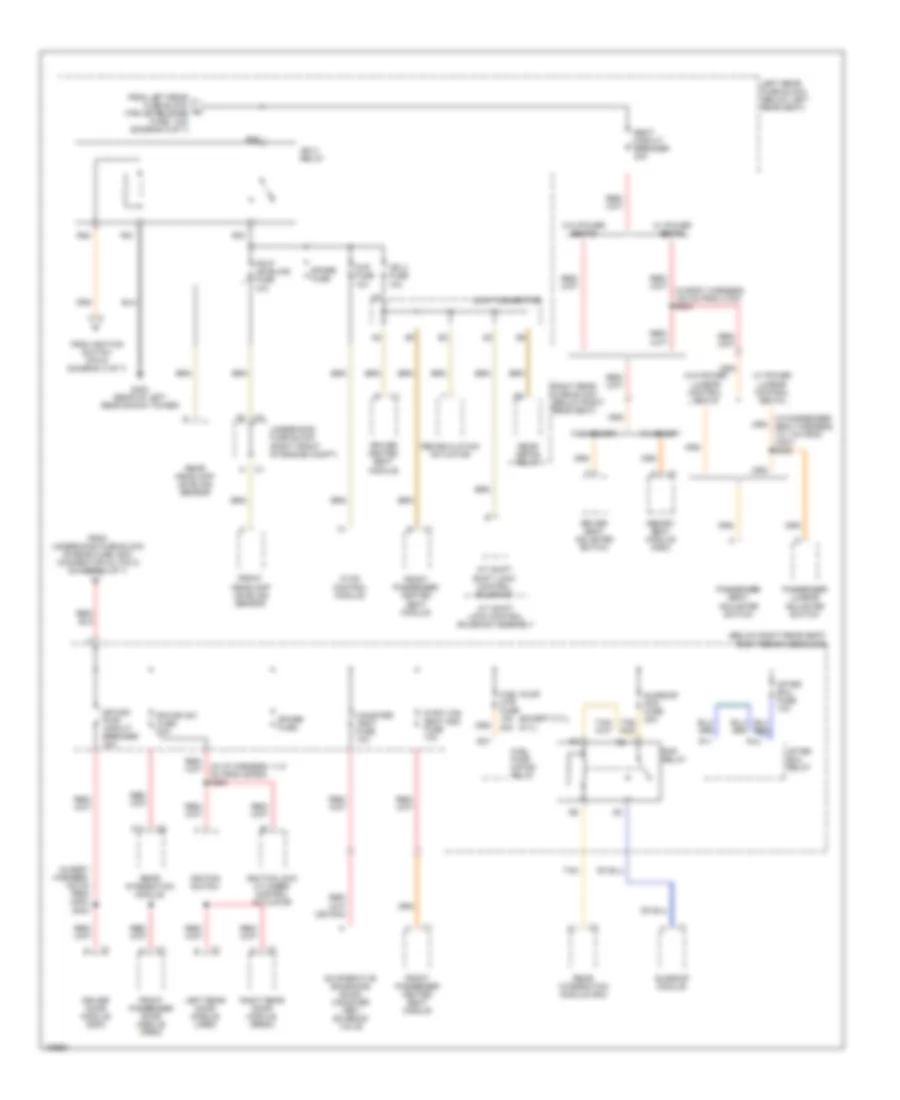
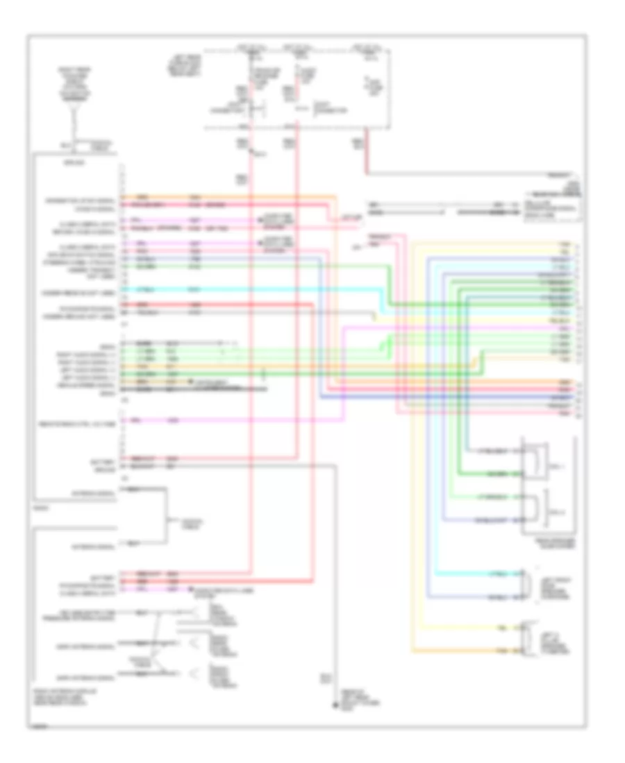
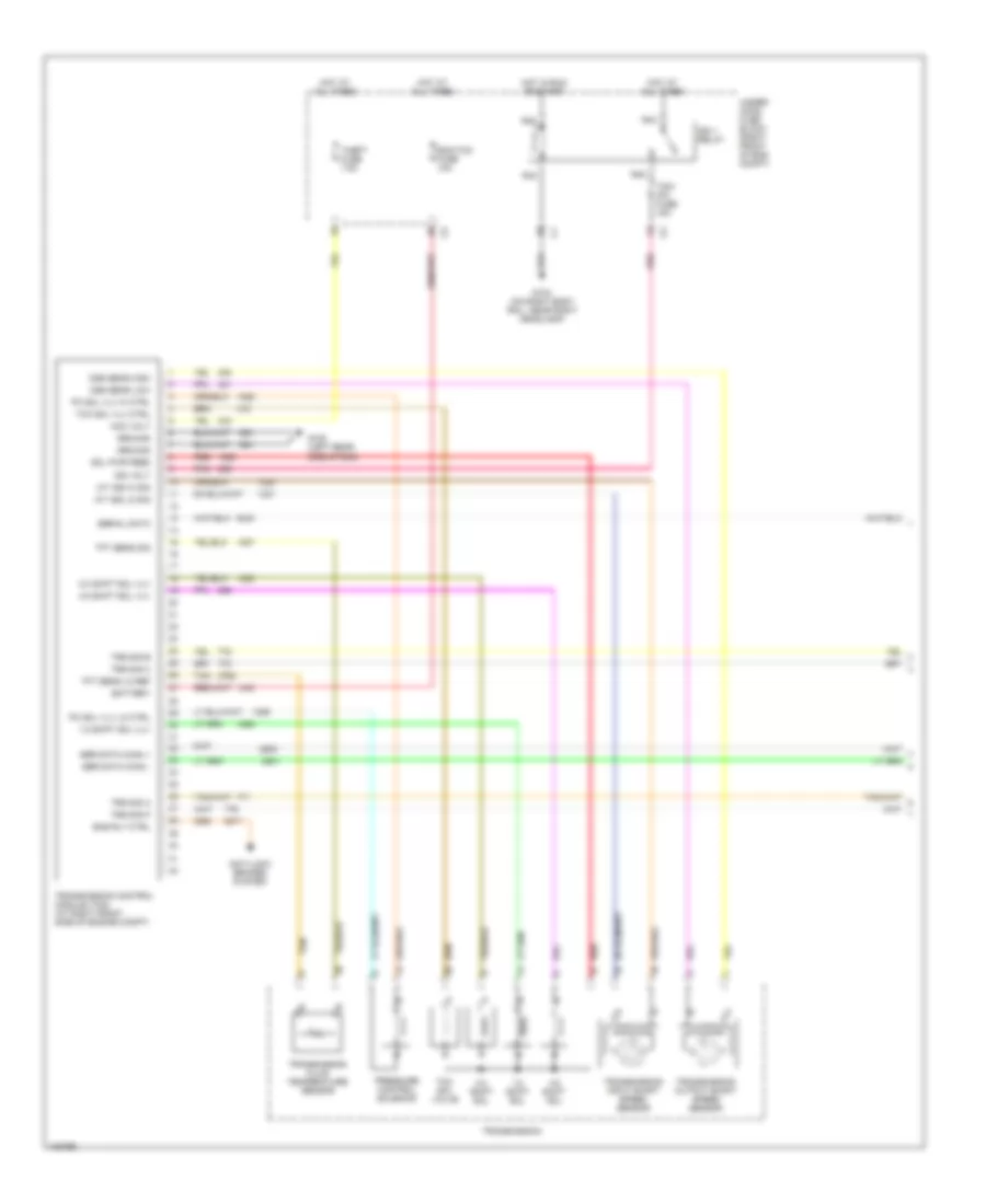
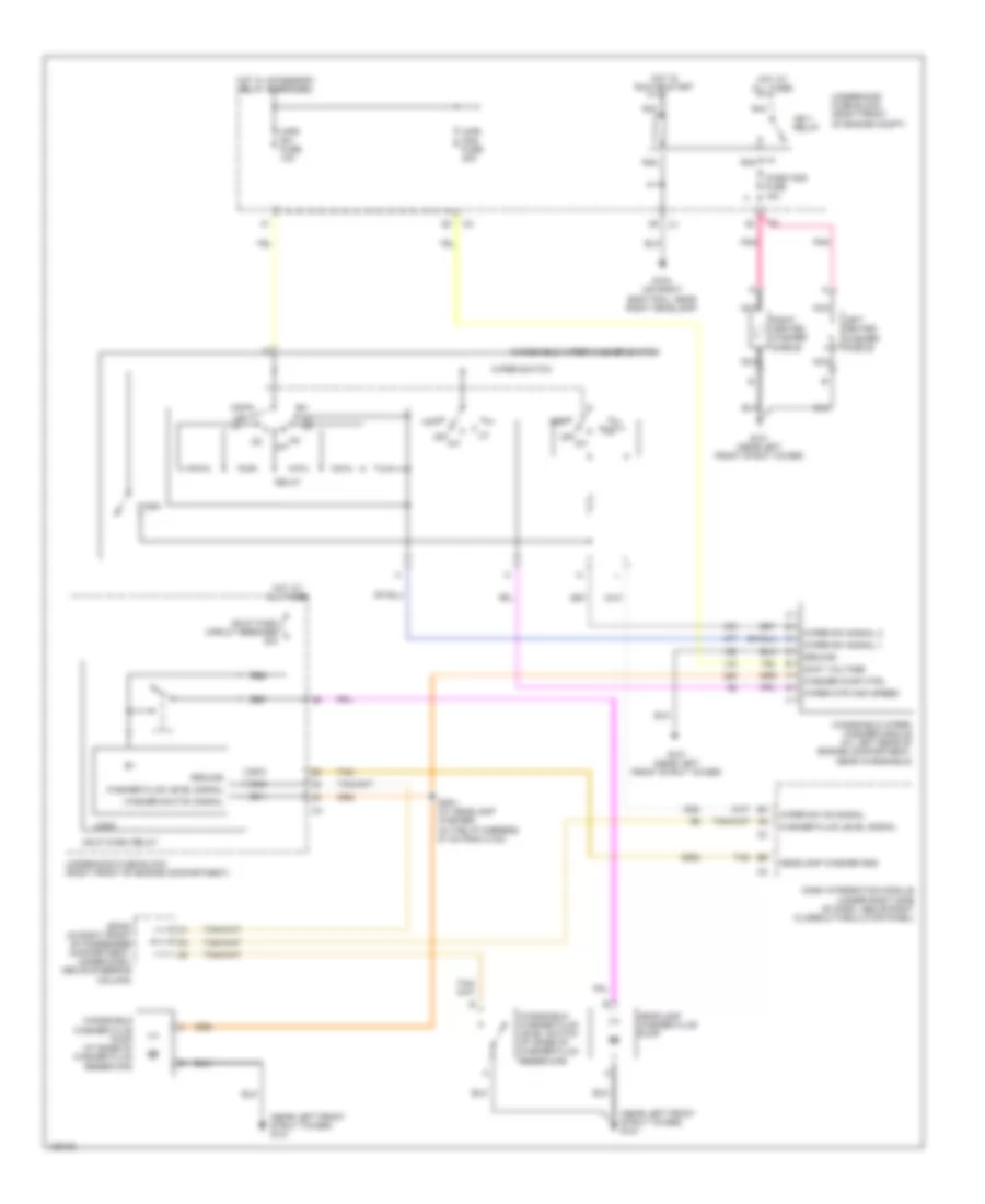
Automatic A/C Wiring Diagram (2 of 3) for Cadillac CTS V 2004
List of elements for Automatic A/C Wiring Diagram (2 of 3) for Cadillac CTS V 2004:
- (3.2l)
- (3.6l)
- (5.7l)
- (in blower motor harness, 115 cm from c323) s323
- (in hvac module harness, 6 cm from c321)
- 3.2l
- A/c
- A/c compressor clutch
- Acc
- After boil coolant pump (on right side of engine block)
- After boil fuse 10a
- After boil relay (3.2l)
- Blower motor (on right side of hvac module)
- Blower motor control processor (on lower left side of blower motor)
- Blower mtr speed ctrl
- Cold
- Def
- Driver air temperature actuator (on hvac module)
- Dry air temp signal
- G100 (left rear side of engine)
- G100 (left rear side of engine) g132 (front of right cylinder head) g142 (rear of right cylinder head)
- G201 (behind right kick panel)
- Hot
- Hot at all times
- Ignition switch
- Lock
- Logic
- Mix motor
- Mode actuator
- Mode actuator (on left side of hvac module)
- Mode valve signal
- Nca
- Off
- Pass air temp signal
- Passenger air temperature actuator (on hvac module)
- Pnk
- R11
- R12
- R13
- R15
- Right rear fuse block (below right rear seat)
- Run
- S118
- S202 (in the i/p harness, 48 cm from hazard switch connector)
- Splice pack sp200 (in right front of passenger compt, under dash, above steering column)
- Start
- Tan
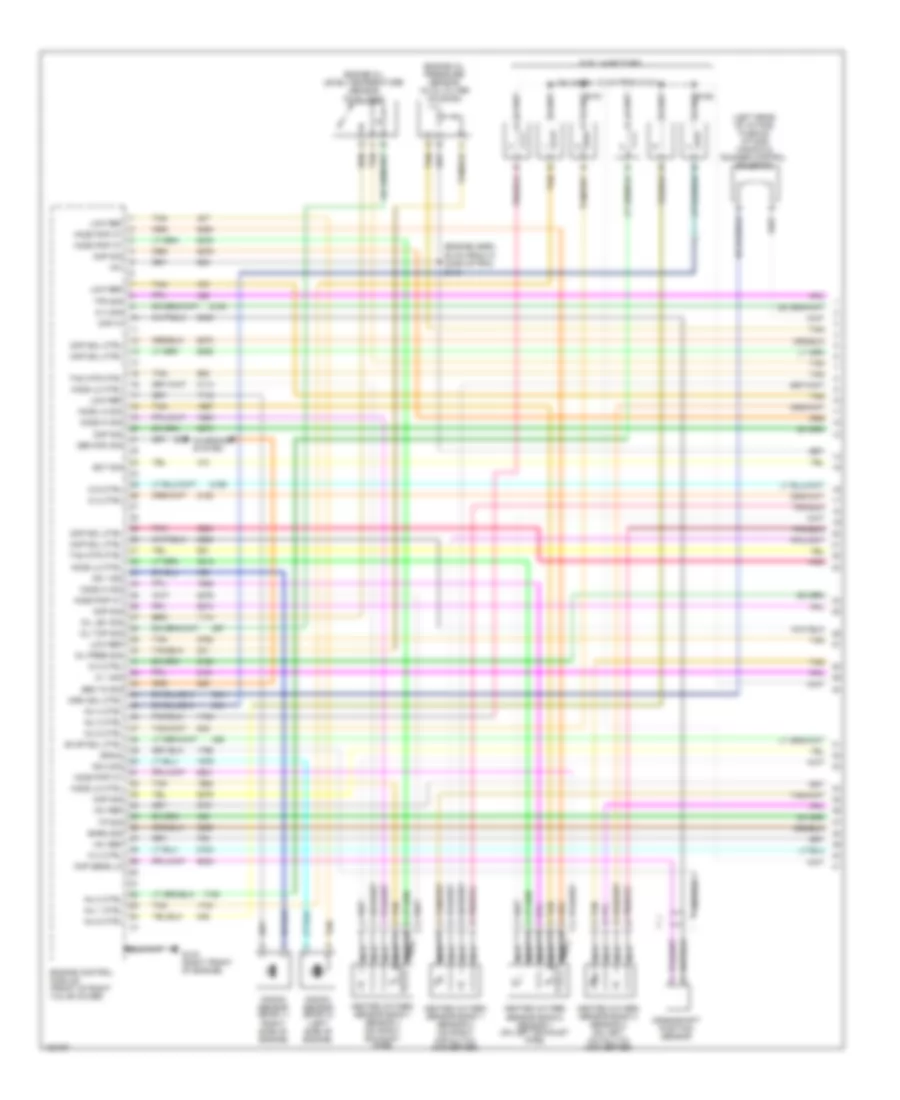
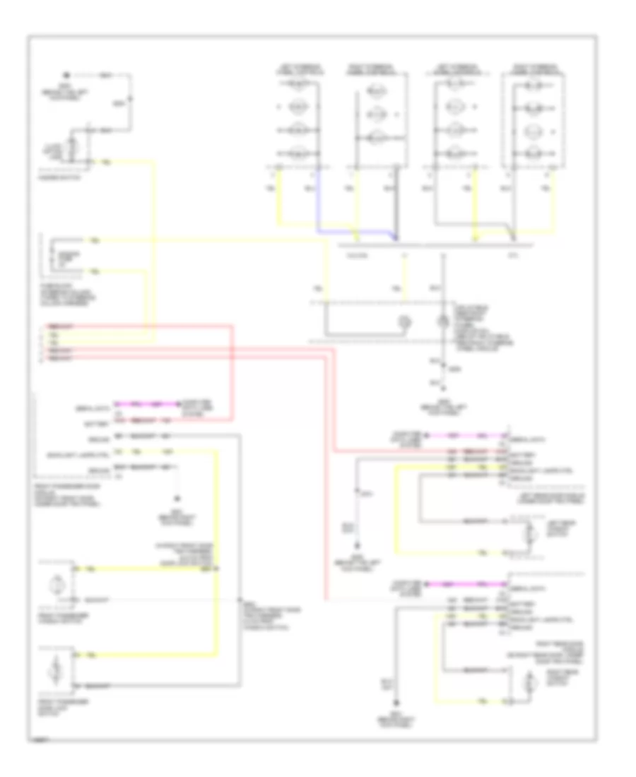
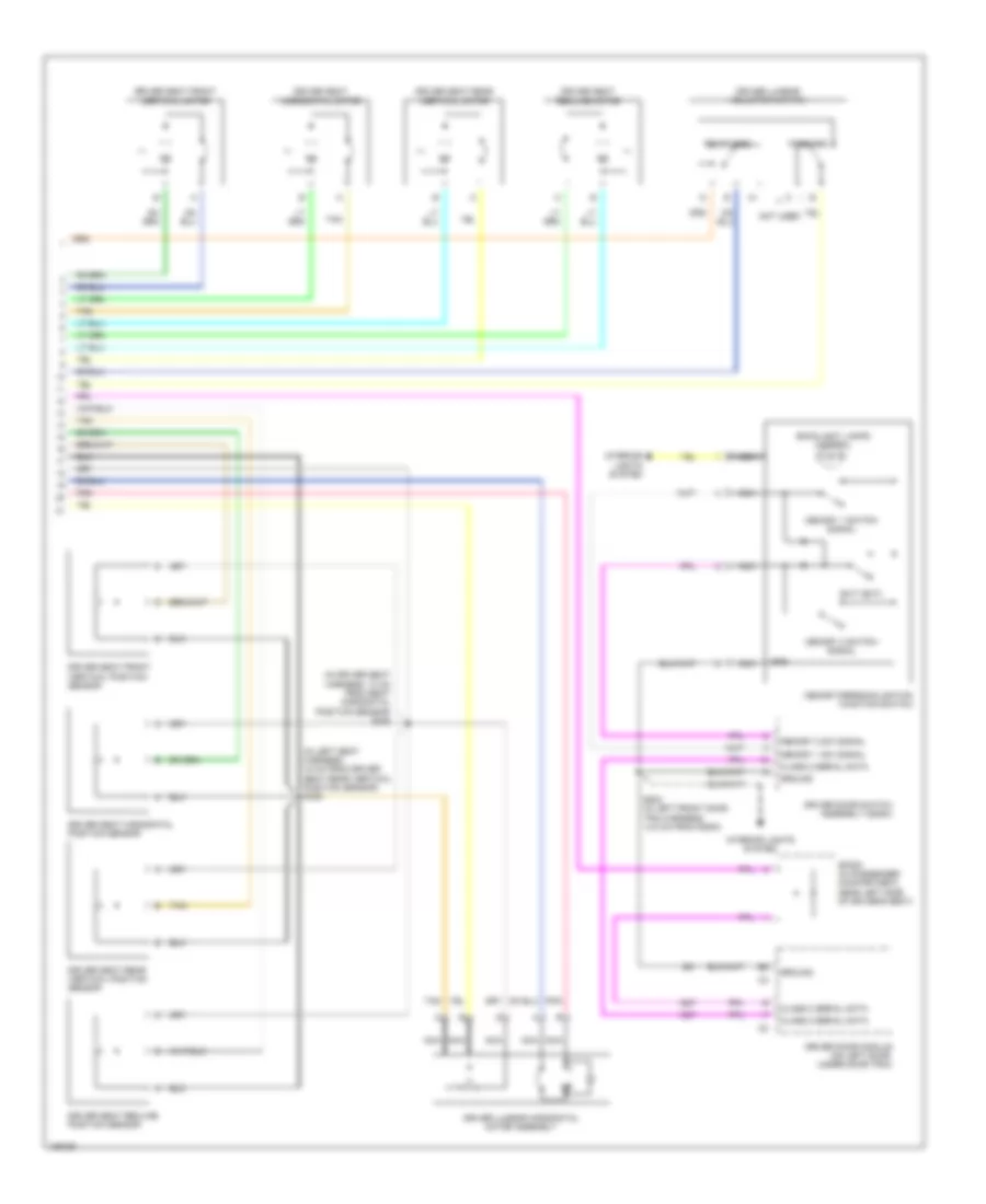
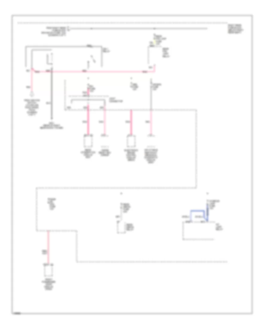
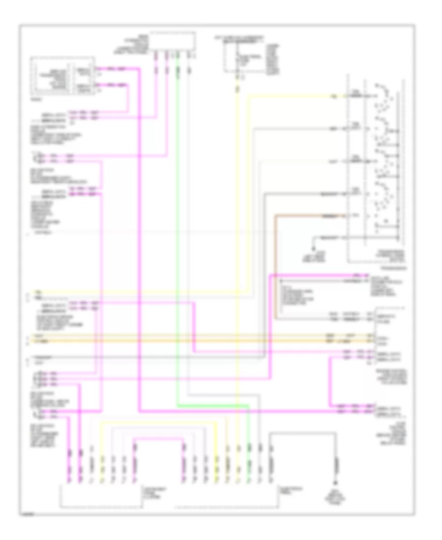
Automatic A/C Wiring Diagram (3 of 3) for Cadillac CTS V 2004
List of elements for Automatic A/C Wiring Diagram (3 of 3) for Cadillac CTS V 2004:
- (3.2l)
- (except 3.2l) a
- (left rear side of engine) g100
- (near left front strut tower) g101
- (on right body rail, near right headlamp) g104
- (or 452)
- (or 470)
- 26 cm from starter motor connector)
- 3.2l
- 3.2l 3.6l
- 3.6l
- 5.7l
- 5v reference
- A/c clutch relay ctrl
- A/c refrig press sensor
- A/c refrigerant pressure sensor (near the left front strut tower)
- Ambient air temperature sensor (under front bumper, near front grille)
- Coolant bypass solenoid
- Coolant level switch (in left front corner of coolant surge tank)
- Ect sensor signal
- Engine control module (ecm) (3.6l (vin 7): front of right valve cover)
- Engine controls system
- Engine coolant low level
- Engine coolant temperature (ect) sensor (3.2l: rear of intake manifold) (3.6l: side of left cylinder head) (5.7l: front of left cylinder head)
- Except 5.7l
- Feed
- Hi speed fan relay
- Hi speed fan relay ctrl
- High fan fuse 30a
- Hot at all times
- Hot in on or start
- Htr vlv/cltch fuse 10a
- Left cooling fan (left side of radiator)
- Lo speed fan relay
- Logic
- Low fan fuse 30a
- Low reference
- Low speed fan relay ctrl
- Main relay
- Main relay ctrl
- Message center
- Pnk
- Powertrain control module
- R14
- R15
- R16
- R17
- R18
- R19
- R20
- R21
- R22
- R39
- R40
- R41
- R42
- R47
- R48
- R49
- R50
- Radio
- Right cooling fan (right side of radiator)
- Rtn
- S/p fan relay
- S111 s148 (3.6l) (3.2l) (in engine harness, (in engine harness under throttle body, 11.5 cm towards the right)
- S156 (3.6l (vin 7)) (in engine harness, approximately 24 cm from ebcm connector)
- Serial data
- Sig
- Splice pack sp102 (except 5.7l) (right front corner of engine compt)
- Tan
- Underhood fuse block (right front of engine compartment)
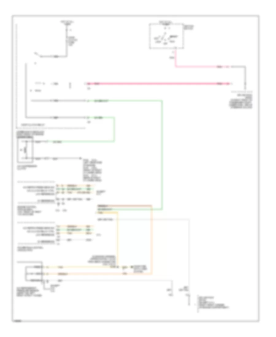
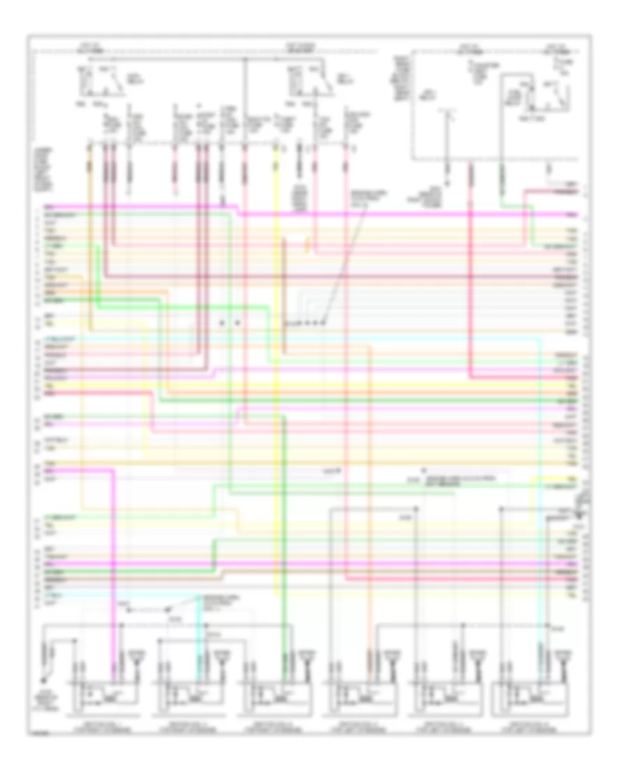
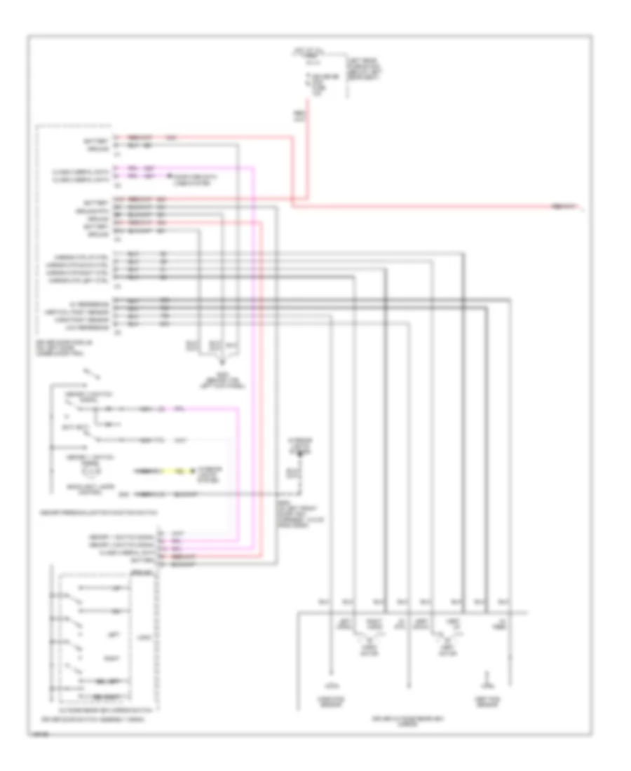
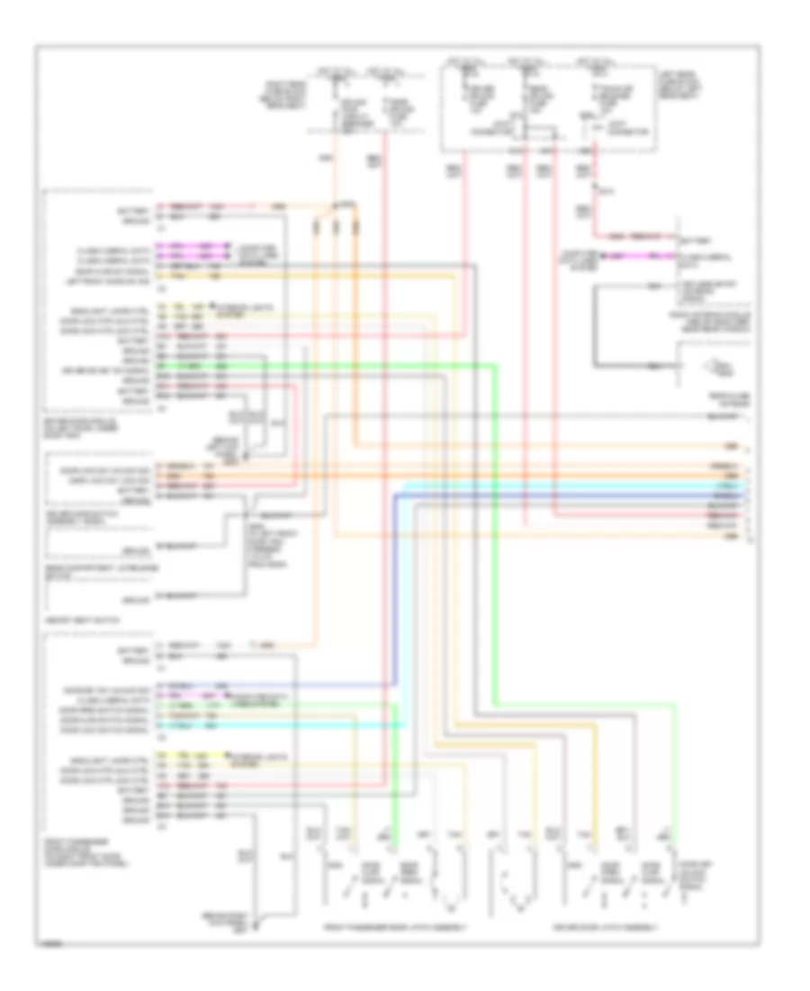
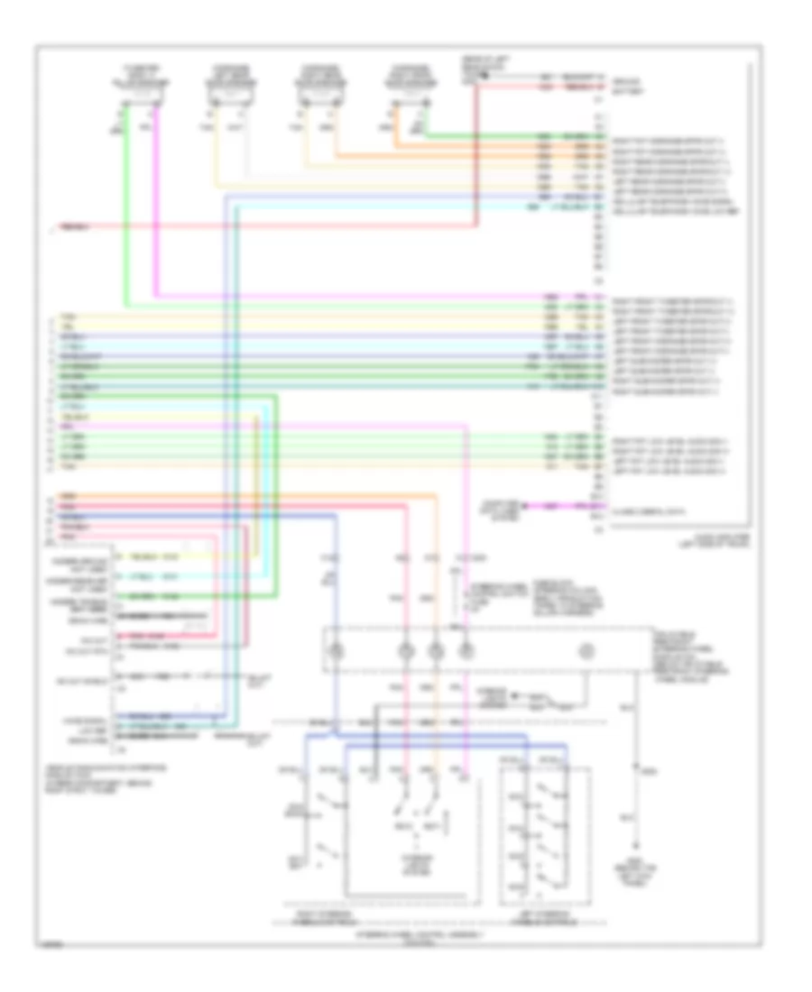
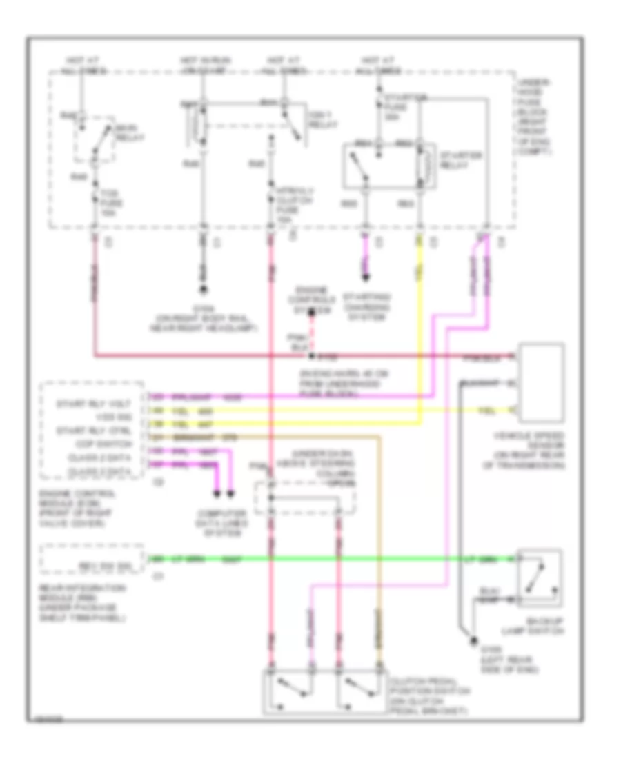
Compressor Wiring Diagram for Cadillac CTS V 2004
List of elements for Compressor Wiring Diagram for Cadillac CTS V 2004:
- (3.2l)
- (3.6l)
- (5.7l)
- (in engine harness, approximately 24 cm from ebcm connector) (3.6l (vin 7)) s156
- (or tan)
- 3.2l
- 3.6l
- 470 (or 452)
- 5.7l
- 5v reference
- A/c clutch relay ctrl
- A/c compressor clutch
- A/c refrig press sens sig
- A/c refrigerant pressure sensor (near the left front strut tower)
- Acc
- Comp clutch fuse 10a
- Comp clutch relay
- Computer data lines system
- Engine control module (ecm) (3.6l: front of right valve cover)
- Except 3.2l
- Except 5.7l
- Feed
- G100 (left rear side of engine) g132 (front of right cylinder head) g142 (rear of right cylinder head)
- Hot at all times
- Ignition switch
- Lock
- Low reference
- Nca
- Off
- Pnk
- Powertrain control module (pcm)
- R55
- R56
- R57
- R58
- Return
- Run
- Sig
- Splice pack sp102 (except 5.7l) (right front corner of engine compartment)
- Splice pack sp200 (in right front of passenger compt, under dash, above steering column)
- Start
- Tan
- Underhood fuse block (right front of engine compartment)
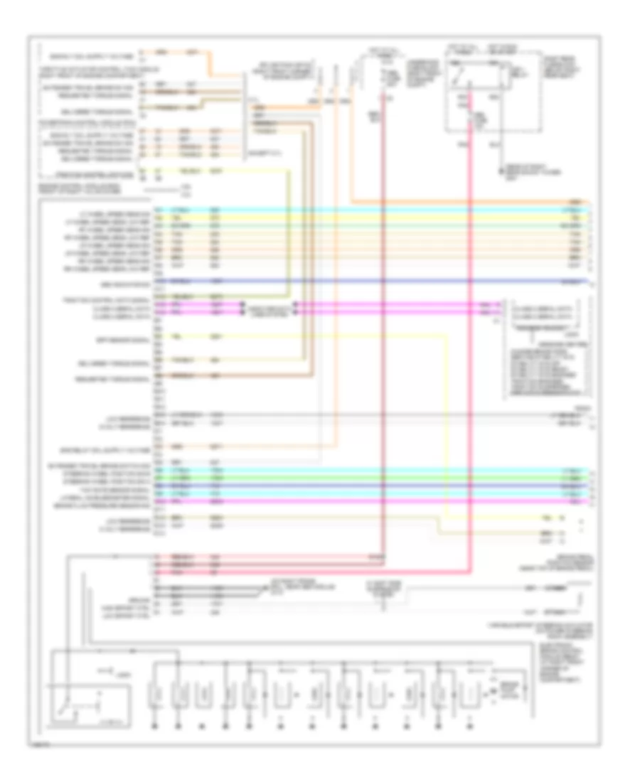
ANTI-LOCK BRAKES
Anti-lock Brakes Wiring Diagram (1 of 2) for Cadillac CTS V 2004
List of elements for Anti-lock Brakes Wiring Diagram (1 of 2) for Cadillac CTS V 2004:
- (on right frame rail, near abs module) g110
- (rear of right rear shock tower) g401
- 3.2l
- 3.6l
- 5 volt reference
- 5-volt reference
- 5.7l
- A10
- A11
- A12
- A13
- A14
- Abs fuse 10a
- Abs fuse 50a
- Abs indicator sig
- B10
- B11
- B12
- B13
- B14
- Bpp sensor signal
- Brake fluid pressure sensor sig
- Brake pedal position sensor (near top of brake pedal)
- Brake pump motor
- C10
- C11
- C12
- C13
- C14
- Change brake pads service stability sys stability sys off stability sys ready stability sys engaged traction engaged traction suspended service suspension sys
- Class 2 serial data
- Computer data lines system
- Delivered torque signal
- Electronic brake control module (ebcm) (at right front corner of engine compartment)
- Engine control module (ecm) (front of right valve cover)
- Except 5.7l
- Extended travel brake sw sig
- Extended travel brake switch sig
- Ground
- High effort ctrl
- Hot at all times
- Hot in run or start
- Ign 1 relay
- Lateral accelerometer signal
- Lf wheel speed sens low ref
- Lf wheel speed sens sig
- Logic
- Low effort ctrl
- Low reference
- Lr wheel speed sens low ref
- Lr wheel speed sens sig
- Message center
- Message request
- Nca
- Pnk
- Powertrain control module (pcm)
- R21
- R22
- R23
- R25
- Radio
- Requested torque signal
- Rf wheel speed sens low ref
- Rf wheel speed sens sig
- Right rear fuse block (below right rear seat)
- Rr wheel speed sens low ref
- Rr wheel speed sens sig
- S130
- Splice pack sp102 (right front corner of engine compt)
- Steering wheel position sig a
- Steering wheel position sig b
- Tan
- Throttle actuator control (tac) module (right front of engine compartment)
- Traction control data sig
- Traction control data signal
- Underhood fuse block (right front of engine compt)
- Variable effort steering actuator (on power steering rack assembly)
- W/ soft ride suspension system
- Yaw rate sensor signal
Anti-lock Brakes Wiring Diagram (2 of 2) for Cadillac CTS V 2004
List of elements for Anti-lock Brakes Wiring Diagram (2 of 2) for Cadillac CTS V 2004:
- (3.2l: in engine harness, 21 cm from generator connector) (3.6l: in engine harness, 21 cm from variable effort steering actuator)
- (5.7l: in engine harness, 10 cm from where the pre ho2s branches from the main harness)
- (behind right kick panel) g201
- (behind the left kick panel) g200
- (in body harness, 22.5 cm from vcim connector) s300
- (in body harness, 22.5 cm from vcim connector) s301
- (in body harness, 31 cm from audio amplifier connector) s306
- (on back of left front wheel) left front wheel speed sensor (wss)
- (on back of right front wheel) right front wheel speed sensor (wss)
- (on inside of left rear wheel) left rear wheel speed sensor (wss)
- (on inside of right rear wheel) right rear wheel speed sensor (wss)
- 5.7l
- 5v reference
- A/t
- A12
- Abs ind
- Abs ind sig
- B12
- Bas fuse 15a
- Base relay
- Brake fluid pressure sensor (on rear of brake pressure modulator valve)
- Class 2 serial data
- Computer data lines system
- Electronic prndl (except 5.7l
- Except 5.7l
- Exterior lights system
- G402 (rear of left rear shock tower)
- Ground
- Hot at all times
- Instrument panel cluster (ipc)
- Joint connector
- Lateral accelerometer sig
- Left rear fuse block (below left rear seat)
- Logic
- Low reference
- Main harness)
- Rear integration module (under package shelf trim panel)
- S101 (w/ active brake control)
- S200
- S302 (in body harness, 36 cm from audio amplifier connector)
- Sport mode
- Sport mode switch signal
- Steering wheel position sensor (near middle of steering column)
- Tan
- Traction control off ind
- Traction control switch
- Winter mode
- Winter mode switch signal
- Yaw rate & lateral acceleration sensor (w/ active brake control) (under center console) console)
- Yaw rate sens signal
ANTI-THEFT
Anti-theft Wiring Diagram (1 of 2) for Cadillac CTS V 2004
List of elements for Anti-theft Wiring Diagram (1 of 2) for Cadillac CTS V 2004:
- A11
- A12
- Accessory voltage
- Alarm on signal
- Armed signal
- B10
- B12
- Battery
- C (not used)
- Class 2 serial data
- Control pwr output
- Dash integration module (under right side of dash, above right closeout/ insulator panel)
- Door open
- Door open switch signal
- Driver door latch assembly
- Driver door module (on left door, under door trim)
- Ecm/tcm fuse 10a
- Exterior lights system
- F (not used)
- G200 (behind left kick panel)
- Ground
- Horn relay ctrl
- Horns system
- Hot at all times
- Hot in acc or run
- Hot in run or start
- Ign 1 voltage
- Ignition key
- Intrusion sensor
- Joint connector
- Left rear door latch assembly
- Left rear door module (under door trim panel)
- Left rear fuse block (below left rear seat)
- Nca
- Park lamp relay ctrl
- Pnk
- R31
- R32
- R33
- R35
- Reader/ exciter
- Rear integration module (under package shelf trim panel)
- Right rear door latch assembly
- Right rear door module (on right rear door, under door trim panel)
- Right rear fuse block (below right rear seat)
- Rim fuse 10a
- S20
- S205
- S21
- S22
- S23
- S313
- Sp303 (in passenger compartment, near right rear fuse block)
- Tan
- Theft deterrent control module (at top of steering column)
- Theft fuse 7.5a
- Transponder
- Trunk ajar switch signal
- Trunk dr rel sol relay
- Trunk dr release fuse 10a
- Trunk release relay ctrl
- Underhood fuse block (right front of engine compt)
Anti-theft Wiring Diagram (2 of 2) for Cadillac CTS V 2004
List of elements for Anti-theft Wiring Diagram (2 of 2) for Cadillac CTS V 2004:
- (in engine harness, approximately 18 cm from tcm connector) s154
- (not used)
- (rear of left rear shock tower) g402
- 3.2l
- 3.6l
- 5.7l
- A13
- A14
- B10
- Class 2 serial data
- Data link connector (under left side of dash)
- Door open
- Door open sw sig
- E10
- Electronic brake control module (ebcm) (at right front corner of engine compartment)
- Engine control module (ecm) (3.6l (vin 7): front of right valve cover)
- Front passenger door latch assembly
- Front passenger door module (on right front door, under door trim panel)
- Gnd
- Ground
- Hvac control module (behind center of dash, below radio)
- Ign
- Instrument panel cluster (ipc)
- Interior lights system
- Logic
- Powertrain control module
- Radio
- Rear compartment lid release actuator (center of rear compartment lid)
- Right rear fuse block (below right rear seat)
- Security indicator
- Sp200 (in right front of passenger compt, under dash, above steering column)
- Sp300 (in passenger compartment, near left side of driver's seat)
- Trunk ajar switch signal
- Trunk diode
BODY CONTROL MODULES
Dash Integration Module Wiring Diagram for Cadillac CTS V 2004
List of elements for Dash Integration Module Wiring Diagram for Cadillac CTS V 2004:
- (3.6l: back of right cylinder head) (5.7l: on engine block, near generator) (3.2l: on engine block, near starter) g102
- 5 volt reference
- A10
- A11
- A12
- Accessory
- Accessory voltage
- B10
- B11
- B12
- Backlight lamps control
- Battery
- Cigar relay
- Cigar relay coil voltage
- Class 2 serial data
- Computer data lines system
- Control power output
- Courtesy lamp switch on signal
- Crank
- Dash integration module (under right side of dash, above right closeout/insulator panel)
- Dim/ aldl fuse 10a
- Dimming fuse 10a
- Drl relay ctrl
- Exterior lights system
- Flash to pass switch signal
- Fog lamp relay control
- Front fog lamps switch signal
- G200 (behind the left kick panel)
- Ground
- Ground distribution system
- Hazard switch output
- Hazard switch signal
- Headlamp hi beam relay ctrl
- Headlamp low beam relay ctrl
- Headlamp switch on signal
- Headlamp washer ground
- Headlights system
- Horn relay control
- Horns system
- Hot at all times
- Ignition 1 voltage
- Ignition lock cyl switch
- Ignition switch
- Inst panel lp dimmer sw low ref
- Inst panel lp dimmer switch
- Interior lights system
- Key in ignition switch signal
- Off/lock
- Park lamp relay
- Park lamp relay ctrl
- Park lp sw on signal
- Pnk
- Power distribution system
- R31
- R32
- R33
- R34
- R59
- R62
- Run
- S201
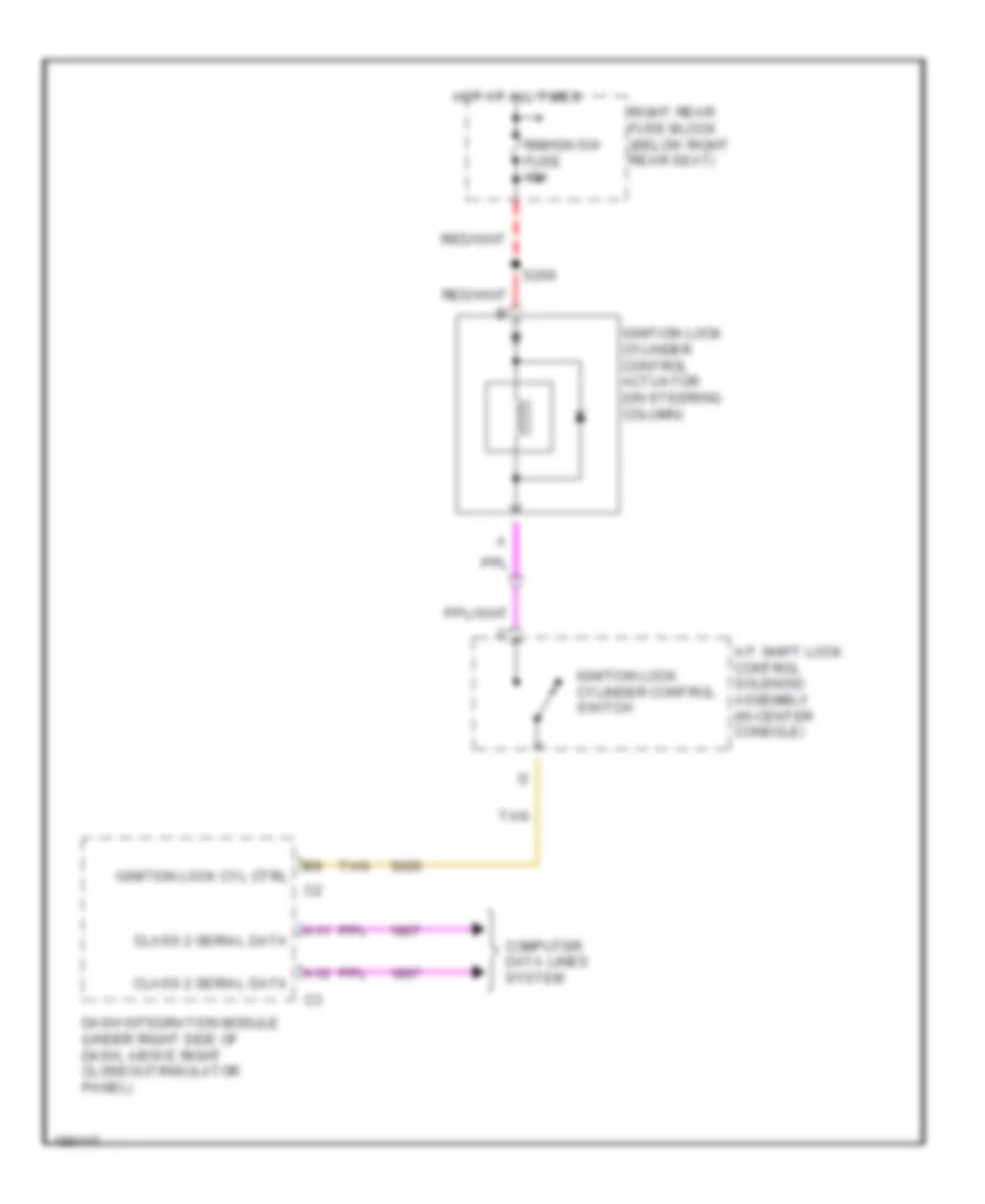
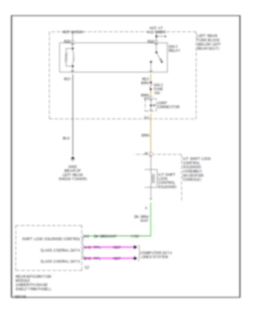
- Shift interlock system
- Sp201
- Tan
- Twilight sentinal delay signal
- Underhood fuse block (right front of engine compt)
- Voltage check fuse 10a
- Warning system
- Washer fluid level signal
- Wiper switch on signal
- Wiper/washer system
Rear Integration Module Wiring Diagram for Cadillac CTS V 2004
List of elements for Rear Integration Module Wiring Diagram for Cadillac CTS V 2004:
- 5007 (or 5053)
- A/t shift lock ctrl solenoid control
- A10
- A11
- A12
- Anti-lock brakes system
- Anti-theft system
- B10
- B11
- B12
- Battery
- Class 2 serial data
- Computer data lines system
- Courtesy lamp control
- Courtesy lamp ctrl
- Courtesy lamp relay ctrl
- Defogger system
- Driver heated seat high/low signal
- Exterior lights system
- G401 (rear of right rear shock tower)
- Ground
- Hot at all times
- Htd seat ctrl module status signal
- Ignition 1 voltage
- Interior lights system
- Intrusion sensor alarm on signal
- Intrusion sensor armed signal
- Joint connector
- Pass htd seat ctrl module status signal
- Passenger heated seat high/low signal
- Pnk
- Power distribution system
- Power tops system
- Rap relay coil control
- Rear compt lid ajar switch sig
- Rear defog relay ctrl
- Rear integration module (under package shelf trim panel)
- Reverse relay ctrl
- Reverse signal (or winter mode signal)
- Right rear fuse block (below right rear seat)
- Rim fuse 10a
- Rim/ign sw fuse 10a
- S21
- S22
- Seats system
- Shift interlock system
- Sport mode switch signal
- Tan
- Theft deterrent system
- Traction control switch signal
- Transmissions system
- Trunk release relay ctrl
- Trunk, tailgate, fuel doors system
- Vehicle speed signal
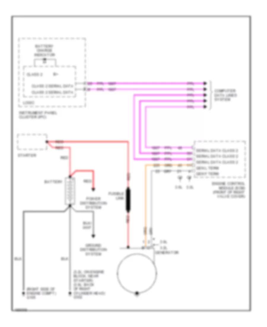
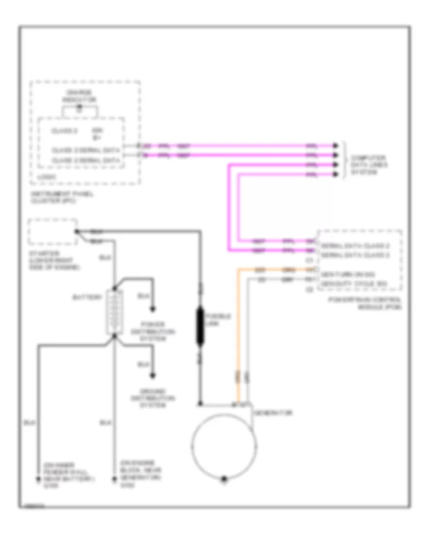
COMPUTER DATA LINES
Computer Data Lines Wiring Diagram for Cadillac CTS V 2004
List of elements for Computer Data Lines Wiring Diagram for Cadillac CTS V 2004:
- (behind the left kick panel) g200
- (in engine harness, 26 cm from starter motor connector)
- 3.2l
- 3.2l 3.6l
- 3.2l a/t
- 3.6l
- 3.6l a/t
- 5.7l
- A/t
- A11
- A12
- A13
- A14
- Audio amplifier (left side of trunk)
- B11
- B12
- Base
- Class 2 serial data
- Dash integration module (dim) (under right side of dash above right closeout/ insulator panel)
- Data link connector (under left side of dash)
- Digital radio receiver (left side of rear package shelf)
- Dim/aldl fuse 10a
- Driver door module (on left door, under door trim)
- Driver door switch assembly (ddsa)
- Driver's memory seat module (under driver's seat)
- E10
- Electronic brake control module (ebcm) (at right front corner of engine compt)
- Engine control module (ecm) (3.6l: front of right valve cover)
- Except
- F14
- Front passenger door module (on right front door, under door trim panel)
- H speed gmlan data bus +
- H speed gmlan data bus -
- Hot at all times
- Hvac control module (behind center of dash, below radio)
- If equipped
- Inflatable restraint sensing & diagnostic module (under center console)
- Instrument panel cluster (ipc)
- Key word 2000 serial data
- Left headlamp
- Left rear door module (under door trim panel)
- Luxury
- Powertrain control module
- Radio
- Radio antenna module (above headliner, near rear window)
- Rear integration module (rim) (under package shelf trim panel)
- Right headlamp
- Right rear door module (on right rear door, under door trim panel)
- S114
- S119
- S154 (in engine harness, approxi- mately 18 cm from tcm connector)
- S200
- S201
- Sp200 (in right front of passenger compt, under dash, above steering column)
- Sp300 (in passenger comp, near left side of driver's seat)
- Sp303 (in passenger compt, near right rear fuse block)
- Theft deterrent control module (at top of steering column)
- Transmission control module (tcm) (at right front of engine compt)
- Tv antenna module
- U2k/u2l
- U2y/u2x
- Underhood fuse block (right front of engine compt)
- Vehicle communication interface module (vcim) (in rear compt, behind right strut tower)
- W/ automatic headlamps control leveling system
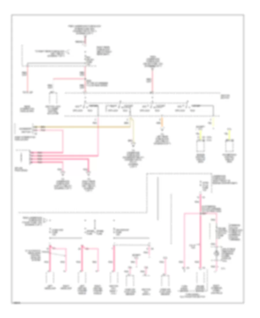
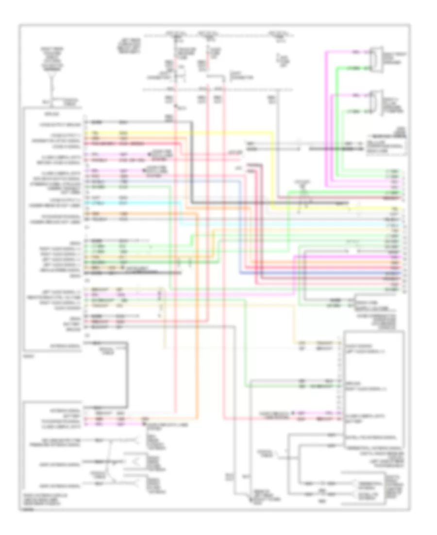
COOLING FAN
Cooling Fan Wiring Diagram for Cadillac CTS V 2004
List of elements for Cooling Fan Wiring Diagram for Cadillac CTS V 2004:
- (in engine harness under throttle body, 11.5 cm towards the right) (3.6l) s148
- (left rear side of engine) g100
- (near left front strut tower) g101
- (on right body rail, near right headlamp) g104
- (or 470)
- 3.2l
- 3.2l 3.6l
- 5.7l
- After boil coolant pump (on right side of engine block)
- After boil fuse 10a
- After boil relay (3.2l)
- Computer data lines system
- Coolant bypass valve solenoid
- Coolant level sw
- Coolant level switch (in left front corner of coolant surge tank)
- E10
- E11
- Ect sensor signal
- Engine control module (ecm) (3.6l front of right valve cover)
- Engine coolant low level
- Engine coolant temperature (ect) sensor (3.2l rear of intake manifold) (3.6l side of left cylinder head) (5.7l front of left cylinder head)
- Except 5.7l
- Hi fan fuse 30a
- Hi speed fan relay
- High speed fan relay ctrl
- Hot at all times
- Hot in on or start
- Htr vlv/cltch fuse 10a
- Hvac control module (behind center of dash, below radio)
- Left cooling fan (left side of radiator)
- Lo speed fan relay
- Logic
- Low fan fuse 30a
- Low reference
- Low speed fan relay ctrl
- Main relay
- Main relay ctrl
- Message center
- Pnk
- Powertrain control module (pcm)
- R11
- R12
- R13
- R14
- R15
- R16
- R17
- R18
- R19
- R20
- R21
- R22
- R39
- R40
- R41
- R42
- R47
- R48
- R49
- R50
- Radio
- Relay control
- Right cooling fan (right side of radiator)
- Right rear fuse block (below right rear seat)
- S/p fan relay
- S111 (3.2l) (in engine harness, 26 cm from starter motor connector)
- Serial data
- Tan
- Underhood fuse block (right front of engine compartment)
CRUISE CONTROL
3.2L VIN N
3.2L VIN N, Cruise Control Wiring Diagram for Cadillac CTS V 2004
List of elements for 3.2L VIN N, Cruise Control Wiring Diagram for Cadillac CTS V 2004:
- left rear side of engine) g100
- (right front corner of engine compt) sp102
- 3.2l
- 3.6l
- 3.6l
- 5 volt reference
- Bpp sensor signal
- Brake pedal position sensor (near top of brake pedal)
- C12
- C13
- Class 2 serial data
- Clutch pedal position (cpp) sensor (m/t)
- Computer data lines system
- Cpp switch signal
- Cruise control switch
- Cruise control switch signal
- Cruise indicator
- Electronic brake control module (ebcm) (at right front corner of engine compartment)
- Engine control module (ecm) (front of right valve cover)
- Extended travel brake sw sig
- G104 (on right body rail, near right headlamp)
- Hot at all times
- Hot in run or start
- Htr vlv/ cltch fuse 10a
- Ign 1 relay
- Ignition
- Instrument panel cluster (ipc)
- Logic
- Low reference
- Main relay
- Off
- Pnk
- R/a
- R43
- R44
- R45
- R46
- R48
- R49
- S132
- S207
- Sp102 (right front corner of engine compt)
- Sp200 (in right front of passenger compartment, under dash, above steering column)
- Strg ctls fuse 10a
- Tac motor control-1
- Tac motor control-2
- Tan
- Tcm/ ipc fuse 15a
- Throttle actuator control (tac) motor
- Throttle body assembly
- Throttle position (tp) sensor
- Tos fuse 10a
- Tp sensor 1 signal
- Tp sensor 2 signal
- Turn signal/ multi-function switch
- Underhood fuse block (right front of engine compt)
- Vehicle speed sensor (vss) (m/t) (on right rear of transmission)
- Vehicle speed sensor signal
3.6L VIN 7
3.6L VIN 7, Cruise Control Wiring Diagram for Cadillac CTS V 2004
List of elements for 3.6L VIN 7, Cruise Control Wiring Diagram for Cadillac CTS V 2004:
- left rear side of engine) g100
- (right front corner of engine compt) sp102
- 3.2l
- 3.6l
- 3.6l
- 5 volt reference
- Bpp sensor signal
- Brake pedal position sensor (near top of brake pedal)
- C12
- C13
- Class 2 serial data
- Clutch pedal position (cpp) sensor (m/t)
- Computer data lines system
- Cpp switch signal
- Cruise control switch
- Cruise control switch signal
- Cruise indicator
- Electronic brake control module (ebcm) (at right front corner of engine compartment)
- Engine control module (ecm) (front of right valve cover)
- Extended travel brake sw sig
- G104 (on right body rail, near right headlamp)
- Hot at all times
- Hot in run or start
- Htr vlv/ cltch fuse 10a
- Ign 1 relay
- Ignition
- Instrument panel cluster (ipc)
- Logic
- Low reference
- Main relay
- Off
- Pnk
- R/a
- R43
- R44
- R45
- R46
- R48
- R49
- S132
- S207
- Sp102 (right front corner of engine compt)
- Sp200 (in right front of passenger compartment, under dash, above steering column)
- Strg ctls fuse 10a
- Tac motor control-1
- Tac motor control-2
- Tan
- Tcm/ ipc fuse 15a
- Throttle actuator control (tac) motor
- Throttle body assembly
- Throttle position (tp) sensor
- Tos fuse 10a
- Tp sensor 1 signal
- Tp sensor 2 signal
- Turn signal/ multi-function switch
- Underhood fuse block (right front of engine compt)
- Vehicle speed sensor (vss) (m/t) (on right rear of transmission)
- Vehicle speed sensor signal
5.7L VIN P
5.7L VIN P, Cruise Control Wiring Diagram for Cadillac CTS V 2004
List of elements for 5.7L VIN P, Cruise Control Wiring Diagram for Cadillac CTS V 2004:
- (rear of right cylinder head) g142
- 5 volt reference
- 5v ref
- Anti-lock brakes system
- Bpp sensor signal
- Brake pedal position sensor (near top of brake pedal)
- C12
- C13
- C208
- Class 2 serial data
- Clutch pedal position (cpp) sensor
- Coast
- Computer data lines system
- Cpp switch signal
- Cruise control switch fuse 2a
- Cruise indicator
- Cruise switch
- Electronic brake control module (ebcm) (at right front corner of engine compartment)
- Extended travel brake sw sig
- G104 (on right body rail, near right headlamp)
- Ground
- Hot at all times
- Hot in run or start
- Htr vlv/ cltch fuse 10a
- Ign 1 relay
- Ignition
- Ignition 1 voltage
- Inflatable restraint steering wheel module coil (below inflatable restraint steering wheel module)
- Instrument panel cluster (ipc)
- Logic
- Low erf
- Low ref
- Low reference
- On sw sig
- Pnk
- Powertrain control module (pcm)
- R43
- R44
- R45
- R46
- Resume/ accel
- Resume/acc sw sig
- Right steering wheel controls
- S207
- Set
- Set/coast sw sig
- Sp200 (in right front of passenger compartment, under dash, above steering column)
- Steering column fuse block (taped to steering column harness)
- Steering wheel control switch fuse 2a
- Strg ctls fuse 10a
- Tac motor ctrl-1
- Tac motor ctrl-2
- Tcm/ ipc fuse 15a
- Throttle actuator control (tac) module (right front of engine compt)
- Throttle actuator control (tac) motor (right front of engine compt)
- Throttle position (tp) sensor (right side of throttle body)
- Tp sens 1 sig
- Tp sens 2 sig
- Tp sensor 1
- Tp sensor 2
- Underhood fuse block (right front of engine compt)
- Vehicle speed sensor (vss) (on left rear of transmission)
- Vss high signal
- Vss low signal
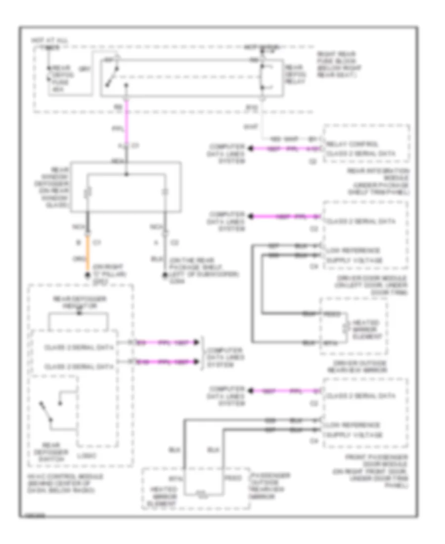
DEFOGGERS
Defoggers Wiring Diagram for Cadillac CTS V 2004
List of elements for Defoggers Wiring Diagram for Cadillac CTS V 2004:
- (on right "c" pillar) g303
- A12
- Class 2 serial data
- Computer data lines system
- Driver door module (on left door, under door trim)
- Driver outside rearview mirror
- E10
- Feed
- Front passenger door module (on right front door, under door trim panel)
- Heated mirror element
- Hot at all times
- Hot in run
- Hvac control module (behind center of dash, below radio)
- Logic
- Low reference
- Nca
- Passenger outside rearview mirror
- R10
- Rear defog fuse 40a
- Rear defog relay
- Rear defogger indicator
- Rear defogger switch
- Rear integration module (under package shelf trim panel)
- Rear window defogger (on rear window glass)
- Relay control
- Right rear fuse block (below right rear seat)
- Rtn
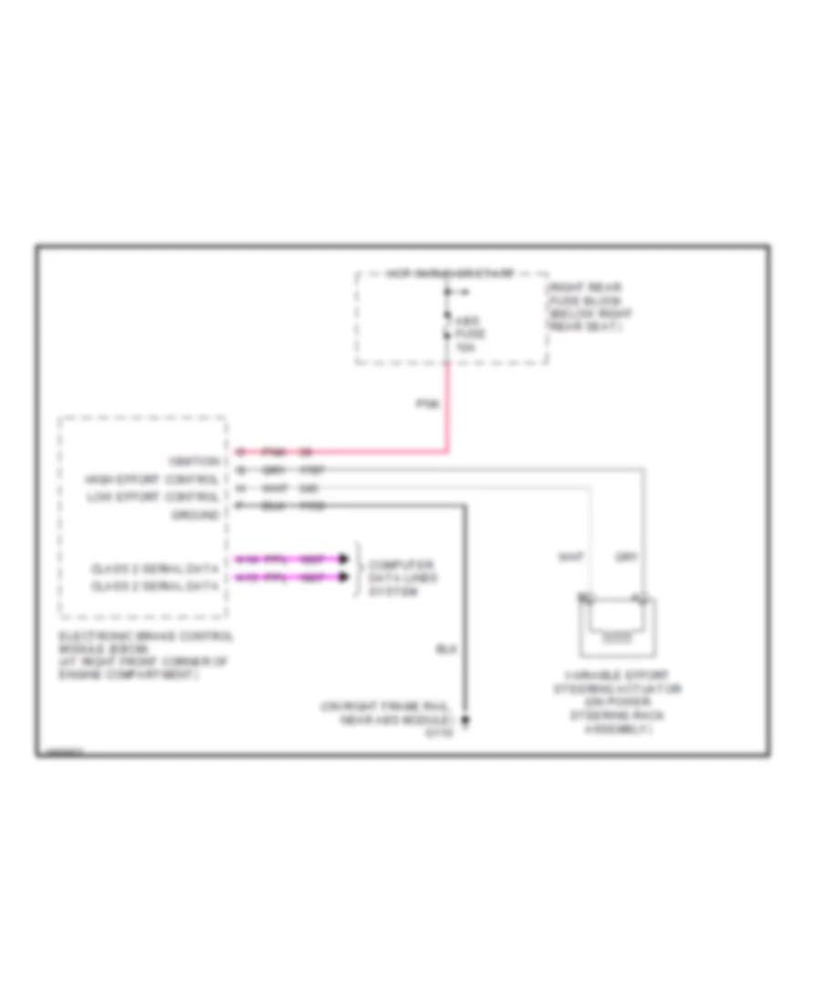
ELECTRONIC POWER STEERING
Electronic Power Steering Wiring Diagram for Cadillac CTS V 2004
List of elements for Electronic Power Steering Wiring Diagram for Cadillac CTS V 2004:
- (on right frame rail, near abs module) g110
- A13
- A14
- Abs fuse 10a
- Class 2 serial data
- Computer data lines system
- Electronic brake control module (ebcm) (at right front corner of engine compartment)
- Ground
- High effort control
- Hot in run or start
- Ignition
- Low effort control
- Pnk
- Right rear fuse block (below right rear seat)
- Variable effort steering actuator (on power steering rack assembly)
ENGINE PERFORMANCE
3.2L VIN N
3.2L VIN N, Engine Performance Wiring Diagram (1 of 3) for Cadillac CTS V 2004
List of elements for 3.2L VIN N, Engine Performance Wiring Diagram (1 of 3) for Cadillac CTS V 2004:
- (in engine harness, 120 cm from ho2s 21)
- (in fuel injector harness, near c112)
- (left rear of intake plenum) intake manifold runner control solenoid
- (near ignition coils)
- +5v ref
- Case ground
- Ckp hi
- Ckp low
- Cmp sig
- Coil 1 ctrl
- Coil 2 ctrl
- Coil 3 ctrl
- Coil 4 ctrl
- Coil 5 ctrl
- Coil 6 ctrl
- Crankshaft position sensor
- Dk red/
- Ect sens
- Elec- tronic ignition module (bank 2)
- Electronic ignition module (bank 1)
- Engine control module (front of right valve cover)
- Evap purge
- Fuel inj 1
- Fuel inj 2
- Fuel inj 4
- Fuel inj 5
- Fuel inj 6
- Fuel injectors
- G100 (near starter motor)
- G107
- Heated oxygen sensor bank 1 sensor 1 (on right exhaust pipe)
- Heated oxygen sensor bank 1 sensor 2 (on right catalytic converter)
- Heated oxygen sensor bank 2 sensor 1 (on left exhaust pipe)
- Heated oxygen sensor bank 2 sensor 2 (on left catalytic converter)
- Ho2s 1,1 htr
- Ho2s 1,1 low
- Ho2s 1,1 sig
- Ho2s 1,2 hi
- Ho2s 1,2 htr
- Ho2s 1,2 lo
- Ho2s 2,1 htr
- Ho2s 2,1 low
- Ho2s 2,1 sig
- Ho2s 2,2 hi
- Ho2s 2,2 lo
- Iat sig
- Inj 3 ctrl
- Intk out 1
- Intk out 2
- Knock sensor (bank 1) (right side of engine)
- Knock sensor (bank 2) (left side of engine)
- Ks1 sig
- Ks2 sig
- Lo ref
- Low ref
- Maf sig
- Mass airflow sensor (right side of air cleaner)
- Nca
- Oil pres sig
- Pnk
- S108
- S111
- Shld ground
- Tac mtr ctrl
- Tan
- Tan/red
- To spark plugs
- Tps sens 1
- Tps sens 2
3.2L VIN N, Engine Performance Wiring Diagram (2 of 3) for Cadillac CTS V 2004
List of elements for 3.2L VIN N, Engine Performance Wiring Diagram (2 of 3) for Cadillac CTS V 2004:
- (in front of underhood fuse box)
- Camshaft position sensor (left front of engine)
- Canister vent fuse 10a
- Ecm fuse 15a
- Ecm/tcm fuse 10a
- Engine coolant temperature sensor (top rear of intake manifold)
- Engine oil pressure sensor (aboe oil filter)
- Evap canister purge solenoid (right side of engine)
- Even inj/ coil fuse 15a
- Fuel pump relay
- Fuse a 15a
- G100 (near starter motor)
- G104 (near right head- lamp)
- G401 (rear of right shock tower)
- Hot at all times
- Hot in run or start
- Ign 1 relay
- Ign mod/ maf fuse 15a
- Intake manifold tuning valve solenoid (rear side of intake duct)
- Main relay
- Odd inj/ coil fuse 15a
- Pnk
- Post fuse 15a
- Pre 02/ cam fuse 15a
- R36
- R37
- R38
- R40
- R43
- R44
- R45
- R46
- R47
- R48
- R49
- R50
- Right rear fuse block (below right rear seat)
- S132
- Sp102
- Tan
- Tcm/ ipc fuse 15a
- Theft fuse 7.5a
- Throttle position sensor (top right front of engine)
- Tos fuse 10a
- Under- hood fuse block (left front of eng compt)
- Vehicle speed sensor (m/t) (near rear of transmission assembly)
3.2L VIN N, Engine Performance Wiring Diagram (3 of 3) for Cadillac CTS V 2004
List of elements for 3.2L VIN N, Engine Performance Wiring Diagram (3 of 3) for Cadillac CTS V 2004:
- (engine harn, 160 cm from ecm ground)
- (in rear compt lid harn, 237 cm from c401)
- +5v ref
- 1786 (or 1035)
- 2000 ser dat
- A/c pres
- A/c rly ctrl
- A/c system
- A/t
- Acc
- Acc volt
- Accelerator pedal
- Anti-lock brakes system
- App 2 sig
- App sens1
- Automatic transmission manual shift shaft switch assembly
- Bas rly ctrl
- Battery
- Charging system
- Class 2 data
- Computer data lines system
- Cooling fans system
- Cpp sw sig
- Crank
- Cruise control system
- Data bus
- Data link connector (under left side of dash)
- Del tor sig
- Eng spd sig
- Engine control module (front of right valve cover)
- Engine speed
- Evap canister vent solenoid (above rear differential)
- Evap ctrl
- Ext brk sig
- F lev sig
- Fuel lev sns
- Fuel level sensor
- Fuel pump/ sender assembly
- Fuel tank pressure sensor (in fuel tank)
- G100 (near starter motor)
- G401 (rear of right shock tower)
- Gen on sig
- Gen signal
- Gmlan data
- Hot at all times
- Ign 1
- Ign 1 volt
- Ign voltage
- Ignition switch
- Instrument panel cluster
- Lan bus +
- Lan bus -
- Logic
- Low red
- Low ref
- M/t
- Main rly ctrl
- Malfunction indicator lamp
- Mil ctrl
- Off/ lock
- P/n sig
- Pnk
- Position sensor (above accelerator pedal)
- Req torq
- Res/accel
- Rly coil ctrl
- Rly ctrl
- Run
- S114
- S400
- Secondary fuel sender assembly
- Ser data
- Sound system
- Sp102 (in front of underhood fuse box)
- Start
- Starting system
- Tan
- Tnk pres sig
- Trac ctrl
- Transmission control module (right front side of engine compt)
- Vss
- Vss signal
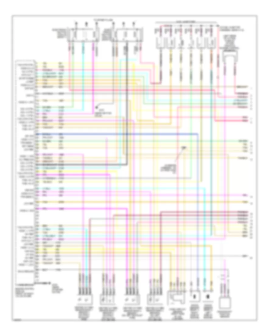
3.6L VIN 7
3.6L VIN 7, Engine Performance Wiring Diagram (1 of 4) for Cadillac CTS V 2004
List of elements for 3.6L VIN 7, Engine Performance Wiring Diagram (1 of 4) for Cadillac CTS V 2004:
- (engine harn, 20 cm from c1 conn of pcm)
- (inj harn, 10 cm from c121)
- (left rear of intake plenum) intake manifold runner control solenoid
- +5v
- +5v ref
- Baro sig
- Charging system
- Ckp hi
- Ckp sens lo
- Cmp sig
- Cmp sol ctrl
- Crankshaft position sensor
- Drain
- Ect sig
- Engine control module (front of right valve cover)
- Engine oil level/temperature sensor (in oil pan)
- Engine oil pressure sensor (in oil filter housing)
- Evap sol ctrl
- Fuel injectors
- G133 (right front of engine)
- Gen fdc sig
- Gen to sig
- Heated oxygen sensor bank 1 sensor 1 (on right exhaust pipe)
- Heated oxygen sensor bank 1 sensor 2 (on right catalytic converter)
- Heated oxygen sensor bank 2 sensor 1 (on left exhaust pipe)
- Heated oxygen sensor bank 2 sensor 2 (on left catalytic converter)
- Ho2s hi sig
- Ho2s lo ctrl
- Ho2s lo sig
- Ho2s pmp ct
- Ic 1 sig
- Ic 2 ctrl
- Ic 3 ctrl
- Ic 4 sig
- Ic 5 ctrl
- Ic 6 ctrl
- Imrc sol ctrl
- Inj 1 ctrl
- Inj 2 ctrl
- Inj 3 ctrl
- Inj 4 ctrl
- Inj 5 ctrl
- Inj 6 ctrl
- Knock sensor (bank 1) (right side of engine)
- Knock sensor (bank 2) (left side of engine)
- Ks 1 sig
- Ks 2 sig
- Low ref
- Nca
- Oil lev sig
- Oil pres sig
- Oil tmp sig
- Pnk
- S140
- Tac mtr ctrl
- Tan
- Tan a
- Tp sig
- Tp2 sig
3.6L VIN 7, Engine Performance Wiring Diagram (2 of 4) for Cadillac CTS V 2004
List of elements for 3.6L VIN 7, Engine Performance Wiring Diagram (2 of 4) for Cadillac CTS V 2004:
- (engine harn 24.5 cm from ect sensor)
- (engine harn, 15 cm from coil 1)
- (engine harn, 15 cm from coil 5)
- (left rear of eng)
- Canister vent fuse 10a
- Ecm fuse 15a
- Ecm/tcm fuse 10a
- Even inj/ coil fuse 15a
- Fuel pump relay
- Fuse a 15a
- G104 (near right head- lamp)
- G130 (rear of right cyl head)
- G131
- G401 (rear of right shock tower)
- Hot at all times
- Hot in run or start
- Ign 1 relay
- Ign mod/ maf fuse 15a
- Ignition coil 1 (top right of engine)
- Ignition coil 2 (top left of engine)
- Ignition coil 3 (top right of engine)
- Ignition coil 4 (top left of engine)
- Ignition coil 5 (top right of engine)
- Ignition coil 6 (top left of engine)
- Main relay
- Nca
- Odd inj/ coil fuse 15a
- Pnk
- Post fuse 15a
- Pre 02/ cam fuse 15a
- R36
- R37
- R38
- R40
- R43
- R44
- R45
- R46
- R47
- R48
- R49
- R50
- Right rear fuse block (below right rear seat)
- S142
- S144
- S145
- S146
- S149
- S150
- Spark plug
- Tan
- Tcm/ ipc fuse 15a
- Theft fuse 7.5a
- Under- hood fuse block (left front of eng compt)
3.6L VIN 7, Engine Performance Wiring Diagram (3 of 4) for Cadillac CTS V 2004
List of elements for 3.6L VIN 7, Engine Performance Wiring Diagram (3 of 4) for Cadillac CTS V 2004:
- (front of left cyl head) camshaft position actuator solenoid (exhaust bank 2)
- (front of left cyl head) camshaft position actuator solenoid (intake bank 2)
- (front of left cyl head) camshaft position sensor (exhaust bank 1)
- (front of left cyl head) camshaft position sensor (intake bank 2)
- (front of right cyl head) camshaft position actuator solenoid (exhaust bank 1)
- (front of right cyl head) camshaft position actuator solenoid (intake bank 1)
- (front of right cyl head) camshaft position sensor (exhaust bank 1)
- (front of right cyl head) camshaft position sensor (intake bank 1)
- +5v
- A/c refrigerant pressure sensor (near left front strut tower)
- Barometric pressure sensor (top rear of engine)
- Engine coolant temperature sensor (top rear of intake manifold)
- Evap canister purge solenoid (right side of engine)
- Low ref
- Mass airflow sensor (right side of air cleaner)
- Pnk
- S148
- Signal
- Tan
- Throttle position sensor (top right front of engine)
3.6L VIN 7, Engine Performance Wiring Diagram (4 of 4) for Cadillac CTS V 2004
List of elements for 3.6L VIN 7, Engine Performance Wiring Diagram (4 of 4) for Cadillac CTS V 2004:
- (front of right cyl head)
- (fuel tank harn, 40 cm from c420)
- +5v ref
- +5v ref a
- +5v ref c
- A/c ref pres
- A/c system
- Acc
- Acc volt
- Accelerator pedal
- Anti-lock brake system
- App sens 2 sig
- App sens sig
- Automatic transmission manual shift shaft switch assembly
- Battery +
- Brk sw sig
- Cc sw sig
- Class 2 data
- Clu rly ctrl
- Computer data lines system
- Cooling fans system
- Crank volt
- Cruise control system
- Delv torque sig
- Eng spd sig
- Engine control module (front of right valve cover)
- Engine speed
- Evap canister vent solenoid (above rear differential)
- Evap sol ctrl
- Fan rly ctrl
- Fuel lev sens
- Fuel lev sig
- Fuel level sensor
- Fuel pump/ sender assembly
- Fuel tank pressure sensor (in fuel tank)
- G132
- G401 (rear of right shock tower)
- Gmlan bus
- Ho2s hi sig
- Ho2s lo ctrl
- Ho2s lo sig
- Hot at all times
- Iat sig
- Ign 1 volt
- Ignition switch
- Instrument panel cluster
- Lan bus +
- Lan bus -
- Logic
- Low ref
- Maf sig
- Main rly ctrl
- Malfunction indicator lamp
- Mil ctrl
- Off/ lock
- P/n sig
- Pnk
- Position sensor (above accelerator pedal)
- Req torq sig
- Rly coil ctrl
- Rly coil supp
- Rly ctrl
- Run
- S156
- S400
- Secondary fuel sender assembly
- Ser data bus
- Sound system
- Sp102 (in front of underhood fuse box)
- Start
- Starting system
- Tan
- Tank pres sig
- Tc data sig
- Transmission control module (right front side of engine compt)
- Vss
5.7L VIN P
5.7L VIN P, Engine Performance Wiring Diagram (1 of 4) for Cadillac CTS V 2004
List of elements for 5.7L VIN P, Engine Performance Wiring Diagram (1 of 4) for Cadillac CTS V 2004:
- (center of eng, below intake manifold)
- (engine harn, 15.5 cm from c101)
- (engine harn, 20 cm from underhood fuse block breakout)
- (rear of left cyl head)
- +5v ref a
- +5v ref b
- 5v ref
- Acc voltage
- Anti-lock brake system
- Ckp sen b+
- Ckp sen sig
- Cmp sen sig
- Computer data lines system
- Cooling fans system
- Cpp sw sig
- Ect sen sig
- Eng cool fan rly 1 ctrl
- Engine coolant temperature sensor (left side of of eng, below generator)
- Extended travel brake sw
- Fuel inj n04 ctrl
- Fuel inj n06
- Fuel inj n07 ctrl
- Fuel inj no1
- Fuel inj no2 ctrl
- Fuel inj no3 ctrl
- Fuel inj no5 ctrl
- Fuel inj no8 ctrl
- Fuel injectors
- G140
- G141 (rear of left cylinder head)
- G142 (rear of right cylinder head)
- Ground
- Heated oxygen sensor, bank 1 sensor 1 (forward of catalytic converter)
- Heated oxygen sensor, bank 1 sensor 2 (rear of catalytic converter)
- Heated oxygen sensor, bank 2 sensor 1 (forward of catalytic converter)
- Heated oxygen sensor, bank 2 sensor 2 (rear of catalytic converter)
- Ho2s sig hi bank 1 sen1
- Ho2s sig hi bank1 sen1
- Ho2s sig hi bank2 sen1
- Ho2s sig hi bank2 sen2
- Ho2s sig lo bank1 sen1
- Ho2s sig lo bank1 sen2
- Ho2s sig lo bank2 sen1
- Ho2s sig lo bank2 sen2
- Knock sen sig 1
- Knock sen sig 2
- Knock sensor
- Low oil level sw sig
- Low ref
- Nca
- Pcm gnd
- Pnk
- Powertrain control module (behind right front fender)
- Request torque sig
- Rly coil ctrl
- S160
- S161
- S162
- S169
- S170
- Serial data
- Skip shift sol ctrl
- Starting system
- Tan
- Tan a
- Uart serial data
5.7L VIN P, Engine Performance Wiring Diagram (2 of 4) for Cadillac CTS V 2004
List of elements for 5.7L VIN P, Engine Performance Wiring Diagram (2 of 4) for Cadillac CTS V 2004:
- (rear compt lid harn, 237 cm from c401)
- (rear of right shock tower) g401
- Canister vent fuse 10a
- Ecm/tcm fuse 10a
- Evaporative emission canister purge solenoid valve (top left side of eng, on intake manifold)
- Even inj/ coil fuse 15a
- Fuel level sensor
- Fuel pump motor fuse 20a r37
- Fuel pump relay
- Fuel pump/ sender assembly
- G104 (near right head- lamp)
- G401 (rear of right shock tower)
- Hot at all times
- Hot in run or start
- Ign 1 relay
- Ign mod/ maf fuse 15a
- Main relay
- Manifold absolute pressure sensor (on top rear of intake manifold)
- Odd inj/ coil fuse 15a
- Pnk
- Post fuse 15a
- Pre 02/ cam fuse 15a
- R36
- R38
- R40
- R43
- R44
- R45
- R46
- R47
- R48
- R49
- R50
- Right rear fuse block (below right rear seat)
- S400
- Secondary fuel sender assembly
- Sp102 (right front corner of engine compt)
- Tan
- Tcm/ ipc fuse 15a
- Theft fuse 7.5a
- Tos fuse 10a
- Transmission fluid temperature sensor (in transmission)
- Under- hood fuse block (left front of eng compt)
5.7L VIN P, Engine Performance Wiring Diagram (3 of 4) for Cadillac CTS V 2004
List of elements for 5.7L VIN P, Engine Performance Wiring Diagram (3 of 4) for Cadillac CTS V 2004:
- (attached to pcm below battery) throttle actuator control module
- (ign coil module, on left valve cover)
- (lower right side of eng) crankshaft position sensor
- (on left side of throttle body) throttle actuator control motor
- (on left side of transmission) reverse lockout solenoid
- (on right side of throttle body) throttle position sensor
- (on top of accelerator pedal, part of mounting bracket) accelerator pedal position sensor
- (rear of right cylinder head)
- (top center rear of eng) camshaft position sensor
- (under vehicle, on left side of transmission) skip shift solenoid
- +5v ref
- 5v ref
- A/c refrigerant pressure sensor (near left front strut tower)
- Anti-lock brake system
- App no1 sig
- App no2 sig
- App no3 sig
- Bas rly supp
- Cruise control system
- Engine oil level/temper- ature sensor (in oil pan)
- Engine oil pressure sensor (on top center rear of eng)
- G141 (rear of left cylinder head)
- G142
- G142 (rear of right cylinder head)
- Gnd
- Ign
- Ign 1
- Ignition coil/module 1 (top of cylinder)
- Ignition coil/module 3 (top of cylinder)
- Ignition coil/module 5 (top of cylinder)
- Ignition coil/module 7 (top of cylinder)
- Low ref
- On/off sig
- Plug spark
- Pnk
- Red
- Red c ign ctrl
- Ref lo
- Res/acc sig
- S163
- S165
- S167
- Set/coast sig
- Spark plug
- Tac ctrl no1
- Tac ctrl no2
- Tan
- Tan a
- Tps no1 sig
- Tps no2 sig
- Uart ser data
5.7L VIN P, Engine Performance Wiring Diagram (4 of 4) for Cadillac CTS V 2004
List of elements for 5.7L VIN P, Engine Performance Wiring Diagram (4 of 4) for Cadillac CTS V 2004:
- (ign coil module, on left valve cover)
- (inside right rear wheelhouse panel) evaporative emission canister vent solenoid valve
- (on air intake assembly) mass air flow sensor
- (on right of differential) vehicle speed sensor
- +12v ref
- A gnd
- A tan
- A/c clutch rly ctrl
- A/c refrig press sen sig
- A/c system
- Acc
- Alt term l
- Anti-lock brake system
- B ref lo
- Charging system
- Cooling fans system
- Crank voltage
- D ign
- D pnk
- Eng oil press sen sig
- Eng speed (tach) out sig
- Engine speed
- Evap can purge sol ctrl
- Evap can vent valve ctrl
- Fuel level sen sig
- Fuel levl sen sig (second)
- Fuel pump rly ctrl
- Fuel tank press sen sig
- Fuel tank pressure sensor (in right fuel tank)
- G140 (rear of left cyl head)
- G142 (rear of right cylinder head)
- Gen field duty sig
- Ground
- Hi spd fan rly ctrl
- Ho2s htr low ctrl
- Hot at all times
- Iat sen sig
- Ign ctrl 1
- Ign ctrl 2
- Ign ctrl 3
- Ign ctrl 4
- Ign ctrl 5
- Ign ctrl 6
- Ign ctrl 7
- Ign ctrl 8
- Ignition coil/ module 2 (top of cylinder)
- Ignition coil/ module 4 (top of cylinder)
- Ignition coil/ module 6 (top of cylinder)
- Ignition coil/ module 8 (top of cylinder)
- Ignition switch
- Instrument panel cluster
- Logic
- Low ref
- Maf sen sig
- Main rly ctrl
- Malfunction indicator lamp
- Map sen sig
- Mil ctrl
- Off/ lock
- Oil temp
- Plug spark
- Pnk
- Powertrain control module (behind right front fender)
- Red
- Reverse inhibit sol ctrl
- Run
- S164
- S166
- S168
- Sound system
- Spark plug
- Ss ind
- Ss lamp ctrl
- Start
- Starting system
- Tan
- Tft sen sig
- Torque delivered
- Vehicle speed out
- Vss
- Vss ref lo
- Vss sig hi
EXTERIOR LIGHTS
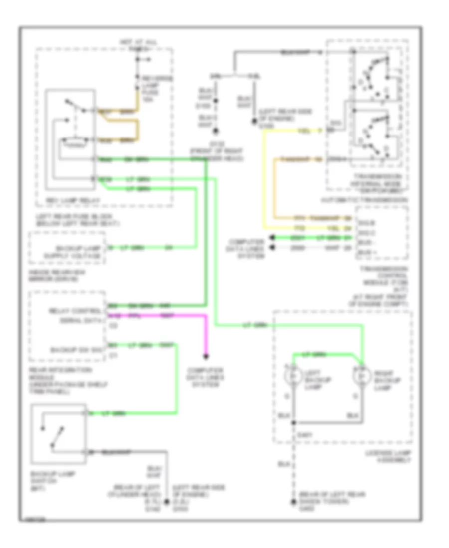
Back-up Lamps Wiring Diagram for Cadillac CTS V 2004
List of elements for Back-up Lamps Wiring Diagram for Cadillac CTS V 2004:
- (left rear side of engine) (3.2l) g100
- (left rear side of engine) g100
- (rear of left cylinder head) (5.7l) g142
- (rear of left rear shock tower) g402
- 3.2l
- 3.6l
- A12
- Automatic transmission
- Backup lamp switch (m/t)
- Backup sw sig
- Bus +
- Bus -
- Computer data lines system
- G132 (front of right cylinder head)
- Hot at all times
- Inside rearview mirror (isrvm)
- Left backup lamp
- Left rear fuse block (below left rear seat)
- License lamp assembly
- R36
- R37
- R38
- R40
- Rear integration module (under package shelf trim panel)
- Relay control
- Rev lamp relay
- Reverse lamp fuse 10a
- Right backup lamp
- S155
- S401
- Serial data
- Sig a
- Sig b
- Sig c
- Transmission control module (tcm) (a/t) (at right front of engine compt)
- Transmission internal mode switch (ims)
Exterior Lamps Wiring Diagram (1 of 2) for Cadillac CTS V 2004
List of elements for Exterior Lamps Wiring Diagram (1 of 2) for Cadillac CTS V 2004:
- (40 cm from c421) s402
- (behind the left kick panel) g200
- (not used)
- 5v ref
- A11
- A12
- Auto
- Bas rly
- Battery
- Bpp sig
- Brake pedal position (bpp) sensor (near top of brake pedal)
- C12
- C13
- Center high mounted stop lamp (chmsl)
- Class 2 serial data
- Computer data lines system
- Dash integration module (under right side of dash, above right closeout/ insulator panel)
- Dimming fuse 10a
- Drl low control
- Drl low ctrl
- Electronic brake control module (ebcm) (at right front corner of engine compartment)
- Flasher fuse 15a
- G104 (on right body rail, near right headlamp)
- G200 (behind the left kick panel)
- G402 (rear of left rear shock tower)
- Ground
- Hazard request sig
- Hazard sw sig
- Hazard sw signal
- Hazard switch
- Head
- Headlamps on sig
- Hot at all times
- Hot in run or start
- Ign 1 relay
- Interior lights system
- Left front turn signal lamp
- Left front turn signal/ fog lamp assembly
- Left license lamp
- Left turn signal voltage
- Left turn sw sig
- License lamp assembly
- Low ref
- Off
- Park
- Park lamp relay
- Park lamp rly ctrl
- Park lamp sw on sig
- Pnk
- R31
- R32
- R33
- R34
- R43
- R44
- R45
- R46
- Right front turn signal lamp
- Right front turn signal/ fog lamp assembly
- Right license lamp
- Right turn signal voltage
- Right turn sw sig
- S200
- S207
- S208
- S401
- Sp102 (right front corner of engine compartment)
- Sp200 (in right front of passenger compt, under dash, above steering column)
- Strg ctls fuse 10a
- To underhood fuse block (lt park fuse, 10a) (diagram 2 of 2)
- Turn signal/ multi-function switch
- Turn signal/hazard flasher module
- Underhood fuse block (right front of engine compt)
Exterior Lamps Wiring Diagram (2 of 2) for Cadillac CTS V 2004
List of elements for Exterior Lamps Wiring Diagram (2 of 2) for Cadillac CTS V 2004:
- (behind the left kick panel)
- (below left rear seat) left rear fuse block
- (in body harness, 30 cm from c410) s415
- (in body harness, 34 cm from c411) s416
- (on right body rail, near right headlamp) g104
- (rear of right rear shock tower) g401
- (right front of engine compt) underhood fuse block
- Bas fuse 15a
- Bas relay
- Class 2 (dim)
- Class 2 serial data
- Computer data lines system
- E trailering (not used)
- From underhood fuse block (dimming fuse, 10a) (diagram 1 of 2)
- G200
- G402 (rear of left rear shock tower)
- Ground
- Hot at all times
- Instrument panel cluster (ipc)
- Joint connector
- Left front marker lamp
- Left front park lamp
- Left headlamp (w/o automatic headlamps control leveling system)
- Left rear marker lamp
- Left rear turn signal lamp
- Left tail lamp
- Left tail lamp assembly
- Left tail/ stop lamp
- Left turn indicator
- Lights on ind
- Logic
- Lt park fuse 10a
- Message center
- Message request
- Radio
- Right front marker lamp
- Right front park lamp
- Right headlamp (w/o automatic headlamps control leveling system)
- Right rear marker lamp
- Right rear turn signal lamp
- Right tail lamp
- Right tail lamp assembly
- Right tail/ stop lamp
- Right turn indicator
- Rt park fuse 10a
- S116 (in forward lamp harness, 40 cm from right cooling fan connector)
- S201
- S24
- S25
- S26
- S27
- S405
- S406
- Turn signal on theft attempted
- W/ hid
- W/o hid
GROUND DISTRIBUTION
Ground Distribution Wiring Diagram (1 of 5) for Cadillac CTS V 2004
List of elements for Ground Distribution Wiring Diagram (1 of 5) for Cadillac CTS V 2004:
- (3.2l left rear of engine) g107
- (3.2l, 3.6l): right side of engine compartment) (5.7l): on inner fender wall, near battery) g105
- (3.6l: back of right cylinder head) (5.7l: on engine block, near generator) (3.2l: on engine block, near starter) g102
- (in cellular antenna coax cable, about 31 cm from g304) s309
- (on right
- (on right frame rail, near abs module) g110
- (on the rear package shelf, left of subwoofer) g304
- (under center console) g306
- A/c compressor clutch
- A/t
- After boil coolant pump
- Automatic transmission
- B12
- Back-up switch
- Battery
- Brake fluid level switch
- Cellular antenna
- Coolant bypass valve solenoid
- Coolant level switch
- Dash integration module (dim)
- Electronic brake control module (ebcm)
- Engine control module (ecm)
- G100 (3.2l: left rear side of engine)
- G101 (near left front strut tower)
- Headlamp washer fluid pump
- If equipped
- Ignition coil bank 1
- Ignition coil bank 2
- Inflatable restraint sensing & diagnostic module (sdm)
- Left heated washer nozzle
- M/t
- Nca
- Rear window defogger
- Right heated washer nozzle
- Transmission control module (tcm)
- Vehicle communication interface module (vcim)
- Vehicle speed sensor (vss)
- W/ high pressure headlamp washer
- W/o high pressure headlamp washer
- Washer fluid level switch
- Windshield washer fluid pump
- Windshield wiper/ washer module
- ``c" pillar) g303
Ground Distribution Wiring Diagram (2 of 5) for Cadillac CTS V 2004
List of elements for Ground Distribution Wiring Diagram (2 of 5) for Cadillac CTS V 2004:
- (right front of engine compartment) underhood fuse block
- (w/ hid) left headlamp
- (w/ hid) right headlamp
- A/t
- Accessory relay
- Auxiliary cooling fan
- Auxiliary power outlet
- B12
- Blower motor control processor
- Cigar lighter
- Electronic prndl
- From c312)
- Front headlamp leveling sensor
- Front passenger door module (fpdm)
- G104 (on right body rail, near right headlamp)
- G201 (behind right kick panel)
- Hood ajar switch
- Horn assembly
- Hvac control module
- Ign 1 relay
- Left cooling fan
- Left front fog lamp
- Left front marker lamp
- Left front turn signal lamp
- Left front turn signal/ fog lamp assembly
- Left headlamp
- M/t
- R16
- R35
- R46
- Right front fog lamp
- Right front marker lamp
- Right front turn signal lamp
- Right front turn signal/ fog lamp assembly
- Right headlamp
- Right rear door module (rrdm)
- S/p fan relay
- S202 (in the i/p harness, 48 cm from hazard switch connector)
- Trailer provisions
- W/ automatic headlamps control leveling system
- W/ hid
- W/o automatic headlamps control leveling system
- W/o hid
Ground Distribution Wiring Diagram (3 of 5) for Cadillac CTS V 2004
List of elements for Ground Distribution Wiring Diagram (3 of 5) for Cadillac CTS V 2004:
- (w/ 8-way adjuster power passenger seat) passenger seat adjuster switch
- (w/ front heater seat) front passenger heated seat module
- B12
- Dash integration module (dim)
- Data link connector (dlc)
- Driver door module (ddm)
- Driver heated seat module
- Driver seat adjuster switch
- Front passenger heated seat module
- G200 (behind left kick panel)
- G307 (on floor, left of driver's seat)
- Hazard switch
- Ignition key alarm switch
- Inflatable restraint steering wheel module coil
- Instrument panel cluster (ipc)
- Left rear door module (lrdm)
- Left steering wheel controls
- Memory seat module (msm)
- Passenger lumbar adjuster switch
- Passenger seat adjuster switch
- Right steering wheel controls
- S200 (in the i/p harness, 11.5 cm from sp200)
- S201 (in the i/p harness, 54 cm from hazard switch connector)
- S205 (in steering column harness, 12.7 cm from c202)
- S208 (in steering column harness, 12.7 cm from c202)
- S305 (in body harness, 18 cm from left rear fuse block)
- S350 (in driver seat harness, 8 cm from msm connector)
- Theft deterrent control module
- Traction control switch
- Turn signal/ hazard flasher module
- Turn signal/ multi-function switch
- W/ 8-way adjuster power passenger seat
- W/ 8-way adjuster power passenger seat, front heater seat
- W/ front heater seat
- W/ memory seat
- W/ power lumbar control seat
- W/o memory seat
- W/o power lumbar control seat
Ground Distribution Wiring Diagram (4 of 5) for Cadillac CTS V 2004
List of elements for Ground Distribution Wiring Diagram (4 of 5) for Cadillac CTS V 2004:
- (below right rear seat) right rear fuse block
- (if equipped)
- (if equipped) digital radio receiver
- (w/ navigation) traffic information receiver
- (w/ navigation) tv antenna module
- Audio amplifier
- B11
- Bas relay
- Center high mounted stop lamp (chmsl)
- Coil
- Courtesy lamps
- Driver sunshade
- Fuel pump & sender assembly
- Fuel pump relay
- G401 (rear of right rear shock tower)
- G402 (rear of left rear shock tower)
- Ign 1 relay
- Ign 3 relay
- Inside rearview mirror (isrvm)
- Left backup lamp
- Left license lamp
- Left rear fog lamp
- Left rear fuse block (below left rear seat)
- Left rear marker lamp
- Left rear tail lamp
- Left rear tail/ stop lamp
- Left rear turn signal lamp
- Left tail lamp assembly
- Left vanity lamps
- License lamp assembly
- Nca
- Overhead console
- Passenger sunshade
- R21
- R25
- R36
- Radio
- Rear compartment lid release actuator
- Rear headlamp leveling sensor
- Rear integration module (rim)
- Right backup lamp
- Right license lamp
- Right rear fog lamp
- Right rear marker lamp
- Right rear tail lamp
- Right rear tail/stop lamp
- Right rear turn signal lamp
- Right tail lamp assembly
- Right vanity lamps
- S401 (in license lamp harness, 40 cm from c421)
- S405 (in left tail lamp harness, 12.7 cm from c410)
- S406 (in right tail lamp harness, 12.7 cm from c411)
- Sunroof control switch
- Sunroof module
- Sunshade)
- Theft deterrent alarm
- Vehicle communication interface module (vcim)
- W/ electric sliding sun roof glass
- W/o electric sliding sun roof glass
Ground Distribution Wiring Diagram (5 of 5) for Cadillac CTS V 2004
List of elements for Ground Distribution Wiring Diagram (5 of 5) for Cadillac CTS V 2004:
- A/c compressor clutch
- Automatic transmission
- Backup lamp switch
- Engine control module (ecm)
- Engine oil level/ temperature sensor
- G130 (3.6l) (rear of right cylinder head)
- G131 (3.6l) (left rear of engine)
- G132 (3.6l) (front of right cylinder head)
- G133 (3.6l) (right front of engine)
- G140 (5.7l) (rear of left cylinder head)
- G141 (5.7l) (rear of left cylinder head)
- G142 (5.7l) (rear of right cylinder head)
- Ignition coil 1
- Ignition coil 2
- Ignition coil 3
- Ignition coil 4
- Ignition coil 5
- Ignition coil 6
- Ignition coil/ module 1
- Ignition coil/ module 2
- Ignition coil/ module 3
- Ignition coil/ module 4
- Ignition coil/ module 5
- Ignition coil/ module 6
- Ignition coil/ module 7
- Ignition coil/ module 8
- Mass air flow (maf) sensor
- Nca
- Powertraiin control module (pcm)
- Powertrain control module (pcm)
- S143 (in engine harness, 15 cm from g130)
- S144 (in engine harness, 20 cm from g130)
- S149 (in engine harness, 15 cm from coil 4)
- S150 (in engine harness, 15 cm from coil 4)
- S155 (in engine harness, approximately 17.5 cm from c101)
- S160 (in engine harness, approximately 8 cm from ect connector)
- S167 (in ignition coil/module harness, on left valve cover, 5 cm from c131)
- S168 (in ignition coil/module harness, on right valve cover, 5 cm from c132)
- Throttle actuator control (tac) module
- Transmission control module (tcm)
HEADLIGHTS
Headlights Wiring Diagram (1 of 2) for Cadillac CTS V 2004
List of elements for Headlights Wiring Diagram (1 of 2) for Cadillac CTS V 2004:
- (behind the left kick panel) g200
- (in right front of passenger compt, under dash, above steering column) sp200
- (in steering wheel control harness, 15.2 cm from c208) (m/t) s210
- 6 spd m/t
- A11
- A12
- Ambient light sens sig
- Auto
- B c2
- Class 2 (dim)
- Class 2 serial data
- Coil sply volt ctrl
- Computer data lines system
- Dash integration module (under right side of dash, above right closeout/insulator panel)
- E10
- F11
- F12
- F13
- F15
- Flash to pass signal
- Flash to pass switch signal
- Fog lamp fuse 15a
- Fog lamp relay
- Fog lamp rly ctrl
- Front fog lamp ind
- Front fog lamp switch
- Ft fog lamp sw sig
- G104 (on right body rail, near right headlamp)
- Head
- Headlamp on signal
- Headlamp relay control
- Hi beam rly ctrl
- High beam ind
- Hot at all times
- Hot in run or start
- Hvac control module (behind center of dash, below radio)
- Instrument panel cluster (ipc)
- J c4
- K c1
- Left front fog lamp
- Left front turn signal/ fog lamp assembly
- Lo beam rly control
- Logic
- Low
- Low reference
- Lt sunload sens sig
- M/t
- Nca
- Off
- Others
- Park
- Park lamp sw on sig
- Right front fog lamp
- Right front turn signal/ fog lamp assembly
- Rt sunload sens sig
- S201
- S208
- Sentinel display
- Sunload sensor (top center of i/p, on defrost grill)
- Turn signal/ multifunction switch
- Underhood fuse block (right front of engine compartment)
Headlights Wiring Diagram (2 of 2) for Cadillac CTS V 2004
List of elements for Headlights Wiring Diagram (2 of 2) for Cadillac CTS V 2004:
- (on right body rail, near right headlamp) g104
- Hi beam relay
- High beam
- Hot at all times
- Left headlamp
- Low beam
- Low beam/hid relay
- Lt hi beam fuse 10a
- Lt low beam fuse 20a
- Nca
- R23
- R24
- R25
- R26
- R27
- R28
- R29
- R30
- Right headlamp
- Rt hi beam fuse 10a
- Rt low beam fuse 20a
- Underhood fuse block (right front of engine compartment)
- W/ high intensity discharge headlamps
- W/o high intensity discharge headlamps
HORN
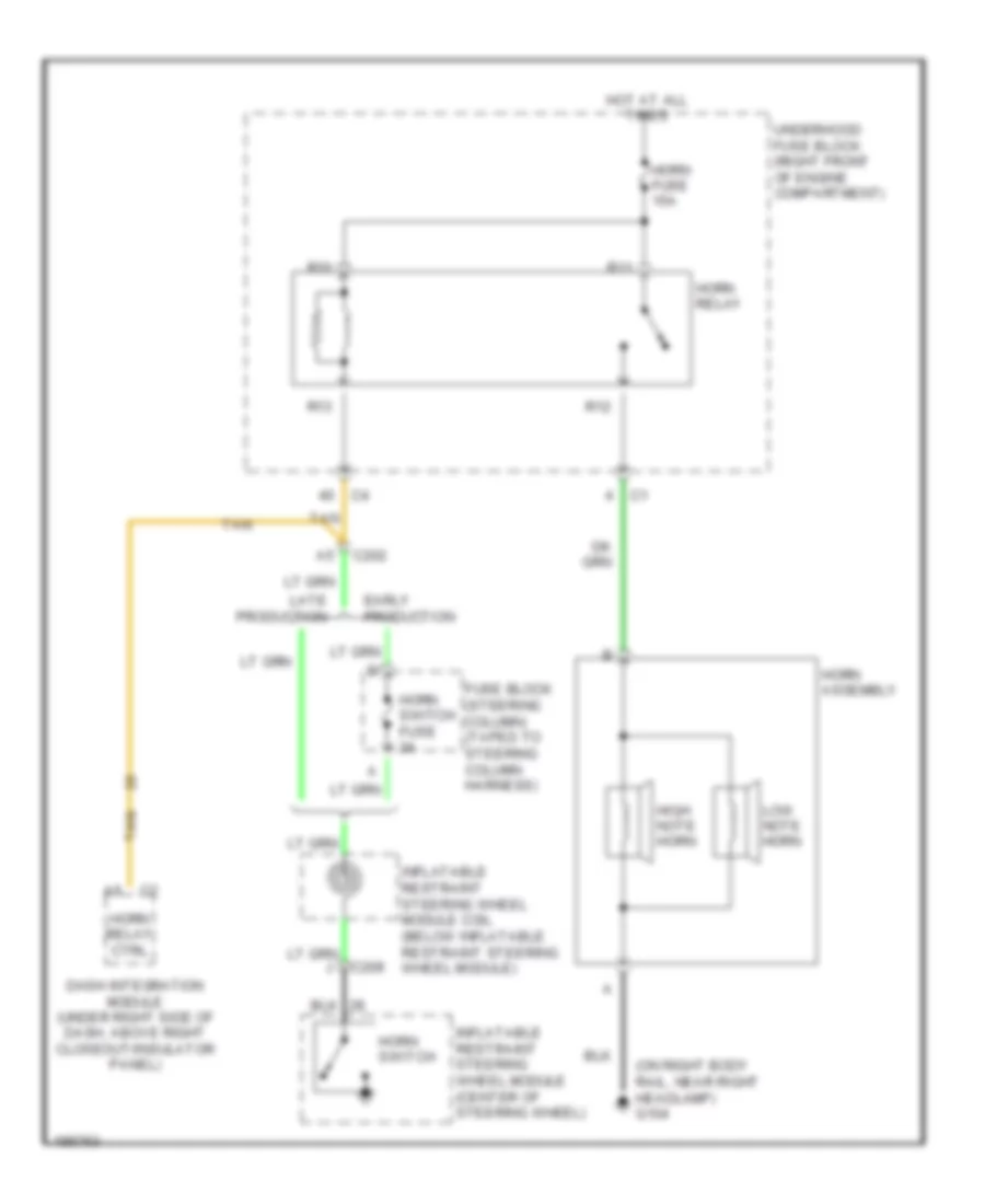
Horn Wiring Diagram for Cadillac CTS V 2004
List of elements for Horn Wiring Diagram for Cadillac CTS V 2004:
- (on right body rail, near right headlamp) g104
- C202
- C208
- Dash integration module (under right side of dash, above right closeout/insulator panel)
- Early production
- Fuse block (steering column) (taped to steering column harness)
- High note horn
- Horn assembly
- Horn fuse 15a
- Horn relay
- Horn relay ctrl
- Horn switch
- Horn switch fuse 2a
- Hot at all times
- Inflatable restraint steering wheel module (center of steering wheel)
- Inflatable restraint steering wheel module coil (below inflatable restraint steering wheel module)
- Late production
- Low note horn
- R10
- R11
- R12
- R13
- Tan
- Underhood fuse block (right front of engine compartment)
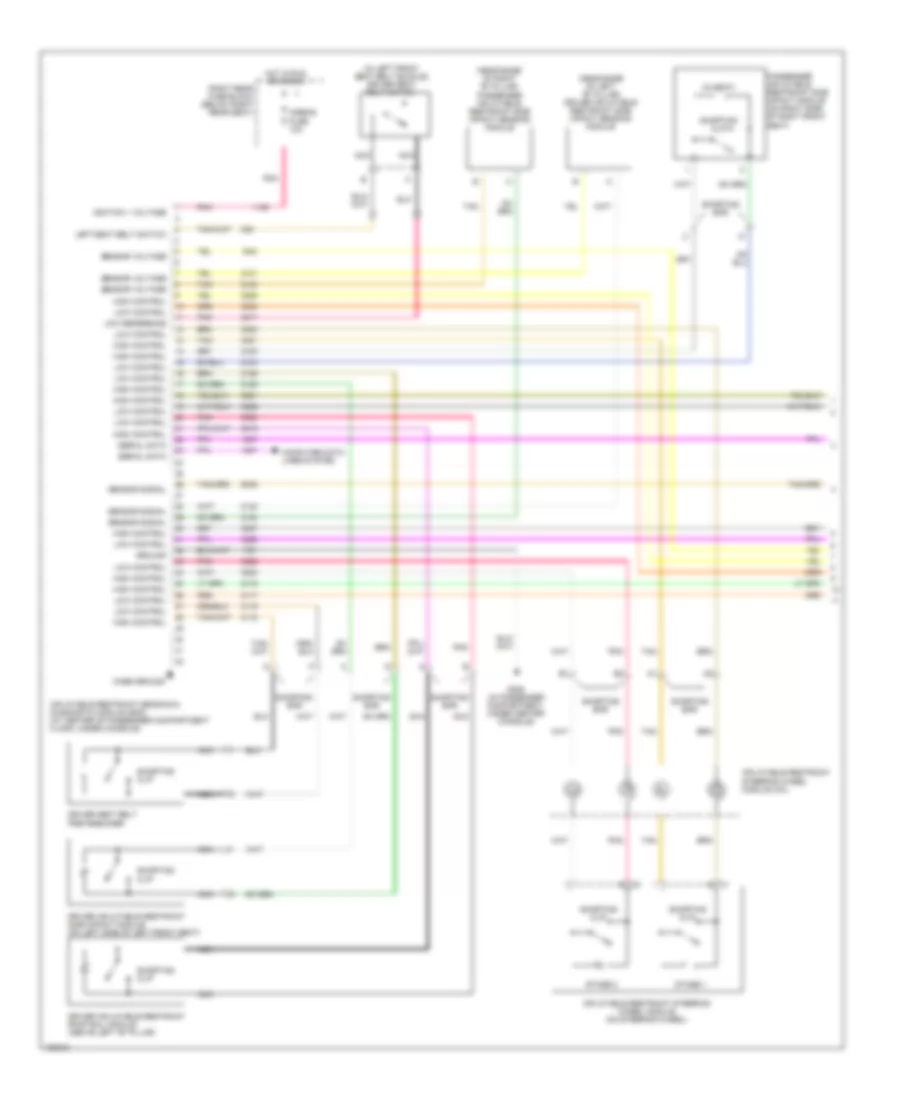
INSTRUMENT CLUSTER
Instrument Cluster Wiring Diagram (1 of 2) for Cadillac CTS V 2004
List of elements for Instrument Cluster Wiring Diagram (1 of 2) for Cadillac CTS V 2004:
- (5.7l) left driver information center (dic)
- (not used)
- 5.7l
- Abs indicator
- Anti-lock brakes system
- Backlighting
- Backlighting ctrl
- Battery (+)
- Brake fluid level switch (on brake fluid reservoir)
- Break indicator
- Charge indicator
- Class 2
- Class 2 (dim)
- Class 2 (ebcm)
- Class 2 (ecm)
- Class 2 (rim)
- Class 2 (sdm)
- Computer data lines system
- Cruise indicator
- Ecm/tcm fuse 10a
- Elec prndl fuse 10a
- Electronic prndl
- Eng speed sig
- Engine controls system
- Engine coolant temperature indicator
- Exterior lights system
- Fasten safety belt indicator
- Front fog lamps indicator
- Fuel level
- G101 (near left front strut tower)
- G200 (behind the left kick panel)
- G201 (behind right kick panel)
- Gnd
- Ground
- Ground ground steering wheel ctrl sig serial data
- High beam indicator
- Hot at all times
- Hot in acc or run
- Hot in run or start
- Ignition 1 voltage
- Instrument panel cluster (ipc)
- Led dimming sig
- Left turn indicator
- Level sens sig
- Lights on indicator
- Logic
- Low engine oil pressure ind
- Low tire pressure indicator
- Malfunction ind lamp (mil)
- Oil temp sens sig
- Park brake sw sig
- Park brake switch (on park brake assembly)
- Pnk
- Rear fog lamps indicator
- Right driver information center (dic) (5.7l)
- Right turn indicator
- S201
- Security indicator
- Serial data
- Sir indicator
- Skip shift ind
- Speedometer
- Speedometer control
- Sport mode indicator
- Tachometer
- Tachometer control
- Tcm/ipc fuse 15a
- Temperature
- Traction control off indicator
- Transmission range sw sig a
- Transmission range sw sig b
- Transmission range sw sig c
- Transmission range sw sig p
- Transmissions system
- Trip reset sw sig
- Trip reset switch
- Trip/ odometer
- Trip/odometer ctrl
- Underhood fuse block (right front of engine compt)
- Vehicle speed sig
- Voltage
- Wait to start indicator (not used)
- Winter mode indicator
Instrument Cluster Wiring Diagram (2 of 2) for Cadillac CTS V 2004
List of elements for Instrument Cluster Wiring Diagram (2 of 2) for Cadillac CTS V 2004:
- (in engine harness, 20 cm from pcm) s140
- (in fuel tank harness, 40 cm from c420)
- (left side of fuel tank)
- 3.2l
- 3.6l
- 5 volt reference
- 5.7l
- Back
- C12
- Clear dic sig
- Clr
- Computer data lines system
- Dic back sig
- Engine control module (ecm) (front of right valve cover)
- Engine controls system
- Engine oil level/ temperature sensor (3.6l) (in oil pan)
- Engine oil level/ temperature sensor (5.7l)
- Engine oil pressure (eop) sensor (3.2l) (on front right side of engine)
- Engine oil pressure (eop) sensor (3.6l) (in oil filter housing)
- Engine oil pressure (eop) sensor (5.7l)
- Engine speed sig
- Except 5.7l
- Fuel level sens sig
- Fuel level sensor
- Fuel pump & sensor assembly (in fuel tank)
- G142 (rear of right cylinder head)
- Ground
- Inflatable restraint steering wheel module coil (below inflatable restraint steering wheel module)
- Info
- Information dn sw sig
- Information up sw sig
- Left steering wheel controls
- Logic
- Low reference
- Message center
- Message request
- Oil level sw sig
- Oil pressure sens sig
- Oil pressure sw sig
- Oil temp sens sig
- Powertrain control module (pcm) (5.7l)
- Radio
- S148 (in engine harness under throttle body, 11.5 cm towards the right)
- S156 (approximately 24 cm from ebcm connector)
- S400
- Scroll dic sig
- Secondary fuel sender assembly
- Serial data
- Steering wheel control assembly
- Switch 1
- Switch 2
- Switch 3
- Switch 4
- Tan
- Tune/sel
- U2v, u2x, u2y
- Vehicle speed sig
- Vehicle speed signal
INTERIOR LIGHTS
Courtesy Lamps Wiring Diagram (1 of 2) for Cadillac CTS V 2004
List of elements for Courtesy Lamps Wiring Diagram (1 of 2) for Cadillac CTS V 2004:
- (under door trim panel)
- 5v reference
- A11
- A12
- B10
- C2 g
- Class 2 serial data
- Computer data lines system
- Courtesy lamp switch
- Courtesy lps on signal
- Dash integration module (under right side of dash, above right closeout/ insulator panel)
- Dim/ aldl fuse 10a
- Dimmer sw low reference
- Driver door latch assembly
- Driver door module (on left door, under door trim)
- Driver door open sw sig
- Front passenger door latch assembly
- Front passenger door module (on right front door, under door trim panel)
- Front passenger door sw sig
- G402 (rear of left rear shock tower)
- Ground
- Hot at all times
- I/p lamps dimmer switch
- Instrument illumination circuit
- Left courtesy/reading lamp
- Left rear door latch assembly
- Left rear door module
- Left rear door open sw sig
- Overhead console
- Right courtesy/reading lamp
- Right rear door latch assembly
- Right rear door module (on right rear door, under door trim panel)
- Right rear door open sw sig
- S314
- Tan
- Underhood fuse block (right front of engine compartment)
Courtesy Lamps Wiring Diagram (2 of 2) for Cadillac CTS V 2004
List of elements for Courtesy Lamps Wiring Diagram (2 of 2) for Cadillac CTS V 2004:
- (center of rear compartment lid) rear compartment lid release actuator
- (in headliner harness, 39.5 cm from c305) s312
- (in headliner harness, 69.5 cm from c305) s319
- A10
- A12
- B10
- B12
- Class 2 serial data
- Computer data lines system
- Courtesy lamp ctrl
- Courtesy lp ctrl
- Courtesy lp relay ctrl
- Courtesy lp voltage
- Driver sunshade
- Driver vanity lamps
- Fd1
- Fd2
- G402 (rear of left rear shock tower)
- Hot at all times
- Int lamp relay
- Interior lamp fuse 10a
- Joint connector
- Left footwell courtesy lamp
- Left front door courtesy lamp
- Lid ajar sw signal
- Nca
- Passenger sunshade
- Passenger vanity lamps
- R16
- R17
- R18
- R20
- Rear compartment courtesy lamp
- Rear dome lamp
- Rear integration module (under package shelf trim panel)
- Right footwell courtesy lamp
- Right front door courtesy lamp
- Right rear fuse block (below right rear seat)
- S10
- S11
- S314
- Trunk diode
Instrument Illumination Wiring Diagram (1 of 2) for Cadillac CTS V 2004
List of elements for Instrument Illumination Wiring Diagram (1 of 2) for Cadillac CTS V 2004:
- (in the i/p harness, 47 cm from hazard switch connector) s203
- 5 volt reference
- A11
- A12
- Auto head
- B12
- Backlight lamps ctrl
- Backlights lamp ctrl
- Battery
- C2 b3
- Class 2 serial data
- Computer data lines system
- Control power output
- Dash integration module (under right side of dash, above right closeout/insulator panel)
- Dim/ aldl fuse 10a
- Dimmer switch signal
- Dimming fuse 10a
- Driver door lock switch
- Driver door module (on left door, under door trim)
- Driver door switch assembly (ddsa)
- Driver dr mod fuse 10a
- Electronic prndl (a/t)
- G200 (behind the left kick panel)
- G201 (behind right kick panel)
- G402 (rear of left rear shock tower)
- Ground
- Hot at all times
- I/p dimmer switch
- Illumination lamp
- Inc dim
- Instrument panel cluster (ipc)
- Joint connector
- Led dimming signal
- Left rear fuse block (below left rear seat)
- Low reference
- Memory/ personalization function switch
- Off
- Overhead console
- Park
- Park lamp relay
- Park lamp sw on sig
- Park lp rly ctrl
- Psgr dr mod fuse 10a
- R31
- R32
- R33
- R34
- Rear compartment lid release switch
- Rear dr mod fuse 15a
- Right rear fuse block (below right rear seat)
- S12
- S13
- S14
- S208
- S308
- S314
- S321 (in headliner harness, 32.5 cm from dome lamp)
- S501 (in left front door trim harness, 24 cm from driver door lock switch)
- S502 (in left front door trim harness, 14.5 cm from ddsa)
- Serial data
- Sunroof control switch
- Turn signal/ multi-function switch
- Underhood fuse block (right front of engine compartment)
Instrument Illumination Wiring Diagram (2 of 2) for Cadillac CTS V 2004
List of elements for Instrument Illumination Wiring Diagram (2 of 2) for Cadillac CTS V 2004:
- (in right front door trim harness, 24.5 cm from door lock switch) s601
- 3.2l/3.6l
- 5.7l
- A12
- B12
- Backlight lamps ctrl
- Battery
- Computer data lines system
- Dimming fuse 2a
- Front passenger door lock switch
- Front passenger door module (on right front door, under door trim panel)
- Front passenger window switch
- Fuse block (steering column) (taped to steering column harness)
- G200 (behind the left kick panel)
- G201 (behind right kick panel)
- Ground
- Hazard switch
- Illumi- nation lamp
- Inflatable restraint steering wheel module coil (below inflatable restraint steering wheel module)
- Left rear door module (under door trim panel)
- Left rear window switch
- Left steering wheel controls
- Right rear door module (on right rear door, under door trim panel)
- Right rear window switch
- Right steering wheel controls
- S200
- S208
- S602 (in right front door trim harness, 8.5 cm from window switch)
- S701
- Serial data
MEMORY SYSTEMS
Memory Mirrors Wiring Diagram (1 of 2) for Cadillac CTS V 2004
List of elements for Memory Mirrors Wiring Diagram (1 of 2) for Cadillac CTS V 2004:
- 5v feed
- 5v reference
- 5v rtn
- A12
- B11
- B12
- Backlight lamps control
- Battery
- Class 2 serial data
- Computer data lines system
- Driver door module (on left door, under door trim)
- Driver door switch assembly (ddsa)
- Driver dr mod fuse 10a
- Driver outside rearview mirror
- Exit (ext)
- G200 (behind the left kick panel)
- Gnd
- Ground
- Ground rtn
- Horiz motor
- Horiz pos sensor
- Horiz posit sensor
- Hot at all times
- Interior lights system
- Left
- Left horiz
- Left rear fuse block (below left rear seat)
- Logic
- Low reference
- Memory 1 switch signal
- Memory 2 switch signal
- Memory/personalization function switch
- Mirror mtr down ctrl
- Mirror mtr left ctrl
- Mirror mtr right ctrl
- Mirror mtr up ctrl
- Nca
- Outside rearview mirror switch
- Right
- Right horiz
- S502 (in left front door trim harness, 14.5 cm from ddsa)
- Sel left
- Sel right
- Vert down
- Vert motor
- Vert pos sensor
- Vert up
- Vertical posit sensor
Memory Mirrors Wiring Diagram (2 of 2) for Cadillac CTS V 2004
List of elements for Memory Mirrors Wiring Diagram (2 of 2) for Cadillac CTS V 2004:
- 5v feed
- 5v reference
- 5v rtn
- A12
- B12
- Battery
- Class 2 serial data
- Computer data lines system
- Dr mod pwr circuit breaker 30a
- Front passenger door module (on right front door, under door trim panel)
- G201 (behind right kick panel)
- Ground
- Horiz motor
- Horiz pos sensor
- Horizontal posit sensor
- Hot at all times
- Left horiz
- Low reference
- Mirror mtr down ctrl
- Mirror mtr left ctrl
- Mirror mtr right ctrl
- Mirror mtr up ctrl
- Passenger outside rearview mirror
- Psgr dr mod fuse 10a
- Right horiz
- Right rear fuse block (below right rear seat)
- S303
- Vert down
- Vert motor
- Vert pos sensor
- Vert up
- Vertical posit sensor
Memory Seat Wiring Diagram (1 of 2) for Cadillac CTS V 2004
List of elements for Memory Seat Wiring Diagram (1 of 2) for Cadillac CTS V 2004:
- 5 volt reference
- Battery positive voltage
- Class 2 serial data
- Dr lumbar horiz posit sens signal
- Driver seat adjuster switch
- E10
- E11
- E12
- E13
- E14
- E15
- E16
- F10
- F11
- F12
- F13
- F14
- F15
- F16 c2
- Front vertical down
- Front vertical motor down control
- Front vertical motor up control
- Front vertical up
- G307 (on floor, left of driver's seat)
- Ground
- Horizontal forward
- Horizontal forward switch signal
- Horizontal motor forward ctrl
- Horizontal motor rearward control
- Horizontal rearward
- Horizontal rearward switch signal
- Hot at all times
- Left rear fuse block (below left rear seat)
- Low reference
- Lumbar forward switch signal
- Lumbar rearward switch signal
- Lumber motor forward control
- Lumber motor rearward control
- Mem/adapt seat fuse 10a
- Memory seat module (msm) (under driver's seat)
- Pnk
- Rear vertical down
- Rear vertical motor down control
- Rear vertical motor up control
- Rear vertical posit sens signal
- Rear vertical up
- Recline back switch signal
- Recline forward
- Recline forward switch signal
- Recline motor forward control
- Recline motor rearward control
- Recline posit sens signal
- Recline rearward
- S350 (w/ heated seats)
- S351
- Seat circuit breaker 30a
- Seat horiz posit sensor signal
- Tan
- Vertical down switch signal
- Vertical posit sens signal
- Vertical up switch signal
Memory Seat Wiring Diagram (2 of 2) for Cadillac CTS V 2004
List of elements for Memory Seat Wiring Diagram (2 of 2) for Cadillac CTS V 2004:
- (in driver seat harness, 10 cm from seat horizontal position sensor) s348
- (in left seat harness, 15 cm from driver seat rear vertical position sensor) s349
- Backlight lamps control
- Class 2 serial data
- Driver door module (on left door, under door trim)
- Driver door switch assembly (ddsa)
- Driver lumbar adjuster switch
- Driver lumbar horizontal motor assembly
- Driver seat front vertical motor
- Driver seat front vertical position sensor
- Driver seat horizontal motor
- Driver seat horizontal position sensor
- Driver seat rear vertical motor
- Driver seat rear vertical position sensor
- Driver seat recline motor
- Driver seat recline position sensor
- Exit (ext)
- Forward
- Gnd
- Ground
- Interior lights system
- Memory 1 sw signal
- Memory 1 switch signal
- Memory 2 sw signal
- Memory 2 switch signal
- Memory/personalization function switch
- Nca
- Not used
- Pnk
- Rearward
- S502 (in left front door trim harness, 14.5 cm from ddsa)
- Sp300 (in passenger compartment, near left side of driver's seat)
- Tan
NAVIGATION
Navigation Wiring Diagram for Cadillac CTS V 2004
List of elements for Navigation Wiring Diagram for Cadillac CTS V 2004:
- (coaxial cable)
- (or 1782)
- (or 655)
- (or bare)
- Audio amplifier (left side of trunk)
- Audio fuse 10a
- Bare
- Battery
- Class 2 serial data
- Computer data lines system
- Drain wire
- G402 (rear of left rear shock tower)
- Gps signal
- Ground
- Hot at all times
- Infotainment system
- Inside rearview mirror (isrvm)
- Joint connector
- Left rear fuse block (under left rear seat)
- Mic out feed
- Mic out return
- Nav voice in (+)
- Nav voice out (-)
- Navigation antenna
- Navigation voice low ref
- Navigation voice signal
- Pnk
- Radio
- S18
- Sig
- Vehicle communication interface module (vcim) (in rear compartment, behind right strut tower)
- Vehicle communication system
- Voice output (+)
- Voice output (-)
- Voice output ground
POWER DISTRIBUTION
Power Distribution Wiring Diagram (1 of 7) for Cadillac CTS V 2004
List of elements for Power Distribution Wiring Diagram (1 of 7) for Cadillac CTS V 2004:
- (3.2l)
- (3.6l)
- (except 3.2l)
- (in engine harness, 15 cm from coil 1) s145
- (in fuel injector harness, 15 cm from c121) s151
- (in fuel injector harness, near c112) s108
- (in ignition coil/module harness, on left valve cover, 5 cm from c131) s163
- (in the engine harness, 45 cm from the underhood fuse block) s132
- (not used)
- (right front of engine compartment) underhood fuse block
- 3.2l
- 3.6l
- 5.7l
- A/t
- Battery
- Blower fuse 40a
- Blower relay
- C1 g
- C2 a12
- Ccp fuse 10a
- Dash integration module (dim)
- Data link connector (dlc)
- Dim/ aldl fuse 10a
- Ecm fuse 15a
- Ecm/tcm fuse 10a
- Engine control module (ecm)
- Evaporative emission (evap) canister purge solenoid valve
- Evaporative emissions (evap) canister purge solenoid valve
- Except 5.7l
- Flasher fuse 15a
- Fuel injector
- Fusible link
- Generator
- Heated oxygen sensor (ho2s) bank 1 sensor 2
- Heated oxygen sensor (ho2s) bank 2 sensor 2
- Hi fan fuse 30a
- Hi speed fan relay
- Hvac control module
- Ignition coil 1
- Ignition coil 3
- Ignition coil 5
- Ignition coil/ module 1
- Ignition coil/ module 3
- Ignition coil/ module 5
- Ignition coil/ module 7
- Ignition manifold runner control (imrc) solenoid
- Instrument panel cluster (ipc)
- Intake manifold tuning valve (imtv) solenoid
- Left rear fuse block (below left rear seat)
- Low fan fuse 30a
- Low speed fan relay
- Main relay
- Mass air flow (maf) sensor
- Odd inj/ coil fuse 15a
- Post 2 fuse 15a
- Powertrain control module (pcm)
- Pusher fan relay
- R14
- R19
- R20
- R39
- R40
- R47
- R48
- R49
- R50
- R51
- R52
- S/p fan relay
- Spare fuse
- Starter
- Theft deterrent control module
- To underhood fuse block (horn relay) (diagram 2 of 7)
- To underhood fuse block (pre 2/cam fuse, 15a) (diagram 3 of 7)
- Tos fuse 10a
- Trailer provisions
- Transmission control module (tcm)
- Turn signal/ hazard flasher module
- Vehicle speed sensor (vss) (manual transmission)
- Volt check fuse 10a
Power Distribution Wiring Diagram (2 of 7) for Cadillac CTS V 2004
List of elements for Power Distribution Wiring Diagram (2 of 7) for Cadillac CTS V 2004:
- (3.2l)
- (3.6l)
- (in engine harness, approximately 8 cm from ebcm connector) s130
- (right front of engine compartment) underhood fuse block
- 5.7l
- Abs fuse 50a
- Accessory relay
- Comp clutch fuse 10a
- Comp clutch relay
- Drl relay
- Elec prndl fuse 10a
- Electronic brake control module (ebcm)
- Electronic prndl (a/t)
- Engine control module (ecm)
- Except 5.7l
- Fog lamp fuse 15a
- Fog lamp relay
- From ignition switch (pin 2) (diagram 4 of 7)
- From underhood fuse block a (main relay) (diagram 1 of 7)
- G104 (on right body rail, near right headlamp)
- Hdlp wash circuit breaker 30a
- Hdlp washer relay
- High beam relay
- Horn fuse 15a
- Horn relay
- Ign sw fuse 10a
- L rear fuse 60a
- Low beam/ hid relay
- Park lamp relay
- Powertrain control module (pcm)
- R rear fuse 60a
- R10
- R11
- R24
- R28
- R32
- R35
- R36
- R37
- R38
- R56
- R68
- Spare fuse
- Theft deterrent control module
- Theft fuse 7.5a
- To ignition switch (pin 6) (diagram 4 of 7)
- To left rear fuse block (driver dr mod fuse, 10a) (diagram 5 of 7)
- To left rear fuse block (pusher fan fuse, 30a) (diagram 5 of 7)
- To right rear fuse block (dr mod pwr circuit breaker, 30a) (diagram 6 of 7)
- To right rear fuse block (rim/ign sw fuse, 10a) (diagram 4 of 7)
- To underhood fuse block (i/p out let fuse, 20a) (diagram 3 of 7)
- Transmission control module (tcm) (a/t)
- Windshield wiper/ washer module
- Windshield wiper/ washer switch
- Wpr mod fuse 30a
- Wpr sw fuse 10a
Power Distribution Wiring Diagram (3 of 7) for Cadillac CTS V 2004
List of elements for Power Distribution Wiring Diagram (3 of 7) for Cadillac CTS V 2004:
- (3.2l)
- (3.6l)
- (a/t)
- (accessory relay) (diagram 2 of 7)
- (in body harness, 22 cm from a/c pressure switch connector)
- (in engine harness, 15 cm from coil 5) s142
- (in engine harness, 24.5 cm from ect sensor) s146
- (in engine harness, approximately 20 cm from underhood fuse block) s162
- (in fuel injector harness, 15 cm from c121) s152
- (in ignition coil/module harness, on right valve cover, 5 cm from c132) s164
- (on right body rail, near right headlamp) g104
- (right front of engine compartment) underhood fuse block
- 3.2l
- 3.6l
- 5.7l
- A/t
- A8 c2
- Auxiliary power outlet
- B+ mode
- Battery saver mode
- Camshaft actuator solenoid exhaust bank 1
- Camshaft actuator solenoid exhaust bank 2
- Camshaft actuator solenoid intake bank 1
- Camshaft actuator solenoid intake bank 2
- Camshaft position (cmp) sensor
- Cigar lighter
- Cigar relay
- Clutch pedal position (cpp) sensor
- Cmp clu relay
- Coolant bypass valve solenoid
- Dash integration module (dim)
- Engine control module (ecm)
- Evaporative emission (evap) canister purge solenoid valve
- Even inj/ coil fuse 15a
- Except 3.6l
- Except 5.7l
- Fog lamp relay
- From ignition switch (via splice pack sp200) (pin 8) (diagram 4 of 7)
- From underhood fuse block b (ecm fuse, 15a) (diagram 1 of 7)
- From underhood fuse block h
- Fuel injector 2
- Fuel injector 4
- Fuel injector 6
- Fuel injector 8
- G201 (behind right kick panel)
- Heated oxygen sensor (ho2s) bank 1 sensor 1
- Heated oxygen sensor (ho2s) bank 2 sensor 1
- Htr vlv/ cltch fuse 10a
- I/p outlet fuse 20a
- Ign 1 relay
- Ignition coil 2
- Ignition coil 4
- Ignition coil 6
- Ignition coil/ module 2
- Ignition coil/ module 4
- Ignition coil/ module 6
- Ignition coil/ module 8
- Instrument panel cluster (ipc)
- Intake manifold runner control (imrc) solenoid
- M/t
- Outlet fuse 30a
- Pnk
- Pnk a
- Pnk/ (in engine harness, 15.5 cm from c101) s170
- Powertrain control module (pcm)
- Pre o2/ cam fuse 15a
- R43
- R44
- R45
- R46
- R55
- R59
- R60
- R61
- R62
- R63
- R64
- Reverse lockout solenoid
- S131
- S202
- S308
- Skip shift solenoid
- Splice pack sp200
- Starter fuse 30a
- Starter relay
- Tcm/ipc fuse 15a
- Throttle actuator control (tac) module
- To underhood fuse block (wash noz fuse, 10a) (diagram 4 of 7)
- Transmission control module (tcm)
Power Distribution Wiring Diagram (4 of 7) for Cadillac CTS V 2004
List of elements for Power Distribution Wiring Diagram (4 of 7) for Cadillac CTS V 2004:
- (3.2l)
- (3.6l)
- (in steering column harness, 12.7 cm from c202) s207
- 3.2l
- 3.2l & 3.6l
- 3.6l
- 5.7l
- A11
- Acc
- Accessory
- Cruise control switch
- Cruise control switch fuse 2a
- Dash integration module (dim)
- Engine control module (ecm)
- Except 5.7l
- From underhood fuse block (ign sw fuse, 10a) (diagram 2 of 7)
- From underhood fuse block (r rear fuse, 60a) (connector c3, pin 1) (diagram 2 of 7)
- From underhood fuse block (tcc/et fuse, 10a) (diagram 3 of 7)
- Ign mod/maf fuse 15a
- Ignition 1
- Ignition coil bank 1 (3.2l)
- Ignition coil bank 2
- Ignition lock cylinder control actuator
- Ignition switch
- Inflatable restraint steering wheel module coil
- Left headlamp
- Left heated washer nozzle
- Mass air flow (maf) sensor
- Off/lock
- Pnk
- Powertrain control module (pcm)
- Rear integration module (rim)
- Right headlamp
- Right heated washer nozzle
- Right rear fuse block (below right rear seat)
- Right steering wheel controls
- Rim/ ign sw fuse 10a
- Run
- S200 (in the i/p harness, 11.5 cm from sp200)
- Spare fuse
- Splice pack sp200
- Start
- Steering column fuse block (taped to steering column harness)
- Strg ctls fuse 10a
- To left rear fuse block (ign 3 relay) (diagram 6 of 7)
- To right rear fuse block (ign 1 relay) (diagram 7 of 7)
- To underhood fuse block (accessory relay) (connector c4, pin 37) (diagram 2 of 7)
- To underhood fuse block (cmp clu relay) (diagram 3 of 7)
- Turn signal switch
- Turn signal/ multifunction switch
- Underhood fuse block (right front of engine compartment)
- W/ automatic headlamps control leveling system
- Wash noz fuse 10a
Power Distribution Wiring Diagram (5 of 7) for Cadillac CTS V 2004
List of elements for Power Distribution Wiring Diagram (5 of 7) for Cadillac CTS V 2004:
- (below left rear seat) left rear fuse block
- (in driver seat harness, 8 cm from msm connector) s351
- (in headliner harness, 22.5 cm from radio antenna module) s313
- A12
- Amp fuse 30a
- Audio amplifier
- Audio fuse 10a
- Bas fuse 15a
- Bas relay
- Digital radio receiver
- Driver adjuster seat switch
- Driver door module (ddm)
- Driver dr mod fuse 10a
- Driver heated seat module
- Driver lumbar adjuster switch
- F11
- From underhood fuse block (l rear fuse, 60a) (connector c2, pin 1) (diagram 2 of 7)
- From underhood fuse block (l rear fuse, 60a) (connector c2, pin 2) (diagram 2 of 7)
- Garage door opener
- Joint connector
- L frt htd seat mod fuse 10a
- Left rear door module (lrdm)
- Left rear fuse block (ign 3 relay) (diagram 6 of 7)
- Mem/adapt seat fuse 10a
- Memory seat module (msm)
- Pusher fan fuse 30a
- Pusher fan relay (trailer provisions)
- R31
- R32
- R36
- R37
- Radio
- Radio antenna module
- Rear dr mod fuse 15a
- Rev lamp relay
- Reverse lamp fuse 10a
- Right rear door module (rrdm)
- S12
- S13
- S14
- S15
- S17
- S18
- S19
- S20
- S21
- S22
- S23
- Spare fuse
- Trk dr rel sol relay
- Trunk dr release fuse 10a
- Vehicle communication interface module (vcim)
- W/ 7 speaker system
- W/o 7 speaker system
Power Distribution Wiring Diagram (6 of 7) for Cadillac CTS V 2004
List of elements for Power Distribution Wiring Diagram (6 of 7) for Cadillac CTS V 2004:
- (below right rear seat) right rear fuse block
- (except 5.7l) (5.7l)
- (in body harness, 108 cm from c700) s304
- (in body harness, 108 cm from c800) s303
- (in i/p harness, 11.5 cm from sp200) s200
- (in passenger seat harness, 12.7 cm from c307) s352
- A/t shift lock control solenoid assembly
- A/t shift shift lock control solenoid
- A11
- After boil fuse 10a
- After boil relay
- Canister vent fuse 10a
- Ccp fuse 10a
- Dr mod pwr circuit breaker 30a
- Driver door module (ddm)
- Driver heated seat module
- Driver seat adjuster switch
- Evaporative emissions (evap) canister vent solenoid valve
- From ignition switch (pin 5) (diagram 4 of 7)
- From left rear fuse block (trk dr release fuse, 10a) (diagram 5 of 7)
- From underhood fuse block (r rear fuse, 60a) (connector c3, pin 2) (diagram 2 of 7)
- Front headlamp leveling sensor
- Front passenger door module (fpdm)
- Front passenger heated seat module
- Fuel pump motor relay
- Fuel pump mtr fuse 15a 20a
- G402 (rear of left rear shock tower)
- Hdlp leveling fuse 10a
- Hvac control module
- Ign 3 fuse 10a
- Ign 3 relay
- Ignition lock cylinder control actuator
- Ignition switch
- Joint connector
- Left rear door module (lrdm)
- Left rear fuse block (below left rear seat)
- Memory seat module (msm)
- Passenger lumbar adjuster switch
- Passenger seat adjuster switch
- R frt htd seat mod fuse 10a
- R11
- R12
- R21
- R22
- R23
- R25
- R37
- Rap relay
- Rear defog relay
- Rear headlamp leveling sensor
- Rear integration module
- Rear integration module (rim)
- Recirculation actuator
- Right rear door module (rrdm)
- Right rear fuse block (below right rear seat)
- Rim/ign sw fuse 10a
- Seat circuit breaker 30a
- Spare fuse
- Sunroof module
- Tan
- Underhood fuse block (right front of engine compt)
- W/ memory
- W/ power lumbar control seats
- W/ power seats
- W/o memory
- W/o power lumbar control seats
- W/o power seats
Power Distribution Wiring Diagram (7 of 7) for Cadillac CTS V 2004
List of elements for Power Distribution Wiring Diagram (7 of 7) for Cadillac CTS V 2004:
- A12
- Abs fuse 10a
- Air bag fuse 10a
- Electronic brake control module (ebcm)
- From ignition switch (via splice pack sp200, pin 9) (diagram 4 of 7)
- From right rear fuse block (rim/ign sw fuse, 10a) (diagram 4 of 7)
- Front passenger door module (fpdm)
- G401 (rear of right rear shock tower)
- Ign 1 relay
- Inflatable restraint sensing & diagnostic module (sdm)
- Inside rear view mirror
- Int lamp relay
- Interior lamp fuse 10a
- Joint connector
- Pnk
- Psgr dr mod fuse 10a
- R16
- R17
- R21
- R22
- R23
- R25
- R31
- R32
- Rear defog fuse 40a
- Rear defog relay
- Rear fog lamp fuse 10a
- Rear fog lamp relay
- Rear integration module (rim)
- Right rear fuse block (below right rear seat)
- Rim fuse 10a
- S20
- S21
- S22
- S23
POWER DOOR LOCKS
Power Door Locks Wiring Diagram (1 of 2) for Cadillac CTS V 2004
List of elements for Power Door Locks Wiring Diagram (1 of 2) for Cadillac CTS V 2004:
- (behind left kick panel) g200
- (behind right kick panel) g201
- A12
- B10
- B11
- B12
- Backlight lamps ctrl
- Battery
- Class 2 serial data
- Computer data lines system
- Door ajar signal
- Door ajar sw signal
- Door ajar switch signal
- Door key sw unlock sig
- Door key unlock switch signal
- Door lock mtr lock ctrl
- Door lock mtr unlk ctrl
- Door lock sw lock sig
- Door lock sw unlock sig
- Door lock switch signal
- Door open signal
- Door open switch signal
- Dr mod pwr circuit breaker 30a
- Driver door latch assembly
- Driver door module (on left door, under door trim)
- Driver door switch assembly (ddsa)
- Driver dr key sw signal
- Driver dr mod fuse 10a
- Front passenger door latch assembly
- Front passenger door module (on right front door, under door trim panel)
- Gnd
- Ground
- Hot at all times
- Interior lights system
- Joint connector
- Keyless entry antenna signal
- Left front door sw sig
- Left rear fuse block (below left rear seat)
- Memory seat switch
- Psgr dr mod fuse 10a
- Radio antenna module (above headliner, near rear window)
- Rear compartment lid release switch
- Rear dr mod fuse 15a
- Rear glass antenna
- Rfa grid
- Right rear fuse block (below right rear seat)
- S12
- S13
- S14
- S20
- S22
- S303
- S313
- S502 (in left front door trim harness, 14.5 cm from ddsa)
- Tan
- Trunk dr release fuse 10a
Power Door Locks Wiring Diagram (2 of 2) for Cadillac CTS V 2004
List of elements for Power Door Locks Wiring Diagram (2 of 2) for Cadillac CTS V 2004:
- (behind left kick panel) g200
- (behind right kick panel) g201
- A12
- Ajar
- B10
- B12
- Backlight lamp ctrl
- Backlight lamps control
- Backlight lamps ctrl
- Battery
- Class 2 serial data
- Computer data lines system
- Door act lock ctrl
- Door ajar switch signal
- Door lock act lock ctrl
- Door lock act unlk ctrl
- Door lock unlock ctrl
- Door open switch signal
- Driver door lock switch
- Front passenger door lock switch
- Front passenger window switch
- Ground
- Interior lights system
- Left rear door latch assembly
- Left rear door module (under door trim panel)
- Lock
- Open
- Right rear door latch assembly
- Right rear door module (on right rear door, under door trim panel)
- S602 (in right front door trim harness, 8.5 cm from window switch)
- S701
- Tan
- Unlock
POWER MIRRORS
Automatic Day/Night Mirror Wiring Diagram for Cadillac CTS V 2004
List of elements for Automatic Day/Night Mirror Wiring Diagram for Cadillac CTS V 2004:
- (or bare)
- (rear of left rear shock tower) g402
- A12
- Backup lamp voltage
- Bare
- Base
- Class 2 serial data
- Computer data lines system
- Drain wire
- Exterior lights system
- Ground
- Hot at all times
- Hot in run or start
- Ignition voltage
- Inside rearview mirror (isrvm)
- Joint connector
- Key pad sig
- Led signal
- Left rear fuse block (below left rear seat)
- Luxury
- Microphone
- Microphone low ref
- Microphone sig
- Pnk
- Pnk s21
- R36
- R37
- R38
- R40
- Radio
- Rear integration module (under package shelf trim panel)
- Rev lamp fuse 10a
- Rev lamp relay
- Reverse lamp ctrl
- Right rear fuse block (below right rear seat)
- Rim fuse 10a
- S23
- Vehicle communication interface module (vcim) (in rear compt, behind right strut tower)
Power Mirrors Wiring Diagram for Cadillac CTS V 2004
List of elements for Power Mirrors Wiring Diagram for Cadillac CTS V 2004:
- A12
- B11
- B12
- Battery
- Class 2 serial data
- Computer data lines system
- Down
- Dr mod pwr circuit breaker 30a
- Driver door module (on left door, under door trim)
- Driver door switch assembly (ddsa)
- Driver dr mod fuse 10a
- Driver outside rearview mirror
- Front passenger door module (on right front door, under door trim panel)
- G200 (behind the left kick panel)
- G201 (behind right kick panel)
- Ground
- Ground rtn
- Horiz motor
- Hot at all times
- Interior lights system
- Left
- Left mirror mtr-down
- Left mirror mtr-left
- Left mirror mtr-right
- Left mirror mtr-up
- Left rear fuse block (below left rear seat)
- Logic
- Outside rearview mirror switch
- Passenger outside rearview mirror
- Psgr dr mod fuse 10a
- Right
- Right mirror motor-up
- Right mirror mtr -down
- Right mirror mtr-left
- Right mirror mtr-right
- Right rear fuse block (below right rear seat)
- S303
- S502 (in left front door trim harness, 14.5 cm from ddsa)
- Sel left
- Sel right
- Vert motor
POWER SEATS
Heated Seats Wiring Diagram for Cadillac CTS V 2004
List of elements for Heated Seats Wiring Diagram for Cadillac CTS V 2004:
- (on floor, left of driver's seat) g307
- A11
- A12
- B12
- Battery
- Class 2 serial data
- Computer data lines system
- Dash integration module (dim) (under right side of dash, above right closeout/insulator panel)
- Driver heated seat
- Driver heated seat status
- Driver heated seat switch
- Driver high/low signal
- Driver seat back heated seat element
- Driver seat front cushion heated seat element
- Driver seat rear cushion heated seat element
- Driver's heated seat module (under driver's seat)
- E10
- Front passenger heated seat
- Front passenger seat back heated seat element
- Front passenger seat cushion front heated seat element
- Front passenger seat cushion rear heated seat element
- Ground
- Heated seat element control
- Heated seat element voltage
- Heated seat high/low signal
- Heated seat module status sig
- Heated seat module status signal
- Heated seat sensor low ref
- Heated seat temp sens signal
- Hot at all times
- Hot in run
- Hvac control module (behind center of dash, below radio)
- Ign 3 fuse 10a
- Ignition 3 voltage
- Joint connector
- Left rear fuse block (below left rear seat)
- Logic
- Lt frt htd seat mod fuse 10a
- Passenger heated seat status
- Passenger heated seat switch
- Passenger high/low signal
- Passenger's heated seat module (under passenger's seat)
- Pnk
- R frt htd seat mod fuse 10a
- Radio
- Rear integration module (under package shelf trim panel)
- Right rear fuse block (below right rear seat)
- S305 (w/o power lumbar)
- S320 (w/ power lumbar)
- S350
- Seat temp sensor low ref
- Seat temp sensor signal
- Thermistor
Passenger"s Lumbar Wiring Diagram for Cadillac CTS V 2004
List of elements for Passenger"s Lumbar Wiring Diagram for Cadillac CTS V 2004:
- Forward
- G307 (on floor, left of driver's seat)
- Hot at all times
- Left rear fuse block (below left rear seat)
- Passenger lumbar adjuster switch
- Passenger lumbar horizontal motor
- Rearward
- S320
- S352
- Seat circuit breaker 30a
Power Seats Wiring Diagram for Cadillac CTS V 2004
List of elements for Power Seats Wiring Diagram for Cadillac CTS V 2004:
- (on floor, left of driver's seat) g307
- Aft
- Battery
- Down
- Driver seat adjuster switch
- Driver seat front vertical motor
- Driver seat horizontal motor
- Driver seat rear vertical motor
- Driver seat recline motor
- Front vertical down
- Front vertical up
- Fwd
- Gnd
- Horizontal forward
- Horizontal rearward
- Hot at all times
- Left rear fuse block (below left rear seat)
- Passenger seat adjuster switch
- Passenger seat front vertical motor
- Passenger seat horizontal motor
- Passenger seat rear vertical motor
- Passenger seat recline motor
- Rear vertical down
- Rear vertical up
- Recline forward
- Recline rearward
- S304 (w/ passenger power seats)
- S305 (w/o power lumbar)
- S320 (w/ power lumbar)
- S350 (w/ heated seats)
- S352 (w/ power lumbar)
- Seat circuit breaker 30a
- Tan
POWER TOP/SUNROOF
Sunroof Wiring Diagram for Cadillac CTS V 2004
List of elements for Sunroof Wiring Diagram for Cadillac CTS V 2004:
- (in sunroof harness, 9 cm from sunroof module)
- Close
- G401 (rear of right rear shock tower)
- Ground
- Hall effect sensor 1
- Hall effect sensor 2
- Hot at all times
- Illumination +
- Illumination -
- Interior lights system
- Limit switch
- Nca
- Open
- Pnk
- Rap relay
- Rap relay coil ctrl
- Rear integration module (under package shelf trim panel)
- Right rear fuse block (below right rear seat)
- S318
- Solid state (close)
- Solid state (open)
- Sunroof control switch
- Sunroof limit switch low reference
- Sunroof limit switch stop signal
- Sunroof mod fuse 30a
- Sunroof module
- Sunroof motor (at left front corner of sunroof module)
- Sunroof motor close control
- Sunroof motor open control
- Sunroof obstruction sensor 12 vref
- Sunroof obstruction sensor 2 signal
- Sunroof obstruction sensor signal
- Sunroof switch low reference
- Sunroof switch-data 1
- Sunroof switch-data 2
- Sunroof switch-data 3
- Sunroof switch-data 4
- Sunroof switch-data 5
- Sunroof switch-data 6
- Sunroof switch-low reference
- Tan
- Vehicle speed signal
POWER WINDOWS
Power Windows Wiring Diagram (1 of 2) for Cadillac CTS V 2004
List of elements for Power Windows Wiring Diagram (1 of 2) for Cadillac CTS V 2004:
- A12
- B11
- B12
- Battery
- Battery positive voltage
- Class 2 serial data
- Computer data lines system
- Door locks system
- Down control
- Down sig
- Dr mod pwr c/b circuit breaker 30a
- Driver door module (on left door, under door trim)
- Driver dr mod fuse 10a
- Driver window motor
- Express signal
- Front passenger door module (on right front door, under door trim panel)
- Front passenger window motor
- Front passenger window switch
- G200 (behind the left kick panel)
- G201 (behind right kick panel)
- Ground
- High speed serial data
- Hot at all times
- Interior lights system
- Joint connector
- Left rear fuse block (below left rear seat)
- Low reference
- Low speed serial data
- Pnk
- Psgr dr mod fuse 10a
- Rear dr mod fuse 15a
- Right rear fuse block (below right rear seat)
- S12
- S13
- S14
- S303
- S602 (in right front door trim harness, 8.5 cm from window switch)
- Up control
- Up signal
Power Windows Wiring Diagram (2 of 2) for Cadillac CTS V 2004
List of elements for Power Windows Wiring Diagram (2 of 2) for Cadillac CTS V 2004:
- (on right rear door, under door trim panel) right rear door module
- A12
- B12
- Backlights lamps ctrl
- Battery
- Class 2 serial data
- Computer data lines system
- Door locks system
- Down control
- Down signal
- Driver door switch assembly (ddsa)
- Drv window down sig
- Drv window express sig
- Drv window up sig
- Express signal
- Front passenger down sig
- Front passenger express sig
- Front passenger up sig
- G200 (behind the left kick panel)
- G201 (behind right kick panel)
- Ground
- Left rear door module (under door trim panel)
- Left rear window motor
- Left rear window switch
- Logic
- Lr window down sig
- Lr window express sig
- Lr window up sig
- Right rear window motor
- Right rear window switch
- Rr window down sig
- Rr window express sig
- Rr window up sig
- S701
- Up control
- Up signal
- Window lock out
RADIO
Radio Wiring Diagram, Base (1 of 2) for Cadillac CTS V 2004
List of elements for Radio Wiring Diagram, Base (1 of 2) for Cadillac CTS V 2004:
- (dd8) inside rearview mirror
- (or 1782)
- (or 655)
- (or bare)
- (rear of left rear shock tower) g402
- (right rear package shelf) (w/o gps) navigation antenna
- Am/fm antenna signal
- Amp fuse 30a
- Antenna signal
- Audio fuse 10a
- Bare
- Battery
- Cellular microphone signal
- Class 2 serial data
- Coaxial cable
- Coil 1
- Coil 2
- Computer data lines system
- Drain
- Drain wire
- Fm composite signal
- Gps sig
- Ground
- Hot at all times
- Info down switch signal
- Information up sw signal
- Instrument cluster system
- Joint connector
- Keyless entry/tire pressure antenna signal
- Left a pillar speaker (tweeter)
- Left audio signal (+)
- Left audio signal (-)
- Left front door speaker (midrange)
- Left rear fuse block (below left rear seat)
- Modern ground (not used)
- Modern receive (not used)
- Modern transmit (not used)
- Pnk
- Radio
- Radio antenna module (above headliner, near rear window)
- Radio front glass antenna
- Radio rear glass antenna
- Rear speaker (subwoofer)
- Red
- Remote radio ctrl voltage
- Return voice in signal
- Rfa rear window antenna
- Right audio signal (+)
- Right audio signal (-)
- S18
- S22
- S313
- Steering wheel ctrls sig
- Tan
- U2y/u26
- Uav
- Vehicle speed signal
- Voice in signal
Radio Wiring Diagram, Base (2 of 2) for Cadillac CTS V 2004
List of elements for Radio Wiring Diagram, Base (2 of 2) for Cadillac CTS V 2004:
- (midrange) left rear door speaker
- (midrange) right front door speaker
- (midrange) right rear door speaker
- (rear of left rear shock tower) g402
- (tweeter) right a pillar speaker
- A10
- A11
- Audio amplifier (left side of trunk)
- B10
- B11
- B12
- Bare
- Battery
- C12
- C202 c1
- Cellular telephone voice low ref
- Cellular telephone voice signal
- Class 2 serial data
- Computer data lines system
- Drain wire
- Fuse block (steering column) (early production) (taped to steering column harness)
- G200 (behind the left kick panel)
- Ground
- Inflatable restraint steering wheel module coil (below inflatable restraint steering wheel module)
- Interior lights system
- Left fnt low level audio sig (+)
- Left fnt low level audio sig (-)
- Left front midrange spkr out (+)
- Left front midrange spkr out (-)
- Left front tweeter spkr out (+)
- Left front tweeter spkr out (-)
- Left rear midrange spkr out (+)
- Left rear midrange spkr out (-)
- Left steering wheels controls
- Left subwoofer spkr out (+)
- Left subwoofer spkr out (-)
- Low ref
- Mic out
- Mic out rtn
- Mic out shield
- Modern ground (not used)
- Modern receiver (not used)
- Modern trasmid (not used) (not used)
- Nca
- Pnk
- Rdt1
- Rdt2
- Right fnt low level audio sig (+)
- Right fnt low level audio sig (-)
- Right fnt midrange spkr out (+)
- Right fnt midrange spkr out (-)
- Right front tweeter spkr out (+)
- Right front tweeter spkr out (-)
- Right rear midrange spkr out (+)
- Right rear midrange spkr out (-)
- Right steering wheels controls
- Right subwoofer spkr out (+)
- Right subwoofer spkr out (-)
- S208
- Steering wheel control assembly (3.2l/3.6l)
- Steering wheel control switch fuse 2a
- Sw1 ent
- Sw2 back
- Sw3
- Sw4
- Sw5
- Sw6
- Tan
- Vehicle communication interface module (vcim) (in rear compartment, behind right strut tower)
- Voice signal
Radio Wiring Diagram, Luxury (1 of 2) for Cadillac CTS V 2004
List of elements for Radio Wiring Diagram, Luxury (1 of 2) for Cadillac CTS V 2004:
- (dd8) inside rearview mirror
- (or 1782)
- (or 655)
- (rear of left rear shock tower) g402
- (right rear package shelf) (w/o gps) navigation antenna
- 10a
- Am/fm antenna signal
- Amp fuse 30a
- Antenna signal
- Audio common
- Audio fuse 10a
- Bare
- Battery
- Cellular microphone signal
- Class 2 serial data
- Coaxial cable
- Computer data lines system
- Digital radio antenna (center rear of roof)
- Digital radio receiver (u2k/u2l) (left side of rear package shelf)
- Drain
- Drain wire
- Fm composite signal
- Gps sig
- Ground
- Hot at all times
- Info down switch signal
- Information up sw signal
- Instrument cluster system
- Joint connector
- Keyless entry/tire pressure antenna signal
- Left audio signal (+)
- Left audio signal (-)
- Left rear fuse block (below left rear seat)
- Modern ground (not used)
- Modern receive (not used)
- Modern transmit (not used)
- Nca
- Noise compensation microphone (in overhead console)
- Pnk
- Radio
- Radio antenna module (above headliner, near rear window)
- Radio front glass antenna
- Radio rear glass antenna
- Red
- Remote radio ctrl voltage
- Return voice in signal
- Rfa rear window antenna
- Right a pillar speaker (tweeter)
- Right audio signal (+)
- Right audio signal (-)
- Right front door speaker
- S18
- S19
- S22
- S313
- Satellite antenna
- Satellite antenna signal
- Steering wheel ctrls sig
- Tan
- Terrestrial antenna
- Terrestrial antenna signal
- Trunk dr release fuse
- U2y/u26
- Uav
- Uav/u2x/ u2y
- Vehicle speed signal
- Voice in signal
- Voice output (+)
- Voice output (-)
- Voice output ground
Radio Wiring Diagram, Luxury (2 of 2) for Cadillac CTS V 2004
List of elements for Radio Wiring Diagram, Luxury (2 of 2) for Cadillac CTS V 2004:
- (in passenger compartment, near left side of driver's seat) sp300
- (midrange) left rear door speaker
- (rear of left rear shock tower) g402
- (subwoofer) rear speaker
- A10
- A11
- A12
- Audio amplifier (left side of trunk)
- B10
- B11
- B12
- Bare
- Battery
- C1 c202
- C12
- Cellular telephone voice low ref
- Cellular telephone voice signal
- Class 2 serial data
- Computer data lines system
- Drain wire
- Front center speaker out (+)
- Front center speaker out (-)
- Front speaker (center)
- Fuse block (steering column) (early production) (taped to steering column harness)
- G200 (behind the left kick panel)
- Ground
- Inflatable restraint steering wheel module coil (below inflatable restraint steering wheel module)
- Interior lights system
- Left a pillar speaker (tweeter)
- Left front door speaker (tweeter)
- Left front low level signal (+)
- Left front low level signal (-)
- Left front tweeter spkr out (+)
- Left front tweeter spkr out (-)
- Left rear midrange spkr out (+)
- Left rear midrange spkr out (-)
- Left steering wheels controls
- Low ref
- Mic out
- Mic out rtn
- Modern ground (not used)
- Modern receiver (not used)
- Modern tranmid (not used)
- Navigation voice in (+)
- Navigation voice out (-)
- Noise compensation micro voltage
- Pnk
- Rdt1
- Rdt2
- Right front low level signal (+)
- Right front low level signal (-)
- Right front tweeter spkr out (+)
- Right front tweeter spkr out (-)
- Right rear door speaker
- Right rear midrange spkr out (-)
- Right steering wheels controls
- S208
- Steering wheel control assembly (3.2l/3.6l)
- Steering wheel control sw fuse 2a
- Subwoofer spkr out (+)
- Subwoofer spkr out (-)
- Sw1 ent
- Sw2 back
- Sw3
- Sw4
- Sw5
- Sw6
- Tan
- Vehicle communication interface module (vcim) (in rear compartment, behind right strut tower)
- Voice signal
SHIFT INTERLOCK
Ignition Lock Solenoid Wiring Diagram for Cadillac CTS V 2004
List of elements for Ignition Lock Solenoid Wiring Diagram for Cadillac CTS V 2004:
- A/t shift lock control solenoid assembly (in center console)
- A11
- A12
- Class 2 serial data
- Computer data lines system
- Dash integration module (under right side of dash, above right closeout/insulator panel)
- Hot at all times
- Ignition lock cyl ctrl
- Ignition lock cylinder control actuator (on steering column)
- Ignition lock cylinder control switch
- Right rear fuse block (below right rear seat)
- Rim/ign sw fuse 10a
- S200
- Tan
Shift Interlock Wiring Diagram for Cadillac CTS V 2004
List of elements for Shift Interlock Wiring Diagram for Cadillac CTS V 2004:
- A/t shift lock control solenoid
- A/t shift lock control solenoid assembly (in center console)
- A12
- B12
- Class 2 serial data
- Computer data lines system
- G402 (rear of left rear shock tower)
- Hot at all times
- Hot in run
- Ign 3 fuse 10a
- Ign 3 relay
- Joint connector
- Left rear fuse block (below left rear seat)
- R21
- R22
- R25
- Rear integration module (under package shelf trim panel)
- Shift lock solenoid control
STARTING/CHARGING
3.2L VIN N
3.2L VIN N, Charging Wiring Diagram for Cadillac CTS V 2004
List of elements for 3.2L VIN N, Charging Wiring Diagram for Cadillac CTS V 2004:
- (3.2l: on engine block, near starter) (3.6l: back of right cylinder head) g102
- (right side of engine compt) g105
- 3.2l
- 3.6l
- 3.6l 3.2l
- Battery
- Battery charge indicator
- Class 2
- Class 2 serial data
- Computer data lines system
- Engine control module (ecm) (front of right valve cover)
- Fusible link
- Gen f term
- Gen l term
- Generator
- Ground distribution system
- Instrument panel cluster (ipc)
- Logic
- Power distribution system
- Red
- Serial data class 2
- Starter
3.2L VIN N, Starting Wiring Diagram for Cadillac CTS V 2004
List of elements for 3.2L VIN N, Starting Wiring Diagram for Cadillac CTS V 2004:
- (3.2l: on engine block, near starter) (3.6l: back of right cylinder head) g102
- (on right body rail, near right headlamp) g104
- (right side of engine compt) g105
- 3.2l
- 3.6l
- A/t
- Acc
- Battery
- Charging circuit
- Clutch pedal position switch (m/t) (on clutch pedal bracket)
- Computer data lines system
- Cooling fans system
- Cpp switch signal
- Crank voltage
- Engine control module (ecm) (3.6l (vin 7): fronr of right valve cover)
- Ground distribution system
- Hot at all times
- Hot in run or start
- Htr vlv/ cltch fuse 10a
- Ign 1 relay
- Ignition switch
- Lock
- M/t
- Off
- Pnk
- R43
- R44
- R45
- R46
- R63
- R64
- R65
- R66
- Red
- Run
- S131 (in body harness, 22 cm from a/c pressure switch connector)
- Serial data
- Splice pack sp200 (in right front of passenger compartment, under dash, above steering column)
- Start
- Starter
- Starter fuse 30a
- Starter relay
- Starter relay coil ctrl
- Starter relay coil voltage
- Underhood fuse block (right front of engine compartment)
3.6L VIN 7
3.6L VIN 7, Charging Wiring Diagram for Cadillac CTS V 2004
List of elements for 3.6L VIN 7, Charging Wiring Diagram for Cadillac CTS V 2004:
- (3.2l: on engine block, near starter) (3.6l: back of right cylinder head) g102
- (right side of engine compt) g105
- 3.2l
- 3.6l
- 3.6l 3.2l
- Battery
- Battery charge indicator
- Class 2
- Class 2 serial data
- Computer data lines system
- Engine control module (ecm) (front of right valve cover)
- Fusible link
- Gen f term
- Gen l term
- Generator
- Ground distribution system
- Instrument panel cluster (ipc)
- Logic
- Power distribution system
- Red
- Serial data class 2
- Starter
3.6L VIN 7, Starting Wiring Diagram for Cadillac CTS V 2004
List of elements for 3.6L VIN 7, Starting Wiring Diagram for Cadillac CTS V 2004:
- (3.2l: on engine block, near starter) (3.6l: back of right cylinder head) g102
- (on right body rail, near right headlamp) g104
- (right side of engine compt) g105
- 3.2l
- 3.6l
- A/t
- Acc
- Battery
- Charging circuit
- Clutch pedal position switch (m/t) (on clutch pedal bracket)
- Computer data lines system
- Cooling fans system
- Cpp switch signal
- Crank voltage
- Engine control module (ecm) (3.6l (vin 7): fronr of right valve cover)
- Ground distribution system
- Hot at all times
- Hot in run or start
- Htr vlv/ cltch fuse 10a
- Ign 1 relay
- Ignition switch
- Lock
- M/t
- Off
- Pnk
- R43
- R44
- R45
- R46
- R63
- R64
- R65
- R66
- Red
- Run
- S131 (in body harness, 22 cm from a/c pressure switch connector)
- Serial data
- Splice pack sp200 (in right front of passenger compartment, under dash, above steering column)
- Start
- Starter
- Starter fuse 30a
- Starter relay
- Starter relay coil ctrl
- Starter relay coil voltage
- Underhood fuse block (right front of engine compartment)
5.7L VIN P
5.7L VIN P, Charging Wiring Diagram for Cadillac CTS V 2004
List of elements for 5.7L VIN P, Charging Wiring Diagram for Cadillac CTS V 2004:
- (on engine block, near generator)
- (on inner fender wall, near battery) g105
- Battery
- Charge indicator
- Class 2
- Class 2 serial data
- Computer data lines system
- Fusible link
- G102
- Gen duty cycle sig
- Gen turn on sig
- Generator
- Ground distribution system
- Ign b+
- Instrument panel cluster (ipc)
- Logic
- Power distribution system
- Powertrain control module (pcm)
- Serial data class 2
- Starter (lower right side of engine)
5.7L VIN P, Starting Wiring Diagram for Cadillac CTS V 2004
List of elements for 5.7L VIN P, Starting Wiring Diagram for Cadillac CTS V 2004:
- (on engine block, near generator) g102
- (on inner fender wall, near battery) g105
- (on right body rail, near right headlamp) g104
- Acc
- Battery
- Charging circuit
- Clutch pedal position switch (on clutch pedal bracket)
- Cpp switch signal
- Crank voltage
- Ground distribution system
- Hot at all times
- Hot in run or start
- Htr vlv/ cltch fuse 10a
- Ign 1 relay
- Ignition switch
- Lock
- Off
- Pnk
- Powertrain control module (pcm)
- R43
- R44
- R45
- R46
- R63
- R64
- R65
- R66
- Run
- Splice pack sp200 (in right front of passenger compartment, under dash, above steering column)
- Start
- Starter
- Starter fuse 30a
- Starter relay
- Starter relay coil ctrl
- Starter relay coil voltage
- Underhood fuse block (right front of engine compartment)
SUPPLEMENTAL RESTRAINTS
Supplemental Restraints Wiring Diagram (1 of 2) for Cadillac CTS V 2004
List of elements for Supplemental Restraints Wiring Diagram (1 of 2) for Cadillac CTS V 2004:
- (in left front seat belt buckle) driver seat belt switch
- (in seat)
- (near base of left "b" pillar) driver inflatable restraint side impact sensing module
- (near base of right "b" pillar) passenger inflatable restraint side impact sensing module
- Airbag fuse 10a
- Case ground
- Computer data lines system
- Driver inflatable restraint roof rail module (above left "b" pillar)
- Driver inflatable restraint side impact module (on left side of left front seat)
- Driver seat belt pretensioner
- G306 (in passenger compartment, under center console)
- Ground
- High control
- Hot in run or crank
- Ignition 1 voltage
- Inflatable restraint sensing & diagnostic module (sdm) (at center of passenger compartment floor, under console)
- Inflatable restraint steering wheel module (on steering wheel)
- Inflatable restraint steering wheel module coil
- Left seat belt switch
- Low control
- Low reference
- Nca
- Passenger inflatable restraint side impact module (on right side of right front seat)
- Pnk
- Right rear fuse block (below right rear seat)
- Sensor signal
- Sensor voltage
- Serial data
- Shorting bar
- Shorting clip
- Stage 1
- Stage 2
- Tan
Supplemental Restraints Wiring Diagram (2 of 2) for Cadillac CTS V 2004
List of elements for Supplemental Restraints Wiring Diagram (2 of 2) for Cadillac CTS V 2004:
- Air bag indicator
- Class 2
- Computer data lines system
- Data link connector (dlc) (under left side of dash)
- Ign
- Inflatable restraint front end discriminating sensor (on upper radiator support)
- Inflatable restraint i/p module
- Instrument panel cluster
- Logic
- Message center
- Nca
- Passenger inflatable restraint roof rail module (above right "b" pillar)
- Passenger seat belt pretensioner
- Radio
- Serial data
- Service air bag
- Shorting bar
- Shorting clip
- Splice pack sp200 (right front passenger compartment, under dash, above steering column)
- Splice pack sp300 (in passenger compartment, on left frame rail, near left side of driver's seat)
- Stage 1
- Stage 2
- Underhood fuse block (at right front of engine compartment)
TRANSMISSION
3.2L VIN N
3.2L VIN N, A/T Wiring Diagram (1 of 2) for Cadillac CTS V 2004
List of elements for 3.2L VIN N, A/T Wiring Diagram (1 of 2) for Cadillac CTS V 2004:
- 1-2 shift sol
- 1-2 shift sol vlv
- 2-3 shift sol
- 2-3 shift sol vlv
- 4-5 shift sol
- 4-5 shift sol vlv
- A/t iss hi sig
- A/t iss lo sig
- Acc volt
- Anti-lock brakes system
- Bas rly ctrl
- Battery
- Ecm/tcm fuse 10a
- G100 (left rear side of eng
- G104 (on right body rail, near right headlamp)
- Ground
- Hot at all times
- Hot in run or start
- Ign 1 relay
- Ign volt
- Oss sens high
- Oss sens low
- Pc sol vlv hi ctrl
- Pc sol vlv lo ctrl
- Pnk
- Pressure control solenoid
- R43
- R44
- R45
- R46
- Red
- Ser data (can) +
- Ser data (can) -
- Serial data
- Sol pwr feed
- Tan
- Tcc sol valve
- Tcc sol vlv ctrl
- Tcm/ ipc fuse 15a
- Tft sens lo ref
- Tft sens sig
- Theft fuse 7.5a
- Transmission
- Transmission control module (tcm) (at right front side of engine compt)
- Transmission fluid temperature sensor
- Transmission input shaft speed sensor
- Transmission output shaft speed sensor
- Trs sig a
- Trs sig b
- Trs sig c
- Trs sig p
- Under- hood fuse block (right front of eng compt)
3.2L VIN N, A/T Wiring Diagram (2 of 2) for Cadillac CTS V 2004
List of elements for 3.2L VIN N, A/T Wiring Diagram (2 of 2) for Cadillac CTS V 2004:
- (can) +
- (can) -
- (left rear side of eng)
- A11
- A12
- A13
- A14
- B12
- Dash integration module (under right side of dash, about right closeout/ insulator panel)
- Data link connector (dlc) (partial) (under left side of dash)
- E10
- Elec prndl fuse 10a
- Electronic brake control module (at right front corner of eng compt)
- Electronic prndl
- Engine control module (ecm) (front of right valve cover)
- G100
- G201 (behind right kick panel)
- Hot when mini accessory relay energized
- Hvac control module (behind center of dash, below radio)
- Inflatable restraint sensing & diagnostic module (under center console)
- Instrument panel cluster
- P/n
- P/n sig
- Radio
- Rear integration module (under package shelf trim panel)
- S114 (in engine harn, 26 cm from starter motor connector)
- Ser data
- Serial data
- Serial data
- Service transmission trans hot idle engine
- Splice pack sp 200 (under dash, above steering column)
- Splice pack sp 300 (in passenger compt, near left side of driver seat)
- Splice pack sp 303 (in passenger compt, near right rear fuse block)
- Transmission
- Transmission internal mode switch
- Trs sig a
- Trs sig b
- Trs sig c
- Trs sig p
- Under- hood fuse block (right front of eng compt)
3.2L VIN N, M/T Wiring Diagram for Cadillac CTS V 2004
List of elements for 3.2L VIN N, M/T Wiring Diagram for Cadillac CTS V 2004:
- (in eng harn, 45 cm from underhood fuse block)
- (under dash, above steering column) sp200
- Backup lamp switch
- Ccp switch
- Class 2 data
- Clutch pedal position switch (on clutch pedal bracket)
- Computer data lines system
- Engine control module (ecm) (front of right valve cover)
- Engine controls system
- G100 (left rear side of eng)
- G104 (on right body rail, near right headlamp)
- Hot at all times
- Hot in run or start
- Htr/vlv clutch fuse 10a
- Ign 1 relay
- Main relay
- Pnk
- R43
- R44
- R45
- R46
- R48
- R49
- R63
- R64
- R65
- R66
- Rear integration module (rim) (under package shelf trim panel)
- Rev sw sig
- S132
- Start rly ctrl
- Start rly volt
- Starter fuse 30a
- Starter relay
- Starting/ charging system
- Tos fuse 10a
- Under- hood fuse block (right front of eng compt)
- Vehicle speed sensor (on right rear of transmission)
- Vss sig
3.6L VIN 7
3.6L VIN 7, A/T Wiring Diagram (1 of 2) for Cadillac CTS V 2004
List of elements for 3.6L VIN 7, A/T Wiring Diagram (1 of 2) for Cadillac CTS V 2004:
- (partial) (under left side of dash)
- 1-2 shift sol
- 1-2 shift sol vlv
- 2-3 shift sol
- 2-3 shift sol vlv
- 4-5 shift sol
- 4-5 shift sol vlv
- A/t iss hi sig
- A/t iss lo sig
- Acc volt
- Anti-lock brakes system
- Bas rly ctrl
- Battery
- Data link connector
- Ecm/tcm fuse 10a
- G104 (on right body rail, near right headlamp)
- G132 (front of right cylinder head)
- Ground
- Hi spd gmlan +
- Hi spd gmlan 2
- Hot at all times
- Hot in run or start
- Ign 1 relay
- Ign volt
- Oss sens high
- Oss sens low
- Pc sol vlv hi ctrl
- Pc sol vlv lo ctrl
- Pnk
- Pressure control solenoid
- R43
- R44
- R45
- R46
- Red
- Ser data (can) +
- Ser data (can) -
- Sol pwr feed
- Tan
- Tcc sol valve
- Tcc sol vlv ctrl
- Tcm/ ipc fuse 15a
- Tft sens lo ref
- Tft sens sig
- Theft fuse 7.5a
- Transmission
- Transmission control module (tcm) (at right front side of engine compt)
- Transmission fluid temperature sensor
- Transmission input shaft speed sensor
- Transmission output shaft speed sensor
- Trs sig a
- Trs sig b
- Trs sig c
- Trs sig p
- Under- hood fuse block (right front of eng compt)
3.6L VIN 7, A/T Wiring Diagram (2 of 2) for Cadillac CTS V 2004
List of elements for 3.6L VIN 7, A/T Wiring Diagram (2 of 2) for Cadillac CTS V 2004:
- (front of right cylinder head)
- A11
- A12
- A13
- A14
- B12
- Dash integration module (under right side of dash, about right closeout/ insulator panel)
- E10
- Elec prndl fuse 10a
- Electronic brake control module (at right front corner of eng compt)
- Electronic prndl
- Engine control module (ecm) (front of right valve cover)
- G132
- G201 (behind right kick panel)
- Hi spd gmlan +
- Hi spd gmlan -
- Hot when mini accessory relay energized
- Hvac control module (behind center of dash, below radio)
- Inflatable restraint sensing & diagnostic module (under center console)
- Instrument panel cluster
- P/n
- P/n sig
- Radio
- Rear integration module (under package shelf trim panel)
- S154 (in eng harn, 18 cm from tcm connector)
- Serial data
- Serial data
- Service transmission trans hot idle engine
- Splice pack sp 200 (under dash, above steering column)
- Splice pack sp 300 (in passenger compt, near left side of driver seat)
- Splice pack sp 303 (in passenger compt, near right rear fuse block)
- Transmission
- Transmission internal mode switch
- Trs sig a
- Trs sig b
- Trs sig c
- Trs sig p
- Under- hood fuse block (right front of eng compt)
5.7L VIN P
5.7L VIN P, M/T Wiring Diagram for Cadillac CTS V 2004
List of elements for 5.7L VIN P, M/T Wiring Diagram for Cadillac CTS V 2004:
- +5v ref
- 5v ref
- Ccp switch
- Clutch pedal position switch (on clutch pedal bracket)
- G104 (on right body rail, near right head lamp)
- Heated oxygen sensors
- Hot at all times
- Hot in run or start
- Htr/vlv clutch fuse 10a
- Ign 1 relay
- Instrument cluster
- Low ref
- Main relay
- Main rly ctrl
- Pnk
- Powertrain control module (ecm) (behind right front fender)
- Pre o2/ cam fuse 15a
- R43
- R44
- R45
- R46
- R47
- R48
- R49
- R50
- R63
- R64
- R65
- R66
- Reverse lockout sol
- Reverse lockout solenoid (left rear of transmission)
- S170 (in eng harn, 15.5 cm from c101)
- Skip shift ind
- Skip shift ind ctrl
- Skip shift sol ctrl
- Skip shift solenoid (left side of transmission)
- Splice pack sp200 (in right front of passenger compt, under dash, above steering column)
- Start rly coil volt
- Start rly ctrl
- Starte rly coil ctrl
- Starter fuse 30a
- Starter relay
- Starting/ charging system
- Tan
- Throttle actuator control module (attached to pcm below battery)
- Throttle position sensor (on right side of throttle body)
- Tps no1 sig
- Tps no2 sig
- Transmission fluid temperature sensor (in transmission)
- Uart ser data
- Under- hood fuse block (right front of eng compt)
- Vehicle speed sensor (vss) (on left rear of transmission)
- Vss sig hi
- Vss sig lo
TRUNK, TAILGATE, FUEL DOOR
Trunk Release Wiring Diagram for Cadillac CTS V 2004
List of elements for Trunk Release Wiring Diagram for Cadillac CTS V 2004:
- (in left front door trim harness, 14.5 cm from ddsa) s502
- (not used)
- (rear of left rear shock tower) g402
- A12
- Computer data lines system
- Door locks system
- Driver door module (on left door, under door trim)
- Driver door switch assembly (ddsa)
- Gnd
- Ground
- Hot at all times
- Interior lights system
- Joint connector
- Left rear fuse block (below left rear seat)
- R31
- R32
- R33
- R35
- Rear compartment lid ajar switch signal
- Rear compartment lid release actuator (center of rear compartment lid)
- Rear compartment lid release switch
- Rear integration module (under package shelf trim panel)
- Relay ctrl
- Release switch
- Right rear fuse block (below right rear seat)
- S20
- S21
- S23
- Serial data
- Switch signal
- Tan
- Trk dr rel sol relay micro
- Trunk diode
- Trunk door release fuse 10a
WARNING SYSTEMS
Warning Systems Wiring Diagram for Cadillac CTS V 2004
List of elements for Warning Systems Wiring Diagram for Cadillac CTS V 2004:
- (behind the left kick panel) g200
- A11
- A12
- Audio amplifier (left side of trunk)
- Auto
- B10
- B11
- Base
- Battery
- Check tire pressure, service monitor
- Class 2 (dim)
- Class 2 (sdm)
- Class 2 serial data
- Computer data lines system
- Dash integration module (under right side of dash, above right closeout/insulator panel)
- Dim/aldl fuse 10a
- Door ajar signal
- Door ajar sw signal
- Door open signal
- Driver door latch assembly
- Driver door module (on left door, under door trim)
- Driver seat belt switch
- Driver sig
- Fasten safety belt indicator
- G200 (behind the left kick panel)
- Gnd
- Ground
- Head
- Headlamps on sig
- Hot at all times
- Ignition key alarm switch (on steering column)
- Inflatable restraint sensing & diagnostic module (under center console)
- Instrument panel cluster (ipc)
- Key in ign sw sig
- Keyless entry/ tire pressure antenna signal
- Lf door sw sig
- Lights on indicator
- Logic
- Low ref
- Low tire pressure indicator
- Luxury
- Message center
- Nca
- Off
- Park
- Park lamp on sw sig
- Pnk
- Radio
- Radio antenna module (above headliner, near rear window)
- Rfa rear window antenna
- S200
- S201
- S205
- Serial data
- Tan
- Turn signal/multi-function switch
- Underhood fuse block (right front of engine compt)
- Volt check fuse 10a
WIPER/WASHER
Wiper/Washer Wiring Diagram for Cadillac CTS V 2004
List of elements for Wiper/Washer Wiring Diagram for Cadillac CTS V 2004:
- (near left front strut tower) g101
- Accy voltage
- Dash integration module (under right side of dash, above right closeout/insulator panel)
- Delay
- G101 (near left front strut tower)
- G104 (on right body rail, near right headlamp)
- Ground
- Hdlp wash circuit breaker 30a
- Hdlp wash relay
- Headlamp washer fluid pump
- Headlamp washer gnd
- Hot at all times
- Hot in run or start
- Hot w/ accessory relay energized
- Ign 1 relay
- Int
- Left heated washer nozzle
- Lo d5
- Logic
- Mist
- Nca
- Off
- Off d1
- Pnk
- R43
- R44
- R45
- R46
- R67
- R68
- R69
- R70
- R71
- Right heated washer nozzle
- S204 (w/ headlamp washer) (in the i/p harness, 37 cm from c103)
- Sp200 (in right front of passenger compartment, under dash, above steering column)
- Tan
- Underhood fuse block (right front of engine compartment)
- Underhood fuse block (right front of engine compt)
- Wash
- Wash noz fuse 10a
- Washer fluid level signal
- Washer pump ctrl
- Washer switch signal
- Windshield washer fluid level switch (at base of washer fluid reservoir)
- Windshield washer fluid pump (at base of washer fluid reservoir)
- Windshield wiper/ washer module (at left rear of engine compartment, near windshield)
- Windshield wiper/washer switch
- Wiper mtr high speed
- Wiper sw on signal
- Wiper sw signal 1
- Wiper sw signal 2
- Wiper switch
- Wpr mod fuse 30a
- Wpr sw fuse 10a