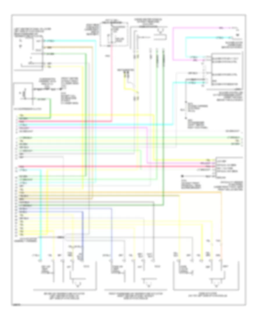
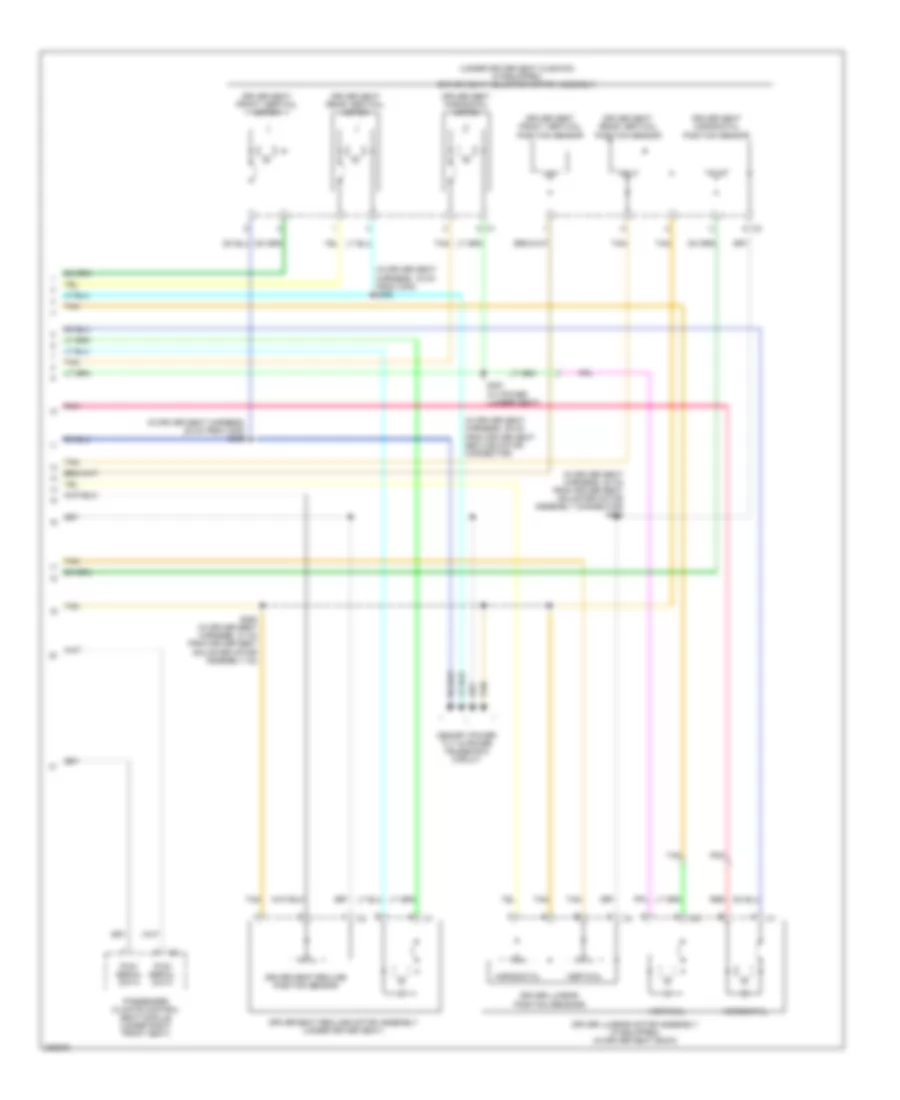
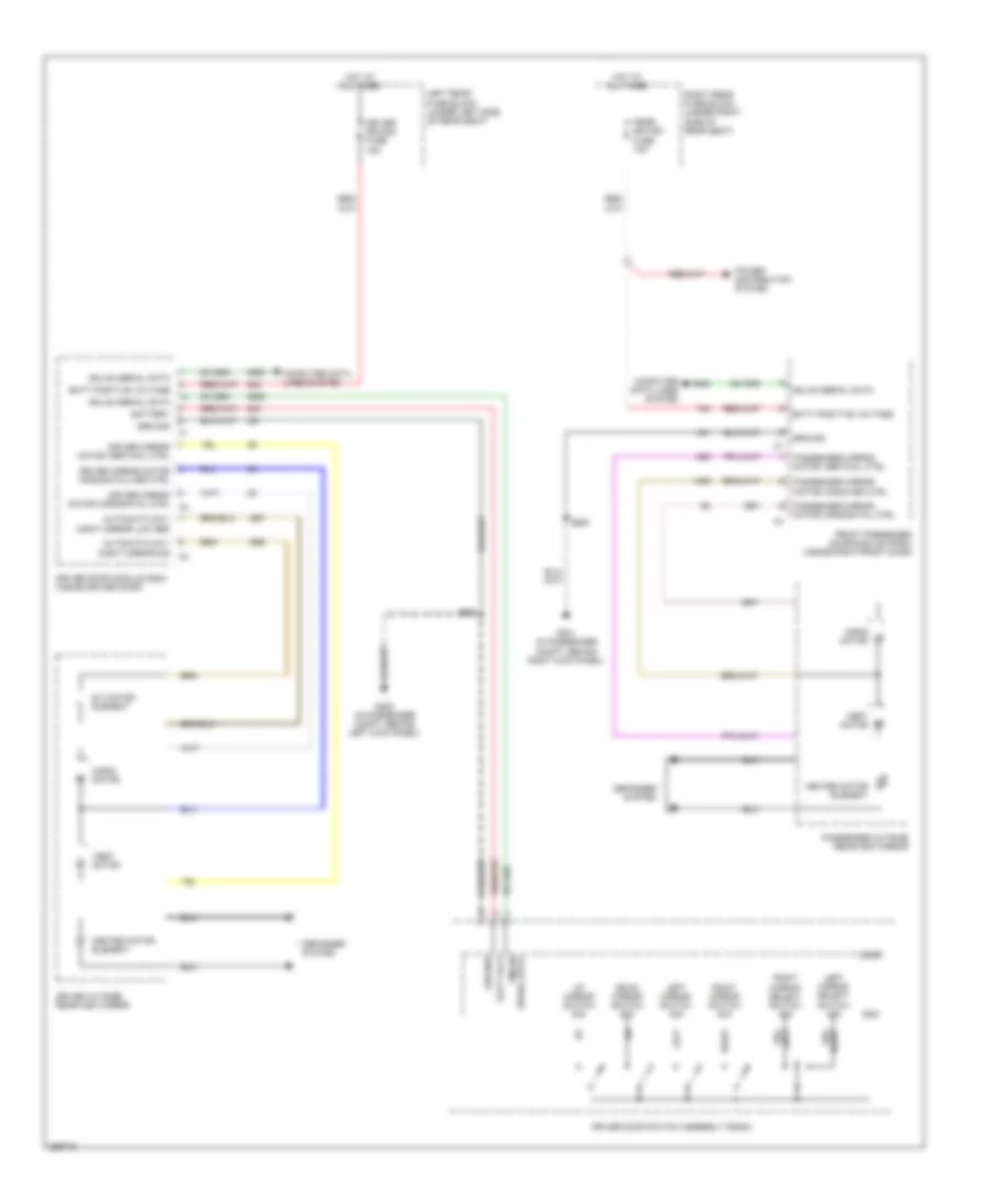
AIR CONDITIONING
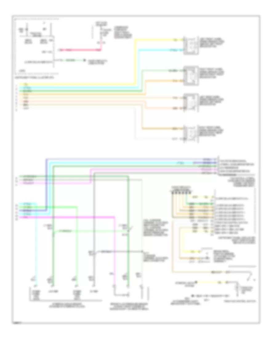
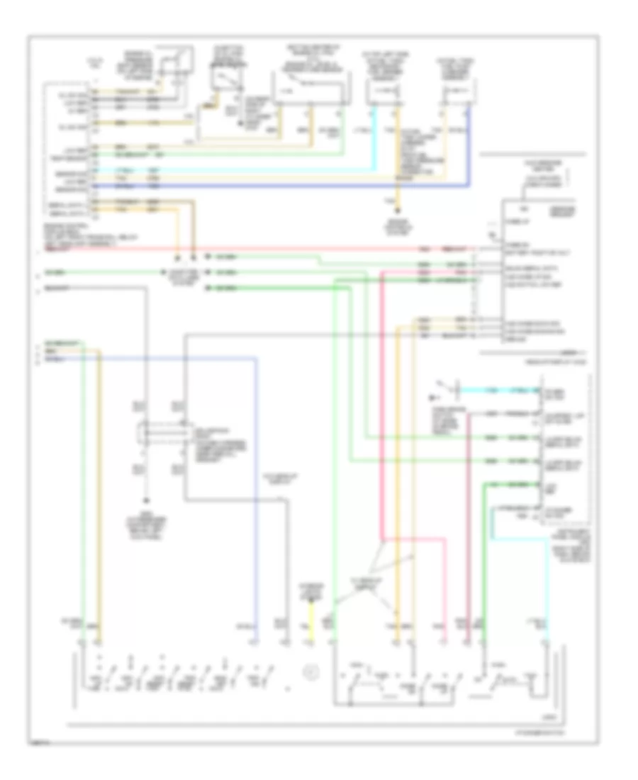
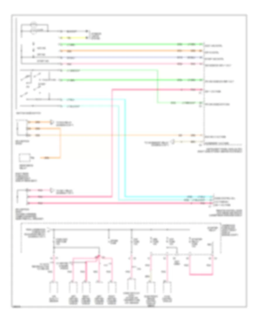
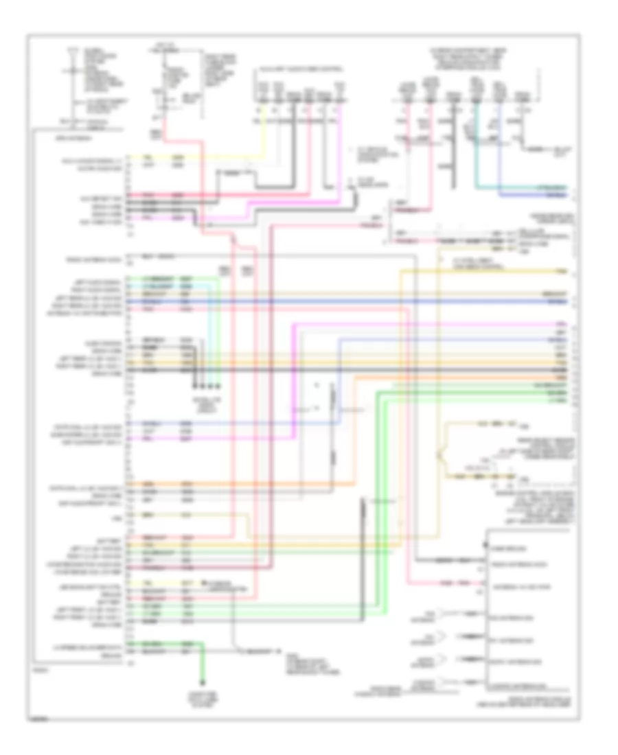
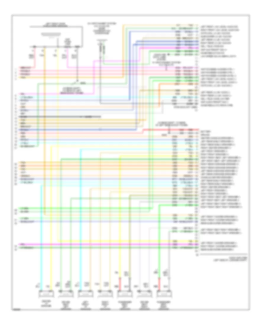
Automatic A/C Wiring Diagram (1 of 3) for Cadillac STS V 2007

List of elements for Automatic A/C Wiring Diagram (1 of 3) for Cadillac STS V 2007:
- (in dash harness, 35 cm from c214)
- (in dash harness, 51 cm from left front dash speaker connector)
- 5 volt ref
- A10
- A11
- A12
- Air quality hc sens sig
- Air quality nox sens sig
- Amb air temp sens sig
- Ambient light sens sig
- Ambient light sensor sig
- Aux inside air temp sens sig
- B10
- B11
- B12
- Battery
- Blower fuse 40a
- Blower mtr spd ctrl
- Blower relay
- Ccp fuse 10a
- Cmp clu relay
- Comp cltch fuse 10a
- Drv air temp dr ctrl b
- Drv air temp dr pos sig
- Drv temp dr ctrl a
- Evap low temp sens sig
- Evaporator temperature sensor (inside hvac case, at evaporator core)
- G201 (behind right kick panel)
- Gnd
- Hot at all times
- Hot in run or start
- Hot w/ run/ crank relay energized
- Hvac control module (in center of dash, below radio)
- Ign 1 volt
- Ign 3 volt
- Inside air temp sens ctrl
- Inside air temp sens sig
- Inside air temperature sensor (on dash, right of steering column)
- Interior lights system
- L sunload sens sig
- Led backlight dimming cntrl
- Left sunload sensor signal
- Low ref
- Low reference
- Low spd gmlan serial data
- Med blower motor ctrl
- Mode dr ctrl a
- Mode dr ctrl b
- Mode dr pos sig
- Nca
- Pass air temp dr ctrl a
- Pass air temp dr ctrl b
- Pass air temp dr pos sig
- Pnk
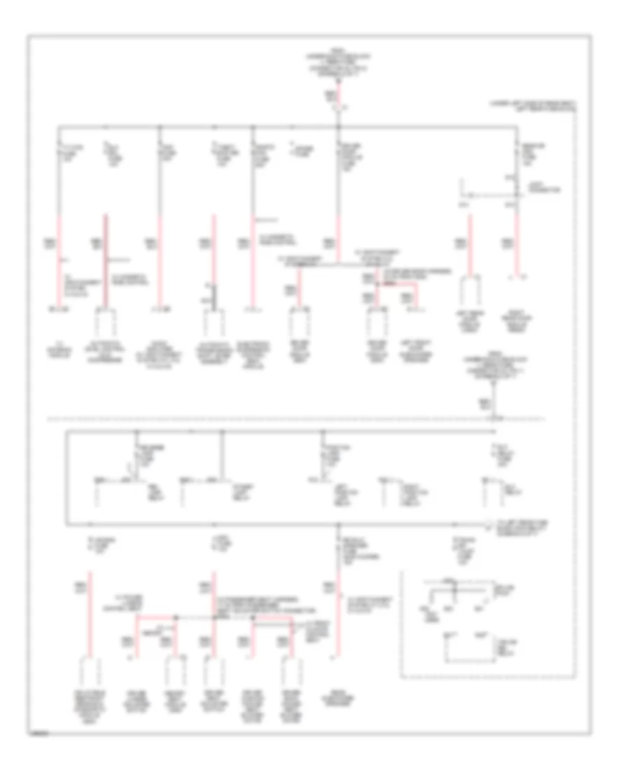
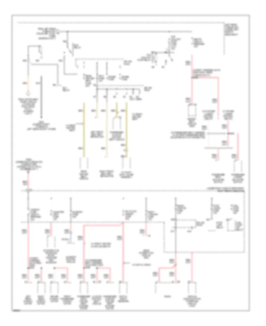
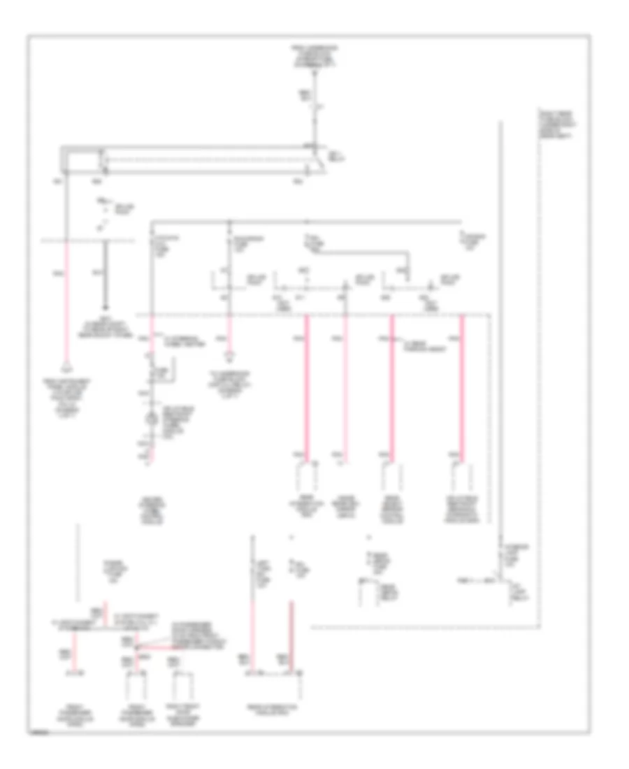
- Power distribution system
- R sunload sens sig
- R51
- R52
- R53
- R54
- R55
- R56
- R57
- R58
- Rear mode dr ctrl a
- Rear mode dr ctrl b
- Rear mode dr pos sig
- Rear mode sw sig
- Rear temp sw sig
- Recirc dr ctrl b
- Recirc dr pos sig
- Recirculation actuator (on hvac module, left of blower motor)
- Right sunload sensor signal
- S202
- S210
- S211 (in dash harness, 28 cm from c214)
- S222 (in hvac motor assembly harness)
- Seats system
- Solid state
- Sunload sensor (center of dash, in defroster grille)
- Tan
- Underhood fuse block (right front side of engine compt)
- Wash noz/ aqs fuse 10a
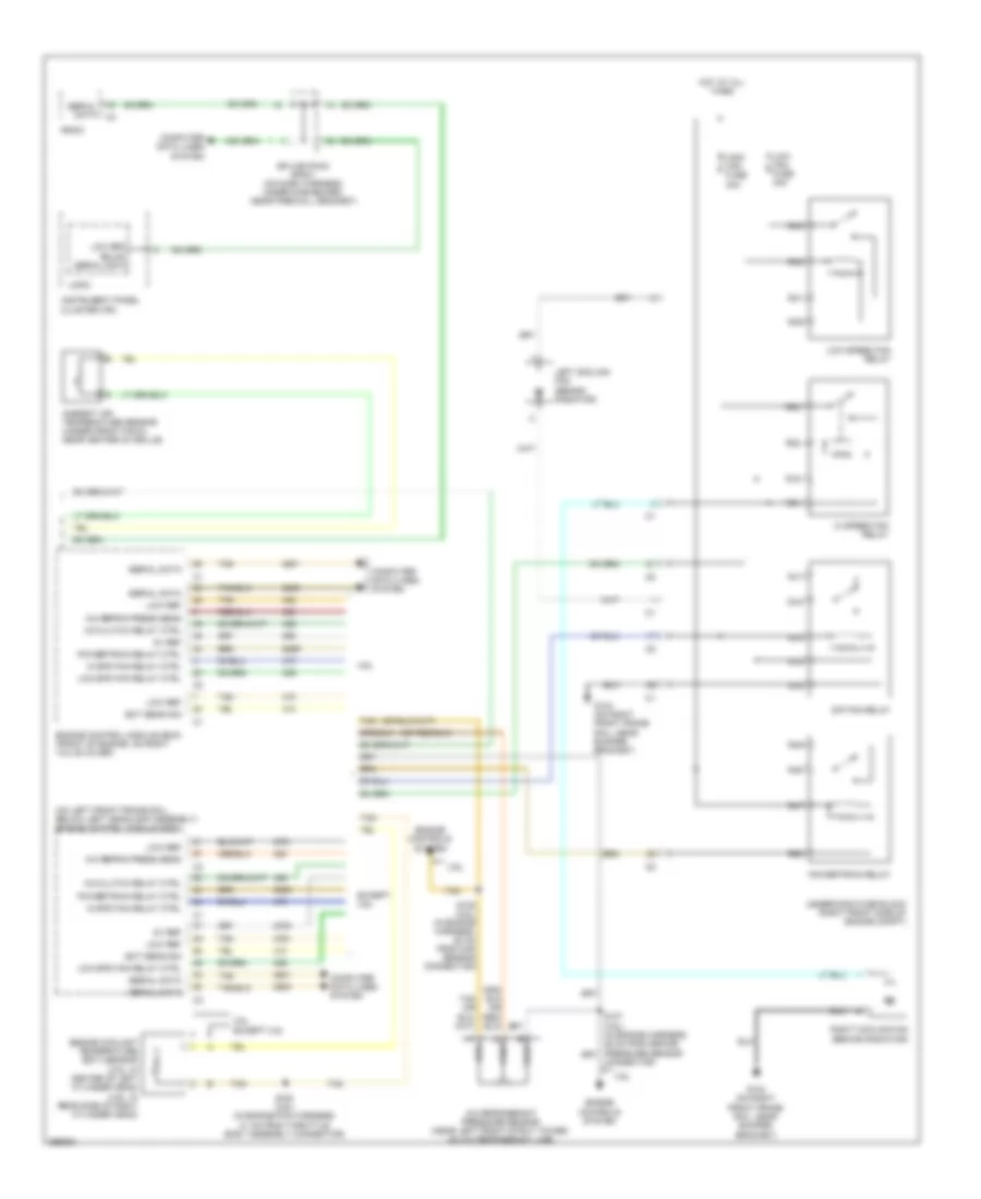
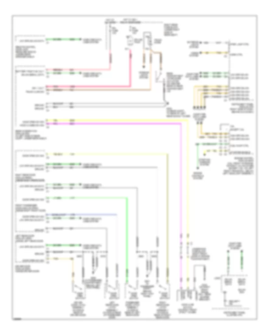
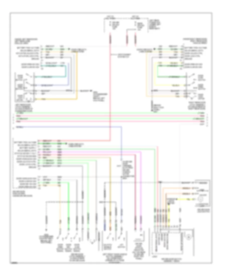
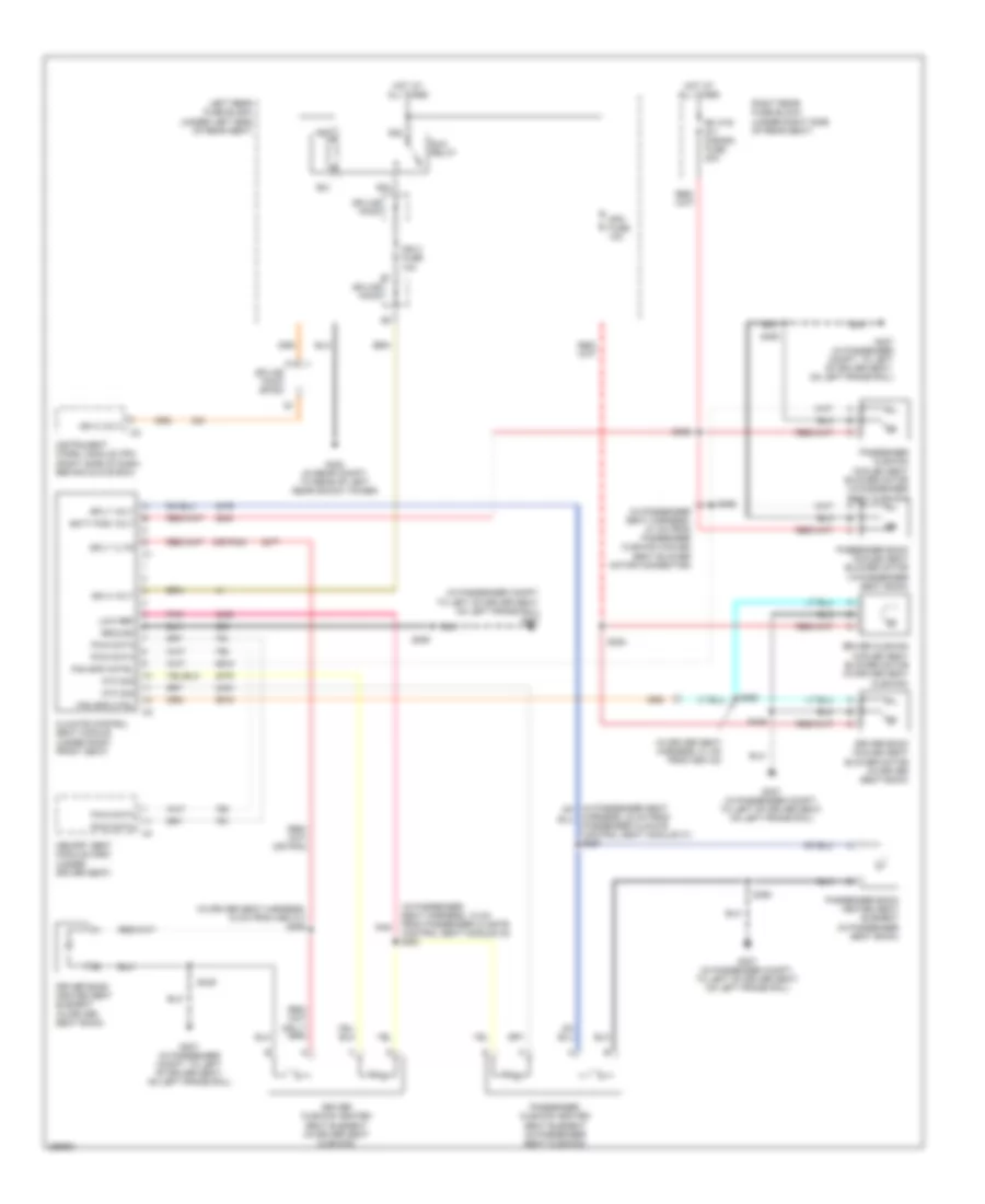
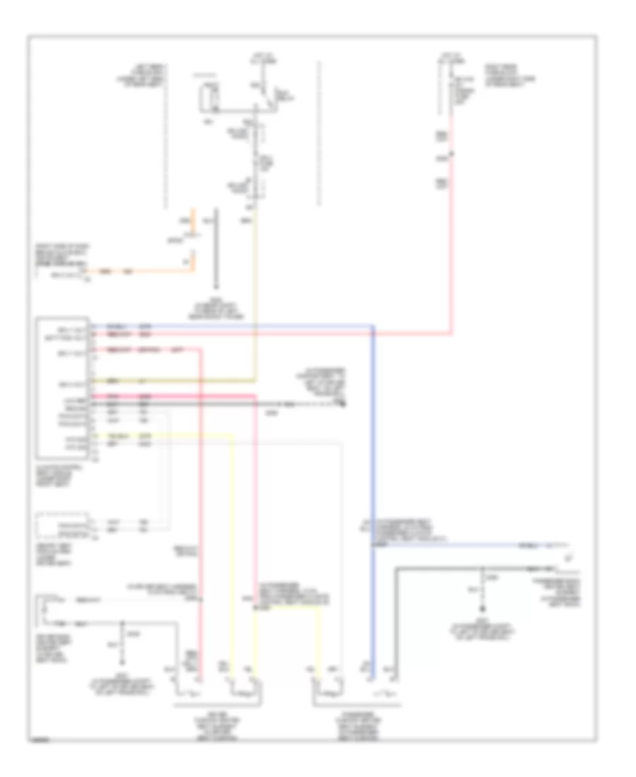
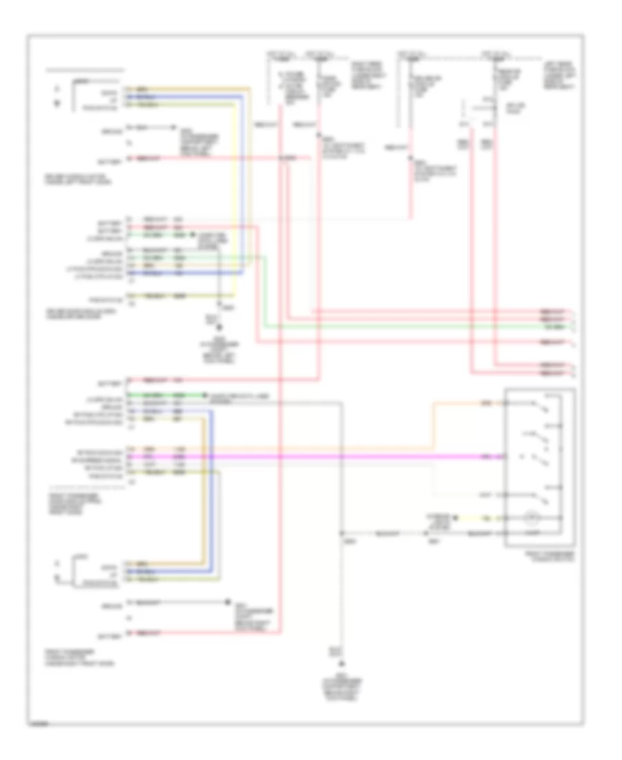
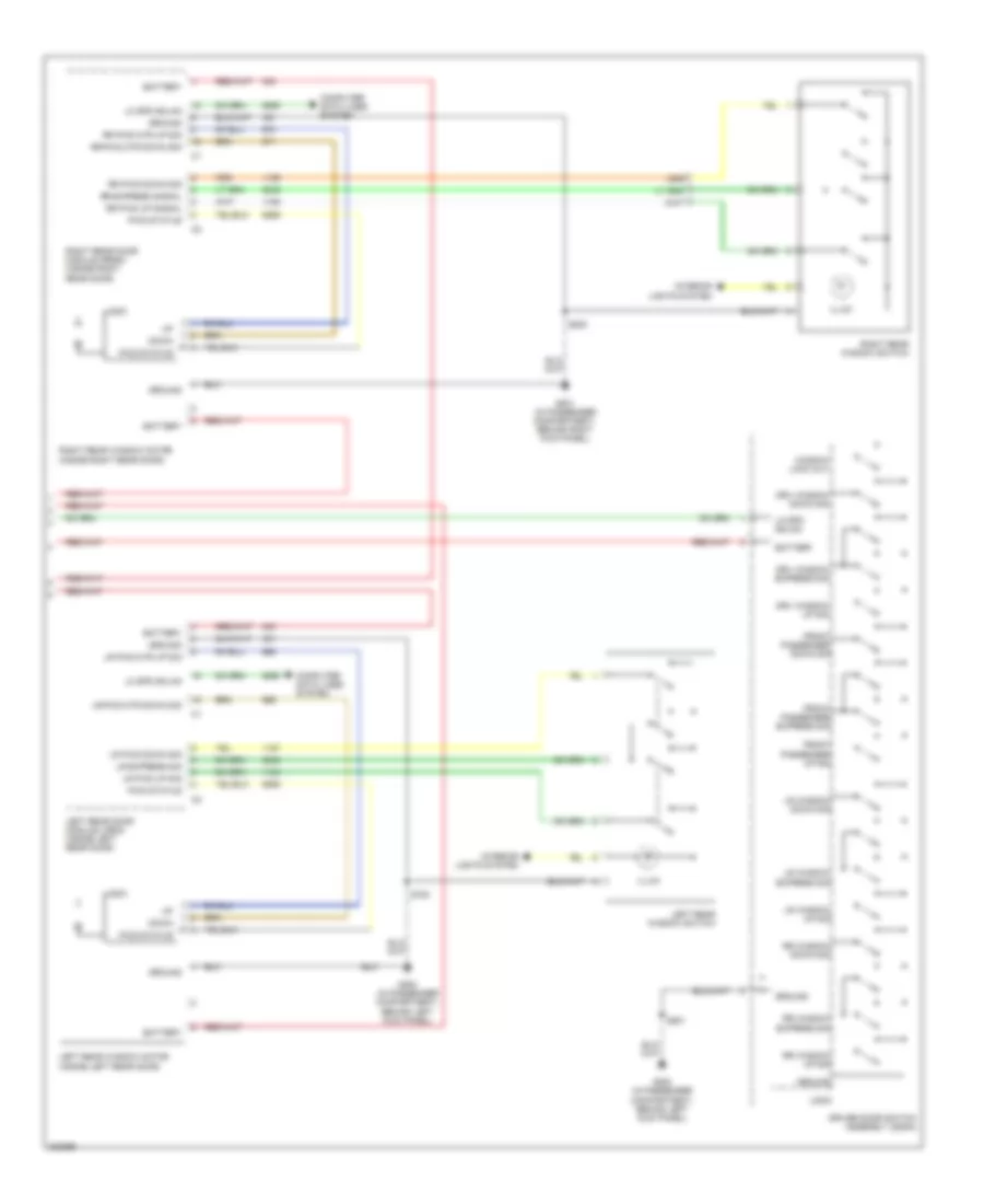
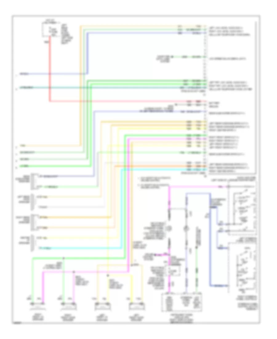
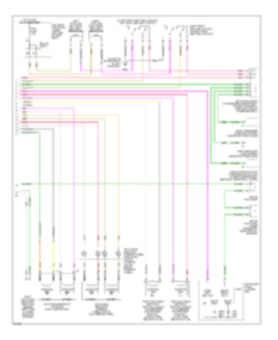
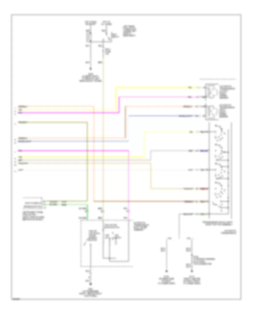
Automatic A/C Wiring Diagram (2 of 3) for Cadillac STS V 2007
List of elements for Automatic A/C Wiring Diagram (2 of 3) for Cadillac STS V 2007:
- (front center of right front cylinder head) (3.6l) g113
- (in engine poa harness, 39 cm from g113) (3.6l) s148
- (in hvac motor assembly harness)
- (inside center console, on right rear side) auxiliary mode actuator
- (left center of dash, on lower left side of hvac module) rear passenger air temperature actuator
- A/c compressor clutch
- Air qual hc sens
- Air qual nox sens
- Air quality sensor (if equipped) (under front facia, near front grille center)
- Blower controller (in the passenger compt, under the dash, behind the glove box)
- Blower motor (under dash, behind glove box)
- Blower mtr fan ctrl
- Blower mtr resistor
- Blower mtr spd ctrl
- Blower mtr sply volt
- Cold
- Def
- Driver air temperature actuator (left center of dash, on left side of hvac module)
- Dry air temp signal
- Front passenger air temperature actuator (right center of dash, on right side of hvac module)
- G100 (except 3.6l) (on rear side of right cylinder head)
- G104 (on right front frame rail, near bumper bracket)
- G201 (in passenger compt, behind right kick panel)
- Gnd
- Ground
- Hot
- Hot w/ ign 1 relay energized
- Ign 1 voltage
- Logic
- Low ref
- Mode actuator (on top left side of hvac module)
- Mode valve signal
- Pass air temp signal
- Pnk
- Right rear fuse block (under right side of rear seat)
- Run/crank fuse 10a
- S212 (in dash harness, 38 cm from ipm c3)
- S223
- Seats system
- Splice pack
- Tan
- Tan/ red
- Vent
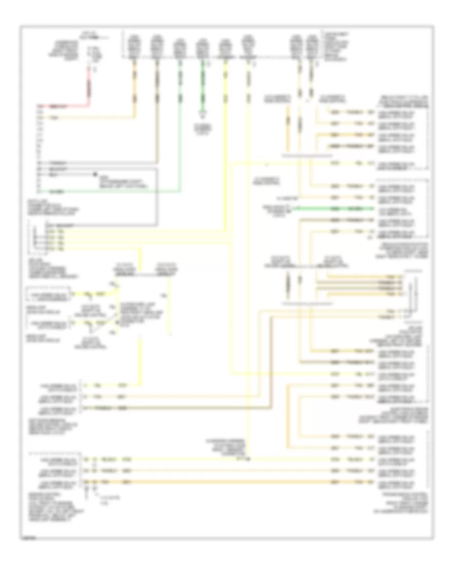
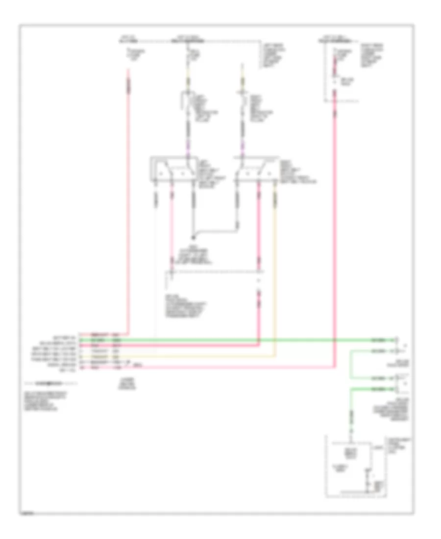
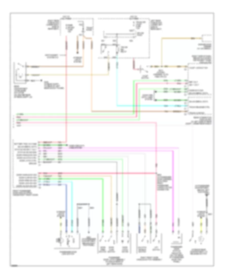
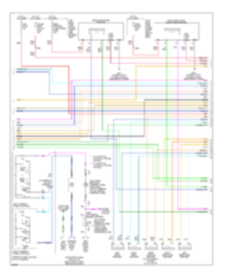
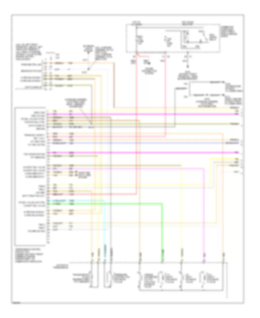
Automatic A/C Wiring Diagram (3 of 3) for Cadillac STS V 2007
List of elements for Automatic A/C Wiring Diagram (3 of 3) for Cadillac STS V 2007:
- (on left front frame rail, below left headlamp assembly) engine control module (ecm)
- 3.6l
- 5v ref
- A/c clutch relay ctrl
- A/c refrig press sens
- A/c refrigerant pressure sensor (near left front strut tower, on a/c refrigerant line)
- Ambient air temperature sensor (under front facia, near center of grille)
- Computer data lines system
- Connector)
- Ect sens sig
- Engine control module (ecm) (front of engine, on right valve cover)
- Engine controls system
- Engine coolant temperature (ect) sensor (3.6l: in center of left cylinder head) (4.6l: in rear side of right cylinder head)
- Except 3.6l
- Feed
- G104 (on right front frame rail, near bumper bracket)
- Hi spd fan relay ctrl
- Hi speed fan relay
- High fan fuse 30a
- Hot at all times
- Instrument panel cluster (ipc)
- Left cooling fan (behind radiator)
- Logic
- Low fan fuse 30a
- Low ref
- Low spd fan relay ctrl
- Low spd gmlan serial data
- Low speed fan relay
- Powertrain relay
- Powertrain relay ctrl
- R14
- R15
- R16
- R17
- R18
- R19
- R20
- R21
- R22
- R39
- R40
- R41
- R42
- R47
- R48
- R49
- R50
- Radio
- Right cooling fan (behind radiator)
- Rtn
- S/p fan relay
- S108 (3.6l) (in engine harness, 28 cm from maf sensor connector)
- S120 (3.6l) (in engine poa harness, 21 cm from throttle body assembly connector)
- Serial data
- Sig
- Splice pack sp201 (on dash harness, under dashboard, near firewall grommet)
- Tan
- Underhood fuse block (right front side of engine compt)
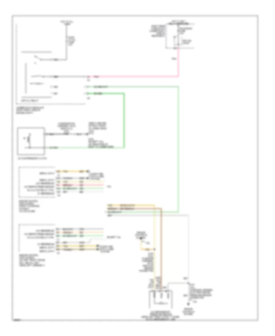
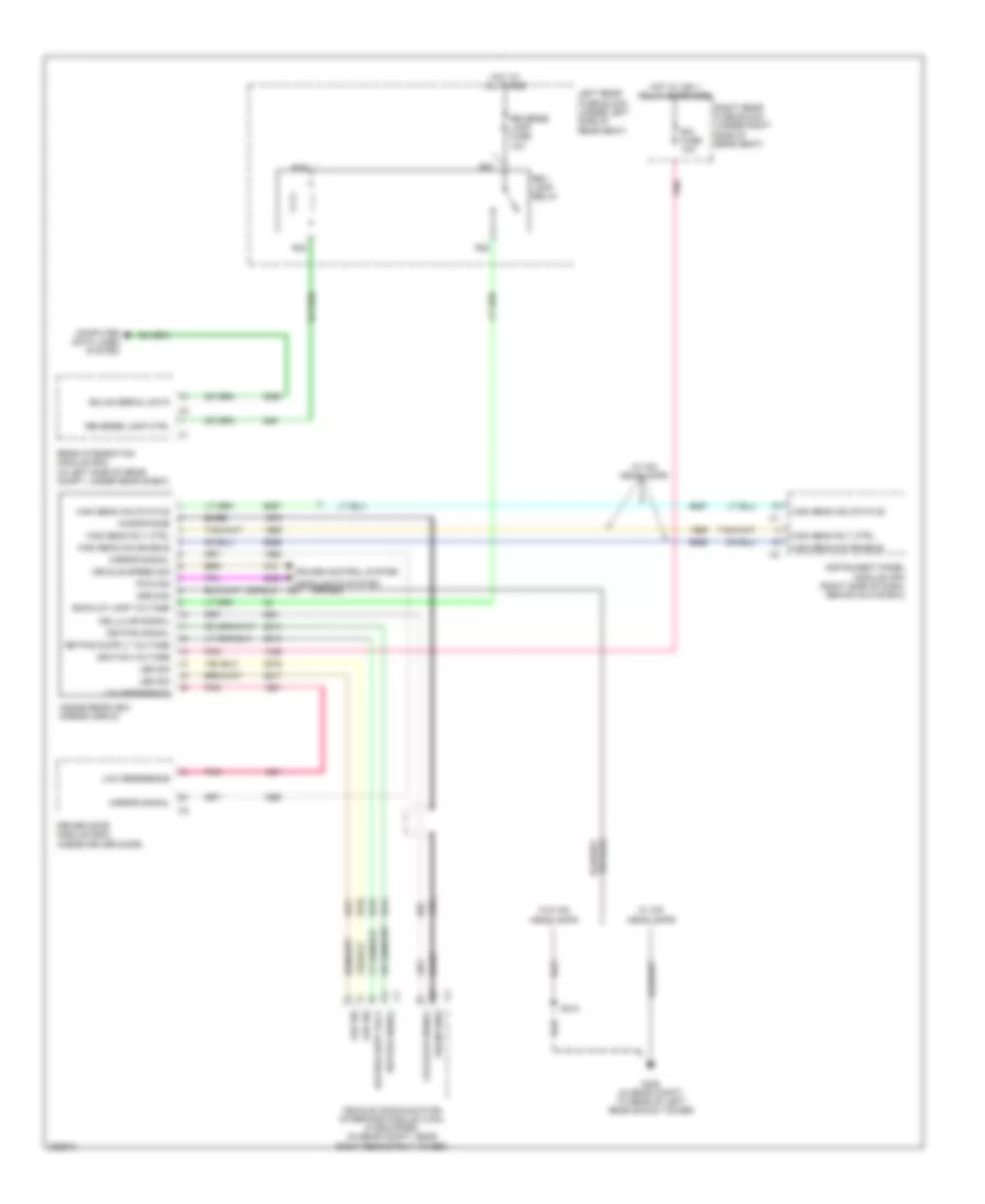
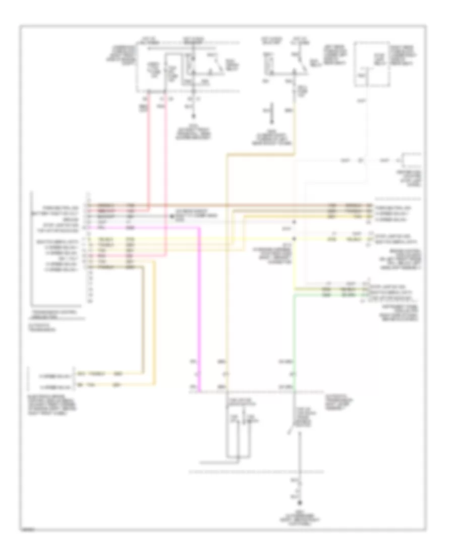
Compressor Wiring Diagram for Cadillac STS V 2007
List of elements for Compressor Wiring Diagram for Cadillac STS V 2007:
- (front center of right front cylinder head) (3.6l) g113
- (in engine poa harness, 39 cm from g113) (3.6l) s148
- 3.6l
- 5v reference
- A/c clutch relay ctrl
- A/c compressor clutch
- A/c refrig press sensor
- A/c refrigerant pressure sensor (near left front strut tower, on a/c refrigerant line)
- Cmp clu relay
- Comp cltch fuse 10a
- Computer data lines system
- Connector)
- Engine control module (ecm) (front of engine, on right valve cover)
- Engine control module (ecm) (on left front frame rail, below left headlight assembly)
- Engine controls system
- Except 3.6l
- Feed
- G100 (except 3.6l) (on rear side of right cylinder head)
- Hot at all times
- Hot w/ ign 1 relay energized
- Low reference
- Pnk
- R55
- R56
- R57
- R58
- Right rear fuse block (under right side of rear seat)
- Rtn
- Run/crank fuse 10a
- S108 (3.6l) (in engine harness, 28 cm from maf sensor connector)
- Serial data
- Sig
- Splice pack
- Tan
- Underhood fuse block (right front side of engine compt)
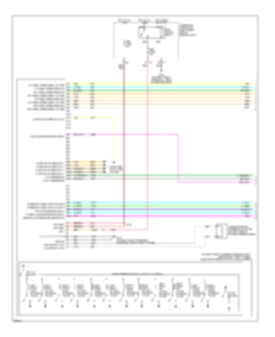
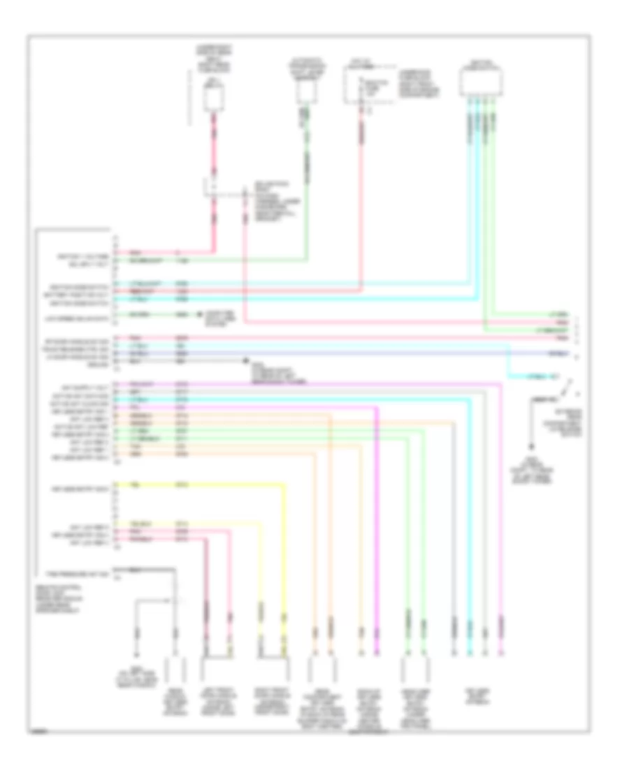
ANTI-LOCK BRAKES
Anti-lock Brakes Wiring Diagram (1 of 2) for Cadillac STS V 2007
List of elements for Anti-lock Brakes Wiring Diagram (1 of 2) for Cadillac STS V 2007:
- (on right front corner of engine compt, behind right front wheel) electronic brake control module (ebcm)
- 5-volt reference
- A10
- A11
- A12
- A13
- A14
- Abs fuse 15a
- Abs fuse 50a
- B10
- B11
- B12
- B13
- B14
- Battery
- Brake fluid pressure sensor sig
- Brake pressure modulator valve (bpmv)
- C10
- Computer data lines system
- G104 (on right front frame rail, near bumper bracket)
- G110 (on right front frame rail, near right front strut tower)
- Ground
- Hi spd gmlan ser data +
- Hi spd gmlan ser data -
- Hi spd gmlan ser data w/u
- High effort ctrl
- Hot at all times
- Hot in run or start
- Ign 1
- Lateral accelerometer signal
- Left front inlet solenoid valve
- Left front iso- lation solenoid valve
- Left front outlet solenoid valve
- Left front prime solenoid valve
- Left rear inlet solenoid valve
- Left rear outlet solenoid valve
- Lf wheel speed sens low ref
- Lf wheel speed sens sig
- Long accelerometer signal
- Low effort ctrl
- Low reference
- Lr wheel speed sens low ref
- Lr wheel speed sens sig
- Motor control
- Pnk
- R43
- R44
- R45
- R46
- Rf wheel speed sens low ref
- Rf wheel speed sens sig
- Right front inlet solenoid valve
- Right front iso- lation solenoid valve
- Right front outlet solenoid valve
- Right front prime solenoid valve
- Right rear inlet solenoid valve
- Right rear outlet solenoid valve
- Rr wheel speed sens low ref
- Rr wheel speed sens sig
- Run/ crank relay
- S100
- Sol vlv control
- Steering wheel position sig a
- Steering wheel position sig b
- Tan
- Underhood fuse block (right front side of engine compt)
- Variable effort steering actuator (on left side of power steering gear)
- Yaw rate sensor signal
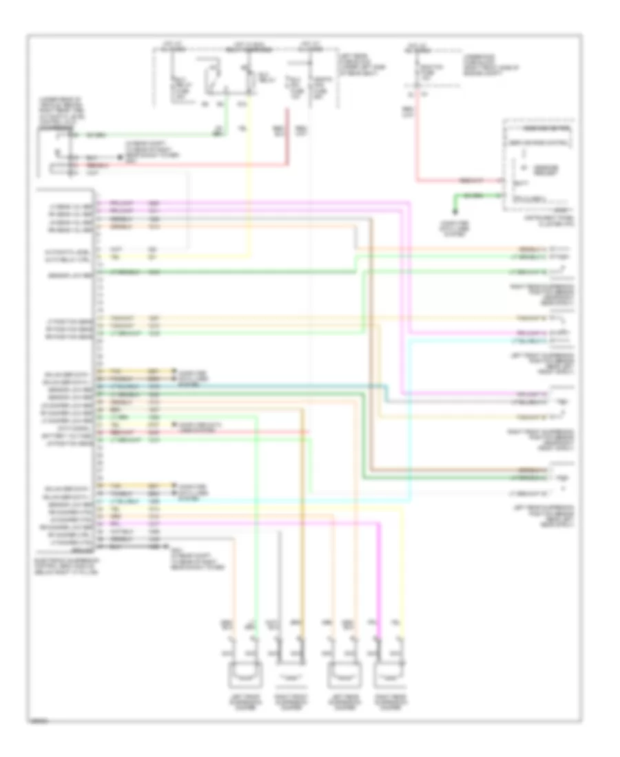
Anti-lock Brakes Wiring Diagram (2 of 2) for Cadillac STS V 2007
List of elements for Anti-lock Brakes Wiring Diagram (2 of 2) for Cadillac STS V 2007:
- (3.6l: in engine harness, 30 cm from ebcm connector) (4.6l: in engine harness, 25 cm from brake pressure sensor connector)
- (in passenger compt, behind right kick panel)
- 5v ref
- 5v reference
- Abs ind
- Brake fluid pressure sensor (in right front corner of engine compt, on rear of ebcm)
- Brake pedal position sensor (attached to top of brake pedal assembly)
- Computer data lines system
- Ebcm gmlan
- G201
- Hi spd gmlan ser data +
- Hi spd gmlan ser data -
- Hi spd gmlan ser data w/u
- Hot in on or start
- Ign
- Ign 1 vol
- Instrument panel cluster (ipc)
- Instrument panel module (ipm) (right side of dash, behind glove box)
- Interior lights system
- Lateral accelerometer sig
- Left front wheel speed sensor (wss) (behind left front brake rotor)
- Left rear wheel speed sensor (wss) (behind left rear brake rotor)
- Lo spd gmlan ser data
- Logic
- Long accelerometer sig
- Low ref
- Low reference
- Pnk
- Right front wheel speed sensor (wss) (behind right front brake rotor)
- Right rear wheel speed sensor (wss) (behind right rear brake rotor)
- S117 (in engine harness, 36 cm from ebcm connector)
- S118
- S311
- Steer wheel pos sig a
- Steer wheel pos sig b
- Steering angle sensor (on base of steering column)
- Tan
- Tcm/ipc fuse 15a
- Traction control ind
- Traction control switch
- Traction off ind
- Underhood fuse bock (right front side of engine compartment)
- Yaw rate & lateral acceleration sensor (under the front passenger seat)
- Yaw rate sens signal
ANTI-THEFT
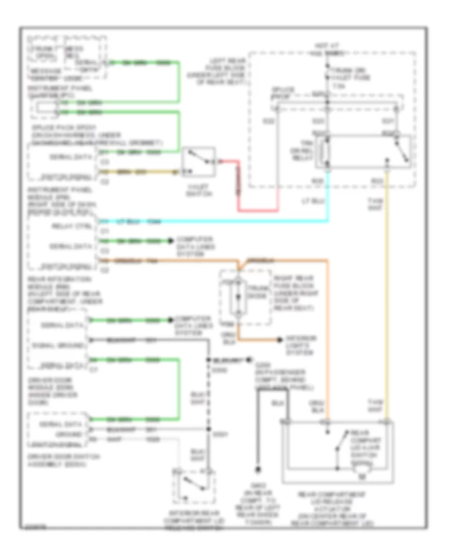
Anti-theft Wiring Diagram for Cadillac STS V 2007
List of elements for Anti-theft Wiring Diagram for Cadillac STS V 2007:
- 3.6l
- A open sw sig
- B closed sw sig
- Battery positive volt
- Computer data lines system
- Door open sw sig
- Door open switch
- Driver door latch assembly (in middle rear of driver door)
- Driver door module (ddm) (inside driver door)
- Engine control module (ecm) (3.6l: front of engine, on right valve cover) (except 3.6l: on left front frame rail, below left headlamp assembly)
- Engine controls system
- Except 3.6l
- Exterior lights system
- Fd1
- Fd2
- Front passenger door module (fpdm) (inside right front door)
- Fuel pump ctrl
- G104 (on right front frame rail, near bumper bracket)
- G200 (in passenger compartment, behind left kick panel)
- G201 (in passenger compt, behind right kick panel)
- G402 (in rear compt, to rear of left rear shock tower)
- Gmlan (rim)
- Gmlan serial data
- Ground
- High spd gmlan+
- High spd gmlan-
- Hood ajar switch (on right front strut tower)
- Hood closed sw sig
- Hood open sw sig
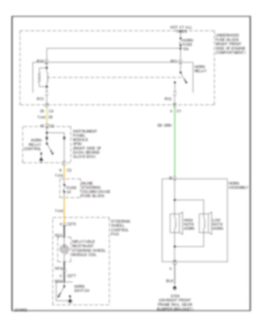
- Horn ctrl
- Horns system
- Hot at all times
- Hot w/ ign 1 relay energized
- Ign
- Ign 1 volt
- Instrument panel cluster (ipc)
- Instrument panel module (ipm) (right side of dash, behind glove box)
- Interior lights system
- Left rear door latch assembly (in middle rear of passenger door)
- Left rear door module (lrdm) (inside left rear door)
- Logic
- Low spd gmlan
- Low spd gmlan data
- Park lamp ctrl
- Passenger door latch assembly (in middle rear of left rear door)
- Pnk
- Rear compartment lid release actuator (on center rear of rear compartment lid)
- Rear integration module (rim) (in left side of rear compt, under rear shelf)
- Remote control door lock receiver (rcdlr) (under rear speaker shelf)
- Right rear door latch assembly (in middle rear of right rear door)
- Right rear door module (rrdm) (inside right rear door)
- Right rear fuse block (under right side of rear seat)
- Rim fuse 10a
- S11
- S500
- S600
- S700
- S800
- Security ind
- Splice pack
- Starter enable
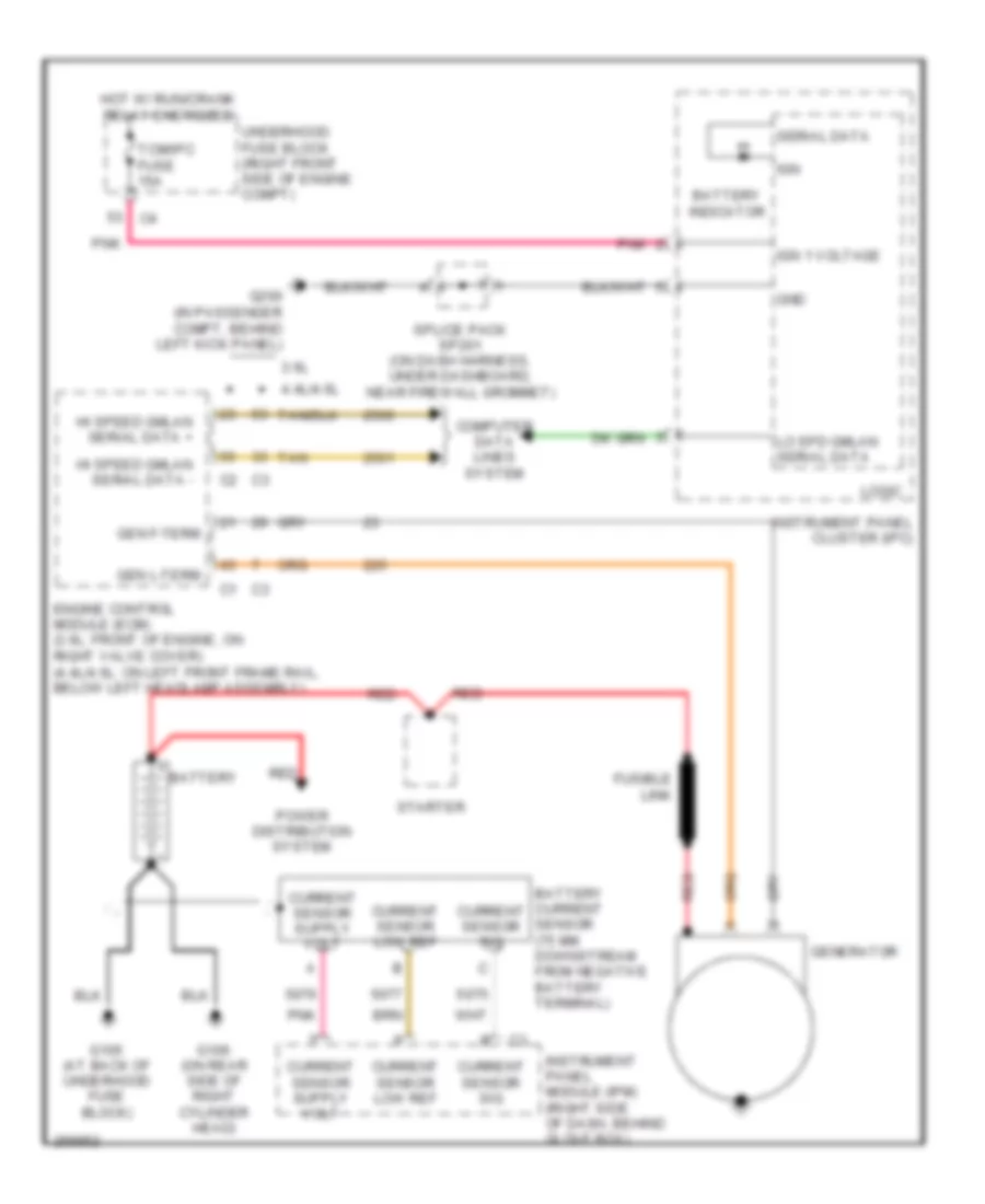
- Starting/ charging system
- Tan
- Trunk ajar sig
- Trunk diode
- Underhood fuse block (right front side of engine c1 compartment)
BODY CONTROL MODULES
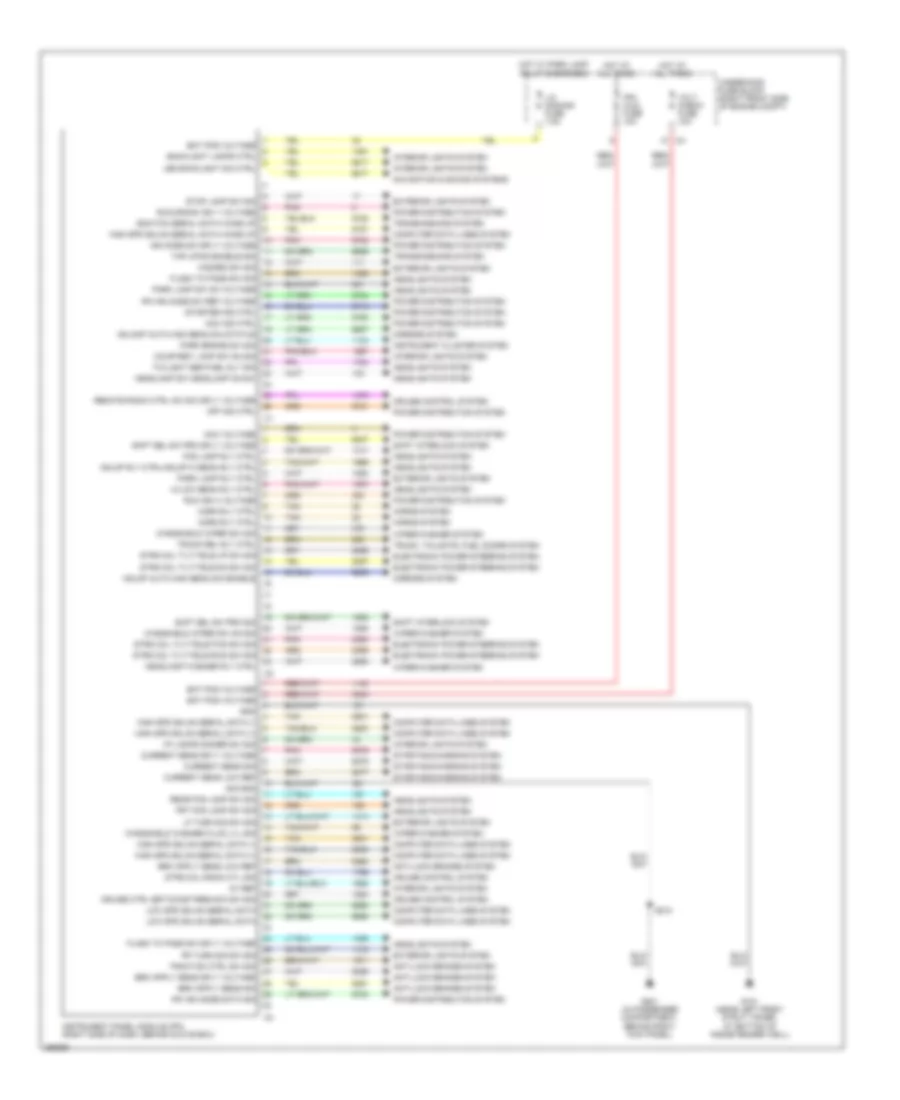
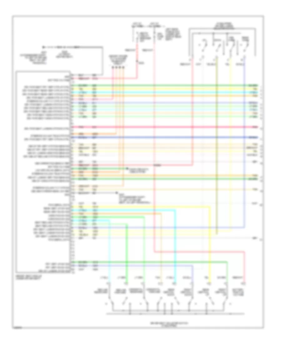
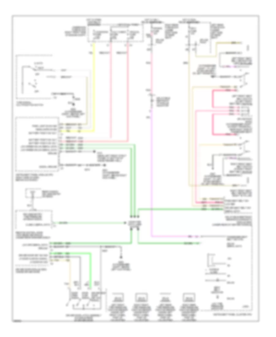
Instrument Panel Module Wiring Diagram for Cadillac STS V 2007
List of elements for Instrument Panel Module Wiring Diagram for Cadillac STS V 2007:
- 5v ref
- Acc ind ctrl
- Acc voltage
- Anti-lock brakes system
- Backlight lamps ctrl
- Bat pos voltage
- Computer data lines system
- Courtesy lamp sw on sig
- Cruise control system
- Cruise ctrl set/coast/res/acc sw sig
- Current sens low ref
- Current sens sig
- Current sens sply voltage
- Ecm/tcm serial data wake up
- Electronic power steering system
- Exterior lights system
- Flash to pass sw sig
- Flash to pass sw sply voltage
- Fog lamp rly ctrl
- Frt fog lamp sw sig
- G101 (near left front strut tower, at bottom of inside fender well)
- G201 (in passenger compartment, behind right kick panel)
- Gnd
- Hazard sw sig
- Hdlamp auto high beam dim status
- Hdlmp auto high beam dim enable
- Hdlmp rly ctrl/hdlmp hi beam rly ctrl
- Headlamp sw headlamp on sw
- Headlamp washer rly ctrl
- Headlights system
- Hi/low beam rly ctrl
- High spd gmlan serial data (+)
- High spd gmlan serial data (-)
- High spd gmlan serial data wake up
- Horn rly ctrl
- Horns system
- Hot at all times
- Hot w/ park lamp relay energized
- I/p lamps dimmer sw sig
- Ign mode sw sply voltage
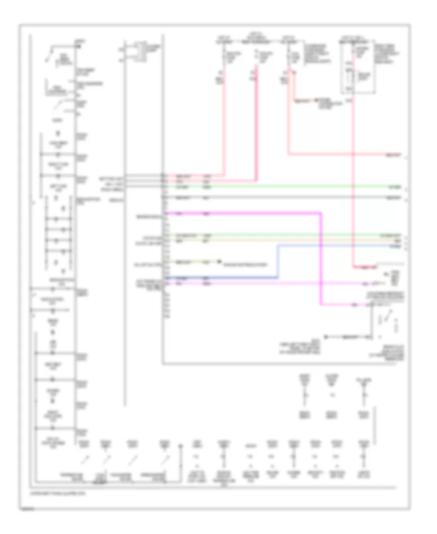
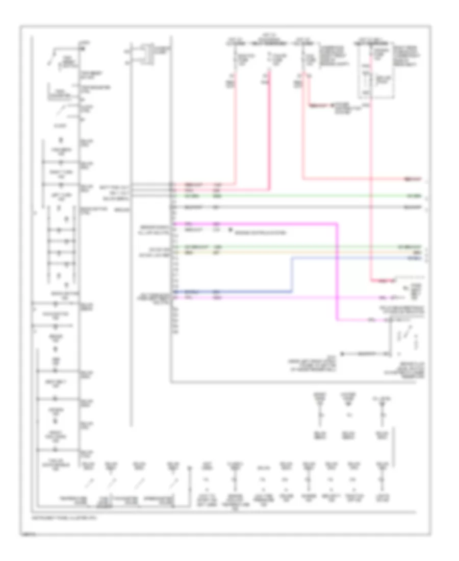
- Instrument cluster system
- Instrument panel module (ipm) (right side of dash, behind glove box)
- Interior lights system
- Ipm ign mode data sig
- Ipm ign mode sw ref voltage
- Ipm/ aldl fuse 10a
- Led backlight dim ctrl
- Lf turn sig sw sig
- Lic dimming fuse 7.5a
- Low spd gmlan serial data
- Mirrors system
- Navigation & sound systems
- Off ind ctrl
- Park brake sw sig
- Park lamp rly ctrl
- Park lamp sw on voltage
- Pnk
- Power distribution system
- Rear fog lamp sw sig
- Remote radio ctrl hd acc sply voltage
- Rf turn sig sw sig
- Run ign 3 voltage
- Run/crank ign 1 voltage
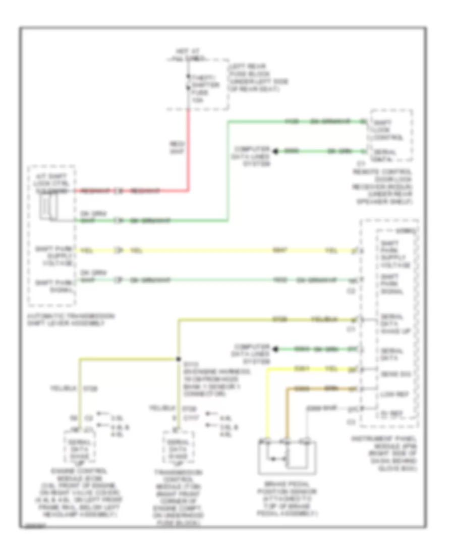
- S210
- Shft sel sw prk sig
- Shft sel sw prk sply voltage
- Shift interlock system
- Sig gnd
- Starter ind ctrl
- Starting/charging system
- Stop lamp sw sig
- Strg col radio ctl sig
- Strg col tilt/tele dn sw sig
- Strg col tilt/tele fwd sw sig
- Strg col tilt/tele rwd sw sig
- Strg col tilt/tele up sw sig
- Tan
- Tap up/dn enable sig
- Traction ctrl sw sig
- Transmissions system
- Trunk rel rly ctrl
- Trunk, tailgate, fuel doors system
- Twilight sentinel dly sig
- Underhood fuse block (right front side of engine compt)
- Volt check fuse 10a
- Windshield washer fluid lvl sig
- Windshield wiper sw on sig
- Windshield wiper sw sig
- Wiper/washer system
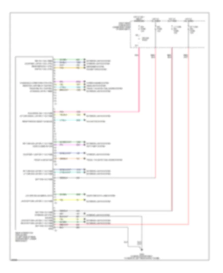
Rear Integration Module Wiring Diagram for Cadillac STS V 2007
List of elements for Rear Integration Module Wiring Diagram for Cadillac STS V 2007:
- Anti-theft system
- Bat pos voltage
- Computer data lines system
- Courtesy lamp sply voltage
- Courtesy lmp rly coil ctrl
- Defogger system
- Exterior lights system
- G402 (in rear compartment, to rear of left rear shock tower)
- Gnd
- Headlights system
- Hood closed sw sig
- Hot at all times
- Hot w/ ign 1 relay energized
- Interior lights system
- Interior lmp ctrl
- Lf turn sig lmp sply voltage
- Low spd gmlan serial data
- Lr stop/turn lmp sply voltage
- Lr turn signal lmp sply voltage
- Lt turn rim fuse 10a
- Navigation system
- Pnk
- Power tops system
- Rap rly coil ctrl
- Rear defog rly ctrl
- Rear fog lamp relay control
- Rear integration module (rim) (in left side of rear compartment, under rear shelf)
- Rear parking assist chime sig
- Rev rly coil feed
- Rf turn sig lmp sply voltage
- Right rear fuse block (under right side of rear seat)
- Rim fuse 10a
- Rr stop/turn lmp sply voltage
- Rr turn sig lmp sply voltage
- Rt turn rim fuse 10a
- Run/crank ign 1 voltage
- S11
- Sig gnd
- Splice pack
- Standing lmp rly feed
- Tan
- Trunk ajar sw sig
- Trunk rel rly control
- Trunk, tailgate, fuel doors system
- Windshield wiper park mtr ctrl
- Wiper/washer system
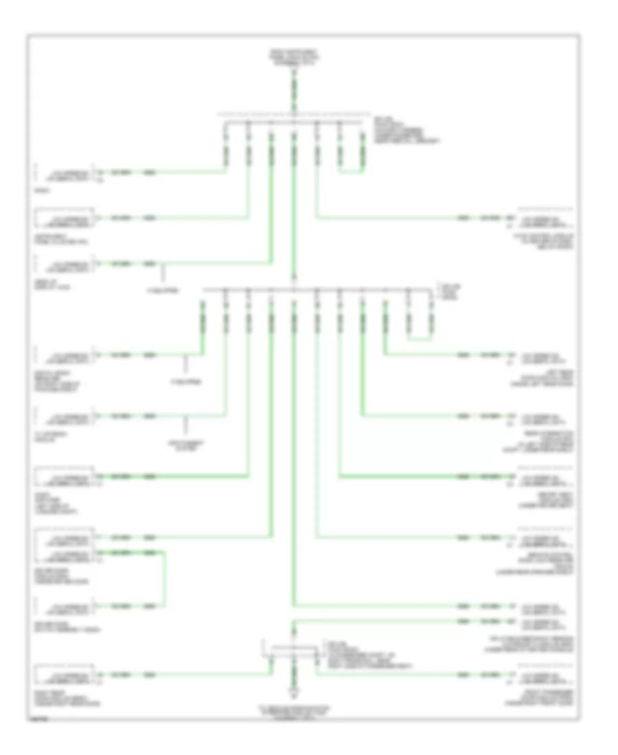
COMPUTER DATA LINES
Computer Data Lines Wiring Diagram (1 of 2) for Cadillac STS V 2007
List of elements for Computer Data Lines Wiring Diagram (1 of 2) for Cadillac STS V 2007:
- (below right "c" pillar) electronic suspension (esc) control module
- (in engine harness, 19 cm from ho2s bank 1 sensor 1 connector) s113
- (in forward lamp harness, 31 cm from right headlamp leveling actuator connector) s116
- 3.6l
- 4.4l & 4.6l
- A11
- B10
- B11
- B12
- Data link connector (dlc) (under left side of dash, near steering column)
- Data wake-up
- Distance sensing cruise control module (behind front fascia, near hood latch)
- Electronic brake control module (ebcm) (on right front corner of engine compt, behind right front wheel)
- Engine control module (ecm) (3.6l: front of engine, on right valve cover) (except 3.6l: on left front frame rail, below left headlamp assembly)
- From sp303 (diagram 2 of 2)
- G200 (in passenger compt, behind left kick panel)
- Headlamp leveling module
- High speed gmlan
- High speed gmlan data wake-up
- High speed gmlan data wakeup
- High speed gmlan ecm/ tcm wakeup
- High speed gmlan serial data bus +
- High speed gmlan serial data bus -
- Hot at all times
- Instrument panel module (ipm) (right side of dash, behind glove box)
- Ipm/ aldl fuse 10a
- Low speed gm lan serial data
- Low speed gmlan serial data
- Splice pack sp100 (on forward lamp harness, left of center, behind front bumper)
- Splice pack sp201 (on dash harness, under dashboard, near firewall grommet)
- Tan
- To sp201 (diagram 2 of 2)
- Transmission control module (tcm) (right front corner of engine compt, on underhood fuse block)
- Underhood fuse block (right front side of engine compt)
- Vehicle communication interface module (vcim) (in rear compt, near right rear strut tower)
- W/ auto adaptive cruise control
- W/ auto headlamps leveling
- W/ magnetic ride control
- W/ onstar
- W/o auto adaptive cruise control
- W/o auto headlamps leveling
- W/o magnetic ride control
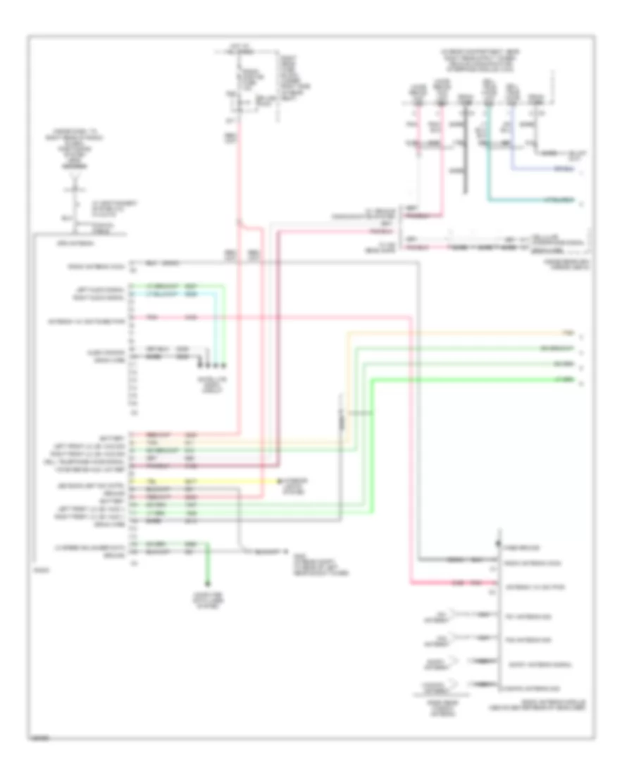
Computer Data Lines Wiring Diagram (2 of 2) for Cadillac STS V 2007
List of elements for Computer Data Lines Wiring Diagram (2 of 2) for Cadillac STS V 2007:
- Audio amplifier (left side of luggage compt)
- Digital radio receiver (on right side of package shelf)
- Driver door module (ddm) (inside driver door)
- Driver door switch assembly (ddsa)
- From instrument panel module (ipm) (diagram 1 of 2)
- Front passenger door module (fpdm) (inside right front door)
- Head up display (hud)
- Hvac control module (in center of dash, below radio)
- If equipped
- Inflatable restraint sensing & diagnostic module (sdm) (under rear of center console)
- Infotainment system
- Instrument panel cluster (ipc)
- Left rear door module (lrdm) (inside left rear door)
- Low speed gm lan serial data
- Memory seat module (msm) (under driver seat)
- Radio
- Rear integration module (rim) (in left side of rear compt, under rear shelf)
- Remote control door lock receiver (rcdlr) (under rear speaker shelf)
- Right rear door module (rrdm) (inside right rear door)
- Splice pack sp201 (on dash harness, under dashboard, near firewall grommet)
- Splice pack sp300
- Splice pack sp303 (in passenger compt, on right frame rail, near right side of passenger seat)
- To vehicle communication interface module (vcim) (diagram 1 of 2)
- Tv antenna module
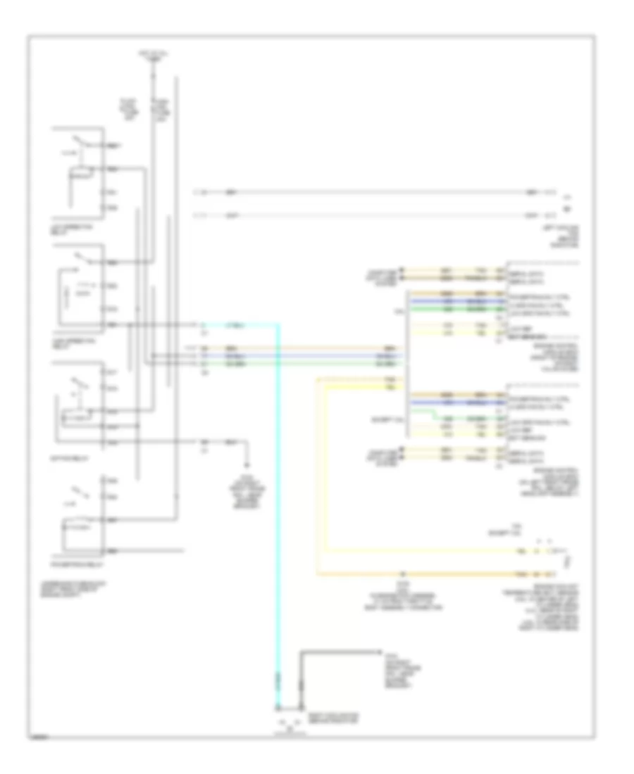
COOLING FAN
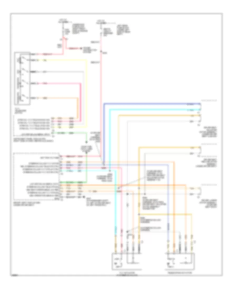
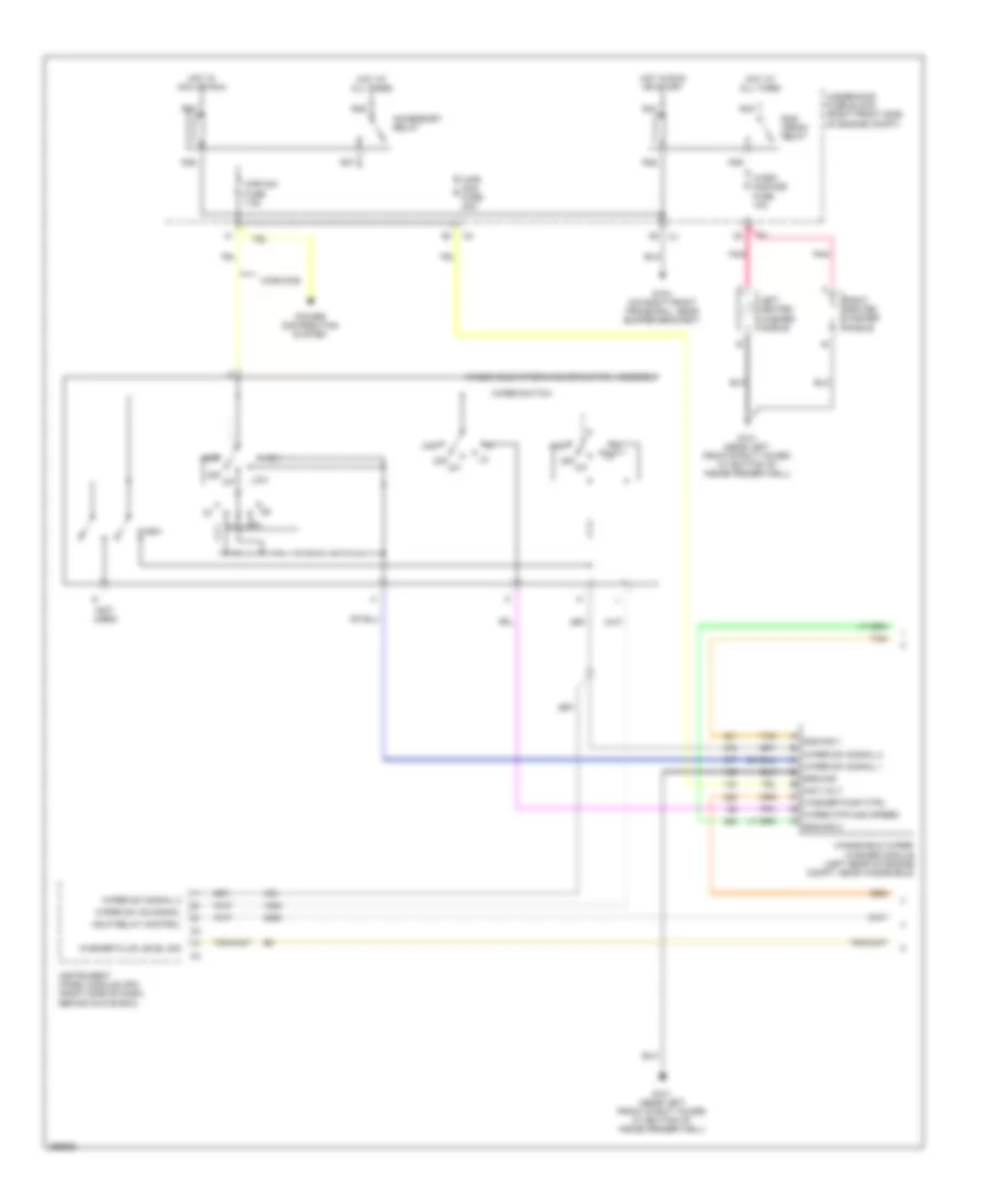
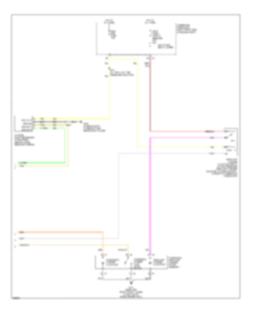
Cooling Fan Wiring Diagram for Cadillac STS V 2007
List of elements for Cooling Fan Wiring Diagram for Cadillac STS V 2007:
- 3.6l
- Computer data lines system
- Ect sens sig
- Engine control module (ecm) (front of engine, on right valve cover)
- Engine control module (ecm) (on left front frame rail, below left headlamp assembly)
- Engine coolant temperature (ect) sensor (3.6l: in center of left cylinder head) (4.4l: rear of right cylinder head) (4.6l: in rear side of right cylinder head)
- Except 3.6l
- G104 (on right front frame rail, near bumper bracket)
- Hi spd fan rly ctrl
- High fan fuse 30a
- High speed fan relay
- Hot at all times
- Left cooling fan (behind radiator)
- Low fan fuse 30a
- Low ref
- Low spd fan rly ctrl
- Low speed fan relay
- Powertrain relay
- Powertrain rly ctrl
- R14
- R15
- R16
- R17
- R18
- R19
- R20
- R21
- R22
- R39
- R40
- R41
- R42
- R47
- R48
- R49
- R50
- Right cooling fan (behind radiator)
- S/p fan relay
- S120 (3.6l) (in engine poa harness, 21 cm from throttle body assembly connector)
- Serial data
- Tan
- Underhood fuse block (right front side of engine compt)
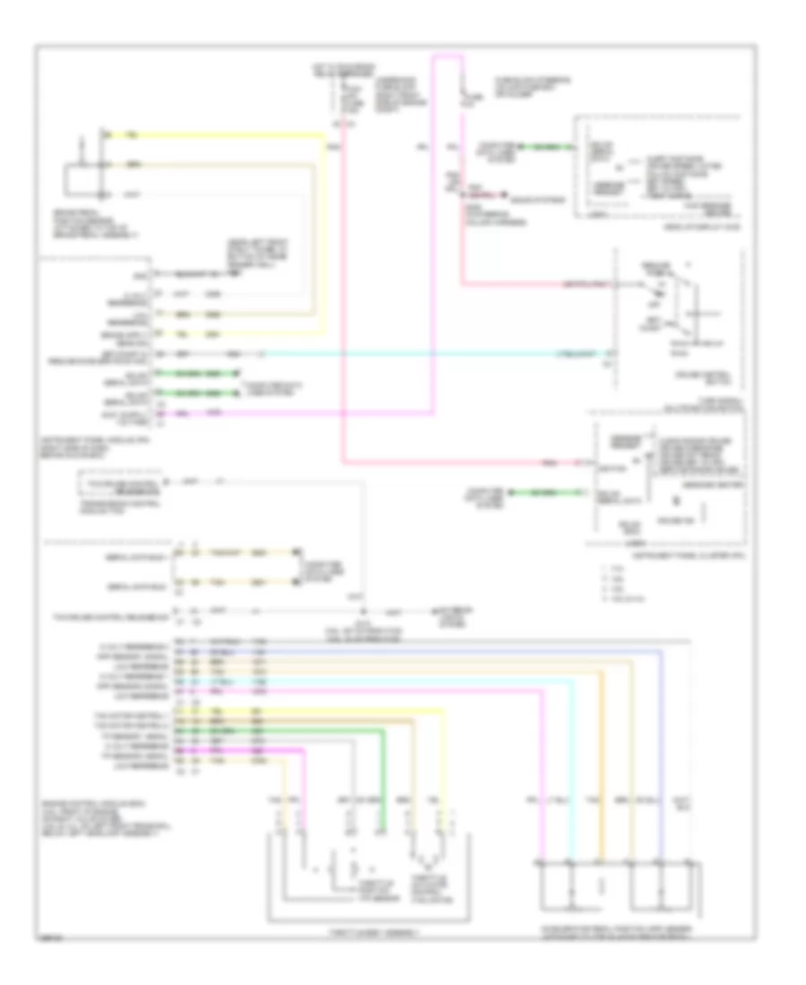
CRUISE CONTROL
Adaptive Cruise Control Wiring Diagram for Cadillac STS V 2007
List of elements for Adaptive Cruise Control Wiring Diagram for Cadillac STS V 2007:
- (below right "c" pillar) electronic suspension control (esc) module
- (in forward lamp harness, 31 cm from right headlamp leveling actuator connector) s116
- (on dash harness, under dashboard, near firewall grommet) sp201
- 5v ref
- A11
- Alert distance cruise speed limited follow distance set speed set xx mph tight curve
- Brake pedal position sensor (attached to top of brake pedal assembly)
- C276
- C277
- Ccp fuse 10a
- Clean radar cruise cruise disengage cruise not ready cruise set xx mph service radar cruise
- Computer data lines system
- Cruise control switch
- Distance sensing cruise control module (behind front fascia, near hood latch)
- Electronic brake control module (ebcm) (on right front corner of engine compt, behind right front wheel)
- Fuse 2a
- Fuse block steering column fuse box or holder
- G104 (on right front frame rail, near bumper bracket)
- Gmlan serial wake up
- Gmlan serial data bus +
- Gmlan serial data bus -
- Gmlan serial wake up
- Ground
- Head up display (hud)
- Headlights system
- Hot at all times
- Ignition 1 voltage
- Inflatable restraint steering wheel module coil (top of steering column, behind steering wheel)
- Instrument panel cluster (ipc)
- Instrument panel module (ipm) (right side of dash, behind glove box)
- Left steering wheel controls
- Logic
- Low ref
- Message center
- Message request
- Nca
- Off
- Pnk
- Power distribution system
- Resume/ accel +
- Right steering wheel controls
- S229 (in steering column harness)
- Sens sig
- Serial data
- Serial data +
- Serial data -
- Set/ coast
- Signal
- Tan
- Turn signal/ multifunction switch
- Underhood fuse block (right front side of engine compt)
- W/ hid lamps
Conventional Cruise Control Wiring Diagram for Cadillac STS V 2007
List of elements for Conventional Cruise Control Wiring Diagram for Cadillac STS V 2007:
- (near left front strut tower, at bottom of inside fender well) g101
- 3.6l
- 4.4l
- 4.6l
- 4.6l & 4.4l
- 5 volt reference
- 5 volt reference 1
- 5 volt reference 2
- Accelerator pedal position (app) sensor (attached to top of accelerator pedal)
- Alert distance cruise speed limited follow distance set speed set xx mph tight curve
- App sensor 1 signal
- App sensor 2 signal
- Brake pedal position sensor (attached to top of brake pedal assembly)
- Clean radar cruise cruise disengage cruise not ready cruise set xx mph service radar cruise
- Coast
- Computer data lines system
- Cruise control switch
- Cruise ind
- Engine control module (ecm) (3.6l: front of engine, on right valve cover) (4.6l & 4.4l: on left front frame rail, below left headlamp assembly)
- Exterior lights system
- Fuse 2a
- Fuse block steering column fuse box or holder
- Gmlan (ecm)
- Gmlan serial data
- Gnd
- Head up display (hud)
- Hot w/ run/crank relay energized
- Hud message center
- Ignition
- Instrument panel cluster (ipc)
- Instrument panel module (ipm) (right side of dash, behind glove box)
- Logic
- Low reference
- Message center
- Message request
- Off
- Pnk
- Resume/ accel+
- S147 (3.6l: 387 cm from c102) (4.6l: 24 cm from c102)
- S225 (in steering column harness)
- Serial data bus +
- Serial data bus -
- Set/
- Set/coast & resume/accelerate sw sig
- Sound systems
- Tac motor control-1
- Tac motor control-2
- Tan
- Tcc/cruise control release sig
- Tcm/ ipc fuse 15a
- Throttle actuator control (tac) motor
- Throttle body assembly
- Throttle position (tp) sensor
- Tp sensor 1 signal
- Tp sensor 2 signal
- Transmission control module (tcm)
- Turn signal/ multifunction switch
- Underhood fuse block (right front side of engine compt)
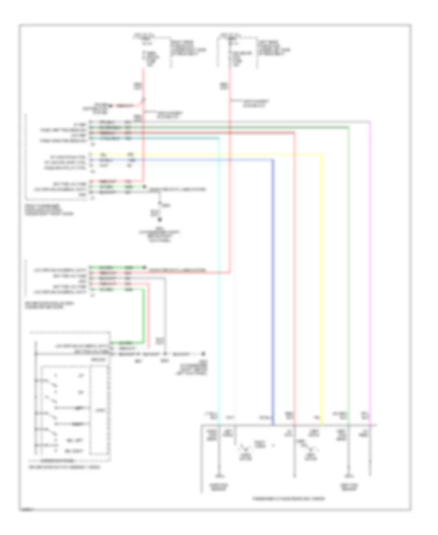
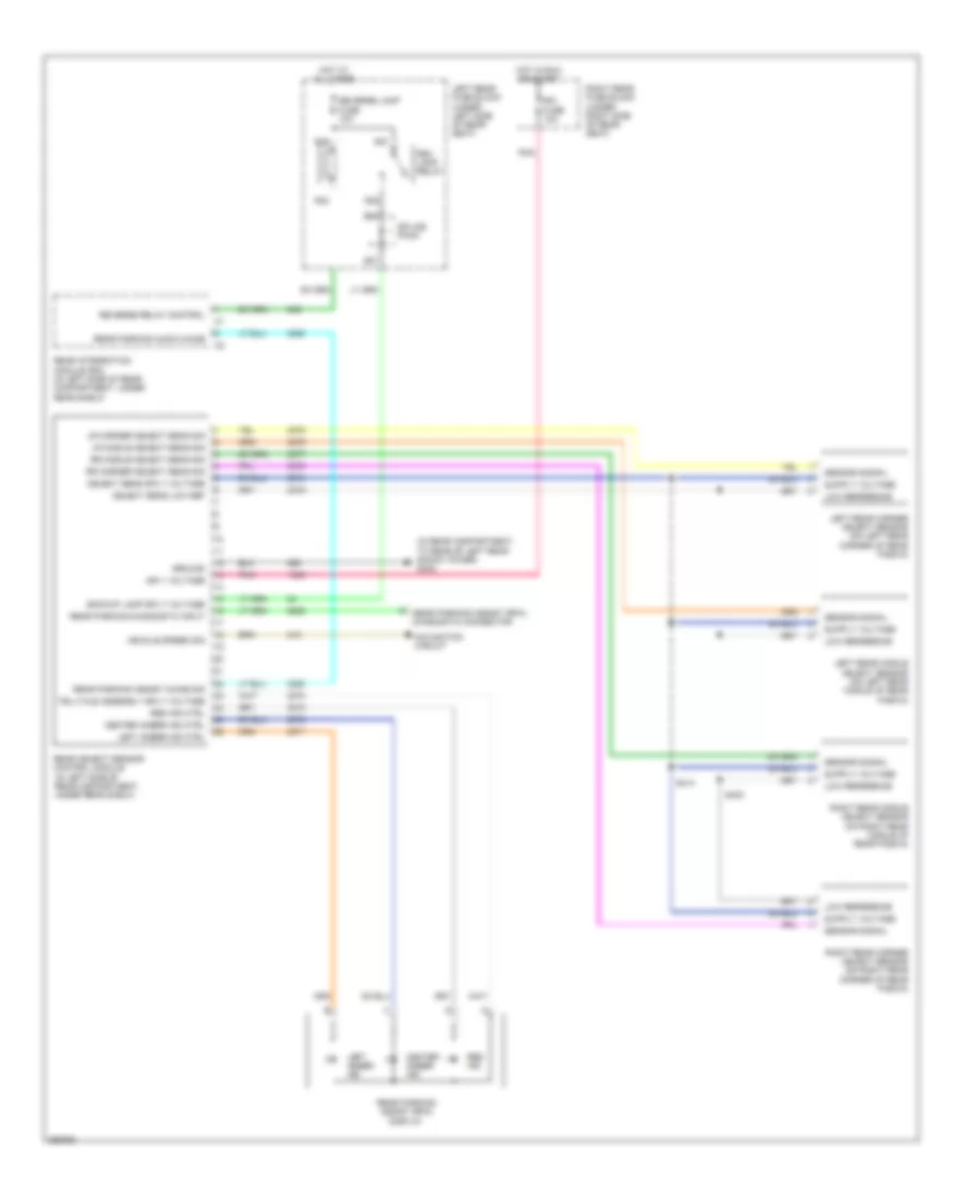
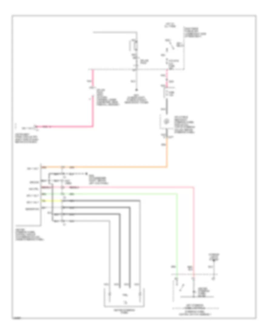
DEFOGGERS
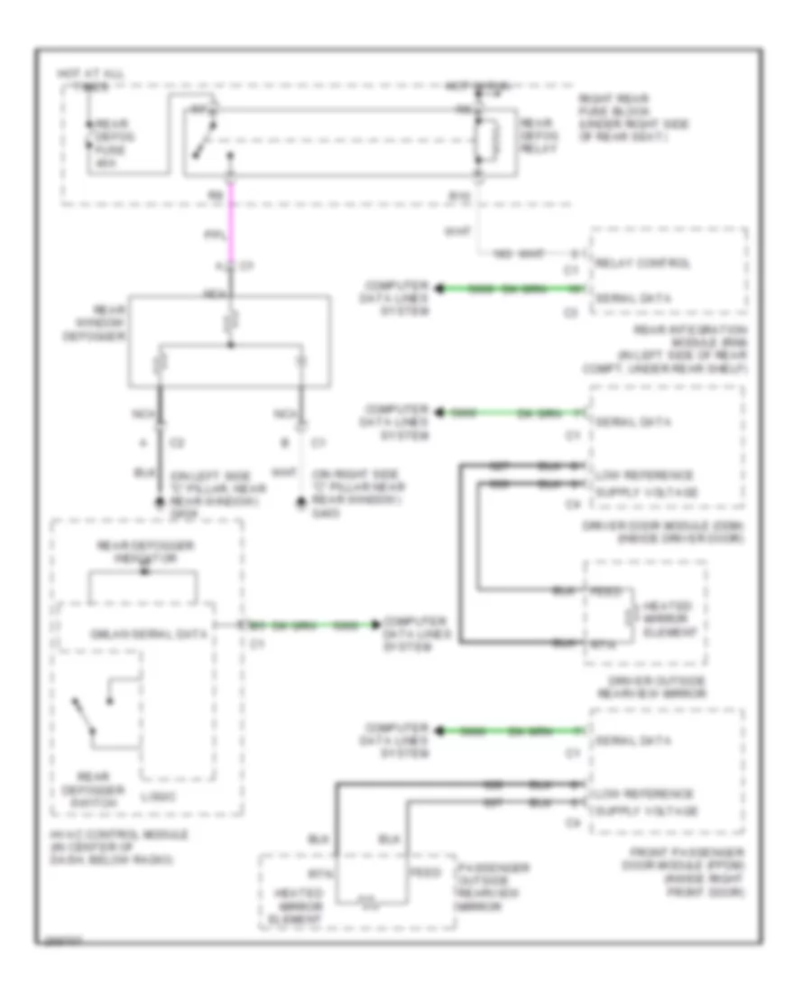
Defoggers Wiring Diagram for Cadillac STS V 2007
List of elements for Defoggers Wiring Diagram for Cadillac STS V 2007:
- Computer data lines system
- Driver door module (ddm) (inside driver door)
- Driver outside rearview mirror
- Feed
- Front passenger door module (fpdm) (inside right front door)
- Gmlan serial data
- Heated mirror element
- Hot at all times
- Hot in run
- Hvac control module (in center of dash, below radio)
- Logic
- Low reference
- Nca
- Passenger outside rearview mirror
- R10
- Rear defog fuse 40a
- Rear defog relay
- Rear defogger indicator
- Rear defogger switch
- Rear integration module (rim) (in left side of rear compt, under rear shelf)
- Rear window defogger
- Relay control
- Right rear fuse block (under right side of rear seat)
- Rtn
- Serial data
ELECTRONIC POWER STEERING
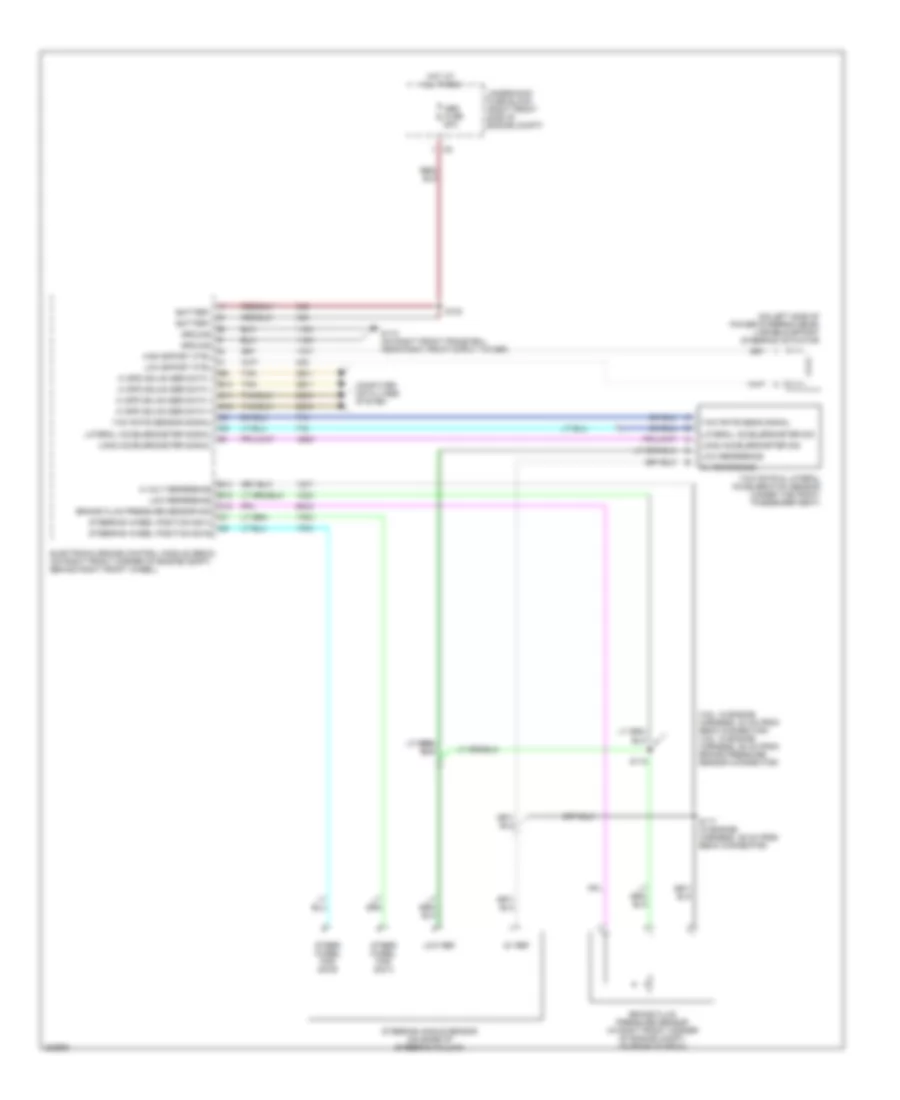
Electronic Power Steering Wiring Diagram for Cadillac STS V 2007
List of elements for Electronic Power Steering Wiring Diagram for Cadillac STS V 2007:
- (3.6l: in engine harness, 30 cm from ebcm connector) (4.6l: in engine harness, 25 cm from brake pressure sensor connector)
- (on left side of power steering gear) variable effort steering actuator
- 5 volt reference
- 5v ref
- 5v reference
- Abs fuse 50a
- B10
- B11
- B12
- B13
- B14
- Battery
- Brake fluid pressure sensor (in right front corner of engine compt, on rear of ebcm)
- Brake fluid pressure sensor sig
- C10
- Computer data lines system
- Electronic brake control module (ebcm) (on right front corner of engine compt, behind right front wheel)
- G110 (on right front frame rail, near right front strut tower)
- Ground
- Hi spd gmlan ser data +
- Hi spd gmlan ser data -
- High effort ctrl
- Hot at all times
- Lateral accelerometer sig
- Lateral accelerometer signal
- Long accelerometer sig
- Long accelerometer signal
- Low effort ctrl
- Low ref
- Low reference
- S100
- S117 (in engine harness, 36 cm from ebcm connector)
- S118
- Steer wheel pos sig a
- Steer wheel pos sig b
- Steering angle sensor (on base of steering column)
- Steering wheel position sig a
- Steering wheel position sig b
- Tan
- Underhood fuse block (right front side of engine compt)
- Yaw rate & lateral acceleration sensor (under the front passenger seat)
- Yaw rate sens signal
- Yaw rate sensor signal
ELECTRONIC SUSPENSION
Electronic Suspension Wiring Diagram for Cadillac STS V 2007
List of elements for Electronic Suspension Wiring Diagram for Cadillac STS V 2007:
- (in rear compt, to rear of right rear shock tower) g401
- (under rear of vehicle, behind right rear tire) automatic level control (alc) compressor
- Auto relay ctrl
- Automatic level
- Batt
- Battery voltage
- Computer data lines system
- Data signal
- Ecm/tcm fuse 10a
- Elc relay
- Elc relay fuse 30a
- Elc sol fuse 10a
- Electronic suspension control (esc) module (below right "c" pillar)
- G401 (in rear compt, to rear of right rear shock tower)
- Gmlan ser data +
- Gmlan ser data -
- Ground
- Hot at all times
- Hot w/ run relay energized
- Instrument panel cluster (ipc)
- Ipc class 2
- Left front suspension damper
- Left front suspension position sensor (near left front strut)
- Left rear fuse block (under left side of rear seat)
- Left rear suspension damper
- Left rear suspension position sensor (near left rear strut)
- Lf damper ctrl
- Lf damper low ref
- Lf position sens
- Lf sens vol ref
- Logic
- Lr damper ctrl
- Lr damper low ref
- Lr position sens
- Lr sens vol ref
- Message center
- Message request
- Mr-rtd mod fuse 25a
- Nca
- R10
- Rf damper ctrl
- Rf damper low ref
- Rf position sens
- Rf sens vol ref
- Right front suspension damper
- Right front suspension position sensor (near right front strut)
- Right rear suspension damper
- Right rear suspension position sensor (near right rear strut)
- Rr damper ctrl
- Rr damper low ref
- Rr position sens
- Rr sens vol ref
- Sensor low ref
- Service ride control
- Tan
- Underhood fuse block (right front side of engine compt)
ENGINE PERFORMANCE
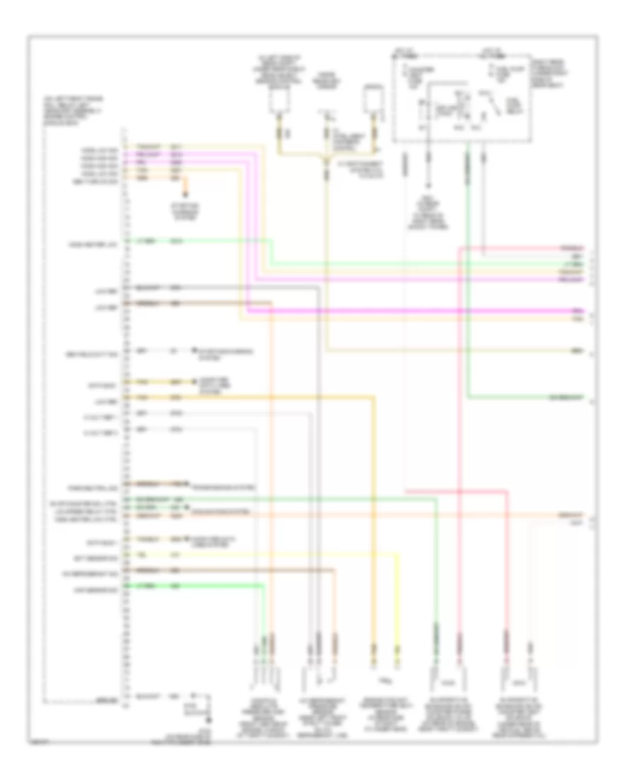
3.6L VIN 7
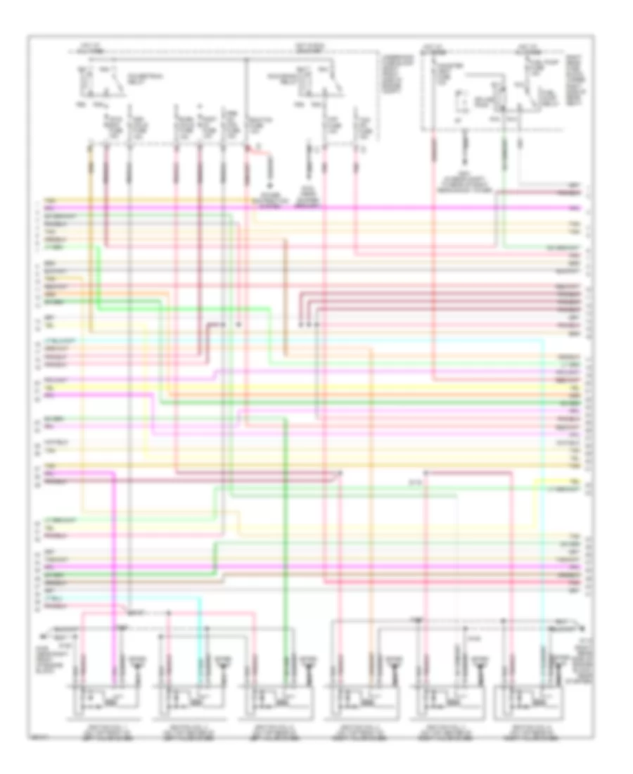
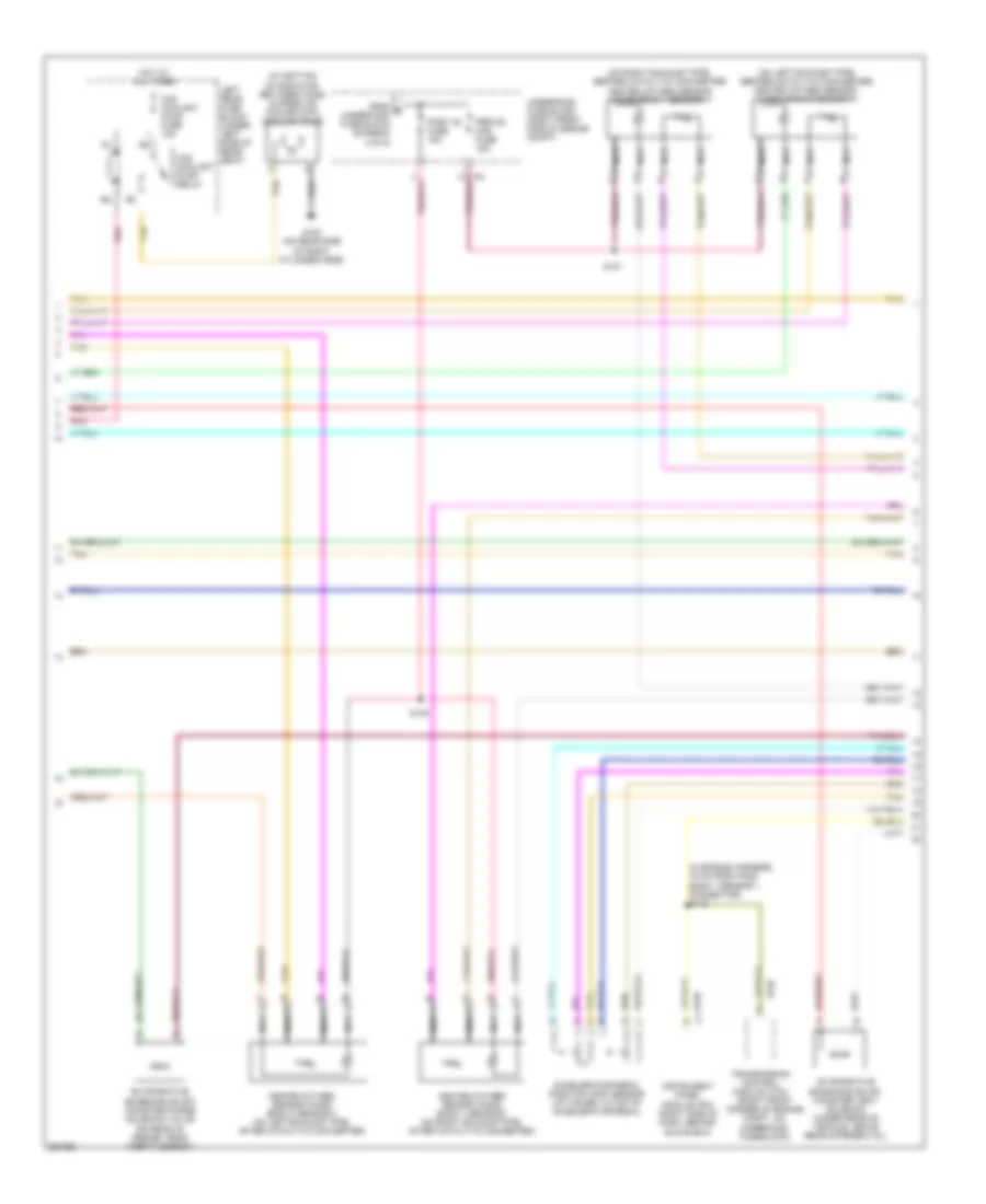
3.6L VIN 7, Engine Performance Wiring Diagram (1 of 4) for Cadillac STS V 2007
List of elements for 3.6L VIN 7, Engine Performance Wiring Diagram (1 of 4) for Cadillac STS V 2007:
- (1,3,5: top right side of engine) fuel injectors
- (2,4,6: top left side of engine) fuel injectors
- (in engine poa harness, 1 cm from ckp sensor connector)
- (in engine poa harness, 17 cm from ecm c1)
- (on left side of engine, attached to oil filter adapter housing) engine oil pressure (eop) sensor
- (on rear of intake manifold) intake manifold runner control (imrc) solenoid
- 5 volt ref 1
- 5 volt ref 2
- Bare
- Ckp sens sig
- Cmp exhaust 1
- Cmp exhaust 2
- Cmp intake 1
- Cmp intake 2
- Crankshaft position (ckp) sensor (on left side of engine)
- Ect sig
- Engine control module (ecm) (front of engine, on right valve cover)
- Evap purge
- G103 (top right side of engine, fastened to ecm case)
- G113 (front center of right front cylinder head)
- Gen fdc sig
- Gen turn on sig
- Ground
- Heated oxygen sensor (ho2s) bank 1 sensor 1 (on right exhaust pipe)
- Heated oxygen sensor (ho2s) bank 1 sensor 2 (on right exhaust pipe)
- Heated oxygen sensor (ho2s) bank 2 sensor 1 (on left exhaust pipe)
- Heated oxygen sensor (ho2s) bank 2 sensor 2 (on left exhaust pipe)
- Ho2s heat ctrl
- Ho2s input pump
- Ho2s low ref
- Ho2s pump cur
- Ho2s ref volt
- Ic 1 ctrl
- Ic 2 ctrl
- Ic 3 ctrl
- Ic 4 ctrl
- Ic 5 ctrl
- Ic 6 ctrl
- Inj 1 ctrl
- Inj 2 ctrl
- Inj 3 ctrl
- Inj 4 ctrl
- Inj 5 ctrl
- Inj 6 ctrl
- Intake man ctrl
- Knock sensor (ks) 1 (on right side of engine)
- Knock sensor (ks) 2 (on left side of engine)
- Ks 1 sig
- Ks 2 sig
- Low ref
- Manifold pos sig
- Nca
- Oil pres sig
- Pres sens sig
- S104
- S121
- S137
- S148
- S150
- Starting/ charging system
- Tac mtr ctrl 1
- Tac mtr ctrl 2
- Tan
- Tan a
- Tps 2 sig
- Tps sig 1
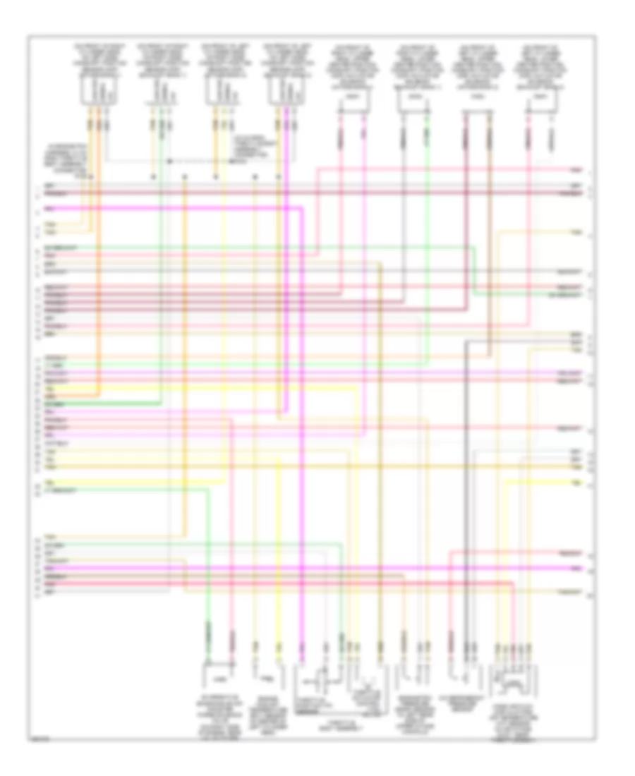
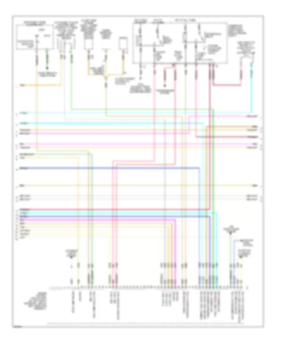
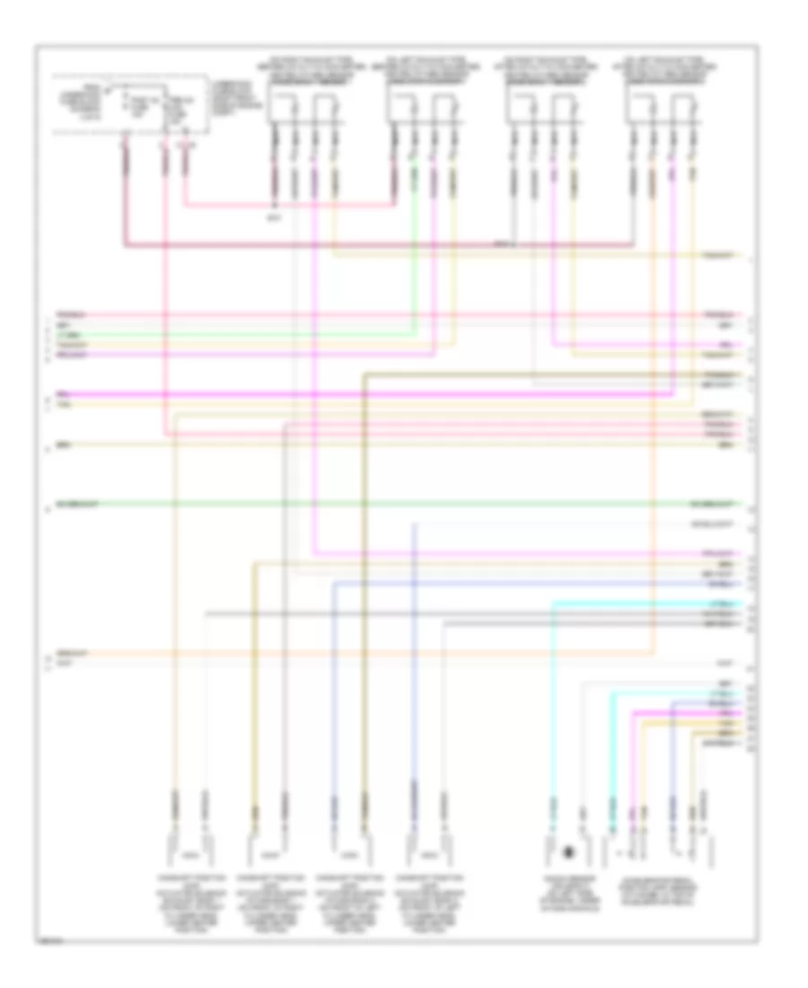
3.6L VIN 7, Engine Performance Wiring Diagram (2 of 4) for Cadillac STS V 2007
List of elements for 3.6L VIN 7, Engine Performance Wiring Diagram (2 of 4) for Cadillac STS V 2007:
- (right rear side of engine block, near starter)
- Canister vent fuse 10a
- Ecm/tcm fuse 10a
- Even coils fuse 15a
- Fuel pump fuse 15a
- Fuel pump relay
- G104 (near bumper bracket)
- G109 (near right front of engine block)
- G112
- G401 (in rear compt, to rear of right rear shock tower)
- Hfv6 ecm fuse 15a
- Hot at all times
- Hot in run or start
- Ignition coil 1 (on top front of left valve cover)
- Ignition coil 2 (on top front of right valve cover)
- Ignition coil 3 (on top center of left valve cover)
- Ignition coil 4 (on top center of right valve cover)
- Ignition coil 5 (on top rear of left valve cover)
- Ignition coil 6 (on top rear of right valve cover)
- Maf fuse 10a
- Nca
- Odd coils fuse 15a
- Pnk
- Post o2 fuse 10a
- Power distribution system
- Powertrain relay
- Pre o2/ cam fuse 15a
- R11
- R12
- R13
- R15
- R43
- R44
- R45
- R46
- R47
- R48
- R49
- R50
- Right rear fuse block (under right side of rear seat)
- Run/crank relay
- S101
- S119
- S125
- S126
- S127
- S128
- S129
- Spark plug
- Splice pack
- Tan
- Tcm/ ipc fuse 15a
- Underhood fuse block (right front side of engine compt)
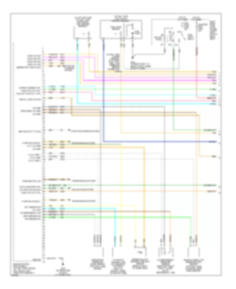
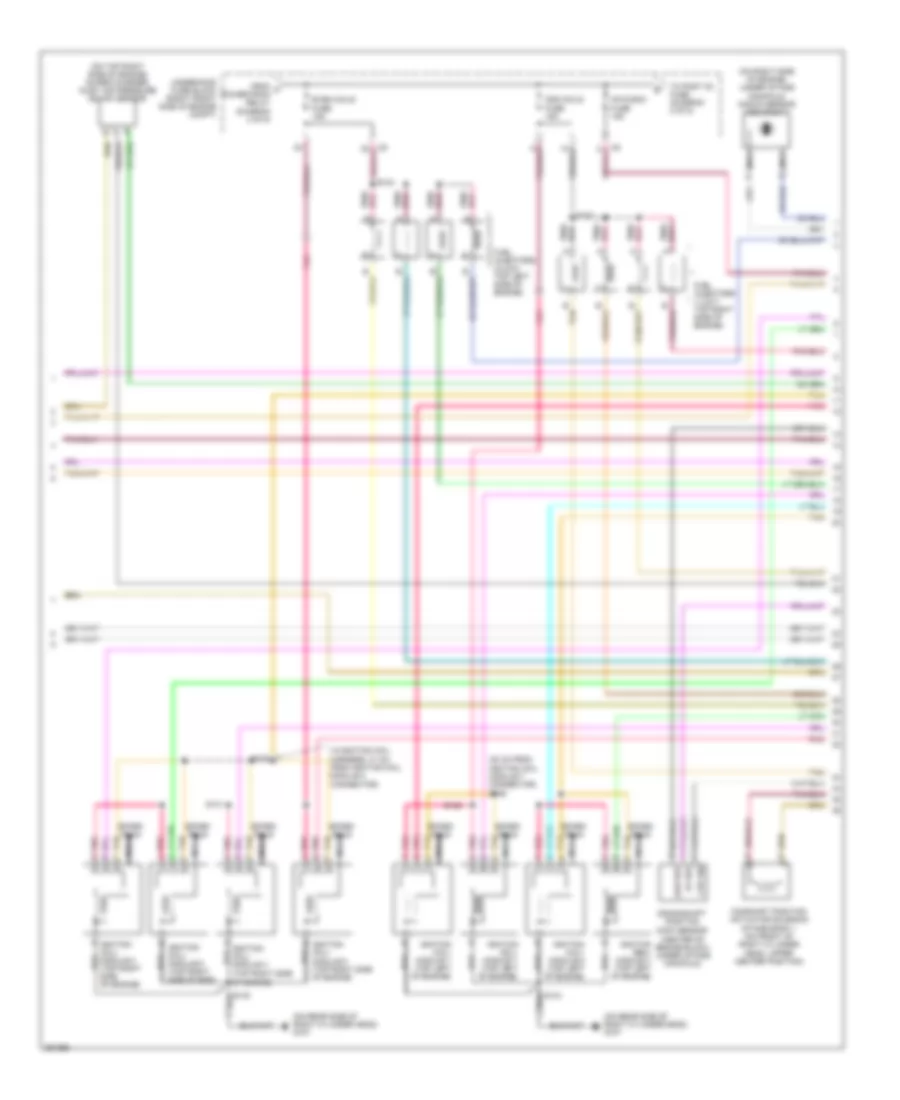
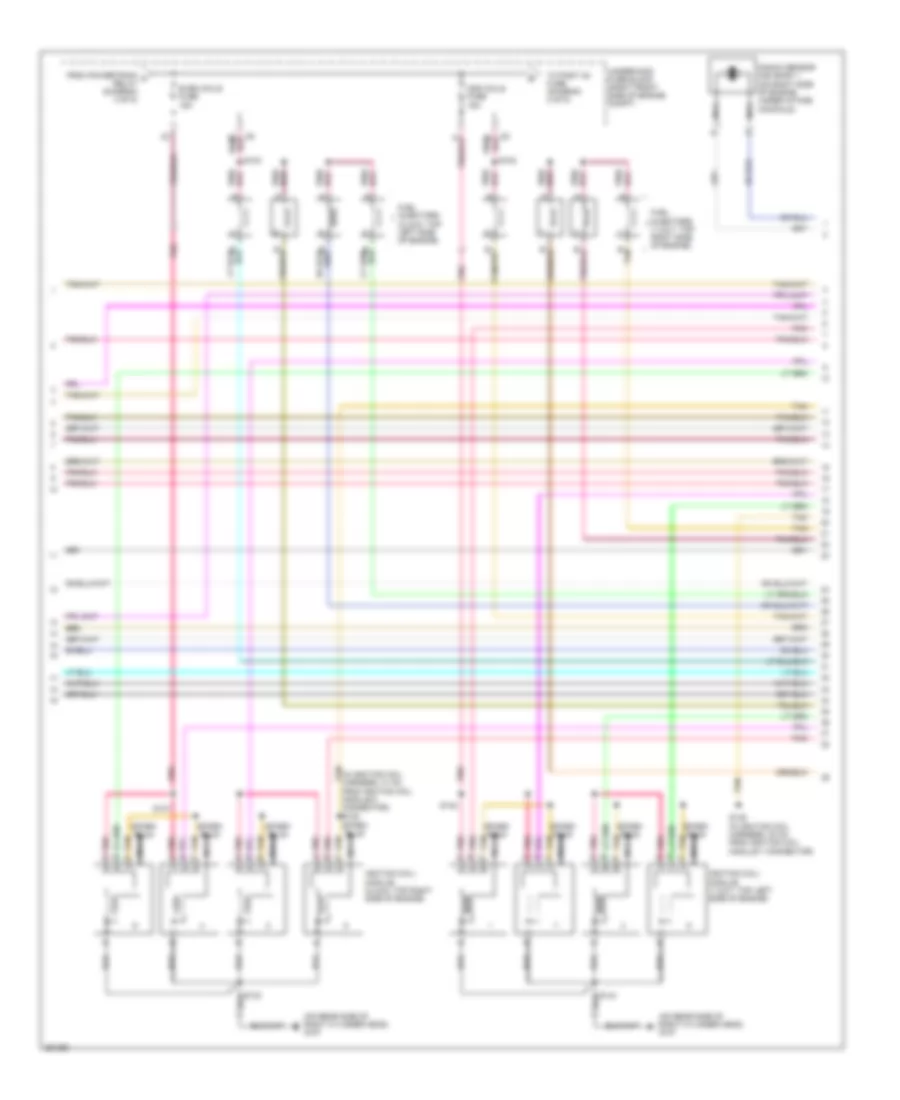
3.6L VIN 7, Engine Performance Wiring Diagram (3 of 4) for Cadillac STS V 2007
List of elements for 3.6L VIN 7, Engine Performance Wiring Diagram (3 of 4) for Cadillac STS V 2007:
- (32 cm from throttle body assembly connector) s124
- (in engine poa harness, 21 cm from throttle body assembly connector) s120
- (on front of left cylinder head, lower center position) camshaft position (cmp) actuator solenoid (exhaust bank 2)
- (on front of left cylinder head, on left side) camshaft position sensor (cmp) (exhaust bank 2)
- (on front of left cylinder head, on right side) camshaft position sensor (cmp) (intake bank 2)
- (on front of left cylinder head, upper center position) camshaft position (cmp) actuator solenoid (intake bank 2)
- (on front of right cylinder head, lower center position) camshaft position (cmp) actuator solenoid (exhaust bank 1)
- (on front of right cylinder head, on left side) camshaft position sensor (cmp) (intake bank 1)
- (on front of right cylinder head, on right side) camshaft position sensor (cmp) (exhaust bank 1)
- (on front of right cylinder head, upper center position) camshaft position (cmp) actuator solenoid (intake bank 1)
- +5v
- A/c refrigerant pressure sensor
- Barometric pressure (baro) sensor (in left rear side of upper intake manifold)
- Engine coolant temperature (ect) sensor (in center of left cylinder head)
- Evaporative emissions (evap) canister purge solenoid valve (on right side of engine, near valve cover)
- Logic
- Low ref
- Mass air flow (maf) & intake air temperature (iat) sensor (in air intake duct, near throttle body)
- Pnk
- Signal
- Tan
- Throttle actuator control (tac) motor
- Throttle body assembly
- Throttle position (tp) sensor
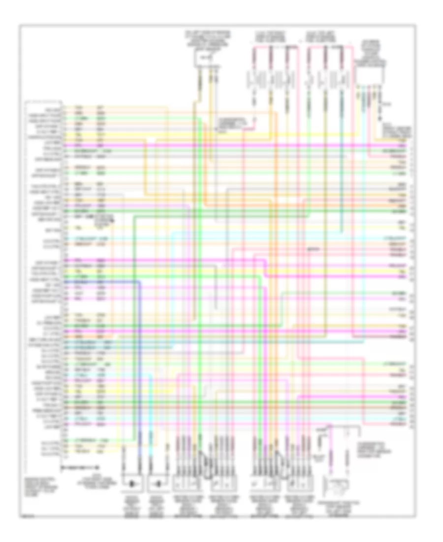
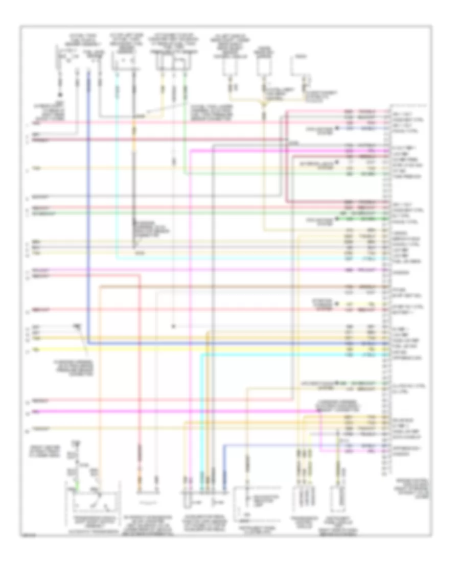
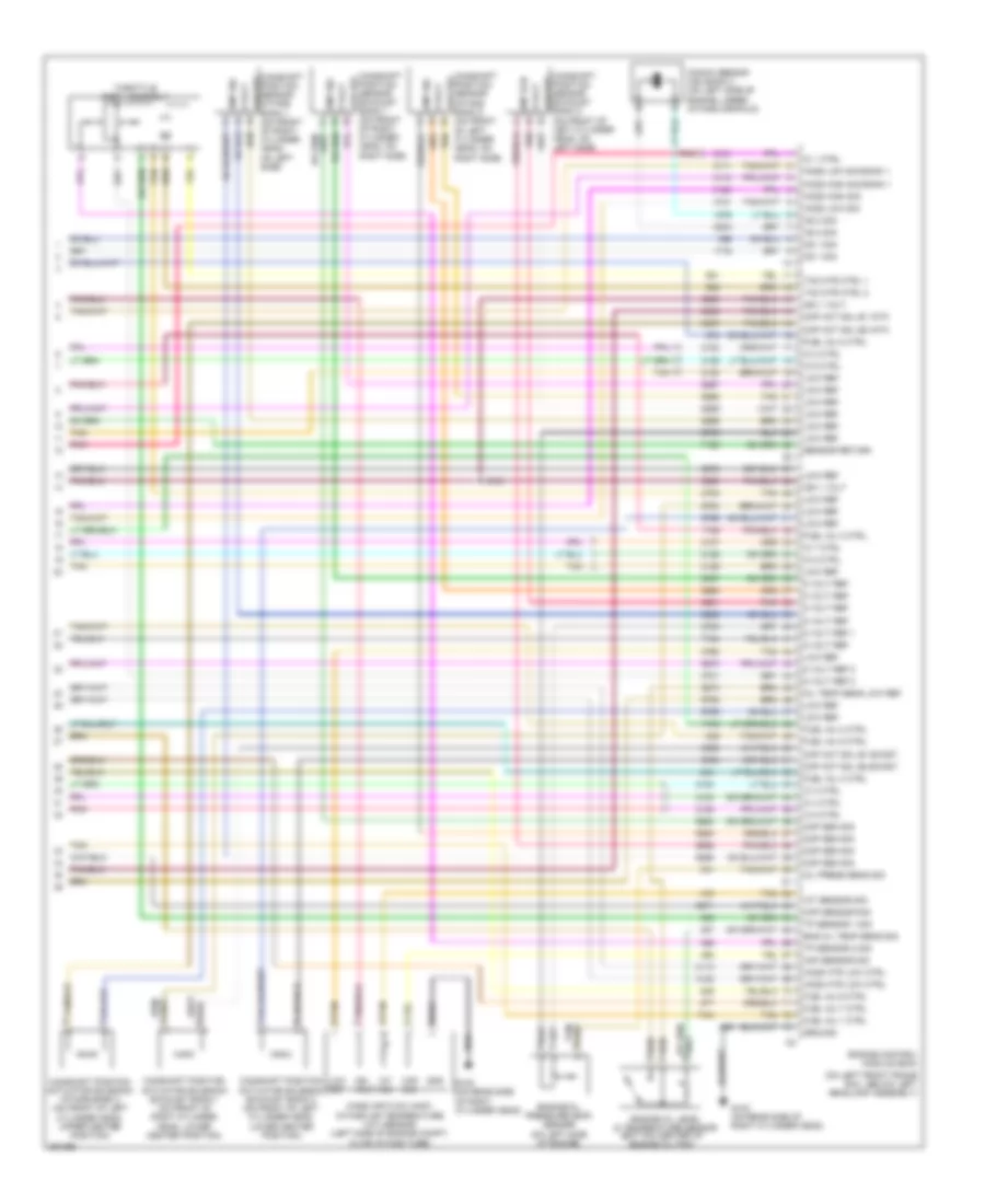
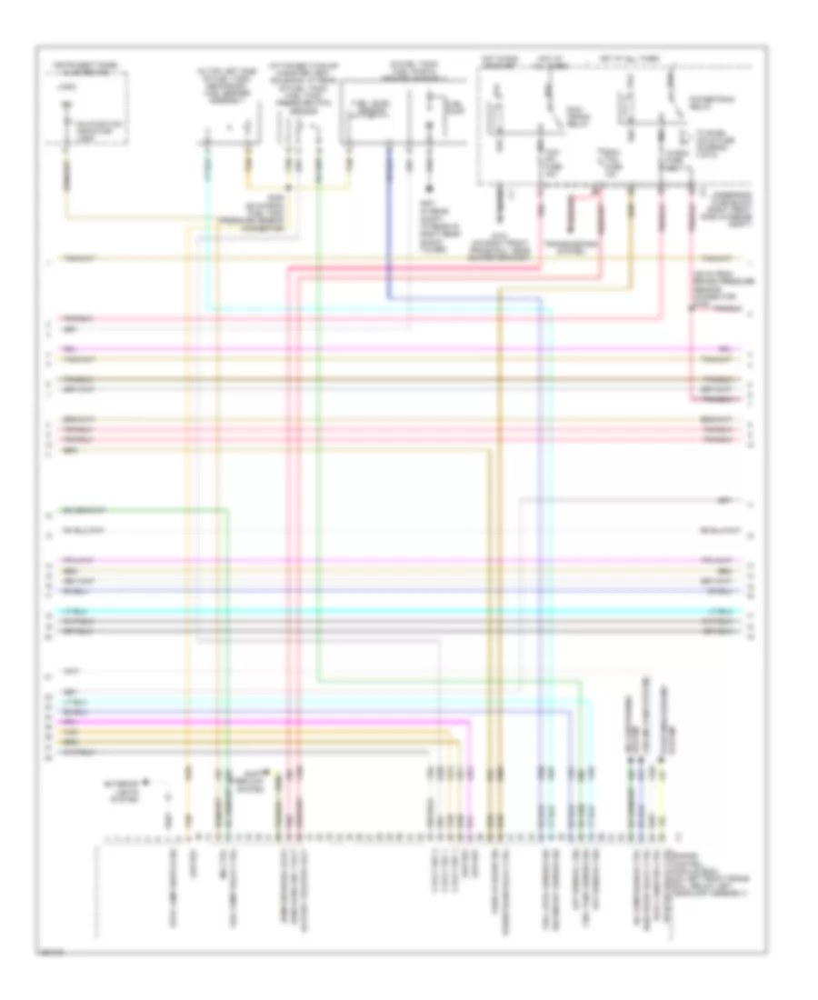
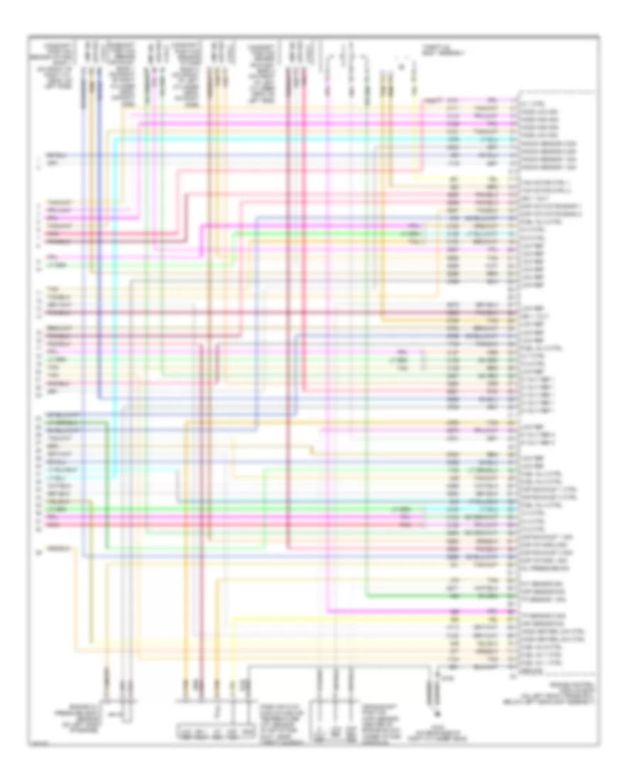
3.6L VIN 7, Engine Performance Wiring Diagram (4 of 4) for Cadillac STS V 2007
List of elements for 3.6L VIN 7, Engine Performance Wiring Diagram (4 of 4) for Cadillac STS V 2007:
- (attached to evap canister vent solenoid, at rear of fuel tank) fuel tank pressure (ftp) sensor
- (front center of right front cylinder head)
- (in engine harness, 19 cm from ho2s bank 1 sensor 1 connector)
- (in engine harness, 36 cm from brake pressure sensor connector)
- (in fuel tank jumper harness, 28 cm from fuel tank pressure sensor connector)
- (in fuel tank) fuel pump & sender assembly
- (in left side of rear compt, under rear shelf) rear object sensor control module
- (in top left side of fuel tank) secondary fuel sender assembly
- 5 volt ref 1
- 5v ref 1
- 5v ref 3
- A/c ref pres
- Accelerator pedal position (app) sensor (attached to top of accelerator pedal)
- Air conditioning system
- App sens 2 sig
- App sens sig 1
- Automatic transmission
- Battery +
- Clutch rly ctrl
- Cooling fans system
- Data wake-up
- Engine control module (ecm) (front of engine, on right valve cover)
- Evap vent sol
- Evaporative emissions (evap) canister vent solenoid valve (under rear of vehicle, above rear differential)
- Exterior lights system
- Fan rly ctrl
- Fuel lev sens
- Fuel lev sig
- Fuel level sensor
- G113
- G401 (in rear compt, to rear of right rear shock tower)
- Gmlan bus
- Ho2s heat ctrl
- Ho2s low ref
- Ho2s sig
- Iat sig
- Ign
- Ign 1 volt
- Inside rearview mirror
- Instrument panel cluster (ipc)
- Instrument panel module (ipm) (right side of dash, behind glove box)
- Lan bus +
- Lan bus -
- Logic
- Low ref
- Maf sig
- Main rly ctrl
- Malfunction indicator lamp
- Mil ctrl
- P/n sig
- Pnk
- Radio
- Rly ctrl
- S106
- S107
- S108
- S109
- S113
- S406
- Ser data bus
- Start rly ctrl
- Starting/ charging system
- Stop lp sw sig
- Tan
- Tank pres sig
- Transmission control module
- Transmission manual shift shaft switch assembly
- Vss sig
- W/infotainment system 012, 014 & 015
- W/intelligent high beam control
- Wake-up
4.4L VIN D
4.4L VIN D, Engine Performance Wiring Diagram (1 of 5) for Cadillac STS V 2007
List of elements for 4.4L VIN D, Engine Performance Wiring Diagram (1 of 5) for Cadillac STS V 2007:
- (in fuel tank jumper harness, 28 cm from fuel tank pressure sensor connector) s406
- (in fuel tank) fuel pump & sender assembly
- (in top left side of fuel tank) secondary fuel sender assembly
- (rear of right cylinder head)
- 5 volt ref
- 5 volt ref 1
- 5 volt ref 2
- A/c refrigerant pressure sensor (near left front strut tower, on a/c refrigerant line)
- A/c refrigerant sig
- Baro sens low ref
- Baro sensor sig
- Barometric pressure (baro) sensor (top right side engine)
- Canister vent fuse 10a
- Coolant pump rly ctrl
- Cooling fans system
- D tan
- Ect sensor sig
- Eng oil level sw sig
- Engine control module (ecm) (on left front frame rail, below left headlamp assembly)
- Engine coolant temperature (ect) sensor
- Evap canister ctrl
- Fuel level sensor
- Fuel pump
- Fuel pump fuse 15a
- Fuel pump relay
- G100 (on rear side of right cylinder head)
- G401 (in rear compt, to rear of right rear shock tower)
- Gen field duty cycle
- Generator turn on sig
- Ground
- Hi spd gmlan bus +
- Hi spd gmlan bus -
- Ho2s high sig
- Ho2s htr low ctrl
- Ho2s low sig
- Hot at all times
- Iat 2 low ref
- Iat 2 sig
- Intake air temperature (iat) sensor 2 (top right front of engine, under intake air tube)
- Low ref
- Low spd cooling fan
- Manifold absolute pressure (map) sensor (top right side of engine, near baro sensor)
- Map sensor sig
- Park/neutral sig
- Pnk
- R11
- R12
- R13
- R15
- Right rear fuse block (under right side of rear seat)
- Splice pack
- Starting/ charging system
- Starting/charging system
- Super charger ctrl
- Tan
- Transmissions system
4.4L VIN D, Engine Performance Wiring Diagram (2 of 5) for Cadillac STS V 2007
List of elements for 4.4L VIN D, Engine Performance Wiring Diagram (2 of 5) for Cadillac STS V 2007:
- (at bottom of radiator, between fans) charge air cooler (cac) coolant pump
- (in engine harness, 19 cm from ho2s bank 1 sensor 1 connector) s113
- (on left exhaust pipe, before catalytic converter) heated oxygen sensor (ho2s) bank 2 sensor 1
- (on right exhaust pipe, before catalytic converter) heated oxygen sensor (ho2s) bank 1 sensor 1
- (right front corner of engine compt, on underhood fuse block)
- Accelerator pedal position (app) sensor (attached to top of accelerator pedal)
- Cac coolant pump fuse 10a
- Cac coolant pump relay
- Evaporative emissions (evap) canister purge solenoid valve (on rear of engine, near throttle body)
- Evaporative emissions (evap) canister vent solenoid (under rear of vehicle, above rear differential)
- From b underhood fuse block (diagram 4 of 5)
- G100 (on rear side of right cylinder head)
- Heated oxygen sensor (ho2s) bank 1 sensor 2 (on right exhaust pipe, after catalytic converter)
- Heated oxygen sensor (ho2s) bank 2 sensor 2 (on left exhaust pipe, after catalytic converter)
- Hot at all times
- Instrument panel module (ipm) (right side of dash, behind glove box)
- Left rear fuse block (under left side of rear seat)
- Nca
- Pnk
- Post o2 fuse 15a
- Pre o2/ cam fuse 15a
- S101
- S104
- Tan
- Transmission control module (tcm)
- Underhood fuse block (right front side of engine compt)
4.4L VIN D, Engine Performance Wiring Diagram (3 of 5) for Cadillac STS V 2007
List of elements for 4.4L VIN D, Engine Performance Wiring Diagram (3 of 5) for Cadillac STS V 2007:
- (attached to evap canister vent solenoid, at rear of fuel tank) fuel tank pressure (ftp) sensor
- (in left side of rear compt, under rear shelf) rear object sensor control module
- (left front of engine, at injector no 2) vacuum bypass valve
- (on left front frame rail, below left headlamp assembly)
- 5 volt ref 1
- 5 volt ref 2
- A/c compress rly ctrl
- Air conditioning system
- App sensor 1 sig
- App sensor 2 sig
- Battery positive volt
- Computer data lines system
- Cooling fans system
- Data
- Ecm/ tcm fuse 10a
- Engine control module (ecm)
- Evap canister vent ctrl
- Exterior lights system
- Fuel pump relay ctrl
- Fuel tank press sig
- G104 (on right front frame rail, near bumper bracket)
- Hi spd cooling fan
- Hot at all times
- Hot in run or start
- Ign
- Ign 1 volt
- Inside rearview mirror (isrvm)
- Instrument panel cluster (ipc)
- Logic
- Low ref
- Malfunction indicator lamp
- Mil ctrl
- Pnk
- Powertrain relay
- Powertrain rly ctrl
- Pressure sensor sig
- Primary fuel level sig
- R43
- R44
- R45
- R46
- R47
- R48
- R49
- R50
- Radio
- Run/ crank relay
- Second fuel level sig
- Starter rly coil ctrl
- Starting/ charging system
- Stop lamp sw sig
- Tan
- Tcm/ipc/ ecm fuse 15a
- To even coils fuse (diagram 4 of 5)
- Transmissions system
- Underhood fuse block (right front side of engine compt)
- V8 ecm fuse 10a
- Vehicle speed sig
- W/ infotainment system 012, 014 & 015
- W/ intelligent high beam control
4.4L VIN D, Engine Performance Wiring Diagram (4 of 5) for Cadillac STS V 2007
List of elements for 4.4L VIN D, Engine Performance Wiring Diagram (4 of 5) for Cadillac STS V 2007:
- (30 cm from ignition coil module 7 connector) s146
- (center of engine block, under intake manifold)
- (in ignition coil harness, 31 cm from ignition coil module 8 connector)
- (on rear side of right cylinder head) g107
- (on right side of engine, under intake manifold) knock sensor (ks) bank 1
- (on top right side of engine) super charger inlet air pressure (sciap) sensor
- (top right side of engine)
- 5v ref
- B tan
- Camshaft position actuator solenoid intake bank 1 (on front of right cylinder head, upper center position)
- Ckp sig
- Crankshaft position (ckp) sensor
- D d
- Even coils fuse 15a
- From a powertrain relay (diagram 3 of 5)
- Fuel injectors (1,3,5,7: top right side of engine)
- Fuel injectors (2,4,6,8: top left side of engine)
- Hfv6 ecm fuse 15a
- Ignition coil/ coil/ module 3 (top left of engine)
- Ignition coil/ module 1 (top left of engine)
- Ignition coil/ module 5 (top left of engine)
- Ignition coil/ module 6 (top right side of eng)
- Ignition coil/ module 7 (top left of engine)
- Ignition coil/ module 8 (top right side of engine)
- Low ref
- Nca
- Odd coils fuse 15a
- Pnk
- Pnk a
- Pnk b
- S102
- S103
- S131
- S133
- S135
- S142
- S144
- Side of engine)
- Spark plug
- Tan
- Tan c
- Tan c c
- To post o2 fuse (diagram 2 of 5)
- Underhood fuse block (right front side of engine compt)
4.4L VIN D, Engine Performance Wiring Diagram (5 of 5) for Cadillac STS V 2007
List of elements for 4.4L VIN D, Engine Performance Wiring Diagram (5 of 5) for Cadillac STS V 2007:
- (on front of left cylinder head, on left side)
- (on front of left cylinder head, on right side)
- (on front of right cylinder head, on left side)
- (on front of right cylinder head, on right side)
- (on left front frame rail, below left headlamp assembly)
- 5 volt a
- 5 volt ref
- 5 volt ref 1
- 5 volt ref 2
- Camshaft position actuator solenoid exhaust bank 1 (on front of right cylinder head, lower center position)
- Camshaft position actuator solenoid exhaust bank 2 (on front of left cylinder head, lower center position)
- Camshaft position actuator solenoid intake bank 2 (on front of left cylinder head, upper center position)
- Camshaft position sensor exhaust bank 1 low ref b
- Camshaft position sensor exhaust bank 2 low ref b
- Camshaft position sensor intake bank 1 low ref b
- Camshaft position sensor intake bank 2 low ref b
- Ckp sensor sig
- Cmp act sol b1 exhst
- Cmp act sol b1 intk
- Cmp act sol b2 exhst
- Cmp act sol b2 intk
- Cmp exh c
- Cmp sen sig
- Cmp sig c
- Eng oil temp sens sig
- Engine control module (ecm)
- Engine oil level & temperature sensor (bottom center of engine oil pan)
- Engine oil pressure (eop) sensor (on left side of engine)
- Fuel inj 1 ctrl
- Fuel inj 2 ctrl
- Fuel inj 3 ctrl
- Fuel inj 4 ctrl
- Fuel inj 5 ctrl
- Fuel inj 6 ctrl
- Fuel inj 7 ctrl
- Fuel inj 8 ctrl
- G100 (on rear side of right cylinder head)
- Gnd
- Ground
- Ho2s high sig
- Ho2s high sig bank 1
- Ho2s htr low ctrl
- Ho2s low sig
- Ho2s low sig bank 1
- Iat sensor sig
- Iat sig
- Ic 1 ctrl
- Ic 2 ctrl
- Ic 3 ctrl
- Ic 4 ctrl
- Ic 5 ctrl
- Ic 6 ctrl
- Ic 7 ctrl
- Ic 8 ctrl
- Ign 1 volt
- Ign volt
- Knock sensor (ks) bank 2 (on left side of engine, under intake manifold)
- Ks 1 sig
- Ks 2 sig
- Low ref
- Maf sensor sig
- Maf sig
- Mass air flow (maf)/ intake air temperature (iat) sensor (left side of engine compt, in air intake tube)
- Oil press sens sig
- Oil temp sens low ref
- Pnk
- S151
- Sensor return
- Tac mtr ctrl 1
- Tac mtr ctrl 2
- Tan
- Tan d
- Tan e
- Throttle body assembly
- Tp sensor 1 sig
- Tp sensor 2 sig
4.6L VIN A
4.6L VIN A, Engine Performance Wiring Diagram (1 of 5) for Cadillac STS V 2007
List of elements for 4.6L VIN A, Engine Performance Wiring Diagram (1 of 5) for Cadillac STS V 2007:
- (in left side of rear compt, under rear shelf) rear object sensor control module
- (on left front frame rail, below left headlamp assembly) engine control module (ecm)
- 5 volt ref 1
- 5 volt ref 2
- A/c refrigerant pressure sensor (near left front strut tower, on a/c refrigerant line)
- A/c refrigerant sig
- Canister vent fuse 10a
- Computer data lines system
- Cooling fans system
- Data bus +
- Data bus -
- Ect sensor sig
- Engine coolant temperature (ect) sensor (in rear side of right cylinder head)
- Evap canister sol ctrl
- Evaporative emissions (evap) canister purge solenoid valve (on rear of engine, near throttle body)
- Evaporative emissions (evap) canister vent solenoid (under rear of vehicle, above rear differential)
- Fuel pump fuse 15a
- Fuel pump relay
- G100 (on rear side of right cylinder head)
- G401 (in rear compt, to rear of right rear shock tower)
- Gen field duty sig
- Gen turn on sig
- Ground
- Ho2s heater low
- Ho2s heater low ctrl
- Ho2s high sig
- Ho2s low sig
- Hot at all times
- Inside rearview mirror
- Low ref
- Low speed relay ctrl
- Manifold absolute pressure (map) sensor (front center of engine, in back of throttle body)
- Map sensor sig
- Park/neutral sig
- R11
- R12
- R13
- R15
- Radio
- Right rear fuse block (under right side of rear seat)
- S152
- Splice pack
- Starting/ charging system
- Starting/charging system
- Tan
- Transmissions system
- W/ infotainment system 012, 014 & 015
- W/ intelligent high beam control
4.6L VIN A, Engine Performance Wiring Diagram (2 of 5) for Cadillac STS V 2007
List of elements for 4.6L VIN A, Engine Performance Wiring Diagram (2 of 5) for Cadillac STS V 2007:
- (on left exhaust pipe, after catalytic converter) heated oxygen sensor (ho2s) bank 2 sensor 2
- (on left exhaust pipe, before catalytic converter) heated oxygen sensor (ho2s) bank 2 sensor 1
- (on right exhaust pipe, after catalytic converter) heated oxygen sensor (ho2s) bank 1 sensor 2
- (on right exhaust pipe, before catalytic converter) heated oxygen sensor (ho2s) bank 1 sensor 1
- Accelerator pedal position (app) sensor (attached to top of accelerator pedal)
- Camshaft position (cmp) actuator solenoid exhaust bank 1 (on front of right cylinder head, lower center position)
- Camshaft position (cmp) actuator solenoid exhaust bank 2 (on front of left cylinder head, lower center position)
- Camshaft position (cmp) actuator solenoid intake bank 1 (on front of right cylinder head, upper center position)
- Camshaft position (cmp) actuator solenoid intake bank 2 (on front of left cylinder head, upper center position)
- From b underhood fuse block (diagram 4 of 5)
- Knock sensor (ks) bank 2 (on left side of engine, under intake manifold)
- Nca
- Post o2 fuse 15a
- Pre o2/ cam fuse 15a
- S101
- S104
- Tan
- Underhood fuse block (right front side of engine compt)
4.6L VIN A, Engine Performance Wiring Diagram (3 of 5) for Cadillac STS V 2007
List of elements for 4.6L VIN A, Engine Performance Wiring Diagram (3 of 5) for Cadillac STS V 2007:
- (39 cm from brake pressure sensor connector) s105
- (attached to evap canister vent solenoid, at rear of fuel tank) fuel tank pressure (ftp) sensor
- (in fuel tank) fuel pump & sender assembly
- (in rear compt, to rear of right rear shock tower)
- (in top left side of fuel tank) secondary fuel sender assembly
- 5 volt ref 1
- 5 volt ref 2
- A/c compressor ctrl
- Air conditioning system
- App sensor 1 sig
- App sensor 2 sig
- Battery positive volt
- C1 starter relay ctrl
- Cooling fans system
- Ecm/ tcm fuse 10a
- Ecm/tcm serial data
- Engine control module (ecm) (on left front frame rail, below left headlamp assembly)
- Evap canister ctrl
- Exterior lights system
- Fuel level sensor
- Fuel level sensor sig
- Fuel pump
- Fuel pump relay ctrl
- Fuel tank sensor sig
- G104 (on right front frame rail, near bumper bracket)
- G401
- High speed relay ctrl
- Hot at all times
- Hot in run or start
- Ign
- Instrument panel cluster (ipc)
- Logic
- Low ref
- Malfunction indicator lamp
- Mil ctrl
- Pnk
- Powertrain relay
- Powertrain relay ctrl
- R43
- R44
- R45
- R46
- R47
- R48
- R49
- R50
- Run/ crank relay
- Run/crank ign 1 volt
- S406 (28 cm from fuel tank pressure sensor connector)
- Secondary sensor sig
- Shift interlock system
- Starting/charging system
- Stop lamp switch sig
- Tan
- Tcm/ ipc fuse 15a
- To even coils fuse (diagram 4 of 5)
- Transmissions system
- Underhood fuse block (right front side of engine compt)
- V8 ecm fuse 10a
- Vehicle speed sig
4.6L VIN A, Engine Performance Wiring Diagram (4 of 5) for Cadillac STS V 2007
List of elements for 4.6L VIN A, Engine Performance Wiring Diagram (4 of 5) for Cadillac STS V 2007:
- (in ignition coil harness, 31 cm tan
- (on rear side of right cylinder head) g107
- B tan
- D d
- Even coils fuse 15a
- From ignition coil module 8 connector) s135
- From powertrain a relay (diagram 3 of 5)
- Fuel injectors (1,3,5,7: top right side of engine)
- Fuel injectors (2,4,6,8: top left side of engine)
- Ignition coil/ module (1,3,5,7: top left side of engine)
- Ignition coil/ module (2,4,6,8: top right side of engine)
- Knock sensor (ks) bank 1 (on right side of engine, under intake manifold)
- Nca
- Odd coils fuse 15a
- Pnk
- Pnk a
- Pnk b
- S102
- S103
- S131
- S133
- S142
- S144
- S146 (in ignition coil harness, 30 cm from ignition coil module 7 connector)
- Spark plug
- Tan
- Tan c
- Tan c c
- To post o2 fuse (diagram 2 of 5)
- Underhood fuse block (right front side of engine compt)
4.6L VIN A, Engine Performance Wiring Diagram (5 of 5) for Cadillac STS V 2007
List of elements for 4.6L VIN A, Engine Performance Wiring Diagram (5 of 5) for Cadillac STS V 2007:
- 5 volt
- 5 volt ref 1
- 5 volt ref 2
- A pnk
- B tan
- Camshaft position sensor exhaust bank 1 (on front of right cylinder head, on right side)
- Camshaft position sensor exhaust bank 2 (on front of left cylinder head, on left side)
- Camshaft position sensor intake bank 1 (on front of right cyl head, on left side)
- Camshaft position sensor intake bank 2 (on front of left cylinder head, on right side)
- Ckp sen sig
- Ckp sensor sig
- Cmp actuator bank 1
- Cmp actuator bank 2
- Cmp exhaust 1 ctrl
- Cmp exhaust 1 sig
- Cmp exhaust 2 ctrl
- Cmp exhaust 2 sig
- Cmp intake 1 sig
- Cmp intake 2 sig
- Cmp sig
- Crankshaft position (ckp) sensor (center of engine block, under intake manifold)
- Engine control module (ecm) (on left front frame rail, below left headlamp assembly)
- Engine oil pressure (eop) sensor (on left side of engine)
- Fuel inj 1 ctrl
- Fuel inj 2 ctrl
- Fuel inj 3 ctrl
- Fuel inj 4 ctrl
- Fuel inj 5 ctrl
- Fuel inj 6 ctrl
- Fuel inj 7 ctrl
- Fuel inj 8 ctrl
- G100 (on rear side of right cylinder head)
- Gnd
- Ground
- Ho2s heater low ctrl
- Ho2s high sig
- Ho2s low sig
- Iat sensor sig
- Iat sig
- Ic 1 ctrl
- Ic 2 ctrl
- Ic 3 ctrl
- Ic 4 ctrl
- Ic 5 ctrl
- Ic 6 ctrl
- Ic 7 ctrl
- Ic 8 ctrl
- Ign 1 volt
- Knock sensor 1 sig
- Knock sensor 2 sig
- Low ref
- Maf sensor sig
- Maf sig
- Mass air flow (maf)/intake air temperature (iat) sensor (in air intake duct, near throttle body)
- Oil pressure sig
- Pnk
- S152
- Tac motor ctrl 1
- Tac motor ctrl 2
- Tan
- Tan d
- Tan e
- Throttle body assembly
- Tp sensor 1 sig
- Tp sensor 2 sig
- Volt ref
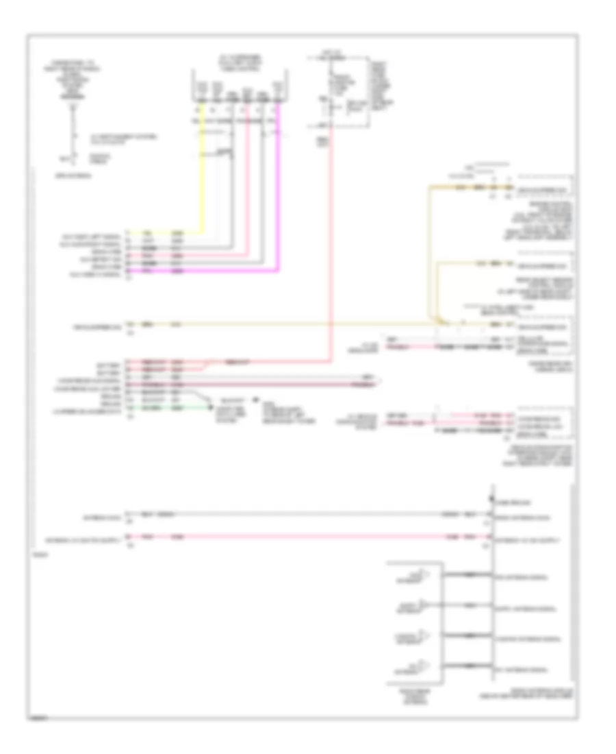
EXTERIOR LIGHTS
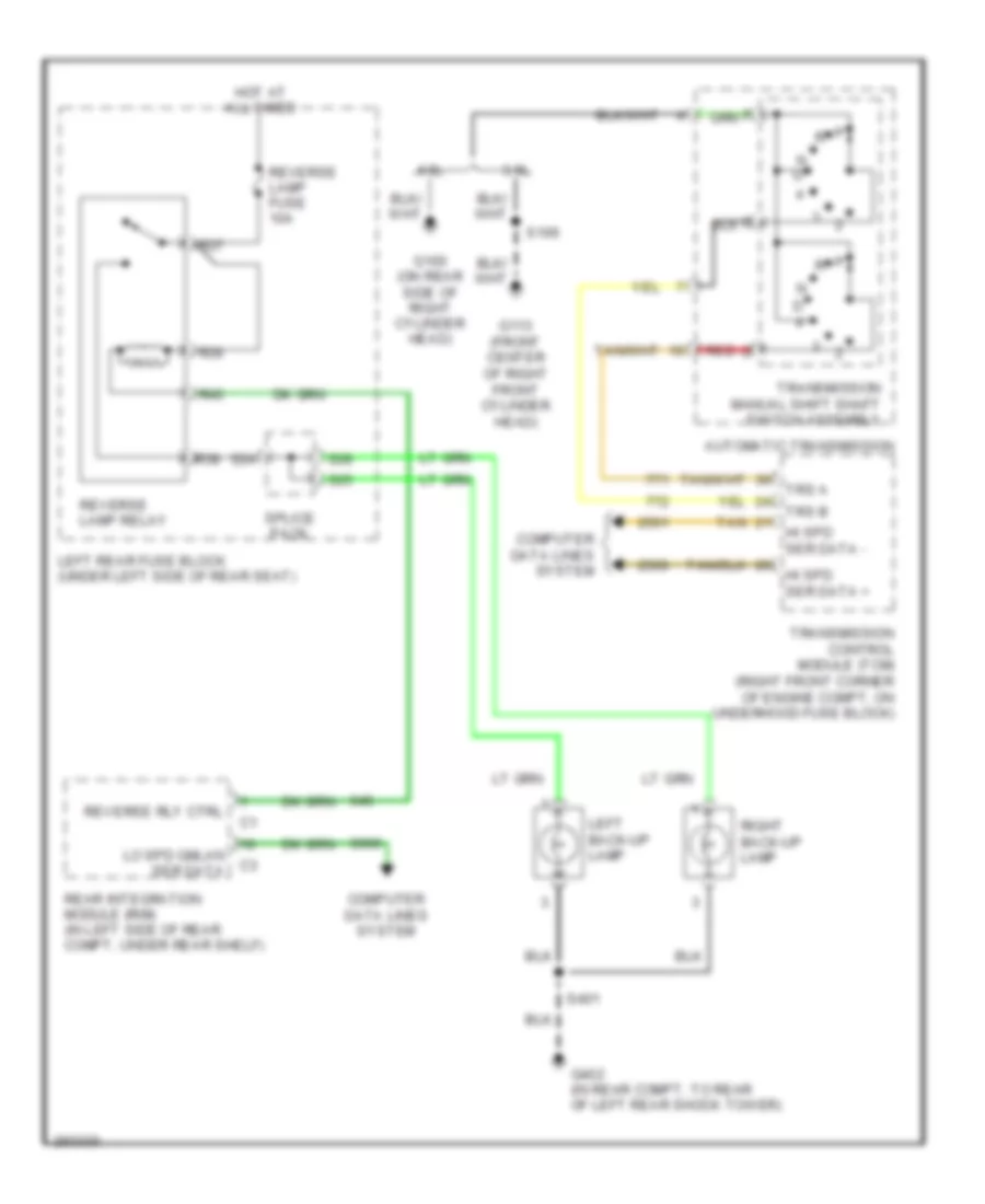
Backup Lamps Wiring Diagram for Cadillac STS V 2007
List of elements for Backup Lamps Wiring Diagram for Cadillac STS V 2007:
- 3.6l
- 4.6l
- Automatic transmission
- Computer data lines system
- G100 (on rear side of right cylinder head)
- G113 (front center of right front cylinder head)
- G402 (in rear compt, to rear of left rear shock tower)
- Hi spd ser data +
- Hi spd ser data -
- Hot at all times
- Left back-up lamp
- Left rear fuse block (under left side of rear seat)
- Lo spd gmlan ser data
- N d
- R36
- R37
- R38
- R40
- Rear integration module (rim) (in left side of rear compt, under rear shelf)
- Red d
- Reverse lamp fuse 10a
- Reverse lamp relay
- Reverse rly ctrl
- Right back-up lamp
- S106
- S24
- S25
- S28
- S401
- Splice pack
- Tan
- Transmission control module (tcm) (right front corner of engine compt, on underhood fuse block)
- Transmission manual shift shaft switch assembly
- Trs a
- Trs b
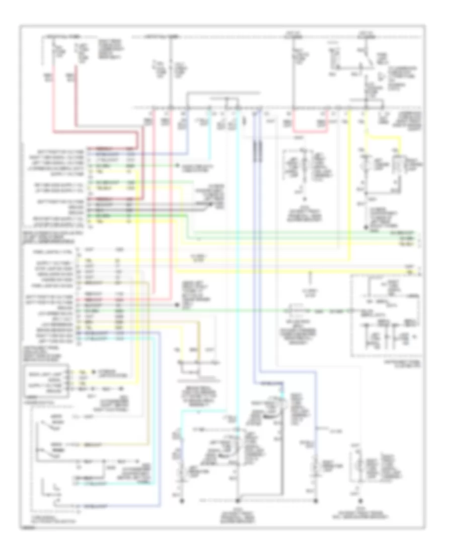
Exterior Lamps Wiring Diagram (1 of 2) for Cadillac STS V 2007
List of elements for Exterior Lamps Wiring Diagram (1 of 2) for Cadillac STS V 2007:
- (in rear compartment, to rear of left rear shock tower) g402
- (near left front strut tower, at bottom of inside fender well) g101
- (not used)
- Back light lamp
- Batt positive voltage
- Brake pedal position sensor (attached to top of brake pedal assembly)
- Brake sensor sig
- Computer data lines system
- Data
- Ext lights fuse 10a
- G104 (on right front frame rail, near bumper bracket)
- G200 (in passenger compartment, behind left kick panel)
- G201 (in passenger compt, behind right kick panel)
- Gmlan serial data
- Ground
- Hazard sw sign
- Hazard switch
- Head
- Head- lights system
- Headlamps on sig
- Hot at all times
- Ign
- Instrument panel cluster (ipc)
- Instrument panel module (ipm) (right side of dash, behind glove box)
- Interior lights system
- Ipm/ aldl fuse 10a
- Lamp outage ind
- Left front turn signal lamp
- Left front turn signal/ fog lamp assembly (4.4l)
- Left front turn signal/ fog lamp assembly (4.6l & 3.6l)
- Left license lamp
- Left repeater lamp
- Left turn rim fuse 10a
- Left turn signal ind
- Left turn signal voltage
- Left turn sw sig
- Lic/ dimming fuse 7.5a
- Lo speed gmlan serial data
- Logic
- Low reference
- Low speed gmlan
- Off
- Park
- Park lamp relay
- Park lamp rly ctrl
- Park lamp sw on sig
- R31
- R32
- R33
- R34
- Rear integration module (rim) (in left side of rear compt, under rear shelf)
- Right front turn signal lamp
- Right front turn signal/ fog lamp assembly (4.4l)
- Right front turn signal/ fog lamp assembly (4.6l & 3.6l)
- Right license lamp
- Right rear fuse block (under right side of rear seat)
- Right repeater lamp
- Right turn signal ind
- Right turn signal voltage
- Right turn sw sig
- Rim fuse 10a
- S226
- S311
- S401
- Serial
- Serial data
- Signal
- Splice pack sp201 (on dash harness, under dashboard, near firewall grommet)
- Sply volt
- Stop lamp sw sign
- To underhood fuse block lt park fuse, 10a (diagram 2 of 2)
- Turn signal/ multifunction switch
- Underhood fuse block (right front side of engine compt)
- Volt check fuse 10a
- W/ gps 1 & hid
- W/ hid
Exterior Lamps Wiring Diagram (2 of 2) for Cadillac STS V 2007
List of elements for Exterior Lamps Wiring Diagram (2 of 2) for Cadillac STS V 2007:
- (in body harness, 58 cm from
- (in body harness, 72 cm from right rear fuse block c1) (w/ gps 1) s317
- (right front side of engine compt) underhood fuse block
- (under right side of rear seat) right rear fuse block
- (w/ hid)
- (w/o hid)
- Center high mounted stop lamp (chmsl)
- Engine controls & transmissions systems
- From underhood fuse block lic/dimming fuse, 7.5a (diagram 1 of 2)
- G104 (on right front frame rail, near bumper bracket)
- G401 (in rear compt, to rear of right rear shock tower)
- G402 (in rear compt, to rear of left rear shock tower)
- Ground
- Hot at all times
- Left front park lamp
- Left front side marker lamp
- Left headlamp assembly
- Left rear side marker lamp
- Left tail lamp assembly
- Left tail lamp outage detection signal
- Logic
- Lt park fuse 10a
- Nca
- R36
- R37
- R38
- R40
- Right front park lamp
- Right front side marker lamp
- Right headlamp assembly
- Right rear fuse block c1) (w/ gps 1) s306
- Right rear side marker lamp
- Right tail lamp assembly
- Right tail lamp outage detection signal
- Rt park fuse 10a
- S12
- S13
- S14
- S400
- S401
- Side marker
- Splice pack
- Stop lamp relay
- Stop lamps fuse 10a
- Stop/ turn
- Tail
- W/ gps 1 & hid
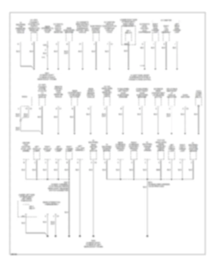
GROUND DISTRIBUTION
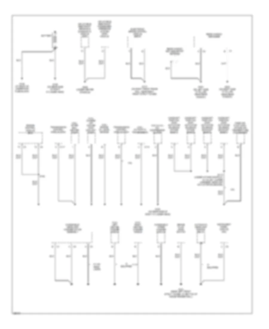
Ground Distribution Wiring Diagram (1 of 5) for Cadillac STS V 2007
List of elements for Ground Distribution Wiring Diagram (1 of 5) for Cadillac STS V 2007:
- (4.4l) charge air cooler (cac) coolant pump
- (4.4l) left heated washer nozzle
- (4.4l) right heated washer nozzle
- (4.6l & 4.4l) a/c compressor clutch
- (4.6l) after boil heater pump
- (4.6l) automatic transmission
- (4.6l) engine oil level switch
- 4.6l
- Automatic headlamp dimming relay
- Battery
- Brake fluid level switch
- C110
- C117
- Camshaft position (cmp) actuator solenoid exhaust bank 1
- Camshaft position (cmp) actuator solenoid exhaust bank 2
- Camshaft position (cmp) actuator solenoid intake bank 1
- Camshaft position (cmp) actuator solenoid intake bank 2
- Electronic brake control module (ebcm)
- Engine control module (ecm)
- G100 (on rear side of right cylinder head)
- G101 (near left front strut tower, at bottom of inside fender well)
- G105 (at back of underhood fuse block)
- G106 (on rear side of right cylinder head)
- G110 (on right front frame rail, near right front strut tower)
- G306 (under center console)
- G403 (on right side "c" pillar, near rear window)
- G404 (on left side "c" pillar, near rear window)
- If equipped
- Inflatable restraint passenger presence system (pps) module
- Inflatable restraint sensing & diagnostic module (sdm)
- Instrument panel module (ipm)
- Mass air flow (maf)/ intake air temperature (iat) sensor
- Rear window defogger
- Rear window keyless entry antenna
- S112 (under intake manifold, in valley jumper harness, near cmp actuator solenoids)
- S152
- Transmission control module (tcm)
- W/ hid head- lamps
- Windshield wiper/ washer module
- Windshield/ headlamp washer motor assembly
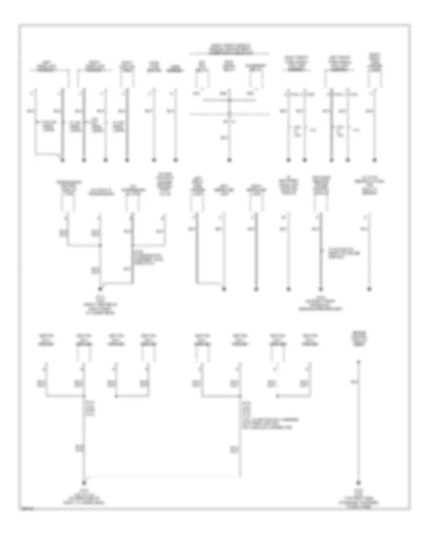
Ground Distribution Wiring Diagram (2 of 5) for Cadillac STS V 2007
List of elements for Ground Distribution Wiring Diagram (2 of 5) for Cadillac STS V 2007:
- (if equipped)
- (right front side of engine compartment) underhood fuse block
- (w/ auto recirculating) air quality sensor
- 4.4l
- 4.6l & 3.6l
- A/c compressor clutch
- Accessory relay
- Automatic transmission
- C c124
- C c125
- C122
- C123
- Distance sensing cruise control module
- Engine control module (ecm)
- G103 (3.6l) (top right side of engine, fastened to ecm case)
- G104 (on right front frame rail, near bumper bracket)
- G107 (4.6l & 4.4l) (on rear side of right cylinder head)
- G113 (3.6l) (front center of right front cylinder head)
- Headlamp leveling module
- Hood ajar switch
- Horn assembly
- Ignition coil/ module 1
- Ignition coil/ module 2
- Ignition coil/ module 3
- Ignition coil/ module 4
- Ignition coil/ module 5
- Ignition coil/ module 6
- Ignition coil/ module 7
- Ignition coil/ module 8
- Intake manifold runner control (imrc) valve
- Left front side marker lamp
- Left front turn signal/ fog lamp assembly
- Left headlamp assembly
- Left repeater lamp
- R16
- R35
- R46
- Right cooling fan
- Right front side marker lamp
- Right front turn signal/ fog lamp assembly
- Right headlamp assembly
- Right repeater lamp
- Run/ crank relay
- S/p fan relay
- S133 (4.6l) s134 (4.4l) (4.6l: in ignition coil harness, 30 cm from ignition coil module 2 connector)
- S144 (4.6l) s145 (4.4l)
- S148 (in engine poa harness, 39 cm from g113)
- Transmission control module (tcm)
- W/ automatic adaptive cruise control
- W/ hid head- lamps
- W/o hid head- lamps
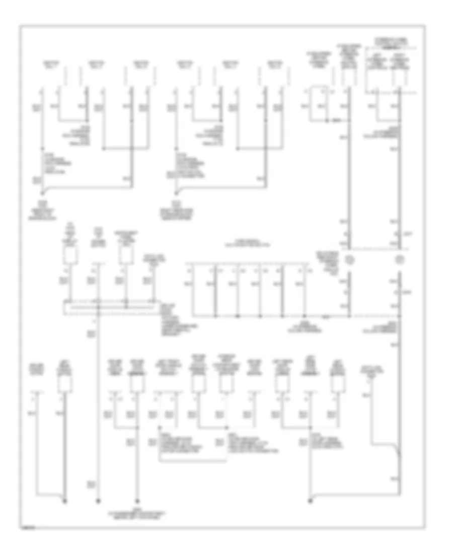
Ground Distribution Wiring Diagram (3 of 5) for Cadillac STS V 2007
List of elements for Ground Distribution Wiring Diagram (3 of 5) for Cadillac STS V 2007:
- (if equipped) heated steering wheel
- (if equipped) heated steering wheel control module
- (w/ hud)
- (w/o hud) i/p dimmer switch
- C276
- C277
- Data link connector (dlc)
- Driver door latch assembly
- Driver door lock switch
- Driver door module (ddm)
- Driver door switch assembly (ddsa)
- Driver window motor
- G109 (3.6l) (near right front of engine block)
- G112 (3.6l) (right rear side of engine block, near starter)
- G200 (in passenger compartment, behind left kick panel)
- Head up display (hud)
- Ignition coil 1
- Ignition coil 2
- Ignition coil 3
- Ignition coil 4
- Ignition coil 5
- Ignition coil 6
- Inflatable restraint steering wheel module coil
- Instrument panel cluster (ipc)
- Interior rear compartment lid release switch
- Left front door handle switch assembly
- Left rear door latch assembly
- Left rear door module (lrdm)
- Left rear window motor
- Left rear window switch
- Left steering wheel controls
- Nca
- Right steering wheel controls
- S125 (in engine poa harness, 12 cm from g109)
- S126 (in engine poa harness, 18 cm from g109)
- S129 (in engine poa harness, 17 cm from g112)
- S224 (in steering column harness)
- S226 (in steering column harness)
- S228 (in steering column harness)
- S500 (in driver door harness, 32 cm from driver window motor connector)
- S501 (in driver door trim harness, 47 cm from driver door lock switch connector)
- S700 (in left rear door harness, 32 cm from c701)
- Splice pack sp201 (on dash harness, under dashboard, near firewall grommet)
- Steering wheel control switch assembly
- Turn signal/ multifunction switch
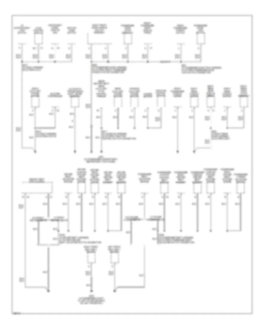
Ground Distribution Wiring Diagram (4 of 5) for Cadillac STS V 2007
List of elements for Ground Distribution Wiring Diagram (4 of 5) for Cadillac STS V 2007:
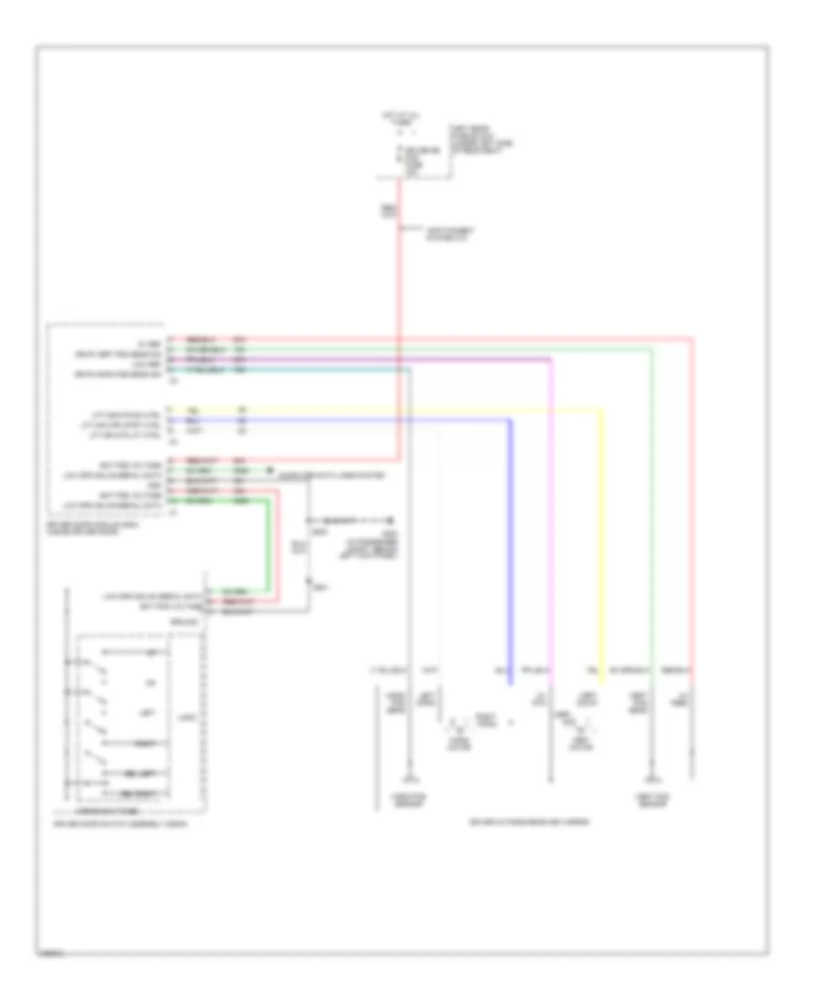
- (rear heated seat) rear auxiliary hvac control module
- Automatic transmission shift lever assembly
- B11
- Blower controller
- Console auxiliary power outlet
- Driver back cooled seat blower motor
- Driver back heated seat element
- Driver cushion cooled seat blower motor
- Driver cushion heated seat element
- Driver seat adjuster switch
- Front auxiliary power outlet
- Front passenger door module (fpdm)
- Front passenger window motor
- Front passenger window switch
- G201 (in passenger compartment, behind right kick panel)
- G307 (in passenger compt, to left of driver seat, on left frame rail)
- Hazard switch
- Hvac control module
- I/p compartment lamp switch
- Ignition mode switch
- Instrument panel module (ipm)
- Left front seat belt switch
- Memory seat module (msm)
- Passenger back cooled seat blower motor
- Passenger back heated seat element
- Passenger climate control seat module
- Passenger cushion cooled seat blower motor
- Passenger cushion heated seat element
- Passenger door latch assembly
- Passenger door lock switch
- Passenger lumbar adjuster switch
- Passenger seat adjuster switch
- Rear auxiliary power outlet
- Right front door handle switch assembly
- Right front seat belt switch
- Right rear door latch assembly
- Right rear door module (rrdm)
- Right rear window motor
- Right rear window switch
- S210 (in dash harness, 35 cm from c214)
- S600 (in passenger door harness, 32 cm from front passenger window motor connector)
- S601 (in passenger door trim harness, 42 cm from passenger door lock switch connector)
- Traction control switch
- W/ front heated seats
- W/ power lumbar seats
- W/o front heated seats
- W/o power lumbar seats
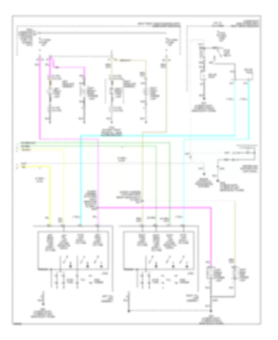
Ground Distribution Wiring Diagram (5 of 5) for Cadillac STS V 2007
List of elements for Ground Distribution Wiring Diagram (5 of 5) for Cadillac STS V 2007:
- (if equipped)
- (if equipped) garage door opener
- (if equipped) left front door subwoofer speaker
- (if equipped) outside moisture sensor
- (if equipped) right front door subwoofer speaker
- (if equipped) sunroof switch
- (if equipped) tire pressure monitor module
- (under left side of rear seat) left rear fuse block
- (under right side of rear seat) right rear fuse block
- (w/ digital radio) digital radio receiver
- (w/ hid headlamps) inside rearview mirror (isrvm)
- (w/ info- tainment system 014 & 015) tv antenna module
- (w/ info- tainment system 015) traffic information receiver (vics)
- (w/ magnetic ride control) electronic suspension control (esc) module
- (w/ onstar)
- (w/ onstar) vehicle communication interface module (vcim)
- (w/o hid headlamps) inside rearview mirror (isrvm)
- (wcv) wiper inhibit relay
- 4.4l
- Audio amplifier
- Automatic level control (alc) compressor
- Center high mounted stop lamp (chmsl)
- Electronic sunroof control module
- Exterior rear compartment lid release switch
- Front overhead courtesy/ reading lamps
- G401 (in rear compt, to rear of right rear shock tower)
- G402 (in rear compt, to rear of left rear shock tower)
- Ign 1 relay
- Ign 3 relay
- Inflatable restraint i/p module indicator
- Left back-up lamp
- Left license lamp
- Left rear side marker lamp
- Left tail lamp assembly
- Left vanity mirror lamp
- Nca
- R21
- R25
- Radio
- Rear compartment lid release actuator
- Rear differential cooler pump
- Rear heated seat module
- Rear integration module (rim)
- Rear object sensor control module
- Rear overhead courtesy/ reading lamps
- Rear subwoofer speaker
- Remote control door lock receiver (rcdlr)
- Right back-up lamp
- Right license lamp
- Right rear side marker lamp
- Right tail lamp assembly
- Right vanity mirror lamp
- S401 (in body harness, 15 cm from exterior rear compt release switch connector)
- W/ soft ride, sport suspension system & magnetic ride control
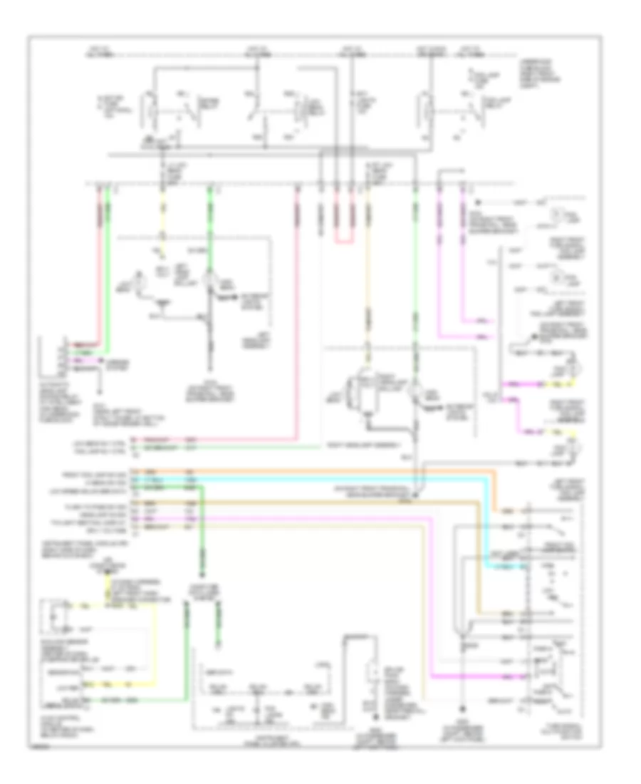
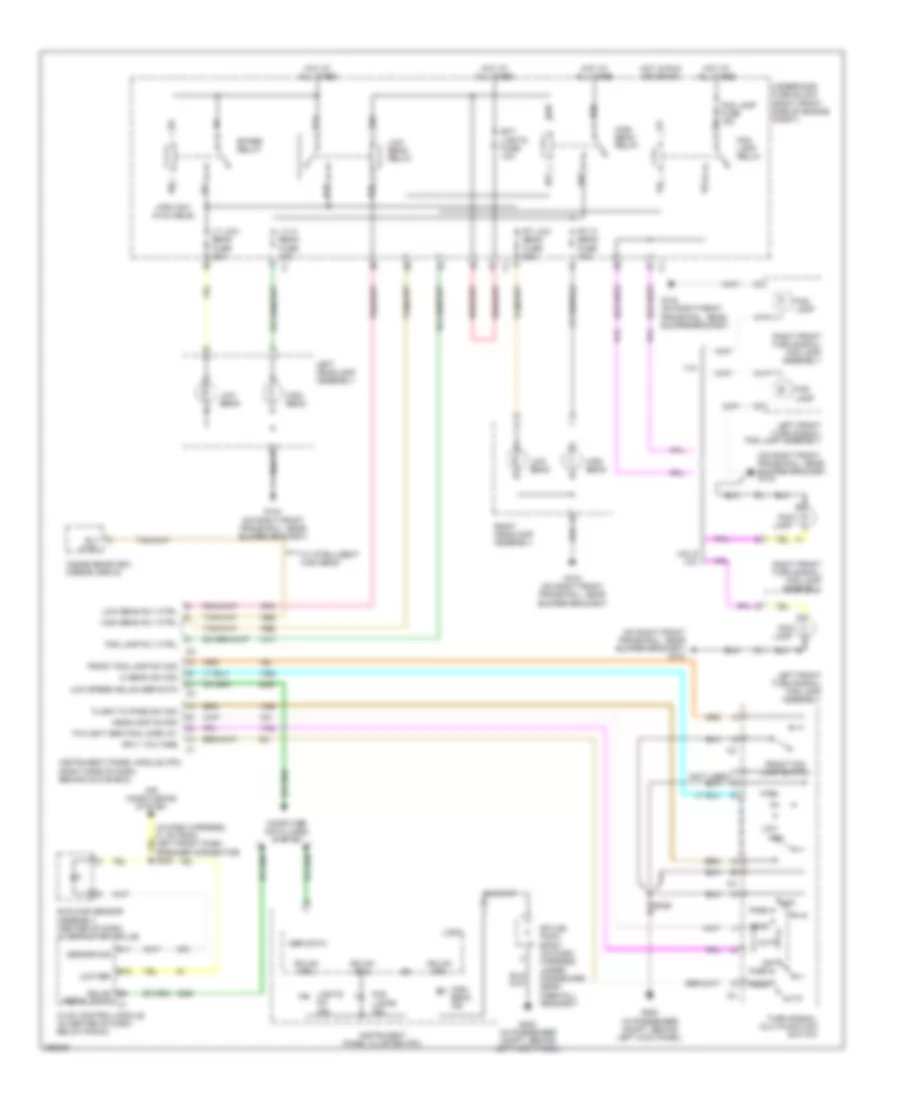
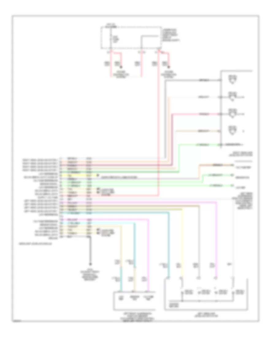
HEADLIGHTS
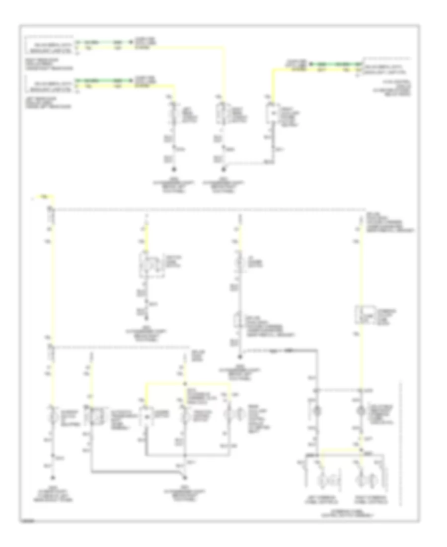
Headlamps Wiring Diagram, with High Intensity Discharge for Cadillac STS V 2007
List of elements for Headlamps Wiring Diagram, with High Intensity Discharge for Cadillac STS V 2007:
- (in dash harness, 51 cm from left front dash speaker connector) s202
- (on right front frame rail, near bumper bracket) g104
- 4.4l
- 4.6l & 3.6l
- A11 sensor sig
- Air conditioning system
- Auto
- Automatic headlamp dimming relay (w/ intelligent high beam) (in underhood fuse block)
- B12 low ref
- C (not used)
- Computer data lines system
- Ext lights fuse 10a
- Exterior lights system
- Flash to pass sw sig
- Fog lamp
- Fog lamp fuse 15a
- Fog lamp relay
- Fog lamp rly ctrl
- Fog lamps ind
- Front fog lamp sw sig
- Front fog lamp switch
- Ftp
- G101 (near left front strut tower, at bottom of inside fender well)
- G104 (on right front frame rail, near bumper bracket)
- G200 (in passenger compt, behind left kick panel)
- Gmlan (ipm)
- Gmlan (rim)
- Gmlan b5
- Gnd
- Head
- Headlamp on sig
- Hi beam sw sig
- High
- High beam
- High beam ind
- Hot at all times
- Hot in run or crank
- Hvac control module (in center of dash, below radio)
- Instrument panel cluster (ipc)
- Instrument panel module (ipm) (right side of dash, behind glove box)
- Left front turn signal/ fog lamp assembly
- Left head- lamp ballast
- Left headlamp assembly
- Lights on ind
- Logic
- Low
- Low beam
- Low beam relay
- Low beam rly ctrl
- Low speed gmlan ser data
- Lt low beam fuse 20a
- Mirrors system
- Off
- Park
- R23
- R24
- R25
- R26
- R9 (info not available)
- Right front turn signal/ fog lamp assembly
- Right headlamp assembly
- Right headlamp ballast
- Rt low beam fuse 20a
- S226
- Ser data
- Serial data c1
- Smt bm fuse (optional) 10a
- Spare relay
- Splice pack sp201 (on dash harness, under dashboard, near firewall grommet)
- Sply volt
- Sply voltage
- Sunload sensor assembly (center of dash, in defroster grille)
- Turn signal/ multifunction switch
- Twilight sentinal display
- Underhood fuse block (right front side of engine compt)
Headlamps Wiring Diagram, without High Intensity Discharge for Cadillac STS V 2007
List of elements for Headlamps Wiring Diagram, without High Intensity Discharge for Cadillac STS V 2007:
- (in dash harness, 51 cm from left front dash speaker connector) s202
- (info not available)
- (on right front frame rail, near bumper bracket) g104
- 4.4l
- 4.6l & 3.6l
- A11 sensor sig
- Air conditioning system
- Auto
- B12 low ref
- C (not used)
- Computer data lines system
- Ext lights fuse 10a
- Flash to pass sw sig
- Fog lamp
- Fog lamp fuse 15a
- Fog lamp relay
- Fog lamp rly ctrl
- Fog lamps ind
- Front fog lamp sw sig
- Front fog lamp switch
- Ftp
- G104 (on right front frame rail, near bumper bracket)
- G200 (in passenger compt, behind left kick panel)
- Gmlan (ipm)
- Gmlan (rim)
- Gmlan b5
- Head
- Headlamp on sig
- Hi beam sw sig
- High
- High beam
- High beam ind
- High beam relay
- High beam rly ctrl
- Hot at all times
- Hot in run or crank
- Hvac control module (in center of dash, below radio)
- Inside rearview mirror (isrvm)
- Instrument panel cluster (ipc)
- Instrument panel module (ipm) (right side of dash, behind glove box)
- Left front turn signal/ fog lamp assembly
- Left headlamp assembly
- Lights on ind
- Logic
- Low
- Low beam
- Low beam relay
- Low beam rly ctrl
- Low speed gmlan ser data
- Lt hi beam fuse 10a c1
- Lt low beam fuse 20a
- Off
- Park
- R23
- R24
- R25
- R26
- R27
- R28
- R29
- R30
- Right front turn signal/ fog lamp assembly
- Right headlamp assembly
- Rly ctrl
- Rt hi beam fuse 10a
- Rt low beam fuse 20a
- S226
- Ser data
- Serial data c1
- Spare relay
- Splice pack sp201 (on dash harness, under dashboard, near firewall grommet)
- Sply voltage
- Sunload sensor assembly (center of dash, in defroster grille)
- Turn signal/ multifunction switch
- Twilight sentinal display
- Underhood fuse block (right front side of engine compt)
- W/ intelligent high beam
Headlamps Leveling Wiring Diagram for Cadillac STS V 2007
List of elements for Headlamps Leveling Wiring Diagram for Cadillac STS V 2007:
- Ccp fuse 10a
- Common return
- Common rtn
- Computer data lines system
- Drive 1 motor
- Drive 2 motor
- Drive 3 motor
- Drive 4 motor
- G104 (on right front frame rail, near bumper bracket)
- Gmlan serial data
- Gmlan serial data wake up
- Ground
- Headlamp leveling module
- Hot at all times
- Left front suspension position sensor (w/o magnetic ride control) (near left front strut)
- Left head leveling motor 1
- Left head leveling motor 2
- Left head leveling motor 3
- Left head leveling motor 4
- Left headlamp leveling actuator
- Left rear suspension position sensor (w/o magnetic ride control) (near left rear strut)
- Low ref
- Low reference
- Power distribution system
- Right head leveling motor 1
- Right head leveling motor 2
- Right head leveling motor 3
- Right head leveling motor 4
- Right headlamp leveling actuator
- Sensor sig
- Sensor signal
- Tan
- Underhood fuse block (right front side of engine compt)
- Voltage ref
- Voltage reference
HORN
Horn Wiring Diagram for Cadillac STS V 2007
List of elements for Horn Wiring Diagram for Cadillac STS V 2007:
- C276
- C277
- Fuse 2a
- G104 (on right front frame rail, near bumper bracket)
- High note horn
- Horn assembly
- Horn fuse 15a
- Horn relay
- Horn relay control
- Horn switch
- Hot at all times
- Inflatable restraint steering wheel module coil
- Inline steering column usage fuse block
- Instrument panel module (ipm) (right side of dash, behind glove box)
- Low note horn
- Nca
- R10
- R11
- R12
- R13
- Steering wheel control pad
- Tan
- Underhood fuse block (right front side of engine compartment)
INSTRUMENT CLUSTER
3.6L VIN 7
3.6L VIN 7, Instrument Cluster Wiring Diagram (1 of 2) for Cadillac STS V 2007
List of elements for 3.6L VIN 7, Instrument Cluster Wiring Diagram (1 of 2) for Cadillac STS V 2007:
- (not used)
- Abs ind
- Air bag fuse 10a
- Air bag ind
- Audible alarm
- Backlighting ctrl
- Backlighting ind
- Batt pos volt
- Brake fluid level switch (in master cylinder reservoir)
- Brake ind
- Charge ind
- Class 2 (ecm)
- Clock
- Clock ctrl
- Cruise ind
- Dic sw low ref
- Dic sw sig
- Dic toggle sw
- Ecm/tcm fuse 10a
- Engine controls system
- Engine coolant temperature ind
- Front fog lamps ind
- Fuel level gauge
- G101 (near left front strut tower, at bottom of inside fender well)
- Gmlan
- Gmlan (ebcm)
- Gmlan (ecm)
- Gmlan (ipm)
- Gmlan (rim)
- Gmlan (sdm)
- Gmlan (tcm)
- Gmlan serial
- Ground
- High beam ind
- Hot at all times
- Hot w/ ign 1 relay energized
- Hot w/ run/crank relay energized
- Hud fuse 10a
- Ign 1 volt
- Inflatable restraint i/p module indicator
- Instrument panel cluster (ipc)
- Ipc
- Left turn ind
- Lights on ind
- Logic
- Low tire pressure ind
- Malfunction ind
- Mil lmp ind ctrl
- Oil level ind
- Pass seat belt ind
- Pass seat belt ind ctrl
- Pnk
- Power distribution system
- Right rear fuse block (under right side of rear seat)
- Right turn ind
- S18
- S20
- Seat belt ind
- Security ind
- Sensor signal
- Speedometer gauge
- Splice pack
- Sport mode ind
- Tachometer gauge
- Tap up/ down enable ind
- Tcm/ipc fuse 15a
- Temperature gauge
- Traction off ind
- Trip reset sw sig
- Trip reset switch
- Trip/ odometer
- Trip/odometer ctrl
- Underhood fuse block (right front side of engine compt)
- Wait to start ind (not used)
- Winter mode ind
3.6L VIN 7, Instrument Cluster Wiring Diagram (2 of 2) for Cadillac STS V 2007
List of elements for 3.6L VIN 7, Instrument Cluster Wiring Diagram (2 of 2) for Cadillac STS V 2007:
- (in engine poa harness, 17 cm from ecm c1) s121
- (in fuel tank jumper tan
- (in fuel tank) fuel pump & sender assembly
- (in top left side of fuel tank) secondary fuel sender assembly
- 5v ref
- Auto
- Battery positive volt
- Computer data lines system
- Courtesy lmp sw on sig
- Eng/ met
- Engine controls system
- Engine oil pressure (eop) sensor (on left side of engine, attached to oil filter adapter housing)
- G200 (in passenger compartment, behind left kick panel)
- Gmlan serial data
- Ground
- Harness, 28 cm from fuel tank pressure sensor connector) s406
- Head-up display (hud)
- Hud image dimming sig
- Hud image down sig
- Hud image up sig
- Hud message center
- Hud switch low ref
- I/p dimmer sw sig
- I/p dimmer switch
- Ign
- Image dn
- Image up
- Info dn
- Info reset
- Info up
- Instrument panel module (ipm) (right side of dash, behind glove box)
- Interior lights system
- Lo spd gmlan serial data
- Logic
- Low ref
- Message request
- Oil sw sig
- Park brake switch (at base of brake pedal)
- Pk brk sw sig
- Pnk
- S120 (in engine poa harness, 21 cm from throttle body assembly connector)
- Sensor sig
- Serial data +
- Serial data -
- Splice pack sp201 (on dash harness, under dashboard, near firewall grommet)
- Tan
- Trip a/b
- Trip reset
- W/ head-up display
- W/o head-up display
- Xxx mph/kpm check gages
4.4L VIN D
4.4L VIN D, Instrument Cluster Wiring Diagram (1 of 2) for Cadillac STS V 2007
List of elements for 4.4L VIN D, Instrument Cluster Wiring Diagram (1 of 2) for Cadillac STS V 2007:
- (not used)
- Abs ind
- Air bag fuse 10a
- Air bag ind
- Audible alarm
- Backlighting ctrl
- Backlighting ind
- Batt pos volt
- Brake fluid level switch (in master cylinder reservoir)
- Brake ind
- Charge ind
- Class 2 (ecm)
- Clock
- Clock ctrl
- Cruise ind
- Dic sw low ref
- Dic sw sig
- Dic toggle sw pass seat beat ind ctrl
- Ecm/tcm fuse 10a
- Engine controls system
- Engine coolant temperature ind
- Front fog lamps ind
- Fuel level gauge
- G101 (near left front strut tower, at bottom of inside fender well)
- Gmlan
- Gmlan (ebcm)
- Gmlan (ecm)
- Gmlan (ipm)
- Gmlan (rim)
- Gmlan (sdm)
- Gmlan (tcm)
- Gmlan serial
- Ground
- High beam ind
- Hot at all times
- Hot w/ ign 1 relay energized
- Hot w/ run/crank relay energized
- Hud fuse 10a
- Ign 1 volt
- Inflatable restraint i/p module indicator
- Instrument panel cluster (ipc)
- Ipc
- Left turn ind
- Lights on ind
- Logic
- Low tire pressure ind
- Malfunction ind
- Mil lmp ind ctrl
- Oil level ind
- Pass seat belt ind
- Pnk
- Power distribution system
- Right rear fuse block (under right side of rear seat)
- Right turn ind
- S18
- S20
- Seat belt ind
- Security ind
- Sensor signal
- Speedometer gauge
- Splice pack
- Sport mode ind
- Tachometer gauge
- Tap up/ down enable ind
- Tcm/ipc fuse 15a
- Temperature gauge
- Traction off ind
- Trip reset sw sig
- Trip reset switch
- Trip/ odometer
- Trip/odometer ctrl
- Underhood fuse block (right front side of engine compt)
- Wait to start ind (not used)
- Winter mode ind
4.4L VIN D, Instrument Cluster Wiring Diagram (2 of 2) for Cadillac STS V 2007
List of elements for 4.4L VIN D, Instrument Cluster Wiring Diagram (2 of 2) for Cadillac STS V 2007:
- (bottom center of engine oil pan) (4.4l) engine oil level & temperature sensor
- (in bottom of oil pan) engine oil level switch
- (in fuel tank) fuel pump & sender assembly
- (in top left side of fuel tank) secondary fuel sender assembly
- (on rear side of right cylinder head) g100
- 4.4l
- 4.4l & 4.6l
- 4.6l
- 5v ref
- Auto
- Battery positive volt
- Computer data lines system
- Courtesy lmp sw on sig
- Eng/ met
- Engine controls system
- Engine oil pressure (eop) sensor (on left side of engine)
- G200 (in passenger compartment, behind left kick panel)
- Gmlan serial data
- Ground
- Head-up display (hud)
- Hud image dimming sig
- Hud image down sig
- Hud image up sig
- Hud message center
- Hud switch low ref
- I/p dimmer sw sig
- I/p dimmer switch
- Ign
- Image dn
- Image up
- Info dn
- Info reset
- Info up
- Instrument panel module (ipm) (right side of dash, behind glove box)
- Interior lights system
- Lo spd gmlan serial data
- Logic
- Low ref
- Message request
- Oil sw sig
- Park brake switch (at base of brake pedal)
- Pk brk sw sig
- Pnk
- Sensor sig
- Serial data +
- Serial data -
- Splice pack sp201 (on dash harness, under dashboard, near firewall grommet)
- Tan
- Tan (in fuel tank jumper harness, 28 cm from fuel tank pressure sensor connector) s406
- Temp sensor
- Trip a/b
- Trip reset
- W/ head-up display
- W/o head-up display
- Xxx mph/kpm check gages
4.6L VIN A
4.6L VIN A, Instrument Cluster Wiring Diagram (1 of 2) for Cadillac STS V 2007
List of elements for 4.6L VIN A, Instrument Cluster Wiring Diagram (1 of 2) for Cadillac STS V 2007:
- (not used)
- Abs ind
- Air bag fuse 10a
- Air bag ind
- Audible alarm
- Backlighting ctrl
- Backlighting ind
- Batt pos volt
- Brake fluid level switch (in master cylinder reservoir)
- Brake ind
- Charge ind
- Class 2 (ecm)
- Clock
- Clock ctrl
- Cruise ind
- Dic sw low ref
- Dic sw sig
- Dic toggle sw pass seat beat ind ctrl
- Ecm/tcm fuse 10a
- Engine controls system
- Engine coolant temperature ind
- Front fog lamps ind
- Fuel level gauge
- G101 (near left front strut tower, at bottom of inside fender well)
- Gmlan
- Gmlan (ebcm)
- Gmlan (ecm)
- Gmlan (ipm)
- Gmlan (rim)
- Gmlan (sdm)
- Gmlan (tcm)
- Gmlan serial
- Ground
- High beam ind
- Hot at all times
- Hot w/ ign 1 relay energized
- Hot w/ run/crank relay energized
- Hud fuse 10a
- Ign 1 volt
- Inflatable restraint i/p module indicator
- Instrument panel cluster (ipc)
- Ipc
- Left turn ind
- Lights on ind
- Logic
- Low tire pressure ind
- Malfunction ind
- Mil lmp ind ctrl
- Oil level ind
- Pass seat belt ind
- Pnk
- Power distribution system
- Right rear fuse block (under right side of rear seat)
- Right turn ind
- S18
- S20
- Seat belt ind
- Security ind
- Sensor signal
- Speedometer gauge
- Splice pack
- Sport mode ind
- Tachometer gauge
- Tap up/ down enable ind
- Tcm/ipc fuse 15a
- Temperature gauge
- Traction off ind
- Trip reset sw sig
- Trip reset switch
- Trip/ odometer
- Trip/odometer ctrl
- Underhood fuse block (right front side of engine compt)
- Wait to start ind (not used)
- Winter mode ind
4.6L VIN A, Instrument Cluster Wiring Diagram (2 of 2) for Cadillac STS V 2007
List of elements for 4.6L VIN A, Instrument Cluster Wiring Diagram (2 of 2) for Cadillac STS V 2007:
- (bottom center of engine oil pan) (4.4l) engine oil level & temperature sensor
- (in bottom of oil pan) engine oil level switch
- (in fuel tank) fuel pump & sender assembly
- (in top left side of fuel tank) secondary fuel sender assembly
- (on rear side of right cylinder head) g100
- 4.4l
- 4.4l & 4.6l
- 4.6l
- 5v ref
- Auto
- Battery positive volt
- Computer data lines system
- Courtesy lmp sw on sig
- Eng/ met
- Engine controls system
- Engine oil pressure (eop) sensor (on left side of engine)
- G200 (in passenger compartment, behind left kick panel)
- Gmlan serial data
- Ground
- Head-up display (hud)
- Hud image dimming sig
- Hud image down sig
- Hud image up sig
- Hud message center
- Hud switch low ref
- I/p dimmer sw sig
- I/p dimmer switch
- Ign
- Image dn
- Image up
- Info dn
- Info reset
- Info up
- Instrument panel module (ipm) (right side of dash, behind glove box)
- Interior lights system
- Lo spd gmlan serial data
- Logic
- Low ref
- Message request
- Oil sw sig
- Park brake switch (at base of brake pedal)
- Pk brk sw sig
- Pnk
- Sensor sig
- Serial data +
- Serial data -
- Splice pack sp201 (on dash harness, under dashboard, near firewall grommet)
- Tan
- Tan (in fuel tank jumper harness, 28 cm from fuel tank pressure sensor connector) s406
- Temp sensor
- Trip a/b
- Trip reset
- W/ head-up display
- W/o head-up display
- Xxx mph/kpm check gages
INTERIOR LIGHTS
Courtesy Lamps Wiring Diagram (1 of 2) for Cadillac STS V 2007
List of elements for Courtesy Lamps Wiring Diagram (1 of 2) for Cadillac STS V 2007:
- Computer data lines system
- Courtesy lamp ctrl
- Courtesy rly ctrl
- Courtesy sply ctrl
- Front overhead courtesy/ reading lamps
- G201 (in passenger compt, behind right kick panel)
- G402 (in rear compartment, to rear of left rear shock tower)
- G402 (in rear compt, to rear of left rear shock tower)
- Gmlan serial data
- Hot at all times
- I/p compart- ment lamp
- I/p compartment lamp switch
- Interior lamp fuse 10a
- Interior lamp relay
- Left footwell courtesy lamp
- Left rear door courtesy lamp
- Left vanity mirror lamp
- Nca
- R17
- R18
- R19
- R20
- Rear compart- ment courtesy lamp
- Rear compartment lid release actuator (on center rear of rear compt lid)
- Rear integration module (rim) (in left side of rear compt, under rear shelf)
- Rear overhead courtesy/ reading lamps
- Right footwell courtesy lamp
- Right rear door courtesy lamp
- Right rear fuse block (under right side of rear seat)
- Right vanity mirror lamp
- S210
- S215 (in dash harness, 65 cm from c200)
- S308 (in headliner harness, 82 cm from c308)
- S309 (in headliner harness, 92 cm from c308)
- S310
- Splice pack sp300
- Splice pack sp303 (in passenger compt, on right frame rail, near right side of passenger seat)
- Trunk diode
Courtesy Lamps Wiring Diagram (2 of 2) for Cadillac STS V 2007
List of elements for Courtesy Lamps Wiring Diagram (2 of 2) for Cadillac STS V 2007:
- Ajar
- Computer data lines system
- Courtesy lamp ctrl high
- Courtesy lamp ctrl low
- Courtesy lamp sw on
- Driver door latch assembly (in middle rear of driver door)
- Driver door module (ddm) (inside driver door)
- Front passenger door latch assembly (in middle rear of left rear door)
- Front passenger door module (fpdm) (inside right front door)
- G200 (in passenger compt, behind left kick panel)
- G201 (in passenger compt, behind right kick panel)
- Gmlan serial data
- I/p dimmer switch
- Instrument panel module (ipm) (right side of dash, behind glove box)
- Left front door courtesy lamp
- Left rear door latch assembly (in middle rear of passenger door)
- Left rear door module (lrdm) (inside left rear door)
- Lf door ajar
- Low reference
- Lr door ajar sw sig
- Rf door ajar sw sig
- Right front door courtesy lamp
- Right rear door latch assembly (in middle rear of right rear door)
- Right rear door module (rrdm) (inside right rear door)
- Rr door ajar sw sig
- S500
- S600
- S700
- S800
Instrument Illumination Wiring Diagram (1 of 2) for Cadillac STS V 2007
List of elements for Instrument Illumination Wiring Diagram (1 of 2) for Cadillac STS V 2007:
- (in driver door trim harness, 71 cm from driver door lock switch connector) s504
- (on dash harness, under dashboard, near firewall grommet) splice pack sp201
- Auto
- Backlight lamp ctrl
- Backlighting control
- Backlighting ind (8 bulbs)
- Batt pos volt
- Computer data lines system
- Courtesy lamp on sig
- Dimmer sw sig
- Driver door lock switch
- Driver door module (ddm) (inside driver door)
- Driver door switch assembly
- Ecm/ tcm fuse 10a
- Ext lights fuse 10a
- Front passenger door module (fpdm) (inside right front door)
- Front passenger window switch
- G101 (near left front strut tower, at bottom of inside fender well)
- G200 (in passenger compartment, behind left kick panel)
- G200 (in passenger compt, behind left kick panel)
- G201 (in passenger compt, behind right kick panel)
- Gmlan serial data
- Ground
- Head
- Hot at all times
- I/p dimmer switch
- Instrument panel cluster (ipc)
- Instrument panel module (ipm) (right side of dash, behind glove box)
- Interior rear compartment lid release switch
- Ipm/aldl fuse 10a
- Lamp ctrl sply vol
- Lic/ dimming fuse 7.5a
- Logic
- Low reference
- Off
- Park
- Park lamp relay
- Park lamp rly ctrl
- Passenger door lock switch
- R31
- R32
- R33
- R34
- S210
- S501
- S601
- Turn signal/ multi-function switch
- Underhood fuse block (right front side of engine compt)
Instrument Illumination Wiring Diagram (2 of 2) for Cadillac STS V 2007
List of elements for Instrument Illumination Wiring Diagram (2 of 2) for Cadillac STS V 2007:
- Automatic transmission shift lever assembly
- Backlight lamp ctrl
- Computer data lines system
- F c276
- F c277
- From c212)
- Front auxiliary power outlet ashtray
- Fuse 2a
- G200 (in passenger compt, behind left kick panel)
- G201 (in passenger compt, behind right kick panel)
- G402 (in rear compt, to rear of left rear shock tower)
- Gmlan serial data
- Hazard switch
- Hvac control module (in center of dash, below radio)
- I/p dimmer switch
- Ignition mode switch
- Inflatable restraint steering wheel module coil
- Left rear door module (lrdm) (inside left rear door)
- Left rear window switch
- Left steering wheel controls
- Nca
- Rear auxiliary hvac control module (w/ heated seat)
- Right rear door module (rrdm) (inside right rear door)
- Right rear window switch
- Right steering wheel controls
- S210
- S224
- S227
- S228
- S310
- S311
- S700
- S800
- Splice pack sp201 (on dash harness, under dashboard, near firewall grommet)
- Splice pack sp300
- Steering column fuse block
- Steering wheel control switch assembly
- Sunroof switch (if equipped)
- Traction control switch
MEMORY SYSTEMS
Driver"s Mirror Wiring Diagram for Cadillac STS V 2007
List of elements for Driver"s Mirror Wiring Diagram for Cadillac STS V 2007:
- 5v feed
- 5v ref
- 5v rtn
- Bat pos voltage
- Computer data lines system
- Driver door module (ddm) (inside driver door)
- Driver door switch assembly (ddsa)
- Driver dr mod fuse 15a
- Driver outside rearview mirror
- Drvr horiz pos sens sig
- Drvr vert pos sens sig
- G200 (in passenger compt, behind left kick panel)
- Gnd
- Ground
- Horiz motor
- Horiz pos sens
- Horiz pos sensor
- Hot at all times
- Infotainment system 010
- Left
- Left horiz
- Left rear fuse block (under left side of rear seat)
- Lft mir mtr dn ctrl
- Lft mir mtr lft ctrl
- Lft mir mtr up/rt ctrl
- Logic
- Low ref
- Low spd gmlan serial data
- Mirror switches
- Right
- Right horiz
- S500
- S501
- Sel left
- Sel right
- Vert down
- Vert motor
- Vert pos sens
- Vert pos sensor
- Vert up
Memory Power Tilt & Power Telescopic Wiring Diagram for Cadillac STS V 2007
List of elements for Memory Power Tilt & Power Telescopic Wiring Diagram for Cadillac STS V 2007:
- (in driver seat harness, 21 cm from driver seat adjuster motor assembly c2)
- (in driver seat harness, 25 cm from c300)
- (in steering column harness)
- Bat pos voltage
- Computer data lines system
- Driver lumbar motor assembly (in driver seat back)
- Driver seat adjuster motor assembly (under driver seat cushion)
- Driver seat recline motor assembly (under driver seat)
- G307 (in passenger compt, to left of driver seat, on left frame rail)
- Gnd
- Hot at all times
- Hud fuse 10a
- Instrument panel module (ipm) (right side of dash, behind glove box)
- Left rear fuse block (under left side of rear seat)
- Low spd gmlan serial data
- Mem mirror pos sens 5v ref
- Mem seat/mirror sens low ref
- Memory seat module (msm) (under driver seat)
- Nca
- Out
- Pnk
- Power distribution system
- Red
- Rev steering column tele mtr ctrl
- S302
- S352 (in driver seat harness, 20 cm from driver seat adjuster motor assembly connector)
- S356
- S362 (in driver seat harness, 16 cm from c300)
- S363
- S369 (in steering column harness)
- S370
- Seats circuit breaker 30a
- Steering column tele mtr sig
- Steering column tilt motor
- Steering column tilt motor ctrl
- Steering column tilt mtr sig
- Steering column tilt mtr up ctrl
- Strg col tilt/tele dn sw sig
- Strg col tilt/tele fwd sw sig
- Strg col tilt/tele rwd sw sig
- Strg col tilt/tele up sw sig
- Tan
- Telescope in
- Telescope out
- Telescoping actuator
- Tilt actuator (in steering column)
- Tilt down
- Tilt up
- Tilt/ telescope switch
- Underhood fuse block (right front side of engine compt)
Memory Seat Wiring Diagram (1 of 2) for Cadillac STS V 2007
List of elements for Memory Seat Wiring Diagram (1 of 2) for Cadillac STS V 2007:
- (if equipped) driver lumbar adjuster switch
- Bat pos voltage
- Battery positive voltage
- Computer data lines system
- Down
- Dpm fuse 10a
- Driver seat adjuster switch (if equipped)
- Drv mem st recline mtr pos sens sig
- Drv pwr seat frt vert mtr dn ctrl
- Drv pwr seat frt vert mtr up ctrl
- Drv pwr seat horiz mtr fwd ctrl
- Drv pwr seat horiz mtr rwd ctrl
- Drv pwr seat lumbar mtr fwd ctrl
- Drv pwr seat lumbar mtr rwd ctrl
- Drv pwr seat lumbar mtr up ctrl
- Drv pwr seat rear vert mtr dn ctrl
- Drv pwr seat rear vert mtr up ctrl
- Drv pwr seat recline mtr fwd ctrl
- Drv pwr seat recline mtr rwd ctrl
- Drv seat lumbar dn sw sig
- Drv seat lumbar fwd sw sig
- Drv seat lumbar rwd sw sig
- Drv st lumbar up sw sig
- For- ward
- Front vertical down
- Front vertical up
- Frt vert dn sw sig
- Frt vert up sw sig
- G307 (in passenger compt, to left of driver seat, on left frame rail)
- Gnd
- Horiz fwd sw sig
- Horiz rwd sw sig
- Horizontal forward
- Horizontal rearward
- Hot at all times
- Left rear fuse block (under left side of rear seat)
- Low spd gmlan serial data
- Mem mirror pos sens 5v ref
- Mem seat/mirror sens low ref
- Mem st frt vert mtr pos sens sig
- Mem st horiz mtr pos sens sig
- Mem st lumbar horiz pos sens sig
- Mem st lumbar vert pos sens sig
- Mem st rr vert mtr pos sens sig
- Memory power tilt & power telescopic circuit
- Memory seat module (under driver seat)
- Pnk
- Pwm serial data
- Rear vert dn sw sig
- Rear vert up sw sig
- Rear vertical down
- Rear vertical up
- Rear- ward
- Recline forward
- Recline rearward
- S302
- S349 (w/ front heater seat)
- S354
- Seat recline mtr fwd ctrl
- Seat recline mtr rwd ctrl
- Seats circuit breaker 30a
- Steering column tele mtr fwd
- Steering column tele mtr sig
- Steering column tilt mtr sig
- Steering column tilt mtr up ctrl
- Tan
Memory Seat Wiring Diagram (2 of 2) for Cadillac STS V 2007
List of elements for Memory Seat Wiring Diagram (2 of 2) for Cadillac STS V 2007:
- (in driver seat harness, 16 cm from c300) s362
- (in driver seat harness, 20 cm from driver seat adjuster motor assembly connector) s352
- (in driver seat harness, 25 cm from c300) s356
- (in driver seat harness, 39 cm from driver seat recline motor connector)
- (under driver seat cushion) (if equipped) driver seat adjuster motor assembly
- Driver lumbar motor assembly (if equipped) (in driver seat back)
- Driver lumbar position sensors
- Driver seat front vertical motor
- Driver seat front vertical position sensor
- Driver seat horizontal motor
- Driver seat horizontal position sensor
- Driver seat rear vertical motor
- Driver seat rear vertical position sensor
- Driver seat recline motor assembly (under driver seat)
- Driver seat recline position sensor
- Horizontal
- Memory power tilt & power telescopic circuit
- Passenger climate control seat module (under right front seat)
- Pnk
- Pwm serial data
- Red
- S351 (w/ power lumber seat)
- S363 (in driver seat harness, 21 cm from driver seat adjuster motor assembly c2)
- Tan
- Vertical
Passenger"s Mirror Wiring Diagram for Cadillac STS V 2007
List of elements for Passenger"s Mirror Wiring Diagram for Cadillac STS V 2007:
- 5v feed
- 5v ref
- 5v rtn
- Bat pos voltage
- Computer data lines system
- Driver door module (ddm) (inside driver door)
- Driver door switch assembly (ddsa)
- Driver dr mod fuse 15a
- Front passenger door module (fpdm) (inside right front door)
- G200 (in passenger compt, behind left kick panel)
- G201 (in passenger compt, behind right kick panel)
- Gnd
- Ground
- Horiz motor
- Horiz pos sens
- Horiz pos sensor
- Hot at all times
- Infotainment system 010
- Left
- Left horiz
- Left rear fuse block (under left side of rear seat)
- Logic
- Low ref
- Low spd gmlan serial data
- Mirror switches
- Pass horiz pos sens sig
- Pass mir mtr lft ctrl
- Pass vert pos sens sig
- Passenger outside rearview mirror
- Power distribution system
- Psgr dr mod fuse 15a
- Right
- Right horiz
- Right rear fuse block (under right side of rear seat)
- Rt mir mtr dn ctrl
- Rt mir mtr up/rt ctrl
- S500
- S501
- S600
- Sel left
- Sel right
- Vert down
- Vert motor
- Vert pos sens
- Vert pos sensor
- Vert up
NAVIGATION
Navigation Wiring Diagram for Cadillac STS V 2007
List of elements for Navigation Wiring Diagram for Cadillac STS V 2007:
- (coax)
- (inside dash, to right rear of radio) global positioning system (gps) antenna
- (w/ 15 speaker) auxiliary audio/ video control
- 3.6l
- 4.4l & 4.6l
- Am/fm1
- Am/fm1 antenna signal
- Antenna
- Antenna coax c5
- Aux aud lt sig
- Aux aud rt sig
- Aux audio left signal
- Aux audio right signal
- Aux det sig
- Aux detect sig
- Aux vid hi sig
- Aux video hi signal c1
- Bare
- Battery
- Case ground
- Cellular microphone signal
- Coaxial cable
- Computer data lines system
- Drain wire
- Drn wire
- Engine control module (ecm) (3.6l: front of engine, on right valve cover) (4.4l & 4.6l: on left front frame rail, below left headlamp assembly)
- Fm1 antenna
- Fm1 antenna signal
- Fm2
- Fm2 antenna signal
- G402 (in rear compt, to rear of left rear shock tower)
- Gps antenna
- Ground
- Hot at all times
- Inside rearview mirror (isrvm)
- Lo speed gmlan ser data
- Nca
- Pnk
- Radio
- Radio antenna coax
- Radio antenna module (above center rear of headliner)
- Radio rear window antenna
- Radio/ onstar fuse 10a
- Rear object sensor control module (in left side of rear compt, under rear shelf)
- Right rear fuse block (under right side of rear seat)
- S15
- S17
- Splice pack
- Vehicle communication interface module (vcim) (in rear compt, near right rear strut tower)
- Vehicle speed sig
- Vics-fm3 antenna
- Vics-fm3 antenna signal
- Voice recog aud low ref
- Voice recog aud signal
- Voice recog low
- Voice recog sig
- W/ hid headlamps
- W/ infotainment system 012, 014 & 015
- W/ intelligent high beam control
- W/ vehicle communication system
Parking Assistant Wiring Diagram for Cadillac STS V 2007
List of elements for Parking Assistant Wiring Diagram for Cadillac STS V 2007:
- (in rear compartment, to rear of left rear shock tower) g402
- Backup lamp sply voltage
- Center amber ind
- Center amber ind ctrl
- Ground
- Hot at all times
- Hot in run or start
- Ign 1 voltage
- Left amber ind
- Left amber ind ctrl
- Left rear corner object sensor (on left rear corner of rear fascia)
- Left rear fuse block (under left side of rear seat)
- Left rear middle object sensor (on left rear middle of rear fascia)
- Low reference
- Lr corner object sens sig
- Lr middle object sens sig
- Navigation circuit
- Object sens low ref
- Object sens sply voltage
- Pnk
- R36
- R37
- R38
- R40
- Rear integration module (rim) (in left side of rear compartment, under rear shelf)
- Rear object sensor control module (in left side of rear compartment, under rear shelf)
- Rear parking assist (rpa) diagnostic connector
- Rear parking assist (rpa) display
- Rear parking assist chime sig
- Rear parking audio chime
- Rear parking diagnostic input
- Red ind
- Red ind ctrl
- Rev lamp relay
- Reverse lamp fuse 10a
- Reverse relay control
- Right rear corner object sensor (on right rear corner of rear fascia)
- Right rear fuse block (under right side of rear seat)
- Right rear middle object sensor (on right rear middle of rear fascia)
- Rim fuse 10a
- Rr corner object sens sig
- Rr middle object sens sig
- S24
- S27
- S403
- S414
- Sensor signal
- Splice pack
- Telltale assembly sply voltage
- Vehicle speed sig
PASSIVE RESTRAINTS
Passive Restraints Wiring Diagram for Cadillac STS V 2007
List of elements for Passive Restraints Wiring Diagram for Cadillac STS V 2007:
- (under center console)
- Air bag fuse 10a
- Air bag fuse 10a pnk
- Battery b+
- Case ground
- Class 2 (sdm)
- Drvr seat belt sw sig
- G306
- G307 (in passenger compt, to left of driver seat, on left frame rail)
- Gmlan serial data
- Hot at all times
- Hot w/ ign 1 relay energized
- Hot w/ run relay energized
- Ign
- Ign 1 vol
- Ign 3 fuse 10a
- Inflatable restraint sensing & diagnostic module (sdm) (under rear of center console)
- Instrument panel cluster (ipc)
- Left front seat belt retractor (left "b" pillar)
- Left front seat belt switch (in left front seat belt buckle)
- Left rear fuse block (under left side of rear seat)
- Logic
- Pass seat belt sw sig
- Pnk
- Right front seat belt retractor (right "b" pillar)
- Right front seat belt switch (in right front seat belt buckle)
- Right rear fuse block (under right side of rear seat)
- S18
- S19
- Seat belt ind
- Seat belt sw low ref
- Signal ground
- Splice pack
- Splice pack sp201 (on dash harness, under dashboard, near firewall grommet)
- Splice pack sp300
- Splice pack sp303 (in passenger compt, on right frame rail, near right side of passenger seat)
POWER DISTRIBUTION
Power Distribution Wiring Diagram (1 of 7) for Cadillac STS V 2007
List of elements for Power Distribution Wiring Diagram (1 of 7) for Cadillac STS V 2007:
- (3.6l & 4.6l)
- (3.6l)
- (3.6l: in engine harness, 27 cm from evap canister purge solenoid valve connector) (4.6l: in engine harness, 15 cm from fuel injector 5 connector) s101
- (4.4l)
- (4.6l)
- (engine harness, 36 cm from tcm connector)
- (in engine poa harness, 18 cm from ignition coil 1 connector) s127
- (in ignition coil harness, 30 cm from ignition coil module 1 connector) s142
- (not used)
- (right front side of engine compt) underhood fuse block
- 3.6l
- 4.4l
- 4.6l
- 4.6l/ 4.4l
- Automatic headlamp dimming relay
- Battery
- Blower fuse 40a
- Blower relay
- C1 h
- Camshaft position (cmp) actuator solenoid exhaust bank 1
- Camshaft position (cmp) actuator solenoid exhaust bank 2
- Camshaft position (cmp) actuator solenoid intake bank 1
- Camshaft position (cmp) actuator solenoid intake bank 2
- Data link connector (dlc)
- Ecm/tcm fuse 10a
- Engine control
- Engine control module (ecm)
- Evaporative emissions (evap) canister purge solenoid valve
- Fuel injector
- Fusible link
- Generator
- Heated oxygen sensor (ho2s) bank 1 sensor 1
- Heated oxygen sensor (ho2s) bank 2 sensor 1
- Hfv6 ecm fuse 15a
- Hi fan fuse 30a
- High speed fan relay
- Ignition coil 1
- Ignition coil 3
- Ignition coil 5
- Ignition coil/ module
- Instrument panel cluster (ipc)
- Instrument panel module (ipm)
- Intake manifold runner control (imrc) solenoid
- Ipm/ aldl fuse 10a
- Low fan fuse 30a
- Low speed fan relay
- Module (ecm)
- Odd coils fuse 15a
- Pnk/ (in engine harness, 14 cm from fuel injector 7 connector) s102
- Powertrain relay
- Pre o2/ cam fuse 15a
- R14
- R19
- R20
- R39
- R40
- R47
- R48
- R49
- R50
- R51
- R52
- Red
- Remote control door lock receiver (rcdlr)
- S/p fan relay
- S109
- S136
- Smt-bm fuse (optional) 10a
- Starter
- To underhood fuse block (horn fuse) (diagram 2 of 7)
- To underhood fuse block (post o2 fuse) (diagram 3 of 7)
- Transmission control module (tcm)
- V8 ecm fuse 10a
- Vacuum bypass
- Valve
- Volt check fuse 10a
Power Distribution Wiring Diagram (2 of 7) for Cadillac STS V 2007
List of elements for Power Distribution Wiring Diagram (2 of 7) for Cadillac STS V 2007:
- (3.6l: 30 cm from ebcm connector) (4.6l: 25 cm from brake pressure sensor connector) s118
- (right front side of engine compt) underhood fuse block
- (w/ auto headlamps leveling)
- Abs fuse 50a
- Accessory relay
- Ccp fuse 10a
- Cmp clu relay
- Comp clutch fuse 10a
- Distance sensing cruise control module (w/ auto adaptive cruise control)
- Electronic brake control module (ebcm)
- Ext lights fuse 10a
- Fog lamp fuse 15a
- Fog lamp relay
- From instrument panel module (ipm) (diagram 4 of 7)
- From underhood fuse block a (blower fuse) (diagram 1 of 7)
- G104 (on right front frame rail, near bumper bracket)
- Hdlp washer circuit breaker (optional) 30a
- Head up display (hud)
- Headlamp leveling module
- Headlamp washer fluid pump fluid
- Headlamp washer fluid pump relay (w/ high intensity discharge)
- High beam relay
- Horn fuse 15a
- Horn relay
- Hud fuse 10a
- Hvac control module
- Jumper
- L rear fuse 60a
- Low beam relay/hid mini (optional)
- Outside moisture sensor (if equipped)
- Park lamp relay
- R rear fuse 60a
- R10
- R11
- R23
- R24
- R27
- R28
- R31
- R32
- R35
- R36
- R37
- R38
- R56
- Rain ssr fuse 7.5a
- S411
- Spare fuse
- Spare relay
- Tilt/ telescope switch
- Tire pressure monitor module (w/ low tire pressure indicator)
- To left rear fuse block (driver door module fuse) (diagram 5 of 7)
- To left rear fuse block (elc relay fuse) (diagram 5 of 7)
- To right rear fuse block (ign 1 relay) (diagram 7 of 7)
- To right rear fuse block (power windows motor circuit breaker) (diagram 6 of 7)
- To underhood fuse block (outlet fuse) (diagram 3 of 7)
- W/ head up display
- W/ low tire pressure indicator
- W/o low tire pressure indicator
- Windshield wiper/ washer module
- Windshield wiper/ washer switch assembly
- Wpr mod fuse 30a
- Wpr sw fuse 7.5a
Power Distribution Wiring Diagram (3 of 7) for Cadillac STS V 2007
List of elements for Power Distribution Wiring Diagram (3 of 7) for Cadillac STS V 2007:
- (3.6l: in engine harness, 52 cm from ho2s bank 1 sensor 2 connector) (4.6l: in engine harness, 34 cm from c102) s104
- (in console harness, 31 cm from hazard switch connector) s312
- (in engine harness, 16 cm from fuel injector 8 connector) s103
- (in engine harness, 39 cm from brake pressure sensor connector) s105
- (in engine poa harness, 25 cm from ignition coil 2 connector) s119
- (in ignition coil harness, 36 cm from ignition coil module 2 connector) s131
- (in passenger compt, behind right kick panel)
- (not used)
- (right front side of engine compt) underhood fuse block
- 3.6l
- 4.6l
- Cmp clu relay
- Console auxiliary power outlet
- Engine control module (ecm)
- Even coils fuse 15a
- Fog lamp relay
- From right rear fuse block (run/crank fuse, 10a) (diagram 7 of 7)
- From underhood fuse block (hud fuse) (diagram 2 of 7)
- From underhood fuse block c (pre o2/cam fuse) (diagram 1 of 7)
- Front ashtray auxiliary power outlet
- Fuel injector
- Fuel injector 2
- Fuel injector 4
- Fuel injector 6
- G104 (on right front frame rail, near bumper bracket)
- G201
- Heated oxygen sensor (ho2s) bank 1 sensor 2
- Heated oxygen sensor (ho2s) bank 2 sensor 2
- I/p outlet fuse 15a
- Ignition coil 2
- Ignition coil 4
- Ignition coil 6
- Ignition coil/ module 2
- Ignition coil/ module 4
- Ignition coil/ module 6
- Ignition coil/ module 8
- Instrument panel cluster (ipc)
- Nca
- Outlet fuse 20a
- Pnk
- Post fuse 10a
- R43
- R44
- R45
- R46
- R55
- R64
- Rear ashtray auxiliary power outlet
- Red
- Run/crank relay
- S137
- S212
- S311
- Spare fuse
- Starter fuse 30a
- Starter relay
- Tcm/ipc fuse 15a
- To underhood fuse block (wash noz/aqs fuse) (diagram 4 of 7)
- Transmission control module (tcm)
- Underhood fuse block (right front side of engine compt)
Power Distribution Wiring Diagram (4 of 7) for Cadillac STS V 2007
List of elements for Power Distribution Wiring Diagram (4 of 7) for Cadillac STS V 2007:
- (not used)
- 3.6l
- 4.4l
- Abs fuse 15a
- Acc ind
- Accessory voltage
- Accy ind cntrl
- Air quality sensor
- Ccp fuse 10a
- Electronic brake control module (ebcm)
- From underhood fuse block (run/crank relay) (diagram 3 of 7)
- Hvac control module
- Ign 1 voltage
- Ign mode sw sply volt
- Ignition mode switch
- Illum
- Instrument panel module (ipm) (right side of dash, behind glove box)
- Interior lights system
- Ipm ign mode data sig
- Ipm ign mode sw ref volt
- Left heated washer nozzle
- Maf fuse 10a
- Mass air flow (maf)/ intake air temperature (iat) sensor
- Mode control b/u
- Off
- Off in cntrl
- Off ind
- Pnk
- R63
- Rear defog relay
- Remote control door lock receiver (rcdlr) (under rear speaker shelf)
- Right heated washer nozzle
- Right rear fuse block (under right side of rear seat)
- Run ign 3 voltage
- Spare fuse
- Splice pack sp201 (on dash harness, under dashboard, near firewall grommet)
- Splice pack sp300
- Start
- Start ind
- Start ind cntrl
- Starter relay
- Starter relay fuse 10a
- To accessory relay (diagram 2 of 7)
- To ign 1 relay (diagram 7 of 7)
- To run relay (diagram 6 of 7)
- Underhood fuse block (right front side of engine compt)
- Voltage b/u
- W/ auto recircualting filter air
- W/ heated washer nozzle
- Wash noz/ aqs fuse 10a
Power Distribution Wiring Diagram (5 of 7) for Cadillac STS V 2007
List of elements for Power Distribution Wiring Diagram (5 of 7) for Cadillac STS V 2007:
- (in driver door harness, 54 cm from c500) s502
- (in passenger seat harness, 17 cm from passenger seat adjuster switch connector) s354
- (under left side of rear seat) left rear fuse block
- Air bag fuse 10a
- Amp fuse 30a
- Audio amplifier (w/ infotainment system 010, 012, 014 & 015)
- Automatic level control (alc) compressor
- Automatic transmission shift lever assembly
- Dpm fuse 10a
- Driver back cooled seat blower motor
- Driver cushion cooled seat blower motor
- Driver door module (ddm)
- Driver door module fuse 15a
- Driver lumbar adjuster switch
- Driver seat adjuster switch
- Elc relay
- Elc relay fuse 30a
- Elc sol fuse 10a
- Electronic suspension control (esc) module
- From underhood fuse block (l rear fuse) (connector c2, pin 1) (diagram 2 of 7)
- From underhood fuse block (l rear fuse) (connector c2, pin 2) (diagram 2 of 7)
- Inflatable restraint sensing & diagnostic module (sdm)
- Joint connector
- Left front door subwoofer speaker
- Left position lamp relay
- Left rear door module (lrdm)
- Memory seat module (msm)
- Mr-rtd mod fuse 25a
- Nca
- Position lamp fuse 10a
- R13
- R18
- R28
- R29
- R31
- R32
- R36
- R37
- Rear dr mod fuse 15a
- Rear subwoofer speaker
- Rev lamp relay
- Reverse lamp fuse 10a
- Right position lamp relay
- Right rear door module (rrdm)
- Rr shlf speaker fuse (sub woofer) 15a
- S12
- S13
- S14
- S20
- S21
- S22 (not used)
- S23
- Spare fuse
- Splice pack
- Stndby lamp relay
- Theft/ shifter fuse 10a
- To left rear fuse block (run relay) (diagram 6 of 7)
- Trk dr rel relay
- Trunk dr/ valet fuse 10a
- Tv antenna module
- Tv/vics fuse 10a
- W/ front climate control seat
- W/ infotainment system 010
- W/ infotainment system 011,012, 014 & 015
- W/ infotainment system 012, 014 & 015
- W/ infotainment system 014 & 015
- W/ magnetic ride control
- W/ memory
- W/ power lumbar control seat
Power Distribution Wiring Diagram (6 of 7) for Cadillac STS V 2007
List of elements for Power Distribution Wiring Diagram (6 of 7) for Cadillac STS V 2007:
- (in body harness, 58 cm from right rear fuse block c1) s302
- (in body harness, 86 cm from g306) s303
- (in passenger seat harness, 24 cm from passenger seat adjuster switch connector)
- (in passenger seat harness, 32 cm from c307) s355
- (not used)
- (under right side of rear seat) right rear fuse block
- A/t shift shift lever assembly
- Cac coolant pump fuse (4.4l) 10a
- Cac coolant pump relay
- Canister vent fuse 10a
- Climate control seat module
- Digital radio receiver
- Driver window motor
- Elc relay
- Evaporative emissions (evap) canister vent solenoid
- From instrument panel module (via splice pack sp300, pin 31) (diagram 4 of 7)
- From left rear fuse block (trunk dr/ valet fuse) (diagram 5 of 7)
- From underhood fuse block (r rear fuse) (connector c3, pin 2) (diagram 2 of 7)
- Front passenger window motor
- Fuel pump (fp) relay
- Fuel pump fuse 15a
- G402 (in rear compt, to rear of left rear shock tower)
- Ign 3 fuse 10a
- Left front seat belt retractor
- Left rear fuse block (under left side of rear seat)
- Left rear window motor
- Memory seat module (msm)
- Passenger back cooled seat blower motor
- Passenger climate control seat module
- Passenger cushion cooled seat blower motor
- Passenger lumbar adjuster switch
- Passenger seat adjuster switch
- R12
- R21
- R22
- R23
- R25
- R37
- Radio
- Radio/ onstar fuse 10a
- Rear heated seat fuse 20a
- Rear heated seat module
- Rear integration module (rim)
- Rf htd st/ s-band fuse 20a
- Right front seat belt retractor
- Right rear window motor
- Right turn-rim fuse 10a
- Run relay
- S15
- S16
- S17
- S353
- Seats circuit breaker 30a
- Spare fuse
- Splice pack
- Stop lamp relay
- Stop lamps fuse 10a
- Sunroof control module
- Sunroof fuse 20a
- Vehicle communication interface module (vcim)
- W/ digital radio
- W/ front heated & cooling seats
- W/ front heated seat
- W/ power lumbar control seats
- W/ rear heated seat
- W/o power lumbar control seats
- Window mtrs circuit breaker 30a
Power Distribution Wiring Diagram (7 of 7) for Cadillac STS V 2007
List of elements for Power Distribution Wiring Diagram (7 of 7) for Cadillac STS V 2007:
- (in passenger door harness, 34 cm from front passenger window motor connector)
- Air bag fuse 10a
- D pnk
- From instrument panel module (via splice pack sp201, pin 10) (diagram 4 of 7)
- From underhood fuse block (r rear fuse) (diagram 2 of 7)
- Front passenger door module (fpdm)
- Fuse 7.5a
- G401 (in rear compt, to rear of right rear shock tower)
- Heated steering wheel control module
- Htd stg/ clm fuse 15a
- Ign 1 relay
- Inflatable restraint sensing & diagnostic module (sdm)
- Inflatable restraint steering wheel module coil
- Inside rearview mirror (isrvm)
- Int lamp relay
- Interior lamp fuse 10a
- Left turn rim fuse 10a
- Nca
- Pnk
- Psgr dr mod fuse 15a
- R16
- R17
- R21
- R22
- R23
- R25
- Rear defog fuse 40a
- Rear defog relay
- Rear integration module (rim)
- Rear object sensor control module
- Right front door subwoofer speaker
- Right rear fuse block (under right side of rear seat)
- Rim fuse 10a
- Run/crank fuse 10a
- S10 (not used)
- S11
- S22
- S23 (not used)
- S25
- Splice pack
- To underhood fuse block (cmp clu relay) (diagram 3 of 7)
- W/ infotainment system 010
- W/ infotainment system 012, 011, 014 & 015
- W/ rear parking assist
- W/ steering wheel heater
POWER DOOR LOCKS
Power Door Locks Wiring Diagram (1 of 3) for Cadillac STS V 2007
List of elements for Power Door Locks Wiring Diagram (1 of 3) for Cadillac STS V 2007:
- (under right side of rear seat) right rear fuse block
- Active ant clock sig
- Active ant data sig
- Active ant low ref
- Ant low ref 1
- Ant low ref 2
- Ant low ref 3
- Ant low ref 4
- Ant low ref 5
- Automatic transmission shift lever assembly
- Back-up keyless entry antenna (inside center console compartment)
- Battery positive volt
- Computer data lines system
- Ecm/tcm fuse 10a
- Exterior rear compartment lid release switch
- G402 (in rear compt, to rear of left rear shock tower)
- G404 (on left side "c" pillar, near rear window)
- Ground
- Headliner keyless entry antenna (under headliner trim panel)
- Hot at all times
- Ign 1 relay
- Ignition 1 voltage
- Ignition mode switch
- Keyless entry antenna
- Keyless entry sig 1
- Keyless entry sig 2
- Keyless entry sig 3
- Keyless entry sig 4
- Keyless entry sig 5
- Left front door handle antenna (inside left front door)
- Lf door handle sw sig
- Low speed gmlan data
- Pnk
- R21
- Rear compartment keyless entry antenna (in back of rear bumper fascia on body (center))
- Rear window keyless entry antenna
- Remote control door lock receiver (rcdlr) (under rear speaker shelf)
- Rf door handle sw sig
- Right front door handle antenna (inside right front door)
- Sol sply volt
- Splice pack sp201 (on dash harness, under dashboard, near firewall grommet)
- Tan
- Tire pressure ant sig
- Trunk release ctrl sig
- Underhood fuse block (right front side of engine compartment)
Power Door Locks Wiring Diagram (2 of 3) for Cadillac STS V 2007
List of elements for Power Door Locks Wiring Diagram (2 of 3) for Cadillac STS V 2007:
- (behind right kick panel) g201
- (in driver door harness, 52 cm from driver window motor connector) s503
- (inside left rear door) left rear door module (lrdm)
- (inside right rear door) right rear door module (rrdm)
- Actuator lock ctrl
- Actuator unlock ctrl
- Battery b+
- Battery pos voltage
- Computer data lines system
- Door ajar sw sig
- Door ajar switch
- Door ajar switch signal
- Door handle sw sig
- Door key sw sig
- Door key switch signal
- Door latch ctrl
- Door lock ctrl
- Door lock motor
- Door lock sig
- Door open sw sig
- Door open switch
- Door open switch signal
- Door unlatch ctrl
- Door unlock ctrl
- Door unlock sig
- Driver door latch assembly (in middle rear of driver door)
- Driver door lock switch
- Driver door module (ddm) (inside driver door)
- Driver door status indicator (on top rear of driver door trim panel)
- Driver door switch assembly (ddsa)
- Driver dr mod fuse 15a
- G200 (in passenger compartment, behind left kick panel)
- G200 (in passenger compt, behind left kick panel)
- Gmlan serial data
- Ground
- Hot at all times
- Illuminating lamp
- Infotainment system 010
- Interior lights system
- Latch
- Left front door handle switch assembly (on upper right corner of outside door panel)
- Left rear door latch assembly (in middle rear of passenger door)
- Left rear fuse block (under left side of rear seat)
- Lift switch
- Lock
- Logic
- Pnk
- Rear dr mod fuse 10a
- Rear lid release
- Right rear door latch assembly (in middle rear of right rear door)
- S500
- S501
- S700
- S800
- Status ind sig gnd
- Status ind sply volt
- Tan
- Unlatch
- Unlatch enable switch
- Unlock
Power Door Locks Wiring Diagram (3 of 3) for Cadillac STS V 2007
List of elements for Power Door Locks Wiring Diagram (3 of 3) for Cadillac STS V 2007:
- (in passenger compartment, behind left kick panel) g200
- (right side of dash, behind glove box) instrument panel module (ipm)
- Battery pos voltage
- Computer data lines system
- Door ajar sw sig
- Door ajar switch
- Door handle sw sig
- Door latch ctrl
- Door latch motor
- Door lock sw sig
- Door open sw sig
- Door open switch
- Door unlatch ctrl
- Door unlock sw sig
- Fd1
- Fd2
- Front passenger door module (fpdm) (inside right front door)
- G201 (in passenger compartment, behind right kick panel)
- G402 (in rear compt, to rear of left rear shock tower)
- Garage door opener (w/ universal)
- Gmlan serial data
- Ground
- Hot at all times
- Ign 1 volt
- Illu lamp
- Infotainment system 010
- Interior lights system
- Interior rear compartment lid release switch
- Left rear fuse block (under left side of rear seat)
- Lift switch
- Lock
- Mode data sig
- Passenger door latch assembly (in middle rear of left rear door)
- Passenger door lock switch
- Passenger door status indicator (on top rear of passenger door trim panel)
- Pnk
- Psgr dr mod fuse 15a
- R31
- R32
- R33
- R35
- Rear compartment lid release actuator (on center rear of rear compt lid)
- Rear integration module (rim) (in left side of rear compt, under rear shelf)
- Ref volt
- Right front door handle switch assembly
- Right rear fuse block (under right side of rear seat)
- S20
- S21
- S214 (in dash harness, 32 cm from ipm c3)
- S22
- S23
- S501
- S600
- S601
- S603 (in passenger door harness, 39 cm from front passenger window motor connector)
- Splice pack
- Status ind sig gnd
- Status ind sply volt
- Trk dr rel relay
- Trunk ajar sig
- Trunk diode
- Trunk dr/ valet fuse 7.5a
- Trunk release ctrl
- Unlatch enable switch
- Unlock
- Valet lockout sw
- Valet switch
POWER MIRRORS
Automatic Day/Night Mirror Wiring Diagram for Cadillac STS V 2007
List of elements for Automatic Day/Night Mirror Wiring Diagram for Cadillac STS V 2007:
- (or 850)
- Back-up lamp voltage
- Bare
- Cellular signal
- Computer data lines system
- Cruise control system
- Drain wire
- Driver door module (ddm) (inside driver door)
- G402 (in rear compt, to rear of left rear shock tower)
- Gmlan serial data
- Ground
- Headlights system
- High beam dim enable
- High beam dim status
- High beam rly ctrl
- Hot at all times
- Hot w/ ign 1 relay energized
- Ignition voltage
- Inside rearview mirror (isrvm)
- Instrument panel module (ipm) (right side of dash, behind glove box)
- Keypad signal
- Keypad supp volt
- Led sig
- Left rear fuse block (under left side of rear seat)
- Low reference
- Microphone
- Mirror signal
- Pnk
- Pwm sig
- R36
- R37
- R38
- R40
- Rear integration module (rim) (in left side of rear compt, under rear shelf)
- Rev lamp relay
- Reverse lamp ctrl
- Reverse lamp fuse 10a
- Right rear fuse block (under right side of rear seat)
- Rim fuse 10a
- S310
- Vehicle communication interface module (vcim) (if equipped) (in rear compt, near right rear strut tower)
- Vehicle speed sig
- W/ hid headlamps
- W/o hid headlamps
Power Mirrors Wiring Diagram for Cadillac STS V 2007
List of elements for Power Mirrors Wiring Diagram for Cadillac STS V 2007:
- Automatic day/ night mirror low ref
- Automatic day/ night mirror sig
- Batt positive voltage
- Batt volt
- Battery
- Computer data lines system
- Defogger system
- Down mirror switch sig
- Driver door module (ddm) (inside driver door)
- Driver door switch assembly (ddsa)
- Driver dr mod fuse 15a
- Driver mirror motor horizontal ctrl
- Driver mirror motor horizontal/ver ctrl
- Driver mirror motor vertical ctrl
- Driver outside rearview mirror
- E c motor element
- Front passenger door module (fpdm) (inside right front door)
- G200 (in passenger compt, behind left kick panel)
- G201 (in passenger compt, behind right kick panel)
- Gmlan serial data
- Gnd
- Ground
- Heated motor element
- Horiz motor
- Hot at all times
- Left
- Left mirror select switch sig
- Left mirror switch sig
- Left rear fuse block (under left side of rear seat)
- Left sel
- Logic
- Passenger mirror motor horiz/ver ctrl
- Passenger mirror motor horizontal ctrl
- Passenger mirror motor vertical ctrl
- Passenger outside rearview mirror
- Power distribution system
- Psgr dr mod fuse 15a
- Right
- Right mirror select switch sig
- Right mirror switch sig
- Right rear fuse block (under right side of rear seat)
- Right sel
- S500
- S600
- Serial data gmlan
- Up mirror switch sig
- Vert motor
POWER SEATS
Climate Control Seats Wiring Diagram for Cadillac STS V 2007
List of elements for Climate Control Seats Wiring Diagram for Cadillac STS V 2007:
- (in driver seat harness, 15 cm from msm c1) s358
- (in driver seat harness, 21 cm from msm c2)
- (in passenger compt, to left of driver seat, on left frame rail) g307
- (in passenger seat harness, 10 cm from passenger climate control seat module c2) s361
- (in passenger seat harness, 27 cm from passenger cushion cooled seat blower motor connector)
- (or pnk)
- Batt pos volt
- Climate control seat module (under right front seat)
- Dpm fuse 10a
- Driver back cooled seat blower motor (in driver seat back)
- Driver back heated seat element (in driver seat back)
- Driver cushion cooled seat blower motor (in driver seat cushion)
- Driver cushion heated seat element (in driver seat cushion)
- Fan spd cntrl
- Fan spd ctrl
- G307 (in passenger compt, to left of driver seat, on left frame rail)
- G402 (in rear compt, to rear of left rear shock tower)
- Ground
- Harness, 24 cm from passenger climate control seat module c1) s357
- Hot at all times
- Ign 3 fuse 10a
- Ign 3 volt
- Instrument panel module (ipm) (right side of dash, behind glove box)
- Left rear fuse block (under left side of rear seat)
- Low ref
- Memory seat module (msm) (under driver seat)
- Ntc sig
- Passenger back cooled seat blower motor (in passenger seat back)
- Passenger back heated seat element (in passenger seat back)
- Passenger cushion cooled seat blower motor (in passenger seat cushion)
- Passenger cushion heated seat element (in passenger seat cushion)
- Pnk
- Pwm data
- R21
- R22
- R23
- R25
- Rf htd st/ s-band fuse 20a
- Right rear fuse block (under right side of rear seat)
- Run relay
- S349
- S350
- S354
- S355
- S359
- S360
- Splice pack
- Splice pack sp300
- Sply vltg
- Sply volt
Front Seat Heater Wiring Diagram for Cadillac STS V 2007
List of elements for Front Seat Heater Wiring Diagram for Cadillac STS V 2007:
- (in driver seat harness, 15 cm from msm c1) s358
- (in passenger compartment, to left of driver seat, on left frame rail) g307
- (in passenger seat harness, 10 cm from passenger climate control seat module c2) s361
- (or pnk)
- (right side of dash, behind glove box) instrument panel module (ipm)
- Batt pos volt
- Climate control seat module (under right front seat)
- Driver back heated seat element (in driver seat back)
- Driver cushion heated seat element (in driver seat cushion)
- G307 (in passenger compt, to left of driver seat, on left frame rail)
- G402 (in rear compt, to rear of left rear shock tower)
- Ground
- Harness, 24 cm from passenger climate control seat module c1) s357
- Hot at all times
- Ign 3 fuse 10a
- Ign 3 volt
- Left rear fuse block (under left side of rear seat)
- Low ref
- Memory seat module (msm) (under driver seat)
- Ntc sig
- Passenger back heated seat element (in passenger seat back)
- Passenger cushion heated seat element (in passenger seat cushion)
- Pnk
- Pwm data
- R21
- R22
- R23
- R25
- Rf htd st/ s-band fuse 20a
- Right rear fuse block (under right side of rear seat)
- Run relay
- S349
- S350
- S355
- Sp300
- Splice pack
- Sply volt
Heated Steering Wheel Wiring Diagram for Cadillac STS V 2007
List of elements for Heated Steering Wheel Wiring Diagram for Cadillac STS V 2007:
- (not used)
- C277
- Fuse 7.5a
- G200 (in passenger compt, behind left kick panel)
- G401 (in rear compt, to rear of right rear shock tower)
- Ground
- Heated steering wheel
- Heated steering wheel control module (in steering column, under steering wheel)
- Heated steering wheel on ind
- Hot at all times
- Htd stg/ clm fuse 15a
- Ign 1 relay
- Ign 1 volt
- Ind ctrl
- Inflatable restraint steering wheel module coil (top of steering column, behind steering wheel)
- Instrument panel module (ipm) (right side of dash, behind glove box)
- Interior lights system
- Left steering wheel controls
- Nca
- Pnk
- R21
- R22
- R23
- R25
- Right rear fuse block (under right side of rear seat)
- S221
- Sensor sig
- Splice pack
- Splice pack sp201 (on dash harness, under dashboard, near firewall grommet)
- Sply volt
- Steering wheel control switch assembly
Passenger"s Lumbar Wiring Diagram for Cadillac STS V 2007
List of elements for Passenger"s Lumbar Wiring Diagram for Cadillac STS V 2007:
- A c2
- B c1
- Battery positive voltage
- Down
- Fwd
- G307 (in passenger compt, to left of driver seat, on left frame rail)
- Gnd
- Horizontal
- Hot at all times
- Left rear fuse block (under left side of rear seat)
- Lumbar motor down control
- Lumbar motor forward control
- Lumbar motor rearward control
- Lumbar motor up control
- Passenger lumbar adjuster switch
- Passenger lumbar motor assembly
- Pnk
- Red
- Rwd
- S350
- S353
- Seats circuit breaker 30a
- Vertical
Passenger"s Power Seat Wiring Diagram for Cadillac STS V 2007
List of elements for Passenger"s Power Seat Wiring Diagram for Cadillac STS V 2007:
- Down
- Front vertical down
- Front vertical up
- Fwd
- G307 (in passenger compt, to left of driver seat, on left frame rail)
- Gnd
- Horizontal forward
- Horizontal rearward
- Hot at all times
- Left rear fuse block (under left side of rear seat)
- Nca
- Passenger seat adjuster motor assembly (under passenger seat cushion)
- Passenger seat adjuster switch
- Passenger seat front vertical motor
- Passenger seat horizontal motor
- Passenger seat rear vertical motor
- Passenger seat recline motor (under front passenger seat, part of seat adjuster motor assembly)
- Rear
- Rear vertical down
- Rear vertical up
- Recline forward
- Recline rearward
- S350 (w/ power lumbar seats)
- S353 (w/ power lumbar)
- Seats circuit breaker 30a
- Tan
Rear Heated Seats Wiring Diagram for Cadillac STS V 2007
List of elements for Rear Heated Seats Wiring Diagram for Cadillac STS V 2007:
- (in rear seat back harness, 10 cm from c315)
- (in rear seat back harness, 15 cm from heated rear seat module c1) s365
- (in rear seat back harness, 32 cm from right rear heated seat back element connector)
- (in rear seat back harness, 39 cm from right rear heated seat back element connector) s367
- (not used)
- G402 (in rear compt, to rear of left rear shock tower)
- Ground
- Hot in run
- Ignition 3
- Left rear back heated seat element (in left rear seat back)
- Left rear cushion heated seat element (in left rear seat cushion)
- Left rear fuse block (under left side of rear seat)
- Left rear heated seat switch
- Left rear high temperature indicator
- Left rear low temperature indicator
- Left rear medium temperature indicator
- Lr element ctrl
- Lr element sply
- Lr high ind
- Lr htd sw sig
- Lr low ind
- Lr med ind
- Lr temp sns
- Lr temp sns low
- Not used
- Pnk
- Rear auxiliary hvac control module
- Rear heated seat module (in center of rear seat back)
- Rear htd seats fuse 20a
- Right rear back heated seat element (in right rear seat back)
- Right rear cushion heated seat element (in right rear seat cushion)
- Right rear heated seat switch
- Right rear high temperature indicator
- Right rear low temperature indicator
- Right rear medium temperature indicator
- Rr element ctrl
- Rr element sply
- Rr high ind
- Rr htd sw sig
- Rr low ind
- Rr med ind
- Rr temp sns
- Rr temp sns low
- S366
- S368
- Sw suply volt
POWER TOP/SUNROOF
Power Top/Sunroof Wiring Diagram for Cadillac STS V 2007
List of elements for Power Top/Sunroof Wiring Diagram for Cadillac STS V 2007:
- (above headliner, near rear of sunroof) sunroof control module
- (in rear compt, to rear of right rear shock tower) g401
- Battery
- Close ctrl
- Close sig
- Close vent sig
- Dimming
- Enable sig
- Enable sig c1
- Express sig
- G402 (in rear compt, to rear of left rear shock tower)
- Ground
- Hot at all times
- Interior lights system
- Limit switch
- Low ref
- Open ctrl
- Open sig
- Open vent sig
- Pnk
- Rear integration module (rim) (in left side of rear compartment, under rear shelf)
- Right rear fuse block (under right side of rear seat)
- Roof close
- Roof express
- Roof open
- S310
- Soft stop sig
- Sunroof fuse 20a
- Sunroof motor
- Sunroof motor assembly
- Sunroof switches
- Tan
- Vent close
- Vent express
- Vent express sig
- Vent open
POWER WINDOWS
Power Windows Wiring Diagram (1 of 2) for Cadillac STS V 2007
List of elements for Power Windows Wiring Diagram (1 of 2) for Cadillac STS V 2007:
- Battery
- Computer data lines system
- Down
- Driver door module (ddm) (inside driver door)
- Driver dr module fuse 15a
- Driver window motor (inside left front door)
- Front passenger door module (fpdm) (inside right front door)
- Front passenger window motor (inside right front door)
- Front passenger window switch
- G200 (in passenger compartment, behind left kick panel)
- G200 (in passenger compt, behind left kick panel)
- G201 (in passenger compartment, behind right kick panel)
- G201 (in passenger compt, behind right kick panel)
- Ground
- Hot at all times
- Illum
- Interior lights system
- Left rear fuse block (under left side of rear seat)
- Lf pwd mtr down sig
- Lf pwd mtr up sig
- Lo spd gmlan
- Logic
- Power window motor circuit breaker 30a
- Psgr dr mod fuse 15a
- Pwd status
- Rear dr module fuse 15a
- Rf express signal
- Rf pwd down sig
- Rf pwd mtr down sig
- Rf pwd mtr up sig
- Rf pwd up sig
- Right rear fuse block (under right side of rear seat)
- S12
- S13
- S14
- S303
- S500
- S502 (w/ infotaiment system 012, 014 & 015)
- S600
- S601
- S602 (w/ infotaiment system 011, 012, 014 & 015)
- Splice pack
Power Windows Wiring Diagram (2 of 2) for Cadillac STS V 2007
List of elements for Power Windows Wiring Diagram (2 of 2) for Cadillac STS V 2007:
- Battery
- Computer data lines system
- Down
- Driver door switch assembly (ddsa)
- Drv window down sig
- Drv window express sig
- Drv window up sig
- Front passenger down sig
- Front passenger express sig
- Front passenger up sig
- G200 (in passenger compartment, behind left kick panel)
- G201 (in passenger compartment, behind right kick panel)
- Ground
- Illum
- Interior lights system
- Left rear door module (lrdm) (inside left rear door)
- Left rear window motor (inside left rear door)
- Left rear window switch
- Lo spd gmlan
- Logic
- Lr express sig
- Lr pwd down sig
- Lr pwd mtr down sig
- Lr pwd mtr up sig
- Lr pwd up sig
- Lr window down sig
- Lr window express sig
- Lr window up sig
- Pwd status
- Right rear door module (rrdm) (inside right rear door)
- Right rear window motor (inside right rear door)
- Right rear window switch
- Rr express signal
- Rr pwd down sig
- Rr pwd mtr down sig
- Rr pwd mtr up sig
- Rr pwd up signal
- Rr window down sig
- Rr window express sig
- Rr window up sig
- S501
- S700
- S800
- Window lock out
RADIO
15-Speaker System Wiring Diagram (1 of 3) for Cadillac STS V 2007
List of elements for 15-Speaker System Wiring Diagram (1 of 3) for Cadillac STS V 2007:
- (coax)
- (in rear compartment, near right rear strut tower) vehicle communication interface module (vcim)
- 3.6l
- 4.6l & 4.4l
- Am/fm1 antenna
- Am/fm1 antenna sig
- Amp aud prompt sig (+)
- Amp audio prompt sig (-)
- Antenna 14v sw pwr
- Antenna 14v switched pwr
- Audio common
- Aux aud lh sig
- Aux aud rh sig
- Aux det sig
- Aux detect sig
- Aux lh audio signal (1)
- Aux rh audio sig
- Aux vid hi sig
- Aux video hi sig
- Auxiliary audio/video control
- Bare
- Bare bare
- Battery
- Case ground
- Cell tele voice low ref
- Cell tele voice sig
- Cellular microphone signal
- Cntr chnl lo lev aud sig
- Cntr chnl lo lev aud sig (-)
- Coaxial cable
- Computer data lines system
- Drain wire
- Engine control module (ecm) (3.6l: front of engine, on right valve cover) (4.4l & 4.6l: on left front frame rail, below left headlamp assembly)
- Fm1 antenna
- Fm1 antenna sig
- Fm2 antenna
- Fm2 antenna sig
- G402 (in rear compt, to rear of left rear shock tower)
- Global positioning system (gps) antenna (inside dash, to right rear of radio)
- Gps antenna
- Ground
- Hot at all times
- Inside rearview mirror (isrvm)
- Interior lights system
- Led backlight dim ctrl
- Left audio signal
- Left front lo lev aud (-)
- Left lo lev aud sig
- Left rear lo lev aud (-)
- Left rear lo lev aud sig
- Lo speed gmlan ser data
- Nca
- Pnk
- Radio
- Radio antenna coax
- Radio antenna coax c5
- Radio antenna module (above center rear of headliner)
- Radio rear window antenna
- Radio/ onstar fuse 10a
- Rear object sensor control module (in left side of rear compt, under rear shelf)
- Right audio signal
- Right front lo lev aud (-)
- Right lo lev aud sig
- Right rear fuse block (under right side of rear seat)
- Right rear lo lev aud (-)
- Right rear lo lev aud sig
- S15
- S17
- Satellite radio circuit
- Splice pack
- Subwoofer lo lev aud sig
- Tan
- Vics-fm3 antenna
- Vics-fm3 antenna sig
- Voice recog aud low ref
- Voice recog aud sig
- Voice recognition audio sig
- Vss
- W/ hid headlamps
- W/ infotinment system 012, 014 & 015
- W/ intelligent high beam control
- W/ vehicle communication system
15-Speaker System Wiring Diagram (2 of 3) for Cadillac STS V 2007
List of elements for 15-Speaker System Wiring Diagram (2 of 3) for Cadillac STS V 2007:
- (in steering column harness) s229
- 1-6
- Amp fuse 30a
- Amp pwrd wfr cntrl
- Bare
- C276
- C277
- Column harness)
- Computer data lines system
- Cruise control system
- Driver door module fuse 15a
- Fuse 2a
- G401 (in rear compt, to rear of right rear shock tower)
- G402 (in rear compt, to rear of left rear shock tower)
- Gnd
- Hot at all times
- Inflatable restraint steering wheel module coil (top of steering column, behind steering wheel)
- Inflatable restraint steering wheel module coil fuse holder (near base of steering column)
- Instrument panel module (ipm) (right side of dash, behind glove box)
- Left rear door speaker
- Left rear fuse block (under left side of rear seat)
- Left rear speaker
- Left steering wheel controls
- Low spd gmlan ser data
- Mute gap +
- Nca
- Psgr dr mod fuse 15a
- Rear console speaker (w/ ifotainment system 012, 014 & 015)
- Rear speaker (subwoofer) fuse 15a
- Rear subwoofer speaker
- Red
- Rem radio cntrl head accy pwr
- Right front door subwoofer speaker
- Right rear door speaker
- Right rear fuse block (under right side of rear seat)
- Right rear speaker
- Right steering wheel controls
- S225
- S502
- S602
- Seek dn
- Seek up
- Srce gap -
- Steering column radio cntrl sig
- Steering wheel control switch assembly
- Tan
- Voice req
- Vol down
- Vol up
- W/ adaptive automatic cruise control
- W/o adaptive automatic cruise control
15-Speaker System Wiring Diagram (3 of 3) for Cadillac STS V 2007
List of elements for 15-Speaker System Wiring Diagram (3 of 3) for Cadillac STS V 2007:
- (in rear compt, to rear of left rear shock tower)
- (pins 26-32 not used)
- (w/ infotainment system 012, 014 & 015) noise compensation microphone
- Amp aud prompt sig (+)
- Amp audio prompt sig (-)
- Amp powered woofer cntrl 2
- Amp powered woofer ctrl 1
- Amp pwrd wfr cntrl
- Audio amplifier (left side of luggage compt)
- Bare
- Battery
- Cell tele voice low ref
- Cell tele voice sig
- Center console speaker (+)
- Center i/p speaker
- Cntr chnl lo lev aud sig
- Cntr chnl lo lev aud sig (-)
- Computer data lines system
- Console center speaker (-)
- Driver seat left speaker
- Driver seat right speaker
- Front center speaker (+)
- Front center speaker (-)
- G402
- Gnd
- Ground
- Left front door subwoofer speaker
- Left front i/p speaker
- Left front low level audio (-)
- Left front low level audio sig
- Left front seat left speaker (+)
- Left front seat left speaker (-)
- Left front seat right speaker (+)
- Left front seat right speaker (-)
- Left front speaker (+)
- Left front speaker (-)
- Left front woofer speaker (+)
- Left front woofer speaker (-)
- Left rear lo lev aud sig
- Left rear lo lev audio (-)
- Left rear midrange speaker (+)
- Left rear midrange speaker (-)
- Left rear shelf speaker (+)
- Left rear shelf speaker (-)
- Low speed gmlan serial data
- Noise reduc mic drain wire
- Noise reduction mic
- Passenger seat left speaker
- Passenger seat right speaker
- Rear subwoofer speaker (+)
- Rear subwoofer speaker (-)
- Red
- Right front i/p speaker
- Right front low level audio (-)
- Right front low level audio sig
- Right front seat left speaker (+)
- Right front seat left speaker (-)
- Right front seat right speaker (+)
- Right front seat right speaker (-)
- Right front speaker (+)
- Right front speaker (-)
- Right front woofer speaker (+)
- Right front woofer speaker (-)
- Right rear lo lev aud sig
- Right rear lo lev audio (-)
- Right rear midrange speaker (+)
- Right rear midrange speaker (-)
- Right rear shelf speaker (+)
- Right rear shelf speaker (-)
- Subwoofer lo lev aud sig
- Tan
- W/ infotainment system 012, 014 & 015
8-Speaker System Wiring Diagram (1 of 2) for Cadillac STS V 2007
List of elements for 8-Speaker System Wiring Diagram (1 of 2) for Cadillac STS V 2007:
- (coax)
- (in rear compartment, near right rear strut tower) vehicle communication interface module (vcim)
- (inside dash, to right rear of radio) global positioning system (gps) antenna
- Am/fm1
- Am/fm1 antenna signal
- Antenna
- Antenna 14v sw pwr
- Antenna 14v switched pwr
- Audio common
- Bare
- Battery
- Case ground
- Cell tele voice low sig
- Cell tele voice sig
- Cell telephone voice signal
- Cellular microphone signal
- Coaxial cable
- Computer data lines system
- Drain wire
- Fm1
- Fm1 antenna sig
- Fm2
- Fm2 antenna sig
- G402 (in rear compt, to rear of left rear shock tower)
- Gps antenna
- Ground
- Hot at all times
- Inside rearview mirror (isrvm)
- Interior lights system
- Led backlight dim cntrl
- Left audio signal
- Left front lo lev aud (-)
- Left front lo lev aud sig
- Lo speed gmlan ser data
- Nca
- Pnk
- Radio
- Radio antenna coax
- Radio antenna coax c5
- Radio antenna module (above center rear of headliner)
- Radio rear window antenna
- Radio/ onstar fuse 10a
- Right audio signal
- Right front lo lev aud (-)
- Right front lo lev aud sig
- Right rear fuse block (under right side of rear seat)
- S15
- S17
- Satellite radio circuit
- Splice pack
- Tan
- Vics-fm3 antenna
- Vics-fm3 antenna sig
- Voice recog aud low ref
- Voice recog aud sig
- W/ hid headlamps
- W/ infotainment system 012, 014 & 015
- W/ vehicle communication system
8-Speaker System Wiring Diagram (2 of 2) for Cadillac STS V 2007
List of elements for 8-Speaker System Wiring Diagram (2 of 2) for Cadillac STS V 2007:
- (in body harn, 40 cm from g200)
- (in steering column harness) s229
- (pins 20-32 not used)
- (pins 22-38 not used)
- 1-6
- Amp fuse 30a
- Audio amplifier (left side of luggage compartment)
- Battery
- C276
- C277
- Cellular telephone voice low ref
- Cellular telephone voice signal
- Center i/p speaker
- Computer data lines system
- Cruise control
- Cruise control system
- Front center spkr (+)
- Front center spkr (-)
- Fuse 2a
- G402 (in rear compt, to rear of left rear shock tower)
- Gap +
- Gap -
- Ground
- Harness)
- Hot at all times
- Inflatable restraint steering wheel module coil (top of steering column, behind steering wheel)
- Inflatable restraint steering wheel module coil fuse holder (near base of steering column)
- Instrument panel module (ipm) (right side of dash, behind glove box)
- Left front door speaker
- Left front i/p speaker
- Left front spkr out (+)
- Left front spkr out (-)
- Left frt low level audio sig (-)
- Left low level audio sig (+)
- Left rear door speaker
- Left rear fuse block (under left side of rear seat)
- Left rear midrange spkr out (+)
- Left rear midrange spkr out (-)
- Left steering wheel controls
- Low spd gmlan ser data
- Low speed gmlan serial data
- Mute
- Nca
- Rear subwoofer speaker
- Rear subwoofer spkr out (+)
- Rear subwoofer spkr out (-)
- Red
- Rem radio cntrl head accy pwr
- Right front door speaker
- Right front i/p speaker
- Right front spkr out (+)
- Right front spkr out (-)
- Right frt low level audio sig (-)
- Right low level audio sig (-)
- Right rear door speaker
- Right rear midrange spkr out (+)
- Right rear midrange spkr out (-)
- Right steering wheel controls
- S205
- S207 (in body harn, 58 cm from g200)
- S208 (in body harn, 36 cm from g201)
- S209 (in body harn, 41 cm from g201)
- S225
- Seek dn
- Seek up
- Srce
- Steering wheel cntrl sig
- Steering wheel control switch assembly
- Tan
- Voice req
- Vol down
- Vol up
- W/ adaptive automatic cruise control
- W/o adaptive automatic
Satellite Radio Wiring Diagram for Cadillac STS V 2007
List of elements for Satellite Radio Wiring Diagram for Cadillac STS V 2007:
- (coax)
- (in rear compt, to rear of right rear shock tower) g401
- Antenna sig
- Audio common
- Bare
- Battery
- Cellular navigation & digital radio antenna
- Computer data lines system
- Digital radio receiver (on right side of package shelf)
- Drain wire
- Ground
- Hot at all times
- Lh audio sig
- Radio
- Rf htd st/ s-band fuse 20a
- Rh audio sig
- Right rear fuse block (under right side of rear seat)
- Serial data
SHIFT INTERLOCK
Shift Interlock Wiring Diagram for Cadillac STS V 2007
List of elements for Shift Interlock Wiring Diagram for Cadillac STS V 2007:
- 3.6l
- 3.6l & 4.6l
- 4.4l
- 4.4l & 4.6l
- 5v ref
- A/t shift lock ctrl solenoid
- Automatic transmission shift lever assembly
- Brake pedal position sensor (attached to top of brake pedal assembly)
- C117
- Computer data lines system
- Hot at all times
- Instrument panel module (ipm) (right side of dash, behind glove box)
- Left rear fuse block (under left side of rear seat)
- Logic
- Low ref
- Remote control door lock receiver (rcdlr) (under rear speaker shelf)
- S113 (in engine harness, 19 cm from ho2s bank 1 sensor 1 connector)
- Sens sig
- Serial data
- Serial data wake up
- Serial data wake up engine control module (ecm) (3.6l: front of engine, on right valve cover) (4.4l & 4.6l: on left front frame rail, below left headlamp assembly)
- Shift lock control
- Shift park signal
- Theft/ shifter fuse 10a
- Transmission control module (tcm) (right front corner of engine compt, on underhood fuse block)
STARTING/CHARGING
Charging Wiring Diagram for Cadillac STS V 2007
List of elements for Charging Wiring Diagram for Cadillac STS V 2007:
- 3.6l
- 4.4l/4.6l
- Battery
- Battery indicator
- Computer data lines system
- Current sensor low ref
- Current sensor sig
- Engine control module (ecm) (3.6l: front of engine, on right valve cover) (4.4l/4.6l: on left front frame rail, below left headlamp assembly)
- Fusible link
- G105 (at back of underhood fuse block)
- G106 (on rear side of right cylinder head)
- G200 (in passenger compt, behind left kick panel)
- Gen f-term
- Gen l-term
- Generator
- Gnd
- Hi speed gmlan serial data +
- Hi speed gmlan serial data -
- Hot w/ run/crank relay energized
- Ign
- Ign 1 voltage
- Instrument panel cluster (ipc)
- Instrument panel module (ipm) (right side of dash, behind glove box)
- Lo spd gmlan serial data
- Logic
- Pnk
- Power distribution system
- Red
- Serial data
- Splice pack sp201 (on dash harness, under dashboard, near firewall grommet)
- Starter
- Tan
- Tcm/ipc fuse 15a
- Underhood fuse block (right front side of engine compt)
Starting Wiring Diagram for Cadillac STS V 2007
List of elements for Starting Wiring Diagram for Cadillac STS V 2007:
- 3.6l
- 4.4l\4.6l
- Battery
- Charging circuit
- Computer data lines system
- Engine control module (ecm) (3.6l: front of engine, on right valve cover) (4.4l/4.6l: on left front frame rail, below left headlamp assembly)
- G104 (on right front frame rail, near bumper bracket)
- G105 (at back of underhood fuse block)
- G106 (on rear side of right cylinder head)
- Hi speed gmlan serial data +
- Hi speed gmlan serial data -
- Hot in run or start
- Ignition mode data signal
- Ignition mode switch
- Instrument panel module (ipm) (right side of dash, behind glove box)
- Ipm high speed gmlan serial data +
- Ipm high speed gmlan serial data -
- Off
- Pnk
- R43
- R44
- R45
- R46
- R63
- R64
- R65
- R66
- Red
- Run/ crank relay
- Start
- Starter
- Starter fuse 30a
- Starter relay
- Starter relay coil control
- Str rly fuse 10a
- Tan
- Underhood fuse block (right front side of engine compt)
SUPPLEMENTAL RESTRAINTS
Supplemental Restraints Wiring Diagram (1 of 2) for Cadillac STS V 2007
List of elements for Supplemental Restraints Wiring Diagram (1 of 2) for Cadillac STS V 2007:
- (in rear compartment, to rear of left rear shock tower) g402
- (under center console) g306
- Air bag fuse 10a
- Battery b+
- Case ground
- Drvr pretensioner high
- Drvr pretensioner low
- Drvr seat belt sw low
- Drvr seat belt sw sig
- Forward sensor sig
- Gmlan serial data
- Gnd
- Hot at all times
- Hot w/ ign 1 relay energized
- Ignition 1
- Inflatable restraint i/p module indicator
- Inflatable restraint passenger presence system (pps) module (under passenger's seat)
- Inflatable restraint sensing & diagnostic module (sdm) (under rear of center console)
- L side impact mod high
- L side impact mod low
- Left front seat
- Left inflatable restraint front end sensor (left side of upper radiator support)
- Left inflatable restraint side impact module (left side of left front seat back)
- Left inflatable restraint side impact sensor (on base of left "b" pillar, behind trim panel)
- Left rear fuse block (under left side of rear seat)
- Left seat belt pretensioner (left side of left front seat back)
- Lf discriminating low
- Lf head curtain high
- Lf head curtain low
- Lf side impact sig
- Lf side impact voltage
- Nca
- Occ sensor serial data
- Off ind
- On ind
- On ind ctrl
- Pass i/p stage 1 high
- Pass i/p stage 1 low
- Pass i/p stage 2 high
- Pass i/p stage 2 low
- Pass pretensioner high
- Pass pretensioner low
- Passenger air bag ind
- Pnk
- R side impact mod high
- R side impact mod low
- Rf discriminating low
- Rf discriminating sig
- Rf head curtain high
- Rf head curtain low
- Rf side impact sig
- Rf side impact voltage
- Right front seat
- Right inflatable restraint side impact module (right side of right front seat back)
- Right inflatable restraint side impact sensor (on base of right "b" pillar, behind trim panel)
- Right rear fuse block (under right side of rear seat)
- Right seat belt pretensioner (right side of right front seat back)
- S18
- S19
- S20
- S21
- Seat belt ind
- Serial data
- Shorting bar
- Signal ground
- Splice pack
- Steer whl stage 1 high
- Steer whl stage 1 low
- Steer whl stage 2 high
- Steer whl stage 2 low
- Tan
Supplemental Restraints Wiring Diagram (2 of 2) for Cadillac STS V 2007
List of elements for Supplemental Restraints Wiring Diagram (2 of 2) for Cadillac STS V 2007:
- (in left front seat belt buckle) left front seat belt switch
- (left "b" pillar) left front seat belt retractor
- (right "b" pillar) right front seat belt retractor
- (to left of driver's seat, on left frame rail)
- Air bag ind
- Front passenger door module (fpdm) (inside right front door)
- G307
- Gmlan (sdm)
- Gmlan serial data
- Hot w/ run relay energized
- Ign
- Ign 3 fuse 10a
- Inflatable restraint i/p module (right side of dash)
- Inflatable restraint steering wheel module (on steering wheel)
- Inflatable restraint steering wheel module coil (top of steering column, behind steering wheel)
- Instrument panel cluster (ipc)
- Left inflatable restraint roof rail module (in passenger compartment roof rail, on left side, above "b" pillar)
- Left rear fuse block (under left side of rear seat)
- Logic
- Nca
- Pass seat belt ind
- Pnk
- Right front seat belt switch (in right front seat belt buckle)
- Right inflatable restraint front end sensor (right side of upper radiator support)
- Right inflatable restraint roof rail module (in passenger compartment roof rail, on right side, above "b" pillar)
- Right rear door module (rrdm) (inside right rear door)
- Seat belt ind
- Shorting bar
- Splice pack
- Splice pack sp201 (under dashboard, near firewall grommet)
- Splice pack sp300
- Splice pack sp303 (in passenger compartment, on right frame rail, near right side of passenger seat)
- Stage 1
- Stage 2
- Tan
- Vehicle communication interface module (vcim) (in rear compartment, near right rear strut tower)
TRANSMISSION
3.6L VIN 7
3.6L VIN 7, A/T Wiring Diagram (1 of 2) for Cadillac STS V 2007
List of elements for 3.6L VIN 7, A/T Wiring Diagram (1 of 2) for Cadillac STS V 2007:
- (3.6l: in engine harness, 387 cm from c102) (4.6l: in engine harness, 24 cm from c102)
- (4.6l: on left front frame rail, below left headlamp assembly) (3.6l: front of engine, on right valve cover) engine control module (ecm)
- (in engine harness, 19 cm from ho2s bank 1 sensor 1 connector)
- 1-2 shift sol valve
- 1-2 shift solenoid valve
- 2-3 shift sol valve
- 2-3 shift solenoid valve
- 3.6l
- 4-5 shift sol valve
- 4-5 shift solenoid valve
- 4.6l
- 751 (or 1551)
- A/t iss hi sig
- A/t iss low sig
- Automatic transmission
- Batt positive volt
- Brake switch sig
- Computer data lines system
- Data wake up
- Ecm/ tcm fuse 10a
- Exterior lights system
- G100 (on rear side of right cylinder head)
- G104 (on right front frame rail, near bumper bracket)
- G113 (front center of right front cylinder head)
- Ground
- Hi spd gmlan bus +
- Hi spd gmlan bus -
- Hi spd ser data +
- Hi spd ser data -
- Hot at all times
- Hot in run or start
- Ign 1 volt
- Low ref
- Oss hi sig
- Oss low sig
- Park/neutral sig
- Pc sol valve hi ctrl
- Pc sol valve low ctrl
- Pnk
- Power distribution system
- Pressure control (pc) solenoid valve
- R43
- R44
- R45
- R46
- Run/ crank relay
- S106 (in engine harness, 20 cm from tcm connector)
- S113
- S147
- Tan
- Tap up/dwn sw sig
- Tcc brk sw sig
- Tcc/pwm sol ctrl
- Tcm/ ipc fuse 15a
- Tft sens sig
- Torque converter clutch (tcc) pwm solenoid valve
- Transmission control module (tcm) (connector: right front corner of engine compartment, on underhood fuse block)
- Transmission fluid temperature (tft) sensor
- Trs a
- Trs b
- Trs c
- Trs p
- Underhood fuse block (right front side of engine compt)
3.6L VIN 7, A/T Wiring Diagram (2 of 2) for Cadillac STS V 2007
List of elements for 3.6L VIN 7, A/T Wiring Diagram (2 of 2) for Cadillac STS V 2007:
- 3.6l
- 4.6l
- Automatic transmission
- Automatic transmission input shaft speed sensor
- Automatic transmission output shaft speed sensor
- Automatic transmission shift lever assembly
- D red
- Data wake up
- Enable switch
- G100 (on rear side of right cylinder head)
- G113 (front center of right front cylinder head)
- G201 (in passenger compt, behind right kick panel)
- G402 (in rear compt, to rear of left rear shock tower)
- Hot at all times
- Hot in run or start
- Ign 3 fuse 10a
- Instrument panel module (ipm) (right side of dash, behind glove box)
- Left rear fuse block (under left side of rear seat)
- R21
- R22
- R23
- R25
- Run relay
- S106 (in engine harness, 20 cm from tcm connector)
- Tap down -
- Tap up +
- Tap up/ tap down trans enable switch
- Tap up/tap down switch
- Transmission manual shift shaft switch assembly
4.4L VIN D
4.4L VIN D, A/T Wiring Diagram for Cadillac STS V 2007
List of elements for 4.4L VIN D, A/T Wiring Diagram for Cadillac STS V 2007:
- (on rear side of right cylinder head) g100
- Automatic transmission
- Automatic transmission shift lever assembly
- B12
- Battery positive volt
- Center high mounted stop lamp (chmsl)
- Control module (ebcm) (on right front corner of engine compt, behind right front wheel)
- Ecm/ tcm fuse 10a
- Ecm/tcm serial data
- Electronic brake
- Engine control module (ecm) (on left front frame rail, below left headlamp assembly)
- G104 (on right front frame rail, near bumper bracket)
- G201 (in passenger compt, behind right kick panel)
- G402 (in rear compt, to rear of left rear shock tower)
- Ground
- Hi speed gmlan +
- Hi speed gmlan -
- Hot at all times
- Hot in run or start
- Ign 1 volt
- Ign 3 fuse 10a
- Instrument panel module (ipm) (right side of dash, behind glove box)
- Left rear fuse block (under left side of rear seat)
- Park/neutral sig
- Pnk
- R21
- R22
- R23
- R25
- R40
- R43
- R44
- R45
- R46
- Right rear fuse block (under right side of rear seat)
- Run relay
- Run/ crank relay
- S113 (in engine harness, 19 cm from ho2s bank 1 sensor 1 connector)
- S147
- Stop lamp relay
- Stop lamp sw sig
- Tan
- Tap down -
- Tap up +
- Tap up/ tap down trans enable switch
- Tap up/tap down sig
- Tap up/tap down sw
- Tap up/tap down switch
- Tcm/ ipc fuse 15a
- Transmission control module (tcm)
- Underhood fuse block (right front side of engine compt)
4.6L VIN A
4.6L VIN A, A/T Wiring Diagram (1 of 2) for Cadillac STS V 2007
List of elements for 4.6L VIN A, A/T Wiring Diagram (1 of 2) for Cadillac STS V 2007:
- (3.6l: in engine harness, 387 cm from c102) (4.6l: in engine harness, 24 cm from c102)
- (4.6l: on left front frame rail, below left headlamp assembly) (3.6l: front of engine, on right valve cover) engine control module (ecm)
- (in engine harness, 19 cm from ho2s bank 1 sensor 1 connector)
- 1-2 shift sol valve
- 1-2 shift solenoid valve
- 2-3 shift sol valve
- 2-3 shift solenoid valve
- 3.6l
- 4-5 shift sol valve
- 4-5 shift solenoid valve
- 4.6l
- 751 (or 1551)
- A/t iss hi sig
- A/t iss low sig
- Automatic transmission
- Batt positive volt
- Brake switch sig
- Computer data lines system
- Data wake up
- Ecm/ tcm fuse 10a
- Exterior lights system
- G100 (on rear side of right cylinder head)
- G104 (on right front frame rail, near bumper bracket)
- G113 (front center of right front cylinder head)
- Ground
- Hi spd gmlan bus +
- Hi spd gmlan bus -
- Hi spd ser data +
- Hi spd ser data -
- Hot at all times
- Hot in run or start
- Ign 1 volt
- Low ref
- Oss hi sig
- Oss low sig
- Park/neutral sig
- Pc sol valve hi ctrl
- Pc sol valve low ctrl
- Pnk
- Power distribution system
- Pressure control (pc) solenoid valve
- R43
- R44
- R45
- R46
- Run/ crank relay
- S106 (in engine harness, 20 cm from tcm connector)
- S113
- S147
- Tan
- Tap up/dwn sw sig
- Tcc brk sw sig
- Tcc/pwm sol ctrl
- Tcm/ ipc fuse 15a
- Tft sens sig
- Torque converter clutch (tcc) pwm solenoid valve
- Transmission control module (tcm) (connector: right front corner of engine compartment, on underhood fuse block)
- Transmission fluid temperature (tft) sensor
- Trs a
- Trs b
- Trs c
- Trs p
- Underhood fuse block (right front side of engine compt)
4.6L VIN A, A/T Wiring Diagram (2 of 2) for Cadillac STS V 2007
List of elements for 4.6L VIN A, A/T Wiring Diagram (2 of 2) for Cadillac STS V 2007:
- 3.6l
- 4.6l
- Automatic transmission
- Automatic transmission input shaft speed sensor
- Automatic transmission output shaft speed sensor
- Automatic transmission shift lever assembly
- D red
- Data wake up
- Enable switch
- G100 (on rear side of right cylinder head)
- G113 (front center of right front cylinder head)
- G201 (in passenger compt, behind right kick panel)
- G402 (in rear compt, to rear of left rear shock tower)
- Hot at all times
- Hot in run or start
- Ign 3 fuse 10a
- Instrument panel module (ipm) (right side of dash, behind glove box)
- Left rear fuse block (under left side of rear seat)
- R21
- R22
- R23
- R25
- Run relay
- S106 (in engine harness, 20 cm from tcm connector)
- Tap down -
- Tap up +
- Tap up/ tap down trans enable switch
- Tap up/tap down switch
- Transmission manual shift shaft switch assembly
TRUNK, TAILGATE, FUEL DOOR
Trunk Release Wiring Diagram for Cadillac STS V 2007
List of elements for Trunk Release Wiring Diagram for Cadillac STS V 2007:
- 7.5a
- Computer data lines system
- Driver door module (ddm) (inside driver door)
- Driver door switch assembly (ddsa)
- Fd1
- Fd2
- G200 (in passenger compt, behind left kick panel)
- G402 (in rear compt, to rear of left rear shock tower)
- Ground
- Hot at all times
- Instrument panel cluster (ipc)
- Instrument panel module (ipm) (right side of dash, behind glove box)
- Interior lights system
- Interior rear compartment lid release switch
- Left rear fuse block (under left side of rear seat)
- Logic
- Mess req
- Message center
- R31
- R32
- R33
- R35
- Rear compart lid ajar switch signal
- Rear compartment lid release actuator (on center rear of rear compartment lid)
- Rear integration module (rim) (in left side of rear compartment, under rear shelf)
- Relay ctrl
- Right rear fuse block (under right side of rear seat)
- S20
- S21
- S22
- S23
- S500
- S501
- Serial data
- Serial data c1
- Signal ground
- Splice pack
- Splice pack sp201 (on dash harness, under dashboard, near firewall grommet)
- Switch signal
- Trk dr rel relay
- Trunk diode
- Trunk dr/ valet fuse
- Trunk open
- Valet switch
WARNING SYSTEMS
Warning Systems Wiring Diagram for Cadillac STS V 2007
List of elements for Warning Systems Wiring Diagram for Cadillac STS V 2007:
- (in passenger compt, to left of driver seat, on left frame rail) g307
- Air bag fuse 10a pnk s18
- Audible alarm
- Auto
- Battery positive volt
- Class 2 serial data
- Computer data lines system
- Door ajar signal
- Door open signal
- Driver door key sw sig
- Driver door key sw signal
- Driver door latch assembly (in middle rear of driver door)
- Driver door module (ddm) (inside driver door)
- Driver seat belt sw
- G101 (near left front strut tower, at bottom of inside fender well)
- G200 (in passenger compt, behind left kick panel)
- G201 (in passenger compt, behind right kick panel)
- G307 (in passenger compt, to left of driver seat, on left frame rail)
- Gmlan
- Gmlan serial data
- Gnd
- Ground
- Hdlp
- Headlamps on sig
- Hot at all times
- Hot w/ ign 1 relay energized
- Hot w/ park lamp relay energized
- Hot w/ run relay energized
- Ign 3 fuse 10a
- Inflatable restraint i/p module indicator
- Inflatable restraint sensing & diagnostic module (sdm) (under rear of center console)
- Instrument panel cluster (ipc)
- Instrument panel module (ipm) (right side of dash, behind glove box)
- Ipc
- Ipm/aldl fuse 10a
- Keyless entry/ tire pressure antenna signal
- Left front seat belt retractor (left "b" pillar)
- Left front seat belt switch (in left front seat belt buckle)
- Left front tire pressure monitor sensor (inside left front wheel, part of valve stem)
- Left rear fuse block (under left side of rear seat)
- Left rear tire pressure monitor sensor (inside left rear wheel, part of valve stem)
- Lf door ajar sw signal
- Lf door sw sig
- Lic/dimming fuse 7.5a
- Logic
- Low ref
- Low spd serial data
- Low speed gmlan serial data
- Low tire pressure indicator
- Off
- Park lamp on sw sig
- Pass seat belt sw
- Passenger seat belt ind ctrl
- Pnk
- Rear window keyless entry antenna
- Remote control door lock receiver (rcdlr) (under rear speaker shelf)
- Right front seat belt retractor (right "b" pillar)
- Right front seat belt switch (in right front seat belt buckle)
- Right front tire pressure monitor sensor (inside right front wheel, part of valve stem)
- Right rear fuse block (under right side of rear seat)
- Right rear tire pressure monitor sensor (inside right rear wheel, part of valve stem)
- S20
- S210
- S226
- S500
- Seat belt indicator
- Serial data
- Signal ground
- Solid state
- Splice pack
- Splice pack sp303 (in passenger compt, on right frame rail, near right side of passenger seat)
- Tan
- Turn signal/ multifunction switch
- Underhood fuse block (right front side of engine compt)
- Volt check fuse 10a
WIPER/WASHER
Wiper/Washer Wiring Diagram (1 of 2) for Cadillac STS V 2007
List of elements for Wiper/Washer Wiring Diagram (1 of 2) for Cadillac STS V 2007:
- (not used)
- Acc volt
- Accessory relay
- G101 (near left front strut tower, at bottom of inside fender well)
- G104 (on right front frame rail, near bumper bracket)
- Ground
- Hdlp relay control
- High
- Hot at all times
- Hot in acc or run
- Hot in run or start
- Instrument panel module (ipm) (right side of dash, behind glove box)
- Int
- Left heated washer nozzle
- Low
- Mist
- Off
- Pnk
- Power distribution system
- R35
- R36
- R37
- R38
- R43
- R44
- R45
- R46
- Right heated washer nozzle
- Run/ crank relay
- Sns sig 1
- Sns sig 2
- Tan
- Underhood fuse block (right front side of engine compt)
- Wash
- Wash noz/aqs fuse 10a
- Washer fluid level sig
- Washer pump ctrl
- Wcr/wce
- Windshield wiper/ washer module (left rear of engine compt, near windshield)
- Windshield wiper/washer switch assembly
- Wiper mtr high speed
- Wiper sw on signal
- Wiper sw signal 1
- Wiper sw signal 2
- Wiper switch
- Wpr mod fuse 30a
- Wpr sw fuse 7.5a
Wiper/Washer Wiring Diagram (2 of 2) for Cadillac STS V 2007
List of elements for Wiper/Washer Wiring Diagram (2 of 2) for Cadillac STS V 2007:
- A c1
- A c2
- A c3
- Acc volt
- B c1
- B c2
- B c3
- G101 (near left front strut tower, at bottom of inside fender well)
- G402 (in rear compt, to rear of left rear shock tower)
- Ground
- Hdlp wash circuit breaker opt 30a
- Hdlp wash relay jumper
- Headlamp washer fluid pump
- Headlamp washer fluid pump relay (w/ high pressure headlamp washer) (mounted to core support, in front of underhood fuse block)
- Hot at all times
- Outside moisture sensor (if equipped) (behind inside rearview mirror)
- Rain ssr fuse 7.5a
- S310
- Sns sig 1
- Sns sig 2
- Tan
- Underhood fuse block (right front side of engine compt)
- Windshield washer fluid level switch
- Windshield washer fluid pump
- Windshield/ headlamp washer motor assembly