Diagram sections — 26 (64 total)
AIR CONDITIONING ANTI-LOCK BRAKES ANTI-THEFT COMPUTER DATA LINES CRUISE CONTROL DEFOGGERS ENGINE PERFORMANCE EXTERIOR LIGHTS GROUND DISTRIBUTION HEADLIGHTS HORN INSTRUMENT CLUSTER INTERIOR LIGHTS POWER ANTENNA POWER DISTRIBUTION POWER DOOR LOCKS POWER MIRRORS POWER SEATS POWER WINDOWS RADIO SHIFT INTERLOCKS STARTING/CHARGING SUPPLEMENTAL RESTRAINTS TRANSMISSION WARNING SYSTEMS WIPER/WASHER
AIR CONDITIONING
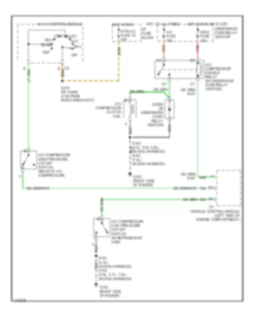
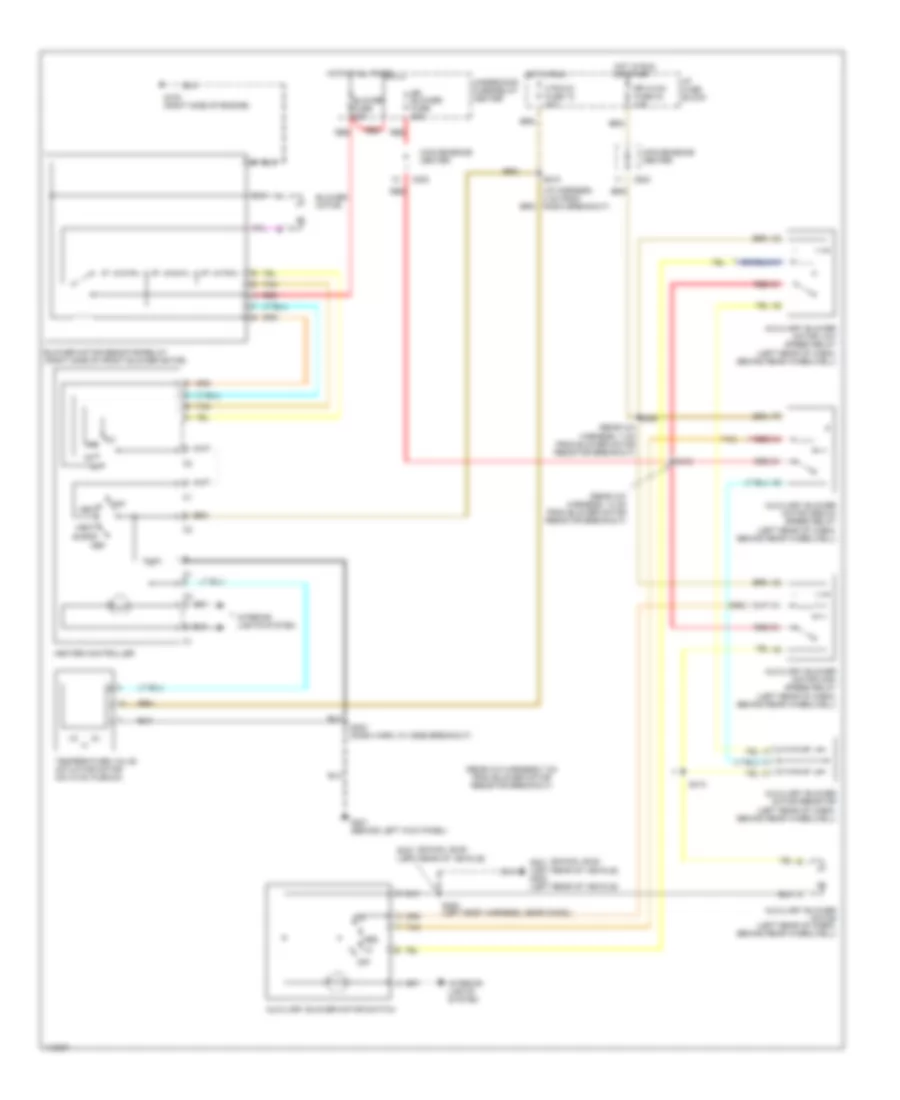
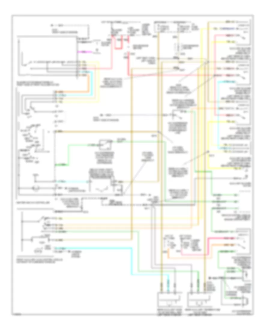
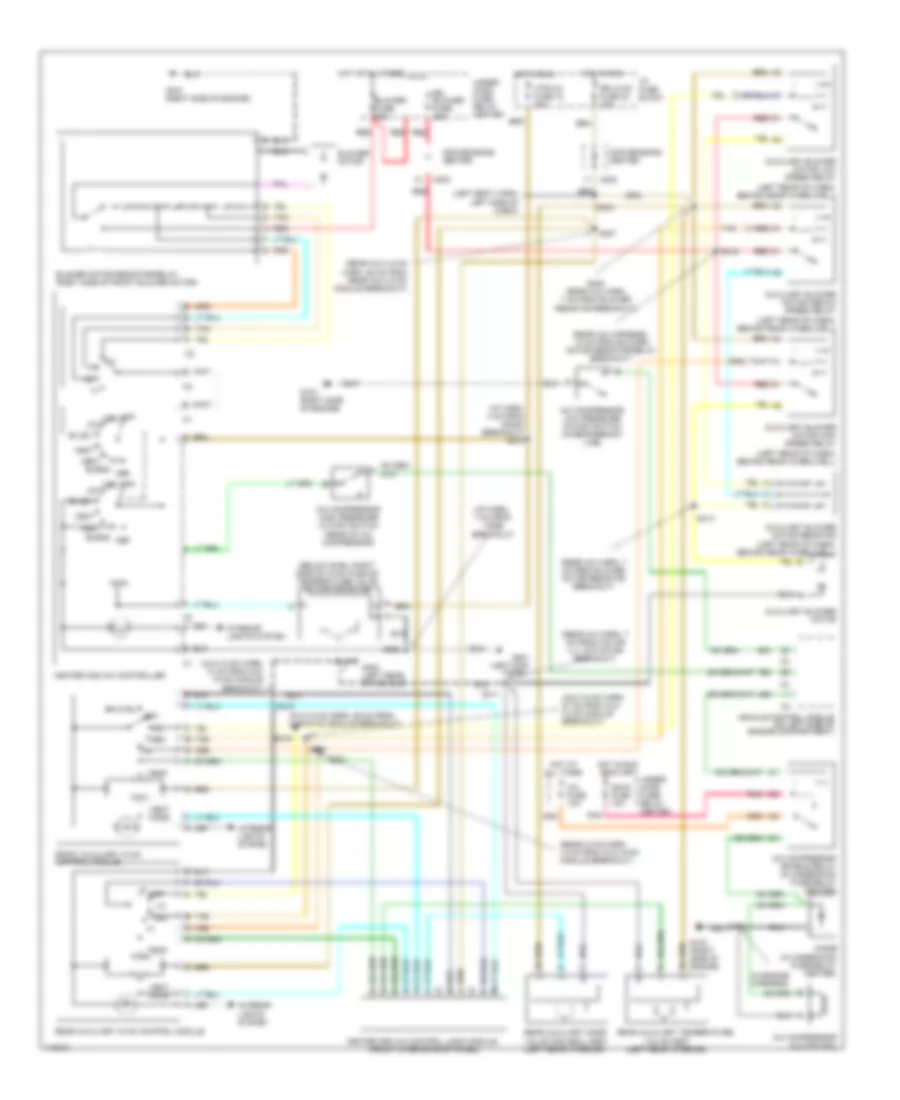
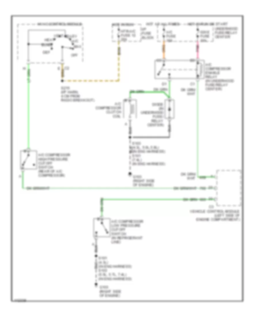
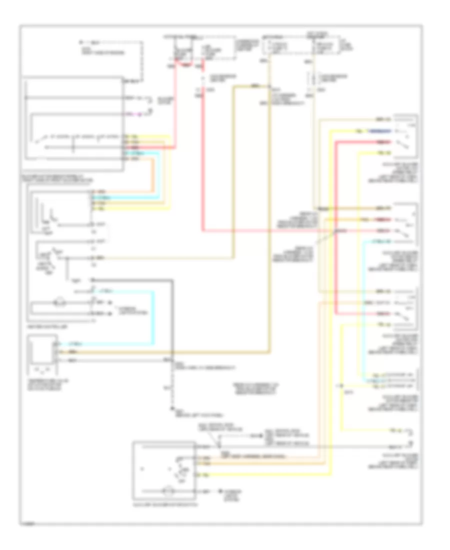
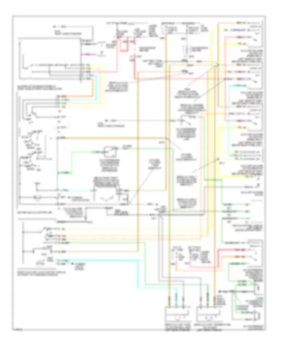
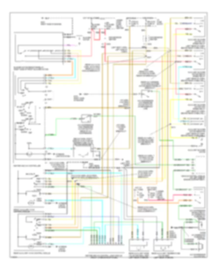
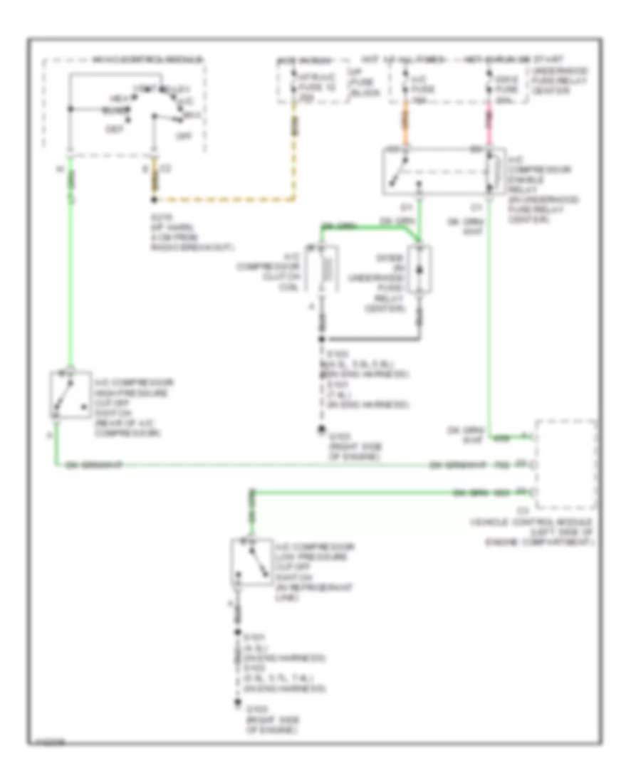
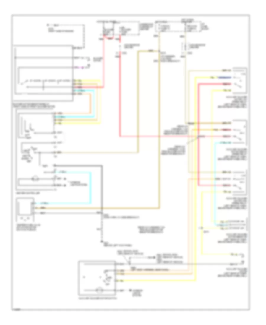
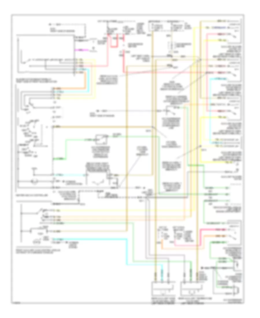
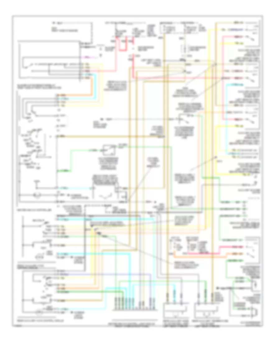
4.3L 4.3L VIN W, Compressor Wiring Diagram for Chevrolet Chevy Express G1999 1500 List of elements for 4.3L VIN W, Compressor Wiring Diagram for Chevrolet Chevy Express G1999 1500: 27 (in eng harness) s101 (7.4l) (in eng harness) (in eng harness) s103 (5.0l, 5.7l, 7.4l) (in eng harness) A/c A/c compress0r high pressure cutoff switch (rear of a/c compressor) A/c compress0r low pressure cutoff switch (in refrigerant line) A/c compressor clutch coil A/c compressor enable relay (in underhood fuse/relay center) A/c fuse 10a Bi-lev Blnd Def G103 (right side of engine) Heat Hot at all times Hot in run Hot in run or start Htr-a/c fuse 12 20a Hvac control module I/p fuse block Ign e fuse 10a Max Off Pnk S215 (i/p harn, 4 cm from radio breakout) Underhood fuse/relay center Vehicle control module (left side of engine compartment) Vent 4.3L VIN W, Heater Wiring Diagram for Chevrolet Chevy Express G1999 1500 List of elements for 4.3L VIN W, Heater Wiring Diagram for Chevrolet Chevy Express G1999 1500: 48 (i/p harness, 4 cm from radio breakout) (left rear of cabin, behind rear wheelwell) (rear a/c harness, 13 cm from blower motor resistor breakout) (rear a/c harness, 7 cm from blower motor resistor breakout) (rear a/c harness,7 cm from blower motor resistor breakout) (school bus) Auxiliary blower motor (left rear of cabin, behind rear wheelwell) Auxiliary blower motor high speed relay Auxiliary blower motor low speed relay Auxiliary blower motor medium speed relay Auxiliary blower motor resistor (left rear of cabin, behind rear wheelwell) Auxiliary blower motor switch Blend Blower fuse 60a Blower motor Blower motor resistor/relay (right side of front blower motor) C1 f C2 c C202 Convenience center Def G103 (right side of engine) G201 (behind left kick panel) G301 (left rear of vehicle) g400 (left rear of vehicle) Heat Heater controller Hot at all times Hot in run Hot in run or start Htr-a/c fuse 12 20a I/p fuse block Interior lights system Med Off Red Rr blower fuse 30a Rr hvac fuse 24 10a S202 (dash harn, in vssb breakout) S215 S327 (left rear of vehicle) S400 (left body harness, near chmsl) S405 S412 S413 Tan Temperature valve actuator motor (on hvac plenum) Underhood fuse/relay center Vent 4.3L VIN W, Manual A/C Wiring Diagram, Cargo Van for Chevrolet Chevy Express G1999 1500 List of elements for 4.3L VIN W, Manual A/C Wiring Diagram, Cargo Van for Chevrolet Chevy Express G1999 1500: 75 (aux hvac harn, 14 cm from aux hvac module breakout) (below dash, right side of hvac plenum) temperature valve actuator motor (i/p harn, 4 cm from radio breakout) (i/p harn, 7 cm from vssb breakout) (in engine harness) (in underhood fuse/relay center) (left body harn, left side of cabin) (left rear interior) (left rear of cabin, behind rear wheelwell) (left rear of vehicle) (rear a/c harn, 7 cm from blower motor resistor breakout) (rear a/c harn, 7 cm from o/s air vlv actuator breakout) (rear a/c harness, 13 cm from blower motor resistor/relay breakout) (rear aux hvac harn, 29 cm from rear aux hvac module breakout) A/c A/c compressor clutch coil A/c compressor enable relay (in underhood fuse/relay center) A/c compressor high pressure cutoff switch (rear of a/c compressor) A/c compressor low pressure cutoff switch (in refrigerant line) A/c fuse 10a Auxiliary blower motor Auxiliary blower motor high speed relay Auxiliary blower motor low speed relay Auxiliary blower motor medium speed relay Auxiliary blower motor resistor (left rear of cabin, behind rear wheelwell) Bi-lev Blend Blower fuse 60a Blower motor Blower motor resistor/relay (right side of front blower motor) C2 c C202 C3 d3 Convenience center D3 c3 Def Diode Front auxiliary hvac control module (on front of overhead console) G103 (right side of engine) G201 (left kick panel) G400 Heat Heater and a/c controller Hot at all times Hot in run Hot in run or start Htr-a/c fuse 12 20a I/p fuse block Ign e fuse 10a Interior lights system Max Med Off Pnk Rear auxiliary mode valve and seal assy (left rear interior) Rear auxiliary temperature Red Rr blower fuse 30a Rr hvac fuse 24 10a S202 S215 S307 S318 S404 S405 (rear a/c harn, 7 cm from blower resistor breakout) S411 S412 S413 Tan Temp Under- hood fuse/ relay center Valve assy Vehicle control module (left side of engine compartment) Vent Vent mode 4.3L VIN W, Manual A/C Wiring Diagram, Passenger Van for Chevrolet Chevy Express G1999 1500 List of elements for 4.3L VIN W, Manual A/C Wiring Diagram, Passenger Van for Chevrolet Chevy Express G1999 1500: 81 (aux hvac harn, 14 cm from aux hvac module breakout) (aux hvac harn, 26 cm from aux hvac module breakout) (aux hvac harn, 57 cm from aux hvac module breakout) (below dash, right side of hvac plenum) temperature valve actuator motor (front interior roof panel) (i/p harn, 7 cm from vssb breakout) (i/p harn, 4 cm from radio breakout) s215 (in engine harness) (in underhood fuse/relay center) (left body harn, left side of cabin) (left rear interior) (left rear of cabin, behind rear wheelwell) (rear a/c harn, 7 cm from blower motor resistor breakout) (rear a/c harn, 7 cm from o/s air vlv actuator breakout) (rear a/c harness, 13 cm from blower motor resistor/relay breakout) (rear aux hvac harn, 29 cm from rear aux hvac module breakout) (rear hvac harn, 13 cm from aux hvac module breakout) A/c A/c compressor clutch coil A/c compressor enable relay (in underhood fuse/relay center) A/c compressor high pressure cutoff switch (rear of a/c compressor) A/c compressor low pressure cutoff switch (in refrigerant line) A/c fuse 10a Auxiliary blower motor Auxiliary blower motor high speed relay Auxiliary blower motor low speed relay Auxiliary blower motor medium speed relay Auxiliary blower motor resistor (left rear of cabin, behind rear wheelwell) Bi-lev Blend Blower fuse 60a Blower motor Blower motor resistor/relay (right side of front blower motor) C2 c C202 Convenience center Def Diode Front auxiliary hvac control module G103 (right side of engine) G201 (left kick panel) G400 (left rear of vehicle) Heat Heater and a/c control logic module Heater and a/c controller Hot at all times Hot in run Hot in run or start Htr-a/c fuse 12 20a I/p fuse block Ign e fuse 10a Interior lights system Max Med Off Pnk Rear auxiliary hvac control module Rear auxiliary mode valve and seal assy (left rear interior) Rear auxiliary temperature Red Rr blower fuse 30a Rr ctrl Rr hvac fuse 24 10a S202 S307 S318 S319 S320 S321 S404 S405 (rear a/c harn, 7 cm from blower resistor breakout) S411 S412 S413 Tan Temp Under- hood fuse/ relay center Valve assy Vehicle control module (on left side of engine compartment) Vent Vent mode
5.0L 5.0L VIN M, Compressor Wiring Diagram for Chevrolet Chevy Express G1999 1500 List of elements for 5.0L VIN M, Compressor Wiring Diagram for Chevrolet Chevy Express G1999 1500: 27 (in eng harness) s101 (7.4l) (in eng harness) (in eng harness) s103 (5.0l, 5.7l, 7.4l) (in eng harness) A/c A/c compress0r high pressure cutoff switch (rear of a/c compressor) A/c compress0r low pressure cutoff switch (in refrigerant line) A/c compressor clutch coil A/c compressor enable relay (in underhood fuse/relay center) A/c fuse 10a Bi-lev Blnd Def G103 (right side of engine) Heat Hot at all times Hot in run Hot in run or start Htr-a/c fuse 12 20a Hvac control module I/p fuse block Ign e fuse 10a Max Off Pnk S215 (i/p harn, 4 cm from radio breakout) Underhood fuse/relay center Vehicle control module (left side of engine compartment) Vent 5.0L VIN M, Heater Wiring Diagram for Chevrolet Chevy Express G1999 1500 List of elements for 5.0L VIN M, Heater Wiring Diagram for Chevrolet Chevy Express G1999 1500: 48 (i/p harness, 4 cm from radio breakout) (left rear of cabin, behind rear wheelwell) (rear a/c harness, 13 cm from blower motor resistor breakout) (rear a/c harness, 7 cm from blower motor resistor breakout) (rear a/c harness,7 cm from blower motor resistor breakout) (school bus) Auxiliary blower motor (left rear of cabin, behind rear wheelwell) Auxiliary blower motor high speed relay Auxiliary blower motor low speed relay Auxiliary blower motor medium speed relay Auxiliary blower motor resistor (left rear of cabin, behind rear wheelwell) Auxiliary blower motor switch Blend Blower fuse 60a Blower motor Blower motor resistor/relay (right side of front blower motor) C1 f C2 c C202 Convenience center Def G103 (right side of engine) G201 (behind left kick panel) G301 (left rear of vehicle) g400 (left rear of vehicle) Heat Heater controller Hot at all times Hot in run Hot in run or start Htr-a/c fuse 12 20a I/p fuse block Interior lights system Med Off Red Rr blower fuse 30a Rr hvac fuse 24 10a S202 (dash harn, in vssb breakout) S215 S327 (left rear of vehicle) S400 (left body harness, near chmsl) S405 S412 S413 Tan Temperature valve actuator motor (on hvac plenum) Underhood fuse/relay center Vent 5.0L VIN M, Manual A/C Wiring Diagram, Cargo Van for Chevrolet Chevy Express G1999 1500 List of elements for 5.0L VIN M, Manual A/C Wiring Diagram, Cargo Van for Chevrolet Chevy Express G1999 1500: 75 (aux hvac harn, 14 cm from aux hvac module breakout) (below dash, right side of hvac plenum) temperature valve actuator motor (i/p harn, 4 cm from radio breakout) (i/p harn, 7 cm from vssb breakout) (in engine harness) (in underhood fuse/relay center) (left body harn, left side of cabin) (left rear interior) (left rear of cabin, behind rear wheelwell) (left rear of vehicle) (rear a/c harn, 7 cm from blower motor resistor breakout) (rear a/c harn, 7 cm from o/s air vlv actuator breakout) (rear a/c harness, 13 cm from blower motor resistor/relay breakout) (rear aux hvac harn, 29 cm from rear aux hvac module breakout) A/c A/c compressor clutch coil A/c compressor enable relay (in underhood fuse/relay center) A/c compressor high pressure cutoff switch (rear of a/c compressor) A/c compressor low pressure cutoff switch (in refrigerant line) A/c fuse 10a Auxiliary blower motor Auxiliary blower motor high speed relay Auxiliary blower motor low speed relay Auxiliary blower motor medium speed relay Auxiliary blower motor resistor (left rear of cabin, behind rear wheelwell) Bi-lev Blend Blower fuse 60a Blower motor Blower motor resistor/relay (right side of front blower motor) C2 c C202 C3 d3 Convenience center D3 c3 Def Diode Front auxiliary hvac control module (on front of overhead console) G103 (right side of engine) G201 (left kick panel) G400 Heat Heater and a/c controller Hot at all times Hot in run Hot in run or start Htr-a/c fuse 12 20a I/p fuse block Ign e fuse 10a Interior lights system Max Med Off Pnk Rear auxiliary mode valve and seal assy (left rear interior) Rear auxiliary temperature Red Rr blower fuse 30a Rr hvac fuse 24 10a S202 S215 S307 S318 S404 S405 (rear a/c harn, 7 cm from blower resistor breakout) S411 S412 S413 Tan Temp Under- hood fuse/ relay center Valve assy Vehicle control module (left side of engine compartment) Vent Vent mode 5.0L VIN M, Manual A/C Wiring Diagram, Passenger Van for Chevrolet Chevy Express G1999 1500 List of elements for 5.0L VIN M, Manual A/C Wiring Diagram, Passenger Van for Chevrolet Chevy Express G1999 1500: 81 (aux hvac harn, 14 cm from aux hvac module breakout) (aux hvac harn, 26 cm from aux hvac module breakout) (aux hvac harn, 57 cm from aux hvac module breakout) (below dash, right side of hvac plenum) temperature valve actuator motor (front interior roof panel) (i/p harn, 7 cm from vssb breakout) (i/p harn, 4 cm from radio breakout) s215 (in engine harness) (in underhood fuse/relay center) (left body harn, left side of cabin) (left rear interior) (left rear of cabin, behind rear wheelwell) (rear a/c harn, 7 cm from blower motor resistor breakout) (rear a/c harn, 7 cm from o/s air vlv actuator breakout) (rear a/c harness, 13 cm from blower motor resistor/relay breakout) (rear aux hvac harn, 29 cm from rear aux hvac module breakout) (rear hvac harn, 13 cm from aux hvac module breakout) A/c A/c compressor clutch coil A/c compressor enable relay (in underhood fuse/relay center) A/c compressor high pressure cutoff switch (rear of a/c compressor) A/c compressor low pressure cutoff switch (in refrigerant line) A/c fuse 10a Auxiliary blower motor Auxiliary blower motor high speed relay Auxiliary blower motor low speed relay Auxiliary blower motor medium speed relay Auxiliary blower motor resistor (left rear of cabin, behind rear wheelwell) Bi-lev Blend Blower fuse 60a Blower motor Blower motor resistor/relay (right side of front blower motor) C2 c C202 Convenience center Def Diode Front auxiliary hvac control module G103 (right side of engine) G201 (left kick panel) G400 (left rear of vehicle) Heat Heater and a/c control logic module Heater and a/c controller Hot at all times Hot in run Hot in run or start Htr-a/c fuse 12 20a I/p fuse block Ign e fuse 10a Interior lights system Max Med Off Pnk Rear auxiliary hvac control module Rear auxiliary mode valve and seal assy (left rear interior) Rear auxiliary temperature Red Rr blower fuse 30a Rr ctrl Rr hvac fuse 24 10a S202 S307 S318 S319 S320 S321 S404 S405 (rear a/c harn, 7 cm from blower resistor breakout) S411 S412 S413 Tan Temp Under- hood fuse/ relay center Valve assy Vehicle control module (on left side of engine compartment) Vent Vent mode
5.7L 5.7L VIN R, Compressor Wiring Diagram for Chevrolet Chevy Express G1999 1500 List of elements for 5.7L VIN R, Compressor Wiring Diagram for Chevrolet Chevy Express G1999 1500: 27 (in eng harness) s101 (7.4l) (in eng harness) (in eng harness) s103 (5.0l, 5.7l, 7.4l) (in eng harness) A/c A/c compress0r high pressure cutoff switch (rear of a/c compressor) A/c compress0r low pressure cutoff switch (in refrigerant line) A/c compressor clutch coil A/c compressor enable relay (in underhood fuse/relay center) A/c fuse 10a Bi-lev Blnd Def G103 (right side of engine) Heat Hot at all times Hot in run Hot in run or start Htr-a/c fuse 12 20a Hvac control module I/p fuse block Ign e fuse 10a Max Off Pnk S215 (i/p harn, 4 cm from radio breakout) Underhood fuse/relay center Vehicle control module (left side of engine compartment) Vent 5.7L VIN R, Heater Wiring Diagram for Chevrolet Chevy Express G1999 1500 List of elements for 5.7L VIN R, Heater Wiring Diagram for Chevrolet Chevy Express G1999 1500: 48 (i/p harness, 4 cm from radio breakout) (left rear of cabin, behind rear wheelwell) (rear a/c harness, 13 cm from blower motor resistor breakout) (rear a/c harness, 7 cm from blower motor resistor breakout) (rear a/c harness,7 cm from blower motor resistor breakout) (school bus) Auxiliary blower motor (left rear of cabin, behind rear wheelwell) Auxiliary blower motor high speed relay Auxiliary blower motor low speed relay Auxiliary blower motor medium speed relay Auxiliary blower motor resistor (left rear of cabin, behind rear wheelwell) Auxiliary blower motor switch Blend Blower fuse 60a Blower motor Blower motor resistor/relay (right side of front blower motor) C1 f C2 c C202 Convenience center Def G103 (right side of engine) G201 (behind left kick panel) G301 (left rear of vehicle) g400 (left rear of vehicle) Heat Heater controller Hot at all times Hot in run Hot in run or start Htr-a/c fuse 12 20a I/p fuse block Interior lights system Med Off Red Rr blower fuse 30a Rr hvac fuse 24 10a S202 (dash harn, in vssb breakout) S215 S327 (left rear of vehicle) S400 (left body harness, near chmsl) S405 S412 S413 Tan Temperature valve actuator motor (on hvac plenum) Underhood fuse/relay center Vent 5.7L VIN R, Manual A/C Wiring Diagram, Cargo Van for Chevrolet Chevy Express G1999 1500 List of elements for 5.7L VIN R, Manual A/C Wiring Diagram, Cargo Van for Chevrolet Chevy Express G1999 1500: 75 (aux hvac harn, 14 cm from aux hvac module breakout) (below dash, right side of hvac plenum) temperature valve actuator motor (i/p harn, 4 cm from radio breakout) (i/p harn, 7 cm from vssb breakout) (in engine harness) (in underhood fuse/relay center) (left body harn, left side of cabin) (left rear interior) (left rear of cabin, behind rear wheelwell) (left rear of vehicle) (rear a/c harn, 7 cm from blower motor resistor breakout) (rear a/c harn, 7 cm from o/s air vlv actuator breakout) (rear a/c harness, 13 cm from blower motor resistor/relay breakout) (rear aux hvac harn, 29 cm from rear aux hvac module breakout) A/c A/c compressor clutch coil A/c compressor enable relay (in underhood fuse/relay center) A/c compressor high pressure cutoff switch (rear of a/c compressor) A/c compressor low pressure cutoff switch (in refrigerant line) A/c fuse 10a Auxiliary blower motor Auxiliary blower motor high speed relay Auxiliary blower motor low speed relay Auxiliary blower motor medium speed relay Auxiliary blower motor resistor (left rear of cabin, behind rear wheelwell) Bi-lev Blend Blower fuse 60a Blower motor Blower motor resistor/relay (right side of front blower motor) C2 c C202 C3 d3 Convenience center D3 c3 Def Diode Front auxiliary hvac control module (on front of overhead console) G103 (right side of engine) G201 (left kick panel) G400 Heat Heater and a/c controller Hot at all times Hot in run Hot in run or start Htr-a/c fuse 12 20a I/p fuse block Ign e fuse 10a Interior lights system Max Med Off Pnk Rear auxiliary mode valve and seal assy (left rear interior) Rear auxiliary temperature Red Rr blower fuse 30a Rr hvac fuse 24 10a S202 S215 S307 S318 S404 S405 (rear a/c harn, 7 cm from blower resistor breakout) S411 S412 S413 Tan Temp Under- hood fuse/ relay center Valve assy Vehicle control module (left side of engine compartment) Vent Vent mode 5.7L VIN R, Manual A/C Wiring Diagram, Passenger Van for Chevrolet Chevy Express G1999 1500 List of elements for 5.7L VIN R, Manual A/C Wiring Diagram, Passenger Van for Chevrolet Chevy Express G1999 1500: 81 (aux hvac harn, 14 cm from aux hvac module breakout) (aux hvac harn, 26 cm from aux hvac module breakout) (aux hvac harn, 57 cm from aux hvac module breakout) (below dash, right side of hvac plenum) temperature valve actuator motor (front interior roof panel) (i/p harn, 7 cm from vssb breakout) (i/p harn, 4 cm from radio breakout) s215 (in engine harness) (in underhood fuse/relay center) (left body harn, left side of cabin) (left rear interior) (left rear of cabin, behind rear wheelwell) (rear a/c harn, 7 cm from blower motor resistor breakout) (rear a/c harn, 7 cm from o/s air vlv actuator breakout) (rear a/c harness, 13 cm from blower motor resistor/relay breakout) (rear aux hvac harn, 29 cm from rear aux hvac module breakout) (rear hvac harn, 13 cm from aux hvac module breakout) A/c A/c compressor clutch coil A/c compressor enable relay (in underhood fuse/relay center) A/c compressor high pressure cutoff switch (rear of a/c compressor) A/c compressor low pressure cutoff switch (in refrigerant line) A/c fuse 10a Auxiliary blower motor Auxiliary blower motor high speed relay Auxiliary blower motor low speed relay Auxiliary blower motor medium speed relay Auxiliary blower motor resistor (left rear of cabin, behind rear wheelwell) Bi-lev Blend Blower fuse 60a Blower motor Blower motor resistor/relay (right side of front blower motor) C2 c C202 Convenience center Def Diode Front auxiliary hvac control module G103 (right side of engine) G201 (left kick panel) G400 (left rear of vehicle) Heat Heater and a/c control logic module Heater and a/c controller Hot at all times Hot in run Hot in run or start Htr-a/c fuse 12 20a I/p fuse block Ign e fuse 10a Interior lights system Max Med Off Pnk Rear auxiliary hvac control module Rear auxiliary mode valve and seal assy (left rear interior) Rear auxiliary temperature Red Rr blower fuse 30a Rr ctrl Rr hvac fuse 24 10a S202 S307 S318 S319 S320 S321 S404 S405 (rear a/c harn, 7 cm from blower resistor breakout) S411 S412 S413 Tan Temp Under- hood fuse/ relay center Valve assy Vehicle control module (on left side of engine compartment) Vent Vent mode
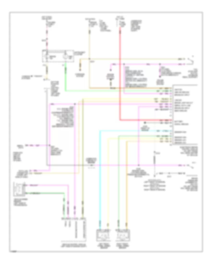
ANTI-LOCK BRAKES Anti-lock Brake Wiring Diagrams for Chevrolet Chevy Express G1999 1500 List of elements for Anti-lock Brake Wiring Diagrams for Chevrolet Chevy Express G1999 1500: 59 18 cm from park brake warning switch breakout) Abs fuse 60a Abs ind Abs ind ground B17 Battery Brake fuse 18 10a Brake ind Brake ind input Brake lamp ind out Brake pressure differential switch (on left frame rail near center of vehicle) Brake sw input Brake sw output Cruise control system Data link connector (under left side of dash) Daytime running lamp control module (under left side of dash) Ebcm ground Electronic brake control module (on left frame rail near center of vehicle) Engine control system G110 (5.0l,5.7l) (left front of engine) g119 (4.3l) (right front of engine) g117 (7.4l) (right rear of engine) G125 (front of engine) Gauges fuse 4 10a Hot at all times Hot in run Hot in run and start I/p fuse block (on left lower kick panel) Ignition Instrument cluster Left front wheel speed sensor Passlock module (below center of dash) Pnk Red Right front wheel speed sensor S101 S102 S122 S153 (4.3l: engine harn, 4 cm from a/c compressor breakout; 5.0l,5.7l: engine harn, 8 cm from ignition coil breakout; 7.4l: engine harn, 4 cm from c100 breakout toward egr sensor breakout) S154 (4.3l) (engine harn, 98 cm from underhood fuse/relay center) (5.0l,5.7l) (engine harn, 4 cm from ignition coil breakout) (7.4l) (engine harn, 3 cm from maf sensor breakout) S156 (engine harn, 4 cm from brake pressure differential switch) S207 (i/p harn, approx 4 cm from vssb breakout) S210 S216 Sensor high Sensor low Serial data Serial data line Signal ground Tan Tcc/ stoplamp switch (on brake pedal support) Underhood fuse/relay center Underhood fuse/relay center (left side of engine compt) Vehicle control module (left side of engine compt) Vehicle speed sensor (left side of transmission) Vehicle speed sig Vss (+) Vss (-) Vss sig Warning systems Warnings system
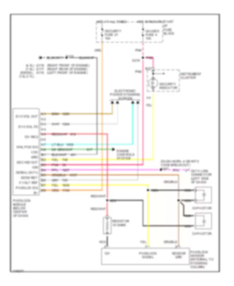
ANTI-THEFT Anti-theft Wiring Diagram for Chevrolet Chevy Express G1999 1500 List of elements for Anti-theft Wiring Diagram for Chevrolet Chevy Express G1999 1500: 38 (4.3l) g119 g117 g110 (7.4l) (diesel, 5.0l,5.7l) (dash harn, 4 cm into vssb breakout) s207 (right front of engine) (right rear of engine) (left front of engine) 12v 12v reg 5 volt ref B17 Capacitor Data link connector (left side of dash) Electronic power steering system Engine controls system Evo sol fd Evo sol out Gauges fuse 4 10a Grd Hot at all times Hot in run or start I/p fuse block Ign Instrument cluster Nca Passlck sig Passlock module (below center of dash) Passlock sensor (internal to steering column) Passlock signal Pnk Resistor 10 ohms S112 S216 Sec ind out Security fuse 21 10a Security indicator Sens ret Sensor grd Serial data Vss Whl pos sig
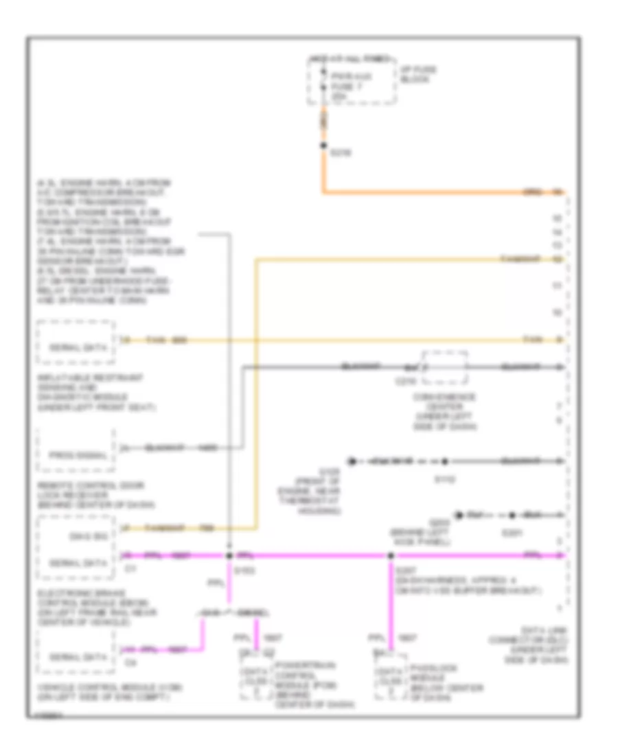
COMPUTER DATA LINES Computer Data Lines for Chevrolet Chevy Express G1999 1500 List of elements for Computer Data Lines for Chevrolet Chevy Express G1999 1500: 27 (4.3l: engine harn, 4 cm from a/c compressor breakout, toward transmission) (5.0/5.7l: engine harn, 8 cm from ignition coil breakout toward transmission) (7.4l: engine harn, 4 cm from 36 pin in-line conn toward egr sensor breakout) (6.5l diesel: engine harn, 27 cm from underhood fuse- relay center to main harn and 36 pin in-line conn) C210 Convenience center (under left side of dash) Data clss Data link connector (dlc) (under left side of dash) Diag sig Diesel Electronic brake control module (ebcm) (on left frame rail near center of vehicle) G125 (front of engine, near thermostat housing) G200 (behind left kick panel) Gas Hot at all times I/p fuse block Inflatable restraint sensing and diagnostic module (under left front seat) Passlock module (below center of dash) Powertrain control module (pcm) (behind center of dash) Prog signal Pwr aux fuse 7 25a Remote control door lock receiver (behind center of dash) S112 S153 S201 S207 (dash harness, approx 4 cm into vss buffer breakout) S218 Serial data Tan Vehicle control module (vcm) (on left side of eng compt)
CRUISE CONTROL
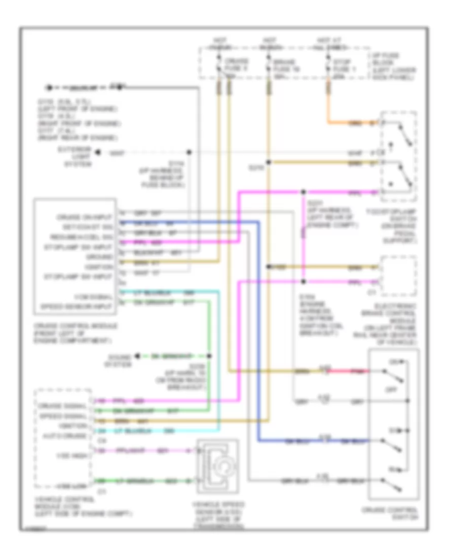
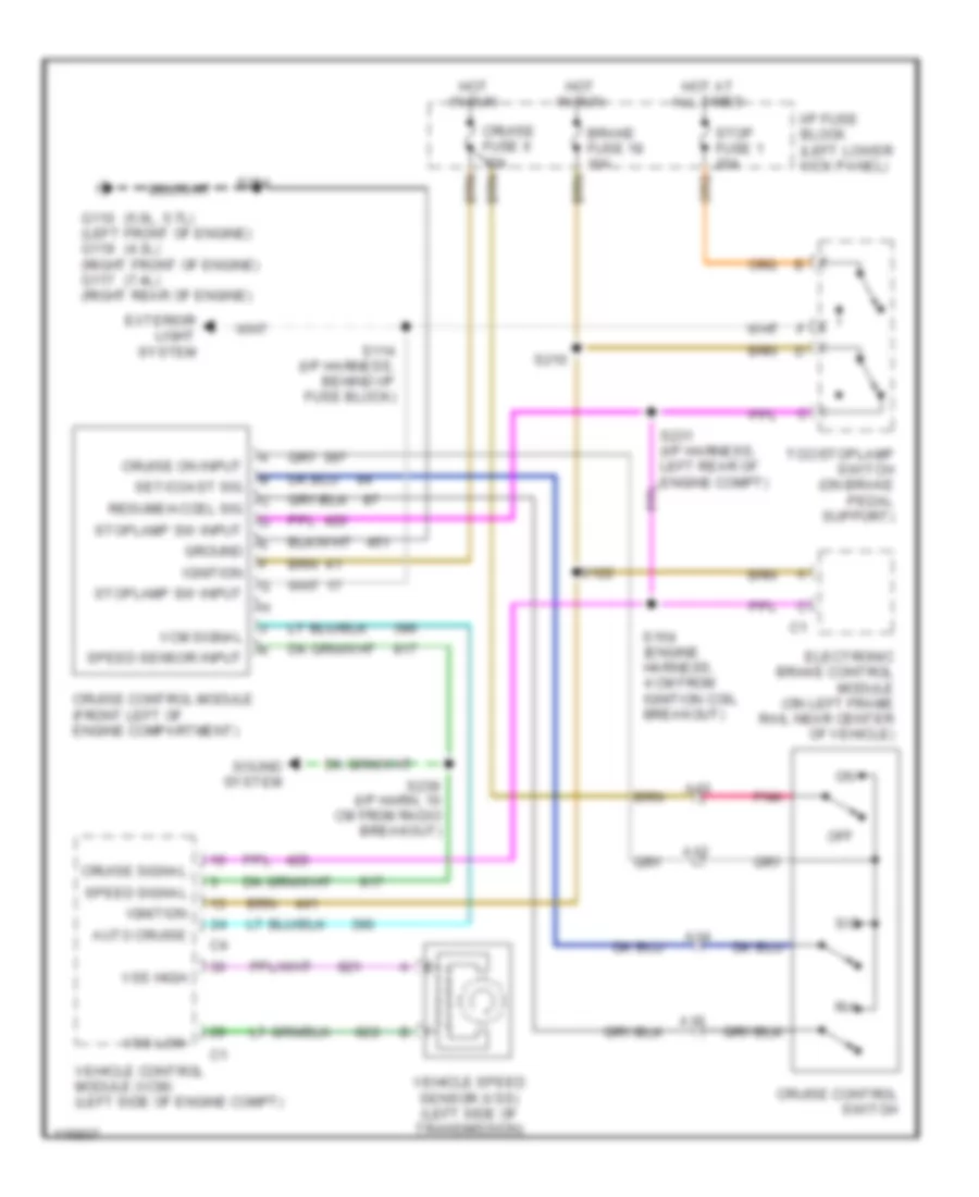
4.3L 4.3L VIN W, Cruise Control Wiring Diagram for Chevrolet Chevy Express G1999 1500 List of elements for 4.3L VIN W, Cruise Control Wiring Diagram for Chevrolet Chevy Express G1999 1500: 45 (4.3l) (5.0l, 5.7l) (7.4l) A12 A13 A14 A15 Auto cruise Brake fuse 18 10a Cruise control module (front left of engine compartment) Cruise control switch Cruise fuse 6 10a Cruise on input Cruise signal Electronic brake control module (on left frame rail near center of vehicle) Exterior light system G110 (left front of engine) g119 (right front of engine) g117 (right rear of engine) Ground Hot at all times Hot in run I/p fuse block (left lower kick panel) Ignition Off Pnk R/a Resume/accel sig S/c S114 (i/p harness, behind i/p fuse block) S122 S154 (engine harness, 4 cm from ignition coil breakout) S210 S239 (i/p harn, 10 cm from radio breakout) S254 Set/coast sig Sound system Speed sensor input Speed signal Stop fuse 1 20a Stoplamp sw input Tcc/stoplamp switch (on brake pedal support) Vcm signal Vehicle control module (vcm) (left side of engine compt) Vehicle speed sensor (vss) (left side of transmission) Vss high Vss low
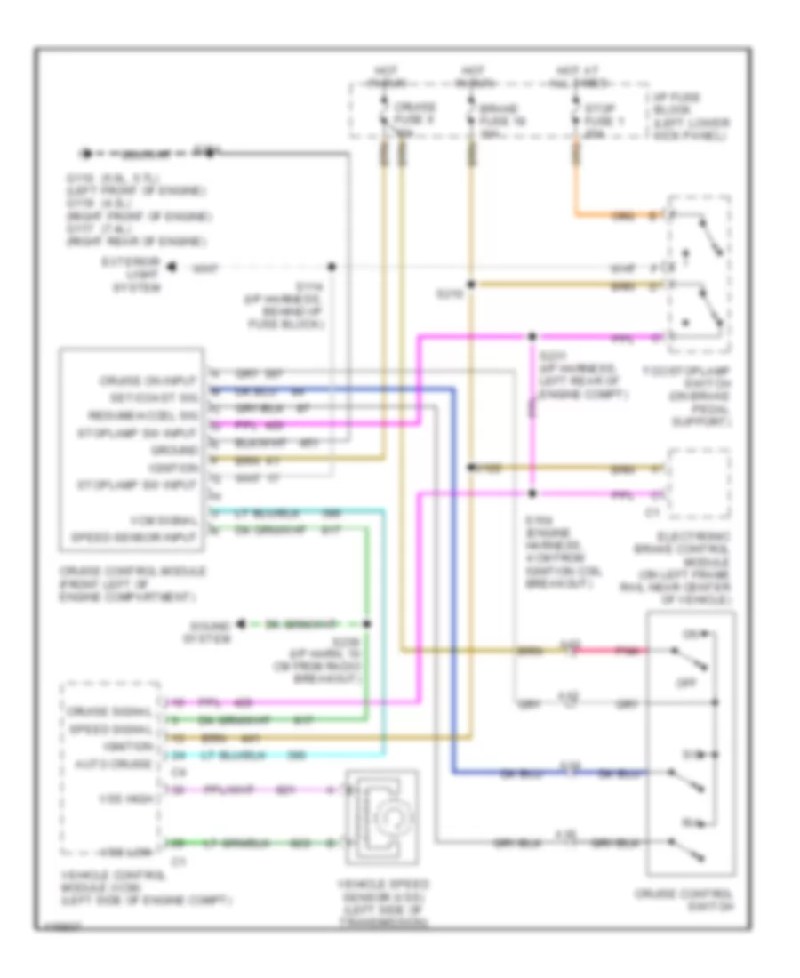
5.0L 5.0L VIN M, Cruise Control Wiring Diagram for Chevrolet Chevy Express G1999 1500 List of elements for 5.0L VIN M, Cruise Control Wiring Diagram for Chevrolet Chevy Express G1999 1500: 45 (4.3l) (5.0l, 5.7l) (7.4l) A12 A13 A14 A15 Auto cruise Brake fuse 18 10a Cruise control module (front left of engine compartment) Cruise control switch Cruise fuse 6 10a Cruise on input Cruise signal Electronic brake control module (on left frame rail near center of vehicle) Exterior light system G110 (left front of engine) g119 (right front of engine) g117 (right rear of engine) Ground Hot at all times Hot in run I/p fuse block (left lower kick panel) Ignition Off Pnk R/a Resume/accel sig S/c S114 (i/p harness, behind i/p fuse block) S122 S154 (engine harness, 4 cm from ignition coil breakout) S210 S239 (i/p harn, 10 cm from radio breakout) S254 Set/coast sig Sound system Speed sensor input Speed signal Stop fuse 1 20a Stoplamp sw input Tcc/stoplamp switch (on brake pedal support) Vcm signal Vehicle control module (vcm) (left side of engine compt) Vehicle speed sensor (vss) (left side of transmission) Vss high Vss low
5.7L 5.7L VIN R, Cruise Control Wiring Diagram for Chevrolet Chevy Express G1999 1500 List of elements for 5.7L VIN R, Cruise Control Wiring Diagram for Chevrolet Chevy Express G1999 1500: 45 (4.3l) (5.0l, 5.7l) (7.4l) A12 A13 A14 A15 Auto cruise Brake fuse 18 10a Cruise control module (front left of engine compartment) Cruise control switch Cruise fuse 6 10a Cruise on input Cruise signal Electronic brake control module (on left frame rail near center of vehicle) Exterior light system G110 (left front of engine) g119 (right front of engine) g117 (right rear of engine) Ground Hot at all times Hot in run I/p fuse block (left lower kick panel) Ignition Off Pnk R/a Resume/accel sig S/c S114 (i/p harness, behind i/p fuse block) S122 S154 (engine harness, 4 cm from ignition coil breakout) S210 S239 (i/p harn, 10 cm from radio breakout) S254 Set/coast sig Sound system Speed sensor input Speed signal Stop fuse 1 20a Stoplamp sw input Tcc/stoplamp switch (on brake pedal support) Vcm signal Vehicle control module (vcm) (left side of engine compt) Vehicle speed sensor (vss) (left side of transmission) Vss high Vss low
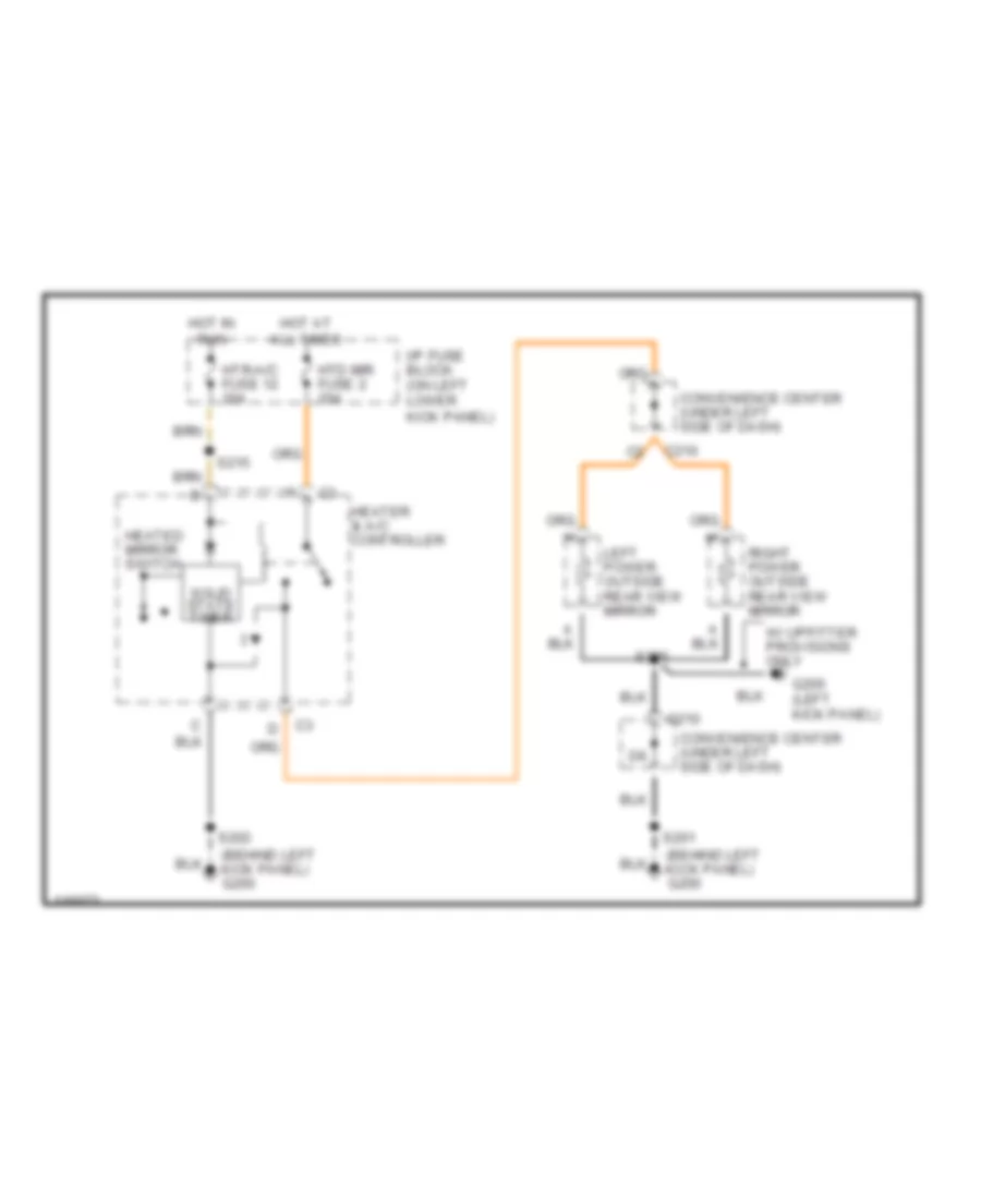
DEFOGGERS Defogger Wiring Diagram for Chevrolet Chevy Express G1999 1500 List of elements for Defogger Wiring Diagram for Chevrolet Chevy Express G1999 1500: 19 (behind left kick panel) g200 C210 Convenience center (under left side of dash) G200 (left kick panel) Heated mirror switch Heater & a/c controller Hot at all times Hot in run Htd mir fuse 2 20a Htr-a/c fuse 12 20a I/p fuse block (on left lower kick panel) Left power outside rear view mirror Right power outside rear view mirror S201 S202 S206 S215 Solid state timer W/ upfitter provisions only
ENGINE PERFORMANCE
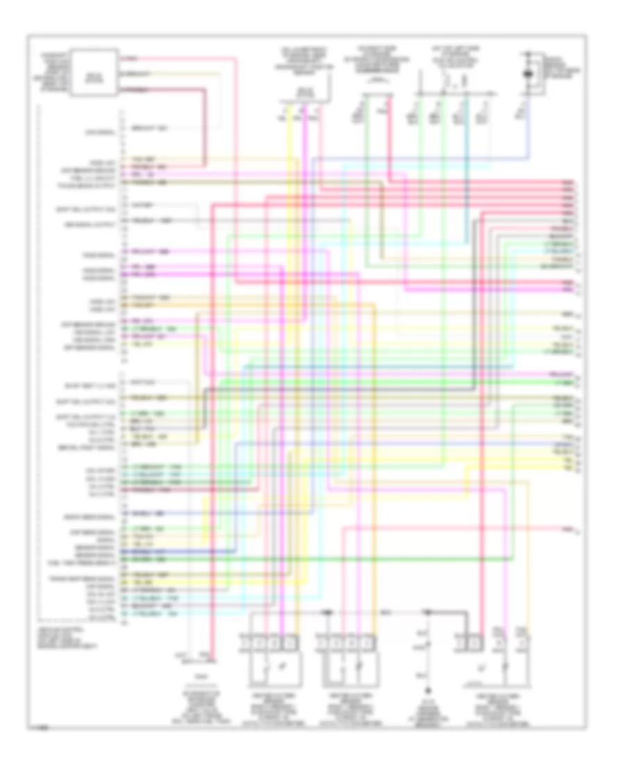
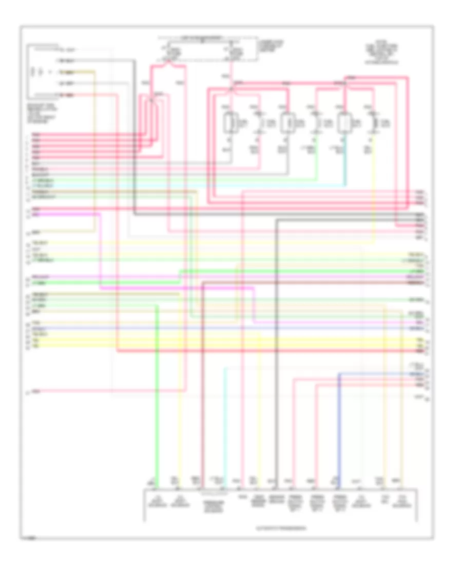
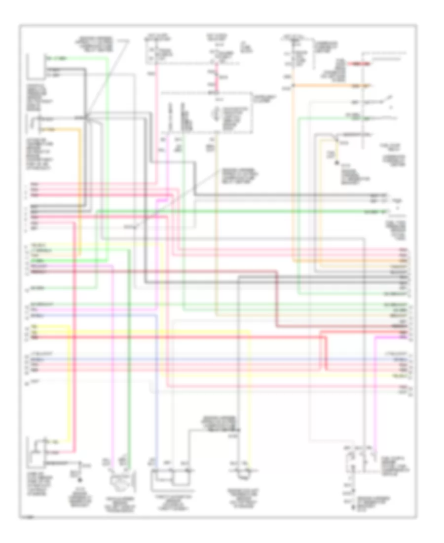
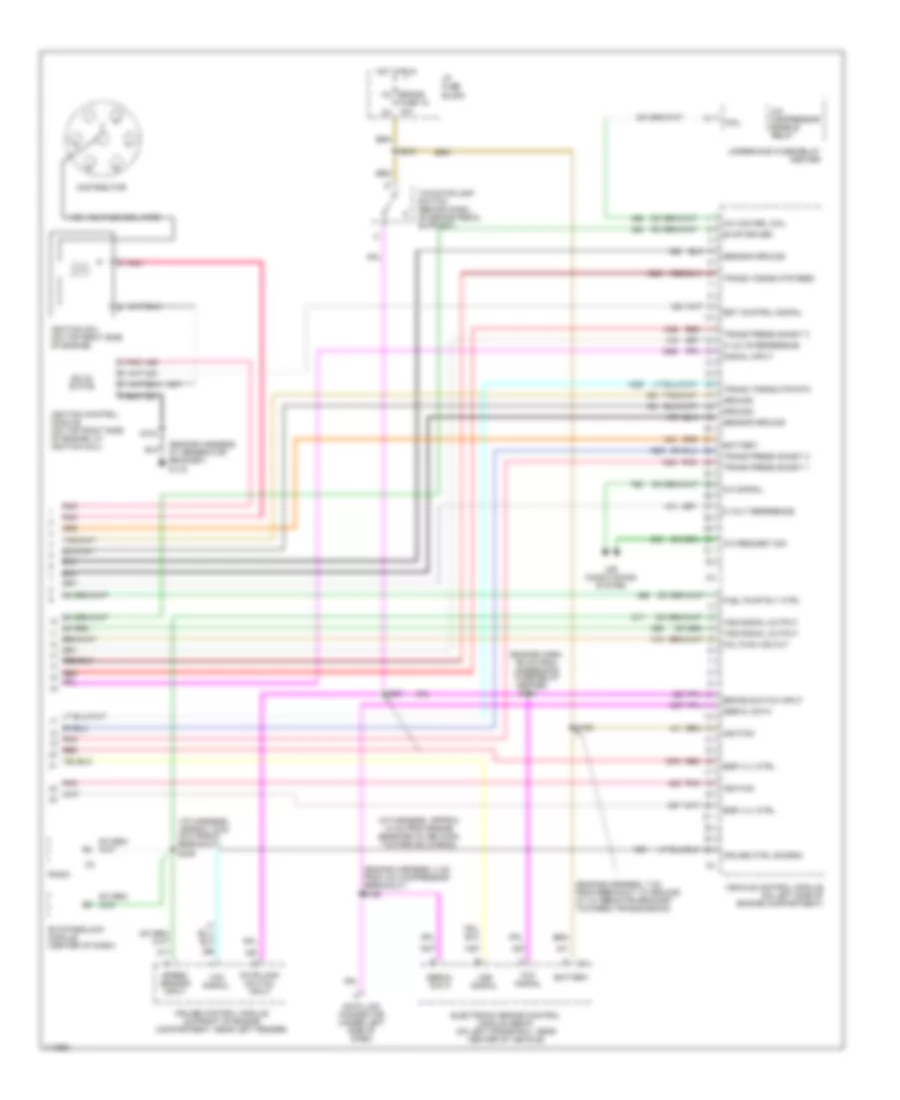
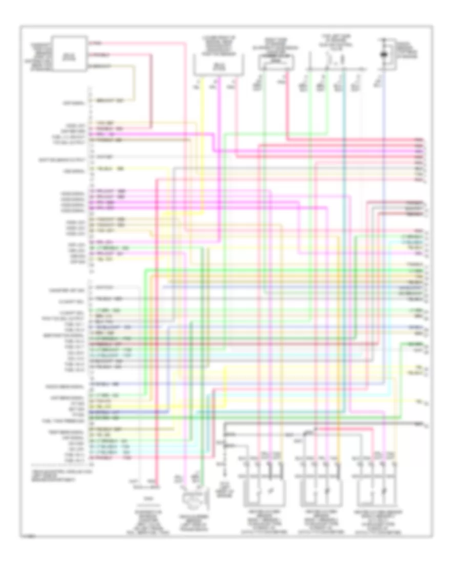
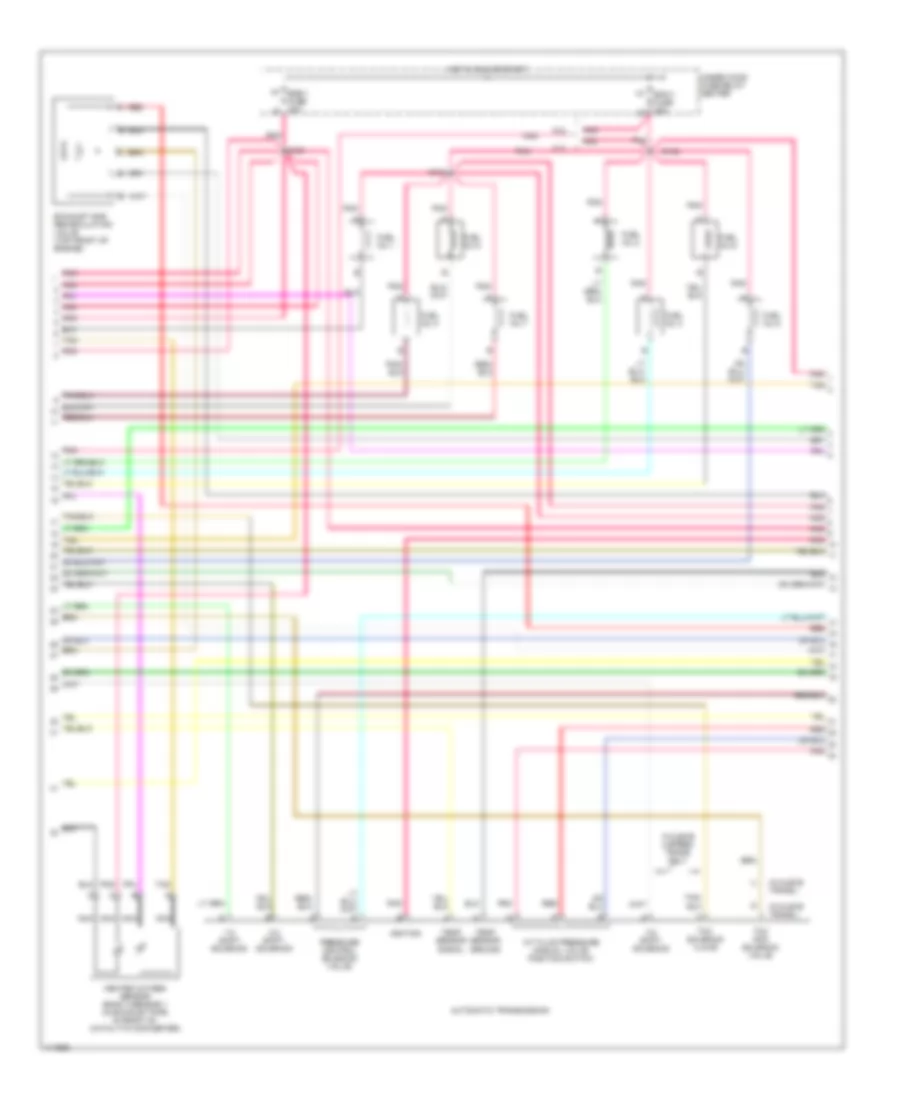
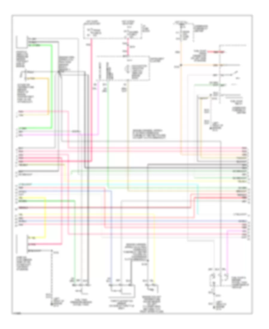
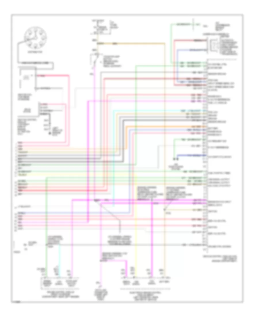
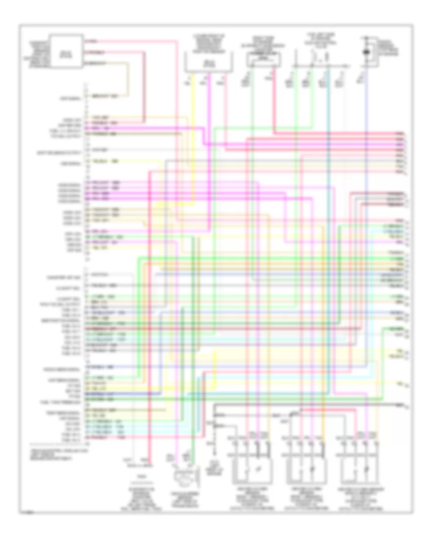
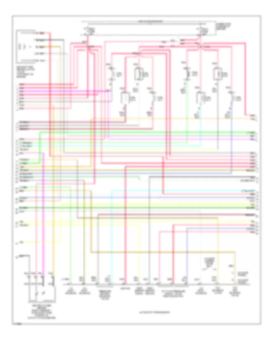
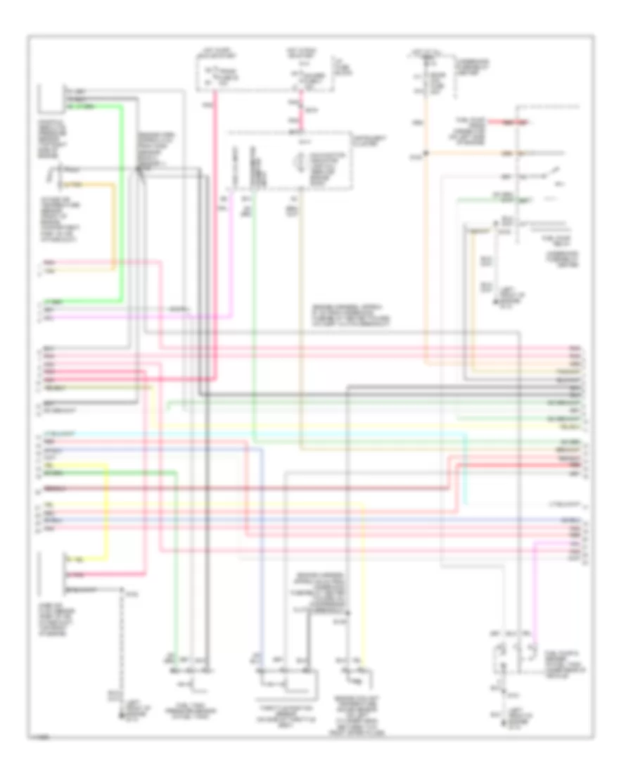
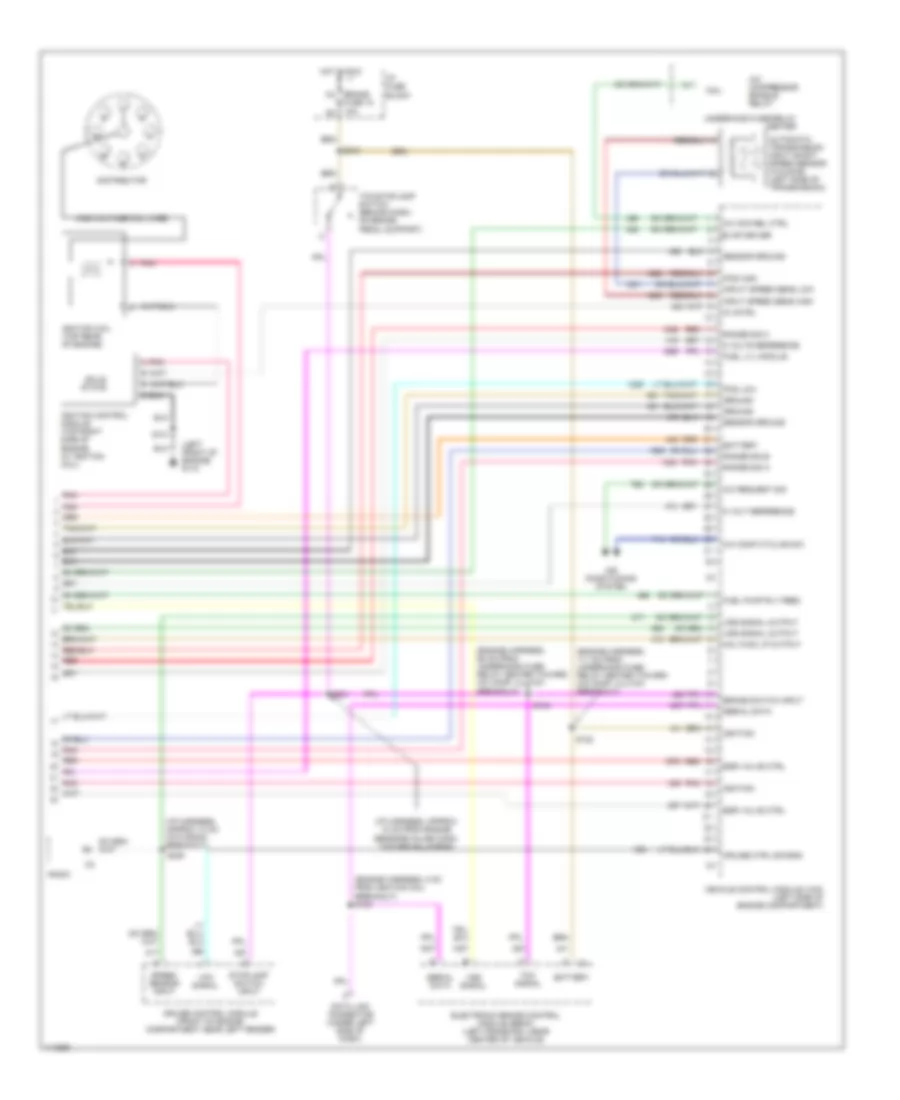
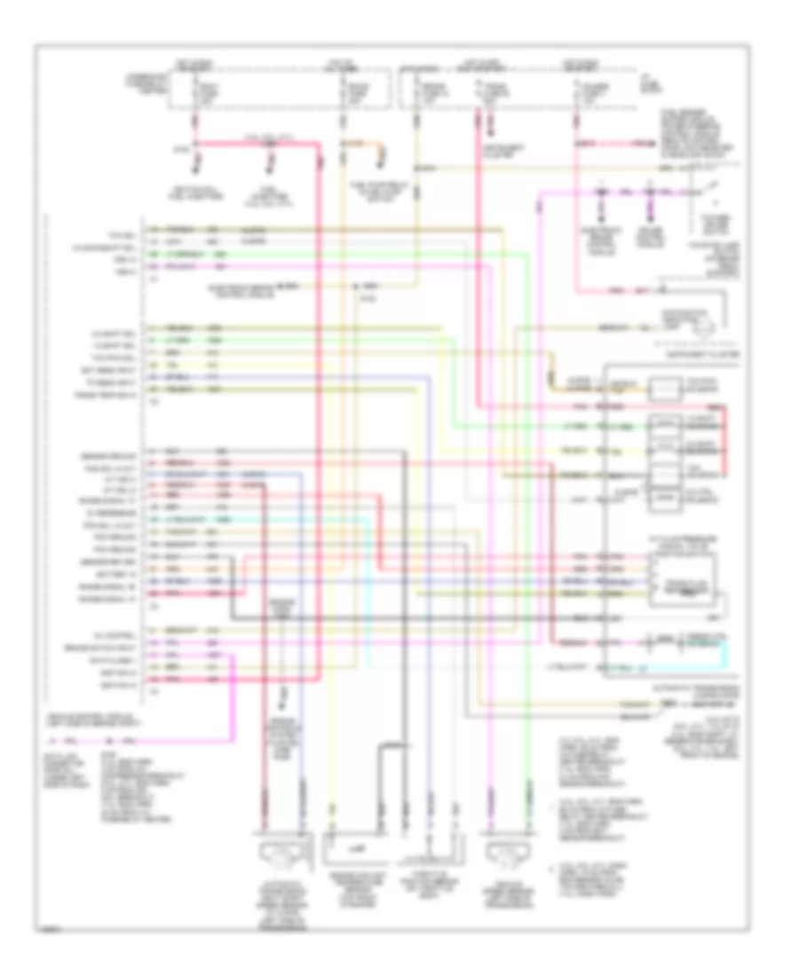
4.3L 4.3L VIN W, Engine Performance Wiring Diagrams (1 of 4) for Chevrolet Chevy Express G1999 1500 List of elements for 4.3L VIN W, Engine Performance Wiring Diagrams (1 of 4) for Chevrolet Chevy Express G1999 1500: 55 (on lower front of engine, near crankshaft) crankshaft position sensor (on right side of engine) evaporative emissions canister purge solenoid valve (on top left side of engine) Cam signal Camshaft position sensor (part of distributor, rear top of engine) Ckp sensor ground Ckp sensor signal Cmp sensor ground Coil a high Coil a low Coil b high Coil b low Egr sol posit signal Evap vent vlv sig Evaporative emissions canister vent valve (on left frame rail, near fuel tank) Fuel lvl sig out Fuel tank press sens in G119 (engine harness at generator bracket) Heated oxygen sensor bank 1 sensor 1 (in exhaust pipe, in front of catalytic converter) Heated oxygen sensor bank 1 sensor 3 (in exhaust pipe, in front of catalytic converter) Heated oxygen sensor bank 2 sensor 1 (in exhaust pipe, in front of catalytic converter) Ho2s low Ho2s signal Idle air control valve motor Inj 1 ctrl Inj 2 ctrl Inj 3 ctrl Inj 4 ctrl Inj 5 ctrl Inj 6 ctrl Knock sens signal Knock sensor (on top rear of engine) Maf signal Map sens signal Nca Pnk Pnk a Pnk c S101 S103 S152 Sensor signal Shift sol output (1/2) Shift sol output (2/3) Shift sol output (3/2) Signal Solid state Tan Tcc pwm sol ctrl Tcc solenoid output Trans temp sens signal Vehicle control module (vcm) (on left side of engine compartment) Vss signal high Vss signal low Vss signal output 4.3L VIN W, Engine Performance Wiring Diagrams (2 of 4) for Chevrolet Chevy Express G1999 1500 List of elements for 4.3L VIN W, Engine Performance Wiring Diagrams (2 of 4) for Chevrolet Chevy Express G1999 1500: 32 1-2 shift solenoid 2-3 shift solenoid 3-2 shift solenoid Automatic transmission Eng1 fuse 20a Exhaust gas recirculation valve (on top front of engine) Fuel inj 1 Fuel inj 2 Fuel inj 3 Fuel inj 4 Fuel inj 5 Fuel inj 6 H7 ecm1 fuse 20a Hot in run or start Note: fuel injectors are located in central sfi, top of intake manifold Pnk Pnk pnk pnk Press switch signal bit 1 Press switch signal bit 2 Press switch signal bit 3 Pressure control solenoid Pwr Red S130 S132 S133 Sensor ground Tan Tcc pwm solenoid Tcc sol Temp sensor signal Under hood fuse-relay center 4.3L VIN W, Engine Performance Wiring Diagrams (3 of 4) for Chevrolet Chevy Express G1999 1500 List of elements for 4.3L VIN W, Engine Performance Wiring Diagrams (3 of 4) for Chevrolet Chevy Express G1999 1500: 43 (engine harness at generator bracket) g119 (engine harness, approx 111 cm from underhood fuse- relay center) (engine harness, approx 85 cm from underhood fuse- relay center) (engine harness, approx 91 cm from underhood fuse- relay center) (engine harness, at generator bracket) B14 B17 Ecm-b mini fuse 20a Engine coolant temperature sensor (on top front of engine) F11 Fuel lvl input Fuel pump & sender (in fuel tank under rear of vehicle) Fuel pump prime connector (on left side of eng) Fuel pump relay Fuel tank pressure sensor (in fuel tank) G119 G119 (engine harness at generator bracket) G12 Gauges fuse 4 10a Hot at all times Hot in off, run or start Hot in run or start I/p fuse block Instrument cluster Intake air temperature sensor (on front of engine compartment, part of air intake duct) Malfunction indicator lamp (mil) "service engine soon" Manifold absolute pressure sensor (on top right side of engine) Mass air flow sensor (part of air intake duct, top front of engine) Pnk Red S102 S120 S136 S137 S139 S216 Speedometer/ odometer input Tan Tan a Throttle position sensor (on side of throttle body) Trans fuse 20 10a Underhood fuse-relay center Vehicle speed sensor (on left side of transmission) 4.3L VIN W, Engine Performance Wiring Diagrams (4 of 4) for Chevrolet Chevy Express G1999 1500 List of elements for 4.3L VIN W, Engine Performance Wiring Diagrams (4 of 4) for Chevrolet Chevy Express G1999 1500: 62 (engine harn, 98 cm from underhood (engine harness at generator bracket) g119 (engine harness, 4 cm from a/c compressor breakout) s153 (engine harness, 7 cm from breakout to ground at alternator bracket towards transmission) (i/p harness, approx 10cm into radio breakout) s239 (i/p harness, approx 18 cm from engine sensors inline conn toward bulkhead) 5 volt reference 5 volts reference A pnk A/c com rel coil A/c compressor enable relay A/c request sig A/c signal Air conditioning system Battery Brake switch input Coil Cruise control module (on front of engine compartment, near left fender) Cruise ctrl sig-eng Data link connector (under left side of dash) Distributor Egr vlv ctrl Electronic brake control module (ebcm) (on left frame rail, near center of vehicle) Est control signal Evap driver Evo/passlock module (center of dash) Fuel pump rly ctrl Fuse-relay center) s154 Ground High voltage coil wire Hot in run I/p fuse block Ignition Ignition coil (on top right side of engine) Ignition control module (on top right side of engine, at ignition coil) M4 brake fuse 18 10a n3 Mal func ind out Pnk Radio Red S103 S122 S210 S231 Sensor ground Serial data Signal input Solid state Speed sensor input Stoplamp switch input Tcc signal Tcc/stoplamp switch (behind dash, on brake pedal support) Trans press sig-bit 1 Trans press sig-bit 2 Trans press sig-bit 3 Trans. force mtr feed Trans. force mtr rtn Underhood fuse-relay center Vcm signal Vehicle control module (on left side of engine compartment) Vss signal Vss signal output
5.0L 5.0L VIN M, Engine Performance Wiring Diagrams (1 of 4) for Chevrolet Chevy Express G1999 1500 List of elements for 5.0L VIN M, Engine Performance Wiring Diagrams (1 of 4) for Chevrolet Chevy Express G1999 1500: 57 (lower front of engine, near crankshaft) crankshaft position sensor (right side of engine) evaporative emission canister purge valve (top left side of engine) idle air control valve 1-2 shift sol 2-3 shift sol Camshaft position sensor (part of distributor, rear top of engine) Canister vet sig Ckp low Ckp sig Cmp return Cmp signal Coil a hi Coil b hi Css sig Ect sig Egr position signal Evaporative emission canister vent valve (on left frame rail, near fuel tank) Fuel inj 1 Fuel inj 2 Fuel inj 3 Fuel inj 4 Fuel inj 5 Fuel inj 6 Fuel inj 7 Fuel inj 8 Fuel lvl sig out Fuel tank press sig G110 (left front of engine) Heated oxygen sensor bank 1 sensor 1 (in exhaust pipe in front of catalytic converter) Heated oxygen sensor bank 1 sensor 3 (in exhaust pipe in front of catalytic converter) Heated oxygen sensor bank 2 sensor 2 (5.7l 0nly) (in exhaust pipe in back of catalytic converter) Ho2s low Ho2s signal Iac high Iac low Iat sig Knock sens signal Knock sensor (top rear of engine) Maf signal Map sens signal Nca Pnk Pnk c Pwm tcc sol output S103 S301 S304 Shift solenoid output Solid state Tan Tcc sol output Temp sens signal Tp sig Vehicle control module (vcm) (left side of engine compartment) Vehicle speed sensor (left side of transmission) Vss low Vss signal 5.0L VIN M, Engine Performance Wiring Diagrams (2 of 4) for Chevrolet Chevy Express G1999 1500 List of elements for 5.0L VIN M, Engine Performance Wiring Diagrams (2 of 4) for Chevrolet Chevy Express G1999 1500: 38 (w/4l60-e trans.) (w/4l80-e trans.) 1-2 shift solenoid 2-3 shift solenoid 3-2 shift solenoid 5.0l 5.7l A/t fluid pressure manual valve position switch Automatic transmission Ecm-1 fuse 20a Exhaust gas recirculation valve (top front of engine) Fuel inj 1 Fuel inj 2 Fuel inj 3 Fuel inj 4 Fuel inj 5 Fuel inj 6 Fuel inj 7 Fuel inj 8 Heated oxygen sensor bank 2 sensor 1 (in exhaust pipe in front of catalytic converter) Hot in run or start Ignition K7 eng-1 fuse 20a l8 Nca Pnk Pnk tan Pressure control solenoid valve Red S130 S132 S133 Tan Tcc pcm solenoid valve Tcc solenoid vlave Temp sensor ground Temp sensor signal Under hood fuse-relay center W/4l60-e 4-speed trans only 5.0L VIN M, Engine Performance Wiring Diagrams (3 of 4) for Chevrolet Chevy Express G1999 1500 List of elements for 5.0L VIN M, Engine Performance Wiring Diagrams (3 of 4) for Chevrolet Chevy Express G1999 1500: 40 (engine harn, approx 8 cm from ho2s sensor) bank 2 sensor 1) s136 (engine harness, approx 85 cm from underhood fuse-relay center toward a/c compressor clutch breakout) (engine harness, approx 91 cm from underhood fuse-relay center toward a/c comp. clutch breakout) (left front of engine) g110 B14 B17 Ecm-b mini fuse 20a Engine coolant temperature gauge sensor (on left cylinder head, between two front spark plugs) F11 Fuel lvl input Fuel pump & sender (in fuel tank under rear of vehicle) Fuel pump prime connector (on left side of engine) Fuel pump relay Fuel tank pressure sensor (in fuel tank) G12 Gauges fuse 4 10a Hot at all times Hot in off, run or start Hot in run or start I/p fuse block Input Instrument cluster Intake air temperature sensor (front of engine compartment, part of air intake duct) Malfunction indicator lamp (mil) "service engine soon" Manifold absolute pressure sensor (top right side of engine) Mass air flow sensor (part of air intake duct, top front of engine) Odometer speedometer/ Pnk Pnk tan Red S101 S102 S120 S137 S139 S216 Tan a Throttle position sensor (on side of throttle body) Trans fuse 20 10a Underhood fuse-relay center 5.0L VIN M, Engine Performance Wiring Diagrams (4 of 4) for Chevrolet Chevy Express G1999 1500 List of elements for 5.0L VIN M, Engine Performance Wiring Diagrams (4 of 4) for Chevrolet Chevy Express G1999 1500: 65 (engine harness, 111 cm from underhood fuse- relay center toward a/c comp. clutch breakout) (engine harness, 8 cm from ignition coil breakout) s153 (engine harness, 98 cm from underhood fuse- relay center toward a/c comp. clutch breakout) (i/p harness, approx 10 cm into radio breakout) (i/p harness, approx 18 cm from engine sensors inline conn. toward bulkhead) (left front of engine) g110 5 volt reference 5 volts reference A/c com rel ctrl A/c comp cycling sw A/c compressor enable relay A/c request sig Air conditioning system Automatic transmission input shaft speed sensor (w/4l80-e) (left side of transmission) Battery Brake switch input Coil Cruise control module (front of engine compartment near left fender) Cruise ctrl sig eng Data link connector (under left side of dash) Distributor Egr valve ctrl Electronic brake control module (ebcm) (left frame rail near center of vehicle) Evap driver Fuel lvl module Fuel pump rly feed Ground High voltage coil wire Hot in run I/p fuse block Ic cntrl Ignition Ignition coil (top rear of engine) Ignition control module (top right side of engine, at ignition coil) Inpuit speed sens low Input speed sens high M4 brake fuse 18 10a n3 Mal func lp output Pcs high Pcs low Pnk Pnk a Radio Range sig a Range sig b Range sig c Red S101 S122 S154 S210 S231 S239 Sensor ground Serial data Solid state Speed sensor input Stoplamp switch input Tcc signal Tcc/stoplamp switch (behind dash, on brake pedal support) Underhood fuse-relay center Vcm signal Vehicle control module (vcm) (left side of engine compartment) Vss signal Vss signal output
5.7L 5.7L VIN R, Engine Performance Wiring Diagrams (1 of 4) for Chevrolet Chevy Express G1999 1500 List of elements for 5.7L VIN R, Engine Performance Wiring Diagrams (1 of 4) for Chevrolet Chevy Express G1999 1500: 57 (lower front of engine, near crankshaft) crankshaft position sensor (right side of engine) evaporative emission canister purge valve (top left side of engine) idle air control valve 1-2 shift sol 2-3 shift sol Camshaft position sensor (part of distributor, rear top of engine) Canister vet sig Ckp low Ckp sig Cmp return Cmp signal Coil a hi Coil b hi Css sig Ect sig Egr position signal Evaporative emission canister vent valve (on left frame rail, near fuel tank) Fuel inj 1 Fuel inj 2 Fuel inj 3 Fuel inj 4 Fuel inj 5 Fuel inj 6 Fuel inj 7 Fuel inj 8 Fuel lvl sig out Fuel tank press sig G110 (left front of engine) Heated oxygen sensor bank 1 sensor 1 (in exhaust pipe in front of catalytic converter) Heated oxygen sensor bank 1 sensor 3 (in exhaust pipe in front of catalytic converter) Heated oxygen sensor bank 2 sensor 2 (5.7l 0nly) (in exhaust pipe in back of catalytic converter) Ho2s low Ho2s signal Iac high Iac low Iat sig Knock sens signal Knock sensor (top rear of engine) Maf signal Map sens signal Nca Pnk Pnk c Pwm tcc sol output S103 S301 S304 Shift solenoid output Solid state Tan Tcc sol output Temp sens signal Tp sig Vehicle control module (vcm) (left side of engine compartment) Vehicle speed sensor (left side of transmission) Vss low Vss signal 5.7L VIN R, Engine Performance Wiring Diagrams (2 of 4) for Chevrolet Chevy Express G1999 1500 List of elements for 5.7L VIN R, Engine Performance Wiring Diagrams (2 of 4) for Chevrolet Chevy Express G1999 1500: 38 (w/4l60-e trans.) (w/4l80-e trans.) 1-2 shift solenoid 2-3 shift solenoid 3-2 shift solenoid 5.0l 5.7l A/t fluid pressure manual valve position switch Automatic transmission Ecm-1 fuse 20a Exhaust gas recirculation valve (top front of engine) Fuel inj 1 Fuel inj 2 Fuel inj 3 Fuel inj 4 Fuel inj 5 Fuel inj 6 Fuel inj 7 Fuel inj 8 Heated oxygen sensor bank 2 sensor 1 (in exhaust pipe in front of catalytic converter) Hot in run or start Ignition K7 eng-1 fuse 20a l8 Nca Pnk Pnk tan Pressure control solenoid valve Red S130 S132 S133 Tan Tcc pcm solenoid valve Tcc solenoid vlave Temp sensor ground Temp sensor signal Under hood fuse-relay center W/4l60-e 4-speed trans only 5.7L VIN R, Engine Performance Wiring Diagrams (3 of 4) for Chevrolet Chevy Express G1999 1500 List of elements for 5.7L VIN R, Engine Performance Wiring Diagrams (3 of 4) for Chevrolet Chevy Express G1999 1500: 40 (engine harn, approx 8 cm from ho2s sensor) bank 2 sensor 1) s136 (engine harness, approx 85 cm from underhood fuse-relay center toward a/c compressor clutch breakout) (engine harness, approx 91 cm from underhood fuse-relay center toward a/c comp. clutch breakout) (left front of engine) g110 B14 B17 Ecm-b mini fuse 20a Engine coolant temperature gauge sensor (on left cylinder head, between two front spark plugs) F11 Fuel lvl input Fuel pump & sender (in fuel tank under rear of vehicle) Fuel pump prime connector (on left side of engine) Fuel pump relay Fuel tank pressure sensor (in fuel tank) G12 Gauges fuse 4 10a Hot at all times Hot in off, run or start Hot in run or start I/p fuse block Input Instrument cluster Intake air temperature sensor (front of engine compartment, part of air intake duct) Malfunction indicator lamp (mil) "service engine soon" Manifold absolute pressure sensor (top right side of engine) Mass air flow sensor (part of air intake duct, top front of engine) Odometer speedometer/ Pnk Pnk tan Red S101 S102 S120 S137 S139 S216 Tan a Throttle position sensor (on side of throttle body) Trans fuse 20 10a Underhood fuse-relay center 5.7L VIN R, Engine Performance Wiring Diagrams (4 of 4) for Chevrolet Chevy Express G1999 1500 List of elements for 5.7L VIN R, Engine Performance Wiring Diagrams (4 of 4) for Chevrolet Chevy Express G1999 1500: 65 (engine harness, 111 cm from underhood fuse- relay center toward a/c comp. clutch breakout) (engine harness, 8 cm from ignition coil breakout) s153 (engine harness, 98 cm from underhood fuse- relay center toward a/c comp. clutch breakout) (i/p harness, approx 10 cm into radio breakout) (i/p harness, approx 18 cm from engine sensors inline conn. toward bulkhead) (left front of engine) g110 5 volt reference 5 volts reference A/c com rel ctrl A/c comp cycling sw A/c compressor enable relay A/c request sig Air conditioning system Automatic transmission input shaft speed sensor (w/4l80-e) (left side of transmission) Battery Brake switch input Coil Cruise control module (front of engine compartment near left fender) Cruise ctrl sig eng Data link connector (under left side of dash) Distributor Egr valve ctrl Electronic brake control module (ebcm) (left frame rail near center of vehicle) Evap driver Fuel lvl module Fuel pump rly feed Ground High voltage coil wire Hot in run I/p fuse block Ic cntrl Ignition Ignition coil (top rear of engine) Ignition control module (top right side of engine, at ignition coil) Inpuit speed sens low Input speed sens high M4 brake fuse 18 10a n3 Mal func lp output Pcs high Pcs low Pnk Pnk a Radio Range sig a Range sig b Range sig c Red S101 S122 S154 S210 S231 S239 Sensor ground Serial data Solid state Speed sensor input Stoplamp switch input Tcc signal Tcc/stoplamp switch (behind dash, on brake pedal support) Underhood fuse-relay center Vcm signal Vehicle control module (vcm) (left side of engine compartment) Vss signal Vss signal output
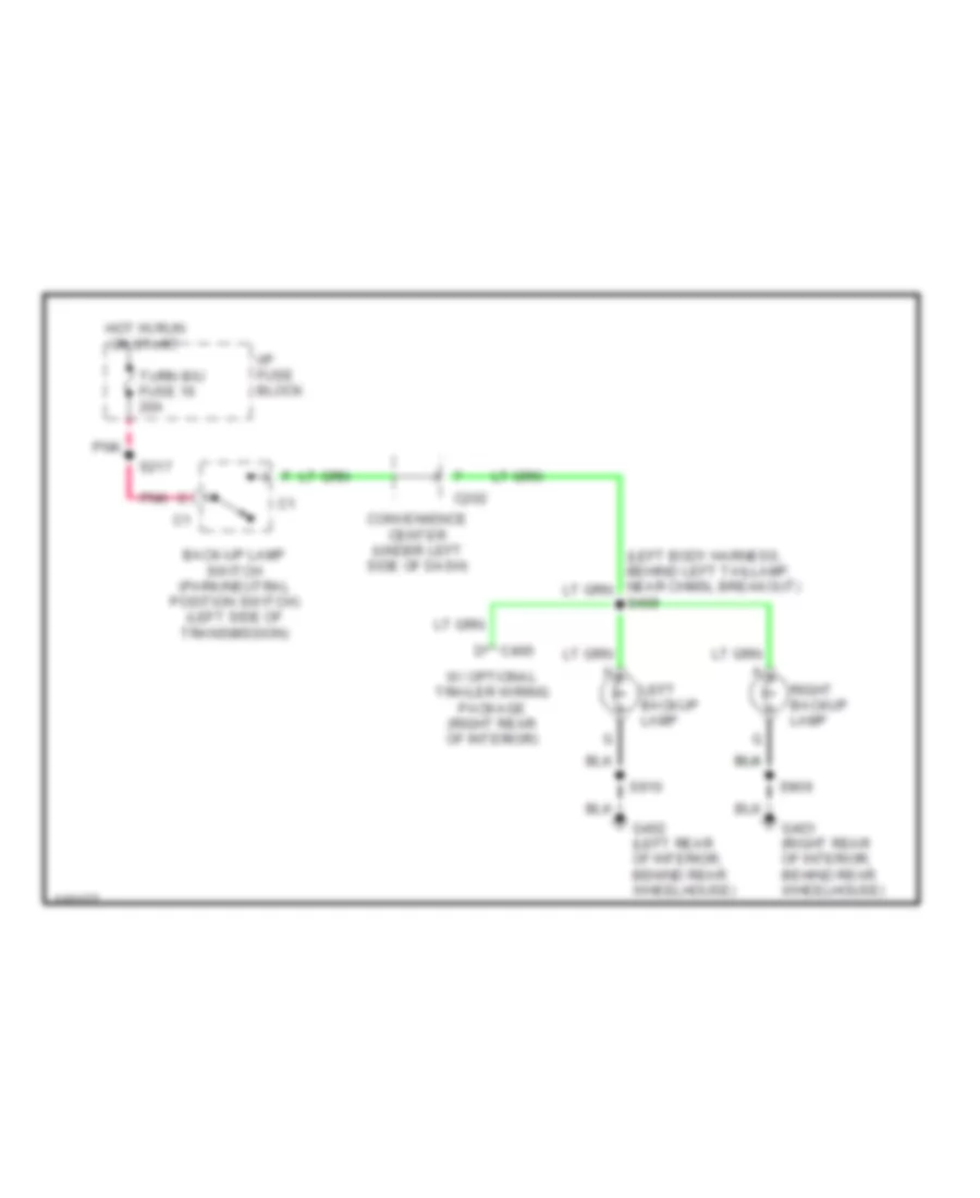
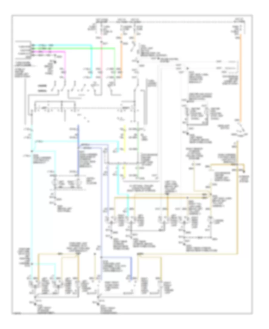
EXTERIOR LIGHTS Back-up Lamps Wiring Diagram for Chevrolet Chevy Express G1999 1500 List of elements for Back-up Lamps Wiring Diagram for Chevrolet Chevy Express G1999 1500: 17 Back-up lamp switch (park/neutral position switch) (left side of transmission) C202 Convenience center (under left side of dash) D c406 G402 (left rear of interior, behind rear wheelhouse) G403 (right rear of interior, behind rear wheelhouse) Hot in run or start I/p fuse block Left backup lamp Pnk Right backup lamp S217 S409 S909 S910 Turn b/u fuse 16 20a W/ optional trailer wiring package (right rear of interior) Exterior Lamps Wiring Diagram, with Composite Headlamps for Chevrolet Chevy Express G1999 1500 List of elements for Exterior Lamps Wiring Diagram, with Composite Headlamps for Chevrolet Chevy Express G1999 1500: 74 (center high mount stoplamp harness, behind chmsl) s422 (dash harness, 4 cm from head- lamp switch breakout) s225 (forward lamp harn, 26 cm into left forward lamp harness) s142 (forward lamp harness, 26 cm from left forward lamp breakout) s135 (left tail- lamp harn, behind left taillamp assembly) s901 (not used) (right rear of interior) w/ optional trailer wiring package) A10 B c406 B9 turn pwr b8 haz pwr b7 flshr out c8 gnd C202 Center high mounted stop lamp (chmsl) Convenience center (under left side of dash) Cruise control system F c406 G100 (left front of engine compartment) G101 (right front of engine compartment) G200 (behind left kick panel) G402 (left rear interior, behind rear wheelhouse) G403 (right rear interior, behind rear wheelhouse) Haz sw Hazard Hazard fuse 20a Head Headlamp switch Hot at all times Hot in run or start I/p fuse block I/p relay center (under left side of dash) Instru- ment cluster Interior lights system Left Left front inner park/ turn signal lamp Left front outer park/ turn signal lamp Left front side marker lamp Left rear park/ stop lamp Left rear park/ turn lamp Left turn ind License lamp Normal Off Park Park lps fuse 9 20a Pnk Right Right front inner park/ turn signal lamp Right front outer park/ turn signal lamp Right front side marker lamp Right rear park/ stop lamp Right rear park/ turn lamp Right turn ind S110 S118 S145 (forward lamp harness, 15 cm into right forward lamps breakout) S202 S217 S222 S236 (dash harness, 4 cm from dlc breakout) S237 (dash harness, near base of steering column, near cluster breakout) S253 S402 (left body harn, behind left taillamp assembly) S410 (left body harn, near chmsl connector breakout) S421 S904 S909 S910 Stop fuse 20a Taillamp assembly) Tcc/ stop lamp switch (behind dash, on brake pedal support) Tn sw Turn- b/u fuse 16 20a Turn/ hazard switch Turn/hazard lamp flasher W/ optional trailer wiring package (right rear of interior) Exterior Lamps Wiring Diagram, with Sealed Beam Headlamps for Chevrolet Chevy Express G1999 1500 List of elements for Exterior Lamps Wiring Diagram, with Sealed Beam Headlamps for Chevrolet Chevy Express G1999 1500: 72 (center high mount stoplamp harness, behind chmsl) s422 (dash harness, 4 cm from head- lamp switch breakout) s225 (forward lamp harness, 26 cm from left forward lamp breakout) s135 (left tail- lamp harn, behind left taillamp assembly) s901 (not used) (right rear of interior) w/ optional trailer wiring package) A10 B c406 B9 turn pwr b8 haz pwr b7 flshr out c8 gnd C202 Center high mounted stop lamp (chmsl) Convenience center (under left side of dash) Cruise control system F c406 G100 (left front of engine compartment) G101 (right front of engine compartment) G200 (behind left kick panel) G402 (left rear interior, behind rear wheelhouse) G403 (right rear interior, behind rear wheelhouse) Haz sw Hazard Hazard fuse 20a Head Headlamp switch Hot at all times Hot in run or start I/p fuse block I/p relay center (under left side of dash) Instru- ment cluster Interior lights system Left Left front park/turn signal lamp Left front side marker lamp Left rear park/ stop lamp Left rear park/ turn lamp Left turn ind License lamp Normal Off Park Park lps fuse 9 20a Pnk R100 (resistor) (6 ohms, 30 watts) (forward lamp harness, left front of vehicle near headlamp) Right Right front park/turn signal lamp Right front side marker lamp Right rear park/ stop lamp Right rear park/ turn lamp Right turn ind S110 S118 S142 (forward lamp harn, 26 cm into left forward lamp harness) S202 S217 S222 S236 (dash harness, 4 cm from dlc breakout) S237 (dash harness, near base of steering column, near cluster breakout) S253 S402 (left body harn, behind left taillamp assembly) S410 (left body harn, near chmsl connector breakout) S421 S904 S909 S910 Stop fuse 20a Taillamp assembly) Tcc/ stop lamp switch (behind dash, on brake pedal support) Tn sw Turn- b/u fuse 16 20a Turn/ hazard switch Turn/hazard lamp flasher W/ optional trailer wiring package (right rear of interior)
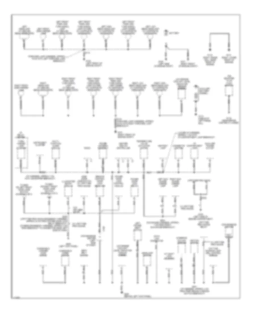
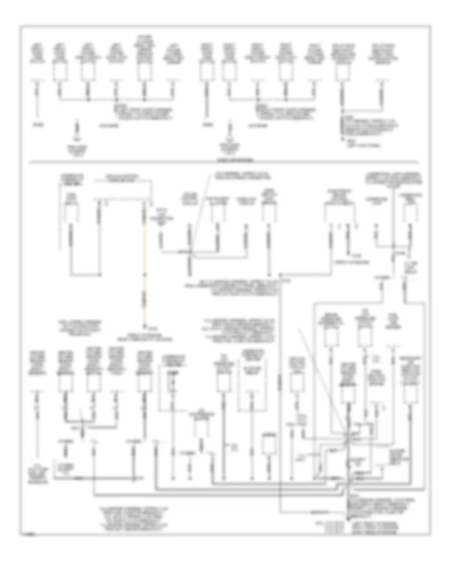
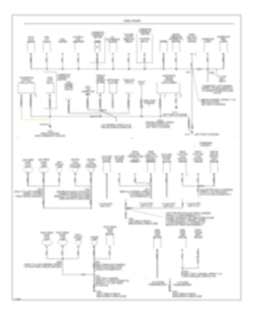
GROUND DISTRIBUTION Ground Distribution Wiring Diagram (1 of 3) for Chevrolet Chevy Express G1999 1500 List of elements for Ground Distribution Wiring Diagram (1 of 3) for Chevrolet Chevy Express G1999 1500: 81 (forward lamp harness, approx 19 cm into left forward lamp breakout) (forward lamp harness, approx 22 cm into right forward lamp breakout) (i/p harness, approx 7 cm into vss buffer breakout) (lower i/p harness, approx 7 cm into i/p compartment lamp breakout) (not used) e13 (upfitter provision) (w/ upfitter provisions) A/t shift lock solenoid Ashtray lamp Auxiliary battery (diesel) Auxiliary power outlet Battery C210 Cigarette lighter Convenience center Convenience center (left side of dash) Data link connector Daytime running lamp (drl) control module G100 (left front of engine compt) G100 (left side G100 (left side of engine compartment) G101 (right front G101 (right front of engine compt) G113 (middle of left frame rail) G116 (near brake master cylinder) G118 (right lower front of engine) G119 (right frame rail, near front of engine) G200 (behind left kick panel) G200 (left kick panel) Headlamp switch Heater and a/c controller I/p compartment lamp I/p relay center Ignition switch Illuminated entry module Instrument cluster Left front park and turn signal lamp (inner) (w/ composite headlamps) Left front park and turn signal lamp (outer) (w/ composite headlamps) Left front park and turn signal lamp (w/ sealed beam headlamps) Left front side marker lamp Left headlamp (w/ sealed beam headlamps) Left high beam headlamp (w/ composite headlamps) Left low beam headlamp (w/ composite headlamps) Left power seat switch Left sun shade mirror lamp Low engine coolant level indicator module (diesel) Low engine coolant level indicator sensor (diesel) Multi- function alarm module Nca Of engine compt) P/b booster fluid flow switch Power antenna assembly Power door lock control module Power door lock relay Radio Remote control door lock receiver Right front park and turn signal lamp (inner) (w/ composite headlamps) Right front park and turn signal lamp (outer) (w/ composite headlamps) Right front park and turn signal lamp (w/ sealed beam headlamps) Right front side marker lamp Right headlamp (w/ sealed beam headlamps) Right high beam headlamp (w/ composite headlamps) Right low beam headlamp (w/ composite headlamps) Right sun shade mirror lamp S201 (i/p harness, approx 4 cm from park brake warning switch breakout) S202 S204 (sun shade harness, approx 7 cm from right sun shade breakout) S205 S206 (upfitter provision-crossbody harness, approx 24 cm from power door lock relay breakout, others-crossbody harness, approx 4 cm from breakout to connector near left side of dash) Seat belt switch Side door jamb switch (w/ upfitter provisions) Steering column ground Temperature valve actuator motor To s500 or left front door jamb switch (diagram 2 of 3) To s601 or right front door jamb switch (diagram 2 of 3) Turn/ hazard lamp flasher Upfitter provisions relay W/ upfitter provisions W/o keyless entry Windshield washer pump motor Windshield wiper motor Ground Distribution Wiring Diagram (2 of 3) for Chevrolet Chevy Express G1999 1500 List of elements for Ground Distribution Wiring Diagram (2 of 3) for Chevrolet Chevy Express G1999 1500: 76 (4.3l-engine harness, approx 20 cm from knock sensor breakout, 5.0l or 5.7l-engine harness, approx 10 cm from g117 breakout, 7.4l-engine harness, approx 14 cm from fuel injector breakout) (4.3l-engine harness, approx 4 cm from fuel injector breakout, 5.0l or 5.7l-approx 4 cm from a/c comp clutch breakout, 7.4l-engine harness, approx 8 cm from ect sensor breakout) (5.0l, 5.7l) g110 (4.3l) g119 (7.4l) g117 (front of engine) (front of engine, near thermostat housing) (i/p harness, approx 40 cm from bulkhead connector) (left front door harness, approx 7 cm from power window switch breakout) (left front of engine) (right front of engine) (right rear of engine) (o2s jumper harness, 15-77 cm from 6-pin connector on right frame rail) (right front door harness, approx 7 cm from power window switch breakout) (underhood lamp harness, approx 4 cm from breakout to connector near blower motor) 4.3l 4.3l, gvw over 8500 lbs., federal emissions 5.0/ 5.7l 5.0l, 5.7l, 7.4l 7.4l 7.4l only 7.4l/ 4.3l A/c compressor clutch A/c low pressure cutout switch B13 Base Blower motor resistor/ relay Brake pressure differential switch Cruise control module Data link connector (dlc) Diode Electronic brake control module (ebcm) Except 7.4l From s206 (diagram 1 of 3) Fuel pump and sender Fuel pump relay G125 G200 (left kick panel) Gasoline engines Heated oxygen sensor (ho2s) bank 1 sensor 1 Heated oxygen sensor (ho2s) bank 1 sensor 2 Heated oxygen sensor (ho2s) bank 1 sensor 3 Heated oxygen sensor (ho2s) bank 1 sensor 3 (ex 7.4l) Heated oxygen sensor (ho2s) bank 2 sensor 1 Heated oxygen sensor (ho2s) bank 2 sensor 2 (7.4l) Horns Ignition control module (icm) Inflatable restraint front end discriminating sensor Inflatable restraint sensing and diagnostic module Instrument cluster Left front door jamb switch Left front power door lock switch Left front power side window switch Left power outside rear view mirror Mass airflow (maf) sensor Nca Non base Others Others except 7.4l Park/ neutral position switch Passlock module Power outside rear view mirror remote control switch Right front door jamb switch Right front power door lock switch Right front power side window switch Right power outside rear view mirror S101 S102 (ex 7.4l-engine harness, approx 104 cm from underhood fuse/relay panel breakout, 7.4l-engine harness, approx 5 cm from a/c comp clutch breakout) S103 S104 S112 S208 (i/p harness, approx 7 cm into inflatable restraint sensing and diagnostic module breakout) S301 Secondary air injection reaction (air) pump clutch (7.4l only) Starter relay Underhood fuse/relay center Underhood lamp Underhood reel lamp Vehicle control module (vcm) W/ tr9 lamp group Ground Distribution Wiring Diagram (3 of 3) for Chevrolet Chevy Express G1999 1500 List of elements for Ground Distribution Wiring Diagram (3 of 3) for Chevrolet Chevy Express G1999 1500: 74 (aux heater and a/c harness, approx 14 cm from front aux hvac module breakout) (engine harness, approx 11 cm from 38-pin conn left front of engine) (engine harness, approx 4 cm from 38-pin conn left front of engine) (i/p harness, approx 40 cm from bulkhead connector) (left front of engine) (underhood lamp harness, approx 4 cm from breakout to connector near blower motor) (upfitter provision-left body harness, approx 7 cm from breakout to connector behind left rear wheelhouse, others-left body harness, approx 7 cm from breakout to connector behind left rear lens assembly) A/c compressor clutch Ambulance package Auxiliary blower motor Auxiliary blower motor switch B13 Blower motor resistor/ relay Brake pressure differential switch Center high mounted stoplamp Data link connector (dlc) Diesel engines Diode Electronic brake control module (ebcm) Front auxiliary hvac control module Fuel heater Fuel lift pump Fuel pump relay Fuel sender buffer module G110 G125 (front of engine, near thermostat housing) G402 (left rear interior, behind rear wheelhouse) G403 (right rear interior, behind rear wheelhouse) Glow plug relay Heater and a/c control logic module Horns Instrument cluster Left backup lamp Left rear park/ stop lamp Left rear park/ turn lamp License lamp Nca Park/ neutral position switch Passenger vans only Passlock module Powertrain control module (pcm) Rear auxiliary hvac control module Rear auxiliary mode valve and seal assembly Rear auxiliary temperature valve assembly Right backup lamp Right power seat switch Right rear door jamb switch Right rear park/ stop lamp Right rear park/ turn lamp S101 S102 S104 S112 S303 (right body harness, approx 7 cm from side door jamb switch) S318 S400 S401 (left body harness, approx 7 cm from connector breakout to left rear of vehicle) S411 (rear a/c harness, approx 13 cm from blower motor breakout) S421 (center high mount stoplamp harness, approx 60 cm from breakout to connector under rear center of headliner) S904 (right rear door harness, approx 29 cm from door jamb switch breakout) S909 (right taillamp harness, approx 7 cm from pass-through grommet) S910 (right taillamp harness, approx 7 cm from pass-through grommet) Side door jamb switch Starter relay Underhood fuse/relay center Underhood lamp Underhood reel lamp Vehicle speed sensor buffer W/ auxiliary heat & a/c W/ auxiliary heat only W/ power passenger seat W/ tr9 lamp group W/o power passenger seat Water-in- fuel indicator
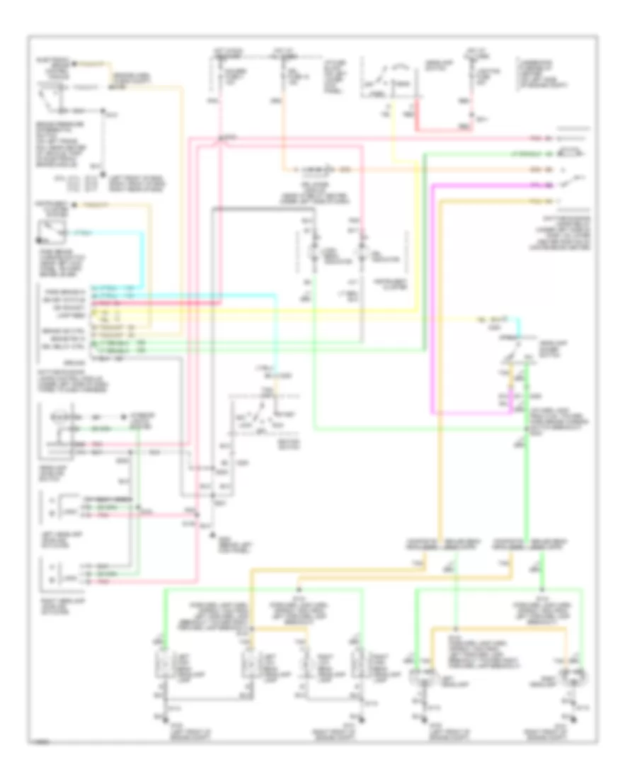
HEADLIGHTS Headlight Wiring Diagram for Chevrolet Chevy Express G1999 1500 List of elements for Headlight Wiring Diagram for Chevrolet Chevy Express G1999 1500: 82 (5.0l, 5.7l) (4.3l) (7.4l) (engine harn, in eng compt) s156 (forward lamp harn, approx 13cm from left forward lamp breakout toward right forward lamp breakout) s143 (left front of eng) (right front of eng) (right rear of eng) 17a 31a 56b A17 Acc B17 Brake ind ctrl Brake pressure differential switch (on left frame rail near center of vehicle, part of electronic brake module) Brake psi in C200 Composite headlamps Daytime running lamps control module (under left side of dash, taped to dash harness) Daytime running lamps relay (under left side of dash, on lower center portion of convenience center) Drl diode module (near i/p relay center, under left side of dash) Drl fuse 15 15a Drl indicator Drl relay ctrl E11 c200 E12 E13 Electronic brake control module F f G100 (left front of engine compt) G101 (right front of engine compt) G110 g119 g117 G200 (behind left kick panel) Gauges fuse 4 10a Ground Head Headlamp dimmer switch Headlamp leveling switch Headlamp switch High beam indicator Hot at all times Hot in run or start I/p fuse block (on left lower kick panel) Ign (run/st) Ign key status Ignition switch Instrument cluster Instrument cluster system Interior lights system Lamp feed Left headlamp Left headlamp leveling actuator Left high beam headlamp lamp Left low beam headlamp lamp Lighting fuse 40a Lock Logic Off Park Park brake in Park brake warning switch (near left kick panel, on park brake lever) Pnk Red Right headlamp Right headlamp leveling actuator Right high beam headlamp lamp Right low beam headlamp lamp Run S101 S110 S118 S143 (forward lamp harn, approx 13cm from left forward lamp breakout toward right forward lamp breakout) S144 (forward lamp harn, approx 19cm from left forward lamp breakout) S149 S150 S151 S201 S202 S205 S211 S216 Sealed beam headlamps Start Tan Underhood fuse/relay center (on left side of engine compt)
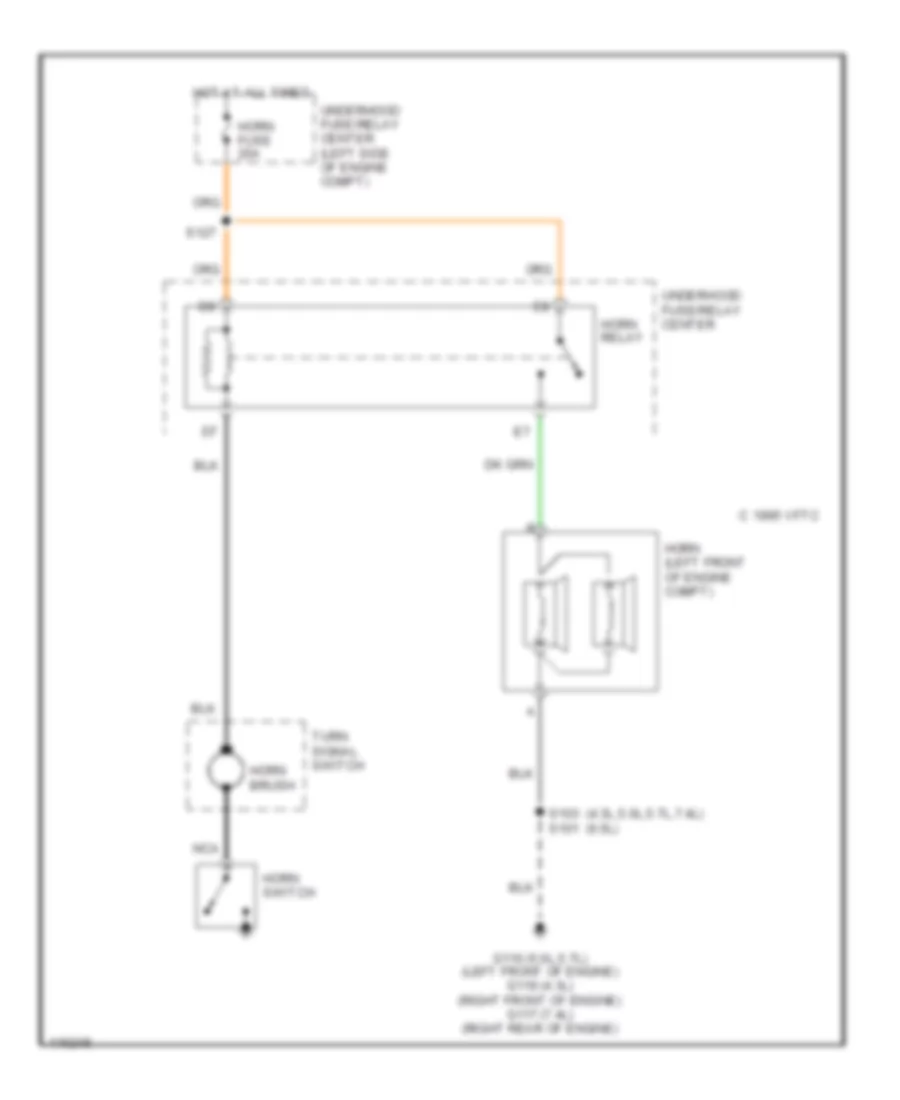
HORN Horn Wiring Diagram for Chevrolet Chevy Express G1999 1500 List of elements for Horn Wiring Diagram for Chevrolet Chevy Express G1999 1500: 15 (4.3l,5.0l,5.7l,7.4l) (6.5l) C 1995 vftc G110 (5.0l,5.7l) (left front of engine) g119 (4.3l) (right front of engine) g117 (7.4l) (right rear of engine) Horn (left front of engine compt) Horn brush Horn fuse 20a Horn relay Horn switch Hot at all times Nca S103 s101 S127 Turn signal switch Underhood fuse/relay center Underhood fuse/relay center (left side of engine compt)
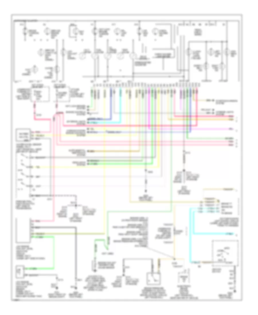
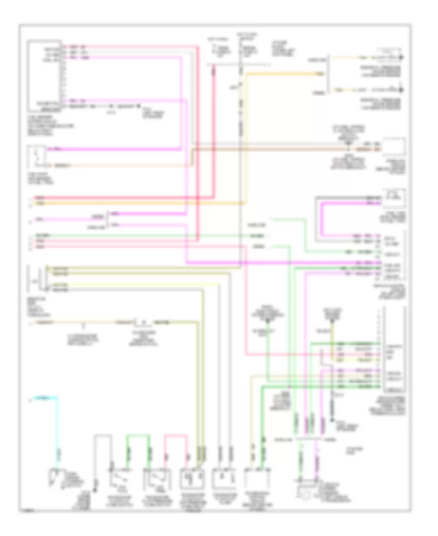
INSTRUMENT CLUSTER Instrument Cluster Wiring Diagram (1 of 2) for Chevrolet Chevy Express G1999 1500 List of elements for Instrument Cluster Wiring Diagram (1 of 2) for Chevrolet Chevy Express G1999 1500: 99 (4.3l/6.5l/7.4l: left side of eng, on cylinder head, 5.0l/5.7l: left cylinder head, between two front spark plugs) (7 bulbs) (engine harn, 14 cm from knock sensor) (4.3l) (engine harn, 8 cm from injector harn breakout) (5.0/5.7l) (engine harn, 10 cm from input shaft sensor) (7.4l) (engine harn, 4 cm from brake pressure differential switch) (6.5l diesel) (not used) A10 A11 A12 A13 A14 A15 A16 A17 Acc Air bag ind Anti-lock brakes system Anti-lock brakes warning ind B10 B11 B12 B13 B14 B15 B16 B17 Bat ind Brake ind in Brake pressure differential switch (part of electronic brake control module, left frame rail) Brake psi Brake tt Brake warning ind Check gauges ind Check gauges lamp driver Daytime running lamp control module (under left side of dash, taped to harness) Diesel only Diode-i d101 Drl lamp ind Electronic brake control module (left frame rail, near center of vehicle) Eng-i mini fuse 20a Engine controls system Engine coolant temperature gauge sensor Exterior lights system Fuel gauge G101 (right front of engine compt) G110 (5.0, 5.7, 7.4l) (left front of engine) G110 (6.5l) (left front of engine) G119 (4.3l) (right front of engine) G119 (4.3l) (right frt of engine) G200 (behind left kick panel) Gauges fuse 4 10a Gnd Headlights system High beam ind Hot in run or start I/p fuse block (lower left kick panel) Ign Ign feed Ignition switch Illumin- ation lamps Ind ctrl Instrument cluster Interior lights system Left turn ind Lock Low coolant ind (diesel) Low engine coolant level indicator module (diesel only) (under left side of dash) Low engine coolant level indicator sensor (diesel only) (under coolant recovery/surge tank) Nca Off Oil press gauge Park/neutral position switch (left side of transmission) Pk brake Pnk Prndl circuit board Right turn ind Run S101 S112 S118 S130 S156 S201 S202 S216 Safety belt ind Service engine soon ind Service throttle soon ind (diesel) Solid state Speedometer/ odometer Start Starting/charging system Tan Temp gauge Underhood fuse-relay center (left side of eng compt) Underhood fuse-relay center (on left side of eng compt) Volt- meter Wait ind (diesel) Warning system engine controls system Water in fuel ind (diesel) Water-in-fuel sensor (diesel only) (left frame rail, near center of vehicle) Instrument Cluster Wiring Diagram (2 of 2) for Chevrolet Chevy Express G1999 1500 List of elements for Instrument Cluster Wiring Diagram (2 of 2) for Chevrolet Chevy Express G1999 1500: 56 (i/p harn, approx 21 cm from hvac switch breakout) s247 (on inner knee bolster, +5v ref 1.5k Anti-lock brakes system Batt Below right side of dash) Brake fuse 18 10a Diesel Engine oil pressure gauge sender (top rear of engine) Engine oil pressure gauge sensor (top rear of engine) Fuel lev Fuel pump and sender (in fuel tank) Fuel sender buffer module Fuel sig Fuel tank level sender (in fuel tank) G110 (left front of engine) G116 (under brake master cylinder) Gasoline Gauge ctrl Gnd Hot in acc or run Hot in run I/p fuse block (lower left kick panel) Ign Ignition Inline diode d202 (near park brake switch) Low flow Low pres. P/b booster fluid flow alarm P/b booster fluid flow alarm switch P/b booster fluid flow and pressure alarm delay module P/b booster fluid pressure alarm switch Park brake warning switch Passlock module (behind center of dash) Pnk Powertrain control module (behind center of dash) Radio, electronic power steering system Resistor r208 (w/ uj1) (near i/p fuse block) S112 S210 S238 (i/p harn, 4 cm from cluster breakout) S246 (i/p harn, approx 25 cm from hvac switch breakout) Sens gnd Sense sw Sig in Tan Trans fuse 24 10a Twisted pair Vehicle control module (on left side of eng compt) Vehicle speed sensor (left side of transmission) Vehicle speed sensor buffer (diesel only) (below dash, near steering column) Vss out Vss rtn Vss sig W/ p/b booster warning option, rpo code-uj1
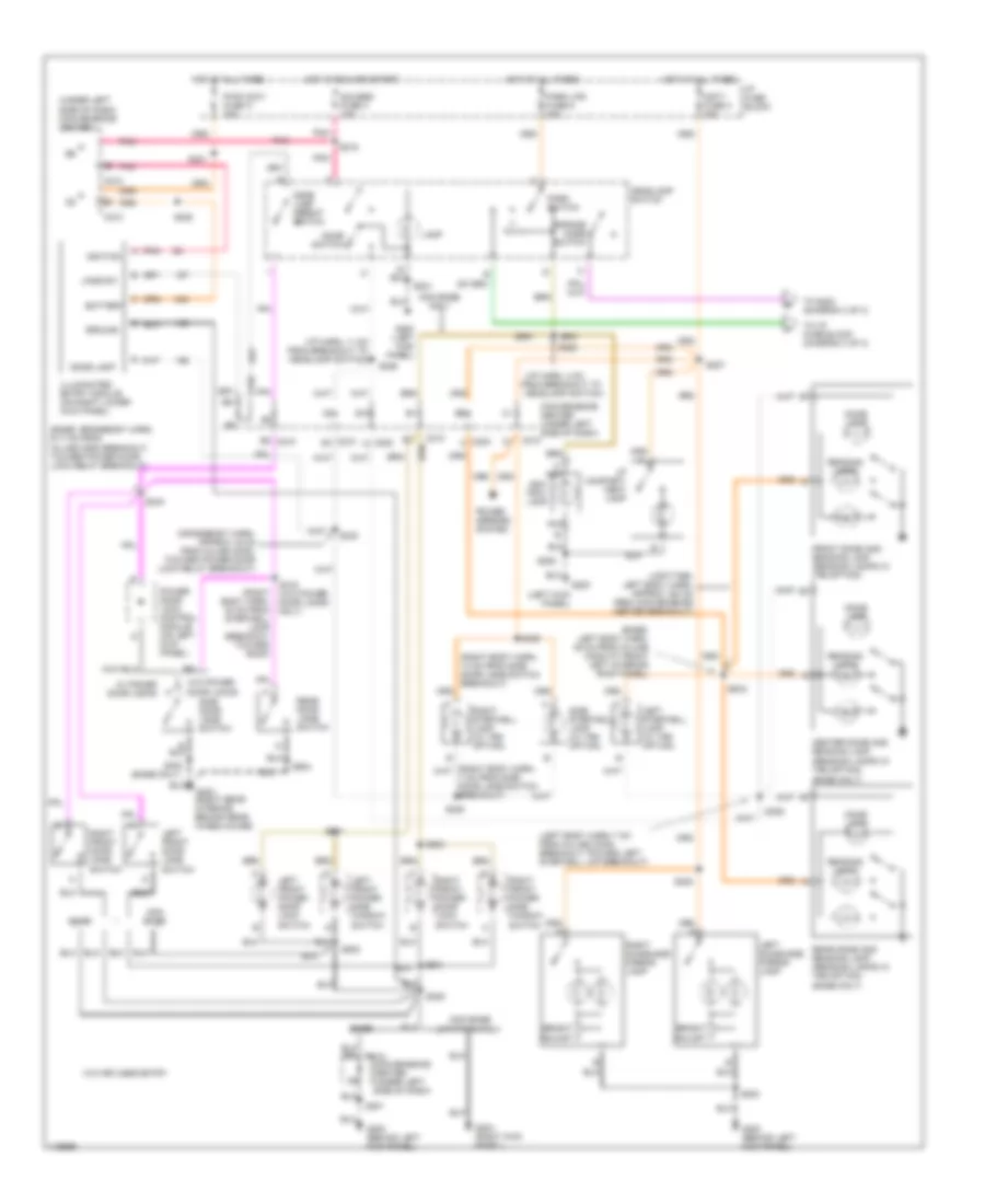
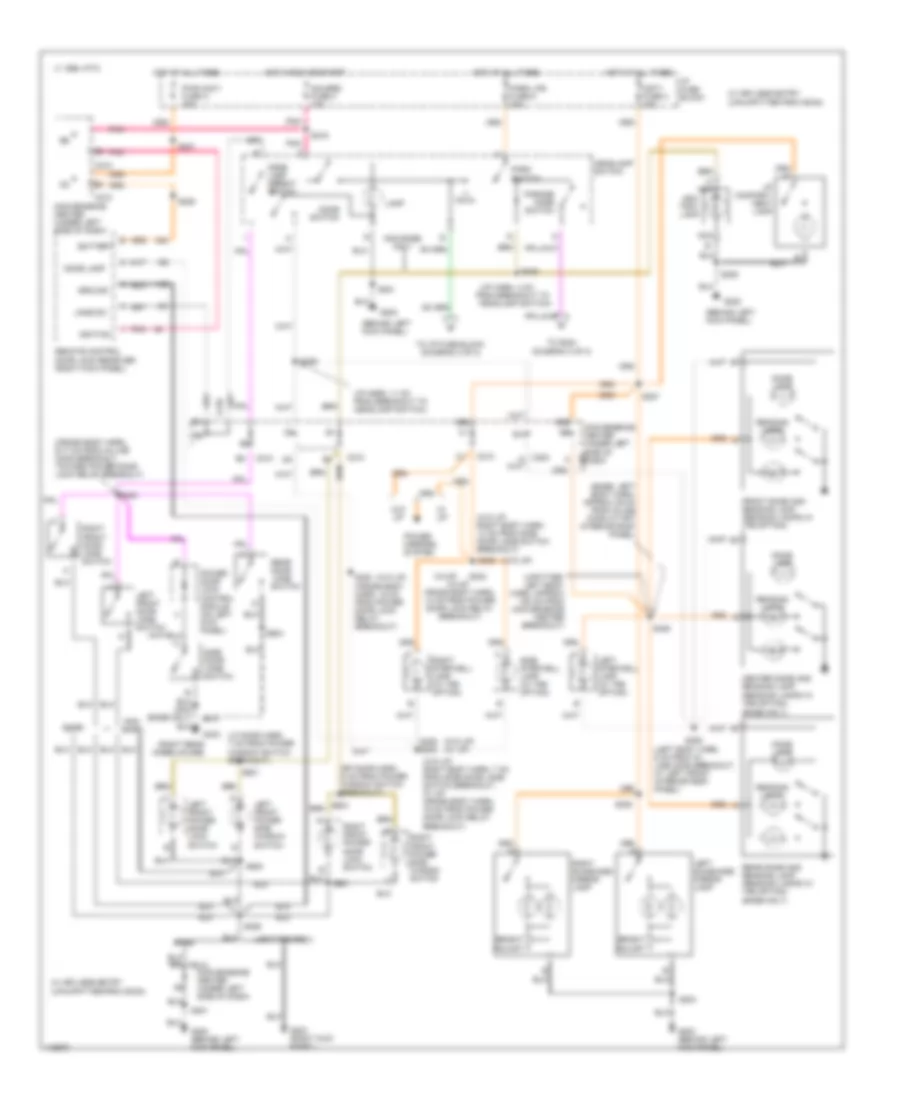
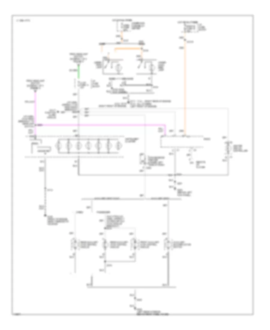
INTERIOR LIGHTS Interior Light Wiring Diagram (1 of 3) for Chevrolet Chevy Express G1999 1500 List of elements for Interior Light Wiring Diagram (1 of 3) for Chevrolet Chevy Express G1999 1500: 102 (base only) (base: crossbody harn, 9-17 cm from in-line conn breakout, toward power door lock relay breakout) (base: left body harn, 39 cm from in-line conn at front left interior roof panel) (crossbody harn, approx 16 cm from inline conn, toward power door lock relay breakout) (i/p harn, 11 cm from breakout to headlamp switch) (i/p harn, 4 cm (left body harn, 7 cm from in-line conn breakout toward left stepwell lmp breakout) (left kick panel) (right body harn, 13 cm from side door jamb switch breakout) (right body harn, 33 cm from stepwell lamp breakout toward roof) (under left side of dash) convenience center (upfitter: left body harn, approx 150 cm from convenience center breakout) A nca Ash- tray lamp B2 c210 Base Battery Bright adjust C202 C210 C210 c1 C210 c6 Center dome and reading lamp (reading lamps w/ tr9 option) Convenience center (under left side of dash) Csty fuse 3 20a Dome lamp Dome lamp defeat switch Dome switch E10 From breakout to headlamp switch) Front dome and reading lamp (reading lamps w/ tr9 option) G200 G200 (behind left kick panel) G200 (left kick panel) G203 (right kick panel) G403 (right rear interior, behind rear wheelhouse) Gauges fuse 4 10a Ground Headlamp switch Hot at all times Hot in run and start I/p compart- ment lamp I/p fuse block Ignition Illuminated entry module (on right lower kick panel) Jamb sw Lamp Left front door jamb switch Left front power door lock switch Left front power side window switch Left stepwell lamp (w/ tr9 option) Left sunshade mirror lamp Nca Non base Non base only Non base upfitter prov. Parade mode switch Park lps fuse 9 20a Park switch Pnk Power door lock control module (on left kick panel) Power mirrors system Pwr accy fuse a 25a Reading lamps Rear dome and reading lamp (reading lamps w/ tr9 option) Rear door jamb switch Right front door jamb switch Right front power door lock switch Right front power side window switch Right stepwell lamp (w/ tr9 option) Right sunshade mirror lamp S201 S204 S205 S206 S216 S221 S225 S226 S227 S228 S230 S240 S303 S305 S306 S308 S309 S316 (w/o power door locks only) S406 S500 S501 S601 S603 S904 Side door jamb switch Side stepwell lamp (w/ tr9 option) To i/p fuse block (diagram 3 of 3) To s224 (diagram 3 of 3) W/ power door locks W/o keyless entry W/o power door locks Interior Light Wiring Diagram (2 of 3) for Chevrolet Chevy Express G1999 1500 List of elements for Interior Light Wiring Diagram (2 of 3) for Chevrolet Chevy Express G1999 1500: 104 (base only) (base: left body harn, approx 39 cm from inline conn at frt interior roof panel) (behind left kick panel) (cross body harn, 16 cm from power door lock relay breakout) (cross body harn, 9-17 cm from in-line conn breakout, toward power door lock relay breakout) (i/p harn, 11 cm from breakout to headlamp switch) (i/p harn, 4 cm (left body harn, 6 cm from in- line conn breakout, at left front interior roof panel) (lf door harn, 7 cm from power window switch breakout) (rf door harn, 5 cm from power window switch breakout) (right rear wheelhouse) (up=upfitter provision) (upfitter: left body harn, approx 150 cm from convenience center breakout) (w/o up) (w/o up) (w/ up) (w/o up: right body harn, 13 cm from side door jamb switch breakout) (w/o up: right body harn, 7 cm from side door jamb switch breakout; w/ up: cross body harn, 16 cm from power door lock relay breakout) (w/up) (w/up: cross body harn, 14 cm from power door lock relay breakout) 1995 vftc c A nca Ash- tray lamp Base Battery Bright adjust C202 C210 Center dome and reading lamp (reading lamps w/ tr9 option) Convenience center (under left side of dash) Csty fuse 3 20a Dome lamp Dome lamp defeat switch Dome switch E10 From breakout to headlamp switch) Front dome and reading lamp (reading lamps w/ tr9 option) G200 G200 (behind left kick panel) G203 (right kick panel) G403 Gauges fuse 4 10a Ground Headlamp switch Hot at all times Hot in run or start I/p compart- ment lamp I/p fuse block Ignition Jamb sw Lamp Left front door jamb switch Left front power door lock switch Left front power side window switch Left stepwell lamp (w/ tr9 option) Left sunshade mirror lamp Nca Non base Non base only Parade mode switch Park lps fuse 9 20a Park switch Pnk Power door lock control module (on left kick panel) Power mirrors system Pwr accy fuse a 25a Reading lamps Rear dome and reading lamp (reading lamps w/ tr9 option) Rear door jamb switch Remote control door lock receiver (right kick panel) Right front door jamb switch Right front power door lock switch Right front power side window switch Right stepwell lamp (w/ tr9 option) Right sunshade mirror lamp S201 S204 S205 S206 S216 S221 S225 S226 S227 S228 S230 S232 S240 S305 s230 S306 S308 S309 S406 S500 S501 S601 S904 Side door jamb switch Side stepwell lamp (w/ tr9 option) To i/p fuse block (diagram 3 of 3) To s224 (diagram 3 of 3) Upfitter prov. W/ keyless entry W/ up W/o up Interior Light Wiring Diagram (3 of 3) for Chevrolet Chevy Express G1999 1500 List of elements for Interior Light Wiring Diagram (3 of 3) for Chevrolet Chevy Express G1999 1500: 55 (4.3l) (7.4l) (all others) (aux htr & a/c harn, approx 7 cm from rr aux hvac module breakout) s310 (i/p harn, 15 cm from breakout to headlamp switch) (i/p harn, approx 17 cm from radio breakout) s223 (right rear of engine) 1995 vftc c Auxiliary blower motor switch Auxiliary heat Auxiliary heat w/a/c B12 B13 Base C202 Cargo Convenience center (under left side of dash) Dim From headlamp switch (diagram 1 0f 3 or 2 of 3) Front auxiliary hvac control module G110 (left front of engine) G117 G119 (right front of engine) G125 (front of engine, near thermostat housing) G200 (behind left G402 (left rear interior, behind rear wheel house) Heater and a/c controller Horn fuse 20a Hot at all times I/p fuse block Illum fuse 14 10a Instrument cluster Kick panel) Multi function alarm module Non base Odometer Passenger Prndl Radio Radio b fuse 19 10a Rear auxiliary hvac control module Remote cd player S104 S112 S1219 S127 S148 S201 S202 S224 S318 S400 Under- hood lamp Under- hood reel lamp Underhood fuse-relay center
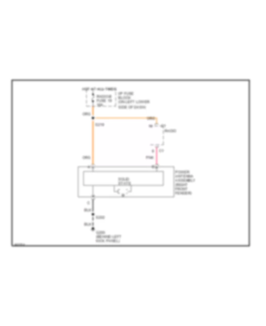
POWER ANTENNA Power Antenna Wiring Diagram for Chevrolet Chevy Express G1999 1500 List of elements for Power Antenna Wiring Diagram for Chevrolet Chevy Express G1999 1500: 11 G200 (behind left kick panel) Hot at all times I/p fuse block (on left lower Pnk Power antenna assembly (right front fender) Radio Radio-b fuse 19 10a S202 S219 Side of dash) Solid state
POWER DISTRIBUTION Power Distribution Wiring Diagram (1 of 4) for Chevrolet Chevy Express G1999 1500 List of elements for Power Distribution Wiring Diagram (1 of 4) for Chevrolet Chevy Express G1999 1500: 99 (crossbody harness, approx 4 cm from convenience center conn breakout) (engine harn, near bulkhead connector) (i/p harness, approx 4 cm into tcc/stoplamp switch breakout) (rear a/c harness, approx 23 cm from blower motor resistor/ relay breakout) (rear a/c harness, approx 7 cm from blower motor resistor breakout) (rear aux htr and a/c harness, approx 33 cm from rear aux hvac module breakout) A13 Abs fuse 60a Acc Ambulance Aux-a fuse 50a Aux-b fuse 50a Auxiliary battery Auxiliary blower motor high speed relay Auxiliary blower motor low speed relay Auxiliary blower motor medium speed relay Battery Battery junction block Blower fuse 60a Blower motor resistor relay Brake fuse 18 10a C202 C206 C210 C302 Convenience center Crank fuse 8 10a Cruise control module (gasoline) Cruise control switch Cruise fuse 6 10a Diesel Electronic brake control module (ebcm) From aux-a fuse (diagram 1 of 4) Front auxiliary hvac control module Fusible link (10 ga- rust) Fusible link (10 ga-rust) G200 (left kick panel) Gasoline Generator Glowplug relay Heater and a/c control logic module Heater and a/c controller Htr a/c fuse 12 20a I/p fuse block Ign-a fuse 40a Ign-b fuse 50a Ignition switch Inline fuse 30a Left front power side window switch Lock Nca Off P/b booster fluid low alarm Park/ neutral position switch Passenger Pnk Pwr wdo fuse b 25a Radio Radio 1 fuse 17 10a Rear auxiliary hvac control module Rear auxiliary mode valve and seal assembly Rear auxiliary temperature valve assembly Red Resistor Right front power side window switch Rr blower fuse 30a Rr hvac fuse 24 10a Run S122 S201 S210 S213 S220 S229 S252 S307 S311 S312 S404 S405 S412 Start Starter relay Starter solenoid Tcc/ stoplamp switch Temperature valve actuator motor To s214 (diagram 3 of 4) To trans fuse (diagram 4 of 4) To underhood fuse-relay center (diagram 2 of 4) To upfitter provision relay (diagram 1 of 4) Trailer wiring provision Underhood fuse/relay center Upfitter provision connector Upfitter provision relay (behind left b pillar) Vehicle control module (vcm) (gasoline) W/ rear a/c Windshield washer/ wiper switch Windshield wiper motor Wiper fuse 11 25a Power Distribution Wiring Diagram (2 of 4) for Chevrolet Chevy Express G1999 1500 List of elements for Power Distribution Wiring Diagram (2 of 4) for Chevrolet Chevy Express G1999 1500: 98 (6.5l, 5.0l, 5.7l-engine harness, approx 11-19 cm from bulkhead connector, 4.3l, 7.4l-engine harness, approx 65cm from underhood fuse relay center) s127 (crossbody harness, approx 14 cm from power door lock relay breakout) s232 (crossbody harness, left side of dash) (engine harness, approx 4 cm into main harness breakout) (i/p harness, 4 cm from radio breakout) (i/p harness, 7 cm from instrument cluster breakout) (i/p harness, approx 4 cm into power seat harness breakout) (i/p harness, approx 8 cm into i/p relay center breakout) (i/p harness, approx 9 cm from radio breakout) s227 (right body harness, approx 13 cm from side door jamb switch breakout) (right body harness, approx 7 cm from power seat switch breakout) (sun shade illum mirror harness, approx 7 cm from right sun shade lamp breakout) (underhood lamp harness, approx 11 cm from reel lamp connector breakout) s148 (upfitter provision-left body harness, 150 cm from convenience center connector others-left body harness, behind left "b" pillar) A/c compressor enable relay A/c fuse 20a Auxiliary power outlet Batt fuse 50a C13 C202 C210 Center dome lamp Cig ltr fuse 13 20a Cigarette lighter Convenience center Ctsy fuse 3 20a D13 Data link connector (dlc) Daytime running lamp (drl) diode module Drl fuse 15 15a Ecm-b fuse 20a From underhood b fuse-relay center (diagram 1 of 4) From underhood fuse-relay center (diagram 1 of 4) Front dome lamp Fuel pump relay G200 (left kick panel) Hazard fuse 5 20a Hazard warning switch Headlamp switch Heater and a/c controller Horn fuse 20a Horn relay Htd mir fuse 2 20a I/p compartment lamp I/p fuse block Illuminated entry module Left front power door lock switch Left power seat switch Left stepwell lamp Left sun shade mirror lamp Lighting fuse 40a Multi- function alarm module Nca Others Park lps fuse 9 20a Passlock module Power antenna assembly Power door lock control module Power door lock relay Power outside rear view mirror remote control switch Powertrain control module (pcm) (diesel) Pwr accy fuse a 25a Pwr aux fuse 7 25a Radio Radio-b fuse 19 10a Rear dome lamp Red Remote control door lock receiver Right front power door lock switch Right power seat switch Right rear power door lock switch Right stepwell lamp Right sun shade mirror lamp S120 S205 S211 (i/p harness, approx 4 cm from park brake warning switch breakout) S212 S218 S219 S221 S222 S300 S308 S309 S406 Security strg fuse 21 10a Side stepwell lamp Stop fuse 1 20a Tcc/stop- lamp switch Underhood fuse/relay center Underhood lamp Underhood reel lamp Vehicle control module (vcm) (gasoline) W/ lamp group option W/ power pass seat W/ upfitter provisions W/o keyless entry W/o upfitter provissions Power Distribution Wiring Diagram (3 of 4) for Chevrolet Chevy Express G1999 1500 List of elements for Power Distribution Wiring Diagram (3 of 4) for Chevrolet Chevy Express G1999 1500: 79 (engine harness, 117 cm from underhood fuse-relay center) (engine harness, appprox 12 cm from right ho2s sensor (bnk 2 sens 1) breakout) (engine harness, approx 15 cm into fuel injector harness breakout) (engine harness, approx 4 cm from egr valve breakout) 5.0l, 5.7l (engine harness, approx 4 cm from fuel injector harness breakout) (engine harness, approx 7 cm into main harness breakout) (engine harness, approx 8 cm from fuel injector harness breakout) (engine harness, approx 8 cm into fuel injector harness breakout) (engine harness, near front of engine) (engine harness, top left of engine) (engine jumper harness, approx 2 cm from optical fuel temperature sensor breakout) (engine jumper harness, near left side of engine) (fed) (cal) (o2s jumper harness, 35 cm from 6-pin connector on right frame rail) (o2s jumper harness, approx 66 cm from 6-pin conn on right frame rail) 4.3l 5.0l, 5.7l 6.5l 7.4l A/c compressor enable relay C nca C11 C12 Camshaft position (cmp) sensor Crankshaft position (ckp) sensor Diesel Ecm-1 fuse 20a Eng-1 fuse 20a Epr solenoid Evaporative emission (evap) canister purge solenoid valve Evaporative emission (evap) canister purge valve Evaporative emission (evap) canister purge valve solenoid Evaporative emission (evap) canister vent valve From ignition switch (diagram 1 of 4) Fuel heater Fuel injectors 1, 3 & 5 Fuel injectors 1, 3, 5 & 7 Fuel injectors 1, 3, 5, & 7 Fuel injectors 2, 4 & 6 Fuel injectors 2, 4, 6 & 8 Fuel injectors 2, 4, 6, & 8 Fuel shutoff solenoid Fuel solenoid driver Glow plug relay Heated oxygen sensor (ho2s) bank 1 Heated oxygen sensor (ho2s) bank 1 sensor 1 Heated oxygen sensor (ho2s) bank 1 sensor 2 Heated oxygen sensor (ho2s) bank 1 sensor 3 Heated oxygen sensor (ho2s) bank 2 sensor 1 Heated oxygen sensor (ho2s) bank 2 sensor 2 Ign-1 fuse 20a Ign-e fuse 10a Ignition coil Ignition control module (icm) Mass airflow (maf) sensor Pnk Pnk (engine harness, approx 5 cm from ho2s sens (bnk 2 sens 1) breakout) s130 Pnk s304 Powertrain control module (pcm) S107 S108 S117 pnk S126 S130 S131 pnk S132 S132 pnk S133 pnk S214 S304 S304 (na1) Secondary air injection (air) reaction pump relay Sensor 2 (na1) To i/p fuse block (diagram 4 of 4) Underhood fuse/relay center Underhood fuse/relay center (calif only) Vehicle control module (vcm) Waste gate solenoid Water in fuel sensor Power Distribution Wiring Diagram (4 of 4) for Chevrolet Chevy Express G1999 1500 List of elements for Power Distribution Wiring Diagram (4 of 4) for Chevrolet Chevy Express G1999 1500: 35 (i/p harness, approx 30 cm from bulkhead connector) s217 (i/p harness, approx 4 cm from breakout to connector at base of steering column) s216 Air bags fuse 10 10a Automatic transmission B10 B17 C210 Convenience center Daytime running lamp (drl) control module Daytime running lamp (drl) relay From ignition switch (diagram 1 of 4) From s214 (diagram 3 of 4) Fuel sender buffer module (diesel) Gauges fuse 4 10a Hazard warning switch Headlamp switch I/p fuse block I/p relay center Illum fuse 14 10a Illuminated entry module Inflatable restraint sensing and diagnositc module Instrument cluster Interior lights system Interior lights system (i/p dimmer switch) Low engine coolant level indicator module (diesel) Multi- function alarm module Park/neutral position switch Passlock module Pnk Remote control door lock receiver Trans fuse 20 10a Turn b/u fuse 16 20a Vehicle speed sensor buffer (diesel) W/ keyless entry W/o keyless entry
POWER DOOR LOCKS Power Door Lock Wiring Diagram, with Keyless Entry for Chevrolet Chevy Express G1999 1500 List of elements for Power Door Lock Wiring Diagram, with Keyless Entry for Chevrolet Chevy Express G1999 1500: 53 (crossbody harn, near power lock relay breakout) s243 (right body harness, 7cm from power seat switch breakout) (w/ passenger power seat only) s300 Base models Batt (b+) Battery (b+) Convenience center (under left side of dash) Data link connector (under left side of dash) Dome lamps Dome lmp off Driver dr unlk G200 (left kick panel) Gauges fuse 4 10a Ground Hot at all times Hot in run, bulb test or start I/p fuse block (on left lower kick panel) Ignition Interior lights system Left door lock switch Left front door lock actuator Lock Lock out Lock sig Pass drs unlk Pnk Power door lock control module (on left kick panel) Power door lock relay (behind center of dash) Program sig Pwr accy fuse a 25a Rear door lock actuator Remote control door lock receiver (behind center of dash) Right door lock switch Right front door lock actuator Right rear door lock switch Rr door unlk S206 S216 S221 S228 S241 (crossbody harness, near power lock relay breakout) S242 (crossbody harn, near power lock relay breakout) S244 (crossbody harness, near power lock relay breakout) S303 (w/ pwr pass seat) S315 (right body harn, 19cm from side door jamb switch harness breakout) Side door contactor (right "b" pillar) Side door jamb switch Side door lock actuator Side door sw Tan Unlock Unlock in Unlock sig Upfitter package Power Door Lock Wiring Diagram, without Keyless Entry for Chevrolet Chevy Express G1999 1500 List of elements for Power Door Lock Wiring Diagram, without Keyless Entry for Chevrolet Chevy Express G1999 1500: 36 (crossbody harn, near power lock relay breakout) s243 (right body harness, 26cm from side door jamb switch harn breakout) s314 Base models Battery (b+) Convenience center (under left side of dash) G200 (left kick panel) Ground Hot at all times I/p fuse block (on lower left kick panel) Left door lock switch Left front door lock actuator Lock Lock sig Power door lock control module (on left kick panel) Power door lock relay (behind center of dash) Pwr accy fuse a 25a Rear door lock actuator Rear door lock switch Right door lock switch Right front door lock actuator S206 S221 S228 S241 (crossbody harness, near power lock relay breakout) S242 (crossbody harn, near power lock relay breakout) S244 (crossbody harn, near power lock relay breakout) S300 S315 (right body harn, 19cm from side door jamb switch harness breakout) Side door contactor (right "b" pillar) Side door jamb switch Side door lock actuator Side door sw Tan Unlock Unlock sig Upfitter package
POWER MIRRORS Power Mirror Wiring Diagram for Chevrolet Chevy Express G1999 1500 List of elements for Power Mirror Wiring Diagram for Chevrolet Chevy Express G1999 1500: 23 (behind left kick panel) g200 (crossbody harn, approx 14 cm from power door lock relay breakout) s232 (left front door harness, approx 15 cm from power mirror motor connector) (right front door harness, approx 15 cm from power mirror switch connector) C210 Convenience center (under left side of dash) Ctsy fuse 3 20a Hot at all times I/p fuse block Interior lights system Left mirror Left power outside rearview mirror Power outside rearview mirror remote control switch Right mirror Right power outside rearview mirror Right/ left motor S227 S500 S502 S604 Up/ down motor W/ upfitter provisions W/o upfitter provisions
POWER SEATS 6-Way Power Seat Wiring Diagram for Chevrolet Chevy Express G1999 1500 List of elements for 6-Way Power Seat Wiring Diagram for Chevrolet Chevy Express G1999 1500: 35 All- down All-up Back C210 d2 Convenience center (under left side of dash) Down Entire seat For- ward Front down Front up G200 (behind left kick panel) G403 (right rear interior, behind rear wheel- house) Hot at all times I/p fuse block Left power seat forward/ rearward motor Left power seat front tilt motor Left power seat rear tilt motor Left power seat switch Left seat adjuster motor assembly Nca Pwr accy fuse a 25a Rear down Rear up Red Right power seat forward/ rearward motor Right power seat front tilt motor Right power seat rear tilt motor Right power seat switch Right seat adjuster motor assembly S201 S221 S228 S300 S303 Tan
POWER WINDOWS Power Window Wiring Diagram for Chevrolet Chevy Express G1999 1500 List of elements for Power Window Wiring Diagram for Chevrolet Chevy Express G1999 1500: 16 (left kick panel) g200 C210 Convenience center (left side of dash) Driver window motor Driver window switch Front passenger window motor Front passenger window switch Hot in accy & run I/p fuse block (on lower left kick panel) Interior lights system Left Power wdo fuse b 25a Right S229 S500 Tan
RADIO Radio Wiring Diagrams for Chevrolet Chevy Express G1999 1500 List of elements for Radio Wiring Diagrams for Chevrolet Chevy Express G1999 1500: 73 (left front door harn, approx 13cm from radio speaker breakout) s504 (left front door harn, approx 7cm from radio speaker breakout) s503 (right body harn, near center high mounted stoplamp breakout) s423 (right body harn, near center high mounted stoplamp breakout) s424 Antenna Anti-theft system Audio rtn Base Battery Convenience center (left side of dash) Diesel Dim ctrl Dim sig in Dim sig out Drain E&c line Except G200 (behind left kick panel) Gasoline Ground Hot at all times Hot in acc or run I/p fuse block Ignition Illuminaton Interior lights system Left front door speaker Left front door tweeter speaker Left overhead speaker Left rear door speaker Lf + Lf - Line Lr + Lr - Lt input Lt output Nca Pnk Power antenna assembly Premium Pwr antenna R14 in R14 out Radio Radio i fuse 17 10a Radio-b fuse 19 10a Red Remote compact disk player (below radio) Rf + Rf - Right front door speaker Right front door tweeter speaker Right overhead speaker Right rear door speaker Rr + Rr - Rt input Rt output S202 S219 S220 S239 (i/p harn, approx 10cm into radio breakout) S407 (left body harn near left "b" pillar) S419 (left body harn, near left "b" pillar) S605 (right front door harn, approx 7cm from power window motor breakout) S606 (right front door harn, approx 4cm from power window motor breakout) Tan Vehicle control module (left side of engine compt) Vehicle speed sensor buffer (below dash, near steering column) Vss signal W/ upfitter W/o upfitter
SHIFT INTERLOCKS Shift Interlock Wiring Diagram for Chevrolet Chevy Express G1999 1500 List of elements for Shift Interlock Wiring Diagram for Chevrolet Chevy Express G1999 1500: 10 A/t shift lock solenoid (right side of steering column) G200 (behind left kick panel) Hot in run or start I/p fuse block Park/ neutral position switch (left side of transmission) c1 Pnk S201 S217 pnk Turn/ hazard switch Turn/bu fuse 16 20a
STARTING/CHARGING Charging Wiring Diagram for Chevrolet Chevy Express G1999 1500 List of elements for Charging Wiring Diagram for Chevrolet Chevy Express G1999 1500: 26 (100a) (124a) (not used) B l B16 B17 Battery Battery junction block (next to radiator) Charge indicator Fusible link (10 ga- rust) Fusible link (10 ga-rust) G100 (left side of engine compt) G101 (right front of engine compt) Gauges fuse 4 10a Generator Generator (w/ ambulance package) Hot at all times Hot in run or start I/p fuse block (left kick panel) Instrument cluster Pnk Power distribution system Red S158 (w/ambulance pkg) (engine harness, 4 cm from breakout to a/c compressor) S216 Starting circuit Stud Starting Wiring Diagram for Chevrolet Chevy Express G1999 1500 List of elements for Starting Wiring Diagram for Chevrolet Chevy Express G1999 1500: 35 (diesel) (gas) Accy Auxiliary battery Battery Battery junction block Bulb test Crank fuse 8 10a Diesel Fusible link (10 ga- rust) Fusible link (10 ga- rust) (diesel) G100 (left side of engine compt) G101 (right front of engine compt) G103 g119 (diesel - front of right cylinder head) (gas - rear of left cylinder head) G113 (middle of left frame rail) Gas Generator Hold- in coil I/p fuse block (left kick panel) Ign-a fuse 40a Ignition switch Label stud Lock Off Orange Park/ neutral position switch (left side of transmission) Power distribution Pull- in coil Red Run S103 Start Starter motor Starter relay (in underhood fuse/relay center) Underhood fuse/relay center (left side of engine compt) White
SUPPLEMENTAL RESTRAINTS Supplemental Restraint Wiring Diagram for Chevrolet Chevy Express G1999 1500 List of elements for Supplemental Restraint Wiring Diagram for Chevrolet Chevy Express G1999 1500: 43 A16 Air bag indicator Air bags fuse 10 10a B nca B17 Bar Data line Data link connector (dlc) (under left side of dash) Driver side high Driver side low G200 (behind left kick panel) G200 (left kick panel) Gauges fuse 4 10a Hot in run and start I/p fuse block (lower left kick panel) Ignition Indicator ctrl Inflatable restraint diagnostic resistor Inflatable restraint front end discriminating sensor (on front of vehicle) Inflatable restraint i/p module Inflatable restraint sensing and diagnostic module (under left front seat) Inflatable restraint steering wheel module Inflatable restraint steering wheel module coil Instrument cluster Lf seat belt input Multi-function alarm module (under left side of dash) Nca Pass side high Pass side low Pnk S201 (i/p harn, near breakout to park brake warning sw) S208 (i/p harn, in breakout to sdm) S209 (i/p harn, in breakout to sdm) S216 (i/p harn, 4 cm from breakout to conn at base of steerning column) Seat belt sig Seat belt switch (at driver's stationary belt connector Sensor feed Shorting Shorting bar Sir ground Tan W/ pass sir W/o pass sir
TRANSMISSION
4.3L 4.3L VIN W, A/T Wiring Diagram for Chevrolet Chevy Express G1999 1500 List of elements for 4.3L VIN W, A/T Wiring Diagram for Chevrolet Chevy Express G1999 1500: 86 (4.3, 5.0l, 5.7l: eng harn, 85 cm from uh fuse/relay center breakout) (7.4l: eng harn, 21 cm from maf sensor breakout) (4.3l) g119 (5.0l, 5.7l, 7.4l) g110 (4.3l: eng compt, at generator bracket) (5.0l, 5.7l, 7.4l: left front of engine) (4.3l, 5.0l, 5.7l) s133 (4.3l, 5.0l, 5.7l: dash harn, 18 cm from eng sensor inline toward firewall) (7.4l: dash harn) (4.3l, 5.0l, 5.7l: eng harn, 98 cm from uh fuse/ relay center breakout) (7.4l: eng harn, 4 cm from ect sensor breakout) (4l60-e) (4l80-e) (engine harn) s136 (twisted wire pair) 1-2 shift sol 1-2 shift solenoid 2-3 shift sol 2-3 shift solenoid 3-2 ctrl solenoid 3-2 downshift sol 5v reference A/t fluid pressure manual valve position switch A/t iss hi A/t iss lo Automatic transmission (4l60-e/4l80-e) Automatic transmission input shaft speed sensor (w/ 4l80-e) (left side of transmission) B17 Battery in Brake fuse 18 10a Brake switch input Cruise control module Data class ii Data link connector (partial) (under left side of dash) Ecm-1 fuse 20a Ecm-b fuse 20a Ect sens input Electronic brake control module Engine controls system Engine coolant temperature sensor (top front of engine) Fuel injectors (4.3l, 5.0l, 5.7l) Fuel pump relay & fuel pump switch Fuel sender buffer module, power steering control module, remote control door lock receiver & headlamp swich Gauges fuse 4 10a Hot at all times Hot in off, run or start Hot in run Hot in run or start I/p fuse block Ignition coil, fuel injectors Ignition in Instrument cluster Malfunction indicator lamp Mil control Pcm ground Pcs sol hi out Pcs sol lo out Pnk Press ctrl Range signal "a" Range signal "b" Range signal "c" Red S102 S120 S122 S132 S139 S153 (4.3l: eng harn, 4 cm from a/c compressor breakout) (5.ol, 5.7l: eng harn, 8 cm from ign coil breakout) (7.4l: eng harn, 42 cm from u/h fuse/relay center) S154 S210 S216 S231 Sensor ground Sensor return Solenoid Tcc pwm sol Tcc pwm solenoid Tcc sol Tcc solenoid Tcc/abs/ cruise switch Tcc/stop lamp switch (on brake pedal support) Throttle position sensor (on throttle body) Tp sens input Trans fluid temp sensor Trans fuse 20 10a Trans temp sig in Underhood fuse/relay center Vehicle control module (left side of engine compt) Vehicle speed sensor (left side of transmission) Vss hi Vss lo
5.0L 5.0L VIN M, A/T Wiring Diagram for Chevrolet Chevy Express G1999 1500 List of elements for 5.0L VIN M, A/T Wiring Diagram for Chevrolet Chevy Express G1999 1500: 86 (4.3, 5.0l, 5.7l: eng harn, 85 cm from uh fuse/relay center breakout) (7.4l: eng harn, 21 cm from maf sensor breakout) (4.3l) g119 (5.0l, 5.7l, 7.4l) g110 (4.3l: eng compt, at generator bracket) (5.0l, 5.7l, 7.4l: left front of engine) (4.3l, 5.0l, 5.7l) s133 (4.3l, 5.0l, 5.7l: dash harn, 18 cm from eng sensor inline toward firewall) (7.4l: dash harn) (4.3l, 5.0l, 5.7l: eng harn, 98 cm from uh fuse/ relay center breakout) (7.4l: eng harn, 4 cm from ect sensor breakout) (4l60-e) (4l80-e) (engine harn) s136 (twisted wire pair) 1-2 shift sol 1-2 shift solenoid 2-3 shift sol 2-3 shift solenoid 3-2 ctrl solenoid 3-2 downshift sol 5v reference A/t fluid pressure manual valve position switch A/t iss hi A/t iss lo Automatic transmission (4l60-e/4l80-e) Automatic transmission input shaft speed sensor (w/ 4l80-e) (left side of transmission) B17 Battery in Brake fuse 18 10a Brake switch input Cruise control module Data class ii Data link connector (partial) (under left side of dash) Ecm-1 fuse 20a Ecm-b fuse 20a Ect sens input Electronic brake control module Engine controls system Engine coolant temperature sensor (top front of engine) Fuel injectors (4.3l, 5.0l, 5.7l) Fuel pump relay & fuel pump switch Fuel sender buffer module, power steering control module, remote control door lock receiver & headlamp swich Gauges fuse 4 10a Hot at all times Hot in off, run or start Hot in run Hot in run or start I/p fuse block Ignition coil, fuel injectors Ignition in Instrument cluster Malfunction indicator lamp Mil control Pcm ground Pcs sol hi out Pcs sol lo out Pnk Press ctrl Range signal "a" Range signal "b" Range signal "c" Red S102 S120 S122 S132 S139 S153 (4.3l: eng harn, 4 cm from a/c compressor breakout) (5.ol, 5.7l: eng harn, 8 cm from ign coil breakout) (7.4l: eng harn, 42 cm from u/h fuse/relay center) S154 S210 S216 S231 Sensor ground Sensor return Solenoid Tcc pwm sol Tcc pwm solenoid Tcc sol Tcc solenoid Tcc/abs/ cruise switch Tcc/stop lamp switch (on brake pedal support) Throttle position sensor (on throttle body) Tp sens input Trans fluid temp sensor Trans fuse 20 10a Trans temp sig in Underhood fuse/relay center Vehicle control module (left side of engine compt) Vehicle speed sensor (left side of transmission) Vss hi Vss lo
5.7L 5.7L VIN R, A/T Wiring Diagram for Chevrolet Chevy Express G1999 1500 List of elements for 5.7L VIN R, A/T Wiring Diagram for Chevrolet Chevy Express G1999 1500: 86 (4.3, 5.0l, 5.7l: eng harn, 85 cm from uh fuse/relay center breakout) (7.4l: eng harn, 21 cm from maf sensor breakout) (4.3l) g119 (5.0l, 5.7l, 7.4l) g110 (4.3l: eng compt, at generator bracket) (5.0l, 5.7l, 7.4l: left front of engine) (4.3l, 5.0l, 5.7l) s133 (4.3l, 5.0l, 5.7l: dash harn, 18 cm from eng sensor inline toward firewall) (7.4l: dash harn) (4.3l, 5.0l, 5.7l: eng harn, 98 cm from uh fuse/ relay center breakout) (7.4l: eng harn, 4 cm from ect sensor breakout) (4l60-e) (4l80-e) (engine harn) s136 (twisted wire pair) 1-2 shift sol 1-2 shift solenoid 2-3 shift sol 2-3 shift solenoid 3-2 ctrl solenoid 3-2 downshift sol 5v reference A/t fluid pressure manual valve position switch A/t iss hi A/t iss lo Automatic transmission (4l60-e/4l80-e) Automatic transmission input shaft speed sensor (w/ 4l80-e) (left side of transmission) B17 Battery in Brake fuse 18 10a Brake switch input Cruise control module Data class ii Data link connector (partial) (under left side of dash) Ecm-1 fuse 20a Ecm-b fuse 20a Ect sens input Electronic brake control module Engine controls system Engine coolant temperature sensor (top front of engine) Fuel injectors (4.3l, 5.0l, 5.7l) Fuel pump relay & fuel pump switch Fuel sender buffer module, power steering control module, remote control door lock receiver & headlamp swich Gauges fuse 4 10a Hot at all times Hot in off, run or start Hot in run Hot in run or start I/p fuse block Ignition coil, fuel injectors Ignition in Instrument cluster Malfunction indicator lamp Mil control Pcm ground Pcs sol hi out Pcs sol lo out Pnk Press ctrl Range signal "a" Range signal "b" Range signal "c" Red S102 S120 S122 S132 S139 S153 (4.3l: eng harn, 4 cm from a/c compressor breakout) (5.ol, 5.7l: eng harn, 8 cm from ign coil breakout) (7.4l: eng harn, 42 cm from u/h fuse/relay center) S154 S210 S216 S231 Sensor ground Sensor return Solenoid Tcc pwm sol Tcc pwm solenoid Tcc sol Tcc solenoid Tcc/abs/ cruise switch Tcc/stop lamp switch (on brake pedal support) Throttle position sensor (on throttle body) Tp sens input Trans fluid temp sensor Trans fuse 20 10a Trans temp sig in Underhood fuse/relay center Vehicle control module (left side of engine compt) Vehicle speed sensor (left side of transmission) Vss hi Vss lo
WARNING SYSTEMS Warning System Wiring Diagrams for Chevrolet Chevy Express G1999 1500 List of elements for Warning System Wiring Diagrams for Chevrolet Chevy Express G1999 1500: 42 (i/p harn, 39 cm into inflatable restraint sensing & diagnostic module breakout) (left kick panel) A12 Battery input C200 C210 Convenience center (under left side of dash) Fasten belts out G200 G200 (left kick panel) Gauges fuse 4 10a Ground Hazard fuse 5 20a Hot at all times Hot in park or head Hot in run or start I/p fuse block (on lower left kick panel) Ignition on input Illum mir fuse 14 10a Instrument cluster Instrument cluster system Key-in sw input Key-in warning switch (inside steering column assembly) Left front door jamb switch Lights on input Multi-function alarm module (under left side of dash) Nca Pnk S201 S202 S206 S209 S216 S222 S223 S500 Safety belt input Safety belt lamp Seat belt switch (opens with belt buckled) (in driver's stationary belt connector) Speed input Tan Upfitter package only
WIPER/WASHER Wiper/Washer Wiring Diagram for Chevrolet Chevy Express G1999 1500 List of elements for Wiper/Washer Wiring Diagram for Chevrolet Chevy Express G1999 1500: 21 G200 (behind left kick panel) Hot in acc or run I/p fuse block (lower left kick panel) Inst wipe Inst wipe k Low Mist Mist off Off Pulse Red S201 S252 Solid state Wash Washer switch Windshield washer pump motor (left front of engine compt, at washer reservoir) Windshield washer/ wiper switch Windshield wiper motor (on left side of firewall) Wiper fuse 11 25a Wiper switch