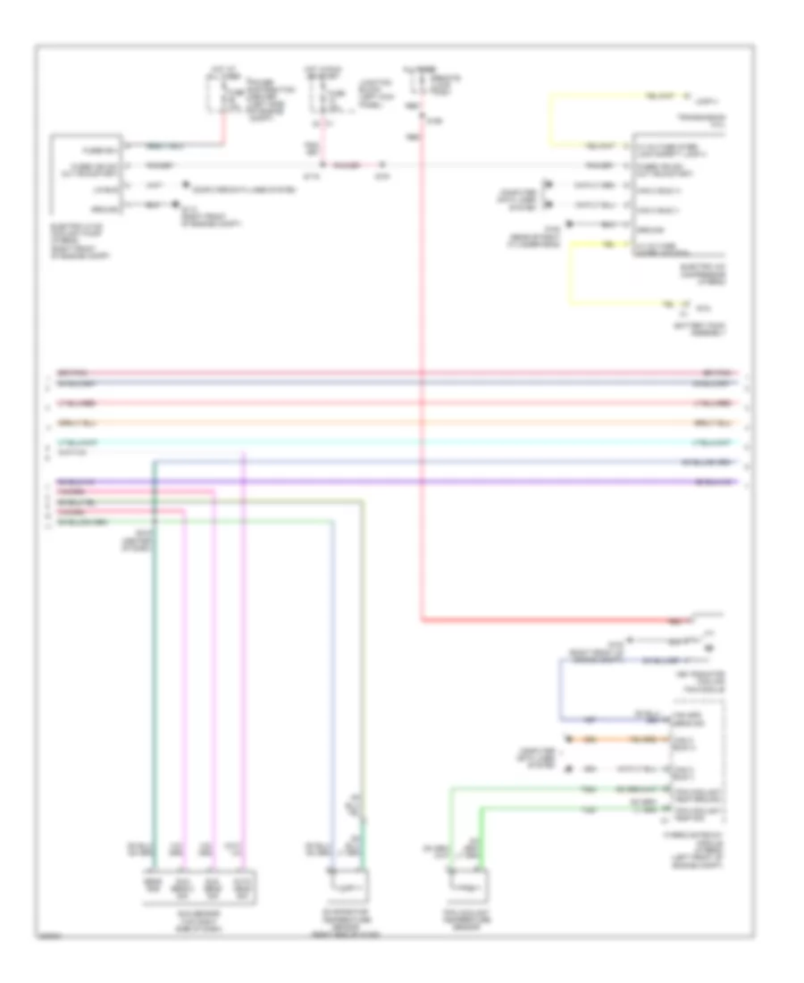
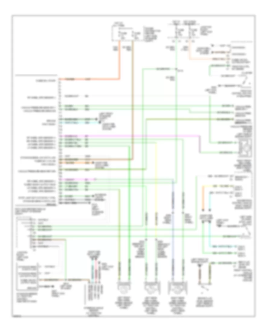
AIR CONDITIONING
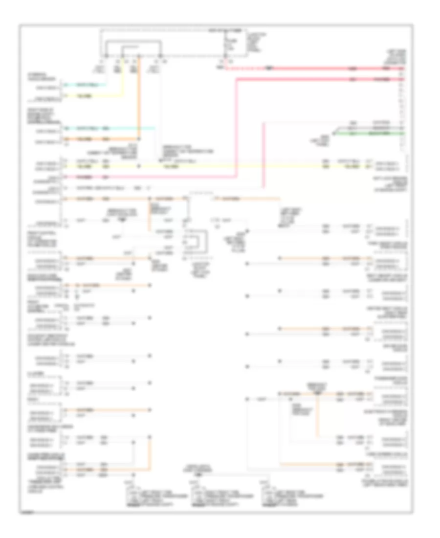
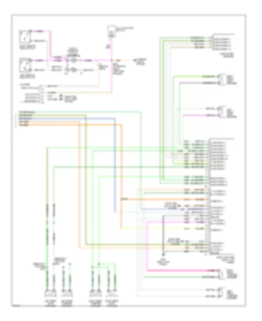
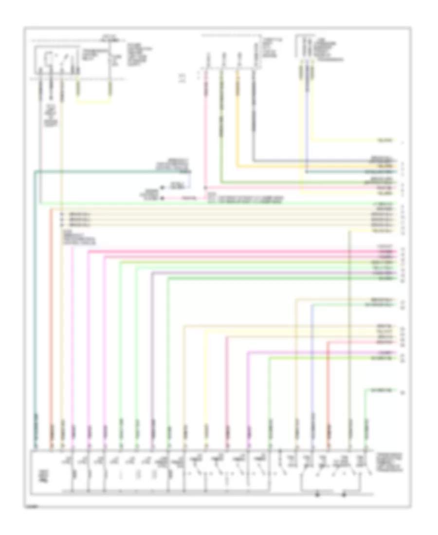
Automatic A/C Wiring Diagram (1 of 3) for Chrysler Aspen Limited Hybrid 2009

List of elements for Automatic A/C Wiring Diagram (1 of 3) for Chrysler Aspen Limited Hybrid 2009:
- (on hvac unit, near breakout for c202) s188
- (rear hvac) s346
- (right end of hvac) front blower power module
- (right kick panel) g207
- 87a
- A/c select
- A925
- Auto hdlp sig
- C121
- C151
- C152
- C153
- C154
- C21
- C22
- C29
- C32
- C34
- C53
- C54
- C56
- C61
- C800
- C801
- C802
- C803
- C804
- C805
- C806
- C807
- C808
- Can b bus (+)
- Can b bus (-)
- Common door driver 2
- Common door driver 3
- Computer data lines system
- D54
- D55
- E12
- Ebl select
- Evap temp sens sig
- Fr blower motor relay out
- Fr common door drv
- Front a/c heater module
- Front blend door driver
- Front blower control
- Front blower motor (right end of hvac)
- Front blower motor relay
- Front blower switch
- Front mode door actuator (floor to defrost)
- Front mode door actuator (floor to panel)
- Fuse 13 15a
- Fuse 24 10a
- Fuse 7 40a
- Fused b (+)
- G114 (left front of engine compt)
- G139
- G39
- Ground
- High
- Hot at all times
- Hot w/ run remote relay energized
- Hvac micro controller
- Illumination
- Interior lights system
- Junction block (left kick panel)
- L24
- Left blend door actuator
- Low
- Manual a/c circuit
- Med 1
- Med 2
- Medium
- Mode door 1 driver
- Mode door 2 driver
- Nca
- Off
- Panel drv lamp
- Pass blend door drv
- Power distribution center (left side of engine compt)
- Rear
- Rear blend door actuator (rear hvac)
- Rear blend door driver
- Rear blend sens
- Rear blower motor (rear hvac)
- Rear blower motor relay
- Rear blower motor resistor block (rear hvac)
- Rear blower switch
- Rear blower- medium
- Rear blower-high
- Rear blower-low
- Rear common door drv
- Rear mode door actuator
- Rear mode door driver
- Rear wash/ wipe
- Recirc door driver
- Recirculation door actuator
- Right blend door actuator
- S131
- S203
- S347 (rear hvac)
- Sens ground
- Sun sens 2 sig
- Sun sens sig
- Z24
- Z928
- Z961
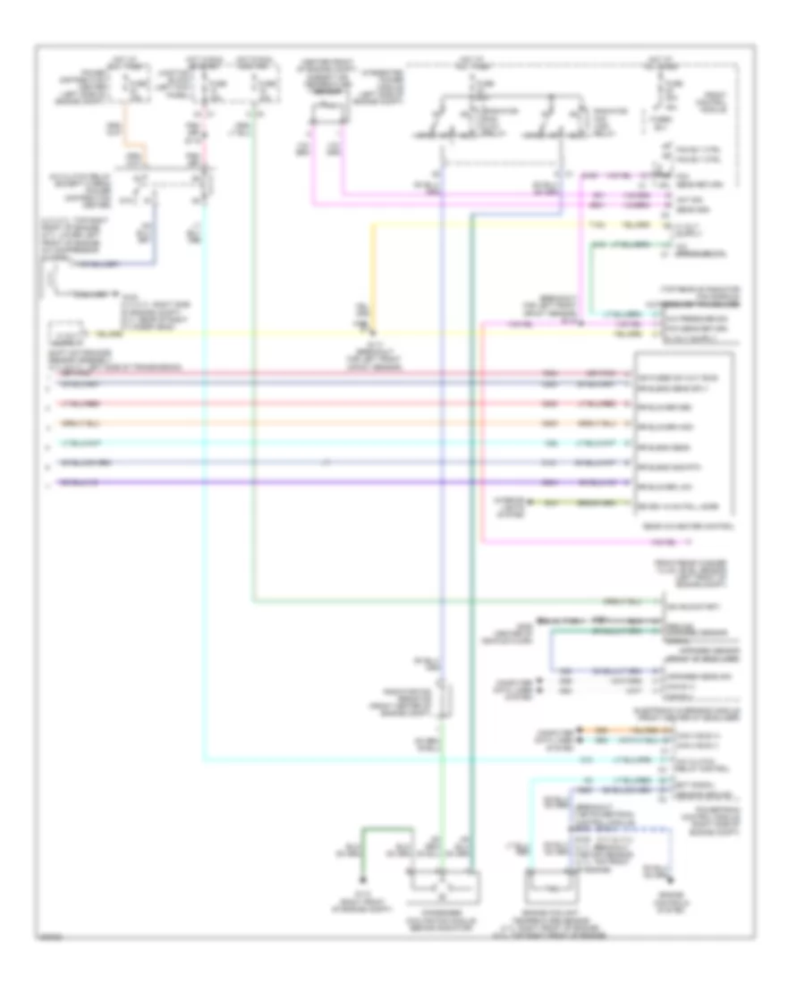
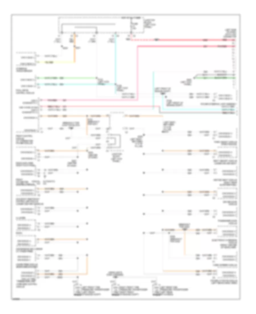
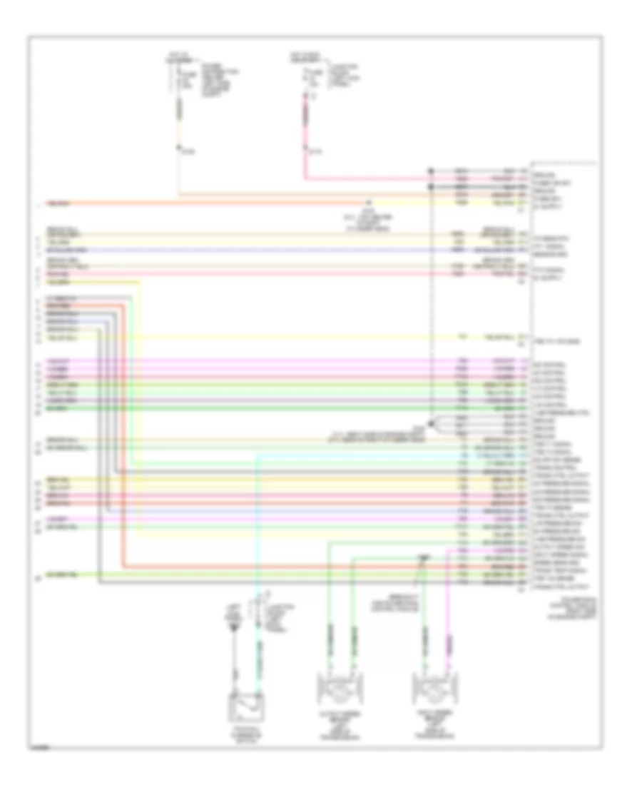
Automatic A/C Wiring Diagram (2 of 3) for Chrysler Aspen Limited Hybrid 2009
List of elements for Automatic A/C Wiring Diagram (2 of 3) for Chrysler Aspen Limited Hybrid 2009:
- All times
- Auto head sig
- Battery pack assembly
- Can c bus (+)
- Can c bus (-)
- Computer data lines system
- D64
- D65
- Electric a/c compressor (hybrid)
- Electric hvac coolant pump (hybrid) (right front of engine compt)
- Evaporator temperature sensor (right end of hvac)
- Fan spd sens sig
- Fuse 10a
- Fused b(+)
- Fused ign sw out (run-start)
- G100 (rear of right cylinder head)
- G103 (right front of engine compt)
- G112 (right front of engine compt)
- Ground
- Hev radiator cooling fan module
- Hi voltage inter- lock safety loop 4
- Hi voltage interlock rtn
- Hot at all times
- Hot in run or start
- Hybrid gateway module (hybrid) (left front of engine compt)
- Junction block (left kick panel)
- Lin bus
- Loop 4
- N27
- Power distribution center (left side of engine compt)
- Red
- Remote jump post
- Rtn
- S119
- S190
- S191
- S219 (center of dash)
- Sens gnd
- Sun sens 2 sig
- Sun sens sig
- Sun sensor (top right side of dash)
- T383
- T384
- Tpim coolant temp ground
- Tpim coolant temp sig c1
- Tpim coolant temperature sensor
- Transmission hvil
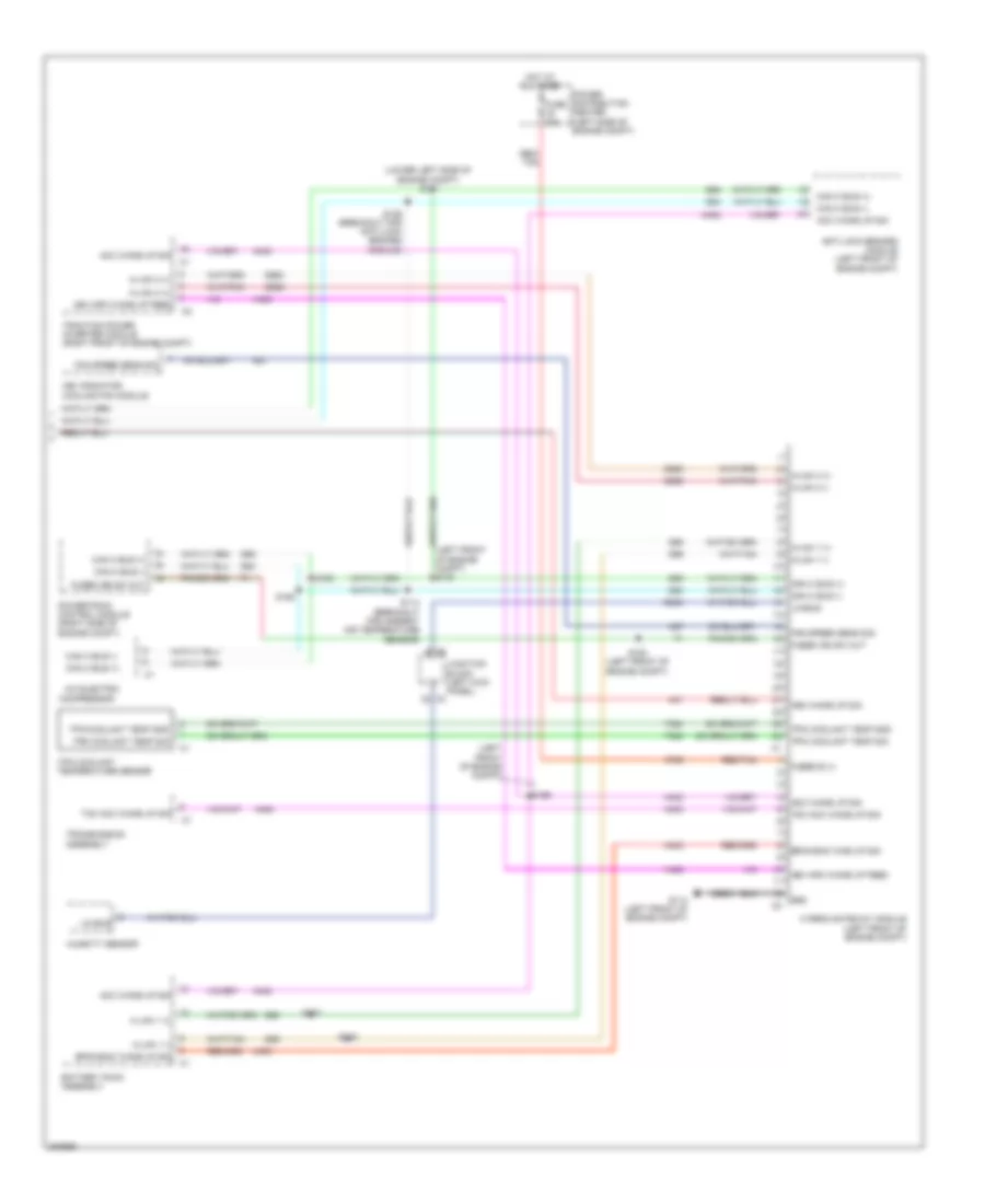
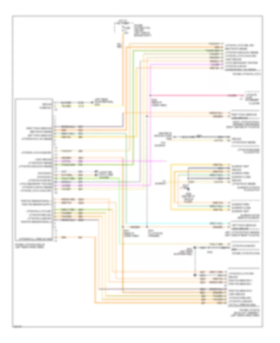
Automatic A/C Wiring Diagram (3 of 3) for Chrysler Aspen Limited Hybrid 2009
List of elements for Automatic A/C Wiring Diagram (3 of 3) for Chrysler Aspen Limited Hybrid 2009:
- (3.7l & 4.7l)
- (4.7l/3.7l: top right front of engine) (5.7l: lower left front of engine) a/c compressor clutch
- (5.7l)
- (breakout for left front impact sensor) s118
- (center front of engine compt) ambient air temperature sensor
- (top rear of radiator fan shroud) a/c pressure transducer
- 4wd
- 87a
- A/c clutch relay (except hybrid) (power distribution center)
- A/c clutch relay control
- A/c pressure sig
- A/c pressure sig c1
- Aat sig
- C121
- C13
- C18
- C22
- C800
- C802
- C803
- C804
- C83
- Can b (+)
- Can b (-)
- Can c bus (+)
- Can c bus (-)
- Computer data lines system
- Condenser cooling fan module (behind radiator)
- D54
- D55
- D64
- D65
- E10
- Ect signal
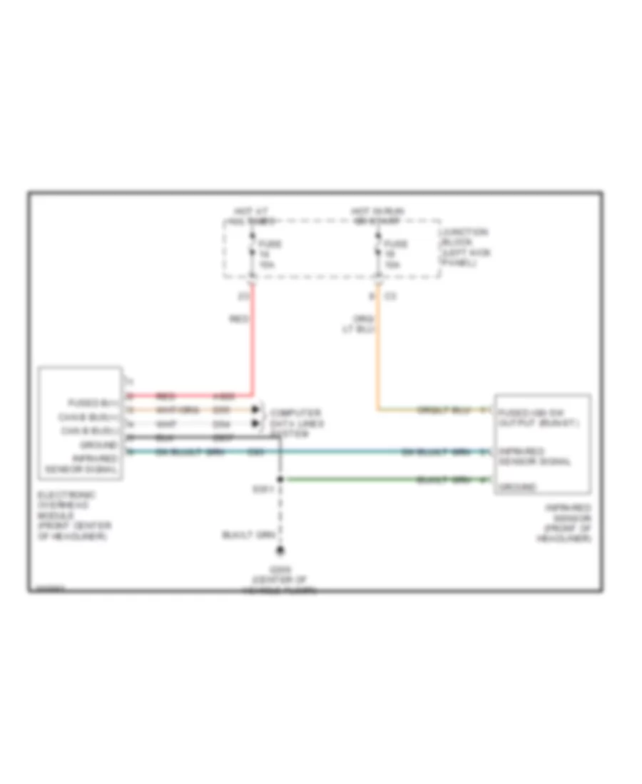
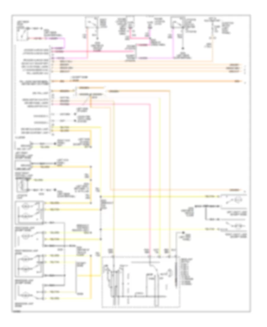
- Electronic overhead module (front center of headliner)
- Engine controls system
- Engine coolant temperature sensor (4.7l: right front of engine) (3.7l: top right front of engine)
- F504
- Fan rly ctrl
- Fcm sens return
- Fcm sens return ipm
- Front control module
- Front/rear washer fluid level sensor (left front of engine compt)
- Fuse 10a
- Fuse 15a
- Fuse 30a
- Fuse 40a
- Fused b(+)
- G100 (4.7l/3.7l: right side of engine compt) (5.7l: rear of right cylinder head)
- G112 (right front of engine compt)
- G180
- G306 (center of vehicle floor)
- G31
- G931
- Ground infrared sensor signal
- Hot at all times
- Hot in run or start
- Ign (run-start)
- Ign fused sw out (run)
- Infrared sens sig
- Infrared sensor (front of headliner)
- Integrated power module (left side of engine compt)
- Interior lights system
- Ipm
- Junction block (left kick panel)
- K900
- Power distribution center (left side of engine compt)
- Powertrain control module (right side of engine compt)
- Radiator fan high relay
- Radiator fan low relay
- Radiator fan resistor (front center of engine compt)
- Rear a/c-heater control
- Rr blend sens
- Rr blend sens sply
- Rr blend sns rtn
- Rr blower high
- Rr blower low
- Rr blower med
- Rr drv hvac pnl lamps
- S105 (3.7l: breakout for map sensor) (4.7l: top front of engine)
- S117 (breakout for left front impact sensor)
- S119
- S351
- Sens gnd
- Sensor ground
- Shift motor/mode sensor assembly (4.7l & 5.7l: left side of transmission)
- T103
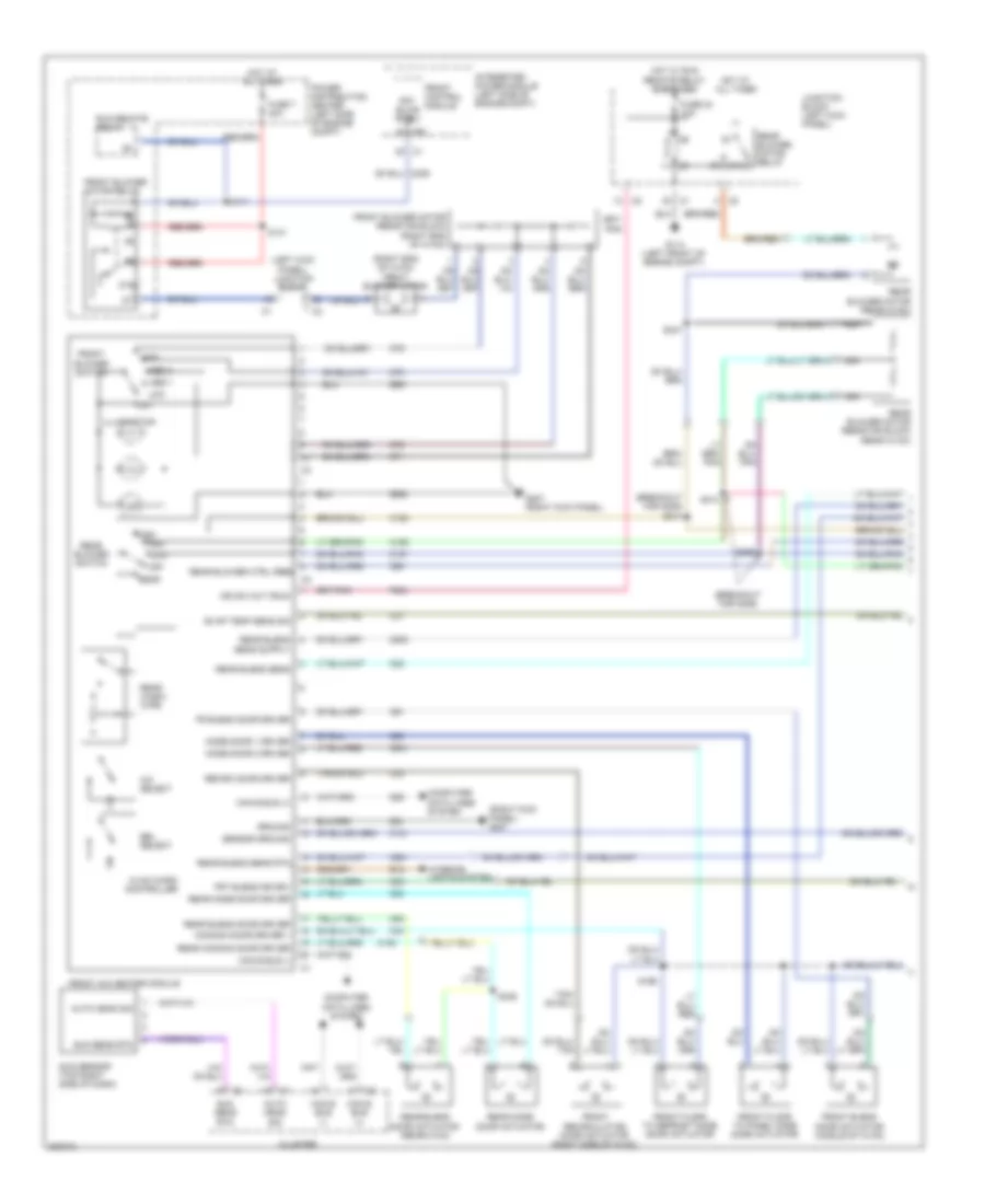
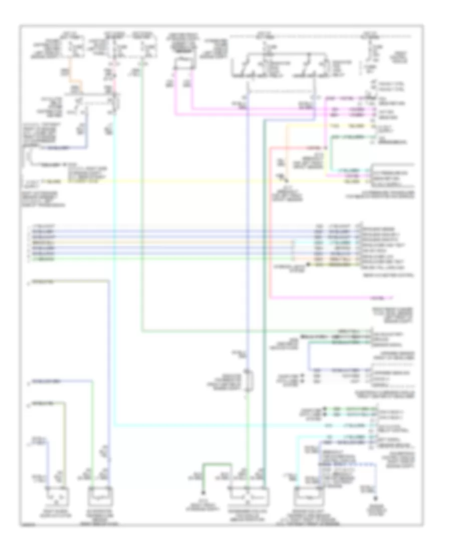
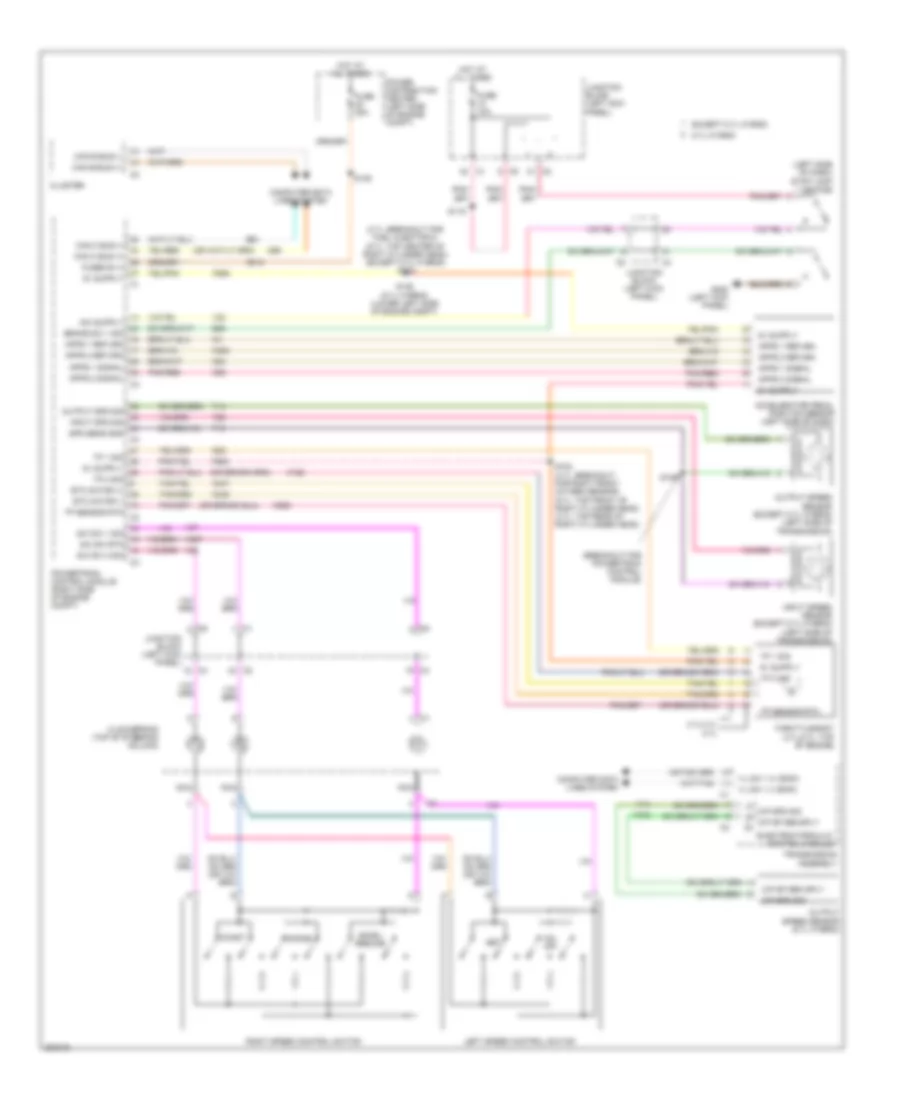
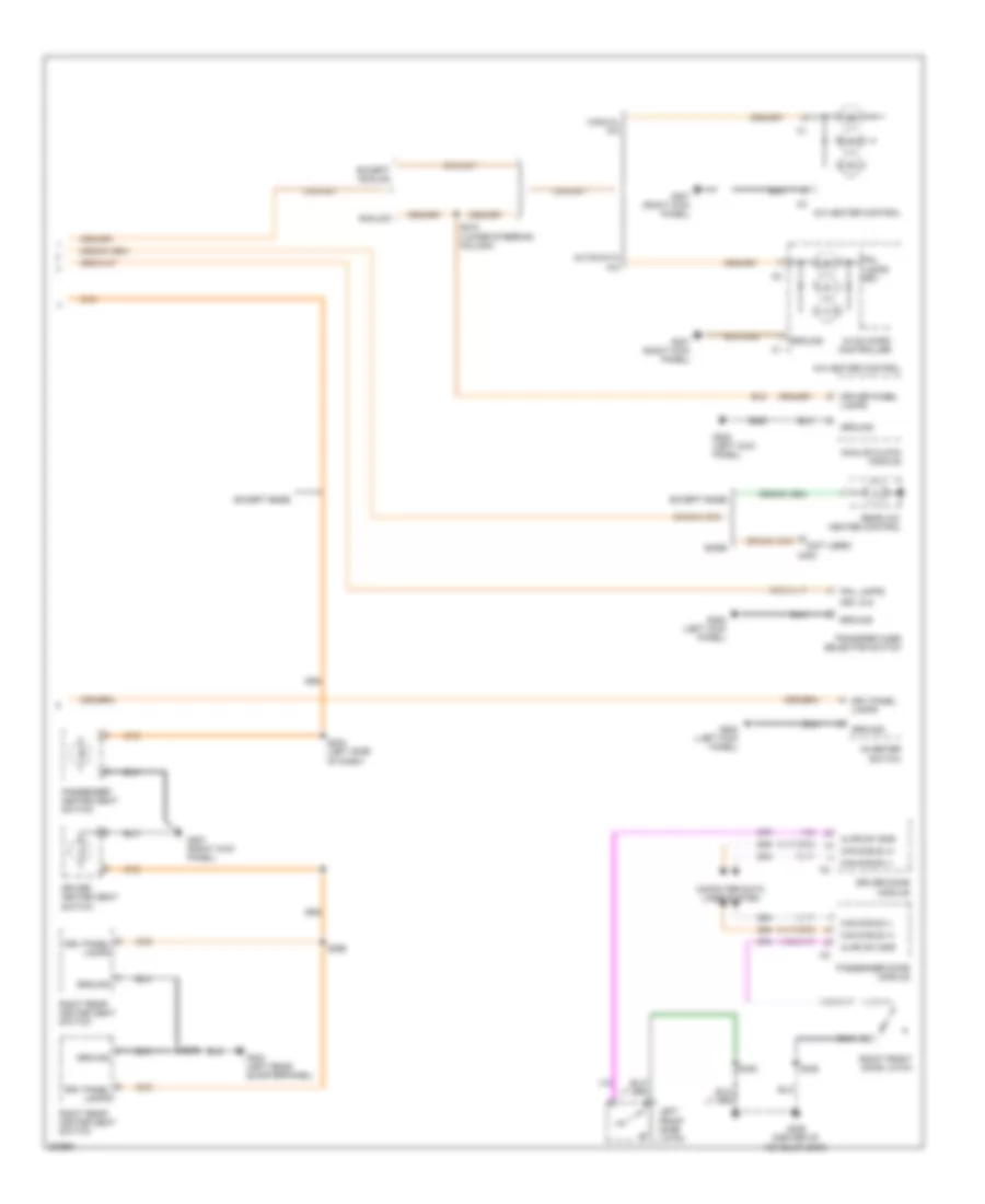
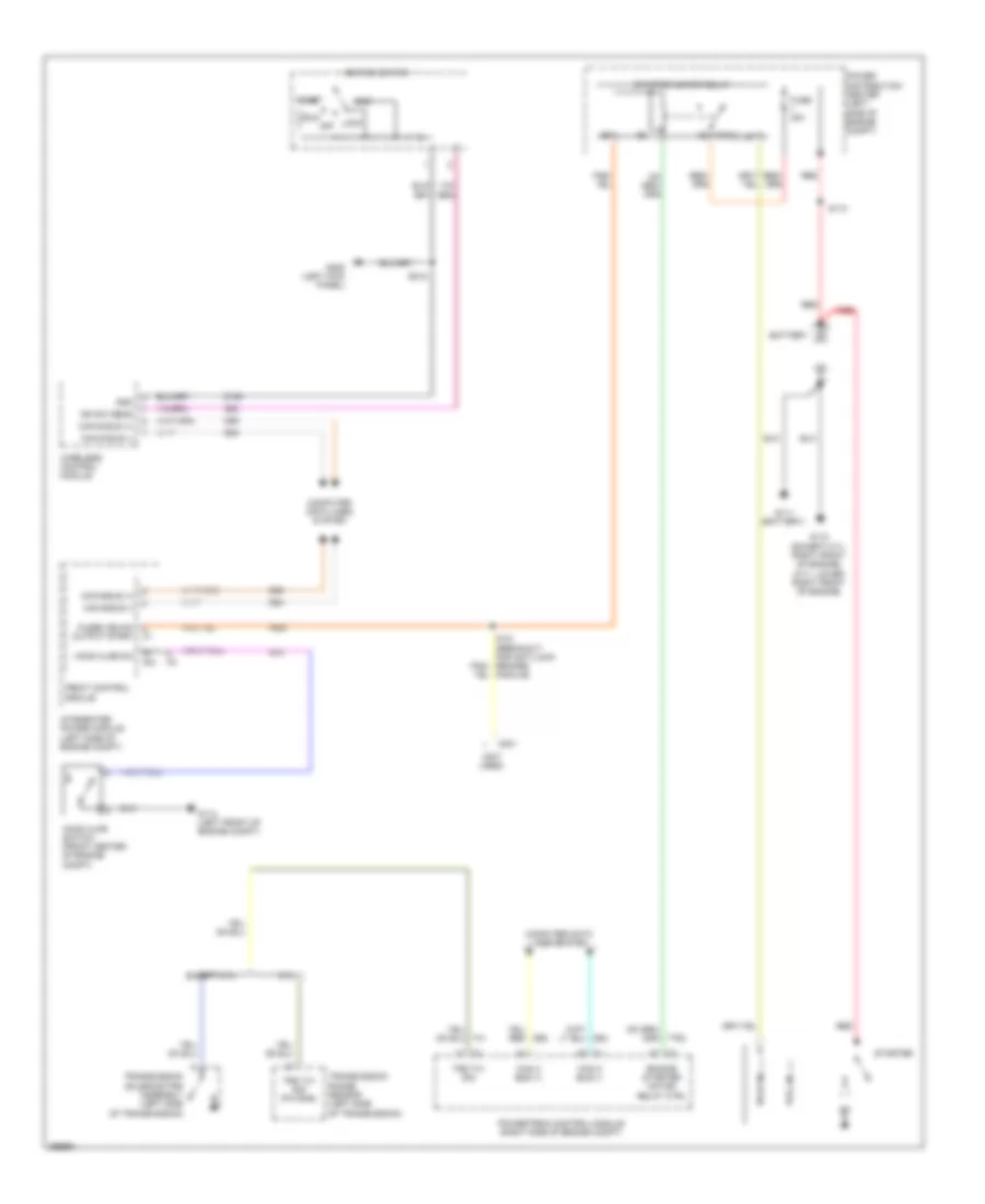
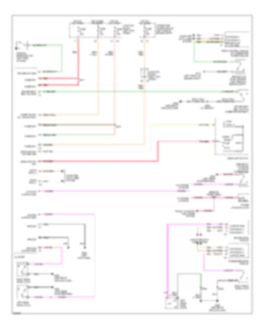
Manual A/C Wiring Diagram (1 of 2) for Chrysler Aspen Limited Hybrid 2009
List of elements for Manual A/C Wiring Diagram (1 of 2) for Chrysler Aspen Limited Hybrid 2009:
- (breakout for g306)
- (breakout for g306) s314
- (left kick panel) junction block
- (right end of hvac) front blower motor
- (right kick panel) g207
- 87a
- A/c select
- Auto head sig
- C121
- C151
- C152
- C153
- C154
- C21
- C22
- C29
- C32
- C33
- C34
- C50
- C53
- C54
- C61
- C71
- C72
- C73
- C75
- C800
- C801
- C931
- Can b bus (+)
- Can b bus (-)
- Cluster
- Common door driver 1
- Computer data lines system
- D54
- D55
- E12
- Ebl select
- Evap temp sens sig
- F504
- Fr blend door driver
- Front a/c heater module
- Front blend door actuator (middle of hvac)
- Front blower motor relay
- Front blower motor resistor block (right end of hvac)
- Front blower switch
- Front control module
- Front floor to defrost mode door actuator
- Front floor to panel mode door actuator
- Front recirculation door actuator (right side of hvac)
- Frt blend dr drv
- Frt blwr ctrl
- Fuse 24 10a
- Fuse 7 40a
- G114 (left front of engine compt)
- G207 (right kick panel)
- Ground
- High
- Hot at all times
- Hot w/ run remote relay energized
- Hvac micro controller
- Ign sw out (run)
- Illumination
- Integrated power module (left side of engine compt)
- Interior lights system
- Ipm
- Junction block (left kick panel)
- Low
- Med
- Med 1
- Med 2
- Mode door 1 driver
- Mode door 2 driver
- Nca
- Off
- Power distribution center (left side of engine compt)
- Rear
- Rear blend door actuator (rear hvac)
- Rear blend door driver
- Rear blend sens
- Rear blend sens rtn
- Rear blower ctrl feed
- Rear blower motor (rear hvac)
- Rear blower motor relay
- Rear blower motor resistor block (rear hvac)
- Rear blower switch
- Rear common door driver
- Rear mode door actuator
- Rear mode door driver
- Rear wash/ wipe
- Recirc door driver
- Run remote relay
- S111
- S131
- S196
- S313
- S346
- S347
- S359
- Sensor ground
- Sun sens rtn
- Sun sensor (top right side of dash)
- Z24
- Z928
- Z961
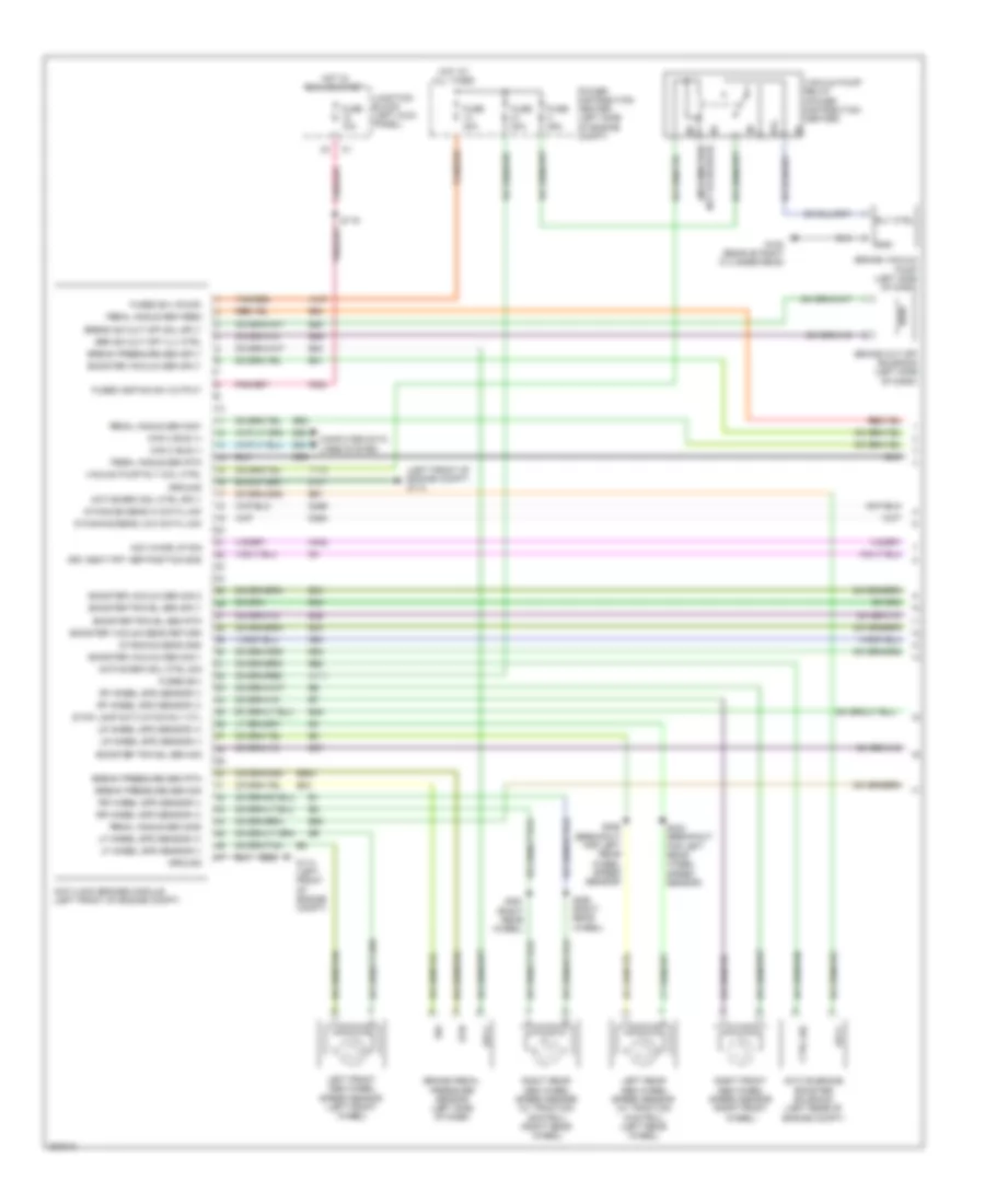
Manual A/C Wiring Diagram (2 of 2) for Chrysler Aspen Limited Hybrid 2009
List of elements for Manual A/C Wiring Diagram (2 of 2) for Chrysler Aspen Limited Hybrid 2009:
- (3.7l & 4.7l)
- (4.7l/3.7l: top right front of engine) (5.7l: lower left front of engine) a/c compressor clutch
- (5.7l)
- (center front of engine compt) ambient air temperature sensor
- 4wd
- 87a
- A/c clutch relay (power distribution center)
- A/c clutch relay control
- A/c pressure sig
- A/c pressure sig c1
- A/c pressure transducer (top rear of radiator fan shroud)
- Aat sig
- C13
- C18
- C22
- C800
- C802
- C803
- C804
- C83
- C931
- Can b (+)
- Can b (-)
- Can c bus (+)
- Can c bus (-)
- Computer data lines system
- Condenser cooling fan module (behind radiator)
- D54
- D55
- D64
- D65
- E10
- Ect signal
- Electronic overhead module (front center of headliner)
- Engine controls system
- Engine coolant temperature sensor (4.7l: right front of engine) (3.7l: top right front of engine)
- Evaporator temperature sensor (right end of hvac)
- F504
- Fan rly ctrl
- Fcm sens return ipm
- Front control module
- Front/rear washer fluid level sensor (left front of engine compt)
- Fuse 10a
- Fuse 15a
- Fuse 30a
- Fuse 40a
- Fused b(+)
- G100 (4.7l/3.7l: right side of engine compt) (5.7l: rear of right cylinder head)
- G112 (right front of engine compt)
- G180
- G306 (center of vehicle floor)
- G31
- G931
- Ground
- Hot at all times
- Hot in run or start
- Ign (run-start)
- Ign sw (run)
- Infrared sens sig
- Infrared sensor (front of headliner)
- Integrated power module (left side of engine compt)
- Interior lights system
- Ipm
- Junction block (left kick panel)
- K900
- Power distribution center (left side of engine compt)
- Powertrain control module (right side of engine compt)
- Radiator fan high relay
- Radiator fan low relay
- Radiator fan resistor (front center of engine compt)
- Rear a/c-heater control
- Right blend door actuator
- Rr blend sense
- Rr blend sns rtn
- Rr blend sns sply
- Rr blower high text
- Rr blower low
- Rr blower med text
- Rr drv pnl lmps high
- S117 (breakout for left front impact sensor)
- S118 (breakout for left front impact sensor)
- S119
- S351
- Sens gnd
- Sens return
- Sensor ground
- Sensor signal
- Shift motor/mode sensor assembly (4.7l & 5.7l: left side of transmission)
- T103
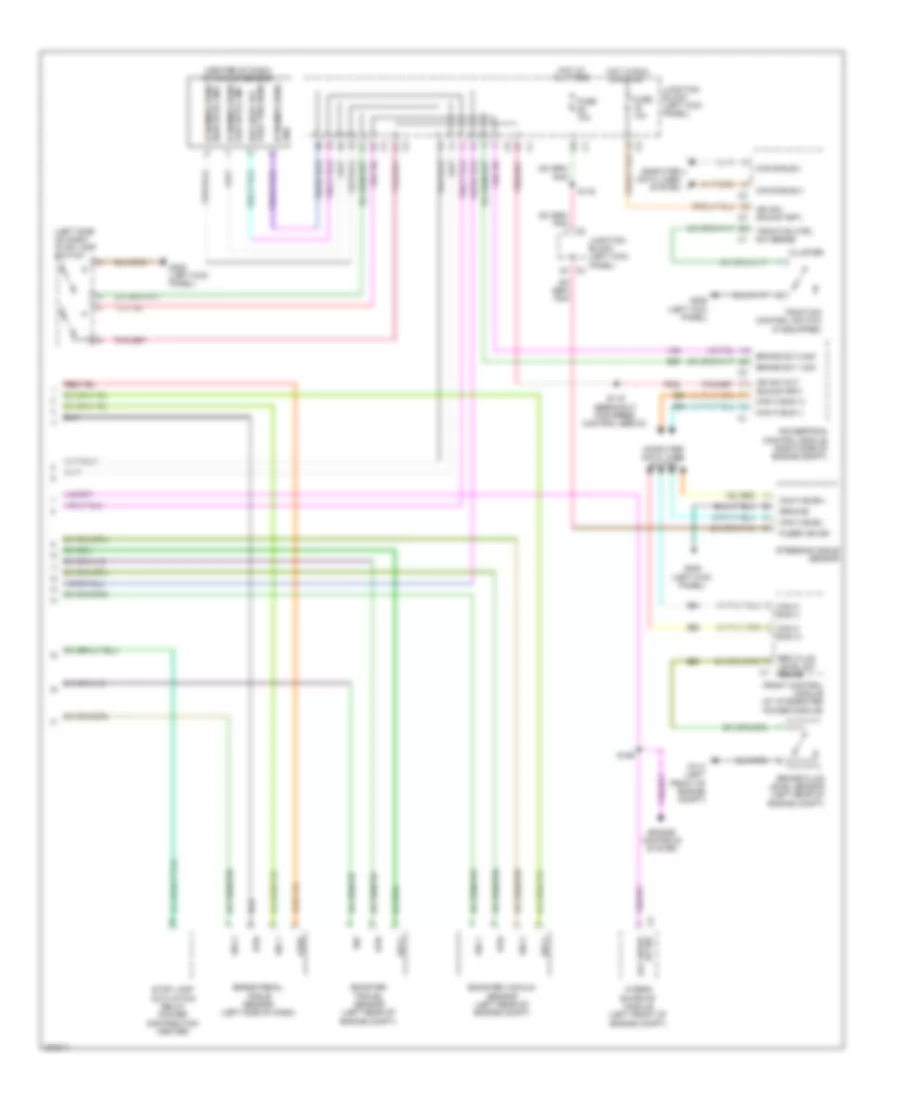
ANTI-LOCK BRAKES
Anti-lock Brakes Wiring Diagram, Except Hybrid for Chrysler Aspen Limited Hybrid 2009
List of elements for Anti-lock Brakes Wiring Diagram, Except Hybrid for Chrysler Aspen Limited Hybrid 2009:
- (left front of engine compt) g114
- (left kick panel) g208
- (left side of dash) stop lamp switch
- (w/ traction control)
- A can c bus(-)
- A107
- A111
- Anti-lock brakes module (left front of engine compt)
- B can c bus(+)
- B20
- B29
- B31
- B32
- B33
- B401
- Brake fluid level sensor (left rear of engine compt)
- Brake sw 1 signal
- Brk fluid level sw sense
- Can b bus(+)
- Can b bus(-)
- Can c bus (+)
- Can c bus (-)
- Can c bus (-) c1
- Can c bus(+)
- Can c bus(-)
- Cluster
- Computer data lines system
- D fused ign sw output (run)
- D464
- D465
- D64
- D65
- Dynamics sens hi data link
- Dynamics sens low data link
- Dynamics sensor (w/ traction control) (center of dash)
- Exterior lights system
- F500
- Front control module (at integrated power module)
- Fuse 10a
- Fuse 20a
- Fuse 40a
- Fused b(+) (pump)
- Fused b(+) (valve)
- Fused ign sw out(run-start)
- Fused ign sw output (run)
- G114 (left front of engine compt)
- G207 (right kick panel)
- G208 (left kick panel)
- Ground
- Hot at all times
- Hot in run
- Hot in run or start
- Junction block (left kick panel)
- Left front abs wheel speed sensor (left front wheel)
- Left rear abs wheel speed sensor (w/ traction control) (left rear wheel)
- Lf wheel spd sensor (+)
- Lf wheel spd sensor (-)
- Lr wheel spd sensor (+)
- Lr wheel spd sensor (-)
- Power distribution center (left side of engine compt)
- Powertrain control module (right side of engine compt)
- Rf wheel spd sensor (+)
- Rf wheel spd sensor (-)
- Right front abs wheel speed sensor (right front wheel)
- Right rear abs wheel speed sensor (w/ traction control) (right rear wheel)
- Rr wheel spd sensor (+)
- Rr wheel spd sensor (-)
- S116
- S212 (left side of dash)
- S334 (breakout for left rear wheel speed sensor)
- S358 (breakout for left rear wheel speed sensor)
- S360 (right rear wheel)
- S361 (right rear wheel)
- Steering angle sensor
- Stop lamp activation rly ctrl
- Tan/ red
- Tan/red
- Traction control switch (if equipped)
- Traction ctrl sw sense
- Vacuum pres sens rtn
- Vacuum pres sens sig
- Vacuum pres sens sply
- Vacuum pressure sens return
- Vacuum pressure sens sig
- Vacuum pressure sens sply
- Vacuum pressure sensor (w/ esp) (left side of engine compt)
- Z107
- Z923
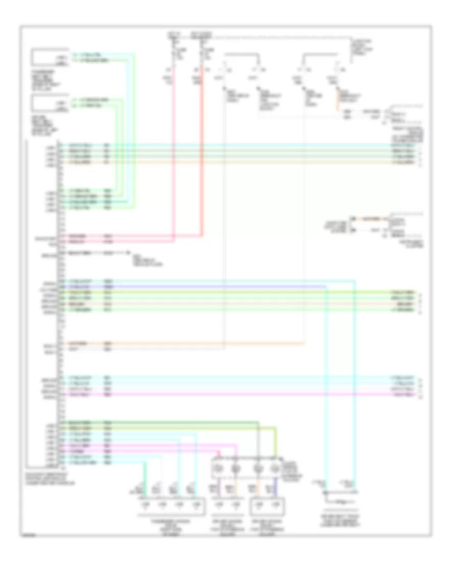
Anti-lock Brakes Wiring Diagram, Hybrid (1 of 2) for Chrysler Aspen Limited Hybrid 2009
List of elements for Anti-lock Brakes Wiring Diagram, Hybrid (1 of 2) for Chrysler Aspen Limited Hybrid 2009:
- (information not available)
- (left front of engine compt) g114
- 87a
- A107
- A111
- Acc wake up sig
- Active brake booster solenoid (left rear of engine compt)
- Active brk sol ctrl sig
- Active brk sol ctrl sply
- Anti-lock brakes module (left front of engine compt)
- B31
- B32
- B33
- B34
- B35
- B36
- B37
- B45
- B52
- B53
- B54
- B56
- B58
- B59
- B61
- B62
- B83
- B84
- B984
- Booster travel sen rtn
- Booster travel sen sig
- Booster travel sen sply
- Booster vacuum sen sig 1
- Booster vacuum sen sig 2
- Booster vacuum sen sply
- Booster vacuum sens return
- Brake cut off solenoid (left side of dash)
- Brake pedal pressure sensor (left side of dash)
- Brake vacuum pump (left side of dash)
- Break pressure sen rtn
- Break pressure sen sig
- Break pressure sen sply
- Break sim cut off sol sply
- Brk sim cut off vlv ctrl
- Can c bus (+)
- Can c bus (-)
- Computer data lines system
- Ctrl sig
- D464
- D465
- D64
- D65
- Drv seat frt ver position sns
- Dynamics sens gnd
- Dynamics sens hi data link
- Dynamics sens low data link
- F202
- Fuse 10a
- Fuse 20a
- Fuse 25a
- Fuse 40a
- Fused b(+)
- Fused b(+) (pump)
- Fused igntion sw output
- G100 (rear of right cylinder head)
- G114 (left front of engine compt)
- G94
- Gnd
- Ground
- H402
- Hot at all times
- Hot in run or start
- Junction block (left kick panel)
- Left front abs wheel speed sensor (left front wheel)
- Left rear abs wheel speed sensor (w/ traction control) (left rear wheel)
- Lf wheel spd sensor (+)
- Lf wheel spd sensor (-)
- Lr wheel spd sensor (+)
- Lr wheel spd sensor (-)
- Pedal angle sen feed
- Pedal angle sen rtn
- Pedal angle sen sig1
- Pedal angle sen sig2
- Power distribution center (left side of engine compt)
- Rf wheel spd sensor (+)
- Rf wheel spd sensor (-)
- Right front abs wheel speed sensor (right front wheel)
- Right rear abs wheel speed sensor (w/ traction control) (right rear wheel)
- Rly ctrl
- Rr wheel spd sensor (+)
- Rr wheel spd sensor (-)
- Rtn
- S119
- S334 (breakout for left rear wheel speed sensor)
- S358 (breakout for left rear wheel speed sensor)
- S360 (right rear wheel)
- S361 (right rear wheel)
- Sig
- Sply
- Stop lamp activation rly ctl
- T110
- Tan/red
- Vacuum pump relay (power distribution center)
- Vacuum pump rly coil ctrl
- Z107
- Z923
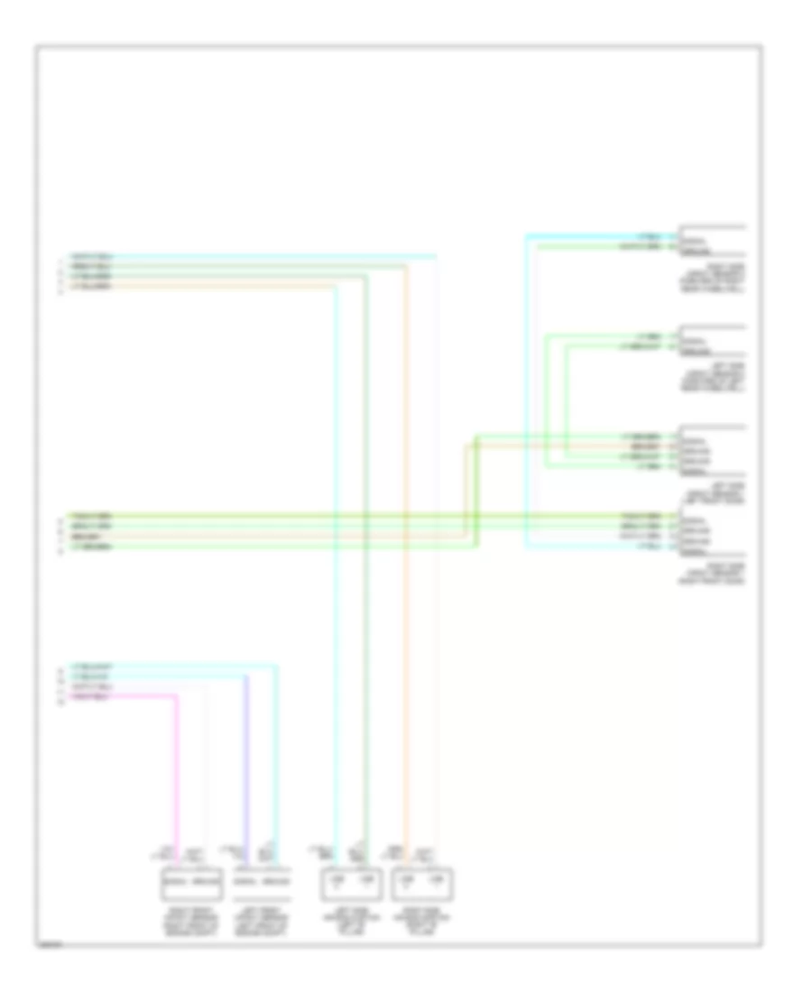
Anti-lock Brakes Wiring Diagram, Hybrid (2 of 2) for Chrysler Aspen Limited Hybrid 2009
List of elements for Anti-lock Brakes Wiring Diagram, Hybrid (2 of 2) for Chrysler Aspen Limited Hybrid 2009:
- (center of dash) dynamics sensor
- (left side of dash) stop lamp switch
- B20
- B29
- Booster travel sensor (left rear of engine compt)
- Booster vacuum sensor (left rear of engine compt)
- Brake fluid level sensor (left rear of engine compt)
- Brake pedal angle sensor (left side of dash)
- Brake sw 1 sig
- Brake sw 2 sig
- Brk fluid level sw sense
- Can b bus(+)
- Can b bus(-)
- Can c bus (+)
- Can c bus (-)
- Can c bus(+)
- Can c bus(-)
- Cluster
- Computer data lines system
- D64
- D65
- Drv seat frt vert pos sens
- Dynamics sens gnd
- Engine controls system
- F202
- Feed
- Front control module (at integrated power module)
- Fuse 10a
- Fused ign sw
- G114 (left front of engine compt)
- G208 (left kick panel)
- Ground
- High data link dynamics sens
- Hot at all times
- Hot in run or start
- Hybrid gateway module (left front of engine compt)
- Ign sw (run-start)
- Ign sw out (run-start)
- Junction block (left kick panel)
- Low data link dynamics sens
- Powertrain control module (right side of engine compt)
- Rtn
- S116
- S119 (breakout for speed control servo)
- S159
- Sig
- Sig 1
- Sig 2
- Sply
- Steering angle sensor
- Stop lamp activation relay (power distribution center)
- Traction control switch (if equipped)
- Traction ctrl sw sense
- Up sig acc wake
- V32
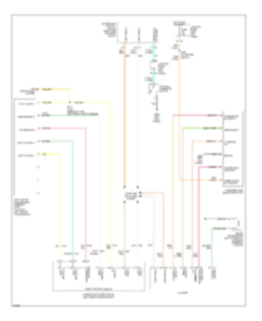
ANTI-THEFT
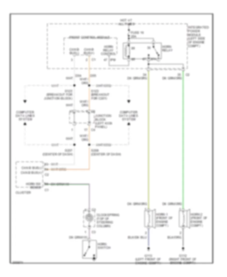
Anti-theft Wiring Diagram for Chrysler Aspen Limited Hybrid 2009
List of elements for Anti-theft Wiring Diagram for Chrysler Aspen Limited Hybrid 2009:
- (center of vehicle floor) g306
- (front center of engine compt) (except 5.7l hybrid) hood ajar switch
- (left body, between "a" & "b" pillar) s310
- (left rear quarterpanel) g304
- (rear of cargo area) s340
- (right body, between "a" & "b" pillar)
- 87a
- A926
- Acc
- Accessory delay relay
- Cab b bus (+)
- Cab b bus (-)
- Can b bus (+)
- Can b bus (-)
- Can c bus (+)
- Can c bus (+) c1
- Can c bus (-)
- Circuit breaker 25a
- Cluster
- Com-lin
- Computer data lines system
- D508
- D54
- D55
- D64
- D65
- Dr lk drv lf
- Dr lk drv lh drs
- Dr lk drv rh drs
- Dr unlk drv lr/lift
- Dr unlk drv rh drs
- Driver door module
- Driver window/ door lock switch
- Drv door ajar sw sense
- Drv exp window sw rtn
- F20
- F30
- Front control module
- Fuse 15a
- Fuse 16 20a
- Fused acc delay rly output
- Fused acc rly out
- Fused b (+)
- Fused ign sw out
- G112 (right front of engine compt)
- G114 (left front of engine compt)
- G160
- G161
- G20
- G208 (left kick panel)
- G306 (center of vehicle floor)
- G64
- G65
- G70
- G74
- G75
- G775
- G776
- G79
- Ground
- Headlights system
- Hood ajar sw
- Hood ajar sw sens c4
- Hood ajar switch 2 (5.7 hybrid)
- Horn relay
- Horn rly ctrl ipm
- Horns system
- Hot at all times
- If equipped
- Ign sw sense
- Ignition switch
- Integrated power module (left front of engine compt)
- Junction block (left kick panel)
- L33
- L34
- Left door lock sw mux
- Left door lock sw rtn
- Left front door latch
- Left front tire pressure transponder (left front of engine compt)
- Left rear door latch
- Left rear tire pressure transponder (left rear of chassis)
- Lh hi bm drv
- Lift ajar sw sense
- Lift ajar sw sns
- Liftgate ajar switch (center of liftgate)
- Lock
- Logic ground
- Lr dr ajar sw sns
- Manual release liftgate latch (w/o power liftgate)
- Master sw lf window mux
- Master sw rf window mux
- Off
- Pass door ajar sw sense
- Passenger door module
- Passenger window/ door lock switch
- Power liftgate latch
- Power liftgate module (left rear cargo area)
- Powertrain control module (right side of engine compt)
- Q221
- Q222
- Q994
- Red
- Rh hi bm drv c2
- Right door lock sw mux
- Right door lock sw rtn
- Right front door latch
- Right front tire pressure transponder (right front of engine compt)
- Right rear door latch
- Rr dr ajar sw sns
- Run
- S200
- S214
- S218
- S302 (w/o power liftgate) (left rear door sill)
- S308
- S315
- S316
- S328
- S341 (rear of cargo area)
- S344 (in liftgate harness)
- S353
- S354
- S355
- Start
- Trunk, tailgate, fuel doors system
- W/ memory
- W/ power liftgate
- W/o power liftgate
- Wireless control module
- Z109
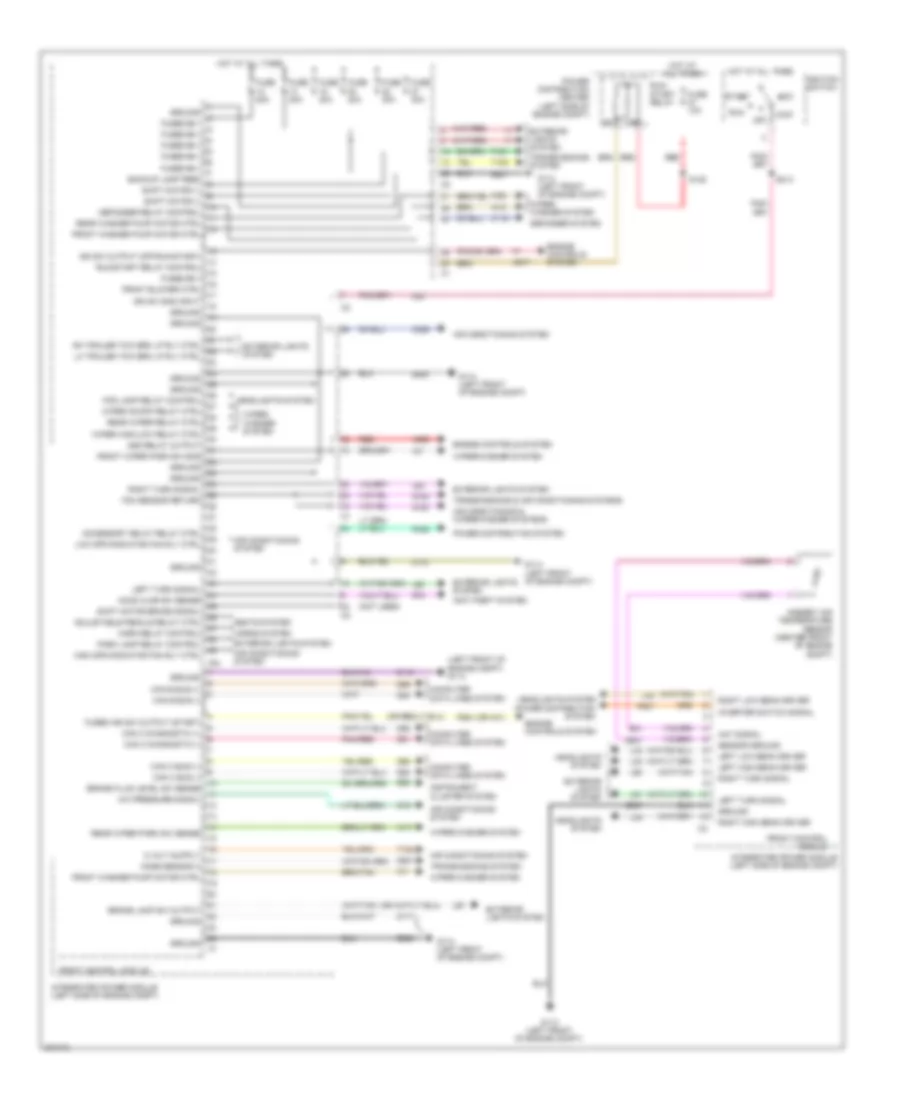
BODY CONTROL MODULES
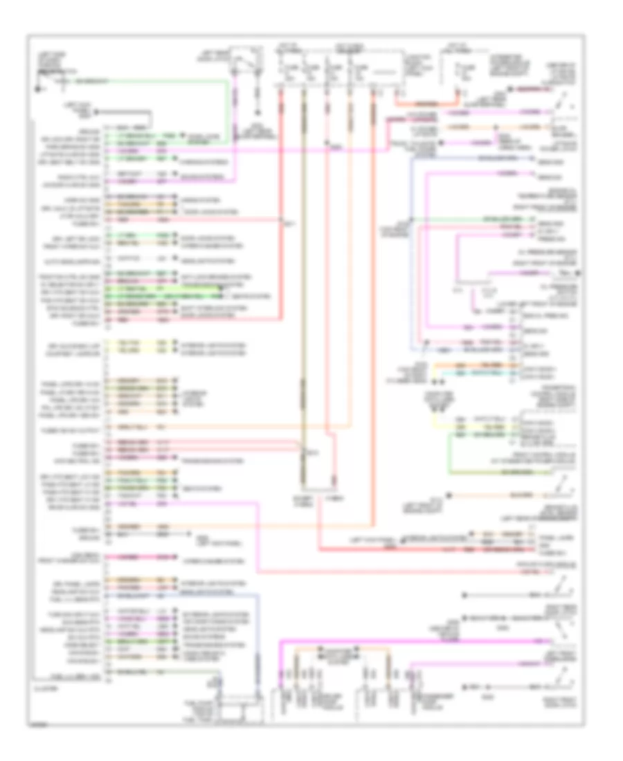
Body Control Modules Wiring Diagram for Chrysler Aspen Limited Hybrid 2009
List of elements for Body Control Modules Wiring Diagram for Chrysler Aspen Limited Hybrid 2009:
- (left front of engine compt) g114
- (not used)
- (or h31)
- A/c pressure signal
- A955
- Aat signal
- Acc
- Accessory delay relay ctrl
- Adjustable pedals relay ctrl
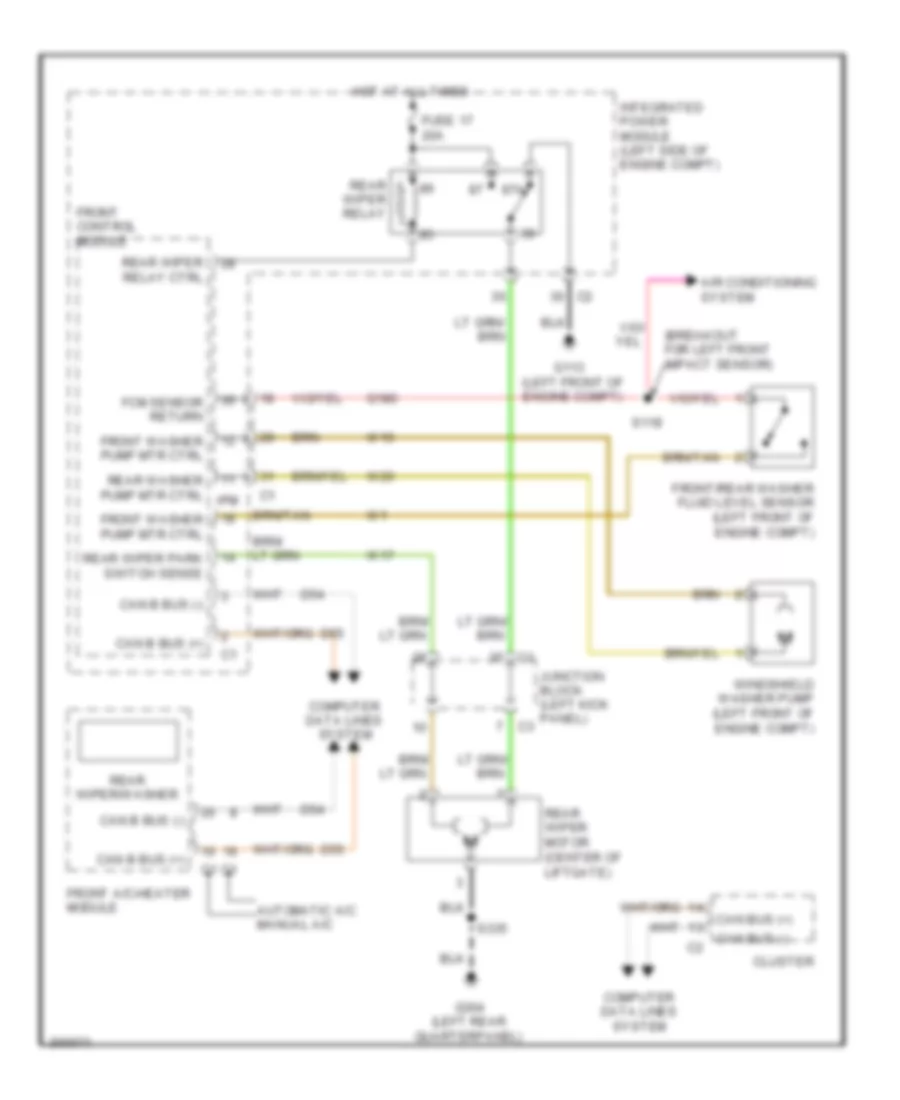
- Air conditioning & wiper/washer systems
- Air conditioning system
- Ambient air temperature sensor (center front of engine compt)
- Anti-theft system
- Asd relay output
- B20
- Backup lamp feed
- Brake fluid level sw sense
- Brake lamp sw output
- C115
- C18
- C229
- Can b bus (+)
- Can b bus (-)
- Can c bus (+)
- Can c bus (-)
- Can c diagnostic (+)
- Can c diagnostic (-)
- Computer data lines system
- D201
- D51
- D52
- D54
- D55
- D64
- D65
- Defogger relay control
- Defogger system
- Engine controls system
- Exterior lights system
- F20
- F924
- Fcm sensor return
- Fog lamp relay control
- Front blower ctrl
- Front control module
- Front washer pump motor ctrl
- Front wiper park sw sns
- Fuse 10a
- Fuse 20a
- Fuse 30a
- Fused b(+)
- Fused ign sw output (start)
- G113 (left front of engine compt)
- G114 (left front of engine compt)
- G180
- G31
- G70
- G931
- Ground
- Headlights system
- High spd radiator fan rly ctrl
- Hood ajar sw sense
- Horn relay control
- Horns system
- Hot at all times
- Ign sw output (off-run-start)
- Ign sw sns input
- Ignition switch
- Instrument cluster system
- Integrated power module (left side of engine compt)
- Inverter switch signal
- Ipm
- K617
- L33
- L34
- L43
- L44
- L50
- L60
- L61
- L62
- L63
- Left high beam driver
- Left low beam driver
- Left turn signal
- Lh trailer tow brk lp rly ctrl
- Lock
- Low spd radiator fan rly ctrl
- Mode sensor a
- Off
- P305
- P807
- Park lamp relay control
- Pnk/red
- Power distribution center (left side of engine compt)
- Power distribution system
- Rear washer pump motor ctrl
- Rear wiper park sw sense
- Rear wiper relay ctrl
- Red
- Rh trailer tow brk lp rly ctrl
- Right high beam driver
- Right low beam driver
- Right turn signal
- Run
- Run/ start relay
- Run/start relay control
- S128
- S214
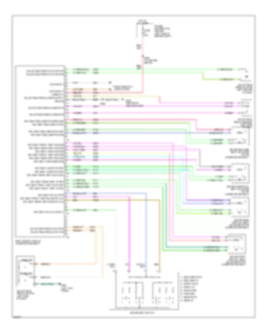
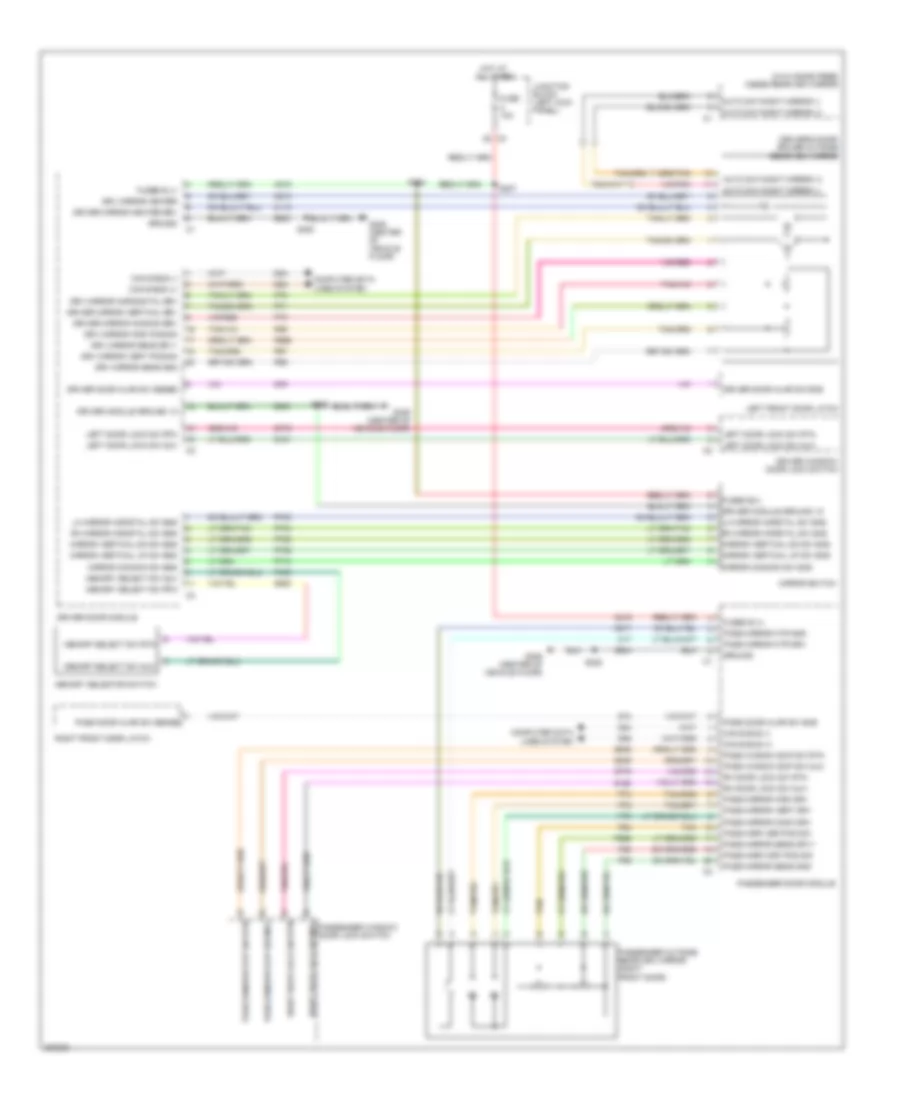
- Seats system
- Sensor ground
- Shift motor (+)
- Shift motor (-)
- Shift motor brake signal
- Start
- T101
- T102
- T103
- Transmissions & air conditioning systems
- Transmissions system
- W10
- W17
- W20
- Wiper high/low relay ctrl
- Wiper on/off relay ctrl
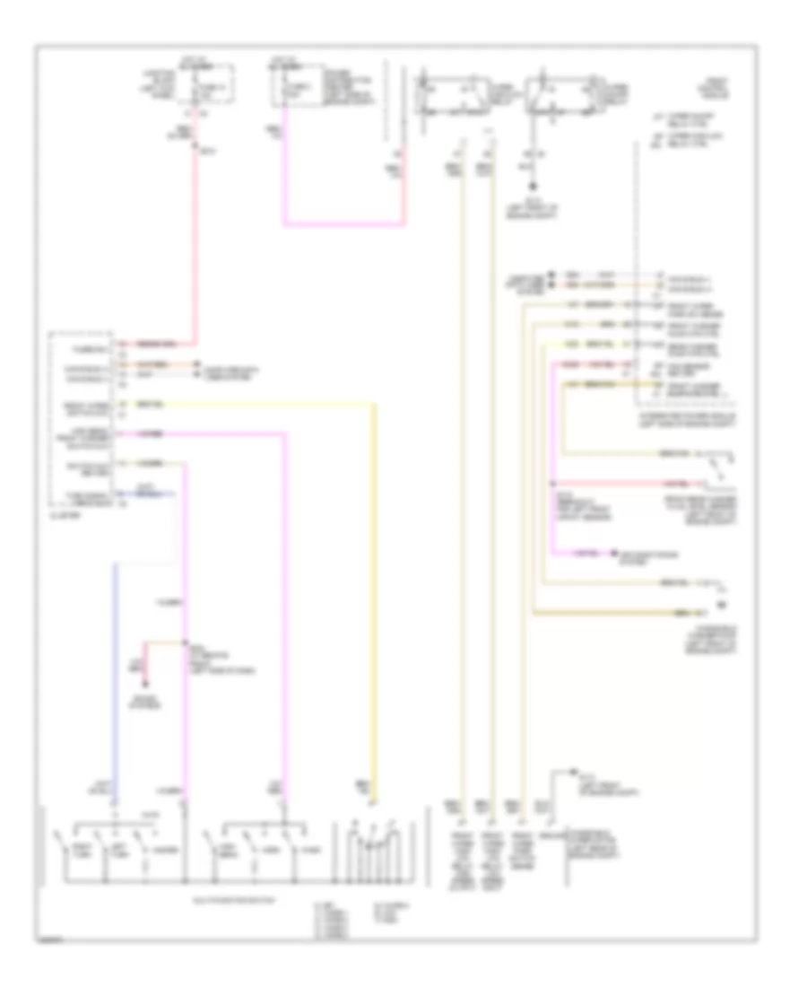
- Wiper/ washer system
- Wiper/washer system
- Z116
- Z117
- Z118
- Z909
- Z921
- Z947
- Z965
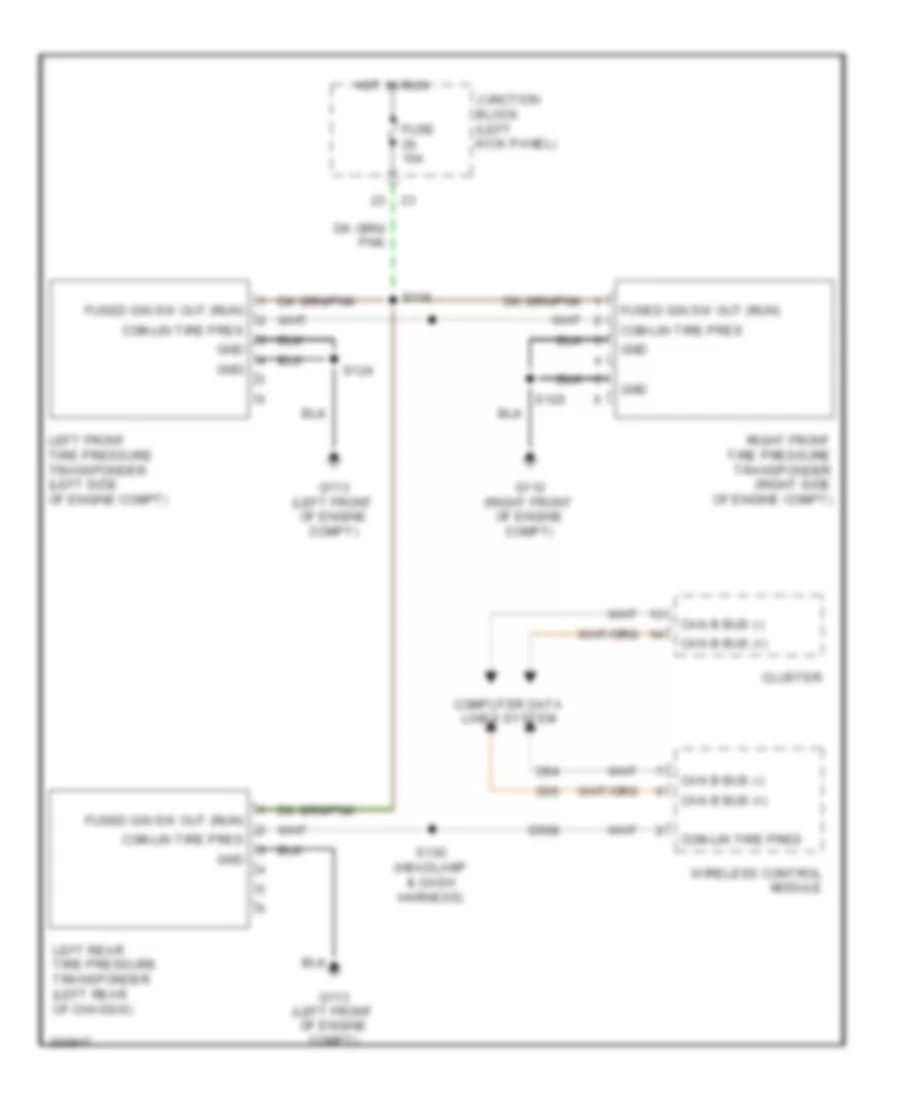
COMPUTER DATA LINES
Computer Data Lines Wiring Diagram, Except Hybrid for Chrysler Aspen Limited Hybrid 2009
List of elements for Computer Data Lines Wiring Diagram, Except Hybrid for Chrysler Aspen Limited Hybrid 2009:
- (breakout for ambient air temperature sensor) s115
- (breakout for c222) s325
- (breakout for junction block) s125
- (front center of headliner)
- (headlamp & dash harness) s130
- (left body, between "a" & "b" pillar) s310
- (left side of dash) data link connector
- (right side of engine compt) powertrain control module
- A926
- Anti-lock brakes module (left front of engine compt)
- Automatic a/c
- Can b bus (+)
- Can b bus (-)
- Can c bus (+)
- Can c bus (-)
- Can c diagnostic (+)
- Can c diagnostic (-)
- Cluster
- Com- lin tire press
- Com-lin tire press moni lan
- D508
- D51
- D52
- D54
- D55
- D64
- D65
- Driver door module
- Electronic overhead module
- Front a/c-heater control
- Front control module (at integrated power module)
- Fuse 15a
- G208 (left kick panel)
- Hands free module (right end of dash)
- Heated seat module (right rear quarterpanel)
- Hot at all times
- Inside rearview mirror (w/ hands free)
- Junction block (left kick panel)
- Left front tire pressure transponder (left front of engine compt)
- Left rear tire pressure transponder (left rear of chassis)
- Manual a/c
- Occupant restraint controller module (under center console)
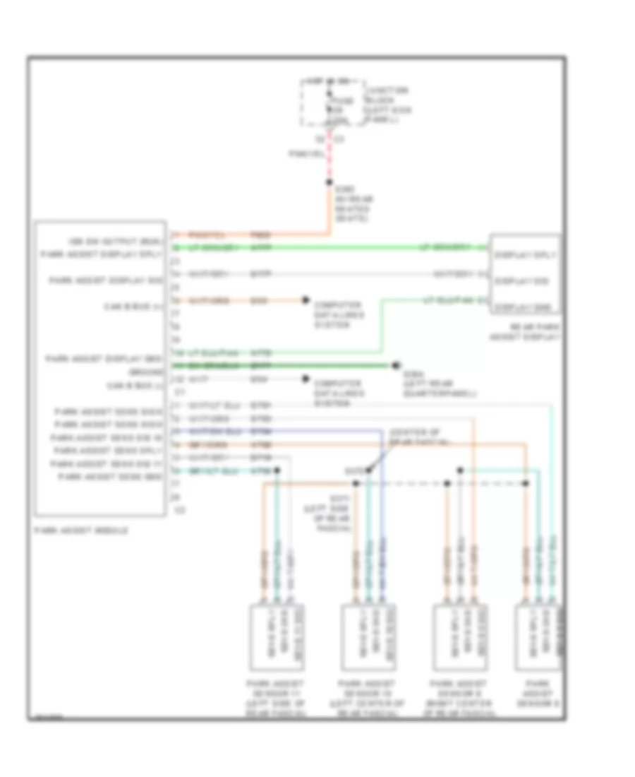
- Park assist module (parktronics)
- Passenger door module
- Pnk/red
- Power liftgate module (left rear cargo area)
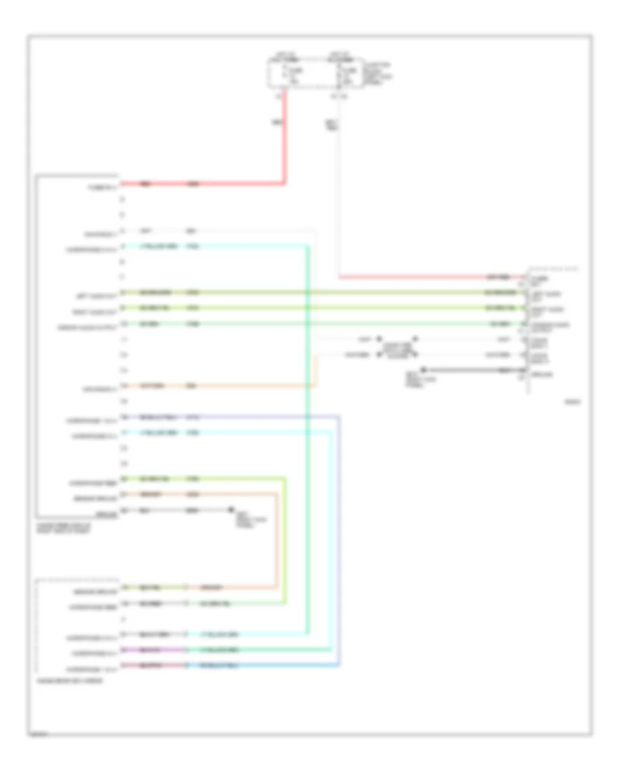
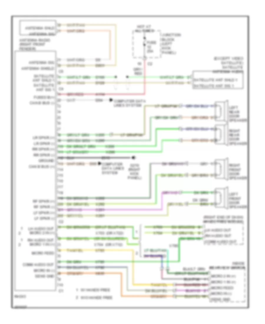
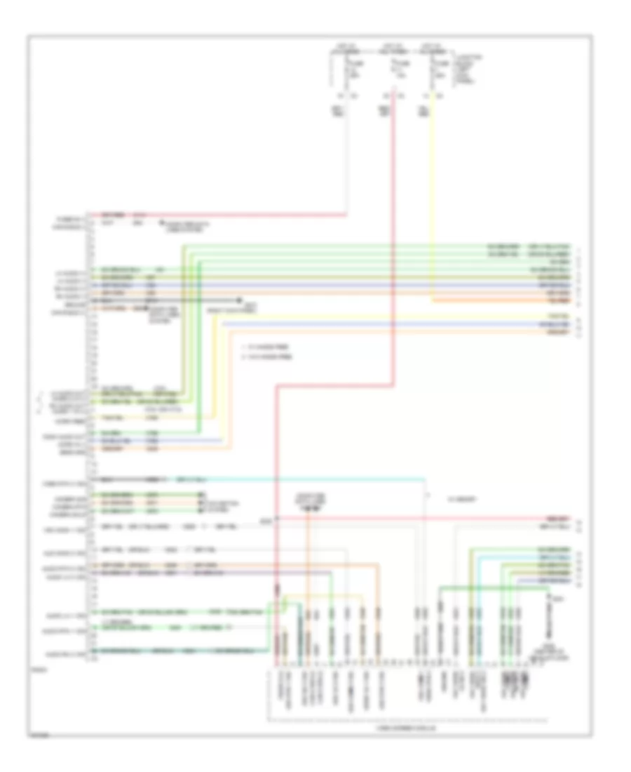
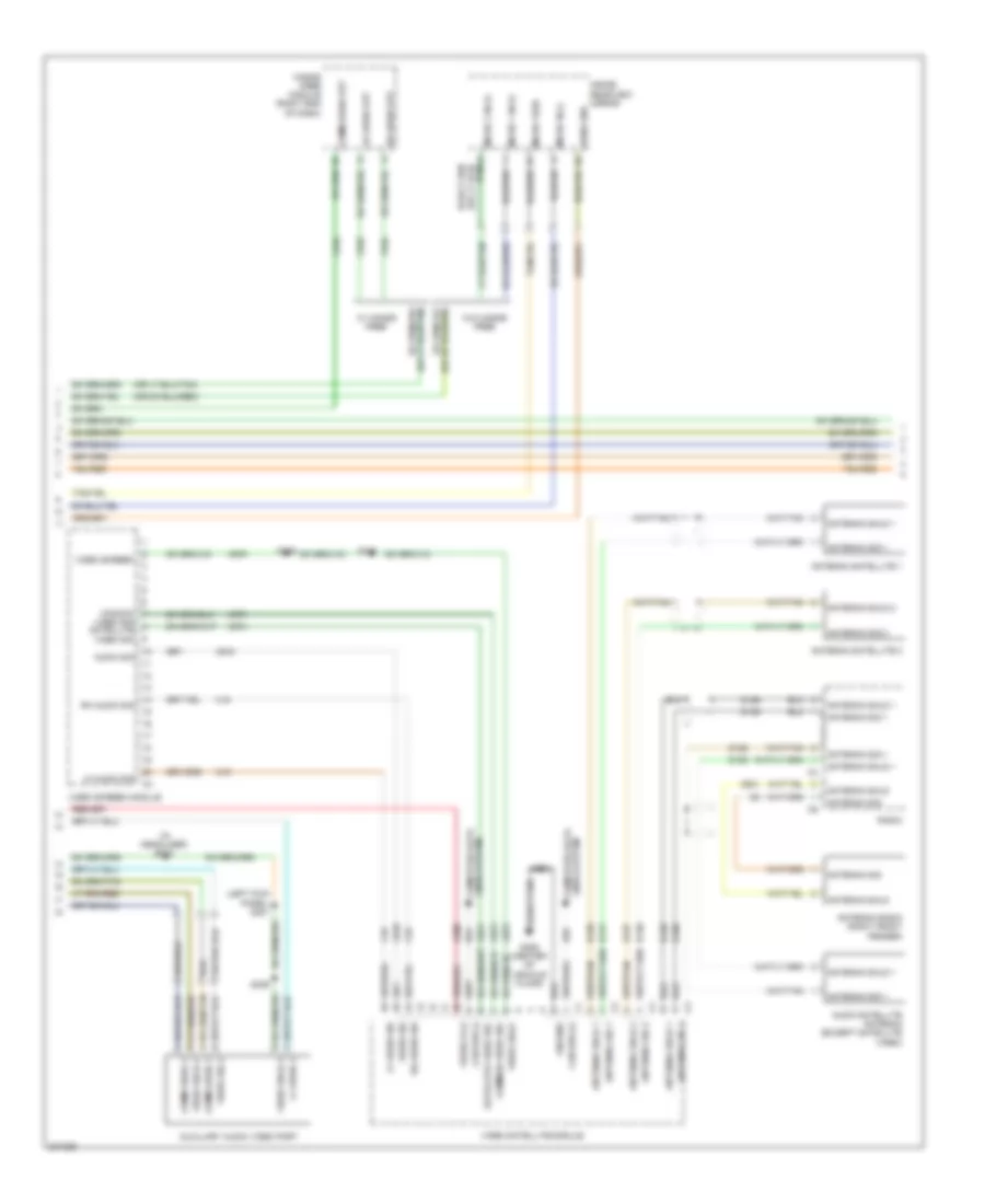
- Radio
- Radio amplifier (right kick panel)
- Red
- Right front tire pressure transponder (right front of engine compt)
- S113 (breakout for ambient air temperature sensor)
- S123 (breakout for c201)
- S200
- S207 (center of dash)
- S208 (center of dash)
- S309 (left body, between "a" & "b" pillar)
- S326 (breakout for c222)
- Seat memory module (under driver seat)
- Steering angle sensor
- Video screen module
- Wireless control module
- Z11
- Z111
Computer Data Lines Wiring Diagram, Hybrid (1 of 2) for Chrysler Aspen Limited Hybrid 2009
List of elements for Computer Data Lines Wiring Diagram, Hybrid (1 of 2) for Chrysler Aspen Limited Hybrid 2009:
- (breakout for c222) s325
- (breakout for junction block) s125
- (front center of headliner)
- (headlamp & dash harness) s130
- (left body, between "a" & "b" pillar) s310
- (left front of engine compt) s149
- (left side of dash) data link connector
- A926
- Automatic a/c
- Can b bus (+)
- Can b bus (-)
- Can c bus (+)
- Can c bus (-)
- Can c diagnostic (-)
- Cluster
- Com- lin tire press
- Com-lin tire press moni lan
- D508
- D51
- D52
- D54
- D55
- D64
- D65
- Driver door module
- Electronic overhead module
- Final drive control module
- Front a/c-heater control module
- Front control module (at integrated power module)
- Fuse 15a
- G208 (left kick panel)
- H31
- Hands free module (right end of dash)
- Heated seat module (right rear quarterpanel)
- Hgm wake up sig can c diagnostic (+)
- Hot at all times
- Inside rearview mirror (w/ hands free)
- Junction block (left kick panel)
- Left front tire pressure transponder (left front of engine compt)
- Left rear tire pressure transponder (left rear of chassis)
- Manual a/c
- Occupant restraint controller module (under center console)
- Park assist module (parktronics)
- Passenger door module
- Pnk/red
- Power liftgate module (left rear cargo area)
- Power steering lamp assembly
- Radio
- Radio amplifier (right kick panel)
- Red
- Right front tire pressure transponder (right front of engine compt)
- S123 (breakout for c201)
- S129 (left kick panel)
- S142 (left kick panel)
- S150 (left front of engine compt)
- S200
- S207 (center of dash)
- S208 (center of dash)
- S230
- S231
- S309 (left body, between "a" & "b" pillar)
- S326 (breakout for c222)
- Seat memory module (under driver seat)
- Steering angle sensor
- Video screen module
- Wireless control module
- Z11
- Z111
Computer Data Lines Wiring Diagram, Hybrid (2 of 2) for Chrysler Aspen Limited Hybrid 2009
List of elements for Computer Data Lines Wiring Diagram, Hybrid (2 of 2) for Chrysler Aspen Limited Hybrid 2009:
- (left front of engine compt)
- (lower left side of engine compt) s141
- A/c electric
- A785
- Acc wake up sig
- Anti-lock brakes module (left front of engine compt)
- Battery pack assembly
- Bpcm/eac wake up sig
- Bpcm/eac wke up sig
- Can c bus (+)
- Can c bus (-)
- Compressor
- D505
- D64
- D65
- D68
- D682
- D69
- D692
- Fan speed sens sig
- Fuse 20a
- Fused b (+)
- Fused ign sw out
- G114 (left front of engine compt)
- Gnd
- H-lan 1 (+)
- H-lan 1 (-)
- H-lan 3 (+)
- H-lan 3 (-)
- H31
- H400
- H402
- H403
- Hev radiator cooling fan module
- Hev-apm wake up feed
- Hgm wake up sig
- Hot at all times
- Humidity sensor
- Hybrid gateway module (left front of engine compt)
- Junction block (left kick panel)
- Lin bus
- N27
- Of engine compt) s140
- Power distribution center (left side of engine compt)
- Powertrain control module (right side of engine compt)
- Red/ tan
- Red/tan
- S114 (breakout for ambient air temperature sensor)
- S126 (breakout for anti-lock brakes module)
- S153 (left front of engine compt)
- S159
- S192
- S193
- S345
- S347
- T383
- T384
- Tcm acc wake up sig
- Tpim coolant temp gnd
- Tpim coolant temp sig
- Tpim coolant temperature sensor
- Traction power inverter module (right front of engine compt)
- Transmission assembly
- Z989
COOLING FAN
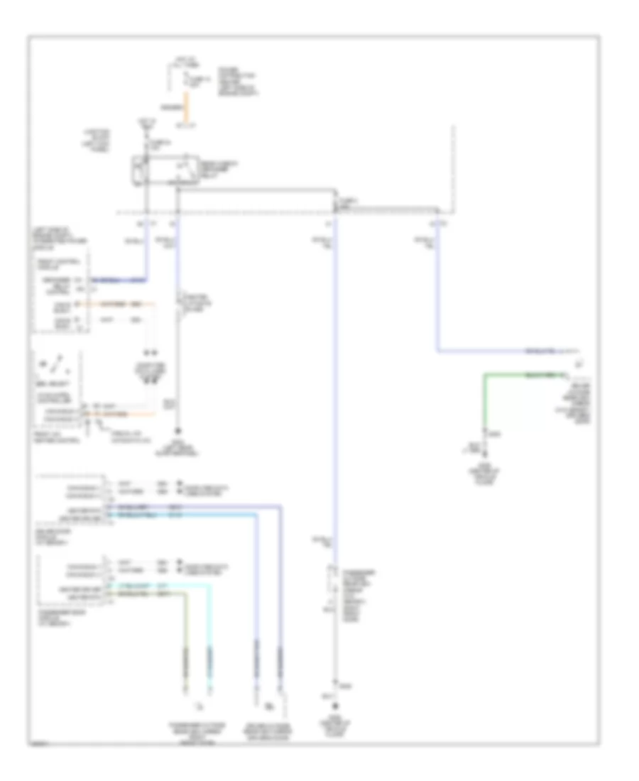
Cooling Fan Wiring Diagram, Except Hybrid for Chrysler Aspen Limited Hybrid 2009
List of elements for Cooling Fan Wiring Diagram, Except Hybrid for Chrysler Aspen Limited Hybrid 2009:
- (3.7l & 4.7l) (5.7l)
- (right front of engine compt) g112
- (right side of engine compt) powertrain control module
- 87a
- Can c bus (+)
- Can c bus (-)
- Can c bus (-) c1
- Computer data lines system
- Condenser cooling fan module (behind radiator)
- D64
- D65
- Ect signal
- Engine coolant temperature sensor (3.7l: top right front of engine) (4.7l: right front of engine)
- Front control module
- Fuse 23 40a
- Hi spd rad fan rly ctrl
- Hot at all times
- Integrated power module (left side of engine compt)
- Ipm
- K900
- Low spd rad fan rly ctrl
- Radiator fan high relay
- Radiator fan low relay
- Radiator fan resistor (front center of engine compt)
- Red
- Sens gnd c2
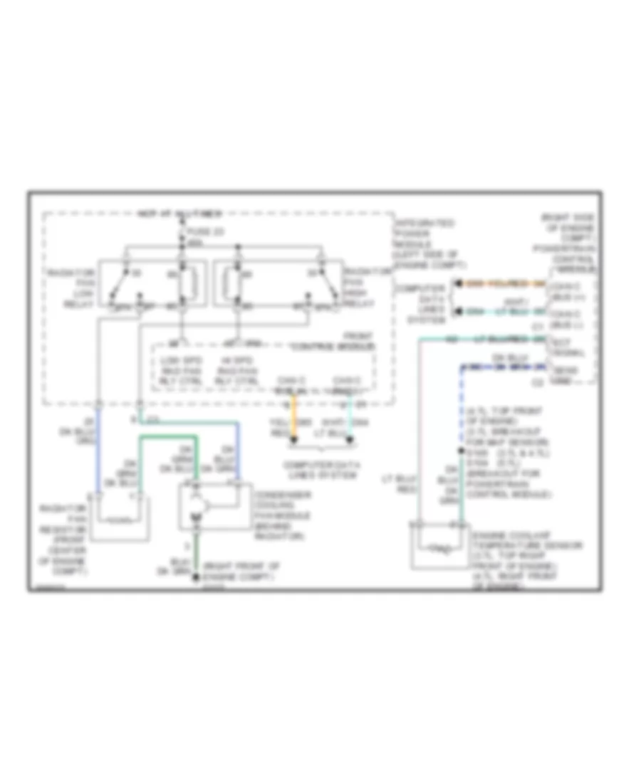
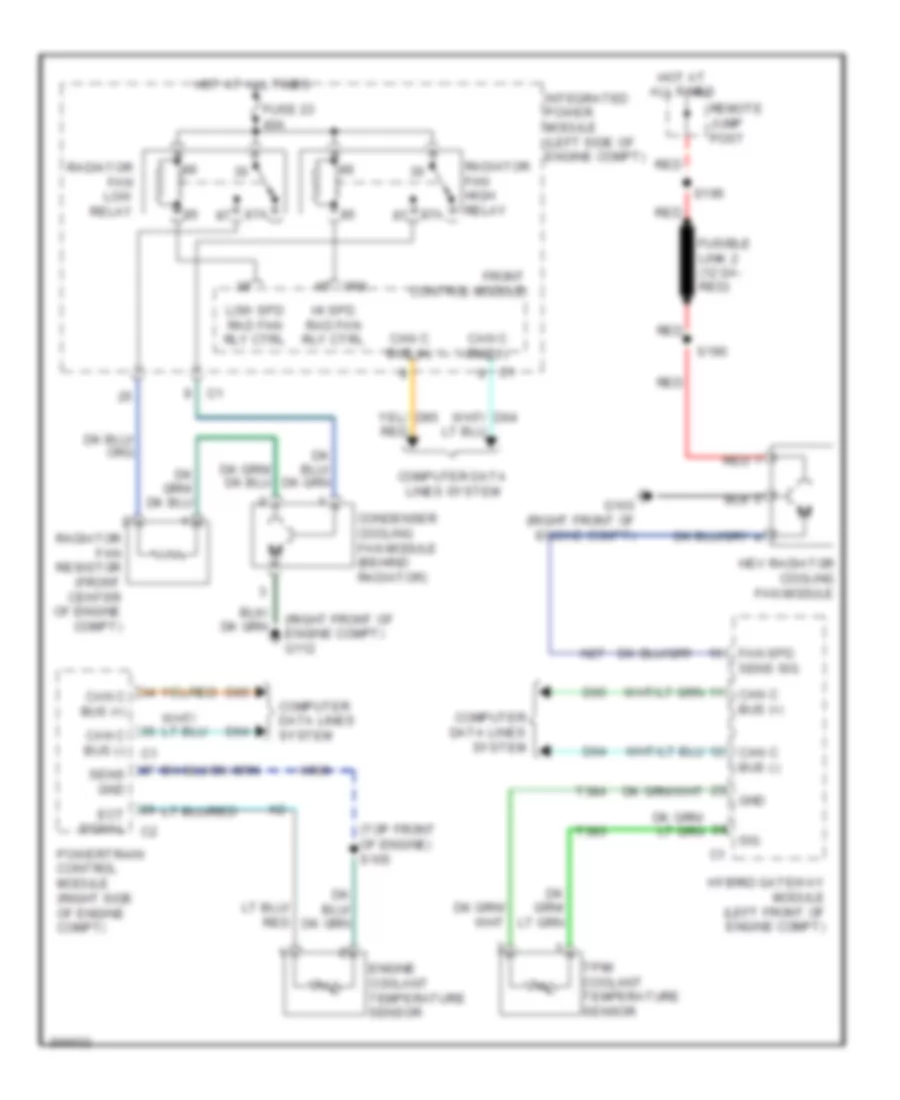
Cooling Fan Wiring Diagram, Hybrid for Chrysler Aspen Limited Hybrid 2009
List of elements for Cooling Fan Wiring Diagram, Hybrid for Chrysler Aspen Limited Hybrid 2009:
- (right front of engine compt) g112
- (top front of engine) s105
- 87a
- Can c bus (+)
- Can c bus (-)
- Computer data lines system
- Condenser cooling fan module (behind radiator)
- D64
- D65
- Ect signal
- Engine coolant temperature sensor
- Fan spd sens sig
- Front control module
- Fuse 23 40a
- Fusible link 2 (12 ga- red)
- G103 (right front of engine compt)
- Gnd
- Hev radiator cooling fan module
- Hi spd rad fan rly ctrl
- Hot at all times
- Hybrid gateway module (left front of engine compt)
- Integrated power module (left side of engine compt)
- Ipm
- K900
- Low spd rad fan rly ctrl
- N27
- Powertrain control module (right side of engine compt)
- Radiator fan high relay
- Radiator fan low relay
- Radiator fan resistor (front center of engine compt)
- Red
- Remote jump post
- S190
- S196
- Sens gnd
- Sig
- T383
- T384
- Tpim coolant temperature sensor
CRUISE CONTROL
Cruise Control Wiring Diagram for Chrysler Aspen Limited Hybrid 2009
List of elements for Cruise Control Wiring Diagram for Chrysler Aspen Limited Hybrid 2009:
- (3.7l: breakout for fuel injector 8) (5.7l: top center of right cylinder head) (except 5.7l hybrid) s103
- (breakout for powertrain control module)
- (left side of dash)
- 3.7l/4.7l
- 5.7l
- 5.7l hydrid
- A919
- Accel/ resume
- Accelerator pedal position sensor (left side of dash)
- Apps 1 return
- Apps 1 signal
- Apps 2 return
- Apps 2 signal
- B29
- Brake sw 1 sig
- C o/p spd sig b o/p sp sen sply c2
- Can b bus (+)
- Can b bus (-)
- Can c bus (-) can c bus (+)
- Cancel
- Clockspring (top of steering column)
- Cluster
- Coast
- Computer data lines system
- D64
- D65
- Electrohydraulic control module
- Etc motor (+)
- Etc motor (-)
- Except 5.7l hydrid
- F855
- F856
- Fuse 10a
- Fuse 20a
- Fused b (+)
- G208 (left kick panel)
- H lan 1 (+) (500k)
- H lan 1 (-) (500k)
- Hot at all times
- Input spd sig
- Input speed sensor (except 5.7l hybrid) (left side of transmission)
- Junction block (left kick panel)
- K122
- K22
- K23
- K29
- K400
- K447
- K448
- K922
- Left speed control switch
- Nca
- O/p sp sen sply
- O/p spd sig
- On/ off
- Output spd sig
- Output speed sensor (5.7l hybrid)
- Output speed sensor (except 5.7l hybrid) (left side of transmission)
- Pnk/red
- Power distribution center (left side of engine compt)
- Powertrain control module (right side of engine compt)
- Right speed control switch
- S/c sw 1 sig
- S/c sw 2 sig
- S/c sw rtn
- S102 (3.7l: breakout for right front oxygen sensor) (5.7l: top front of right cylinder head) (4.7l: top rear of right cylinder head)
- S108
- S119
- S139
- S146 (5.7l hybrid) (lower left side of engine compt)
- Set
- Spd sens gnd
- Stop lamp switch
- T13
- T14
- T378
- T52
- Throttle body (3.7l/5.7l: top of engine)
- Tp 1 sig
- Tp 2 sig
- Tp sensor rtn
- Tp sensor rtn c2
- Transmission assembly
- V32
- V37
- V38
- V937
DEFOGGERS
Defoggers Wiring Diagram for Chrysler Aspen Limited Hybrid 2009
List of elements for Defoggers Wiring Diagram for Chrysler Aspen Limited Hybrid 2009:
- (left side of engine compt) integrated power module
- 87a
- Automatic a/c
- C110
- C115
- C17
- C910
- C917
- Can b bus (+)
- Can b bus (+) c1
- Can b bus (-)
- Can b bus(+)
- Can b bus(-) c1
- Computer data lines system
- D54
- D55
- Defogger relay ipm control
- Driver door module (w/ memory)
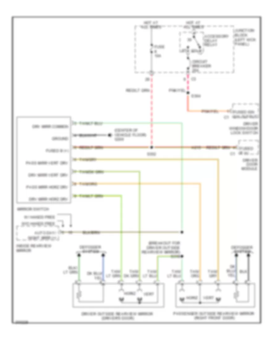
- Driver outside rearview mirror (driver's door)
- Driver outside rearview mirror (w/o memory) (driver's door)
- Ebl select
- Front a/c heater control
- Front control module
- Fuse 12 40a
- Fuse 2 10a
- Fuse 24 10a
- G304 (left rear quarterpanel)
- G306 (center of vehicle floor)
- Heated liftgate glass
- Heater driver
- Heater rtn
- Hot at all times
- Hot in run
- Hvac micro- controller
- Junction block (left kick panel)
- Manual a/c
- Passenger door module (w/ memory)
- Passenger outside rearview mirror (right front door)
- Passenger outside rearview mirror (w/o memory) (right front door)
- Power distribution center (left side of engine compt)
- Rear window defogger relay
- S328
- S353
ENGINE PERFORMANCE
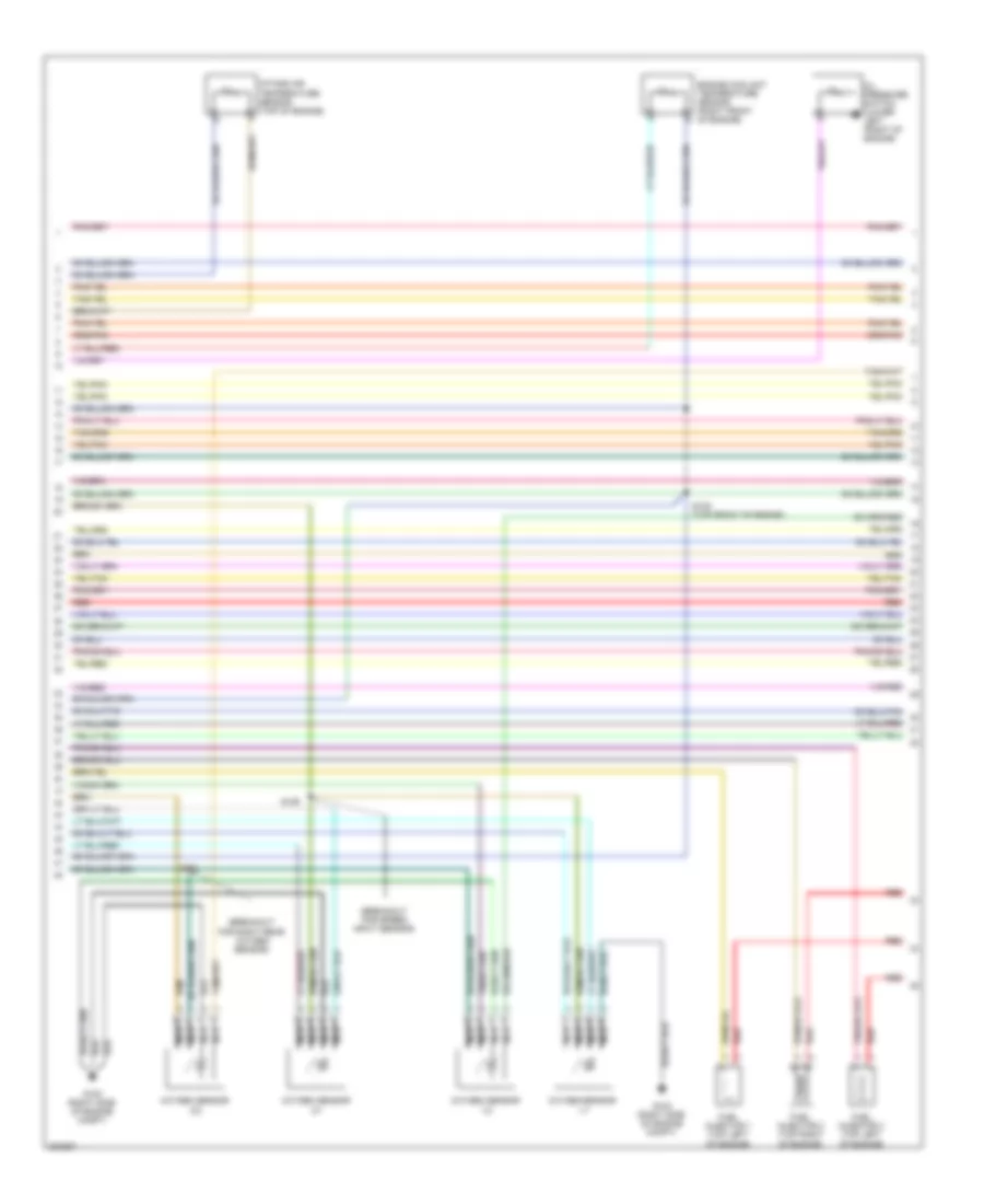
4.7L FLEX FUEL
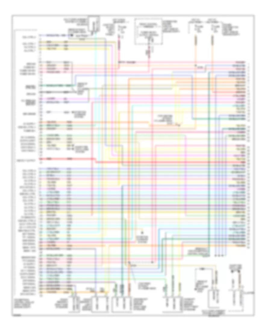
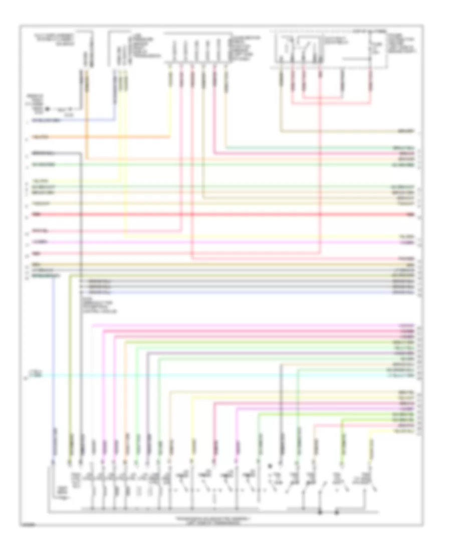
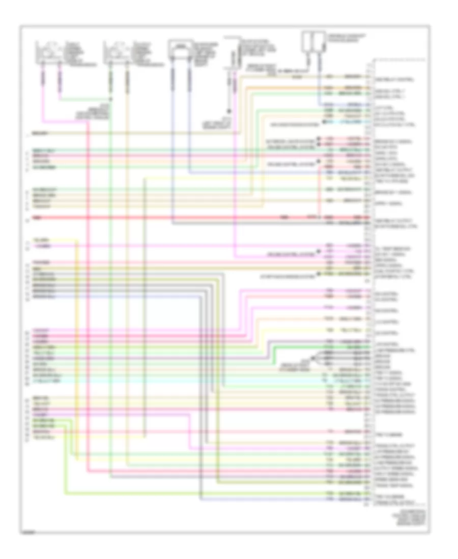
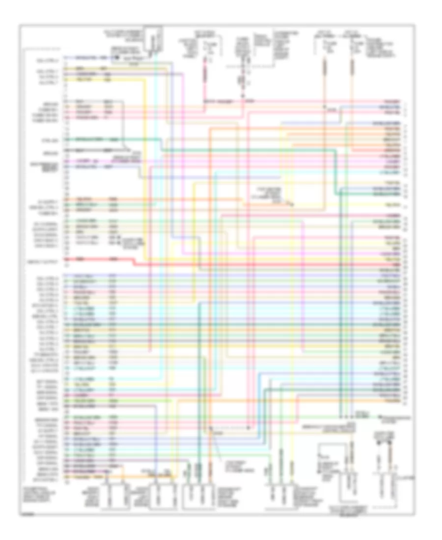
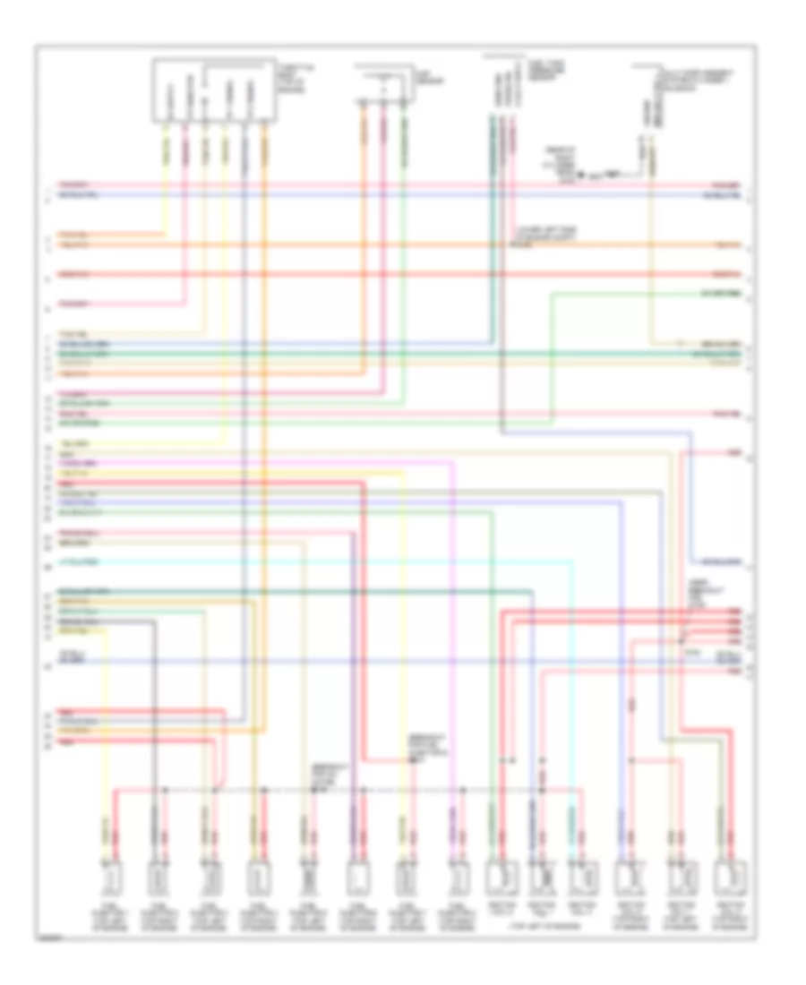
4.7L Flex Fuel, Engine Performance Wiring Diagram (1 of 6) for Chrysler Aspen Limited Hybrid 2009
List of elements for 4.7L Flex Fuel, Engine Performance Wiring Diagram (1 of 6) for Chrysler Aspen Limited Hybrid 2009:
- (right side of engine compt) g100
- (top rear of right cylinder head)
- A803
- A919
- A955
- Asd rly output
- Camshaft position sensor (right front of engine)
- Can b bus (+)
- Can b bus (-)
- Can c bus (+)
- Can c bus (-)
- Ckp sig
- Ckp signal
- Cluster
- Cmp sig
- Cmp signal
- Coil ctrl 1
- Coil ctrl 2
- Coil ctrl 3
- Coil ctrl 4
- Coil ctrl 5
- Coil ctrl 6
- Coil ctrl 7
- Coil ctrl 8
- Computer data lines system
- Crankshaft position sensor (right side of engine)
- D64
- D65
- Ect signal
- Egr signal
- Egr sol ctrl
- Egr valve assembly (top rear of engine)
- Etc mtr +
- Etc mtr -
- F202
- F855
- F856
- Front control module
- Fuse 10a
- Fuse 20a
- Fused b(+)
- Fused ign sw
- Fused ign sw output (off-run start)
- G100 (right side of engine compt)
- Gen field ctrl
- Gen sense
- Ground
- Hot at all times
- Hot in run or start
- Iat signal
- Inj ctrl 1
- Inj ctrl 2
- Inj ctrl 3
- Inj ctrl 4
- Inj ctrl 5
- Inj ctrl 6
- Inj ctrl 7
- Inj ctrl 8
- Integrated power module (left side of engine compt)
- Ipm
- Junction block (left kick panel)
- K10
- K11
- K12
- K122
- K13
- K14
- K141
- K15
- K16
- K17
- K18
- K19
- K199
- K20
- K21
- K22
- K24
- K243
- K26
- K28
- K34
- K35
- K38
- K41
- K42
- K43
- K44
- K447
- K448
- K58
- K900
- K902
- K904
- K922
- K942
- K97
- K98
- K99
- Knock sensor
- Map signal
- O2 1/1 htr ctrl
- O2 1/1 signal
- O2 1/2 signal
- O2 2/1 htr ctrl
- O2 2/1 signal
- O2 2/2 signal
- O2 rtn (dnst)
- O2 rtn (upst)
- Oil pres signal
- Power distribution center (left side of engine compt)
- Powertrain control module (right side of engine compt)
- Red
- S102
- S103
- S104 (breakout for powertrain control module)
- S119
- S139
- Sens 1 rtn
- Sens 1 sig
- Sens gnd
- Sensor gnd
- Sply
- Starting/ charging system
- Tp 1 signal
- Tp 2 sig
- Tp sens rtn
- Z913
- Z937
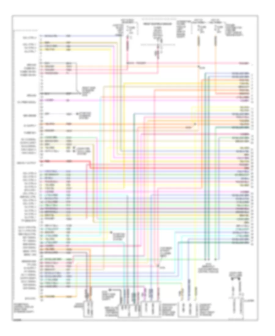
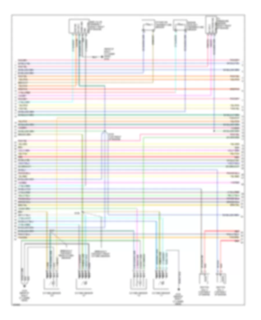
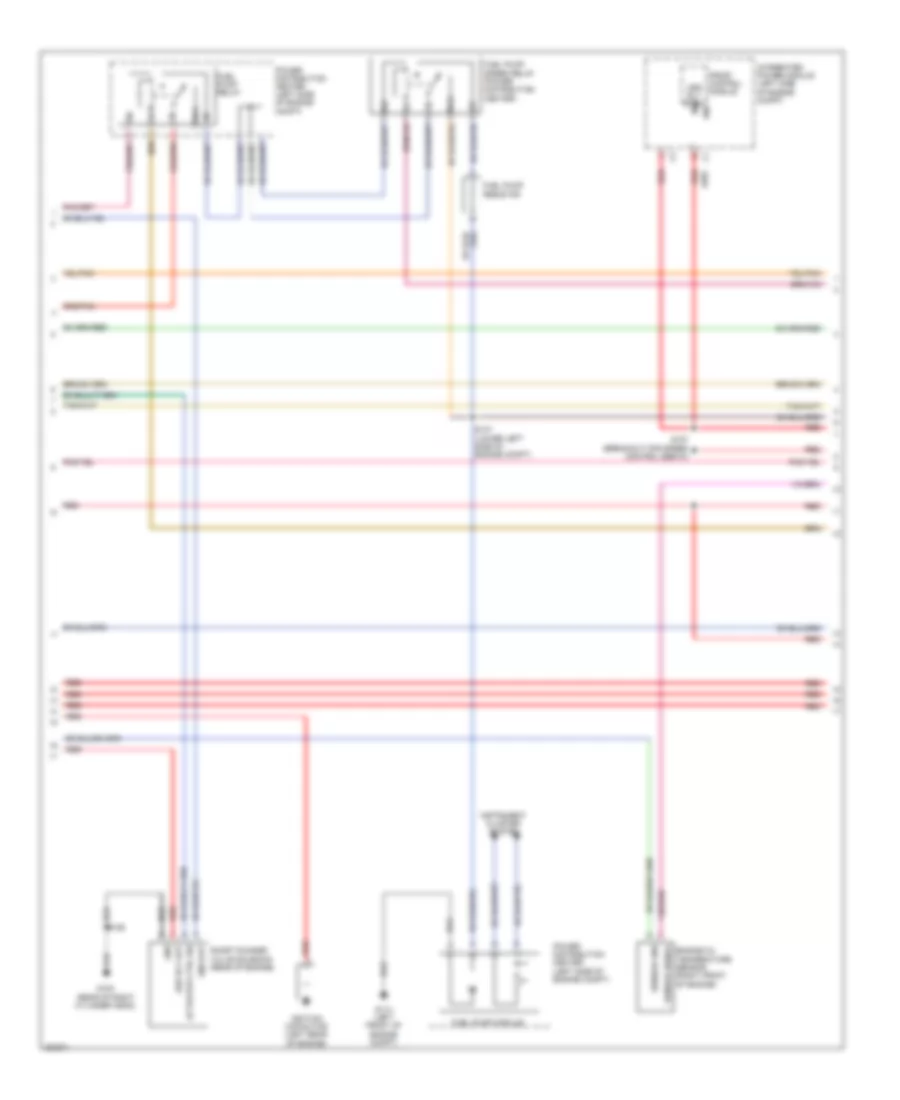
4.7L Flex Fuel, Engine Performance Wiring Diagram (2 of 6) for Chrysler Aspen Limited Hybrid 2009
List of elements for 4.7L Flex Fuel, Engine Performance Wiring Diagram (2 of 6) for Chrysler Aspen Limited Hybrid 2009:
- (breakout for right rear oxygen sensor)
- (breakout for speed input sensor)
- Engine coolant temperature sensor (right front of engine)
- Fuel injector 1 (top left of engine)
- Fuel injector 2 (top right of engine)
- Fuel injector 3 (top left of engine)
- G100 (right side of engine compt)
- Intake air temperature sensor (top of engine)
- Nca
- Oil pressure switch (lower left front of engine)
- Oxygen sensor 1/1
- Oxygen sensor 1/2
- Oxygen sensor 2/1
- Oxygen sensor 2/2
- Red
- S105 (top front of engine)
- S106
- S107
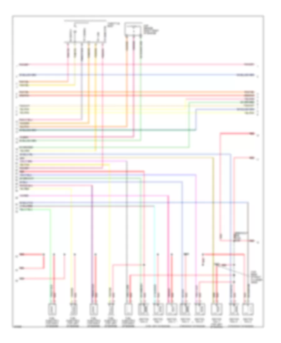
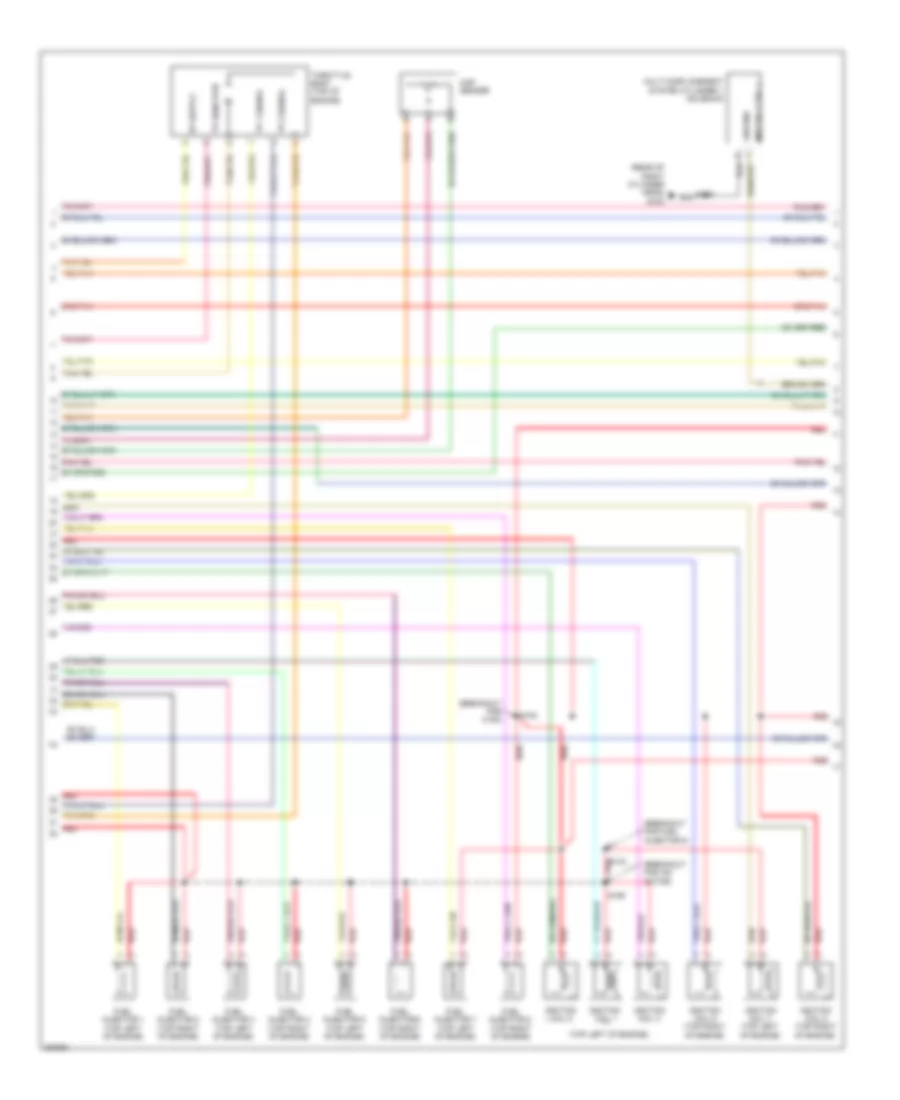
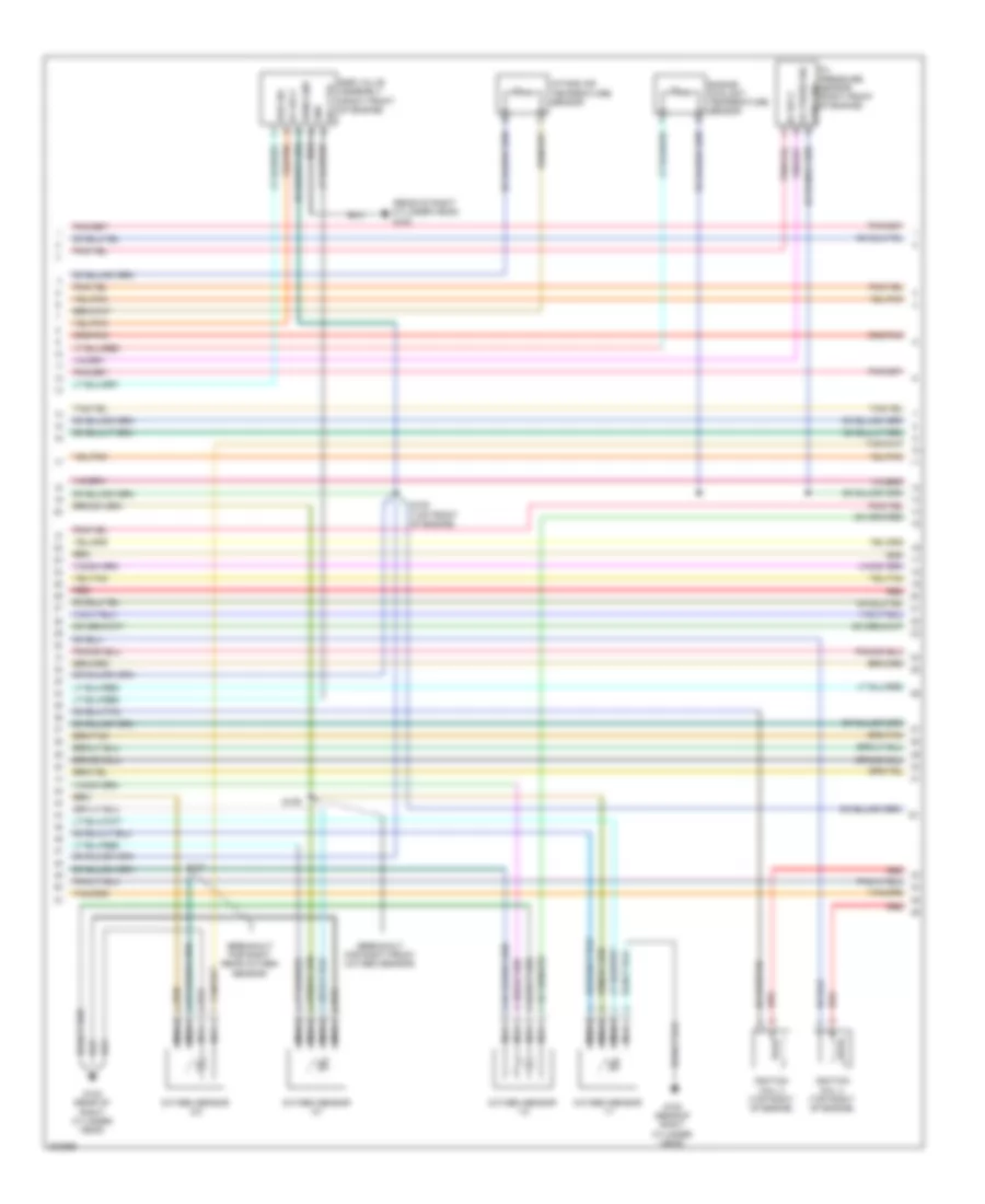
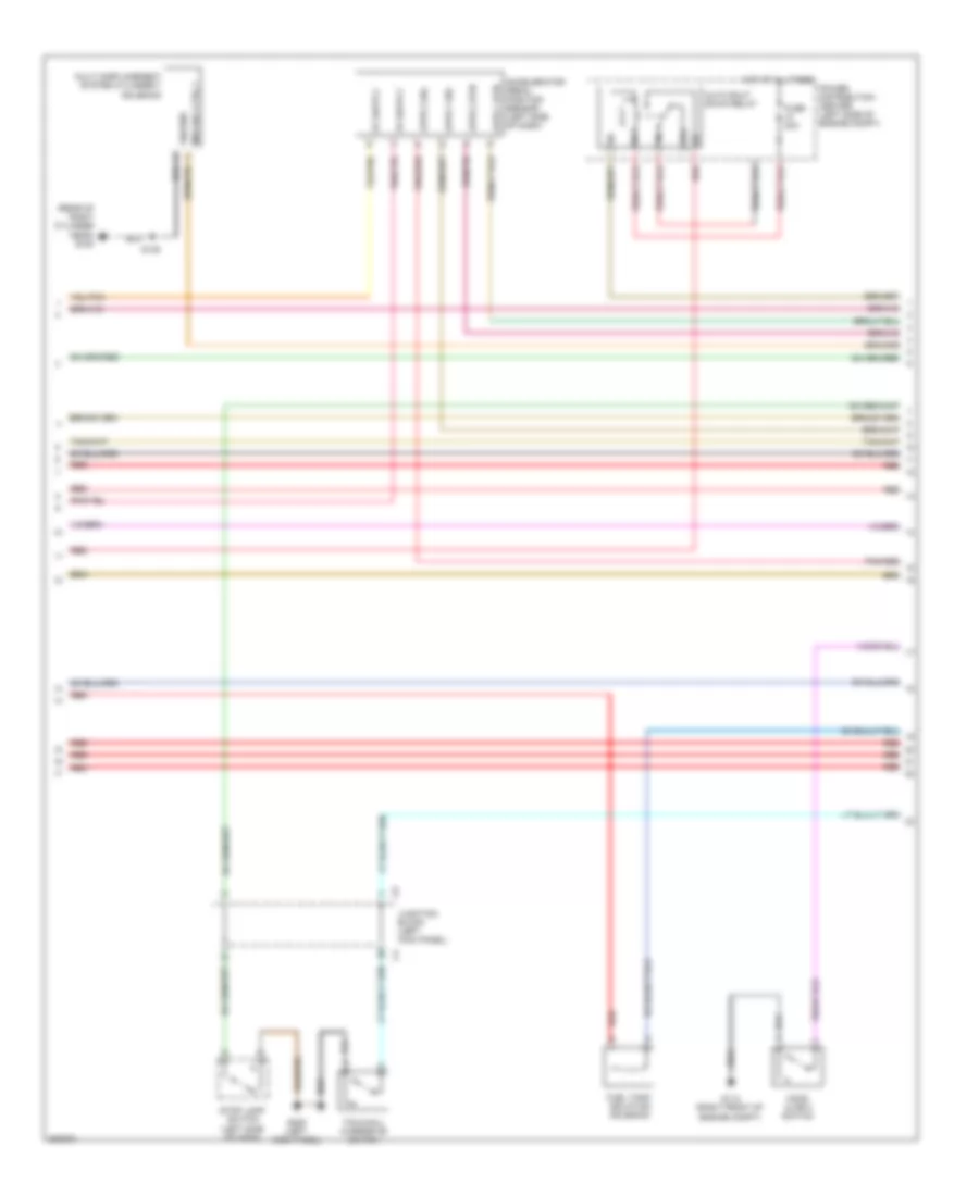
4.7L Flex Fuel, Engine Performance Wiring Diagram (3 of 6) for Chrysler Aspen Limited Hybrid 2009
List of elements for 4.7L Flex Fuel, Engine Performance Wiring Diagram (3 of 6) for Chrysler Aspen Limited Hybrid 2009:
- (breakout for c108) s184
- (top left of engine)
- (top rear of right cylinder head)
- (top right of engine)
- Fuel injector 4 (top right of engine)
- Fuel injector 5 (top left of engine)
- Fuel injector 6 (top right of engine)
- Fuel injector 7 (top left of engine)
- Fuel injector 8 (top right of engine)
- Ignition coil 1
- Ignition coil 2
- Ignition coil 3
- Ignition coil 4
- Ignition coil 5
- Ignition coil 6
- Ignition coil 7 (top left of engine)
- Ignition coil 8
- Map sensor (right front of engine)
- Red
- S134
- S186
- Throttle body
- Tp 1 sig
- Tp 2 signal
- Tp sens rtn
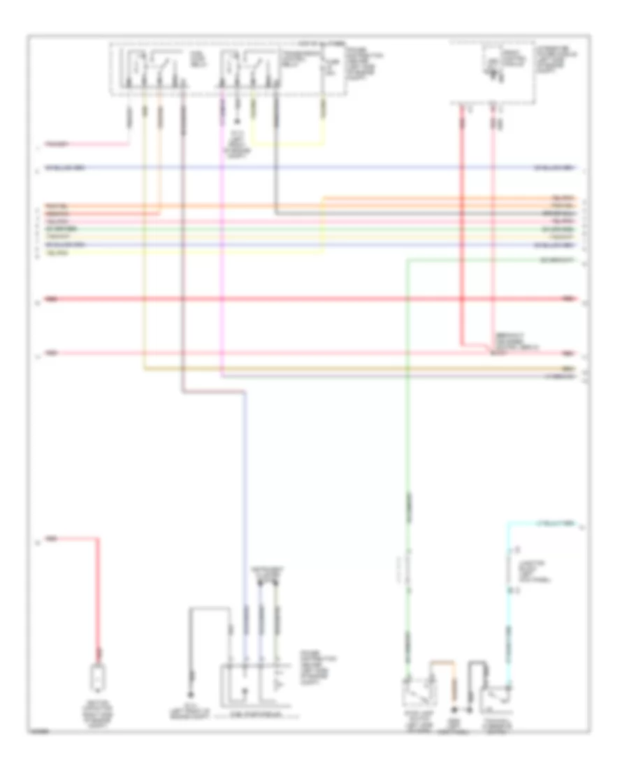
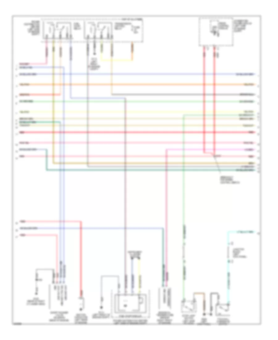
4.7L Flex Fuel, Engine Performance Wiring Diagram (4 of 6) for Chrysler Aspen Limited Hybrid 2009
List of elements for 4.7L Flex Fuel, Engine Performance Wiring Diagram (4 of 6) for Chrysler Aspen Limited Hybrid 2009:
- (breakout for speed control servo) s187
- 87a
- A955
- Asd rly ctrl
- Front control module
- Fuel pump module
- Fuel pump relay
- Fuse 20a
- G113 (left front of engine compt)
- G114 (left front of engine compt)
- G208 (left kick panel)
- Hot at all times
- Ignition capacitor (right side of engine compt)
- Instrument cluster system
- Integrated power module (left side of engine compt)
- Ipm
- Junction block (left kick panel)
- Power distribution center (left side of engine compt)
- Red
- Stop lamp switch (left side of dash)
- Tow/haul overdrive switch
- Transmission control relay
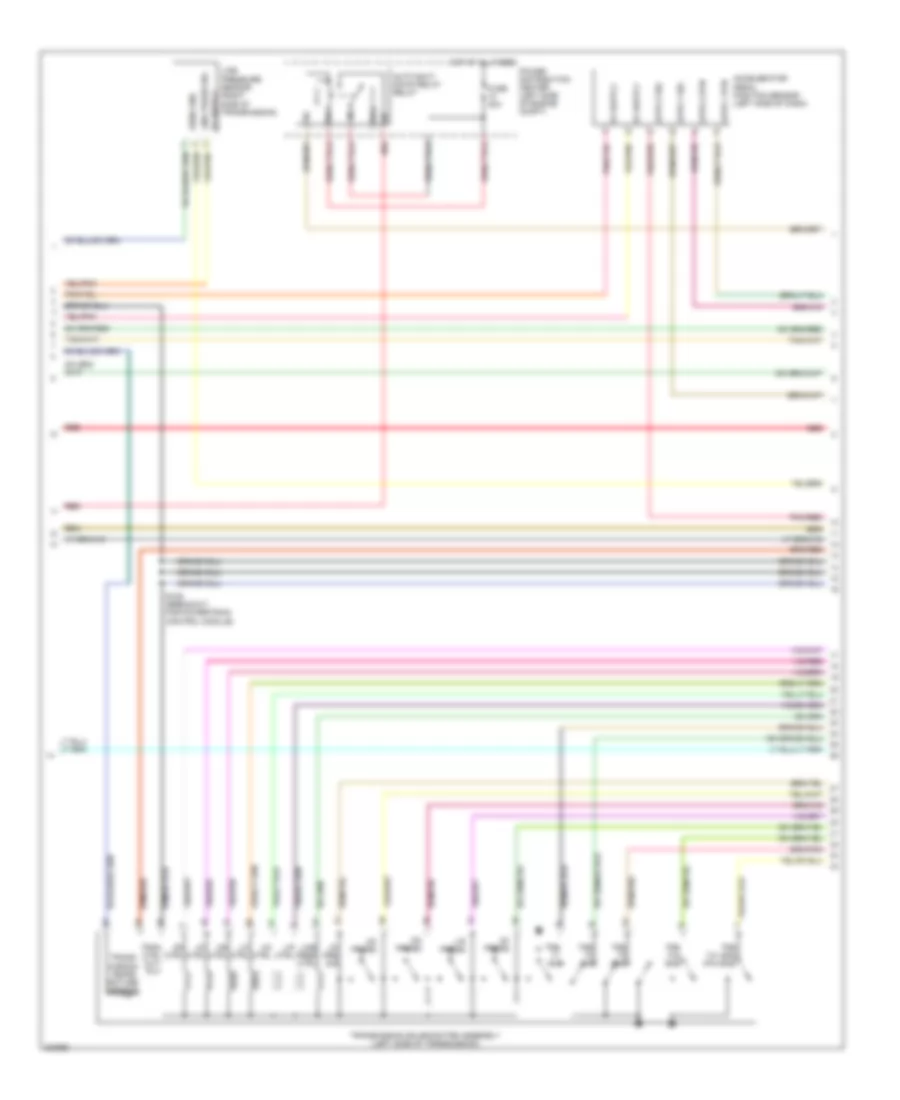
4.7L Flex Fuel, Engine Performance Wiring Diagram (5 of 6) for Chrysler Aspen Limited Hybrid 2009
List of elements for 4.7L Flex Fuel, Engine Performance Wiring Diagram (5 of 6) for Chrysler Aspen Limited Hybrid 2009:
- 2c press
- 4c ctrl
- 4c prs sig
- 87a
- Accelerator pedal position sensor (left side of dash)
- Apps 1 rtn
- Apps 1 sig
- Apps 2 rtn
- Apps 2 sig
- Auto shut down relay relay
- Fuse 30a
- Hot at all times
- L/c ctrl
- L/r ctrl
- L/r press
- Line pres ctrl
- Line press sig
- Line pressure sensor (right side of transmission)
- Ms ctrl
- Od ctrl
- Od press
- Pnk/red
- Power distribution center (left side of engine compt)
- Red
- S109 (breakout for powertrain control module)
- Sens gnd
- Tran ctrl out- put
- Trans- mission tempe- rature sensor
- Transmission solenoid/trs assembly (left side of transmission)
- Trs t1 sig
- Trs t2 sns
- Trs t3 sig
- Trs t41 sns (p/n sns)
- Trs t42 sns
- Ud ctrl
- Ud press
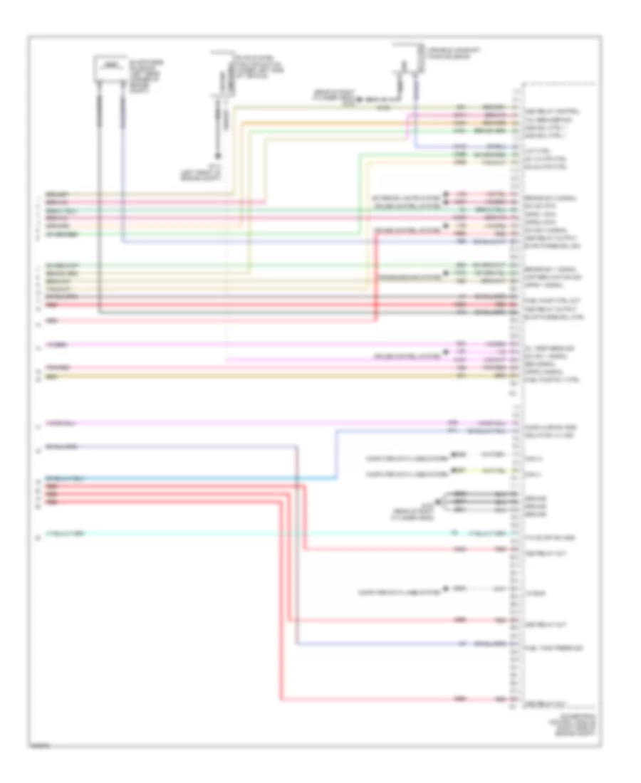
4.7L Flex Fuel, Engine Performance Wiring Diagram (6 of 6) for Chrysler Aspen Limited Hybrid 2009
List of elements for 4.7L Flex Fuel, Engine Performance Wiring Diagram (6 of 6) for Chrysler Aspen Limited Hybrid 2009:
- (near breakout for c108) s176
- (right side of engine compt) g100
- 2c pressure sig
- 4c control
- 4c pressure sig
- A/c clutch rly ctrl
- A955
- Air conditioning system
- Apps 1 rtn
- Apps 1 signal
- Apps 2 rtn
- Apps 2 signal
- Asd relay output
- Asd rly ctrl
- B29
- Brake sw 1 signal
- Brake sw 2 signal
- C13
- Cruise control system
- Esm signal
- Evap purge sol ctr
- Evap purge sol sig
- Evap system monitor switch (under left side of vehicle)
- Evap/purge solenoid (left rear corner of engine compt)
- Exterior lights system
- Fuel pump rly ctrl
- G114 (left front of engine compt)
- Ground
- Input speed sensor (left side of transmission)
- Input speed signal
- K107
- K23
- K29
- K299
- K31
- K399
- K400
- K51
- K52
- K70
- L/c control
- L/r control
- L/r pressure sig
- Line pressure ctrl
- Line pressure sig
- Ms control
- O2 1/2 htr ctrl
- O2 2/2 htr ctrl
- Od control
- Od off sw sens
- Od pressure sig
- Output speed sensor (left side of transmission)
- Output speed signal
- Pnk/red
- Powertrain control module (right side of engine compt)
- Red
- S/c sw 2 signal
- S/c sw rtn
- S/c switch signal
- S108 (breakout for powertrain control module)
- Speed sens gnd
- Starter rly ctrl
- Starting/charging system
- T118
- T13
- T14
- T140
- T147
- T15
- T16
- T20
- T219
- T259
- T29
- T38
- T41
- T42
- T48
- T50
- T52
- T54
- T59
- T60
- T752
- Trans ctrl
- Trans ctrl out
- Trans ctrl output
- Trans temp sens
- Trs t1 signal
- Trs t2 sense
- Trs t3 signal
- Trs t41 (p/n sns)
- Trs t42 sense
- Ud control
- Ud pressure sig
- V32
- V37
- V38
- V937
- Z904
- Z908
- Z977
5.7L
5.7L, Engine Performance Wiring Diagram, Except Hybrid (1 of 6) for Chrysler Aspen Limited Hybrid 2009
List of elements for 5.7L, Engine Performance Wiring Diagram, Except Hybrid (1 of 6) for Chrysler Aspen Limited Hybrid 2009:
- (breakout for powertrain control module) s104
- (rear of right cylinder head) g100
- (top center of right cylinder head) s103
- (top front of right cylinder head)
- A803
- A919
- A955
- Asd rly output
- Camshaft position sensor (right front of engine)
- Can b bus (+)
- Can b bus (-)
- Can c bus (+)
- Can c bus (-)
- Ckp sig
- Ckp signal
- Cluster
- Cmp sig
- Cmp signal
- Coil ctrl 1
- Coil ctrl 2
- Coil ctrl 3
- Coil ctrl 4
- Coil ctrl 5
- Coil ctrl 6
- Coil ctrl 7
- Coil ctrl 8
- Computer data lines system
- Crankshaft position sensor (right side of engine)
- D64
- D65
- Ect signal
- Egr signal
- Egr sol ctrl
- Eng-srv ctrl sig
- Etc motor (+)
- Etc motor (-)
- F202
- F855
- F856
- Front control module
- Fuse 10a
- Fuse 20a
- Fused b(+)
- Fused ign sw
- Fused ign sw output (off-run start)
- G100
- Gen field ctrl
- Gen sense
- Ground
- Hot at all times
- Hot in run or start
- Iat signal
- Inj ctrl 1
- Inj ctrl 2
- Inj ctrl 3
- Inj ctrl 4
- Inj ctrl 5
- Inj ctrl 6
- Inj ctrl 7
- Inj ctrl 8
- Integrated power module (left side of engine compt)
- Ipm
- Junction block (left kick panel)
- K10
- K11
- K12
- K122
- K13
- K14
- K141
- K15
- K16
- K17
- K18
- K19
- K199
- K20
- K21
- K22
- K237
- K238
- K24
- K242
- K243
- K26
- K28
- K34
- K35
- K38
- K41
- K42
- K43
- K44
- K447
- K448
- K452
- K453
- K58
- K900
- K902
- K904
- K922
- K924
- K942
- K97
- K98
- K99
- Knock sensor 1 (left side of engine)
- Knock sensor 2 (right side of engine)
- Map signal
- Mds sol ctrl 4
- Mds sol ctrl 6
- Multi displacement system cylinder 4 solenoid
- Multi displacement system cylinder 6 solenoid
- O2 1/1 htr ctr
- O2 1/1 signal
- O2 1/2 signal
- O2 2/1 htr ctr
- O2 2/1 signal
- O2 2/2 signal
- O2 rtn (dnst)
- O2 rtn (upst)
- Oil pres sig eng-srv sna out
- Power distribution center (left side of engine compt)
- Powertrain control module (right side of engine compt)
- Red
- S102
- S119
- S135
- S139
- Sens 1 rtn
- Sens 1 sig
- Sens 2 rtn
- Sens 2 sig
- Sens gnd
- Sensor gnd
- Sol ctrl 4
- Sol ctrl 6
- Starting/ charging system
- Tp 1 signal
- Tp 2 signal
- Tp sens rtn
- Z913
- Z937
5.7L, Engine Performance Wiring Diagram, Except Hybrid (2 of 6) for Chrysler Aspen Limited Hybrid 2009
List of elements for 5.7L, Engine Performance Wiring Diagram, Except Hybrid (2 of 6) for Chrysler Aspen Limited Hybrid 2009:
- (breakout for right front oxygen sensor)
- (breakout for right rear oxygen sensor)
- (rear of right cylinder head) g100
- 5v sply
- Egr sig
- Egr valve assembly (right front of engine)
- Engine coolant temperature sensor
- G100 (rear of right cylinder head)
- Gnd
- Ignition coil 2 (top right of engine)
- Ignition coil 4 (top right of engine)
- Intake air temperature sensor
- Nca
- Oil press sig
- Oil pressure sensor (right front of engine)
- Oxygen sensor 1/1
- Oxygen sensor 1/2
- Oxygen sensor 2/1
- Oxygen sensor 2/2
- Red
- S105 (top front of engine)
- S106
- S107
- Sens gnd
- Sol ctrl
5.7L, Engine Performance Wiring Diagram, Except Hybrid (3 of 6) for Chrysler Aspen Limited Hybrid 2009
List of elements for 5.7L, Engine Performance Wiring Diagram, Except Hybrid (3 of 6) for Chrysler Aspen Limited Hybrid 2009:
- (breakout for c108)
- (breakout for fuel injector 5)
- (breakout for iac motor)
- (rear of right cylinder head) g100
- (top left of engine)
- Fuel injector 1 (top left of engine)
- Fuel injector 2 (top right of engine)
- Fuel injector 3 (top left of engine)
- Fuel injector 4 (top right of engine)
- Fuel injector 5 (top left of engine)
- Fuel injector 6 (top right of engine)
- Fuel injector 7 (top left of engine)
- Fuel injector 8 (top right of engine)
- Ground
- Ignition coil 1
- Ignition coil 3
- Ignition coil 5
- Ignition coil 6 (top right of engine)
- Ignition coil 7 (top left of engine)
- Ignition coil 8 (top right of engine)
- Map sensor
- Mds sol ctrl 1
- Multi displacement system cylinder 1 solenoid
- Red
- S134
- S135
- S184
- S186
- Throttle body (top of engine)
- Tp 1 signal
- Tp 2 signal
- Tp sens rtn
5.7L, Engine Performance Wiring Diagram, Except Hybrid (4 of 6) for Chrysler Aspen Limited Hybrid 2009
List of elements for 5.7L, Engine Performance Wiring Diagram, Except Hybrid (4 of 6) for Chrysler Aspen Limited Hybrid 2009:
- (breakout for speed control servo)
- 87a
- A955
- Asd rly ctrl
- Asd rly out
- Eng-srv ctrl sig
- Eng-srv out
- Engine oil temperature sensor (right front of engine)
- Front control module
- Fuel pump module
- Fuel pump relay
- Fuse 20a
- G100 (rear of right cylinder head)
- G113 (left front of engine compt)
- G114 (left front of engine compt)
- G208 (left kick panel)
- Gnd
- Hot at all times
- Ignition capacitor (left rear of engine)
- Instrument cluster system
- Integrated power module (left side of engine compt)
- Ipm
- Junction block (left kick panel)
- Power distribution center (left side of engine compt)
- Red
- S187
- Sensor gnd
- Sensor signal
- Short runner valve solenoid (rear of engine)
- Stop lamp switch (left side of dash)
- Tow/haul overdrive switch
- Transmission control relay
5.7L, Engine Performance Wiring Diagram, Except Hybrid (5 of 6) for Chrysler Aspen Limited Hybrid 2009
List of elements for 5.7L, Engine Performance Wiring Diagram, Except Hybrid (5 of 6) for Chrysler Aspen Limited Hybrid 2009:
- (rear of right cylinder head) g100
- 2c press
- 4c ctrl
- 4c prs sig
- 87a
- Accelerator pedal position sensor (left side of dash)
- Apps 1 rtn
- Apps 1 sig
- Apps 2 rtn
- Apps 2 sig
- Auto shut down relay
- Fuse 30a
- Ground
- Hot at all times
- L/c ctrl
- L/r ctrl
- L/r press
- Line pres ctrl
- Line press sig
- Line pressure sensor (right side of transmission)
- Mds sol ctrl 7
- Ms ctrl
- Multi displacement system cylinder 7 solenoid
- Od ctrl
- Od press
- Pnk/red
- Power distribution center (left side of engine compt)
- Red
- S109 (breakout for powertrain control module)
- S135
- Sens gnd
- Temp sens
- Tran ctrl out- put
- Transmission solenoid/trs assembly (left side of transmission)
- Trs t1 sig
- Trs t2 sns
- Trs t3 sig
- Trs t41 sns (p/n sns)
- Trs t42 sns
- Ud ctrl
- Ud press
5.7L, Engine Performance Wiring Diagram, Except Hybrid (6 of 6) for Chrysler Aspen Limited Hybrid 2009
List of elements for 5.7L, Engine Performance Wiring Diagram, Except Hybrid (6 of 6) for Chrysler Aspen Limited Hybrid 2009:
- (rear of right cylinder head) g100
- 2c pressure signal
- 4c control
- 4c pressure signal
- A/c clutch rly ctrl
- A955
- Air conditioning system
- Apps 1 rtn
- Apps 1 signal
- Apps 2 rtn
- Apps 2 signal
- Asd relay control
- Asd relay output
- B29
- Brake sw 1 signal
- Brake sw 2 signal
- C13
- Cruise control system
- Esm signal
- Evap purge sol ctrl
- Evap purge sol sig
- Evap system monitor switch (under left side of vehicle)
- Evap/purge solenoid (left rear corner of engine compt)
- Exterior lights system
- Fuel pump rly ctrl
- G100 (rear of right cylinder head)
- G114 (left front of engine compt)
- G24
- Gnd
- Ground
- Input speed sensor (left side of transmission)
- Input speed signal
- K107
- K23
- K29
- K299
- K31
- K399
- K400
- K442
- K451
- K454
- K51
- K52
- K70
- L/c control
- L/r control
- L/r pressure sw
- Line pressure ctrl
- Line pressure sig
- Mds sol ctrl 1
- Mds sol ctrl 7
- Ms control
- O2 1/2 htr ctrl
- O2 2/2 htr ctrl
- Od control
- Od pressure signal
- Oil temp sens sig
- Output speed sensor (left side of transmission)
- Output speed signal
- Pnk/red
- Powertrain control module (right side of engine compt)
- Red
- S/c sw 1 signal
- S/c sw 2 signal
- S/c sw rtn
- S108 (breakout for powertrain control module)
- S135
- S176
- Speed sens gnd
- Starter rly ctrl
- Starting/charging system
- T/h od off sw sns
- T118
- T13
- T14
- T140
- T147
- T15
- T16
- T20
- T219
- T259
- T29
- T38
- T41
- T42
- T48
- T50
- T52
- T54
- T59
- T60
- T752
- Trans control
- Trans ctrl output
- Trans temp signal
- Trs t1 signal
- Trs t2 sense
- Trs t3 signal
- Trs t41 (p/n sns)
- Trs t42 sense
- Ud control
- Ud pressure signal
- V32
- V37
- V38
- V937
- Variable camshaft timing solenoid
- Vct ctrl
- Z904
- Z908
- Z977
5.7L, Engine Performance Wiring Diagram, Hybrid (1 of 6) for Chrysler Aspen Limited Hybrid 2009
List of elements for 5.7L, Engine Performance Wiring Diagram, Hybrid (1 of 6) for Chrysler Aspen Limited Hybrid 2009:
- (rear of right cylinder head) g100
- (top center of right cylinder head) s103
- (top front of right cylinder head)
- A919
- A955
- Asd rly output
- Camshaft position sensor (right front of engine)
- Can b bus (+)
- Can b bus (-)
- Can c bus (+)
- Can c bus (-)
- Ckp sig
- Ckp signal
- Cluster
- Cmp sig
- Cmp signal
- Coil ctrl 1
- Coil ctrl 3
- Coil ctrl 4
- Coil ctrl 5
- Coil ctrl 6
- Coil ctrl 7
- Coil ctrl 8
- Computer data lines system
- Crankshaft position sensor (right side of engine)
- Ctrl sig
- D64
- D65
- Ect signal
- Egr signal
- Egr sol ctrl
- Eng press sig eng-srv sns out
- Etc motor (+)
- Etc motor (-)
- F202
- F855
- F856
- Front control module
- Fuse 10a
- Fuse 20a
- Fused b(+)
- Fused ign sw
- Fused ign sw output (off-run start)
- G100 (rear of right cylinder head)
- Ground
- Hot at all times
- Hot in run or start
- Iat signal
- Inj ctrl 1
- Inj ctrl 2
- Inj ctrl 3
- Inj ctrl 4
- Inj ctrl 5
- Inj ctrl 6
- Inj ctrl 7
- Inj ctrl 8
- Integrated power module (left side of engine compt)
- Ipm
- Junction block (left kick panel)
- K10
- K11
- K12
- K122
- K13
- K14
- K141
- K15
- K16
- K17
- K18
- K19
- K199
- K21
- K22
- K237
- K238
- K24
- K242
- K243
- K26
- K28
- K34
- K35
- K38
- K41
- K42
- K43
- K44
- K447
- K448
- K452
- K453
- K58
- K900
- K902
- K904
- K922
- K924
- K942
- K97
- K98
- K99
- Knock sensor 1 (left side of engine)
- Knock sensor 2 (right side of engine)
- Map signal
- Mds sol ctrl 4
- Mds sol ctrl 6
- Multi displacement system cylinder 4 solenoid
- Multi displacement system cylinder 6 solenoid
- O2 1/1 htr ctr
- O2 1/1 signal
- O2 1/2 signal
- O2 2/1 htr ctr
- O2 2/1 signal
- O2 2/2 signal
- O2 rtn (dnst)
- O2 rtn (upst)
- Power distribution center (left side of engine compt)
- Powertrain control module (right side of engine compt)
- Red
- S102
- S104 (breakout for powertrain control module)
- S119
- S135
- S139
- S153
- Sens 1 rtn
- Sens 1 sig
- Sens 2 rtn
- Sens 2 sig
- Sens gnd
- Sensor gnd
- Sol ctrl 4
- Sol ctrl 6
- Tp 1 signal
- Tp 2 signal
- Tp sens rtn
- Transmissions system
- Z913
- Z937
5.7L, Engine Performance Wiring Diagram, Hybrid (2 of 6) for Chrysler Aspen Limited Hybrid 2009
List of elements for 5.7L, Engine Performance Wiring Diagram, Hybrid (2 of 6) for Chrysler Aspen Limited Hybrid 2009:
- (breakout for right front oxygen sensor)
- (breakout for right rear oxygen sensor)
- (rear of right cylinder head) g100
- 5v sply
- Egr sig
- Egr valve assembly (right front of engine)
- Engine coolant temperature sensor
- G100 (rear of right cylinder head)
- Gnd
- Ignition coil 2 (top right of engine)
- Ignition coil 4 (top right of engine)
- Intake air temperature sensor
- Nca
- Oil press sig
- Oil pressure sensor (right front of engine)
- Oxygen sensor 1/1
- Oxygen sensor 1/2
- Oxygen sensor 2/1
- Oxygen sensor 2/2
- Red
- S105 (top front of engine)
- S106
- S107
- Sens gnd
- Sol ctrl
5.7L, Engine Performance Wiring Diagram, Hybrid (3 of 6) for Chrysler Aspen Limited Hybrid 2009
List of elements for 5.7L, Engine Performance Wiring Diagram, Hybrid (3 of 6) for Chrysler Aspen Limited Hybrid 2009:
- (breakout for fuel injector 5) s134
- (breakout for iac motor) s186
- (lower left side of engine compt) s146
- (near breakout for c108)
- (rear of right cylinder head) g100
- (top left of engine)
- 5 volt suply
- Fuel injector 1 (top left of engine)
- Fuel injector 2 (top right of engine)
- Fuel injector 3 (top left of engine)
- Fuel injector 4 (top right of engine)
- Fuel injector 5 (top left of engine)
- Fuel injector 6 (top right of engine)
- Fuel injector 7 (top left of engine)
- Fuel injector 8 (top right of engine)
- Fuel tank pressure sensor
- Ground
- Ignition coil 1
- Ignition coil 3
- Ignition coil 5
- Ignition coil 6 (top right of engine)
- Ignition coil 7 (top left of engine)
- Ignition coil 8 (top right of engine)
- Map sensor
- Mds sol ctrl 1
- Multi displacement system cylinder 1 solenoid
- Press sig
- Red
- S135
- S184
- Sens gnd
- Throttle body (top of engine)
- Tp 1 signal
- Tp 2 signal
- Tp sens rtn
5.7L, Engine Performance Wiring Diagram, Hybrid (4 of 6) for Chrysler Aspen Limited Hybrid 2009
List of elements for 5.7L, Engine Performance Wiring Diagram, Hybrid (4 of 6) for Chrysler Aspen Limited Hybrid 2009:
- 87a
- A955
- Actuator ctrl sig
- Asd rly ctrl
- Asd rly out
- Engine oil temperature sensor (right front of engine)
- Front control module
- Fuel pump module
- Fuel pump relay
- Fuel pump resistor
- Fuel pump speed relay (power distribution center)
- G100 (rear of right cylinder head)
- G114 (left front of engine compt)
- Gnd
- Ignition capacitor (left rear of engine)
- Instrument cluster system
- Integrated power module (left side of engine compt)
- Ipm
- Power distribution center (left side of engine compt)
- Red
- S147 (lower left side of engine compt)
- S158
- S187 (breakout for speed control servo)
- Sensor gnd
- Sensor signal
- Short runner valve solenoid (rear of engine)
- Sns out
5.7L, Engine Performance Wiring Diagram, Hybrid (5 of 6) for Chrysler Aspen Limited Hybrid 2009
List of elements for 5.7L, Engine Performance Wiring Diagram, Hybrid (5 of 6) for Chrysler Aspen Limited Hybrid 2009:
- (rear of right cylinder head) g100
- 87a
- Accelerator pedal position sensor (left side of dash)
- Apps 1 rtn
- Apps 1 sig
- Apps 2 rtn
- Apps 2 sig
- Auto shut down relay
- Fuel tank isolation solenoid
- Fuse 30a
- G112 (right front of engine compt)
- G208 (left kick panel)
- Ground
- Hood ajar 2 switch
- Hot at all times
- Junction block (left kick panel)
- Mds sol ctrl 7
- Multi displacement system cylinder 7 solenoid
- Pnk/red
- Power distribution center (left side of engine compt)
- Red
- S135
- Stop lamp switch (left side of dash)
- Tow/haul overdrive switch
5.7L, Engine Performance Wiring Diagram, Hybrid (6 of 6) for Chrysler Aspen Limited Hybrid 2009
List of elements for 5.7L, Engine Performance Wiring Diagram, Hybrid (6 of 6) for Chrysler Aspen Limited Hybrid 2009:
- (rear of right cylinder head) g100
- A955
- Apps 1 rtn
- Apps 1 signal
- Apps 2 rtn
- Apps 2 signal
- Asd relay control
- Asd relay out
- Asd relay output
- Asd relay ouy
- B29
- Brake sw 1 signal
- Brake sw 2 signal
- Can (+)
- Can (-)
- Ckp replication sig
- Computer data lines system
- Cruise control system
- D500
- D66
- D67
- Esm signal
- Evap purge sol ctrl
- Evap purge sol sig
- Evap system monitor switch (under left side of vehicle)
- Evap/purge solenoid (left rear corner of engine compt)
- Exterior lights system
- Fuel pump ctrl out
- Fuel pump rly ctrl
- Fuel tank press sig
- G100 (rear of right cylinder head)
- G114 (left front of engine compt)
- G24
- G79
- Gnd
- Ground
- Hood ajar sw sns
- Isolation vlv sig
- K107
- K23
- K29
- K299
- K31
- K317
- K399
- K400
- K442
- K451
- K454
- K51
- K52
- K70
- Lin bus
- Mds sol ctrl 1
- Mds sol ctrl 7
- N71
- O2 1/2 htr ctrl
- O2 2/2 htr ctrl
- Oil temp sens sig
- Pnk/red
- Powertrain control module (right side of engine compt)
- Red
- S/c sw 1 signal
- S/c sw 2 signal
- S/c sw rtn
- S135
- T/h od off sw sns
- T379
- Transmissions system
- V32
- V37
- V38
- V937
- Variable camshaft timing solenoid
- Vct ctrl
- Vol reducer sig
- Z904
- Z908
- Z977
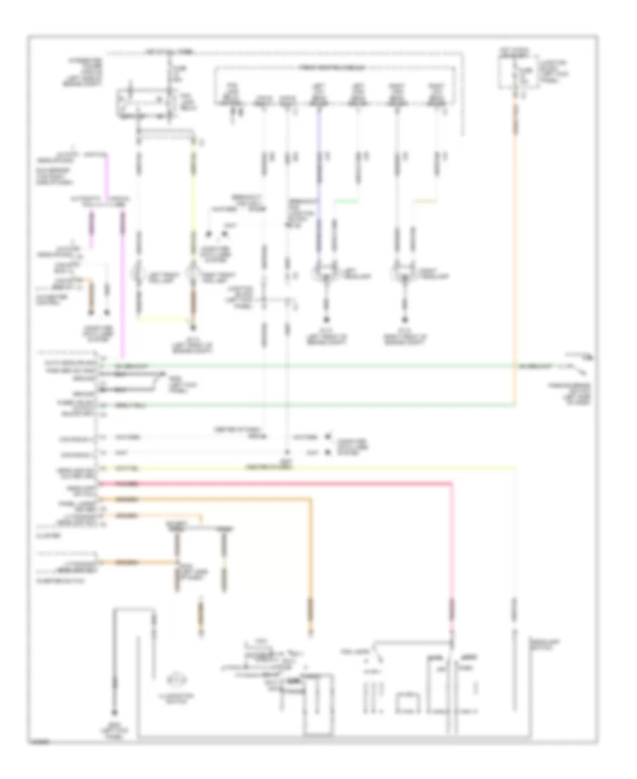
EXTERIOR LIGHTS
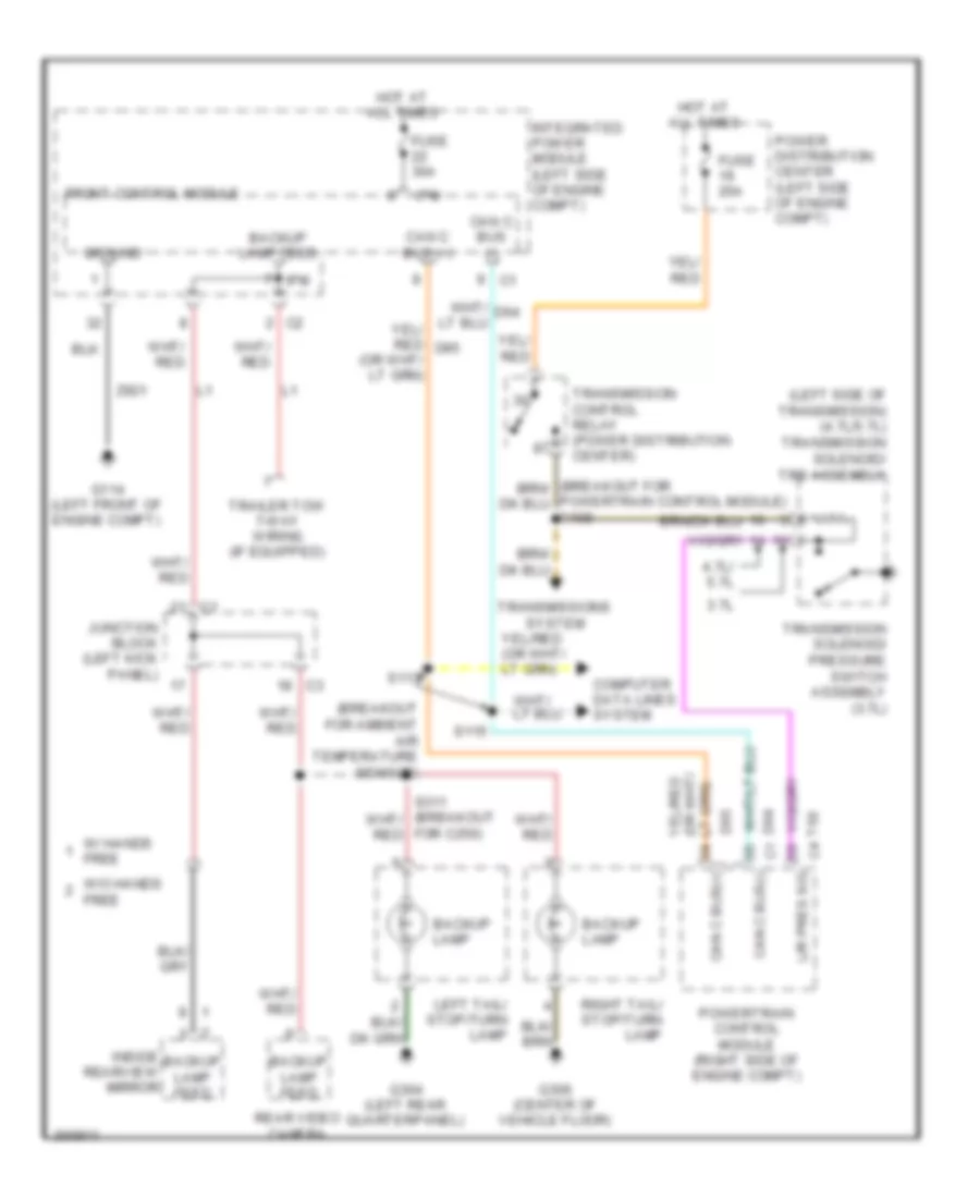
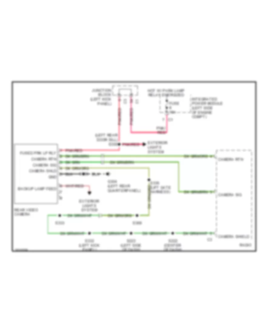
Backup Lamps Wiring Diagram for Chrysler Aspen Limited Hybrid 2009
List of elements for Backup Lamps Wiring Diagram for Chrysler Aspen Limited Hybrid 2009:
- (breakout for ambient air temperature sensor)
- (left side of transmission) (4.7l/5.7l) transmission solenoid/ trs assembly
- 3.7l
- 4.7l/ 5.7l
- Backup lamp
- Backup lamp feed
- C1 can c bus(-)
- Can c bus (+)
- Can c bus (-)
- Can c bus(+)
- Computer data lines system
- D64
- D65
- For c250)
- Front control module
- Fuse 20a
- Fuse 30a
- G114 (left front of engine compt)
- G304 (left rear quarterpanel)
- G306 (center of vehicle floor)
- Ground
- Hot at all times
- Inside rearview mirror
- Integrated power module (left side of engine compt)
- Ipm
- Junction block (left kick panel)
- L/r pres sig
- Left tail/ stop/turn lamp
- Power distribution center (left side of engine compt)
- Powertrain control module (right side of engine compt)
- Powertrain control module) s109
- Rear video camera
- Right tail/ stop/turn lamp
- S113
- S115
- T50
- Trailer tow 7-way wiring (if equipped)
- Transmission control relay (power distribution center)
- Transmission solenoid/ pressure switch assembly (3.7l)
- Transmissions system
- W/ hands free
- W/o hands free
- Z921
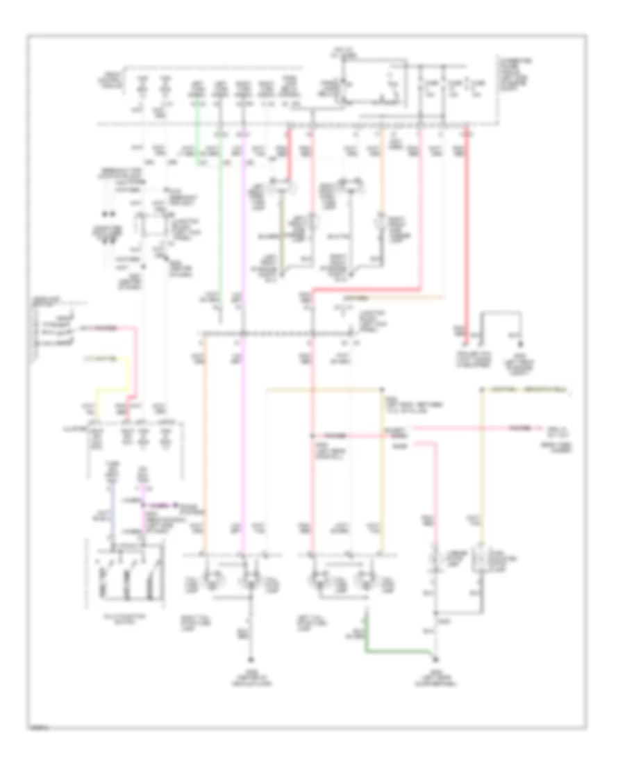
Exterior Lamps Wiring Diagram (1 of 2) for Chrysler Aspen Limited Hybrid 2009
List of elements for Exterior Lamps Wiring Diagram (1 of 2) for Chrysler Aspen Limited Hybrid 2009:
- (breakout for junction block) s125
- (left front of engine compt) g113
- (not used)
- (right front of engine compt) g112
- 87a
- Auto
- Base
- Can b bus (+)
- Can b bus (-)
- Cluster
- Computer data lines system
- D54
- D55
- Except base
- Front control module
- Fuse 10a
- G304 (left rear quarterpanel)
- G305 (left front of engine compt)
- G306 (center of vehicle floor)
- Hazard
- Hdlp sw mux
- Hdlp sw mux rtn
- Head
- Headlamp switch
- High mounted stop lamp
- Hot at all times
- Integrated power module (left side of engine compt)
- Ipm
- Junction block (left kick panel)
- L61
- L62
- L63
- Left front park/ turn lamp
- Left front side marker lamp
- Left tail/ stop/turn lamp
- Left turn
- Left turn signal
- License plate lamp
- Multi-function switch
- Off
- Park
- Park lamp relay
- Park lamp relay control
- Pnk/ red
- Pnk/red
- Prk lp rly out
- Rear video camera
- Right front park/ turn lamp
- Right front side marker lamp
- Right tail/ stop/turn lamp
- Right turn
- Right turn signal
- S207 (center of dash)
- S208 (center of dash)
- S300 (left rear door sill)
- S303 (left body, between ``a" & ``b" pillar)
- S335
- Sound systems
- Sw mux rtn
- Tail/ stop lamp
- Tail/ turn lamp
- Trailer tow 7-way wiring (if equipped)
- Turn sig input mux
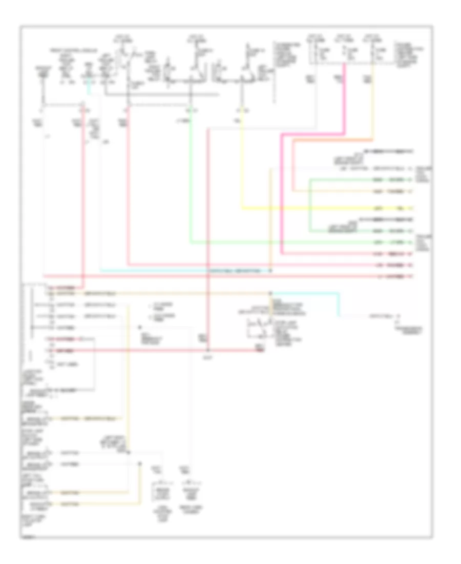
Exterior Lamps Wiring Diagram (2 of 2) for Chrysler Aspen Limited Hybrid 2009
List of elements for Exterior Lamps Wiring Diagram (2 of 2) for Chrysler Aspen Limited Hybrid 2009:
- (breakout for proportional purge solenoid) s122
- (breakout for speed control servo) s119
- (or b45)
- 87a
- Anti-lock brakes module (left front of engine compt)
- B29
- B401
- Brake lamp sw out
- Brake sw 1 signal c3
- Can c bus (+)
- Can c bus (-)
- Computer data lines system
- D64
- D65
- Except hybrid
- F202
- Front control module (at integrated power module)
- Fuse 10a
- Fuse 15a
- Fused ign
- G208 (left kick panel)
- Hot at all times
- Hot in run
- Hybrid
- Junction block (left kick panel)
- L50
- Power distribution center (left side of engine compt)
- Powertrain control module (right side of engine compt)
- Rly ctrl
- S116
- S127
- Stop lamp activation relay
- Stop lamp switch (left side of dash)
- Sw output (run-start)
- Trailer tow 4-way wiring
- Transmission assembly
- V32
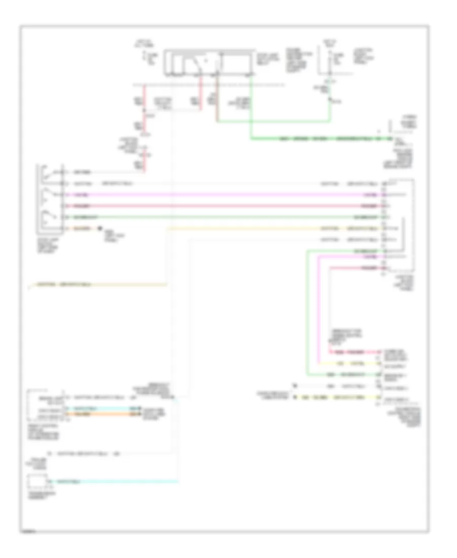
Trailer Tow Wiring Diagram for Chrysler Aspen Limited Hybrid 2009
List of elements for Trailer Tow Wiring Diagram for Chrysler Aspen Limited Hybrid 2009:
- (left body, between ``a" & ``b" pillar) s303
- (not used)
- 87a
- A100
- A400
- B400
- Backup lamp feed
- Backup lp feed
- Brake lp sw output
- Brk lp sw output
- Front control module
- Fuse 15a
- Fuse 19 20a
- Fuse 20a
- Fuse 21 20a
- Fuse 40a
- Fuse 9 10a
- G114 (left front of engine compt)
- G305 (left front of engine compt)
- High mounted stop lamp
- Hot at all times
- Inside rearview mirror
- Integrated power module (left side of engine compt)
- Ipm
- Junction block (left kick panel)
- L50
- L673
- L674
- L76
- Left tail/ stop/turn lamp
- Left trailer tow brk lp rly ctrl
- Left trailer tow relay
- Park lamp relay
- Pnk/ red
- Pnk/red
- Power distribution center (left side of engine compt)
- Rear video camera
- Right trailer tow brk lp rly ctrl
- Right trailer tow relay
- Right turn/ tail/stop lamp
- S122 (breakout for proportional purge solenoid)
- S127
- S311 (breakout for c250)
- Stop lamp activation relay (power distribution center)
- Stop lamp switch (left side of dash)
- Tan/ red
- Tan/red
- Trailer tow 4-way wiring
- Trailer tow 7-way wiring
- Transmission assembly
- W/ hands free
- W/o hands free
- Z916
- Z976
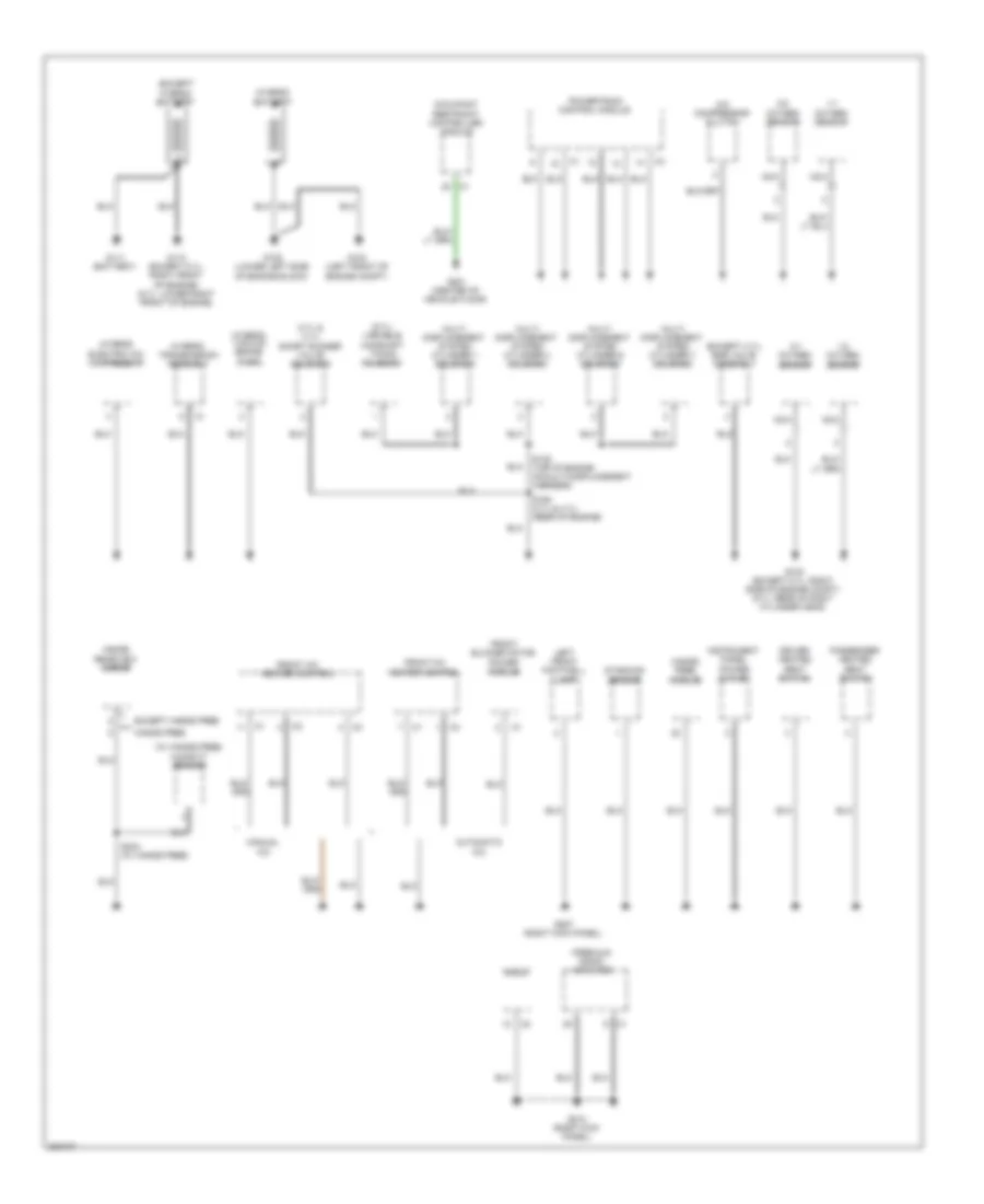
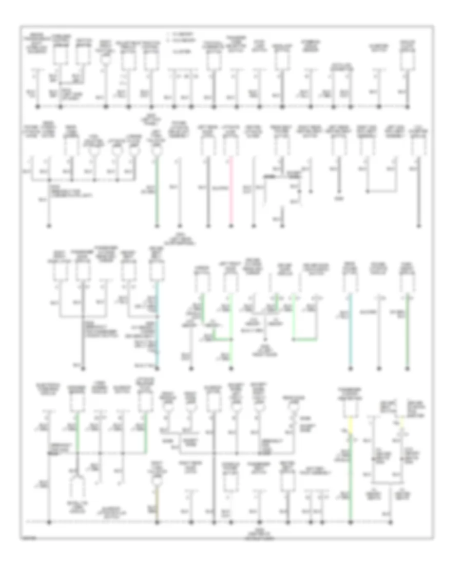
GROUND DISTRIBUTION
Ground Distribution Wiring Diagram (1 of 3) for Chrysler Aspen Limited Hybrid 2009
List of elements for Ground Distribution Wiring Diagram (1 of 3) for Chrysler Aspen Limited Hybrid 2009:
- (3.7l & 4.7l) short runner valve solenoid
- (5.7l) variable camshaft timing solenoid
- (except 3.7l) egr valve assembly
- (except hybrid) battery
- (hybrid) battery
- (hybrid) electric a/c compressor
- (hybrid) transmission assembly
- (hybrid) vacuum brake pump
- (premium) radio amplifier
- (w/ hands free) humidity sensor
- 1/1 oxygen sensor
- 1/2 oxygen sensor
- 2/1 oxygen sensor
- 2/2 oxygen sensor
- A/c compressor clutch
- Automatic a/c
- Driver heated seat switch
- Dynamics sensor
- Except hands free
- Front a/c heater control
- Front blower motor power module
- G100 (except 5.7l: right side of engine compt) (5.7l: rear of right cylinder head)
- G104 (left front of engine compt)
- G108 (lower left side of engine block)
- G110 (except 5.7l: right front of engine) (5.7l: lower right front of engine)
- G111 (battery)
- G201 (center of vehicle floor)
- G207 (right kick panel)
- G210 (right kick panel)
- Hands free
- Hands free module
- Inside rearview mirror
- Instrument panel power outlet
- Left front footwell lamp
- Manual a/c
- Multi displacement system cylinder 1 solenoid
- Multi displacement system cylinder 4 solenoid
- Multi displacement system cylinder 6 solenoid
- Multi displacement system cylinder 7 solenoid
- Nca
- Occupant restraint controller module
- Passenger heated seat switch
- Powertrain control module
- Radio
- S135 (top of engine on multi-displacement harness)
- S158 (3.7l & 4.7l) (rear of engine)
- S234 (w/ hands free)
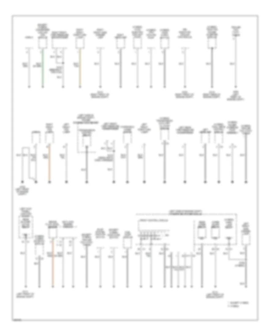
Ground Distribution Wiring Diagram (2 of 3) for Chrysler Aspen Limited Hybrid 2009
List of elements for Ground Distribution Wiring Diagram (2 of 3) for Chrysler Aspen Limited Hybrid 2009:
- (except hybrid) condenser cooling fan module
- (except hybrid) hood ajar switch
- (except hybrid) trailer tow 4-way wiring
- (hybrid) final drive control module
- (hybrid) hood ajar 2 switch
- (hybrid) hvac electric coolant pump
- (hybrid) hybrid gateway module
- (hybrid) park lamp relay
- (hybrid) power steering pump assembly
- (hybrid) tpim cooling pump
- (hybrid) traction power inverter module
- (hybrid) trailer tow 4-way wiring
- (hybrid) transmission auxiliary oil pump module
- (left kick panel) junction block
- (left side of engine compt) integrated power module
- (left side of engine compt) power distribution center
- 87a
- Anti-lock brakes module
- Brake fluid level sensor
- Evap system monitor switch
- Except hybrid
- Front control module
- Fuel pump module
- G102 (left front of engine compt)
- G103 (right front of engine compt)
- G112 (right front of engine compt)
- G113 (left front of engine compt)
- G114 (left front of engine compt)
- G115 (right rear of engine compt)
- G305 (left front of engine compt)
- Hev radiator cooling fan module
- Horn 1
- Horn 2
- Hybrid
- Ipm
- Left front fog lamp
- Left front park/turn lamp
- Left front side marker lamp
- Left front tire pressure transponder
- Left headlamp
- Left rear tire pressure transponder
- Rear blower motor relay
- Rear wiper relay
- Right front fog lamp
- Right front park/turn lamp
- Right front side marker lamp
- Right front tire pressure transponder
- Right headlamp
- S120 (breakout for c108)
- S124 (headlamp & dash harness)
- S165 (hybrid)
- Trailer tow 7-way wiring
- Transmission control relay
- Windshield
- Wiper motor
- Wiper on/off relay
Ground Distribution Wiring Diagram (3 of 3) for Chrysler Aspen Limited Hybrid 2009
List of elements for Ground Distribution Wiring Diagram (3 of 3) for Chrysler Aspen Limited Hybrid 2009:
- (breakout for c222) s329
- (breakout for c222) s351
- (except base) left vanity lamp
- (except base) right vanity lamp
- (left side of dash)
- (w/ heated seats) s364
- (w/o memory seats) s364
- 110v inverter module
- Adjustable pedals switch
- Analog clock module
- Base
- Battery pack assembly
- Brake transmission shift interlock solenoid
- Cluster
- Console power outlet
- Data link connector
- Driver cushion pad heater
- Driver door lock/window switch
- Driver door module
- Driver outside rearview mirror
- Driver seat belt switch
- Driver seat switch
- Electronic overhead module
- Except base
- Front dome lamp
- Front reading lamp
- G208 (left kick panel)
- G304 (left rear quarterpanel)
- G306 (center of vehicle floor)
- Headlamp switch
- Heated liftgate glass
- Heated seat module
- High mounted stop lamp
- Ignition switch
- Infrared sensor
- Inverter switch
- Left 2nd row seat assembly
- Left front door latch
- Left rear door latch
- Left rear heated seat switch
- Left turn/ tail/stop lamp
- License plate lamp
- Liftgate ajar switch
- Liftgate lamp
- Liftgate release plug switch
- Memory seat module
- Mirror switch
- Park assist module
- Passenger cushion heater pad
- Passenger door module
- Passenger outside rearview mirror
- Passenger seat switch
- Power liftgate chime
- Power liftgate drive unit assembly
- Power liftgate module
- Rear dome lamp
- Rear power outlet
- Rear seat power outlet
- Rear video camera
- Rear window wiper motor
- Right 2nd row seat assembly
- Right front door latch
- Right front footwell lamp
- Right rear door latch
- Right rear heated seat switch
- Right turn/ tail/stop lamp
- S328 (breakout for passenger window switch)
- S335 (breakout for license plate light)
- S353 (in left front door)
- S365 (w/ memory) (under driver's seat)
- S368
- Satellite video module
- Steering angle sensor
- Stop lamp switch
- Sunroof motor
- Sunroof switch
- Sunroof/ liftgate plug switch
- Tow/haul overdrive switch
- Traction control switch
- Transfer case selector switch
- Video screen module
- W/ heated seats
- W/ memory
- W/ memory seats
- W/o memory
- Wireless control module
HEADLIGHTS
Headlights Wiring Diagram for Chrysler Aspen Limited Hybrid 2009
List of elements for Headlights Wiring Diagram for Chrysler Aspen Limited Hybrid 2009:
- (breakout for c201) s123
- (breakout for junction block) s125
- (center of dash)
- 87a
- A/c-heater control
- Auto
- Auto headlps sig
- Auto headlps sig c2
- Automatic a/c
- Base
- Can b bus (+)
- Can b bus (+) c1
- Can b bus (-)
- Cargo dome
- Cluster
- Computer data lines system
- D54
- D55
- Dim 1
- Dim 2
- Dim 3
- Dim 4
- Dim 5
- Dim 6
- Except base
- Fog lamp relay
- Fog lamp relay control
- Fog lamps
- Front control module
- Fuse 10a
- Fuse 20a
- Fused ign sw output (run-start) c3
- G112 (right front of engine compt)
- G113 (left front of engine compt)
- G208 (left kick panel)
- Ground
- Head
- Headlamp sw mux
- Headlamp sw mux return
- Headlamp switch
- Hot at all times
- Hot in run or start
- Illumination switch
- Ilt-dimming headlamp sw
- Ilt-dimming headlamp sw c3
- Integrated power module (left side of engine compt)
- Inverter switch
- Ipm
- Junction block (left kick panel)
- L33
- L34
- L43
- L44
- Left front fog lamp
- Left headlamp
- Left high beam driver
- Left low beam driver
- Manual a/c
- Off
- Panel lamps driver
- Parade
- Park
- Park brk sw sns
- Parking brake switch (left side of dash)
- Pnk/red
- Right front fog lamp
- Right headlamp
- Right high beam driver
- Right low beam driver
- S207 (center of dash)
- S208
- S216 (left side of dash)
- Sun sensor (top right side of dash)
HORN
Horn Wiring Diagram for Chrysler Aspen Limited Hybrid 2009
List of elements for Horn Wiring Diagram for Chrysler Aspen Limited Hybrid 2009:
- 87a
- Can b bus(+)
- Can b bus(+) c2
- Can b bus(-)
- Clockspring (top of steering column)
- Cluster
- Computer data lines system
- D54
- D55
- Front control module
- Fuse 16 20a
- G112 (right front of engine compt)
- G113 (left front of engine compt)
- Horn 1 (front of engine compt)
- Horn 2 (front of engine compt)
- Horn relay
- Horn relay control
- Horn sw
- Horn switch
- Hot at all times
- Integrated power module (left side of engine compt)
- Ipm
- Junction block (left kick panel) c4
- S123 (breakout for c201)
- S125 (breakout for junction block)
- S207 (center of dash)
- S208 (center of dash)
- Sense
INSTRUMENT CLUSTER
Instrument Cluster Wiring Diagram for Chrysler Aspen Limited Hybrid 2009
List of elements for Instrument Cluster Wiring Diagram for Chrysler Aspen Limited Hybrid 2009:
- (center of liftgate) liftgate ajar switch
- (left kick panel) g208
- (left side of dash) parking brake switch
- 3.7l & 4.7l
- 4wd neutral ind
- 5.7l
- 5v selector sw sply
- 5v sply
- A117
- A920
- A924
- Air conditioning system
- Ajar sw sns
- Analog clock module
- Anti-lock brakes system
- Auto headlamps sig
- B20
- B25
- B27
- B30
- Brake fluid level sensor (left rear of engine compt)
- Brake fluid lvl sw sns
- Btsi solenoid ctrl
- Bus(+) can b
- Bus(-) can b
- C2 bus(-) can b
- C2 sns ajar sw
- Can b bus(+)
- Can b bus(-)
- Can c bus(+)
- Can c bus(-)
- Cluster
- Computer data lines system
- Courtesy lamps dr
- D54
- D55
- D64
- D65
- Door locks system
- Dr lock drv right dr
- Driver door module
- Drv glove box lmp
- Drv htd seat hi ind
- Drv htd seat low ind
- Drv htd seat sw mux
- Drv left dr lock
- Drv panel lamps
- Drv right dr unlk
- Drv seat belt sw sns
- Drv unlk lr liftgate
- E10
- E11
- E12
- E19
- E33
- Eng oil pres sig
- Engine oil temperature sensor (5.7l) (right front of engine)
- Except hybrid
- Exterior lights system
- F21
- F855
- Front control module (at integrated power module)
- Front washer sw mux
- Front wiper sw mux
- Fuel lvl sen 1 sig
- Fuel lvl sens rtn
- Fuel pump module (top of fuel tank)
- Fuse 10a
- Fuse 15a
- Fuse 20a
- Fuse 30a
- Fused b(+)
- Fused ign sw output
- G114 (left front of engine compt)
- G194
- G208 (left kick panel)
- G24
- G304 (left rear quarterpanel)
- G306 (center of vehicle floor)
- G74
- G75
- G76
- G77
- G778
- G78
- G902
- G939
- G95
- Gnd
- Ground
- Headlamp sw mux
- Headlamp sw mux rtn
- Headlights system
- High beam/
- Horn sw sns
- Horns system
- Hot at all times
- Hot in run or start
- Hybrid
- Integrated power module (left front of engine compt)
- Interior lights system
- Junction block (left kick panel)
- K77
- K900
- K977
- L12
- L24
- L307
- L900
- Left front door latch
- Left rear door latch
- Lf dr unlk drv
- Liftgate ajar sw sns
- Liftgate power latch
- Lr door ajar sw sns
- M22
- M28
- Mode select
- Oil pressure sensor (5.7l) (right front of engine)
- Oil pressure switch (3.7l & 4.7l) (lower left front of engine)
- P392
- P393
- P81
- P82
- P83
- P84
- Panel lamps
- Panel lmps drv hvac
- Panel lp drv rr hvac
- Panel lps drv 4x4
- Panel lps drv cen sw
- Park brake sw sns
- Pas htd seat sw mux
- Pass htd seat hi ind
- Pass htd seat lo ind
- Passenger door module
- Pnk/red
- Pnl lps drv hd lp sw
- Powertrain control module (right side of engine compt)
- Press sig
- R57
- Radio ctrl mux
- Red
- Right front door latch
- Right rear door latch
- Rr dr ajar sw sns
- S102 (top front of right cylinder head)
- S105 (top front of engine)
- S200
- S210
- S211
- S328
- S340 (rear of cargo area)
- S353
- Seats system
- Sens gnd
- Sens sig
- Shift interlock system
- Sns ajar sw
- Sound systems
- Sun sens rtn
- Sw mux rtn
- Traction ctrl sw sns
- Transmissions system
- Trunk, tailgate, fuel doors system
- Turn sig input mux
- W/ power liftgate
- W/o power liftgate
- W52
- Warning systems
- Wiper/washer system
- X20
- Z925
- Z946
- Z948
Overhead Console Wiring Diagram for Chrysler Aspen Limited Hybrid 2009
List of elements for Overhead Console Wiring Diagram for Chrysler Aspen Limited Hybrid 2009:
- A926
- C83
- Can b bus(+)
- Can b bus(-)
- Computer data lines system
- D54
- D55
- Electronic overhead module (front center of headliner)
- Fuse 10a
- Fuse 15a
- Fused b(+)
- Fused ign sw output (run-st)
- G306 (center of vehicle floor)
- Ground
- Hot at all times
- Hot in run or start
- Infrared sensor (front of headliner)
- Infrared sensor signal
- Junction block (left kick panel)
- Red
- S351
- Z957
INTERIOR LIGHTS
Interior Lights Wiring Diagram (1 of 2) for Chrysler Aspen Limited Hybrid 2009
List of elements for Interior Lights Wiring Diagram (1 of 2) for Chrysler Aspen Limited Hybrid 2009:
- (breakout for front reading light) s323
- (left kick panel) g208
- (left side of dash)
- (left side of dash) (except base) s217
- (right kick panel) g207
- Ajar sw sns
- Auto
- Base
- Can b bus (+)
- Can b bus (-)
- Cluster
- Computer data lines system
- Driver courtesy lamp
- Driver glove box lamp
- Driver panel lamps
- Drv csy lp
- Drv hvac panel lamps
- Drv pnl lamp
- Except base
- Except power liftgate
- Front dome lamp (except base)
- Front reading lamp (base)
- Fuse 10a
- G208 (left kick panel)
- G304 (left rear quarterpanel)
- G306 (center of vehicle floor)
- G78
- Ground
- Head
- Headlamp sw mux
- Headlamp sw mux rtn
- Headlamp switch 5) dim 1 6) dim 2 7) dim 3 8) dim 4 9) dim 5 10) dim 6 11) parade 12) dome 13) cargo
- Hot in run or start
- Ign sw out (run/start)
- Illumination switch
- Ilt dimming rear hvac
- Junction block (left kick panel)
- Left front footwell lamp (except base)
- Left rear door latch
- Left vanity lamp (except base)
- Liftgate ajar sw sns
- Liftgate ajar switch (center of liftgate)
- Liftgate lamp
- Lr door ajar sw sns
- Off
- Park
- Pnk/ red
- Pnk/red
- Pnl lamps center bezel/ heated seat switches
- Pnl lamps drv 4x4
- Power liftgate
- Power liftgate latch
- Power liftgate module (left rear cargo area)
- Rear dome lamp (base)
- Rear dome lamp (except base)
- Right front footwell lamp (except base)
- Right rear door latch
- Right vanity lamp (except base)
- Rr door ajar sw sns
- S216
- S304 (left body, between ``a" & ``b" pillar)
- S324 (breakout for c222)
- S329
- S335
- S340 (rear of cargo area)
Interior Lights Wiring Diagram (2 of 2) for Chrysler Aspen Limited Hybrid 2009
List of elements for Interior Lights Wiring Diagram (2 of 2) for Chrysler Aspen Limited Hybrid 2009:
- (not used)
- A/c heater control
- Ajar sw sns
- Analog
- Analog clock module
- Automatic a/c
- Base
- C200
- Can b bus (+)
- Can b bus (-)
- Computer data lines system
- D54
- D55
- Driver door module
- Driver heated seat switch
- Driver panel lamps
- Drv 4x4
- Drv panel lamps
- E12
- Except analog
- Except base
- G207 (right kick panel)
- G208 (left kick panel)
- G304 (left rear quarterpanel)
- G306 (center of vehicle floor)
- G74
- G75
- Ground
- Hvac micro controller
- Inverter switch
- Left front door latch
- Manual a/c
- Passenger door module
- Passenger heated seat switch
- Pnl lamps
- Pnl lamps drv
- Rear a/c- heater control
- Right front door latch
- Right rear heated seat switch
- S215 (lower steering column)
- S224 (left side of dash)
- S328
- S353
- S366
- S368
- Transfer case selector switch
- Z925
MEMORY SYSTEMS
Memory Systems Wiring Diagram (1 of 2) for Chrysler Aspen Limited Hybrid 2009
List of elements for Memory Systems Wiring Diagram (1 of 2) for Chrysler Aspen Limited Hybrid 2009:
- (left kick panel)
- A940
- Adjustable pedals motor (left center of dash)
- Adjustable pedals motor fwd
- Adjustable pedals motor rwd
- Adjustable pedals sens rtn
- Adjustable pedals sens sig
- Adjustable pedals sensor (left side of dash)
- Adjustable pedals sw fwd
- Adjustable pedals sw rwd
- Adjustable pedals switch (left side of dash)
- Backward
- Can b bus (+)
- Can b bus (-)
- Computer data lines system
- D54
- D55
- Driver front vertical seat adjuster motor (under driver seat)
- Driver horizontal seat adjuster motor (under driver seat)
- Driver rear vertical seat adjuster motor (under driver seat)
- Driver recliner seat adjuster motor (under driver seat)
- Driver seat switch
- Drv seat front vert down drv
- Drv seat front vert pos sns
- Drv seat front vert sns gnd
- Drv seat front vert up drv
- Drv seat front vert/rclinr sw mux
- Drv seat horiz fwd drv
- Drv seat horiz pos sns
- Drv seat horiz rwd drv
- Drv seat horiz sens gnd
- Drv seat rear vert down drv
- Drv seat rear vert pos sns
- Drv seat rear vert sns gnd
- Drv seat rear vert up drv
- Drv seat rear vert/horiz sw mux
- Drv seat recliner down drv
- Drv seat recliner pos sens gnd
- Drv seat recliner pos sns
- Drv seat recliner up drv
- Drv seat sw mux rtn
- Forward
- Front down
- Front up
- Fuse 40a
- Fused b (+)
- G11
- G12
- G208
- G306 (center of vehicle floor)
- G401
- G402
- G403
- G404
- G491
- G492
- G493
- G494
- G912
- Ground
- Hot at all times
- P111
- P113
- P115
- P117
- P119
- P121
- P141
- P143
- P205
- P206
- P28
- P29
- P309
- P311
- Power distribution center (left side of engine compt)
- Q100
- Q900
- Rear down
- Rear up
- Rearward
- Recliner down
- Recliner up
- S356 (w/ heated seats)
- S365
- Seat memory module (under driver seat)
- Z930
Memory Systems Wiring Diagram (2 of 2) for Chrysler Aspen Limited Hybrid 2009
List of elements for Memory Systems Wiring Diagram (2 of 2) for Chrysler Aspen Limited Hybrid 2009:
- (driver's door) driver outside rearview mirror
- (w/o hands free) inside rearview mirror
- A215
- Auto day/night mirror (+)
- Auto day/night mirror (-)
- C110
- C17
- C910
- C917
- Can b bus (+)
- Can b bus (-)
- Computer data lines system
- D54
- D55
- Driver door ajar sw sense
- Driver door ajar sw sns
- Driver door module
- Driver mirror common drv
- Driver mirror heater drv
- Driver mirror vertical drv
- Driver module ground i d
- Driver window/ door lock switch
- Drv mirror heater
- Drv mirror hori pos sig
- Drv mirror horizontal drv
- Drv mirror sens gnd
- Drv mirror sens sply
- Drv mirror vert pos sig
- Fuse 10a
- Fused b (+)
- Fused b(+)
- G160
- G161
- G306 (center of vehicle floor)
- G74
- G75
- G775
- G776
- G920
- Ground
- Hot at all times
- Junction block (left kick panel)
- Left door lock sw mux
- Left door lock sw rtn
- Left front door latch
- Lh mirror horiztal sw sns
- Lh mirror horztal sw sns
- Memory select sw mux
- Memory select sw rtn
- Memory selector switch
- Mirror common sw sns
- Mirror switch
- Mirror vertical dn sw sns
- Mirror vertical up sw sns
- P339
- P64
- P65
- P66
- P666
- P669
- P67
- P68
- P69
- P70
- P703
- P704
- P705
- P706
- P71
- P710
- P72
- P73
- P74
- P75
- Pass door ajar sw sense
- Pass door ajar sw sns
- Pass mirr hori pos sig
- Pass mirr ver pos sig
- Pass mirror comm drv
- Pass mirror hori drv
- Pass mirror htr drv
- Pass mirror htr gnd
- Pass mirror sens gnd
- Pass mirror sens sply
- Pass mirror vert drv
- Pass window exp sw mux
- Pass window exp sw rtn
- Passenger door module
- Passenger outside rearview mirror (right front door)
- Passenger window/ door lock switch
- Q336
- Q936
- Rh door lock sw mux
- Rh door lock sw rtn
- Rh mirror horiztal sw sns
- Rh mirror horztal sw sns
- Right door lock sw mux
- Right door lock sw rtn
- Right front door latch
- S307
- S328
- S352
- S353
- Tan
- Z940
- Z944
NAVIGATION
Parking Assistant Wiring Diagram for Chrysler Aspen Limited Hybrid 2009
List of elements for Parking Assistant Wiring Diagram for Chrysler Aspen Limited Hybrid 2009:
- (center of rear fascia)
- Can b bus (+)
- Can b bus (-)
- Computer data lines system
- D54
- D55
- D701
- D703
- D704
- D710
- D777
- Display gnd
- Display sig
- Display sply
- F922
- Fuse 20a
- G304 (left rear quarterpanel)
- Ground
- Hot in on
- Ign sw output (run)
- Junction block (left kick panel)
- Park assist display gnd
- Park assist display sig
- Park assist display sply
- Park assist module
- Park assist sens gnd
- Park assist sens sig 10
- Park assist sens sig 11
- Park assist sens sig 8
- Park assist sens sig 9
- Park assist sens sply
- Park assist sensor 10 (left center of rear fascia)
- Park assist sensor 11 (left side of rear fascia)
- Park assist sensor 8
- Park assist sensor 9 (right center of rear fascia)
- Rear park assist display
- S363 (w/ rear heated seats)
- S371 (left side of rear fascia)
- S372
- Sens 10 sig
- Sens 11 sig
- Sens 8 sig
- Sens 9 sig
- Sens gnd
- Sens sply
- X700
- X750
- X772
- X777
- Z177
Rear Camera Wiring Diagram for Chrysler Aspen Limited Hybrid 2009
List of elements for Rear Camera Wiring Diagram for Chrysler Aspen Limited Hybrid 2009:
- (left rear door sill) s300 pnk/red
- Backup lamp feed
- Camera rtn
- Camera shield
- Camera shld
- Camera sig
- Exterior lights system
- Fuse 10a
- Fused prk lp rly
- G304 (left rear quarterpanel)
- Gnd
- Hot w/ park lamp relay energized
- Integrated power module (left side of engine compt)
- Junction block (left kick panel)
- Pnk/ red
- Pnk/red
- Radio
- Rear video camera
- S222 (center of dash)
- S223 (left side of dash)
- S332 (left kick panel)
- S333
- S335
- S369
POWER DISTRIBUTION
Power Distribution Wiring Diagram, Except Hybrid (1 of 4) for Chrysler Aspen Limited Hybrid 2009
List of elements for Power Distribution Wiring Diagram, Except Hybrid (1 of 4) for Chrysler Aspen Limited Hybrid 2009:
- (diagram
- (in left front door) s354
- (left kick panel) junction block
- (left side of engine compt) power distribution center
- (left side of engine compt) s111
- (left side of engine compt) s138
- 2 of 4)
- 4 of 4)
- 87a
- A/c clutch relay
- Accessory delay relay
- Air bag squib)
- Analog clock module
- Anti-lock brakes module
- Auto shut down relay
- Battery
- Between "a" & "b" pillar) s308
- Block
- Circuit breaker 25a
- Cluster
- Door lock switch breakout) s355
- Driver door module
- Driver window/ door lock switch
- For instrument cluster) s210
- For passenger
- Front blower motor relay
- Front control module
- Fuel pump relay
- Fuse 10a
- Fuse 15a
- Fuse 20a
- Fuse 25a
- Fuse 30a
- Fuse 40a
- Fuse 60a
- Fusible link 1 (4 ga- red)
- G207 (right kick panel)
- Generator
- Harness, near battery)
- Instrument panel power outlet
- Integrated power module (left side of engine compt)
- Inverter
- Ipm
- Junction
- Mirror switch
- Module
- Passenger door module
- Passenger window/ door lock switch
- Power liftgate module
- Powertrain control module
- Radio amplifier
- Rear blower motor relay
- Rear window defogger relay
- Red
- Red/ pnk
- Run remote relay
- S143 (left kick panel)
- S205 (breakout
- S211 (breakout for instrument cluster) red
- S352 (in left front door)
- Starter
- Starter motor relay
- Sunroof motor
- Tan/ red
- To 110v
- To fuse 35 (diagram 2 of 4)
- To integrated power module fuse 14 (diagram 3 of 4)
- To junction block (diagram 2 of 4)
- To junction block fuse 24 (diagram 2 of 4)
- To junction block fuse 35 (diagram 2 of 4)
- To splice s121 (diagram 4 of 4)
- To splice s127 (diagram 2 of 4)
- To splice s128 (diagram 2 of 4)
- Trailer tow 4-way wiring
- Trailer tow 7-way wiring
- Transmission control relay
- Wiper high/low relay
- Wiper on/off relay
Power Distribution Wiring Diagram, Except Hybrid (2 of 4) for Chrysler Aspen Limited Hybrid 2009
List of elements for Power Distribution Wiring Diagram, Except Hybrid (2 of 4) for Chrysler Aspen Limited Hybrid 2009:
- "a" & "b" pillar) s363
- (left side of engine compt) power distribution center
- (not used)
- 87a
- Accessory delay
- Automatic a/c
- Battery
- Cluster
- Console power outlet
- Driver seat switch
- From circuit braker (diagram 1 of 4)
- From front blower motor relay (diagram 1 of 4)
- From power distribution center fuse 25 (diagram 1 of 4)
- From power distribution center fuse 27 (diagram 1 of 4)
- From power distribution center fuse 5 (diagram 1 of 4)
- From run remote relay (diagram 1 of 4)
- From splice s128 (diagram 2 of 4) j
- From splice s143 (diagram 1 of 4)
- Front a/c heater control
- Front blower motor power module (automatic a/c)
- Front control module
- Fuse 10a
- Fuse 20a
- G304 (left rear quarterpanel)
- G306 (center of vehicle floor)
- Heated seat module
- Infrared sensor
- Integrated power module (left side of engine compt)
- Ipm
- Junction block (left kick panel)
- Left rear seat heated switch
- Manual a/c
- Memory seat module
- Occupant restraint controller module
- Park assist module
- Passenger seat switch
- Power distribution center (left side of engine compt)
- Rear a/c heater control
- Rear blower motor relay
- Rear power outlet (right rear corner of vehicle)
- Rear seat power outlet
- Rear window defogger relay
- Red
- Red (left side of engine compt) s128
- Right rear seat heated switch
- Run/ start relay ctrl
- Run/start relay
- S367
- Stop lamp activation relay
- Stop lamp switch
- To ignition switch (diagram 4 of 4)
- To junction block fuse 34 (diagram 2 of 4)
- To splice s116 (diagram 4 of 4)
- To splice s119 (diagram 3 of 4)
- To transfer case selector switch (diagram 3 of 4)
- W/ highline
- W/ memory
- W/ park assist
- W/ passenger power seats
- W/ rear heated seats
- W/o highline
- W/o memory
- W/o park assist
- W/o passenger power seats
- W/o rear heated seats
Power Distribution Wiring Diagram, Except Hybrid (3 of 4) for Chrysler Aspen Limited Hybrid 2009
List of elements for Power Distribution Wiring Diagram, Except Hybrid (3 of 4) for Chrysler Aspen Limited Hybrid 2009:
- (breakout for passenger air bag squib) s200
- (breakout for speed control servo) s119
- (left side of engine compt) integrated power module
- (w/ humidity sensor)
- A/c clutch relay
- A/c-heater control (automatic a/c)
- Adjustable pedals relay (except memory)
- B(+)
- Cluster
- Data link connector
- Driver heated seat switch
- Electronic overhead module
- Except hands free
- Fog lamp relay
- From junction block fuse 18 (diagram 2 of 4)
- From junction block fuse 19 (diagram 2 of 4)
- From power distribution center (diagram 1 of 4)
- Front control module
- Fuel pump relay
- Fuse 10a
- Fuse 15a
- Fuse 20a
- Fuse 25a
- Fuse 30a
- Fuse 40a
- Hands free
- Hands free module (if equipped)
- Horn relay
- Humidity sensor
- Inside rearview mirror
- Ipm
- Junction block (left kick panel)
- Junction block (left kick panel) c2
- Left trailer tow relay
- Park lamp relay
- Passenger heated seat switch
- Power distribution center (left side of engine compt)
- Powertrain control module
- Radiator fan high relay
- Radiator fan low relay
- Radio
- Rear wiper relay
- Red
- Right trailer tow relay
- S233
- S338
- Satellite video module (w/ remote radio)
- Stop lamp switch
- Transfer case selector switch
- Video screen module
- W/ heated seats
- W/ humidity sensor
- W/o heated seats
- Wireless control module
Power Distribution Wiring Diagram, Except Hybrid (4 of 4) for Chrysler Aspen Limited Hybrid 2009
List of elements for Power Distribution Wiring Diagram, Except Hybrid (4 of 4) for Chrysler Aspen Limited Hybrid 2009:
- (not used)
- 110v inverter module
- Ac line 1
- Ac line 2
- Ac power outlet
- Acc
- Anti-lock brakes module
- C201
- Dynamics sensor (w/ esp)
- From junction block fuse 26 (diagram 2 of 4)
- From junction block fuse 34 (diagram 2 of 4)
- From power distribution center fuse 16 (diagram 1 of 4)
- From starter motor relay (diagram 1 of 4)
- Front control module
- Fused b(+)
- Fused ign sw output (off-run- start)
- Fused ign sw output (start)
- G208 (left kick panel)
- G304 (left rear quarterpanel)
- Ground
- Headlamp switch panel lamps driver
- Ign sw sense input
- Ignition switch
- Integrated power module (left side of engine compt)
- Interior lights system
- Inverter enable switch signal
- Inverter status indicator driver
- Inverter switch
- Inverter switch signal
- Ipm
- Junction block (left kick panel) c4
- Left front tire pressure transponder
- Left rear tire pressure transponder
- Lock off
- Near grommet)
- Power distribution center (left side of engine compt)
- Powertrain control module
- Red
- Red a957
- Right front tire pressure transponder
- Run
- S121 (near breakout for anti-lock brakes module)
- S214 (lower steering column)
- S218
- Start
- Steering angle sensor
- Stop lamp activation relay
- Wireless control module
Power Distribution Wiring Diagram, Hybrid (1 of 4) for Chrysler Aspen Limited Hybrid 2009
List of elements for Power Distribution Wiring Diagram, Hybrid (1 of 4) for Chrysler Aspen Limited Hybrid 2009:
- (diagram
- (in left front door) s354
- (left body, between "a" & "b" pillar) s307
- (left kick panel) junction block
- (left side of engine compt) power distribution center
- (left side of engine compt) s111
- (left side of engine compt) s138
- 2 of 4)
- 4 of 4)
- 87a
- A/c clutch relay
- Accessory delay relay
- Air bag squib)
- Anti-lock brakes module
- Auto shut down relay
- Battery
- Between "a" & "b" pillar) s308
- Block
- Block fuse 35
- Circuit breaker 25a
- Cluster
- Compt) s190
- Door lock switch breakout) s355
- Driver door module
- Driver window/ door lock switch
- Final drive control module
- For instrument cluster) s210
- For passenger
- Front blower motor relay
- Front control module
- Fuel pump relay
- Fuse 10a
- Fuse 15a
- Fuse 20a
- Fuse 25a
- Fuse 30a
- Fuse 40a
- Fuse 50a
- Fuse 60a
- Fusible link 2 (12 ga- red)
- G207 (right kick panel)
- Hev radiator cooling fan module
- Hybrid gateway module
- Instrument panel power outlet
- Integrated power module (left side of engine compt)
- Inverter
- Ipm
- Junction
- Mirror switch
- Module
- Passenger door module
- Passenger window/ door lock switch
- Power liftgate module
- Powertrain control module
- Radio amplifier
- Rear blower motor relay
- Rear window defogger relay
- Red
- Red/ (left side of engine compt) s131
- Red/ pnk
- Red/ tan
- Remote jump post
- Rly ctrl
- Run remote relay
- S143 (left kick panel)
- S154
- S157
- S196
- S205 (breakout
- S211 (breakout for instrument cluster) red
- S352 (in left front door)
- Splice
- Sunroof motor
- Tan/ red
- To 110v
- To fuse 35 (diagram 2 of 4)
- To integrated power module fuse 14 (diagram 3 of 4)
- To junction block (diagram 2 of 4)
- To junction block fuse 24 (diagram 2 of 4)
- To splice
- To splice s127 (diagram 2 of 4)
- To splice s128 (diagram 2 of 4)
- Tpim cooling pump
- Traction power inverter module
- Trailer tow 4-way wiring
- Trailer tow 7-way wiring
- Wiper high/low relay
- Wiper on/off relay
Power Distribution Wiring Diagram, Hybrid (2 of 4) for Chrysler Aspen Limited Hybrid 2009
List of elements for Power Distribution Wiring Diagram, Hybrid (2 of 4) for Chrysler Aspen Limited Hybrid 2009:
- (left body, between "a" & "b" pillar) s363
- (not used)
- 87a
- Accessory delay
- Automatic a/c
- Battery
- Cluster
- Console power outlet
- Driver seat switch
- From circuit breaker (diagram 1 of 4)
- From front blower motor relay (diagram 1 of 4)
- From power distribution center fuse 25 (diagram 1 of 4)
- From power distribution center fuse 27 (diagram 1 of 4)
- From power distribution center fuse 5 (diagram 1 of 4)
- From run remote relay (diagram 1 of 4)
- From splice s128 (diagram 2 of 4)
- From splice s143 (diagram 1 of 4)
- Front a/c heater control
- Front blower motor power module (automatic a/c)
- Front control module
- Fuse 10a
- Fuse 20a
- G304 (left rear quarterpanel)
- G306 (center of vehicle floor)
- Heated seat module
- Infrared sensor
- Integrated power module (left side of engine compt)
- Ipm
- Junction block (left kick panel)
- Left rear seat heated switch
- Manual a/c
- Memory seat module
- Occupant restraint controller module
- Park assist module
- Passenger seat switch
- Power distribution center (left side of engine compt)
- Rear a/c heater control
- Rear blower motor relay
- Rear power outlet (right rear corner of vehicle)
- Rear seat power outlet
- Rear window defogger relay
- Red
- Red (left side of engine compt) s128
- Right rear seat heated switch
- Run/ start relay ctrl
- Run/start relay
- S367
- Stop lamp activation relay
- Stop lamp switch
- To ignition switch (diagram 4 of 4)
- To junction block fuse 17 (diagram 2 of 4)
- To splice s116 (diagram 4 of 4)
- To splice s119 (diagram 3 of 4)
- To transfer case selector switch (diagram 3 of 4)
- W/ highline
- W/ memory
- W/ park assist
- W/ passenger power seats
- W/ rear heated seats
- W/o highline
- W/o memory
- W/o park assist
- W/o passenger power seats
- W/o rear heated seats
Power Distribution Wiring Diagram, Hybrid (3 of 4) for Chrysler Aspen Limited Hybrid 2009
List of elements for Power Distribution Wiring Diagram, Hybrid (3 of 4) for Chrysler Aspen Limited Hybrid 2009:
- (breakout for passenger air bag squib) s200
- (breakout for speed control servo) s119
- (left side of engine compt) integrated power module
- Adjustable pedals relay (except memory)
- Analog clock module
- Anti-lock brakes module
- B(+)
- Cluster
- Data link connector
- Driver heated seat switch
- Electric a/c compressor
- Electronic overhead module
- Except hands free
- Except humidity sensor
- Final drive control module
- Fog lamp relay
- From junction block fuse 18 (diagram 2 of 4)
- From junction block fuse 19 (diagram 2 of 4)
- From power distribution center (diagram 1 of 4)
- Front a/c-heater control (automatic a/c)
- Front control module
- Fuel pump relay
- Fuse 10a
- Fuse 15a
- Fuse 20a
- Fuse 25a
- Fuse 30a
- Fuse 40a
- Hands free module (if equipped)
- Hands- free
- Horn relay
- Humidity sensor
- Hvac electronic coolant pump
- Inside rearview mirror
- Ipm
- Junction block (left kick panel)
- Left trailer tow relay
- Park lamp relay
- Passenger heated seat switch
- Power distribution center (left side of engine compt)
- Power steering pump assembly
- Powertrain control module
- Radiator fan high relay
- Radiator fan low relay
- Radio
- Rear wiper relay
- Red
- Right trailer tow relay
- S151 (left rear of engine compt)
- S191
- S206 (breakout for left front tweeter speaker)
- S233
- S338
- Satellite video module (w/ remote radio)
- Traction power inverter module
- Transfer case selector switch
- Transmission assembly
- Transmission auxiliary oil pump module
- Video screen module
- W/ heated seats
- W/o heated seats
- Wireless control module
Power Distribution Wiring Diagram, Hybrid (4 of 4) for Chrysler Aspen Limited Hybrid 2009
List of elements for Power Distribution Wiring Diagram, Hybrid (4 of 4) for Chrysler Aspen Limited Hybrid 2009:
- (left front of engine compt) s152
- (left front of engine compt) s154
- (left front of engine compt) s157
- 110v inverter module
- Ac line 1
- Ac line 2
- Ac power outlet
- Acc
- Battery pack assembly
- From junction block fuse 26 (diagram 2 of 4)
- From junction block fuse 34 (diagram 2 of 4)
- From power distribution center fuse 20 (diagram 1 of 4)
- From power distribution center fuse 4 (diagram 1 of 4)
- From remote jump post (diagram 1 of 4)
- Front control module
- Fuse 10a
- Fuse 20a
- Fuse 25a
- Fuse 40a
- Fuse 80a
- Fused b(+)
- Fused ign sw output (off-run- start)
- Fused ign sw output (run- start)
- Fused ign sw output (start)
- G208 (left kick panel)
- G304 (left rear quarterpanel)
- Ground
- Headlamp switch panel lamps driver
- Hev power distribution center
- Hvac electric coolant pump
- Hybrid gateway module
- Ignition switch
- Integrated power module (left side of engine compt)
- Interior lights system
- Inverter enable switch signal
- Inverter status indicator driver
- Inverter switch
- Inverter switch signal
- Ipm
- Junction block (left kick panel)
- Junction block (left kick panel) c4
- Left front tire pressure transponder
- Left rear tire pressure transponder
- Lock off
- Power distribution center (left side of engine compt)
- Power steering pump assembly
- Power traction inverter module
- Powertrain control module
- Red
- Red a957
- Right front tire pressure transponder
- Run
- S153 (left front of engine compt)
- S214 (lower steering column)
- S218
- Start
- Steering angle sensor
- Stop lamp activation relay
- Tpim cooling pump
- Transmission assembly
- Transmission auxiliary oil pump module
- Vacuum pump relay
- Wireless control module
POWER DOOR LOCKS
Power Door Locks Wiring Diagram for Chrysler Aspen Limited Hybrid 2009
List of elements for Power Door Locks Wiring Diagram for Chrysler Aspen Limited Hybrid 2009:
- (center of vehicle floor) g306
- (front center of engine compt) (except 5.7l hybrid) hood ajar switch
- (left body, between "a" & "b" pillar) s310
- (left rear quarterpanel) g304
- (rear of cargo area) s340
- (right body, between "a" & "b" pillar)
- 87a
- A926
- Acc
- Accessory delay relay
- Cab b bus (+)
- Cab b bus (-)
- Can b bus (+)
- Can b bus (-)
- Can c bus (+)
- Can c bus (+) c1
- Can c bus (-)
- Circuit breaker 25a
- Cluster
- Com-lin
- Computer data lines system
- D508
- D54
- D55
- D64
- D65
- Dr lk drv lf
- Dr lk drv lh drs
- Dr lk drv rh drs
- Dr unlk drv lr/lift
- Dr unlk drv rh drs
- Driver door module
- Driver window/ door lock switch
- Drv door ajar sw sense
- Drv exp window sw rtn
- F20
- F30
- Front control module
- Fuse 15a
- Fuse 16 20a
- Fused acc delay rly output
- Fused acc rly out
- Fused b (+)
- Fused ign sw out
- G112 (right front of engine compt)
- G114 (left front of engine compt)
- G160
- G161
- G20
- G208 (left kick panel)
- G306 (center of vehicle floor)
- G64
- G65
- G70
- G74
- G75
- G775
- G776
- G79
- Ground
- Headlights system
- Hood ajar sw
- Hood ajar sw sens c4
- Hood ajar switch 2 (5.7 hybrid)
- Horn relay
- Horn rly ctrl ipm
- Horns system
- Hot at all times
- If equipped
- Ign sw sense
- Ignition switch
- Integrated power module (left front of engine compt)
- Junction block (left kick panel)
- L33
- L34
- Left door lock sw mux
- Left door lock sw rtn
- Left front door latch
- Left front tire pressure transponder (left front of engine compt)
- Left rear door latch
- Left rear tire pressure transponder (left rear of chassis)
- Lh hi bm drv
- Lift ajar sw sense
- Lift ajar sw sns
- Liftgate ajar switch (center of liftgate)
- Lock
- Logic ground
- Lr dr ajar sw sns
- Manual release liftgate latch (w/o power liftgate)
- Master sw lf window mux
- Master sw rf window mux
- Off
- Pass door ajar sw sense
- Passenger door module
- Passenger window/ door lock switch
- Power liftgate latch
- Power liftgate module (left rear cargo area)
- Powertrain control module (right side of engine compt)
- Q221
- Q222
- Q994
- Red
- Rh hi bm drv c2
- Right door lock sw mux
- Right door lock sw rtn
- Right front door latch
- Right front tire pressure transponder (right front of engine compt)
- Right rear door latch
- Rr dr ajar sw sns
- Run
- S200
- S214
- S218
- S302 (w/o power liftgate) (left rear door sill)
- S308
- S315
- S316
- S328
- S341 (rear of cargo area)
- S344 (in liftgate harness)
- S353
- S354
- S355
- Start
- Trunk, tailgate, fuel doors system
- W/ memory
- W/ power liftgate
- W/o power liftgate
- Wireless control module
- Z109
POWER MIRRORS
Automatic Day/Night Mirror Wiring Diagram, with Hands Free for Chrysler Aspen Limited Hybrid 2009
List of elements for Automatic Day/Night Mirror Wiring Diagram, with Hands Free for Chrysler Aspen Limited Hybrid 2009:
- (right kick panel) g207
- Auto day/night mirr (+)
- Auto day/night mirr (-)
- Backup lamp feed
- Backup lamp feed ipm
- Can b bus (+)
- Can b bus (+) c1
- Can b bus (-)
- Computer data lines system
- D54
- D55
- Driver outside rearview mirror (driver's door)
- F21
- Front control module
- Fuse 10a
- Fused ign sw out (run-start)
- Ground
- Hands free module (right end of dash)
- Hot in run or start
- Inside rearview mirror
- Integrated power module (left front of engine compt)
- Junction block (left kick panel)
- Micro 1 in (+)
- Micro 2 in (+)
- Micro feed
- Micro in (+)
- Microphone 1 in (+)
- Microphone 2 in (+)
- Microphone feed
- Microphone in (-)
- Mirr (+)
- Mirr (-)
- P112
- P114
- S206 (except humidity sensor)
- S233 (humidity sensor)
- S234
- Sen gnd
- Sensor ground
- X712
- X722
- X792
- X793
- X835
- Z999
Automatic Day/Night Mirror Wiring Diagram, without Hands Free for Chrysler Aspen Limited Hybrid 2009
List of elements for Automatic Day/Night Mirror Wiring Diagram, without Hands Free for Chrysler Aspen Limited Hybrid 2009:
- (right kick panel) g207
- Auto day/night mirr (+)
- Auto day/night mirr (-)
- Backup lamp feed
- Backup lamp feed ipm
- Can b bus (+) c1
- Can b bus (-)
- Computer data lines system
- D54
- D55
- Driver outside rearview mirror (driver's door)
- F21
- Front control module
- Fuse 10a
- Fused ign sw
- Ground
- Hot in run or start
- Inside rearview mirror
- Integrated power module (left front of engine compt)
- Junction block (left kick panel)
- Mirr (+)
- Mirr (-)
- Out (run-start)
- P112
- P114
- S206 (w/heated seats)
- Z999
Power Mirrors Wiring Diagram for Chrysler Aspen Limited Hybrid 2009
List of elements for Power Mirrors Wiring Diagram for Chrysler Aspen Limited Hybrid 2009:
- (breakout for driver outside rearview mirror) s318
- (center of vehicle floor) g306
- 87a
- A215
- Accessory delay relay
- Auto day/
- Circuit breaker 25a
- Defogger system
- Driver door module
- Driver outside rearview mirror (driver's door)
- Driver window/door lock switch
- Drv mirr common
- Drv mirr horz drv
- Drv mirr vert drv
- Fuse 10a
- Fused b (+)
- Fused ign sw output c1
- Ground
- Horiz
- Hot at all times
- Inside rearview mirror
- Junction block (left kick panel)
- Mirror switch
- Night mirr (+)
- Pass mirr horz drv
- Pass mirr vert drv
- Passenger outside rearview mirror (right front door)
- S352
- S364
- Vert
- W/ hands free
- W/o hands free
POWER SEATS
Adjustable Pedal Wiring Diagram for Chrysler Aspen Limited Hybrid 2009
List of elements for Adjustable Pedal Wiring Diagram for Chrysler Aspen Limited Hybrid 2009:
- (left kick panel) junction block
- 87a
- Adjustable pedals motor (left center of dash)
- Adjustable pedals relay
- Adjustable pedals rly control
- Adjustable pedals switch (left side of dash)
- Front control module
- Fuse 20a
- G208 (left kick panel)
- Hot at all times
- Integrated power module (left side of engine compt)
- Ipm
Driver Seat Wiring Diagram for Chrysler Aspen Limited Hybrid 2009
List of elements for Driver Seat Wiring Diagram for Chrysler Aspen Limited Hybrid 2009:
- (left kick panel) junction block
- (w/ heated seats) s364
- Bwd
- Driver front seat vertical adjuster motor (under driver seat)
- Driver horizontal seat adjuster motor (under driver seat)
- Driver recliner seat adjuster motor (under driver seat)
- Driver seat rear vertical adjuster motor (under driver seat)
- Driver seat switch
- Front vertical
- Fuse 5 40a
- Fwd
- G306 (center of vehicle floor)
- Horizontal
- Hot at all times
- Power distribution center (left side of engine compt)
- Power distribution system
- Rear vertical
- Recliner
- S366 (w/ passenger power seats)
Front Heated Seats Wiring Diagram for Chrysler Aspen Limited Hybrid 2009
List of elements for Front Heated Seats Wiring Diagram for Chrysler Aspen Limited Hybrid 2009:
- (center of vehicle floor) g306
- (w/o memory) s364
- A940
- Can b bus (+)
- Can b bus (-)
- Cluster
- Computer data lines system
- D54
- D55
- Driver cushion pad heater (under driver seat)
- Driver heated seat high ind drv
- Driver heated seat low ind drv
- Driver heated seat switch
- Driver heated seat switch mux
- Driver seat back heater (under driver seat)
- Driver seat heater b (+) driver
- Fuse 19 10a
- Fuse 5 40a
- Fused b (+)
- Fused ignition switch output (run-start)
- G207 (right kick panel)
- G306 (center of vehicle floor)
- Ground
- Heated seat module (right rear quarterpanel)
- Hot at all times
- Hot in run or start
- Interior lights system
- Junction block (left kick panel)
- P187
- P188
- Passenger cushion pad heater (under passenger seat)
- Passenger heated seat high ind drv
- Passenger heated seat low ind drv
- Passenger heated seat switch
- Passenger heated seat switch mux
- Passenger seat back heater (under passenger seat)
- Passenger seat heater b (+) driver
- Power distribution center (left side of engine compt)
- S206
- S356
- Z387
Passenger Seat Wiring Diagram for Chrysler Aspen Limited Hybrid 2009
List of elements for Passenger Seat Wiring Diagram for Chrysler Aspen Limited Hybrid 2009:
- Fuse 5 40a
- Fwd
- G306 (center of vehicle floor)
- Horizontal
- Hot at all times
- Passenger horizontal seat adjuster motor (under passenger seat)
- Passenger recliner seat adjuster motor (under passenger seat)
- Passenger seat switch
- Power distribution center (left side of engine compt)
- Recliner
- Red
- Rwd
- S356
Rear Heated Seats Wiring Diagram for Chrysler Aspen Limited Hybrid 2009
List of elements for Rear Heated Seats Wiring Diagram for Chrysler Aspen Limited Hybrid 2009:
- Drv pnl lp cen bzl/st sw
- Fuse 29 20a
- Fused ign sw output (run)
- G304 (left rear quarterpanel)
- Ground
- Hot in run
- Interior lights system
- Junction block (left kick panel)
- Left 2nd row seat assembly
- Left rear heated seat switch
- Lh rear heated seat feed
- Rh rear heated seat feed
- Right 2nd row seat assembly
- Right rear heated seat switch
- S367
- S368
POWER TOP/SUNROOF
Power Top/Sunroof Wiring Diagram for Chrysler Aspen Limited Hybrid 2009
List of elements for Power Top/Sunroof Wiring Diagram for Chrysler Aspen Limited Hybrid 2009:
- 87a
- Accessory delay relay
- Circuit breaker 25a
- Except power liftgate
- Fuse 10a
- Fuse 40a
- Fuse 60a
- Fused acc delay relay output
- Fused b(+)
- G306 (center of vehicle floor)
- Ground
- Hot at all times
- Junction block (left kick panel)
- Liftgate sw sense
- Power distribution center (left side of engine compt)
- Power liftgate
- Power liftgate module (left rear cargo area)
- Red
- Red/ pnk
- S308
- S329
- S351
- Sunroof close
- Sunroof motor (rear of sunroof)
- Sunroof open
- Sunroof switch
- Sunroof vent
- Sunroof/liftgate plg switch
- Tan
POWER WINDOWS
Power Windows Wiring Diagram for Chrysler Aspen Limited Hybrid 2009
List of elements for Power Windows Wiring Diagram for Chrysler Aspen Limited Hybrid 2009:
- (breakout for c250) s312
- (in left front door)
- 87a
- Accessory delay relay
- Circuit breaker 25a
- Door locks system
- Driver door module
- Driver window hall sens rtn
- Driver window motor (left front door)
- Driver window/door lock switch
- Drv exp window sw rtn
- Drv window exp down drv
- Drv window exp up drv
- Drv window hall sens a sig
- Drv window hall sens b sig
- Drv window hall sens rtn
- Drv window hall sens sply
- F30
- Fused acc delay rly output
- Fused ign sw output
- G306 (center of vehicle floor)
- Ground
- Hot at all times
- Junction block (left kick panel)
- Left rear power window switch
- Left rear window drv (down)
- Left rear window drv (up)
- Left rear window motor (left rear door)
- Lf window master sw mux
- Lr master window sw (down)
- Lr master window sw (up)
- Pass window exp down drv
- Pass window exp up drv
- Pass window express sw mux
- Pass window express sw rtn
- Pass window hall sens a sig
- Pass window hall sens b sig
- Pass window hall sens rtn
- Pass window hall sens sply
- Passenger door lock sw rtn
- Passenger door module
- Passenger window motor (right front door)
- Passenger window/door lock switch
- Power window sw feed
- Q15
- Q221
- Q222
- Q301
- Q302
- Q303
- Q304
- Q305
- Q306
- Q308
- Q311
- Q312
- Q321
- Q322
- Q336
- Q936
- Q991
- Q994
- Rf window master sw mux
- Right door lock sw mux
- Right rear power window switch
- Right rear window drv (down)
- Right rear window drv (up)
- Right rear window motor (right rear door)
- Rr master window sw (down)
- Rr master window sw (up)
- S308
- S353
- S354
- S355
- S370
- W/ memory
- Window lock out sw output
RADIO
Hands Free Module Wiring Diagram for Chrysler Aspen Limited Hybrid 2009
List of elements for Hands Free Module Wiring Diagram for Chrysler Aspen Limited Hybrid 2009:
- A926
- Can b bus (+)
- Can b bus (-)
- Common audio output
- Computer data lines system
- D54
- D55
- Fuse 15a
- Fuse 25a
- Fused b (+)
- Fused b(+)
- G207 (right kick panel)
- G210 (right kick panel)
- Ground
- Hands free module (right end of dash)
- Hot at all times
- Inside rearview mirror
- Junction block (left kick panel)
- Left audio out
- Microphone 1 in (+)
- Microphone 2 in (+)
- Microphone feed
- Microphone in (-)
- Radio
- Red
- Right audio out
- Sensor ground
- X703
- X704
- X712
- X722
- X792
- X793
- X795
- X835
- Z939
Radio Wiring Diagram, Base for Chrysler Aspen Limited Hybrid 2009
List of elements for Radio Wiring Diagram, Base for Chrysler Aspen Limited Hybrid 2009:
- (except video satellite) satellite antenna audio
- (or x712)
- (or x722)
- (right end of dash) hands free module
- A114
- Ant shld 1
- Antenna radio (right front fender)
- Antenna shield
- Antenna shld
- Antenna sig
- Can b bus (+)
- Can b bus (-)
- Comm audio out
- Computer data lines system
- D106
- D126
- D54
- D55
- D931
- Fuse 25a
- Fused b(+)
- G210 (right kick panel)
- Ground
- Hot at all times
- Inside rearview mirror
- Junction block (left kick panel)
- Left front door speaker
- Left rear door speaker
- Lf spkr (+)
- Lf spkr (-)
- Lh audio out
- Lh audio out micro 2 in (+)
- Lr spkr (+)
- Lr spkr (-)
- Micro 1 in (+)
- Micro feed
- Micro in (-)
- Radio
- Rf spkr (+)
- Rf spkr (-)
- Rh audio out
- Rh audio out micro 1 in (+)
- Right front door speaker
- Right rear door speaker
- Rr spkr (+)
- Rr spkr (-)
- Satellite
- Satellite ant shld 1
- Satellite ant sig 1
- Sens gnd
- W/ hands free
- W/o hands free
- X201
- X202
- X205
- X206
- X291
- X292
- X295
- X296
- X703
- X704
- X792
- X793
- X795
- X835
- Z515
Radio Wiring Diagram, Premium (1 of 3) for Chrysler Aspen Limited Hybrid 2009
List of elements for Radio Wiring Diagram, Premium (1 of 3) for Chrysler Aspen Limited Hybrid 2009:
- (or x712)
- A114
- A300
- Aud comm 2 vdo
- Aud lh 3 vdo
- Aud rh 2 vdo
- Aud rtn 1 vdo
- Aud rtn 2 vdo
- Audio lh 1 vdo
- Audio lh 3 vdo
- Audio rh 2 vdo
- Audio rtn 1 vdo
- Audio rtn 2 vdo
- Aux audio
- Aux video
- Camera rtn
- Camera shld
- Camera sig
- Can b bus (+)
- Can b bus (-)
- Comm 2
- Comm 2 aux video
- Comm audio out
- Computer data lines system
- D54
- D55
- Fuse 10a
- Fuse 25a
- Fused b (+)
- G210 (right kick panel)
- G306 (center of vehicle floor)
- Ground
- Hot at all times
- Junction block (left kick panel)
- Lh audio (+)
- Lh audio (-)
- Lh audio out
- Lh sig 2
- Micro 2 in (+)
- Micro feed
- Micro in (-)
- Navigation system
- Radio
- Rh audio (+)
- Rh audio (-)
- Rh audio out micro 1 in (+)
- Rh sig 2 aux audio
- S338
- S351
- Sens gnd
- Shld 2 aux video sig 2
- Vdo comm 1
- Vdo comm 1 vdo
- Video rtn 3
- Video rtn 3 vdo
- Video screen module
- W/ hands free
- W/ memory
- W/o hands free
- X51
- X519
- X52
- X521
- X522
- X531
- X532
- X533
- X535
- X539
- X540
- X542
- X544
- X546
- X551
- X552
- X57
- X58
- X703 (or x722)
- X704
- X792
- X793
- X795
- X835
- X970
- X971
- X972
- Z515
- Z957
Radio Wiring Diagram, Premium (2 of 3) for Chrysler Aspen Limited Hybrid 2009
List of elements for Radio Wiring Diagram, Premium (2 of 3) for Chrysler Aspen Limited Hybrid 2009:
- (in headliner) s225
- (left kick panel) s301
- A300
- Antenna radio (right front fender)
- Antenna satellite 1
- Antenna satellite 2
- Antenna shld
- Antenna shld 1
- Antenna shld 2
- Antenna sig
- Antenna sig 1
- Antenna sig 2
- Audio satellite antenna (except satellite video)
- Audio sig
- Auxiliary audio video port
- Can bus (+)
- Can bus (-)
- Comm audio 2
- Comm audio out
- Comm video 2
- Common
- Common video sig
- Computer data lines system
- D106
- D126
- D127
- D128
- D140
- D141
- D54
- D55
- D931
- Fused b (+)
- G306 (center of vehicle floor)
- Ground
- Hands free module (right end of dash)
- Inside rearview mirror
- Lf audio 2
- Lf audio sig
- Lh audio out
- Micro 1 in (+)
- Micro 2 in (+)
- Micro feed
- Micro in (-)
- Radio
- Rh audio out
- Rh audio sig
- S306
- S339
- S346
- S351
- Satellite video sig
- Sens gnd
- Tan)
- Video satellite module
- Video screen
- Video screen module
- Video shld
- Video shld 2
- Video sig 2
- Video sig satellite video sig
- W/ hands free
- W/o hands free
- X18
- X19
- X703
- X704
- X795
- X918
- X973
- X974
- X975
Radio Wiring Diagram, Premium (3 of 3) for Chrysler Aspen Limited Hybrid 2009
List of elements for Radio Wiring Diagram, Premium (3 of 3) for Chrysler Aspen Limited Hybrid 2009:
- (breakout for c366) s319
- (breakout for c366) s320
- (top of steering column) clockspring
- A116
- Can b bus (+)
- Can b bus (-)
- Cluster
- Computer data lines system
- D54
- D55
- Fused b (+)
- G210 (right kick panel)
- Ground
- Interior lights system
- Left front door speaker
- Left front tweeter speaker
- Left rear door speaker
- Left rear tweeter speaker
- Left remote radio switch
- Lf dr spkr (+)
- Lf dr spkr (-)
- Lh audio (+)
- Lh audio (-)
- Lr dr spkr (+)
- Lr dr spkr (-)
- Lt i/p spkr (+)
- Lt i/p spkr (-)
- Multi-function switch
- Radio amplifier (right kick panel)
- Radio ctrl mux
- Rf dr spkr (+)
- Rf dr spkr (-)
- Rh audio (+)
- Rh audio (-)
- Right front door speaker
- Right front tweeter speaker
- Right rear door speaker
- Right rear tweeter speaker
- Right remote radio switch
- Rr dr spkr (+)
- Rr dr spkr (-)
- Rt i/p spkr (+)
- Rt i/p spkr (-)
- S205
- S224 (w/ remote radio) (left side of dash)
- Subwoofer 1(+)
- Subwoofer 1(-)
- Subwoofer 2(+)
- Subwoofer 2(-)
- Subwoofer speaker
- Sw mux rtn
- W/ remote radio
- X201
- X202
- X205
- X206
- X208
- X209
- X291
- X292
- X295
- X296
- X298
- X299
- X300
- X301
- X390
- X391
- X51
- X513
- X52
- X57
- X58
- Z980
SHIFT INTERLOCK
4.7L FLEX FUEL
4.7L Flex Fuel, Shift Interlock Wiring Diagram for Chrysler Aspen Limited Hybrid 2009
List of elements for 4.7L Flex Fuel, Shift Interlock Wiring Diagram for Chrysler Aspen Limited Hybrid 2009:
- A919
- B29
- Brake transmission shift interlock solenoid (4wd) (steering column)
- Brk sw 1 sig
- Brk sw sens
- Btsi sol ctrl
- Can bus (+)
- Can bus (-)
- Cluster
- Computer data lines system
- D64
- D65
- Fuse 22 20a
- Fused b (+)
- G208 (left kick panel)
- Hot at all times
- Junction block (left kick panel)
- Parking brake switch (left side of dash)
- Power distribution center (left side of engine compt)
- Powertrain control module (right side of engine compt)
- S139
- Stop lamp switch (left side of dash)
- T41
- T42
- Transmission solenoid/trs assembly (left side of transmission)
- Trs t1 sig
- Trs t2 sense
- Trs t3 sig
- Trs t41 sense (p/n sense)
- Trs t42 sense
5.7L
5.7L, Shift Interlock Wiring Diagram for Chrysler Aspen Limited Hybrid 2009
List of elements for 5.7L, Shift Interlock Wiring Diagram for Chrysler Aspen Limited Hybrid 2009:
- A919
- B29
- Brake transmission shift interlock solenoid (4wd) (steering column)
- Brk sw 1 sig
- Brk sw sens
- Btsi sol ctrl
- Can bus (+)
- Can bus (-)
- Cluster
- Computer data lines system
- D64
- D65
- Fuse 22 20a
- Fused b (+)
- G208 (left kick panel)
- Hot at all times
- Junction block (left kick panel)
- Parking brake switch (left side of dash)
- Power distribution center (left side of engine compt)
- Powertrain control module (right side of engine compt)
- S139
- Stop lamp switch (left side of dash)
- T41
- T42
- Transmission solenoid/trs assembly (left side of transmission)
- Trs t1 sig
- Trs t2 sense
- Trs t3 sig
- Trs t41 sense (p/n sense)
- Trs t42 sense
5.7L HYBRID
5.7L Hybrid, Shift Interlock Wiring Diagram for Chrysler Aspen Limited Hybrid 2009
List of elements for 5.7L Hybrid, Shift Interlock Wiring Diagram for Chrysler Aspen Limited Hybrid 2009:
- A919
- B29
- Brake transmission shift interlock solenoid (4wd) (steering column)
- Brk sw 1 sig
- Brk sw sens
- Btsi sol ctrl
- Can (+)
- Can (-)
- Can bus (+)
- Can bus (-)
- Can c bus (+)
- Can c bus (-)
- Cluster
- Computer data lines system
- D64
- D65
- D66
- D67
- Electrohydraulic control module
- Fuse 22 20a
- Fused b(+)
- G208 (left kick panel)
- H lan (+)
- H lan (-)
- Hot at all times
- Junction block (left kick panel)
- Parking brake switch (left side of dash)
- Power distribution center (left side of engine compt)
- Power inverter traction module
- Powertrain control module (right side of engine compt)
- Prndl a
- Prndl b
- Prndl c
- Prndl d1
- Prndl d2
- Prndl gnd
- Prndl p
- Prndl r1
- Prndl r2
- S139
- Stop lamp switch (left side of dash)
- T354
- T355
- T356
- T357
- T358
- T41
- Transmission assembly
- Transmission range sensor
- Trs t41 sig
STARTING/CHARGING
Charging Wiring Diagram for Chrysler Aspen Limited Hybrid 2009
List of elements for Charging Wiring Diagram for Chrysler Aspen Limited Hybrid 2009:
- A803
- B(+)
- Battery
- Can b bus (+)
- Can b bus (-)
- Can c bus (+)
- Can c bus (-)
- Cluster
- Computer data lines system
- D64
- D65
- Fusible link-1 (4 ga- red)
- G110 (except 5.7l: right front of engine) (5.7l: lower right front of engine)
- G111 (battery)
- Gen field ctrl
- Gen sense
- Generator
- Integrated power module (left side of engine compt)
- K20
- Power distribution center (left side of engine compt)
- Powertrain control module (right side of engine compt)
- Red
- Red a1
- S110
- Starter
Starting Wiring Diagram for Chrysler Aspen Limited Hybrid 2009
List of elements for Starting Wiring Diagram for Chrysler Aspen Limited Hybrid 2009:
- (not used)
- 3.7l
- 87a
- Acc
- Battery
- C201
- Can b bus (+)
- Can b bus (-)
- Can c bus (+)
- Can c bus (-)
- Computer data lines system
- D54
- D55
- D64
- D65
- Engine starter motor relay ctrl
- Except 3.7l
- F924
- Front control module
- Fuse 30a
- Fused ign sw c1
- G110 (except 5.7l: right front of engine) (5.7l: lower right front of engine)
- G111 (battery)
- G114 (left front of engine compt)
- G20
- G208 (left kick panel)
- G70
- Gnd
- Hold-in
- Hood ajar sw
- Hood ajar switch (front center of engine compt)
- Ign sw sens
- Ignition switch
- Integrated power module (left side of engine compt)
- Ipm
- Lock
- Off
- Output start
- Power distribution center (left side of engine compt)
- Powertrain control module (right side of engine compt)
- Pull-in
- Red
- Run
- S110
- S121 (breakout for anti-lock brakes module)
- S218
- Start
- Starter
- Starter motor relay
- T41
- T752
- Transmission range sensor (left side of transmission)
- Transmission solenoid/trs assembly (left side of transmission)
- Trs t41 sig
- Trs t41 sig (p/n sns)
- Wireless control module
- Z109
SUPPLEMENTAL RESTRAINTS
Supplemental Restraints Wiring Diagram (1 of 2) for Chrysler Aspen Limited Hybrid 2009
List of elements for Supplemental Restraints Wiring Diagram (1 of 2) for Chrysler Aspen Limited Hybrid 2009:
- Bus (+)
- Bus (-)
- Can b bus (+)
- Can b bus (-)
- Clock- spring (top of steering column)
- Computer data lines system
- D54
- D55
- Driver air bag squib 1 (top of steering column)
- Driver air bag squib 2 (top of steering column)
- Driver seat belt tensioner (base of left "b" pillar)
- Driver seat track position sensor (under driver seat)
- F100
- F201
- Front control module (at integrated power module)
- Fuse 10a
- G201 (center of vehicle floor)
- Ground
- Hot in run
- Hot in run or start
- Instrument cluster
- Junction block (left kick panel)
- Line
- Line 1
- Line 2
- Occupant restraint controller module (under center console)
- Passenger air bag squib (right side of dash)
- Passenger seat belt tensioner (base of right "b" pillar)
- R13
- R14
- R15
- R16
- R261
- R263
- R42
- R43
- R44
- R45
- R53
- R54
- R55
- R56
- R61
- R62
- R63
- R64
- R79
- R80
- R81
- R82
- Run
- Run-start
- S123 (breakout for c201)
- S125 (breakout for junction block)
- S207 (center of dash)
- S208 (center of dash)
- Signal
- Voltage
- Z104
Supplemental Restraints Wiring Diagram (2 of 2) for Chrysler Aspen Limited Hybrid 2009
List of elements for Supplemental Restraints Wiring Diagram (2 of 2) for Chrysler Aspen Limited Hybrid 2009:
- (left front of engine compt)
- (right front of engine compt)
- Ground
- Left front impact sensor
- Left side air bag curtain (left "b" pillar)
- Left side impact sensor 1 (left front door)
- Left side impact sensor 2 (forward of left rear wheelwell)
- Line
- Right front impact sensor
- Right side air bag curtain (right "b" pillar)
- Right side impact sensor 1 (right front door)
- Right side impact sensor 2 (forward of right rear wheelwell)
- Signal
TRANSMISSION
Transfer Case Wiring Diagram for Chrysler Aspen Limited Hybrid 2009
List of elements for Transfer Case Wiring Diagram for Chrysler Aspen Limited Hybrid 2009:
- 4wd neutral indicator
- Air conditioning system
- Brake transmission shift interlock solenoid (steering column)
- Bus (+) can b
- C2 can b bus (+)
- Can b bus (-)
- Can c bus (+)
- Can c bus (-)
- Cluster
- Computer data lines system
- Control btsi sol
- D64
- D65
- Dimming 4x4 ilt-
- Fcm sens rtn
- Fcm sensor return
- Front control module
- Fuse 10a
- Fused ign sw out (run-st)
- G208 (left kick panel)
- Ground
- Hot in run or start
- Ilt-dimming 4x4
- Indicator 4wd neutral
- Integrated power module (left side of engine compt)
- Ipm
- Junction block (left kick panel)
- Mode select
- Mode sensor a
- Motor (+) shift
- Powertrain control module (right side of engine compt)
- S117 (4wd) (breakout for left front impact sensor)
- S206 (w/ heated seats)
- Sensor a mode
- Shift motor (+)
- Shift motor (-)
- Shift motor/ mode sensor assembly (4wd) (4.7l & 5.7l: left side of transmission)
- Tow/haul od off sw sns
- Tow/haul overdrive switch
- Transfer case selector switch
4.7L FLEX FUEL
4.7L Flex Fuel, A/T Wiring Diagram (1 of 2) for Chrysler Aspen Limited Hybrid 2009
List of elements for 4.7L Flex Fuel, A/T Wiring Diagram (1 of 2) for Chrysler Aspen Limited Hybrid 2009:
- (breakout for powertrain control module) s104
- 2c press
- 4.7l
- 4c ctrl
- 4c press sig
- 5.7l
- 5v sply
- 87a
- Engine controls system
- Fuse 20a
- G113 (left front of engine compt)
- Hot at all times
- L/c ctrl
- L/r ctrl
- L/r press
- Line press ctrl
- Line pressure sensor (right side of transmission)
- Ms ctrl
- Od ctrl
- Od press
- Power distribution center (left side of engine compt)
- Press sig
- S102 (5.7l: top front of right cylinder head) (4.7l: top rear of right cylinder head)
- S109 (breakout for powertrain control module)
- Sens gnd
- Temp sens sig
- Throttle body (5.7l: top of engine)
- Tp 1 sig
- Tp 2 sig
- Tp sens rtn
- Transmission control relay
- Transmission solenoid/trs assembly (left side of transmission)
- Trs t1 sig
- Trs t2 sns
- Trs t3 sig
- Trs t41 sns (p/n sns)
- Trs t42 sns
- Ud ctrl
- Ud press
4.7L Flex Fuel, A/T Wiring Diagram (2 of 2) for Chrysler Aspen Limited Hybrid 2009
List of elements for 4.7L Flex Fuel, A/T Wiring Diagram (2 of 2) for Chrysler Aspen Limited Hybrid 2009:
- (breakout for powertrain control module)
- (left kick panel) g208
- 2c pressure sig
- 4c control
- 4c pressure signal
- A919
- F202
- F855
- F856
- Fuse 10a
- Fuse 20a
- Fused b(+)
- Fused ign sw
- G100 (4.7l: right side of engine compt) (5.7l: rear of right cylinder head)
- Ground
- Hot at all times
- Hot in run or start
- Input speed sensor (left side of transmission)
- Input speed signal
- Junction block (left kick panel)
- K122
- K22
- K900
- K922
- L/c control
- L/r control
- L/r pressure sig
- Line pressure ctrl
- Line pressure sig
- Ms control
- Od control
- Od off sw sense
- Od pressure signal
- Output speed sensor (left side of transmission)
- Output speed sig
- Power distribution center (left side of engine compt)
- Powertrain control module (right side on engine compt)
- S103 (5.7l: top center of right cylinder head)
- S108
- S119
- S139
- Sensor gnd
- Speed sens gnd
- T118
- T13
- T14
- T140
- T147
- T15
- T16
- T20
- T219
- T259
- T29
- T38
- T41
- T42
- T48
- T50
- T52
- T54
- T59
- T60
- Tow/haul overdrive switch
- Tp 1 signal
- Tp 2 signal
- Tp sens rtn
- Trans control
- Trans ctrl output
- Trans temp signal
- Trs t1 signal
- Trs t2 sense
- Trs t3 signal
- Trs t41 (p/n sns)
- Trs t42 sense
- Ud control
- Ud pressure signal
- Z904 t1
- Z908
- Z913
- Z937
- Z977
5.7L
5.7L, A/T Wiring Diagram, Except Hybrid (1 of 2) for Chrysler Aspen Limited Hybrid 2009
List of elements for 5.7L, A/T Wiring Diagram, Except Hybrid (1 of 2) for Chrysler Aspen Limited Hybrid 2009:
- (breakout for powertrain control module) s104
- 2c press
- 4.7l
- 4c ctrl
- 4c press sig
- 5.7l
- 5v sply
- 87a
- Engine controls system
- Fuse 20a
- G113 (left front of engine compt)
- Hot at all times
- L/c ctrl
- L/r ctrl
- L/r press
- Line press ctrl
- Line pressure sensor (right side of transmission)
- Ms ctrl
- Od ctrl
- Od press
- Power distribution center (left side of engine compt)
- Press sig
- S102 (5.7l: top front of right cylinder head) (4.7l: top rear of right cylinder head)
- S109 (breakout for powertrain control module)
- Sens gnd
- Temp sens sig
- Throttle body (5.7l: top of engine)
- Tp 1 sig
- Tp 2 sig
- Tp sens rtn
- Transmission control relay
- Transmission solenoid/trs assembly (left side of transmission)
- Trs t1 sig
- Trs t2 sns
- Trs t3 sig
- Trs t41 sns (p/n sns)
- Trs t42 sns
- Ud ctrl
- Ud press
5.7L, A/T Wiring Diagram, Except Hybrid (2 of 2) for Chrysler Aspen Limited Hybrid 2009
List of elements for 5.7L, A/T Wiring Diagram, Except Hybrid (2 of 2) for Chrysler Aspen Limited Hybrid 2009:
- (breakout for powertrain control module)
- (left kick panel) g208
- 2c pressure sig
- 4c control
- 4c pressure signal
- A919
- F202
- F855
- F856
- Fuse 10a
- Fuse 20a
- Fused b(+)
- Fused ign sw
- G100 (4.7l: right side of engine compt) (5.7l: rear of right cylinder head)
- Ground
- Hot at all times
- Hot in run or start
- Input speed sensor (left side of transmission)
- Input speed signal
- Junction block (left kick panel)
- K122
- K22
- K900
- K922
- L/c control
- L/r control
- L/r pressure sig
- Line pressure ctrl
- Line pressure sig
- Ms control
- Od control
- Od off sw sense
- Od pressure signal
- Output speed sensor (left side of transmission)
- Output speed sig
- Power distribution center (left side of engine compt)
- Powertrain control module (right side on engine compt)
- S103 (5.7l: top center of right cylinder head)
- S108
- S119
- S139
- Sensor gnd
- Speed sens gnd
- T118
- T13
- T14
- T140
- T147
- T15
- T16
- T20
- T219
- T259
- T29
- T38
- T41
- T42
- T48
- T50
- T52
- T54
- T59
- T60
- Tow/haul overdrive switch
- Tp 1 signal
- Tp 2 signal
- Tp sens rtn
- Trans control
- Trans ctrl output
- Trans temp signal
- Trs t1 signal
- Trs t2 sense
- Trs t3 signal
- Trs t41 (p/n sns)
- Trs t42 sense
- Ud control
- Ud pressure signal
- Z904 t1
- Z908
- Z913
- Z937
- Z977
TRUNK, TAILGATE, FUEL DOOR
Power Liftgate Wiring Diagram for Chrysler Aspen Limited Hybrid 2009
List of elements for Power Liftgate Wiring Diagram for Chrysler Aspen Limited Hybrid 2009:
- (center of vehicle floor) g306
- (left rear quarterpanel) g304
- A115
- Can b bus(+)
- Can b bus(-)
- Cluster
- Computer data lines system
- D54
- D55
- Fuse 40a
- Fused b(+)
- G25
- G304 (left rear quarterpanel)
- G306 (center of vehicle floor)
- G78
- Gnd
- Ground
- Hot at all times
- Latch secondary pos sns
- Left liftgate pinch sensor (left side of rear tailgate)
- Left pinch sens sig
- Lift full open sw sns
- Liftgate ajar sw
- Liftgate ajar sw sense
- Liftgate chime drv
- Liftgate close drv
- Liftgate clutch drv
- Liftgate full open sw sns
- Liftgate handle sw sense
- Liftgate latch cinch drv
- Liftgate latch rel drv
- Liftgate latch rlse drv
- Liftgate open drv
- Liftgate pawl sw sense
- Liftgate release plug switch
- Liftgate sw sense
- Logic ground
- P30
- Position sens sig 1
- Position sens sig 2
- Position sens sply
- Position sensor signal 1
- Position sensor signal 2
- Power distribution center (left side of engine compt)
- Power liftgate chime
- Power liftgate drive unit assembly (left rear cargo area)
- Power liftgate latch
- Power liftgate module (left rear cargo area)
- Q201
- Q203
- Q204
- Q205
- Q51
- Q60
- Q75
- Q76
- Q78
- Q79
- Q84
- Q85
- Q88
- Q89
- Q901
- Q94
- Right liftgate pinch/ temperature sensor (right center of tailgate)
- Right pinch sens sig
- S335
- S340 (rear of cargo area)
- S341 (rear of cargo area)
- S344 (in liftgate harness)
- S351
- Sector sw sense
- Sunroof close
- Sunroof motor (rear of sunroof)
- Sunroof open
- Sunroof vent
- Sunroof/liftgate plug switch
- W/ sunroof
- W/o sunroof
- Z125
- Z918
WARNING SYSTEMS
Chime Wiring Diagram for Chrysler Aspen Limited Hybrid 2009
List of elements for Chime Wiring Diagram for Chrysler Aspen Limited Hybrid 2009:
- (center of liftgate) liftgate ajar switch
- (rear of cargo area) s340
- Ajar sw sns
- Auto
- B20
- Brake fluid level sensor (left rear of engine compt)
- Brake fluid lvl sw sns
- Can b bus (+)
- Can b bus (-)
- Cluster
- Computer data lines system
- D54
- D55
- Driver door module
- Driver seat belt sw sns
- Driver seat belt switch (under driver seat)
- Front control module (at integrated power module)
- Fuse 10a
- Fuse 15a
- Fuse 20a
- Fuse 30a
- Fused b(+)
- Fused ign sw out (run-start)
- G114 (left front of engine compt)
- G208 (left kick panel)
- G304 (left rear quarterpanel)
- G306 (center of vehicle floor)
- G74
- G75
- Ground
- Head
- Headlamp sw mux
- Headlamp sw mux return
- Headlamp switch
- Hot at all times
- Hot in run or start
- Integrated power module (left side of engine compt)
- Junction block (left kick panel)
- Left front door latch
- Left rear door latch
- Liftgate ajar sw sns
- Lr door ajar sw sns
- Off
- Park
- Parking brake switch (left side of dash)
- Passenger door module
- Pnk/red
- Power liftgate latch
- Prk brk sw sns
- Red
- Right front door latch
- Right rear door latch
- Rr door ajar sw sns
- S210
- S211
- S328
- S353
- S365 (w/ memory)
- Trunk, tailgate, fuel doors system
- W/ power liftgate
- W/o power liftgate
Tire Pressure Monitoring Wiring Diagram for Chrysler Aspen Limited Hybrid 2009
List of elements for Tire Pressure Monitoring Wiring Diagram for Chrysler Aspen Limited Hybrid 2009:
- Can b bus (+)
- Can b bus (-)
- Cluster
- Com-lin tire pres
- Computer data lines system
- D508
- D54
- D55
- Fuse 10a
- Fused ign sw out (run)
- G112 (right front of engine compt)
- G113 (left front of engine compt)
- Gnd
- Hot in run
- Junction block (left kick panel)
- Left front tire pressure transponder (left side of engine compt)
- Left rear tire pressure transponder (left rear of chassis)
- Right front tire pressure transponder (right side of engine compt)
- S116
- S120
- S124
- S130 (headlamp & dash harness)
- Wireless control module
WIPER/WASHER
Front Wiper/Washer Wiring Diagram for Chrysler Aspen Limited Hybrid 2009
List of elements for Front Wiper/Washer Wiring Diagram for Chrysler Aspen Limited Hybrid 2009:
- 0) off 1) i/wipe 1 2) i/wipe 2 3) i/wipe 3 4) i/wipe 4
- 5) i/wipe 5 6) low 7) high
- 87a
- Air conditioning system
- Can b bus (+)
- Can b bus (-)
- Cluster
- Computer data lines system
- D54
- D55
- Fcm sensor return ipm
- Front control module
- Front washer pump mtr ctrl
- Front washer pump mtr ctrl c1
- Front wiper high/ low relay high speed output
- Front wiper high/ low relay low speed input
- Front wiper park sw sense
- Front wiper park switch sense
- Front wiper switch mux
- Front/rear washer fluid level sensor (left front of engine compt)
- Fuse 10 15a
- Fuse 2 30a
- Fused b(+)
- G113 (left front of engine compt)
- G180
- Ground
- Hazard
- High beam
- High beam/ front washer switch mux
- Horn
- Hot at all times
- Integrated power module (left side of engine compt)
- Junction block (left kick panel)
- Left turn
- Multi-function switch
- Power distribution center (left side of engine compt)
- Rear washer pump mtr ctrl
- Relay ctrl
- Relay ctrl ipm
- Right turn
- S118 (breakout for left front impact sensor)
- S210
- S224 (w/ remote radio) (left side of dash)
- Sound systems
- Switch mux return
- Turn signal input mux
- W10
- W20
- Wash
- Windshield washer pump (left front of engine compt)
- Windshield wiper motor (left rear of engine compt)
- Wiper high/low
- Wiper high/low relay
- Wiper on/off
- Wiper on/off relay
Rear Wiper/Washer Wiring Diagram for Chrysler Aspen Limited Hybrid 2009
List of elements for Rear Wiper/Washer Wiring Diagram for Chrysler Aspen Limited Hybrid 2009:
- (breakout for left front impact sensor)
- 87a
- Air conditioning system
- Automatic a/c manual a/c
- Can b bus (+)
- Can b bus (-)
- Can bus (+)
- Can bus (-)
- Cluster
- Computer data lines system
- D54
- D55
- Fcm sensor return
- Front a/c-heater module
- Front control module
- Front washer pump mtr ctrl
- Front/rear washer fluid level sensor (left front of engine compt)
- Fuse 17 20a
- G113 (left front of engine compt)
- G180
- G304 (left rear quarterpanel)
- Hot at all times
- Integrated power module (left side of engine compt)
- Junction block (left kick panel)
- Rear washer pump mtr ctrl ipm
- Rear wiper motor (center of liftgate)
- Rear wiper park switch sense
- Rear wiper relay
- Rear wiper relay ctrl
- Rear wiper/washer
- S118
- S335
- W10
- W17
- W20
- Windshield washer pump (left front of engine compt)