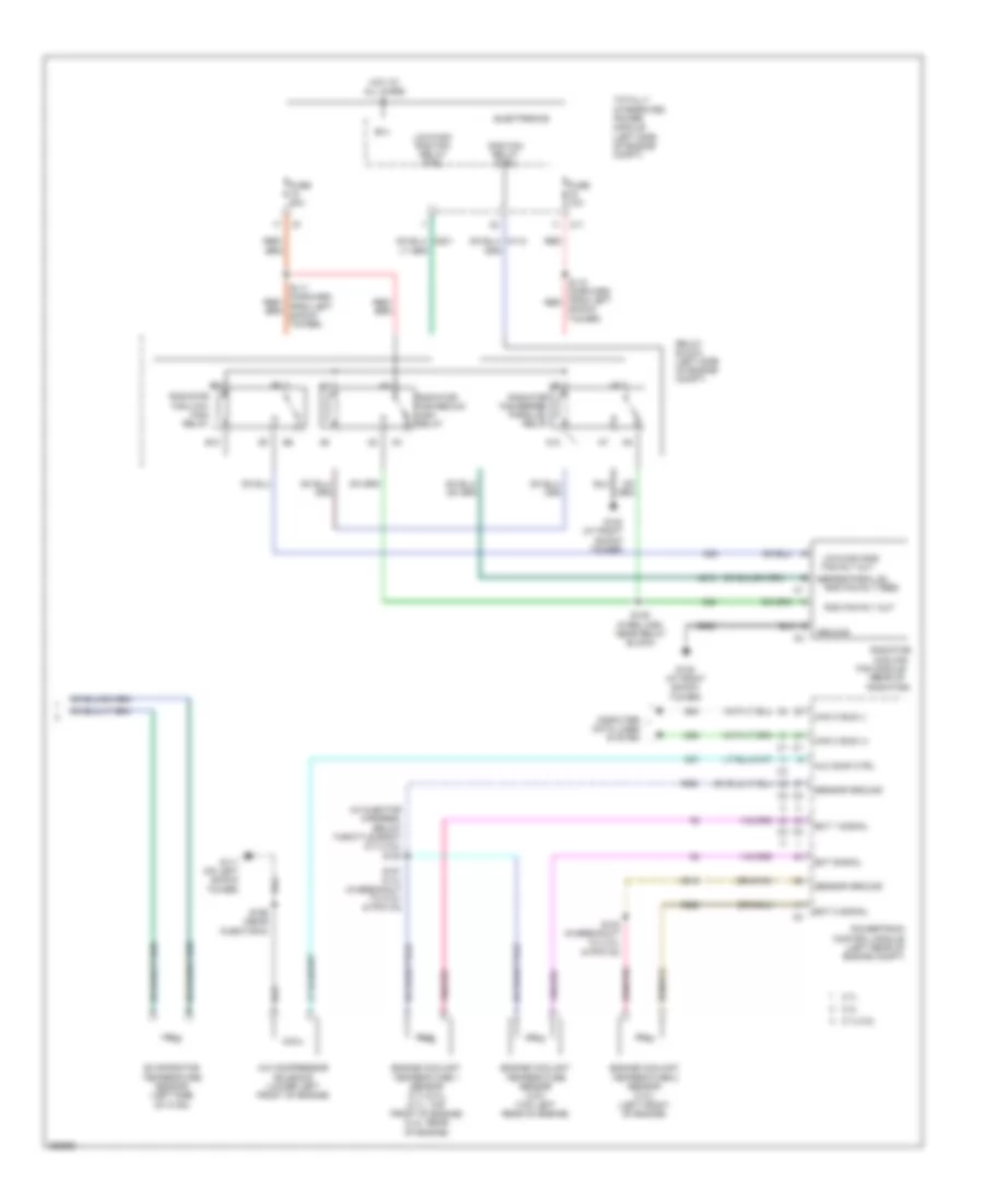
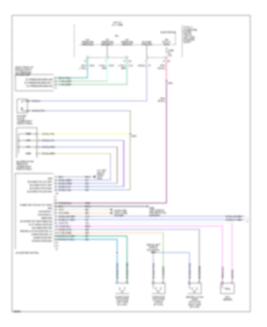
AIR CONDITIONING
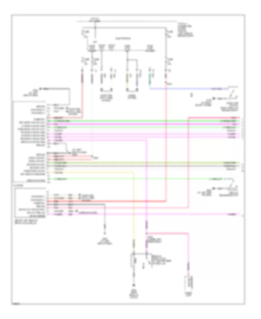
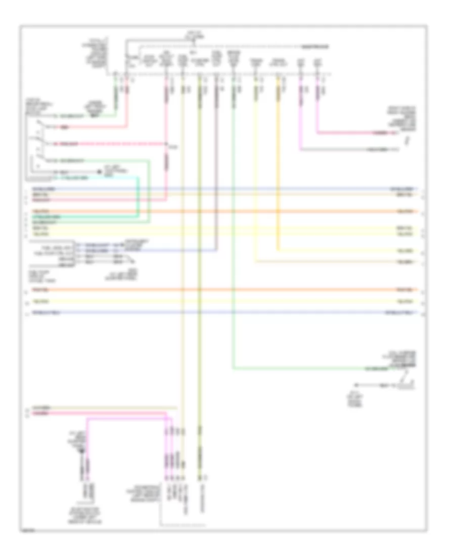
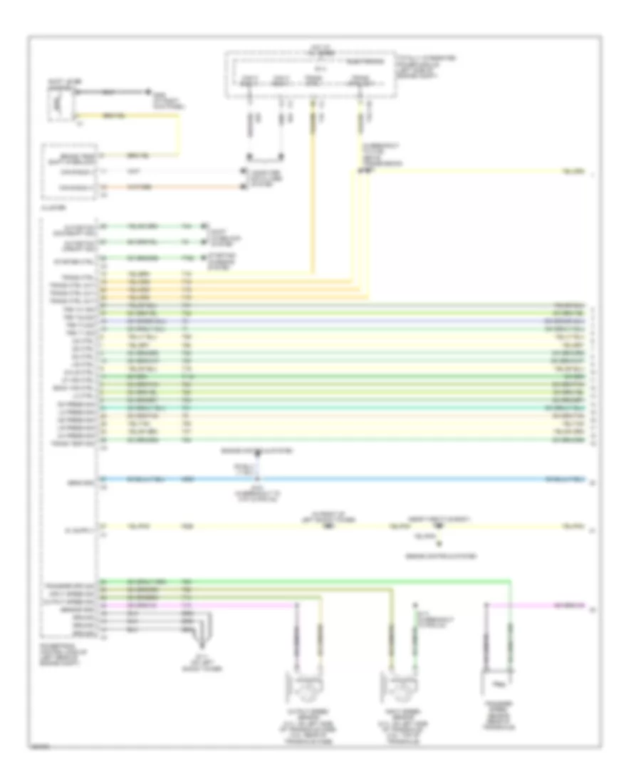
Automatic A/C Wiring Diagram (1 of 2) for Chrysler Sebring 2007

List of elements for Automatic A/C Wiring Diagram (1 of 2) for Chrysler Sebring 2007:
- (above left side of glove box) s202
- A/c pressure sens gnd
- A/c pressure sens sig
- A/c pressure sens sply
- A/c pressure transducer (right front of engine compt)
- A/c-heater control
- A417
- Auto headlamps sig
- B(+)
- Blend door actuator (left side of hvac)
- Blend door drv
- Blower motor (under right side of dash)
- Blower mtr ctrl
- Blower mtr speed ctrl
- Blower power module
- C11
- C121
- C18
- C21
- C32
- C34
- C35
- C56
- C61
- C818
- C83
- C830
- C918
- Can b bus (+)
- Can b bus (-)
- Common door drv
- Computer data lines system
- D54
- D55
- Electronics
- End of dash)
- Evaporator temp sens sig
- F202
- F929
- Fuse 10a
- Fused b(+) (i.o.d.)
- Fused ignition sw out (run)
- G200 (at left
- G250 (left side of center stack support)
- G939
- Gnd
- Ground
- Hot at all times
- Ign sw out (run)
- Ign sw out (run-start)
- Ignition sw out (run-start)
- Infrared sensor
- Ir sens return
- Ir sens sig
- L24
- Mode door actuator (middle of hvac)
- Mode door drv (a)
- Recirculation door actuator (right side of hvac)
- Recirculation door drv (a)
- S116 (w/o hands free) (at left kick panel)
- S201 (behind left side of glove box)
- S221
- S320 (at center of dash panel)
- Sens gnd
- Sun sens return
- Sun sensor
- Totally integrated power module (left side of engine compt)
- Z134
- Z910
- Z912
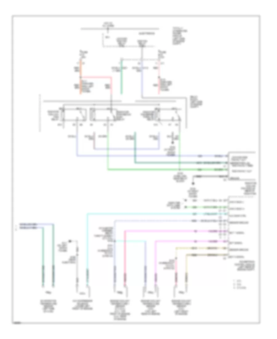
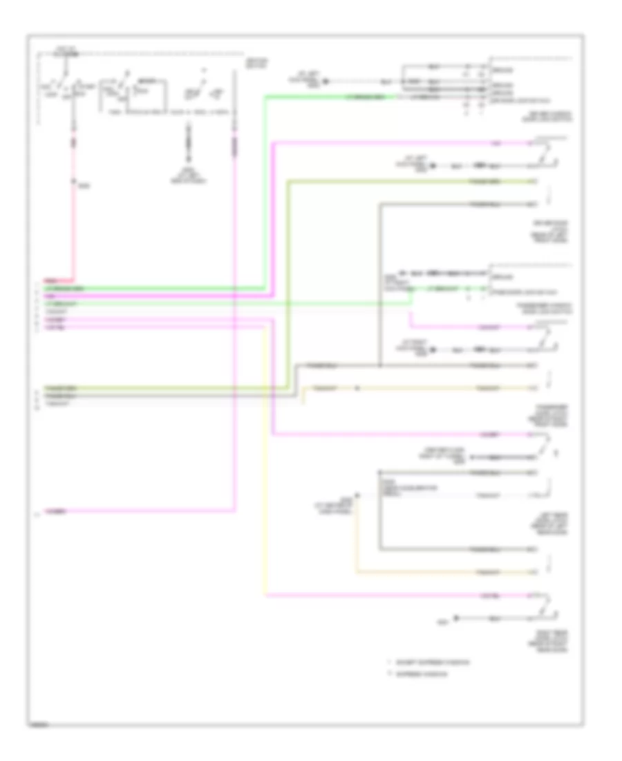
Automatic A/C Wiring Diagram (2 of 2) for Chrysler Sebring 2007
List of elements for Automatic A/C Wiring Diagram (2 of 2) for Chrysler Sebring 2007:
- (in injector harness, below throttle body) (2.7l/3.5l) s182
- (rear of radiator)
- 2.4l
- 2.7l
- 2.7l/3.5l
- A/c comp ctrl
- A/c compressor solenoid (lower left front of engine)
- A10
- B(+)
- B10
- C11
- C27
- Can c bus (+)
- Can c bus (-)
- Computer data lines system
- Cooling
- D64
- D65
- Ect 1 signal
- Ect 2 signal
- Ect signal
- Electronics
- Engine coolant temperature 1 sensor (2.7l/2.4l) (2.7l: top front of engine) (2.4l: rear of engine)
- Engine coolant temperature 2 sensor (2.4l) (left front of engine)
- Engine coolant temperature sensor (3.5l) (top left rear of engine)
- Evaporator temperature sensor (left side of hvac)
- Fan module
- Fan rly out
- Fuse 10a
- Fuse 50a
- G102 (at right shock tower)
- G105 (at right shock tower)
- G111 (on left shock tower)
- Ground
- Hot at all times
- K222
- K900
- K915
- Low/high rad
- Low/high rad fan relay ctrl
- N210
- N23
- N24
- Powertrain control module (left rear of engine compt)
- Rad fan relay ctrl
- Rad fan rly feed
- Rad fan rly out
- Radiator
- Radiator fan-low/ high relay
- Radiator fan-medium/ high relay
- Radiator fan-series/ parallel relay
- Red
- Relay block (left side of engine compt)
- S110 (forward from left red
- S125 (wire loom, near relay block)
- S181 (2.4l) (in breakout to c101 & pcm c2)
- S184 (in breakout to c101 & pcm c2)
- S199 (near injector 6)
- Sensor ground
- Series/parallel
- Shock tower)
- Totally integrated power module (left side of engine compt)
- Z920
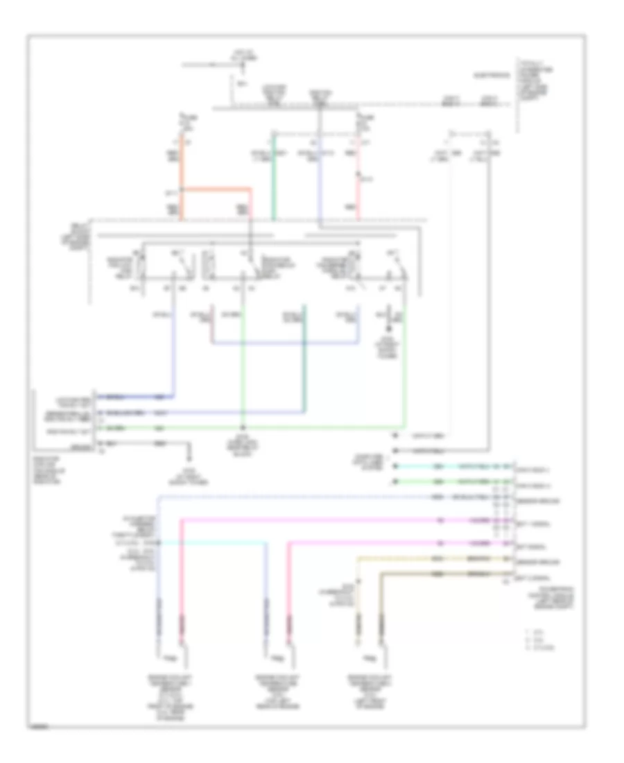
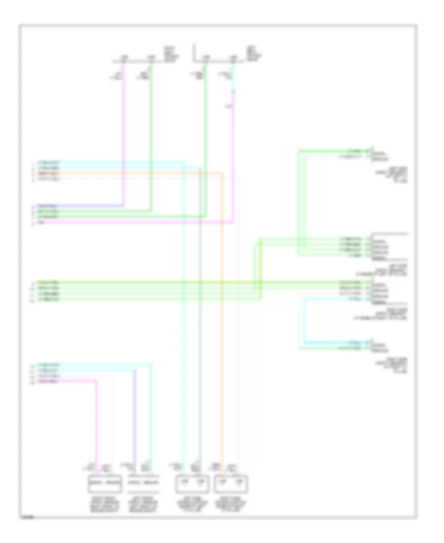
Manual A/C Wiring Diagram (1 of 2) for Chrysler Sebring 2007
List of elements for Manual A/C Wiring Diagram (1 of 2) for Chrysler Sebring 2007:
- (above left side of glove box) s202
- (at left
- (right front of engine compt) a/c pressure transducer
- A/c pressure sens gnd
- A/c pressure sens sig
- A/c pressure sens sply
- A/c-heater control
- Auto headlamps sig
- B(+)
- Blend door actuator (left side of hvac)
- Blend door drv
- Blower motor (under right side of dash)
- Blower motor resistor (under right side of dash)
- Blower mtr ctrl
- Blower mtr high drv
- Blower mtr low drv
- Blower mtr m1 drv
- Blower mtr m2 drv
- C121
- C18
- C21
- C32
- C34
- C35
- C61
- C70
- C71
- C72
- C73
- C818
- C918
- Can b bus (+)
- Can b bus (-)
- Common door drv
- Computer data lines system
- D54
- D55
- Electronics
- End of dash)
- Evaporator temp sens sig
- F929
- Fuse 10a
- Fused ignition sw out (run)
- G200
- G250 (left side of center stack support)
- G939
- Gnd
- High
- Hot at all times
- Ign sw out (run)
- L24
- Low
- Mode door actuator (middle of hvac)
- Mode door drv (a)
- Recirculation door actuator (right side of hvac)
- Recirculation door drv (a)
- S203
- S221
- Sens gnd
- Sun sens return
- Sun sensor
- Totally integrated power module (left side of engine compt)
- Z910
- Z912
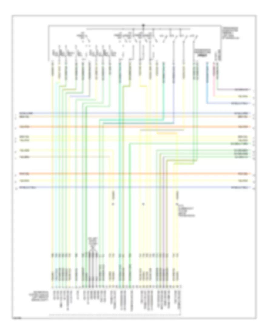
Manual A/C Wiring Diagram (2 of 2) for Chrysler Sebring 2007
List of elements for Manual A/C Wiring Diagram (2 of 2) for Chrysler Sebring 2007:
- (in injector harness, below throttle body) (2.7l/3.5l) s182
- (rear of radiator)
- 2.4l
- 2.7l
- 2.7l/3.5l
- A/c comp ctrl
- A/c compressor solenoid (lower left front of engine)
- A10
- B(+)
- B10
- C11
- C27
- Can c bus (+)
- Can c bus (-)
- Computer data lines system
- Cooling
- D64
- D65
- Ect 1 signal
- Ect 2 signal
- Ect signal
- Electronics
- Engine coolant temperature 1 sensor (2.7l/2.4l) (2.7l: top front of engine) (2.4l: rear of engine)
- Engine coolant temperature 2 sensor (2.4l) (left front of engine)
- Engine coolant temperature sensor (3.5l) (top left rear of engine)
- Evaporator temperature sensor (left side of hvac)
- Fan module
- Fan rly out
- Fuse 10a
- Fuse 50a
- G102 (at right shock tower)
- G105 (at right shock tower)
- G111 (on left shock tower)
- Ground
- Hot at all times
- K222
- K900
- K915
- Low/high rad
- Low/high rad fan relay ctrl
- N210
- N23
- N24
- Powertrain control module (left rear of engine compt)
- Rad fan relay ctrl
- Rad fan rly feed
- Rad fan rly out
- Radiator
- Radiator fan-low/ high relay
- Radiator fan-medium/ high relay
- Radiator fan-series/ parallel relay
- Red
- Relay block (left side of engine compt)
- S110 (forward from left red
- S125 (wire loom, near relay block)
- S181 (2.4l) (in breakout to c101 & pcm c2)
- S184 (in breakout to c101 & pcm c2)
- S199 (near injector 6)
- Sensor ground
- Series/parallel
- Shock tower)
- Totally integrated power module (left side of engine compt)
- Z920
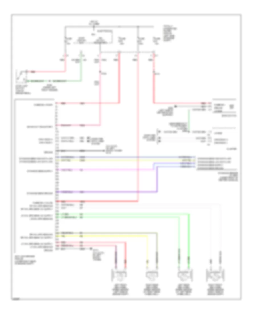
ANTI-LOCK BRAKES
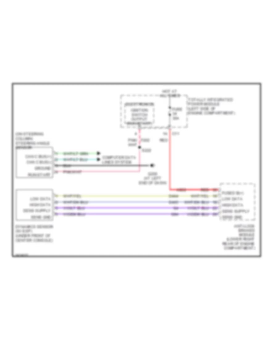
Anti-lock Brakes Wiring Diagram for Chrysler Sebring 2007
List of elements for Anti-lock Brakes Wiring Diagram for Chrysler Sebring 2007:
- (2.4l & 3.5l: on left shock tower) g110
- (near breakout to instrument cluster) s260
- A921
- A922
- Anti-lock brakes module (lower right rear of engine compt)
- B(+)
- Bank switch
- C11
- Can b bus (+)
- Can b bus (-)
- Can c bus (+)
- Can c bus (-)
- Cluster
- Computer data lines system
- D464
- D465
- D64
- D65
- Dynamics sens ground
- Dynamics sens high data link
- Dynamics sens low data link
- Dynamics sensor (w/ esp) (under front of center console)
- Electronics
- Esp off
- F202
- Fuse 10a
- Fuse 30a
- Fuse 40a
- Fused b(+)
- Fused b(+) (pump)
- Fused b(+) (valve)
- G110 (2.4l & 3.5l: on left shock tower)
- G250 (left side of center stack support)
- G94
- Ground
- Hot at all times
- Ign sw out (run-start)
- L53
- Left front abs wheel speed sensor (left side of engine compt)
- Left rear abs wheel speed sensor (at left rear wheelwell)
- Lf whl spd sens sig
- Lin bus
- Lr whl spd sens sig
- Red
- Rf whl spd sens sig
- Right front abs wheel speed sensor (right side of engine compt)
- Right rear abs wheel speed sensor (at right rear wheelwell)
- Rr whl spd sens sig
- S110
- S120
- S126 (inside left front fender)
- Stop lamp sw out
- Stop lamp switch (top of brake pedal)
- Totally integrated power module (left side of engine compt)
- Z905
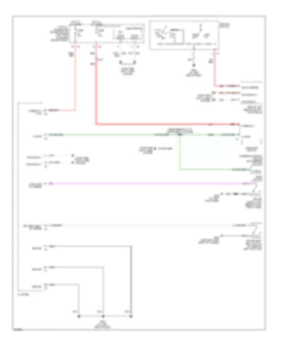
ANTI-THEFT
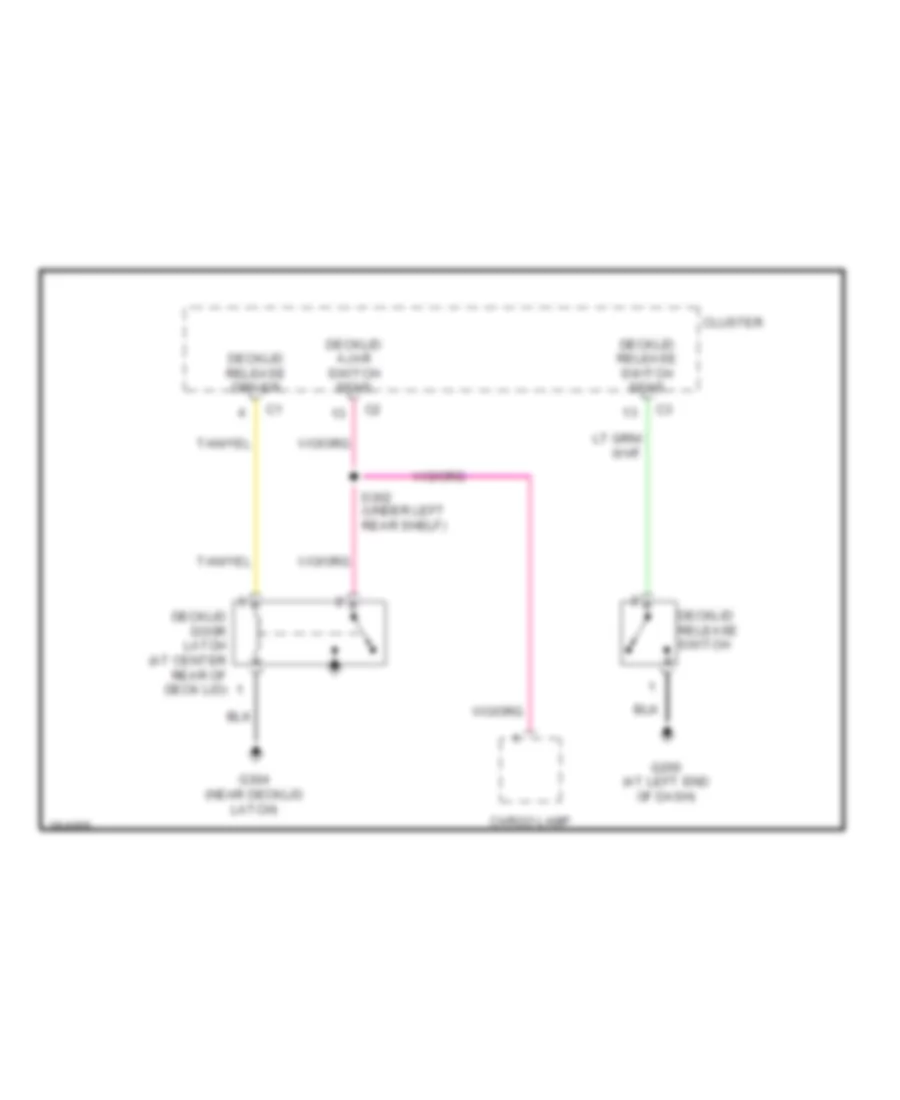
Anti-theft Wiring Diagram (1 of 2) for Chrysler Sebring 2007
List of elements for Anti-theft Wiring Diagram (1 of 2) for Chrysler Sebring 2007:
- (at left end of dash) g200
- A411
- Ajar sw decklid
- B(+)
- C11
- Can b bus (+)
- Can b bus (-)
- Cargo lamp
- Cluster
- Com-lin tire lan
- Computer data lines system
- D508
- D54
- D55
- Decklid ajar sw sns
- Decklid door latch (at center rear of deck lid)
- Decklid release switch
- Decklid sw sns
- Door lock b(+)
- Door lock power
- Dr door lock
- Dr door unlock
- Drv decklid release
- Drv door lock sw mux
- Electronics
- F20
- Fuse 10a
- Fuse 20a
- Fuse 30a
- Fused b(+)
- G105 (at right shock tower)
- G20
- G200 (at left end of dash)
- G304 (near decklid latch)
- G70
- Ground
- Hood ajar sw sns
- Hood ajar switch (right front of engine compt)
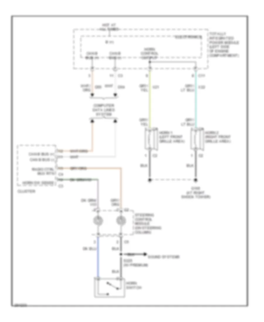
- Horn ctrl out
- Horns system
- Hot at all times
- Ign sw out (run-start)
- Ign sw sense
- Lf door ajar sw sns
- Lr door ajar sw sns
- Pass door lock sw mux
- Pass door unlock
- Pnk
- Red
- Rf door ajar sw sns
- Rr door ajar sw sns
- S200
- S210
- S302 (under left rear shelf)
- Sentry key remote entry/wcm module
- Totally integrated power module (left side of engine compt)
- Warning system
- X21
- X22
- Z910
Anti-theft Wiring Diagram (2 of 2) for Chrysler Sebring 2007
List of elements for Anti-theft Wiring Diagram (2 of 2) for Chrysler Sebring 2007:
- (at left kick panel) g302
- (at right kick panel) g306
- (center floor, right of tunnel) g300
- Acc
- Acc lock
- Dr door lock sw mux
- Driver door latch (rear of left front door)
- Driver window/ door lock switch
- Except express windows
- Express windows
- G200 (at left end of dash)
- G301
- G306 (at right kick panel)
- Ground
- Hot at all times
- Ignition switch
- Key
- Key out
- Left rear door latch (rear of left rear door)
- Lock
- Off
- Pass door lock sw mux
- Passenger door latch (rear of right front door)
- Passenger window/ door lock switch
- Pnk
- Right rear door latch (rear of right rear door)
- Run
- S220
- S325 (near accelerator pedal)
- S328 (at center of dash panel)
- S353
- S359
- Start
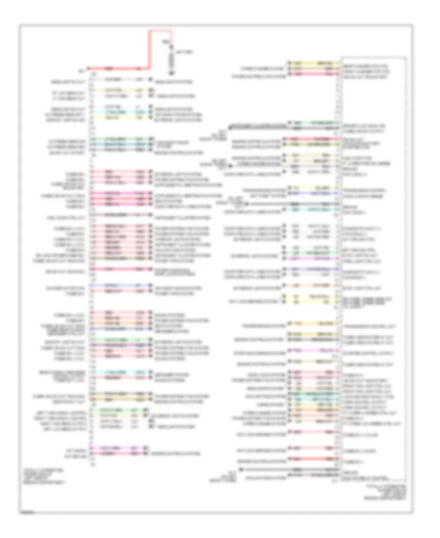
BODY CONTROL MODULES
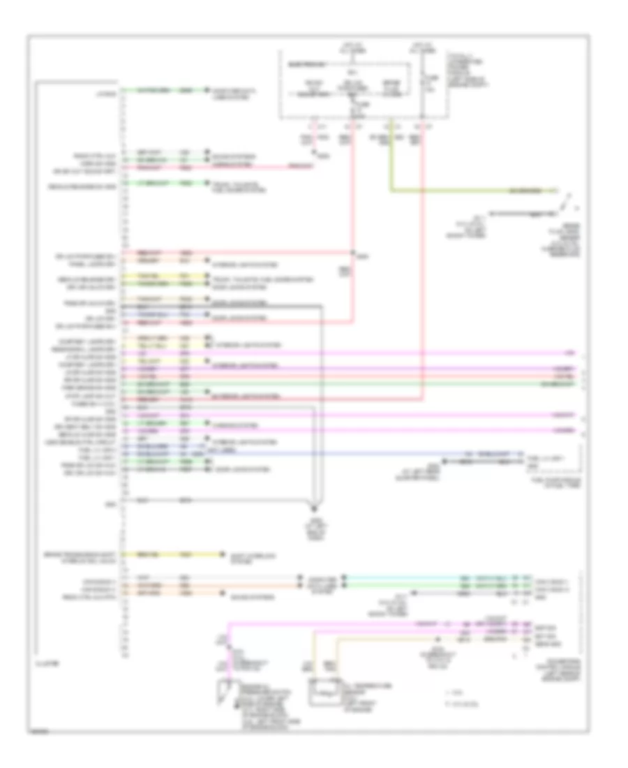
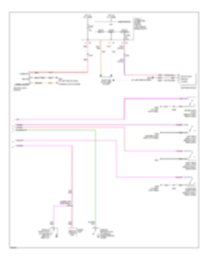
Body Control Modules Wiring Diagram for Chrysler Sebring 2007
List of elements for Body Control Modules Wiring Diagram for Chrysler Sebring 2007:
- (on left shock tower) g111
- A/c press sens gnd
- A/c press sens sig
- A/c press sens sply
- A14
- A16
- A411
- A412
- A413
- A417
- A418
- A419
- A420
- A921
- A922
- A924
- A927
- A929
- A931
- A932
- A933
- A935
- A937
- A950
- A952
- Aat return
- Aat signal
- Air conditioning system
- Anti-lock brakes system
- Anti-theft system
- Asd/main rly out
- B(+)
- B20
- Backup lamp sw out
- Backup lamp sw sig
- Battery
- Blower motor ctrl
- Brake fluid level sig
- C10
- C11
- C16
- C18
- C515
- C818
- C918
- Can b bus (+)
- Can b bus (-)
- Can c bus (+)
- Can c bus (-)
- Computer data lines system
- Cooling fans system
- D54
- D55
- D64
- D65
- D71
- D72
- Defogger system
- Diagnostic can c (+)
- Diagnostic can c (-)
- Door locks system
- Dr lock power-fused b(+)
- Engine controls system
- Exterior lights system
- F100
- F20
- F200
- F202
- F342
- F343
- F344
- F901
- F929
- F937
- F962
- F981
- F986
- F996
- Front fog lamp ctrl out
- Front washer mtr ctrl
- Ft wiper hi speed ctrl out
- Ft wiper low speed ctrl out
- Ft wiper park sw sense
- Fuel pump ctrl
- Fuel pump ctrl out
- Fused asd/main relay out
- Fused b (+)
- Fused b (+) (pump)
- Fused b (+) (valve)
- Fused b(+)
- Fused b(+) (i.o.d.)
- Fused b(+) fused ign sw out (run-start)
- Fused ign sw out (run)
- Fused ign sw out (run) fused rear window defogger ctrl out
- Fused ign sw out (run-acc)
- Fused ign sw output
- G111 (on left shock tower)
- G31
- G70
- G931
- Ground
- Headlamp sw out
- Headlights system
- Hood ajar sw sense
- Horn control output
- Horns system
- Ign sw out (run-acc)
- Ign sw out (run-start)
- Ign sw out (start)
- Ign sw out (unlock-run-start) starter ctrl
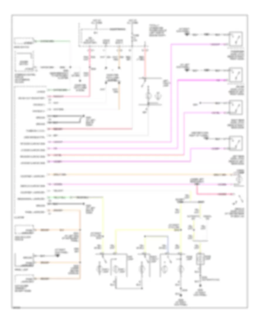
- Instrument cluster system
- Interior lights system
- K31
- K542
- L217
- L33
- L34
- L43
- L44
- L53
- L55
- L60
- L61
- L62
- L63
- L70
- L89
- L90
- Left low beam output
- Left turn signal control
- Low/high rad fan rly ctrl
- Lr turn sig ctrl
- Lt high beam out
- N112
- N201
- Park lamp ctrl out
- Pnk
- Pnk/red
- Power distribution system
- Power tops system
- Power windows & door locks systems
- Rad fan relay control
- Rear washer mtr ctrl
- Rear window defogger control output fused b(+) (i.o.d.)
- Red
- Red/pnk
- Red/tan
- Right high beam output
- Right turn signal control
- Rr turn sig ctrl
- Rt low beam out
- Seats system
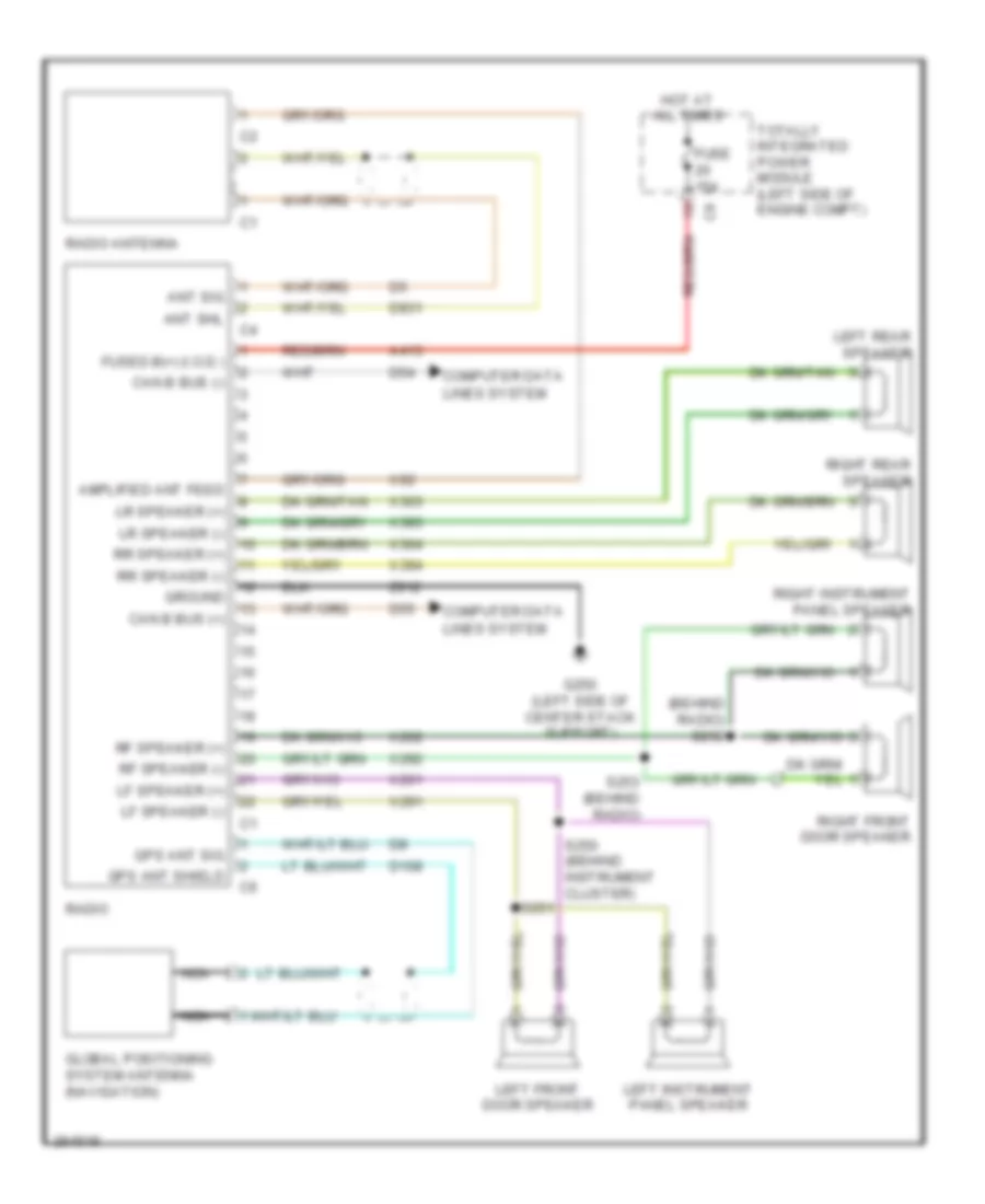
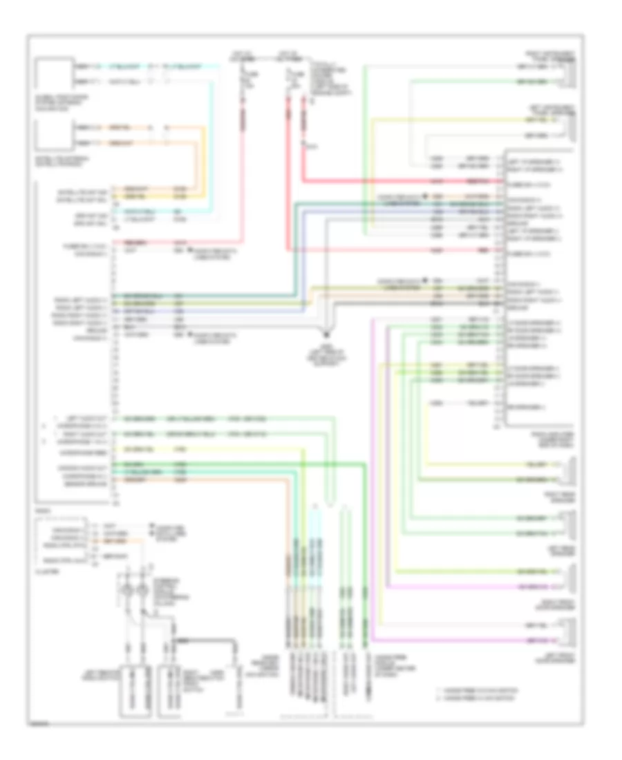
- Sound systems
- Starter control output
- Starting/charging system
- Stop lamp ctrl out
- Stop lamp sw out
- T15
- T16
- T22
- T750
- T752
- Totally integrated power module (left side of engine compartment)
- Transmission control
- Transmission control out
- Transmissions system
- W10
- W20
- Wiper/washer system
- X21
- X22
- Z902
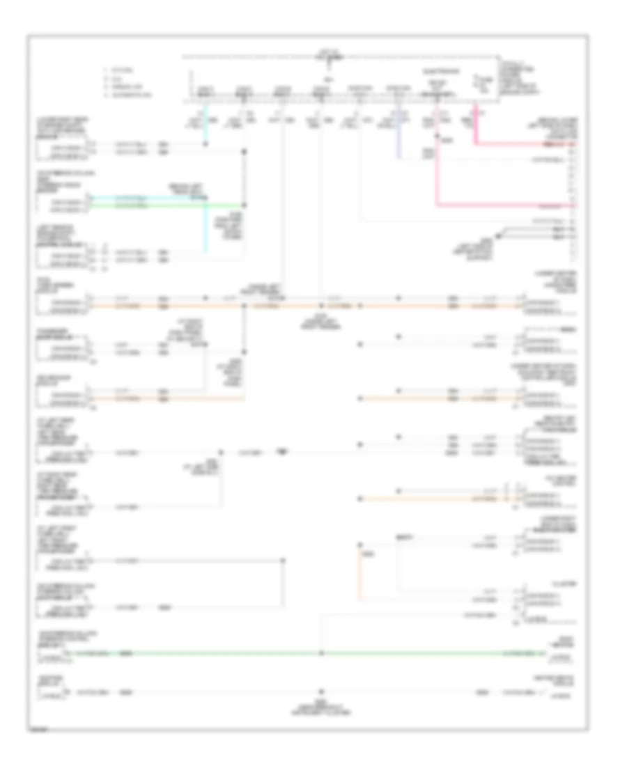
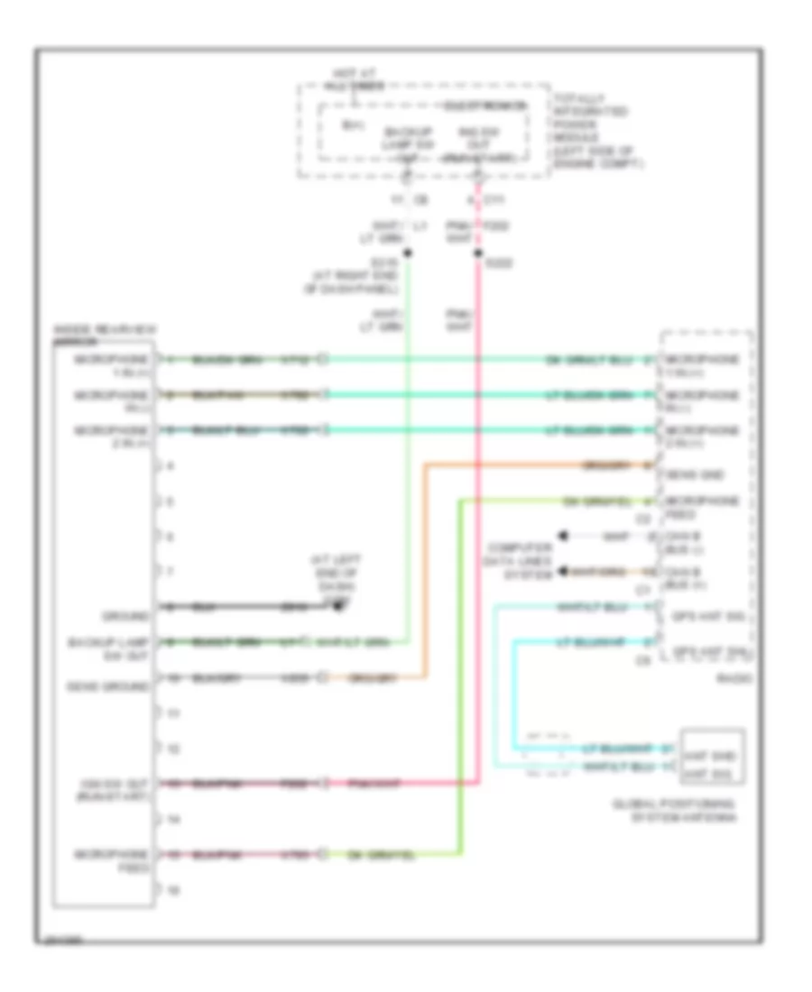
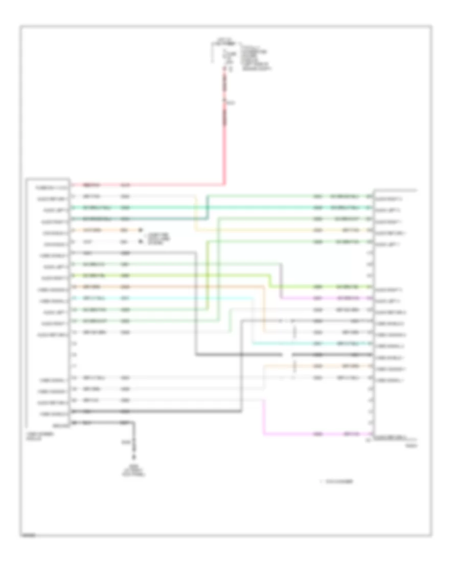
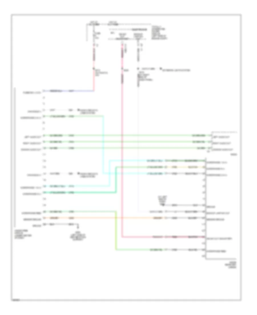
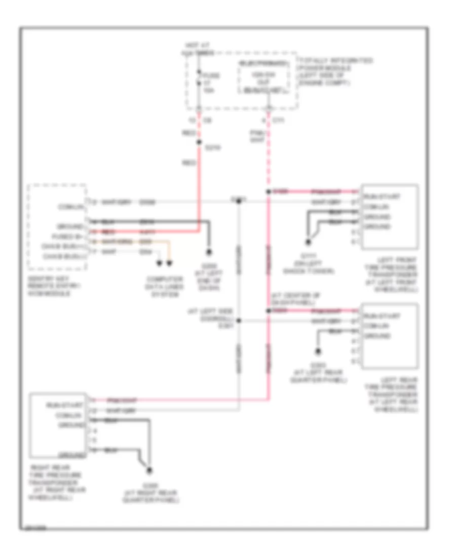
COMPUTER DATA LINES
Computer Data Lines Wiring Diagram for Chrysler Sebring 2007
List of elements for Computer Data Lines Wiring Diagram for Chrysler Sebring 2007:
- (at left front wheelwell) left front tire pressure transponder
- (at left rear wheelwell) left rear tire pressure transponder
- (at right end of dash panel) (w/ security) s370
- (at right rear wheelwell) right rear tire pressure transponder
- (behind left headlight) s175
- (behind lower left side of dash) data link connector
- (dvd) video screen module
- (inside left front fender) s170
- (left rear of engine compt) powertrain control module
- (lower right rear of engine compt) anti-lock brakes module
- (on steering column) (esp) steering angle sensor
- (on steering column) steering column lock module
- (on steering column) steering control module
- (under center of dash) hands free module
- (under center of dash) occupant restraint controller module (orc)
- (under right end of dash) radio amplifier
- 2.4l
- 2.7l/3.5l
- A/c heater control
- Automatic a/c
- B(+)
- Bank switch
- C11
- Can b bus (+)
- Can b bus (-)
- Can c bus (+)
- Can c bus (-)
- Cluster
- Com-lin tire pres moni lan
- Compass module
- D506
- D508
- D54
- D55
- D64
- D65
- Diag can c (+)
- Diag can c (-)
- Driver door module
- Electronics
- Fuse 10a
- G250 (left side of center stack support)
- Heated seats module
- Hot at all times
- Ign sw out (run-start)
- Lin bus
- Manual a/c
- Passenger door module
- Pnk/ f202
- Radio
- S180 (inside left front fender)
- S185 (forward from left shock tower)
- S222
- S260 (near breakout instrument cluster)
- S261
- S270
- S280
- S361 (at left side door sill)
- S380 (at right end of dash panel)
- Sentry key remote entry/ wcm module
- Totally integrated power module (left side of engine compt)
COOLING FAN
Cooling Fan Wiring Diagram for Chrysler Sebring 2007
List of elements for Cooling Fan Wiring Diagram for Chrysler Sebring 2007:
- (2.4l)
- (2.7l/3.5l)
- (in injector harness, below throttle body)
- 2.4l
- 2.7l
- 2.7l/3.5l
- A10
- B(+)
- B10
- C11
- Can c bus (+)
- Can c bus (-)
- Computer data lines system
- D64
- D65
- Ect 1 signal
- Ect 2 signal
- Ect signal
- Electronics
- Engine coolant temperature 1 sensor (2.7l/2.4l) (2.7l: top front of engine) (2.4l: rear of engine)
- Engine coolant temperature 2 sensor (2.4l) (left front of engine)
- Engine coolant temperature sensor (3.5l) (top left rear of engine)
- Fuse 10a
- Fuse 50a
- G102 (at right shock tower)
- G105 (at right shock tower)
- Ground
- Hot at all times
- K222
- K900
- K915
- Low/high rad fan relay ctrl
- Low/high rad fan rly out
- N210
- N23
- N24
- Powertrain control module (left rear of engine compt)
- Rad fan relay ctrl
- Rad fan rly out
- Radiator cooling fan module (rear of radiator)
- Radiator fan-low/ high relay
- Radiator fan-medium/ high relay
- Radiator fan-series/ parallel relay
- Red
- Relay block (left side of engine compt)
- S110
- S111
- S125 (wire loom, near relay block)
- S181 (in breakout to c101 & pcm c2)
- S182
- S184 (in breakout to c101 & pcm c2)
- Sensor ground
- Series/parallel rad fan rly feed
- Totally integrated power module (left side of engine compt)
- Z920
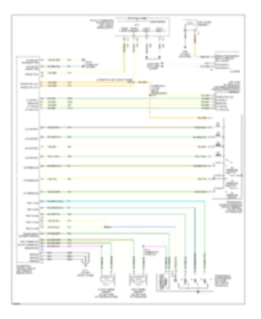
CRUISE CONTROL
2.4L
2.4L, Cruise Control Wiring Diagram for Chrysler Sebring 2007
List of elements for 2.4L, Cruise Control Wiring Diagram for Chrysler Sebring 2007:
- (at left kick panel) g302
- (below throttle body) s192
- (inside left front fender) s126
- (top of brake pedal) stop lamp switch
- 5v sply
- A/t
- Accelerator pedal position sensor (top of accelerator pedal)
- App sens gnd 1
- App sens gnd 2
- App sig 1
- App sig 2
- B(+)
- B15
- B16
- Break sig 1
- Break sig 2
- C11
- Clutch interlock sig
- Clutch interlock switch (top of clutch pedal, on bracket)
- Electronics
- Etc mtr (+)
- Etc mtr (-)
- F202
- F855
- F856
- Fuse 10a
- Hot at all times
- Ign sw out (run-start)
- In speed sig
- Input speed sensor (40/41te) (on left side of transaxle)
- K122
- K124
- K126
- K167
- K22
- K23
- K29
- K400
- K75
- K852
- K854
- K914
- K922
- L53
- M/t
- Out speed sig
- Output speed sensor (40/41te) (on left side of transaxle case)
- Pnk
- Powertrain control module (left rear of engine compt)
- Red
- S/c sig 1
- S/c sig 2
- S/c sw gnd
- S128 (near battery jump posts)
- S171 (in breakout to pcm c4)
- S191 (near throttle body)
- S194
- S320
- Sens gnd
- Speed control switch
- Steering control module (on steering column)
- Stop lamp sw out
- T13
- T14
- T41
- T52
- Throttle body (left rear of engine)
- Totally integrated power module (left side of engine compt)
- Tp sens gnd
- Tp sig 1
- Tp sig 2
- Transmission range sensor (40/41te) (on lower left side of transaxle)
- Trs t41 sig
- V71
- V72
- V937
- Vehicle speed sensor (m/t) (left side of engine compt)
- Vehicle speed sig
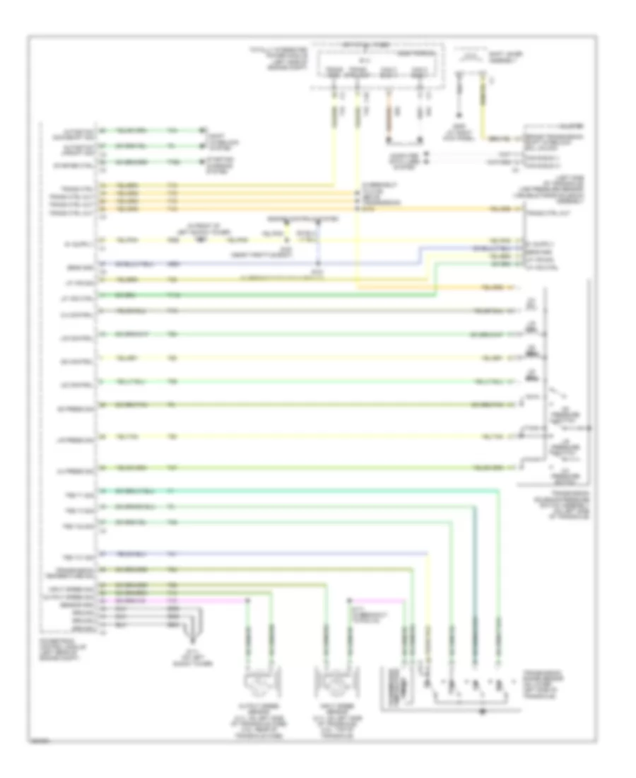
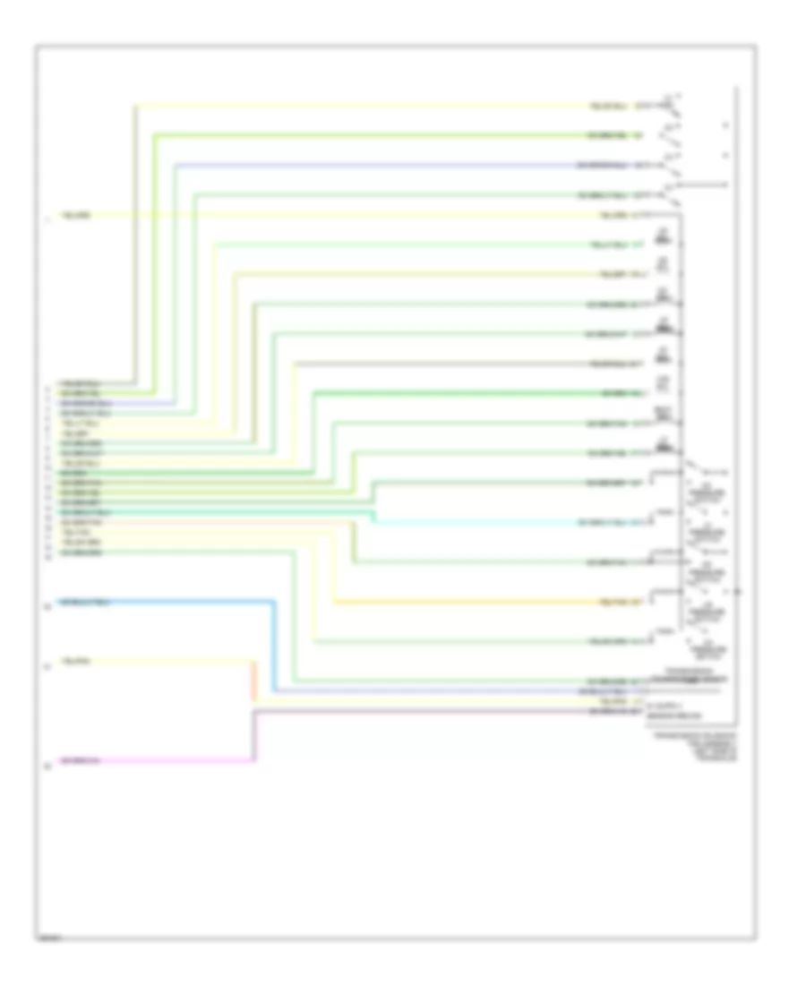
2.7L
2.7L, Cruise Control Wiring Diagram for Chrysler Sebring 2007
List of elements for 2.7L, Cruise Control Wiring Diagram for Chrysler Sebring 2007:
- (at left kick panel) g302
- (below throttle body) s192
- (inside left front fender) s126
- (top of brake pedal) stop lamp switch
- 40/41te
- 5v sply
- 62te
- Accelerator pedal position sensor (top of accelerator pedal)
- App sens gnd 1
- App sens gnd 2
- App sig 1
- App sig 2
- B(+)
- B15
- B16
- Break sig 1
- Break sig 2
- C11
- Electronics
- Etc mtr (+)
- Etc mtr (-)
- F202
- F855
- F856
- Fuse 10a
- Hot at all times
- Ign sw out (run-start)
- In speed sig
- Input speed sensor (2.7l: on left side of transaxle) (3.5l: top of of transaxle)
- K122
- K124
- K126
- K167
- K22
- K23
- K29
- K400
- K922
- L53
- Out speed sig
- Output speed sensor (2.7l: on left side of transaxle case) (3.5l: rear of transaxle case)
- Pnk
- Powertrain control module (left rear of engine compt)
- Red
- S/c sig 1
- S/c sig 2
- S/c sw gnd
- S123 (in front of left shock tower)
- S171 (in breakout to pcm c4)
- S320
- Sens gnd
- Speed control switch
- Steering control module (on steering column)
- Stop lamp sw out
- T13
- T14
- T41
- T52
- T85
- Throttle body (top rear of engine)
- Totally integrated power module (left side of engine compt)
- Tp sens gnd
- Tp sig 1
- Tp sig 2
- Transfer speed sensor (62te) (rear of transaxle)
- Transfer speed sig
- Transmission range sensor (2.7l: on lower left side of transaxle)
- Transmission solenoid/trs assembly (left side of transaxle)
- Trs t41 sig
- V71
- V72
- V937
3.5L
3.5L, Cruise Control Wiring Diagram for Chrysler Sebring 2007
List of elements for 3.5L, Cruise Control Wiring Diagram for Chrysler Sebring 2007:
- (at left kick panel) g302
- (below throttle body) s192
- (inside left front fender) s126
- (top of brake pedal) stop lamp switch
- 40/41te
- 5v sply
- 62te
- Accelerator pedal position sensor (top of accelerator pedal)
- App sens gnd 1
- App sens gnd 2
- App sig 1
- App sig 2
- B(+)
- B15
- B16
- Break sig 1
- Break sig 2
- C11
- Electronics
- Etc mtr (+)
- Etc mtr (-)
- F202
- F855
- F856
- Fuse 10a
- Hot at all times
- Ign sw out (run-start)
- In speed sig
- Input speed sensor (2.7l: on left side of transaxle) (3.5l: top of of transaxle)
- K122
- K124
- K126
- K167
- K22
- K23
- K29
- K400
- K922
- L53
- Out speed sig
- Output speed sensor (2.7l: on left side of transaxle case) (3.5l: rear of transaxle case)
- Pnk
- Powertrain control module (left rear of engine compt)
- Red
- S/c sig 1
- S/c sig 2
- S/c sw gnd
- S123 (in front of left shock tower)
- S171 (in breakout to pcm c4)
- S320
- Sens gnd
- Speed control switch
- Steering control module (on steering column)
- Stop lamp sw out
- T13
- T14
- T41
- T52
- T85
- Throttle body (top rear of engine)
- Totally integrated power module (left side of engine compt)
- Tp sens gnd
- Tp sig 1
- Tp sig 2
- Transfer speed sensor (62te) (rear of transaxle)
- Transfer speed sig
- Transmission range sensor (2.7l: on lower left side of transaxle)
- Transmission solenoid/trs assembly (left side of transaxle)
- Trs t41 sig
- V71
- V72
- V937
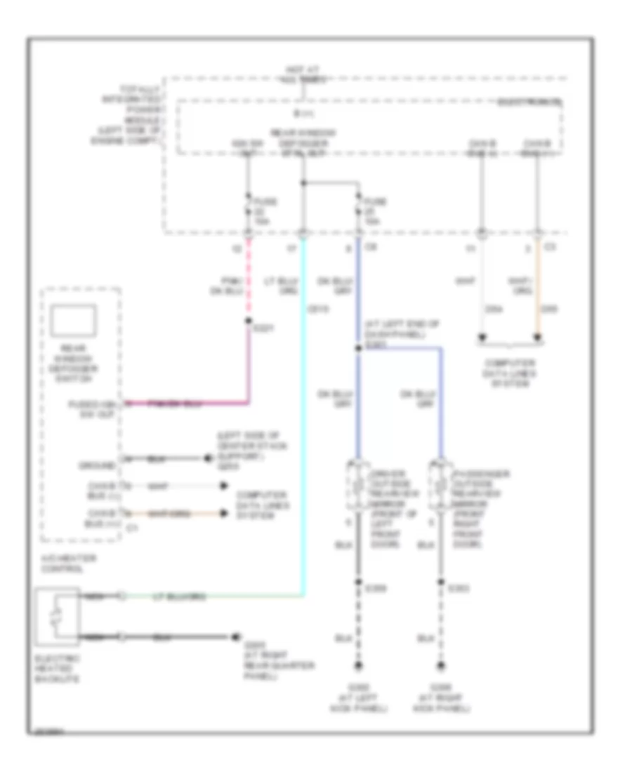
DEFOGGERS
Defoggers Wiring Diagram for Chrysler Sebring 2007
List of elements for Defoggers Wiring Diagram for Chrysler Sebring 2007:
- (at left end of dash panel) s301
- (left side of center stack support) g250
- A/c-heater control
- B (+)
- Bus (+)
- Bus (-)
- C515
- Can b
- Can b bus (+)
- Can b bus (-)
- Computer data lines system
- D54
- D55
- Driver outside rearview mirror (front of left front door)
- Electric heated backlite
- Electronics
- Fuse 10a
- Fused ign sw out
- G302 (at left kick panel)
- G305 (at right rear quarter panel)
- G306 (at right kick panel)
- Ground
- Hot at all times
- Ign sw out
- Nca
- Passenger outside rearview mirror (front right front door)
- Rear window defogger ctrl out
- Rear window defogger switch
- S221
- S353
- S359
- Totally integrated power module (left side of engine compt)
ELECTRONIC POWER STEERING
Electronic Power Steering Wiring Diagram for Chrysler Sebring 2007
List of elements for Electronic Power Steering Wiring Diagram for Chrysler Sebring 2007:
- (on steering column) steering angle sensor
- A922
- Anti-lock brakes module (lower right rear of engine compartment)
- C11
- Can c bus(+)
- Can c bus(-)
- Computer data lines system
- D464
- D465
- Dynamics sensor (w/ esp) (under front of center console)
- Electronics
- Fuse 30a
- Fused b(+)
- G200 (at left end of dash)
- G94
- Ground
- High data
- Hot at all times
- Ignition switch output (run-start)
- Low data
- Pnk/ f202
- Red
- Run-start
- S222
- Sens gnd
- Totally integrated power module (left side of engine compartment)
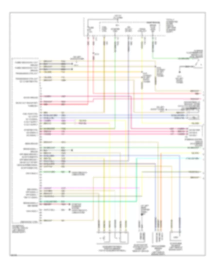
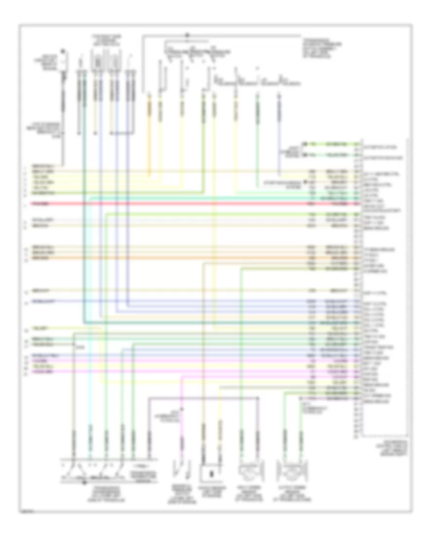
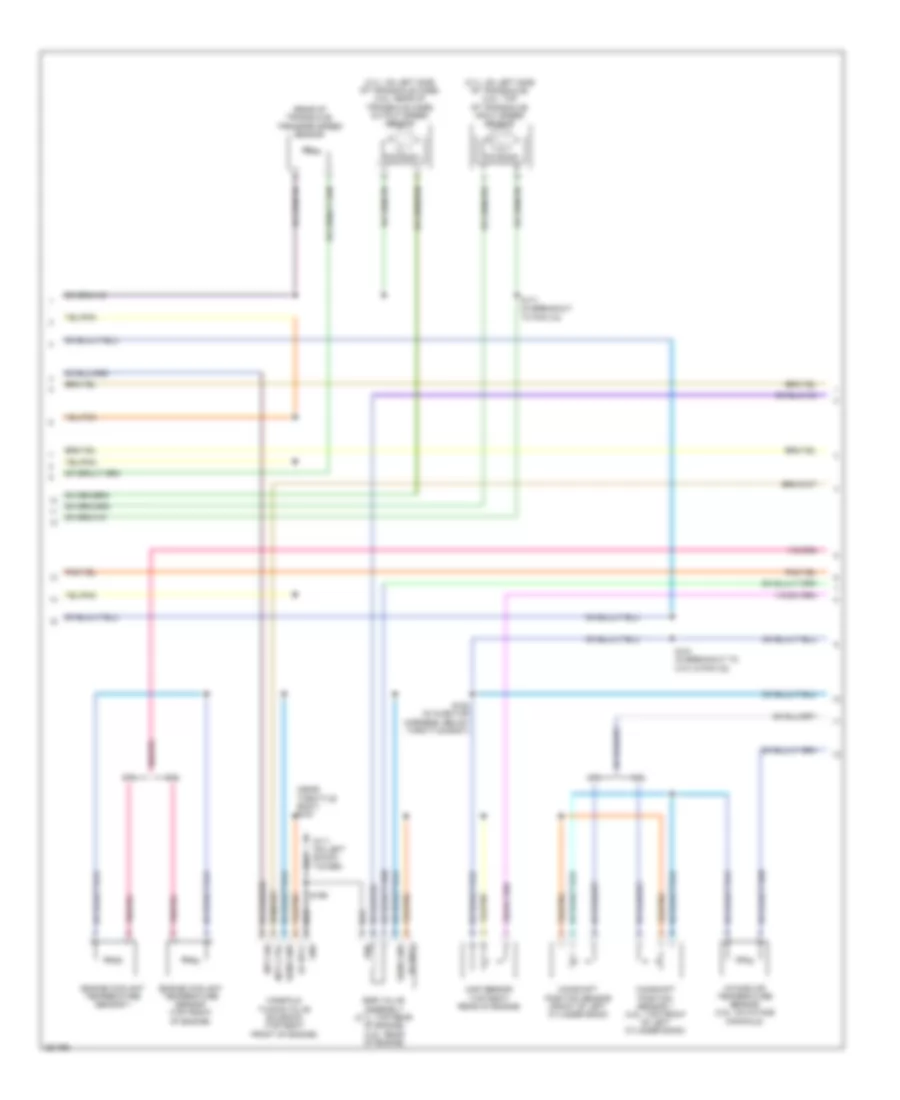
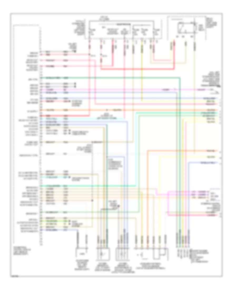
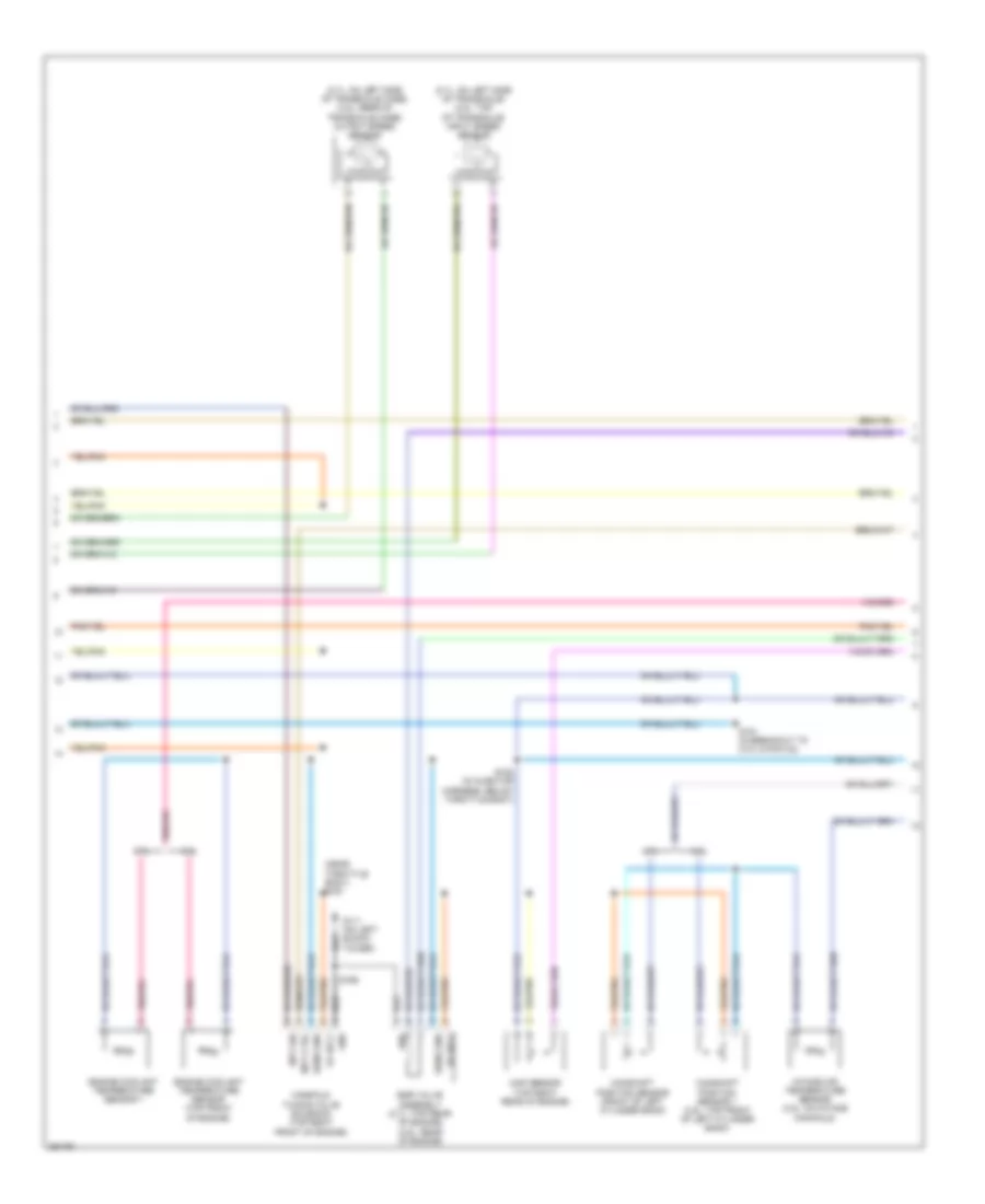
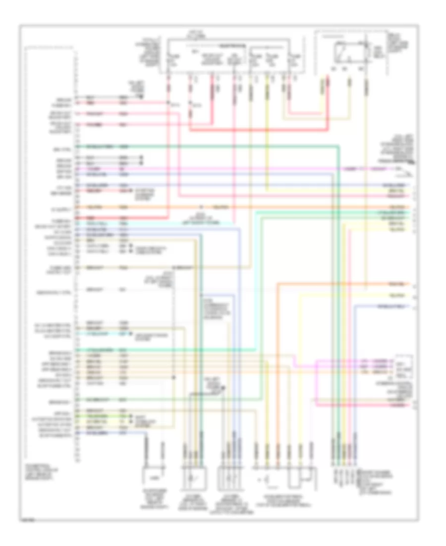
ENGINE PERFORMANCE
2.4L
2.4L, Engine Performance Wiring Diagram (1 of 4) for Chrysler Sebring 2007
List of elements for 2.4L, Engine Performance Wiring Diagram (1 of 4) for Chrysler Sebring 2007:
- (at left rear quarter panel) g303
- (downstream: in exhaust, after catalytic converter) oxygen sensor 1/2
- (in brake fluid reservoir) brake fluid level sensor
- (on left shock tower)
- (on left shock tower) g111
- 5v sply
- A804
- Accelerator pedal position sensor (top of accelerator pedal)
- App sens ground 1
- App sens ground 2
- App signal 1
- App signal 2
- Asd/main rly ctrl
- B(+)
- B15
- B16
- B20
- Brake fluid level sig
- Brake signal 1
- Brake signal 2
- C10
- C11
- Can c bus (+)
- Can c bus (-)
- Computer data lines system
- D64
- D65
- Electronics
- Esm sig
- Esm signal
- Evap monitor system switch (under left rear of vehicle)
- Evap purge ctrl
- Evap purge rtn
- Evap/purge solenoid (left rear of engine compt)
- F202
- F342
- F962
- Fuel pump ctrl
- Fuse 10a
- Fused asd/main rly out
- Fused b(+)
- G111
- G111 (on left shock tower)
- Gen sense
- Ground
- Hot at all times
- Ign sw out (run-start)
- Ign sw out (start)
- K107
- K141
- K167
- K23
- K29
- K299
- K31
- K400
- K51
- K52
- K70
- K75
- K852
- K854
- K904
- K914
- O2 1/2 heater ctrl
- O2 1/2 rtn
- O2 1/2 signal
- Powertrain control module (left rear of engine compt)
- Red
- S/c sig 1
- S/c sig 2
- S/c signal 1
- S/c signal 2
- S/c sw gnd
- S/c sw ground
- S103 (in front of left shock tower)
- S110
- S127 (in front of left shock tower)
- Sens gnd
- Sens ground
- Speed sig
- Starter ctrl
- Starting/ charging system
- Steering control module (on steering column)
- T16
- T41
- T752
- Totally integrated power module (left side of engine compt)
- Trans ctrl out
- Transmission ctrl out
- Trs t41 signal
- V71
- V72
- V937
- Vehicle speed sensor (m/t) (left side of engine compt)
- Vehicle speed signal
- Z902
- Z931
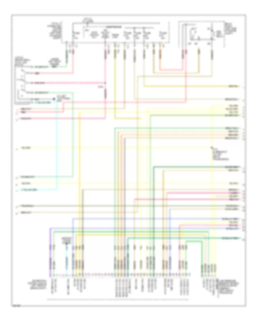
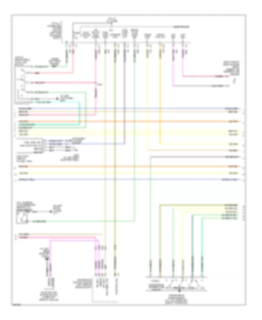
2.4L, Engine Performance Wiring Diagram (2 of 4) for Chrysler Sebring 2007
List of elements for 2.4L, Engine Performance Wiring Diagram (2 of 4) for Chrysler Sebring 2007:
- (at left
- (inside left front fender) s126
- (top of brake pedal) stop lamp switch
- 2-4 pres sig
- 5v sply
- A/c comp ctrl
- Aircondi- tioning system
- Asd/ main relay
- B(+)
- C10
- C11
- C27
- Cmp 1/2 sig
- Ect 2 sig
- Electronics
- Eot sig
- Etc motor (+)
- Etc motor (-)
- F202
- F855
- F856
- Fuse 10a
- Fuse 15a
- Fuse 30a
- Fuse 40a
- G24
- G302
- Hot at all times
- Iat sig
- Ign sw out (run- start)
- Injector 1 ctrl
- Injector 2 ctrl
- Injector 3 ctrl
- Injector 4 ctrl
- K11
- K12
- K124
- K126
- K13
- K14
- K21
- K222
- K41
- K441
- K601
- K902
- Kick panel)
- L/r pres sig
- L53
- Line pressure sensor/variable force solenoid assembly (left side of transaxle)
- Lp vfs ctrl
- Lp vfs sig
- Mfv ctrl
- O2 1/1 return
- O2 1/1 sig
- Od pres sig
- Powertrain control module (left rear of engine compt)
- Red
- Relay block (left side of engine compt)
- S120
- S172 (in breakout to c106, above transmission)
- Sens gnd
- Stop lamp sw out
- T118
- T15
- T38
- T47
- T50
- T854
- Tans ctrl out
- Totally integrated power module (left side of engine compt)
- Trans ctrl
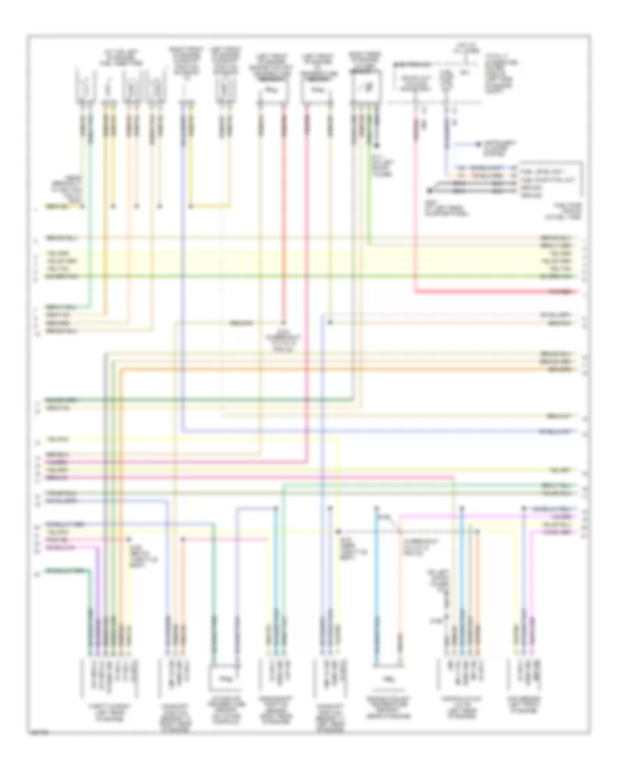
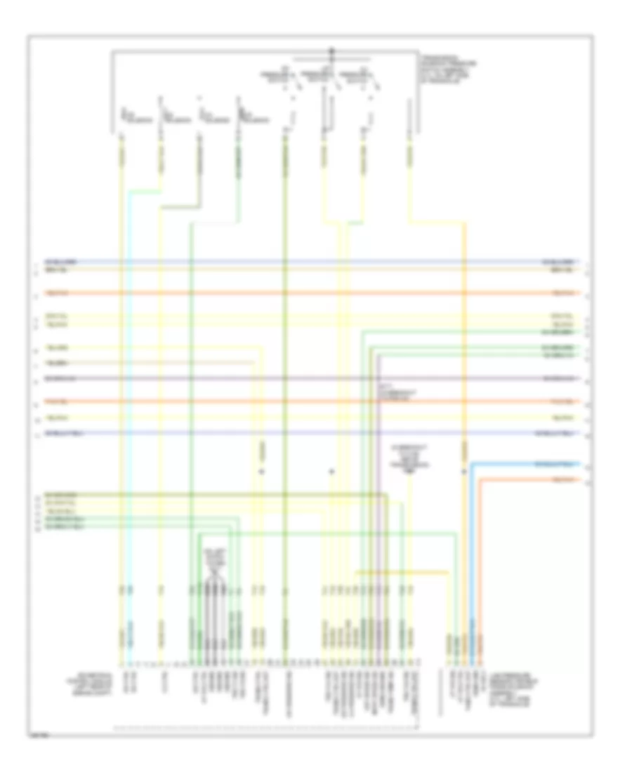
2.4L, Engine Performance Wiring Diagram (3 of 4) for Chrysler Sebring 2007
List of elements for 2.4L, Engine Performance Wiring Diagram (3 of 4) for Chrysler Sebring 2007:
- (at top left of engine) fuel injectors
- (in breakout to c101 & pcm c2)
- (left front of engine) camshaft position solenoid 1/1
- (left front of engine) engine coolant temperature sensor 2
- (left front of engine) oil temperature sensor
- (near breakout to ignition coil 5) s190
- (on left shock tower) g111
- (right front of engine) camshaft position solenoid 1/2
- (right rear of engine) oxygen sensor 1/1
- 5v sply
- B(+)
- Camshaft position sensor 1/1 (left rear of engine)
- Camshaft position sensor 1/2 (right rear of engine)
- Ckp sig
- Cmp 1/1 sig
- Cmp 1/2 sig
- Crankshaft position sensor (right rear of engine)
- Electronics
- Engine coolant temperature sensor 1 (rear of engine)
- Etc mtr (+)
- Etc mtr (-)
- F901
- Fuel level sig 1
- Fuel pump ctrl out
- Fuel pump module (in fuel tank)
- G111 (on left shock tower)
- G303 (at left rear quarter panel)
- Gnd
- Ground
- Hot at all times
- Ign sw out (unlock- run-start)
- Instrument cluster system
- Intake air temperature sensor (on intake manifold)
- Manifold flow valve (left rear of engine)
- Map sensor (left front of engine)
- Map sig
- Mfv ctrl
- Mfv sig
- Pnk/red
- S181
- S184 (in breakout to c101 & pcm c2)
- S191 (near throttle body)
- S192 (below throttle body)
- S199
- Sens gnd
- Throttle body (left rear of engine)
- Totally integrated power module (left side of engine compt)
- Tp sens gnd
- Tp sig 1
- Tp sig 2
- Z916
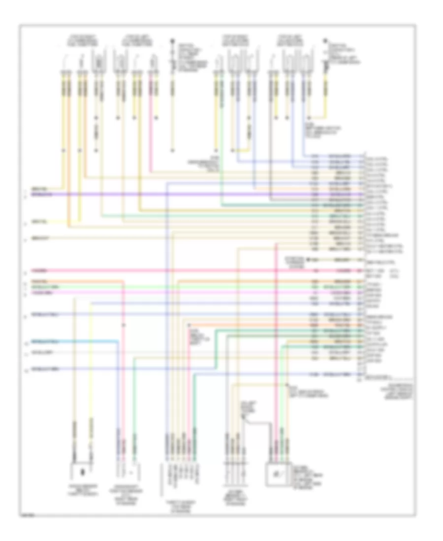
2.4L, Engine Performance Wiring Diagram (4 of 4) for Chrysler Sebring 2007
List of elements for 2.4L, Engine Performance Wiring Diagram (4 of 4) for Chrysler Sebring 2007:
- (top of engine, near ignition coil breakout 4) s196
- (top right side of engine) ignition coils
- 2-4 ctrl
- 2-4 pressure switch
- 2-4 solenoid
- Autostick down sig
- Autostick up sig
- Ckp sig
- Cmp 1/1 ctrl
- Cmp 1/1 sig
- Cmp 1/2 ctrl
- Coil 1 ctrl
- Coil 2 ctrl
- Coil 3 ctrl
- Coil 4 ctrl
- Ect 1 sig
- Engine oil pressure switch (lower left side of engine)
- Eop sig
- F901
- Gen field ctrl
- Ign sw out (unlock-run-start)
- Ignition capacitor 1 (rear of engine)
- In speed sig
- Input speed sensor (on left side of transaxle)
- K122
- K15
- K17
- K18
- K19
- K20
- K22
- K24
- K276
- K42
- K44
- K602
- K76
- K900
- K915
- K922
- K942
- K99
- Knock sensor (left side of engine)
- Ks return
- Ks sig
- L/r ctrl
- L/r pressure switch
- L/r solenoid
- Map sig
- Mfv sig
- Nca
- Nol
- O2 1/1 heater ctrl
- Od ctrl
- Od pressure switch
- Od solenoid
- Out speed sig
- Output speed sensor (on left side of transaxle case)
- P3l
- Pnk/red
- Powertrain control module (left rear of engine compt)
- Prnl
- S101 (in breakout to pcm c2)
- S171 (in breakout to pcm c4)
- S194
- Sens ground
- Shift interlock system
- Starting/charging system
- T13
- T14
- T19
- T20
- T41
- T42
- T44
- T52
- T54
- T59
- T60
- T853
- Tp sens ground
- Tp sig 1
- Tp sig 2
- Trans temp sig
- Transmission range sensor (on lower left side of transaxle)
- Transmission solenoid/ pressure switch assembly (on left side of transaxle)
- Transmission temperature sensor
- Trs t1 sig
- Trs t3 sig
- Trs t41 sig
- Trs t42 sig
- Ud ctrl
- Ud solenoid
2.7L FLEX FUEL
2.7L Flex Fuel, Engine Performance Wiring Diagram, 40/41TE (1 of 5) for Chrysler Sebring 2007
List of elements for 2.7L Flex Fuel, Engine Performance Wiring Diagram, 40/41TE (1 of 5) for Chrysler Sebring 2007:
- (3.5l: left front side of engine block) (2.7l: right side of engine block) engine oil pressure switch
- (on left shock tower) g111
- (run-start)
- (unlock- run-start)
- 5v sply
- A/c comp ctrl
- A804
- A931
- Accelerator pedal position sensor (top of accelerator pedal)
- Air conditioning system
- App sens gnd 1
- App sens gnd 2
- App sig 1
- Asd/ main relay
- Asd/main rly ctrl
- Asd/main rly out
- Autostick down sig
- Autostick up sig
- B(+)
- B15
- B16
- Brake sig 1
- Brake sig 2
- C10
- C11
- C27
- Can c bus (+)
- Can c bus (-)
- Computer data lines system
- D64
- D65
- Electronics
- Eop sig
- Evap purge ctrl
- Evap purge rtn
- Evap/purge solenoid (3.5l: left rear of engine compt)
- F202
- F342
- F856
- F901
- F962
- Fuse 10a
- Fuse 15a
- Fuse 30a
- Fuse 40a
- Fused asd/ main rly out c1
- Fused b(+)
- Gen sense
- Ground
- Hot at all times
- Ign sw out
- Ign sw out (start)
- Ign sw out (unlock- run-start)
- K141
- K167
- K23
- K234
- K235
- K236
- K243
- K299
- K399
- K400
- K51
- K52
- K70
- K904
- Mtv sig
- O2 1/2 heater ctrl
- O2 1/2 sig
- O2 2/2 heater ctrl
- O2 2/2 sig
- O2 rtn (down)
- Oxygen sensor 1/2 (downstream: in exhaust, after catalytic converter)
- Oxygen sensor 2/2 (3.5l: at right side of engine)
- Pnk/red
- Powertrain control module (left rear of engine compt)
- Red
- Relay block (left side of engine compt)
- Rly out
- S/c sig 2
- S/c sw gnd
- S103 (3.5l: in front of left shock tower)
- S106 (in breakout to manifold tuning valve solenoid)
- S110
- S114
- S123 (in front of left shock tower)
- Sens gnd
- Shift interlock system
- Short runner valve solenoid (3.5l) (top front of left cylinder bank)
- Sig 1
- Sig 2
- Srv ctrl
- Srv sig
- Starting/ charging system
- Steering control module (on steering column)
- Sw gnd
- T44
- Totally integrated power module (left side of engine compt)
- V71
- V72
- V937
- Z902
2.7L Flex Fuel, Engine Performance Wiring Diagram, 40/41TE (2 of 5) for Chrysler Sebring 2007
List of elements for 2.7L Flex Fuel, Engine Performance Wiring Diagram, 40/41TE (2 of 5) for Chrysler Sebring 2007:
- (3.5l: in brake fluid reservoir) brake fluid level sensor
- (at left
- (at left rear quarter panel) g303
- (inside left front fender) s126
- (on left shock tower) g111
- (right side of front bumper beam) ambient air temperature sensor
- (top of brake pedal) stop lamp switch
- Aat rtn
- Aat sig
- App sig 2
- B(+)
- B20
- Brake fluid level sig
- C10
- C11
- Electronics
- Esm sig
- Evap monitor system switch (under left rear of vehicle)
- F202
- Fuel level sig 1
- Fuel pump ctrl
- Fuel pump ctrl out
- Fuel pump module (in fuel tank)
- Fuse 10a
- G302
- G303 (at left rear quarter panel)
- G31
- G931
- Ground
- Hot at all times
- Ign sw out (run- start)
- Instrument cluster system
- K107
- K29
- K31
- Kick panel)
- L53
- Nol
- P3l
- Powertrain control module (left rear of engine compt)
- Prnl
- Red
- S/c sig 1
- S120
- Starter ctrl
- Stop lamp sw out
- T15
- T16
- T752
- Totally integrated power module (left side of engine compt)
- Trans ctrl
- Trans ctrl out
- Transmission range sensor (2.7l: on lower left side of transaxle)
- Transmission temperature sensor
- V71
- Z916
2.7L Flex Fuel, Engine Performance Wiring Diagram, 40/41TE (3 of 5) for Chrysler Sebring 2007
List of elements for 2.7L Flex Fuel, Engine Performance Wiring Diagram, 40/41TE (3 of 5) for Chrysler Sebring 2007:
- (in breakout to c106, above transmission) s172
- (on left shock tower) g111
- 2-4 ctrl
- 2-4 pressure sig
- 2-4 pressure switch
- 2-4 solenoid
- 5v sply
- Ground
- Input speed sig
- L/r ctrl
- L/r pressure sig
- L/r pressure switch
- L/r solenoid
- Line pressure sensor/variable force solenoid assembly (2.7l: left side of transaxle)
- Lp vfs ctrl
- Lp vfs sig
- Od ctrl
- Od pressure sig
- Od pressure switch
- Od solenoid
- Out speed sig
- Powertrain control module (left rear of engine compt)
- S171 (in breakout to pcm c4)
- Sens gnd
- Sens ground
- T118
- T13
- T14
- T15
- T16
- T19
- T20
- T38
- T41
- T42
- T47
- T50
- T52
- T54
- T59
- T60
- Tans ctrl out
- Trans ctrl
- Trans ctrl out
- Trans temp sig
- Transmission solenoid/ pressure switch assembly (2.7l: on left side of transaxle)
- Trs t1 sig
- Trs t3 sig
- Trs t41 sig
- Trs t42 sig
- Ud ctrl
- Ud solenoid
- Z902
2.7L Flex Fuel, Engine Performance Wiring Diagram, 40/41TE (4 of 5) for Chrysler Sebring 2007
List of elements for 2.7L Flex Fuel, Engine Performance Wiring Diagram, 40/41TE (4 of 5) for Chrysler Sebring 2007:
- (2.7l: on left side of transaxle case) (3.5l: rear of transaxle case) output speed sensor
- (2.7l: on left side of transaxle) (3.5l: top of transaxle) input speed sensor
- (near throttle body) s191
- 2.7l
- 3.5l
- 5v sply
- Camshaft position sensor (front of left cylinder bank)
- Camshaft position sensor 1 (3.5l: top front of left cylinder bank)
- Egr valve assembly (2.7l: top rear of engine) (3.5l: rear of engine)
- Engine coolant temperature sensor (top front of engine)
- Engine coolant temperature sensor 1
- G111 (on left shock tower)
- Gnd
- Intake air temperature sensor (3.5l: on intake manifold)
- Manifold tuning valve solenoid (top right front of engine)
- Map sensor (top right rear of engine)
- Mtv ctrl
- Mtv sig
- S181 (in breakout to c101 & pcm c2)
- S182 (in injector harness, below throttle body)
- S199
- Sens gnd
2.7L Flex Fuel, Engine Performance Wiring Diagram, 40/41TE (5 of 5) for Chrysler Sebring 2007
List of elements for 2.7L Flex Fuel, Engine Performance Wiring Diagram, 40/41TE (5 of 5) for Chrysler Sebring 2007:
- (2.7l)
- (3.5l)
- (on left shock tower) g111
- (top of left cylinder bank) fuel injectors
- (top of left valve cover) ignition coils
- (top of right cylinder bank) fuel injectors
- (top of right valve cover) ignition coils
- 5v sply
- Ckp sig
- Cmp sig
- Coil 1 ctrl
- Coil 2 ctrl
- Coil 3 ctrl
- Coil 4 ctrl
- Coil 5 ctrl
- Coil 6 ctrl
- Crankshaft position sensor (2.7l) (right rear of engine)
- Ect 1 sig
- Ect sig
- Egr ctrl
- Egr sig
- Etc motor (+)
- Etc motor (-)
- Etc mtr (+)
- Etc mtr (-)
- F855
- Gen field ctrl
- Iat sig
- Ignition capacitor 1 (2.7l: rear of right cylinder bank) (3.5l: top rear of engine)
- Ignition capacitor 2 (2.7l) (rear of left cylinder bank)
- Inj 1 ctrl
- Inj 2 ctrl
- Inj 3 ctrl
- Inj 4 ctrl
- Inj 5 ctrl
- Inj 6 ctrl
- K10
- K11
- K12
- K122
- K124
- K126
- K13
- K136
- K14
- K15
- K16
- K17
- K18
- K19
- K199
- K20
- K21
- K22
- K24
- K34
- K35
- K38
- K41
- K42
- K43
- K44
- K58
- K900
- K902
- K922
- K942
- K99
- Knock sensor (below throttle body)
- Ks rtn
- Ks sig
- Map sig
- Mtv ctrl
- Nca
- O2 1/1 heater ctrl
- O2 1/1 sig
- O2 2/1 heater ctrl
- O2 2/1 sig
- O2 rtn (up)
- Oxygen sensor 1/1 (right front of engine)
- Oxygen sensor 2/1 (2.7l: left rear of engine) (3.5l: left side of engine)
- Powertrain control module (left rear of engine compt)
- S183 (2.7l: end of front left cylinder head)
- S190 (near breakout to ignition coil 5)
- S192 (below throttle body)
- S195 (between ignition coil breakouts to 4 & 6)
- Sens ground
- Starting/ charging system
- Throttle body (top rear of engine)
- Tp sens gnd
- Tp sens ground
- Tp sig 1
- Tp sig 2
2.7L Flex Fuel, Engine Performance Wiring Diagram, 62TE (1 of 5) for Chrysler Sebring 2007
List of elements for 2.7L Flex Fuel, Engine Performance Wiring Diagram, 62TE (1 of 5) for Chrysler Sebring 2007:
- (3.5l: left front side of engine block) (2.7l: right side of engine block) engine oil pressure switch
- (on left shock tower) g111
- (run-start)
- (unlock- run-start)
- 5v sply
- A/c comp ctrl
- A804
- A931
- Accelerator pedal position sensor (top of accelerator pedal)
- Air conditioning system
- App sens gnd 1
- App sens gnd 2
- App sig 1
- Asd/ main relay
- Asd/main rly ctrl
- Asd/main rly out
- Autostick down sig
- Autostick up sig
- B(+)
- B15
- B16
- Brake sig 1
- Brake sig 2
- C10
- C11
- C27
- Can c bus (+)
- Can c bus (-)
- Computer data lines system
- D64
- D65
- Electronics
- Eop sig
- Evap purge ctrl
- Evap purge rtn
- Evap/purge solenoid (3.5l: left rear of engine compt)
- F202
- F342
- F856
- F901
- F962
- Fuse 10a
- Fuse 15a
- Fuse 30a
- Fuse 40a
- Fused asd/ main rly out c1
- Fused b(+)
- Gen sense
- Ground
- Hot at all times
- Ign sw out
- Ign sw out (start)
- Ign sw out (unlock- run-start)
- K141
- K167
- K23
- K234
- K235
- K236
- K243
- K299
- K399
- K400
- K51
- K52
- K70
- K904
- Mtv sig
- O2 1/2 heater ctrl
- O2 1/2 sig
- O2 2/2 heater ctrl
- O2 2/2 sig
- O2 rtn (down)
- Oxygen sensor 1/2 (downstream: in exhaust, after catalytic converter)
- Oxygen sensor 2/2 (3.5l: at right side of engine)
- Pnk/red
- Powertrain control module (left rear of engine compt)
- Red
- Relay block (left side of engine compt)
- Rly out
- S/c sig 2
- S/c sw gnd
- S103 (3.5l: in front of left shock tower)
- S106 (in breakout to manifold tuning valve solenoid)
- S110
- S114
- S123 (in front of left shock tower)
- Sens gnd
- Shift interlock system
- Short runner valve solenoid (3.5l) (top front of left cylinder bank)
- Sig 1
- Sig 2
- Srv ctrl
- Srv sig
- Starting/ charging system
- Steering control module (on steering column)
- Sw gnd
- T44
- Totally integrated power module (left side of engine compt)
- V71
- V72
- V937
- Z902
2.7L Flex Fuel, Engine Performance Wiring Diagram, 62TE (2 of 5) for Chrysler Sebring 2007
List of elements for 2.7L Flex Fuel, Engine Performance Wiring Diagram, 62TE (2 of 5) for Chrysler Sebring 2007:
- (3.5l: in brake fluid reservoir) brake fluid level sensor
- (at left
- (at left rear quarter panel) g303
- (inside left front fender) s126
- (right side of front bumper beam) ambient air temperature sensor
- (top of brake pedal) stop lamp switch
- Aat rtn
- Aat sig
- App sig 2
- B(+)
- B20
- Brake fluid level sig
- C10
- C11
- Electronics
- Esm sig
- Evap monitor system switch (under left rear of vehicle)
- F202
- Fuel level sig 1
- Fuel pump ctrl
- Fuel pump ctrl out
- Fuel pump module (in fuel tank)
- Fuse 10a
- G111 (on left shock tower)
- G302
- G303 (at left rear quarter panel)
- G31
- G931
- Ground
- Hot at all times
- Ign sw out (run- start)
- Instrument cluster system
- K107
- K29
- K31
- Kick panel)
- L53
- Powertrain control module (left rear of engine compt)
- Red
- S/c sig 1
- S120
- Starter ctrl
- Stop lamp sw out
- T15
- T16
- T752
- Totally integrated power module (left side of engine compt)
- Trans ctrl
- Trans ctrl out
- V71
- Z916
2.7L Flex Fuel, Engine Performance Wiring Diagram, 62TE (3 of 5) for Chrysler Sebring 2007
List of elements for 2.7L Flex Fuel, Engine Performance Wiring Diagram, 62TE (3 of 5) for Chrysler Sebring 2007:
- (on left shock tower) g111
- 2-4 lr ctrl
- 2-4 press sw
- 2-4 pressure sig
- 4c sol
- 5v sply
- Dc ctrl
- Dc press sw
- Dc pressure sig
- Dc sol
- Emcc sol
- Emcc vfs ctrl
- Ground
- Input speed sig
- L/r ctrl
- L/r press sw
- L/r pressure sig
- Lc ctrl
- Lc press sw
- Lc pressure sig
- Lc sol
- Lp vfs ctrl
- Lr sol
- Od ctrl
- Od press sw
- Od pressure sig
- Od sol
- Out speed sig
- Powertrain control module (left rear of engine compt)
- S172 (in breakout to c106, above transmission)
- Sens gnd
- Sens ground
- T118
- T13
- T14
- T15
- T16
- T19
- T20
- T38
- T41
- T42
- T47
- T50
- T52
- T54
- T59
- T60
- T80
- T81
- T82
- T83
- T84
- T85
- Trans ctrl
- Trans ctrl out
- Trans temp sig
- Transfer spd sig
- Transmission solenoid/trs assembly (left side of transaxle)
- Transmission temperature sensor
- Trs t1 sig
- Trs t3 sig
- Trs t41 sig
- Trs t42 sig
- Ud ctrl
- Ud sol
- Vfs sol
- Z902
2.7L Flex Fuel, Engine Performance Wiring Diagram, 62TE (4 of 5) for Chrysler Sebring 2007
List of elements for 2.7L Flex Fuel, Engine Performance Wiring Diagram, 62TE (4 of 5) for Chrysler Sebring 2007:
- (2.7l: on left side of transaxle case) (3.5l: rear of transaxle case) output speed sensor
- (2.7l: on left side of transaxle) (3.5l: top of transaxle) input speed sensor
- (near throttle body) s191
- (rear of transaxle) transfer speed sensor
- 2.7l
- 3.5l
- 5v sply
- Camshaft position sensor (front of left cylinder bank)
- Camshaft position sensor 1 (3.5l: top front of left cylinder bank)
- Egr valve assembly (2.7l: top rear of engine) (3.5l: rear of engine)
- Engine coolant temperature sensor (top front of engine)
- Engine coolant temperature sensor 1
- G111 (on left shock tower)
- Gnd
- Intake air temperature sensor (3.5l: on intake manifold)
- Manifold tuning valve solenoid (top right front of engine)
- Map sensor (top right rear of engine)
- Mtv ctrl
- Mtv sig
- S171 (in breakout to pcm c4)
- S181 (in breakout to c101 & pcm c2)
- S182 (in injector harness, below throttle body)
- S199
- Sens gnd
2.7L Flex Fuel, Engine Performance Wiring Diagram, 62TE (5 of 5) for Chrysler Sebring 2007
List of elements for 2.7L Flex Fuel, Engine Performance Wiring Diagram, 62TE (5 of 5) for Chrysler Sebring 2007:
- (2.7l)
- (3.5l)
- (on left shock tower) g111
- (top of left cylinder bank) fuel injectors
- (top of left valve cover) ignition coils
- (top of right cylinder bank) fuel injectors
- (top of right valve cover) ignition coils
- 5v sply
- Ckp sig
- Cmp sig
- Coil 1 ctrl
- Coil 2 ctrl
- Coil 3 ctrl
- Coil 4 ctrl
- Coil 5 ctrl
- Coil 6 ctrl
- Crankshaft position sensor (2.7l) (right rear of engine)
- Ect 1 sig
- Ect sig
- Egr ctrl
- Egr sig
- Etc motor (+)
- Etc motor (-)
- Etc mtr (+)
- Etc mtr (-)
- F855
- Gen field ctrl
- Iat sig
- Ignition capacitor 1 (2.7l: rear of right cylinder bank) (3.5l: top rear of engine)
- Ignition capacitor 2 (2.7l) (rear of left cylinder bank)
- Inj 1 ctrl
- Inj 2 ctrl
- Inj 3 ctrl
- Inj 4 ctrl
- Inj 5 ctrl
- Inj 6 ctrl
- K10
- K11
- K12
- K122
- K124
- K126
- K13
- K136
- K14
- K15
- K16
- K17
- K18
- K19
- K199
- K20
- K21
- K22
- K24
- K34
- K35
- K38
- K41
- K42
- K43
- K44
- K58
- K900
- K902
- K922
- K942
- K99
- Knock sensor (below throttle body)
- Ks rtn
- Ks sig
- Map sig
- Mtv ctrl
- Nca
- O2 1/1 heater ctrl
- O2 1/1 sig
- O2 2/1 heater ctrl
- O2 2/1 sig
- O2 rtn (up)
- Oxygen sensor 1/1 (right front of engine)
- Oxygen sensor 2/1 (2.7l: left rear of engine) (3.5l: left side of engine)
- Powertrain control module (left rear of engine compt)
- S183 (2.7l: end of front left cylinder head)
- S190 (near breakout to ignition coil 5)
- S192 (below throttle body)
- S195 (between ignition coil breakouts to 4 & 6)
- Sens ground
- Starting/ charging system
- Throttle body (top rear of engine)
- Tp sens gnd
- Tp sens ground
- Tp sig 1
- Tp sig 2
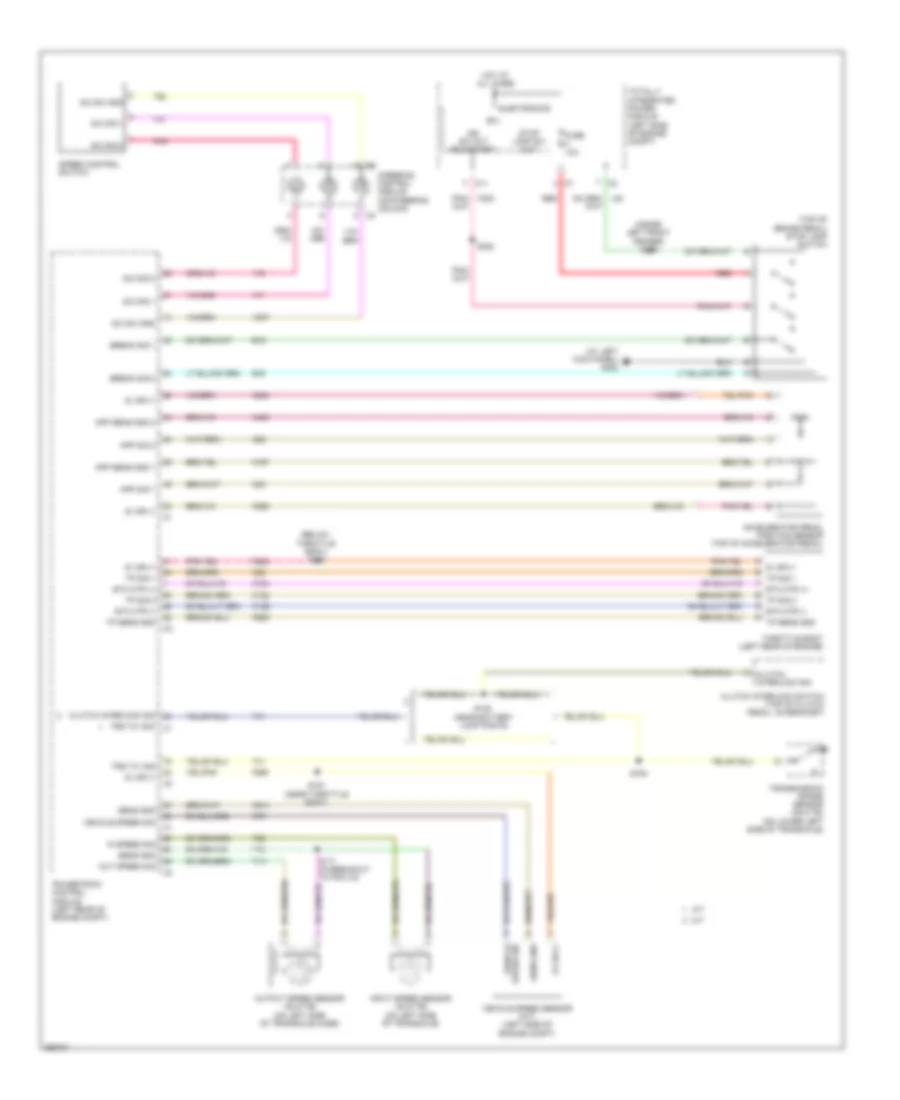
3.5L
3.5L, Engine Performance Wiring Diagram, 40/41TE (1 of 5) for Chrysler Sebring 2007
List of elements for 3.5L, Engine Performance Wiring Diagram, 40/41TE (1 of 5) for Chrysler Sebring 2007:
- (3.5l: left front side of engine block) (2.7l: right side of engine block) engine oil pressure switch
- (on left shock tower) g111
- (run-start)
- (unlock- run-start)
- 5v sply
- A/c comp ctrl
- A804
- A931
- Accelerator pedal position sensor (top of accelerator pedal)
- Air conditioning system
- App sens gnd 1
- App sens gnd 2
- App sig 1
- Asd/ main relay
- Asd/main rly ctrl
- Asd/main rly out
- Autostick down sig
- Autostick up sig
- B(+)
- B15
- B16
- Brake sig 1
- Brake sig 2
- C10
- C11
- C27
- Can c bus (+)
- Can c bus (-)
- Computer data lines system
- D64
- D65
- Electronics
- Eop sig
- Evap purge ctrl
- Evap purge rtn
- Evap/purge solenoid (3.5l: left rear of engine compt)
- F202
- F342
- F856
- F901
- F962
- Fuse 10a
- Fuse 15a
- Fuse 30a
- Fuse 40a
- Fused asd/ main rly out c1
- Fused b(+)
- Gen sense
- Ground
- Hot at all times
- Ign sw out
- Ign sw out (start)
- Ign sw out (unlock- run-start)
- K141
- K167
- K23
- K234
- K235
- K236
- K243
- K299
- K399
- K400
- K51
- K52
- K70
- K904
- Mtv sig
- O2 1/2 heater ctrl
- O2 1/2 sig
- O2 2/2 heater ctrl
- O2 2/2 sig
- O2 rtn (down)
- Oxygen sensor 1/2 (downstream: in exhaust, after catalytic converter)
- Oxygen sensor 2/2 (3.5l: at right side of engine)
- Pnk/red
- Powertrain control module (left rear of engine compt)
- Red
- Relay block (left side of engine compt)
- Rly out
- S/c sig 2
- S/c sw gnd
- S103 (3.5l: in front of left shock tower)
- S106 (in breakout to manifold tuning valve solenoid)
- S110
- S114
- S123 (in front of left shock tower)
- Sens gnd
- Shift interlock system
- Short runner valve solenoid (3.5l) (top front of left cylinder bank)
- Sig 1
- Sig 2
- Srv ctrl
- Srv sig
- Starting/ charging system
- Steering control module (on steering column)
- Sw gnd
- T44
- Totally integrated power module (left side of engine compt)
- V71
- V72
- V937
- Z902
3.5L, Engine Performance Wiring Diagram, 40/41TE (2 of 5) for Chrysler Sebring 2007
List of elements for 3.5L, Engine Performance Wiring Diagram, 40/41TE (2 of 5) for Chrysler Sebring 2007:
- (3.5l: in brake fluid reservoir) brake fluid level sensor
- (at left
- (at left rear quarter panel) g303
- (inside left front fender) s126
- (on left shock tower) g111
- (right side of front bumper beam) ambient air temperature sensor
- (top of brake pedal) stop lamp switch
- Aat rtn
- Aat sig
- App sig 2
- B(+)
- B20
- Brake fluid level sig
- C10
- C11
- Electronics
- Esm sig
- Evap monitor system switch (under left rear of vehicle)
- F202
- Fuel level sig 1
- Fuel pump ctrl
- Fuel pump ctrl out
- Fuel pump module (in fuel tank)
- Fuse 10a
- G302
- G303 (at left rear quarter panel)
- G31
- G931
- Ground
- Hot at all times
- Ign sw out (run- start)
- Instrument cluster system
- K107
- K29
- K31
- Kick panel)
- L53
- Nol
- P3l
- Powertrain control module (left rear of engine compt)
- Prnl
- Red
- S/c sig 1
- S120
- Starter ctrl
- Stop lamp sw out
- T15
- T16
- T752
- Totally integrated power module (left side of engine compt)
- Trans ctrl
- Trans ctrl out
- Transmission range sensor (2.7l: on lower left side of transaxle)
- Transmission temperature sensor
- V71
- Z916
3.5L, Engine Performance Wiring Diagram, 40/41TE (3 of 5) for Chrysler Sebring 2007
List of elements for 3.5L, Engine Performance Wiring Diagram, 40/41TE (3 of 5) for Chrysler Sebring 2007:
- (in breakout to c106, above transmission) s172
- (on left shock tower) g111
- 2-4 ctrl
- 2-4 pressure sig
- 2-4 pressure switch
- 2-4 solenoid
- 5v sply
- Ground
- Input speed sig
- L/r ctrl
- L/r pressure sig
- L/r pressure switch
- L/r solenoid
- Line pressure sensor/variable force solenoid assembly (2.7l: left side of transaxle)
- Lp vfs ctrl
- Lp vfs sig
- Od ctrl
- Od pressure sig
- Od pressure switch
- Od solenoid
- Out speed sig
- Powertrain control module (left rear of engine compt)
- S171 (in breakout to pcm c4)
- Sens gnd
- Sens ground
- T118
- T13
- T14
- T15
- T16
- T19
- T20
- T38
- T41
- T42
- T47
- T50
- T52
- T54
- T59
- T60
- Tans ctrl out
- Trans ctrl
- Trans ctrl out
- Trans temp sig
- Transmission solenoid/ pressure switch assembly (2.7l: on left side of transaxle)
- Trs t1 sig
- Trs t3 sig
- Trs t41 sig
- Trs t42 sig
- Ud ctrl
- Ud solenoid
- Z902
3.5L, Engine Performance Wiring Diagram, 40/41TE (4 of 5) for Chrysler Sebring 2007
List of elements for 3.5L, Engine Performance Wiring Diagram, 40/41TE (4 of 5) for Chrysler Sebring 2007:
- (2.7l: on left side of transaxle case) (3.5l: rear of transaxle case) output speed sensor
- (2.7l: on left side of transaxle) (3.5l: top of transaxle) input speed sensor
- (near throttle body) s191
- 2.7l
- 3.5l
- 5v sply
- Camshaft position sensor (front of left cylinder bank)
- Camshaft position sensor 1 (3.5l: top front of left cylinder bank)
- Egr valve assembly (2.7l: top rear of engine) (3.5l: rear of engine)
- Engine coolant temperature sensor (top front of engine)
- Engine coolant temperature sensor 1
- G111 (on left shock tower)
- Gnd
- Intake air temperature sensor (3.5l: on intake manifold)
- Manifold tuning valve solenoid (top right front of engine)
- Map sensor (top right rear of engine)
- Mtv ctrl
- Mtv sig
- S181 (in breakout to c101 & pcm c2)
- S182 (in injector harness, below throttle body)
- S199
- Sens gnd
3.5L, Engine Performance Wiring Diagram, 40/41TE (5 of 5) for Chrysler Sebring 2007
List of elements for 3.5L, Engine Performance Wiring Diagram, 40/41TE (5 of 5) for Chrysler Sebring 2007:
- (2.7l)
- (3.5l)
- (on left shock tower) g111
- (top of left cylinder bank) fuel injectors
- (top of left valve cover) ignition coils
- (top of right cylinder bank) fuel injectors
- (top of right valve cover) ignition coils
- 5v sply
- Ckp sig
- Cmp sig
- Coil 1 ctrl
- Coil 2 ctrl
- Coil 3 ctrl
- Coil 4 ctrl
- Coil 5 ctrl
- Coil 6 ctrl
- Crankshaft position sensor (2.7l) (right rear of engine)
- Ect 1 sig
- Ect sig
- Egr ctrl
- Egr sig
- Etc motor (+)
- Etc motor (-)
- Etc mtr (+)
- Etc mtr (-)
- F855
- Gen field ctrl
- Iat sig
- Ignition capacitor 1 (2.7l: rear of right cylinder bank) (3.5l: top rear of engine)
- Ignition capacitor 2 (2.7l) (rear of left cylinder bank)
- Inj 1 ctrl
- Inj 2 ctrl
- Inj 3 ctrl
- Inj 4 ctrl
- Inj 5 ctrl
- Inj 6 ctrl
- K10
- K11
- K12
- K122
- K124
- K126
- K13
- K136
- K14
- K15
- K16
- K17
- K18
- K19
- K199
- K20
- K21
- K22
- K24
- K34
- K35
- K38
- K41
- K42
- K43
- K44
- K58
- K900
- K902
- K922
- K942
- K99
- Knock sensor (below throttle body)
- Ks rtn
- Ks sig
- Map sig
- Mtv ctrl
- Nca
- O2 1/1 heater ctrl
- O2 1/1 sig
- O2 2/1 heater ctrl
- O2 2/1 sig
- O2 rtn (up)
- Oxygen sensor 1/1 (right front of engine)
- Oxygen sensor 2/1 (2.7l: left rear of engine) (3.5l: left side of engine)
- Powertrain control module (left rear of engine compt)
- S183 (2.7l: end of front left cylinder head)
- S190 (near breakout to ignition coil 5)
- S192 (below throttle body)
- S195 (between ignition coil breakouts to 4 & 6)
- Sens ground
- Starting/ charging system
- Throttle body (top rear of engine)
- Tp sens gnd
- Tp sens ground
- Tp sig 1
- Tp sig 2
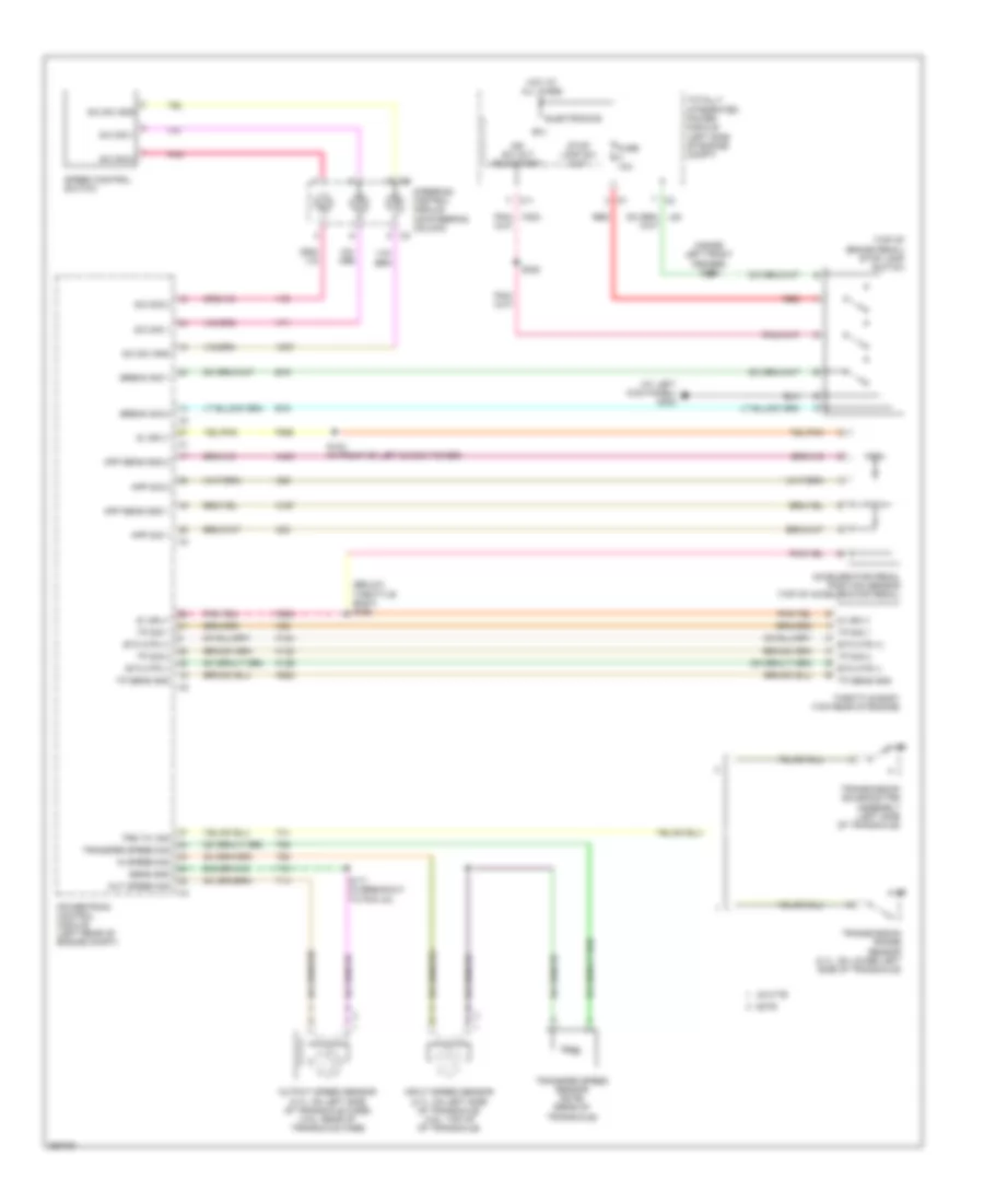
3.5L, Engine Performance Wiring Diagram, 62TE (1 of 5) for Chrysler Sebring 2007
List of elements for 3.5L, Engine Performance Wiring Diagram, 62TE (1 of 5) for Chrysler Sebring 2007:
- (3.5l: left front side of engine block) (2.7l: right side of engine block) engine oil pressure switch
- (on left shock tower) g111
- (run-start)
- (unlock- run-start)
- 5v sply
- A/c comp ctrl
- A804
- A931
- Accelerator pedal position sensor (top of accelerator pedal)
- Air conditioning system
- App sens gnd 1
- App sens gnd 2
- App sig 1
- Asd/ main relay
- Asd/main rly ctrl
- Asd/main rly out
- Autostick down sig
- Autostick up sig
- B(+)
- B15
- B16
- Brake sig 1
- Brake sig 2
- C10
- C11
- C27
- Can c bus (+)
- Can c bus (-)
- Computer data lines system
- D64
- D65
- Electronics
- Eop sig
- Evap purge ctrl
- Evap purge rtn
- Evap/purge solenoid (3.5l: left rear of engine compt)
- F202
- F342
- F856
- F901
- F962
- Fuse 10a
- Fuse 15a
- Fuse 30a
- Fuse 40a
- Fused asd/ main rly out c1
- Fused b(+)
- Gen sense
- Ground
- Hot at all times
- Ign sw out
- Ign sw out (start)
- Ign sw out (unlock- run-start)
- K141
- K167
- K23
- K234
- K235
- K236
- K243
- K299
- K399
- K400
- K51
- K52
- K70
- K904
- Mtv sig
- O2 1/2 heater ctrl
- O2 1/2 sig
- O2 2/2 heater ctrl
- O2 2/2 sig
- O2 rtn (down)
- Oxygen sensor 1/2 (downstream: in exhaust, after catalytic converter)
- Oxygen sensor 2/2 (3.5l: at right side of engine)
- Pnk/red
- Powertrain control module (left rear of engine compt)
- Red
- Relay block (left side of engine compt)
- Rly out
- S/c sig 2
- S/c sw gnd
- S103 (3.5l: in front of left shock tower)
- S106 (in breakout to manifold tuning valve solenoid)
- S110
- S114
- S123 (in front of left shock tower)
- Sens gnd
- Shift interlock system
- Short runner valve solenoid (3.5l) (top front of left cylinder bank)
- Sig 1
- Sig 2
- Srv ctrl
- Srv sig
- Starting/ charging system
- Steering control module (on steering column)
- Sw gnd
- T44
- Totally integrated power module (left side of engine compt)
- V71
- V72
- V937
- Z902
3.5L, Engine Performance Wiring Diagram, 62TE (2 of 5) for Chrysler Sebring 2007
List of elements for 3.5L, Engine Performance Wiring Diagram, 62TE (2 of 5) for Chrysler Sebring 2007:
- (3.5l: in brake fluid reservoir) brake fluid level sensor
- (at left
- (at left rear quarter panel) g303
- (inside left front fender) s126
- (right side of front bumper beam) ambient air temperature sensor
- (top of brake pedal) stop lamp switch
- Aat rtn
- Aat sig
- App sig 2
- B(+)
- B20
- Brake fluid level sig
- C10
- C11
- Electronics
- Esm sig
- Evap monitor system switch (under left rear of vehicle)
- F202
- Fuel level sig 1
- Fuel pump ctrl
- Fuel pump ctrl out
- Fuel pump module (in fuel tank)
- Fuse 10a
- G111 (on left shock tower)
- G302
- G303 (at left rear quarter panel)
- G31
- G931
- Ground
- Hot at all times
- Ign sw out (run- start)
- Instrument cluster system
- K107
- K29
- K31
- Kick panel)
- L53
- Powertrain control module (left rear of engine compt)
- Red
- S/c sig 1
- S120
- Starter ctrl
- Stop lamp sw out
- T15
- T16
- T752
- Totally integrated power module (left side of engine compt)
- Trans ctrl
- Trans ctrl out
- V71
- Z916
3.5L, Engine Performance Wiring Diagram, 62TE (3 of 5) for Chrysler Sebring 2007
List of elements for 3.5L, Engine Performance Wiring Diagram, 62TE (3 of 5) for Chrysler Sebring 2007:
- (on left shock tower) g111
- 2-4 lr ctrl
- 2-4 press sw
- 2-4 pressure sig
- 4c sol
- 5v sply
- Dc ctrl
- Dc press sw
- Dc pressure sig
- Dc sol
- Emcc sol
- Emcc vfs ctrl
- Ground
- Input speed sig
- L/r ctrl
- L/r press sw
- L/r pressure sig
- Lc ctrl
- Lc press sw
- Lc pressure sig
- Lc sol
- Lp vfs ctrl
- Lr sol
- Od ctrl
- Od press sw
- Od pressure sig
- Od sol
- Out speed sig
- Powertrain control module (left rear of engine compt)
- S172 (in breakout to c106, above transmission)
- Sens gnd
- Sens ground
- T118
- T13
- T14
- T15
- T16
- T19
- T20
- T38
- T41
- T42
- T47
- T50
- T52
- T54
- T59
- T60
- T80
- T81
- T82
- T83
- T84
- T85
- Trans ctrl
- Trans ctrl out
- Trans temp sig
- Transfer spd sig
- Transmission solenoid/trs assembly (left side of transaxle)
- Transmission temperature sensor
- Trs t1 sig
- Trs t3 sig
- Trs t41 sig
- Trs t42 sig
- Ud ctrl
- Ud sol
- Vfs sol
- Z902
3.5L, Engine Performance Wiring Diagram, 62TE (4 of 5) for Chrysler Sebring 2007
List of elements for 3.5L, Engine Performance Wiring Diagram, 62TE (4 of 5) for Chrysler Sebring 2007:
- (2.7l: on left side of transaxle case) (3.5l: rear of transaxle case) output speed sensor
- (2.7l: on left side of transaxle) (3.5l: top of transaxle) input speed sensor
- (near throttle body) s191
- (rear of transaxle) transfer speed sensor
- 2.7l
- 3.5l
- 5v sply
- Camshaft position sensor (front of left cylinder bank)
- Camshaft position sensor 1 (3.5l: top front of left cylinder bank)
- Egr valve assembly (2.7l: top rear of engine) (3.5l: rear of engine)
- Engine coolant temperature sensor (top front of engine)
- Engine coolant temperature sensor 1
- G111 (on left shock tower)
- Gnd
- Intake air temperature sensor (3.5l: on intake manifold)
- Manifold tuning valve solenoid (top right front of engine)
- Map sensor (top right rear of engine)
- Mtv ctrl
- Mtv sig
- S171 (in breakout to pcm c4)
- S181 (in breakout to c101 & pcm c2)
- S182 (in injector harness, below throttle body)
- S199
- Sens gnd
3.5L, Engine Performance Wiring Diagram, 62TE (5 of 5) for Chrysler Sebring 2007
List of elements for 3.5L, Engine Performance Wiring Diagram, 62TE (5 of 5) for Chrysler Sebring 2007:
- (2.7l)
- (3.5l)
- (on left shock tower) g111
- (top of left cylinder bank) fuel injectors
- (top of left valve cover) ignition coils
- (top of right cylinder bank) fuel injectors
- (top of right valve cover) ignition coils
- 5v sply
- Ckp sig
- Cmp sig
- Coil 1 ctrl
- Coil 2 ctrl
- Coil 3 ctrl
- Coil 4 ctrl
- Coil 5 ctrl
- Coil 6 ctrl
- Crankshaft position sensor (2.7l) (right rear of engine)
- Ect 1 sig
- Ect sig
- Egr ctrl
- Egr sig
- Etc motor (+)
- Etc motor (-)
- Etc mtr (+)
- Etc mtr (-)
- F855
- Gen field ctrl
- Iat sig
- Ignition capacitor 1 (2.7l: rear of right cylinder bank) (3.5l: top rear of engine)
- Ignition capacitor 2 (2.7l) (rear of left cylinder bank)
- Inj 1 ctrl
- Inj 2 ctrl
- Inj 3 ctrl
- Inj 4 ctrl
- Inj 5 ctrl
- Inj 6 ctrl
- K10
- K11
- K12
- K122
- K124
- K126
- K13
- K136
- K14
- K15
- K16
- K17
- K18
- K19
- K199
- K20
- K21
- K22
- K24
- K34
- K35
- K38
- K41
- K42
- K43
- K44
- K58
- K900
- K902
- K922
- K942
- K99
- Knock sensor (below throttle body)
- Ks rtn
- Ks sig
- Map sig
- Mtv ctrl
- Nca
- O2 1/1 heater ctrl
- O2 1/1 sig
- O2 2/1 heater ctrl
- O2 2/1 sig
- O2 rtn (up)
- Oxygen sensor 1/1 (right front of engine)
- Oxygen sensor 2/1 (2.7l: left rear of engine) (3.5l: left side of engine)
- Powertrain control module (left rear of engine compt)
- S183 (2.7l: end of front left cylinder head)
- S190 (near breakout to ignition coil 5)
- S192 (below throttle body)
- S195 (between ignition coil breakouts to 4 & 6)
- Sens ground
- Starting/ charging system
- Throttle body (top rear of engine)
- Tp sens gnd
- Tp sens ground
- Tp sig 1
- Tp sig 2
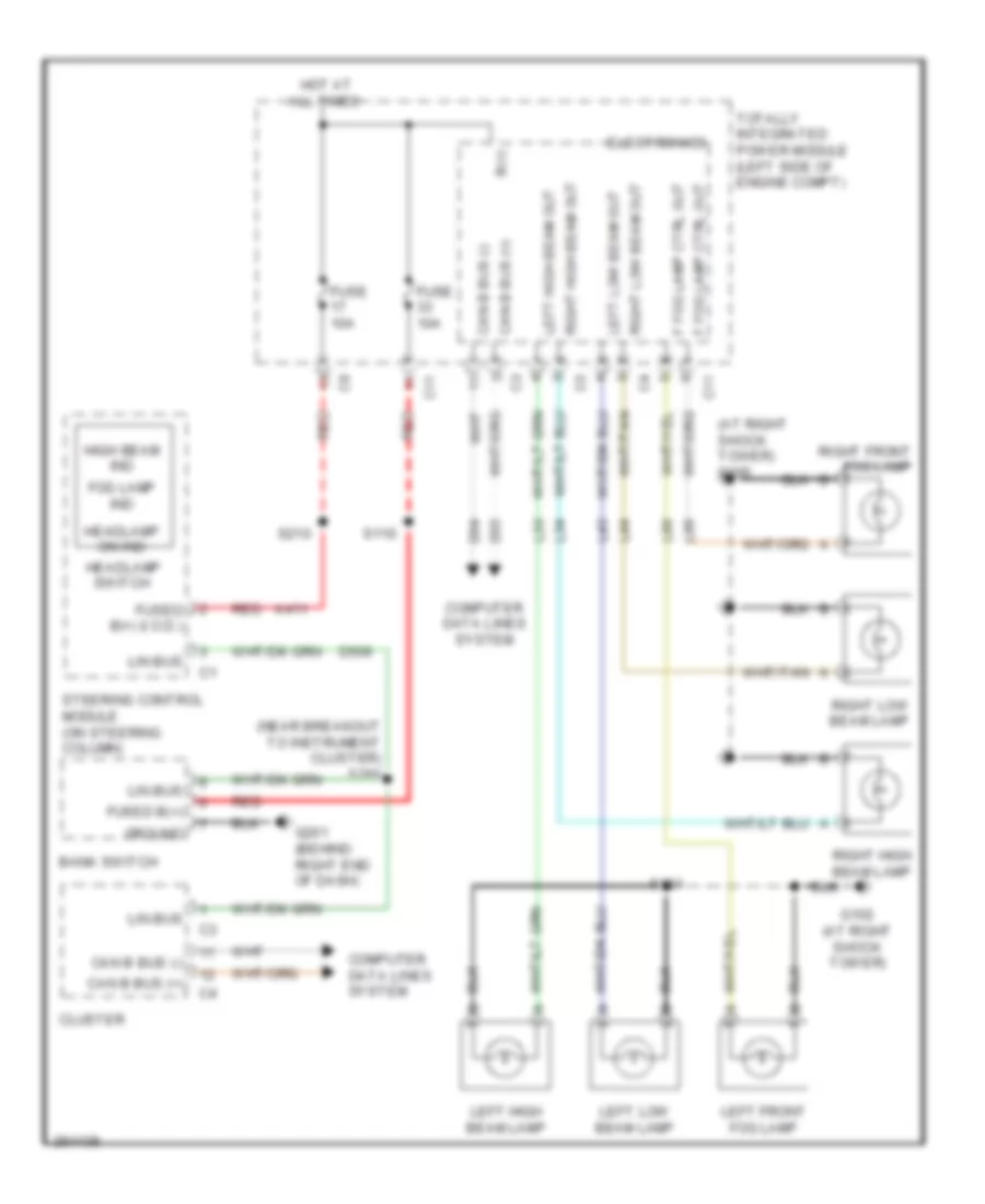
EXTERIOR LIGHTS
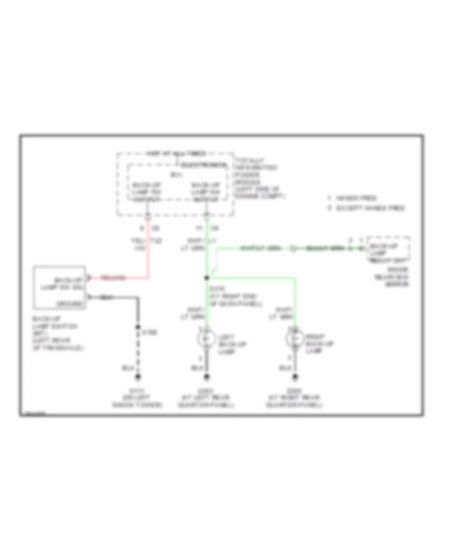
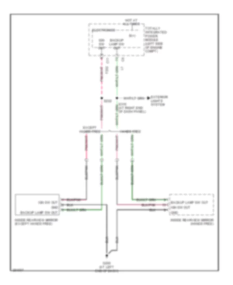
Back-up Lamps Wiring Diagram for Chrysler Sebring 2007
List of elements for Back-up Lamps Wiring Diagram for Chrysler Sebring 2007:
- B(+)
- Back-up lamp relay out
- Back-up lamp sw output
- Back-up lamp sw sig
- Back-up lamp switch (m/t) (left rear of transaxle)
- Electronics
- Except hands free
- G111 (on left shock tower)
- G303 (at left rear quarter panel)
- G305 (at right rear quarter panel)
- Ground
- Hands free
- Hot at all times
- Inside rearview mirror
- Left back-up lamp
- Right back-up lamp
- S199
- S315 (at right end of dash panel)
- Totally integrated power module (left side of engine compt)
Exterior Lamps Wiring Diagram for Chrysler Sebring 2007
List of elements for Exterior Lamps Wiring Diagram for Chrysler Sebring 2007:
- (at left end of dash) g200
- (at left rear quarter panel) g303
- (at right rear quarter panel) g305
- (at right shock tower) g102
- (at right shock tower) g105
- A411
- B(+)
- Bank switch
- C11
- Can b bus (+)
- Can b bus (-)
- Cluster
- Computer data lines system
- D506
- D54
- D55
- Electronics
- F202
- Front park lamp
- Fuse 10a
- Fused b(+)
- Fused b(+) (i.o.d)
- G201 (behind right end of dash)
- G303 (at left rear quarter panel)
- G305 (at right rear quarter panel)
- Ground
- Hazard switch
- Headlamp sw out
- Headlamp switch
- High mounted stop lamp
- Hot at all times
- Ign sw out (run-start)
- L217
- L53
- L55
- L60
- L61
- L62
- L63
- L70
- Left front park/turn lamp
- Left license lamp
- Left rear park lamp
- Left tail stop/park lamp
- Left tail turn lamp
- Left turn sig ctrl
- Lin bus
- Lr turn sig ctrl
- Park lamp ctrl out
- Red
- Right front park/turn lamp
- Right license lamp
- Right rear park lamp
- Right tail stop/park lamp
- Right tail turn lamp
- Rr turn sig ctrl
- S110
- S126 (inside left front fender)
- S154
- S210
- S222
- S260 (near breakout to instrument cluster)
- S310 (behind left rear fascia)
- S316
- S317 (at bottom of left kick panel)
- S318 (at left side doorsill)
- S390
- Steering control module (on steering column)
- Stop lamp
- Stop lamp ctrl out
- Stop lamp sw out
- Stop lamp switch (top of brake pedal)
- Tail lamp
- Totally integrated power module (left side of engine compt)
- Turn signal lamp
- Turn signal switch
- Z910
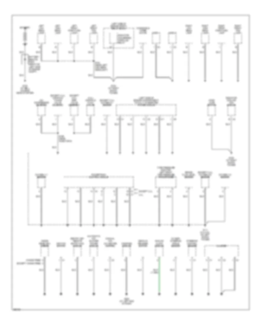
GROUND DISTRIBUTION
Ground Distribution Wiring Diagram (1 of 3) for Chrysler Sebring 2007
List of elements for Ground Distribution Wiring Diagram (1 of 3) for Chrysler Sebring 2007:
- (2.4l) manifold flow valve
- (automatic a/c) blower power module
- (except 2.4l) egr valve assembly
- (except 2.4l) manifold tuning valve solenoid
- (except 2.4l) oxygen 2/1 sensor
- (except 2.4l) oxygen 2/2 sensor
- (except hands free)
- (hands free)
- (left side of engine compartment) totally integrated power module
- (left side of engine compt) relay block
- (manual a/c) a/c heater control
- (tire pressure monitor) left front tire pressure transponder
- (w/ esp) steering angle sensor
- 2.4l
- A/c compressor solenoid
- Analog clock module
- Battery
- Brake fluid level sensor
- C11
- C2 b
- Cluster
- Compass module
- Decklid release switch
- Except 2.4l
- G100 (at bell housing near starter)
- G102 (at right shock tower)
- G105 (at right shock tower)
- G111 (2.4l/3.5l: on left shock tower)
- G200 (at left end of dash)
- Hood ajar switch
- Horn 1
- Horn 2
- Ignition switch
- Inside rearview mirror
- Left front fog lamp
- Left front park/turn lamp
- Left high beam lamp
- Left low beam lamp
- Oxygen 1/1 sensor
- Oxygen 1/2 sensor
- Powertrain control module
- Radiator cooling fan module
- Radiator fan-series/ parallel relay
- Right front fog lamp
- Right front park/turn lamp
- Right high beam lamp
- Right low beam lamp
- S154 (near left high beam headlight)
- S199 (near injector 6)
- Sentry key remote entry/wcm module
- Steering control sensor
- Windshield wiper motor
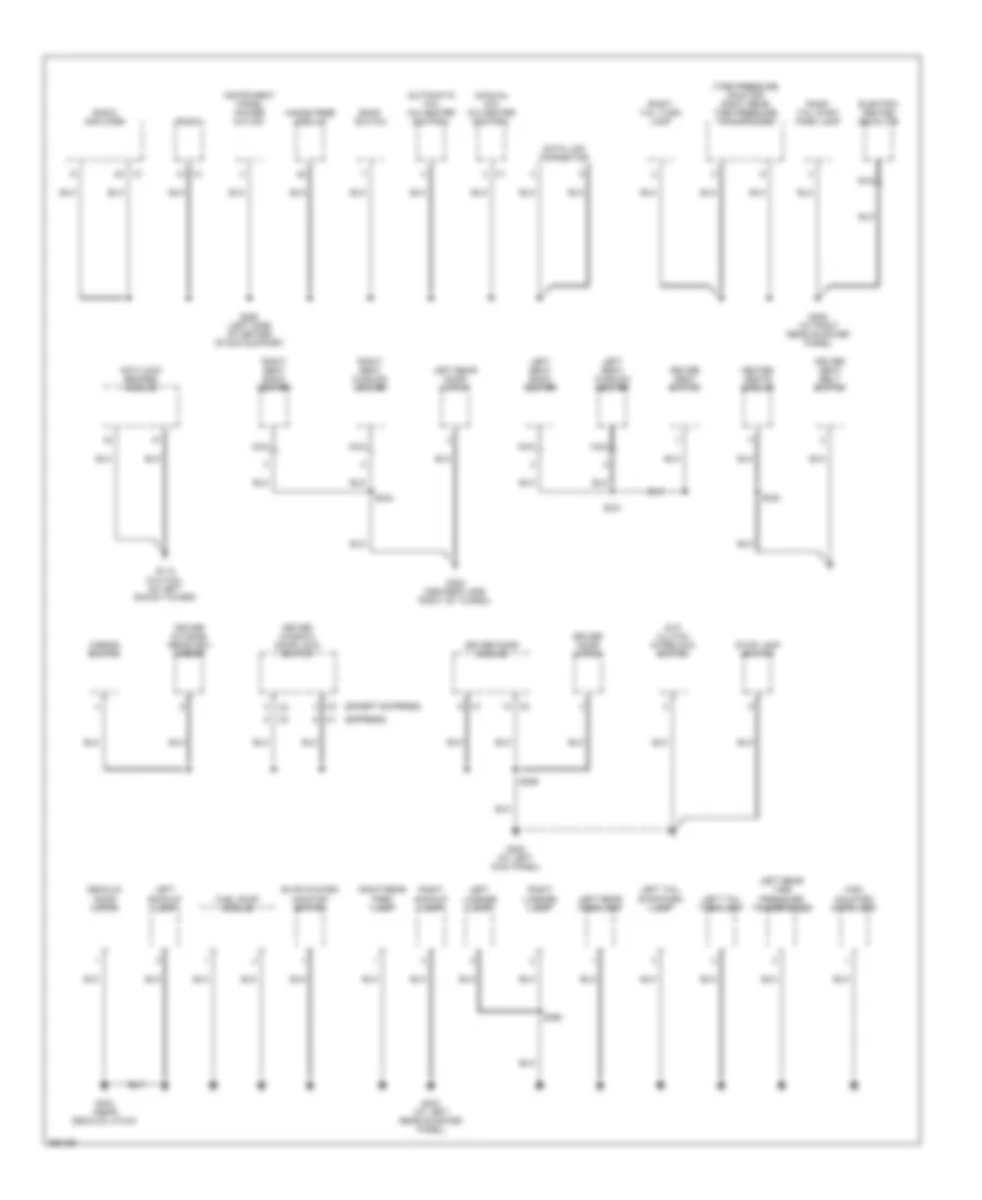
Ground Distribution Wiring Diagram (2 of 3) for Chrysler Sebring 2007
List of elements for Ground Distribution Wiring Diagram (2 of 3) for Chrysler Sebring 2007:
- (automatic a/c) a/c heater control
- (except express)
- (express)
- (m/t) clutch interlock switch
- (manual a/c) a/c heater control
- (tire pressure monitor) right rear tire pressure transponder
- Anti-lock brakes module
- Bank switch
- Data link connector
- Decklid door latch
- Driver door latch
- Driver door module
- Driver outside rearview mirror
- Driver seat belt switch
- Driver seat switch
- Driver window/ door lock switch
- Electric heated backlite
- Evap system monitor switch
- Fuel pump module
- G110 (2.4l/3.5l: on left shock tower)
- G250 (left side of center stack support)
- G300 (center floor, right of tunnel)
- G302 (at left kick panel)
- G303 (at left rear quarter panel)
- G304 (near decklid latch)
- G305 (at right rear quarter panel)
- Hands free module
- Heated seats module
- High mounted stop lamp
- Instrument panel power outlet
- Left backup lamp
- Left license lamp
- Left rear door latch
- Left rear park lamp
- Left rear tire pressure transponder
- Left seat back heater
- Left seat cushion heater
- Left tail stop/park lamp
- Left tail turn lamp
- Mirror switch
- Nca
- Radio
- Radio amplifier
- Right backup lamp
- Right license lamp
- Right rear park lamp
- Right seat back heater
- Right seat cushion heater
- Right tail stop/ park lamp
- Right tail turn lamp
- S330
- S331
- S334
- S359
- S390
- Stop lamp switch
Ground Distribution Wiring Diagram (3 of 3) for Chrysler Sebring 2007
List of elements for Ground Distribution Wiring Diagram (3 of 3) for Chrysler Sebring 2007:
- (at right "a" pillar) s349
- (autostick) shift lever assembly
- (base)
- (dvd) video screen module
- (except express)
- (express)
- Automatic a/c
- B (except base)
- Base
- Console power outlet
- Cup holder assembly
- Dome lamp
- Driver seat switch
- Except base
- G301
- G306 (at right kick panel)
- G307
- Heated seats module
- Left seat back heater
- Left seat cushion heater
- Manual a/c
- Map lamp
- Nca
- Occupant restraint controller (orc) module
- Passenger door latch
- Passenger door module
- Passenger outside rearview mirror
- Passenger window/ door lock switch
- Prndl lamp
- Right rear door latch
- Right seat back heater
- Right seat cushion heater
- Right vanity lamp
- S330
- S331
- S334
- S339
- S353 (near left front door hinge)
- Shift lever assembly
- Sunroof motor
HEADLIGHTS
Headlights Wiring Diagram for Chrysler Sebring 2007
List of elements for Headlights Wiring Diagram for Chrysler Sebring 2007:
- (at right shock tower) g105
- (near breakout to instrument cluster) s260
- A411
- B(+)
- Bank switch
- C11
- Can b bus (+)
- Can b bus (-)
- Cluster
- Computer data lines system
- D506
- D54
- D55
- Electronics
- F fog lamp ctrl out
- Fog lamp ind
- Fuse 10a
- Fused b(+)
- Fused b(+) (i.o.d.)
- G102 (at right shock tower)
- G201 (behind right end of dash)
- Ground
- Headlamp on ind
- Headlamp switch
- High beam ind
- Hot at all times
- L33
- L34
- L43
- L44
- L89
- L90
- Left front fog lamp
- Left high beam lamp
- Left high beam out
- Left low beam lamp
- Left low beam out
- Lin bus
- Red
- Right front fog lamp
- Right high beam lamp
- Right high beam out
- Right low beam lamp
- Right low beam out
- S110
- S154
- S210
- Steering control module (on steering column)
- Totally integrated power module (left side of engine compt)
HORN
Horn Wiring Diagram for Chrysler Sebring 2007
List of elements for Horn Wiring Diagram for Chrysler Sebring 2007:
- B (+)
- C11
- Can b bus (+)
- Can b bus (-)
- Cluster
- Computer data lines system
- Electronics
- G105 (at right shock tower)
- Horn 1 (left front grille area)
- Horn 2 (right front grille area)
- Horn control output
- Horn sw sense
- Horn switch
- Hot at all times
- Radio ctrl mux rtn c4
- S225 (w/ premium)
- Sound systems
- Steering control module (on steering column)
- Totally integrated power module (left side of engine compartment)
INSTRUMENT CLUSTER
Instrument Cluster Wiring Diagram (1 of 2) for Chrysler Sebring 2007
List of elements for Instrument Cluster Wiring Diagram (1 of 2) for Chrysler Sebring 2007:
- (not used) c200
- 2.4l
- 2.7l & 3.5l
- A412
- A932
- B(+)
- B25
- Brake fluid level sensor (2.4l & 3.5l: in brake fluid reservoir)
- Brake fluid lvl sig
- Brake transmission shift interlck sol unlck
- C11
- Can b bus (+)
- Can b bus (-)
- Can c bus (+)
- Can c bus (-)
- Cluster
- Computer data lines system
- Courtesy lamps drv
- D506
- D54
- D55
- D64
- D65
- Decklid ajar sw sns
- Decklid release drv
- Decklid release sw sns
- Door locks system
- Dr lck drv
- Dr lck pwr-fused b(+)
- Drv dr lck sw mux
- Drv dr unlck drv
- Drv seat belt sw sns
- E12
- Electronics
- Engine oil pressure switch (2.4l: lower left side of engine) (2.7l: right side of engine block) (3.5l: left front side of engine block)
- Eop sig
- Eot sig
- Exterior lights system
- F202
- Fuel lvl sig 1
- Fuel lvl sig 2
- Fuel pump module (in fuel tank)
- Fuse 10a
- Fuse 20a
- Fused b(+) (i.o.d.)
- G111 (2.4l & 3.5l: on left shock tower)
- G200 (at left end of dash)
- G24
- G303 (at left rear quarter panel)
- G38
- G74
- G75
- G76
- G77
- G78
- Gnd
- Horn sw sns
- Horns system
- Hot at all times
- Ign sw out (run-start)
- Interior lights system
- K321
- K915
- L53
- Lf dr ajar sw sns
- Lin bus
- Lr dr ajar sw sns
- M24
- M25
- M27
- Oil temperature sensor (2.4l) (left front of engine)
- P223
- P238
- P240
- P31
- P33
- P696
- P697
- Panel lamps drv
- Park brake sw sns
- Pass dr lck sw mux
- Pass dr unlck drv
- Pnk/ f202
- Powertrain control module (left rear of engine compt)
- R57
- Radio ctrl mux
- Radio ctrl mux rtn
- Reading/rail lamps drv
- Rf dr ajar sw sns
- Rr dr ajar sw sns
- S184 (in breakout to c101 & pcm c2)
- S200
- S222
- Sens gnd
- Shift interlock system
- Sound systems
- Stop lamp sw out
- To pcm c2)
- Totally integrated power module (left side of engine compt)
- Trunk, tailgate, fuel doors system
- Ugdo enable ctrl circuit
- Warning system
- X20
- X920
- Z902
- Z910
- Z916
Instrument Cluster Wiring Diagram (2 of 2) for Chrysler Sebring 2007
List of elements for Instrument Cluster Wiring Diagram (2 of 2) for Chrysler Sebring 2007:
- (under left rear shelf) s302
- A411
- Analog clock module
- B(+)
- Can b bus (+)
- Can b bus (-)
- Cargo lamp
- Compass module
- Computer data lines system
- D506
- D54
- D55
- Decklid ajar sw sns
- Decklid door latch (at center rear of deck lid)
- Driver door latch (rear of left front door)
- E12
- Electronics
- F929
- Fuse 10a
- Fused b(+)
- G200 (at left end of dash)
- G300 (center floor, right of tunnel)
- G301
- G302 (at left kick panel)
- G306 (at right kick panel)
- Ground
- Hot at all times
- Ign sw (run)
- Ign sw out (run)
- Interior lights system
- Left rear door latch (rear of left rear door)
- Lin bus
- Panel lmp drv
- Parking brake switch (at base of parking brake lever)
- Passenger door latch (rear of right front door)
- Red
- Right rear door latch (rear of right rear door)
- S210
- S221
- S353
- S359
- Totally integrated power module (left side of engine compt)
- Z910
INTERIOR LIGHTS
Interior Lights Wiring Diagram for Chrysler Sebring 2007
List of elements for Interior Lights Wiring Diagram for Chrysler Sebring 2007:
- (at left kick panel) g302
- (at right "a" pillar) s342
- (at right "a" pillar) s343
- (at right kick panel) g306
- (center floor, right of tunnel) g300
- (under left rear shelf) s302
- Analog clock module
- Automatic a/c
- B(+)
- Bank switch
- Base
- C11
- Can b bus (+)
- Can b bus (-)
- Can bus (+)
- Can bus (-)
- Cargo lamp
- Cluster
- Computer data lines system
- Courtesy lamps drv
- Cup holder assembly (except base)
- D506
- Decklid ajar sw sns
- Decklid door latch (at center rear of deck lid)
- Dimmer switch
- Dome lamp
- Driver door latch (rear of left front door)
- E12
- Electronics
- Except base
- Fuse 10a
- Fused b(+) (i.o.d.)
- G200 (at left end of dash)
- G301
- G306 (at right kick panel)
- Ground
- Hot at all times
- Ign sw out (run-start)
- Left rear door latch (rear of left rear door)
- Left vanity lamp
- Lf door ajar sw sns
- Lin bus
- Lr door ajar sw sns
- Manual a/c
- Map 1 lamp
- Map 2 lamp
- Map lamp
- Panel lamps drv
- Passenger door latch (rear of right front door)
- Pnk/ f202
- Prndl lamp
- Reading/rail lamps drv
- Rf door ajar sw sns
- Right rear door latch (rear of right rear door)
- Right vanity lamp
- Rr door ajar sw sns
- S204 (at left end of instrument panel)
- S222
- S260 (near breakout to instrument cluster)
- S305 (under center console)
- S349
- S349 (automatic a/c)
- S353
- S359
- Steering control module (on steering column)
- Totally integrated power module (left side of engine compt)
- Ugdo enable ctrl
NAVIGATION
Navigation Wiring Diagram for Chrysler Sebring 2007
List of elements for Navigation Wiring Diagram for Chrysler Sebring 2007:
- (at left end of dash) g200
- Ant shd
- Ant sig
- B(+)
- Backup lamp sw out
- C11
- Can b bus (+)
- Can b bus (-)
- Computer data lines system
- Electronics
- F202
- Global positioning
- Gps ant shl
- Gps ant sig
- Ground
- Hot at all times
- Ign sw out (run-start)
- Ing sw out (run-start)
- Inside rearview mirror
- Microphone 1 in (+)
- Microphone 2 in (+)
- Microphone feed
- Microphone in (-)
- Radio
- S222
- S315 (at right end of dash panel)
- Sens gnd
- Sens ground
- System antenna
- Totally integrated power module (left side of engine compt)
- X712
- X722
- X792
- X793
- X835
- Z910
POWER DISTRIBUTION
Power Distribution Wiring Diagram (1 of 3) for Chrysler Sebring 2007
List of elements for Power Distribution Wiring Diagram (1 of 3) for Chrysler Sebring 2007:
- (at left end of instrument panel) s210
- (below left shock tower grounds) s114
- (forward from left shock tower) s110
- (near breakout to instrument cluster) s212
- (not used)
- 2.4l
- 2.7l/3.5l
- A/c heater control
- Analog clock module
- Asd/ main relay
- Automatic a/c
- Bank switch
- Battery
- Battery remote positive post (left side of engine compt)
- C11
- C114
- Data link connector
- Driver seat switch
- Except hands free
- From fuse 3 (diagram 1 of 3)
- Fuse 10a
- Fuse 19 20a (w/ amplifier)
- Fuse 30a
- Fuse 40a
- Fuse 50a
- Generator
- Hands free
- Hands free module
- Manual a/c
- Mirror switch
- Nca
- Powertrain control module
- Radiator fan-low/ high relay
- Radiator fan-medium/ high relay
- Radiator fan-series/ parallel relay
- Radio amplifier
- Red
- Red/ pnk
- Relay block (left side of engine compt)
- S111 (forward from left shock tower)
- S116 (at left kick panel)
- S121 (at left kick panel)
- S130 (left front corner of front cylinder head)
- Sentry key remote entry/wcm module
- Starter
- Steering control module
- Stop lamp switch
- To fuse 4 (diagram 2 of 3)
- To fuse 8 (diagram 1 of 3)
- Totally integrated power module (left side of engine compt)
- Video screen module (dvd)
Power Distribution Wiring Diagram (2 of 3) for Chrysler Sebring 2007
List of elements for Power Distribution Wiring Diagram (2 of 3) for Chrysler Sebring 2007:
- (at left end of dash panel) s312
- (automatic a/c)
- (center of right door module) s352
- (inside left front fender) s124
- (manual a/c)
- (not used)
- A/c heater control
- Acc
- Acc lock
- Anti-lock brakes module
- B(+)
- Battery
- C11
- Cluster
- Compass module
- Console power outlet
- Cup holder assembly
- Door lock pwr fused b(+)
- Driver door module
- Electronics
- From c fuse 4 (diagram 2 of 3)
- From fuse 9 (diagram 1 of 3)
- Fuse (w/ esp)
- Fuse 10a
- Fuse 15a
- Fuse 20a
- Fuse 25a (w/ power sunroof)
- Fuse 30a
- Fuse 30a (w/ esp)
- Fuse 30a (w/ express windows)
- G200 (at left end of dash)
- G250 (left side of center stack support)
- G306 (at right kick panel)
- Ign sw out (run)
- Ign sw out (run-acc)
- Ign sw out (run-start)
- Ignition
- Ignition switch
- Instrument panel power outlet
- Key
- Key out
- Left vanity lamp
- Lock
- Off
- Passenger door module
- Pnk
- Radio
- Red
- Red/ tan
- Run
- S200
- S211 (center instrument panel near ignition switch)
- S220
- S221
- S339 (except base)
- S350 (center of left door module)
- Sentry key remote entry/wcm module
- Start
- Sunroof motor
- To fuse 7 (diagram 2 of 3)
- Totally integrated power module (left side of engine compt)
Power Distribution Wiring Diagram (3 of 3) for Chrysler Sebring 2007
List of elements for Power Distribution Wiring Diagram (3 of 3) for Chrysler Sebring 2007:
- (2.4l)
- (2.7l/3.5l)
- (above left side of glove box) s222
- (at center of dash panel) s320
- (at left end of dash panel) s323
- (behind left headlight) s120
- (except express windows)
- (except hands free)
- (express windows)
- (hands free)
- Anti-lock brakes module
- C11
- Cluster
- Data link connector
- Driver door lock window switch
- Electronics
- Fuse 10a
- Fuse 20a (w/ heated seats)
- Heated seats module
- Ign sw out (run)
- Ign sw out (run-acc)
- Ign sw out (run-start)
- Ign sw out (start)
- Ign sw out (unlock-run-start)
- Infrared sensor (automatic a/c)
- Inside rearview mirror
- Left front tire pressure transponder (tire pressure monitor)
- Left rear tire pressure transponder (tire pressure monitor)
- Occupant restraint controller module
- Passenger door lock window switch
- Pnk
- Pnk/ red
- Powertrain control module
- Right rear tire pressure transponder (tire pressure monitor)
- S153
- Steering angle sensor (w/ esp)
- Steering control module
- Stop lamp switch
- Totally integrated power module (left side of engine compt)
POWER DOOR LOCKS
Power Door Locks Wiring Diagram (1 of 2) for Chrysler Sebring 2007
List of elements for Power Door Locks Wiring Diagram (1 of 2) for Chrysler Sebring 2007:
- (at left end of dash) g200
- A411
- Ajar sw decklid
- B(+)
- C11
- Can b bus (+)
- Can b bus (-)
- Cargo lamp
- Cluster
- Com-lin tire lan
- Computer data lines system
- D508
- D54
- D55
- Decklid ajar sw sns
- Decklid door latch (at center rear of deck lid)
- Decklid release switch
- Decklid sw sns
- Door lock b(+)
- Door lock power
- Dr door lock
- Dr door unlock
- Drv decklid release
- Drv door lock sw mux
- Electronics
- F20
- Fuse 10a
- Fuse 20a
- Fuse 30a
- Fused b(+)
- G105 (at right shock tower)
- G20
- G200 (at left end of dash)
- G304 (near decklid latch)
- G70
- Ground
- Hood ajar sw sns
- Hood ajar switch (right front of engine compt)
- Horn ctrl out
- Horns system
- Hot at all times
- Ign sw out (run-start)
- Ign sw sense
- Lf door ajar sw sns
- Lr door ajar sw sns
- Pass door lock sw mux
- Pass door unlock
- Pnk
- Red
- Rf door ajar sw sns
- Rr door ajar sw sns
- S200
- S210
- S302 (under left rear shelf)
- Sentry key remote entry/wcm module
- Totally integrated power module (left side of engine compt)
- Warning system
- X21
- X22
- Z910
Power Door Locks Wiring Diagram (2 of 2) for Chrysler Sebring 2007
List of elements for Power Door Locks Wiring Diagram (2 of 2) for Chrysler Sebring 2007:
- (at left kick panel) g302
- (at right kick panel) g306
- (center floor, right of tunnel) g300
- Acc
- Acc lock
- Dr door lock sw mux
- Driver door latch (rear of left front door)
- Driver window/ door lock switch
- Except express windows
- Express windows
- G200 (at left end of dash)
- G301
- G306 (at right kick panel)
- Ground
- Hot at all times
- Ignition switch
- Key
- Key out
- Left rear door latch (rear of left rear door)
- Lock
- Off
- Pass door lock sw mux
- Passenger door latch (rear of right front door)
- Passenger window/ door lock switch
- Pnk
- Right rear door latch (rear of right rear door)
- Run
- S220
- S325 (near accelerator pedal)
- S328 (at center of dash panel)
- S353
- S359
- Start
POWER MIRRORS
Automatic Day/Night Mirror Wiring Diagram for Chrysler Sebring 2007
List of elements for Automatic Day/Night Mirror Wiring Diagram for Chrysler Sebring 2007:
- B(+)
- Backup lamp sw out
- C11
- Electronics
- Except hands free
- Exterior lights system
- F202
- G200 (at left end of dash)
- Gnd
- Hands free
- Hot at all times
- Ign sw out
- Inside rearview mirror (except hands free)
- Inside rearview mirror (hands free)
- S222
- Totally integrated power module (left side of engine compt)
Power Mirrors Wiring Diagram for Chrysler Sebring 2007
List of elements for Power Mirrors Wiring Diagram for Chrysler Sebring 2007:
- (at left end of dash panel) s301
- 0) off 1) driver mirror 2) passenger mirror
- A/c heater control
- B(+)
- Can b bus (+)
- Can b bus (-)
- Can b bus (_)
- Computer data lines system
- D54
- D55
- Down
- Driver outside rearview mirror (front of left front door)
- Electronics
- Fuse 10a
- Fuse 30a
- G250 (left side of center stack support)
- G302 (at left kick panel)
- G306 (at right kick panel)
- Gnd
- Horizontal
- Hot at all times
- Ign sw out
- Ign sw output (run)
- Left
- Mirror switch
- Passenger outside rearview mirror (front right front door)
- Rear window defogger ctrl out
- Rear window defogger switch
- Right
- S116
- S221
- S353
- S359
- Tan
- Totally integrated power module (left side of engine compt)
- Vertical
POWER SEATS
Heated Seats Wiring Diagram for Chrysler Sebring 2007
List of elements for Heated Seats Wiring Diagram for Chrysler Sebring 2007:
- (near breakout to instrument cluster) s260
- B(+)
- Bank switch
- C11
- Computer data lines system
- D506
- Electronics
- Fuse 10a
- Fuse 20a
- Fused b(+)
- Fused ign sw out
- G250 (left side of center stack support)
- G300 (center floor, right of tunnel)
- G301
- Gnd
- Heated seats module
- Hot at all times
- Ign sw out (run)
- Left heated seat switch
- Left seat back heater
- Left seat cushion heater
- Lin bus
- Lt seat htr b(+)
- Nca
- P157
- P185
- P937
- Red
- Right heated seat switch
- Right seat back heater
- Right seat cushion heater
- Rt seat htr b(-)
- S110
- S330
- S331
- S332
- S333
- S334
- Totally integrated power module (left side of engine compt)
- Z914
Power Seat Wiring Diagram for Chrysler Sebring 2007
List of elements for Power Seat Wiring Diagram for Chrysler Sebring 2007:
- (center floor, right of tunnel) g300
- Driver horizontal seat adjuster motor
- Driver recliner seat adjuster motor
- Driver seat switch
- Front driver vertical seat adjuster motor
- Fuse 40a
- Fused b(+)
- Gnd
- Hot at all times
- Rear driver vertical seat adjuster motor
- Red
- S330
- Seat front down
- Seat front up
- Seat hori forward
- Seat hori rearward
- Seat rear riser down
- Seat rear riser up
- Seat recliner down
- Seat recliner up
- Totally integrated power module (left side of engine compt)
POWER TOP/SUNROOF
Power Top/Sunroof Wiring Diagram for Chrysler Sebring 2007
List of elements for Power Top/Sunroof Wiring Diagram for Chrysler Sebring 2007:
- B(+)
- Close
- Electronics
- Fuse 15a
- Fuse 25a
- Fused b (+)
- Fused ign sw out
- G306 (at right kick panel)
- Ground
- Hot at all times
- Ign sw out
- Open
- S349
- Sunroof close sw sens
- Sunroof motor (center front of roof)
- Sunroof open sw sens
- Sunroof switch
- Sunroof vent sw sens
- Totally integrated power module (left side of engine compt)
- Vent
POWER WINDOWS
Power Windows Wiring Diagram, Except Express Windows for Chrysler Sebring 2007
List of elements for Power Windows Wiring Diagram, Except Express Windows for Chrysler Sebring 2007:
- B(+)
- Cluster
- Driver window motor (middle of left front door)
- Driver window/door lock switch
- Drv door lck sw mux
- Drv window drv (down)
- Drv window drv (up)
- Electronics
- F981
- G302 (at left kick panel)
- G306 (at right kick panel)
- Ground
- Hot at all times
- Ign sw out (run-acc)
- Ing sw out (run-acc)
- Left rear power window switch
- Left rear window motor (front of left rear door)
- Lr mstr window sw (down)
- Lr mstr window sw (up)
- Lr window drv (down)
- Lr window drv (up)
- Mstr window sw pass (down)
- Mstr window sw pass (up)
- Pass door lck sw mux
- Pass window drv (down)
- Pass window drv (up)
- Passenger window motor (middle of right front door)
- Passenger window/door lock switch
- Pnk
- Right rear power window switch
- Right rear window motor (front of right rear door)
- Rr mstr window sw (down)
- Rr mstr window sw (up)
- Rr window drv (down)
- Rr window drv (up)
- S303 (near right kick panel)
- S323
- S353
- S359
- Totally integrated power module (left side of engine compt)
- Window lck out sw out
Power Windows Wiring Diagram, Express Windows (1 of 2) for Chrysler Sebring 2007
List of elements for Power Windows Wiring Diagram, Express Windows (1 of 2) for Chrysler Sebring 2007:
- A937
- B(+)
- C11
- Can b bus (+)
- Can b bus (-)
- Computer data lines system
- D54
- D55
- Driver door module
- Driver window motor (middle of left front door)
- Driver window/door lock switch
- Drv door lck sw mux
- Drv exp window sw rtn
- Drv window exp down drv
- Drv window exp up drv
- Drv window hall sens a sig
- Drv window hall sens b sig
- Drv window hall sens rtn
- Drv window hall sens sply
- Electronics
- F981
- Fuse 30a
- Fused b(+)
- G302 (at left kick panel)
- Ground
- Hot at all times
- Ign sw out (run-acc)
- Ing sw out (run-acc)
- Left rear power window switch
- Left rear window motor (front of left rear door)
- Lf mstr sw window mux
- Lr mstr window sw (down)
- Lr mstr window sw (up)
- Lr window drv (down)
- Lr window drv (up)
- Pnk
- Q221
- Q222
- Q301
- Q303
- Q305
- Q311
- Q321
- Q991
- Q994
- Red
- Rf mstr sw window mux
- Rr mstr window sw (down)
- Rr mstr window sw (up)
- S303 (near right kick panel)
- S312
- S323
- S350 (center of left door module)
- S351 (center of left door module)
- S359
- Totally integrated power module (left side of engine compt)
- Window lck out sw out
- Z908
Power Windows Wiring Diagram, Express Windows (2 of 2) for Chrysler Sebring 2007
List of elements for Power Windows Wiring Diagram, Express Windows (2 of 2) for Chrysler Sebring 2007:
- Can b bus (+)
- Can b bus (-)
- Cluster
- Computer
- D54
- D55
- Data lines
- Drv door lck sw mux
- Fused b(+)
- G306 (at right kick panel)
- Ground
- Ign sw out (run-acc)
- Pass door lck sw mux
- Pass window exp down drv
- Pass window exp sw mux
- Pass window exp sw rtn
- Pass window exp up drv
- Pass window hall sens a
- Pass window hall sens a sig
- Pass window hall sens b sig
- Pass window hall sens rtn
- Pass window hall sens sply
- Passenger door module
- Passenger window motor (middle of right front door)
- Passenger window/door lock switch
- Pnk
- Q302
- Q304
- Q306
- Q312
- Q322
- Q336
- Q936
- Q937
- Q990
- Red
- Right rear power window switch
- Right rear window motor (front of right rear door)
- Rr mstr window sw (down)
- Rr mstr window sw (up)
- Rr window drv (down)
- Rr window drv (up)
- S352
- S353
- System
- Window lck out sw out
- Z907
RADIO
DVD Player Wiring Diagram for Chrysler Sebring 2007
List of elements for DVD Player Wiring Diagram for Chrysler Sebring 2007:
- A419
- Audio left 1
- Audio left 2
- Audio left 3
- Audio return 1
- Audio return 2
- Audio return 3
- Audio right 1
- Audio right 2
- Audio right 3
- Can b bus (+)
- Can b bus (-)
- Computer data lines system
- D54
- D55
- Dvd changer
- Fuse 20a
- Fused b(+) (i.o.d.)
- G306 (at right kick panel)
- Ground
- Hot at all times
- Nca
- Radio
- Red/pnk
- S121
- Totally integrated power module (left side of engine compt)
- Video common 1
- Video common 2
- Video screen module
- Video shield 1
- Video shield 2
- Video signal 1
- Video signal 2
- X534
- X535
- X536
- X538
- X539
- X540
- X541
- X542
- X543
- X544
- X545
- X546
- X550
- X551
- X552
- Z907
Hands Free Module Wiring Diagram for Chrysler Sebring 2007
List of elements for Hands Free Module Wiring Diagram for Chrysler Sebring 2007:
- (at left end of dash) g200
- A417
- B(+)
- Backup lamp sw out
- C11
- Can b bus (+)
- Can b bus (-)
- Common audio out
- Computer data
- D54
- D55
- Electronics
- End of dash panel)
- Exterior lights system
- F202
- Fuse 10a
- Fused b(+) (i.o.d.)
- G250 (left side of center stack support)
- Ground
- Hands free module (under center of dash)
- Hot at all times
- Ign sw out (run-start)
- Inside rearview mirror
- Left audio out
- Lines system
- Microphone 1 in (+)
- Microphone 2 in (+)
- Microphone feed
- Microphone in (-)
- Radio
- Right audio out
- S212 (automatic a/c)
- S222
- Sensor ground
- Totally integrated power module (left side of engine compt)
- X703
- X704
- X712
- X722
- X792
- X793
- X795
- X835
- Z910
- Z912
Radio Wiring Diagram, Base for Chrysler Sebring 2007
List of elements for Radio Wiring Diagram, Base for Chrysler Sebring 2007:
- (behind radio) s252
- A413
- Amplified ant feed
- Ant shl
- Ant sig
- Can b bus (+)
- Can b bus (-)
- Computer data
- D108
- D54
- D55
- D931
- Fuse 15a
- Fused b(+) (i.o.d.)
- G250 (left side of center stack support)
- Global positioning system antenna (navigation)
- Gps ant shield
- Gps ant sig
- Ground
- Hot at all times
- Left front door speaker
- Left instrument panel speaker
- Left rear speaker
- Lf speaker (+)
- Lf speaker (-)
- Lines system
- Lr speaker (+)
- Lr speaker (-)
- Nca
- Radio
- Radio antenna
- Rf speaker (+)
- Rf speaker (-)
- Right front door speaker
- Right instrument panel speaker
- Right rear speaker
- Rr speaker (+)
- Rr speaker (-)
- S250 (behind instrument cluster)
- S251
- S253 (behind radio)
- Totally integrated power module (left side of engine compt)
- X201
- X202
- X291
- X292
- X303
- X304
- X393
- X394
- X62
- Z912
Radio Wiring Diagram, Premium for Chrysler Sebring 2007
List of elements for Radio Wiring Diagram, Premium for Chrysler Sebring 2007:
- (or x712)
- (or x722)
- A413
- A419
- A420
- Can b bus (+)
- Can b bus (-)
- Cluster
- Common audio out
- Computer data
- Computer data lines system
- D106
- D108
- D126
- D54
- D55
- Fuse 15a
- Fuse 20a
- Fused b(+) (i.o.d.)
- G250 (left side of center stack support)
- Global positioning system antenna (navigation)
- Gps ant shl
- Gps ant sig
- Ground
- Hands free module (under center of dash)
- Hands free w/ navigation
- Hands free w/o navigation
- Horn switch
- Hot at all times
- Inside rearview mirror (navigation)
- Left audio out
- Left front door speaker
- Left i/p speaker (+)
- Left i/p speaker (-)
- Left instrument panel speaker
- Left rear speaker
- Left remote radio switch
- Lf door speaker (+)
- Lf door speaker (-)
- Lines system
- Lr speaker (+)
- Lr speaker (-)
- Microphone 1 in (+)
- Microphone 2 in (+)
- Microphone feed
- Microphone in (-)
- Nca
- Radio
- Radio amplifier (under right end of dash)
- Radio ctrl mux
- Radio ctrl rtn
- Radio left audio (+)
- Radio left audio (-)
- Radio right audio (+)
- Radio right audio (-)
- Red
- Red/pnk
- Rf door speaker (+)
- Rf door speaker (-)
- Right audio out
- Right front door speaker
- Right i/p speaker (+)
- Right i/p speaker (-)
- Right instrument panel speaker
- Right rear speaker
- Right remote radio switch
- Rr speaker (+)
- Rr speaker (-)
- S121
- S225
- Satellite ant shl
- Satellite ant sig
- Satellite antenna (satellite radio)
- Sensor ground
- Steering control module (on steering column)
- Totally integrated power module (left side of engine compt)
- X201
- X202
- X208
- X209
- X291
- X292
- X298
- X299
- X303
- X304
- X393
- X394
- X51
- X52
- X57
- X58
- X703
- X704
- X792
- X793
- X795
- X835
- Z912
SHIFT INTERLOCK
Shift Interlock Wiring Diagram for Chrysler Sebring 2007
List of elements for Shift Interlock Wiring Diagram for Chrysler Sebring 2007:
- 2.4l
- Autostick
- Autostick down shift signal
- Autostick up shift signal
- Brk trans
- Cluster
- Except 2.4l
- Fuse 10a
- Fused b(+) (i.o.d) c2
- G306 (at right kick panel)
- Hot at all times
- Powertrain control module (left rear of engine compt)
- Shift interlock c4 sol unlock
- Shift lever assembly
- T44
- Totally integrated power module (left side of engine compt)
STARTING/CHARGING
Charging Wiring Diagram for Chrysler Sebring 2007
List of elements for Charging Wiring Diagram for Chrysler Sebring 2007:
- 2.4l & gpec
- A804
- Battery
- Except 2.4l & ngc
- G100 (at bell housing near starter)
- Gen field ctrl
- Gen sens fused gen sens
- Generator
- K20
- Nca
- Positive remote post battery (left side of engine compt)
- Power distribution system
- Powertrain control module (left rear of engine compt)
- Red
- S130
- Starter
Starting Wiring Diagram for Chrysler Sebring 2007
List of elements for Starting Wiring Diagram for Chrysler Sebring 2007:
- (at left kick panel) g302
- 2.4l & gpec
- 2.7l
- 2.7l & ngc
- 3.5l
- A/t
- Acc
- B (+)
- Battery
- C10
- Can b bus (+)
- Can b bus (-)
- Can c bus (+)
- Can c bus (-)
- Clutch interlock sig
- Clutch interlock switch (m/t) (top of clutch pedal, on bracket)
- Computer data lines system
- D54
- D55
- D64
- D65
- Electronics
- Engine controls system
- Except 2.4l & ngc
- G100 (at bell housing near starter)
- G20
- G200 (at left end of dash)
- Generator
- Gnd
- Hold-in
- Ignition sw sens
- Ignition switch
- Key
- Key out
- Lock
- Nca
- Positive remote post battery (left side of engine compt)
- Powertrain control module (left rear of engine compt)
- Pull-in
- Red
- Run
- S128 (near battery jump posts)
- S130
- S194
- Sentry key remote entry/wcm module
- Start
- Starter
- Starter ctrl out
- T41
- T750
- Totally integrated power module (left side of engine compt)
- Transmission range sensor (40/41te) (on lower left side of transaxle)
- Transmission solenoid/trs assembly (62te) (left side of transaxle)
- Transmissions system
- Trs t41 sig
- Unlock
SUPPLEMENTAL RESTRAINTS
Supplemental Restraints Wiring Diagram, Base (1 of 2) for Chrysler Sebring 2007
List of elements for Supplemental Restraints Wiring Diagram, Base (1 of 2) for Chrysler Sebring 2007:
- B(+)
- Can b bus (+)
- Can b bus (-)
- Can b(+)
- Can b(-)
- Cluster
- D54
- D55
- Driver air bag squib 1 (in steering wheel)
- Driver air bag squib 2 (in steering wheel)
- Driver seat belt tensioner (base of left "b" pillar)
- Driver seat track position sensor
- Electronics
- F100
- F200
- Fuse 10a
- G307
- Ground
- Hot at all times
- Line
- Line 1
- Line 2
- Occupant restraint controller module (under center of dash)
- Passenger air bag squib 1 (behind right side of dash)
- Passenger air bag squib 2 (behind right side of dash)
- Passenger seat belt tensioner (base of right "b" pillar)
- Passenger seat track position sensor
- R13
- R14
- R15
- R16
- R261
- R262
- R263
- R264
- R42
- R43
- R44
- R45
- R53
- R54
- R55
- R56
- R61
- R62
- R63
- R64
- R79
- R80
- R81
- R82
- Red
- Run
- Run-start
- Run/start
- S270
- S280
- Signal
- Steering control module (on steering column)
- Totally integrated power module (left side of engine compt)
- Voltage
- Z945
Supplemental Restraints Wiring Diagram, Base (2 of 2) for Chrysler Sebring 2007
List of elements for Supplemental Restraints Wiring Diagram, Base (2 of 2) for Chrysler Sebring 2007:
- (left front of engine compt)
- (right front of engine compt)
- Ground
- Left front impact sensor
- Left seat air bag squib
- Left side air bag curtain (base of left "c" pillar)
- Left side impact sensor 1 (at base of left "b" pillar)
- Left side impact sensor 2 (at left "c" pillar)
- Line
- Right front impact sensor
- Right seat air bag squib
- Right side air bag curtain (base of right "c" pillar)
- Right side impact sensor 1 (at base of right "b" pillar)
- Right side impact sensor 2 (at right "c" pillar)
- Signal
TRANSMISSION
2.4L
2.4L, A/T Wiring Diagram, 40/41TE for Chrysler Sebring 2007
List of elements for 2.4L, A/T Wiring Diagram, 40/41TE for Chrysler Sebring 2007:
- (in breakout to c106, above transmission) s172
- (in front of left shock tower) s127
- (left side of transaxle) line pressure sensor/ variable force solenoid assembly
- 2-4 control
- 2-4 press sig
- 2-4 pressure switch
- 2/4 sol
- Autostick downshift sig
- Autostick upshift sig
- B (+)
- Brake transmission shift interlock sol unlock
- C10
- Can b bus (+)
- Can b bus (-)
- Can c bus (+)
- Can c bus (-)
- Cluster
- Computer data lines system
- D54
- D55
- Electronics
- G111 (on left shock tower)
- G306 (at right kick panel)
- Ground
- Hot at all times
- Input speed sensor (on left side of transaxle)
- Input speed sig
- L/r control
- L/r press sig
- L/r pressure switch
- L/r sol
- Lp vfs ctrl
- Lp vfs sig
- Nol
- Od control
- Od press sig
- Od pressure switch
- Od sol
- Output speed sensor (on left side of transaxle case)
- Output speed sig
- P3l
- Powertrain control module (left rear of engine compt)
- Prnl
- S171 (in breakout to pcm c4)
- S194
- Sens gnd
- Sensor
- Sensor gnd
- Shift interlock system
- Shift lever assembly
- T118
- T13
- T14
- T15
- T16
- T19
- T20
- T38
- T41
- T42
- T44
- T47
- T50
- T52
- T54
- T59
- T60
- T853
- T854
- Temperature transmission
- Totally integrated power module (left side of engine compt)
- Trans ctrl
- Trans ctrl out
- Transmission range sensor (on lower left side of transaxle)
- Transmission solenoid/pressure switch assembly (on left side of transaxle)
- Transmission temperature sig
- Trs t1 sig
- Trs t3 sig
- Trs t41 sig
- Trs t42 sig
- Ud control
- Ud sol
- Z902
2.7L FLEX FUEL
2.7L Flex Fuel, A/T Wiring Diagram, 40/41TE for Chrysler Sebring 2007
List of elements for 2.7L Flex Fuel, A/T Wiring Diagram, 40/41TE for Chrysler Sebring 2007:
- (in breakout to c106, above transmission) s172
- (in front of left shock tower)
- (left side of transaxle) line pressure sensor/ variable force solenoid assembly
- 2-4 control
- 2-4 press sig
- 2-4 pressure switch
- 2/4 sol
- Autostick downshift sig
- Autostick upshift sig
- B (+)
- Brake transmission shift interlock sol unlock
- C10
- Can b bus (+)
- Can b bus (-)
- Can c bus (+)
- Can c bus (-)
- Cluster
- Computer data lines system
- D54
- D55
- Electronics
- Engine controls system
- F856
- G111 (on left shock tower)
- G306 (at right kick panel)
- Ground
- Hot at all times
- Input speed sensor (2.7l: on left side of transaxle) (3.5l: top of transaxle)
- Input speed sig
- K900
- L/r control
- L/r press sig
- L/r pressure switch
- L/r sol
- Lp vfs ctrl
- Lp vfs sig
- Nol
- Od control
- Od press sig
- Od pressure switch
- Od sol
- Output speed sensor (2.7l: on left side of transaxle case) (3.5l: rear of transaxle case)
- Output speed sig
- P3l
- Powertrain control module (left rear of engine compt)
- Prnl
- S123
- S171 (in breakout to pcm c4)
- S181 (in breakout to c101 & pcm c2)
- S191 (near throttle body)
- Sens gnd
- Sensor gnd
- Shift interlock system
- Shift lever assembly
- Starter ctrl
- Starting/ charging system
- T118
- T13
- T14
- T15
- T16
- T19
- T20
- T38
- T41
- T42
- T44
- T47
- T50
- T52
- T54
- T59
- T60
- T752
- Totally integrated power module (left side of engine compt)
- Trans ctrl
- Trans ctrl out
- Transmission range sensor (on lower left side of transaxle)
- Transmission solenoid/pressure switch assembly (on left side of transaxle)
- Transmission temperature sensor
- Transmission temperature sig
- Trs t1 sig
- Trs t3 sig
- Trs t41 sig
- Trs t42 sig
- Ud control
- Ud sol
- Z902
2.7L Flex Fuel, A/T Wiring Diagram, 62TE (1 of 2) for Chrysler Sebring 2007
List of elements for 2.7L Flex Fuel, A/T Wiring Diagram, 62TE (1 of 2) for Chrysler Sebring 2007:
- (in breakout to c106, above transmission) s172
- (in front of left shock tower) s123
- (near throttle body) s191
- 2/4 press sig
- 2/4-lr ctrl
- Autostick downshift sig
- Autostick upshift sig
- B (+)
- Brake trns shift interlock
- C10
- Can b bus (+)
- Can b bus (-)
- Can c bus (+)
- Can c bus (-)
- Cluster
- Computer data lines system
- D54
- D55
- Dc ctrl
- Dc press sig
- Electronics
- Emcc vfs ctrl
- Engine controls system
- F856
- G111 (on left shock tower)
- G306 (at right kick panel)
- Ground
- Hot at all times
- Input speed sensor (2.7l: on left side of transaxle) (3.5l: top of transaxle)
- Input speed sig
- K900
- L/r ctrl
- L/r press sig
- Lc ctrl
- Lc press sig
- Lp vfs ctrl
- Od ctrl
- Od press sig
- Output speed sensor (2.7l: on left side of transaxle case) (3.5l: rear of transaxle case)
- Output speed sig
- Powertrain control module (left rear of engine compt)
- S171 (in breakout to pcm c4)
- S181 (in breakout to c101 & pcm c2)
- Sens gnd
- Sensor gnd
- Shift interlock system
- Shift lever assembly
- Starter ctrl
- Starting/ charging system
- T118
- T13
- T14
- T15
- T16
- T19
- T20
- T41
- T42
- T44
- T47
- T50
- T52
- T54
- T59
- T60
- T752
- T80
- T81
- T82
- T83
- T84
- T85
- Totally integrated power module (left side of engine compt)
- Trans ctrl
- Trans ctrl out
- Trans temp sig
- Transfer spd sig
- Transfer speed sensor (rear of transaxle)
- Trs t1 sig
- Trs t3 sig
- Trs t41 sig
- Trs t42 sig
- Ud ctrl
- Z902
2.7L Flex Fuel, A/T Wiring Diagram, 62TE (2 of 2) for Chrysler Sebring 2007
List of elements for 2.7L Flex Fuel, A/T Wiring Diagram, 62TE (2 of 2) for Chrysler Sebring 2007:
- 2/4 pressure switch
- 4c sol
- C1 pn
- Dc pressure switch
- Dc sol
- Emcc sol
- L/r pressure switch
- Lc pressure switch
- Lc sol
- Lr sol
- Od pressure switch
- Od sol
- Sensor ground
- Transmission solenoid/ trs assembly (left side of transaxle)
- Transmission temperature sensor
- Ud sol
- Vfs sol
3.5L
3.5L, A/T Wiring Diagram, 40/41TE for Chrysler Sebring 2007
List of elements for 3.5L, A/T Wiring Diagram, 40/41TE for Chrysler Sebring 2007:
- (in breakout to c106, above transmission) s172
- (in front of left shock tower)
- (left side of transaxle) line pressure sensor/ variable force solenoid assembly
- 2-4 control
- 2-4 press sig
- 2-4 pressure switch
- 2/4 sol
- Autostick downshift sig
- Autostick upshift sig
- B (+)
- Brake transmission shift interlock sol unlock
- C10
- Can b bus (+)
- Can b bus (-)
- Can c bus (+)
- Can c bus (-)
- Cluster
- Computer data lines system
- D54
- D55
- Electronics
- Engine controls system
- F856
- G111 (on left shock tower)
- G306 (at right kick panel)
- Ground
- Hot at all times
- Input speed sensor (2.7l: on left side of transaxle) (3.5l: top of transaxle)
- Input speed sig
- K900
- L/r control
- L/r press sig
- L/r pressure switch
- L/r sol
- Lp vfs ctrl
- Lp vfs sig
- Nol
- Od control
- Od press sig
- Od pressure switch
- Od sol
- Output speed sensor (2.7l: on left side of transaxle case) (3.5l: rear of transaxle case)
- Output speed sig
- P3l
- Powertrain control module (left rear of engine compt)
- Prnl
- S123
- S171 (in breakout to pcm c4)
- S181 (in breakout to c101 & pcm c2)
- S191 (near throttle body)
- Sens gnd
- Sensor gnd
- Shift interlock system
- Shift lever assembly
- Starter ctrl
- Starting/ charging system
- T118
- T13
- T14
- T15
- T16
- T19
- T20
- T38
- T41
- T42
- T44
- T47
- T50
- T52
- T54
- T59
- T60
- T752
- Totally integrated power module (left side of engine compt)
- Trans ctrl
- Trans ctrl out
- Transmission range sensor (on lower left side of transaxle)
- Transmission solenoid/pressure switch assembly (on left side of transaxle)
- Transmission temperature sensor
- Transmission temperature sig
- Trs t1 sig
- Trs t3 sig
- Trs t41 sig
- Trs t42 sig
- Ud control
- Ud sol
- Z902
3.5L, A/T Wiring Diagram, 62TE (1 of 2) for Chrysler Sebring 2007
List of elements for 3.5L, A/T Wiring Diagram, 62TE (1 of 2) for Chrysler Sebring 2007:
- (in breakout to c106, above transmission) s172
- (in front of left shock tower) s123
- (near throttle body) s191
- 2/4 press sig
- 2/4-lr ctrl
- Autostick downshift sig
- Autostick upshift sig
- B (+)
- Brake trns shift interlock
- C10
- Can b bus (+)
- Can b bus (-)
- Can c bus (+)
- Can c bus (-)
- Cluster
- Computer data lines system
- D54
- D55
- Dc ctrl
- Dc press sig
- Electronics
- Emcc vfs ctrl
- Engine controls system
- F856
- G111 (on left shock tower)
- G306 (at right kick panel)
- Ground
- Hot at all times
- Input speed sensor (2.7l: on left side of transaxle) (3.5l: top of transaxle)
- Input speed sig
- K900
- L/r ctrl
- L/r press sig
- Lc ctrl
- Lc press sig
- Lp vfs ctrl
- Od ctrl
- Od press sig
- Output speed sensor (2.7l: on left side of transaxle case) (3.5l: rear of transaxle case)
- Output speed sig
- Powertrain control module (left rear of engine compt)
- S171 (in breakout to pcm c4)
- S181 (in breakout to c101 & pcm c2)
- Sens gnd
- Sensor gnd
- Shift interlock system
- Shift lever assembly
- Starter ctrl
- Starting/ charging system
- T118
- T13
- T14
- T15
- T16
- T19
- T20
- T41
- T42
- T44
- T47
- T50
- T52
- T54
- T59
- T60
- T752
- T80
- T81
- T82
- T83
- T84
- T85
- Totally integrated power module (left side of engine compt)
- Trans ctrl
- Trans ctrl out
- Trans temp sig
- Transfer spd sig
- Transfer speed sensor (rear of transaxle)
- Trs t1 sig
- Trs t3 sig
- Trs t41 sig
- Trs t42 sig
- Ud ctrl
- Z902
3.5L, A/T Wiring Diagram, 62TE (2 of 2) for Chrysler Sebring 2007
List of elements for 3.5L, A/T Wiring Diagram, 62TE (2 of 2) for Chrysler Sebring 2007:
- 2/4 pressure switch
- 4c sol
- C1 pn
- Dc pressure switch
- Dc sol
- Emcc sol
- L/r pressure switch
- Lc pressure switch
- Lc sol
- Lr sol
- Od pressure switch
- Od sol
- Sensor ground
- Transmission solenoid/ trs assembly (left side of transaxle)
- Transmission temperature sensor
- Ud sol
- Vfs sol
TRUNK, TAILGATE, FUEL DOOR
Deck Lid Release Wiring Diagram for Chrysler Sebring 2007
List of elements for Deck Lid Release Wiring Diagram for Chrysler Sebring 2007:
- Cargo lamp
- Cluster
- Decklid ajar switch sens
- Decklid door latch (at center rear of deck lid)
- Decklid release driver
- Decklid release switch
- Decklid release switch sens
- G200 (at left end of dash)
- G304 (near decklid latch)
- S302 (under left rear shelf)
WARNING SYSTEMS
Chime Wiring Diagram for Chrysler Sebring 2007
List of elements for Chime Wiring Diagram for Chrysler Sebring 2007:
- (near breakout to instrument cluster) s260
- A411
- Acc
- B(+)
- Bank switch
- Can b bus (+)
- Can b bus (-)
- Cluster
- Computer data lines system
- D506
- D54
- D55
- Driver door latch (rear of left front door)
- Driver seat belt switch (at base of left "b" pillar)
- Drv seat belt sw sense
- Electronics
- Fuse 10a
- Fused b (+)
- Fused b (+) (i.o.d)
- G20
- G200 (at left end of dash)
- G300 (center floor, right of tunnel)
- G302 (at left kick panel)
- Ground
- Headlamp switch
- Hot at all times
- Ign sw sense
- Ignition switch
- Key
- Key out
- Lf dr ajar sw sense
- Lin bus
- Lock
- Off
- Red
- Run
- S210
- S359
- Sentry key remote entry/ wcm module
- Start
- Steering control module (on steering column)
- Totally integrated power module (left side of engine compartment)
Tire Pressure Monitoring Wiring Diagram for Chrysler Sebring 2007
List of elements for Tire Pressure Monitoring Wiring Diagram for Chrysler Sebring 2007:
- (at center of dash panel) s320
- (at left side doorsill) s361
- (at right rear
- A411
- C11
- Can b bus(+)
- Can b bus(-)
- Com-lin
- Computer data lines system
- D508
- D54
- D55
- Electronics
- Fuse 10a
- Fused b+
- G111 (on left shock tower)
- G200 (at left end of dash)
- G303 (at left rear quarter panel)
- G305 (at right rear quarter panel)
- Ground
- Hot at all times
- Ign sw out (run-start)
- Left front tire pressure transponder (at left front wheelwell)
- Left rear tire pressure transponder (at left rear wheelwell)
- Red
- Right rear
- Run-start
- S120
- S210
- S261
- Sentry key remote entry/ wcm module
- Tire pressure
- Totally integrated power module (left side of engine compt)
- Transponder
- Wheelwell)
- Z910
WIPER/WASHER
Wiper/Washer Wiring Diagram for Chrysler Sebring 2007
List of elements for Wiper/Washer Wiring Diagram for Chrysler Sebring 2007:
- (at right shock tower) g102
- (near breakout to instrument cluster) s260
- A411
- B(+)
- C11
- Can b bus (+)
- Can b bus (-)
- Cluster
- Computer data lines system
- D506
- D54
- D55
- Electronics
- F202
- Front washer ctrl
- Front wiper hi out
- Front wiper low out
- Front wiper sw sns
- Fuse 10a
- Fuse 30a
- Fused b(+)
- G200 (at left end of dash)
- Gnd
- High
- Hot at all times
- Ign sw out (run- start)
- Ign sw out (run-start)
- Indicator drivers
- Lin bus
- Low
- Rear washer ctrl
- Red
- S210
- S222
- Steering control module (on steering column)
- Totally integrated power module (left side of engine compt)
- W10
- W20
- Windshield washer pump (in washer reservoir)
- Windshield wiper motor (left rear of engine compt)
- Wiper/ washer switch
- Z910