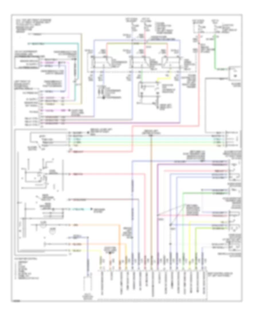
AIR CONDITIONING
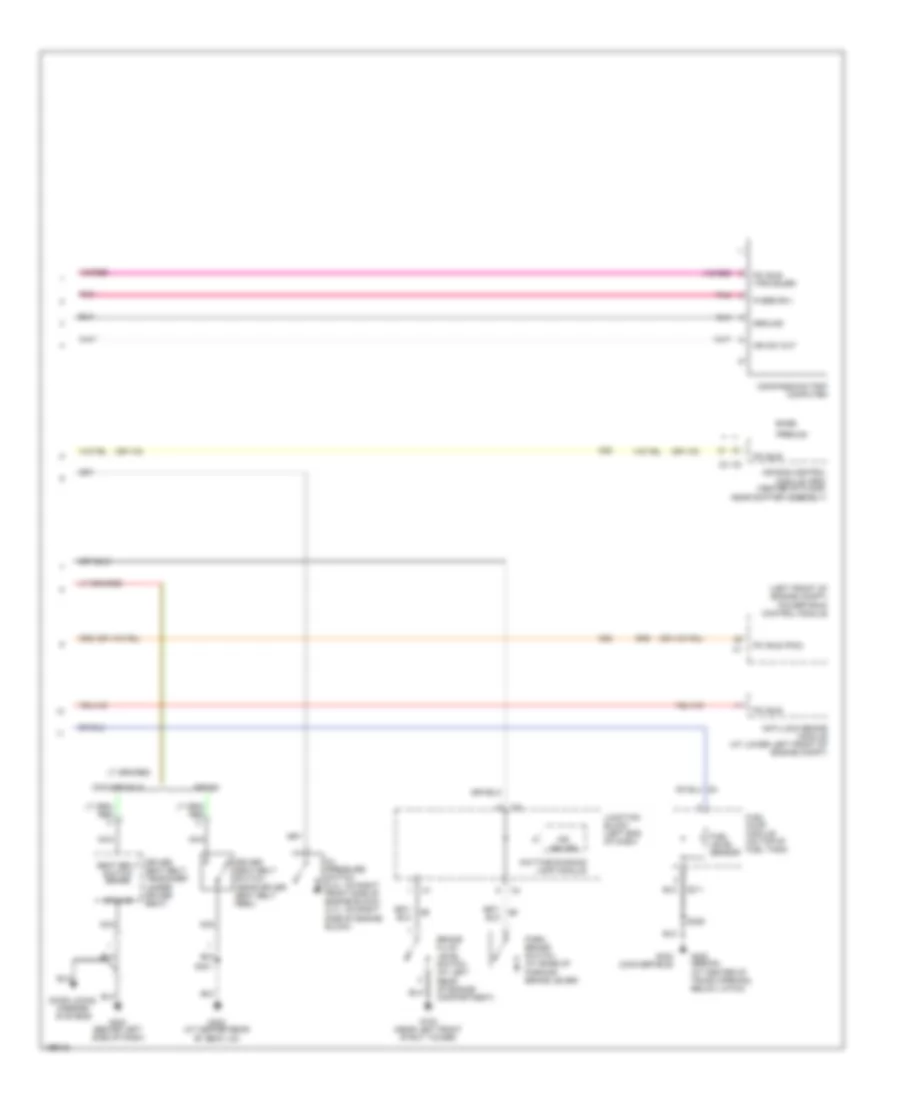
Automatic A/C Wiring Diagram for Chrysler Sebring Limited 2005

List of elements for Automatic A/C Wiring Diagram for Chrysler Sebring Limited 2005:
- (at left kick panel) s120
- (behind left center of dash)
- (behind left side of dash) g203
- (between
- (between blend door actuator & mode door actuator)
- (inside power distribution center)
- (near breakout for
- (near breakout for map/iat sensor)
- A/c compressor clutch (on compressor)
- A/c compressor clutch relay
- A/c compressor clutch)
- A/c evap temperature sensor & blend door actuator)
- A/c evaporator temperature sensor (at right side of hvac)
- A/c pressure transducer (on a/c compressor discharge line)
- Aspirator motor
- Aspirator motor sensor sig pci bus(pcm) sensor sig c1
- Automatic temperature control head
- Blend door actuator (at bottom center of hvac)
- Blower motor
- Blower motor (at bottom right of hvac)
- Blower motor blower motor c2
- Blower motor power module (at right end of hvac)
- Body control module (at left kick panel)
- C10
- C12
- C18
- C24
- C26
- C27
- C28
- C32
- C33
- C34
- C35
- C36
- C37
- C38
- C56
- C57
- C71
- C72
- Computer data lines system
- Convertible
- D25
- Engine coolant temp sensor (2.4l: top left front of engine) (2.7l: at front of engine, next to coolant fill neck)
- F20
- Feedback sig mode door driver door blend air sensor sig c2
- Fuse 10a
- Fuse 15a
- Fuse 20a
- Fuse 30a
- Fuse 40a
- Fused b(+)
- Fused ign sw blower motor ground
- Fused ign switch
- G108 (near left headlight)
- G202 (behind lower left center of dash)
- G203 (behind left side of dash)
- Ground
- High speed radiator fan relay
- Hot at all times
- Hot in on
- Hot in on or start
- In-car temp sens
- Junction block (left end of dash)
- Low speed radiator fan relay
- Mode door actuator (at bottom left of hvac)
- Panel lamps
- Pci bus
- Pnk
- Power distribution center (on left front inner fender)
- Powertrain control module (left front of engine compt)
- Radiator fan (on rear of radiator)
- Recirculation door actuator (at right side of hvac)
- Red/tan
- S103
- S105
- S115
- S117 (near breakout for powertrain control module)
- S156
- S200
- S201
- S202
- S211 (behind left center of dash)
- S212
- S220 (behind left center of dash)
- S222
- S223 (at left kick panel)
- Sedan
- Sensor gnd
- Sensor sig
- Sun sensor (at center of dash)
- Z116
- Z117
- Z118
- Z132
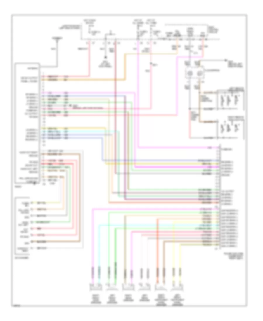
Manual A/C Wiring Diagram for Chrysler Sebring Limited 2005
List of elements for Manual A/C Wiring Diagram for Chrysler Sebring Limited 2005:
- (2.4l: top left front of engine) (2.7l: at front of engine, next to coolant fill neck) engine coolant temperature sensor
- (behind left center of dash) s212
- (behind left center of dash) s214
- (behind lower left center of dash) g202
- (between a/c evap temperature sensor & blend door actuator) s200
- (between blend door actuator & mode door actuator)
- (inside power distribution center)
- (left front of engine compt) powertrain control module
- (near breakout for a/c compressor clutch) s156
- (near breakout for camshaft position sensor)
- (near breakout for map/iat sensor)
- (near left headlight) g108
- (on a/c compressor discharge line) a/c pressure transducer
- A/c compressor clutch (on compressor)
- A/c compressor clutch relay
- A/c evaporator temperature sensor (in hvac housing)
- A/c mode mux
- A/c press sig
- A/c press signal
- A/c switch sens
- A/c-heater control
- Blend door actuator
- Blend door driver
- Blend dr feedback
- Blower motor
- Blower motor driver
- Blower motor resistor block (at right side of hvac)
- Blower switch
- Body control module (at left kick panel)
- C12
- C18
- C21
- C24
- C26
- C27
- C28
- C32
- C33
- C34
- C35
- C36
- C37
- C57
- C58
- C82
- Common driver
- Computer data lines system
- D25
- Day brightness sen
- Defogger system
- Defrost mix floor bi-level panel bi-level a/c panel a/c recirculation a/c
- E17
- Ect signal
- Evap temp sens sig
- Fuse 10a
- Fuse 20a
- Fuse 30a
- Fuse 40a
- High
- High speed radiator fan relay
- Hot at all times
- Hot in run
- Hot in run or start
- Illum
- Junction block (left end of dash)
- Low
- Low speed radiator fan relay
- Med high
- Med low
- Mode door actuator (at bottom left side of hvac)
- Mode door driver
- Mode dr feedback
- Mode switch
- Multi- function switch
- Of dash)
- Off
- Panel lamps driver
- Pci bus
- Power distribution center (on left front inner fender)
- Radiator fan (on rear of radiator)
- Rear defogger sw ind
- Rear defogger switch
- Recirc door driver
- Recirculation door actuator
- Red/tan
- Relay ctrl
- S103
- S105
- S115
- S117
- S201
- S202
- Sensor gnd
- Sensor ground
- Tan
- Temp select sig
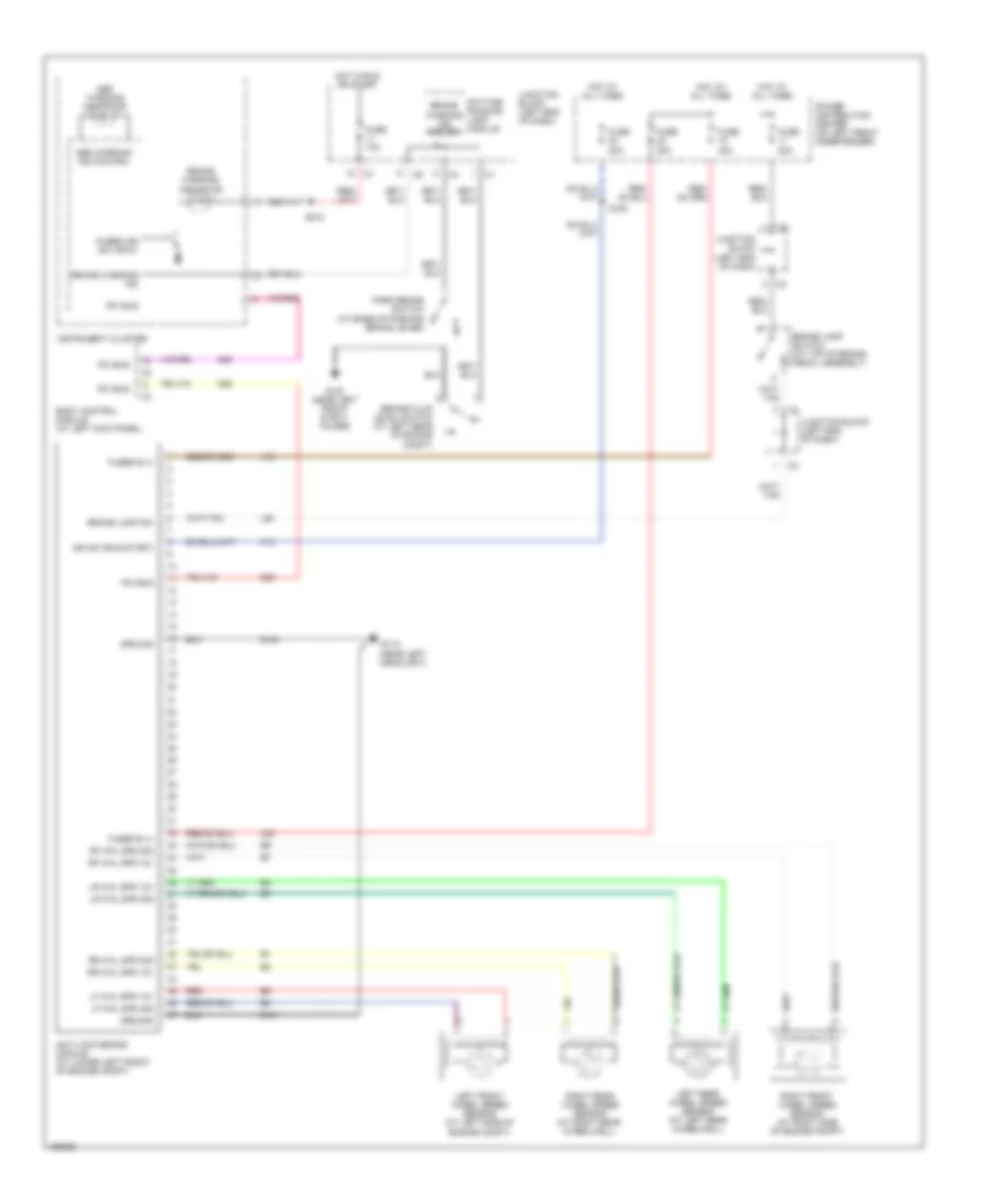
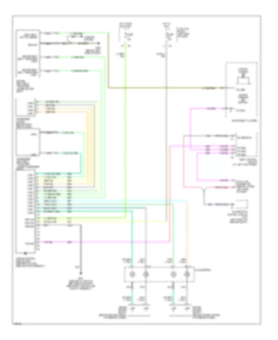
ANTI-LOCK BRAKES
Anti-lock Brakes Wiring Diagram for Chrysler Sebring Limited 2005
List of elements for Anti-lock Brakes Wiring Diagram for Chrysler Sebring Limited 2005:
- A10
- A20
- Abs warning ind control
- Abs warning indicator
- Anti-lock brake module (at lower left front of engine compt)
- Body control module (at left kick panel)
- Brake fluid level switch (at left rear of engine compt)
- Brake lamp sw
- Brake lamp switch (at top of brake pedal assembly)
- Brake warning ind
- Brake warning ind driver
- Brake warning indicator
- D25
- Daytime running lamp module
- F12
- Fuse 10a
- Fuse 20a
- Fuse 40a
- Fused b (+)
- Fused ign sw input
- G103 (near left front strut tower)
- G113 (near left headlight)
- Ground
- Hot at all times
- Hot in run or start
- Ign sw (run-start)
- Instrument cluster
- Junction block (left end of dash)
- L50
- Left front wheel speed sensor (at left side of engine compt)
- Left rear wheel speed sensor (at left rear wheelwell)
- Lf whl spd 12v
- Lf whl spd sig
- Lr whl spd 12v
- Lr whl spd sig
- Park brake switch (at base of parking brake lever)
- Pci bus
- Power distribution center (on left front inner fender)
- Red
- Rf whl spd 12v
- Rf whl spd sig
- Right front wheel speed sensor (at right side of engine compt)
- Right rear wheel speed sensor (at right rear wheelwell)
- Rr whl spd 12v
- Rr whl spd sig
- S105
- S210
- Z101
- Z102
ANTI-THEFT
Anti-theft Wiring Diagram for Chrysler Sebring Limited 2005
List of elements for Anti-theft Wiring Diagram for Chrysler Sebring Limited 2005:
- (at left kick panel) s120
- (behind left side of dash) g203
- (or tan)
- (or tan/red)
- A/t
- A21
- A31
- A51
- Acc
- Battery
- Body control module
- Convertible
- D25
- Decklid ajar
- Decklid cylinder lock switch (vtss) (convertible: at center rear of deck lid)
- Decklid release solenoid/ ajar switch
- Decklid sw sense
- Door locks system
- Door)
- Driver cyl sw
- Driver cylinder lock switch
- Driver door ajar
- Driver door lock motor/ ajar switch (at rear of driver door)
- F12
- Fuse 10a
- Fuse 15a
- Fuse 20a
- Fused (b+)
- G108 (near left headlight)
- G203 (behind left side of dash)
- G301 (at left kick panel)
- G302 (at center rear of decklid)
- G310 (at rear center of decklid)
- G69
- G71
- G73
- G74
- G75
- G76
- G77
- G78
- Ground
- Head lamp sw out
- Headlamp delay relay
- Headlamp sw out
- Headlmp rly ctrl
- Horn relay
- Horn rly ctrl
- Hot at all times
- Hot in off, run & start
- Hot in run or start
- Ignition
- Ignition (run/acc)
- Ignition (run/st)
- Ignition switch
- Instrument cluster
- Junction block (left end of dash)
- Left park/ turn signal lamp
- Left rear door lock motor/ ajar switch (sedan)
- Lock
- Lr door ajar
- Off
- Pass door ajar
- Passenger door lock motor/ ajar switch (at rear of passenger door)
- Pci bus
- Pci bus (pcm)
- Pnk
- Power distribution center (on left front inner fender)
- Power distribution system
- Powertrain control module (left front of engine compt)
- Premium
- Right park/ turn signal lamp
- Right rear door lock motor/ ajar switch (sedan)
- Rr door ajar
- Run
- Run-start
- S105
- S209
- S225 (premium)
- S301
- S313
- S320
- S321
- S327 (in driver's pnk
- Sentry key immobilizer module (on steering column)
- Start
- Tan
- Tan/ red
- Tan/red
- Trunk lamp
- Unlk
- Vtss ind driver
- Vtss set led
- Z110
- Z132
- Z313
- Z380
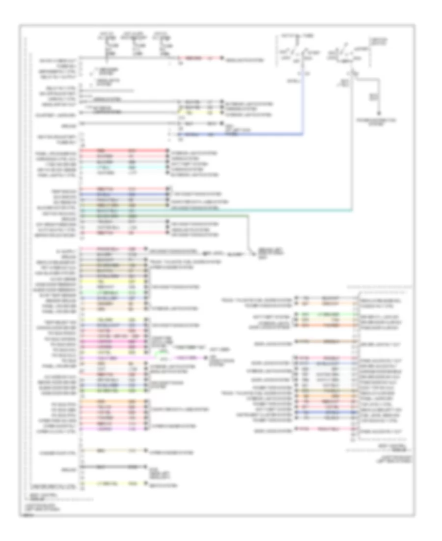
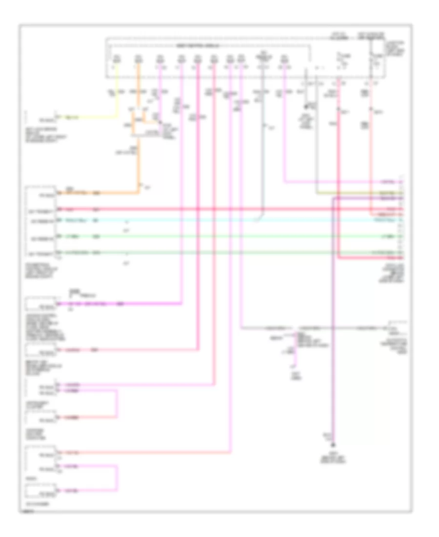
BODY CONTROL MODULES
Body Control Modules Wiring Diagram for Chrysler Sebring Limited 2005
List of elements for Body Control Modules Wiring Diagram for Chrysler Sebring Limited 2005:
- (atc)
- (behind left side of dash) g203
- (not used)
- A/c mode sw mux
- A/c sw sense
- A21
- A31
- Acc
- Air conditioning system
- Anti-theft system
- Aspirator motor drv
- Atc
- Auto hdlp rly ctrl
- Blend door driver
- Blend door feedback
- Blower motor ctrl
- Body control module
- C10
- C12
- C21
- C26
- C32
- C33
- C34
- C35
- C36
- C37
- C38
- C56
- C57
- C58
- C82
- Common door driver
- Computer data lines system
- Conv top sw mux
- Courtesy lamps drv
- D25
- Day brightness sns
- Decklid ajar sns
- Decklid release sol
- Decklid release sw
- Decklid security sw
- Defogger system
- Defogger rly ctrl
- Delay rly ctrl
- Delay rly output
- Dim sw hi beam out
- Door locks system
- Driver cyl lock sw
- Driver door ajar sw
- Driver door sw mux
- Driver lock rly out
- Driver unlock rly
- E17
- E19
- Evap temp sensor
- Exterior lights system
- Frt wiper sw mux
- Fuel level sens sig
- Fuse 10a
- Fuse 15a
- Fused b(+)
- G108 (near left headlight)
- G26
- G301 (at left kick panel)
- G38
- G69
- G71
- G73
- G74
- G75
- G78
- Garage door enable
- Ground
- Headlamp sw out
- Headlights system
- Heated seat rly ctrl
- High blower mtr drv
- Horn rly ctrl
- Horn/radio ctrl mux
- Horns system
- Hot at all times
- Hot in off, run or start
- Ign (off-run-start)
- Ignition (run-acc)
- Ignition (run-start)
- Ignition switch
- Instrument cluster system
- Interior lights system
- Interior lights, door locks systems
- Junction block (left end of dash)
- Key-in ign sw sense
- L109
- L124
- L177
- Lock
- Mirrors system
- Mode door driver
- Mode door feedback
- Mtc
- Off
- P175
- P176
- P177
- P178
- P340
- P96
- P97
- Panel lamps drv
- Panel lps dimmer sig
- Panel lps driver
- Park lamp rly ctrl
- Pass door ajar sw
- Pass door sw mux
- Pass unlock rly out
- Pci bus
- Pci bus (abs)
- Pci bus (air bag)
- Pci bus (dlc)
- Pci bus (mic)
- Pci bus (pcm)
- Pci bus (radio)
- Pci bus (skim)
- Power distribution system
- Power tops system
- Power windows system
- Q31
- Q37
- Recirc door driver
- Red
- Red/tan
- Run
- S222
- Sci receive
- Seats system
- Sensor ground
- Start
- Sun sns sig
- Tan
- Tan/red
- Temp select sig
- Temp sns sig
- Top down rly ctrl
- Top up rly ctrl
- Trunk, tailgate, fuel doors system
- V10
- V14
- V16
- V52
- V55
- Vtss ind driver
- Warning system
- Washer pump ctrl
- Window rly ctrl
- Wiper hi/lo rly ctrl
- Wiper on/off rly
- Wiper park sw sns
- Wiper/washer system
- Z132
- Z313
- Z380
COMPUTER DATA LINES
Computer Data Lines Wiring Diagram for Chrysler Sebring Limited 2005
List of elements for Computer Data Lines Wiring Diagram for Chrysler Sebring Limited 2005:
- (not used)
- A/t
- Air bag control module (orc) (base: center of floor, near shifter assembly) (premium: center of floor, near shifter)
- Anti-lock brake module (at lower left front of engine compt)
- Automatic temperature control head
- Base
- Body control module
- Bus
- Cd changer
- Compass/ mini-trip computer
- D15
- D20
- D21
- D25
- Data link connector (behind lower left side of dash)
- Fuse 10a
- G203 (behind left side of dash)
- G301 (at left kick panel)
- Hot at all times
- Hot in run or off or start
- Instrument cluster
- Junction block (left end of dash)
- M/t
- Pci
- Pci bus
- Pnk
- Powertrain control module (left front of engine compt)
- Premium
- Radio
- S120 (at left kick panel)
- S210
- S211
- S221 (sedan) (behind left center of dash)
- Sci receive
- Sci receive (tcm)
- Sci transmit
- Sedan
- Sentry key immobilizer module (on steering column)
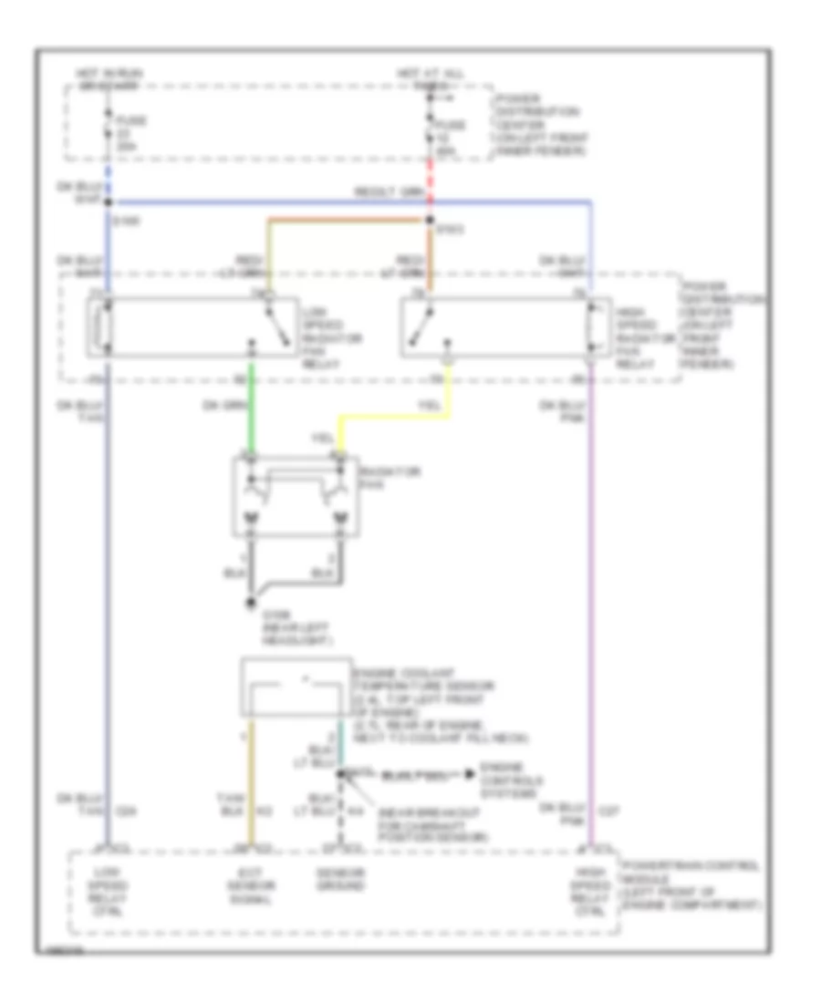
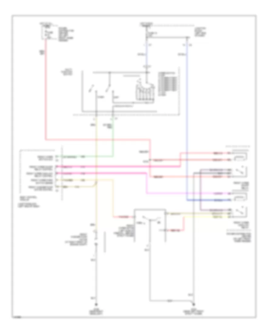
COOLING FAN
Cooling Fan Wiring Diagram for Chrysler Sebring Limited 2005
List of elements for Cooling Fan Wiring Diagram for Chrysler Sebring Limited 2005:
- (near breakout for camshaft position sensor)
- C24
- Ect sensor signal
- Engine controls systems
- Engine coolant temperature sensor (2.4l: top left front of engine) (2.7l: rear of engine, next to coolant fill neck)
- Fuse 20a
- Fuse 40a
- G108 (near left headlight)
- High speed radiator fan relay
- High speed relay ctrl
- Hot at all times
- Hot in run or start
- Low speed radiator fan relay
- Low speed relay ctrl
- Pnk
- Power distribution center (on left front inner fender)
- Powertrain control module (left front of engine compartment)
- Radiator fan
- S103
- S105
- Sensor ground
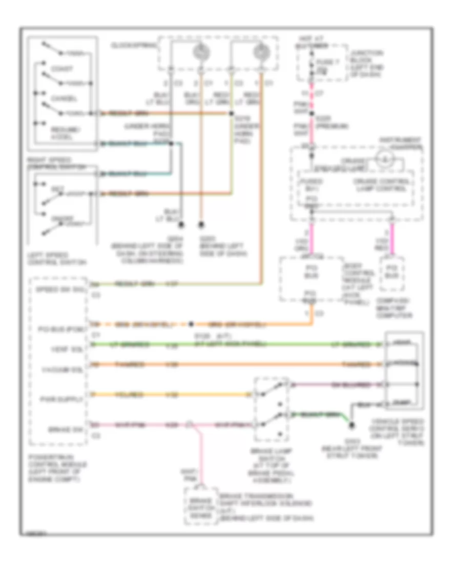
CRUISE CONTROL
Cruise Control Wiring Diagram for Chrysler Sebring Limited 2005
List of elements for Cruise Control Wiring Diagram for Chrysler Sebring Limited 2005:
- (a/t)
- (under horn pad) s218
- Body control module (at left kick panel)
- Brake lamp switch (at top of brake pedal assembly)
- Brake sw
- Brake switch sense
- Brake transmission shift interlock solenoid (a/t) (behind left side of dash)
- Cancel
- Clockspring
- Coast
- Compass/ mini-trip computer
- Cruise control lamp control
- Cruise engaged lamp
- Dump
- Fuse 7 20a
- Fused b(+)
- G103 (near left front strut tower)
- G203 (behind left side of dash)
- G204 (behind left side of dash, on steering column harness)
- Hot at all times
- Instrument cluster
- Junction block (left end of dash)
- K29
- Left speed control switch
- On/off
- Pci bus
- Pci bus (pcm)
- Powertrain control module (left front of engine compt)
- Resume/ accel
- Right speed control switch
- S120 (at left kick panel)
- S219 (under horn pad)
- S225 (premium)
- Set
- Speed sw sig
- Tan/red
- V32
- V35
- V36
- V37
- Vacuum
- Vacuum sol
- Vehicle speed control servo (on left strut tower)
- Vent
- Vent sol
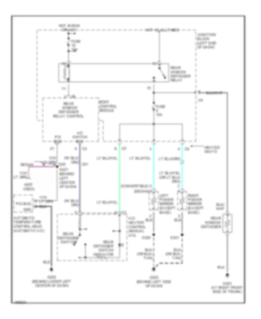
DEFOGGERS
Defoggers Wiring Diagram for Chrysler Sebring Limited 2005
List of elements for Defoggers Wiring Diagram for Chrysler Sebring Limited 2005:
- (convertible)
- (not used)
- (sedan)
- A/c switch mux
- A/c- heater control (manual a/c)
- Automatic temperature control head (automatic a/c)
- Body control module
- C7 c7
- Fuse 10a
- G202 (behind lower left center of dash)
- G203 (behind left side of dash)
- G303 (at right front side of trunk)
- Gnd
- Heated seats
- Hot at all times
- Hot in run
- Junction block (left end of dash)
- Left power mirror (except base)
- Or acc
- Pci bus
- Rear defogger switch
- Rear defogger switch indicator
- Rear window defogger
- Rear window defogger relay
- Rear window defogger relay control
- Right power mirror (except base)
- S221 (behind left center of dash)
- S320
- S321
- Sedan
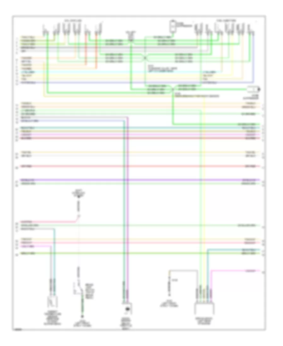
ENGINE PERFORMANCE
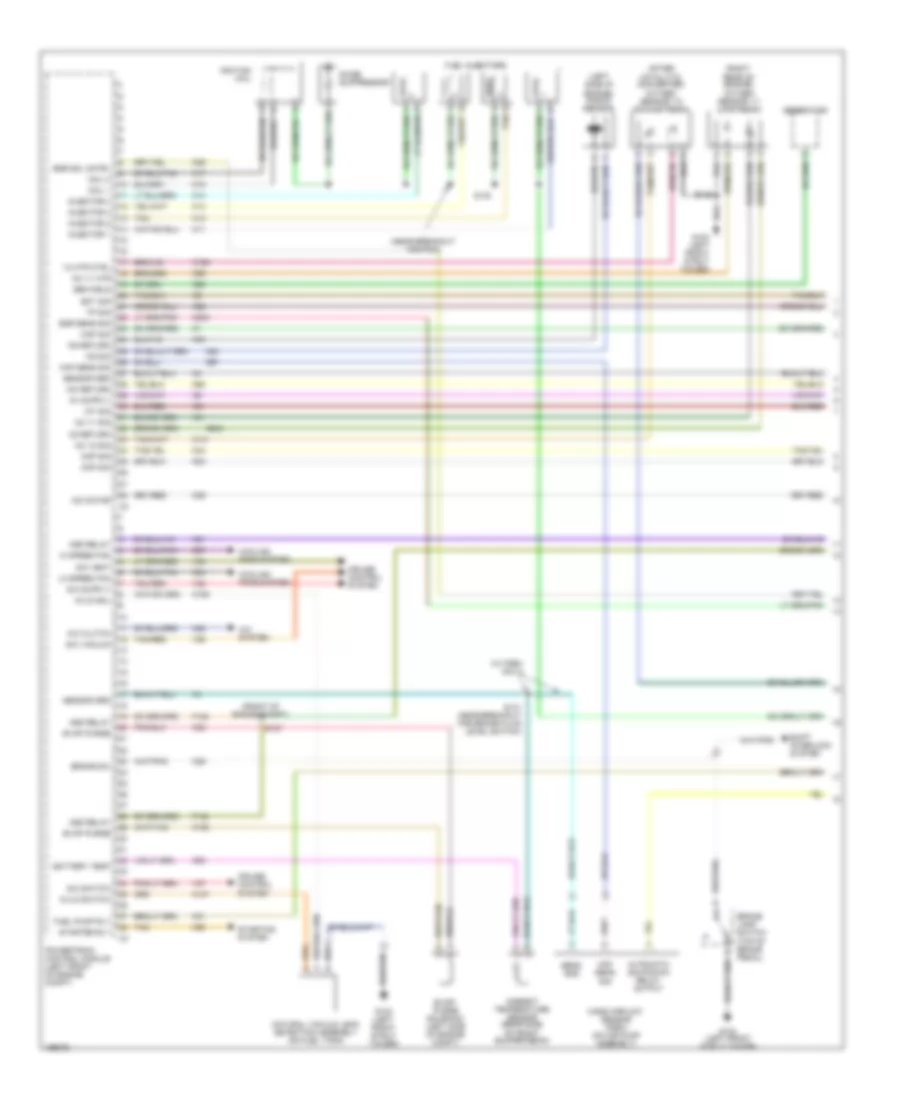
2.4L
2.4L, Engine Performance Wiring Diagram (1 of 3) for Chrysler Sebring Limited 2005
List of elements for 2.4L, Engine Performance Wiring Diagram (1 of 3) for Chrysler Sebring Limited 2005:
- (after catalytic converter) oxygen sensor 1/2 (downstream)
- (front of engine compt)
- (left side of engine) knock sensor
- (near breakout for pcm)
- (right rear of engine) oxygen sensor 1/1 (upstream)
- (w/ pzev only)
- 1/2 htr ctrl
- A/c clutch
- A/c system
- Ambient temperature sensor (rear side of front bumper beam)
- Asd relay
- Automatic shutdown relay output
- Battery temp
- Brake lamp switch (top of brake pedal)
- Brake sw
- C24
- C27
- C28
- Ckp sig
- Cmp sig
- Coil 1
- Coil 2
- Cooling fans system
- Cruise control system
- Ect sig
- Egr sens sig
- Egr sol cntrl
- Evap purge
- Evap/ purge solenoid (left side of engine compt)
- F142
- Fuel injectors
- Fuel pump rly
- G103 (left front strut tower)
- Gen field
- Generator
- Hi speed fan
- Iac motor
- Iac return
- Iat sig
- Ignition coil
- Injector 1
- Injector 2
- Injector 3
- Injector 4
- K106
- K107
- K108
- K11
- K12
- K13
- K14
- K141
- K17
- K19
- K199
- K20
- K21
- K22
- K235
- K24
- K25
- K29
- K31
- K35
- K39
- K41
- K42
- K44
- K45
- K51
- K52
- K57
- K60
- K90
- K902
- K99
- Ks return
- Ks sig
- Lo speed fan
- Maf sens sig
- Map sig
- Mass airflow sensor (pzev) (on air pump assembly)
- Natural vacuum leak detection assembly (on fuel tank)
- Noise suppressor
- Nvld sol
- Nvld switch
- O2 1/1 htr
- O2 1/1 sig
- O2 1/2 sig
- O2 return
- Powertrain control module (left front of engine compt)
- S/c switch
- S/c vacuum
- S/c vent
- S127
- S131 (near breakout for brake fluid level switch)
- S135
- S142
- Sens gnd
- Sensor grd
- Shift interlock system
- Starter rly
- Starting system
- Tan
- Tan/red
- Tp sig
- V32
- V35
- V36
- V37
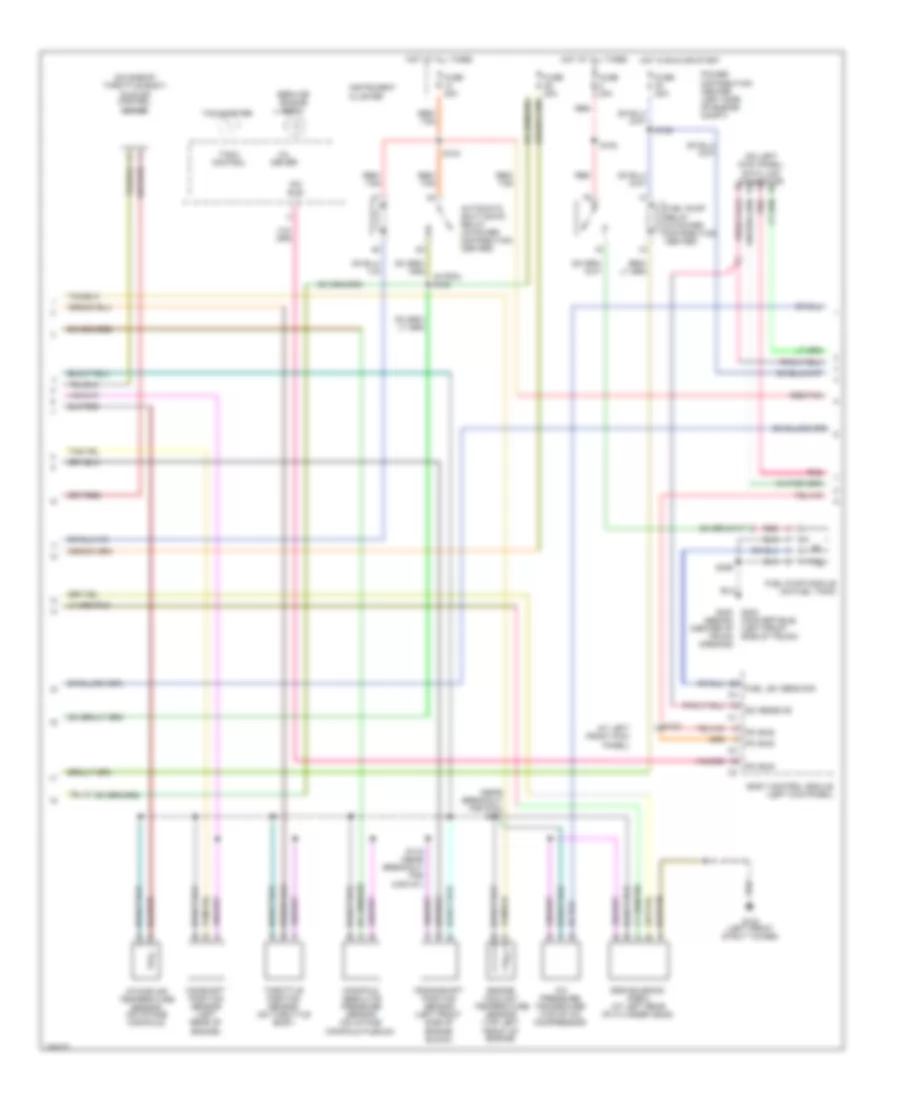
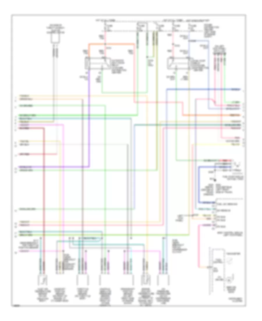
2.4L, Engine Performance Wiring Diagram (2 of 3) for Chrysler Sebring Limited 2005
List of elements for 2.4L, Engine Performance Wiring Diagram (2 of 3) for Chrysler Sebring Limited 2005:
- (at left front kick panel)
- (convertible) (left front side of trunk)
- (in pdc) s108
- (near breakout for pcm) s117
- (on left kick panel) data link connector
- (on side of throttle body)
- A/c pressure transducer (top of a/c compressor)
- Automatic shut down relay (in power distribution center)
- Body control module (left kick panel)
- Camshaft position sensor (left rear of engine)
- Crankshaft position sensor (left front side of engine block)
- Egr solenoid (pzev) (at left rear of cylinder head)
- Engine coolant temperature sensor (top left front of engine)
- Fuel lev sens sig
- Fuel pump module (on fuel tank)
- Fuel pump relay (in power distribution center)
- Fuse 20a
- Fuse 30a
- G103 (left front strut tower)
- G302 g300 (sedan) (center of trunk opening)
- Hot at all times
- Hot in run or start
- Idle air control motor
- Instrument cluster
- Intake air temperature sensor (on intake manifold)
- Manifold absolute pressure sensor (on intake manifold plenum)
- Mil driver
- Pci bus
- Pnk
- Power distribution center (left side of engine compt)
- Red
- Red/ tan
- Red/tan
- S102
- S104
- S105
- S115 (near breakout for map/iat)
- S120
- S326
- Sci receive
- Service engine soon
- Tach control
- Tachometer
- Throttle position sensor (on throttle body)
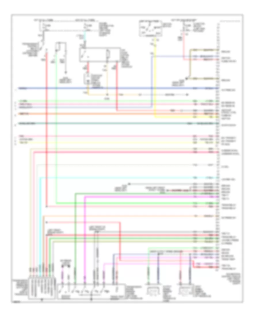
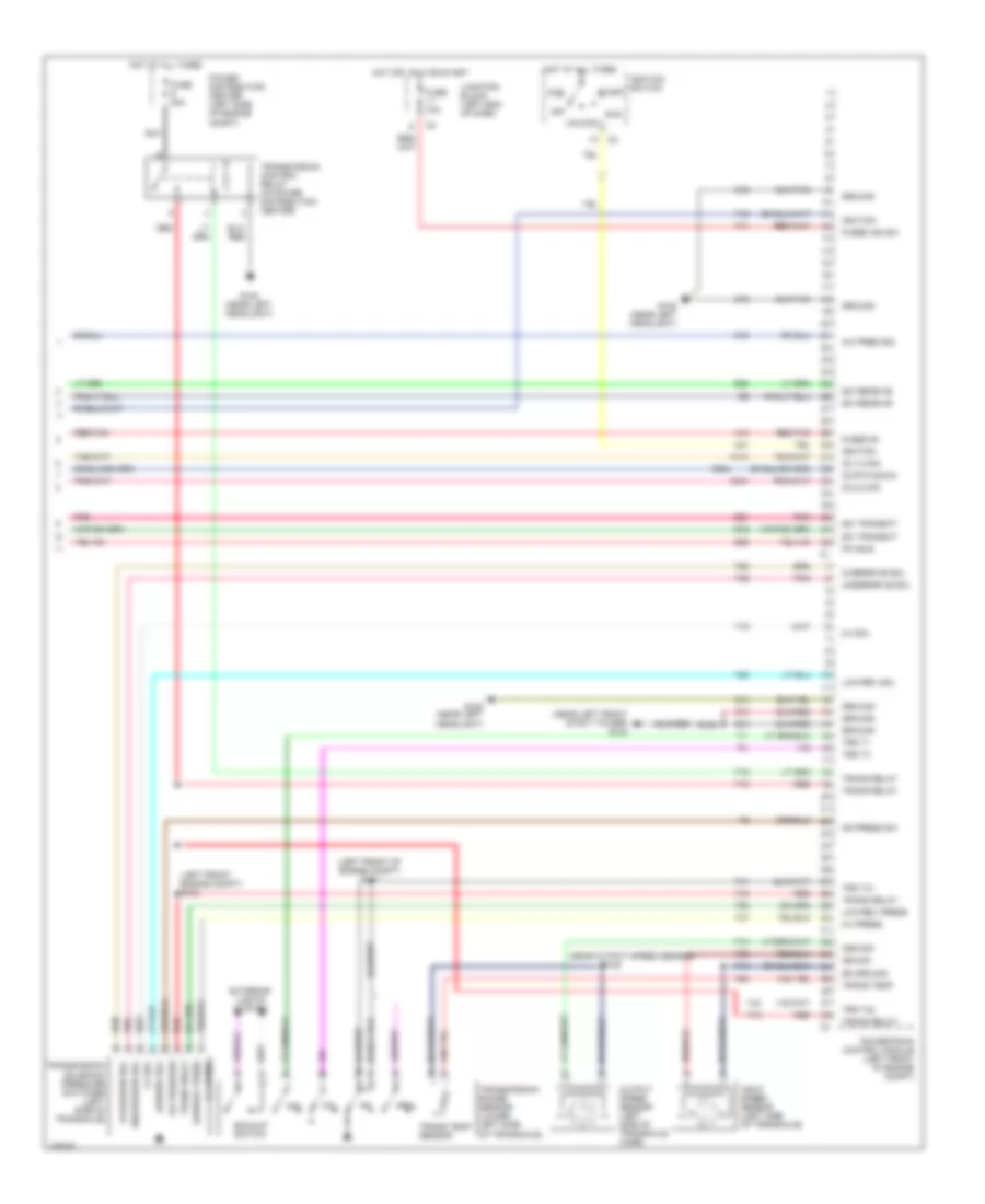
2.4L, Engine Performance Wiring Diagram (3 of 3) for Chrysler Sebring Limited 2005
List of elements for 2.4L, Engine Performance Wiring Diagram (3 of 3) for Chrysler Sebring Limited 2005:
- (left front engine compt) s100
- (left front of engine compt) s111
- (near left front strut tower) g103
- (near output speed sensor)
- 2-4 press
- 2-4 sol
- A/c pres sig
- A14
- A41
- Acc
- Air pump motor (pzev) (below intake manifold)
- Air pump motor relay (pzev) (below intake manifold)
- Air pump mtr rly ctrl
- Backup switch
- C18
- D15
- D20
- D21
- D25
- Exterior lights system
- F11
- F12
- Fuse 10a
- Fuse 20a
- Fuse 40a
- Fused b+
- Fused ign sw
- G108 (near left headlight)
- Ground
- Hot at all times
- Hot off, run or start
- Ignition
- Ignition switch
- Input speed sensor (left side of transaxle)
- Iss sig
- Junction block (left end of dash)
- K62
- K904
- Low/rev press
- Low/rev sol
- Nol
- O2 rtn down
- Od press sw
- Off
- Oss sig
- Output speed sensor (left side of transaxle case)
- Overdrive sol
- P3l
- Pci bus
- Pnk
- Power distribution center (left side of engine compt)
- Powertrain control module (left front of engine compt)
- Prnl
- Red
- Red/tan
- Run
- S123
- S125
- S160
- Sci receive
- Sci transmit
- Ss ground
- Start
- T13
- T14
- T15
- T16
- T19
- T20
- T41
- T42
- T47
- T50
- T52
- T54
- T59
- T60
- Tan
- Trans relay
- Trans temp
- Trans temp sensor
- Transmission control relay (in power distribution center)
- Transmission range sensor (lower left side of transaxle)
- Transmission solenoid/ pressure switches (left side of transaxle)
- Trs t1
- Trs t3
- Trs t41
- Trs t42
- Underdrive sol
- Unlock
- Z12
- Z13
- Z14
2.7L
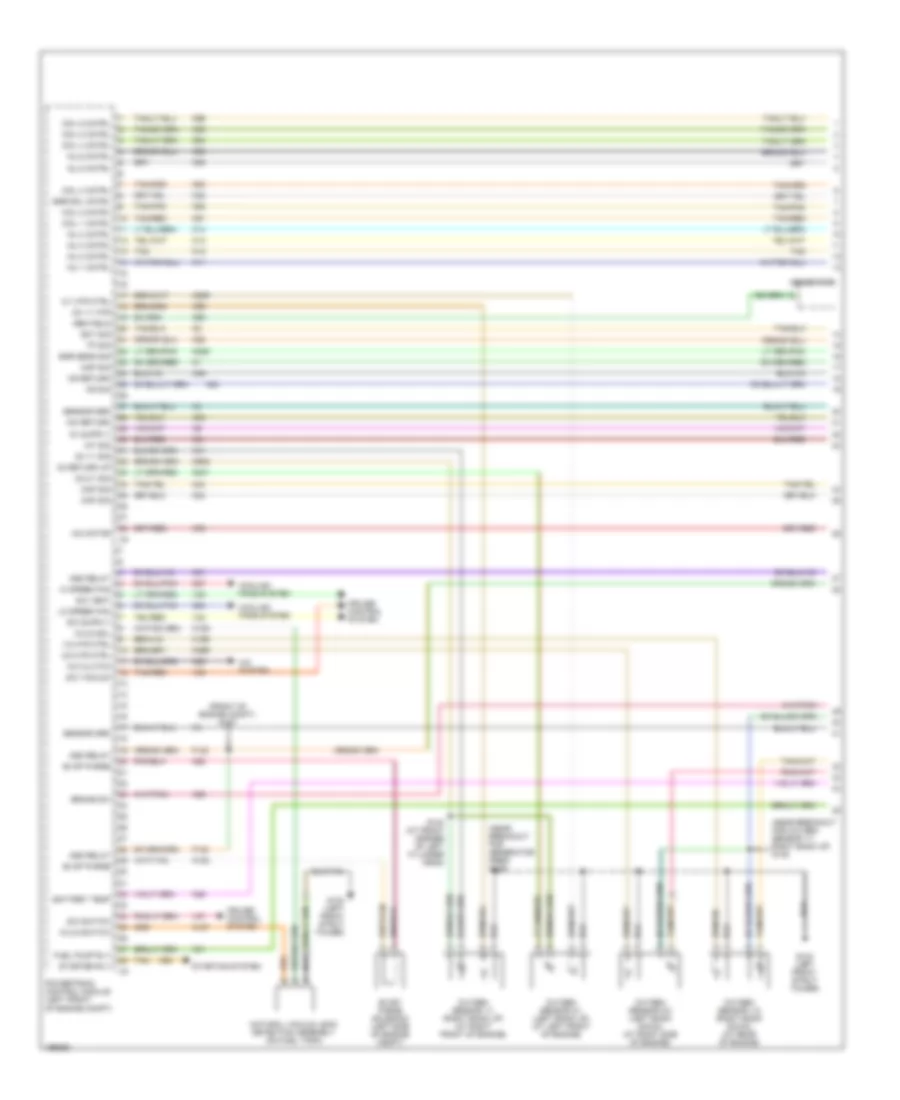
2.7L, Engine Performance Wiring Diagram (1 of 4) for Chrysler Sebring Limited 2005
List of elements for 2.7L, Engine Performance Wiring Diagram (1 of 4) for Chrysler Sebring Limited 2005:
- (front of engine compt) s127
- (near breakout for generator feed) s149
- (near breakout for oxygen sensor 1/1 right bank up) s138
- 1/2 htr ctrl
- 2/1 htr ctrl
- 2/2 htr ctrl
- A/c clutch
- A/c system
- Asd relay
- Battery temp
- Brake sw
- C24
- C27
- C28
- Ckp sig
- Cmp sig
- Coil 1 cntrl
- Coil 2 cntrl
- Coil 3 cntrl
- Coil 4 cntrl
- Coil 5 cntrl
- Coil 6 cntrl
- Cooling fans system
- Cruise control system
- Ect sig
- Egr sens sig
- Egr sol cntrl
- Evap purge
- Evap/ purge solenoid (left side of engine compt)
- F142
- Fuel pump rly
- G103 (left front strut tower)
- Gen field
- Generator
- Hi speed fan
- Iac motor
- Iac return
- Iat sig
- Inj 1 cntrl
- Inj 2 cntrl
- Inj 3 cntrl
- Inj 4 cntrl
- Inj 5 cntrl
- Inj 6 cntrl
- K106
- K107
- K108
- K11
- K12
- K13
- K14
- K199
- K20
- K21
- K22
- K235
- K24
- K241
- K25
- K29
- K299
- K31
- K35
- K38
- K39
- K399
- K41
- K42
- K44
- K45
- K51
- K52
- K58
- K60
- K90
- K902
- K91
- K92
- K93
- K94
- K95
- K96
- K99
- Ks return
- Ks sig
- Lo speed fan
- Map sig
- Natural vacuum leak detection assembly (on fuel tank)
- Nvld sol
- Nvld switch
- O2 1/1 htr
- O2 1/1 sig
- O2 2/1 sig
- O2 return up
- Oxygen sensor 1/1 (right bank up) (at right front of engine)
- Oxygen sensor 1/2 (right bank down) (at rear of engine)
- Oxygen sensor 2/1 (left bank up) (at left front of engine)
- Oxygen sensor 2/2 (left bank down) (at right side of engine)
- Powertrain control module (left front of engine compt)
- S/c switch
- S/c vacuum
- S/c vent
- S140 (at front corner of left cylinder head)
- Sensor grd
- Starter rly
- Starting system
- Tan
- Tan/pnk
- Tan/red
- Tp sig
- V32
- V35
- V36
- V37
2.7L, Engine Performance Wiring Diagram (2 of 4) for Chrysler Sebring Limited 2005
List of elements for 2.7L, Engine Performance Wiring Diagram (2 of 4) for Chrysler Sebring Limited 2005:
- (on left fuel rail) s143
- Ambient temperature sensor (rear side of front bumper beam)
- Brake lamp switch (top of brake pedal)
- Coil on plugs
- Egr solenoid (left rear of engine)
- Fuel injectors
- G103 (left front strut tower)
- Knock sensor (below throttle body)
- Noise suppressor
- S137 (in engine valley, near left cylinder head)
- S139 (near breakout for knock sensor)
- S149
- Shift interlock system
- Tan
- Tan/pnk
- Tan/red
2.7L, Engine Performance Wiring Diagram (3 of 4) for Chrysler Sebring Limited 2005
List of elements for 2.7L, Engine Performance Wiring Diagram (3 of 4) for Chrysler Sebring Limited 2005:
- (convertible) (left front side of trunk)
- (left kick panel)
- (on left kick panel) data link connector
- (on side of throttle body)
- A/c pressure transducer (on a/c compressor discharge line)
- Automatic shut down relay (in power distribution center)
- Body control module (left kick panel)
- Camshaft position sensor (on front of engine, at cylinder head)
- Crankshaft position sensor (on left front side of engine block)
- Engine coolant temperature sensor (at front of engine, next to coolant fill neck)
- Fuel lev sens sig
- Fuel pump module (on fuel tank)
- Fuel pump relay (in power distribution center)
- Fuse 20a
- Fuse 30a
- G302 g300 (sedan) (center of trunk opening)
- Hot at all times
- Hot in run or start
- Idle air control motor
- Inlet air temperature sensor (on air induction boot)
- Instrument cluster
- Manifold absolute pressure sensor (on right front of intake manifold)
- Mil driver
- Pci bus
- Pnk
- Power distribution center (left side of engine compt)
- Red
- Red/ tan
- Red/tan
- S102
- S104
- S105
- S108 (in pdc)
- S117 (near breakout for throttle position sensor)
- S120
- S156 (near breakout for a/c compressor clutch)
- S326
- Sci receive
- Service engine soon
- Tach control
- Tachometer
- Throttle position sensor (on throttle body)
2.7L, Engine Performance Wiring Diagram (4 of 4) for Chrysler Sebring Limited 2005
List of elements for 2.7L, Engine Performance Wiring Diagram (4 of 4) for Chrysler Sebring Limited 2005:
- (left front engine compt) s100
- (left front of engine compt) s111
- (near left front strut tower) g103
- (near output speed sensor)
- 2-4 press
- 2-4 sol
- A/c pres sig
- A14
- A41
- Acc
- Backup switch
- C18
- D15
- D20
- D21
- D25
- Exterior lights system
- F11
- F12
- Fuse 10a
- Fuse 20a
- Fused b+
- Fused ign sw
- G108 (near left headlight)
- Ground
- Hot at all times
- Hot off, run or start
- Ignition
- Ignition switch
- Input speed sensor (left side of transaxle)
- Iss sig
- Junction block (left end of dash)
- K141
- K341
- K904
- Low/rev press
- Low/rev sol
- Nol
- O2 1/2 sig
- O2 2/2 sig
- O2 rtn down
- Od press sw
- Off
- Oss sig
- Output speed sensor (left side of transaxle case)
- Overdrive sol
- P3l
- Pci bus
- Pnk
- Power distribution center (left side of engine compt)
- Powertrain control module (left front of engine compt)
- Prnl
- Red
- Red/tan
- Run
- S123
- S125
- Sci receive
- Sci transmit
- Ss ground
- Start
- T13
- T14
- T15
- T16
- T19
- T20
- T41
- T42
- T47
- T50
- T52
- T54
- T59
- T60
- Trans relay
- Trans temp
- Trans temp sensor
- Transmission control relay (in power distribution center)
- Transmission range sensor (lower left side of transaxle)
- Transmission solenoid/ pressure switches (left side of transaxle)
- Trs t1
- Trs t3
- Trs t41
- Trs t42
- Underdrive sol
- Unlock
- Z12
- Z13
- Z14
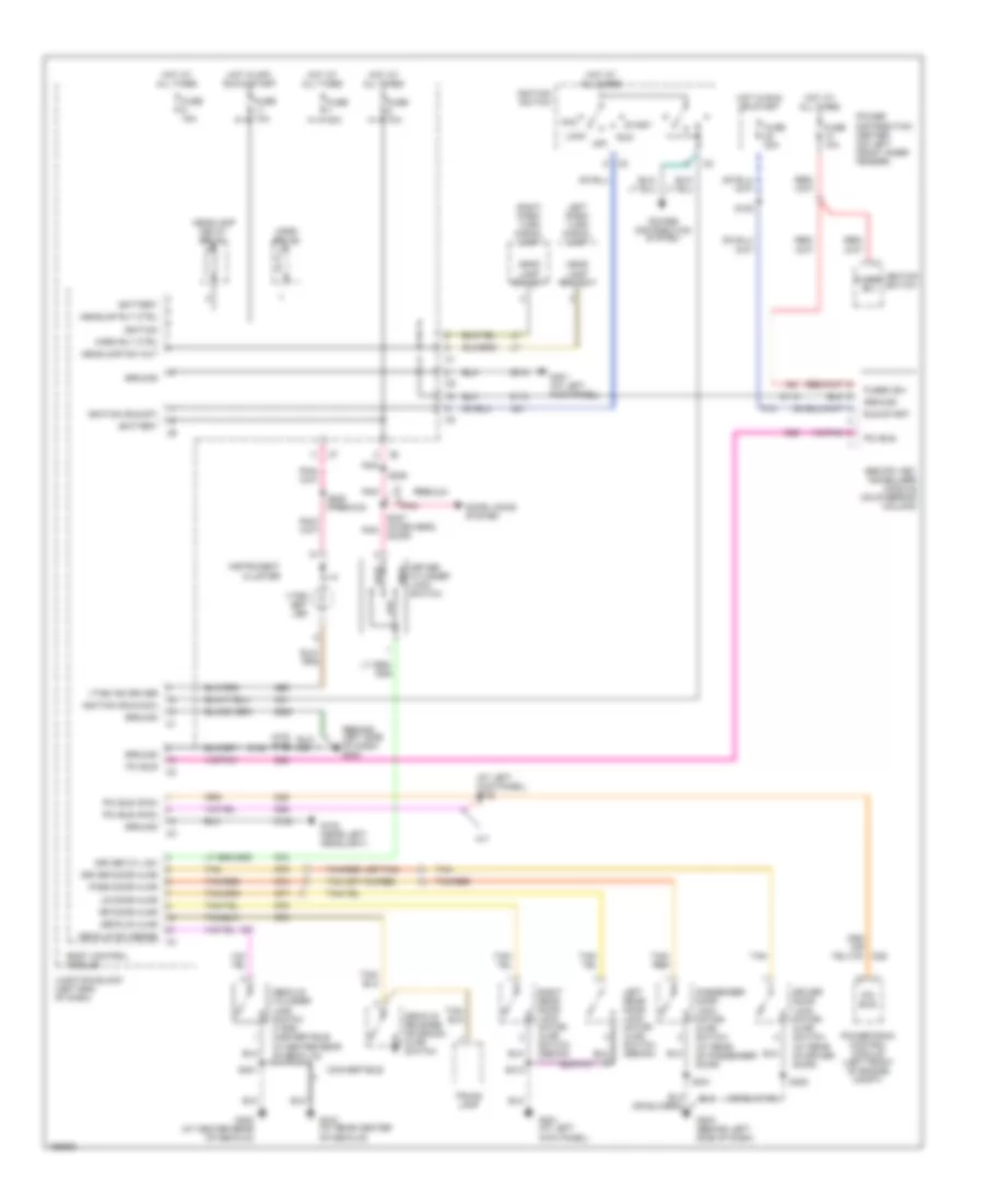
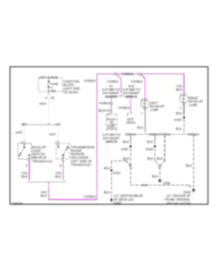
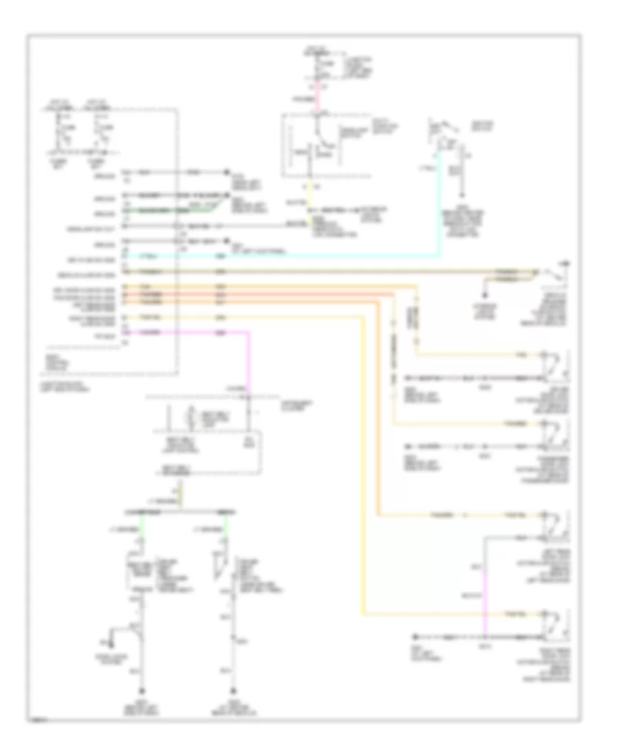
EXTERIOR LIGHTS
Back-up Lamps Wiring Diagram for Chrysler Sebring Limited 2005
List of elements for Back-up Lamps Wiring Diagram for Chrysler Sebring Limited 2005:
- (at center rear of deck lid) g302
- (not used)
- A/t
- Automatic day/night mirror
- Back- up lamp feed
- Back-up light switch (rear of transaxle)
- Convertible
- Fuse 15a
- G300 (at center of trunk opening, below latch)
- G302
- Hot in run
- Junction block (left end of dash)
- Left back-up lamp
- M/t
- Right back-up lamp
- S301
- S304
- S305
- S307
- Sedan
- Transmission range sensor (on lower left side of transaxle)
- W/ automatic day/night mirror
- W/o automatic day/night mirror
Exterior Lamps Wiring Diagram for Chrysler Sebring Limited 2005
List of elements for Exterior Lamps Wiring Diagram for Chrysler Sebring Limited 2005:
- (at top of brake pedal assembly) brake lamp switch
- (near breakout for license light) s331
- (near data link connector) (premium) s226
- Acc
- Anti-lock brakes system
- Body control module
- Body control module (at left kick panel)
- Center high mounted stop lamp
- Combination flasher
- Flasher output
- Fuse 11 20a
- Fuse 15 10a
- Fuse 16 40a
- Fuse 20 20a
- Fuse 7 20a
- Fuse 8 20a
- Fused b(+)
- G106 (near right headlight)
- G108 (near left headlight)
- G203 (behind left side of dash)
- G301 (at left kick panel)
- G302
- G310 (at rear center of deck lid)
- Gnd
- Ground
- Hazard flasher switch
- Hazard switch
- Hdlt sw out
- Head
- Headlamp switch
- Hot at all times
- Ignition switch
- Instrument cluster
- Junction block (left end of dash)
- Left license lamp
- Left park/ turn signal lamp
- Left tail/ stop lamp
- Left turn lamp
- Left turn signal ind
- Lock
- Multi- function switch
- Multi-function switch
- Off
- Park
- Park lamp relay
- Pnk
- Pnk/ red
- Pnk/red
- Power distribution center (on left front inner fender)
- Red
- Right license lamp
- Right park/ turn signal lamp
- Right tail/ stop lamp
- Right turn lamp
- Right turn signal ind
- Run
- S102
- S225
- S301
- S304
- S305
- S332 (near left license light)
- Start
- Tan
- Turn signal switch
GROUND DISTRIBUTION
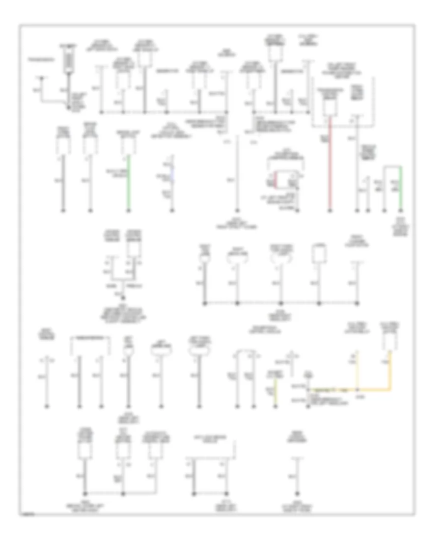
Ground Distribution Wiring Diagram (1 of 3) for Chrysler Sebring Limited 2005
List of elements for Ground Distribution Wiring Diagram (1 of 3) for Chrysler Sebring Limited 2005:
- (2.4l pzev) air pump motor
- (2.4l pzev) air pump motor relay
- (2.4l pzev) egr solenoid
- (2.4l) natural vacuum leak detection assembly
- (a/t) powertrain control module
- (m/t) a/c- heater control
- (on left front inner fender) power distribution center
- (on left front strut tower) g100
- 2.4l
- 2.4l pzev
- 2.7l
- Air bag control module
- Anti-lock brake module
- Automatic temperature control head
- Base
- Battery
- Body control module
- Brake fluid level switch
- Brake lamp switch
- Cigar lighter/ power outlet
- Egr solenoid
- Except 2.4l pzev
- For left headlamp)
- Front washer pump motor
- Front wiper motor
- Front wiper on/off relay
- G103 (near left front strut tower)
- G104 (2.7l) (at right side of engine)
- G106 (near right headlight)
- G108 (near left headlight)
- G113 (near left headlight)
- G201 (center of vehicle, between occupant restraint controller & shift assembly)
- G202 (behind lower left center dash)
- G303 (at right front side of trunk)
- Generator
- Horn
- Left fog lamp
- Left headlamp
- Left park/ turn signal lamp
- Oxygen sensor 1/1 right bank up
- Oxygen sensor 1/1 upstream
- Oxygen sensor 1/2 downstream
- Oxygen sensor 1/2 right bank down
- Oxygen sensor 2/1 left bank up
- Oxygen sensor 2/2 left bank down
- Powertrain control module
- Premium
- Radiator fan
- Rear window defogger
- Right fog lamp
- Right headlamp
- Right park/ turn signal lamp
- S123 (at left front of engine compt)
- S149 (near breakout for generator feed)
- S160
- Tan
- Transmission
- Transmission control relay
- Vehicle speed control servo
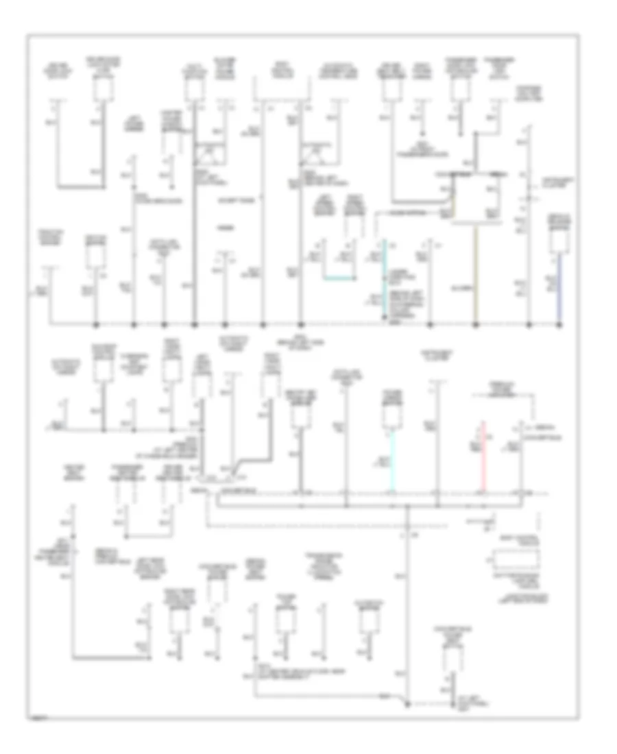
Ground Distribution Wiring Diagram (2 of 3) for Chrysler Sebring Limited 2005
List of elements for Ground Distribution Wiring Diagram (2 of 3) for Chrysler Sebring Limited 2005:
- (at left kick panel) g301
- (behind left side of dash, on steering column harness) g204
- (convertible)
- (convertible) power outlet
- (convertible) power seat switch
- (premium) power amplifier
- (sedan)
- (sedan) power seat switch
- (under horn pad) s218
- Automatic a/c
- Automatic day/night mirror
- Automatic temperature control head
- Autostick switch
- Blower motor power module
- Body control module
- C10
- Clock spring
- Compass/ mini-trip computer
- Convertible
- Data link connector (dlc)
- Daytime running lamp (drl) module
- Decklid release switch
- Driver door lock motor/ ajar switch
- Driver door lock switch
- Driver heated seat module
- Driver seat belt tensioner
- Except base
- G203 (behind left side of dash)
- Heated seat switch
- Ignition switch
- Instrument cluster
- Junction block (left end of dash)
- Left power mirror
- Left rear door lock motor/ajar switch
- Left speed control switch
- Left visor/ vanity lamps
- Master power window switch
- Multi- function switch
- Overhead map/ courtesy lamps
- Passenger door lock motor/ajar switch
- Passenger door lock switch
- Passenger heated seat module
- Power mirror switch
- Power top switch
- Radio
- Right power mirror
- Right rear door lock motor/ajar switch
- Right speed control switch
- Right visor/ vanity lamps
- S223 (at left kick panel)
- S303 (premium) (at left center of windshield header)
- S311 (near passenger heated seat module)
- S313 (at center vehicle floor, near shifter assembly)
- S320 (in driver's door)
- S321 (in front passenger's door)
- Sedan
- Sedan & premium convertible
- Sentry key immobilizer module
- Sun roof control module
- Traction control switch
- Transmission range indicator illumination (prndl)
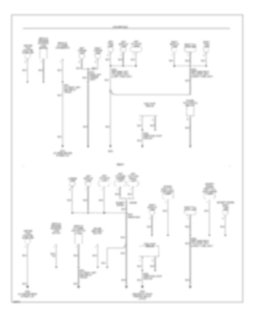
Ground Distribution Wiring Diagram (3 of 3) for Chrysler Sebring Limited 2005
List of elements for Ground Distribution Wiring Diagram (3 of 3) for Chrysler Sebring Limited 2005:
- (dodge) right tail/ turn signal lamp
- (except dodge)
- (except dodge) right turn lamp
- Center high mounted stop lamp
- Convertible
- Decklid cylinder lock switch
- Decklid cylinder lock switch (vtss)
- Decklid release solenoid/ ajar switch
- Dodge
- Driver seat belt switch
- Except dodge
- Fuel pump module
- G300 (center of trunk opening, below latch)
- G302
- G302 (at center rear of deck lid)
- G310 (at rear center of deck lid)
- Left back-up lamp
- Left license lamp
- Left tail/side marker lamp
- Left tail/stop lamp
- Left tail/turn signal lamp
- Left turn lamp
- License lamp
- Power top up/down relays
- Right back-up lamp
- Right license lamp
- Right tail/ side marker lamp
- Right tail/ stop lamp
- Right turn lamp
- S301 (at front left center of trunk)
- S301 (at front left center of trunk)
- S304 (between left tail/stop light & left turn light)
- S305 (between right tail/stop light & right turn light)
- S307 (near c320)
- S326 (near fuel pump module)
- S332 (near left license light)
- Sedan
HEADLIGHTS
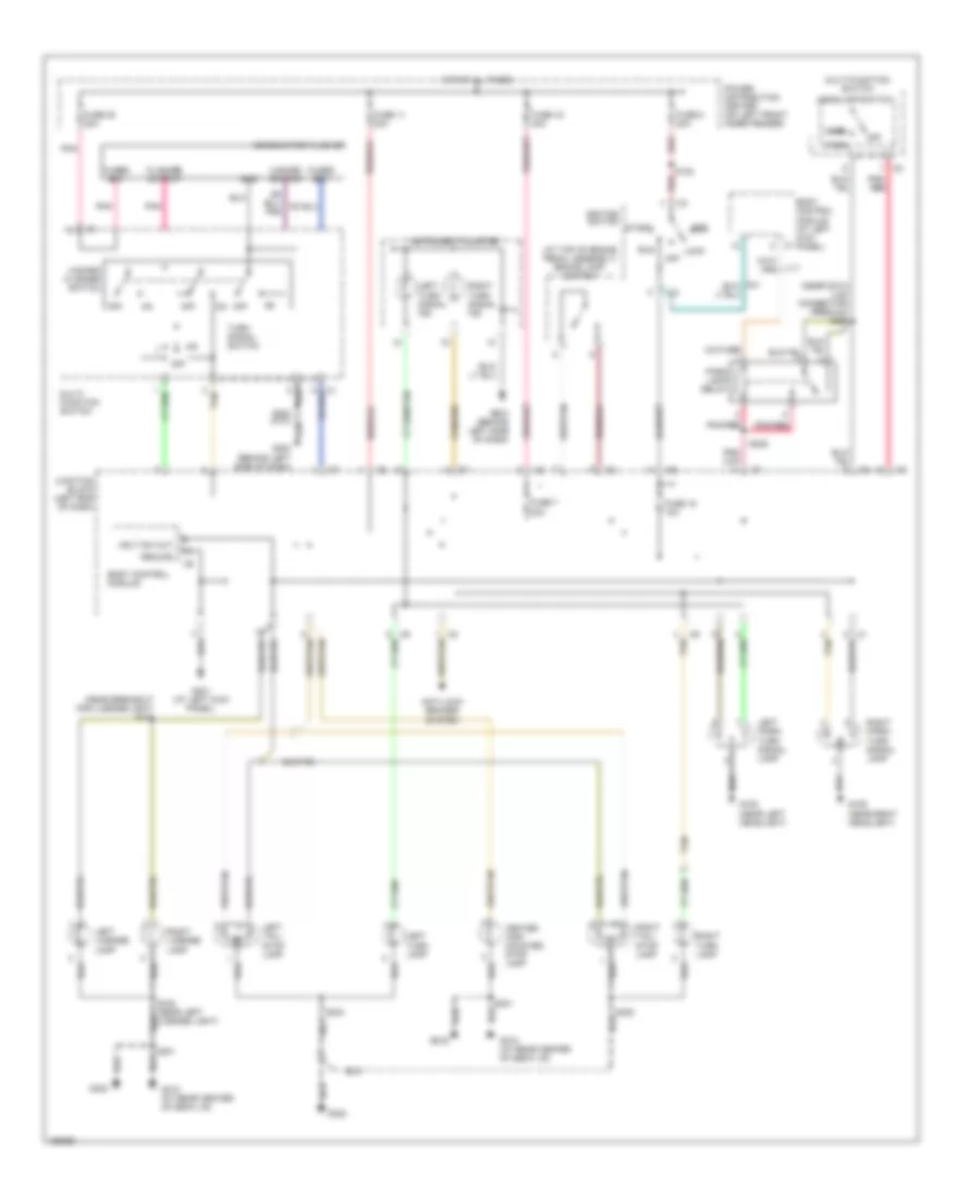
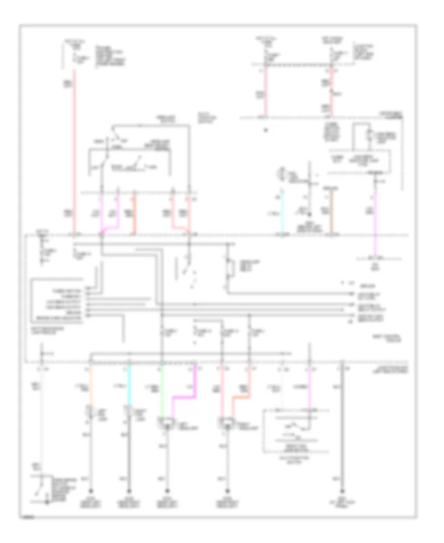
Headlights Wiring Diagram, Base for Chrysler Sebring Limited 2005
List of elements for Headlights Wiring Diagram, Base for Chrysler Sebring Limited 2005:
- Body control module
- Brake warn indicator
- Daytime running lamp module
- Dimm sw high beam output
- Fog lamp indicator
- Front fog lamp switch
- Fuse 10 20a
- Fuse 11 10a
- Fuse 12 10a
- Fuse 13 20a
- Fuse 2 10a
- Fuse 3 10a
- Fuse 4 15a
- Fuse 4 40a
- Fuse 7 20a
- Fused b (+)
- Fused b(+)
- Fused ignition
- Fused ignition switch (off-run- start)
- G106 (near right headlight)
- G108 (near left headlight)
- G203 (behind left side of dash)
- G301 (at left kick panel)
- Ground
- Hdlp delay relay output
- Hdlp delay rly ctrl
- Head
- Headlamp beam select switch
- Headlamp delay relay
- Headlamp switch
- High
- High beam indicator lamp
- High beam indicator lamp ctrl
- High beam output
- Hot at all times
- Hot in run
- Hot in run or start
- Instrument cluster
- Junction block (left end of dash)
- Left fog lamp
- Left headlamp
- Low
- Low beam output
- Multi- function switch
- Multi-function switch
- Off
- Park
- Park brake switch (at base of parking brake lever)
- Pci bus
- Power distribution center (on left front inner fender)
- Right fog lamp
- Right headlamp
- S210
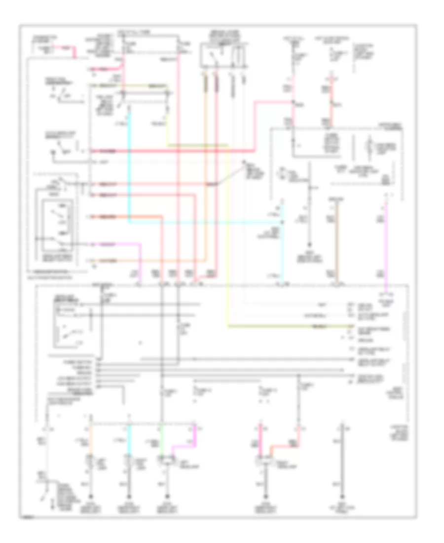
Headlights Wiring Diagram, Premium for Chrysler Sebring Limited 2005
List of elements for Headlights Wiring Diagram, Premium for Chrysler Sebring Limited 2005:
- (behind lower center of dash) auto headlamp relay
- Auto headlamp rly ctrl
- Auto headlamp switch
- Body control module
- Brake warn indicator
- Combination flasher
- Day brightness sense
- Daytime running lamp module
- Dimm sw high beam output
- Fog lamp indicator
- Fog lamp relay (behind left side of dash)
- Front fog lamp switch
- Fsd ign sw out
- Fuse 11 10a
- Fuse 12 10a
- Fuse 13 20a
- Fuse 2 10a
- Fuse 20a
- Fuse 3 10a
- Fuse 4 15a
- Fuse 40a
- Fuse 7 20a
- Fused (b+)
- Fused b (+)
- Fused b(+)
- Fused ignition
- Fused ignition switch (off-run- start)
- G106 (near right headlight)
- G108 (near left headlight)
- G203 (behind left side of dash)
- G301 (at left kick panel)
- Ground
- Head
- Headlamp beam select switch
- Headlamp delay relay
- Headlamp delay relay output
- Headlamp delay rly ctrl
- Headlamp switch
- High
- High beam indicator lamp
- High beam indicator lamp ctrl
- High beam output
- Hot at all times
- Hot in off or run or start
- Hot in run
- Instrument cluster
- Junction block (left end of dash)
- Left fog lamp
- Left headlamp
- Low
- Low beam output
- Multi-function switch
- Off
- Park
- Park brake switch (at base of parking brake lever)
- Pci bus (mic)
- Pnk
- Pnk/red
- Power distribution center (on left front inner fender)
- Right fog lamp
- Right headlamp
- S210
- S224
- S225
- S227 (at left kick panel)
- S228 (behind left side of dash)
HORN
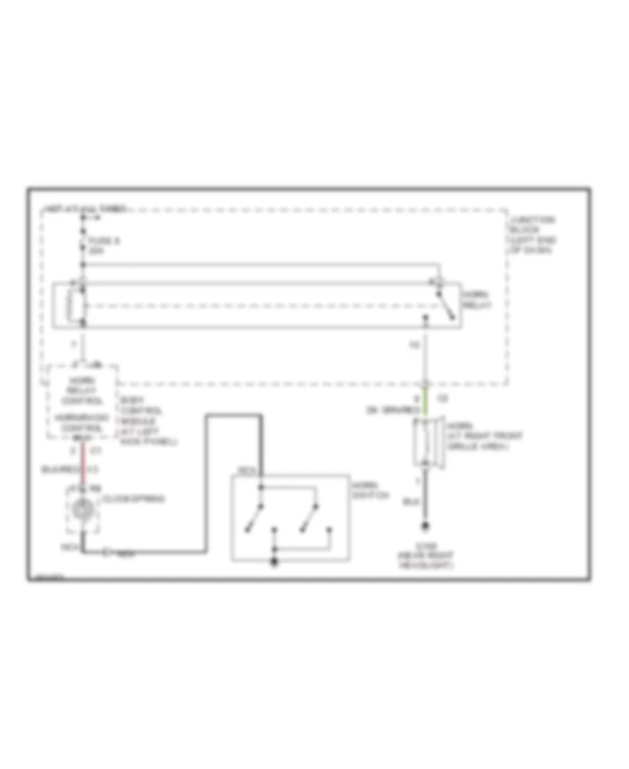
Horn Wiring Diagram for Chrysler Sebring Limited 2005
List of elements for Horn Wiring Diagram for Chrysler Sebring Limited 2005:
- Body control module (at left kick panel)
- Clockspring
- Fuse 8 20a
- G106 (near right headlight)
- Horn (at right front grille area)
- Horn relay
- Horn relay control
- Horn switch
- Horn/radio control mux
- Hot at all times
- Junction block (left end of dash)
- Nca
INSTRUMENT CLUSTER
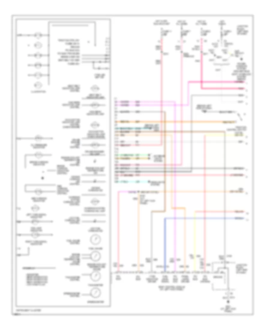
Instrument Cluster Wiring Diagram (1 of 2) for Chrysler Sebring Limited 2005
List of elements for Instrument Cluster Wiring Diagram (1 of 2) for Chrysler Sebring Limited 2005:
- (at left kick panel)
- (behind left side of dash) g203
- (convertible)
- - odometer - gear information - door information - deck information - low wash fluid
- Abs warning indicator
- Abs warning indicator control
- Air bag warning ind
- Air bag warning led control
- Auto a/c
- B27
- Body control module (at left kick panel)
- Brake warn ind
- Brake warning indicator
- Brake warning indicator control
- Charging system warning ind lamp
- Charging system warning lamp control
- Cruise engage lamp control
- Cruise engaged ind lamp
- D25
- Engine coolant temperature gauge
- Engine coolant temperature gauge control
- Engine coolant temperature ind
- Engine coolant temperature led control
- Exterior lights system
- F11
- F33
- Fog lamp indicator
- Fuel gauge
- Fuel gauge control
- Fuel level signal
- Fuse 11 10a
- Fuse 4 15a
- Fuse 5 10a
- Fuse 7 20a
- Fused (b+)
- Fused ign in
- G10
- G301 (at left kick panel)
- G69
- Ground
- Headlights system
- High beam indicator lamp
- High beam indicator lamp control
- Hot at all times
- Hot in off,
- Hot in run
- Illumination
- Instrument cluster
- Junction block (left end of dash)
- L39
- L60
- L61
- Left turn signal indicator
- Low fuel warning ind
- Low fuel warning led control
- Malfunction indicator lamp (check engine)
- Malfunction indicator lamp control (check engine)
- Manual a/c
- Oil pressure indicator
- Panel lamps driver
- Pci bus
- Pci bus (air bag)
- Pci bus (mic)
- Pci bus (traveler)
- Pnk
- Power windows system
- Right turn signal indicator
- Run or start
- S210
- S211
- S220
- S225 (premium)
- Seat belt indicator lamp
- Seat belt indicator lamp control
- Seat belt sw sen
- Shift interlock system (sedan)
- Speedometer
- Speedometer control
- Tachometer
- Tachometer control
- Traction control switch
- Traction ctrl sw
- Vf display
- Vtss indicator driver
- Vtss led set ind
- Z104
- Z105
- Z106
- Z313
Instrument Cluster Wiring Diagram (2 of 2) for Chrysler Sebring Limited 2005
List of elements for Instrument Cluster Wiring Diagram (2 of 2) for Chrysler Sebring Limited 2005:
- (at center of trunk opening, below latch)
- (left front of engine compt) powertrain control module
- Air bag control
- Anti-lock brake module (at lower left front of engine compt)
- Base
- Brake fluid level switch (at left rear of engine compartment)
- Compass/mini-trip computer
- Convertible
- D25
- Daytime running lamp module
- Door locks, mirrors systems
- Driver seat belt switch (near driver seat belt reel)
- Driver seat belt tensioner (under driver seat)
- Fuel level sensor
- Fuel pump module (on top of fuel tank)
- Fused b(+)
- G103 (near left front strut tower)
- G203 (behind left side of dash)
- G300 (sedan)
- G302 (at center rear of deck lid)
- G302 (convertible)
- Ground
- Ign sw out
- Ind driver
- Junction block (left end of dash)
- Module (orc) (center of floor, near shifter assembly)
- Nca
- Oil pressure switch (2.4l: on right front side of engine block) (2.7l: on right side of engine block)
- Park brake switch (at base of parking brake lever)
- Pci bus
- Pci bus (pcm)
- Pci bus (traveler)
- Pnk
- Premium
- S301
- S326
- Seat belt switch sense
- Sedan
- Z211
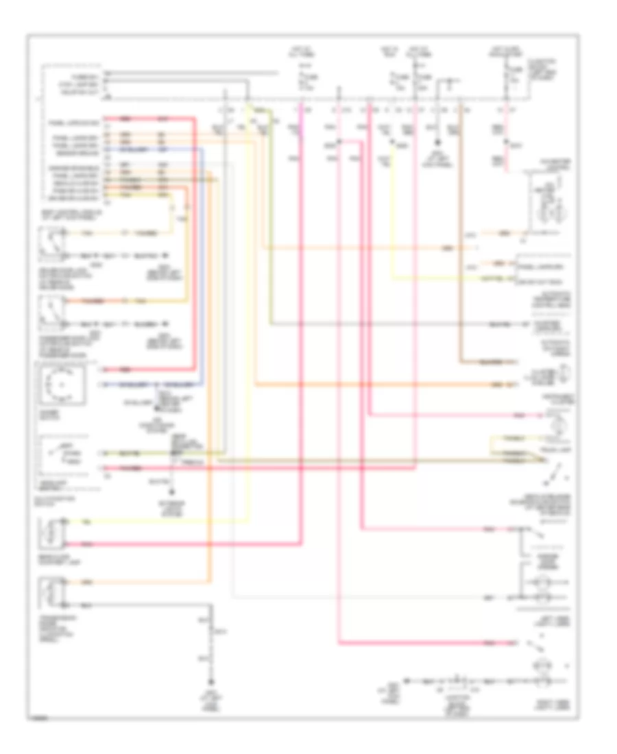
INTERIOR LIGHTS
Interior Lights Wiring Diagram for Chrysler Sebring Limited 2005
List of elements for Interior Lights Wiring Diagram for Chrysler Sebring Limited 2005:
- (near data link connector) s226
- A/c- heater ctrl illum
- A/c-heater control
- Air conditioning system
- Atc
- Automatic day/night mirror
- Automatic temperature control head
- Body control module (at left kick panel)
- C10
- C57
- Cluster illum lamps (6 bulbs)
- Courtesy lamps drv
- Ctsy lamp drv
- Decklid ajar sw
- Decklid release solenoid/ajar switch (at center rear of decklid)
- Dimmer switch
- Driver door lock motor/ajar switch (at rear of driver door)
- Driver dr ajar sw
- E19
- Exterior lights system
- Fuse 10a
- Fuse 15a
- Fuse 20a
- Fused b(+)
- G203 (behind left side of dash)
- G301 (at left
- G301 (at left kick panel)
- G38
- G74
- G75
- G78
- Garage door opener
- Garage dr enable
- Hdlmp sw out
- Head
- Headlamp switch
- Hot at all times
- Hot in off, run & start
- Hot in run
- Ign sw out (run)
- Instrument cluster
- Junction block (left end of dash)
- Kick panel)
- Left visor/ vanity lamps
- Mtc
- Multi-function switch
- Off
- Panel lamps drv
- Panel lmps dim sig
- Park
- Pass dr ajar sw
- Passenger door lock motor/ajar switch (at rear of passenger door)
- Pnk
- Pnk/ red
- Pnk/red
- Premium
- Rear floor courtesy lamp
- Red
- Right visor/ vanity lamps
- S210
- S212 (behind left center of dash)
- S220
- S302
- S313
- S320
- S321
- Sensor ground
- Tan
- Tan/red
- Transmission range indicator illumination (prndl)
- Trunk lamp
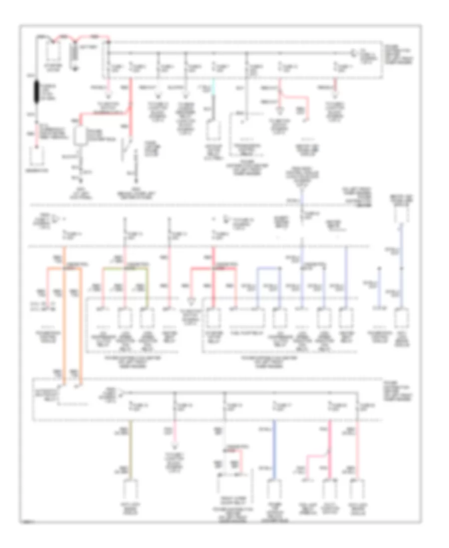
POWER DISTRIBUTION
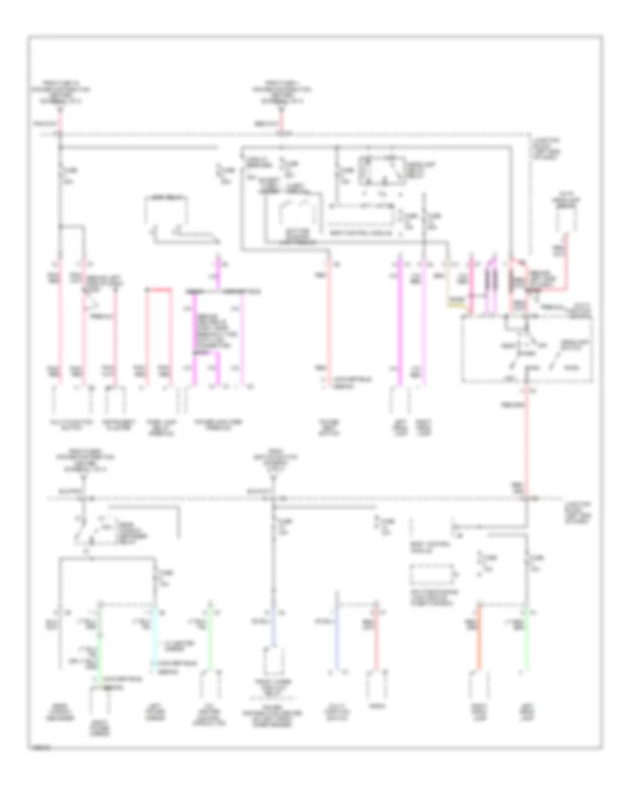
Power Distribution Wiring Diagram (1 of 4) for Chrysler Sebring Limited 2005
List of elements for Power Distribution Wiring Diagram (1 of 4) for Chrysler Sebring Limited 2005:
- (2.4l)
- (2.7l)
- (at left kick panel)
- (behind lower left center of dash)
- (inside pdc) s102
- (inside pdc) s103
- (inside pdc) s104
- (inside pdc) s105
- (inside pdc) s122
- (on left front inner fender) power distribution center
- A/c compressor clutch relay
- Air pump motor relay (2.4l pzev)
- Anti- lock brake module
- Anti-lock brake module
- Automatic shutdown relay
- Battery
- Cigar lighter/ power outlet
- Except heated seats
- Fog lamp relay (premium)
- From body control module (junction block) (diagram 2 of 4)
- From fuse 11 a (diagram 1 of 4)
- From fuse 8 (diagram 1 of 4)
- Front wiper on/off relay
- Fuel pump relay
- Fuse 1 40a
- Fuse 10 10a
- Fuse 11 20a
- Fuse 12 40a
- Fuse 13 20a
- Fuse 14 30a
- Fuse 15 40a
- Fuse 16 40a
- Fuse 17 40a
- Fuse 18 40a
- Fuse 2 20a
- Fuse 20 20a
- Fuse 22 20a
- Fuse 23 20a
- Fuse 4 40a
- Fuse 6 40a
- Fuse 7 40a
- Fuse 8 20a
- Fuse 9 20a (a/t)
- G202
- G301
- Generator
- Heated seat relay
- Heated seats
- High speed radiator fan relay
- Low speed radiator fan relay
- Multi- function switch
- Nca
- Pnk
- Power distribution center (on left front inner fender)
- Power outlet (convertible)
- Power top up/down relays (convertible)
- Powertrain control module
- Red
- Red/ tan
- S113 (in breakout for starter feed terminal)
- S313
- Sentry key immobilizer module
- Starter motor
- Starter motor relay
- To fuse 10 (junction block) (diagram 3 of 4)
- To fuse 14 (diagram 1 of 4)
- To fuse 15 (diagram 1 of 4)
- To fuse 5 (junction block) (diagram 4 of 4)
- To fuse 7 (junction block) (diagram 3 of 4)
- To ignition switch (diagram 2 of 4)
- To rear window defogger relay (junction block) (diagram 3 of 4)
- Transmission control relay
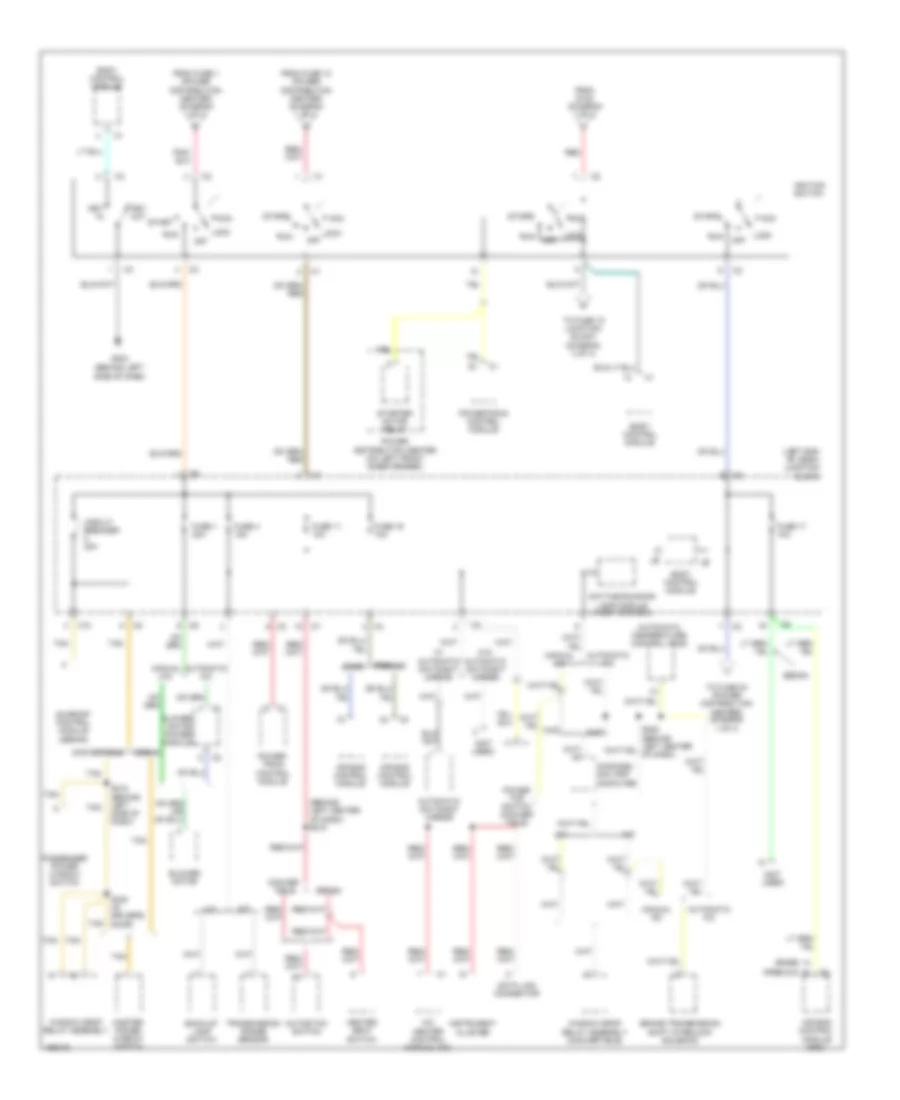
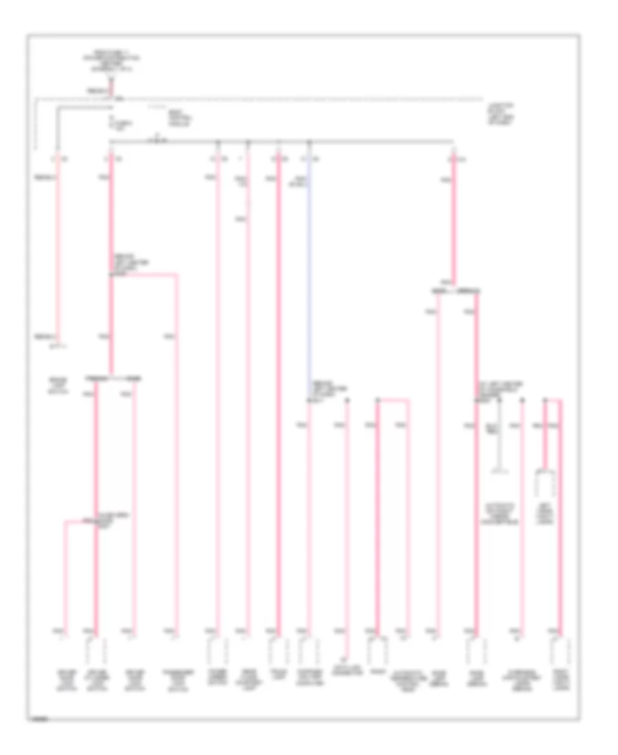
Power Distribution Wiring Diagram (2 of 4) for Chrysler Sebring Limited 2005
List of elements for Power Distribution Wiring Diagram (2 of 4) for Chrysler Sebring Limited 2005:
- (base)
- (behind left center of dash) s210
- (behind left side of dash)
- (left end of dash) junction block
- (not used)
- (premium)
- A/c heater control (manual a/c)
- A/t
- Acc
- Air bag control module
- Air bag control module (orc)
- Automatic a/c
- Automatic day/night mirror
- Automatic temperature control head
- Autostick switch
- Back-up lamp switch
- Base
- Blower motor
- Blower motor power module
- Body control module
- Brake transmission shift interlock solenoid
- C10
- Circuit breaker 30a
- Compass/ mini-trip computer
- Conver- tible
- Convertible
- Data link connector
- Daytime running lamp module (fleet/canada)
- From fuse 1 (power distribution center) (diagram 1 of 4)
- From fuse 10 (power distribution center) (diagram 1 of 4)
- From s102 (diagram 1 of 4)
- Fuse 1 30a
- Fuse 11 10a
- Fuse 16 10a
- Fuse 17 10a
- Fuse 4 15a
- G203
- Heated seat switch
- Ignition switch
- Instrument cluster
- Key in
- Key out
- Lock
- M/t
- Manual a/c
- Master power window switch
- Off
- Passenger power window switch
- Power distribution center (on left front inner fender)
- Power top switch (conver- tible)
- Power- train control module
- Powertrain control module
- Premium
- Red
- Run
- S215 (behind left side of dash)
- S330 (in driver's door)
- Sedan
- Start
- Starter motor relay
- Sunroof control module (sedan)
- Tan
- To fuse 15 junction block (diagram 3 of 4)
- To fuse 23 (power distribution center) (diagram 1 of 4)
- Transmission range sensor
- W/ automatic day/night mirror
- W/o automatic day/night mirror
- Window drop relay assembly
- Window drop relay assembly (convertible)
Power Distribution Wiring Diagram (3 of 4) for Chrysler Sebring Limited 2005
List of elements for Power Distribution Wiring Diagram (3 of 4) for Chrysler Sebring Limited 2005:
- (behind center of dash, near breakout for data link connector) s203
- (convertible)
- (sedan)
- A/c heater control (manual a/c)
- Auto headlamp relay
- Base
- Body control module
- C11
- Circuit breaker 20a
- Coil
- Convertible
- Daytime running lamp module
- Daytime running lamp module (fleet/canada)
- Except fleet/ canada
- Fleet/ canada
- From fuse 16 (power distribution center) (diagram 1 of 4)
- From fuse 4 (power distribution center) (diagram 1 of 4)
- From fuse 6 (power distribution center) (diagram 1 of 4)
- From ignition switch (diagram 2 of 4)
- Front wiper high/low relay
- Fuse 10a
- Fuse 15a
- Fuse 20a
- Head
- Headlamp delay relay
- Headlamp switch
- High
- Horn relay
- Instrument cluster
- Junction block (left end of dash)
- Left head- lamp
- Left power mirror
- Low
- Multi- function switch
- Multi-function switch
- Off
- Park
- Park lamp relay (premium)
- Pnk/ red
- Power amplifier (premium)
- Power distribution center (on left front inner fender)
- Power seat switch
- Premium
- Radio
- Rear window defogger
- Rear window defogger relay
- Red
- Right head- lamp
- Right power mirror
- Sedan
- W/ heated mirror
Power Distribution Wiring Diagram (4 of 4) for Chrysler Sebring Limited 2005
List of elements for Power Distribution Wiring Diagram (4 of 4) for Chrysler Sebring Limited 2005:
- (at left center of windshield header) s302
- (behind left center of dash) s209
- (behind left center of dash) s211
- (in driver's door) s327
- Automatic day/night mirror (convertible)
- Automatic temperature control head
- Base
- Body control module
- Brake lamp switch
- C10
- Compass/ mini-trip computer
- Data link connector
- Dome lamp (sedan)
- Driver cylinder lock switch
- Driver door lock switch
- From fuse 11 (power distribution center) (diagram 1 of 4)
- Fuse 5 10a
- Junction block (left end of dash)
- Left visor/ vanity lamps
- Overhead map/courtesy lamps (sedan)
- Passenger door lock switch
- Pnk
- Power mirror switch
- Premium
- Radio
- Rear floor courtesy lamp
- Right visor/ vanity lamps
- Trunk lamp
POWER DOOR LOCKS
Power Door Locks Wiring Diagram for Chrysler Sebring Limited 2005
List of elements for Power Door Locks Wiring Diagram for Chrysler Sebring Limited 2005:
- A21
- A31
- Acc
- Base
- Body control module
- Driver cyl lock
- Driver cylinder lock switch
- Driver door ajar
- Driver door lock motor/ ajar switch (at rear of driver door)
- Driver door lock switch
- Driver door sw
- Driver lock rly
- Driver unlock rly
- Fuse 10a
- Fuse 15a
- Fused b(+)
- G108 (near left headlight)
- G203 (behind left side of dash)
- G301 (at left kick panel)
- G73
- G74
- G75
- Ground
- Hot at all times
- Hot in run & start
- Ignition
- Ignition (run/acc)
- Ignition (run/st)
- Ignition switch
- Junction block (left end of dash)
- Lock
- Off
- P175
- P176
- P177
- P178
- P96
- P97
- Pass door ajar
- Pass door sw
- Pass lock rly
- Pass unlock rly
- Passenger door lock motor/ajar switch (at rear of passenger door)
- Passenger door lock switch
- Pnk
- Power distribution system
- Premium
- Run
- S209
- S222 (atc)
- S320
- S321
- S327 (in driver's door)
- Start
- Tan
- Tan/ red
- Tan/red
- Unlk
- Z132
- Z313
- Z380
POWER MIRRORS
Power Mirrors Wiring Diagram for Chrysler Sebring Limited 2005
List of elements for Power Mirrors Wiring Diagram for Chrysler Sebring Limited 2005:
- (at left kick panel) g301
- Automatic day/night mirror
- Back-up lamp feed
- Body control module
- C10
- Courtesy lamps driver
- Defogger system
- Down
- Fuse 4 15a
- Fuse 5 10a
- Fused b(+)
- Fused ignition (run)
- G203 (behind left side of dash)
- Ground
- Hot at all times
- Hot in run
- Junction block (left end of dash)
- Left
- Left power mirror
- Pnk
- Power mirror switch
- Right
- Right power mirror
- S302
- S320
- S321
- Transmission range sensor (on lower left side of transaxle)
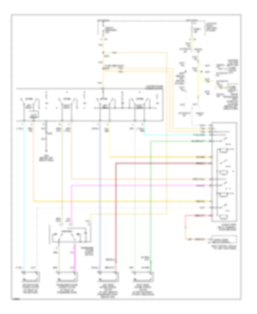
POWER SEATS
Heated Seats Wiring Diagram for Chrysler Sebring Limited 2005
List of elements for Heated Seats Wiring Diagram for Chrysler Sebring Limited 2005:
- (60 mm from harness tie down) s310
- Body control module (at left kick panel)
- Driver heated seat back
- Driver heated seat cushion
- Driver heated seat module
- Drv ht st feed
- Drv ht st sw output
- Drv on
- F98
- F99
- Fuse 11 10a
- Fuse 13 20a
- Fuse 23 20a
- Fused b(+)
- G301 (at left kick panel)
- Ground
- Heated seat relay (in pdc)
- Heated seat relay control
- Heated seat switch
- Hot at all times
- Hot in run or start
- Ht st relay
- Junction block (left end of dash)
- Nca
- Off
- P86
- Pass
- Pass ht st feed
- Pass ht st sw output
- Pass on
- Passenger heated seat back
- Passenger heated seat cushion
- Passenger heated seat module (under passenger seat)
- Power distribution center (on left front inner fender)
- Red
- S210
- S311
- S312
- Seat heater output
- Seat temp sense signal
- Z121
- Z122
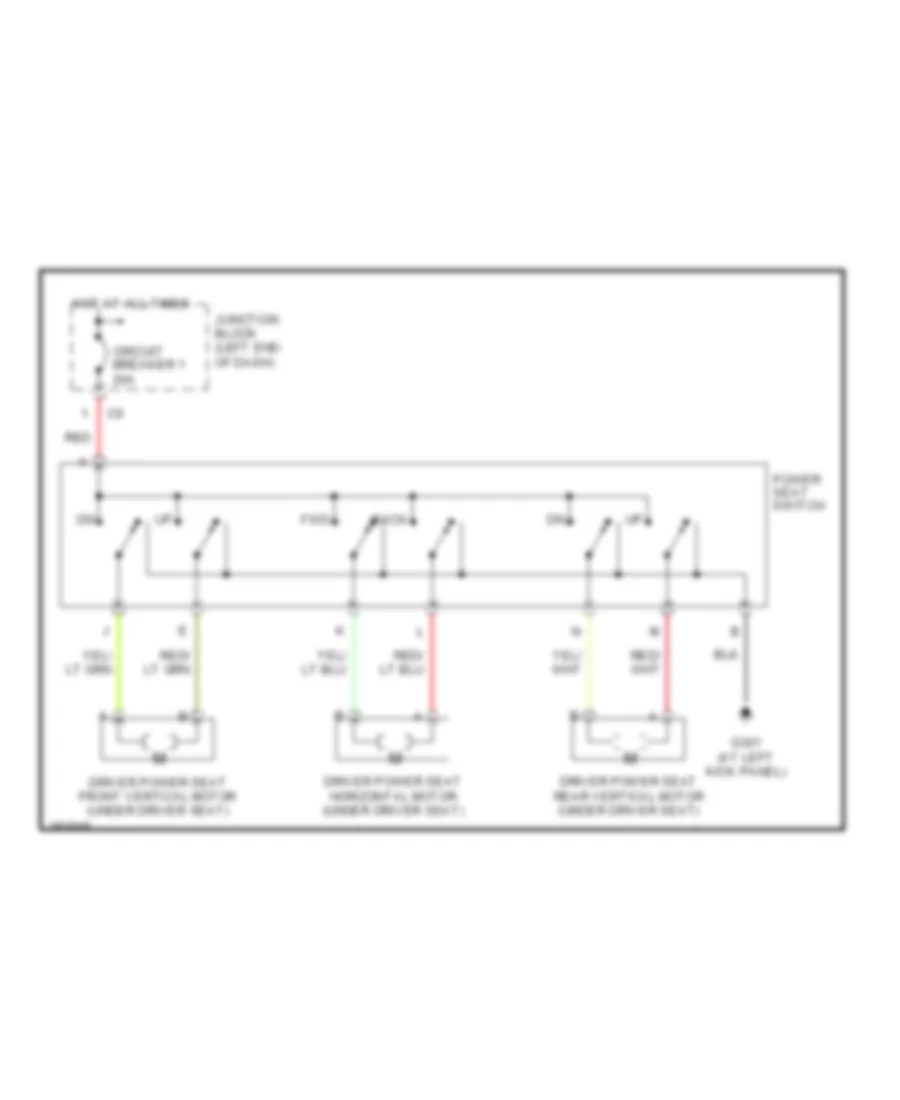
Power Seat Wiring Diagram for Chrysler Sebring Limited 2005
List of elements for Power Seat Wiring Diagram for Chrysler Sebring Limited 2005:
- Back
- Circuit breaker 1 20a
- Driver power seat front vertical motor (under driver seat)
- Driver power seat horizontal motor (under driver seat)
- Driver power seat rear vertical motor (under driver seat)
- Fwd
- G301 (at left kick panel)
- Hot at all times
- Junction block (left end of dash)
- Power seat switch
- Red
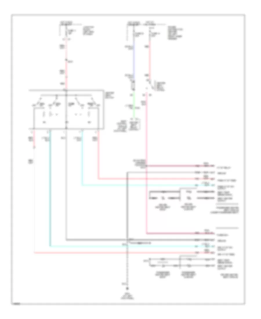
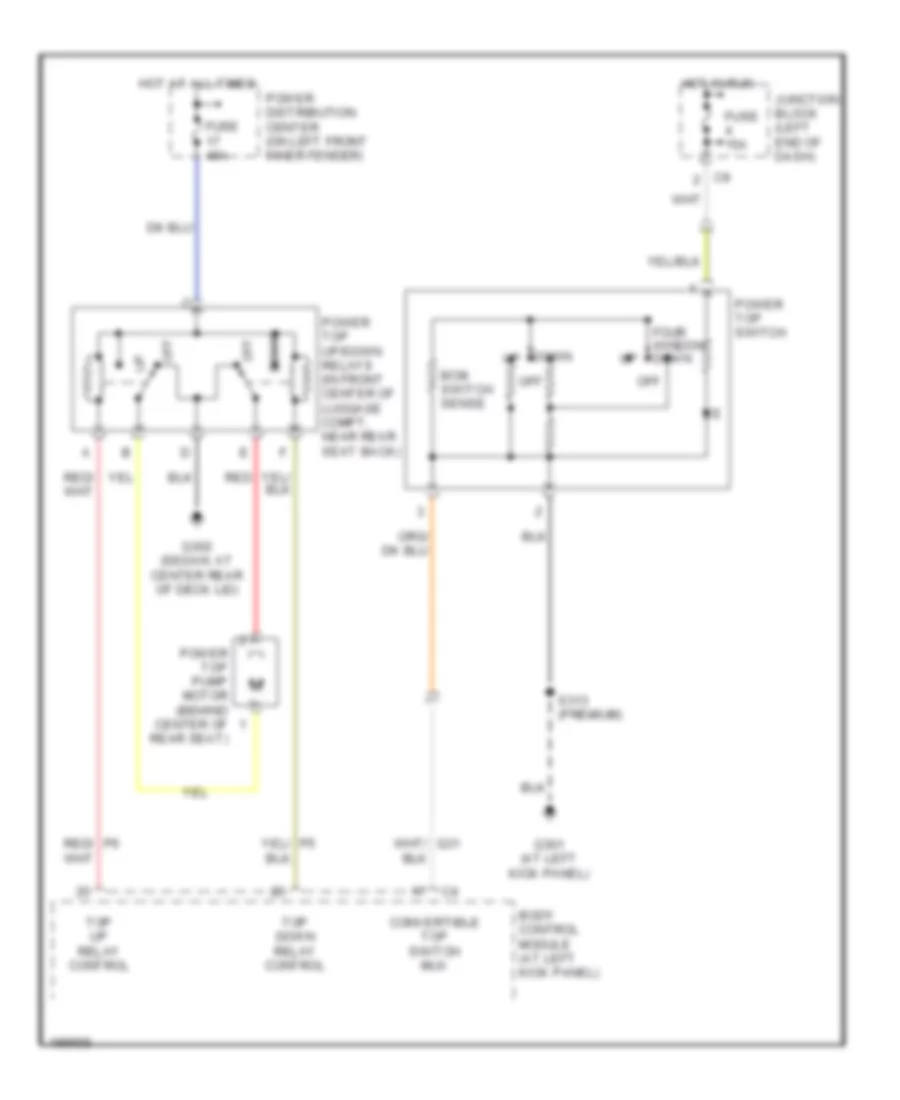
POWER TOP/SUNROOF
Power Top/Sunroof Wiring Diagram for Chrysler Sebring Limited 2005
List of elements for Power Top/Sunroof Wiring Diagram for Chrysler Sebring Limited 2005:
- Bcm switch sense
- Body control module (at left kick panel)
- Convertible top switch mux
- Down
- Four window down
- Fuse 15a
- Fuse 40a
- G301 (at left kick panel)
- G302 (sedan: at center rear of deck lid)
- Hot at all times
- Hot in run
- Junction block (left end of dash)
- Off
- Power distribution center (on left front inner fender)
- Power top pump motor (behind center of rear seat)
- Power top switch
- Power top up/down relays (in front center of luggage compt, near rear seat back)
- Red
- Red/ p6
- S313 (premium)
- Top down relay control
- Top up relay control
POWER WINDOWS
Power Windows Wiring Diagram for Chrysler Sebring Limited 2005
List of elements for Power Windows Wiring Diagram for Chrysler Sebring Limited 2005:
- (at front of passenger door)
- (at front of driver door)
- (at left rear of passenger compt, behind trim)
- (behind left center of dash)
- (in driver's door) s330
- Auto down
- Automatic a/c
- Body control module (at left kick panel)
- Brake transmission shift interlock solenoid (behind left side of dash)
- Circuit breaker 2 30a
- Compass/ mini-trip computer
- Driver power window motor
- Fuse 4 15a
- Fused ign sw out
- G203 (behind left side of dash)
- Hot in run
- Junction block (left end of dash)
- Left front
- Left rear
- Left rear power window motor
- Manual a/c
- Master power window switch
- Passenger power window motor
- Passenger power window switch
- Q37
- Right front
- Right rear
- Right rear power window motor (at bottom front of right rear door)
- S215
- S220
- S320
- Tan
- Window drop relay assembly (in driver door)
- Window drop relay control
RADIO
Radio Wiring Diagram, Base for Chrysler Sebring Limited 2005
List of elements for Radio Wiring Diagram, Base for Chrysler Sebring Limited 2005:
- All times
- Antenna
- Audio out left
- Audio out right
- Body control module
- Cd changer
- D25
- E14
- Fuse 14 10a
- Fuse 5 10a
- Fused b(+)
- G203 (behind left side of dash)
- Gnd
- Ground
- Hot at
- Hot in run
- Ign sw out
- Ign sw output
- Junction block (left end of dash)
- L pnl spkr (+)
- L pnl spkr (-)
- Left front door speaker
- Left front instrument panel speaker
- Left rear speaker speaker
- Lr spkr (+)
- Lr spkr (-)
- Nca
- Or acc
- Panel lamps driver
- Panel lamps drv
- Pci bus
- Pnk
- Pnl lmps dim sig
- Pnl lts dim sig
- R pnl spkr (+)
- R pnl spkr (-)
- Radio
- Red
- Right front door speaker
- Right front instrument panel speaker
- Right rear speaker
- Rr spkr (+)
- Rr spkr (-)
- S211
- X112
- X12
- X160
- X40
- X41
- X51
- X52
- X57
- X58
- X80
- X82
- X85
- X87
- Z140
Radio Wiring Diagram, Premium for Chrysler Sebring Limited 2005
List of elements for Radio Wiring Diagram, Premium for Chrysler Sebring Limited 2005:
- 12v output
- 2.7l
- All times
- Amp ld spkr (+)
- Amp ld spkr (-)
- Amp lf spkr (+)
- Amp lf spkr (-)
- Amp lr spkr (+)
- Amp lr spkr (-)
- Amp rd spkr (+)
- Amp rd spkr (-)
- Amp rf spkr (+)
- Amp rf spkr (-)
- Amp rr spkr (+)
- Amp rr spkr (-)
- Antenna
- Audio out left
- Audio out right
- Body control module
- Bus
- Cd changer
- Clockspring
- D25
- E14
- Fuse 14 10a
- Fuse 5 10a
- Fuse 8 20a
- Fused b(+)
- G203 (behind left side of dash)
- G301 (at left kick panel)
- Gnd
- Ground
- Horn/ radio ctrl mux
- Hot at
- Hot in run
- Ign sw out
- Ign sw output
- Junction block (left end of dash)
- Left front door speaker
- Left front instrument panel speaker
- Left rear speaker
- Left remote radio switch
- Lf spkr (+)
- Lf spkr (-)
- Lr spkr (+)
- Lr spkr (-)
- Mode
- Nca
- Or acc
- Out ign sw
- Panel lts drv
- Pci
- Pci bus
- Pnk
- Pnl lmps dim sig
- Pnl lmps driver
- Power amplifier (under right front seat)
- Preset
- Radio
- Red
- Rf spkr (+)
- Rf spkr (-)
- Right front door speaker
- Right front instrument panel speaker
- Right rear speaker
- Right remote radio switch
- Rr spkr (+)
- Rr spkr (-)
- S211
- S216 (under horn pad)
- S217 (under horn pad)
- Seek dn
- Seek up
- Vol dn
- Vol up
- X112
- X12
- X160
- X40
- X41
- X51
- X52
- X53
- X54
- X55
- X56
- X57
- X58
- X60
- Z140
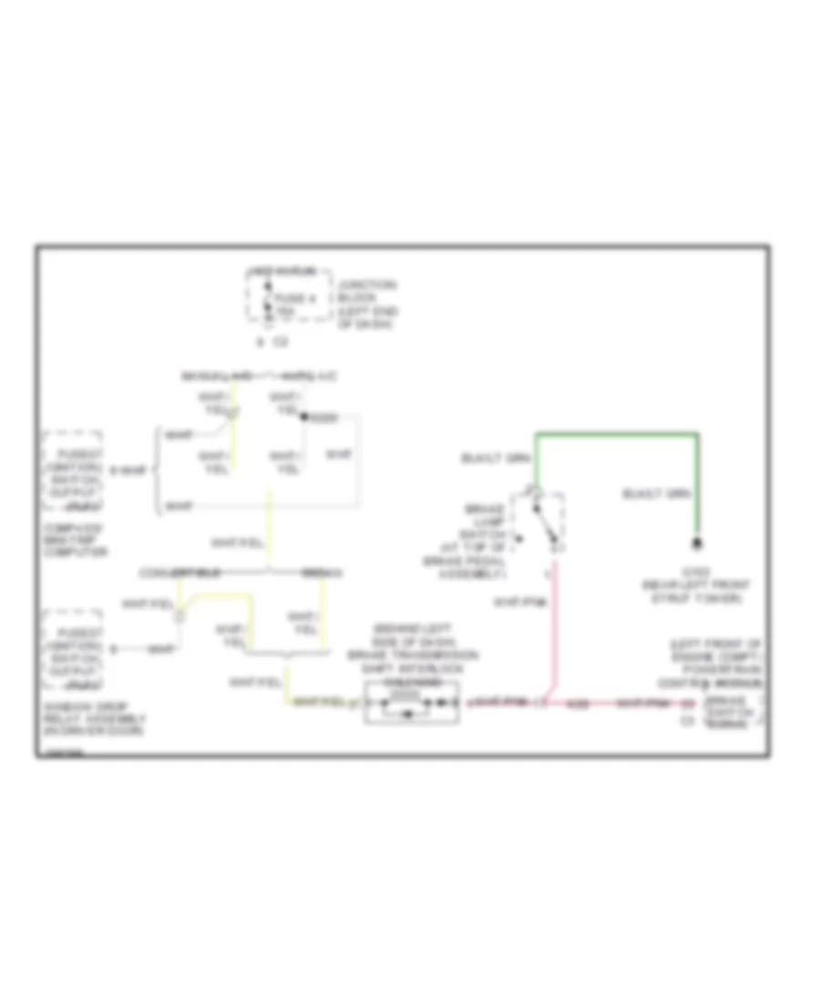
SHIFT INTERLOCK
Shift Interlock Wiring Diagram for Chrysler Sebring Limited 2005
List of elements for Shift Interlock Wiring Diagram for Chrysler Sebring Limited 2005:
- (behind left side of dash) brake transmission shift interlock solenoid
- (left front of engine compt) powertrain control module
- Auto a/c
- Brake lamp switch (at top of brake pedal assembly)
- Brake switch signal
- Compass/ mini-trip computer
- Convertible
- Fuse 4 15a
- Fused ignition
- G103 (near left front strut tower)
- Hot in run
- Junction block (left end of dash)
- K29
- Manual a/c
- Sedan
- Switch output (run)
- Window drop relay assembly (in driver door)
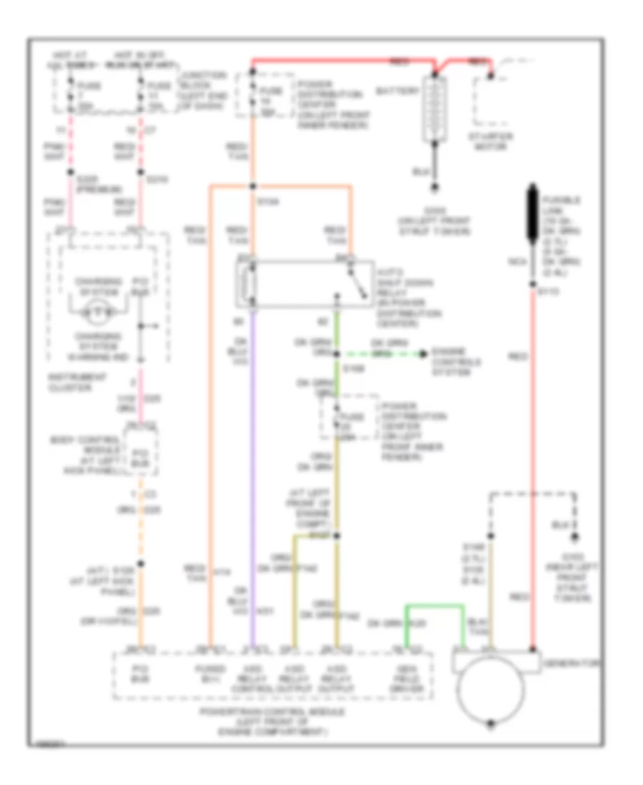
STARTING/CHARGING
Charging Wiring Diagram for Chrysler Sebring Limited 2005
List of elements for Charging Wiring Diagram for Chrysler Sebring Limited 2005:
- (a/t)
- (at left front of engine compt) s127
- Asd relay control
- Asd relay output
- Auto shut down relay (in power distribution center)
- Battery
- Body control module (at left kick panel)
- Charging system
- Charging system warning ind
- Engine controls system
- Fuse 10a
- Fuse 20a
- Fuse 30a
- Fused b(+)
- G100 (on left front strut tower)
- G103 (near left front strut tower)
- Gen field driver
- Generator
- Hot at all times
- Hot in off, run or start
- Instrument cluster
- Junction block (left end of dash)
- Nca
- Pci bus
- Power distribution center (on left front inner fender)
- Powertrain control module (left front of engine compartment)
- Red
- Red/ a14 tan
- Red/ tan
- S104
- S108
- S113
- S120 (at left kick panel)
- S135 (2.4l)
- S149 (2.7l)
- S210
- S225 (premium)
- Starter motor
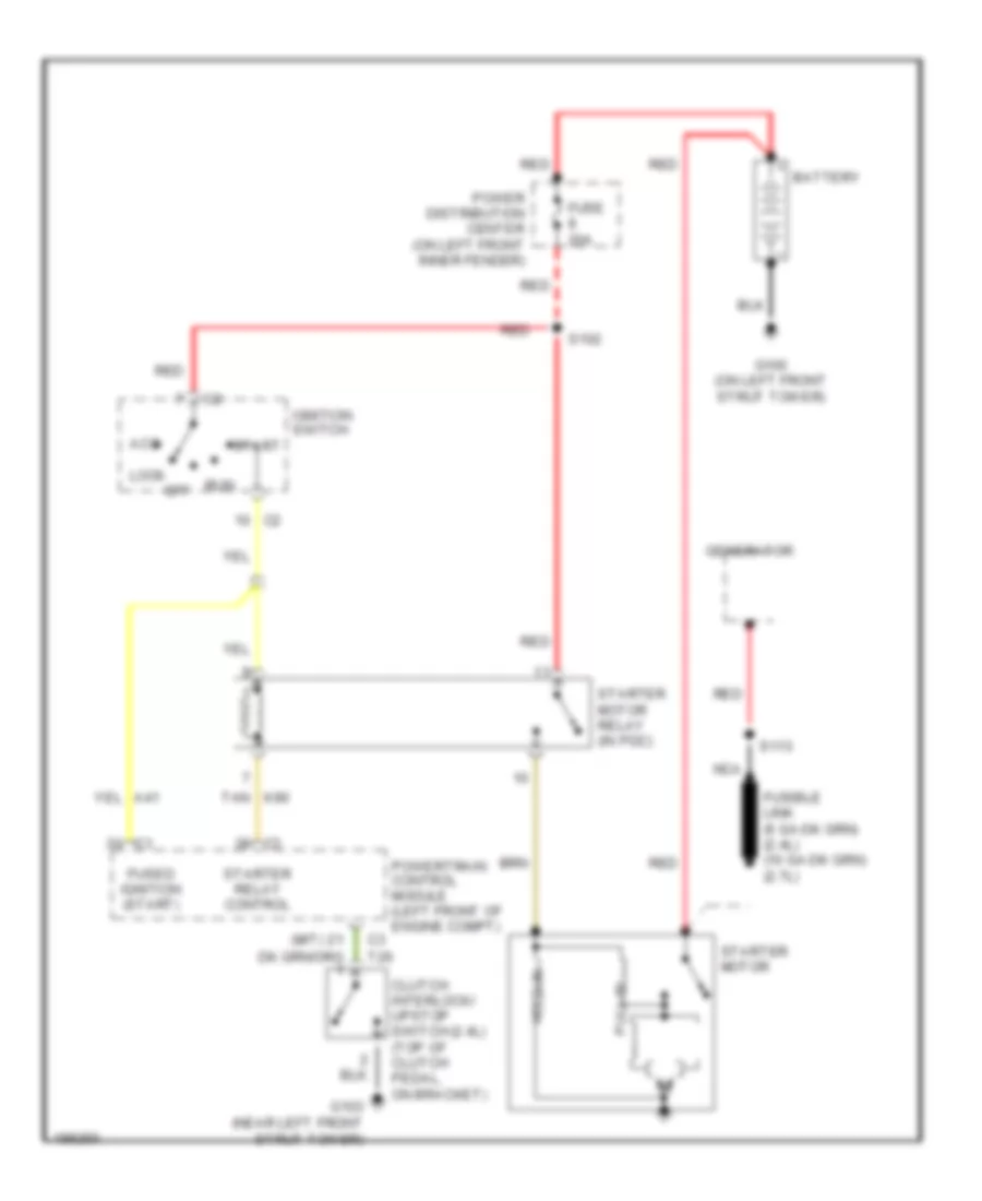
Starting Wiring Diagram for Chrysler Sebring Limited 2005
List of elements for Starting Wiring Diagram for Chrysler Sebring Limited 2005:
- (2.4l)
- (m/t)
- Acc
- Battery
- C3 t26
- Clutch interlock/ upstop switch (top of clutch pedal, on bracket)
- Fuse 20a
- Fused ignition (start)
- G100 (on left front strut tower)
- G103 (near left front strut tower)
- Generator
- Hold-in
- Ignition switch
- Lock
- Nca
- Off
- Power distribution center (on left front inner fender)
- Powertrain control module (left front of engine compt)
- Pull-in
- Red
- Run
- S102
- S113
- Start
- Starter motor
- Starter motor relay (in pdc)
- Starter relay control
- Tan k90
SUPPLEMENTAL RESTRAINTS
Supplemental Restraints Wiring Diagram for Chrysler Sebring Limited 2005
List of elements for Supplemental Restraints Wiring Diagram for Chrysler Sebring Limited 2005:
- Air bag control module (orc) (center of floor, near shifter assembly)
- Air bag warning led
- Air bag warning led control
- Body control module (at left kick panel)
- Clockspring
- D25
- Data link connector (behind lower left side of dash)
- Driver air bag squib 1 (behind driver air bag, in steering wheel)
- Driver air bag squib 2 (behind driver air bag, in steering wheel)
- Driver seat belt tensioner (under driver seat)
- Driver seat belt tensioner line 1
- Driver seat belt tensioner line 2
- F14
- F23
- Fuse 10a
- G201 (center of vehicle, between occupant restraint controller & shift assembly)
- G203 (behind left side of dash)
- Ground
- Hot in run
- Hot in run or start
- Ignition
- Instrument cluster
- Junction block (left end of dash)
- Line
- Line 1
- Line 2
- Nca
- Passenger air bag (behind right side of dash)
- Passenger seat belt tensioner (under passenger seat)
- Pci bus
- Powertrain control module (a/t) (left front of engine compt)
- R42
- R43
- R44
- R45
- R53
- R54
- R55
- R56
- R61
- R62
- R63
- R64
- Sci receive
- Seat belt switch sense
- Sw sen
- Warning system
- Z100
TRANSMISSION
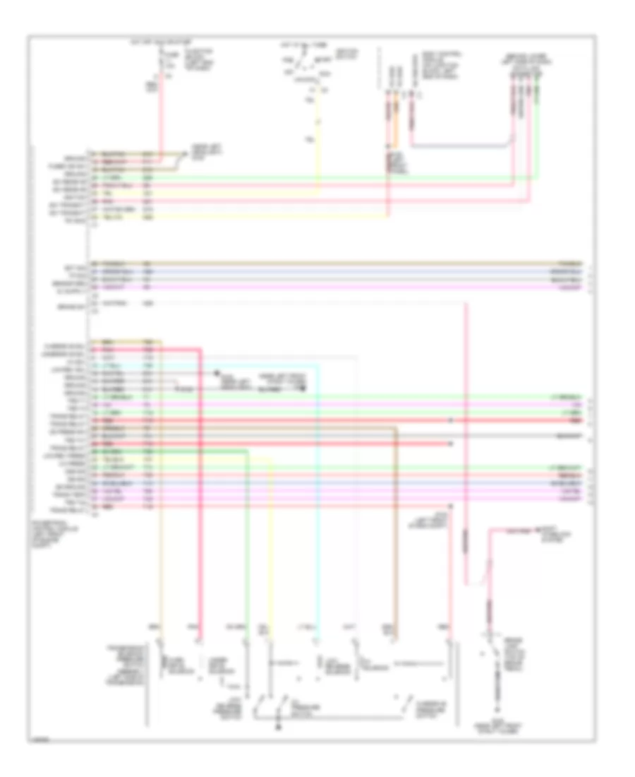
A/T Wiring Diagram (1 of 2) for Chrysler Sebring Limited 2005
List of elements for A/T Wiring Diagram (1 of 2) for Chrysler Sebring Limited 2005:
- (behind lower left side of dash) data link connector
- (near left front strut tower) g103
- (near left headlight) g108
- 2-4 press
- 2-4 pressure switch
- 2-4 sol
- 2-4 solenoid
- A41
- Acc
- Body control module (on junction block, left end of dash)
- Brake lamp switch (top of brake pedal)
- Brake sw
- D15
- D20
- D21
- D25
- Ect sig
- F11
- Fuse 10a
- Fused ign sw
- G103 (near left front strut tower)
- G108 (near left headlight)
- Ground
- Hot at all times
- Hot off, run or start
- Ignition
- Ignition switch
- Iss sig
- Junction block (left end of dash)
- K22
- K29
- Low/ reverse pressure switch
- Low/ reverse solenoid
- Low/rev press
- Low/rev sol
- Od press sw
- Off
- Oss sig
- Over- drive solenoid
- Overdrive pressure switch
- Overdrive sol
- Pci bus
- Pnk
- Powertrain control module (left front of engine compt)
- Red
- Run
- S100 (left front of eng compt)
- S123
- Sci receive
- Sci transmit
- Sensor grd
- Shift interlock system
- Ss ground
- Start
- T13
- T14
- T15
- T16
- T19
- T20
- T41
- T42
- T47
- T50
- T52
- T54
- T59
- T60
- Tp sig
- Trans relay
- Trans temp
- Transmission solenoid/ pressure switch assembly (left side of transmission)
- Trs t1
- Trs t3
- Trs t41
- Trs t42
- Under- drive solenoid
- Underdrive sol
- Unlock
- Z12
- Z13
- Z14
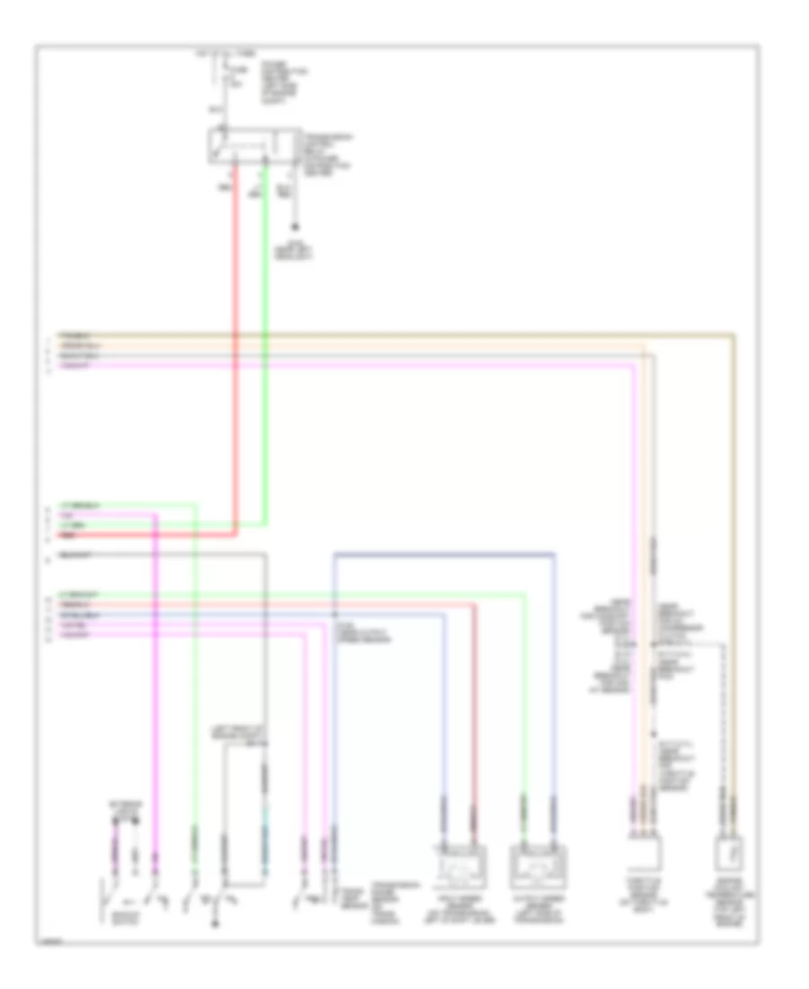
A/T Wiring Diagram (2 of 2) for Chrysler Sebring Limited 2005
List of elements for A/T Wiring Diagram (2 of 2) for Chrysler Sebring Limited 2005:
- (left front of engine compt) s111
- (near breakout for a/c compressor clutch) s156 (2.7l)
- (near breakout for camshaft position sensor) (2.7l) s155
- Backup switch
- Engine coolant temperature sensor (top left front of engine)
- Exterior lights system
- Fuse 20a
- G108 (near left headlight)
- Hot at all times
- Input speed sensor (on transmission, left of shift lever)
- Nol
- Output speed sensor (left side of transmission)
- P3l
- Power distribution center (left side of engine compt)
- Prnl
- Red
- S115 (2.4l) (near breakout for map/ iat sensor)
- S117 (2.4l) (near breakout pcm)
- S117 (2.7l) (near breakout for throttle position sensor)
- S125 (near output speed sensor)
- Throttle position sensor (on throttle body)
- Trans temp sensor
- Transmission control relay (in power distribution center)
- Transmission range sensor (on trans- mission)
TRUNK, TAILGATE, FUEL DOOR
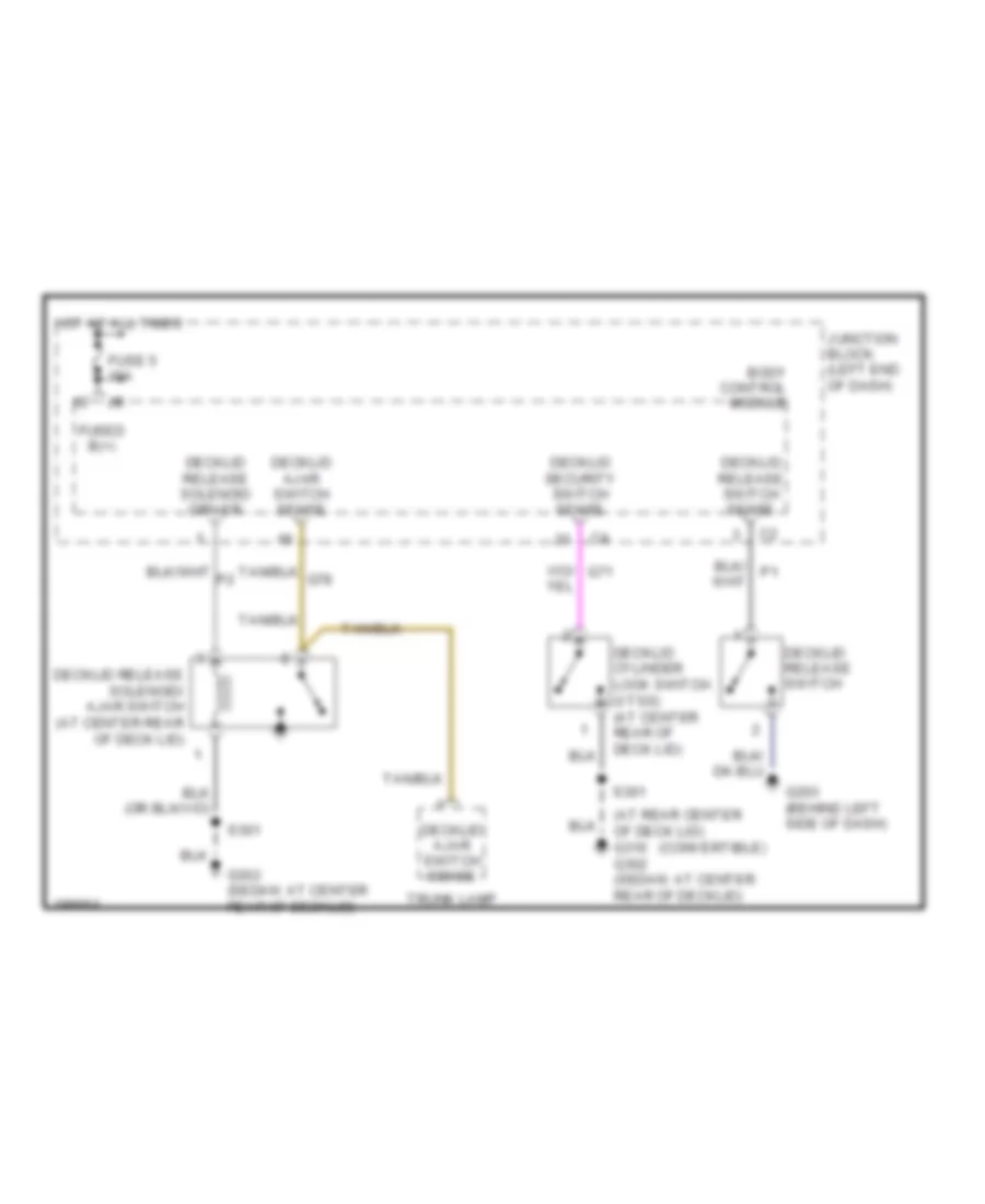
Deck Lid Release Wiring Diagram for Chrysler Sebring Limited 2005
List of elements for Deck Lid Release Wiring Diagram for Chrysler Sebring Limited 2005:
-
- (at rear center of deck lid) g310 g302 (sedan: at center rear of decklid)
- (convertible)
- Body control module
- Decklid ajar switch sense
- Decklid cylinder lock switch (vtss) (at center rear of deck lid)
- Decklid release solenoid driver
- Decklid release solenoid/ ajar switch (at center rear of deck lid)
- Decklid release switch
- Decklid release switch sense
- Decklid security switch sense
- Fuse 5 10a
- Fused b(+)
- G203 (behind left side of dash)
- G302 (sedan: at center rear of decklid)
- Hot at all times
- Junction block (left end of dash)
- S301
- Trunk lamp
WARNING SYSTEMS
Warning Systems Wiring Diagram for Chrysler Sebring Limited 2005
List of elements for Warning Systems Wiring Diagram for Chrysler Sebring Limited 2005:
- (atc)
- (or tan/red)
- Body control module
- Convertible
- D25
- Decklid ajar sw sns
- Decklid release solenoid/ ajar switch (at center rear of decklid)
- Door locks system
- Driver door lock motor/ajar switch (at rear of driver door)
- Driver seat belt switch (near driver seat belt reel)
- Driver seat belt tensioner (under driver seat)
- Drv door ajar sw sns
- Exterior lights system
- Fuse 10a
- Fuse 15a
- Fuse 20a
- Fused b(+)
- G108 (near left headlight)
- G203 (behind center of dash, near breakout for data link connector)
- G203 (behind left side of dash)
- G26
- G301 (at left kick panel)
- G302 (at center rear of decklid)
- G74
- G75
- G76
- G77
- G78
- Ground
- Head
- Headlamp sw out
- Headlamp switch
- Hot at all times
- Ignition switch
- Instrument cluster
- Interior lights system
- Junction block (left end of dash)
- Key in
- Key out
- Key-in ign sw sns
- Left rear door ajar sw sns
- Left rear door lock motor/ajar switch (sedan) (at rear of left rear door)
- Multi- function switch
- Nca
- Off
- Park
- Pas door ajar sw sns
- Passenger door lock motor/ajar switch (at rear of passenger door)
- Pci bus
- Pnk/red
- Right rear door ajar sw sns
- Right rear door lock motor/ajar switch (sedan) (at rear of right rear door)
- S222
- S226 (premium) (near data link connector)
- S301
- S313
- S320
- S321
- Seat belt indicator lamp
- Seat belt indicator lamp control
- Seat belt sw sense
- Seat belt switch sense
- Sedan
- Tan
- Tan/red
- Tan/red (or tan)
- Z132
- Z313
- Z380
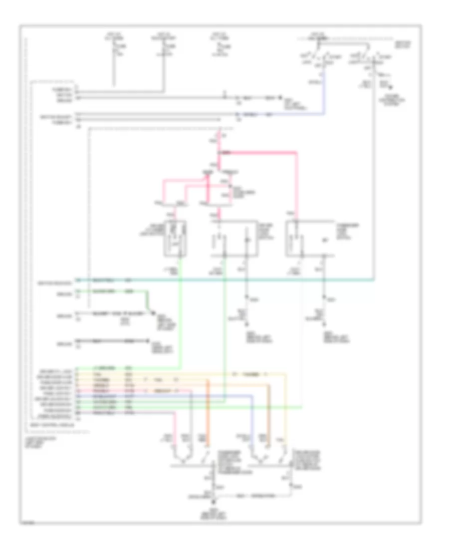
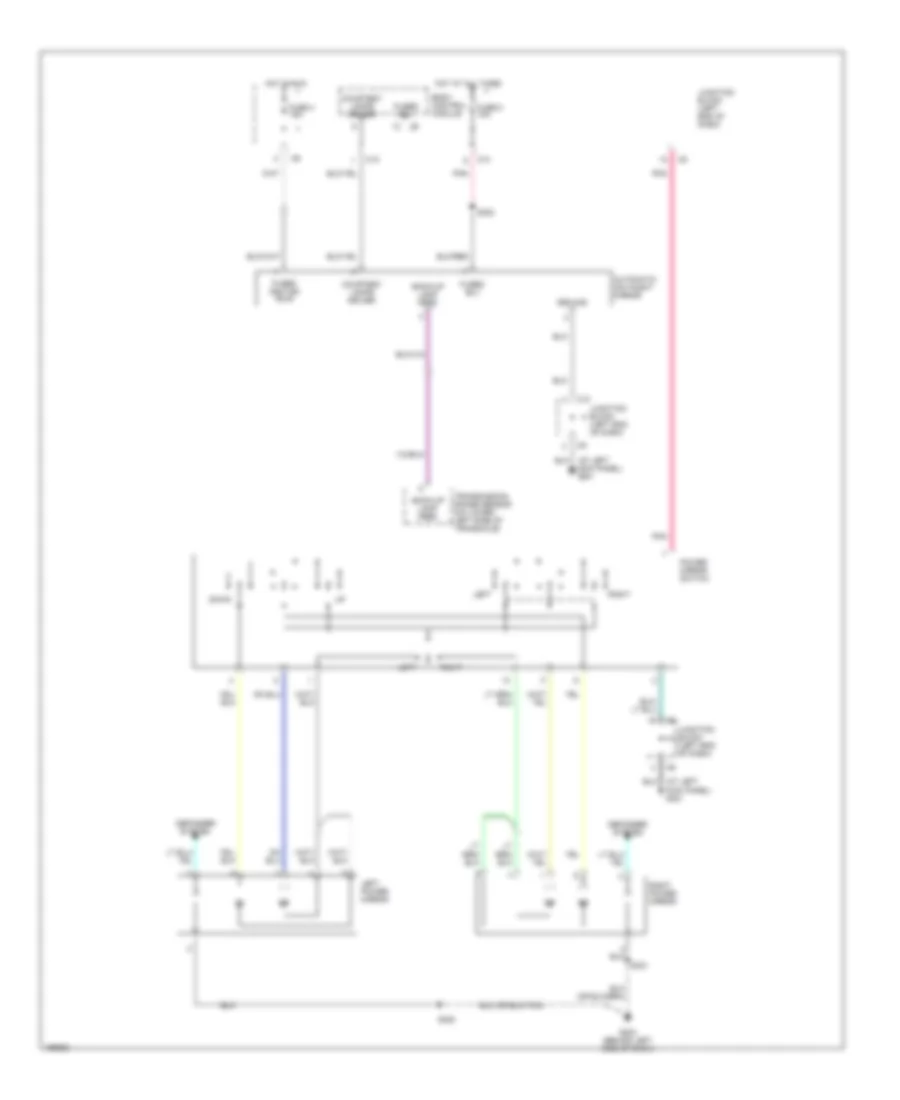
WIPER/WASHER
Wiper/Washer Wiring Diagram for Chrysler Sebring Limited 2005
List of elements for Wiper/Washer Wiring Diagram for Chrysler Sebring Limited 2005:
- Body control module
- Front washer pump motor (at right front of engine compt)
- Front washer pump motor control
- Front wiper high/low relay
- Front wiper high/low relay control
- Front wiper motor (left side of firewall, behind strut tower)
- Front wiper on/off relay
- Front wiper on/off relay control
- Front wiper park switch sense
- Front wiper switch mux
- Fuse 15 10a
- Fuse 40a
- G103 (near left front strut tower)
- G106 (near right headlight)
- Hot at all times
- Hot in run or acc
- Junction block (left end of dash)
- Mist
- Multi- function switch
- Park
- Power distribution center (on left front inner fender)
- S122
- Tan/red
- V10
- V14
- V16
- V52
- V55
- Wash
- Wiper switch 0) off 1) intermittent 2) intermittent 3) intermittent 4) intermittent 5) intermittent 6) intermittent 7) low 8) high