Diagram sections — 27 (52 total)
AIR CONDITIONING ANTI-LOCK BRAKES ANTI-THEFT BODY COMPUTER COMPUTER DATA LINES COOLING FAN CRUISE CONTROL DEFOGGERS ENGINE PERFORMANCE EXTERIOR LIGHTS GROUND DISTRIBUTION HEADLIGHTS HORN INSTRUMENT CLUSTER INTERIOR LIGHTS MEMORY SYSTEMS POWER DISTRIBUTION POWER DOOR LOCKS POWER MIRRORS POWER SEATS POWER WINDOWS RADIO STARTING/CHARGING SUPPLEMENTAL RESTRAINTS TRANSMISSION WARNING SYSTEMS WIPER/WASHER
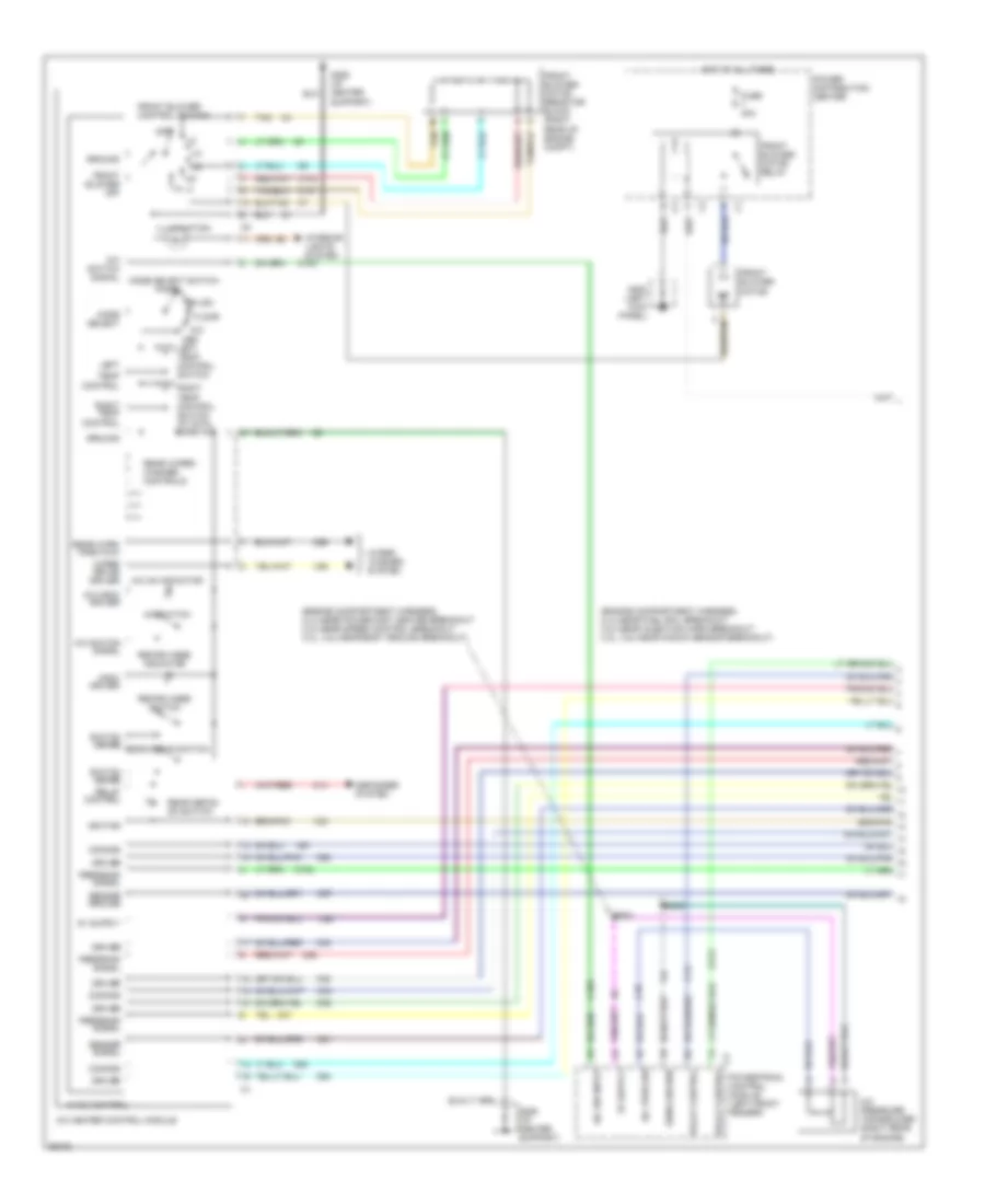
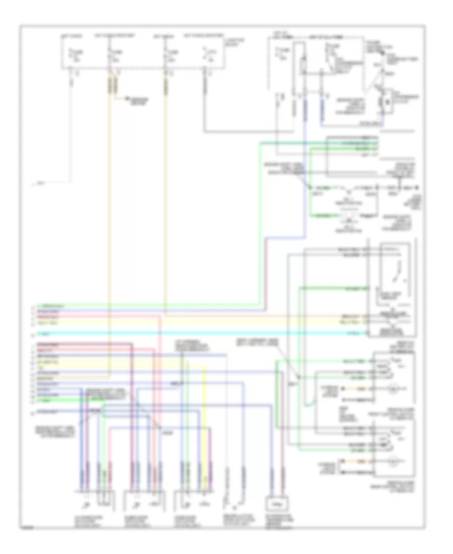
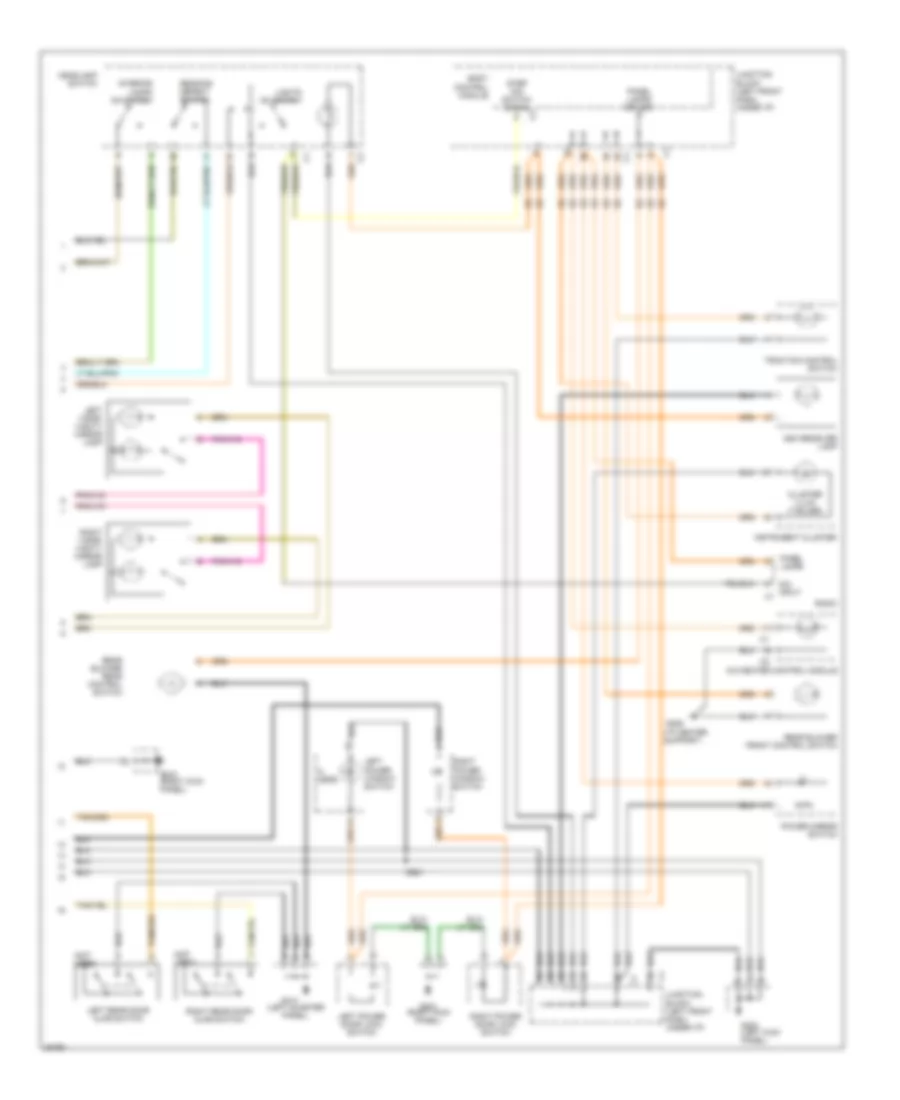
AIR CONDITIONING Air Conditioning Wiring Diagrams (1 of 2) for Chrysler Town & Country LX 1997 List of elements for Air Conditioning Wiring Diagrams (1 of 2) for Chrysler Town & Country LX 1997: 85 (engine compartment harness, 2.4l-near fuel rail breakout 3.0l-near injection harn breakout 3.3l, 3.8l-near knock sensor breakout) (engine compartment harness, 2.4l-near power dist center breakout 3.0l-near speed control breakout 3.3l, 3.8l-near body ground breakout) A/c heater control module A/c indic driver A/c on indicator A/c pres sw A/c pressure transducer (right rear of engine) A/c sw input A/c switch A/c switch signal Bi-lev C102 C103 C104 C107 C13 C14 C18 C2 relay control C21 C26 C32 C33 C34 C35 C36 C37 C57 C61 C62 C63 C64 C66 Common Def Defogger system Driver Es02 Es03 Feedback signal Floor Front blower control switch Front blower motor Front blower motor relay Front blower motor resistor block (right rear of engine compt) Front blower off Fuse 40a G200 (left kick panel) G206 (i/p center support) Ground Hot at all times Hvac control Ignition Illumination Indic driver Interior lights system K173 Left Left temp control switch Mix Mode select Mode select switch Off Panel Power distribution center Powertrain control module (left front fender) Rear defog on switch Rear wipe/ wash mux Rear wiper/ washer controls Recirc mode indicator Recirc mode switch Relay control Right temp control Right temp control switch (w/ dual zone a/c) Sens ground Sensor ground Sensor signal Switch sense Switch sense rear defog switch Tan Temp control V23 V26 Wiper de-ice driver Wiper/ washer system Air Conditioning Wiring Diagrams (2 of 2) for Chrysler Town & Country LX 1997 List of elements for Air Conditioning Wiring Diagrams (2 of 2) for Chrysler Town & Country LX 1997: 48 (body harness, near split for tail lamps) (engine compt harn, in radiator fan breakout) (engine compt harn, near recirculation motor breakout) (i/p harness, near mode door motor breakout) A/c compressor clutch A/c compressor clutch relay A/c zone door actuator (in hvac unit) Blend door actuator (in hvac unit) Bs17 E48 Engine compt harn, harn, near radiator module) Es23 Evaporator temperature sensor (in hvac unit) Fuse 10a Fuse 15a Fuse 20a Fuse 40a G100 (under battery tray) G206 (i/p center support) High temp sensor Hot at all times Hot in run Hot in run or start Interior lights system Js01a Js01b Js02a Js02b Js03 Junction block Low Med Message center Mode door actuator (in hvac unit) Motor No. 1 radiator fan No. 2 radiator fan Off Power distribution center Ptc 9a Radiator fan relay (front of left frame rail) Rear Rear a/c heater unit (w/ rear a/c) Rear blower Rear blower front control switch (w/ rear a/c) Rear blower rear control switch (w/ rear a/c) Rear mode door motor Recirculation door actuator (in hvac unit)
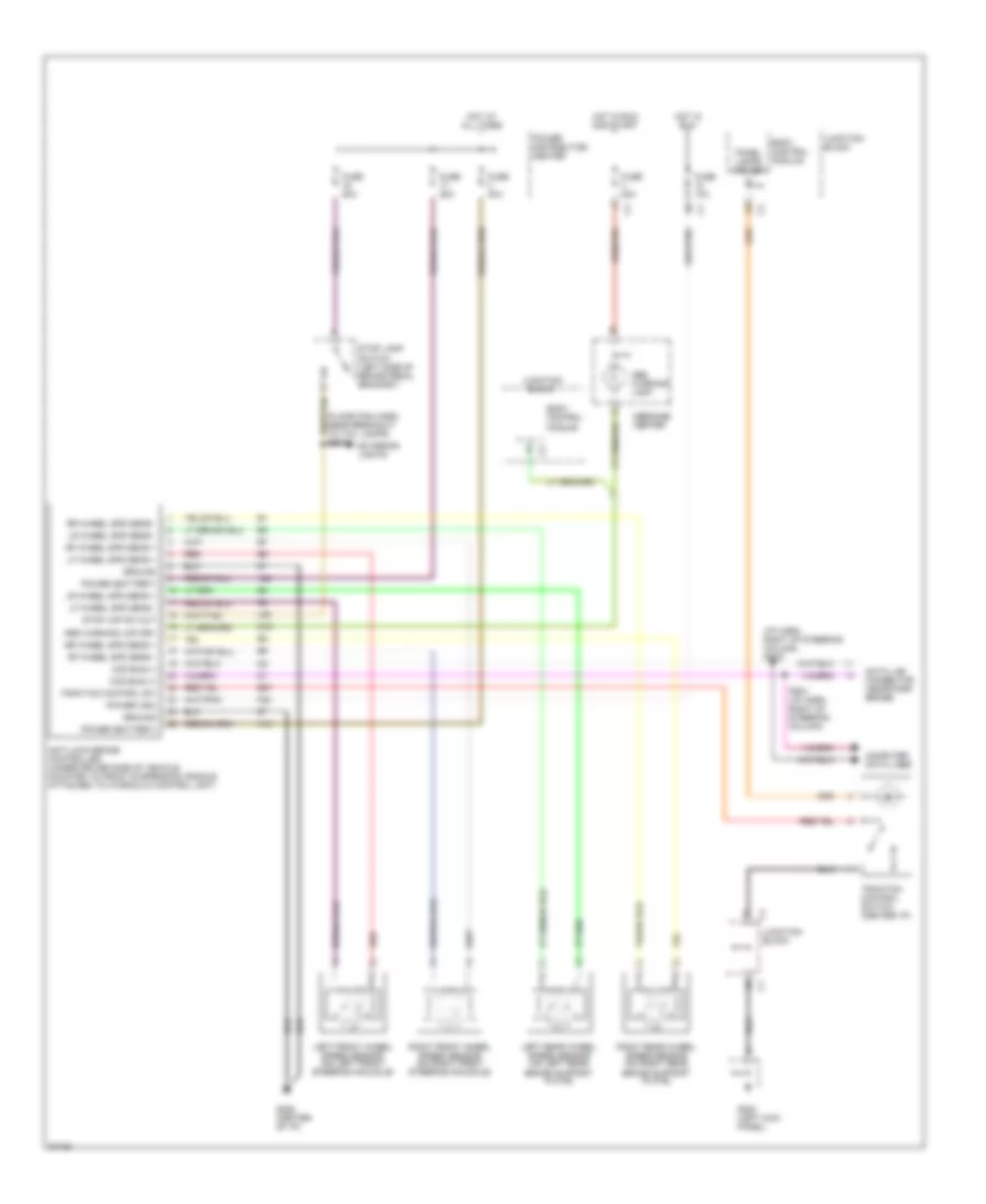
ANTI-LOCK BRAKES Anti-lock Brake Wiring Diagrams for Chrysler Town & Country LX 1997 List of elements for Anti-lock Brake Wiring Diagrams for Chrysler Town & Country LX 1997: 51 (floor pan harn, near breakout to tail lamps) bs01 (i/p harn, right of steering column) ps02 A10 A20 Abs warning lamp Abs warning lmp drv Anti-lock brake controller (under driver side of vehicle, mounted to front suspension cradle, attached to hydraulic control unit) B27 Body control module Ccd bus (+) Ccd bus (-) Computer data lines Data link connector (near park brake) Exterior lights F22 Fuse 10a Fuse 20a Fuse 25a Fuse 40a G19 G200 (left kick panel) G206 (center of i/p) Ground Hot at all times Hot in run Hot in run and start Junction block L50 Left front wheel speed sensor (on left front steering knuckle) Left rear wheel speed sensor (on left rear brake support plate) Lf wheel spd sens + Lf wheel spd sens - Lr wheel spd sens + Lr wheel spd sens - Message center Panel lamps driver Power (battery) Power (ign) Power distribution center Ps01 (i/p harn, right of steering column) Red Rf wheel spd sens + Rf wheel spd sens - Right front wheel speed sensor (on right front steering knuckle) Right rear wheel speed sensor (on right rear brake support plate) Rr wheel spd sens + Rr wheel spd sens - Stop lamp switch (left side of brake pedal bracket) Stop lmp sw out Traction control sw Traction control switch (center i/p)
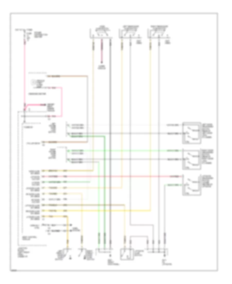
ANTI-THEFT Anti-theft Wiring Diagram for Chrysler Town & Country LX 1997 List of elements for Anti-theft Wiring Diagram for Chrysler Town & Country LX 1997: 48 (not used) Body control module Fuse 10a c3 Fused b+ G301 (right kick panel) G411 (in liftgate) G70 G74 G75 G76 G77 G78 Hood ajar sw sens Hood ajar switch Horn rly ctrl Horn system Hot at all times Junction block (left front dash, under i/p) Left door arm/disarm switch (rear of left door lock cylinder) Left front door ajar switch Left power door lock switch Left rear door ajar switch Lf door ajar sw sens Lf door mux sig Liftgate ajar sw sens Liftgate ajar switch Liftgate arm/disarm switch (lower center of liftgate Liftgate mux sig Lr door ajar sw sens Memory seat/ mirror module Message center P96 P97 P98 Pnk Power distribution center Rf door ajar sw sens Rf door mux sig Right door arm/disarm switch (rear of right door lock cylinder) Right front door ajar switch Right power door lock switch Right rear door ajar switch Rr door ajar sw sens Tan Tan/red Vehicle theft alarm lamp Vta lmp drvr Wiper module
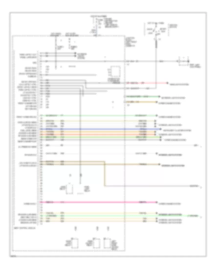
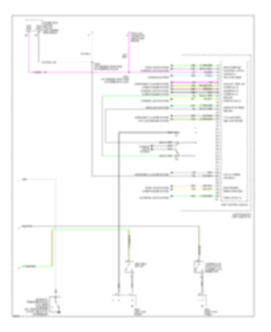
BODY COMPUTER Body Computer Wiring Diagrams (1 of 2) for Chrysler Town & Country LX 1997 List of elements for Body Computer Wiring Diagrams (1 of 2) for Chrysler Town & Country LX 1997: 95 (left A31 Acc Body control module Combination flasher/drl module Crtsy lmp rly drvr Door lock relay Door unlock relay Exterior lights system F11 F155 F236 F238 Front washer mtr Front wiper prk sw Fuel level sens Fuse 10a Fuse 2 fuse 2 10a 10a Fuse 3 20a Fused b+ G10 G200 kick panel) G29 G70 G74 G75 G76 G77 G78 Gnd Headlights system Hi/lo lmp rly ctrl Hood ajar sw sens Horn relay Horn rly ctrl Hot at all times Hot in off, Hot in run Ign sw (off/acc) Ign sw (off/run/st) Ign sw (run) Ignition switch Instrument cluster system Interior lights system Interior lights system interior lights system Junction block (left front dash, under i/p) L62 L63 L93 L97 Left front door unlock relay Lf door ajar sens Lf door mux Lf unlock rly Liftgate ajar sw Liftgate mux in Lock Lock rly ctrl Low wash fluid in Lr door ajar sens Lr turn sig M112 M20 Off Oil press sw sens Or start P96 P97 P98 Panel lmps drvr Park lamp relay Park lmp rly ctrl Park lmp rly out Power distribution center (left side of engine compt) Reading lmp gnd Rear washer pump Rear wiper mtr Rf door ajar sens Rf door mux Rr door ajar sens Rr turn sig Run Run or start Seat belt sw in Start Tan Tan/red Unlock rly ctrl V10 V13 V14 V20 V23 Wiper on rly Wiper/washer system Body Computer Wiring Diagrams (2 of 2) for Chrysler Town & Country LX 1997 List of elements for Body Computer Wiring Diagrams (2 of 2) for Chrysler Town & Country LX 1997: 51 (left fender side shield) Abs lamp driver Anti-lock brakes system Body control module Ccd bus (+) Ccd bus (-) Coolant temp lmp Courtesy lmp sw D09 Data link connector (near park brake) Dimmer sw in Door locks system E17 E92 Engine oil pressure switch (2.4l: rear of engine) (3.0l: near starter) (3.3/3.8l: below a/c compressor) Exterior lights system G19 G200 (left kick panel) G203 (right kick panel) G26 G69 G96 Ground Headlights system Headlmp sw sens Instrument cluster system Interior lights system Junction block (left side of i/p) Key-in sw sens L307 L308 Low oil press M32 Park lmp sw in Powertrain control module Pso1 (i/p harness, right side of steering column) Pso2 (i/p harness, right side of steering column) Rear wipe/wash Rke interface Rke program Seat belt switch Step dim sw in V26 V52 Vta lamp drvr Warning systems Washer fluid level switch (washer fluid reservoir) Wiper mux in Wiper sw in Wiper/washer system Z20
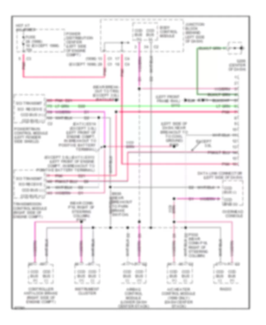
COMPUTER DATA LINES Computer Data Lines for Chrysler Town & Country LX 1997 List of elements for Computer Data Lines for Chrysler Town & Country LX 1997: 36 (1998) (1998) (except 1998) (eatx) es14 (except 3.0l) (left front of engine compt, in breakout to positive battery terminal) (except 1998) (except 3.0l) (eatx) es13 (left front of engine compt, in breakout to positive battery terminal) (left front frame rail) g113 (left side of dash, near breakout to to cowl ground) b205 (near break- out to trs) (except 3.0l) (eatx) es24 (near conn p18, right of steering column) ps01 A/c heater control module (1998 only) (dash center stack) Airbag control module (lower dash center stack) Body control module Ccd bus (+) Ccd bus (-) Conn p18, right of steering column) Controller anti-lock brake (right side of engine compt) D20 D21 Data link connector (left side of dash) Es11 Except 3.0l Fuse 10a G206 (center of dash) Hot at all times Instrument cluster Junction block (behind left side of dash) Overhead console Pnk Power distribution center (left side of engine compt) Powertrain control module (left fender side shield) Ps02 (near d2 Radio Sci receive Sci receive Sci transmit Transmission control module (right side of engine compt)
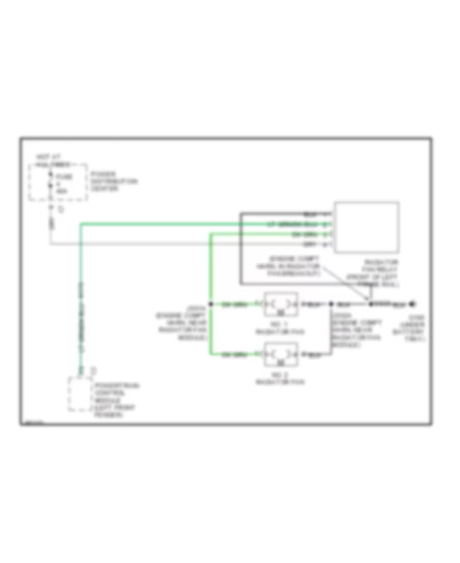
COOLING FAN Cooling Fan Wiring Diagram for Chrysler Town & Country LX 1997 List of elements for Cooling Fan Wiring Diagram for Chrysler Town & Country LX 1997: 12 (engine compt harn, in radiator fan breakout) Es23 Fuse 40a G100 (under battery tray) Hot at all times Js01a (engine compt harn, near radiator fan module) Js02a (engine compt harn, near radiator fan module) No. 1 radiator fan No. 2 radiator fan Power distribution center Powertrain control module (left front fender) Radiator fan relay (front of left frame rail)
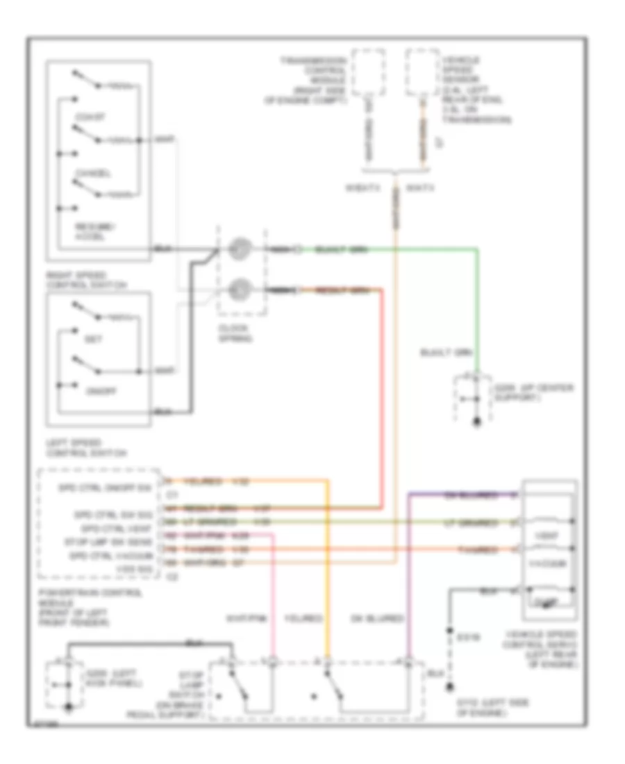
CRUISE CONTROL Cruise Control Wiring Diagram for Chrysler Town & Country LX 1997 List of elements for Cruise Control Wiring Diagram for Chrysler Town & Country LX 1997: 38 (i/p center (left (left side Cancel Clock spring Coast Dump Es18 G112 of engine) G200 kick panel) G206 support) K29 Left speed control switch Nca On/off Powertrain control module (front of left front fender) Resume/ accel Right speed control switch Set Spd ctrl on/off sw Spd ctrl sw sig Spd ctrl vacuum Spd ctrl vent Stop lamp switch (on brake pedal support) Stop lmp sw sens Tan/red Transmission control module (right side of engine compt) V32 V35 V36 V37 Vacuum Vehicle speed control servo (left rear of engine) Vehicle speed sensor (2.4l: left rear of eng, 3.0l: on transmission) Vent Vss sig W/atx W/eatx
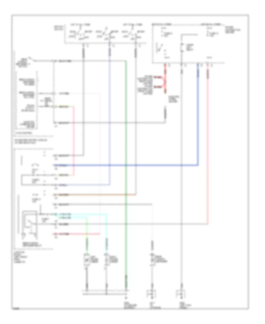
DEFOGGERS Defogger Wiring Diagram for Chrysler Town & Country LX 1997 List of elements for Defogger Wiring Diagram for Chrysler Town & Country LX 1997: 34 A/c-heater control module (i/p center stack) Acc Cigar/ acc. relay Electric wiper de-ice driver Electric wiper de-icer Fuse 12 10a Fuse 21 20a Fuse 3 20a Fuse 7 10a G200 (left kick panel) G206 (i/p center support) G411 (in liftgate) Hot at all times Hvac control Ign sw output (start/run) Ignition switch Junction block (left front dash, under i/p) Left power mirror Lock Off Power distribution (front cigar lighter) Power distribution (rear cigar lighter) Power distribution center Ptc 7 6a Rear defog on ind Rear window defogger Rear window defogger relay Rear window defogger rly ctrl Rear window defogger sw sens Rear window defogger switch Red Right power mirror Run Start
ENGINE PERFORMANCE
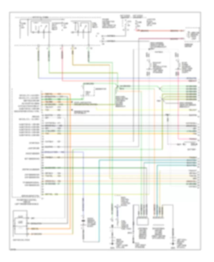
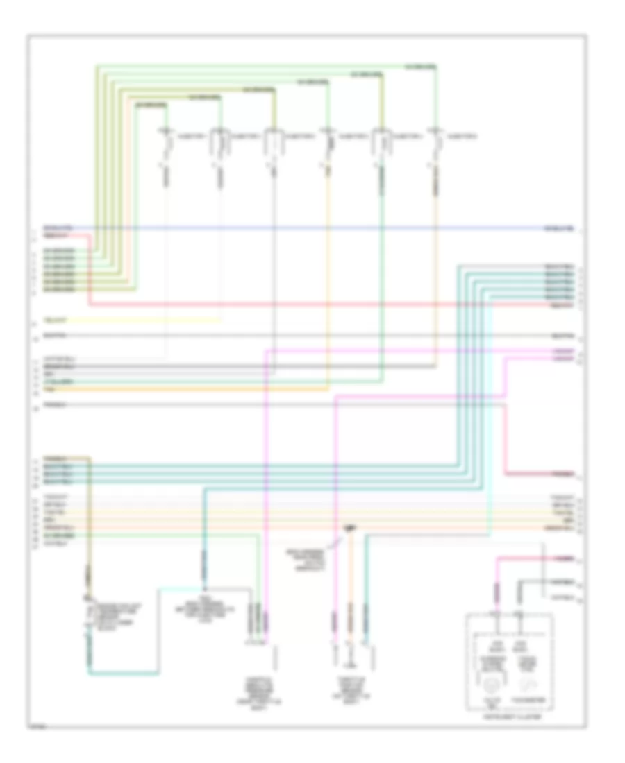
3.3L 3.3L, Engine Performance Wiring Diagrams (1 of 3) for Chrysler Town & Country LX 1997 List of elements for 3.3L, Engine Performance Wiring Diagrams (1 of 3) for Chrysler Town & Country LX 1997: 82 (eng harn, near heated upstream oxygen sensor breakout) (eng harness, near map sensor breakout) (eng harness, near starter motor breakout) es07 A142 Auto shutdown relay Automatic shut down relay Battery Body control module (junction block) c1 Ckp sensor sig Cmp sensor sig Downstream heated oxygen sensor (front center of floor pan) Ect sensor sig Egr solenoid ctrl Eng starter mtr rly ctrl Engine starter motor relay Es11 Es12 Es18 Evap/ purge solenoid (right side of engine compt) Exhaust gas recirculation solenoid (left rear of engine) F87 Field coil Fs01 Fuel pump module (side of fuel tank) Fuel pump relay Fuse 20a G110 (left front of engine) G200 G404 Gen field driver Generator Ground Hot at all times Hot in run or start Ign coil cyl 3 & 6 driv Ign coil cyl. 1 & 4 driv Ign coil cyl. 2 & 5 driv Ignition coil pack Injector no. 1 driver Injector no. 2 driver Injector no. 3 driver Injector no. 4 driver Injector no. 5 driver Injector no. 6 driver Junction block (left side of i/p) K11 K12 K13 K14 K17 K18 K19 K20 K22 K24 K35 K38 K41 K42 K44 K58 K90 Knock sensor Knock sensor (front of cylinder block) Lamp driver Left cowl ground panel (left side of cowl) Map sensor sig Message center Power distribution center (left front of engine compt) Powertrain control module (left fender side shield) Ptc 9a Rear ground block (left lower d-pillar) Sc on/off sw sens Service engine soon lamp Start/run Stop lamp switch (cruise control system) Tan Tp sensor signal Upstream heated oxygen sensor (rear of engine) Upstrm o2 sensor V32 Z12 3.3L, Engine Performance Wiring Diagrams (2 of 3) for Chrysler Town & Country LX 1997 List of elements for 3.3L, Engine Performance Wiring Diagrams (2 of 3) for Chrysler Town & Country LX 1997: 20 (eng harness, near prndl switch breakout) Ccd bus(+) Ccd bus(-) Charging system ind ctrl Engine coolant temperature sensor (on cylinder block) Es08 Fs02 (eng harness, between breakouts for injectors 4 & 6) Injector 1 Injector 2 Injector 3 Injector 4 Injector 5 Injector 6 Instrument cluster Manifold absolute pressure sensor (near throttle body) Tacho- meter ctrl Tachometer Tan Throttle position sensor (on throttle body) Volts ind 3.3L, Engine Performance Wiring Diagrams (3 of 3) for Chrysler Town & Country LX 1997 List of elements for 3.3L, Engine Performance Wiring Diagrams (3 of 3) for Chrysler Town & Country LX 1997: 112 (+) ccd bus (eng harness, in battery positive terminal breakout) (eng harness, near breakout for prndl switch) (eng harness, near knock sensor breakout) (eng harness, near prndl switch breakout) (front of transmission) (i/p harness, above accelerator pedal) A/c cmp clutch rly A/c compressor clutch relay A/c on/off sw sig A/c pressure signal A/c pressure transducer (right side cowl) A/c-heater control module A14 Auto shut down rly Body control module C103 C13 C18 Camshaft position sensor (right side of engine) Ccd bus (+) Ccd bus (-) Clockspring (cruise control system) Crankshaft position sensor (rear of engine) D20 D21 Data link connector (partial) (near park brake) Dnstream o2 sensor Es02 Es03 (eng harness, near body ground breakout) Es05 Es10 Es13 Es14 Es17 (eng harness, in battery positve terminal breakout) Es21 (eng harness, near breakout for a/c comp clutch) Es24 Evap leak detect ctrl Evap leak detect sense Evap leak detection pump (left rear of cross member) Evap sol ctrl Fuel pmp rly ctrl Fused b (+) Gnd Gnd spd sens Ground Iac motor drivers Iac motor no. 1 driver Iac motor no. 2 driver Iac motor no. 3 driver Iac motor no. 4 driver Idle air control motor (on throttle body) Ign sw (run/ start) Input speed Junction block (left side of i/p) K106 K107 K141 K173 K22 K24 K29 K31 K39 K40 K51 K52 K59 K60 Output shaft speed sensor (front of transmission) Output speed P22 Pnk Powertrain control module (left fender side shield) Ps01 Ps02 Rad fan rly ctrl Radiator fan relay Sc sw signal Sc vacuum sol ctrl Sc vent sol ctrl Sci receive Sci transmit Sensor gnd Sensor ground Sensor signal Signal ckp Signal sensor Signal tps Sol ctrl Speed input Stop lamp sw sense Stop lamp switch (cruise control system) Stroke sense T10 T13 T14 T41 T52 Tan/red Torq req sense Torque req sense Transmission control module (right fender shield) Transmission range sensor (on trans- mission) Trs c1 sense Turbine speed sensor V35 V36 V37 Vehicle speed control servo Vss signal Z12
3.8L 3.8L, Engine Performance Wiring Diagrams (1 of 3) for Chrysler Town & Country LX 1997 List of elements for 3.8L, Engine Performance Wiring Diagrams (1 of 3) for Chrysler Town & Country LX 1997: 82 (eng harn, near heated upstream oxygen sensor breakout) (eng harness, near map sensor breakout) (eng harness, near starter motor breakout) es07 A142 Auto shutdown relay Automatic shut down relay Battery Body control module (junction block) c1 Ckp sensor sig Cmp sensor sig Downstream heated oxygen sensor (front center of floor pan) Ect sensor sig Egr solenoid ctrl Eng starter mtr rly ctrl Engine starter motor relay Es11 Es12 Es18 Evap/ purge solenoid (right side of engine compt) Exhaust gas recirculation solenoid (left rear of engine) F87 Field coil Fs01 Fuel pump module (side of fuel tank) Fuel pump relay Fuse 20a G110 (left front of engine) G200 G404 Gen field driver Generator Ground Hot at all times Hot in run or start Ign coil cyl 3 & 6 driv Ign coil cyl. 1 & 4 driv Ign coil cyl. 2 & 5 driv Ignition coil pack Injector no. 1 driver Injector no. 2 driver Injector no. 3 driver Injector no. 4 driver Injector no. 5 driver Injector no. 6 driver Junction block (left side of i/p) K11 K12 K13 K14 K17 K18 K19 K20 K22 K24 K35 K38 K41 K42 K44 K58 K90 Knock sensor Knock sensor (front of cylinder block) Lamp driver Left cowl ground panel (left side of cowl) Map sensor sig Message center Power distribution center (left front of engine compt) Powertrain control module (left fender side shield) Ptc 9a Rear ground block (left lower d-pillar) Sc on/off sw sens Service engine soon lamp Start/run Stop lamp switch (cruise control system) Tan Tp sensor signal Upstream heated oxygen sensor (rear of engine) Upstrm o2 sensor V32 Z12 3.8L, Engine Performance Wiring Diagrams (2 of 3) for Chrysler Town & Country LX 1997 List of elements for 3.8L, Engine Performance Wiring Diagrams (2 of 3) for Chrysler Town & Country LX 1997: 20 (eng harness, near prndl switch breakout) Ccd bus(+) Ccd bus(-) Charging system ind ctrl Engine coolant temperature sensor (on cylinder block) Es08 Fs02 (eng harness, between breakouts for injectors 4 & 6) Injector 1 Injector 2 Injector 3 Injector 4 Injector 5 Injector 6 Instrument cluster Manifold absolute pressure sensor (near throttle body) Tacho- meter ctrl Tachometer Tan Throttle position sensor (on throttle body) Volts ind 3.8L, Engine Performance Wiring Diagrams (3 of 3) for Chrysler Town & Country LX 1997 List of elements for 3.8L, Engine Performance Wiring Diagrams (3 of 3) for Chrysler Town & Country LX 1997: 112 (+) ccd bus (eng harness, in battery positive terminal breakout) (eng harness, near breakout for prndl switch) (eng harness, near knock sensor breakout) (eng harness, near prndl switch breakout) (front of transmission) (i/p harness, above accelerator pedal) A/c cmp clutch rly A/c compressor clutch relay A/c on/off sw sig A/c pressure signal A/c pressure transducer (right side cowl) A/c-heater control module A14 Auto shut down rly Body control module C103 C13 C18 Camshaft position sensor (right side of engine) Ccd bus (+) Ccd bus (-) Clockspring (cruise control system) Crankshaft position sensor (rear of engine) D20 D21 Data link connector (partial) (near park brake) Dnstream o2 sensor Es02 Es03 (eng harness, near body ground breakout) Es05 Es10 Es13 Es14 Es17 (eng harness, in battery positve terminal breakout) Es21 (eng harness, near breakout for a/c comp clutch) Es24 Evap leak detect ctrl Evap leak detect sense Evap leak detection pump (left rear of cross member) Evap sol ctrl Fuel pmp rly ctrl Fused b (+) Gnd Gnd spd sens Ground Iac motor drivers Iac motor no. 1 driver Iac motor no. 2 driver Iac motor no. 3 driver Iac motor no. 4 driver Idle air control motor (on throttle body) Ign sw (run/ start) Input speed Junction block (left side of i/p) K106 K107 K141 K173 K22 K24 K29 K31 K39 K40 K51 K52 K59 K60 Output shaft speed sensor (front of transmission) Output speed P22 Pnk Powertrain control module (left fender side shield) Ps01 Ps02 Rad fan rly ctrl Radiator fan relay Sc sw signal Sc vacuum sol ctrl Sc vent sol ctrl Sci receive Sci transmit Sensor gnd Sensor ground Sensor signal Signal ckp Signal sensor Signal tps Sol ctrl Speed input Stop lamp sw sense Stop lamp switch (cruise control system) Stroke sense T10 T13 T14 T41 T52 Tan/red Torq req sense Torque req sense Transmission control module (right fender shield) Transmission range sensor (on trans- mission) Trs c1 sense Turbine speed sensor V35 V36 V37 Vehicle speed control servo Vss signal Z12
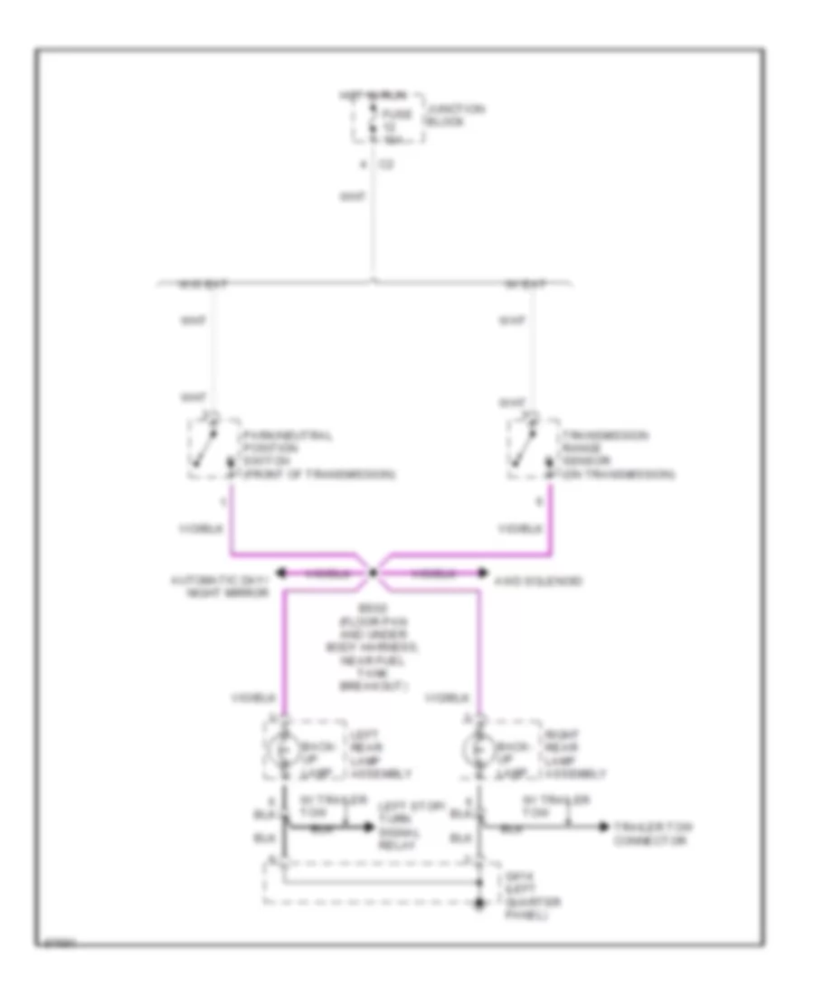
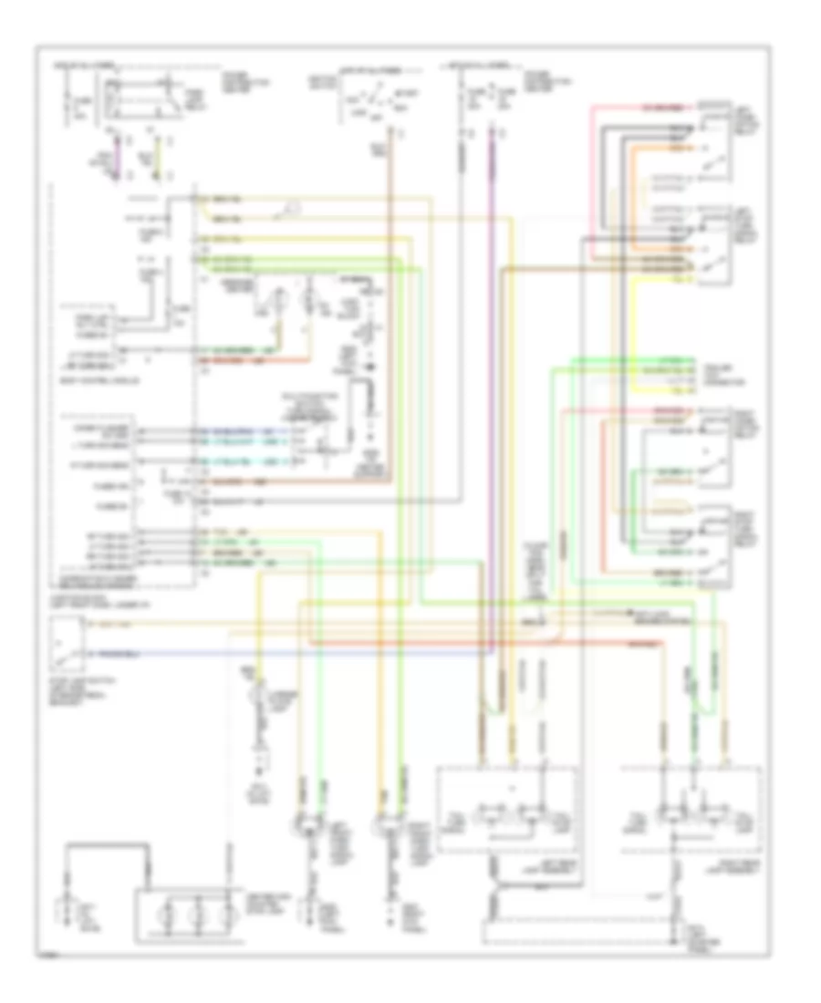
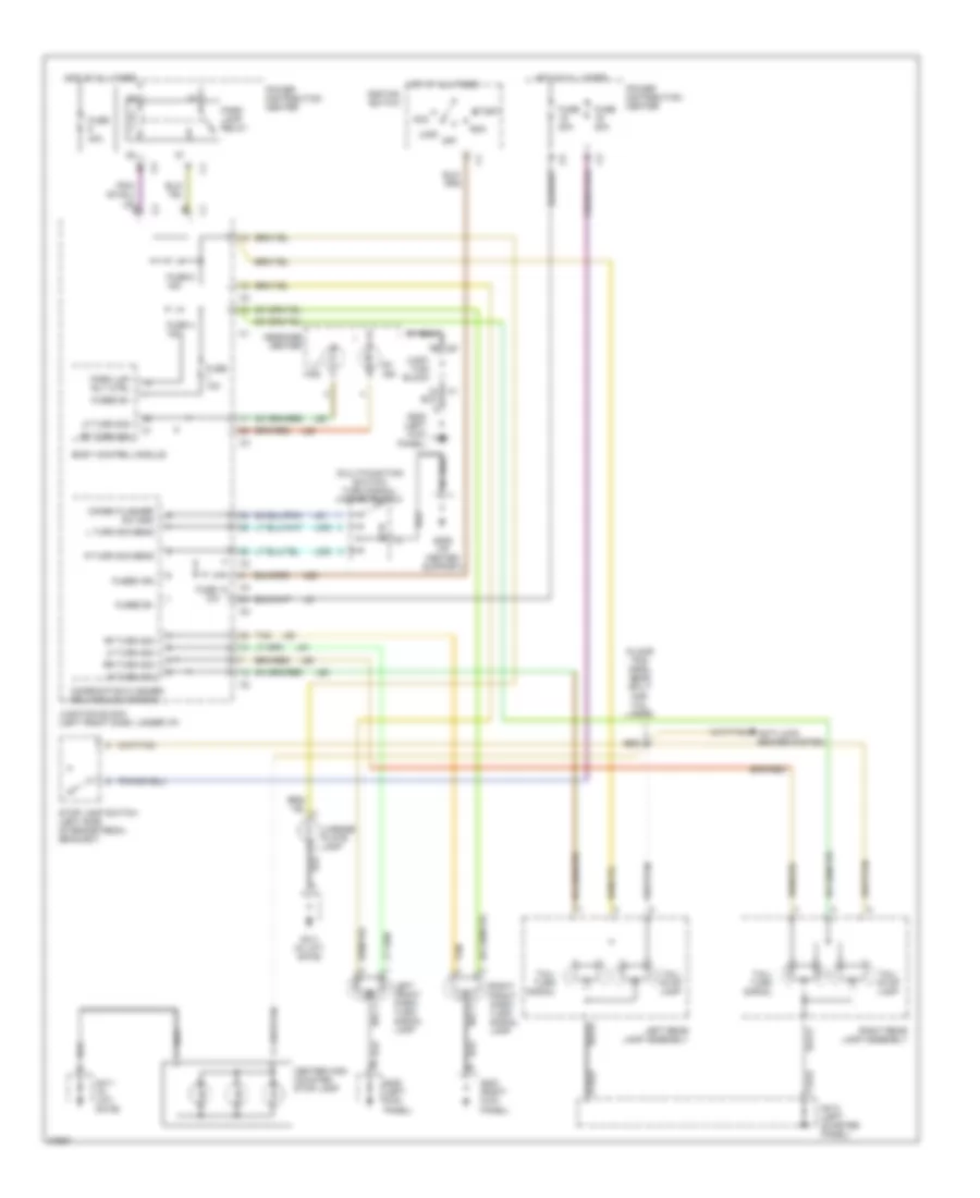
EXTERIOR LIGHTS Back-up Lamps Wiring Diagram for Chrysler Town & Country LX 1997 List of elements for Back-up Lamps Wiring Diagram for Chrysler Town & Country LX 1997: 17 Automatic day/ night mirror Awd solenoid Back- up lamp Bs02 (floor pan and under body harness, near fuel tank breakout) Fuse 10a G414 (left quarter panel) Hot in run Junction block Left rear lamp assembly Left stop/ turn signal relay Park/neutral position switch (front of transmission) Right rear lamp assembly Trailer tow connector Transmission range sensor (on transmission) W/ eat W/ trailer tow W/o eat Exterior Lamps Wiring Diagram, with Trailer Tow for Chrysler Town & Country LX 1997 List of elements for Exterior Lamps Wiring Diagram, with Trailer Tow for Chrysler Town & Country LX 1997: 65 (floor pan harn, near split for tail lamps) (multi-function switch) turn signal/ hazard switch A22 Acc Anti-lock brakes system Body control module Bs01 Center high mounted stop lamp Combination flasher/ drl module (canada) Combo flasher sw gnd Fuse 10a Fuse 12 10a Fuse 20a Fuse 4 15a Fuse 40a Fuse 6 15a Fused b+ Fused ign G200 (left kick panel) G203 (right kick panel) G206 (i/p center support) G411 (in lift- gate) G414 (left quarter panel) Hot at all times Ignition switch Junc- tion block Junction block (left front dash, under i/p) L turn sig sens L302 L305 L60 L61 L62 L63 L91 L97 Left combi- nation relay Left front park/ turn signal lamp Left rear lamp assembly Left stop turn signal relay Lf turn sig License plate lamp Lock Lr turn sig Lt ind Message center Off Park lamp relay Park lmp rly ctrl Power distribution center R turn sig sens Rf turn sig Right combi- nation relay Right front park/ turn signal lamp Right rear lamp assembly Right stop turn signal relay Rr turn sig Rt ind Run Start Stop lamp switch (left side of brake pedal bracket) Tail/ stop lamp Tail/ turn signal Tan Trailer tow connector Exterior Lamps Wiring Diagram, without Trailer Tow for Chrysler Town & Country LX 1997 List of elements for Exterior Lamps Wiring Diagram, without Trailer Tow for Chrysler Town & Country LX 1997: 60 (floor pan harn, near split for tail lamps) (multi-function switch) turn signal/ hazard switch A22 Acc Anti-lock brakes system Body control module Bs01 Center high mounted stop lamp Combination flasher/ drl module (canada) Combo flasher sw gnd Fuse 10a Fuse 12 10a Fuse 20a Fuse 4 15a Fuse 40a Fuse 6 15a Fused b+ Fused ign G200 (left kick panel) G203 (right kick panel) G206 (i/p center support) G411 (in lift- gate) G414 (left quarter panel) Hot at all times Ignition switch Junc- tion block Junction block (left front dash, under i/p) L turn sig sens L302 L305 L60 L61 L62 L63 L91 L97 Left front park/ turn signal lamp Left rear lamp assembly Lf turn sig License plate lamp Lock Lr turn sig Lt ind Message center Off Park lamp relay Park lmp rly ctrl Power distribution center R turn sig sens Rf turn sig Right front park/ turn signal lamp Right rear lamp assembly Rr turn sig Rt ind Run Start Stop lamp switch (left side of brake pedal bracket) Tail/ stop lamp Tail/ turn signal Tan
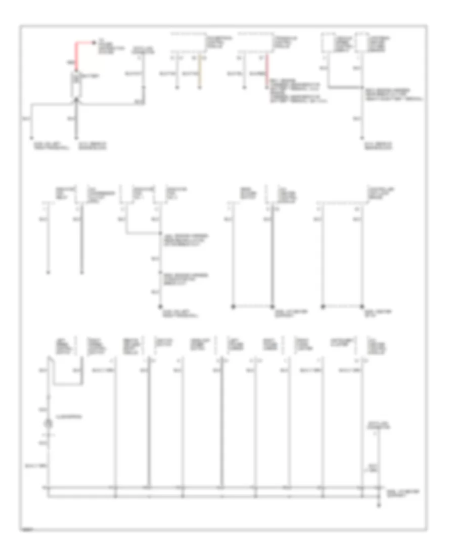
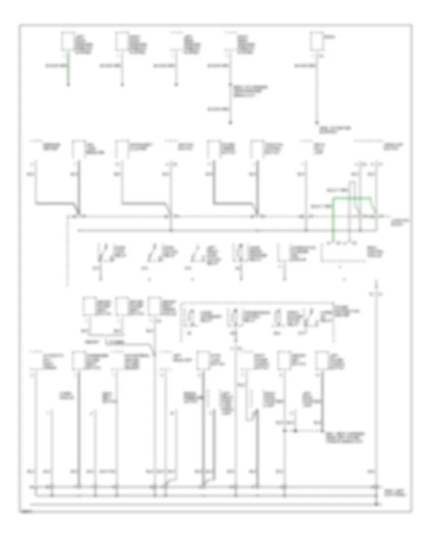
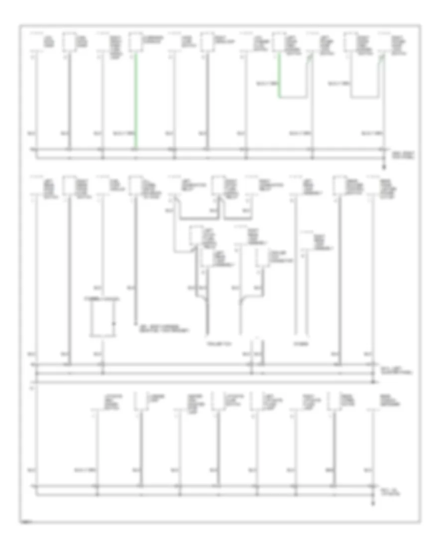
GROUND DISTRIBUTION Ground Distribution Wiring Diagram (1 of 3) for Chrysler Town & Country LX 1997 List of elements for Ground Distribution Wiring Diagram (1 of 3) for Chrysler Town & Country LX 1997: 40 (2.4l) (center (engine (engine harness, (ex. 2.4l)) (i/p center (on left (rear of A/c compressor clutch (pdc) A/c heater control module Battery Clockspring Controller anti-lock brake Data link connector Es23 in radiator fan break out) Front cigar lighter G106 front frame rail) G112 engine block) G206 of i/p) G206 support) Headlamp dimmer switch Ignition switch Instrument cluster Js02 near recirculation motor break out) Left power mirror Left speed control switch Nca Powertrain control module Radiator fan no. 1 Radiator fan no. 2 Radiator fan relay Rear blower switch Red Remote keyless entry module Right power mirror Right speed control switch To power distribution system Transaxle control module Upstream heated oxygen sensor Vehicle speed control servo Ground Distribution Wiring Diagram (2 of 3) for Chrysler Town & Country LX 1997 List of elements for Ground Distribution Wiring Diagram (2 of 3) for Chrysler Town & Country LX 1997: 53 (body harness, (i/p center (i/p harness, (left 87a Ash lamp receiver Automatic day/ night mirror Body control module Brake pressure switch Bs08 near speaker break out) Cigar/ accessory relay Combination flasher/ drl module Door lock relay Door unlock relay Downstream heated oxygen sensor Driver power seat switch Ds01 near left power window break out) Front blower motor relay G200 kick panel) G206 support) Headlamp switch Ignition switch Instrument cluster Junction block Key-in halo lamp Left door courtesy lamp Left door speaker (premium system) Left front door unlock relay Left front park/ turn signal lamp Left headlamp Left power window switch Left rear speaker (premium system) Memory Memory power seat switch Memory seat/ mirror module Memory set switch Message center Name brand speaker relay Others Passenger power seat switch Power distribution center Power mirror switch Radio Right door courtesy lamp Right door speaker (premium system) Right power window switch Right rear speaker (premium system) Seat belt switch Stop lamp switch Traction control switch Transmission control relay Wiper module Wiper on relay Ground Distribution Wiring Diagram (3 of 3) for Chrysler Town & Country LX 1997 List of elements for Ground Distribution Wiring Diagram (3 of 3) for Chrysler Town & Country LX 1997: 43 (body harness, (in (left (right 3.3l/3.8l All wheel drive solenoid (w/ awd) Center high mounted stop lamp Fuel pump module G203 kick panel) G411 liftgate) G414 quarter panel) High note horn Hood ajar switch Js01 near fuel tank grommet) Left combination relay Left door arm/ disarm switch Left liftgate flood lamp Left power door lock switch Left rear door ajar switch Left rear lamp assembly Left stop/ turn signal relay License lamp Liftgate ajar switch Liftgate arm/ disarm switch Low note horn Low washer fluid switch Others Overhead console Rear blower control switch Rear cigar lighter/ power outlet Rear window defogger Rear wiper motor Right combination relay Right door arm/ disarm switch Right front park/ turn signal lamp Right headlamp Right liftgate flood lamp Right power door lock switch Right rear door ajar switch Right rear lamp assembly Right stop/ turn signal relay Trailer tow Trailer tow connector
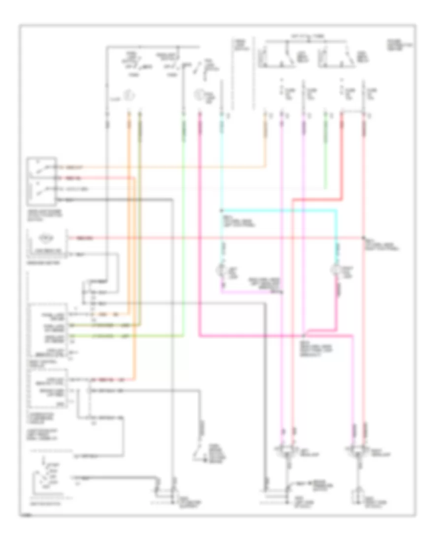
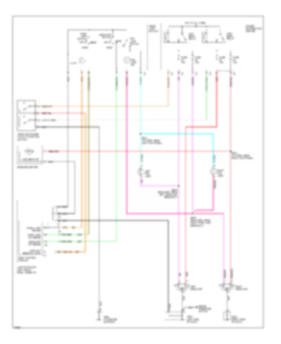
HEADLIGHTS Headlamps/Fog Lamps Wiring Diagram, with DRL for Chrysler Town & Country LX 1997 List of elements for Headlamps/Fog Lamps Wiring Diagram, with DRL for Chrysler Town & Country LX 1997: 49 (eng harn, near left headlamp breakout) bs15 Acc Body control module Brake pressure switch Brake warn lmp (red) Bs14 (i/p harn, near left kick panel) Bs14 (i/p harn, near right kick panel) Bs16 (eng harn, near right park lamp breakout) Combination flasher/drl module Fog lamp ind Fog lamp switch Fuse 10a Fuse 15a G200 (left side of cowl) G203 (right side of cowl) G205 (i/p center support) Gnd Head Head- lamp switch Headlamp dimmer (in multi-function switch) Headlamp sw sense Headlamp switch High beam ind High beam relay High/low beam rly ctrl Hot at all times Ignition switch Illum Junction block (left front dash, under i/p) L307 L308 L93 Left fog lamp Left headlamp Lock Low beam relay Message center Off Panel lmps driver Park Park brake switch (on park brake) Park lamp switch Park lmps sw sense Power distribution center Red Right fog lamp Right headlamp Run Start Headlamps/Fog Lamps Wiring Diagram, without DRL for Chrysler Town & Country LX 1997 List of elements for Headlamps/Fog Lamps Wiring Diagram, without DRL for Chrysler Town & Country LX 1997: 40 Body control module Brake pressure switch Bs14 (i/p harn, near left kick panel) Bs14 (i/p harn, near right kick panel) Bs15 (eng harn, near left headlamp breakout) Bs16 (eng harn, near right park lamp breakout) Fog lamp ind Fog lamp switch Fuse 10a Fuse 15a G200 (left side of cowl) G203 (right side of cowl) G205 (i/p center support) Head Head- lamp switch Headlamp dimmer (in multi-function switch) Headlamp sw sense Headlamp switch High beam ind High beam relay High/low beam rly ctrl Hot at all times Illum Junction block (left front dash, under i/p) L307 L308 L93 Left fog lamp Left headlamp Low beam relay Message center Off Panel lmps driver Park Park lamp switch Park lmps sw sense Power distribution center Red Right fog lamp Right headlamp
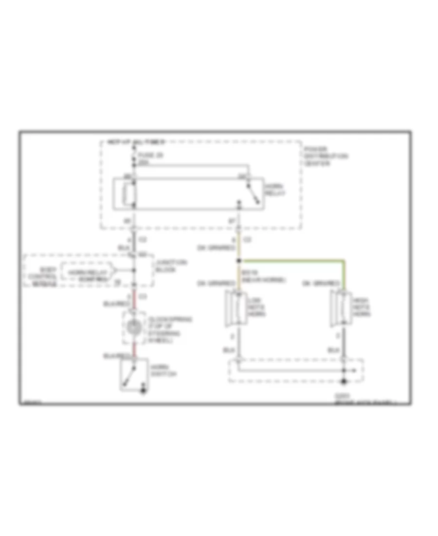
HORN Horn Wiring Diagram for Chrysler Town & Country LX 1997 List of elements for Horn Wiring Diagram for Chrysler Town & Country LX 1997: 12 Body control module Clockspring (top of steering wheel) Fuse 20 20a G203 (right kick panel) High note horn Horn relay Horn relay control Horn switch Hot at all times Junction block Low note horn Power distribution center
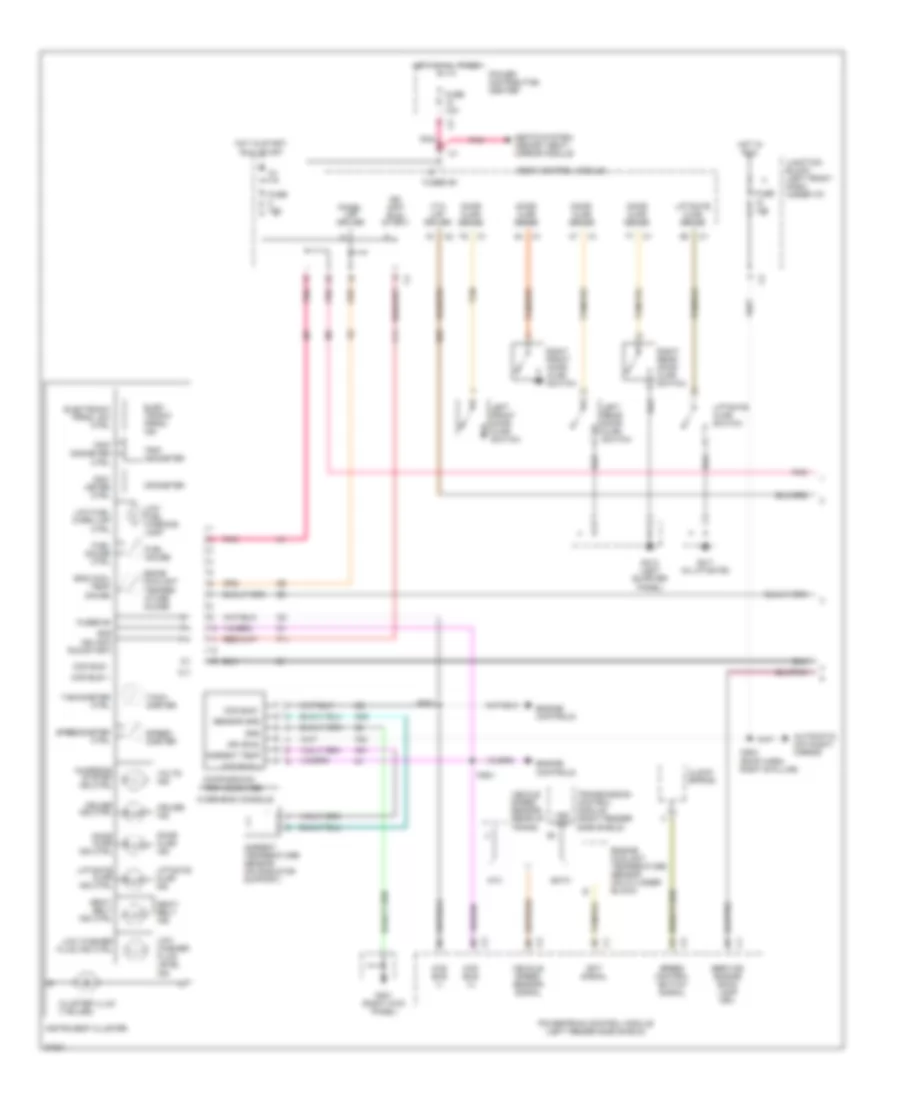
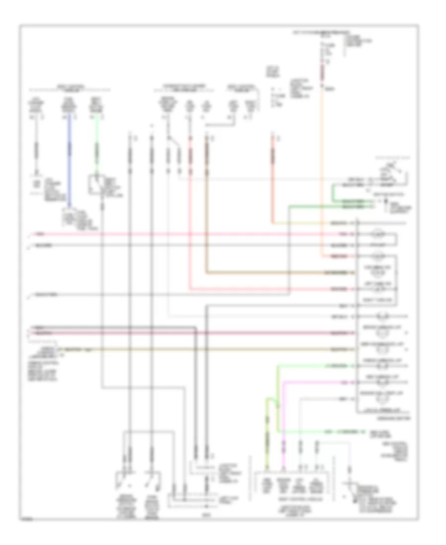
INSTRUMENT CLUSTER Instrument Cluster Wiring Diagram (1 of 2) for Chrysler Town & Country LX 1997 List of elements for Instrument Cluster Wiring Diagram (1 of 2) for Chrysler Town & Country LX 1997: 89 Ambient temp Ambient temperature sensor (on radiator support) Atx Automatic day/night mirror Body control module Ccd bus (+) Ccd bus (-) Ccd bus + Ccd bus - Charging system ind ctrl Clock- spring Cluster illum (7 bulbs) Compass/mini- trip computer Cruise ind Cruise ind ctrl Cs04 (roof harn, right b pillar) Door ajar ind Door ajar ind ctrl Door ajar sense Eatx Ect signal Egine coolant temper- ature guage Elec- tronic prndl ind Electronic prndl sw ctrl Eng cool temp gauge Engine controls Engine coolant temperature sensor (on cylinder block) F11 F20 Fuel gauge Fuel gauge ctrl Fuse 10a Fused b+ G301 (right kick panel) G31 G32 G411 (in liftgate) G414 (left quarter panel) G69 Gnd Hot at all times Hot in run Hot in start, run or off Ign (off/ run/ start) Ign (off/ run/start) Ign (run) Instrument cluster Junction block (left front dash, under i/p) Left front door ajar switch Left rear door ajar switch Liftgate ajar ind Liftgate ajar ind ctrl Liftgate ajar sense Liftgate ajar switch Low fuel warn lmp ctrl Low fuel warning lamp Low washer fluid ind ctrl Low washer fluid level ind Odo- meter ctrl Odometer Overhead console Panel lmp driver Pnk Power distribution center Powertrain control module (left fender side shield) Ps01 Ps02 Right front door ajar switch Right rear door ajar switch Seat- belt ind Seat- belt ind ctrl Seats system, memory seat/ mirror module Sensor gnd Service engine soon lamp drv Speed control switch signal Speed- ometer Speedometer ctrl Tach- ometer Tachometer ctrl Tan Tan/red Transmission control module (right fender side shield) Trip odometer Trip odometer ctrl Vehcle speed sensor (rear of trans) Vehicle speed sensor signal Volts ind Vss sig Vta lmp driver Instrument Cluster Wiring Diagram (2 of 2) for Chrysler Town & Country LX 1997 List of elements for Instrument Cluster Wiring Diagram (2 of 2) for Chrysler Town & Country LX 1997: 58 (left kick panel) Abs control module (above accelerator pedal) Abs warn lamp drv Abs warn lmp driver Abs warning lmp Acc Airbag control module (behind lower portion of i/p, center stack) Airbag warning lamp driver Airbag warning lmp Body control module Brake pressure switch (on brake master cylinder) Brake warn lmp driver (red) Brake warning lmp Bs09 Combination flasher/ drl module Engine cool temp drv Engine cool temp lmp Engine oil pressure switch (2.4l: rear of eng, 3.0l: near starter, 3.3l & 3.8l: below a/c compressor) Fuel level sensor signal Fuel level sig Fuel pump module (side of fuel tank) Fuse 10a Fuse 20a G19 G200 G206 (i/p center support) High beam ind Hot in start or run Hot with high beam relay on Ignition switch Junction block (left front dash, under i/p) L62 L63 Left turn ind Left turn sig Lock Low oil press lmp Low oil press lmp drv Low washer fluid signal Low washer fluid switch (bottom of reservoir) Lr turn sig Message center Off Oil press switch sense Park brake switch (top of park brake) Pnk Power distribution center R41 Right turn ind Right turn sig Rr turn sig Run Seat belt switch (left b pillar) Seat belt switch sense Service eng soon lmp Start Vss sig Vta lmp
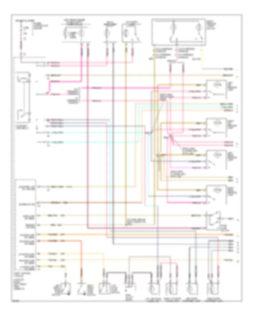
INTERIOR LIGHTS Interior Light Wiring Diagram (1 of 2) for Chrysler Town & Country LX 1997 List of elements for Interior Light Wiring Diagram (1 of 2) for Chrysler Town & Country LX 1997: 57 (i/p harn, behind right side of i/p) bs10 (left rear corner of eng compt) wiper module (roof harn, above right door) (roof harn, in upper left "b" pillar) (w/ overhead (w/ overhead console) (w/o overhead console) 15a Body control module Console) Courtesy lamp relay Courtesy lmp rly driver Cs01 Cs02 Cs03 Dimmer sw sig E92 Front reading lamps/ switch Fuse G406 (in lift- gate) G70 G74 G75 G76 G77 G78 Glove box lamp Hood ajar sw sens Hood ajar switch Hot at all times Junction block (left front dash, under i/p) Key-in halo lamp Left door courtesy lamp Left front door ajar switch Left mid reading lamp Left rear reading lamp Lf door ajar sw sens Lift leftgate flood lamp Lift- gate ajar switch Liftgate ajar sw sens Lr door ajar sw sens M112 M20 Power distribution center Reading lmp gnd Rf door ajar sw sens Right door courtesy lamp Right front door ajar switch Right liftgate flood lamp Right mid reading lamp Right rear reading lamp Rr door ajar sw sens Tan Tan/red Under- hood lamps W/ overhead console W/o overhead console Interior Light Wiring Diagram (2 of 2) for Chrysler Town & Country LX 1997 List of elements for Interior Light Wiring Diagram (2 of 2) for Chrysler Town & Country LX 1997: 38 (4 leds) (i/p center support) (left quarter panel) (not used) (right kick panel) A/c-heater control module Ash receiver lamp Body control module Cluster illum (7 bulbs) Dim input c1 Ds01 G200 (left kick panel) G203 G203 (right kick panel) G206 G414 Headlamp switch Instrument cluster Interior lamps on switch Junction block (left front dash, under i/p) Left power door lock switch Left power window switch Left rear door ajar switch Left visor/ vanity mirror lamp Lights on switch Panel lamps Panel lamps driver Power mirror switch Radio Reading defeat switch Rear blower front control switch Rear blower rear control switch Right power door lock switch Right power window switch Right rear door ajar switch Right visor/ vanity mirror lamp Step dim switch signal Traction control switch
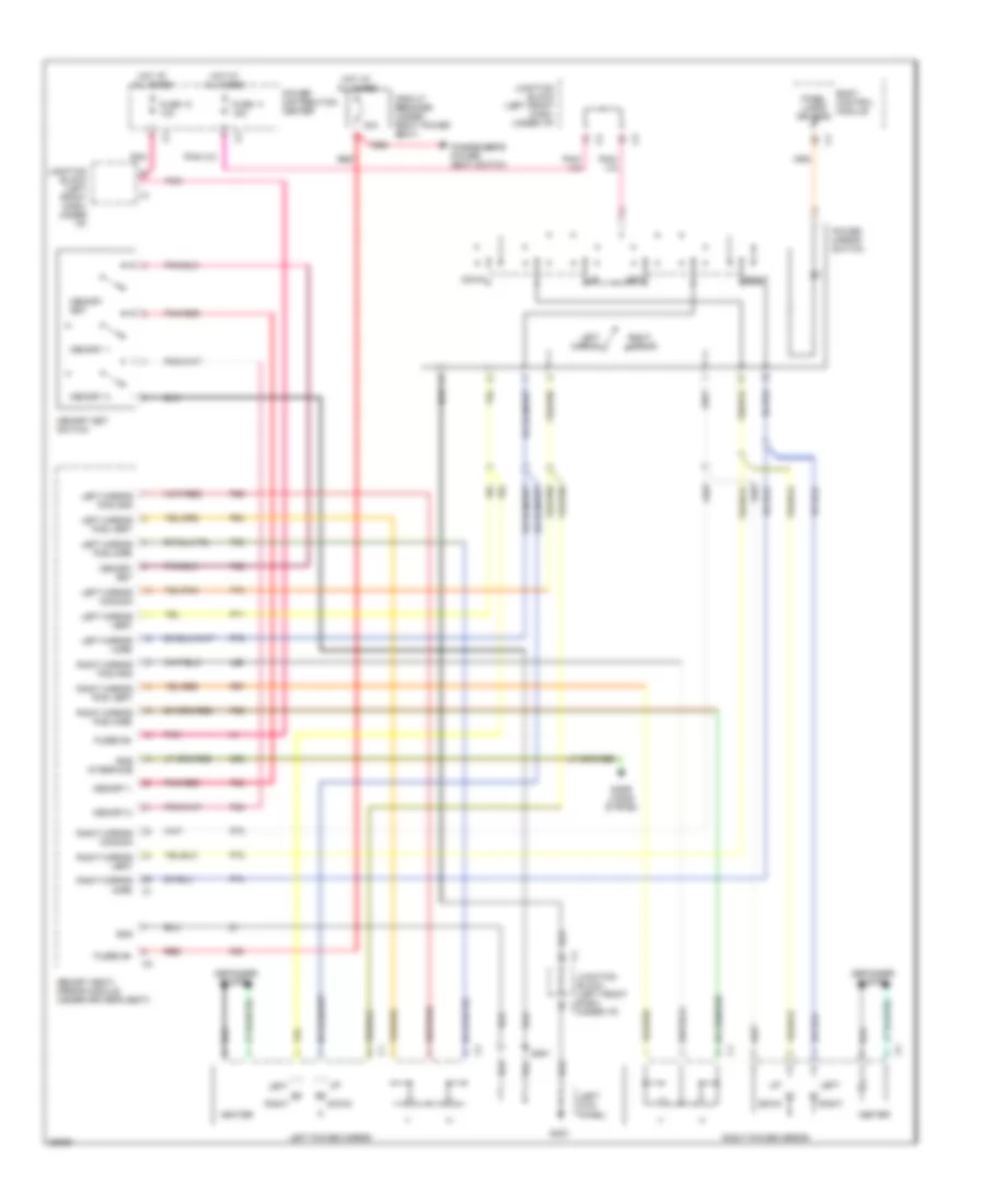
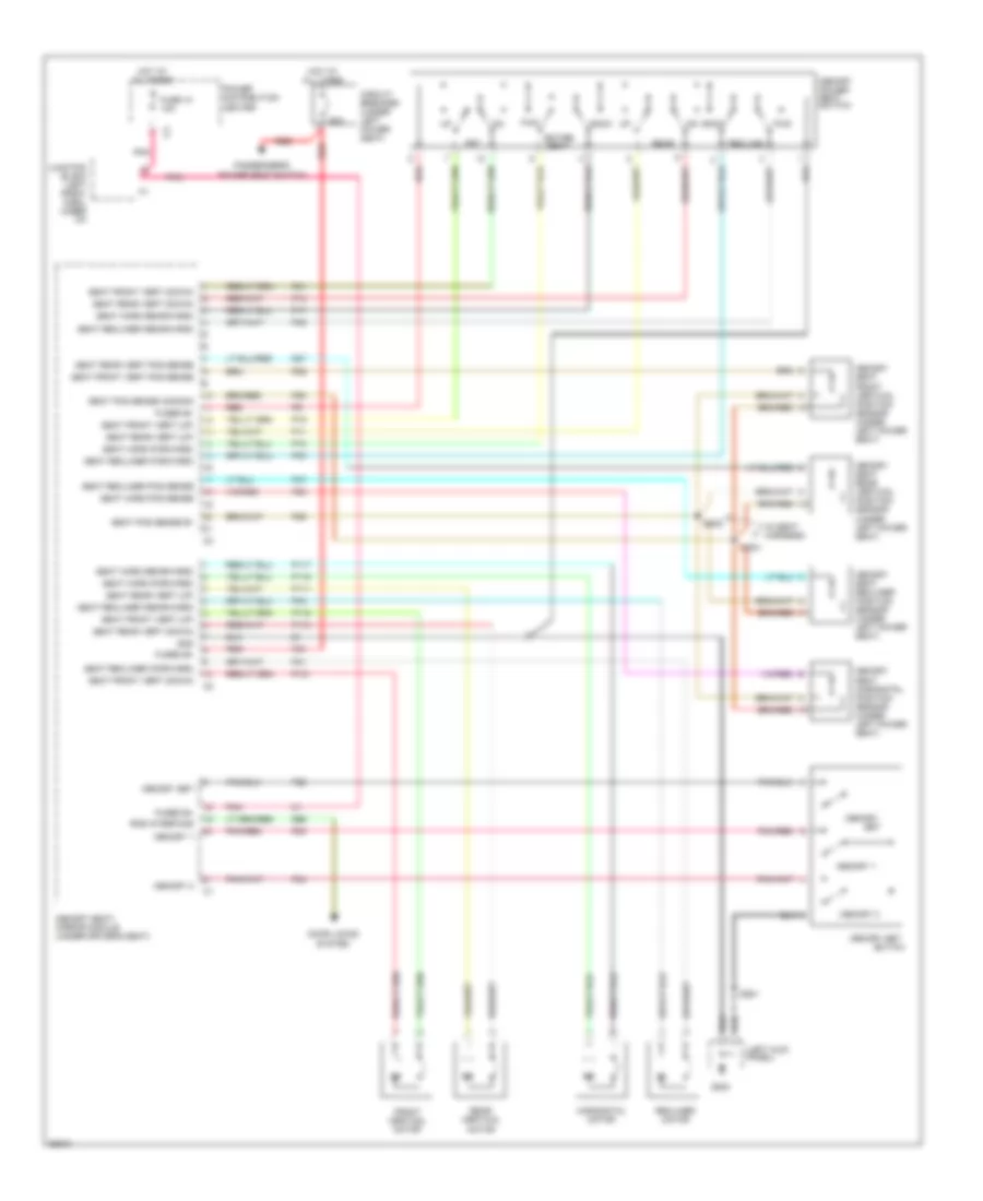
MEMORY SYSTEMS Memory Mirrors Wiring Diagram for Chrysler Town & Country LX 1997 List of elements for Memory Mirrors Wiring Diagram for Chrysler Town & Country LX 1997: 66 (left kick panel) 30a Body control module Circuit breaker (under right power seat) Defogger system Door locks system Down Ds01 F35 Fuse 10 10a Fuse 11 15a Fused b+ G200 G96 Gnd Heater Hot at all times Junction block (left front dash, c1 Junction block (left front dash, under i/p) L66 Left Left mirror Left mirror common Left mirror horz Left mirror pos gnd Left mirror pos horz Left mirror pos vert Left mirror vert Left power mirror Memory 1 Memory 2 Memory seat/ mirror module (under driver's seat) Memory set Memory set switch P22 P23 P24 P64 P65 P67 P68 P69 P70 P71 P72 P73 P74 P75 Panel lamps drivers Passenger's power seat switch Pnk Pnk/red Power distribution center Power mirror switch Red Right Right mirror Right mirror common Right mirror horz Right mirror pos gnd Right mirror pos horz Right mirror pos vert Right mirror vert Right power mirror Rke interface Under i/p) Memory Seat Wiring Diagram for Chrysler Town & Country LX 1997 List of elements for Memory Seat Wiring Diagram for Chrysler Town & Country LX 1997: 83 (in seat harness) (left kick panel) 30a Back Circuit breaker (under left power seat) D27 Door locks system Ds01 Entire seat F35 Front vertical motor Frt Fuse 10 10a Fused b+ Fwd G200 G96 Gnd Horizontal motor Hot at all times Junction block (left front dash, under i/p) Memory Memory 1 Memory 2 Memory power seat switch Memory seat front vertical position sensor (under left power seat) Memory seat horizontal position sensor (under left power seat) Memory seat rear vertical position sensor (under left power seat) Memory seat recliner position sensor (under left power seat) Memory seat/ mirror module (under driver's seat) Memory set P11 P111 P113 P115 P117 P119 P121 P13 P15 P17 P19 P21 P22 P23 P24 P25 P26 P28 P29 P40 P41 P43 P47 P48 Passenger's power seat switch Pnk Pnk/red Power distribution center Rear Rear vertical motor Recline Recliner motor Red Rke interface Seat front vert (down) Seat front vert (up) Seat front vert pos sense Seat horz (forward) Seat horz (rearward) Seat horz pos sense Seat pos sense b+ Seat pos sense common Seat rear vert (down) Seat rear vert (up) Seat rear vert pos sense Seat recliner (forward) Seat recliner (rearward) Seat recliner pos sense Set Ss01 Ss02 Switch
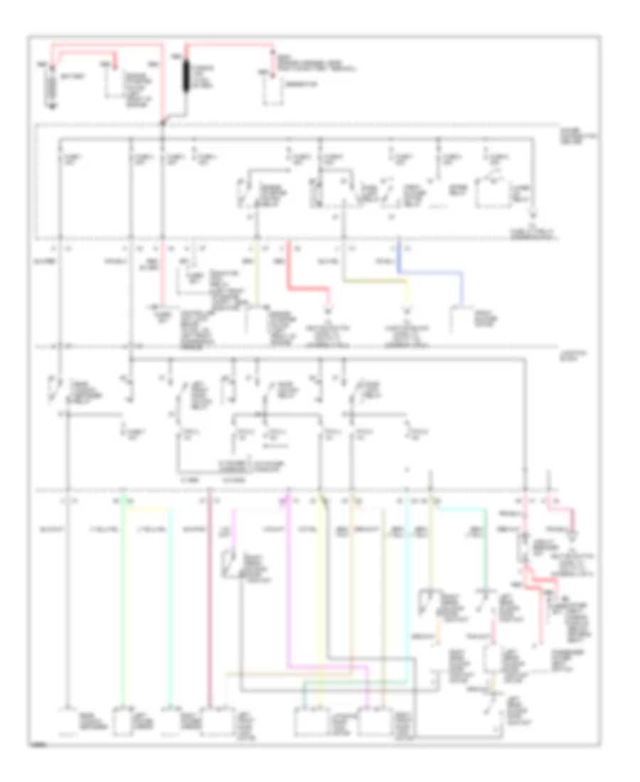
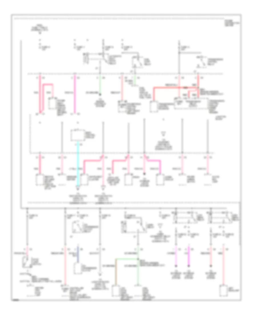
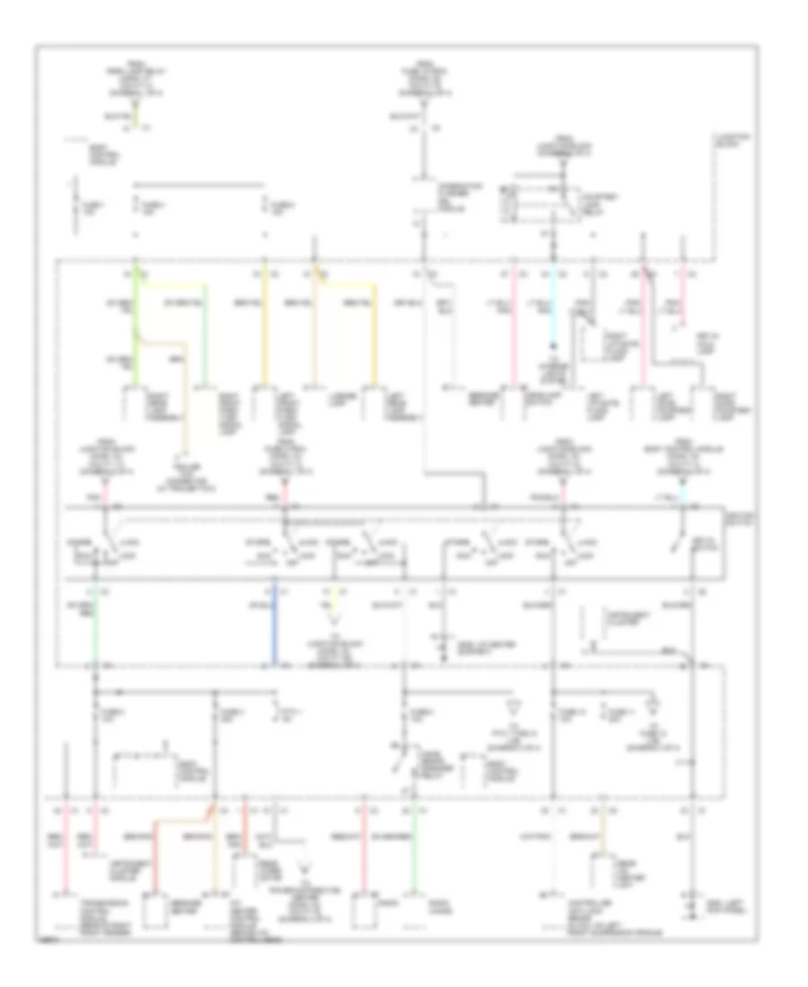
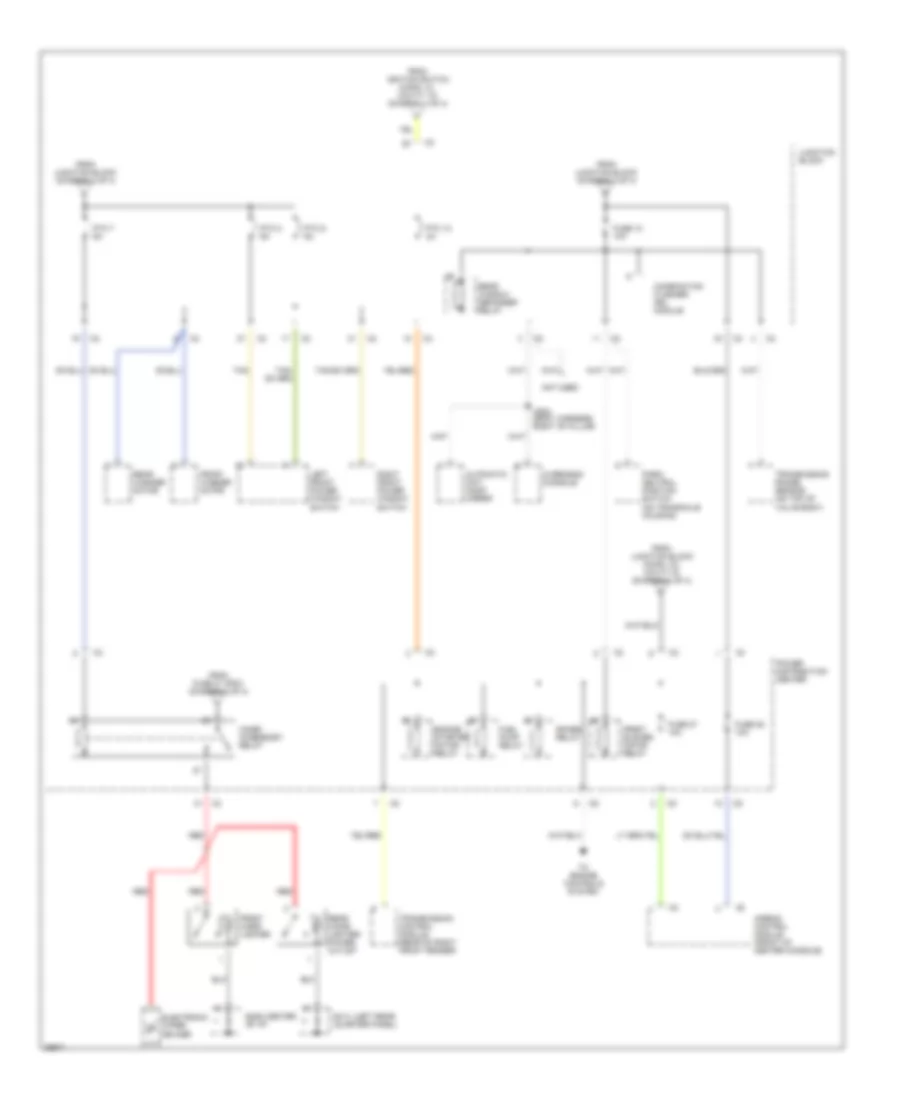
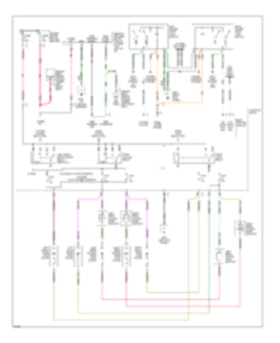
POWER DISTRIBUTION Power Distribution Wiring Diagram (1 of 4) for Chrysler Town & Country LX 1997 List of elements for Power Distribution Wiring Diagram (1 of 4) for Chrysler Town & Country LX 1997: 56 Battery Circuit breaker 30a Controller anti-lock brake (in hcu, on left front suspension cradle) Door lock relay Door unlock relay Engine starter motor (left front of engine) Engine starter motor relay Es09 (engine harness, near positive battery terminal) Front blower motor Front blower motor relay Fuse 1 40a Fuse 2 40a Fuse 3 40a Fuse 4 40a Fuse 5 40a Fuse 6 40a Fuse 7 10a Fuse 7 40a Fuse 8 40a Fuse 9 30a Fused b(+) Generator Junction block Left front door lock motor Left front door unlock relay Left power mirror Left rear sliding door contact Left rear sliding door contact motor Liftgate door lock motor Park lamp relay Passenger power seat switch Power distribution center Power seat/ mirror module (below driver's seat) Ptc 2 3a Ptc 3 4a Ptc 4 6a Ptc 5 4a Ptc 6 6a Radiator fan relay (left front of engine compt., near radiator) Rear window defogger Rear window defogger relay Red Right front door lock motor Right power mirror Right rear sliding door contact Right rear sliding door contact motor Spare relay To fuse 10 thru 21 (diagram 2 of 4) To ignition switch (conn. c1, cavity 3) (diagram 3 of 4) To ignition switch (conn. c1, cavity 7) (diagram 3 of 4) To junction block (conn. c1, cavity 10) (diagram 3 of 4) W/ power windows W/ rke W/o power windows W/o rke Wiper on relay Power Distribution Wiring Diagram (2 of 4) for Chrysler Town & Country LX 1997 List of elements for Power Distribution Wiring Diagram (2 of 4) for Chrysler Town & Country LX 1997: 61 A/c compressor clutch A/c compressor clutch relay Automatic shut down relay Body control module Bs01 (body harness, near split for tail lamps) Bs19 (engine harness, near horn break out) Center high stop lamp Controller anti-lock brake (in hcu, on left front suspension cradle) Data link connector (left side of i/p) Es01 (engine harness, near tcm break out) From fuse 1 thru 9 (diagram 1 of 4) Fuel pump module (on top of fuel tank) Fuel pump relay Fuse 10 10a Fuse 11 15a Fuse 12 20a Fuse 13 20a Fuse 14 20a Fuse 16 20a Fuse 17 25a Fuse 18 15a Fuse 19 20a Fuse 20 20a Fuse 21 20a Fuse 22 15a Fuse 23 15a Fuse 24 10a Fuse 25 10a Fused b(+) Glove box lamp High beam relay High note horn (below left front fender) Horn relay Instrument cluster Junction block Left headlamp Low beam relay Low note horn (below left front fender) Message center Pnk Power distribution center Power mirror switch Power seat/ mirror module (below driver's seat) Powertrain control module (left front fender) Radio Red Remote keyless entry module (left side of i/p) Stop lamp switch To cigar/ accessory relay (cavity 30) (diagram 4 of 4) To courtesy lamp relay (cavity 30 & 86) (diagram 3 of 4) To engine controls system To exterior lights system To ignition switch (conn. c2, cavity 1) (diagram 3 of 4) To ignition switch (conn. c3, cavity 1) (diagram 3 of 4) To interior lights system To junction block (conn. c2, cavity 24) (diagram 3 of 4) Transmission control module (inner right fender) Transmission control relay Transmission control solenoid Transmission relay output Wiper module Power Distribution Wiring Diagram (3 of 4) for Chrysler Town & Country LX 1997 List of elements for Power Distribution Wiring Diagram (3 of 4) for Chrysler Town & Country LX 1997: 61 (i/p center (left A/c heater control module (behind a/c control head) Acc Body control module Combination flasher/ drl module Controller anti-lock brake (in hcu, on left front suspension cradle) Courtesy lamp relay From body control module (conn. c2, cavity 4) (diagram 2 of 4) From fuse 19 (pdc) (conn. c5, cavity 9) (diagram 2 of 4) From fuse 5 (pdc) (conn. c4, cavity 3) (diagram 1 of 4) From junction block (conn. c4, cavity 17) (diagram 2 of 4) From junction block (conn. c4, cavity 6) (diagram 1 of 4) From junction block (diagram 2 of 4) From park lamp relay (conn. c1, cavity 4) (diagram 1 of 4) Fuse 1 10a Fuse 10 10a Fuse 11 20a Fuse 2 10a Fuse 3 20a Fuse 4 15a Fuse 6 15a Fuse 8 10a G200 kick panel) G206 support) Headlamp switch Ignition switch Instrument cluster Instrument cluster module Junction block Key-in halo lamp Key-in switch Left door courtesy lamp Left front park/ turn signal lamp Left liftgate flood lamp Left rear lamp assembly License lamp Lock off Message center Name brand speaker relay Pnk Pnk/ Ptc 1 9a Radio Radio choke Rear a/c heater unit Rear wiper motor Red Right door courtesy lamp Right front park/ turn signal lamp Right liftgate flood lamp Right rear lamp assembly Run Start To fuse 12 (j/b) (diagram 4 of 4) To interior lights system To junction block (conn. c3, cavity 28) (diagram 4 of 4) To power distribution center (conn. c2, cavity 6) (diagram 4 of 4) To ptc 7 thru 9 (j/b) (diagram 4 of 4) Trailer tow connector (w/ trailer tow) Transmission control module (rear of right front fender) Power Distribution Wiring Diagram (4 of 4) for Chrysler Town & Country LX 1997 List of elements for Power Distribution Wiring Diagram (4 of 4) for Chrysler Town & Country LX 1997: 42 (center (left rear Airbag control module (front of center console) Automatic day/ night mirror Cigar/ accessory relay Combination flasher/ drl module Cs04 (body harness, right "b" pillar) Electronic wiper de-icer Engine starter motor relay From fuse 21 (pdc) (diagram 2 of 4) From ignition switch (conn. c1, cavity 10) (diagram 3 of 4) From junction block (conn. c3, cavity 9) (diagram 3 of 4) From junction block (diagram 3 of 4) Front blower motor relay Front cigar lighter Front washer motor Fuel pump relay Fuse 12 10a Fuse 27 10a Fuse 28 10a G206 of i/p) G414 quarter panel) Junction block Left front power window switch Not used Overhead console Park/ neutral position switch (on transaxle housing) Power distribution center Ptc 10 3a Ptc 7 6a Ptc 8 9a Ptc 9 9a Rear cigar lighter/ power outlet Rear washer motor Rear window defogger relay Red Right front power window switch Spare relay Tan To engine controls system Transmission control module (rear of right front fender) Transmission range sensor (on top of valve body)
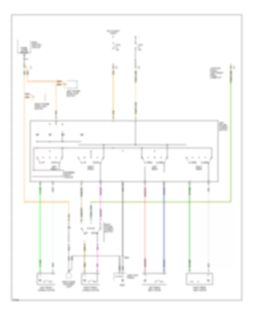
POWER DOOR LOCKS Power Door Lock Wiring Diagram for Chrysler Town & Country LX 1997 List of elements for Power Door Lock Wiring Diagram for Chrysler Town & Country LX 1997: 58 (i/p center support) (w/ rke) anti- theft system (w/ rke) anti-theft system 1.5k 87a Anti- theft system (w/ rke) Body control module Door lock relay Door lock relay ctrl Door unlock relay Door unlock relay ctrl Fuse 10a Fuse 40a Fused Fused b+ G200 (left kick panel) G203 (right kick panel) G206 G96 Gnd Hot at all times Junction block Lefr rear sliding door lock motor Left front door lock motor Left front door unlock relay (rke only) Left power door lock switch Left rear sliding door contact Lf door mux sig Lf door unlock relay ctrl Lift- gate door lock motor Lift- gate mux sig Memory c1 Memory seat/ mirror module (under left front seat) P96 P97 P98 Panel lamps driver Pnk Power distri- bution center Power windows system Ptc 3a Ptc 4a Ptc 6a Remote keyless entry module (w/ rke) (top left of i/p) Rf door mux sig Right front door lock motor Right power door lock switch Right rear sliding door contact Right rear sliding door lock motor Rke in- ter- face Rke inter- face Rke interface Rke program sig Rke program signal Seat/ mirror module (under left front seat) W/ rke W/o rke & w/ pwr windows W/o rke & w/o power windows
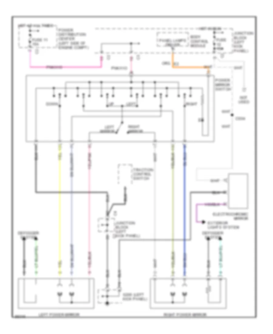
POWER MIRRORS Power Mirror Wiring Diagram for Chrysler Town & Country LX 1997 List of elements for Power Mirror Wiring Diagram for Chrysler Town & Country LX 1997: 24 (left Body control module Cs04 Defogger system Down Electrochromic mirror Exterior lights system Fuse 11 15a Fuse 15a G200 kick panel) Hot at all times Hot in run Junction block (left kick panel) Left Left mirror Left power mirror Not used Panel lamps driver Power distribution center (left side of engine compt) Power mirror switch Right Right mirror Right power mirror Traction control switch
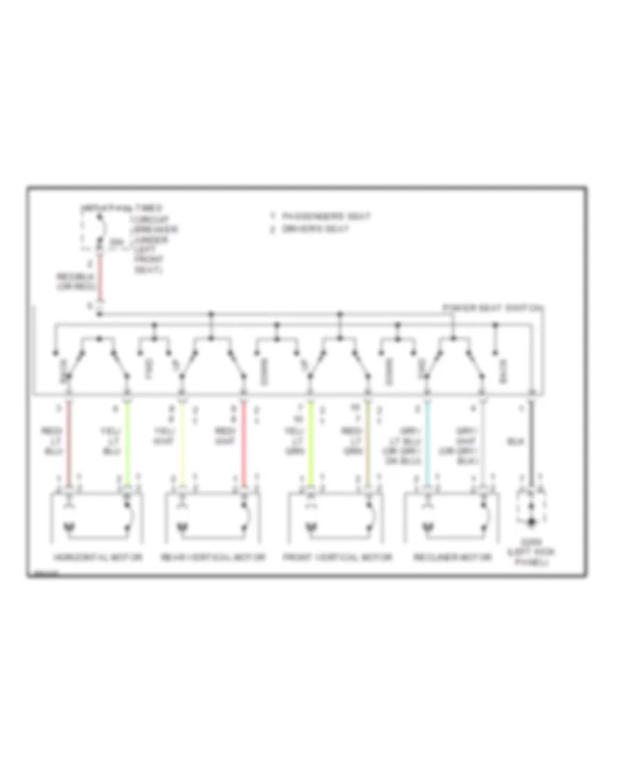
POWER SEATS Power Seat Wiring Diagrams for Chrysler Town & Country LX 1997 List of elements for Power Seat Wiring Diagrams for Chrysler Town & Country LX 1997: 14 30a Back Circuit breaker (under left front seat) Down Driver's seat Front vertical motor Fwd G200 (left kick panel) Horizontal motor Hot at all times Passenger's seat Power seat switch Rear vertical motor Recliner motor
POWER WINDOWS Power Window Wiring Diagram for Chrysler Town & Country LX 1997 List of elements for Power Window Wiring Diagram for Chrysler Town & Country LX 1997: 26 (left kick panel) Body control module Close Down Ds01 Express down module G200 Hot in accy or run Junction block (left front dash, under i/p) Left front Left front window motor Left power door lock switch Left power window switch Left rear Left rear vent motor Open Panel lamps driver Ptc 9a Right door courtesy lamp Right front Right front window motor Right power door lock switch Right power window switch Right rear Right rear vent motor Tan
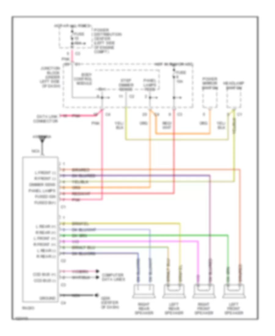
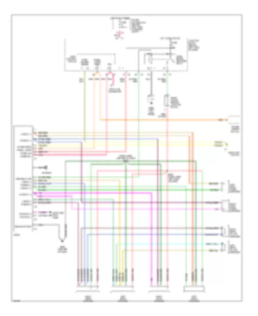
RADIO Radio Wiring Diagrams, Base Radio for Chrysler Town & Country LX 1997 List of elements for Radio Wiring Diagrams, Base Radio for Chrysler Town & Country LX 1997: 37 Antenna B(+) Body control module Ccd bus (+) Ccd bus (-) Computer data lines Data link connector Dimmer sens Fuse 10a Fused b(+) Fused ign G206 (center of dash) Ground Headlamp switch Hot at all times Hot in run or acc Junction block (under left side of dash) L front (+) L front (-) L rear (+) L rear (-) Left front speaker Left rear speaker Nca Panel lamps Panel lamps feed Pnk Power distribution center (left side of engine compt) Power mirror switch R front (+) R front (-) R rear (+) R rear (-) Radio Right front speaker Right rear speaker Step dimmer sense Radio Wiring Diagrams, Premium Model for Chrysler Town & Country LX 1997 List of elements for Radio Wiring Diagrams, Premium Model for Chrysler Town & Country LX 1997: 47 (dash harn, center of dash) bs08 Antenna B(+) Body control module Bs03 (dash harn, left side of dash) Ccd bus (+) Ccd bus (-) Computer data lines Data link connector Dimmer sens Fuse 10a Fused b(+) Fused ign G200 (left kick panel) G206 (center of dash) Ground strap Headlamp switch Hot at all times Hot in run or acc Junction block (behind left side of dash) L front (+) L front (-) L rear (+) L rear (-) Left dash panel speaker Left door speaker Left rear pillar speaker Left rear speaker Name brand speaker relay Nbs relay dr Nca Panel lamps Panel lamps feed Pnk Power distribution center (left side of engine compt) Power mirror switch R front (+) R front (-) R rear (+) R rear (-) Radio Radio choke (behind junction block) Right dash panel speaker Right door speaker Right rear pillar speaker Right rear speaker Step dimmer sense
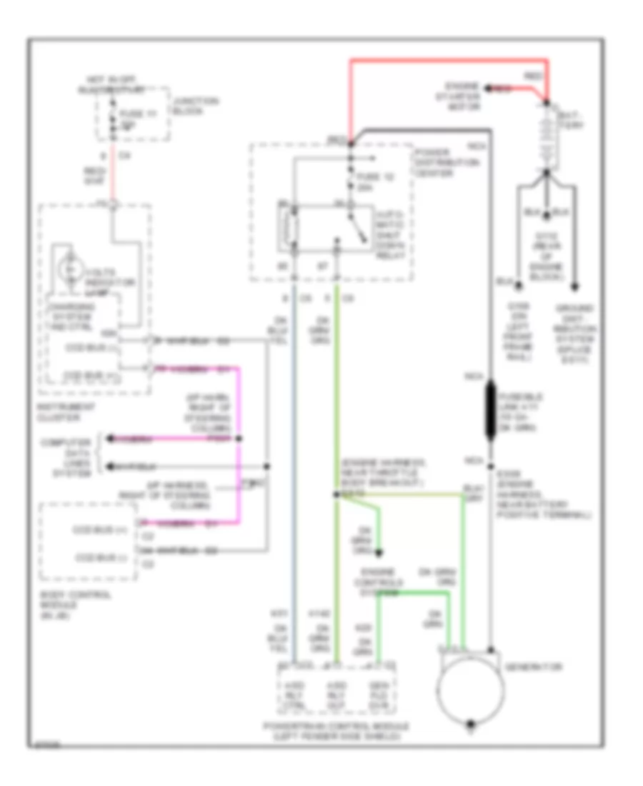
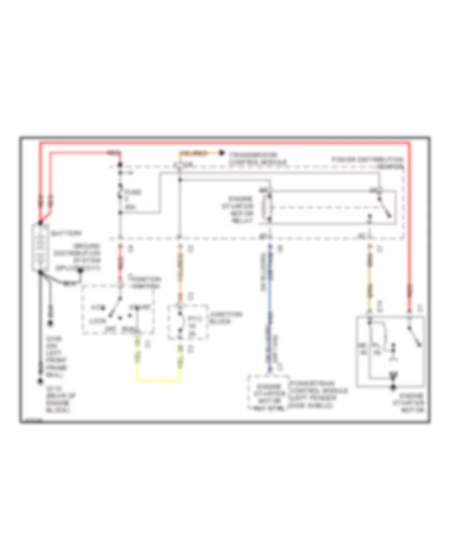
STARTING/CHARGING Charging Wiring Diagram for Chrysler Town & Country LX 1997 List of elements for Charging Wiring Diagram for Chrysler Town & Country LX 1997: 35 (engine harness, near throttle body breakout) es12 (i/p harn, right of steering column) ps01 (i/p harness, right of steering column) A142 Asd rly ctrl Asd rly out Auto- matic shut down relay Bat- tery Body control module (in jb) Ccd bus (+) Ccd bus (-) Charging system ind ctrl Computer data lines system Engine controls system Engine starter motor Es09 (engine harness, near battery positive terminal) Fuse 11 10a Fuse 12 20a G106 (on left front frame rail) G112 (rear of engine block) Gen fld dvr Generator Ground dist- ribution system (splice es11) Hot in off, run or start Ign Instrument cluster Junction block K20 K51 Nca Power distribution center Powertrain control module (left fender side shield) Ps02 Red Volts indicator lamp Starting Wiring Diagram for Chrysler Town & Country LX 1997 List of elements for Starting Wiring Diagram for Chrysler Town & Country LX 1997: 24 Acc Battery E19 Engine starter motor Engine starter motor relay Engine starter motor rly ctrl Fuse 40a G106 (on left front frame rail) G112 (rear of engine block) Ground distribution system (splice es11) Hd in Ignition c1 switch Junction block K90 Lock Off Pl in Power distribution center Powertrain control module (left fender side shield) Ptc 3a Red Run Start Transmission control module
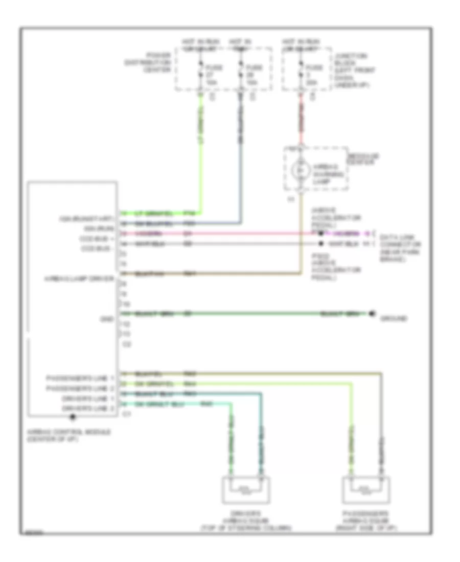
SUPPLEMENTAL RESTRAINTS Supplemental Restraint Wiring Diagram for Chrysler Town & Country LX 1997 List of elements for Supplemental Restraint Wiring Diagram for Chrysler Town & Country LX 1997: 33 (above accelerator pedal) ps01 Airbag control module (center of i/p) Airbag lamp driver Airbag warning lamp Ccd bus + Ccd bus - Center Data link connector (near park brake) Driver's airbag squib (top of steering column) Driver's line 1 Driver's line 2 F14 F23 Fuse 10a Fuse 20a Gnd Ground Hot in run Hot in run or start Ign (run) Ign (run/start) Junction block (left front dash, under i/p) Message Passenger's airbag squib (right side of i/p) Passenger's line 1 Passenger's line 2 Power distribution center Pso2 (above accelerator pedal) R41 R42 R43 R44 R45
TRANSMISSION
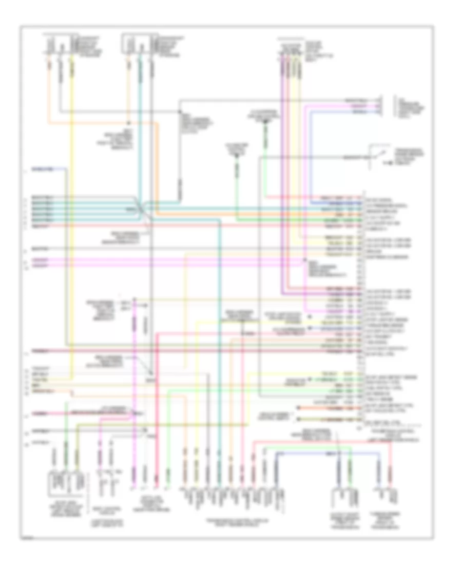
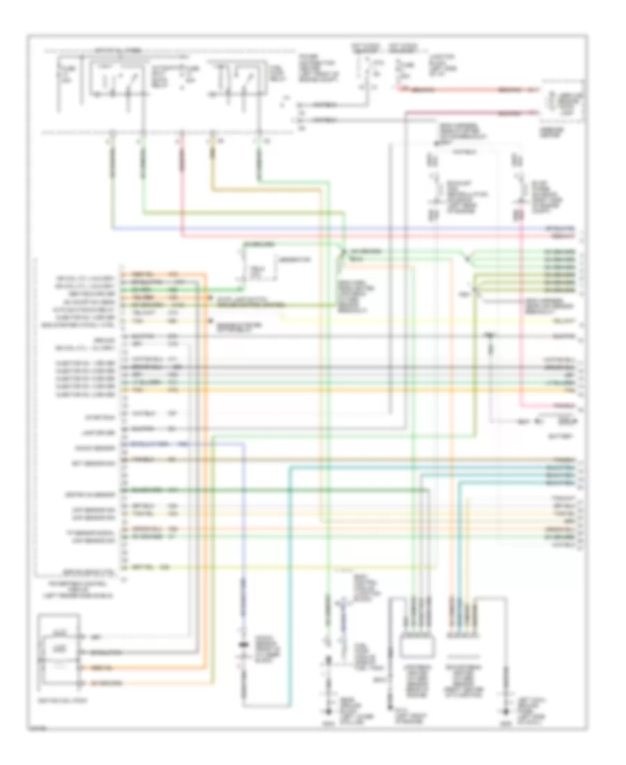
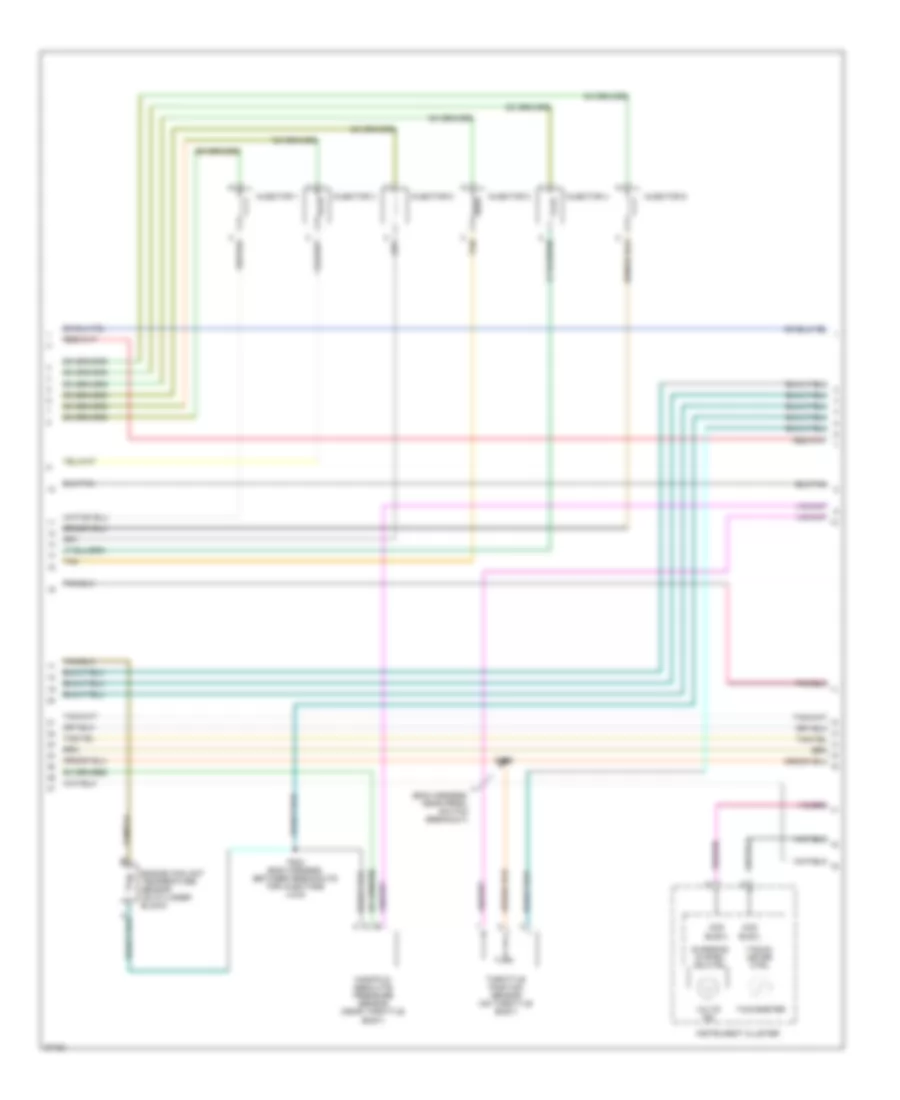
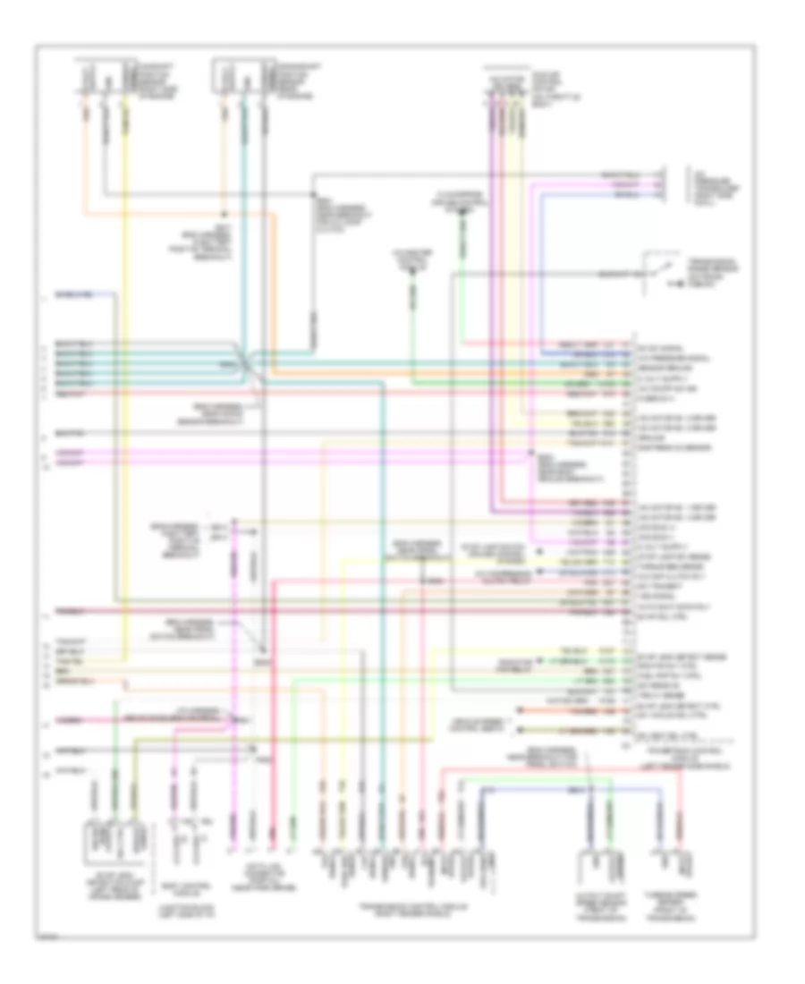
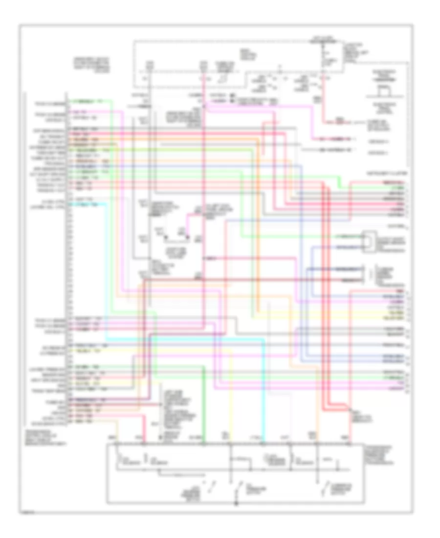
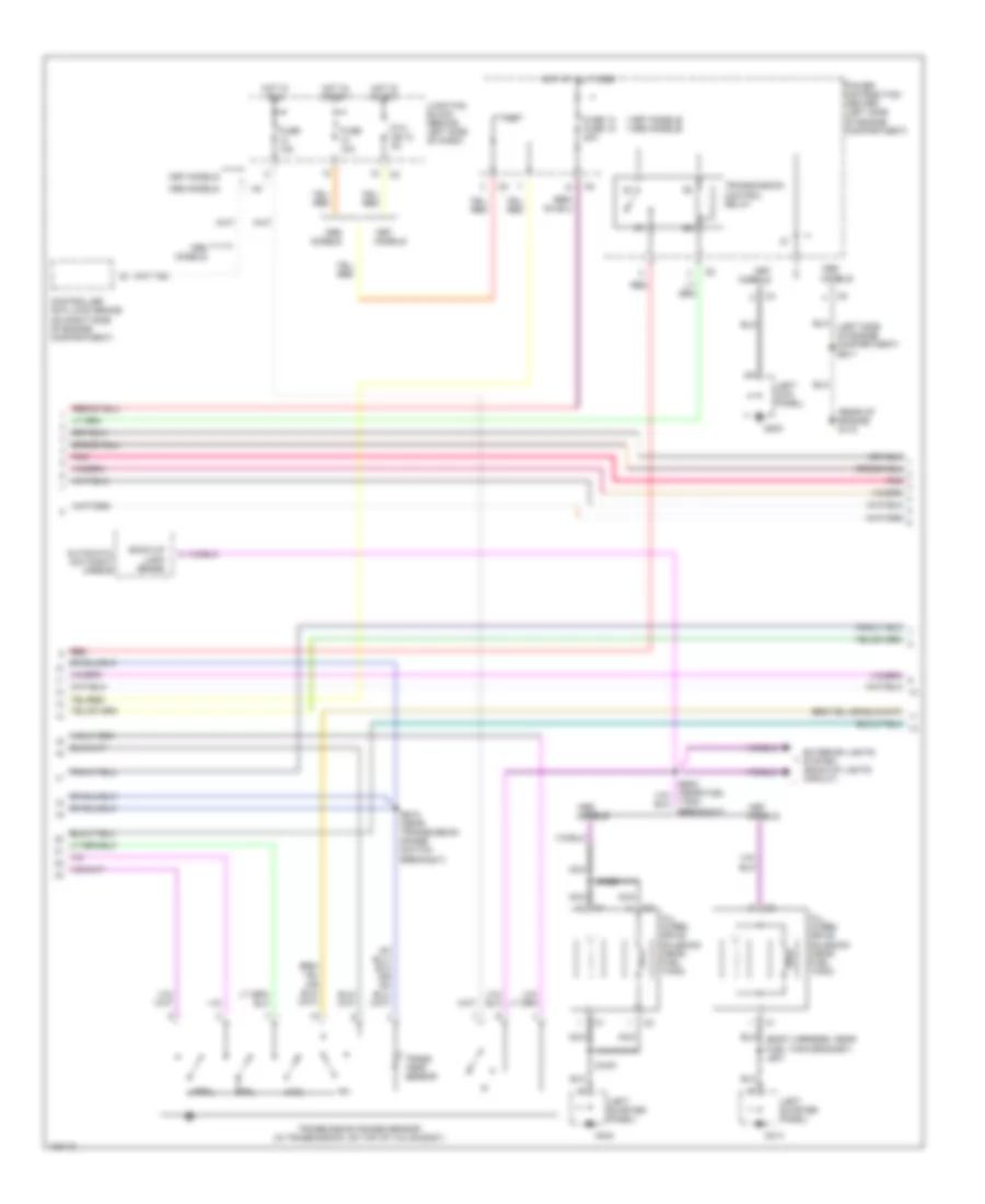
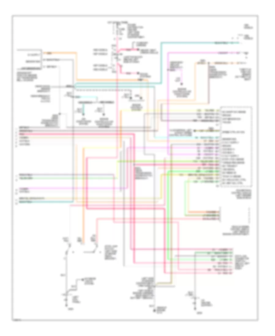
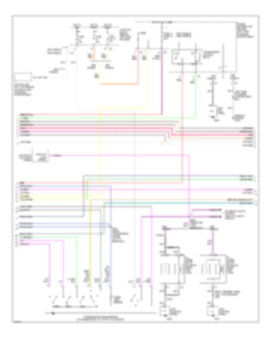
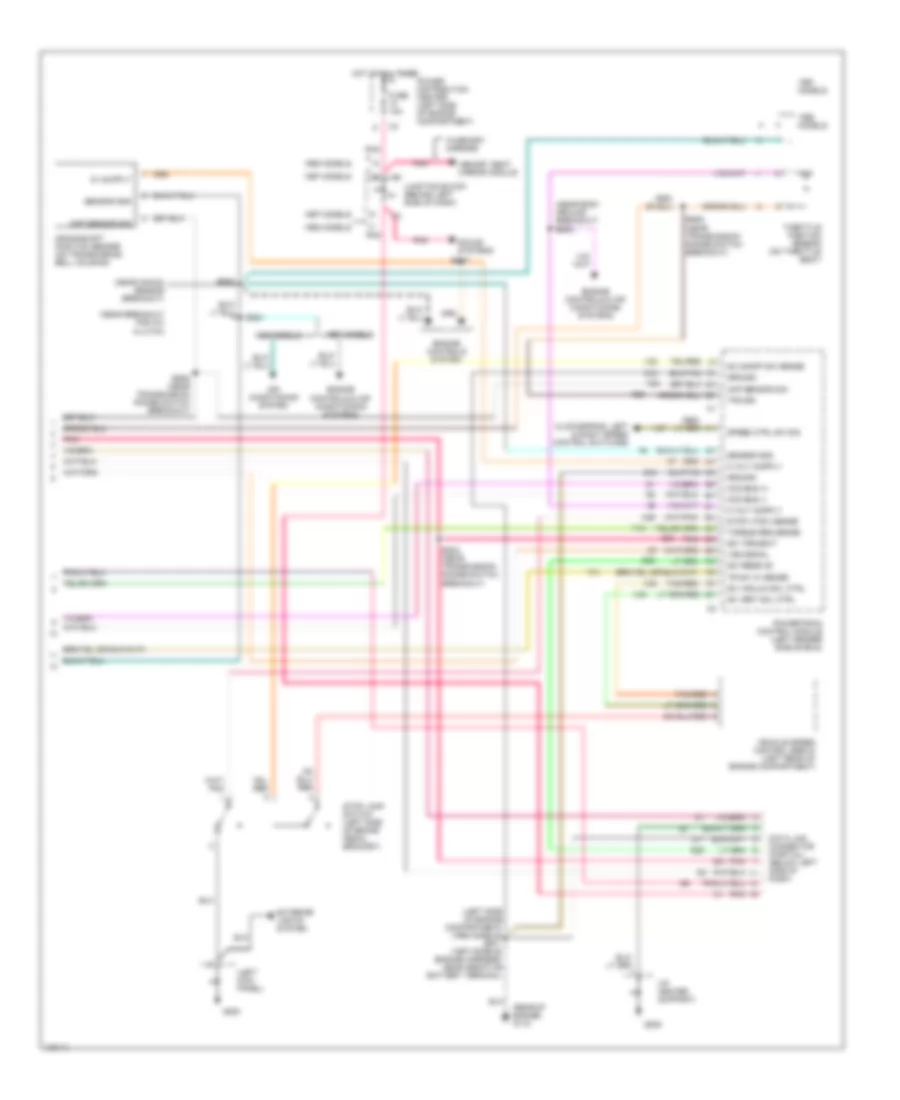
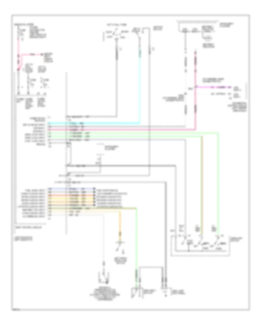
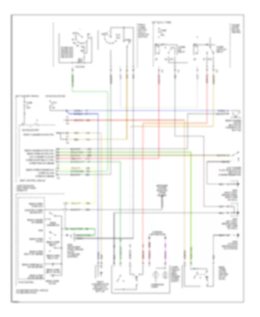
3.3L 3.3L, Transmission Wiring Diagram (1 of 3) for Chrysler Town & Country LX 1997 List of elements for 3.3L, Transmission Wiring Diagram (1 of 3) for Chrysler Town & Country LX 1997: 79 (near gray 36-way in-line connector, right of steering column) (near park brake switch breakout) bs06 (rear of engine) g115 2-4 press sw 2-4 pressure switch 2-4 sol ctrl 2/4 solenoid Body control module Ccd bus (+) Ccd bus (-) Computer data lines system D21 Electronic prndl control Electronic prndl indicator Es01 (near tcm breakout) Es13 Es14 (in positive battery terminal) F11 F45 Fuse 2 10a Fused (b+) Fused ign sw out Fused ign sw output (st-run-off) Fused ign. (off/run/ start) Gnd Hot in off, run or start Input spd sns sig Instrument cluster Junction block (behind left side of dash) K22 K24 Low/ reverse pressure switch Low/ reverse solenoid Low/rev press sw Low/rev sol. ctrl Models O/d solenoid Od solenoid ctrl Out shaft spd sig Output shaft speed sensor (on transmission) Overdrive pressure switch Pnk Prnd3l Ps01 (near gray 36-way in-line connector, right of steering column) Ps02 Red Sci receive Sci transmit Sensor gnd Spd sensor gnd T10 T13 T14 T15 T16 T19 T20 T41 T42 T47 T50 T52 T54 T59 T60 Torq mgmt req Tps signal Tr sw c1 sense Tr sw c2 sense Trans rly out Trans temp sens Transmission control module (right side of engine compartment) Transmission solenoids & pressure switches (transmission) Turbine speed sensor (on transmission) U/d solenoid Ud sol ctrl Vss sig Z13 Z14 3.3L, Transmission Wiring Diagram (2 of 3) for Chrysler Town & Country LX 1997 List of elements for 3.3L, Transmission Wiring Diagram (2 of 3) for Chrysler Town & Country LX 1997: 39 (1997 models) (1998 models) (body harness, near fuel tank grommet) js01 (left kick panel) (left quarter panel) (rear of engine) g115 1997 models 1998 models All wheel drive solenoid (near fuel tank) Automatic day/night mirror Aws1 Aws2 Back-up lamp sense Controller anti-lock brake (on right side of engine compartment) Es10 (near transmission range switch breakout) Exterior lights system (back-up lights circuit) F20 F45 Fuse 10a Fuse 14 fuse 15 20a G200 G404 G414 Hot at all times Hot in run Hot in start Junction block (behind left side of dash) Models Nca Nol P3l Pnk Power distribution center (left side of engine compartment) Prnl Ptc cb 10 3a Red Tank breakout) Trans temp. sensor Transmission control relay Transmission range sensor (in transmission, on top of valve body) 3.3L, Transmission Wiring Diagram (3 of 3) for Chrysler Town & Country LX 1997 List of elements for 3.3L, Transmission Wiring Diagram (3 of 3) for Chrysler Town & Country LX 1997: 66 (i/p center support) (left kick panel) (near body ground breakout) es03 (near breakout for a/c clutch) (near knock sensor breakout) (rear of engine) g115 1997 models 1998 models Air condtioning system Ccd bus (+) Ccd bus (-) Ckp sensor sig Clockspring, left & right speed control switches Crankshaft position sensor (on transmission bell housing) D20 D21 Data link connector (partial) (below left side of dash) Engine controls & air conditioning systems Engine controls system Es02 Es05 (near transmission range switch breakout) Es08 (near transmission range switch breakout) Es17 Es21 Es24 (near transmission range switch breakout) Exterior lights system Fuse 10a G200 G206 Ground Hot at all times Junction block (behind left side of dash) K22 K24 K29 Memory seat mirror module Models Pnk Power distribution center (left side of engine compartment) Powertrain control module (left fender side shield) Sc on/off sw sense Sc vacuum sol ctrl Sc vent sol ctrl Sci receive Sci transmit Sensor gnd Sound systems Speed ctrl sw sig Stop lamp switch (left side of brake pedal bracket) Stop lp sw sense T10 T41 Tan/red Throttle position sensor (on throttle body) Torque req sense Tps sig Tr sw c1 sense V32 V35 V36 V37 Vehicle speed control servo (left rear of engine compartment) Vss signal W/memory mirrors Z11 Z12
3.8L 3.8L, Transmission Wiring Diagram (1 of 3) for Chrysler Town & Country LX 1997 List of elements for 3.8L, Transmission Wiring Diagram (1 of 3) for Chrysler Town & Country LX 1997: 79 (near gray 36-way in-line connector, right of steering column) (near park brake switch breakout) bs06 (rear of engine) g115 2-4 press sw 2-4 pressure switch 2-4 sol ctrl 2/4 solenoid Body control module Ccd bus (+) Ccd bus (-) Computer data lines system D21 Electronic prndl control Electronic prndl indicator Es01 (near tcm breakout) Es13 Es14 (in positive battery terminal) F11 F45 Fuse 2 10a Fused (b+) Fused ign sw out Fused ign sw output (st-run-off) Fused ign. (off/run/ start) Gnd Hot in off, run or start Input spd sns sig Instrument cluster Junction block (behind left side of dash) K22 K24 Low/ reverse pressure switch Low/ reverse solenoid Low/rev press sw Low/rev sol. ctrl Models O/d solenoid Od solenoid ctrl Out shaft spd sig Output shaft speed sensor (on transmission) Overdrive pressure switch Pnk Prnd3l Ps01 (near gray 36-way in-line connector, right of steering column) Ps02 Red Sci receive Sci transmit Sensor gnd Spd sensor gnd T10 T13 T14 T15 T16 T19 T20 T41 T42 T47 T50 T52 T54 T59 T60 Torq mgmt req Tps signal Tr sw c1 sense Tr sw c2 sense Trans rly out Trans temp sens Transmission control module (right side of engine compartment) Transmission solenoids & pressure switches (transmission) Turbine speed sensor (on transmission) U/d solenoid Ud sol ctrl Vss sig Z13 Z14 3.8L, Transmission Wiring Diagram (2 of 3) for Chrysler Town & Country LX 1997 List of elements for 3.8L, Transmission Wiring Diagram (2 of 3) for Chrysler Town & Country LX 1997: 39 (1997 models) (1998 models) (body harness, near fuel tank grommet) js01 (left kick panel) (left quarter panel) (rear of engine) g115 1997 models 1998 models All wheel drive solenoid (near fuel tank) Automatic day/night mirror Aws1 Aws2 Back-up lamp sense Controller anti-lock brake (on right side of engine compartment) Es10 (near transmission range switch breakout) Exterior lights system (back-up lights circuit) F20 F45 Fuse 10a Fuse 14 fuse 15 20a G200 G404 G414 Hot at all times Hot in run Hot in start Junction block (behind left side of dash) Models Nca Nol P3l Pnk Power distribution center (left side of engine compartment) Prnl Ptc cb 10 3a Red Tank breakout) Trans temp. sensor Transmission control relay Transmission range sensor (in transmission, on top of valve body) 3.8L, Transmission Wiring Diagram (3 of 3) for Chrysler Town & Country LX 1997 List of elements for 3.8L, Transmission Wiring Diagram (3 of 3) for Chrysler Town & Country LX 1997: 66 (i/p center support) (left kick panel) (near body ground breakout) es03 (near breakout for a/c clutch) (near knock sensor breakout) (rear of engine) g115 1997 models 1998 models Air condtioning system Ccd bus (+) Ccd bus (-) Ckp sensor sig Clockspring, left & right speed control switches Crankshaft position sensor (on transmission bell housing) D20 D21 Data link connector (partial) (below left side of dash) Engine controls & air conditioning systems Engine controls system Es02 Es05 (near transmission range switch breakout) Es08 (near transmission range switch breakout) Es17 Es21 Es24 (near transmission range switch breakout) Exterior lights system Fuse 10a G200 G206 Ground Hot at all times Junction block (behind left side of dash) K22 K24 K29 Memory seat mirror module Models Pnk Power distribution center (left side of engine compartment) Powertrain control module (left fender side shield) Sc on/off sw sense Sc vacuum sol ctrl Sc vent sol ctrl Sci receive Sci transmit Sensor gnd Sound systems Speed ctrl sw sig Stop lamp switch (left side of brake pedal bracket) Stop lp sw sense T10 T41 Tan/red Throttle position sensor (on throttle body) Torque req sense Tps sig Tr sw c1 sense V32 V35 V36 V37 Vehicle speed control servo (left rear of engine compartment) Vss signal W/memory mirrors Z11 Z12
WARNING SYSTEMS Warning System Wiring Diagrams for Chrysler Town & Country LX 1997 List of elements for Warning System Wiring Diagrams for Chrysler Town & Country LX 1997: 77 (i/p harness, near connector p18) (left A31 Acc Body control module Bus (+) Bus (-) Ccd Ccd bus (+) Ccd bus (-) Ccd bus (-) c2 Ctsy lp sw Ctsy lp sw input Engine oil pressure switch (3.0l-near starter; 2.4l-right rear of engine; 3.3l/3.8l-below a/c compressor) Fuel level input Fuel pump module Fuse 10a Fuse 20a Fused b(+) Fused ign sw (run/ start) Fused ign sw (run/ start/ off) Fused ign sw (run/acc) G10 G200 kick panel) G26 G29 G74 G75 G76 G77 G78 Ground Head Head lp sw input Headlamp switch Hot at all times Hot in run or start Hot in run, start or off Ignition switch Instrument cluster Junction block (left side of i/p) Key-in ign sw input Key-in switch L307 L308 Left front door ajar switch Lf dr ajar sw input Liftgate ajar sw input Liftgate ajar switch Lock Low washer fluid switch Lr door ajar switch Lr dr ajar sw input M32 Memory seat/ mirror module Off Oil press sw input Park Park lp sw input Pnk Power distribution center (left front of engine compt) Powertrain control module (left fender side shield) Ps01 Ps02 (i/p harness, near connector p18) Rf door ajar switch Rf dr ajar sw input Rr door ajar switch Rr dr ajar sw input Run Seat belt switch Seatbelt indicator Seatbelt indicator ctrl Seatbelt sw input Start Tan Tan/red Wash fluid sw input
WIPER/WASHER Wiper/Washer Wiring Diagram for Chrysler Town & Country LX 1997 List of elements for Wiper/Washer Wiring Diagram for Chrysler Town & Country LX 1997: 66 64.9 ohm 87a 90.9 ohm A/c-heater control module (i/p center stack) Body control module C66 Defogger system (electric wiper de-icer) Electric wiper de-ice crtl F41 Front washer motor (bottom of washer fluid bottle) Front washer motor ctrl Front wiper switch (multi- function switch) Fuse 20a Fuse 30a G200 left cowl ground panel (left side of cowl) G203 right cowl ground panel (right side of cowl) G205 instrument panel ground block (i/p center support) G29 G400 liftgate ground block (in liftgate) Gnd Hot at all times Hot in run or acc Hot in start or run Hvac control Ign (run/start) Interior lights system Junction block (left front dash, under i/p) Low washer fluid level switch (bottom of washer reservoir) Low washer fluid sig M100 Off Power distri- bution center Ptc 6a R1=909 ohm r2=383 ohm r3=226 ohm r4=133 ohm r5=100 ohm Rear washer motor (bottom of washer fluid bottle) Rear washer motor ctrl Rear washer sw Rear washer sw sense Rear wiper delay on ind Rear wiper delay on ind driver Rear wiper delay sw Rear wiper delay sw sense Rear wiper motor (center of lift- gate) Rear wiper motor ctrl Rear wiper on ind Rear wiper on ind driver Rear wiper on sw Rear wiper/ wash mux Rear wiper/washer mux Underhood lamps V10 V13 V14 V20 V23 V26 V52 Wash Wiper high/low relay Wiper module (left rear corner of eng compt) Wiper mux sig Wiper on relay Wiper on/off relay ctrl Wiper park sw sense Wiper sw sense Z20