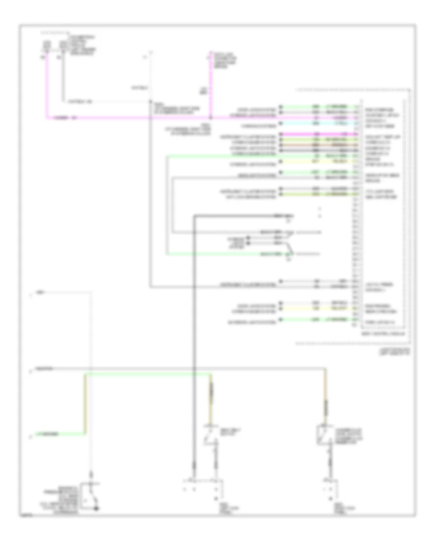
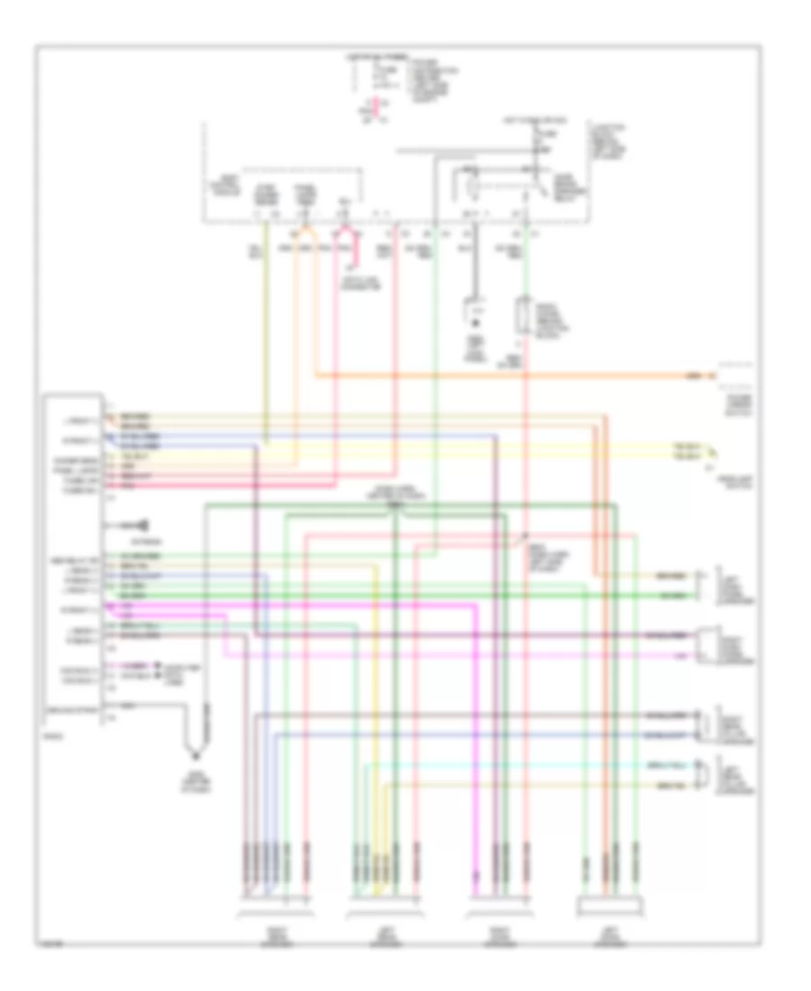
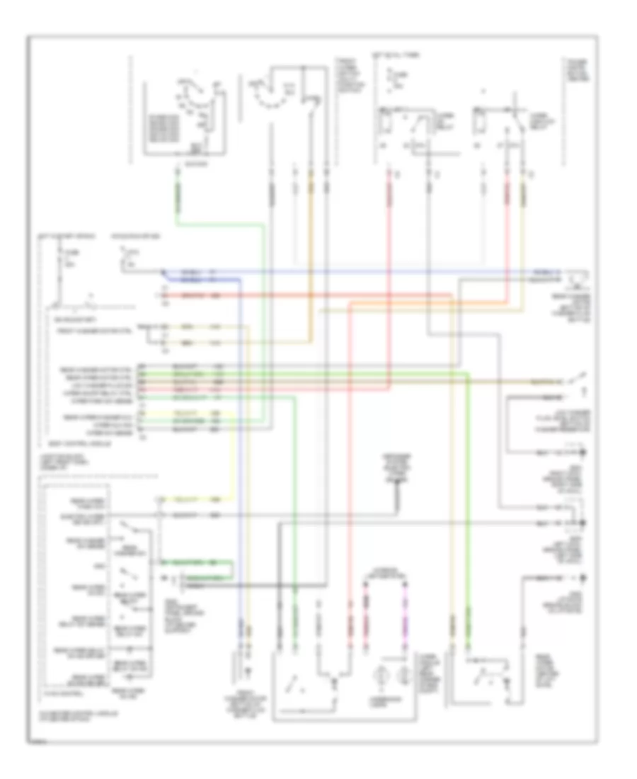
AIR CONDITIONING
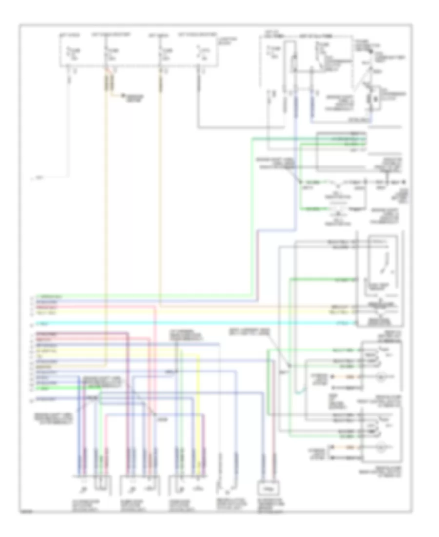
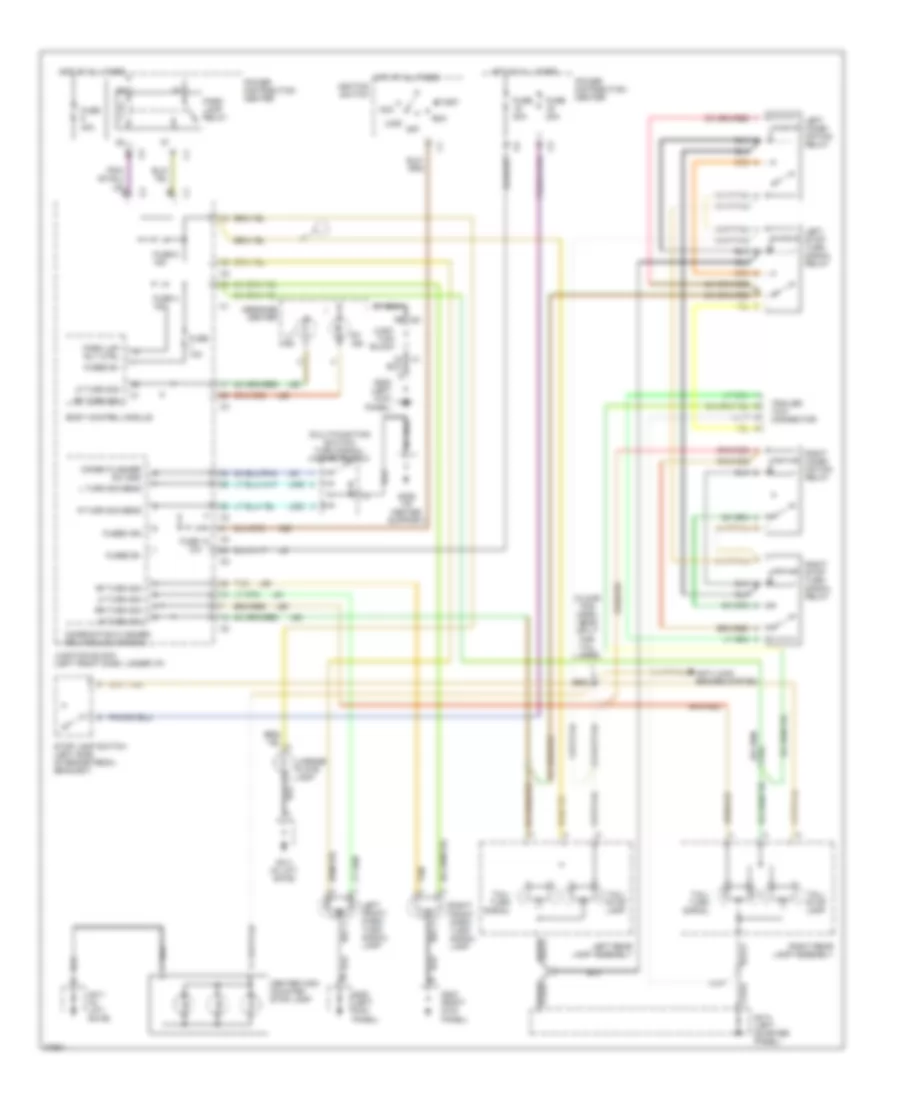
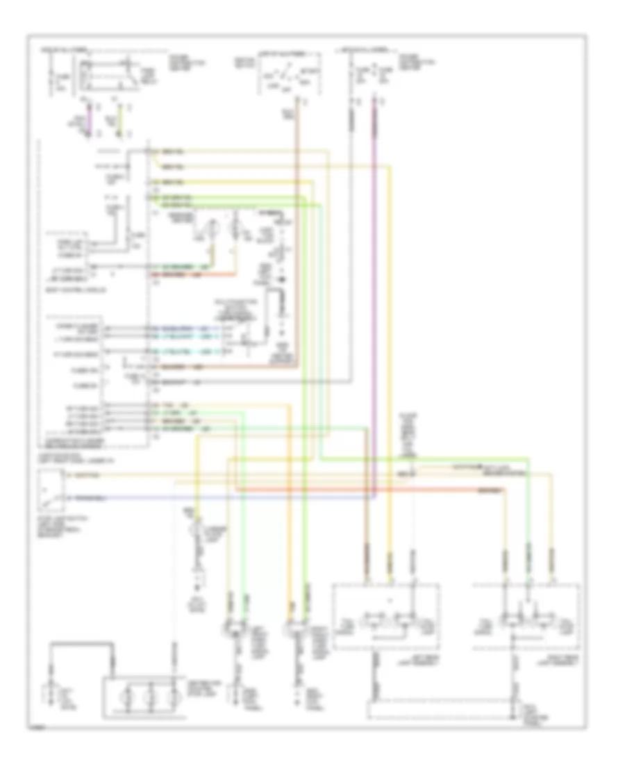
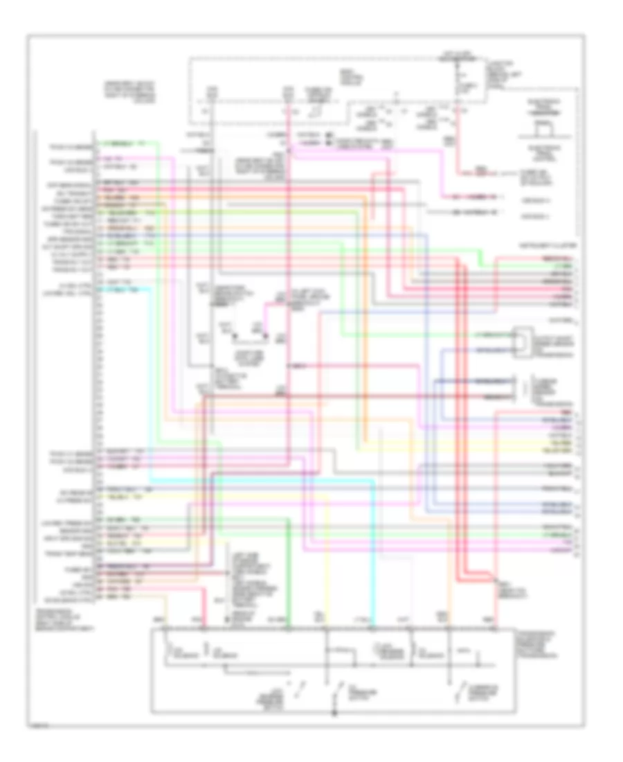
Air Conditioning Wiring Diagrams (1 of 2) for Chrysler Town & Country SX 1997

List of elements for Air Conditioning Wiring Diagrams (1 of 2) for Chrysler Town & Country SX 1997:
- (engine compartment harness, 2.4l-near fuel rail breakout 3.0l-near injection harn breakout 3.3l, 3.8l-near knock sensor breakout)
- (engine compartment harness, 2.4l-near power dist center breakout 3.0l-near speed control breakout 3.3l, 3.8l-near body ground breakout)
- A/c heater control module
- A/c indic driver
- A/c on indicator
- A/c pres sw
- A/c pressure transducer (right rear of engine)
- A/c sw input
- A/c switch
- A/c switch signal
- Bi-lev
- C102
- C103
- C104
- C107
- C13
- C14
- C18
- C2 relay control
- C21
- C26
- C32
- C33
- C34
- C35
- C36
- C37
- C57
- C61
- C62
- C63
- C64
- C66
- Common
- Def
- Defogger system
- Driver
- Es02
- Es03
- Feedback signal
- Floor
- Front blower control switch
- Front blower motor
- Front blower motor relay
- Front blower motor resistor block (right rear of engine compt)
- Front blower off
- Fuse 40a
- G200 (left kick panel)
- G206 (i/p center support)
- Ground
- Hot at all times
- Hvac control
- Ignition
- Illumination
- Indic driver
- Interior lights system
- K173
- Left
- Left temp control switch
- Mix
- Mode select
- Mode select switch
- Off
- Panel
- Power distribution center
- Powertrain control module (left front fender)
- Rear defog on switch
- Rear wipe/ wash mux
- Rear wiper/ washer controls
- Recirc mode indicator
- Recirc mode switch
- Relay control
- Right temp control
- Right temp control switch (w/ dual zone a/c)
- Sens ground
- Sensor ground
- Sensor signal
- Switch sense
- Switch sense rear defog switch
- Tan
- Temp control
- V23
- V26
- Wiper de-ice driver
- Wiper/ washer system
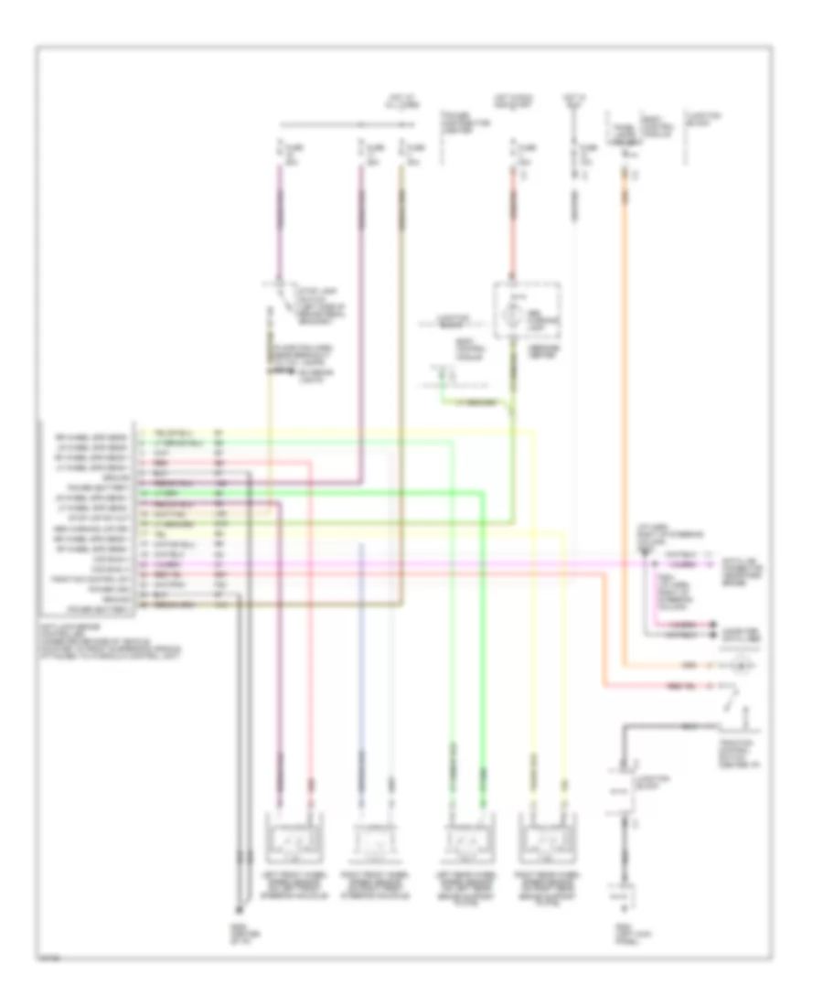
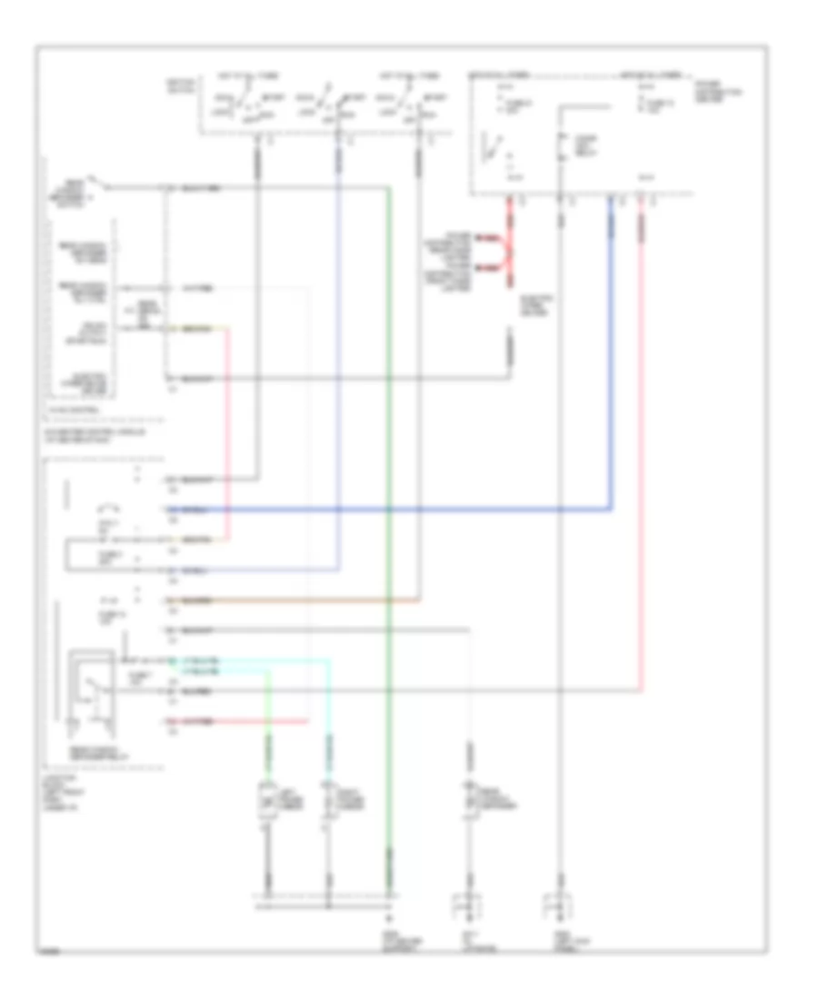
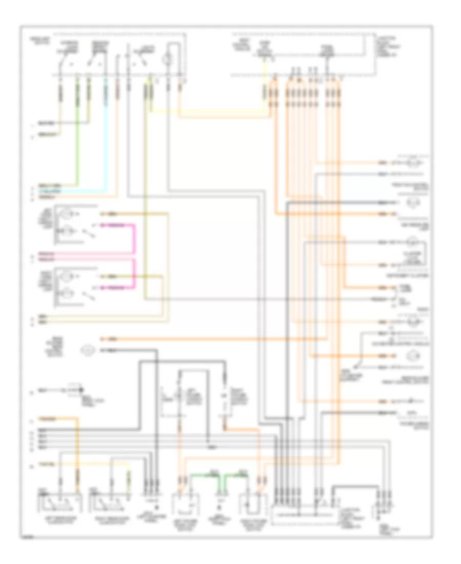
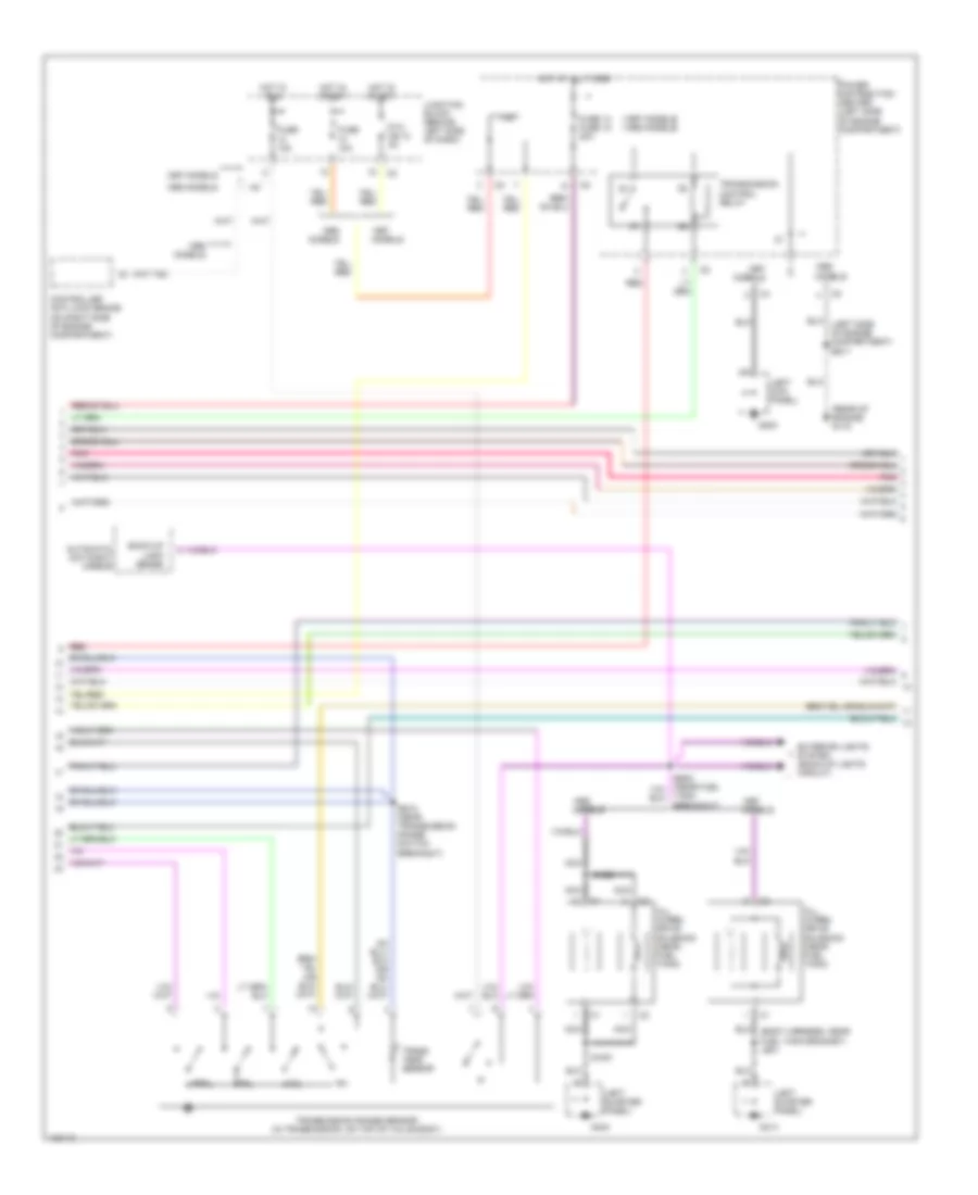
Air Conditioning Wiring Diagrams (2 of 2) for Chrysler Town & Country SX 1997
List of elements for Air Conditioning Wiring Diagrams (2 of 2) for Chrysler Town & Country SX 1997:
- (body harness, near split for tail lamps)
- (engine compt harn, in radiator fan breakout)
- (engine compt harn, near recirculation motor breakout)
- (i/p harness, near mode door motor breakout)
- A/c compressor clutch
- A/c compressor clutch relay
- A/c zone door actuator (in hvac unit)
- Blend door actuator (in hvac unit)
- Bs17
- E48
- Engine compt harn, harn, near radiator module)
- Es23
- Evaporator temperature sensor (in hvac unit)
- Fuse 10a
- Fuse 15a
- Fuse 20a
- Fuse 40a
- G100 (under battery tray)
- G206 (i/p center support)
- High temp sensor
- Hot at all times
- Hot in run
- Hot in run or start
- Interior lights system
- Js01a
- Js01b
- Js02a
- Js02b
- Js03
- Junction block
- Low
- Med
- Message center
- Mode door actuator (in hvac unit)
- Motor
- No. 1 radiator fan
- No. 2 radiator fan
- Off
- Power distribution center
- Ptc 9a
- Radiator fan relay (front of left frame rail)
- Rear
- Rear a/c heater unit (w/ rear a/c)
- Rear blower
- Rear blower front control switch (w/ rear a/c)
- Rear blower rear control switch (w/ rear a/c)
- Rear mode door motor
- Recirculation door actuator (in hvac unit)
ANTI-LOCK BRAKES
Anti-lock Brake Wiring Diagrams for Chrysler Town & Country SX 1997
List of elements for Anti-lock Brake Wiring Diagrams for Chrysler Town & Country SX 1997:
- (floor pan harn, near breakout to tail lamps) bs01
- (i/p harn, right of steering column) ps02
- A10
- A20
- Abs warning lamp
- Abs warning lmp drv
- Anti-lock brake controller (under driver side of vehicle, mounted to front suspension cradle, attached to hydraulic control unit)
- B27
- Body control module
- Ccd bus (+)
- Ccd bus (-)
- Computer data lines
- Data link connector (near park brake)
- Exterior lights
- F22
- Fuse 10a
- Fuse 20a
- Fuse 25a
- Fuse 40a
- G19
- G200 (left kick panel)
- G206 (center of i/p)
- Ground
- Hot at all times
- Hot in run
- Hot in run and start
- Junction block
- L50
- Left front wheel speed sensor (on left front steering knuckle)
- Left rear wheel speed sensor (on left rear brake support plate)
- Lf wheel spd sens +
- Lf wheel spd sens -
- Lr wheel spd sens +
- Lr wheel spd sens -
- Message center
- Panel lamps driver
- Power (battery)
- Power (ign)
- Power distribution center
- Ps01 (i/p harn, right of steering column)
- Red
- Rf wheel spd sens +
- Rf wheel spd sens -
- Right front wheel speed sensor (on right front steering knuckle)
- Right rear wheel speed sensor (on right rear brake support plate)
- Rr wheel spd sens +
- Rr wheel spd sens -
- Stop lamp switch (left side of brake pedal bracket)
- Stop lmp sw out
- Traction control sw
- Traction control switch (center i/p)
ANTI-THEFT
Anti-theft Wiring Diagram for Chrysler Town & Country SX 1997
List of elements for Anti-theft Wiring Diagram for Chrysler Town & Country SX 1997:
- (not used)
- Body control module
- Fuse 10a c3
- Fused b+
- G301 (right kick panel)
- G411 (in liftgate)
- G70
- G74
- G75
- G76
- G77
- G78
- Hood ajar sw sens
- Hood ajar switch
- Horn rly ctrl
- Horn system
- Hot at all times
- Junction block (left front dash, under i/p)
- Left door arm/disarm switch (rear of left door lock cylinder)
- Left front door ajar switch
- Left power door lock switch
- Left rear door ajar switch
- Lf door ajar sw sens
- Lf door mux sig
- Liftgate ajar sw sens
- Liftgate ajar switch
- Liftgate arm/disarm switch (lower center of liftgate
- Liftgate mux sig
- Lr door ajar sw sens
- Memory seat/ mirror module
- Message center
- P96
- P97
- P98
- Pnk
- Power distribution center
- Rf door ajar sw sens
- Rf door mux sig
- Right door arm/disarm switch (rear of right door lock cylinder)
- Right front door ajar switch
- Right power door lock switch
- Right rear door ajar switch
- Rr door ajar sw sens
- Tan
- Tan/red
- Vehicle theft alarm lamp
- Vta lmp drvr
- Wiper module
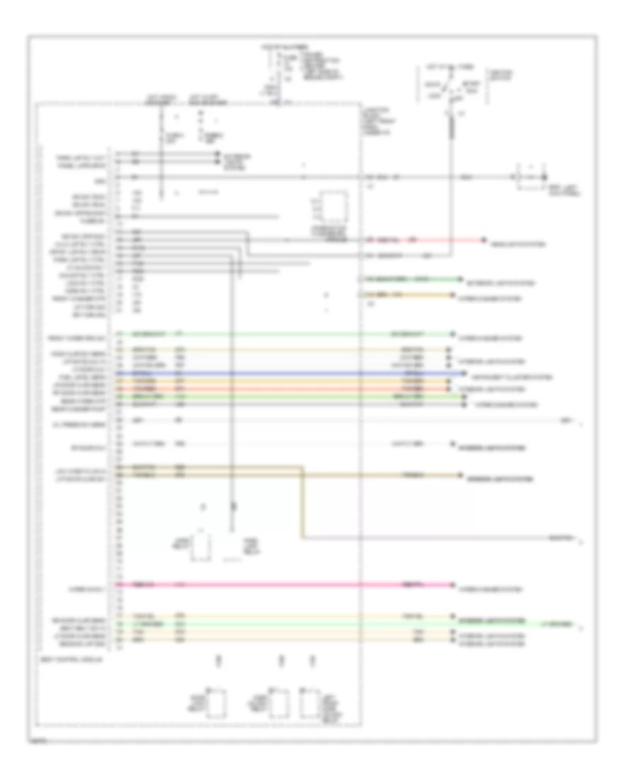
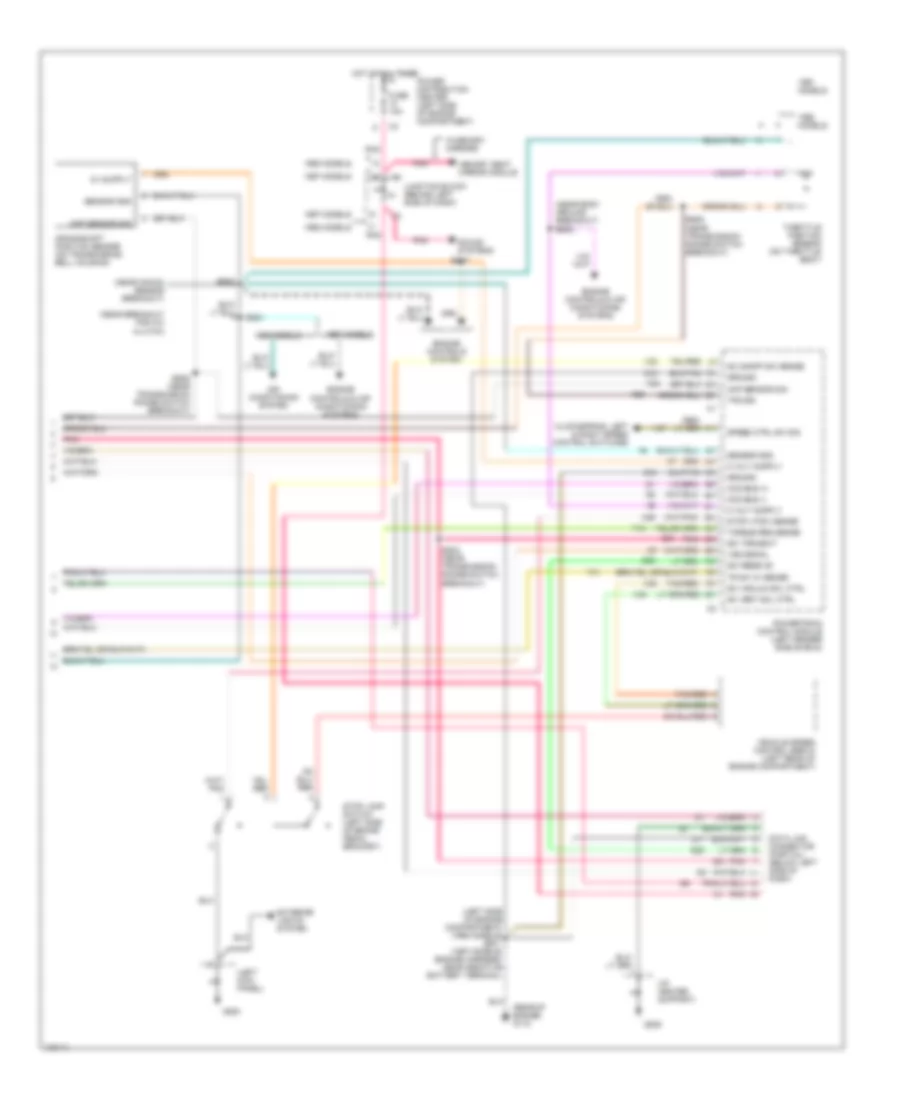
BODY COMPUTER
Body Computer Wiring Diagrams (1 of 2) for Chrysler Town & Country SX 1997
List of elements for Body Computer Wiring Diagrams (1 of 2) for Chrysler Town & Country SX 1997:
- (left
- A31
- Acc
- Body control module
- Combination flasher/drl module
- Crtsy lmp rly drvr
- Door lock relay
- Door unlock relay
- Exterior lights system
- F11
- F155
- F236
- F238
- Front washer mtr
- Front wiper prk sw
- Fuel level sens
- Fuse 10a
- Fuse 2 fuse 2 10a 10a
- Fuse 3 20a
- Fused b+
- G10
- G200 kick panel)
- G29
- G70
- G74
- G75
- G76
- G77
- G78
- Gnd
- Headlights system
- Hi/lo lmp rly ctrl
- Hood ajar sw sens
- Horn relay
- Horn rly ctrl
- Hot at all times
- Hot in off,
- Hot in run
- Ign sw (off/acc)
- Ign sw (off/run/st)
- Ign sw (run)
- Ignition switch
- Instrument cluster system
- Interior lights system
- Interior lights system interior lights system
- Junction block (left front dash, under i/p)
- L62
- L63
- L93
- L97
- Left front door unlock relay
- Lf door ajar sens
- Lf door mux
- Lf unlock rly
- Liftgate ajar sw
- Liftgate mux in
- Lock
- Lock rly ctrl
- Low wash fluid in
- Lr door ajar sens
- Lr turn sig
- M112
- M20
- Off
- Oil press sw sens
- Or start
- P96
- P97
- P98
- Panel lmps drvr
- Park lamp relay
- Park lmp rly ctrl
- Park lmp rly out
- Power distribution center (left side of engine compt)
- Reading lmp gnd
- Rear washer pump
- Rear wiper mtr
- Rf door ajar sens
- Rf door mux
- Rr door ajar sens
- Rr turn sig
- Run
- Run or start
- Seat belt sw in
- Start
- Tan
- Tan/red
- Unlock rly ctrl
- V10
- V13
- V14
- V20
- V23
- Wiper on rly
- Wiper/washer system
Body Computer Wiring Diagrams (2 of 2) for Chrysler Town & Country SX 1997
List of elements for Body Computer Wiring Diagrams (2 of 2) for Chrysler Town & Country SX 1997:
- (left fender side shield)
- Abs lamp driver
- Anti-lock brakes system
- Body control module
- Ccd bus (+)
- Ccd bus (-)
- Coolant temp lmp
- Courtesy lmp sw
- D09
- Data link connector (near park brake)
- Dimmer sw in
- Door locks system
- E17
- E92
- Engine oil pressure switch (2.4l: rear of engine) (3.0l: near starter) (3.3/3.8l: below a/c compressor)
- Exterior lights system
- G19
- G200 (left kick panel)
- G203 (right kick panel)
- G26
- G69
- G96
- Ground
- Headlights system
- Headlmp sw sens
- Instrument cluster system
- Interior lights system
- Junction block (left side of i/p)
- Key-in sw sens
- L307
- L308
- Low oil press
- M32
- Park lmp sw in
- Powertrain control module
- Pso1 (i/p harness, right side of steering column)
- Pso2 (i/p harness, right side of steering column)
- Rear wipe/wash
- Rke interface
- Rke program
- Seat belt switch
- Step dim sw in
- V26
- V52
- Vta lamp drvr
- Warning systems
- Washer fluid level switch (washer fluid reservoir)
- Wiper mux in
- Wiper sw in
- Wiper/washer system
- Z20
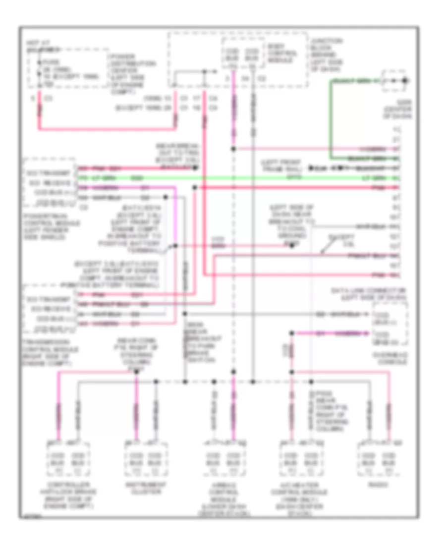
COMPUTER DATA LINES
Computer Data Lines for Chrysler Town & Country SX 1997
List of elements for Computer Data Lines for Chrysler Town & Country SX 1997:
- (1998)
- (1998) (except 1998)
- (eatx) es14 (except 3.0l) (left front of engine compt, in breakout to positive battery terminal)
- (except 1998)
- (except 3.0l) (eatx) es13 (left front of engine compt, in breakout to positive battery terminal)
- (left front frame rail) g113
- (left side of dash, near breakout to to cowl ground) b205
- (near break- out to trs) (except 3.0l) (eatx) es24
- (near conn p18, right of steering column) ps01
- A/c heater control module (1998 only) (dash center stack)
- Airbag control module (lower dash center stack)
- Body control module
- Ccd bus (+)
- Ccd bus (-)
- Conn p18, right of steering column)
- Controller anti-lock brake (right side of engine compt)
- D20
- D21
- Data link connector (left side of dash)
- Es11
- Except 3.0l
- Fuse 10a
- G206 (center of dash)
- Hot at all times
- Instrument cluster
- Junction block (behind left side of dash)
- Overhead console
- Pnk
- Power distribution center (left side of engine compt)
- Powertrain control module (left fender side shield)
- Ps02 (near d2
- Radio
- Sci receive
- Sci receive
- Sci transmit
- Transmission control module (right side of engine compt)
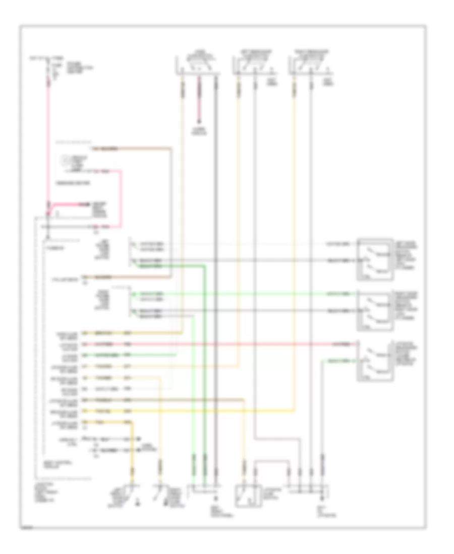
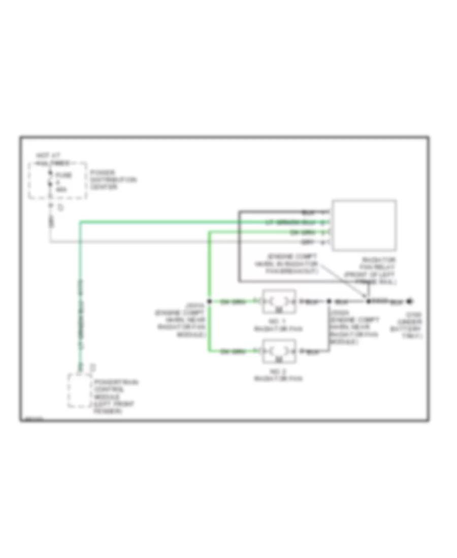
COOLING FAN
Cooling Fan Wiring Diagram for Chrysler Town & Country SX 1997
List of elements for Cooling Fan Wiring Diagram for Chrysler Town & Country SX 1997:
- (engine compt harn, in radiator fan breakout)
- Es23
- Fuse 40a
- G100 (under battery tray)
- Hot at all times
- Js01a (engine compt harn, near radiator fan module)
- Js02a (engine compt harn, near radiator fan module)
- No. 1 radiator fan
- No. 2 radiator fan
- Power distribution center
- Powertrain control module (left front fender)
- Radiator fan relay (front of left frame rail)
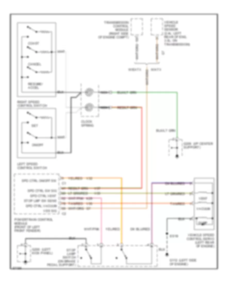
CRUISE CONTROL
Cruise Control Wiring Diagram for Chrysler Town & Country SX 1997
List of elements for Cruise Control Wiring Diagram for Chrysler Town & Country SX 1997:
- (i/p center
- (left
- (left side
- Cancel
- Clock spring
- Coast
- Dump
- Es18
- G112 of engine)
- G200 kick panel)
- G206 support)
- K29
- Left speed control switch
- Nca
- On/off
- Powertrain control module (front of left front fender)
- Resume/ accel
- Right speed control switch
- Set
- Spd ctrl on/off sw
- Spd ctrl sw sig
- Spd ctrl vacuum
- Spd ctrl vent
- Stop lamp switch (on brake pedal support)
- Stop lmp sw sens
- Tan/red
- Transmission control module (right side of engine compt)
- V32
- V35
- V36
- V37
- Vacuum
- Vehicle speed control servo (left rear of engine)
- Vehicle speed sensor (2.4l: left rear of eng, 3.0l: on transmission)
- Vent
- Vss sig
- W/atx
- W/eatx
DEFOGGERS
Defogger Wiring Diagram for Chrysler Town & Country SX 1997
List of elements for Defogger Wiring Diagram for Chrysler Town & Country SX 1997:
- A/c-heater control module (i/p center stack)
- Acc
- Cigar/ acc. relay
- Electric wiper de-ice driver
- Electric wiper de-icer
- Fuse 12 10a
- Fuse 21 20a
- Fuse 3 20a
- Fuse 7 10a
- G200 (left kick panel)
- G206 (i/p center support)
- G411 (in liftgate)
- Hot at all times
- Hvac control
- Ign sw output (start/run)
- Ignition switch
- Junction block (left front dash, under i/p)
- Left power mirror
- Lock
- Off
- Power distribution (front cigar lighter)
- Power distribution (rear cigar lighter)
- Power distribution center
- Ptc 7 6a
- Rear defog on ind
- Rear window defogger
- Rear window defogger relay
- Rear window defogger rly ctrl
- Rear window defogger sw sens
- Rear window defogger switch
- Red
- Right power mirror
- Run
- Start
ENGINE PERFORMANCE
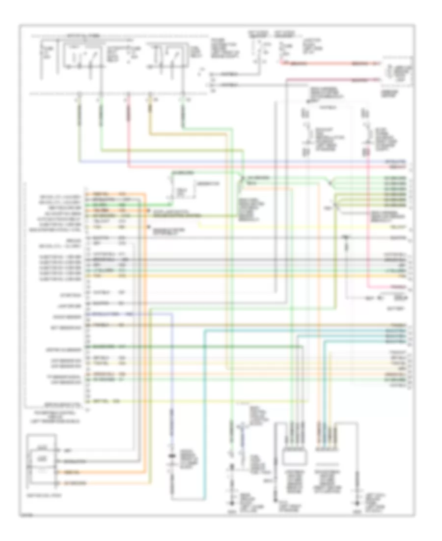
3.3L
3.3L, Engine Performance Wiring Diagrams (1 of 3) for Chrysler Town & Country SX 1997
List of elements for 3.3L, Engine Performance Wiring Diagrams (1 of 3) for Chrysler Town & Country SX 1997:
- (eng harn, near heated upstream oxygen sensor breakout)
- (eng harness, near map sensor breakout)
- (eng harness, near starter motor breakout) es07
- A142
- Auto shutdown relay
- Automatic shut down relay
- Battery
- Body control module (junction block) c1
- Ckp sensor sig
- Cmp sensor sig
- Downstream heated oxygen sensor (front center of floor pan)
- Ect sensor sig
- Egr solenoid ctrl
- Eng starter mtr rly ctrl
- Engine starter motor relay
- Es11
- Es12
- Es18
- Evap/ purge solenoid (right side of engine compt)
- Exhaust gas recirculation solenoid (left rear of engine)
- F87
- Field coil
- Fs01
- Fuel pump module (side of fuel tank)
- Fuel pump relay
- Fuse 20a
- G110 (left front of engine)
- G200
- G404
- Gen field driver
- Generator
- Ground
- Hot at all times
- Hot in run or start
- Ign coil cyl 3 & 6 driv
- Ign coil cyl. 1 & 4 driv
- Ign coil cyl. 2 & 5 driv
- Ignition coil pack
- Injector no. 1 driver
- Injector no. 2 driver
- Injector no. 3 driver
- Injector no. 4 driver
- Injector no. 5 driver
- Injector no. 6 driver
- Junction block (left side of i/p)
- K11
- K12
- K13
- K14
- K17
- K18
- K19
- K20
- K22
- K24
- K35
- K38
- K41
- K42
- K44
- K58
- K90
- Knock sensor
- Knock sensor (front of cylinder block)
- Lamp driver
- Left cowl ground panel (left side of cowl)
- Map sensor sig
- Message center
- Power distribution center (left front of engine compt)
- Powertrain control module (left fender side shield)
- Ptc 9a
- Rear ground block (left lower d-pillar)
- Sc on/off sw sens
- Service engine soon lamp
- Start/run
- Stop lamp switch (cruise control system)
- Tan
- Tp sensor signal
- Upstream heated oxygen sensor (rear of engine)
- Upstrm o2 sensor
- V32
- Z12
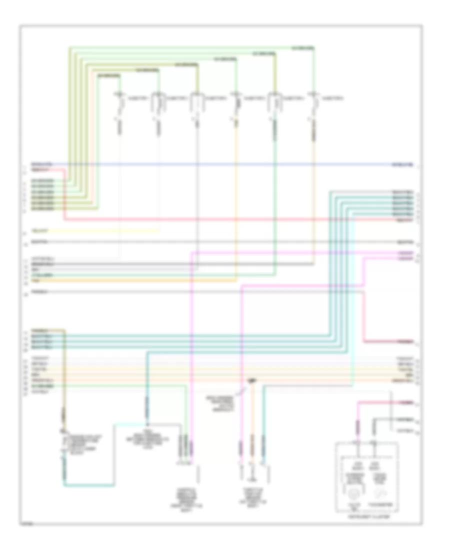
3.3L, Engine Performance Wiring Diagrams (2 of 3) for Chrysler Town & Country SX 1997
List of elements for 3.3L, Engine Performance Wiring Diagrams (2 of 3) for Chrysler Town & Country SX 1997:
- (eng harness, near prndl switch breakout)
- Ccd bus(+)
- Ccd bus(-)
- Charging system ind ctrl
- Engine coolant temperature sensor (on cylinder block)
- Es08
- Fs02 (eng harness, between breakouts for injectors 4 & 6)
- Injector 1
- Injector 2
- Injector 3
- Injector 4
- Injector 5
- Injector 6
- Instrument cluster
- Manifold absolute pressure sensor (near throttle body)
- Tacho- meter ctrl
- Tachometer
- Tan
- Throttle position sensor (on throttle body)
- Volts ind
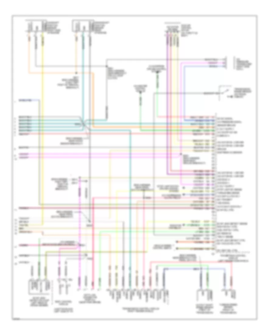
3.3L, Engine Performance Wiring Diagrams (3 of 3) for Chrysler Town & Country SX 1997
List of elements for 3.3L, Engine Performance Wiring Diagrams (3 of 3) for Chrysler Town & Country SX 1997:
- (+) ccd bus
- (eng harness, in battery positive terminal breakout)
- (eng harness, near breakout for prndl switch)
- (eng harness, near knock sensor breakout)
- (eng harness, near prndl switch breakout)
- (front of transmission)
- (i/p harness, above accelerator pedal)
- A/c cmp clutch rly
- A/c compressor clutch relay
- A/c on/off sw sig
- A/c pressure signal
- A/c pressure transducer (right side cowl)
- A/c-heater control module
- A14
- Auto shut down rly
- Body control module
- C103
- C13
- C18
- Camshaft position sensor (right side of engine)
- Ccd bus (+)
- Ccd bus (-)
- Clockspring (cruise control system)
- Crankshaft position sensor (rear of engine)
- D20
- D21
- Data link connector (partial) (near park brake)
- Dnstream o2 sensor
- Es02
- Es03 (eng harness, near body ground breakout)
- Es05
- Es10
- Es13
- Es14
- Es17 (eng harness, in battery positve terminal breakout)
- Es21 (eng harness, near breakout for a/c comp clutch)
- Es24
- Evap leak detect ctrl
- Evap leak detect sense
- Evap leak detection pump (left rear of cross member)
- Evap sol ctrl
- Fuel pmp rly ctrl
- Fused b (+)
- Gnd
- Gnd spd sens
- Ground
- Iac motor drivers
- Iac motor no. 1 driver
- Iac motor no. 2 driver
- Iac motor no. 3 driver
- Iac motor no. 4 driver
- Idle air control motor (on throttle body)
- Ign sw (run/ start)
- Input speed
- Junction block (left side of i/p)
- K106
- K107
- K141
- K173
- K22
- K24
- K29
- K31
- K39
- K40
- K51
- K52
- K59
- K60
- Output shaft speed sensor (front of transmission)
- Output speed
- P22
- Pnk
- Powertrain control module (left fender side shield)
- Ps01
- Ps02
- Rad fan rly ctrl
- Radiator fan relay
- Sc sw signal
- Sc vacuum sol ctrl
- Sc vent sol ctrl
- Sci receive
- Sci transmit
- Sensor gnd
- Sensor ground
- Sensor signal
- Signal ckp
- Signal sensor
- Signal tps
- Sol ctrl
- Speed input
- Stop lamp sw sense
- Stop lamp switch (cruise control system)
- Stroke sense
- T10
- T13
- T14
- T41
- T52
- Tan/red
- Torq req sense
- Torque req sense
- Transmission control module (right fender shield)
- Transmission range sensor (on trans- mission)
- Trs c1 sense
- Turbine speed sensor
- V35
- V36
- V37
- Vehicle speed control servo
- Vss signal
- Z12
3.8L
3.8L, Engine Performance Wiring Diagrams (1 of 3) for Chrysler Town & Country SX 1997
List of elements for 3.8L, Engine Performance Wiring Diagrams (1 of 3) for Chrysler Town & Country SX 1997:
- (eng harn, near heated upstream oxygen sensor breakout)
- (eng harness, near map sensor breakout)
- (eng harness, near starter motor breakout) es07
- A142
- Auto shutdown relay
- Automatic shut down relay
- Battery
- Body control module (junction block) c1
- Ckp sensor sig
- Cmp sensor sig
- Downstream heated oxygen sensor (front center of floor pan)
- Ect sensor sig
- Egr solenoid ctrl
- Eng starter mtr rly ctrl
- Engine starter motor relay
- Es11
- Es12
- Es18
- Evap/ purge solenoid (right side of engine compt)
- Exhaust gas recirculation solenoid (left rear of engine)
- F87
- Field coil
- Fs01
- Fuel pump module (side of fuel tank)
- Fuel pump relay
- Fuse 20a
- G110 (left front of engine)
- G200
- G404
- Gen field driver
- Generator
- Ground
- Hot at all times
- Hot in run or start
- Ign coil cyl 3 & 6 driv
- Ign coil cyl. 1 & 4 driv
- Ign coil cyl. 2 & 5 driv
- Ignition coil pack
- Injector no. 1 driver
- Injector no. 2 driver
- Injector no. 3 driver
- Injector no. 4 driver
- Injector no. 5 driver
- Injector no. 6 driver
- Junction block (left side of i/p)
- K11
- K12
- K13
- K14
- K17
- K18
- K19
- K20
- K22
- K24
- K35
- K38
- K41
- K42
- K44
- K58
- K90
- Knock sensor
- Knock sensor (front of cylinder block)
- Lamp driver
- Left cowl ground panel (left side of cowl)
- Map sensor sig
- Message center
- Power distribution center (left front of engine compt)
- Powertrain control module (left fender side shield)
- Ptc 9a
- Rear ground block (left lower d-pillar)
- Sc on/off sw sens
- Service engine soon lamp
- Start/run
- Stop lamp switch (cruise control system)
- Tan
- Tp sensor signal
- Upstream heated oxygen sensor (rear of engine)
- Upstrm o2 sensor
- V32
- Z12
3.8L, Engine Performance Wiring Diagrams (2 of 3) for Chrysler Town & Country SX 1997
List of elements for 3.8L, Engine Performance Wiring Diagrams (2 of 3) for Chrysler Town & Country SX 1997:
- (eng harness, near prndl switch breakout)
- Ccd bus(+)
- Ccd bus(-)
- Charging system ind ctrl
- Engine coolant temperature sensor (on cylinder block)
- Es08
- Fs02 (eng harness, between breakouts for injectors 4 & 6)
- Injector 1
- Injector 2
- Injector 3
- Injector 4
- Injector 5
- Injector 6
- Instrument cluster
- Manifold absolute pressure sensor (near throttle body)
- Tacho- meter ctrl
- Tachometer
- Tan
- Throttle position sensor (on throttle body)
- Volts ind
3.8L, Engine Performance Wiring Diagrams (3 of 3) for Chrysler Town & Country SX 1997
List of elements for 3.8L, Engine Performance Wiring Diagrams (3 of 3) for Chrysler Town & Country SX 1997:
- (+) ccd bus
- (eng harness, in battery positive terminal breakout)
- (eng harness, near breakout for prndl switch)
- (eng harness, near knock sensor breakout)
- (eng harness, near prndl switch breakout)
- (front of transmission)
- (i/p harness, above accelerator pedal)
- A/c cmp clutch rly
- A/c compressor clutch relay
- A/c on/off sw sig
- A/c pressure signal
- A/c pressure transducer (right side cowl)
- A/c-heater control module
- A14
- Auto shut down rly
- Body control module
- C103
- C13
- C18
- Camshaft position sensor (right side of engine)
- Ccd bus (+)
- Ccd bus (-)
- Clockspring (cruise control system)
- Crankshaft position sensor (rear of engine)
- D20
- D21
- Data link connector (partial) (near park brake)
- Dnstream o2 sensor
- Es02
- Es03 (eng harness, near body ground breakout)
- Es05
- Es10
- Es13
- Es14
- Es17 (eng harness, in battery positve terminal breakout)
- Es21 (eng harness, near breakout for a/c comp clutch)
- Es24
- Evap leak detect ctrl
- Evap leak detect sense
- Evap leak detection pump (left rear of cross member)
- Evap sol ctrl
- Fuel pmp rly ctrl
- Fused b (+)
- Gnd
- Gnd spd sens
- Ground
- Iac motor drivers
- Iac motor no. 1 driver
- Iac motor no. 2 driver
- Iac motor no. 3 driver
- Iac motor no. 4 driver
- Idle air control motor (on throttle body)
- Ign sw (run/ start)
- Input speed
- Junction block (left side of i/p)
- K106
- K107
- K141
- K173
- K22
- K24
- K29
- K31
- K39
- K40
- K51
- K52
- K59
- K60
- Output shaft speed sensor (front of transmission)
- Output speed
- P22
- Pnk
- Powertrain control module (left fender side shield)
- Ps01
- Ps02
- Rad fan rly ctrl
- Radiator fan relay
- Sc sw signal
- Sc vacuum sol ctrl
- Sc vent sol ctrl
- Sci receive
- Sci transmit
- Sensor gnd
- Sensor ground
- Sensor signal
- Signal ckp
- Signal sensor
- Signal tps
- Sol ctrl
- Speed input
- Stop lamp sw sense
- Stop lamp switch (cruise control system)
- Stroke sense
- T10
- T13
- T14
- T41
- T52
- Tan/red
- Torq req sense
- Torque req sense
- Transmission control module (right fender shield)
- Transmission range sensor (on trans- mission)
- Trs c1 sense
- Turbine speed sensor
- V35
- V36
- V37
- Vehicle speed control servo
- Vss signal
- Z12
EXTERIOR LIGHTS
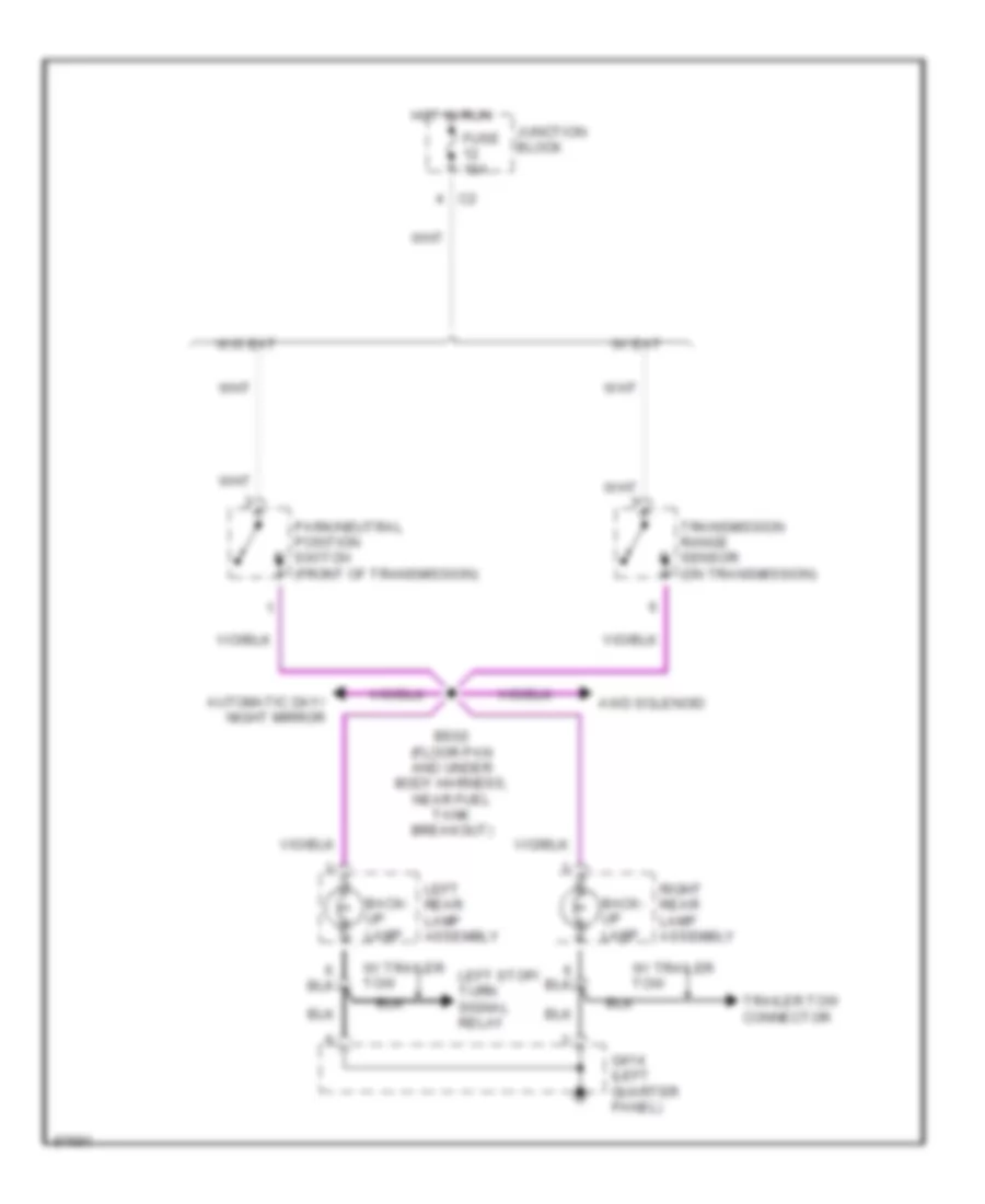
Back-up Lamps Wiring Diagram for Chrysler Town & Country SX 1997
List of elements for Back-up Lamps Wiring Diagram for Chrysler Town & Country SX 1997:
- Automatic day/ night mirror
- Awd solenoid
- Back- up lamp
- Bs02 (floor pan and under body harness, near fuel tank breakout)
- Fuse 10a
- G414 (left quarter panel)
- Hot in run
- Junction block
- Left rear lamp assembly
- Left stop/ turn signal relay
- Park/neutral position switch (front of transmission)
- Right rear lamp assembly
- Trailer tow connector
- Transmission range sensor (on transmission)
- W/ eat
- W/ trailer tow
- W/o eat
Exterior Lamps Wiring Diagram, with Trailer Tow for Chrysler Town & Country SX 1997
List of elements for Exterior Lamps Wiring Diagram, with Trailer Tow for Chrysler Town & Country SX 1997:
- (floor pan harn, near split for tail lamps)
- (multi-function switch) turn signal/ hazard switch
- A22
- Acc
- Anti-lock brakes system
- Body control module
- Bs01
- Center high mounted stop lamp
- Combination flasher/ drl module (canada)
- Combo flasher sw gnd
- Fuse 10a
- Fuse 12 10a
- Fuse 20a
- Fuse 4 15a
- Fuse 40a
- Fuse 6 15a
- Fused b+
- Fused ign
- G200 (left kick panel)
- G203 (right kick panel)
- G206 (i/p center support)
- G411 (in lift- gate)
- G414 (left quarter panel)
- Hot at all times
- Ignition switch
- Junc- tion block
- Junction block (left front dash, under i/p)
- L turn sig sens
- L302
- L305
- L60
- L61
- L62
- L63
- L91
- L97
- Left combi- nation relay
- Left front park/ turn signal lamp
- Left rear lamp assembly
- Left stop turn signal relay
- Lf turn sig
- License plate lamp
- Lock
- Lr turn sig
- Lt ind
- Message center
- Off
- Park lamp relay
- Park lmp rly ctrl
- Power distribution center
- R turn sig sens
- Rf turn sig
- Right combi- nation relay
- Right front park/ turn signal lamp
- Right rear lamp assembly
- Right stop turn signal relay
- Rr turn sig
- Rt ind
- Run
- Start
- Stop lamp switch (left side of brake pedal bracket)
- Tail/ stop lamp
- Tail/ turn signal
- Tan
- Trailer tow connector
Exterior Lamps Wiring Diagram, without Trailer Tow for Chrysler Town & Country SX 1997
List of elements for Exterior Lamps Wiring Diagram, without Trailer Tow for Chrysler Town & Country SX 1997:
- (floor pan harn, near split for tail lamps)
- (multi-function switch) turn signal/ hazard switch
- A22
- Acc
- Anti-lock brakes system
- Body control module
- Bs01
- Center high mounted stop lamp
- Combination flasher/ drl module (canada)
- Combo flasher sw gnd
- Fuse 10a
- Fuse 12 10a
- Fuse 20a
- Fuse 4 15a
- Fuse 40a
- Fuse 6 15a
- Fused b+
- Fused ign
- G200 (left kick panel)
- G203 (right kick panel)
- G206 (i/p center support)
- G411 (in lift- gate)
- G414 (left quarter panel)
- Hot at all times
- Ignition switch
- Junc- tion block
- Junction block (left front dash, under i/p)
- L turn sig sens
- L302
- L305
- L60
- L61
- L62
- L63
- L91
- L97
- Left front park/ turn signal lamp
- Left rear lamp assembly
- Lf turn sig
- License plate lamp
- Lock
- Lr turn sig
- Lt ind
- Message center
- Off
- Park lamp relay
- Park lmp rly ctrl
- Power distribution center
- R turn sig sens
- Rf turn sig
- Right front park/ turn signal lamp
- Right rear lamp assembly
- Rr turn sig
- Rt ind
- Run
- Start
- Stop lamp switch (left side of brake pedal bracket)
- Tail/ stop lamp
- Tail/ turn signal
- Tan
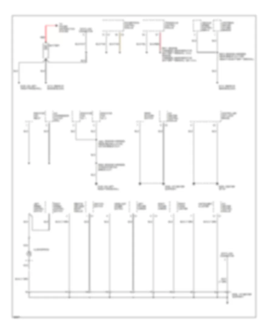
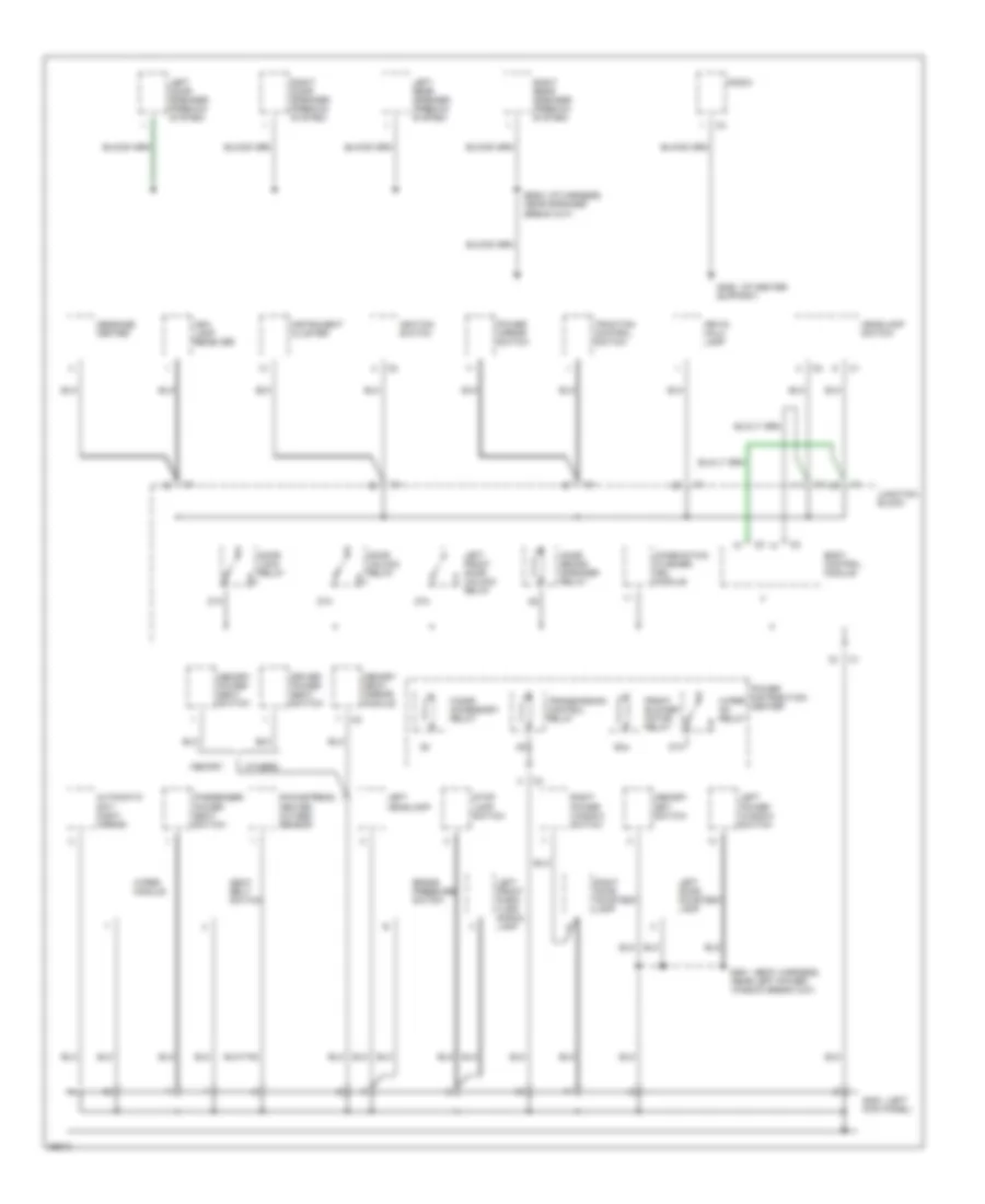
GROUND DISTRIBUTION
Ground Distribution Wiring Diagram (1 of 3) for Chrysler Town & Country SX 1997
List of elements for Ground Distribution Wiring Diagram (1 of 3) for Chrysler Town & Country SX 1997:
- (2.4l)
- (center
- (engine
- (engine harness,
- (ex. 2.4l))
- (i/p center
- (on left
- (rear of
- A/c compressor clutch (pdc)
- A/c heater control module
- Battery
- Clockspring
- Controller anti-lock brake
- Data link connector
- Es23 in radiator fan break out)
- Front cigar lighter
- G106 front frame rail)
- G112 engine block)
- G206 of i/p)
- G206 support)
- Headlamp dimmer switch
- Ignition switch
- Instrument cluster
- Js02 near recirculation motor break out)
- Left power mirror
- Left speed control switch
- Nca
- Powertrain control module
- Radiator fan no. 1
- Radiator fan no. 2
- Radiator fan relay
- Rear blower switch
- Red
- Remote keyless entry module
- Right power mirror
- Right speed control switch
- To power distribution system
- Transaxle control module
- Upstream heated oxygen sensor
- Vehicle speed control servo
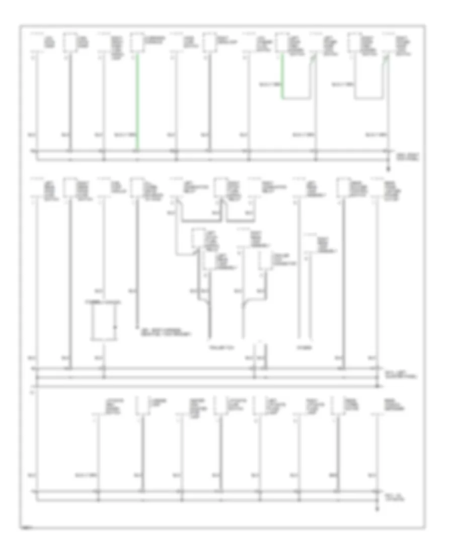
Ground Distribution Wiring Diagram (2 of 3) for Chrysler Town & Country SX 1997
List of elements for Ground Distribution Wiring Diagram (2 of 3) for Chrysler Town & Country SX 1997:
- (body harness,
- (i/p center
- (i/p harness,
- (left
- 87a
- Ash lamp receiver
- Automatic day/ night mirror
- Body control module
- Brake pressure switch
- Bs08 near speaker break out)
- Cigar/ accessory relay
- Combination flasher/ drl module
- Door lock relay
- Door unlock relay
- Downstream heated oxygen sensor
- Driver power seat switch
- Ds01 near left power window break out)
- Front blower motor relay
- G200 kick panel)
- G206 support)
- Headlamp switch
- Ignition switch
- Instrument cluster
- Junction block
- Key-in halo lamp
- Left door courtesy lamp
- Left door speaker (premium system)
- Left front door unlock relay
- Left front park/ turn signal lamp
- Left headlamp
- Left power window switch
- Left rear speaker (premium system)
- Memory
- Memory power seat switch
- Memory seat/ mirror module
- Memory set switch
- Message center
- Name brand speaker relay
- Others
- Passenger power seat switch
- Power distribution center
- Power mirror switch
- Radio
- Right door courtesy lamp
- Right door speaker (premium system)
- Right power window switch
- Right rear speaker (premium system)
- Seat belt switch
- Stop lamp switch
- Traction control switch
- Transmission control relay
- Wiper module
- Wiper on relay
Ground Distribution Wiring Diagram (3 of 3) for Chrysler Town & Country SX 1997
List of elements for Ground Distribution Wiring Diagram (3 of 3) for Chrysler Town & Country SX 1997:
- (body harness,
- (in
- (left
- (right
- 3.3l/3.8l
- All wheel drive solenoid (w/ awd)
- Center high mounted stop lamp
- Fuel pump module
- G203 kick panel)
- G411 liftgate)
- G414 quarter panel)
- High note horn
- Hood ajar switch
- Js01 near fuel tank grommet)
- Left combination relay
- Left door arm/ disarm switch
- Left liftgate flood lamp
- Left power door lock switch
- Left rear door ajar switch
- Left rear lamp assembly
- Left stop/ turn signal relay
- License lamp
- Liftgate ajar switch
- Liftgate arm/ disarm switch
- Low note horn
- Low washer fluid switch
- Others
- Overhead console
- Rear blower control switch
- Rear cigar lighter/ power outlet
- Rear window defogger
- Rear wiper motor
- Right combination relay
- Right door arm/ disarm switch
- Right front park/ turn signal lamp
- Right headlamp
- Right liftgate flood lamp
- Right power door lock switch
- Right rear door ajar switch
- Right rear lamp assembly
- Right stop/ turn signal relay
- Trailer tow
- Trailer tow connector
HEADLIGHTS
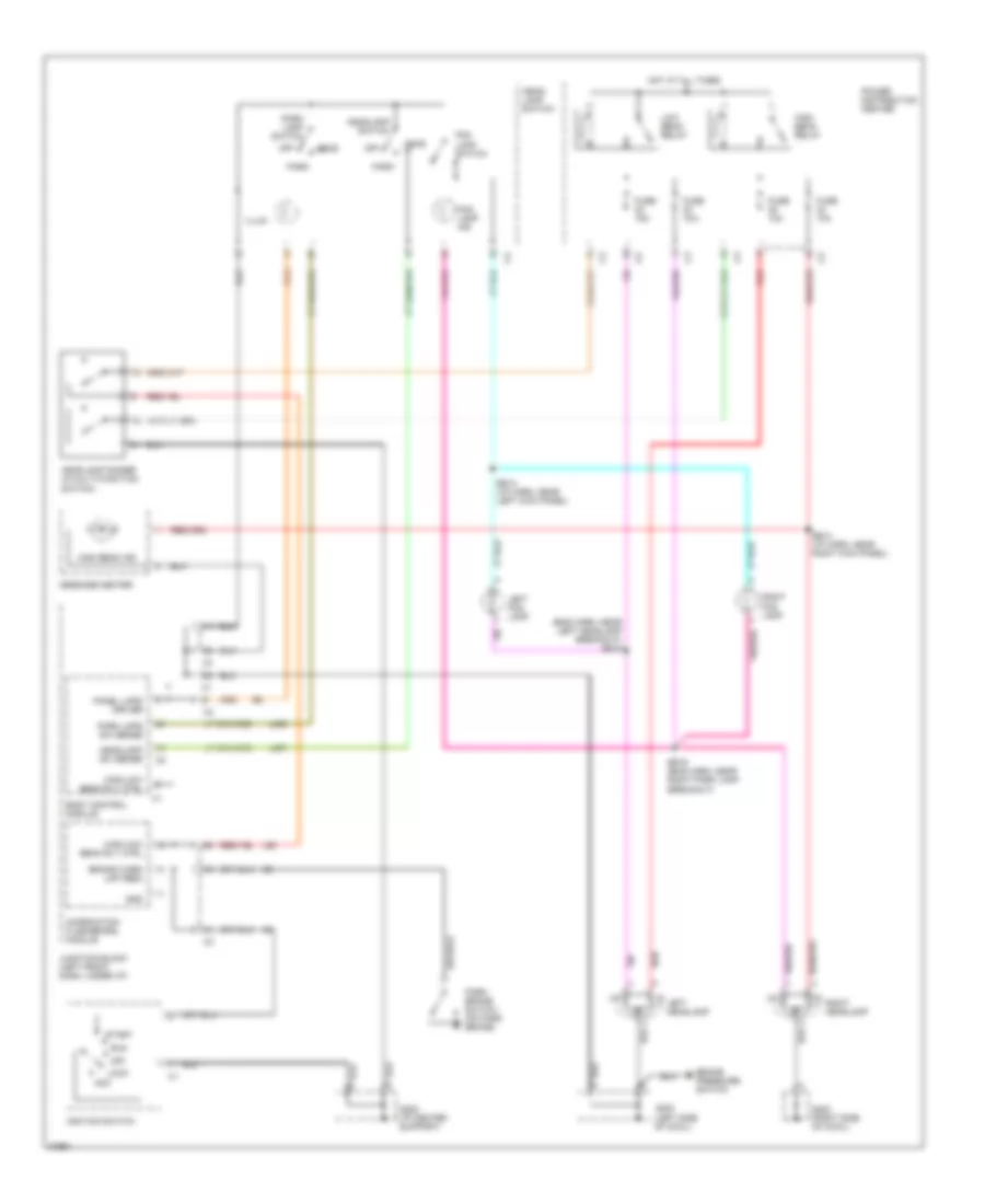
Headlamps/Fog Lamps Wiring Diagram, with DRL for Chrysler Town & Country SX 1997
List of elements for Headlamps/Fog Lamps Wiring Diagram, with DRL for Chrysler Town & Country SX 1997:
- (eng harn, near left headlamp breakout) bs15
- Acc
- Body control module
- Brake pressure switch
- Brake warn lmp (red)
- Bs14 (i/p harn, near left kick panel)
- Bs14 (i/p harn, near right kick panel)
- Bs16 (eng harn, near right park lamp breakout)
- Combination flasher/drl module
- Fog lamp ind
- Fog lamp switch
- Fuse 10a
- Fuse 15a
- G200 (left side of cowl)
- G203 (right side of cowl)
- G205 (i/p center support)
- Gnd
- Head
- Head- lamp switch
- Headlamp dimmer (in multi-function switch)
- Headlamp sw sense
- Headlamp switch
- High beam ind
- High beam relay
- High/low beam rly ctrl
- Hot at all times
- Ignition switch
- Illum
- Junction block (left front dash, under i/p)
- L307
- L308
- L93
- Left fog lamp
- Left headlamp
- Lock
- Low beam relay
- Message center
- Off
- Panel lmps driver
- Park
- Park brake switch (on park brake)
- Park lamp switch
- Park lmps sw sense
- Power distribution center
- Red
- Right fog lamp
- Right headlamp
- Run
- Start
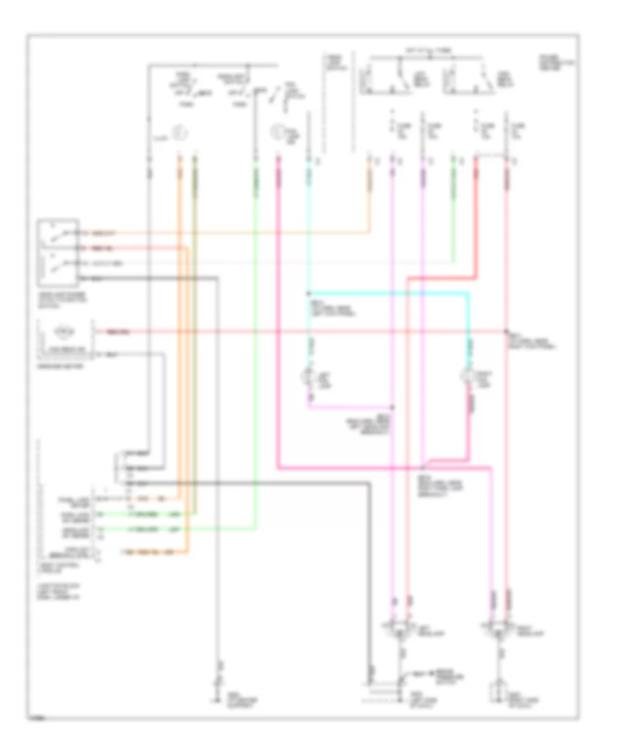
Headlamps/Fog Lamps Wiring Diagram, without DRL for Chrysler Town & Country SX 1997
List of elements for Headlamps/Fog Lamps Wiring Diagram, without DRL for Chrysler Town & Country SX 1997:
- Body control module
- Brake pressure switch
- Bs14 (i/p harn, near left kick panel)
- Bs14 (i/p harn, near right kick panel)
- Bs15 (eng harn, near left headlamp breakout)
- Bs16 (eng harn, near right park lamp breakout)
- Fog lamp ind
- Fog lamp switch
- Fuse 10a
- Fuse 15a
- G200 (left side of cowl)
- G203 (right side of cowl)
- G205 (i/p center support)
- Head
- Head- lamp switch
- Headlamp dimmer (in multi-function switch)
- Headlamp sw sense
- Headlamp switch
- High beam ind
- High beam relay
- High/low beam rly ctrl
- Hot at all times
- Illum
- Junction block (left front dash, under i/p)
- L307
- L308
- L93
- Left fog lamp
- Left headlamp
- Low beam relay
- Message center
- Off
- Panel lmps driver
- Park
- Park lamp switch
- Park lmps sw sense
- Power distribution center
- Red
- Right fog lamp
- Right headlamp
HORN
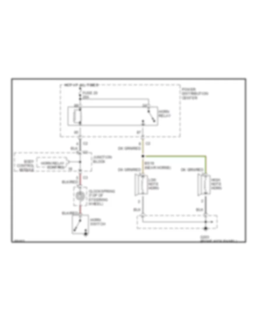
Horn Wiring Diagram for Chrysler Town & Country SX 1997
List of elements for Horn Wiring Diagram for Chrysler Town & Country SX 1997:
- Body control module
- Clockspring (top of steering wheel)
- Fuse 20 20a
- G203 (right kick panel)
- High note horn
- Horn relay
- Horn relay control
- Horn switch
- Hot at all times
- Junction block
- Low note horn
- Power distribution center
INSTRUMENT CLUSTER
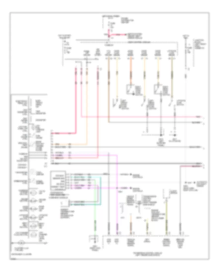
Instrument Cluster Wiring Diagram (1 of 2) for Chrysler Town & Country SX 1997
List of elements for Instrument Cluster Wiring Diagram (1 of 2) for Chrysler Town & Country SX 1997:
- Ambient temp
- Ambient temperature sensor (on radiator support)
- Atx
- Automatic day/night mirror
- Body control module
- Ccd bus (+)
- Ccd bus (-)
- Ccd bus +
- Ccd bus -
- Charging system ind ctrl
- Clock- spring
- Cluster illum (7 bulbs)
- Compass/mini- trip computer
- Cruise ind
- Cruise ind ctrl
- Cs04 (roof harn, right b pillar)
- Door ajar ind
- Door ajar ind ctrl
- Door ajar sense
- Eatx
- Ect signal
- Egine coolant temper- ature guage
- Elec- tronic prndl ind
- Electronic prndl sw ctrl
- Eng cool temp gauge
- Engine controls
- Engine coolant temperature sensor (on cylinder block)
- F11
- F20
- Fuel gauge
- Fuel gauge ctrl
- Fuse 10a
- Fused b+
- G301 (right kick panel)
- G31
- G32
- G411 (in liftgate)
- G414 (left quarter panel)
- G69
- Gnd
- Hot at all times
- Hot in run
- Hot in start, run or off
- Ign (off/ run/ start)
- Ign (off/ run/start)
- Ign (run)
- Instrument cluster
- Junction block (left front dash, under i/p)
- Left front door ajar switch
- Left rear door ajar switch
- Liftgate ajar ind
- Liftgate ajar ind ctrl
- Liftgate ajar sense
- Liftgate ajar switch
- Low fuel warn lmp ctrl
- Low fuel warning lamp
- Low washer fluid ind ctrl
- Low washer fluid level ind
- Odo- meter ctrl
- Odometer
- Overhead console
- Panel lmp driver
- Pnk
- Power distribution center
- Powertrain control module (left fender side shield)
- Ps01
- Ps02
- Right front door ajar switch
- Right rear door ajar switch
- Seat- belt ind
- Seat- belt ind ctrl
- Seats system, memory seat/ mirror module
- Sensor gnd
- Service engine soon lamp drv
- Speed control switch signal
- Speed- ometer
- Speedometer ctrl
- Tach- ometer
- Tachometer ctrl
- Tan
- Tan/red
- Transmission control module (right fender side shield)
- Trip odometer
- Trip odometer ctrl
- Vehcle speed sensor (rear of trans)
- Vehicle speed sensor signal
- Volts ind
- Vss sig
- Vta lmp driver
Instrument Cluster Wiring Diagram (2 of 2) for Chrysler Town & Country SX 1997
List of elements for Instrument Cluster Wiring Diagram (2 of 2) for Chrysler Town & Country SX 1997:
- (left kick panel)
- Abs control module (above accelerator pedal)
- Abs warn lamp drv
- Abs warn lmp driver
- Abs warning lmp
- Acc
- Airbag control module (behind lower portion of i/p, center stack)
- Airbag warning lamp driver
- Airbag warning lmp
- Body control module
- Brake pressure switch (on brake master cylinder)
- Brake warn lmp driver (red)
- Brake warning lmp
- Bs09
- Combination flasher/ drl module
- Engine cool temp drv
- Engine cool temp lmp
- Engine oil pressure switch (2.4l: rear of eng, 3.0l: near starter, 3.3l & 3.8l: below a/c compressor)
- Fuel level sensor signal
- Fuel level sig
- Fuel pump module (side of fuel tank)
- Fuse 10a
- Fuse 20a
- G19
- G200
- G206 (i/p center support)
- High beam ind
- Hot in start or run
- Hot with high beam relay on
- Ignition switch
- Junction block (left front dash, under i/p)
- L62
- L63
- Left turn ind
- Left turn sig
- Lock
- Low oil press lmp
- Low oil press lmp drv
- Low washer fluid signal
- Low washer fluid switch (bottom of reservoir)
- Lr turn sig
- Message center
- Off
- Oil press switch sense
- Park brake switch (top of park brake)
- Pnk
- Power distribution center
- R41
- Right turn ind
- Right turn sig
- Rr turn sig
- Run
- Seat belt switch (left b pillar)
- Seat belt switch sense
- Service eng soon lmp
- Start
- Vss sig
- Vta lmp
INTERIOR LIGHTS
Interior Light Wiring Diagram (1 of 2) for Chrysler Town & Country SX 1997
List of elements for Interior Light Wiring Diagram (1 of 2) for Chrysler Town & Country SX 1997:
- (i/p harn, behind right side of i/p) bs10
- (left rear corner of eng compt) wiper module
- (roof harn, above right door)
- (roof harn, in upper left "b" pillar)
- (w/ overhead
- (w/ overhead console)
- (w/o overhead console)
- 15a
- Body control module
- Console)
- Courtesy lamp relay
- Courtesy lmp rly driver
- Cs01
- Cs02
- Cs03
- Dimmer sw sig
- E92
- Front reading lamps/ switch
- Fuse
- G406 (in lift- gate)
- G70
- G74
- G75
- G76
- G77
- G78
- Glove box lamp
- Hood ajar sw sens
- Hood ajar switch
- Hot at all times
- Junction block (left front dash, under i/p)
- Key-in halo lamp
- Left door courtesy lamp
- Left front door ajar switch
- Left mid reading lamp
- Left rear reading lamp
- Lf door ajar sw sens
- Lift leftgate flood lamp
- Lift- gate ajar switch
- Liftgate ajar sw sens
- Lr door ajar sw sens
- M112
- M20
- Power distribution center
- Reading lmp gnd
- Rf door ajar sw sens
- Right door courtesy lamp
- Right front door ajar switch
- Right liftgate flood lamp
- Right mid reading lamp
- Right rear reading lamp
- Rr door ajar sw sens
- Tan
- Tan/red
- Under- hood lamps
- W/ overhead console
- W/o overhead console
Interior Light Wiring Diagram (2 of 2) for Chrysler Town & Country SX 1997
List of elements for Interior Light Wiring Diagram (2 of 2) for Chrysler Town & Country SX 1997:
- (4 leds)
- (i/p center support)
- (left quarter panel)
- (not used)
- (right kick panel)
- A/c-heater control module
- Ash receiver lamp
- Body control module
- Cluster illum (7 bulbs)
- Dim input c1
- Ds01
- G200 (left kick panel)
- G203
- G203 (right kick panel)
- G206
- G414
- Headlamp switch
- Instrument cluster
- Interior lamps on switch
- Junction block (left front dash, under i/p)
- Left power door lock switch
- Left power window switch
- Left rear door ajar switch
- Left visor/ vanity mirror lamp
- Lights on switch
- Panel lamps
- Panel lamps driver
- Power mirror switch
- Radio
- Reading defeat switch
- Rear blower front control switch
- Rear blower rear control switch
- Right power door lock switch
- Right power window switch
- Right rear door ajar switch
- Right visor/ vanity mirror lamp
- Step dim switch signal
- Traction control switch
MEMORY SYSTEMS
Memory Mirrors Wiring Diagram for Chrysler Town & Country SX 1997
List of elements for Memory Mirrors Wiring Diagram for Chrysler Town & Country SX 1997:
- (left kick panel)
- 30a
- Body control module
- Circuit breaker (under right power seat)
- Defogger system
- Door locks system
- Down
- Ds01
- F35
- Fuse 10 10a
- Fuse 11 15a
- Fused b+
- G200
- G96
- Gnd
- Heater
- Hot at all times
- Junction block (left front dash, c1
- Junction block (left front dash, under i/p)
- L66
- Left
- Left mirror
- Left mirror common
- Left mirror horz
- Left mirror pos gnd
- Left mirror pos horz
- Left mirror pos vert
- Left mirror vert
- Left power mirror
- Memory 1
- Memory 2
- Memory seat/ mirror module (under driver's seat)
- Memory set
- Memory set switch
- P22
- P23
- P24
- P64
- P65
- P67
- P68
- P69
- P70
- P71
- P72
- P73
- P74
- P75
- Panel lamps drivers
- Passenger's power seat switch
- Pnk
- Pnk/red
- Power distribution center
- Power mirror switch
- Red
- Right
- Right mirror
- Right mirror common
- Right mirror horz
- Right mirror pos gnd
- Right mirror pos horz
- Right mirror pos vert
- Right mirror vert
- Right power mirror
- Rke interface
- Under i/p)
Memory Seat Wiring Diagram for Chrysler Town & Country SX 1997
List of elements for Memory Seat Wiring Diagram for Chrysler Town & Country SX 1997:
- (in seat harness)
- (left kick panel)
- 30a
- Back
- Circuit breaker (under left power seat)
- D27
- Door locks system
- Ds01
- Entire seat
- F35
- Front vertical motor
- Frt
- Fuse 10 10a
- Fused b+
- Fwd
- G200
- G96
- Gnd
- Horizontal motor
- Hot at all times
- Junction block (left front dash, under i/p)
- Memory
- Memory 1
- Memory 2
- Memory power seat switch
- Memory seat front vertical position sensor (under left power seat)
- Memory seat horizontal position sensor (under left power seat)
- Memory seat rear vertical position sensor (under left power seat)
- Memory seat recliner position sensor (under left power seat)
- Memory seat/ mirror module (under driver's seat)
- Memory set
- P11
- P111
- P113
- P115
- P117
- P119
- P121
- P13
- P15
- P17
- P19
- P21
- P22
- P23
- P24
- P25
- P26
- P28
- P29
- P40
- P41
- P43
- P47
- P48
- Passenger's power seat switch
- Pnk
- Pnk/red
- Power distribution center
- Rear
- Rear vertical motor
- Recline
- Recliner motor
- Red
- Rke interface
- Seat front vert (down)
- Seat front vert (up)
- Seat front vert pos sense
- Seat horz (forward)
- Seat horz (rearward)
- Seat horz pos sense
- Seat pos sense b+
- Seat pos sense common
- Seat rear vert (down)
- Seat rear vert (up)
- Seat rear vert pos sense
- Seat recliner (forward)
- Seat recliner (rearward)
- Seat recliner pos sense
- Set
- Ss01
- Ss02
- Switch
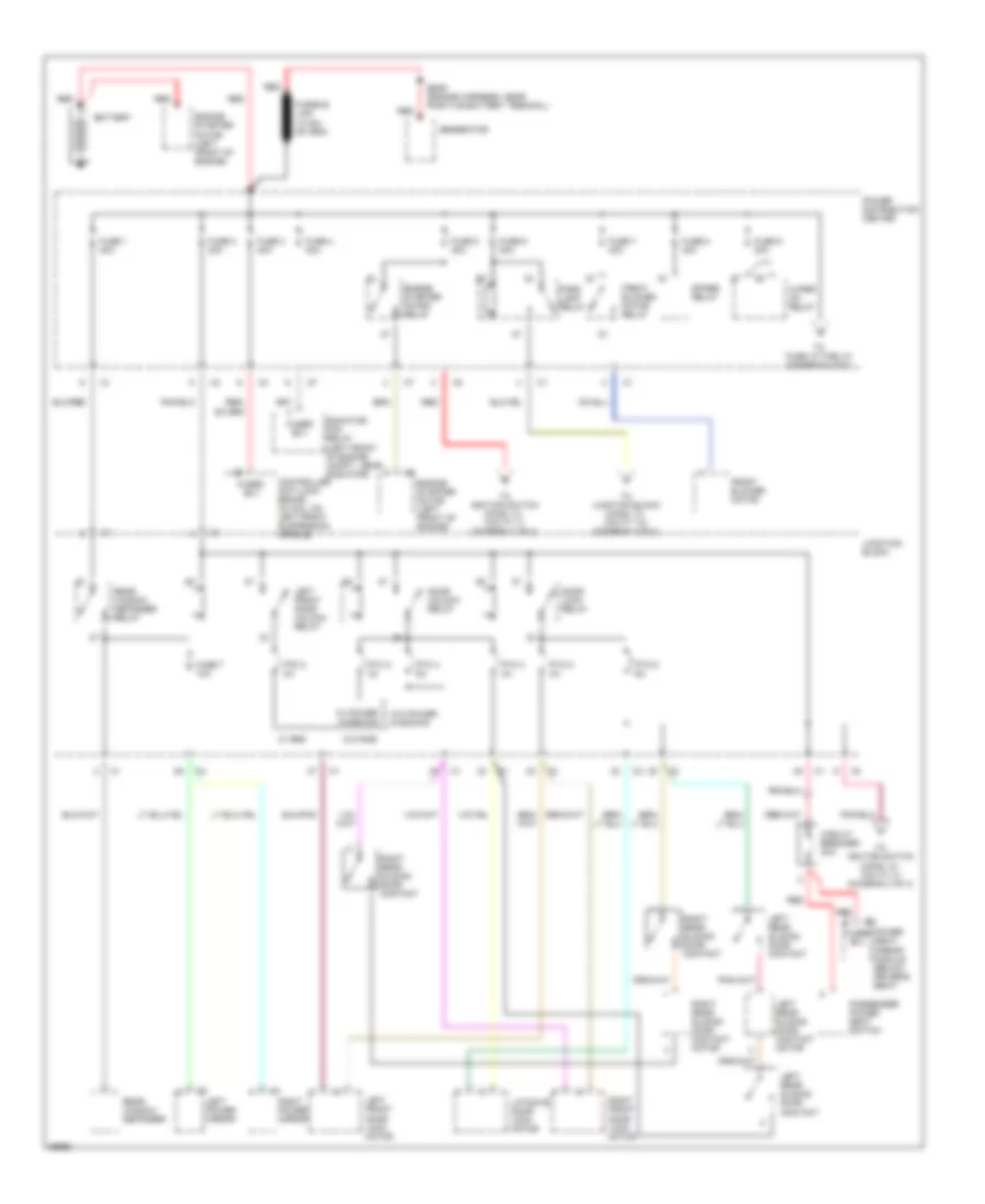
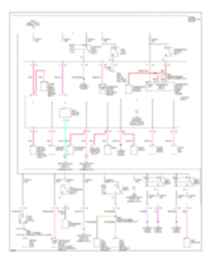
POWER DISTRIBUTION
Power Distribution Wiring Diagram (1 of 4) for Chrysler Town & Country SX 1997
List of elements for Power Distribution Wiring Diagram (1 of 4) for Chrysler Town & Country SX 1997:
- Battery
- Circuit breaker 30a
- Controller anti-lock brake (in hcu, on left front suspension cradle)
- Door lock relay
- Door unlock relay
- Engine starter motor (left front of engine)
- Engine starter motor relay
- Es09 (engine harness, near positive battery terminal)
- Front blower motor
- Front blower motor relay
- Fuse 1 40a
- Fuse 2 40a
- Fuse 3 40a
- Fuse 4 40a
- Fuse 5 40a
- Fuse 6 40a
- Fuse 7 10a
- Fuse 7 40a
- Fuse 8 40a
- Fuse 9 30a
- Fused b(+)
- Generator
- Junction block
- Left front door lock motor
- Left front door unlock relay
- Left power mirror
- Left rear sliding door contact
- Left rear sliding door contact motor
- Liftgate door lock motor
- Park lamp relay
- Passenger power seat switch
- Power distribution center
- Power seat/ mirror module (below driver's seat)
- Ptc 2 3a
- Ptc 3 4a
- Ptc 4 6a
- Ptc 5 4a
- Ptc 6 6a
- Radiator fan relay (left front of engine compt., near radiator)
- Rear window defogger
- Rear window defogger relay
- Red
- Right front door lock motor
- Right power mirror
- Right rear sliding door contact
- Right rear sliding door contact motor
- Spare relay
- To fuse 10 thru 21 (diagram 2 of 4)
- To ignition switch (conn. c1, cavity 3) (diagram 3 of 4)
- To ignition switch (conn. c1, cavity 7) (diagram 3 of 4)
- To junction block (conn. c1, cavity 10) (diagram 3 of 4)
- W/ power windows
- W/ rke
- W/o power windows
- W/o rke
- Wiper on relay
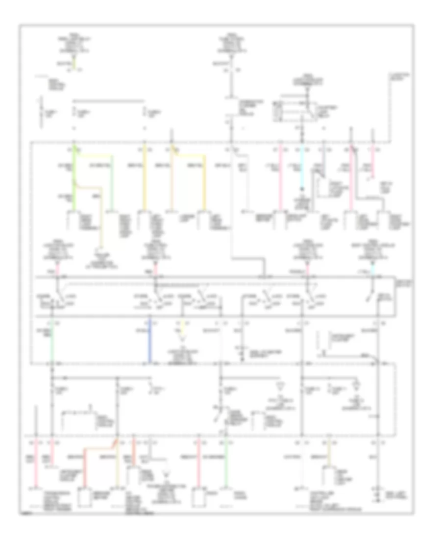
Power Distribution Wiring Diagram (2 of 4) for Chrysler Town & Country SX 1997
List of elements for Power Distribution Wiring Diagram (2 of 4) for Chrysler Town & Country SX 1997:
- A/c compressor clutch
- A/c compressor clutch relay
- Automatic shut down relay
- Body control module
- Bs01 (body harness, near split for tail lamps)
- Bs19 (engine harness, near horn break out)
- Center high stop lamp
- Controller anti-lock brake (in hcu, on left front suspension cradle)
- Data link connector (left side of i/p)
- Es01 (engine harness, near tcm break out)
- From fuse 1 thru 9 (diagram 1 of 4)
- Fuel pump module (on top of fuel tank)
- Fuel pump relay
- Fuse 10 10a
- Fuse 11 15a
- Fuse 12 20a
- Fuse 13 20a
- Fuse 14 20a
- Fuse 16 20a
- Fuse 17 25a
- Fuse 18 15a
- Fuse 19 20a
- Fuse 20 20a
- Fuse 21 20a
- Fuse 22 15a
- Fuse 23 15a
- Fuse 24 10a
- Fuse 25 10a
- Fused b(+)
- Glove box lamp
- High beam relay
- High note horn (below left front fender)
- Horn relay
- Instrument cluster
- Junction block
- Left headlamp
- Low beam relay
- Low note horn (below left front fender)
- Message center
- Pnk
- Power distribution center
- Power mirror switch
- Power seat/ mirror module (below driver's seat)
- Powertrain control module (left front fender)
- Radio
- Red
- Remote keyless entry module (left side of i/p)
- Stop lamp switch
- To cigar/ accessory relay (cavity 30) (diagram 4 of 4)
- To courtesy lamp relay (cavity 30 & 86) (diagram 3 of 4)
- To engine controls system
- To exterior lights system
- To ignition switch (conn. c2, cavity 1) (diagram 3 of 4)
- To ignition switch (conn. c3, cavity 1) (diagram 3 of 4)
- To interior lights system
- To junction block (conn. c2, cavity 24) (diagram 3 of 4)
- Transmission control module (inner right fender)
- Transmission control relay
- Transmission control solenoid
- Transmission relay output
- Wiper module
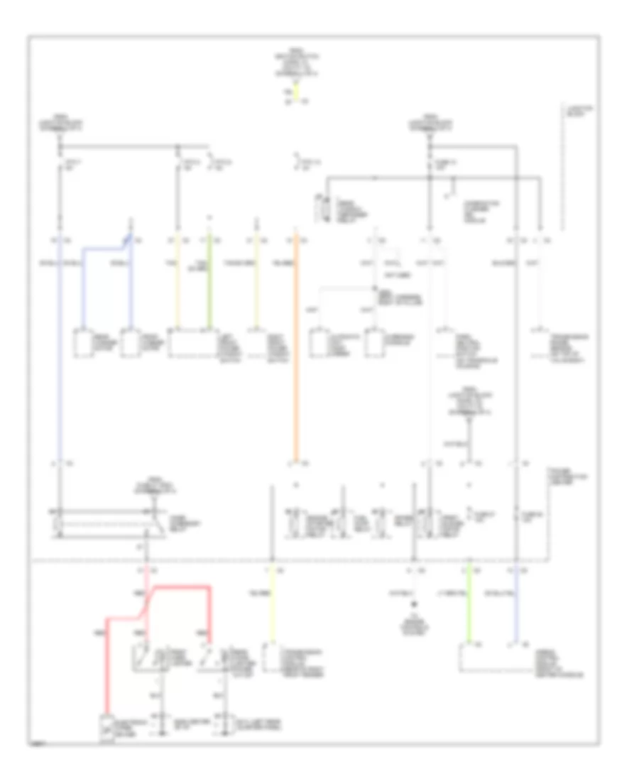
Power Distribution Wiring Diagram (3 of 4) for Chrysler Town & Country SX 1997
List of elements for Power Distribution Wiring Diagram (3 of 4) for Chrysler Town & Country SX 1997:
- (i/p center
- (left
- A/c heater control module (behind a/c control head)
- Acc
- Body control module
- Combination flasher/ drl module
- Controller anti-lock brake (in hcu, on left front suspension cradle)
- Courtesy lamp relay
- From body control module (conn. c2, cavity 4) (diagram 2 of 4)
- From fuse 19 (pdc) (conn. c5, cavity 9) (diagram 2 of 4)
- From fuse 5 (pdc) (conn. c4, cavity 3) (diagram 1 of 4)
- From junction block (conn. c4, cavity 17) (diagram 2 of 4)
- From junction block (conn. c4, cavity 6) (diagram 1 of 4)
- From junction block (diagram 2 of 4)
- From park lamp relay (conn. c1, cavity 4) (diagram 1 of 4)
- Fuse 1 10a
- Fuse 10 10a
- Fuse 11 20a
- Fuse 2 10a
- Fuse 3 20a
- Fuse 4 15a
- Fuse 6 15a
- Fuse 8 10a
- G200 kick panel)
- G206 support)
- Headlamp switch
- Ignition switch
- Instrument cluster
- Instrument cluster module
- Junction block
- Key-in halo lamp
- Key-in switch
- Left door courtesy lamp
- Left front park/ turn signal lamp
- Left liftgate flood lamp
- Left rear lamp assembly
- License lamp
- Lock off
- Message center
- Name brand speaker relay
- Pnk
- Pnk/
- Ptc 1 9a
- Radio
- Radio choke
- Rear a/c heater unit
- Rear wiper motor
- Red
- Right door courtesy lamp
- Right front park/ turn signal lamp
- Right liftgate flood lamp
- Right rear lamp assembly
- Run
- Start
- To fuse 12 (j/b) (diagram 4 of 4)
- To interior lights system
- To junction block (conn. c3, cavity 28) (diagram 4 of 4)
- To power distribution center (conn. c2, cavity 6) (diagram 4 of 4)
- To ptc 7 thru 9 (j/b) (diagram 4 of 4)
- Trailer tow connector (w/ trailer tow)
- Transmission control module (rear of right front fender)
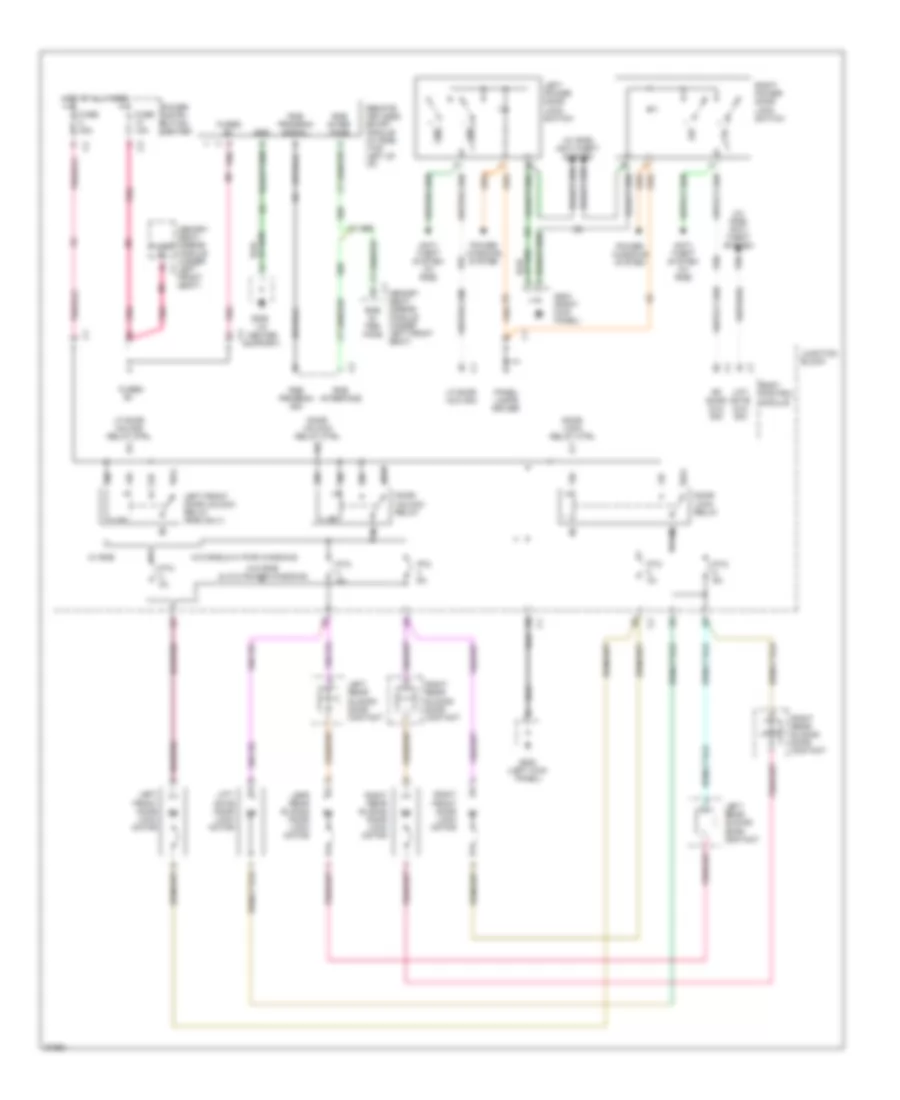
Power Distribution Wiring Diagram (4 of 4) for Chrysler Town & Country SX 1997
List of elements for Power Distribution Wiring Diagram (4 of 4) for Chrysler Town & Country SX 1997:
- (center
- (left rear
- Airbag control module (front of center console)
- Automatic day/ night mirror
- Cigar/ accessory relay
- Combination flasher/ drl module
- Cs04 (body harness, right "b" pillar)
- Electronic wiper de-icer
- Engine starter motor relay
- From fuse 21 (pdc) (diagram 2 of 4)
- From ignition switch (conn. c1, cavity 10) (diagram 3 of 4)
- From junction block (conn. c3, cavity 9) (diagram 3 of 4)
- From junction block (diagram 3 of 4)
- Front blower motor relay
- Front cigar lighter
- Front washer motor
- Fuel pump relay
- Fuse 12 10a
- Fuse 27 10a
- Fuse 28 10a
- G206 of i/p)
- G414 quarter panel)
- Junction block
- Left front power window switch
- Not used
- Overhead console
- Park/ neutral position switch (on transaxle housing)
- Power distribution center
- Ptc 10 3a
- Ptc 7 6a
- Ptc 8 9a
- Ptc 9 9a
- Rear cigar lighter/ power outlet
- Rear washer motor
- Rear window defogger relay
- Red
- Right front power window switch
- Spare relay
- Tan
- To engine controls system
- Transmission control module (rear of right front fender)
- Transmission range sensor (on top of valve body)
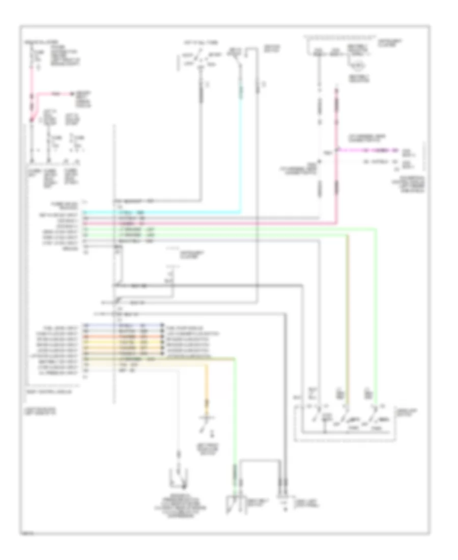
POWER DOOR LOCKS
Power Door Lock Wiring Diagram for Chrysler Town & Country SX 1997
List of elements for Power Door Lock Wiring Diagram for Chrysler Town & Country SX 1997:
- (i/p center support)
- (w/ rke) anti- theft system
- (w/ rke) anti-theft system
- 1.5k
- 87a
- Anti- theft system (w/ rke)
- Body control module
- Door lock relay
- Door lock relay ctrl
- Door unlock relay
- Door unlock relay ctrl
- Fuse 10a
- Fuse 40a
- Fused
- Fused b+
- G200 (left kick panel)
- G203 (right kick panel)
- G206
- G96
- Gnd
- Hot at all times
- Junction block
- Lefr rear sliding door lock motor
- Left front door lock motor
- Left front door unlock relay (rke only)
- Left power door lock switch
- Left rear sliding door contact
- Lf door mux sig
- Lf door unlock relay ctrl
- Lift- gate door lock motor
- Lift- gate mux sig
- Memory c1
- Memory seat/ mirror module (under left front seat)
- P96
- P97
- P98
- Panel lamps driver
- Pnk
- Power distri- bution center
- Power windows system
- Ptc 3a
- Ptc 4a
- Ptc 6a
- Remote keyless entry module (w/ rke) (top left of i/p)
- Rf door mux sig
- Right front door lock motor
- Right power door lock switch
- Right rear sliding door contact
- Right rear sliding door lock motor
- Rke in- ter- face
- Rke inter- face
- Rke interface
- Rke program sig
- Rke program signal
- Seat/ mirror module (under left front seat)
- W/ rke
- W/o rke & w/ pwr windows
- W/o rke & w/o power windows
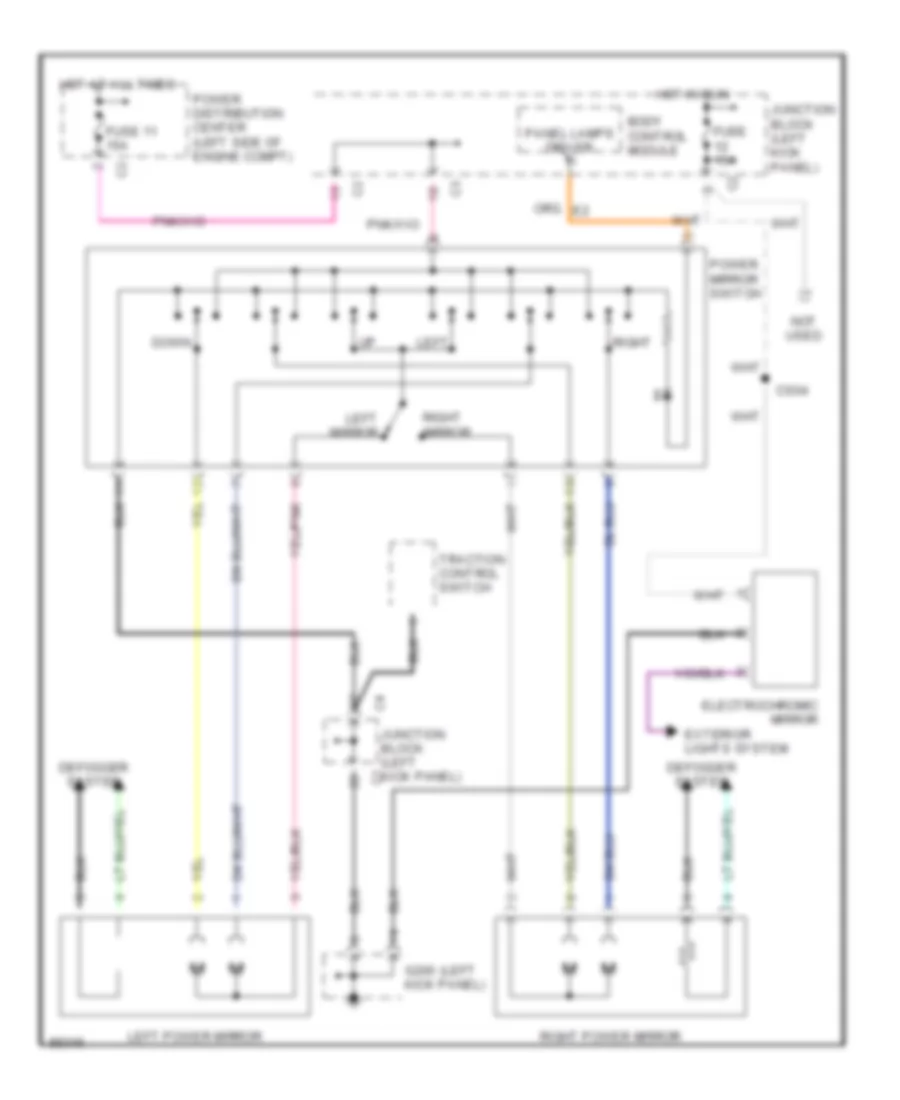
POWER MIRRORS
Power Mirror Wiring Diagram for Chrysler Town & Country SX 1997
List of elements for Power Mirror Wiring Diagram for Chrysler Town & Country SX 1997:
- (left
- Body control module
- Cs04
- Defogger system
- Down
- Electrochromic mirror
- Exterior lights system
- Fuse 11 15a
- Fuse 15a
- G200 kick panel)
- Hot at all times
- Hot in run
- Junction block (left kick panel)
- Left
- Left mirror
- Left power mirror
- Not used
- Panel lamps driver
- Power distribution center (left side of engine compt)
- Power mirror switch
- Right
- Right mirror
- Right power mirror
- Traction control switch
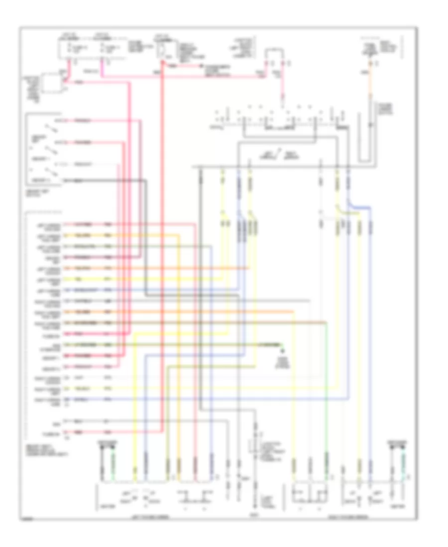
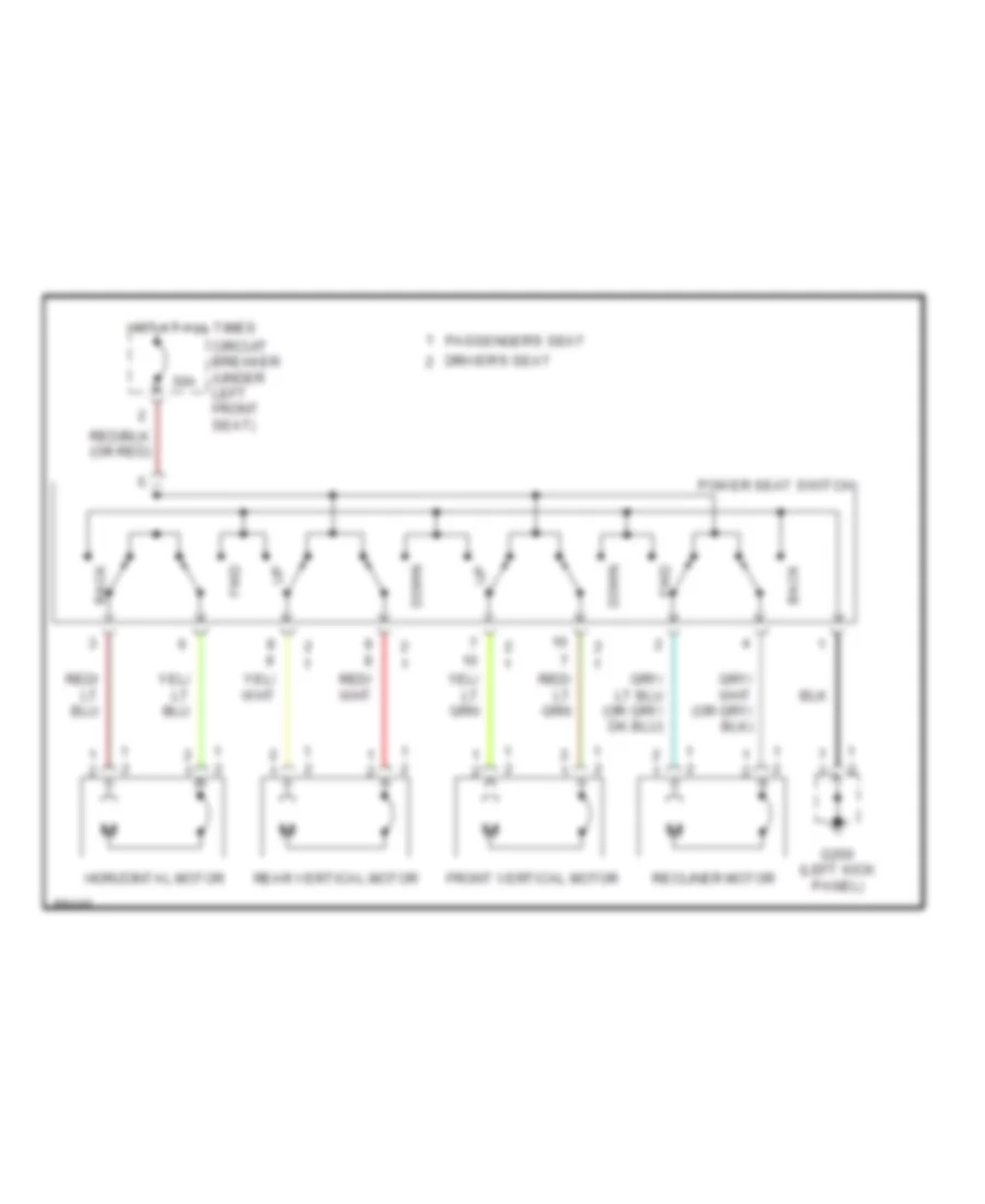
POWER SEATS
Power Seat Wiring Diagrams for Chrysler Town & Country SX 1997
List of elements for Power Seat Wiring Diagrams for Chrysler Town & Country SX 1997:
- 30a
- Back
- Circuit breaker (under left front seat)
- Down
- Driver's seat
- Front vertical motor
- Fwd
- G200 (left kick panel)
- Horizontal motor
- Hot at all times
- Passenger's seat
- Power seat switch
- Rear vertical motor
- Recliner motor
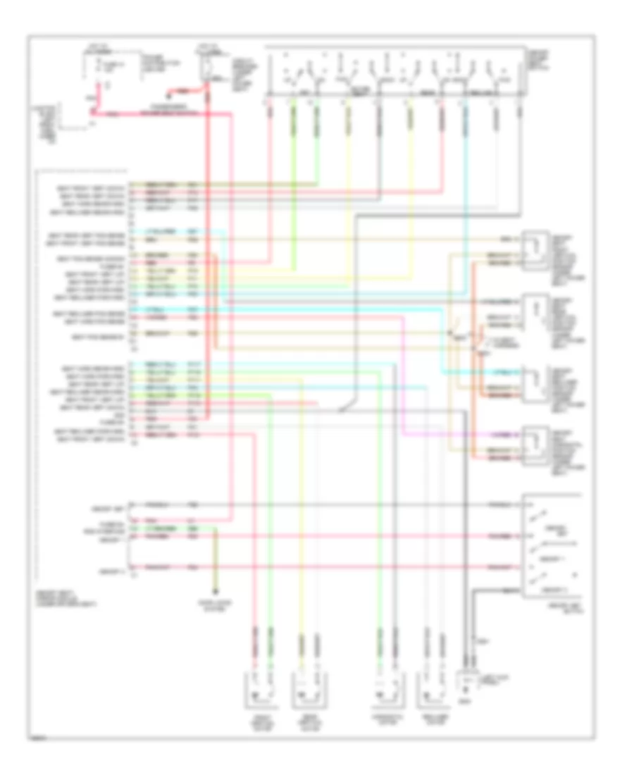
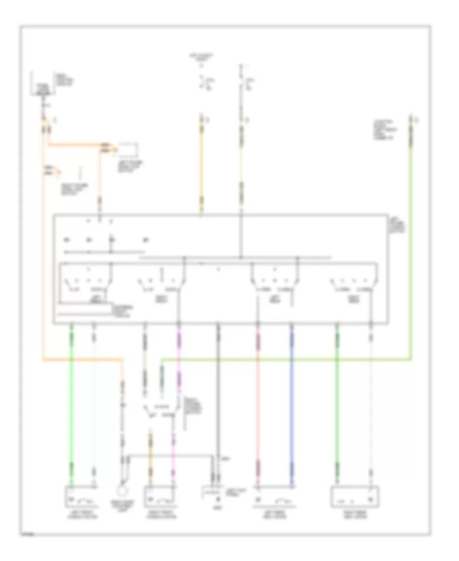
POWER WINDOWS
Power Window Wiring Diagram for Chrysler Town & Country SX 1997
List of elements for Power Window Wiring Diagram for Chrysler Town & Country SX 1997:
- (left kick panel)
- Body control module
- Close
- Down
- Ds01
- Express down module
- G200
- Hot in accy or run
- Junction block (left front dash, under i/p)
- Left front
- Left front window motor
- Left power door lock switch
- Left power window switch
- Left rear
- Left rear vent motor
- Open
- Panel lamps driver
- Ptc 9a
- Right door courtesy lamp
- Right front
- Right front window motor
- Right power door lock switch
- Right power window switch
- Right rear
- Right rear vent motor
- Tan
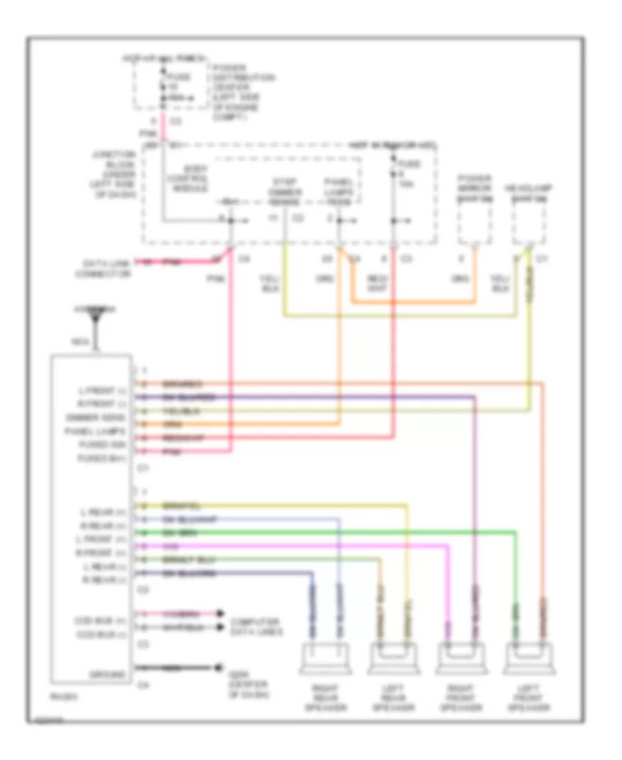
RADIO
Radio Wiring Diagrams, Base Radio for Chrysler Town & Country SX 1997
List of elements for Radio Wiring Diagrams, Base Radio for Chrysler Town & Country SX 1997:
- Antenna
- B(+)
- Body control module
- Ccd bus (+)
- Ccd bus (-)
- Computer data lines
- Data link connector
- Dimmer sens
- Fuse 10a
- Fused b(+)
- Fused ign
- G206 (center of dash)
- Ground
- Headlamp switch
- Hot at all times
- Hot in run or acc
- Junction block (under left side of dash)
- L front (+)
- L front (-)
- L rear (+)
- L rear (-)
- Left front speaker
- Left rear speaker
- Nca
- Panel lamps
- Panel lamps feed
- Pnk
- Power distribution center (left side of engine compt)
- Power mirror switch
- R front (+)
- R front (-)
- R rear (+)
- R rear (-)
- Radio
- Right front speaker
- Right rear speaker
- Step dimmer sense
Radio Wiring Diagrams, Premium Model for Chrysler Town & Country SX 1997
List of elements for Radio Wiring Diagrams, Premium Model for Chrysler Town & Country SX 1997:
- (dash harn, center of dash) bs08
- Antenna
- B(+)
- Body control module
- Bs03 (dash harn, left side of dash)
- Ccd bus (+)
- Ccd bus (-)
- Computer data lines
- Data link connector
- Dimmer sens
- Fuse 10a
- Fused b(+)
- Fused ign
- G200 (left kick panel)
- G206 (center of dash)
- Ground strap
- Headlamp switch
- Hot at all times
- Hot in run or acc
- Junction block (behind left side of dash)
- L front (+)
- L front (-)
- L rear (+)
- L rear (-)
- Left dash panel speaker
- Left door speaker
- Left rear pillar speaker
- Left rear speaker
- Name brand speaker relay
- Nbs relay dr
- Nca
- Panel lamps
- Panel lamps feed
- Pnk
- Power distribution center (left side of engine compt)
- Power mirror switch
- R front (+)
- R front (-)
- R rear (+)
- R rear (-)
- Radio
- Radio choke (behind junction block)
- Right dash panel speaker
- Right door speaker
- Right rear pillar speaker
- Right rear speaker
- Step dimmer sense
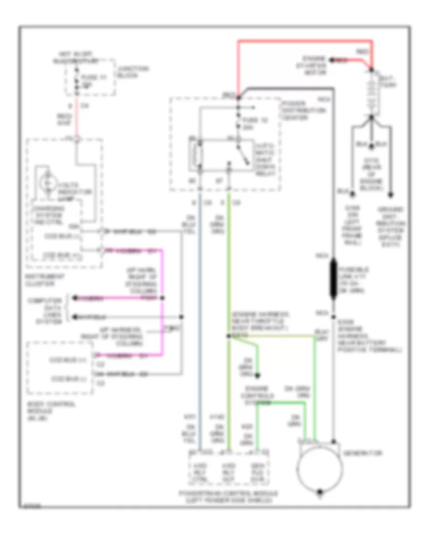
STARTING/CHARGING
Charging Wiring Diagram for Chrysler Town & Country SX 1997
List of elements for Charging Wiring Diagram for Chrysler Town & Country SX 1997:
- (engine harness, near throttle body breakout) es12
- (i/p harn, right of steering column) ps01
- (i/p harness, right of steering column)
- A142
- Asd rly ctrl
- Asd rly out
- Auto- matic shut down relay
- Bat- tery
- Body control module (in jb)
- Ccd bus (+)
- Ccd bus (-)
- Charging system ind ctrl
- Computer data lines system
- Engine controls system
- Engine starter motor
- Es09 (engine harness, near battery positive terminal)
- Fuse 11 10a
- Fuse 12 20a
- G106 (on left front frame rail)
- G112 (rear of engine block)
- Gen fld dvr
- Generator
- Ground dist- ribution system (splice es11)
- Hot in off, run or start
- Ign
- Instrument cluster
- Junction block
- K20
- K51
- Nca
- Power distribution center
- Powertrain control module (left fender side shield)
- Ps02
- Red
- Volts indicator lamp
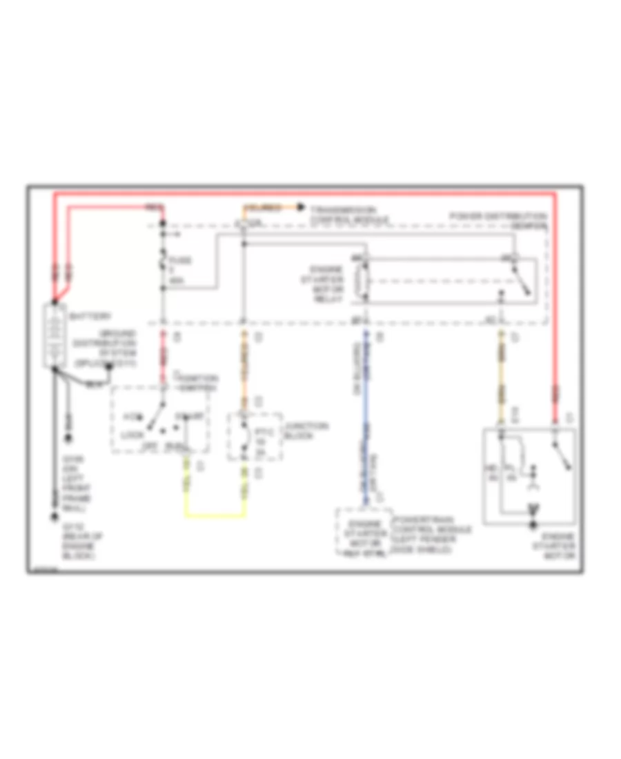
Starting Wiring Diagram for Chrysler Town & Country SX 1997
List of elements for Starting Wiring Diagram for Chrysler Town & Country SX 1997:
- Acc
- Battery
- E19
- Engine starter motor
- Engine starter motor relay
- Engine starter motor rly ctrl
- Fuse 40a
- G106 (on left front frame rail)
- G112 (rear of engine block)
- Ground distribution system (splice es11)
- Hd in
- Ignition c1 switch
- Junction block
- K90
- Lock
- Off
- Pl in
- Power distribution center
- Powertrain control module (left fender side shield)
- Ptc 3a
- Red
- Run
- Start
- Transmission control module
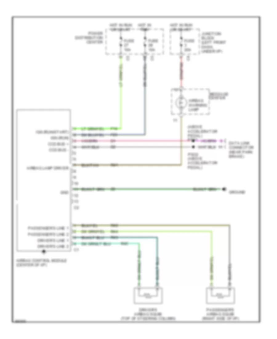
SUPPLEMENTAL RESTRAINTS
Supplemental Restraint Wiring Diagram for Chrysler Town & Country SX 1997
List of elements for Supplemental Restraint Wiring Diagram for Chrysler Town & Country SX 1997:
- (above accelerator pedal) ps01
- Airbag control module (center of i/p)
- Airbag lamp driver
- Airbag warning lamp
- Ccd bus +
- Ccd bus -
- Center
- Data link connector (near park brake)
- Driver's airbag squib (top of steering column)
- Driver's line 1
- Driver's line 2
- F14
- F23
- Fuse 10a
- Fuse 20a
- Gnd
- Ground
- Hot in run
- Hot in run or start
- Ign (run)
- Ign (run/start)
- Junction block (left front dash, under i/p)
- Message
- Passenger's airbag squib (right side of i/p)
- Passenger's line 1
- Passenger's line 2
- Power distribution center
- Pso2 (above accelerator pedal)
- R41
- R42
- R43
- R44
- R45
TRANSMISSION
3.3L
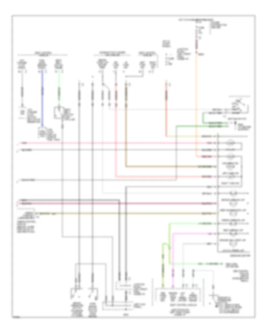
3.3L, Transmission Wiring Diagram (1 of 3) for Chrysler Town & Country SX 1997
List of elements for 3.3L, Transmission Wiring Diagram (1 of 3) for Chrysler Town & Country SX 1997:
- (near gray 36-way in-line connector, right of steering column)
- (near park brake switch breakout) bs06
- (rear of engine) g115
- 2-4 press sw
- 2-4 pressure switch
- 2-4 sol ctrl
- 2/4 solenoid
- Body control module
- Ccd bus (+)
- Ccd bus (-)
- Computer data lines system
- D21
- Electronic prndl control
- Electronic prndl indicator
- Es01 (near tcm breakout)
- Es13
- Es14 (in positive battery terminal)
- F11
- F45
- Fuse 2 10a
- Fused (b+)
- Fused ign sw out
- Fused ign sw output (st-run-off)
- Fused ign. (off/run/ start)
- Gnd
- Hot in off, run or start
- Input spd sns sig
- Instrument cluster
- Junction block (behind left side of dash)
- K22
- K24
- Low/ reverse pressure switch
- Low/ reverse solenoid
- Low/rev press sw
- Low/rev sol. ctrl
- Models
- O/d solenoid
- Od solenoid ctrl
- Out shaft spd sig
- Output shaft speed sensor (on transmission)
- Overdrive pressure switch
- Pnk
- Prnd3l
- Ps01 (near gray 36-way in-line connector, right of steering column)
- Ps02
- Red
- Sci receive
- Sci transmit
- Sensor gnd
- Spd sensor gnd
- T10
- T13
- T14
- T15
- T16
- T19
- T20
- T41
- T42
- T47
- T50
- T52
- T54
- T59
- T60
- Torq mgmt req
- Tps signal
- Tr sw c1 sense
- Tr sw c2 sense
- Trans rly out
- Trans temp sens
- Transmission control module (right side of engine compartment)
- Transmission solenoids & pressure switches (transmission)
- Turbine speed sensor (on transmission)
- U/d solenoid
- Ud sol ctrl
- Vss sig
- Z13
- Z14
3.3L, Transmission Wiring Diagram (2 of 3) for Chrysler Town & Country SX 1997
List of elements for 3.3L, Transmission Wiring Diagram (2 of 3) for Chrysler Town & Country SX 1997:
- (1997 models) (1998 models)
- (body harness, near fuel tank grommet) js01
- (left kick panel)
- (left quarter panel)
- (rear of engine) g115
- 1997 models
- 1998 models
- All wheel drive solenoid (near fuel tank)
- Automatic day/night mirror
- Aws1
- Aws2
- Back-up lamp sense
- Controller anti-lock brake (on right side of engine compartment)
- Es10 (near transmission range switch breakout)
- Exterior lights system (back-up lights circuit)
- F20
- F45
- Fuse 10a
- Fuse 14 fuse 15 20a
- G200
- G404
- G414
- Hot at all times
- Hot in run
- Hot in start
- Junction block (behind left side of dash)
- Models
- Nca
- Nol
- P3l
- Pnk
- Power distribution center (left side of engine compartment)
- Prnl
- Ptc cb 10 3a
- Red
- Tank breakout)
- Trans temp. sensor
- Transmission control relay
- Transmission range sensor (in transmission, on top of valve body)
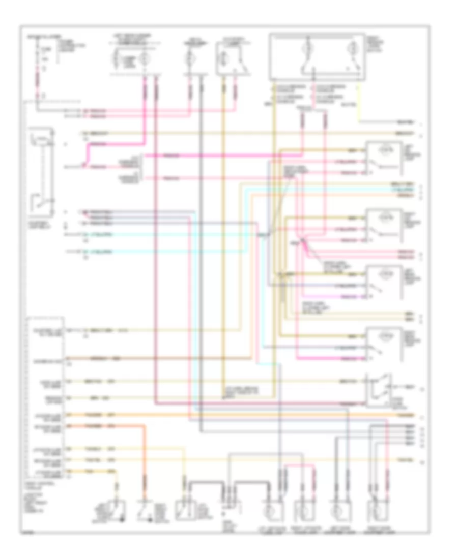
3.3L, Transmission Wiring Diagram (3 of 3) for Chrysler Town & Country SX 1997
List of elements for 3.3L, Transmission Wiring Diagram (3 of 3) for Chrysler Town & Country SX 1997:
- (i/p center support)
- (left kick panel)
- (near body ground breakout) es03
- (near breakout for a/c clutch)
- (near knock sensor breakout)
- (rear of engine) g115
- 1997 models
- 1998 models
- Air condtioning system
- Ccd bus (+)
- Ccd bus (-)
- Ckp sensor sig
- Clockspring, left & right speed control switches
- Crankshaft position sensor (on transmission bell housing)
- D20
- D21
- Data link connector (partial) (below left side of dash)
- Engine controls & air conditioning systems
- Engine controls system
- Es02
- Es05 (near transmission range switch breakout)
- Es08 (near transmission range switch breakout)
- Es17
- Es21
- Es24 (near transmission range switch breakout)
- Exterior lights system
- Fuse 10a
- G200
- G206
- Ground
- Hot at all times
- Junction block (behind left side of dash)
- K22
- K24
- K29
- Memory seat mirror module
- Models
- Pnk
- Power distribution center (left side of engine compartment)
- Powertrain control module (left fender side shield)
- Sc on/off sw sense
- Sc vacuum sol ctrl
- Sc vent sol ctrl
- Sci receive
- Sci transmit
- Sensor gnd
- Sound systems
- Speed ctrl sw sig
- Stop lamp switch (left side of brake pedal bracket)
- Stop lp sw sense
- T10
- T41
- Tan/red
- Throttle position sensor (on throttle body)
- Torque req sense
- Tps sig
- Tr sw c1 sense
- V32
- V35
- V36
- V37
- Vehicle speed control servo (left rear of engine compartment)
- Vss signal
- W/memory mirrors
- Z11
- Z12
3.8L
3.8L, Transmission Wiring Diagram (1 of 3) for Chrysler Town & Country SX 1997
List of elements for 3.8L, Transmission Wiring Diagram (1 of 3) for Chrysler Town & Country SX 1997:
- (near gray 36-way in-line connector, right of steering column)
- (near park brake switch breakout) bs06
- (rear of engine) g115
- 2-4 press sw
- 2-4 pressure switch
- 2-4 sol ctrl
- 2/4 solenoid
- Body control module
- Ccd bus (+)
- Ccd bus (-)
- Computer data lines system
- D21
- Electronic prndl control
- Electronic prndl indicator
- Es01 (near tcm breakout)
- Es13
- Es14 (in positive battery terminal)
- F11
- F45
- Fuse 2 10a
- Fused (b+)
- Fused ign sw out
- Fused ign sw output (st-run-off)
- Fused ign. (off/run/ start)
- Gnd
- Hot in off, run or start
- Input spd sns sig
- Instrument cluster
- Junction block (behind left side of dash)
- K22
- K24
- Low/ reverse pressure switch
- Low/ reverse solenoid
- Low/rev press sw
- Low/rev sol. ctrl
- Models
- O/d solenoid
- Od solenoid ctrl
- Out shaft spd sig
- Output shaft speed sensor (on transmission)
- Overdrive pressure switch
- Pnk
- Prnd3l
- Ps01 (near gray 36-way in-line connector, right of steering column)
- Ps02
- Red
- Sci receive
- Sci transmit
- Sensor gnd
- Spd sensor gnd
- T10
- T13
- T14
- T15
- T16
- T19
- T20
- T41
- T42
- T47
- T50
- T52
- T54
- T59
- T60
- Torq mgmt req
- Tps signal
- Tr sw c1 sense
- Tr sw c2 sense
- Trans rly out
- Trans temp sens
- Transmission control module (right side of engine compartment)
- Transmission solenoids & pressure switches (transmission)
- Turbine speed sensor (on transmission)
- U/d solenoid
- Ud sol ctrl
- Vss sig
- Z13
- Z14
3.8L, Transmission Wiring Diagram (2 of 3) for Chrysler Town & Country SX 1997
List of elements for 3.8L, Transmission Wiring Diagram (2 of 3) for Chrysler Town & Country SX 1997:
- (1997 models) (1998 models)
- (body harness, near fuel tank grommet) js01
- (left kick panel)
- (left quarter panel)
- (rear of engine) g115
- 1997 models
- 1998 models
- All wheel drive solenoid (near fuel tank)
- Automatic day/night mirror
- Aws1
- Aws2
- Back-up lamp sense
- Controller anti-lock brake (on right side of engine compartment)
- Es10 (near transmission range switch breakout)
- Exterior lights system (back-up lights circuit)
- F20
- F45
- Fuse 10a
- Fuse 14 fuse 15 20a
- G200
- G404
- G414
- Hot at all times
- Hot in run
- Hot in start
- Junction block (behind left side of dash)
- Models
- Nca
- Nol
- P3l
- Pnk
- Power distribution center (left side of engine compartment)
- Prnl
- Ptc cb 10 3a
- Red
- Tank breakout)
- Trans temp. sensor
- Transmission control relay
- Transmission range sensor (in transmission, on top of valve body)
3.8L, Transmission Wiring Diagram (3 of 3) for Chrysler Town & Country SX 1997
List of elements for 3.8L, Transmission Wiring Diagram (3 of 3) for Chrysler Town & Country SX 1997:
- (i/p center support)
- (left kick panel)
- (near body ground breakout) es03
- (near breakout for a/c clutch)
- (near knock sensor breakout)
- (rear of engine) g115
- 1997 models
- 1998 models
- Air condtioning system
- Ccd bus (+)
- Ccd bus (-)
- Ckp sensor sig
- Clockspring, left & right speed control switches
- Crankshaft position sensor (on transmission bell housing)
- D20
- D21
- Data link connector (partial) (below left side of dash)
- Engine controls & air conditioning systems
- Engine controls system
- Es02
- Es05 (near transmission range switch breakout)
- Es08 (near transmission range switch breakout)
- Es17
- Es21
- Es24 (near transmission range switch breakout)
- Exterior lights system
- Fuse 10a
- G200
- G206
- Ground
- Hot at all times
- Junction block (behind left side of dash)
- K22
- K24
- K29
- Memory seat mirror module
- Models
- Pnk
- Power distribution center (left side of engine compartment)
- Powertrain control module (left fender side shield)
- Sc on/off sw sense
- Sc vacuum sol ctrl
- Sc vent sol ctrl
- Sci receive
- Sci transmit
- Sensor gnd
- Sound systems
- Speed ctrl sw sig
- Stop lamp switch (left side of brake pedal bracket)
- Stop lp sw sense
- T10
- T41
- Tan/red
- Throttle position sensor (on throttle body)
- Torque req sense
- Tps sig
- Tr sw c1 sense
- V32
- V35
- V36
- V37
- Vehicle speed control servo (left rear of engine compartment)
- Vss signal
- W/memory mirrors
- Z11
- Z12
WARNING SYSTEMS
Warning System Wiring Diagrams for Chrysler Town & Country SX 1997
List of elements for Warning System Wiring Diagrams for Chrysler Town & Country SX 1997:
- (i/p harness, near connector p18)
- (left
- A31
- Acc
- Body control module
- Bus (+)
- Bus (-)
- Ccd
- Ccd bus (+)
- Ccd bus (-)
- Ccd bus (-) c2
- Ctsy lp sw
- Ctsy lp sw input
- Engine oil pressure switch (3.0l-near starter; 2.4l-right rear of engine; 3.3l/3.8l-below a/c compressor)
- Fuel level input
- Fuel pump module
- Fuse 10a
- Fuse 20a
- Fused b(+)
- Fused ign sw (run/ start)
- Fused ign sw (run/ start/ off)
- Fused ign sw (run/acc)
- G10
- G200 kick panel)
- G26
- G29
- G74
- G75
- G76
- G77
- G78
- Ground
- Head
- Head lp sw input
- Headlamp switch
- Hot at all times
- Hot in run or start
- Hot in run, start or off
- Ignition switch
- Instrument cluster
- Junction block (left side of i/p)
- Key-in ign sw input
- Key-in switch
- L307
- L308
- Left front door ajar switch
- Lf dr ajar sw input
- Liftgate ajar sw input
- Liftgate ajar switch
- Lock
- Low washer fluid switch
- Lr door ajar switch
- Lr dr ajar sw input
- M32
- Memory seat/ mirror module
- Off
- Oil press sw input
- Park
- Park lp sw input
- Pnk
- Power distribution center (left front of engine compt)
- Powertrain control module (left fender side shield)
- Ps01
- Ps02 (i/p harness, near connector p18)
- Rf door ajar switch
- Rf dr ajar sw input
- Rr door ajar switch
- Rr dr ajar sw input
- Run
- Seat belt switch
- Seatbelt indicator
- Seatbelt indicator ctrl
- Seatbelt sw input
- Start
- Tan
- Tan/red
- Wash fluid sw input
WIPER/WASHER
Wiper/Washer Wiring Diagram for Chrysler Town & Country SX 1997
List of elements for Wiper/Washer Wiring Diagram for Chrysler Town & Country SX 1997:
- 64.9 ohm
- 87a
- 90.9 ohm
- A/c-heater control module (i/p center stack)
- Body control module
- C66
- Defogger system (electric wiper de-icer)
- Electric wiper de-ice crtl
- F41
- Front washer motor (bottom of washer fluid bottle)
- Front washer motor ctrl
- Front wiper switch (multi- function switch)
- Fuse 20a
- Fuse 30a
- G200 left cowl ground panel (left side of cowl)
- G203 right cowl ground panel (right side of cowl)
- G205 instrument panel ground block (i/p center support)
- G29
- G400 liftgate ground block (in liftgate)
- Gnd
- Hot at all times
- Hot in run or acc
- Hot in start or run
- Hvac control
- Ign (run/start)
- Interior lights system
- Junction block (left front dash, under i/p)
- Low washer fluid level switch (bottom of washer reservoir)
- Low washer fluid sig
- M100
- Off
- Power distri- bution center
- Ptc 6a
- R1=909 ohm r2=383 ohm r3=226 ohm r4=133 ohm r5=100 ohm
- Rear washer motor (bottom of washer fluid bottle)
- Rear washer motor ctrl
- Rear washer sw
- Rear washer sw sense
- Rear wiper delay on ind
- Rear wiper delay on ind driver
- Rear wiper delay sw
- Rear wiper delay sw sense
- Rear wiper motor (center of lift- gate)
- Rear wiper motor ctrl
- Rear wiper on ind
- Rear wiper on ind driver
- Rear wiper on sw
- Rear wiper/ wash mux
- Rear wiper/washer mux
- Underhood lamps
- V10
- V13
- V14
- V20
- V23
- V26
- V52
- Wash
- Wiper high/low relay
- Wiper module (left rear corner of eng compt)
- Wiper mux sig
- Wiper on relay
- Wiper on/off relay ctrl
- Wiper park sw sense
- Wiper sw sense
- Z20