AIR CONDITIONING
A/C Wiring Diagram for Dodge Cab & Chassis R1997 2500

List of elements for A/C Wiring Diagram for Dodge Cab & Chassis R1997 2500:
- l
- 30a
- A/c
- A/c comp clutch rly
- A/c compressor clutch
- A/c compressor clutch relay
- A/c heater control
- A/c high pressure switch (near a/c compressor)
- A/c low pressure switch
- A/c request signal
- A/c select input
- Acc
- Blower motor
- Blower motor relay (on steering column support bracket)
- Blower motor resistor block (right side of i/p)
- C13
- C20
- C22
- C23
- C90
- Def
- Fuse 10a
- Fuse b 20a
- Fuse block
- Fuse f2
- G125 (below compressor)
- G206 (i/p right center support)
- Heat
- Hi/lo
- Hot at all times
- Hot in run or start
- Ignition switch
- Interior lights system
- Max a/c
- Off
- Power distribution center
- Powertrain control module (right side of dash panel)
- Run
- S114 (engine compt harn, left side of engine compt)
- S140 (engine compt harn, left rear corner of engine compartment)
- S155 (engine compt harn, in power distribution center)
- S160 (engine compt harn, left rear corner of engine compt)
- S201 (i/p harness, in fuse block)
- S208 (i/p harn, between i/p cluster breakouts)
- S215 (i/p harn, after airbag control module breakout)
- S217 (i/p harn, near glove box breakout)
- Start
- Tan
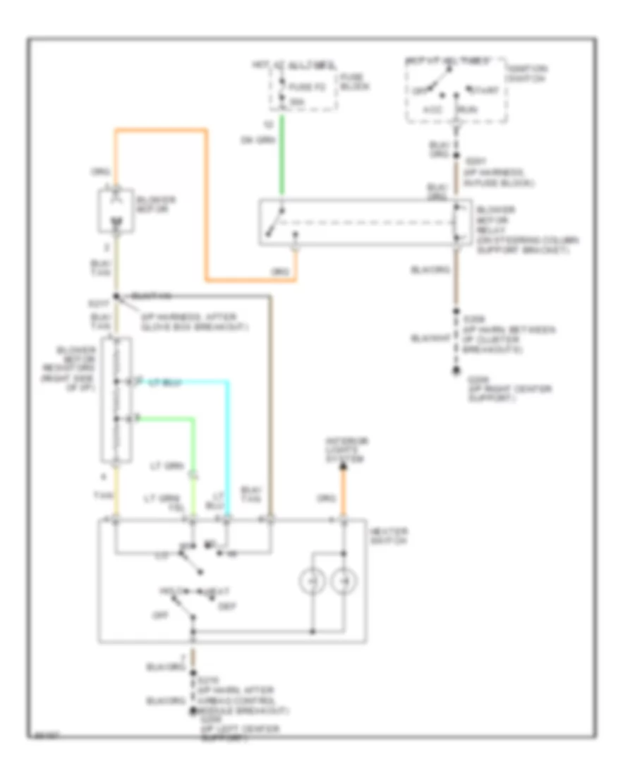
Heater Wiring Diagram for Dodge Cab & Chassis R1997 2500
List of elements for Heater Wiring Diagram for Dodge Cab & Chassis R1997 2500:
- lo
- (i/p harness, after glove box breakout)
- (i/p harness, in fuse block)
- 30a
- Acc
- Blower motor
- Blower motor relay (on steering column support bracket)
- Blower motor resistors (right side of i/p)
- Def
- Fuse block
- Fuse f2
- G206 (i/p right center support)
- Heat
- Heater switch
- Hi/lo
- Hot at all times
- Ignition switch
- Interior lights system
- Off
- Run
- S201
- S208 (i/p harn, between i/p cluster breakouts)
- S215 (i/p harn, after airbag control module breakout) g206 (i/p left center support)
- S217
- Start
- Tan
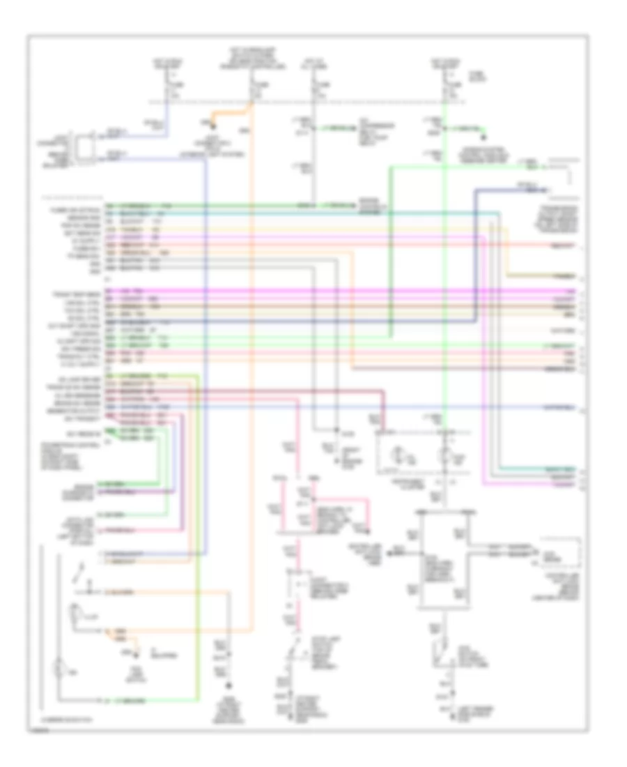
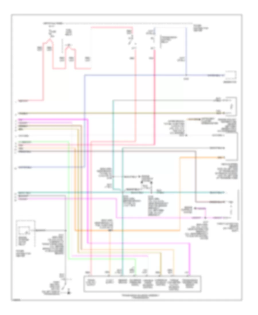
ANTI-LOCK BRAKES
All-Wheel ABS Wiring Diagram for Dodge Cab & Chassis R1997 2500
List of elements for All-Wheel ABS Wiring Diagram for Dodge Cab & Chassis R1997 2500:
- (behind knee bolster) joint connector c
- (engine harn, in breakout to abs mod) s158
- (engine harn, in breakout to abs module) s208
- (engine harn, near breakout to abs module) s109
- (in breakout to hcu) s112
- (right fender side shield)
- (top of rear differential) rear wheels sensor
- 4 x 4 ind
- 4wd switch input
- 4x4 switch (on front of frame)
- 87a
- A20
- Abs 2-way power feed (left fender side shield)
- Abs lamp relay ctrl
- Abs pump relay (in power distribution center)
- Abs pump relay ctrl
- Abs warn ind
- Abs warning ind ctrl
- Abs warning lamp relay (in power distribution center)
- Acc
- Anti-lock brake system control module (left fender side shield)
- B113
- B114
- B116
- B120
- B18
- B19
- B243
- B245
- B248
- B249
- B252
- B254
- B47
- B60
- Brake warn indic.
- Brake warning ind
- Brake warning switch (on left frame rail)
- D11
- D12
- Data link connector (left bottom of i/p)
- Data link input
- Data link output
- Dump sol
- Engine controls (pcm)
- Fuse 20a
- Fuse 40a
- Fuse block
- G100 (left fender shield)
- G100 (left fender side shield)
- G101
- G104 (fender shield)
- G107
- G19
- G206 (i/p right center support)
- Ground
- Ground joint (near pdc)
- Hot at all times
- Hot in run
- Hydraulic control unit (rear of abs pump)
- Ignition
- Ignition switch
- Instrument cluster
- Isolate sol
- Left front reset
- Left front wheel sensor
- Left isolation and dump solenoids
- Lt frnt isolate sol ctrl
- Lt front dump ctrl
- Lt front wheel sensor
- Off
- Power distribution center
- Pump motor ctrl
- Pump motor feed
- Rear dump sol ctrl
- Rear isolate sol ctrl
- Rear reset
- Rear wheels sensor
- Red
- Reset sw
- Right front reset
- Right front wheel sensor
- Rt frnt isolate sol ctrl
- Rt front dump sol ctrl
- Rt front wheel sensor
- Rt isolation and dump solenoids
- Run
- Rwal valve (below master cylinder)
- S103
- S105 (engine harn, in breakout to horn)
- S108
- S110 (in breakout to abs mod)
- S208
- Start
- Stop lamp switch
- Stop lamp switch (on brake pedal bracket)
- V40
- Vacuum sensor (diesel only) (left fender side shield)
Rear Wheel ABS Wiring Diagram for Dodge Cab & Chassis R1997 2500
List of elements for Rear Wheel ABS Wiring Diagram for Dodge Cab & Chassis R1997 2500:
- (left bottom of i/p) data link connector
- 4wd indicator
- 4wd switch input
- 4x4 switch (on front of frame)
- A20
- Abs warning ind ctrl
- Abs warning lamp
- Acc
- B101
- B108
- B111
- B112
- B113
- B114
- Brake sw input
- Brake warning
- Brake warning lamp
- Brake warning switch (left side frame rail)
- Diagnostic signal
- Diesel
- Dump sol
- F32
- Fuse 20a
- Fuse block
- Fused b(+)
- Fused ign (run)
- G100 (left fender side shield)
- G104 (left fender shield)
- G107
- G11
- G19
- G206 (i/p right center support)
- Gasoline
- Ground
- Ground joint (near pdc)
- Hot at all times
- Hot in run
- Ignition switch
- Instrument cluster
- Isolate sol
- Joint connector b (near rear of fuse block)
- Joint connector c (behind knee bolster)
- Off
- Park brake indic.
- Park brake input
- Park brake switch (on brake bracket)
- Rear wheel anti-lock control module (center of i/p)
- Rear wheel sensor (+)
- Rear wheel sensor (-)
- Rear wheel speed sensor (left frame rail, near fuel tank)
- Reset
- Reset sw
- Run
- Rwal dump solenoid
- Rwal hydraulic valve (below master cylinder)
- Rwal isolate solenoid
- S103
- S109 (engine harn, near breakout to abs module)
- S208
- Start
- Stop lamp switch (brake pedal bracket)
- V40
- Vacuum sensor (diesel only) (left fender side shield)
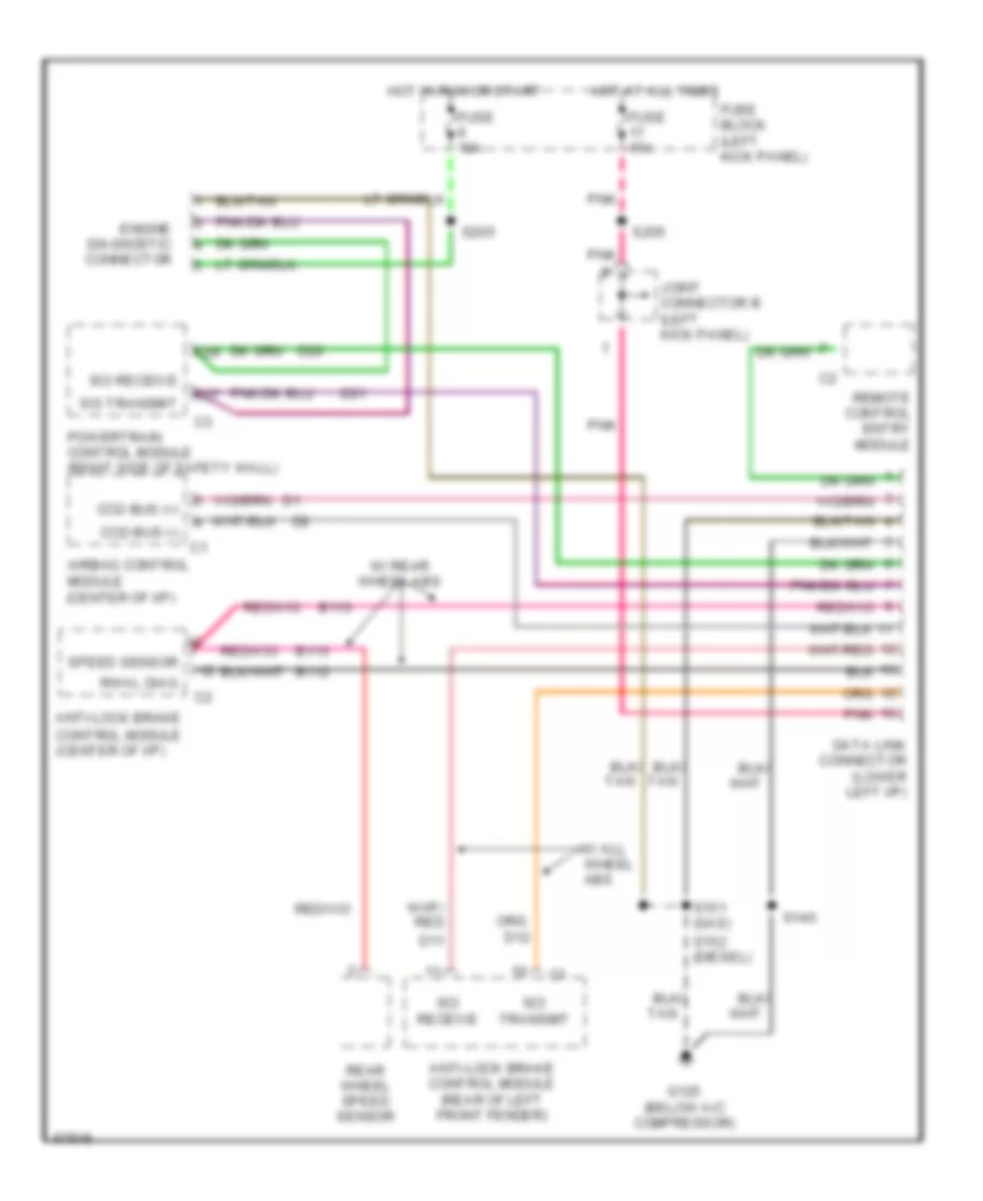
COMPUTER DATA LINES
Computer Data Lines for Dodge Cab & Chassis R1997 2500
List of elements for Computer Data Lines for Dodge Cab & Chassis R1997 2500:
- Airbag control module (center of i/p)
- Anti-lock brake control module (center of i/p)
- Anti-lock brake control module (rear of left front fender)
- B112
- B113
- C27
- C29
- Ccd bus (+)
- Ccd bus (-)
- D11
- D20
- D21
- Data link connector (lower left i/p)
- Engine diagnostic connector
- Fuse 10a
- Fuse 15a
- Fuse block (left kick panel)
- G125 (below a/c compressor)
- Hot at all times
- Hot in run or start
- Joint connector b (left kick panel)
- Pnk
- Powertrain control module (right side of safety wall)
- Rear wheel speed sensor
- Remote control entry module
- Rwal diag
- S140
- S151 (gas)
- S152 (diesel)
- S205
- Sci receive
- Sci transmit
- Speed sensor
- W/ all wheel abs
- W/ rear wheel abs
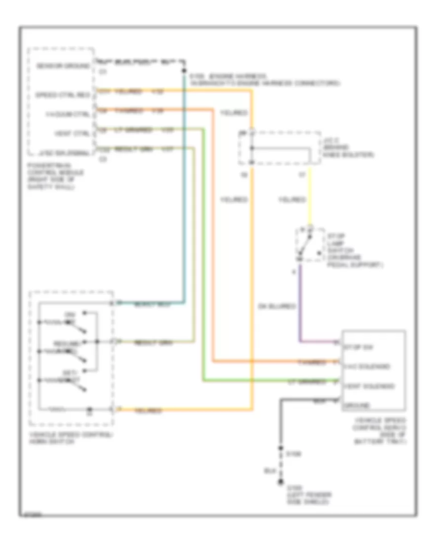
CRUISE CONTROL
Cruise Control Wiring Diagram for Dodge Cab & Chassis R1997 2500
List of elements for Cruise Control Wiring Diagram for Dodge Cab & Chassis R1997 2500:
- (engine harness,
- C11
- C32
- G100 (left fender side shield)
- Ground
- J/c c (behind knee bolster)
- On/ off
- Powertrain control module (right side of safety wall)
- Resume/ accel
- S108
- S156 in branch to engine harness connectors)
- Sensor ground
- Set/ coast
- Speed ctrl res
- Stop lamp switch (on brake pedal support)
- Stop sw
- Tan/red
- V32
- V35
- V36
- V37
- Vac solenoid
- Vacuum ctrl
- Vehicle speed control servo (side of battery tray)
- Vehicle speed control/ horn switch
- Vent ctrl
- Vent solenoid
- Vsc sw signal
ENGINE PERFORMANCE
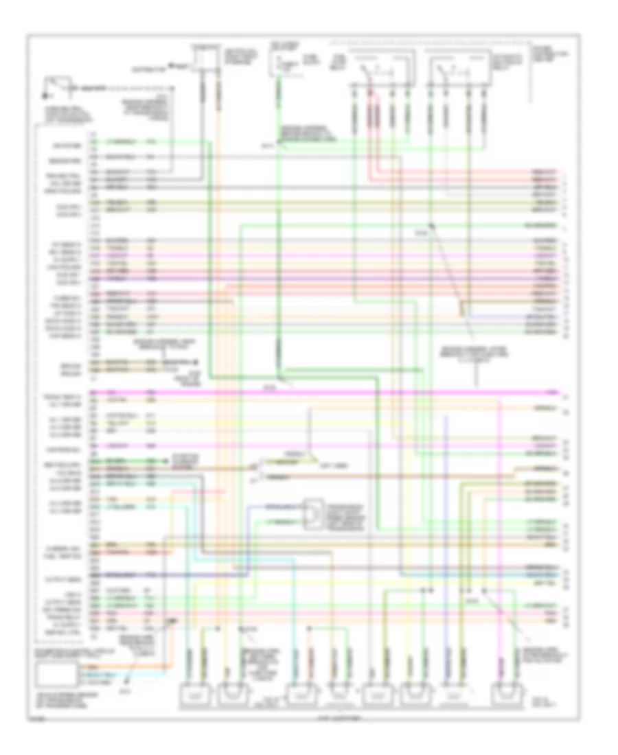
5.2L
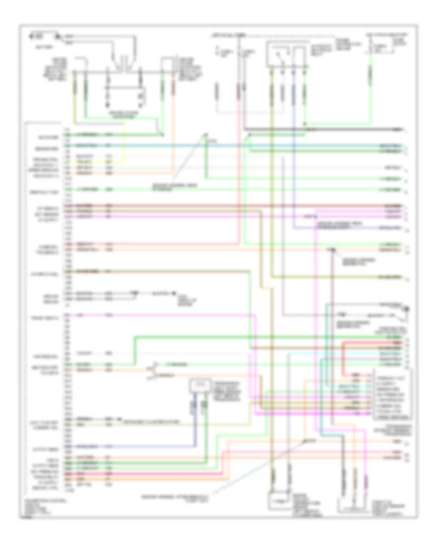
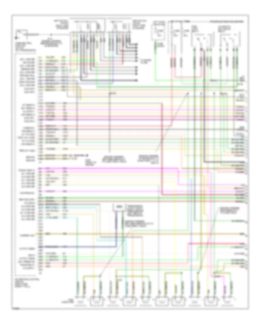
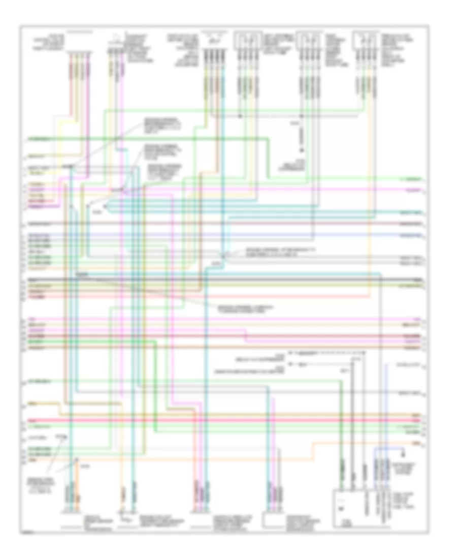
5.2L, Engine Performance Wiring Diagrams (1 of 3) for Dodge Cab & Chassis R1997 2500
List of elements for 5.2L, Engine Performance Wiring Diagrams (1 of 3) for Dodge Cab & Chassis R1997 2500:
- (engine harn, after breakout for iac motor)
- (engine harn, between breakouts for injectors 4 and 6)
- (engine harn, near branch to inj 2, 4, 6, and 8)
- (engine harness, after breakout for injectors 2, 4, 6 and 8)
- (engine harness, before branch to engine connectors)
- (engine harness, near breakout to pcm)
- (front of
- (not used)
- 5.2l &
- 5.2l & 5.9l only
- 5.9l only
- A/t
- A10
- A11
- A12
- A13
- A14
- A15
- A16
- A17
- A18
- A19
- A20
- A21
- A22
- A23
- A24
- A25
- A26
- A27
- A28
- A29
- A30
- A31
- A32
- Automatic shutdown relay
- B10
- B11
- B12
- B13
- B14
- B15
- B16
- B17
- B18
- B19
- B20
- B21
- B22
- B23
- B24
- B25
- B26
- B27
- B28
- B29
- B30
- B31
- B32
- Block
- Cam pos sns
- Coil driver
- Crnk pos sns
- Distributor
- Down ho2s in
- Ect sens in
- Egr sol ctrl
- Engine)
- F18
- Fuel injectors
- Fuel pump relay
- Fuel temp sig
- Fuse
- Fuse 9 10a
- Fused b(+)
- G125
- Gen field drv
- Gov press sig
- Ground
- Hot in run or start
- Iat sens in
- Idle air 1
- Idle air 2
- Idle air 3
- Idle air 4
- Ign power
- Ignition coil (right front of engine)
- Inj 1 driver
- Inj 2 driver
- Inj 3 driver
- Inj 4 driver
- Inj 5 driver
- Inj 6 driver
- Inj 7 driver
- Inj 8 driver
- K11
- K12
- K13
- K14
- K19
- K20
- K21
- K22
- K221
- K24
- K26
- K28
- K30
- K341
- K35
- K38
- K39
- K40
- K41
- K44
- K54
- K58
- K59
- K60
- K88
- M/t
- Map sens in
- Nca
- Output sens
- Overdrv sol
- Park/neutral position switch (on transmission)
- Pnk
- Power distribution center
- Powertrain control module (right side safety wall)
- Prk/neutral
- S114
- S130
- S131
- S132
- S133
- S135
- S138
- S139
- S141 (engine harness, near breakout to transmission wiring)
- Sensor grd
- Starting/ charging system
- T13
- T14
- T25
- T41
- T54
- T60
- Tan
- Tan/pnk
- Tcc drvr
- Tps sens in
- Trans relay
- Trans temp in
- Transmission ouput shaft speed sensor (left rear of transmission)
- Up ho2s in
- Var frce sol
- Vehicle speed sensor (on transmission or transfer case)
- Vss in
- Z12
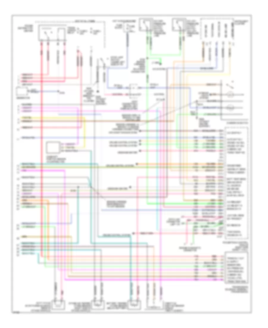
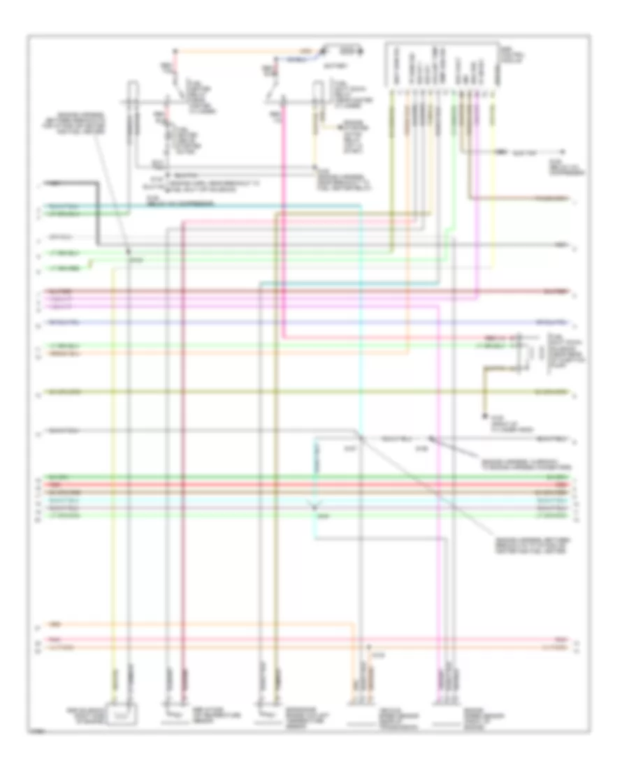
5.2L, Engine Performance Wiring Diagrams (2 of 3) for Dodge Cab & Chassis R1997 2500
List of elements for 5.2L, Engine Performance Wiring Diagrams (2 of 3) for Dodge Cab & Chassis R1997 2500:
- (engine harn, in branch to engine connectors)
- (engine harness, near branch to injectors 1,3,5 and 7)
- (engine harness, near breakout to distributor)
- (engine harness, near breakout to inj 2, 4, 6, 8)
- (engine harness, near bulkhead connector)
- (rear harness, near breakout to fuel pump module)
- Crankshaft position sensor (rear of engine block)
- Downstream heated oxygen sensor (3.9/5.2/ 5.9l l/d trans only) (behind converter)
- Downstream heated oxygen sensor (5.9l h/d trans only) (behind converter)
- Egr solenoid (5.2/5.9l only) (right side of intake manifold)
- Engine coolant temperature sensor (near thermostat)
- Fuel pump
- Fuel pump module (top of fuel tank)
- Fuel signal
- Fuel temperature sensor
- G116 (brake master cylinder)
- G125 (front of engine)
- G206 (i/p right center support)
- Idle air control motor (on side of throttle body)
- Low fuel out
- Manifold absolute pressure sensor (on throttle body)
- Nca
- Pnk
- S116
- S129
- S137
- S140
- S154
- S156
- S311
- Sensor grd
- Sensor return
- Tan/pnk
- Upstream heated oxygen sensor (front of converter shell)
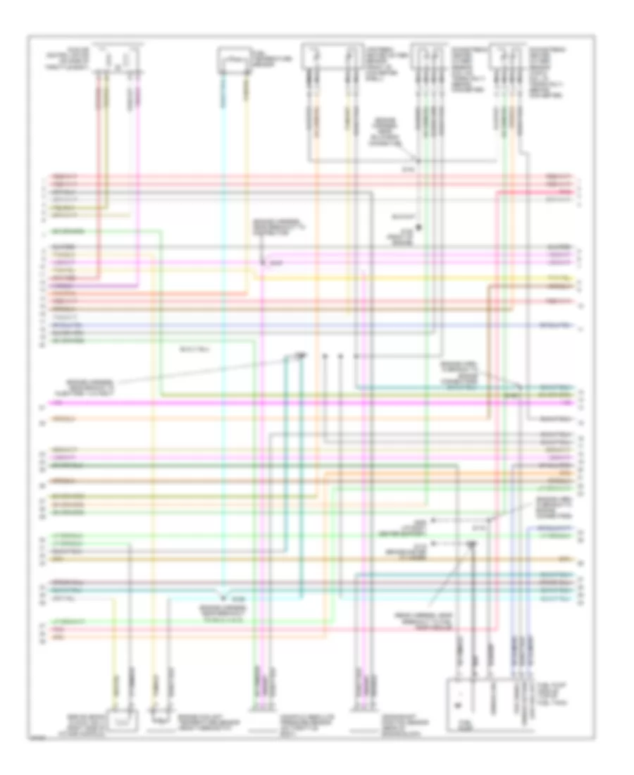
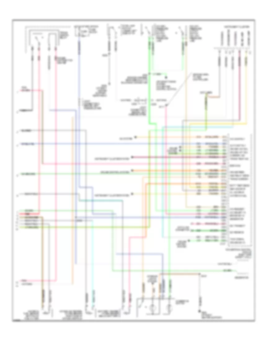
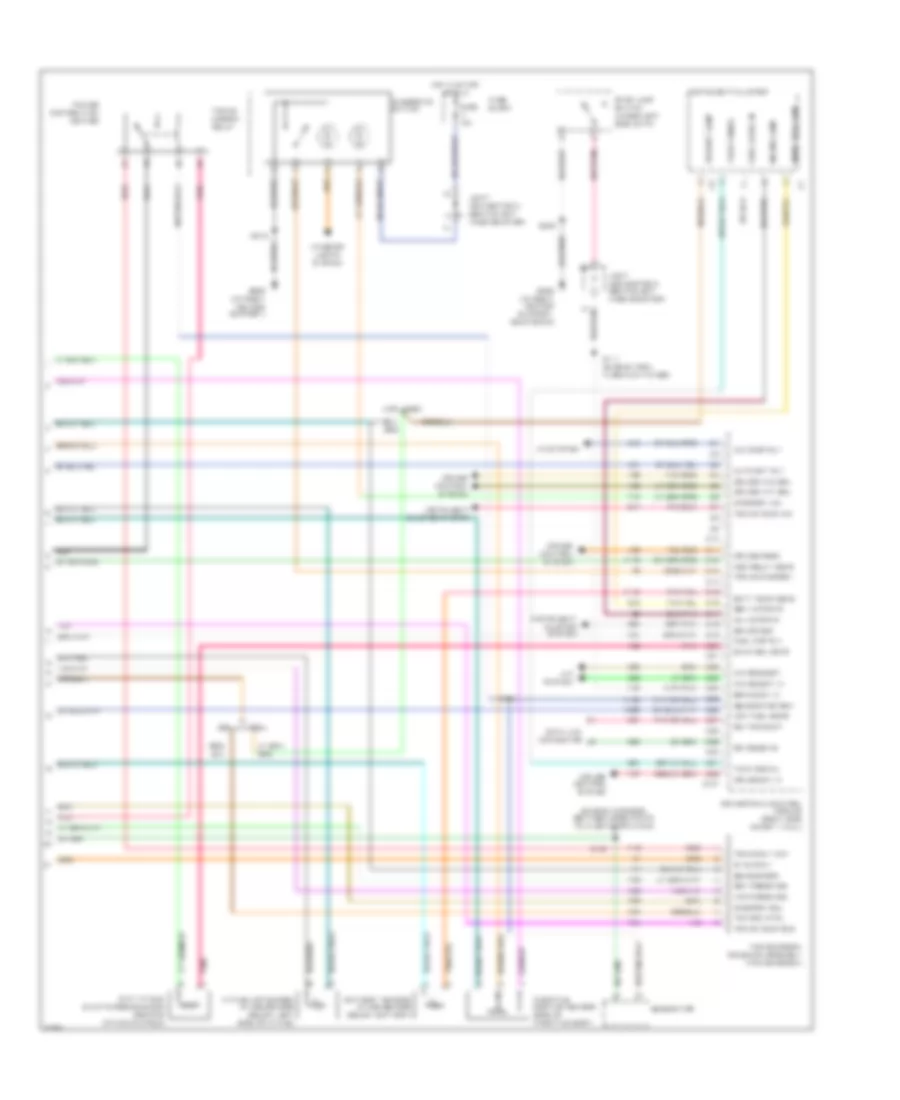
5.2L, Engine Performance Wiring Diagrams (3 of 3) for Dodge Cab & Chassis R1997 2500
List of elements for 5.2L, Engine Performance Wiring Diagrams (3 of 3) for Dodge Cab & Chassis R1997 2500:
- (engine harn, in branch to abs controller)
- (engine harness, in branch to engine harness connectors)
- (engine harness, near breakout to ckp sensor)
- (i/p harn, near breakout for cluster)
- A/c comp rly
- A/c high pressure cutout switch (a/c high pressure line)
- A/c low pressure cutout switch (a/c low pressure line)
- A/c request
- A/c select in
- A/c system
- A142
- Air conditioning system
- Asd relay sens
- Auto sht rly
- Batt temp sens
- Battery temper- ature sensor (below battery)
- Brake sw in
- C10
- C11
- C12
- C13
- C137
- C14
- C15
- C16
- C17
- C18
- C19
- C20
- C21
- C22
- C23
- C24
- C25
- C26
- C27
- C28 c29
- C30 c31
- C32
- C90
- Camshaft position sensor (in distributor)
- Cruise control system
- Cruise feed
- Cruise sw in
- Cruise vac sol
- Cruise vnt sol
- D20
- D21
- Data link connector (left i/p)
- Duty cycle/ evap purge solenoid (rear of intake manifold)
- Engine diagnostic connector
- Evap sol drvr
- Fuel level in
- Fuel pmp rly
- Fuse 10a
- Fuse 4 30a
- Fuse 8 20a
- Fuse block
- G12
- G14
- G206 (i/p right center support)
- G21
- G24
- Gen ind drvr
- Gen ind lamp
- Generator
- Gov press sig
- Hot at all times
- Hot in run or start
- Instrument cluster
- Intake air temper- ature sensor (right side of intake manifold)
- Interior lights system
- Joint connector c (behind left knee bolster)
- K118
- K125
- K226
- K31
- K51
- K52
- K54
- K88
- Low fuel sens
- Message center
- Mil ind drvr
- Mil ind lamp
- Overdrive switch
- Overdrv ind
- Overdrv sol
- Pnk
- Power distribution center
- Powertrain control module (right side safety wall)
- Red
- S111
- S136
- S160 (engine harness, near bulkhead connector)
- S163
- S208
- S215
- Sci receive
- Sci transmit
- Sensor grd
- Sri driver
- Stop lamp switch (under left side of i/p)
- T16
- T18
- T25
- T54
- T60
- Tach signal
- Tan/red
- Tcc sol ctrl
- Throttle position sensor (side of throttle body)
- Trans overdrv
- Trans rly out
- Trans temp ind
- Trans temp sns
- Trans- mission relay
- Transmission solenoid assembly (transmission)
- Up shif ind
- V32
- V35
- V36
- V37
- V40
- Var force sol
5.9L
5.9L Turbo Diesel, Engine Performance Wiring Diagrams (1 of 3) for Dodge Cab & Chassis R1997 2500
List of elements for 5.9L Turbo Diesel, Engine Performance Wiring Diagrams (1 of 3) for Dodge Cab & Chassis R1997 2500:
- (engine harness, after breakout to ect unit)
- (engine harness, before pcm)
- (engine harness, rear of engine compt)
- (engine harness, rear of engine)
- A/t
- A10
- A11
- A12
- A13
- A14
- A15
- A16
- A17
- A18
- A19
- A20
- A21
- A22
- A23
- A24
- A25
- A26
- A27
- A28
- A29
- A30
- A31
- A32
- Air sys rly 1
- Air sys rly 2
- Automatic shutdown relay
- B10
- B11
- B12
- B13
- B14
- B15
- B16
- B17
- B18
- B19
- B20
- B21
- B22
- B23
- B24
- B25
- B26
- B27
- B28
- B29
- B30
- B31
- B32
- Battery
- Block
- C136
- D28
- Ect sensor
- Egr fault mon
- Egr sol ctrl
- Engine coolant temperature sensor (left rear of cylinder head)
- F18
- Fuse
- Fuse 4 30a
- Fuse 8 20a
- Fuse 9 10a
- Fused b(+)
- G125 (front of engine)
- G85
- Gen field drv
- Gov press sig
- Ground
- Heated intake air system
- Heated intake air system relay no. 1 (below left battery)
- Heated intake air system relay no. 2 (below left battery)
- Hot at all times
- Hot in run and start
- Iat sens in
- Ign power
- Instrument cluster system
- K20
- K21
- K22
- K24
- K30
- K35
- K54
- K88
- M/t
- Nca
- Output sens
- Overdrv sol
- Park/neutral position switch
- Pnk
- Power distribution center
- Powertrain control module (right side safety wall)
- Prk/neutral
- Red
- S114
- S130
- S132
- S137
- S139
- S141
- S159
- S21
- S22
- Sensor grd
- Speed sens sig
- T13
- T14
- T25
- T41
- T54
- T60
- Tcc drvr
- Tcc sol ctrl
- Throttle position sensor (side of throtlle body)
- Tps sens in
- Trans relay
- Trans rly out
- Trans temp in
- Trans temp sns
- Transmission ouput shaft speed sensor (left rear of transmission)
- Transmission solenoid assembly (transmission)
- Var force sol
- Var frce sol
- Vss in
- Wait to start
- Water in fuel
- Z12
5.9L Turbo Diesel, Engine Performance Wiring Diagrams (2 of 3) for Dodge Cab & Chassis R1997 2500
List of elements for 5.9L Turbo Diesel, Engine Performance Wiring Diagrams (2 of 3) for Dodge Cab & Chassis R1997 2500:
- (engine harness, between breakouts for intake air heater and fuel heater)
- (engine harness, between breakouts to intake air heater and fuel heater)
- (engine harness, in branch to engine harness connectors)
- Battery
- Coolant temp
- Diag req
- Egr control module
- Egr engine engine coolant temperature sensor
- Egr fault
- Egr iat +
- Egr iat -
- Egr intake air temperature sensor
- Egr sol
- Egr solenoid (right side of engine)
- Engine speed sensor (front of engine)
- Engine starter motor relay (hot in start)
- Fuel heater (above starter motor)
- Fuel heater relay (near master cylinder)
- Fuel shut down relay (near master cylinder)
- Fuel shut down solenoid (near rear of injection pump)
- G125 (below a/c compressor)
- G125 (front of cylinder head)
- Gnd
- Nca
- Pnk
- Red
- Red/ tan
- S138
- S142
- S143
- S152
- S152 (engine harness, near breakout to fuel heater relay)
- S156
- S157
- S161
- Shut dwn rel
- Temp sen grd
- Tp sens sig
- Vehicle speed sensor (rear of transmission)
5.9L Turbo Diesel, Engine Performance Wiring Diagrams (3 of 3) for Dodge Cab & Chassis R1997 2500
List of elements for 5.9L Turbo Diesel, Engine Performance Wiring Diagrams (3 of 3) for Dodge Cab & Chassis R1997 2500:
- (engine harn, to abs controller)
- (not used)
- A/c comp rly
- A/c high pressure cutout switch (a/c high pressure line)
- A/c low pressure cutout switch (a/c low pressure line)
- A/c request
- A/c select in
- A/c system
- A142
- Air conditioning system (a/c-heater control switch)
- Asd relay sens
- Auto sht rly
- Batt temp sens
- Battery temper- ature sensor (below battery)
- Brake sw in
- C10
- C11
- C12
- C13
- C137
- C14
- C15
- C16
- C17
- C18
- C19
- C20
- C209
- C21
- C22
- C23
- C24
- C25
- C26
- C27
- C28
- C29
- C30
- C31
- C32
- Cruise control system
- Cruise feed
- Cruise sw in
- Cruise vac sol
- Cruise vnt sol
- D20
- D21
- D29
- Data link connector
- Egr diag
- Fuse 10a
- Fuse block
- G12
- G14
- G206 (i/p right center support)
- G206 (i/p right center support, near radio)
- G21
- G86
- Gen ind drvr
- Gen ind lamp
- Generator
- Hot in start or run
- Instrument cluster
- Instrument cluster system
- Intake air temper- ature sensor (right side of intake manifold)
- Interior lights system
- Joint connector c (behind left knee bolster)
- K118
- K125
- K51
- Mil ind drvr
- Mil ind lamp
- Nca
- Overdrive switch
- Overdrv ind
- Pnk
- Pnk/
- Power distribution center
- Powertrain control module (right side safety wall)
- Red
- S111
- S160 (engine harness, near breakout to bulkhead connector)
- S162
- S208
- S215
- Sci receive
- Sci transmit
- Speedometer
- Stop lamp switch (under left side of i/p)
- T18
- Tach signal
- Tan/red
- Trans overdrv
- Trans temp ind
- Trans- mission relay
- V32
- V35
- V36
- V37
- V40
- Water in fuel
- Water in fuel sensor (bottom of fuel filter)
5.9L, Engine Performance Wiring Diagrams (1 of 3) for Dodge Cab & Chassis R1997 2500
List of elements for 5.9L, Engine Performance Wiring Diagrams (1 of 3) for Dodge Cab & Chassis R1997 2500:
- (engine harn, after breakout for iac motor)
- (engine harn, between breakouts for injectors 4 and 6)
- (engine harn, near branch to inj 2, 4, 6, and 8)
- (engine harness, after breakout for injectors 2, 4, 6 and 8)
- (engine harness, before branch to engine connectors)
- (engine harness, near breakout to pcm)
- (front of
- (not used)
- 5.2l &
- 5.2l & 5.9l only
- 5.9l only
- A/t
- A10
- A11
- A12
- A13
- A14
- A15
- A16
- A17
- A18
- A19
- A20
- A21
- A22
- A23
- A24
- A25
- A26
- A27
- A28
- A29
- A30
- A31
- A32
- Automatic shutdown relay
- B10
- B11
- B12
- B13
- B14
- B15
- B16
- B17
- B18
- B19
- B20
- B21
- B22
- B23
- B24
- B25
- B26
- B27
- B28
- B29
- B30
- B31
- B32
- Block
- Cam pos sns
- Coil driver
- Crnk pos sns
- Distributor
- Down ho2s in
- Ect sens in
- Egr sol ctrl
- Engine)
- F18
- Fuel injectors
- Fuel pump relay
- Fuel temp sig
- Fuse
- Fuse 9 10a
- Fused b(+)
- G125
- Gen field drv
- Gov press sig
- Ground
- Hot in run or start
- Iat sens in
- Idle air 1
- Idle air 2
- Idle air 3
- Idle air 4
- Ign power
- Ignition coil (right front of engine)
- Inj 1 driver
- Inj 2 driver
- Inj 3 driver
- Inj 4 driver
- Inj 5 driver
- Inj 6 driver
- Inj 7 driver
- Inj 8 driver
- K11
- K12
- K13
- K14
- K19
- K20
- K21
- K22
- K221
- K24
- K26
- K28
- K30
- K341
- K35
- K38
- K39
- K40
- K41
- K44
- K54
- K58
- K59
- K60
- K88
- M/t
- Map sens in
- Nca
- Output sens
- Overdrv sol
- Park/neutral position switch (on transmission)
- Pnk
- Power distribution center
- Powertrain control module (right side safety wall)
- Prk/neutral
- S114
- S130
- S131
- S132
- S133
- S135
- S138
- S139
- S141 (engine harness, near breakout to transmission wiring)
- Sensor grd
- Starting/ charging system
- T13
- T14
- T25
- T41
- T54
- T60
- Tan
- Tan/pnk
- Tcc drvr
- Tps sens in
- Trans relay
- Trans temp in
- Transmission ouput shaft speed sensor (left rear of transmission)
- Up ho2s in
- Var frce sol
- Vehicle speed sensor (on transmission or transfer case)
- Vss in
- Z12
5.9L, Engine Performance Wiring Diagrams (2 of 3) for Dodge Cab & Chassis R1997 2500
List of elements for 5.9L, Engine Performance Wiring Diagrams (2 of 3) for Dodge Cab & Chassis R1997 2500:
- (engine harn, in branch to engine connectors)
- (engine harness, near branch to injectors 1,3,5 and 7)
- (engine harness, near breakout to distributor)
- (engine harness, near breakout to inj 2, 4, 6, 8)
- (engine harness, near bulkhead connector)
- (rear harness, near breakout to fuel pump module)
- Crankshaft position sensor (rear of engine block)
- Downstream heated oxygen sensor (3.9/5.2/ 5.9l l/d trans only) (behind converter)
- Downstream heated oxygen sensor (5.9l h/d trans only) (behind converter)
- Egr solenoid (5.2/5.9l only) (right side of intake manifold)
- Engine coolant temperature sensor (near thermostat)
- Fuel pump
- Fuel pump module (top of fuel tank)
- Fuel signal
- Fuel temperature sensor
- G116 (brake master cylinder)
- G125 (front of engine)
- G206 (i/p right center support)
- Idle air control motor (on side of throttle body)
- Low fuel out
- Manifold absolute pressure sensor (on throttle body)
- Nca
- Pnk
- S116
- S129
- S137
- S140
- S154
- S156
- S311
- Sensor grd
- Sensor return
- Tan/pnk
- Upstream heated oxygen sensor (front of converter shell)
5.9L, Engine Performance Wiring Diagrams (3 of 3) for Dodge Cab & Chassis R1997 2500
List of elements for 5.9L, Engine Performance Wiring Diagrams (3 of 3) for Dodge Cab & Chassis R1997 2500:
- (engine harn, in branch to abs controller)
- (engine harness, in branch to engine harness connectors)
- (engine harness, near breakout to ckp sensor)
- (i/p harn, near breakout for cluster)
- A/c comp rly
- A/c high pressure cutout switch (a/c high pressure line)
- A/c low pressure cutout switch (a/c low pressure line)
- A/c request
- A/c select in
- A/c system
- A142
- Air conditioning system
- Asd relay sens
- Auto sht rly
- Batt temp sens
- Battery temper- ature sensor (below battery)
- Brake sw in
- C10
- C11
- C12
- C13
- C137
- C14
- C15
- C16
- C17
- C18
- C19
- C20
- C21
- C22
- C23
- C24
- C25
- C26
- C27
- C28 c29
- C30 c31
- C32
- C90
- Camshaft position sensor (in distributor)
- Cruise control system
- Cruise feed
- Cruise sw in
- Cruise vac sol
- Cruise vnt sol
- D20
- D21
- Data link connector (left i/p)
- Duty cycle/ evap purge solenoid (rear of intake manifold)
- Engine diagnostic connector
- Evap sol drvr
- Fuel level in
- Fuel pmp rly
- Fuse 10a
- Fuse 4 30a
- Fuse 8 20a
- Fuse block
- G12
- G14
- G206 (i/p right center support)
- G21
- G24
- Gen ind drvr
- Gen ind lamp
- Generator
- Gov press sig
- Hot at all times
- Hot in run or start
- Instrument cluster
- Intake air temper- ature sensor (right side of intake manifold)
- Interior lights system
- Joint connector c (behind left knee bolster)
- K118
- K125
- K226
- K31
- K51
- K52
- K54
- K88
- Low fuel sens
- Message center
- Mil ind drvr
- Mil ind lamp
- Overdrive switch
- Overdrv ind
- Overdrv sol
- Pnk
- Power distribution center
- Powertrain control module (right side safety wall)
- Red
- S111
- S136
- S160 (engine harness, near bulkhead connector)
- S163
- S208
- S215
- Sci receive
- Sci transmit
- Sensor grd
- Sri driver
- Stop lamp switch (under left side of i/p)
- T16
- T18
- T25
- T54
- T60
- Tach signal
- Tan/red
- Tcc sol ctrl
- Throttle position sensor (side of throttle body)
- Trans overdrv
- Trans rly out
- Trans temp ind
- Trans temp sns
- Trans- mission relay
- Transmission solenoid assembly (transmission)
- Up shif ind
- V32
- V35
- V36
- V37
- V40
- Var force sol
8.0L
8.0L, Engine Performance Wiring Diagrams (1 of 3) for Dodge Cab & Chassis R1997 2500
List of elements for 8.0L, Engine Performance Wiring Diagrams (1 of 3) for Dodge Cab & Chassis R1997 2500:
- (engine harness, after branch to injectors 2, 4, 6, 8, and 10)
- (engine harness, before branch to o2 sensors)
- (engine harness, between breakout to injectors 4 and 6)
- (engine harness, between breakouts to injectors 4 and 6)
- (engine harness, near breakout to injector 5)
- A10
- A11
- A12
- A13
- A14
- A15
- A16
- A17
- A18
- A19
- A20
- A21
- A22
- A23
- A24
- A25
- A26
- A27
- A28
- A29
- A30
- A31
- A32
- Automatic shutdown relay
- B10
- B11
- B12
- B13
- B14
- B15
- B16
- B17
- B18
- B19
- B20
- B21
- B22
- B23
- B24
- B25
- B26
- B27
- B28
- B29
- B30
- B31
- B32
- Block
- Cmp sens in
- Coil 1 driver
- Coil 2 driver
- Coil 3 driver
- Coil 4 driver
- Coil 5 driver
- Crnk pos sns
- Ect sens in
- F18
- Fuel injectors
- Fuel pump relay
- Fuse
- Fuse 20a
- Fuse 10a
- Fuse 30a
- Fused b(+)
- G125 (front of engine)
- Gen field drv
- Gov press sig
- Ground
- Hot at all times
- Hot in run and start
- Iat sens in
- Idle air 1
- Idle air 2
- Idle air 3
- Idle air 4
- Ign power
- Ignition coil 4-pack (right side of engine)
- Ignition coil 6-pack (right side of engine)
- Inj 1 driver
- Inj 10 driver
- Inj 2 driver
- Inj 3 driver
- Inj 4 driver
- Inj 5 driver
- Inj 6 driver
- Inj 7 driver
- Inj 8 driver
- Inj 9 driver
- K11
- K115
- K116
- K12
- K13
- K14
- K141
- K17
- K18
- K19
- K20
- K21
- K22
- K24
- K26
- K28
- K30
- K32
- K341
- K38
- K39
- K40
- K41
- K43
- K44
- K441
- K54
- K58
- K59
- K60
- K88
- Lft up ho2s
- Map sens in
- Nca
- Output sens
- Overdrv sol
- Park/neutral position switch (on transmission)
- Pnk
- Post cat ho2s
- Power distribution center
- Powertrain control module (right side safety wall)
- Pre cat ho2s
- Prk/neutral
- Rt up ho2s
- S114
- S132
- S133
- S135
- S138
- S139
- S141
- Sensor grd
- T13
- T14
- T25
- T41
- T54
- T60
- Tan
- Tan/red
- Tcc drvr
- To spark plugs
- Tps sens in
- Trans relay
- Trans temp in
- Transmission output shaft speed sensor (left rear of transmission)
- Var frce sol
- Vss in
- Z12
8.0L, Engine Performance Wiring Diagrams (2 of 3) for Dodge Cab & Chassis R1997 2500
List of elements for 8.0L, Engine Performance Wiring Diagrams (2 of 3) for Dodge Cab & Chassis R1997 2500:
- (engine harn, after branch to inj 2, 4, 6, 8, and 10)
- (engine harness, after branch to injectors 2, 4, 6, 8, and 10)
- (engine harness, before branch to injectors 2, 4, 6, 8, and 10)
- (engine harness, in branch to engine connectors)
- (engine harness, near breakout to idle air control valve)
- (engine harness, near breakout to injectors 1, 3, 5, 7, and 9)
- Camshaft position sensor (left front of engine, on timing chain cover)
- Crankshaft position sensor (right side of engine block)
- Engine coolant temperature sensor (near thermostat)
- Fuel pump
- Fuel pump module (top of fuel tank)
- Fuel signal
- G104 (near power distribution center)
- G125 (below a/c compressor)
- Idle air control valve (on side of throttle body)
- Instrument cluster system
- Left upstream heated oxygen sensor (left exhaust down tube)
- Low fuel out
- Manifold absolute pressure sensor (side of upper intake manifold)
- Nca
- Pnk
- Post-catalyst heated oxygen sensor (california only) (behind catalytic converter)
- Pre-catalyst heated oxygen sensor (california only) (front of converter shell)
- Right upstream heated oxygen sensor (right exhaust down tube)
- S116
- S129
- S130
- S131
- S136
- S137
- S140
- S154
- S156
- S311
- Sensor grd
- Sensor return
- Tan/red
- Vehicle speed sensor (on transmission)
8.0L, Engine Performance Wiring Diagrams (3 of 3) for Dodge Cab & Chassis R1997 2500
List of elements for 8.0L, Engine Performance Wiring Diagrams (3 of 3) for Dodge Cab & Chassis R1997 2500:
- (engine harness, between breakouts to injectors 6 and 8)
- (not used)
- A/c comp rly
- A/c request
- A/c select in
- A/c system
- A/t
- A142
- Asd relay sens
- Auto sht rly
- Batt temp sens
- Battery temper- ature sensor (below battery)
- Brake sw in
- C10
- C11
- C12
- C13
- C137
- C14
- C15
- C16
- C17
- C18
- C19
- C20
- C21
- C22
- C23
- C24
- C25
- C26
- C27
- C28
- C29
- C30
- C31
- C32
- Cruise control system
- Cruise feed
- Cruise sw in
- Cruise vac sol
- Cruise vnt sol
- D20
- D21
- Data link connector
- Duty cycle/ evap purge solenoid (rear of intake manifold)
- Evap sol drvr
- Fuel level in
- Fuel pmp rly
- Fuse 10a
- Fuse block
- G12
- G14
- G206 (i/p right center support)
- G206 (i/p right center support, near radio)
- G21
- G24
- Gen ind drvr
- Generator
- Generator driv
- Gov press sig
- Hot in start or run
- Instrument cluster
- Instrument cluster system
- Intake air temper- ature sensor (below left side of intake)
- Interior lights system
- Joint connector c (behind left knee bolster)
- K118
- K125
- K226
- K31
- K51
- K52
- K54
- K88
- Low fuel sens
- M/t
- Maint req lamp
- Mil ind drvr
- Mil ind lamp
- Nca
- Overdrive switch
- Overdrv ind
- Overdrv sol
- Pnk
- Power distribution center
- Powertrain control module (right side safety wall)
- Red
- S111 (engine harn, in branch to abs)
- S134
- S163
- S208
- S215
- Sci receive
- Sci transmit
- Sensor grd
- Sri driver
- Stop lamp switch (under left side of i/p)
- T16
- T18
- T25
- T54
- T60
- Tach signal
- Tan/red
- Tcc sol ctrl
- Throttle position sensor (side of throttle body)
- Trans overdrv
- Trans rly out
- Trans temp ind
- Trans temp sns
- Trans- mission relay
- Transmission solenoid assembly (transmission)
- Upshift lamp
- V32
- V35
- V36
- V37
- V40
- Var force sol
EXTERIOR LIGHTS
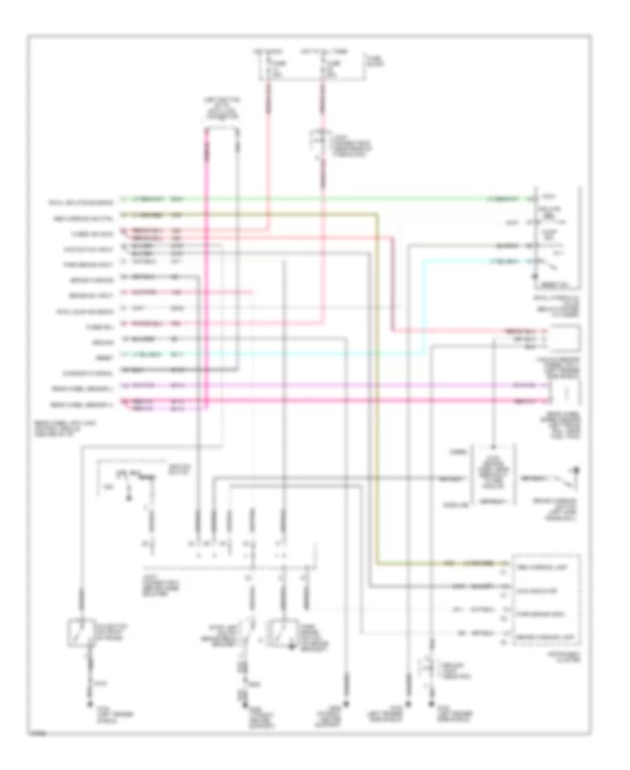
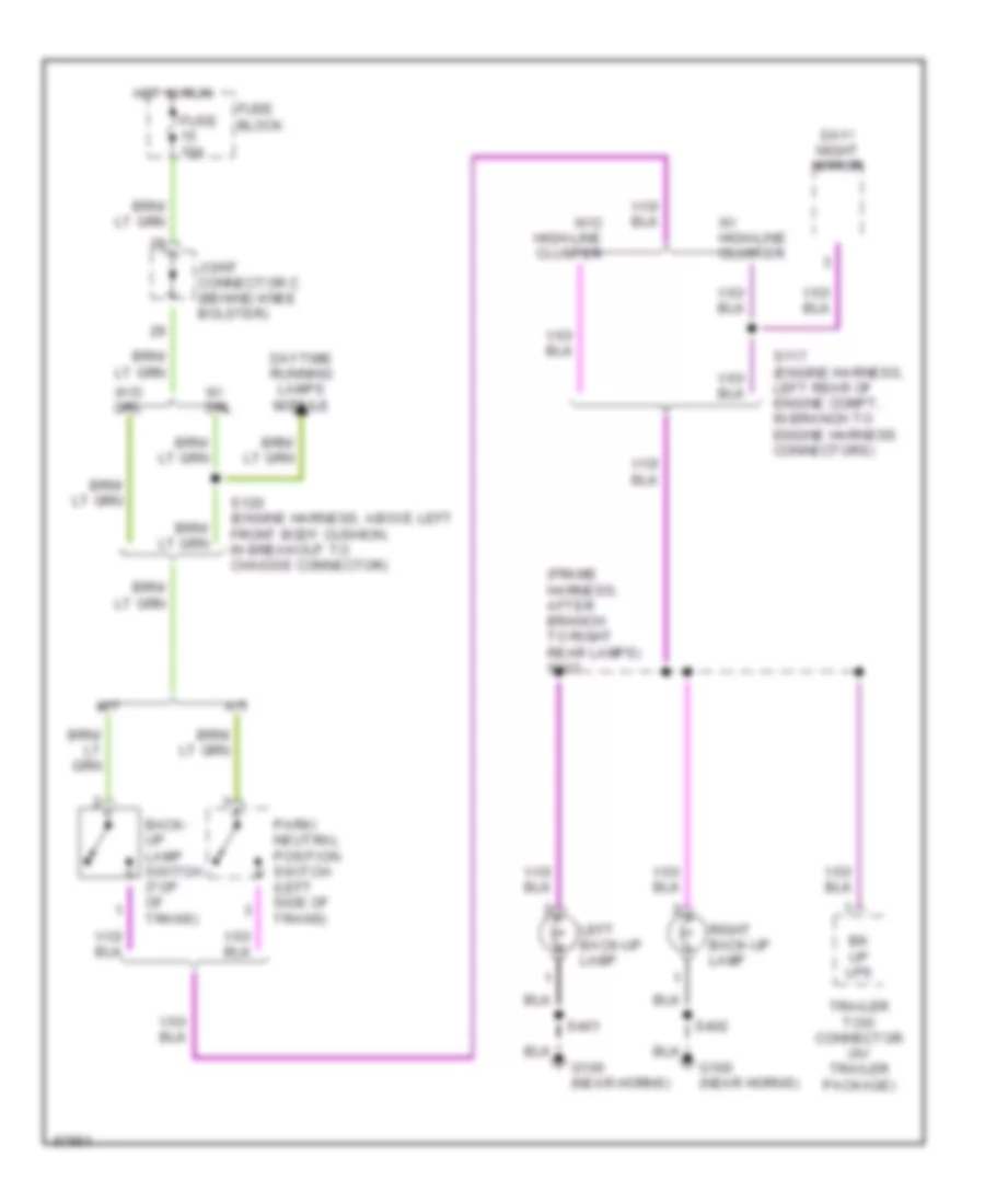
Back-up Lamps Wiring Diagram for Dodge Cab & Chassis R1997 2500
List of elements for Back-up Lamps Wiring Diagram for Dodge Cab & Chassis R1997 2500:
- (frame harness, after branch to right rear lamps) s313
- A/t
- Back- up lamp switch (top of trans)
- Bk up lps
- Day/ night mirror
- Daytime running lamps module
- Fuse 10a
- Fuse block
- G100 (near horns)
- Hot in run
- Joint connector c (behind knee bolster)
- Left back-up lamp
- M/t
- Park/ neutral position switch (left side of trans)
- Right back-up lamp
- S117 (engine harness, left rear of engine compt, in branch to engine harness connectors)
- S120 (engine harness, above left front body cushion, in breakout to chassis connector)
- S401
- S402
- Trailer tow connector (w/ trailer package)
- W/ drl
- W/ high-line cluster
- W/o drl
- W/o high-line cluster
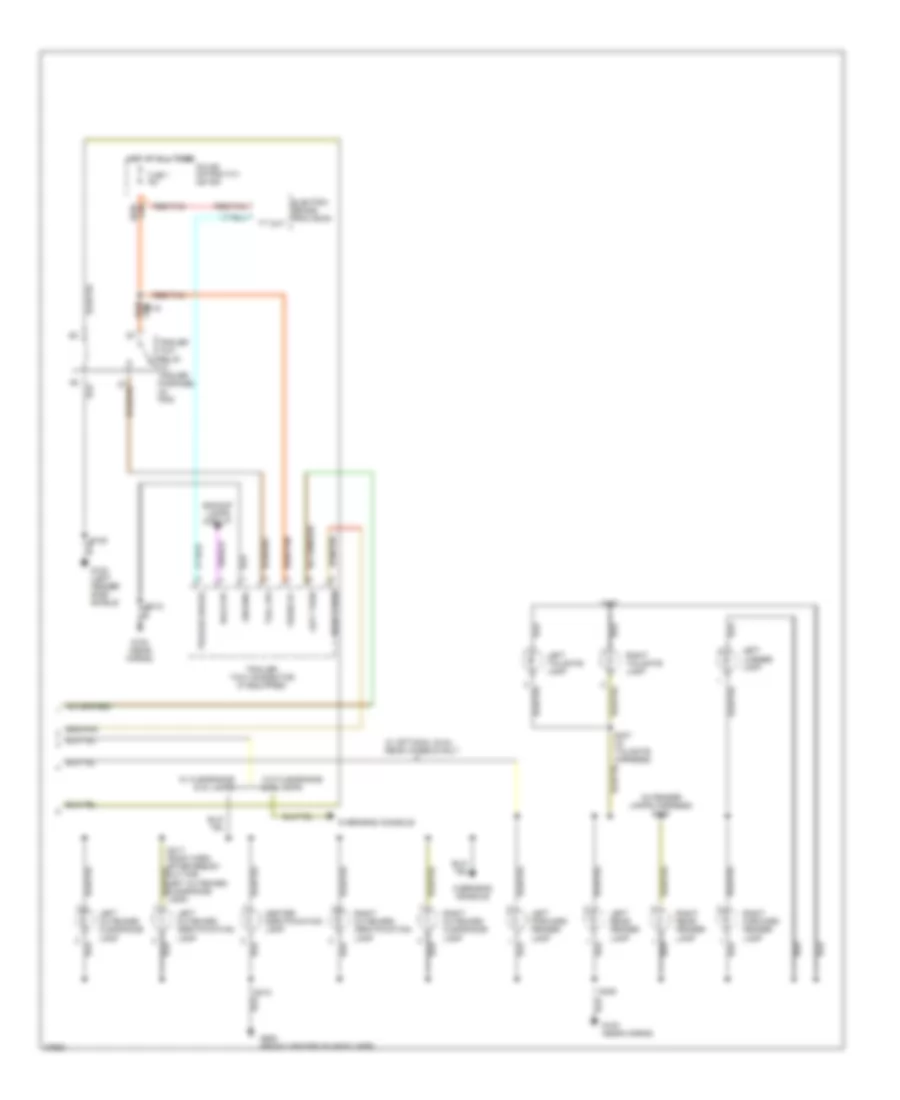
Exterior Lamps Wiring Diagram (1 of 2) for Dodge Cab & Chassis R1997 2500
List of elements for Exterior Lamps Wiring Diagram (1 of 2) for Dodge Cab & Chassis R1997 2500:
- (engine harn, in break- out for left turn signal lamp) s123
- (engine harn, in break- out for right turn signal lamp) s102
- (engine harness, after branch for horn breakout) s106
- (frame harn, in break- out to trailer conn) s316
- (frame harn, in breakout to trailer connector)
- (frame harness, after branch to right rear lamps) s314
- (no connection)
- Center high mounted stop lamp 1
- Center high mounted stop lamp 2
- Fog lamp relay
- Fuse 18 15a
- Fuse 20 20a
- Fuse 6 20a
- Fuse block
- Fuse c 20a
- G100 (left front fender side shield)
- G100 (near horns)
- G104 (left fender shield)
- G206 (i/p right center support)
- G308 (below left rear speaker)
- Ground joint (near pdc)
- Hazard
- Hazard warning flasher (in fuse box)
- Head
- Headlamp switch
- Hot at all times
- Hot in acc or run
- Instrument cluster
- Joint connector a (rear of fuse block)
- Joint connector b (near rear of fuse block)
- Left license lamp
- Left park/turn signal lamp
- Left tail/ stop & turn signal lamp
- Left turn
- Left turn ind
- Normal
- Off
- Park
- Pnk/red
- Power distribution center
- Right license lamp
- Right park/turn signal lamp
- Right tail/ stop & turn signal lamp
- Right turn
- Right turn ind
- S103
- S115
- S206
- S207 (i/p harness, between breakouts for cluster conn- tan ectors)
- S312
- S315
- S401
- S402
- Seatbelt switch
- Stop lamp switch (on brake pedal arm)
- Turn signal and hazard flasher switch (part of multi- function switch, located on steering column)
- Turn signal flasher (in fuse box)
- W/ dual rear wheels
- W/ trailer tow
- W/o dual rear wheels
- W/o trailer tow
Exterior Lamps Wiring Diagram (2 of 2) for Dodge Cab & Chassis R1997 2500
List of elements for Exterior Lamps Wiring Diagram (2 of 2) for Dodge Cab & Chassis R1997 2500:
- (in fender lamps harness) s406
- Back-up
- Backup lamps circuit
- Center identification lamp
- Electric brake provision
- Fuse 7 40a
- Fused b+
- G100 (left fender side shield)
- G100 (near horns)
- G908 (front center of headliner)
- Ground
- Hot at all times
- Left forward fender lamp
- Left license lamp
- Left outboard clearance lamp
- Left outboard identification lamp
- Left rear fender lamp
- Left tailgate lamp
- Left turn
- Overhead console
- Power distribution center
- Red/tan
- Right forward fender lamp
- Right outboard clearance lamp
- Right outboard identification lamp
- Right rear fender lamp
- Right tailgate lamp
- Right turn
- S108
- S119
- S312
- S317 (roof harn, after break- out for left outboard clearance lamp)
- S318
- S405
- S407 (in tailgate harness)
- S408
- Tail lps
- Tan red/
- Trailer brake
- Trailer tow connector (if equipped)
- Trailer tow relay (w/ trailer package) (in pdc)
- Tt out
- W/ clearance & id lamps
- W/ optional dual rear wheels only
- W/o clearance & id lamps
GROUND DISTRIBUTION
Ground Distribution Wiring Diagram (1 of 3) for Dodge Cab & Chassis R1997 2500
List of elements for Ground Distribution Wiring Diagram (1 of 3) for Dodge Cab & Chassis R1997 2500:
- (left side of engine block)
- (near left battery)
- (not used)
- 4x4 switch
- 87a
- Abs 2-way power feed (w/ all wheel abs)
- Abs warning lamp relay
- Airbag control module
- All wheel abs
- Anti-lock brake (abs) controller
- Battery
- Before breakout for right headlamp)
- Daytime running lamp module
- Diesel
- Fog lamp relay 1
- Fuel pump module
- Fuel shutdown solenoid (diesel)
- G100
- G100 (front of tight frame rail)
- G100 (left fender side shield)
- G100 (left front fender side shield)
- G100 (left side shield)
- G100 (near horns)
- G101 (near right battery)
- G101 (right fender side shield)
- G104 (left fender shield)
- G104 (rear of left fender side shield)
- G111 (near battery)
- G112
- G116 (at brake master cylinder)
- G120 (right side of engine block)
- G125 (front of cylinder head)
- G125 (front of engine)
- G408 (body harness, in tailgate harness)
- Gasoline
- Generator
- Ground joint (near power distribution center)
- High note horn
- In branch to right fog lamp)
- Left backup lamp
- Left battery
- Left door speaker
- Left fog lamp
- Left forward fender lamp
- Left headlamp
- Left license lamp
- Left park & turn signal lamp
- Left rear fender lamp
- Left rear speaker
- Left tail/stop turn signal lamp
- Left tailgate lamp
- Low note horn
- Low washer fluid switch
- Power distribution center
- Radio
- Radio choke relay
- Rear wheel abs
- Right backup lamp
- Right battery
- Right door speaker
- Right fog lamp
- Right forward fender lamp
- Right headlamp
- Right license lamp
- Right park/ turn signal lamp
- Right rear fender lamp
- Right rear speaker
- Right tail/stop turn signal lamp
- Right tailgate lamp
- Rwal valve
- S108 (engine harness, near controller anti-lock brake)
- S115 (engine harness, before branch to engine harness breakout)
- S122 (i/p harness, in branch to i/p harness)
- S212 (i/p harness, near radio choke relay breakout)
- S301 (body harness, near body ground breakout)
- S311 (body harness, near fuel pump module breakout)
- S312 (body harness, after branch to right rear lamps)
- Trailer tow relay
- Underhood lamp
- Vacuum sensor (diesel)
- Vehicle speed control servo
- W/ abs
- W/ dual rear wheels
- W/ low-line cluster
- W/ medium or high- line clusters
- W/ premium speakers
- W/ standard speakers/ low line cluster
- Windshield washer pump motor
- Windshield wiper motor
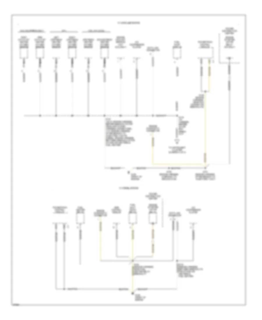
Ground Distribution Wiring Diagram (2 of 3) for Dodge Cab & Chassis R1997 2500
List of elements for Ground Distribution Wiring Diagram (2 of 3) for Dodge Cab & Chassis R1997 2500:
-
-
-
- downstream heated oxygen sensor
- 3.9l, 5.2l & 5.9l
- 8.0l
- 8.0l california only
- A/c compressor clutch
- A31
- A32
- Data link connector
- Egr control module
- Engine coolant sending unit (8.0l only)
- Engine diagnostic connector
- Engine starter motor relay
- Engine starter motor relay (m/t only)
- Fuel heater relay
- Fuel pump module
- Fuel shut down relay
- G125 (front of engine)
- Left upstream heated oxygen sensor
- Nca
- Post catalyst heated oxygen sensor
- Power distribution center
- Powertrain control module
- Pre- catalyst heated oxygen sensor
- Right upstream heated oxygen sensor
- S116 (i/p harness, before glove box break- out)
- S139 (engine harness, near pcm connector breakouts)
- S140 (v6/v8: engine harness, before breakouts for headlamp & dash harness connectors) (v10: engine harness, after branch to injectors 1/3/5/7/9) (diesel: engine harness, between breakouts for intake air heaters & fuel heater)
- S150 (engine harness, in branch to ground g125)
- S151 (engine harness, after branch to injectors 1/3/5/7)
- To instrument cluster (diagram 3 of 3)
- Upstream heated oxygen sensor
- W/ diesel engine
- W/ gasoline engine
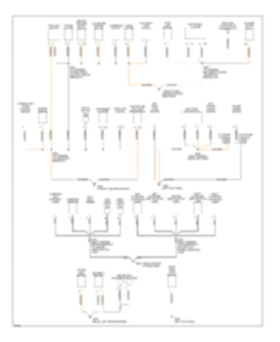
Ground Distribution Wiring Diagram (3 of 3) for Dodge Cab & Chassis R1997 2500
List of elements for Ground Distribution Wiring Diagram (3 of 3) for Dodge Cab & Chassis R1997 2500:
- (below left rear speaker)
- (front center of headliner)
- (i/p right center support)
- (left kick panel)
- (w/ power windows & door locks)
- (w/o power windows & door locks)
- A/c-heater control switch
- After breakout for left out- board clearance lamp)
- Before breakout to center identification lamp)
- Blower motor relay
- Buzzer
- Center high mounted stop lamps
- Center identification lamp
- Center support, near radio)
- Cigar lighter
- Controller anti-lock brake (rwal)
- Day/ night mirror
- Fog lamp switch
- From fuel pump module (diagram 2 of 3)
- G200
- G200
- G206
- G206 (i/p right
- G308
- G908
- Glove box lamp/ switch
- Headlamp switch
- Instrument cluster
- Intermittent wiper control module
- Key-in- switch halo lamp
- Left door jamb switch
- Left door lock switch
- Left outboard clearance lamp
- Left outboard identification lamp
- Left power window switch
- Left visor/ vanity lamp
- Module
- Overdrive switch
- Overhead console
- Overhead map/ courtesy lamp
- Power mirror switch
- Power outlet
- Power seat switch
- Remote keyless entry module
- Right door jamb switch
- Right outboard clearance lamp
- Right outboard identification lamp
- Right visor/ vanity lamp
- S206 (i/p harness, in fuse block breakout)
- S208 (i/p harness, between cluster connector breakouts)
- S215 (i/p harness, after air bag control module breakout)
- S306 (body harness, inside left door)
- Seatbelt switch
- Stop lamp switch
HEADLIGHTS
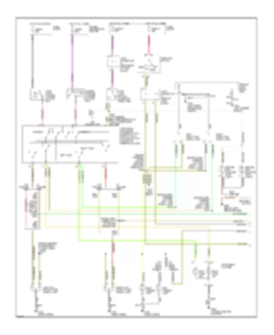
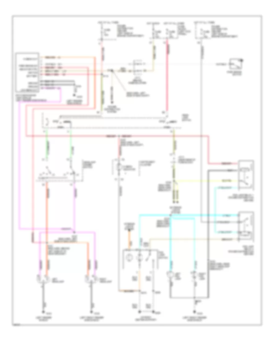
Headlamps/Fog Lamps Wiring Diagram, with DRL for Dodge Cab & Chassis R1997 2500
List of elements for Headlamps/Fog Lamps Wiring Diagram, with DRL for Dodge Cab & Chassis R1997 2500:
- (eng harn, left side of eng compt)
- (i/p right center support)
- (left fender shield)
- (left fender side shield)
- (left front fender side shield)
- Battery
- Daytime running lamp module (left fender side shield)
- Exterior lights system
- Flash
- Fog lamp relay 1 (power distribution center)
- Fog lamp relay 2 (power distribution center)
- Fog lamp switch
- Fuse 10a
- Fuse 15a
- Fuse 40a
- Fuse a 15a
- Fuse block (left kick panel)
- G100
- G104
- G11
- G206
- G34
- Ground
- Head
- Head- lamp switch
- Headlamp dimmer switch
- Hi beam indicator
- Hi beam out
- Hot at all times
- Hot in run
- Ignition
- Indicator ctrl
- Instrument cluster
- Interior lights system
- J/c a (near rear of fuse block)
- J/c c (behind knee bolster)
- L10
- Left fog lamp
- Left headlamp
- Low beam out
- Off
- Park
- Park brake sw
- Park brake switch
- Pnk/red
- Power distribution center (left side of engine compartment)
- Power distribution system
- Right fog lamp
- Right headlamp
- S103 (eng harn, near right headlamp breakout)
- S104 (eng harn, near horn breakout)
- S106 (eng harn, near horn breakout)
- S107 (eng harn, left side of eng compt)
- S108
- S118
- S120
- S121 (eng harn, behind left side of i/p, near grommet)
- S153 (eng harn, left side of eng compt)
- S206
- S215
- S409
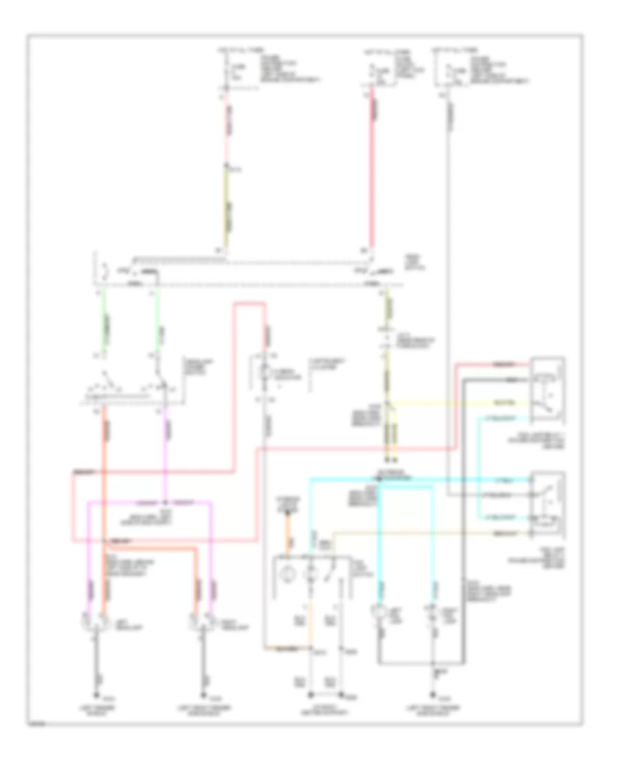
Headlamps/Fog Lamps Wiring Diagram, without DRL for Dodge Cab & Chassis R1997 2500
List of elements for Headlamps/Fog Lamps Wiring Diagram, without DRL for Dodge Cab & Chassis R1997 2500:
- (i/p right center support)
- (left fender shield)
- (left front fender side shield)
- Exterior lights system
- Flash
- Fog lamp relay 1 (power distribution center)
- Fog lamp relay 2 (power distribution center)
- Fog lamp switch
- Fuse 15a
- Fuse 40a
- Fuse a 15a
- Fuse block (left kick panel)
- G100
- G104
- G206
- Head
- Head- lamp switch
- Headlamp dimmer switch
- Hi beam indicator
- Hot at all times
- Instrument cluster
- Interior lights system
- J/c a (near rear of fuse block)
- Left fog lamp
- Left headlamp
- Off
- Park
- Pnk/red
- Power distribution center (left side of engine compartment)
- Right fog lamp
- Right headlamp
- S103 (eng harn, near right headlamp breakout)
- S104 (eng harn, near horn breakout)
- S106 (eng harn, near horn breakout)
- S107 (eng harn, left side of eng compt)
- S118
- S121 (eng harn, behind left side of i/p, near grommet)
- S206
- S215
- S409
HORN
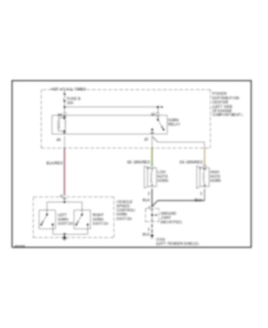
Horn Wiring Diagram for Dodge Cab & Chassis R1997 2500
List of elements for Horn Wiring Diagram for Dodge Cab & Chassis R1997 2500:
- Fuse b 20a
- G104 (left fender shield)
- Ground joint (near pdc)
- High note horn
- Horn relay
- Hot at all times
- Left horn switch
- Low note horn
- Power distribution center (left side of engine compartment)
- Right horn switch
- Vehicle speed control/ horn switch
INSTRUMENT CLUSTER
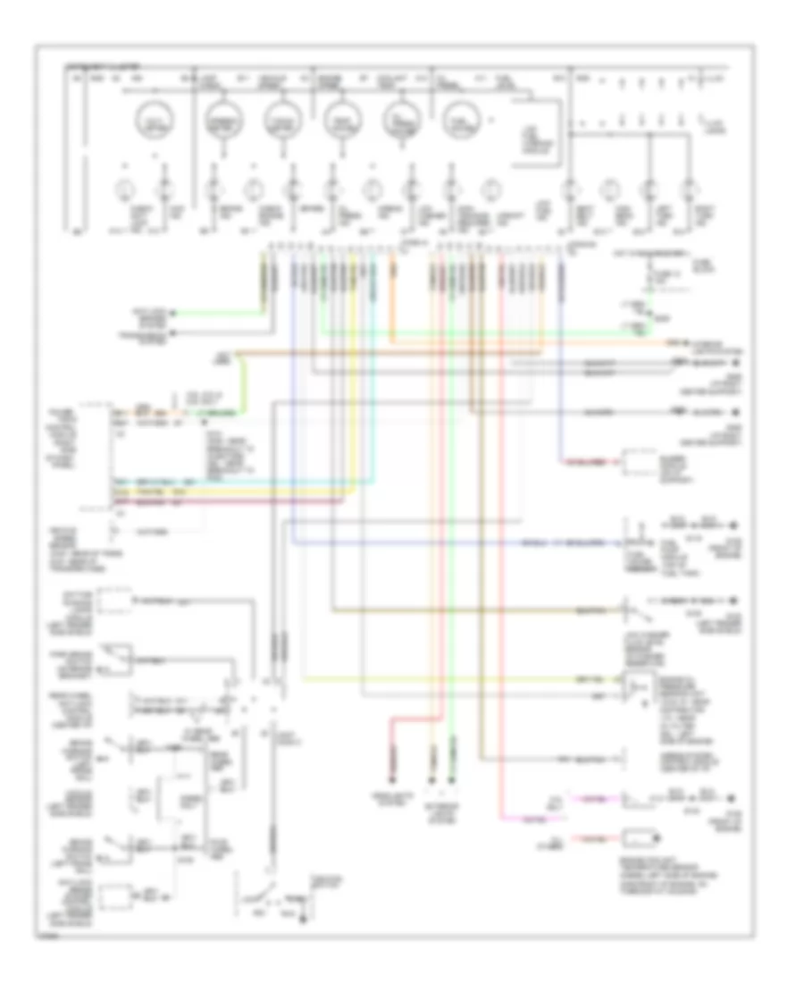
Instrument Cluster Wiring Diagram for Dodge Cab & Chassis R1997 2500
List of elements for Instrument Cluster Wiring Diagram for Dodge Cab & Chassis R1997 2500:
- (2wd - rear of trans 4wd - rear of transfer case)
- (conn a)
- (conn b)
- (diesel-left side of engine)
- (gas-front of engine, on thermostat housing)
- (right
- (spare)
- (top of fuel tank)
- (v6 & v8 - near distributor
- 3.9l, 5.2l & 5.9l only
- 4wd ind.
- 8.0l only
- A10
- A11
- A13
- A14
- Acc
- Airbag ind.
- Airbag system control module (center of i/p)
- All others
- Anti-lock brake system control module (left fender side shield)
- Anti-lock brakes system
- B10
- B11
- B12
- B13
- B14
- B27
- Brake ind.
- Brake warning switch (left frame rail)
- Buzzer module (on i/p support)
- C16
- C17
- C31
- Center support)
- Check anti- lock ind.
- Check engine ind.
- Control
- Coolant temp.
- Daytime running lamps module (left fender side shield)
- Diesel only
- Dsl - left side of engine)
- Engine coolant temperature sensor
- Engine oil pressure sending unit
- Engine speed
- Exterior lights system
- Four wheel abs
- Fuel gauge
- Fuel gauge sensor
- Fuel level
- Fuel pump module
- Fuse 12 15a
- Fuse block
- G100 (left fender side shield)
- G11
- G12
- G125 (front of engine)
- G206 (i/p right
- G206 (i/p right center support)
- G21
- G54
- Gnd
- Headlights system
- High beam ind.
- Hot in run or start
- Ign
- Ignition switch
- Illum.
- Illum. lamps
- Instrument cluster
- Interior lights system
- Joint conn c
- Lamp check
- Left turn ind.
- Lock
- Low fuel ind.
- Low fuel warning module
- Low washer fluid level sensor (in washer reservoir)
- Low washer ind.
- Main- tenance required ind.
- Module
- Not used
- Of dash
- Oil press.
- Oil press. gauge
- Oil press. ind.
- Panel)
- Park brake switch (on brake bracket)
- Power-
- R41
- Rear wheel abs
- Rear wheel anti-lock control module (center i/p)
- Right turn ind.
- Run
- S108
- S109
- S116
- S131 (gas - near breakout to injectors dsl - near breakout to pcm)
- S140
- S206
- S208
- S209
- Seat belt ind.
- Side
- Speedo- meter
- Start
- Tacho- meter
- Temp. gauge
- Train
- Transmission system
- Upshift ind.
- V10 - near oil filter
- Vacuum sensor (left fender side shield)
- Vehicle speed
- Vehicle speed sensor
- Volt- meter
- W/ rear wheel abs
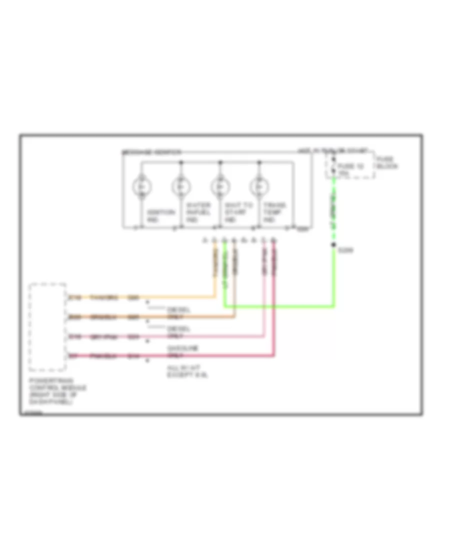
Message Center Wiring Diagram for Dodge Cab & Chassis R1997 2500
List of elements for Message Center Wiring Diagram for Dodge Cab & Chassis R1997 2500:
- All w/ a/t except 8.0l
- B20
- C18
- Diesel only
- Fuse 12 15a
- Fuse block
- G14
- G24
- G85
- G86
- Gasoline only
- Hot in run or start
- Ign
- Ignition ind.
- Message center
- Powertrain control module (right side of dash panel)
- S209
- Trans. temp. ind.
- Wait to start ind.
- Water in-fuel ind.
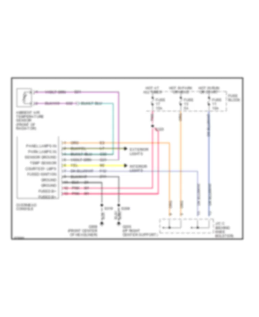
Overhead Console Wiring Diagram for Dodge Cab & Chassis R1997 2500
List of elements for Overhead Console Wiring Diagram for Dodge Cab & Chassis R1997 2500:
- Ambient air temperature sensor (front of radiator)
- Courtesy lmps
- Exterior lights
- F12
- Fuse 10a
- Fuse 15a
- Fuse 5a
- Fuse block
- Fused b+
- Fused ignition
- G206 (i/p right center support)
- G31
- G32
- G908 (front center of headliner)
- Ground
- Hot at all times
- Hot in park or head
- Hot in run or start
- Interior lights
- J/c c (behind knee bolster)
- Overhead console
- Panel lamps in
- Park lamps in
- Pnk
- S208
- S319
- S320
- Sensor ground
- Temp sensor
- Z11
INTERIOR LIGHTS
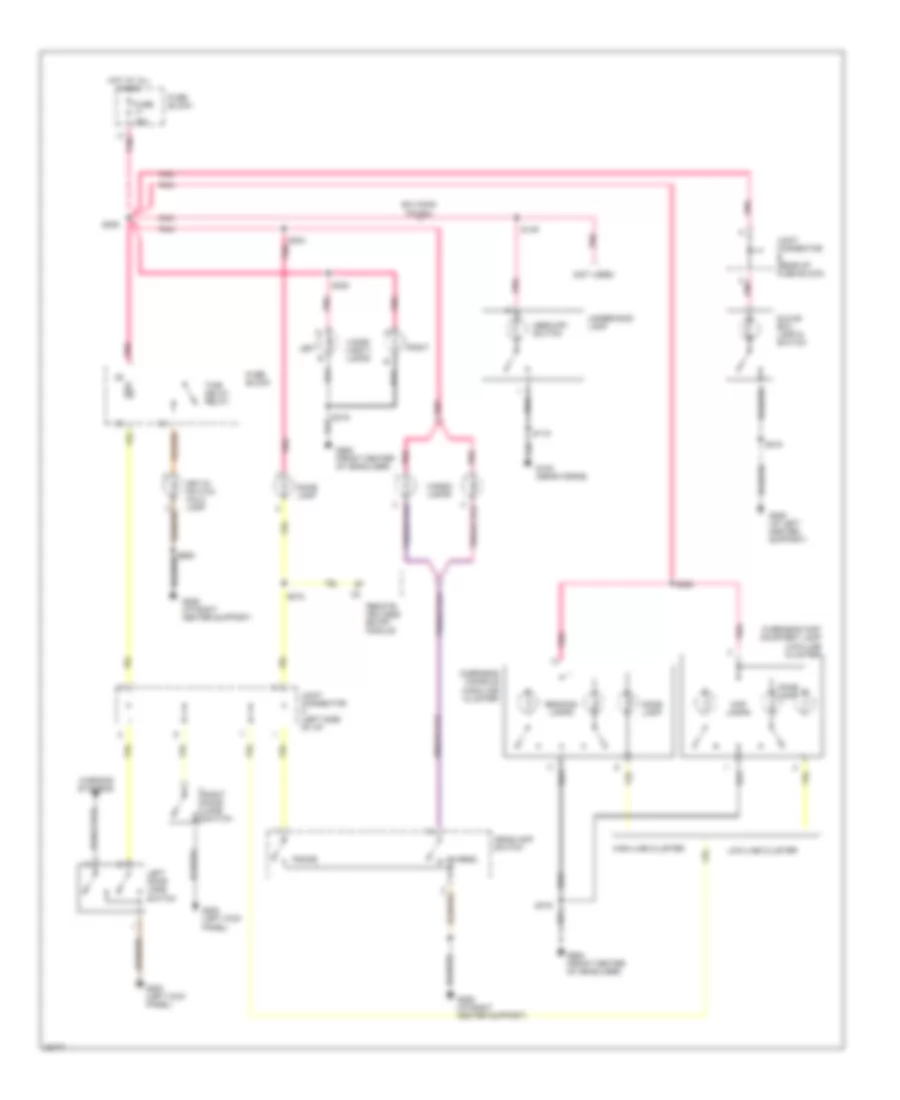
Courtesy Lamp Wiring Diagram for Dodge Cab & Chassis R1997 2500
List of elements for Courtesy Lamp Wiring Diagram for Dodge Cab & Chassis R1997 2500:
- (not used)
- B/h conn pin #34
- Cargo
- Cargo lamps
- Dome
- Dome lamp
- Fuse 15a
- Fuse block
- G100 (near horns)
- G200 (left kick panel)
- G206 (i/p left center support)
- G206 (i/p right center support)
- G908 (front center of headliner)
- Glove box lamp & switch
- Headlamp switch
- High-line cluster
- Hot at all times
- Joint connector a (left side of i/p)
- Joint connector b (rear of fuse block)
- Key-in switch halo lamp
- Left
- Left door jamb switch
- Low-line cluster
- Map lamps
- Mercury switch
- Overhead console (high-line cluster)
- Overhead map/ courtesy lamp (low-line cluster)
- Pnk
- Reading lamps
- Remote keyless entry module
- Right
- Right door jamb switch
- S115
- S149
- S205
- S215
- S218
- S303 pnk
- S319
- S320
- Time delay relay
- Underhood lamp
- Visor/ vanity lamps
- Warning systems
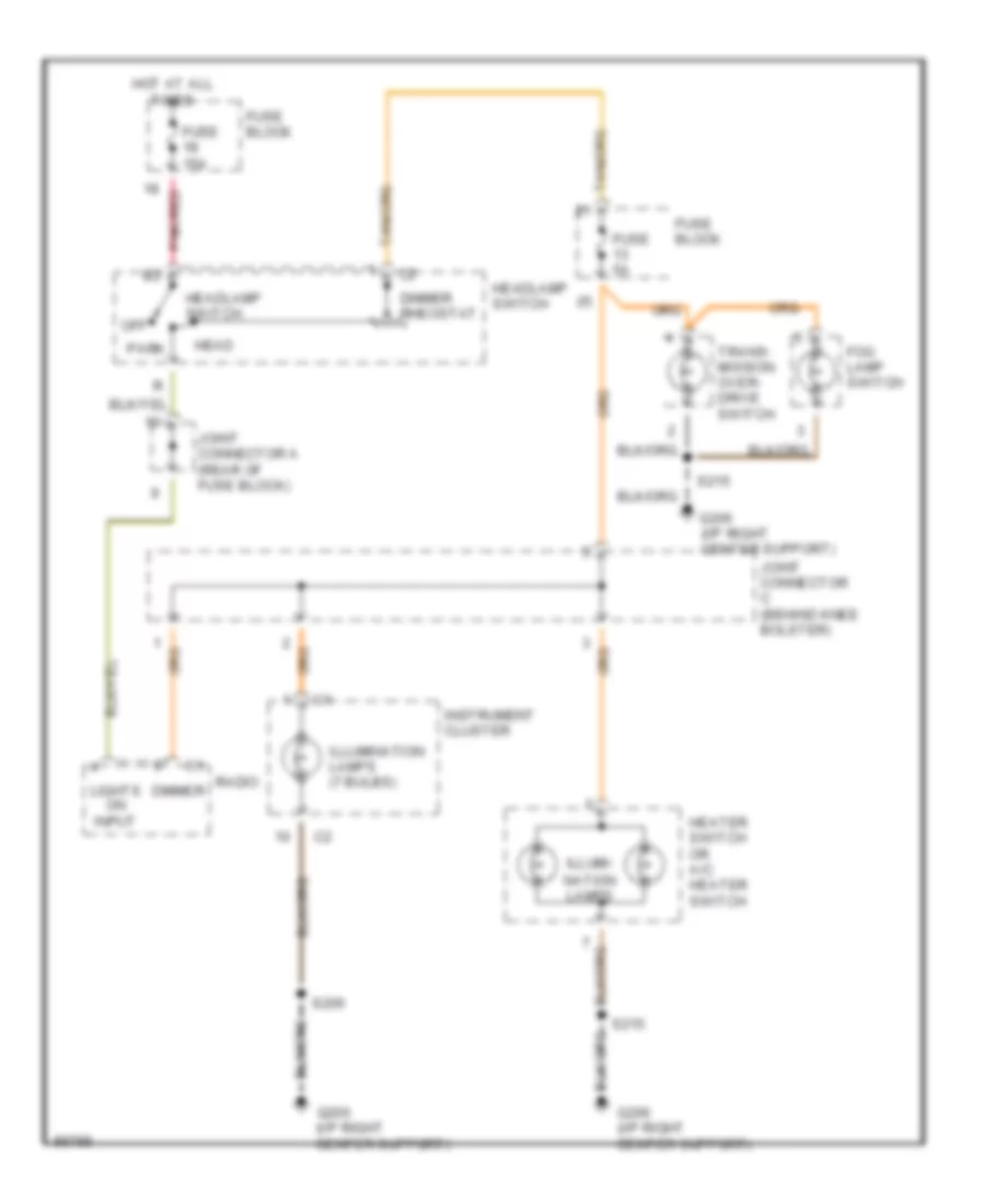
Instrument Illumination Wiring Diagram for Dodge Cab & Chassis R1997 2500
List of elements for Instrument Illumination Wiring Diagram for Dodge Cab & Chassis R1997 2500:
- Dimmer
- Dimmer rheostat
- Fog lamp switch
- Fuse 15a
- Fuse 5a
- Fuse block
- G206 (i/p right center support)
- Head
- Headlamp switch
- Heater switch or a/c heater switch
- Hot at all times
- Illumi-
- Illumination lamps (7 bulbs)
- Instrument cluster
- Joint connector a (rear of fuse block)
- Joint connector c (behind knee bolster)
- Lights on input
- Nation lamps
- Off
- Park
- Pnk/red
- Radio
- S206
- S215
- Trans- mission over- drive switch
POWER DISTRIBUTION
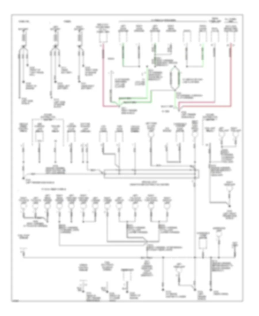
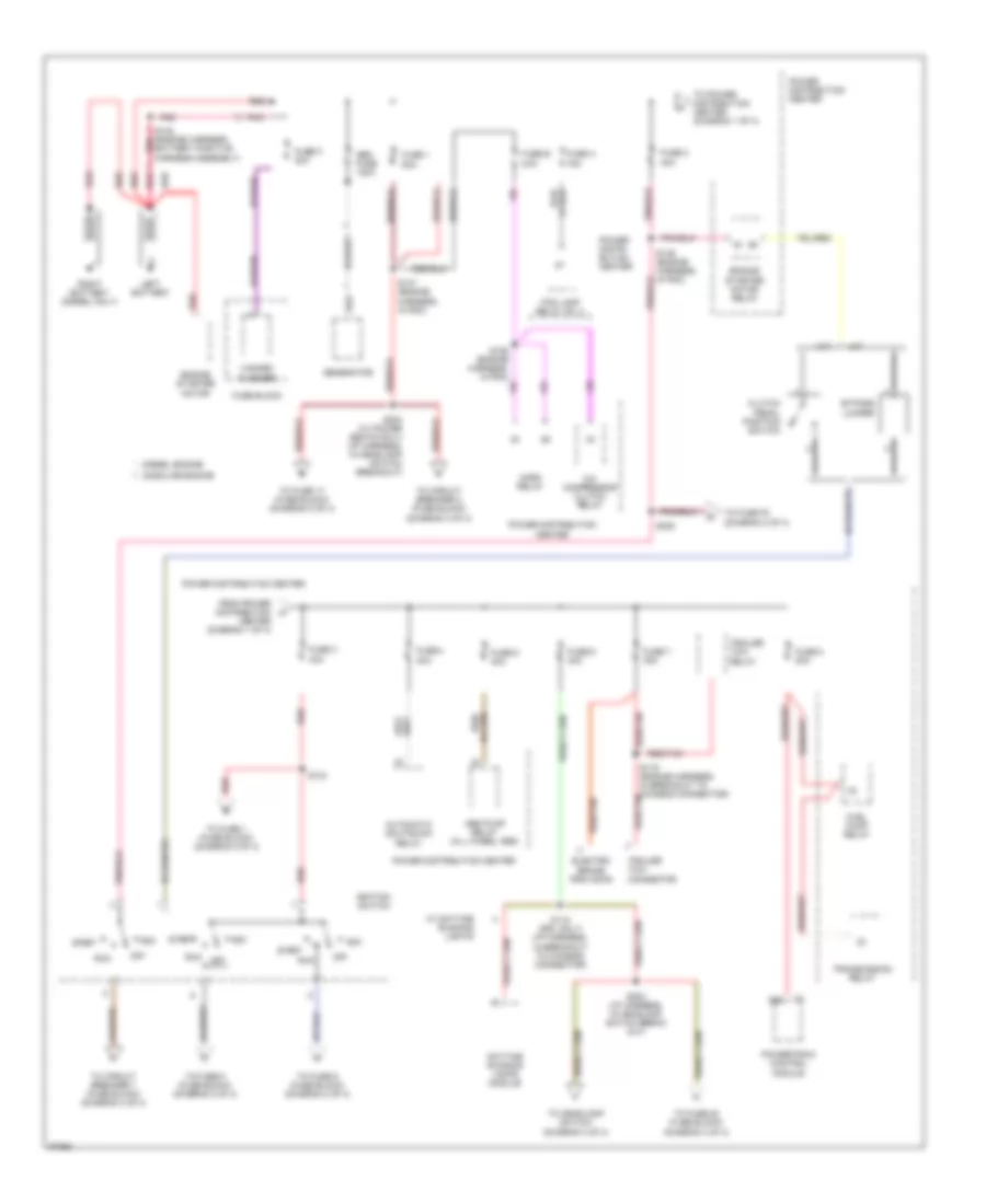
Power Distribution Wiring Diagram (1 of 4) for Dodge Cab & Chassis R1997 2500
List of elements for Power Distribution Wiring Diagram (1 of 4) for Dodge Cab & Chassis R1997 2500:
- 40a
- 50a
- A/c compressor clutch relay
- A/t
- A22
- Abs pump relay (all wheel abs)
- Acc
- Automatic shutdown relay
- Bypass jumper
- Center (diagram 1 of 4)
- Clutch pedal position switch
- Daytime running lamps module
- Diesel engine
- Electric brake provision
- Engine starter motor
- Engine starter motor relay
- Fog lamp relay no. 2
- From power distribution a
- Fuel pump relay
- Fuse 1
- Fuse 2
- Fuse 3 40a
- Fuse 4 30a
- Fuse 5 40a
- Fuse 6 40a
- Fuse 7 30a
- Fuse 8 20a
- Fuse a 15a
- Fuse b 20a
- Fuse block
- Fuse c 20a
- Gasoline engine
- Gen fuse 120a
- Generator
- Hazard flasher
- Horn relay
- Ignition switch
- Left battery
- M/t
- Off
- Pnk
- Power distri- bution center
- Power distribution center
- Powertrain control module
- Red
- Red/
- Red/tan
- Right battery (diesel only)
- Run
- S118 (drl only) (i/p harness, in breakout to chassis connector)
- S119 (engine harness, in breakout to chassis connector)
- S124
- S146 (engine harness, in pdc)
- S147 (engine harness, in pdc)
- S148 (engine harness, battery positive harness assembly)
- S155 (engine harness, in pdc)
- S203 (i/p harness, in headlamp switch break out)
- S204 (w/ power seats only) (i/p harness, in headlamp switch breakout)
- S220
- Start
- To circuit breaker 1 (fuse block) (diagram 4 of 4)
- To circuit breaker 2 (fuse block) (diagram 3 of 4)
- To fuse 1 (fuse block) (diagram 2 of 4)
- To fuse 17 (fuse block) (diagram 3 of 4)
- To fuse 20 (fuse block) (diagram 3 of 4)
- To fuse 5 (fuse block) (diagram 2 of 4)
- To fuse 9 (fuse block) (diagram 2 of 4)
- To fuse f2 (diagram 2 of 4)
- To headlamp switch (diagram 3 of 4)
- To power distribution center (diagram 1 of 4)
- Trailer tow connector
- Trailer tow relay
- Transmission relay
- W/ daytime running lights
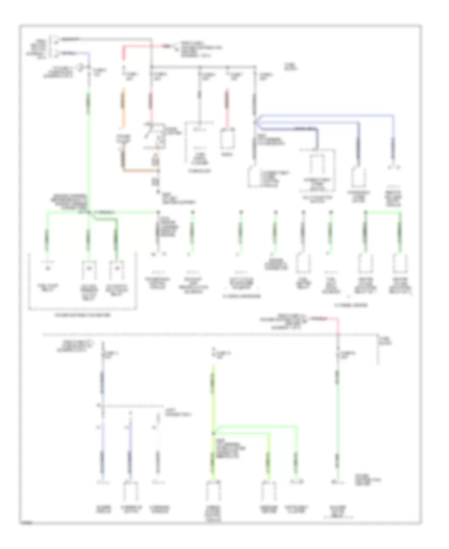
Power Distribution Wiring Diagram (2 of 4) for Dodge Cab & Chassis R1997 2500
List of elements for Power Distribution Wiring Diagram (2 of 4) for Dodge Cab & Chassis R1997 2500:
- (diagram 2 of 4)
- (engine harness, before branch to engine harness connectors) s114
- A/c com- pressor clutch relay
- Airbag system control module
- Automatic shut down relay
- Blower motor relay
- Buzzer module
- Cigar lighter
- Duty cycle evap/purge solenoid
- Engine diagnostic connector
- Exhaust gas recirculation solenoid
- From fuse 2 (power distribution d center) (diagram 1 of 4)
- From fuse 3 (power distribution center) (diagram 1 of 4)
- From fuse 9 (fuse block) l
- From ignition switch (diagram 1 of 4)
- Fuel heater relay
- Fuel pump relay
- Fuel shut down solenoid
- Fuse 1 20a
- Fuse 11 10a
- Fuse 12 15a
- Fuse 5 20a
- Fuse 6 20a
- Fuse 7 15a
- Fuse 8 20a
- Fuse 9 10a
- Fuse block
- Fuse f2 30a
- G206 (i/p left center support)
- Heated intake air system relay no. 1
- Heated intake air system relay no. 2
- Instrument cluster
- Intermittent wiper control module
- Intermittent wiper switch
- Joint connector c
- Message center
- Multi-function switch
- Overdrive switch
- Overhead console
- Power distribution center
- Power outlet
- Powertrain control module
- Radio
- Red
- Remote keyless entry module
- S132 (engine harness, rear of engine)
- S202 (i/p harness, in fuse block)
- S209 (i/p harness, after cluster connector breakouts)
- To fuse 11 (fuse block) (diagram 2 of 4)
- Turn signal flasher
- W/ diesel engine
- W/ gasoline engine
- Windshield wiper motor
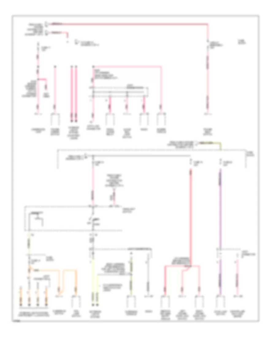
Power Distribution Wiring Diagram (3 of 4) for Dodge Cab & Chassis R1997 2500
List of elements for Power Distribution Wiring Diagram (3 of 4) for Dodge Cab & Chassis R1997 2500:
- (body harness, after breakout for left outboard clearance lamp) s317
- (courtesy lamps)
- (i/p harness, before glove box breakout) s216
- (not used)
- Buzzer module
- Circuit breaker 2 30a
- Controller anti-lock brake
- Data link connector
- Exterior lights
- Fog lamp switch
- From fuse 1 (power distribution center) (diagram 1 of 4)
- From fuse 17 m (diagram 3 of 4)
- From fuse 6 (power distribution center) (diagram 1 of 4)
- Fuse 13 5a
- Fuse 17 15a
- Fuse 18 15a
- Fuse 19 20a
- Fuse 20 20a
- Fuse block
- Glove box lamp/ switch
- Head
- Headlight switch
- Interior lights system
- Interior lights system (instrument illumination)
- Joint connector a
- Joint connector b
- Joint connector c
- Left power door lock switch
- Off
- Overdrive switch
- Overhead console
- Park
- Pnk
- Pnk/red
- Power mirror switch
- Power seat switch
- Radio
- Radio choke relay
- Red
- Remote keyless entry module
- Rheostat
- Right power door lock switch
- S149 (engine harness, in break out to chassis connector)
- S205 (i/p harness, near headlamp switch break out)
- Stop lamp switch
- System
- To fuse 18 (diagram 3 of 4)
- Underhood lamp
- W/ clearance & identification lamps
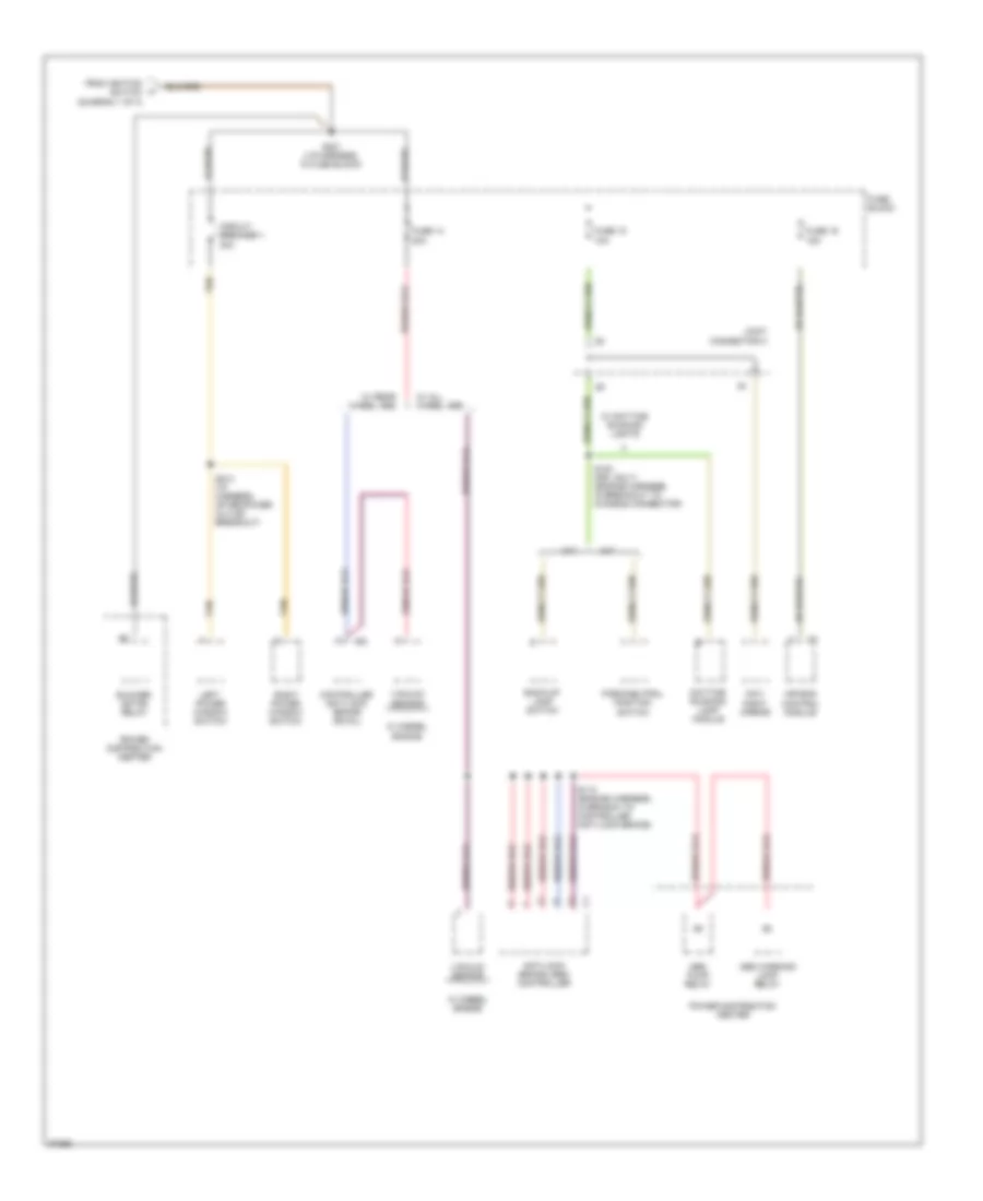
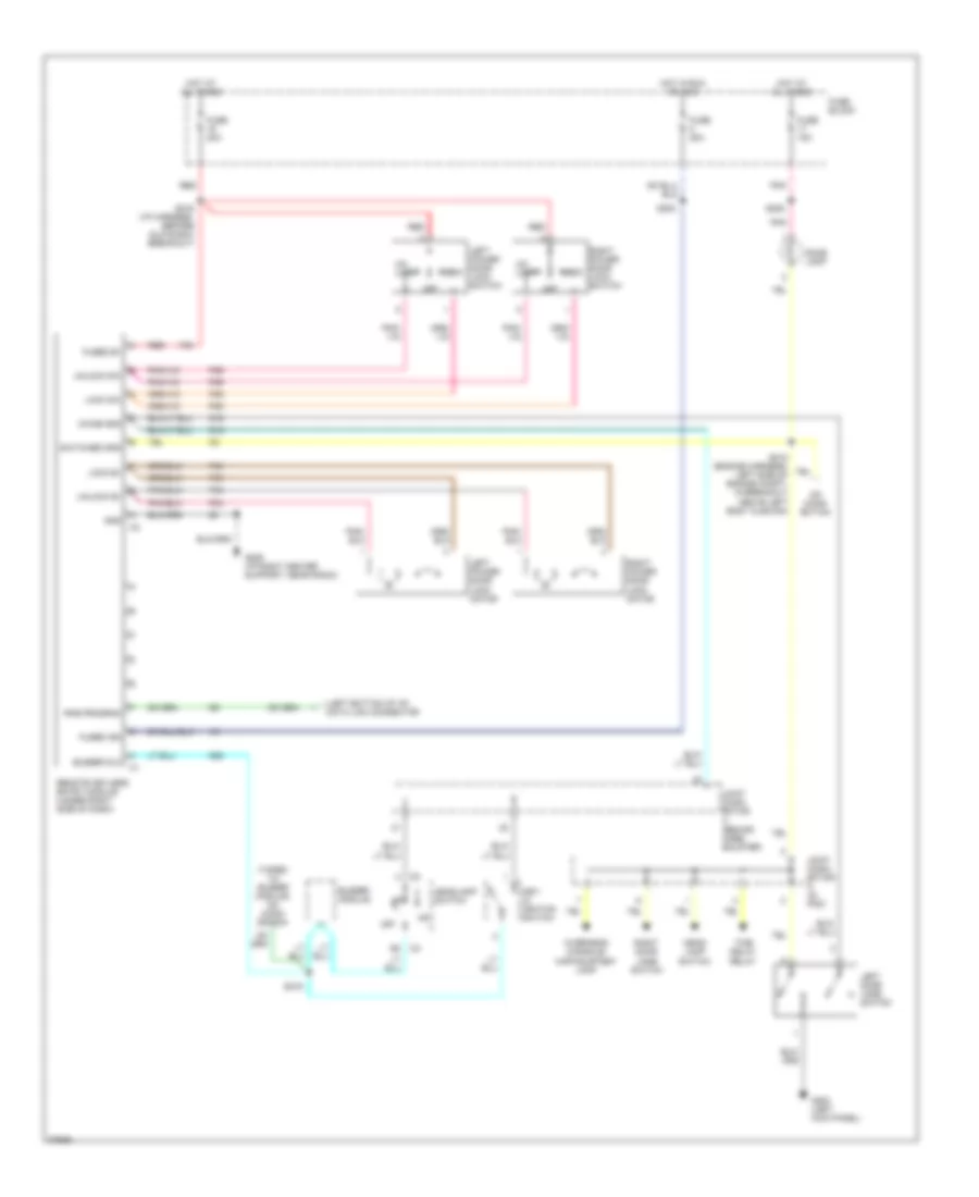
Power Distribution Wiring Diagram (4 of 4) for Dodge Cab & Chassis R1997 2500
List of elements for Power Distribution Wiring Diagram (4 of 4) for Dodge Cab & Chassis R1997 2500:
- A/t
- Abs pump relay
- Abs warning lamp relay
- Air bag control module
- Anti-lock brake (abs) controller
- Back-up lamp switch
- Blower motor relay
- Circuit breaker 1 30a
- Controller anti-lock brake (rwal)
- Day/ night mirror
- Daytime running lamp module
- From ignition switch (diagram 1 of 4)
- Fuse 14 20a
- Fuse 15 10a
- Fuse 16 15a
- Fuse block
- Joint connector c
- Left power window switch
- M/t
- Park/neutral position switch
- Power distribution center
- Right power window switch
- S110 (engine harness, in branch to controller anti-lock brake)
- S120 (drl only) (engine harness, in breakout to chassis connector)
- S201 (i/p harness, in fuse block)
- S214 (i/p harness, after power outlet breakout)
- Tan
- Vacuum sensor
- W/ all wheel abs
- W/ daytime running lights
- W/ diesel engine
- W/ rear wheel abs
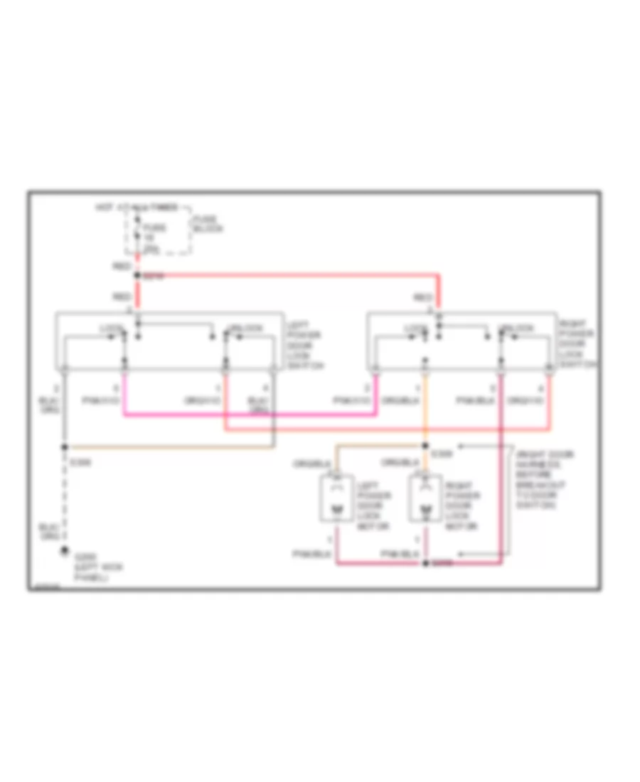
POWER DOOR LOCKS
Door Lock Wiring Diagram for Dodge Cab & Chassis R1997 2500
List of elements for Door Lock Wiring Diagram for Dodge Cab & Chassis R1997 2500:
- (right door harness, before breakout to door switch)
- Fuse 20a
- Fuse block
- G200 (left kick panel)
- Hot at all times
- Left power door lock motor
- Left power door lock switch
- Lock
- Red
- Right power door lock motor
- Right power door lock switch
- S216
- S306
- S309
- S310
- Unlock
Keyless Entry Wiring Diagram for Dodge Cab & Chassis R1997 2500
List of elements for Keyless Entry Wiring Diagram for Dodge Cab & Chassis R1997 2500:
- (left bottom of i/p) data link connector
- (taped to buzzer module) no conn- ection
- Buzzer dlc
- Buzzer module
- Chime gnd
- Dome lamp
- F35
- Fuse 15a
- Fuse 20a
- Fuse block
- Fused b+
- Fused ign
- G16
- G200 (left kick panel)
- G206 (i/p right center support, near radio)
- G26
- Gnd
- Head- lamp switch
- Headlamp switch
- Hot at all times
- Hot in run or acc
- Joint conn- ector a (in pdc)
- Joint conn- ector c (behind knee bolster)
- Key- in ignition switch
- Left door jamb switch
- Left power door lock lock switch
- Left power door lock motor
- Lock b+
- Lock sw
- No conn- ection
- Off
- Overhead console/ map/courtesy lamp
- P33
- P34
- P35
- P36
- Pnk
- Red
- Remote keyless entry module (under right side of dash)
- Right door jamb switch
- Right power door lock lock switch
- Right power door lock motor
- Rke program
- S202
- S205
- S216 (i/p harness, before glove box breakout)
- S218 (engine harness, left side of engine compt, in breakout above left body cushion)
- S219
- Switched gnd
- Time delay relay
- Un- lock
- Unlock b+
- Unlock sw
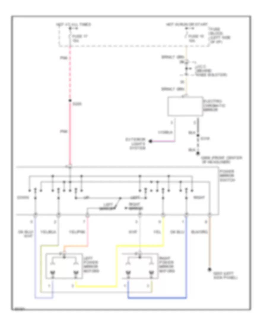
POWER MIRRORS
Power Mirror Wiring Diagram for Dodge Cab & Chassis R1997 2500
List of elements for Power Mirror Wiring Diagram for Dodge Cab & Chassis R1997 2500:
- (front center
- (left
- Down
- Electro- chromatic mirror
- Exterior lights system
- Fuse 15 10a
- Fuse 17 15a
- Fuse block (left side of i/p)
- G200 kick panel)
- G908 of headliner)
- Hot at all times
- Hot in run or start
- J/c c (behind knee bolster)
- Left
- Left mirror
- Left power mirror motors
- Pnk
- Power mirror switch
- Right
- Right mirror
- Right power mirror motors
- S205
- S319
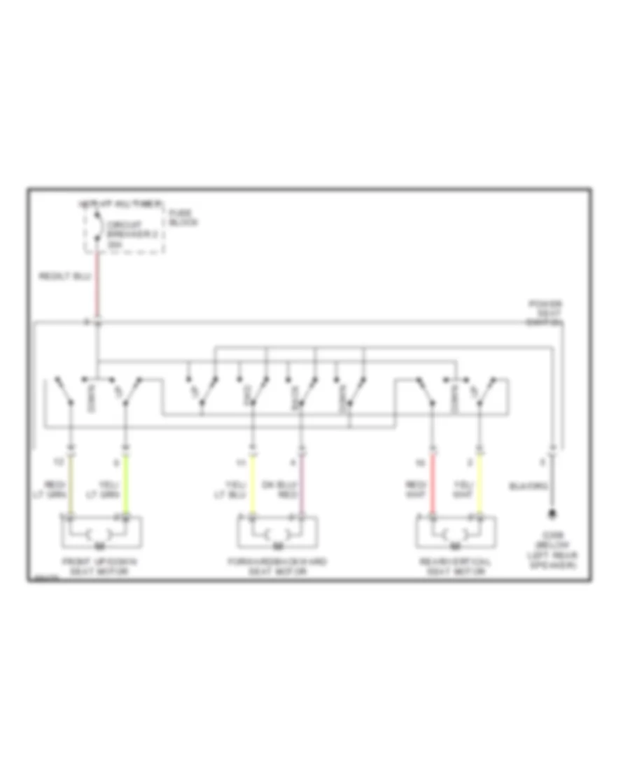
POWER SEATS
Power Seat Wiring Diagrams for Dodge Cab & Chassis R1997 2500
List of elements for Power Seat Wiring Diagrams for Dodge Cab & Chassis R1997 2500:
- Back
- Circuit breaker 2 30a
- Down
- Forward/backward seat motor
- Front up/down seat motor
- Fuse block
- Fwd
- G308 (below left rear speaker)
- Hot at all times
- Power seat switch
- Rear/vertical seat motor
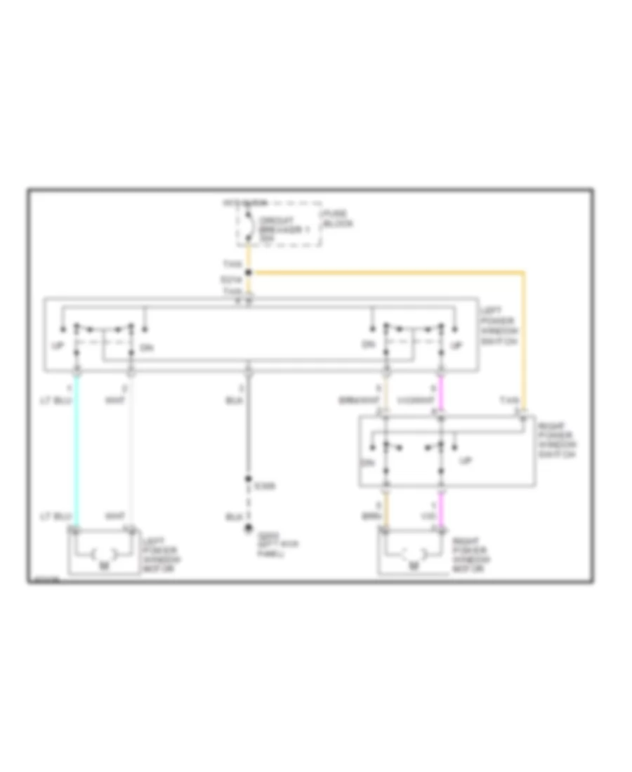
POWER WINDOWS
Power Window Wiring Diagram for Dodge Cab & Chassis R1997 2500
List of elements for Power Window Wiring Diagram for Dodge Cab & Chassis R1997 2500:
- Circuit breaker 1 30a
- Fuse block
- G200 (left kick panel)
- Hot in run
- Left power window motor
- Left power window switch
- Right power window motor
- Right power window switch
- S214
- S306
- Tan
RADIO
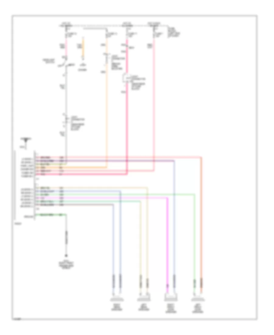
Radio Wiring Diagrams, Base Radio for Dodge Cab & Chassis R1997 2500
List of elements for Radio Wiring Diagrams, Base Radio for Dodge Cab & Chassis R1997 2500:
- Antenna
- Dimmer
- Dimmer sig
- Fender side shield)
- Fuse 13 5a
- Fuse 17 15a
- Fuse 18 15a
- Fuse 7 15a
- Fuse block (left end of dash)
- Fused b(+)
- Fused ign
- G101 (right front
- Ground
- Head
- Headlamp switch
- Hot at all times
- Hot in run or acc
- Joint connector a (near rear of fuse block)
- Joint connector b (near rear of fuse block)
- Joint connector c (behind knee bolster)
- Left front door speaker
- Left rear speaker
- Lf spkr (+)
- Lf spkr (-)
- Lr spkr (+)
- Lr spkr (-)
- Nca
- Off
- Park lamp
- Pnk
- Pnk/ red
- Radio
- Rf spkr (+)
- Rf spkr (-)
- Right front door speaker
- Right rear speaker
- Rr spkr (+)
- Rr spkr (-)
- S205
- X12
- X51
- X52
- X53
- X54
- X55
- X56
- X57
- X58
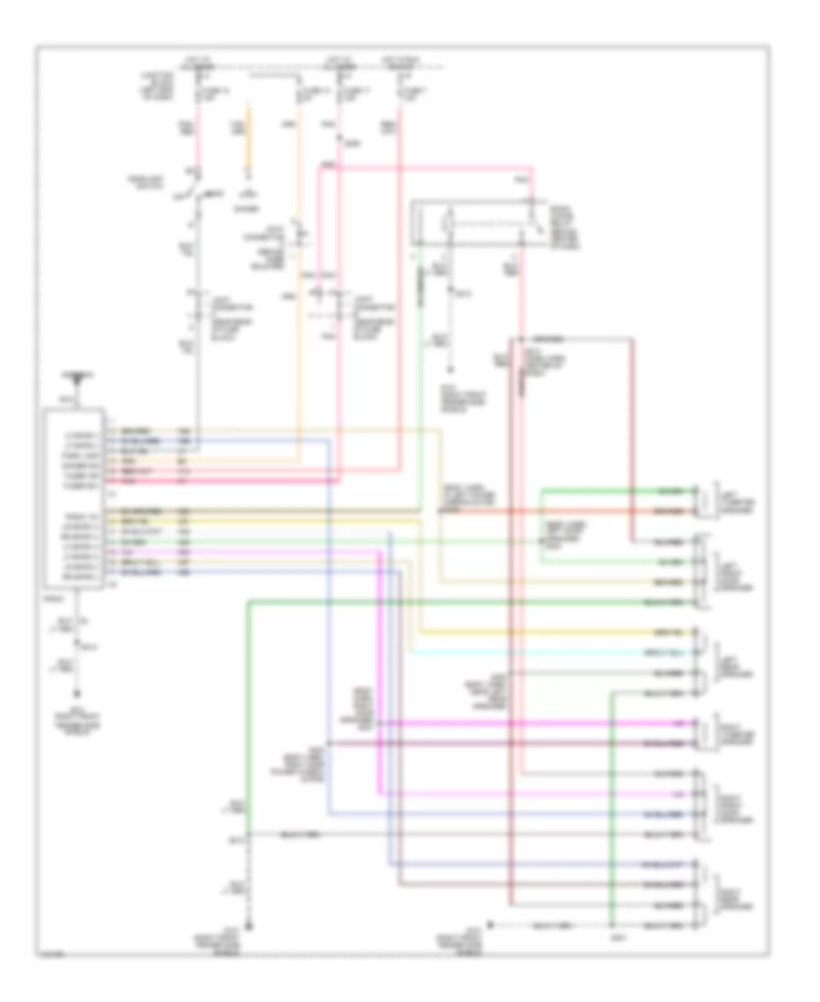
Radio Wiring Diagrams, Premium Radio for Dodge Cab & Chassis R1997 2500
List of elements for Radio Wiring Diagrams, Premium Radio for Dodge Cab & Chassis R1997 2500:
- (body harn, in left power mirror motor) s305
- (body harn, left door speaker) s304
- (body harn, right door speaker) s307
- Antenna
- Dimmer
- Dimmer sig
- Fender side shield)
- Fuse 13 5a
- Fuse 17 15a
- Fuse 18 15a
- Fuse 7 15a
- Fused b(+)
- Fused ign
- G101 (right front
- G101 (right front fender side shield)
- Head
- Headlamp switch
- Hot at all times
- Hot in run or acc
- Joint connector a (near rear of fuse block)
- Joint connector b (near rear of fuse block)
- Joint connector c (behind knee bolster)
- Junction block (left end of dash)
- Left front door speaker
- Left rear speaker
- Left tweeter speaker
- Lf spkr (+)
- Lf spkr (-)
- Lr spkr (+)
- Lr spkr (-)
- Nca
- Off
- Park lamp
- Pnk
- Pnk/ red
- Radio
- Radio 12v
- Radio choke relay (behind center of dash)
- Right front door speaker
- Right rear speaker
- Right tweeter speaker
- Rr spkr (+)
- Rr spkr (-)
- S205
- S212
- S213 (dash harn, center of dash)
- S301
- S302 (body harn, near left rear speaker)
- S308 (body harn, right door power window motor)
- X12
- X51
- X52
- X53
- X54
- X55
- X56
- X57
- X58
- X60
STARTING/CHARGING
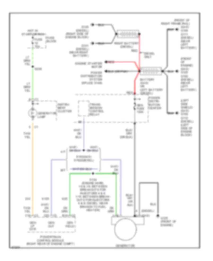
Charging Wiring Diagram for Dodge Cab & Chassis R1997 2500
List of elements for Charging Wiring Diagram for Dodge Cab & Chassis R1997 2500:
- (diesel)
- (front of engine) (gas) g125
- (front of right frame rail)
- (gas)
- (gas) g100
- (left side shield) (gas) g100
- A/t
- B10
- Battery (gas) or left battery (diesel)
- C16
- C25
- Diesel only
- Engine starter motor
- Fuse 15a
- Fuse block
- G100 (diesel) (near left battery)
- G101 (diesel) (near right battery)
- G111 (diesel) (near left battery)
- G112 (diesel) (left side of engine block)
- G12
- G120 (diesel) (right side of engine block)
- G125 (front of engine)
- Gen field
- Gen fuse 120a
- Gen lp dvr
- Gen out
- Generator
- Generator lamp
- Hot in start or run
- Instru- ment cluster
- K125
- K20
- M/t
- Power distri- bution center
- Power distribution system (splice s148)
- Powertrain control module (right rear of engine compt)
- Red
- Right battery (diesel)
- S134 (engine harn, v6 & v8: between breakouts for injectors 4 & 6; v10: between break- outs for injectors 6 & 8; diesel: near branch to fuel heater)
- S163(gas) s162(diesel)
- S209
- Trans- mission control relay
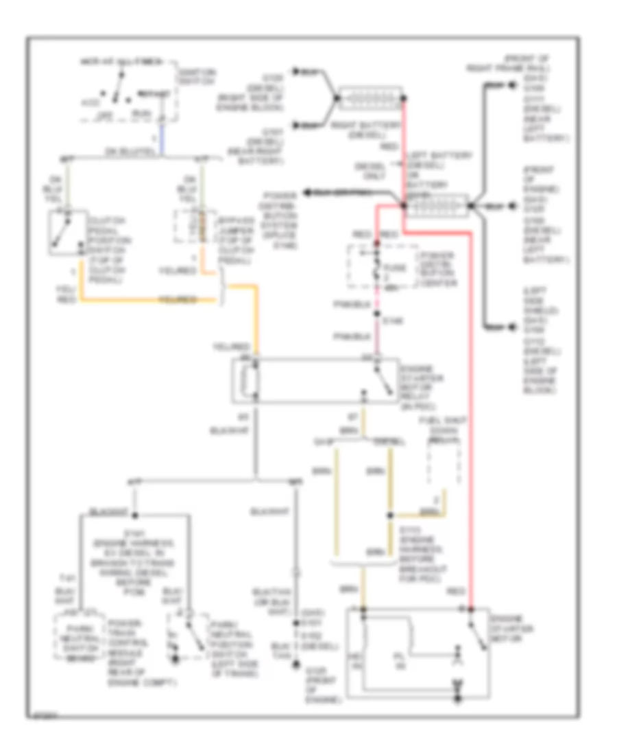
Starting Wiring Diagram for Dodge Cab & Chassis R1997 2500
List of elements for Starting Wiring Diagram for Dodge Cab & Chassis R1997 2500:
- (front of engine) (gas) g125
- (front of right frame rail)
- (gas) g100
- (left side shield) (gas) g100
- A/t
- Acc
- Bypass jumper (top of clutch pedal)
- Clutch pedal position switch (top of clutch pedal)
- Diesel
- Diesel only
- Engine starter motor
- Engine starter motor relay (in pdc)
- Fuel shut down relay
- Fuse 40a
- G100 (diesel) (near left battery)
- G101 (diesel) (near right battery)
- G111 (diesel) (near left battery)
- G112 (diesel) (left side of engine block)
- G120 (diesel) (right side of engine block)
- G125 (front of engine)
- Gas
- Hd in
- Hot at all times
- Ignition switch
- Left battery (diesel) or battery (gas)
- M/t
- Off
- P/ n
- Park/ neutral position switch (left side of trans)
- Park/ neutral switch sense
- Pl in
- Power distri- bution center
- Power distrib- bution system (splice s148)
- Power- train control module (right rear of engine compt)
- Red
- Right battery (diesel)
- Run
- S113 (engine harness, before breakout for pdc)
- S141 (engine harness, ex diesel: in branch to trans wiring; diesel: before pcm)
- S146
- Start
- T41
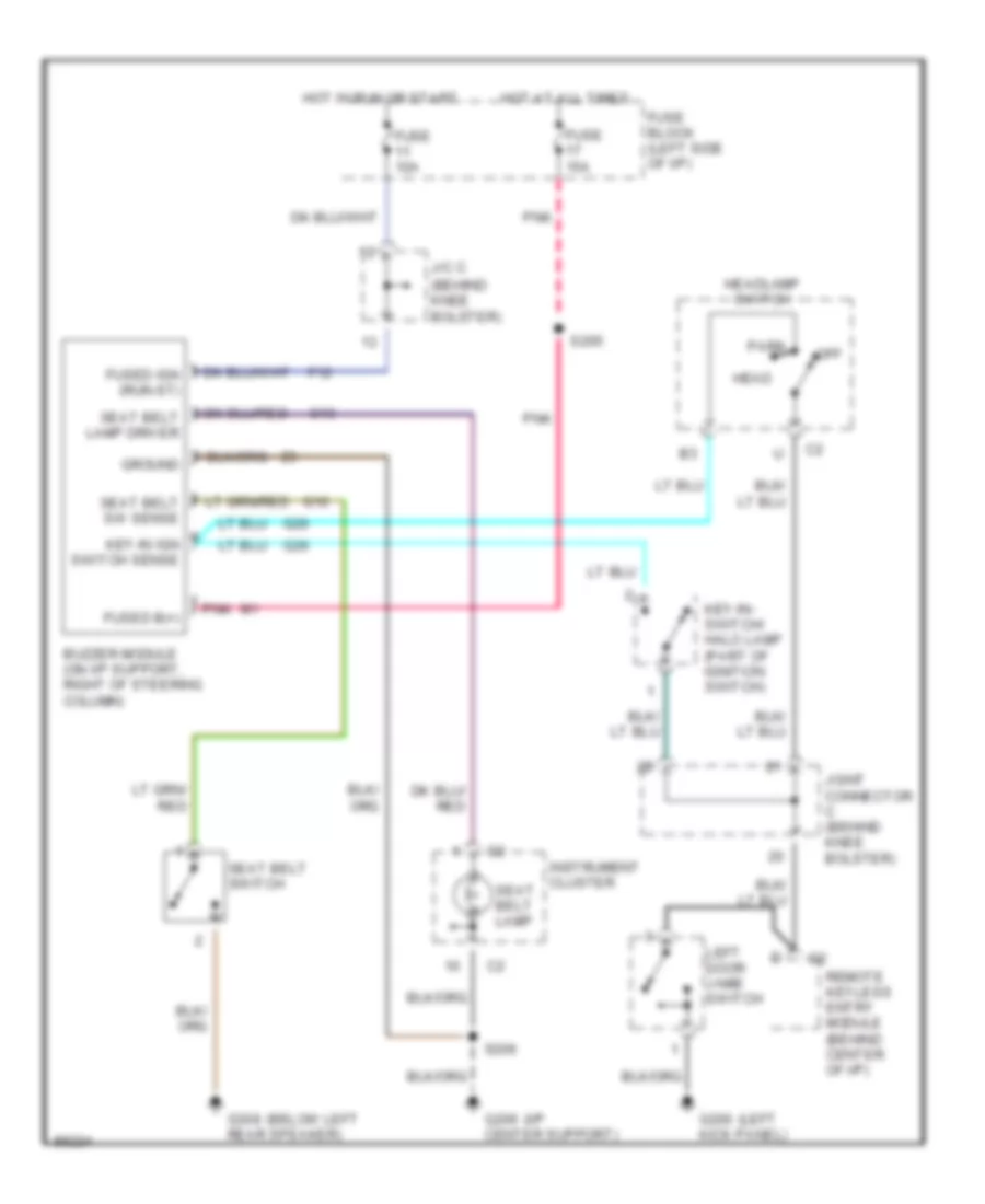
SUPPLEMENTAL RESTRAINTS
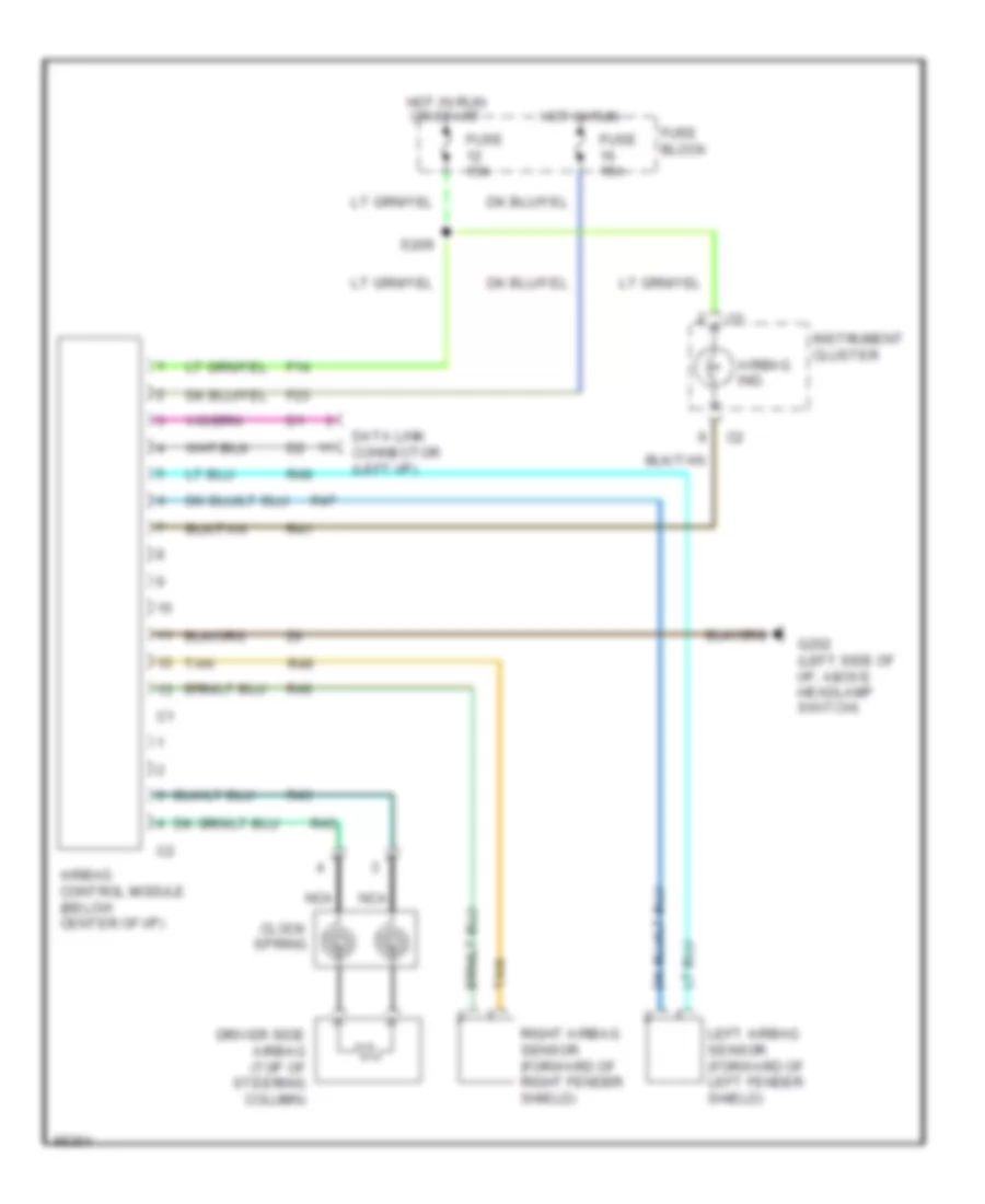
Supplemental Restraint Wiring Diagram for Dodge Cab & Chassis R1997 2500
List of elements for Supplemental Restraint Wiring Diagram for Dodge Cab & Chassis R1997 2500:
- Airbag control module (below center of i/p)
- Airbag ind.
- Clock spring
- Data link connector (left i/p)
- Driver side airbag (top of steering column)
- F14
- F23
- Fuse 15a
- Fuse block
- G202 (left side of i/p, above headlamp switch)
- Hot in run
- Hot in run or start
- Instrument cluster
- Left airbag sensor (forward of left fender shield)
- Nca
- R41
- R43
- R45
- R46
- R47
- R48
- R49
- Right airbag sensor (forward of right fender shield)
- S209
- Tan
TRANSMISSION
5.2L
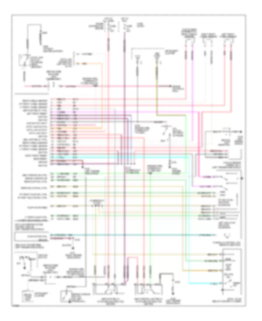
5.2L, Transmission Wiring Diagram (1 of 2) for Dodge Cab & Chassis R1997 2500
List of elements for 5.2L, Transmission Wiring Diagram (1 of 2) for Dodge Cab & Chassis R1997 2500:
- (eng harn, in branch to controller anti-lock brakes)
- (front of engine) g125
- (i/p right center support, near radio) g206
- (left bottom of dash)
- (left fender side shield) g100
- 4wd ind
- 4wd sense
- 4wd switch (on front axle tube)
- A/c compressor relay, fuel pump relay
- A14
- A16
- A17
- A22
- A23
- A31
- A32
- Abs
- Air bag system control module & message center
- B11
- B21
- B25
- B27
- B28
- B29
- B30
- B31
- Brake sw sense
- C13
- C17
- C24
- C25
- C27
- C29
- Connector
- Controller anti-lock brake (abs)
- Controller anti-lock brake (behind (center of dash)
- D20
- D21
- Data link connector (partial)
- Ect sens sig
- Engine controls system
- Engine diagnostic
- F18
- Fog lamp switch
- Fuse 10a
- Fuse 15a
- Fuse 5a
- Fuse block
- Fused b(+)
- Fused ign (st/run)
- G107
- G206 (i/p right center support, near radio)
- Generator output
- Gnd
- Gov press sig
- Hot at all times
- Hot in run or start
- Hot w/headlamp switch in park or head position (rheostat controlled)
- If equipped
- Illum
- Ind
- Instrument cluster
- Joint connector c (behind knee bolster)
- Joint connector c (pin 5) (interior light system)
- K125
- K22
- K30
- K54
- K88
- Mil driversense
- Mil ind
- Od lamp driver
- Od sol ctrl
- Ou shft spd sig
- Out shaft spd gnd
- Overdrive switch
- Pnk
- Pnp sw sense
- Powertrain control module (in eng compt, on right side of dash panel)
- Rwal
- S103
- S105 (eng harn, in branch for horn breakout)
- S111
- S114
- S132
- S139
- S208
- S209
- S215
- Sc1 receive
- Sci transmit
- Sensor gnd
- Stop lamp switch (top of brake pedal bracket)
- T13
- T14
- T18
- T25
- T41
- T54
- T60
- Tcc sol ctrl
- Tp sens sig
- Trans od sw sense
- Trans rly ctrl
- Trans temp sens
- Transmission output shaft speed sensor (on left side of transmission)
- V40
- Var sol ctrl
- Vss signal
- Z12
5.2L, Transmission Wiring Diagram (2 of 2) for Dodge Cab & Chassis R1997 2500
List of elements for 5.2L, Transmission Wiring Diagram (2 of 2) for Dodge Cab & Chassis R1997 2500:
- (after branch to fuel injectors 2,4,6,8 & (10)) (3.9l, 5.2l, 5.2l cng, 5.9l & 8.0l engines) s131
- (eng harn, near branch to fuel inj 2,4,6,8 or 10) s129
- (eng harn, near branch to fuel injectors 2,4,6,8 or 10)
- Engine controls system
- Engine coolant temperature sensor (between generator & a/c compressor)
- Engine starter motor relay
- Fuel pump relay
- Fuse 20a
- Generator
- Governor pressure signal
- Hot at all times
- Instrument cluster (speedometer)
- Overdrive solenoid control
- Park/ neutral position switch (on left side of transmission)
- Pnk
- Power distribution center
- Power distribution center
- Red
- S130
- S136 (eng harn, 3.9l, 5.2l & 5.9l: near crankshaft position sensor breakout, 8.0l: between fuel inj 5 & 7 breakout)
- S137 (eng harn, 3.9l, 5.2l, & 5.9l: near distributor breakout; 8.0l: near breakout to idle air control motor)
- S141 (eng harn, 3.9l 5.2l & 5.9l: in branch to trans wiring harn; 8.0l: before branch to oxygen & vehicle speed sensor)
- S154 (eng harn, before branch to fuel inj 1,3,5,7 or 9)
- S163
- Sensor ground
- Throttle position sensor (on throttle body)
- Torque converter clutch solenoid control
- Trans ctrl rly output
- Transmission control relay
- Transmission solenoid assembly (transmission)
- Transmission temperature sensor signal
- Variable force solenoid control
- Vehicle speed sensor (2wd: on left side of transmission extension housing, 4wd: on left side of transfer case)
5.9L
5.9L Turbo Diesel, Transmission Wiring Diagram (1 of 2) for Dodge Cab & Chassis R1997 2500
List of elements for 5.9L Turbo Diesel, Transmission Wiring Diagram (1 of 2) for Dodge Cab & Chassis R1997 2500:
- (eng harn, in branch to controller anti-lock brakes)
- (front of engine) g125
- (i/p right center support, near radio) g206
- (left bottom of dash)
- (left fender side shield) g100
- (on left side of transmission) transmission output shaft speed sensor
- 4wd ind
- 4wd sense
- 4wd switch (on front axle tube)
- A/c compressor relay, fuel pump relay
- A14
- A16
- A17
- A22
- A23
- A31
- A32
- Abs
- Air bag system control module & message center
- B11
- B21
- B25
- B27
- B28
- B29
- B30
- B31
- Brake sw sense
- C13
- C17
- C24
- C25
- C27
- C29
- Connector
- Controller anti-lock brake (abs)
- Controller anti-lock brake (behind (center of dash)
- D20
- D21
- Data link connector (partial)
- Ect sens sig
- Eng speed sens sig
- Engine controls system
- Engine diagnostic
- F18
- Fog lamp switch
- Fuse 10a
- Fuse 15a
- Fuse 5a
- Fuse block
- Fused b(+)
- Fused ign (st/run)
- G107
- G206 (i/p right center support, near radio)
- Generator output
- Gnd
- Gov press sig
- Hot at all times
- Hot in run or start
- Hot w/headlamp switch in park or head position (rheostat controlled)
- If equipped
- Illum
- Ind
- Instrument cluster
- Joint connector c (behind knee bolster)
- Joint connector c (pin 5) (interior light system)
- K125
- K22
- K24
- K30
- K54
- K88
- Mil ind
- Mil ind driver
- Od lamp driver
- Od sol ctrl
- Ou shft spd sig
- Out shaft spd gnd
- Overdrive switch
- Pnk
- Pnp sw sense
- Powertrain control module (in eng compt, on right side of dash panel)
- Rwal
- S103
- S105 (eng harn, in branch for horn breakout)
- S111
- S114
- S132
- S139
- S208
- S209
- S215
- Sc1 receive
- Sci transmit
- Sensor gnd
- Stop lamp switch (top of brake pedal bracket)
- T13
- T14
- T18
- T25
- T41
- T54
- T60
- Tcc sol ctrl
- Tp sens sig
- Trans od sw sense
- Trans rly ctrl
- Trans temp sens
- V40
- Var sol ctrl
- Vss signal
- Z12
5.9L Turbo Diesel, Transmission Wiring Diagram (2 of 2) for Dodge Cab & Chassis R1997 2500
List of elements for 5.9L Turbo Diesel, Transmission Wiring Diagram (2 of 2) for Dodge Cab & Chassis R1997 2500:
- (eng harn, after engine coolant temp sending unit
- (eng harn, before pcm) s131
- (eng harn, near distributor)
- Breakout) s130
- Egr control module
- Engine controls system
- Engine coolant temperature sensor (between generator & a/c compressor)
- Engine speed sensor (on front of eng, in timing chain case/cover)
- Engine starter motor relay
- Fuel pump relay
- Fuse 20a
- Generator
- Governor pressure signal
- Hot at all times
- Instrument cluster (speedometer)
- Overdrive solenoid control
- Park/ neutral position switch (on left side of transmission)
- Pnk
- Power distribution center
- Power distribution center
- Red
- S137
- S141 (eng harn, before pcm)
- S157 (eng harn, between intake air heater & fuel heater breakout)
- S159 (eng harn, before pcm)
- S161
- S162
- Sensor ground
- Throttle position sensor (on top of injector pump)
- Torque converter clutch solenoid control
- Trans ctrl rly output
- Transmission control relay
- Transmission solenoid assembly (transmission)
- Transmission temperature sensor signal
- Variable force solenoid control
- Vehicle speed sensor (2wd: on left side of transmission extension housing, 4wd: on left side of transfer case)
- W/ egr cotrol module
- W/o egr cotrol module
5.9L, Transmission Wiring Diagram (1 of 2) for Dodge Cab & Chassis R1997 2500
List of elements for 5.9L, Transmission Wiring Diagram (1 of 2) for Dodge Cab & Chassis R1997 2500:
- (eng harn, in branch to controller anti-lock brakes)
- (front of engine) g125
- (i/p right center support, near radio) g206
- (left bottom of dash)
- (left fender side shield) g100
- 4wd ind
- 4wd sense
- 4wd switch (on front axle tube)
- A/c compressor relay, fuel pump relay
- A14
- A16
- A17
- A22
- A23
- A31
- A32
- Abs
- Air bag system control module & message center
- B11
- B21
- B25
- B27
- B28
- B29
- B30
- B31
- Brake sw sense
- C13
- C17
- C24
- C25
- C27
- C29
- Connector
- Controller anti-lock brake (abs)
- Controller anti-lock brake (behind (center of dash)
- D20
- D21
- Data link connector (partial)
- Ect sens sig
- Engine controls system
- Engine diagnostic
- F18
- Fog lamp switch
- Fuse 10a
- Fuse 15a
- Fuse 5a
- Fuse block
- Fused b(+)
- Fused ign (st/run)
- G107
- G206 (i/p right center support, near radio)
- Generator output
- Gnd
- Gov press sig
- Hot at all times
- Hot in run or start
- Hot w/headlamp switch in park or head position (rheostat controlled)
- If equipped
- Illum
- Ind
- Instrument cluster
- Joint connector c (behind knee bolster)
- Joint connector c (pin 5) (interior light system)
- K125
- K22
- K30
- K54
- K88
- Mil driversense
- Mil ind
- Od lamp driver
- Od sol ctrl
- Ou shft spd sig
- Out shaft spd gnd
- Overdrive switch
- Pnk
- Pnp sw sense
- Powertrain control module (in eng compt, on right side of dash panel)
- Rwal
- S103
- S105 (eng harn, in branch for horn breakout)
- S111
- S114
- S132
- S139
- S208
- S209
- S215
- Sc1 receive
- Sci transmit
- Sensor gnd
- Stop lamp switch (top of brake pedal bracket)
- T13
- T14
- T18
- T25
- T41
- T54
- T60
- Tcc sol ctrl
- Tp sens sig
- Trans od sw sense
- Trans rly ctrl
- Trans temp sens
- Transmission output shaft speed sensor (on left side of transmission)
- V40
- Var sol ctrl
- Vss signal
- Z12
5.9L, Transmission Wiring Diagram (2 of 2) for Dodge Cab & Chassis R1997 2500
List of elements for 5.9L, Transmission Wiring Diagram (2 of 2) for Dodge Cab & Chassis R1997 2500:
- (after branch to fuel injectors 2,4,6,8 & (10)) (3.9l, 5.2l, 5.2l cng, 5.9l & 8.0l engines) s131
- (eng harn, near branch to fuel inj 2,4,6,8 or 10) s129
- (eng harn, near branch to fuel injectors 2,4,6,8 or 10)
- Engine controls system
- Engine coolant temperature sensor (between generator & a/c compressor)
- Engine starter motor relay
- Fuel pump relay
- Fuse 20a
- Generator
- Governor pressure signal
- Hot at all times
- Instrument cluster (speedometer)
- Overdrive solenoid control
- Park/ neutral position switch (on left side of transmission)
- Pnk
- Power distribution center
- Power distribution center
- Red
- S130
- S136 (eng harn, 3.9l, 5.2l & 5.9l: near crankshaft position sensor breakout, 8.0l: between fuel inj 5 & 7 breakout)
- S137 (eng harn, 3.9l, 5.2l, & 5.9l: near distributor breakout; 8.0l: near breakout to idle air control motor)
- S141 (eng harn, 3.9l 5.2l & 5.9l: in branch to trans wiring harn; 8.0l: before branch to oxygen & vehicle speed sensor)
- S154 (eng harn, before branch to fuel inj 1,3,5,7 or 9)
- S163
- Sensor ground
- Throttle position sensor (on throttle body)
- Torque converter clutch solenoid control
- Trans ctrl rly output
- Transmission control relay
- Transmission solenoid assembly (transmission)
- Transmission temperature sensor signal
- Variable force solenoid control
- Vehicle speed sensor (2wd: on left side of transmission extension housing, 4wd: on left side of transfer case)
8.0L
8.0L, Transmission Wiring Diagram (1 of 2) for Dodge Cab & Chassis R1997 2500
List of elements for 8.0L, Transmission Wiring Diagram (1 of 2) for Dodge Cab & Chassis R1997 2500:
- (eng harn, in branch to controller anti-lock brakes)
- (front of engine) g125
- (i/p right center support, near radio) g206
- (left bottom of dash)
- (left fender side shield) g100
- 4wd ind
- 4wd sense
- 4wd switch (on front axle tube)
- A/c compressor relay, fuel pump relay
- A14
- A16
- A17
- A22
- A23
- A31
- A32
- Abs
- Air bag system control module & message center
- B11
- B21
- B25
- B27
- B28
- B29
- B30
- B31
- Brake sw sense
- C13
- C17
- C24
- C25
- C27
- C29
- Connector
- Controller anti-lock brake (abs)
- Controller anti-lock brake (behind (center of dash)
- D20
- D21
- Data link connector (partial)
- Ect sens sig
- Engine controls system
- Engine diagnostic
- F18
- Fog lamp switch
- Fuse 10a
- Fuse 15a
- Fuse 5a
- Fuse block
- Fused b(+)
- Fused ign (st/run)
- G107
- G206 (i/p right center support, near radio)
- Generator output
- Gnd
- Gov press sig
- Hot at all times
- Hot in run or start
- Hot w/headlamp switch in park or head position (rheostat controlled)
- If equipped
- Illum
- Ind
- Instrument cluster
- Joint connector c (behind knee bolster)
- Joint connector c (pin 5) (interior light system)
- K125
- K22
- K30
- K54
- K88
- Mil driversense
- Mil ind
- Od lamp driver
- Od sol ctrl
- Ou shft spd sig
- Out shaft spd gnd
- Overdrive switch
- Pnk
- Pnp sw sense
- Powertrain control module (in eng compt, on right side of dash panel)
- Rwal
- S103
- S105 (eng harn, in branch for horn breakout)
- S111
- S114
- S132
- S139
- S208
- S209
- S215
- Sc1 receive
- Sci transmit
- Sensor gnd
- Stop lamp switch (top of brake pedal bracket)
- T13
- T14
- T18
- T25
- T41
- T54
- T60
- Tcc sol ctrl
- Tp sens sig
- Trans od sw sense
- Trans rly ctrl
- Trans temp sens
- Transmission output shaft speed sensor (on left side of transmission)
- V40
- Var sol ctrl
- Vss signal
- Z12
8.0L, Transmission Wiring Diagram (2 of 2) for Dodge Cab & Chassis R1997 2500
List of elements for 8.0L, Transmission Wiring Diagram (2 of 2) for Dodge Cab & Chassis R1997 2500:
- (after branch to fuel injectors 2,4,6,8 & (10)) (3.9l, 5.2l, 5.2l cng, 5.9l & 8.0l engines) s131
- (eng harn, near branch to fuel inj 2,4,6,8 or 10) s129
- (eng harn, near branch to fuel injectors 2,4,6,8 or 10)
- Engine controls system
- Engine coolant temperature sensor (between generator & a/c compressor)
- Engine starter motor relay
- Fuel pump relay
- Fuse 20a
- Generator
- Governor pressure signal
- Hot at all times
- Instrument cluster (speedometer)
- Overdrive solenoid control
- Park/ neutral position switch (on left side of transmission)
- Pnk
- Power distribution center
- Power distribution center
- Red
- S130
- S136 (eng harn, 3.9l, 5.2l & 5.9l: near crankshaft position sensor breakout, 8.0l: between fuel inj 5 & 7 breakout)
- S137 (eng harn, 3.9l, 5.2l, & 5.9l: near distributor breakout; 8.0l: near breakout to idle air control motor)
- S141 (eng harn, 3.9l 5.2l & 5.9l: in branch to trans wiring harn; 8.0l: before branch to oxygen & vehicle speed sensor)
- S154 (eng harn, before branch to fuel inj 1,3,5,7 or 9)
- S163
- Sensor ground
- Throttle position sensor (on throttle body)
- Torque converter clutch solenoid control
- Trans ctrl rly output
- Transmission control relay
- Transmission solenoid assembly (transmission)
- Transmission temperature sensor signal
- Variable force solenoid control
- Vehicle speed sensor (2wd: on left side of transmission extension housing, 4wd: on left side of transfer case)
WARNING SYSTEMS
Warning System Wiring Diagrams for Dodge Cab & Chassis R1997 2500
List of elements for Warning System Wiring Diagrams for Dodge Cab & Chassis R1997 2500:
- (behind knee bolster)
- (below left
- (i/p
- (left
- Buzzer module (on i/p support, right of steering column)
- F12
- Fuse 10a
- Fuse 15a
- Fuse block (left side of i/p)
- Fused b(+)
- G10
- G13
- G200 kick panel)
- G206 center support)
- G26
- G308 rear speaker)
- Ground
- Head
- Headlamp switch
- Hot at all times
- Hot in run or start
- Instrument cluster
- J/c c
- Joint connector c (behind knee bolster)
- Key-in ign switch sense
- Key-in- switch/ halo lamp (part of ignition switch)
- Left door jamb switch
- Off
- Park
- Pnk
- Remote keyless entry module (behind center of i/p)
- S205
- S206
- Seat belt lamp
- Seat belt sw sense
- Seat belt switch
WIPER/WASHER
Wiper/Washer Wiring Diagram for Dodge Cab & Chassis R1997 2500
List of elements for Wiper/Washer Wiring Diagram for Dodge Cab & Chassis R1997 2500:
- (behind
- (near
- (right i/p
- Center support)
- Delay
- Fuse 8 20a
- Fuse block (left side of i/p)
- Fuse ign. (run-acc)
- G100
- G107
- G201
- Ground
- Horns)
- Hot in acc or run
- Instrument cluster
- Intermittent wiper control module (left side of i/p)
- Low washer fluid level indic.
- Low washer fluid level switch (bottom of washer fluid reservoir)
- Off
- Park switch
- Right headlamp)
- S103
- S108
- S115
- S202
- S206
- V10
- V17
- Washer pump motor (bottom of washer fluid reservoir)
- Washer switch
- Washer switch signal
- Wiper motor
- Wiper park switch signal
- Wiper switch
- Wiper switch delay output
- Wiper switch mode sense
- Wiper switch mode signal