AIR CONDITIONING
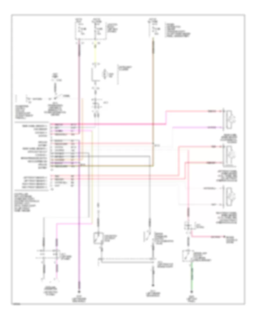
Heater Wiring Diagram for Dodge Cab & Chassis R2000 3500

List of elements for Heater Wiring Diagram for Dodge Cab & Chassis R2000 3500:
- (dash panel right center support) g206
- (left fender side shield) g100
- Bi-level
- Blower motor (behind right side of dash)
- Blower motor relay
- Blower motor resistor block (behind right side of dash, on a/c-heater housing)
- Blower motor speed switch
- Defrost
- Floor
- Floor/defrost
- Fuse 10a
- Fuse 40a
- Heater control
- High
- Hot at all times
- Hot in run
- Illum
- Interior lights system
- J/c 1
- J/c 8 (behind center of dash)
- Junction block (left end of dash)
- Low
- Med 1
- Med 2
- Mode select switch
- Off
- Panel
- Power distribution center (in engine compartment, on left inner fender panel, near battery)
- S207 (dash harness, near blower motor)
- Tan
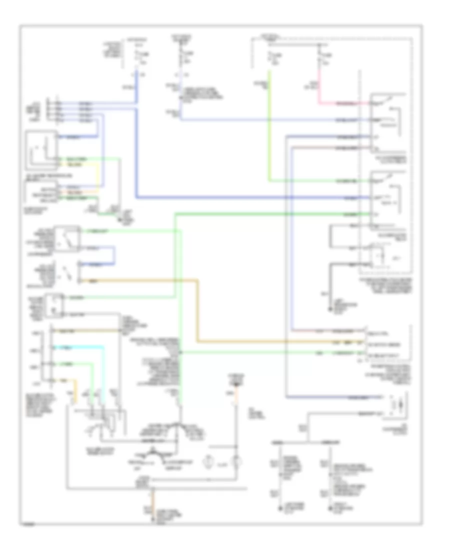
Manual A/C Wiring Diagram for Dodge Cab & Chassis R2000 3500
List of elements for Manual A/C Wiring Diagram for Dodge Cab & Chassis R2000 3500:
- (dash harness, near blower motor) s207
- (dash panel right center support) g206
- (engine harn., near break- out to fuel injectors) (6 cyl & 8 cyl) s120 (10 cyl (1), diesel (2)) ((1) engine harness, rear of engine) ((2) transmission harness, near breakout to a/c low pressure switch)
- (engine harness, near fuel transfer pump) s164
- (engine harness, top of transmission) (6 cyl & 8 cyl) s122 (1o cyl) (engine harness, in breakout to transmission)
- (front of engine) g125
- (headlamp & dash harness, in power distribution center) s105
- (left fender side shield) g100
- (left rear of engine) g114
- A/c compressor clutch
- A/c compressor clutch relay
- A/c heater control
- A/c heater temperature select
- A/c high pressure switch (on discharge line, near a/c compressor)
- A/c low pressure switch (on top of a/c accumulator)
- A/c select input
- A/c switch sense
- A/c-high
- A/c-low
- A/c-med 1
- A/c-med 2
- Bi- level
- Blend door actuator
- Blower motor (behind right side of dash)
- Blower motor relay
- Blower motor resistor block (behind right side of dash, on a/c-heater housing)
- Blower motor speed switch
- C13
- C20
- C90
- Defrost
- Diesel
- Floor
- Floor/defrost
- Fuse 10a
- Fuse 40a
- Fuse j 10a
- Gasoline
- Ground
- Heater-high
- Heater-low
- Heater-med 1
- Heater-med 2
- High
- Hot at all times
- Hot in run
- Hot in run or start
- Ignition
- Illum
- Interior lights system
- J/c 1
- J/c 8 (behind center of dash)
- Junction block (left end of dash)
- Low
- Med 1
- Med 2
- Mode select switch
- Off
- Panel
- Power distribution center (in engine compartment, on left inner fender panel, near battery)
- Powertrain control module (pcm) (in engine compartment, on right side of firewall)
- Recirc
- Relay ctrl
- Tan
- Temp select
ANTI-LOCK BRAKES
Anti-lock Brake Wiring Diagrams for Dodge Cab & Chassis R2000 3500
List of elements for Anti-lock Brake Wiring Diagrams for Dodge Cab & Chassis R2000 3500:
- (left bottom of dash)
- (not used)
- 4wd ind
- 4wd sensor
- 4wd switch (on front axle)
- A10
- A20
- B113
- B114
- Battery
- Brake lamp switch (on brake pedal bracket)
- Brake pressure switch
- Brake pressure switch (on combination valve)
- C125
- Ccd bus (+)
- Ccd bus (-)
- Controller anti-lock brake (4wabs: eng compt, mounted on hydraulic control unit) (rwal: in eng compt, on left front inner fender)
- Data link connector
- Diesel
- Engine controls system
- Fuse 10a
- Fuse 40a
- G100 (left fender side shield)
- G107
- G111 (left fender side shield)
- G200 (left kick panel)
- Ground
- Hot at all times
- Hot in run
- Ignition
- Instrument cluster
- J/c 1 (in pdc)
- J/c 3
- J/c 4 (left front of engine compt)
- J/c 7 (left side of dash)
- Junction block (left end of dash)
- Left front sensor (+)
- Left front sensor (-)
- Left front wheel speed sensor (w/ all wheel abs) (on left front steering knuckle)
- Power distribution center (in engine compt, on left inner fender panel, near battery)
- Powertrain control module (in eng compt, on right side of firewall)
- Rear wheel sensor (+)
- Rear wheel sensor (-)
- Rear wheel speed sensor (in differential housing)
- Red
- Right front sensor (+)
- Right front sensor (-)
- Right front wheel speed sensor (w/ all wheel abs) (on right front steering knuckle)
- S112
- S113
- S174 (transmission harness, in breakout to power distribution center)
- Stoplight sw out
- V40
- Vehicle speed sig
ANTI-THEFT
Anti-theft Wiring Diagram for Dodge Cab & Chassis R2000 3500
List of elements for Anti-theft Wiring Diagram for Dodge Cab & Chassis R2000 3500:
- (at upper left kick panel) s308
- (left fender side shield) g100
- (left side of dash) j/c 5
- (right center of dash) g206
- (right front of engine compartment)
- Ccd bus (+)
- Ccd bus (-)
- Central timer/ integrated electronic module (left side of dash)
- Clockspring 1
- Ctm
- Data link connector (left bottom of dash)
- Disarm sense
- Door ajar sense
- Driver cylinder lock switch
- Driver door jamb switch
- F12
- Fuse 10a
- Fuse g 15a
- Fuse h 20a
- Fused b(+)
- Fused ign
- G100 (left fender side shield)
- G16
- G200 (left kick panel)
- G304 (lower left rear of cab)
- G50
- G69
- G73
- G75
- Ground
- Headlights system
- High note horn
- Horn relay
- Horn relay ctrl
- Hot at all times
- Hot in run or start
- Iem
- J/c 1 (in pdc)
- J/c 3 (right side of engine compt)
- J/c 6 (left side of dash)
- J/c 7 (left side of dash)
- J/c 8 (left side of dash)
- Junction block (left end of dash)
- Low note horn
- Nca
- Overhead console
- Passenger cylinder lock switch
- Passenger door jamb switch
- Power distribution center (on left inner fender panel, near battery)
- Red
- S143 (highline)
- S305
- S329
- S330
- Security relay
- Tan
- Vehicle speed control/ horn switch
- Vtss lamp
- Vtss lamp driver
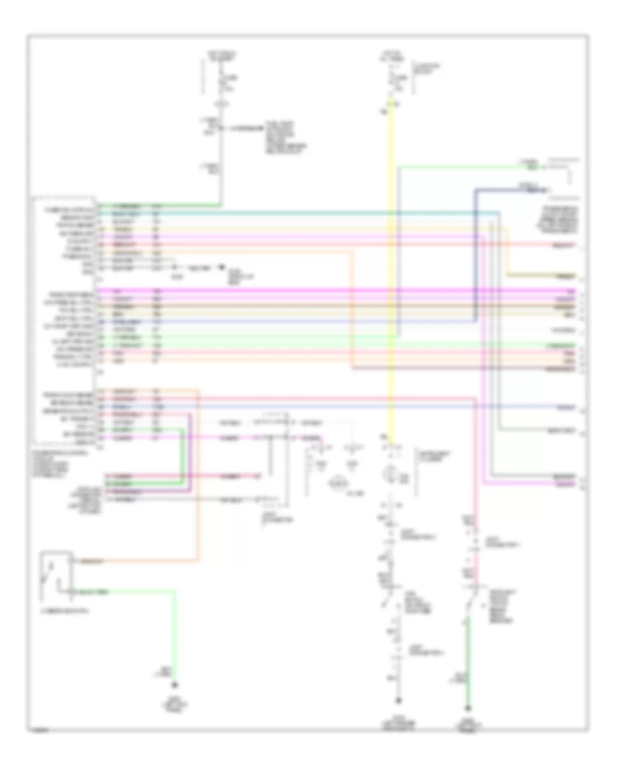
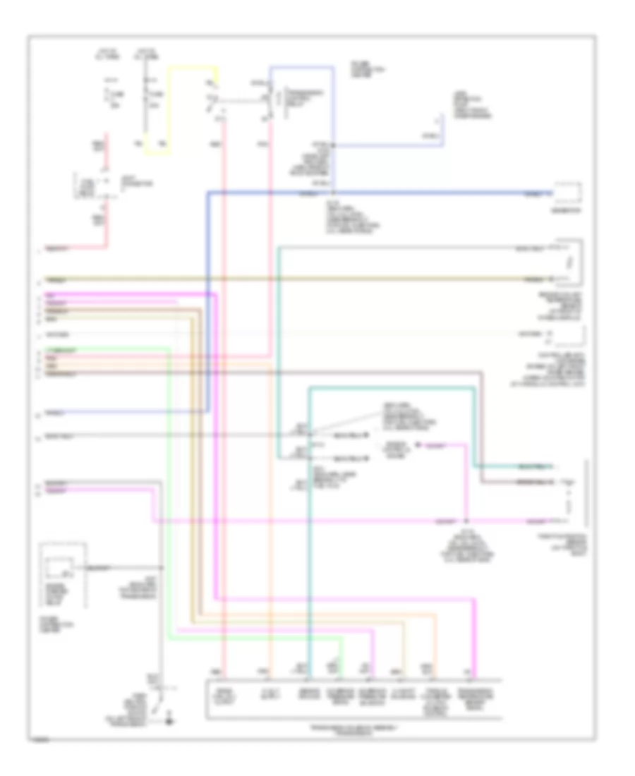
BODY COMPUTER
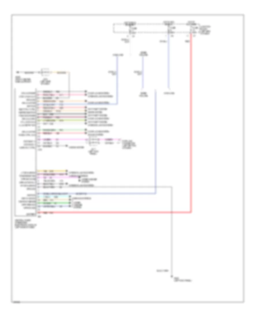
Central Timer Module Wiring Diagram for Dodge Cab & Chassis R2000 3500
List of elements for Central Timer Module Wiring Diagram for Dodge Cab & Chassis R2000 3500:
- dr lk motor
- (base/ midline)
- (highline)
- Anti-theft system
- Battery
- Ccd bus (+)
- Ccd bus (-)
- Central timer/ integrated electronic module (left side of dash)
- Ctm
- Ctsy lp sw out
- Cyl lk sw mux
- Data link connector (left bottom of dash)
- Door locks system
- Dr lk driver
- Dr lk motor
- Dr unlk drv
- F12
- F35
- Fuse 10a
- Fuse 25a
- G13
- G16
- G200 (left kick panel)
- G206 (right center dash support)
- G26
- G50
- G69
- G73
- G75
- Ground
- Heated seat sw
- Horn rly ctrl
- Horns system
- Hot at all times
- Hot in acc or run
- Hot in run or start
- Iem
- Ignition
- Illum entry sw
- Interior lights system
- J/c 5 (left side of dash)
- J/c 7 (left kick panel)
- Junction block (left end of dash)
- Key-in ign sw
- Lt dr ajar sw
- M11
- M22
- P132
- P30
- P31
- P33
- P34
- Radio ctrl mux
- Red
- Rt dr ajar sw
- Seats system
- Secty rly ctrl
- Sound system
- Tan
- Tone reqst sig
- V10
- V18
- V6 (or f12)
- Vtss ind driver
- Warning systems
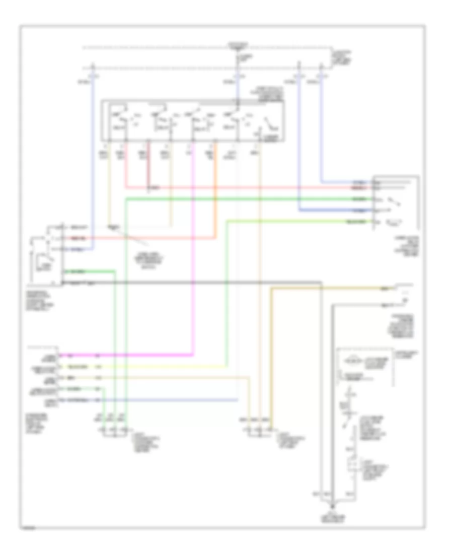
- Wiper/ washer system
- Wiper/washer system
- Wpr motor rly
- Wpr park sw
- Wpr sw mode
- Wpr sw sig
- Wshr sw sense
- X20
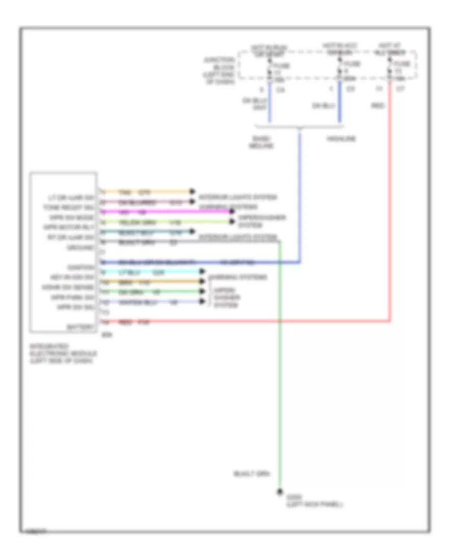
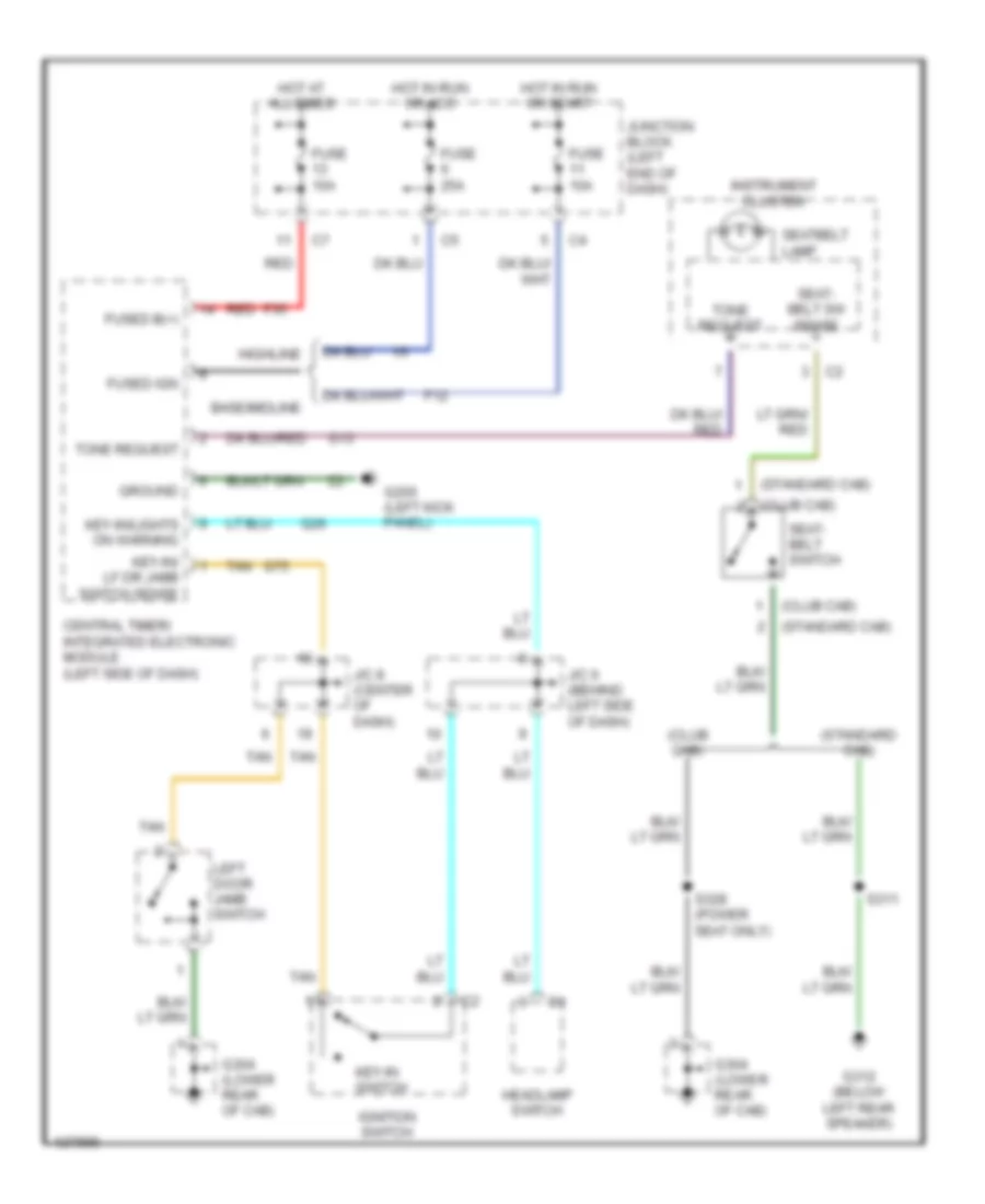
Integrated Central Electronics Module Wiring Diagram, Base for Dodge Cab & Chassis R2000 3500
List of elements for Integrated Central Electronics Module Wiring Diagram, Base for Dodge Cab & Chassis R2000 3500:
- Base/ midline
- Battery
- F35
- Fuse 10a
- Fuse 25a
- G13
- G16
- G200 (left kick panel)
- G26
- G75
- Ground
- Highline
- Hot at all times
- Hot in acc or run
- Hot in run or start
- Iem
- Ignition
- Integrated electronic module (left side of dash)
- Interior lights system
- Junction block (left end of dash)
- Key-in ign sw
- Lt dr ajar sw
- Red
- Rt dr ajar sw
- Tan
- Tone reqst sig
- V10
- V18
- V6 (or f12)
- Warning systems
- Wiper/ washer system
- Wiper/washer system
- Wpr motor rly
- Wpr park sw
- Wpr sw mode
- Wpr sw sig
- Wshr sw sense
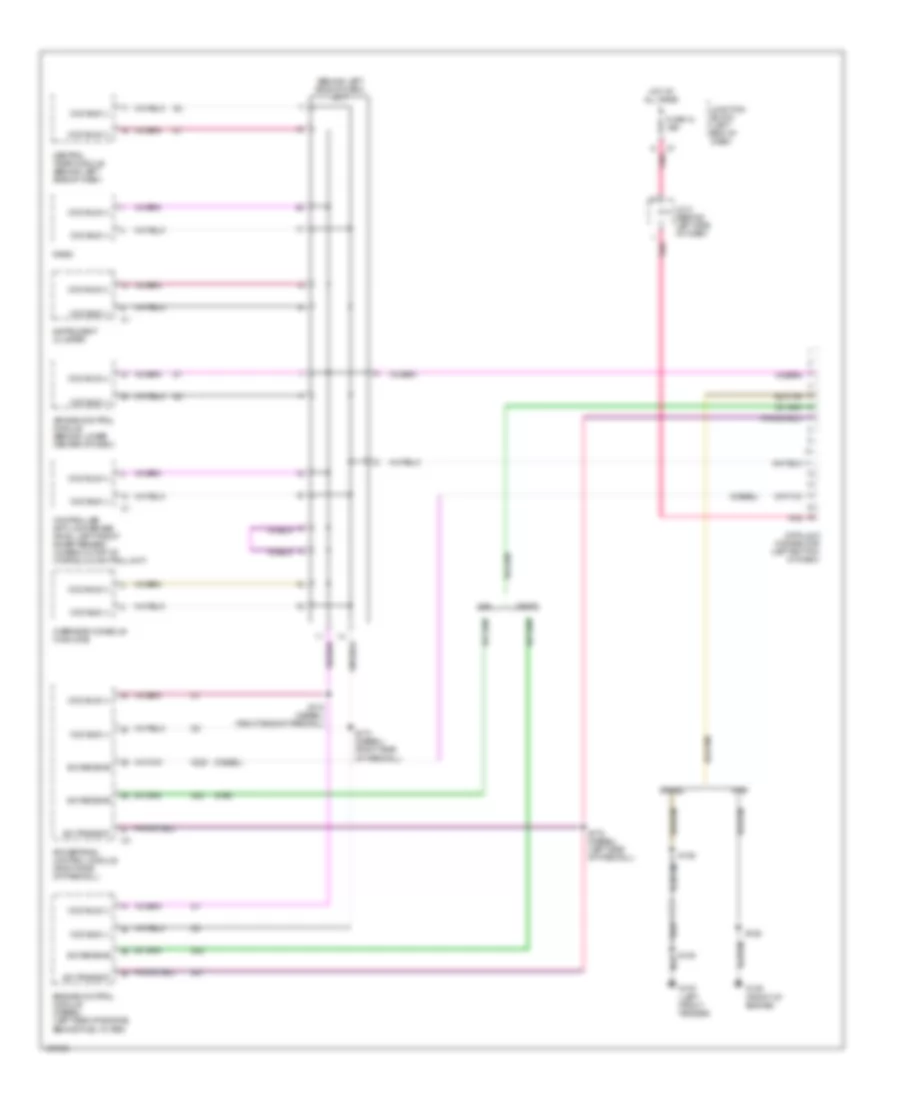
COMPUTER DATA LINES
Computer Data Lines for Dodge Cab & Chassis R2000 3500
List of elements for Computer Data Lines for Dodge Cab & Chassis R2000 3500:
- (behind left side of dash) j/c 7
- (diesel)
- (gas)
- Air bag control module (behind lower center of dash)
- Ccd bus (+)
- Ccd bus (-)
- Central timer module (behind left side of dash)
- Controller anti-lock brake (rwal: left front inner fender) (4wabs: on top of hydraulic control unit)
- D20
- D21
- D220
- Data link connector (left bottom of dash)
- Diesel
- Engine control module (diesel) (left side of engine, behind fuel filter)
- Fuse 12 10a
- G100 (left front fender)
- G125 (front of engine)
- Gas
- Hot at all times
- Instrument cluster
- J/c 5 (behind left side of dash)
- Junction block (left end of dash)
- Overhead console (highline)
- Pnk
- Powertrain control module (right side of firewall)
- Radio
- S109
- S126
- S172 (diesel) (right side of firewall)
- S173 (diesel) (right side of firewall)
- S175 (diesel) (left side of firewall)
- Sci receive
- Sci transmit
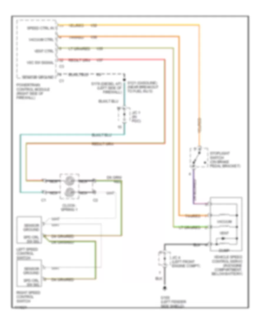
CRUISE CONTROL
Cruise Control Wiring Diagram for Dodge Cab & Chassis R2000 3500
List of elements for Cruise Control Wiring Diagram for Dodge Cab & Chassis R2000 3500:
- Clock- spring 1
- Dump
- G100 (left fender side shield)
- J/c 1 (in pdc)
- J/c 4 (left front engine compt)
- Left speed control switch
- Nca
- Powertrain control module (right side of firewall)
- Right speed control switch
- S121 (gasoline) (near breakout to fuel inj 5)
- S179 (diesel a/t) (left side of firewall)
- Sensor ground
- Spd crl sw sig
- Speed ctrl in
- Stoplight switch (on brake pedal bracket)
- Tan/red
- V32
- V35
- V36
- V37
- Vacuum
- Vacuum ctrl
- Vehicle speed control servo (in engine compartment, below battery)
- Vent
- Vent ctrl
- Vsc sw signal
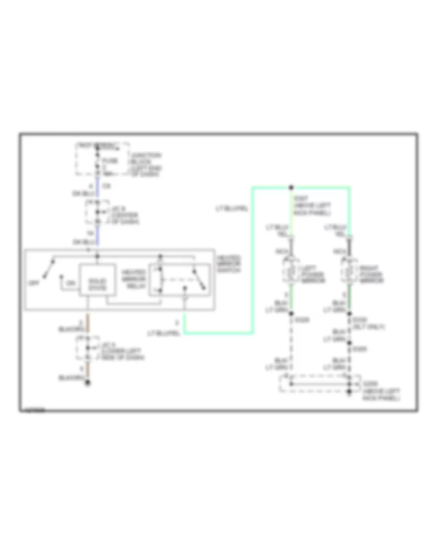
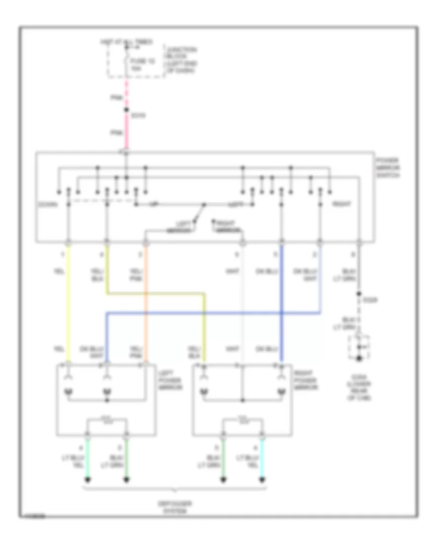
DEFOGGERS
Defogger Wiring Diagram for Dodge Cab & Chassis R2000 3500
List of elements for Defogger Wiring Diagram for Dodge Cab & Chassis R2000 3500:
- Fuse 10a
- G200 (above left kick panel)
- Heated mirror relay
- Heated mirror switch
- Hot in run
- J/c 5 (lower left side of dash)
- J/c 8 (center of dash)
- Junction block (left end of dash)
- Left power mirror
- Nca
- Off
- Right power mirror
- S305
- S307 (above left kick panel)
- S329
- S330 (slt only)
- Solid state
ENGINE PERFORMANCE
5.9L
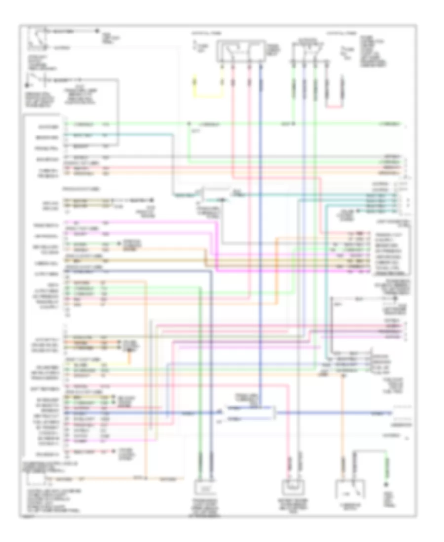
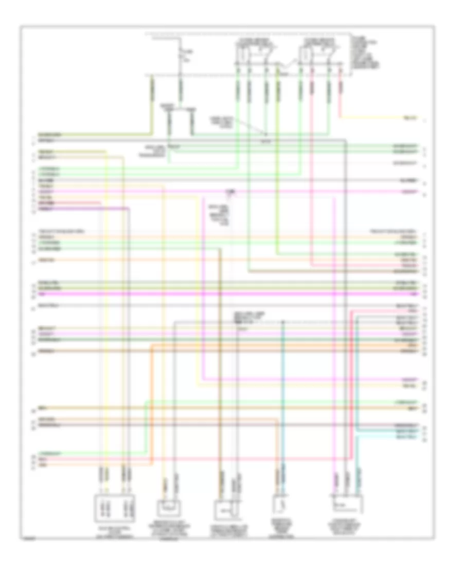
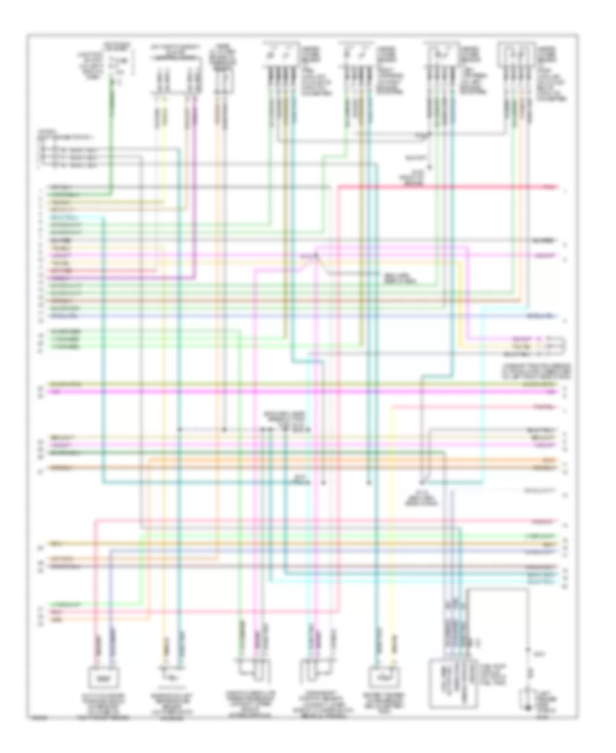
5.9L 24-Valve Diesel, Engine Performance Wiring Diagrams (1 of 3) for Dodge Cab & Chassis R2000 3500
List of elements for 5.9L 24-Valve Diesel, Engine Performance Wiring Diagrams (1 of 3) for Dodge Cab & Chassis R2000 3500:
- (front of
- (not used)
- (pins 12-20 not used)
- (pins 16-21 not used)
- (pins 2-7 not used)
- (pins 22-24 not used)
- (pins 24-30 not used)
- (pins 7-10 not used)
- (pins 9-21 not used)
- (trans harn, in breakout pdc) s116
- (trans harn, in breakout to pdc)
- A/c request
- A/c select in
- A/t
- A14
- A142
- A61
- Air condi- tioning system
- Asd relay sens
- Auto sht rly
- Automatic shutdown relay
- Batt temp sens
- Battery temper- ature sensor (below battery tray)
- Brake sw
- C20
- C90
- Ccd bus (+)
- Ccd bus (-)
- Controller anti-lock brake (4wabs: in eng compt, mounted on hydraulic control unit; rwabs: in eng compt, on left inner fender panel)
- Cruise control system
- Cruise feed
- Cruise sw in
- Cruise vac sol
- Cruise vnt sol
- D21
- D220
- Eng spd sig
- Engine)
- F18
- Fuel lev
- Fuel lev sens
- Fuel pmp
- Fuel pump module (top of fuel tank)
- Fuse 30a
- Fuse i 20a
- Fused b(+)
- G100 (left fender side shield)
- G125
- G200 (left kick panel)
- Gen field drv
- Gen field out
- Generator
- Gov press sig
- Ground
- Hot at all times
- Ign power
- Joint connector 1 (in pdc)
- K118
- K20
- K22
- K226
- K24
- K30
- K51
- K54
- K88
- M/t
- Output sens
- Overdrive switch
- Overdrv sol
- Park/neutral position switch (on left side of transmission)
- Pnk
- Power distribution center (in eng compt, on left inner fender panel, near battery)
- Powertrain control module (in eng compt, on right side of firewall)
- Prk/neutral
- Red
- S107
- S126
- S127 (trans harn, near breakout to park/neutral position switch)
- S171
- S174
- S179
- S331
- Sci receive
- Sci transmit
- Sens gnd
- Sensor grd
- Starting/ charging system
- Stoplight switch (on brake pedal bracket)
- T125
- T13
- T14
- T16
- T25
- T41
- T54
- T60
- Tan/red
- Tcc drvr
- Tcc sol ctrl
- Tps sens in
- Trans overdrv
- Trans relay
- Trans rly out
- Trans temp in
- Trans temp sns
- Trans- mission relay
- Transmission ouput shaft speed sensor (on left side of transmission)
- Transmission solenoid assembly (on left side of transmission)
- V32
- V35
- V36
- V37
- V40
- Var force sol
- Var frce sol
- Vss in
- Z12
- Z13
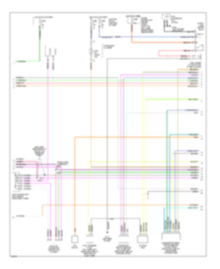
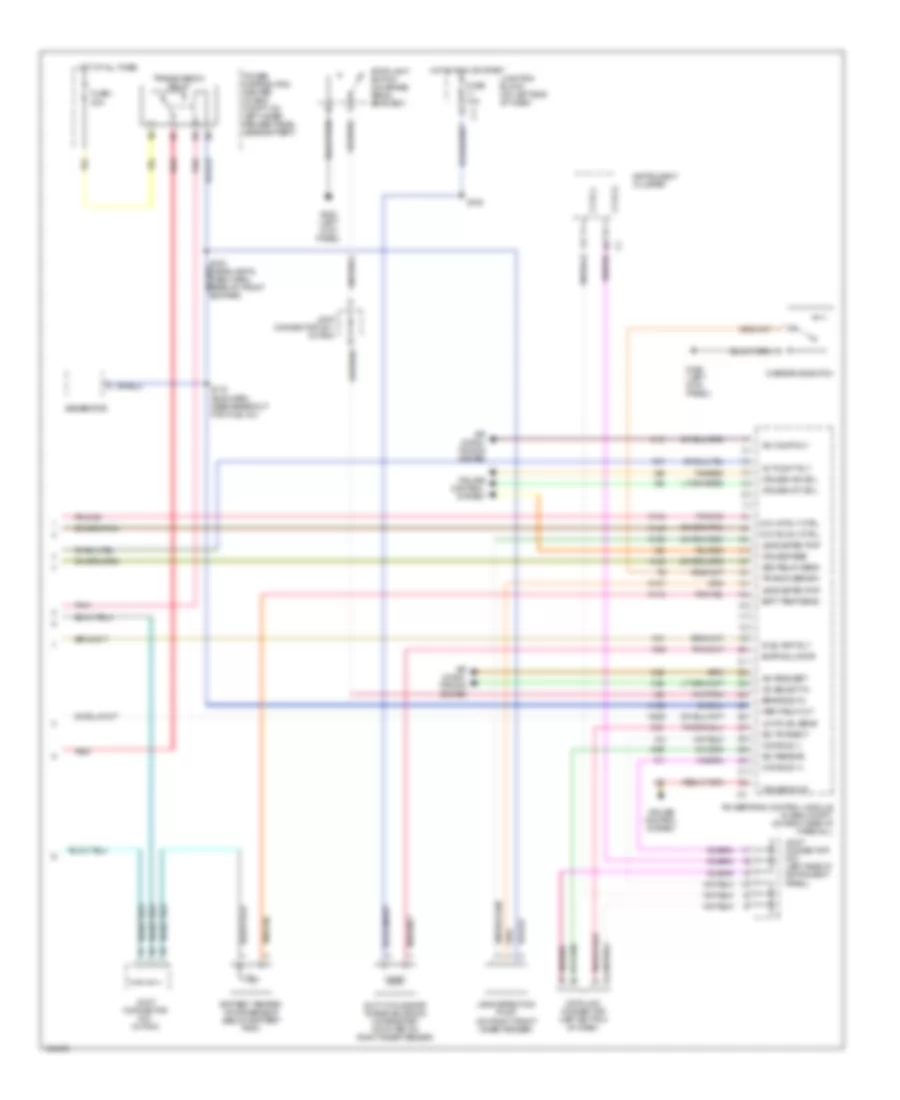
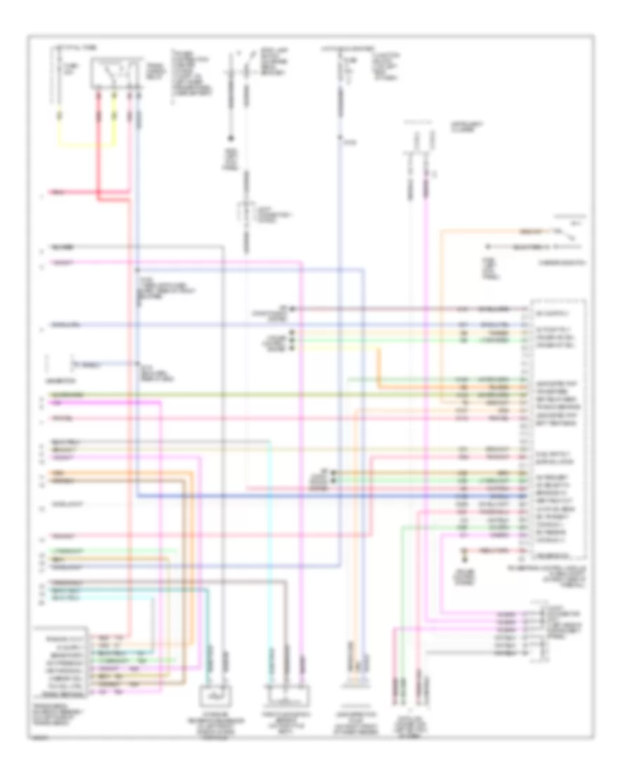
5.9L 24-Valve Diesel, Engine Performance Wiring Diagrams (2 of 3) for Dodge Cab & Chassis R2000 3500
List of elements for 5.9L 24-Valve Diesel, Engine Performance Wiring Diagrams (2 of 3) for Dodge Cab & Chassis R2000 3500:
- (eng harn, near breakout for a/c low pressure switch)
- (in pdc) fuel heater relay
- (trans harn, in breakout pdc)
- Accelerator pedal position sensor (at left front side of eng, below cable/lever/ linkage cover)
- Ccd (+)
- Ccd (-)
- Crankshaft position sensor (on lower left side of eng, behind starter motor)
- Cummins bus
- Data link connector (left bottom of dash)
- Drain
- Fuel heater (in top of fuel filter housing)
- Fuel transfer pump (on lower left side of eng, below rearward of fuel filter)
- Fuse 10a
- Fuse 40a
- G100 (left fender side shield)
- G114 (left rear of eng)
- Hot at all times
- Hot in run or start
- Instrument cluster
- Join connector no1 (in pdc)
- Joint connector 7 (left side of instrument panel)
- Junction block (left end of dash)
- Power distribution center (in eng compt, on left inner fender panel, near battery)
- Pto switch
- Red/tan
- S105
- S164
- S172
- S173
- S175
- Wait to start ind
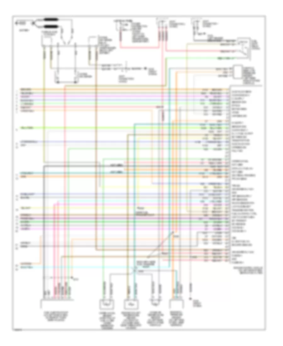
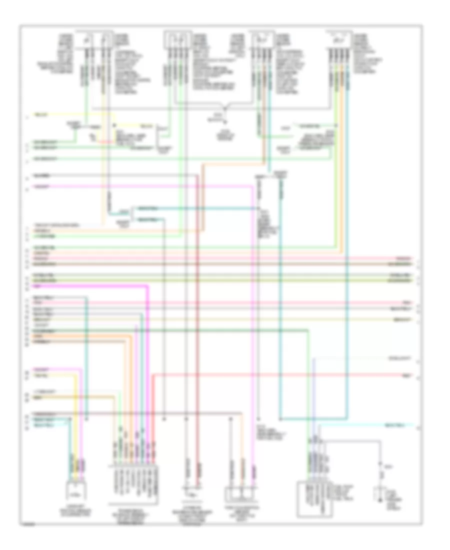
5.9L 24-Valve Diesel, Engine Performance Wiring Diagrams (3 of 3) for Dodge Cab & Chassis R2000 3500
List of elements for 5.9L 24-Valve Diesel, Engine Performance Wiring Diagrams (3 of 3) for Dodge Cab & Chassis R2000 3500:
- (eng harn, near fuel transfer pump)
- (near fuel transfer pump)
- (not used)
- A14
- Acc pedal pos sens
- Air heater rly no1
- Air heater rly no2
- App sens gnd
- Battery
- Ccd bus(-)
- Ccd buss (+)
- Ckpsens sig
- Cummin bus (-)
- Cummins bus (+)
- D20
- D21
- Data lk (-) fuel inj
- Dl (+) fuel inj pmp
- Dl shd fuel inj
- Drain
- Ect sens sig
- Eng spd sens sig
- Engine control module (on left side of eng, behind fuel filter)
- Engine coolant temperature sensor (on front of cylinder head, near thermostat housing)
- Engine oil pressure sensor (on left side of eng, near near ecm)
- Eop sw sens
- F18
- Fault sig
- Fuel inj pmp rly ctrl
- Fuel injection pump (on left side of eng, on rear of timing gear housing)
- Fuel pump relay (in pdc)
- Fuse 20a
- Fuse b(+)
- Fused b(+)
- G10
- G100 (left fender side shield)
- G113
- G12
- G125 (front of eng)
- G85
- Gnd
- H101
- H102
- H103
- H104
- H105
- Hot at all times
- Iat sig
- Idle val sw no2
- Idle val sw sens
- Intake air heater
- Intake air heater relay (on left inner fender, below left battery)
- Intake air temperature sensor (in left rear side of intake manifold)
- Joint connector 1 (in pdc)
- Joint connector 2 (in pdc)
- K104
- K124
- K131
- K135
- K14
- K21
- K22
- K24
- K240
- K242
- K243
- K244
- K246
- K247
- K44
- K45
- K48
- Knock sensor rtn
- Low idle select
- Manifold absolute pressure sensor (left rear side of intake manifold)
- Map sens sig
- Nca
- Not used
- Power distribution center (in eng compt, on left inner fender panel, near battery)
- Pto sw sens
- S160
- S161
- S165
- S166
- S167
- S168
- S170
- S21
- S22
- Sci receive
- Sci transmit
- Sensor gnd
- St-run
- Tps sig
- Trans pmp pwr
- Transfer pmp pwr
- V32
- V37
- Vss
- Wait to start warn
- Water in-fuel sensor (at bottom of fuel filter/ water seperator canister)
- Water-in-fuel
- Z12
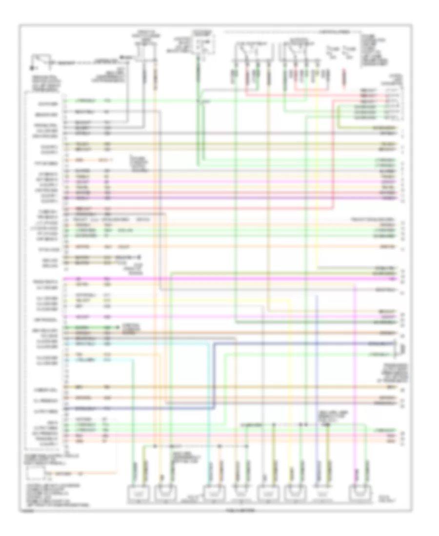
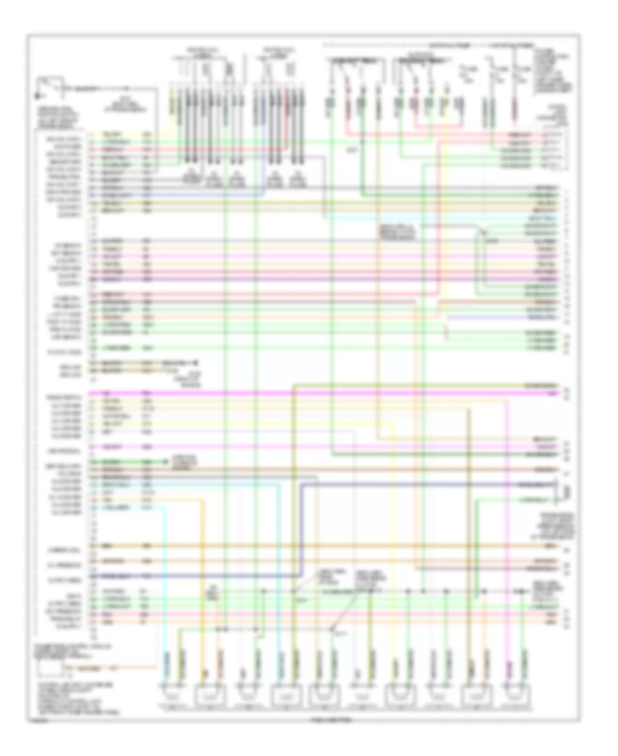
5.9L, Engine Performance Wiring Diagrams (1 of 4) for Dodge Cab & Chassis R2000 3500
List of elements for 5.9L, Engine Performance Wiring Diagrams (1 of 4) for Dodge Cab & Chassis R2000 3500:
- (5.9l hd)
- (calif)
- (eng harn, near breakout for fuel inj 3 )
- (eng harn, near breakout for fuel injs)
- (front of
- (front of right cylinder head) ignition coil
- (in pdc) joint connector
- (lt) down ho2s
- (lt) up ho2s
- (or k41)
- 5.2l &
- 5.2l & 5.9l only
- 5.9l only
- A14
- Automatic shutdown relay
- Cam pos sns
- Coil driver
- Controller anti-lock brake (4wabs: in eng compt, mounted on hydraulic control unit; rwabs: in eng compt, on left front of inner fender panel)
- Crnk pos sns
- Distributor
- Ect sens in
- Engine)
- F18
- Fuel injectors
- Fuel pump relay
- Fuse 10a
- Fuse 20a
- Fuse 30a
- Fused b(+)
- G113
- G125
- G60
- Gen field drv
- Gov press sig
- Ground
- Hot at all times
- Hot in run or start
- Iat sens in
- Idle air 1
- Idle air 2
- Idle air 3
- Idle air 4
- Ign power
- Inj 1 driver
- Inj 2 driver
- Inj 3 driver
- Inj 4 driver
- Inj 5 driver
- Inj 6 driver
- Inj 7 driver
- Inj 8 driver
- Junction block (on left eng of dash)
- K11
- K12
- K13
- K14
- K141
- K19
- K20
- K21
- K22
- K24
- K241
- K26
- K28
- K30
- K341
- K38
- K39
- K40
- K44
- K441
- K54
- K58
- K59
- K60
- K88
- Map sens in
- Nca
- Oil press sig
- Ort/tan
- Output sens
- Overdrv sol
- Park/neutral position switch (on left side of transmission)
- Pnk
- Power distribution center (in eng compt, on left inner fender panel, near battery)
- Power take off switch (5.2l/5.9l)
- Powertrain control module (in eng compt, on right side of firewall)
- Prk/neutral
- Pto sw sens
- Red/
- Rt dn ho2s
- Rt up ho2s
- S107
- S117
- S123
- S126
- S127 (eng harn, (near breakout for transmission)
- Sensor grd
- Starting/ charging system
- T13
- T14
- T25
- T41
- T54
- T60
- Tan
- Tcc drvr
- Tps sens in
- Trans relay
- Trans temp in
- Transmission output shaft speed sensor (on left side of transmission)
- Var frce sol
- Vss in
- Z12
5.9L, Engine Performance Wiring Diagrams (2 of 4) for Dodge Cab & Chassis R2000 3500
List of elements for 5.9L, Engine Performance Wiring Diagrams (2 of 4) for Dodge Cab & Chassis R2000 3500:
- (eng harn, near breakout for fuel inj 5)
- (eng harn, near breakout for fuel injs)
- (eng harn, top of transmission)
- (headlamp & dash harn, in pdc)
- Calif
- Crankshaft position sensor (right rear of eng block)
- Engine coolant temperature sensor (in water jacket, at front of intake manifold)
- Engine oil pressure sensor (near distributor)
- Except calif
- Fuse k 15a
- Iac mtr 1
- Iac mtr 2
- Iac mtr 3
- Iac mtr 4
- Idle air control motor (on throttle body)
- Manifold absolute pressure sensor (on throttle body)
- Oxygen sensor downstream relay
- Oxygen sensor upstream relay
- Pnk
- Power distribution center (in eng compt, on left inner fender panel, near battery)
- S119
- S121
- S124
- S176
5.9L, Engine Performance Wiring Diagrams (3 of 4) for Dodge Cab & Chassis R2000 3500
List of elements for 5.9L, Engine Performance Wiring Diagrams (3 of 4) for Dodge Cab & Chassis R2000 3500:
- A61
- Calif
- Camshaft position sensor (in distributor)
- Except
- Except calif
- Fuel pump module (top of fuel tank)
- G100 (left fender side shield)
- G125 (front of engine)
- Gov press sig
- Ground
- Heated oxygen sensor 1/1 (left bank up) (5.9l h/d) (on left exhaust downpipe, before catalytic converter)
- Heated oxygen sensor 1/1 (upstream) (3.9l, 5.2l & 5.9l) except calif: on inlet of catalytic converter; calif: on left exhaust downpipe, before mini- catalytic converter)
- Heated oxygen sensor 1/2 (downstream) (3.9l, 5.2l & 5.9l) except calif: near outlet of end catalytic converter; calif: on outlet end of left mini- catalytic converter)
- Heated oxygen sensor 1/2 (left bank dn) (cali)
- Heated oxygen sensor 2/1 (right bank up) (5.9l h/d) (except calif: on right exhaust downpipe, before catalytic converter; calif: on right exhaust downpipe, before mini- catalytic converter)
- Heated oxygen sensor 2/2 (right bank down) (calif) (on outlet end of right mini- catalytic converter)
- Intake air temperature sensor (in right front side of intake manifold)
- K226
- K54
- K88
- Nca
- Overdrv sol
- Pnk
- Red
- Rly out (b+) fuel pump
- S118 (eng harn, near breakout for fuel injs)
- S121 (eng harn, near breakout for fuel inj 5)
- S122
- S130 (eng harn, near breakout for oil pressure sensor)
- S331
- Sensor grd
- Sensor return
- Sensor sig
- T16
- T25
- T54
- T60
- Tcc sol ctrl
- Throttle position sensor (on throttle body)
- Trans rly out
- Trans temp sns
- Transmission solenoid assembly (at left side of transmission)
- Var force sol
- Z13
5.9L, Engine Performance Wiring Diagrams (4 of 4) for Dodge Cab & Chassis R2000 3500
List of elements for 5.9L, Engine Performance Wiring Diagrams (4 of 4) for Dodge Cab & Chassis R2000 3500:
- A/c comp rly
- A/c request
- A/c select in
- A142
- Air condi- tioning system
- Asd relay sens
- Auto sht rly
- Batt temp sens
- Battery temper- ature sensor (below battery tray)
- Brake sw in
- C13
- C20
- C90
- Ccd (+)
- Ccd (-)
- Ccd bus (+)
- Ccd bus (-)
- Cruise control system
- Cruise feed
- Cruise sw in
- Cruise vac sol
- Cruise vnt sol
- D20
- D21
- Dash harn, rear of front bumper)
- Data link connector (left bottom of dash)
- Duty cycle evap/ purge solenoid (on bracket, mounted on right inner fender)
- Evap sol drvr
- Fuel pmp rly
- Fuse 10a
- Fuse i 20a
- G200 (left kick panel)
- Gen field out
- Generator
- Hot at all times
- Hot in run or start
- Instrument cluster
- Joint connector no 1 (in pdc)
- Joint connector no1 (in pdc)
- Joint connector no7 (left side of instrument panel)
- Junction block (on left end of dash)
- K106
- K107
- K118
- K125
- K143
- K145
- K226
- K31
- K51
- K52
- Leak detec pmp
- Leak detection pump (on right front inner fender)
- Low fuel sens
- Overdrive switch
- Oxy dn rly ctrl
- Oxy up rly ctrl
- Pnk
- Power distribution center (in eng compt, on left inner fender panel, near battery)
- Powertrain control module (in eng compt, on right side of firewall)
- Red
- S105
- S116 (eng harn, near breakout for fuel inj)
- Sci receive
- Sci transmit
- Stoplight switch (on brake pedal bracket)
- Tan/red
- Trans overdrv
- Transmission relay
- V32
- V35
- V36
- V37
- V40
8.0L
8.0L, Engine Performance Wiring Diagrams (1 of 3) for Dodge Cab & Chassis R2000 3500
List of elements for 8.0L, Engine Performance Wiring Diagrams (1 of 3) for Dodge Cab & Chassis R2000 3500:
- (eng harn, in breakout for transmission)
- (eng harn, near break- out for fuel inj 1)
- (eng harn, rear of eng)
- (front of
- (in pdc) joint connector no2
- A14
- Automatic shutdown relay
- Cam pos sns
- Controller anti-lock brake (4wabs: in eng compt, mounted on hydraulic control unit; rwabs: in eng compt, on left front inner fender panel)
- Crnk pos sns
- Ect sens in
- Engine)
- F18
- Fuel injectors
- Fuel pump relay
- Fuse 20a
- Fuse 30a
- Fuse k 15a
- Fused b(+)
- G125
- G60
- Gen field drv
- Gov press sig
- Ground
- Hot at all times
- Iat sens in
- Idle air 1
- Idle air 2
- Idle air 3
- Idle air 4
- Ign coil dvr 1
- Ign coil dvr 2
- Ign coil dvr 3
- Ign coil dvr 4
- Ign coil dvr 5
- Ign power
- Ignition coil 4-pack
- Ignition coil 6-pack
- Inj 1 driver
- Inj 10 driver
- Inj 2 driver
- Inj 3 driver
- Inj 4 driver
- Inj 5 driver
- Inj 6 driver
- Inj 7 driver
- Inj 8 driver
- Inj 9 driver
- K11
- K115
- K116
- K12
- K13
- K14
- K17
- K18
- K19
- K20
- K21
- K22
- K24
- K241
- K26
- K28
- K30
- K32
- K341
- K38
- K39
- K40
- K41
- K43
- K44
- K54
- K58
- K59
- K60
- K88
- L up 1/1 ho2s
- Map sens in
- Nca
- Oil press sig
- Output sens
- Overdrv sol
- Park/neutral position switch (on left side of transmission)
- Pnk
- Post 1/3 ho2s
- Power distribution center (in eng compt, on left inner fender panel, near battery)
- Powertrain control module (in eng compt, on right side of firewall)
- Pre 1/2 ho2s
- Prk/neutral
- R up 2/1 ho2s
- S107
- S117
- S123
- S124
- S126
- S127 (eng harn, at transmission)
- S131
- Sensor grd
- Starting/ charging system
- T13
- T14
- T25
- T41
- T54
- T60
- Tan
- Tcc drvr
- To spark plugs
- Tps sens in
- Trans relay
- Trans temp in
- Transmission ouput shaft speed sensor (on left side of transmission)
- Var frce sol
- Vss in
- Z12
8.0L, Engine Performance Wiring Diagrams (2 of 3) for Dodge Cab & Chassis R2000 3500
List of elements for 8.0L, Engine Performance Wiring Diagrams (2 of 3) for Dodge Cab & Chassis R2000 3500:
- (eng harn, near breakout for fuel inj 5) s121
- (eng harn, rear of eng)
- (in pdc) joint connector no 1
- (left fender side shield)
- (near oil filter) engine oil pressure sensor
- (on right lower side of cylinder block, above oil pan rail)
- (on throttle body) idle air control motor
- (pre- catalyst) (on inlet of catalytic converter)
- A61
- Battery temper- ature sensor (below battery tray)
- Camshaft position sensor (in timing chain case/cover on left front side of eng)
- Crankshaft position sensor
- Duty cycle evap/ purge solenoid (on bracket, mounted on right inner fender)
- Engine coolant temperature sensor (on thermostat housing)
- Fuel pump module (on top of fuel tank)
- Fuse 10a
- G100
- G125 (front of engine)
- Ground
- Heated oxygen sensor 1/1 (left upstream) (on left exhaust downpipe)
- Heated oxygen sensor 1/2
- Heated oxygen sensor 1/3 (post- catalyst) (on outlet eng of catalytic converter)
- Heated oxygen sensor 2/1 (right upstream) (on right exhaust downpipe)
- Hot in run or start
- Iac mtr 1
- Iac mtr 2
- Iac mtr 3
- Iac mtr 4
- Junction block (on left end of dash)
- K226
- Manifold absolute pressure sensor (on right upper side of intake manifold)
- Nca
- Pnk
- S118 (eng harn, rear of eng)
- S119
- S122
- S331
- Sensor return
- Sensor sig rly out (b+) fuel pump
- Z13
8.0L, Engine Performance Wiring Diagrams (3 of 3) for Dodge Cab & Chassis R2000 3500
List of elements for 8.0L, Engine Performance Wiring Diagrams (3 of 3) for Dodge Cab & Chassis R2000 3500:
- A/c comp rly
- A/c request
- A/c select in
- A142
- Air condi- tioning system
- Air conditioning system
- Asd relay sens
- Auto sht rly
- Batt temp sens
- Brake sw in
- C13
- C20
- C90
- Ccd (+)
- Ccd (-)
- Ccd bus (+)
- Ccd bus (-)
- Cruise control system
- Cruise feed
- Cruise sw in
- Cruise vac sol
- Cruise vnt sol
- D20
- D21
- Data link connector (left bottom of dash)
- Evap sol drvr
- Fuel pmp rly
- Fuse 10a
- Fuse i 20a
- G200 (left kick panel)
- Gen field out
- Generator
- Gov press sig
- Hot at all times
- Hot in run or start
- Instrument cluster
- Intake air temperature sensor (in left front side of intake manifold)
- Joint connector 1 (in pdc)
- Joint connector no7 (left side of instrument panel)
- Junction block (on left end of dash)
- K106
- K107
- K118
- K125
- K226
- K31
- K51
- K52
- K54
- K88
- Leak detec pmp
- Leak detection pump (on right front of inner fender)
- Low fuel sens
- Overdrive switch
- Overdrv sol
- Pnk
- Power distribution center (in eng compt, on left inner fender panel, near battery)
- Powertrain control module (in eng compt, on right side of firewall)
- Red
- S105
- S116 (eng harn, rear of eng)
- S180 (headlamp & dash harn, rear of front bumper)
- Sci receive
- Sci transmit
- Sensor grd
- Stop lamp switch (on brake pedal bracket)
- T16
- T25
- T54
- T60
- Tan/red
- Tcc sol ctrl
- Throttle position sensor (on throttle body)
- Trans overdrive
- Trans rly out
- Trans temp sns
- Trans- mission relay
- Transmission solenoid assembly (on left side of transmission)
- V32
- V35
- V36
- V37
- V40
- Var force sol
EXTERIOR LIGHTS
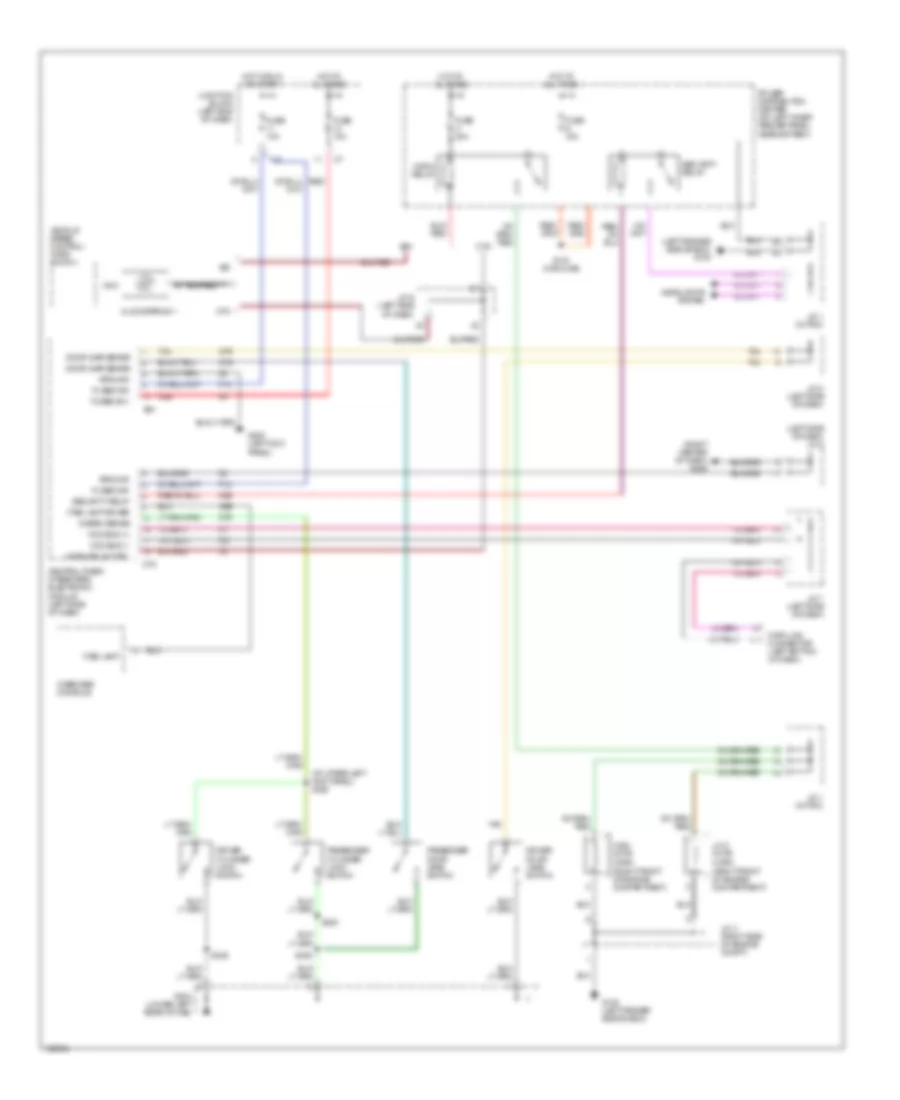
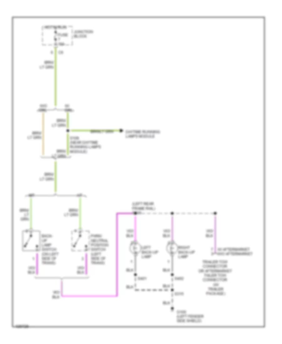
Back-up Lamps Wiring Diagram for Dodge Cab & Chassis R2000 3500
List of elements for Back-up Lamps Wiring Diagram for Dodge Cab & Chassis R2000 3500:
- (left rear frame rail) s316
- (w/ trailer package)
- A/t
- Back- up lamp switch (on left side of trans)
- Daytime running lamps module
- Fuse 10a
- G100 (left fender side shield)
- Hot in run
- Junction block
- Left back-up lamp
- M/t
- Park/ neutral position switch (left side of trans)
- Right back-up lamp
- S108 (near daytime running lamps module)
- S315
- S401
- S402
- Trailer tow connector or aftermarket tailer tow connector
- W/ aftermarket w/o aftermarket
- W/ drl
- W/o drl
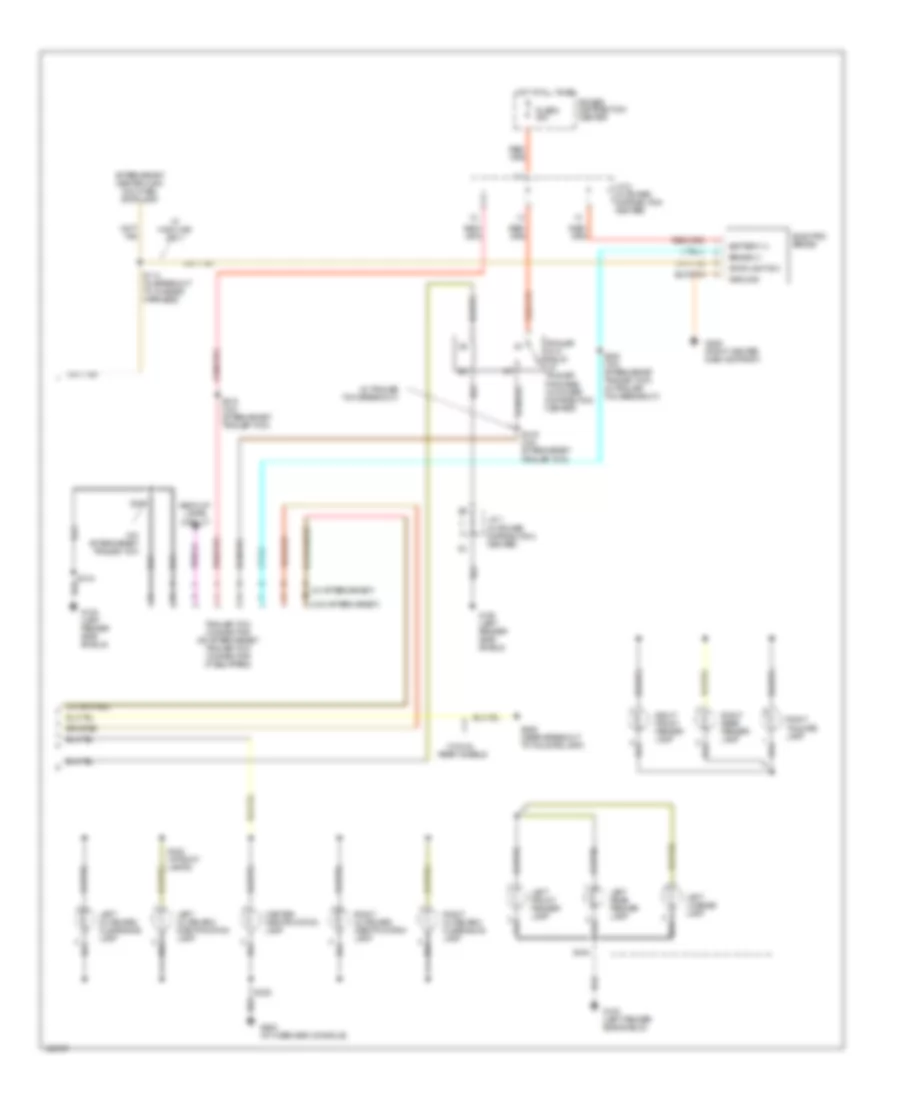
Exterior Lamps & Trailer connector Wiring Diagram (1 of 2) for Dodge Cab & Chassis R2000 3500
List of elements for Exterior Lamps & Trailer connector Wiring Diagram (1 of 2) for Dodge Cab & Chassis R2000 3500:
- (left frame rail)
- (left frame rail) s313
- (left front fender area) s104
- (left s314
- (near left front park/ turn signal lamp)
- (near right front park/ turn signal lamp)
- (right of radiator) s141
- Center high mounted stop lamp 1
- Center high mounted stop lamp 2
- Combination flasher
- Frame rail)
- Fuse 10 10a
- Fuse 4 20a
- Fuse 5 20a
- Fuse f 20a
- G100 (left fender side shield)
- G206 (right center of dash)
- G312 (below left rear speaker)
- Hazard
- Head
- Headlamp switch
- Hot at all times
- Hot in acc or run
- J/c 3
- J/c 4
- J/c 6 (left side of dash)
- Junction block
- Left
- Left front park/turn signal lamp
- Left license lamp
- Left tail/ stop/turn signal lamp
- Normal
- Off
- Park
- Pnk
- Pnk/red
- Power distribution center
- Right
- Right front park/turn signal lamp
- Right license lamp
- Right tail/ stop/turn signal lamp
- S102
- S103
- S311
- S315
- S317
- S401
- S402
- Stop lamp switch (on brake pedal bracket)
- Tan
- Timing control
- Turn signal/ hazard switch (part of multi- function switch)
- W/ dual rear wheels
- W/ trailer tow
- W/o dual rear wheels
- W/o trailer tow
Exterior Lamps & Trailer connector Wiring Diagram (2 of 2) for Dodge Cab & Chassis R2000 3500
List of elements for Exterior Lamps & Trailer connector Wiring Diagram (2 of 2) for Dodge Cab & Chassis R2000 3500:
- (in trailer tow breakout)
- (w/ aftermarket)
- (w/o aftermarket)
- Aftermarket center high mounted stop lamp
- Back-up lamps circuit
- Battery (+)
- Brake (+)
- Center identification lamp
- Electric brake
- Fuse 8 40a
- G100 (left fender side shield)
- G206 (right center dash support)
- G908 (at overhead console)
- Ground
- Hot at all times
- J/c 1 (in power distribution center)
- J/c 2 (in power distribution center)
- Left front fender lamp
- Left license lamp
- Left outboard clearance lamp
- Left outboard identification lamp
- Left rear fender lamp
- Power distribution center
- Rear wheels
- Right front fender lamp
- Right outboard clearance lamp
- Right outboard identification lamp
- Right rear fender lamp
- Right tailgate lamp
- S114 (in breakout to chassis harness)
- S315
- S318 (w/o aftermarket trailer tow)
- S319 (w/o aftermarket trailer tow)
- S320 (w/o aftermarket trailer tow) (in trailer tow breakout)
- S321
- S322 (at roof lamps)
- S325
- S404
- S406 (near breakout to tailgate lamp)
- Stoplight sw
- Trailer tow connector or aftermarket trailer tow connector (if equipped)
- Trailer tow relay (w/ trailer package) (in power distribution center)
- W/ dual
- W/ highline only
- W/0 aftermarket trailer tow
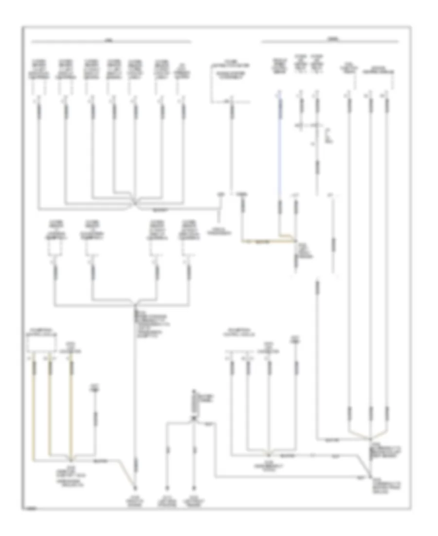
GROUND DISTRIBUTION
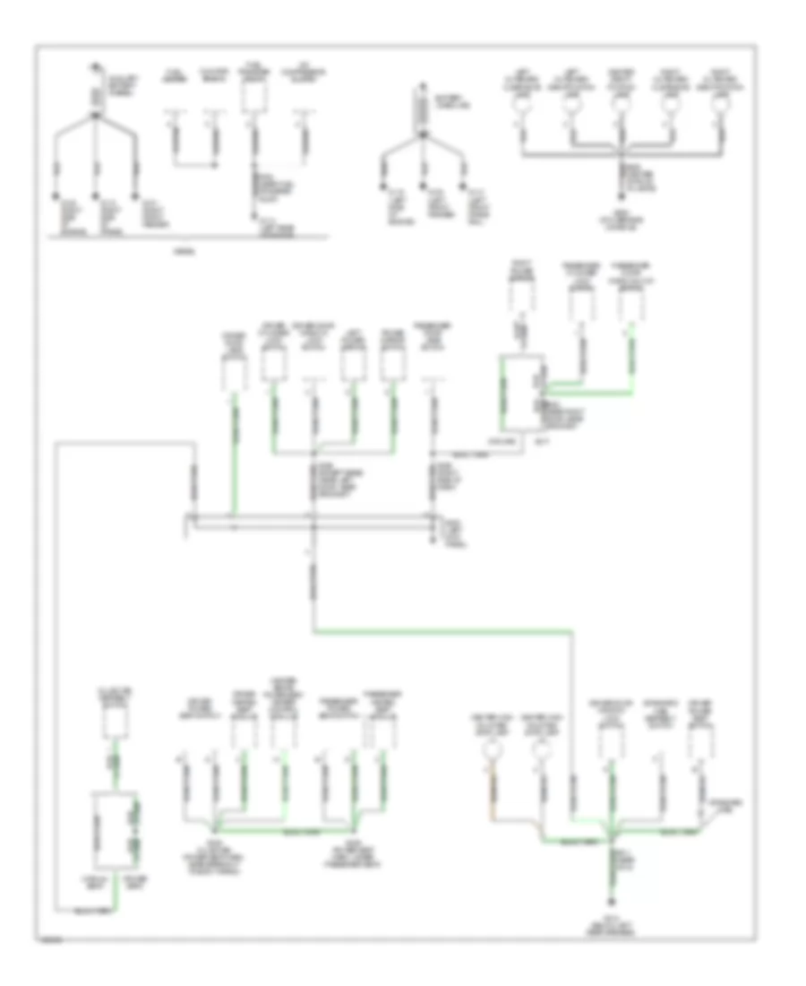
Ground Distribution Wiring Diagram (1 of 4) for Dodge Cab & Chassis R2000 3500
List of elements for Ground Distribution Wiring Diagram (1 of 4) for Dodge Cab & Chassis R2000 3500:
- (club cab) seatbelt switch
- (heated seats) power seat heater control module
- (manual seat)
- (midline)
- (power seat)
- (slt)
- (standard cab)
- (standard cab) seatbelt switch
- A/c compressor clutch
- Auxiliary battery (diesel)
- Battery (gasoline)
- Center high mounted stop lamp
- Center identi- fication lamp
- Cummins bus (+)
- Diesel
- Driver cylinder lock switch
- Driver door jamb switch
- Driver door window/ lock switch
- Driver heated seat module
- Driver power seat switch
- Fuel heater
- Fuel transfer pump
- G100 (left front fender)
- G101 (right front fender)
- G112 (left side of engine)
- G113 (left front frame rail)
- G114 (left rear of engine)
- G118 (right side of frame)
- G120 (right side of engine)
- G200 (left kick panel)
- G312 (below left rear speaker)
- G908 (at overhead console)
- Left outboard clearance lamp
- Left outboard identification lamp
- Left power mirror
- Passenger cylinder lock switch
- Passenger door jamb switch
- Passenger door window/lock switch
- Passenger heated seat module
- Passenger power seat switch
- Power mirror switch
- Right outboard clearance lamp
- Right outboard identification lamp
- Right power mirror
- S305 (right side of dash)
- S328 (club cab) (power seat harn, near breakout to body wiring)
- S329 (except base) (near left door, near grommet)
- S336 (power seat harn, under passenger seat)
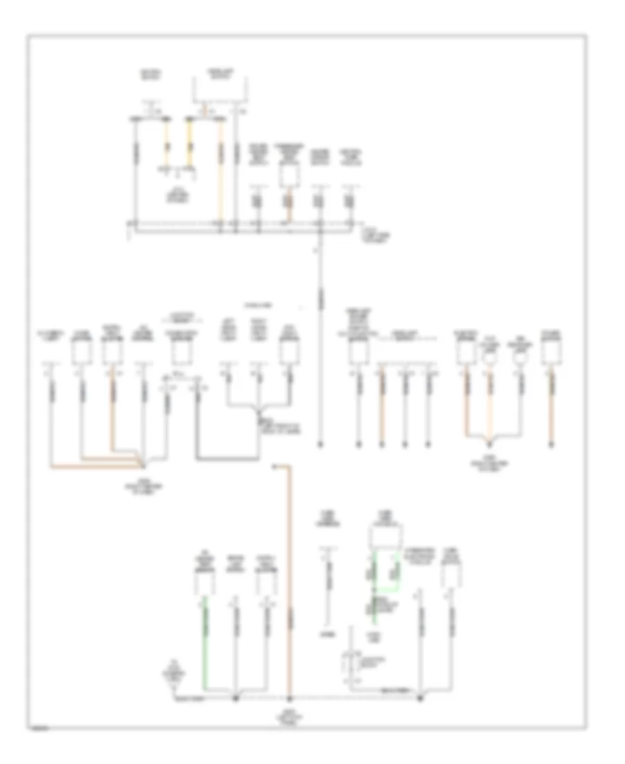
Ground Distribution Wiring Diagram (2 of 4) for Dodge Cab & Chassis R2000 3500
List of elements for Ground Distribution Wiring Diagram (2 of 4) for Dodge Cab & Chassis R2000 3500:
- (base)
- (ctm)
- (high- line)
- (high-line)
- (iem)
- A/c heater control
- A/c heater temp select
- Ash receiver lamp
- Brake lamp switch
- Central timer module
- Cigar lighter
- Combination flasher
- Cup holder lamp
- Day/ night mirror
- Driver heated seat switch
- Electric brake
- G200 (left kick panel)
- G206 (right center of dash)
- Glovebox lamp
- Headlamp dimmer switch (part of multi-function switch)
- Headlamp switch
- Heated mirror switch
- Ignition switch
- Instru- ment cluster
- Integrated electronic module
- J/c 5 (left side of dash)
- J/c 8 (center of dash)
- Junction block
- Left visor/ vanity lamp
- Over- drive switch
- Over- head console
- Passenger heated seat switch
- Power outlet
- Right visor/ vanity lamp
- S340 (at roof lamps)
- Tan
- To g100 (diagram 3 of 4)
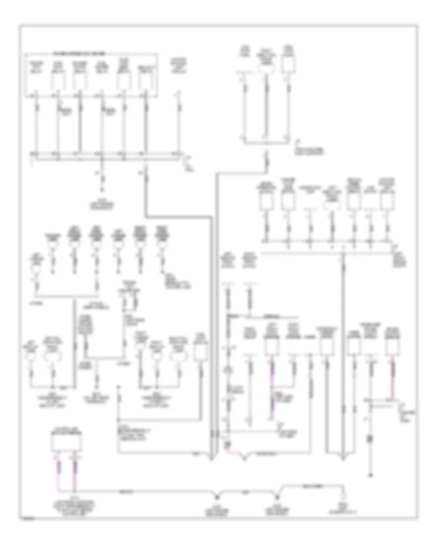
Ground Distribution Wiring Diagram (3 of 4) for Dodge Cab & Chassis R2000 3500
List of elements for Ground Distribution Wiring Diagram (3 of 4) for Dodge Cab & Chassis R2000 3500:
- (after- market)
- (left side of dash)
- (other)
- (w/ dual rear wheels)
- 4wd switch
- After- market trailer tow con- nector
- Air bag control module
- Blower motor relay
- Brake pressure switch
- C nca
- Controller anti-lock brake
- Daytime running lamp module
- Diesel only
- From g200 (diagram 2 of 4)
- Fuel heater relay
- Fuel pump module
- Fuel pump relay
- G100 (left fender side shield)
- High note horn
- J/c (center of dash)
- J/c (front bumper right support)
- J/c (in pdc)
- J/c (left front engine compt)
- J/c (left side of dash)
- Left back-up lamp
- Left front door speaker
- Left left front front fender fender lamp lamp
- Left left license license lamp lamp
- Left left rear rear fender fender lamp lamp
- Left license lamp
- Left park/turn signal lamp
- Left remote radio switch
- Left tail/ stop/turn signal lamp
- Low note horn
- Nca
- Passenger air bag on/off switch
- Power distribution center
- Premium
- Quad high beam relay
- Radio
- Radio choke relay
- Right back-up lamp
- Right front door speaker
- Right license lamp
- Right park/turn signal lamp
- Right remote radio switch
- Right right front front fender fender lamp lamp
- Right right rear rear fender fender lamp lamp
- Right tail/ stop/turn signal lamp
- S112 (left rear of engine compt, near breakout to anti-lock brake controller)
- S209
- S302
- S315 (on left rear frame rail)
- S321 (left rear lamps)
- S401 (near breakout to left back-up lamp)
- S402 (near breakout to right back-up lamp)
- S404 (near breakout to tailgate lamp)
- Security relay
- Tailgate tailgate lamp lamp
- Trailer tow connector
- Trailer tow relay
- Underhood lamp
- Vehicle speed control servo
- Washer fluid level switch
- Windshield washer pump
- Wiper motor
Ground Distribution Wiring Diagram (4 of 4) for Dodge Cab & Chassis R2000 3500
List of elements for Ground Distribution Wiring Diagram (4 of 4) for Dodge Cab & Chassis R2000 3500:
- (near engine
- (near fuel injector 1:v6,v8)
- (not used)
- A/c com-
- A/t
- Battery (diesel)
- Data link connector
- Diesel
- Engine control module
- Engine coolant temp sensor)
- Engine starter motor relay
- Fuel injection pump
- G100 (left front fender)
- G112 (left side of engine)
- G125 (front of engine)
- Gas
- Ground:v10)
- Intake air heater relay
- J/c (in pdc)
- M/t
- Manual
- Oxygen sensor 1/1 left bank up (5.9l/8.0l)
- Oxygen sensor 1/1 left bank up (california)
- Oxygen sensor 1/1 upstream (except 8.0l)
- Oxygen sensor 1/2 downstream (except 8.0l)
- Oxygen sensor 1/2 left bank down (california)
- Oxygen sensor 1/2 pre- catalyst (8.0l)
- Oxygen sensor 1/3 post- catalyst (8.0l)
- Oxygen sensor 2/1 right bank up (5.9l/8.0l)
- Oxygen sensor 2/1 right bank up (california)
- Oxygen sensor 2/2 right bank down (california)
- Power distribution center
- Powertrain control module
- Pressor clutch
- S109 (in breakout to engine & trans ground)
- S126
- S126 (near breakout to pcm)
- S128 (left front fender)
- Transmission
- Vehicle speed control servo
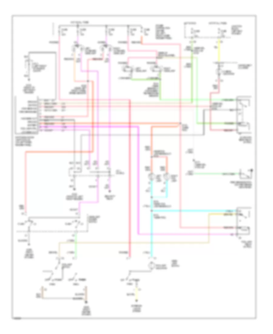
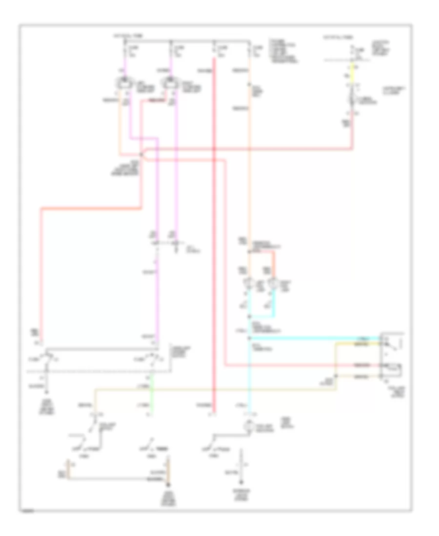
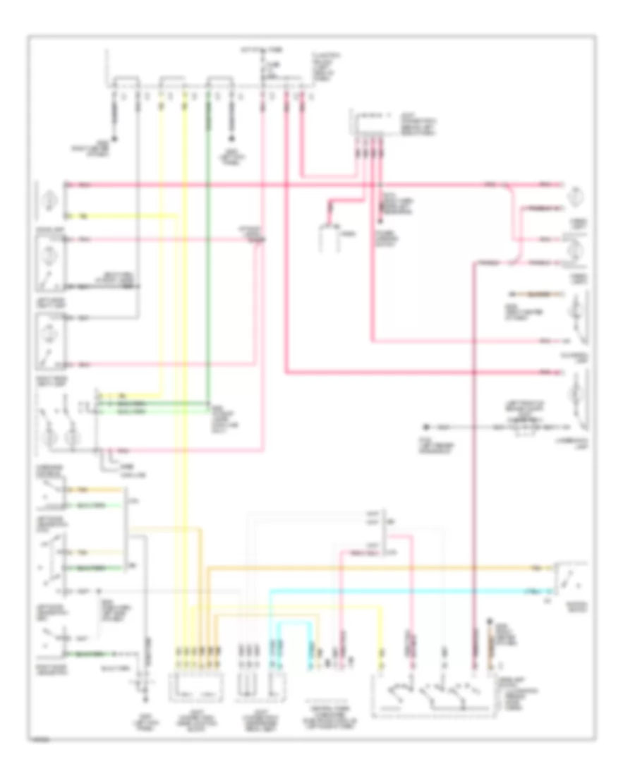
HEADLIGHTS
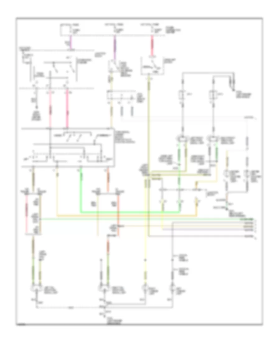
Headlight Wiring Diagram, with DRL & with Quad Headlights for Dodge Cab & Chassis R2000 3500
List of elements for Headlight Wiring Diagram, with DRL & with Quad Headlights for Dodge Cab & Chassis R2000 3500:
- (front of left front fender)
- (near drl module) s182
- (near fog lamp breakout) s136
- (near pdc)
- (rear of front bumper) s181
- 87a
- Battery
- Daytime running lamp module (on left inner fender panel)
- Exterior lights system
- Flash
- Fog lamp ctrl
- Fog lamp indicator
- Fog lamp relay (in pdc)
- Fog lamp switch
- Fuse 10a
- Fuse b 15a
- Fuse c 15a
- Fuse e 15a
- Fuse f 20a
- Fuse g 15a
- G100
- G100 (front of left front fender)
- G11
- G206 (right center of dash)
- G34
- Ground
- Head
- Head- lamp switch
- Headlamp dimmer switch
- Hi beam indicator
- High beam ind
- High beam out
- Hot at all times
- Hot in run
- Ignition
- Instrument cluster
- J/c 1 (in pdc)
- J/c 4 (left front of engine compt)
- Junction block (left end of dash)
- L10
- L139
- L34
- Left fog lamp
- Left headlamp
- Left outboard headlamp
- Low beam out
- Off
- Park
- Park brake sen
- Park brake switch (on park brake mechanism)
- Pnk/red
- Power distribution center (on left front inner fender panel)
- Quad high beam relay (in pdc)
- Right fog lamp
- Right headlamp
- Right outboard headlamp
- S106 (near left front wheel speed sensor)
- S110
- S134 (near fog lamp breakout)
- S143 (near pdc)
- S144 (near breakout for ambient temperature sensor)
- S177 (near drl module)
- Security relay
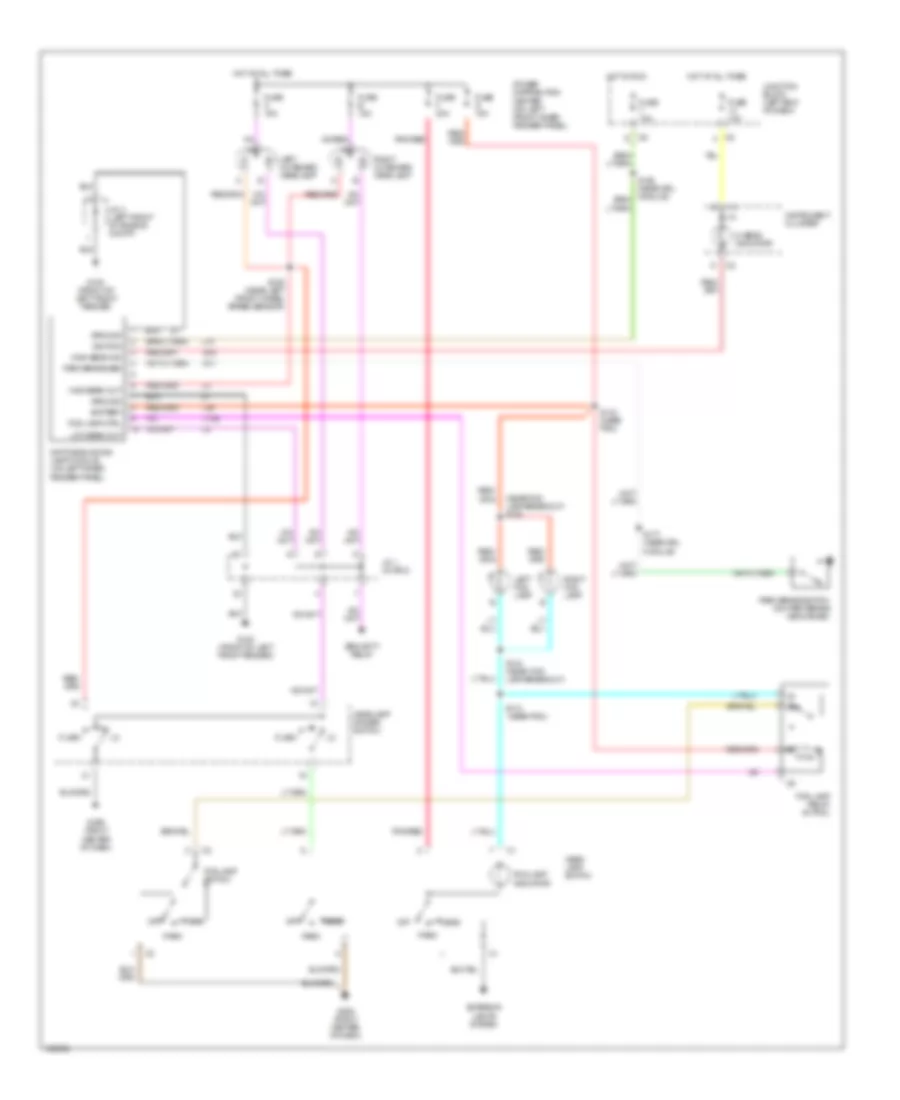
Headlight Wiring Diagram, with DRL & without Quad Headlights for Dodge Cab & Chassis R2000 3500
List of elements for Headlight Wiring Diagram, with DRL & without Quad Headlights for Dodge Cab & Chassis R2000 3500:
- (front of left front fender)
- (near fog lamp breakout) s136
- (near pdc)
- 87a
- Battery
- Daytime running lamp module (on left inner fender panel)
- Exterior lights system
- Flash
- Fog lamp ctrl
- Fog lamp indicator
- Fog lamp relay (in pdc)
- Fog lamp switch
- Fuse 10a
- Fuse b 15a
- Fuse c 15a
- Fuse f 20a
- Fuse g 15a
- G100
- G100 (front of left front fender)
- G11
- G206 (right center of dash)
- G34
- Ground
- Head
- Head- lamp switch
- Headlamp dimmer switch
- Hi beam indicator
- High beam ind
- High beam out
- Hot at all times
- Hot in run
- Ignition
- Instrument cluster
- J/c 1 (in pdc)
- J/c 4 (left front of engine compt)
- Junction block (left end of dash)
- L10
- L139
- L34
- Left fog lamp
- Left outboard headlamp
- Low beam out
- Off
- Park
- Park brake sen
- Park brake switch (on park brake mechanism)
- Pnk/red
- Power distribution center (on left front inner fender panel)
- Right fog lamp
- Right outboard headlamp
- S106 (near left front wheel speed sensor)
- S110
- S134 (near fog lamp breakout)
- S143 (near pdc)
- S177 (near drl module)
- Security relay
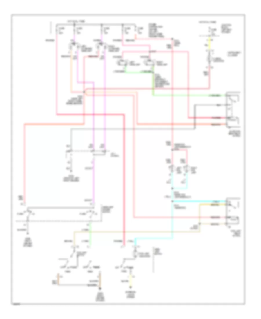
Headlight Wiring Diagram, without DRL & with Quad Headlights for Dodge Cab & Chassis R2000 3500
List of elements for Headlight Wiring Diagram, without DRL & with Quad Headlights for Dodge Cab & Chassis R2000 3500:
- (near fog lamp breakout) s136
- (near pdc)
- Exterior lights system
- Flash
- Fog lamp indicator
- Fog lamp relay (in pdc)
- Fog lamp switch
- Fuse 10a
- Fuse b 15a
- Fuse c 15a
- Fuse e 15a
- Fuse f 20a
- Fuse g 15a
- G100 (front of left front fender)
- G206 (right center of dash)
- Head
- Head- lamp switch
- Headlamp dimmer switch
- Hi beam indicator
- Hot at all times
- Instrument cluster
- J/c 1 (in pdc)
- Junction block (left end of dash)
- Left fog lamp
- Left headlamp
- Left outboard headlamp
- Off
- Park
- Pnk/red
- Power distribution center (on left front inner fender panel)
- Quad high beam relay (in pdc)
- Right fog lamp
- Right headlamp
- Right outboard headlamp
- S106 (near left front wheel speed sensor)
- S110
- S134 (near fog lamp breakout)
- S143 (near pdc)
- S144 (near breakout for ambient temperature sensor)
- S181
- S183 (in pdc)
Headlight Wiring Diagram, without DRL & without Quad Headlights for Dodge Cab & Chassis R2000 3500
List of elements for Headlight Wiring Diagram, without DRL & without Quad Headlights for Dodge Cab & Chassis R2000 3500:
- (near fog lamp breakout) s136
- (near pdc)
- Exterior lights system
- Flash
- Fog lamp indicator
- Fog lamp relay (in pdc)
- Fog lamp switch
- Fuse 10a
- Fuse b 15a
- Fuse c 15a
- Fuse f 20a
- Fuse g 15a
- G206 (right center of dash)
- Head
- Head- lamp switch
- Headlamp dimmer switch
- Hi beam indicator
- Hot at all times
- Instrument cluster
- J/c 1 (in pdc)
- Junction block (left end of dash)
- Left fog lamp
- Left outboard headlamp
- Off
- Park
- Pnk/red
- Power distribution center (on left front inner fender panel)
- Right fog lamp
- Right outboard headlamp
- S106 (near left front wheel speed sensor)
- S110
- S134 (near fog lamp breakout)
- S143 (near pdc)
- S183 (in pdc)
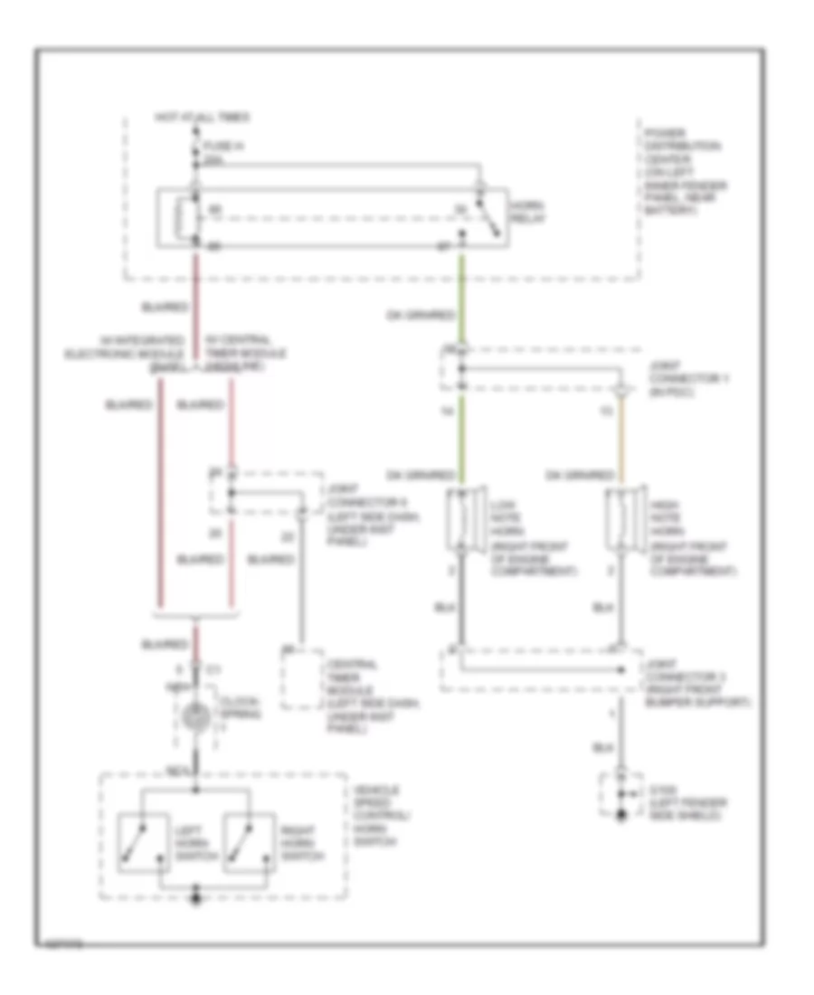
HORN
Horn Wiring Diagram for Dodge Cab & Chassis R2000 3500
List of elements for Horn Wiring Diagram for Dodge Cab & Chassis R2000 3500:
- (left side dash, under inst panel)
- (right front of engine compartment)
- Central timer module (left side dash, under inst panel)
- Clock- spring
- Fuse h 20a
- G100 (left fender side shield)
- High note horn
- Horn relay
- Hot at all times
- Joint connector 1 (in pdc)
- Joint connector 3 (right front bumper support)
- Joint connector 6
- Left horn switch
- Low note horn
- Nca
- Power distribution center (on left inner fender panel, near battery)
- Right horn switch
- Vehicle speed control/ horn switch
- W/ central timer module (highline)
- W/ integrated electronic module (base)
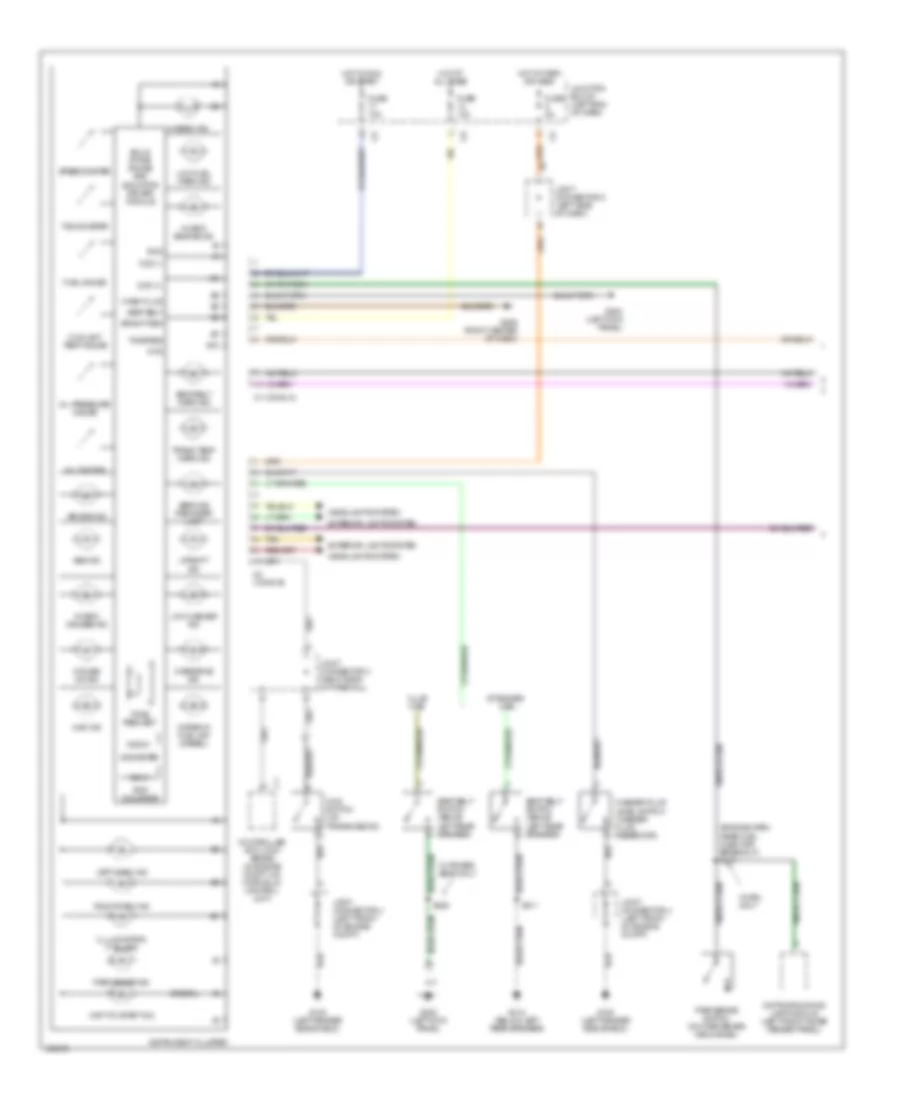
INSTRUMENT CLUSTER
Instrument Cluster Wiring Diagram (1 of 2) for Dodge Cab & Chassis R2000 3500
List of elements for Instrument Cluster Wiring Diagram (1 of 2) for Dodge Cab & Chassis R2000 3500:
- (diesel)
- (engine harn, near fuel injector breakout) s117
- 025.6
- 4wd
- 4wd ind
- 4wd switch (on transmission)
- A10
- Abs ind
- Air bag ind
- B10
- Bright sen
- C1 (conn a)
- C2 (conn b)
- Ccd (+)
- Ccd (-)
- Check engine ind
- Check gauges ind
- Club cab
- Controller anti-lock brake (in engine compt, on hydraulic control unit)
- Coolant temp gauge
- Cruise on ind
- Daytime running lamp module (left front inner fender panel)
- Exterior lights system
- Fuel gauge
- Fuse 10a
- Fuse 5a
- G100 (left fender side shield)
- G200 (left kick panel)
- G206 (right center of dash)
- G312 (below left rear speaker)
- Gnd
- Headlights system
- Hi beam ind
- Hot at all times
- Hot in park or head
- Hot in run or start
- Illlumination (7 bulbs)
- Instrument cluster
- Joint connector 3 (right side of firewall)
- Joint connector 4 (left front of engine compt)
- Joint connector 5 (left side of dash)
- Junction block (left end of dash)
- Left turn ind
- Low fuel warn ind
- Low washer ind
- Odometer
- Oil pressure gauge
- Overdrive ind
- Park brake ind
- Park brake switch (on park brake mechanism)
- Right turn ind
- S311
- S328
- Seat belt
- Seat belt switch (above left rear speaker)
- Seat belt warn ind
- Service reminder lamp
- Solid state gauge and indicator driver module
- Speedometer
- Standard cab
- Tachometer
- Tan
- Tone req
- Tone request
- Trans temp warn ind
- Trip odometer
- Upshift ind
- Voltmeter
- W/ drl only
- W/ power seat only
- Wait-to-start ind
- Wash fluid
- Washer fluid level switch (washer fluid reservoir)
- Water-in fuel ind
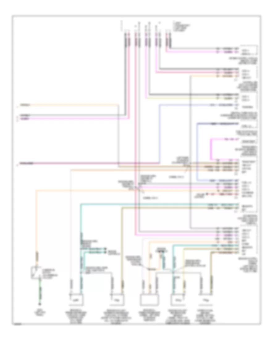
Instrument Cluster Wiring Diagram (2 of 2) for Dodge Cab & Chassis R2000 3500
List of elements for Instrument Cluster Wiring Diagram (2 of 2) for Dodge Cab & Chassis R2000 3500:
- (diesel only)
- (diesel)
- (engine harn, center of firewall) s172
- (engine harn, center of firewall) s173
- (engine harn, near engine control module)
- (engine harn, near fuel injector 5) s121
- (gas)
- (left rear of engine compartment) s174
- 5v ref
- Air bag control module (behind lower center of dash)
- Ccd (+)
- Ccd (-)
- Central timer module/ integrated electronic module (under left side of dash)
- Controller anti-lock brake (left front inner fender panel)
- Cruise control
- Ect
- Engine control module (diesel) (left side of engine, behind fuel filter)
- Engine controls
- Engine coolant temperature sensor (3.9/5.2/5.9l: in water jacket, at intake manifold) (8.0l: on thermostat housing)
- Engine coolant temperature sensor (diesel: front of cylinder head, near thermostat housing)
- Engine oil pressure sensor (3.9/5.2/5.9l: near distributor) (8.0l: near oil filter)
- Engine oil pressure sensor (diesel: left side of engine, near ecm)
- Eop
- Fuel lvl
- Fuel pump module (top of fuel tank)
- G13
- G200 (left kick panel)
- G60
- G85
- Joint connector 7 (left side of dash)
- K104
- K226
- O/d sense
- Overdrive switch (on steering column)
- Powertrain control module (right side of firewall)
- S118
- S165
- S166
- Sens rtn
- Spd ctrl
- T54
- Tone req
- Trans temp
- Transmission solenoid assembly (left side of transmission)
- V37
- Vss out
- Wait ind
- Water in fuel sensor (diesel: bottom of fuel filter/ water seperator canister)
- Wif
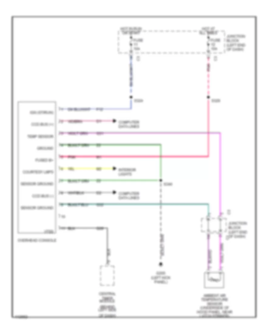
Overhead Console Wiring Diagram for Dodge Cab & Chassis R2000 3500
List of elements for Overhead Console Wiring Diagram for Dodge Cab & Chassis R2000 3500:
- (behind left side
- Ambient air temperature sensor (underside of hood panel, near latch striker)
- Ccd bus (+)
- Ccd bus (-)
- Central timer module
- Computer data lines
- Courtesy lmps
- F12
- Fuse 10a
- Fused b+
- G200 (left kick panel)
- G31
- G32
- G69
- Ground
- Hot at all times
- Hot in run or start
- Ign (st/run)
- Interior lights
- Junction block (left end of dash)
- Of dash)
- Overhead console
- Pnk
- S324
- S326
- S340
- Sensor ground
- Temp sensor
- Vtss
INTERIOR LIGHTS
Courtesy Lamps Wiring Diagram for Dodge Cab & Chassis R2000 3500
List of elements for Courtesy Lamps Wiring Diagram for Dodge Cab & Chassis R2000 3500:
- (at roof lamps) s326
- (body harn, at roof lamps) s323
- (left front of engine compt) joint connector 4
- Base
- Cargo lamp 1
- Cargo lamp 2
- Central timer/ integrated electronic module (left side of dash)
- Ctm
- Dome lamp
- Fuse 10a
- G100 (left fender side shield)
- G200 (left kick panel)
- G206 (right center of dash)
- Glove box lamp
- Headlamp switch
- High-line
- Hot at all times
- Iem
- Ignition switch
- Illumination parade dome cargo
- Joint connector 5 (behind left side of dash)
- Joint connector 6 (near brake pedal assy)
- Joint connector 8 (near junction block)
- Junction block (left end of dash)
- Left door jamb switch (ctm)
- Left door jamb switch (iem)
- Left visor/ vanity lamp
- Overhead console
- Pnk
- Power mirrors switch
- Radio
- Right door jamb switch
- Right visor/ vanity lamp
- S310 (body harn, near left rear spkr)
- S332 (dash harn, left side of dash)
- S340 (at roof lamps) (high-line only)
- Tan
- Underhood lamp
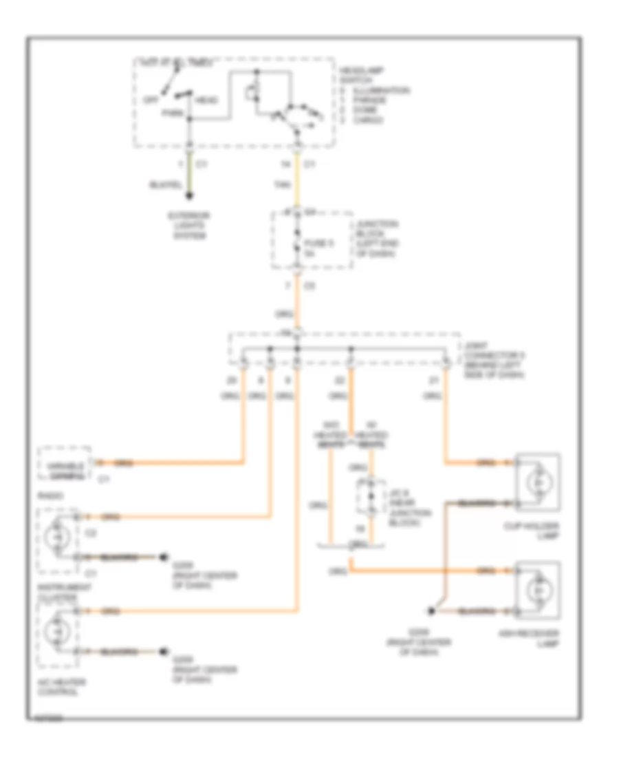
Instrument Illumination Wiring Diagram for Dodge Cab & Chassis R2000 3500
List of elements for Instrument Illumination Wiring Diagram for Dodge Cab & Chassis R2000 3500:
- A/c heater control
- Ash receiver lamp
- Cup holder lamp
- Exterior lights system
- Fuse 5 5a
- G206 (right center of dash)
- Head
- Headlamp switch
- Hot at all times
- Illumination parade dome cargo
- Instrument cluster
- J/c 8 (near junction block)
- Joint connector 5 (behind left side of dash)
- Junction block (left end of dash)
- Off
- Park
- Radio
- Tan
- Variable dimming
- W/ heated seats
- W/o heated seats
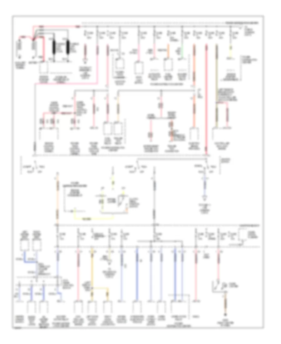
POWER DISTRIBUTION
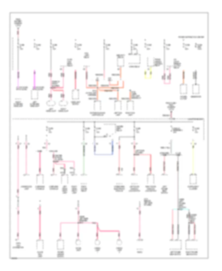
Power Distribution Wiring Diagram (1 of 3) for Dodge Cab & Chassis R2000 3500
List of elements for Power Distribution Wiring Diagram (1 of 3) for Dodge Cab & Chassis R2000 3500:
- (left rear of engine compt, in breakout to controller anti-lock brake) s113
- (left side of dash) s304
- (near engine control module) s167
- (near power- train control module) s161
- (not used)
- A/c heater temp- erature select
- A/t
- A14
- Acc
- After- market
- Aftermarket trailer tow connector
- Air bag control module
- Automatic shutdown relay
- Auxiliary battery (diesel)
- Battery
- Blend door act- uator
- Blower motor relay
- Breakout)
- Bypass jumper
- Cigar lighter
- Circuit breaker 1 20a
- Clutch pedal position switch
- Combi- nation flasher
- Combin- ation flasher
- Con- troller anti-lock brake
- Controller anti-lock brake
- Electric brake provision
- Engine starter motor relay
- Engine control module (diesel)
- Engine starter motor
- Engine starter motor relay
- Except after- market
- F23
- Fuel heater relay
- Fuel pump relay
- Fuse 10a
- Fuse 20a
- Fuse 25a
- Fuse 30a
- Fuse 40a
- Fuse 40a (diesel)
- Fuse 50a
- Fuse d 20a
- Fuse spare
- G206 (right center of dash)
- Heated mirror switch
- Ignition switch
- Intake air heater relay (diesel)
- Integrated electronic module
- Inter- mittent wiper switch
- J/c (in pdc)
- J/c 8 (near junction block)
- Junction block
- Left door window/ lock switch
- Left heated seat switch
- M/t
- Nca
- Off
- Power distrib- ution center
- Power distribuiton center
- Power distribution center
- Power- train control module (diesel)
- Power- train control module (gas)
- Radio
- Red
- Red/
- Red/tan
- Right door window/ lock switch
- Right heated seat switch
- Run
- Start
- Stop- light switch
- Tan
- To circuit breaker 2 (j/b) (diagram 2 of 3)
- To fuse 11 (j/b) (diagram 3 of 3)
- To fuse b (diagram 2 of 3)
- To splice s108 (diagram 3 of 3)
- Trailer tow connector
- Trailer tow relay
- Wiper motor
- Wiper motor relay
Power Distribution Wiring Diagram (2 of 3) for Dodge Cab & Chassis R2000 3500
List of elements for Power Distribution Wiring Diagram (2 of 3) for Dodge Cab & Chassis R2000 3500:
- (center of roof pnk at lamps) s326
- (left side of dash) s306
- (near left power seat switch) s327
- (near left rear speaker) s310
- (rear of front bumper) s181
- A (w/0 quad) (w/ quad)
- A/c comp- ressor clutch relay
- Base
- Cargo lamp
- Circuit breaker 2 20a
- Club cab
- Data link connector
- Daytime running lamp module
- Dome lamp
- F35
- Fog lamp relay
- From battery (diagram 1 of 3)
- From fuse 1 (pdc) (diagram 1 of 3)
- Fuse 10a
- Fuse 15a
- Fuse b 15a
- Fuse c 15a
- Fuse e 15a
- Fuse f 20a
- Fuse g 15a
- Fuse gen 140a
- Fuse h 20a
- Fuse i 20a
- Fuse j 10a
- Fuse l 20a
- Generator
- Glove box lamp
- Headlamp switch
- Heated seat relay
- Highline
- Horn relay
- Instrument cluster
- Integrated electronic module
- J/c 5 (behind left side of dash)
- Junction block
- Left door window/ lock switch
- Left fog lamp
- Left headlalmp
- Left outboard headlamp
- Left power seat switch
- Left visor/ vanity lamp
- Nca
- Overhead console
- Pnk
- Pnk/ red
- Pnk/red
- Power distribution center
- Power mirror switch
- Power outlet
- Quad high beam relay
- Radio
- Radio choke relay
- Red
- Red/
- Red/tan
- Right door window/ lock switch
- Right fog lamp
- Right headlalmp
- Right outboard headlamp
- Right power seat switch
- Right visor/ vanity lamp
- S136 (near fog lamp breakout)
- S143 (in fog lamp harness)
- Seat) s337
- Security relay
- Standard cab
- Trans- mission control relay
- Underhood lamp
- W/ drl
- W/o drl
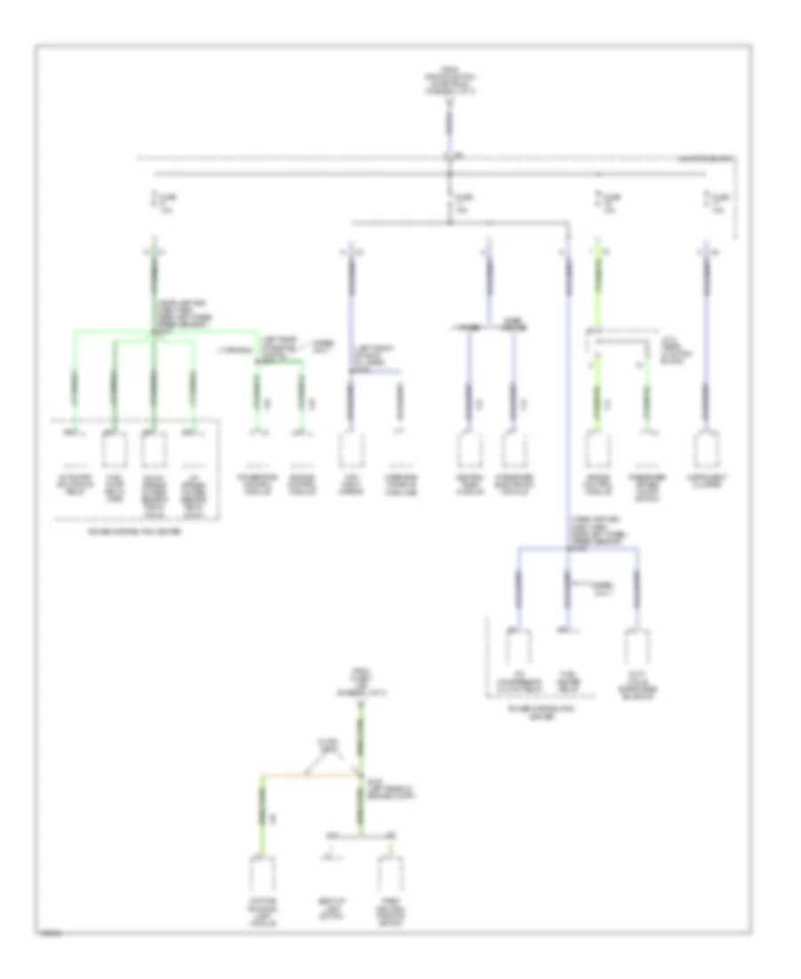
Power Distribution Wiring Diagram (3 of 3) for Dodge Cab & Chassis R2000 3500
List of elements for Power Distribution Wiring Diagram (3 of 3) for Dodge Cab & Chassis R2000 3500:
- (headlamp and dash harn, near left wheel speed sensor) s105
- (headlamp and dash harn, near left wheel speed sensor) s107
- (left front of roof at lamps) s324
- (left rear of engine compt) s171
- A/c compressor clutch relay
- A/t
- Air bag control module
- Automatic shutdown relay
- Back-up lamp switch
- Base/ midline
- Central timer module
- Day/ night mirror
- Daytime running lamp module
- Diesel only
- Down- stream oxygen sensor relay (calif)
- Duty cycle evap/purge solenoid
- Engine control module
- F12
- F14
- F18
- From fuse 7 (j/b) (diagram 1 of 3)
- From ignition switch (start/run) (diagram 1 of 3)
- Fuel heater relay
- Fuel pump relay (gas)
- Fuse 10a
- Instrument cluster
- Integrated electronic module
- J/c 8 (near junction block)
- Junction block
- L10
- M/t
- Other
- Overhead console (highline)
- Park/ neutral position switch
- Passenger air bag on/off switch
- Power distribution center
- Powertrain control module
- S108 (left rear of engine compt)
- Up- stream oxygen sensor relay (calif)
- W/ drl only
POWER DOOR LOCKS
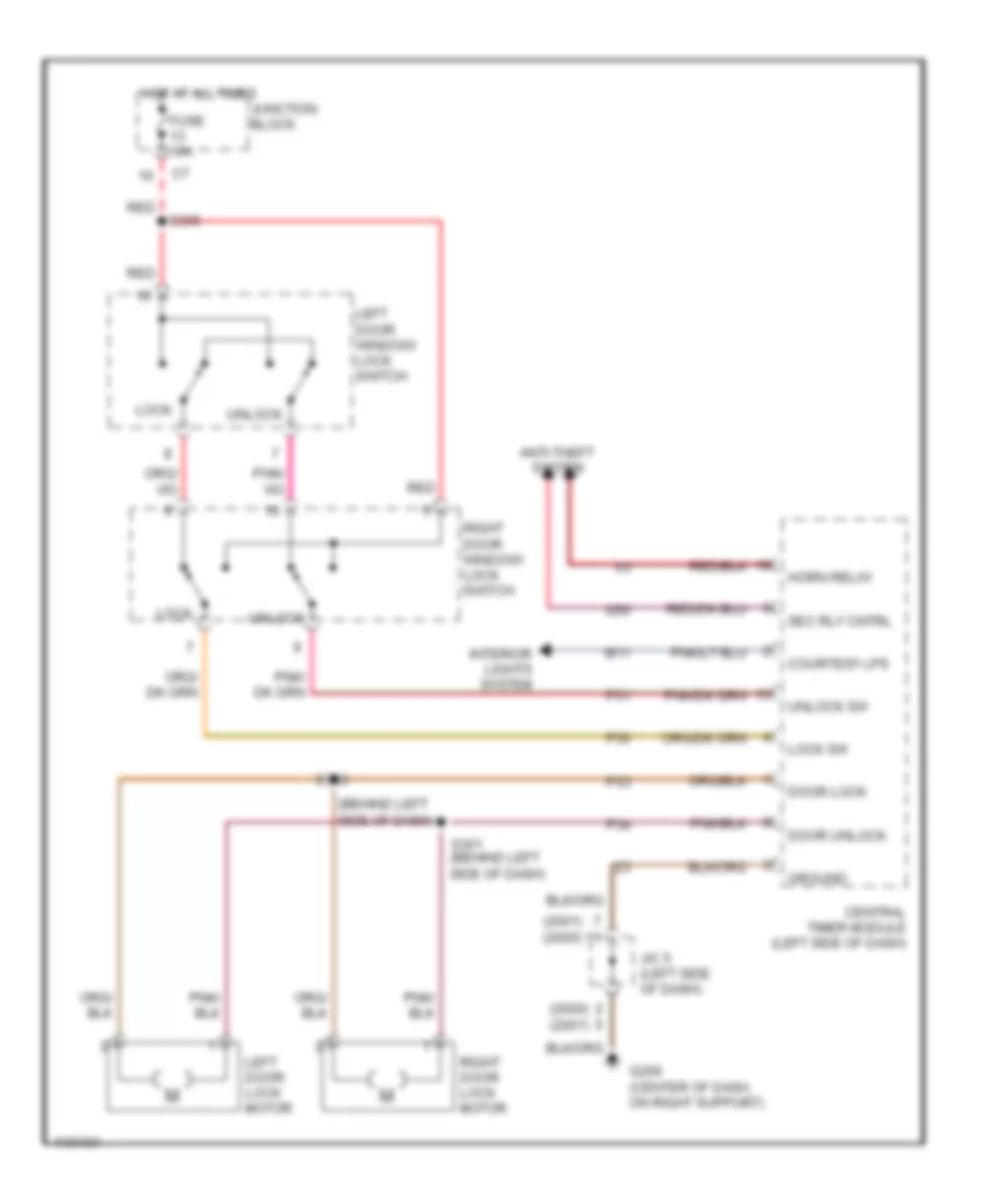
Power Door Lock Wiring Diagram, with Keyless Entry for Dodge Cab & Chassis R2000 3500
List of elements for Power Door Lock Wiring Diagram, with Keyless Entry for Dodge Cab & Chassis R2000 3500:
- (2000) (2001)
- (2001) (2000)
- (behind left side of dash)
- Anti-theft system
- Central timer module (left side of dash)
- Courtesy lps
- Door lock
- Door unlock
- Fuse 10a
- G206 (center of dash, on right support)
- G50
- Ground
- Horn relay
- Hot at all times
- Interior lights system
- J/c 5 (left side of dash)
- Junction block
- Left door lock motor
- Left door window/ lock switch
- Lock
- Lock sw
- M11
- P30
- P31
- P33
- P34
- Red
- Right door lock motor
- Right door window/ lock switch
- S300
- S301 (behind left side of dash)
- S306
- Sec rly cntrl
- Unlock
- Unlock sw
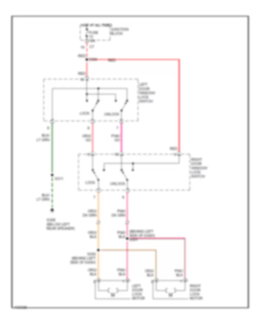
Power Door Lock Wiring Diagram, without Keyless Entry for Dodge Cab & Chassis R2000 3500
List of elements for Power Door Lock Wiring Diagram, without Keyless Entry for Dodge Cab & Chassis R2000 3500:
- Fuse 10a
- G308 (below left rear speaker)
- Hot at all times
- Junction block
- Left door lock motor
- Left door window/ lock switch
- Lock
- Red
- Red s306
- Right door lock motor
- Right door window/ lock switch
- S300 (behind left side of dash)
- S311
- Side of dash) s301
- Unlock
POWER MIRRORS
Power Mirror Wiring Diagram for Dodge Cab & Chassis R2000 3500
List of elements for Power Mirror Wiring Diagram for Dodge Cab & Chassis R2000 3500:
- Defogger system
- Down
- Fuse 12 10a
- G304 (lower rear of cab)
- Hot at all times
- Junction block (left end of dash)
- Left
- Left mirror
- Left power mirror
- Pnk
- Power mirror switch
- Right
- Right mirror
- Right power mirror
- S310
- S329
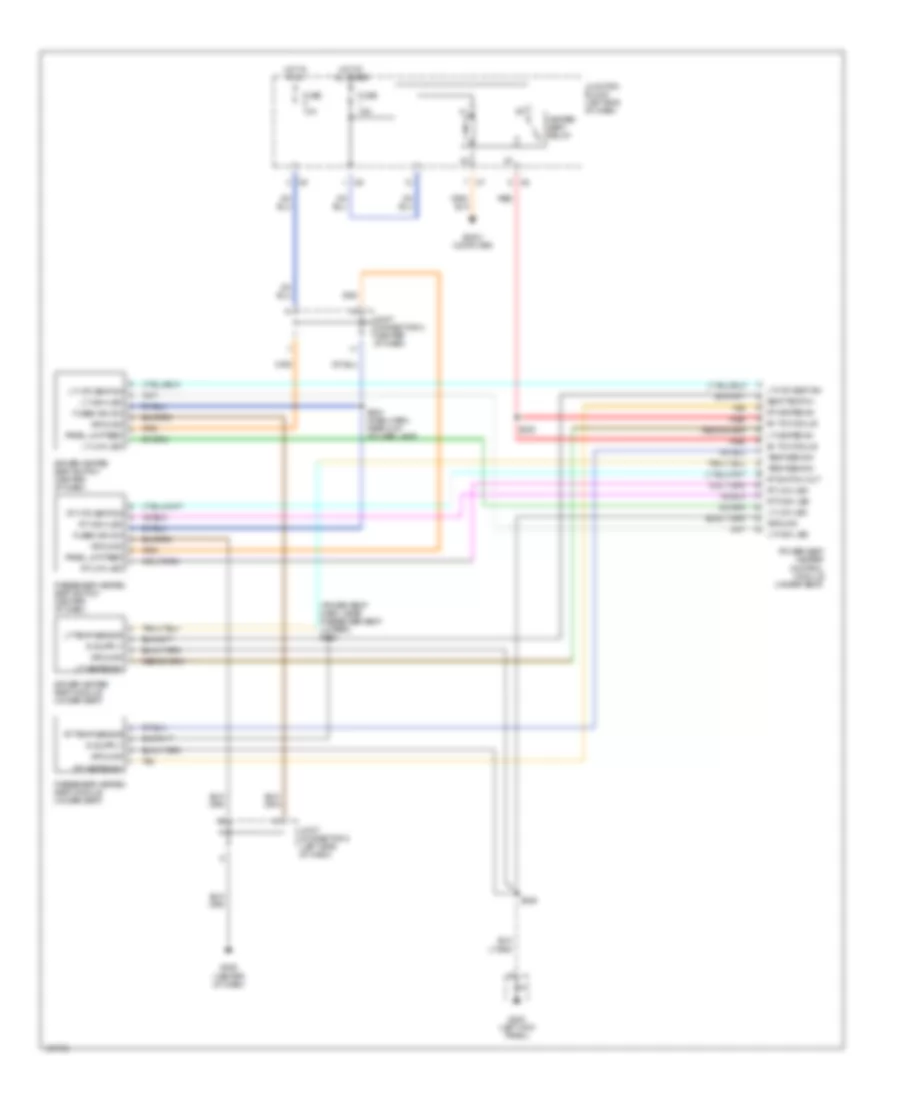
POWER SEATS
Heated Seats Wiring Diagram for Dodge Cab & Chassis R2000 3500
List of elements for Heated Seats Wiring Diagram for Dodge Cab & Chassis R2000 3500:
- (power seat harn, near passenger seat jumper) s333
- B+ to module
- Body computer
- Driver heated seat module (under seat)
- Driver heated seat switch (center of dash)
- Fuse 10a
- Fuse 15a
- Fused ign sw
- G200 (left kick panel)
- G206 (center of dash)
- Ground
- Heated seat relay
- Hot at all times
- Hot in run
- Joint connector 5 (left side of dash)
- Joint connector 8 (center of dash)
- Junction block (left end of dash)
- Lt heated b+
- Lt high led
- Lt htd seat sw
- Lt low led
- Lt temp sensor
- Panel lmp feed
- Passenger heated seat module (under seat)
- Passenger heated seat switch (center of dash)
- Power seat heater control module (under seat)
- Red
- Rt heated b+
- Rt high led
- Rt htd seat sw
- Rt low led
- Rt switch out
- Rt temp sensor
- S204 (dash harn, near cup holder lamp)
- S328
- S335
- Seat temp 5v
- Tan
- Temp sens in
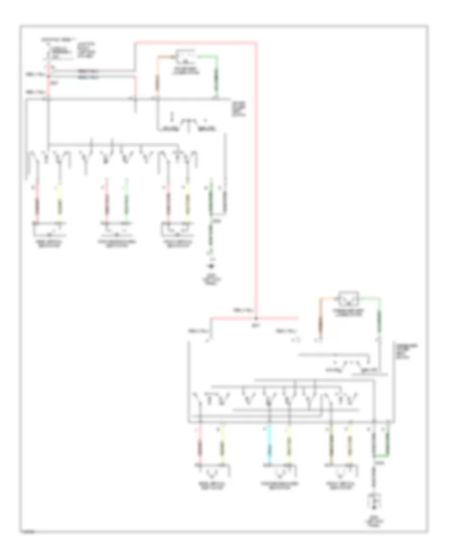
Power Seat Wiring Diagrams, Crew Cab for Dodge Cab & Chassis R2000 3500
List of elements for Power Seat Wiring Diagrams, Crew Cab for Dodge Cab & Chassis R2000 3500:
- Back
- Circuit breaker 2 20a
- Deflate
- Driver power seat switch
- Driver seat lumbar motor
- F dn
- F up
- Forward/backward seat motor
- Front vertical seat motor
- Fwd
- G200 (left kick panel)
- Hot at all times
- Inflate
- Junction block (left end of dash)
- Passenger power seat switch
- Passenger seat lumbar motor
- R dn
- R up
- Rear vertical seat motor
- S327
- S328
- S336
- S337
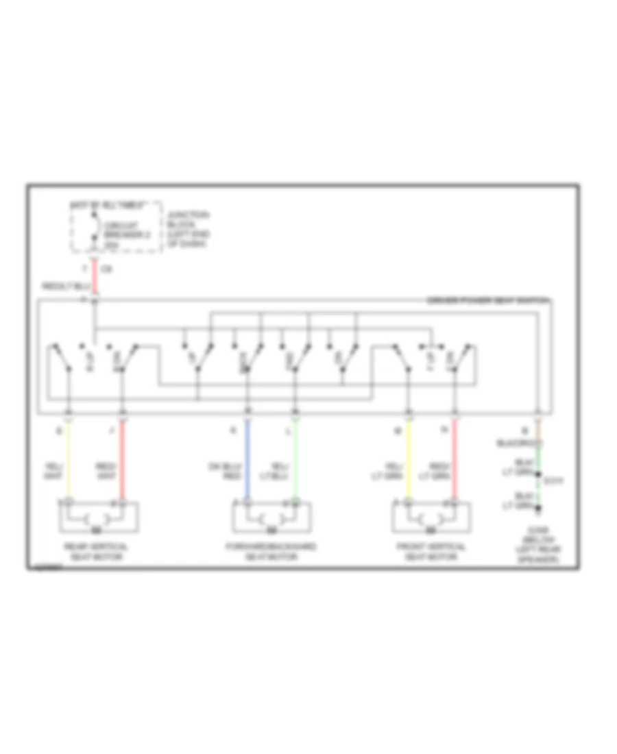
Power Seat Wiring Diagrams, Standard for Dodge Cab & Chassis R2000 3500
List of elements for Power Seat Wiring Diagrams, Standard for Dodge Cab & Chassis R2000 3500:
- Back
- Circuit breaker 2 20a
- Driver power seat switch
- F dn
- F up
- Forward/backward seat motor
- Front vertical seat motor
- Fwd
- G308 (below left rear speaker)
- Hot at all times
- Junction block (left end of dash)
- R dn
- R up
- Rear vertical seat motor
- S311
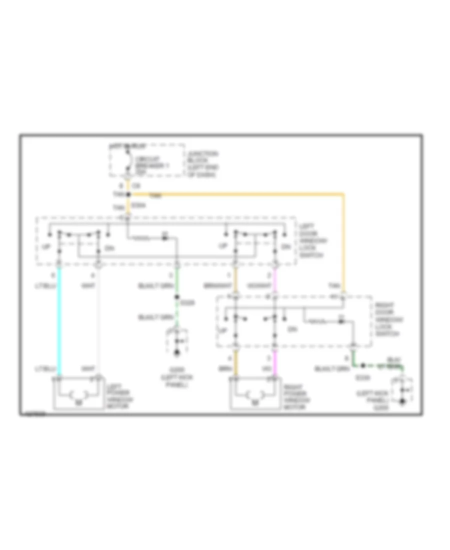
POWER WINDOWS
Power Window Wiring Diagram for Dodge Cab & Chassis R2000 3500
List of elements for Power Window Wiring Diagram for Dodge Cab & Chassis R2000 3500:
- (left kick panel) g200
- Circuit breaker 1 20a
- G200 (left kick panel)
- Hot in run
- Junction block (left end of dash)
- Left door window/ lock switch
- Left power window motor
- Right door window/ lock switch
- Right power window motor
- S304 tan
- S329
- S330
- Tan
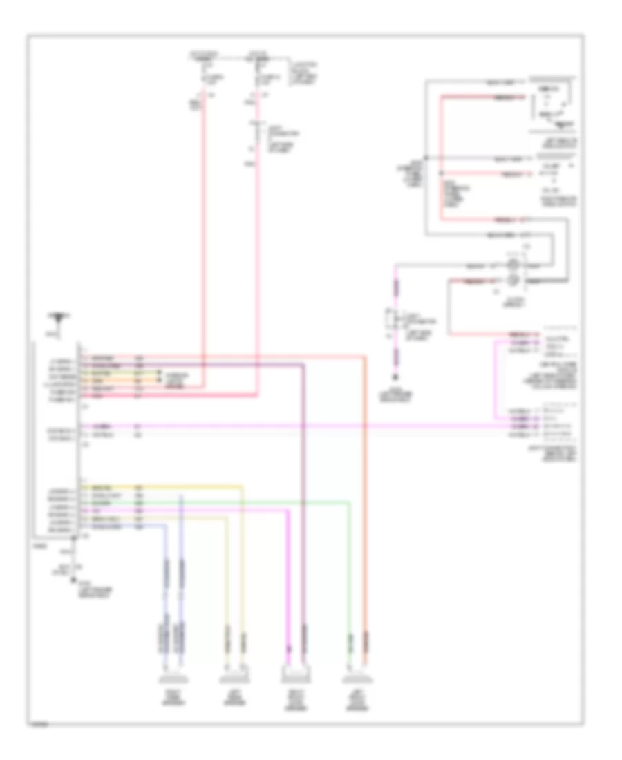
RADIO
Base Radio for Dodge Cab & Chassis R2000 3500
List of elements for Base Radio for Dodge Cab & Chassis R2000 3500:
- Antenna
- Ccd (+)
- Ccd (-)
- Ccd bus (+)
- Ccd bus (-)
- Central timer module (left side of dash, inboard of steering column opening)
- Clock- spring 1
- Day sense
- E17
- Fuse 12 10a
- Fuse 8 10a
- Fused b(+)
- Fused ign
- G100 (left fender side shield)
- Hot at all times
- Hot in run or acc
- Illumination
- Interior lights system
- Joint connector (left side of dash)
- Joint connector 7 (behind left side of dash)
- Junction block (left end of dash)
- Left front door speaker
- Left rear speaker
- Left remote radio switch
- Lf spkr (+)
- Lf spkr (-)
- Lr spkr (+)
- Lr spkr (-)
- Mux ctrl
- Nca
- Pnk
- Preset
- Radio
- Rf spkr (+)
- Rf spkr (-)
- Right front door speaker
- Right rear speaker
- Right remote radio switch
- Rr spkr (+)
- Rr spkr (-)
- S209 (steering wheel jumper harn)
- S210 (steering wheel jumper harn)
- Seek dn
- Seek up
- Vol dn
- Vol up
- X12
- X51
- X52
- X53
- X54
- X55
- X56
- X57
- X58
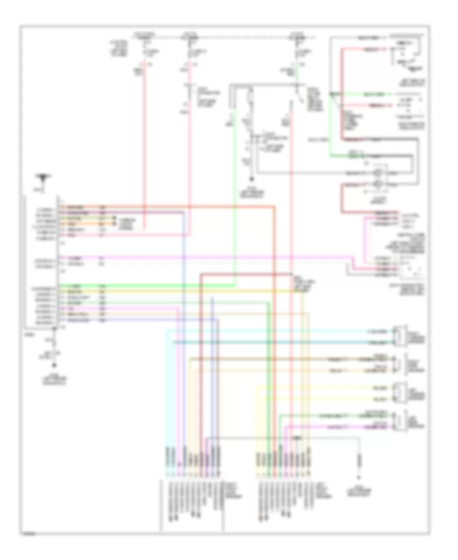
Premium Sound Radio Wiring Diagram for Dodge Cab & Chassis R2000 3500
List of elements for Premium Sound Radio Wiring Diagram for Dodge Cab & Chassis R2000 3500:
- (2001) (2000)
- Amp l rear spkr (+)
- Amp l rear spkr (-)
- Amp r rear spkr (+)
- Amp r rear spkr (-)
- Amp tweeter spkr (+)
- Amp tweeter spkr (-)
- Antenna
- C b
- Ccd (+)
- Ccd (-)
- Ccd bus (+)
- Ccd bus (-)
- Central timer module (left side of dash, inboard of steering column opening)
- Choke relay
- Clock- spring 1
- Day sense
- E17
- Fuse 12 10a
- Fuse 4 10a
- Fuse 8 10a
- Fused b(+)
- Fused ign
- G100 (left fender side shield)
- Ground
- Hot at all times
- Hot in run or acc
- Illumination
- Interior lights system
- Joint connector (left side of dash)
- Joint connector 7 (behind left side of dash)
- Junction block (left end of dash)
- L front spkr (+)
- L front spkr (-)
- L rear spkr (+)
- L rear spkr (-)
- Left front door speaker
- Left rear speaker
- Left remote radio switch
- Left tweeter speaker
- Lf spkr (+)
- Lf spkr (-)
- Lr spkr (+)
- Lr spkr (-)
- Mux ctrl
- Nca
- Pnk
- Preset
- R front spkr (+)
- R front spkr (-)
- R rear spkr (+)
- R rear spkr (-)
- Radio
- Radio choke
- Radio choke relay (behind center of dash)
- Rf spkr (+)
- Rf spkr (-)
- Right front door speaker
- Right rear speaker
- Right remote radio switch
- Right tweeter speaker
- Rr spkr (+)
- Rr spkr (-)
- S209
- S210 (steering wheel jumper harn)
- S302
- S303 (dash harn, left side of dash)
- Seek dn
- Seek up
- Vol dn
- Vol up
- X12
- X16
- X51
- X52
- X53
- X54
- X55
- X56
- X57
- X58
STARTING/CHARGING
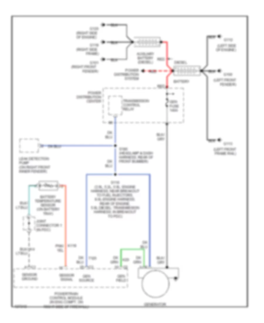
Charging Wiring Diagram for Dodge Cab & Chassis R2000 3500
List of elements for Charging Wiring Diagram for Dodge Cab & Chassis R2000 3500:
- (left front fender)
- (left front frame rail)
- (left side of engine)
- (right front
- (right side
- (right side of engine)
- Auxiliary battery (diesel)
- Battery
- Battery temperature sensor (on battery tray)
- Diesel
- Fender)
- Frame)
- G100
- G101
- G112
- G113
- G118
- G120
- Gen field
- Gen fuse 140a
- Gen source
- Generator
- Joint connector 1 (in pdc)
- K20
- Leak detection pump (on right front inner fender)
- Power distribution center
- Power distribution system
- Powertrain control module (in eng compt, on right side of firewall)
- Red
- S116 (3.9l, 5.2l, 5.9l: engine harness, near breakout to fuel injectors, 8.0l-engine harness, rear of engine, 5.9l diesel: transmission harness, in breakout to pdc)
- S180 (headlamp & dash harness, rear of front bumber)
- Sensor ground
- Sensor signal
- T125
- Transmission control relay
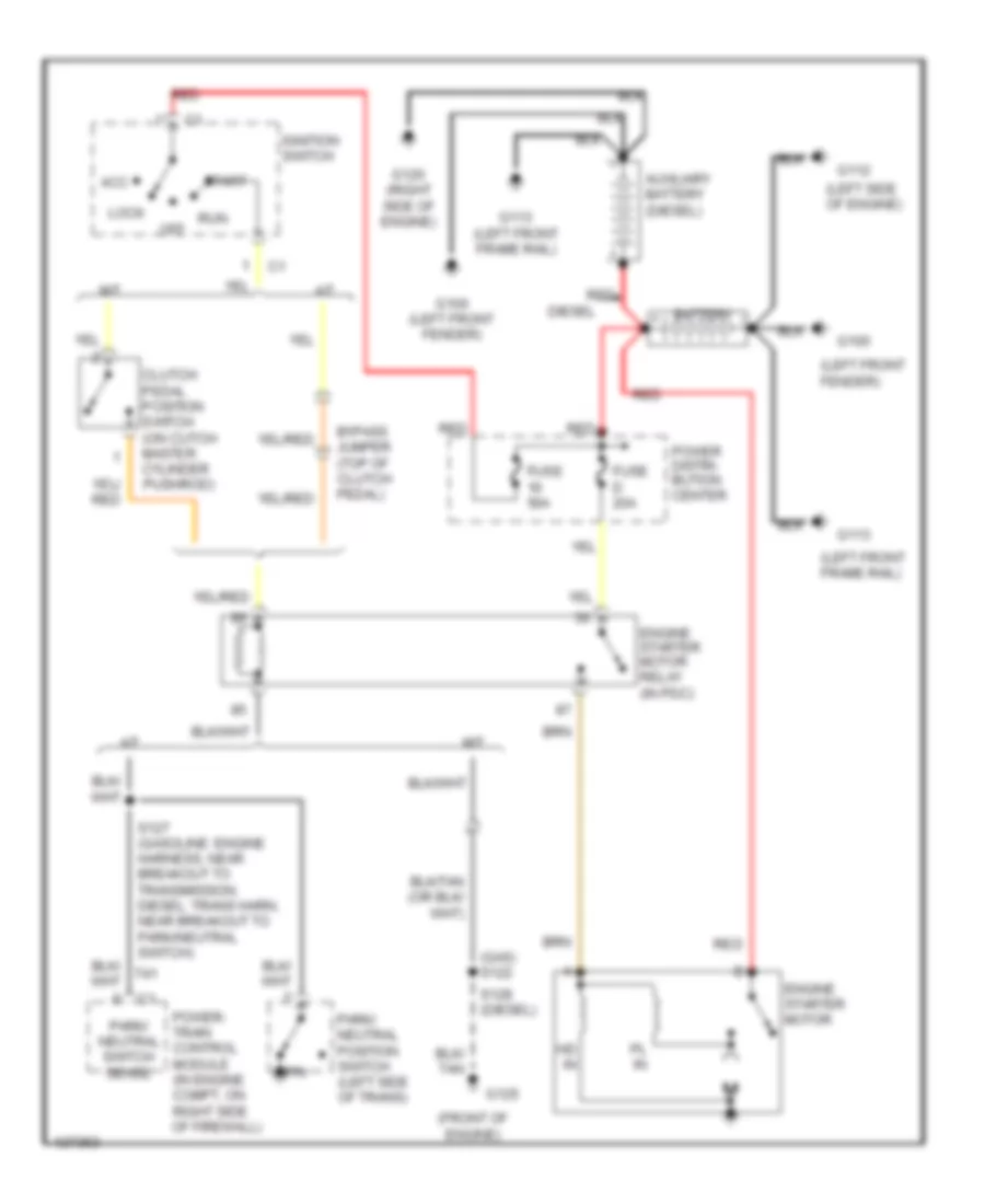
Starting Wiring Diagram for Dodge Cab & Chassis R2000 3500
List of elements for Starting Wiring Diagram for Dodge Cab & Chassis R2000 3500:
- (front of engine)
- (gas) s122
- (left front fender)
- (left front frame rail)
- (left side of engine)
- A/t
- Acc
- Auxiliary battery (diesel)
- Battery
- Bypass jumper (top of clutch pedal)
- Clutch pedal position switch (on cutch master cylinder pushrod)
- Diesel
- Engine starter motor
- Engine starter motor relay (in pdc)
- Fuse 50a
- Fuse d 20a
- G100
- G100 (left front fender)
- G112
- G113
- G113 (left front frame rail)
- G120 (right side of engine)
- G125
- Hd in
- Ignition switch
- Lock
- M/t
- Off
- P/n
- Park/ neutral position switch (left side of trans)
- Park/ neutral switch sense
- Pl in
- Power distri- bution center
- Power- train control module (in engine compt, on right side of firewall)
- Red
- Run
- S127 (gasoline: engine harness, near breakout to transmission, diesel: trans harn, near breakout to park/neutral switch)
- S128 (diesel)
- Start
- T41
SUPPLEMENTAL RESTRAINTS
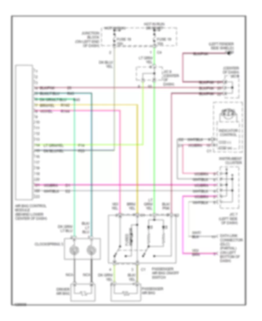
Supplemental Restraint Wiring Diagram for Dodge Cab & Chassis R2000 3500
List of elements for Supplemental Restraint Wiring Diagram for Dodge Cab & Chassis R2000 3500:
- (center of dash) j/c 8
- (left fender side shield) g100
- Air bag
- Air bag control module (behind lower center of dash)
- Ccd (+)
- Ccd (-)
- Clockspring 3
- Data link connector (dlc) (partial) (on left bottom of dash)
- Driver air bag
- F14
- F23
- Fuse 18 10a
- Fuse 19 10a
- Hot in run
- Hot in run or start
- Indicator control
- Instrument cluster
- J/c 7 (left side of dash)
- J/c 8 (center of dash)
- Junction block (on left end of dash)
- Nca
- Passenger air bag
- Passenger air bag on/off switch
- R142
- R144
- R43
- R45
- Resistor fused
TRANSMISSION
5.9L
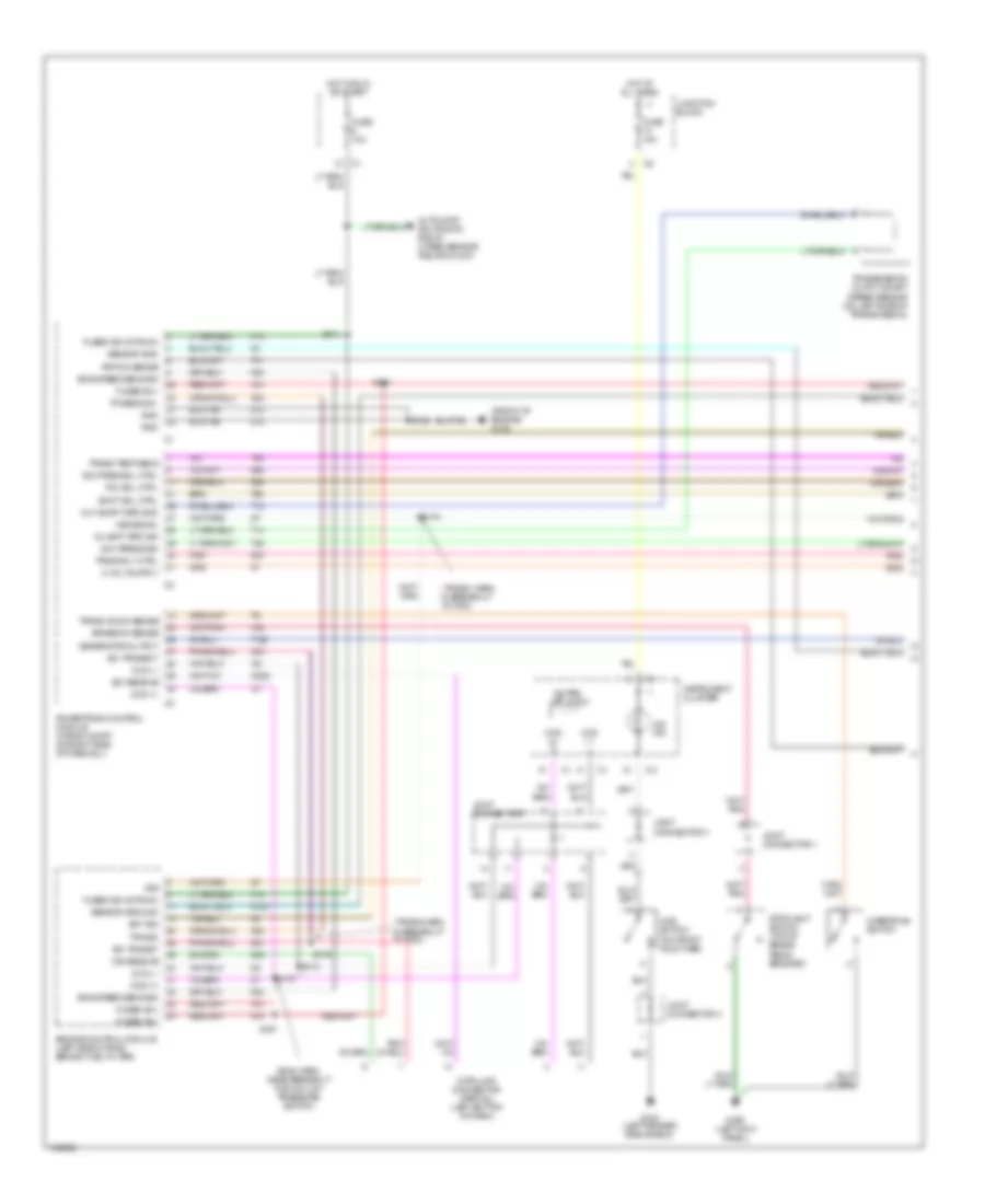
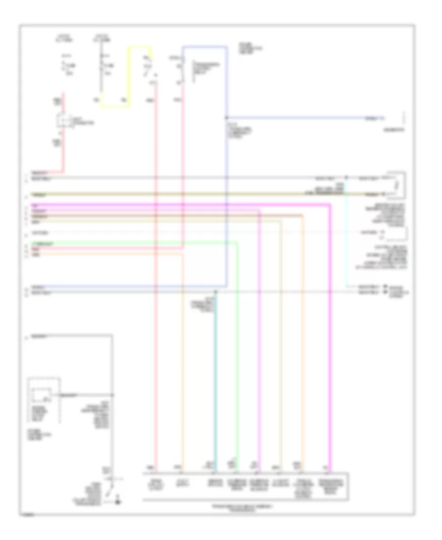
5.9L 24-Valve Diesel, A/T Wiring Diagram (1 of 2) for Dodge Cab & Chassis R2000 3500
List of elements for 5.9L 24-Valve Diesel, A/T Wiring Diagram (1 of 2) for Dodge Cab & Chassis R2000 3500:
- (eng harn, near breakout for a/c low pressure switch)
- (front of engine) g125
- (trans harn, in breakout to pdc)
- (trans harn, in breakout to pdc)
- 4wd switch (on front axle tube)
- 4x4 ind
- A14
- Automatic shutdown relay, oxgen sensor relays (calif)
- Brake sw sense
- Ccd (+)
- Ccd (-)
- Csi receive
- D20
- D21
- D220
- Data link connector (partial) (left bottom of dash)
- Ect sig
- Eng speed sens sig
- Engine control module (left side of eng, behind fuel filter)
- F18
- Fuse 10a
- Fused (b+)
- Fused b(+)
- Fused ign (st/run)
- G100 (left fender side shield)
- G200 (left kick panel)
- Generator output
- Gnd
- Gov pres sol ctrl
- Gov press sig
- Hot at all times
- Hot in run or start
- Instrument cluster
- Joint connector 1
- Joint connector 3
- Joint connector 4
- Joint connector 7
- Junction block
- K104
- K22
- K24
- K30
- K54
- K88
- Mil ind
- Ou shft spd sig
- Out shaft spd gnd
- Overdrive switch
- Pnk
- Pnp sw sense
- Powertrain control module (in eng compt, on right side of firewall)
- S126
- S161
- S167
- S171
- S172
- S173
- S174
- S175
- Sci receive
- Sci transit
- Sci transmit
- Sensor gnd
- Sensor ground
- Shift sol ctrl
- Stoplight switch (top of brake pedal bracket)
- T125
- T13
- T14
- T25
- T41
- T54
- T60
- Tcc sol ctrl
- Tp sens sig
- Tps sig
- Trans od sw sense
- Trans rly ctrl
- Trans temp sens
- Transmission output shaft speed sensor (on left side of transmission)
- V40
- Vss
- Vss signal
- Z12
5.9L 24-Valve Diesel, A/T Wiring Diagram (2 of 2) for Dodge Cab & Chassis R2000 3500
List of elements for 5.9L 24-Valve Diesel, A/T Wiring Diagram (2 of 2) for Dodge Cab & Chassis R2000 3500:
- 3-4 shift solenoid
- Controller anti- lock brake (rwabs: on left front inner fender, 4wabs: mounted on top of hydraulic control unit)
- Engine controls system
- Engine coolant temperature sensor (on front of cylinder head, near thermostat housing)
- Engine starter motor relay
- Fuse 20a
- Fuse i 10a
- Generator
- Governor pressure signal
- Governor pressure solenoid
- Hot at all times
- Joint connector
- Park/ neutral position switch (on left side of transmission)
- Pnk
- Power distribution center
- Power distribution center
- Red
- S116 (trans harn, in breakout to pdc)
- S127 (trans harn, near breakout to park/ neutral position switch)
- S165 (eng harn, near fuel transfer pump)
- S179 (trans harn, in breakout to pdc)
- Sensor ground
- Torque converter clutch solenoid control
- Trans ctrl rly output
- Transmission control relay
- Transmission solenoid assembly (transmission)
- Transmission temperature sensor signal
5.9L, A/T Wiring Diagram (1 of 2) for Dodge Cab & Chassis R2000 3500
List of elements for 5.9L, A/T Wiring Diagram (1 of 2) for Dodge Cab & Chassis R2000 3500:
- 4wd switch (on front axle tube)
- 4x4 ind
- A14
- Brake sw sense
- Ccd (+)
- Ccd (-)
- D20
- D21
- Data link connector (partial) (left bottom of dash)
- Ect sens sig
- F18
- Fuel pump, automatic shutdown relays, oxygen sensor relays (calif)
- Fuse 10a
- Fused b(+)
- Fused ign (st/run)
- G100 (left fender side shield)
- G125 (front of eng)
- G200 (left kick panel)
- Generator output
- Gnd
- Gov pres sol ctrl
- Gov press sig
- Hot at all times
- Hot in run or start
- Instrument cluster
- Joint connector
- Joint connector 1
- Joint connector 3
- Joint connector 4
- Junction block
- K22
- K30
- K54
- K88
- Mil ind
- Ou shft spd sig
- Out shaft spd gnd
- Overdrive switch
- Pnk
- Pnp sw sense
- Powertrain control module (in eng compt, on right side of firewall)
- S107
- S126
- Sci receive
- Sci transmit
- Sensor gnd
- Shift sol ctrl
- Stoplight switch (top of brake pedal bracket)
- T125
- T13
- T14
- T25
- T41
- T54
- T60
- Tcc sol ctrl
- Tp sens sig
- Trans od sw sense
- Trans rly ctrl
- Trans temp sens
- Transmission output shaft speed sensor (on left side of transmission)
- V40
- Vss signal
- Z12
5.9L, A/T Wiring Diagram (2 of 2) for Dodge Cab & Chassis R2000 3500
List of elements for 5.9L, A/T Wiring Diagram (2 of 2) for Dodge Cab & Chassis R2000 3500:
- (eng harn, 3.9l, 5.2l & 5.9l: near breakout for fuel injectors; 8.0l: rear of eng)
- 3-4 shift solenoid
- Controller anti- lock brake (rwabs: on left front inner fender, 4wabs: mounted on top of hydraulic control unit)
- Engine controls system
- Engine coolant temperature sensor (at front of intake manifold)
- Engine starter motor relay
- Fuel pump relay
- Fuse 20a
- Fuse i 20a
- G119 (eng harn, 3.9l, 5.2l & 5.9l: near breakout for fuel injectors; 8.0l: rear of eng)
- Generator
- Governor pressure signal
- Governor pressure solenoid
- Hot at all times
- Joint connector
- Leak detection pump (right front inner fender)
- Park/ neutral position switch (on left side of transmission)
- Pnk
- Power distribution center
- Power distribution center
- Red
- S116 (eng harn, 3.9l, 5.2l & 5.9l: near breakout for fuel injectors; 8.0l: rear of eng)
- S118
- S121 (eng harn, near breakout to fuel inj 5)
- S127 (eng harn, top center of transmission)
- S180 (headlamp and dash, harn, rear of front bumper)
- Sensor ground
- Throttle position sensor (on throttle body)
- Torque converter clutch solenoid control
- Trans ctrl rly output
- Transmission control relay
- Transmission solenoid assembly (transmission)
- Transmission temperature sensor signal
8.0L
8.0L, A/T Wiring Diagram (1 of 2) for Dodge Cab & Chassis R2000 3500
List of elements for 8.0L, A/T Wiring Diagram (1 of 2) for Dodge Cab & Chassis R2000 3500:
- 4wd switch (on front axle tube)
- 4x4 ind
- A14
- Brake sw sense
- Ccd (+)
- Ccd (-)
- D20
- D21
- Data link connector (partial) (left bottom of dash)
- Ect sens sig
- F18
- Fuel pump, automatic shutdown relays, oxygen sensor relays (calif)
- Fuse 10a
- Fused b(+)
- Fused ign (st/run)
- G100 (left fender side shield)
- G125 (front of eng)
- G200 (left kick panel)
- Generator output
- Gnd
- Gov pres sol ctrl
- Gov press sig
- Hot at all times
- Hot in run or start
- Instrument cluster
- Joint connector
- Joint connector 1
- Joint connector 3
- Joint connector 4
- Junction block
- K22
- K30
- K54
- K88
- Mil ind
- Ou shft spd sig
- Out shaft spd gnd
- Overdrive switch
- Pnk
- Pnp sw sense
- Powertrain control module (in eng compt, on right side of firewall)
- S107
- S126
- Sci receive
- Sci transmit
- Sensor gnd
- Shift sol ctrl
- Stoplight switch (top of brake pedal bracket)
- T125
- T13
- T14
- T25
- T41
- T54
- T60
- Tcc sol ctrl
- Tp sens sig
- Trans od sw sense
- Trans rly ctrl
- Trans temp sens
- Transmission output shaft speed sensor (on left side of transmission)
- V40
- Vss signal
- Z12
8.0L, A/T Wiring Diagram (2 of 2) for Dodge Cab & Chassis R2000 3500
List of elements for 8.0L, A/T Wiring Diagram (2 of 2) for Dodge Cab & Chassis R2000 3500:
- (eng harn, 3.9l, 5.2l & 5.9l: near breakout for fuel injectors; 8.0l: rear of eng)
- 3-4 shift solenoid
- Controller anti- lock brake (rwabs: on left front inner fender, 4wabs: mounted on top of hydraulic control unit)
- Engine controls system
- Engine coolant temperature sensor (at front of intake manifold)
- Engine starter motor relay
- Fuel pump relay
- Fuse 20a
- Fuse i 20a
- G119 (eng harn, 3.9l, 5.2l & 5.9l: near breakout for fuel injectors; 8.0l: rear of eng)
- Generator
- Governor pressure signal
- Governor pressure solenoid
- Hot at all times
- Joint connector
- Leak detection pump (right front inner fender)
- Park/ neutral position switch (on left side of transmission)
- Pnk
- Power distribution center
- Power distribution center
- Red
- S116 (eng harn, 3.9l, 5.2l & 5.9l: near breakout for fuel injectors; 8.0l: rear of eng)
- S118
- S121 (eng harn, near breakout to fuel inj 5)
- S127 (eng harn, top center of transmission)
- S180 (headlamp and dash, harn, rear of front bumper)
- Sensor ground
- Throttle position sensor (on throttle body)
- Torque converter clutch solenoid control
- Trans ctrl rly output
- Transmission control relay
- Transmission solenoid assembly (transmission)
- Transmission temperature sensor signal
WARNING SYSTEMS
Warning System Wiring Diagrams for Dodge Cab & Chassis R2000 3500
List of elements for Warning System Wiring Diagrams for Dodge Cab & Chassis R2000 3500:
- (club cab)
- (standard cab)
- Base/midline
- Central timer/ integrated electronic module (left side of dash)
- F12
- F35
- Fuse 10a
- Fuse 25a
- Fused b(+)
- Fused ign
- G13
- G200 (left kick panel)
- G26
- G304 (lower rear of cab)
- G312 (below left rear speaker)
- G75
- Ground
- Headlamp switch
- Highline
- Hot at all times
- Hot in run or acc
- Hot in run or start
- Ignition switch
- Instrument cluster
- J/c 6 (behind left side of dash)
- J/c 8 (center of dash)
- Junction block (left end of dash)
- Key-in switch
- Key-in/ lf dr jamb switch sense
- Key-in/lights on warning
- Left door jamb switch
- Red
- S311
- S328 (power seat only)
- Seat- belt sw sense
- Seat- belt switch
- Seatbelt lamp
- Tan
- Tone request
WIPER/WASHER
Wiper/Washer Wiring Diagram for Dodge Cab & Chassis R2000 3500
List of elements for Wiper/Washer Wiring Diagram for Dodge Cab & Chassis R2000 3500:
- (dash harn, near breakout to overdrive
- (part of multi- function switch) intermittent wiper switch
- 87a
- Delay
- Fuse 6 25a
- G111 (left fender side shield)
- Hot in run or acc
- Indicator driver
- Instrument cluster
- Integrated electronic module (left side of dash)
- Joint connector 2 (in power distribution center)
- Joint connector 4 (left front of engine compt)
- Joint connector 6 (left side of dash)
- Junction block (left end of dash)
- Low washer fluid level indicator
- Low washer fluid level switch (on side of washer fluid reservoir)
- Nca
- Off
- Park switch
- S202
- S203
- Switch)
- V10
- V18
- Wash sense
- Washer switch
- Windshield washer pump motor (at bottom of washer fluid reservoir)
- Windshield wiper motor (in engine compt, center of firewall)
- Wiper delay
- Wiper enable
- Wiper motor relay (in power distribution center)
- Wiper motor relay ctrl
- Wiper motor relay output