AIR CONDITIONING
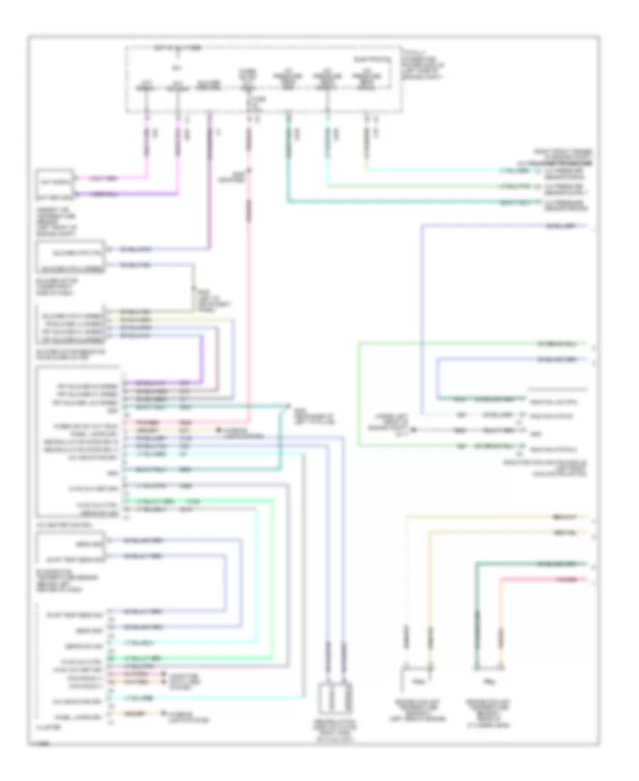
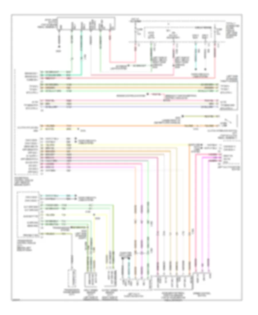
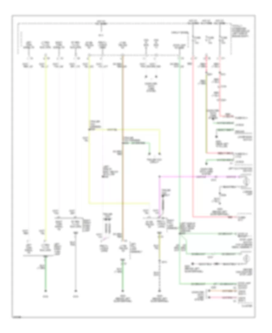
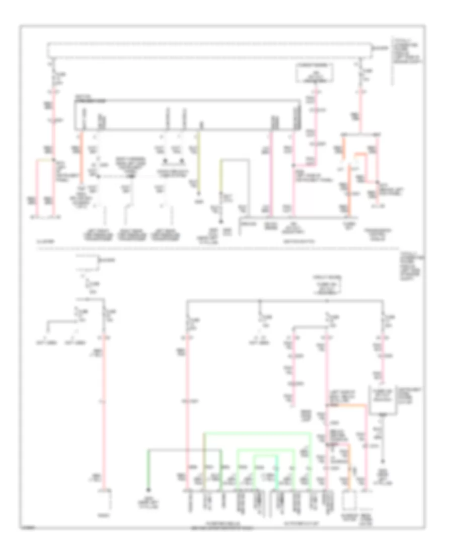
Automatic A/C Wiring Diagram (1 of 2) for Dodge Caliber Uptown 2010

List of elements for Automatic A/C Wiring Diagram (1 of 2) for Dodge Caliber Uptown 2010:
- (right front corner of engine compt) a/c pressure transducer
- A/c press
- A/c press sens fd
- A/c press sns
- A/c pressure sens rtn
- A/c pressure sig
- A417
- Aat rtn 1
- Aat sig
- Act com
- Act dr
- Act drv
- Act temp driv
- Ambient air temperature sensor (left front of engine compt)
- B(+)
- Blower motor (under right side of dash)
- C121
- C18
- C201
- C202
- C21
- C32
- C34
- C35
- C56
- C61
- C818
- C83
- C830
- C918
- Can bus (+)
- Can bus (-)
- Circuit board
- Computer data lines system
- D54
- D55
- Engine coolant temperature sensor 1 (rear of cylinder head)
- Engine coolant temperature sensor 2 (left side of engine)
- Evap sens rtn
- Evap sig
- Evap snse
- Evaporator temperature sensor (behind left center of dash)
- F929
- Front blower power motor module
- Front door mode actuator
- Ft blw fd
- Ft blw pwm ctrl
- Ft mode act drv
- Ft pwm blw
- Fuse 10a
- G103
- G200 (near left "a" pillar)
- G31
- G931
- Gnd
- Gnd ft pwm blw
- Hot at all times
- Hvac a/c heater control
- Ign r
- Ign r pre
- Infrared sensor
- Iod fd
- Left blend door actuator
- N210
- N23
- N24
- Pnk/red
- Rad fan lo rtn
- Rad fan mtr fd
- Rad fan mtr fd 2
- Radiator cooling fan module (left/right cooling fan motor)
- Rcrc act dr
- Recirculation door actuator (right side of hvac unit)
- Rtn
- S201
- S202
- S209
- Sig
- Snse fd
- Snsr ir rtn
- Snsr ir sig
- Totally integrated power module (left side of engine compt)
- Z134
- Z902
- Z903
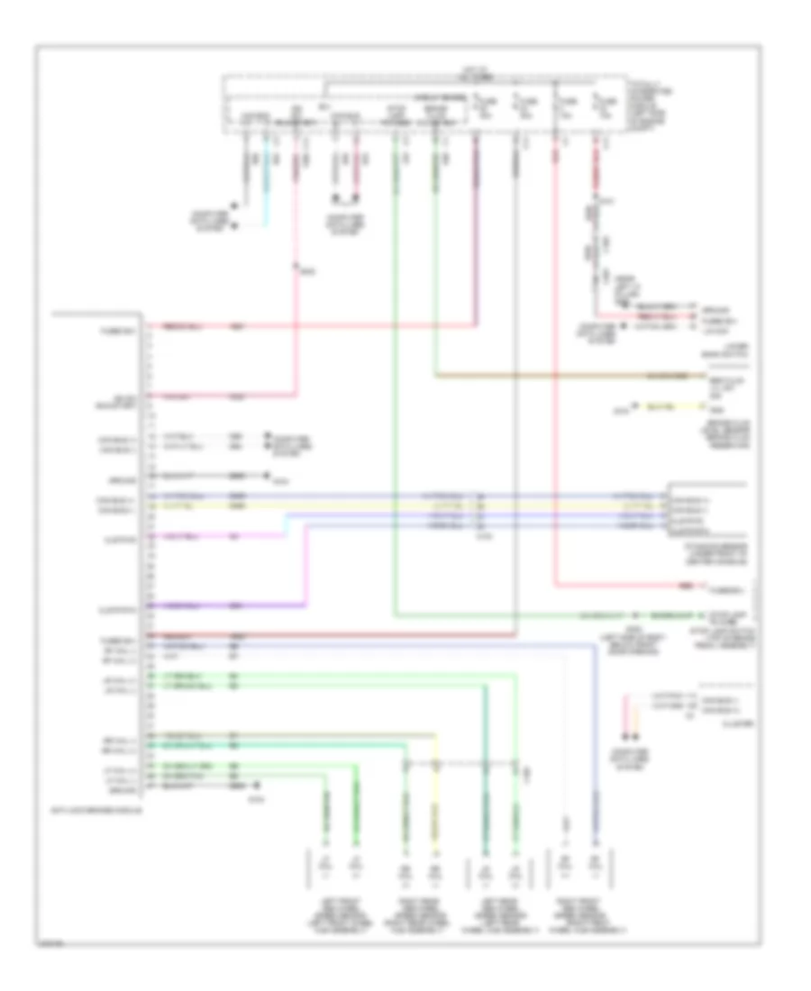
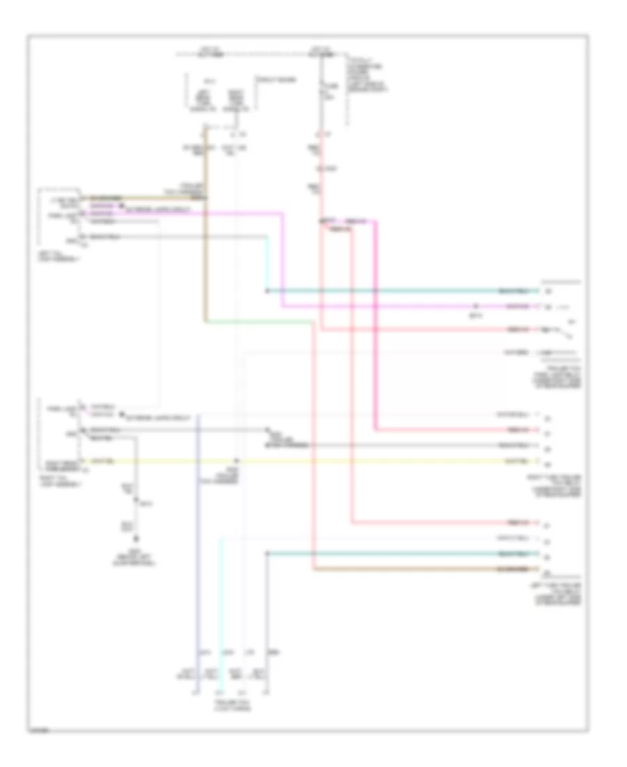
Automatic A/C Wiring Diagram (2 of 2) for Dodge Caliber Uptown 2010
List of elements for Automatic A/C Wiring Diagram (2 of 2) for Dodge Caliber Uptown 2010:
- (left front of engine compt, near impact sensor breakout) s033
- (left side of engine) s106
- (left side of engine) s107
- 87a
- A/c compressor ctrl
- A/c compressor solenoid (left front of engine)
- C105
- C11
- C27
- Circuit board
- Cmprsr
- Ctrl
- Ect 1 sig
- Ect 2 sig
- Engine controls system
- Fuse 10a
- Fuse 40a
- Fuse/relay block (left front corner of engine compt)
- G103
- G104
- Gnd
- Hot at all times
- K222
- K51
- K900
- K915
- Main relay
- Main rly ctrl
- N112
- N201
- Powertrain control module (left rear of engine compt)
- Rad fan hi spd sig
- Rad fan low spd sig
- Radiator fan series/ parallel relay
- Red
- S026 (left front of engine compt, near impact sensor breakout)
- S108
- S203
- Sens rtn
- Sens rtn3
- Totally integrated power module (left side of engine compt)
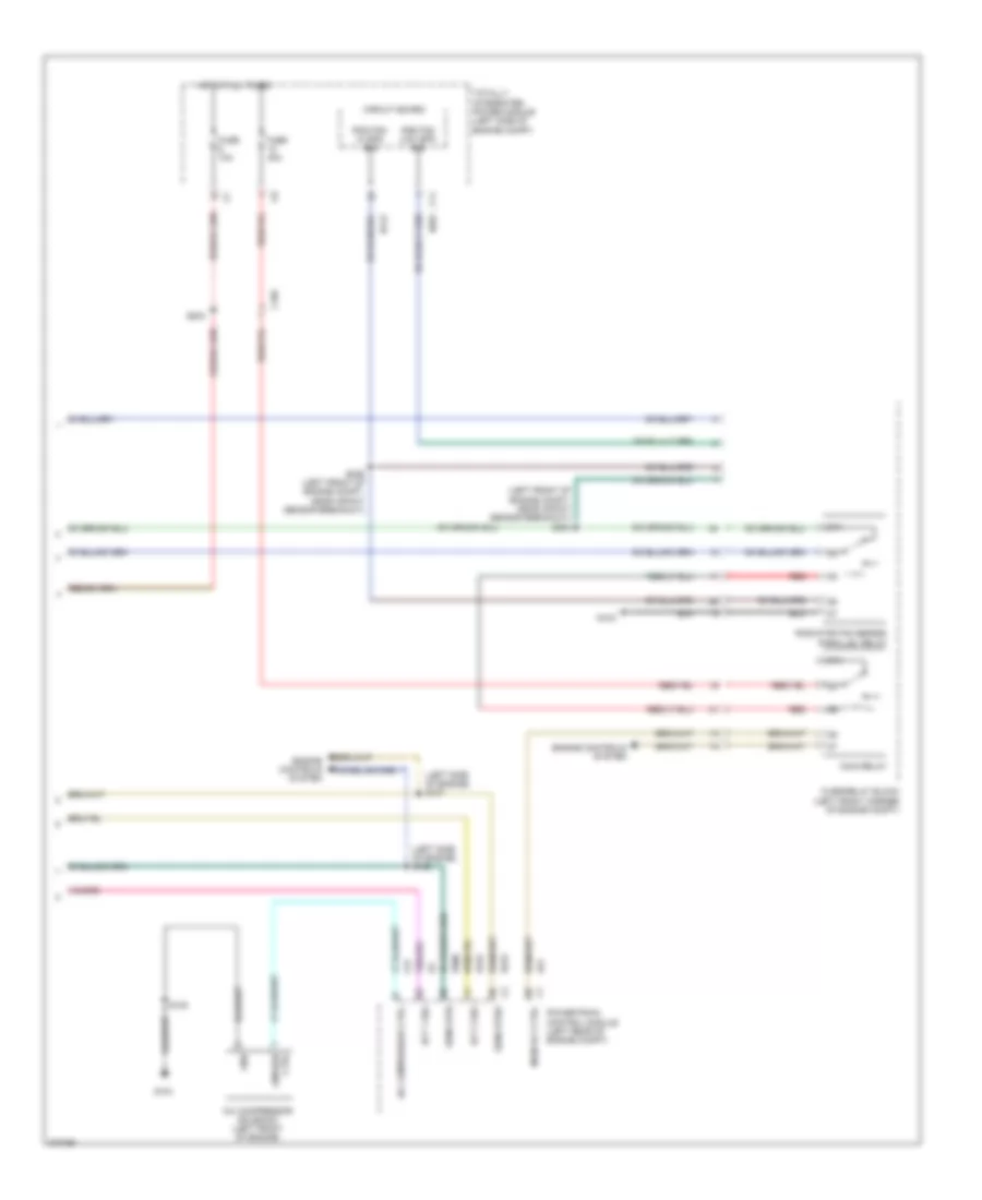
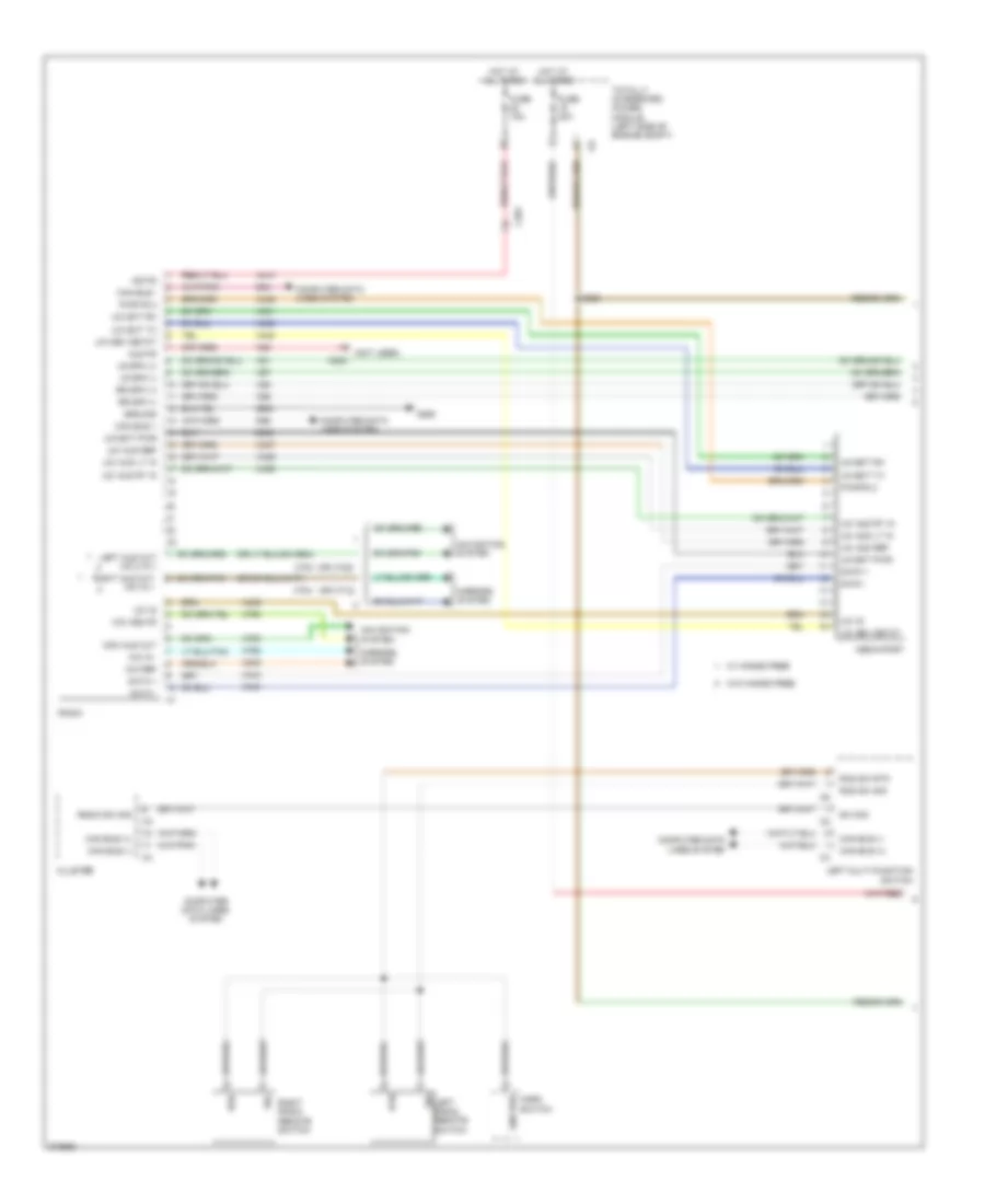
Manual A/C Wiring Diagram (1 of 2) for Dodge Caliber Uptown 2010
List of elements for Manual A/C Wiring Diagram (1 of 2) for Dodge Caliber Uptown 2010:
- (right front corner of engine compt) a/c pressure transducer
- (upper left front of engine compt) g111
- A/c heater control
- A/c indicator drv
- A/c pressure
- A/c pressure sens gnd
- A/c pressure sens signal
- Aat return
- Aat signal
- Ambient air temperature sensor (left front of engine compt)
- B(+)
- Blower motor (under right side of dash)
- Blower motor resistor (on blower motor)
- Blower mtr ctrl
- Blower mtr hi speed
- C105
- C132
- C18
- C215
- C32
- C71
- C72
- C73
- C818
- C918
- C955
- Can b bus (+)
- Can b bus (-)
- Cluster
- Computer data lines system
- Defog sw sig
- Driver a
- Driver b
- E12
- Electronics
- Engine coolant temperature sensor 1 (rear of cylinder head)
- Engine coolant temperature sensor 2 (left side of engine)
- Evap temp sens sig
- Evaporator temperature sensor (behind left center of dash)
- F929
- Fr blower lo speed
- Frt blower low speed
- Frt blower m1 speed
- Frt blower m2 speed
- Fuse 10a
- Fused ign sw out (run)
- G200 (near base of left "a" pillar)
- G31
- G931
- Gnd
- Hot at all times
- Hvac mux ctrl
- Hvac mux return
- Interior lights system
- N210
- N23
- N24
- Panel lamps drv
- Pnk/red
- Rad fan low rtn
- Rad fan mtr fd
- Rad fan mtr fd 2
- Radiator cooling fan module (left/right cooling fan motor)
- Recirculation door actuator (right side of hvac unit)
- Recirculation door drv a
- Recirculation door drv b
- S206 (left of instrument panel)
- S209 (compass)
- Sens gnd
- Sensor ground
- Sensor signal
- Totally integrated power module (left side of engine compt)
- Z902
- Z903
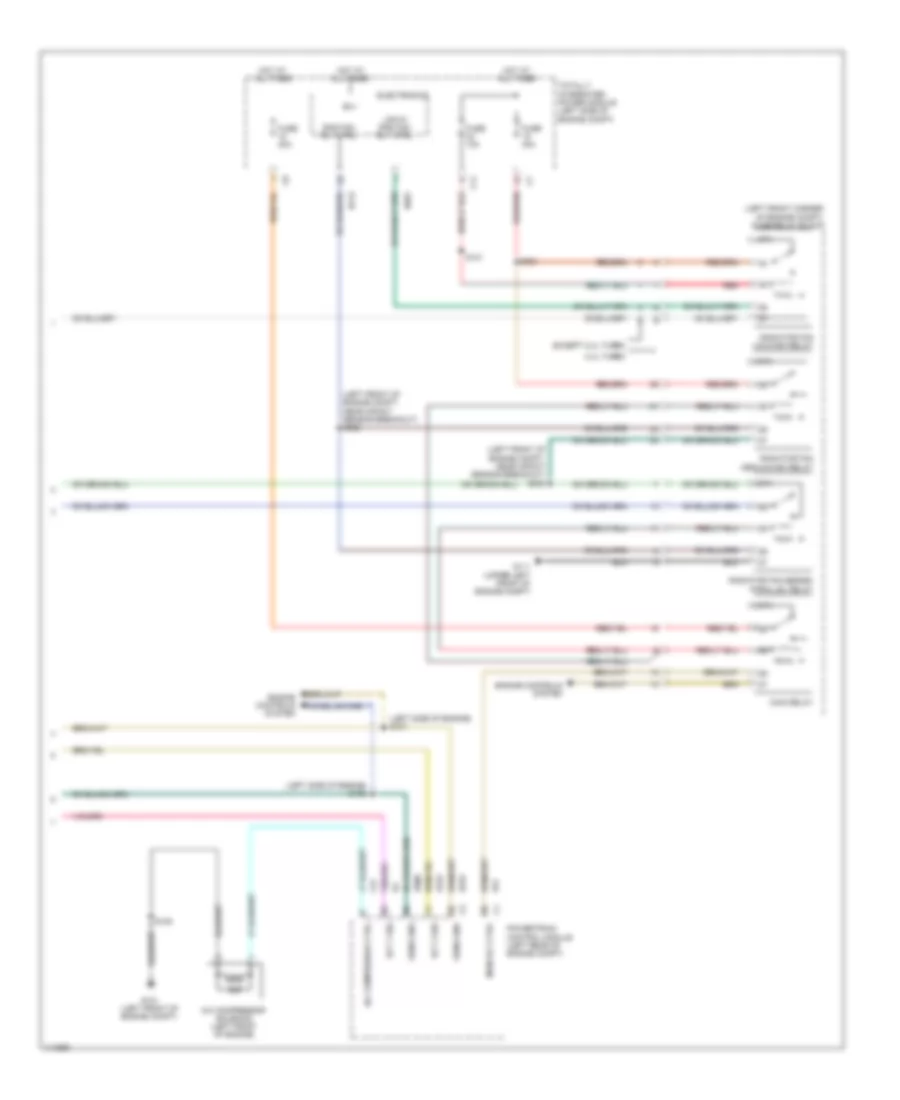
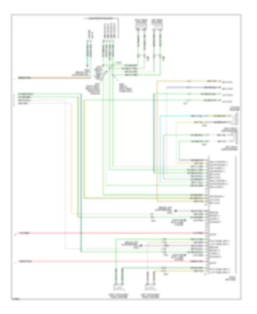
Manual A/C Wiring Diagram (2 of 2) for Dodge Caliber Uptown 2010
List of elements for Manual A/C Wiring Diagram (2 of 2) for Dodge Caliber Uptown 2010:
- (left front corner of engine compt) fuse/relay block
- (left front of engine compt, near impact sensor breakout) s026
- (left front of engine compt, near impact sensor breakout) s033
- (left side of engine) s106
- (left side of engine) s107
- 2.4l turbo
- 87a
- A/c compressor ctrl
- A/c compressor solenoid (left front of engine)
- B(+)
- C11
- C27
- Ect 1 sig
- Ect 2 sig
- Electronics
- Engine controls system
- Except 2.4l turbo
- Fuse 10a
- Fuse 40a
- G101 (left front of engine compt)
- G111 (upper left front of engine compt)
- Hot at all times
- K222
- K51
- K900
- K915
- Low/hi rad fan rly ctrl
- Main relay
- Main rly ctrl
- N112
- N201
- Powertrain control module (left rear of engine compt)
- Rad fan rly ctrl
- Radiator fan low/high relay
- Radiator fan medium/high relay
- Radiator fan series/ parallel relay
- Red
- S024
- S101
- S108
- Sens gnd
- Totally integrated power module (left side of engine compt)
ANTI-LOCK BRAKES
Anti-lock Brakes Wiring Diagram for Dodge Caliber Uptown 2010
List of elements for Anti-lock Brakes Wiring Diagram for Dodge Caliber Uptown 2010:
- (+)
- (-)
- (near left "a" pillar) g200
- (right front wheel hub assembly)
- A921
- A922
- Anti-lock brakes module
- B(+)
- B20
- Brake fluid level sensor (brake fluid reservoir)
- Brake fluid lvl sw sig
- Brk fluid lvl sw sig
- C103
- C11
- C201
- Can bus
- Can bus (+)
- Can bus (-)
- Circuit board
- Clstr fd
- Clstr rtn
- Cluster
- Computer data lines system
- D464
- D465
- D54
- D55
- D64
- D65
- Dynamics sensor (under front of center console)
- F202
- Fd cmbd
- Fuse 10a
- Fuse 30a
- Fuse 40a
- Fused b(+)
- G104
- G94
- Gnd
- Ground
- Hot at all times
- Ign sw (run-start)
- L53
- Left front abs wheel speed sensor (left front wheel hub assembly)
- Left rear abs wheel speed sensor (left rear wheel hub assembly)
- Lf whl
- Lf whl (+)
- Lf whl (-)
- Lin ccn
- Lower bank switch
- Lr whl
- Lr whl (+)
- Lr whl (-)
- Red
- Rf whl
- Rf whl (+)
- Rf whl (-)
- Right front abs wheel speed sensor
- Right rear abs wheel speed sensor (right rear wheel hub assembly)
- Rr whl
- Rr whl (+)
- Rr whl (-)
- S003
- S101
- S308 (left side of body, below front door opening)
- Stop lamp
- Stop lamp fm cmbd
- Stop lamp switch (top of brake pedal assembly)
- Totally integrated power module (left side of engine compt)
- Z909
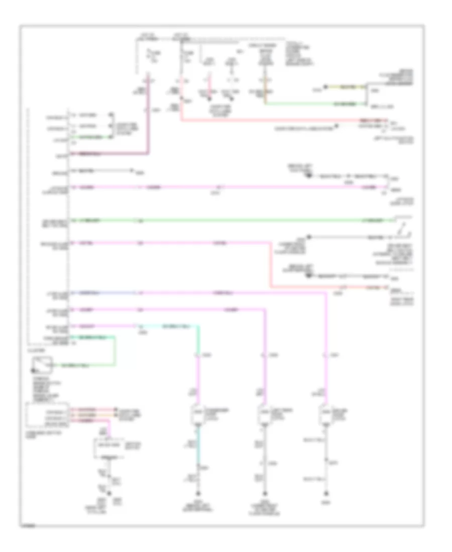
ANTI-THEFT
Anti-theft Wiring Diagram (1 of 2) for Dodge Caliber Uptown 2010
List of elements for Anti-theft Wiring Diagram (1 of 2) for Dodge Caliber Uptown 2010:
- (body harness, below left side instrument panel)
- (near left "a" pillar) g200
- A411
- B(+)
- Bk up lmps fd
- C103
- C11
- C200
- C301
- C303
- C308
- C310
- Can b bus (+)
- Can b bus (-)
- Can bus (+)
- Can bus (-)
- Circuit board
- Cluster
- Com in tire press lan
- Computer data lines system
- D508
- D54
- D55
- Dr lock
- Dr lock sw mux
- Driver door latch
- Driver window/ door lock switch
- Drv dr lock
- Drv dr unlock
- Exterior lights system
- F20
- Ft driv dr ajar sw in
- Ft pass dr ajar sw in
- Fused b(+)
- G20
- G250
- G300 (under front of center floor console)
- G303 (behind left quarterpanel)
- G305
- Gnd
- Ground
- Headlights system
- Horn drv
- Horns system
- Hot at all times
- Ign run st
- Ign sw out (run-start)
- Ign sw sen
- Ign sw sns
- Ignition switch
- Iod fd
- L217
- L53
- L70
- Left rear door latch
- Lf dr ajar sw sns
- Liftgate ajar sw in
- Lr dr ajar sw sig
- Lr dr ajar sw sns
- Lt prk/ tl/ lic run lamps
- Pass dr lk mux
- Pass dr unlock
- Passenger door latch
- Prk/ tl/ lic run lmps 2
- Rf dr ajar sw sns
- Rr dr ajar sw sig
- Rt prk/ tl/ lic run lamps
- S220 (left side of instrument panel)
- S310 (behind left kick panel)
- S311
- S351
- S370
- Stp ld fd
- Totally integrated power module (left side of engine compt)
- Ugdo enable ctrl
- Warning systems
- Wireless ignition node
- X21
- Z903
Anti-theft Wiring Diagram (2 of 2) for Dodge Caliber Uptown 2010
List of elements for Anti-theft Wiring Diagram (2 of 2) for Dodge Caliber Uptown 2010:
- A417
- Alarm on
- C201
- C202
- C306
- C309
- C310
- Can bus (+)
- Can bus (-)
- Circuit board
- Computer data lines system
- D54
- D55
- Dr lock
- Fuse 10a
- G104
- G303 (behind left quarterpanel)
- G38
- G70
- Gnd
- Ground
- Hood ajar switch (left rear of engine compt)
- Hot at all times
- Iod fd
- Liftgate ajar sw sns
- Liftgate door latch
- Pass dr lk mux
- Pass dr unlock
- Passenger window/ door lock switch
- Right rear door latch
- Rr dr ajar sw sns
- S201
- S203
- S355
- Totally integrated power module (left side of engine compt)
- Ugdo module
- Uhood sw sig
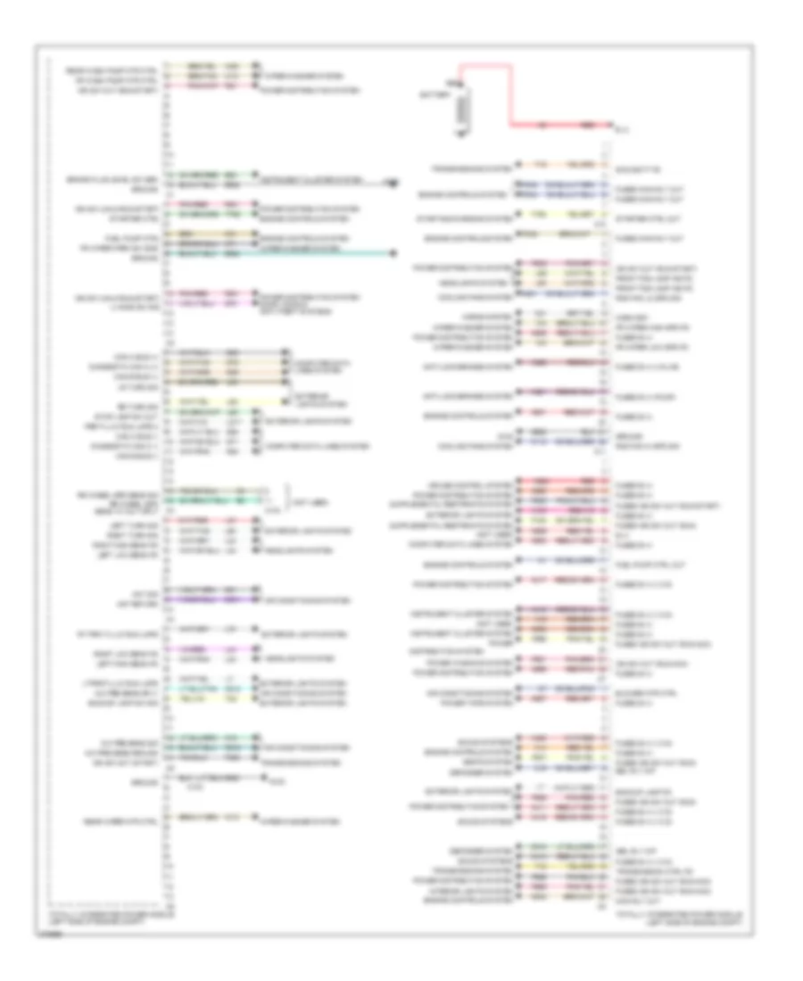
BODY CONTROL MODULES
Body Control Modules Wiring Diagram for Dodge Caliber Uptown 2010
List of elements for Body Control Modules Wiring Diagram for Dodge Caliber Uptown 2010:
- (not used)
- A/c pre sens ground
- A/c pre sens sig
- A/c pre sens sply
- A100
- A14
- A16
- A411
- A412
- A413
- A417
- A419
- A420
- A921
- A922
- A924
- A927
- A929
- A931
- A932
- A933
- A935
- A952
- A999
- Aat return
- Aat sig
- Air conditioning system
- Anti-lock brakes system
- B (+)
- B20
- Backup lamp fd
- Backup lamp sw sig
- Battery
- Blower mtr ctrl
- Brake fluid level sw sen
- C10
- C103
- C11
- C16
- C18
- C515
- C818
- C918
- Can b bus (+)
- Can b bus (-)
- Can c bus (+)
- Can c bus (-)
- Computer data lines system
- Cooling fans system
- Cruise control system
- D54
- D55
- D64
- D65
- D71
- D72
- Defogger system
- Diagnostic can c (+)
- Diagnostic can c (-)
- Distribution system
- Ebl rly o/p
- Engine controls system
- Exterior lights system
- F100
- F20
- F200
- F202
- F342
- F343
- F344
- F901
- F929
- F937
- F962
- F981
- F985
- F986
- F996
- Fr wash pump mtr ctrl
- Fr wiper high spd fd
- Fr wiper low spd fd
- Fr wiper park sw sns
- Front fog lamp ind fd
- Fuel pump ctrl
- Fuel pump ctrl out
- Fused b (+)
- Fused b (+) (i o d)
- Fused b (+) (pump)
- Fused b (+) (valve)
- Fused ign sw out (run)
- Fused ign sw out (run-acc)
- Fused ign sw out (run-start)
- Fused main rly out
- G102
- G31
- G70
- G931
- Ground
- Headlights system
- Horn drv
- Horns system
- Ign sw (unlk-run-start)
- Ign sw out (run-acc)
- Ign sw out (run-start)
- Ign sw out (start)
- Instrument cluster system
- Interior lights system
- K31
- K542
- L217
- L33
- L34
- L43
- L44
- L53
- L60
- L61
- L62
- L63
- L70
- L89
- L90
- Left high beam fd
- Left low beam fd
- Left turn sig
- Lr turn sig
- Ltprk/tl/lic run lmps
- Main rly out
- N112
- N201
- Pnk/red
- Power
- Power distribution system
- Power distribution system door locks & anti-theft systems
- Power tops system
- Power windows system
- Prk/tl/lic run lmps 2
- Rad fan hi spd sig
- Rad fan lo spd sig
- Rear wash pump mtr ctrl
- Rear wiper mtr ctrl
- Red
- Red/pnk
- Right high beam fd
- Right low beam fd
- Right turn sig
- Rr turn sig
- Rr wheel spd sens 12 volt sply
- Rr wheel spd sens sig
- Rt prk /tl/lic run lmps
- Seats system
- Sound systems
- Starter ctrl
- Starter ctrl out
- Starting/charging system
- Stop lamp sw out
- Swd batt fd
- T16
- T22
- T750
- T752
- Totally integrated power module (left side of engine compt)
- Transmission ctrl fd
- Transmissions system
- U hood sw sig
- W10
- W13
- W20
- Wiper/washer system
- X21
- Z932
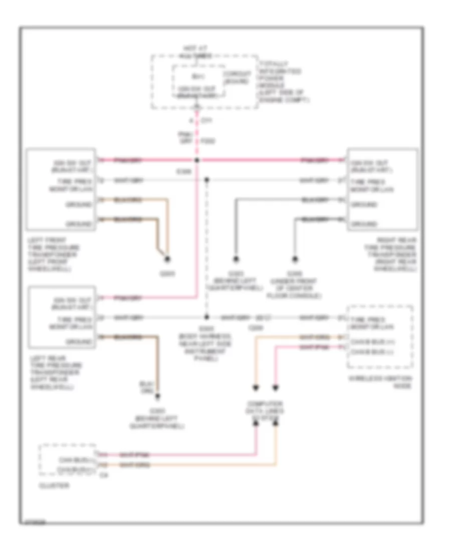
COMPUTER DATA LINES
Computer Data Lines Wiring Diagram for Dodge Caliber Uptown 2010
List of elements for Computer Data Lines Wiring Diagram for Dodge Caliber Uptown 2010:
- (body harness, below right side of instrument panel) s302
- (left of instrument panel) s205
- A933
- Anti-lock brakes module (left rear of engine compt)
- B(+)
- C103
- C200
- C201
- C305
- Can b bus (+)
- Can b bus (-)
- Can c bus (+)
- Can c bus (-)
- Circuit board
- Cluster
- Compass module
- D506
- D54
- D55
- D64
- D65
- D71
- D72
- Data link connector (under left end of dash)
- Diagnostic can c (+)
- Diagnostic can c (-)
- Fuse 10a
- G305
- Hands free module (if equipped) (under left end of dash)
- Heated seats module
- Hot at all times
- Hvac a/c heater control
- Left front tire pressure transponder (left front wheelwell)
- Left multi function switch
- Left rear tire pressure transponder (left rear wheelwell)
- Lin ccn
- Lin tire press
- Lower bank switch
- Occupant restraint controller module (under front of center console)
- Powertrain control module (left rear of engine compt)
- Radio
- Radio amplifier
- Right rear tire pressure transponder (right rear wheelwell)
- S1 d64
- S2 d65
- S207 (under center console)
- S303 (cvt) (front of left front wheelwell)
- S304 (cvt) (rear of left front fender)
- S305 (body harness, near left side instrument panel)
- S330
- S346
- Totally integrated power module (left side of engine compt)
- Transmission control module (cvt) (behind left side of dash)
- Wireless ignition node
- Z932
COOLING FAN
Cooling Fan Wiring Diagram for Dodge Caliber Uptown 2010
List of elements for Cooling Fan Wiring Diagram for Dodge Caliber Uptown 2010:
- (left front of engine compt, near impact sensor breakout) s033
- (left side of engine) s106
- (left side of engine) s107
- (left/right
- 87a
- A/c compressor ctrl
- A/c compressor solenoid (left front of engine)
- C105
- C11
- C27
- Circuit board
- Cmprsr
- Cooling fan motor)
- Ctrl
- Ect 1 sig
- Ect 2 sig
- Engine controls system
- Engine coolant temperature sensor 1 (rear of cylinder head)
- Engine coolant temperature sensor 2 (left side of engine)
- Fuse 40a
- Fuse/relay block (left front corner of engine compt)
- G103
- G104
- Gnd
- Hot at all times
- K222
- K51
- K900
- K915
- Main relay
- Main rly ctrl
- N112
- N201
- N210
- N23
- N24
- Powertrain control module (left rear of engine compt)
- Rad fan hi spd sig
- Rad fan lo rtn
- Rad fan lo spd sig
- Rad fan mtr fd
- Rad fan mtr fd 2
- Radiator cooling fan module
- Radiator fan series/ parallel relay
- Red
- S026 (left front of engine compt, near impact sensor breakout)
- S108
- Sens rtn
- Sens rtn 3
- Totally integrated power module (left side of engine compt)
- Z902
CRUISE CONTROL
Cruise Control Wiring Diagram for Dodge Caliber Uptown 2010
List of elements for Cruise Control Wiring Diagram for Dodge Caliber Uptown 2010:
- (breakout for powertrain control module c2) s102
- (left side of body, below front door opening) s306
- (left side of body, below front door opening) s308
- (left side of engine) throttle body
- 5v fd
- A931
- Accelerator pedal position sensor (top of accelerator pedal bracket)
- App sens rtn
- App sens rtn 2
- App sig 1
- App sig 2
- B(+)
- B15
- B16
- Batt fd
- Brake sig 1
- Brake sig 2
- Bus +
- Bus -
- C103
- C104
- C106
- C11
- C201
- Can
- Can bus (+)
- Can bus (-)
- Can c bus +
- Can c bus -
- Circuit board
- Clutch interlock switch (m/t) (top of clutch pedal assembly)
- Clutch intlck sig
- Computer data lines system
- D64
- D65
- Engine controls system
- Etc mtr (+)
- Etc mtr (-)
- Exterior lights system
- F202
- F855
- F856
- Fuse 10a
- Fused b(+)
- G103
- G300 (under front of center floor console)
- G305
- Gnd
- Hot at all times
- Ign sw out (run -start)
- Ign sw out (run-start)
- In spd sig
- Input speed sensor (cvt) (left side of transmission)
- Inter- lock
- K122
- K124
- K126
- K167
- K22
- K23
- K29
- K400
- K858
- K922
- L53
- Lamp sw stop
- Left multi function switch
- Left multi-function switch
- Out spd gnd
- Out spd rtn
- Out spd sig
- Output speed sensor (cvt) (right side of transmission)
- Powertrain control module (left rear of engine compt)
- Prk/neut sig
- Rdnt fd
- Red
- Rtn
- Rtn app sens
- S/c sig 1
- S/c sig 2
- S/c sw rtn
- S322
- S335 (left side of engine compt)
- Sens gnd
- Sens rtn
- Sens sec fd
- Sig 1
- Sig 2
- Speed control switch
- Stop lamp sw fd
- Stop lamp switch (top of brake pedal assembly)
- Sw fd
- Sw rtn
- Swd batt fd
- T13
- T130
- T14
- T141
- T16
- T41
- T52
- Totally integrated power module (left side of engine compt)
- Tp sens gnd
- Tp sens rtn
- Tp sig 1
- Tp sig 2
- Transmission control module (cvt) (behind left side of dash)
- Transmission range sensor (cvt)
- Transmissions system
- V71
- V72
- V937
- Z932
DEFOGGERS
Defoggers Wiring Diagram for Dodge Caliber Uptown 2010
List of elements for Defoggers Wiring Diagram for Dodge Caliber Uptown 2010:
- A/c heater control
- B (+)
- C301
- C303
- C311
- Can bus (+)
- Can bus (-)
- Circuit board
- Computer data lines system
- D54
- D55
- Defog ctrl out
- Driver outside rearview mirror
- Electric heated backlite
- Fuse 10a
- G303 (behind left quarter panel)
- G305
- Gnd
- Hot at all times
- Ign r
- Ign r pre
- Passenger outside rearview mirror
- Pnk/ red
- Rear window defogger control output
- S209
- S351
- S355
- S370
- Totally integrated power module (left side of engine compt)
ENGINE PERFORMANCE
2.0L
2.0L, Engine Performance Wiring Diagram (1 of 5) for Dodge Caliber Uptown 2010
List of elements for 2.0L, Engine Performance Wiring Diagram (1 of 5) for Dodge Caliber Uptown 2010:
- (center front of engine compt, above left radiator fan)
- (left side of body, below front door opening)
- (under front of center floor console) g300
- A804
- A931
- App sensor ground 1
- App sensor ground 2
- App sig 2
- App signal 1
- B(+)
- B15
- B16
- Brake signal 1
- Brake signal 2
- C10
- C100
- C103
- C105
- C11
- Can c bus (+)
- Can c bus (-)
- Circuit board
- Clutch interlock signal
- Clutch interlock switch (m/t) (top of clutch pedal assembly)
- Computer data lines system
- Control fuel pump
- Control starter
- D64
- D65
- Enable
- Esm signal
- Evap purge control
- Evap purge return
- Evap purge solenoid (lower left rear of engine compt)
- Evap system monitor switch (near evap canister)
- Exterior lights system
- F202
- F342
- F856
- F963
- Fuel pump control
- Fuse 10a
- Fuse 15a
- Fuse 30a
- Fuse 40a
- Fused b(+)
- Fused main relay out
- G103
- Gen sense
- Ground
- Hot at all times
- Ign sw out (run-start)
- K107
- K141
- K167
- K23
- K29
- K299
- K31
- K400
- K51
- K52
- K70
- K858
- K904
- L53
- Main relay control
- O2 1/2 heater control
- O2 1/2 return
- O2 1/2 signal
- Powertrain control module (left rear of engine compt)
- Red
- S/c signal 1
- S/c signal 2
- S/c sw ground
- S003
- S007 (left side of engine compt, in pcm c1 breakout)
- S306 (left side of body, below front door opening)
- S308
- Signal esm
- Start
- Start enable
- Starter control
- Starting/charging system
- Stop lamp sw out
- T141
- T752
- Totally integrated power module (left side of engine compt)
- Transmission range sensor
- V71
- V72
- V937
- Z932
2.0L, Engine Performance Wiring Diagram (2 of 5) for Dodge Caliber Uptown 2010
List of elements for 2.0L, Engine Performance Wiring Diagram (2 of 5) for Dodge Caliber Uptown 2010:
- (behind left kick panel) (except srt) g301 (behind left quarterpanel) (srt) g303
- (right rear of engine) camshaft position solenoid 1/2
- (top left side of engine) fuel injectors
- 5v sply
- 87a
- Accelerator pedal position sensor (top of accelerator pedal bracket)
- App sens gnd 1
- App sens gnd 2
- App sig 1
- App sig 2
- Brake sig 1
- Brake sig 2
- C103
- C104
- C201
- Fuse/relay block (left front corner of engine compt)
- Fused b(+)
- G102
- Gnd
- Ground
- Ign sw out (run- start)
- Left multi-function switch
- Main relay
- Oxygen sensor 1/2 (exhaust system)
- Radiator fan series/ parallel relay
- Red
- S/c
- S/c sw
- S103
- Signal 1
- Signal 2
- Stop lamp switch (top of brake pedal assembly)
- Stop lp
- Sw out
2.0L, Engine Performance Wiring Diagram (3 of 5) for Dodge Caliber Uptown 2010
List of elements for 2.0L, Engine Performance Wiring Diagram (3 of 5) for Dodge Caliber Uptown 2010:
- (left front of engine) camshaft position solenoid 1/1
- (near breakout for ignition coil 4) s104
- (top right side of engine) ignition coils
- A/c compressor control
- A/c compressor solenoid (left front of engine)
- C27
- Cmp 1/2 signal
- Ect 2 signal
- Eot signal
- Etc motor (+)
- Etc motor (-)
- F855
- G104
- G24
- Iat signal
- Ignition capacitor (right rear of engine)
- Injector 1 control
- Injector 2 control
- Injector 3 control
- Injector 4 control
- K11
- K12
- K124
- K126
- K13
- K14
- K21
- K222
- K41
- K441
- K601
- K857
- K902
- K99
- Mfv control
- O2 1/1 heater control
- O2 1/1 return
- O2 1/1 signal
- Powertrain control module (left rear of engine compt)
- S108
2.0L, Engine Performance Wiring Diagram (4 of 5) for Dodge Caliber Uptown 2010
List of elements for 2.0L, Engine Performance Wiring Diagram (4 of 5) for Dodge Caliber Uptown 2010:
- (behind left center of dash) evaporator temperature sensor
- (brake fluid reservoir) brake fluid level sensor
- (left side of engine) s107
- (top left side of fuel tank) fuel pump module
- A/c heater control
- Aat
- Aat signal
- Ambient air temperature sensor (left front of engine compt)
- B20
- Brk fluid lvl sw sns
- C200
- Camshaft position sensor 1/2 (right rear of engine)
- Can b bus (+)
- Can b bus (-)
- Can bus (+)
- Can bus (-)
- Circuit board
- Ckp signal
- Cluster
- Cmp 1/2 signal
- Computer data lines system
- Control out fuel pump
- Crankshaft position sensor (right rear of engine)
- Engine coolant temperature sensor 2 (left side of engine)
- Evap rtn
- Evap sig
- Evap temp sensor signal
- Fuel lvl signal 1
- Fuel pump control out
- G104
- G300 (under front of center floor console)
- G31
- G931
- Ground
- Ground c1
- Intake air temperature sensor (rear of engine)
- Oil temperature sensor (front of engine)
- Oxygen sensor 1/1 (right rear of engine, in exhaust)
- Return
- Return aat
- S102 (breakout for powertrain control module c2)
- S108
- Sensor ground
- Signal 1 fuel lvl
- Totally integrated power module (left side of engine compt)
- Z906
2.0L, Engine Performance Wiring Diagram (5 of 5) for Dodge Caliber Uptown 2010
List of elements for 2.0L, Engine Performance Wiring Diagram (5 of 5) for Dodge Caliber Uptown 2010:
- (left side of engine) knock sensor
- (left side of engine) throttle body
- (not used)
- C100
- Camshaft position sensor 1/1 (left rear of engine)
- Ckp signal
- Cmp 1/1 control
- Cmp 1/1 signal
- Cmp 1/2 control
- Coil 1 control
- Coil 2 control
- Coil 3 control
- Coil 4 control
- Ect 1 signal
- Engine coolant temperature sensor 1 (rear of cylinder head)
- Engine oil pressure switch (left side of engine)
- Eop signal
- Etc motor (+)
- Etc motor (-)
- G104
- Gen field control
- Ground
- K122
- K15
- K17
- K18
- K19
- K20
- K22
- K24
- K276
- K42
- K44
- K602
- K76
- K900
- K915
- K922
- K942
- Ks return
- Ks signal
- Manifold flow valve (left rear of engine)
- Map sensor (left front of engine)
- Map signal
- Mfv control
- Mfv signal
- Oil temp sens sig
- Powertrain control module (left rear of engine compt)
- S105 (left front of engine)
- S106 (left side of engine)
- S108
- Sensor ground
- Starting/ charging system
- Tp sensor ground
- Tp signal 1
- Tp signal 2
2.4L
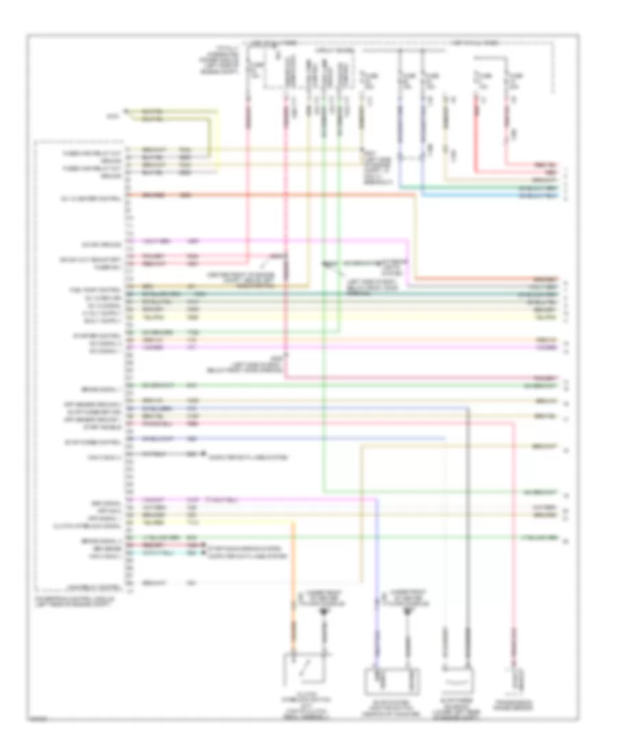
2.4L, Engine Performance Wiring Diagram (1 of 5) for Dodge Caliber Uptown 2010
List of elements for 2.4L, Engine Performance Wiring Diagram (1 of 5) for Dodge Caliber Uptown 2010:
- (center front of engine compt, above left radiator fan)
- (left side of body, below front door opening)
- (under front of center floor console) g300
- A804
- A931
- App sensor ground 1
- App sensor ground 2
- App sig 2
- App signal 1
- B(+)
- B15
- B16
- Brake signal 1
- Brake signal 2
- C10
- C100
- C103
- C105
- C11
- Can c bus (+)
- Can c bus (-)
- Circuit board
- Clutch interlock signal
- Clutch interlock switch (m/t) (top of clutch pedal assembly)
- Computer data lines system
- Control fuel pump
- Control starter
- D64
- D65
- Enable
- Esm signal
- Evap purge control
- Evap purge return
- Evap purge solenoid (lower left rear of engine compt)
- Evap system monitor switch (near evap canister)
- Exterior lights system
- F202
- F342
- F856
- F963
- Fuel pump control
- Fuse 10a
- Fuse 15a
- Fuse 30a
- Fuse 40a
- Fused b(+)
- Fused main relay out
- G103
- Gen sense
- Ground
- Hot at all times
- Ign sw out (run-start)
- K107
- K141
- K167
- K23
- K29
- K299
- K31
- K400
- K51
- K52
- K70
- K858
- K904
- L53
- Main relay control
- O2 1/2 heater control
- O2 1/2 return
- O2 1/2 signal
- Powertrain control module (left rear of engine compt)
- Red
- S/c signal 1
- S/c signal 2
- S/c sw ground
- S003
- S007 (left side of engine compt, in pcm c1 breakout)
- S306 (left side of body, below front door opening)
- S308
- Signal esm
- Start
- Start enable
- Starter control
- Starting/charging system
- Stop lamp sw out
- T141
- T752
- Totally integrated power module (left side of engine compt)
- Transmission range sensor
- V71
- V72
- V937
- Z932
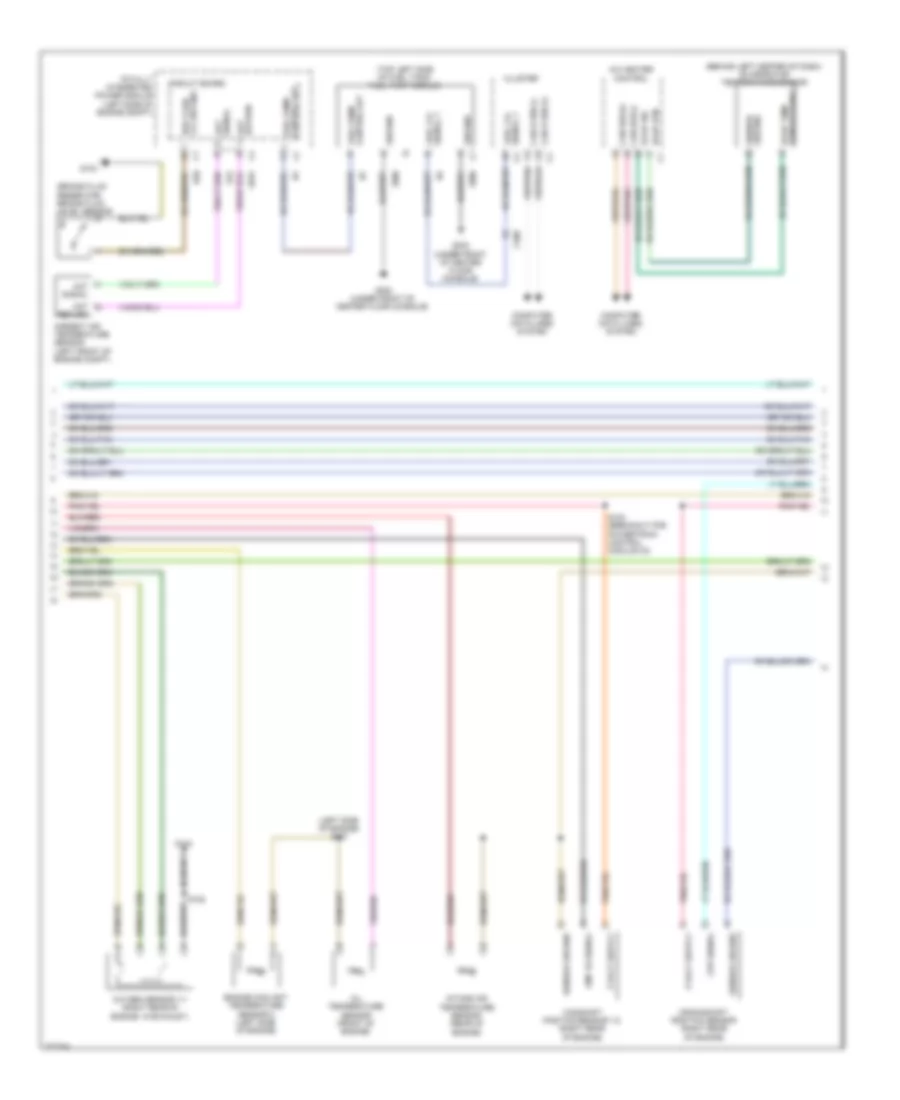
2.4L, Engine Performance Wiring Diagram (2 of 5) for Dodge Caliber Uptown 2010
List of elements for 2.4L, Engine Performance Wiring Diagram (2 of 5) for Dodge Caliber Uptown 2010:
- (behind left kick panel) (except srt) g301 (behind left quarterpanel) (srt) g303
- (right rear of engine) camshaft position solenoid 1/2
- (top left side of engine) fuel injectors
- 5v sply
- 87a
- Accelerator pedal position sensor (top of accelerator pedal bracket)
- App sens gnd 1
- App sens gnd 2
- App sig 1
- App sig 2
- Brake sig 1
- Brake sig 2
- C103
- C104
- C201
- Fuse/relay block (left front corner of engine compt)
- Fused b(+)
- G102
- Gnd
- Ground
- Ign sw out (run- start)
- Left multi-function switch
- Main relay
- Oxygen sensor 1/2 (exhaust system)
- Radiator fan series/ parallel relay
- Red
- S/c
- S/c sw
- S103
- Signal 1
- Signal 2
- Stop lamp switch (top of brake pedal assembly)
- Stop lp
- Sw out
2.4L, Engine Performance Wiring Diagram (3 of 5) for Dodge Caliber Uptown 2010
List of elements for 2.4L, Engine Performance Wiring Diagram (3 of 5) for Dodge Caliber Uptown 2010:
- (left front of engine) camshaft position solenoid 1/1
- (near breakout for ignition coil 4) s104
- (top right side of engine) ignition coils
- A/c compressor control
- A/c compressor solenoid (left front of engine)
- C27
- Cmp 1/2 signal
- Ect 2 signal
- Eot signal
- Etc motor (+)
- Etc motor (-)
- F855
- G104
- G24
- Iat signal
- Ignition capacitor (right rear of engine)
- Injector 1 control
- Injector 2 control
- Injector 3 control
- Injector 4 control
- K11
- K12
- K124
- K126
- K13
- K14
- K21
- K222
- K41
- K441
- K601
- K857
- K902
- K99
- Mfv control
- O2 1/1 heater control
- O2 1/1 return
- O2 1/1 signal
- Powertrain control module (left rear of engine compt)
- S108
2.4L, Engine Performance Wiring Diagram (4 of 5) for Dodge Caliber Uptown 2010
List of elements for 2.4L, Engine Performance Wiring Diagram (4 of 5) for Dodge Caliber Uptown 2010:
- (behind left center of dash) evaporator temperature sensor
- (brake fluid reservoir) brake fluid level sensor
- (left side of engine) s107
- (top left side of fuel tank) fuel pump module
- A/c heater control
- Aat
- Aat signal
- Ambient air temperature sensor (left front of engine compt)
- B20
- Brk fluid lvl sw sns
- C200
- Camshaft position sensor 1/2 (right rear of engine)
- Can b bus (+)
- Can b bus (-)
- Can bus (+)
- Can bus (-)
- Circuit board
- Ckp signal
- Cluster
- Cmp 1/2 signal
- Computer data lines system
- Control out fuel pump
- Crankshaft position sensor (right rear of engine)
- Engine coolant temperature sensor 2 (left side of engine)
- Evap rtn
- Evap sig
- Evap temp sensor signal
- Fuel lvl signal 1
- Fuel pump control out
- G104
- G300 (under front of center floor console)
- G31
- G931
- Ground
- Ground c1
- Intake air temperature sensor (rear of engine)
- Oil temperature sensor (front of engine)
- Oxygen sensor 1/1 (right rear of engine, in exhaust)
- Return
- Return aat
- S102 (breakout for powertrain control module c2)
- S108
- Sensor ground
- Signal 1 fuel lvl
- Totally integrated power module (left side of engine compt)
- Z906
2.4L, Engine Performance Wiring Diagram (5 of 5) for Dodge Caliber Uptown 2010
List of elements for 2.4L, Engine Performance Wiring Diagram (5 of 5) for Dodge Caliber Uptown 2010:
- (left side of engine) knock sensor
- (left side of engine) throttle body
- (not used)
- C100
- Camshaft position sensor 1/1 (left rear of engine)
- Ckp signal
- Cmp 1/1 control
- Cmp 1/1 signal
- Cmp 1/2 control
- Coil 1 control
- Coil 2 control
- Coil 3 control
- Coil 4 control
- Ect 1 signal
- Engine coolant temperature sensor 1 (rear of cylinder head)
- Engine oil pressure switch (left side of engine)
- Eop signal
- Etc motor (+)
- Etc motor (-)
- G104
- Gen field control
- Ground
- K122
- K15
- K17
- K18
- K19
- K20
- K22
- K24
- K276
- K42
- K44
- K602
- K76
- K900
- K915
- K922
- K942
- Ks return
- Ks signal
- Manifold flow valve (left rear of engine)
- Map sensor (left front of engine)
- Map signal
- Mfv control
- Mfv signal
- Oil temp sens sig
- Powertrain control module (left rear of engine compt)
- S105 (left front of engine)
- S106 (left side of engine)
- S108
- Sensor ground
- Starting/ charging system
- Tp sensor ground
- Tp signal 1
- Tp signal 2
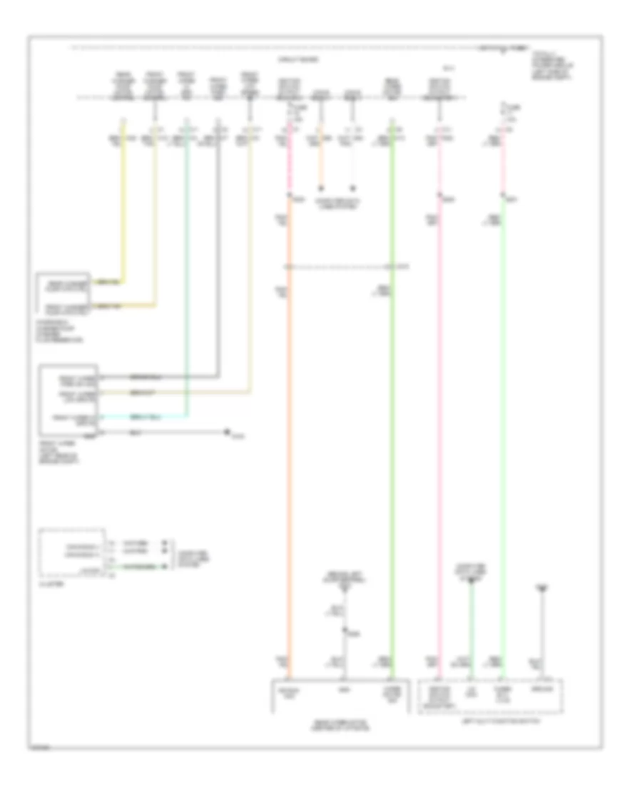
EXTERIOR LIGHTS
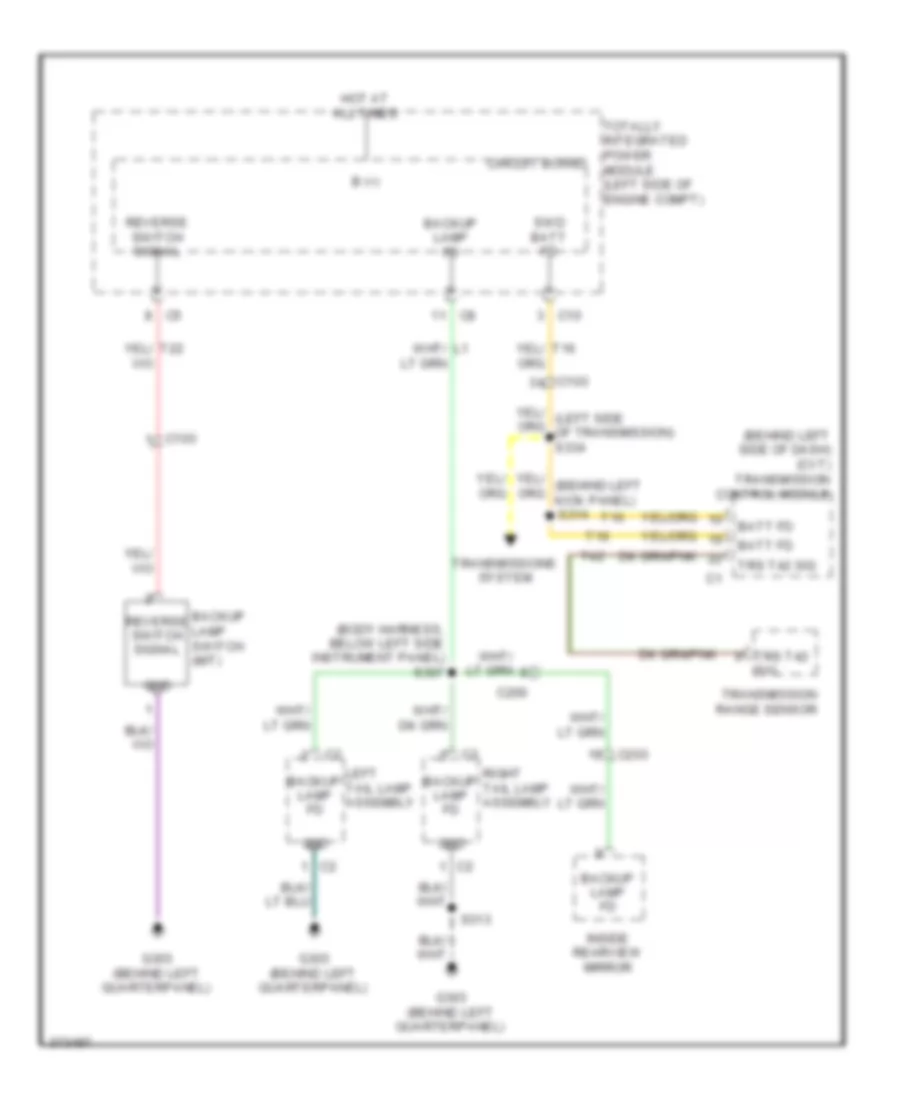
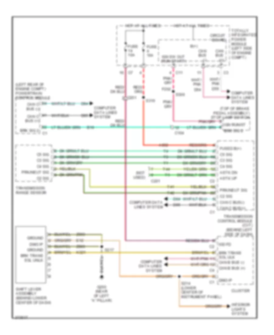
Backup Lamps Wiring Diagram for Dodge Caliber Uptown 2010
List of elements for Backup Lamps Wiring Diagram for Dodge Caliber Uptown 2010:
- (behind left side of dash) (cvt) transmission control module
- (body harness, below left side instrument panel) s307
- B (+)
- Backup lamp fd
- Backup lamp switch (m/t)
- Batt fd
- C10
- C103
- C200
- C203
- Circuit board
- G303 (behind left quarterpanel)
- Gnd
- Hot at all times
- Inside rearview mirror
- Left tail lamp assembly
- Reverse switch signal
- Right tail lamp assembly
- S313
- S314
- Sig
- Swd batt fd
- T16
- T42
- Totally integrated power module (left side of engine compt)
- Transmission range sensor
- Transmissions system
- Trs t42
- Trs t42 sig
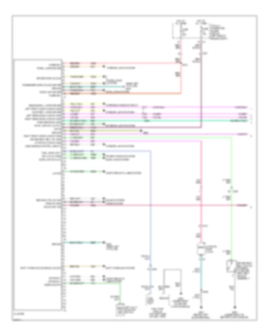
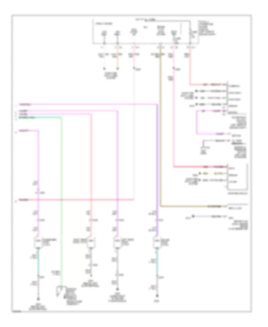
Exterior Lamps Wiring Diagram for Dodge Caliber Uptown 2010
List of elements for Exterior Lamps Wiring Diagram for Dodge Caliber Uptown 2010:
- (left side of body, below "b" pillar) s326
- (left side of body, below front door opening) s308
- (trailer tow harness) s325
- (trailer tow harness) s339
- B (+)
- C103
- C11
- C200
- C201
- C310
- Can b bus (+)
- Can b bus (-)
- Can b bus (-) c4
- Center high mounted stop lamp
- Circuit board
- Cluster
- Computer data lines system
- D54
- D55
- Fuse 10a
- Fused b (+)
- Fused b (+) (i o d)
- G102
- G104
- G200 (near left "a" pillar)
- G303 (behind left quarterpanel)
- Gnd
- Ground
- Hot at all times
- L217
- L53
- L60
- L61
- L62
- L63
- L70
- Left front park/ turn lamp
- Left multi-function switch
- Left tail/ lamp assembly
- Left turn signal fd
- License lamp
- Lin bus
- Lower bank
- Lt prk/ tl/lic/ run lmps
- Lt rr trn sig fd
- Prk/tl/ lic/run lmps2
- Red
- Right front park/ turn lamp
- Right tail/ lamp assembly
- Right turn signal fd
- Rt prk/ tl/lic/ run lmps
- Rt rr trn sig fd
- S101
- S201
- S313
- S355
- Stop lamp fd cmbd
- Stop lamp switch (top of brake pedal assembly)
- Stop lp
- Sw out
- Switch
- Switch output
- Totally integrated power module (left side of engine compt)
- Tow circuit
- Trailer
- Trailer tow circuit
Trailer Tow Wiring Diagram for Dodge Caliber Uptown 2010
List of elements for Trailer Tow Wiring Diagram for Dodge Caliber Uptown 2010:
- (trailer tow harness) s339
- B (+)
- C323
- Circuit board
- Exterior lamps circuit
- Fuse 20a
- G303 (behind left quarterpanel)
- Gnd
- Hot at all times
- L614
- L615
- L76
- Left rear turn signal fd
- Left tail lamp assembly
- Left turn trailer tow relay (under left side of rear bumper)
- Lt rr trn sig fd
- Park lamp fd
- Red
- Right rear turn sig fd c3
- Right rear turn signal fd
- Right tail lamp assembly
- Right turn trailer tow relay (under right side of rear bumper)
- S313
- S318
- S319
- S325 (trailer tow harness)
- S342 (trailer tow harness)
- Totally integrated power module (left side of engine compt)
- Trailer tow 4 way wiring
- Trailer tow park lamp relay (under right side of rear bumper)
- Z960
GROUND DISTRIBUTION
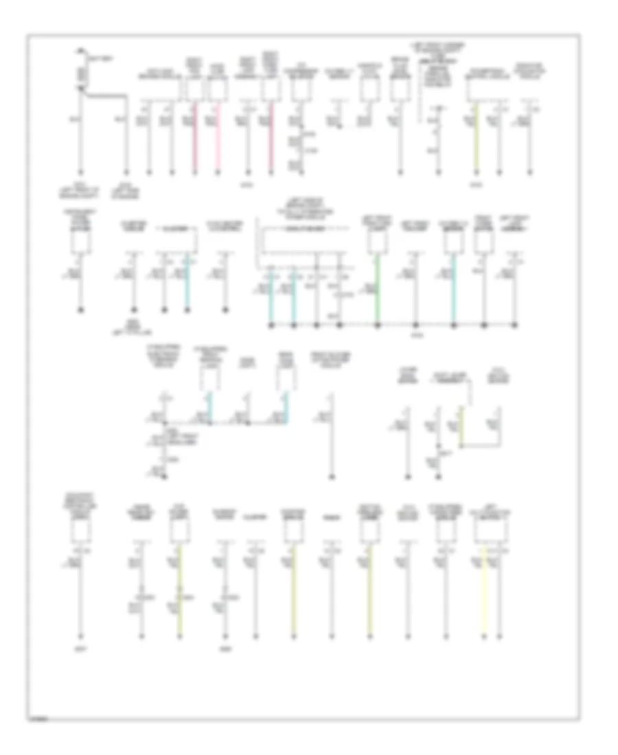
Ground Distribution Wiring Diagram (1 of 2) for Dodge Caliber Uptown 2010
List of elements for Ground Distribution Wiring Diagram (1 of 2) for Dodge Caliber Uptown 2010:
- (2.0l) ignition switch
- (2.4l)
- (if equipped)
- (if equipped) front reading lamp
- (if equipped) hands free module
- (left front corner of engine compt) fuse/ relay block
- (left side of engine compt) totally integrated power module
- A/c compressor solenoid
- Anti-lock brakes module
- Battery
- Brake fluid level sensor
- C100
- C103
- C11
- C202
- C203
- C204
- Circuit board
- Cluster
- Compass module
- Cup holder lamp
- Dome lamp 2
- Electronic overhead module
- Front blower motor power module
- Front wiper motor
- G100 (left side of engine)
- G101 (left front of engine compt)
- G102
- G103
- G104
- G200 (near left "a" pillar)
- G250
- G307
- Hood ajar switch
- Hvac heater a/c control
- Ignition switch
- Ignition wireless node
- Inside rearview mirror
- Instrument panel power outlet
- Inverter module
- Left front fog lamp
- Left front lamp assembly
- Left front park/turn lamp
- Left multi-function switch
- Lower bank switch
- Manifold flow valve
- Occupant restraint controller module (orc)
- Oxygen 1/1 sensor
- Oxygen 1/2 sensor
- Powertrain control module
- Radiator cooling fan module
- Radio
- Rear dome lamp
- Right front fog lamp
- Right front lamp assembly
- Right front park/ turn lamp
- S217
- Series/ parallel radiator fan relay
- Shift lever assembly
- Sunroof motor
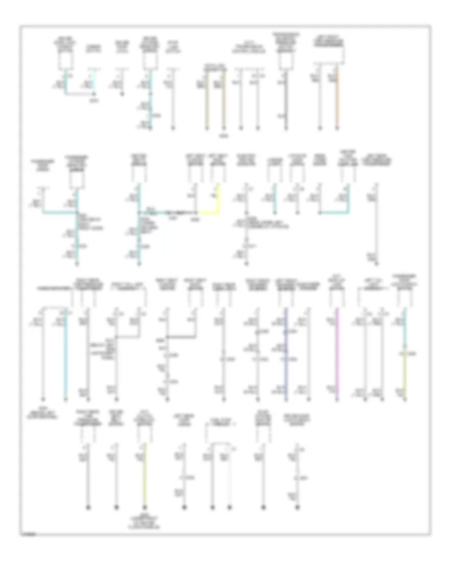
Ground Distribution Wiring Diagram (2 of 2) for Dodge Caliber Uptown 2010
List of elements for Ground Distribution Wiring Diagram (2 of 2) for Dodge Caliber Uptown 2010:
- (cvt) transmission control module
- (m/t) back up lamp switch
- (m/t) clutch interlock switch
- C301
- C302
- C303
- C304
- C305
- C306
- C308
- C309
- C311
- C352
- C353
- C390
- C391
- Center high mounted stop lamp
- Data link connector
- Driver door latch
- Driver door lock/ window switch
- Driver door lock/window switch
- Driver outside rearview mirror
- Driver seat belt switch
- Electric heated backlite
- Evap system monitor switch
- Fuel pump module
- G300 (under front of center floor console)
- G303 (behind left quarterpanel)
- G305
- Heated seats module
- Left front headrest solenoid
- Left front tire pressure transponder
- Left rear door latch
- Left rear tire pressure transponder
- Left seat back heater
- Left seat cushion heater
- Left tail light assembly
- License lamp
- Liftgate door latch
- Mirror switch
- Passenger door latch
- Passenger door lock/window switch
- Passenger outside rearview mirror
- Radio amplifier
- Rear wiper motor
- Right front headrest solenoid
- Right rear door latch
- Right rear tire pressure transponder
- Right seat back heater
- Right seat cushion heater
- Right tail lamp assembly
- S313 (below left side instrument panel)
- S351 (center of right front door)
- S358
- S359
- S370
- Stop lamp switch
- Subwoofer speaker
- Transmission solenoid/ pressure switch assembly
HEADLIGHTS
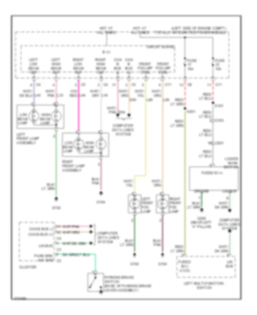
Headlights Wiring Diagram for Dodge Caliber Uptown 2010
List of elements for Headlights Wiring Diagram for Dodge Caliber Uptown 2010:
- (left side of engine compt) totally integrated power module
- B (+)
- C103
- C11
- C201
- Can b bus (+)
- Can b bus (-)
- Circuit board
- Cluster
- Computer data lines system
- D54
- D55
- Front fog lmp ctrl
- Fuse 10a
- Fused b (+)
- Fused b(+) (i.o.d)
- G102
- G104
- G200 (near left "a" pillar)
- Ground
- High beam lamp
- Hot at all times
- L33
- L34
- L43
- L44
- L89
- L90
- Left front fog lamp
- Left front lamp assembly
- Left high beam out
- Left low beam out
- Left multi-function switch
- Lin bus
- Low beam lamp
- Lower bank switch
- Park brk sw sns c2
- Parking brake switch (base of parking brake lever assembly)
- Right front fog lamp
- Right front lamp assembly
- Right high beam out
- Right low beam out
- S101
- S201
HORN
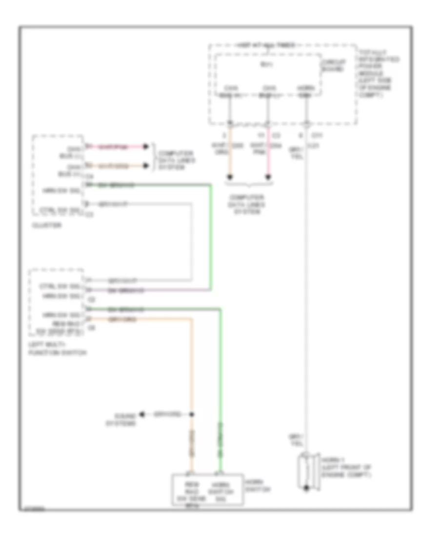
Horn Wiring Diagram for Dodge Caliber Uptown 2010
List of elements for Horn Wiring Diagram for Dodge Caliber Uptown 2010:
- B(+)
- C11
- Can bus (+)
- Can bus (+) c4
- Can bus (-)
- Circuit board
- Cluster
- Computer data lines system
- Ctrl sw sig
- Ctrl sw sig c3
- D54
- D55
- Function switch
- Horn 1 (left front of engine compt)
- Horn drv
- Horn switch
- Horn switch sig
- Hot at all times
- Hrn sw sig
- Left multi-
- Rem rad sw sens rtn
- Sound systems
- Totally integrated power module (left side of engine compt)
- X21
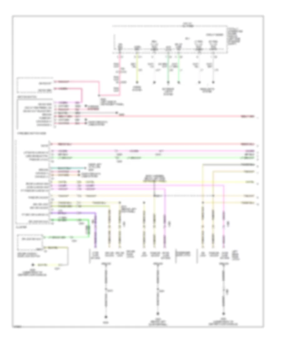
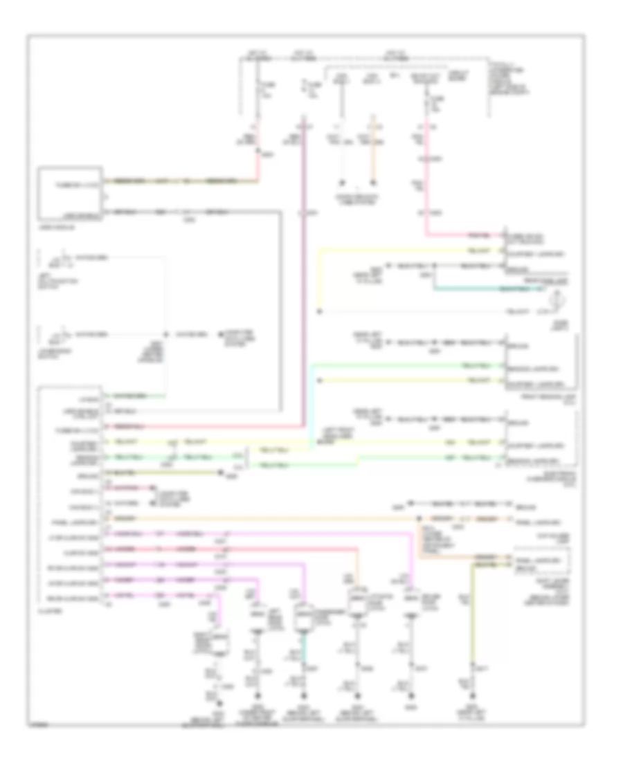
INSTRUMENT CLUSTER
Instrument Cluster Wiring Diagram (1 of 2) for Dodge Caliber Uptown 2010
List of elements for Instrument Cluster Wiring Diagram (1 of 2) for Dodge Caliber Uptown 2010:
- (near left "a" pillar) g200
- A412
- A932
- B25
- C200
- C201
- C310
- Can bus (+)
- Can bus (-)
- Cluster
- Computer data lines system
- Courtesy lamps driver
- D506
- D54
- D55
- Door lock driver
- Door lock sw mux
- Door locks system
- Dr lic mux pass
- Driver door unlock
- Driver seat belt sw sns
- Driver seat belt switch (integral to driver seat belt buckle assembly)
- E12
- Exterior lights system
- F202
- Floor console)
- Fuel level sig 1
- Fuel pump module (top left side of fuel tank)
- Fuse 10a
- Fuse 20a
- Fused b(+)
- G200 (near left "a" pillar)
- G250
- G300 (under front of center
- G300 (under front of center floor console)
- G303 (behind left quarterpanel)
- G38
- G74
- G75
- G76
- G77
- G78
- Gnd
- Ground
- Horn sw sns
- Horns system
- Hot at all times
- Interior lights system
- Iod fd
- K321
- L53
- Left front door ajar sw sns
- Left multi- function switch
- Left rear door ajar sw sns
- Liftgate ajar sw sns
- Liftgate door latch
- Lin ccn
- M24
- M27
- Overhead console circuit
- P238
- P240
- P33
- P696
- P697
- Panel lamps driver
- Park brake sw sns
- Passenger door unlock driver
- Power windows system
- R57
- Reading/rail lamps driver
- Rem rad ctrl sw sig
- Right front door ajar sw sns
- Right rear door ajar sw sns
- Run-start ign
- S210
- S355
- Sens
- Sens com rtn
- Shift interlock solenoid unlock
- Shift interlock system
- Snsr com rtn
- Sound systems
- Stop lamp sw output
- Totally integrated power module (left side of engine compt)
- Ugdo enable control circuit
- X20
- Y13
- Z903
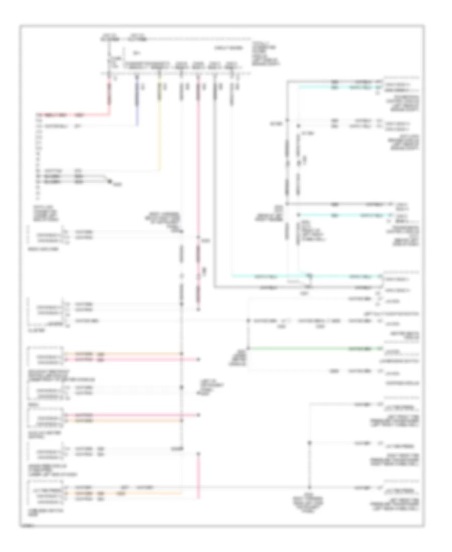
Instrument Cluster Wiring Diagram (2 of 2) for Dodge Caliber Uptown 2010
List of elements for Instrument Cluster Wiring Diagram (2 of 2) for Dodge Caliber Uptown 2010:
- (not used)
- A931
- B(+)
- Brake fluid level sensor (brake fluid reservoir)
- Brake fluid level sw sns
- Brk lul sig
- C100
- C11
- C200
- C301
- C303
- C308
- C309
- Can bus +
- Can bus -
- Can c bus +
- Can c bus -
- Circuit board
- Compass module
- Computer data lines system
- D506
- D64
- D65
- Driver door latch
- Engine oil pressure switch (left side of engine)
- Eop sig
- F929
- Fuse 10a
- Fused b(+)
- G103
- G104
- G250
- G300 (under front of center floor console)
- G303 (behind left quarterpanel)
- G305
- Gnd
- Ground
- Hot at all times
- Ign r
- Ign r pre
- Left rear door latch
- Lin ccn
- Oil temp sens sig
- Parking brake switch (base of parking brake lever assembly)
- Passenger door latch
- Pnk
- Pnk/ f202
- Pnk/ red
- Pnk/red
- Powertrain control module (left rear of engine compt)
- Red
- Right rear door latch
- Run- start ign
- S208
- S209
- S351
- S370
- Sns
- Totally integrated power module (left side of engine compt)
- Z903
- Z932
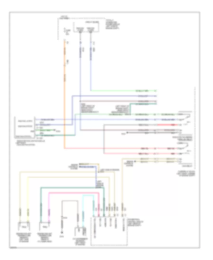
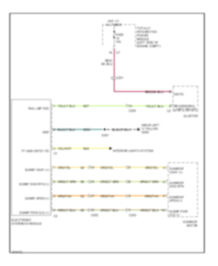
Overhead Console Wiring Diagram for Dodge Caliber Uptown 2010
List of elements for Overhead Console Wiring Diagram for Dodge Caliber Uptown 2010:
- (near left "a" pillar) g200
- C201
- C202
- C203
- Cluster
- Electronic overhead module
- Ft hdr crtsy fd
- Fuse 10a
- Gnd
- Hot at all times
- Interior lights system
- Iod fd
- Lamps driver c2
- M24
- M27
- Rail lmp fds
- Reading/rail
- S361
- Sunrf open (+)
- Sunrf pwr cls (+)
- Sunrf swd rtn (+)
- Sunrf vent (+)
- Sunroof motor
- Sunroof open (+)
- Sunroof swd rtn
- Sunroof vent (+)
- Totally integrated power module (left side of engine compt)
- Z903
INTERIOR LIGHTS
Interior Lights Wiring Diagram for Dodge Caliber Uptown 2010
List of elements for Interior Lights Wiring Diagram for Dodge Caliber Uptown 2010:
- (behind left quarterpanel)
- (left front headliner) s360
- (near left "a" pillar) g200
- 2.0l
- 2.4l
- A417
- Ajar sw sns
- B(+)
- C200
- C201
- C202
- C204
- C301
- C303
- C308
- C309
- C310
- Can bus (+)
- Can bus (-)
- Circuit board
- Cluster
- Computer data lines system
- Courtesy lamps drv
- Cup holder lamp
- Dome lamp 2
- Driver door latch
- Electronic overhead module (2.0l)
- Front reading lamp (2.4l)
- Fuse 10a
- Fuse 15a
- Fused b(+) (i.o.d)
- Fused ign sw out (run-acc)
- G200 (near left "a" pillar)
- G250
- G300 (under front of center floor console)
- G303
- G303 (behind left quarterpanel)
- G305
- G38
- Gnd
- Ground
- Hot at all times
- Ign sw out (run-acc)
- Left multifunction switch
- Left rear door latch
- Lf dr ajar sw sns
- Liftgate door latch
- Lin bus
- Lower bank switch
- Lr dr ajar sw sns
- M24
- M27
- Panel lamps drv
- Passenger door latch
- Reading lamps drv
- Rear dome lamp
- Rf dr ajar sw sns
- Right rear door latch
- Rr dr ajar sw sns
- S203
- S207 (under center console)
- S214 (lower center of instrument panel)
- S217
- S351
- S355
- S361
- S370
- Sens
- Shift lever assembly (cvt) (behind lower center of dash)
- Totally integrated power module (left side of engine compt)
- Ugdo enable
- Ugdo enable ctrl ckt
- Ugdo module
- Z903
NAVIGATION
Navigation Wiring Diagram for Dodge Caliber Uptown 2010
List of elements for Navigation Wiring Diagram for Dodge Caliber Uptown 2010:
- A417
- B(+)
- C201
- C203
- Can bus (+)
- Can bus (-)
- Circuit board
- Cluster
- Common audio out
- Computer data lines system
- D54
- D55
- Fuse 10a
- Fuse 15a
- G250
- Ground
- Hands free module (under left end of dash)
- Hot at all times
- In (-)
- Inside rearview mirror
- Iod fd
- Left audio out
- Media port
- Micro
- Micro phone ref
- Microphone
- Microphone 1 in (+)
- Microphone 2 in (+)
- Microphone feed
- Microphone in (-)
- Phone ref
- Pwr fd passth
- Radio
- Red
- Right audio out
- S203
- S211
- Totally integrated power module (left side of engine compt)
- Uci audio l in
- Uci audio r in
- Uci audio ref
- Uci dev detct
- Uci ext pwr gnd passthr
- Uci ext rx from uci
- Uci ext txt to uci
- Uci id
- X430
- X431
- X435
- X436
- X437
- X439
- X440
- X441
- X703
- X704
- X712
- X722
- X792
- X793
- X795
- X835
- Z433
- Z903
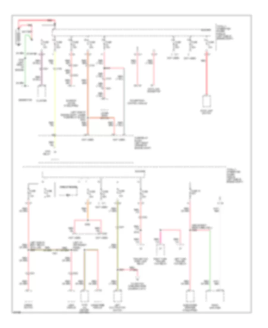
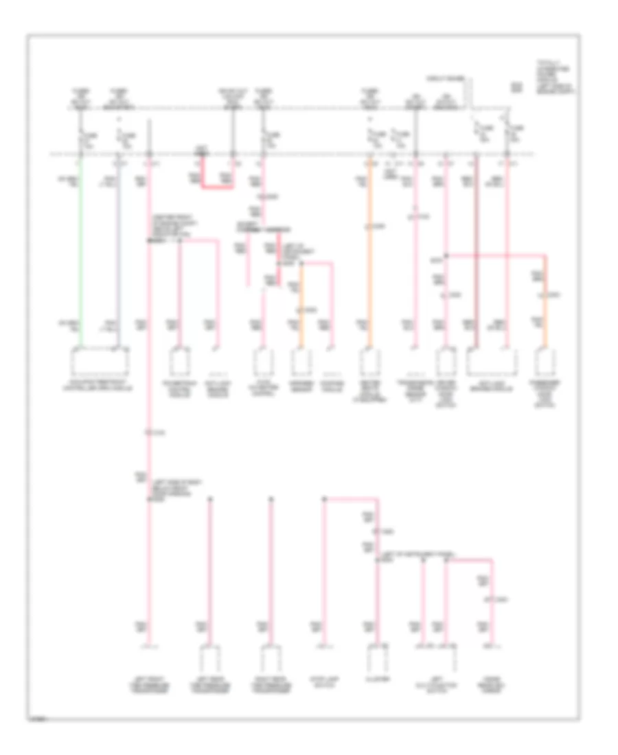
POWER DISTRIBUTION
Power Distribution Wiring Diagram (1 of 3) for Dodge Caliber Uptown 2010
List of elements for Power Distribution Wiring Diagram (1 of 3) for Dodge Caliber Uptown 2010:
- (above right rear wheelwell) s328
- (left of instrument panel) s203
- (left side of body, below "b" pillar) s329
- (left side of engine compt, under fuse/relay block) s024
- (not used)
- B(+)
- Battery
- Bus bar
- C103
- C105
- C11
- C201
- C202
- C203
- C301
- C305
- C323
- Circuit board
- Cluster
- Data link connector
- Fuse 10a
- Fuse 15a
- Fuse 19 20a
- Fuse 20a
- Fuse 25a
- Fuse 30a
- Fuse 40a
- Fuse/relay block (left front corner of engine compt)
- Generator
- Hands free module
- Hvac a/c heater control
- Left multi-fuction switch
- Left turn trailer tow relay
- Lower bank switch
- Main relay
- Mirror switch
- Powertrain control module
- Radio amplifier
- Red
- Right turn trailer tow relay
- S101
- S150 (left front of engine)
- S201
- S318
- S365
- Starter
- Stop lamp switch
- Subwoofer speaker (if equipped)
- Sunroof motor (if equipped)
- To ignition wireless node (daigram 2 of 3)
- Totally integrated power module (left side of engine compt)
- Trailer tow park lamp relay
- Ugdo module
Power Distribution Wiring Diagram (2 of 3) for Dodge Caliber Uptown 2010
List of elements for Power Distribution Wiring Diagram (2 of 3) for Dodge Caliber Uptown 2010:
- (body harness, near left side instrument panel) s305
- (left side of body, below "b" pillar) s320
- (not used)
- (run-acc) ign sw out fused
- 110 volt ac commom
- A999
- Ac commom 110 volt
- Ac line 1 110 volt
- Ac power outlet
- Batt feed
- Bus bar
- C103
- C200
- C201
- C202
- C203
- C204
- C310
- Can bus (+)
- Can bus (-)
- Circuit board
- Cluster
- Computer data lines system
- Console) s200
- Cvt
- Enb sw sig inverter
- From splice s201 (diagram 1 of 3)
- Fuse 10a
- Fuse 15a
- Fuse 20a
- Fuse 30a
- Fused b(+)
- Fused ign sw out (run-acc)
- G200 (2.ol) (near left "a" pillar)
- G200 (near left "a" pillar)
- G250
- G250 (2.4l)
- Gnd
- Ground
- Ign sw out (run-start)
- Ign sw sense
- Ignition switch
- Ignition wireless node
- Instrument panel power outlet
- Inverter enb sw sig
- Inverter module (behind lower center of dash)
- Left front tire pressure transponder
- Left rear tire pressure transponder
- Lin tire press
- M/t
- P801
- P805
- P809
- Radio
- Rear dome lamp
- Rear wiper motor
- Red/ pnk
- Right rear tire pressure transponder
- S210 (left of instrument panel)
- S217 (2.ol)
- S220 (left side of instrument panel)
- S310 (behind left kick panel)
- Sunroof motor
- Totally integrated power module (left side of engine compt)
- Transmission control module
- W/ sunroof
- Z908
Power Distribution Wiring Diagram (3 of 3) for Dodge Caliber Uptown 2010
List of elements for Power Distribution Wiring Diagram (3 of 3) for Dodge Caliber Uptown 2010:
- (center front of engine compt, above left radiator fan) s003
- (left of instrument panel) s208
- (left of instrument panel) s209
- (not used)
- Anti-lock brakes module
- Bus bar
- C103
- C11
- C200
- C202
- C203
- C302
- C303
- C305
- Circuit board
- Cluster
- Compass
- Compass module
- Driver window/ door lock switch
- Except compass
- Fuse 10a
- Fuse 30a
- Fuse 40a
- Fused ign sw out (run)
- Fused ign sw out (run-start)
- Heated seats module (if equipped)
- Hvac a/c heater control
- Ign sw out (run-acc)
- Ign sw out (start)
- Ign sw out (unlock run- start)
- Infrared sensor
- Inside rearview mirror
- Left front tire pressure transponder
- Left multi-function switch
- Left rear tire pressure transponder
- Occupant restraint controller (orc) module
- Passenger window/ door lock switch
- Pnk/ red
- Powertrain control module
- Right rear tire pressure transponder
- S375
- Stop lamp switch
- Totally integrated power module (left side of engine compt)
- Transmission range sensor (cvt)
POWER DOOR LOCKS
Power Door Locks Wiring Diagram (1 of 2) for Dodge Caliber Uptown 2010
List of elements for Power Door Locks Wiring Diagram (1 of 2) for Dodge Caliber Uptown 2010:
- (body harness, below left side instrument panel)
- (near left "a" pillar) g200
- A411
- B(+)
- Bk up lmps fd
- C103
- C11
- C200
- C301
- C303
- C308
- C310
- Can b bus (+)
- Can b bus (-)
- Can bus (+)
- Can bus (-)
- Circuit board
- Cluster
- Com in tire press lan
- Computer data lines system
- D508
- D54
- D55
- Dr lock
- Dr lock sw mux
- Driver door latch
- Driver window/ door lock switch
- Drv dr lock
- Drv dr unlock
- Exterior lights system
- F20
- Ft driv dr ajar sw in
- Ft pass dr ajar sw in
- Fused b(+)
- G20
- G250
- G300 (under front of center floor console)
- G303 (behind left quarterpanel)
- G305
- Gnd
- Ground
- Headlights system
- Horn drv
- Horns system
- Hot at all times
- Ign run st
- Ign sw out (run-start)
- Ign sw sen
- Ign sw sns
- Ignition switch
- Iod fd
- L217
- L53
- L70
- Left rear door latch
- Lf dr ajar sw sns
- Liftgate ajar sw in
- Lr dr ajar sw sig
- Lr dr ajar sw sns
- Lt prk/ tl/ lic run lamps
- Pass dr lk mux
- Pass dr unlock
- Passenger door latch
- Prk/ tl/ lic run lmps 2
- Rf dr ajar sw sns
- Rr dr ajar sw sig
- Rt prk/ tl/ lic run lamps
- S220 (left side of instrument panel)
- S310 (behind left kick panel)
- S311
- S351
- S370
- Stp ld fd
- Totally integrated power module (left side of engine compt)
- Ugdo enable ctrl
- Warning systems
- Wireless ignition node
- X21
- Z903
Power Door Locks Wiring Diagram (2 of 2) for Dodge Caliber Uptown 2010
List of elements for Power Door Locks Wiring Diagram (2 of 2) for Dodge Caliber Uptown 2010:
- A417
- Alarm on
- C201
- C202
- C306
- C309
- C310
- Can bus (+)
- Can bus (-)
- Circuit board
- Computer data lines system
- D54
- D55
- Dr lock
- Fuse 10a
- G104
- G303 (behind left quarterpanel)
- G38
- G70
- Gnd
- Ground
- Hood ajar switch (left rear of engine compt)
- Hot at all times
- Iod fd
- Liftgate ajar sw sns
- Liftgate door latch
- Pass dr lk mux
- Pass dr unlock
- Passenger window/ door lock switch
- Right rear door latch
- Rr dr ajar sw sns
- S201
- S203
- S355
- Totally integrated power module (left side of engine compt)
- Ugdo module
- Uhood sw sig
POWER MIRRORS
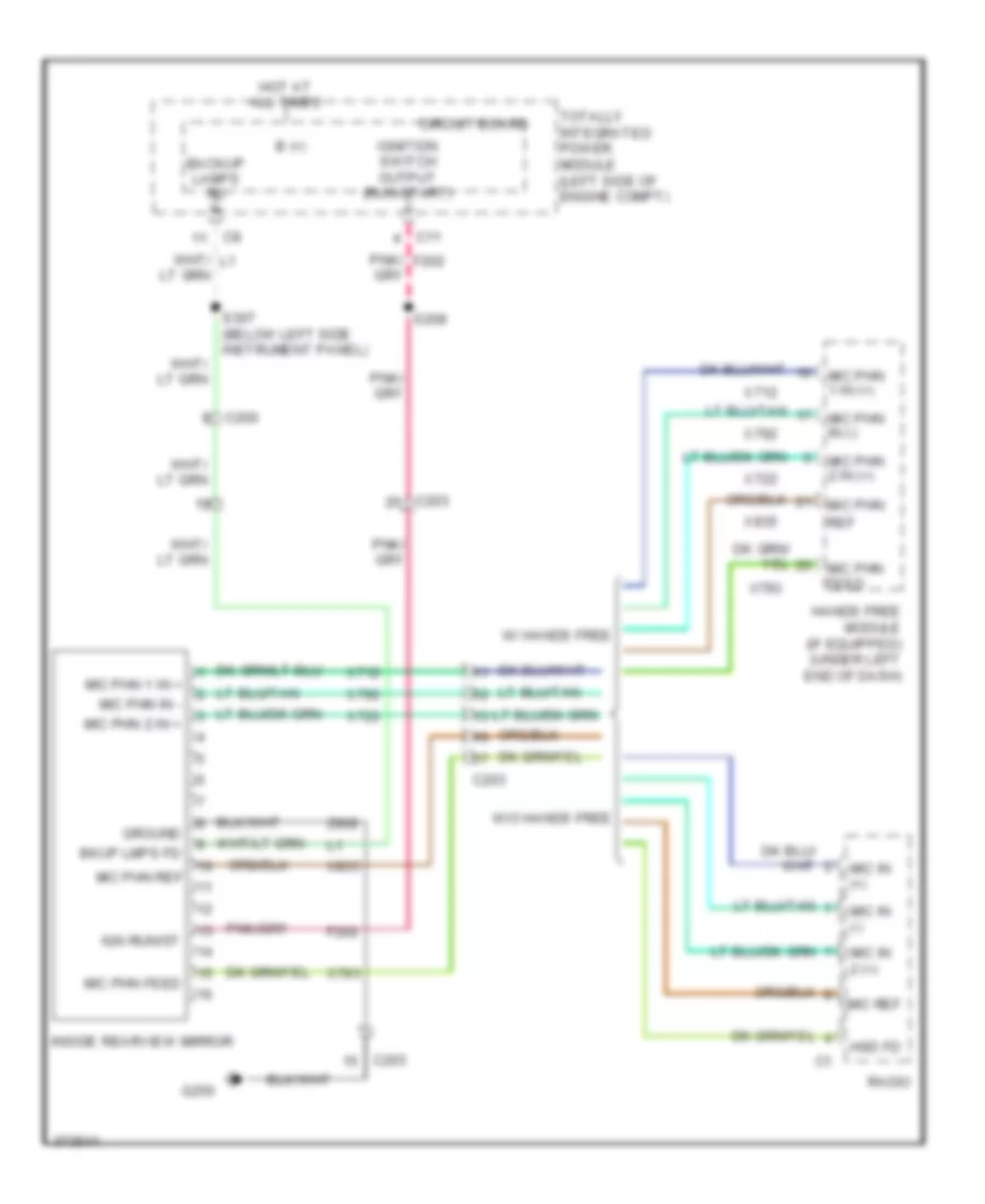
Automatic Day/Night Mirror Wiring Diagram for Dodge Caliber Uptown 2010
List of elements for Automatic Day/Night Mirror Wiring Diagram for Dodge Caliber Uptown 2010:
- B (+)
- Backup lamps fd
- Bkup lmps fd
- C11
- C200
- C203
- Circuit board
- F202
- G250
- Ground
- Hands free module (if equipped) (under left end of dash)
- Hot at all times
- Hsd fd
- Ign run/st
- Ignition switch output (run-start)
- Inside rearview mirror
- Mic in (+)
- Mic in (-)
- Mic in 2 (+)
- Mic phn
- Mic phn 1 in (+)
- Mic phn 1 in +
- Mic phn 2 in (+)
- Mic phn 2 in +
- Mic phn feed
- Mic phn in (-)
- Mic phn in -
- Mic phn ref
- Mic ref
- Pnk/ f202
- Radio
- Ref
- S208
- S307 (below left side instrument panel)
- Totally integrated power module (left side of engine compt)
- W/ hands free
- W/o hands free
- X712
- X722
- X792
- X793
- X835
- Z908
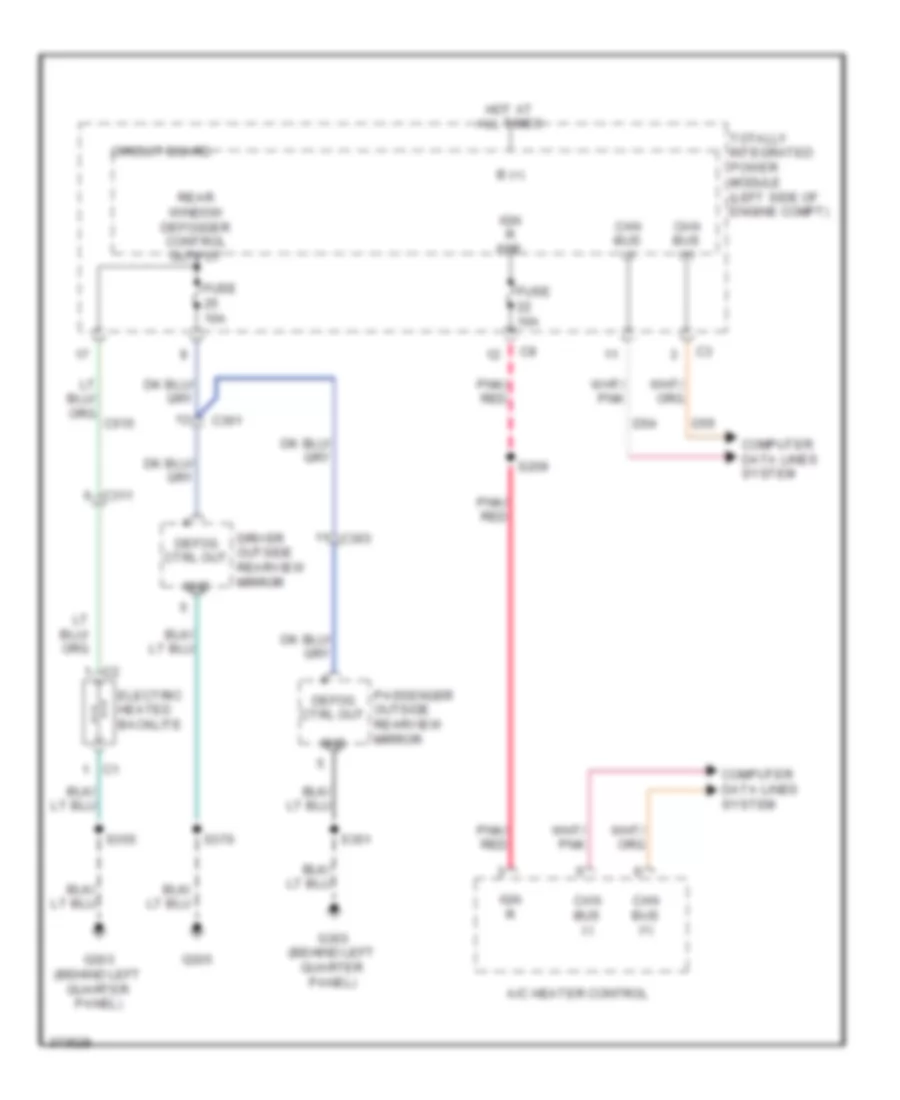
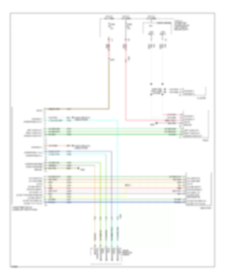
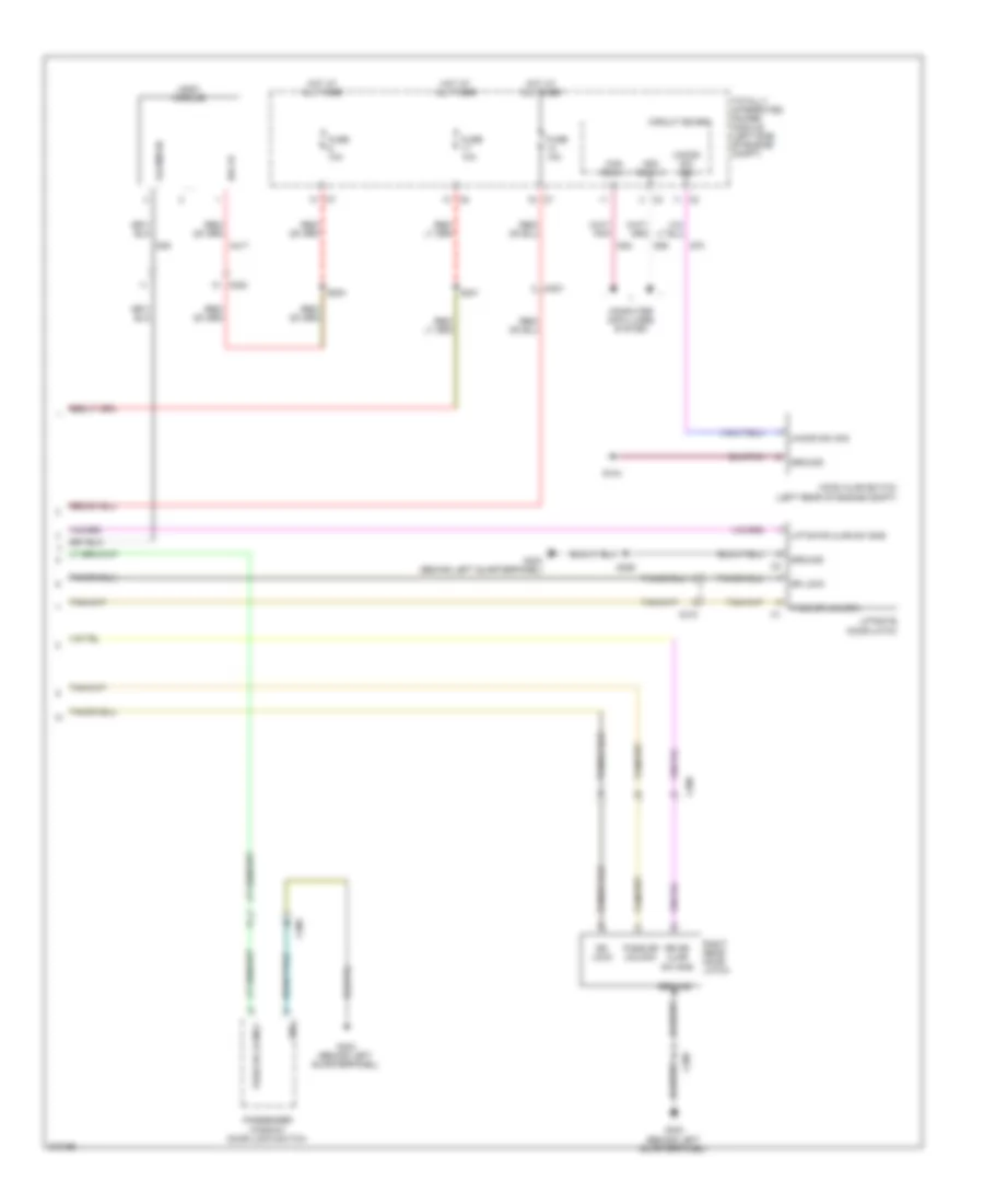
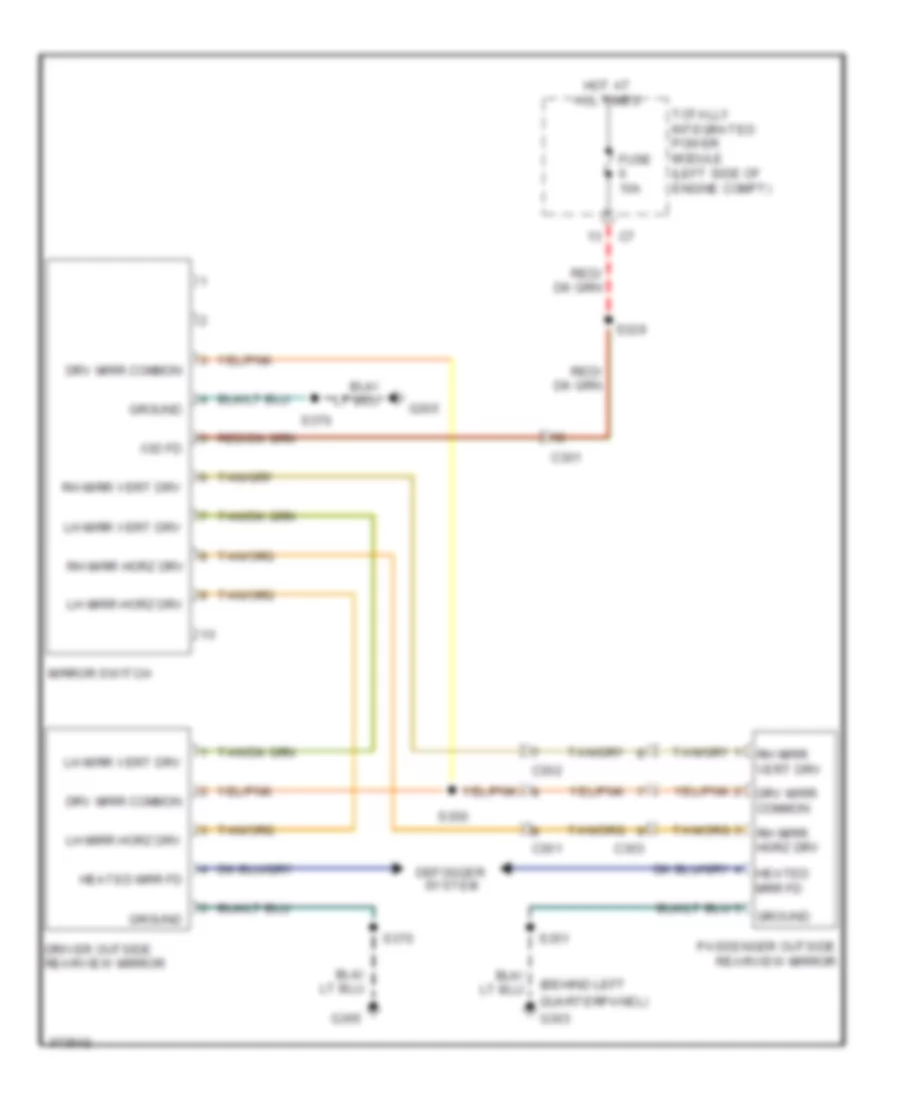
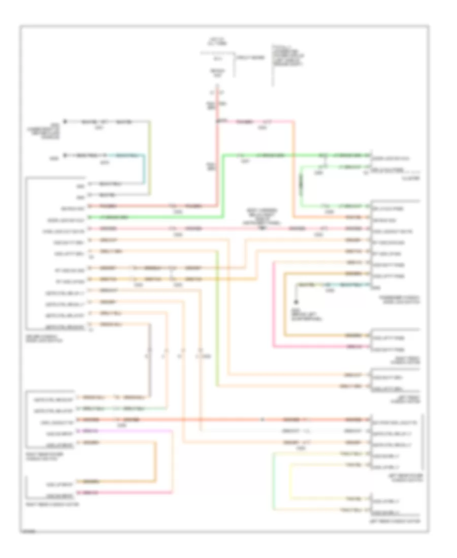
Power Mirrors Wiring Diagram for Dodge Caliber Uptown 2010
List of elements for Power Mirrors Wiring Diagram for Dodge Caliber Uptown 2010:
- (behind left
- C301
- C302
- C303
- Defogger system
- Driver outside rearview mirror
- Drv mirr common
- Fuse 10a
- G303
- G305
- Ground
- Heated mrr fd
- Hot at all times
- Iod fd
- Lh mirr horz drv
- Lh mirr vert drv
- Mirror switch
- Passenger outside rearview mirror
- Quarterpanel)
- Rh mirr horz drv
- Rh mirr vert drv
- S329
- S350
- S351
- S370
- Totally integrated power module (left side of engine compt)
POWER SEATS
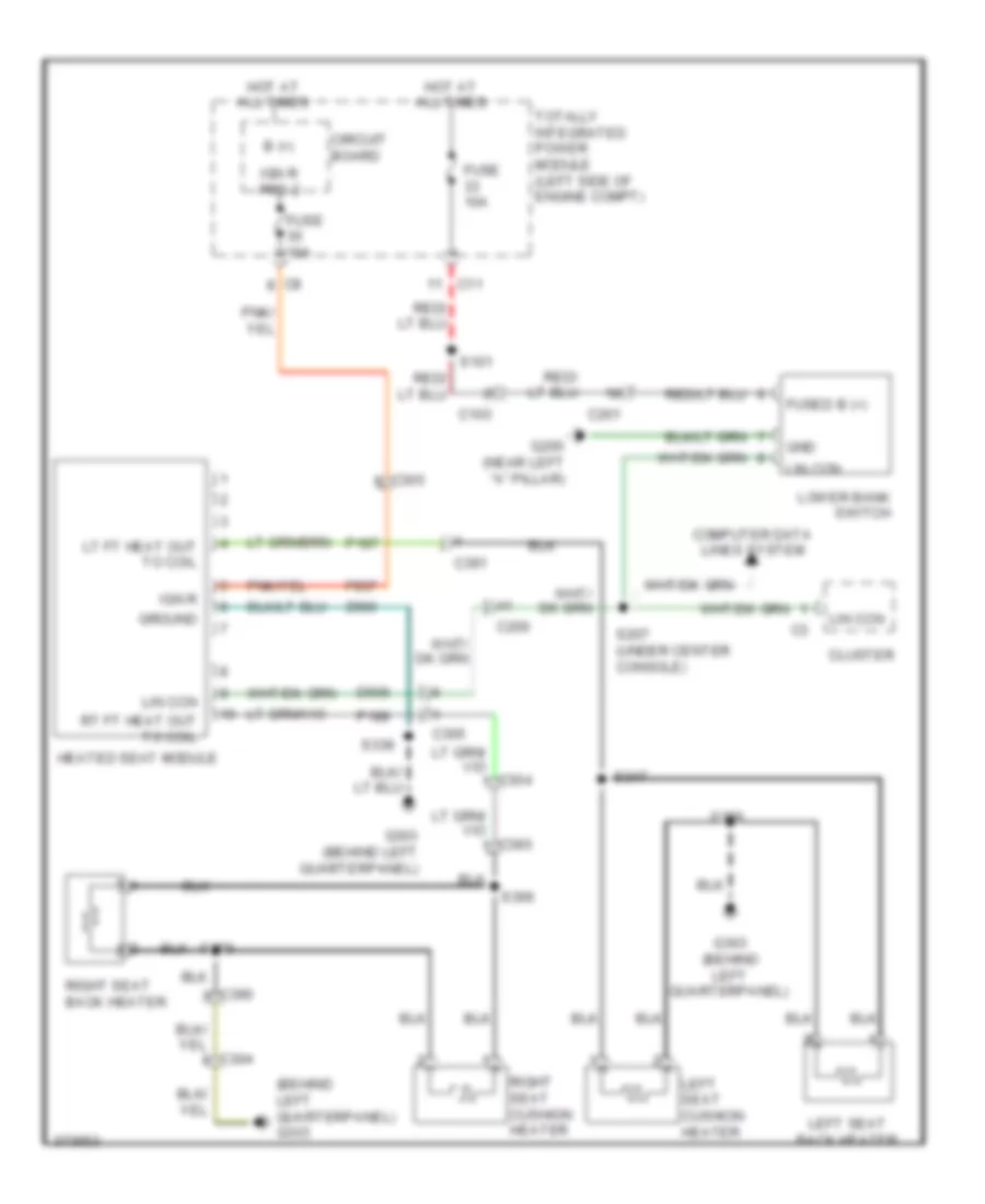
Power Seats Wiring Diagram for Dodge Caliber Uptown 2010
List of elements for Power Seats Wiring Diagram for Dodge Caliber Uptown 2010:
- (behind left quarterpanel) g303
- B (+)
- C103
- C11
- C200
- C201
- C304
- C305
- C390
- C391
- Circuit board
- Cluster
- Computer data lines system
- D506
- F937
- Fuse 10a
- Fused b (+)
- G200 (near left "a" pillar)
- G303 (behind left quarterpanel)
- Gnd
- Ground
- Heated seat module
- Hot at all times
- Ign r
- Ign r pre 2
- Left seat back heater
- Left seat cushion heater
- Lin ccn
- Lower bank switch
- Lt ft heat out to coil
- P187
- P188
- Right seat back heater
- Right seat cushion heater
- Rt ft heat out to coil
- S101
- S207 (under center console)
- S338
- S347
- S358
- S359
- S366
- Totally integrated power module (left side of engine compt)
- Z960
POWER TOP/SUNROOF
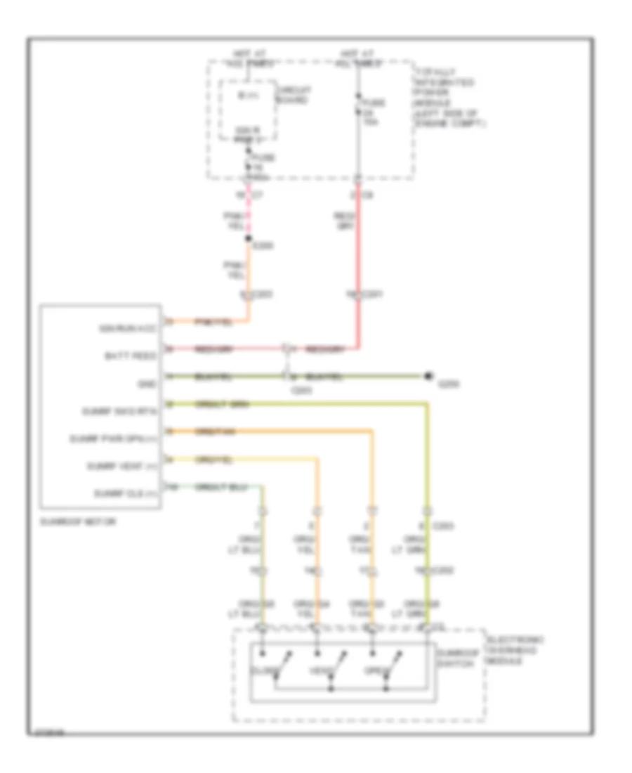
Power Top/Sunroof Wiring Diagram for Dodge Caliber Uptown 2010
List of elements for Power Top/Sunroof Wiring Diagram for Dodge Caliber Uptown 2010:
- B (+)
- Batt feed
- C201
- C202
- C203
- Circuit board
- Close
- Electronic overhead module
- Fuse 15a
- G250
- Gnd
- Hot at all times
- Ign r pre 3
- Ign run acc
- Open
- S200
- Sunrf cls (+)
- Sunrf pwr opn (+)
- Sunrf swd rtn
- Sunrf vent (+)
- Sunroof motor
- Sunroof switch
- Totally integrated power module (left side of engine compt)
- Vent
POWER WINDOWS
Power Windows Wiring Diagram for Dodge Caliber Uptown 2010
List of elements for Power Windows Wiring Diagram for Dodge Caliber Uptown 2010:
- (body harness, below right side of instrument panel) s312
- B (+)
- C200
- C301
- C302
- C303
- C306
- C308
- C309
- Circuit board
- Cluster
- Door lock sw mux
- Dr lk mux pass
- Driver window/ door lock switch
- G300 (under front of center floor console)
- G303 (behind left quarterpanel)
- G305
- Gnd
- Hot at all times
- Ign run acc
- Left front window motor
- Left rear power window switch
- Left rear window motor
- Mstr ctrl rr dn lt
- Mstr ctrl rr dn rt
- Mstr ctrl rr up lt
- Mstr ctrl rr up rt
- Passenger window/ door lock switch
- Pnk/ f981
- Right front window motor
- Right rear power window switch
- Right rear window motor
- Rt wdo dw sig
- Rt wdo dwn sig
- Rt wdo up sig
- S370
- S375
- Sw pwr wdo lkout fd
- Totally integrated power module (left side of engine compt)
- Wdo dn ft driv
- Wdo dn ft pass
- Wdo dn rr lt
- Wdo dn rr rt
- Wdo dw ft driv
- Wdo lockout fd
- Wdo lockout sw fd
- Wdo up ft driv
- Wdo up ft pass
- Wdo up rr lt
- Wdo up rr rt
- Wind lock out sw fd
RADIO
Radio Wiring Diagram (1 of 2) for Dodge Caliber Uptown 2010
List of elements for Radio Wiring Diagram (1 of 2) for Dodge Caliber Uptown 2010:
- (not used)
- (or x712)
- (or x722)
- A413
- Aud fd
- C200
- C201
- Can bus (+)
- Can bus (-)
- Can bus +
- Can bus -
- Cluster
- Com aud out
- Computer data lines system
- D54
- D55
- Data +
- Data -
- Fuse 15a
- Fuse 20a
- G250
- Ground
- Horn switch
- Hot at all times
- Iod fd
- Left aud out mic 2 in +
- Left multi-function switch
- Left radio remote switch
- Lr spk (+)
- Lr spk (-)
- Media-port
- Mic hsd fd
- Mic in -
- Mic ref
- Mirrors system
- Navigation system
- Pwr fd 2
- Rad sw rtn
- Rad sw sig
- Radio
- Radio sw sig
- Right aud out mic in +
- Right radio remote switch
- Rr spk (+)
- Rr spk (-)
- Rtn
- S328
- Sig
- Snr rtn
- Sw sig
- Totally integrated power module (left side of engine compt)
- Uci aud lt in
- Uci aud ref
- Uci aud rt in
- Uci dev detct
- Uci ext rx
- Uci ext tx
- Uci id
- Uci-ext pwr
- Uci-ext rx
- Uci-ext tx
- W/ hands free
- W/o hands free
- X430
- X431
- X435
- X436
- X437
- X439
- X440
- X444
- X445
- X446
- X51
- X52
- X57
- X58
- X62
- X703
- X704
- X792
- X793
- X795
- X835
- Z433
- Z903
Radio Wiring Diagram (2 of 2) for Dodge Caliber Uptown 2010
List of elements for Radio Wiring Diagram (2 of 2) for Dodge Caliber Uptown 2010:
- (behind left quarterpanel)
- (behind left quarterpanel) g303
- Amp lf dr spk (+)
- Amp lf dr spk (-)
- Amp lr spk (+)
- Amp lr spk (-)
- Amp rf dr spk (+)
- Amp rf dr spk (-)
- Amp rr spk (+)
- Amp rr spk (-)
- C201
- C301
- C303
- C308
- C309
- C311
- Can bus (+)
- Can bus (-)
- Computer data lines system
- G303
- Ground
- Iod fd
- L int panel spk (+)
- L int panel spk (-)
- Left front door speaker
- Left instrument panel speaker
- Left rear speaker
- Liftgate speaker
- Lr spk (+)
- Lr spk (-)
- Lr twtr +
- Lr twtr -
- R int panel spk (+)
- R int panel spk (-)
- Radio amplifier
- Right front door speaker
- Right instrument panel speaker
- Right rear speaker
- Rr spk (+)
- Rr spk (-)
- Rr twtr +
- Rr twtr -
- S368 (above right rear wheelwell)
- S372
- S373 (right body, below right rear door opening)
- S374 (above right rear wheel- well)
- Subwoofer speaker
SHIFT INTERLOCK
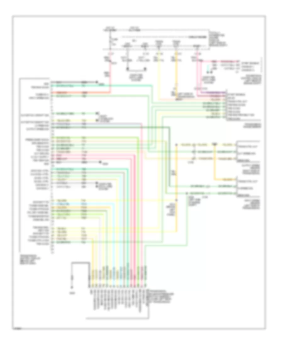
Shift Interlock Wiring Diagram for Dodge Caliber Uptown 2010
List of elements for Shift Interlock Wiring Diagram for Dodge Caliber Uptown 2010:
- (left rear of engine compt) powertrain control module
- (not used)
- (top of brake pedal assembly) stop lamp switch
- A952
- Astk dn
- Astk up
- B(+)
- B16
- Brk sig 2
- Brk sig 2 c1
- Brk trans sol ulk
- Brk trans sol unlk
- C104
- C11
- C2 sig
- C201
- C3 sig
- C4 sig
- C5 sig
- Can b bus (+)
- Can b bus (-)
- Can bus (+)
- Can bus (-)
- Can c bus (+)
- Can c bus (-)
- Can c bus(+)
- Can c bus(-)
- Circuit board
- Cluster
- Computer data lines system
- D54
- D55
- D64
- D65
- Dim3 ip
- E12
- F202
- Fuse 10a
- Fused b(+)
- G200 (near of left "a" pillar)
- Ground
- Hot at all times
- Ign run/st
- Ign sw out (run-start)
- Interior lights system
- Iod fd
- K321
- Prk/neut sig
- S214 (lower center of instrument panel)
- S217
- S306
- S310
- Shift lever assembly (behind lower center of dash)
- T41
- T42
- T44
- Totally integrated power module (left side of engine compt)
- Transmission control module (cvt) (behind left side of dash)
- Transmission range sensor
- Z903
STARTING/CHARGING
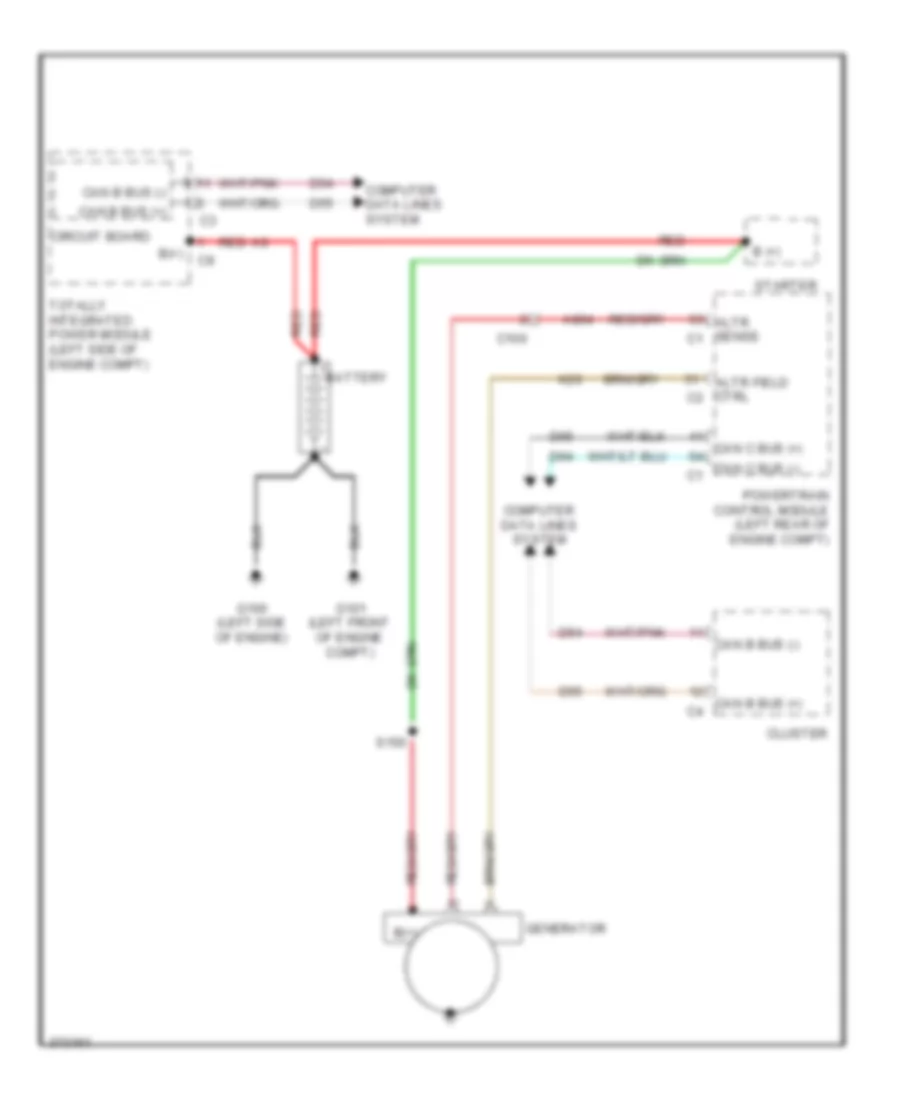
Charging Wiring Diagram for Dodge Caliber Uptown 2010
List of elements for Charging Wiring Diagram for Dodge Caliber Uptown 2010:
- A804
- Altr field ctrl c2
- Altr sense c1
- B (+)
- B(+)
- Battery
- C100
- Can b bus (+)
- Can b bus (+) c4
- Can b bus (-)
- Can c bus (+)
- Can c bus (-) c1
- Circuit board
- Cluster
- Computer data lines system
- D54
- D55
- D64
- D65
- G100 (left side of engine)
- G101 (left front of engine compt)
- Generator
- K20
- Powertrain control module (left rear of engine compt)
- Red
- S150
- Starter
- Totally integrated power module (left side of engine compt)
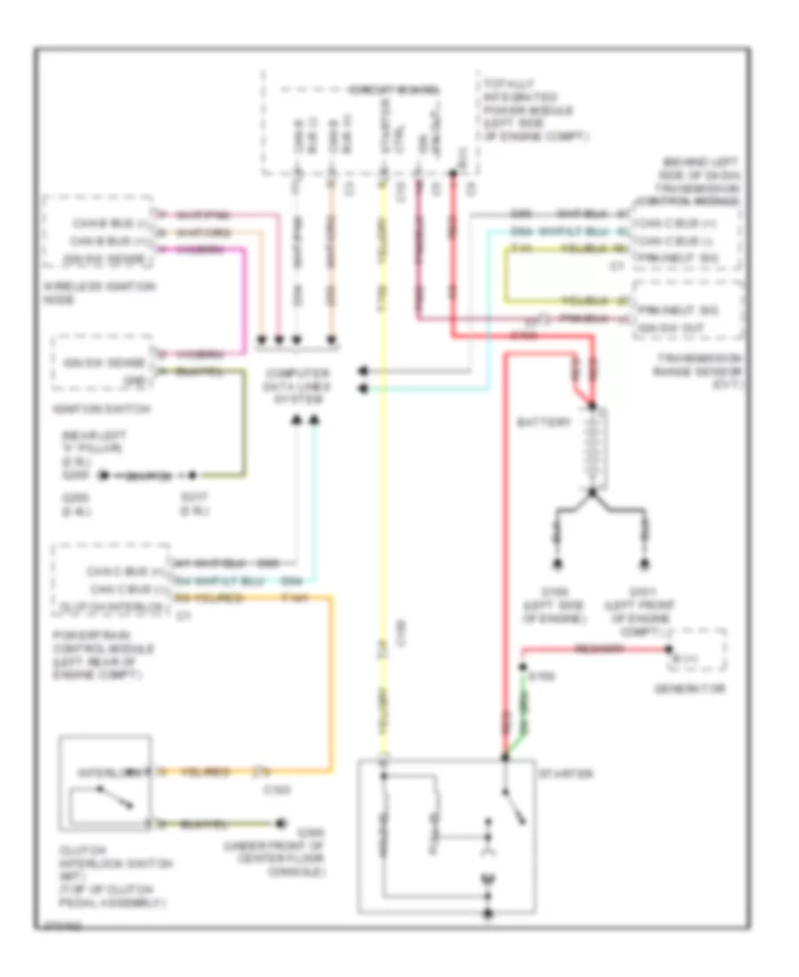
Starting Wiring Diagram for Dodge Caliber Uptown 2010
List of elements for Starting Wiring Diagram for Dodge Caliber Uptown 2010:
- (behind left side of dash) transmission control module
- (near left "a" pillar) (2.0l) g200
- B (+)
- B(+)
- Battery
- C10
- C100
- C103
- Can b bus (+)
- Can b bus (-)
- Can c bus (+)
- Can c bus (-)
- Circuit board
- Clutch interlck
- Clutch interlock switch (m/t) (top of clutch pedal assembly)
- Computer data lines system
- Ctrl starter
- D54
- D55
- D64
- D65
- F962
- G100 (left side of engine)
- G101 (left front of engine compt)
- G250 (2.4l)
- G300 (under front of center floor console)
- Generator
- Gnd
- Hold-in
- Ign sw out
- Ign sw sense
- Ignition switch
- Interlock
- Powertrain control module (left rear of engine compt)
- Prk/neut sig
- Pull-in
- Red
- S150
- S217 (2.0l)
- Starter
- T141
- T41
- T750
- Totally integrated power module (left side of engine compt)
- Transmission range sensor (cvt)
- Wireless ignition node
SUPPLEMENTAL RESTRAINTS
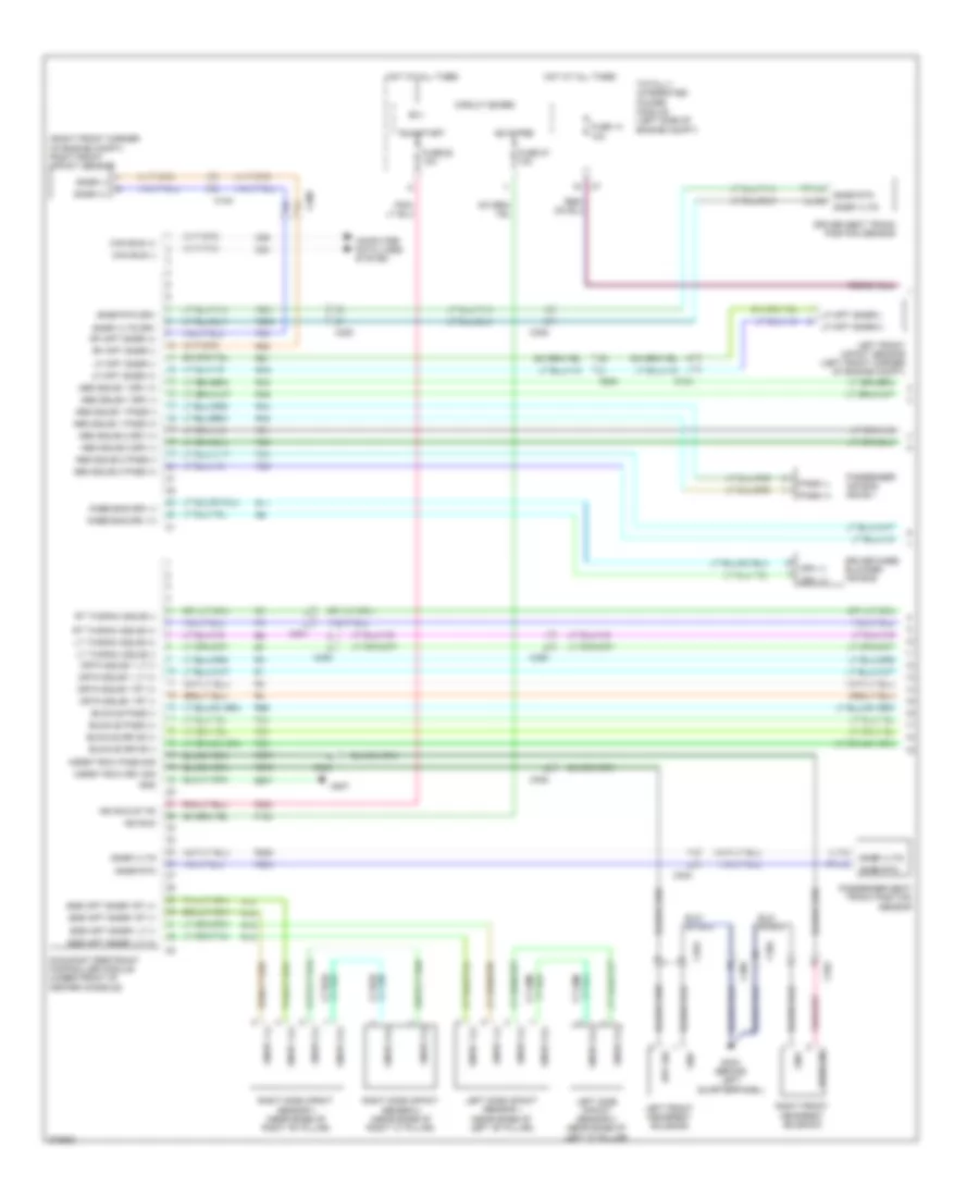
Supplemental Restraints Wiring Diagram (1 of 2) for Dodge Caliber Uptown 2010
List of elements for Supplemental Restraints Wiring Diagram (1 of 2) for Dodge Caliber Uptown 2010:
- (right front corner of engine compt) right front impact sensor
- Abg squib 1 drv (+)
- Abg squib 1 drv (-)
- Abg squib 1 pass (+)
- Abg squib 1 pass (-)
- Abg squib 2 drv (+)
- Abg squib 2 drv (-)
- Abg squib 2 pass (+)
- Abg squib 2 pass (-)
- B(+)
- Buckle drive (+)
- Buckle drive (-)
- Buckle pass (+)
- Buckle pass (-)
- C104
- C200
- C304
- C305
- C352
- C353
- Can bus (+)
- Can bus (-)
- Circuit board
- Computer data lines system
- Crtn squib 1 lt (+)
- Crtn squib 1 lt (-)
- Crtn squib 1 rt (+)
- Crtn squib 1 rt (-)
- D54
- D55
- Driver knee blocker air bag
- Driver seat track position sensor
- Drv (+)
- Drv (-)
- Drv sig
- F100
- F200
- Fuse 14 10a
- Fuse 27 10a
- Fuse 28 10a
- G303 (behind left quarterpanel)
- G307
- Gnd
- Hdrst row drv sig
- Hdrst row pass sig
- Hot at all times
- Ign r pre
- Ign run
- Ign run st fd
- Knee bag drv (+)
- Knee bag drv (-)
- Left front headrest solenoid
- Left front impact sensor (left front corner of engine compt)
- Left side impact sensor 1 (near base of left "b" pillar)
- Left side impact sensor 2 (near base of left "c" pillar)
- Lf impt snsr (+)
- Lf impt snsr (-)
- Lf impt snsr(+)
- Lf impt snsr(-)
- Lt thorax squib (+)
- Lt thorax squib (-)
- Occupant restraint controller module (under front of center console)
- Pass (+)
- Pass (-)
- Pass sig
- Passenger air bag squib 1
- Passenger seat track position sensor
- R11
- R13
- R14
- R15
- R16
- R261
- R262
- R263
- R264
- R42
- R43
- R44
- R45
- R53
- R54
- R55
- R56
- R61
- R62
- R63
- R64
- R676
- R677
- R79
- R80
- R81
- R82
- Rf impt snsr (+)
- Rf impt snsr (-)
- Right front headrest solenoid
- Right side impact sensor 1 (near base of right "b" pillar)
- Right side impact sensor 2 (near base of right "c" pillar)
- Rt thorax squib (+)
- Rt thorax squib (-)
- Rtn-d
- Run/start
- Sde impt snsr1 lt (+)
- Sde impt snsr1 lt (-)
- Sde impt snsr1 rt (+)
- Sde impt snsr1 rt (-)
- Snsr (+)
- Snsr (-)
- Snsr 1 (+)
- Snsr 1 (-)
- Snsr 2 (+)
- Snsr 2 (-)
- Snsr rtn
- Snsr rtn drv
- Snsr vltg
- Snsr vltg drv
- Totally integrated power module (left side of engine compt)
- Vltg
- Z907
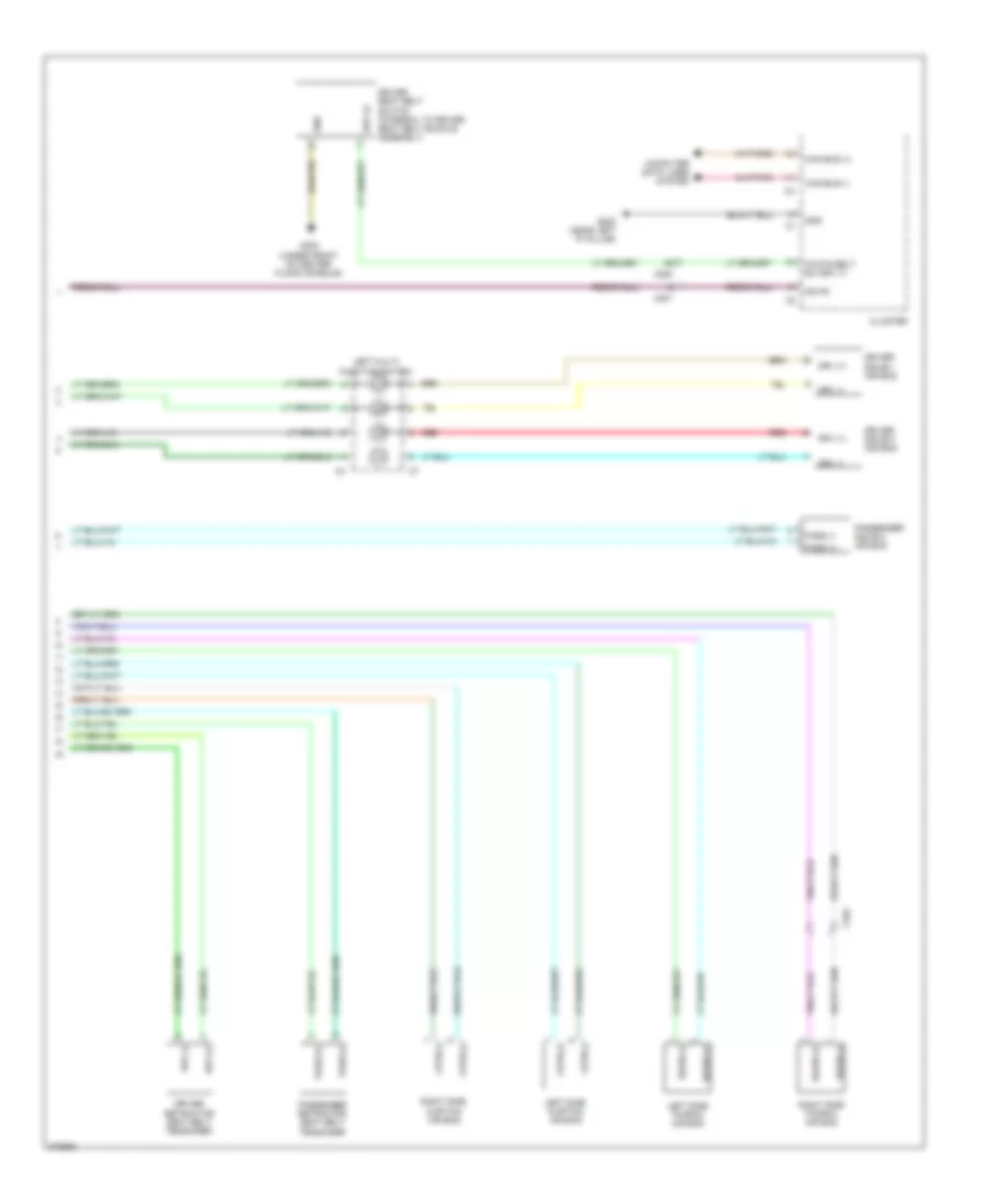
Supplemental Restraints Wiring Diagram (2 of 2) for Dodge Caliber Uptown 2010
List of elements for Supplemental Restraints Wiring Diagram (2 of 2) for Dodge Caliber Uptown 2010:
- 1r sts belt sw drv (+)
- C200
- C201
- C352
- Can bus (+)
- Can bus (-)
- Cluster
- Computer data lines system
- Crtn (+)
- Crtn (-)
- Driver retractor seat belt tensioner
- Driver seat belt switch (integral to driver seat belt buckle assembly)
- Driver squib 1 air bag
- Driver squib 2 air bag
- Drv (+)
- Drv (-)
- G200 (near left "a" pillar)
- G300 (under front of center floor console)
- Gnd
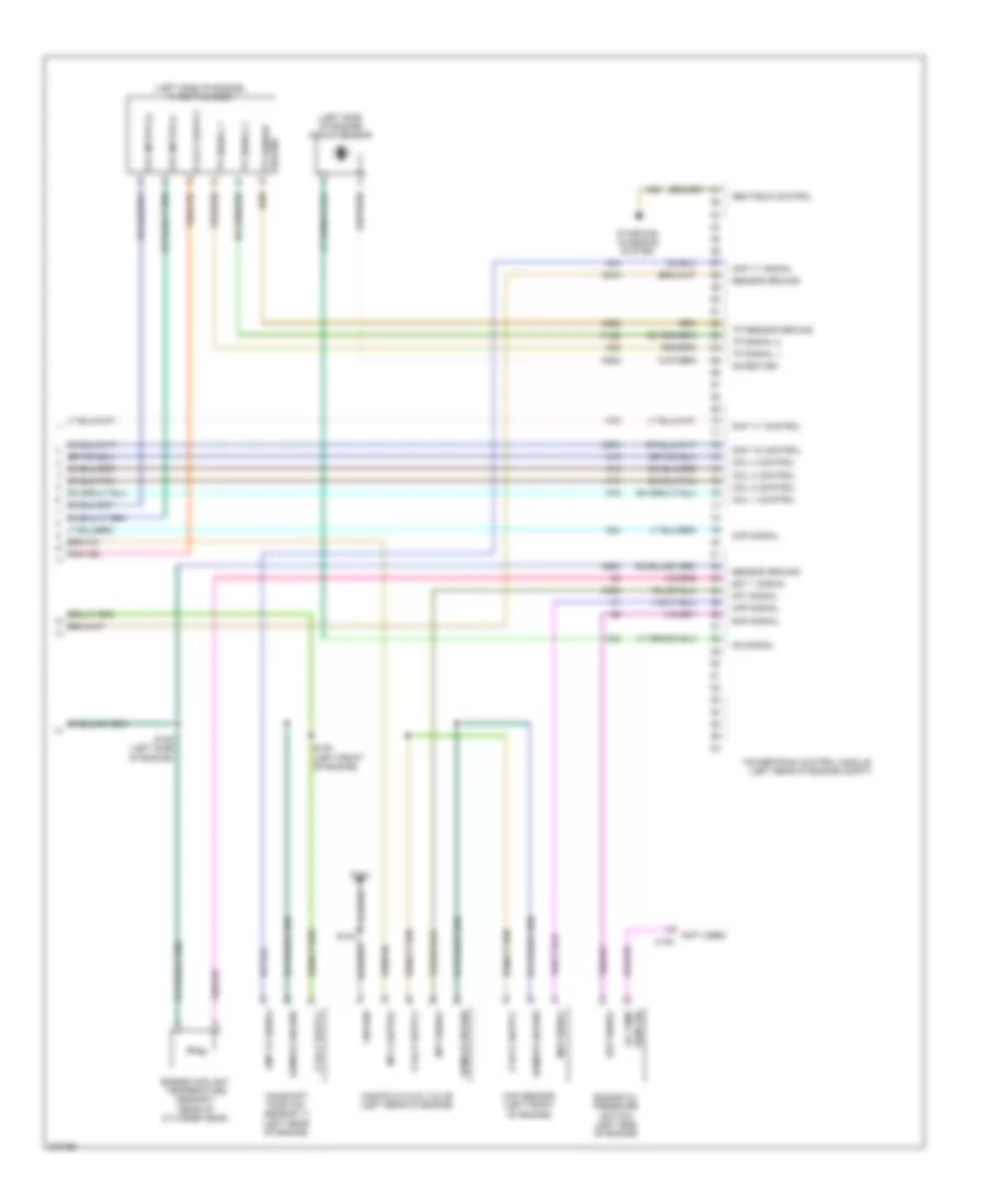
- Iod fd
- Left multi- function switch
- Left side curtain air bag
- Left side thorax air bag
- Pass (+)
- Pass (-)
- Passenger retractor seat belt tensioner
- Passenger squib 2 air bag
- Red
- Right side curtain air bag
- Right side thorax air bag
- Squib (+)
- Squib (-)
TRANSMISSION
Transmission Wiring Diagram for Dodge Caliber Uptown 2010
List of elements for Transmission Wiring Diagram for Dodge Caliber Uptown 2010:
- 2-4/lr sol ctrl
- A952
- Autostick dnshift sig
- Autostick upshift sig
- B(+)
- C10
- C103
- C106
- Can bus (+)
- Can bus (-)
- Circuit board
- Computer data lines system
- D64
- D65
- F963
- Fnl drv mode sel
- Fuse 10a
- Fused b (+)
- G305
- Gnd
- Hot at all times
- Ign sc
- In speed sig
- Input speed sensor (left side of transmission)
- Input speed sig
- Lo pres sig
- Lr/cc sol ctrl
- Mode sel sig
- Neut sig
- Od sol ctrl
- Out spd sig
- Out speed sig
- Output speed sensor (right side of transmission)
- Output speed sig
- Pnk
- Powertrain control module (left rear of engine compt)
- Press snsr accum
- S310
- S314 (behind left kick panel)
- S322
- S335 (left side of engine compt)
- Sens gnd
- Shift interlock system
- Spd sens rtn
- Start enable
- Swd batt fd
- T13
- T130
- T14
- T16
- T19
- T20
- T21
- T302
- T313
- T314
- T315
- T316
- T317
- T327
- T41
- T42
- T44
- T50
- T52
- T54
- T59
- T60
- T72
- Tcase encdr sig
- Tcase mode sel
- Tcase mtr b sig
- Tcase mtr lk sig
- Totally integrated power module (left side of engine compt)
- Trans ctrl out
- Transmission control module (behind left side of dash)
- Transmission range sensor
- Transmission solenoid/pressure switch assembly (lower left rear of transmission)
- Trs c2 sig
- Trs c3 sig
- Trs c4 sig
- Trs rng c5 sig
- Trs rng prk/
- Trs rng prk/neut sig
- Trs temp sig
- Ud sol ctrl
- Z906
WARNING SYSTEMS
Chime Wiring Diagram for Dodge Caliber Uptown 2010
List of elements for Chime Wiring Diagram for Dodge Caliber Uptown 2010:
- (behind left kick panel) g303
- (behind left quarterpanel) g303
- (brake fluid reservoir) brake fluid level sensor
- B(+)
- Brake fluid level sw sns
- Brk lvl sig
- C200
- C201
- C301
- C303
- C308
- C309
- C310
- Can bus (+)
- Can bus (-)
- Circuit board
- Cluster
- Computer data lines system
- Driver door latch
- Driver seat belt sw sns
- Driver seat belt switch (integral to driver seat belt buckle assembly)
- Fuse 10a
- G104
- G200 (2.0l) (near left "a" pillar)
- G250
- G250 (2.4l)
- G300 (under front of center floor console)
- G303 (behind left quarterpanel)
- G305
- Gnd
- Ground
- Hot at all times
- Ign sw sns
- Ignition switch
- Iod fd
- Left multi-function switch
- Left rear door latch
- Lf dr ajar sw sns
- Liftgate ajar sw sns
- Liftgate door latch
- Lin ccn
- Lr dr ajar sw sns
- Park brake sw sns c2
- Parking brake switch (base of parking brake lever assembly)
- Passenger door latch
- Pnk
- Red
- Rf dr ajar sw sns
- Right rear door latch
- Rr door ajar sw sns
- S201
- S217 (2.0l)
- S351
- S355
- S370
- Sens
- Sns
- Totally integrated power module (left side of engine compt)
- Wireless ignition node
Tire Pressure Monitoring Wiring Diagram for Dodge Caliber Uptown 2010
List of elements for Tire Pressure Monitoring Wiring Diagram for Dodge Caliber Uptown 2010:
- B(+)
- C11
- C200
- Can b bus (+)
- Can b bus (-)
- Can bus(+)
- Can bus(-)
- Circuit board
- Cluster
- Computer data lines system
- G300 (under front of center floor console)
- G303 (behind left quarterpanel)
- G305
- Ground
- Hot at all times
- Ign sw out (run-start)
- Left front tire pressure transponder (left front wheelwell)
- Left rear tire pressure transponder (left rear wheelwell)
- Right rear tire pressure transponder (right rear wheelwell)
- S305 (body harness, near left side instrument panel)
- S306
- Tire pres monitor lan
- Totally integrated power module (left side of engine compt)
- Wireless ignition node
WIPER/WASHER
Wiper/Washer Wiring Diagram for Dodge Caliber Uptown 2010
List of elements for Wiper/Washer Wiring Diagram for Dodge Caliber Uptown 2010:
- (behind left quarterpanel) g303
- B (+)
- C11
- C310
- Can b bus (+)
- Can b bus (-)
- Circuit board
- Cluster
- Computer data lines system
- Front washer pump motor control
- Front wiper hi spd fd
- Front wiper low spd fd
- Front wiper low speed fd
- Front wiper motor (left rear of engine compt)
- Front wiper park sig
- Front wiper park sw sig
- Fuse 10a
- Fuse 15a
- Fused b (+) (i o d)
- G102
- G250
- Gnd
- Ground
- Hot at all times
- Ign run acc
- Ignition switch output (run-acc)
- Ignition switch output (run-start)
- Left multi function switch
- Lin ccn
- Rear washer pump motor control
- Rear wiper motor (center of liftgate)
- Rear wiper motor sig
- S201
- S208
- S320
- S355
- Totally integrated power module (left side of engine compt)
- Windshield washer pump (washer fluid reservoir)
- Wiper motor sig