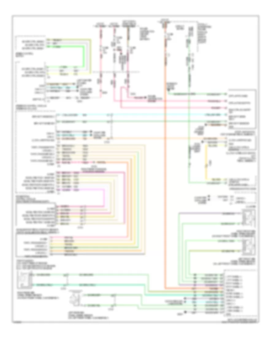
AIR CONDITIONING
Automatic A/C Wiring Diagram (1 of 2) for Dodge Challenger R/T Plus 2013

List of elements for Automatic A/C Wiring Diagram (1 of 2) for Dodge Challenger R/T Plus 2013:
- 5v ref
- 6.4l
- 87a
- A/c cltch fd
- A/c heater control
- A/c press sig
- A/c pressure transducer (left rear of engine compt)
- A/cc
- A117
- A23
- Abs run only ign fd
- Act temp(driv)
- Ambient air temperature sensor (right front of engine compt)
- Assy rad fan
- Auto hdlp sig
- C (+)
- C (-)
- C115
- C121
- C13
- C18
- C202
- C21
- C32
- C34
- C35
- C36
- C56
- C61
- C918
- Can
- Can b (+)
- Can b (-)
- Circuit board
- Cluster
- Com door ctrl
- Computer data lines system
- D54
- D55
- D64
- D65
- Defogger rly ctrl
- Defogger system
- Engine controls system
- Engine coolant temperature sensor (3.6l: left rear of engine) (except 3.6l: left front of engine)
- Evap sens gnd
- Evap sig
- Evaporator temperature sensor (on hvac evaporator)
- Except 6.4l
- F500
- F891
- Fsd b (+)
- Ft blw pwm ctrl
- Ft mode act drv
- Fuse 50a
- G139
- G1a (right front of engine compt)
- G2a (left front of engine compt)
- G39
- G51a (right front of engine compt)
- G931
- G9a (left side of dash)
- Gnd
- Hot at all times
- In car temperature sensor (left side of dash)
- K915
- L24
- Powertrain control module (right rear of engine compt)
- Rad fan hi spd sig
- Rad fan lo
- Rad fan lo ctrl
- Rad fan mtr fd2
- Rad fan mtr spd sig
- Radiator fan high/lo relay
- Radiator fan medium/ high relay
- Radiator fan motor (6.4l)
- Radiator fan motor (except 6.4l)
- Radiator fan motor 2 (6.4l)
- Radiator fan resistor
- Radiator fan series/ parallel relay
- Rerc act dr
- S01
- S155 (except 3.6l: center rear of engine, in engine harness) (3.6l: left rear of engine, in engine harness)
- S239 (center of dash, in instrument panel harness)
- Sens rtn
- Sens sig
- Snsr gnd
- Snsr sig
- Ssr sunld sig
- Ssr sunld sig 2
- Temp sig
- Totally integrated power module (right side of engine compt)
- Z902
- Z909
Automatic A/C Wiring Diagram (2 of 2) for Dodge Challenger R/T Plus 2013
List of elements for Automatic A/C Wiring Diagram (2 of 2) for Dodge Challenger R/T Plus 2013:
- (right front of engine compt) g51a
- (right side of dash, in instrument panel harness) s238
- 14b
- 28b
- 3.6l
- 38b
- 42b
- A/c cltch fd
- A/c compressor clutch (lower left front of engine)
- Blower motor (right side of dash)
- C100
- C104
- C200
- C202
- C56
- Clkwse rcrc plse drv
- Cntr clkwse rcrc plse drv
- Except 3.6l
- Front mode door actuator (on hvac unit)
- Front power blower motor module (near hvac blower motor)
- Ft blw fd gnd c1
- Ft blw pwm ctrl
- Fuse 10a
- Fuse 30a
- G51a (right front of engine compt)
- G8a
- Gnf
- Gnf ft blw fd
- Hdlp sig
- Hot at all times
- Hot w/ run relay energized
- Left blend door actuator (left side of hvac unit)
- Lt clkwse temp plse drv
- Lt cntr clkwse temp plse drv
- Plse drv clkwse mode
- Plse drv cntr clkwse
- Power distribution center (near battery)
- Recirculation door actuator (on hvac unit)
- S154
- S200
- S210
- S374
- Sens gnd
- Ssr sunld sig
- Sun sensor (top center of dash)
- Sunld sig 2
- Z134
- Z908
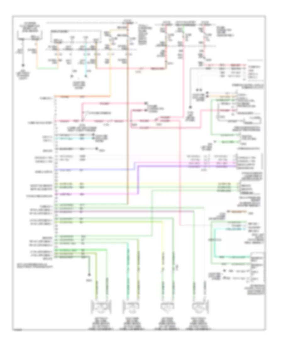
ANTI-LOCK BRAKES
Anti-lock Brakes Wiring Diagram for Dodge Challenger R/T Plus 2013
List of elements for Anti-lock Brakes Wiring Diagram for Dodge Challenger R/T Plus 2013:
- (on brake fluid reservoir) brake fluid level sensor
- 10a
- 29b
- 30a
- 30b
- 50a tan/ red
- A107
- A111
- A913
- Anti-lock brakes module (right front of engine compt)
- B15
- B16
- B31
- B32
- B33
- Batt fd
- Boost vac sens fd
- Brake sw sig 1
- Brake sw sig 2
- Brk lvl sw sig
- Brk sig 1
- Brk sig 2
- Bstr vac snsr rtn
- C102
- C104
- C203
- Can b (+) traction ctrl sw sense prk brk sw sig
- Can b (-)
- Can bus (+) yaw
- Can bus (-) yaw
- Can c (+)
- Can c (-)
- Can c (-) c1
- Circuit board
- Cluster
- Computer data lines system
- D464
- D465
- D64
- D65
- Dynamic sens ground
- Dynamics sensor (under rear of center console)
- F202
- Fuse
- Fuse 10a
- Fused b (+)
- Fused b(+)
- Fused ign run-start
- G10a (left center of dash)
- G12a (under driver's seat)
- G2a (left front of engine compt)
- G52a
- G94
- G9a (left side of dash)
- Gnd
- Ground
- Hot at all times
- Hot w/ run/start relay energized
- Ign run strt
- Left front abs wheel speed sensor (on left front wheel hub assembly)
- Left rear abs wheel speed sensor (on left rear wheel hub assembly)
- Lf whl spd sens (+)
- Lf whl spd sens (-)
- Lr whl spd sens (+)
- Lr whl spd sens (-)
- Parking brake switch (base of parking brake)
- Power distribution center (near battery)
- Power distribution system
- Powertrain control module (right rear of engine compt)
- Press sig
- Red
- Rf whl spd sens (+)
- Rf whl spd sens (-)
- Right front abs wheel speed sensor (on right front wheel hub assembly)
- Right rear abs wheel speed sensor (on right rear wheel hub assembly)
- Rr whl spd sens (+)
- Rr whl spd sens (-)
- Run/start
- S128 (under left side of rear shelf, in body harness)
- S209
- S309
- S374
- Sens clstr fd
- Sens fd
- Sens ground
- Sens rtn
- Sens sig
- Snsr clstr fd
- Steering control module (steering column)
- Stop lamp switch (top of brake pedal assembly)
- Sw sig
- Tan/ red
- Tan/red
- Totally integrated power module (right side of engine compt)
- Traction ctrl sw sns
- Upper bank switch
- Vacuum pressure sensor (on brake vacuum booster assembly)
- W/ power steering
- Z910
- Z931
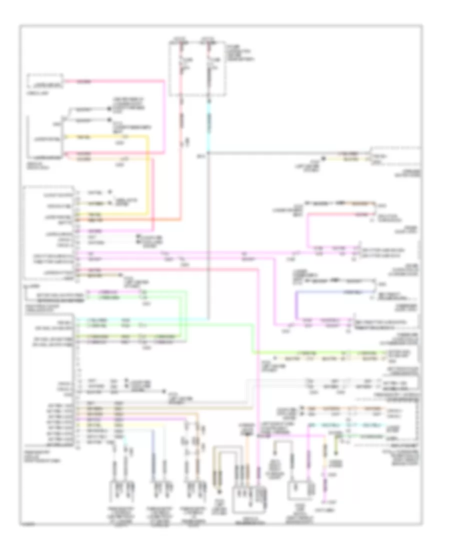
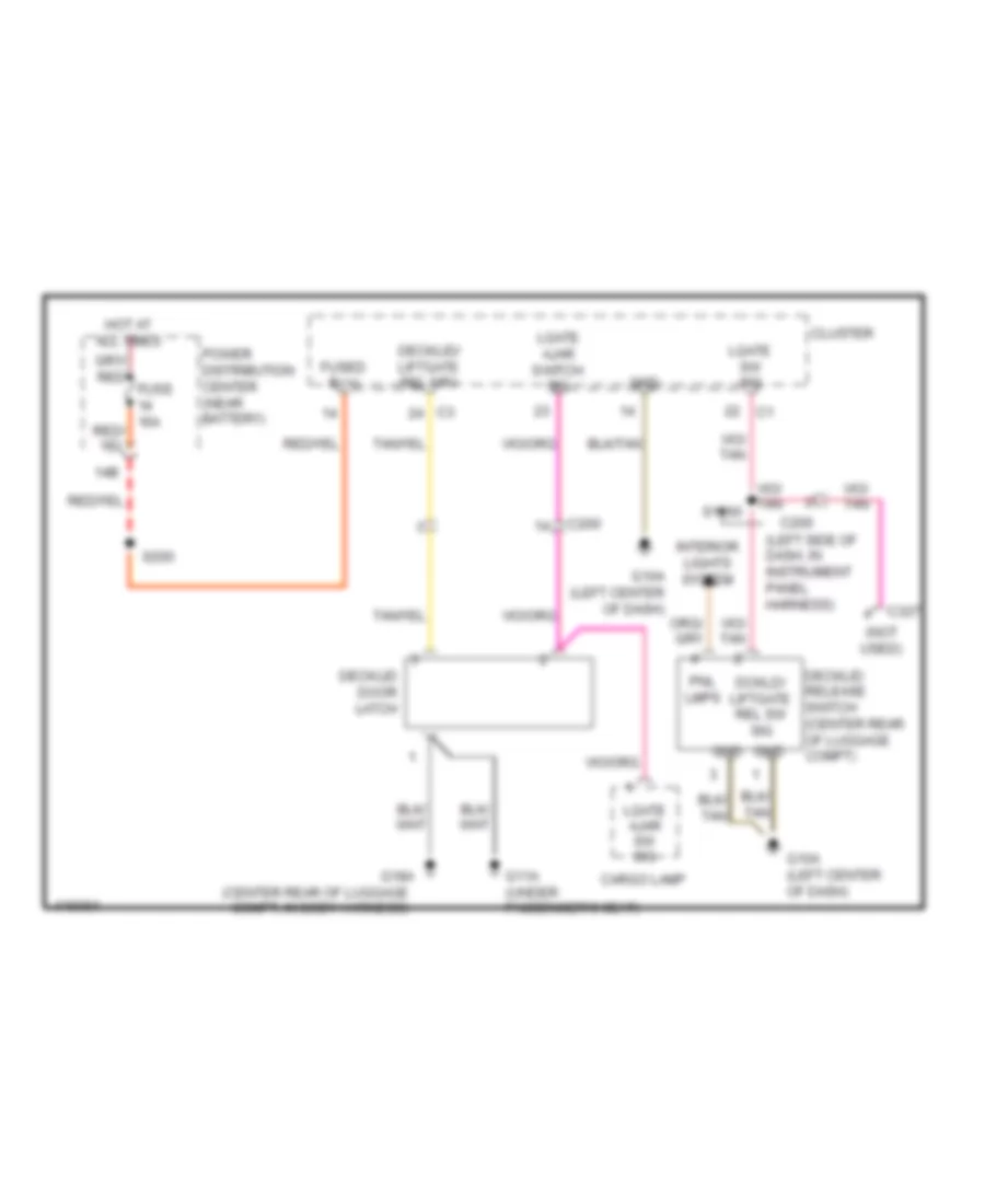
ANTI-THEFT
Anti-theft Wiring Diagram for Dodge Challenger R/T Plus 2013
List of elements for Anti-theft Wiring Diagram for Dodge Challenger R/T Plus 2013:
- (center rear of luggage compt, in body harness) g18a
- (left side of dash, in instrument panel harness) s1460
- (not used)
- (under passenger's seat) g11a
- 17b
- 4 rtn
- A106
- Ant pem 1 rtn
- Ant pem 1 sig
- Ant pem 2 rtn
- Ant pem 2 sig
- Ant pem 3 rtn
- Ant pem 3 sig
- Ant pem 4 rtn
- Ant pem 4 sig
- Batt fd
- C200
- C203
- C300
- C301
- C327
- Can b (+)
- Can b (-)
- Can b (-) can b (+) c1
- Cargo lamp
- Circuit board
- Cluster
- Computer data lines system
- D54
- D55
- D920
- D921
- D922
- D923
- D924
- D925
- D926
- D927
- Decklid door latch
- Decklid release switch
- Dr hndl sw rtn pass
- Dr hndl sw sig drv
- Dr hndl sw sig pass
- Driv ft dr ajar sig ddm
- Driv ft dr ajar sw in
- Driver door latch
- Driver door module (in driver door)
- Ext dr hndl sw rtn pass
- Ext dr hndl sw sig drv
- Ext dr hndl sw sig pass
- Fsd b(+)
- Fuse 20a red
- G10a (left center of dash)
- G11a (under passenger's seat)
- G12a (under driver's seat)
- G51a (right front of engine compt)
- G70
- G74
- G745
- G75
- G755
- Gnd
- Headlights system
- Hood ajar switch (right rear of engine compt)
- Horn
- Horns system
- Hot at all times red
- Interior lights system
- Left front door handle switch
- Lgate ajar sig
- Lgate pwr rel
- Lgate sw ft sig
- Mfs hdlp sel
- Mlfnct sw rtn
- P125
- P400
- P401
- Pass ft dr ajar sw in
- Pass ft dr ajar sw in c3
- Passenger door latch
- Passenger door module (in passenger door)
- Passive entry 1 antenna (in driver's door)
- Passive entry 2 antenna (in passenger's door)
- Passive entry 3 antenna (under front of center console)
- Passive entry 4 antenna (center front of luggage compt)
- Passive entry module (right side of dash)
- Pnl lamps
- Power distribution center (near battery)
- Red/tan
- Rel sw sig lt gate dckld/
- Right front door handle switch
- S215
- S490
- S590
- Sec pass ft dr ajar sig pdm
- Totally integrated power module (right side of engine compt)
- Uhood sw sig
- Wireless ignition node
- Z910
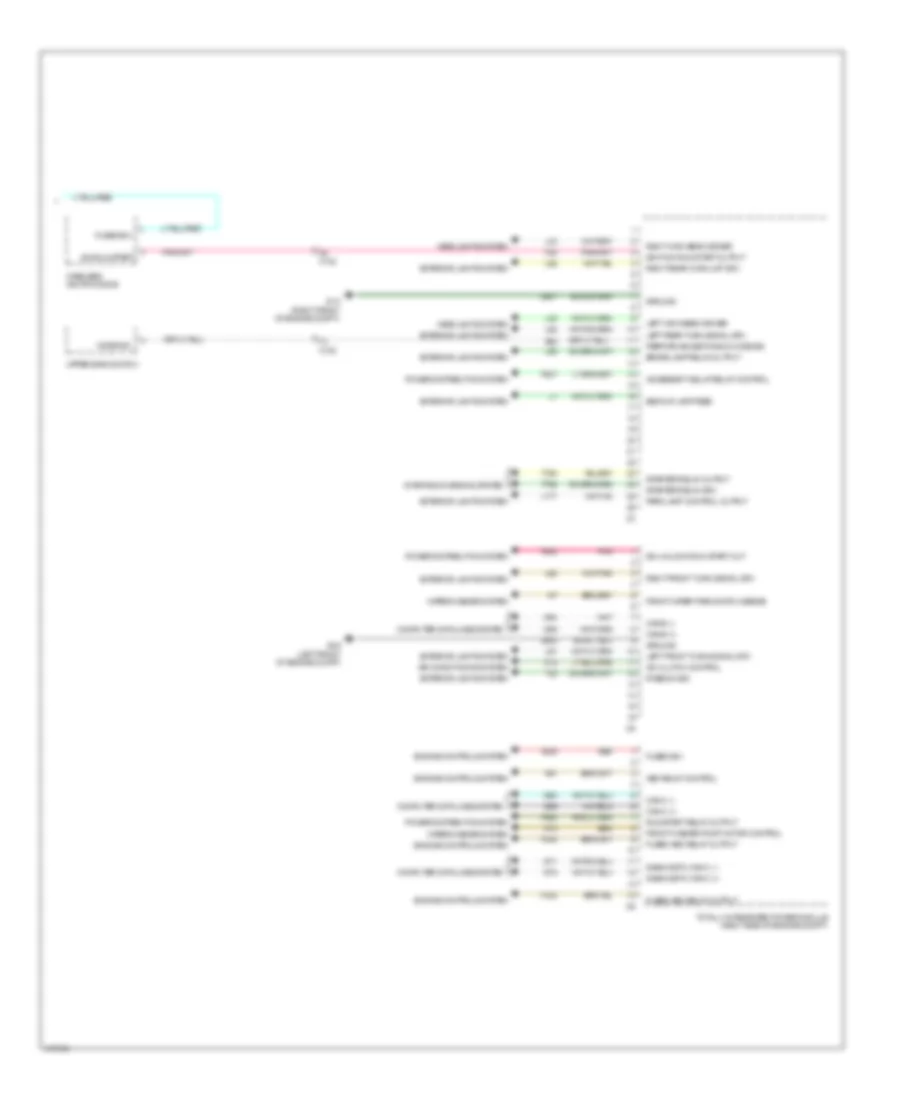
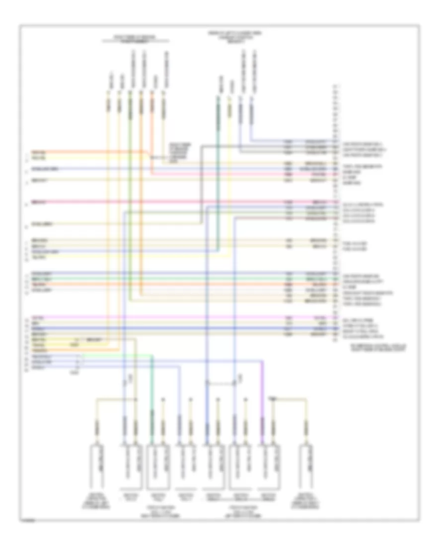
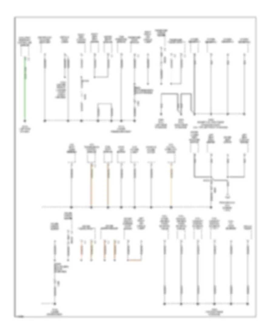
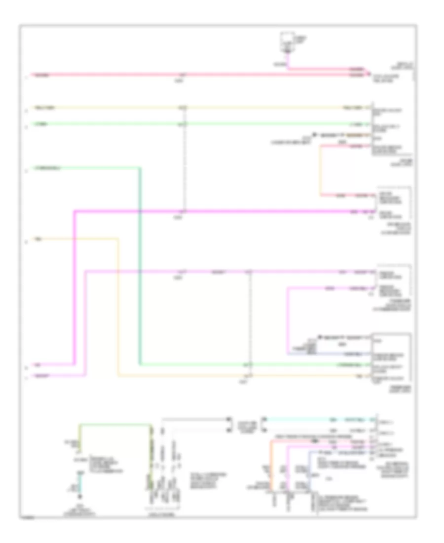
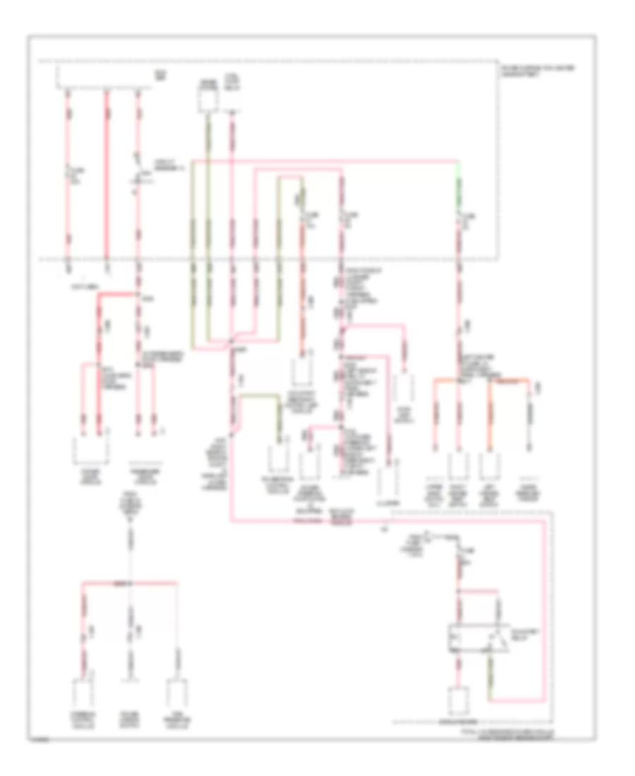
BODY CONTROL MODULES
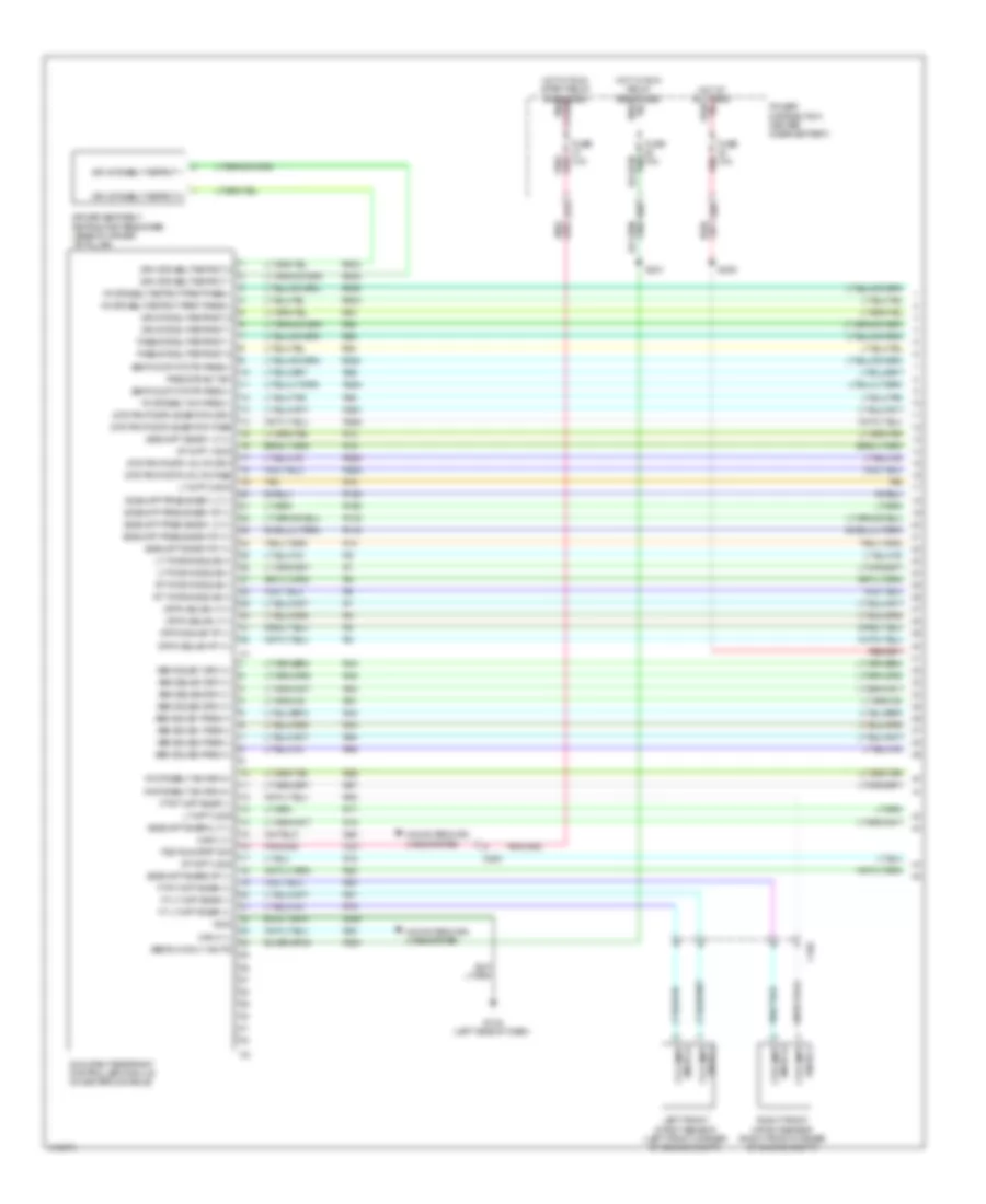
Body Control Modules Wiring Diagram (1 of 2) for Dodge Challenger R/T Plus 2013
List of elements for Body Control Modules Wiring Diagram (1 of 2) for Dodge Challenger R/T Plus 2013:
- (right front of engine compt) g1a
- (top of right cylinder head, in engine harness) (except 6.4l) s904
- 38b
- A/c clutch control output
- A/c pressure sensor ground
- A/c pressure transducer signal
- A107
- A11
- A111
- A117
- A22
- Aat signal
- Air conditioning system
- Anti-lock brakes system
- Anti-theft system
- B(+)
- B1 pass through post
- B20
- Battery
- Brake fluid level sig
- C104
- C18
- C918
- Cooling fans system
- Exterior lights system
- F891
- F923
- Fuse 10a
- Fuse 15a
- Fuse 40a
- Fused b(+)
- Fused b(+) (i.o.d.)
- Fused b(+) (pump)
- G31
- G70
- G931
- Ground
- Hazard switch sense
- Headlights system
- Hood ajar switch sense
- Horn control output
- Horns system
- Hot at all times
- Instrument cluster system
- L43
- L44
- L89
- L91
- Left fog lamp control
- Left low beam driver
- Lo spd rad fan cirl
- N210
- N23
- N24
- Nca
- Power distribution center (near battery)
- Power distribution system
- Rad fan control relay
- Rad fan high/low control feed
- Red
- Right low beam driver
- Run relay control
- S138
- S215
- S374
- Sensor ground
- Tan/red
- Totally integrated power module (right side of engine compt)
- Washer fluid level switch sense
- Wiper high spd ctrl output
- Wiper/washer system
- Z901
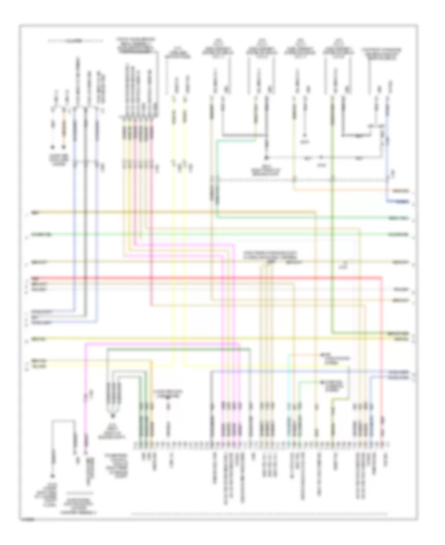
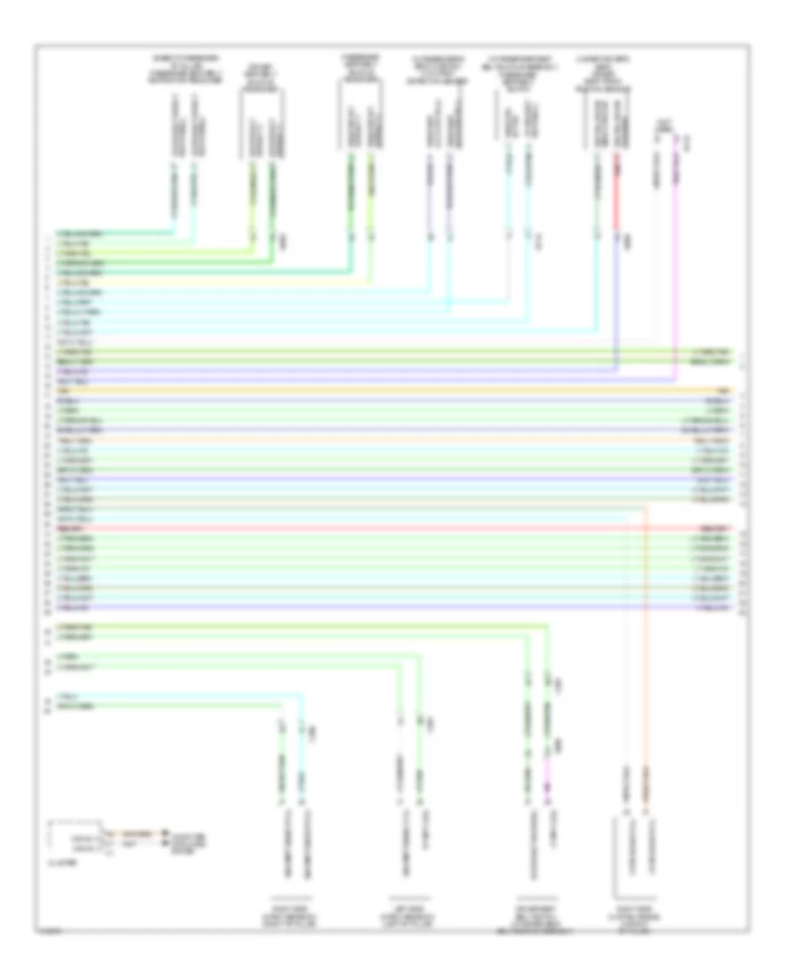
Body Control Modules Wiring Diagram (2 of 2) for Dodge Challenger R/T Plus 2013
List of elements for Body Control Modules Wiring Diagram (2 of 2) for Dodge Challenger R/T Plus 2013:
- A/c clutch control
- A209
- Accessory delay relay control
- Air conditioning system
- Asd relay control
- Backup lamp feed
- Brake lamp relay output
- C102
- C13
- Can b (+)
- Can b (-)
- Can c (+)
- Can c (-)
- Computer data lines system
- D54
- D55
- D64
- D65
- D71
- D72
- Diagnostic can c (+)
- Diagnostic can c (-)
- Engine controls system
- Exterior lights system
- F20
- F342
- F343
- F902
- F950
- Front washer pump motor control
- Front wiper park switch sense
- Fused asd relay output
- Fused b(+)
- G1a (right front of engine compt)
- G2a (left front of engine compt)
- Ground
- Headlights system
- Ign run-start
- Ign unlock-run-start out
- Ignition run-start output
- K51
- L33
- L34
- L53
- L60
- L61
- L62
- L63
- L777
- Left front turn signal drv
- Left high beam driver
- Left rear turn signal drv
- Mode sig
- P307
- Park lamp control output
- Performance/dynamic mode sig
- Pnk
- Power distribution system
- Red
- Right front turn signal drv
- Right high beam driver
- Right rear turn lmp drv
- Run/start relay output
- Rvse sw sig
- S52
- Starter relay drv
- Starter relay output
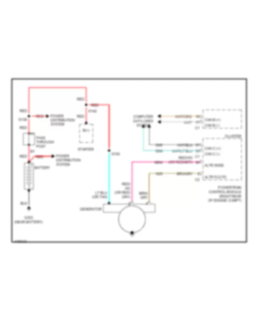
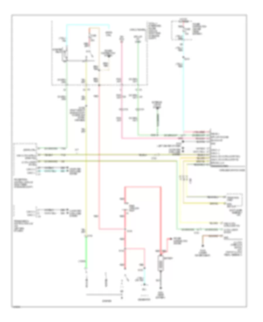
- Starting/charging system
- T22
- T750
- T752
- Totally integrated power module (right side of engine compt)
- Upper bank switch
- W10
- Wiper/washer system
- Wireless ignition node
- Z901
- Z902
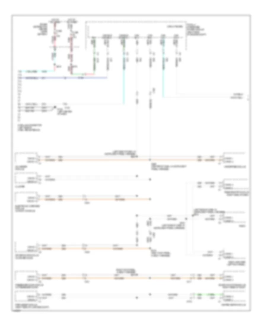
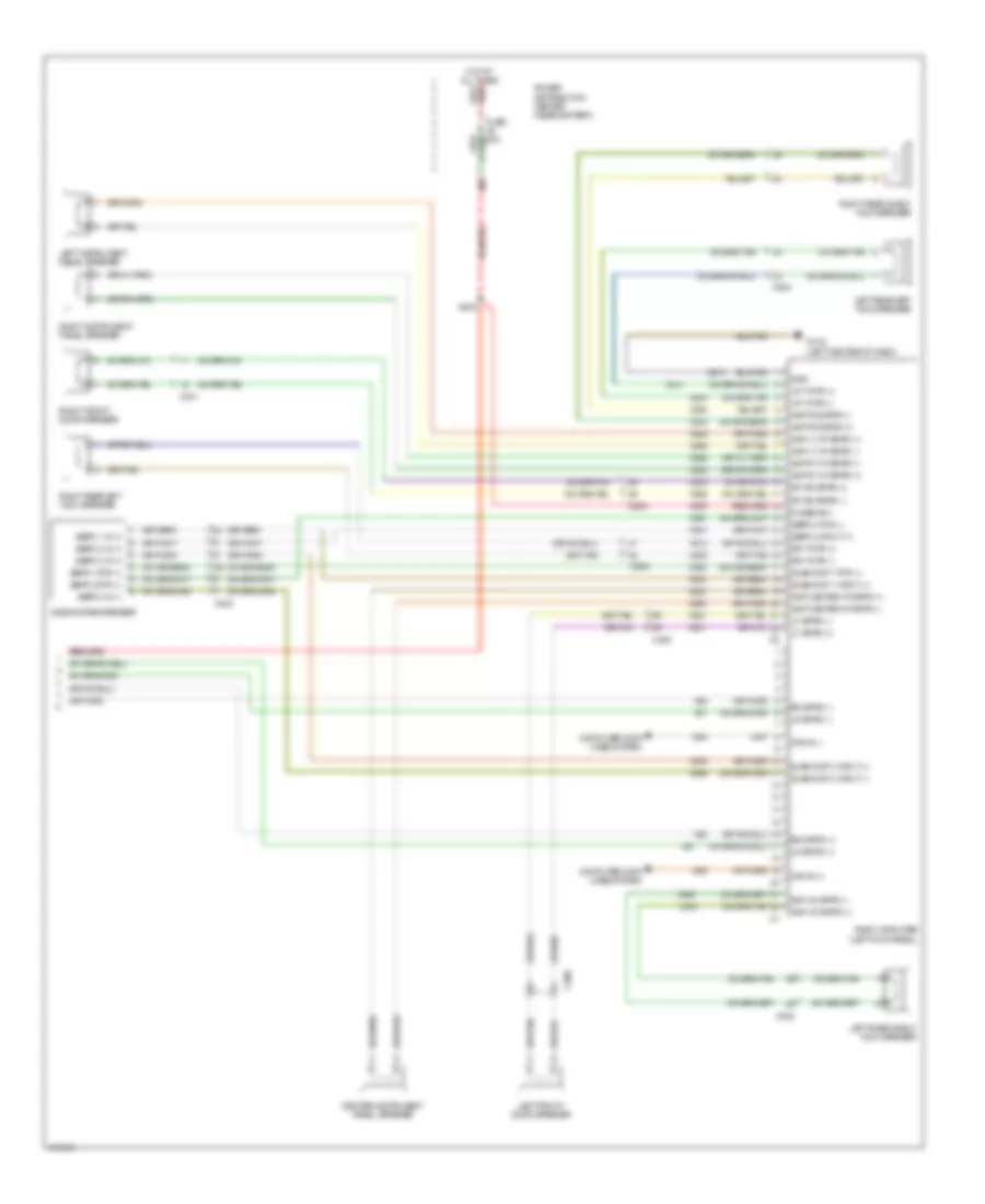
COMPUTER DATA LINES
Computer Data Lines Wiring Diagram (1 of 2) for Dodge Challenger R/T Plus 2013
List of elements for Computer Data Lines Wiring Diagram (1 of 2) for Dodge Challenger R/T Plus 2013:
- (left side of dash, in instrument panel harness) s204
- (left side of dash, in instrument panel harness) s218
- (right kick panel, in body harness) s318
- 38b
- A/c heater module
- A106
- A117
- B(+)
- C102
- C104
- C203
- C204
- C300
- C301
- C311
- Can b (+)
- Can b (-)
- Can bus d diag (+)
- Can bus d diag (-)
- Can c (+)
- Can c (-)
- Circuit board
- Cluster
- D54
- D55
- D64
- D65
- D71
- D72
- Data link connector (left side of dash, above pedals)
- Driver door module (in driver door)
- Electronic overhead module (in roof console)
- Fuse 15a
- G10a (left center of dash)
- Handsfree module
- Heated seats module
- Hot at all times
- Hot at all times red
- I470a
- Park assist module (right side of luggage compt)
- Passenger door module (in passenger door)
- Passive entry module (right side of dash)
- Power distribution center (near battery)
- Radio
- Radio amplifier (left kick panel)
- Red/
- S205 (center of dash, in instrument panel harness)
- S215
- S219 (left side of dash, in instrument panel harness)
- S319 (right kick panel, in body harness)
- Sunroof motor/module (right rear of roof)
- Totally integrated power module (right side of engine compt)
- Z910
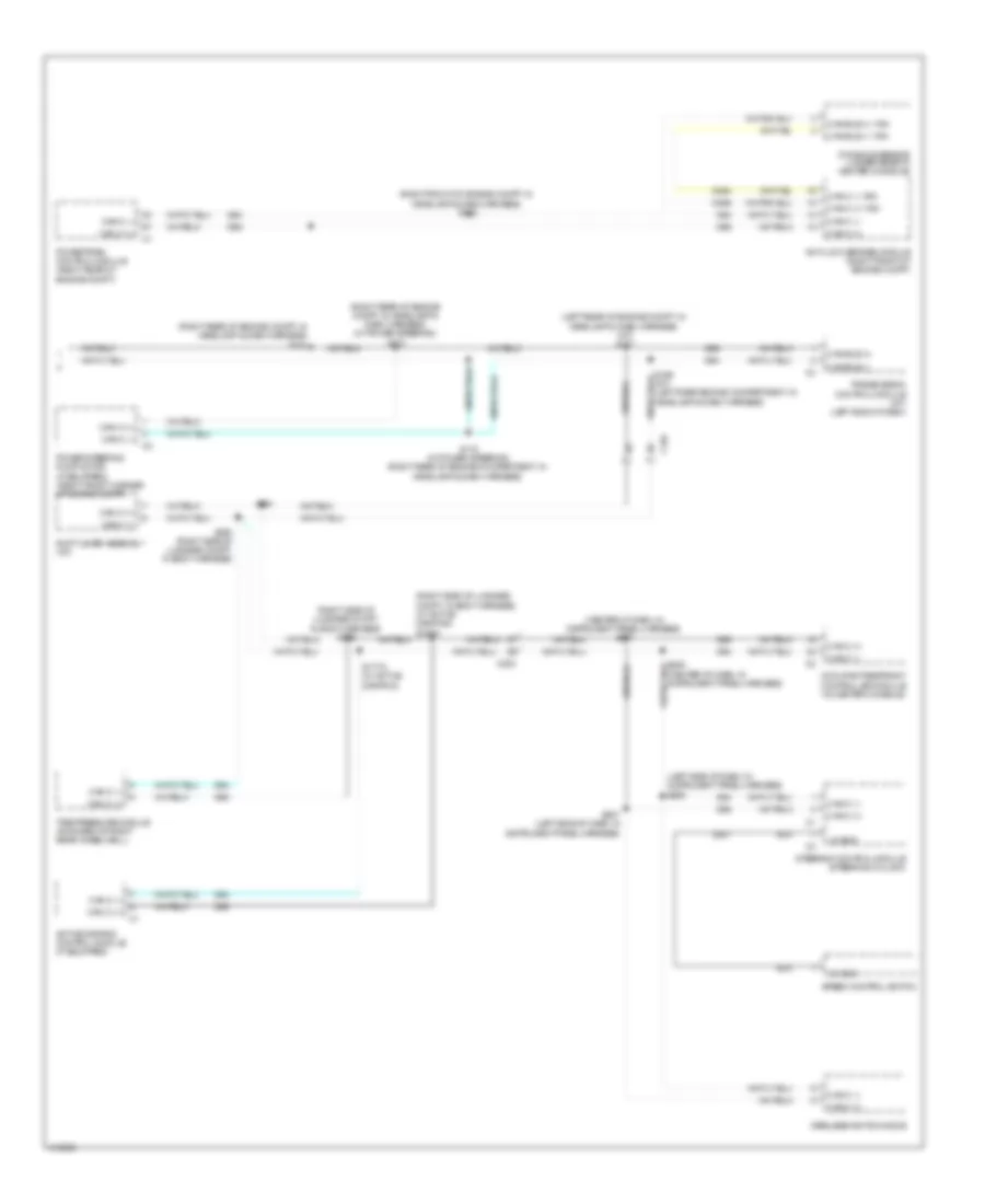
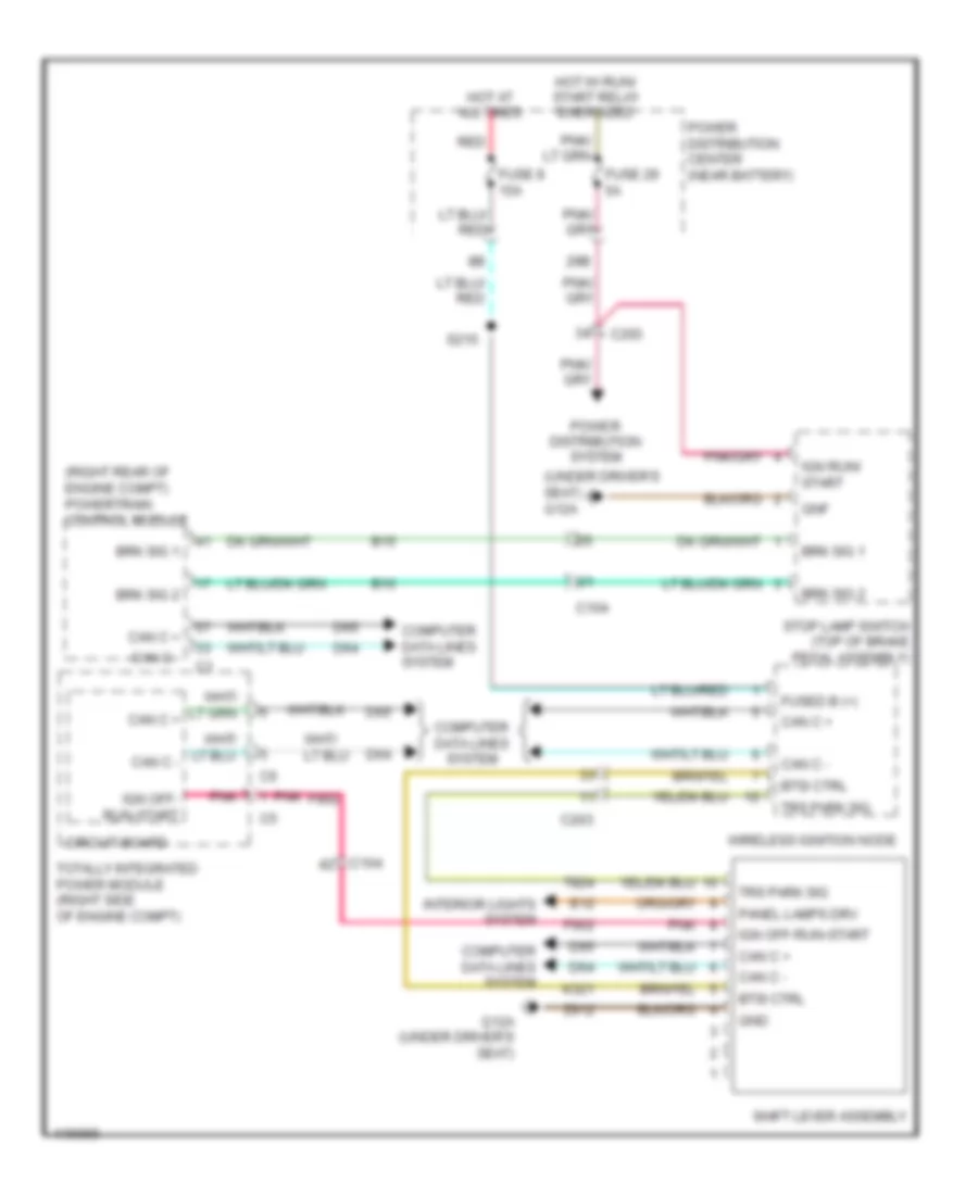
Computer Data Lines Wiring Diagram (2 of 2) for Dodge Challenger R/T Plus 2013
List of elements for Computer Data Lines Wiring Diagram (2 of 2) for Dodge Challenger R/T Plus 2013:
- (center of dash, in instrument panel harness)
- (center of dash, in instrument panel harness) s237
- (left rear of engine compt, in headlamp & dash harness) (a/t) s171
- (left side of dash, in instrument panel harness) s206
- (right front of engine compt, in headlamp & dash harness) s122
- (right rear of engine compt, in headlamp & dash harness) (w/ power steering) s172
- (right rear of engine compt, in headlamp & dash harness) s124
- (right side of luggage compt, in body harness) s336
- Active damping control module (if equipped)
- Anti-lock brakes module (right front of engine compt)
- C104
- C200
- Can bus (+)
- Can bus (+) yaw
- Can bus (-)
- Can bus (-) yaw
- Can c (+)
- Can c (+) yaw
- Can c (-)
- Can c (-) yaw
- D464
- D465
- D507
- D64
- D65
- Dynamics sensor (under rear of center console)
- Lin bus
- Occupant restraint controller module (in center console)
- Power steering pump motor (if equipped) (right front corner of engine compt)
- Powertrain control module (right rear of engine compt)
- S169 (a/t) (left rear engine compartment, in headlamp & dash harness)
- S170 (w/ power steering) (right rear of engine compartment, in headlamp & dash harness)
- S177a (w/ active damping)
- S207 (left side of dash, in instrument panel harness)
- S390 (right side of luggage compt, in body harness)
- S391
- Shift lever assembly (a/t)
- Speed control switch
- Steering control module (steering column)
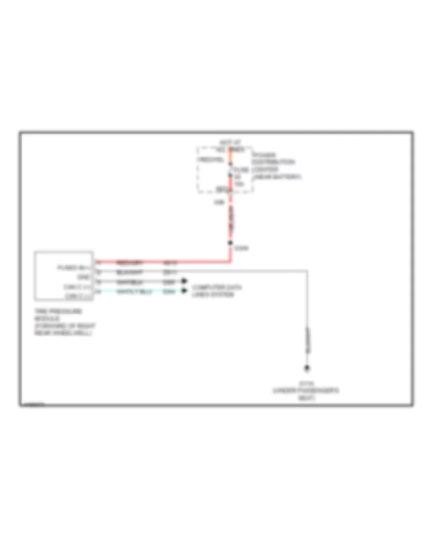
- Tire pressure module (forward of right rear wheelwell)
- Transmission control module (a/t) (left end of dash)
- Wireless ignition node
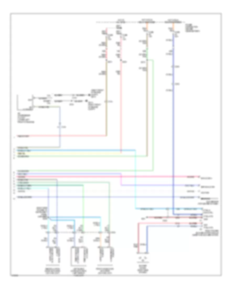
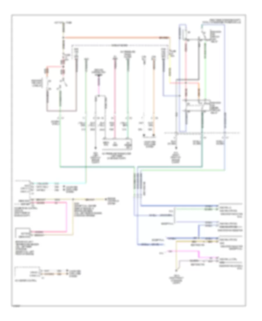
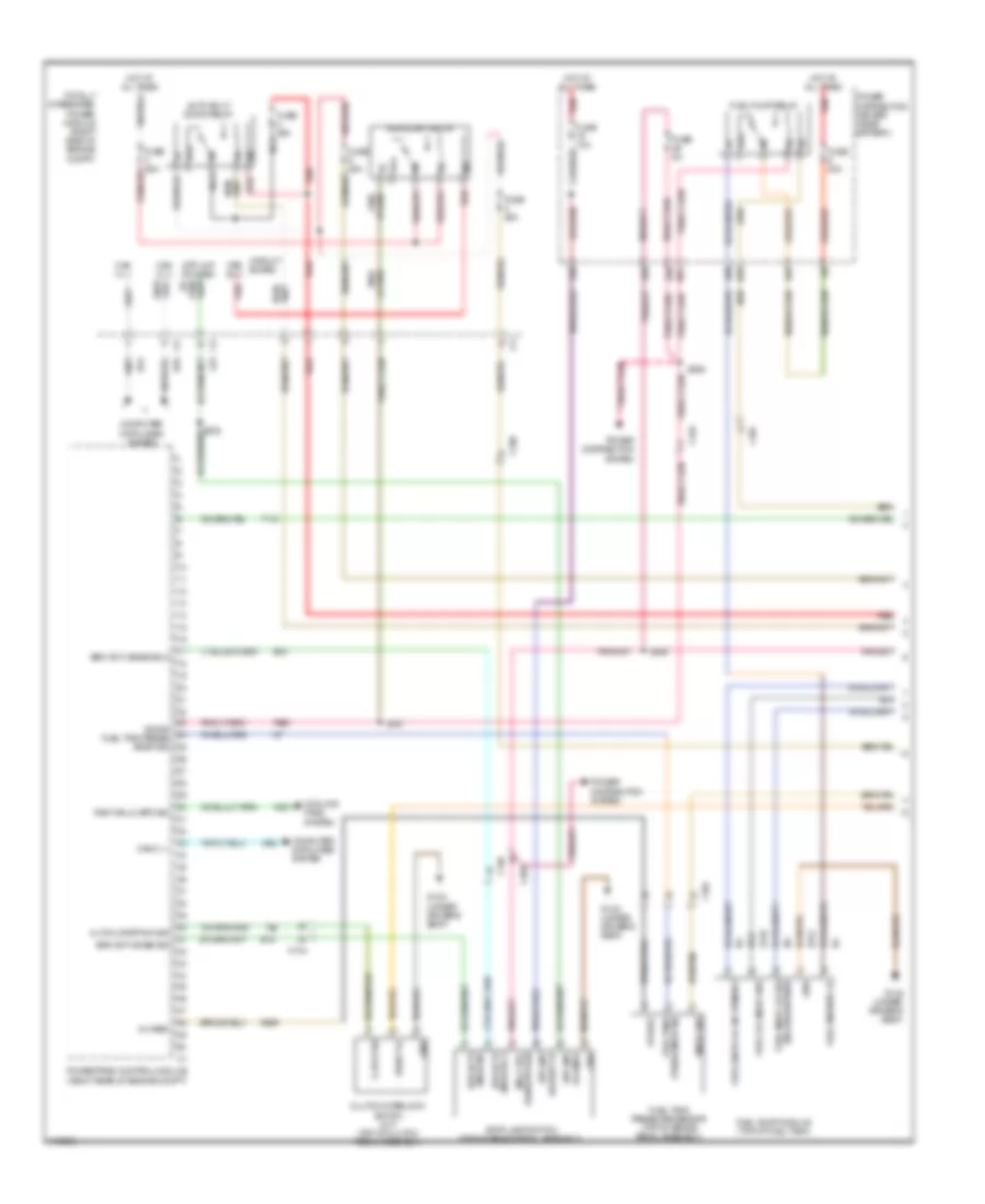
COOLING FAN
Cooling Fan Wiring Diagram for Dodge Challenger R/T Plus 2013
List of elements for Cooling Fan Wiring Diagram for Dodge Challenger R/T Plus 2013:
- (right side of engine compt) totally integrated power module
- 5v vref
- 6.4l
- 87a
- A/c heater control
- A/c press sig
- A/c pressure transducer (left rear of engine compt)
- A/cc can c (-)
- Assy rad fan
- C13
- C18
- C918
- Can b (+)
- Can b (-)
- Can c (+)
- Circuit board
- Computer data lines system
- D54
- D55
- D64
- D65
- Ect sig
- Engine controls system
- Engine coolant temperature sensor (3.6l: left rear of engine) (except 3.6l: left front of engine)
- Except 6.4l
- F891
- Fuse 50a
- G1a (right front of engine compt)
- G2a (left front of engine compt)
- G51a (right front of engine compt)
- Gnd
- Ground distribution system
- K915
- Powertrain control module (right rear of engine compt)
- Rad fan lo
- Rad fan lo ctrl
- Rad fan mtr fd2
- Radiator fan high/ lo relay
- Radiator fan medium/ high relay
- Radiator fan motor (6.4l)
- Radiator fan motor (except 6.4l)
- Radiator fan motor 2 (6.4l)
- Radiator fan resistor
- Radiator fan series/ parallel relay
- Red/
- S01
- S155 (except 3.6l: center rear of engine, in engine harness) (3.6l: left rear of engine, in engine harness)
- Sens gnd
- Sens rtn
- Z902
CRUISE CONTROL
Cruise Control Wiring Diagram for Dodge Challenger R/T Plus 2013
List of elements for Cruise Control Wiring Diagram for Dodge Challenger R/T Plus 2013:
- (left center of dash) g10a
- (under driver's seat)
- 19b
- 29b
- 30b
- 5v ref
- A107
- A913
- Accel ped pos 1 snsr sig
- Accel ped pos 2 snsr sig
- Accel ped postn snsr rtn
- Accel ped postn snsr rtn 2
- Accelerator pedal position sensor (top of accelerator pedal assembly)
- Anti-lock brakes module (right front of engine compt)
- B15
- B16
- Batt fd 13
- Brk actv snse sig
- Brk actv snse sig 2
- C104
- C203
- Can b (+)
- Can b (-)
- Can c (+)
- Can c (-)
- Can c+
- Can c-
- Circuit board
- Cltch upstp sw sig
- Cluster
- Clutch interlock switch (m/t) (top of clutch pedal assembly)
- Computer data lines system
- D64
- D65
- Distribution power
- Eng ctrl run/strt ign
- Exterior lights system
- F855
- Fsd b(+)
- Fuse 10a
- Fuse 50a
- Fuse 5a
- G12a
- G12a (under driver's seat)
- G52a
- Gnd
- Hot at all times
- Hot w/ run/ start relay energized
- K122
- K167
- K22
- K23
- K29
- K400
- K447
- K448
- K852
- K854
- K922
- L53
- Left front abs wheel speed sensor (on left front wheel hub assembly)
- Left rear abs wheel speed sensor (on left rear wheel hub assembly)
- Lt ft wheel (+)
- Lt ft wheel (-)
- Lt rr wheel (+)
- Lt rr wheel (-)
- Man cltch intrlk start fd
- Man cltch intrlk start fd stp lmp fd cmbd
- Mtr etc (+)
- Mtr etc (-)
- Power distribution center (near battery)
- Power distribution system
- Powertrain control module (right rear of engine compt)
- Red
- Right front abs wheel speed sensor (on right front wheel hub assembly)
- Right rear abs wheel speed sensor (on right rear wheel hub assembly)
- Rt ft wheel (+)
- Rt ft wheel (-)
- Rt rr wheel (+)
- Rt rr wheel (-)
- S105 (right rear of engine, in engine harness)
- S302
- S309
- Speed control switch
- Steering control module (steering column)
- Stop lamp switch (top of brake pedal assembly)
- Stp lmp fd cmbd
- Str lmp sw batt fd
- Sw spd ctrl rtn
- Sw spd ctrl snse 1
- Sw spd ctrl snse 2
- System
- T26
- Tan/red
- Throttle body (3.6l: right rear of engine) (5.7l: top center front of engine) (6.4l: top left front of engine)
- Thrtl pos snsr rtn
- Thrtl pos snsr sig 1
- Thrtl pos snsr sig 2
- Totally integrated power module (right side of engine compt)
- V71
- V72
- V937
- Wireless ignition node
- Z910
- Z931
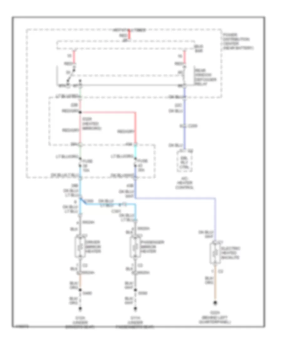
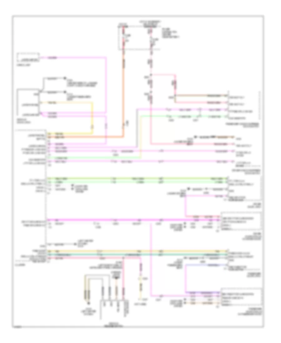
DEFOGGERS
Defoggers Wiring Diagram for Dodge Challenger R/T Plus 2013
List of elements for Defoggers Wiring Diagram for Dodge Challenger R/T Plus 2013:
- 22b
- 22c
- 39a
- 43a
- 43b
- 87a
- A/c- heater control
- Bus bar
- C200
- C300
- C301
- Driver mirror heater
- Ebl rly ctrl
- Electric heated backlite
- Fuse 10a
- Fuse 30a
- G11a (under passenger's seat)
- G12a (under driver's seat)
- G22a (behind left quarterpanel)
- Hot at all times
- I6624a
- I6626a
- Passenger mirror heater
- Power distribution center (near battery)
- Rear window defogger relay
- Red
- S490
- S590
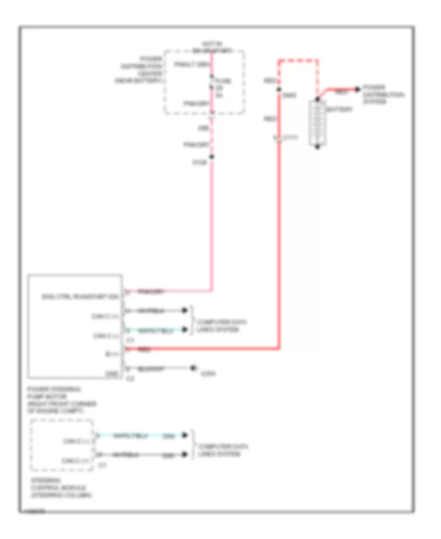
ELECTRONIC POWER STEERING
Electronic Power Steering Wiring Diagram for Dodge Challenger R/T Plus 2013
List of elements for Electronic Power Steering Wiring Diagram for Dodge Challenger R/T Plus 2013:
- 29b
- B (+)
- Battery
- C111
- Can c (+)
- Can c (-)
- Computer data lines system
- D64
- D65
- Eng ctrl run/start ign
- Fuse 5a
- G35a
- Gnd
- Hot in on or start
- Power distribution center (near battery)
- Power distribution system
- Power steering pump motor (right front corner of engine compt)
- Red
- S128
- S905
- Steering control module (steering column)
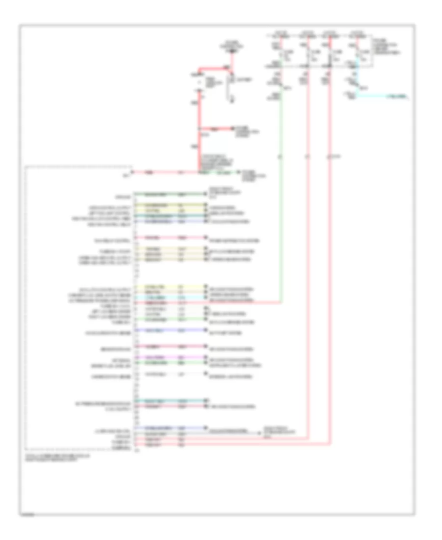
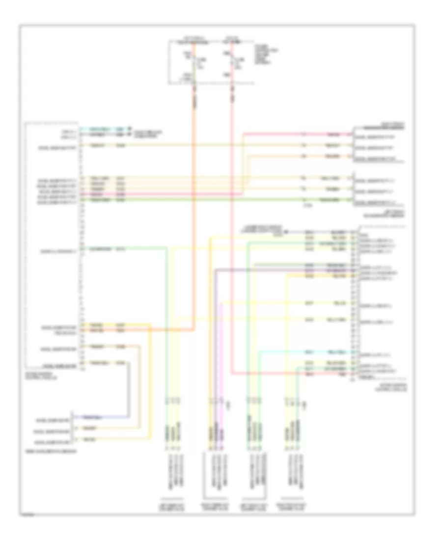
ELECTRONIC SUSPENSION
Electronic Suspension Wiring Diagram for Dodge Challenger R/T Plus 2013
List of elements for Electronic Suspension Wiring Diagram for Dodge Challenger R/T Plus 2013:
- (under right side of luggage compt floor) g14a
- 15b
- 41b
- A914
- Accel snsr pwr ft lt
- Accel snsr pwr ft rt
- Accel snsr pwr rr
- Accel snsr rtn ft lt
- Accel snsr rtn ft rt
- Accel snsr rtn rr
- Accel snsr sig ft lt
- Accel snsr sig ft rt
- Accel snsr sig rr
- Active damping control module
- C105
- C323
- Can c (+)
- Can c (-)
- Computer data lines system
- D64
- D65
- Dmpr vlv ft lt (+)
- Dmpr vlv ft lt (-)
- Dmpr vlv ft rt (+)
- Dmpr vlv ft rt (-)
- Dmpr vlv pwr ft lt
- Dmpr vlv pwr ft rt
- Dmpr vlv pwr rr lt
- Dmpr vlv pwr rr rt
- Dmpr vlv rr lt (+)
- Dmpr vlv rr lt (-)
- Dmpr vlv rr rt (+)
- Dmpr vlv rr rt (-)
- F930
- Fsd b(+)
- Fsd ign run
- Fuse 10a
- Fuse 20a
- Gnd
- Hot at all times
- Hot w/ run relay energized
- Left front acceleration sensor
- Left front act damper valve
- Left rear act damper valve
- Power distribution center (near battery)
- Rear acceleration sensor
- Red
- Right front acceleration sensor
- Right front act damper valve
- Right rear act damper valve
- S130
- S131
- S132
- S133
- S134
- S135
- S136
- S137
- S160
- S161
- S162
- S163
- S164
- S165
- S166
- S167
- S168
- S170
- S171
- S172
- S173
- Z914
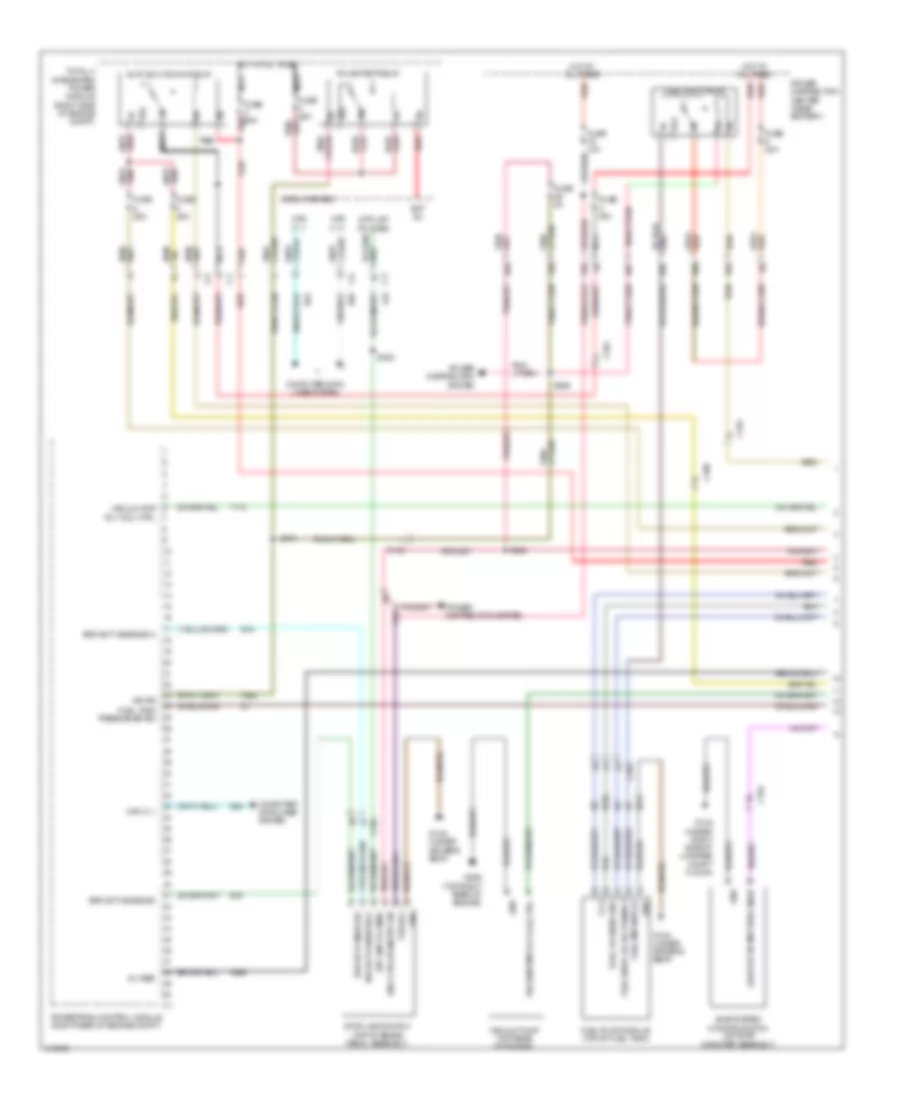
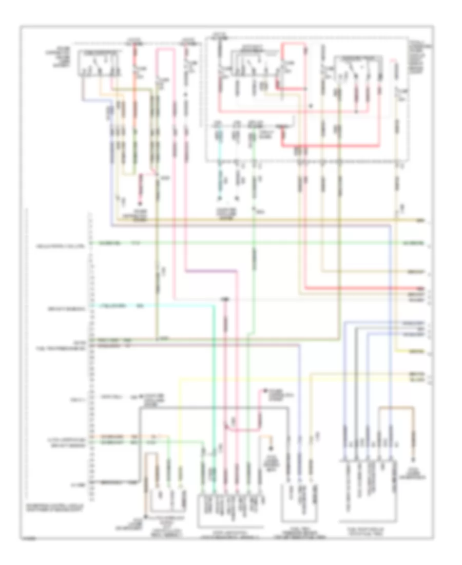
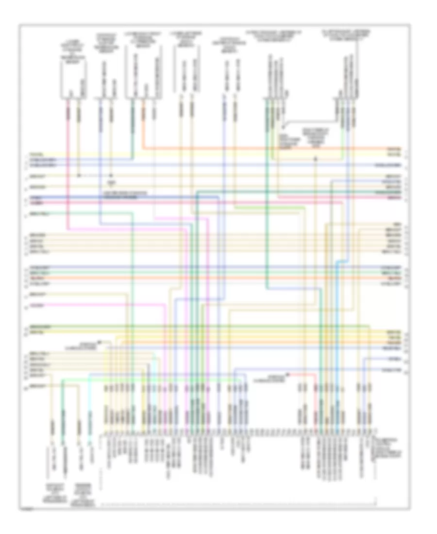
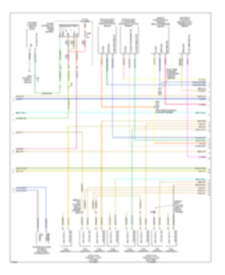
ENGINE PERFORMANCE
3.6L FLEX FUEL
3.6L Flex Fuel, Engine Performance Wiring Diagram (1 of 5) for Dodge Challenger R/T Plus 2013
List of elements for 3.6L Flex Fuel, Engine Performance Wiring Diagram (1 of 5) for Dodge Challenger R/T Plus 2013:
- 19b
- 29a
- 29b
- 46a
- 46b
- 46c
- 46d
- 5v vref
- 87a
- Auto shut down relay
- B15
- B16
- Bat fd
- Brk actv snse sig
- Brk actv snse sig 2
- C100
- C104
- C203
- Can c (+)
- Can c (-)
- Circuit board
- Computer data lines system
- D64
- D65
- Eng ctrl run/strt ign
- Evap system monitor switch (on evap canister assembly)
- F950
- Fli 2
- Fsd b(+)
- Fuel lvl snsr gnd
- Fuel pmp mtr fd
- Fuel pump module (top of fuel tank)
- Fuel pump relay
- Fuel sndr lvl sig primary
- Fuel tank press snsr sig
- Fuse 10a
- Fuse 20a
- Fuse 25a
- Fuse 40a
- Fuse 5a
- G12a (under driver's seat)
- G14a (under right side of luggage compt floor)
- G36a (top right rear of engine)
- Gnd
- Hot at all times
- Ign rs
- K859
- L53
- Leak dtctn pmp strk snse
- Nca
- Power distribution center (near battery)
- Power distribution system
- Powertrain control module (right rear of engine compt)
- Red
- Run/start relay
- S167
- S302
- S336
- S389
- Stop lamp switch (top of brake pedal assembly)
- Stp lmp fd cmbd
- T110
- Totally integrated power module (right side of engine compt)
- Vacuum pmp rly coil ctrl
- Vacuum pump (top rear of engine)
- Z210
- Z912
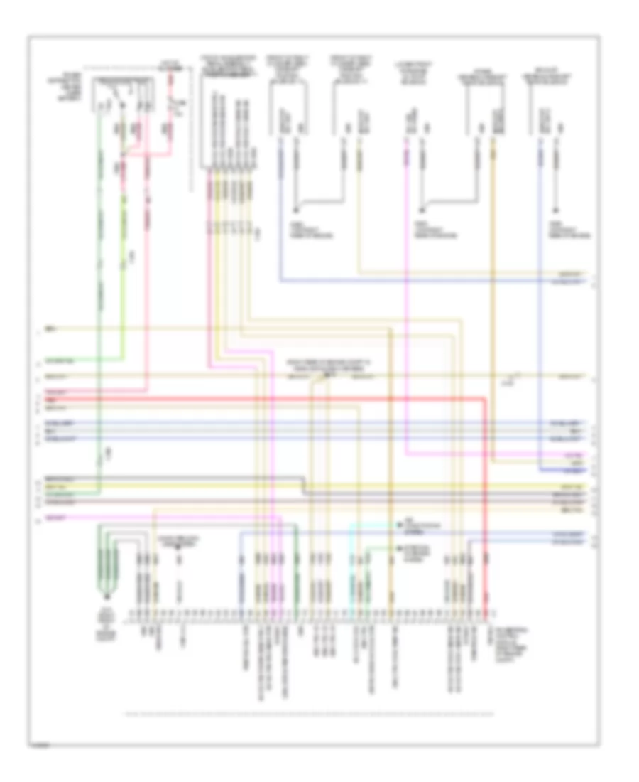
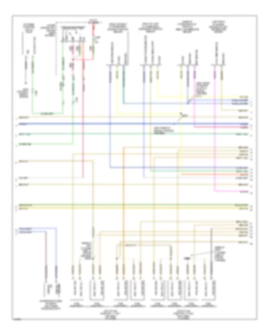
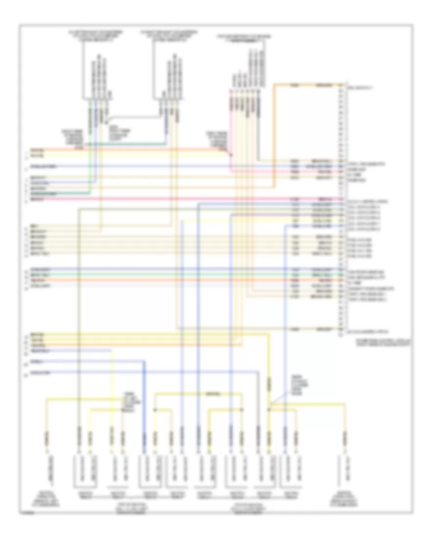
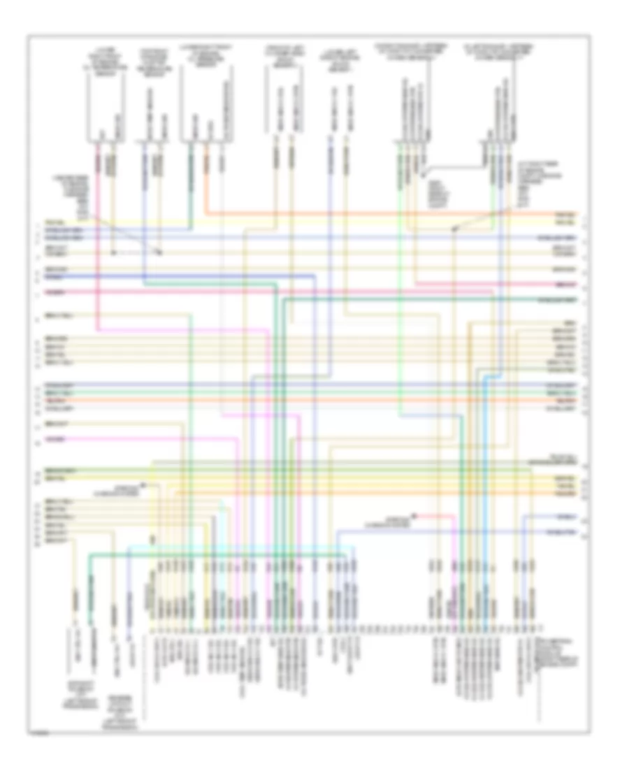
3.6L Flex Fuel, Engine Performance Wiring Diagram (2 of 5) for Dodge Challenger R/T Plus 2013
List of elements for 3.6L Flex Fuel, Engine Performance Wiring Diagram (2 of 5) for Dodge Challenger R/T Plus 2013:
- (front of right cylinder head) camshaft position solenoid 1/1
- (front of right cylinder head) camshaft position solenoid 1/2
- (lower front of engine) oil pump solenoid
- (right rear of engine compt, in headlamp & dash harness) s143
- (top of accelerator pedal assembly) accelerator pedal position sensor
- (top right rear of engine)
- 34c
- 34d
- 5v vref
- 87a
- A/c cltch coil
- A209
- Accel ped pos 1 snsr sig
- Accel ped pos 2 snsr sig
- Accel ped pos snsr rtn
- Accel ped postn snsr rtn
- Accel ped postn snsr rtn 2
- Air conditioning system
- Asd ctrl
- Asd ctrl fd
- C100
- C104
- C13
- Can c (+)
- Computer data lines system
- D65
- Eng ctrl fuel pump sig
- Exhaust variable camshaft timing solenoid
- Exhst vvt sol drv
- F342
- Fsd b(+)
- Fuse 10a
- G1a (right front of engine compt)
- G36a
- G36a (top right rear of engine)
- Gnd
- Hot at all times
- Intake variable camshaft timing solenoid
- Intke vvt sol drv
- K107
- K167
- K23
- K29
- K31
- K400
- K51
- K52
- K70
- K852
- K854
- K917
- Leak detcn pmp strke snse
- Power distribution center (near battery)
- Powertrain control module (right rear of engine compt)
- Pwm prg sol rtn
- Pwm prge sig
- Red
- Snsr gnd
- Sol drv 2 exhst vvt
- Sol drv 2 intke vvt
- Sol var oil press
- Starting/ charging system
- Strtr ovrde rly coil rtn
- T752
- Vacuum pump relay
- Z901
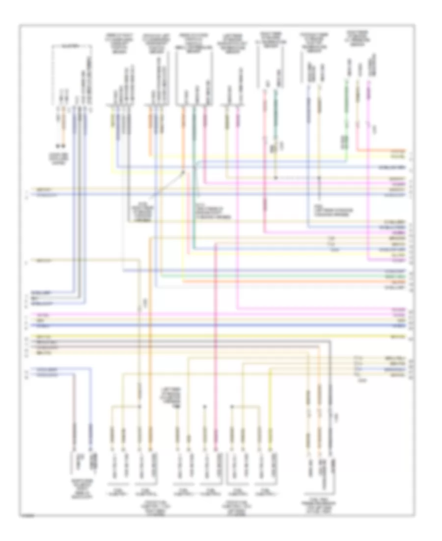
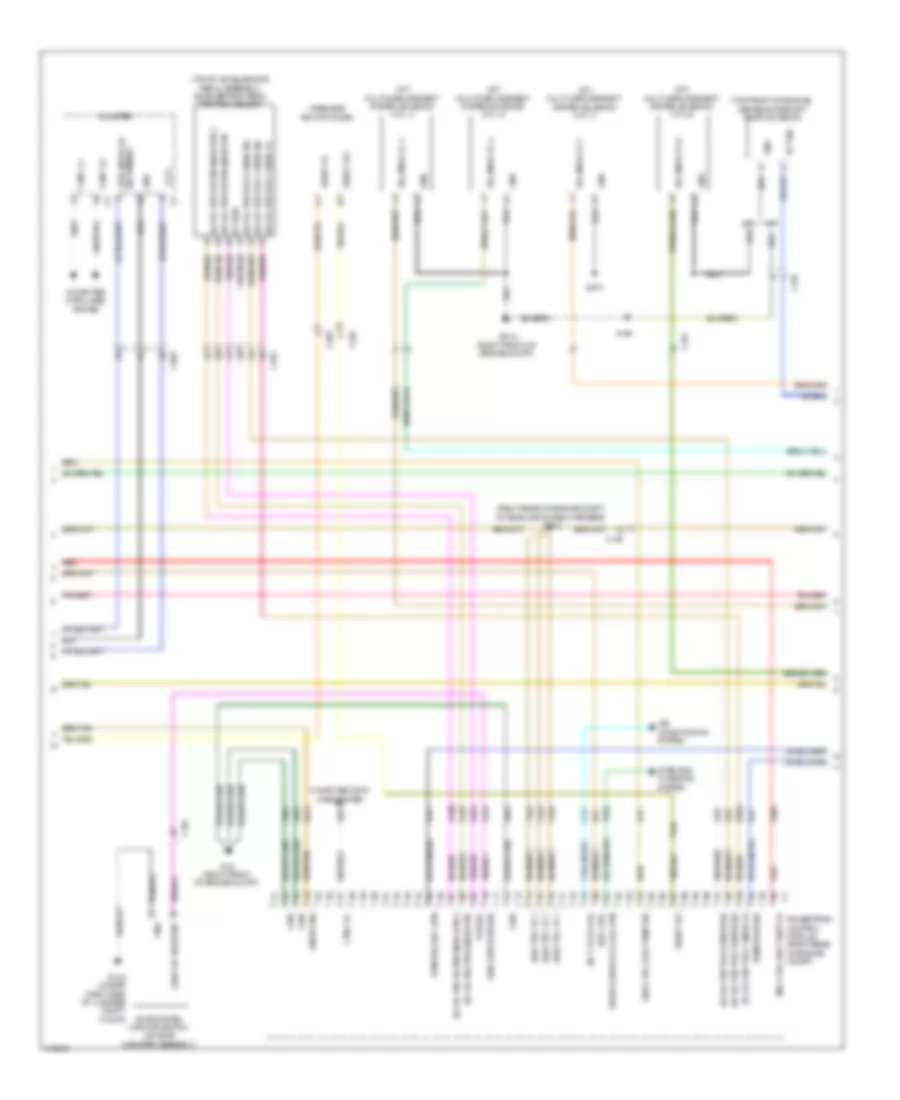
3.6L Flex Fuel, Engine Performance Wiring Diagram (3 of 5) for Dodge Challenger R/T Plus 2013
List of elements for 3.6L Flex Fuel, Engine Performance Wiring Diagram (3 of 5) for Dodge Challenger R/T Plus 2013:
- (front of left cylinder bank) crankshaft position sensor
- (left rear of engine) engine coolant temperature sensor
- (left rear of engine, in injector harness) s342
- (rear of intake manifold) manifold absolute pressure sensor
- (rear of right cylinder head) camshaft position sensor
- (right rear of engine) oil pressure sensor
- (right rear of engine) oil temperature sensor
- (top of fuel injector 1, 3 & 5 right bank cylinder)
- (top of fuel injector 2, 4 & 6 left bank cylinder)
- (top right rear of engine) inlet air temperature sensor
- 5v vref
- Asd ctrl fd 1
- C104
- C231
- C232
- Cam postn snsr sig
- Cam postn snsr sig 2
- Can c (+)
- Can c (-)
- Cluster
- Computer data lines system
- Cool temp snsr sig
- Crk spd snsr outpt
- Crkshft postn snsr rtn
- Eot
- Evap purge solenoid (right rear of eng compt)
- Fli 2
- Fuel inj 1 sig
- Fuel inj 2 sig
- Fuel inj 3 sig
- Fuel inj 4 sig
- Fuel inj 5 sig
- Fuel inj 6 sig
- Fuel injector 1
- Fuel injector 2
- Fuel injector 3
- Fuel injector 4
- Fuel injector 5
- Fuel injector 6
- Fuel lvl snsr gnd
- Fuel sndr lvl sig primary
- Fuel tank pressure sensor (top left side of fuel tank)
- Fuel tnk
- Intke temp snsr sig
- Map snsr sig
- Oil press snse/ sw sig
- Press sensr sig
- Pwm prg
- S106 (right rear of engine, in engine harness)
- S110 (right rear of engine compt, in engine harness)
- S155 (left rear of engine, in engine harness)
- Sig pwm prg
- Snsr gnd
- Sol rtn
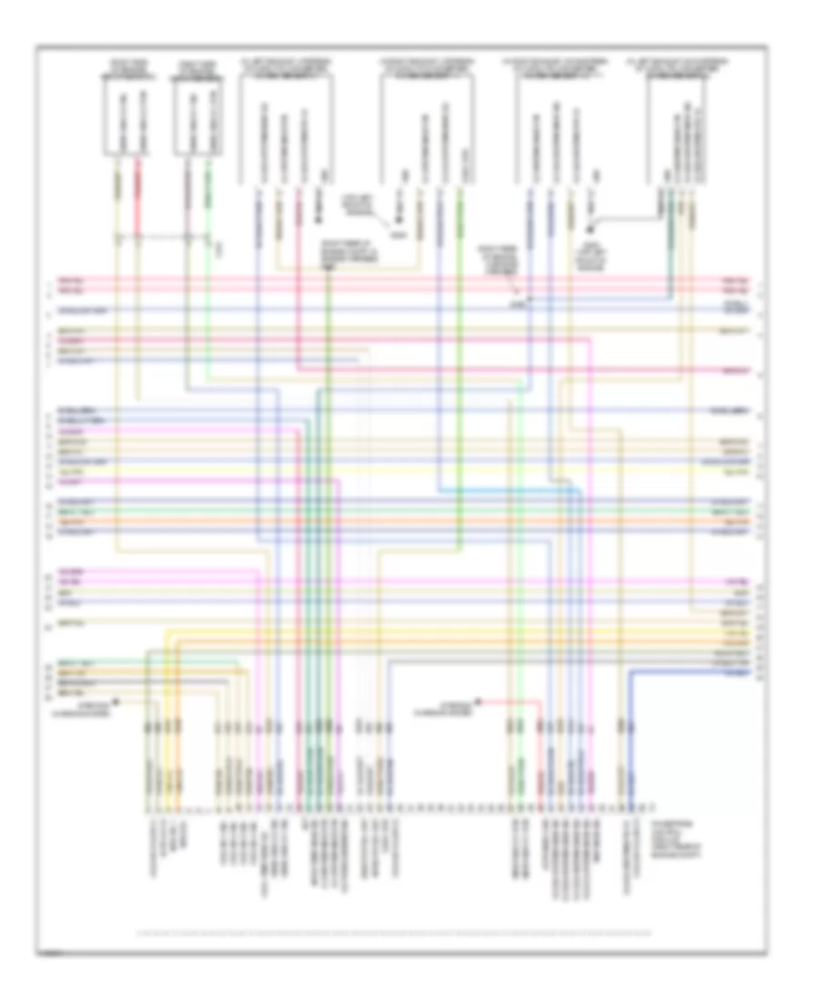
3.6L Flex Fuel, Engine Performance Wiring Diagram (4 of 5) for Dodge Challenger R/T Plus 2013
List of elements for 3.6L Flex Fuel, Engine Performance Wiring Diagram (4 of 5) for Dodge Challenger R/T Plus 2013:
- (in left exhaust, downstream of catalytic converter) oxygen sensor 2/2
- (in left exhaust, upstream of catalytic converter) oxygen sensor 2/1
- (in right exhaust, downstream of catalytic converter) oxygen sensor 1/2
- (in right exhaust, upstream of catalytic converter) oxygen sensor 1/1
- (right rear of engine compt, in engine harness) s153
- (right rear of engine, in engine harness)
- (right side of engine) knock sensor 1
- (right side of engine) knock sensor 2
- (top left front of engine)
- A804
- Altr fld fd
- Altr snse flnk
- C231
- Coil on plg drv 1
- Coil on plg drv 2
- Coil on plg drv 3
- Cool temp snsr sig
- Eot
- Exhst vvt sol drv
- Fuel inj 1 sig
- Fuel inj 2 sig
- Fuel inj 3 sig
- Fuel inj 4 sig
- G24
- G29a
- G29a (top left front of engine)
- Gnd
- Intke temp snsr sig
- Intke vvt sol drv
- K11
- K12
- K13
- K14
- K141
- K20
- K21
- K242
- K243
- K276
- K299
- K41
- K42
- K43
- K447
- K448
- K76
- K85
- K86
- K902
- K904
- K924
- K93
- K942
- K99
- Map snsr sig
- Mtr etc +
- Mtr etc-
- O2 (1/1) upstrm snsr sig
- O2 (1/2) dnstrm htr fd
- O2 (1/2) dnstrm snsr sig
- O2 (2/1) upstrm htr fd
- O2 (2/1) upstrm snsr sig
- O2 (2/2) dnstrm htr fd
- O2 (2/2) dnstrm snsr sig
- O2 (2/2) dwstrm snsr sig
- O2 dnstrm snse rtn
- O2 upstrm snse rtn
- O2 upstrm snsr rtn
- O2s11 htr
- Oil press snse/sw sig
- Pnk/red
- Powertrain control module (right rear of engine compt)
- S156
- Snsr knock 1 rtn
- Snsr knock 1 sig
- Snsr knock 2 rtn
- Snsr knock 2 sig
- Starting/ charging system
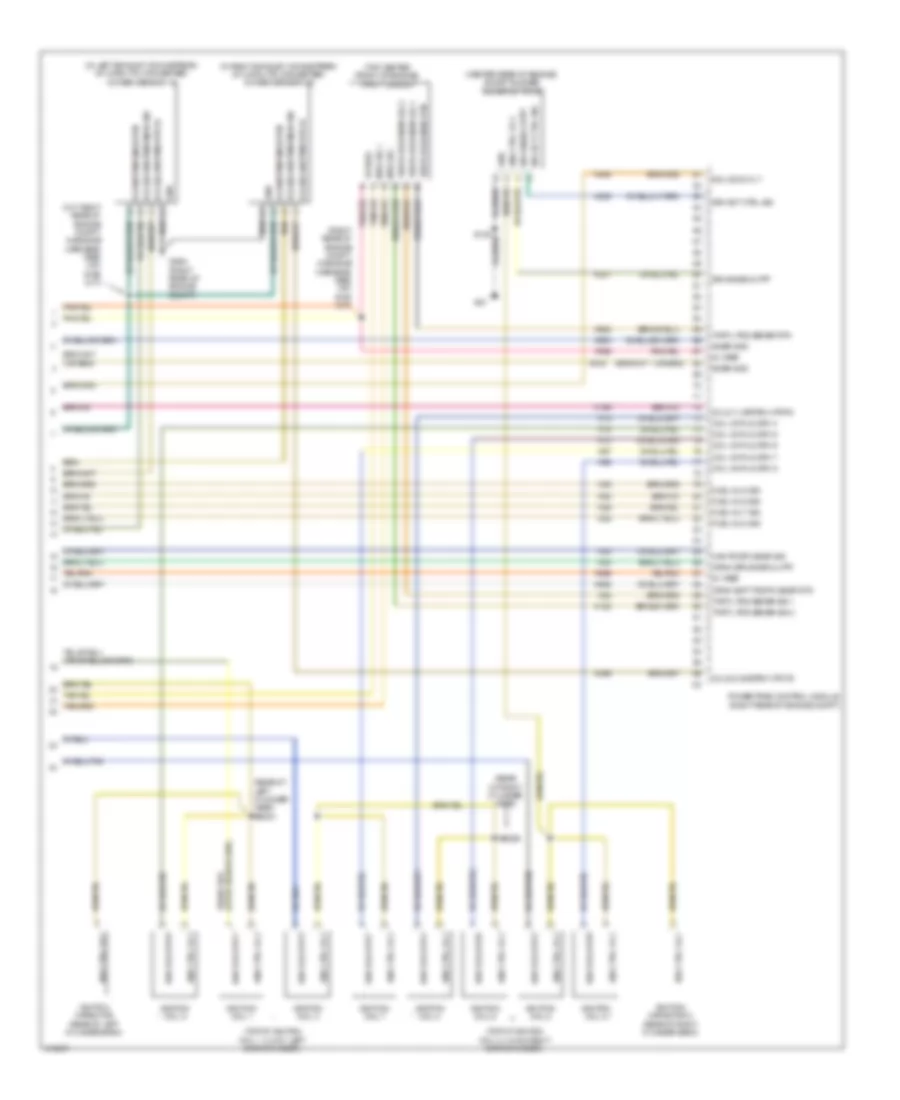
3.6L Flex Fuel, Engine Performance Wiring Diagram (5 of 5) for Dodge Challenger R/T Plus 2013
List of elements for 3.6L Flex Fuel, Engine Performance Wiring Diagram (5 of 5) for Dodge Challenger R/T Plus 2013:
- (rear of left cylinder head)
- (right rear of engine) throttle body
- (right rear of engine, in engine harness) s105
- (top of ignition coil 1, 3 & 5 right bank cylinder)
- (top of ignition coil 2, 4 & 6 left bank cylinder)
- 5v vref
- Asd ctrl fd 2
- C232
- Cam postn snsr sig
- Cam postn snsr sig 3
- Cam postn snsr sig 4
- Camshaft position sensor 2
- Coil on plg drv 1
- Coil on plg drv 2
- Coil on plg drv 3
- Coil on plg drv 4
- Coil on plg drv 5
- Coil on plg drv 6
- Crnk shft postn snsr rtn
- Crnk spd snsr outpt
- Cshft postn snsr sig 2
- Cshft postn snsr sig 3
- Cshft postn snsr sig 4
- Exhst vvt sol drv2
- F855
- F856
- Fuel inj 5 sig
- Fuel inj 6 sig
- G62
- Ignition capacitor (rear of left cylinder bank)
- Ignition capacitor 2 (rear of right cylinder bank)
- Ignition coil 1
- Ignition coil 2
- Ignition coil 3
- Ignition coil 4
- Ignition coil 5
- Ignition coil 6
- Intke vvt sol drv 2
- K10
- K122
- K15
- K16
- K199
- K22
- K24
- K277
- K38
- K399
- K44
- K441
- K444
- K445
- K58
- K78
- K900
- K915
- K922
- K925
- Mtr etc +
- Mtr etc -
- O2 (2/1) upstrm htr fd
- O2 (2/2) dnstrm htr fd
- Powertrain control module (right rear of engine compt)
- S344
- Snsr gnd
- Snsr rtn
- Sol var oil prss
- Thrtl pos sensr rtn
- Thrtl pos snsr rtn
- Thrtl pos snsr sig 1
- Thrtl pos snsr sig 2
5.7L
5.7L, Engine Performance Wiring Diagram (1 of 5) for Dodge Challenger R/T Plus 2013
List of elements for 5.7L, Engine Performance Wiring Diagram (1 of 5) for Dodge Challenger R/T Plus 2013:
- 19b
- 29a
- 29b
- 46a
- 46b
- 46c
- 46d
- 5v vref
- 87a
- Auto shut down relay
- B15
- B16
- Brk actv snse sig
- Brk actv snse sig 2
- C100
- C104
- C203
- Can c (+)
- Can c (-)
- Circuit board
- Cltch sw
- Cltch upstp sw sig
- Clutch interlock switch (m/t) (top of clutch pedal assembly)
- Computer data lines system
- D64
- D65
- F950
- Fd cmbd stp lmp
- Fsd b(+)
- Fuel lvl snsr gnd
- Fuel pmp mtr fd
- Fuel pump module (top of fuel tank)
- Fuel pump relay
- Fuel sndr lvl sig primary
- Fuel sndr lvl sig secondary sub
- Fuel tank
- Fuel tank press snsr sig
- Fuel tank pressure sensor (top left side of fuel tank)
- Fuse 20a
- Fuse 25a
- Fuse 5a
- G12a (under driver's seat)
- Gnd
- Hot at all times
- Ign rs
- K859
- L53
- Power distribution center (near battery)
- Power distribution system
- Powertrain control module (right rear of engine compt)
- Press snsr sig
- Red
- Run/start relay
- Run/strt ign eng ctrl
- S167
- S302
- S336
- S389
- Snse sig 2 brk actv
- Snse sig brk actv
- Snsr gnd
- Start fd
- Stop lamp switch (top of brake pedal assembly)
- Stp lmp fd cmbd
- Sw batt fd stp lmp
- T110
- T26
- Totally integrated power module (right side of engine compt)
- Vacuum pmp rly coil ctrl
- Z210
- Z912
5.7L, Engine Performance Wiring Diagram (2 of 5) for Dodge Challenger R/T Plus 2013
List of elements for 5.7L, Engine Performance Wiring Diagram (2 of 5) for Dodge Challenger R/T Plus 2013:
- (a/t) multi displacement system solenoid (cyl 1)
- (a/t) multi displacement system solenoid (cyl 4)
- (a/t) multi displacement system solenoid (cyl 6)
- (a/t) multi displacement system solenoid (cyl 7)
- (m/t) wireless ignition node
- (right rear of engine compt, in headlamp & dash harness) s143
- (top front of engine) variable camshaft timing solenoid
- (top of accelerator pedal assembly) accelerator pedal position sensor
- 5v vref
- A/c cltch coil
- A/t
- A209
- Accel ped pos 1 snsr sig
- Accel ped pos 2 snsr fd
- Accel ped pos 2 snsr sig
- Accel ped pos snsr rtn
- Accel ped postn snsr rtn
- Accel ped postn snsr rtn 2
- Air conditioning system
- Asd ctrl
- Asd ctrl fd 1
- C100
- C101
- C102
- C104
- C13
- C203
- Can c (+)
- Can c (-)
- Cluster
- Computer data lines system
- D65
- Eng ctrl fuel pump sig
- Evap system monitor switch (on evap canister assembly)
- F342
- Fsd b(+)
- Fuel lvl snsr gnd
- Fuel sndr lvl sig primary
- G14a (under right side of luggage compt floor)
- G1a (right front of engine compt)
- G51a (right front of engine compt)
- Gnd
- K107
- K167
- K23
- K29
- K31
- K400
- K51
- K52
- K70
- K852
- K854
- K917
- Leak detcn pmp strke snse
- M/t
- Powertrain control module (right rear of engine compt)
- Pwm prg sig
- Pwm prg sol rtn
- Red
- S154
- S270
- Secondary sub fuel sndr lvl sig
- Snsr gnd
- Sol mds cyl 1
- Sol mds cyl 4
- Sol mds cyl 6
- Sol mds cyl 7
- Start fd
- Start fd2
- Starting/ charging system
- Strke snse leak detcn pmp
- Strtr ovrde rly coil rtn
- T142
- T752
- Vct sig
- Z901
5.7L, Engine Performance Wiring Diagram (3 of 5) for Dodge Challenger R/T Plus 2013
List of elements for 5.7L, Engine Performance Wiring Diagram (3 of 5) for Dodge Challenger R/T Plus 2013:
- (front of left cylinder bank) crankshaft position sensor
- (front of right cylinder bank) camshaft position sensor
- (left front of engine) engine coolant temperature sensor
- (rear of intake manifold) manifold absolute pressure sensor
- (rear of left cylinder head, in engine harness) s922a
- (rear of right cylinder head, in engine harness)
- (right rear of engine compt, in engine harness) s110
- (right rear of engine, in engine harness)
- (top of fuel injector 1, 3, 5 & 7 left bank cylinder)
- (top of fuel injector 2, 4, 6 & 8 right bank cylinder)
- (top rear of engine) vacuum pump
- 34b
- 34c
- 34d
- 5v vref
- 87a
- Asd ctrl fd 1
- C100
- C104
- Cam postn snsr sig
- Cool temp snsr sig
- Crk spd snsr outpt
- Crkshft postn snsr rtn
- Evaporator purge solenoid (right rear of engine compt)
- Fuel inj 1 sig
- Fuel inj 2 sig
- Fuel inj 3 sig
- Fuel inj 4 sig
- Fuel inj 5 sig
- Fuel inj 6 sig
- Fuel inj 7 sig
- Fuel inj 8 sig
- Fuel injector 1
- Fuel injector 2
- Fuel injector 3
- Fuel injector 4
- Fuel injector 5
- Fuel injector 6
- Fuel injector 7
- Fuel injector 8
- Fuse 10a
- G36a (top right rear of engine)
- Gnf
- Hot at all times
- Map snsr sig
- Power distribution center (near battery)
- Pwm prg
- Red
- Rly cntct ctrl
- S106
- S922b
- Sig pwm prg
- Snsr gnd
- Sol rtn
- Vacuum pump relay
5.7L, Engine Performance Wiring Diagram (4 of 5) for Dodge Challenger R/T Plus 2013
List of elements for 5.7L, Engine Performance Wiring Diagram (4 of 5) for Dodge Challenger R/T Plus 2013:
- (center rear of engine, in engine harness)
- (in left exhaust, upstream of catalytic converter) oxygen sensor 1/1
- (in right exhaust, upstream of catalytic converter) oxygen sensor 2/1
- (lower left rear of engine) knock sensor 2
- (lower right front of engine) oil pressure sensor
- (lower right front of engine) oil temperature sensor
- (right rear of engine compt, in engine harness) s153
- (top front center of engine) knock sensor 1
- (top front of engine) inlet air temperature sensor
- 5v vref
- A804
- Altr fld fd
- Altr snse flnk to mod
- Asd ctrl fd1
- Coil 2
- Coil 3
- Coil on plg drv 1
- Cool temp snsr sig
- Eng ctrl com snsr rtn
- Eot
- Fuel inj 1 sig
- Fuel inj 2 sig
- Fuel inj 3 sig
- Fuel inj 4 sig
- G24
- G29a (right rear of engine compt)
- Gnd
- Intke temp snsr sig
- K11
- K12
- K13
- K14
- K141
- K20
- K21
- K242
- K243
- K299
- K33
- K333
- K41
- K42
- K43
- K442
- K447
- K448
- K451
- K452
- K453
- K85
- K86
- K902
- K904
- K924
- K93
- K942
- K99
- Lkout fd
- Map snsr sig
- Mtr etc +
- Mtr etc -
- O2 (1/1) upstrm snsr sig
- O2 (1/2) dnstrm htr fd
- O2 (1/2) dnstrm snsr sig
- O2 (2/1) upstrm htr fd
- O2 (2/1) upstrm snsr sig
- O2 (2/2) dwstrm snsr sig
- O2 dnstrm snse rtn
- O2 upstream snse rtn
- O2 upstrm snse rtn
- O2s11 htr
- Oil press snse/sw sig
- Powertrain control module (right rear of engine compt)
- Reverse lockout solenoid (m/t) (left side of transmission)
- S155
- Shift lkout fd
- Skip shift solenoid (m/t) (left side of transmission)
- Snsr gnd
- Snsr knock 1 rtn
- Snsr knock 1 sig
- Snsr knock 2 rtn
- Snsr knock 2 sig
- Sol mds cyl 1
- Sol mds cyl 4
- Sol mds cyl 6
- Starting/ charging system
- Vct sig
5.7L, Engine Performance Wiring Diagram (5 of 5) for Dodge Challenger R/T Plus 2013
List of elements for 5.7L, Engine Performance Wiring Diagram (5 of 5) for Dodge Challenger R/T Plus 2013:
- (in left exhaust, downstream of catalytic converter) oxygen sensor 1/2
- (in right exhaust, downstream of catalytic converter) oxygen sensor 2/2
- (rear of left cylinder head) s923a
- (rear of right cylinder head) s923b
- (right rear of engine, in engine harness) s105
- (right rear of engine, in engine harness) s156
- (top center front of engine) throttle body
- (top of ignition coil 1, 3, 5 & 7 left bank cylinder)
- (top of ignition coil 2, 4, 6 & 8 right bank cylinder)
- 5v vref
- Asd ctrl fd 2
- Cam postn snsr sig
- Coil on plg drv 4
- Coil on plg drv 5
- Coil on plg drv 6
- Coil on plg drv 7
- Coil on plg drv 8
- Crk spd snsr outpt
- Crkshft postn snsr rtn
- F855
- F856
- Fuel inj 5 sig
- Fuel inj 6 sig
- Fuel inj 7 sig
- Fuel inj 8 sig
- G29a (right rear of engine compt)
- Gnd
- Ign coil drv 1
- Ign coil drv 2
- Ign coil drv 3
- Ign coil drv 4
- Ign coil drv 5
- Ign coil drv 6
- Ign coil drv 7
- Ign coil drv 8
- Ignition capacitor (rear of left cylinder bank)
- Ignition capacitor 2 (rear of right cylinder bank)
- Ignition coil 1
- Ignition coil 2
- Ignition coil 3
- Ignition coil 4
- Ignition coil 5
- Ignition coil 6
- Ignition coil 7
- Ignition coil 8
- K10
- K122
- K15
- K16
- K199
- K22
- K24
- K26
- K28
- K38
- K399
- K44
- K454
- K58
- K900
- K915
- K922
- K925
- K97
- K98
- Mtr etc +
- Mtr etc -
- O2 (1/2) dnstrm htr fd
- O2 (1/2) dnstrm snsr sig
- O2 (2/1) upstrm htr fd
- O2 (2/2) dnstrm htr fd
- O2 (2/2) dwstrm snsr sig
- O2 dnstrm snse rtn
- Powertrain control module (right rear of engine compt)
- Snsr gnd
- Sol mds cyl 7
- Thrtl pos snsr rtn
- Thrtl pos snsr sig 1
- Thrtl pos snsr sig 2
6.4L
6.4L, Engine Performance Wiring Diagram (1 of 5) for Dodge Challenger R/T Plus 2013
List of elements for 6.4L, Engine Performance Wiring Diagram (1 of 5) for Dodge Challenger R/T Plus 2013:
- 19b
- 29a
- 29b
- 46a
- 46b
- 46c
- 46d
- 5v vref
- 87a
- Auto shut down relay
- B15
- B16
- Brk actv snse sig
- Brk actv snse sig 2
- C100
- C104
- C203
- Can c (+)
- Can c (-)
- Circuit board
- Cltch sw
- Cltch upstp sw sig
- Clutch interlock switch (m/t) (top of clutch pedal assembly)
- Computer data lines system
- Cooling fans system
- D54
- D55
- D64
- F950
- Fd cmbd stp lmp
- Fsd b (+)
- Fuel lvl snsr gnd
- Fuel pmp mtr fd
- Fuel pump module (top of fuel tank)
- Fuel pump relay
- Fuel sndr lvl sig primary
- Fuel sndr lvl sig secondary/sub
- Fuel tank
- Fuel tank pressure sensor (top of brake pedal assembly)
- Fuse 10a
- Fuse 20a
- Fuse 25a
- Fuse 5a
- G12a (under driver's seat)
- Gnd
- Hot at all times
- Ign rs fuel tank press snsr sig
- K859
- L53
- N201
- Nca
- Power distribution center (near battery)
- Power distribution system
- Powertrain control module (right rear of engine compt)
- Press snsr sig
- Rad fan lo spd sig
- Red
- Run/start relay
- Run/strt ign eng ctrl
- S167
- S336
- S389
- Snse sig 2 brk actv
- Snse sig brk actv
- Snsr gnd
- Start fd
- Stop lamp switch (top of brake pedal assembly)
- Stp lmp fd cmbd
- Sw batt fd stp lmp
- T110
- T26
- Totally integrated power module (right side of engine compt)
- Z210
- Z912
6.4L, Engine Performance Wiring Diagram (2 of 5) for Dodge Challenger R/T Plus 2013
List of elements for 6.4L, Engine Performance Wiring Diagram (2 of 5) for Dodge Challenger R/T Plus 2013:
- (a/t) multi displacement system solenoid (cyl 1)
- (a/t) multi displacement system solenoid (cyl 4)
- (a/t) multi displacement system solenoid (cyl 6)
- (a/t) multi displacement system solenoid (cyl 7)
- (right rear of engine compt, in headlamp & dash harness) s143
- (top front of engine) variable camshaft timing solenoid
- (top of accelerator pedal assembly) accelerator pedal position sensor
- 5v vref
- A/c cltch coil
- A/t
- A209
- Accel ped pos 1 snsr fd
- Accel ped pos 1 snsr sig
- Accel ped pos 2 snsr sig
- Accel ped pos snsr rtn
- Accel ped postn snsr rtn
- Accel ped postn snsr rtn 2
- Air conditioning system
- Asd ctrl
- Asd ctrl fd 1
- C100
- C101
- C102
- C104
- C13
- C203
- Can c (+)
- Can c (-)
- Cluster
- Computer data lines system
- D65
- Eng ctrl drct batt fd
- Eng ctrl fuel pump sig
- Evap system monitor switch (on evap canister assembly)
- F342
- Flt 2
- Fuel sndr lvl sig primary
- G14a (under right side of luggage compt floor)
- G1a (right front of engine compt)
- G51a (right front of engine compt)
- Gnd
- K107
- K167
- K23
- K29
- K31
- K400
- K51
- K52
- K70
- K852
- K854
- K917
- Leak detcn sw sig
- Leak dtctn sw sig
- M/t
- Powertrain control module (right rear of engine compt)
- Pwm prg sol rtn
- Pwm prge sig
- Red
- S154
- S270
- Snsr gnd
- Sol mds cyl 1
- Sol mds cyl 4
- Sol mds cyl 6
- Sol mds cyl 7
- Start fd
- Start fd2
- Starting/ charging system
- Strtr ovrde rly coil rtn
- T142
- T752
- Vct sig
- Wireless ignition node
- Z901
6.4L, Engine Performance Wiring Diagram (3 of 5) for Dodge Challenger R/T Plus 2013
List of elements for 6.4L, Engine Performance Wiring Diagram (3 of 5) for Dodge Challenger R/T Plus 2013:
- (front of left cylinder bank) crankshaft position sensor
- (front of right cylinder bank) camshaft position sensor
- (left front of engine) engine coolant temperature sensor
- (rear of intake manifold) manifold absolute pressure sensor
- (rear of left cylinder head, in engine harness) s922a
- (rear of right cylinder head, in engine harness)
- (right rear of engine compartment, in engine harness)
- (top of fuel injector 1, 3, 5 & 7 left bank cylinder)
- (top of fuel injector 2, 4, 6 & 8 right bank cylinder)
- (top rear of engine) vacuum pump
- 34b
- 34c
- 34d
- 5v vref
- 87a
- Asd ctrl fd 1
- C100
- C104
- Cam postn snsr sig
- Cool temp snsr sig
- Crk spd snsr outpt
- Crkshft postn snsr rtn
- Evaporator purge solenoid (right rear of engine compt)
- Fuel inj 1 sig
- Fuel inj 2 sig
- Fuel inj 3 sig
- Fuel inj 4 sig
- Fuel inj 5 sig
- Fuel inj 6 sig
- Fuel inj 7 sig
- Fuel inj 8 sig
- Fuel injector 1
- Fuel injector 2
- Fuel injector 3
- Fuel injector 4
- Fuel injector 5
- Fuel injector 6
- Fuel injector 7
- Fuel injector 8
- Fuse 10a
- G36a (top right rear of engine)
- Gnf
- Hot at all times
- Map snsr sig
- Power distribution center (near battery)
- Pwm prg
- Red
- Rly cntct ctrl
- S110 m/t s990 (a/t)
- S922b
- S926 (m/t) s106 (a/t) (right rear of engine, in engine harness)
- Sig pwm prg
- Snsr gnd
- Sol rtn
- Vacuum pump relay
6.4L, Engine Performance Wiring Diagram (4 of 5) for Dodge Challenger R/T Plus 2013
List of elements for 6.4L, Engine Performance Wiring Diagram (4 of 5) for Dodge Challenger R/T Plus 2013:
- (center rear of engine, in engine harness) s995 (a/t) s155 (m/t)
- (front of left cylinder head) knock sensor 2
- (in left exhaust, upstream of catalytic converter) oxygen sensor 1/1
- (in right exhaust, upstream of catalytic converter) oxygen sensor 2/1
- (lower left side of engine) knock sensor 1
- (lower right front of engine) oil pressure sensor
- (lower right front of engine) oil temperature sensor
- (m/t: right rear of engine compt, in engine harness) s992 (a/t) s153 (m/t)
- (top front of engine) inlet air temperature sensor
- 02s11 htr
- 5v vref
- A804
- Altr fld fd
- Altr snse flnk to mod
- Asd ctrl fd1
- Coil 2
- Coil on plg drv 1
- Coil on plg drv 3
- Cool temp snsr sig
- Eot
- Fuel inj 1 sig
- Fuel inj 2 sig
- Fuel inj 3 sig
- Fuel inj 4 sig
- G24
- G29a (right rear of engine compt)
- Gnd
- Intke temp snsr sig
- K11
- K12
- K13
- K14
- K141
- K20
- K21
- K242
- K243
- K299
- K33
- K333
- K41
- K42
- K43
- K442
- K447
- K448
- K451
- K452
- K453
- K85
- K86
- K902
- K904
- K924
- K93
- K942
- K99
- Lkout fd
- Map snsr sig
- Mtr etc +
- Mtr etc-
- O2 (1/1) upstrm snsr sig
- O2 (1/2) dnstrm htr fd
- O2 (1/2) dnstrm snsr sig
- O2 (2/1) upstrm htr fd
- O2 (2/1) upstrm snsr sig
- O2 (2/2) dwstrm snsr sig
- O2 dnstrm snse rtn
- O2 upstrm snse rtn
- Oil press snse /sw sig
- Oil press snse/ sw sig
- Powertrain control module (right rear of engine compt)
- Reverse lockout solenoid (m/t) (left side of transmission)
- Shift lkout fd
- Skip shift solenoid (m/t) (left side of transmission)
- Snsr gnd
- Snsr knock 1 rtn
- Snsr knock 1 sig
- Snsr knock 2 rtn
- Snsr knock 2 sig
- Sol mds cyl 1
- Sol mds cyl 4
- Sol mds cyl 6
- Starting/ charging system
- Vct sig
6.4L, Engine Performance Wiring Diagram (5 of 5) for Dodge Challenger R/T Plus 2013
List of elements for 6.4L, Engine Performance Wiring Diagram (5 of 5) for Dodge Challenger R/T Plus 2013:
- (center rear of engine) short runner solenoid valve
- (in left exhaust, downstream of catalytic converter) oxygen sensor 1/2
- (in right exhaust, downstream of catalytic converter) oxygen sensor 2/2
- (m/t: right rear of engine compt, in engine harness) s993 (a/t) s156 (m/t)
- (rear of left cylinder head) s923a
- (rear of right cylinder head)
- (right rear of engine compt, in engine harness) s925 (a/t) s105 (m/t)
- (top center front of engine) throttle body
- (top of ignition coil 1, 3, 5 & 7 left bank cylinder)
- (top of ignition coil 2, 4, 6 & 8 right bank cylinder)
- 5v vref
- Asd ctrl fd 2
- Cam postn snsr sig
- Coil on plg drv 4
- Coil on plg drv 5
- Coil on plg drv 6
- Coil on plg drv 7
- Coil on plg drv 8
- Crnk shft postn snsr rtn
- Crnk spd snsr outpt
- F855
- F856
- Fuel inj 5 sig
- Fuel inj 6 sig
- Fuel inj 7 sig
- Fuel inj 8 sig
- G29a (right rear of engine compt)
- G51
- Gnd
- Ign coil drv 1
- Ign coil drv 2
- Ign coil drv 3
- Ign coil drv 4
- Ign coil drv 5
- Ign coil drv 6
- Ign coil drv 7
- Ign coil drv 8
- Ignition capacitor (rear of left cylinder bank)
- Ignition capacitor 2 (rear of right cylinder bank)
- Ignition coil 1
- Ignition coil 2
- Ignition coil 3
- Ignition coil 4
- Ignition coil 5
- Ignition coil 6
- Ignition coil 7
- Ignition coil 8
- K10
- K122
- K15
- K16
- K199
- K22
- K237
- K238
- K24
- K26
- K28
- K38
- K399
- K44
- K454
- K58
- K900
- K915
- K922
- K925
- K97
- K98
- Mtr etc +
- Mtr etc -
- O2 (1/2) dnstrm htr fd
- O2 (1/2) dnstrm snsr sig
- O2 (2/1) upstrm htr fd
- O2 (2/2) dnstrm htr fd
- O2 (2/2) dnstrm snsr sig
- O2 dnstrm snse rtn
- Powertrain control module (right rear of engine compt)
- S923b
- Snsr gnd
- Sol mds cyl 7
- Srv act ctrl sig
- Srv snse outpt
- Thrtl pos sensr rtn
- Thrtl pos sensr sig 1
- Thrtl pos sensr sig 2
- Thrtl pos snsr rtn
- Thrtl pos snsr sig 1
- Thrtl pos snsr sig 2
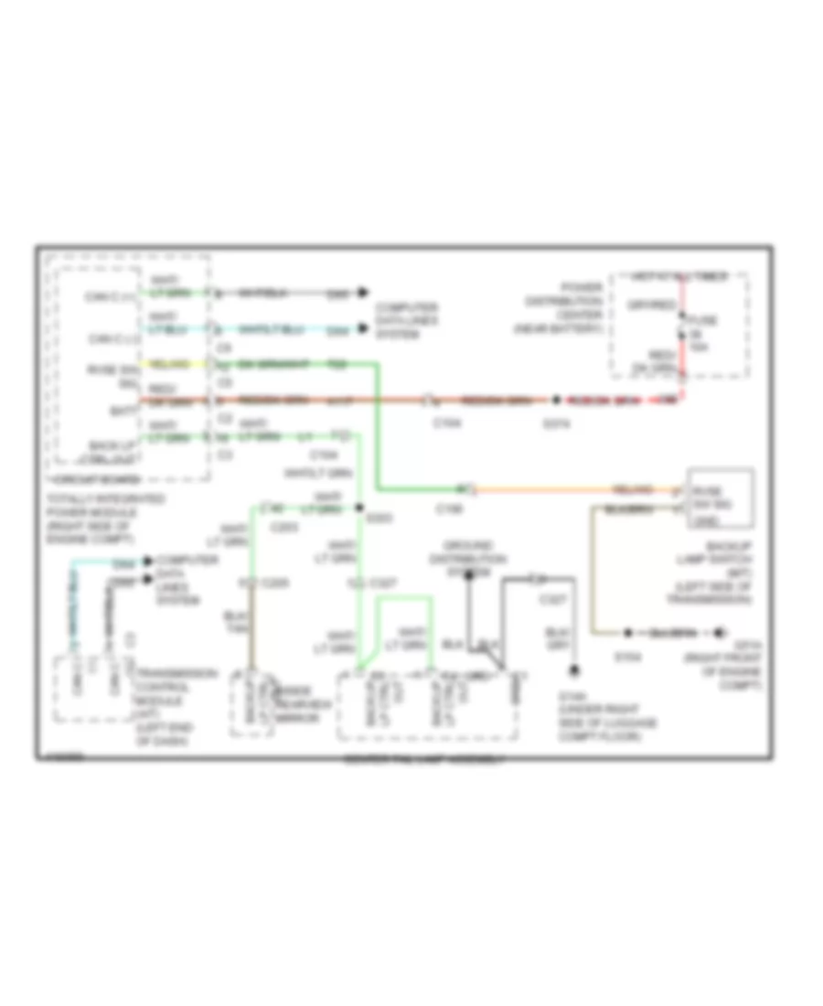
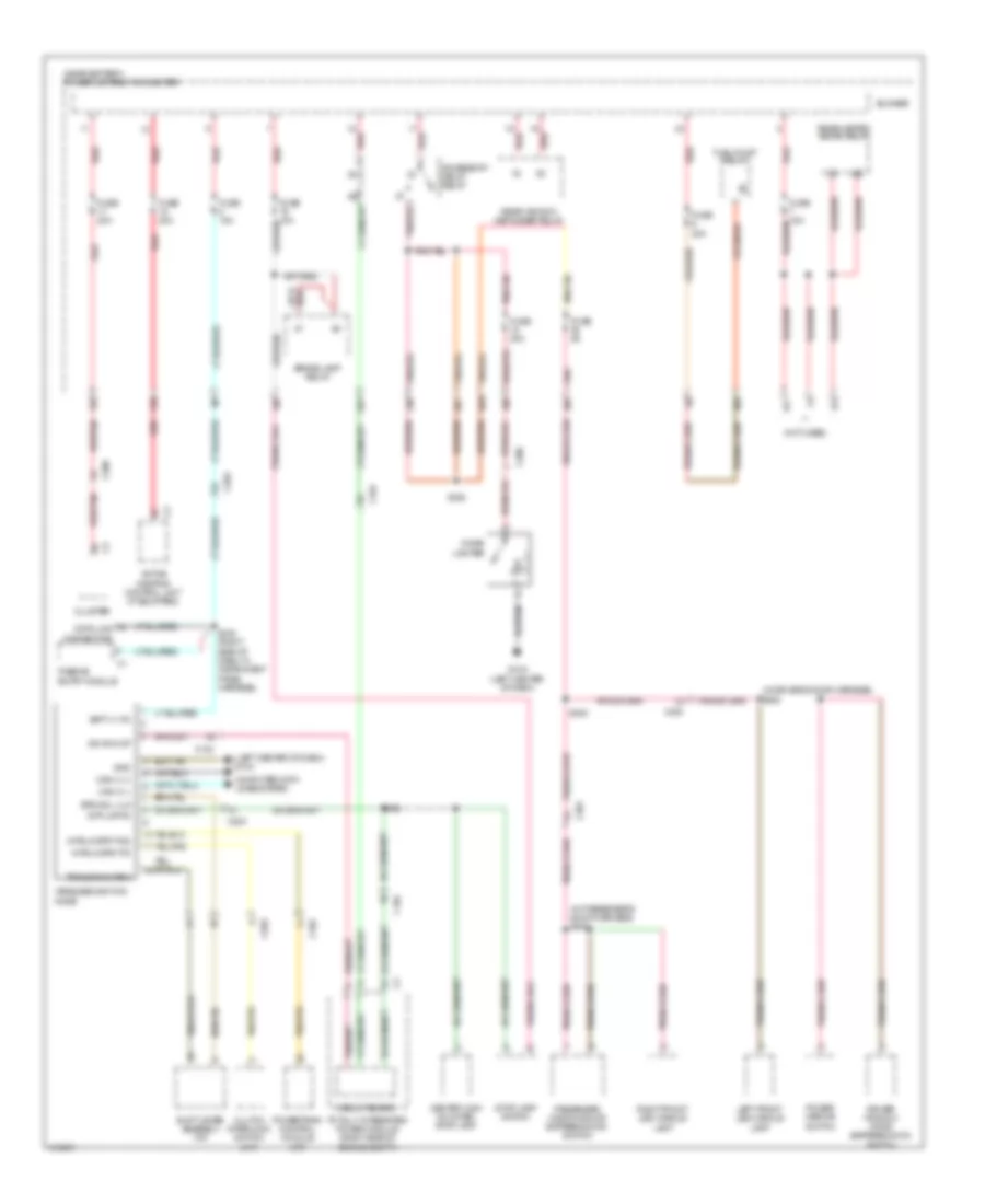
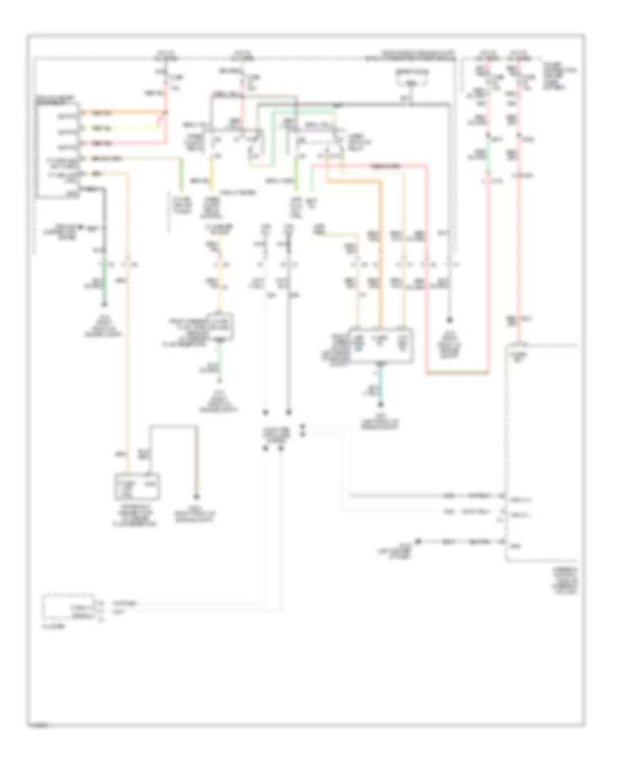
EXTERIOR LIGHTS
Backup Lamps Wiring Diagram for Dodge Challenger R/T Plus 2013
List of elements for Backup Lamps Wiring Diagram for Dodge Challenger R/T Plus 2013:
- (+) can c
- (-) can c
- 38b
- A117
- Back lp ctrl out
- Backup
- Backup lamp switch (m/t) (left side of transmission)
- Batt
- C100
- C104
- C203
- C205
- C3 out lp ctrl backup
- C327
- C4 out lp ctrl backup
- Can c (+)
- Can c (-)
- Center tail lamp assembly
- Circuit board
- Computer data lines system
- D64
- D65
- Fuse 10a
- G14a (under right side of luggage compt floor)
- G51a (right front of engine compt)
- Gnd
- Grd
- Ground distribution system
- Hot at all times
- Inside rearview mirror
- Out lp ctrl
- Power distribution center (near battery)
- Rvse sw sig
- S154
- S303
- S374
- T22
- Totally integrated power module (right side of engine compt)
- Transmission control module (a/t) (left end of dash)
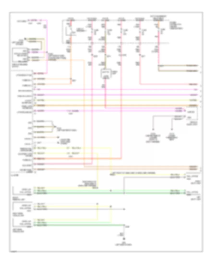
Exterior Lamps Wiring Diagram (1 of 2) for Dodge Challenger R/T Plus 2013
List of elements for Exterior Lamps Wiring Diagram (1 of 2) for Dodge Challenger R/T Plus 2013:
- 38b
- Backup lamp ctrl out
- Backup lp ctrl out
- Batt
- C102
- C104
- C203
- C205
- C307
- C308
- Can b (+)
- Can b (-)
- Can c (+)
- Can c (-)
- Center high mounted stop lamp
- Circuit board
- Cluster
- Computer data lines system
- D64
- D65
- Fuse 10a
- G11a (under passenger's seat)
- G1a (right front of engine compt)
- G2a (left front of engine compt)
- G9a (left side of dash)
- Gnd
- Hazard switch sense
- Hot at all times
- Hzrd sw sig
- I100
- Inside rearview mirror
- Interior lights system
- Lamps drv panel
- Left front fog lamp
- Left front lamp assembly
- Left front side marker lamp
- Left front turn signal ctrl
- Left rear turn signal ctrl
- Lh frt turn sig ctrl
- Lt ft prk/ tl lmps 2
- Mfs hdlp sel
- Panel lp
- Park/ tl lmps 2
- Power distribution center (near battery)
- Prk lmp ctrl out
- Rh frt turn sig ctrl
- Right front fog lamp
- Right front lamp assembly
- Right front side marker lamp
- Right front turn signal ctrl
- Right rear turn signal ctrl
- Rtn mlfnct sw
- S127 (under luggage compt floor, in body harness)
- S302
- S303
- S374
- Steering control module (steering column)
- Stp lmp fd cmbo
- Totally integrated power module (right side of engine compt)
- Upper bank switch
- Wireless ignition node
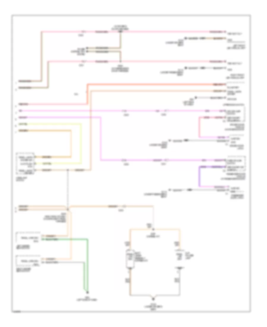
Exterior Lamps Wiring Diagram (2 of 2) for Dodge Challenger R/T Plus 2013
List of elements for Exterior Lamps Wiring Diagram (2 of 2) for Dodge Challenger R/T Plus 2013:
- (top of brake pedal assembly) stop lamp switch
- 19b
- 29b
- B15
- B16
- Brk sig 1
- Brk sig 2
- C104
- C203
- C306
- C307
- C308
- C327
- Can c (+)
- Can c (-)
- Center tail lamp assembly
- Computer
- Ctrl out backup lp
- D64
- D65
- Data lines
- Fsd b(+)
- Fuse 10a
- Fuse 5a
- G10a (left center of dash)
- G12a (under driver's seat)
- G14a (under right side of luggage compt floor)
- Gnd
- Grd
- Ground
- Headlamp switch
- Hot at all times
- Hot in run or start
- I500
- Ign run/st
- Lamps 2 prk/tl
- Lamps drv panel
- Left rear side marker lamp
- Left tail lamp assembly
- Lh rr turn sig ctrl
- Lh rr turn sig ctrl c1
- License lamp
- Mes hdlp sel
- Mnr
- Panel lp
- Power distribution center (near battery)
- Powertrain control module (right rear of engine compt)
- Prk/tl lamps 2
- Prk/tl lmps 2
- Red
- Rh rr turn sig ctrl
- Rh rr turn sig ctrl c1
- Right rear side marker lamp
- Right tail lamp assembly
- Rtn mlfnct sw
- S304
- S336
- Stp lmp fd cmbo
- System
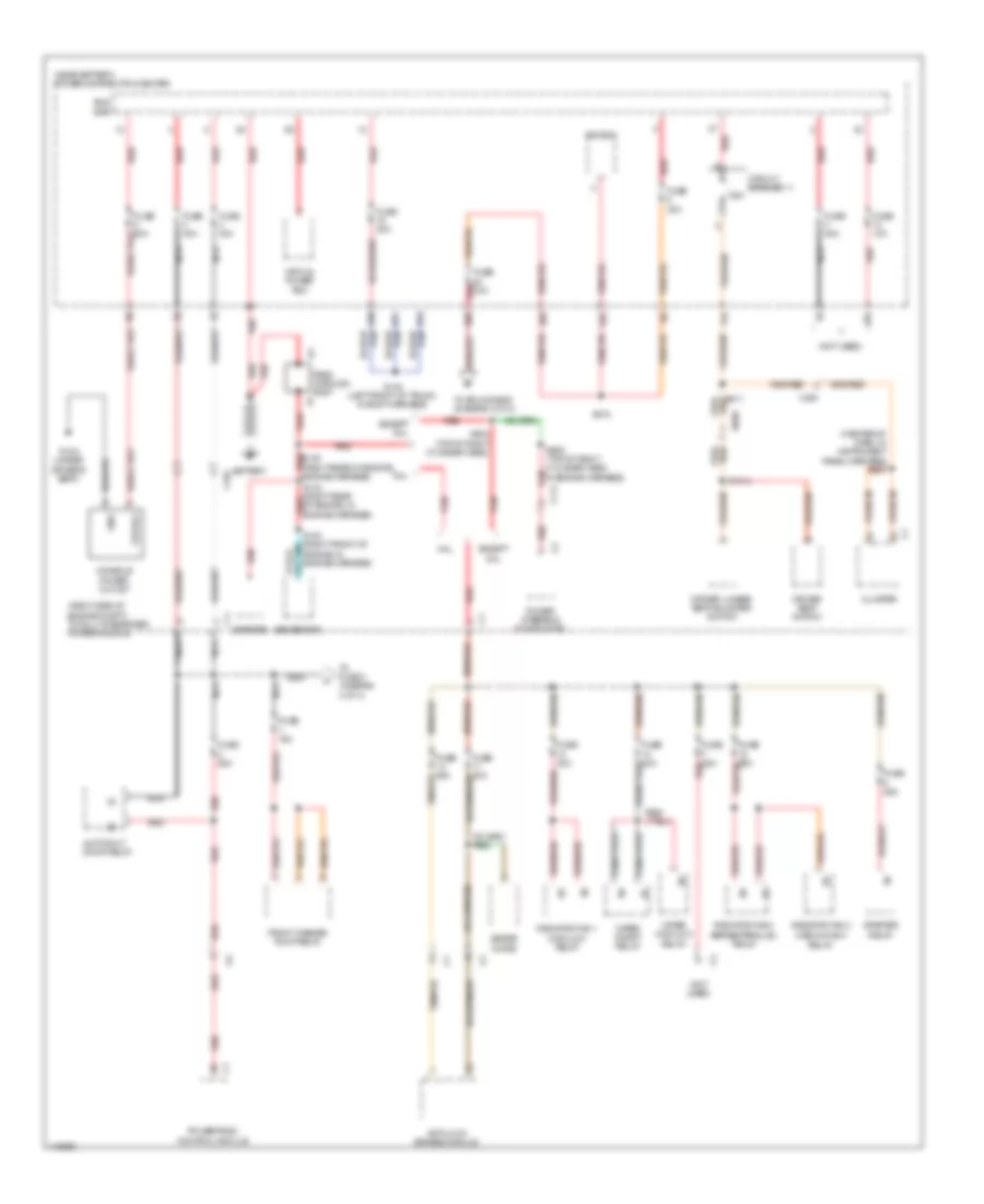
GROUND DISTRIBUTION
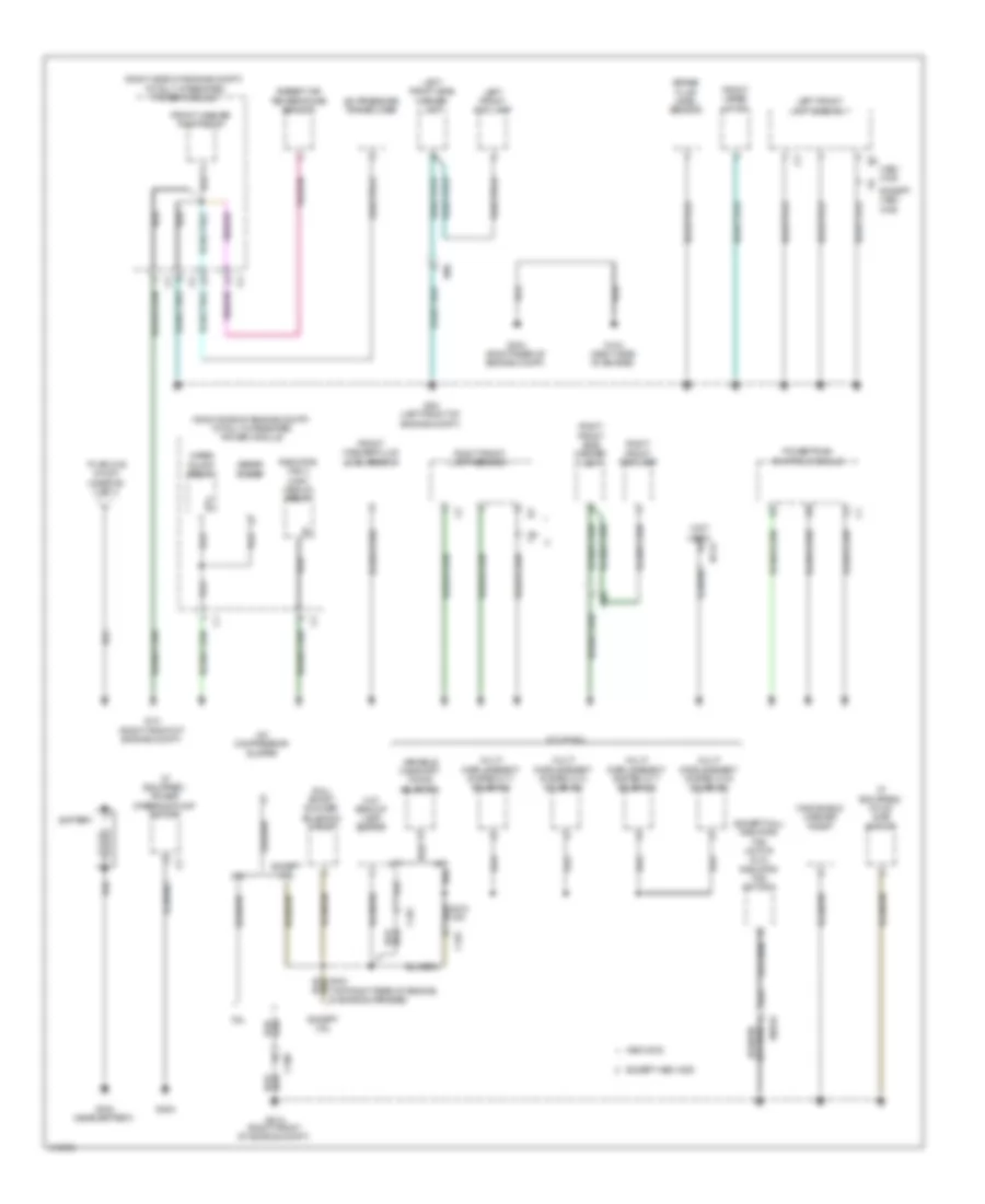
Ground Distribution Wiring Diagram (1 of 3) for Dodge Challenger R/T Plus 2013
List of elements for Ground Distribution Wiring Diagram (1 of 3) for Dodge Challenger R/T Plus 2013:
- (6.4l) short runner solenoid valve
- (a/t)
- (except 6.4l) radiator fan motor (6.4l) radiator fan motor 2
- (if equipped) hood ajar switch
- (if equipped) power steering pump motor
- (m/t) backup lamp switch
- (not used)
- (right side of engine compt) totally integrated power module
- (top right rear of engine, in engine harness)
- 3.6l
- 5.7l & 6.4l
- 87a
- A/c compressor clutch
- A/c pressure transducer
- A/t
- Ambient air temperature sensor
- Battery
- Brake fluid level sensor
- C100
- C101
- Except 3.6l
- Except hemi mds
- Front washer fluid level sensor
- Front washer pump relay
- Front wiper motor
- G104 (right side of engine)
- G1a (right front of engine compt)
- G2a (left front of engine compt)
- G303 (near battery)
- G304 (right rear of engine compt)
- G35a
- G51a (right front of engine compt)
- Hemi mds
- I100
- I3022a
- I471a
- Left front fog lamp
- Left front lamp assembly
- Left front side marker lamp
- M/t
- Multi displacement system cy 1 solenoid
- Multi displacement system cy 4 solenoid
- Multi displacement system cy 6 solenoid
- Multi displacement system cy 7 solenoid
- Powertrain control module
- Radiator fan 3 high/ medium relay
- Right front fog lamp
- Right front lamp assembly
- Right front side marker lamp
- To splice s100a (diagram 3 of 3)
- Variable camshaft timing solenoid
- Windshield washer pump
- Wiper on/off relay
- Zener diode
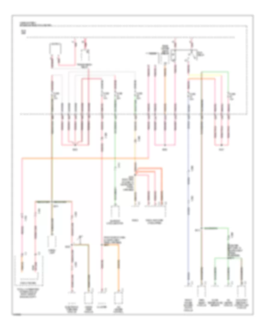
Ground Distribution Wiring Diagram (2 of 3) for Dodge Challenger R/T Plus 2013
List of elements for Ground Distribution Wiring Diagram (2 of 3) for Dodge Challenger R/T Plus 2013:
- (if equipped) active damping control module
- (if equipped) sunroof motor/ module
- (near battery) power distribution center
- (not used)
- 24d
- 26e
- 33a
- 87a
- A/c heater control
- Anti lock brakes module
- C202
- C203
- C204
- C205
- C300
- C306
- C307
- C308
- C311
- C327
- Center tail lamp assembly
- Cigar lighter
- Cluster
- Data link connector
- Decklid release switch
- Diode 2
- Electric heated backlite
- Electronic overhead module
- Evap system monitor switch
- Front blower motor power module
- Front reading lamp
- G10a (left center of dash)
- G14a (under right side of luggage compt floor)
- G22a (behind left quarterpanel)
- G52a
- G8a
- G9a (left side of dash)
- Grd
- Hands- free module
- Headlamp switch
- In car temperature sensor
- Inside rearview mirror
- Left front exterior door handle switch
- Left grab handle lamp
- Left heated seat switch
- Left rear side marker lamp
- Left tail lamp assembly
- Left vanity lamp
- License lamp
- Park assist module
- Passive entry module
- Radio
- Radio amplifier
- Rear wiper relay
- Right grab handle lamp
- Right heated seat switch
- Right rear side marker lamp
- Right tail lamp assembly
- Right vanity lamp
- S349 (center front of roof, in headliner harness)
- Steering control module
- Transmission relay
- Upper bank switch
- Wireless ignition node
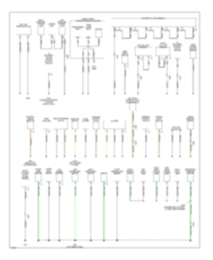
Ground Distribution Wiring Diagram (3 of 3) for Dodge Challenger R/T Plus 2013
List of elements for Ground Distribution Wiring Diagram (3 of 3) for Dodge Challenger R/T Plus 2013:
- (3.6l) camshaft position solenoid 1/1
- (3.6l) camshaft position solenoid 1/2
- (3.6l) exhaust variable timing solenoid valve
- (3.6l) intake variable timing solenoid valve
- (3.6l) oil pump solenoid
- (a/t) shift lever assembly
- (a/t) transmission control module
- (in driver's door harness)
- (m/t) clutch interlock switch
- C300
- C301
- Center high mounted stop lamp
- Console power outlet
- Cup holder lamp
- Decklid door latch
- Driver door latch
- Driver door module
- Driver lumbar seat adjuster switch
- Driver mirror heater
- Driver seat switch
- Driver window express down switch
- From ground g1a (diagram 1 of 3)
- Fuel pump module
- G11a (under passenger's seat)
- G12a (under driver's seat)
- G13a (left side of dash)
- G18a (center rear of luggage compt, in body harness)
- G25a (6.4l) (right rear of engine)
- G26a (6.4l) (left rear of engine)
- G29a (except 3.6l: right rear of engine compt) (3.6l: top left front of engine)
- G36a (top right rear of engine)
- Heated seats module
- I460a
- I470a
- I6624a
- I6626a
- Left front led handle lamp
- Left seat back heater
- Left seat cushion heater
- Occupant restraint controller module
- Oxygen sensor 1/1
- Oxygen sensor 1/2
- Oxygen sensor 2/1
- Oxygen sensor 2/2
- Passenger door latch
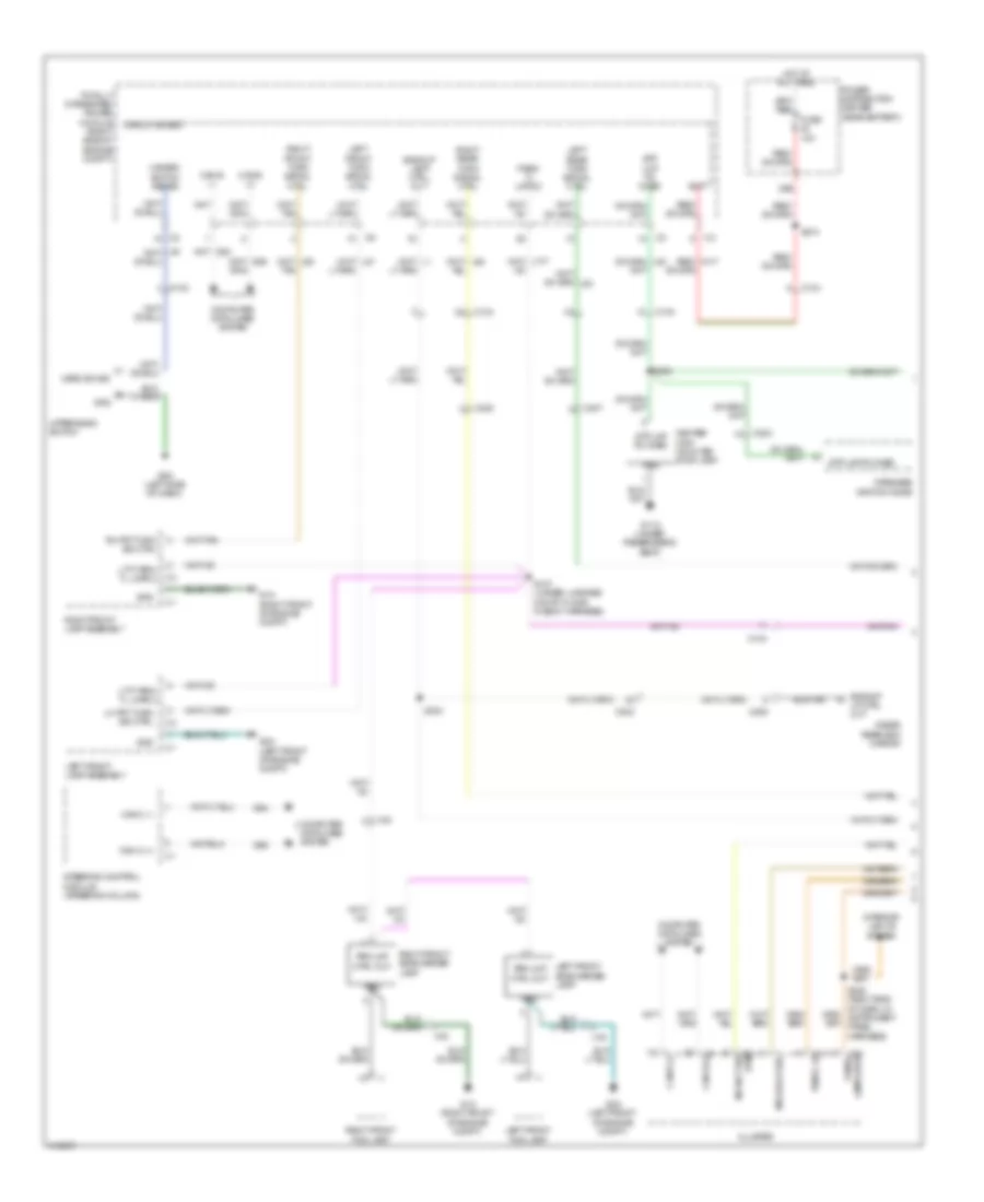
- Passenger door module
- Passenger mirror heater
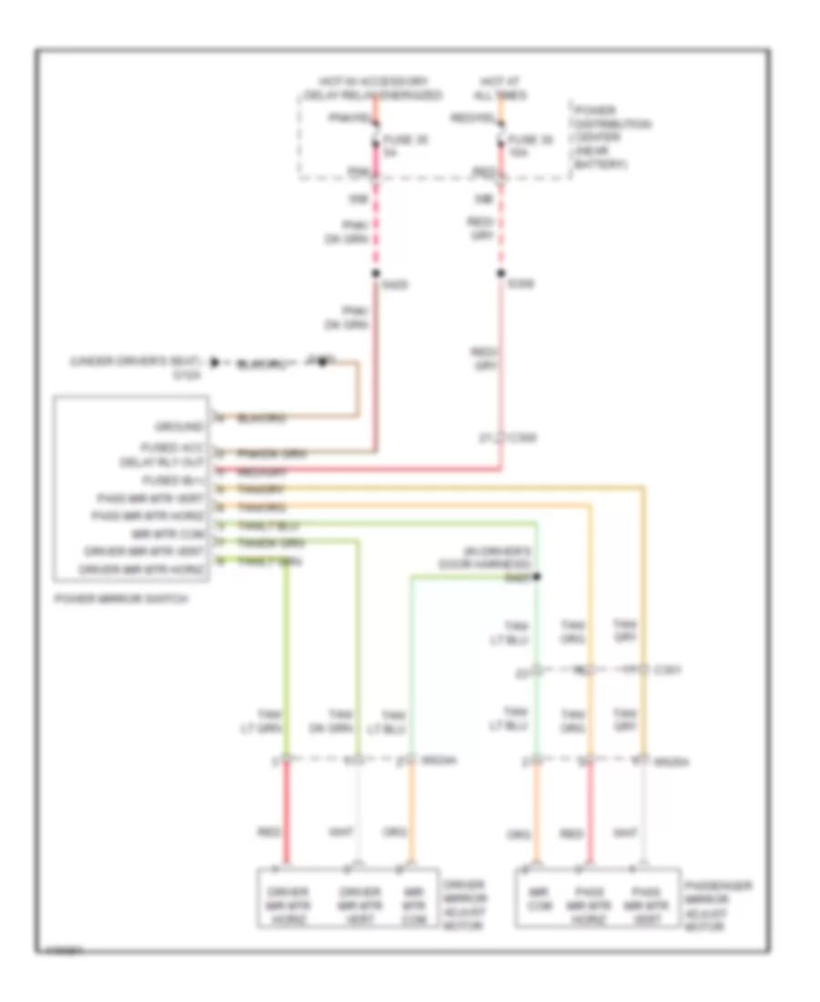
- Power mirror switch
- Right front led handle lamp
- Right seat back heater
- Right seat cushion heater
- S100a
- Stop lamp switch
- Tire pressure module
- Vacuum pump
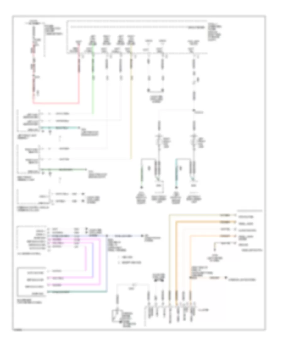
HEADLIGHTS
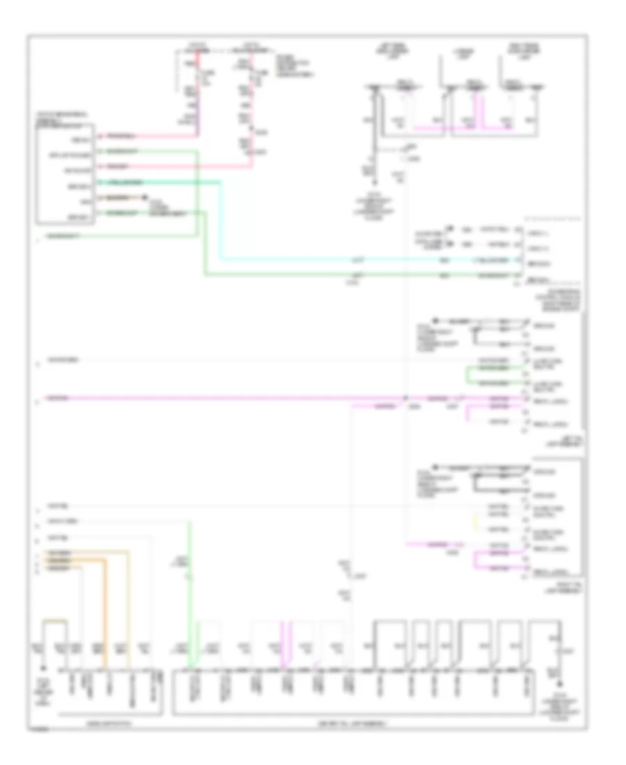
Headlights Wiring Diagram for Dodge Challenger R/T Plus 2013
List of elements for Headlights Wiring Diagram for Dodge Challenger R/T Plus 2013:
- (right end of dash, in instrument panel harness) s208
- 38b
- A/c heater control
- Air conditioning system
- Auto hdlp sig
- Batt fd
- C104
- C121
- C2 rtn mlfnct sw
- C203
- C3 driver
- Can b (+)
- Can b (-)
- Can c (+)
- Can c (-)
- Circuit board
- Cluster
- Computer data lines system
- D54
- D55
- D64
- D65
- Except hemi mds
- Fog lamp/ ind fd1
- Fuse 10a
- G10a (left center of dash)
- G139
- G1a (right front of engine compt)
- G2a (left front of engine compt)
- G39
- Gnd
- Ground
- Headlamp switch
- Hemi mds
- Hot at all times
- I100
- Interior lights system
- L24
- L33
- L34
- L43
- L44
- L89
- Left front fog lamp
- Left front lamp assembly
- Left front side marker lamp
- Left high beam driver
- Left low beam driver
- Mfs hdlp sel
- Mlfnct sw rtn
- Panel lamps
- Panel lamps driver
- Park brk
- Parking brake switch (base of parking brake)
- Power distribution center (near battery)
- Right front assembly lamp
- Right front fog lamp
- Right front side marker lamp
- Right high beam driver
- Right high beam fd
- Right low beam driver
- Right low beam fd
- S1001a
- S239 (center of dash, in instrument panel harness)
- S374
- Snsr gnd
- Ssr sunld sig
- Ssr sunld sig 2
- Steering control module (steering column)
- Sun sensor (top center of dash)
- Sw sns
- Totally integrated power module (right side of engine compt)
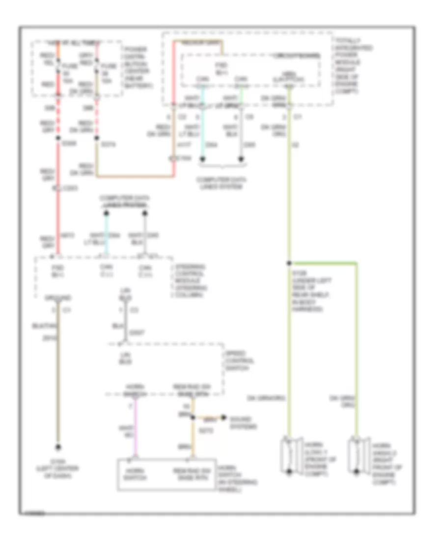
HORN
Horn Wiring Diagram for Dodge Challenger R/T Plus 2013
List of elements for Horn Wiring Diagram for Dodge Challenger R/T Plus 2013:
- 30b
- 38b
- A117
- C104
- C203
- Can c (+)
- Can c (-)
- Circuit board
- Computer data lines system
- D507
- D64
- D65
- Fsd b(+)
- Fuse 10a
- G10a (left center of dash)
- Ground
- Horn (high) 2 (right front of engine compt)
- Horn (low) 1 (front of engine compt)
- Horn switch
- Horn switch (in steering wheel)
- Hot at all times
- Hrn (l/h ptch) fd
- Lin bus
- Power distri- bution center (near battery)
- Red
- Rem rad sw snse rtn
- S128 (under left side of rear shelf, in body harness)
- S272
- S309
- S374
- Sound systems
- Speed control switch
- Steering control module (steering column)
- Totally integrated power module (right side of engine compt)
- Z910
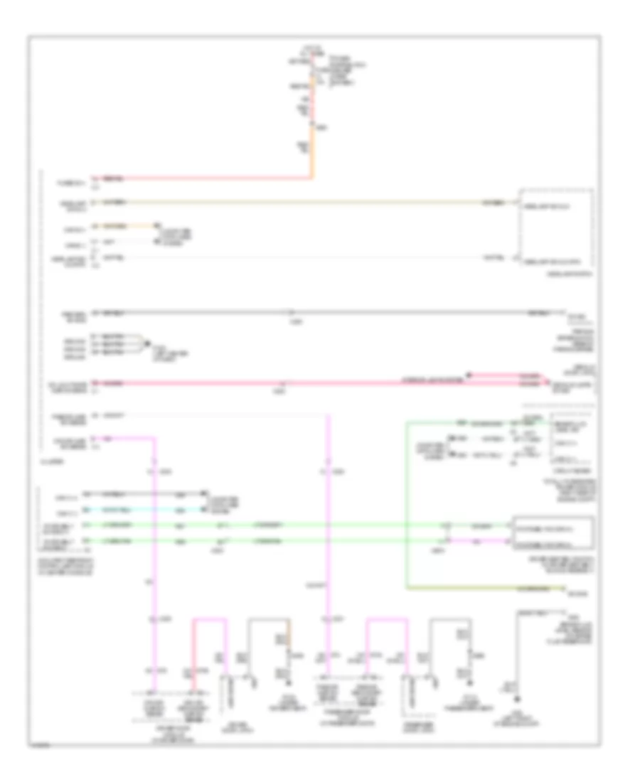
INSTRUMENT CLUSTER
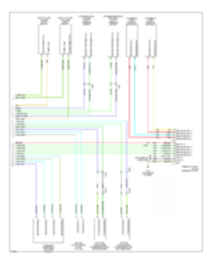
Instrument Cluster Wiring Diagram (1 of 2) for Dodge Challenger R/T Plus 2013
List of elements for Instrument Cluster Wiring Diagram (1 of 2) for Dodge Challenger R/T Plus 2013:
- 11a
- 14b
- 17b
- 29b
- A110
- A23
- A917
- Ajar sw sns
- Anti-lock brakes system
- B (+)
- B25
- B27
- C200
- C203
- C93
- C94
- Can b (+)
- Can b (-)
- Circuit breaker 11 25a
- Cluster
- Com snsr
- Computer data lines system
- Court lmps drvr
- D54
- D55
- Dklid/lgate
- Door locks system
- Dr ajar sw sns
- Dr lk sw mux
- Drv dr lk
- Drv unlk drv
- E12
- F202
- Fuel level sig 1
- Fuel level sig 2
- Fuel lvl sig 1
- Fuel lvl sig 2
- Fuel pump module (top of fuel tank)
- Fuse 10a
- Fuse 20a
- Fuse 5a
- G10a (left center of dash)
- G160
- G161
- G167
- G25
- G74
- G75
- G78
- Gnd
- Hdlmp sw mux
- Hdlmp sw mux rtn
- Headlights system
- Hi ind drvr
- High ind drvr
- Hot at all times
- Hot in run or start
- Interior lights system
- L307
- L900
- Lamps drvr
- Lft seat sw sns
- Lgate release drvr
- Low ind drvr
- Lt ft dr ulk sw sig
- M24
- M27
- P303
- P31
- P365
- P366
- P37
- P392
- P393
- P81
- P82
- P83
- P84
- Panel lmps drvr
- Parking brake switch (base of parking brake)
- Pass dr unlk
- Pnl lmps
- Power distribution center (near battery)
- Prk brk sw sns
- Red
- Red/ tan
- Red/tan
- Rel sw sns
- Rt seat sw sns
- Run-start
- S200
- S201
- S209
- Seats system
- Sw sig
- T/c sw sns
- Tan
- Trunk, tailgate, fuel doors system
- Upper bank switch
- Z210
- Z910
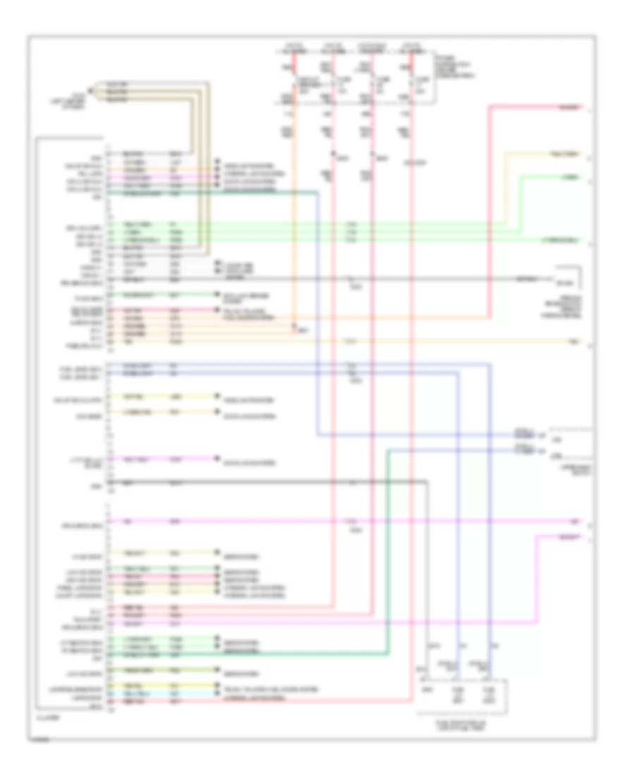
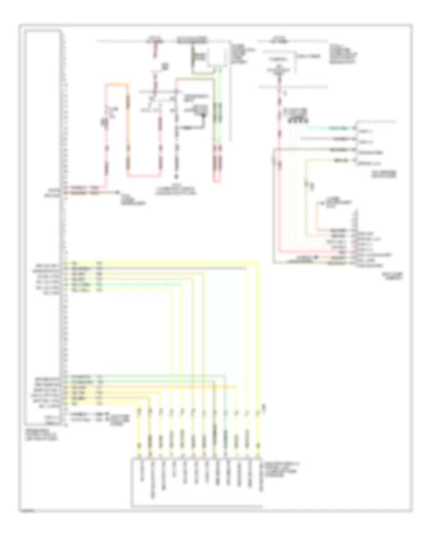
Instrument Cluster Wiring Diagram (2 of 2) for Dodge Challenger R/T Plus 2013
List of elements for Instrument Cluster Wiring Diagram (2 of 2) for Dodge Challenger R/T Plus 2013:
- (right rear of engine, in engine harness) s105
- 3.6l
- 5v sply
- Ajar sw sns
- B20
- Brake fluid level sensor (on brake fluid reservoir)
- Bus(-) can c
- C200
- C231
- C300
- C301
- Can c (+)
- Can c (-)
- Cargo lamp
- Circuit board
- Computer data lines system
- D64
- D65
- Dck lid/lgate rel sw sig
- Deck lid door latch
- Dr lock dr lt doors
- Dr lock drv rt doors
- Driver door latch
- Driver door module (in driver door)
- Drv dr ajar sw sns
- Drv dr second ajar sw sns
- Drv dr secondary ajar sw sns
- Drv dr unlock drv
- F855
- G11a (under passenger's seat)
- G12a (under driver's seat)
- G2a (left front of engine compt)
- G74
- G745
- G75
- G755
- Gnd
- K900
- Oil press
- Oil press sig
- Oil pressure sensor (except 3.6l: lower right front of engine) (3.6l:right rear of engine)
- Pass dr ajar sw sns
- Pass dr second ajar sw sns
- Pass dr secondary ajar sw sns
- Pass dr unlock drv
- Passenger door latch
- Passenger door module (in passenger door)
- Powertrain control module (right rear of engine compt)
- S110 (right rear of engine compt, in engine harness)
- S490
- S590
- Sens gnd
- Sig
- Sw sns
- Tan
- Totally integrated power module (right side of engine compt)
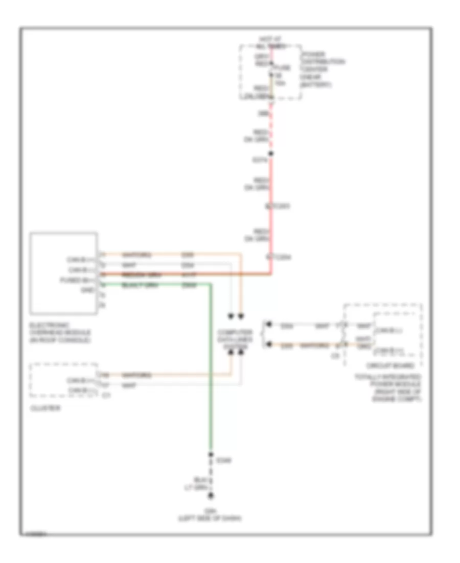
Overhead Console Wiring Diagram for Dodge Challenger R/T Plus 2013
List of elements for Overhead Console Wiring Diagram for Dodge Challenger R/T Plus 2013:
- 38b
- A117
- C203
- C204
- Can b (+)
- Can b (-)
- Circuit board
- Cluster
- Computer data lines system
- D54
- D55
- Electronic overhead module (in roof console)
- Fused b(+)
- G9a (left side of dash)
- Gnd
- Hot at all times
- Power distribution center (near battery)
- S349
- S374
- Totally integrated power module (right side of engine compt)
- Z909
INTERIOR LIGHTS
Interior Lights Wiring Diagram (1 of 2) for Dodge Challenger R/T Plus 2013
List of elements for Interior Lights Wiring Diagram (1 of 2) for Dodge Challenger R/T Plus 2013:
- (left front of headliner, in headliner harness) s341
- (not used)
- (right front of headliner, in headliner harness) s342
- 11a
- 17b
- 25a
- 29b
- 35b
- 38b
- 40b
- Ajar sig
- Batt fd
- C200
- C204
- C327
- Can b (+)
- Can b (-)
- Cargo lamp
- Circuit breaker 11
- Cluster
- Computer data lines system
- Courtesy lmps driver
- Crtsy lmp
- Dckld/ltgate rel sw sig
- Decklid door latch
- Decklid release switch
- Driver panel lamps
- Drv dr ajar sw
- Front reading lamp
- Fuse 10a
- Fuse 20a
- Fuse 5a
- Fused b (+)
- Fused b(+)
- G10a (left center of dash)
- G11a (under passenger's seat)
- G18a (center rear of luggage compt, in body harness)
- G9a (left side of dash)
- Gnd
- Hot at all times
- Hot in run or start
- Hot w/ accessory delay relay energized
- Left grab handle lamp
- Left vanity lamp
- Lgate ajar sig
- Liftgate ajar sig
- Liftgate sw ft sig
- Mlfnct sw return
- Panel lmps dimmer sig
- Pass dr ajar sw
- Pnk
- Pnl lmps
- Power distribution center (near battery)
- Rail lmp fds
- Reading/ rail lamps driver
- Red
- Red/ tan
- Red/tan
- Right grab handle lamp
- Right vanity lamp
- Run-start
- S1460 (left side of dash, in instrument panel harness)
- S201
- S209
- S217
- S300
- S349
- S374
Interior Lights Wiring Diagram (2 of 2) for Dodge Challenger R/T Plus 2013
List of elements for Interior Lights Wiring Diagram (2 of 2) for Dodge Challenger R/T Plus 2013:
- (in driver's door harness) s420
- 6.4l
- Ajar sig
- C200
- C203
- C300
- C301
- Cup holder lamp
- Driver door latch
- Driver door module (in driver's door)
- Drv dr ajar switch
- Fsd accy dly
- G11a (under passenger's seat)
- G12a (under driver's seat)
- G74
- G745
- G75
- G755
- G9a (left side of dash)
- Gnd
- Ground
- Headlamp switch
- Left front led handle lamp
- Left heated seat switch
- Mlfctn sw rtn
- Panel lamps dimmer sig
- Panel lamps driver
- Panel lmps drv
- Panel lps drv
- Pass dr ajar switch
- Passenger door latch
- Passenger door module (in passenger's door)
- Power distribution system
- Right front led handle lamp
- Right heated seat switch
- Run/start
- S208 (right end of dash, in instrument panel harness)
- S387 (5 speed a/t)
- S490
- S520 (in passenger's door harness)
- S590
- Secondary dr ajar sw c2
- Shift lever assembly (5 speed a/t)
- Upper bank switch
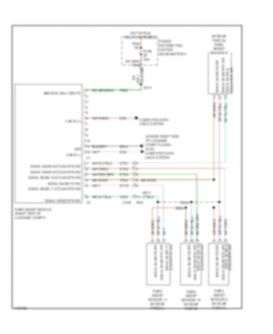
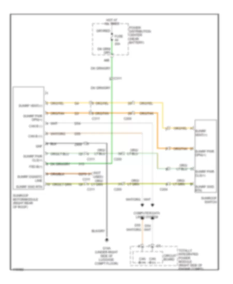
NAVIGATION
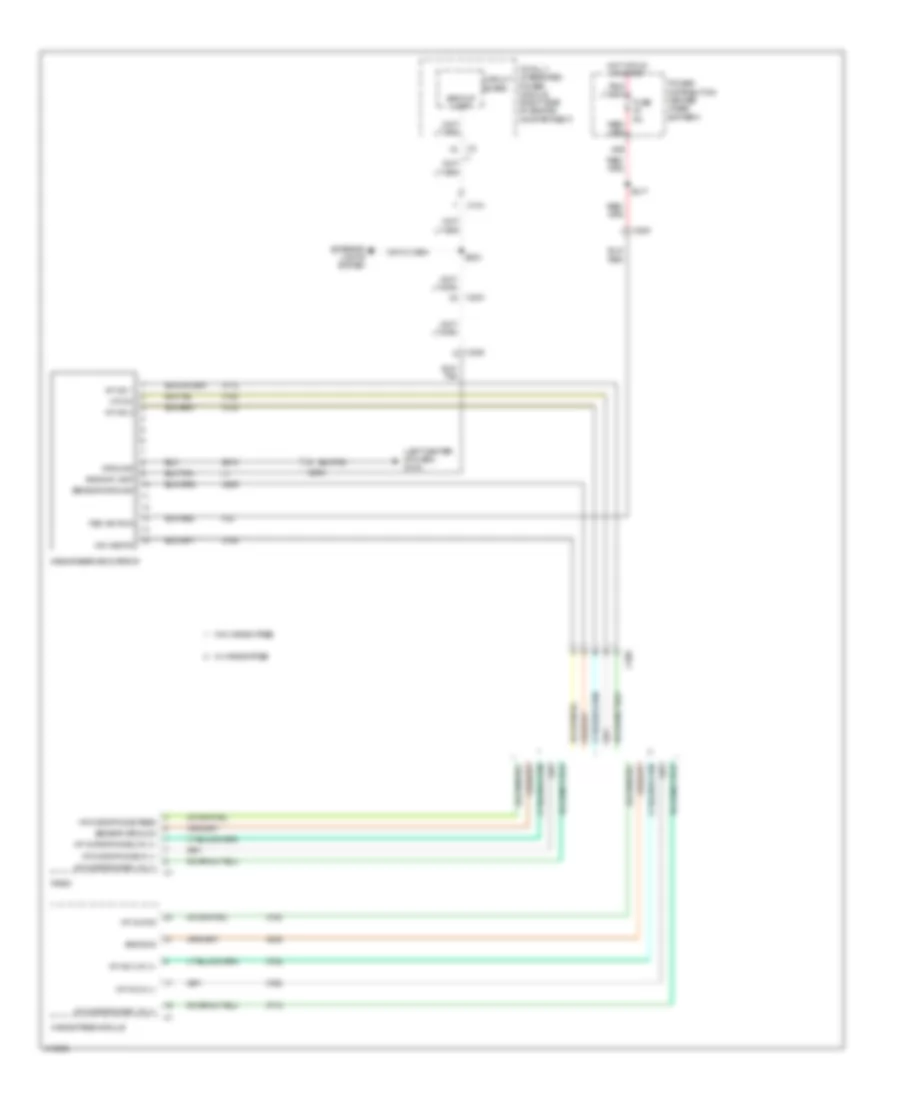
Navigation Wiring Diagram for Dodge Challenger R/T Plus 2013
List of elements for Navigation Wiring Diagram for Dodge Challenger R/T Plus 2013:
- (in rear fascia) park assist sensor 8
- (under right side of luggage compt floor) g14a computer data lines system
- 28b
- Abs run only ign fd
- C306
- Can b (+)
- Can b (-)
- Computer data lines system
- D54
- D55
- D701
- D703
- D704
- D710
- Dtlnk rtn rr
- Dtlnk rtn rr sonic snsr 8 sonic snsr rtn rr
- F500
- Gnf
- Hot w/ run relay energized
- I500
- Park assist module (right side of luggage compt)
- Park assist sensor 10 (in rear fascia)
- Park assist sensor 11 (in rear fascia)
- Park assist sensor 9 (in rear fascia)
- Power distribution center (near battery)
- S313
- S90a
- S91a
- Sonic snsr 10 dtlnk rtn rr
- Sonic snsr 10 sonic snsr rtn rr
- Sonic snsr 11
- Sonic snsr 11 dtlnk rtn rr
- Sonic snsr 8 dtlnk rtn rr
- Sonic snsr 9 dtlnk rtn rr
- Sonic snsr 9 sonic snsr rtn rr
- Sonic snsr fd rr
- Sonic snsr rtn rr
- X700
- X750
- Z914
POWER DISTRIBUTION
Power Distribution Wiring Diagram (1 of 4) for Dodge Challenger R/T Plus 2013
List of elements for Power Distribution Wiring Diagram (1 of 4) for Dodge Challenger R/T Plus 2013:
- (center of dash, in instrument panel harness) s201
- (near battery) power distribution center
- (not used)
- (right side of engine compt) totally integrated power module
- 10a
- 11a
- 16b
- 25a
- 30a
- 30b
- 33b
- 47a
- 47c
- 6.4l
- Anti-lock brakes module
- Auto shut down relay
- Bar
- Battery
- Bus
- C104
- C111
- C200
- Circuit breaker 11
- Cluster
- Console power outlet
- Diode 2
- Driver lumbar seat adjuster switch
- Driver seat switch
- Except 6.4l
- Front washer pump relay
- Fsd b(+)
- Fuse 10a
- Fuse 15a
- Fuse 20a
- Fuse 25a
- Fuse 25a red
- Fuse 30a
- Fuse 40a
- Fuse 50a tan/red
- G12a (under driver's seat)
- Generator
- Gnd
- I460a
- Nca
- Pass through post
- Power steering pump motor
- Powertrain control module
- Radiator fan 1 high/low relay
- Radiator fan 2 series/parallel relay
- Radiator fan 3 medium/high
- Red
- Red s138 (right rear of engine, engine harness)
- Relay
- S100 (right front of engine, in engine harness)
- S101a
- S140 (left front of trunk, in body harness)
- S142 (right rear red of engine, in engine harness)
- S315
- S904 (top of right cylinder head)
- S905 (top of right cylinder head, in engine harness)
- Starter
- Starter relay
- Tan/red
- To fuse 3 (diagram 4 of 4)
- To splice s309 (diagram 4 of 4)
- Virtual power pdc
- Wiper high/low relay
- Wiper on/off relay
- Zener diode
Power Distribution Wiring Diagram (2 of 4) for Dodge Challenger R/T Plus 2013
List of elements for Power Distribution Wiring Diagram (2 of 4) for Dodge Challenger R/T Plus 2013:
- (in driver's door harness) s420
- (in passenger's door harness) s520
- (left center of dash) g10a
- (near battery) power distribution center
- (not used)
- 15b
- 17b
- 18b
- 18c
- 19b
- 23b
- 23c
- 35a
- 35b
- 46a
- 47a
- 47c
- Accessory delay relay
- Active damping control unit (if equipped)
- Batt (+) fd
- Brake lamp relay
- Btsi sol ulk
- Bus bar
- C102
- C104
- C200
- C203
- C300
- C301
- Can c (+)
- Can c (-)
- Center high mounted stop lamp
- Cigar lighter
- Circuit board
- Cluster
- Clutch interlock switch (m/t)
- Computer data lines system
- Data link connector
- Driver window/ door express down switch
- Fuel pump relay
- Fuse 15a
- Fuse 20a
- Fuse 5a
- G10a (left center of dash)
- Gnd
- Ign run st
- Intrlk strt fd
- Intrlk strt fd2
- Left front led handle lamp
- Passenger window/door express down switch
- Passive entry module
- Pnk
- Power mirror switch
- Powertrain control module (m/t)
- Rear heated seats relay
- Rear window defogger relay
- Red
- Red/tan
- Right front led handle lamp
- S215 (right side of dash, in instrument panel harness)
- S300
- S302
- S323
- Shift lever assembly (a/t)
- Stop lamp switch
- Stp lmp fd
- Totally integrated power module (right side of engine compt)
- Trans rng park
- Wireless ignition node
Power Distribution Wiring Diagram (3 of 4) for Dodge Challenger R/T Plus 2013
List of elements for Power Distribution Wiring Diagram (3 of 4) for Dodge Challenger R/T Plus 2013:
- (center of dash, in instrument panel harness) s210
- (near battery) power distribution center
- (right side of dash, in instrument panel harness) s200
- 14a
- 14b
- 21b
- 21c
- 28a
- 28b
- 31a
- 31b
- 36a
- 36b
- 38a
- 38b
- 42a
- 42b
- 44a
- 44b
- 47d
- A/c heater control
- A/c heater module
- Bus bar
- C104
- C200
- C202
- C203
- C204
- C311
- Cargo lamp
- Circuit board
- Cluster
- Diode
- Electronic overhead module
- Front power blower motor module
- Fuse 10a
- Fuse 20a
- Fuse 30a
- Hands free module
- In car temperature sensor
- Iod-pdc
- Occupant restraint controller module
- Park assist module
- R/t
- Radio
- Radio amplifier (if equipped)
- Rear heated seats relay
- Red
- Run relay
- S202
- S203 (right end of dash, in instrument panel harness)
- S313
- S321
- S322
- S374
- S388
- Sunroof module/motor
- Totally integrated power module (right side of engine compt)
- Transmission relay
Power Distribution Wiring Diagram (4 of 4) for Dodge Challenger R/T Plus 2013
List of elements for Power Distribution Wiring Diagram (4 of 4) for Dodge Challenger R/T Plus 2013:
- (if equipped) s336
- (in passenger's door harness) s510
- (left center of dash, in instrument panel harness) s217
- (not used)
- (right side of luggage compt, in body harness)
- 11b
- 12b
- 20b
- 25a
- 27a
- 27b
- 29a
- 29b
- 32a
- 40a
- 40b
- 46c
- Anti-lock brakes module
- Bus bar
- C102
- C104
- C200
- C203
- C205
- C300
- C301
- Circuit board
- Circuit breaker 12
- Cluster
- Dash, in instrument panel harness)
- Driver door module
- From a fuse 1 (diagram 1 of 4)
- From fuse 30 (diagram 1 of 4)
- Fuel pump relay
- Fuse 10a
- Fuse 20a
- Fuse 5a
- Inside rearview mirror
- Left heated seat switch
- Nca
- Occupant restraint controller module
- Passenger door module
- Power distribution center (near battery)
- Power mirror switch
- Power steering pump motor (if equipped)
- Powertrain control module
- Red
- Right heated seat switch
- Run/start relay
- S128 (w/ power steering) (under left side of rear shelf, in body harness)
- S167 (right rear of engine compt, in headlamp & dash harness)
- S305
- S309
- S410 (in driver's door harness)
- Steering control module
- Stop lamp switch
- Tire pressure module
- Totally integrated power module (right side of engine compt)
- Upper bank switch (6.4l)
- Zener diode
POWER DOOR LOCKS
Power Door Locks Wiring Diagram for Dodge Challenger R/T Plus 2013
List of elements for Power Door Locks Wiring Diagram for Dodge Challenger R/T Plus 2013:
- (left center of dash) g10a
- (not used)
- 17b
- 35b
- Batt fd
- C200
- C203
- C300
- C301
- C327
- Can b (+)
- Can b (-)
- Cargo lamp
- Cluster
- Com snsr rtn
- Computer data lines system
- D54
- D55
- Decklid door latch
- Decklid release switch
- Driver door latch
- Driver door module (in driver door)
- Driver window express down switch
- Drs lk ctrl-ft/rr-lt
- Drs lk ctrl-ft/rr-rt
- Drs lk ctrl-ft/rr-rt dckld/lt gte rel sw sig c1
- Drv ft dr ajar sw in
- Fsd accy dly
- Ft drv dr lk sw sig
- Ft lt drv ulk
- Ft pass dr lk sw sig
- Fuse 20a
- Fuse 5a pnk
- G10a (left center of dash)
- G11a (under passenger's seat)
- G12a (under driver's seat)
- G18a (center rear of luggage compt, in body harness)
- G74
- G745
- G75
- G755
- Gnd
- Hot at all times
- Hot w/ accessory delay relay energized
- Interior lights system
- Lgate ajar sig
- Lgate pwr rel
- Lt ft dr ulk sw sig
- Pass door unlck
- Pass dr ajar sw in
- Passenger door latch
- Passenger door module (in passenger door)
- Passenger window express down switch
- Pnl lmps
- Power distribution center (near battery)
- Red
- Red/tan
- Rel sw sig dckld/lt gte
- S1460 (left side of dash, in instrument panel harness)
- S300
- S420
- S490
- S520
- S590
- Sec drv ft dr ajar sig ddm
- Sec pass ft dr ajar sig pdm
- Tan
POWER MIRRORS
Automatic Day/Night Mirror Wiring Diagram for Dodge Challenger R/T Plus 2013
List of elements for Automatic Day/Night Mirror Wiring Diagram for Dodge Challenger R/T Plus 2013:
- (left center of dash) g10a
- 40b
- Backup lamp
- C104
- C203
- C205
- Circuit board
- Exterior lights system
- F23
- Fsd ign run
- Fuse 5a
- Ground
- Hands free module
- Hf mic
- Hf mic 1
- Hf mic 2
- Hf mic 2 in (+)
- Hf mic in (-)
- Hf mic rd
- Hf microphone 1 in (+)
- Hf microphone 2 in (+)
- Hf microphone feed
- Hf microphone in (-)
- Hot in run or start
- Inside rearview mirror
- Mic hsd fd
- Power distribution center (near battery)
- Radio
- S217
- S303
- Sensor ground
- Sns gnd
- Totally integrated power module (right side of engine compartment)
- W/ hands free
- W/o hands free
- X712
- X722
- X792
- X793
- X835
- Z910
Power Mirrors Wiring Diagram for Dodge Challenger R/T Plus 2013
List of elements for Power Mirrors Wiring Diagram for Dodge Challenger R/T Plus 2013:
- (in driver's door harness) s425
- (under driver's seat) g12a
- 30b
- 35b
- C300
- C301
- Delay rly out
- Driver mir mtr horiz
- Driver mir mtr vert
- Driver mirror adjust motor
- Fuse 30 10a
- Fuse 35 5a
- Fused acc
- Fused b(+)
- Ground
- Hot at all times
- Hot w/ accessory delay relay energized
- I6624a
- I6626a
- Mir com
- Mir mtr com
- Pass mir mtr horiz
- Pass mir mtr vert
- Passenger mirror adjust motor
- Pnk
- Power distribution center (near battery)
- Power mirror switch
- Red
- S309
- S420
- S490
POWER SEATS
Driver Power Seat Wiring Diagram for Dodge Challenger R/T Plus 2013
List of elements for Driver Power Seat Wiring Diagram for Dodge Challenger R/T Plus 2013:
- (under driver's seat) g12a
- 11a
- 25a
- Circuit breaker 11
- Ckt brkr bayy fd
- Driver horizontal seat adjuster motor
- Driver seat switch
- Driver vertical front seat adjuster motor
- Driver vertical rear seat adjuster motor
- Drv pwr
- Drv pwr sts
- Drv pwr sts ft dn
- Drv pwr sts ft up
- Drv pwr sts horz aft
- Drv pwr sts horz fwd
- Drv pwr sts rr vert dn
- Drv pwr sts rr vert up
- Gnd
- Horz aft
- Horz fwd
- Hot at all times
- Power distribution center (near battery)
- Red
- S100a
- S101a
- Sts ft dn
- Sts ft up
Driver"s Lumbar Wiring Diagram for Dodge Challenger R/T Plus 2013
List of elements for Driver"s Lumbar Wiring Diagram for Dodge Challenger R/T Plus 2013:
- 11a
- 25a
- Circuit breaker 11
- Deflate/rearward
- Driver forward/ rearward seat lumbar motor
- Driver lumbar seat adjuster switch
- Driver up/down seat lumbar motor
- Fsd b(+)
- G12a (under driver's seat)
- Gnd
- Hot at all times
- I1900a
- Inflate/forward
- Lmbr down driv
- Lmbr up driv
- Power distribution center (near battery)
- Red
- S100a
- S101a
Heated Seats Wiring Diagram for Dodge Challenger R/T Plus 2013
List of elements for Heated Seats Wiring Diagram for Dodge Challenger R/T Plus 2013:
- (left center of dash, in instrument panel harness) s217
- (left side of dash) g9a
- (under passenger's seat) g11a
- 21c
- 31b
- 40b
- 47b
- 47d
- C1 can b (-)
- C104
- C200
- C91
- C986
- Can b (+)
- Can b (-)
- Circuit board
- Cluster
- Computer data lines system
- D54
- D55
- Diode
- F98
- Fsd ign run
- Ft htd sts sw pos snse lt
- Ft htd sts sw pos snse rt
- Fuse 15a
- Fuse 5a
- G11a (under passenger's seat)
- G12a (under driver's seat)
- G9a (left side of dash)
- Gnd
- Ground
- Heat out to coil ft lt
- Heat out to coil ft rt
- Heated seat sens rtn
- Heated seats module
- High ind lt ft htd sts
- Hot at all times
- Hot in on or start
- Ht out to coil ft lt
- Htd str whl fd
- Htd sts snse rtn
- I460a
- I470a
- Left heated seat switch
- Left htd sts high ind
- Left seat back heater
- Left seat cushion heater
- Lo ind rt ft htd sts
- Low ind left htd sts
- Low ind lt ft htd sts
- Lt ft htd sts temp snse
- Lt ft htd sts temp snsr
- P187
- P188
- P687
- P688
- P968
- Pnl lmps
- Pos snse lt ft htd sts sw
- Pos snse rt ft htd sts sw
- Power distribution center (near battery)
- Power distribution system
- Rear heated seats relay
- Red
- Rf heated seat temp sens
- Rf htd sts low ind
- Rf seat htr ctrl
- Right heated seat switch
- Right seat back heater
- Right seat cushion heater
- Rt ft htd sts hi ind
- Rt ft htd sts temp snse
- S100a
- S101a
- S102a
- S208 (right end of dash, in instrument panel harness)
- S388
- S98a
- Steering control module (steering column)
- Strg whl htr rtn
- Totally integrated power module (right side of engine compt)
- Z911
Heated Steering Wheel Wiring Diagram for Dodge Challenger R/T Plus 2013
List of elements for Heated Steering Wheel Wiring Diagram for Dodge Challenger R/T Plus 2013:
- 30b
- A913
- C200
- C203
- C91
- C986
- Can c (+)
- Can c (-)
- Computer data lines system
- D507
- D64
- D65
- Evic/nav rmux rtn
- Fsd b(+)
- Fuse 10a
- G10a (left center of dash)
- Gnd
- Heated seats module
- Hot at all times
- Htd str whl fd
- Htd str whl feed
- Htd str whl sig
- Htr rtn str whl
- I470a
- Left steering wheel switch
- Lin bus
- Power distribution center (near battery)
- Red
- Rmux rtn evic/nav3
- S270
- S309
- Speed control switch
- Steering control module (steering column)
- Steering wheel heater sensor
- Stg whl htr rtn
- Str whl htr rtn
- Whl feed htd str
- Z910
POWER TOP/SUNROOF
Power Top/Sunroof Wiring Diagram for Dodge Challenger R/T Plus 2013
List of elements for Power Top/Sunroof Wiring Diagram for Dodge Challenger R/T Plus 2013:
- (not used)
- 44b
- C200
- C204
- C311
- Can b (+)
- Can b (-)
- Circuit board
- Computer data lines system
- D270
- D54
- D55
- Fsd b(+)
- Fuse 20a
- G14a (under right side of luggage compt floor)
- Gnf
- Hot at all times
- Power distribution center (near battery)
- Sunrf dgnstc line
- Sunrf pwr cls(+)
- Sunrf pwr opn(+)
- Sunrf swd rtn
- Sunrf vent(+)
- Sunroof motor/module (right rear of roof)
- Sunroof switch
- Totally integrated power module (right side of engine compt)
- X13
- Z909
POWER WINDOWS
Power Windows Wiring Diagram for Dodge Challenger R/T Plus 2013
List of elements for Power Windows Wiring Diagram for Dodge Challenger R/T Plus 2013:
- 12b red
- 25a
- A937
- B red
- C300
- C301
- Can b (+)
- Can b (-)
- Circuit breaker 12
- Computer data lines system
- D54
- D55
- Driver door module (in driver door)
- Driver window driver (down)
- Driver window driver (up)
- Driver window express down motor
- Driver window express down switch
- Ft driv wdo snsr rtn
- Ft drv hall snsr
- Ft drv hall snsr b
- Ft drv hall snsr fd
- Ft pass hall snsr a
- Ft pass hall snsr b
- Ft pass hall snsr fd
- Ft pass sw illum/ sns rtn
- Ft pass up sw snse
- Ft pass wndw snsr rtn
- Fused b(+)
- G11a (under passenger's seat)
- G12a (under driver's seat)
- Ground
- Hot at all times red
- Left front door latch
- Lt ft wdw sig to dr node
- Lt master wdo vent rtn
- Lt pawl opn sig
- Passenger door module (in passenger door)
- Passenger window driver (down)
- Passenger window driver (up)
- Passenger window express down motor
- Passenger window express down switch
- Power distribution center (near battery)
- Q11
- Q12
- Q21
- Q22
- Q221
- Q222
- Q301
- Q302
- Q303
- Q304
- Q305
- Q306
- Q336
- Q58
- Q59
- Q936
- Q990
- Q991
- Q994
- Red
- Right front door latch
- Rt ft wdw sig to dr node
- Rt pawl open sig
- S305
- S410
- S490
- S510
- S590
- Z911
- Z912
RADIO
Hands Free Module Wiring Diagram for Dodge Challenger R/T Plus 2013
List of elements for Hands Free Module Wiring Diagram for Dodge Challenger R/T Plus 2013:
- (left center of dash) g10a
- 40b
- A117
- B(+)
- Backup lamp
- C104
- C203
- C205
- C353
- Can b(+)
- Can b(-)
- Circuit board
- Computer data
- D54
- D55
- Data+
- Data-
- Exterior lights system
- F23
- Fsd b(+)
- Fsd ign run
- Fuse 5a
- G9a (left side of dash)
- Gnf
- Handsfree module
- Hf audio outpt com
- Hf audio outpt lt
- Hf audio outpt rt
- Hf audio output com
- Hf audio output lt
- Hf audio output rt
- Hf mic 2 in +
- Hf mic hsd fd
- Hnds free mic in +
- Hnds free mic in -
- Hot at all times
- Hot w/ run/start relay energized
- Inside rearview mirror
- Lines system
- Media port
- Nca
- Power distribution center (near battery)
- Radio
- S202
- S217
- S303
- Snsr gnd
- Totally integrated power module (right side of engine compt)
- Usb gnd
- Usb pwr
- X442
- X443
- X444
- X445
- X703
- X704
- X712
- X722
- X792
- X793
- X795
- X835
- Z909
- Z910
Radio Wiring Diagram (1 of 2) for Dodge Challenger R/T Plus 2013
List of elements for Radio Wiring Diagram (1 of 2) for Dodge Challenger R/T Plus 2013:
- A300
- Am/fm coax
- Am/fr coax
- Amp ant feed
- C200
- C205
- C207
- C209
- C353
- Can b (+)
- Can b (-)
- Can c (+)
- Can c (-)
- Comp fd
- Computer data lines system
- D106
- D126
- D507
- D54
- D55
- D64
- D65
- D931
- Data (+)
- Data (-)
- Fuse b(+)
- G10a (left center of dash)
- G9a (left side of dash)
- Gnd
- Ground
- Hf microphone 1 in (+)
- Hf microphone 2 in (+)
- Hf microphone feed
- Hf microphone in (-)
- Horn switch (in steering wheel)
- Inside rearview mirror
- Left paddle shift switch
- Lin bus
- Lr spkr (+)
- Lr spkr (-)
- Media port
- Nca
- Radio
- Radio antenna
- Red
- Rem rad ctrl sw sig
- Rem rad sw rtn
- Right paddle shift switch
- Rr spkr (+)
- Rr spkr (-)
- S271
- S272
- Sat ant shld
- Sat ant sig
- Sat ant sig/shld
- Satellite radio antenna
- Satellite video antenna
- Sens gnd
- Speed control switch
- Steering control module (steering column)
- Usb gnd
- Usb pwr
- W/ satellite radio antenna
- W/ satellite video antenna
- X442
- X443
- X444
- X445
- X51
- X52
- X57
- X58
- X62
- X712
- X722
- X792
- X793
- X835
- Z909
Radio Wiring Diagram (2 of 2) for Dodge Challenger R/T Plus 2013
List of elements for Radio Wiring Diagram (2 of 2) for Dodge Challenger R/T Plus 2013:
- 36b
- Amp center i/p spkr (+)
- Amp center i/p spkr (-)
- Amp lr spkr (+)
- Amp lr spkr (-)
- Amp lt i/p spkr (+)
- Amp lt i/p spkr (-)
- Amp rr spkr (+)
- Amp rr spkr (-)
- Amp rt i/p spkr (+)
- Amp rt i/p spkr (-)
- C200
- C203
- C300
- C301
- Can b (+)
- Can b (-)
- Center instrument panel speaker
- Computer data lines system
- D54
- D55
- Fused b(+)
- G10a (left center of dash)
- Gnd
- Hot at all times
- Left front door speaker
- Left instrument panel speaker
- Left rear shelf 18ch speaker
- Left rear srt 18ch speaker
- Lf spkr (+)
- Lf spkr (-)
- Lr spkr (+)
- Lr spkr (-)
- Lr twtr (+)
- Lr twtr (-)
- Power distribution center (near battery)
- Radio amplifier (left kick panel)
- Rf dr spkr (+)
- Rf dr spkr (-)
- Right front door speaker
- Right instrument panel speaker
- Right rear shelf 18ch speaker
- Right rear srt 18ch speaker
- Rr spkr (+)
- Rr spkr (-)
- Rr twtr (+)
- Rr twtr (-)
- S203
- Sbfr 1 in (+)
- Sbfr 1 rtn (-)
- Sbfr 2 in (+)
- Sbfr 2 input (+)
- Sbfr 2 rtn (-)
- Sbfr 3 in (+)
- Sbfr 3 in (-)
- Subwoof 1 input (+)
- Subwoof 1 rtn (-)
- Subwoof 3 input (+)
- Subwoof 3 input (-)
- Subwoofer speaker
- X200
- X201
- X202
- X208
- X209
- X212
- X214
- X282
- X284
- X290
- X291
- X292
- X298
- X299
- X300
- X301
- X303
- X304
- X305
- X390
- X391
- X393
- X394
- X395
- X51
- X52
- X57
- X58
- Z910
SHIFT INTERLOCK
Shift Interlock Wiring Diagram for Dodge Challenger R/T Plus 2013
List of elements for Shift Interlock Wiring Diagram for Dodge Challenger R/T Plus 2013:
- (right rear of engine compt) powertrain control module
- (under driver's seat) g12a
- 29b
- B15
- B16
- Brk sig 1
- Brk sig 2
- Btsi ctrl
- C104
- C203
- Can c +
- Can c -
- Circuit board
- Computer data lines system
- D64
- D65
- E12
- F902
- Fuse 29 5a
- Fuse 8 15a
- Fused b (+)
- G12a (under driver's seat)
- Gnd
- Gnf
- Hot at all times
- Hot w/ run/ start relay energized
- Ign off- run-start
- Ign off-run-start
- Ign run/ start
- Interior lights system
- K321
- Panel lamps drv
- Pnk
- Power distribution center (near battery)
- Power distribution system
- Red
- S215
- Shift lever assembly
- Stop lamp switch (top of brake pedal assembly)
- T824
- Totally integrated power module (right side of engine compt)
- Trs park sig
- Wireless ignition node
- Z912
STARTING/CHARGING
Charging Wiring Diagram for Dodge Challenger R/T Plus 2013
List of elements for Charging Wiring Diagram for Dodge Challenger R/T Plus 2013:
- A804
- Altr fld fd
- Altr snse
- B(+)
- Battery
- Can b (+)
- Can b (-)
- Can c (+)
- Can c (-)
- Cluster
- Computer data lines system
- D64
- D65
- G303 (near battery)
- Generator
- K20
- Pass through post
- Power distribution system
- Powertrain control module (right rear of engine compt)
- Red
- S100
- S138
- S142
- Starter
Starting Wiring Diagram for Dodge Challenger R/T Plus 2013
List of elements for Starting Wiring Diagram for Dodge Challenger R/T Plus 2013:
- (a/t)
- B(+)
- Battery
- Btsi sol ulk
- C100
- C102
- C104
- C203
- Can c (+)
- Can c (-)
- Circuit board
- Cltch upstp sw sig
- Clutch interlock switch (m/t) (top of clutch pedal assembly)
- Computer data lines system
- D64
- D65
- Exterior lights system
- Fsd b(+)
- Fuse 15a
- Fuse 25a
- G10a (left center of dash)
- G12a (under driver's seat)
- G303 (near battery)
- Generator
- Gnd
- Hold-in
- Hot at all times
- Ign run st
- Ign run-st
- M/t
- Man cltch intrlk start fd2
- Man cltch intrlk strt fd
- Man cltch intrlk strt fd2
- Pass through post
- Power distribution center (near battery)
- Power distribution system
- Powertrain control module (right rear of engine compt)
- Pull-in
- Red
- S100
- S138
- S1390 (right side of engine compt in headlamp & dash harness)
- S142
- S215
- S302
- Shift lever assembly
- Starter
- Starter relay
- Stp lmp fd cmbd
- Strtr ctrl
- T142
- T26
- T752
- Totally integrated power module (right side of engine compt)
- Trans rng park
- Transmission control module (a/t) (left end of dash)
- Wireless ignition node
SUPPLEMENTAL RESTRAINTS
Supplemental Restraints Wiring Diagram (1 of 3) for Dodge Challenger R/T Plus 2013
List of elements for Supplemental Restraints Wiring Diagram (1 of 3) for Dodge Challenger R/T Plus 2013:
- 1r sts belt retrct pret pass(+)
- 1r sts belt retrct pret pass(-)
- 1r sts belt sw driv(+)
- 1r sts belt sw driv(-)
- 1r sts belt sw pass (-)
- 27b
- 28b
- 30b
- Abg squib1 driv (+)
- Abg squib1 driv (-)
- Abg squib1 pass (+)
- Abg squib1 pass (-)
- Abg squib2 driv (+)
- Abg squib2 driv (-)
- Abg squib2 pass (+)
- Abg squib2 pass (-)
- Abs run only ign fd
- C102
- C200
- Can c (+)
- Can c (-)
- Computer data lines system
- Crtn squib lt (+)
- Crtn squib lt (-)
- Crtn squib1 rt (+)
- Crtn squib1 rt (-)
- D64
- D65
- Driver seat belt retractor/tensioner (base of driver "b" pillar)
- Drv sts belt retrct 1
- Drv sts belt retrct 2
- Drv sts blt retract 1
- Drv sts blt retract 2
- F201
- F500
- Fsd run/strt ign
- Ft lt impt
- Ft lt impt snsr (+)
- Ft lt impt snsr (-)
- Ft rt impt
- Ft rt impt snsr (+)
- Ft rt impt snsr (-)
- Fuse 10a
- G13a (left side of dash)
- Gnd
- Hot w/ run relay energized
- Left front impact sensor (left front corner of engine compt)
- Lt impt 2 gnd
- Lt impt 2 sig
- Lt thorax squib (+)
- Lt thorax squib (-)
- Occupant restraint controller module (in center console)
- Pass sts blt retract 1
- Pass sts blt retract 2
- Pass sts blt sw
- Pnk/
- Power distribution center (near battery)
- R13
- R130
- R14
- R140
- R15
- R150
- R16
- R160
- R17
- R18
- R19
- R20
- R261
- R262
- R263
- R264
- R283
- R284
- R42
- R43
- R44
- R45
- R503
- R504
- R505
- R506
- R53
- R54
- R55
- R56
- R57
- R58
- R59
- R60
- R61
- R62
- R63
- R64
- R79
- R80
- R81
- R82
- Red
- Red/
- Right front impact sensor (right front corner of engine compt)
- Rt impt 1 gnd
- Rt impt 2 sig
- Rt thorax squib (+)
- Rt thorax squib (-)
- S210
- S309
- Seat occp dtctr pass (-)
- Seat occp dtctr pass(+)
- Side impt prss snsr1 lt (+)
- Side impt prss snsr1 lt (-)
- Side impt prss snsr1 rt (+)
- Side impt prss snsr1 rt (-)
- Side impt snsr1 lt (+)
- Side impt snsr1 rt (+)
- Side impt snsr2 lt (-)
- Side impt snsr2 rt (-)
- Snsr (+)
- Snsr (-)
- Sts trk postn snsr rtn driv
- Sts trk postn snsr rtn pass
- Sts trk postn voltg driv
- Sts trk postn voltg pass
- Tan
- Z939
Supplemental Restraints Wiring Diagram (2 of 3) for Dodge Challenger R/T Plus 2013
List of elements for Supplemental Restraints Wiring Diagram (2 of 3) for Dodge Challenger R/T Plus 2013:
- (base of passenger "b" pillar) passenger seat belt retractor/tensioner
- (in passenger seat belt buckle assembly)
- (in passenger's seat cushion) occupant detection sensor
- (not used)
- (under driver's seat) driver seat track position sensor
- 1r sts belt retrct pret pass(-)
- 1r sts belt sw driv(+)
- C200
- C203
- Can b (+)
- Can b (-)
- Cluster
- Computer data lines system
- Crtn squib rt (+)
- Crtn squib rt (-)
- Driver seat belt buckle tensioner
- Driver seat belt switch (in driver seat belt buckle assembly)
- Drv sts blt retract 2
- I460a
- I471a
- Left side impact sensor 2 (left "b" pillar)
- Lt impt 2 sig
- Occp dtctr (-) pass seat
- Pass seat occp dtctr (+)
- Pass sts blt retract 2
- Pass sts blt sw
- Passenger seat belt buckle tensioner
- Passenger seat belt switch
- Pret pass(+) 1r sts belt retrct
- Red
- Retract 1 drv sts blt
- Retract 1 pass sts blt
- Right side curtain air bag (in right "c" pillar)
- Right side impact sensor 2 (right "b" pillar)
- Rt impt 2 sig
- Side impt snsr2 lt (-)
- Side impt snsr2 rt (+)
- Side impt snsr2 rt (-)
- Snsr rtn driv sts trk postn
- Sts trk postn vltg driv
- Sw pass (-) 1r sts belt
- Tan
Supplemental Restraints Wiring Diagram (3 of 3) for Dodge Challenger R/T Plus 2013
List of elements for Supplemental Restraints Wiring Diagram (3 of 3) for Dodge Challenger R/T Plus 2013:
- (in driver's door) left side impact pressure sensor
- (in passenger's door) right side impact pressure sensor
- (in steering wheel) driver air bag squib 1
- (in steering wheel) driver air bag squib 2
- (left "c" pillar) left side impact sensor 1
- (right "c" pillar) right side impact sensor 1
- A913
- Abg squib1 driv (+)
- Abg squib1 driv (-)
- Abg squib1 pass (+)
- Abg squib1 pass (-)
- Abg squib2 driv (+)
- Abg squib2 driv (-)
- Abg squib2 pass (+)
- Abg squib2 pass (-)
- Batt fd 13
- C203
- C300
- C301
- Can c (+)
- Can c (-)
- Computer data lines system
- Crtn squib lt (+)
- Crtn squib lt (-)
- D64
- D65
- G10a (left center of dash)
- Gnd
- I1451a
- I1461a
- I460a
- I471a
- Left side curtain air bag (in left "c" pillar)
- Left side thorax air bag (outer edge of left front seat back)
- Lt impt 2 gnd
- Lt thorax squib (+)
- Lt thorax squib (-)
- Passenger air bag squib (right side of dash)
- R43
- R45
- R61
- R63
- Red
- Right side thorax air bag (outer edge of right front seat back)
- Rt impt 1 gnd
- Rt thorax squib (+)
- Rt thorax squib (-)
- Side impt prss snsr1 lt (+)
- Side impt prss snsr1 lt (-)
- Side impt prss snsr1 rt (+)
- Side impt prss snsr1 rt (-)
- Side impt snsr1 lt (+)
- Side impt snsr1 rt (+)
- Steering control module (steering column)
- Tan
- Z910
TRANSMISSION
Transmission Wiring Diagram for Dodge Challenger R/T Plus 2013
List of elements for Transmission Wiring Diagram for Dodge Challenger R/T Plus 2013:
- (under driver's seat) g12a
- 24b
- 24c
- 32b
- 33a
- 37a
- 37b
- 87a
- Btsi sol ulk
- Bus bar
- C100
- C104
- C203
- Can c (+)
- Can c (-)
- Circuit bord
- Computer data lines system
- D64
- D65
- Electrohydraulic control unit (lower left rear of engine)
- F942
- Fuse 15a
- Fused b(+)
- G12a (under driver's seat)
- G14a (under right side of luggage compt floor)
- Ground
- Ground distribution system
- Hot at all times
- Hot w/ run start relay energized
- Ign rs
- Ign ulk-run-start
- Ign unlock-run- start
- Interior lights system
- Mod outpt ctrl
- Od sol ctrl
- Pnk
- Pnl lmps
- Power distribution center (near battery)
- Red
- Shift lever assembly
- Shift sol ctrl
- Shift sol outpt ctrl
- Snsr (n3) sig +
- Snsr spd fd 6v
- Sol (23) ctrl
- Sol (34) ctrl
- Sol vlvs fd
- Spd (n2) sig +
- Spd (n2) spd sig +
- Spd sens rtn
- T13
- T54
- T60
- T70
- T71
- T72
- T73
- T74
- T75
- T76
- T77
- T78
- Tcc ctrl
- Temp snsr sig
- Totally integrated power module (right side of engine compt)
- Transmission control module (left end of dash)
- Transmission relay
- Trs rng park
- Win wireless ignition node
- Z912
- Zener diode
TRUNK, TAILGATE, FUEL DOOR
Deck Lid Release Wiring Diagram for Dodge Challenger R/T Plus 2013
List of elements for Deck Lid Release Wiring Diagram for Dodge Challenger R/T Plus 2013:
- (left side of dash, in instrument panel harness)
- (not used)
- 14b
- C200
- C327
- Cargo lamp
- Cluster
- Dckld/ liftgate rel sw sig
- Decklid door latch
- Decklid release switch (center rear of luggage compt)
- Decklid/ liftgate rel drv
- Fused b (+)
- G10a (left center of dash)
- G11a (under passenger's seat)
- G18a (center rear of luggage compt, in body harness)
- Gnd
- Hot at all times
- Interior lights system
- Lgate ajar sw sig
- Lgate ajar switch sig
- Lgate sw sig
- Pnl lmps
- Power distribution center (near battery)
- S1460
- S200
WARNING SYSTEMS
Chime Wiring Diagram for Dodge Challenger R/T Plus 2013
List of elements for Chime Wiring Diagram for Dodge Challenger R/T Plus 2013:
- 14b
- 1r sts belt sw driv(+)
- 1r sts belt sw driv(-)
- Ajar sw sig
- B20
- Brake fluid level sensor (on brake fluid reservoir)
- Brake fluid level sig
- C200
- C203
- C300
- C301
- Can b (+)
- Can b (-)
- Can c (+)
- Can c (-)
- Circuit board
- Cluster
- Computer data lines system
- D64
- D65
- Decklid door latch
- Decklid/lgate sw sig
- Dk lid/lftgate ajar sw sens c1
- Driver door latch
- Driver door module (in driver door)
- Driver seat belt switch (in driver seat belt buckle assembly)
- Drv dr ajar sw sense
- Drv dr secondary ajar sw sense
- Fused b (+)
- G10a (left center of dash)
- G11a (under passenger's seat)
- G12a (under driver's seat)
- G2a (left front of engine compt)
- Gnd
- Ground
- Headlamp sw mux
- Headlamp sw mux rtn
- Headlamp switch
- Hot at all times
- I460a
- Interior lights system
- Occupant restraint controller module (in center console)
- Park brk sw sns
- Parking brake switch (base of parking brake)
- Pass dr ajar sw sense
- Pass dr secondary ajar sw sense
- Passenger door latch
- Passenger door module (in passenger door)
- Power distribution center (near battery)
- R57
- R59
- S200
- S490
- S590
- Sw sig
- Sw sns
- Tan
- Totally integrated power module (right side of engine compt)
Tire Pressure Monitoring Wiring Diagram for Dodge Challenger R/T Plus 2013
List of elements for Tire Pressure Monitoring Wiring Diagram for Dodge Challenger R/T Plus 2013:
- 30b
- A913
- Can c (+)
- Can c (-)
- Computer data lines system
- D64
- D65
- Fuse 10a
- Fused b(+)
- G11a (under passenger's seat)
- Gnd
- Hot at all times
- Power distribution center (near battery)
- Red
- S309
- Tire pressure module (forward of right rear wheelwell)
- Z911
WIPER/WASHER
Wiper/Washer Wiring Diagram for Dodge Challenger R/T Plus 2013
List of elements for Wiper/Washer Wiring Diagram for Dodge Challenger R/T Plus 2013:
- (right side of engine compt) totally integrated power module
- 30b
- 38b
- 87a
- Batt fd
- C104
- C203
- Can b (+)
- Can b (-)
- Can c (+)
- Can c (-)
- Circuit board
- Cluster
- Computer data lines system
- D54
- D55
- D64
- D65
- Front washer fluid level sensor (in washer fluid reservoir)
- Front washer pump relay
- Front wiper motor (left rear of engine compt)
- Ft wpr wsh sig to bcm
- Ft wsh mtr ctrl
- Fuse 15a
- Fuse 30a
- Fused b(+)
- G10a (left center of dash)
- G1a (right front of engine compt)
- G2a (left front of engine compt)
- G51a (right front of engine compt)
- Gnd
- Ground distribution system
- Hi spd fd
- Hot at all times
- Lo washer sw sns
- Lo wsh sw sns
- Low spd fd
- Nca
- Power distribution center (near battery)
- Red
- Red/ a913
- S309
- S374
- Steering control module (steering column)
- Windshield washer pump (in washer fluid reservoir)
- Wiper high/low relay
- Wiper on/off relay
- Wiper on/off relay control
- Wpr hi/lo rly ctrl
- Wpr park
- Wpr park sig
- Z910
- Zener diode